

Mitsubishi PKA-A12HA6 Operation Manual
SPLIT-SYSTEM HEAT PUMP
PKA-A·HA6
OPERATION MANUAL
For safe and correct use, please read this operation manual thoroughly before operating the air-conditioner unit.
MANUEL D’UTILISATION
Pour une utilisation correcte sans risques, veuillez lire le manuel d’utilisation en entier avant de vous servir du
climatiseur.
MANUAL DE INSTRUCCIONES
Lea este manual de instrucciones hasta el fi nal antes de poner en marcha la unidad de aire acondicionado para
garantizar un uso seguro y correcto.
FOR USER
POUR L’UTILISATEUR
PARA EL USUARIO
English
Français
Español
Contents
1. Safety Precautions ...............................................................2
2. Parts Names ........................................................................2
3. Operation .............................................................................3
4. Timer ....................................................................................5
5. Emergency Operation for IR wireless remote controller ......5
6. Care and Cleaning ...............................................................5
1. Safety Precautions
► Before installing the unit, make sure you read all the
“Safety Precautions”.
► The “Safety Precautions” provide very important
points regarding safety. Make sure you follow them.
► Please report to or take consent by the supply author-
ity before connection to the system.
Warning:
• The unit must not be installed by the user. Ask the dealer or an
authorized company to install the unit. If the unit is installed improperly, water leakage, electric shock or fi re may result.
• Do not stand on, or place any items on the unit.
• Do not splash water over the unit and do not touch the unit with
wet hands. An electric shock may result.
• Do not spray combustible gas close to the unit. Fire may result.
• Do not place a gas heater or any other open-flame appliance
where it will be exposed to the air discharged from the unit. Incomplete combustion may result.
• Do not remove the front panel or the fan guard from the outdoor
unit when it is running.
7. Trouble Shooting ..................................................................5
8. Specifi cations .......................................................................7
9. Operation Manual for IR wireless remote controller .............8
Symbols used in the text
Warning:
Describes precautions that should be observed to prevent danger
of injury or death to the user.
Caution:
Describes precautions that should be observed to prevent damage
to the unit.
Symbols used in the illustrations
: Indicates a part which must be grounded.
• When you notice exceptionally abnormal noise or vibration, stop
operation, turn off the power switch, and contact your dealer.
• Never insert fi ngers, sticks etc. into the intakes or outlets.
• If you detect odd smells, stop using the unit, turn off the power
switch and consult your dealer. Otherwise, a breakdown, electric
shock or fi re may result.
• This air conditioner is NOT intended for use by children or infi rm
persons without supervision.
• Young children must be supervised to ensure that they do not
play with the air conditioner.
• If the refrigeration gas blows out or leaks, stop the operation of
the air conditioner, thoroughly ventilate the room, and contact
your dealer.
Caution:
• Do not use any sharp object to push the buttons, as this may
damage the remote controller.
• Never block or cover the indoor or outdoor unit’s intakes or outlets.
2. Parts Names
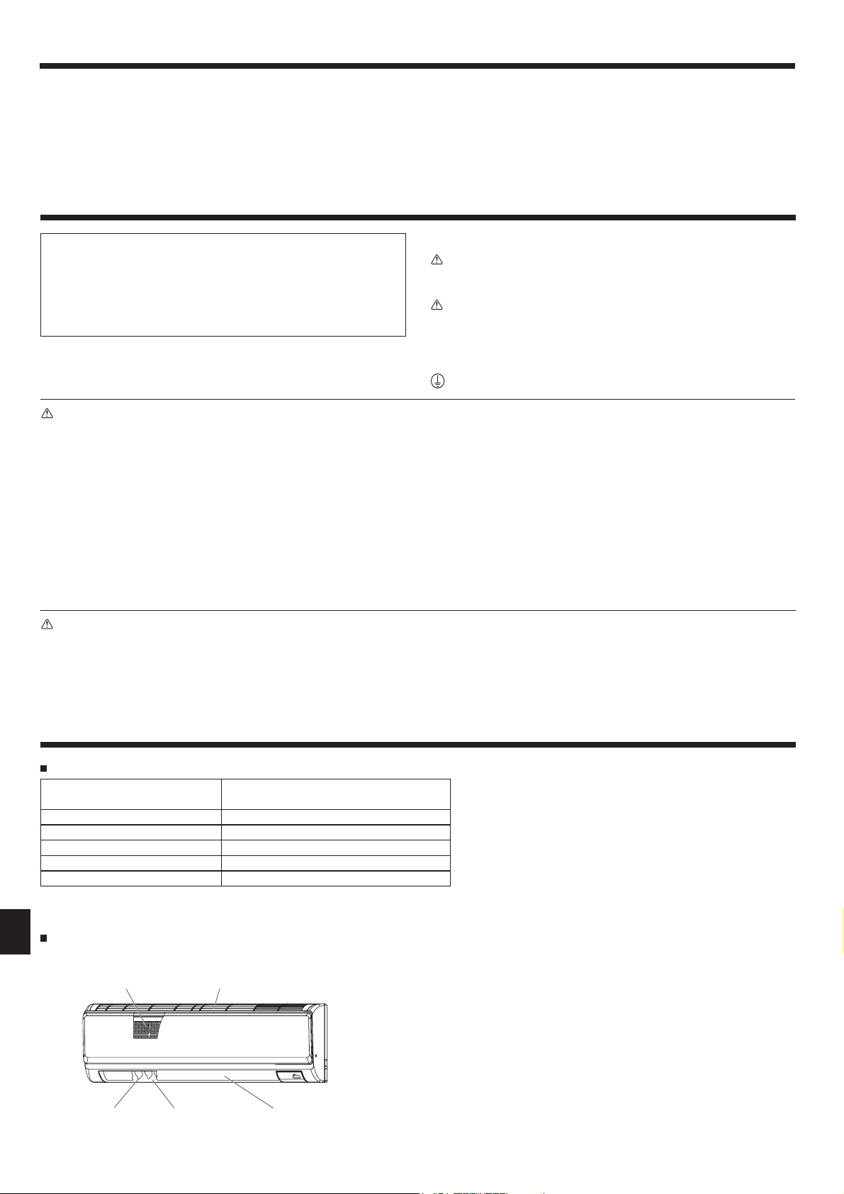
Indoor Unit
PKA-A·HA6
Fan speed 3 speeds + Auto
Vane Auto with swing
Louver Manual
Filter Normal
Filter cleaning indication 100 hr
PKA-A·HA6
Wall Mounted
Filter
Air intake
Disposing of the unit
When you need to dispose of the unit, consult your dealer.
Louver
Air outlet
Vane
2

2. Parts Names
Remote controller (Optional parts)
Radio frequency interface Wired remote controller IR wireless remote controller
RF thermostat
COOL
DRY
AUTO
FAN
HEAT
Outdoor unit
TEMP.
ON/OFF
Ref. Pipes
Indoor-Outdoor
Connection wire
Power
Service Panel
3. Operation
About the operation method, refer to the operation manual that comes
each remote controller.
3.1. Turning ON/OFF
Earth
Note:
Even if you press the ON/OFF button immediately after shutting down the operation is progress, the air conditioner will not start for about three minutes.
This is to prevent the internal components from being damaged.
3
3. Operation
3.2. Operation mode select
Cool/Dry/Fan/Heat/Automatic (cool/heat)/Ventilation modes are available.
Note:
Heat and Automatic mode can not be available for cooling only units.
z
Ventilation mode: only indicated on the following condition. Wired remote
z
controller is used and LOSSNAY is connected.
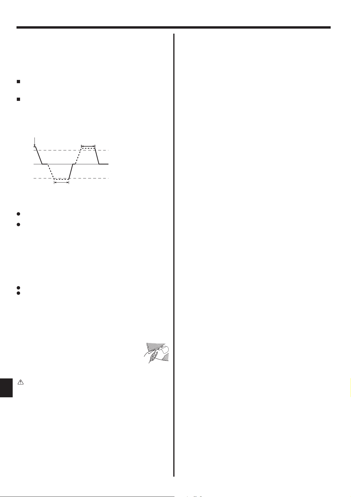
Automatic mode
z
According to a set temperature, cooling operation starts if the room
temperature is too hot and heating operation starts if the room temperature is too cold.
During automatic operation, if the room temperature changes and
remains 2 °C, 4 °F or more above the set temperature for 15 minutes,
the air conditioner switches to cooling mode. In the same way, if the
room temperature remains 2 °C, 4 °F or more below the set temperature for 15 minutes, the air conditioner switches to heating mode.
Cooling mode
15 minutes (switches
from cooling to heating )
15 minutes (switches
from heating to cooling)
Set temperature +2°C, +4°F
Set temperature
Set temperature -2°C, -4°F
3.3. Fan speed setting
Note:
The number of available fan speeds depends on the type of unit
connected.
In the following cases, the actual fan speed generated by the unit
will differ from the speed shown the remote controller display.
1. When the unit is in STANDBY or DEFROST states.
2. When the temperature of the heat exchanger is low in the heat-
ing mode. (e.g. immediately after heating operation starts)
3. In HEAT mode, when room temperature is higher than the tem-
perature setting.
4. When the unit is in DRY mode.
3.4. Airfl ow direction setting
During swing operation, the directional indication an the screen does not
change in sync with the directional vanes on the unit.
Available directions depend on the type of unit connected.
In the following cases, the actual air direction will differ from the
direction indicated on the remote controller display.
1. When the unit is in STANDBY or DEFROST states.
2. Immediately after starting heater mode (while the system is
waiting for the mode change to take effect).
3.
In heat mode, when room temperature is higher than the temperature setting.
<[Manual] To Change the Airfl ow’s Left/Right Direction>
* The louver button 7 cannot be used.
• Stop the unit operation, hold the lever of the louver,
and
adjust to the desired direction.
* Do not set to the inside direction when the unit is
in the cooling or drying mode because there is a
risk of condensation and water dripping.
3.5. Ventilation
► For LOSSNAY combination
The following 2 patterns of operation is available.
z
• Run the ventilator together with the indoor unit.
• Run
t
Note:
With some model confi gurations, the fan on the indoor unit may come on
z
even when you set the ventilator to run independently.
Note: (for IR wireless remote controller and RF thermostat)
Running the ventilator independently is not available.
z
No indication on the remote controller.
z
he ventilator independently.
Caution:
When you operate the process above, be sure to take measures to
avoid falls.
4
4. Timer
Timer functions are different by each remote controller.
For details on how to operate the remote controller, refer to the appropriate operation manual included with each remote controller.
5. Emergency Operation for IR wireless remote controller
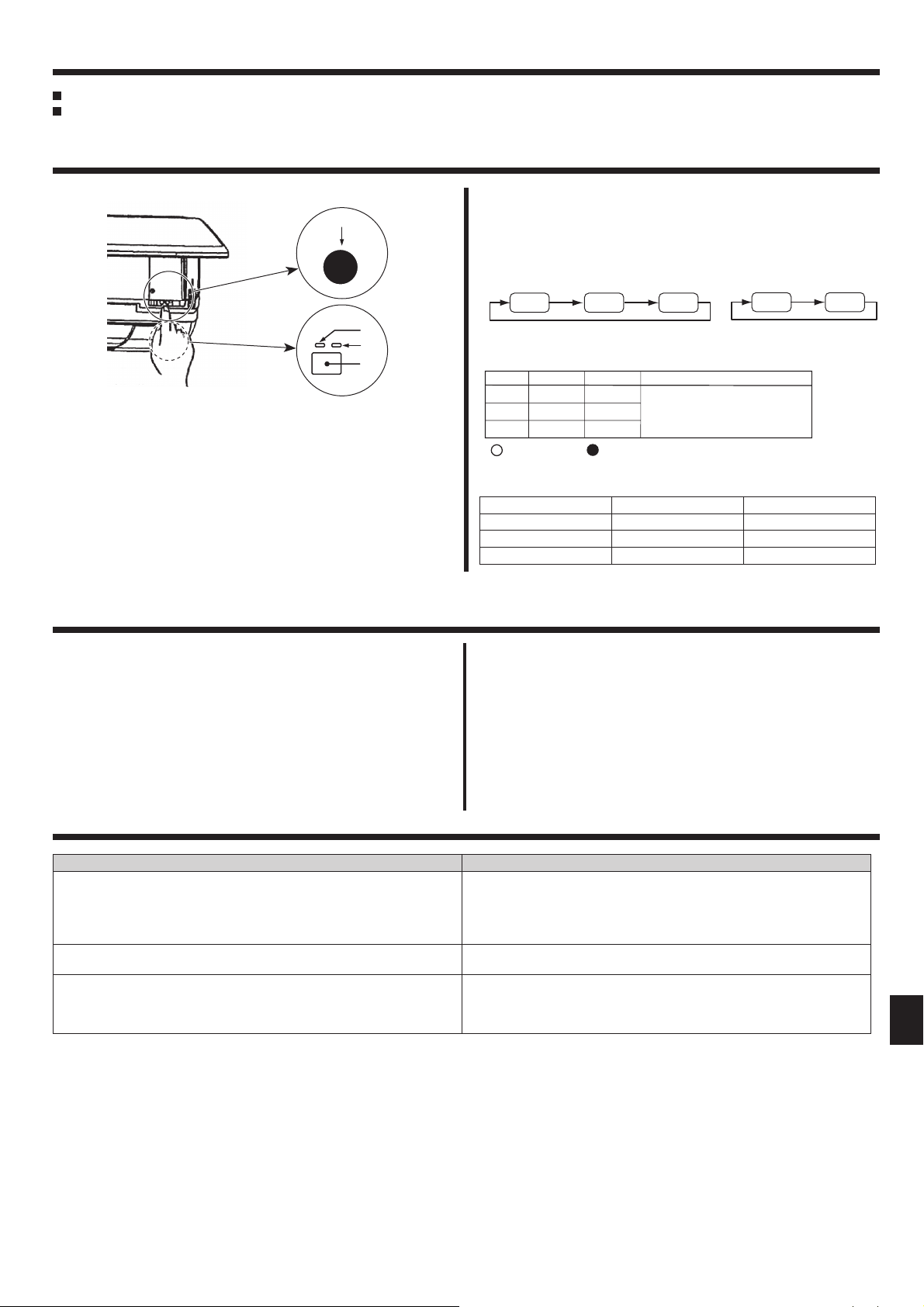
(For PKA-A·HA6)
E.O.
SW
Fig. 5-1
When the IR wireless remote controller cannot be used
When the batteries of the IR wireless remote controller run out or the IR
wireless remote controller malfunctions, the emergency operation can be
done using the emergency buttons.
[Fig. 5-1]
C Emergency operation switch (cooling/heating)
D Receiver
A DEFROST/STAND BY lamp (Orange)
B Operation lamp (Green)
6. Care and Cleaning
• Each press of the emergency operation switch will toggle the operation
mode.
• Check “COOL/HEAT” with the operation monitor display. (The orange
A follows this monitor display for 5 seconds after pressing the
lamp
emergency operation switch.)
[Heat pump type]
Cooling Heating Stop
Operation Monitor Display
GREEN
STOP
COOL
HEAT
: Turning off : Lighting
Note:
• Details of emergency mode are as shown below.
Operation mode COOL HEAT
Set temperature 24°C, 75°F 24°C, 75°F
Fan speed High High
Airfl ow direction Horizontal Downward 4 (5)
ORANGE
○ ○
●○
●
The orange lamp follows the
switch operation as indicated
at the left for 5 seconds, and
then it will return to the normal
display.
●
[Cooling only type]
Cooling Stop
Following indication shows that the fi lter needs cleaning.
■
• Wired remote controller : “FILTER”
• RF thermostat : “Clean Filter”
• ASK authorized pepole to clean the fi lter.
When resetting “FILTER” or “Clean Filter” display. Resetting the
■
indication, refer to the operation manual of each remote controller.
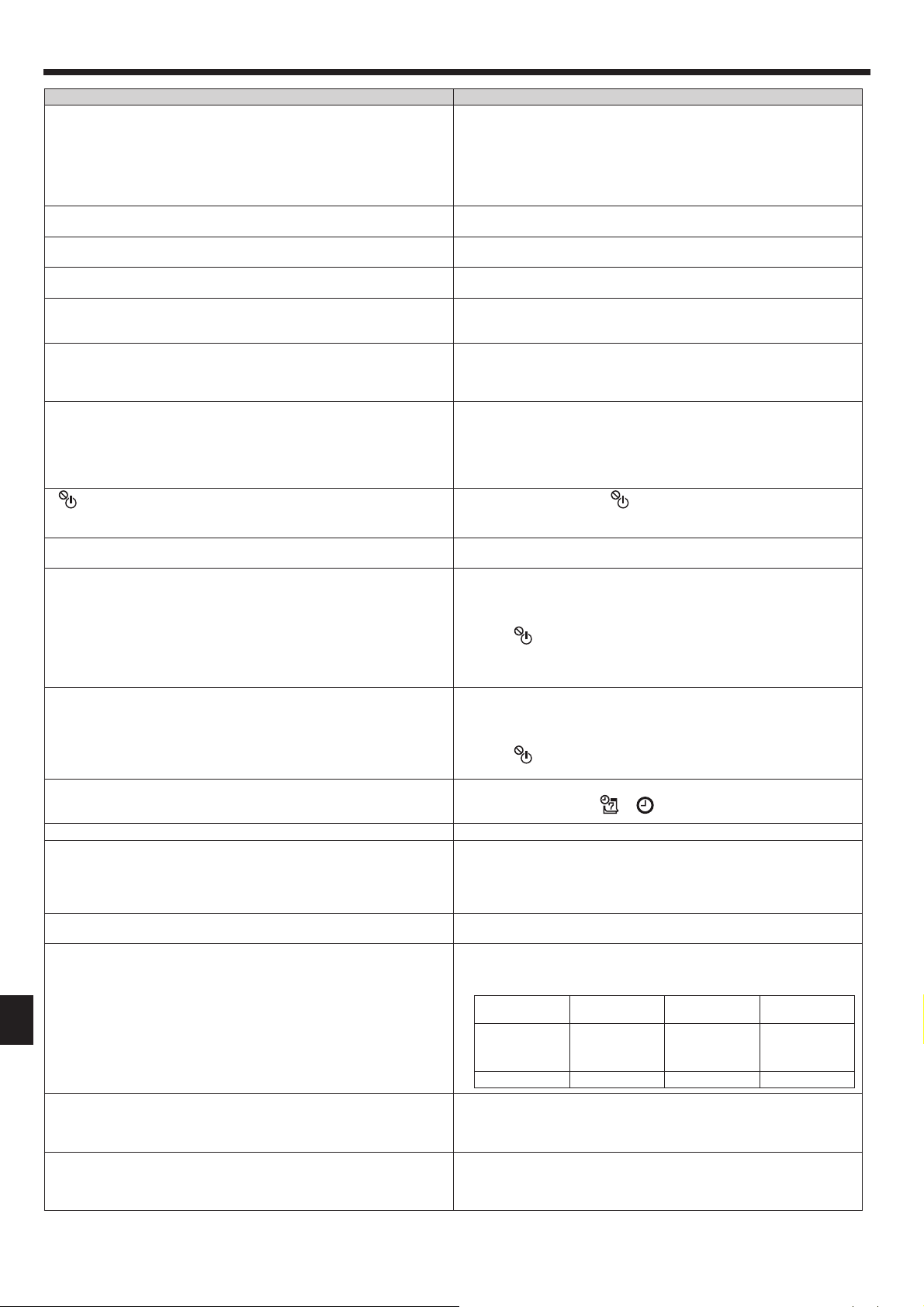
7. Trouble Shooting
Having trouble? Here is the solution. (Unit is operating normally.)
Air conditioner does not heat or cool well.
When heating operation starts, warm air does not blow from the indoor
unit soon.
During heating mode, the air conditioner stops before the set room temperature is reached.
Note:
When 2 or more different types of indoor unit are controlled, the cleaning
●
period differs with the type of fi lter. When the master unit cleaning period
arrives, “FILTER” is displayed. When the fi lter display goes off, the cumu-
lative time is reset. (only for wired remote controller)
“FILTER” or “Clean Filter” indicates the cleaning period when the air
●
conditioner was used under general indoor air conditions by criteria time.
Since the degree of dirtiness depends on the environmental conditions,
clean the fi lter accordingly.
The fi lter cleaning period cumulative time differs with the model.
●
This indication is not available for IR wireless remote controller.
●
Clean the fi lter. (Airfl ow is reduced when the fi lter is dirty or clogged.)
■
Check the temperature adjustment and adjust the set temperature.
■
Make sure that there is plenty of space around the outdoor unit. Is the
■
indoor unit air intake or outlet blocked?
Has a door or window been left open?
■
Warm air does not blow until the indoor unit has suffi ciently warmed
■
up.
When the outdoor temperature is low and the humidity is high, frost
■
may form on the outdoor unit. If this occurs, the outdoor unit performs
a defrosting operation. Normal operation should begin after approximately 10 minutes.
5
7. Trouble Shooting
Having trouble? Here is the solution. (Unit is operating normally.)
Airfl ow direction changes during operation or airfl ow direction cannot be
set.
When the airfl ow direction is changed, the vanes always move up and
down past the set position before fi nally stopping at the position.
A fl owing water sound or occasional hissing sound is heard.
A cracking or creaking sound is heard.
The room has an unpleasant odor.
A white mist or vapor is emitted from the indoor unit.
Water or vapor is emitted from the outdoor unit.
“
” appears in the wired remote controller display. (*1)
When restarting the air conditioner soon after stopping it, it does not operate even though the ON/OFF button is pressed.
Air conditioner operates without the ON/OFF button being pressed. (*1)■ Is the on timer set?
Air conditioner stops without the ON/OFF button being pressed. (*1)
Wired remote controller timer operation cannot be set. (*1)
“PLEASE WAIT” appears in the wired remote controller display. (*1)
An error code appears in the remote controller display.
Draining water or motor rotation sound is heard.
Noise is louder than specifi cations.
Nothing appears in the IR wireless remote controller display, the display
is faint, or signals are not received by the indoor unit unless the IR wireless remote controller is close. (*2)
The operation lamp near the receiver for the IR wireless remote controller on the indoor unit is blinking. (*2)
During cooling mode, the vanes automatically move to the horizontal
■
(down) position after 1 hour when the down (horizontal) airfl ow direc-
tion is selected. This is to prevent water from forming and dripping
from the vanes.
During heating mode, the vanes automatically move to the horizontal
■
airfl ow direction when the airfl ow temperature is low or during defrost-
ing mode.
When the airfl ow direction is changed, the vanes move to the set po-
■
sition after detecting the base position.
These sounds can be heard when refrigerant is fl owing in the air con-
■
ditioner or when the refrigerant fl ow is changing.
These sounds can be heard when parts rub against each due to ex-
■
pansion and contraction from temperature changes.
The indoor unit draws in air that contains gases produced from the
■
walls, carpeting, and furniture as well as odors trapped in clothing,
and then blows this air back into the room.
If the indoor temperature and the humidity are high, this condition
■
may occur when operation starts.
During defrosting mode, cool airfl ow may blow down and appear like
■
a mist.
During cooling mode, water may form and drip from the cool pipes
■
and joints.
During heating mode, water may form and drip from the heat ex-
■
changer.
During defrosting mode, water on the heat exchanger evaporates and
■
water vapor may be emitted.
During central control, “
■
display and air conditioner operation cannot be started or stopped using the wired remote controller.
Wait approximately three minutes.
■
(Operation has stopped to protect the air conditioner.)
Press the ON/OFF button to stop operation.
Is the air conditioner connected to a central wired remote controller?
■
Consult the concerned people who control the air conditioner.
Does “
■
Consult the concerned people who control the air conditioner.
Has the auto recovery feature from power failures been set?
■
Press the ON/OFF button to stop operation.
Is the off timer set?
■
Press the ON/OFF button to restart operation.
Is the air conditioner connected to a central wired remote controller?
■
Consult the concerned people who control the air conditioner.
Does “
■
Consult the concerned people who control the air conditioner.
Are timer settings invalid?
■
If the timer can be set,
ler display.
The initial settings are being performed. Wait approximately 3 minutes.
■
The protection devices have operated to protect the air conditioner.
■
Do not attempt to repair this equipment by yourself.
■
Turn off the power switch immediately and consult your dealer. Be
sure to provide the dealer with the model name and information that
appeared in the remote controller display.
When cooling operation stops, the drain pump operates and then
■
stops. Wait approximately 3 minutes.
The indoor operation sound level is affected by the acoustics of the
■
particular room as shown in the following table and will be higher than
the noise specifi cation, which was measured in an echo-free room.
Location
examples
Noise levels 3 to 7 dB 6 to 10 dB 9 to 13 dB
The batteries are low.
■
Replace the batteries and press the Reset button.
If nothing appears even after the batteries are replaced, make sure
■
that the batteries are installed in the correct directions (+, –).
The self diagnosis function has operated to protect the air conditioner.
■
Do not attempt to repair this equipment by yourself.
■
Turn off the power switch immediately and consult your dealer. Be
sure to provide the dealer with the model name.
” appear in the wired remote controller display?
” appear in the wired remote controller display?
” appears in the wired remote controller
or appears in the wired remote control-
High soundabsorbing rooms
Broadcasting
studio, music
room, etc.
Normal rooms
Reception
room, hotel
lobby, etc.
Low sound-absorbing rooms
Offi ce, hotel
room
6
7. Trouble Shooting
Having trouble? Here is the solution. (Unit is operating normally.)
When dry mode starts, the set temperature changes.
*1. Only for Wired remote controller
*2. Only for IR wireless remote controller.
When Dry mode starts, the set temperature automatically changes to
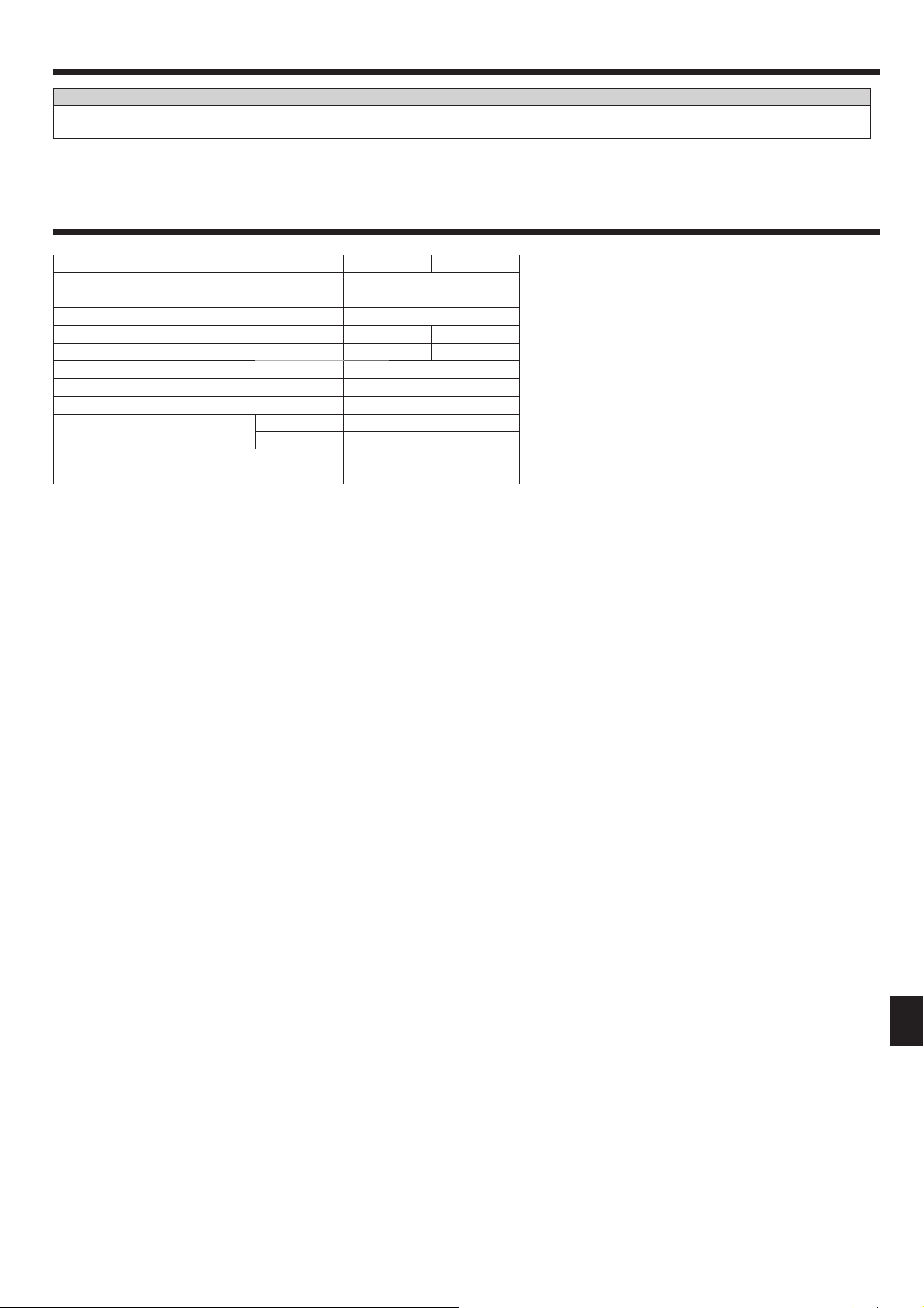
8. Specifi cations
Model PKA-A12HA6 PKA-A18HA6
Power source (Phase, Voltage <V>,
Frequency <Hz>)
Fan motor <FLA> 0.33
MCA <A> 1 1
MOCP <A> 15 15
Dimension (Height) <inch> 11-5/8
Dimension (Width) <inch> 35-3/8
Dimension (Depth) <inch> 9-13/16
Airfl ow
(Low-Middle-High)
Noise level (Low-Middle-High) <dB> 36-40-43
Net weight <lbs> 29
DRY <CFM> 320-370-425
WET <CFM> 290-335-380
Single 208/230, 60
the optimum initial set temperature.
7
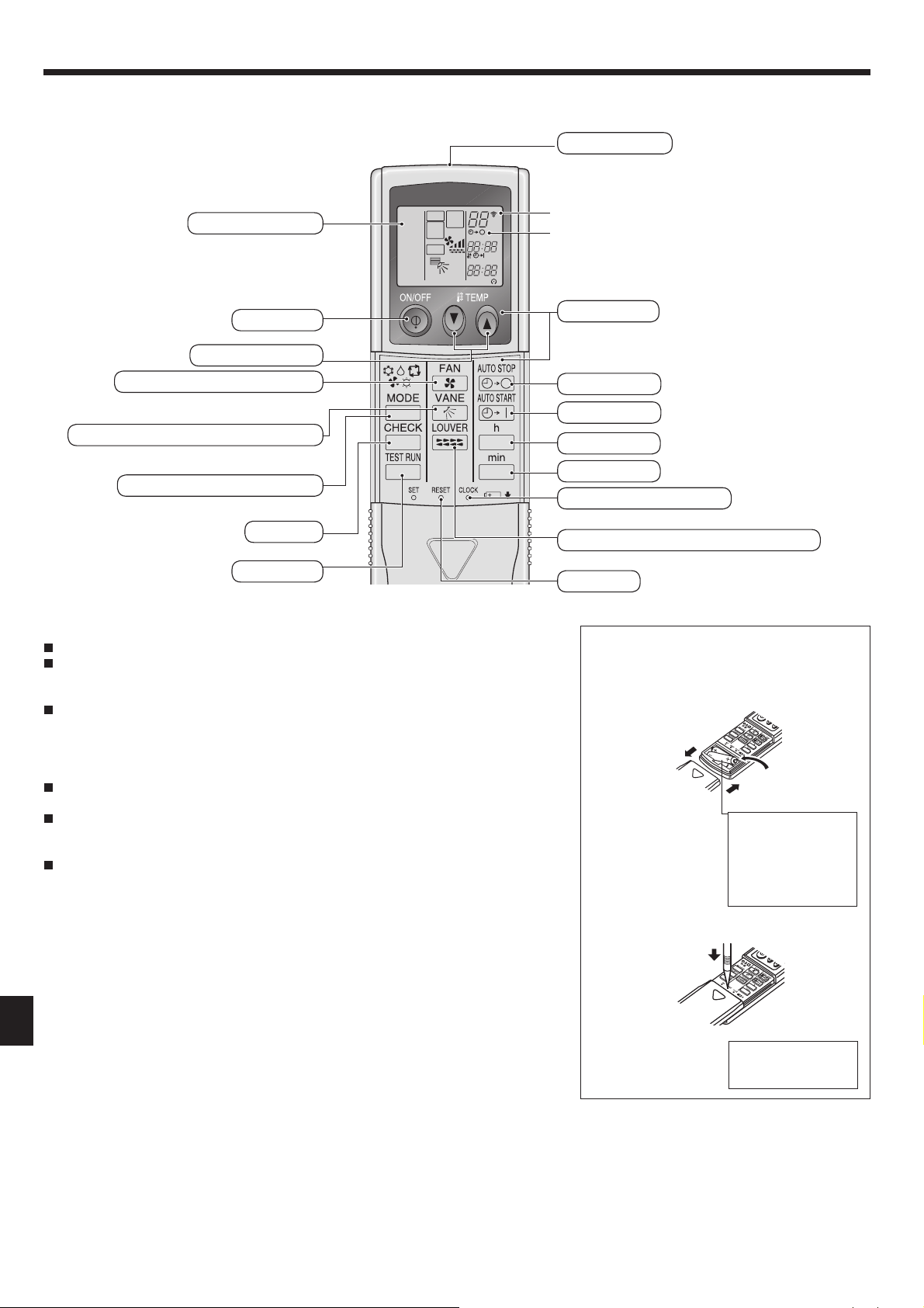
9. Operation Manual for IR wireless remote controller
9.1 Parts Names
Transmission area
Remote controller display
* For explanation purposes, all of the items
that appear in the display are shown.
* All items are displayed when the Reset
button is pressed.
ON/OFF button
Set Temperature buttons
Fan Speed button (Changes fan speed)
Airfl ow button (Changes up/down airfl ow direction)
Mode button (Changes operation mode)
Check button
Test Run button
COOL
DRY
AUTO
FA N
HEAT
MODEL
SELECT
FA N
NOT AVAILABLE
RUN
SWING
START
°F
°C
AMPMSTOP
AMPM
TEST
CHECK
Note:
When using the IR wireless remote controller, point it towards the receiver on the indoor unit.
If the IR wireless remote controller is operated within approximately 2 minutes after power is
supplied to the indoor unit, the indoor unit may beep twice as the unit is performing the initial
automatic check.
The indoor unit beeps to confi rm that the signal transmitted from the IR wireless remote con-
troller has been received. Signals can be received up to approximately 7 meters in a direct
line from the indoor unit in an area 45° to the left and right of the unit. However, illumination
such as fl uorescent lights and strong light can affect the ability of the indoor unit to receive
signals.
If the operation lamp near the receiver on the indoor unit is blinking, the unit needs to be in-
spected. Consult your dealer for service.
Handle the IR wireless remote controller carefully! Do not drop the IR wireless remote con-
troller or subject it to strong shocks. In addition, do not get the IR wireless remote controller
wet or leave it in a location with high humidity.
To avoid misplacing the IR wireless remote controller, install the holder included with the IR
wireless remote controller on a wall and be sure to always place the IR wireless remote controller in the holder after use.
Transmission indicator
Timer indicator
Operation areas
Timer Off button
Timer On button
Hour button
Minute button
Set Time button (Sets the time)
Louver button (Changes left/right airfl ow direction)
Reset button
Battery installation/replacement
1. Remove the top cover, insert 2 AAA batteries,
and then install the top cover.
1
2
Top cover
2. Press the Reset button.
3
2 AAA batteries
Insert the negative (–)
end of each battery
first. Install the batteries in the correct
directions (+, –)!
Press the Reset button with an object that
has a narrow end.
8
9. Operation Manual for IR wireless remote controller
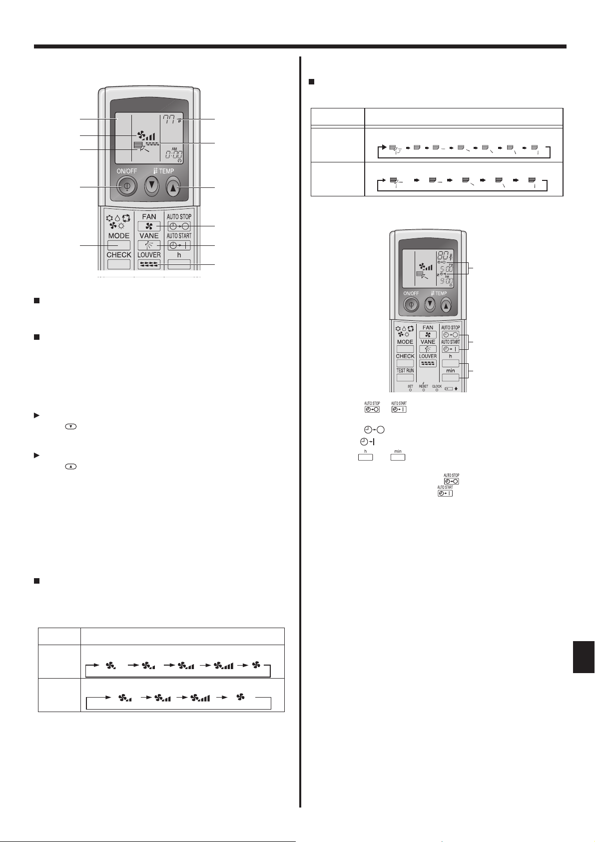
9.2. Operation
9.2.1. Turning ON/OFF
2
5
6
1
2
<To Start Operation>
Press the ON/OFF button 1.
• The ON lamp 1 and the display area come on.
<To Stop Operation>
Press the ON/OFF button 1 again.
• The ON lamp 1 and the display area go dark.
COOL
˚F
9.2.4. Airfl ow direction setting
<To Change the Airfl ow’s Up/Down Direction>
With the unit running, press the Airfl ow Up/Down button 6 as necessary.
• Each press changes the direction. The current direction is shown at 6.
• The change sequence, and the available settings, are as follows.
3
7
3
Remote controller Display
Swing
Swing
Auto 1 2
1
2
Wired type
IR Wireless
remote controller
3
3
5
4
4
9.3 Timer
5
6
7
COOL
Note:
Even if you press the ON/OFF button immediately after shutting down the operation is progress, the air conditioner will not start for about three minutes.
This is to prevent the internal components from being damaged.
9.2.2. Temperature setting
To decrease the room temperature:
Press button 3 to set the desired temperature.
The selected temperature is displayed 3.
To increase the room temperature:
Press button 3 to set the desired temperature.
The selected temperature is displayed 3.
• Available temperature ranges are as follows:
Cooling/Drying: 19 - 30 °C, 67 - 87 °F
Heating: 17 - 28 °C, 63 - 83 °F
Automatic: 19 - 28 °C, 67 - 83 °F
• The display 4 fl ashes either 8 °C - 39 °C, 46 °F - 102 °F to inform you
if the room temperature is lower or higher than the displayed temperature. (This display does not appear on the wireless remote controller.)
9.2.3. Fan speed setting
Press the Fan Speed button 5 as many times as necessary while the
system is running.
• Each press changes the force. The currently selected speed is
shown at 5.
• The change sequence, and the available settings, are as follows.
FAN SPEED Display
4-speed
+
Auto
3-speed
+
Auto
Speed 1 Speed 2 Speed 3 Speed 4 Auto
Speed 1 Speed 2 Speed 3 Auto
Press the or button (TIMER SET).
1
• Time can be set while the following symbol is blinking.
OFF timer: A
is blinking.
ON timer: A is blinking.
Use the and buttons to set the desired time.
2
Cancelling the timer.
3
To cancel the OFF timer, press the button.
To cancel the ON timer, press the button.
• It is possible to combine both OFF and ON timers.
• Pressing the 1 ON/OFF button of the remote controller during timer
mode to stop the unit will cancel the timers.
• If the current time has not been set, the timer operation cannot be
used.
9
 Loading...