

Mitsubishi Electric PKA-A18HA4, PKA-A12HA4 Installation Manual
Air-Conditioners
PKA-A·HA4
INSTALLATION MANUAL
For safe and correct use, read this manual and the outdoor unit installation manual thoroughly before installing
the air-conditioner unit.
MANUEL D’INSTALLATION
Avant d’installer le climatiseur, lire attentivement ce manuel, ainsi que le manuel d’installation de l’appareil
extérieur pour une utilisation sûre et correct.
MANUAL DE INSTALACIÓN
Para un uso correcto y seguro, lea detalladamente este manual y el manual de instalación de la unidad exterior
antes de instalar la unidad de aire acondicionado.
FOR INSTALLER
English
POUR L’INSTALLATEUR
Français
PARA EL INSTALADOR
Español
Contents
1. Safety precautions .............................................................................................2
2. Installation location ............................................................................................3
3. Installing the indoor unit ....................................................................................3
4. Installing the refrigerant piping ..........................................................................6
1. Safety precautions
► Before installing the unit, make sure you read all the “Safety
precautions”.
► Please report to your supply authority or obtain their consent before
connecting this equipment to the power supply system.
Warning:
Describes precautions that must be observed to prevent danger of injury or
death to the user.
Caution:
Describes precautions that must be observed to prevent damage to the unit.
Warning:
• Ask a dealer or an authorized technician to install the unit.
• For installation work, follow the instructions in the Installation Manual and
use tools and pipe components specifically made for use with refrigerant
specified in the outdoor unit installation manual.
• The unit must be installed according to the instructions in order to
minimize the risk of damage from earthquakes, typhoons, or strong winds.
An incorrectly installed unit may fall down and cause damage or injuries.
• The unit must be securely installed on a structure that can sustain its
weight.
• If the air conditioner is installed in a small room, measures must be taken
to prevent the refrigerant concentration in the room from exceeding the
safety limit in the event of refrigerant leakage. Should the refrigerant leak
and cause the concentration limit to be exceeded, hazards due to lack of
oxygen in the room may result.
• Ventilate the room if refrigerant leaks during operation. If refrigerant
comes into contact with a flame, poisonous gases will be released.
• All electric work must be performed by a qualified technician according to
local regulations and the instructions given in this manual.
• Use only specified cables for wiring.
5. Drainage piping work .........................................................................................7
6. Electrical work ...................................................................................................8
7. Test run ............................................................................................................12
8. Easy maintenance function [This function only for A-control] ..........................14
After installation work has been completed, explain the “Safety precautions,” use,
and maintenance of the unit to the customer according to the information in the
Operation Manual and perform the test run to ensure normal operation. Both the
Installation Manual and Operation Manual must be given to the user for keeping.
These manuals must be passed on to subsequent users.
: Indicates a part which must be grounded.
Warning:
Carefully read the labels affixed to the main unit.
• The terminal block cover panel of the unit must be firmly attached.
• Use only accessories authorized by Mitsubishi Electric and ask a dealer or
an authorized technician to install them.
• The user should never attempt to repair the unit or transfer it to another
location.
• After installation has been completed, check for refrigerant leaks. If
refrigerant leaks into the room and comes into contact with the flame of a
heater or portable cooking range, poisonous gases will be released.
• When installing or relocating, or servicing the air conditioner, use only the
specified refrigerant (R410A) to charge the refrigerant lines. Do not mix it
with any other refrigerant and do not allow air to remain in the lines.
If air is mixed with the refrigerant, then it can be the cause of abnormal
high pressure in the refrigerant line, and may result in an explosion and
other hazards.
The use of any refrigerant other than that specified for the system will
cause mechanical failure or system malfunction or unit breakdown. In the
worst case, this could lead to a serious impediment to securing product
safety.
1.1. Before installation (Environment)
Caution:
• Do not use the unit in an unusual environment. If the air conditioner is
installed in areas exposed to steam, volatile oil (including machine oil), or
sulfuric gas, areas exposed to high salt content such as the seaside, the
performance can be significantly reduced and the internal parts can be
damaged.
• Do not install the unit where combustible gases may leak, be produced,
flow, or accumulate. If combustible gas accumulates around the unit, fire
or explosion may result.
• Do not keep food, plants, caged pets, artwork, or precision instruments in
the direct airflow of the indoor unit or too close to the unit as these items
can be damaged by temperature changes or dripping water.
1.2. Before installation or relocation
Caution:
• Be extremely careful when transporting the units. Two or more persons
are needed to handle the unit as it weighs 20 kg, 44lbs or more. Do not
grasp the packaging bands. Wear protective gloves as you can injure your
hands on the fins or other parts.
• Be sure to safely dispose of the packaging materials. Packaging materials,
such as nails and other metal or wooden parts may cause stabs or other
injuries.
1.3. Before electric work
Caution:
• Be sure to install molded case circuit brakers. If not installed, electric
shock may result.
• For the power lines, use standard cables of sufficient capacity. Otherwise,
a short circuit, overheating, or fire may result.
• When installing the power lines, do not apply tension to the cables.
• When the room humidity exceeds 80% or when the drainpipe is clogged,
water may drip from the indoor unit. Do not install the indoor unit where
such dripping can cause damage.
• When installing the unit in a hospital or communications office, be
prepared for noise and electronic interference. Inverters, home appliances,
high-frequency medical equipment, and radio communications equipment
can cause the air conditioner to malfunction or breakdown. The air
conditioner may also affect medical equipment, disturbing medical care,
and communications equipment, harming the screen display quality.
• Thermal insulation of the refrigerant pipe is necessary to prevent
condensation. If the refrigerant pipe is not properly insulated, condensation
will be formed.
• Place thermal insulation on the pipes to prevent condensation. If the
drainpipe is installed incorrectly, water leakage and damage to the ceiling,
floor, furniture, or other possessions may result.
• Do not clean the air conditioner unit with water. Electric shock may result.
• Tighten all flare nuts to specification using a torque wrench. If tightened
too much, the flare nut can break after an extended period.
• Be sure to ground the unit. If the unit is not properly grounded, electric
shock may result.
• Use circuit breakers (ground fault interrupter, isolating switch (+B fuse),
and molded case circuit breaker) with the specified capacity. If the circuit
breaker capacity is larger than the specified capacity, breakdown or fire
may result.
1.4. Before starting the test run
Caution:
• Turn on the main power switch more than 12 hours before starting
operation. Starting operation just after turning on the power switch can
severely damage the internal parts.
• Before starting operation, check that all panels, guards and other
protective parts are correctly installed. Rotating, hot, or high voltage parts
can cause injuries.
2
• Do not operate the air conditioner without the air filter set in place. If the
air filter is not installed, dust may accumulate and breakdown may result.
• Do not touch any switch with wet hands. Electric shock may result.
• Do not touch the refrigerant pipes with bare hands during operation.
• After stopping operation, be sure to wait at least five minutes before turning
off the main power switch. Otherwise, water leakage or breakdown may
result.
2. Installation location
G
L
M
B
F
898
35-23/64
Fig. 2-1
3. Installing the indoor unit
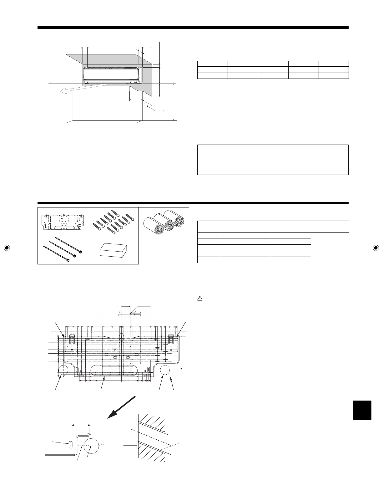
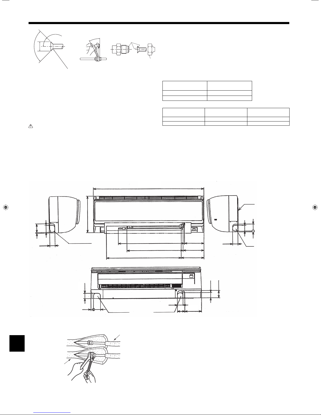
2.1. Outline dimensions (Indoor unit) (Fig. 2-1)
A
249
8-51/64
E
*
(mm)
(inch)
C
K
295
11-39/64
D
J
H
I
Select a proper position allowing the following clearances for installation and
maintenance.
(mm, inch)
ABCDE
Min. 150 Min. 50 Min. 50 Min. 250 Min. 220
Min. 5-29/32 Min. 1-31/32 Min. 1-31/32 Min. 9-27/32 Min. 8-21/32
F Air outlet: Do not place an obstacle within 1500 mm, 59-1/16 inch of the air outlet.
G Floor surface
H Furnishing
I When the projection dimension of a curtain rail or the like from the wall exceeds 60 mm,
2-23/64 inch extra distance should be taken because the fan air current may create a short
cycle.
J 1800 mm, 70-7/8 inch or greater from the floor surface (for high location mounting)
K 55 mm, 2-11/64 inch or greater with left or rear left piping and optional drain pump
installation
L 550 mm, 21-21/32 inch or greater with optional drain pump installation
M Minimum 7 mm, 9/32 inch: 250 mm, 9-27/32 inch or greater with optional drain pump
installation
Note: (For radio frequency interface)
■ Connect a cord of the radio frequency interface to indoor controller
board before mounting the indoor unit on the wall.
■ Refer to P.8 for details on how to installation the radio frequency
interface.
1
2 3
4 5
Fig. 3-1
G
2-9/32
H
14-21/32
14-1/32
12-57/64
11-15/32
10-7/16
8-55/64
7-7/8
4-59/64
2-3/4
19/32
5/8
25/32
1-1/8
1-39/64
2-7/64
2-19/32
3-3/32
3-37/64
4-5/64
4-9/16
5-1/16
6-3/64
6-17/32
7-1/32
9-5/32
9-31/64
9-63/64
9-3/8
8-25/64
6-27/32
3-15/16
J
10-61/64
A
I
CE B
A
K
Fig. 3-2
19/32
C
5/64
2-3/4
4-17/32
4-59/64
7-7/8
8-55/64
7-5/8
7-3/32
5-33/64
6-37/64
D
Fig. 3-3
9-3/8
10-7/16
11-15/32
E
(inch)
12-57/64
14-1/32
14-21/32
9-7/64
D
B
3.1. Check the indoor unit accessories (Fig. 3-1)
The indoor unit should be supplied with the following accessories.
PART
NUMBER
1
2
3
4
5
ACCESSORY QUANTITY
Mount board 1
Tapping screw 4 × 35 12
Felt tape 3
Band 3
Block of cushion 1
LOCATION OF
Fix at the back of
the unit
3.2. Installing the wall mounting fixture (Fig. 3-2)
3.2.1. Setting the wall mounting fixture and piping positions
► Using the wall mounting fixture, determine the unit’s installation position
and the locations of the piping holes to be drilled.
Warning:
Before drilling a hole in the wall, you must consult the building contractor.
A Mount board 1
F
B Indoor unit
C Bottom left rear pipe hole (ø65 mm, 2-9/16 inch)
D Bottom right rear pipe hole (ø65 mm, 2-9/19 inch)
E Knockout hole for left rear hole (70 mm, 2-3/4 inch × 310 mm, 12-13/14 inch)
F Bolt hole (4-ø9 mm, 23/64 inch hole)
G Center measurement hole (ø2.5 mm, 3/32 inch hole)
H Tapping hole (77-ø5.1 mm, 13/64 inch hole)
I Hole centre
J Align the scale with the line.
K Insert scale.
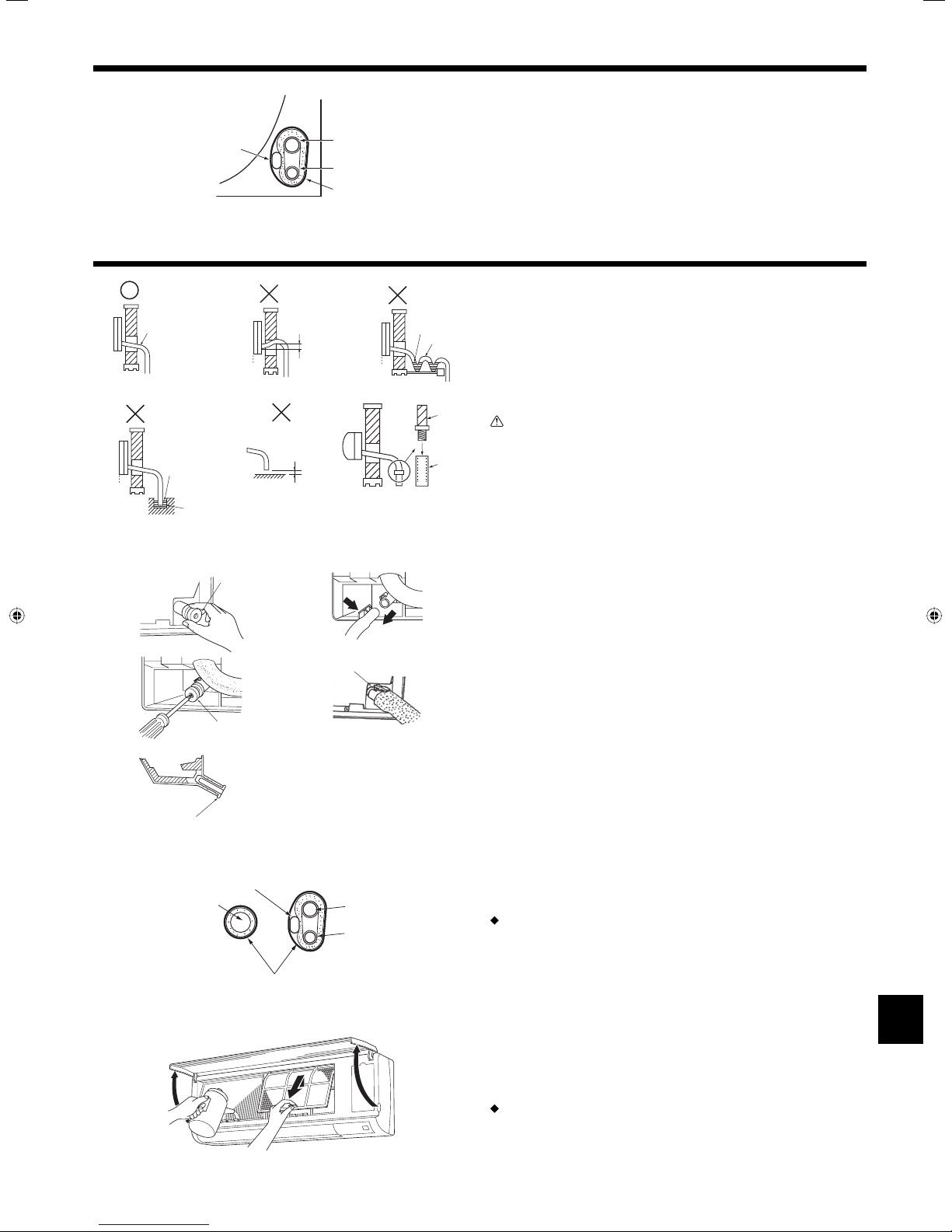
3.2.2. Drilling the piping hole (Fig. 3-3)
► Use a core drill to make a hole of 65-80 mm, 2-9/16-3-5/32 inch diameter in
the wall in the piping direction, at the position shown in the diagram to the
left.
► The hole should incline so that the outside opening is lower than the
inside opening.
► Insert a sleeve (with a 65-80 mm, 2-9/16-3-5/32 inch diameter and
purchased locally) through the hole.
A Sleeve
B Hole
C (Indoors)
D Wal l
E (Outdoors)
Note:
The purpose of the hole’s inclination is to promote drain flow.
SETTING
3
3. Installing the indoor unit
E
D
B
F
A
D
C
A
E
I
H
Fig. 3-4
B
Fig. 3-5
C
D
Fig. 3-6
)
1
Fig. 3-7
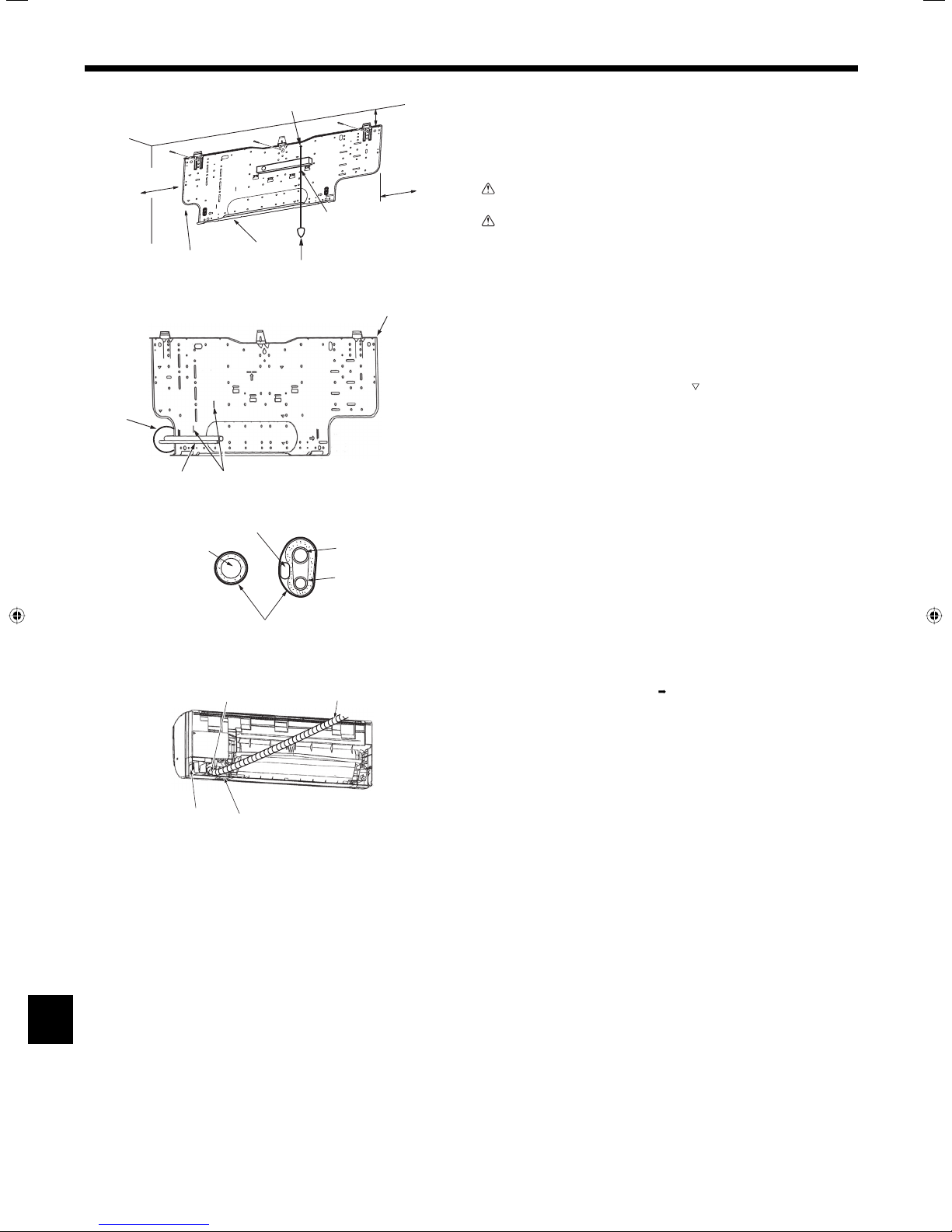
3.2.3. Installing the wall mounting fixture (Fig. 3-4)
► Since the indoor unit weighs near 13 kg, 29lbs, selection of the mounting
C
location requires thorough consideration. If the wall does not seem to be
strong enough, reinforce it with boards or beams before installation.
► The mounting fixture must be secured at both ends and at the centre, if
possible. Never fix it at a single spot or in any nonsymetrical way.
(If possible, secure the fixture at all the positions marked with a bold
arrow.)
B
G
A
Warning:
If possible, secure the fixture at all positions indicated with a bold arrow.
Caution:
• The unit body must be mounted horizontally.
• Fasten at the holes marked with ▲ as shown by the arrows.
A Min. 90 mm, 3-35/64 inch (617.6 mm, 24-5/16 inch or greater with optional drain pump
installation)
B Min. 200 mm, 7-7/8 inch
C Min. 72 mm, 2-53/64 inch (142.5 mm, 5-39/64 inch or greater with left, rear left, or lower
left piping, and optional drain pump installation)
D Fixing screws (4 × 35 mm, 1-3/8 inch) 2
E Level
F Fasten a thread to the hole.
G
Place the level against the horizontal reference line of the mount board and mount so that it is
level. Hang a weight from the thread and align with
H Weight
I Mount board 1
EPK of the mount board to permit leveling.
3.3. When embedding pipes into the wall (Fig. 3-5)
• The pipes are on the bottom left.
• When the cooling pipe, drain pipes internal/external connection lines etc are to
be embedded into the wall in advance, the extruding pipes etc, may have to be
bent and have their length modified to suit the unit.
• Use marking on the mount board as a reference when adjusting the length of the
embedded cooling pipe.
• During construction, give the length of the extruding pipes etc some leeway.
B
A
A Mount board 1
B Reference marking for flare connection
C Through hole
D On-site piping
3.4. Preparing the indoor unit
* Check beforehand because the preparatory work will differ depending on the
exiting direction of the piping.
* When bending the piping, bend gradually while maintaining the base of the
piping exiting portion. (Abrupt bending will cause misshaping of the piping.)
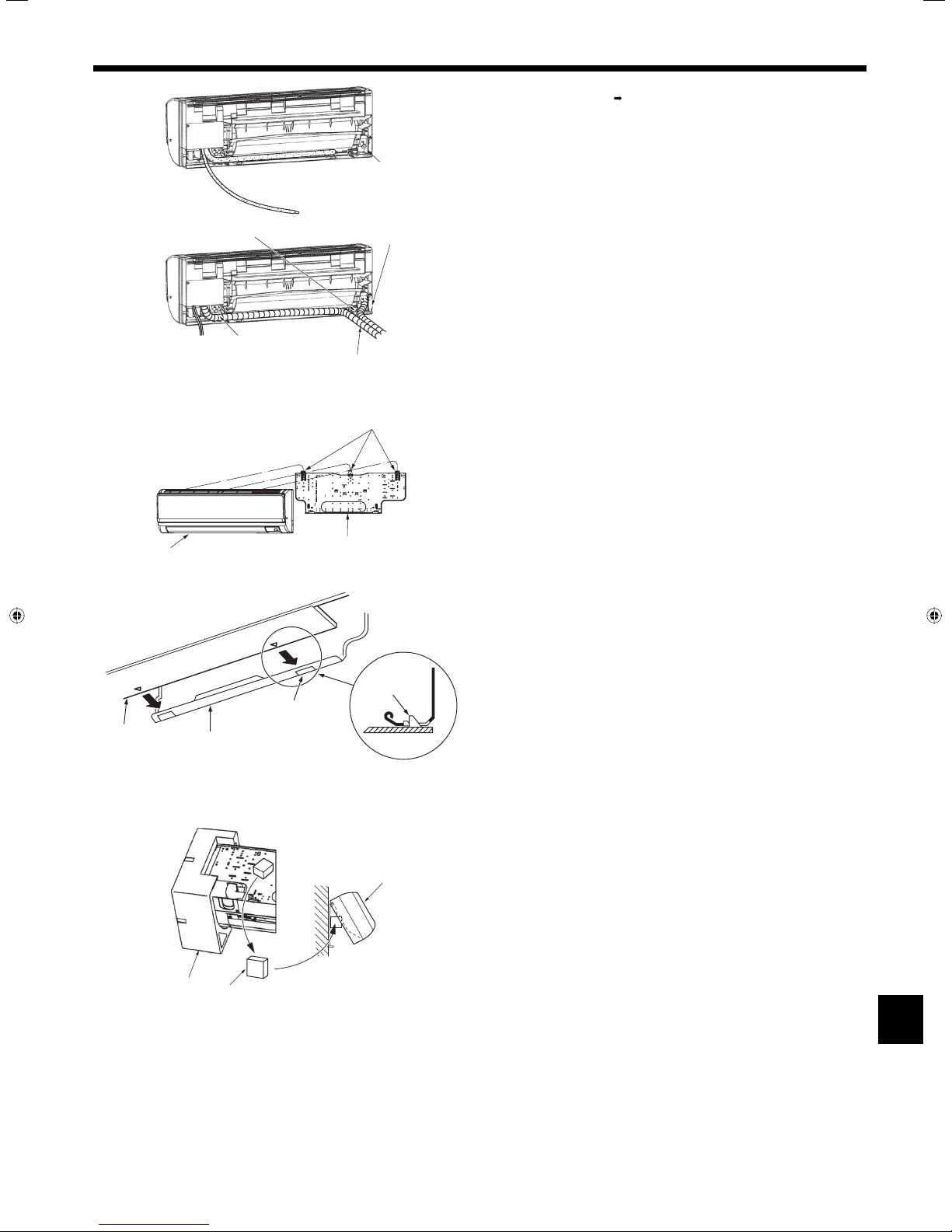
Extraction and processing of the piping and wiring (Fig. 3-6)
)
2
1. Connection of indoor/outdoor wiring See page. 8.
2. Wrap the felt tape 3 in the range of the refrigerant piping and drain hose which
will be housed within the piping space of the indoor unit.
• Wrap the felt tape 3 securely from the base for each of the refrigerant piping
and the drain hose.
• Overlap the felt tape 3 at one-half of the tape width.
• Fasten the end portion of the wrapping with vinyl tape.
A Liquid pipe
B Gas pipe
C Indoor/outdoor connection cable
D Drain hose
E Felt tape 3
3. Be careful that the drain hose is not raised, and that contact is not made with the
indoor unit box body.
Do not pull the drain hose forcefully because it might come out.
4
Rear, right and lower piping (Fig. 3-7)
1) Be careful that the drain hose is not raised, and that contact is not made with
the indoor unit box body.
Arrange the drain hose at the underside of the piping and wrap it with felt
tape 3.
2) Securely wrap the felt tape 3 starting from the base. (Overlap the felt tape at
one-half of the tape width.)
A Cut off for right piping.
B Cut off for lower piping.
3. Installing the indoor unit
B
)
1
)
2
Fig. 3-8
Left and left rear piping (Fig. 3-8)
4. Drain hose replacement See 5. Drainage piping work
Be sure to replace the drain hose and the drain cap for the left and rear left
piping. Dripping may occur if you forget to install or fail to replace these parts.
C Drain cap
1) Be careful that the drain hose is not raised, and that contact is not made with
C
the indoor unit box body.
2) Securely wrap the felt tape 3 starting from the base. (Overlap the felt tape at
one-half of the tape width.)
3) Fasten the end portion of the felt tape 3 with vinyl tape.
D Cut off for left piping.
D
)
3
B
A
Fig. 3-9
D
Fig. 3-10
A
C
C
A
3.5. Mounting the indoor unit
1. Affix the mount board 1 to the wall.
2. Hang the indoor unit on the hook positioned on the upper part of the mount
board.
Rear, right and lower piping (Fig. 3-9)
3. While inserting the refrigerant piping and drain hose into the wall penetration
hole (penetration sleeve), hang the top of the indoor unit to the mount board 1.
4. Move the indoor unit to the left and right, and verify that the indoor unit is hung
securely.
5. Fasten by pushing the bottom part of the indoor unit onto the mount board 1.
(Fig. 3-10)
* Check that the knobs on the bottom of the indoor unit are securely hooked into
the mount board 1.
6. After installation, be sure to check that the indoor unit is installed level.
A Mount board 1
B Indoor unit
C Hook
D square hole
Left and left rear piping (Fig. 3-11)
3. While inserting the drain hose into the wall penetration hole (penetration sleeve),
hang the top of the indoor unit to the mount board 1.
Giving consideration to the piping storage, move the unit all the way to the left
side, then cut part of the packaging carton and wrap into a cylindrical form as
illustrated in the diagram. Hook this to the rear surface rib as a spacer, and raise
the indoor unit.
4. Connect the refrigerant piping with the site-side refrigerant piping.
5. Fasten by pushing the bottom part of the indoor unit onto the mount board 1.
* Check that the knobs on the bottom of the indoor unit are securely hooked into
the mount board 1.
6. After installation, be sure to check that the indoor unit is installed level.
A Indoor unit
B Packaging cushion
C Block of cushion 9
B
C
Fig. 3-11
5
4. Installing the refrigerant piping
A
45±2°
B
(inch)
C
øA
90°±0.5°
R1-64~R1/32
D
Fig. 4-1
4.1. Precautions
4.1.1. For devices that use R410A refrigerant
• Use ester oil, ether oil, alkylbenzene oil (small amount) as the refrigeration
oil applied to the flared sections.
• Use C1220 copper phosphorus, for copper and copper alloy seamless
pipes, to connect the refrigerant pipes. Use refrigerant pipes with the
thicknesses specified in the table to the below. Make sure the insides of
the pipes are clean and do not contain any harmful contaminants such as
sulfuric compounds, oxidants, debris, or dust.
Warning:
When installing or relocating, or servicing the air conditioner, use only the
specified refrigerant (R410A) to charge the refrigerant lines. Do not mix it
with any other refrigerant and do not allow air to remain in the lines.
If air is mixed with the refrigerant, then it can be the cause of abnormal high
pressure in the refrigerant line, and may result in an explosion and other
hazards.
The use of any refrigerant other than that specified for the system will cause
mechanical failure or system malfunction or unit breakdown. In the worst
case, this could lead to a serious impediment to securing product safety.
4.2. Connecting pipes (Fig. 4-1)
• When commercially available copper pipes are used, wrap liquid and gas pipes
with commercially available insulation materials (heat-resistant to 100 °C, 212 °F
or more, thickness of 12 mm, 1/2 inch or more).
•
The indoor parts of the drain pipe should be wrapped with polyethylene foam
insulation materials (specific gravity of 0.03, thickness of 9 mm, 23/64 inch or more).
• Apply thin layer of refrigerant oil to pipe and joint seating surface before
tightening flare nut.
• Use two wrenches to tighten piping connections.
• Use refrigerant piping insulation provided to insulate indoor unit connections.
Insulate carefully.
A Flare cutting dimensions
Copper pipe O.D.
(mm, inch)
ø6.35, 1/4” 8.7-9.1, 11/32-23/64
ø12.7, 1/2” 16.2-16.6, 41/64-21/32
Flare dimensions
øA dimensions (mm, inch)
B Flare nut tightening torque
Copper pipe O.D.
(mm, inch)
ø6.35, 1/4” 22, 7/8 14-18, 10-13
ø12.7, 1/2” 29, 1-9/64 49-61, 35-44
Flare nut O.D.
(mm, inch)
Tightening torque
(N·m, ft·lbs)
C Apply refrigerating machine oil over the entire flare seat surface.
D Use correct flare nuts meeting the pipe size of the outdoor unit.
4.3. Positioning refrigerant and drain piping (Fig. 4-2)
A Gas pipe * Indicates the condition with accessories mounted.
B Liquid pipe C Drain hose
D Left-side piping knockout hole E Right-side piping knockout hole
F Lower piping knockout hole G Mount board 1
2-23/32
15/64
1-11/16
2-13/64
35-23/64
G
1-27/32
E
2-13/64
15/64
1-11/16
25/32
11-39/64
D
2-13/64
21-7/32
17-63/64
24-1/64
(B)
(A)
(C)
1-27/32
FF
2-23/64
6-7/32
6-21/32
7-7/32
5-5/16
1-11/16
1-11/16
2-21/64
Fig. 4-2
A
B
Fig. 4-3
4.4. Refrigerant piping (Fig. 4-3)
Indoor unit
1. Remove the flare nut and cap of the indoor unit.
2. Make a flare for the liquid pipe and gas pipe and apply refrigerating machine oil
(available from your local supplier) to the flare sheet surface.
3. Quickly connect the on site cooling pipes to the unit.
4. Wrap the pipe cover that is attached to the gas pipe and make sure that the
connection join is not visible.
5. Wrap the pipe cover of the unit’s liquid pipe and make sure that it covers the
insulation material of the on site liquid pipe.
6. The portion where the insulation material is joined is sealed by taping.
A Site-side refrigerant piping
B Unit side refrigerant piping
6
4. Installing the refrigerant piping
E
C
Fig. 4-4
A
B
D
5. Drainage piping work
A
C
G
C
H
1
3
A
Fig. 5-1
I
B
2
a
4
B
4.4.1. Storing in the piping space of the unit (Fig. 4-4)
1. Wrap the supplied felt tape in the range of the refrigerant piping which will be
housed within the piping space of the unit to prevent dripping.
2. Overlap the felt tape at one-half of the tape width.
3. Fasten the end portion of the wrapping with vinyl tape, etc.
A Gas pipe
B Liquid pipe
C Indoor/outdoor connection cable
D Felt tape 3
5.1. Drainage piping work (Fig. 5-1)
• Drain pipes should have an inclination of 1/100 or more.
• For extension of the drain pipe, use a soft hose (inner dia. 15 mm, 19/32 inch)
D
E
C
F
J
K
b
available on the market or hard vinyl chloride pipe (VP-16/O.D. ø22 mm,
ø55/64 inch PVC TUBE). Make sure that there is no water leakage from the
connections.
• Do not put the drain piping directly in a drainage ditch where sulphuric gas may
be generated.
• When piping has been completed, check that water flows from the end of the
drain pipe.
Caution:
The drain pipe should be installed according to this Installation Manual to
ensure correct drainage. Thermal insulation of the drain pipes is necessary
to prevent condensation. If the drain pipes are not properly installed and
insulated, condensation may drip on the ceiling, floor or other possessions.
A Inclined downwards
B Must be lower than outlet point
C Water leakage
D Trapped drainage
E Air
F Wav y
G The end of drain pipe is under water.
H Drainage ditch
I 5 cm, 1-31/32 inch or less between the end of drain pipe and the ground.
J Drain hose
K Soft PVC hose (Inside diameter 15 mm, 19/32 inch)
or
Hard PVC pipe (VP-16)
* Bond with PVC type adhesive
A
Preparing left and left rear piping (Fig. 5-2)
1 Remove the drain cap.
A
Fig. 5-2
D
C
A
B
Fig. 5-3
• Remove the drain cap by holding the bit that sticks out at the end of the pipe and
pulling.
A Drain cap
2 Remove the drain hose.
• Remove the drain hose by holding on to the base of the hose a (shown by
arrow) and pulling towards yourself b.
3 Insert the drain cap.
• Insert a screwdriver etc into the hole at the end of the pipe and be sure to push
to the base of the drain cap.
4 Insert the drain hose.
• Push the drain hose until it is at the base of the drain box connection outlet.
• Please make sure the drain hose hook is fastened properly over the extruding
drain box connection outlet.
B Hooks
Storing in the piping space of the indoor unit (Fig. 5-3)
* When the drain hose will be routed indoors, be sure to wrap it with commercially
available insulation.
* Gather the drain hose and the refrigerant piping together and wrap them with the
supplied felt tape 3.
* Overlap the felt tape 3 at one-half of the tape width.
* Fasten the end portion of the wrapping with vinyl tape, etc.
A Gas pipe
B Liquid pipe
C Drain hose
D Indoor/outdoor connection wiring
E Felt tape 3
Check of drainage (Fig. 5-4)
1. Open the front grille and remove the filter.
2. Facing the fins of the heat exchanger, slowly fill with water.
3. After the drainage check, attach the filter and close the grille.
Fig. 5-4
7
6. Electrical work
K
I
2-11/64 inch
15/32 inch
or Q
I
R
F
J
D
G
POLM N
S
Fig. 6-1
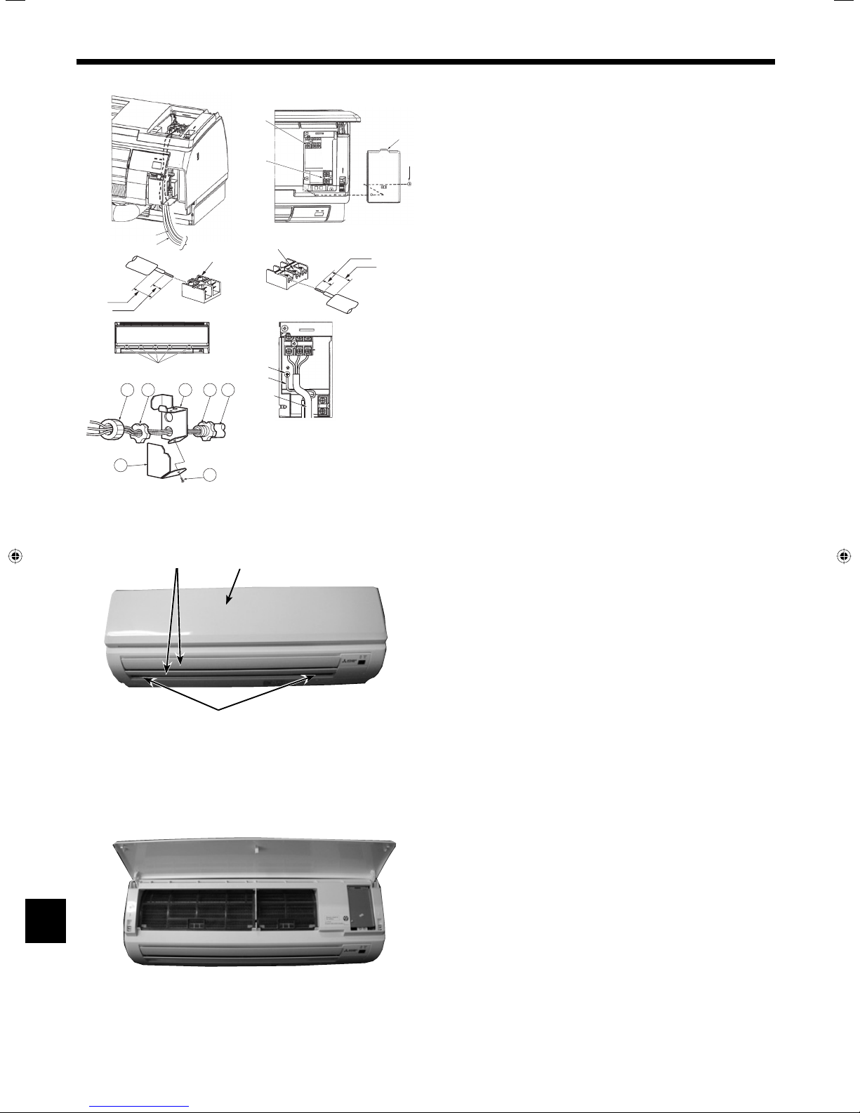
6.1. Indoor unit (Fig. 6-1)
Connection can be made without removing the front panel.
E
D
G
E
15/32 inch
2-11/54 inch
J
S1
S2 S3
C
H
J
1. Open the front grille, remove the screw (1 piece), and remove the electrical parts
A
cover.
* Electrical work can be conducted more effectively with the panel removed. When
attaching the panel, check that the hooks K at five locations on the air outlet side
B
are connected securely.
2. Securely connect each wire to the terminal board.
* In consideration of servicing, provide extra length for each of the wires.
* Take care when using strand wires, because beards may cause the wiring to
short out.
3. Install the parts that were removed back to their original condition.
4. Fasten each of the wires with the clamp under the electrical parts box.
A Electrical box cover
B Fixing screw (Electrical box cover)
C Earth wire connection portion
E Indoor/outdoor connection terminal board: S1, S2, and S3, have polarity
F Lead
H Earth wire: Connect earth wire in the direction illustrated in the diagram.
J Indoor/outdoor connection cord
K Hook
L Conduit plate
M Bush (purchased locally)
N Lock nut (purchased locally)
O Connector (purchased locally)
P Conduit (purchased locally)
R Conduit cover
S Fixing screw (Conduit cover)
Only for wired remote controller
D Wired remote control terminal board: 1 and 2, do not have polarity
G Terminal screw
I Wired remote control cord
Only for Radio frequency interface code.
Q Radio frequency interface code.
BA
C
Fig. 6-2
■ For radio freguency interface.
1. Press and unlock the knobs on both sides of the front
panel and lift the front panel until it is level. Pull the hinges forward to remove
the front panel. (Fig. 6-3)
2. Move the horizontal vanes in a downward direction.
3. Remove the screw caps of the panel. Remove the screws. (Fig. 6-2)
4. Hold the lower part of both ends of the panel and pull it slightly toward you, and
then remove the panel by pushing it upward.
A Front panel
B Va ne
C Screw caps
Fig. 6-3
8
6. Electrical work
F
G
D
E
H
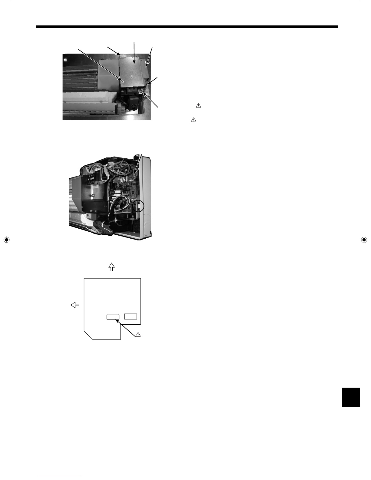
5. Remove the room temp. thermistor TH1. (Fig. 6-4)
6. Remove the electrical box covers (screw 4 × 12). (Fig. 6-4)
7. Connect the electric code of radio frequency interface securely to CN105 (RED)
on indoor controller board. (Fig. 6-6)
8. Replace the removed parts.
D Electrical box cover (top)
E Electrical box cover (side)
F Screw (top cover)
G Screw (side cover)
H Room temp. thermistor (TH1)
I Screw (side cover)
J Indoor controller board
Fig. 6-4
Fig. 6-5
TOP
J
K
I
Warning
K Sharp-edged parts
Warning:
Be extremely careful not to cut your hands by Sharp-edged parts or end
faces of the box.
There are some Sharp-edged parts on the indoor controller board.
CN105
FRONT
(RED)
Fig. 6-6
Warning:
Sharp-edged parts
9
6. Electrical work
6.1.1. Indoor unit power supplied from outdoor unit (A-control application)
The following connection patterns are available.
The outdoor unit power supply patterns vary on models.
1:1 System
E
E
F
CN105
(RED)
S1
S2
H
S3
1
2
FF
S1
S1
S2
S2
S3
S3
1
1
2
2
C
L1
AB
L2
GR
S1
S2
S3
D
G
* Affix a label A that is included with the manuals near each wiring diagram for the indoor and outdoor units.
Simultaneous twin/triple/four system
C
L1
AB
L2
GR
S1
S2
S3
D
A Outdoor unit power supply
B Wiring circuit breaker or isolating switch
C Outdoor unit
D Indoor unit/outdoor unit connecting cords
I
E Wired remote controller
F Indoor unit
G Indoor unit earth
H Indoor controller board
I Radio frequency interface for RF thermostat
A Outdoor unit power supply
B Wiring circuit breaker or isolating switch
C Outdoor unit
D Indoor unit/outdoor unit connecting cords
E Wired remote controller
F Indoor unit
G Indoor unit earth
■
Only for wired remote controller.
GG
* Affix a label A that is included with the manuals near each wiring diagram for the indoor and outdoor units.
Indoor unit model PKA-A·HA4
Minimum circuit ampacity 1A
Maximum rating of overcurrent protective device 15A
Indoor unit-Outdoor unit *1 3 × AWG16 (Polar)
Indoor unit earth 1 × Min. AWG16
Wiring
× size
Wire No.
Wired remote controller-Indoor unit *2 2 × AWG22 (Non-polar, unshielded)
Indoor unit-Outdoor unit S1-S2 *3 AC 208/230 V
Indoor unit-Outdoor unit S2-S3 *3 DC24 V
rating
Circuit
Wired remote controller-Indoor unit *3 DC12 V
*1. Max. 50 m, 165 ft
*2. The 3 m, 9 ft wire is attached in the wired remote controller accessory. Max. 500 m, 1500 ft
*3. The figures are NOT always against the ground.
S3 terminal has DC 24 V against S2 terminal. However between S3 and S1, these terminals are not electrically insulataed by the transformer or other device.
Notes: 1. Wiring size must comply with the applicable local and national code.
2. Use copper supply wires.
3. Use wires rated 300V or more for the power supply cords and the indoor unit/outdoor unit connecting cords.
4. Install an earth longer than other cords.
6.2. Remote controller
6.2.1. For wired remote controller
1) Two wired remote controllers setting
If two wired remote controllers are connected, set one to “Main” and the other to
“Sub”. For setting procedures, refer to “Function selection of remote controller” in
the operation manual for the indoor unit.
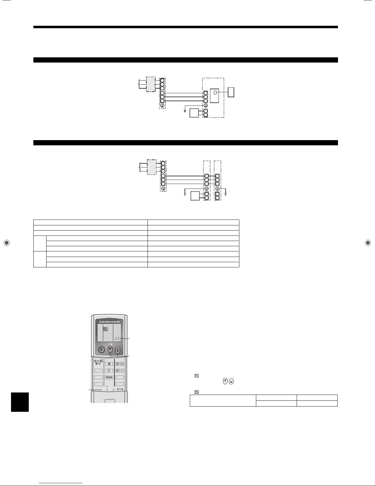
6.2.2. For IR wireless remote controller
1) Setting (Fig. 6-7)
1 Insert batteries.
2 Press the SET button with something sharp at the end.
blinks and Model No. is lighted.
3 Press the temp
4 Press the SET button with something sharp at the end.
and Model No. are lighted for three seconds, then turned off.
PKA (A12, A18)
button to set the Model No.
heat pump models 002
cooling only models 034
2,4
ON/OFF TEMP
FAN
VANE
MODE
LOUVER
CHECK
TEST RUN
RESETSET CLOCK
AUTO STOP
AUTO START
h
min
A
3
Fig. 6-7
10
6. Electrical work
1,4
BACK DAY
PAR-21MAA
CHECK
FAN
VANE
LOUVER
RESETSET CLOCK
TEMP.
MENU
MONITOR/SET
AUTO STOP
AUTO START
h
min
ON/OFF
CLOCK
OPERATION
DC
C,D
A
B
E
F
F
E
G
ON/OFF TEMP
MODE
CHECK
TEST RUN
ON/OFF TEMP
FAN
VANE
MODE
LOUVER
CHECK
TEST RUN
RESETSET CLOCK
Fig. 6-8
ON/OFF
FILTER
CHECK
TEST
CLEAR
Fig. 6-9
1
3
Fig. 6-10
AUTO STOP
AUTO START
A
B
CHECK
2) Assigning a IR wireless remote controller to each unit (Fig. 6-8)
Each unit can be operated only by the assigned IR wireless remote controller.
A
Make sure each pair of an indoor unit PC board and a IR wireless remote controller
is assigned to the same pair No.
3) IR wireless remote controller pair number setting operation
1 Press the SET button with something sharp at the end.
Start this operation from the status of IR wireless remote controller display
3
h
min
2
turned off.
blinks and Model No. is lighted.
min
2 Press the
button twice continuously.
Pair No. “0” blinks.
3 Press the temp
button to set the pair number you want to set.
4 Press the SET button with something sharp at the end.
Set pair number is lighted for three seconds then turned off.
A Pair No. of IR wireless remote controller
Indoor PC board
0 Factory setting
1 Cut J41
2 Cut J42
3-9 Cut J41, J42
6.3. Function settings
Mode number
Setting number
Refrigerant address
Unit number
2
CHECKCHECK
4
CHECK
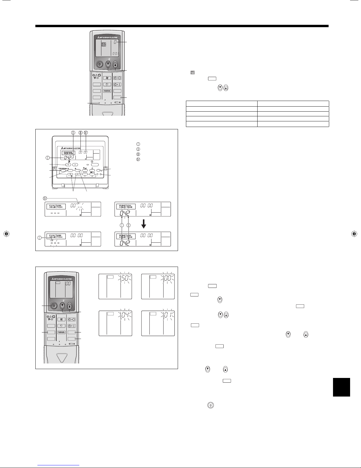
6.3.1 Function setting on the unit (Selecting the unit functions)
1) For wired remote controller (Fig. 6-9)
Changing the power voltage setting
• Be sure to change the power voltage setting depending on the voltage used.
1 Go to the function setting mode.
Switch OFF the wired remote controller.
Press the A and B buttons simultaneously and hold them for at least 2
seconds. FUNCTION will start to flash.
2 Use the C button to set the refrigerant address (3) to 00.
3 Press D and [--] will start to flash in the unit number (4) display.
4 Use the C button to set the unit number (4) to 00.
5 Press the E MODE button to designate the refrigerant address/unit number. [--]
will flash in the mode number (1) display momentarily.
6 Press the F buttons to set the mode number (1) to 04.
7 Press the G button and the current set setting number (2) will flash.
Use the F button to switch the setting number in response to the power supply
voltage to be used.
Power supply voltage
230 V : setting number = 1
208 V : setting number = 2
8 Press the MODE button E and mode and the setting number (1) and (2) will
change to being on constantly and the contents of the setting can be confirmed.
9 Press the FILTER A and TEST RUN B buttons simultaneously for at least two
seconds. The function selection screen will disappear momentarily and the air
conditioner OFF display will appear.
2) For IR wireless remote controller (Fig. 6-10)
Changing the power voltage setting
• Be sure to change the power voltage setting depending on the voltage used.
1 Go to the function select mode
2 Setting the unit number
3 Selecting a mode
Current setting number: 1 = 1 beep (one second)
2 = 2 beeps (one second each)
3 = 3 beeps (one second each)
4 Selecting the setting number
5 To select multiple functions continuously
6 Complete function selection
Note:
Whenever changes are made to the function settings after installation or
maintenance, be sure to record the changes with a mark in the “Setting”
column of the Function table.
CHECK
Press the
button F twice continuously.
(Start this operation from the status of IR wireless remote controller display turned off.)
CHECK
is lighted and “00” blinks.
Press the temp
controller toward the receiver of the indoor unit and press the
Press the temp
wireless remote controller toward the receiver of the indoor unit and press the
min
button B.
Enter 04 to change the power voltage setting using the
Direct the IR wireless remote controller toward the receiver of the indoor unit
and press the
Use the
(230 V). Direct the IR wireless remote controller toward the sensor of the indoor
unit and press the
button C once to set “50”. Direct the IR wireless remote
h
button A.
button C and D to set the unit number “00”. Direct the IR
C and D buttons.
h
button A.
C and D buttons to change the power voltage setting to 01
h
button A.
Repeat steps 3 and 4 to change multiple function settings continuously.
Direct the IR wireless remote controller toward the sensor of the indoor unit and
press the
button E.
6.3.2 Function setting on the remote controller
For details on how to operate the remote controller, refer to the appropriate
operation manual included with each remote controller.
11
6. Electrical work
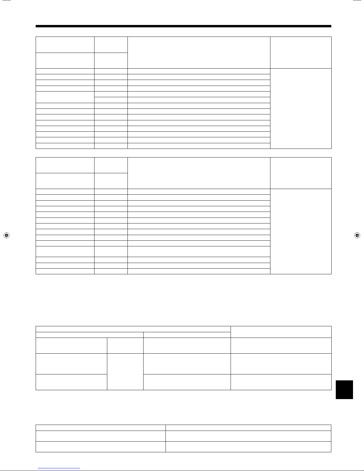
Function table
Select unit number 00
Mode Settings
Power failure automatic
recovery
Indoor temperature detecting Indoor unit operating average
LOSSNAY connectivity Not Supported
Power voltage 230 V
Select unit numbers 01 to 03 or all units (AL [wired remote controller]/07 [wireless remote controller])
Mode Settings
Filter sign 100Hr
Fan speed Silent
*1 When the power supply returns, the air conditioner will start 3 minutes later.
Not available
Available *1
Set by indoor unit’s remote controller 2
Wired remote controller’s internal sensor 3
Supported (indoor unit is not equipped with outdoor-air intake) 2
Supported (indoor unit is equipped with outdoor-air intake) 3
208 V 2
2500Hr 2
No filter sign indicator 3
Standard
High ceiling 3
7. Test run
Mode No.
Wired remote controller
(RF thermostat)
01
(101)
02
(—)
03
(103)
04
(104)
Mode No.
Wired remote controller
(RF thermostat)
07
(107)
08
(108)
Setting no. Initial setting setting
1
2
1
1
1
Setting no. Initial setting setting
1
1
–
2
–
7.1. Before test run
► After completing installation and the wiring and piping of the indoor and
outdoor units, check for refrigerant leakage, looseness in the power
supply or control wiring, wrong polarity, and no disconnection of one
phase in the supply.
► Use a 500-volt megohmmeter to check that the resistance between the
power supply terminals and ground is at least 1.0 MΩ.
► Do not carry out this test on the control wiring (low voltage circuit)
Do not use the air conditioner if the insulation resistance is less than 1.0 MΩ.
Insulation resistance.
7.2. Test run
■ Refer to the installation manual that comes with each remote controller for details.
7.3. Self-check
■ Refer to the installation manual that comes with each remote controller for details.
■ RF thermostat is not established.
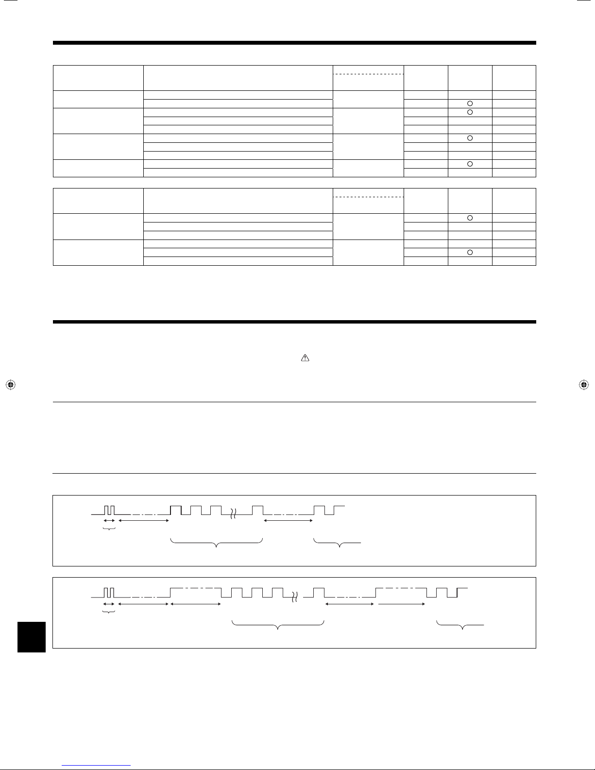
• Refer to the following tables for details on the check codes. (IR wireless remote controller)
[Output pattern A]
Beeper sounds
OPERATION
INDICATOR
lamp flash
pattern
[Output pattern B]
Beeper sounds
OPERATION
INDICATOR
lamp flash
pattern
Beep
Self-check
starts
(Start signal
received)
Beep
Self-check
starts
(Start signal
received)
Beep Beep Beep Beep Beep
Beep
st
1
Off
Approx. 2.5 sec.On0.5 sec.
Number of flashes/beeps in pattern indicates the check
code in the following table (i.e., n=5 for “P5”)
Off
Approx. 2.5 sec.
Approx. 3 sec.On0.5 sec.On0.5 sec.On0.5 sec.
rd
2nd3
On
0.5 sec.On0.5 sec.
Beep Beep Beep Beep Beep Beep
On
Number of flashes/beeps in pattern indicates the check
code in the following table (i.e., n=5 for “U2”)
th
n
On
0.5 sec.
1st2nd3
Off
Approx. 2.5 sec.On0.5 sec.On0.5 sec.
rd
terminals.
Warning:
nd
1st2
Number of flashes/beeps in pattern indicates
the check code in the following table
th
n
On
0.5 sec.
· · · Repeated
Off
Approx. 2.5 sec.OnApprox. 3 sec.On0.5 sec.On0.5 sec.
nd
1st2
Number of flashes/beeps in pattern indicates
the check code in the following table
· · · Repeated
12
7. Test run
[Output pattern A] Errors detected by indoor unit
IR wireless remote controller
Beeper sounds/OPERATION
INDICATOR lamp flashes
Check code (Number of times)
[Output pattern B] Errors detected by unit other than indoor unit (outdoor unit, etc.)
IR wireless remote controller
Beeper sounds/OPERATION
INDICATOR lamp flashes
*1 If the beeper does not sound again after the initial two beeps to confirm the self-check start signal was received and the OPERATION INDICATOR lamp does not come
on, there are no error records.
*2 If the beeper sounds three times continuously “beep, beep, beep (0.4 + 0.4 + 0.4 sec.)” after the initial two beeps to confirm the self-check start signal was received, the
specified refrigerant address is incorrect.
• On IR wireless remote controller
The continuous buzzer sounds from receiving section of indoor unit.
Blink of operation lamp
• On wired remote controller
Check code displayed in the LCD.
• If the unit cannot be operated properly after the above test run has been performed, refer to the following table to remove the cause.
PLEASE WAIT
PLEASE WAIT → Error code
Display messages do not appear even
when operation switch is turned ON
(operation lamp does not light up).
On the IR wireless remote controller with condition above, following phenomena takes place.
• No signals from the remote controller are accepted.
• OPE lamp is blinking.
• The buzzer makes a short pipng sound.
Note:
Operation is not possible for about 30 seconds after cancellation of function selection. (Correct operation)
For description of each LED (LED 1, 2, 3) provided on the indoor controller, refer to the following table.
LED 1 (power for microcomputer) Indicates whether control power is supplied. Make sure that this LED is always lit.
LED 2 (power for remote controller) Indicates whether power is supplied to the remote controller. This LED lights only in the case
LED 3 (communication between indoor and outdoor units only A-control) Indicates state of communication between the indoor and outdoor units. Make sure that this
1 P1 Intake sensor error
2 P2, P9 Pipe (Liquid or 2-phase pipe) sensor error
3 E6, E7 Indoor/outdoor unit communication error
4 P4 Float switch connector CN4F open.
5
6 P6 Freezing/Overheating safeguard operation
7 EE Communication error between indoor and outdoor units
8 P8 Pipe temperature error
9 E4 Remote controller signal receiving error
10 – –
11 – –
12 Fb Indoor unit control system error (memory error, etc.)
No sound – – – – No corresponding
(Number of times)
1 E9 Indoor/outdoor unit communication error (Transmitting error) (Outdoor unit)
2 UP Compressor overcurrent interruption
3 U3, U4 Open/short of outdoor unit thermistors
4 UF Compressor overcurrent interruption (When compressor locked)
5 U2 Abnormal high discharging temperature/49C worked/insufficient refrigerant
6 U1, Ud Abnormal high pressure (63H worked)/Overheating safeguard operation
7 U5 Abnormal temperature of heat sink
8 U8 Outdoor unit fan safeguard stop
9 U6 Compressor overcurrent interruption/Abnormal of power module
10 U7 Abnormality of super heat due to low discharge temperature
11 U9, UH Abnormality such as overvoltage or voltage shortage and abnormal
12 – –
13 – –
14 Others Other errors (Refer to the technical manual for the outdoor unit.)
Wired remote controller LED 1, 2 (PCB in outdoor unit)
Wired remote
controller
RF thermostat
Check code
P5 Drain pump error
PA Forced compressor error
Wired remote
controller
RF thermostat
Check code
For about 2
minutes following
power-on
After about 2
minutes has
expired following
power-on
Symptom Remark
Symptom Remark
synchronous signal to main circuit/Current sensor error
Symptom
After LED 1, 2 are lighted, LED 2 is turned off,
then only LED 1 is lighted. (Correct operation)
Only LED 1 is lighted. → LED 1, 2 blink.
Only LED 1 is lighted. → LED 1 blinks twice,
LED 2 blinks once.
of the indoor unit which is connected to the outdoor unit refrigerant address “0”.
LED is always blinking.
For details, check the LED
display of the outdoor controller
board.
Cause
• For about 2 minutes following power-on, operation of
the remote controller is not possible due to system
start-up. (Correct operation)
• Connector for the outdoor unit’s protection device is not
connected.
• Reverse or open phase wiring for the outdoor unit’s
power terminal block (L1, L2, GR)
• Incorrect wiring between indoor and outdoor units
(incorrect polarity of S1, S2, S3)
• Remote controller wire short
13
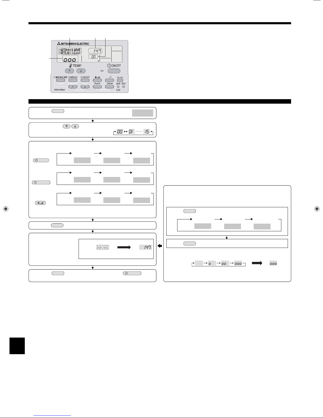
8. Easy maintenance function [This function only for A-control]
Display example (Comp discharge temperature 147°F)
ACB
D
Maintenance mode operation procedures
(1) Press the
activate the maintenance mode.
(2) Press the TEMP.
(3) Select the data you want to display.
Compressor
information
MENU
Outdoor unit
information
ON/OFF
Indoor unit
information
* The filter operation time displayed is the number of hours the filter has been
used since the filter reset was performed.
(4) Press the
(5) The data is displayed in C.
* Repeat steps (2) to (5) to check another date.
(6) Press the
to deactivate the maintenance mode.
TEST
button for three seconds to
buttons to set the refrigerant address.
Cumulative
operation time
Display A
Display A
Display A
FILTER
TEST
COMP ON
x10 HOURS
Heat exchanger
temperature
OUTDOOR UNIT
H·EXC. TEMP
Indoor room
temperature
INDOOR UNIT
INLET TEMP
button.
Display C
button for three seconds or press the
Approx.
10 sec.
MAINTENANCE
Operation
current
COMP ON
CURRENT (A)
Outdoor ambient
temperature
OUTDOOR UNIT
OUTDOOR TEMP
Filter operation
time
INDOOR UNIT
FILTER USE H
ON/OFF
Display A
Display B
ON/OFF
number
COMP ON
x100 TIMES
Comp discharge
temperature
OUTDOOR UNIT
OUTLET TEMP
Heat exchanger
temperature
INDOOR UNIT
H·EXC. TEMP
(Airflow temperature display example)
Flashing
Waiting for
response
147°F
button
■
Only for wired remote controller
By using the maintenance mode, you can display many types of
maintenancedata on the wired remote controller such as the heat exchanger
temperature and compressor current consumption for the indoor and outdoor
units.
This function can be used whether the air conditioner is operating or not.
During air conditioner operation, data can be checked during either normal
operation or maintenance mode stable operation.
* This function cannot be used during the test run.
* The availability of this function depends on the connecting outdoor unit. Refer
to the brochures.
Stable operation
Using the maintenance mode, the operation frequency can be fixed and the
operation can be stabilized. If the air conditioner is stopped, use the following
procedure to start this operation.
Display A
Display D
MODE
button to select the operation mode.
FILTER
Stable cooling
operation
COOL
STABLE MODE
button.
Stable heating
operation
HEAT
STABLE MODE
Stable operation
cancellation
STABLE MODE
CANCEL
10-20 min.
Stable
operation
Press the
Press the
Waiting for stable
operation
* You can check the data using steps (3) to (5) of the maintenance mode
operation procedures while waiting for the stable operation.
14
 Loading...