

Mitsubishi Electric PKA-A12HA, PKA-A18HA, PKA-A12HAL, PKA-A18HAL Service Manual
SPLIT-TYPE, HEAT PUMP AIR CONDITIONERS
3 3 2 2 3
SPLIT-TYPE, AIR CONDITIONERS
SERVICE MANUAL
Indoor unit
[Model names] [Service Ref.]
PKA-A12HA
PKA-A18HA
PKA-A12HAL
PKA-A12HA
PKA-A18HA
PKA-A12HAL
March 2009
No. OCH456
NOTE:
• This manual describes
only service data of the
indoor units.
• RoHS compliant products
have <G> mark on the
spec name plate.
PKA-A18HAL
INDOOR UNIT
PKA-A18HAL
COOL
DRY
AUTO
FAN
HEAT
CONTENTS
1. REFERENCE MANUAL
2. SAFETY PRECAUTION
3. PART NAMES AND FUNCTIONS
4. SPECIFICATIONS
5. NOISE CRITERION CURVES
6. OUTLINES AND DIMENSIONS
7. WIRING DIAGRAM
8. REFRIGERANT SYSTEM DIAGRAM
9. TROUBLESHOOTING
10. SPECIAL FUNCTION
11. DISASSEMBLY PROCEDURE
...................................
...................................
...................
............................................
..........................
.......................
.........................................10
....................................
.....................................
.......................
............
2
3
4
7
8
9
11
12
27
30
TEMP.
WIRED REMOTE
CONTROLLER
ON/OFF
WIRELESS REMOTE
CONTROLLER
PARTS CATALOG (OCB456)
1
REFERENCE MANUAL
1-1. OUTDOOR UNIT SERVICE MANUAL
Service Ref. Service Manual No.
PUZ-A18/24/36NHA3
PUZ-A18/24/36NHA3-BS
PUY-A12/18/24/36NHA3
PUY-A12/18/24/36NHA3-BS
PUZ-HA36NHA2
OCH458
OCB458
OCH426
OCB426
1-2. TECHNICAL DATA BOOK
Series (Outdoor unit) Data Book No.
PUZ-A·NHA3(-BS)
PUY-A·NHA3(-BS)
PUZ-HA·NHA2 OCS15
OCS14
2
2
SAFETY PRECAUTION
2-1. ALWAYS OBSERVE FOR SAFETY
Before obtaining access to terminal, all supply
circuits must be disconnected.
2-2. CAUTIONS RELATED TO NEW REFRIGERANT
Cautions for units utilising refrigerant R410A
Use new refrigerant pipes.
Make sure that the inside and outside of refrigerant piping is clean and it has no contamination
such as sulfur hazardous for use, oxides, dirt,
shaving particles, etc.
In addition, use pipes with specified thickness.
Contamination inside refrigerant piping can cause deterioration of refrigerant oil etc.
Store the piping to be used indoors during
installation, and keep both ends of the piping
sealed until just before brazing. (Leave elbow
joints, etc. in their packaging.)
If dirt, dust or moisture enters into refrigerant cycle, that can
cause deterioration of refrigerant oil or malfunction of compressor.
Use ester oil, ether oil or alkylbenzene oil (small
amount) as the refrigerant oil applied to flares
and flange connections.
If large amount of mineral oil enters, that can cause deterioration of refrigerant oil etc.
Do not use refrigerant other than R410A.
If other refrigerant (R22 etc.) is used, chlorine in refrigerant can cause deterioration of refrigerant oil etc.
Use a vacuum pump with a reverse flow check
valve.
Vacuum pump oil may flow back into refrigerant cycle and
that can cause deterioration of refrigerant oil etc.
Use the following tools specifically designed for
use with R410A refrigerant.
The following tools are necessary to use R410A refrigerant.
Tools for R410A
Gauge manifold
Charge hose
Gas leak detector
Torque wrench
Flare tool
Size adjustment gauge
Vacuum pump adaptor
Electronic refrigerant
charging scale
Handle tools with care.
If dirt, dust or moisture enters into refrigerant cycle, that can
cause deterioration of refrigerant oil or malfunction of compressor.
Charge refrigerant from liquid phase of gas
cylinder.
If the refrigerant is charged from gas phase, composition
change may occur in refrigerant and the efficiency will be
lowered.
[1] Cautions for service
(1) Perform service after recovering the refrigerant left in unit completely.
(2) Do not release refrigerant in the air.
(3) After completing service, charge the cycle with specified amount of refrigerant.
(4) When performing service, install a filter drier simultaneously.
Be sure to use a filter drier for new refrigerant.
[2] Additional refrigerant charge
When charging directly from cylinder
· Check that cylinder for R410A on the market is syphon type.
· Charging should be performed with the cylinder of syphon stood vertically. (Refrigerant is charged from liquid phase.)
Do not use a charging cylinder.
If a charging cylinder is used, the composition of refrigerant will change and the efficiency will be lowered.
Ventilate the room if refrigerant leaks during
operation. If refrigerant comes into contact with
a flame, poisonous gases will be released.
3
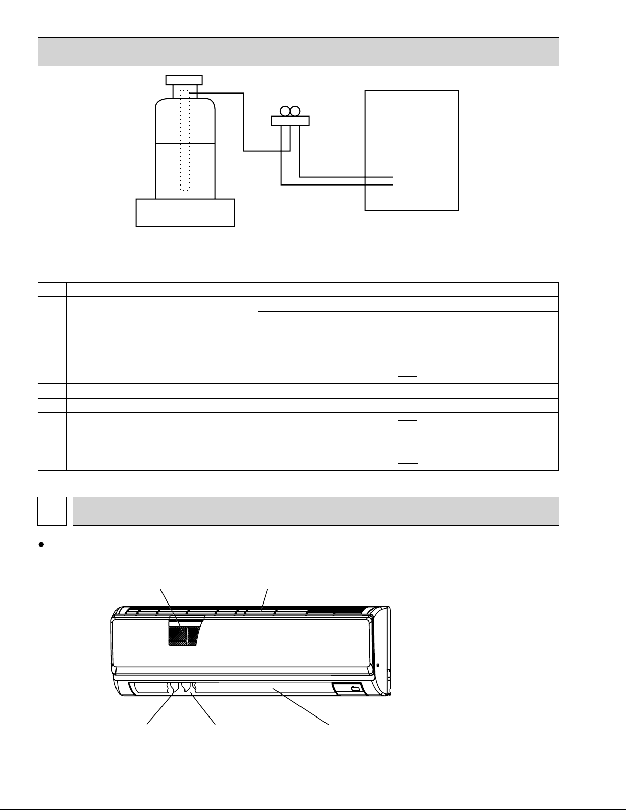
Unit
Gravimeter
[3] Service tools
Use the below service tools as exclusive tools for R410A refrigerant.
No. Tool name Specifications
1 Gauge manifold · Only for R410A
· Use the existing fitting
· Use high-tension side pressure of 5.3MPa·G or over.
2 Charge hose · Only for R410A
· Use pressure performance of 5.09MPa·G or over.
3 Electronic scale
4 Gas leak detector · Use the detector for R134a, R407C or R410A.
5 Adaptor for reverse flow check · Attach on vacuum pump.
6 Refrigerant charge base
7 Refrigerant cylinder · Only for R410A · Top of cylinder (Pink)
· Cylinder with syphon
8 Refrigerant recovery equipment
specifications
. (UNF1/2)
3
PART NAMES AND FUNCTIONS
Indoor unit
Filter
Louver
Air outlet
Air intake
Vane
4
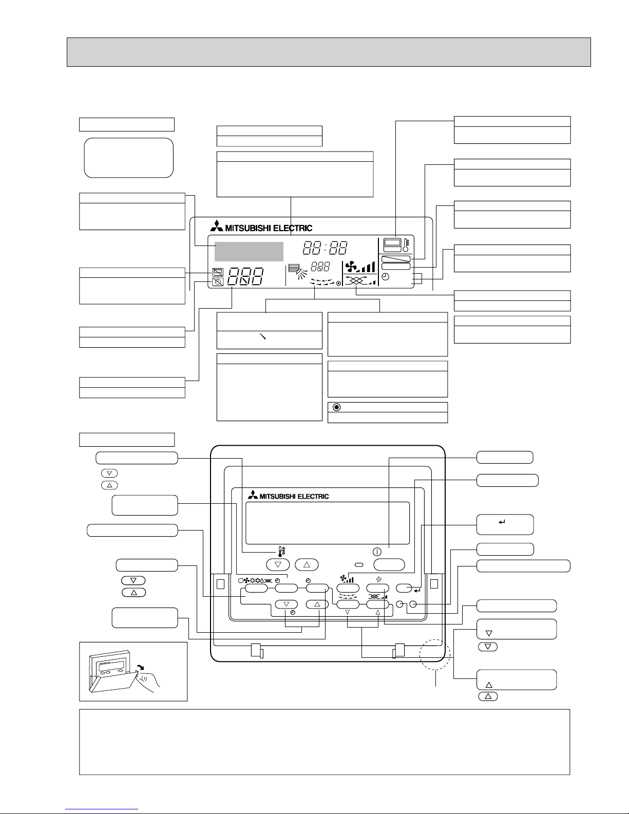
Wired remote controller
Display Section
For purposes of this explanation,
all parts of the display are shown
as lit. During actual operation, only
the relevant items will be lit.
Identifies the current operation
Shows the operating mode, etc.
*Multilanguage display is available.
“Centrally Controlled” indicator
Indicates that operation from the
remote controller has been prohibited by a master controller.
“Timer is Off” indicator
Indicates that the timer is off.
Temperature Setting
Shows the target temperature.
Day-of-Week
Shows the current day of the week.
Time/Timer Display
Shows the current time, unless the simple or Auto Off
timer is set.
If the simple or Auto Off timer is set, the time to be
switched off is shown.
TIME SUN MON TUE WED THU FRI SAT
TIMER
AFTER
ERROR CODE
°F°C
Hr
AFTER
°F°C
ONLY1Hr.
Up/Down Air Direction indicator
The indicator shows the direction of the outcoming airflow.
“One Hour Only” indicator
Displayed if the airflow is set to
low or downward during COOL
or DRY mode. (Operation varies
according to model.)
The indicator goes off in 1 hour,
when the airflow direction
also changes.
Room Temperature display
Shows the room temperature. The room
temperature display range is 46–102˚F.
The display blinks if the temperature
is less than 46˚F or 102˚F or more.
Louver display
Indicates the action of the swing louver.
Does not appear if the louver is not
running.
(Power On indicator)
Indicates that the power is on.
ON
OFF
FUNCTION
FILTER
WEEKLY
SIMPLE
AUTO OFF
“Sensor” indication
Displayed when the remote controller
sensor is used.
“Locked” indicator
Indicates that remote controller buttons have been locked.
“Clean The Filter” indicator
To be displayed on when it is time to
clean the filter.
Timer indicators
The indicator comes on if the corresponding timer is set.
Fan Speed indicator
Shows the selected fan speed.
Ventilation indicator
Appears when the unit is running in
Ventilation mode.
Operation Section
Temperature setting buttons
Down
Up
Timer Menu button
(Monitor/Set button)
Mode button (Return button)
TEMP.
Set Time buttons
Back
Ahead
Timer On/Off button
(Set Day button)
Opening the
lid
Note:
“PLEASE WAIT” message
•
This message is displayed for approximately 3 minutes when power is supplied to the indoor unit or when the unit is recoveringfrom a power failure.
“NOT AVAILABLE” message
•
This message is displayed if an invalid button is pressed (to operate a function that the indoor unit does not have).
BACK DAY
PAR-21MAA
MENU
MONITOR/SET
CLOCK
ON/OFF
OPERATION
ON/OFF
FILTER
CHECK
TEST
CLEAR
Built-in temperature sensor
If a single remote controller is used to operate multiple indoor units simultaneously that are different types, this message will not be displayed as
far as any of the indoor units is equipped with the function.
ON/OFF button
Fan Speed button
Filter button
(<Enter> button)
Test Run button
Check button (Clear button)
Airflow Up/Down button
Louver button
( Operation button)
To return operation
number
Ventilation button
( Operation button)
To go to next operation
number
5
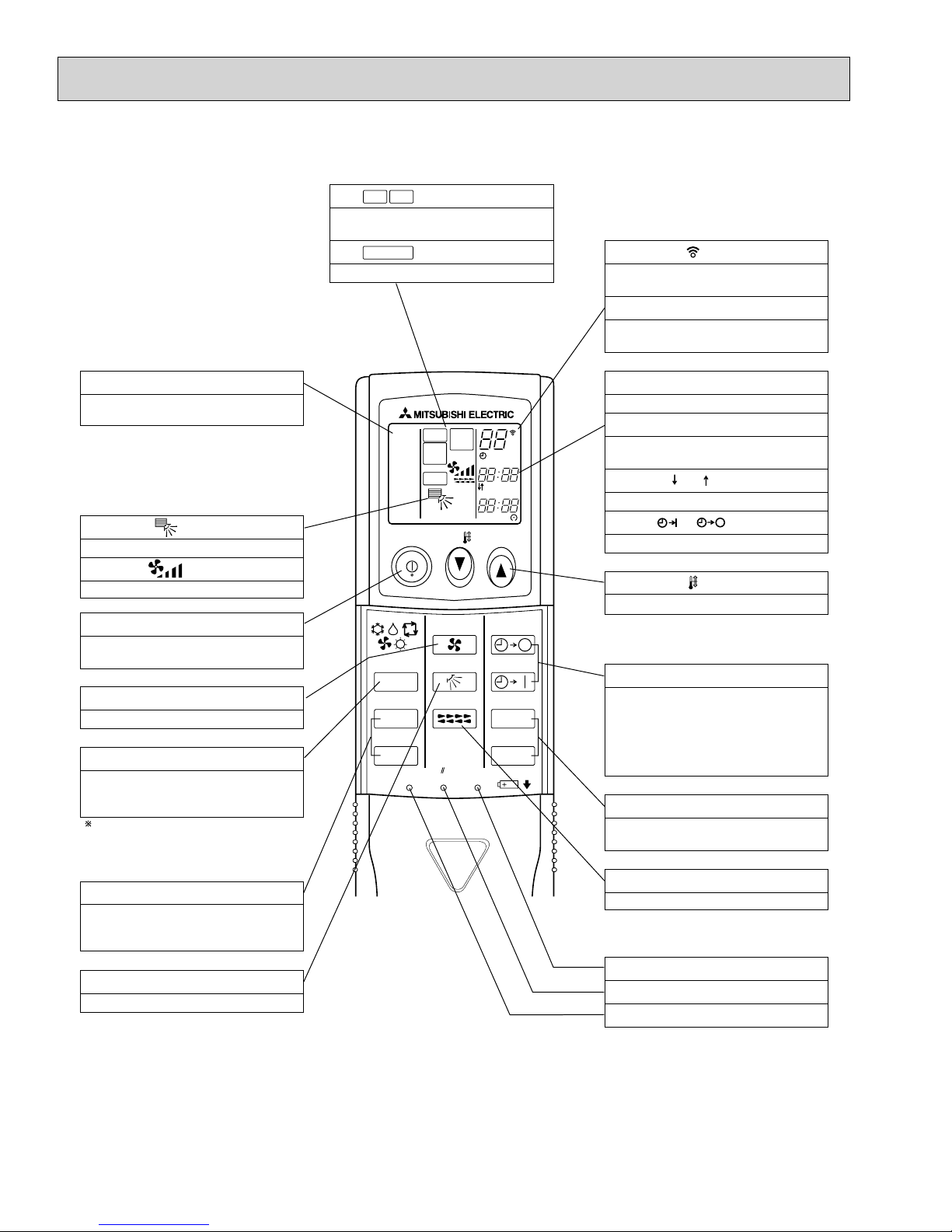
Wireless remote controller
CHECK
TEST RUN
display
Indicate that the unit is being checked or
test-run.
MODEL SELECT
Blinks when model is selected.
display
display
Lights up while the signal is transmitted to
the indoor unit when the button is pressed.
Temperature setting display
Indicates the desired temperature setting
which is set.
OPERATION MODE display
OPERATION MODE display
Indicates which operation mode is in effect.
display
The vertical direction of airflow is indicated.
display
Displays selected fan speed.
ON/OFF button
The unit is turned ON and OFF alternately
each time the button is pressed.
FAN SPEED SELECT button
Changes the fan speed.
MODE SELECT button
Switches the operation mode between
COOLING/DRY/FAN/HEATING and AUTO
mode.
In case the outdoor unit is cooling only
type, the heating and auto mode are not
available.
COOL
DRY
AUTO
FAN
HEAT
RUN
MODEL
SELECT
FAN
SWING
NOT AVAILABLE
TEST
CHECK
ON/OFF TEMP
FAN
MODE
CHECK
VAN E
LOUVER
TEST RUN
RESETSET CLOCK
°F
°C
AMPMSTOP
AMPM
START
AUTO STOP
AUTO START
h
min
CLOCK display
Displays the current time.
TIMER display
Displays when in timer operation or when
setting timer.
“ ” “ ” display
Displays the order of timer operation.
“ ” “ ” display
Displays whether timer is on or off.
button
Sets any desired room temperature.
TIMER CONTROL buttons
AUTO STOP (OFF timer): when this switch
is set, the air conditioner will be
autom ati ca lly stopped at the preset time.
AUTO START (ON timer): when this switch is
set, the air conditioner will be automatically
started at the preset time.
"h" and "min" buttons
Buttons used to set the “hour and minute” of
the current time and timer settings.
CHECK-TEST RUN button
Performs an inspection check or test
operation. Do not use it for normal
operation.
VANE CONTROL button
Changes the air flow direction.
LOUVER button
Changes left / right airflow direction.
(Not available for this model.)
CLOCK button
RESET button
SET button
6
4
SPECIFICATIONS
Service Ref.
Power supply(phase, cycle, voltage)
External finish
Heat exchanger
Fan Fan(drive) % No.
INDOOR UNIT
Operation control & Thermostat
Noise level(Low-Middle-High)
Field drain pipe O.D.
Dimensions
Weight
Service Ref.
Power supply(phase, cycle, voltage)
External finish
Heat exchanger
Fan Fan(drive) % No.
INDOOR UNIT
Operation control & Thermostat
Noise level(Low-Middle-High)
Field drain pipe O.D.
Dimensions
Weight
Max. Fuse Size
Min.Circuit Ampacity
Fan motor output
Fan motor
Airflow(Low-Middle-High)
External static pressure
Max. Fuse Size
Min.Circuit Ampacity
Fan motor output
Fan motor
Airflow(Low-Middle-High)
External static pressure
W
D
H
W
D
H
A
A
kW
F.L.A
m3/min(CFM)
Pa(mmAq)
dB
mm(in.)
mm(in.)
mm(in.)
mm(in.)
kg(lbs)
A
A
kW
F.L.A
*/min(CFM)
Pa(mmAq)
dB
mm(in.)
mm(in.)
mm(in.)
mm(in.)
kg(lbs)
PKA-A12HA, PKA-A12HAL
1 phase, 60Hz, 208/230V
15
1
White Munsell 1.0Y 9.2/0.2
Plate fin coil
Line flow fan (direct) % 1
0.030
0.33
Dry: 9-10.5-12 (320-370-425)
Wet: 8-9.5-11 (290-335-380)
0(direct blow)
Remote controller & built-in
36-40-43
16(5/8)
898 (35-3/8)
249 (9-13/16)
295 (11-5/8)
13 (29)
PKA-A18HA, PKA-A18HAL
1 phase, 60Hz, 208/230V
15
1
White Munsell 1.0Y 9.2/0.2
Plate fin coil
Line flow fan (direct) % 1
0.030
0.33
Dry: 9-10.5-12 (320-370-425)
Wet: 8-9.5-11 (290-335-380)
0(direct blow)
Remote controller & built-in
36-40-43
16(5/8)
898 (35-3/8)
249 (9-13/16)
295 (11-5/8)
13 (29)
7
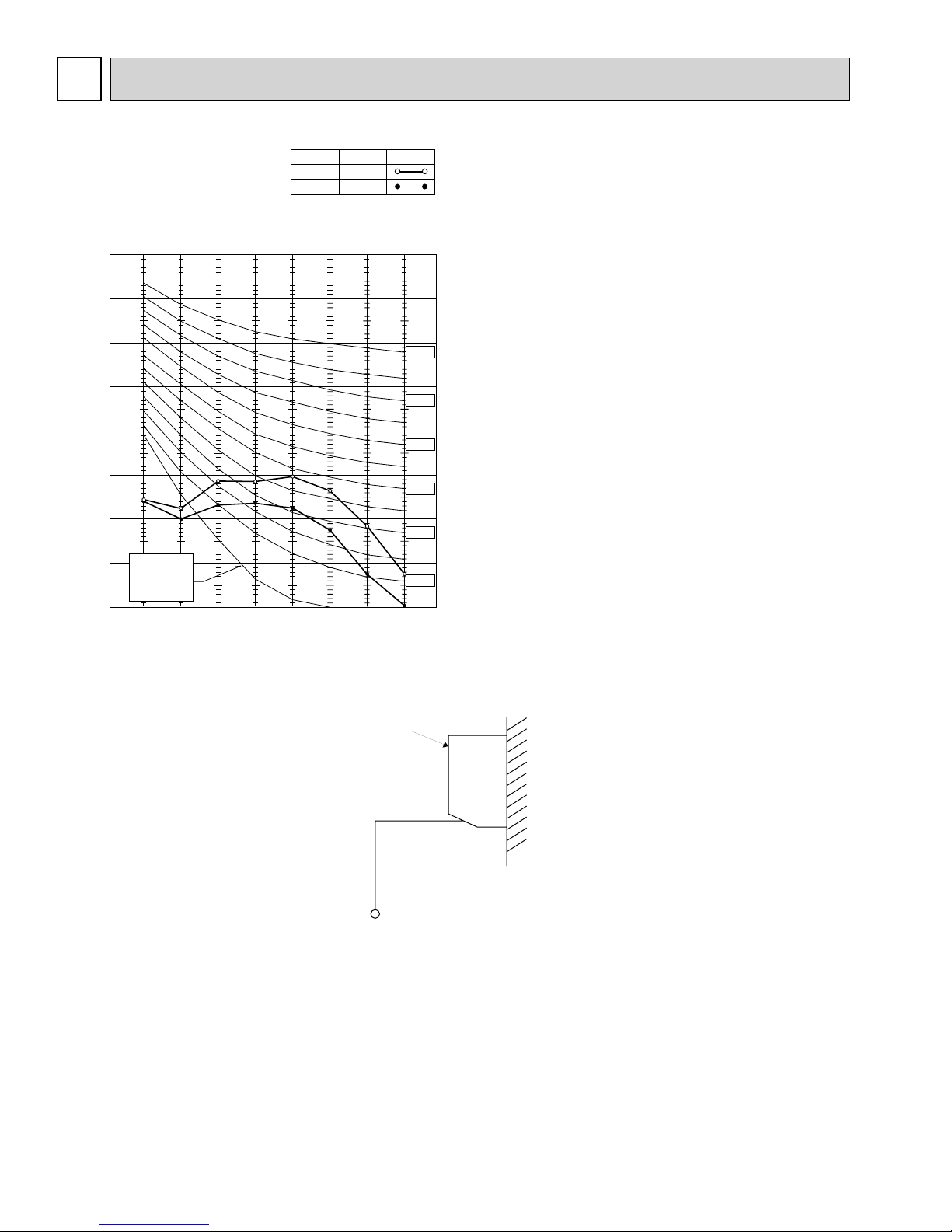
5
NOISE CRITERION CURVES
PKA-A12HA
PKA-A18HA
PKA-A12HAL
PKA-A18HAL
90
80
70
60
50
40
30
OCTAVE BAND SOUND PRESSURE LEVEL, dB (0dB=0.0002 μbar)
APPROXIMATE
20
THRESHOLD OF
HEARING FOR
CONTINUOUS
NOISE
10
63 125 250 500 1000 2000 4000 8000
NOTCH
High
Low
BAND CENTER FREQUENCIES, Hz
SPL(dB)
43
36
LINE
NC-70
NC-60
NC-50
NC-40
NC-30
NC-20
UNIT
3.3ft
3.3ft
MICROPHONE
WALL
8
6
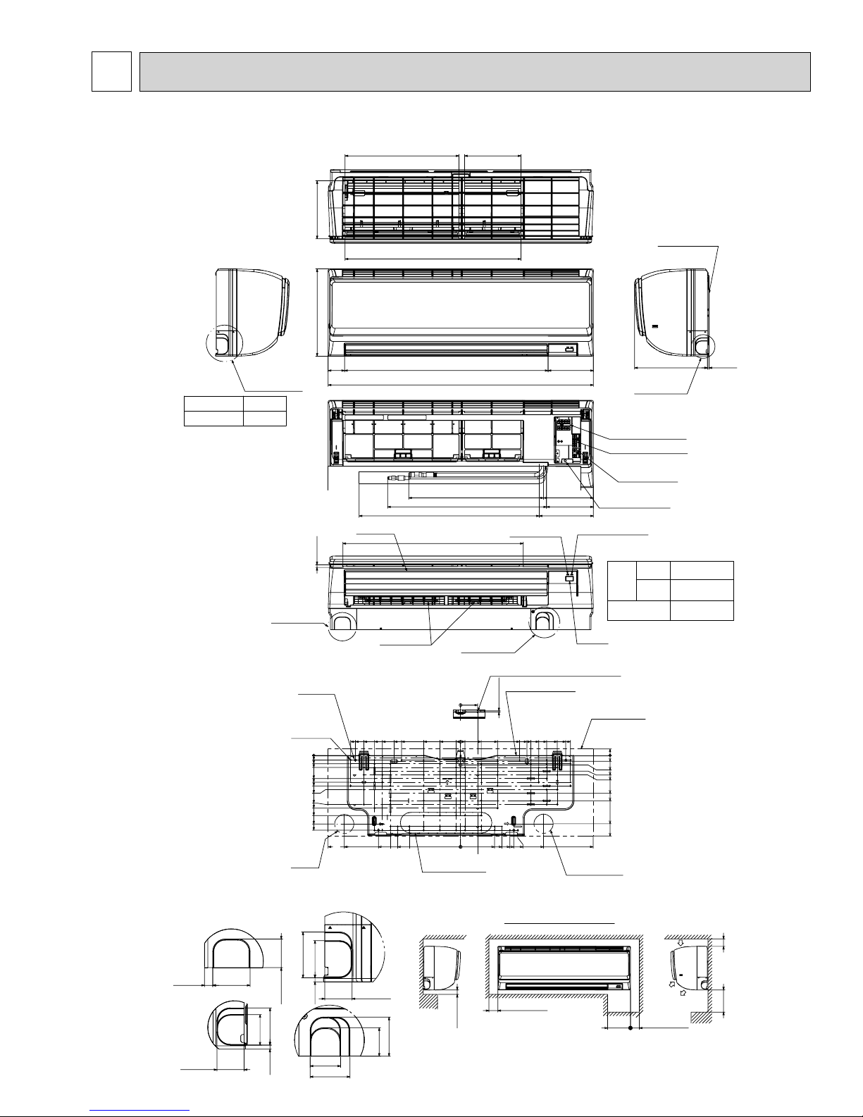
OUTLINES AND DIMENSIONS
PKA-A12HA PKA-A12HAL PKA-A18HA PKA-A18HAL Unit: inch (mm)
15-3/16(387)
7-3/4(197)
23-9/16(599)
7-1/2(192)
Top side
Front side
Mount board
Right side
D
Sleeve
(purchased locally)
:2-1/2~:3-1/8
(:65~:80)
Left side
Knock out hole
for left piping
Through hole
:2-1/2~:3-1/8
(:65~:80)
Knock out hole
for lower piping
77Tap p in g
screw hole
5/8(16)
1-1/16(28.5)
1-9/16(41)
3-1/16(78.5)
3-9/16(91)
4-1/16(103.5)
4-9/16(116)
6-1/2(166)
7(178.5)
8(203.5)
9-1/8(232.5)
9-15/16(253.5)
11-5/8(295)
5/16(8)
4-:5/16(:9)
Bolt hole
:
3/16(:5.1)
0
Wall hole
for
left rear
piping
2-1/8
(55)
Vane(auto)
C
14-5/8(372.3)
14(356.3)
15-1/2(394)
17-5/8(449)
Louver(manual)
12-7/8(327.5)
10-3/8(265)
11-7/16(291.5)
10-15/16(278.3)
24-1/16(612)
7-13/16(200)
8-13/16(225)
8-3/8(213)
9-5/16(238)
6-13/16(174)
27-1/16(688)
35-3/8(898)
Front side(Grille open)
17-15/16(457)Gas pipe
21-3/16(539)Liquid pipe
24(610)Drain hose
Under side
Knock out hole
for lower piping
0
4-7/8(125)
2-3/4(70)
0
9/16(15)
0
Knock out hole for
left rear piping
2-3/4×12-3/16(70×310)
Operation lamp
Center measurement hole :3/32(:2.5)
Mount board
2-1/4(58)
5/32(3.8)
8-13/16(225)
2-3/4(70)
4-1/2(115)
7-13/16(200)
4-7/8(125)
5-1/2(140)
6-9/16(167)
7-1/16(180.3)
7-9/16(193.5)
9/16(15)
6-1/16(155)
6-5/8(169)
6-3/16(158)
7-3/16(184)
B
11-7/16(291.5)
10-3/8(265)
9-5/16(238)
11-1/16(281)
DEFROST/STAND BY lamp
Receiver
Indoor unit outline
14-5/8(372.3)
14(356.3)
12-7/8(237.5)
Wall hole for
right rear piping
Knock out hole
for right piping
Terminal block for indoor/outdoor
connecting line
Terminal block for power supply (option)
Terminal block for
MA-remote controller
(only PKA-A·HA models)
Emergency operation switch
(cooling/heating)
Liquid pipe
Refrigerant
Piping
Gas pipe
Drain hose
13/16(21.8)
0
3/4(20)
1-1/4(32.7)
2-1/16(53.5)
2-9/16(66)
5(128.5)
6(153.5)
9-1/16(231.5)
10-3/4(273.2)
17-5/8(449)
:
6.35)
1/4F (
1/2F (:12.7)
:
5/8 (:16) O.D
A
3/16(5)9-13/16(249)
Knock out hole for piping
C
2-3/16(56)
1-3/4(46)
3/16(6)
1-11/16(43)
1-11/16(43)
2-3/16(56)7/16(12.5)
A
2-11/16(69)
2-3/16(56)
3/16(6)
1-3/4(46)
2-5/16(60)
1-11/16(43)
1-11/16(43)
D
2-5/16(59)
B
Required space(Indoor unit)
Min.1-31/32(50)
Min.1/4(7)
250mm,9-13/16inch or greater with
optional drain pump installation.
Min.8-5/8
(220)
(mm)
Air inlet
Air inlet
Air outlet
Min.5-7/8(150)
Min.1-31/32(50)
Min.9-13/16(250)
9
7
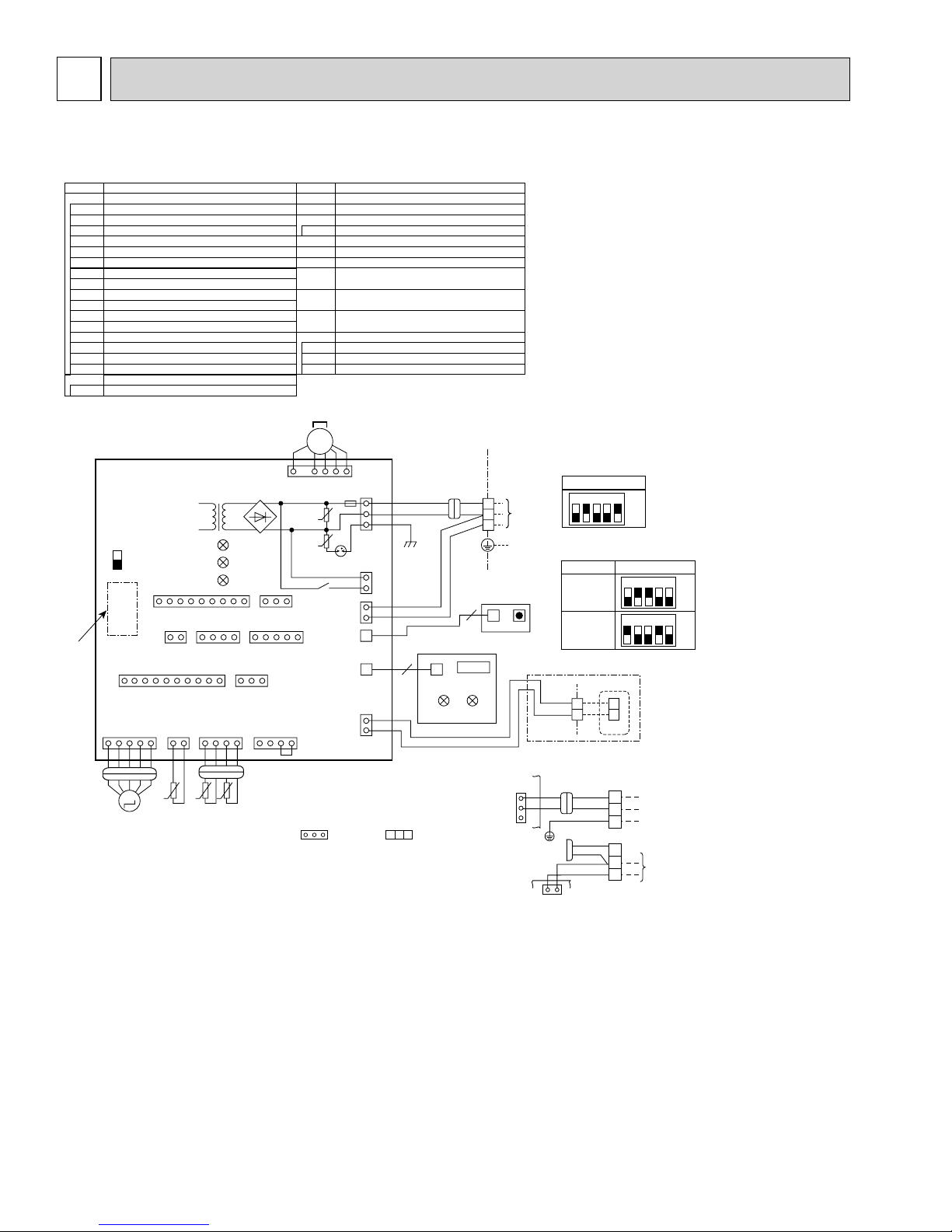
WIRING DIAGRAM
PKA-A12HA PKA-A18HA PKA-A12HAL PKA-A18HAL
[Explanation of symbols]
Symbol
I.B Indoor controller board
CN2L Connector (LOSSNAY)
CN30 Connector (LLC)
CN32 Connector ( Remote switch)
CN41 Connector (HA terminal-A)
CN51 Connector (Centrally control)
CN90 Connector (Remote operation adapter)
CN152 Connector (Back-up heating)
DSA Surge absorber
FUSE FUSE(T3.15AL250V)
LED1 Power supply (I.B)
LED2 Power supply (R.B)
LED3 Transmission (Indoor-outdoor)
SW1 Switch (Model selection) +See table 1
SW2
Switch (Capacity code) +See table 2
Connector (Emergency operation)
SWE
ZNR01,02
Varistor
R.B
Wired remote controller
TB6
Terminal block (Remote controller transmission line)
Name
I.B
T11 DB1
SWE
ON
OFF
Refer to
tables
1and 2
CN151
(WHT)
11
M
2
11 1 54
CN2L
(RED)
CN152
(WHT)
CN20
(RED)
○t○t○
t
TH1 TH2 TH5
CN90
(WHT)
141425
CN41
(WHT)
CN44
(WHT)
LED1
LED3
LED2
11310
CN30
(BLK)
Notes:
1.SymboIs used in wiring diagram above are, : Connector, : Terminal (block).
2.Indoor and outdoor connecting wires have poIarities, make sure to match terminal
numbers (S1, S2, S3)for correct wirings.
3.Since the outdoor side electric wiring may change, be sure to check the outdoor unit
electric wiring diagram for servicing.
4.This diagram shows the wiring of indoor and outdoor connecting wires.(specification of
230V), adopting superimposed system for power and signal.
+
1: If indoor and outdoor units have separate power supplies, refer to Fig 1.
+
2: For power supply system of this unit, refer to the caution label located near this diagram.
+
3: Use copper supply wires.
Symbol
M Vane motor
MS Fan motor
S.W
Switch board
SWE2 Emergency operation
TB2 Terminal block(Indoor unit Power (option))
TB4 Terminal block (Indoor/outdoor connecting line)
TB5 Terminal block (Remote controller transmission line)
TH1 Room temp. Thermistor
(32°F/15ΚΩ, 77°F/5.4ΚΩ Detect)
TH2
Pipe temp. Thermistor/liquid
(32°F/15ΚΩ, 77°F/5.4ΚΩ Detect)
TH5
Cond./eva. temp. Thermistor
(32°F/15ΚΩ, 77°F/5.4ΚΩ Detect)
W.B Pcb for wireless remote controller
LED1 LED (Operation indication: Green)
LED2 LED (Preparation for heating: Orange)
REC1 Receiving unit
MS
3~
CNMF
1139
CN32
(WHT)
CN51
(WHT)
CN4F
(WHT)
1
ZNR01
ZNR02
(WHT)
U
U
X1
CNP(BLU)
6
FUSE
DSA
CN3C
(BLU)
LDSWE(A
(BLU)
CNRU
(WHT)
CN22
(BLU)
CN01
(BLK)
3
1
3
1
)
1
2
Name
1
3
ORN
5
BLK
ORN
BRN
W.B
6
LD101(B)
LED1
YLWYLW
ORN
RU
REC1
LED2
2
<+3>
TB4
TO
S1
OUTDOOR
S2
UNIT
S3
S.W
LDSWE(B) SWE2
+1(Fig. 1)
CN01
(BLK)
1
3
5
BLU
BLU
I.B
YLW
ORN
I.B
1
CN3C(BLU)
<Table 1>
SW1
(MODEL SELECTION)
SETTING
12345
<Table 2>
SW2(CAPACITY CODE)
MODELS
A12
A18
1
2
TB5
For PKA-A.HA
GRN
INDOOR/OUTDOOR
3
COMMUNICATION
RED
BLU
/
YLW
YLW
ORN
ORN
BRN
R.B
TB6
TB2
L1
L2
GR
TB4
S1
S2
S3
1
2
ON
OFF
SETTING
12345
12345
POWER SUPPLY
208/230V 60Hz
TO OUTDOOR
UNIT
ON
OFF
ON
OFF
10
8
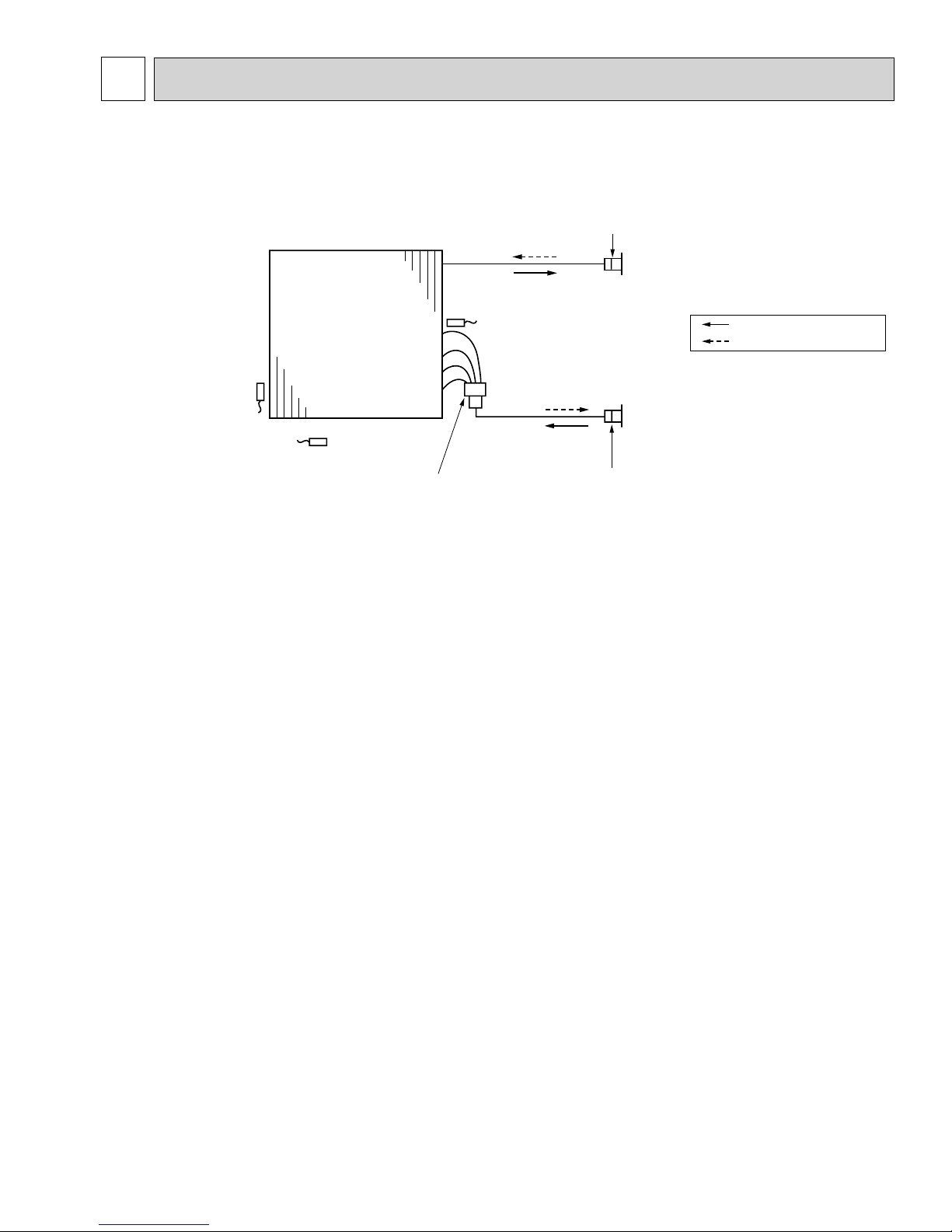
REFRIGERANT SYSTEM DIAGRAM
PKA-A12HA PKA-A18HA PKA-A12HAL PKA-A18HAL
Heat exchanger
Strainer (#50)
Refrigerant GAS pipe connection
(Flare)
Thermistor TH5
(Cond./ Eva.temperature)
Thermistor TH1
(Room temperature)
Thermistor TH2
Pipe temperature(Liquid)
Distributor
with strainer (#50/#50)
Refrigerant flow in cooling
Refrigerant flow in heating
Refrigerant LIQUID pipe connection
(Flare)
Strainer (#50)
11
 Loading...