

Mitsubishi PKA-A12GA1, PKA-A18GA1, PKA-A12GA2, PKA-A18GA, PKA-A18GA2 Service Manual
...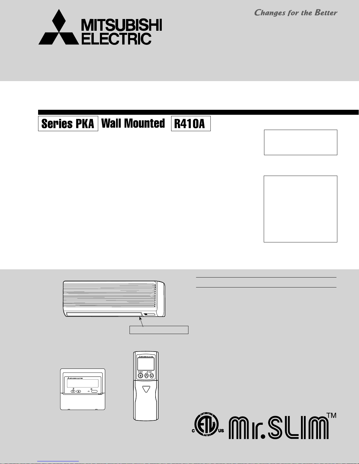
SPLIT-TYPE, HEAT PUMP AIR CONDITIONERS
SPLIT-TYPE, AIR CONDITIONERS
SERVICE MANUAL
April 2009
No.OC369
REVISED EDITION-D
Indoor unit
[Model names]
PKA-A12GA
PKA-A18GA
PKA-A24FA
PKA-A30FA
PKA-A36FA
PKA-A12GAL
PKA-A18GAL
PKA-A24FAL
PKA-A30FAL
PKA-A36FAL
PKA-A12GA PKA-A18GA
PKA-A12GAL PKA-A18GAL
TEMP.
[Service Ref.]
PKA-A12GA PKA-A12GA1 PKA-A12GA2
PKA-A18GA PKA-A18GA1 PKA-A18GA2
PKA-A24FA PKA-A24FA1 PKA-A24FA2
PKA-A30FA PKA-A30FA1 PKA-A30FA2
PKA-A36FA PKA-A36FA1 PKA-A36FA2
PKA-A12GAL PKA-A12GAL1 PKA-A12GAL2
PKA-A18GAL PKA-A18GAL1 PKA-A18GAL2
PKA-A24FAL PKA-A24FAL1 PKA-A24FAL2
PKA-A30FAL PKA-A30FAL1 PKA-A30FAL2
PKA-A36FAL PKA-A36FAL1 PKA-A36FAL2
Indoor unit
ON/OFF
Model name indication
Revision:
• "14. RoHS PARTS LIST" has
been modified.
• Please void OC369
REVISED EDTION-C.
NOTE:
• This manual describes only
service data of the indoor
units.
• RoHS compliant products
have <G> mark on the spec
name plate.
• For servicing RoHS compliant products, refer to the
RoHS PARTS LIST.
CONTENTS
1. TECHNICAL CHANGES
2. REFERENCE MANUAL
3. SAFETY PRECAUTION
4. PART NAMES AND FUNCTIONS
5. SPECIFICATIONS
6. NOISE CRITERION CURVES
7. OUTLINES AND DIMENSIONS
8. WIRING DIAGRAM
REFRIGERANT SYSTEM DIAGRAM
9.
10. TROUBLE SHOOTING
11. SPECIAL FUNCTION
12. DISASSEMBLY PROCEDURE
13. PARTS LIST
.......................................................
14. RoHS PARTS LIST
......................................
.......................................
.......................................
................................................
............................................
.......................................
.........................................
.............................................
........................
............................
.........................
........................
...........................
11
12
15
19
20
35
38
44
53
2
2
3
5
9
WIRED REMOTE
CONTROLLER
WIRELESS REMOTE
CONTROLLER
3 3 2 2 3
Revision :
"14. RoHS PARTS LIST" has been modifi ed on page 53.
Page Revise point Service Ref. Incorrect Correct
STRUCTUAL PARTS
PKA-A12/18GA(L)
PKA-A12/18GA(L)
PKA-A12/18GA(L)
R01 10Y 658 R01 08Y 658
1
2
R01 08Y 658 R01 10Y 658
53
No. 2
CORNER COVER
STRUCTUAL PARTS
No. 11
CORNER COVER
1 TECHNICAL CHANGES
PKA-A12GA
1 PKA-A12GA2
PKA-A18GA1 PKA-A18GA2
PKA-A24FA1 PKA-A24FA2
PKA-A30FA1 PKA-A30FA2
PKA-A36FA1 PKA-A36FA2
PKA-A12GAL1 PKA-A12GAL2
PKA-A18GAL1 PKA-A18GAL2
PKA-A24FAL1 PKA-A24FAL2
PKA-A30FAL1 PKA-A30FAL2
PKA-A36FAL1 PKA-A36FAL2
• Indoor controller board (I.B) has been changed (11. SPECIAL FUNCTION is added).
PKA-A12GA PKA-A12GA1
PKA-A18GA PKA-A18GA1
PKA-A24FA PKA-A24FA1
PKA-A30FA PKA-A30FA1
PKA-A36FA PKA-A36FA1
PKA-A12GAL PKA-A12GAL1
PKA-A18GAL PKA-A18GAL1
PKA-A24FAL PKA-A24FAL1
PKA-A30FAL PKA-A30FAL1
PKA-A36FAL PKA-A36FAL1
• Indoor controller board (I.B) has been changed.
2
REFERENCE MANUAL
2-1. OUTDOOR UNIT SERVICE MANUAL
Service Ref.
PUZ-A18/24/30/36/42NHA
PUZ-A18/24/30/36/42NHA-BS
PUY-A12/18/24/30/36/42NHA(1)
PUY-A12/18/24/30/36/42NHA(1)-BS
PUZ-HA36NHA
2-2. TECHNICAL DATA BOOK
Series (Outdoor unit)
PUZ-A·NHA(-BS)
PUY-A·NHA(-BS)
PUZ-HA36NHA
Service Manual No.
OC367
OCH426
OCB426
Data Book No.
OCS04
OCS12
2
3 SAFETY PRECAUTION
3-1. ALWAYS OBSERVE FOR SAFETY
Before obtaining access to terminals, all supply
circuits must be disconnected.
3-2. CAUTIONS RELATED TO NEW REFRIGERANT
Cautions for units utilizing refrigerant R410A
Use new refrigerant pipes.
Make sure that the inside and outside of refrigerant piping is clean and it has no contamination
such as sulfur hazardous for use, oxides, dirt,
shaving particles, etc.
In addition, use pipes with specified thickness.
Contamination inside refrigerant piping can cause deterioration of refrigerant oil etc.
Store the piping to be used indoors during
installation and both ends of the piping sealed
until just before brazing. (Leave elbow joints, etc.
in their packaging.)
If dirt, dust or moisture enters into refrigerant cycle, that
can cause deterioration of refrigerant oil or malfunction of
compressor.
Use ester oil, ether oil or alkylbenzene oil (small
amount) as the refrigerant oil applied to flares
and flange connections.
If large amount of mineral oil enters, that can cause deterioration of refrigerant oil etc.
Do not use refrigerant other than R410A.
If other refrigerant (R22 etc.) is used, chlorine in refrigerant can cause deterioration of refrigerant oil etc.
Use a vacuum pump with a reverse flow check
valve.
Vacuum pump oil may flow back into refrigerant cycle and
that can cause deterioration of refrigerant oil etc.
Use the following tools specifically designed for
use with R410A refrigerant.
The following tools are necessary to use R410A refrigerant.
Tools for R410A
Gauge manifold
Charge hose
Gas leak detector
Torque wrench
Flare tool
Size adjustment gauge
Vacuum pump adaptor
Electronic refrigerant
charging scale
Handle tools with care.
If dirt, dust or moisture enters into refrigerant cycle, that can
cause deterioration of refrigerant oil or malfunction of compressor.
Charge refrigerant from liquid phase of gas
cylinder.
If the refrigerant is charged from gas phase, composition
change may occur in refrigerant and the efficiency will be
lowered.
[1] Cautions for service
(1) Perform service after recovering the refrigerant left in unit completely.
(2) Do not release refrigerant in the air.
(3) After completing service, charge the cycle with specified amount of refrigerant.
(4) When performing service, install a filter drier simultaneously.
Be sure to use a filter drier for new refrigerant.
Do not use a charging cylinder.
If a charging cylinder is used, the composition of refrigerant will change and the efficiency will be lowered.
Ventilate the room if refrigerant leaks during
operation. If refrigerant comes into contact with
a flame, poisonous gases will be released.
3
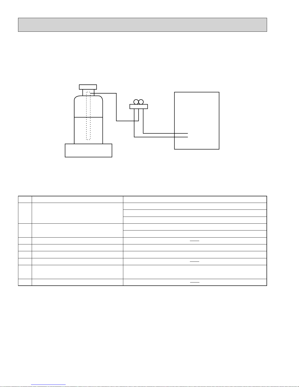
[2] Additional refrigerant charge
When charging directly from cylinder
· Check that cylinder for R410A on the market is syphon type.
· Charging should be performed with the cylinder of syphon stood vertically. (Refrigerant is charged from liquid phase.)
Unit
Gravimeter
[3] Service tools
Use the below service tools as exclusive tools for R410A refrigerant.
No. Tool name Specifications
1 Gauge manifold · Only for R410A
· Use the existing fitting
· Use high-tension side pressure of 5.3MPa·G or over.
2 Charge hose · Only for R410A
· Use pressure performance of 5.09MPa·G or over.
3 Electronic scale
4 Gas leak detector · Use the detector for R134a, R407C or R410A.
5 Adaptor for reverse flow check · Attach on vacuum pump.
6 Refrigerant charge base
7 Refrigerant cylinder · Only for R410A · Top of cylinder (Pink)
· Cylinder with syphon
8 Refrigerant recovery equipment
specifications
. (UNF1/2)
4
4 PART NAMES AND FUNCTIONS
Indoor Unit
PKA-A12GA
PKA-A18GA
PKA-A12GAL
PKA-A18GAL
PKA-A12GA
1
PKA-A18GA1
PKA-A12GAL1
PKA-A18GAL1
PKA-A12GA2
PKA-A18GA2
PKA-A12GAL2
PKA-A18GAL2
Indoor Unit
PKA-A24FA
PKA-A30FA
PKA-A36FA
PKA-A24FAL
PKA-A30FAL
PKA-A36FAL
PKA-A24FA
1
PKA-A30FA1
PKA-A36FA1
PKA-A24FAL1
PKA-A30FAL1
PKA-A36FAL1
PKA-A24FA2
PKA-A30FA2
PKA-A36FA2
PKA-A24FAL2
PKA-A30FAL2
PKA-A36FAL2
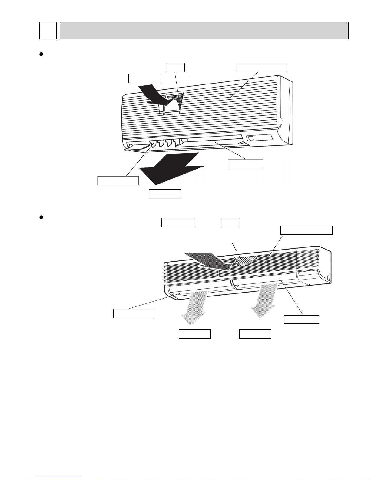
Air intake
Guide vane
Guide vane
Airflow can be changed
to horizontally by moving
the guide vane to the left
or right.
Filter
Air outlet
Air intake
Room air is suctioned
here
.
Air outlet
Air intake grille
Auto vane
Filter
Removes dust and dirt
from the intake air.
Air outlet
Air intake grille
Auto vane
Disperse airflow up and
down as well as adjusts the
angle of airflow direction.
5
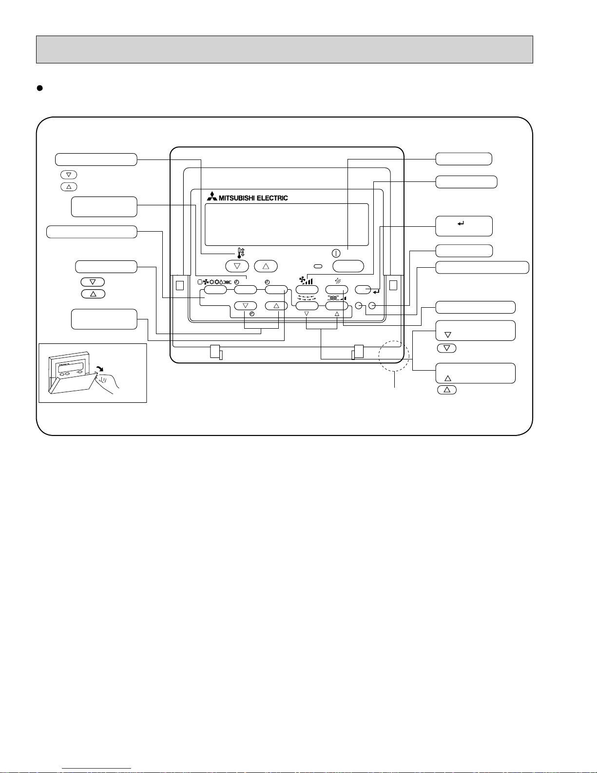
PAR-21MAA
ON/OFF
FILTER
CHECK
OPERATION
CLEAR
TEST
TEMP.
MENU
BACK DAY
MONITOR/SET
CLOCK
ON/OFF
Temperature setting buttons
Down
Up
Timer Menu button
(Monitor/Set button)
Mode button (Return button)
Set Time buttons
Back
Ahead
Timer On/Off button
(Set Day button)
Opening the
lid
ON/OFF button
Fan Speed button
Filter button
(<Enter> button)
Test Run button
Check button (Clear button)
Airflow Up/Down button
Louver button
( Operation button)
To return operation
number
Ventilation button
( Operation button)
To go to next operation
number
Built-in temperature sensor
Wired remote controller
Once the controllers are set, the same operation mode can be repeated by simply pressing the ON/OFF button.
6
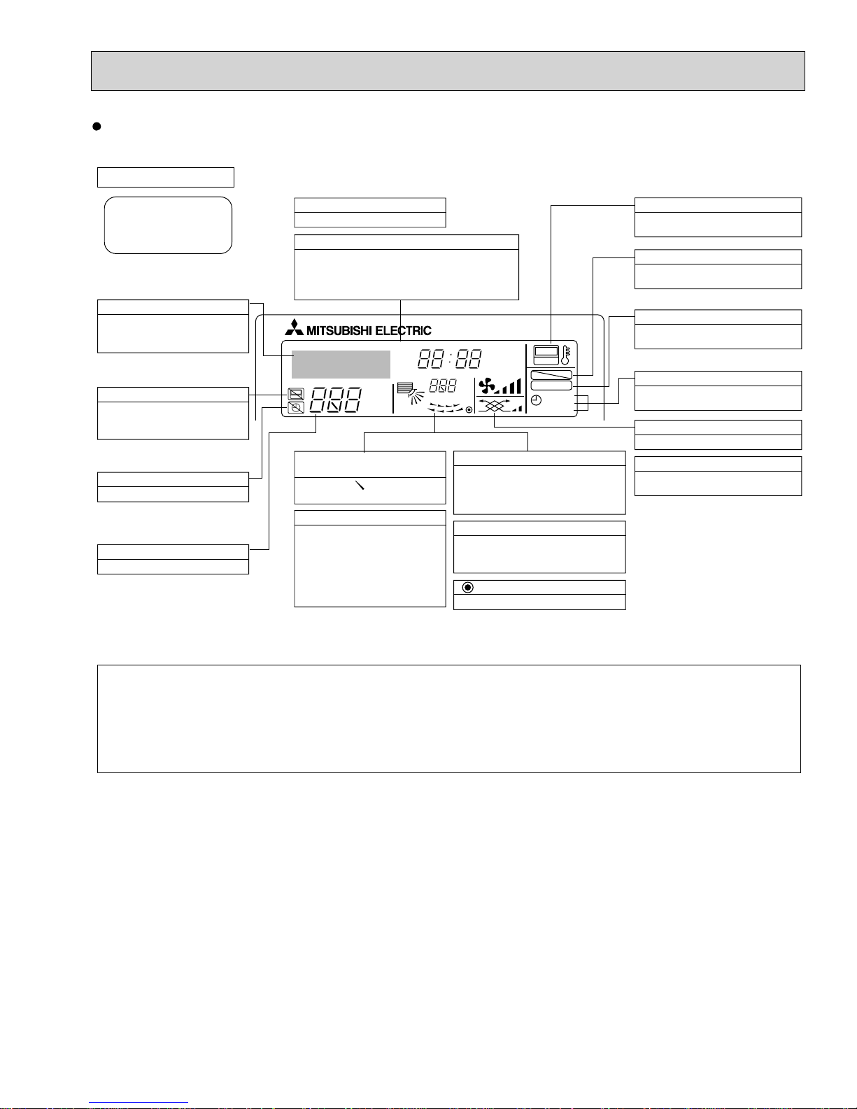
Wired remote controller
Display Section
For purposes of this explanation,
all parts of the display are shown
as lit. During actual operation, only
the relevant items will be lit.
Identifies the current operation
Shows the operating mode, etc.
*Multilanguage display is available.
“Centrally Controlled” indicator
Indicates that operation from the
remote controller has been prohibited by a master controller.
“Timer is Off” indicator
Indicates that the timer is off.
Temperature Setting
Shows the target temperature.
Day-of-Week
Shows the current day of the week.
Time/Timer Display
Shows the current time, unless the simple or Auto Off
timer is set.
If the simple or Auto Off timer is set, the time to be
switched off is shown.
TIME SUN MON TUE WED THU FRI SAT
TIMER
AFTER
ERROR CODE
°F°C
Hr
AFTER
°F°C
ONLY1Hr.
Up/Down Air Direction indicator
The indicator shows the direction of the outcoming airflow.
“One Hour Only” indicator
Displayed if the airflow is set to
low or downward during COOL
or DRY mode. (Operation varies
according to model.)
The indicator goes off in 1 hour,
when the airflow direction
also changes.
Room Temperature display
Shows the room temperature. The room
temperature display range is 46–102°F.
The display blinks if the temperature
is less than 46°
Louver display
Indicates the action of the swing louver.
Does not appear if the louver is not
running.
(Power On indicator)
Indicates that the power is on.
ON
OFF
FUNCTION
FILTER
WEEKLY
SIMPLE
AUTO OFF
F
or 102°F or more.
“Sensor” indication
Displayed when the remote controller
sensor is used.
“Locked” indicator
Indicates that remote controller buttons have been locked.
“Clean The Filter” indicator
To be displayed on when it is time to
clean the filter.
Timer indicators
The indicator comes on if the corresponding timer is set.
Fan Speed indicator
Shows the selected fan speed.
Ventilation indicator
Appears when the unit is running in
Ventilation mode.
Note:
L
“PLEASE WAIT” message
This message is displayed for approximately 3 minutes when power is supplied to the indoor unit or when the unit is recovering from a power failure.
L
“NOT AVAILABLE” message
This message is displayed if an invalid button is pressed (to operate a function that the indoor unit does not have).
If a single remote controller is used to operate multiple indoor units simultaneously that are different types, this message will not be displayed as
far as any of the indoor units is equipped with the function.
7
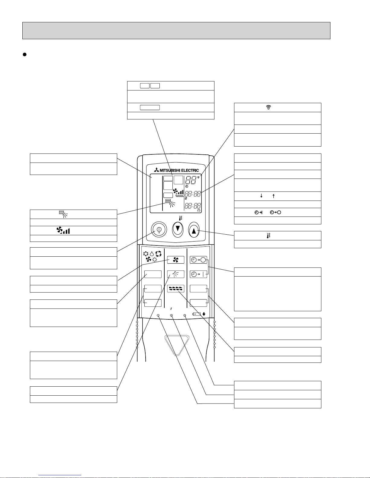
Wireless remote controller
CHECK
TEST RUN
display
Indicate that the unit is being checked or
test-run.
MODEL SELECT
Blinks when model is selected.
display
display
Lights up while the signal is transmitted to
the indoor unit when the button is pressed.
Temperature setting display
Indicates the desired temperature setting
which is set.
OPERATION MODE display
OPERATION MODE display
Indicates which operation mode is in effect.
display
The vertical direction of airflow is indicated.
display
Displays selected fan speed.
ON/OFF button
The unit is turned ON and OFF alternately
each time the button is pressed.
FAN SPEED SELECT button
Changes the fan speed.
MODE SELECT button
Switches the operation mode between
COOLING/DRY/FAN/HEATING and AUTO
mode.
+In case the outdoor unit is cooling only
type, the heating and auto mode are not
available.
COOL
DRY
AUTO
FAN
HEAT
RUN
MODEL
SELECT
FAN
SWING
NOT AVAILABLE
TEST
CHECK
ON/OFF TEMP
FAN
MODE
CHECK
VAN E
LOUVER
TEST RUN
RESETSET CLOCK
°F
°C
AMPMSTOP
AMPM
START
AUTO STOP
AUTO START
h
min
CLOCK display
Displays the current time.
TIMER display
Displays when in timer operation or when
setting timer.
“” “ ” display
Displays the order of timer operation.
“ ” “ ” display
Displays whether timer is on or off.
button
Sets any desired room temperature.
TIMER CONTROL buttons
AUTO STOP (OFF timer): when this switch
is set, the air conditioner will be
autom at ically stopped at the preset time.
AUTO START (ON timer): when this switch
is set, the air conditioner will be
automatically started at the preset time.
"h" and "min" buttons
Buttons used to set the “hour and minute” of
the current time and timer settings.
CHECK-TEST RUN button
Performs an inspection check or test
operation.
Do not use it for normal operation.
VANE CONTROL button
Changes the air flow direction.
LOUVER button
Changes left / right airflow direction.
(Not available for this model.)
CLOCK button
RESET button
SET button
8
5
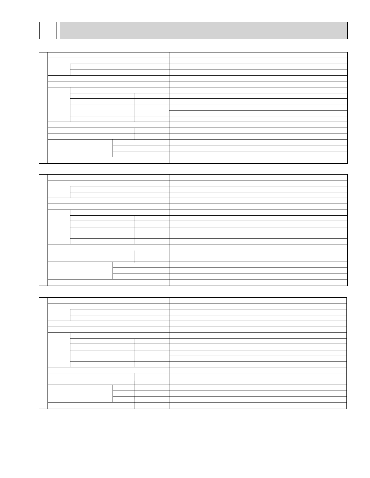
SPECIFICATIONS
Service Ref.
Power supply(phase, cycle, voltage)
Max. Fuse Size
Min. Circuit Ampacity
External finish
Heat exchanger
Fan Fan(drive) % No.
Fan motor output
Fan motor
Airflow
(Low-Medium2-Medium1-High)
External static pressure
INDOOR UNIT
Operation control & Thermostat
Noise level(
Field drain pipe I.D.
Dimensions
Weight
Service Ref.
Power supply(phase, cycle, voltage)
Max. Fuse Size
Min. Circuit Ampacity
External finish
Heat exchanger
Fan Fan(drive) % No.
Fan motor output
Fan motor
External static pressure
INDOOR UNIT
Operation control & Thermostat
Noise level(Low-High)
Field drain pipe I.D.
Dimensions
Weight
Low-Medium2-Medium1-High)
Low-Medium2-Medium1-High
Airflow(
W
D
H
W
D
H
F. L. A
*/min(CFM)
Pa(mmAq)
mm(in.)
mm(in.)
mm(in.)
mm(in.)
kg(lbs)
F. L. A
*/min(CFM)
)
Pa(mmAq)
mm(in.)
mm(in.)
mm(in.)
mm(in.)
kg(lbs)
kW
dB
kW
dB
PKA-A12GA
Single phase, 60Hz, 208/230V
A
A
Dry: 9-10-11-12(320-350-390-425)
Wet:8-9-10-11(290-315-350-380)
GA: Wired remote controller & built-in GAL: Wireless remote controller & built-in
PKA-A18GA
Single phase, 60Hz, 208/230V
A
A
Dry: 9-10-11-12(320-350-390-425)
Wet:8-9-10-11(290-315-350-380)
GA: Wired remote controller & built-in GAL:Wireless remote controller & built-in
(1)(2) / PKA-A12GAL(1)(2)
15
1
Munsell 0.70Y 8.59/0.97
Plate fin coil
Line flow (direct) % 1
0.030
0.33
0(direct blow)
36-38-41-43
20(13/16)
990(39)
235(9-1/4)
340(13-3/8)
16(35)
(1)(2) / PKA-A18GAL(1)(2)
15
1
Munsell 0.70Y 8.59/0.97
Plate fin coil
Line flow (direct) % 1
0.030
0.33
0(direct blow)
36-38-41-43
20(13/16)
990(39)
235(9-1/4)
340(13-3/8)
16(35)
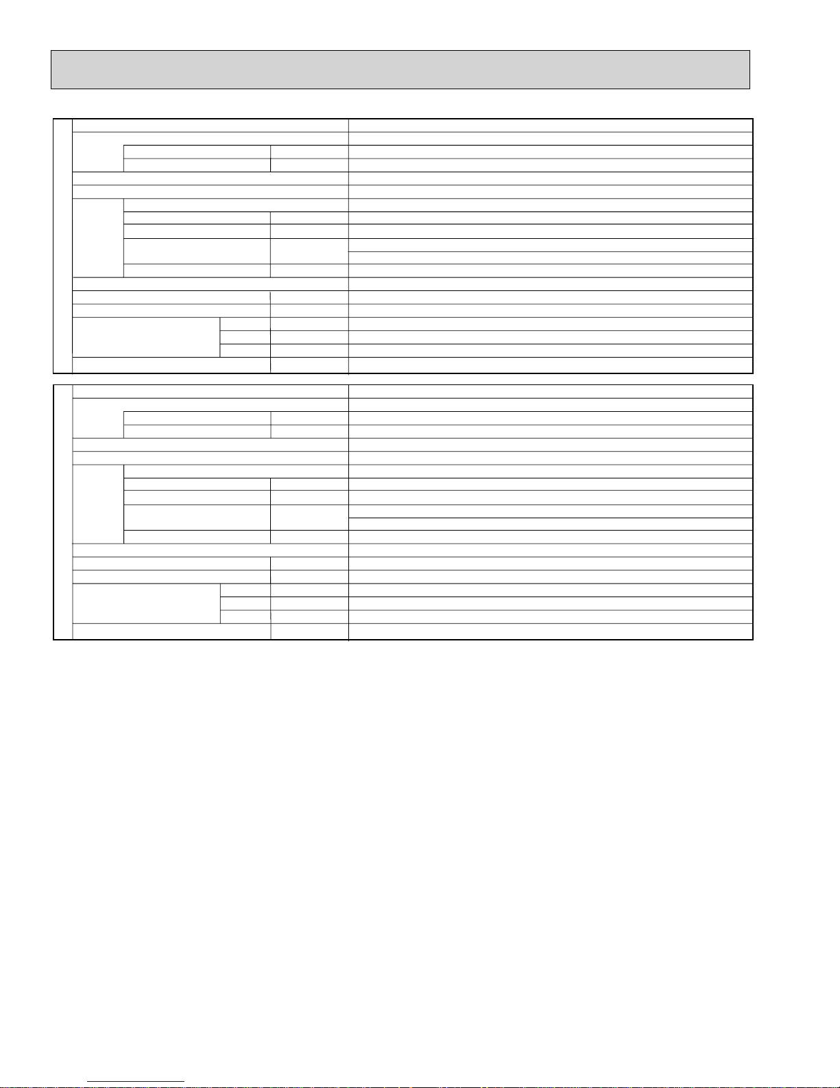
Service Ref.
Power supply (phase, cycle, voltage)
Max. Fuse Size
Min. Circuit Ampacity
External finish
Heat exchanger
Fan Fan (drive) % No.
Fan motor output
Fan motor
Low-High
Airflow (
External static pressure
INDOOR UNIT
Operation control & Thermostat
Noise level(Low-High)
Field drain pipe I.D.
Dimensions
Weight
)
W
D
H
A
A
kW
F. L. A
*/min(CFM)
Pa(mmAq)
dB
mm(in.)
mm(in.)
mm(in.)
mm(in.)
kg(lbs)
PKA-A24FA
Single phase, 60Hz, 208/230V
FA:Wired remote controller & built-in FAL: Wireless remote controller & built-in
(1)(2) / PKA-A24FAL(1)(2)
15
1
Munsell 3.4Y 7.7/0.8
Plate fin coil
Line flow (direct) % 2
0.045
0.43
Dry: 15-20(530-705)
Wet:14-18(480-635)
0(direct blow)
39-45
20(13/16)
1,400(55-1/8)
235(9-1/4)
340(13-3/8)
24(53)
9
Service Ref.
Power supply (phase, cycle, voltage)
Max. Fuse Size
Min. Circuit Ampacity
External finish
Heat exchanger
Fan Fan (drive) % No.
Fan motor output
Fan motor
Airflow (Low-High)
External static pressure
INDOOR UNIT
Operation control & Thermostat
Noise level (Low-High)
Field drain pipe I.D.
Dimensions
Weight
W
D
H
A
A
kW
F. L. A
*/min(CFM)
Pa(mmAq)
dB
mm(in.)
mm(in.)
mm(in.)
mm(in.)
kg(lbs)
PKA-A30FA
Single phase, 60Hz, 208/230V
FA: Wired remote controller & built-in FAL: Wireless remote controller & built-in
(1)(2) / PKA-A30FAL(1)(2)
15
1
Munsell 3.4Y 7.7/0.8
Plate fin coil
Line flow (direct) % 2
0.045
0.43
Dry: 15-20(530-705)
Wet: 14-18(480-635)
0(direct blow)
39-45
20(13/16)
1,400(55-1/8)
235(9-1/4)
340(13-3/8)
24(53)
Service Ref.
Power supply (phase, cycle, voltage)
Max. Fuse Size
Min. Circuit Ampacity
External finish
Heat exchanger
Fan Fan(drive) % No.
Fan motor output
Fan motor
Airflow (Low-High)
External static pressure
INDOOR UNIT
Operation control & Thermostat
Noise level (Low-High)
Field drain pipe I.D.
Dimensions
Weight
W
D
H
A
A
kW
F. L. A
*/min(CFM)
Pa(mmAq)
dB
mm(in.)
mm(in.)
mm(in.)
mm(in.)
kg(lbs)
PKA-A36FA
Single phase, 60Hz, 208/230V
FA: Wired remote controller & built-in FAL: Wireless remote controller & built-in
(1)(2) / PKA-A36FAL(1)(2)
15
1
Munsell 3.4Y 7.7/0.8
Plate fin coil
Line flow (direct) % 2
0.070
0.52
Dry: 22-28(780-990)
Wet:20-25(700-890)
0(direct blow)
46-49
20(13/16)
1,680(66-1/8)
235(9-1/4)
340(13-3/8)
28(62)
10
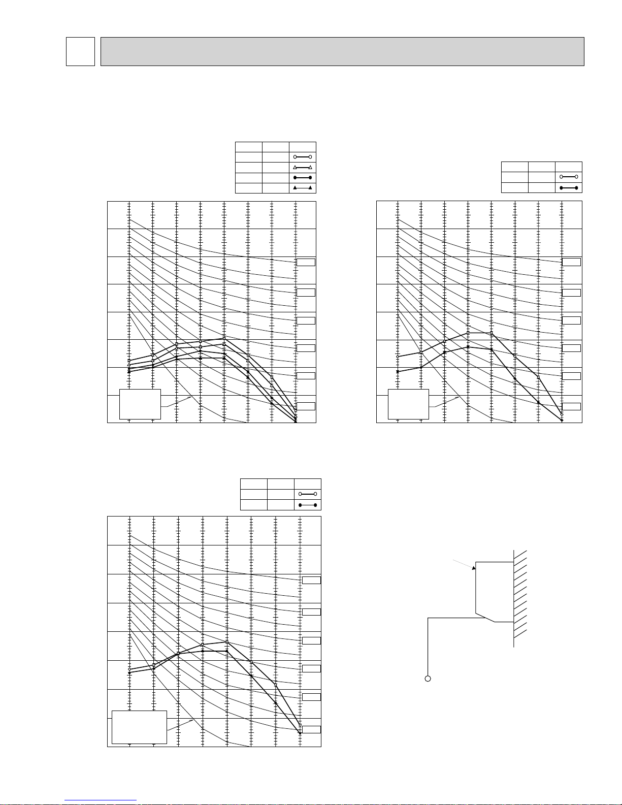
6 NOISE CRITERION CURVES
PKA-A12GA
PKA-A12GAL
PKA-A18GA
PKA-A18GAL
PKA-A12GA
1
PKA-A12GAL1
PKA-A18GA1
PKA-A18GAL1
90
80
70
60
50
40
30
OCTAVE BAND SOUND PRESSURE LEVEL, dB (0dB=0.0002 μbar)
APPROXIMATE
20
THRESHOLD OF
HEARING FOR
CONTINUOUS
NOISE
10
63 125 250 500 1000 2000 4000 8000
PKA-A12GA2
PKA-A12GAL2
PKA-A18GA2
PKA-A18GAL2
Medium1
Medium2
BAND CENTER FREQUENCIES, Hz
NOTCH
High
Low
SPL(dB)
43
41
38
36
LINE
NC-70
NC-60
NC-50
NC-40
NC-30
NC-20
PKA-A24FA
PKA-A30FA
PKA-A24FAL
PKA-A30FAL
PKA-A24FA
1
PKA-A30FA1
PKA-A24FAL1
PKA-A30FAL1
90
80
70
60
50
40
30
OCTAVE BAND SOUND PRESSURE LEVEL, dB(0dB=0.0002 μbar)
APPROXIMATE
20
THRESHOLD OF
HEARING FOR
CONTINUOUS
NOISE
10
63 125 250 500 1000 2000 4000 8000
PKA-A24FA2
PKA-A30FA2
PKA-A24FAL2
PKA-A30FAL2
NOTCH
High
Low
BAND CENTER FREQUENCIES, Hz
SPL(dB)39LINE
45
NC-70
NC-60
NC-50
NC-40
NC-30
NC-20
PKA-A36FA
PKA-A36FAL
PKA-A36FA
PKA-A36FA2
PKA-A36FAL2
1
PKA-A36FAL1
90
bar)
μ
80
70
60
50
40
30
APPROXIMATE
20
OCTAVE BAND SOUND PRESSURE LEVEL, dB (0dB=0.0002
THRESHOLD OF
HEARING FOR
CONTINUOUS
NOISE
10
63 125 250 500 1000 2000 4000 8000
BAND CENTER FREQUENCIES, Hz
NOTCH
High
Low
SPL(dB) LINE
49
46
NC-70
NC-60
NC-50
NC-40
NC-30
NC-20
UNIT
WALL
3.3ft
3.3ft
MICROPHONE
11
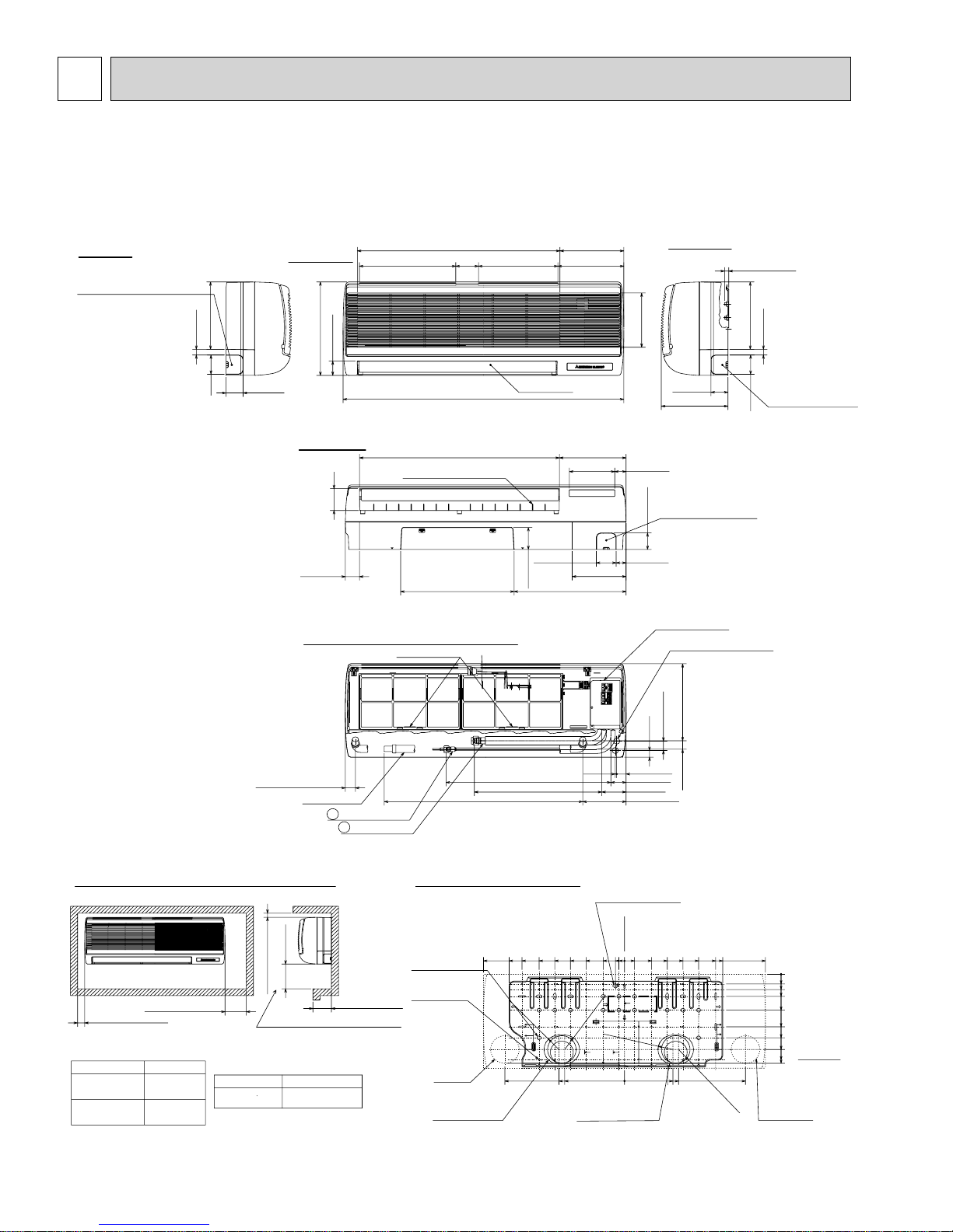
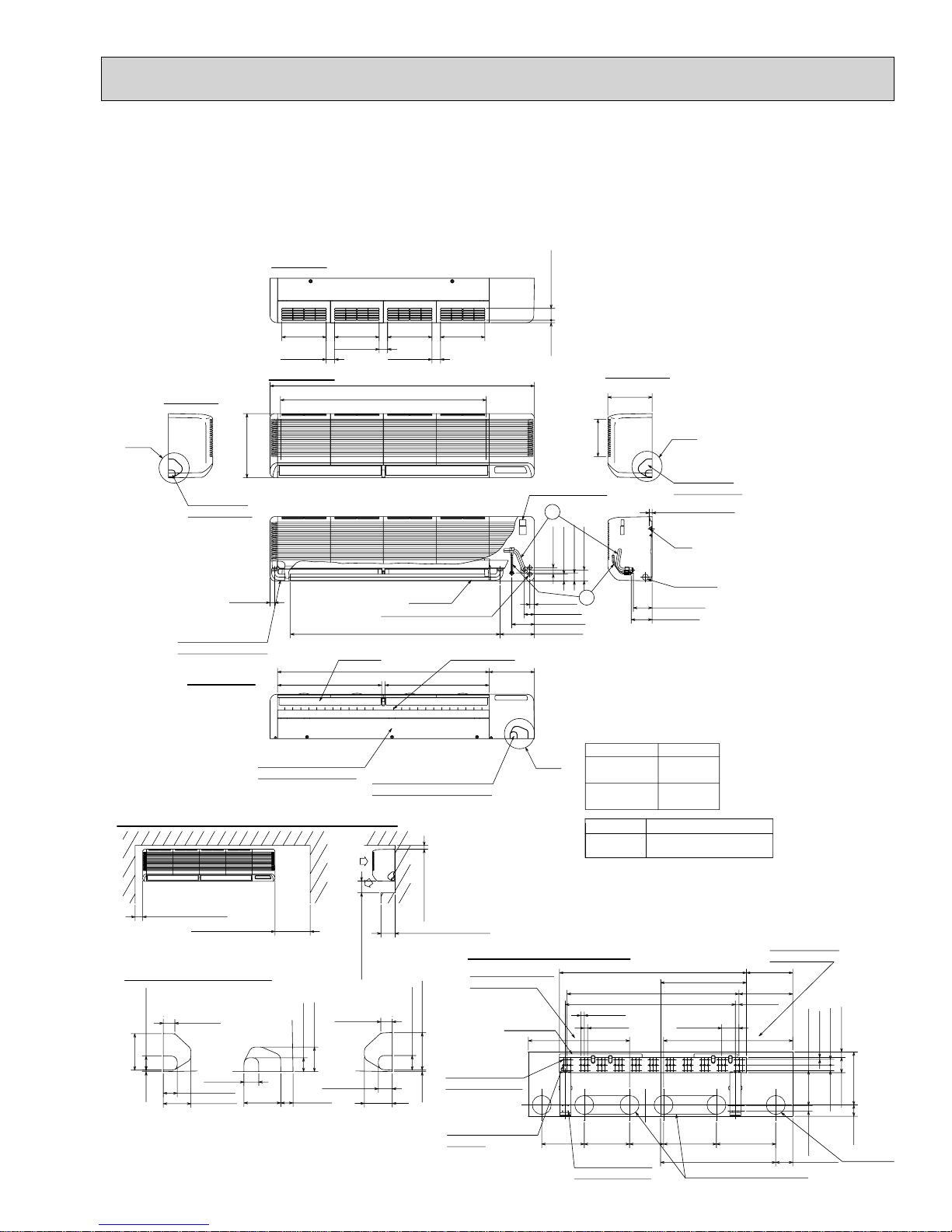
7
OUTLINES AND DIMENSIONS
INDOOR UNIT
PKA-A12GA PKA-A18GA PKA-A12GAL PKA-A18GAL
PKA-A12GA1 PKA-A18GA1 PKA-A12GAL1 PKA-A18GAL1
PKA-A12GA2 PKA-A18GA2 PKA-A12GAL2 PKA-A18GAL2
Unit :inch(mm)
Left side
Knockout hole for left piping
Refrigerant pipe Drain pipe Wiring hole.
9-21/32(245)
13/16(21)
2-3/4(70)
Front view
2-3/8(60)
13-3/8(340)
2-3/32(53)
28-5/32(715) Air intake
13-3/8(340)
Air intake
Lower side
12-Louvers(manual)
3-1/8(79)
1-31/32(50)
Front view (the open-topped grille)
Filter grip
3-5/32(80)
39(990)
27-3/4(705) Air outlet
11-1/32(280) 9-3/16(233)
Air intake
8-27/32(225)
Auto vane
9-1/4(235)
6-5/16(160) 1-9/16(40)
2-3/4(70) 1-3/8(35)
3-1/8(80)
7-15/32(190)
15-9/16(395)15-3/4(400)
Right side
Air intake
7-25/32(198)
2-3/8(60)
9-1/4(235)
Knockout hole for under piping
Refrigerant piping Drain pipe
Wiring hole
2-3/8(60)
Service panel
(Power supply access)
Wiring entrance holes
Less than 19/32(15)
9-21/32(245)
13/16(21)
Knockout hole for right piping
Refrigerant pipe Drain pipe
Wiring hole
2-3/4(70)
(Left side piping
installation)
1-3/8(35)
Service space required around indoor unit
1-13/16(30) or more
1-31/32(50) or more
5-29/32(150) or more
MODEL 12/18
Liquid pipe
Gas pipe
*1 Sleeves are available on the market.
*2 This size shows the lower end of through hole.
1/4 inch
1/2 inch
ø2-15/16(ø75)
7-3/32(180) or more
(Necessary clearance for unit installation)
Through-holeSleeve *1
ø2-15/16~ø3-5/32
(ø75~ø80)
Drain hose
Liquid pipe
1
2
Gas pipe
Right side
Less than 5-1/8(130)
22-7/8(581)
27-9/16(700) 6-1/32(153)
(Flexible hose total length 31-1/2(800))
17-11/16(449)
Details of installation plate
14-:9/16(:14)holes
for bolts
49-:3/16(:5)holes
for tapping screw
Left-rear
piping hole
Knockout hole for
left-rear piping
19-1/2(495)
14-3/16(360)
15-15/16(405)
R2-1/16(R52.5)
16-17/32(420)
11-13/16(300)
3/16(5)
5-5/16(135)
7-15/32(190)
9-21/32(245)
R2-1/16(R52.5)
Knockout hole for
right-rear piping
9-1/16(230)
8-9/32(210)
1-11/32(34)
1(25)
1-5/16(33)
2-1/8(54)
3-3/8(86)
(Right side piping installation)
Installation plate
balance point hole
Unit center
25/32(20)
2-15/16(75)
0
1-3/8(35)
3-3/4(95)
1-1/4(32)
R2-1/16(R52.5)
5-29/32(150)
0
1-7/32(31) 11-1/32(280)
8-1/16(205)
7-15/32(190)
6-11/16(170)
10-1/4(260)
12-19/32(320)
13-19/32(345)
R2-1/16(R52.5)
19-1/2(495)
Right-rear
piping hole
16-23/32(425)
0
0
1-3/8(35)
2-5/32(55)
3-5/32(80)
5-1/8(130)
7-15/32(190)
9-1/16(230)
10-23/32(272)
12-7/32(310)
12-11/16(322)+1
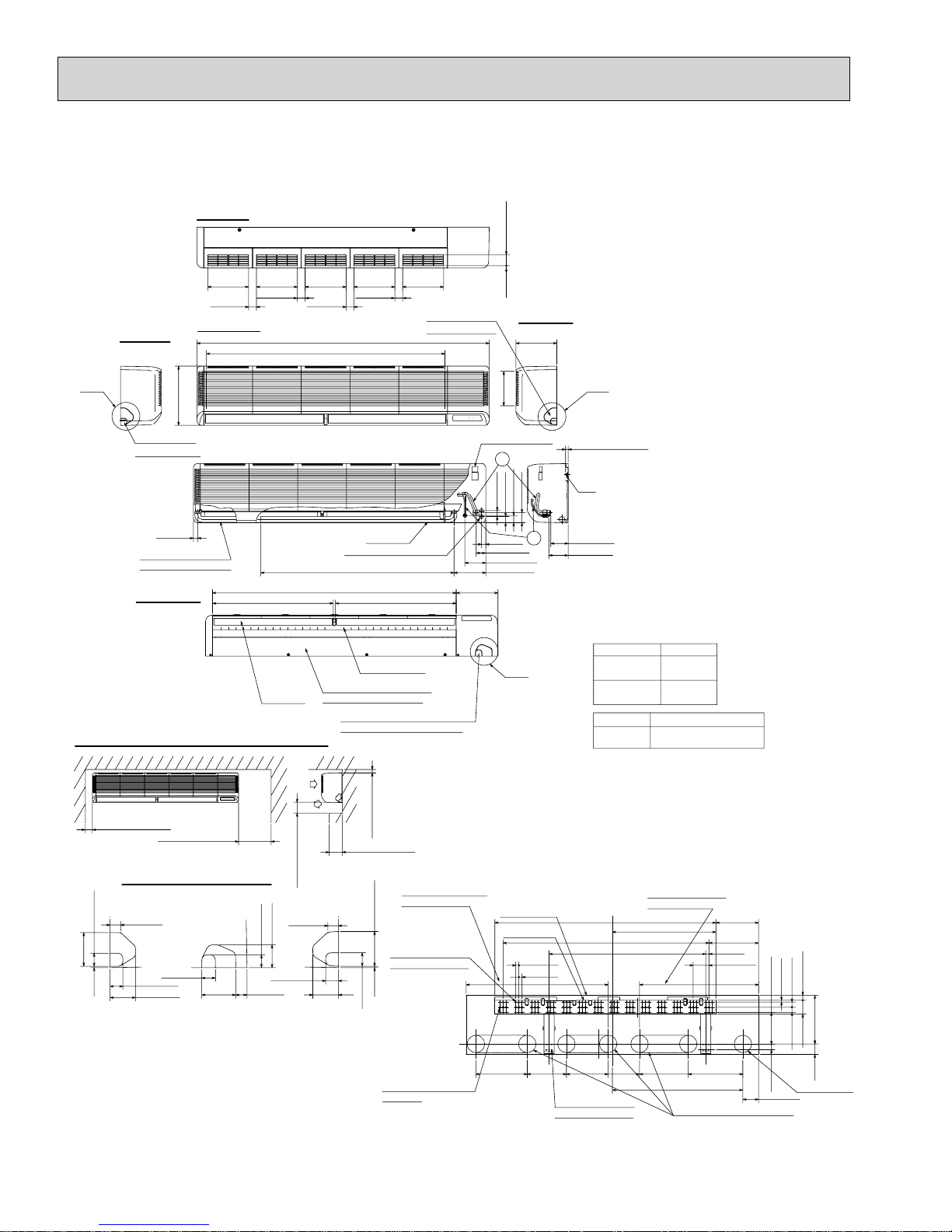
12
INDOOR UNIT
o
PKA-A24FA PKA-A30FA PKA-A24FAL PKA-A30FAL
PKA-A24FA1 PKA-A30FA1 PKA-A24FAL1 PKA-A30FAL1
PKA-A24FA2 PKA-A30FA2 PKA-A24FAL2 PKA-A30FAL2
Top side
Unit :inch(mm)
9-1/4(235) 9-1/4(235)
1-25/32(45)
1-25/32(45)
Front view
42-29/32(1090) Air intake
43-11/16(1110) Drain hose
Auto vanes
44-3/32(1120)
A
Left side
Knockout hole
for left piping
Drain hose for
left-hand side piping
Lower side
13-3/8(340)
31/32(25)
21-23/32(552) Air outlet
Under panel(Removable at
left-hand side piping)
Service space required around indoor unit
Air
intake
Air
2-9/16(65)
1-15/32(37)
1-15/32(37)
1-1/4(32)
outlet
9-27/32(250) or more
1-3/16(30)
1-31/32(50) or more
9-27/32(250) or more
Knockout hole for wiring
AB C
1-3/16(30)
1-17/32(39)
3-15/16(100)
5/32(4)
1-9/16(39)
1-15/32(37)
2-29/32(74)
3-27/32(98)
9-1/4(235)
1-25/32(45)
55-1/8(1400)
Wiring entrance holes
21-23/32(552) Air outlet
Knockout hole for under-piping
Refrigerant pipe /Drain pipe
9-1/4(235)
Drain hose
Louvers(Manual)
1-3/16(30) or more
Less than 9-27/32(250)
Details of installation plate
Drainage range on
left hand side
3-15/16(100)
1-17/32(39)
66-ø1/4(ø6) holes
for tapping screws
2-29/32(74)
5/32(4)
9-7/16(240)
Wall fixture
1/2(13) 2-15/32(62.5)
Right side
9-1/4(235)
7-3/4(197)
Terminal blockTerminal block
2
1-5/16(34)
2-9/32(58)
1-7/16(36)
1-21/32(42)
1
15/16(24)
2-5/32(55)
4-23/32(120)
7-7/32(183)
B
Liquid pipe
Gas pipe
Sleeve*1
ø3-17/32
(ø90)
*1 Sleeves are available
on the market.
Unit center
38-31/32(990)
13/32*3-19/32=(35-13/16) (10*91=(910))
35-7/16(900)
23/32(18)
23/32(18)
C
Knockout hole
for right piping
Less than 19/32(15)
Bolt
Drain hose
4-7/32(107)
4-3/8(111)
24/30MODEL
3/8 inch
5/8 inch
Through hole
ø3-17/32~ø3-15/16
(ø90~ø100)
17-29/32(455)
3-19/32(91)
Drainage range on
right-hand side
9-21/32(245)
11-7/32(285)
3/4(19)
13/32(10)
1-3/16(30)1-3/16(30)
7-1/4(184)1-3/16(30)
1-5/32(29)
11-1/32(280)2-3/8(60)
3-1/8(80)
32-ø15/32(ø12) holes
for bolts
13
8-27/32(225)
12-ø1/4(ø6) holes
for tapping screws
9-7/16(240)
11-1/32(280) 12-3/8(314)
7-3/32(180)
24-1/32(610)
Range for left rear piping hole
3-17/32(90)
Rear piping h
INDOOR UNIT
PKA-A36FA PKA-A36FAL PKA-A36FA
PKA-A36FA2 PKA-A36FAL2
Top side
1 PKA-A36FAL1 Unit :inch(mm)
2-15/32(62.5)
Left side
9-1/4(235)
Front view
1-25/32(45)
9-1/4(235)
1-25/32(45)
53-15/16(1370) Air intake
9-1/4(235)
1-25/32(45)
A
13-3/8(340)
Knockout hole
for left piping
31/32(25)
Drain hose for
left-hand side piping
Lower side
27-5/16(694) Air outlet
55-1/8(1400)
Auto vanes
Service space required around indoor unit
Air
intake
9-1/4(235)
1-25/32(45)
66-1/8(1680)
Drain hose
Wiring entrance holes
43-11/16(1110) Drain hose
27-5/16(694) Air outlet
Louvers(Manual)
Under panel(Removable at
left-hand side piping)
Knockout hole for under-piping
Refrigerant pipe /Drain pipe
9-1/4(235)
Knockout hole
for right piping
9-7/16(240)
1/2(13)
Right side
9-1/4(235)
7-3/4(197)
Terminal block
2
2-9/32(58)
1-5/16(34)
1-7/16(36)
1-21/32(42)
1
15/16(24)
2-5/32(55)
4-23/32(120)
7-7/32(183)
B
C
Less than 9/16(15)
Bolt
4-1/32(102)
4-3/8(111)
MODEL 36
Liquid pipe
Gas pipe
Sleeve*1
ø3-17/32
(ø90)
*1 Sleeves are available
on the market.
3/8 inch
5/8 inch
Through hole
ø3-17/32~ø3-15/16
(ø90~ø100)
Air
1-31/32(50) or more
9-27/32(250) or more
Knockout hole for wiring
outlet
9-27/32(250) or more
ACB
1-3/16(30)
3-15/16(100)
5/32(4) 1-17/32(39)
1-17/32(39)
1-15/32(37)
2-29/32(74)
1-15/32(37)
1-1/4(32)3-27/32(98)
1-3/16(30)
2-9/16(65)
1-15/32(37)
2-29/32(74)
1-3/16(30) or more
Less than 5-29/32(150)
Drainage range on
left hand side
3-15/16(100)
84-ø1/4(ø6) holes
for tapping screws
5/32(4)
1-17/32(39)
41-ø15/32(ø12) holes
for bolts
Unit outline
Wall fixture
11-5/8(295) 8-27/32(225)
14
Unit center
50(1270)
1/2*3-19/32=(46-9/16) (13*91=(1183))
23/32(18)
23/32(18)
9-7/16(240) 7-3/32(180) 11-1/32(280) 12-3/8(314)
12-ø1/4(ø6) holes
for tapping screws
35-7/16(900)
Drainage range on
right-hand side
23-7/16(595)
29-17/32(750)
Range for left rear piping hole
9-21/32(245)
11-7/32(285)
3/4(19)
3-19/32(91)
13/32(10)
1-3/16(30) 7-1/4(184)
3-9/16(90)
1-5/32(29)
1-3/16(30)1-3/16(30)
11-1/32(280)
3-5/32(80)
2-3/8(60)
Rear piping hole
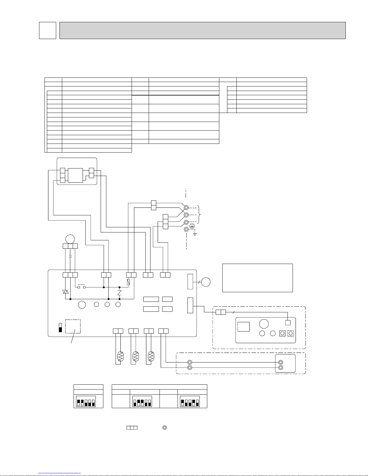
8
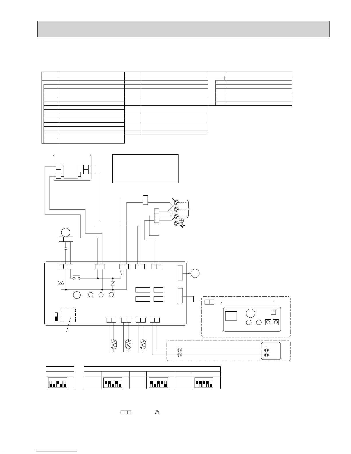
WIRING DIAGRAM
PKA-A12GA PKA-A18GA PKA-A12GAL PKA-A18GAL
PKA-A12GA
1 PKA-A18GA1 PKA-A12GAL1 PKA-A18GAL1
[LEGEND]
SYMBOL NAME
P. B
I.B
INDOOR POWER BOARD
INDOOR CONTROLLER BOARD
FUSE FUSE (6.3A/250V)
ZNR VARISTOR
CN2L CONNECTOR<LOSSNAY>
CN32 CONNECTOR<REMOTE SWITCH>
CN41 CONNECTOR<HA TERMINAL-A>
CN51 CONNECTOR<CENTRALLY CONTROL>
SW1 SWITCH <MODEL SELECTION>+See Table 1.
SW2 SWITCH <CAPACITY CODE>+See Table 2.
SWE
SWITCH<EMERGENCY OPERATION>
X4 RELAY<FAN MOTOR>
BCR
FAN CONTROL ELEMENT
LED1 POWER SUPPLY<I.B>
POWER SUPPLY<R.B>
LED2
TRANSMISSION<INDOOR-OUTDOOR>LED3
P. B
CNDK
(RED)
1
2
DC13.1V
CN2S
(WHT)
1
2
3
MF
1
2 3
C
SYMBOL NAME
C CAPACITOR<FAN MOTOR>
MF
MV
TB4
TB5,TB6
TH1
TH2
TH5
R.B
FAN MOTOR
VANE MOTOR
TERMINAL BLOCK<INDOOR/OUTDOOR
CONNECTING LINE>
TERMINAL BLOCK<REMOTE CONTROLLER
TRANSMISSION LINE >
ROOM TEMP.THERMISTOR
<32°F/15kΩ, 77°F/5.2kΩ DETECT>
PIPE TEMP.THERMISTOR/LIQUID
<32°F/15kΩ, 77°F/5.2kΩ DETECT>
COND./EVA.TEMP.THERMISTOR
<32°F/15kΩ, 77°F/5.2kΩ DETECT>
WIRED REMOTE CONTROLLER BOARD
YLW
TB4
ORN
YLW
ORN
BRN
S1
S2
S3
+1
TO
OUTDOOR
UNIT
W.B
WIRELESS REMOTE CONTROLLER BOARD
RECEIVING UNIT
RU
BZ
BUZZER
LED1
LED<RUN INDICATOR >
LED2
LED<HOT ADJUST>
SW1
SWITCH<HEATING ON/OFF>
SW2
SWITCH<COOLING ON/OFF>
NAMESYMBOL
BLK
WHT
RED
I.B
1 3 5
FAN
(
)
WHT
BCR
SWE
ON
OFF
Refer to tables 1 and 2
for service PCB.
X4
X4
SW2 SW1
Table 1
Service board
1 2 3 4 5
POWER
CNDK
(RED)
SW1
WHT
RED
POWER
CND
(ORN)
LED3 LED2 LED1
INTAKE
CN20
(
RED
1 2
Table 2
MODELS
PKA-
ON
A12GA(L)
OFF
YLW
ORN
BLK
WHT
BRN
ORN
1 31 31 3 1 2
POWER
CN2D(WHT)
FUSE
ZNR
LIQUID
CN21
(
)
)
WHT
1 2
TH2
Service board Service board
1 2 3 4 5
A-CONTROL
CN3C(BLU)
CN41 CN2L
CN51 CN32
PIPE
REMOCON
CN29
CN22
(
)
(
BLK
BLU
1 2
1 2
TH5TH1
SW2
PKA-
ON
A18GA(L)
OFF
)
MODELS
VAN E
CN6V
(
GRN
WIRELESS
CN90
(
WHT
TB5
6
)
MV
)
2
TRANSMISSION WIRES DC12V
1
1 2 3 4 5
ON
OFF
Please set the voltage
using the remote controller.
For the setting method,
please refer to the indoor
unit Installation Manual.
9
BZ
RU
RECEIVER
LED1 LED2 SW2 SW1
R.B
NOTES:
1. Since the outdoor side electric wiring may change, be sure to check the outdoor unit electric wiring for servicing.
2. Indoor and outdoor connecting wires have polarities, make sure to match terminal numbers (S1, S2, S3) for correct wiring.
3. Symbols used in wiring diagram above are, : Connector, : Terminal (block).
4. This diagram shows the wiring of Indoor and Outdoor connecting wires (specification of 230V), adopting superimposed system of
power and signal.
+1. Use copper supply wires.
For A12/18GAL
CNB
W.B
1
TB6
2
For A12/18GA
15
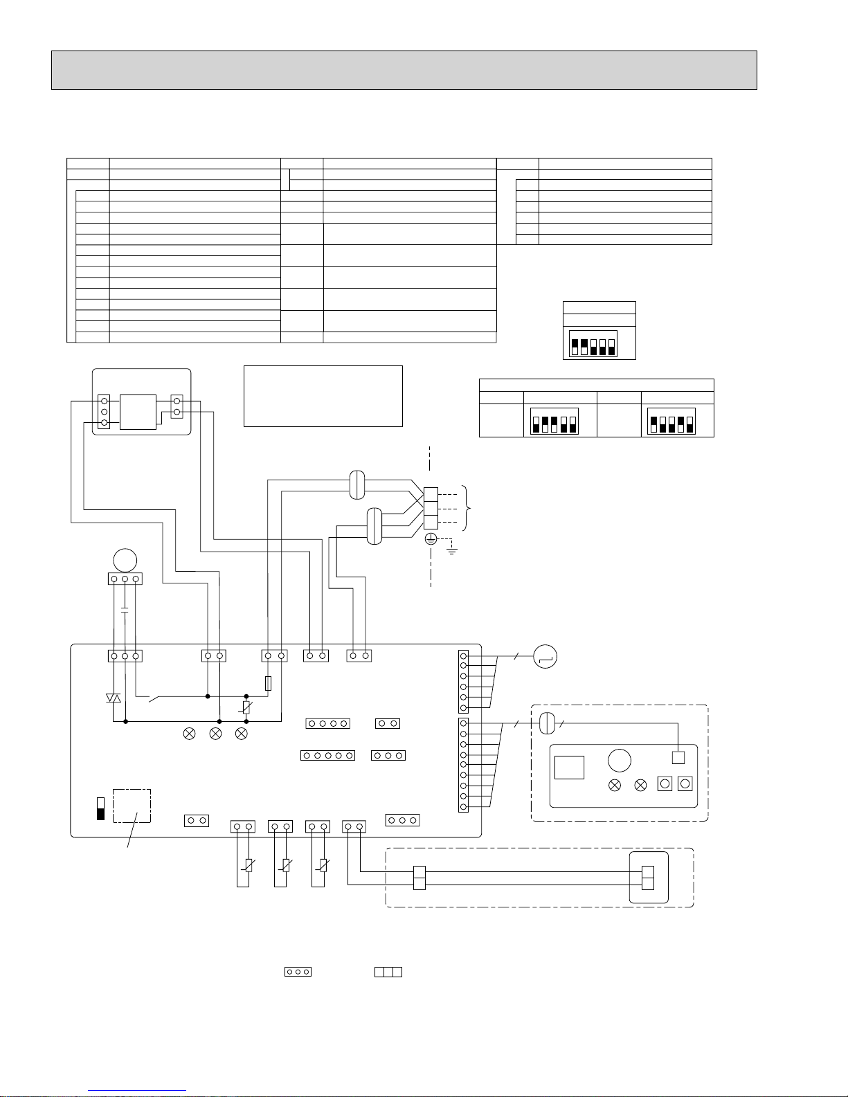
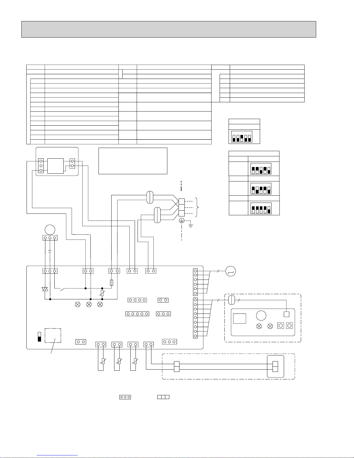
PKA-A12GA2 PKA-A18GA2 PKA-A12GAL2 PKA-A18GAL2
[LEGEND]
SYMBOL
P.B
I.B
P.B
INDOOR POWER BOARD
INDOOR CONTROLLER BOARD
FUSE FUSE (6.3A/250V)
ZNR VARISTOR
CN2L CONNECTOR<LOSSNAY>
CN24 CONNECTOR<BACK-UP HEATING>
CN30 CONNECTOR<LLC>
CN32 CONNECTOR<REMOTE SWITCH>
CN41 CONNECTOR<HA TERMINAL-A>
CN51 CONNECTOR<CENTRALLY CONTROL>
SW1 SWITCH <MODEL SELECTION>+See Table 1.
SW2 SWITCH <CAPACITY CODE>+See Table 2.
SWE
SWITCH<EMERGENCY OPERATION>
X4 RELAY<FAN MOTOR>
FAN CONTROL ELEMENT
BCR
LED1 POWER SUPPLY<I.B>
CNSK
(RED)
1
DC13.1V
3
CN2S
(WHT)
1
2
NAME
SYMBOL NAME
POWER SUPPLY<R.B>
LED2
C
MF
MV
TB4
TB5,TB6
TH1
TH2
TH5
R.B
TRANSMISSION<INDOOR-OUTDOOR>LED3
CAPACITOR<FAN MOTOR>
FAN MOTOR
VANE MOTOR
TERMINAL BLOCK<INDOOR/OUTDOOR
CONNECTING LINE>
TERMINAL BLOCK<REMOTE CONTROLLER
TRANSMISSION LINE >
ROOM TEMP.THERMISTOR
Ω, 77°F/5.2kΩ DETECT>
<32°F/15k
PIPE TEMP.THERMISTOR/LIQUID
Ω, 77°F/5.2kΩ DETECT>
<32°F/15k
COND./EVA.TEMP.THERMISTOR
Ω, 77°F/5.2kΩ DETECT>
<32°F/15k
WIRED REMOTE CONTROLLER BOARD
Please set the voltage
using the remote controller.
For the setting method,
please refer to the indoor
unit Installation Manual.
SYMBOL
W.B
Table 2
MODELS
PKAA12GA(L)
WIRELESS REMOTE CONTROLLER BOARD
RECEIVING UNIT
RU
BZ
BUZZER
LED1
LED<RUN INDICATOR >
LED2
LED<HOT ADJUST>
SW1
SWITCH<HEATING ON/OFF>
SW2
SWITCH<COOLING ON/OFF>
NAME
Table 1
SW1
Service board
1 2 3 4 5
ON
OFF
SW2
Service board Service board
1 2 3 4 5
ON
OFF
MODELS
PKAA18GA(L)
1 2 3 4 5
ON
OFF
YLW
ORN
YLW
ORN
BRN
TB4
S1
S2
S3
+1
TO
OUTDOOR
UNIT
MF
M
1~
1
32
C
BLK
WHT
RED
I.B
FAN
(
)
WHT
5
1
3
BCR
SW2 SW1
SWE
ON
OFF
Refer to tables 1 and 2
for service PCB.
POWER
CNDK
X4
(RED)
WHT
RED
11
3
POWER
CND
(ORN)
ZNR
U
YLW
LED3 LED2 LED1
CN24
(
YLW
INTAKE
CN20
)
(
)
RED
12
1
2121212
ttt
ORN
BLK
1
3
POWER
CN2D
(WHT)
FUSE
CN41
CN51
51
LIQUID
CN21
(
WHT
TH2
PIPE
CN29
)
(
BLK
TH5TH1
WHT
BRN
1
2
A-CONTROL
CN3C
(BLU)
(
)
WHT
14
(
)
WHT
REMOCON
CN22
)
(
BLU
ORN
3
(
CN2L
RED
12
(
CN32
WHT
13
CN30
(
BLK
)
6
VANE
CN6V
(GRN)
)
1
6
1
)
WIRELESS
CN90
(WHT)
)
9
13
1
TRANSMISSION WIRES DC12V
2
TB5
M
MV
99
RU
RECEIVER
For A12/18GAL
CNB
BZ
LED1 LED2 SW2SW1
R.B
1
2
TB6
For A12/18GA
NOTES:
1. Since the outdoor side electric wiring may change be sure to check the outdoor unit electric wiring for servicing.
2. Indoor and outdoor connecting wires are made with polarities, make wiring matching terminal numbers (S1, S2, S3).
3. Symbols used in wiring diagram above are, : Connector, : Terminal (block).
4. This diagram shows the wiring of Indoor and Outdoor connecting wires (specification of 230V), adopting superimposed system of
power and signal.
+1. Use copper supply wires.
[Self-diagnosis]
Please refer to technical manuals etc.
W.B
16
PKA-A24FA PKA-A30FA PKA-A36FA PKA-A24FAL PKA-A30FAL PKA-A36FAL
PKA-A24FA
[LEGEND]
SYMBOL
P.B
I.B
FUSE FUSE (6.3A/250V)
ZNR VARISTOR
CN2L CONNECTOR<LOSSNAY>
CN32 CONNECTOR<REMOTE SWITCH>
CN41 CONNECTOR<HA TERMINAL-A>
CN51 CONNECTOR<CENTRALLY CONTROL>
SW1 SWITCH <MODEL SELECTION>+See Table 1.
SW2 SWITCH <CAPACITY CODE>+See Table 2.
SWE
X4 RELAY<FAN MOTOR>
BCR
LED1 POWER SUPPLY<I.B>
LED2
1 PKA-A30FA1 PKA-A36FA1 PKA-A24FAL1 PKA-A30FAL1 PKA-A36FAL1
INDOOR POWER BOARD
INDOOR CONTROLLER BOARD
SWITCH<EMERGENCY OPERATION>
FAN CONTROL ELEMENT
POWER SUPPLY<R.B>
TRANSMISSION<INDOOR-OUTDOOR>LED3
NAME
SYMBOL NAME
C CAPACITOR<FAN MOTOR>
MF
MV
TB4
TB5,TB6
TH1
TH2
TH5
R.B
FAN MOTOR
VANE MOTOR
TERMINAL BLOCK<INDOOR/OUTDOOR
CONNECTING LINE>
TERMINAL BLOCK<REMOTE CONTROLLER
TRANSMISSION LINE>
ROOM TEMP.THERMISTOR
<32
°F/15kΩ, 77°F/5.2kΩ DETECT>
PIPE TEMP.THERMISTOR/LIQUID
°F/15kΩ, 77°F/5.2kΩ DETECT>
<32
COND./EVA.TEMP.THERMISTOR
<32
°F/15kΩ, 77°F/5.2kΩ DETECT>
WIRED REMOTE CONTROLLER BOARD
W.B
WIRELESS REMOTE CONTROLLER BOARD
RECEIVING UNIT
RU
BZ
BUZZER
LED1
LED<RUN INDICATOR>
LED2
LED<HOT ADJUST>
SW1
SWITCH<HEATING ON/OFF>
SW2
SWITCH<COOLING ON/OFF>
NAMESYMBOL
P.B
CNDK
(RED)
1
DC13.1V
2
3
MF
1
2 3
C
BLK
WHT
RED
I.B
1 3 5
FAN
(
)
WHT
SW2 SW1
ON
OFF
X4
X4
BCR
SWE
ON
OFF
Refer to tables 1 and 2
for service PCB.
Table 1
SW1
Service board
1 2 3 4 5
CN2S
(WHT)
1
2
RED
POWER
CNDK
(RED)
LED3 LED2 LED1
Table 2
MODELS
PKAA24FA(L)
Please set the voltage
using the remote controller.
For the setting method,
please refer to the indoor
unit Installation Manual.
YLW
TB4
ORN
YLW
ORN
BRN
WHT
POWER
CND
(ORN)
ZNR
INTAKE
CN20
(
)
RED
1 2
YLW
ORN
FUSE
LIQUID
CN21
(
WHT
1 2
BLK
WHT
POWER
CN2D(WHT)
CN41 CN2L
CN51 CN32
PIPE
CN29
)
(
)
BLK
1 2
TH2
TH5TH1
BRN
ORN
1 31 31 3 1 2
A-CONTROL
CN3C(BLU)
REMOCON
CN22
(
)
BLU
1 2
VANE
CN6V
(
GRN
WIRELESS
CN90
(
WHT
2
TB5
SW2
Service board Service board Service board
1 2 3 4 5
ON
OFF
MODELS
PKAA30FA(L)
1 2 3 4 5
ON
OFF
+
1
S1
TO
S2
OUTDOOR
UNIT
S3
6
)
MV
)
TRANSMISSION WIRES DC12V
1
MODELS
PKAA36FA(L)
1 2 3 4 5
ON
OFF
9
RU
RECEIVER
For A24/30/36FAL
CNB
BZ
LED1 LED2 SW2 SW1
W.B
R.B
1
TB6
2
For A24/30/36FA
NOTES:
1. Since the outdoor side electric wiring may change be sure to check the outdoor unit electric wiring for servicing.
2. Indoor and outdoor connecting wires have polarities, make sure to match terminal numbers (S1, S2, S3) for correct wiring.
3. Symbols used in wiring diagram above are, : Connector, : Terminal (block).
4. This diagram shows the wiring of Indoor and Outdoor connecting wires (specification of 230V), adopting superimposed system of
power and signal.
+1. Use copper supply wires.
17
PKA-A24FA2 PKA-A30FA2 PKA-A36FA2 PKA-A24FAL2 PKA-A30FAL2 PKA-A36FAL2
[LEGEND]
SYMBOL
P.B
I.B
P.B
INDOOR POWER BOARD
INDOOR CONTROLLER BOARD
FUSE FUSE (6.3A/250V)
ZNR VARISTOR
CN2L CONNECTOR<LOSSNAY>
CN24 CONNECTOR<BACK-UP HEATING>
CN30 CONNECTOR<LLC>
CN32 CONNECTOR<REMOTE SWITCH>
CN41 CONNECTOR<HA TERMINAL-A>
CN51 CONNECTOR<CENTRALLY CONTROL>
SW1 SWITCH <MODEL SELECTION>+See Table 1.
SW2 SWITCH <CAPACITY CODE>+See Table 2.
SWE
SWITCH<EMERGENCY OPERATION>
X4 RELAY<FAN MOTOR>
BCR
FAN CONTROL ELEMENT
LED1 POWER SUPPLY<I.B>
CNSK
(RED)
1
DC13.1V
3
CN2S
(WHT)
1
2
NAME
Please set the voltage
using the remote controller.
For the setting method,
please refer to the indoor
unit Installation Manual.
MF
M
1~
SYMBOL NAME
POWER SUPPLY<R.B>
LED2
C
MF
MV
TB4
TB5,TB6
TH1
TH2
TH5
R.B
TRANSMISSION<INDOOR-OUTDOOR>LED3
CAPACITOR<FAN MOTOR>
FAN MOTOR
VANE MOTOR
TERMINAL BLOCK<INDOOR/OUTDOOR
CONNECTING LINE>
TERMINAL BLOCK<REMOTE CONTROLLER
TRANSMISSION LINE >
ROOM TEMP.THERMISTOR
<32°F/15k
Ω
, 77°F/5.2kΩ DETECT>
PIPE TEMP.THERMISTOR/LIQUID
Ω
, 77°F/5.2kΩ DETECT>
<32°F/15k
COND./EVA.TEMP.THERMISTOR
<32°F/15k
Ω
, 77°F/5.2kΩ DETECT>
WIRED REMOTE CONTROLLER BOARD
YLW
ORN
YLW
ORN
BRN
TB4
S1
S2
S3
SYMBOL
W.B
+1
TO
OUTDOOR
UNIT
WIRELESS REMOTE CONTROLLER BOARD
RECEIVING UNIT
RU
BZ
BUZZER
LED1
LED<RUN INDICATOR >
LED2
LED<HOT ADJUST>
SW1
SWITCH<HEATING ON/OFF>
SW2
SWITCH<COOLING ON/OFF>
Table 1
SW1
Service board
1 2 3 4 5
Table 2
MODELS
PKAA24FA(L)
MODELS
PKAA30FA(L)
MODELS
PKAA36FA(L)
NAME
ON
OFF
SW2
Service board
1 2 3 4 5
Service board
1 2 3 4 5
Service board
1 2 3 4 5
ON
OFF
ON
OFF
ON
OFF
1
32
C
BLK
WHT
RED
I.B
FAN
(
WHT
BCR
)
SWE
1
3
SW2 SW1
POWER
5
CNDK
(RED)
X4
ON
OFF
Refer to tables 1 and 2
for service PCB.
NOTES:
1. Since the outdoor side electric wiring may change be sure to check the outdoor unit electric wiring for servicing.
WHT
RED
11
3
POWER
CND
(ORN)
ZNR
U
YLW
LED3 LED2 LED1
LIQUID
CN24
(
YLW
INTAKE
CN20
)
(
)
RED
12
1
2121212
ttt
ORN
BLK
WHT
1
3
POWER
CN2D
(WHT)
FUSE
CN41
CN51
51
PIPE
CN21
CN29
(
)
(
WHT
BLK
TH2
TH5TH1
BRN
1
2
A-CONTROL
CN3C
(BLU)
(
)
WHT
14
(
)
WHT
REMOCON
CN22
)
(
)
BLU
ORN
3
(
CN2L
RED
12
(
CN32
WHT
13
CN30
(
BLK
6
)
6
VANE
CN6V
(GRN)
1
1
)
WIRELESS
CN90
(WHT)
)
9
13
1
TRANSMISSION WIRES DC12V
2
TB5
M
MV
99
RU
RECEIVER
For A24/30/36FAL
BZ
LED1 LED2 SW2 SW1
R.B
TB6
For A24/30/36FA
2. Indoor and outdoor connecting wires are made with polarities, make wiring matching terminal numbers (S1, S2, S3).
3. Symbols used in wiring diagram above are, : Connector, : Terminal (block).
4. This diagram shows the wiring of Indoor and Outdoor connecting wires (specification of 230V), adopting superimposed system of
power and signal.
+1. Use copper supply wires.
CNB
W.B
1
2
[Self-diagnosis]
Please refer to technical manuals etc.
18
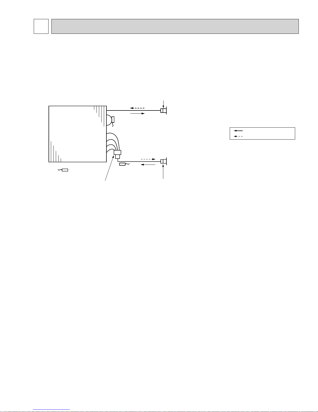
9
REFRIGERANT SYSTEM DIAGRAM
PKA-A12GA PKA-A18GA PKA-A24FA PKA-A30FA PKA-A36FA
PKA-A12GAL PKA-A18GAL PKA-A24FAL PKA-A30FAL PKA-A36FAL
PKA-A12GA1 PKA-A18GA1 PKA-A24FA1 PKA-A30FA1 PKA-A36FA
1
PKA-A12GAL1 PKA-A18GAL1 PKA-A24FAL1 PKA-A30FAL1 PKA-A36FAL
PKA-A12GA2 PKA-A18GA2 PKA-A24FA2 PKA-A30FA2 PKA-A36FA
2
PKA-A12GAL2 PKA-A18GAL2 PKA-A24FAL2 PKA-A30FAL2 PKA-A36FAL
Strainer
#50
Heat exchanger
Refrigerant GAS pipe connection
(Flare)
Condenser/evaporator
temperature thermistor
Room temperature
thermistor (TH1)
Distributor
with strainer
#50
(TH5)
Refrigerant LIQUID pipe connection
(Flare)
Pipe temperature
thermistor/liquid
(TH2)
Strainer
#50
Refrigerant flow in cooling
Refrigerant flow in heating
1
2
19
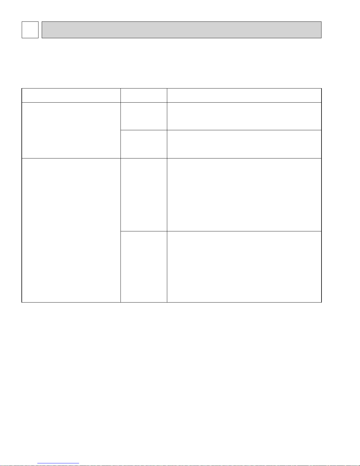
10 TROUBLESHOOTING
10-1. TROUBLESHOOTING
<Error code display by self-diagnosis and actions to be taken for service (summary)>
Present and past error codes are logged and displayed on the wired remote controller or controller board of outdoor unit.
Actions to be taken for service and the trouble reoccurrence at field are summarized in the table below. Check the contents
below before investigating details.
Unit conditions at service
The trouble is reoccurring.
The trouble is not reoccurring.
Error code
Displayed
Not displayed
Logged
Not logged
Actions to be taken for service (summary)
Judge what is wrong and take a corrective action
according to “SELF-DIAGNOSIS ACTION TABLE” (10-3).
Identify the cause of the trouble and take a corrective
action according to “TROUBLESHOOTING
BY INFERIOR PHENOMENA ” (10-4).
Consider the temporary defects such as the work of
protection devices in the refrigerant circuit including
compressor, poor connection of wiring, noise and etc.
Re-check the symptom, and check the installation
environment, refrigerant amount, weather when the
trouble occurred, and wiring related.
Reset error code logs and restart the unit after finishing
service.
There is no abnormality in electrical components,
controller boards, and remote controller.
Recheck the abnormal symptom.
Identify the cause of the trouble and take a corrective
action according to “TROUBLESHOOTING
BY INFERIOR PHENOMENA ” (10-4).
Continue to operate unit for the time being if the cause
is not ascertained.
There is no abnormality in electrical components,
controller boards, remote controller etc.
20
 Loading...