

Mitsubishi PK12FK, PK12FK1, PK18FK, PK18FK1, PK18FK2 Instruction Manual
...
PK12FK, PK12FK1
PK18FK, PK18FK1, PK18FK2
PK24FK, PK24FK1, PK24FK2
PK30FK, PK30FK1, PK30FK2
PK36FK, PK36FK1, PK36FK2
CONTENTS
1. TECHNICAL CHANGE ················································································OC196A- 2
2. FEATURES···································································································OC196A- 3
3. PART NAMES AND FUNCTIONS·······························································OC196A- 6
4. SPECIFICATIONS ························································································OC196A-10
5. DATA ············································································································OC196A-11
6. OUTLINES AND DIMENSIONS···································································OC196A-19
7. REFRIGERANT SYSTEM DIAGRAM··························································OC196A-23
8. WIRING DIAGRAM······················································································OC196A- 24
9. OPERATION FLOW-CHART·······································································OC196A-28
10. MICROPROCESSOR CONTROL································································OC196A- 31
11. TROUBLESHOOTING ·················································································OC196A-44
12. SYSTEM CONTROL····················································································OC196A-51
13. DISASSEMBLY PROCEDURE ····································································OC196A- 56
14. PARTS LIST·································································································OC196A-59
15. OPTIONAL PARTS ······················································································OC196A-68
OC196A-1
1
Change points
Optional parts
Program timer
FK
Switch for temperature unit
Switch for louvers
—
PAC–SK65PT
Canceled
Canceled
Addition of "Mode selector"
PAC–SC32PTA
FK1
SW17
SW18
SW7
No.9
No.0
No.1
No.2
No.3
No.4
18
OFF
ON
OFF
OFF
24
OFF
ON
OFF
OFF
30
ON
ON
OFF
OFF
36
ON
ON
OFF
OFF
18
OFF
ON
OFF
OFF
24
ON
ON
OFF
OFF
30
OFF
ON
ON
OFF
36
ON
ON
ON
OFF
Dip SW
Dip SW
Appearances
Remote
controller
Indoor controller
(18,24,30,36 only)
4-3/4 o 2-3/4 o 5/8 5-1/8 o 4-3/4 o 3/4
REMOTE CONTROLLER
REMOCON COVER
12 18 24 30 36
PART NAME
Model
TECHNICAL CHANGE
PK12FK ➔ PK12FK
1
PK18FK ➔ PK18FK1
PK24FK ➔ PK24FK1
PK30FK ➔ PK30FK1
PK36FK ➔ PK36FK1
Differences with PK12/18/24/30/36FK which is a basic service manual OC121.
Change of the service parts.
Refer to the parts list on the page OC196A-59 to 67 for the details.
PK18FK1 ➔ PK18FK2
PK24FK1 ➔ PK24FK2
PK30FK1 ➔ PK30FK2
PK36FK1 ➔ PK36FK2
● DRAIN PAN shape has changed.
● NOSE shape has changed.
● UNDER PLATE shape has changed.
OC196A-2
2
FILTER
CHECK MODE
TEST RUN
TIMER OFF TIMER
CHECK SET TEMP.
CLOCK AUTO AUTO
START STOP
SWING
FAN
SPEED
AUTO
RETURN
MITSUBISHI ELECTRIC
ON
DRY
COOL
FAN
CHECK
SET TEMP
TIMER OFF
AUTO STOP
AUTO START
F
HR
F
LOW HIGH
AUTO RETURN
CHECK TEST RUN
POWER
ON/OFF
MODE SELECT
SET
TEMPERATURE
FAN COOL/DRY
COOLERWARMER
TIMER MODE HOURS
FAN SPEED LOW/HIOGH
AIR
DISCHARGE
UP/DOWN
SWING
STOP
CHECK TEST RUN
•CENTRALLY CONTROLLED•
FEATURES
Indoor unit
(PK12/18/24/30/36FK) PK12/18/24/30/36FK1
()
PK18/24/30/36FK2
Remote controller
Models Cooling capacity SEER
PK12FK, PK12FK1 12,500 Btu/h 11.5
PK18FK, PK18FK1, PK18FK2 18,500 Btu/h 11.3
PK24FK, PK24FK1, PK24FK2 24,000 Btu/h 10.6
PK30FK, PK30FK1, PK30FK2 30,000 Btu/h 10.7
PK36FK, PK36FK1, PK36FK2 34,200 Btu/h 10.2
1. COMPACT DESIGN
The PK series models have been downsized and now require such minimal wall space that they can even be installed
above windows. For the PK12, 11-13/16in of wall space between the ceiling and the window allows “above window”
installation. (13-3/8in for the PK24/30/36)
2. AUTO FLAP SHUTTER
With a simple flick of the OFF switch the air outlet will be closed off with a shutter. The shutter also functions as a flap
during operation to adjust the air flow angle, with “Auto Angle 1” securing a comfortable air flow.
3. INSTALLATION : FAST AND ENDLESSLY ADAPTABLE
(1) Multi-directional piping
Multi directional drain and refrigerant piping radically improves flexibility in selecting installation layouts.
PK12 drain piping can be installed in 5 directions, while PK18/24/30/36 models boast refrigerant piping in 4 directions
and drain piping 2 directions.
(2) Back plate installation guide
The back plate installation guide gives clear instructions on installation positions. The enlarged back plate secures the
unit firmly to the wall, while the support piece which lifts the unit makes left side piping work much easier.
(3) Easily removable filter
The presence of thumbscrews on the filters means that the filters can be quickly and smoothly removed.
OC196A-3
4. ADVANCED MICROPROCESSOR
TIMER OFF TIMER
CHECK SET TEMP.
DRY COOL
FAN
CLOCK AUTO AUTO
START STOP
MODE TIMER ON/OFF CLOCK/TIMER FAN SPEED AIR DISCHARGE FILTER
CHECK
TEST RUN
AIR SWEEP
SET TEMP. TIMER SET
F
FAN
SPEED
SWING
AUTO
RETURN
REMOTE CONTROLLER
MITSUBISHI ELECTRIC
ON
DRY
COOL
FAN
CHECK
SET TEMP
TIMER OFF
AUTO STOP
AUTO START
F
HR
F
LOW HIGH
AUTO RETURN
CHECK TEST RUN
POWER
ON/OFF
MODE SELECT
SET
TEMPERATURE
FAN COOL/DRY
COOLERWARMER
TIMER MODE HOURS
FAN SPEED LOW/HIGH
AIR
DISCHARGE
UP/DOWN
SWING
STOP
CHECK TEST RUN
•CENTRALLY CONTROLLED•
[Remote controller]
(1) Easy to Use Microprocessor
1) Ultra-Thin Remote Controller
The streamlined, wide controller is designed to
blend with any kind of interior and the adoption of
a sophisticated microprocessor allows you to
carry out a wide range of operations easily.
2) Attractive Liquid Crystal Display (LCD)
Units operation mode, set temperature, room tem-
perature, timer setting, fan speed,
and air flow direction are displayed on the
remote controller with the easily understood visual
Liquid Crystal Display (LCD).
3) Convenient 24-Hour ON-OFF Timer
The timer allows Mr.SLIM to be switched on or
(PK12/18/24/30/36FK)
PK12/18/24/30/36FK
()
PK18/24/30/36FK2
off automatically at the time is shown on the LCD.
4) Self-Diagnostic Feature Indicates Instantly
In the rare case when a problem occurs, the unit stops operating and the set temperature indicator changes to the
self-diagnostic indicator, indicating the location of the fault.
If the check switch is pressed twice, the unit stops operating and the check mode is initiated. The cause of the most
recent problem stored in the memory is displayed on the LCD. This is extremely useful for maintenance purposes.
5) Useful Memory Feature for Storing Instructions
The previous set value is memorised so that constant temperature control can be obtained. This is convenient when,
for example, a power failure occurs.
(2) Non-polar Two-Wire Remote Controller Cables
The non-polar, two-wire type remote controller cable is slim, installation is simple and trouble-free. Remote controller
wire can be extended up to 550 yards.
1
5. REDI-CHARGED REFRIGERANT SYSTEM
PRE-CHARGE REFRIGERANT REQUIRED FOR LINE LENGTH OF 100ft AT
SHIPMENT. PREVENTING TROUBLES DUE TO SHORTAGE OF REFRIGERANT.
The unique refrigerant circuit and a large accumulator always controls the refrigerant to its optimum condition regardless of
the length of 164ft maximum (PK12/18 130ft maximum). The additional refrigerant charging work at the field which often
caused uncertain problems heretofore is completely eliminated. This unique system serves to improve the quality of work
and reliability, and also helps
to speed up the installation work.
OC196A-4
6. HIGH RELIABILITY AND EASY SERVICING
Rear
Right
Base
Front
In addition to the self-diagnostic function, units are also equipped with a 3-minute time delay mechanism (cooling), an auto
restart function, an emergency operation function, a test run switch, etc., to assure high reliability and easy servicing.
7. FOUR-WAY PIPING ACCESS MAKES
INSTALLATION LAYOUT EASY
Piping on the outdoor unit may be connected from either of
four directions: front, rear, side or beneath the base.
This easy-access design makes it possible to install a
number of units in a compact arrangement at a single site.
The outdoor unit allows for unheard-of flexibility in
determining a piping layout, thus greatly simplifying
installation.
8. FRONT-ACCESS FACILITATES
MAINTENANCE
The outdoor unit has been designed with a front access
service panel that allows easy access to all maintenance
point, regardless of the installation layout. What’s more, this
front panel may be removed by loosening only two screws.
It all adds up to greatly simplified maintenance work.
9. NITROGEN GAS IS CHARGED TO
INDOOR UNIT
Indoor unit and refrigerant pipes are charged with nitrogen
gas (N2) instead of R-22 before shipment from the
factory.
OC196A-5
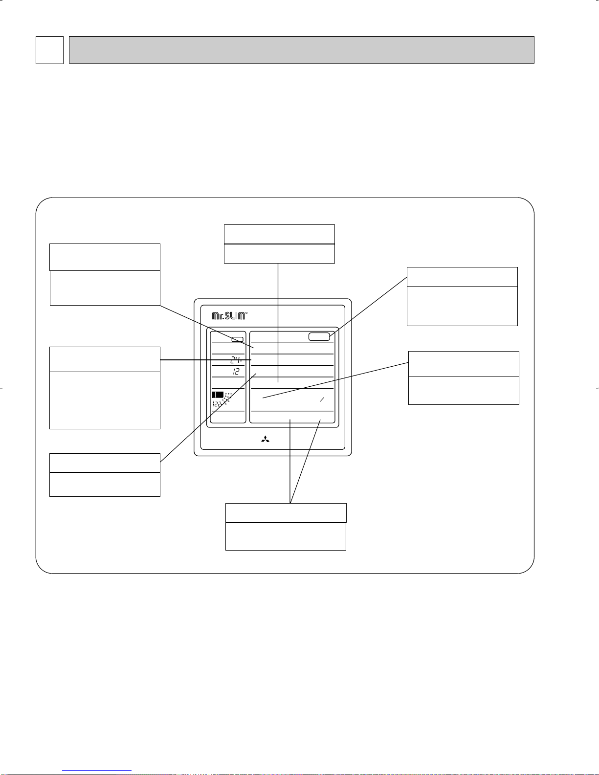
3 PART NAMES AND FUNCTIONS
MITSUBISHI ELECTRIC
ON
DRY
COOL
FAN
CHECK
SET TEMP
TIMER OFF
AUTO STOP
AUTO START
F
HR
F
LOW HIGH
AUTO RETURN
CHECK TEST RUN
POWER
ON/OFF
MODE SELECT
SET
TEMPERATURE
FAN COOL/DRY
COOLERWARMER
TIMER MODE HOURS
FAN SPEED LOW/HIGH
AIR
DISCHARGE
UP/DOWN
SWING
STOP
CHECK TEST RUN
•CENTRALLY CONTROLLED•
Remote controller (PK12/18/24/30/36FK)
Settings remain in effect until changed.
Air conditioner can be operated by simply pushing ON/OFF button once settings have been
made.
Remote controller operation buttons
FAN SPEED button
OPERATION MODE
button
Press this button to switch the cooling,electronic dry (Dehumidify), fan
modes.
SET TEMPERATURE
button
This sets the room temperature.
The temperature setting can be performed in 2˚F units.
Setting range :
Cooling 65˚F to 87˚F
TIMER ON/OFF button
This switches between continuous
operation and the timer operation.
This sets the ventilation fan speed.
ON/OFF button
This switches between the operation and stop modes each time it is
press. The lamp on this button
lights during operation.
AIR DISCHARGE
button
This adjusts the vertical angle of the
ventilation.
CHECK-TEST RUN button
Only press this button to perform an
inspection check or test operation.
Do not use it for normal operation.
OC196A-6
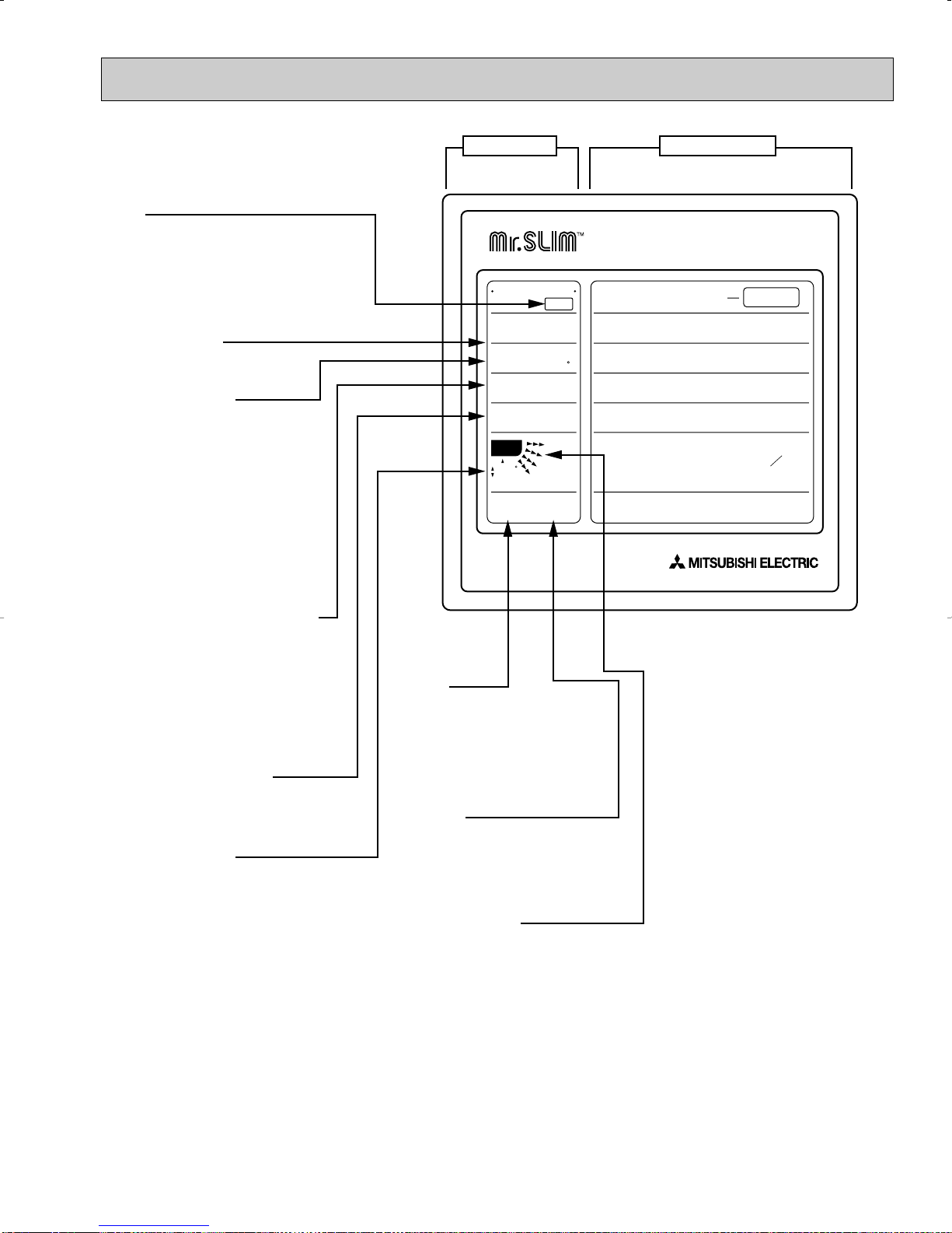
CENTRALLY CONTROLLED
ON
ON/OFF
DRY
MODE SELECT
COOL/DRY
FAN
SET
TENPERATURE
WARMER
TIMER
FAN SPEED
LOW/HIGH
UP/DOWN
AIR
DISCHARGE
MODE
CHECK TEST RUN
HOURS
COOLER
FAN COOL
CHECK
SET TEMP
81
88
12
F
AUTO RETURN
HR
F
TIMER OFF
CHECK TEST RUN
AUTO STOP
AUTO START
LOW HIGH
POWER
Display panel Operating panel
SWING
STOP
ON
Displayed during operation (ON).
FAN, COOL/DRY
Operation mode is displayed.
SET TEMP./CHECK
SET TEMP :
The desired temperature setting
is displayed.
CHECK :
When unit malfunctioning occurs,
this display is activated. At this
time, "Unit address" and "checkcode" are alternately displayed,
indicating the malfunctioning unit
and the cause.
TIMER OFF, AUTO STOP, AUTO
START (TIMER MODE)
TIMER OFF (continuous operation), AUTO STOP, AUTO START
mode are displayed. In AUTO
STOP/AUTO START mode, the
set time is also displayed. Time
setting is in 1 hour units for up to
24 hours.
Fan speed (LOW, HIGH)
The fan speed (Low/High) is displayed.
Room Temperature
During operation, the room temperature is displayed (not displayed when
not operating). The room temperature's display range is 47˚F - 97˚F.
When this range is exceeded, "▼
47˚F" or "▲ 97˚F" is displayed.
CHECK
Displayed when "self-diagnostic"
functioning occurs, and simultaneously the check code is displayed in the "set temp."
TEST RUN
Displayed when test run operation mode is functioning. (Turned
automatically off after 2 hours of
operation).
Louver ON/OFF
operation
❈ NOTE
1 "CENTRALLY CONTROLLED"
is displayed for two seconds
after POWER button is turned
to on. This is not defective.
2 All LCD are off during power
OFF.
3 When a button on the operat-
ing panel is pressed, a beep
sound is heard.
4 Do not operate the buttons with
something sharp-pointed, or
the operating panel will be
damaged.
OC196A-7
TIMER OFF TIMER
CHECK SET TEMP.
DRY COOL
FAN
CLOCK AUTO AUTO
START STOP
MODE TIMER ON/OFF CLOCK/TIMER FAN SPEED AIR DISCHARGE FILTER
CHECK
TEST RUN
AIR SWEEP
SET TEMP. TIMER SET
F
FAN
SPEED
SWING
AUTO
RETURN
REMOTE CONTROLLER
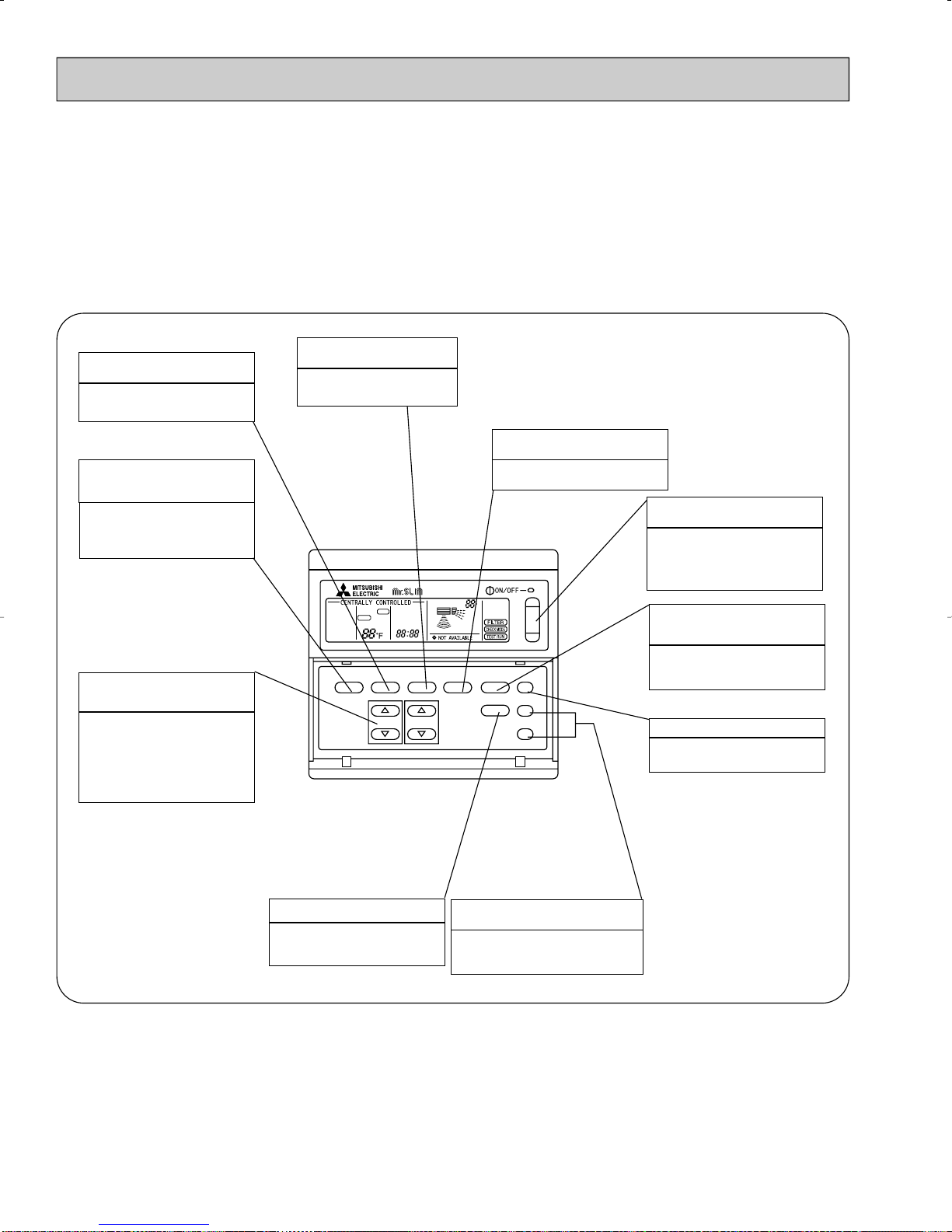
Remote controller (PK12/18/24/30/36FK1, PK18/24/30/36FK2)
Settings remain in effect unit changed.
Air conditioner can be operated by simply pushing ON/OFF button once setting have been
mode.
Remote controller operation buttons
TIMER ON/OFF button
This switches between continuous
operation and the timer operation.
OPERATION MODE
button
Press this button to switch the cooling,electronic dry (Dehumidify), fan
modes.
SET TEMPERATURE
button
This sets the room temperature.
The temperature setting can be performed in 2˚F units.
Setting range :
Cooling 65˚F to 87˚F
CLOCK/TIMER button
This sets or switches the current
time,start time and stop time.
FAN SPEED button
This sets the ventilation fan speed.
ON/OFF button
This switches between the operation and stop modes each time it is
press. The lamp on this button
lights during operation.
AIR DISCHARGE
button
This adjusts the vertical angle of the
ventilation.
FILTER button
This resets the filter service indication display.
AIR SWEEP button
This switches the horizontal fan
motion ON and OFF.
(This button is not available)
CHECK-TEST RUN button
Only press this button to perform an
inspection check or test operation.
Do not use it for normal operation.
OC196A-8
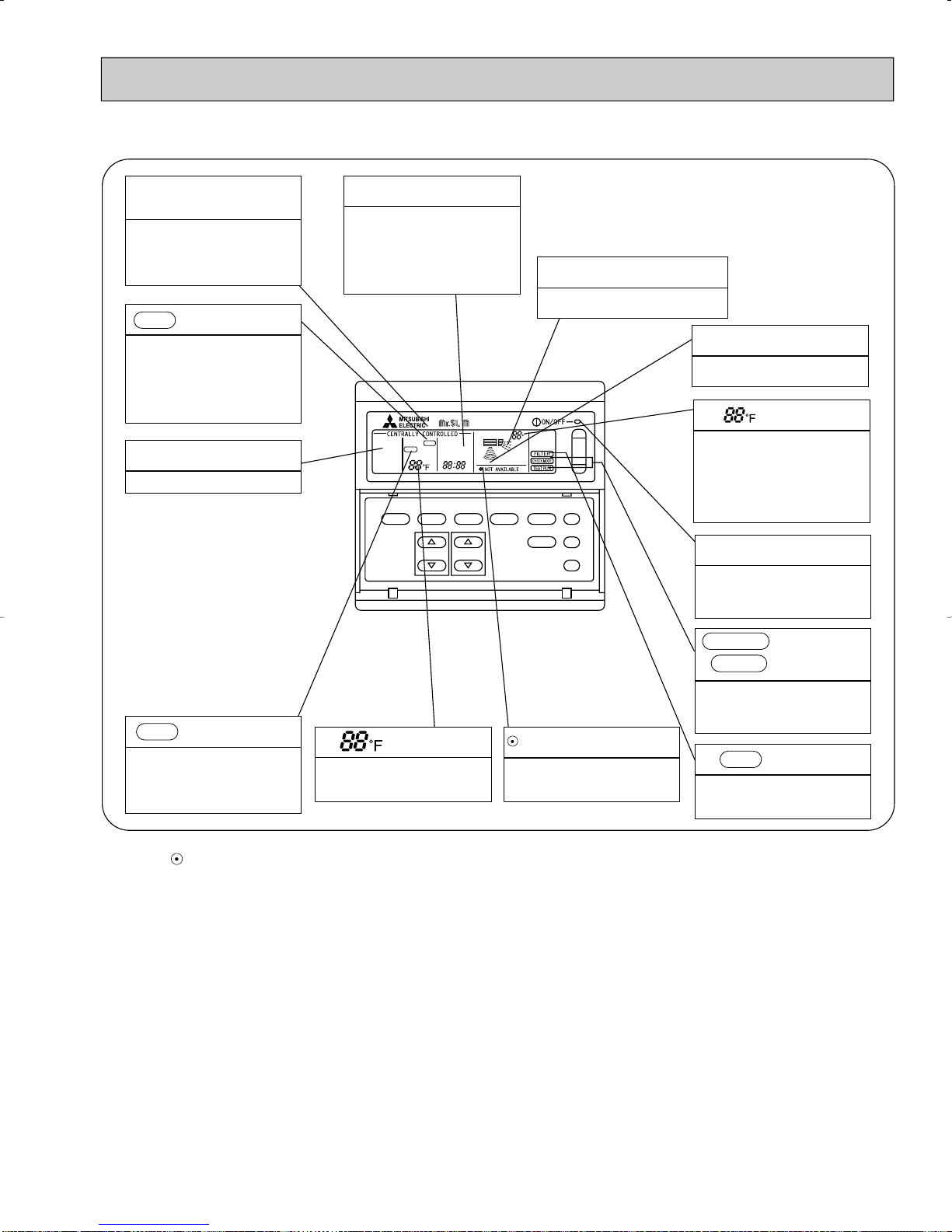
Remote controller display
CENTRALLY
CONTROLLED display
This indicates when the unit is controlled by optional features such as
central control type remote controller.
TIMER display
This indicates when the continuous
operation and time operation modes
are set.
It also display the time for the timer
operation at the same time as when
it is set.
OPERATION MODE display
This indicates the operation mode.
CLOCK display
The current time , start time and stop
time can be displayed in ten second
intervals by pressing the time switch
button. The start time or stop time is
always displayed during the timer
operation.
TIMER OFF TIMER
DRY COOL
FAN
MODE TIMER ON/OFF CLOCK/TIMER FAN SPEED AIR DISCHARGE FILTER
REMOTE CONTROLLER
CLOCK AUTO AUTO
CHECK SET TEMP.
START STOP
SET TEMP. TIMER SET
FAN
SPEED
SWING
AUTO
RETURN
In this display example on the bottom left, a condition where all display lamps light is shown for
explanation purposes although this differs from
actual operation.
AIR DISCHARGE display
This displays the air direction.
FAN SPEED display
The selected fan speed is displayed.
display
F
AIR SWEEP
CHECK
TEST RUN
The temperature of the return air is
displayed during operation. The display range is 47° to 97°F. The display flashes 47°F when the actual
temperature is less than 47° and
flashes 97°F when the actual temperature is greater than 97°F.
Operation lamp
This lamp lights during operation,
goes off when the unit stops and
flashes when a malfunction occurs.
CHECK display
This indicates when a malfunction
has occurred in the unit which should
be checked.
display
This displays the selected setting
temperature.
display
This lamp lights when electricity is
supplied to the unit.
CHECK MODE
TEST RUN
This display lights in the check mode
or when a test operation is performed.
FILTER
This lamp lights when the filter needs
to be cleaned.
display
display
Caution
● Only the display lights when the unit is stopped and power supplied to the unit.
● When power is turned ON for the first time the (CENTRAL CTRL) display appears to go off momentarily but this is not a malfunction.
●When the central control remote control unit, which is sold separately, is used the ON-OFF button,OPERA TION MODE button and SET
TEMP button do not operate.
● “NOTAVAILABLE” is displayed when the AIR SWEEP button are pressed.
(AIR SWEEP function is not provided for PK series.)
OC196A-9
4 SPECIFICATIONS
Capacity
Power consumption
EER
SEER
INDOOR UNIT MODEL
External finish
Power supply
Max. fuse size (time delay)
Min ampacity
Fan motor
Airflow Hi-Lo
Moisture removal
Sound level Hi-Lo
Cond. drain connection OD
Dimensions
Weight
OUTDOOR UNIT MODEL
External finish
Power supply
Max. fuse size (time delay)
Min. ampacity
Fan motor
Compressor
Crankcase heater
Refrigerant control
Sound level
Dimensions
Weight
REMOTE CONTROLLER
Control voltage (by built-in transformer)
REFRIGERANT PIPING
Pipe size
Connection method
Between the indoor
& outdoor units
❈ 1
❈ 1
❈ 1
Dry
Wet
W
D
H
Model
W
D
H
Liquid
Gas
Indoors
Outdoors
Height
Piping length
Btu/h
kW
V, Phase, Hz
A
A
F.L.A.
CFM
CFM
Pints/h
dB
in.
in.
in.
in.
Ib.
V, Phase, Hz
A
A
F.L.A
R.L.A
L.R.A
A(W)
dB
in.
in.
in.
Ib.
in.
in.
ft
fr
PK12FK
PK12FK
1
Model
12,500
1.21
10.3
11.5
PK12FK,PK12FK
1
15
1
0.7
490-350
440-320
3.8
45-38
1
49-7/32
7-7/8
11-13/16
37
PU12EK
1
15
11
0.65
RH167NAB
8.9
29
0.11/0.12 (23/28)
50
25-9/16
105
130
130
PK18FK
PK18FK
1
PK18FK2
18,500
1.75
10.6
11.3
PK18FK, PK18FK1, PK18FK2
15
1
0.7
710-530
640-480
5.3
48-41
1
53
PU18EK
1
20
16
0.75
RH247NAB
12.0
37
0.11/0.12 (23/28)
53
33-1/2
154
3/8
5/8
55-1/8
34-1/4
11-5/8
PK24FK
PK24FK
1
PK24FK2
24,000
2.34
10.3
10.6
PK24FK, PK24FK1, PK24FK2
Munsell 3.4Y7.7/0.8
115, 1, 60
15
1
0.7
710-530
640-480
7.2
48-41
1
9-1/4
13-3/8
53
PU24EK
1
Munsell 5Y7/1
208/230, 1, 60
20
16
0.65+0.65
NH33NBD
11.5
54
0.16/0.17 (33/39)
Capillary tube
55
207
With indoor unit
Indoor unit - remote controller : DC12V, Indoor unit - outdoor unit : DC12V
Not supplied (optional parts)
Flared
Flared
PK30FK
PK30FK
1
PK30FK2
30,000
3.06
9.8
10.7
PK30FK, PK30FK1, PK30FK2
15
2
1.0
990-780
890-700
9.6
49-44
1
62
PU30EK
1
30
20
0.65+0.65
NH41NAD
14.0
73
0.16/0.17 (33/39)
55
49-9/16
208
164
164
1/2
3/4
PK36FK
PK36FK
1
PK36FK2
34,200
3.47
9.9
10.2
PK36FK, PK36FK1, PK36FK2
15
2
1.0
990-780
890-700
10.5
49-44
1
62
PU36EK
1
30
22
0.75+0.75
NH47NAD
17.5
87
0.16/0.17 (33/39)
55
38-3/16
13-9/16
220
66-5/32
Item
NOTES : ❈ 1.Rating conditions —indoor : D.B. 80˚F, W.B. 67˚F outdoor : D.B. 95˚F, W.B. 75˚F.
Operating range
Indoor intake air temperature
D.B. 95˚F, W.B. 71˚F
D.B. 67˚F, W.B. 57˚F
Outdoor intake air temperature
D.B. 115˚F
D.B. 0˚F *
Cooling
Maximum
Minimum
*
In case of the wind baffle is installed.
(In case of the wind baffle is not installed, the minimum temperature will be D.B. 23˚F.)
MODELS : PK12/18/24/30/36FK, PK12/18/24/30/36FK1, PK18/24/30/36FK2
OC196A-10
5
Notes 1. B.F. : Bypass Factor, IWB : Intake air wet-bulb temperature
TC : Total Capacity (x10
3
Btu/h), SHC : Sensible Heat Capacity (x10
3
Btu/h)
TPC : Total Power Consumption (kW)
2. Cooling capacity correction factors and Refrigerant piping length (one way) range.
MODEL
Refrigerant piping length (one way)
PK12FK, PK12FK
1
PK18FK, PK18FK1, PK18FK2
PK24FK, PK24FK1, PK24FK2
PK30FK, PK30FK1, PK30FK2
PK36FK, PK36FK1, PK36FK2
1.0
1.0
1.0
1.0
1.0
25ft
0.992
0.992
0.981
0.981
0.981
40ft
0.983
0.983
0.968
0.968
0.968
55ft
0.978
0.978
0.952
0.952
0.952
70ft
0.966
0.966
0.940
0.940
0.940
85ft
0.959
0.959
0.925
0.925
0.925
100ft
0.950
0.950
0.913
0.913
0.913
115ft
0.945
0.945
0.900
0.900
0.900
130ft
—
—
0.886
0.886
0.886
150ft
—
—
0.874
0.874
0.874
164ft
TC
14.5
13.6
12.7
12.6
12.0
11.8
21.5
20.1
18.8
18.6
17.8
17.4
27.9
26.1
24.3
24.1
23.0
22.6
34.9
32.6
30.4
30.2
28.8
28.3
39.8
37.1
34.7
34.4
32.8
32.2
IWB
(˚F)
71
67
63
62.5
60
59
71
67
63
62.5
60
59
71
67
63
62.5
60
59
71
67
63
62.5
60
59
71
67
63
62.5
60
59
Indoor air
Airflow
(CFM)
B.F
Models
PK12FK
PK12FK
1
PK18FK
PK18FK
1
PK18FK2
PK24FK
PK24FK
1
PK24FK2
PK30FK
PK30FK
1
PK30FK2
PK36FK
PK36FK
1
PK36FK2
490
0.18
710
0.14
710
0.14
990
0.15
990
0.15
D.B. 80˚F
D.B.75˚F(50%RH)
D.B.72˚F(50%RH)
D.B.70˚F(50%RH)
D.B. 80˚F
D.B.75˚F(50%RH)
D.B.72˚F(50%RH)
D.B.70˚F(50%RH)
D.B. 80˚F
D.B.75˚F(50%RH)
D.B.72˚F(50%RH)
D.B.70˚F(50%RH)
D.B. 80˚F
D.B.75˚F(50%RH)
D.B.72˚F(50%RH)
D.B.70˚F(50%RH)
D.B. 80˚F
D.B.75˚F(50%RH)
D.B.72˚F(50%RH)
D.B.70˚F(50%RH)
75
SHC
9.8
11.0
12.0
10.7
10.4
10.1
14.8
16.5
17.9
16.0
15.6
15.0
16.4
18.8
20.7
18.3
17.8
17.3
21.5
24.5
26.9
23.8
23.2
22.5
23.0
26.3
29.3
25.8
25.1
24.3
TPC
1.05
1.03
1.01
1.01
0.99
0.99
1.52
1.49
1.46
1.45
1.43
1.43
2.04
1.99
1.95
1.94
1.92
1.91
2.66
2.61
2.55
2.54
2.51
2.49
3.02
2.96
2.89
2.88
2.84
2.83
TC
14.0
13.1
12.2
12.1
11.5
11.3
20.8
19.3
18.0
17.9
17.1
16.7
26.9
25.1
23.4
23.2
22.1
21.7
33.7
31.4
29.2
29.0
27.7
27.1
38.4
35.7
33.3
33.1
31.5
30.9
85
SHC
9.5
10.6
11.5
10.3
10.0
9.7
14.3
15.8
17.2
15.4
15.0
14.4
15.8
18.1
20.0
17.6
17.1
16.6
20.8
23.6
25.8
22.9
22.3
21.5
22.1
25.3
28.1
24.8
24.1
23.3
TPC
1.14
1.12
1.09
1.09
1.07
1.06
1.65
1.61
1.57
1.57
1.55
1.54
2.21
2.16
2.11
2.10
2.07
2.05
2.89
2.82
2.75
2.75
2.70
2.69
3.28
3.20
3.12
3.11
3.07
3.05
TC
13.5
12.5
11.6
11.5
11.0
10.8
19.9
18.5
17.2
17.1
16.3
16.0
25.8
24.0
22.4
22.2
21.1
20.7
32.3
30.0
27.9
27.7
26.4
25.9
36.8
34.2
31.9
31.6
30.1
29.5
Outdoor intake air DB temperature(˚F
)
95
SHC
9.1
10.1
10.9
9.8
9.5
9.2
13.7
15.2
16.4
14.7
14.3
13.8
15.1
17.3
19.1
16.8
16.4
15.8
19.9
22.5
24.6
21.9
21.3
20.6
21.2
24.3
26.9
23.7
23.0
22.3
TPC
1.24
1.21
1.18
1.17
1.15
1.15
1.80
1.75
1.70
1.70
1.67
1.66
2.40
2.34
2.28
2.27
2.23
2.22
3.14
3.06
2.98
2.97
2.92
2.90
3.57
3.47
3.38
3.37
3.31
3.29
TC
12.8
11.9
11.1
11.0
10.4
10.2
19.0
17.6
16.4
16.2
15.5
15.1
24.6
22.9
21.3
21.1
20.0
19.6
30.8
28.6
26.6
26.3
25.1
24.6
35.1
32.6
30.3
30.0
28.6
28.0
105
SHC
8.7
9.6
10.5
9.3
9.0
8.7
13.0
14.4
15.6
13.9
13.6
13.1
14.4
16.5
18.2
16.0
15.5
15.0
19.0
21.5
23.5
20.7
20.2
19.5
20.2
23.1
25.6
22.5
21.9
21.1
TPC
1.35
1.31
1.27
1.26
1.24
1.23
1.95
1.89
1.83
1.83
1.79
1.78
2.61
2.53
2.45
2.44
2.40
2.38
3.41
3.30
3.21
3.20
3.14
3.11
3.87
3.74
3.64
3.63
3.56
3.53
TC
12.2
11.3
10.5
10.4
9.9
9.7
18.1
16.7
15.5
15.4
14.6
14.3
23.4
21.7
20.1
19.9
18.9
18.5
29.3
27.1
25.1
24.9
23.7
23.2
33.4
30.9
28.7
28.4
27.0
26.4
115
SHC
8.3
9.2
9.9
8.8
8.6
8.3
12.4
13.7
14.8
13.2
12.8
12.4
13.7
15.6
17.2
15.1
14.7
14.1
18.1
20.3
22.2
19.6
19.1
18.4
19.3
21.9
24.2
21.3
20.7
19.9
TPC
1.45
1.40
1.36
1.35
1.32
1.31
2.10
2.03
1.96
1.96
1.92
1.90
2.81
2.71
2.62
2.62
2.56
2.54
3.68
3.54
3.43
3.42
3.35
3.32
4.17
4.02
3.89
3.88
3.80
3.77
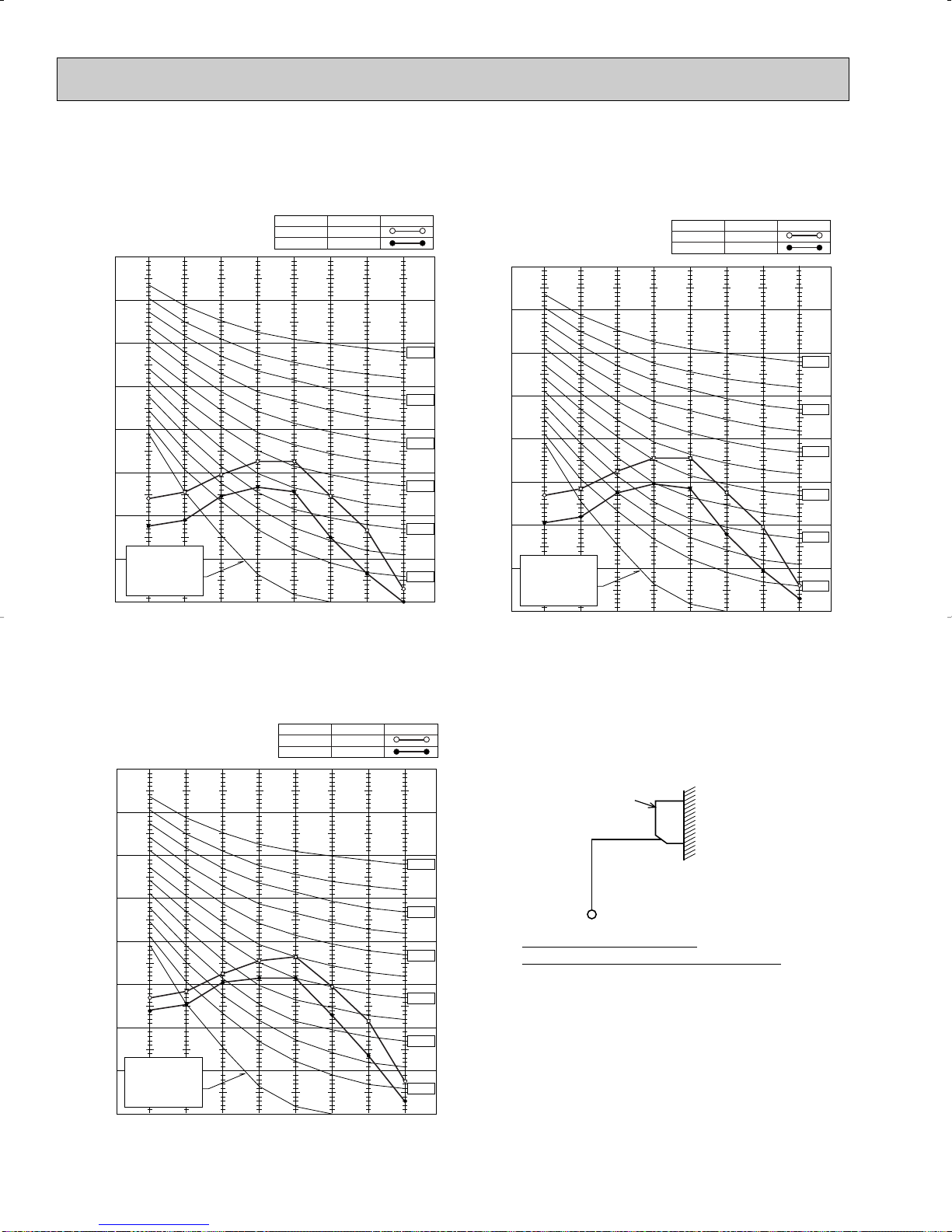
DATA
1. PERFORMANCE DATA
1) COOLING CAPACITY
2) COOLING CAPACITY CORRECTIONS
OC196A-11
2. PERFORMANCE CURVE
18
71
67
63
71
67
63
12
6
1.6
1.4
1.2
1.0
0.8
023 3235
45 55
65(67) 75
85 95 105 115
Total capacity (✕10
3
Btu/h)Total power consumption (kW)
Outdoor intake air D.B. temperature (°F)
indoor intake air W.B. temperature (°F)
indoor intake air W.B. temperature (°F)
SHF=0.81
30
71
67
63
71
67
63
18
24
12
3.0
2.5
2.0
1.5
1.0
023 3235
45 55
65(67)
75 85 95 105 115
Total capacity (✕10
3
Btu/h)Total power consumption (kW)
Outdoor intake air D.B. temperature (°F)
indoor intake air W.B. temperature (°F)
indoor intake air W.B. temperature (°F)
SHF=0.82
Total capacity (✕10
3
Btu/h)Total power consumption (kW)
Outdoor intake air D.B. temperature (°F)
023 3235
45
65 (67)
75 85 95 105 11555
1.5
2.0
2.5
3.0
3.5
18
36
24
30
71
67
63
71
67
63
023 3235
45
65 (67)
75 85 95 105 11555
2.0
2.5
3.0
3.5
4.0
24
42
30
36
71
67
63
71
67
63
indoor intake air W.B. temperature (°F)
indoor intake air W.B. temperature (°F)
Total capacity (✕10
3
Btu/h)Total power consumption (kW)
Outdoor intake air D.B. temperature (°F)
indoor intake air W.B. temperature (°F)
indoor intake air W.B. temperature (°F)
SHF=0.72 SHF=0.72
NOTE : Apoint on the curve shows the reference point.
PK12FK
PK12FK1
COOLING CAPACITY COOLING CAPACITY
PK18FK
PK18FK1
PK18FK2
PK24FK
COOLING CAPACITY COOLING CAPACITY
PK24FK1
PK24FK2
PK30FK
PK30FK1
PK30FK2
OC196A-12
Outdoor ambient temperature (°F)
indoor intake air W.B. temperature (°F)
[psi. G]
350
340
330
320
310
300
290
280
270
260
250
240
230
220
210
200
190
180
170
160
150
86
80
75
70
PK12FK
PK12FK
1
<Cooling mode>
Condensing pressure
30 40 50 60 70 80 90 100 110
D.B.(°F)
Outdoor ambient temperature (°F)
indoor intake air W.B. temperature (°F)
[psi. G]
100
90
80
70
60
50
40
30
86
80
75
70
PK12FK
PK12FK
1
Suction pressure
30 40 50 60 70 80 90 100 110
D.B.(°F)
42
71
67
63
71
67
63
30
36
24
4.5
4.0
3.5
3.0
2.5
023 3235
45 55
65(67) 75
85 95 105 115
Total capacity (✕10
3
Btu/h)Total power consumption (kW)
Outdoor intake air D.B. temperature (°F)
indoor intake air W.B. temperature (°F)
indoor intake air W.B. temperature (°F)
SHF=0.71
PK36FK
PK36FK1
PK36FK2
COOLING CAPACITY
Data is based on the condition of indoor humidity 50%.
Air flow should be set at HI.
A point on the curve shows the reference point.
OC196A-13
Data is based on the condition of indoor humidity 50%.
PK18FK
PK18FK
1
PK18FK2
<Cooling mode>
PK18FK
PK18FK
1
PK18FK2
86
80
75
70
86
80
75
70
Outdoor ambient temperature
30 40 50 60 70 80 90 100 110
360
350
340
330
320
310
300
290
280
270
260
250
240
230
220
210
200
190
180
170
160
[psi.G]
100
90
80
70
60
50
40
30
20
30 40 50 60 70 80 90 100 110
Outdoor ambient temperature
D.B.(°F)
D.B.(°F)
[psi.G]
Indoor D.B. temperature (°F)
Indoor D.B. temperature (°F)
Condensing pressure
Suction pressure
PK24FK
PK24FK
1
PK24FK2
<Cooling mode>
PK24FK
PK24FK
1
PK24FK2
Outdoor ambient temperature
Outdoor ambient temperature
D.B.(°F)
D.B.(°F)
86
80
75
70
86
80
75
70
30 40 50 60 70 80 90 100 110
350
340
330
320
310
300
290
280
270
260
250
240
230
220
210
200
190
180
170
160
150
[psi.G]
100
90
80
70
60
50
40
30
20
30 40 50 60 70 80 90 100 110
[psi.G]
Indoor D.B. temperature (°F)
Indoor D.B. temperature (°F)
Condensing pressure
Suction pressure
Air flow should be set at HI.
A point on the curve shows the reference point.
OC196A-14
Data is based on the condition of indoor humidity 50%.
Outdoor ambient temperature (°F)
indoor intake air W.B. temperature (°F)
[psi. G]
340
330
320
310
300
290
280
270
260
250
240
230
220
210
200
190
180
170
160
150
140
86
80
75
70
PK30FK
PK30FK
1
PK30FK2
<Cooling mode>
Condensing pressure
30 40 50 60 70 80 90 100 110
D.B.(°F)
Outdoor ambient temperature (°F)
PK30FK
PK30FK
1
PK30FK2
Suction pressure
D.B.(°F)
86
80
75
70
100
90
80
70
60
50
40
30
30 40 50 60 70 80 90 100 110
[psi.G]
indoor intake air W.B. temperature (°F)
Outdoor ambient temperature (°F)
indoor intake air W.B. temperature (°F)
[psi. G]
340
330
320
310
300
290
280
270
260
250
240
230
220
210
200
190
180
170
160
150
140
86
80
75
70
PK36FK
PK36FK
1
PK36FK2
<Cooling mode>
Condensing pressure
30 40 50 60 70 80 90 100 110
D.B.(°F)
Outdoor ambient temperature (°F)
indoor intake air W.B. temperature (°F)
[psi. G]
90
80
70
60
50
40
30
20
86
80
75
70
PK36FK
PK36FK
1
PK36FK2
Suction pressure
30 40 50 60 70 80 90 100 110
D.B.(°F)
Air flow should be set at HI.
A point on the curve shows the reference point.
OC196A-15
3. STANDARD OPERATION DATA
750 750 750 750 760 760
Capacity
SHF
Input
INDOOR UNIT MODEL
Power supply (V, phase, Hz)
Input
Fan current
OUTDOOR UNIT MODEL
Power supply (V, phase, Hz)
Input
Comp. current
Fan current
Condensing pressure
Suction pressure
Discharge temp.
Condensing temp.
Suction temp.
Ref. pipe length
Refrigerant charge
Intake air temperature
Discharge air temperature
Fan speed (High)
Airflow (High)
Intake air temperature
Fan speed upper / lower
Airflow
Unit
Btu / t
—
kW
kW
A
kW
A
A
psi-G
psi-G
˚F
˚F
˚F
ft
—
˚F
˚F
˚F
˚F
rpm
CFM
˚F
˚F
rpm
CFM
Cooling
12,500
0.81
1.21
PK12FK, PK12FK
1
115, 1, 60
0.07
0.7
PU12EK
1
208/230, 1, 60
1.14
8.9
0.65
247
87
155
116
52
25
4 lbs 14oz
80
67
61
59
1,420
490
95
75
790
1,590
Cooling
18,500
0.82
1.75
PK18FK, PK18FK1, PK18FK2
115, 1, 60
0.09
0.7
PU18EK
1
208/230, 1, 60
1.66
12.0
0.75
255
82
171
118
51
25
5 lbs 8 oz
80
67
61
59
1,300
710
95
75
790
1,590
Cooling
24,000
0.72
2.34
PK24FK, PK24FK1, PK24FK2
115, 1, 60
0.09
0.7
PU24EK
1
208/230, 1, 60
2.25
11.5
0.65+0.65
240
74
155
114
44
25
9 lbs 15 oz
80
67
58
56
1,300
710
95
75
3,170
Cooling
30,000
0.75
3.06
PK30FK, PK30FK1, PK30FK2
115, 1, 60
0.12
1.0
PU30EK
1
208/230, 1, 60
2.94
14.0
0.65+0.65
247
77
163
116
46
25
10 lbs 2 oz
80
67
59
58
1,380
990
95
75
3,170
Cooling
34,200
0.71
3.47
PK36FK, PK36FK1, PK36FK2
115, 1, 60
0.12
1.0
PU36EK
1
208/230, 1, 60
3.35
17.5
0.75+0.75
247
73
163
116
43
25
10 lbs 9 oz
80
67
58
56
1,380
990
95
75
3,350
PK12FK
PK12FK
1
PK18FK
PK18FK
1
PK18FK2
PK24FK
PK24FK
1
PK24FK2
PK30FK
PK30FK
1
PK30FK2
PK36FK
PK36FK
1
PK36FK2
D.B.
W.B.
D.B.
W.B.
D.B.
W.B.
Item
Model
TotalRefrigerant circuitIndoor sideOutdoor side Electrical circuit
OC196A-16
4. OPERATING RANGE
Indoor unit
Outdoor unit
Rating
115V 1 phase 60Hz
208/230V 1 phase 60Hz
Allowable voltage
Min. 103V — Max. 127V
Min. 198V — Max. 253V
Function
Cooling
D.B.(˚F)
80
95
67
80
Condition
Standard temperature
Maximum temperature
Minimum temperature
Maximum humidity
Indoor
Intake air temperature
Outdoor
W.B.(˚F)
67
71
57
75
D.B.(˚F)
95
115
*0
80
* With wind baffle D.B. 23˚F if no wind baffle.
W.B.(˚F)
75
75
—
75
Airflow
Air speed
Coverage range
(CFM)
(ft / sec.)
(ft)
Standard
height
(8.2ft)
490
14.1
32
710
16.1
41
710
16.1
41
990
17.7
50
990
17.7
50
PK12FK
PK12FK
1
PK18FK
PK18FK
1
PK18FK2
PK24FK
PK24FK
1
PK24FK2
PK30FK
PK30FK
1
PK30FK2
PK36FK
PK36FK
1
PK36FK2
Model
PK12FK, PK12FK1
PK18FK, PK18FK1, PK18FK2
PK24FK, PK24FK1, PK24FK2
PK30FK, PK30FK1, PK30FK2
PK36FK, PK36FK1, PK36FK2
4 lbs 14 oz
5 lbs 8 oz
9 lbs 15 oz
10 lbs 2 oz
10 lbs 9 oz
25ft
0
0
0
0
0
40ft
0
0
0
0
0
55ft
0
0
0
0
0
70ft
0
0
0
0
0
85ft
0
0
0
0
0
Refrigerant piping length (over way)
100ft
0
0
0
0
0
115ft
2
2
2
5
5
130ft
4
4
4
10
10
150ft
—
—
7
16
16
164ft
—
—
9
20
20
Outdoor unit
precharged
(up to 100ft)
1) POWER SUPPLY
2) OPERATION
5. OUTLET AIR SPEED AND COVERAGE RANGE
● The air coverage range is the value up to the position where the air speed is 0.8ft/sec. when air is blown out
horizontally from the unit at the High fan setting.
The coverage range should be used only as a general guideline since it varies according to the size of the
room and furniture installed inside the room.
6. ADDITIONAL REFRIGERANT CHARGE (R22 (oz))
OC196A-17
6. NOISE CRITERION CURVES
90
80
70
60
50
40
30
20
10
63 125 250 500 1000 2000 4000 8000
OCTAVE BAND SOUND PRESSURE LEVEL, dB re 0.0002 MICRO BAR
BAND CENTER FREQUENCIES, Hz
APPROXIMATE
THRESHOLD OF
HEARING FOR
CONTINUOUS
NOISE
NC-60
NC-50
NC-40
NC-30
NC-20
NC-70
Hi
NOTCH
Lo
49
SPL(dB)44LINE
90
80
70
60
50
40
30
20
10
63 125 250 500 1000 2000 4000 8000
NC-60
NC-50
NC-40
NC-30
NC-20
NC-70
OCTAVE BAND SOUND PRESSURE LEVEL, dB re 0.0002 MICRO BAR
BAND CENTER FREQUENCIES, Hz
APPROXIMATE
THRESHOLD OF
HEARING FOR
CONTINUOUS
NOISE
Hi
NOTCH
Lo
48
SPL(dB)41LINE
Wall
Unit
3.3ft
3.3ft
90
80
70
60
50
40
30
20
10
63 125 250 500 1000 2000 4000 8000
APPROXIMATE
THRESHOLD OF
HEARING FOR
CONTINUOUS
NOISE
NC-60
NC-50
NC-40
NC-30
NC-20
NC-70
OCTAVE BAND SOUND PRESSURE LEVEL, dB re 0.0002 MICRO BAR
BAND CENTER FREQUENCIES, Hz
Hi
NOTCH
Lo
45
SPL(dB)38LINE
PK12FK
PK12FK1
PK18/24FK
PK18/24FK1
PK18/24FK2
PK30/36FK
PK30/36FK1
PK30/36FK2
Ambient temperature 80˚F
Test conditions are based on JIS Z8731
OC196A-18
6
0
10-29/32
0
2-3/32
(2:1)
11-13/16
(Hight of unit)
7-1/8
or more
6 or more
17-19/32
49-7/32 (Width of unit)
Gas pipe
Liquid pipe
2
1
2
1
Terminal block for
control
knock out hole
for piping
16-louvers
(manual)
Lower side
Air outletAir outlet
(2:1)
Terminal block
Right side
service panel for power supply connection
Front
Air intake
Air intake
Knock out hole for left-rear piping
11-1/4
9-9/32
8-15/16
6-31/32
5-1/8
3-5/32
2-3/32
0
1-3/8
2-unit hangers
Liquid pipe
for installation plate
hole
1-3/16
or more
2O5-{1/8
hole for
tapping
screw
68-{3/16
hole for
tapping
screw
5/8F
3/8F
Sleeve
13-{9/16 hole
Air intake
2-3/8
Knock out hole
for piping
knock out hole
for piping
W2
end of through hole.
W2 This size shows the lower
W1 Sleeves are available
on the market.
3-1/2~{4{3-1/2
W1
Through
0
15/16
1/2
25
27
(100 for left-hand
side piping)
Pipe position
Left side
Installation bolt
position
2-3/8
Drain hose(Flexible hose;length 47-1/4)
Drain hose
Terminal block & pipe position
1-25/32
13 2-3/8
7-15/32 14-3/4
(7)
14-23/32
Details of installation plate
(Necessary clearance for
Unit installation)
2
43-5/16(Drain hose) 7-7/8
Rear piping hole
Right side
Lower side
Auto vanes
Service space required
around indoor unit
2-tapping screws
Terminal block
for power supply
Terminal block for
remote controller
5/16
25/32
5/16
2-3/4
Knock out hole
for under piping
5/16
25/32
5/16
2-3/4
Knock-out hole for
right-hand side piping
R2-1/16
R2-1/16
0
24-19/32
19-1/8
0
19-11/32
18-3/4
17-23/32
15-15/16
12-23/32
10-7/8
9-1/32
7-1/16
5-29/32
2-3/4
0
18-3/4
17-23/32
15-15/16
12-17/32
10-21/32
8-13/16
6-27/32
5-29/32
0
2-3/4
unit center
8-25/32
1
Air intake
Knock out hole
for right-hand side piping
Knock out hole
for left-hand
side piping
Front
Right side
Left side
Drain hose
Gas pipe
5-5/8
3-5/32
7-1/2
6-3/4
Bolt
8-15/16
3-1/8
5-1/8 or less
6-5/8
19/32 or less
2 or more
1-7/8
2-7/8
11/32
3-19/32
1-27/32
9-9/32
1
1-3/8
8-15/32
2-3/8
17-11/16 17-11/16
2-3/4
6-13/16
2-9/16
21-25/32
8-3/8
7-7/8
38-7/16
18-27/32 18-27/32
8-3/4
19-11/16
11-13/16
49-7/32
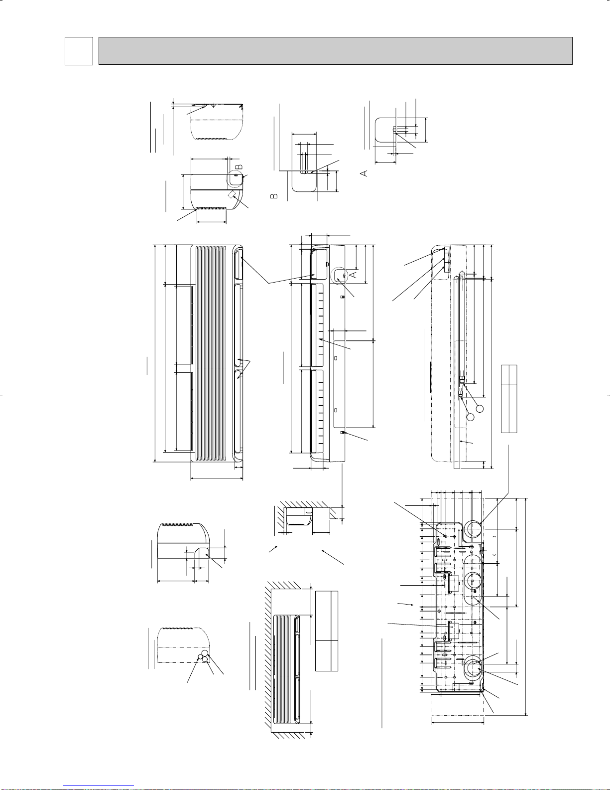
OUTLINES AND DIMENSIONS
Indoor Unit
PK12FK
PK12FK1
OC196A-19
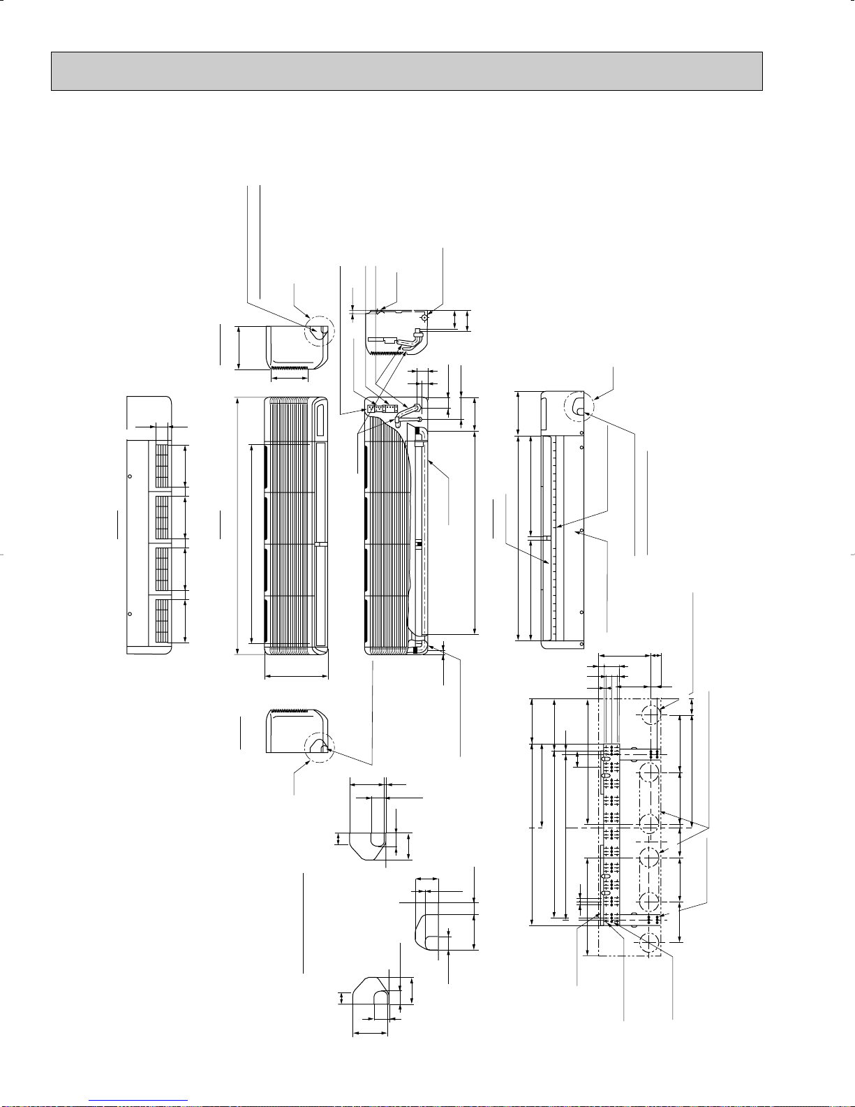
PK18/24FK
9-1/4
1-25/32
9-1/4
1-25/32
9-1/4 9-1/4
1-25/32
1/2
13-3/8
7-3/4
1-21/32
2-9/32
Top
Front
Right side
Left side
55-1/8
42-15/16
Air intake
9-1/4
C
Knock out hole for right piping
Refrigerant pipe. Drain pipe
Knock out hole for
left piping
Drain hose for
left-hand side piping
Drain hose
Lower side
Auto vane
(Gas pipe)
Drain hose
Bolt
Gas pipe
19/32
Terminal block for power supply
Terminal block for control
Terminal block for remote controller
(Liquid pipe)
Liquid pipe
Gas pipe
Liquid pipe
A
1-3/16
1-15/32
1-17/32
3-27/32 2-9/16
2-29/32
5/32
3-15/16
1-17/32
1-3/16
1-15/32
2-29/32
5/32
1-5/32
11-1/32
1-3/16
7-1/4
1-3/16
3-5/32
1-3/18
2-3/8
13/32
1-17/32
1-15/32
2-9/16
3-15/16
A
B
C
Knock out hole for piping
31/32
43-11/16
7-7/32
9-7/16
B
44-3/32
21-23/32
4-23/32
2-5/32
4-1/32
4-3/8
Air outlet
21-23/32
Air outlet
Change vane (manual)
Under panel
Removable at left-hand
side piping
Knock out hole for under-piping
Refrigerant pipe. Drain pipe
Rear piping opening
Range for left rear piping opening
12-{1/4 Hole for
tapping screw
66-{1/4 hole for
tapping screw
Wall fixture
Unit center
32-{15/32
hole for bolt
23/32
3-19/32
35-7/16
38-31/32
17-29/32
11-7/32
9-21/32
3/4
9-7/16 11-1/32 12-3/8
24
Drainage range
on left-hand side
Drainage range
on right-hand side
10x3-19/32=(35-13/16)
7-3/32
2-15/32
8-27/32
3-17/32
23/32
PK18/24FK1
PK18/24FK2
OC196A-20
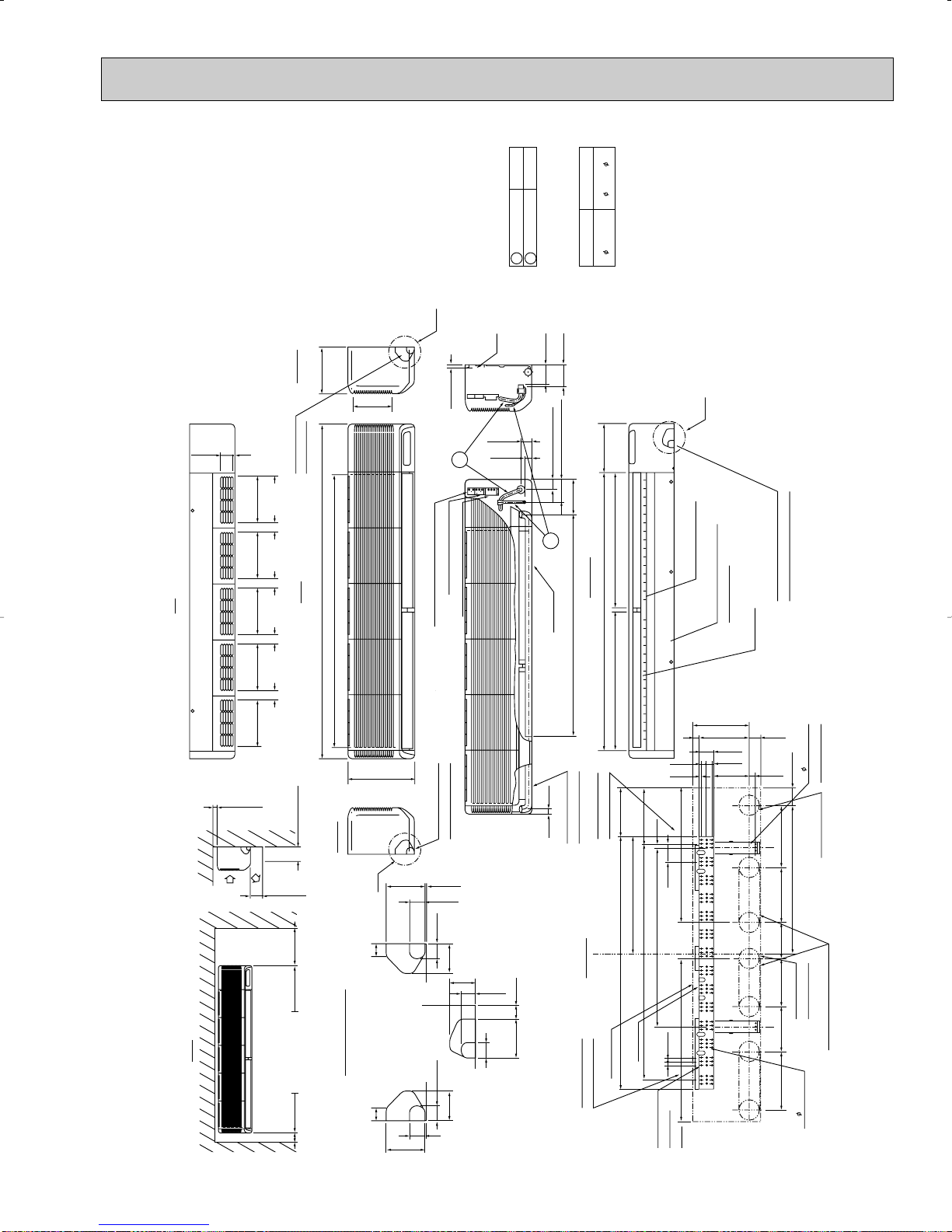
PK30/36FK
66-5/32
9-1/4
53-15/16 Air Intake
Front
Knock out hole
Right side
9-1/4
7-3/4
C
for right piping
B
A
A
B
C
4-1/32
Liquid pipe 1/2F
Gas pipe
Sleeve >< 1
>< 1 Sleeves are available
on the market.
Through hole
3-1/2 3-1/2~ 4
3/4F
Bolt
19/32
or less
Terminal block for remote controller
4-3/8
2-5/32(Gas pipe)
Terminal block for control
Terminal block for power supply
31/32
Drain hose for
left-hand side piping
7-7/32
9-7/16
43-11/16 (Drain hose)
27-5/16 Air outlet 27-5/16 Air outlet
louvers(manual)
Under panel (Removable at
Auto vanes
Knock out hole for under-piping
Refrigerant pipe .Drain pipe
left-hand piping)
55-1/8
Drain hose
1-21/32
2-9/32
4-23/32(Liquid pipe)
Top
Front
Left side
Air
intake
5-/15/16 or less
1-3/16
or more
10 or more
Air
outlet
13-3/8
Knock out hole
for left piping
1-3/161-3/16
1-15/32
1-15/32
2-9/16
1-15/32
1-17/32
1-17/32
3-15/16
3-15/16
5/32
5/32
2-29/32
2-29/32
2-9/163-27/32
1-17/32
Lower side
2
1
Knock out hole for wiring
2 or more 10 or more
9-1/4
1-25/32
9-1/4
1-25/32
9-1/4
1-25/32
9-1/4
1/2
1-25/32
2-15/32
1
2
11-5/8
23/32
Wall fixture
Unit out line
84-{1/4 hole
for tapping
screw
Drainage range on
Left hand side
23/32
35-7/16
23-7/16
50
13x3-19/32=(7-3/16) 11-7/32
9-21/32
Drainage range on
right-hand side
3-19/32
3/4
Range for left rear piping hole
Range for left
rear piping hole
41- 15/32 hole
for bolt
9-7/16 7-3/328-27/32 11-1/32 12-3/8
1-3/16
7-1/4 13/32
1-3/16
1-3/16
3-5/32
1-5/32
11-1/32
2-3/8
29-17/32
7-17/32
12- 1/4 hole
for tapping screwRear piping hole
Unit center
PK30/36FK1
PK30/36FK2
OC196A-21
 Loading...