

Mitsubishi Electric PFFY-P25VKM-E, PFFY-P20VKM-E, PFFY-P32VKM-E, PFFY-P40VKM-E INSTALLATION MANUAL
Air-Conditioners For Building Application
INDOOR UNIT
PFFY-P•VKM-E
INSTALLATION MANUAL
For safe and correct use, read this manual and the outdoor unit installation manual thoroughly before installing
the air-conditioner unit.
INSTALLATIONSHANDBUCH
Aus Sicherheitsgründen und zur richtigen Anwendung vor Installation der Klimaanlage die vorliegende Bedienungsanleitung und das Installationshandbuch gründlich durchlesen.
MANUEL D’INSTALLATION
Avant d’installer le climatiseur, lire attentivement ce manuel, ainsi que le manuel d’installation de l’appareil extérieur pour une utilisation sûre et correct.
INSTALLATIEHANDLEIDING
Lees deze handleiding en de installatiehandleiding van het buitenapparaat zorgvuldig door voordat u met het
installeren van de airconditioner begint.
MANUAL DE INSTALACIÓN
Para un uso seguro y correcto, lea detalladamente este manual de instalación antes de montar la unidad de
aire acondicionado.
MANUALE DI INSTALLAZIONE
Per un uso sicuro e corretto, prima di installare il condizionatore d’aria leggere attentamente il presente manuale
ed il manuale d’installazione dell’unità esterna.
ΕΓΧΕΙΡΙΔΙΟ ΟΔΗΓΙΩΝ ΕΓΚΑΤΑΣΤΑΣΗΣ
Για σωστή και ασφαλή χρήση, διαβάστε προσεκτικά αυτό το εγχειρίδιο, καθώς και το εγχειρίδιο εγκατάστασης
της εξωτερικής μονάδας, πριν από την εγκατάσταση της μονάδας κλιματιστικού.
MANUAL DE INSTALAÇÃO
Para uma utilização segura e correcta, leia atentamente este manual e o manual de instalação da unidade exterior antes de instalar o aparelho de ar condicionado.
MONTAJ ELKİTABI
Emniyetli ve doğru kullanım için, klima cihazını monte etmeden önce bu kılavuzu ve dış ünite montaj kılavuzunu
tamamıyla okuyun.
FOR INSTALLER
FÜR INSTALLATEURE
POUR L’INSTALLATEUR
VOOR DE INSTALLATEUR
PARA EL INSTALADOR
PER L’INSTALLATORE
ΓΙΑ ΑΥΤΟΝ ΠΟΥ ΚΑΝΕΙ ΤΗΝ ΕΓΚΑΤΑΣΤΑΣΗ
PARA O INSTALADOR
MONTÖR İÇİN
English (GB)
Deutsch (D)
Français (F)
Nederlands (NL)
Español (E)
Italiano (I)
Ελληνικά (GR)
Português (P)
Türkçe (TR)
РУКОВОДСТВО ПО УСТАНОВКЕ
Для обеспечения безопасной и надлежащей эксплуатации внимательно прочтите данное руководство и
руководство по установке наружного прибора перед установкой кондиционера.
安装说明书
在安装空调机之前,请先通读此安装说明书,以便安全正确地使用。
ДЛЯ УСТАНОВИТЕЛЯ
安装人员适用
Русский (RU)
中文 ( 中 )
Contents
1. Safety precautions ........................................................................................ 2
2. Installation location ....................................................................................... 2
3. Installing the indoor unit................................................................................ 3
4. Refrigerant pipe ........................................................................................... 4
5. Drainage piping work .................................................................................... 5
1. Safety precautions
► Before installing the unit, make sure you read all the “Safety precau-
tions”.
► Please report to your supply authority or obtain their consent before
connecting this equipment to the power supply system.
Warning:
Describes precautions that must be observed to prevent danger of injury or
death to the user.
Caution:
Describes precautions that must be observed to prevent damage to the unit.
After installation work has been completed, explain the “Safety Precautions,” use,
and maintenance of the unit to the customer according to the information in the
Operation Manual and perform the test run to ensure normal operation. Both the
Installation Manual and Operation Manual must be given to the user for keeping.
These manuals must be passed on to subsequent users.
Warning:
• Ask the dealer or an authorized technician to install the air conditioner.
• Install the unit at a place that can withstand its weight.
• Use the specifi ed cables for wiring.
• Use only accessories authorized by Mitsubishi Electric and ask the dealer
or an authorized technician to install them.
• Do not touch the heat exchanger fi ns.
GB
• Install the air conditioner according to this Installation Manual.
Caution:
Do not use the existing refrigerant piping, when use R410A or R407C refrigerant.
•
•
Use ester oil, either oil or alkylbenzene (small amount) as the refrigerator oil
to coat fl ares and fl ange connections, when use R410A or R407C refrigerant.
• Do not use the air conditioner where food, pets, plants, precision instru-
ments, or artwork are kept.
• Do not use the air conditioner in special environments.
• Ground the unit.
6. Embedding the indoor unit in a wall.............................................................. 6
7. Electrical work .............................................................................................. 7
8. Test run ......................................................................................................... 8
9. Air outlet selection ........................................................................................ 9
: Indicates an action that must be avoided.
: Indicates that important instructions must be followed.
: Indicates a part which must be grounded.
: Indicates that caution should be taken with rotating parts.
: Indicates that the main switch must be turned off before servicing.
: Beware of electric shock.
: Beware of hot surface.
: At servicing, please shut down the power supply for both the Indoor and
ELV
Outdoor Unit.
Warning:
Carefully read the labels affi xed to the main unit.
• Have all electric work done by a licensed electrician according to local
regulations.
• If the air conditioner is installed in a small room, measures must be taken
to prevent the refrigerant concentration from exceeding the safety limit
even if the refrigerant should leak.
• The cut face punched parts may cause injury by cut, etc. The installers are
requested to wear protective equipment such as gloves, etc.
• Install an leak circuit breaker, as required.
• Use power line cables of suffi cient current carrying capacity and rating.
• Use only a circuit breaker and fuse of the specifi ed capacity.
• Do not touch the switches with wet fi ngers.
• Do not touch the refrigerant pipes during and immediately after operation.
• Do not operate the air conditioner with the panels and guards removed.
• Do not turn off the power immediately after stopping operation.
2. Installation location
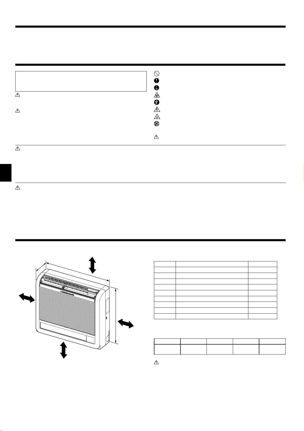
200
B
700
D
Fig. 2-1
(mm)
A
600
C
The indoor unit should be supplied with the following accessories.
PART NUMBER
1
2
3
4
5
6
7
8
9
Drain hose 1
Pipe cover 1
Band 2
Indoor unit mounting bracket 1
Fixing screw for 4 4 × 25 mm 5
Wood screw for the indoor unit fi xation 4
Washer of
Felt tape (Used for left or left-rear piping) 1
MA Remote controller cable 1
ACCESSORY QUANTITY
6
4
2.1. Outline dimensions (Indoor unit) (Fig. 2-1)
The unit must be securely installed on a structure that can sustain its weight.
Models A B C D
P20/25/32/40 100 mm or more 100 mm or more 100 mm or more
Warning:
Mount the indoor unit on a wall structure strong enough to withstand the
weight of the unit.
150 mm or below
from the fl oor
2
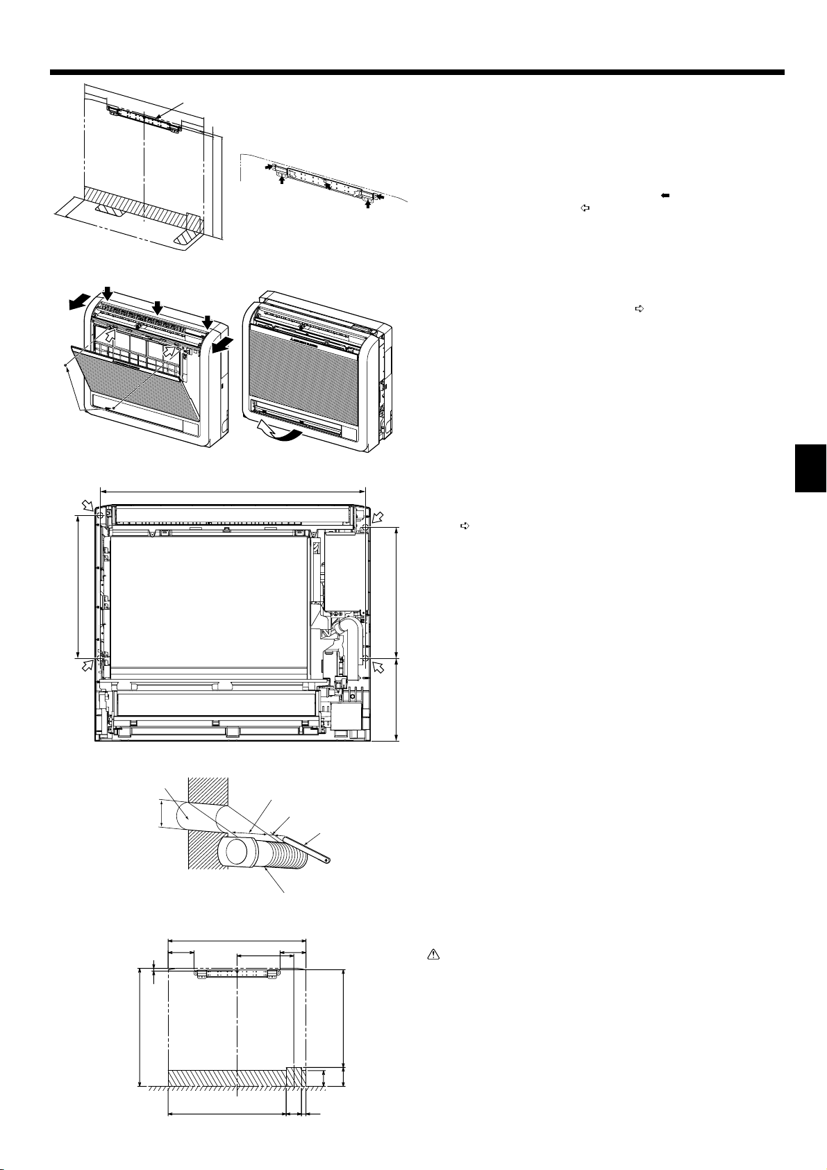
3. Installing the indoor unit
200
131
(700)
Fig. 3-1
Fig. 3-3
131
14
586
(600)
674
Fig. 3-2
Fig. 3-4
(mm)
3.1. Indoor unit mounting bracket installation
• Install the bracket fi rmly to the wall structure (stud, etc.). (Fig. 3-1)
• Use a level to install the mounting bracket horizontally.
• Install the indoor unit 150 mm or below from the fl oor.
Indoor unit mounting bracket
A
Note:
To prevent the indoor unit mounting bracket from vibrating slightly, be sure
to fasten the bracket at the holes indicated by . In addition, fasten the
bracket at the holes indicated by if possible. (Fig. 3-2)
3.2. Indoor unit preparation
Press the 2 positions indicated by the arrows and open the front grille.
1
(Fig. 3-3)
Open the front grille and remove the 2 screws.
2
Open the horizontal vane for the upper air outlet, push the top of the front panel
3
in 3 locations, and then pull the top of the grille away from the indoor unit.
Screws
B
Lift up the front grille to remove it. (Fig. 3-4)
4
3.3. Indoor unit installation (Fig. 3-5)
• Hook the top of the indoor unit on the indoor unit mounting bracket.
• Use the included wood screws and washer, and fasten the indoor unit at 2 loca-
tions ( ) each at the top and the middle of the unit.
GB
Note:
Install the indoor unit securely to the wall, making sure that there is no gap
between the unit and the wall.
363
333210
Fig. 3-5
Fig. 3-6
1)
131
14
600
700
288
131
496
97
80
3.4. Making holes in the wall and fl oor
3.4.1. Making holes (Fig. 3-6)
Make ø65 mm or ø75 mm holes that are approximately 5–7 mm deep and an-
1
gled slightly downward outward from the room.
Insert the wall hole sleeves into the holes.
2
Wall hole
A
65 mm or 75 mm dia.
B
Indoor side
C
Wall hole cross section
D
Wall thickness
E
One scale
F
Cut with 1 extra scale length.
G
Wall hole sleeve
H
Caution:
Be sure to use the wall hole sleeves. Otherwise, the indoor/outdoor unit connecting wires may contact a metal object in the wall or, in the case of hollow
walls, small rodents may gnaw on the wires, resulting in a very dangerous
situation.
3.4.2. Determining hole positions
The areas where the piping can be routed are indicated with oblique lines in the
fi gure.
1) For rear or left-rear piping (Fig. 3-7)
(The following fi gure is a front view of the indoor unit installation location.)
599
Fig. 3-7
2378
3
3. Installing the indoor unit
2)
60
200
150
168
700
61
75
62
(mm)
31
73
105
147
2) For right downward or left downward piping (Fig. 3-8)
(The following fi gure is a view of the bottom of the indoor unit from above.)
When the unit is installed on the wall.
A
When the unit is installed on the fl oor.
B
Fig. 3-8
3)
60
19
60
Fig. 3-9
4)
60
Fig. 3-10
19 60
3) For left piping (Fig. 3-9)
4) For right piping (Fig. 3-10)
3.4.3. Sealing the holes
Use putty or a caulking compound to seal the holes.
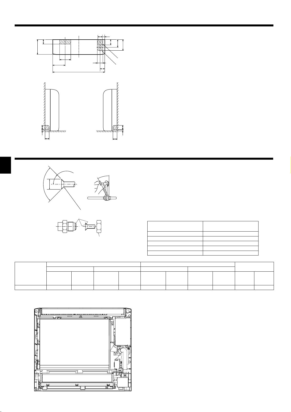
4. Refrigerant pipe
GB
±0.5°
°
90
øA
45°±2°
R0.4 ~ R0.8
Fig. 4-1
Refrigerant pipe sizes & Flare nut tightening torque
B
Liquid pipe Gas pipe Liquid pipe Gas pipe
Pipe size
(mm)
P20/25/32/40
Apply refrigerating machine oil over the entire fl are seat surface.
C
* Do not apply refrigerating machine oil to the screw portions. (This will make the fl are nuts more apt to loosen.)
Be certain to use the fl are nuts those are attached to the main unit. (Use of commercially-available products may result in cracking.)
D
O.D. ø6.35 (1/4”)
R407C or R22 R410A
Tightening
torque
(N·m)
14 - 18
Pipe size
(mm)
O.D. ø12.7 (1/2”)
Tightening
torque
(N·m)
49 - 61
4.1. Connecting pipes (Fig. 4-1)
• When commercially available copper pipes are used, wrap liquid and gas pipes
with commercially available insulation materials (heat-resistant to 100°C or more,
thickness of 12 mm or more).
• The indoor parts of the drain pipe should be wrapped with polyethylene foam
insulation materials (specifi c gravity of 0.03, thickness of 9 mm or more).
• Apply thin layer of refrigerant oil to pipe and joint seating surface before tightening
fl are nut.
• Use two wrenches to tighten piping connections.
• Use refrigerant piping insulation provided to insulate indoor unit connections.
Insulate carefully.
Flare cutting dimensions
A
Copper pipe O.D.
(mm)
ø6.35 8.7 - 9.1
ø9.52 12.8 - 13.2
ø12.7 16.2 - 16.6
ø15.88 19.3 - 19.7
ø19.05 23.6 - 24.0
Pipe size
(mm)
O.D. ø6.35 (1/4”)
Tightening
torque
(N·m)
14 - 18
O.D. ø12.7 (1/2”)
Pipe size
(mm)
Flare dimensions
øA dimensions (mm)
Flare nut O.D.
Tightening
torque
(N·m)
49 - 61 17 26
Liquid pipe
(mm)
Gas pipe
(mm)
4.2. Refrigerant piping
4.2.1. Connecting pipe installation
Install the connecting pipes so that the piping can move slightly to the front, back,
left, and right. (Fig. 4-2)
Fig. 4-2
4

4. Refrigerant pipe
Fig. 4-3
3)
Installing flushagainst a wall with
molding
2)1)
Fig. 4-5
For left or right piping
Fig. 4-4
1) For right downward piping (Fig. 4-3)
2) For piping other than right downward (Fig. 4-4)
Bands
A
Pipe covers
B
Remove the cover.
C
• Be sure to insulate the connecting pipes and place them near the rear of the indoor unit so that they do not contact the front panel.
• Be careful not to crush the connecting pipes when bending them.
3) For left or left-rear piping (Fig. 4-5)
Bundle the connecting pipes and drain hose together, and then wrap them in felt
tape.
Make sure that the drain hose is not routed upward.
A
Felt tape
B
* Wrap the felt tape tightly around the pipes and hose starting near where the
pipes and hose are routed from the indoor unit. (The overlap width of the felt
tape should not be more than 1/2 of the tape width.)
Start wrapping the piping tape around the pipes and hose 10 mm inside the
C
indoor unit.
Fasten the end of the felt tape with a bandage stopper.
D
Cut and use the lower side panels on the left and right sides of the indoor unit as
shown.
Smooth the cut edges of the side panels so that they will not damage the insulation
coating. (Fig. 4-6)
Cut the lower side panels to match the height of the modelling.
E
GB
Fig. 4-6
5. Drainage piping work
Fig. 5-1
Fig. 5-2
5.1. Drainage piping work
• Be sure to route the drain piping slightly downward (1/100 or more) so that the
drain water fl ows easily.
• Do not route the drain piping as shown in the examples mark with an “X” in the
fi gure. (Fig. 5-1)
• If the drain hose is too short, refer to Fig. 5-2 to extend the length of the hose.
• If the indoor unit is installed in a high location such as a high-rise apartment,
strong winds may cause the drain water to fl ow back through the drain hose and
leak from the unit. If necessary, contact your nearest Mitsubishi Electric representative for the optional parts to prevent this problem.
• If the drain hose is routed indoors, be sure to wrap it in commercially-available
insulation.
• Do not connect the drain piping directly to a septic tank, sewage tank, etc., where
ammonia gases or hydrogen sulfi de are produced.
• If there is slack in the drain hose or the end of the drain hose is raised up, the
drain water may not fl ow smoothly and some drain water may collect in the hose.
This can lead to a strange sound (burbling) being produced during strong winds
or when a ventilation fan, etc., is used in a residence that is well-sealed. If necessary, contact your nearest Mitsubishi Electric representative for the optional parts
to prevent this problem.
Sloping downward
A
No upward slope
B
Accumulated drain water
C
Air
D
End of drain hose is immersed in water.
E
Drainage channel
F
50 mm or less from ground
G
Drain hose
H
Fixable PVC hose (inner diameter: 15 mm) or rigid PVC pipe (VP-15)
I
• When routing the drain piping, make sure that the drain hose is routed as shown.
(Fig. 5-3)
Fig. 5-3
200
50
5
5. Drainage piping work
• Insert the drain hose all the way to the base of the drain pan. (Fig. 5-4) Make sure
that the drain hose is securely caught on the projection in the hole in the drain
pan.
Fig. 5-4
Fig. 5-5
6. Embedding the indoor unit in a wall
GB
52
475
65
Fig. 6-1
• Route the drain hose diagonally below the connecting pipes. (Fig. 5-5)
Piping tape
A
Refrigerant piping
B
Drain hose
C
• Make sure that the drain hose is not routed upward and that there are no waves
in the hose.
• Do not pull the drain hose, and then wrap tape around it.
• Route the piping so that it does not project past the rear of the indoor unit. (Refer
to the fi gure to the left.)
Piping bent outward
D
Push
E
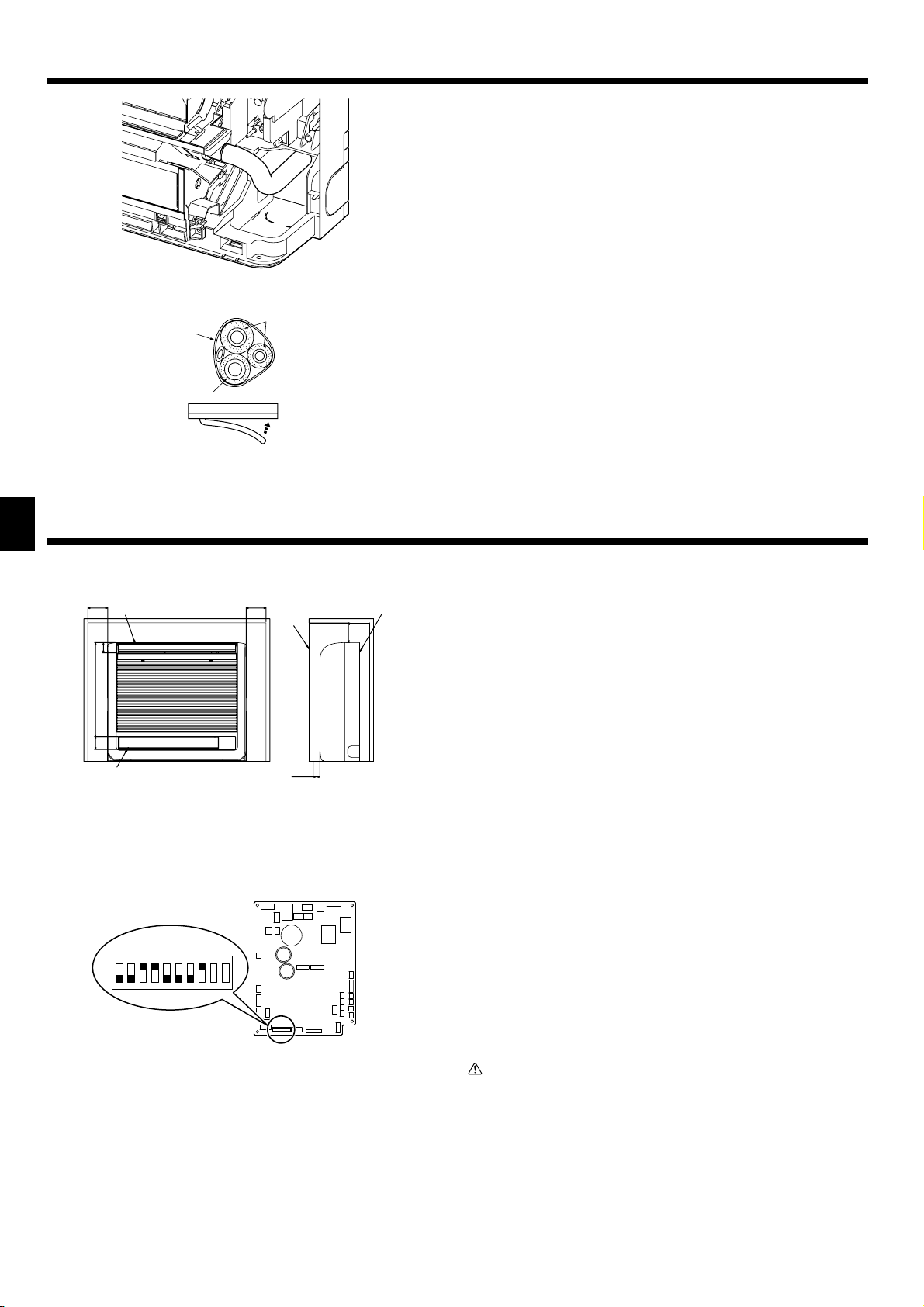
6.1. Embedding the indoor unit in a wall (Fig. 6-1)
• On the indoor unit and right and left space (100 mm or more) are the service
space.
• On a right side of the indoor unit, there is a hole for the room temperature sensor,
and do not close it, please.
• When installing a grating, use a grating with narrow upper and lower horizontal
bars so that the airfl ow from the upper and lower air outlets does not contact the
bars. If the horizontal bars will block the lower air outlet, use a stand, etc., to adjust the height of the indoor unit. If the upper or lower air outlet is blocked, the air
conditioner will not be able to cool or warm the room well.
• Use a grating with vertical bars, etc., that has at least 75% open area. If the grating has horizontal bars or if the open area is less than 75%, performance could
be reduced.
• When the indoor unit is embedded in a wall (built-in), the time it takes for the room
temperature to reach the set temperature will increase.
100 mm or more
A
Upper air outlet
B
Lower air outlet
C
Grating
D
100 mm or more
E
Indoor unit
F
35 mm or more
G
6.2.
Embedded indoor unit setting (must be performed)
(Fig. 6-2)
• When embedding the indoor unit in a wall, restrict the movement of the horizontal
SW3
ON
1234567 8 9 10
Fig. 6-2
vane for the upper air outlet so that it only operates horizontally.
• If this setting is not performed, heat will build up in the wall and the room will not
be cooled or warmed properly.
• Remove the electrical part cover and pull out the control board.
• Set DIP switches 3-5 and 3-6 on the control board to ON.
• After setting the switches, reinstall the control board in its original position and
install the electrical part cover.
Caution:
To avoid damage to the control board due to static electricity, be sure to discharge the static buildup before handling it.
6
 Loading...