

Page 1

AIR-COOLED SPLIT-TYPE DUCTED AIR CONDITIONERS
DATA BOOK
Series : PE(H)
Cooling only
Model Service ref.
PE-7MYC PE-7MYC-EU
PE-8MYC PE-8MYC-EU
PE-10MYC PE-10MYC-EU
PE-15MYC PE-15MYC-EU
PE-20MYC PE-20MYC-EU
Heat pump
PEH-5MYA PEH-5MYA-EU
PEH-7MYA PEH-7MYA-EU
PEH-8MYA PEH-8MYA-EU
PEH-10MYA PEH-10MYA-EU
PEH-15MYA PEH-15MYA-EU
PEH-20MYA PEH-20MYA-EU
Page 2

- 1 -
CONTENTS
SAFETY FOR USE ------------------------------------------------------2
A COMPLETE LINE UP ------------------------------------------------4
FEATURES-----------------------------------------------------------------5
DESCRIPTIONS----------------------------------------------------------5
MECHANICAL SPECIFICATIONS ----------------------------------6
TYPICAL INSTALLATION EXAMPLE ------------------------------6
MODEL-DESIGNATION BREAKDOWN ---------------------------7
SPECIFICATIONS -------------------------------------------------------8
ELECTRICAL DATA----------------------------------------------------11
SELECTION PROCEDURE -----------------------------------------14
CAPACITY TABLES----------------------------------------------------16
OPERATION RANGE--------------------------------------------------36
FAN PERFORMANCE-------------------------------------------------37
SOUND DATA------------------------------------------------------------40
OUTLINE DIMENSIONS----------------------------------------------41
WIRING DIAGRAMS---------------------------------------------------48
ELECTRICAL OPERATION FLOW CHARTS -------------------71
REFRIGERANT SCHEMATICS-------------------------------------74
SAFETY & CONTROL DEVICES ----------------------------------75
SPECIAL ORDER------------------------------------------------------77
PHYSICAL DATA--------------------------------------------------------78
INSTALLATION----------------------------------------------------------87
INSTRUCTIONS FOR USE----------------------------------------103
HOW TO OPERATE--------------------------------------------------108
SPECIFICATION GUIDELINES ----------------------------------112
Specifications subject to change without notice.
Page 3
SAFETY FOR USE
- 2 -
fire may result. If you need to have the unit
Ask your dealer or specialized subcontractor
for installation.
For installation, conduct the work correctly by
following the Installation Manual.
Install the unit on a spot sufficiently durable against
the unit weight.
All electric work must be performed by licensed
technician, according to local regulations and the
instructions given in this manual.
The units should be powered by dedicated power
lines.
Use only the specified cables for wiring. The
connections must be made secured without
tension the terminals.
The unit should be installed according to the
instructions in order to minimize the risk of damage
from earthquakes, typhoons or strong winds.
The outdoor unit must be installed on stable, level
surface, in a place where there is no accumulation
of snow , leaves or rubbish.
The outdoor unit should be installed in a location
where air and noise emitted by the unit will not
disturb the neighbors. The indoor unit should be
securely installed.
Never repair the unit, remodel or transfer it to
another site by yourself.
Use only the specified refrigerant (R-22) to charge
the refrigerant circuit.
Do not mix it with any other refrigerant and do not
allow air to remain in the circuit.
Ventilate the room if refrigerant leaks during
Installation.
After completing installation work, make sure that
refrigerant gas has not leaked.
Take a proper measure to suppress the critical
concentration of refrigerant if leaked when
installing the unit in a small room.
The terminal block cover of unit must be firmly
attached to prevent entry of dust and moisture.
Use only optional parts authorised by Mitsubishi
Electric.
Before conducting installation work, please read this ''SAFETY FOR USE'' carefully
for
correct installation.
Since the caution items shown here contain important description relative to safety, please
observe them without fail.
After reading, please keep it with you together the Instruction Manual, and read it again at the
movement of the unit.
Conducting installation work by yourself improperly
may cause a fire, electric shock or water leakage.
Improper installation may cause a fire, electrical shock
or water leakage.
Insufficient durability can cause an injury by the falling
down of unit.
Power lines with insufficient capacity or improper
electrical work may result in electric shock or fire.
Improper connection or fastening can cause a fire or
electrical shock.
Improper installation work can cause an injury by the
falling down of the unit.
If the unit is loosely mounted, it may fall, and cause injury.
If they are performed improperly, water leakage, electric
shock or
repaired or moved, consult your dealer.
Air enclosed in the circuit can cause high pressure resulting
in a rupture and other hazards.
The refrigerant heated generates poisonous gas by
decomposition which can cause poisoning.
If refrigerant gas has leaked and exposed to fan heater,
Please do the gas leakage inspection before starting.
stove, oven and so on, it may generate noxious gases.
The limit density is made not to be exceeded even if the
refrigerant leaks by any chance.
You are necessary to ventilation measures to prevent
the accident. If the refrigerant leaks, hypoxia accident
may caused.
For the countermeasure to be taken, consult your
dealer.
Improper mounting of the cover cause electric shock or
fire.
If the accessories are installed improperly, water
leakage, electric shock or fire may result.
Ask your dealer or an authorised company to install
them.
Erroneous handling gives a high possibility to induce serious results such as
death or heavy injury.
Erroneous handling may induce serious injury depending on the situation.
Warning
Warning
Caution
The heating of refrigerant is noted.
When the refrigerant touches the fire etc., it was decomposed and a poisonous gas is generated.
Do not use the welding machine etc., in the room close up
of the installation of the air conditioner.
Page 4

- 3 -
The gas may ignite or explode when the gas leaks and
collects in surround of the unit.
The erroneous operation of air conditioner may be
induced by inverter equipment, independent power
device, medical equipment or communication
equipment.
As the use for the applications other than that
designed originally may result in the deterioration of the
quality. Consult your dealer in this regard.
Installing the unit at the following places may cause a
trouble, a place where is much machine oil, salt ,
humidity or dust, spa district, a place full of sulfur gas,
volatile gas, or corrosive gas, a place near high
frequency processing machine.
If the drain pipes are not properly insulated,
condensation will result and drip on ceiling, floor or other
possessions.
When the unit inclines, it causes the water leak and the
breakdown.
Please confirm the horizontal with the spirit level.
Improper drain piping (hose) may cause water leakage
and damage to furniture or other possessions.
Do not connect the earth wire to gas pipe, city water
pipe, lightning rod or telephone earth wire.
Improper earth connection may cause electrical shock.
Failure to mount the electric leak breaker may cause
electrical shock.
Using a wire or copper wire instead of proper capacity
can cause fire or trouble.
Other appliances connected to the same line could cause
an overload.
Otherwise, current leakage, overheating or fire may
occur.
The tighten or loosen the connections may cause generate
heat and cause fire.
The poor mounting of the panel or terminal cover may
cause the heat generation of the terminal connection,
a fire or electrical shock.
Otherwise electric shock can be resulted.
The unit should not be carried by only one person if it is
more than 20kg. It occasionally causes the damage of
the unit and health to be impaired.
Some unit use PP bands for packing. Do not use any PP
band for delivery purpose. It may cause the injury.
Do not touch the heat exchanger fins with your bear hands.
Doing so may cut your hands.
When carrying in outdoor unit, be sure to support it at four
points. Carrying in and lifting with 3-point support may
make outdoor unit unstable, resulting in a fall of it.
Be sure to safety dispose the packing materials.
Packing materials, such as catches and other metal or
wooden parts, may cause stabs or other injuries.
The damaged base may cause the falling down of the
unit which may give injury.
Do not turn the main power switch OFF during seasons
of heavy use, doing so can result in failure.
Touching directly such part can cause a burn or
frostbite as it becomes high or low temperature
according to the refrigerant state.
Touching directly it may injure your hands.
You could be injured if you touch rotating, hot or highvoltage parts.
Dust may accumulate, and cause a failure.
Continuing the operation without eliminating the
emergency state may cause a machine trouble, fire, or
electrical shock.
Otherwise, water leakage or unit failure may occur.
If washed with water, electric shock may be caused.
Do not wash the unit with water.
Never install on the place where a combustible
gas might leak.
When the unit is installed at telecommunication
centers or hospitals, take a proper provision
against noise.
For special use as for foods, animals/plants,
precision equipment or art objects, the applicability
should be confirmed beforehand.
Do not use the unit under a special atmosphere.
Thermal insulation of the drain pipes is necessary
prevent dew condensation.
The unit should be securely installed level surface.
Install drain piping (hose) according to this
Installation Manual to ensure proper drainage.
The unit must be properly earth connected.
When installing at a watery place, provide an
electric leak breaker.
Make sure that each appliance has a main power
switch.
Use breaker or fuse with proper capacity.
For the power lines, use standard cables of
sufficient current capacity.
When installing the power lines, do not apply
tension to the cables.
Arrange the configuration of wiring not to bring up
the panel and terminal cover, and fasten the panel
and terminal cover securely.
When the room is high humidity or when the drain pipe
is clogged, water may drip from the indoor unit.
A thing embarrassed which gets wet under the unit
is not put.
Do not handle the switch with wet hands.
Be very careful about unit transportation.
Do not leave the mounting base being damaged.
Turn on the main power switch more than 6 hours
before starting operation.
Do not touch the compressor or refrigerant piping
without wearing glove on your hands.
Do not touch the metal edges inside the unit
without wearing glove on your hands.
Do not remove the panel or the fan guard from the
unit when it is running.
Do not operate the air conditioner without the air
filter set place.
At emergency (if you smell something burning), stop
operation and turn the power source switch off.
After stopping operation, be sure to wait for five
minutes before turning off the main power switch.
Caution
Remote controller is not installed for the place
where direct sunshine strikes.
It occasionally causes the electric shock and the breakdown.
Remote controller is not pushed with the thing
sharpening ahead.
Page 5
- 4 -
A COMPLETE LINE UP
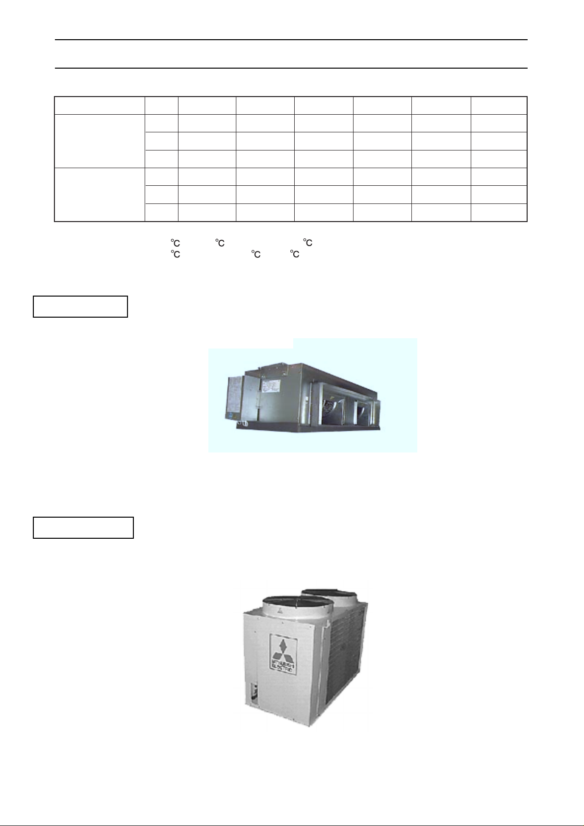
Indoor unit
PEH-5
kcal/h
12,400
Cooling capacity
Btu/h
49,150
kW
14.4
kcal/h
12,400
Heating capacity
(PEH only)
Btu/h
49,150
kW
14.4
PE(H)-7
15,400
61,000
17.9
16,200
64,100
18.8
PE(H)-8
18,900
75,100
22.0
18,900
75,100
22.0
PE(H)-10
24,800
98,300
28.8
24,800
98,300
28.8
PE(H)-15
37,900
150,200
44.0
37,900
150,200
44.0
PE(H)-20
49,600
196,600
57.6
49,600
196,600
57.6
Note: Cooling & heating capacities are based following conditions.
Cooling: Indoor:27 DB, 19 WB; Outdoor: 35 DB
Heating: Indoor:21 DB; Outdoor: 7 DB, 6 WB (PEH only)
Cooling and Heating capacities are based 5m pipe length
Outdoor unit
Example PEH-7
Example PUH-7
Page 6
FEATURES
- 5-
DESCRIPTIONS
High sensible cooling capacity.
The sensible cooling capacity has been significantly
improved through balanced optimised heat
exchanger design.
Comfort heating. (PEH only)
Highly efficient operation.
The EER(Energy Efficiency Ratio) on these models
is greatly improved by revised design specifications
and by being manufactured stringently to Mitsubishi
Electric high quality standards.
Flexibility of Supply Air Delivery
PE, PEH-15,20 feature belt driven Supply Air fans
enabling accurate matching of actual airflow rates
to the specified quantities. Accurate commissioning
is assisted by the capability to change pulleys and
belts if necessary to achieve the desired air balance.
Labour saving installation.
The unit operation can commence immediately after
connecting to the power supply, refrigerant piping,
drain piping, ducting and control system.
Low ambient cooling. (Special order)
In applications with relatively high internal loads,
there may be a requirement for all series to
operate on cooling at low ambient conditions.
Special order parts is available to maintain the
refrigeration circuit in balance at outdoor temperatures
as low as -5 .
Please consult your local Mitsubishi Electric Sales
office for application advice on these parts.
Wide electrical control capability.
The PEH series are designed to provide effective
heating even when the outside temperature is down
to -10 .
All series is flexible mechanical control
configuration.
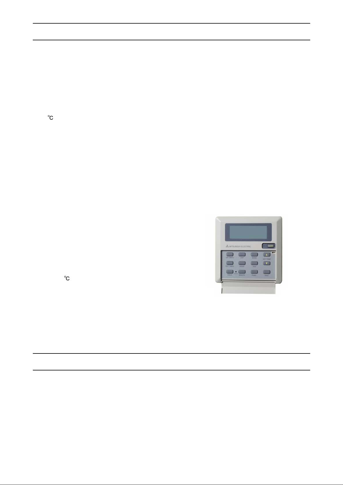
In addition Global Remote Controller is prepared as
special order.
The Global Remote Controller gives the programmable
weekly timer, compressor anti-short cycle timer(3min.),
cool/heat/fan/auto changeover etc.(Heat and auto
changeover are only PEH.)
The factory standard is for provision of 24 volt terminal
block to enable a field wired control of contractors
choice to be connected.
Please consult your local Mitsubishi Electric Sales
office for application advice on these control.
Mitsubishi Electric air conditioners series PE(H)/PU(H)
are available in a wide range of sizes and models to
enables the designer to select the best model for
each application.
All series units are completely assembled, wired and
strictly tested at the factory.
With the development of all series demands
for such features as light weight, compactness,
increased capacity, appropriate static pressure, air
flow control, and having flexibility of inter facing
energy saving electronic controls, Mitsubishi
Electric have met market expectations.
Grobal Remote Controller
Page 7
- 6-
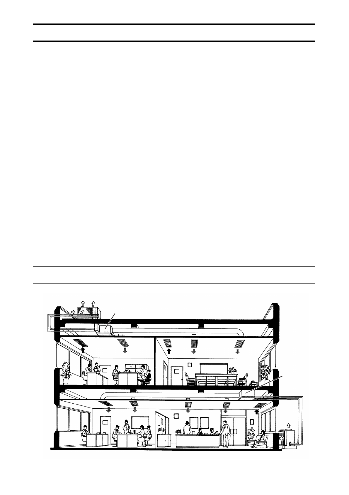
TYPICAL INSTALLATION EXAMPLE
MECHANICAL SPECIFICATIONS
General
All units are factory assembled, piped, internally wired.
They are also tested and checked under a strict quality
control system in the factory.
Exterior surfaces of all units of outdoor unit are
phosphatized, zinc-coated steel with powder coating
and ivory white baked enamel finish.
Refrigeration Controls
Refrigeration controls include condenser fan,
evaporator fan and compressor contactors.
Compressors
All units have high efficiency type hermetic line starting
compressors.
Compressors are equipped with thermal overload
protector, over-current relay and high pressure
protection control.
Crankcase heaters are standard.
Evaporator Coils
Highly efficient cross-finned coil are applied to provide a
larger cooling capacity with low air speed on the coil.
Coils are made of 9.52mm OD and 0.35mm thick
seamless copper tubing mechanically bonded to 0.12mm
thick aluminium fins and are factory leak tested at a
pressure of 3.3MPa.
They are provided with strainers
attached to the capillary tubes to further ensure a clean
system.
Condenser Coils
Unnecessary power input due to higher discharge
pressure is avoided by high performance designs of
cross-finned coil.
Condenser coils are made of 9.52mm OD, 0.35mm
thick seamless copper tubes mechanically bonded to
0. 12mm thick aluminium fins and factory pressure
and leak tested at 3.3MPa.
Evaporator Fans
The sirocco fans are made of galvanised steel and
balanced to proved accurate air flow performance at
low noise level.
Condenser Fan
The direct-drive propeller fan is dynamically balanced,
to ensure smooth airflow.
A weatherproof three-phase squirrel cage induction
motor is used to drive the condenser fan.
PU(H)
PE(H)
PE(H)
PU(H)
Page 8

- 7 -
MODEL-DESIGNATION BREAKDOWN
PE-10MYC
1
Design Sequence
Electrical Supply
Compressor Horsepower
Series Number
5 = 5 HP
7 = 7 HP
8 = 7.5 HP
10= 10 HP
15= 15 HP
20= 20 HP
PE = Indoor unit
PEH = Indoor unit
PU = Outdoor unit
PUH = Outdoor unit
Y = 3 phase 380~415V 50Hz 4 wires
(
In case of PE(H)-7 Indoor unit
Y = 1 phase 220~240V 50Hz 2 wires
)
Service reference
Page 9
- 8 -
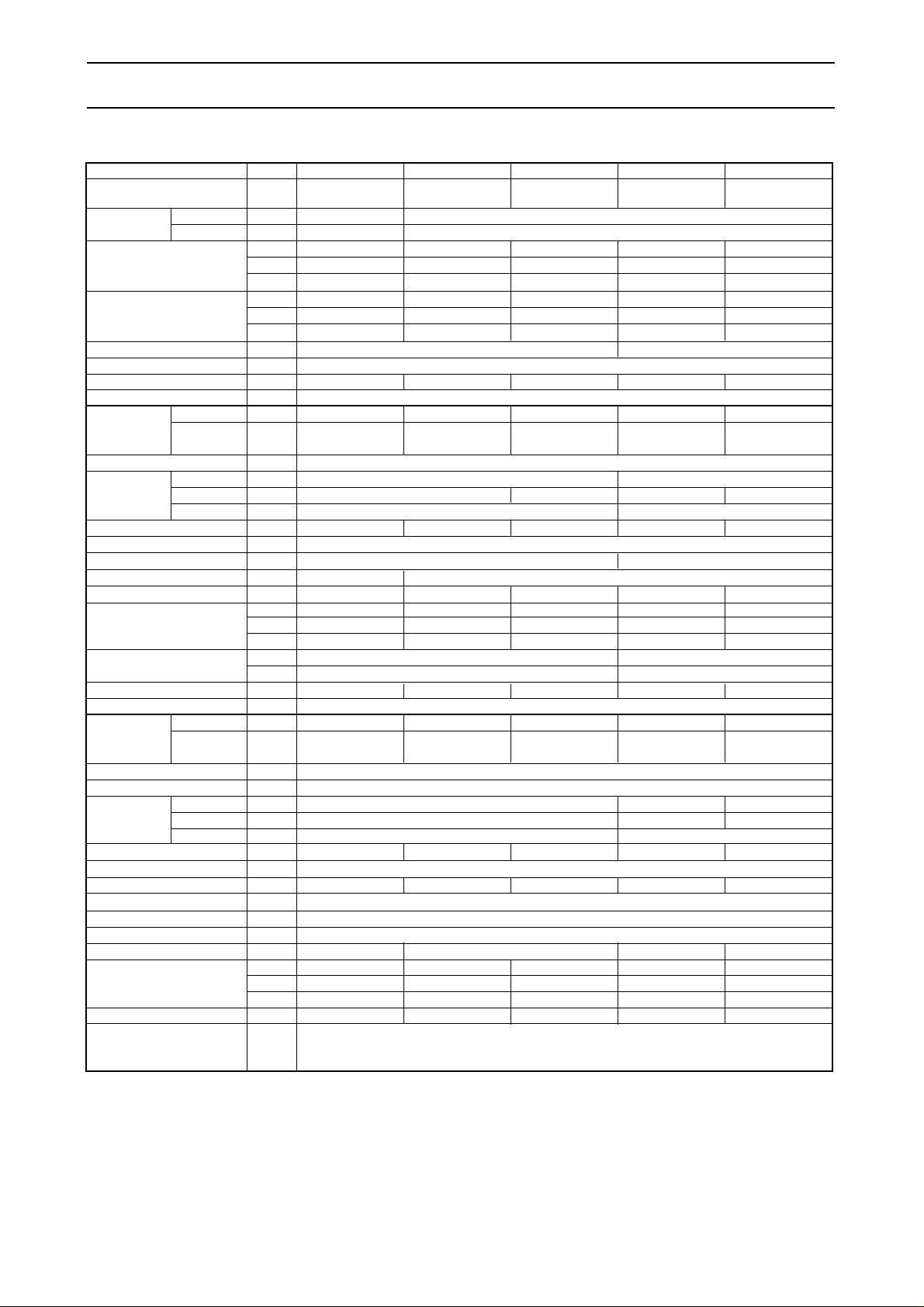
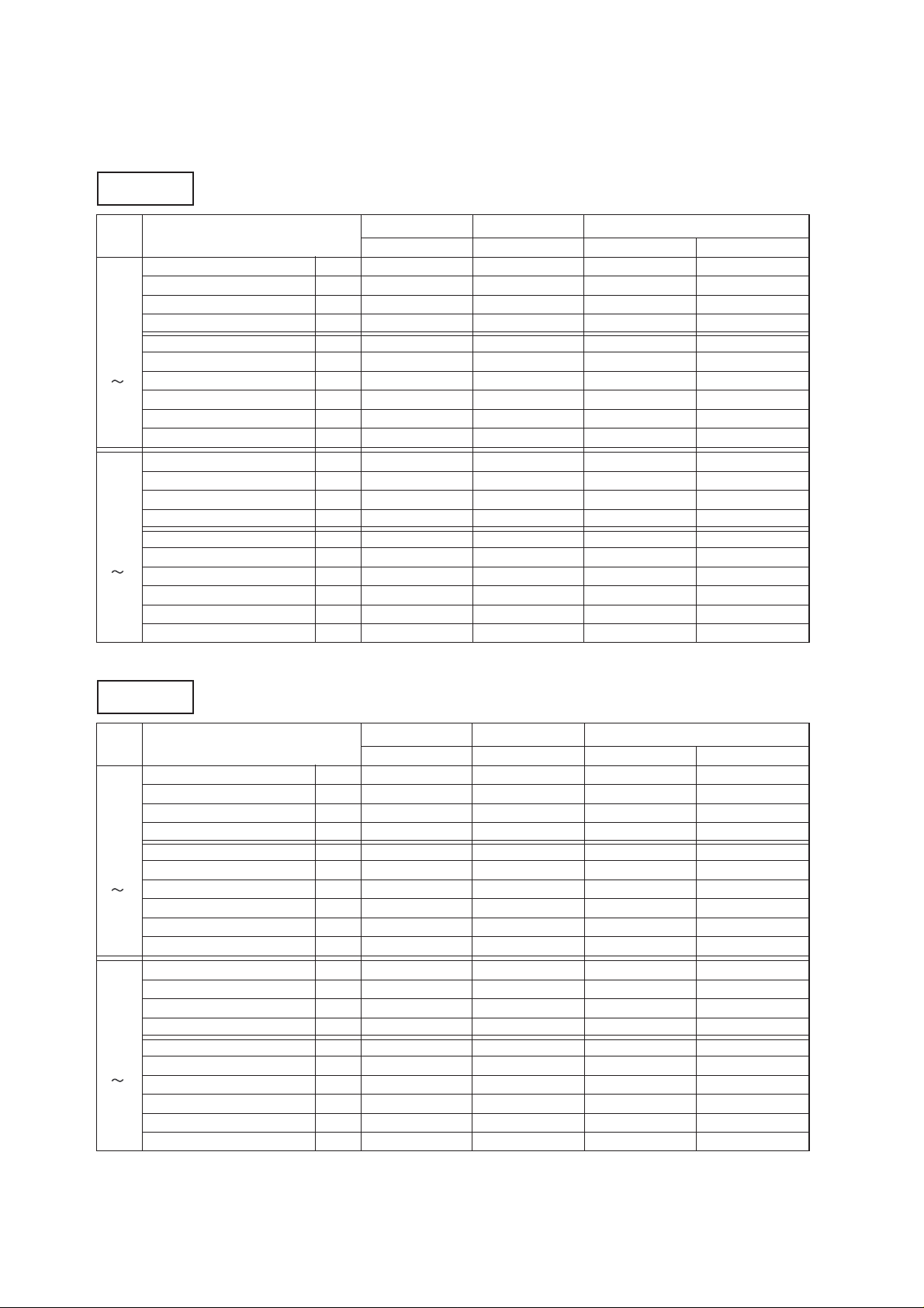
SPECIFICATIONS
Model name
Service
reference
Power supply Indoor
Outdoor
Total cooling capacity
Sensible cooling capacity
kW
Btu/h
kcal/h
%
Capacity step
Refrigerant
Refrigerant charge
kg
Capillary tube
Refrigerant control
Indoor Unit
Model name
Service
reference
External finish
Acrylic resin coating
Munsell 5Y 8/1
Dimension Height mm
Width
mm
Depth mm
Net weight
Compressor
kg
Indoor coil
Cross fin coil
Indoor fan
Centrifugal (Galvanized) - Belt driveCentrifugal (Galvanized) - Direct drive
Indoor fan motor
Three phase induction motor
Single phase induction motor
kW
No. ✕ Motor output
Indoor fan air flow
CMM
CFM
L/S
External static
pressure
mmAq
Pa
Sound pressure level
dB(A)
Outdoor unit
Model name
Service
reference
External finish
Color
Dimension Height mm
Width mm
Depth mm
Net weight
kg
Outdoor coil
Cross fin coil
Outdoor fan
Propeller-Direct drive
Outdoor fan motor
Three phase induction motor
No. ✕ Motor output
kW
No. ✕ Motor output
kW
Outdoor fan air flow CMM
CFM
L/S
Sound pressure level dB(A)
Protection devices
3PH 4W380 ~ 415V 50Hz
3PH 4W380 ~ 415V 50Hz
1PH 2W220~240V 50Hz
3PH 4W 380~415V 50Hz
17.9
61,100
15,400
kW
Btu/h
kcal/h
14.3
48,800
12,300
0-100 0-50-100
5.7 5.0 8.7 2
✕ 4.8 2 ✕ 9.7
2 ✕ 0.09 2 ✕ 0.15 1 ✕ 0.24 2 ✕ 0.24
Note1.Cooling capacity is based on the following conditions.
Indoor;27˚CDB,19˚CWB, Outdoor;35˚CDB
Cooling capacity is based 5m pipe length.
2.Refergirant charge volumes are factory charged (at 5m piping length).Refrigerant is enclosed with the outdoor unit.
3.Capacity is gross capacity which do not include a deduction for evaporator fan motor heat.
4.The measuring point of the Sound pressure level is 1m from the unit surface.
5.Specification subject to change without notice.
R-22
Drain connection
mm
Hermetic line start(reciprocating)
PE-7MYC PE-8MYC PE-10MYC
PE-15MYC PE-20MYC
PE-7MYC-EU PE-8MYC-EU
PE-10MYC-EU
PE-15MYC-EU PE-20MYC-EU
PE-7MYC PE-8MYC PE-10MYC
PE-15MYC PE-20MYC
PE-7MYC-EU PE-8MYC-EU
PE-10MYC-EU
PE-15MYC-EU PE-20MYC-EU
22.0 28.8
75,100 98,300
18,900 24,800
17.6 23.0
60,100 78,500
15,100 19,800
44.0 57.6
150,200 196,600
37,900 49,600
35.2 46.1
120,200 157,300
30,200 39,600
Galvanized steel
428
1,415
1,615
650
67 70 84
706
1,690
1,993
865
180 212
60
2,119
1,000
70
2,472
1,167
90
3,179
1,500
140
4,945
2,333
180
6,358
3,000
1 ✕ 0.21
1 ✕ 0.7 1 ✕ 1.0
1 ✕ 2.2
1 ✕ 3.7
1 ✕ 5.0
1 ✕ 5.5 1 ✕ 7.5
2 ✕ 5.5
2 ✕ 7.5
PU-7MYC PU-8MYC PU-10MYC PU-15MYC PU-20MYC
PU-7MYC1-EU(S) PU-8MYC1-EU(S) PU-10MYC1-EU(S) PU-15MYC1-EU(S) PU-20MYC1-EU(S)
980
1,400
700
202
205
230
1,230
998
961
1,996
998
285
360
190 220
6,711 7,770
3,167
210
7,415
3,000 3,667
65 65 65 67 68
240
8,477
4,000
480
16,954
8,000
High pressure switch, freeze & frost protection, Fuse
Internal thermostat (comp & indoor fan, outdoor fan)
Over current relay (comp & indoor fan, outdoor fan)
12.5
125
20
200
55 56 59
25.4
61 62
PE-7~20MYC
Cooling only
Page 10
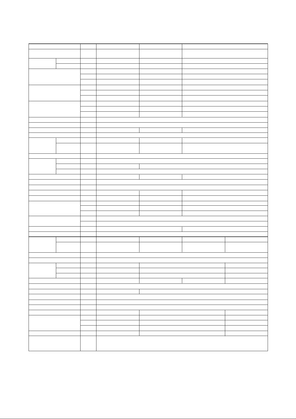
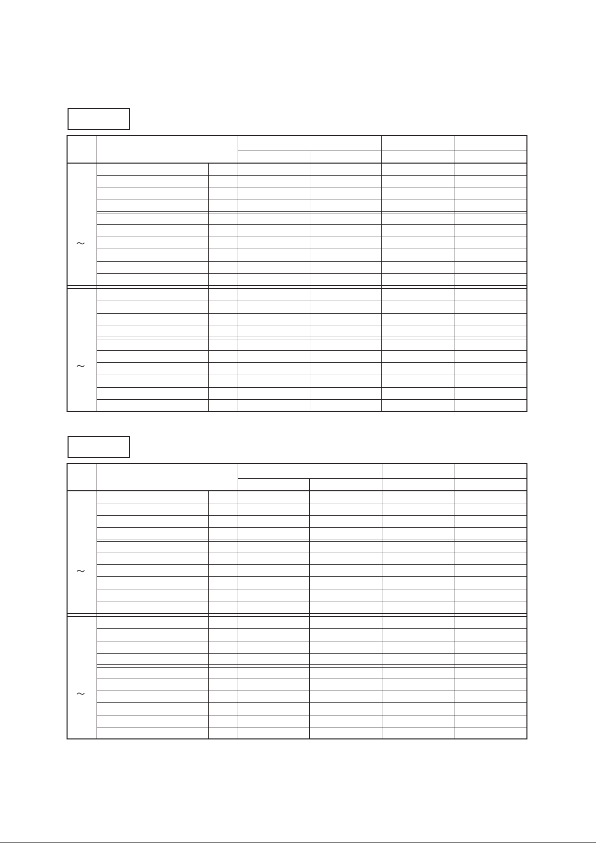
Model name
Service
reference
Power supply Indoor
Outdoor
kW
Btu/h
kcal/h
%
Capacity step
Refrigerant
Refrigerant charge kg
Capillary tube
Refrigerant control
Indoor Unit
Model name
Service
reference
External finish
Acrylic resin coating
Munsell 5Y 8/1
Dimension Height mm
Width
mm
Depth mm
Net weight
Compressor
kg
Indoor coil
Cross fin coil
Indoor fan
Centrifugal (Galvanized) - Direct drive
Indoor fan motor
Three phase induction motor
Three phase induction motor Single phase induction motor
kW
No. ✕ Motor output
Indoor fan air flow
CMM
CFM
L/S
External static
pressure
mmAq
Pa
Sound pressure level
dB(A)
Outdoor unit
Model name
Service
reference
External finish
Color
Dimension Height mm
Width mm
Depth mm
Net weight
kg
Outdoor coil
Cross fin coil
Outdoor fan
Propeller-Direct drive
Outdoor fan motor
Three phase induction motor
No. ✕ Motor output
kW
No. ✕ Motor output
kW
Outdoor fan air flow CMM
CFM
L/S
Sound pressure level dB(A)
Protection devices
3PH 4W380~415V 50Hz
3PH 4W380~415V 50Hz
3PH 4W380~415V 50Hz
3PH 4W380~415V 50Hz
kW
Btu/h
kcal/h
5.7 6.65.0
1 ✕ 0.15 2 ✕ 0.09
Note 1. Cooling and heating capacities are based on the following conditions.
Cooling indoor; 27˚CDB, 19˚CWB, outdoor :35˚CDB
Heating indoor; 21˚CDB, outdoor :7.0˚CDB, 6.0˚CWB
Cooling and heating capacities are based 5m pipe length.
2.Refergirant charge volumes are factory charged (at 5m piping length).Refrigerant is enclosed with the outdoor unit.
3.Capacity is gross capacity which do not include a deduction for evaporator fan motor heat.
4.The measuring point of the Sound pressure level is 1m from the unit surface.
5.Specification subject to change without notice.
Drain connection
mm
Hermetic line start(reciprocating)
Galvanized steel
428
1,095
1,415
650
60 67 70
42
1,483
700
60
2,119
1,000
70
2,472
1,167
1 ✕ 0.45 1 ✕ 0.21 1 ✕ 0.7
1 ✕
3.73 1 ✕ 5.5
95
3,355
1,583
167
5,898
2,783
57 65
1 ✕ 0.35
200
7,063
3,333
65
High pressure switch, freeze & frost protection, Fuse
Internal thermostat (comp & indoor fan, outdoor fan)
Over current relay (comp & indoor fan, outdoor fan)
12.5
125
55
25.4
56
PEH-7MYA PEH-8MYA
PEH-7MYA-EU
PEH-5MYA
PEH-5MYA-EU PEH-8MYA-EU
PEH-7MYA PEH-8MYA
PEH-7MYA-EU
PEH-5MYA
PEH-5MYA-EU PEH-8MYA-EU
Total cooling capacity
Sensible cooling capacity
kW
Btu/h
kcal/h
Sensible heating capacity
1PH 2W220~240V 50Hz
3PH 4W380~415V 50Hz
17.9
22.0
61,100
75,100
15,400
18,900
14.3
17.6
48,800
60,100
12,300
15,100
18.8
22.0
64,100
75,100
16,200
14.4
49,150
12,400
11.5
39,400
10,000
14.4
49,150
12,400 18,900
0-100
R-22
PUH-7MYC
PUH-8MYE
PUH-7MYC1-EU(S) PUH-8MYE-EU
PUH-8MYC
PUH-8MYC1-EU(S)
PUH-5MYE
PUH-5MYE-EU
980
1,400
700
1,175
1,250
550
1,175
1,000
550
188
150
211
214
- 9 -
PEH-5,7,8MYA
Heat pump
Page 11
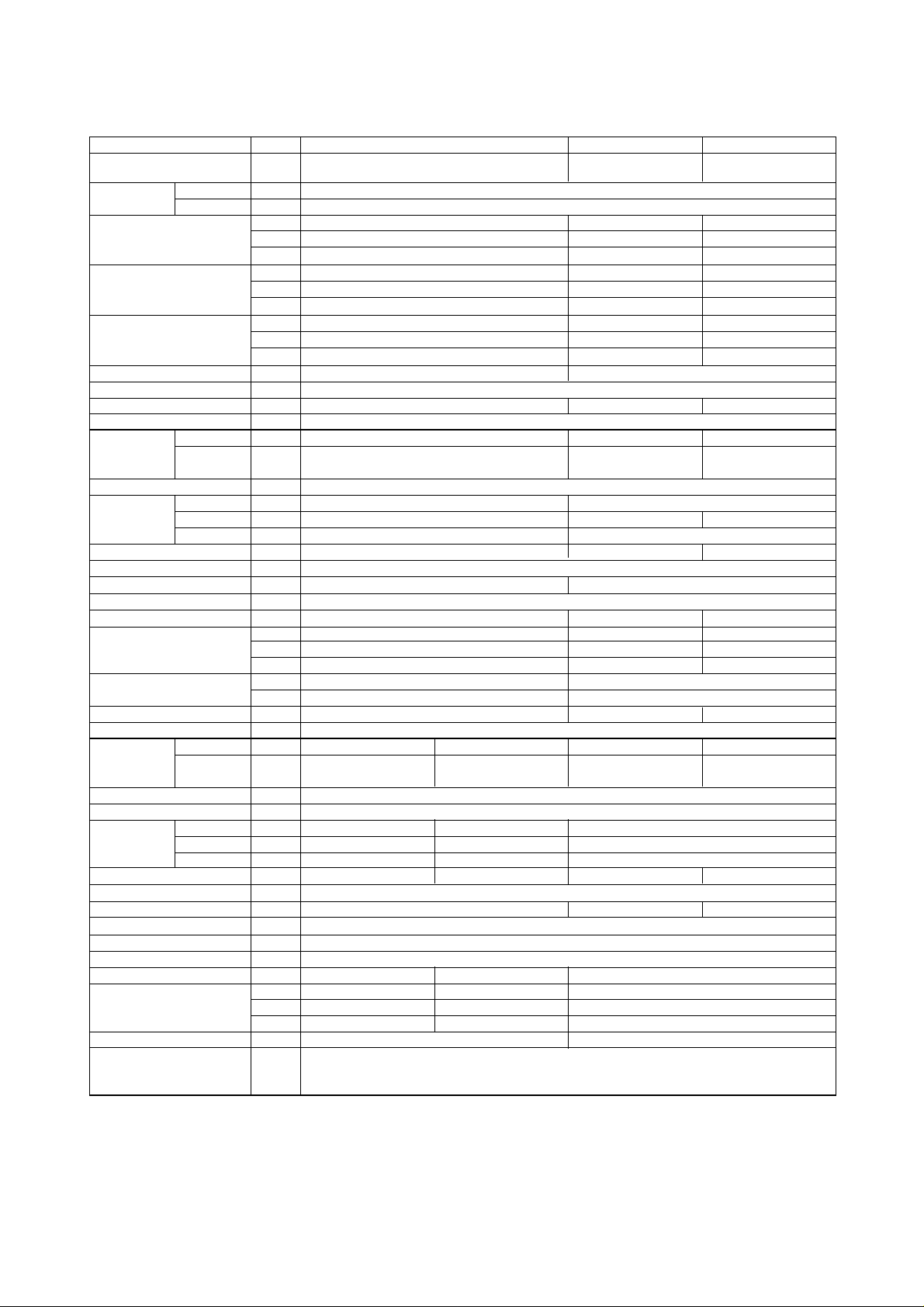
Model name
Service
reference
Power supply Indoor
Outdoor
kW
Btu/h
kcal/h
%
Capacity step
Refrigerant
Refrigerant charge kg
Capillary tube
Refrigerant control
Indoor Unit
Model name
Service
reference
External finish
Acrylic resin coating
Munsell 5Y 8/1
Dimension Height mm
Width
mm
Depth mm
Net weight
Compressor
kg
Indoor coil
Cross fin coil
Indoor fan
Centrifugal (Galvanized) - Direct drive Centrifugal (Galvanized) - Belt drive
Indoor fan motor
Three phase induction motor
kW
No. ✕ Motor output
Indoor fan air flow
CMM
CFM
L/S
External static
pressure
mmAq
Pa
Sound pressure level
dB(A)
Outdoor unit
Model name
Service
reference
External finish
Color
Dimension Height mm
Width mm
Depth mm
Net weight
kg
Outdoor coil
Cross fin coil
Outdoor fan
Propeller-Direct drive
Outdoor fan motor
Three phase induction motor
No. ✕ Motor output
kW
No. ✕ Motor output
kW
Outdoor fan air flow CMM
CFM
L/S
Sound pressure level dB(A)
Protection devices
kW
Btu/h
kcal/h
2 ✕
9.72 ✕ 6.69.9
2 ✕ 0.15 0.35
Note 1. Cooling and heating capacities are based on the following conditions.
Cooling indoor; 27˚CDB, 19˚CWB, outdoor :35˚CDB
Heating indoor; 21˚CDB, outdoor :7.0˚CDB, 6.0˚CWB
Cooling and heating capacities are based 5m pipe length.
2.Refergirant charge volumes are factory charged (at 5m piping length).Refrigerant is enclosed with the outdoor unit.
3.Capacity is gross capacity which do not include a deduction for evaporator fan motor heat.
4.The measuring point of the Sound pressure level is 1m from the unit surface.
5.Specification subject to change without notice.
Drain connection
mm
Hermetic line start(reciprocating)
Galvanized steel
428
1,615
650
1 ✕ 7.5 2 ✕ 5.5 2 ✕ 7.5
190
6,711
3,167
200
7,063
3,333
65
2 ✕ 0.35
2 ✕ 185
2 ✕ 6,534
2 ✕ 3,083
69
High pressure switch, freeze & frost protection, Fuse
Internal thermostat (comp & indoor fan, outdoor fan)
Over current relay (comp & indoor fan, outdoor fan)
25.4
Total cooling capacity
Sensible cooling capacity
kW
Btu/h
kcal/h
Sensible heating capacity
0-100 0-50-100
R-22
PEH-15MYA PEH-20MYAPEH-10MYA
PEH-10MYA-EU PEH-15MYA-EU PEH-20MYA-EU
PEH-15MYA PEH-20MYAPEH-10MYA
PEH-10MYA-EU PEH-15MYA-EU PEH-20MYA-EU
28.8
98,300
24,800
23.0
78,500
19,800
28.8
98,300
24,800
3PH 4W380 ~ 415V 50Hz
3PH 4W380 ~ 415V 50Hz
84
706
1,690 1,993
865
180 212
1 ✕ 1.0
90
3,179
1,500
1 ✕ 2.2 1 ✕ 3.7
20
200
12.5
125
140
4,945
2,333
180
6,358
3,000
59
61
62
PUH-10MYEPUH-10MYC PUH-15MYC PUH-20MYC
PUH-10MYE-EUPUH-10MYC
1-EU(S) PUH-15MYC1-EU(S) PUH-20MYC1-EU(S)
980
1,400
700
240
1,175
1,250
550
221
1,200
1,951
1,080
431
472
44.0 57.6
150,200 196,600
37,900 49,600
35.2 46.0
120,200 157,000
30,200 39,600
44.0 57.6
150,200 196,600
37,800 49,500
PEH-10,15,20MYA
Heat pump
- 10 -
Page 12
- 11 -
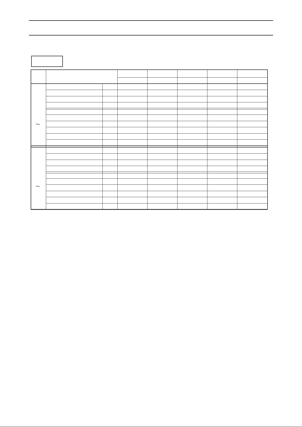
ELECTRICAL DATA
VOLT ITEM
TOTAL INPUT kW
TOTAL RUN CURRENT A
POWER FACTOR %
START CURRENT A
PE-7
240V
PE8 20
415V
COMPRESSOR INPUT kW
RUN CURRENT A
INDOOR FAN INPUT
OUTDOOR FAN INPUT
INDOOR FAN INPUT
OUTDOOR FAN INPUT
kW
RUN CURRENT A
kW
RUN CURRENT A
TOTAL INPUT kW
TOTAL RUN CURRENT A
POWER FACTOR %
START CURRENT A
COMPRESSOR INPUT kW
RUN CURRENT A
kW
RUN CURRENT A
kW
RUN CURRENT A
Cooling
PE-8MYC-EU
PE-7MYC-EU
PE-10MYC-EU PE-15MYC-EU PE-20MYC-EU
PU-8MYC1-EU
PU-7MYC
1-EU
PU-10MYC
1-EU
PU-15MYC1-EU PU-20MYC1-EU
7.2
14.6
-
74
6.0
10.7
0.8
3.2
0.4
0.7
7.2
15.9
-
81
6.0
11.6
0.8
3.5
0.4
0.8
7.8
14.2
74
83
6.8
12.3
0.6
1.2
0.4
0.7
7.8
15.5
74
91
6.8
13.4
0.6
1.3
0.4
0.8
10.1
18.9
74
82
8.6
15.9
1.0
2.0
0.5
1.0
10.1
20.7
74
90
8.6
17.6
1.0
2.1
0.5
1.0
17.6
29.6
83
119
2X7.65
2X12.45
1.7
3.5
0.6
1.2
17.6
32.3
83
131
2X7.65
2X13.65
1.7
3.8
0.6
1.2
22.0
39.1
78
140
2X9.2
2X15.95
2.4
4.8
2X0.6
2X1.2
22.0
42.7
78
152
2X9.2
2X17.55
2.4
5.2
2X0.6
2X1.2
PE-7
220V
PE8 20
380V
PE-7~20MYC-EU
Page 13
- 12 -
Heating
VOLT ITEM
TOTAL INPUT kW
TOTAL RUN CURRENT A
POWER FACTOR %
START CURRENT A
PEH-7
240V
PEH8 20
415V
COMPRESSOR INPUT kW
RUN CURRENT A
kW
RUN CURRENT A
kW
RUN CURRENT A
TOTAL INPUT kW
TOTAL RUN CURRENT A
POWER FACTOR %
START CURRENT A
COMPRESSOR INPUT kW
RUN CURRENT A
kW
RUN CURRENT A
kW
RUN CURRENT A
Cooling
PEH-8MYA-EU
PEH-7MYA-EU
PUH-8MYC1-EU
PUH-7MYC
1-EU
7.2
14.6
-
74
6.0
10.7
0.8
3.2
0.4
0.7
7.2
15.9
-
81
6.0
11.6
0.8
3.5
0.4
0.8
7.8
14.2
76
83
6.8
12.3
0.6
1.2
0.4
0.7
7.8
15.5
76
91
6.8
13.4
0.6
1.3
0.4
0.8
PEH-7
220V
PEH8 20
380V
VOLT ITEM
TOTAL INPUT kW
TOTAL RUN CURRENT A
POWER FACTOR %
START CURRENT A
PEH-7
240V
PEH8 20
415V
COMPRESSOR INPUT kW
RUN CURRENT A
kW
RUN CURRENT A
kW
RUN CURRENT A
TOTAL INPUT kW
TOTAL RUN CURRENT A
POWER FACTOR %
START CURRENT A
COMPRESSOR INPUT kW
RUN CURRENT A
kW
RUN CURRENT A
kW
RUN CURRENT A
6.3
13.6
-
74
5.1
9.7
0.8
3.2
0.4
0.7
6.3
14.9
-
81
5.1
10.6
0.8
3.5
0.4
0.8
PEH-5MYA-EU
PUH-5MYE-EU
5.5
9.5
80
69
4.7
8.1
0.54
0.9
0.25
0.5
5.5
10.4
80
69
4.7
8.85
0.54
1.0
0.25
0.55
4.5
8.5
73
69
3.7
7.1
0.54
0.9
0.25
0.5
4.5
9.2
74
69
3.7
7.75
0.54
1.0
0.25
0.55
6.5
12.4
73
83
5.5
10.5
0.6
1.2
0.4
0.7
6.5
13.6
73
91
5.5
11.5
0.6
1.3
0.4
0.8
PUH-8MYE-EU
PEH-8MYA-EU
PEH-7MYA-EU
PUH-8MYC1-EU
PUH-7MYC
1-EU
PEH-5MYA-EU
PUH-5MYE-EU
7.9
14.7
75
83
6.77
12.3
0.6
1.2
0.53
1.2
7.9
16.0
75
91
6.77
13.4
0.6
1.3
0.53
1.3
PUH-8MYE-EU
6.6
12.9
71
83
5.47
10.5
0.6
1.2
0.53
1.2
6.6
14.1
71
91
5.47
11.5
0.6
1.3
0.53
1.3
PEH-7
220V
PEH8 20
380V
INDOOR FAN INPUT
OUTDOOR FAN INPUT
INDOOR FAN INPUT
OUTDOOR FAN INPUT
INDOOR FAN INPUT
OUTDOOR FAN INPUT
INDOOR FAN INPUT
OUTDOOR FAN INPUT
PEH-5,7,8MYA-EU
Page 14
- 13 -
Heating
VOLT ITEM
TOTAL INPUT kW
TOTAL RUN CURRENT A
POWER FACTOR %
START CURRENT A
PEH-7
240V
PEH8 20
415V
COMPRESSOR INPUT kW
RUN CURRENT A
kW
RUN CURRENT A
kW
RUN CURRENT A
TOTAL INPUT kW
TOTAL RUN CURRENT A
POWER FACTOR %
START CURRENT A
COMPRESSOR INPUT kW
RUN CURRENT A
kW
RUN CURRENT A
kW
RUN CURRENT A
Cooling
10.2
19.1
74
82
8.67
15.9
1.0
2.0
0.53
1.2
10.2
21.0
74
90
8.67
17.6
1.0
2.1
0.53
1.3
PEH-7
220V
PEH8 20
380V
VOLT ITEM
TOTAL INPUT kW
TOTAL RUN CURRENT A
POWER FACTOR %
START CURRENT A
PEH-7
240V
PEH8 20
415V
COMPRESSOR INPUT kW
RUN CURRENT A
kW
RUN CURRENT A
kW
RUN CURRENT A
TOTAL INPUT kW
TOTAL RUN CURRENT A
POWER FACTOR %
START CURRENT A
COMPRESSOR INPUT kW
RUN CURRENT A
kW
RUN CURRENT A
kW
RUN CURRENT A
8.6
16.2
72
82
7.07
13.0
1.0
2.0
0.53
1.2
8.6
17.8
72
90
7.07
14.4
1.0
2.1
0.53
1.3
PEH-7
220V
PEH8 20
380V
INDOOR FAN INPUT
OUTDOOR FAN INPUT
INDOOR FAN INPUT
OUTDOOR FAN INPUT
PEH-10MYA-EU
PEH-15MYA-EU PEH-20MYA-EU
PUH-10MYC1-EU PUH-15MYC1-EU PUH-20MYC1-EU
10.1
18.9
74
82
8.57
15.9
1.0
2.0
0.53
1.0
10.1
20.7
74
90
8.57
17.6
1.0
2.1
0.53
1.1
16.9
30.9
76
119
2X6.77
2X12.2
2.3
4.1
2X0.53
2X1.2
16.9
33.7
76
131
2X6.77
2X13.3
2.3
4.5
2X0.53
2X1.3
21.8
39.3
77
140
2X9.12
2X16.1
2.5
4.7
2X0.53
2X1.2
21.8
42.9
77
152
2X9.12
2X17.6
2.5
5.1
2X0.53
2X1.3
PEH-10MYA-EU
PEH-15MYA-EU PEH-20MYA-EU
PUH-10MYC1-EU
PUH-10MYE-EU
PUH-10MYE-EU PUH-15MYC1-EU PUH-20MYC1-EU
8.3
16.0
72
82
6.77
13.0
1.0
2.0
0.53
1.0
8.3
17.5
72
90
6.77
14.4
1.0
2.1
0.53
1.1
14.5
26.9
75
115
2X5.57
2X10.2
2.3
4.1
2X0.53
2X1.2
14.5
29.4
75
126
2X5.57
2X11.15
2.3
4.5
2X0.53
2X1.3
17.2
33.2
72
136
2X6.82
2X13.05
2.5
4.7
2X0.53
2X1.2
17.2
36.3
72
148
2X6.82
2X14.25
2.5
5.1
2X0.53
2X1.3
INDOOR FAN INPUT
OUTDOOR FAN INPUT
INDOOR FAN INPUT
OUTDOOR FAN INPUT
PEH-10,15,20MYA-EU
Page 15

- 14 -
SELECTION PROCEDURE
1. Model Selection (With actual examples)
First step, to select the approximate model:
Based on the cooling load and the cooling capacity listed in the capacity table, select the applicable model.
Notes:
*1. The correct WB is required since it has a serious effect on the capacity.
*2. The cooling capacity decreases as the outdoor temperature increases. Therefore, the estimated highest
temperature during an air conditioning time frame is the "designed outdoor temperature". However, it is
recommended that the abnormal outdoor temperature which may occur once or twice a year be excluded from
the calculation to avoid selection of an excessively large capacity model.
*3. The wind pressure loss of an air duct should be calculated correctly. If a value having an excessive allowance
is used, an excessively large model will be selected. Moreover, an excessively high air flow will be induced
during actual operation causing the generation of high operating sounds and carry-over of condensed water.
(Step-1) Confirmation of operation range
Confirm that the conditions given above for the model to be selected are within the
operation range listed on Page 36.
(Step-2) Calculation of actual air flow, external static pressure, and fan motor input
Based on the designed air flow and external static pressure, obtain the actual air flow,
actual external static pressure, and fan motor power input from the fan performance
table for the model selected. For an explanation of how to use the fan performance
table, see the following examples.
Example: PE-8MYC, 50Hz
Example 1. (To operate with values near to the designed air flow and external static pressure.)
Condition : Designed air flow 70CMM
Designed external static pressure 60Pa
Calculation : The designed point is A. Therefore, duct resistance line passing A is
dotted line.
Therefore, actual point is B for ∆ connection
Actual air flow = 77CMM
Actual external static pressure = 70Pa
Notes: Duct resustance line is secondary curve.
Second step, to select the model:
To select the model, the following conditions must be known:
(1) Total cooling load or sensible cooling load
(2) Indoor conditioned temperature (WB*1, DB)
(3) Designed outdoor temperature (DB)*2
(4) Designed air flow
(5) Designed external static pressure (= Wind pressure loss of air duct)*3
450
400
350
300
250
200
150
100
50
(Pa)
Fan speed
(rpm)
50 55 60 65 70 75 80
Recommended Range
Internal SP
0
Total static pressure
Air flow (CMM)
800
900
1000
1100
1200
1300
1400
Fan Performance Curve 50Hz
For connection
operation line
For connection
operation line
77
60Pa
A
B
Page 16
At 26˚CDB, 19˚CWB of Indoor,
Q = 21.3, SHC = 16.3, T/I = 8.3
Therefore, when air flow is 77(CMM)
Q = 21.3 ✕ (1+(1.025 - 1.0) ✕ 7/10*) 21.7(kW)
SHC = 16.3 ✕ (1+(1.044 - 1.0) ✕ 7/10*) 16.8(kW)
T/I = 8.3 ✕ (1+(1.009-1.0))✕ 7/10*) 8.4(kW) Note * : 7/10 = (77-70)/(80-70)
- 15 -
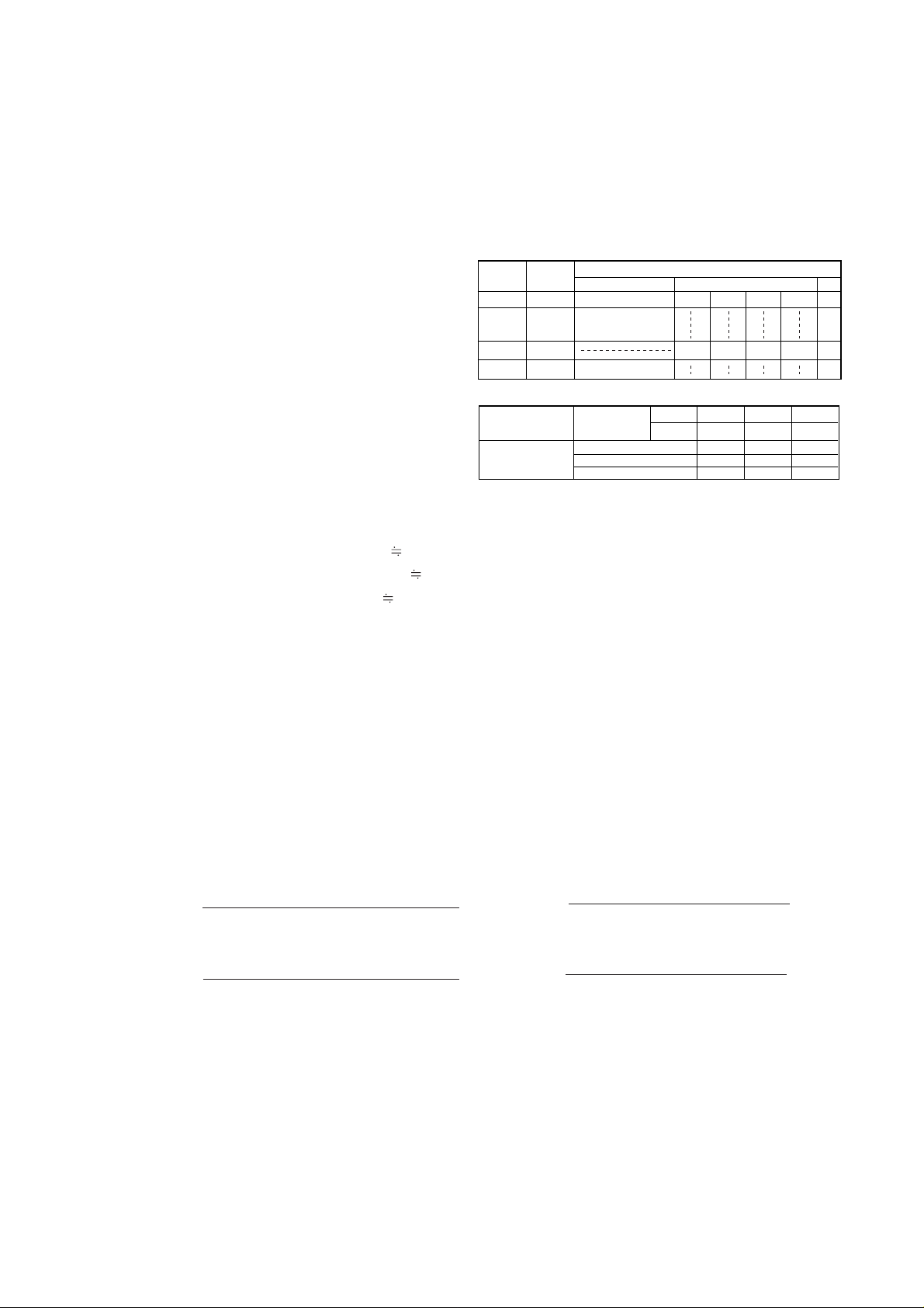
(Step-3) Calculation of net capacity
Based on the indoor conditioned temperature (WB,DB), designed outdoor temperature (DB), and the
actual air flow obtained in Step-2, obtain the gross capacity from the gross capacity tables (pages
16~35). Then, calculate the net capacity from the formula below by using the fan motor input obtained
in Step-2.
Net capacity (kW) = Gross capacity (kW) - Fan motor input (kW)
Example: PE-8MYC
Condition:
Indoor conditioned temp. : 26˚CDB, 19˚CWB
Designed outdoor temp. : 40˚CDB
Actual air flow : 77CMM
Fan motor input : 0.6kW (See P.11)
Calculation :
The sections of the gross capacity table applicable
for the above conditions are shown right.
Therfore, the net capacity is,
Net total cooling capacity = 21.7 (kw) - 0.6(kW)
= 21.1 (kW)
Net sensible cooling capacity = 16.8 (kW) - 0.6 (kW)
= 16.2 (kW)
• Refrigerant cycle energy efficienty
(1) COP =
(2) ERR =
• System energy efficienty
(1) COP =
(2) ERR =
Notes: 1. COP : Coefficient of performance
2. EER : Energy efficiency ratio
3. Temperature condition of COP, EER (ARI Standard Ratings)
Indoor entering air temp. : 80˚FDB (=27˚CDB), 66˚FWB(=19˚CWB)
Outdoor entering air temp. : 95˚FDB (=35˚CDB)
4. Total input = Compressor input + Indoor fan motor input + Outdoor fan motor input (page 11).
Gross total cooling capacity (kW)
Compressor input (kW)
Gross total cooling capacity (kW)
Total input (kW)
Net cooling capacity (kW)
Compressor input (kW)
Net cooling capacity (kW)
Total input (kW)
PE-8MYC-EU
AIR VOLUME
CMM 60 70 80
L/S 1,000 1,167 1,330
COOLING
CAPACITY 0.976 1.0 1.025
SHC 0.963 1.0 1.044
TOTAL INPUT 0.991 1.0 1.009
21.3 16.3 0.77 8.3
OUTDOOR DB˚C
INDOOR INDOOR
40.0
Q kW
SHC kW
SHF T/I kW
DB˚C
WB˚C
26 19
Factor for Various Air Flow
1kW = 3412Btu/h
2. Efficiency Calculation
Page 17
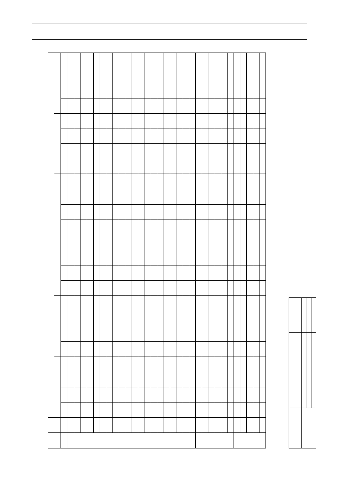
OUTDOOR DB ˚C
INDOOR INDOOR 20.0 25.0 30.0 35.0 40.0
DB ˚C WB ˚C Q kW SHC kW SHF T/I kW Q kW SHC kW SHF T/I kW Q kW SHC kW SHF T/I kW Q kW SHC kW SHF T/I kW Q kW SHC kW SHF T/I kW
15
20 16
171516
22 17
181916
17
24 18
1920211819
26 20
2122231920
28 21
222324202130222324
PEH-5MYE-EU
AIR VOLUME
CMM 35 42 50
L/S 584 700 834
COOLING
CAPACITY 0.969 1.0 1.025
SHC 0.967 1.0 1.028
TOTAL INPUT 0.989 1.0 1.009
46.0
Q kW SHC kW SH F T/I kW
13.9
14.5
15.0
13.9
14.5
15.0
15.6
16.1
14.5
15.0
15.6
16.1
17.3
17.3
15.6
16.1
17.3
17.3
17.9
18.5
16.1
17.3
17.3
17.9
18.5
19.0
17.3
17.3
17.9
18.5
19.0
9.8
9.1
8.3
11.3
10.6
9.9
9.1
8.3
12.3
11.5
10.6
9.8
9.3
8.1
12.1
11.3
10.9
9.8
9.0
8.1
13.0
12.7
11.4
10.7
9.8
8.9
14.0
12.9
12.2
11.5
10.7
0.71
0.63
0.56
0.81
0.74
0.66
0.59
0.51
0.85
0.77
0.68
0.61
0.54
0.47
0.78
0.70
0.63
0.57
0.50
0.44
0.81
0.73
0.66
0.60
0.53
0.47
0.81
0.75
0.68
0.62
0.56
4.4
4.5
4.5
4.4
4.5
4.5
4.5
4.6
4.5
4.5
4.5
4.6
4.6
4.7
4.5
4.6
4.6
4.7
4.7
4.8
4.6
4.6
4.7
4.7
4.8
4.8
4.6
4.7
4.7
4.8
4.8
12.0
12.4
12.8
12.0
12.4
12.8
13.3
13.7
12.4
12.8
13.3
13.7
14.7
14.7
13.3
13.7
14.7
14.7
15.2
15.7
13.7
14.7
14.7
15.2
15.7
16.3
14.7
14.7
15.2
15.7
16.3
8.8
8.1
7.3
10.4
9.7
8.9
8.2
7.3
11.3
10.6
9.7
8.8
8.2
7.0
11.2
10.4
9.9
8.8
8.1
7.2
12.1
11.8
10.6
9.8
8.9
8.0
13.0
11.9
11.2
10.5
9.7
0.74
0.65
0.57
0.87
0.78
0.70
0.62
0.54
0.92
0.82
0.73
0.65
0.56
0.48
0.85
0.76
0.67
0.60
0.53
0.46
0.89
0.80
0.72
0.64
0.57
0.49
0.89
0.81
0.74
0.67
0.60
5.7
5.8
5.8
5.7
5.8
5.8
5.9
5.9
5.8
5.8
5.9
5.9
6.0
6.0
5.9
5.9
6.0
6.0
6.1
6.2
5.9
6.0
6.0
6.1
6.2
6.3
6.0
6.0
6.1
6.2
6.3
13.5
14.1
14.6
13.5
14.1
14.6
15.1
15.6
14.1
14.6
15.1
15.6
16.8
16.8
15.1
15.6
16.8
16.8
17.4
18.0
15.6
16.8
16.8
17.4
18.0
18.5
16.8
16.8
17.4
18.0
18.5
9.6
8.9
8.2
11.1
10.5
9.8
9.0
8.1
12.1
11.3
10.4
9.6
9.1
7.8
11.9
11.1
10.7
9.6
8.8
8.0
12.8
12.5
11.2
10.5
9.7
8.7
13.8
12.7
11.9
11.3
10.5
0.71
0.64
0.56
0.82
0.75
0.67
0.59
0.52
0.86
0.78
0.69
0.61
0.54
0.46
0.79
0.71
0.64
0.57
0.51
0.44
0.82
0.74
0.67
0.60
0.54
0.47
0.82
0.75
0.69
0.63
0.57
11.3
11.7
12.1
11.3
11.7
12.1
12.5
12.9
11.7
12.1
12.5
12.9
13.8
13.8
12.5
12.9
13.8
13.8
14.3
14.8
12.9
13.8
13.8
14.3
14.8
15.3
13.8
13.8
14.3
14.8
15.3
8.5
7.7
6.9
10.1
9.4
8.6
7.8
7.0
11.0
10.2
9.4
8.5
7.9
6.6
10.9
10.0
9.5
8.5
7.7
6.9
11.7
11.4
10.2
9.4
8.6
7.6
12.7
11.6
10.9
10.1
9.3
0.75
0.66
0.57
0.89
0.80
0.71
0.63
0.54
0.94
0.85
0.75
0.66
0.57
0.48
0.87
0.78
0.69
0.62
0.54
0.47
0.91
0.83
0.74
0.66
0.58
0.50
0.92
0.84
0.76
0.69
0.61
6.1
6.2
6.3
6.1
6.2
6.3
6.3
6.4
6.2
6.3
6.3
6.4
6.4
6.5
6.3
6.4
6.4
6.5
6.6
6.7
6.4
6.4
6.5
6.6
6.7
6.7
6.4
6.5
6.6
6.7
6.7
4.6
4.7
4.7
4.6
4.7
4.7
4.8
4.8
4.7
4.7
4.8
4.8
4.9
4.9
4.8
4.8
4.9
4.9
5.0
5.1
4.8
4.9
4.9
5.0
5.1
5.1
4.9
4.9
5.0
5.1
5.1
13.1
13.6
14.1
13.1
13.6
14.1
14.6
15.1
13.6
14.1
14.6
15.1
16.2
16.2
14.6
15.1
16.2
16.2
16.8
17.3
15.1
16.2
16.2
16.8
17.3
17.9
16.2
16.2
16.8
17.3
17.9
9.4
8.7
7.9
10.9
10.2
9.5
8.7
7.9
11.9
11.1
10.2
9.4
8.8
7.6
11.7
10.9
10.4
9.4
8.6
7.8
12.6
12.3
11.1
10.3
9.5
8.6
13.5
12.5
11.8
11.1
10.3
0.72
0.64
0.56
0.84
0.76
0.68
0.60
0.52
0.88
0.79
0.70
0.62
0.54
0.47
0.81
0.72
0.64
0.58
0.51
0.45
0.84
0.76
0.68
0.62
0.55
0.48
0.83
0.77
0.70
0.64
0.58
4.9
5.0
5.0
4.9
5.0
5.0
5.1
5.1
5.0
5.0
5.1
5.1
5.2
5.2
5.1
5.1
5.2
5.2
5.3
5.4
5.1
5.2
5.2
5.3
5.4
5.4
5.2
5.2
5.3
5.4
5.4
12.6
13.0
13.5
12.6
13.0
13.5
14.0
14.4
13.0
13.5
14.0
14.4
15.5
15.5
14.0
14.4
15.5
15.5
16.0
16.6
14.4
15.5
15.5
16.0
16.6
17.1
15.5
15.5
16.0
16.6
17.1
9.1
8.3
7.5
10.7
10.0
9.2
8.5
7.6
11.6
10.8
9.9
9.1
8.5
7.3
11.4
10.6
10.1
9.1
8.3
7.5
12.4
12.1
10.8
10.1
9.3
8.4
13.2
12.2
11.5
10.8
10.1
0.72
0.64
0.56
0.85
0.77
0.68
0.61
0.53
0.89
0.80
0.71
0.63
0.55
0.47
0.82
0.74
0.65
0.58
0.52
045
0.86
0.78
0.70
0.63
0.56
0.49
0.85
0.78
0.72
0.65
0.59
5.3
5.3
5.4
5.3
5.3
5.4
5.4
5.5
5.3
5.4
5.4
5.5
5.5
5.6
5.4
5.5
5.5
5.6
5.7
5.8
5.5
5.5
5.6
5.7
5.8
5.8
5.5
5.6
5.7
5.8
5.8
Note1. * Q :COOLING CAPACITY SHC:SENSIBLE HEAT CAPACITY T/I:TOTAL INPUT
Factor for Various Air Flow
- 16 -
Cooling Capacity (Standard Air Flow)
PEH-5MYE-EU
CAPACITY TABLES
Page 18
OUTDOOR WB ˚C
INDOOR
-10.0 -5.0 0.0
DB ˚C Q kW Q kW Q kW T/I kW
OUTDOOR WB ˚C
INDOOR
5.0 10.0 15.0
DB ˚C Q kW Q kW Q kW T/I kW
15161718192021222324252627
T/I kWT/I kW
15161718192021222324252627
T/I kWT/I kW
PEH-5MYA-EU
AIR VOLUME
CMM
35 42 50
L/S
584 700 834
HEATING
CAPACITY 0.987 1.0 1.011
TOTAL INPUT 1.021 1.0 0.983
9.2
9.2
9.1
9.1
9.1
9.0
9.0
8.9
8.9
8.8
8.8
8.7
8.7
3.1
3.1
3.1
3.2
3.2
3.2
3.2
3.2
3.2
3.2
3.2
3.3
3.3
10.7
10.7
10.7
10.6
10.6
10.5
10.5
10.4
10.4
10.3
10.3
10.2
10.2
3.4
3.4
3.4
3.5
3.5
3.5
3.5
3.5
3.6
3.6
3.6
3.6
3.7
12.4
12.3
12.3
12.3
12.2
12.2
12.2
12.1
12.1
12.0
12.0
11.9
11.8
3.7
3.7
3.8
3.8
3.8
3.8
3.9
3.9
3.9
4.0
4.1
4.1
4.1
14.3
14.3
14.2
14.2
14.1
14.1
14.0
14.0
13.9
13.9
13.8
13.7
13.6
4.2
4.2
4.2
4.2
4.3
4.3
4.4
4.4
4.4
4.5
4.5
4.5
4.6
16.4
16.4
16.3
16.3
16.2
16.1
16.1
16.0
15.9
15.9
15.8
15.7
15.6
4.7
4.7
4.7
4.8
4.8
4.9
4.9
4.9
5.0
5.0
5.1
5.1
5.2
18.7
18.6
18.6
18.5
18.5
18.4
18.3
18.2
18.1
18.1
18.0
17.8
17.7
5.2
5.1
5.2
5.4
5.4
5.5
5.5
5.6
5.6
5.6
5.7
5.8
5.8
- 17 -
* Q : HEATING CAPACITY T/I : TOTAL INPUT
Factor for Various Air Flow
Heating Capacity (Standard Air Flow)
PEH-5MYE-EU
Page 19

OUTDOOR DB ˚C
INDOOR INDOOR 20.0 25.0 30.0 35.0 40.0
DB ˚C WB ˚C Q kW SHC kW SHF T/I kW Q kW SHC kW SHF T/I kW Q kW SHC kW SHF T/I kW Q kW SHC kW SHF T/I kW Q kW SHC kW SHF T/I kW
15
20 16
171516
22 17
181916
17
24 18
1920211819
26 20
2122231920
28 21
222324202130222324
PE-7MYC-EU
PEH-7MYA-EU
AIR VOLUME
CMM 50 60 70
L/S 830 1,000 1,167
COOLING
CAPACITY 0.975 1.0 1.024
SHC 0.964 1.0 1.040
TOTAL INPUT 0.989 1.0 1.009
16.9 11.7 0.69 5.5 16.5 11.5 0.70 5.8 15.8 11.1 0.70 6.2 15.1 10.8 0.71 6.7 14.3 10.4 0.73
17.7 10.8 0.61 5.6 17.2 10.5 0.61 5.9 16.5 10.2 0.62 6.3 15.8 9.9 0.62 6.8 15 9.5 0.63
18.4 9.6 0.52 5.7 17.9 9.4 0.53 6.0 17.2 9.1 0.53 6.4 16.5 8.8 0.54 6.9 15.7 8.5 0.54
16.9 13.5 0.80 5.5 16.5 13.3 0.81 5.8 15.8 13.0 0.82 6.2 15.1 12.7 0.84 6.7 14.3 12.4 0.87
17.7 12.8 0.72 5.6 17.2 12.5 0.73 5.9 16.5 12.2 0.74 6.3 15.8 11.9 0.75 6.8 15.0 11.6 0.77
18.4 11.8 0.64 5.7 17.9 11.6 0.65 6.0 17.2 11.3 0.66 6.4 16.5 11.0 0.67 6.9 15.7 10.7 0.68
19.3 10.9 0.57 5.8 18.7 10.6 0.57 6.1 18.0 10.4 0.58 6.6 17.2 10.0 0.58 7.0 16.5 9.8 0.59
19.9 9.7 0.49 5.9 19.3 9.4 0.49 6.3 18.7 9.2 0.49 6.7 17.9 8.9 0.50 7.2 17.0 8.6 0.51
17.7 15.0 0.85 5.6 17.2 14.7 0.86 5.9 16.5 14.5 0.88 6.3 15.8 14.1 0.89 6.8 15.0 13.8 0.92
18.4 14.0 0.76 5.7 17.9 13.7 0.77 6.0 17.2 13.4 0.78 6.4 16.5 13.1 0.80 6.9 15.7 12.8 0.82
19.3 12.9 0.67 5.8 18.7 12.7 0.68 6.1 18.0 12.4 0.69 6.6 17.2 12.0 0.70 7.0 16.5 11.8 0.72
19.9 11.8 0.59 5.9 19.3 11.6 0.60 6.3 18.7 11.4 0.61 6.7 17.9 11.1 0.62 7.2 17.0 10.7 0.63
21.2 10.9 0.52 6.1 20.4 10.6 0.52 6.4 19.7 10.4 0.53 6.8 18.8 10.1 0.54 7.3 17.9 9.8 0.55
22.0 9.7 0.44 6.2 21.2 9.4 0.44 6.5 20.5 9.2 0.45 6.9 19.6 9.0 0.46 7.4 18.7 8.7 0.46
19.3 15.0 0.78 5.8 18.7 14.7 0.79 6.1 18.0 14.5 0.80 6.6 17.2 14.0 0.82 7.0 16.5 13.9 0.84
19.9 13.9 0.70 5.9 19.3 13.6 0.70 6.3 18.7 13.4 0.72 6.7 17.9 13.1 0.73 7.2 17.0 12.8 0.75
21.2 13.1 0.62 6.1 20.4 12.7 0.62 6.4 19.7 12.5 0.63 6.8 18.8 12.2 0.65 7.3 17.9 11.9 0.66
22.0 12.1 0.55 6.2 21.2 11.7 0.55 6.5 20.5 11.5 0.56 6.9 19.6 11.3 0.57 7.4 18.7 10.9 0.58
22.8 11.0 0.48 6.3 22.1 10.7 0.48 6.6 21.3 10.5 0.49 7.0 20.4 10.2 0.50 7.5 19.5 9.8 0.50
23.7 9.9 0.42 6.4 23.0 9.5 0.41 6.8 22.1 9.3 0.42 7.2 21.2 9.0 0.43 7.7 20.3 8.6 0.43
19.9 15.9 0.80 5.9 19.3 15.8 0.82 6.3 18.7 15.7 0.84 6.7 17.9 15.4 0.86 7.2 17.0 15.0 0.88
21.2 15.3 0.72 6.1 20.4 15.0 0.74 6.4 19.7 14.8 0.75 6.8 18.8 14.5 0.77 7.3 17.9 14.1 0.79
22.0 14.1 0.64 6.2 21.2 13.8 0.65 6.5 20.5 13.6 0.67 6.9 19.6 13.3 0.68 7.4 18.7 13.0 0.69
22.8 13.1 0.57 6.3 22.1 12.9 0.58 6.6 21.3 12.6 0.59 7.0 20.4 12.4 0.61 7.5 19.5 12.1 0.62
23.7 12.0 0.51 6.4 23.0 11.8 0.51 6.8 22.1 11.5 0.52 7.2 21.2 11.3 0.53 7.7 20.3 11.1 0.55
24.7 10.9 0.44 6.6 24.0 10.6 0.44 6.9 23.1 10.4 0.45 7.3 22.2 10.1 0.46 7.8 21.2 10.0 0.47
21.2 17.2 0.81 6.1 20.4 16.7 0.82 6.4 19.7 16.5 0.84 6.8 18.8 16.1 0.86 7.3 17.9 16.0 0.89
22.0 16.2 0.74 6.2 21.2 15.8 0.75 6.5 20.5 15.6 0.76 6.9 19.6 15.3 0.78 7.4 18.7 15.1 0.81
22.8 15.1 0.66 6.3 22.1 14.8 0.67 6.6 21.3 14.6 0.69 7.0 20.4 14.3 0.70 7.5 19.5 14.0 0.72
23.7 14.2 0.60 6.4 23.0 14.1 0.61 6.8 22.1 13.7 0.62 7.2 21.2 13.4 0.63 7.7 20.3 13.2 0.65
24.7 13.2 0.53 6.6 24.0 13.0 0.54 6.9 23.1 12.8 0.55 7.3 22.2 12.5 0.56 7.8 21.2 12.2 0.58
7.2
7.3
7.5
7.2
7.3
7.5
7.6
7.7
7.3
7.5
7.6
7.7
7.9
8.0
7.6
7.7
7.9
8.0
8.1
8.2
7.7
7.9
8.0
8.1
8.2
8.3
7.9
8.0
8.1
8.2
8.3
46.0
Q kW SHC kW SH F T/I kW
13.6 10.1 0.74 7.9
14.2 9.1 0.64 8.0
14.8 8.0 0.54 8.1
13.6 12.1 0.89 7.9
14.2 11.2 0.79 8.0
14.8 10.3 0.69 8.1
15.5 9.4 0.60 8.2
16.0 8.2 0.52 8.3
14.2 13.4 0.94 8.0
14.8 12.4 0.84 8.1
15.5 11.4 0.73 8.2
16.0 10.3 0.65 8.3
16.9 9.4 0.56 8.5
17.6 8.2 0.47 8.6
15.5 13.4 0.86 8.2
16.0 12.3 0.77 8.3
16.9 11.4 0.68 8.5
17.6 10.4 0.59 8.6
18.4 9.4 0.51 8.7
19.2 8.1 0.42 8.9
16.0 14.5 0.91 8.3
16.9 13.6 0.81 8.5
17.6 12.4 0.71 8.6
18.4 11.7 0.63 8.7
19.2 10.7 0.56 8.9
20.0 9.7 0.49 9.0
16.9 15.7 0.93 8.5
17.6 14.6 0.83 8.6
18.4 13.6 0.74 8.7
19.2 12.8 0.66 8.9
20.0 11.8 0.59 9.0
Note1. * Q :COOLING CAPACITY SHC:SENSIBLE HEAT CAPACITY T/I:TOTAL INPUT
Factor for Various Air Flow
Cooling Capacity (Standard Air Flow)
PE-7MYC-EU , PEH-7MYA-EU
- 18 -
Page 20
OUTDOOR DB ˚C
INDOOR
-5.0 0.0 5.0 10.0 15.0
DB ˚C
WB ˚C Q kW SHC kW SHF T/I kW Q kW
SHC kW
SHF T/I kW Q kW SHC kW SHF T/I kW Q kW SHC kW SHF T/I kW Q kW SHC kW SHF T/I kW
15
20 16
171516
22 17
181916
17
24 18
1920211819
26 20
2122231920
28 21
222324202130222324
PE-7MYC-EU
PEH-7MYA-EU
AIR VOLUME
CMM 50 60 70
L/S 830 1,000 1,167
COOLING
CAPACITY 0.975 1.0 1.024
SHC 0.964 1.0 1.040
TOTAL INPUT 0.989 1.0 1.009
0.68 0.68 0.72 0.68 0.69
0.60 0.60 0.64 0.60 0.60
0.52 0.52 0.56 0.52 0.52
0.79 0.79 0.84 0.80 0.80
0.71 0.71 0.76 0.72 0.72
0.63 0.63 0.67 0.63 0.64
0.56 0.56 0.60 0.56 0.56
0.49 0.49 0.53 0.49 0.49
0.82 0.82 0.86 0.83 0.84
0.73 0.73 0.78 0.74 0.75
0.65 0.65 0.69 0.66 0.66
0.58 0.58 0.62 0.58 0.59
0.51 0.51 0.55 0.51 0.51
0.44 0.44 0.48 0.44 0.44
0.75 0.75 0.79 0.76 0.77
0.68 0.68 0.71 0.68 0.69
0.60 0.60 0.64 0.61 0.61
0.54 0.54 0.57 0.54 0.55
0.47 0.47 0.51 0.48 0.48
0.41 0.41 0.44 0.41 0.42
0.78 0.78 0.82 0.78 0.78
0.70 0.70 0.74 0.70 0.71
0.62 0.62 0.66 0.63 0.63
0.56 0.56 0.60 0.57 0.57
0.50 0.50 0.54 0.50 0.50
0.44 0.44 0.48 0.44 0.44
0.78 0.78 0.82 0.79 0.80
0.72 0.72 0.75 0.72 0.73
0.65 0.65 0.69 0.65 0.65
0.59 0.59 0.62 0.59 0.59
0.52 0.52 0.56 0.52 0.52
OUTDOOR WB ˚C
INDOOR
-10.0 -5.0 0.0
DB ˚C Q kW Q kW Q kW T/I kW
OUTDOOR WB ˚C
INDOOR
5.0 10.0 15.0
DB ˚C Q kW Q kW Q kW T/I kW
15161718192021222324252627
T/I kWT/I kW
15161718192021222324252627
T/I kWT/I kW
PEH-7MYA-EU
AIR VOLUME
CMM
50 60 70
L/S
830 1,000 1,167
HEATING
CAPACITY 0.980 1.0 1.011
TOTAL INPUT 1.028 1.0 0.98
11.5 4.6 13.5 5.0 15.4 5.4
11.7 4.6 13.8 5.0 16.1 5.4
11.3 4.7 13.4 5.0 15.8 5.5
11.2 4.7 13.3 5.1 15.7 5.5
11.0 4.8 13.2 5.1 15.6 5.5
11.0 4.8 13.2 5.1 15.6 5.6
11.0 4.8 13.1 5.2 15.5 5.6
10.9 4.8 13.1 5.2 15.5 5.7
10.8 4.8 13.0 5.2 15.4 5.7
10.8 4.8 12.9 5.3 15.3 5.8
10.8 4.8 13.0 5.3 15.4 5.8
10.6 4.8 12.8 5.3 15.1 5.8
10.6 4.9 12.7 5.3 15.0 5.9
18.5 5.9 21.4 6.4 24.6 7.0
18.8 5.9 21.7 6.5 24.8 7.1
18.4 6.0 21.3 6.6 24.4 7.2
18.4 6.0 21.2 6.6 24.4 7.3
18.2 6.1 21.0 6.7 24.2 7.4
18.2 6.1 21.0 6.7 24.2 7.5
18.2 6.2 21.0 6.8 24.1 7.6
18.1 6.2 21.0 6.9 24.1 7.6
18.0 6.3 20.9 7.0 24.0 7.7
18.0 6.4 20.8 7.0 23.9 7.8
18.0 6.4 20.8 7.1 23.9 7.9
17.8 6.5 20.6 7.2 23.7 7.9
17.6 6.5 20.5 7.2 23.6 8.0
16.9
17.9
18.7
16.9
17.9
18.7
19.7
20.3
17.9
18.7
19.7
20.3
21.5
22.2
19.7
20.3
21.5
22.2
23.1
23.9
20.3
21.5
22.2
23.1
23.9
24.7
21.5
22.2
23.1
23.9
24.7
11.5
10.7
9.7
13.3
12.7
11.8
11.0
10.0
14.6
13.7
12.8
11.8
11.0
9.8
14.8
13.7
12.9
12.0
10.9
9.8
15.9
15.1
13.8
13.0
12.1
11.0
16.8
16.0
15.1
14.1
13.0
5.0
5.2
5.3
5.0
5.2
5.3
5.4
5.5
5.2
5.3
5.4
5.5
5.6
5.7
5.4
5.5
5.6
5.7
5.8
6.0
5.5
5.6
5.7
5.8
6.0
6.1
5.6
5.7
5.8
6.0
6.1
16.7
17.7
18.6
16.7
17.7
18.6
19.5
20.1
17.7
18.6
19.5
20.1
21.2
22.0
19.5
20.1
21.2
22.0
22.8
23.7
20.1
21.2
22.0
22.8
23.7
24.4
21.2
22.0
22.8
23.7
24.4
11.3
10.6
9.7
13.3
12.6
11.7
10.9
9.9
14.5
13.7
12.7
11.7
10.8
9.7
14.6
13.6
12.7
11.8
10.8
9.7
15.7
14.9
13.7
12.9
11.9
10.9
16.5
15.8
14.9
14.0
12.8
5.1
5.2
5.3
5.1
5.2
5.3
5.3
5.5
5.2
5.3
5.3
5.5
5.6
5.7
5.3
5.5
5.6
5.7
5.8
5.9
5.5
5.6
5.7
5.8
5.9
6.1
5.6
5.7
5.8
5.9
6.1
16.5
17.4
18.3
16.5
17.4
18.3
19.1
19.8
17.4
18.3
19.1
19.8
20.8
21.7
19.1
19.8
20.8
21.7
22.5
23.3
19.8
20.8
21.7
22.5
23.3
24.3
20.8
21.7
22.5
23.3
24.3
11.9
11.2
10.3
13.9
13.2
12.3
11.4
10.5
15.0
14.2
13.1
12.3
11.4
10.3
15.1
14.1
13.3
12.4
11.4
10.3
16.2
15.4
14.2
13.4
12.5
11.5
17.0
16.3
15.5
14.5
13.5
5.1
5.3
5.4
5.1
5.3
5.4
5.5
5.6
5.8
5.4
5.5
5.6
5.8
5.9
5.5
5.6
5.8
5.9
6.0
6.1
5.6
5.8
5.9
6.0
6.1
6.2
5.8
5.9
6.0
6.1
6.2
16.1
17.0
17.8
16.1
17.0
17.8
18.7
19.4
17.0
17.8
18.7
19.4
20.4
21.2
18.7
19.4
20.4
21.2
21.9
22.9
19.4
20.4
21.2
21.9
22.9
23.7
20.4
21.2
21.9
22.9
23.7
11.0
10.2
9.3
12.8
12.2
11.3
10.5
9.5
14.1
13.2
12.2
11.3
10.5
9.3
14.2
13.3
12.4
11.5
10.5
9.5
15.2
14.4
13.3
12.4
11.5
10.5
16.2
15.3
14.3
13.5
12.4
5.3
5.4
5.5
5.3
5.4
5.5
5.6
5.8
5.4
5.5
5.6
5.8
5.9
6.0
5.6
5.8
5.9
6.0
6.1
6.3
5.8
5.9
6.0
6.1
6.3
6.5
5.9
6.0
6.1
6.3
6.5
15.7
16.5
17.3
15.7
16.5
17.3
18.1
18.7
16.5
17.3
18.1
18.7
19.7
20.5
18.1
18.7
19.7
20.5
21.4
22.2
18.7
19.7
20.5
21.4
22.2
23.1
19.7
20.5
21.4
22.2
23.1
10.8
9.9
9.0
12.5
11.8
11.0
10.2
9.2
13.8
12.9
12.0
10.9
10.1
9.0
13.9
12.9
12.1
11.2
10.3
9.3
14.6
14.0
12.9
12.1
11.2
10.2
15.8
14.9
14.0
13.1
12.1
5.6
5.7
5.8
5.6
5.7
5.8
5.9
6.1
5.7
5.8
5.9
6.1
6.2
6.3
5.9
6.1
6.2
6.3
6.4
6.5
6.1
6.2
6.3
6.4
6.5
6.7
6.2
6.3
6.4
6.5
6.7
Note1. * Q :COOLING CAPACITY SHC:SENSIBLE HEAT CAPACITY T/I:TOTAL INPUT
Factor for Various Air Flow
Cooling Capacity (Standard Air Flow)
(Use for low ambient cooling parts)
PE-7MYC-EU , PEH-7MYA-EU
* Q : HEATING CAPACITY T/I : TOTAL INPUT
Factor for Various Air Flow
Heating Capacity (Standard Air Flow)
PEH-7MYA-EU
- 19 -
Page 21
PE-8MYC-EU
PEH-8MYA-EU
AIR VOLUME
CMM 60 70 80
L/S 1,000 1,167 1,330
COOLING
CAPACITY 0.976 1.0 1.025
SHC 0.963 1.0 1.044
TOTAL INPUT 0.991 1.0 1.009
21.3 14.9 0.70 6.1 20.6 14.6 0.71 6.4 19.9 14.3 0.72 6.8 19.2 14.0 0.73 7.3 18.3 13.5 0.74 7.8
22.0 13.7 0.62 6.2 21.3 13.4 0.63 6.5 20.6 13.0 0.63 6.9 19.9 12.6 0.63 7.4 19.1 12.4 0.65 7.9
22.7 12.4 0.55 6.3 22.0 12.1 0.55 6.6 21.3 11.6 0.55 7.0 20.6 11.1 0.54 7.5 19.8 11.0 0.55 8.1
21.3 17.5 0.82 6.1 20.6 17.1 0.83 6.4 19.9 16.9 0.85 6.8 19.2 16.7 0.87 7.3 18.3 16.1 0.88 7.8
22.0 16.1 0.73 6.2 21.3 15.9 0.75 6.5 20.6 15.6 0.76 6.9 19.9 15.3 0.77 7.4 19.1 14.9 0.78 7.9
22.7 14.7 0.65 6.3 22.0 14.5 0.66 6.6 21.3 14.2 0.67 7.0 20.6 13.8 0.67 7.5 19.8 13.6 0.68 8.1
23.5 13.6 0.58 6.4 22.8 13.4 0.59 6.7 22.1 13.1 0.59 7.2 21.3 12.7 0.60 7.6 20.6 12.5 0.61 8.2
24.4 12.5 0.51 6.5 23.6 12.1 0.51 6.9 22.9 11.8 0.52 7.3 22.0 11.5 0.52 7.8 21.3 11.3 0.53 8.3
22.0 18.9 0.86 6.2 21.3 18.5 0.87 6.5 20.6 18.2 0.89 6.9 19.9 17.9 0.90 7.4 19.1 17.6 0.92 7.9
22.7 17.7 0.78 6.3 22.0 17.3 0.79 6.6 21.3 17.0 0.80 7.0 20.6 16.7 0.81 7.5 19.8 16.4 0.83 8.1
23.5 16.4 0.70 6.4 22.8 16.0 0.70 6.7 22.1 15.7 0.71 7.2 21.3 15.3 0.72 7.6 20.6 15.1 0.74 8.2
24.4 15.1 0.62 6.5 23.6 14.7 0.62 6.9 22.9 14.4 0.63 7.3 22.0 14.0 0.64 7.8 21.3 13.8 0.65 8.3
25.2 13.7 0.54 6.7 24.4 13.2 0.54 7.0 23.7 13.0 0.55 7.4 22.8 12.6 0.55 7.9 22.0 12.3 0.56 8.5
26.1 12.1 0.46 6.8 25.3 11.7 0.46 7.1 24.5 11.4 0.46 7.5 23.7 11.1 0.47 8.0 22.8 10.8 0.47 8.6
23.5 18.7 0.80 6.4 22.8 18.3 0.80 6.7 22.1 18.0 0.82 7.2 21.3 17.7 0.83 7.6 20.6 17.4 0.85 8.2
24.4 17.6 0.72 6.5 23.6 17.1 0.73 6.9 22.9 16.9 0.74 7.3 22.0 16.5 0.75 7.8 21.3 16.3 0.77 8.3
25.2 16.2 0.64 6.7 24.4 15.9 0.65 7.0 23.7 15.7 0.66 7.4 22.8 15.3 0.67 7.9 22.0 15.1 0.69 8.5
26.1 14.9 0.57 6.8 25.3 14.6 0.58 7.1 24.5 14.3 0.58 7.5 23.7 14.0 0.59 8.0 22.8 13.7 0.60 8.6
27.0 13.4 0.50 6.9 26.2 13.2 0.50 7.2 25.4 12.9 0.51 7.6 24.4 12.5 0.51 8.1 23.6 12.2 0.52 8.7
27.9 11.9 0.43 7.0 27.1 11.6 0.43 7.4 26.3 11.3 0.43 7.8 25.3 10.9 0.43 8.3 24.3 10.5 0.43 8.8
24.4 20.1 0.82 6.5 23.6 19.6 0.83 6.9 22.9 19.3 0.84 7.3 22.0 18.7 0.85 7.8 21.3 18.8 0.88 8.3
25.2 18.9 0.75 6.7 24.4 18.5 0.76 7.0 23.7 18.2 0.77 7.4 22.8 17.7 0.78 7.9 22.0 17.7 0.80 8.5
26.1 17.7 0.68 6.8 25.3 17.3 0.68 7.1 24.5 17.0 0.69 7.5 23.7 16.6 0.70 8.0 22.8 16.6 0.73 8.6
27.0 16.4 0.61 6.9 26.2 16.0 0.61 7.2 25.4 15.7 0.62 7.6 24.4 15.3 0.63 8.1 23.6 15.2 0.64 8.7
27.9 15.0 0.54 7.0 27.1 14.7 0.54 7.4 26.3 14.4 0.55 7.8 25.3 14.0 0.55 8.3 24.3 13.7 0.56 8.8
28.8 13.5 0.47 7.2 28.0 13.2 0.47 7.5 27.1 12.9 0.48 7.9 26.0 12.4 0.48 8.4 25.2 12.1 0.48 8.9
25.2 21.6 0.86 6.7 24.4 21.3 0.87 7.0 23.7 21.0 0.89 7.4 22.8 20.5 0.90 7.9 22.0 20.2 0.92 8.5
26.1 20.3 0.78 6.8 25.3 19.9 0.79 7.1 24.5 19.6 0.80 7.5 23.7 19.4 0.82 8.0 22.8 19.0 0.83 8.6
27.0 18.8 0.70 6.9 26.2 18.4 0.70 7.2 25.4 18.2 0.72 7.6 24.4 17.9 0.73 8.1 23.6 17.7 0.75 8.7
27.9 17.6 0.63 7.0 27.1 17.3 0.64 7.4 26.3 17.2 0.65 7.8 25.3 17.0 0.67 8.3 24.3 16.8 0.69 8.8
28.8 16.2 0.56 7.2 28.0 16.0 0.57 7.5 27.1 16.1 0.59 7.9 26.0 15.9 0.61 8.4 25.2 15.9 0.63 8.9
OUTDOOR DB ˚C
INDOOR INDOOR 20.0 25.0 30.0 35.0 40.0
DB ˚C WB ˚C Q kW SHC kW SHF T/I kW Q kW SHC kW SHF T/I kW Q kW SHC kW SHF T/I kW Q kW SHC kW SHF T/I kW Q kW SHC kW SHF T/I kW
15
20 16
171516
22 17
181916
17
24 18
1920211819
26 20
2122231920
28 21
222324202130222324
46.0
Q kW SHC kW SH F T/I kW
17.6 13.2 0.75 8.5
18.3 12.1 0.66 8.6
18.9 10.8 0.57 8.7
17.6 15.6 0.89 8.5
18.3 14.5 0.79 8.6
18.9 13.2 0.70 8.7
19.5 12.1 0.62 8.8
20.2 10.9 0.54 8.9
18.3 17.2 0.94 8.6
18.9 16.0 0.84 8.7
19.5 14.6 0.75 8.8
20.2 13.3 0.66 8.9
20.9 11.9 0.57 9.1
21.7 10.4 0.48 9.2
19.5 16.8 0.86 8.8
20.2 15.8 0.78 8.9
20.9 14.6 0.70 9.1
21.7 13.3 0.61 9.2
22.4 11.7 0.52 9.3
23.1 10.0 0.43 9.5
20.2 18.4 0.91 8.9
20.9 17.4 0.83 9.1
21.7 16.3 0.75 9.2
22.4 14.8 0.66 9.3
23.1 13.2 0.57 9.5
23.9 11.5 0.48 9.6
20.9 19.4 0.93 9.1
21.7 18.5 0.85 9.2
22.4 17.3 0.77 9.3
23.1 16.4 0.71 9.5
23.9 15.6 0.65 9.6
Note1. * Q :COOLING CAPACITY SHC:SENSIBLE HEAT CAPACITY T/I:TOTAL INPUT
Factor for Various Air Flow
Cooling Capacity (Standard Air Flow)
PE-8MYC-EU , PEH-8MYA-EU (combined with PUH-8MYC1-EU)
- 20 -
Page 22
PE-8MYC-EU
PEH-8MYA-EU
AIR VOLUME
CMM 60 70 80
L/S 1,000 1,167 1,330
COOLING
CAPACITY 0.976 1.0 1.025
SHC 0.963 1.0 1.044
TOTAL INPUT 0.991 1.0 1.009
0.69 0.69 0.68 0.69 0.69
0.61 0.61 0.61 0.61 0.62
0.53 0.53 0.53 0.54 0.54
0.80 0.80 0.80 0.81 0.81
0.72 0.72 0.73 0.72 0.72
0.64 0.65 0.65 0.64 0.63
0.58 0.58 0.58 0.58 0.57
0.51 0.51 0.51 0.51 0.51
0.85 0.85 0.84 0.85 0.85
0.76 0.76 0.76 0.77 0.77
0.67 0.68 0.68 0.69 0.69
0.60 0.60 0.60 0.61 0.62
0.53 0.53 0.52 0.53 0.54
0.46 0.45 0.44 0.46 0.47
0.78 0.77 0.75 0.77 0.79
0.71 0.70 0.69 0.70 0.71
0.63 0.63 0.63 0.63 0.63
0.57 0.57 0.56 0.56 0.56
0.50 0.50 0.49 0.49 0.49
0.44 0.43 0.42 0.42 0.42
0.80 0.80 0.80 0.81 0.81
0.73 0.73 0.74 0.74 0.74
0.66 0.67 0.67 0.67 0.67
0.60 0.60 0.60 0.60 0.60
0.53 0.53 0.53 0.53 0.53
0.47 0.47 0.46 0.46 0.46
0.82 0.83 0.83 0.84 0.84
0.75 0.76 0.76 0.76 0.77
0.68 0.68 0.68 0.69 0.69
0.62 0.62 0.62 0.62 0.62
0.55 0.55 0.55 0.55 0.55
OUTDOOR DB ˚C
INDOOR
-5.0 0.0 5.0 10.0 15.0
DB ˚C
WB ˚C Q kW SHC kW SHF T/I kW Q kW
SHC kW
SHF T/I kW Q kW SHC kW SHF T/I kW Q kW SHC kW SHF T/I kW Q kW SHC kW SHF T/I kW
15
20 16
171516
22 17
181916
17
24 18
1920211819
26 20
2122231920
28 21
222324202130222324
OUTDOOR WB ˚C
INDOOR
-10.0 -5.0 0.0
DB ˚C Q kW Q kW Q kW T/I kW
OUTDOOR WB ˚C
INDOOR
5.0 10.0 15.0
DB ˚C Q kW Q kW Q kW T/I kW
15161718192021222324252627
T/I kWT/I kW
15161718192021222324252627
T/I kWT/I kW
PEH-8MYA-EU
AIR VOLUME
CMM 60 70 80
L/S 1,000 1,167 1,330
HEATING
CAPACITY 0.989 1.0 1.011
TOTAL INPUT 1.010 1.0 0.987
14.7 4.8 16.7 5.2 19.1 5.6
14.6 4.8 16.7 5.2 19 5.6
14.5 4.9 16.6 5.2 19 5.7
14.4 4.9 16.5 5.3 18.9 5.7
14.2 5.0 16.4 5.3 18.8 5.7
14.2 5.0 16.4 5.3 18.8 5.8
14.2 5.0 16.3 5.4 18.7 5.8
14.1 5.0 16.3 5.4 18.7 5.9
14 5.0 16.2 5.4 18.6 5.9
14 5.0 16.1 5.5 18.5 6.0
14 5.0 16.2 5.5 18.6 6.0
13.8 5.0 16 5.5 18.3 6.0
13.8 5.1 15.9 5.5 18.2 6.1
21.7 6.1 24.6 6.6 27.8 7.2
21.7 6.1 24.6 7.0 27.7 7.3
21.6 6.2 24.5 6.8 27.6 7.4
21.6 6.2 24.4 6.8 27.6 7.5
21.4 6.3 24.3 6.9 27.4 7.6
21.4 6.3 24.3 6.9 27.4 7.7
21.4 6.4 24.2 7.0 27.3 7.8
21.3 6.4 24.2 7.1 27.3 7.8
21.2 6.5 24.1 7.2 27.2 7.9
21.2 6.6 24 7.2 27.1 8.0
21.2 6.6 24 7.3 27.1 8.1
21 6.7 23.8 7.4 26.9 8.1
20.8 6.7 23.7 7.4 26.8 8.2
20.9
21.9
22.6
20.9
21.9
22.6
23.5
24.3
21.9
22.6
23.5
24.3
25.2
26.2
23.5
24.3
25.2
26.2
27.1
27.8
24.3
25.2
26.2
27.1
27.8
29.0
25.2
26.2
27.1
27.8
29.0
14.4
13.4
12.0
16.7
15.8
14.5
13.5
12.5
18.6
17.2
15.8
14.6
13.4
12.1
18.3
17.2
15.9
14.9
13.6
12.2
19.5
18.4
17.4
16.2
14.8
13.6
20.7
19.7
18.5
17.2
16.0
5.8
5.9
6.0
5.8
5.9
6.0
6.1
6.2
5.9
6.0
6.1
6.2
6.3
6.4
6.1
6.2
6.3
6.4
6.5
6.7
6.2
6.3
6.4
6.5
6.7
6.8
6.3
6.4
6.5
6.7
6.8
20.7
21.6
22.5
20.7
21.6
22.5
23.2
24.0
21.6
22.5
23.2
24.0
24.8
25.8
23.2
24.0
24.8
25.8
26.7
27.5
24.0
24.8
25.8
26.7
27.5
28.6
24.8
25.8
26.7
27.5
28.6
14.2
13.2
11.9
16.6
15.6
14.5
13.5
12.3
18.3
17.1
15.7
14.4
13.1
11.7
17.8
16.8
15.7
14.6
13.3
11.9
19.2
18.2
17.2
16.0
14.7
13.3
20.5
19.5
18.2
17.0
15.8
5.8
5.9
6.0
5.8
5.9
6.0
6.0
6.3
5.9
6.0
6.0
6.3
6.4
6.5
6.0
6.3
6.4
6.5
6.6
6.7
6.3
6.4
6.5
6.6
6.7
6.9
6.4
6.5
6.6
6.7
6.9
20.4
21.2
22.0
20.4
21.2
22.0
22.9
23.6
21.2
22.0
22.9
23.6
24.5
25.3
22.9
23.6
24.5
25.3
26.3
27.2
23.6
24.5
25.3
26.3
27.2
28.2
24.5
25.3
26.3
27.2
28.2
13.9
12.9
11.7
16.3
15.4
14.4
13.3
12.1
17.8
16.8
15.6
14.2
12.8
11.2
17.2
16.3
15.5
14.2
13.0
11.5
18.9
18.0
17.0
15.9
14.5
13.1
20.4
19.2
18.0
16.8
15.6
5.9
6.0
6.1
5.9
6.0
6.1
6.2
6.3
6.0
6.1
6.2
6.3
6.5
6.6
6.2
6.3
6.5
6.6
6.7
6.8
6.3
6.5
6.6
6.7
6.8
7.0
6.5
6.6
6.7
6.8
7.0
20.1
20.9
21.7
20.1
20.9
21.7
22.4
23.1
20.9
21.7
22.4
23.1
24.0
24.8
22.4
23.1
24.0
24.8
25.8
26.6
23.1
24.0
24.8
25.8
26.6
27.5
24.0
24.8
25.8
26.6
27.5
13.8
12.8
11.6
16.2
15.1
13.9
12.9
11.8
17.7
16.6
15.4
14.1
12.8
11.3
17.3
16.2
15.2
14.0
12.7
11.2
18.6
17.8
16.7
15.5
14.2
12.7
20.1
18.9
17.7
16.5
15.2
6.0
6.2
6.3
6.0
6.2
6.3
6.4
6.6
6.2
6.3
6.4
6.6
6.7
6.8
6.4
6.6
6.7
6.8
6.9
7.0
6.6
6.7
6.8
6.9
7.0
7.2
6.7
6.8
6.9
7.0
7.2
19.7
20.5
21.2
19.7
20.5
21.2
21.8
22.6
20.5
21.2
21.8
22.6
23.5
24.3
21.8
22.6
23.5
24.3
25.1
25.9
22.6
23.5
24.3
25.1
25.9
26.8
23.5
24.3
25.1
25.9
26.8
13.6
12.6
11.5
15.9
14.8
13.4
12.5
11.6
17.4
16.4
15.1
13.9
12.7
11.4
17.3
16.1
14.8
13.7
12.4
11.0
18.3
17.4
16.3
15.1
13.8
12.4
19.8
18.6
17.4
16.2
14.8
6.3
6.4
6.5
6.3
6.4
6.5
6.6
7.0
6.4
6.5
6.6
7.0
7.0
7.1
6.6
7.0
7.0
7.1
7.2
7.3
7.0
7.0
7.1
7.2
7.3
7.5
7.0
7.1
7.2
7.3
7.5
Note1. * Q :COOLING CAPACITY SHC:SENSIBLE HEAT CAPACITY T/I:TOTAL INPUT
Factor for Various Air Flow
Cooling Capacity (Standard Air Flow)
(Use for low ambient cooling parts)
PE-8MYC-EU , PEH-8MYA-EU (combined with PUH-8MYC1-EU)
- 21 -
* Q : HEATING CAPACITY T/I : TOTAL INPUT
Factor for Various Air Flow
Heating Capacity (Standard Air Flow)
PEH-8MYA-EU
(combined with PUH-8MYC1-EU)
Page 23
PE-8MYC-EU
PEH-8MYA-EU
AIR VOLUME
CMM 60 70 80
L/S 1,000 1,167 1,330
COOLING
CAPACITY 0.976 1.0 1.025
SHC 0.963 1.0 1.044
TOTAL INPUT 0.991 1.0 1.009
21.3 14.9 0.70 6.2 20.6 14.6 0.71 6.5 19.9 14.3 0.72 6.9 19.2 14.0 0.73 7.4 18.3 13.5 0.74 7.9
22.0 13.7 0.62 6.3 21.3 13.4 0.63 6.6 20.6 13.0 0.63 7.0 19.9 12.6 0.63 7.5 19.1 12.4 0.65 8.0
22.7 12.4 0.55 6.4 22.0 12.1 0.55 6.7 21.3 11.6 0.55 7.1 20.6 11.1 0.54 7.6 19.8 11.0 0.55 8.2
21.3 17.5 0.82 6.2 20.6 17.1 0.83 6.5 19.9 16.9 0.85 6.9 19.2 16.7 0.87 7.4 18.3 16.1 0.88 7.9
22.0 16.1 0.73 6.3 21.3 15.9 0.75 6.6 20.6 15.6 0.76 6.8 19.9 15.3 0.77 7.5 19.1 14.9 0.78 8.0
22.7 14.7 0.65 6.4 22.0 14.5 0.66 6.7 21.3 14.2 0.67 7.1 20.6 13.8 0.67 7.6 19.8 13.6 0.68 8.2
23.5 13.6 0.58 6.5 22.8 13.4 0.59 6.8 22.1 13.1 0.59 7.3 21.3 12.7 0.60 7.7 20.6 12.5 0.61 8.3
24.4 12.5 0.51 6.6 23.6 12.1 0.51 7.0 22.9 11.8 0.52 7.4 22.0 11.5 0.52 7.9 21.3 11.3 0.53 8.4
22.0 18.9 0.86 6.3 21.3 18.5 0.87 6.6 20.6 18.2 0.89 7.0 19.9 17.9 0.90 7.5 19.1 17.6 0.92 8.0
22.7 17.7 0.78 6.4 22.0 17.3 0.79 6.7 21.3 17.0 0.80 7.1 20.6 16.7 0.81 7.6 19.8 16.4 0.83 8.2
23.5 16.4 0.70 6.5 22.8 16.0 0.70 6.8 22.1 15.7 0.71 7.3 21.3 15.3 0.72 7.7 20.6 15.1 0.74 8.3
24.4 15.1 0.62 6.6 23.6 14.7 0.62 7.0 22.9 14.4 0.63 7.4 22.0 14.0 0.64 7.9 21.3 13.8 0.65 8.4
25.2 13.7 0.54 6.8 24.4 13.2 0.54 7.1 23.7 13.0 0.55 7.5 22.8 12.6 0.55 8.0 22.0 12.3 0.56 8.6
26.1 12.1 0.46 6.9 25.3 11.7 0.46 7.2 24.5 11.4 0.46 7.6 23.7 11.1 0.47 8.1 22.8 10.8 0.47 8.7
23.5 18.7 0.80 6.5 22.8 18.3 0.80 6.8 22.1 18.0 0.82 7.3 21.3 17.7 0.83 7.7 20.6 17.4 0.85 8.3
24.4 17.6 0.72 6.6 23.6 17.1 0.73 7.0 22.9 16.9 0.74 7.4 22.0 16.5 0.75 7.9 21.3 16.3 0.77 8.4
25.2 16.2 0.64 6.8 24.4 15.9 0.65 7.1 23.7 15.7 0.66 7.5 22.8 15.3 0.67 8.0 22.0 15.1 0.69 8.6
26.1 14.9 0.57 6.9 25.3 14.6 0.58 7.2 24.5 14.3 0.58 7.6 23.7 14.0 0.59 8.1 22.8 13.7 0.60 8.7
27.0 13.4 0.50 7.0 26.2 13.2 0.50 7.3 25.4 12.9 0.51 7.7 24.4 12.5 0.51 8.2 23.6 12.2 0.52 8.8
27.9 11.9 0.43 7.1 27.1 11.6 0.43 7.5 26.3 11.3 0.43 7.9 25.3 10.9 0.43 8.4 24.3 10.5 0.43 8.9
24.4 20.1 0.82 6.6 23.6 19.6 0.83 7.0 22.9 19.3 0.84 7.4 22.0 18.7 0.85 7.9 21.3 18.8 0.88 8.4
25.2 18.9 0.75 6.8 24.4 18.5 0.76 7.1 23.7 18.2 0.77 7.5 22.8 17.7 0.78 8.0 22.0 17.7 0.80 8.6
26.1 17.7 0.68 6.9 25.3 17.3 0.68 7.2 24.5 17.0 0.69 7.6 23.7 16.6 0.70 8.1 22.8 16.6 0.73 8.7
27.0 16.4 0.61 7.0 26.2 16.0 0.61 7.3 25.4 15.7 0.62 7.7 24.4 15.3 0.63 8.2 23.6 15.2 0.64 8.8
27.9 15.0 0.54 7.1 27.1 14.7 0.54 7.5 26.3 14.4 0.55 7.9 25.3 14.0 0.55 8.4 24.3 13.7 0.56 8.9
28.8 13.5 0.47 7.3 28.0 13.2 0.47 7.6 27.1 12.9 0.48 8.0 26.0 12.4 0.48 8.5 25.2 12.1 0.48 9.0
25.2 21.6 0.86 6.8 24.4 21.3 0.87 7.1 23.7 21.0 0.89 7.5 22.8 20.5 0.90 8.0 22.0 20.2 0.92 8.6
26.1 20.3 0.78 6.9 25.3 19.9 0.79 7.2 24.5 19.6 0.80 7.6 23.7 19.4 0.82 8.1 22.8 19.0 0.83 8.7
27.0 18.8 0.70 7.0 26.2 18.4 0.70 7.3 25.4 18.2 0.72 7.7 24.4 17.9 0.73 8.2 23.6 17.7 0.75 8.8
27.9 17.6 0.63 7.1 27.1 17.3 0.64 7.5 26.3 17.2 0.65 7.9 25.3 17.0 0.67 8.4 24.3 16.8 0.69 8.9
28.8 16.2 0.56 7.3 28.0 16.0 0.57 7.6 27.1 16.1 0.59 8.0 26.0 15.9 0.61 8.5 25.2 15.9 0.63 9.0
OUTDOOR DB ˚C
INDOOR INDOOR 20.0 25.0 30.0 35.0 40.0
DB ˚C WB ˚C Q kW SHC kW SHF T/I kW Q kW SHC kW SHF T/I kW Q kW SHC kW SHF T/I kW Q kW SHC kW SHF T/I kW Q kW SHC kW SHF T/I kW
15
20 16
171516
22 17
181916
17
24 18
1920211819
26 20
2122231920
28 21
222324202130222324
46.0
Q kW SHC kW SH F T/I kW
17.6 13.2 0.75 8.6
18.3 12.1 0.66 8.7
18.9 10.8 0.57 8.8
17.6 15.6 0.89 8.6
18.3 14.5 0.79 8.7
18.9 13.2 0.70 8.8
19.5 12.1 0.62 8.9
20.2 10.9 0.54 9.0
18.3 17.2 0.94 8.7
18.9 16.0 0.84 8.8
19.5 14.6 0.75 8.9
20.2 13.3 0.66 9.0
20.9 11.9 0.57 9.2
21.7 10.4 0.48 9.3
19.5 16.8 0.86 8.9
20.2 15.8 0.78 9.0
20.9 14.6 0.70 9.2
21.7 13.3 0.61 9.3
22.4 11.7 0.52 9.4
23.1 10.0 0.43 9.6
20.2 18.4 0.91 9.0
20.9 17.4 0.83 9.2
21.7 16.3 0.75 9.3
22.4 14.8 0.66 9.4
23.1 13.2 0.57 9.6
23.9 11.5 0.48 9.7
20.9 19.4 0.93 9.2
21.7 18.5 0.85 9.3
22.4 17.3 0.77 9.4
23.1 16.4 0.71 9.6
23.9 15.6 0.65 9.7
Note1. * Q :COOLING CAPACITY SHC:SENSIBLE HEAT CAPACITY T/I:TOTAL INPUT
Factor for Various Air Flow
Cooling Capacity (Standard Air Flow)
PE-8MYC-EU , PEH-8MYA-EU (combined with PUH-8MYE-EU)
- 22 -
Page 24
PE-8MYC-EU
PEH-8MYA-EU
AIR VOLUME
CMM 60 70 80
L/S 1,000 1,167 1,330
COOLING
CAPACITY 0.976 1.0 1.025
SHC 0.963 1.0 1.044
TOTAL INPUT 0.991 1.0 1.009
0.69 0.69 0.68 0.69 0.69
0.61 0.61 0.61 0.61 0.62
0.53 0.53 0.53 0.54 0.54
0.80 0.80 0.80 0.81 0.81
0.72 0.72 0.73 0.72 0.72
0.64 0.65 0.65 0.64 0.63
0.58 0.58 0.58 0.58 0.57
0.51 0.51 0.51 0.51 0.51
0.85 0.85 0.84 0.85 0.85
0.76 0.76 0.76 0.77 0.77
0.67 0.68 0.68 0.69 0.69
0.60 0.60 0.60 0.61 0.62
0.53 0.53 0.52 0.53 0.54
0.46 0.45 0.44 0.46 0.47
0.78 0.77 0.75 0.77 0.79
0.71 0.70 0.69 0.70 0.71
0.63 0.63 0.63 0.63 0.63
0.57 0.57 0.56 0.56 0.56
0.50 0.50 0.49 0.49 0.49
0.44 0.43 0.42 0.42 0.42
0.80 0.80 0.80 0.81 0.81
0.73 0.73 0.74 0.74 0.74
0.66 0.67 0.67 0.67 0.67
0.60 0.60 0.60 0.60 0.60
0.53 0.53 0.53 0.53 0.53
0.47 0.47 0.46 0.46 0.46
0.82 0.83 0.83 0.84 0.84
0.75 0.76 0.76 0.76 0.77
0.68 0.68 0.68 0.69 0.69
0.62 0.62 0.62 0.62 0.62
0.55 0.55 0.55 0.55 0.55
OUTDOOR DB ˚C
INDOOR
-5.0 0.0 5.0 10.0 15.0
DB ˚C
WB ˚C Q kW SHC kW SHF T/I kW Q kW
SHC kW
SHF T/I kW Q kW SHC kW SHF T/I kW Q kW SHC kW SHF T/I kW Q kW SHC kW SHF T/I kW
15
20 16
171516
22 17
181916
17
24 18
1920211819
26 20
2122231920
28 21
222324202130222324
OUTDOOR WB ˚C
INDOOR
-10.0 -5.0 0.0
DB ˚C Q kW Q kW Q kW T/I kW
OUTDOOR WB ˚C
INDOOR
5.0 10.0 15.0
DB ˚C Q kW Q kW Q kW T/I kW
15161718192021222324252627
T/I kWT/I kW
15161718192021222324252627
T/I kWT/I kW
PEH-8MYA-EU
AIR VOLUME
CMM 60 70 80
L/S 1,000 1,167 1,330
HEATING
CAPACITY 0.989 1.0 1.011
TOTAL INPUT 1.010 1.0 0.987
14.7 4.9 16.7 5.3 19.1 5.7
14.6 4.9 16.7 5.3 19 5.7
14.5 5.0 16.6 5.3 19 5.8
14.4 5.0 16.5 5.4 18.9 5.8
14.2 5.1 16.4 5.4 18.8 5.8
14.2 5.1 16.4 5.4 18.8 5.9
14.2 5.1 16.3 5.5 18.7 5.9
14.1 5.1 16.3 5.5 18.7 6.0
14 5.1 16.2 5.5 18.6 6.0
14 5.1 16.1 5.6 18.5 6.1
14 5.1 16.2 5.6 18.6 6.1
13.8 5.1 16 5.6 18.3 6.1
13.8 5.2 15.9 5.6 18.2 6.2
21.7 6.2 24.6 6.7 27.8 7.3
21.7 6.2 24.6 7.1 27.7 7.4
21.6 6.3 24.5 6.9 27.6 7.5
21.6 6.3 24.4 6.9 27.6 7.6
21.4 6.4 24.3 7.0 27.4 7.7
21.4 6.4 24.3 7.0 27.4 7.8
21.4 6.5 24.2 7.1 27.3 7.9
21.3 6.5 24.2 7.2 27.3 7.9
21.2 6.6 24.1 7.3 27.2 8.0
21.2 6.7 24 7.3 27.1 8.1
21.2 6.7 24 7.4 27.1 8.2
21 6.8 23.8 7.5 26.9 8.2
20.8 6.8 23.7 7.5 26.8 8.3
20.9
21.9
22.6
20.9
21.9
22.6
23.5
24.3
21.9
22.6
23.5
24.3
25.2
26.2
23.5
24.3
25.2
26.2
27.1
27.8
24.3
25.2
26.2
27.1
27.8
29.0
25.2
26.2
27.1
27.8
29.0
14.4
13.4
12.0
16.7
15.8
14.5
13.5
12.5
18.6
17.2
15.8
14.6
13.4
12.1
18.3
17.2
15.9
14.9
13.6
12.2
19.5
18.4
17.4
16.2
14.8
13.6
20.7
19.7
18.5
17.2
16.0
5.9
6.0
6.1
5.9
6.0
6.1
6.2
6.3
6.0
6.1
6.2
6.3
6.4
6.5
6.2
6.3
6.4
6.5
6.6
6.8
6.3
6.4
6.5
6.6
6.8
6.9
6.4
6.5
6.6
6.8
6.9
20.7
21.6
22.5
20.7
21.6
22.5
23.2
24.0
21.6
22.5
23.2
24.0
24.8
25.8
23.2
24.0
24.8
25.8
26.7
27.5
24.0
24.8
25.8
26.7
27.5
28.6
24.8
25.8
26.7
27.5
28.6
14.2
13.2
11.9
16.6
15.6
14.5
13.5
12.3
18.3
17.1
15.7
14.4
13.1
11.7
17.8
16.8
15.7
14.6
13.3
11.9
19.2
18.2
17.2
16.0
14.7
13.3
20.5
19.5
18.2
17.0
15.8
5.9
6.0
6.1
5.9
6.0
6.1
6.1
6.4
6.0
6.1
6.1
6.4
6.5
6.6
6.1
6.4
6.5
6.6
6.7
6.8
6.4
6.5
6.6
6.7
6.8
7.0
6.5
6.6
6.7
6.8
7.0
20.4
21.2
22.0
20.4
21.2
22.0
22.9
23.6
21.2
22.0
22.9
23.6
24.5
25.3
22.9
23.6
24.5
25.3
26.3
27.2
23.6
24.5
25.3
26.3
27.2
28.2
24.5
25.3
26.3
27.2
28.2
13.9
12.9
11.7
16.3
15.4
14.4
13.3
12.1
17.8
16.8
15.6
14.2
12.8
11.2
17.2
16.3
15.5
14.2
13.0
11.5
18.9
18.0
17.0
15.9
14.5
13.1
20.4
19.2
18.0
16.8
15.6
6.0
6.1
6.2
6.0
6.1
6.2
6.3
6.4
6.1
6.2
6.3
6.4
6.6
6.7
6.3
6.4
6.6
6.7
6.8
6.9
6.4
6.6
6.7
6.8
6.9
7.1
6.6
6.7
6.8
6.9
7.1
20.1
20.9
21.7
20.1
20.9
21.7
22.4
23.1
20.9
21.7
22.4
23.1
24.0
24.8
22.4
23.1
24.0
24.8
25.8
26.6
23.1
24.0
24.8
25.8
26.6
27.5
24.0
24.8
25.8
26.6
27.5
13.8
12.8
11.6
16.2
15.1
13.9
12.9
11.8
17.7
16.6
15.4
14.1
12.8
11.3
17.3
16.2
15.2
14.0
12.7
11.2
18.6
17.8
16.7
15.5
14.2
12.7
20.1
18.9
17.7
16.5
15.2
6.1
6.3
6.4
6.1
6.3
6.4
6.5
6.7
6.3
6.4
6.5
6.7
6.8
6.9
6.5
6.7
6.8
6.9
7.0
7.1
6.7
6.8
6.9
7.0
7.1
7.3
6.8
6.9
7.0
7.1
7.3
19.7
20.5
21.2
19.7
20.5
21.2
21.8
22.6
20.5
21.2
21.8
22.6
23.5
24.3
21.8
22.6
23.5
24.3
25.1
25.9
22.6
23.5
24.3
25.1
25.9
26.8
23.5
24.3
25.1
25.9
26.8
13.6
12.6
11.5
15.9
14.8
13.4
12.5
11.6
17.4
16.4
15.1
13.9
12.7
11.4
17.3
16.1
14.8
13.7
12.4
11.0
18.3
17.4
16.3
15.1
13.8
12.4
19.8
18.6
17.4
16.2
14.8
6.4
6.5
6.6
6.4
6.5
6.6
6.7
7.1
6.5
6.6
6.7
7.1
7.1
7.2
6.7
7.1
7.1
7.2
7.3
7.4
7.1
7.1
7.2
7.3
7.4
7.6
7.1
7.2
7.3
7.4
7.6
Note1. * Q :COOLING CAPACITY SHC:SENSIBLE HEAT CAPACITY T/I:TOTAL INPUT
Factor for Various Air Flow
Cooling Capacity (Standard Air Flow)
(Use for low ambient cooling parts)
PE-8MYC-EU , PEH-8MYA-EU (combined with PUH-8ME-EU)
* Q : HEATING CAPACITY T/I : TOTAL INPUT
Factor for Various Air Flow
Heating Capacity (Standard Air Flow)
PEH-8MYA-EU
(combined with PUH-8MYE-EU)
- 23 -
Page 25
PE-10MYC-EU
PEH-10MYA-EU
AIR VOLUME
CMM 90
L/S 1,550
100
1,660
COOLING
CAPACITY 1.0 1.035
SHC 1.0 1.037
TOTAL INPUT 1.0
80
1,330
0.977
0.968
0.991 1.005
27.8 19.6 0.71 8.1 27.0 19.2 0.71 8.5 26.1 18.7 0.72 9.1 25.1 18.1 0.72 9.7 23.9 17.6 0.74 10.5
28.9 18.2 0.63 8.2 28.1 17.9 0.64 8.6 27.1 17.3 0.64 9.2 26.0 16.7 0.64 9.8 24.7 16.1 0.65 10.6
30.0 16.7 0.56 8.3 29.1 16.3 0.56 8.7 28.1 15.8 0.56 9.2 26.9 15.1 0.56 9.9 25.6 14.5 0.57 10.7
27.8 22.5 0.81 8.1 27.0 22.2 0.82 8.5 26.1 21.8 0.84 9.1 25.1 21.4 0.85 9.7 23.9 20.9 0.87 10.5
28.9 21.3 0.74 8.2 28.1 21.0 0.75 8.6 27.1 20.5 0.76 9.2 26.0 19.9 0.77 9.8 24.7 19.4 0.78 10.6
30.0 19.8 0.66 8.3 29.1 19.5 0.67 8.7 28.1 19.0 0.68 9.2 26.9 18.3 0.68 9.9 25.6 17.8 0.70 10.7
31.1 18.3 0.59 8.3 30.2 18.0 0.59 8.8 29.1 17.5 0.60 9.3 27.9 16.9 0.61 10.0 26.5 16.3 0.62 10.8
32.1 16.5 0.51 8.4 31.2 16.2 0.52 8.9 30.1 15.8 0.52 9.4 28.8 15.3 0.53 10.1 27.3 14.6 0.54 10.9
28.9 24.6 0.85 8.2 28.1 24.2 0.86 8.6 27.1 23.7 0.88 9.2 26.0 23.2 0.89 9.8 24.7 22.7 0.92 10.6
30.0 23.0 0.77 8.3 29.1 22.6 0.78 8.7 28.1 22.1 0.79 9.2 26.9 21.6 0.80 9.9 25.6 21.1 0.82 10.7
31.1 21.3 0.68 8.3 30.2 20.8 0.69 8.8 29.1 20.4 0.70 9.3 27.9 19.8 0.71 10.0 26.5 19.4 0.73 10.8
32.1 19.6 0.61 8.4 31.2 19.2 0.61 8.9 30.1 18.7 0.62 9.4 28.8 18.2 0.63 10.1 27.3 17.6 0.65 10.9
34.6 18.6 0.54 8.5 33.6 18.1 0.54 9.0 32.4 17.6 0.54 9.5 31.0 17.0 0.55 10.2 29.4 16.5 0.56 11.0
34.6 16.1 0.47 8.6 33.6 15.6 0.46 9.1 32.4 15.1 0.47 9.6 31.0 14.6 0.47 10.3 29.4 14.0 0.48 11.1
31.1 24.2 0.78 8.3 30.2 23.9 0.79 8.8 29.1 23.4 0.81 9.3 27.9 22.9 0.82 10.0 26.5 22.4 0.85 10.8
32.1 22.6 0.70 8.4 31.2 22.3 0.71 8.9 30.1 21.8 0.72 9.4 28.8 21.2 0.74 10.1 27.3 20.7 0.76 10.9
34.6 21.8 0.63 8.5 33.6 21.5 0.64 9.0 32.4 20.9 0.64 9.5 31.0 20.1 0.65 10.2 29.4 19.7 0.67 11.0
34.6 19.6 0.57 8.4 33.6 19.3 0.57 9.1 32.4 18.8 0.58 9.6 31.0 18.1 0.58 10.3 29.4 17.6 0.60 11.1
35.8 18.0 0.50 8.7 34.7 17.7 0.51 9.2 33.5 17.2 0.51 9.8 32.0 16.6 0.52 10.4 30.4 16.1 0.53 11.2
36.9 16.3 0.44 8.8 35.9 15.9 0.44 9.3 34.6 15.5 0.45 9.9 33.1 15.0 0.45 10.6 31.4 14.4 0.46 11.4
32.1 26.0 0.81 8.4 31.2 25.6 0.82 8.9 30.1 25.3 0.84 9.4 28.8 24.8 0.86 10.1 27.3 24.2 0.89 10.9
34.6 25.4 0.73 8.5 33.6 25.0 0.74 9.0 32.4 24.7 0.76 9.5 31.0 24.2 0.78 10.2 29.4 23.6 0.80 11.0
34.6 22.8 0.66 8.6 33.6 22.5 0.67 9.1 32.4 22.2 0.68 9.6 31.0 21.7 0.70 10.3 29.4 21.2 0.72 11.1
35.8 21.3 0.60 8.7 34.7 20.9 0.60 9.2 33.5 20.7 0.62 9.8 32.0 20.1 0.63 10.4 30.4 19.6 0.64 11.2
36.9 19.7 0.53 8.8 35.9 19.3 0.54 9.3 34.6 19.0 0.55 9.9 33.1 18.5 0.56 10.6 31.4 17.9 0.57 11.4
38.0 17.9 0.47 8.9 36.9 17.5 0.47 9.4 35.7 17.2 0.48 10.0 34.2 16.7 0.49 10.7 32.5 16.1 0.49 11.5
34.6 28.0 0.81 8.5 33.6 27.5 0.82 9.0 32.4 27.0 0.83 9.5 31.0 26.3 0.85 10.2 29.4 26.0 0.89 11.0
34.6 25.8 0.75 8.6 33.6 25.3 0.75 9.1 32.4 24.9 0.77 9.6 31.0 24.3 0.78 10.3 29.4 23.9 0.81 11.1
35.8 24.5 0.68 8.7 34.7 23.9 0.69 9.2 33.5 23.6 0.70 9.8 32.0 23.0 0.72 10.4 30.4 22.5 0.74 11.2
36.9 23.0 0.62 8.5 35.9 22.6 0.63 9.3 34.6 22.2 0.64 9.9 33.1 21.6 0.65 10.6 31.4 21.0 0.67 11.4
38.0 21.4 0.56 8.9 36.9 21.0 0.57 9.4 35.7 20.6 0.58 10.0 34.2 20.1 0.59 10.7 32.5 19.5 0.60 11.5
OUTDOOR DB ˚C
INDOOR INDOOR 20.0 25.0 30.0 35.0 40.0
DB ˚C WB ˚C Q kW SHC kW SHF T/I kW Q kW SHC kW SHF T/I kW Q kW SHC kW SHF T/I kW Q kW SHC kW SHF T/I kW Q kW SHC kW SHF T/I kW
15
20 16
171516
22 17
181916
17
24 18
1920211819
26 20
2122231920
28 21
222324202130222324
46.0
Q kW SHC kW SH F T/I kW
22.5 17.0 0.75 11.3
23.3 15.4 0.66 11.4
24.1 13.8 0.57 11.5
22.5 20.1 0.89 11.3
23.3 18.7 0.80 11.4
24.1 17.2 0.71 11.5
24.9 15.6 0.63 11.6
25.7 13.9 0.54 11.7
23.3 22.0 0.94 11.4
24.1 20.4 0.85 11.5
24.9 18.7 0.75 11.6
25.7 17.0 0.66 11.7
27.6 15.8 0.57 11.8
27.6 13.3 0.48 12.0
24.9 21.7 0.87 11.6
25.7 20.1 0.78 11.7
27.6 19.1 0.69 11.8
27.6 17.0 0.62 12.0
28.6 15.5 0.54 12.1
29.5 13.7 0.47 12.2
25.7 23.4 0.91 11.7
27.6 22.8 0.83 11.8
27.6 20.4 0.74 12.0
28.6 18.9 0.66 12.1
29.5 17.1 0.58 12.3
30.5 15.2 0.50 12.4
27.6 25.4 0.92 11.8
27.6 23.2 0.84 12.0
28.6 21.8 0.76 12.1
29.5 20.2 0.69 12.3
30.5 18.6 0.61 12.4
Note1. * Q :COOLING CAPACITY SHC:SENSIBLE HEAT CAPACITY T/I:TOTAL INPUT
Factor for Various Air Flow
Cooling Capacity (Standard Air Flow)
PE-10MYC-EU , PEH-10MYA-EU (combined with PUH-10MYC1-EU)
- 24 -
Page 26
PE-10MYC-EU
PEH-10MYA-EU
AIR VOLUME
CMM 90
L/S 1,550
100
1,660
COOLING
CAPACITY 1.0 1.035
SHC 1.0 1.037
TOTAL INPUT 1.0
80
1,330
0.977
0.968
0.991 1.005
0.69 0.69 0.69 0.70 0.70
0.61 0.61 0.61 0.62 0.63
0.54 0.54 0.54 0.54 0.55
0.79 0.79 0.79 0.80 0.80
0.71 0.72 0.72 0.72 0.73
0.64 0.64 0.65 0.65 0.65
0.57 0.58 0.58 0.58 0.58
0.51 0.51 0.51 0.51 0.51
0.82 0.82 0.83 0.83 0.84
0.74 0.75 0.75 0.75 0.76
0.67 0.67 0.67 0.67 0.68
0.60 0.60 0.60 0.60 0.61
0.53 0.53 0.53 0.53 0.54
0.46 0.46 0.46 0.46 0.47
0.76 0.76 0.76 0.76 0.77
0.69 0.69 0.69 0.69 0.69
0.62 0.62 0.62 0.62 0.62
0.56 0.56 0.56 0.56 0.56
0.50 0.50 0.50 0.50 0.50
0.44 0.44 0.44 0.44 0.44
0.79 0.79 0.79 0.79 0.80
0.71 0.72 0.72 0.72 0.72
0.64 0.64 0.65 0.65 0.65
0.58 0.59 0.59 0.59 0.59
0.53 0.53 0.53 0.53 0.53
0.47 0.47 0.47 0.47 0.47
0.79 0.79 0.79 0.79 0.80
0.73 0.73 0.73 0.73 0.74
0.67 0.67 0.67 0.67 0.68
0.61 0.61 0.61 0.61 0.62
0.55 0.55 0.55 0.55 0.56
OUTDOOR DB ˚C
INDOOR
-5.0 0.0 5.0 10.0 15.0
DB
˚C WB ˚C Q kW SHC kW SHF T/I kW Q kW
SHC kW
SHF T/I kW Q kW SHC kW SHF T/I kW Q kW SHC kW SHF T/I kW Q kW SHC kW SHF T/I kW
15
20 16
171516
22 17
181916
17
24 18
1920211819
26 20
2122231920
28 21
222324202130222324
OUTDOOR WB ˚C
INDOOR
-10.0 -5.0 0.0
DB ˚C Q kW Q kW Q kW T/I kW
OUTDOOR WB ˚C
INDOOR
5.0 10.0 15.0
DB ˚C Q kW Q kW Q kW T/I kW
15161718192021222324252627
T/I kWT/I kW
15161718192021222324252627
T/I kWT/I kW
PEH-10MYA-EU
AIR VOLUME
CMM 80 90 100
L/S 1,330 1,500 1,660
HEATING
CAPACITY 0.989 1.0 1.008
TOTAL INPUT 1.025 1.0 0.984
18.4 5.8 21.4 6.3 24.8 6.9
18.3 5.8 205.8 6.3 24.5 6.9
18.2 5.8 21.3 6.3 24.6 7.0
18.2 5.9 21.2 6.4 24.5 7.0
18.1 5.9 21.1 6.4 24.4 7.1
18.0 5.9 21.0 6.5 24.3 7.1
17.9 5.9 20.9 6.5 24.3 7.2
17.8 6.0 20.8 6.5 24.2 7.3
17.7 6.0 20.7 6.6 24.1 7.3
17.6 6.0 20.6 6.6 24.0 7.4
17.5 6.0 20.5 6.7 23.9 7.5
17.4 6.1 20.4 6.7 23.7 7.5
17.3 6.1 20.3 6.8 23.6 7.6
28.6 7.7 32.8 8.6 37.3 9.6
28.5 7.6 32.7 8.5 37.2 9.5
28.4 7.8 32.6 8.7 37.1 9.7
28.3 7.8 32.5 8.8 37.0 9.9
28.1 7.9 32.3 8.9 36.9 10.0
28.1 8.0 32.2 9.0 36.8 10.1
28.0 8.1 32.1 9.1 36.6 10.2
27.9 8.1 32.0 9.1 36.4 10.3
27.8 8.2 31.8 9.2 36.2 10.3
27.7 8.3 31.7 9.3 36.1 10.4
27.6 8.4 31.6 9.4 35.9 10.5
27.4 8.4 31.4 9.5 35.6 10.7
27.2 8.5 31.1 9.6 35.4 10.8
28.2
29.3
30.3
28.2
29.3
30.3
31.3
32.6
29.3
30.3
31.3
32.6
34.9
34.9
31.3
32.6
34.9
34.9
36.0
37.0
32.6
34.9
34.9
36.0
37.0
37.8
34.9
34.9
36.0
37.0
37.8
19.5
18.0
16.3
22.3
20.9
19.4
17.9
16.6
24.0
22.6
20.9
19.5
18.4
16.0
23.7
22.4
21.6
19.5
17.9
16.2
25.7
24.9
22.2
21.0
19.5
17.9
27.5
25.4
24.0
22.5
20.7
7.5
7.7
7.8
7.5
7.7
7.8
7.9
7.9
7.7
7.8
7.9
7.9
8.0
8.1
7.9
7.9
8.0
8.1
8.2
8.2
7.9
8.0
8.1
8.2
8.2
8.3
8.0
8.1
8.2
8.2
8.3
27.8
28.9
29.9
27.8
28.9
29.9
30.9
32.1
28.9
29.9
30.9
32.1
34.4
34.4
30.9
32.1
34.4
34.4
35.6
36.6
32.1
34.4
34.4
35.6
36.6
37.5
34.4
34.4
35.6
36.6
37.5
19.2
17.7
16.1
22.0
20.7
19.3
17.8
16.4
23.8
22.3
20.7
19.2
18.2
15.8
23.5
22.1
21.3
19.2
17.7
16.0
25.4
24.6
22.1
20.9
19.3
17.6
27.1
25.1
23.8
22.2
20.5
7.8
8.0
8.1
7.8
8.0
8.1
8.2
8.2
8.0
8.1
8.2
8.2
8.3
8.4
8.2
8.2
8.3
8.4
8.5
8.6
8.2
8.3
8.4
8.5
8.6
8.6
8.3
8.4
8.5
8.6
8.6
27.3
28.4
29.4
27.3
28.4
29.4
30.4
31.5
28.4
29.4
30.4
31.5
33.9
33.9
30.4
31.5
33.9
33.9
35.0
36.1
31.5
33.9
33.9
35.0
36.1
36.9
33.9
33.9
35.0
36.1
36.9
18.9
17.4
15.9
21.6
20.4
19.1
17.6
16.0
23.5
22.0
20.4
18.9
17.9
15.5
23.1
21.7
20.9
18.9
17.4
15.8
24.9
24.3
21.9
20.6
19.0
17.3
26.7
24.7
23.4
21.9
20.2
8.1
8.3
8.4
8.1
8.3
8.4
8.5
8.6
8.3
8.4
8.5
8.6
8.6
8.7
8.5
8.6
8.6
8.7
8.8
8.9
8.6
8.6
8.7
8.8
8.9
9.0
8.6
8.7
8.8
8.9
9.0
26.7
27.7
28.7
26.7
27.7
28.7
29.7
30.8
27.7
28.7
29.7
30.8
33.1
33.1
29.7
30.8
33.1
33.1
34.2
35.3
30.8
33.1
33.1
34.2
35.3
36.2
33.1
33.1
34.2
35.3
36.2
18.6
17.2
15.6
21.2
20.0
18.6
17.2
15.7
23.1
21.7
20.0
18.6
17.7
15.3
22.7
21.3
20.5
18.5
17.0
15.5
24.5
23.9
21.5
20.1
18.6
17.0
26.3
24.3
23.0
21.6
20.0
8.6
8.7
8.8
8.6
8.7
8.8
8.9
9.0
8.7
8.8
8.9
9.0
9.1
9.1
8.9
9.0
9.1
9.1
9.2
9.3
9.0
9.1
9.1
9.2
9.3
9.5
9.1
9.1
9.2
9.3
9.5
25.9
26.9
27.9
25.9
26.9
27.9
28.9
29.9
26.9
27.9
28.9
29.9
32.2
32.2
28.9
29.9
32.2
32.2
33.3
34.3
29.9
32.2
32.2
33.3
34.3
35.3
32.2
32.2
33.3
34.3
35.3
18.2
16.8
15.4
20.8
19.5
18.2
16.8
15.2
22.6
21.2
19.7
18.2
17.3
15.1
22.3
20.8
19.9
18.0
16.6
15.0
23.9
23.3
20.9
19.6
18.1
16.5
25.7
23.8
22.6
21.2
19.7
9.2
9.3
9.3
9.2
9.3
9.3
9.4
9.6
9.3
9.3
9.4
9.6
9.7
9.8
9.4
9.6
9.7
9.8
9.9
10.0
9.6
9.7
9.8
9.9
10.0
10.0
9.7
9.8
9.9
10.0
10.0
Note1. * Q :COOLING CAPACITY SHC:SENSIBLE HEAT CAPACITY T/I:TOTAL INPUT
Factor for Various Air Flow
Cooling Capacity (Standard Air Flow)
(Use for low ambient cooling parts)
PE-10MYC-EU , PEH-10MYA-EU (combined with PUH-10MYC1-EU)
- 25 -
* Q : HEATING CAPACITY T/I : TOTAL INPUT
Factor for Various Air Flow
Heating Capacity (Standard Air Flow)
PEH-10MYA-EU
(combined with PUH-10MYC1-EU)
Page 27
PE-10MYC-EU
PEH-10MYA-EU
AIR VOLUME
CMM 90
L/S 1,550
100
1,660
COOLING
CAPACITY 1.0 1.035
SHC 1.0 1.037
TOTAL INPUT 1.0
80
1,330
0.977
0.968
0.991 1.005
27.8 19.6 0.71 8.2 27.0 19.2 0.71 8.6 26.1 18.7 0.72 9.2 25.1 18.1 0.72 9.8 23.9 17.6 0.74 10.6
28.9 18.2 0.63 8.3 28.1 17.9 0.64 8.7 27.1 17.3 0.64 9.3 26.0 16.7 0.64 9.9 24.7 16.1 0.65 10.7
30.0 16.7 0.56 8.4 29.1 16.3 0.56 8.8 28.1 15.8 0.56 9.3 26.9 15.1 0.56 10.0 25.6 14.5 0.57 10.8
27.8 22.5 0.81 8.2 27.0 22.2 0.82 8.6 26.1 21.8 0.84 9.2 25.1 21.4 0.85 9.8 23.9 20.9 0.87 10.6
28.9 21.3 0.74 8.3 28.1 21.0 0.75 8.7 27.1 20.5 0.76 9.3 26.0 19.9 0.77 9.9 24.7 19.4 0.78 10.7
30.0 19.8 0.66 8.4 29.1 19.5 0.67 8.8 28.1 19.0 0.68 9.3 26.9 18.3 0.68 10.0 25.6 17.8 0.70 10.8
31.1 18.3 0.59 8.4 30.2 18.0 0.59 8.9 29.1 17.5 0.60 9.4 27.9 16.9 0.61 10.1 26.5 16.3 0.62 10.9
32.1 16.5 0.51 8.5 31.2 16.2 0.52 9.0 30.1 15.8 0.52 9.5 28.8 15.3 0.53 10.2 27.3 14.6 0.54 11.0
28.9 24.6 0.85 8.3 28.1 24.2 0.86 8.7 27.1 23.7 0.88 9.3 26.0 23.2 0.89 9.9 24.7 22.7 0.92 10.7
30.0 23.0 0.77 8.4 29.1 22.6 0.78 8.8 28.1 22.1 0.79 9.3 26.9 21.6 0.80 10.0 25.6 21.1 0.82 10.8
31.1 21.3 0.68 8.4 30.2 20.8 0.69 8.9 29.1 20.4 0.70 9.4 27.9 19.8 0.71 10.1 26.5 19.4 0.73 10.9
32.1 19.6 0.61 8.5 31.2 19.2 0.61 9.0 30.1 18.7 0.62 9.5 28.8 18.2 0.63 10.2 27.3 17.6 0.65 11.0
34.6 18.6 0.54 8.6 33.6 18.1 0.54 9.1 32.4 17.6 0.54 9.6 31.0 17.0 0.55 10.3 29.4 16.5 0.56 11.1
34.6 16.1 0.47 8.7 33.6 15.6 0.46 9.2 32.4 15.1 0.47 9.7 31.0 14.6 0.47 10.4 29.4 14.0 0.48 11.2
31.1 24.2 0.78 8.4 30.2 23.9 0.79 8.9 29.1 23.4 0.81 9.4 27.9 22.9 0.82 10.1 26.5 22.4 0.85 10.9
32.1 22.6 0.70 8.5 31.2 22.3 0.71 9.0 30.1 21.8 0.72 9.5 28.8 21.2 0.74 10.2 27.3 20.7 0.76 11.0
34.6 21.8 0.63 8.6 33.6 21.5 0.64 9.1 32.4 20.9 0.64 9.6 31.0 20.1 0.65 10.3 29.4 19.7 0.67 11.1
34.6 19.6 0.57 8.7 33.6 19.3 0.57 9.2 32.4 18.8 0.58 9.7 31.0 18.1 0.58 10.4 29.4 17.6 0.60 11.2
35.8 18.0 0.50 8.8 34.7 17.7 0.51 9.3 33.5 17.2 0.51 9.9 32.0 16.6 0.52 10.5 30.4 16.1 0.53 11.3
36.9 16.3 0.44 8.9 35.9 15.9 0.44 9.4 34.6 15.5 0.45 10.0 33.1 15.0 0.45 10.7 31.4 14.4 0.46 11.5
32.1 26.0 0.81 8.5 31.2 25.6 0.82 9.0 30.1 25.3 0.84 9.5 28.8 24.8 0.86 10.2 27.3 24.2 0.89 11.0
34.6 25.4 0.73 8.6 33.6 25.0 0.74 9.1 32.4 24.7 0.76 9.6 31.0 24.2 0.78 10.3 29.4 23.6 0.80 11.1
34.6 22.8 0.66 8.7 33.6 22.5 0.67 9.2 32.4 22.2 0.68 9.7 31.0 21.7 0.70 10.4 29.4 21.2 0.72 11.2
35.8 21.3 0.60 8.8 34.7 20.9 0.60 9.3 33.5 20.7 0.62 9.9 32.0 20.1 0.63 10.5 30.4 19.6 0.64 11.3
36.9 19.7 0.53 8.9 35.9 19.3 0.54 9.4 34.6 19.0 0.55 10.0 33.1 18.5 0.56 10.7 31.4 17.9 0.57 11.5
38.0 17.9 0.47 9.0 36.9 17.5 0.47 9.5 35.7 17.2 0.48 10.1 34.2 16.7 0.49 10.8 32.5 16.1 0.49 11.6
34.6 28.0 0.81 8.6 33.6 27.5 0.82 9.1 32.4 27.0 0.83 9.6 31.0 26.3 0.85 10.3 29.4 26.0 0.89 11.1
34.6 25.8 0.75 8.7 33.6 25.3 0.75 9.2 32.4 24.9 0.77 9.7 31.0 24.3 0.78 10.4 29.4 23.9 0.81 11.2
35.8 24.5 0.68 8.8 34.7 23.9 0.69 9.3 33.5 23.6 0.70 9.9 32.0 23.0 0.72 10.5 30.4 22.5 0.74 11.3
36.9 23.0 0.62 8.6 35.9 22.6 0.63 9.4 34.6 22.2 0.64 10.0 33.1 21.6 0.65 10.7 31.4 21.0 0.67 11.5
38.0 21.4 0.56 9.0 36.9 21.0 0.57 9.5 35.7 20.6 0.58 10.1 34.2 20.1 0.59 10.8 32.5 19.5 0.60 11.6
OUTDOOR DB ˚C
INDOOR INDOOR 20.0 25.0 30.0 35.0 40.0
DB ˚C WB ˚C Q kW SHC kW SHF T/I kW Q kW SHC kW SHF T/I kW Q kW SHC kW SHF T/I kW Q kW SHC kW SHF T/I kW Q kW SHC kW SHF T/I kW
15
20 16
171516
22 17
181916
17
24 18
1920211819
26 20
2122231920
28 21
222324202130222324
46.0
Q kW SHC kW SH F T/I kW
22.5 17.0 0.75 11.4
23.3 15.4 0.66 11.5
24.1 13.8 0.57 11.6
22.5 20.1 0.89 11.4
23.3 18.7 0.80 11.5
24.1 17.2 0.71 11.6
24.9 15.6 0.63 11.7
25.7 13.9 0.54 11.8
23.3 22.0 0.94 11.5
24.1 20.4 0.85 11.6
24.9 18.7 0.75 11.7
25.7 17.0 0.66 11.8
27.6 15.8 0.57 11.9
27.6 13.3 0.48 12.1
24.9 21.7 0.87 11.7
25.7 20.1 0.78 11.8
27.6 19.1 0.69 11.9
27.6 17.0 0.62 12.1
28.6 15.5 0.54 12.2
29.5 13.7 0.47 12.3
25.7 23.4 0.91 11.8
27.6 22.8 0.83 11.9
27.6 20.4 0.74 12.1
28.6 18.9 0.66 12.2
29.5 17.1 0.58 12.4
30.5 15.2 0.50 12.5
27.6 25.4 0.92 11.9
27.6 23.2 0.84 12.1
28.6 21.8 0.76 12.2
29.5 20.2 0.69 12.4
30.5 18.6 0.61 12.5
Note1. * Q :COOLING CAPACITY SHC:SENSIBLE HEAT CAPACITY T/I:TOTAL INPUT
Factor for Various Air Flow
Cooling Capacity (Standard Air Flow)
PE-10MYC-EU , PEH-10MYA-EU (combined with PUH-10MYE-EU)
- 26 -
Page 28
PE-10MYC-EU
PEH-10MYA-EU
AIR VOLUME
CMM 90
L/S 1,550
100
1,660
COOLING
CAPACITY 1.0 1.035
SHC 1.0 1.037
TOTAL INPUT 1.0
80
1,330
0.977
0.968
0.991 1.005
0.69 0.69 0.69 0.70 0.70
0.61 0.61 0.61 0.62 0.63
0.54 0.54 0.54 0.54 0.55
0.79 0.79 0.79 0.80 0.80
0.71 0.72 0.72 0.72 0.73
0.64 0.64 0.65 0.65 0.65
0.57 0.58 0.58 0.58 0.58
0.51 0.51 0.51 0.51 0.51
0.82 0.82 0.83 0.83 0.84
0.74 0.75 0.75 0.75 0.76
0.67 0.67 0.67 0.67 0.68
0.60 0.60 0.60 0.60 0.61
0.53 0.53 0.53 0.53 0.54
0.46 0.46 0.46 0.46 0.47
0.76 0.76 0.76 0.76 0.77
0.69 0.69 0.69 0.69 0.69
0.62 0.62 0.62 0.62 0.62
0.56 0.56 0.56 0.56 0.56
0.50 0.50 0.50 0.50 0.50
0.44 0.44 0.44 0.44 0.44
0.79 0.79 0.79 0.79 0.80
0.71 0.72 0.72 0.72 0.72
0.64 0.64 0.65 0.65 0.65
0.58 0.59 0.59 0.59 0.59
0.53 0.53 0.53 0.53 0.53
0.47 0.47 0.47 0.47 0.47
0.79 0.79 0.79 0.79 0.80
0.73 0.73 0.73 0.73 0.74
0.67 0.67 0.67 0.67 0.68
0.61 0.61 0.61 0.61 0.62
0.55 0.55 0.55 0.55 0.56
OUTDOOR DB˚C
INDOOR
-5.0 0.0 5.0 10.0 15.0
DB ˚C
WB ˚C Q kW SHC kW SHF T/I kW Q kW
SHC kW
SHF T/I kW Q kW SHC kW SHF T/I kW Q kW SHC kW SHF T/I kW Q kW SHC kW SHF T/I kW
15
20 16
171516
22 17
181916
17
24 18
1920211819
26 20
2122231920
28 21
222324202130222324
OUTDOOR WB ˚C
INDOOR
-10.0 -5.0 0.0
DB ˚C Q kW Q kW Q kW T/I kW
OUTDOOR WB˚C
INDOOR
5.0 10.0 15.0
DB ˚C Q kW Q kW Q kW T/I kW
15161718192021222324252627
T/I kWT/I kW
15161718192021222324252627
T/I kWT/I kW
PEH-10MYA-EU
AIR VOLUME
CMM 80 90 100
L/S 1,330 1,500 1,660
HEATING
CAPACITY 0.989 1.0 1.008
TOTAL INPUT 1.025 1.0 0.984
18.4 6.1 21.4 6.4 24.8 7.2
18.3 6.1 205.8 6.4 24.5 7.2
18.2 6.1 21.3 6.4 24.6 7.3
18.2 6.2 21.2 6.5 24.5 7.3
18.1 6.2 21.1 6.5 24.4 7.4
18.0 6.2 21.0 6.6 24.3 7.4
17.9 6.2 20.9 6.6 24.3 7.5
17.8 6.3 20.8 6.6 24.2 7.6
17.7 6.3 20.7 6.7 24.1 7.6
17.6 6.3 20.6 6.7 24.0 7.7
17.5 6.3 20.5 6.8 23.9 7.8
17.4 6.4 20.4 6.8 23.7 7.8
17.3 6.4 20.3 6.9 23.6 7.9
28.6 8.0 32.8 8.7 37.3 9.9
28.5 7.9 32.7 8.6 37.2 9.8
28.4 8.1 32.6 8.8 37.1 10.0
28.3 8.1 32.5 8.9 37.0 10.2
28.1 8.2 32.3 9.0 36.9 10.3
28.1 8.3 32.2 9.1 36.8 10.4
28.0 8.4 32.1 9.2 36.6 10.5
27.9 8.4 32.0 9.2 36.4 10.6
27.8 8.5 31.8 9.3 36.2 10.6
27.7 8.6 31.7 9.4 36.1 10.7
27.6 8.7 31.6 9.5 35.9 10.8
27.4 8.7 31.4 9.6 35.6 11.0
27.2 8.8 31.1 9.7 35.4 11.1
28.2
29.3
30.3
28.2
29.3
30.3
31.3
32.6
29.3
30.3
31.3
32.6
34.9
34.9
31.3
32.6
34.9
34.9
36.0
37.0
32.6
34.9
34.9
36.0
37.0
37.8
34.9
34.9
36.0
37.0
37.8
19.5
18.0
16.3
22.3
20.9
19.4
17.9
16.6
24.0
22.6
20.9
19.5
18.4
16.0
23.7
22.4
21.6
19.5
17.9
16.2
25.7
24.9
22.2
21.0
19.5
17.9
27.5
25.4
24.0
22.5
20.7
7.6
7.8
7.9
7.6
7.8
7.9
8.0
8.0
7.8
7.9
8.0
8.0
8.1
8.2
8.0
8.0
8.1
8.2
8.3
8.3
8.0
8.1
8.2
8.3
8.3
8.4
8.1
8.2
8.3
8.3
8.4
27.8
28.9
29.9
27.8
28.9
29.9
30.9
32.1
28.9
29.9
30.9
32.1
34.4
34.4
30.9
32.1
34.4
34.4
35.6
36.6
32.1
34.4
34.4
35.6
36.6
37.5
34.4
34.4
35.6
36.6
37.5
19.2
17.7
16.1
22.0
20.7
19.3
17.8
16.4
23.8
22.3
20.7
19.2
18.2
15.8
23.5
22.1
21.3
19.2
17.7
16.0
25.4
24.6
22.1
20.9
19.3
17.6
27.1
25.1
23.8
22.2
20.5
7.9
8.1
8.2
7.9
8.1
8.2
8.3
8.3
8.1
8.2
8.3
8.3
8.4
8.5
8.3
8.3
8.4
8.5
8.6
8.7
8.3
8.4
8.5
8.6
8.7
8.7
8.4
8.5
8.6
8.7
8.7
27.3
28.4
29.4
27.3
28.4
29.4
30.4
31.5
28.4
29.4
30.4
31.5
33.9
33.9
30.4
31.5
33.9
33.9
35.0
36.1
31.5
33.9
33.9
35.0
36.1
36.9
33.9
33.9
35.0
36.1
36.9
18.9
17.4
15.9
21.6
20.4
19.1
17.6
16.0
23.5
22.0
20.4
18.9
17.9
15.5
23.1
21.7
20.9
18.9
17.4
15.8
24.9
24.3
21.9
20.6
19.0
17.3
26.7
24.7
23.4
21.9
20.2
8.2
8.4
8.5
8.2
8.4
8.5
8.6
8.7
8.4
8.5
8.6
8.7
8.7
8.8
8.6
8.7
8.7
8.8
8.9
9.0
8.7
8.7
8.8
8.9
9.0
9.1
8.7
8.8
8.9
9.0
9.1
26.7
27.7
28.7
26.7
27.7
28.7
29.7
30.8
27.7
28.7
29.7
30.8
33.1
33.1
29.7
30.8
33.1
33.1
34.2
35.3
30.8
33.1
33.1
34.2
35.3
36.2
33.1
33.1
34.2
35.3
36.2
18.6
17.2
15.6
21.2
20.0
18.6
17.2
15.7
23.1
21.7
20.0
18.6
17.7
15.3
22.7
21.3
20.5
18.5
17.0
15.5
24.5
23.9
21.5
20.1
18.6
17.0
26.3
24.3
23.0
21.6
20.0
8.7
8.8
8.9
8.7
8.8
8.9
9.0
9.1
8.8
8.9
9.0
9.1
9.2
9.2
9.0
9.1
9.2
9.2
9.3
9.4
9.1
9.2
9.2
9.3
9.4
9.6
9.2
9.2
9.3
9.4
9.6
25.9
26.9
27.9
25.9
26.9
27.9
28.9
29.9
26.9
27.9
28.9
29.9
32.2
32.2
28.9
29.9
32.2
32.2
33.3
34.3
29.9
32.2
32.2
33.3
34.3
35.3
32.2
32.2
33.3
34.3
35.3
18.2
16.8
15.4
20.8
19.5
18.2
16.8
15.2
22.6
21.2
19.7
18.2
17.3
15.1
22.3
20.8
19.9
18.0
16.6
15.0
23.9
23.3
20.9
19.6
18.1
16.5
25.7
23.8
22.6
21.2
19.7
9.3
9.4
9.4
9.3
9.4
9.4
9.5
9.7
9.4
9.4
9.5
9.7
9.8
9.9
9.5
9.7
9.8
9.9
10.0
10.1
9.7
9.8
9.9
10.0
10.1
10.1
9.8
9.9
10.0
10.1
10.1
Note1. * Q :COOLING CAPACITY SHC:SENSIBLE HEAT CAPACITY T/I:TOTAL INPUT
Factor for Various Air Flow
Cooling Capacity (Standard Air Flow)
(Use for low ambient cooling parts)
PE-10MYC-EU , PEH-10MYA-EU (combined with PUH-10MYE-EU)
* Q : HEATING CAPACITY T/I : TOTAL INPUT
Factor for Various Air Flow
Heating Capacity (Standard Air Flow)
PEH-10MYA-EU
(combined with PUH-10MYE-EU)
- 27 -
Page 29
OUTDOOR DB ˚C
INDOOR INDOOR 20.0 25.0 30.0 35.0 46.0
DB ˚C WB ˚C Q kW SHC kW SHF T/I kW Q kW SHC kW SHF T/I kW Q kW SHC kW SHF T/I kW Q kW SHC kW SHF T/I kW Q kW SHC kW SHF T/I kW
40.0
Q kW SHC kW SHF T/I kW
15
20 16
171516
22 17
181916
17
24 18
1920211819
26 20
2122231920
28 21
222324202130222324
PE-15MYC-EU AIR VOLUME
CMM 120 140 160
L/S 2,000 2,334 2,660
COOLING
CAPACITY 0.976 1.0 1.025
SHC 0.963 1.0 1.044
TOTAL INPUT 0.991 1.0 1.009
42.6 29.8 0.70 13.8 41.2 29.3 0.71 14.5 39.8 28.7 0.72 15.4 38.4 28.0 0.73 16.5 36.6 27.1 0.74 17.6
44.0 27.4 0.62 14.0 42.6 26.9 0.63 14.7 41.2 26.1 0.63 15.6 39.8 25.3 0.63 16.7 38.2 24.7 0.65 17.9
45.4 24.8 0.55 14.2 44.0 24.2 0.55 14.9 42.6 23.2 0.55 15.8 41.2 22.3 0.54 17.0 39.6 22.0 0.55 18.3
42.6 35.0 0.82 13.8 41.2 34.2 0.83 14.5 39.8 33.8 0.85 15.4 38.4 33.4 0.87 16.5 36.6 32.2 0.88 17.6
44.0 32.3 0.73 14.0 42.6 31.8 0.75 14.7 41.2 31.2 0.76 15.6 39.8 30.6 0.77 16.7 38.2 29.9 0.78 17.9
45.4 29.3 0.65 14.2 44.0 29.1 0.66 14.9 42.6 28.4 0.67 15.8 41.2 27.6 0.67 17.0 39.6 27.1 0.68 18.3
47.0 27.2 0.58 14.5 45.6 26.7 0.59 15.1 44.2 26.1 0.59 16.3 42.6 25.4 0.60 17.2 41.2 25.0 0.61 18.5
48.8 25.0 0.51 14.7 47.2 24.1 0.51 15.6 45.8 23.6 0.52 16.5 44.0 22.9 0.52 17.6 42.6 22.6 0.53 18.8
44.0 37.9 0.86 14.0 42.6 37.1 0.87 14.7 41.2 36.5 0.89 15.6 39.8 35.8 0.90 16.7 38.2 35.1 0.92 17.9
45.4 35.4 0.78 14.2 44.0 34.6 0.79 14.9 42.6 34.0 0.80 15.8 41.2 33.4 0.81 17.0 39.6 32.8 0.83 18.3
47.0 32.7 0.70 14.5 45.6 32.0 0.70 15.1 44.2 31.4 0.71 16.3 42.6 30.7 0.72 17.2 41.2 30.3 0.74 18.5
48.8 30.2 0.62 14.7 47.2 29.3 0.62 15.6 45.8 28.8 0.63 16.5 44.0 28.0 0.64 17.6 42.6 27.6 0.65 18.8
50.4 27.3 0.54 15.1 48.8 26.4 0.54 15.8 47.4 25.9 0.55 16.7 45.6 25.1 0.55 17.9 44.0 24.7 0.56 19.2
52.2 24.3 0.46 15.4 50.6 23.4 0.46 16.0 49.0 22.8 0.46 17.0 47.4 22.1 0.47 18.1 45.6 21.6 0.47 19.4
47.0 37.4 0.80 14.5 45.6 36.5 0.80 15.1 44.2 36.1 0.82 16.3 42.6 35.4 0.83 17.2 41.2 34.8 0.85 18.5
48.8 35.1 0.72 14.7 47.2 34.3 0.73 15.6 45.8 33.8 0.74 16.5 44.0 33.0 0.75 17.6 42.6 32.6 0.77 18.8
50.4 32.4 0.64 15.1 48.8 31.8 0.65 15.8 47.4 31.4 0.66 16.7 45.6 30.6 0.67 17.9 44.0 30.2 0.69 19.2
52.2 29.7 0.57 15.4 50.6 29.2 0.58 16.0 49.0 28.6 0.58 17.0 47.4 28.0 0.59 18.1 45.6 27.4 0.60 19.4
54.0 26.9 0.50 15.6 52.4 26.3 0.50 16.3 50.8 25.8 0.51 17.2 48.8 25.0 0.51 18.3 47.2 24.4 0.52 19.7
55.8 23.7 0.43 15.8 54.2 23.2 0.43 16.7 52.6 22.6 0.43 17.6 50.6 21.9 0.43 18.8 48.6 21.0 0.43 19.9
48.8 40.1 0.82 14.7 47.2 39.2 0.83 15.6 45.8 38.5 0.84 16.5 44.0 37.4 0.85 17.6 42.6 37.5 0.88 18.8
50.4 37.8 0.75 15.1 48.8 36.9 0.76 15.8 47.4 36.3 0.77 16.7 45.6 35.4 0.78 17.9 44.0 35.4 0.80 19.2
52.2 35.4 0.68 15.4 50.6 34.5 0.68 16.0 49.0 33.9 0.69 17.0 47.4 33.3 0.70 18.1 45.6 33.1 0.73 19.4
54.0 32.8 0.61 15.6 52.4 32.1 0.61 16.3 50.8 31.5 0.62 17.2 48.8 30.6 0.63 18.3 47.2 30.4 0.64 19.7
55.8 30.0 0.54 15.8 54.2 29.4 0.54 16.7 52.6 28.8 0.55 17.6 50.6 27.9 0.55 18.8 48.6 27.3 0.56 19.9
57.6 27.0 0.47 16.3 56.0 26.5 0.47 17.0 54.2 25.8 0.48 17.9 52.0 24.8 0.48 19.0 50.4 24.2 0.48 20.1
50.4 43.2 0.86 15.1 48.8 42.5 0.87 15.8 47.4 42.0 0.89 16.7 45.6 41.1 0.90 17.9 44.0 40.3 0.92 19.2
52.2 40.6 0.78 15.4 50.6 39.8 0.79 16.0 49.0 39.3 0.80 17.0 47.4 38.7 0.82 18.1 45.6 38.0 0.83 19.4
54.0 37.7 0.70 15.6 52.4 36.8 0.70 16.3 50.8 36.4 0.72 17.2 48.8 35.7 0.73 18.3 47.2 35.5 0.75 19.7
55.8 35.2 0.63 15.8 54.2 34.6 0.64 16.7 52.6 34.4 0.65 17.6 50.6 34.0 0.67 18.8 48.6 33.6 0.69 19.9
57.6 32.4 0.56 16.3 56.0 32.1 0.57 17.0 54.2 32.1 0.59 17.9 52.0 31.8 0.61 19.0 50.4 31.9 0.63 20.1
35.2 26.4 0.75 19.2
36.6 24.1 0.66 19.4
37.8 21.5 0.57 19.7
35.2 31.3 0.89 19.2
36.6 29.1 0.79 19.4
37.8 26.4 0.70 19.7
39.0 24.2 0.62 19.9
40.4 21.8 0.54 20.1
36.6 34.4 0.94 19.4
37.8 31.9 0.84 19.7
39.0 29.2 0.75 19.9
40.4 26.7 0.66 20.1
41.8 23.8 0.57 20.6
43.4 20.9 0.48 20.8
39.0 33.5 0.86 19.9
40.4 31.5 0.78 20.1
41.8 29.3 0.70 20.6
43.4 26.5 0.61 20.8
44.8 23.3 0.52 21.0
46.2 19.9 0.43 21.5
40.4 36.8 0.91 20.1
41.8 34.7 0.83 20.6
43.4 32.6 0.75 20.8
44.8 29.6 0.66 21.0
46.2 26.4 0.57 21.5
47.8 23.0 0.48 21.7
41.8 38.9 0.93 20.6
43.4 36.9 0.85 20.8
44.8 34.5 0.77 21.0
46.2 32.9 0.71 21.5
47.8 31.1 0.65 21.7
Note1. * Q :COOLING CAPACITY SHC:SENSIBLE HEAT CAPACITY T/I:TOTAL INPUT
Factor for Various Air Flow
Cooling Capacity (Standard Air Flow)
PE-15MYC-EU
- 28 -
Page 30
OUTDOOR DB ˚C
INDOOR INDOOR -5.0 0.0 5.0 10.0 15.0
DB ˚C WB ˚C Q kW SHC kW SHF T/I kW Q kW SHC kW SHF T/I kW Q kW SHC kW SHF T/I kW Q kW SHC kW SHF T/I kW Q kW SHC kW SHF T/I kW
15
20 16
171516
22 17
181916
17
24 18
1920211819
26 20
2122231920
28 21
222324202130222324
PE-15MYC-EU AIR VOLUME
CMM 120 140 160
L/S 2,000 2,334 2,660
COOLING
CAPACITY 0.976 1.0 1.025
SHC 0.963 1.0 1.044
TOTAL INPUT 0.991 1.0 1.009
0.69 0.69 0.68 0.69 43.2 29.8 0.69 13.1
0.61 0.61 0.61 0.61 45.0 27.7 0.62 13.3
0.53 0.53 0.53 0.54 46.6 25.2 0.54 13.6
0.80 0.80 0.80 0.81 43.2 35.0 0.81 13.1
0.72 0.72 0.73 0.72 45.0 32.5 0.72 13.3
0.64 0.65 0.65 0.64 46.6 29.4 0.63 13.6
0.58 0.58 0.58 0.58 48.0 27.4 0.57 13.8
0.51 0.51 0.51 0.51 49.6 25.4 0.51 14.5
0.85 0.85 0.84 0.85 45.0 38.3 0.85 13.3
0.76 0.76 0.76 0.77 46.6 35.9 0.77 13.6
0.67 0.68 0.68 0.69 48.0 33.2 0.69 13.8
0.60 0.60 0.60 0.61 49.6 30.6 0.62 14.5
0.53 0.53 0.52 0.53 51.6 28.0 0.54 14.5
0.46 0.45 0.44 0.46 53.4 25.0 0.47 14.7
0.78 0.77 0.75 0.77 48.0 38.0 0.79 13.8
0.71 0.70 0.69 0.70 49.6 35.3 0.71 14.5
0.63 0.63 0.63 0.63 51.6 32.6 0.63 14.5
0.57 0.57 0.56 0.56 53.4 30.0 0.56 14.7
0.50 0.50 0.49 0.49 55.2 27.2 0.49 14.9
0.44 0.43 0.42 0.42 57.0 24.1 0.42 15.1
0.80 0.80 0.80 0.81 49.6 40.3 0.81 14.5
0.73 0.73 0.74 0.74 51.6 38.3 0.74 14.5
0.66 0.67 0.67 0.67 53.4 35.9 0.67 14.7
0.60 0.60 0.60 0.60 55.2 33.3 0.60 14.9
0.53 0.53 0.53 0.53 57.0 30.4 0.53 15.1
0.47 0.47 0.46 0.46 58.8 27.2 0.46 15.6
0.82 0.83 0.83 0.84 51.6 43.5 0.84 14.5
0.75 0.76 0.76 0.76 53.4 41.0 0.77 14.7
0.68 0.68 0.68 0.69 55.2 38.2 0.69 14.9
0.62 0.62 0.62 0.62 57.0 35.5 0.62 15.1
0.55 0.55 0.55 0.55 58.8 32.5 0.55 15.6
41.8
43.7
45.2
41.8
43.7
45.2
46.9
48.6
43.7
45.2
46.9
48.6
50.4
52.4
46.9
48.6
50.4
52.4
54.2
55.7
48.6
50.4
52.4
54.2
55.7
58.0
50.4
52.4
54.2
55.7
58.0
28.9
26.7
24.0
33.5
31.5
29.0
27.1
24.9
37.2
34.4
31.5
29.3
26.8
24.3
36.7
34.4
31.8
29.8
27.2
24.4
39.0
36.9
34.8
32.4
29.7
27.1
41.4
39.5
37.0
34.4
32.1
12.7
12.9
13.1
12.7
12.9
13.1
13.4
13.6
12.9
13.1
13.4
13.6
13.8
14.1
13.4
13.6
13.8
14.1
14.3
14.8
13.6
13.8
14.1
14.3
14.8
15.0
13.8
14.1
14.3
14.8
15.0
40.7
42.6
44.2
40.7
42.6
44.2
45.7
47.2
42.6
44.2
45.7
47.2
48.8
50.7
45.7
47.2
48.8
50.7
52.5
54.2
47.2
48.8
50.7
52.5
54.2
56.2
48.8
50.7
52.5
54.2
56.2
27.9
25.9
23.5
32.6
30.8
28.6
26.5
24.2
36.0
33.7
30.9
28.4
25.8
22.9
35.0
33.0
30.9
28.7
26.2
23.3
37.8
35.9
33.8
31.5
28.9
26.2
40.4
38.3
35.9
33.5
31.1
13.8
14.0
14.3
13.8
14.0
14.3
14.3
14.8
14.0
14.3
14.3
14.8
15.1
15.3
14.3
14.8
15.1
15.3
15.6
15.8
14.8
15.1
15.3
15.6
15.8
16.3
15.1
15.3
15.6
15.8
16.3
39.4
41.0
42.7
39.4
41.0
42.7
44.3
45.7
41.0
42.7
44.3
45.7
47.3
49.0
44.3
45.7
47.3
49.0
50.9
52.6
45.7
47.3
49.0
50.9
52.6
54.5
47.3
49.0
50.9
52.6
54.5
26.8
24.9
22.7
31.6
29.8
27.8
25.8
23.4
34.5
32.5
30.2
27.5
24.7
21.7
33.3
31.6
29.9
27.5
25.1
22.2
36.7
34.9
32.9
30.7
28.0
25.3
39.4
37.1
34.8
32.5
30.2
14.9
15.2
15.5
14.9
15.2
15.5
15.7
16.0
15.2
15.5
15.7
16.0
16.5
16.8
15.7
16.0
16.5
16.8
17.1
17.4
16.0
16.5
16.8
17.1
17.4
17.6
16.5
16.8
17.1
17.4
17.6
40.1
41.8
43.4
40.1
41.8
43.4
44.9
46.2
41.8
43.4
44.9
46.2
48.0
49.7
44.9
46.2
48.0
49.7
51.5
53.2
46.2
48.0
49.7
51.5
53.2
55.0
48.0
49.7
51.5
53.2
55.0
27.5
25.5
23.3
32.3
30.2
27.9
25.9
23.6
35.3
33.3
30.8
28.2
25.6
22.6
34.7
32.4
30.4
27.9
25.4
22.5
37.3
35.5
33.4
31.1
28.3
25.5
40.2
37.9
35.4
33.0
30.4
14.4
14.7
14.9
14.4
14.7
14.9
15.2
15.7
14.7
14.9
15.2
15.7
16.0
16.2
15.2
15.7
16.0
16.2
16.5
16.7
15.7
16.0
16.2
16.5
16.7
17.3
16.0
16.2
16.5
16.7
17.3
Note1. * Q :COOLING CAPACITY SHC:SENSIBLE HEAT CAPACITY T/I:TOTAL INPUT
Factor for Various Air Flow
Cooling Capacity (Standard Air Flow)
(Use for low ambient cooling parts)
PE-15MYC-EU
- 29 -
Page 31

42.6 29.8 0.70 13.2 41.2 29.3 0.71 13.9 39.8 28.7 0.72 14.8 38.4 28.0 0.73 15.8 36.6 27.1 0.74 16.9
44.0 27.4 0.62 13.5 42.6 26.9 0.63 14.1 41.2 26.1 0.63 15.0 39.8 25.3 0.63 16.1 38.2 24.7 0.65 17.1
45.4 24.8 0.55 13.7 44.0 24.2 0.55 14.3 42.6 23.2 0.55 15.2 41.2 22.3 0.54 16.3 39.6 22.0 0.55 17.6
42.6 35.0 0.82 13.2 41.2 34.2 0.83 13.9 39.8 33.8 0.85 14.8 38.4 33.4 0.87 15.8 36.6 32.2 0.88 16.9
44.0 32.3 0.73 13.5 42.6 31.8 0.75 14.1 41.2 31.2 0.76 15.0 39.8 30.6 0.77 16.1 38.2 29.9 0.78 17.1
45.4 29.3 0.65 13.7 44.0 29.1 0.66 14.3 42.6 28.4 0.67 15.2 41.2 27.6 0.67 16.3 39.6 27.1 0.68 17.6
47.0 27.2 0.58 13.9 45.6 26.7 0.59 14.5 44.2 26.1 0.59 15.6 42.6 25.4 0.60 16.5 41.2 25.0 0.61 17.8
48.8 25.0 0.51 14.1 47.2 24.1 0.51 15.0 45.8 23.6 0.52 15.8 44.0 22.9 0.52 16.9 42.6 22.6 0.53 18.0
44.0 37.9 0.86 13.5 42.6 37.1 0.87 14.1 41.2 36.5 0.89 15.0 39.8 35.8 0.90 16.1 38.2 35.1 0.92 17.1
45.4 35.4 0.78 13.7 44.0 34.6 0.79 14.3 42.6 34.0 0.80 15.2 41.2 33.4 0.81 16.3 39.6 32.8 0.83 17.6
47.0 32.7 0.70 13.9 45.6 32.0 0.70 14.5 44.2 31.4 0.71 15.6 42.6 30.7 0.72 16.5 41.2 30.3 0.74 17.8
48.8 30.2 0.62 14.1 47.2 29.3 0.62 15.0 45.8 28.8 0.63 15.8 44.0 28.0 0.64 16.9 42.6 27.6 0.65 18.0
50.4 27.3 0.54 14.5 48.8 26.4 0.54 15.2 47.4 25.9 0.55 16.1 45.6 25.1 0.55 17.1 44.0 24.7 0.56 18.4
52.2 24.3 0.46 14.8 50.6 23.4 0.46 15.4 49.0 22.8 0.46 16.3 47.4 22.1 0.47 17.4 45.6 21.6 0.47 18.7
47.0 37.4 0.80 13.9 45.6 36.5 0.80 14.5 44.2 36.1 0.82 15.6 42.6 35.4 0.83 16.5 41.2 34.8 0.85 17.8
48.8 35.1 0.72 14.1 47.2 34.3 0.73 15.0 45.8 33.8 0.74 15.8 44.0 33.0 0.75 16.9 42.6 32.6 0.77 18.0
50.4 32.4 0.64 14.5 48.8 31.8 0.65 15.2 47.4 31.4 0.66 16.1 45.6 30.6 0.67 17.1 44.0 30.2 0.69 18.4
52.2 29.7 0.57 14.8 50.6 29.2 0.58 15.4 49.0 28.6 0.58 16.3 47.4 28.0 0.59 17.4 45.6 27.4 0.60 18.7
54.0 26.9 0.50 15.0 52.4 26.3 0.50 15.6 50.8 25.8 0.51 16.5 48.8 25.0 0.51 17.6 47.2 24.4 0.52 18.9
55.8 23.7 0.43 15.2 54.2 23.2 0.43 16.1 52.6 22.6 0.43 16.9 50.6 21.9 0.43 18.0 48.6 21.0 0.43 19.1
48.8 40.1 0.82 14.1 47.2 39.2 0.83 15.0 45.8 38.5 0.84 15.8 44.0 37.4 0.85 16.9 42.6 37.5 0.88 18.0
50.4 37.8 0.75 14.5 48.8 36.9 0.76 15.2 47.4 36.3 0.77 16.1 45.6 35.4 0.78 17.1 44.0 35.4 0.80 18.4
52.2 35.4 0.68 14.8 50.6 34.5 0.68 15.4 49.0 33.9 0.69 16.3 47.4 33.3 0.70 17.4 45.6 33.1 0.73 18.7
54.0 32.8 0.61 15.0 52.4 32.1 0.61 15.6 50.8 31.5 0.62 16.5 48.8 30.6 0.63 17.6 47.2 30.4 0.64 18.9
55.8 30.0 0.54 15.2 54.2 29.4 0.54 16.1 52.6 28.8 0.55 16.9 50.6 27.9 0.55 18.0 48.6 27.3 0.56 19.1
57.6 27.0 0.47 15.6 56.0 26.5 0.47 16.3 54.2 25.8 0.48 17.1 52.0 24.8 0.48 18.2 50.4 24.2 0.48 19.3
50.4 43.2 0.86 14.5 48.8 42.5 0.87 15.2 47.4 42.0 0.89 16.1 45.6 41.1 0.90 17.1 44.0 40.3 0.92 18.4
52.2 40.6 0.78 14.8 50.6 39.8 0.79 15.4 49.0 39.3 0.80 16.3 47.4 38.7 0.82 17.4 45.6 38.0 0.83 18.7
54.0 37.7 0.70 15.0 52.4 36.8 0.70 15.6 50.8 36.4 0.72 16.5 48.8 35.7 0.73 17.6 47.2 35.5 0.75 18.9
55.8 35.2 0.63 15.2 54.2 34.6 0.64 16.1 52.6 34.4 0.65 16.9 50.6 34.0 0.67 18.0 48.6 33.6 0.69 19.1
57.6 32.4 0.56 15.6 56.0 32.1 0.57 16.3 54.2 32.1 0.59 17.1 52.0 31.8 0.61 18.2 50.4 31.9 0.63 19.3
PEH-15MYA-EU AIR VOLUME
CMM 120 140 160
L/S 2,000 2,334 2,660
COOLING
CAPACITY 0.976 1.0 1.025
SHC 0.963 1.0 1.044
TOTAL INPUT 0.991 1.0 1.009
35.2 26.4 0.75 18.4
36.6 24.1 0.66 18.7
37.8 21.5 0.57 18.9
35.2 31.3 0.89 18.4
36.6 29.1 0.79 18.7
37.8 26.4 0.70 18.9
39.0 24.2 0.62 19.1
40.4 21.8 0.54 19.3
36.6 34.4 0.94 18.7
37.8 31.9 0.84 18.9
39.0 29.2 0.75 19.1
40.4 26.7 0.66 19.3
41.8 23.8 0.57 19.7
43.4 20.9 0.48 20.0
39.0 33.5 0.86 19.1
40.4 31.5 0.78 19.3
41.8 29.3 0.70 19.7
43.4 26.5 0.61 20.0
44.8 23.3 0.52 20.2
46.2 19.9 0.43 20.6
40.4 36.8 0.91 19.3
41.8 34.7 0.83 19.7
43.4 32.6 0.75 20.0
44.8 29.6 0.66 20.2
46.2 26.4 0.57 20.6
47.8 23.0 0.48 20.8
41.8 38.9 0.93 19.7
43.4 36.9 0.85 20.0
44.8 34.5 0.77 20.2
46.2 32.9 0.71 20.6
47.8 31.1 0.65 20.8
OUTDOOR DB ˚C
INDOOR INDOOR 20.0 25.0 30.0 35.0 40.0
DB ˚C WB ˚C Q kW SHC kW SHF T/I kW Q kW SHC kW SHF T/I kW Q kW SHC kW SHF T/I kW Q kW SHC kW SHF T/I kW Q kW SHC kW SH F T/I kW
15
20 16
171516
22 17
181916
17
24 18
1920211819
26 20
2122231920
28 21
222324202130222324
46.0
Q kW SHC kW SH F T/I kW
Note1. * Q :COOLING CAPACITY SHC:SENSIBLE HEAT CAPACITY T/I:TOTAL INPUT
Factor for Various Air Flow
Cooling Capacity (Standard Air Flow)
PEH-15MYA-EU
- 30 -
Page 32

PEH-15MYA-EU AIR VOLUME
CMM 120 140 160
L/S 2,000 2,334 2,660
COOLING
CAPACITY 0.976 1.0 1.025
SHC 0.963 1.0 1.044
TOTAL INPUT 0.991 1.0 1.009
0.69 0.69 0.68 0.69 0.69
0.61 0.61 0.61 0.61 0.62
0.53 0.53 0.53 0.54 0.54
0.80 0.80 0.80 0.81 0.81
0.72 0.72 0.73 0.72 0.72
0.64 0.65 0.65 0.64 0.63
0.58 0.58 0.58 0.58 0.57
0.51 0.51 0.51 0.51 0.51
0.85 0.85 0.84 0.85 0.85
0.76 0.76 0.76 0.77 0.77
0.67 0.68 0.68 0.69 0.69
0.60 0.60 0.60 0.61 0.62
0.53 0.53 0.52 0.53 0.54
0.46 0.45 0.44 0.46 0.47
0.78 0.77 0.75 0.77 0.79
0.71 0.70 0.69 0.70 0.71
0.63 0.63 0.63 0.63 0.63
0.57 0.57 0.56 0.56 0.56
0.50 0.50 0.49 0.49 0.49
0.44 0.43 0.42 0.42 0.42
0.80 0.80 0.80 0.81 0.81
0.73 0.73 0.74 0.74 0.74
0.66 0.67 0.67 0.67 0.67
0.60 0.60 0.60 0.60 0.60
0.53 0.53 0.53 0.53 0.53
0.47 0.47 0.46 0.46 0.46
0.82 0.83 0.83 0.84 0.84
0.75 0.76 0.76 0.76 0.77
0.68 0.68 0.68 0.69 0.69
0.62 0.62 0.62 0.62 0.62
0.55 0.55 0.55 0.55 0.55
43.2
45.0
46.6
43.2
45.0
46.6
48.0
49.6
45.0
46.6
48.0
49.6
51.6
53.4
48.0
49.6
51.6
53.4
55.2
57.0
49.6
51.6
53.4
55.2
57.0
58.8
51.6
53.4
55.2
57.0
58.8
29.8
27.7
25.2
35.0
32.5
29.4
27.4
25.4
38.3
35.9
33.2
30.6
28.0
25.0
38.0
35.3
32.6
30.0
27.2
24.1
40.3
38.3
35.9
33.3
30.4
27.2
43.5
41.0
38.2
35.5
32.5
OUTDOOR DB ˚C
INDOOR
-5.0 0.0 5.0 10.0 15.0
DB ˚C
WB ˚C Q kW SHC kW SHF T/I kW Q kW
SHC kW
SHF T/I kW Q kW SHC kW SHF T/I kW Q kW SHC kW SHF T/I kW Q kW SHC kW SHF T/I kW
15
20 16
171516
22 17
181916
17
24 18
1920211819
26 20
2122231920
28 21
222324202130222324
OUTDOOR WB ˚C
INDOOR
-10.0 -5.0 0.0
DB ˚C Q kW Q kW Q kW T/I kW
OUTDOOR WB ˚C
INDOOR
5.0 10.0 15.0
DB ˚C Q kW Q kW Q kW T/I kW
15161718192021222324252627
T/I kWT/I kW
15161718192021222324252627
T/I kWT/I kW
PEH-15MYA-EU
AIR VOLUME
CMM
L/S
HEATING
CAPACITY
0.989 1.0 1.011
TOTAL INPUT
1.015 1.0 0.989
29.5 10.7 33.5 11.6 38.3 12.5
29.3 10.7 33.5 11.6 38.1 12.5
29.1 10.9 33.3 11.6 38.1 12.7
28.9 10.9 33.1 11.8 37.9 12.7
28.5 11.2 32.9 11.8 37.7 12.7
28.5 11.2 32.9 11.8 37.7 12.9
28.5 11.2 32.7 12.0 37.5 12.9
28.3 11.2 32.7 12.0 37.5 13.2
28.1 11.2 32.5 12.0 37.3 13.2
28.1 11.2 32.3 12.3 37.1 13.4
28.1 11.2 32.5 12.3 37.3 13.4
27.7 11.2 32.1 12.3 36.7 13.4
27.7 11.4 31.9 12.3 36.5 13.6
43.5 13.6 49.3 14.7 55.7 16.1
43.5 13.6 49.3 15.6 55.5 16.3
43.3 13.8 49.1 15.2 55.3 16.5
43.3 13.8 48.9 15.2 55.3 16.7
42.9 14.0 48.7 15.4 54.9 16.9
42.9 14.0 48.7 15.4 54.9 17.2
42.9 14.3 48.5 15.6 54.7 17.4
42.7 14.3 48.5 15.8 54.7 17.4
42.5 14.5 48.3 16.1 54.5 17.6
42.5 14.7 48.1 16.1 54.3 17.8
42.5 14.7 48.1 16.3 54.3 18.1
42.1 14.9 47.7 16.5 53.9 18.1
41.7 14.9 47.5 16.5 53.7 18.3
120 140 160
2,000 2,334 2,660
41.8
43.7
45.2
41.8
43.7
45.2
46.9
48.6
43.7
45.2
46.9
48.6
50.4
52.4
46.9
48.6
50.4
52.4
54.2
55.7
48.6
50.4
52.4
54.2
55.7
58.0
50.4
52.4
54.2
55.7
58.0
28.9
26.7
24.0
33.5
31.5
29.0
27.1
24.9
37.2
34.4
31.5
29.3
26.8
24.3
36.7
34.4
31.8
29.8
27.2
24.4
39.0
36.9
34.8
32.4
29.7
27.1
41.4
39.5
37.0
34.4
32.1
12.2
12.4
12.6
12.2
12.4
12.6
12.8
13.1
12.4
12.6
12.8
13.1
13.3
13.5
12.8
13.1
13.3
13.5
13.7
14.2
13.1
13.3
13.5
13.7
14.2
14.4
13.3
13.5
13.7
14.2
14.4
40.7
42.6
44.2
40.7
42.6
44.2
45.7
47.2
42.6
44.2
45.7
47.2
48.8
50.7
45.7
47.2
48.8
50.7
52.5
54.2
47.2
48.8
50.7
52.5
54.2
56.2
48.8
50.7
52.5
54.2
56.2
27.9
25.9
23.5
32.6
30.8
28.6
26.5
24.2
36.0
33.7
30.9
28.4
25.8
22.9
35.0
33.0
30.9
28.7
26.2
23.3
37.8
35.9
33.8
31.5
28.9
26.2
40.4
38.3
35.9
33.5
31.1
13.2
13.5
13.7
13.2
13.5
13.7
13.7
14.2
13.5
13.7
13.7
14.2
14.5
14.7
13.7
14.2
14.5
14.7
14.9
15.2
14.2
14.5
14.7
14.9
15.2
15.7
14.5
14.7
14.9
15.2
15.7
39.4
41.0
42.7
39.4
41.0
42.7
44.3
45.7
41.0
42.7
44.3
45.7
47.3
49.0
44.3
45.7
47.3
49.0
50.9
52.6
45.7
47.3
49.0
50.9
52.6
54.5
47.3
49.0
50.9
52.6
54.5
26.8
24.9
22.7
31.6
29.8
27.8
25.8
23.4
34.5
32.5
30.2
27.5
24.7
21.7
33.3
31.6
29.9
27.5
25.1
22.2
36.7
34.9
32.9
30.7
28.0
25.3
39.4
37.1
34.8
32.5
30.2
14.3
14.6
14.8
14.3
14.6
14.8
15.1
15.4
14.6
14.8
15.1
15.4
15.9
16.1
15.1
15.4
15.9
16.1
16.4
16.7
15.4
15.9
16.1
16.4
16.7
16.9
15.9
16.1
16.4
16.7
16.9
40.1
41.8
43.4
40.1
41.8
43.4
44.9
46.2
41.8
43.4
44.9
46.2
48.0
49.7
44.9
46.2
48.0
49.7
51.5
53.2
46.2
48.0
49.7
51.5
53.2
55.0
48.0
49.7
51.5
53.2
55.0
27.5
25.5
23.3
32.3
30.2
27.9
25.9
23.6
35.3
33.3
30.8
28.2
25.6
22.6
34.7
32.4
30.4
27.9
25.4
22.5
37.3
35.5
33.4
31.1
28.3
25.5
40.2
37.9
35.4
33.0
30.4
13.9
14.1
14.3
13.9
14.1
14.3
14.6
15.1
14.1
14.3
14.6
15.1
15.3
15.6
14.6
15.1
15.3
15.6
15.8
16.1
15.1
15.3
15.6
15.8
16.1
16.6
15.3
15.6
15.8
16.1
16.6
12.6
12.8
13.0
12.6
12.8
13.0
13.2
13.9
120.8
13.0
13.2
13.9
13.9
14.1
13.2
13.9
13.9
14.1
14.3
14.5
13.9
13.9
14.1
14.3
14.5
15.0
13.9
14.1
14.3
14.5
15.0
Note1. * Q :COOLING CAPACITY SHC:SENSIBLE HEAT CAPACITY T/I:TOTAL INPUT
Factor for Various Air Flow
Cooling Capacity (Standard Air Flow)
(Use for low ambient cooling parts)
PEH-15MYA-EU
- 31 -
* Q : HEATING CAPACITY T/I : TOTAL INPUT
Factor for Various Air Flow
Heating Capacity (Standard Air Flow)
PEH-15MYA-EU
Page 33

OUTDOOR DB ˚C
INDOOR INDOOR 20.0 25.0 30.0 35.0 46.0
DB ˚C WB ˚C Q kW SHC kW SHF T/I kW Q kW SHC kW SHF T/I kW Q kW SHC kW SHF T/I kW Q kW SHC kW SHF T/I kW Q kW SHC kW SHF T/I kW
40.0
Q kW SHC kW SHF T/I kW
15
20 16
171516
22 17
181916
17
24 18
1920211819
26 20
2122231920
28 21
222324202130222324
PE-20MYC-EU AIR VOLUME
CMM 160 180 200
L/S 2,660 3,000 3,320
COOLING
CAPACITY 0.976 1.0 1.025
SHC 0.963 1.0 1.044
TOTAL INPUT 0.991 1.0 1.009
55.6 39.2 0.71 17.7 54.0 38.4 0.71 18.5 52.2 37.4 0.72 19.8 50.2 36.2 0.72 21.1 47.8 35.3 0.74 22.9
57.8 36.4 0.63 17.9 56.2 35.7 0.64 18.7 54.2 34.6 0.64 20.1 52.0 33.4 0.64 21.4 49.4 32.2 0.65 23.1
60.0 33.3 0.56 18.1 58.2 32.6 0.56 19.0 56.2 31.5 0.56 20.1 53.8 30.2 0.56 21.6 51.2 29.0 0.57 23.3
55.6 45.1 0.81 17.7 54.0 44.3 0.82 18.5 52.2 43.7 0.84 19.8 50.2 42.8 0.85 21.1 47.8 41.7 0.87 22.9
57.8 42.5 0.74 17.9 56.2 41.9 0.75 18.7 54.2 41.0 0.76 20.1 52.0 39.9 0.77 21.4 49.4 38.8 0.78 23.1
60.0 39.6 0.66 18.1 58.2 39.0 0.67 19.0 56.2 38.0 0.68 20.1 53.8 36.6 0.68 21.6 51.2 35.7 0.70 23.3
62.2 36.5 0.59 18.1 60.4 35.9 0.59 19.2 58.2 34.9 0.60 20.3 55.8 33.8 0.61 21.8 53.0 32.7 0.62 23.5
64.2 33.0 0.51 18.3 62.4 32.4 0.52 19.4 60.2 31.6 0.52 20.5 57.6 30.6 0.53 22.0 54.6 29.3 0.54 23.8
57.8 49.2 0.85 17.9 56.2 48.4 0.86 18.7 54.2 47.5 0.88 20.1 52.0 46.4 0.89 21.4 49.4 45.3 0.92 23.1
60.0 46.1 0.77 18.1 58.2 45.1 0.78 19.0 56.2 44.3 0.79 20.1 53.8 43.1 0.80 21.6 51.2 42.2 0.82 23.3
62.2 42.6 0.68 18.1 60.4 41.7 0.69 19.2 58.2 40.8 0.70 20.3 55.8 39.7 0.71 21.8 53.0 38.8 0.73 23.5
64.2 39.3 0.61 18.3 62.4 38.4 0.61 19.4 60.2 37.5 0.62 20.5 57.6 36.3 0.63 22.0 54.6 35.3 0.65 23.8
69.2 37.3 0.54 18.5 67.2 36.2 0.54 19.6 64.8 35.3 0.54 20.7 62.0 34.1 0.55 22.2 58.8 32.9 0.56 24.0
69.2 32.3 0.47 18.7 67.2 31.2 0.46 19.8 64.8 30.2 0.47 20.9 62.0 29.1 0.47 22.5 58.8 27.9 0.48 24.2
62.2 48.5 0.78 18.1 60.4 47.7 0.79 19.2 58.2 46.9 0.81 20.3 55.8 45.8 0.82 21.8 53.0 44.9 0.85 23.5
64.2 45.2 0.70 18.3 62.4 44.6 0.71 19.4 60.2 43.6 0.72 20.5 57.6 42.4 0.74 22.0 54.6 41.4 0.76 23.8
69.2 43.5 0.63 18.5 67.2 42.9 0.64 19.6 64.8 41.7 0.64 20.7 62.0 40.3 0.65 22.2 58.8 39.4 0.67 24.0
69.2 39.2 0.57 18.7 67.2 38.6 0.57 19.8 64.8 37.5 0.58 20.9 62.0 36.3 0.58 22.5 58.8 35.3 0.60 24.2
71.6 36.0 0.50 19.0 69.4 35.3 0.51 20.1 67.0 34.4 0.51 21.4 64.0 33.2 0.52 22.7 60.8 32.2 0.53 24.4
73.8 32.5 0.44 19.2 71.8 31.8 0.44 20.3 69.2 31.0 0.45 21.6 66.2 30.1 0.45 23.1 62.8 28.9 0.46 24.9
64.2 52.0 0.81 18.3 62.4 51.1 0.82 19.4 60.2 50.6 0.84 20.5 57.6 49.6 0.86 22.0 54.6 48.4 0.89 23.8
69.2 50.8 0.73 18.5 67.2 50.0 0.74 19.6 64.8 49.4 0.76 20.7 62.0 48.3 0.78 22.2 58.8 47.2 0.80 24.0
69.2 45.6 0.66 18.7 67.2 45.0 0.67 19.8 64.8 44.3 0.68 20.9 62.0 43.4 0.70 22.5 58.8 42.3 0.72 24.2
71.6 42.7 0.60 19.0 69.4 41.9 0.60 20.1 67.0 41.3 0.62 21.4 64.0 40.3 0.63 22.7 60.8 39.2 0.64 24.4
73.8 39.3 0.53 19.2 71.8 38.7 0.54 20.3 69.2 38.0 0.55 21.6 66.2 37.0 0.56 23.1 62.8 35.8 0.57 24.9
76.0 35.8 0.47 19.4 73.8 34.9 0.47 20.5 71.4 34.3 0.48 21.8 68.4 33.4 0.49 23.3 65.0 32.1 0.49 25.1
69.2 56.0 0.81 18.5 67.2 55.0 0.82 19.6 64.8 54.1 0.83 20.7 62.0 52.7 0.85 22.2 58.8 52.1 0.89 24.0
69.2 51.6 0.75 18.7 67.2 50.7 0.75 19.8 64.8 49.8 0.77 20.9 62.0 48.7 0.78 22.5 58.8 47.8 0.81 24.2
71.6 48.9 0.68 19.0 69.4 47.8 0.69 20.1 67.0 47.2 0.70 21.4 64.0 46.0 0.72 22.7 60.8 45.0 0.74 24.4
73.8 46.0 0.62 19.2 71.8 45.1 0.63 20.3 69.2 44.4 0.64 21.6 66.2 43.3 0.65 23.1 62.8 42.0 0.67 24.9
76.0 42.8 0.56 19.4 73.8 41.9 0.57 20.5 71.4 41.3 0.58 21.8 68.4 40.3 0.59 23.3 65.0 39.0 0.60 25.1
45.0 33.9 0.75 24.6
46.6 30.9 0.66 24.9
48.2 27.6 0.57 25.1
45.0 40.2 0.89 24.6
46.6 37.4 0.80 24.9
48.2 34.3 0.71 25.1
49.8 31.2 0.63 25.3
51.4 27.8 0.54 25.5
46.6 43.9 0.94 24.9
48.2 40.8 0.85 25.1
49.8 37.5 0.75 25.3
51.4 34.0 0.66 25.5
55.2 31.5 0.57 25.7
55.2 26.5 0.48 26.2
49.8 43.4 0.87 25.3
51.4 40.2 0.78 25.5
55.2 38.1 0.69 25.7
55.2 34.0 0.62 26.2
57.2 30.9 0.54 26.4
59.0 27.4 0.47 26.8
51.4 46.9 0.91 25.5
55.2 45.6 0.83 25.7
55.2 40.9 0.74 26.2
57.2 37.8 0.66 26.4
59.0 34.2 0.58 26.8
61.0 30.5 0.50 27.0
55.2 50.8 0.92 25.7
55.2 46.4 0.84 26.2
57.2 43.5 0.76 26.4
59.0 40.4 0.69 26.8
61.0 37.2 0.61 27.0
- 32 -
Note1. * Q :COOLING CAPACITY SHC:SENSIBLE HEAT CAPACITY T/I:TOTAL INPUT
Factor for Various Air Flow
Cooling Capacity (Standard Air Flow)
PE-20MYC-EU
Page 34

OUTDOOR DB ˚C
INDOOR INDOOR -5.0 0.0 5.0 10.0 15.0
DB ˚C WB ˚C Q kW SHC kW SHF T/I kW Q kW SHC kW SHF T/I kW Q kW SHC kW SHF T/I kW Q kW SHC kW SHF T/I kW Q kW SHC kW SHF T/I kW
15
20 16
171516
22 17
181916
17
24 18
1920211819
26 20
2122231920
28 21
222324202130222324
PE-20MYC-EU AIR VOLUME
CMM 160 180 200
L/S 2,660 3,000 3,320
COOLING
CAPACITY 0.976 1.0 1.025
SHC 0.963 1.0 1.044
TOTAL INPUT 0.991 1.0 1.009
0.69 0.69 0.69 0.70 57.0 39.9 0.70 17.0
0.61 0.61 0.61 0.62 59.2 37.0 0.63 17.2
0.54 0.54 0.54 0.54 61.4 33.8 0.55 17.2
0.79 0.79 0.79 0.80 57.0 45.6 0.80 17.0
0.71 0.72 0.72 0.72 59.2 42.9 0.73 17.2
0.64 0.64 0.65 0.65 61.4 39.9 0.65 17.2
0.57 0.58 0.58 0.58 63.6 36.9 0.58 17.4
0.51 0.51 0.51 0.51 65.8 33.5 0.51 17.7
0.82 0.82 0.83 0.83 59.2 49.7 0.84 17.2
0.74 0.75 0.75 0.75 61.4 46.7 0.76 17.2
0.67 0.67 0.67 0.67 63.6 43.2 0.68 17.4
0.60 0.60 0.60 0.60 65.8 40.1 0.61 17.7
0.53 0.53 0.53 0.53 70.8 38.1 0.54 17.9
0.46 0.46 0.46 0.46 70.8 33.2 0.47 18.1
0.76 0.76 0.76 0.76 63.6 48.9 0.77 17.4
0.69 0.69 0.69 0.69 65.8 45.7 0.69 17.7
0.62 0.62 0.62 0.62 70.8 43.8 0.62 17.9
0.56 0.56 0.56 0.56 70.8 39.5 0.56 18.1
0.50 0.50 0.50 0.50 73.2 36.5 0.50 18.3
0.44 0.44 0.44 0.44 75.4 33.0 0.44 18.5
0.79 0.79 0.79 0.79 65.8 52.6 0.80 17.7
0.71 0.72 0.72 0.72 70.8 51.2 0.72 17.9
0.64 0.64 0.65 0.65 70.8 45.9 0.65 18.1
0.58 0.59 0.59 0.59 73.2 43.1 0.59 18.3
0.53 0.53 0.53 0.53 75.4 39.8 0.53 18.5
0.47 0.47 0.47 0.47 77.6 36.3 0.47 18.5
0.79 0.79 0.79 0.79 70.8 56.5 0.80 17.9
0.73 0.73 0.73 0.73 70.8 52.3 0.74 18.1
0.67 0.67 0.67 0.67 73.2 49.6 0.68 18.3
0.61 0.61 0.61 0.61 75.4 46.6 0.62 18.5
0.55 0.55 0.55 0.55 77.6 43.3 0.56 18.5
56.4
58.5
60.6
56.4
58.5
60.6
62.5
65.2
58.5
60.6
62.5
65.2
69.7
69.7
62.5
65.2
69.7
69.7
72.0
73.9
65.2
69.7
69.7
72.0
73.9
75.6
69.7
69.7
72.0
73.9
75.6
38.9
36.0
32.7
44.6
41.8
38.8
35.9
33.2
48.0
45.1
41.8
39.0
36.8
31.9
47.5
44.9
43.1
38.9
35.9
32.4
51.4
49.7
44.5
42.0
39.0
35.7
55.0
50.8
48.1
44.9
41.4
16.5
16.7
16.9
16.5
16.7
16.9
17.1
17.1
16.7
16.9
17.1
17.1
17.3
17.6
17.1
17.1
17.3
17.6
17.8
17.8
17.1
17.3
17.6
17.8
17.8
18.0
17.3
17.6
17.8
17.8
18.0
54.8
56.8
58.8
54.8
56.8
58.8
60.9
63.3
56.8
58.8
60.9
63.3
67.7
67.7
60.9
63.3
67.7
67.7
70.1
72.0
63.3
67.7
67.7
70.1
72.0
73.8
67.7
67.7
70.1
72.0
73.8
37.8
34.9
31.7
43.3
40.7
37.9
35.1
32.2
46.8
43.9
40.7
37.9
35.8
31.0
46.2
43.6
41.9
37.8
34.9
31.5
49.9
48.5
43.6
41.0
38.0
34.7
53.4
49.3
46.8
43.7
40.4
17.9
18.1
18.4
17.9
18.1
18.4
18.6
18.6
18.1
18.4
18.6
18.6
18.9
19.1
18.6
18.6
18.9
19.1
19.4
19.6
18.6
18.9
19.1
19.4
19.6
19.6
18.9
19.1
19.4
19.6
19.6
52.9
54.9
56.9
52.9
54.9
56.9
58.9
61.0
54.9
56.9
58.9
61.0
65.5
65.5
58.9
61.0
65.5
65.5
67.7
69.8
61.0
65.5
65.5
67.7
69.8
71.5
65.5
65.5
67.7
69.8
71.5
36.5
33.8
30.7
41.8
39.5
36.9
34.1
31.1
45.6
42.6
39.4
36.5
34.6
30.0
44.7
42.0
40.5
36.6
33.7
30.6
48.1
47.1
42.5
39.8
36.9
33.4
51.6
47.7
45.2
42.4
39.1
19.4
19.6
19.9
19.4
19.6
19.9
20.1
20.4
19.6
19.9
20.1
20.4
20.4
20.7
20.1
20.4
20.4
20.7
20.9
21.2
20.4
20.4
20.7
20.9
21.2
21.5
20.4
20.7
20.9
21.2
21.5
53.4
55.4
57.4
53.4
55.4
57.4
59.4
61.6
55.4
57.4
59.4
61.6
66.2
66.2
59.4
61.6
66.2
66.2
68.4
70.7
61.6
66.2
66.2
68.4
70.7
72.5
66.2
66.2
68.4
70.7
72.5
37.1
34.3
31.3
42.4
40.0
37.3
34.4
31.4
46.2
43.3
40.1
37.2
35.3
30.7
45.4
42.6
41.0
37.0
34.1
30.9
48.9
47.7
42.9
40.3
37.3
33.9
52.6
48.6
46.1
43.3
40.1
18.6
18.9
19.1
18.6
18.9
19.1
19.4
19.6
18.9
19.1
19.4
19.6
19.9
19.9
19.4
19.6
19.9
19.9
20.1
20.4
19.6
19.9
19.9
20.1
20.4
20.6
19.9
19.9
20.1
20.4
20.6
Note1. * Q :COOLING CAPACITY SHC:SENSIBLE HEAT CAPACITY T/I:TOTAL INPUT
Factor for Various Air Flow
Cooling Capacity (Standard Air Flow)
(Use for low ambient cooling parts)
PE-20MYC-EU
- 33 -
Page 35

55.6 39.2 0.71 17.5 54.0 38.4 0.71 18.4 52.2 37.4 0.72 19.7 50.2 36.2 0.72 21.0 47.8 35.3 0.74 22.7
57.8 36.4 0.63 17.7 56.2 35.7 0.64 18.6 54.2 34.6 0.64 19.9 52.0 33.4 0.64 21.2 49.4 32.2 0.65 22.9
60.0 33.3 0.56 17.9 58.2 32.6 0.56 18.8 56.2 31.5 0.56 19.9 53.8 30.2 0.56 21.4 51.2 29.0 0.57 23.1
55.6 45.1 0.81 17.5 54.0 44.3 0.82 18.4 52.2 43.7 0.84 19.7 50.2 42.8 0.85 21.0 47.8 41.7 0.87 22.7
57.8 42.5 0.74 17.7 56.2 41.9 0.75 18.6 54.2 41.0 0.76 19.9 52.0 39.9 0.77 21.2 49.4 38.8 0.78 22.9
60.0 39.6 0.66 17.9 58.2 39.0 0.67 18.8 56.2 38.0 0.68 19.9 53.8 36.6 0.68 21.4 51.2 35.7 0.70 23.1
62.2 36.5 0.59 17.9 60.4 35.9 0.59 19.0 58.2 34.9 0.60 20.1 55.8 33.8 0.61 21.6 53.0 32.7 0.62 23.3
64.2 33.0 0.51 18.1 62.4 32.4 0.52 19.2 60.2 31.6 0.52 20.3 57.6 30.6 0.53 21.8 54.6 29.3 0.54 23.5
57.8 49.2 0.85 17.7 56.2 48.4 0.86 18.6 54.2 47.5 0.88 19.9 52.0 46.4 0.89 21.2 49.4 45.3 0.92 22.9
60.0 46.1 0.77 17.9 58.2 45.1 0.78 18.8 56.2 44.3 0.79 19.9 53.8 43.1 0.80 21.4 51.2 42.2 0.82 23.1
62.2 42.6 0.68 17.9 60.4 41.7 0.69 19.0 58.2 40.8 0.70 20.1 55.8 39.7 0.71 21.6 53.0 38.8 0.73 23.3
64.2 39.3 0.61 18.1 62.4 38.4 0.61 19.2 60.2 37.5 0.62 20.3 57.6 36.3 0.63 21.8 54.6 35.3 0.65 23.5
69.2 37.3 0.54 18.4 67.2 36.2 0.54 19.4 64.8 35.3 0.54 20.5 62.0 34.1 0.55 22.0 58.8 32.9 0.56 23.8
69.2 32.3 0.47 18.6 67.2 31.2 0.46 19.7 64.8 30.2 0.47 20.7 62.0 29.1 0.47 22.2 58.8 27.9 0.48 24.0
62.2 48.5 0.78 17.9 60.4 47.7 0.79 19.0 58.2 46.9 0.81 20.1 55.8 45.8 0.82 21.6 53.0 44.9 0.85 23.3
64.2 45.2 0.70 18.1 62.4 44.6 0.71 19.2 60.2 43.6 0.72 20.3 57.6 42.4 0.74 21.8 54.6 41.4 0.76 23.5
69.2 43.5 0.63 18.4 67.2 42.9 0.64 19.4 64.8 41.7 0.64 20.5 62.0 40.3 0.65 22.0 58.8 39.4 0.67 23.8
69.2 39.2 0.57 18.6 67.2 38.6 0.57 19.7 64.8 37.5 0.58 20.7 62.0 36.3 0.58 22.2 58.8 35.3 0.60 24.0
71.6 36.0 0.50 18.8 69.4 35.3 0.51 19.9 67.0 34.4 0.51 21.2 64.0 33.2 0.52 22.5 60.8 32.2 0.53 24.2
73.8 32.5 0.44 19.0 71.8 31.8 0.44 20.1 69.2 31.0 0.45 21.4 66.2 30.1 0.45 22.9 62.8 28.9 0.46 24.6
64.2 52.0 0.81 18.1 62.4 51.1 0.82 19.2 60.2 50.6 0.84 20.3 57.6 49.6 0.86 21.8 54.6 48.4 0.89 23.5
69.2 50.8 0.73 18.4 67.2 50.0 0.74 19.4 64.8 49.4 0.76 20.5 62.0 48.3 0.78 22.0 58.8 47.2 0.80 23.8
69.2 45.6 0.66 18.6 67.2 45.0 0.67 19.7 64.8 44.3 0.68 20.7 62.0 43.4 0.70 22.2 58.8 42.3 0.72 24.0
71.6 42.7 0.60 18.8 69.4 41.9 0.60 19.9 67.0 41.3 0.62 21.2 64.0 40.3 0.63 22.5 60.8 39.2 0.64 24.2
73.8 39.3 0.53 19.0 71.8 38.7 0.54 20.1 69.2 38.0 0.55 21.4 66.2 37.0 0.56 22.9 62.8 35.8 0.57 24.6
76.0 35.8 0.47 19.2 73.8 34.9 0.47 20.3 71.4 34.3 0.48 21.6 68.4 33.4 0.49 23.1 65.0 32.1 0.49 24.8
69.2 56.0 0.81 18.4 67.2 55.0 0.82 19.4 64.8 54.1 0.83 20.5 62.0 52.7 0.85 22.0 58.8 52.1 0.89 23.8
69.2 51.6 0.75 18.6 67.2 50.7 0.75 19.7 64.8 49.8 0.77 20.7 62.0 48.7 0.78 22.2 58.8 47.8 0.81 24.0
71.6 48.9 0.68 18.8 69.4 47.8 0.69 19.9 67.0 47.2 0.70 21.2 64.0 46.0 0.72 22.5 60.8 45.0 0.74 24.2
73.8 46.0 0.62 19.0 71.8 45.1 0.63 20.1 69.2 44.4 0.64 21.4 66.2 43.3 0.65 22.9 62.8 42.0 0.67 24.6
76.0 42.8 0.56 19.2 73.8 41.9 0.57 20.3 71.4 41.3 0.58 21.6 68.4 40.3 0.59 23.1 65.0 39.0 0.60 24.8
PE-20MYC-EU AIR VOLUME
CMM 160 180 200
L/S 2,660 3,000 3,320
COOLING
CAPACITY 0.976 1.0 1.025
SHC 0.963 1.0 1.044
TOTAL INPUT 0.991 1.0 1.009
45.0 33.9 0.75 24.4
46.6 30.9 0.66 24.6
48.2 27.6 0.57 24.8
45.0 40.2 0.89 24.4
46.6 37.4 0.80 24.6
48.2 34.3 0.71 24.8
49.8 31.2 0.63 25.1
51.4 27.8 0.54 25.3
46.6 43.9 0.94 24.6
48.2 40.8 0.85 24.8
49.8 37.5 0.75 25.1
51.4 34.0 0.66 25.3
55.2 31.5 0.57 25.5
55.2 26.5 0.48 25.9
49.8 43.4 0.87 25.1
51.4 40.2 0.78 25.3
55.2 38.1 0.69 25.5
55.2 34.0 0.62 25.9
57.2 30.9 0.54 26.1
59.0 27.4 0.47 26.6
51.4 46.9 0.91 25.3
55.2 45.6 0.83 25.5
55.2 40.9 0.74 25.9
57.2 37.8 0.66 26.1
59.0 34.2 0.58 26.6
61.0 30.5 0.50 26.8
55.2 50.8 0.92 25.5
55.2 46.4 0.84 25.9
57.2 43.5 0.76 26.1
59.0 40.4 0.69 26.6
61.0 37.2 0.61 26.8
OUTDOOR DB ˚C
INDOOR INDOOR 20.0 25.0 30.0 35.0 40.0
DB ˚C WB ˚C Q kW SHC kW SHF T/I kW Q kW SHC kW SHF T/I kW Q kW SHC kW SHF T/I kW Q kW SHC kW SHF T/I kW Q kW SHC kW SHF T/I kW
15
20 16
171516
22 17
181916
17
24 18
1920211819
26 20
2122231920
28 21
222324202130222324
46.0
Q kW SHC kW SH F T/I kW
Note1. * Q :COOLING CAPACITY SHC:SENSIBLE HEAT CAPACITY T/I:TOTAL INPUT
Factor for Various Air Flow
Cooling Capacity (Standard Air Flow)
PEH-20MYA-EU
- 34 -
Page 36

PEH-20MYC-EU AIR VOLUME
CMM 160 180 200
L/S 2,660 3,000 3,320
COOLING
CAPACITY 0.976 1.0 1.025
SHC 0.963 1.0 1.044
TOTAL INPUT 0.991 1.0 1.009
0.69 0.69 0.69 0.70 57.0 39.9 0.70 16.8
0.61 0.61 0.61 0.62 59.2 37.0 0.63 17.1
0.54 0.54 0.54 0.54 61.4 33.8 0.55 17.1
0.79 0.79 0.79 0.80 57.0 45.6 0.80 16.8
0.71 0.72 0.72 0.72 59.2 42.9 0.73 17.1
0.64 0.64 0.65 0.65 61.4 39.9 0.65 17.1
0.57 0.58 0.58 0.58 63.6 36.9 0.58 17.3
0.51 0.51 0.51 0.51 65.8 33.5 0.51 17.5
0.82 0.82 0.83 0.83 59.2 49.7 0.84 17.1
0.74 0.75 0.75 0.75 61.4 46.7 0.76 17.1
0.67 0.67 0.67 0.67 63.6 43.2 0.68 17.3
0.60 0.60 0.60 0.60 65.8 40.1 0.61 17.5
0.53 0.53 0.53 0.53 70.8 38.1 0.54 17.7
0.46 0.46 0.46 0.46 70.8 33.2 0.47 17.9
0.76 0.76 0.76 0.76 63.6 48.9 0.77 17.3
0.69 0.69 0.69 0.69 65.8 45.7 0.69 17.5
0.62 0.62 0.62 0.62 70.8 43.8 0.62 17.7
0.56 0.56 0.56 0.56 70.8 39.5 0.56 17.9
0.50 0.50 0.50 0.50 73.2 36.5 0.50 18.1
0.44 0.44 0.44 0.44 75.4 33.0 0.44 18.4
0.79 0.79 0.79 0.79 65.8 52.6 0.80 17.5
0.71 0.72 0.72 0.72 70.8 51.2 0.72 17.7
0.64 0.64 0.65 0.65 70.8 45.9 0.65 17.9
0.58 0.59 0.59 0.59 73.2 43.1 0.59 18.1
0.53 0.53 0.53 0.53 75.4 39.8 0.53 18.4
0.47 0.47 0.47 0.47 77.6 36.3 0.47 18.4
0.79 0.79 0.79 0.79 70.8 56.5 0.80 17.7
0.73 0.73 0.73 0.73 70.8 52.3 0.74 17.9
0.67 0.67 0.67 0.67 73.2 49.6 0.68 18.1
0.61 0.61 0.61 0.61 75.4 46.6 0.62 18.4
0.55 0.55 0.55 0.55 77.6 43.3 0.56 18.4
OUTDOOR DB ˚C
INDOOR
-5.0 0.0 5.0 10.0 15.0
DB ˚C
WB ˚C Q kW SHC kW SHF T/I kW Q kW
SHC kW
SHF T/I kW Q kW SHC kW SHF T/I kW Q kW SHC kW SHF T/I kW Q kW SHC kW SHF T/I kW
15
20 16
171516
22 17
181916
17
24 18
1920211819
26 20
2122231920
28 21
222324202130222324
OUTDOOR WB ˚C
INDOOR
-10.0 -5.0 0.0
DB ˚C Q kW Q kW Q kW T/I kW
OUTDOOR WB ˚C
INDOOR
5.0 10.0 15.0
DB ˚C Q kW Q kW Q kW T/I kW
15161718192021222324252627
T/I kWT/I kW
15161718192021222324252627
T/I kWT/I kW
PEH-20MYA-EU
AIR VOLUME
CMM
L/S
HEATING
CAPACITY 0.989 1.0 1.008
TOTAL INPUT 1.025 1.0 0.984
160 180 200
2,660 3,000 3,320
36.8 12.0 42.8 13.0 49.6 14.3
36.6 12.0 42.6 13.0 49.0 14.3
36.4 12.0 42.6 13.0 49.2 14.5
36.4 12.2 42.4 13.2 49.0 14.5
36.2 12.2 42.2 13.2 48.8 14.7
36.0 12.2 42.0 13.5 48.6 14.7
35.8 12.2 41.8 13.5 48.6 14.9
35.6 12.4 41.6 13.5 48.4 15.1
35.4 12.4 41.4 13.7 48.2 15.1
35.2 12.4 41.2 13.7 48.0 15.3
35.0 12.4 41.0 13.9 47.8 15.5
34.8 12.6 40.8 13.9 47.4 15.5
34.6 12.6 40.6 14.1 47.2 15.7
57.2 15.9 65.6 17.8 74.6 19.9
57.0 15.7 65.4 17.6 74.4 19.7
56.8 16.1 65.2 18.0 74.2 20.1
56.6 16.1 65.0 18.2 74.0 20.5
56.2 16.4 64.6 18.4 73.8 20.7
56.2 16.6 64.4 18.6 73.6 20.9
56.0 16.8 64.2 18.8 73.2 21.1
55.8 16.8 64.0 18.8 72.8 21.3
55.6 17.0 63.6 19.0 72.4 21.3
55.4 17.2 63.4 19.3 72.2 21.5
55.2 17.4 63.2 19.5 71.8 21.7
54.8 17.4 62.8 19.7 71.2 22.1
54.4 17.6 62.2 19.9 70.8 22.4
56.4
58.5
60.6
56.4
58.5
60.6
62.5
65.2
68.5
60.6
62.5
65.2
69.7
69.7
62.5
65.2
69.7
69.7
72.0
73.9
65.2
69.7
69.7
72.0
73.9
75.6
69.7
69.7
72.0
73.9
75.6
38.9
36.0
32.7
44.6
41.8
38.8
35.9
33.2
48.0
45.1
41.8
39.0
36.8
31.9
47.5
44.9
43.1
38.9
35.9
32.4
51.4
49.7
44.5
42.0
39.0
35.7
55.0
50.8
48.1
44.9
41.4
16.3
16.5
16.7
16.3
16.5
16.7
17.0
17.0
16.5
16.7
17.0
17.0
17.2
17.4
17.0
17.0
17.2
17.4
17.6
17.6
17.0
17.2
17.4
17.6
17.6
17.8
17.2
17.4
17.6
17.6
17.8
54.8
56.8
58.8
54.8
56.8
58.8
60.9
63.3
56.8
58.8
60.9
63.3
67.7
67.7
60.9
63.3
67.7
67.7
70.1
72.0
63.3
67.7
67.7
70.1
72.0
73.8
67.7
67.7
70.1
72.0
73.8
37.8
34.9
31.7
43.3
40.7
37.9
35.1
32.2
46.8
43.9
40.7
37.9
35.8
31.0
46.2
43.6
41.9
37.8
34.9
31.5
49.9
48.5
43.6
41.0
38.0
34.7
53.4
49.3
46.8
43.7
40.4
17.7
18.0
18.2
17.7
18.0
18.2
18.5
18.5
18.0
18.2
18.5
18.5
18.7
18.9
18.5
18.5
18.7
18.9
19.2
19.4
18.5
18.7
18.9
19.2
19.4
19.4
18.7
18.9
19.2
19.4
19.4
52.9
54.9
56.9
52.9
54.9
56.9
58.9
61.0
54.9
56.9
58.9
61.0
65.5
65.5
58.9
61.0
65.5
65.5
67.7
69.8
61.0
65.5
65.5
67.7
69.8
71.5
65.5
65.5
67.7
69.8
71.5
36.5
33.8
30.7
41.8
39.5
36.9
34.1
31.1
45.6
42.6
39.4
36.5
34.6
30.0
44.7
42.0
40.5
36.6
33.7
30.6
48.1
47.1
42.5
39.8
36.9
33.4
51.6
47.7
45.2
42.4
39.1
19.2
19.4
19.7
19.2
19.4
19.7
20.0
20.2
19.4
19.7
20.0
20.2
20.2
20.5
20.0
20.2
20.2
20.5
20.7
21.0
20.2
20.2
20.5
20.7
21.0
21.3
20.2
20.5
20.7
21.0
21.3
53.4
55.4
57.4
53.4
55.4
57.4
59.4
61.6
55.4
57.4
59.4
61.6
66.2
66.2
59.4
61.6
66.2
66.2
68.4
70.7
61.6
66.2
66.2
68.4
70.7
72.5
66.2
66.2
68.4
70.7
72.5
37.1
34.3
31.3
42.4
40.0
37.3
34.4
31.4
46.2
43.3
40.1
37.2
35.3
30.7
45.4
42.6
41.0
37.0
34.1
30.9
48.9
47.7
42.9
40.3
37.3
33.9
52.6
48.6
46.1
43.3
40.1
18.5
18.7
19.0
18.5
18.7
19.0
19.2
19.5
18.7
19.0
19.2
19.5
19.7
19.7
19.2
19.5
19.7
19.7
19.9
20.2
19.5
19.7
19.7
19.9
20.2
20.4
19.7
19.7
19.9
20.2
20.4
Note1. * Q :COOLING CAPACITY SHC:SENSIBLE HEAT CAPACITY T/I:TOTAL INPUT
Factor for Various Air Flow
Cooling Capacity (Standard Air Flow)
(Use for low ambient cooling parts)
PEH-20MYA-EU
- 35 -
* Q : HEATING CAPACITY T/I : TOTAL INPUT
Factor for Various Air Flow
Heating Capacity (Standard Air Flow)
PEH-20MYA-EU
Page 37

- 36 -
OPERATION RANGE
The range of working temperatures is as below.
Make sure which unit you are using and confirm the range of application.
Note
As an applicable humidity outside standard for both indoors and outdoors, we
recommend use within a range of 35-80% relative humidity.
However, it is a condition that there is no be dewy in surfaces of electric parts.
Caution:
The use of your air conditioner
outside the range of working
temperature and humidity can
result in serious failure.
10 15 20
25
30
20
30
40
50
24
46
-5
-15
-10
1510 302520
Indoor temp.(˚CWB)
Outdoor temp.(
˚CDB
)
Indoor temp.(˚CDB)
Outdoor temp.(
˚CWB
)
0
- 5
10
5
15
27
Cooling Heating (PEH only)
10
0
Range for
continuous operation
1510 302520 27
-10
Range for
continuous operation
Use for low ambient
cooling parts
Range for
continuous operation
Page 38

- 37 -
FAN PERFORMANCE
PEH-5MYA-EU
PE-8MYC-EU
PEH-8MYA-EU
PE-10MYC-EU
PEH-10MYA-EU
4035 45 50 55
Recommended Range
Internal SP
450
400
350
300
250
200
150
100
50
450
400
350
300
250
200
150
100
50
0
(Pa)
Total static pressure
Air flow (CMM)
Fan speed
(rpm)
(Pa)
Fan speed
(rpm)
(Pa)
Fan speed
(rpm)
1000
1100
1200
1300
50 55 60 65 70 75 80
Recommended Range
Internal SP
0
Total static pressure
Air flow (CMM)
800
900
1000
1100
1200
1300
1400
Fan Performance Curve
50Hz
Fan Performance Curve
50Hz
5048 55 60 65 70 72 75
Recommended Range
Internal SP
450
400
350
300
250
200
150
100
50
0
For Hi speed
operation line
(Pa)
Total static pressure
Air flow (CMM)
Fan speed
(rpm)
800
900
1000
1100
1200
1300
1400
For Low speed
operation line
Fan Performance Curve
50Hz
Fan Performance Curve
50Hz
60 70 80 90 100
0
Total static pressure
Air flow (CMM)
900
1000
1100
1200
1300
1400
800
Internal SP
Recommended Range
For connection
operation line
For connection
operation line
For connection
operation line
For connection
operation line
For connection
operation line
For connection
operation line
450
400
350
300
250
200
150
100
50
800
900
PE-7MYC-EU
PEH-7MYA-EU
Page 39

- 38 -
400
600
800
1000
200
(Pa)
Fan speed
(rpm)
110 120 130 140 150 160 170
Recommended Range
0
Total static pressure
Air flow (CMM)
standard point
500
600
700
800
900
1000
1100
1300
1200
Fan Performance Curve
50Hz
2.2kW
3.7kW
Internal SP
Total static
pressure
(Pa)
CMM 110 120 130 150
L/S 1830 2000 2170 2500
200
FAN SPEED rpm
768 768 768 768
PULLEY SIZE mm 139.7 139.7 139.7 139.7
(MOTOR SIDE) inch 5.5 5.5 5.5 5.5
PULLEY SIZE mm 254 254 254 254
(FAN SIDE) inch 10 10 10 10
BELT SIZE inch B45 B45 B45 B45
MOTOR kw 2.2 2.2 2.2 2.2
300
FAN SPEED rpm
898 898 898 898
PULLEY SIZE mm 114.3 114.3 114.3 114.3
(MOTOR SIDE) inch 4.5 4.5 4.5 4.5
PULLEY SIZE mm 177.8 177.8 177.8 177.8
(FAN SIDE) inch 777 7
BELT SIZE inch B38X2 B38X2 B38X2 B38X2
MOTOR kw 2.2 2.2 2.2 2.2
400
FAN SPEED rpm
942 942 942 971
PULLEY SIZE mm 152.4 152.4 152.4 139.7
(MOTOR SIDE) inch 6 6 6 5.5
PULLEY SIZE mm 228.6 228.6 228.6 203.2
(FAN SIDE) inch 999 8
BELT SIZE inch B44 B44 B44 B40X2
MOTOR kw 2.2 2.2 2.2 3.7
500
FAN SPEED rpm
1008 1008 1008 1067
PULLEY SIZE mm 127 127 127 152.4
(MOTOR SIDE) inch 555 6
PULLEY SIZE mm 177.8 177.8 177.8 203.2
(FAN SIDE) inch 777 8
BELT SIZE inch B37X2 B37X2 B37X2 B40X2
MOTOR kw 3.7 3.7 3.7 3.7
160
2670
-
-
-
-
-
-
-
898
114.3
4.5
177.8
7
B38X2
2.2
971
139.7
5.5
203.2
8
B40X2
3.7
1067
152.4
6
203.2
8
B40X2
3.7
170
2830
-
-
-
-
-
-
-
898
114.3
4.5
177.8
7
B38X2
2.2
971
139.7
5.5
203.2
8
B40X2
3.7
1067
152.4
6
203.2
8
B40X2
3.7
600
FAN SPEED rpm
1119 1119 1119 1119
PULLEY SIZE mm 139.7 139.7 139.7 139.7
(MOTOR SIDE) inch 5.5 5.5 5.5 5.5
PULLEY SIZE mm 177.8 177.8 177.8 177.8
(FAN SIDE) inch 777 7
BELT SIZE inch B38X2 B38X2 B38X2 B38X2
MOTOR kw 3.7 3.7 3.7 3.7
1119
139.7
5.5
177.8
7
B38X2
3.7
1119
139.7
5.5
177.8
7
B38X2
3.7
700
FAN SPEED rpm
1190 1190 1190 -
PULLEY SIZE mm 127 127 127 -
(MOTOR SIDE) inch 555 -
PULLEY SIZE mm 152.4 152.4 152.4 -
(FAN SIDE) inch 666 -
BELT SIZE inch B36X2 B36X2 B36X2 -
MOTOR kw 3.7 3.7 3.7
140
2330
768
139.7
5.5
254
10
B45
2.2
898
114.3
4.5
177.8
7
B38X2
2.2
942
152.4
6
228.6
9
B44
2.2
1008
127
5
177.8
7
B37X2
3.7
1119
139.7
5.5
177.8
7
B38X2
3.7
1190
127
5
152.4
6
B36X2
3.7 -
-
-
-
-
-
-
-
-
-
-
-
-
-
-
800
FAN SPEED rpm
1258 - - -
PULLEY SIZE mm 177.8 - - -
(MOTOR SIDE) inch 7- - -
PULLEY SIZE mm 203.2 - - -
(FAN SIDE) inch 8-- -
BELT SIZE inch B42 - - -
MOTOR kw 3.7 - -
-
-
-
-
-
-
--
-
-
-
-
-
-
-
-
-
-
-
-
-
-
Std.
Airflow
PE-15MYC-EU, PEH-15MYA-EUModel
400
600
800
1000
200
(Pa)
Fan speed
(rpm)
150 160 180 195200 220 240
Recommended Range
0
Total static pressure
Air flow (CMM)
600
700
800
900
1000
1100
1300
1200
Fan Performance Curve
Internal SP
5.5kW
3.7kW
standard point
Total static
pressure
(Pa)
CMM 150 160 180 220
L/S 2500 2670 3000 3670
200
FAN SPEED rpm
627 627 692 -
PULLEY SIZE mm 127 127 127 -
(MOTOR SIDE) inch 555 -
PULLEY SIZE mm 279.4 279.4 254 -
(FAN SIDE) inch 11 11 10 -
BELT SIZE inch B44X2 B44X2 B42X2 -
MOTOR kw 3.7 3.7 3.7 -
300
FAN SPEED rpm
768 768 773 773
PULLEY SIZE mm 139.7 139.7 127 127
(MOTOR SIDE) inch 5.5 5.5 5 5
PULLEY SIZE mm 254 254 228.6 228.6
(FAN SIDE) inch 10 10 9 9
BELT SIZE inch B43X2 B43X2 B40X2 B40X2
MOTOR kw 3.7 3.7 3.7 3.7
400
FAN SPEED rpm
942 942 942 942
PULLEY SIZE mm 152.4 152.4 152.4 152.4
(MOTOR SIDE) inch 666 6
PULLEY SIZE mm 228.6 228.6 228.6 228.6
(FAN SIDE) inch 999 9
BELT SIZE inch B42X2 B42X2 B42X2 B41X2
MOTOR kw 3.7 3.7 3.7 5.5
500
FAN SPEED rpm
1008 1008 1008 1067
PULLEY SIZE mm 127 127 127 152.4
(MOTOR SIDE) inch 555 6
PULLEY SIZE mm 177.8 177.8 177.8 203.2
(FAN SIDE) inch 777 8
BELT SIZE inch B37X2 B37X2 B37X2 B39X2
MOTOR kw 3.7 3.7 3.7 5.5
240
4000
-
-
-
-
-
-
773
127
5
228.6
9
B40X2
3.7
942
152.4
6
228.6
9
B41X2
5.5
1067
152.4
6
203.2
8
B39X2
5.5
600
FAN SPEED rpm
1119 1119 1119 1119
PULLEY SIZE mm 139.7 139.7 139.7 139.7
(MOTOR SIDE) inch 5.5 5.5 5.5 5.5
PULLEY SIZE mm 177.8 177.8 177.8 177.8
(FAN SIDE) inch 777 7
BELT SIZE inch B37X2 B37X2 B37X2 B37X2
MOTOR kw 5.5 5.5 5.5 5.5
-
-
-
-
-
-
-
700
FAN SPEED rpm
1229 1229 1229 -
PULLEY SIZE mm 152.4 152.4 152.4 -
(MOTOR SIDE) inch 666 -
PULLEY SIZE mm 177.8 177.8 177.8 -
(FAN SIDE) inch 777 -
BELT SIZE inch B38X2 B38X2 B38X2 -
MOTOR kw 5.5 5.5 5.5
200
3330
692
127
5
254
10
B42X2
3.7
773
127
5
228.6
9
B40X2
3.7
942
152.4
6
228.6
9
B42X2
3.7
1067
152.4
6
203.2
8
B39X2
5.5
1119
139.7
5.5
177.8
7
B37X2
5.5
1229
152.4
6
177.8
7
B38X2
5.5 -
-
-
-
-
-
-
-
800
FAN SPEED rpm
1258 1258 1258 -
PULLEY SIZE mm 177.8 177.8 177.8 -
(MOTOR SIDE) inch 777 -
PULLEY SIZE mm 203.2 203.2 203.2 -
(FAN SIDE) inch 888 -
BELT SIZE inch B41X2 B41X2 B41X2 -
MOTOR kw 5.5 5.5 5.5
-
-
-
-
-
-
--
-
-
-
-
-
-
-
Std.
Airflow
PE-20MYC-EU, PEH-20MYA-EUModel
PE-15MYC-EU
PEH-15MYA-EU
PE-20MYC-EU
PEH-20MYA-EU
Page 40

- 39 -
Pulley outside dimensions are shown below: (Unit : mm)
(1) Shape of belt groove
(2) Shape of motor pulley boss (Unit : mm)
e
a
r
1
r
3
f
w
L
0
r2r
2
K
K
0
øP.C
16.5mm
B type
11.0mm
40˚
Sectional plan of V-belt
Shape of
V-belt
Nominal
Dia. øP.Ca(˚
)
L0WKK0ef r1r
2
r
3
V-belt
thickness
(Reference)
B
Over 125
Under 160
Over 160
Under 200
Over 200
34
15.86
36
38
16.07
16.29
12.5 5.5 9.5 19.0 12.5 0.2~0.5 0.5~1.0 1~2 11
CBA
MOTOR
CAPACITY
(kW)
2.2, 3.7
5.5
28
38
+0.028
+ 0.007
+0.028
+ 0.007
31
41
+ 0.128
+ 0.007
+ 0.128
+ 0.009
8
10
+0.018
-0.018
+0.018
-0.018
B
C
A
Page 41

- 40 -
SOUND DATA
Indoor units
Sound Levels
OCTAVE BAND FREQ. Hz
MODEL
SPL
63Hz 125Hz 250Hz 500Hz 1000Hz 2000Hz 4000Hz 8000Hz
63Hz 125Hz 250Hz 500Hz 1000Hz 2000Hz 4000Hz 8000Hz
55
56
59
61
62
62
63
62
25
32
60
61
62.5
40
44
54
55
58.5
47
49
53
54
59.5
52
53.5
50
51
53
55
56.5
42.5
43.5
48
57.5
57.5
37
38
43.5
52
53
31.5
32.5
36
36.5
51
62 63.5 62 62 60 57.5 54 54
62 63.5 62 62 60 57.5 54 54
64.5
45.4
68
66
43
43
65
58
72
69
51
51
64
58
70
70.5
59
59
62.5
58.5
65
65
64
64.5
60
61
60
62
65
65
57
60
57
59
64
64
54.5
51.5
53
56.5
55
55.5
53
47
49.5
53
50.5
51.5
Outdoor units
Indoor unit Outdoor unit
Position mesurement
Sound Levels
Inlet
Outlet
1m
1m
1m
Service
panel side
PE(H) PU(H)
PE-7MYC-EU
PEH-7MYA-EU
PE-8MYC-EU
PEH-8MYA-EU
PE-10MYC-EU
PEH-10MYA-EU
PE-15MYC-EU
PEH-15MYA-EU
PE-20MYC-EU
PEH-20MYA-EU
dB(A)
dB(A)
SPL
PWL
PWL
dB(A)
dB(A)
63
55
60.5 57.5 57.5 52.5 50.5 43 34.5 28.5
PEH-5MYA-EU
63
64
67
69
70
OCTAVE BAND FREQ. Hz
MODEL
PU-7MYC
1-EU
PUH-7MYC1-EU
PU-8MYC
1-EU
PUH-8MYC1-EU
PU-10MYC
1-EU
PUH-10MYC1-EU
PU-15MYC1-EU
PU-20MYC
1-EU
PUH-15MYC
1-EU
PUH-20MYC
1-EU
65
65
65
65
67
68
69
69
76
68 58 57 52.5 52 47.5 49 40
PUH-5MYE-EU
5768
45.4 58 58 58.5 61 60 51.5 47
PUH-8MYE-EU
PUH-10MYE-EU
6576
76
76
76
78
79
80
80
Page 42

- 41 -
OUTLINE DIMENSIONS
131 200 199
95
152 156
AIR INLET DUCT
FLANGE
HOLES:24- 3.1
341102104
31
130130130130130130130130
31
344
20
428
1515
7050
530
650
130130
42
42
40
40
HOLES:4- 12
280 70
DRAIN:Rc1
CONTROL BOX
HOLES:22- 3.1
AIR OUTLET DUCT
FLANGE
33
562
382
25 100 100 25
1240
55
135
40
105
20 20
1280
15
40
120
45
13013013013013013013045
1415
40
1320
1000120
1264
98250
14
OPTIONAL PARTS
CABLE ENTRY 27
(Bottom side)
AIR
OUTLET
CONTROL
CABLE ENTRY 27
(Bottom side)
AIR
INLET
REFRIGERANT PIPE
25.4
(1)
POWER SUPPLY
CABLE ENTRY 27
(Bottom side)
REFRIGERANT PIPE
15.88
(5/8)
50
PE(H)-7,8
131 200 199
428
650
15
130 130 130
130 130 130 130 130
DRAIN:RC1
152 156
530 70
25
15
10025 100
42
50
130
15
130
344
20
42
95
33
562
382
70280
AIR INLET DUCT
FLANGE
HOLES:18-ø3.1
34782104
6666
40
40
HOLES:4-ø12
CONTROL BOX
HOLES:14-ø3.1
AIR OUTLET DUCT
FLANGE
920
55
50
135
40
105
20 20
960
40
210
5555
1095
40
1000
500210
944
9825014
OPTIONAL PARTS
CABLE ENTRY ø27
(Bottom side)
AIR OUTLET
CONTROL
CABLE ENTRY ø27
(Bottom side)
AIR INLET
REFRIGERANT
PIPE ø19.05
(3/4)
POWER SUPPLY
CABLE ENTRY ø27
(Bottom side)
REFRIGERANT
PIPE ø12.7
(1/2)
PEH-5
Page 43

- 42 -
PE(H)-10
PE(H)-15
AIR
INLET
20
156
428
344
95 152
DRAIN:Rc 1
650
50
530
70
15 15
42
280 70
130 130
42
33
562
POWER SUPPLY
CABLE ENTRY 27
(Bottom side)
CONTROL
CABLE ENTRY 27
(Bottom side)
OPTIONAL PARTS
CABLE ENTRY 27
(Bottom side)
CONTROL BOX
HOLES:22- 3.1
AIR OUTLET DUCT
FLANGE
REFRIGERANT PIPE
28.6
(1-1/8)
REFRIGERANT PIPE
382
25 100 100 25
AIR
OUTLET
15.88
(5/8)
135
40
105
50
55
40
40
20 20
1480
4513013013013013013013045
1615
1520
40
1440
1000220
220
1464
341302104
HOLES:26- 3.1
6666 130130130130130130130130130
AIR INLET DUCT
FLANGE
131 200 199
15
HOLES:4- 12
40
9825014
VIEW A
917419174276
AIR INLET
A
26
DRAIN: Rc1
34
81
REFRIGERANT
PIPE 15.88 (5/8)
REFRIGERANT
PIPE 25.4 (1)
REFRIGERANT
PIPE 15.88 (5/8)
REFRIGERANT
PIPE 25.4 (1)
POWER SUPPLY
CABLE ENTRY 27
(BOTTOM SIDE)
CONTROL
CABLE ENTRY 27
(BOTTOM SIDE)
OPTIONAL PARTS
CABLE ENTRY 27
CONTROL BOX
AIR OUTLET DUCT
FLANGE
AIR OUTLET
70
59
50
40 55
190
40
484
50
1690
1300=130X10
HOLES:34- 3.1
1637
46
1587
910=130X7
1002
491418120
AIR INLET DUCT
59
46
101
FLANGE
15
6363
620
2525
HOLES:4- 12
15
HOLES:24- 3.1
AIR OUTLET
50
69
15
37
36
130130130
462207
706
36
865
50746
15
19
23
11011011011011027
AIR INLET
600
87
130
130
Page 44

- 43 -
PE(H)-20
AIR INLET
A
DRAIN:Rc 1
VIEW A
89.59016790269.5
70 491648193
44 1560=130X12 44
POWER SUPPLY
CABLE ENTRY 27
(BOTTOM SIDE)
CONTROL
CABLE ENTRY 27
(BOTTOM SIDE)
REFRIGERANT
PIPE 15.88 (5/8)
REFRIGERANT
PIPE 28.6
REFRIGERANT
PIPE 15.88 (5/8)
REFRIGERANT
PIPE 28.6 (1-1/8)
44
81
50
26
(1-1/8)
OPTIONAL PARTS
CABLE ENTRY 27
CONTROL BOX
AIR OUTLET DUCT
FLANGE
AIR OUTLET
50
40 55
190
40
25
536
50
1993
HOLES:38- 3.1
1940
21 1170=130X9 21
1212
1890
130
130
142
AIR INLET DUCT
FLANGE
15
620 6363
25
HOLES:4- 12
15
HOLES:28- 3.1
AIR OUTLET
50
69
15
37
36
130130130
462207
706
36
865
50746
15
19
23
110110110
AIR INLET
600
110
11027
87
Page 45

- 44 -
Hole : ø15
REFRIGERANT PIPE
Holes :4-12X20
Holes : 2-ø15
REFRIGERANT PIPE
AIR OUTLET
AIR INLET
AIR INLET
CABLE ENTRY
SERVICE PANEL
7584
18
21
75
42
275275
42
21 21
7575 400
1040
131
126
40075
550
1175
1000
ø12.7 (1/2)
ø19.05(3/4)
PUH-5
PU(H)-7,8,10
(Upper blow)
SERVICE PANEL
REFRIGERANT PIPE
ø15.88 (5/8)
REFRIGERANT PIPE
PU(H)- 7,8:ø25.4(1)
PU(H)- 10:ø28.6(1-1/8)
235
175
100
108
120
CABLE ENTRY 25X40
AIR OUTLET
540160
980
AIR INLET
875
34
18
2570025
AIR INLET
AIR INLET
724 13
1000200
700350
13
Holes: 4-12X20
25140025
Page 46

- 45 -
PU-15
PUH-8,10
(Side blow)
AIR INLET
7540075
SERVICE PANEL
REFRIGERANT PIPE
ø15.88(5/8)
REFRIGERANT PIPE
PUH-8:ø25.4(1)
PUH-10:ø28.6(1-1/8)
130
550
400
Holes : 4-12X20
CABLE ENTRY
Holes : 2-ø15
42
7575
21 211290
1250
4944
7584
56
AIR OUTLET
AIR INLET
1175
42
Hole : ø15
275275
SERVICE PANEL
REFRIGERANT PIPE
ø15.88(5/8)
REFRIGERANT PIPE
ø25.4(1)
758575170
2323
1046
AIR OUTLET
998
AIR INLET
AIR INLET
998
AIR INLET
HOLES: 4-Uø15
1230
1070
No.1
No.2
85
169
242
50
CONTROL
CABLE ENTRY ø27
POWER SUPPLY
CABLE ENTRY ø43
78
137721137
Page 47

- 46 -
PU-20
PUH-15,20
911 128
120
68
195
200
27 2005 27
750 130
830
2059
1200
1042
1080 54195154
994478.5
Holes : 4-12X20
CONTROL BOX
REFRIGERANT PIPE
PUH-15:ø25.4(1)
PUH-20:ø28.6(1-1/8)
REFRIGERANT PIPE
ø15.88 (5/8)
SERVICE PANEL
25
No.1
No.2
AIR INLET
AIR OUTLET
998
SERVICE PANEL
CONTROL
CABLE ENTRY ø27
POWER SUPPLY
CABLE ENTRY ø47
AIR INLET
48
17
REFRIGERANT PIPE
ø28.6(1-1/8)
213
85
AIR INLET
HOLES: 6-ø15
No.1
No.2
30
2036
35 464 464 35
17
REFRIGERANT PIPE
ø15.88(5/8)
1996
160
961
801
80
81
756475392
Page 48

- 47 -
In the case of installation are shown below, it is possible to use the unit by connecting the duct.
However, the pressure loss must be 30Pa (3mmAg) or less.
Duct work is local supply.
Note:
DUCT
DUCT
Page 49

- 48 -
WIRING DIAGRAMS
CR2
GRAY
CH
F3(3.15A)
52C
CZ
30
49C
52C
15
TB5
BLUE
CZ2
14
63H
51F2
CZ2
CZ
30
51C
C5
C4
MC
1
2
3
BLACK
RED
MF3
WHITE
52C
51C
3
2
1
51F2
WHITE
MF2
RED
RED
WHITE
BLACK
BLACK
BLACK
WHITE
BLACK
WHITE
RED
RED
RED
PU-7MYC1-EU
PE-7MYC-EU
PE
3Phase
50Hertz
Power supply,
380 415Volt,
CIRCUIT BREAKER
(FIELD SUPPLY) 100A
TB1
L1
L2
L3
N
OUTDOOR
CR1
52F
FZ
FZ
30
52F
BLUE
51F1
30FZ
CZ1
GRAY
GRAY
BLUE
BROWN
RED
C1
C1
4
2
1
SW2(FIELD SUPPLY)
JUMPER
TB4
TB4
6
7
5
Low
Hi
15
15
6
5
C
CZ2
14
TB3
14
(3.15A)
RED
BLUE
RED
TB2
L
N
4
CZ1
51F1
MF1
52F
F2
(3.15A)
F1
24V
Tr
TB4
TB4
SWITCH BOX
(FIELD SUPPLY)
1
SW1
23
FZ
PE
Single Phase
50Hertz
Power supply,
220 240Volt,
CIRCUIT BREAKER
(FIELD SUPPLY) 15A
240V
220
AC AC
Connector
Surge killer
Run capacitor
(compressor)
Internal thermostat
CZ1, 2
C
CR1, 2
30CZ, FZ
Compressor motor
Terminal blockTB1 5
F1 3
Over current relay
Fan motor (outdoor)
Contactor (compressor)
Over current relay(fanI/D,O/D)
Contactor (fan I/D)
Crankcase heater
Transformer
Fuse (3.15A)
Fan motor (indoor)
(compressor)
High-pressure switch
Auxiliary relay (fan)
Auxiliary relay (compressor)
26L
Thermostat (freeze protection)
Auxiliary relay (check)
Switch (on)
Switch (Fan Hi-Low)
Thermostat (room temp.)
C1, 3 ~ 5
Note:1.The dotted lines show field wiring.
2.The figure in the parentheses show field supply parts.
3.Color of earth wire is yellow and green twisting.
4.Not specified color of wire is brown.
5.Please remove the jumper wire ( Mark) in the above
diagram if you use the Switch <SW2> at local.
If the Switch <SW2> is not used, the Fan motor
(indoor) drives at high speed.
6.Specification subject to change without notice.
Option controller connection.
Caution,
1.To protect each Fan motor and Compressor from abnormal
current, Over current relays <51C>, <51F1,2> are installed.
Therefore, do not change factory set value of Over current
relays.
23WA
24VAC(N)
FAN HI
COMP
24VAC(L)
PAC-204RC (Option)
terminal no.
2
3
Power (Neutral)
Fan operation
Cooling operation
Power (Active)
Function
4
1
No.
TB4
Symbol
3
1
C3
C3
26L
PE-7MYC-EU (STANDARD)
Page 50

- 49 -
CR2
GRAY
CH
F3(3.15A)
F1(3.15A)
(3.15A)
52C
CZ
30
49C
52C
15
TB5
BLUE
CZ2
14
63H
51F2
CZ2
CZ
30
51C
C5
C4
MC
1
2
3
BLACK
RED
MF3
WHITE
52C
51C
3
2
1
51F2
WHITE
MF2
RED
RED
WHITE
BLACK
BLACK
BLACK
WHITE
BLACK
WHITE
RED
RED
RED
PU-8, 10MYC1-EU
PE
3Phase
50Hertz
Power supply,
380 415Volt,
CIRCUIT BREAKER
(FIELD SUPPLY) 100A
TB1
L1
L2
L3
N
Note:1.The dotted lines show field wiring.
2.The figure in the parentheses show field supply parts.
3.Color of earth wire is yellow and green twisting.
4.Not specified color of wire is brown.
5.Specification subject to change without notice.
Caution,
1.To protect each Fan motor and Compressor from abnormal
current, Over current relays <51C>, <51F1,2> are installed.
Therefore, do not change factory set value of Over current
relays.
OUTDOOR
CR1
5
4
C1
C1
51F1
49F
N
24V
240V
AC
220
AC
Tr
TB4
TB4
SWITCH BOX
(FIELD SUPPLY)
SW1
23
FZ
F2
CZ1
30FZ
52F
52F
14
RED
4
GRAY
15
FZ
15
GRAY
14
FZ
30
CZ2
BLUE
23WA
TB3
CZ1
C2C1
3
2
1
1
BLUE
WHITE
RED
3
1
2
BLACK
WHITE
RED
TB2
L1
L2
L3
BLUE
RED
51F1
MF1
WHITE
52F
PE-8,10MYC-EU
PE
3Phase
50Hertz
Power supply,
380 415Volt,
CIRCUIT BREAKER
(FIELD SUPPLY) 15A
Connector
(indoor fan)
(compressor)
Internal thermostat
Internal thermostat
49F
CZ1, 2
Surge killer
CR1, 2
30CZ, FZ
Compressor motor
Terminal blockTB1 5
F1 3
Over current relay
Fan motor (outdoor)
Contactor (compressor)
Over current relay(fanI/D,O/D)
Contactor (fan I/D)
Crankcase heater
Transformer
Fuse (3.15A)
Fan motor (indoor)
(compressor)
High-pressure switch
Auxiliary relay (fan)
Auxiliary relay (compressor)
26L
Thermostat (freeze protection)
Auxiliary relay (check)
Switch (on)
Thermostat (room temp.)
C1~5
Option controller connection.
24VAC(N)
FAN HI
COMP
24VAC(L)
PAC-204RC (Option)
terminal no.
2
3
Power (Neutral)
Fan operation
Cooling operation
Power (Active)
Function
4
1
No.
TB4
Symbol
3
1
C3
C3
26L
MF1
1
2
3
C1
1
2
3
C2
This circuit diagram shows connections.
(If the external static Pressure is less
than 30 Pa, change to connections.)
3
2
1
Attach the accessory
Remove
PE-8,10MYC-EU (STANDARD)
Page 51

- 50 -
PE-15MYC-EU (STANDARD)
OUTDOOR
INDOOR UNIT
OUTDOOR UNIT
Contactor (fan O/D)52F2
Timer 2
Over current relay(fanO/D)51F2
Auxiliary relay (fan)30FZ
Surge killerCR1 3
C1, 3, 8 Connector
Internal thermostat(compressor)
49C1,2
Compressor motor
Symbol
Terminal block
Over current relay(compressor)
Fan motor (outdoor)
Contactor (compressor)
Over current relay(fanI/D)
Contactor (fan I/D)
Crankcase heater
Transformer
Fuse (3.15A)
Fan motor (indoor)
TB1 4
MC1,2
MF1
MF2
52C1,2
51F1
CH1,2
Tr
51C1,2
F1 3
Name
63H1,2 High-pressure switch
26L1,2 Thermostat (freeze protection)
52F1
FZ Auxiliary relay (fan)
Auxiliary relay
Auxiliary relay (check)
Switch (on)
CZ1-1,2/2-1,2
30CZ1,2
<SW1>
<23WA> Thermostat (room temp.)
52
F1
F2
52
52
C1 C2
52
52F2
63H1 63H2
51C251C1
2
2
CZ
1-2
CZ
1-1
CZ2
30
C2
52
52
C2
WA
23
CR3
CR2
CR1
1
GRAY
GRAY
GRAY
30
CZ1
30
CZ2-1
52
C1
CZ1
1211
13
52F1
1-2
CZ
1-1
CZ
TB3
1211
1211
13
TB3
2-2
CZ
CZ
2-1
13
5
FZ
3
TB3
2
4
SWITCH BOX (FIELD SUPPLY)
23
WA
SW1
F2
(3.15A)
AC
24V
Tr
AC
220
240V
TB4
2-2
CZ
CZ
2-1
CH2
52
C1
CH1
51
49C1
F2
30
FZ
FZ
30
FZ
CZ2-2
CZ2
30
49C2
F3
(3.15A)
BLACK
WHITE
RED
51C2
52C2
MC2
BLACK
WHITE
RED
BLACK
WHITE
Option controller connection.
PE
PE
PE-15MYC-EU ---30A
PU-15MYC1-EU ---100A
C1
MC1
F1
(3.15A)
52C1
CIRCUIT BREAKER
(FIELD SUPPLY)
BLUE
BLUE
BLACK
WHITE
RED
TB2
L1
L2
L3
N
CIRCUIT BREAKER
(FIELD SUPPLY)
51C1
3
2
1
51F2
WHITE
51F1
MF1
52F1
MF2
RED
RED
WHITE
BLACK
BLACK
BLACK
WHITE
BLACK
WHITE
RED
RED
RED
TB1
L1
L2
L3
N
Note:1.The dotted lines show field wiring.
2.The figure in the parentheses show field supply parts.
3.Color of earth wire is yellow and green twisting.
4.Not specified color of wire is brown.
5.Specification subject to change without notice.
Caution,
1.To protect each Fan motor and Compressor from abnormal
current, Over current relays <51C1,2>, <51F1,2,3> are installed.
Therefore, do not change factory set value of Over current
relays.
24VAC(N)
FAN HI
COMP2
COMP1
24VAC(L)
PAC-204RC (Option)
terminal no.
3
Cooling operation
2
Power (Neutral)
Fan operation
Cooling operation
Power (Active)
Function
5
4
1
No.
TB3
Symbol
Power supply, 3 Phase
380~415 Volt, 50Hertz
Power supply, 3 Phase
380~415 Volt, 50Hertz
3
1
C3
C3
51F1
26L1
3
1
C8
C8
26L2
Page 52

- 51 -
PE-20MYC-EU (STANDARD)
OUTDOOR
INDOOR UNIT
OUTDOOR UNIT
52
F2
52
C2C1
52
52
F1
BLACK
WHITE
RED
52F2
51F2
BLACK
BLACK
WHITE
RED
RED
MF2
WHITE
1
2
3
C1
3
2
1
51F3
C2
BLACK
RED
MF3
WHITE
2
2
CZ
1-2
CZ
1-1
CZ2
30
C2
52
52
C2
WA
23
CR3
CR2
CR1
1
GRAY
GRAY
GRAY
30
CZ1
30
CZ2-1
52
C1
CZ1
1211
13
52F1
1-2CZ1-1
CZ
TB3
1211
1211
13
TB3
2-2
CZ
CZ
2-1
13
5
FZ
3
TB3
2
4
SWITCH BOX (FIELD SUPPLY)
23
WA
SW1
F2
(3.15A)
AC
24V
Tr
AC
220
240V
TB4
2-2
CZ
CZ
2-1
CH2
52
C1
CH1
51
49C1
F2
63H1
51C1
30
FZ
FZ
30
FZ
CZ2-2
CZ2
30
49C2
51
F3
51C2
63H2
F3
(3.15A)
BLACK
WHITE
RED
51C2
52C2
MC2
BLACK
WHITE
RED
BLACK
WHITE
PE
PE
PE-20MYC-EU---30A
PU-20MYC
1-EU---125A
MC1
F1
(3.15A)
52C1
CIRCUIT BREAKER
(FIELD SUPPLY)
BLUE
BLUE
BLACK
WHITE
RED
TB2
L1
L2
L3
N
CIRCUIT BREAKER
(FIELD SUPPLY)
51C1
51F1
MF1
52F1
BLACK
WHITE
BLACK
WHITE
RED
RED
RED
TB1
L1
L2
L3
N
Contactor (fan O/D)52F2
Timer 2
Over current relay(fanO/D)51F2,3
Auxiliary relay (fan)30FZ
Surge killerCR1 3
C1~3, 8 Connector
Internal thermostat(compressor)
49C1,2
Compressor motor
Symbol
Terminal block
Over current relay(compressor)
Fan motor (outdoor)
Contactor (compressor)
Over current relay(fanI/D)
Contactor (fan I/D)
Crankcase heater
Transformer
Fuse (3.15A)
Fan motor (indoor)
TB1 4
MC1,2
MF1
MF2,3
52C1,2
51F1,2
CH1,2
Tr
51C1,2
F1 3
Name
63H1,2 High-pressure switch
26L1,2 Thermostat (freeze protection)
52F1
FZ Auxiliary relay (fan)
Auxiliary relay
Auxiliary relay (check)
Switch (on)
CZ1-1,2/2-1,2
30CZ1,2
<SW1>
<23WA> Thermostat (room temp.)
Note:1.The dotted lines show field wiring.
2.The figure in the parentheses show field supply parts.
3.Color of earth wire is yellow and green twisting.
4.Not specified color of wire is brown.
5.Specification subject to change without notice.
Caution,
1.To protect each Fan motor and Compressor from abnormal
current, Over current relays <51C1,2>, <51F1,2,3> are installed.
Therefore, do not change factory set value of Over current
relays.
Option controller connection.
24VAC(N)
FAN HI
COMP2
COMP1
24VAC(L)
PAC-204RC (Option)
terminal no.
3
Cooling operation
2
Power (Neutral)
Fan operation
Cooling operation
Power (Active)
Function
5
4
1
No.
TB3
Symbol
3
1
C3
C3
51F1
26L1
3
1
C8
C8
26L2
Power supply, 3 Phase
380~415 Volt, 50Hertz
Power supply, 3 Phase
380~415 Volt, 50Hertz
Page 53

- 52 -
OUTDOOR
TM
(3MIN)
TM
CR1
CR2
GRAY
CH
52F
FZ
FZ
30
52F
BLUE
30FZ
F3(3.15A)
51C
63H
51F2
CZ2
CZ
30
CZ
30
52C
CZ1
15
CZ2
14
49C
52C
GRAY
GRAY
BLUE
BROWN
RED
C1
C1
4
2
1
SW2(FIELD SUPPLY)
JUMPER
TB4
TB4
6
7
5
Low
Hi
C5
C4
15
15
6
5
RED
MC
3
2
1
C
BLACK
WHITE
MF3
CZ2
14
TB3
52C
14
BLUE
(3.15A)
RED
BLUE
RED
TB2
L
N
4
51C
3
2
1
51F2
CZ1
WHITE
51F1
MF1
52F
MF2
RED
RED
WHITE
BLACK
BLACK
BLACK
F2
WHITE
BLACK
WHITE
RED
RED
RED
TB1
L1
L2
L3
N
TB5
(3.15A)
F1
Tr
TB4
TB4
SWITCH BOX
(FIELD SUPPLY)
1
23
FZ
PU-7MYC1-EU
3Phase
50Hertz
Power supply,
380 415Volt,
CIRCUIT BREAKER
(FIELD SUPPLY) 100A
Single Phase
50Hertz
Power supply,
220 240Volt,
220
240V
24V
AC
AC
PE
PE
PE-7MYC-EU
CIRCUIT BREAKER
(FIELD SUPPLY) 15A
Connector
Surge killer
Run capacitor
(compressor)
Internal thermostat
CZ1, 2
C
Thermostat (freeze protection)26L
CR1, 2
Timer (Anti short cycle)
TM
30CZ, FZ
Compressor motor
Terminal blockTB1 5
F1 3
Over current relay
Fan motor (outdoor)
Contactor (compressor)
Over current relay(fanI/D,O/D)
Contactor (fan I/D)
Crankcase heater
Transformer
Fuse (3.15A)
Fan motor (indoor)
(compressor)
High-pressure switch
Auxiliary relay (fan)
Auxiliary relay (compressor)
Auxiliary relay (check)
Switch (on)
Switch (Fan Hi-Low)
Thermostat (room temp.)
C1, 3~5
Note:1.The dotted lines show field wiring.
2.The figure in the parentheses show field supply parts.
3.Color of earth wire is yellow and green twisting.
4.Not specified color of wire is brown.
5.Please remove the jumper wire ( Mark) in the above
diagram if you use the Switch <SW2> at local.
If the Switch <SW2> is not used, the Fan motor
(indoor) drives at high speed.
7.Specification subject to change without notice.
6.When PAC-204RC is used, Timer(TM)is unneccessary.
Caution,
1.To protect each Fan motor and Compressor from abnormal
current, Over current relays <51C>, <51F1,2> are installed.
Therefore, do not change factory set value of Over current
relays.
SW1
23WA
Option controller connection.
24VAC(N)
FAN HI
COMP
24VAC(L)
PAC-204RC (Option)
terminal no.
2
3
Power (Neutral)
Fan operation
Cooling operation
Power (Active)
Function
4
1
No.
TB4
Symbol
3
1
C3
C3
51F1
26L
PE-7MYC-EU
(SPECIAL ORDER : ANTI SHORT CYCLE TIMER)
Page 54

- 53 -
OUTDOOR
(3MIN)
TM
TM
CR1
CR2
GRAY
CH
F3(3.15A)
(3.15A)
F3(3.15A)
52C
CZ
30
49C
52C
15
TB5
BLUE
CZ2
14
63H
51F2
CZ2
CZ
30
51C
220
240V
24V
AC
AC
Tr
TB4
TB4
2
3
FZ
F2
CZ1
30FZ
52F
52F
14
RED
4
GRAY
15
FZ
15
GRAY
14
FZ
30
CZ2
BLUE
TB3
CZ1
C2C1
3
2
1
1
BLUE
WHITE
RED
C5
C4
MC
3
1
2
1
2
3
BLACK
RED
MF3
WHITE
52C
BLACK
WHITE
RED
51C
3
2
1
51F2
WHITE
BLUE
RED
51F
MF1
WHITE
52F
MF2
RED
RED
WHITE
BLACK
BLACK
BLACK
WHITE
BLACK
WHITE
RED
RED
RED
PU-8, 10MYC1-EU
PE
3Phase
50Hertz
Power supply,
380 415Volt,
CIRCUIT BREAKER
(FIELD SUPPLY) 100A
TB1
L1
L2
L3
N
PE-8, 10MYC-EU
3Phase
50Hertz
Power supply,
380 415Volt,
CIRCUIT BREAKER
(FIELD SUPPLY) 15A
TB1
L1
L2
L3
N
PE
Note:1.The dotted lines show field wiring.
2.The figure in the parentheses show field supply parts.
3.Color of earth wire is yellow and green twisting.
4.Not specified color of wire is brown.
6.Specification subject to change without notice.
Caution,
1.To protect each Fan motor and Compressor from abnormal
current, Over current relays <51C>, <51F1,2> are installed.
Therefore, do not change factory set value of Over current
relays.
Connector
(indoor fan)
(compressor)
Internal thermostat
Internal thermostat
49F
CZ1, 2
Surge killer
CR1, 2
Timer (Anti short cycle)
TM
30CZ, FZ
Compressor motor
Terminal blockTB1 5
F1 3
Over current relay
Fan motor (outdoor)
Contactor (compressor)
Over current relay(fanI/D,O/D)
Contactor (fan I/D)
Crankcase heater
Transformer
Fuse (3.15A)
Fan motor (indoor)
(compressor)
High-pressure switch
Auxiliary relay (fan)
Auxiliary relay (compressor)
Auxiliary relay (check)
Switch (on)
Thermostat (room temp.)
C1~ 5
SWITCH BOX
(FIELD SUPPLY)
SW1
23WA
Option controller connection.
24VAC(N)
FAN HI
COMP
24VAC(L)
PAC-204RC (Option)
terminal no.
2
3
Power (Neutral)
Fan operation
Cooling operation
Power (Active)
Function
4
1
No.
TB4
Symbol
Thermostat (freeze protection)26L
5.When PAC-204RC is used, Timer(TM)is unneccessary.
5
4
C1
C1
51F1
49F
3
1
C3
C3
26L
MF1
1
2
3
C1
1
2
3
C2
This circuit diagram shows connections.
(If the external static Pressure is less
than 30 Pa, change to connections.)
3
2
1
Attach the accessory
Remove
PE-8,10MYC-EU
(SPECIAL ORDER : ANTI SHORT CYCLE TIMER)
Page 55

- 54 -
OUTDOOR
INDOOR UNIT
OUTDOOR UNIT
Note:1.The dotted lines show field wiring.
2.The figure in the parentheses show field supply parts.
3.Color of earth wire is yellow and green twisting.
4.Not specified color of wire is brown.
6.Specification subject to change without notice.
Timer (Anti short cycle.)TM
Contactor (fan O/D)52F2
Timer 2
Over current relay(fanO/D)51F2
Auxiliary relay (fan)30FZ
Surge killerCR1~3
C1, 3, 8 Connector
Internal thermostat(compressor)49C1,2
Compressor motor
Symbol
Terminal block
Over current relay(compressor)
Fan motor (outdoor)
Contactor (compressor)
Over current relay(fanI/D)
Contactor (fan I/D)
Crankcase heater
Transformer
Fuse (3.15A)
Fan motor (indoor)
TB1~4
MC1,2
MF1
MF2
52C1,2
51F1
CH1,2
Tr
51C1,2
F1~3
Name
63H1,2 High-pressure switch
52F1
FZ Auxiliary relay (fan)
Auxiliary relay
Auxiliary relay (check)
Switch (on)
CZ1-1,2/2-1,2
30CZ1,2
<SW1>
<23WA> Thermostat (room temp.)
C1
52
TM
(3min)
TM
(3min)
52
C2
TM
CZ2-2
CZ2-1
C1 C2
52 52
Caution,
1.To protect each Fan motor and Compressor from abnormal current,
Over current relays<51C1,2>,<51F1,2,3>are installed. Therefore,
do not change factory set value of Over current relays.
2.To protect the starting Compressor<MC1,2>at the same time, Timer
<2> is installed. Therefore, do not change factory set value of this Timer.
3.To protect the starting Compressor<52C1,2>frequently, Timer
<TM> is installed. Therefore, do not change factory set value of this Time
24VAC(N)
FAN HI
COMP2
COMP1
24VAC(L)
PAC-204RC (Option)
terminal no.
2
3 Cooling operation
52
F1
F2
52
52
C1 C2
52
52F2
63H1 63H2
51C251C1
2(2sec)
2
CZ
1-2
CZ
1-1
CZ2
30
C2
52
52
C2
WA
23
CR3
CR2
CR1
1
GRAY
GRAY
GRAY
30
CZ1
30
CZ2-1
52
C1
CZ1
1211
13
52F1
1-2
CZ
1-1
CZ
TB3
1211
1211
13
TB3
2-2
CZ
CZ
2-1
13
5
FZ
3
TB3
2
4
SWITCH BOX (FIELD SUPPLY)
23
WA
SW1
F2
(3.15A)
AC
24V
Tr
AC
220~
240V
TB4
2-2
CZ
CZ
2-1
CH2
52
C1
CH1
51
49C1
F2
30
FZ
FZ
30
FZ
CZ2-2
CZ2
30
49C2
F3
(3.15A)
BLACK
WHITE
RED
51C2
52C2
MC2
BLACK
WHITE
RED
BLACK
WHITE
Power (Neutral)
Fan operation
Cooling operation
Power (Active)
Function
5
4
1
No.
TB3
Symbol
Option controller connection.
PE
PE
PE-15MYC-EU ··· 30A
PU-15MYC1-EU ··· 100A
C1
MC1
F1
(3.15A)
52C1
CIRCUIT BREAKER
(FIELD SUPPLY)
BLUE
BLUE
BLACK
WHITE
RED
TB2
L1
L2
L3
N
CIRCUIT BREAKER
(FIELD SUPPLY)
51C1
3
2
1
51F2
WHITE
51F1
MF1
52F1
MF2
RED
RED
WHITE
BLACK
BLACK
BLACK
WHITE
BLACK
WHITE
RED
RED
RED
TB1
L1
L2
L3
N
Power supply, 3 Phase
380~415 Volt, 50Hertz
Power supply, 3 Phase
380~415 Volt, 50Hertz
5.When PAC-204RC is used, Timer(TM)is unneccessary.
Thermostat (freeze protection)26L1,2
3
1
C3
C3
51F1
26L1
3
1
C8
C8
26L2
PE-15MYC-EU
(SPECIAL ORDER : ANTI SHORT CYCLE TIMER)
Page 56

- 55 -
OUTDOOR
INDOOR UNIT
OUTDOOR UNIT
Timer (Anti short cycle.)TM
Contactor (fan O/D)
52F2
Timer
2
Over current relay(fanO/D)
51F2,3
Auxiliary relay (fan)
30FZ
Surge killer
CR1~3
Note:1.The dotted lines show field wiring.
2.The figure in the parentheses show field supply parts.
3.Color of earth wire is yellow and green twisting.
4.Not specified color of wire is brown.
6.Specification subject to change without notice.
C1~3, 8
Connector
Internal thermostat(compressor)
49C1,2
Compressor motor
Symbol
Terminal block
Over current relay(compressor)
Fan motor (outdoor)
Contactor (compressor)
Over current relay(fanI/D)
Contactor (fan I/D)
Crankcase heater
Transformer
Fuse (3.15A)
Fan motor (indoor)
TB1~4
MC1,2
MF1
MF2,3
52C1,2
51F1
CH1,2
Tr
51C1,2
F1~3
Name
63H1,2
High-pressure switch
52F1
FZ
Auxiliary relay (fan)
Auxiliary relay
Auxiliary relay (check)
Switch (on)
CZ1-1,2/2-1,2
30CZ1,2
<SW1>
<23WA>
Thermostat (room temp.)
C2
52
TM
(3min)
C1
52
TM
(3min)
CZ2-1
CZ2-2
52
C2
52
C1
Caution,
1.To protect each Fan motor and Compressor from abnormal current,
Over current relays<51C1,2>,<51F1,2,3>are installed. Therefore,
do not change factory set value of Over current relays.
2.To protect the starting Compressor <MC1,2>at the same time, Timer
<2> is installed. Therefore, do not change factory set value of this Time
3.To protect the starting Compressor<52C1,2> frequently, Timer
<TM> is installed. Therefore, do not change factory set value of this Ti
Option controller connection.
TM
52
F2
52
C2C1
52
52
F1
BLACK
WHITE
RED
52F2
51F2
BLACK
BLACK
WHITE
RED
RED
MF2
WHITE
1
2
3
C1
3
2
1
51F3
C2
BLACK
RED
MF3
WHITE
2(2sec)
2
CZ
1-2
CZ
1-1
CZ2
30
C2
52
52
C2
WA
23
CR3
CR2
CR1
1
GRAY
GRAY
GRAY
30
CZ1
30
CZ2-1
52
C1
CZ1
1211
13
52F1
1-2
CZ
1-1
CZ
TB3
1211
1211
13
TB3
2-2
CZ
CZ
2-1
13
5
FZ
3
TB3
2
4
SWITCH BOX (FIELD SUPPLY)
23
WA
SW1
F2
(3.15A)
AC
24V
Tr
AC
220~
240V
TB4
2-2
CZ
CZ
2-1
CH2
52
C1
CH1
51
49C1
F2
63H1
51C1
30
FZ
FZ
30
FZ
CZ2-2
CZ2
30
49C2
51
F3
51C2
63H2
F3
(3.15A)
BLACK
WHITE
RED
51C2
52C2
MC2
BLACK
WHITE
RED
BLACK
WHITE
PE
PE
PE-20MYC-EU ··· 30A
PU-20MYC1-EU ··· 125A
MC1
F1
(3.15A)
52C1
CIRCUIT BREAKER
(FIELD SUPPLY)
BLUE
BLUE
BLACK
WHITE
RED
TB2
L1
L2
L3
N
CIRCUIT BREAKER
(FIELD SUPPLY)
51C1
51F1
MF1
52F1
BLACK
WHITE
BLACK
WHITE
RED
RED
RED
TB1
L1
L2
L3
N
24VAC(N)
FAN HI
COMP2
COMP1
24VAC(L)
PAC-204RC (Option)
terminal no.
3 Cooling operation
2
Power (Neutral)
Fan operation
Cooling operation
Power (Active)
Function
5
4
1
No.
TB3
Symbol
Power supply, 3 Phase
380~415 Volt, 50Hertz
Power supply, 3 Phase
380~415 Volt, 50Hertz
5.When PAC-204RC is used, Timer(TM)is unneccessary.
Thermostat
(freeze protection)
26L1,2
3
1
C3
C3
51F1
26L1
3
1
C8
C8
26L2
PE-20MYC-EU
(SPECIAL ORDER : ANTI SHORT CYCLE TIMER)
Page 57

- 56 -
PE-7MYC-EU
(SPECIAL ORDER : LOW AMBIENT COOLING)
Note:1.The dotted lines show field wiring.
2.The figure in the parentheses show field supply parts.
3.Color of earth wire is yellow and green twisting.
4.Not specified color of wire is brown.
5.Please remove the jumper wire ( Mark) in the above
diagram if you use the Switch <SW2> at local.
If the Switch <SW2> is not used, the Fan motor
(indoor) drives at high speed.
6.Specification subject to change without notice.
Caution,
1.To protect each Fan motor and Compressor from abnormal
current, Over current relays <51C>, <51F1,2> are installed.
Therefore, do not change factory set value of Over current
relays.
H
OUTDOOR
5
3
23C
1
1
3
2
C6
5
C4
4
C4
52F3
52F2
BLACK
WHITE
RED
52F4
49F
F2
52
F3
52
52F4
52F2
52F1
52F3
CR1
CR2
GRAY
CH
52F1
FZ
FZ
30
BLUE
30FZ
F3(3.15A)
51C
63H
51F2
CZ2
CZ
30
CZ
30
52C
CZ1
15
CZ2
14
49C
52C
PE-7MYC-EU
PU-7MYC1-EU
PE
GRAY
GRAY
BLUE
BROWN
RED
C1
C1
4
2
1
SW2(FIELD SUPPLY)
JUMPER
TB4
TB4
6
7
5
Low
Hi
C5
C4
15
15
6
5
RED
MC
3
2
1
C
BLACK
WHITE
MF3
Single Phase
220 240Volt,
50Hertz
Power Supply,
3Phase
50Hertz
Power supply,
380 415Volt,
CZ2
14
TB3
52C
14
CIRCUIT BREAKER
(FIELD SUPPLY) 15A
BLUE
(3.15A)
RED
BLUE
RED
TB2
L
N
4
CIRCUIT BREAKER
(FIELD SUPPLY) 100A
51C
3
2
1
51F2
CZ1
WHITE
51F1
MF1
52F1
MF2
RED
RED
WHITE
BLACK
BLACK
BLACK
F2
WHITE
BLACK
WHITE
RED
RED
RED
TB1
L1
L2
L3
N
TB5
(3.15A)
F1
23WA
220
240V
24V
AC
AC
Tr
TB4
TB4
SWITCH BOX
(FIELD SUPPLY)
1
SW1
23
FZ
PE
Run capacitor
Connector
(compressor)
Internal thermostat
Internal thermostat(fan O/D)
F1 3
Tr
49F
52F1
23C
CZ1, 2
C
Surge killer
CR1, 2
C1, 3~6
30CZ, FZ
Compressor motor
52F2 4
TB1 5
Over current relay
Fan motor (outdoor)
Contactor (compressor)
Over current relay(fanI/D,O/D)
Contactor (fan I/D)
Contactor (fan O/D)
Ambient temperature
Fuse (3.15A)
CH
Crankcase heater
Terminal block
Fan motor (indoor)
(compressor)
High-pressure switch
Auxiliary relay (fan)
Auxiliary relay (compressor)
Auxiliary relay (check)
Switch (on)
Switch (Fan Hi-Low)
Thermostat (room temp.)
Transformer
Option controller connection.
24VAC(N)
FAN HI
COMP
24VAC(L)
PAC-204RC (Option)
terminal no.
2
3
Power (Neutral)
Fan operation
Cooling operation
Power (Active)
Function
4
1
No.
TB4
Symbol
Thermostat (freeze protection)26L
3
1
C3
C3
51F1
26L
Page 58

- 57 -
PE-8,10MYC-EU
(SPECIAL ORDER : LOW AMBIENT COOLING)
Note:1.The dotted lines show field wiring.
2.The figure in the parentheses show field supply parts.
3.Color of earth wire is yellow and green twisting.
4.Not specified color of wire is brown.
5.Specification subject to change without notice.
Caution,
1.To protect each Fan motor and Compressor from abnormal
current, Over current relays <51C>, <51F1,2> are installed.
Therefore, do not change factory set value of Over current
relays.
H
OUTDOOR
1
1
3
2
C6
5
C4
C4
49F2
4
52F3
52F2
52F4
52F352
F2
3
5
23C
BLACK
RED
MF2
WHITE
1
2
3
MF3
WHITE
BLACK
1
2
3
MC
RED
C4
C5
52F4
RED
WHITE
BLACK
52F2
52F3
CR1
CR2
GRAY
CH
N
F3(3.15A)
F1(3.15A)
(3.15A)
52C
CZ
30
49C
52C
N
15
TB5
BLUE
CZ2
14
63H
51F2
CZ2
CZ
30
51C
PE
PE
220
240V
24V
AC
AC
Tr
TB4
TB4
SWITCH BOX
(FIELD SUPPLY)
SW1
23
FZ
F2
CZ1
30FZ
52F1
14
RED
4
GRAY
15
FZ
15
GRAY
14
FZ
30
CZ2
BLUE
TB3
CZ1
PU-8,10MYC1-EU
C2C1
3
2
1
1
BLUE
WHITE
RED
3
1
2
52C
BLACK
WHITE
RED
TB2
L1
L2
L3
CIRCUIT BREAKER
(FIELD SUPPLY)100A
PE-8,10MYC-EU
CIRCUIT BREAKER
(FIELD SUPPLY)15A
51C
51F2
BLUE
RED
51F
MF1
WHITE
52F1
RED
WHITE
BLACK
BLACK
WHITE
BLACK
WHITE
RED
RED
RED
TB1
L1
L2
L3
Power Supply,
50Hertz380 415Volt,
3Phase
Power Supply,
50Hertz380 415Volt,
3Phase
52F1
23WA
Connector
(compressor)
(outdoor fan)
(indoor fan)
Internal thermostat
Internal thermostat
F1 3
Tr
49F2
Internal thermostat 49F1
52F1
23C
CZ1, 2
Surge killer
CR1, 2
C1~6
30CZ, FZ
Compressor motor
52F2 4
TB1 5
Over current relay
Fan motor (outdoor)
Contactor (compressor)
Over current relay(fanI/D,O/D)
Contactor (fan I/D)
Contactor (fan O/D)
Ambient temperature
Fuse (3.15A)
CH
Crankcase heater
Terminal block
Fan motor (indoor)
(compressor)
High-pressure switch
Auxiliary relay (fan)
Auxiliary relay (compressor)
Auxiliary relay (check)
Switch (on)
Thermostat (room temp.)
Transformer
Option controller connection.
24VAC(N)
FAN HI
COMP
24VAC(L)
PAC-204RC (Option)
terminal no.
2
3
Power (Neutral)
Fan operation
Cooling operation
Power (Active)
Function
4
1
No.
TB4
Symbol
5
4
C1
C1
51F1
49F1
3
1
C3
C3
26L
Thermostat (freeze protection)
26L
MF1
1
2
3
C1
1
2
3
C2
This circuit diagram shows connections.
(If the external static Pressure is less
than 30 Pa, change to connections.)
3
2
1
Attach the accessory
Remove
Page 59

- 58 -
3
1
C3
C3
51F1
26L1
3
1
C8
C8
26L2
Thermostat (freeze protection)26L1,2
H
OUTDOOR
INDOOR UNIT
OUTDOOR UNIT
Thermostat (ambient temp.)26D
Contactor (fan O/D)
52F2
Timer
2
Over current relay(fanO/D)
51F2,3
Auxiliary relay (fan)
30FZ
Surge killer
CR1~3
Note:1.The dotted lines show field wiring.
2.The figure in the parentheses show field supply parts.
3.Color of earth wire is yellow and green twisting.
4.Not specified color of wire is brown.
5.Specification subject to change without notice.
C1~3, 8
Connector
Internal thermostat(compressor)
49C1,2
Compressor motor
Symbol
Terminal block
Over current relay(compressor)
Fan motor (outdoor)
Contactor (compressor)
Over current relay(fanI/D)
Contactor (fan I/D)
Crankcase heater
Transformer
Fuse (3.15A)
Fan motor (indoor)
TB1~4
MC1,2
MF1
MF2
52C1,2
51F1
CH1,2
Tr
51C1,2
F1~3
Name
63H1,2
High-pressure switch
52F1
FZ
Auxiliary relay (fan)
Auxiliary relay
Auxiliary relay (check)
Switch (on)
CZ1-1,2/2-1,2
30CZ1,2
<SW1>
<23WA>
Thermostat (room temp.)
2.To protect the starting Compressor <MC1,2>at the same time,Timer
<2> is installed. Therefore, do not change factory set value of this Timer.
Option controller connection.
24VAC(N)
FAN HI
COMP2
COMP1
24VAC(L)
PAC-204RC (Option)
terminal no.
3
Cooling operation
2
Power (Neutral)
Fan operation
Cooling operation
Power (Active)
Function
5
4
1
No.
TB3
Symbol
1
3
2
C2
BLACK
WHITE
RED
26D
F252F3
52
52F352
F2
52F2
52F3
52
F1
52
C1 C2
52
63H1 63H2
51C251C1
2
2
CZ
1-2
CZ
1-1
CZ2
30
C2
52
52
C2
WA
23
CR3
CR2
CR1
1
GRAY
GRAY
GRAY
30
CZ1
30
CZ2-1
52
C1
CZ1
1211
13
52F1
1-2
CZ
1-1
CZ
TB3
1211
1211
13
TB3
2-2
CZ
CZ
2-1
13
5
FZ
3
TB3
2
4
SWITCH BOX (FIELD SUPPLY)
23
WA
SW1
F2
(3.15A)
AC
24V
Tr
AC
220~
240V
TB4
2-2
CZ
CZ
2-1
CH2
52
C1
CH1
51
49C1
F2
30
FZ
FZ
30
FZ
CZ2-2
CZ2
30
49C2
F3
(3.15A)
BLACK
WHITE
RED
51C2
52C2
MC2
BLACK
WHITE
RED
BLACK
WHITE
Caution,
1.To protect each Fan motor and Compressor from abnormal current,
Over current relays <51C1,2>,<51F1,2> are installed. Therefore,
do not change factory set value of Over current relays.
PE
PE
PE-15MYC-EU ··· 30A
PU-15MYC1-EU ··· 100A
C1
MC1
F1
(3.15A)
52C1
CIRCUIT BREAKER
(FIELD SUPPLY)
BLUE
BLUE
BLACK
WHITE
RED
TB2
L1
L2
L3
N
CIRCUIT BREAKER
(FIELD SUPPLY)
51C1
3
2
1
51F2
WHITE
51F1
MF1
52F1
MF2
RED
RED
WHITE
BLACK
BLACK
BLACK
WHITE
BLACK
WHITE
RED
RED
RED
TB1
L1
L2
L3
N
Power supply, 3 Phase
380~415 Volt, 50Hertz
Power supply, 3 Phase
380~415 Volt, 50Hertz
PE-15MYC-EU
(SPECIAL ORDER : LOW AMBIENT COOLING)
Page 60

- 59 -
H
H
H
H
OUTDOOR
INDOOR UNIT
OUTDOOR UNIT
Over current relay(fanO/D)
51F2~F5
Auxiliary relay (fan O/D) FZ2~7
Thermostat (ambient temp.)
26D1~4
Contactor (fan O/D)
52F2~7
Timer
2
Auxiliary relay (fanI/D)
30FZ
Surge killer
CR1~3
Note:1.The dotted lines show field wiring.
2.The figure in the parentheses show field supply parts.
3.Color of earth wire is yellow and green twisting.
4.Not specified color of wire is brown.
5.Specification subject to change without notice.
C1~3, 8
Connector
Internal thermostat(compressor)
49C1,2
Compressor motor
Symbol
Terminal block
Over current relay(compressor)
Fan motor (outdoor)
Contactor (compressor)
Over current relay(fanI/D)
Contactor (fan I/D)
Crankcase heater
Transformer
Fuse (3.15A)
Fan motor (indoor)
TB1~6
MC1,2
MF1
MF2,3
52C1,2
51F1
CH1,2
Tr1~3
51C1,2
F1~3
Name
63H1,2
High-pressure switch
52F1
FZ1
Auxiliary relay (fanI/D)
Auxiliary relay
Auxiliary relay (check)
Switch (on)
CZ1-1,2/2-1,2
30CZ1,2
<SW1>
<23WA>
Thermostat (room temp.)
2.To protect the starting Compressor <MC1,2>at the same time,Timer
<2> is installed. Therefore, do not change factory set value of this Timer.
L3-1
L2-1
L1-1
L3-2
L2-2
L1-2
L3-2
L2-2
L1-2
L3-1
L2-1
L1-1
Option controller connection.
24VAC(N)
FAN HI
COMP2
COMP1
24VAC(L)
PAC-204RC (Option)
terminal no.
3 Cooling operation
2
Power (Neutral)
Fan operation
Cooling operation
Power (Active)
Function
5
4
1
No.
TB3
Symbol
52F5
BLACK
WHITE
RED
C1
C2
26D4
F7F7
5252
FZ2
FZ3
FZ4
FZ5
FZ6
FZ7
FZFZ FZFZ
3366
52525252
F2F2 F4F4 F5F5
F6F6F3F3
26D2
26D1
26D3
FZ
FZ FZFZFZ
FZ
FZ
FZ
3
25
6
7
2
5
4
5252 5252 5252
52F7
52F6
52F3
BLACK
WHITE
RED
51F5
TB6TB6
BLACK
WHITE
RED
Tr3
BLACK
WHITE
RED
WHITE
MF3
RED
BLACK
1
2
3
51F4
51F3
52F4
52F2
TB5TB5
BLACK
WHITE
RED
Tr2
BLACK
WHITE
RED
WHITE
MF2
RED
BLACK
1
2
3
52
C2C1
52
52
F1
51F2
2
2
CZ
1-2CZ1-1
CZ2
30
C2
52
52
C2
WA
23
CR3
CR2
CR1
1
GRAY
GRAY
GRAY
30
CZ1
30
CZ2-1
52
C1
CZ1
1211
13
52F1
1-2CZ1-1
CZ
TB3
1211
1211
13
TB3
2-2
CZ
CZ
2-1
13
5
FZ1
3
TB3
2
4
SWITCH BOX (FIELD SUPPLY)
23
WA
SW1
F2
(3.15A)
AC
24V
Tr1
AC
220~
240V
TB4
2-2
CZ
CZ
2-1
CH2
52
C1
CH1
51
49C1
F2
63H1
51C1
30
FZ
FZ
30
FZ1
CZ2-2
CZ2
30
49C2
51
F3
51C2
63H2
F3
(3.15A)
BLACK
WHITE
RED
51C2
52C2
MC2
BLACK
WHITE
RED
BLACK
WHITE
Caution,
1.To protect each Fan motor and Compressor from abnormal current,
Over current relays <51C1,2>,<51F1~5> are installed. Therefore,
do not change factory set value of Over current relays.
PE
PE
PE-20MYC-EU ··· 30A
PU-20MYC1-EU ··· 125A
MC1
F1
(3.15A)
52C1
CIRCUIT BREAKER
(FIELD SUPPLY)
BLUE
BLUE
BLACK
WHITE
RED
TB2
L1
L2
L3
N
CIRCUIT BREAKER
(FIELD SUPPLY)
51C1
51F1
MF1
52F1
BLACK
WHITE
BLACK
WHITE
RED
RED
RED
TB1
L1
L2
L3
N
Thermostat (freeze protection)26L1,2
3
1
C3
C3
51F1
26L1
3
1
C8
C8
26L2
Power supply, 3 Phase
380~415 Volt, 50Hertz
Power supply, 3 Phase
380~415 Volt, 50Hertz
PE-20MYC-EU
(SPECIAL ORDER : LOW AMBIENT COOLING)
Page 61

- 60 -
PEH-5MYA-EU (STANDARD)
MC
OUTDOOR
Connector
Surge killerCR1,2
Contactor (fan O/D)
X2,3 Auxiliary relay (defrost)
T1 Timer (defrost)
Note:1.The dotted lines show field wiring.
2.The figure in the parentheses show field supply parts.
3.Color of earth wire is yellow and green twisting.
4.Not specified color of wire is brown.
5.Specification subject to change without notice.
C1,2,4,6,7
Compressor motor
Symbol
Terminal block
Over current relay(compressor)
Fan motor (outdoor)
Contactor (compressor)
Over current relay(fanI/D,O/D)
Contactor (fan I/D)
Crankcase heater
Transformer
Fuse (3.15A)
Fan motor (indoor)
TB1~4
MC
MF1
MF2
52C
51F1,2
CH
Tr
51C
F1~3
Name
49F Internal thermostat(indoor fan)
63H High-pressure switch
26D1,2 Thermostat (defrost)
52F
FZ Auxiliary relay (fan)
Auxiliary relay (compressor)
Auxiliary relay (4-way valve)
Auxiliary relay (check)
Switch (operation mode)
X1
CZ1,2
HZ1,2
30CZ,FZ
21S4
<SW1>
<SW2> Switch (on)
<23WA> Thermostat (room temp.)
4-Way valve
Z
Y
X
W
V
U
TB3
for Heating operation
Power Supply,
380~415Volt,
50Hertz
3Phase
L2
N
L3
52F
WHITE
MF1
51F1
RED
BLUE
RED
WHITE
BLACK
2
1
3
RED
WHITE
BLUE
1
2
3
C1
C2
F1
(3.15A)
RED
INTERNAL
PROTECTOR
3
COMP1
24VAC(L)
Power (Neutral)
Fan operation
Cooling operation
Power (Active)
Function
5
4
2
1
No.
TB3
Symbol
24VAC(N)
Option controller connection.
PAC-204RC (Option)
terminal no.
FAN HI
Revercing V alve 4WV
CR1
CR2
Caution,
1.To protect each Fan motor and Compressor from abnormal current,
Over current relays<51C>,<51F1,2>are installed. Therefore,
do not change factory set value of Over current relays.
GRAY
X1
C6
3
C6
1
3
C7
5
4
C1
C1
49F
CH
F3(3.15A)
X1
X2
52C
CZ
30
C7
1
26
D2
21
T1
S4
26
D1
X2
X3
X1 X2X3
T1
52C
N
1315
HZ2
TB4
BLUE
CZ2
14
63H
51F2
CZ2
CZ
30
51C
HZ2
PE
AC
220~
240V
AC
24V
Tr
HZ1
3
TB3
SWITCH BOX
(FIELD SUPPLY)
1
SW2
24
FZ
H
C
HZ1
F2
CZ1
51F1
30FZ
52F
52F
(3.15A)
CIRCUIT BREAKER
(FIELD SUPPLY)
14
RED
5
13
GRAY
SW1
HEATCOOL
F1
15
FZ
15
GRAY
HZ2
14
FZ
30
CZ2
PE
BLUE
23
WA
TB3
CZ1
13
C4
52C
TB2
L1
CIRCUIT BREAKER
(FIELD SUPPLY)
51C
3
2
1
51F2
WHITE
X1
MF2
RED
RED
WHITE
BLACK
BLACK
BLACK
WHITE
BLACK
WHITE
RED
RED
RED
TB1
L1
L2
L3
Power Supply,
50Hertz
380~415Volt,
3Phase
PEH-5MYA-EU···15A
PUH-5MYE-EU···50A
MF1
2
3
1
C1
1
2
3
C2
This circuit diagram shows connections.
(If the external static Pressure is less
than 30 Pa, change to connections.)
1
3
2
Attach the accessory
Remove
Page 62

- 61 -
PEH-7MYA-EU (STANDARD)
CR2
GRAY
X1
X1
C6
3
C6
1
1
3
C7
CH
F3(3.15A)
X1
X2
52C
CZ
30
C7
26
D2
21
T1
S4
26
D1
X2
X3
X1 X2X3
T1
49C
52C
1315
HZ2
TB5
BLUE
CZ2
14
63H
51F2
CZ2
CZ
30
51C
HZ2
C5
C4
MC
1
2
3
BLACK
RED
MF3
WHITE
52C
51C
3
2
1
51F2
WHITE
MF2
RED
RED
WHITE
BLACK
BLACK
BLACK
WHITE
BLACK
WHITE
RED
RED
RED
PUH-7MYC1-EU
PEH-7MYA-EU
PE
3Phase
50Hertz
Power supply,
380 415Volt,
CIRCUIT BREAKER
(FIELD SUPPLY) 100A
TB1
L1
L2
L3
N
OUTDOOR
CR1
52F
FZ
FZ
30
52F
BLUE
51F1
30FZ
CZ1
HZ2
GRAY
GRAY
BLUE
BROWN
RED
C1
C1
4
2
1
SW3(FIELD SUPPLY)
JUMPER
TB4
TB4
7
8
6
Low
Hi
15
15
6
5
C
CZ2
13
14
TB3
14
13
(3.15A)
RED
BLUE
RED
TB2
L
N
5
23
WA
CZ1
51F1
MF1
52F
F2
H
C
(3.15A)
F1
SW1
HEATCOOL
24V
Tr
HZ1
3
TB4
TB4
SWITCH BOX
(FIELD SUPPLY)
1
SW2
24
FZ
HZ1
PE
Single Phase
50Hertz
Power supply,
220 240Volt,
CIRCUIT BREAKER
(FIELD SUPPLY) 15A
240V
220
AC
Auxiliary relay (defrost)
Contactor (fan O/D)
T1
Timer (defrost)
Connector
Run capacitor
(compressor)
Internal thermostat
CZ1, 2
HZ1, 2
C
3
Surge killer
CR1, 2
30CZ, FZ
Compressor motor
Terminal blockTB1 5
F1 3
Over current relay
Fan motor (outdoor)
Contactor (compressor)
Over current relay(fanI/D,O/D)
Contactor (fan I/D)
Crankcase heater
Transformer
Fuse (3.15A)
Fan motor (indoor)
(compressor)
High-pressure switch
Thermostat (defrost)
Auxiliary relay (fan)
Auxiliary relay (compressor)
Auxiliary relay (4-way valve)
Auxiliary relay (check)
Switch (operation mode)
Switch (on)
Switch (Fan Hi-Low)
Thermostat (room temp.)
4-Way valve
C1, C3 7
Note:1.The dotted lines show field wiring.
2.The figure in the parentheses show field supply parts.
3.Color of earth wire is yellow and green twisting.
4.Not specified color of wire is brown.
5.Please remove the jumper wire ( Mark) in the above
diagram if you use the Switch <SW3> at local.
If the Switch <SW3> is not used, the Fan motor
(indoor) drives at high speed.
6.Specification subject to change without notice.
Caution,
1.To protect each Fan motor and Compressor from abnormal
current, Over current relays <51C>, <51F1,2> are installed.
Therefore, do not change factory set value of Over current
relays.
Option controller connection.
FAN HI
4WV
COMP
24VAC(L)
PAC-204RC (Option)
terminal no.
24VAC(N)
2
3
Power (Neutral)
Fan operation
Cooling or Heating
operation
Reversing valve
for Heating operation
Power (Active)
Function
5
4
1
No.
TB3
Symbol
Thermostat (freeze protection)26L
HZ1
3
1
C3
C3
26L
Page 63

- 62 -
PEH-8,10MYA-EU (STANDARD)
CR2
GRAY
X1
X1
C6
3
C6
1
1
3
C7
CH
F3(3.15A)
F1(3.15A)
(3.15A)
X1
X2
52C
CZ
30
C7
26
D2
21
T1
S4
26
D1
X2
X3
X1 X2X3
T1
49C
52C
1315
HZ2
TB4 (In case of PUH-8,10MYE-EU)
TB5 (In case of PUH-8,10MYC1-EU)
BLUE
CZ2
14
63H
51F2
CZ2
CZ
30
51C
HZ2
C5
C4
MC
1
2
3
BLACK
RED
MF3
WHITE
52C
51C
3
2
1
51F2
WHITE
MF2
RED
RED
WHITE
BLACK
BLACK
BLACK
WHITE
BLACK
WHITE
RED
RED
RED
PUH-8, 10MYC1-EU ··· 100A
PUH-8,10MYE-EU ···100A
PE
3Phase
50Hertz
Power supply,
380 415Volt,
CIRCUIT BREAKER
(FIELD SUPPLY)
TB1
L1
L2
L3
N
Note:1.The dotted lines show field wiring.
2.The figure in the parentheses show field supply parts.
3.Color of earth wire is yellow and green twisting.
4.Not specified color of wire is brown.
5.Specification subject to change without notice.
Caution,
1.To protect each Fan motor and Compressor from abnormal
current, Over current relays <51C>, <51F1,2> are installed.
Therefore, do not change factory set value of Over current
relays.
OUTDOOR
CR1
5
4
C1
C1
51F1
49F
N
24V
240V
AC
220
AC
Tr
HZ1
3
TB4
TB4
SWITCH BOX
(FIELD SUPPLY)
SW2
24
FZ
H
C
HZ1
F2
CZ1
30FZ
52F
52F
14
RED
5
13
GRAY
SW1
HEAT
COOL
15
FZ
15
GRAY
HZ2
14
FZ
30
CZ2
BLUE
23
WA
TB3
CZ1
13
C2C1
3
2
1
1
BLUE
WHITE
RED
3
1
2
BLACK
WHITE
RED
TB2
L1
L2
L3
BLUE
RED
51F1
MF1
WHITE
52F
PEH-8,10MYA-EU
PE
3Phase
50Hertz
Power supply,
380 415Volt,
CIRCUIT BREAKER
(FIELD SUPPLY) 15A
Auxiliary relay (defrost)
Contactor (fan O/D)
T1
Timer (defrost)
Connector
(C5 is PUH-8,10MYC1-EU only.)
(indoor fan)
(compressor)
Internal thermostat
Internal thermostat
49F
CZ1, 2
HZ1, 2
Surge killer
CR1, 2
30CZ, FZ
Compressor motor
Terminal blockTB1 5
F1 3
Over current relay
Fan motor (outdoor)
Contactor (compressor)
Over current relay(fanI/D,O/D)
Contactor (fan I/D)
Crankcase heater
Transformer
Fuse (3.15A)
Fan motor (indoor)
(compressor)
High-pressure switch
Thermostat (defrost)
Auxiliary relay (fan)
Auxiliary relay (compressor)
Auxiliary relay (4-way valve)
Auxiliary relay (check)
Switch (operation mode)
Switch (on)
Thermostat (room temp.)
4-Way valve
C1~7
Option controller connection.
FAN HI
4WV
COMP
24VAC(L)
PAC-204RC (Option)
terminal no.
24VAC(N)
2
3
Power (Neutral)
Fan operation
Cooling or Heating
operation
Reversing valve
for Heating operation
Power (Active)
Function
5
4
1
No.
TB4
Symbol
MF3 is only PUH-8,10MYC1-EU.
Thermostat (freeze protection)26L
3
1
C3
C3
26L
HZ1
MF1
1
2
3
C1
1
2
3
C2
This circuit diagram shows connections.
(If the external static Pressure is less
than 30 Pa, change to connections.)
3
2
1
Attach the accessory
Remove
Page 64

- 63 -
PEH-15,20MYA-EU (STANDARD)
Timer 2
CR1 3 Surge killer
Over current relay(fanO/D)51F2,3
Auxiliary relay (fan)30FZ
Contactor (fan O/D)
X3 6 Auxiliary relay (defrost)
T1,2 Timer (defrost)
Note:1.The dotted lines show field wiring.
2.The figure in the parentheses show field supply parts.
3.Color of earth wire is yellow and green twisting.
4.Not specified color of wire is brown.
5.Specification subject to change without notice.
C1~8 Connector
Internal thermostat(compressor)49C1,2
Compressor motor
Symbol
Terminal block
Over current relay(compressor)
Fan motor (outdoor)
Contactor (compressor)
Over current relay(fanI/D)
Contactor (fan I/D)
Crankcase heater
Transformer
Fuse (3.15A)
Fan motor (indoor)
TB1 4
MC1,2
MF1
MF2,3
52C1,2
51F1
CH1,2
Tr
51C1,2
F1 3
Name
63H1,2 High-pressure switch
26D1 4 Thermostat (defrost)
52F
FZ Auxiliary relay (fan)
Auxiliary relay
Auxiliary relay (heater)
Auxiliary relay (check)
Switch (operation mode)
X1,2
CZ1-1,2/2-1,2
HZ1,2
30CZ1,2
21S4-1,2
<SW1>
<SW2> Switch (on)
<23WA> Thermostat (room temp.)
4-Way valve
PUH-20MYC1-EU---125A
2
CR3
CR2
CR1
GRAY
GRAY
GRAY
30
CZ1
CZ2-1
C4
C6
3
1
1
3
3
1
C5
C7 1
3
HZ2
HZ1
1-2CZ1-1
CZ
1-21-1
H
C
H
C
HEAT
COOL
AC
24V
AC
220
240V
C5
C4
C7
C6
T2
X4
D4
26
26
D2
X4
X6
S4-2
X2
X3
HZ1
26
D1
D3
26
X3
T1
X5
X1 X2
S4-1
CH2
CH1
49C1
63H1
51C1
30
FZ
CZ2-2
CZ2
30
49C2
51C2
63H2
F3
(3.15A)
BLACK
WHITE
RED
WHITE
RED
RED
WHITE
BLACK
BLACK
BLACK
WHITE
RED
BLACK
WHITE
Caution,
1.To protect each Fan motor and Compressor from abnormal current,
Over current relays<51C1,2>,<51F1,2,3> are installed. Therefore,
do not change factory set value of Over current relays.
PE
PE
PEH-15,20MYA-EU---30A
PUH-15MYC1-EU---100A
F1
(3.15A)
F2
(3.15A)
CIRCUIT BREAKER
(FIELD SUPPLY)
BLUE
BLUE
BLACK
WHITE
RED
L1
L2
L3
N
CIRCUIT BREAKER
(FIELD SUPPLY)
WHITE
RED
RED
WHITE
BLACK
BLACK
BLACK
WHITE
BLACK
WHITE
RED
RED
RED
L1
L2
L3
N
Option controller connection.
Cooling or Heating
operation
FAN HI
4WV
COMP1
24VAC(L)
PAC-204RC (Option)
terminal no.
24VAC(N)
COMP2
2
3
Power (Neutral)
Fan operation
Cooling or Heating
operation
Reversing valve
for Heating operation
Power (Active)
Function
6
5
4
1
No.
TB3
Symbol
Thermostat (freeze protection)26L1,2
Power supply, 3 Phase
380~415 Volt, 50Hertz
Power supply, 3 Phase
380~415 Volt, 50Hertz
3
1
C3
C3
51F1
26L1
3
1
C8
C8
26L2
Page 65

- 64 -
PEH-5MYA-EU
SPECIAL WIRING : ANTI SHORT CYCLE TIMER.,
(
PROTECT FOR COOL AIR BLOW.
)
OUT
DOOR
MC
OUTDOOR
52F
High-pressure switch63H
Internal thermostat(indoor fan)
49F
Name
F1~3
51C
Tr
CH
51F1,2
52C
MF2
MF1
MC
TB1~4
Fan motor (indoor)
Fuse (3.15A)
Transformer
Crankcase heater
Contactor (fan I/D)
Over current relay(fanI/D,O/D)
Contactor (compressor)
Fan motor (outdoor)
Over current relay(compressor)
Terminal block
Symbol
Compressor motor
Thermostat (defrost)26D1,2
Timer (Anti short cycle)
TM
Connector
Surge killerCR1,2
Contactor (fan O/D)
X2,3 Auxiliary relay (defrost)
T1 Timer (defrost)
Note:1.The dotted lines show field wiring.
2.The figure in the parentheses show field supply parts.
3.Color of earth wire is yellow and green twisting.
4.Not specified color of wire is brown.
6.Specification subject to change without notice.
C1~4,6,7
Symbol
Name
FZ Auxiliary relay (fan)
Auxiliary relay (compressor)
Auxiliary relay (4-way valve)
Auxiliary relay (check)
Switch (operation mode)
X1
CZ1,2
HZ1,2
30CZ,FZ
21S4
<SW1>
<SW2> Switch (on)
<23WA> Thermostat (room temp.)
4-Way valve
16
17
16
17
X3
TM
(3MIN)
TM
17
X3
16
Z
Y
X
W
V
U
TB3
for Heating operation
Power Supply,
380~415Volt,
50Hertz
3Phase
L2
N
L3
52F
WHITE
MF1
51F1
RED
BLUE
RED
WHITE
BLACK
2
1
3
RED
WHITE
BLUE
1
2
3
C1
C2
F1
(3.15A)
RED
INTERNAL
PROTECTOR
3
COMP1
24VAC(L)
Power (Neutral)
Fan operation
Cooling operation
Power (Active)
Function
5
4
2
1
No.
TB3
Symbol
24VAC(N)
Option controller connection.
PAC-204RC (Option)
terminal no.
FAN HI
Revercing V alve 4WV
CR1
CR2
Caution,
1.To protect each Fan motor and Compressor from abnormal current,
Over current relays<51C>,<51F1,2>are installed. Therefore,
do not change factory set value of Over current relays.
GRAY
X1
C6
3
C6
1
3
C7
5
4
C1
C1
49F
CH
F3(3.15A)
X1
X2
52C
CZ
30
C7
1
26
D2
21
T1
S4
26
D1
X2
X3
X1 X2X3
T1
52C
N
1315
HZ2
TB4
BLUE
CZ2
14
63H
51F2
CZ2
CZ
30
51C
HZ2
PE
AC
220~
240V
AC
24V
Tr
HZ1
3
TB3
SWITCH BOX
(FIELD SUPPLY)
1
SW2
24
FZ
H
C
HZ1
F2
CZ1
51F1
30FZ
52F
52F
(3.15A)
CIRCUIT BREAKER
(FIELD SUPPLY)
14
RED
5
13
GRAY
SW1
HEAT
COOL
PEH-5MYA-EU···U15A
15
FZ
15
GRAY
HZ2
14
FZ
30
CZ2
PE
BLUE
23
WA
TB3
CZ1
13
PUH-5MYE-EU···-50A
C4
52C
TB2
L1
CIRCUIT BREAKER
(FIELD SUPPLY)
51C
3
2
1
51F2
WHITE
X1
MF2
RED
RED
WHITE
BLACK
BLACK
BLACK
WHITE
BLACK
WHITE
RED
RED
RED
TB1
L1
L2
L3
Power Supply,
50Hertz
380~415Volt,
3Phase
5.When PAC-204RC is used, Timer(TM)is unneccessary.
MF1
2
3
1
C1
1
2
3
C2
This circuit diagram shows connections.
(If the external static Pressure is less
than 30 Pa, change to connections.)
1
3
2
Attach the accessory
Remove
Page 66

- 65 -
PEH-7MYA-EU
SPECIAL WIRING : ANTI SHORT CYCLE TIMER.,
(
PROTECT FOR COOL AIR BLOW.
)
Auxiliary relay (defrost)
Contactor (fan O/D)
Timer (Anti short cycle)TM
T1
Timer (defrost)
Connector
Run capacitor
(compressor)
Internal thermostat
CZ1, 2
HZ1, 2
C
3
Surge killer
CR1, 2
30CZ, FZ
Compressor motor
Terminal blockTB1 5
F1 3
Over current relay
Fan motor (outdoor)
Contactor (compressor)
Over current relay(fanI/D,O/D)
Contactor (fan I/D)
Crankcase heater
Transformer
Fuse (3.15A)
Fan motor (indoor)
(compressor)
High-pressure switch
Thermostat (defrost)
Auxiliary relay (fan)
Auxiliary relay (compressor)
Auxiliary relay (4-way valve)
Auxiliary relay (check)
Switch (operation mode)
Switch (on)
Switch (Fan Hi-Low)
Thermostat (room temp.)
4-Way valve
C1, 3~7
OUT
DOOR
OUTDOOR
TM
(3MIN)
TM
X3
16
17
16
16
X3
17
17
CR1
CR2
GRAY
X1
3
C6
1
C6
C7
3
CH
52F
FZ
FZ
30
52F
BLUE
51F1
30FZ
F3(3.15A)
51C
63H
51F2
CZ2
CZ
30
CZ
30
52C
CZ1
HZ2
1315
HZ2CZ2
14
C7
1
26
D2
21
T1
S4
26
D1
X1
X2
X2
X3
X1 X2X3
T1
49C
52C
HZ2
GRAY
GRAY
BLUE
BROWN
RED
C1
C1
4
2
1
SW3(FIELD SUPPLY)
JUMPER
TB4
TB4
7
8
6
Low
Hi
C5
C4
15
15
6
5
RED
MC
3
2
1
C
BLACK
WHITE
MF3
CZ2
13
14
TB3
52C
14
13
BLUE
(3.15A)
RED
BLUE
RED
TB2
L
N
5
51C
3
2
1
51F2
23
WA
CZ1
WHITE
51F1
MF1
52F
X1
MF2
RED
RED
WHITE
BLACK
BLACK
BLACK
F2
WHITE
BLACK
WHITE
RED
RED
RED
TB1
L1
L2
L3
N
H
C
TB5
(3.15A)
F1
SW1
HEATCOOL
Tr
HZ1
3
TB4
TB4
SWITCH BOX
(FIELD SUPPLY)
1
SW2
24
FZ
HZ1
PUH-7MYC1-EU
3Phase
50Hertz
Power supply,
380 415Volt,
CIRCUIT BREAKER
(FIELD SUPPLY) 100A
Single Phase
50Hertz
Power supply,
220 240Volt,
220
240V
24V
AC
AC
PE
PE
PEH-7MYA-EU
CIRCUIT BREAKER
(FIELD SUPPLY) 15A
Note:1.The dotted lines show field wiring.
2.The figure in the parentheses show field supply parts.
3.Color of earth wire is yellow and green twisting.
4.Not specified color of wire is brown.
5.Please remove the jumper wire ( Mark) in the above
diagram if you use the Switch <SW3> at local.
If the Switch <SW3> is not used, the Fan motor
(indoor) drives at high speed.
7.Specification subject to change without notice.
Caution,
1.To protect each Fan motor and Compressor from abnormal
current, Over current relays <51C>, <51F1,2> are installed.
Therefore, do not change factory set value of Over current
relays.
Option controller connection.
FAN HI
4WV
COMP
24VAC(L)
PAC-204RC (Option)
terminal no.
24VAC(N)
2
3
Power (Neutral)
Fan operation
Cooling or Heating
operation
Reversing valve
for Heating operation
Power (Active)
Function
5
4
1
No.
TB4
Symbol
6.When PAC-204RC is used, Timer(TM)is unneccessary.
Thermostat (freeze protection)26L
HZ1
3
1
C3
C3
26L
Page 67

- 66 -
PEH-8,10MYA-EU
SPECIAL WIRING : ANTI SHORT CYCLE TIMER.,
(
PROTECT FOR COOL AIR BLOW.
)
OUT
DOOR
OUTDOOR
(3MIN)
TM
TM
17
16
X3
17
17
X3
16
16
CR1
CR2
GRAY
X1
X1
C6
3
C6
1
1
3
C7
5
4
C1
C1
49F
51F1
CH
BLUE
F3(3.15A)
(3.15A)
F3(3.15A)
X1
X2
52C
CZ
30
C7
26
D2
21
T1
S4
26
D1
X2
X3
X1 X2X3
T1
49C
52C
1315
HZ2
TB4 (In case of PUH-8,10MYE-EU)
TB5 (In case of PUH-8,10MYC1-EU)
BLUE
CZ2
14
63H
51F2
CZ2
CZ
30
51C
HZ2
220
240V
24V
AC
AC
Tr
HZ1
3
TB4
TB4
SWITCH BOX
(FIELD SUPPLY)
SW2
24
FZ
H
C
HZ1
F2
CZ1
30FZ
52F
52F
14
RED
5
13
GRAY
SW1
HEATCOOL
15
FZ
15
GRAY
HZ2
14
FZ
30
CZ2
BLUE
23
WA
TB3
CZ1
13
C2C1
3
2
1
1
BLUE
WHITE
RED
C5
C4
MC
3
1
2
1
2
3
BLACK
RED
MF3
WHITE
52C
BLACK
WHITE
RED
51C
3
2
1
51F2
WHITE
BLUE
RED
51F
MF1
WHITE
52F
MF2
RED
RED
WHITE
BLACK
BLACK
BLACK
WHITE
BLACK
WHITE
RED
RED
RED
PUH-8, 10MYE-EU
PUH-8, 10MYC1-EU
PE
3Phase
50Hertz
Power supply,
380 415Volt,
CIRCUIT BREAKER
(FIELD SUPPLY) 100A
TB1
L1
L2
L3
N
PEH-8, 10MYA-EU
3Phase
50Hertz
Power supply,
380 415Volt,
CIRCUIT BREAKER
(FIELD SUPPLY) 15A
TB2
L1
L2
L3
N
PE
Auxiliary relay (defrost)
Contactor (fan O/D)
Timer (Anti short cycle)
Timer (defrost)
Connector
(C5 is PUH-8,10MYC-EU only.)
(indoor fan)
(compressor)
Internal thermostat
Internal thermostat
49F
CZ1, 2
HZ1, 2
C1~7
Surge killer
CR1, 2
30CZ, FZ
Compressor motor
Terminal blockTB1 5
F1 3
Over current relay
Fan motor (outdoor)
Contactor (compressor)
Over current relay(fanI/D,O/D)
Contactor (fan I/D)
Crankcase heater
Transformer
Fuse (3.15A)
Fan motor (indoor)
(compressor)
High-pressure switch
Thermostat (defrost)
Auxiliary relay (fan)
Auxiliary relay (compressor)
Auxiliary relay (4-way valve)
Auxiliary relay (check)
Switch (operation mode)
Switch (on)
Thermostat (room temp.)
4-Way valve
Note:1.The dotted lines show field wiring.
2.The figure in the parentheses show field supply parts.
3.Color of earth wire is yellow and green twisting.
4.Not specified color of wire is brown.
6.Specification subject to change without notice.
Caution,
1.To protect each Fan motor and Compressor from abnormal
current, Over current relays <51C>, <51F1,2> are installed.
Therefore, do not change factory set value of Over current
relays.
Option controller connection.
FAN HI
4WV
COMP
24VAC(L)
PAC-204RC (Option)
terminal no.
24VAC(N)
2
3
Power (Neutral)
Fan operation
Cooling or Heating
operation
Reversing valve
for Heating operation
Power (Active)
Function
5
4
1
No.
TB4
Symbol
MF3 is only PUH-8,10MYC1-EU.
5.When PAC-204RC is used, Timer(TM)is unneccessary.
Thermostat (freeze protection)26L
HZ1
3
1
C3
C3
26L
MF1
1
2
3
C1
1
2
3
C2
This circuit diagram shows connections.
(If the external static Pressure is less
than 30 Pa, change to connections.)
3
2
1
Attach the accessory
Remove
Page 68

- 67 -
OUTDOOR
INDOOR UNIT
OUTDOOR UNIT
Note:1.The dotted lines show field wiring.
2.The figure in the parentheses show field supply parts.
3.Color of earth wire is yellow and green twisting.
4.Not specified color of wire is brown.
6.Specification subject to change without notice.
Timer (Anti short cycle)TM
Timer 2
CR1~3 Surge killer
Over current relay(fanO/D)51F2,3
Auxiliary relay (fan)30FZ
Contactor (fan O/D)
X3~6 Auxiliary relay (defrost)
T1,2 Timer (defrost)
C1~8 Connector
Internal thermostat(compressor)49C1,2
Compressor motor
Symbol
Terminal block
Over current relay(compressor)
Fan motor (outdoor)
Contactor (compressor)
Over current relay(fanI/D)
Contactor (fan I/D)
Crankcase heater
Transformer
Fuse (3.15A)
Fan motor (indoor)
TB1~4
MC1,2
MF1
MF2,3
52C1,2
51F1
CH1,2
Tr
51C1,2
F1~3
Name
63H1,2 High-pressure switch
26D1~4 Thermostat (defrost)
52F
FZ Auxiliary relay (fan)
Auxiliary relay
Auxiliary relay (heater)
Auxiliary relay (check)
Switch (operation mode)
X1,2
CZ1-1,2/2-1,2
HZ1,2
30CZ1,2
21S4-1,2
<SW1>
<SW2> Switch (on)
<23WA> Thermostat (room temp.)
4-Way valve
TM
CZ2-2
CZ2-1
C1 C2
52 52
TM
(3min)
52
C2
C1
52
TM
(3min)
Caution,
1.To protect each Fan motor and Compressor from abnormal current,
Over current relays<51C1,2>,<51F1,2,3>are installed. Therefore,
do not change factory set value of Over current relays.
2.To protect the starting Compressor <MC1,2>at the same time, Timer
<2> is installed. Therefore, do not change factory set value of this Timer.
3.To protect the starting Compressor<52C1,2> frequently, Timer
<TM> is installed. Therefore, do not change factory set value of this Timer.
OUT
DOOR
PUH-20MYC1-EU ··· 125A
2
2
CR3
CR2
CR1
1
GRAY
GRAY
GRAY
30
CZ1
30
CZ2-1
52
C1
CZ1
C4
C6
3
1
1
3
3
1
C5
C7
1
3
131211
14
52F
HZ2
HZ1
1-2
CZ
1-1
CZ
TB3
131211
131211
14
TB3
2-2
CZ
HZ2
CZ
2-1
146
1-2
CZ
1-1
H
FZ
HZ1
4
C
CZ
3
TB3
25
SWITCH BOX (FIELD SUPPLY)
23
WA
H
C
SW1
HEATCOOL
SW2
F2
(3.15A)
AC
24V
Tr
AC
220~
240V
51F1
TB4
HZ2
2-2
CZ
CZ
2-1
C5
C4
C7
C6
X2X4X6
T2
X4
D4
26
26
D2
X4
T2
X6
21
S4-2
X2
X5
X3
X3
26
D1
D3
26
X3
T1
X5
X1 X2
X1
T1
21
S4-1
CH2
52C252
C1
CH1
51
49C1
F2
63H1
51C1
30
FZ
FZ
30
FZ
52F
C2
52
CZ2-2
CZ2
30
CZ2
30
49C2
51
F3
51C2
63H2
F3
(3.15A)
BLACK
WHITE
RED
51C2
52C2
MC2
WHITE
X2
MF3
RED
RED
WHITE
BLACK
BLACK
BLACK
C2
WHITE
RED
51F3
1
2
3
BLACK
WHITE
PE
PE
PEH-15,20MYA-EU ··· 30A
PUH-15MYC1-EU ··· 100A
C1
MC1
F1
(3.15A)
52C1
CIRCUIT BREAKER
(FIELD SUPPLY)
BLUE
BLUE
BLACK
WHITE
RED
TB2
L1
L2
L3
N
CIRCUIT BREAKER
(FIELD SUPPLY)
51C1
3
2
1
51F2
WHITE
51F1
MF1
52F
X1
MF2
RED
RED
WHITE
BLACK
BLACK
BLACK
WHITE
BLACK
WHITE
RED
RED
RED
TB1
L1
L2
L3
N
Option controller connection.
Cooling or Heating
operation
FAN HI
4WV
COMP1
24VAC(L)
PAC-204RC (Option)
terminal no.
24VAC(N)
COMP2
2
3
Power (Neutral)
Fan operation
Cooling or Heating
operation
Reversing valve
for Heating operation
Power (Active)
Function
6
5
4
1
No.
TB3
Symbol
Power supply, 3 Phase
380~415 Volt, 50Hertz
Power supply, 3 Phase
380~415 Volt, 50Hertz
5.When PAC-204RC is used, Timer(TM)is unneccessary.
Thermostat (freeze protection)26L1,2
HZ1
3
1
C3
C3
26L1
3
1
C8
C8
26L2
PEH-15,20MYA-EU
(SPECIAL WIRING : ANTI SHORT CYCLE TIMER)
Page 69

- 68 -
PEH-7MYA-EU
(SPECIAL ORDER : LOW AMBIENT COOLING)
Note:1.The dotted lines show field wiring.
2.The figure in the parentheses show field supply parts.
3.Color of earth wire is yellow and green twisting.
4.Not specified color of wire is brown.
5.Please remove the jumper wire ( Mark) in the above
diagram if you use the Switch <SW3> at local.
If the Switch <SW3> is not used, the Fan motor
(indoor) drives at high speed.
6.Specification subject to change without notice.
Caution,
1.To protect each Fan motor and Compressor from abnormal
current, Over current relays <51C>, <51F1,2> are installed.
Therefore, do not change factory set value of Over current
relays.
H
OUTDOOR
5
3
23C
1
HZ2
HZ2
1
3
2
C8
5
C4
4
C4
52F3
52F2
BLACK
WHITE
RED
52F4
49F
F2
52F352
52F4
52F2
52F1
52F3
CR1
CR2
GRAY
X1
3
C6
1
C6
C7
3
CH
52F1
FZ
FZ
30
BLUE
51F1
30FZ
F3(3.15A)
51C
63H
51F2
CZ2
CZ
30
CZ
30
52C
CZ1
HZ2
1315
HZ2
CZ2
14
C7
1
26
D2
21
T1
S4
26
D1
X1
X2
X2
X3
X1 X2X3
T1
49C
52C
HZ2
PEH-7MYA-EU
PUH-7MYC1-EU
PE
GRAY
GRAY
BLUE
BROWN
RED
C1
C1
4
2
1
SW3(FIELD SUPPLY)
JUMPER
TB4
TB4
7
8
6
Low
Hi
C5
C4
15
15
6
5
RED
MC
3
2
1
C
BLACK
WHITE
MF3
Single Phase
220 240Volt,
50Hertz
Power Supply,
3Phase
50Hertz
Power supply,
380 415Volt,
CZ2
13
14
TB3
52C
14
13
CIRCUIT BREAKER
(FIELD SUPPLY) 15A
BLUE
(3.15A)
RED
BLUE
RED
TB2
L
N
5
CIRCUIT BREAKER
(FIELD SUPPLY) 100A
51C
3
2
1
51F2
23
WA
CZ1
WHITE
51F1
MF1
52F1
X1
MF2
RED
RED
WHITE
BLACK
BLACK
BLACK
F2
WHITE
BLACK
WHITE
RED
RED
RED
TB1
L1
L2
L3
N
H
C
TB5
(3.15A)
F1
SW1
HEATCOOL
220
240V
24V
AC
AC
Tr
HZ1
3
TB4
TB4
SWITCH BOX
(FIELD SUPPLY)
1
SW2
24
FZ
HZ1
PE
(compressor)
(fan O/D)
Internal thermostat
Internal thermostat
Compressor motor
Terminal block
Ambient temperature
Over current relay
Fan motor (outdoor)
Contactor (compressor)
Over current relay(fanI/D,O/D)
Contactor (fan I/D)
Contactor (fan O/D)
Contactor (fan O/D)
Crankcase heater
Transformer
Fuse (3.15A)
Fan motor (indoor)
(compressor)
High-pressure switch
49F
49C
52F1
52C
MF2, 3
MF1
MC
52F2, 3
52F4
23C
CH
Tr
F1 3
TB1 5
51C
51F1,2
63H
Thermostat (room temp.)
Auxiliary relay (fan)
Auxiliary relay (compressor)
Auxiliary relay (4-way valve)
Auxiliary relay (check)
Auxiliary relay (defrost)
Run capacitor
Connector
Contactor (fan O/D)
Switch (operation mode)
Timer (defrost)
Surge killer
CR1, 2
T1
X1
30CZ, FZ
HZ1, 2
CZ1, 2
FZ
X2, 3
<SW1>
Switch (on)
<SW2>
Switch (Fan Hi-Low)
<SW3>
<23WA>
C1, 3 8
C
21S4
26D1, 2
4-Way valve
Thermostat (defrost)
Option controller connection.
FAN HI
4WV
COMP
24VAC(L)
PAC-204RC (Option)
terminal no.
24VAC(N)
2
3
Power (Neutral)
Fan operation
Cooling or Heating
operation
Reversing valve
for Heating operation
Power (Active)
Function
5
4
1
No.
TB4
Symbol
Thermostat (freeze protection)
26L
HZ1
3
1
C3
C3
26L
Page 70

- 69 -
PEH-8,10MYA-EU
(SPECIAL ORDER : LOW AMBIENT COOLING)
Note:1.The dotted lines show field wiring.
2.The figure in the parentheses show field supply parts.
3.Color of earth wire is yellow and green twisting.
4.Not specified color of wire is brown.
5.Specification subject to change without notice.
Caution,
1.To protect each Fan motor and Compressor from abnormal
current, Over current relays <51C>, <51F1,2> are installed.
Therefore, do not change factory set value of Over current
relays.
(compressor)
(fan I/D)
(fan O/D)
Internal thermostat
Internal thermostat
Compressor motor
Terminal block
Ambient temperature
Over current relay
Fan motor (outdoor)
Contactor (compressor)
Over current relay(fanI/D,O/D)
Contactor (fan I/D)
Contactor (fan O/D)
Contactor (fan O/D)
Crankcase heater
Transformer
Fuse (3.15A)
Fan motor (indoor)
(compressor)
49F1
Internal thermostat
49F2
49C
52F1
52C
MF2, 3
MF1
MC
52F2, 3
52F4
23C
CH
Tr
F1 3
TB1 5
51C
51F1,2
Thermostat (room temp.)
Auxiliary relay (fan)
Auxiliary relay (compressor)
Auxiliary relay (4-way valve)
Auxiliary relay (check)
Auxiliary relay (defrost)
High-pressure switch
Connector
(C5 is PUH-8,10MYC1-EU only.)
Contactor (fan O/D)
Switch (operation mode)
Timer (defrost)
Surge killer
CR1, 2
T1
X1
30CZ, FZ
HZ1, 2
CZ1, 2
FZ
X2, 3
<SW1>
Switch (on)
<SW2>
Switch (Fan Hi-Low)
<SW3>
<23WA>
C1~8
63H
21S4
26D1, 2
4-Way valve
Thermostat (defrost)
H
OUTDOOR
1
1
3
2
C8
5
C4
C4
49F2
4
HZ2
52F3
52F2
52F4
52F352
F2
3
5
23C
HZ2
BLACK
RED
MF2
WHITE
1
2
3
MF3
WHITE
BLACK
1
2
3
MC
RED
C4
C5
52F4
RED
WHITE
BLACK
52F2
52F3
CR1
CR2
GRAY
X1
X1
C6
3
1
C6
1
3
C7
5
4
C1
C1
49F1
51F1
CH
N
F3(3.15A)
F1(3.15A)
(3.15A)
X1
X2
52C
CZ
30
C7
26
D2
S4
26
D1
X2
X3
X1 X2X3
T1
49C
52C
N
1315
HZ2
BLUE
CZ2
14
63H
51F2
CZ2
CZ
30
51C
PE
PE
220
240V
24V
AC
AC
Tr
HZ1
3
TB4
TB4
SWITCH BOX
(FIELD SUPPLY)
SW2
24
FZ
H
C
HZ1
F2
CZ1
30FZ
52F1
14
RED
5
13
GRAY
SW1
HEAT
COOL
15
FZ
15
GRAY
HZ2
14
FZ
30
CZ2
BLUE
23
WA
TB3
CZ1
13
PUH-8,10MYC1-EU
PUH-8,10MYE-EU
C2C1
3
2
1
1
BLUE
WHITE
RED
3
1
2
52C
BLACK
WHITE
RED
TB2
L1
L2
L3
CIRCUIT BREAKER
(FIELD SUPPLY)100A
PEH-8,10MYA-EU
CIRCUIT BREAKER
(FIELD SUPPLY)15A
51C
51F2
BLUE
RED
51F
MF1
WHITE
52F1
RED
WHITE
BLACK
BLACK
WHITE
BLACK
WHITE
RED
RED
RED
TB1
L1
L2
L3
Power Supply,
50Hertz380 415Volt,
3Phase
Power Supply,
50Hertz380 415Volt,
3Phase
52F1
21
T1
Option controller connection.
FAN HI
4WV
COMP
24VAC(L)
PAC-204RC (Option)
terminal no.
24VAC(N)
2
3
Power (Neutral)
Fan operation
Cooling or Heating
operation
Reversing valve
for Heating operation
Power (Active)
Function
5
4
1
No.
TB4
Symbol
Thermostat (freeze protection)26L
HZ1
3
1
C3
C3
26L
MF3 is only PUH-8,10MYC1-EU.
TB4 (In case of PUH-8,10MYE-EU)
TB5 (In case of PUH-8,10MYC1-EU)
Page 71

- 70 -
FZ7
FZ4
FZ3
FZ2
FZ6
H
H
H
H
INDOOR UNIT
OUTDOOR UNIT
Thermostat (ambient temp.)
Auxiliary relay (fan O/D)FZ2~7
Contactor (fan O/D)52F2~7
26D5~8
Timer 2
CR1~3 Surge killer
Contactor (fan O/D)
X3~6 Auxiliary relay (defrost)
T1,2 Timer (defrost)
Note:1.The dotted lines show field wiring.
2.The figure in the parentheses show field supply parts.
3.Color of earth wire is yellow and green twisting.
4.Not specified color of wire is brown.
5.Specification subject to change without notice.
C1~8 Connector
Internal thermostat(compressor)49C1,2
Compressor motor
Symbol
Terminal block
Over current relay(compressor)
Fan motor (outdoor)
Contactor (compressor)
Over current relay(fanI/D,O/D)
Contactor (fan I/D)
Crankcase heater
Transformer
Fuse (3.15A)
Fan motor (indoor)
TB1~6
MC1,2
MF1
MF2,3
52C1,2
51F1~5
CH1,2
Tr1~3
51C1,2
F1~3
Name
63H1,2 High-pressure switch
26D1~4 Thermostat (defrost)
52F1
FZ1,30FZ Auxiliary relay (fan I/D)
Auxiliary relay
Auxiliary relay (heater)
Auxiliary relay (check)
Switch (operation mode)
X1,2
CZ1-1,2/2-1,2
HZ1,2
30CZ1,2
21S4-1,2
<SW1>
<SW2> Switch (on)
<23WA> Thermostat (room temp.)
4-Way valve
2.To protect the starting Compressor <MC1,2>at the same time,Timer
<2> is installed. Therefore, do not change factory set value of this Timer.
OUTDOOR
Option controller connection.
Cooling or Heating
operation
FAN HI
4WV
COMP1
24VAC(L)
PAC-204RC (Option)
terminal no.
24VAC(N)
COMP2
2
3
Power (Neutral)
Fan operation
Cooling or Heating
operation
Reversing valve
for Heating operation
Power (Active)
Function
6
5
4
1
No.
TB3
Symbol
L3-1
L2-1
L1-1
L3-2
L2-2
L1-2
L3-2
L2-2
L1-2
L3-1
L2-1
L1-1
BLACK
WHITE
RED
52
F1
FZ1
C2
C1
51F1
63H2
51C2
F3
51
49C2
30
CZ2
CZ2-2
X2X1
X5
X3
52
C2
S4-1
21
T1
C6
C4
C6
C4
CR3
2
2
F7
26D8
F7
F6F6
F5F5
5252
5252
5252
66
576
5
FZFZ
FZFZFZ
FZ
F3F3
F4F4F2F2
5252
52525252
4
33
223
FZ
FZFZ
FZFZFZ
26D7
26D6
FZ5
26D5
X1
26
D3
D1
26
X3
X3
X5
3
1
1
3
51C1
MC1
TB4
51C2
MC2
WHITE
BLACK
WHITE
BLACK
51F4
1312
51F2
51F5
52F5
TB6
BLACK
WHITE
RED
3
2
1
BLACK
RED
MF3
WHITE
TB6
BLACK
WHITE
RED
52F7
52F6
Tr3
3
2
1
BLACK
RED
MF2
WHITE
RED
WHITE
BLACK
RED
WHITE
BLACK
TB5
TB5
52F2
52F4
51F3
52F3
Tr2
PUH-20MYC1-EU ··· 125A
CR2
CR1
1
GRAY
GRAY
GRAY
30
CZ1
30
CZ2-1
52
C1
CZ1
3
1
C5
C7
1
3
11
14
52F
HZ2
HZ1
1-2CZ1-1
CZ
TB3
131211
131211
14
TB3
2-2
CZ
HZ2
CZ
2-1
146
1-2CZ1-1
H
HZ1
4
C
CZ
3
TB3
25
SWITCH BOX (FIELD SUPPLY)
23
WA
H
C
SW1
HEATCOOL
SW2
F2
(3.15A)
AC
24V
Tr1
AC
220~
240V
51F1
HZ2
2-2
CZ
CZ
2-1
C5
C7
X2X4X6
T2
X4
D4
26
26
D2
X4
T2
X6
21
S4-2
X2
T1
CH2
52C252
C1
CH1
51
49C1
F2
63H1
51C1
30
FZ
FZ
30
FZ1
CZ2
30
F3
(3.15A)
BLACK
WHITE
RED
52C2
RED
BLACK
WHITE
RED
BLACK
WHITE
Caution,
1.To protect each Fan motor and Compressor from abnormal current,
Over current relays<51C1,2>,<51F1~5>are installed. Therefore,
do not change factory set value of Over current relays.
PE
PE
PEH-15,20MYA-EU ··· 30A
PUH-15MYC1-EU ··· 100A
F1
(3.15A)
52C1
CIRCUIT BREAKER
(FIELD SUPPLY)
BLUE
BLUE
BLACK
WHITE
RED
TB2
L1
L2
L3
N
CIRCUIT BREAKER
(FIELD SUPPLY)
MF1
52F1
RED
BLACK
WHITE
RED
RED
TB1
L1
L2
L3
N
Power supply,
3 Phase
380~415 Volt,
50Hertz
Power supply,
3 Phase
380~415 Volt,
50Hertz
HZ1
3
1
C3
C3
26L1
3
1
C8
C8
26L2
Thermostat (freeze protection)26L1,2
PEH-15,20MYA-EU
(SPECIAL ORDER : LOW AMBIENT COOLING)
Page 72

- 71 -
ELECTRICAL OPERATION FLOW CHARTS
START
POWER ON
52C ON
MC OPERATE
MF2, 3
OPERATE
SERVICE CALL
23WA ON?
SAFETY
DEVICE OFF?
NO
YES
YES
30FZ,30CZ ON (SELF HOLD)
FZ ON
YES
52F ON
MF1 OPERATE
NO
NO
30CZ OFF
CH ON
SW1 ON?
CZ1,2 ON
CH OFF
52C OFF
MC STOP
MF2,3 STOP
MF1 Note
CH ON
START
POWER ON
52C ON
MC OPERATE
MF2, 3
OPERATE
HZ1,2 ON
CH OFF
26D1, 2 ON
X1 ON
X2 ON (SELF HOLD)
21S4 OFF
MF2, 3 STOP
26D1, 2 OFF
21S4 ON
MF2, 3 OPERATE
X1, 2 OFF
SW1 COOL?
23WA ON?
SAFETY
DEVICE OFF?
23WA ON?
NO
YES
NO
YES
YES
YES
YES
NO
YES
NO
30FZ,30CZ ON (SELF HOLD)
FZ ON
YES
52F ON
MF1 OPERATE
NO
NO
NO
30CZ OFF
CH ON
SW2 ON?
CZ1 ON
CH OFF
21S4 ON
CZ1,2 ON
52C ON
MC OPERATE
MF2, 3
OPERATE
CONDENSING
TEMP -12 ?
CONDENSING
TEMP 6 ?
SERVICE CALL
52C OFF
MC STOP
MF2,3 STOP
MF1 Note
CH ON
Note.
1. When the fault of outdoor unit is occurred, the fan(MF1) of indoor unit continues to work.
But the unit doesn't work correctly (not cooling and heating ).
Then, turn off the power supply and check outdoor unit.
PE-7,8,10MYC-EU PEH-5MYA-EU, PEH-7,8,10MYA-EU
Page 73

- 72 -
START
POWER ON
52C1 ON
MC1 OPERATE
MF2
OPERATE
23WA ON?
No.1 SAFETY
DEVICE OFF?
NO
PASS THE 3 MIN?
NO
YES
YES
30FZ,30CZ1,2 ON (SELF HOLD)
SERVICE CALL
FZ ON
YES
52F1 ON
MF1 OPERATE
52C2 ON
MC2 OPERATE
NO
NO
30CZ1 OFF
CH1,2 ON
SW1 ON?
CZ1-1,CZ2-1 ON
CH 1 OFF
CZ1-2,CZ2-2 ON
TIMER 2 ON
52C1 OFF
MC1 STOP
MF2 STOP
CH1 ON
CH2 OFF
No.2 SAFETY
DEVICE OFF?
YES
NO
30CZ2 OFF
52C2 OFF
MC2 STOP
MF2 STOP
CH2 ON
START
POWER ON
52C1 ON
MC1 OPERATE
MF2
OPERATE
23WA ON?
No.1 SAFETY
DEVICE OFF?
NO
PASS THE 3 MIN?
NO
YES
YES
30FZ,30CZ1,2 ON (SELF HOLD)
SERVICE CALL
FZ ON
YES
52F1 ON
MF1 OPERATE
52C2 ON
MC2 OPERATE
MF3 OPERATE
NO
NO
30CZ1 OFF
CH1,2 ON
SW1 ON?
CZ1-1,CZ2-1 ON
CH 1 OFF
CZ1-2,CZ2-2 ON
TIMER 2 ON
52C1 OFF
MC1 STOP
MF2,3 STOP
CH1 ON
CH2 OFF
No.2 SAFETY
DEVICE OFF?
YES
NO
30CZ2 OFF
52C2 OFF
MC2 STOP
MF2,3 STOP
CH2 ON
Note.
When the fault of outdoor unit is occurred, the fan(MF1) of indoor unit continues to work.
But the unit doesn't work correctly (not cooling ).
Then, turn off the power supply and check outdoor unit.
When the fault of indoor unit is occurred, both indoor unit and outdoor unit is stop.
PE-15MYC-EU PE-20MYC-EU
Page 74

- 73 -
START
POWER ON
52C1 ON
MC1 OPERATE
MF2
OPERATE
52C2 ON
MC2 OPERATE
MF3
OPERATE
26D1 4 ON
X1,2,5,6 ON
X3,4 ON (SELF HOLD)
21S4-1,2 OFF
MF2, 3 STOP
21S4-1,2 ON
MF2, 3 OPERATE
X1 6 OFF
SW1 COOL?
23WA ON?
NO
YES
NO
YES
PASS THE 3 MIN?
NO
YES
YES
YES
NO
30FZ,30CZ1,2 ON (SELF HOLD)
FZ ON
YES
52F1 ON
MF1 OPERATE
HZ1,2 ON
21S4-1,2 ON
T1,T2 ON
CZ1-2,CZ2-2 ON
TIMER 2 ON
NO
NO
CH1,2 ON
SW2 ON?
CZ1-1,CZ2-1 ON
CH 1 OFF
CH 1 OFF
CH 2 OFF
52C2 ON
MC2 OPERATE
MF3
OPERATE
NO
YES
CH 2 OFF
CONDENSING
TEMP -12 ?
CONDENSING
TEMP 6 ?
26D1 4 OFF
No.1 SAFETY
DEVICE OFF?
YES
SERVICE CALL
NO
30CZ1 OFF
52C1 OFF
MC1 STOP
MF2 STOP
CH1 ON
No.2 SAFETY
DEVICE OFF?
YES
NO
30CZ2 OFF
52C2 OFF
MC2 STOP
MF3 STOP
CH2 ON
No.1 SAFETY
DEVICE OFF?
YES
SERVICE CALL
NO
30CZ1 OFF
52C1 OFF
MC1 STOP
MF2 STOP
CH1 ON
No.2 SAFETY
DEVICE OFF?
YES
NO
30CZ2 OFF
52C2 OFF
MC2 STOP
MF3 STOP
CH2 ON
52C1 ON
MC1 OPERATE
MF2
OPERATE
23WA ON?
NO
YES
CZ1-1,CZ2-1 ON
Note.
When the fault of outdoor unit is occurred, the fan(MF1) of indoor unit continues to work.
But the unit doesn't work correctly (not cooling ).
Then, turn off the power supply and check outdoor unit.
When the fault of indoor unit is occurred, both indoor unit and outdoor unit is stop.
PASS THE 3 MIN?
CZ1-2,CZ2-2 ON
TIMER 2 ON
PEH-15,20MYA-EU
Page 75

Strainer
Evaporator
Ball valve
Strainer
High
pressure
switch
Check
joint
4-Way
valve
Accumulator
Muffler
Check
joint
Check
valve
Strainer
Ball valve
Strainer Check
valve
Condenser
Inter connecting refrigerant piping
Capillary
Tube
OUTDOOR
PUH
INDOOR
PEH
Capillary
Tube
Compressor
Service
port
(by others)
COOLHEAT
Interconnecting refrigerant piping
(by others)
- 74 -
REFRIGERANT SCHEMATICS
Evaporator
Ball valve
Strainer
High
pressure
switch
Check
joint
Accumulator
Muffler
Check
joint
Ball valve
Strainer
Condenser
Interconnecting refrigerant piping
Capillary
Tube
OUTDOOR
PU
INDOOR
PE
Compressor
(by others)
COOL
Interconnecting refrigerant piping
(by others)
Service
port
PE-7,8,10,15,20MYC-EU
Note:PE-15,20MYC-EU is comprised of two refrigerant cycles.
PEH-5,7,8,10,15,20MYA-EU
Note:PEH-15,20MYA-EU is comprised of two refrigerant cycles.
Page 76

- 75 -
SAFETY & CONTROL DEVICES
ITEM NO.
PE-7MYC-EU
PU-7MYC
1-EU
PE-8MYC-EU
PU-8MYC1-EU
PE-10MYC-EU
PU-10MYC1-EU
COMPRESSOR OVER CURRENT RELAY 51C 19.0A 22.0A 31.0A
COMPRESSOR INTERNAL THERMOSTAT 49C 105 ± 5 ˚C OFF 83 ± 11 ˚C ON
HIGH PRESSURE SWITCH 63H 2.94MPa OFF
INDOOR FAN MOTOR OVER CURRENT RELAY 51F1 5.0A 3.5A 5.0A
OUTDOOR FAN MOTOR OVER CURRENT RELAY 51F2 2.5A
INDOOR FAN MOTOR INTERNAL THERMOSTAT - 150 ˚ C OFF
OUTDOOR FAN MOTOR INTERNAL THERMOSTAT - 150 ˚C OFF
FUSE F1 3 3.15A
ITEM NO.
PE-15MYC-EU
PU-15MYC
1-EU
PE-20MYC-EU
PU-20MYC1-EU
COMPRESSOR OVER CURRENT RELAY 51C1,2 22.0A 31.0A
COMPRESSOR INTERNAL THERMOSTAT 49C
HIGH PRESSURE SWITCH 63 3.24MPa OFF
INDOOR FAN MOTOR OVER CURRENT RELAY 51F1 4.6A 7.2A
OUTDOOR FAN MOTOR OVER CURRENT RELAY 51F2,3 2.5A
OUTDOOR FAN MOTOR INTERNAL THERMOSTAT - 150 ˚C OFF
FUSE F1 3 3.15A
105 ± 5 ˚C OFF 83 ± 11 ˚C ON
PE-7,8,10MYC-EU
PE-15,20MYC-EU
Page 77

- 76 -
PEH-7MYA-EU
PUH-7MYC1-EU
PEH-8MYA-EU
PUH-8MYC1-EU
PUH-8MYE-EU
PEH-5MYA-EU
PUH-5MYE-EU
PEH-10MYA-EU
PUH-10MYC1-EU
PUH-10MYE-EU
COMPRESSOR INTERNAL THERMOSTAT 49C 110 ± 5˚C OFF 105 ± 5˚C OFF
ITEM NO.
COMPRESSOR OVER CURRENT RELAY 51C 15.0A 19.0A 22.0A
HIGH PRESSURE SWITCH 63H 2.94MPa OFF
FROST PROTECTOR
26D1 -12 ± 2 ˚C ON
26D2 6 ± 2 ˚C OFF
INDOOR FAN MOTOR OVER CURRENT RELAY 51F1 3.5A 5.0A 3.5A
OUTDOOR FAN MOTOR OVER CURRENT RELAY 51F2 2.5A
INDOOR FAN MOTOR INTERNAL THERMOSTAT - 150˚ C OFF
OUTDOOR FAN MOTOR INTERNAL THERMOSTAT - 150˚C OFF
FUSE F1 3 3.15A
PEH-15MYA-EU
PUH-15MYC1-EU
PEH-20MYA-EU
PUH-20MYC1-EU
COMPRESSOR INTERNAL THERMOSTAT 49C 105 ± 5 ˚ C OFF 83 ± 11˚C ON
ITEM NO.
COMPRESSOR OVER CURRENT RELAY 51C1,2 31.0A 22.0A 31.0A
HIGH PRESSURE SWITCH 63H 2.94MPa OFF
FROST PROTECTOR
26D1 -12 ± 2 ˚C ON
26D2 6 ± 2 ˚C OFF
INDOOR FAN MOTOR OVER CURRENT RELAY 51F1 5.0A 4.6A 7.2A
OUTDOOR FAN MOTOR OVER CURRENT RELAY 51F 2.5A
OUTDOOR FAN MOTOR INTERNAL THERMOSTAT - 150˚ C OFF
FUSE F1 3 3.15A
61 ± 9˚C ON
83 ± 11˚C ON
PEH-7,8,10MYA-EU
PEH-15,20MYA-EU
Page 78

- 77 -
SPECIAL ORDER
Description
PEH-5MYA
PEH-5MYA-EU
-
PEH-7MYA
PEH-7MYA-EU
PE-7MYC
PE-7MYC-EU
PEH-8MYA
PEH-8MYA-EU
PE-8MYC
PE-8MYC-EU
PEH-10MYA
PEH-10MYA-EU
PE-10MYC
PE-10MYC-EU
PEH-15MYA
PEH-15MYA-EU
PE-15MYC
PE-15MYC-EU
PEH-20MYA
PEH-20MYA-EU
PE-20MYC
PE-20MYC-EU
Anti corrosion
(Service reference)
Low Ambient Cooling
Global Remote Controller
Release
2000 year
Cooling only
Heat pump
Model
Service ref.
Model
Service ref.
(PUH-5MYE-EUS) (PUH-7MYC-EUS)
(PUH-8MYC-EUS,
PUH-8MYE-EUS)
(PUH-10MYC-EUS,
PUH-10MYE-EUS)
(PUH-15MYC-EUS) (PUH-20MYC-EUS)
* Low ambient cooling It is possible to conduct cooling operation under an outdoor temperature even down to -5 ˚C.
*
Page 79

- 78 -
PHYSICAL DATA
PRODUCT
]
PACKAGE AIR COOLED HEATPUMP UNITS
Product type
PE SERIES
Product number : Indoor unit
Outdoor unit
Cooling capacity (AS1861)
Sensible Cooling capacity (AS1861)
Cooling power consumption (Input)
Basic temperature condition cooling 27 DB/19 WB
Basic temperature condition cooling 35 DB
[[ELECTRICAL]
<Indoor unit>
Design voltage
Cy
cles
Power supply
Control voltage
Voltage change Max.
Voltage change Min.
Fan motor output
Fan motor current
<Outdoor unit>
Design voltage
Cycles
Power supply
Voltage change Max.
Voltage change Min.
Fan motor output
Fan motor current
[COMPRESSOR]
Make
Number of compressor
MITSUBISHI
Model
Type
Nominal motor
Locked rotor current
Normal run current (AS1861)
Swept volume
Bore
Stroke
Speed
Number of cylinders
Oil charge
Type of oil
Crankcase heater
[REFRIGERATION SYSTEM]
Refrigerant R22
Refrigerant charge per circuit
kg
5.7 5.0 8.7
Number of refrigerant control
Refrigerant control
Limit of pipe's leng
Limit of pipe's height difference
th
mtrs 30 (In case of outdoor unit above indoor unit)
mtrs 20 (In case of indoor unit above outdoor unit)
kW 17.9 22.0 28.8
kW 14.3 17.6 23.0
kW 7.2 7.8 10.1
Volts 240 415
Hz 50
Volts 1PH-240V 3PH-415V
Volts 240 415
Volts 220 380
HP(kW) 0.28(0.21) 0.94(0.70) 1.34(1.0)
Amps 3.2 1.2 2.0
Volts 415
Hz 50
Volts 415
Volts 380
Amps 0.7 1.0
Amps 76 83 85
Amps 13.0 15.5 19.2
HP(kW)
Volts 3PH-415V
JH519YE JH521YE JH527YE
HERMETIC LINE START (RECIPROCATING)
12
HP(kW) 6.7(5.0) 7.4(5.5) 10.1(7.5)
cc/rev 149 160.8 201
mm
mm 24.0 25.9
rpm 2900
4 5
ml 3000 4500
DIAMOND MS32(N-1) OR SUNISO 3GS(D)
watts 62 72
12
Capillary tube
m 50
PE-7MYC-EU
PU-7MYC
1-EU
PE-8MYC-EU
PU-8MYC1-EU
PE-10MYC-EU
PU-10MYC1-EU
PE-15MYC-EU
PU-15MYC1-EU
PE-20MYC-EU
PU-20MYC1-EU
Indoor
Outdoor
44.0
35.2
16.9
57.6
46.1
22.7
2.95(2.2)
3.5
7.4(5.5)
83
15.5
160.8
10.1(7.5)
85
19.2
201
0.32(0.24)
1.2
2X0.32(2X0.24)
2X1.2
2X0.12(2X0.09)
4.96(3.7)
4.8
JH521YE JH527YE
ø44.45
45
3000 4500
62 72
240/24
2X0.2(2X0.15)
4.8 9.7
PE-7,8,1015,20MYC-EU
Page 80

- 79 -
Product number Indoor unit
Outdoor unit
[INDOOR AIR CIRCUIT]
Number of blowers
Diameter of blowers
Width of blowers
Blower drive
Fan motor output
Fan motor run current
Air quantity
External static pressure
Supply air dimensions(hxw)
mm 341
X
1102
341X
1302
Return air dimensions(hxw)
mm 248
X
998
[EVAPORATOR]
Number of evaporator 1
Face area sq.m 0.42 0.50
Rows deep 4
Rows high
Finned length mm 1100
1300
15
Face velocity m/s 2.2 2.8 3.0
Fin per meter
Fin material thickness
Tube diameter
Gau
g
e of copper tube
Pipe type
Number of circuit
[OUTDOOR AIR CIRCUIT]
Number of fans
Diameter of fan
Blower drive
Quantity of motor
Fan motor output
2X0.09
2X0.15
Fan motor run current
Air
quantity
L/s 3167 3000 3667
[CONDENSER]
Number of condensers 2
0.7
2
1.0
Face area
Rows deep
Rows high
32
30
30
Finned length
Face velocity
Fin per meter/Pitch
Fin material thickness
Fin material/Type
Fin material/Type
Tube diameter/Gauge
Pipe type
Groove tube
Number of circuit
mm 250
mm 245 275
Direct drive Belt drive
kW 0.21 0.70 1.00
A 3.2 1.2 2.0
L/s 1000 1167 1500
Pa 125
474/2.11 513/1.95
mm
Aluminium / Ring
9.52
0.35
mm
mm
Plain tube Groove tube
Plain tube
10
2
mm 600
Direct drive
kW
A
sq.m 2 X 2.1
1 2
mm 2706 2696
m/s 1.4 1.5
474 / 2.7 625 / 1.6 538 / 1.86
mm
Aluminium / Ring
mm 9.52 / 0.35
7 11
PE-7MYC-EU
PU-7MYC
1-EU
PE-8MYC-EU
PU-8MYC1-EU
PE-10MYC-EU
PU-10MYC1-EU
PE-15MYC-EU
PU-15MYC1-EU
PE-20MYC-EU
PU-20MYC1-EU
2
380
200
596X1415
4
954
2X0.36
2X1.2
0.24
1.2
1.32 1.35
0.115
24
270 374
0.86 1.00
2.2
3.5
2333
3.7
4.8
3000
1415
2.7
474/2.11
1615
3.0
513/1.95
16 24
12
12
2
40
1299
1.5
2
30
1775
3.0
6
4000 8000
412X1000 412X1209
0.115
6.25/1.6
Page 81

- 80 -
Product number Indoor unit
Outdoor unit
PE-7MYC-EU
PU-7MYC
1-EU
PE-8MYC-EU
PU-8MYC1-EU
PE-10MYC-EU
PU-10MYC1-EU
PE-15MYC-EU
PU-15MYC1-EU
PE-20MYC-EU
PU-20MYC1-EU
[ENCLOSURE AND FRAME]
height
Dimension width Indoor unit
Outdoor unit
depth
height
Dimension width
depth
Panel thickness
Condense drain size
Weight Indoor unit kg
kg
67 70 84
Weight Outdoor unit 202 205 230
Sound pressure level (indoor unit) dbA
Sound pressure level (outdoor unit) dbA 65 65 65
Sound power level (indoor unit) dbA 63 64 67
Sound power level (outdoor unit) dbA 76 76 76
mm 428
mm 1415 1615
mm 650
mm 980
mm 1400
mm 700
mm 1.2
mm 25.4
55 56 59
706
865
998
1690
1230
998
1993
961
1996
180
285
61
67
69
78
212
360
62
68
70
79
External finish
External finish
(indoor unit)
(outdoor unit)
Galvanized steel
Acrylic resin coationg (Color: Munsell 5Y8/1)
Page 82

- 81 -
PEH-5,7,8MYA-EU
PRODUCT
]
PACKAGE AIR COOLED HEATPUMP UNITS
Product type
PEH SERIES
Product number : Indoor unit
Outdoor unit
Cooling capacity (AS1861)
Sensible Cooling capacity (AS1861)
Coolin
Heating capacity (AS1861)
Heating power consumption
g power consumption (Input)
Basic temperature condition cooling 27 DB/19 WB
Basic temperature condition cooling 35 DB
[[ELECTRICAL]
<Indoor unit>
Design voltage
Cy
cles
Power supply
Control voltage
Voltage change Max.
Voltage change Min.
Fan motor output
Fan motor current
<Outdoor unit>
Design voltage
Cycles
Power supply
Voltage change Max.
Voltage change Min.
Fan motor output
Fan motor current
[COMPRESSOR]
Make
Number of compressor
MITSUBISHICopeland
Model
Type
Nominal motor
Locked rotor current
Normal run current (AS1861)
Reverse cycle valve
Swept volume
Bore
Stroke
Speed
Number of cylinders
Oil charge
Type of oil
Crankcase heater
[REFRIGERATION SYSTEM]
Refrigerant R22
Refrigerant charge per circuit
kg
5.0
Number of refrigerant controls
Refrigerant control
Defrost system
Limit of pipe's leng
Limit of pipe's height difference
th
mtrs 30 (In case of outdoor unit above indoor unit)
mtrs 20 (In case of indoor unit above outdoor unit)
kW
kW
kW
Volts
Hz 50
Volts
Volts
Volts
HP(kW)
Amps
Volts 415
Hz 50
Volts 415
Volts 380
Amps
Amps
Amps
HP(kW)
Volts 3PH-415V
JH519YE
CRNQ-0500-TFD
HERMETIC LINE START (RECIPROCATING)
1
HP(kW)
cc/rev
mm
mm
rpm
24
ml
DIAMOND MS32(N-1) OR SUNISO 3GS(D)
watts
1
Capillary tube
Reverse cycle defrost
m 50
PEH-7MYA-EU
PUH-7MYC
1-EU PUH-8MYC1-EU PUH-8MYE-EU
Indoor
Outdoor
Basic temperature condition heating
7 DB/6 WB
Basic temperature condition heating
21 DB
Indoor
Outdoor
0.94(0.70)
1.2
0.28(0.21)
3.2
0.6(0.45)
1.1/1.0
7.4(5.5)
83
15.5
160.8
6.7(5.0)
76
13.0
149
5.0(3.73)
65
8.6
101.92
30001952
6240
6.65.7
4-way valve
0.47(0.35)
0.71.0
2X0.12(2X0.09)
0.2(0.15)
kW
kW
25.9
2900
PEH-8MYA-EU
415415 240
3PH-415V3PH-415V 1PH-240V
240/24
380
220
415
380
415
240
JH521YE
ø44.45ø49.78
24.026.19
CALUMET RO 15 OR WITCO 3GS
PEH-5MYA-EU
PUH-5MYE-EU
14.4
11.5
6.0
14.4
4.5
22.0
17.6
7.8
22.0
6.5
17.9
14.3
7.2
18.8
6.3
Page 83

- 82 -
Product number Indoor unit
Outdoor unit
[INDOOR AIR CIRCUIT]
Number of blowers
Diameter of blowers
Width of blowers
Blower drive
Fan motor output
Fan motor run current
External static pressure
Supply air dimensions(hxw)
mm
Return air dimensions(hxw)
mm
[EVAPORATOR]
Number of evaporator 1
Face area sq.m
Rows deep 4
Rows high
Finned length mm
15
Face velocity m/s
Fin per meter / pitch
Fin material thickness
Tube diameter
Gau
g
e of copper tube
Pipe type
Number of circuit
[OUTDOOR AIR CIRCUIT]
Number of fans
Diameter of fan
Nominal air quantity
Nominal air quantity
Blower drive
Quantity of motor
Fan motor output
Fan motor run current
L/s
[CONDENSER]
Number of condensers 2
2
Face area
Rows deep
Rows high
30 4444
Finned length
Face velocity
Fin per meter/Pitch
Fin material thickness
Fin material/Type
Fin material/Type
Fin coating NA 510 D*
1
Tube diameter/Gauge
Pipe type
Groove tube
Number of circuit
mm
mm
Direct drive
kW
A
L/s
Pa
mm
Aluminium / Ring
mm 9.52
mm 0.35
Plain tube
10
211
11
11
mm
Direct drive
kW
A
sq.m
2
mm
m/s
474 /2.11 513 /1.95513/1.95
mm
Aluminium / Ring
mm 9.52 / 0.35
7
21
342X1118341X1102342X781
1100
2.8
474/2.11
1100
2.2
474/2.11
780
2.5
513/1.95
7
250
15
0.115
125
Groove tubeGroove tube
800
2X0.09
0.7
2783
0.35
1.2
3333
0.35
1.2
1583
27061000 1400
0.115
2X2.1 1.581.3
1.351.56 1.95
11 11
248X998248X498
275275 245
0.21
3.2
1000
0.45
1.1/1.0
700
100
0.70
1.2
1167
0.420.3
Specifications subject to change without noice
*1 Corrosion proof property : Salt spray JIS Z 2371, 500hrs Humiditiy test 50C 98% 500hrs.
*2 Corrosion proof property : Salt spray JIS Z 2371, 1000hrs Humiditiy test 50C 98% 1000hrs.
600
PEH-7MYA-EU
PUH-7MYC
1-EU
PUH-8MYC
1-EU PUH-8MYE-EU
PEH-8MYA-EU
PEH-5MYA-EU
PUH-5MYE-EU
Page 84

- 83 -
Product number Indoor unit
Outdoor unit
[ENCLOSURE AND FRAME]
height
Dimension width Indoor unit
Outdoor unit
depth
height
Dimension width
depth
Panel thickness
Condense drain size
Weight Indoor unit kg
kg
Weight Outdoor unit
Sound pressure level (indoor unit) dbA
Sound pressure level (outdoor unit) dbA
Sound power level (indoor unit) dbA
Sound power level (outdoor unit) dbA
mm
mm
mm
mm
mm
mm
mm 1.2
mm 25.4
External finish
External finish
(indoor unit)
(outdoor unit)
Galvanized steel
Acrylic resin coationg (Color: Munsell 5Y8/1)
67
211
60
150
57
68
214
65
76
428
650
980
1400
700
14151095
1175
1000
550
1175
1250
550
188
70
56
64
55
63
PEH-7MYA-EU
PUH-7MYC
1-EU
PUH-8MYC
1-EU PUH-8MYE-EU
PE-8MYA-EU
PEH-5MYA-EU
PUH-5MYE-EU
Page 85

PRODUCT
]
PACKAGE AIR COOLED HEATPUMP UNITS
Product type
PEH SERIES
Product number : Indoor unit
Outdoor unit
Cooling capacity (AS1861)
Sensible Cooling capacity (AS1861)
Coolin
Heating capacity (AS1861)
Heating power consumption
g power consumption (Input)
Basic temperature condition cooling 27 DB/19 WB
Basic temperature condition cooling 35 DB
[[ELECTRICAL]
<Indoor unit>
Design voltage
Cy
cles
Power supply
Control voltage
Voltage change Max.
Voltage change Min.
Fan motor output
Fan motor current
<Outdoor unit>
Design voltage
Cycles
Power supply
Voltage change Max.
Voltage change Min.
Fan motor output
Fan motor current
[COMPRESSOR]
Make
Number of compressor
MITSUBISHI
Model
Type
Nominal motor
Locked rotor current
Normal run current (AS1861)
Reverse cycle valve
Swept volume
Bore
Stroke
Speed
Number of cylinders
Oil charge
Type of oil
Crankcase heater
[REFRIGERATION SYSTEM]
Refrigerant R22
Refrigerant charge per circuit
kg
9.9
Number of refrigerant controls
Refrigerant control
Defrost system
Limit of pipe's leng
Limit of pipe's height difference
th
mtrs 30 (In case of outdoor unit above indoor unit)
mtrs 20 (In case of indoor unit above outdoor unit)
kW
kW
kW
Volts
Hz 50
Volts
Volts
Volts
HP(kW)
Amps
Volts 415
Hz 50
Volts 415
Volts 380
Amps
Amps
Amps
HP(kW)
Volts 3PH-415V
JH527YE JH521YE
HERMETIC LINE START (RECIPROCATING)
12
HP(kW)
cc/rev
mm
mm
rpm
545
ml
DIAMOND MS32(N-1) OR SUNISO 3GS(D)
watts
12
Capillary tube
Reverse cycle defrost
m 50
Indoor
Outdoor
Basic temperature condition heating
7 DB/6 WB
Basic temperature condition heating
21 DB
Indoor
Outdoor
4.96(3.70)
4.7
2.95(2.20)
4.1
1.34(1.0)
2.0
1.34(1.0)
2.0
7.4(5.5)
83
15.5
160.8
10.1(7.5)
85
19.2
201
10.1(7.5)
85
19.2
3000 45004500
6272 72
9.76.6
4-way valve
2X1.21.21.0
2X0.2(2X0.15)
2X0.47(2X0.35)0.47(0.35)
kW
kW
25.9
2900
415
3PH-415V
240/24
380
415
JH527YE
ø44.45
201
28.8
23.0
10.1
28.8
8.3
44.0
35.2
16.8
44.0
14.1
57.6
46.0
22.7
57.6
19.3
PUH-10MYC1-EU PUH-10MYE-EU
PEH-10MYA-EU
PEH-15MYA-EU
PUH-15MYC
1-EU
PEH-20MYA-EU
PUH-20MYC1-EU
- 84 -
PEH-10,15,20MYA-EU
Page 86

- 85 -
Product number Indoor unit
Outdoor unit
[INDOOR AIR CIRCUIT]
Number of blowers
Diameter of blowers
Width of blowers
Blower drive
Fan motor output
Fan motor run current
External static pressure
Supply air dimensions(hxw)
mm
Return air dimensions(hxw)
mm
[EVAPORATOR]
Number of evaporator 1 2
Face area sq.m
Rows deep 4
Rows high
Finned length mm
15
Face velocity m/s
Fin per meter / pitch
Fin material thickness
Tube diameter
Gau
g
e of copper tube
Pipe type
Number of circuit
[OUTDOOR AIR CIRCUIT]
Number of fans
Diameter of fan
Nominal air quantity
Nominal air quantity
Blower drive
Quantity of motor
Fan motor output
Fan motor run current
L/s
[CONDENSER]
Number of condensers
2
Face area
Rows deep
Rows high
44 3730
Finned length
Face velocity
Fin per meter/Pitch
Fin material thickness
Fin material/Type
Fin material/Type
Fin coating NA 510 D*
1
(NA 549
*2
)
Tube diameter/Gauge
Pipe type
Groove tube
Number of circuit
mm
mm
Direct drive Belt drive
kW
A
L/s
Pa
mm
Aluminium / Ring
mm 9.52
mm 0.35
Plain tube
16 24
221
21
212
mm
Direct drive
kW
A
sq.m
3
mm
m/s
474 /2.11474/2.11 513/1.95
mm
Aluminium / Ring
mm 9.52 / 0.35
16
2
412X1209412X1000342X1318341X1302
1615
3.0
592/1.69
1415
2.7
513/1.95
1300
3.0
513/1.95
10
250 280
24
0.115
125 200
Groove tube
800
0.35
1.2
3333
2X0.35
1.3
2X3083
2X0.15
1.0
3167
14002706
1.35
2800
0.115
2X1.07 2X1.322X2.1 1.58
1.95 2.89 2.34
11 1411
596X1415248X998
275275 245
1.00
1.8
1500
1.00
2.0
1500
2.20
4.5
2333
3.70
4.7
3000
0.86 0.980.50
Specifications subject to change without noice
*1 Corrosion proof property : Salt spray JIS Z 2371, 500hrs Humiditiy test 50˚C 98% 500hrs.
*2 Corrosion proof property : Salt spray JIS Z 2371, 1000hrs Humiditiy test 50˚C 98% 1000hrs.
(anti corrosion as special order)
600
PUH-10MYC1-EU PUH-10MYE-EU
PEH-10MYA-EU
PEH-15MYA-EU
PUH-15MYC
1-EU
PEH-20MYA-EU
PUH-20MYC1-EU
Page 87

- 86 -
Product number Indoor unit
Outdoor unit
[ENCLOSURE AND FRAME]
height
Dimension width Indoor unit
Outdoor unit
depth
height
Dimension width
depth
Panel thickness
Condense drain size
Weight Indoor unit kg
kg
Weight Outdoor unit
Sound pressure level (indoor unit) dbA
Sound pressure level (outdoor unit) dbA
Sound power level (indoor unit) dbA
Sound power level (outdoor unit) dbA
mm
mm
mm
mm
mm
mm
mm 1.2
mm 25.4
External finish
External finish
(indoor unit)
(outdoor unit)
Galvanized steel
Acrylic resin coationg (Color: Munsell 5Y8/1)
240
180
431
61
69
212
472
62
70
980
1400
700
1175
1250
550
865
1200
1951
1080
706
1690 1993
428
1615
650
221
84
59
65
67
76
69
80
PUH-10MYC1-EU PUH-10MYE-EU
PEH-10MYA-EU
PEH-15MYA-EU
PUH-15MYC
1-EU
PEH-20MYA-EU
PUH-20MYC1-EU
Page 88

- 87 -
INSTALLATION
Space required around unit.
Indoor unit
1.
Dimension of the unit and space necessary for sevicing.
Outdoor unit
Secure enough space necessary for servicing, installing, and for proper function of the unit.
To prevent short-cycling, remove obstacles as much as possible.
(2) Relation of unit when many set up unit.
Please set the unit that the inlet air and the outlet air are not influenced.
PUH-5, 8, 10 (Side blow)
With the inlet surface facing a wall. With the outlet surface facing a wall.
(1) At a single installation
500 over
150 over
150 over
Inlet surface
Outlet surface
Inlet
surface
Service panel
Inlet surface
Outlet surface
Service panel
150 over
300 over
Inlet
surface
500 over500 over500 over500 over
300
over
PEH-5 PE(H)-7, 8, 10
PEH - 5
PE(H) - 7, 8
1560 1000
AB
1880 1320
PE(H) - 10
2080 1520
Ceiling access panel
200
730
380
B
A
180
100
928
428500
530
Ceiling access panel
PE(H)-15,20
PE(H) - 15
AB
2187
PE(H) - 20
2490
400
B
200
A
200
746
946
706
500
1206
100
1587
1890
Page 89

- 88 -
PU(H)-7,8, 10 (Upper blow)
(1) At a single installation
The obstacle is on the outlet side. (Fig 1)
The obstacle is in three directions. (Fig 2,3)
The obstacle is in four directions. (Fig 4)
The right and left side
and the back and forth
side must be opened.
However, the
outlet side must
be opened.
Fig 2
Service Panel
500 over
300 over
300
over
Fig 1
ceiling
1200
over
However, if the service
panel is an interior side,
the right or left side
need 500 over.
If this side is service
panel, you need 500
over. If this side is inlet,
you need 300 over.
300 over
300 over
Fig 4
All "A" is 500 over.
However, outlet side
must be opened.
And the obstacle in
two directions must be
lower than the unit.
A
A
AA
Fig 3
(2) Relation of unit when many set up unit. (Fig 5,6,7)
Fig 6
Fig 5
All "A" is 500 over.
500 over
500
over
300 over
300 over
500 over
300 over
A
A
AA
300 over
Service-panel
If this side is
service panel,
you need 500 over.
If this side is inlet,
you need 300 over.
300 over
Fig 7 All "A" is 500 over in any case.
AA AAA
Service-panel
Page 90

- 89 -
500
over
300 over
500over
Service-panel
Service-panel
(2) Relation of unit when many set up unit. (Fig 3,4)
Fig 3
300 over
300over
A
A
A
Fig 4 All "A" is 500 over.
If this side is
service panel, you
need 500 over.
If this side is inlet,
you need 300 over.
If this side is
service panel, you
need 500 over.
If this side is inlet,
you need 300 over.
If this side is service panel, you
need 500 over.
If this side is inlet, you need 300 over.
(1) At a single installation
The obstacle is on the outlet side. (Fig 1)
The obstacle is in four directions. (Fig 2)
The right and left side
and the back and forth
side must be opened.
However, the outlet
side must be opened.
Service Panel
Fig 1
ceiling
Fig 2
500 over
300 over
300 over
300 over
PU-15
1500
over
300 over
A
A
AA
If this side is
service panel, you
need 500 over.
If this side is inlet,
you need 300 over.
Fig 4 All "A" is 500 over.
If this side is
service panel, you
need 500 over.
If this side is inlet,
you need 300 over.
AAA
Fig 5 All "A" is 500 over in any case.
If this side is
service panel, you
need 500 over.
If this side is inlet,
you need 300 over.
300 over
300 over
The obstacle is on the outlet side. (Fig 1)
The obstacle is in four directions. (Fig 2)
Fig 1
ceiling
1500
over
Service Panel
Fig 2
300 over
300 over
500 over
The right and left side
and the back and forth
side must be opened.
However, the outlet
side must be opened.
PU-20
(1) At a single installation
300 over
(2) Relation of unit when many set up unit. (Fig 3,4,5)
Fig 3
300 over
300 over
Service-panel
Service-panel
500
over
300 over
500 over
Page 91

2. Preparation before installing
Please use the specified hanging bolt in any case.
Hanging bolt is local supply.
Please use the method below or use the angle and the
rectangular lumber, etc. and install the hanging bolt.
Insert etc
100-150kg
Hanging bolt
M10 (PEH-5,PE(H)-7,8,10)
M12 (PE(H)-15,20)
Reinforcement
Indoor unit
- 90 -
300 over
A
A
AA
If this side is
service panel, you
need 500 over.
If this side is inlet,
you need 300 over.
Fig 6 All "A" is 500 over.
The obstacle is on the outlet side. (Fig 1)
The obstacle is in four directions. (Fig 2)
The obstacle is in three directions. (Fig 3,4)
Fig 1
(2) Relation of unit when many set up unit. (Fig 5,6,7)
Fig 5
ceiling
1500
over
300 over
300 over
Service-panel
Service-panel
The right and left side
and the back and forth
side must be opened.
However, outlet side
must be opened.
And the obstacle in
two directions must be
lower than the unit.
500
over
PUH-15, 20
(1) At a single installation
If this side is
service panel, you
need 500 over.
If this side is inlet,
you need 300 over.
AAA
Fig 7 All "A" is 500 over in any case.
If this side is
service panel, you
need 500 over.
If this side is inlet,
you need 300 over.
500 over
Service Panel
However, the outlet side must be opened.
Fig 3 Fig 4
300 over
500 over
Service-panel
Service-panel
300 over 300 over
Fig 2
300 over 300 over
500 over
300 over
300 over
Page 92

- 91 -
3. Installation of the unit.
Indoor unit
Please carry the packed until parallelly to installed place.
Please install the unit before construction of the ceiling -lined.
U washer
100
over
30
100
over
30
Nut
Nut
Washer
PEH-5 PE(H)- 7, 8, 10
PE(H)- 15, 20
100
over
Nut (M10)
Washer
30
Washer
Nut (M10)
Nut (M10)
Nut (M10)
Ceiling
Fix unit tightly with bolts as shown below so that unit will be securely fixed
in place use concrete or angle foundation of unit.
At the time of bottom piping of refrigerant pipe, build a 100mm or higher
foundation so that piping will go through bottom of unit.
Concrete foundation
Installation pitch
Outdoor unit
Anchor bolt (local arrangement)
PUH-5 PU(H)-7, 8, 10
PU(H)-15, 20
M8
M10
Page 93

- 92 -
Canvas Duct
Canvas Duct
Duct earth
Duct earth
Duct
Duct
Outlet
Inlet
Duct-work length 850mm or more
Drain pan
Provide canvas flexible ducting between unit when connect to the duct-work.
The duct unit must use a nonflammable material.
Provide sufficient insulation for prevent dewdrop.
Duct construction.
Lifting method.
When the unit is to be lifted and moved, attach ropes to the suspension plates(3 p.c.s)
The angles at which the ropes suspend the unit should be at least 60 at the compressor end
and at least 45 at the condenser end. Care should be taken to avoid contact with the main unit
while carrying.
It is necessary to protect the unit with the blanket so that the ropes should not injure the unit.
provided on the top of the unit.
When the unit is lifted, it 's center of gravity tends to shift the unit one side and so balance,
such as that in the figure below, should be attained.
Hook (as directly aligned over
the center of gravity as possible.
MITSUBISHI
ELECTRIC
Example PUH-15, 20
Page 94

- 93 -
Piping connection
Please follow the following procedures, during the piping connection work is carried out.
If the procedures are not followed properly, the refrigerant and valve sheet might gush out from the ball valve.
It might cause the injury.
Warning.
In case of Brazing type
1. Open the ball v alve cap before removing the by-pass tube.
Then, turn the knob of the ball valve from ’close’ to ’open’
position.
2. Please repeat to close and open the ball v alve of gas and liquid side at the same time (3 times or more).
And finally make sure the ball valve is at close position.
3. Cut part A (two places) of the by-pass tube as shown in figure belo w.
There will be small amount of refrigerant gushed
out of the by-pass tube at the moment.
Caution
4. Mak e sure that the ball v alve is wrapped with enough wet cloth, during the brazing of the by-pass tube
(for cooling purpose). Mak e sure the temper ature of ball v alve is below 100 degree centigrade. (If the
temperature of the ball valve is o v er 100 deg ree centig rade , the refrigerant and valve sheet might gush
out from the ball valve. It might cause the injury .)
5. Please mak e sure the ball valve is cool enough when removing the by-pass tube. W ait for a while for
further cooling of the ball valve, before the piping connection work begins.
6. When the piping connection begins. Again, mak e sure that the ball valve is wrapped with enough wet
cloth, during the brazing for cooling the ball valv e . Make sure the temperature of ball valve is below 100
degree centigrade. (If the temperature of the ball valve is over 100 degree centigrade, the refrigerant and
valve sheet might gush out from the ball v alv e . It might cause the injury.)
7. Before charging the refrigerant, vacuum the pipes to clear all the air and water.
8. Charge the additional amount of refrigerant according to the tab le .
9. Turn the knob of the ball valve to ’open’ position after leak check.
10. Finally, put the cap back to the ball valve.
CLOSE OPEN
CUT
CUT
enough wet
cloth
Page 95

- 94 -
In case of Flare, Flange type
(1) Open the ball valve cap before cutting the by-pass tube.(Fig.1)
(2) Check the ball valve section is completely closed.(Fig.2)
(3) Cut two parts of the by-pass tube.(Fig.4)
(4) Remove the connection pipe assy.(Fig.5)
Throw away the packing.
Do not brazing the pipe while the flange assy connect the ball
valve. (Except the PUH-5)
(5) Remove the by-pass tube.(Fig.6)
Braze the extension pipe with the flange assy. (Except the PUH-5)
(6) Connect the extension pipes with the packing between the ball
valve and the flange.(Fig.7)
Use the attached new packing certainly.
(1) The extension pipes should be connected with the valve knob
completely closed. (Fig.2)
Check leak test the part of flange and flare.
(2) Before charging the refrigerant, vacuum the pipes to clear all the air
and water.
(3) Charge the additional amount of refrigerant according to the table.
(4) Turn the ball valve knob to "Open" position after leak check again.
(Fig.3)
(5) Finally, put the cap back to the ball valve.
2. HANDLING PRECAUTIONS.
There will be small amount of refrigerant gushed out
of the by-pass tube at the moment.
1. PROCEDURE TO CONNECT THE EXTENSION PIPE.
Proceed with the connection as follows:
Fig. 1
Fig. 2
Valve knob
Close
Fig. 3
Valve knob
Open
Fig. 4
cut
cut
Fig. 5
Pipe assy
throw away
Unit side
Fig. 6
Flange assy
Extension pipe
By-pass tube
Fig. 7
Extension pipe
use the attached new packing
Unit side
Caution
Page 96

- 95 -
Extension piping and installation parts are field supply.
Perform the work only after carefully reading the
appropriate instructions.
Install the unit where the refrigerant piping is shortest,
the difference between the indoor unit and outdoor unit
is smallest.
As pipes purchased in the market may contain
dust, below them off with dry inlet gas.
Take care not to allow dust and water content to enter
the piping during pipe processing or installing.
Minimize the number of bends, and make the bending
radius as long as possible.
Always observe the restriction(allowable length, height
difference, pipe diameter) on the refrigerant piping.
For soldering & brazing, use high-quality materials.
Never purge air with a refrigerant. Always use a vacuum pump for purging.
Provide proper insulation to the piping . Insufficient insulation cause poor cooling/heating
performance or condensation drip, leading to unexpected trouble.
Do not insulate gas or low pressure pipe and liquid or high pressure pipe together.
For the connection of the refrigerant piping, leave the valve of the outdoor unit fully closed
(as set before shipment), and no operate it until the connection between the indoor/outdoor
units and refrigerant piping, refrigerant leak test and evacuation work have been completed.
The maximum permissible values are shown below.
Remove the cover (grommet) attached sheet metal at exit of heat exchanger pipe of indoor
unit before connecting the local piping.
(This cover is protect the pipe from sheet metal edge at unit transportation.)
Please insulate liquid pipe & gas pipe (two places for each) with an insulated pipe of the
attachment after connecting piping.
Finishing tape
Gas pipe
Insulating material
Liquid pipe
Good example
Electric wire
Electric wire
Finishing tape
Gas pipe
Insulating material
Liquid pipe
Bad example
Refrigerant piping.
4.
A
B
When the outdoor unit is lower.
When the outdoor unit is higher.
Dimension A (m)
Dimension B (m)
Number of bends
Total piping length (m)
Piping
Liquid pipe (mm)
size
Gas pipe (mm)
PEH-5
12.7
PE(H)-7 PE(H)-8 PE(H)-10
20
30
15
50
15.88
50
19.05
20
30
15
50
25.4
15.88
20
30
15
25.4
50
20
30
15
PE(H)-15
50
20
30
15
2x25.4
2x15.88
PE(H)-20
50
20
30
15
2x28.6
15.88
28.6
2x15.88
Page 97

- 96 -
Airtight test
Evacuation
Airtight test should be made by pressurizing nitrogen gas to 3Mpa.
For the test method, refer to the following figure.
(Make a test with the valve closed. Be also sure to pressurize both liquid and gas pipe.)
The test result can be judged good if the pressure has not been reduced after leaving
for about one day after completion of nitrogen pressurization.
Evacuation should be made from the service port provided on the outdoor unit’s valve to
the vacuum pump commonly used for both liquid pipe and gas pipe.
(Make evacuation from both liquid pipe and gas pipe with valve closed.)
Remember :Never carry out air purge by refrigerant.
Additional refrigerant charge
The mount of refrigerant charged in this unit is a appropriate for 5-meter long refrigerant pipes.
Refer to the table below and add the corresponding amount of refrigerant if the pipes are
extended.
(The refrigerant is charged in the outdoor unit.)
Vacuum pump
a
a
b
b
c
c
d
d
e
e
f
f
g
g
h
h
i
i
j
j
a.
b.
c.
d.
e.
f.
g.
h.
i.
j.
Nitrogen gas
To indoor unit
System analyzer
Low knob
High knob
Valve
Liquid gas
Gas pipe
Outdoor unit
Service port
a.
b.
c.
d.
e.
f.
g.
h.
i.
j.
To indoor unit
System analyzer
Low knob
High knob
Valve
Liquid gas
Gas pipe
Outdoor unit
Service port
PUH-7
PUH-8
PUH-10
PUH-15
PUH-20
PU-7
unit 10m 15m 20m 25m
30m
charge
mount
R-22
(kg)
0.8
Refrigerant piping length
35m
40m 45m 50m
PUH-5
1.6 2.4 3.2 4.0 4.8 5.6 6.4 7.2
5m
0
PUH-8
PUH-10
Factory charge
charge
mount
R-22
(kg)
PUH-5
Side blow
Upper blow
5.7
6.6
2x6.6
2x9.7
2x4.8
2x9.7
PU-8
PU-10
PU-15
PU-20
0.8 1.6 2.4 3.2 4.0 4.8 5.6 6.4 7.20
PUH-7
PUH-8
PUH-10
PUH-15
PUH-20
PU-7
PU-8
PU-10
PU-15
PU-20
9.9
5.7
5.0
8.7
0.8 1.7 2.5 3.3 4.2 5.0 5.8 6.7 7.50
The outdoor unit of PE-5,8,10 have side
blow type and upper blow type.
Factory charge refer to the table below.
Outdoor unit
2x1.7 2x2.5 2x3.3 2x4.2 2x5.0 2x5.8 2x6.72x0.80
2x7.5
2x1.6 2x2.4 2x3.2 2x4.0 2x4.8 2x5.6 2x6.42x0.80
2x7.2
6.6
9.9
0.5 1.0 1.5 2.0 2.5 3.0 3.5 4.0 4.50
5.0
Page 98

- 97 -
•Incline the drain piping to the outside (drain side) as shown in the figure below.
•The outlet of the indoor unit drain pipe is Rc1.
•After completion of piping, confirm that drainage is good and that there are no leaks.
Indoor unit drain piping
Install thermal insulation
to prevent dew
The drain piping should have a drain trap.
B
A
C
The drain pipe
should extend
below this level.
Drain piping
Slope
20mm/m
Open drainDrain trap
A 70mm
B 2xC 70mm
C 35mm
Drain pan
>
=
>
=
>
=
>
=
Drain piping
5.
Page 99

- 98 -
Construct the earth connection.
All electrical work must be carried out by a suitable qualified electrical trades-person and in
accordance with local supply authority requirements and associated regulators.
The outdoor unit is to be wired directly from an electrical distribution board either by a circuit
breaker (preferred) or HRC fuse.
Fix power source wiring to control box by using buffer bushing for tensible force (PG
connection or the like). Connect control wiring to control terminal block through the knockout
hole of control box using ordinary bushing.
NOTE: Earth wiring must be connected.
Arrangement such as terminal block in control box
Electric wiring
6.
Control module of indoor unit
PEH-5, PE(H)-7, 8,10
Screw for earth
connection
Terminal block for
power supply wires
Bush and band for
the power supply
Terminal block for
connection wires to
Outdoor unit and
remote controller
Bush for the thermistor
Bush and band for the connection wires
to Outdoor unit and remote controller
PE(H)-7 only
PEH only
Control module of indoor unit
PE(H)-15, 20
TB2
CZ1-1
CZ1-2
F2 3.15A
F1 3.15A
Tr
F1
F2
Terminal block for
connection wires to
Outdoor unit and
remote controller
Terminal block for
power supply wires
Screw for earth
connection
Bush and band for
the power supply
Bush and band for the connection wires
to Outdoor unit and remote controller
Bush for the thermistor
PEH-15, 20 only
PEH-15, 20 HZ1
PE-15, 20 FZ
PEH-15, 20 52F&51F1
PE-15, 20 52F1&51F1
30FZ
TB3
FZ
Control module of outdoor unit (PUH-5, 8, 10)
Side blow
Screw for earth
connection
Terminal block for
connection wires
to Indoor unit
52C
&
51C
X2
X3
30CZ
CZ2 HZ2
TB1
X1
51F2
T1
Band for wires
Terminal block
for power supply
wires
TB4
F3
TB2
Tr
F1
F2
30FZ
TB3
FZ
HZ1
CZ1
C
52F
&
51F1
Page 100

- 99 -
Control module of outdoor unit PU(H)-7, 8, 10
Control module of outdoor unit PU-15
Upper blow
PUH only
PUH only
PUH only
Terminal block for
connection wires to
Indoor unit
Terminal block for
power supply wires
Band for wires
Screw for earth
connection
Control module of outdoor unit PUH-15,20
52C2
&
51C2
52C1
&
51C1
51F2
X1
X2
51F3
TB4
T1
T2 2
TB1
X3
X4
X5
X6
30CZ1
30CZ2
CZ
2-1
CZ
2-1
HZ2
F3
Bush for wires
Terminal block for
power supply wires
Screw for earth
connection
Terminal block for
connectioon wires
to Indoor unit
2
30CZ1
30CZ2
CZ
2-1
CZ
2-2
52F2
&
51F2
TB1
TB4
52C1
&
51C1
52C2
&
51C2
F3 3.1
F3
Screw for earth
connection
Bush for wires
Terminal block for
power supply wires
Terminal block for
connectioon wires
to Indoor unit
Control module of outdoor unit PU-20
TB1
TB5
51F2
X2 X3
X1
T1
F3
52C
&
51C
30
CZ1
CZ
2-1
CZ
2-2
30
CZ2
52C2
&
51C2
51F3
TB1
TB4
2
Terminal block for
connection wires
to Indoor unit
Bush for wires
Screw for earth
connection
Terminal block for
power supply wires
52F2&
51F2
52C1
&
51C1
F3
 Loading...