

Page 1
TECHNICAL & SERVICE MANUAL
CONTENTS
1.
TYPES OF CONNECTED OUTDOOR UNITS
···2
2. SAFETY FOR USE································3
3. SAFETY PRECAUTIONS ····················5
4. PART NAMES AND FUNCTIONS ·······7
5. SPECIFICATIONS ································9
6. DATA ···················································11
7.OUTLINES AND DIMENSIONS ·········20
8.WIRING DIAGRAM ····························24
9.
REFRIGERANT SYSTEM DIAGRAM
····26
10.
SELF-DIAGNOSIS AND TROUBLESHOOTING
····27
11.
TEST RUN AND EMERGENCY OPERATION
····38
12. FUNCTION SETTING ························48
13. SYSTEM CONTROL ··························52
14. SERVICE DATA (PARTS NAME) ······56
15. OPTIONAL PARTS LIST ····················60
Indoor unit
Ceiling Concealed
Series PEH
Remote controller
[Model names]
PEH-8GA
PEH-10GA
PEH-16GA
PEH-20GA
SPLIT-TYPE, HEAT PUMP
AIR CONDITIONERS
2007
Page 2
2
TYPES OF CONNECTED OUTDOOR UNITS
1
Indoor Unit List
Indoor unit
Model name Service manual No.
PEH-8GA PUH-8YKA HWE07040
PEH-10GA PUH-10YKA HWE07040
PEH-16GA PUH-8YKA ×2 HWE07040
PEH-20GA PUH-10YKA ×2 HWE07040
Outdoor unit
Specification
High static pressure motor
PEH-8GA.TH-SP
PEH-10GA.TH-SP
Model name
PEH-8GA
PEH-10GA
PEH-16GA
PEH-20GA
Standard Model
PEH-8GA.TH
PEH-10GA.TH
PEH-16GA.TH
PEH-20GA.TH
Steel fan
PEH-8GA.TH-MF
PEH-10GA.TH-MF
–
–
–
–
High static pressure
motor/steel fan
PEH-8GA.TH-SPMF
PEH-10GA.TH-SPMF
–
–
Page 3
3
SAFETY FOR USE
2
Before conducting installation work, please read this ''SAFETY FOR USE'' carefully
for
correct installation.
Since the caution items shown here contain important description relative to safety, please
observe them without fail.
After reading, please keep it with you together the Instruction Manual, and read it again at the
movement of the unit.
The unit should not be installed by the user.
If the unit is installed improperly, explosion, water
leakage, electric shock or fire may be result.
Consult your dealer or specialist subcontractor for
repair and movement.
For installation, conduct the work correctly by
following the Installation Manual.
Improper installation may cause a fire, electrical shock
or water leakage.
Install the unit on a spot sufficiently durable against
the unit weight.
Insufficient durability can cause an injury by the falling
down of unit.
All electric work must be performed by licensed
technician, according to local regulations and the
instructions given in this manual.
The units should be powered by dedicated power lines.
Power lines with insufficient capacity or improper
electrical work may result in electric shock or fire.
Use only the specified cables for wiring. The
connections must be made secured without
tension the terminals.
Improper connection or fastening can cause a fire or
electrical shock.
The unit should be installed according to the
instructions in order to minimize the risk of damage
from earthquakes, typhoons or strong winds.
Improper installation work can cause an injury by the
falling down of the unit.
The outdoor unit must be installed on stable, level
surface, in a place where there is no accumulation
of snow , leaves or rubbish.
The outdoor unit should be installed in a location
where air and noise emitted by the unit will not
disturb the neighbors. The indoor unit should be
securely installed.
When installing or relocating the unit, make sure that
no substance other than the specified refrigerant
enters the refrigerant circuit.
Any presence of foreign substance such as air can
cause abnormal pressure rise or explosion.
If the unit is loosely mounted, it may fall, and cause injury.
Never repair the unit, remodel or transfer it to
another site by yourself.
If they are performed improperly, water leakage, electric
shock or fire may result. If you need to have the unit
repaired or moved, consult your dealer.
Use only the specified refrigerant (R-22) to charge
the refrigerant circuit.
Do not mix it with any other refrigerant and do not
allow air to remain in the circuit.
Air enclosed in the circuit can cause high pressure resulting
in a rupture and other hazards.
Ventilate the room if refrigerant leaks during
Installation.
The refrigerant heated generates poisonous gas by
decomposition which can cause poisoning.
After completing installation work, make sure that
refrigerant gas has not leaked.
If refrigerant gas has leaked and exposed to fan heater,
stove, oven and so on, it may generate noxious gases.
Take a proper measure to suppress the critical
concentration of refrigerant if leaked when
installing the unit in a small room.
The limit density is made not to be exceeded even if the
refrigerant leaks by any chance.
You are necessary to ventilation measures to prevent
the accident. If the refrigerant leaks, hypoxia accident
may caused.
For the countermeasure to be taken, consult your
dealer.
The terminal block cover of unit must be firmly
attached to prevent entry of dust and moisture.
Improper mounting of the cover cause electric shock or
fire.
Use only optional parts authorised by Mitsubishi
Electric.
If the accessories are installed improperly, water
leakage, electric shock or fire may result.
Ask your dealer or an authorised company to install
them.
Erroneous handling gives a high possibility to induce serious results such as
death or heavy injury.
Erroneous handling may induce serious injury depending on the situation.
Warning
Warning
Caution
Page 4
4
Caution
Never install on the place where a combustible gas
might leak.
The gas may ignite or explode when the gas leaks and
collects in surrounding of the unit.
When the unit is installed at telecommunication
centers or hospitals, take a proper provision
against noise.
The erroneous operation of air conditioner may be
induced by inverter equipment, independent power
device, medical equipment or communication
equipment.
While the erroneous operation of medical equipment or
communication equipment may caused by the air
conditioner.
For special use as for foods, animals/plants,
precision equipment or art objects, the applicability
should be confirmed beforehand.
As the use for the applications other than that
designed originally may result in the deterioration of the
quality. Consult your dealer in this regard.
Do not use the unit under a special atmosphere.
Installing the unit at the following places may cause a
trouble, a place where much machine oil, salt sonnet,
humidity or dust, spa district, a place full of sulfur gas,
volatile gas, or corrosive gas, a place near high
frequency processing machine.
Thermal insulation of the drain pipes is necessary
prevent dew condensation.
If the drain pipes are not properly insulated,
condensation will result and drip on ceiling, floor or other
possessions.
The drain piping must process by surely,and insulate
the drain piping not to be dewy.
When the room humidity exceeds 80% or when the
drain pipe is clogged, water may drip from the indoor
unit. The outdoor unit produces condensation during the
heating operation.
Make sure to provide drainage around the outdoor unit if
such condensation is likely to cause damage.
Install drain piping according to this Installation
Manual to ensure proper drainage.
Place thermal insulation on the pipes to prevent
condensation.
Improper drain piping may cause water leakage and
damage to furniture or other possessions.
The unit must be properly earth connected.
Do not connect the earth wire to gas pipe, city water
pipe, lightning rod or telephone earth wire.
Improper earth connection may cause electrical shock.
When installing at a watery place, provide an
electric leak breaker.
Failure to mount the electric leak breaker may cause
electrical shock.
Use breaker or fuse with proper capacity.
Make sure that there is a main power switch.
Using a wire or a copper wire instead of proper capacity
of fuse can cause fire or trouble.
Other appliances connected to the same line could cause
an overload.
For the power lines, use standard cables of
sufficient current capacity.
Otherwise, current leakage, overheating or fire may
occur.
When installing the power lines, do not apply
tension to the cables.
The tighten or loosen the connections may cause generate
heat and cause fire.
Remote controller is not pushed with the thing
sharpening ahead.
It occasionally causes the electric shock and the
breakdown.
Arrange the configuration of wiring not to bring up
the panel and terminal cover, and fasten the panel
and terminal cover securely.
The poor mounting of the panel or terminal cover may
cause the heat generation of the terminal connection,
a fire or electrical shock.
Do not wash the unit with water.
If washed with water, electrical shock may be caused.
Do not handle the switch with wet hands.
Otherwise electrical shock can be resulted.
Be very careful on handling the unit.
When carrying in outdoor unit, be sure to support it at
four points.
Carrying in and lifting with 3-point support may make
outdoor unit unstable, resulting in a fall of it.
The unit should not be carried by only one person if it is
more than 20kg.
Some units use PP bands for packing.
Do not use any PP band for delivery purpose.
Do not touch the heat exchanger fins with your bear
hands.
Doing so may cut your hands.
Be sure to safely dispose the packaging materials.
Packaging materials, such as catches and other metal
or wooden parts, may cause stabs or other injuries.
Tear off and discard plastic packing bags so that
children will not play any of them.
If children play with a plastic bag which was not torn off,
it may cause a risk of suffocation.
Do not leave the mounting base being damaged.
The damaged base may cause the falling down of
the unit which may give injury.
Turn on the main power switch more than 6 hours
before starting operation.
Do not turn the main power switch OFF during seasons
of heavy use, doing so can result in failure.
Do not touch the compressor or refrigerant piping
without wearing glove on your hands.
Touching directly such part can cause a burn or
frostbite as it becomes high or low temperature
according to the refrigerant state.
Do not touch the metal edges inside the unit
without wearing glove on your hands.
Touching directly it may injure your hands.
Do not remove the panel or the fan guard from
the outdoor unit when it is running.
You could be injured if you touch rotating, hot or highvoltage parts.
Do not operate the air conditioner without the air
filter set place.
Dust may accumulate, and cause a failure.
At emergency (if you smell something burning), stop
operation and turn the power source switch off.
Continuing the operation without eliminating the
emergency state may cause a machine trouble, fire, or
electrical shock.
After stopping operation, be sure to wait for five
minutes before turning off the main power switch.
Otherwise, water leakage or unit failure may occur.
Remote controller is not installed for the place
where direct sunshine strikes.
Do not connect the unit in the reverse phase
sequence.
If connected in the reverse phase sequence, the indoor
unit will not be able to provide sufficient cooling air.
Page 5
5
SAFETY PRECAUTIONS
3.1. Before installation and electric work
s Before installing the unit, make sure y ou read all the “Safety
precautions”.
s The “Safety precautions” provide very important points re-
garding safety. Make sure you follow them.
Symbols used in the text
Warning:
Describes precautions that should be observed to prevent danger of injury
or death to the user.
Caution:
Describes precautions that should be observed to prevent damage to the
unit.
Symbols used in the illustrations
: Indicates an action that must be avoided.
: Indicates that important instructions must be followed.
: Indicates a part which must be grounded.
: Beware of electric shock. <Color: yellow>
Warning:
Carefully read the labels affixed to the unit.
Warning:
• Ask the dealer or an authorized technician to install the air conditioner.
- Improper installation by the user may result in water leakage, electric shock,
or fire.
• Install the unit at a place that can withstand its weight.
- Inadequate strength may cause the unit to fall down, resulting in injuries.
• Use the specified cables for wiring. Make the connections securely so
that the outside force of the cable is not applied to the terminals.
- Inadequate connection and fastening may generate heat and cause a fire.
• Prepare for strong winds and earthquakes and install the unit at the specified place.
- Improper installation may cause the unit to topple and result in injury.
• Always use an filter and other accessories specified by Mitsubishi Electric.
- Ask an authorized technician to install the accessories. Improper installation
by the user may result in water leakage, electric shock, or fire.
• Never repair the unit. If the air conditioner must be repaired, consult the
dealer.
- If the unit is repaired improper ly, water leakage, electric shock, or fire may
result.
• Do not touch the heat exchanger fins and metal edges.
- Improper handling may result in injury.
• If refrigerant gas leaks during installation work, ventilate the room.
- If the refrigerant gas comes into contact with a flame, poisonous gases will
be released.
• Install the air conditioner according to this Installation Manual.
- If the unit is installed improper ly, water leakage, electric shock, or fire may
result.
• Have all electric work done by a licensed electrician according to “Elec-
tric Facility Engineering Standard” and “Interior Wire Regulations”and
the instructions given in this manual and always use a special circuit.
- If the power source capacity is inadequate or electric work is performed im-
properly, electric shock and fire may result.
• Securely install the terminal cover (panel).
- If the terminal cover (panel) is not installed properly, dust or water may enter
the outdoor unit and fire or electric shock may result.
• When installing and moving the air conditioner to another site, do not
charge the it with a refrigerant different from the refrigerant (R22) specified on the unit.
- If a different refrigerant or air is mixed with the original refrigerant, the refrig-
erant cycle may malfunction and the unit may be damaged.
• If the air conditioner is installed in a small room, measures must be taken
to prevent the refrigerant concentration from exceeding the safety limit
even if the refrigerant should leak.
- Consult the dealer regarding the appropriate measures to prevent the safety
limit from being exceeded. Should the refrigerant leak and cause the safety
limit to be exceeded, hazards due to lack of oxygen in the room could result.
• When moving and reinstalling the air conditioner, consult the dealer or
an authorized technician.
- If the air conditioner is installed improperly, water leakage, electric shock, or
fire may result.
• After completing installation work, make sure that refrigerant gas is not
leaking.
- If the refrigerant gas leaks and is exposed to a fan heater, stove, oven, or
other heat source, it may generate noxious gases.
• Do not reconstruct or change the settings of the protection devices.
- If the pressure switch, thermal switch, or other protection device is shorted
and operated forcibly, or parts other than those specified by Mitsubishi Electric are used, fire or explosion may result.
• To dispose of this product, consult your dealer.
• The installer and system specialist shall secure safety against leakage
according to local regulation or standards.
- Following standards may be applicable if local regulation are not available.
• Pay a special attention to the place, such as a basement, etc. where refrigeration gas can stay, since refrigeration is heavier than the air.
• The appliance is not intended for use by young children or infirm persons without supervision.
• Young children should be supervised to ensure that they do not play
with the appliance.
• Never operate in open phase condition.
Control box may be broken.
3.2. Before Installation
Caution:
• Do not install the unit where combustible gas may leak.
- If the gas leaks and accumulates around the unit, an explosion may result.
• Do not use the air conditioner where food, pets, plants, precision instruments, or artwork are kept.
- The quality of the food, etc. may deteriorate.
• Do not use the air conditioner in special environments.
- Oil, steam, sulfur ic smoke, etc. can significantly reduce the performance of
the air conditioner or damage its parts.
• When installing the unit in a hospital, communication station, or similar
place, provide sufficient protection against noise.
- The inverter equipment, pr ivate power generator, high-frequency medical
equipment, or radio communication equipment may cause the air conditioner
to operate erroneously, or fail to operate. On the other hand, the air conditioner may affect such equipment by creating noise that disturbs medical
treatment or image broadcasting.
• Do not install the unit on a structure that may cause leakage.
- When the room humidity exceeds 80 % or when the drain pipe is clogged,
condensation may drip from the indoor unit. P erform collective drainage work
together with the outdoor unit, as required.
3.3. Before Installation (moved) - electrical
work
Caution:
• Ground the unit.
- Do not connect the ground wire to gas or water pipes, lightning rods, or
telephone ground lines. Improper grounding may result in electric shock.
• The reverse phase of L lines (L
1, L2, L3) can be detected (Error cord: 4103),
but the reverse phase of L lines and N line can be not be detected.
- Some electr ic par ts should be damaged when power is supplied under the
miss wiring.
• Install the power cable so that tension is not applied to the cable.
- Tension may cause the cable to break and generate heat and cause a fire.
• Install an leak circuit breaker, as required.
- If an leak circuit breaker is not installed, electric shock may result.
• Use power line cables of sufficient current carrying capacity and rating.
- Cables that are too small may leak, generate heat, and cause a fire.
• Use only a circuit breaker and fuse of the specified capacity.
- A fuse or circuit breaker of a larger capacity or a steel or copper wire may
result in a general unit failure or fire.
• Do not wash the air conditioner units.
- Washing them may cause an electric shock.
• Be careful that the installation base is not damaged by long use.
- If the damage is left uncorrected, the unit may fall and cause personal injury
or property damage.
• Install the drain piping according to this Installation Manual to ensure
proper drainage. Wrap thermal insulation around the pipes to prevent
condensation.
- Improper drain piping may cause water leakage and damage to furniture
and other possessions.
• Be very careful about product transportation.
- Only one person should not carry the product if it weighs more than 20 kg.
- Some products use PP bands for packaging. Do not use any PP bands for a
means of transportation. It is dangerous.
- Do not touch the heat exchanger fins. Doing so may cut your fingers.
- When transporting the outdoor unit, suspend it at the specified positions on
the unit base. Also support the outdoor unit at four points so that it cannot
slip sideways.
• Safely dispose of the packing materials.
- Packing materials, such as nails and other metal or wooden parts, may cause
stabs or other injuries.
- Tear apart and throw away plastic packaging bags so that children will not
play with them. If children play with a plastic bag which was not torn apart,
they face the risk of suffocation.
3
Page 6

6
• Remote controller is not allowed to install for the place where direct
sunshine strikes.
3.4. Before starting the test run
Caution:
• Turn on the power at least 12 hours before starting operation.
- Starting operation immediately after turning on the main power switch can
result in severe damage to internal parts. Keep the power switch turned on
during the operational season.
• Do not touch the switches with wet fingers.
- Touching a switch with wet fingers can cause electric shock.
• Do not touch the refrigerant pipes during and immediately after operation.
- During and immediately after operation, the refrigerant pipes are may be
hot and may be cold, depending on the condition of the refrigerant flowing
through the refrigerant piping, compressor, and other refrigerant cycle parts.
Your hands may suffer burns or frostbite if you touch the refrigerant pipes.
• Do not operate the air conditioner with the panels and guards removed.
- Rotating, hot, or high-voltage parts can cause injuries.
• Do not turn off the power immediately after stopping operation.
- Always wait at least five minutes before turning off the power. Otherwise,
water leakage and trouble may occur.
• Do not operate the air conditioner without the air filter set place.
- Dust may accumulate, and cause a failure.
• At emergency (if you smell something burning), stop operation and turn
the power source switch off.
- Continuing the operation without eliminating the emergency state may cause
a machine trouble, fire, or electric shock.
• Remote controller should be pushed with finger.
- It occasionally causes the electric shock and the breakdown.
Page 7
7
PART NAMES AND FUNCTIONS
4
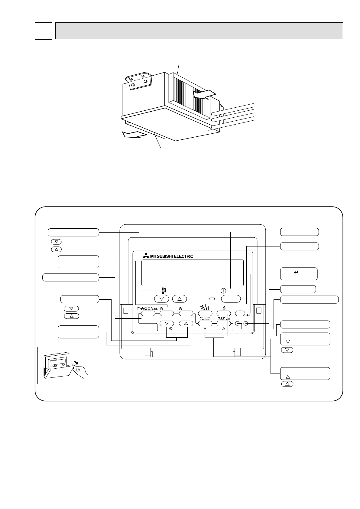
● Indoor (Main) Unit
Air intake duct flange
Air outlet duct flange
Air outlet
Air intake
(sucks the air inside the room into the unit)
● Remote controller
Once the controls are set, the same operation mode can be repeated by simply pressing the ON/OFF button.
● Operation buttons
PAR-21MAA
ON/OFF
FILTER
CHECK
OPERATION
CLEAR
TEST
TEMP.
MENU
BACK DAY
MONITOR/SET
CLOCK
ON/OFF
Set Temperature buttons
Down
Up
Timer Menu button
(Monitor/Set button)
Mode button (Return button)
Set Time buttons
Back
Ahead
Timer On/Off button
(Set Day button)
Opening the
door.
ON/OFF button
Fan Speed button
Filter button
(<Enter> button)
Test Run button
Check button (Clear button)
Airflow Up/Down button
Louver button
(
Operation button)
To preceding operation
number.
Ventilation button
(
Operation button)
To next operation number.
Page 8
8
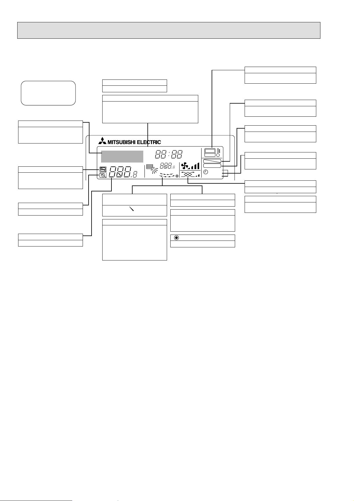
● Display
For purposes of this explanation,
all parts of the display are shown
as lit. During actual operation, only
the relevant items will be lit.
˚F˚C
˚F˚C
ERROR CODE
AFTER
TIMER
TIME SUN MON TUE WED THU FRI SAT
ON
OFF
Hr
AFTER
FILTER
FUNCTION
ONLY1Hr.
WEEKLY
SIMPLE
AUTO OFF
Identifies the current operation
Shows the operating mode, etc.
* Multilanguage display is sup-
ported.
“Centrally Controlled” indicator
Indicates that operation of the remote controller has been prohibited by a master controller.
“Timer Is Off” indicator
Indicates that the timer is off.
Temperature Setting
Shows the target temperature.
Day-of-Week
Shows the current day of the week.
Time/Timer Display
Shows the current time, unless the simple or Auto Off
timer is set.
If the simple or Auto Off timer is set, shows the time
remaining.
“Sensor” indication
Displayed when the remote controller
sensor is used.
“Locked” indicator
Indicates that remote controller buttons have been locked.
“Clean The Filter” indicator
Comes on when it is time to clean the
filter.
Timer indicators
The indicator comes on if the corresponding timer is set.
Up/Down Air Direction indicator
The indicator shows the direction of the outcoming airflow.
“One Hour Only” indicator
Displayed if the airflow is set to
weak and downward during COOL
or DRY mode. (Operation varies
according to model.)
The indicator goes off after one
hour, at which time the airflow direction also changes.
Room Temperature display
Shows the room temperature.
Louver display
Indicates the action of the swing
louver. Does not appear if the
louver is stationary.
(Power On indicator)
Indicates that the power is on.
Fan Speed indicator
Shows the selected fan speed.
Ventilation indicator
Appears when the unit is running in
Ventilation mode.
Caution
● Only the Power on indicator lights when the unit is stopped and power supplied to the unit.
● If you press a button for a feature that is not installed at the indoor unit, the remote controller will display the “Not Available”
message.
If you are using the remote controller to drive multiple indoor units, this message will appear only if he feature is not
present at the parent unit.
● When power is turned ON for the first time, it is normal that “PLEASE WAIT” is displayed on the room temperature indica-
tion (For max. 2minutes). Please wait until this “PLEASE WAIT” indication disappear then start the operation.
Page 9
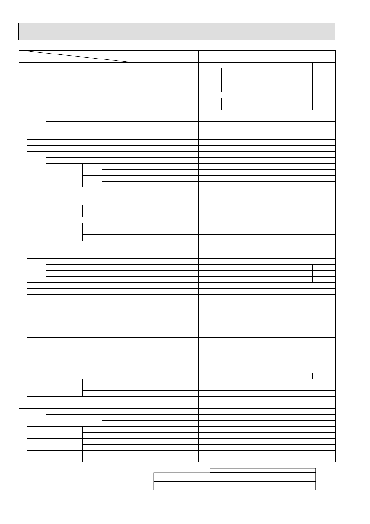
9
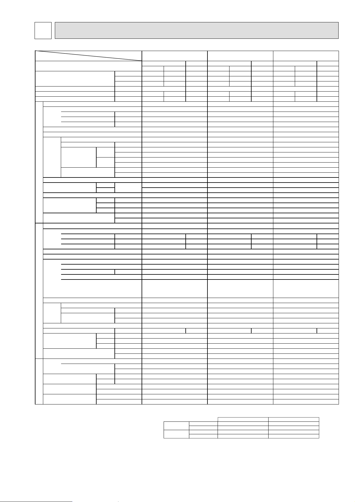
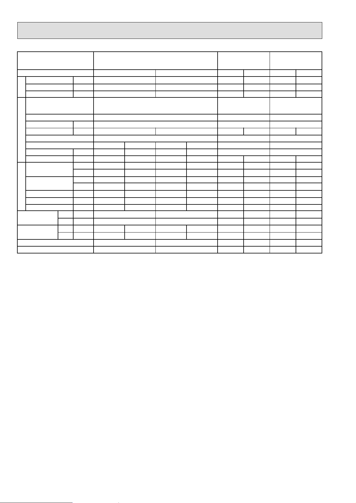
5 SPECIFICATIONS
×
*1 Rating condition
Cooling·····Indoor unit D.B. 27˚C, W.B. 19˚C
Outdoor unit D.B. 35˚C
Heating·····Indoor unit D.B. 20˚C
Outdoor unit D.B. 7˚C, W.B. 6˚C
Refrigerant piping length (one way): 7.5m(24.6ft)
2. Guaranteed operating range
Upper limit
Lower limit
Upper limit
Lower limit
Indoor
D.B. 35˚C, W.B. 24˚C
D.B. 20˚C, W.B. 15˚C
D.B. 27˚C
D.B. 15˚C
Outdoor
D.B. 46˚C
D.B. -5˚C
D.B. 21˚C, W.B. 15˚C
D.B. -8.5˚C, W.B. -15˚C
Cooling
Heating
Item
Function
Capacity*1
Total input
EER
COP
Model name
Power supply(phase,cycle,voltage)
Input
Running current
Starting current
External finish
Heat exchanger
Fan(drive)×No.
Fan motor output
Fan
Airflow
INDOOR UNIT
External static pressure
Operation control & Thermostat
Noise level
Cond. Drain connection O.D.
Dimensions
Weight
Model name
Power supply(phase,cycle,voltage)
Input
Running current
Starting current
External finish
Refrigerant control
Compressor
Model
Motor output
Starter type
Protection devices
Heat exchanger
Fan(drive)×No.
Fan motor output
Fan
Airflow
Defrost method
Noise level
Dimensions
Weight
Refrigerant
Charge
Pipe size O.D.
Connection method
Between the indoor &
REFRIGERANT PIPING OUTDOOR UNIT
outdoor unit
Model name
Btu/h 80,000 76,000 84,000 100,000 96,000 105,000 160,000 154,000 168,000
kW 23.4 22.4 24.6 29.3 28.2 30.7 46.8 45.3 49.2
kcal/h 20,100 19,200 21,100 25,100 24,200 26,300 40,200 38,900 42,300
kW 7.27 9.32 14.09
kcal/h.W 2.54 2.42 2.90 2.51 2.42 2.82 2.61 2.53 3.00
W/W 2.95 2.83 3.38 2.93 2.82 3.29 3.04 2.94 3.49
kW
A
A
kW
Hi
Lo
CMM
L/s
CMM
L/s
Pa
mmAq
Hi
Lo
dB(A)
Hmm
Wmm
Dmm
kg
lbs
kW 6.27 8.22 6.27×2
A 12.3 15.3 12.3×2
A 96 126 108.3
kW
kW
3
/min
m
L/s
dB(A) 63 63 63 / unit
Hmm
Wmm
Dmm
kg
lbs
kg
lbs
Liquid mm
Gas mm
Indoor side
Outdoor side
Height difference
Piping length
PEH-8GA PEH-10GA
Cooling Cooling Cooling
Heating Heating Heating
PEH-16GA
Gross Net Net Gross Net Net Gross Net Net
7.91 10.00
PEH-8GA
PEH-10G
A PEH-16GA
15.37
3PH 4W 50Hz 380-415V 3PH 4W 50Hz 380-415V 3PH 4W 50Hz 380-415V
1.00 1.10 1.55
1.8
1.9 3.8
5.0 5.0 8.5
Galvanized steel Galvanized steel
Galvanized steel
Cross fin coil Cross fin coil Cross fin coil
Centrifugal (direct) ×2 Centrifugal (direct) ×2 Centrifugal (direct) ×2
0.75 0.75 1.3
65 80
120
1,083 1,333 2,000
52 64 -
867 1,067 100 100 150
10 10 15
Remote control & built in Remote control & built in Remote control & built in
49 50 52
45 46 -
R1 R1 R1
400 400 595
1400 1600 1947
634 634 764
70 77 130
154 169 286
Hermetic
5.6×2
Line start
140 / unit
547 / unit
200 / unit
440 / unit
R-22
5.5 / unit
15.88
25.4
Blazed
×
2
PUH-8YKA
3PH 4W 50Hz 380-415V
6.91
13.1
Munsell 3Y 7.8/1.1
Capillary tube
Hermetic
ZR94KC-TFD
5.6
Line start
Thermal relay, Thermal switch
HP switch, LP switch,
Anti-phase protector
Cross fin coil
Propeller(direct)×2
0.15×2
140
2,333
Reverse cycle
61 61
1480
1047
547
200
440
R-22
5.5
12.1
15.88
25.4
Blazed
Flared/Flanged
Max. 40m
Max. 50m
PUH-10YKA PUH-8YKA
3PH 4W 50Hz 380-415V
8.90
16.6
126
Munsell 3Y 7.8/1.1
Capillary tube
Hermetic
ZR125KC-TFD
7.5
Line start
Thermal relay, Thermal switch
HP switch, LP switch,
Anti-phase protector
Cross fin coil
Propeller(direct)×2
0.15×2
140
2,333
Reverse cycle
1480
1047
547
208
458
R-22
6.0
13.2
15.88
28.6
Blazed
Flared/Flanged
Max. 40m
Max. 50m
3PH 4W 50Hz 380-415V
6.91×2
13.1×2
109.196
Munsell 3Y 7.8/1.1
Capillary tube
ZR94KC-TFD×2
Thermal relay, Thermal switch
HP switch, LP switch,
Anti-phase protector
Cross fin coil
Propeller(direct)×2
(0.15×2)×2
2,333 / unit
Reverse cycle
61 / unit
1480 / unit
1047 / unit
12.1 / unit
Flared/Flanged
Max. 40m
Max. 50m
Page 10
10
×
Item
*1 Rating condition
Cooling·····Indoor unit D.B. 27˚C, W.B. 19˚C
Outdoor unit D.B. 35˚C
Heating·····Indoor unit D.B. 20˚C
Outdoor unit D.B. 7˚C, W.B. 6˚C
Refrigerant piping length (one way): 7.5m(24.6ft)
2. Guaranteed operating range
Upper limit
Lower limit
Upper limit
Lower limit
Indoor
D.B. 35˚C, W.B. 24˚C
D.B. 20˚C, W.B. 15˚C
D.B. 27˚C
D.B. 15˚C
Outdoor
D.B. 46˚C
D.B. -5˚C
D.B. 21˚C, W.B. 15˚C
D.B. -8.5˚C, W.B. -15˚C
Cooling
Heating
Model name
Function
Btu/h 200,000 190,000 210,000 80,000 76,000 84,000 100,000 96,000 105,000
Capacity *1
kW 58.6 55.8 61.5 23.4 22.4 24.6 29.3 28.2 30.7
kcal/h 50,300 47,900 52,800 20,100 19,200 21,100 25,100 24,200 26,300
Total input
EER
COP
kW 19.28 7.27 9.32
kcal/h.W 2.43 2.32 2.73 2.54 2.42 2.90 2.51 2.42 2.82
W/W 2.83 2.70 3.18 2.95 2.83 3.38 2.93 2.82 3.29
Model name
Power supply(phase,cycle,voltage)
Input
kW
Running current
Starting current
External finish
Heat exchanger
Fan(drive)×No.
Fan motor output
Fan
INDOOR UNIT
Airflow
External static pressure
Hi
Lo
kW
CMM
L/s
CMM
L/s
mmAq
Operation control & Thermostat
Noise level
Hi
Lo
dB(A)
Cond. Drain connection O.D.
Hmm
Dimensions
Wmm
Dmm
Weight
lbs
Model name
Power supply(phase,cycle,voltage)
Input
kW 8.22×2 6.27 8.22
Running current
Starting current
External finish
Refrigerant control
Compressor
Model
Motor output
kW
Starter type
Protection devices
Heat exchanger
Fan(drive)×No.
Fan
Fan motor output
Airflow
kW
3
m
L/s
Defrost method
Noise level
dB(A) 63 / unit 63 63
Hmm
Dimensions
Wmm
Dmm
Weight
lbs
Refrigerant
Charge
Pipe size O.D.
Connection method
Between the indoor &
REFRIGERANT PIPING OUTDOOR UNIT
outdoor unit
Liquid mm
Gas mm
Indoor side
Outdoor side
Height difference
Piping length
lbs
PEH-20GA
Cooling
(With a high static pressure motor)
Heating Heating Heating
Cooling Cooling
(With a high static pressure motor)
PEH-8GA
PEH-10GA
Gross Net Net Gross Net Net Gross Net Net
20.64
PEH-20GA
3PH 4W 50Hz 380-415V
2.84
A
A
5.4
10.0
Galvanized steel
Cross fin coil
Centrifugal (direct) ×2
1.8
160
2,667
-
-
Pa
150
15
Remote control & built in
53
-
R1
595
1947
764
kg
133
293
PUH-10YKA
×
2
3PH 4W 50Hz 380-415V
8.90×2
A15.3
A 141.3 96 126
16.6×2
142.6
×
2 12.3 15.3
Munsell 3Y 7.8/1.1
Capillary tube
Hermetic
ZR125KC-TFD×2
7.5×2
Line start
Thermal relay, Thermal switch
HP switch, LP switch,
Anti-phase protector
Cross fin coil
Propeller(direct)×2
(0.15×2)×2
/min
140 / unit
2,333 / unit
Reverse cycle
61 / unit
1480 / unit
1047 / unit
547 / unit
kg
208 / unit
458 / unit
R-22
kg
6.0 / unit
13.2 / unit
15.88
28.6
Blazed
Flared/Flanged
Max. 40m
Max. 50m
7.91 10.00
PEH-8GA PEH-10GA
3PH 4W 50Hz 380-415V 3PH 4W 50Hz 380-415V
1.00 1.10
1.8 2.1
6.4 6.4
Galvanized steel Galvanized steel
Cross fin coil Cross fin coil
Centrifugal (direct) ×2 Centrifugal (direct) ×2
0.77 0.77
65 80
1,083 1,333
52 64
867 1,067
150 150
15 15
Remote control & built in Remote control & built in
51 52
48 49
R1 R1
400 400
1400 1600
634 634
70 77
154 169
PUH-8YKA PUH-10YKA
3PH 4W 50Hz 380-415V 3PH 4W 50Hz 380-415V
6.91 8.90
13.1 16.6
96 126
Munsell 3Y 7.8/1.1 Munsell 3Y 7.8/1.1
Capillary tube Capillary tube
Hermetic Hermetic
ZR94KC-TFD ZR125KC-TFD
5.6 7.5
Line start Line start
Thermal relay, Thermal switch
HP switch, LP switch,
Anti-phase protector
Thermal relay, Thermal switch
HP switch, LP switch,
Anti-phase protector
Cross fin coil Cross fin coil
Propeller(direct)×2 Propeller(direct)×2
0.15×20.15
×
2
140 140
2,333 2,333
Reverse cycle Reverse cycle
61 61
1480 1480
1047 1047
547 547
200 208
440 458
R-22 R-22
5.5 6.0
12.1 13.2
15.88 15.88
25.4 28.6
Blazed Blazed
Flared/Flanged Flared/Flanged
Max. 40m Max. 40m
Max. 50m Max. 50m
Page 11
11
DATA
6
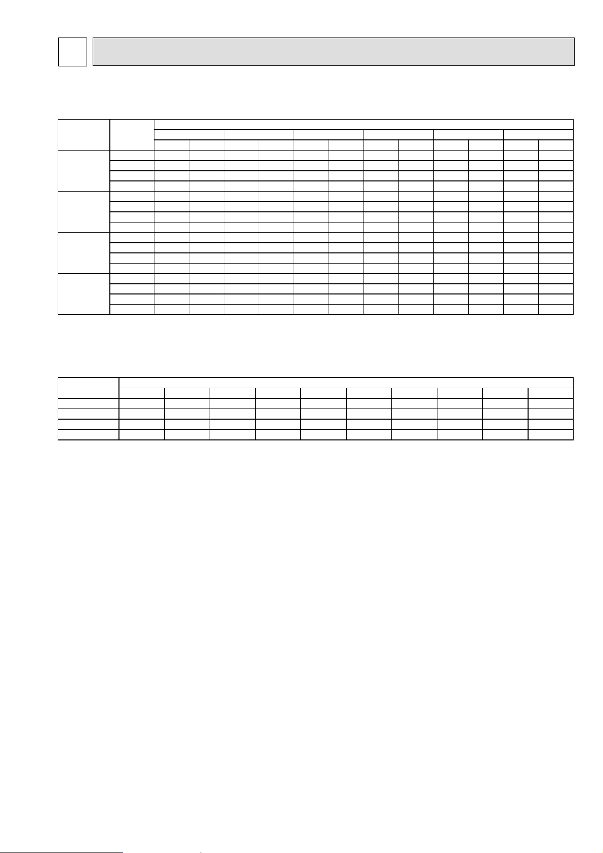
6-1. PERFORMANCE DATA
1) COOLING CAPACITY
Note: C A : Capacity (W)
P.C. : Power consumption (kW)
Cooling capacity correction factors
r
Model name 20
PEH-8GA
PEH-10GA
PEH-16GA
PEH-20GA
Indoo
Intake
air W.B.
16 23,480 6.31 22,921 6.68 22,042 7.11 21,004 7.62 19,886 8.27 18,528 8.93
18 24,917 6.53 24,358 6.82 23,400 7.26 22,442 7.76 21,483 8.42 20,126 9.14
20 26,834 6.68 26,275 6.97 25,237 7.55 24,358 8.06 23,320 8.64 22,042 9.29
22 28,431 6.82 27,872 7.11 27,074 7.62 26,275 8.64 25,157 8.78 23,879 9.51
16 29,400 7.98 28,700 8.44 27,600 8.99 26,300 9.63 24,900 10.46 23,200 11.29
18 31,200 8.26 30,500 8.62 29,300 9.17 28,100 9.82 26,900 10.64 25,200 11.56
20 33,600 8.44 32,900 8.81 31,600 9.54 30,500 10.18 29,200 10.92 27,600 11.74
22 35,600 8.62 34,900 8.99 33,900 9.63 32,900 10.92 31,500 11.10 29,900 12.02
16 46,960 12.26 45,842 12.97 44,085 13.82 42,008 14.81 39,772 16.08 37,057 17.35
18 49,835 12.69 48,717 13.25 46,800 14.10 44,883 15.09 42,967 16.36 40,251 17.77
20 53,668 12.97 52,550 13.54 50,474 14.66 48,717 15.65 46,640 16.78 44,085 18.05
22 56,863 13.25 55,745 13.82 54,147 14.81 52,550 16.78 50,314 17.06 47,758 18.48
16 58,800 16.47 57,400 17.42 55,200 18.55 52,600 19.88 49,800 21.59 46,400 23.29
18 62,400 17.04 61,000 17.80 58,600 18.93 56,200 20.26 53,800 21.97 50,400 23.86
20 67,200 17.42 65,800 18.18 63,200 19.69 61,000 21.02 58,400 22.54 55,200 24.24
22 71,200 17.80 69,800 18.55 67,800 19.88 65,800 22.54 63,000 22.91 59,800 24.81
CA P.C. CA P.C. CA P.C. CA P.C. CA P.C. CA P.C.
˚C
25 30 35 40 45
Outdoor intake air D.B.
˚C
Model name
PEH-8GA
PEH-10GA
PEH-16GA
PEH-20GA
7.5m 10m 15m 20m 25m 30m 35m 40m 45m 50m
1.000 0.994 0.981 0.968 0.955 0.942 0.929 0.916 0.903 0.890
1.000
1.000
1.000
0.995
0.994
0.995
0.985
0.981
0.985
Refrigerant piping length (one way)
0.975
0.968
0.975
0.965
0.955
0.965
0.955
0.942
0.955
0.945
0.929
0.945
0.935
0.916
0.935
0.925
0.903
0.925
0.915
0.890
0.915
Page 12
12
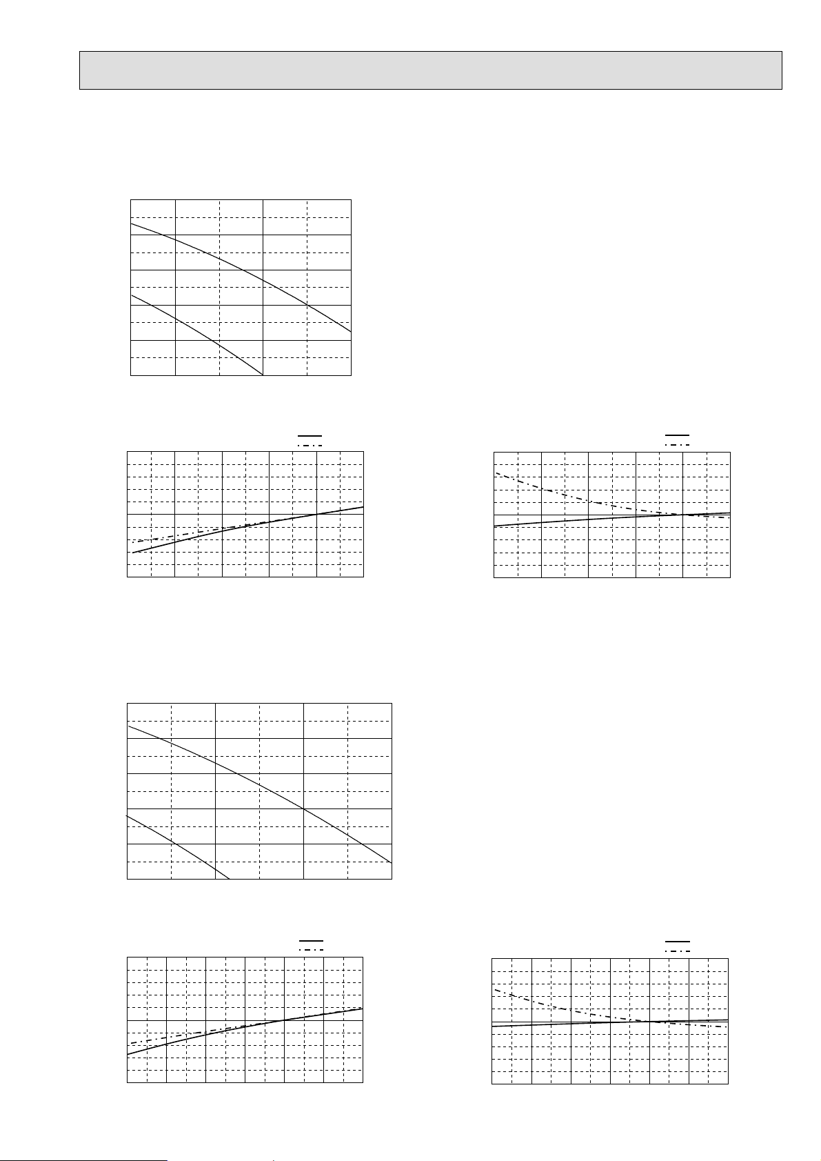
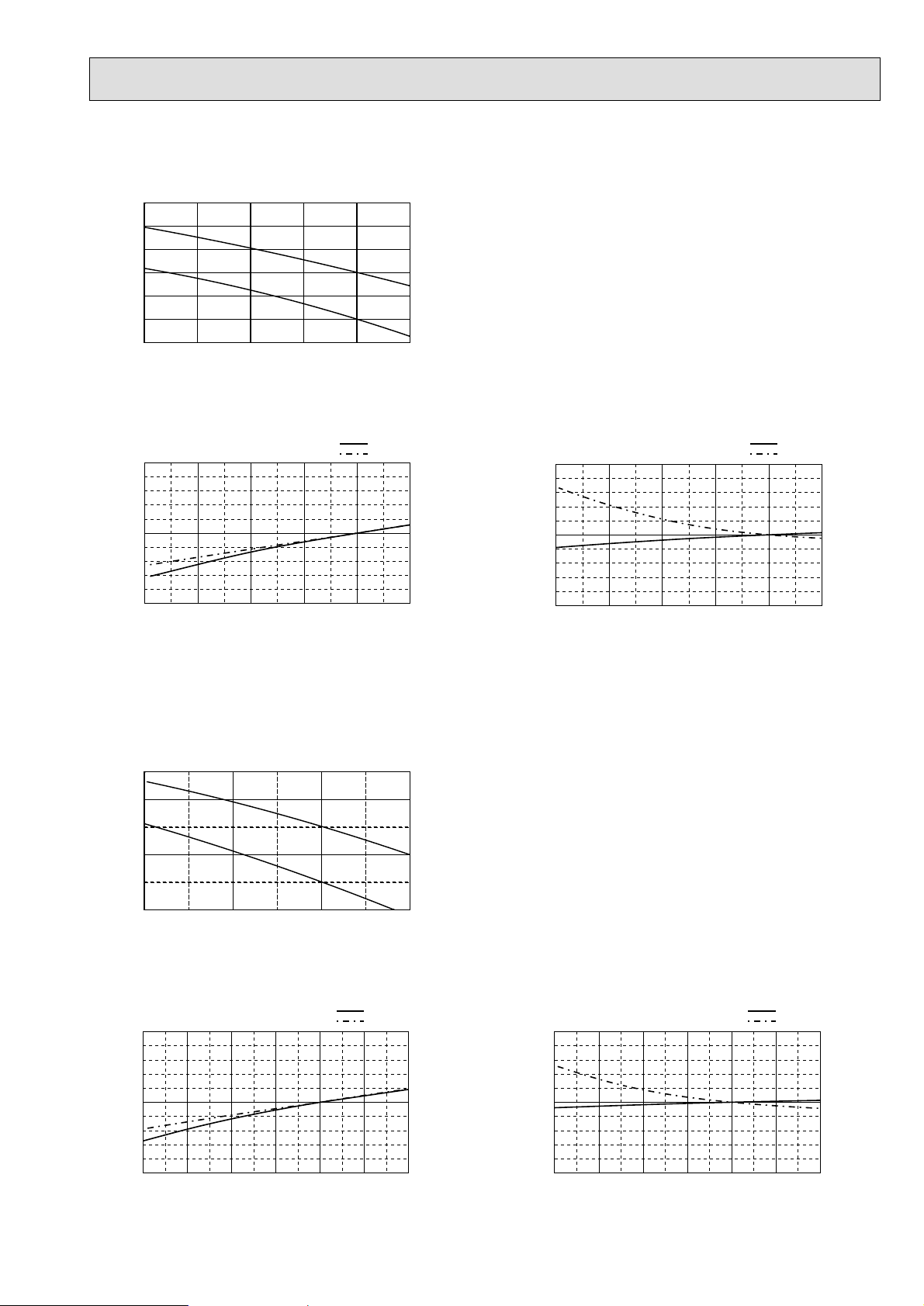
Heating
Cooling
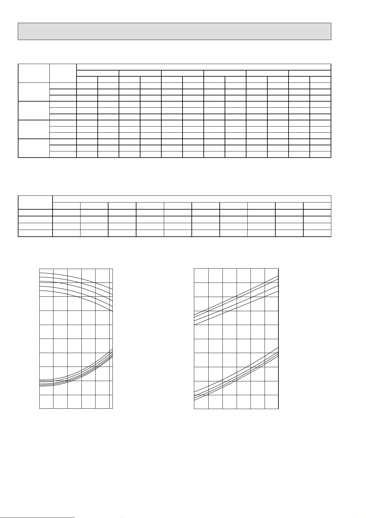
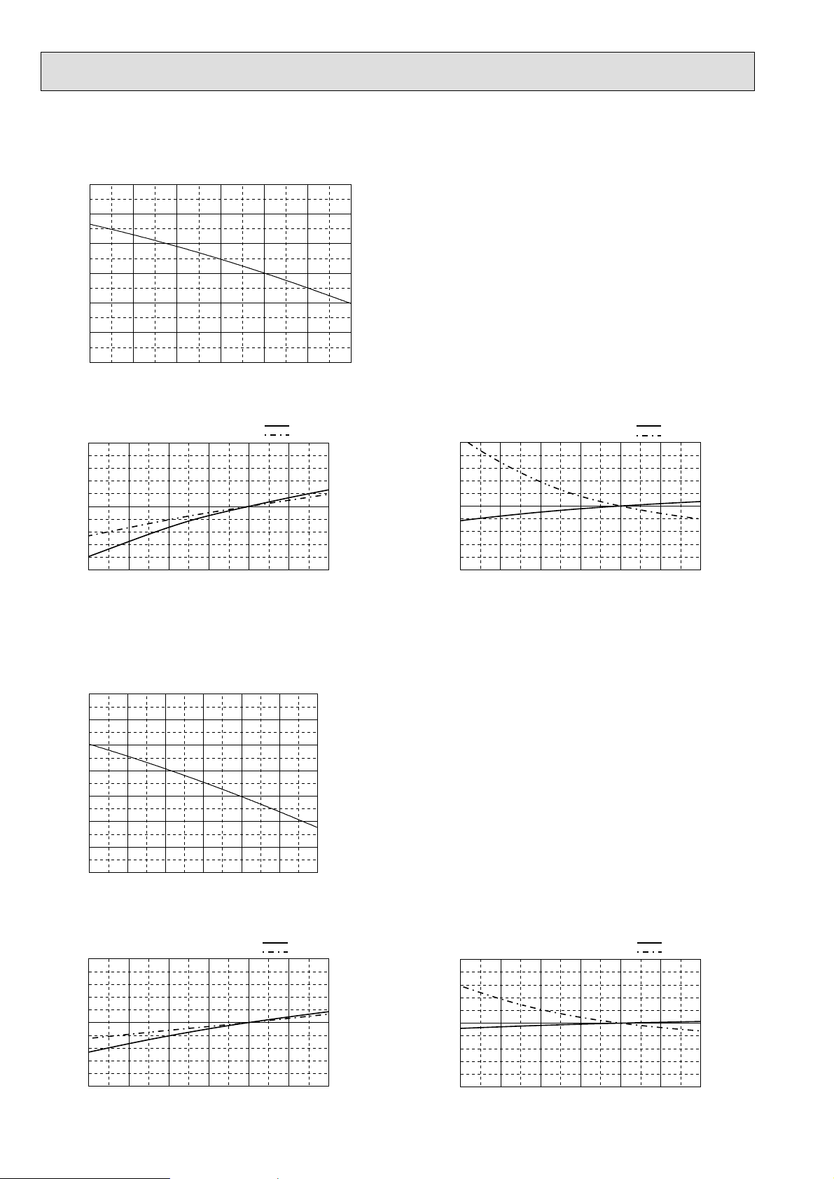
6-2. PERFORMANCE CURVE
2) HEATING CAPACITY
Note:C A : Capacity (W)
P.C. : Power consumption (kW)
Heating capacity correction factors
r
Model name
Indoo
Intake
air D.B.
-10 -5 0 5 10 15
Outdoor intake air W.B.
CA P.C. CA P.C. CA P.C. CA P.C. CA P.C. CA P.C.
˚C
˚C
15 17,949 4.94 20,353 5.50 22,597 6.14 25,401 6.70 28,046 7.25 31,491 7.65
PEH-8GA
20 16,988 5.26 19,231 5.98 21,315 6.54 24,119 7.17 26,844 7.73 30,209 8.21
25 15,706 5.82 17,949 6.46 20,193 7.09 23,158 7.73 26,042 8.45 29,007 8.93
15 22,400 6.34 25,400 7.05 28,200 7.87 31,700 8.58 35,000 9.30 39,300 9.81
PEH-10GA
20 21,200 6.74 24,000 7.66 26,600 8.38 30,100 9.20 33,500 9.91 37,700 10.53
25 19,600 7.46 22,400 8.28 25,200 9.10 28,900 9.91 32,500 10.83 36,200 11.45
15 35,898 9.58 40,706 10.66 45,193 11.90 50,803 12.98 56,091 14.06 62,982 14.83
PEH-16GA
20 33,975 10.20 38,463 11.59 42,629 12.67 48,238 13.90 53,687 14.99 60,418 15.91
25 31,411 11.28 35,898 12.51 40,386 13.75 46,315 14.99 52,085 16.38 58,014 17.30
15 44,873 13.11 50,883 14.59 56,492 16.28 63,503 17.76 70,114 19.24 78,728 20.29
PEH-20GA
20 42,469 13.95 48,078 15.86 53,287 17.34 60,298 19.03 67,109 20.51 75,523 21.77
25 39,264 15.43 44,873 17.12 50,482 18.81 57,894 20.51 65,106 22.41 72,518 23.68
Model name
PEH-8GA 1.000 0.997 0.991 0.984 0.978 0.971 0.965 0.958 0.952 0.945
PEH-10GA 1.000 0.997 0.990 0.983 0.976 0.969 0.962 0.955 0.948 0.941
PEH-16GA 1.000 0.997 0.991 0.984 0.978 0.971 0.965 0.958 0.952 0.945
PEH-20GA 1.000 0.997 0.990 0.983 0.976 0.969 0.962 0.955 0.948 0.941
7.5m 10m 15m 20m 25m 30m 35m 40m 45m 50m
Refrigerant piping length (one way)
1.4
1.2
24
1.0
0.8
0.6
1.4
1.2
1.0
0.8
0.6
TOTAL INPUT (RATIO) CAPACITY (RATIO)
0.4
-5 5 15 25 35 46
OUTDOOR D.B.(˚C)
22
20
18
16
24
22
20
18
16
INDOOR W.B. (˚C)
INDOOR W.B. (˚C)
1.4
1.2
1.0
0.8
0.6
1.4
1.2
1.0
0.8
0.6
TOTAL INPUT (RATIO) CAPACITY (RATIO)
0.4
-15 -10 -5 0 5 10 15
OUTDOOR W.B.(˚C)
15
INDOOR D.B.(˚C)
20
25
27
27
INDOOR D.B.(˚C)
25
20
15
Page 13
13
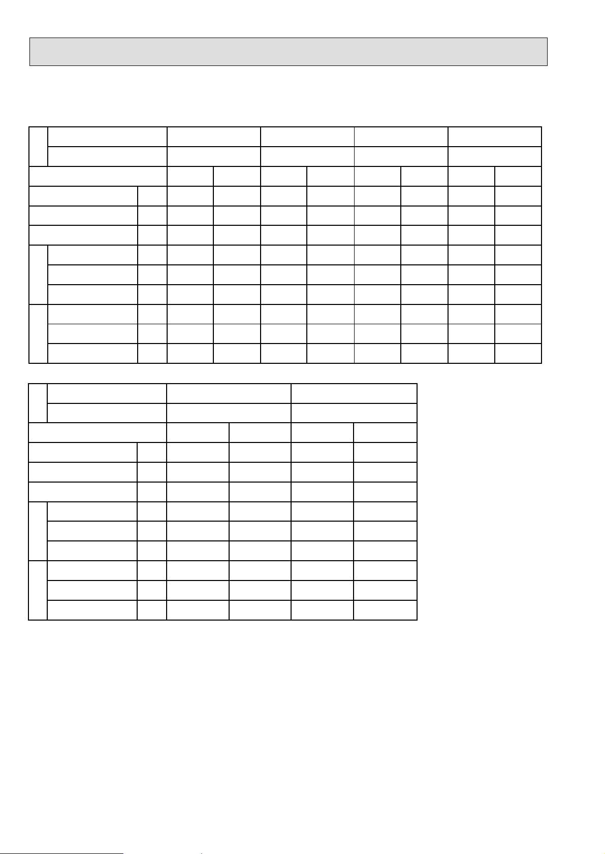
6-3. FAN PERFORMANCE AND CORRECTED AIR FLOW
(1) PEH-8GA
Fan Performance
250
200
150
100
External static pressure (Pa)
50
0
Lo
50.045.0 60.0 70.0
Air flow
Hi
Corrected Air flow
Cooling
1.1
1.0
Capacity/ input factor
0.9
45 50 55 60 65 70
Air flow
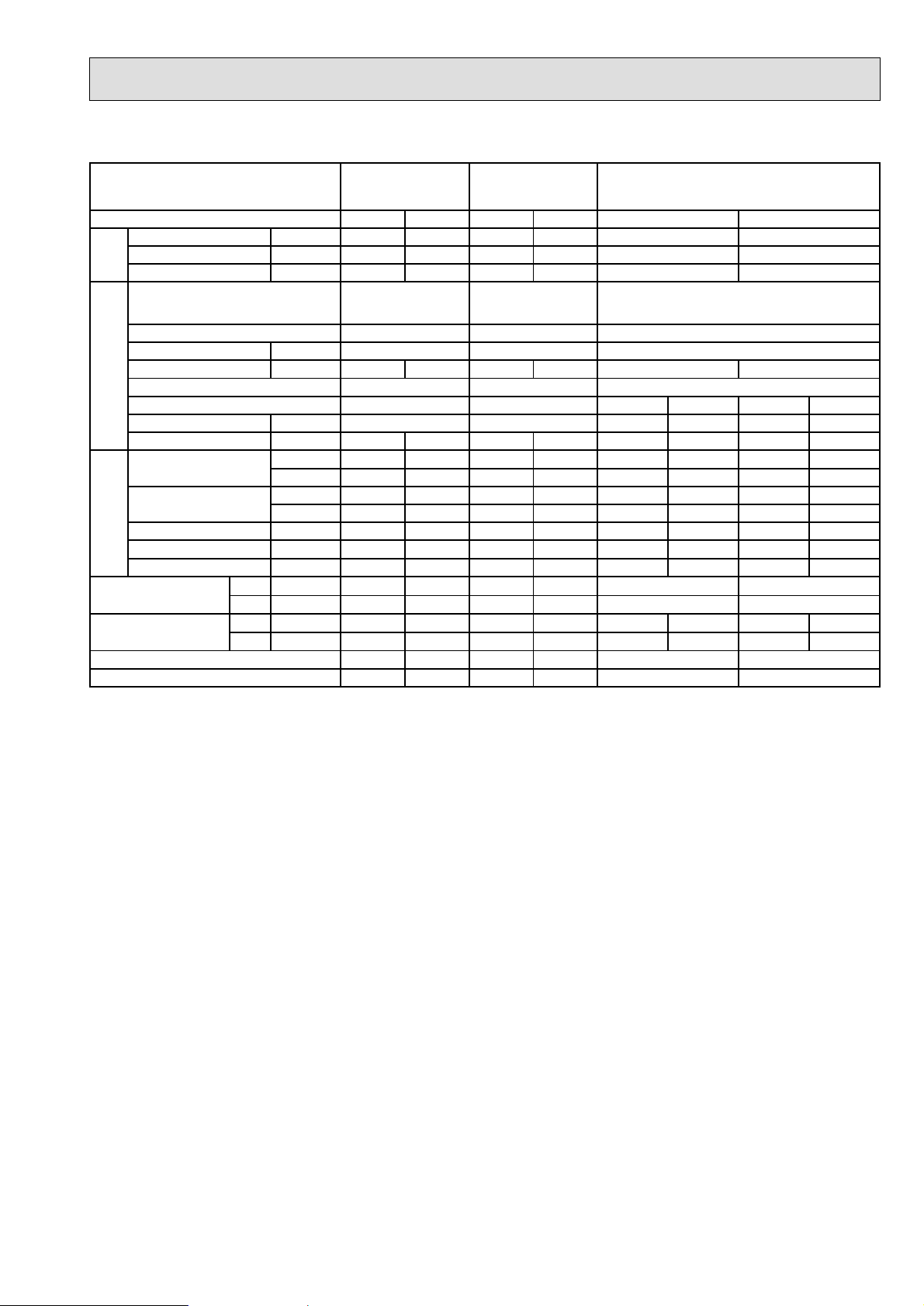
(2) PEH-10GA
Capacity
Input
(CMM)
Heating
1.1
Capacity
Input
1.0
Capacity/ input factor
(CMM) (CMM)
0.9
45 50 55 60 65 70
Air flow
Fan Performance
250
200
150
100
External static pressure (Pa)
50
0
60.0 70.0 80.0 90.0
Lo
Hi
Air flow
Corrected Air flow
Cooling
1.1
1.0
Capacity/ input factor
0.9
60 65 70 75 80 85 90
Air flow
Capacity
Input
(CMM)
(CMM)
Heating
1.1
1.0
Capacity/ input factor
0.9
60 65 70 75 80 85 90
Air flow
Capacity
Input
(CMM)
Page 14
14
(3) PEH-16GA
300
250
200
150
100
External static pressure (Pa)
50
Fan Performance
0
80.0 100.0 110.0 120.0 130.0 140.090.0
Air flow
Corrected Air flow
Cooling
1.1
1.0
Capacity/ input factor
0.9
80 90 100 110 120 130 140
Air flow
(4) PEH-20GA
Fan Performance
350
300
250
Capacity
Input
(CMM)
(CMM)
Heating
1.1
1.0
Capacity/ input factor
0.9
80 90 100 110 120 130 140
Air flow
Capacity
Input
(CMM)
200
150
100
External static pressure (Pa)
50
0
120.0 130.0 140.0 150.0 160.0 170.0 180.0
Air flow
Corrected Air flow
Cooling
1.1
1.0
Capacity/ input factor
0.9
120 130 140 150 160 170 180
Air flow
Capacity
Input
(CMM)
(CMM)
Heating
1.1
1.0
Capacity/ input factor
0.9
120 130 140 150 160 170 180
Air flow
Capacity
Input
(CMM)
Page 15
15
(5) PEH-8GA (High static pressure motor)
Fan Performance
300
250
200
Lo
Air flow
Hi
Capacity
Input
150
100
50
0
External static pressure (Pa)
45.0 50.0 55.0 60.0 65.0 70.0
Corrected Air flow
Cooling
1.1
(CMM)
1.1
Heating
Capacity
Input
1.0
Capacity/ input factor
0.9
45 50 55 60 65 70
Air flow
(6) PEH-10GA (High static pressure motor)
Fan Performance
250
200
150
100
Lo
50
0
External static pressure (Pa)
60.0 65.0 70.0 75.0 80.0 85.0 90.0
Hi
Air flow
(CMM)
(CMM)
1.0
Capacity/ input factor
0.9
45 50 55 60 65 70
Air flow
(CMM)
Corrected Air flow
Cooling
1.1
1.0
Capacity/ input factor
0.9
60 65 70 75 80 85 90
Air flow
Capacity
Input
Capacity
Input
1.1
Heating
1.0
Capacity/ input factor
0.9
(CMM) (CMM)
60 65 70 75 80 85 90
Air flow
Page 16
16
6-4. ELECTRICAL DATA
Indoor unit········240V 50Hz 1phase
Outdoor unit ·····240V 50Hz 1phase / 415V 50Hz 3phase
Indoor unit
Outdoor unit
Mode
Capacity (GROSS)
Capacity (NET)
Total input
Input kW
Current A
Indoor unit
Starting current A
Input kW
Current A
Starting current A
Outdoor unit
Indoor unit
Outdoor unit
PEH-8GA PEH-10GA
PUH-8YKA
Cool
kW
kW
kW
23.4
22.4
7.91
1.00
1.8
5.0
6.91
13.1
96
(With a high static pressure motor)
Heat
-
24.6
7.27
1.00
1.8
5.0
6.27
12.3
96
PEH-8GA
PUH-8YKA PUH-10YKA
PEH-16GA
PUH-10YKA
Cool
29.3
28.2
10.00
1.10
1.9
5.0
8.90
16.6
126
Heat
-
30.7
9.32
1.10
1.9
5.0
8.22
15.3
126
PEH-10GA
(With a high static pressure motor)
PUH-8YKA×2
Cool
46.8
45.3
15.37
1.55
3.8
8.5
13.82
26.2
109.1
Heat
-
49.2
14.09
1.55
3.8
8.5
12.54
24.6
108.3
PEH-20GA
PUH-10YKA×2
Cool
58.6
55.8
20.64
2.84
5.4
10.0
17.80
33.2
142.6
Heat
61.5
19.28
2.84
10.0
16.44
30.6
141.3
-
5.4
Mode
Capacity (GROSS)
Capacity (NET)
Total input
Input kW 1.00 1.00 1.10 1.10
Current A 1.8 1.8 2.1 2.1
Indoor unit
Starting current A 6.4 6.4 6.4 6.4
Input kW 6.91 6.27 8.90 8.22
Current A 13.1 12.3 16.6 15.3
Starting current A 96 96 126 126
Outdoor unit
kW 23.4 - 29.3 kW 22.4 24.6 28.2 30.7
kW 7.91 7.27 10.00 9.32
Cool Heat Cool Heat
Page 17
17
6-5. STANDARD OPERATION DATA
The unit of pressure has been changed to MPa based on SI (International System of Units) in accordance with I.S.O.
(International Organization for Standardization).
The conversion factor is : 1(MPa) =10.2 (kgf/cm2)
PEH-8GA PEH-10GA PEH-16GAModel name
Mode
Capacity (GROSS)
Capacity (NET)
Total
Input
Indoor unit
Phase, Hz
Volts
Amperes
Outdoor unit
Phase, Hz
Electrical circuitRefrigerant circuit
Volts
Amperes
Discharge
Pressure
Suction
Pressure
Discharge temp.
Suction temp.
Ref. pipe length
Indoor intake
air temp.
Outdoor intake
air temp.
SHF
BF
D.B.
W.B.
D.B.
W.B.
Cooling Heating Cooling Heating
kW 23.4 - 29.3 kW 22.4 24.6 28.4 30.7
kW 7.91 7.27 10.00 9.32
PEH-8GA
3, 50
V
A 1.8 1.8 1.9 1.9
V
A 13.1 12.3 16.6 15.3 13.1 13.1 12.3
MPa 2.01 1.86 2.21 1.94 2.01 2.01 1.86
kgf/cm
MPa 0.45 0.33 0.45 0.31 0.45 0.45 0.33
kgf/cm
˚C
˚C
m 7.5 7.5 7.5 7.5 7.5 7.5 7.5
˚C
˚C
˚C
˚C
380/400/415 380/400/415
3, 50
380/400/415 380/400/415
2
20.5 19.0 22.5 19.8 20.5 20.5 19.0
2
4.6 3.4 4.6 3.2 4.6 4.6 3.4
105 84 96 94 105 105 84
19 -1 7 -5 19 19 -1
27 20 27 20
19 15 19 15
35 7 35 7 35 35 7
24 6 24 6 24 24
0.74 - 0.75 -
0.18 - 0.15 -
PEH-10GA PEH-16GA
3, 50
PUH-10YKA
3, 50
Cooling
46.8
45.3
15.37
3, 50
380/400/415
3.8 3.8
PUH-8YKAPUH-8YKA
3, 50 3, 50 3, 50
380/400/415 380/400/415 380/400/415
27
19
0.69
0.24
Heating
-
49.2
14.09
3, 50
380/400/415
12.3
1.86
19.0
0.33
3.4
84
-1
7.5
20
15
7
66
-
-
Page 18
18
The unit of pressure has been changed to MPa based on SI (International System of Units) in accordance with I.S.O.
(International Organization for Standardization).
The conversion factor is : 1(MPa) =10.2 (kgf/cm2)
Model name
Mode
Capacity (GROSS)
Capacity (NET)
Total
Input
Indoor unit
Phase, Hz
Volts
Amperes
Outdoor unit
Phase, Hz
Electrical circuitRefrigerant circuit
Volts
Amperes
Discharge
Pressure
Suction
Pressure
Discharge temp.
Suction temp.
Ref. pipe length
Indoor intake
air temp.
Outdoor intake
air temp.
D.B.
W.B.
D.B.
W.B.
SHF
BF
PEH-20GA
Cooling Heating
kW - 29.3
kW 24.6 28.4
kW 7.27 10.00
58.6
56.0
20.64
-
61.5
19.28
PEH-20GA
3, 50
V
A 1.8 2.1
5.4
380/400/415
5.4
PUH-10YKA
3, 50 3, 50
380/400/415 380/400/415
V
A 16.6 15.3 12.3 16.6
MPa 2.21 1.94 1.86 2.21
2
kgf/cm
MPa 0.45 0.31 0.33 0.45
kgf/cm
˚C
˚C
22.5 19.8 19.0 22.5
2
4.6 3.2 3.4 4.6
96 94 84 96
7 7 -5 -1 7
m 7.5 7.5 7.5 7.5
˚C
˚C
˚C
˚C
35 7 7 35
24
3, 50
380/400/415
16.6
2.21
22.5
0.45
4.6
96
7.5
27
19
35
24 6
0.69
0.30
3, 50
380/400/415
15.3
1.94
19.8
0.31
3.2
94
-5
7.5
20
15
7
6624
-
-
(With a high static
pressure motor)
Cooling
Heating Cooling
(With a high static
pressure motor)
23.4
22.4
7.91
PEH-8GA PEH-10GA
(With a high static
pressure motor)
(With a high static
pressure motor)
3, 50 3, 50
380/400/415 380/400/415
1.8
PUH-8YKA PUH-10YKA
3, 50
380/400/415 380/400/415
13.1
2.01
20.5
0.45
4.6
105
19
7.5
27
19
20 27
15 19
35
24
0.74
- 0.75
0.18 - 0.15
PEH-8GA
PEH-10GA
Heating
-
30.7
9.32
2.1
3, 50
15.3
1.94
19.8
0.31
3.2
94
-5
7.5
20
15
7
6
-
-
Page 19
19
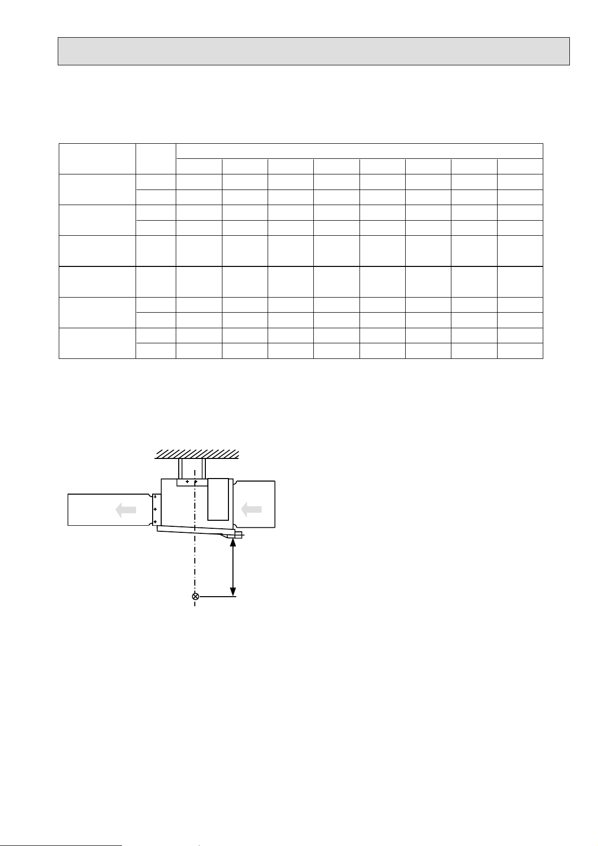
6-6. SOUND DATA
Indoor units
1) Sound Levels
Model
PEH-8GA
PEH-10GA
PEH-16GA
PEH-20GA
PEH-8GA
(High static
pressure motor)
PEH-10GA
(High static
pressure motor)
SPL
dB(A) 63Hz 125Hz 250Hz 500Hz 1000Hz 2000Hz 4000Hz 8000Hz
49 52 51 50 45 45 42 34 26
45 46 45 45 41 41 36 28 19
50 51 50 51 46 45 41 34 26
46 47 46 46 43 42 37 28 19
52 53 51 52 50 46 44 39 30
53 55 54 51 50 48 44 40 31
51 55 54 51 49 47 43 33 27
48 50 50 47 46 44 40 29 21
52 56 55 52 50 48 44 34 28
49 51 51 48 47 45 41 30
Position measurement
Indoor unit
PEH-8,10,12: Upper High/Lower Low
OCTAVE BAND FREQ.Hz
22
Outlet
2m
1m
Inlet
1.5m
Measurement point
Page 20

20
OUTLINES AND DIMENSIONS
7
7-1. INDOOR UNITS
Unit : mm
PEH-8GA
Rubber bush <Remote
controller wiring>
Rubber bush
<Outdoor unit
connection wiring>
Rubber bush
<Power supply
wiring>
75
55
12970
Return air
sensor
A
A
4- 12 Holes
Drain R1
Top view
Control box
Return air
duct flange
Supply air
duct flange
<For hanging bolt M10>
[Field supply]
22- 3.1 Holes
24- 3 Holes
Refrigerant pipe
15.88 (5/8 braze)
Refrigerant pipe
25.4 (1 braze)
<Accessory>
.
Pipe cover.......................................... 2pcs.
(For dew condensation prevention of
local piping and unit connection.)
.
Remote controller............................... 1pcs.
Return air
Left side view
Supply air
Front view
42
124 34
131
530
50
9525011
7×130(=910)
10
130
130
45
45
31 31
1102
200
10
8×130(=1040)
1300
20
199
100
40
20
462
144
1284
400
155 1000 105
40 1260 40
1340
1400
56539
22330
145
89
35
130
130
35
634
262 73
10
54
10
376
2510010025
Page 21

21
Rubber bush <Remote
controller wiring>
Rubber bush
<Outdoor unit
connection wiring>
Rubber bush
<Power supply
wiring>
755570 129
A
A
4- 12 Holes
Drain R1
Top view
Control box
22- 3.1 Holes
<For hanging bolt M10>
[Field supply]
Return air
duct flange
Supply air
duct flange
26- 3 Holes
Left side view
Supply air
Return air
Front view
Return air
sensor
<Accessory>
.
Pipe cover..........................................2pcs.
(For dew condensation prevention of
.
Remote controller.............................. 1pcs.
local piping and unit connection.)
Refrigerant pipe
15.88 (5/8 braze)
Refrigerant pipe
28.6 (1-1/8 braze)
42
124
131
50 530
34
130
9525011
10
66
1302
1484
7×130(=910)
130
45
45
200
20
100
20
199
40
1500
462
66 9×130(=1170)
10
25 100 100 25
10 10
1540
40146040
255 205
376
1000
1600
73262
400
39 565
54
634
35130
89
145
144
330 22
130
35
PEH-10GA
Unit : mm
Page 22

22
<Accessory>
(For dew condensation prevention of
local piping and unit connection.)
A
Rubber bush
<Outdoor unit
connection wiring>
Rubber bush
<Power supply
wiring>
Rubber bush
<Remote controller
wiring>
A
Supply air
duct flange
Control box
Return air
duct flange
[Field supply]
4 15 HOLES
Supply air
Return air
Top view
Front viewLeft side view
36- 3 HOLES
24 - 3.1 HOLES
Drain R1
Return air
sensor
(2 places)
Refrigerant pipe
PEH-16GA
PEH-20GA
[2 places (*1 part)]
Refrigerant pipe
[2 places (*2 part)]
*1
*2
*1
*2
15.88 (5/8 braze)
: 25.4 (1 braze)
: 28.6 (1-1/8 braze)
Pipe cover..........................................4pcs.
Remote controller...............................1pc.
<For hanging bolt M12>
39 700
59 425
20
141 320 203
10
42.5 8
×
130(=1040)
130
42.5
100
45
1618149
29 12
×
130(=1560) 29
130
33
10
4013013040
570
1947
22 188340
395 1125 280
764
50
1824
595
22.5 4×120(=480)
120
22.5
102 117 156 117 81
22525
66450
1880
180040 40
60
61
6060 40
10
184020
10
PEH-16, 20GA
Unit : mm
Page 23

23
Unit : mm
7-2. REMOTE CONTROLLER
130
120
19
Page 24

24
WIRING DIAGRAM
8
PEH-8, 10GA
ROOM TEMP
LIQUID PIPE TEMP
COND/EVA TEMP
OUTDOOR>)
.
NAME
MAGNETIC CONTACTOR (INDOOR FAN MOTOR<LOW SPEED>)
OVER CURRENT RELAY (INDOOR FAN MOTOR)
INTERNAL THERMOSTAT (INDOOR FAN MOTOR)
TERMINAL BLOCK
49F
TB2,4,5
THERMISTOR
X1 AUXILIARY RELAY
TH5
TH1
TH2
FB FERRITE CORE
CR1,2 SURGE KILLER
MAGNETIC CONTACTOR (INDOOR FAN MOTOR<HIGH SPEED>)
FAN MOTOR (INDOOR)
51F
MF1
52FHi
52FLo
SYMBOL NAME
INDOOR UNIT
C02
2
(Hi)
3
(3P)
MF1
C01
52F
(6P)
3211
(Lo)
Lo
51F
FUSE (T6.3AL250V)
VARISTOR
AUXILIARY RELAY
FUSE
ZNR
X4-6
INDOOR
CONTROLLER
BOARD
52F
Hi
ZNR5~7
LED (POWER SUPPLY)
LED (POWER SUPPLY<REMOTE CONTROLLER>)
CONNECTOR (EMERGENCY OPERATION)
SWITCH (CAPACITY CODE)
SWITCH (MODEL SELECTION)
SW2
SWE
LED1
SW1
DSA
LED2
TH1
DSR
SNB BOARD 1
CONNECTOR (LOSSNAY)
CONNECTOR (HA TERMINAL-A)
CONNECTOR (REMOTE SWITCH)
CONNECTOR (DRAIN SENSOR)
LED (TRANSMISSION<INDOOR
CN32
CN41
CN31
CN2L
LED3
ARRESTER
CONNECTOR (WIRELESS REMOTE CONTROLLER)
CONNECTOR (CENTRALLY CONTROL)
VARISTOR
CN51
CN90
DSA,DSR
ZNR5~7
SNB BOARD 1
ON
OFF
ON
OFF
5
54321
TH2
TH5
SW1
ON
SW2
OFF
3214
INDOOR
CONTROLLER BOARD
CN21
CN29
CN41
123
CN51
54321
CN2L
1
2
1
1
2
4
CN31
CN32
123
123
CN22
123456789
1
2
2
TB6 TERMINAL BLOCK
SYMBOL
REMOTE CONTROLLER
2.Color of earth wire is yellow and green twisting.
3.Specification subject to change without notice.
4.Indoor and outdoor connecting wires are made with polarities,make sure
1.The dotted lines show field wiring.
Note:
SWE
FAN
X4 X5 X6
CN20
1
LED1
CN90
X4 X5 X6
2
LED2
ZNR
LED3
7531
31
CND CNDK
FUSE
31
CN3C
CN2D
21 31
DC13.1V
FB
matching wiring and terminal.
If a trouble occurs with either the remote controller or the indoor microcom-
puter and no other trouble exists, emergency operation for cooling or heating
can be performed by changing the setting of connector (SWE) "ON" on the
indoor controller board.
SWE:ON / Indoor fan is running high speed.
5.Emergency operation
6. mark is connector. mark is terminal.
Therefore, do not change factory set value of over current relays.
1.To protect fan motor from abnormal current,over current relays is installed.
Caution,
OUTDOOR UNIT
TO OUTDOOR UNIT
CONNECTING WIRES
(POLAR)
51F
C01
49F
5
4
X1
52F
X1
52F
1
3
DC
13.1V
1
2
CN2S CNSK
INDOOR
POWER BOARD
X1
Hi
CR2 CR1
Lo
TAB1
TB4
S1S2S3
RED
WHITE
BLACK
TB2
L1L2L3
INDOOR UNIT
CIRCUIT BREAKER
(FIELD SUPPLY)
PEH-8,10GA:15A
POWER SUPPLY
3N~PE
380/400/415V
N
50Hz
RED
WHITE
BLACK
PE
TB5
LCD
BOARD
REMOTE CONTROLLER
1
2
REMOTE CONTROLLER
TB6
Page 25

25
PEH-16, 20GA
COND/EVA TEMP
LIQUID PIPE TEMP
ROOM TEMP
OUTDOOR>)
.
NAME
NAME
MAGNETIC CONTACTOR (INDOOR FAN MOTOR)
TERMINAL BLOCK
INTERNAL THERMOSTAT (INDOOR FAN MOTOR)
OVER CURRENT RELAY (INDOOR FAN MOTOR)
FAN MOTOR (INDOOR)
SURGE KILLERCR
THERMISTOR
AUXILIARY RELAYX1,2
SYMBOL NAME
MF1
52F
INDOOR UNIT
C02C01
123
MF1
123
FB21,FB22
FB11,FB12 FERRITE CORE
TH2-1
TH1-1
TH5-1,5-2
TH2-1,2-2
TH1-1,1-2
TB2,4-1,4-2,5
49F
51F
52F 51F
DSA
DSR
ZNR5~7
SNB BOARD 1
RED
WHITE
BLACK
X02
X01
51F
5
49F
52F
CR
CONNECTOR (EMERGENCY OPERATION)
SWITCH (CAPACITY CORD)
SWITCH (MODEL SELECTION)
LED (POWER SUPPLY<REMOTE CONTROLLER>)
VARISTOR
FUSE (T6.3AL250V)
ZNR
FUSE
INDOOR
CONTROLLER
LED (POWER SUPPLY)
AUXILIARY RELAY
SW1
LED2
LED1
SWE
SW2
X4-6
BOARD
ON
OFF
5
543
43
21
SW1
12
TH5-1
(No.1)
INDOOR
CONTROLLER BOARD
CN41
123412121
FB12
CN31
CN51
12312
54321
CN2L
CN22
12123456789
1
2
4
C01
CONNECTOR (LOSSNAY)
LED (TRANSMISSION<INDOOR
CN2L
LED3
CONNECTOR (WIRELESS REMOTE CONTROLLER)
CONNECTOR (CENTRALLY CONTROL)
CONNECTOR (HA TERMINAL-A)
CONNECTOR (REMOTE SWITCH)
CONNECTOR (DRAIN SENSOR)
CN32
CN31
CN41
CN51
CN90
ARRESTER
VARISTOR
DSA,DSR
ZNR5~7
SNB BOARD 1
OFF
ON
SWE
ON
OFF
CN29
SW2
CN21
CN32
X4 X5 X6
CN20
2
LED1
3
CN90
LED2
X4 X5 X6
ZNR
LED3
FAN
7531
CNDK
CND
FUSE
31 31
CN3C
CN2D
21 31
TERMINAL BLOCK
TB3,TB8
SYMBOL
OUTDOOR UNIT
REMOTE CONTROLLER
TB3
S1S2S3
(No.1)
OUTDOOR UNIT
TO OUTDOOR UNIT
CONNECTING WIRES
(POLAR)
TB4-1
S1S2S3
X1
1
3
POWER BOARD
INDOOR
DC
13.1V
1
FB11
(No.1)
CN2S CNSK
2
DC13.1V
TERMINAL BLOCK
TB6
SYMBOL
Note:
TB8
IN
IN
OUT
OUT
TH1-2
TH2-2
TH5-2
TAB1
matching wiring and terminal.
If a trouble occurs with either the remote controller or the indoor microcom-
puter and no other trouble exists, emergency operation for cooling or heating
can be performed by changing the setting of connector (SWE) "ON" on the
indoor controller board.
4.Indoor and outdoor connecting wires are made with polarities,make sure
1.The dotted lines show field wiring.
5.Emergency operation
2.Color of earth wire is yellow and green twisting.
3.Specification subject to change without notice.
SWE :ON / Indoor fan is running high speed.
Therefore, do not change factory set value of over current relays.
6. mark is connector. mark is terminal.
1.To protect fan motor from abnormal current,over current relays is installed.
Caution,
(No.2)
TB8
OUT
OUT
TB3
IN
IN
S1S2S3
OUTDOOR UNIT
TO OUTDOOR UNIT
CONNECTING WIRES
(POLAR)
FAN
7531
CNDK
CND
31 31
INDOOR
CN2D
DC13.1V
FB21
21 31
TB4-2
S1S2S3
X2
1
3
TAB1
POWER BOARD
DC
13.1V
1
2
CN2S CNSK
(No.2)
ON
ON
OFF
5
543
43
21
SW1
12
(No.2)
INDOOR
CONTROLLER BOARD
CN41
CN29
123412121
FB22
CN31
CN51
12312
54321
CN2L
CN22
1
2
12123456789
OFF
SW2
CN21
CN32
SWE
ON
OFF
X4 X5 X6
X4 X5 X6
CN20
2
FUSE
ZNR
LED1
LED2
LED3
3
CN3C
CN90
RED
WHITE
BLACK
TB2
L1L2L3
INDOOR UNIT
CIRCUIT BREAKER
(FIELD SUPPLY)
PEH-16,20GA:15A
POWER SUPPLY
3N~PE
380/400/415V
GREEN/YELLOW
BLUE
N
PE
50Hz
TB5
1
2
BOARD
REMOTE CONTROLLER
REMOTE CONTROLLER
LCD
TB6
Page 26

26
PEH-8, 10, 16, 20GA
Unit : mm
*Two outdoor units must be connected when using PEH-16, 20GA.
9
REFRIGERANT SYSTEM DIAGRAM
R.V.coil
Heating:ON
Cooling:OFF
Outdoor heat exchanger
Refrigerant flow in cooling
Refrigerant flow in heating
High pressure switch
(protection)
I.D. 4.0-L700
×
I.D. 4.0-L800
×
Capillary tube
O.D. 6.0
Capillary tube
O.D. 6.0
Service
port
Strainer
Capillary
tube
Thermistor
TH1
(liquid temp)
Restrictor
valve
Thermistor TH2
(discharge temp)
Compressor
I.D. 4.6-L1500
I.D. 4.0-L1400
×
×
PUH-8:
O.D. 6.0
PUH-10:
O.D. 6.0
4-wau value
Ball valve
Service
port
Flange
connection
Brazing
connection
High pressure
switch (control)
Solenoid valve
Service port
Low pressure
switch
Refrigerant pipe
8HP:Ø25.4
10HP:Ø28.6
(with heat insulator)
Strainer Strainer
Distributor
Accumulator
Ball
valve
Flared
connection
(with heat insulator)
Ø15.88
Refrigerant pipe
Brazing
connection
Restrictor
valve
Capillary
I.D. 3.0-L700
×
I.D. 3.0-L1000
×
tube
PEH-10: O.D. 4.0
PEH-8: O.D. 4.0
Indoor
heat
Thermistor
exchanger
TH5
Thermistor
TH2
Page 27

27
10
SELF-DIAGNOSIS AND TROUBLESHOOTING
<Abnormality detected at power on>
Abnormality display
None
EA
Eb
EC
F1
F2
Meaning of abnormality display and
abnormality troubleshooting
Indoor/outdoor connection erroneous wiring, too many indoor
units (5 or more)
1.Outdoor controller board automatically recognizes the number of
connected indoor units. However,
when the number of connected indoor units cannot be set due to erroneous indoor/outdoor connection, erroneous wiring, etc. even
after 4 minutes have elapsed since
the power was turned on, an abnormality is recognized.
2.When the outdoor controller board
identified “5 or more” connected in-
door units, an abnormality is recognized.
Indoor/outdoor connection erroneous wiring
The outdoor controller board automatically sets the unit No. of the indoor units. However, when the unit
No. of the indoor units cannot be set
due to indoor/outdoor connection erroneous wiring even after 4 minutes
has elapsed since the power was
turned on, an abnormality is recognized.
Start-up time over
When start-up processing does not
end even through 4 minutes has
elapsed since the power was turned
on, an abnormality is recognized.
Reverse phase detected
Missing phase detected
Cause
(1) Voltage not applied to outdoor unit ter-
minal block TB1.
a. Power supply circuit breaker not
closed.
b. Power supply terminals connection
faulty, or disconnected.
c. Missing phase (R or S phase)
(2) No electricity at controller board power
supply connector.
a. Power supply connector contact
faulty.
b. Terminal R/1 or S/2 on controller
board disconnected.
(3)Outdoor unit controller board faulty.
a. Blown fuse on controller board.
b. Part faulty.
(1)Indoor/outdoor connection wire con-
tact faulty or erroneous wiring.
(2) Indoor/outdoor connection wire diam-
eter or wiring length outside specification.
(3)Five or more indoor units connected
to outdoor unit.
(4) Outdoor controller board send/receive
circuit faulty.
(5)Indoor controller board send/receive
circuit faulty.
(6)Noise has entered on power supply
or indoor/outdoor connection wire.
(1)Indoor/outdoor connection wire con-
tact faulty, or erroneous wiring.
(2) Indoor/outdoor connection wire diam-
eter or wiring length outside specification.
(3) Outdoor controller board send/receive
circuit faulty.
(4)Indoor controller board send/receive
circuit faulty.
(5)Noise has entered on power supply
or indoor/outdoor connection wire.
(1)Indoor/outdoor connection wire con-
tact faulty.
(2) Indoor/outdoor connection wire diam-
eter or wiring length outside specification.
(3)Noise has entered on power supply
or indoor/outdoor connection wire.
Power supply reverse phase connection.
Power supply missing phase.
Judgment method and remedy
(1)
a. Check power supply circuit breaker.
b. Check power supply terminal block
connections.
c. Check power supply terminal block
connections.
(2)
a. Check power supply connector board
connections.
(3)
a. Replace fuse.
b. Replace controller board.
(However, when cannot be repaired
even through the check above was
carried out.)
(1)Check if indoor unit or outdoor unit in-
door/outdoor connection wire disconnected or loose. Also check polarity.
(2) Check indoor/outdoor wire diameter
and wiring length.
Outdoor-indoor: Max. 50m
Indoor-indoor (span): Max. 30m
Also check that VVF and other flat
cables are connected in S1, S2, S3 order. (S2 in the middle)
(3)Check number of indoor units con-
nected to outdoor unit.
(4)Check by turning power off and on.
If abnormality is displayed again, replace outdoor controller board or indoor
controller board.
* LED3 of the indoor controller board
flashes when communication is being
performed.
(1) Check power supply terminal block
connections.
(2)Replace controller board
(However, when cannot be repaired
even though check above was carried
out.)
Page 28

28
<Abnormality detected during unit operation: Outdoor unit>
Abnormality display
U2
U3
Meaning of abnormality display and
abnormality troubleshooting
Discharge temperature abnormal
When the discharge thermistor temperature (TH2) exceeds 1 35 while
the compressor is operating, an abnormality is recognized.
49C trip (CN23 connector disconnected)
When connector CN23 opens while
the compressor is operating, an abnormality is recognized.
Discharge temp thermistor (TH2)
open or shorted.
When an open (0 or lower) or
short (216 or higher) is detected
while the compressor is operating, an
abnormality is recognized.
(Detection is disabled for 5 minutes
at compressor starting.)
˚C
˚C
˚C
Cause
(1) Compressor overheating due to insuf-
ficient refrigerant.
(2)Thermistor faulty. (TH2)
(3)Outdoor controller board faulty.
(1)Shorting connector CN23 on outdoor
controller board dislodged or contact
faulty.
(1)Connector (CN3) dislodged or con-
nect faulty.
(2)Thermistor faulty .
(3)Outdoor controller board faulty.
Judgment method and remedy
(1)Check input super heat.
Check for refrigerant leakage and
check piping length.
Charge with additional refrigerant.
(2)(3)
Turn off power and restar t operation
and check if U3 is displayed within 8
minutes.
When U3 is displayed, carry out U3 processing.
(Do not replace board at U2 display
only.)
(1)Repair shorting connector.
(1)Check connector contact and ther-
mistor wire.
(2)Check ther mistor resistance value, or
check temperature by microcomputer.
(Check using SW2 self-diagnosis function.)
See Outdoor service manual.
(3)Replace outdoor controller board.
(Replace board after sufficiently checking 1 and 2.)
U4
U6
UE
Liquid temp thermistor (TH1)
open or shorted.
When an open (–39 ˚C
short (88 ˚C or higher) is detected
while the compressor is operating, an
abnormality is recognized. (Detection
is disabled for 7 minutes beginning
from 10 seconds after the compressor starts and for 10 minutes after
return from defrosting.)
Compressor overcurrent trip
When the current value reaches the
overload set value or higher while the
compressor is operating, an abnormality is recognized.
PUH-8YKA ............................
PUH-10YKA 28 A
High pressure abnormal (63H1
trip)
Detected (3.3
while compressor is operating.
63H1: Pressure switch (high pres-
OFF: 3.3 MPa
sure)
..........................
+0
-0.15
or lower) or
22A
MPa) by 63H1 trip
(1) Connector (TH1: CN2) dislodged or
contact faulty.
(2)Thermistor faulty .
(3)Outdoor controller board faulty.
(1) Overload operation exceeding unit us-
age range limit.
(2)Power supply terminal voltage low.
(3)Power supply missing phase.
(4)Compressor motor faulty.
(5)Compressor locked.
(6) Connector (CN22) on outdoor control-
ler board dislodged or contact faulty.
(7)51C disconnected or contact faulty.
(1)Started with ball valve closed.
(2) Connector (CN21) on outdoor control-
ler board dislodged or contact faulty.
(3)63H1 disconnected or contact faulty.
(4)Indoor filter clogged. Power reset de-
tected during heating overload opera-
tion (Heating).
(5)Low indoor unit air flow (heating).
(6)Low outdoor unit air flow (cooling).
(7)Part faulty.
(1)Check connector contact and ther-
mistor wire.
(2)Check thermistor resistance value or
check temperature by microcomputer.
(Check using SW2 self-diagnosis function.)
See Outdoor service manual.
(3)Replace outdoor controller board.
(Replace board after sufficiently checking 1 and 2)
(1)Check usage conditions.
(Check for short cycle operation.)
(2)Check power supply voltage.
(3) Check wiring for breaks and faulty con-
tact.
(4)Check motor winding resistance (See
Outdoor service manual.)
(5)Replace compressor.
(6)(7)
After checking connections, restart and
check operation.
(1)Check if ball valve is fully open.
(2)(3)
Repair connector.
(4)Check indoor filter.
(5) Check flow duct static pressure and for
faulty fan motor.
(6)Check for faulty outdoor fan motor.
(7)
Replace pressure switch.
Page 29

29
Abnormality display
Meaning of abnormality display and
abnormality troubleshooting
Cause
Judgment method and remedy
UL
EO
E3
Low pressure abnormal (63L trip)
Detected by tripping of 63L while the
compressor is operating. (Ignored
during defrosting and for 10 minutes
at defrosting return.)
63L: Pressure s witch (low pressure)
OFF: 0 MPa
Remote controller communications receive abnormal (remote
controller).
1) When transmission from refrigerant address “0” IC is not received
normally even once in 3 minutes,
an abnormality is recognized.
2) When a slave remote controller
does not receive even one signal
in 2 minutes, an abnormality is
recognized.
Remote controller communication
send abnormal (remote controller)
1) When the remote controller can
not confirm that the transmission
circuit is idle in 6 seconds, an abnormality is recognized.
2) When the remote controller cannot complete 30 continuous transmissions, an abnormality is recognized.
(1)Started with ball valve closed.
(2) Connector (CN27) on outdoor control-
ler board open or contact faulty.
(3)63L disconnected or contact faulty.
(4)Part faulty.
(1)Remote controller send/receive
circuit faulty.
(2) Refrigerant address “0” indoor control-
ler board send/receive circuit faulty.
(3) Noise entered on remote controller
transmission line.
(1) Remote controller send/receive circuit
faulty.
(2) Noise entered on remote controller
transmission line.
(1)Check if ball valve fully open.
(2)(3) Repair connector.
(4)Replace pressure switch.
Perform remote controller diagnosis.
Take the following action based on the diagnosed result:
a) [RC OK] display
Remote controller normal.
Turn power off and on and check.
If “PLEASE WAIT” remains on for
4 minutes or longer, replace indoor
controller board.
b) [RC NG] display
Replace remote controller.
c) [RC E3] display
[ERC00-66]
Noise, etc. probable
cause.
E8
E9
EF
Indoor-outdoor communication
receive abnormal
(Outdoor unit)
When the outdoor controller can
not receive normally even once in
3 minutes, an abnormality is recognized.
Indoor-outdoor communication
send abnormal
(Outdoor unit)
1) When the outdoor controller
detectes reception of 30 consecutive “0” even through “1” was re-
ceived, an abnormality is recognized.
2) When the outdoor controller can
not confirm that the transmission
circuit is idle in 3 minutes, an error is recognized.
Check code undefined
Displayed when an undefined check
code is received.
(1)Indoor/outdoor connection wire con-
tact faulty.
(2) Outdoor controller board send/receive
circuit faulty.
(3)Indoor controller board send/receive
circuit faulty.
(4) Noise entered on indoor/outdoor con-
nection wire.
(1) Outdoor controller board send/receive
circuit faulty.
(2)Noise entered at power supply.
(3) Noise entered on indoor/outdoor con-
nection wire.
(1) Noise entered on remote controller
transmission line.
(2) Noise entered on indoor/outdoor con-
nection wire.
(1) Check f or disconnected or loose indoor
unit or outdoor unit indoor/outdoor connection wire.
(2)-(4)
Turn power off and on and check.
If abnormality displayed again, replace
indoor controller board or outdoor controller board.
(1)(2)(3)
Turn power off and on and check.
If abnormality displayed again, replace
indoor controller board or outdoor controller board.
(1)(2)
Turn power off and on and check.
If abnormality displayed again, replace
indoor controller board or outdoor controller board.
Page 30

30
<Abnormality detected during unit operation: Indoor unit>
Abnormality display
P1
P2
P4
Meaning of abnormality display and
abnormality troubleshooting
Intake sensor abnormal
1) If thermistor open or short is detected and the compressor enters
the 3 minutes restart prevention
mode and does not return to normal after 3 minutes, an abnormality is recognized.
(If returned, returns to normal operation.)
2) Always detected during cool, dry,
and heat operations.
Short: 90 °C or higher
Open: –40 °C or lower
Piping (liquid) sensor abnormal
1) If thermistor short or open is detected and the compressor enters
the 3 minutes restart prevention
mode and does not return to normal after 3 minutes, an abnormality is recognized.
(If returned, returns to normal operation.)
2) Always detected during cool, dry ,
and heat (except during defrosting) operation.
Short: 90 °C or higher
Open: –40 °C or lower
Drain sensor abnormal
1) If thermistor short or open continuously detected for 30 seconds, the
compressor enters the check
mode and turns off and the indoor
fan turns off.
2) When another short or open is
continuously detected for 30 seconds in the check mode, an abnormality is recognized.
(If returned, returns to normal operation.)
3) Always detected during cool, dry ,
and drain pump operation.
Short: 90 °C or higher
Open: –20 °C or lower
Cause
(1)Thermistor characteristics faulty.
(2)Connector contact faulty.
(Insertion faulty)
(3) Thermistor wiring open or contact
faulty.
(4)Indoor controller board faulty.
(1)Thermistor characteristics faulty.
(2)Connector contact faulty.
(Insertion faulty)
(3) Thermistor wiring open or contact
faulty.
(4)Faulty refrigerant circuit, etc. has
caused thermistor temperature to rise
to 90 °C or higher or drop to –40 °C
or lower.
(5)Indoor controller board faulty.
(1)Thermistor characteristics faulty.
(2)Connector contact faulty.
(Insertion faulty)
(3)Drain sensor wiring open or contact
faulty.
(4)Indoor controller board faulty.
Judgment method and remedy
(1)-(3)
Check thermistor resistance value
0 °C ...... 15.0 kΩ
10 °C ........ 9.7 kΩ
20 °C ........ 6.4 kΩ
30 °C ........ 5.3 kΩ
40 °C ........ 3.1 kΩ
Open or faulty contact can be detected
by applying force (pulling, bending) to
lead wire while measuring thermistor
resistance.
(2)Check for connector faulty contact.
After reinserting connector, turn on
power and recheck operation.
(4) Check remote controller room tempera-
ture display.
If there is a difference between actual
room temperature and displayed room
temperature after checking that there
are no problems at (1)-(3), replace indoor controller board.
If there are no problems above, there
are no abnormalities.
Turn power off and on and operate.
(1)-(3)
Check thermistor resistance value.
For characteristic, see above (P1).
(2)Check for connector faulty contact.
After reinserting connector, turn on
power and recheck operation.
(4) Operate in trail run mode and check
piping temperature with remote controller. When piping temperature is abnormally low (cooling) or high (heating),
refrigerant circuit is probably faulty.
(5)Check test run mode piping tempera-
ture with remote controller.
If there is a difference between actual
piping temperature and displayed piping temperature when there are no abnormalities at (1)-(4), replace indoor
controller board. If there is no problem
above, there are no abnormalities.
Turn on power and operate.
(1)-(3)
Check thermistor resistance value.
0 °C.... 6.0 kΩ
10 °C.... 3.9 kΩ
20 °C.... 2.6 kΩ
30 °C.... 1.8 kΩ
40 °C.... 1.3 kΩ
(2)Check connector for faulty contact.
After reinserting connector, turn on
power and recheck operation.
(4)If abnormality reproduced by shorting
between drain sensor connector CN31
pins 1 and 2 and operating air conditioner, replace indoor controller board.
If there are no problems above, there
are no abnormalities.
T
urn on power and operate.
Page 31

31
<Abnormality detected during unit operation: Indoor unit>
Abnormality display
P5
Meaning of abnormality display and
abnormality troubleshooting
Drain overflow protection operation
1) When the drain sensor thermistor
overheats and the temperature
rise is small, the compressor enters the check mode and is turned
off and the indoor fan is turned off.
2) If the state above is detected again
in the check mode, drain pump
abnormality is recognized.
3) Always detected during drain
pump operation.
Water leakage abnormality (PDH
only)
1) When the drain sensor thermistor
overheats and the temperature
rise is small, the compressor enters the check mode and the drain
pump is turned on for 6 minutes.
(Detection: 1 time/hour)
2) If the state above is detected
again within 12 hours after the
check mode was entered, a water leakage abnormality is recognized.
3) Detected during stop, fan, and
heat operation.
Cause
(1)Drain pump trouble.
(2)Drain faulty.
Drain pump clogged.
Drain pipe clogged.
(3)Water droplets on drain sensor.
Drain water waves created by transmission of drain water from lead wire,
clogged filter, etc.
(4)Indoor controller board faulty.
(1)Water leaking from humidifier water
supply pipe.
(2)Water droplets on drain sensor.
(3)Indoor controller board faulty.
Judgment method and remedy
(1)Check drain up mechanism.
(2)Check drain characteristic.
(3)Check drain sensor lead wire arrange-
ment and check for filter clogging.
(4)If abnormality reproduced by shorting
between drain sensor connector CN31
pins 1 and 2 and operating air conditioner, replace indoor controller board.
If there are no problems above, there
are no abnormalities.
Turn on the power and operate.
(1)Repair water leakage.
(2)Check drain sensor lead wire arrange-
ment and check for filter clogging.
(3)If abnormality reproduced by shorting
between drain sensor connector CN31
pins 1 and 2 and operating air conditioner, replace indoor controller board.
If there are no problems above, there
are no abnormalities.
Turn on power and operate.
P6
Freezing/excessive rise protection
operation
1) Freezing protection
When the piping temperature remains at –15 °C or lo wer for 3 minutes after 3 minutes have elapsed
since the compressor started, the
compressor enters the 6 minutes
restart prohibit mode and if the
piping temperature again remains
at –15 °C for 3 minutes within 16
minutes after 6 minutes restarting,
an abnormality is recognized.
2) Excessive rise protection
When a piping temperature rise
to 70 °C or higher is detected after the compressor starts, the
compressor enters the 6 minutes
restart prohibit mode. If a piping
temperature rise up to 70 °C or
higher is detected again within 10
minutes after 6 minutes restarting,
an abnormality is recognized.
<Cool and dry>
(1)Filter is clogged (insufficient air flo w).
(2)Air duct short cycle.
(3) Low load operation (lo w temperature)
exceeding allowable range.
(4)Indoor fan motor faulty.
(5)Outdoor fan control faulty (intermedi-
ate period, winter).
(6)Refrigerant overcharged.
(7)Refrigerant circuit faulty (clogged).
<Heat>
(1)Filter clogged (insufficient air flow)
(2)Air duct short cycle.
(3) Overload operation (high tempera-
ture) exceeding allowable range.
(4)Indoor fan motor faulty.
(5)Outdoor fan control faulty (intermedi-
ate period)
(6)Refrigerant overcharged.
(7)Refrigerant circuit faulty (clogged)
(8)Outdoor unit bypass circuit faulty.
<Cool and dry>
(1)Check filter for clogging.
(2)Remove obstruction.
(4)Check fan motor operation and wind-
ing resistance.
(5)Check outdoor fan motor operation.
(6)(7)
Check refrigerant circuit operation.
<Heat>
(1)Check filter for clogging.
(2)Remove obstruction.
(4)Check fan motor operation and wind-
ing resistance.
(5)Check outdoor fan motor operation.
(6)-(8)
Check refrigerant circuit operation.
Page 32

32
<Abnormality detected during unit operation: Indoor unit>
Abnormality display
P8
Meaning of abnormality display and
abnormality troubleshooting
Piping temperature abnormal
<Cool>
When the piping temperature stays
outside the cooling area for 1 minute
after 3 minutes have elapsed since
the compressor was started, the indoor fan operates at low speed. If the
piping temperature does not return
to the cooling area after 5 minutes
operation at low speed, an abnormality is recognized.
Note 1) It takes a minimum of 9 min-
utes for an abnormality to be
detected.
Note 2) At dry operation, P8 abnor-
mality is not detected.
<Heat>
When the piping temperature falls
outside the heating area and enters
the ventilation area after compressor
operation and the end of hot adjust,
the indoor fan stops and the piping
temperature does not return to the
heating area within 20 minutes after
10 seconds have elapsed after it left
the heating area, an abnormality is
recognized.
Note 3) It takes a minimum of 22
minutes and a maximum of
27 minutes for an abnormal-
ity to be detected.
Note 4) Except during defrosting
(Detected again after de-
frosting return.)
Cause
(1)Indoor intake piping ther mistor tem-
perature differential small.
- EInsufficient refrigerant
- EPiping thermistor holder dislodged.
- ERefrigerant circuit faulty.
(2) Extension piping (When multiple units
connected).
(3) Indoor/outdoor connection wire
(When multiple units connected).
(4) Indoor intake piping thermistor detec-
tion faulty.
Judgment method and remedy
(1) Operate in test run mode and check
piping temperature.
(2)(3)
Check extension piping or indoor/outdoor connection wire.
(4) Check remote controller room tempera-
ture display and piping temperature in
test run mode.
P9
Piping (2-phase pipe) sensor
abnormal
1) If thermistor short or open is de-
tected and the compressor enters
the 3 minutes restart prevention
mode and does not return to normal after 3 minutes, an abnormality is recognized.
(If returned, returns to normal operation.)
2) Always detected during cool, dry ,
and heat (except during defrosting) operation.
Short: 90 °C or higher
Open: –40 °C or lower
(1)Thermistor characteristics faulty.
(2)Connector contact faulty.
(Insertion faulty)
(3) Thermistor wiring open or contact
faulty.
(4)Faulty refrigerant circuit, etc. has
caused thermistor temperature to rise
to 90 °C or higher or drop to –40 °C
or lower.
(5)Indoor controller board faulty.
(1)-(3)
Check thermistor resistance value.
For characteristic, see above (P1).
(2)Check for connector faulty contact.
After reinserting connector, turn on
power and recheck operation.
(4) Operate in trail run mode and check
piping temperature with remote controller. When piping temperature is abnormally low (cooling) or high (heating),
refrigerant circuit is probably faulty.
(5)Check test run mode piping tempera-
ture with remote controller.
If there is a difference between actual
piping temperature and displayed piping temperature when there are no abnormalities at (1)-(4), replace indoor
controller board. If there is no problem
above, there are no abnormalities.
Turn on power and operate.
Page 33

33
Abnormality display
Meaning of abnormality display and
abnormality troubleshooting
Cause
Judgment method and remedy
E4
Remote control communication receive abnormal
1) When the indoor controller board
can not receive data normally
from the remote controller or another indoor controller board even
once in 3 minutes, an abnormality is recognized.
2) When the indoor controller board
can not receive signals even once
in 2 minutes, an abnormality is
recognized.
(1)Remote controller transmission line
contact faulty.
(2)All remote controllers set as “slave”
remote controller.
(3) Remote controller send/receive circuit
faulty.
(4)Indoor controller board send/receive
circuit faulty.
(5) Noise entered on remote controller
transmission line.
(1)Check if indoor unit or remote control-
ler transmission line disconnected or
loose.
(2)Set one remote controller as “master”.
When there are no problems at the
above
(3)Perform remote controller diagnosis.
a) [RC OK] display
Remote controller normal.
Check by turning power off and on.
If the abnormality occurs again, replace
indoor controller board.
b) [RC NG] display
Replace remote controller.
c) [RC E3] display
[ERC00-66] noise, etc. is probable
cause.
Page 34

34
the No.1 outdoor unit. (single system
(1) Repair cable A.
operation.) Change No.1 address to 01.
[Emergency Repair]
(1) Set to the No.2 address and cut the power to
Single system operation.
(1) Repair cable B.
[Emergency Repair]
(1) Cut power to outdoor unit No.2.
(1) Repair cable C
(1) Repair cable C
Correct cause of error.
Correct cause of error.
Correct cause of error.
Error Details Recommended Countermeasure
The outdoor unit for address 00 is no longer
connected to the system, and operation is not
possible as there is no power supply to the
remote controller, resulting in an error.
Error occurred at both No.2 system outdoor and
indoor unit and error occurs at remote controller.
Operation can be continued as no error has
occurred at system No.1, however, remote
controller operation is not possible other than at
stoppage. (No fan stoppage.)
Set to the No.2 address 00 and cut the power
to the No.1 outdoor unit. (single system
(1) Repair cable A.
The outdoor unit for address 00 is no longer
operation.) Change No.1 address to 01.
[Emergency Repair]
(1)
connected to the system, and operation is not
possible as there is no power supply to the
remote controller, resulting in an error.
Single system operation.
(1) Repair cable B.
[Emergency Repair]
(1) Cut power to outdoor unit No.2.
Error detected at both No.2 outdoor and indoor
unit, however, the remote controller cannot be
used during the stoppage, and therefore no
error is indicated.
No.1 system error stoppage.
No No.2 system stoppage.
Remote controller indicates error, however,
Communication error detected at No.1 and No.2
system indoor unit due to remote controller
error, and all systems stopped.
Communication error detected at No.2 system
indoor unit, however, no error reported at
remote controller when D breakage occurs.
Communication error detected at No.2 system
indoor unit, resulting in stoppage.
(1) Repair cable C
(1) Repair cable C
indoor unit, however, no error reported at
remote controller when D breakage occurs. No.2
system indoor unit due to remote controller
error, however, no error reported at remote
controller as inoperable during stoppage.
system cannot be operated.
remote controller operation is not possible other
No error occurs, therefore no countermeasures
possible.
Normal stoppage
No No.1 system stoppage.
No.2 system error stoppage.
Remote controller indicates error, however,
remote controller operation is not possible other
No No.1 system stoppage.
No.2 system error stoppage.
Remote controller indicates error, however,
remote controller operation is not possible other
than at stoppage. (No fan stoppage.)
than at stoppage. (No fan stoppage.)
No error occurs, therefore no countermeasures
possible.
Normal stoppage
than at stoppage. (Fan stoppage.)
No error occurs, therefore no countermeasures
possible.
Normal stoppage
No. 1 system indoor/outdoor unit transmission cable.
No. 2 system indoor/outdoor unit transmission cable.
Remote controller cable for board No.1 (communication of operation and control details).
Cable connecting No.1 and No.2 board (communication of operation and control details)
:::
:
A
B
C
D
D
BA
Outdoor unit No.2
Address: 01
Outdoor unit No.1
Address: 00
* Error countermeasures for PEH-16, 20
No.2 board
Indoor unit
No.1 board
C
Error Details Recommended Countermeasure Error Details Recommended Countermeasure
Prior to power ON to boot-up Stoppage (power supplied) During Operation
Remote controller
to the No.1 outdoor unit. (single system
operation.) Change No.1 address to 01.
Set to the No.2 address 00 and cut the power
(1) Repair cable A.
[Emergency Repair]
(1)
The outdoor unit for address 00 is no longer
connected to the system, and operation is not
possible as there is no power supply to the
remote controller. Error can be confirmed at
outdoor unit LED.
Cable A
breakage,
reverse
connection
Wiring Errors
Single system operation.
(1) Repair cable B.
[Emergency Repair]
(1) Cut power to outdoor unit No.2.
Unable to boot up system No.2 and error
detected at both the outdoor and indoor unit,
however, the remote controller cannot be used
during the stoppage, and therefore no error is
indicated. Error can be confirmed at outdoor unit
LED.
Cable B
breakage,
reverse
connection
(1) Repair cable C Communication error detected at No.1 and No.2
(No.1 system has booted up and therefore
operation is possible.)
No power to remote controller and so
Cable C
(1) Repair cable D Communication error detected at No.2 system
Communication error detected at No.2 system
inoperable.
Error can be confirmed at outdoor unit LED.
breakage,
reverse
connection
Cable D
No error occurs, therefore no countermeasures
indoor unit, however, no error reported at
remote controller when D breakage occurs.
Error can be confirmed at outdoor unit LED.
(No.1 system has booted up and therefore
breakage,
reverse
connection
operation is possible.)
Normal boot-up completed.
No.1 system
Refrigerant
No error occurs, therefore no countermeasures
possible.
Normal boot-up completed.
error
Related Errors
No.2 system
No error occurs, therefore no countermeasures
possible.
error
possible.
Normal boot-up completed.
51F error
Page 35

35
<Troubleshooting and repair by symptom>
Symptom and operation when normal
Cause
Symptom judgment and remedy
1. No remote controller display
2. Remote controller displays
“PLEASE WAIT” unchanged.
3. When remote controller operation
switch pressed, operation display
appears but immediately disappears.
(1)DC14V is not supplied to remote con-
troller.
(No power O display on liquid crystal
panel.)
(2)DC14V is supplied to remote controller
but nothing is displayed.
- “PLEASE WAIT” not displayed
- “PLEASE WAIT ” displayed
(1)Remote controller displays
“PLEASE WAIT” for maximum of
2 minutes for starting after power
turned on.
(2) Indoor-remote controller communication
faulty.
(3)Outdoor-indoor communication faulty.
(1) Operation switch is disab led for appro xi-
mately 30 seconds after function select
operation from remote controller is released.
(1) Check LED2 on indoor controller board.
1)Steady light
Check remote controller wire open or faulty
contact.
2)Flashing
Check for remote controller wire short.
3)Not lit
Check outdoor controller refrigerant address .
(2) Make the following judgment:
- When “PLEASE WAIT” is not displayed,
remote controller is faulty.
- When “PLEASE WAIT” is displayed, see
item 2.
(1)Normal operation.
(2)Remote controller self-diagnosis.
(3)When outdoor-indoor cannot communicate
“PLEASE WAIT” is displayed for a maximum
6 minutes.
Check LED3 on indoor controller board.
1) Does not flash
Check indoor/outdoor connection cable for
erroneous wiring.
(S1 and S2 or S3 open)
2) Flashes
Indoor/outdoor connection cable is normal.
(1)Normal operation.
4. Does not beep and air conditioner
does not operate even when operated with wireless remote controller.
(Operation display appears on wireless remote controller.)
5. When operated with wireless remote controller, beeps but does not
operate.
6. Remote controller display is normal
and cooling operation is performed,
but without any capacity (does not
cool).
(1)Wireless remote controller and indoor
controller board pair number setting mismatched.
(2)Cause of item 1.
(1)Air conditioner does not operate for a
maximum of 2 minutes after the power
is turned on.
(2)Set to local operation prohibit mode.
- Remote start/stop adapter is connected to CN32 on indoor controller
board.
- Air conditioner is connected to
MELANS and is set to local operation
prohibit mode from centralized controller, etc.
(3)Cause of item 2.
(1)Insufficient refrigerant.
(2)Filter clogged.
(3)Outdoor unit heat exchanger clogged.
(4)Air duct short cycle.
(5)Outdoor unit bypass circuit faulty.
(1)Check pair number setting.
(2)Item check of item 1.
(1)Normal operation.
(2)Normal operation.
(3)Item check of item 2.
(1) - When there is leakage, discharge tempera-
ture rises. Therefore, check by measuring
temperature.
- Check for gas leakage from piping connections, etc.
(2)Open intak e grille and check filter. Clean filter,
and remove dust and dirt.
(3) - Since both indoor piping temperature and
outlet pressure rise when filter clogged, judge
by measuring outlet pressure.
- Clean heat exchanger.
(4)Remove obstruction.
(5)
Check refrigerant circuit operation state.
Page 36

36
Symptom and operation when normal
7. Remote controller display is normal
and heating operation is performed
but without any capacity (does no
t
heat).
Cause
(1)Insufficient refrigerant.
(2)Refrigerant piping heat insulation insuf-
ficient.
(3)Filter clogged.
(4)Indoor unit heat exchanger clogged.
(5)Air duct short cycle.
(6)Outdoor unit bypass circuit faulty.
Symptom judgment and remedy
(1) - Since the discharge temperature rises when
there is leakage, judge by measuring the temperature.
- Check piping connections, etc. for gas leakage.
(2) Check heat insulation.
(3) Open intake grille and check filter.
Clean filter, and remove dust and dirt.
(4) - Since the indoor piping temperature and out-
let pressure rise when the heat exchanger is
clogged, judge by measuring the outlet pressure.
- Clean heat exchanger.
(5) Remove obstruction.
(6)
Check refrigerant circuit operation state.
Page 37

37
Erroneous wiring contents Remarks
Normal
wiring
Open
between S1
Open
between S2
Open
between S3
Remote control-
ler display
“ ” Powe r
supply mark
No display
No display
No display
Eb
No display
No display
No display
No display
No display
No display
No display
No display
No display
No display
No display
Eb
<Indoor/outdoor connection wire erroneous wiring and open symptoms>
Condition
Trial run
(relocation)
Trial run
relocation
Trial run
relocation
Trial run
relocation
Trial run
relocation
Trial run
relocation
Trial run
relocation
Trial run
relocation
Trial run
relocation
Indoor controller board
LED display
Outdoor controller
board LED display
OO
EA
(after 4 minutes)
Eb
(after 4 minutes)
EA
(after 4 minutes)
Eb
(after 4 minutes)
EA
(after 4 minutes)
Eb
(after 4 minutes)
EA
(after 4 minutes)
Eb
(after 4 minutes)
EA
(after 4 minutes)
Eb
(after 4 minutes)
EA
(after 4 minutes)
Eb
(after 4 minutes)
EA
(after 4 minutes)
Eb
(after 4 minutes)
EA
(after 4 minutes)
Eb
(after 4 minutes)
LED1
On
Off
Off
On
On
Off
Off
On
Off
On
Off
Off
Off
Off
Off
On
On
LED2
On
Off
Off
Off
On
Off
Off
Off
Off
Off
Off
Off
Off
Off
Off
Off
On
LED3
Flashing
Off
Off
Off
Off
Off
Off
Off
Off
Off
Off
Off
Off
Off
Off
Off
Off
Indoor
side
S1
S2
S3
Indoor
side
S1
S2
S3
Indoor
side
S1
S2
S3
Indoor
side
S1
S2
S3
Indoor
side
S1
S2
S3
Indoor
side
S1
S2
S3
Indoor
side
S1
S2
S3
Indoor
side
S1
S2
S3
Indoor
side
S1
S2
S3
Outdoor
side
S1
S2
S3
Outdoor
side
S1
S2
S3
Outdoor
side
S1
S2
S3
Outdoor
side
S1
S2
S3
Outdoor
side
S1
S2
S3
Outdoor
side
S1
S2
S3
Outdoor
side
S1
S2
S3
Outdoor
side
S1
S2
S3
Outdoor
side
S1
S2
S3
Page 38

38
C
CENTRALL
Y CONTR
r
T
.
t
e
r
e
.
n
/
r
w
te
r
r
e
)
-
e
r
e
o
r
.
R
and
are displa
y
[
r
c
r
o
r
s
e
r
g
l
e
.
d
.
.
r
n
r
f
.
)
are
y
s
.
.
n
n
)
r
o
r
.
r
in the char
)
e
d
e
is dis-
.
r
or
e
n
).
n
.
-
).
s
.
r
(negativ
is
r
.
-
-
).
-
d
is displa
).
v
d
/tr
/
)
r
f
y
)
r
n
t
t
).
N
R
K
TEST RUN AND EMERGENCY OPERATION
11
11-1. Test run
(1) Before test run
(2) Test run procedures
he test run can be carried out from the indoor unit
Checklis
, check that ref
complet
ot loose, and the poles are not reersed
se a 500
een the power terinal and the ground is 1.0 M or more If it is less tha
.0 M, do not operate the unit. * Absolutely do not touch the tester to indoor
efre turing the power ON, make sure that test run switch (SW4) of outdoo
heck the electrical po
Starting at least 12 hours befre the test
c
damage to the compressor could result.
r specific models requiring changing of settings fr higher ceilings or selec
desc
checks are complete, carry out the test run as indicated in th
ll
urn on the main power suppl
is disab off the
, and wiring of the indoor and outdoor units is
er and control wires ar
.
ersed, the fan may rota
, or unusual sounds ma
er period of tim
, mak erring to th
, the remote controlle
Press the [ON/OFF] button to reset the test run in prgres
wn after two hours in response to th
A
O STOP setting of tw hours on the time
uring the test run, the room temperature display shows the indoor unit tubin
emperatures
n the case of the test run, the OFF timer will activate, and the test run wil
automatically stop after two hours
he room temperature display section shows the control temperature fr th
indoor units during the test run
heck that all the indoor units are running properly fr simultaneous twin an
iple operation
alfunctions ma
ed een if the wiring is incorrect
egister a telephone numbe
he telephone number of the repair shop, sales office, etc., to contact if a
umbe
will be displa
, re
er
Page11
Operation mode displa
displa
imer stops test run after tw hour
iping temperature displa
LOC
OPERATIO
CLEA
uring test run, the RN lamp remains on
atel
ON/OFF] button
utto
] butto
Y CONTR
indicato
OLLED
Press the [TEST] b
run stars
EST
Press
TION MODE
] button
ed alteratel
ooling/d
a
Che
he outdoor unit features automatic capacity control to proide optimum fa
peeds
he fan keeps
e maximum p
the fan may stop or
Symptoms
emote controller is displaying
peration is not possibl
er is tured ON,
pla
ed fr 3 mins
er is tu
LEASE
, an
After
arup
pla
up
ed
displa
ed
After
a
After
AIT
est
ispla
en when remot
After
arup
controller operation switch is tured ON (operatio
lamp does not light up
After
arup
pla
After
arup
pla
Operation display appears b
ecuted
e
up
pla
displa
ed
displa
displa
est
ation
error code i
A
ation
*1
After tu
lash. Als
the case of the outdoor substrate LED displa
alteratively at 1-second interals
ope
v
been dete
y abo.
is dis
After power is tured ON, system startup lasts fr about 2 mins., an
LEASE
Negati
Single phase: L, N,
iple phase: L1, L2, L3, N,
iple phase: L1, L2, L3, N,
Outdoor unit and indoor unit construction diffe
ing
r S1, S2, S3
emote controller transmission wire sho
is dis
is dis
here is no outdoor unit fr address 0 (address is something other tha
emote controller transmission wire bu
is dis
30 secs (correct operation
ate LEDs
, dealt with
Note that
aus
ed (correct operation
grounding and S1, S2, S3
ou
ation is not possible fr abou
and
, the fllowing causes
ollowing symptoms
arup
power terinal boar
L, N,
.
(P
larit
Page 39

39
* Press the remote controllers CHECK button twice consecutively to be able to run a self-check. See the chart below for content of error code displays.
LCD Nonconformity Content
E6 ~ EF Signal error between indoor and outdoor
units
- - - - No error history
FFFF No relevant unit
LCD Nonconformity Content LCD Nonconformity Content
P8 Tube temperature error
P9
Open/short in condenser/evaporator temp thermistor
U0 ~ UP Outdoor unit nonconformity
F1 ~ FA Outdoor unit nonconformity
E0 ~ E5 Signal error between remote controller and
indoor unit
P1 Suction sensor error
P2 Open/short in liquid temp thermistor
P4 Drain sensor error
P5 Drain overflow safeguard operation
P6 Freezing/overheating safeguard operation
See the chart below for details of the LED displays (LED 1, 2, 3) on the indoor substrate.
LED 1 (microcomputer power supply) Displays the ON/OFF of power for control. Check that this is lit during normal use.
LED 2 (remote controller feed) Displays the ON/OFF of feed to wired remote controller. Is only lit f or indoor unit linked to outdoor unit with address 00 .
LED 3 (indoor and outdoor signals) Displays signal between indoor and outdoor units. Check that this is flashing during normal use.
Retrieve the error history of each unit using the remote controller.
1 Switch to the self check mode.
When the H [CHECK] button is pressed twice successively within three seconds, the display shown below appears.
2 Set the address or refrigerant address No. you want to self check.
When the F [
TEMP. ( ) and ( )] buttons are pressed, the address decreases and increases between 01 and 50 or 00 and 15. Set it to the address
No. or refrigerant address No. you want to self check.
Approximately three seconds after the change operation, the self check refrigerant address changes from flashing to a steady light and self check begins.
Self check address or self check refrigerant address
3 Self check result display <Error history> (For the contents of the error code, refer to 13. Troubleshooting, error code list.)
4 Error history reset
The error history is displayed in 3 Self check results display.
5 Self check reset
There are the following two ways of resetting self check.
Press the H [CHECK] button twice successively within three seconds
→ Resets self check and returns to the state before self check.
Press the I [
ON/OFF] button → Self check resets and indoor units stop.
(When operation is prohibited, this operation is ineffective.)
Error code 4 digits or error code 2 digits
Address 3 digits or unit address No. 2 digits
<When opposite side does not exist>
<When there is no error history>
When the D [ MENU] button is pressed twice successively within three seconds, the self check address or refrigerant address flashes.
When the error history was reset, the display shown below appears.
When error history reset failed, the error contents are displayed again.
If operation cannot be carried out from the remote controller, use this function to diagnose the remote controller.
Power mark
1 First check the power mark.
When normal voltage (DC12V) is not applied to the remote controller, the power
mark goes off.
When the power mark is off, check the remote controller wiring and the indoor
unit.
2 Switch to the remote controller check mode.
When the H [CHECK] button is held down for five seconds or longer, the display shown below appears.
When the A [FILTER] button is pressed, remote controller check begins.
ERROR CODE
ERROR CODE ERROR CODE
ERROR CODE ERROR CODE
ERROR CODE
(3) Self-check
(4) Remote controller check
Page 40

40
When remote controller is faulty
(Error display 1) NG flashes
→ Remote controller send/receive circuit abnormal
Remote controller switching is necessary.
(Error display 3) ERC and data error count are displayed
→ Data error generation
Data error count is the difference between the number of bits of remote controller
send data and the number of bits actually sent to the transmission line. In this case ,
the send data was disturbed by the noise, etc. Check the transmission line.
Send data on transmission line
When data error count is 02
Remote controller send data
3 Remote controller check result
When remote controller is normal
Since there is no problem at the remote controller, check for other causes.
When the problem is other than the checked remote controller
(Error code 2) E3 6833 6832 flash
→ Cannot send
There is noise on the transmission line, or the indoor unit or another remote controller is faulty. Check the transmission line and the other remote controllers.
4 Remote controller check reset
When the H [CHECK] button is held down for five seconds or longer, remote controller check resets and the PLEASE WAIT and RUN lamp flash. Approximately 30
seconds later, the remote controller returns to the state before remote controller check.
Error code list: details
ERROR CODE
1) How to handle problems with the test run
Remote controller communication — reception error
Remote controller board error
Remote controller communication — transmission error
Remote controller communication — reception error
Remote controller communication — transmission error
Communication between indoor and outdoor units — reception error
Communication between indoor and outdoor units — transmission error
Communication between indoor and outdoor units — reception error
Communication between indoor and outdoor units — transmission error
Indoor/outdoor connection wiring error, indoor unit overload (5 units or more)
Indoor/outdoor connection wiring error (interference, loose)
Excessive time in use
Serial communication error
Serial communication error
Reverse phase, out of phase verification
Faulty input circuit
Duplicated M-NET address setting
M-NET error in PH/W transmission
M-NET bus busy
M-NET communication error with P transmission
M-NET error — no ACK
M-NET error- no response
Undefined error code
Outlet temperature error
CN23 Short-circuit Connector Unplugged
Open/short in discharge temp thermistor
Compressor overcurrent interruption (51C operation)
High pressure error (63H1 operation)
Low pressure error (63L operation)
Power synchronous idle circuit error
Inlet sensor error
Open/short in liquid temp thermistor
Open/short in liquid temp thermistor
Drain sensor error
Drain overflow protector operation
Water leak error (PDH only)
Freeze prevention operation
Surge prevention operation
Piping temperature error
Open/short in condenser/evaporater temp thermistor
Error details
Problem location
Remote Controller
Remote Controller
Remote Controller
Indoor unit
Indoor unit
Indoor unit
Indoor unit
Outdoor unit
Outdoor unit
Outdoor unit
Outdoor unit
Outdoor unit
Outdoor unit
M-NET board
Outdoor unit
Outdoor unit
M-NET board
M-NET board
M-NET board
M-NET board
M-NET board
M-NET board
—
Outdoor unit
Outdoor unit
Outdoor unit
Outdoor unit
Outdoor unit
Outdoor unit
Outdoor unit
Outdoor unit
Indoor unit
Indoor unit
Indoor unit
Indoor unit
Indoor unit
Indoor unit
Indoor unit
Indoor unit
Indoor unit
MELANS display
6831,6834
6201,6202
6832,6833
6831,6834
6832,6833
6740,6843
6841,6842
6840,6843
6841,6842
6844
6845
6846
0403
0403
4103
4115
6600
6602
6603
6606
6607
6608
undefined
1102
1108
5104
4101
1302
1300
4115
5101
5102
2503
2502
2500
1503
1504
1110
5103
Remote controller
display
E0
E1, E2
E3
E4
E5
E6
E7
E8
E9
EA
EB
EC
ED
EE
F1
F8
A0
A2
A3
A6
A7
A8
EF
U2
U2
U3
5105
U4
U6
UE
UL
F8
P1
P2
P4
P5
P5
P6
P6
P8
P9
(5) Troubleshooting
Page 41

41
During thermostat OFF mode, low speed air operation will take place.
During thermostat ON mode, low speed air will switch automatically to set notch (fan
speed) on the basis of time or piping temperature.
During defrosting, the fan will stop.
After the switch is turned ON, low speed air will take place, for 7 minutes (or after pipe
temperature reaches 35˚C, 2 minutes) before automatically switch to set notch (fan
speed).
(Hot adjustment)
There is a risk of the power to the outdoor unit being connected in reverse phase. Be
sure to check that the phase is correct.
Ordinary display
Defrosting display
Remote controller display
Problem
Cause
Heating preparations
underway
Ordinary display
When the switch is turned ON, the fan does
not begin to operate. (PEH-8, 10)
The outdoor unit fan turns in reverse or stops,
and an unusual sound is heard.
The fan setting changes during heating.
(PEH-8, 10)
The fan stops during heating.
Note:
If the fan in the indoor unit does not operate, check the over-current relay on the fan motor to determine whether it has been tripped.
If the over-current relay has been tripped, reset it after eliminating the cause of the problem (e.g. motor lock).
To reset the over -current rela y, open the control box and press the green claw on bottom-right of the relay until a c lick is hear d. Release the claw and check that
it returns to its original position.
Note that if it is pressed too hard it will not return to its original position.
2) The following occurrences are not problems or errors
Page 42

42
it
r
)
.
n
n
-
)
y)
r
w
-
.
)
g
.
-
r
tart
)
g
.
)
.
.
.
ery
.
y
d
8
)
9
)
l
)
g
g
11-2. Emergency operation
1)hen the
on the board
ollowing check displays occur atthe outdoor unit, or when the wired remotecontroller or indoor un
areno othe
that allow emergency operatio
emergency
s possible byshorting the connectorCN31
Displa
4 Liquid
E
E
E0-
hecktems and precautions when performing emergency operatio
a)addition
malityother than the above, emergency operation
b)heckthe operating
Since the outdooran alwaysoperates atull speed atemergency operation, do notoperate the airconditione
outside the
Coolin
eatin
c)hen performing emergency setthe outdoorunitaftersetting the operation switch
on the indoor controller board. For the emergency operation method, refer
diagram
d)Apower
mentand other operations cannotbe performed
When a PEH-8,10,16,20indoor unit
then s
e)Since coolair
emergency do the air
f
g)At the end ofemergency operation, always the switch settings, etc.
emp thermistor
ndoor-outdoor
ndoor-outdoor send abnormal
ommunication other than outdoor unit abnorma
o the abnormalities above, check the outdoor unit
ange.
angeshown belo
Operation
ailure causes emergency operation
emergency operation.
angeoutdoor unit
geater than
ess than
s discharged
cooling upo
heckcontents
TH1) open or shorte
outdoor unit
outdoor unit
or any abnormalities.
s impossible.
For
4displa
ntake temperature
o become continuous operation. ON/OFF,
rom the remote controlle
s connected, check that the specialindoor unitpower
rom the indoor unit, when the outdoor unitstartsthedefrosting operation durin
Operation outside this
pressor trouble
or a time
he heat exchanger
otheiroriginalstate
When there
angeaycause com
o the indoor unitwirin
emperature adjust
s an abnor
s
turned on,
ayreeze
SWE
3)Emergency operation contents
a)he mode according
b)he
c)he operation mode display
an condition
s
lashes
o the contentssetcooling or heating)bySW4-2
v
other second
Page 43

43
4) Emergency operation method
Start
Piping work complete?
YES
Check that mains power is OFF
Turn on emergency operation switch
(SWE) on indoor controller board
Short CN31 (emergency operation
connector) on outdoor controller board
Set operation mode (cooling or heating) with SW4-2 on outdoor board
(SW4-1 not used)
Cooling Heating
SW4
OFF
1
2
ON
NO
* Before starting, recheck that the trouble allows
emergency operation.
T
urn on indoor power *1
T
urn on mains power
Check that emergency operation starts,
and that operation mode display flashes
5)
Emergency operation release method
a)
Turn off mains power. (Outdoor, indoor)
*1
b)
Turn off emergency operation switch
(SWE) on indoor controller board
c)
Open CN31 (emergency operation
connector) on outdoor controller board
d)
Set SW4-2 as shown below
OFF
1
2
*1 Only when PEH-8,10,16,20 indoor
unit connected.
SW4
ON
e)
Turn on mains power
*1. When PEH-8,10,16,20 indoor unit
is connected, first turn off the outdoor unit power,
then turn off the indoor unit power.
Page 44

44
11-3. HOW TO CHECK THE PARTS
PEH-8GA PEH-10GA
<Thermistor characteristic table>
Thermistor <Intake temperature detection> (TH1)
Thermistor <Liquid temperature detection> (TH2)
Thermistor <Condenser/evaporator temperature detection> (TH5)
Thermistor Ro = 15 kΩ ± 3 %
B constant = 3,460 kΩ ± 2 %
Rt = 15 exp {3,460 (–––––– – ––––)}
0 °C: 15 kΩ
10 °C: 9.7 kΩ
20 °C: 6.4 kΩ
25 °C: 5.3 kΩ
30 °C: 4.3 kΩ
40 °C: 3.1 kΩ
11
273 + t 273
Resistance
<Low temperature thermistor>
Temperature
• Built-in thermistor for indoor unit
Part name Judgment instructions
•Indoor unit
Thermistor (TH1) <Intake temperature
detection>
Thermistor (TH2) <Liquid temperature
detection>
Thermistor (TH5)
<Condenser/evaporater temperature
detection>
•PEH-8,10
Thermal protector trip temperature
135 ±5˚C : open
86 ±15˚C : close
Red
ab
ZY
Lo
Hi
Red
(Black marking)
White
(Black marking)
White
THERMO
Blue
Hi
(Black marking)
Blue
Lo
•PEH-16,20
Thermal protector trip temperature
150 ±5˚C : open
96 ±15˚C : close
THERMO
W
Disconnect the connector and measure the resistance value with a multimeter.
(Ambient temperature 10 ˚C to 30 ˚C)
NormalIndoor unit
TH1,2,5
(Based on thermistor characteristic table)
Measure the resistance value across the terminals with a multimeter
temperature 20 ˚C)
Normal
Hi
Lo
U
X
V
PEH-8,10
PEH-8,10
(High static
pressure motor)
PEH-16
PEH-20
Red-White / White-Blue / Red-Blue
Hi
Lo
Red-White / White-Blue / Red-Blue
Red-White / White-Blue / Red-Blue
Hi
Lo
Red-White / White-Blue / Red-Blue
Red-White / White-Blue / Red-Blue
Red-White / White-Blue / Red-Blue
26.0
37.8
19.9
25.1
34.2
25.2
Abnormal
Open or short
Abnormal
Open or short
50
40
30
20
10
0
-20 -10 10 20 30 40 50 600
Page 45

45
11-4. TEST POINT DIAGRAM
11-4-1. Power board
PEH-8GA PEH-10GA PEH-16GA PEH-20GA
CNSK
Connect to the indoor controller board
(CNDK)
Between
1 to 3 220-240V AC
CN2S
Connect to the indoor controller board (CN2D)
Between
1 to 3 12.6-13.7V DC (Pin1 (+))
Page 46

46
11-4-2. Indoor controller board
PEH-8GA PEH-10GA PEH-16GA PEH-20GA
FAN
Fan motor output
CNP
Drain-pump output
(DP)
(220~240V AC)
CNC
Dew prevention
heater (H2)
(220~240V AC)
CNDK
Connect to the indoor
power board (CNSK)
(220~240V AC)
FUSE
(6.3A 250V)
CND
Power
supply input
(220~240V AC)
SWE
Emergency operation
SW1
Model setting
CN2L
Connector
(LOSSNAY)
CN51
Centrally control
CN6V
Vane motor output
(MV)
CN90
Connect to the wireless remote controller board (CNB)
CN31
Drain sensor (DS)
CN21
Pipe temperature
thermistor/Liquid
(TH2)
CN20
Room temperature
thermistor (TH1)
CN22
Remote controller
connecting wire
(10.4~14.6V DC)
LED2
Power supply
(R.B)
LED1
Power supply
(I.B)
CN2D
Connector to the indoor
power board (CN2S)
(12.5~13.7V DC)
}
}
+
–
+
–
SW5
System Setting
CN32
Remote Switch
CN41
Connector
(HA terminal-A)
CN105/ CN92
(RED)
SW6
Emergency
operation
CN30
Transmission
(indoor/outdoor)
CNL
Louver motor output
(ML)
(220~240V AC)
Page 47

47
11-5. FUNCTIONS OF DIP SWITCH
Each function is controlled by the dip switch on control p.c. board.
Indoor Unit
DIP SW1 for model Selection (DIP SW1 has been set at factory)
1)
ON
12345
OFF
PEH-8GA/10GA : SW1-1, -2, -4 ON, SW1-3, -5 OFF
ON
12345
OFF
PEH-16GA/20GA : SW1-1, -4 ON, SW1-2, -3, -5 OFF
2)
DIP SW2 for Capacity Setting (DIP SW2 has been set at factory)
ON
12345
OFF
PEH-8GA/10GA/16GA/20GA : SW2-2, -3, -5 ON, SW2-1, -4 OFF
3)
DIP SWE for Emergency Operation
ON
OFF
When SWE is turned ON, FAN turns ON. Setting of emergency operation other than SWE is
performed at the outdoor unit. For a description of the specific emergency operation execution
method, Refer to Chapter 11 “Test Run”.
Page 48

48
Set the functions of each indoor unit from the remote controller, as required. The functions of each indoor unit can be selected only from the remote controller.
Set the functions by selecting the necessary items from Table 1 and Table 2. (Default settings are also shown below)
Table 1. Itemized functions of the entire refrigerant system (select unit number 00 to 15)
Function
Power failure
automatic recovery
Indoor temperature
detection
LOSSNAY
connectivity
Power voltage
Settings
Not available
Available
Unit operating average
Set by units remote controller
Remote controllers internal sensor
Not Supported
Supported (unit is not equipped with outdoor-air intake)
Supported (unit is equipped with outdoor-air intake)
240 V
220 V , 230 V
Mode no. Setting no. Check Default settings
1
01
2
1
02 2
3
1
03 2
3
04
1
2
Remarks
Approx. 4-minute wait-period
after power is restored.
Note:
When the indoor unit functions were changed using the function selection after installation is complete, always indicate the set contents by entering or other
mark in the appropriate check field of Table 1 and Table 2.
Table 2. Itemized functions of the indoor unit (select unit numbers 01 to 04 or AL)
Function
Filter sign
Fan operation
during thermo off
in heating
operation
Fan operation
during thermo off
in cooling
operation
Settings
100 Hr
2500 Hr
No filter sign indicator
Mode no. Setting no. Check Default settings Remarks
1
07 2
3
When selecting fan operation
Stop , set setting no. of Mode
no. 02 in T able 1 to 3 . Be sure
to place the remote controller
inside the room to be air-conditioned so that it can monitor the
room temperature.
3
(PEH-16,20)
(PEH-5,6,8,10,12)
2
1
25
Operation (Last set fan speed)
Stop
27
1
2
Operation (Last set fan speed)
Stop
Operation (Low speed)
[Function selection flow]
First grasp the function selection flow. The following describes setting of Power voltage of Table 1 as an example.
(For the actual setting procedure, see [Setting procedure] 1 to 0.)
PAR-21MAA
ON/OFF
FILTER
CHECK
OPERATION
CLEAR
TEST
TEMP.
MENU
BACK DAY
MONITOR/SET
CLOCK
ON/OFF
F
G
C
D
B
I
A
H
E
1 Check the function selection set contents.
5 Registration (Press button E.)
6 Mode No. Selection
→ 04 (Power voltage)
7 Setting No. selection
→ 2 (220 V, 230 V)
(Buttons F and G operation)
(Specified indoor unit
→
Fan operation)
3 Refrigerant address specification
→ 00 (Outdoor unit specification)
(Unnecessary for single refrigerant system.)
4 Unit address No. specification
→ 00 (Indoor unit specification)
(Buttons C and D operation)
End?
8
0
Register (Press button E.)
Ending function display (Press buttons A and B simultaneously.)
Change
refrigerant
address and unit
address No.?
9
YES
NO
2 Switch to the FUNCTION SELECTION mode.
(Press A and B simultaneously in the remote controller OFF state.)
YES
NO
[Procedure] (Set only when change is necessary.)
1 Check the set contents of each mode. When the set contents of a mode were changed by function selection, the functions of that mode also change.
Check the set contents as described in steps 2 to 7 and change the setting based on the entries in the Table 1 and Table 2. (Refer default settings, when change the
setting)
2 Set the remote controller to Off.
Press and hold down the A [FILTER] and B [TEST] buttons at the same time
for two seconds or longer.
FUNCTION SELECTION blinks for a while, then the remote controller displa y
changes to the display shown below.
3 Set the outdoor unit refrigerant address No.
When the C [
CLOCK ( ) and ( )] buttons are pressed, the refrigerant
address No. decreases and increases betw een 00 and 15. Set it to the refrigerant address No. whose function you want to select.
(This step is unnecessary for single refrigerant system.)
* If the remote controller enters the OFF state after the FUNCTION SELECTION and room temperature displays
have flashes f or two seconds, communication is
probably abnormal. Make sure there are no noise sources near the transmission line.
Note:
If you make a mistake during operation, end function selection by step 0 and repeat selection from step 2.
Refrigerant address display
12-1. Selecting unit functions with a remote controller
FUNCTION SETTING12
Page 49

49
4 Set the indoor unit address No.
Press the D [ ON/OFF] button. The unit address No. display - - flashes.
When the [ CLOCK ( ) and ( )] buttons are pressed, the unit address
No. changes in 00
→ 01 → 02 → 03 → 04 → AL order. Set it to the unit address
No. of the indoor unit whose functions you want to set.
* When setting mode 01 to 04, set the unit address No. to 00 .
* When setting modes 07, 25, 27:
¥ When setting for each indoor unit, set the unit address No. to 01-04 .
¥ When batch setting for all indoor units, set the unit address No. to AL.
Unit address No. display
5 Refrigerant address and unit address No. registration
Press the E [
] button. The refrigerant address and unit address No.
are registered.
After a while, the mode No. display
- - flashes.
* When
flashes at the room temperature display, the selected refrigerant
address is not in the system.
When F is displayed at the unit address No. display, and when it flashes together with the refrigerant address display, the selected unit address No. does
not exist. Correctly set the refrigerant address and unit address No. by repeating steps 2 and 3.
When registered using the E [ ] button, the registered indoor unit
begins fan operation. When you w ant to know the location of the indoor units of
the unit address No. whose functions were selected, check here. When the unit
address No. is 00 or AL, all the indoor units of the selected refrigerant address
perform the fan operation.
Ex) When refrigerant address 00, unit address No. = 01 registered
* When grouping by different refrigerant systems and an indoor unit other than
the specified refrigerant address performs the fan operation, the refrigerant
address set here is probably duplicated.
Recheck the refrigerant address at the outdoor unit DIP switches.
Mode No. display
Outdoor unit
Indoor unit
Refrigerant address 00
Unit address
No. 01
Fan operation
Registration
Remote Controller
6 Mode No. selection
Select the mode No. you want to set with the F [
TEMP. ( ) and ( )] buttons. (Only the settable mode numbers can be selected.)
7 Select the setting contents of the selected mode.
When the G [
MENU] button is pressed, the current setting No. flashes.
Use this to check the currently set contents.
8 The contents set at steps 3 to 7 are registered.
When the E [
] button is pressed, the mode No. and setting No. flash and registration begins. The flashing mode No. and setting No. change to a steady light
and setting ends.
* When - - appears at the mode No. and setting No. displays and flashes at the room temperature display, communication is probably abnormal.
Make sure there are no noise sources near the transmission line.
9 To select more functions, repeat steps 3 to 8.
0 End function selection.
Press and hold down the A [FILTER] and B [TEST] buttons at the same time for two seconds or longer.
After a while, the function selection display disappears and the remote controller returns to the air conditioner off display.
* Do not operate the air conditioner from the remote controller for 30 seconds after the end of function selection.
Note:
When the functions of an indoor unit were changed by function selection after the end of installation, always indicate the set contents b y entering a or other
mark in the appropriate check field of Table 1 and Table 2.
Mode No. 04 = Power voltage
Mode No. display
Setting No. display
Setting No. 1 = 240 V
Setting No. 2 = 220 V, 230 V
Select the setting No. using the F [ TEMP. ( ) and ( )] buttons.
Page 50

50
12-2. FUNCTION SELECTION OF REMOTE CONTROLLER
The setting of the following remote controller functions can be changed using the remote controller function selection mode.
Change the setting when needed.
Item 1
1.Change Language
("CHANGE LANGUAGE")
2.Function limit
("FUNCTION SELECTION")
3.Mode selection
("MODE SELECTION")
4.Display change
("DISP MODE SETTING")
Item 3 (Setting content)
• Display in multiple languages is possible.
• Setting the range of operation limit (operation lock)
• Setting the use or non-use of "automatic" operation mode
• Setting the temperature adjustable range (maximum, minimum)
• Selecting main or sub remote controller
*
When two remote controllers are connected to one group, one controller must be set to sub.
• Setting the use or non-use of clock function
• Setting the timer type
• Contact number display in case of error
• Setting the telephone number
• Setting the temperature unit (: or °F) to display
• Setting the use or non-use of the display of indoor (suction) air temperature
• Setting the use or non-use of the display of "Cooling" or "Heating" display during
operation with automatic mode
Item 2
Language setting to display
(1)
Operation function limit setting (operation lock) ("LOCKING FUNCTION")
(2)
Use of automatic mode setting ("SELECT AUTO MODE")
(3)
Temperature range limit setting ("LIMIT TEMP FUNCTION")
(1)
Remote controller main/sub setting ("CONTROLLER MAIN/SUB")
(2) Use of clock setting ("CLOCK")
(3) Timer function setting ("WEEKLY TIMER")
(4) Contact number setting for error situation ("CALL.")
(1) Temperature display :/°F setting ("TEMP MODE :/°F")
(2)
Suction air temperature display setting ("ROOM TEMP DISP SELECT")
(3)
Automatic cooling/heating display setting ("AUTO MODE DISP C/H")
[Function selection flowchart] Refer to next page.
[1] Stop the air conditioner to start remote controller function selection mode. [2] Select from item1. [3] Select from item2. [4] Make the setting.
(Details are specified in item3) [5] Setting completed. [6] Change the display to the normal one. (End)
➔➔➔
➔➔
[Detailed setting]
[4] -1. CHANGE LANGUAGE setting
The language that appears on the dot display can be selected.
• Press the [
MENU] button to change the language.
1 Japanese (JP), 2 English (GB), 3 German (D), 4 Spanish (E),
5 Russian (RU), 6 Italian (I), 7 Chinese (CH),8 French (F)
[4] -2. Function limit
(1) Operation function limit setting (operation lock)
• To switch the setting, press the [ ON/OFF] button.
1 no1 : Operation lock setting is made on all buttons other than
the [
ON/OFF] button.
2 no2: Operation lock setting is made on all buttons.
3 OFF (Initial setting value) : Operation lock setting is not made
* To make the operation lock setting valid on the normal screen, it is
necessary to press buttons (Press and hold down the [FILTER]
and [ ON/OFF] buttons at the same time for two seconds.) on
the normal screen after the above setting is made..
(2) Use of automatic mode setting
When the remote controller is connected to the unit that has automatic operation mode, the following settings can be made.
• To switch the setting, press the [ ON/OFF] button.
1 ON (Initial setting value) : The automatic mode is displayed when
the operation mode is selected.
2 OFF : The automatic mode is not display
when the operation mode is selected.
[4] -3. Mode selection setting
(1) Remote controller main/sub setting
• To switch the setting, press the [ ON/OFF] button.
1 Main : The controller will be the main controller.
2 Sub : The controller will be the sub controller.
(2) Use of clock setting
• To switch the setting, press the [ ON/OFF] button.
1 ON :The clock function can be used.
2 OFF: The clock function cannot be used.
(3) Timer function setting
• To switch the setting, press the [ ON/OFF] button (Choose one of
the followings.).
1 WEEKLY TIMER (initial setting on MA deluxe):
The weekly timer can be used.
2 AUTO OFF TIMER: The auto off timer can be used.
SIMPLE TIMER (Default setting on MA smooth):
The simple timer can be used.
4
3
TIMER MODE OFF: The timer mode cannot be used.
* When the use of clock setting is OFF , the "WEEKLY TIMER" cannot be
used.
(4) Contact number setting for error situation
• To switch the setting, press the [ ON/OFF] button.
1 CALL OFF:
The set contact numbers are not displayed in case of error.
2 CALL **** *** **** : The set contact numbers are displayed in case
of error.
(3) Temperature range limit setting
After this setting is made, the temperature can be changed within the set range.
• To switch the setting, press the [ ON/OFF] button.
1 LIMIT TEMP COOL MODE :
The temperature range can be changed on cooling/dry mode.
2 LIMIT TEMP HEAT MODE :
The temperature range can be changed on heating mode.
3 LIMIT TEMP AUTO MODE :
The temperature range can be changed on automatic mode.
4 OFF (initial setting) : The temperature range limit is not active.
*
When the setting, other than OFF, is made, the temperature range limit setting
on cooling, heating and automatic mode is made at the same time. However
the range cannot be limited when the set temperature range has not changed.
•
To increase or decrease the temperature, press the [ TEMP ( ) or ( )] button.
•
To switch the upper limit setting and the lower limit setting, press the
[ ]
button. The selected setting will flash and the temperature can be set.
• Settable range
Cooling/Dry mode : Lower limit: 19 : ~ 30: Upper limit: 30 : ~ 19:
Heating mode : Lower limit: 17 : ~ 28: Upper limit: 28 : ~ 17:
Automatic mode : Lower limit: 19 : ~ 28: Upper limit: 28 : ~ 19:
CALL_ : The contact number can be set when the display is as
shown on the left.
• Setting the contact numbers
To set the contact numbers, follow the following procedures.
Move the flashing cursor to set numbers. Press the [
TEMP. ( ) and
( )] button to move the cursor to the right (left). Press the [ CLOCK
(
) and ( )] button to set the numbers.
[4] -4. Display change setting
(1) Temperature display :/ F setting
• To switch the setting, press the [ ON/OFF] button.
1 : : The temperature unit : is used.
2 F: The temperature unit
°
°°
F is used.
(2) Suction air temperature display setting
• To switch the setting, press the [ ON/OFF] button.
1 ON :The suction air temperature is displayed.
2 OFF: The suction air temperature is not displayed.
(3) Automatic cooling/heating display setting
• To switch the setting, press the [ ON/OFF] button.
1 ON :One of "Automatic cooling" and "A utomatic heating" is displayed
under the automatic mode is running.
2 OFF: Only "Automatic" is displayed under the automatic mode.
Page 51

51
Flowchart of Function Setting
Setting language (English)
Hold down the E button and press the D button for 2 seconds.
Remote controller function selection mode
Item1 Item2
Change
Language
E
Normal display
(Display when the air condition is not running)
G
EN
GE
ES
RU
G
IT
ZH
FR
Hold down the E button and press the D button for 2 seconds.
E Press the operation mode button.
G Press the TIMER MENU button.
D Press the TIMER ON/OFF button.
Dot display
F
TEMP.
MENU
E
PAR-21MAA
G
MONITOR/SET
BACK DAY
CLOCK
ON/OFF
C
OPERATION
D
ON/OFF
CHECK
CLEAR
FILTER
TEST
I
A
B
H
Function
selection
Mode
selection
JA
G
G
E
G
G
E
G
G
E
G
G
G
D
D
D
D
D
D
Item3
D
D
D
D
D
D
OFF
on1
on2
ON
OFF
OFF
Operation lock setting is not used.
(Initial setting value)
D
Operation lock setting is except On/Off buttons.
Operation lock setting is All buttons.
The automatic mode is displayed when the operation mode is
selected. (Initial setting value)
D
The automatic mode is not displayed when the operation mode
is selected.
The temperature range limit is not active. (Initial setting value)
D
The temperature range can be changed on cooling/dry mode.
The temperature range can be changed on heating mode.
The temperature range can be changed on automatic mode.
The remote controller will be the main controller. (Initial setting value)
D
The remote controller will be the sub controller.
ON
OFF
The clock function can be used. (Initial setting value)
D
The clock function can not be used.
Weekly timer can be used. (Initial setting value)
D
Auto off timer can be used.
Simple timer can be used.
Display
mode setting
Timer mode can not be used.
D
OFF
D
CALL-
G
G
G
G
D
:
°F
D
D
ON
OFF
D
D
ON
OFF
D
The set contact numbers are not displayed in case of error.
(Initial setting value)
D
The set contact numbers are displayed in case of error.
:
The temperature unit
D
The temperature unit °F is used.
Room air temperature is displayed. (Initial setting value)
is used. (Initial setting value)
D
Room air temperature is not displayed.
One of "Automatic cooling" and "Automatic heating" is displayed
under the automatic mode is running. (Initial setting value)
D
Only "Automatic" is displayed under the automatic mode.
Page 52

52
SYSTEM CONTROL13
••When controlling a group, the address must be set for each outdoor unit.
During address setting, set all the dip switches SW1 (3 - 6) on the board to
<when shipped from factory: all OFF>. (Address setting is not necessary for
1:1 or Free multi-component systems.)
••Settings using SW1 are given below.
Please set the mutually different address, and pre vent the start up simultaneously. (In case of connecting with PEH-16, 20)
SW1 function
switching
2 Error history clear
Operation by switch manipulation
Clear
Outdoor unit address
Settings 0 - 15
OFF ON
1
2
3
4
5
6
ON
OFF
(SW1)
Ordinary
Model
1 –
3 Refrigerant system
address setting
4 ↑
5 ↑
6 ↑
––
*
<Standard setting>
Set the refrigerant system address of one outdoor unit to 00 for the power supply
to the remote controller.
(The refrigerant system address is set to 00 when shipped from the factory.)
Do not duplicate the refrigerant system address settings within the same system.
With the PEH-16, 20 which has two outdoor units, the capacity can be controlled to
0%, 50% or 100%.
This is set by setting the outdoor unit side dip switches as shown in the table below
before turning the power on.
Ex.
1
2
Indoor unit
PEH-8, 10
PEH-16, 20
Outdoor unit
–
No.1
No.2
Outdoor unit refrigerant
system address
00
00
01~15
Remote controller
power supply unit
X
DipSW5-1
No.1 side outdoor unit
OFF
No.2 side outdoor unit
ON
OFF ON
1
2
3
4
5
6
0
OFF ON
1
2
3
4
5
6
1
OFF ON
1
2
3
4
5
6
2
OFF ON
1
2
3
4
5
6
3
OFF ON
1
2
3
4
5
6
4
OFF ON
1
2
3
4
5
6
5
OFF ON
1
2
3
4
5
6
6
OFF ON
1
2
3
4
5
6
7
OFF ON
1
2
3
4
5
6
8
OFF ON
1
2
3
4
5
6
9
OFF ON
1
2
3
4
5
6
10
OFF ON
1
2
3
4
5
6
11
OFF ON
1
2
3
4
5
6
12
OFF ON
1
2
3
4
5
6
13
OFF ON
1
2
3
4
5
6
14
OFF ON
1
2
3
4
5
6
15
Combination of indoor/outdoor unit can be controlled up to a maximum of 16 refrigerant systems.
B Indoor unitA Outdoor unit
C Main remote controller D Subordinate remote controller
E Standard (Refrigerant address = 00)
F Refrigerant address = 01 G Refrigerant address = 02
H Refrigerant address = 03 I Refrigerant address = 14
J
Refrigerant address = 15
1
1
2
2 2
AA
B
A
BBB
FGEJ
C
A
D
* In case of PEH-8, 10 * In case of PEH-16, 20
1
1
2
2
B BB
C D
A
No.1ANo.2ANo.1ANo.2ANo.1
A
EF GH IJ
No.2
13-1. Outdoor unit address settings
13-2. Examples of refrigerant system address setting
13-3. Capacity control setting method (PEH-16, 20 only)
13-4. Grouping by using LCD remote controller
Page 53

53
13-5. GROUP CONTROL
(1) Notes on performing group control
• Up to 16 indoor units can be sequentially started up with each remote controller.
• The ON/OFF control of the room temperature is performed individually for each refrigerant system with the inlet
thermistor that is built-in on the unit.
• Up to two remote controllers can be connected to each group.
(Up to two wired remote controllers can be connected. There are no restrictions on the number of wireless controllers
that can be connected.)
<System diagram>
Outdoor unit 00 Outdoor unit 01 Outdoor unit 02 Outdoor unit 15
Main
Outdoor unit
00-1
Deluxe remote controller
Indoor unit No. (Refrigerant address)
Indoor unit No. (Unit No.)
Power supply to the remote
controller (main indoor unit)
01-1
Sub
Outdoor unit
00
01102
1
02-1
1
Sub
Outdoor unit
15-1
15
1
Sub
Outdoor unit
Switch setting
Automatic setting
Automatic setting
<Wiring and setting procedures>
When connecting two remote controllers, the two controllers cannot be daisy-chained. Make the connections
through indoor units.
2 Make the refrigerant address setting for each indoor unit, and turn on the power.
Set the refrigerant address before turning on the power.
*The remote controller power supply unit is automatically set to the indoor unit with the refrigerant address of 01.
(LED 2 comes on.)
<Refrigerant address setting method>
Refrigerant addresses are also used by the sequential start up timer (4 second interval) to prevent rush current.
If any of the indoor unit addresses overlap, correct indoor unit cannot be identified during self-diagnosis or function
selection. Assign a different refrigerant address to all indoor units, following the setting procedures below.
<Refrigerant address setting with SW1 (No.3-6) on the Outdoor unit>
Operation content
Refrigerant address
No. 3 ON
123456
1
10Delay time (sec.)
ON
OFF
No. 4 ON
123456
2
11
ON
OFF
No. 5 ON
123456
4
13
ON
OFF
No. 6 ON
123456
8
17
ON
OFF
At factory shipment, switches 3 through 6 of SW1 are all set to OFF, and the refrigerant address is set to “0.”
In this case, the delay time will be between 0 and 9.
* Varies depending on the number of connected indoor units and remote controller operation timing.
According to the combination of switches 3 through 6 above, units can be sequentially started up at 1-second
intervals between address 1 and address 15 (Delayed time between 10 and 24 seconds).
(Example) Sequential start up timer set to 12 seconds
12 = 8 + 4 No. 5 and 6 switches ON
Page 54

54
13-6. Notes for M-NET <MELANS> wiring connection
(1) Example: Wiring system (When M-NET <MELANS> [Option] is used)
1: 1 system
Power supplyPower supply
Outdoor unit
RS
Switch
2
Earth leakage breaker
Earth Remote controller
S1 S2 S3 S1 S2 S3
TRST
ABS
M-NET
Indoor unit
Switch
1
Power supply
2
Earth leakage breaker
Free Compo Multi (Connected with two indoor units) Grouping (Connected with up to 16 indoor units)
1 Model without a heater
Outdoor unit
RS
Switch
2
Earth leakage breaker
Earth Remote controller
S1 S2 S3 S1 S2 S3
TABS
M-NET
Indoor unit
1
Indoor unit
S1 S2 S3
Power supplyPower supplyPower supply
Outdoor unit
(Address 0)
RS
SwitchSwitchSwitch
2
Earth leakage breakerEarth leakage breakerEarth leakage breaker
Outdoor unit
(Address 14)
RS
2
Outdoor unit
(Address 15)
RS
2
Earth
S1 S2 S3 S1 S2 S3
T
ABS
M-NET
1
Earth
S1 S2 S3
T
ABS
M-NET
1
Earth
S1 S2 S3
TABS
M-NET
1
Indoor unit
Indoor unit
Indoor unit
Indoor unit
S1 S2 S3
S1 S2 S3
S1 S2 S3
Remote
controller
For detailed M-NET <MELANS> wiring connection, refer to the MELANS installation manual.
<Wiring connection sample>
Slim outdoor unit
[00]
007
TB7
TB3
Slim outdoor unit
[00]
006
TB7 TB3
Y series outdoor unit
051
TB7 TB3
MELANS
TB5TB4
TB7 TB3
In the case without group operation
TB5TB4
A
001
002
003
101 103
In the case with group operation
[01]
008
004 005
TB5TB4
: Indoor unit : M-NET transmission line
: Remote controller
Numbers inside [ ] : outdoor unit address
Numbers inside : M-NET (MELANS) address
To Slim outdoor unit
(MELANS)
: Indoor/outdoor
transmission line
: Remote controller line
TB7
SBA
To Y series outdoor unit
Magnified view of section “A”
1 Magnified view of section “A”
TB7
BAS
Shield line
MELANS
To TB7 of other outdoor unit
2 Use a switch or a breaker for
wiring connection together
with an earth leakage breaker
when it is only for ground fault
protection use.
Page 55

55
(2) Address Setting
OFF ON
1
2
3
4
5
6
0
OFF ON
1
2
3
4
5
6
OFF ON
1
2
3
4
5
6
1
OFF ON
1
2
3
4
5
6
2
OFF ON
1
2
3
4
5
6
3
OFF ON
1
2
3
4
5
6
4
OFF ON
1
2
3
4
5
6
5
OFF ON
1
2
3
4
5
6
6
OFF ON
1
2
3
4
5
6
7
OFF ON
1
2
3
4
5
6
8
OFF ON
1
2
3
4
5
6
9
OFF ON
1
2
3
4
5
6
10
OFF ON
1
2
3
4
5
6
11
OFF ON
1
2
3
4
5
6
12
OFF ON
1
2
3
4
5
6
13
OFF ON
1
2
3
4
5
6
14
OFF ON
1
2
3
4
5
6
15
1 Compulsory defrosting
2 Deletion of error history
3 Refrigerant address setting
4
5
6
ON
Start
Deletion
OFF
Normal
Normal
Address setting of outdoor unit
(0-15)
SW1
Function
selection
Model
Operation according to switch setting
(SW1)
Refrigerant address No.
12
50
SW11
(1's digit)
SW12
(10's digit)
·
Address setting of outdoor unit
Address setting of M-NET (MELANS) [Option]
· Address setting of each outdoor unit is required when group control is used.
· Dip SW1 (3-6) on the circuit board < All are set to OFF at factory shipment. > is used to set the address of outdoor unit.
(Address setting is not required for 1: 1 system and Free Compo Multi.)
· Address setting with SW1 is shown below.
·
Set M-NET (MELANS) address among 1~50. Assign the smallest
address in a group to the M-NET (MELANS) connected with the
outdoor unit whose address is 0. (Refer to the wiring connection
sample.)
·
Use the rotary switches SW11 and SW12 inside the control box on
the M-NET circuit board to set the address. (SW11: 1's digit,
SW12: 10's digit < They are set to 0 at factory shipment. >)
Note that 10's digit is on the right, and 1's digit is on the left
on the actual switch.
<Approval sample>
Switch
setting
M-NET address
→→→
Page 56

56
Indoor unit
11
External parts
• PEH-8, 10GA
Control box
Drain pan
Drain pipe connection
(R1)
Fan motor
Sirocco fan
Suspension bracket
Special washer
SERVICE DATA (PARTS NAME)14
Check valve
Gas pipe
2-phase pipe
thermistor (TH5)
Liquid pipe
Strainer
Strainer
Capillary tube
Liquid pipe thermistor
(TH2)
Inlet thermistor
(TH1)
Heat exchanger
Page 57

57
• PEH-16, 20GA
Drain pan
Drain pipe connection
(R1)
Fan motor
Sirocco fan
Suspension bracket
Control box
Special
washer
Heat exchanger
No.1 Liquid pipe
No.2 Liquid pipe
Check valve
Liquid pipe thermistor
(TH2-2)
Liquid pipe thermistor
(TH2-1)
Capillary tube
Capillary tube
Strainer
No.2 Gas pipe
No.1 Gas pipe
2-phase
pipe
thermistor
(TH5-1)
2-phase
pipe
thermistor
(TH5-2)
Strainer
Strainer
Strainer
No.2
Inlet thermistor (TH2)
No.1
Inlet thermistor (TH1)
Page 58

58
A
Ferrite core
Power supply board
Control board
I/D
POWER BOARD
I/D
CONTROLLER BOARD
Lo
52F
Hi
52F
51F
X1
FB
view A
L2 NL3L1
TB2
TB4
TB5
12
Relay
SNB
board
Magnetic contactor
(Fan motor Lo speed)
Magnetic contactor
(Fan motor Hi speed)
Terminal block for
remote controller
Terminal block for
outdoor/indoor control
wiring connection
Power supply
terminal block
S1 S2 S3
11
Control box parts
• PEH-8, 10GA
Page 59

59
• PEH-16, 20GA
Ferrite core Ferrite core
Control board
(No.2 unit)
Control board
(No.1 unit)
Relay
Power supply
terminal block
Terminal block for
outdoor/indoor control
wiring connection
(No.1 unit)
Terminal block for
outdoor/indoor control
wiring connection
(No.2 unit)
Terminal block for
remote controller
Magnetic
contactor
Control board
(No.1 unit)
Control board
(No.2 unit)
SNB board
(NO.2)
I/D
POWER BOARD
(NO.1)
I/D
POWER BOARD
A
view A
I/D
CONTROLLER BOARD
(NO.2)
CONTROLLER BOARD
(NO.1)
I/D
FB12
FB22
FB11
FB21
52F
TB2
TB4-1 TB5TB4-2
X1
X2
51F
Page 60

60
OPTIONAL PARTS LIST15
Item Individual order number Applicable model
Air filter PAC-KE208AF
PAC-KE210AF
PAC-KE220AF
PEH-8GA
PEH-10GA
PEH-16,20GA
1
Page 61

Page 62

New publication, effective July 2007.
Specifications subject to change without notice.
HWE07030
Printed in Japan
 Loading...