

Mitsubishi Electric PURY-WP-YJM-A, CMB-WP-V-G, PEFY-WP-VMA-E, PFFY-WP-VLRMM-E, PEFY-WP-VMS1-E Service Manual
Page 1

DATA BOOK
PURY-WP-YJM-A
CMB-WP-V-G
PEFY-WP-VMS1-E
PEFY-WP-VMA-E
PFFY-WP-VLRMM-E
MODEL
3rd edition
Page 2

HYBRID CITY MULTI
Databook
Databook
1. INDOOR
Ceiling concealed (Slim type) ................................................................................................................. 1 - 3
PEFY-WP-VMS1-E
Ceiling concealed (Middle static pressure type) ..................................................................................... 1 - 19
PEFY-WP-VMA-E
Floor standing (Concealed type)............................................................................................................. 1 - 37
PFFY-WP-VLRMM-E
HBC controller......................................................................................................................................... 1 - 49
CMB-WP-V-G
CAPACITY TABLES ............................................................................................................................... 1 - 59
2. OUTDOOR
HYBRID CITY MULTI ............................................................................................................................. 2 - 3
3. CONTROLLER
MITSUBISHI ELECTRIC's Air-conditioner Network System. (MELANS) .......................................... 3 - 2
Local remote controller ...................................................................................................................... 3 - 4
System remote controller................................................................................................................... 3 - 12
System component ............................................................................................................................ 3 - 83
4. SYSTEM DESIGN
SYSTEM DESIGN .................................................................................................................................. 4 - 3
Page 3

Databook
Page 4

1 - 1
HYBRID CITY MULTI
INDOOR UNITS
1. INDOOR UNITS
Ceiling concealed (Slim type) ................................................................................................................. 1 - 3
PEFY-WP-VMS1-E
Ceiling concealed (Middle static pressure type) ..................................................................................... 1 - 19
PEFY-WP-VMA-E
Floor standing (Concealed type)............................................................................................................. 1 - 37
PFFY-WP-VLRMM-E
HBC controller......................................................................................................................................... 1 - 49
CMB-WP-V-G
CAPACITY TABLES ............................................................................................................................... 1 - 59
Page 5

1 - 2INDOOR UNITS
Page 6

1 - 3
Ceiling concealed (Slim type)
INDOOR UNITS
PEFY-WP-VMS1-E
I.
Ceiling concealed (Slim type)
1. SPECIFICATIONS........................................................................................................................................... 1 - 4
2. EXTERNAL DIMENSIONS.............................................................................................................................. 1 - 6
3. CENTER OF GRAVITY ................................................................................................................................... 1 - 8
4. ELECTRICAL WIRING DIAGRAMS................................................................................................................ 1 - 9
5. SOUND LEVELS ............................................................................................................................................. 1 - 10
5-1. Sound levels ............................................................................................................................................ 1 - 10
5-2. NC curves ................................................................................................................................................ 1 - 11
6. FAN CHARACTERISTICS CURVES............................................................................................................... 1 - 13
7. OPTIONAL PARTS.......................................................................................................................................... 1 - 17
7-1. Optional parts line up for the Indoor unit.................................................................................................. 1 - 17
7-2. Control box replace kit ............................................................................................................................. 1 - 18
Page 7
1. SPECIFICATIONS
INDOOR UNITS 1 - 4
PEFY
I.Ceiling concealed (Slim type)1. SPECIFICATIONS
Model PEFY-WP15VMS1-E PEFY-WP20VMS1-E PEFY-WP25VMS1-E PEFY-WP32VMS1-E
Power source
1-phase 220-230-240 V 50/60 Hz1-phase 220-230-240 V 50/60 Hz1-phase 220-230-240 V 50/60 Hz1-phase 220-230-240 V 50/60
Hz
Cooling capacity *1 kW 1.7 2.2 2.8 3.6
(Nominal) *1 kcal/h 1,500 1,900 2,400 3,100
*1 BTU/h 5,800 7,500 9,600 12,300
*2 Power input kW 0.050 0.051 0.060 0.071
*2 Current input A 0.44 0.49 0.51 0.61
Heating capacity *3 kW 1.9 2.5 3.2 4.0
(Nominal) *3 kcal/h 1,600 2,200 2,800 3,400
*3 BTU/h 6,500 8,500 10,900 13,600
*2 Power input kW 0.030 0.031 0.040 0.051
*2 Current input A 0.33 0.38 0.40 0.50
External finish Galvanized steel plate Galvanized steel plate Galvanized steel plate Galvanized steel plate
External dimension H x W x D mm 200 x 790 x 700 200 x 790 x 700 200 x 790 x 700 200 x 990 x 700
in. 7-7/8 x 31-1/8 x 27-9/16 7-7/8 x 31-1/8 x 27-9/16 7-7/8 x 31-1/8 x 27-9/16 7-7/8 x 39 x 27-9/16
Net weight kg (lbs) 19 (42) 20 (45) 20 (45) 25 (56)
Heat exchanger
Cross fin (Aluminum fin and
copper tube)
Cross fin (Aluminum fin and
copper tube)
Cross fin (Aluminum fin and
copper tube)
Cross fin (Aluminum fin and
copper tube)
Water Volume L 0.7 0.9 0.9 1.0
FAN Type x Quantity Sirocco fan x 2 Sirocco fan x 2 Sirocco fan x 2 Sirocco fan x 3
*4 External static press. Pa <5> - 15 - <35> - <50> <5> - 15 - <35> - <50> <5> - 15 - <35> - <50> <5> - 15 - <35> - <50>
mmH
2
O <0.5> - 1.5 - <3.6> - <5.1> <0.5> - 1.5 - <3.6> - <5.1> <0.5> - 1.5 - <3.6> - <5.1> <0.5> - 1.5 - <3.6> - <5.1>
Motor Type DC motor DC motor DC motor DC motor
Motor output kW 0.096 0.096 0.096 0.096
Driving mechanism Direct-driven by motor Direct-driven by motor Direct-driven by motor Direct-driven by motor
Air flow rate (Low-Mid-High) (Low-Mid-High) (Low-Mid-High) (Low-Mid-High)
m
3
/min 5.0 - 6.0 - 7.0 5.5 - 6.5 - 8.0 5.5 - 7.0 - 9.0 8.0 - 9.0 - 11.0
L/s 83 - 100 - 117 92 - 108 - 133 92 - 117 - 150 133 - 150 - 183
cfm 177 - 212 - 247 194 - 230 - 282 194 - 247 - 318 282 - 318 - 388
Sound pressure level (measured in anechoic room) (Low-Mid-High) (Low-Mid-High) (Low-Mid-High) (Low-Mid-High)
*2 dB <A> 22-24-28 23-25-29 23-26-30 28-30-33
Insulation material
EPS, Polyethylene foam, Ure-
thane foam
EPS, Polyethylene foam, Ure-
thane foam
EPS, Polyethylene foam, Ure-
thane foam
EPS, Polyethylene foam, Ure-
thane foam
Air filter PP honeycomb fabric. PP honeycomb fabric. PP honeycomb fabric. PP honeycomb fabric.
Protection device Fuse Fuse Fuse Fuse
Refrigerant control device - - - -
Connectable outdoor unit/HBC controller
HYBRID CITY MULTI/CMB-
WP-V-G
HYBRID CITY MULTI/CMB-
WP-V-G
HYBRID CITY MULTI/CMB-
WP-V-G
HYBRID CITY MULTI/CMB-
WP-V-G
Water piping diameter Inlet in. Rc 3/4 screw Rc 3/4 screw Rc 3/4 screw Rc 3/4 screw
*5 *6 Outlet in. Rc 3/4 screw Rc 3/4 screw Rc 3/4 screw Rc 3/4 screw
Field drain pipe size mm (in.) O.D.32 (1-1/4) O.D.32 (1-1/4) O.D.32 (1-1/4) O.D.32 (1-1/4)
Drawing External KD94T794X01 KD94T794X01 KD94T794X01 KD94T794X01
Wiring KD94T793X01 KD94T793X01 KD94T793X01 KD94T793X01
Refrigerant cycle - - - -
Standard attachment Document
Installation Manual, Instruc-
tion Book
Installation Manual, Instruc-
tion Book
Installation Manual, Instruc-
tion Book
Installation Manual, Instruc-
tion Book
Accessory
Insulation pipe for water pipe,
Washer, Drain hose, Tie band
Insulation pipe for water pipe,
Washer, Drain hose, Tie band
Insulation pipe for water pipe,
Washer, Drain hose, Tie band
Insulation pipe for water pipe,
Washer, Drain hose, Tie band
Optional parts Control box replace kit PAC-KE70HS-E PAC-KE70HS-E PAC-KE70HS-E PAC-KE70HS-E
Remarks Details on foundation work, duct work, insulation work, electrical wiring, power source switch, and other items shall be referred
to the Installation Manual.
Due to continuing improvement, above specifications may be subject to change without notice.
Notes : Unit converter
1.Nominal cooling conditions
Indoor: 27°CD.B./19°CW.B. (81°FD.B./66°FW.B.), Outdoor: 35°CD.B. (95°FD.B.)
Pipe length: 7.5 m (24-9/16 ft.), Level difference: 0 m (0 ft.)
2.The values are measured at the factory setting of external static pressure.
3.Nominal heating conditions
Indoor: 20°CD.B. (68°FD.B.), Outdoor: 7°CD.B./6°CW.B. (45°FD.B./43°FW.B.)
Pipe length: 7.5 m (24-9/16 ft.), Level difference: 0 m (0 ft.)
4.The factory setting of external static pressure is shown without < >.
Refer to "Fan characteristics curves", according to the external static pressure, in DATA BOOK for the usable
range of air flow rate.
5.Be sure to install a valve on the water outlet.
6.Install a strainer (40 mesh or more) on the pipe next to the valve to remove the foreign matters.
7.Please group units that operate on 1 branch.
kcal =kW x 860
BTU/h =kW x 3,412
cfm =m
3
/min x 35.31
lbs =kg/0.4536
*Above specification data is
subject to rounding variation.
Page 8
1. SPECIFICATIONS
1 - 5INDOOR UNITS
PEFY
Model PEFY-WP40VMS1-E PEFY-WP50VMS1-E
Power source
1-phase 220-230-240 V 50/60 Hz1-phase 220-230-240 V 50/ 60
Hz
Cooling capacity *1 kW 4.5 5.6
(Nominal) *1 kcal/h 3,900 4,800
*1 BTU/h 15,400 19,100
*2 Power input kW 0.090 0.090
*2 Current input A 0.73 0.77
Heating capacity *3 kW 5.0 6.3
(Nominal) *3 kcal/h 4,300 5,400
*3 BTU/h 17,100 21,500
*2 Power input kW 0.070 0.070
*2 Current input A 0.62 0.66
External finish Galvanized steel plate Galvanized steel plate
External dimension H x W x D mm 200 x 990 x 700 200 x 1,190 x 700
in. 7-7/8 x 39 x 27-9/16 7-7/8 x 46-7/8 x 27-9/16
Net weight kg (lbs) 25 (56) 27 (60)
Heat exchanger
Cross fin (Aluminum fin and
copper tube)
Cross fin (Aluminum fin and
copper tube)
Water Volume L 1.0 1.7
FAN Type x Quantity Sirocco fan x 3 Sirocco fan x 4
*4 External static press. Pa <5> - 15 - <35> - <50> <5> - 15 - <35> - <50>
mmH
2
O <0.5> - 1.5 - <3.6> - <5.1> <0.5> - 1.5 - <3.6> - <5.1>
Motor Type DC motor DC motor
Motor output kW 0.096 0.096
Driving mechanism Direct-driven by motor Direct-driven by motor
Air flow rate (Low-Mid-High) (Low-Mid-High)
m
3
/min 9.5 - 11.0 - 13.0 12.0 - 14.0 - 16.5
L/s 158 - 183 - 217 200 - 233 - 275
cfm 335 - 388 - 459 424 - 494 - 583
Sound pressure level (measured in anechoic room) (Low-Mid-High) (Low-Mid-High)
*2 dB <A> 30-32-35 30-33-36
Insulation material
EPS, Polyethylene foam, Ure-
thane foam
EPS, Polyethylene foam, Ure-
thane foam
Air filter PP honeycomb fabric. PP honeycomb fabric.
Protection device Fuse Fuse
Refrigerant control device - -
Connectable outdoor unit/HBC controller
HYBRID CITY MULTI/CMB-
WP-V-G
HYBRID CITY MULTI/CMB-
WP-V-G
Water piping diameter Inlet in. Rc 3/4 screw Rc 3/4 screw
*5 *6 Outlet in. Rc 3/4 screw Rc 3/4 screw
Field drain pipe size mm (in.) O.D.32 (1-1/4) O.D.32 (1-1/4)
Drawing External KD94T794X01 KD94T794X01
Wiring KD94T793X01 KD94T793X01
Refrigerant cycle - -
Standard attachment Document
Installation Manual, Instruc-
tion Book
Installation Manual, Instruc-
tion Book
Accessory
Insulation pipe for water pipe,
Washer, Drain hose, Tie band
Insulation pipe for water pipe,
Washer, Drain hose, Tie band
Optional parts Control box replace kit PAC-KE70HS-E PAC-KE70HS-E
Remarks Details on foundation work, duct work, insulation work, electrical wiring, power source switch, and other items shall be referred
to the Installation Manual.
Due to continuing improvement, above specifications may be subject to change without notice.
Notes : Unit converter
1.Nominal cooling conditions
Indoor: 27°CD.B./19°CW.B. (81°FD.B./66°FW.B.), Outdoor: 35°CD.B. (95°FD.B.)
Pipe length: 7.5 m (24-9/16 ft.), Level difference: 0 m (0 ft.)
2.The values are measured at the factory setting of external static pressure.
3.Nominal heating conditions
Indoor: 20°CD.B. (68°FD.B.), Outdoor: 7°CD.B./6°CW.B. (45°FD.B./43°FW.B.)
Pipe length: 7.5 m (24-9/16 ft.), Level difference: 0 m (0 ft.)
4.The factory setting of external static pressure is shown without < >.
Refer to "Fan characteristics curves", according to the external static pressure, in DATA BOOK for the usable
range of air flow rate.
5.Be sure to install a valve on the water outlet.
6.Install a strainer (40 mesh or more) on the pipe next to the valve to remove the foreign matters.
7.Please group units that operate on 1 branch.
kcal =kW x 860
BTU/h =kW x 3,412
cfm =m
3
/min x 35.31
lbs =kg/0.4536
*Above specification data is
subject to rounding variation.
Page 9

2. EXTERNAL DIMENSIONS
INDOOR UNITS 1 - 6
PEFY
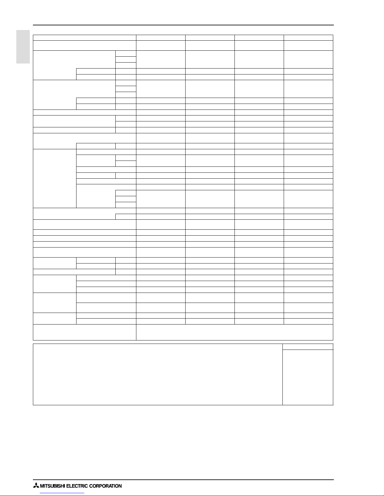
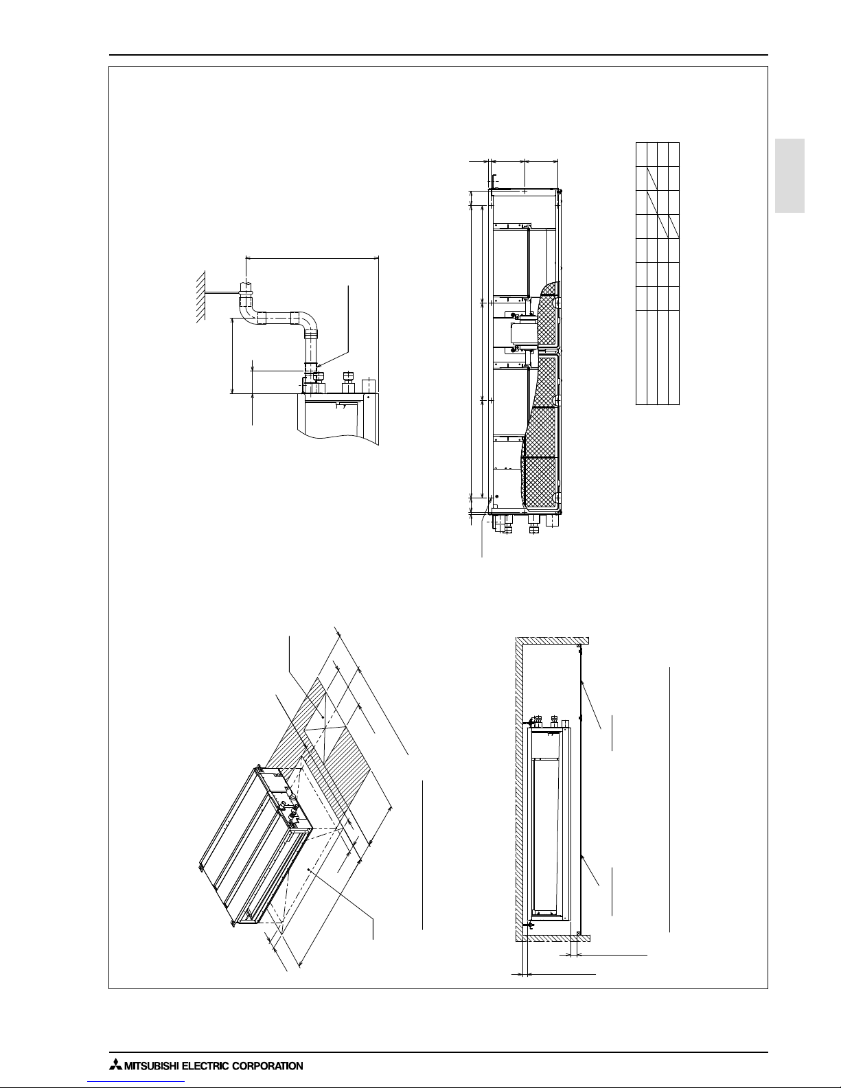
2. EXTERNAL DIMENSIONS
(Actual length)
<accessory>
Drain hose (I.D.ø32)
Less than 300mm
65
0
-10
Less than 550mm
Unit : mm
PEFY-WP15, 20, 25, 32, 40, 50VMS1-E
64
70116
10
102
Note1. Use M10 screw for the suspension bolt (field supply).
2. Keep the service space for the maintenance at the bottom.
3. This chart indicates for PEFY-WP32, 40VMS1-E models, which has 3 fans.
PEFY-WP15, 20, 25VMS1-E models have 2 fans.
PEFY-WP50VMS1-E models have 4 fans.
4. In case an inlet duct is used, remove the air filter (supply with
the unit), then install the filter (field supply) at suction side.
Water pipe(To HBC unit)
Rc3/4 screw
Rc3/4 screw
Water pipe(From HBC unit)
Air
outlet
Air
inlet
(O.D.
ø
32)
Drain pipe
Drain pump
Terminal bed(Transmission)
Drain pipe(O.D.
ø
32)
(Spontaneous draining)
1
2
Terminal bed(Power source)
Suspension bolt hole
4-14×30 Slot
Air filter
Control box
2
×
E-
ø
2.9
2
×
2-
ø
2.9
K-
ø
2.9
Knockout hole
ø
27
Knockout hole
ø
27
(Power source wiring)
(Transmission wiring)
PEFY-WP50VMS1-E
PEFY-WP40VMS1-E
PEFY-WP32VMS1-E
PEFY-WP25VMS1-E
PEFY-WP20VMS1-E
119 0
990
790
1239
1039
839
M
24
20
16
900
700
500
9
7
5
1060
860
660
LJHK
700 752 798 660 7 600
Rc3/4 screw
(To HBC unit)
(From HBC unit)
119 8
998
A
Model
PEFY-WP15VMS1-E
115 2
952
B
110 0
900
C
1060
860
D
11
9
E
1000
800
FG
57
15
700
150(Duct)
200
23
677
23
90
20
C
D (Duct)
A
M
L
49
625(Suspension bolt pitch)
23
B (Suspension bolt pitch)
270
48
270
170
10
100
100
×
(E-1)=F
30
25
100
25
20
100
100
×
H=J
12
88
37
100 37
88
12
157.5
20
G
10
Water pipe
1
Watetr pipe
2
To
HBC Unit
From
HBC Unit
Page 10
2. EXTERNAL DIMENSIONS
1 - 7INDOOR UNITS
PEFY
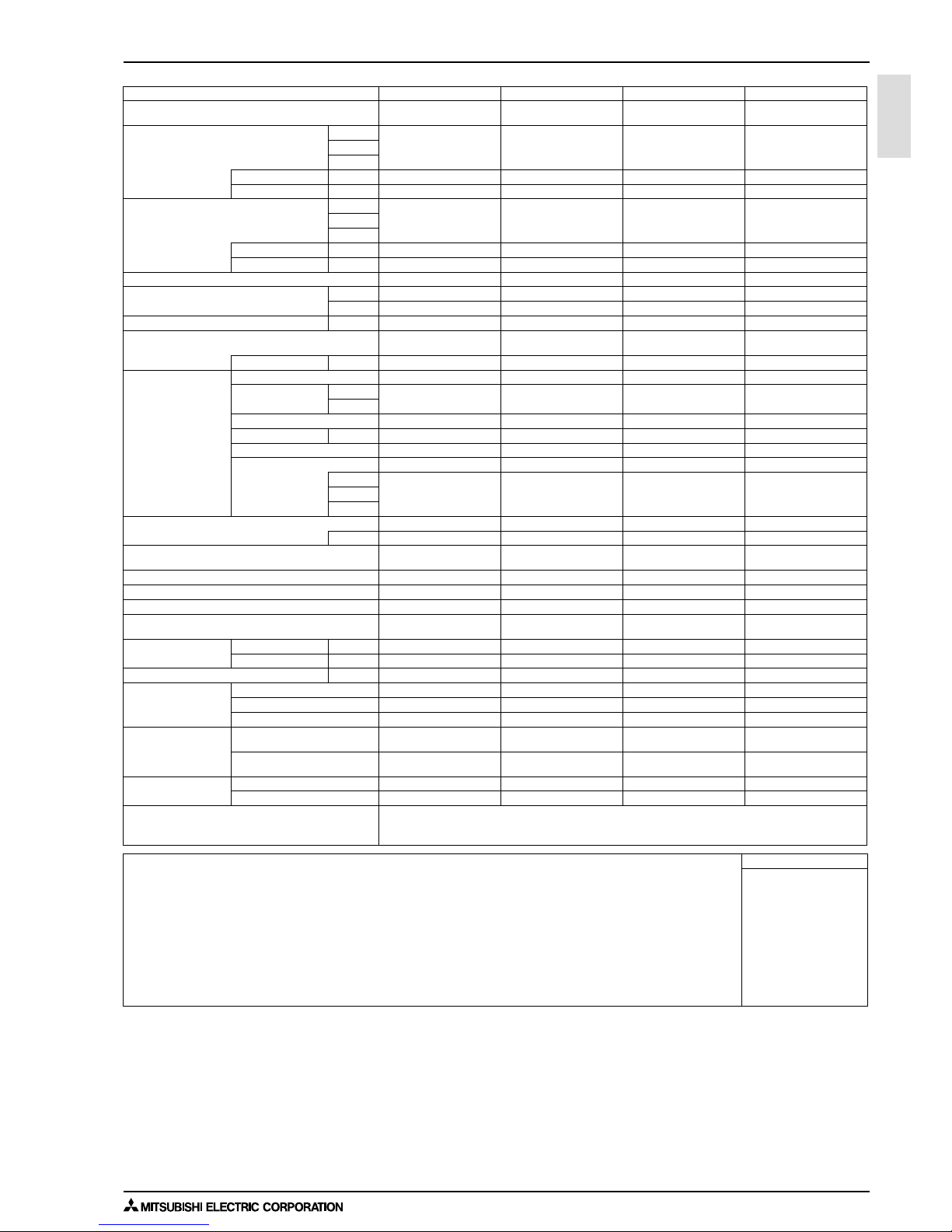
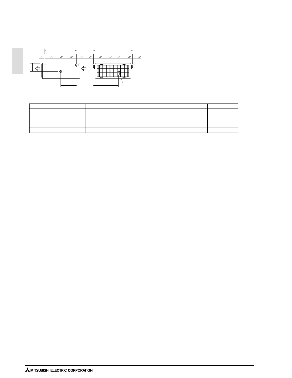
Unit : mm
PEFY-WP15, 20, 25, 32, 40, 50VMS1-E
Min.300mm
Access door 1
(450×450)
Access door 3
Electric box
Intake air
Access door 1
(450×450)
Ceiling beam
Access door 2 (450×450)
Electric box
Supply air
Supply air Intake air
Maintenance access space
Maintenance access space
Maintenance access space
Electric box
Access door 4
(Viewed from the direction
of the arrow B)
Access door 3
Electric box
Bottom of
indoor unit
(Viewed from the direction of the arrow B)
B
Ceiling beam
Ceiling
(Viewed from the direction of the arrow A)
Access door 2
(450×450)
Ceiling
A
Bottom of indoor unit
100~200
100~200
Electric box
Min.10mm
450
450
450
50~150
P
700
700
Min.300mm
N
50
50
R
777
777
50
Q
50
475
N
450
Min.20mm
Min.300mm
N
450
475
700
450
Min.300mm
Min.10mm
Fig.3
Fig.4
Fig.5
Fig.2
Fig.1
Bottom of
indoor unit
[Maintenance access space]
Secure enough access space to allow for the maintenance, inspection, and replacement of the motor, fan, drain pump, heat exchanger,
and electric box in one of the following ways.
Select an installation site for the indoor unit so that its maintenance access space will not be obstructed by beams or other objects.
(1) When a space of 300mm or more is available below the unit between the unit and the ceiling. (Fig.1)
·
Create access door 1 and 2 (450x450mm each) as shown in Fig.2.
(Access door 2 is not required if enough space is available below the unit for a maintenance worker to work in.)
(2) When a space of less than 300mm is available below the unit between the unit and the ceiling.
(At least 20mm of space should be left below the unit as shown in Fig.3.)
·
Create access door 1 diagonally below the electric box and access door 3 below the unit as shown in Fig.4.
or
PEFY-WP15VMS1-E
PEFY-WP20VMS1-E
PEFY-WP25VMS1-E
PEFY-WP32VMS1-E
PEFY-WP40VMS1-E
PEFY-WP50VMS1-E
700
N
Model
110 0
900
150~250
250~350
P
50~150
800
Q
1200
1000
R
1700
1500
1300
·
Create access door 4 below the electric box and the unit as shown in Fig.5.
Page 11
3. CENTER OF GRAVITY
INDOOR UNITS 1 - 8
PEFY
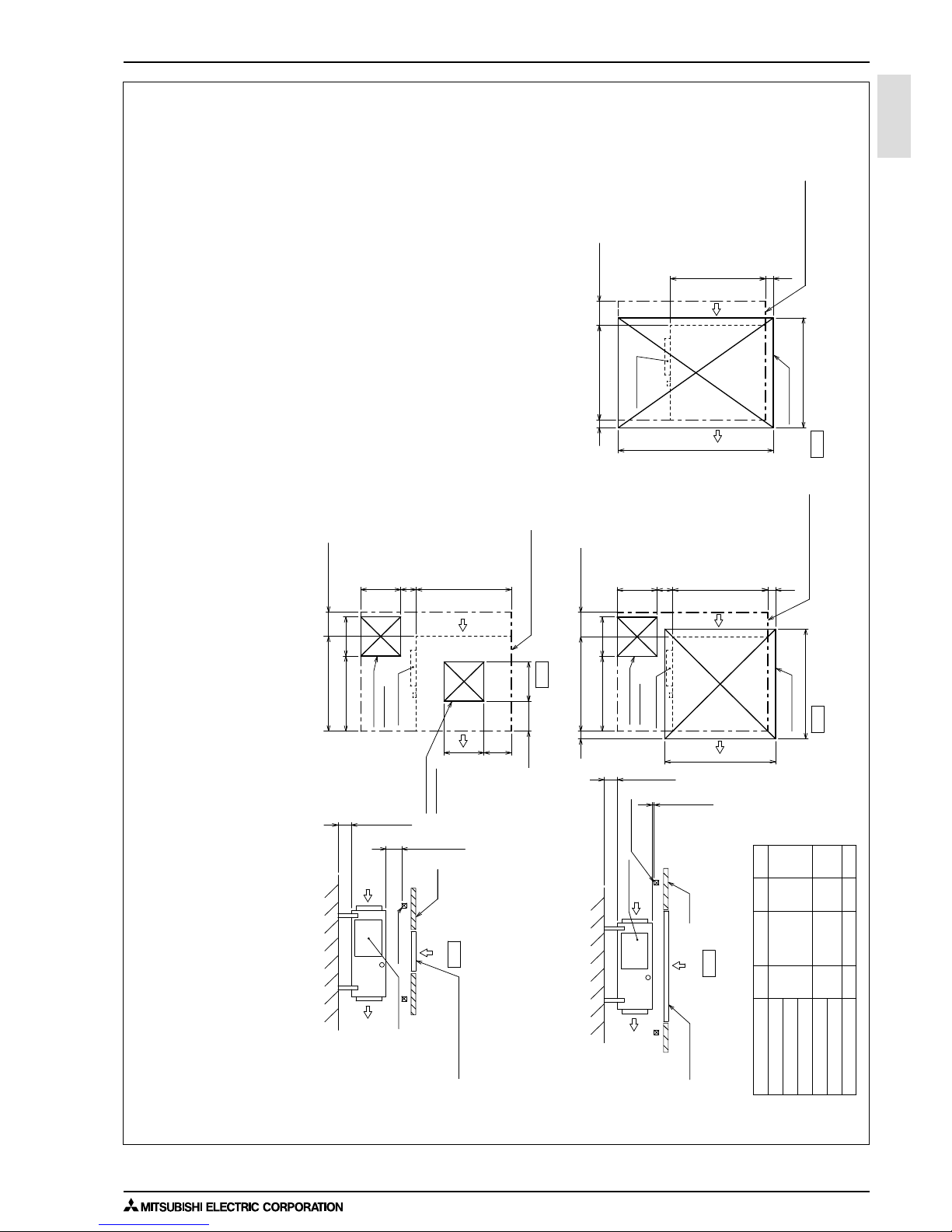
3. CENTER OF GRAVITY
Model name
PEFY-WP15VMS1-E
PEFY-WP50VMS1-E
PEFY-WP40VMS1-E
PEFY-WP32VMS1-E
PEFY-WP25VMS1-E
PEFY-WP20VMS1-E
W
625 [24-5/8]
625 [24-5/8]
625 [24-5/8]
625 [24-5/8]
625 [24-5/8]
L
752 [29-5/8]
752 [29-5/8]
952 [37-1/2]
952 [37-1/2]
1152 [45-3/8]
X
263 [10-3/8]
263 [10-3/8]
280 [11-1/32]
280 [11-1/32]
285 [11-1/4]
Y
338 [13-5/16]
338 [13-5/16]
422 [16-5/8]
422 [16-5/8]
511 [20-1/8]
Z
105 [4-5/32]
625 [24-5/8] 752 [29-5/8] 263 [10-3/8] 338 [13-5/16] 105 [4-5/32]
105 [4-5/32]
104 [4-1/8]
104 [4-1/8]
104 [4-1/8]
A: Center of gravity
YX
L
W
A
Z
PEFY-WP15, 20, 25, 32, 40, 50VMS1-E
(mm)[in]
Page 12
4. ELECTRICAL WIRING DIAGRAMS
1 - 9INDOOR UNITS
PEFY
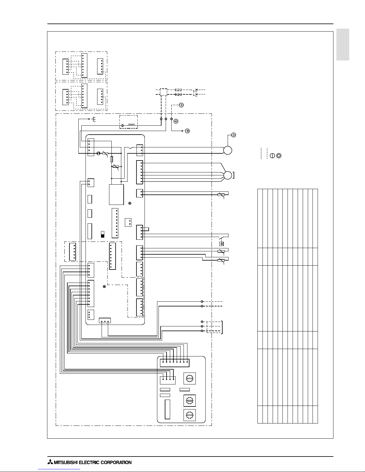
4. ELECTRICAL WIRING DIAGRAMS
NOTE: Symbols used in wiring diagram above are,
(HEAVY DOTTED LINE):FIELD WIRING
(THIN DOTTED LINE) :OPTIONAL PARTS
: CONNECTOR
: TERMINAL
Connector (IT terminal)
CN100
Switch (for mode selection)
SW3(I.B.)
Switch (for model selection)
Connector (emergency operation)
Switch (for mode selection)
Switch (10ths digit address set)
Switch (connection No.set)
Switch (for static pressure selection)
Switch (for model selection)
Switch (for static pressure selection)
Switch (for capacity code)
Thermistor (piping temp.detection/water out)
Thermistor (piping temp.detection/water in)
SWB(A.B.)
AC reactor (Power factor improvement)
L1
SWA(A.B.)
SWC(A.B.)
Drainpump
Connector (Wireless)
X1
Aux. relay
Arrester
DSA
Varistor
ZNR01, 02
Fuse AC250V 6.3A
FUSE
Fan motor
SWE(I.B.)
Float switch
FS
Connector (Remote indication)
Connector (Centrally control)
CN90
Connector (Remote switch)
Connector (Damper)
CN32
CN52
CN51
CN41
Transmission terminal block
TB15
TH21
Thermistor (inlet air temp.detection)
TH23
TH22
NAME SYMBOL SYMBOL
I.B.
A.B.
Indoor controller board
Address board
Switch (1s digit address set)
SW2(I.B.)
SW11(A.B.)
SW12(A.B.)
SW14(A.B.)
SW1(A.B.)
SW4(I.B.)
TB2
TB5
Transmission terminal block
Power source terminal block
SYMBOL EXPLANATION
NAME
CN27
Connector (HA terminal-A)
SYMBOL NAME
*A
In connecting optional IT terminal,
use either CN51 or CN52 which is
not connected.
Be careful for connector colors.
*A
L1: only PEFY-WP50VMS1-E
INSIDE SECTION OF CONTROL BOX
TO MA REMOTE
CONTROLLER
TO OUTDOOR UNIT
BC CONTROLLER
REMOTE CONTROLLER
SW14
(Connection No.)
SWBSWA
SWC
SW12
(10ths digit)
SW11
(1s digit)
SW1
A. B.
I. B.
31
12345
54185418
12345
8145
34512
MS
3~
8765432
1
432
1
1~
M
4231 1324
12 14567
3
1
135
12
132481324567
13
0
1
2
3
4
5
6
7
8
9
A
B
C
D
E
F
0
1
2
3
4
5
6
7
8
9
0
1
2
3
4
5
6
7
8
9
IT terminal
(PAC-IT51AD-E)
IT terminal
(PAC-IT52AD-E)
CN52
(Green)
CN100
CN51
CN100
CN100
IT terminal
CN82
CN43
L1
t° t°
U
LED1
LED2
DC310~340V
Rectify circuit
ZNR01
POWER SUPPLY
~220, 230, 240V
50, 60Hz
TO NEXT INDOOR UNIT
FUSE (16A)
PULL BOX
BREAKER (16A)
FUSE
X1
ZNR02
DSA
U
t°
(Green)
(Blue)
(Red)
(Red)
(Red)
(Red)
(Blue)
(Blue)
(Black)
TB5
N
L
TB15
12
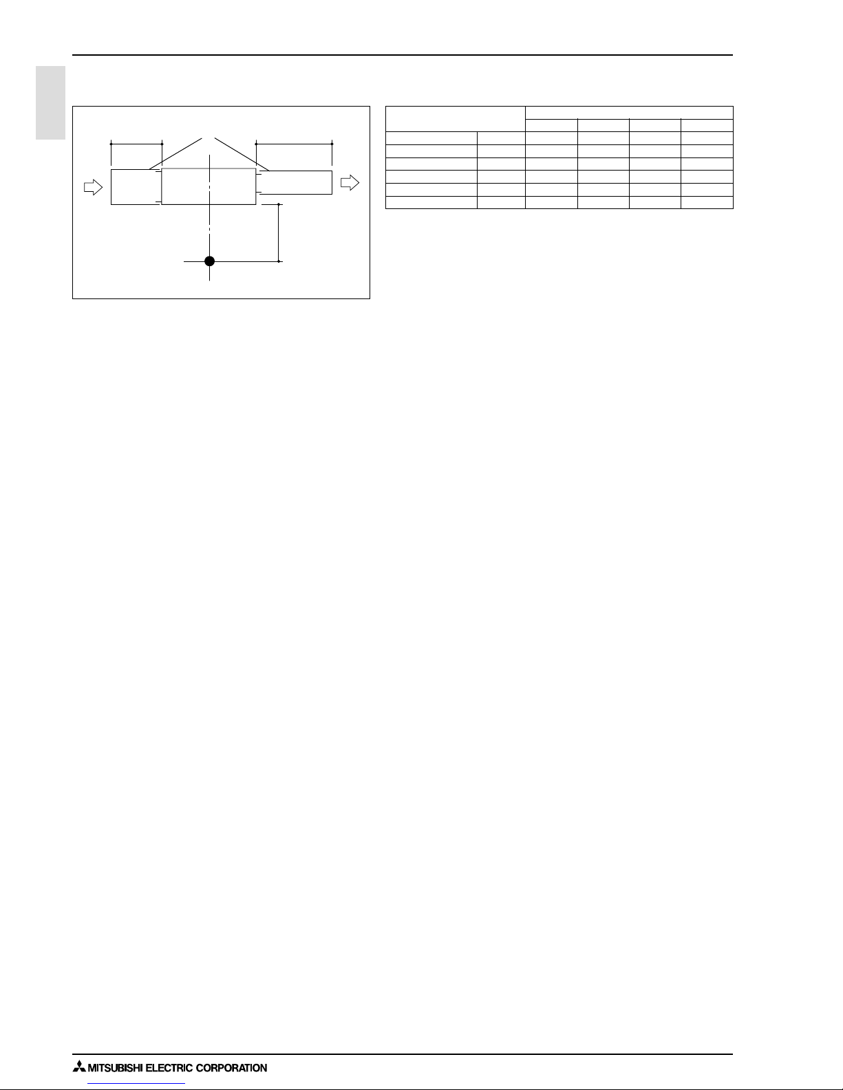
S(SHIELD)
M2
TB2
M1
FSTH22 TH23
TH21
CN3A
CNMF
CNP
CND
CN2M
SW2SW4SW3
CN90
CN42CN81CN32
CN27
CN20
CN4FCN44CN41CN52 CN51
SWE
ON
OFF
PEFY-WP15, 20, 25, 32, 40, 50VMS1-E
Page 13
5. SOUND LEVELS
INDOOR UNITS 1 - 10
PEFY
5. SOUND LEVELS
5-1. Sound levels
PEFY-WP-VMS1-E Sound level at anechoic room : Low-Mid-High
Sound level dB ( A )
5Pa 15Pa 35Pa 50Pa
PEFY-WP15VMS1-E 220-240V 22 - 24 - 26 22 - 24 - 28 23 - 26 - 29 23 - 27 - 30
PEFY-WP20VMS1-E 220-240V 22 - 25 - 28 23 - 25 - 29 24 - 27 - 30 25 - 28 - 32
PEFY-WP25VMS1-E 220-240V 22 - 25 - 29 23 - 26 - 30 24 - 28 - 31 25 - 29 - 33
PEFY-WP32VMS1-E 220-240V 26 - 28 - 30 28 - 30 - 33 30 - 32- 35 31 - 33 - 36
PEFY-WP40VMS1-E 220-240V 29 - 31 - 34 30 - 32 - 35 31 - 34 - 37 32 - 34 - 38
PEFY-WP50VMS1-E 220-240V 29 - 32 - 35 30 - 33 - 36 31 - 35 - 39 32 - 36 - 40
* Measured in anechoic room.
Aux.duct
1m
1.5m
Measurement location
2m
Page 14
5. SOUND LEVELS
1 - 11INDOOR UNITS
PEFY
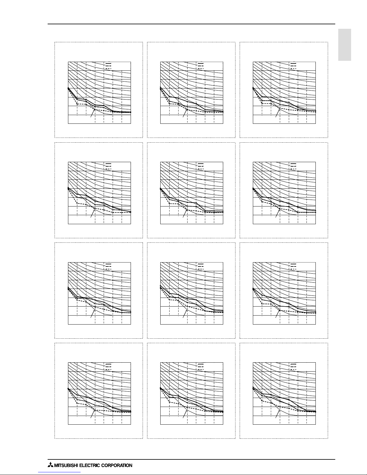
5-2. NC curves
PEFY-WP15VMS1-E
External static pressure : 5Pa
Power source : 220,230,240V, 50/60Hz
PEFY-WP15VMS1-E
External static pressure : 15Pa
Power source : 220,230,240V, 50/60Hz
PEFY-WP15VMS1-E
External static pressure : 35Pa
Power source : 220,230,240V, 50/60HzHz
PEFY-WP15VMS1-E
External static pressure : 50Pa
Power source : 220,230,240V, 50/60Hz
PEFY-WP20VMS1-E
External static pressure : 5Pa
Power source : 220,230,240V, 50/60Hz
PEFY-WP20VMS1-E
External static pressure : 15Pa
Power source : 220,230,240V, 50/60Hz
PEFY-WP20VMS1-E
External static pressure : 35Pa
Power source : 220,230,240V, 50/60Hz
PEFY-WP20VMS1-E
External static pressure : 50Pa
Power source : 220,230,240V, 50/60Hz
PEFY-WP25VMS1-E
External static pressure : 5Pa
Power source : 220,230,240V, 50/60Hz
PEFY-WP25VMS1-E
External static pressure : 15Pa
Power source : 220,230,240V, 50/60Hz
PEFY-WP25VMS1-E
External static pressure : 35Pa
Power source : 220,230,240V, 50/60Hz
PEFY-WP25VMS1-E
External static pressure : 50Pa
Power source : 220,230,240V, 50/60Hz
Approximate minimum
audible limit on
continuous noise
70
60
50
40
30
20
63 125 250 500 1000 2000 4000 8000
10
0
NC60
NC50
NC40
NC30
NC20
Approximate minimum
audible limit on
continuous noise
OCTAVE BAND PRESSURE LEVEL (dB) 0dB = 20µPa
OCTAVE BAND CENTER FREQUENCIES (Hz)
High speed
Low speed
Middle speed
NC20
Approximate minimum
audible limit on
continuous noise
70
60
50
40
30
20
63 125 250 500 1000 2000 4000 8000
10
0
NC60
NC50
NC40
NC30
Approximate minimum
audible limit on
continuous noise
OCTAVE BAND PRESSURE LEVEL (dB) 0dB = 20µPa
OCTAVE BAND CENTER FREQUENCIES (Hz)
High speed
Low speed
Middle speed
Approximate minimum
audible limit on
continuous noise
70
60
50
40
30
20
63 125 250 500 1000 2000 4000 8000
10
0
NC60
NC50
NC40
NC30
NC20
Approximate minimum
audible limit on
continuous noise
OCTAVE BAND PRESSURE LEVEL (dB) 0dB = 20µPa
OCTAVE BAND CENTER FREQUENCIES (Hz)
High speed
Low speed
Middle speed
NC20
Approximate minimum
audible limit on
continuous noise
70
60
50
40
30
20
63 125 250 500 1000 2000 4000 8000
10
0
NC60
NC50
NC40
NC30
Approximate minimum
audible limit on
continuous noise
OCTAVE BAND PRESSURE LEVEL (dB) 0dB = 20µPa
OCTAVE BAND CENTER FREQUENCIES (Hz)
High speed
Low speed
Middle speed
Approximate minimum
audible limit on
continuous noise
70
60
50
40
30
20
63 125 250 500 1000 2000 4000 8000
10
0
NC60
NC50
NC40
NC30
NC20
Approximate minimum
audible limit on
continuous noise
OCTAVE BAND PRESSURE LEVEL (dB) 0dB = 20µPa
OCTAVE BAND CENTER FREQUENCIES (Hz)
High speed
Low speed
Middle speed
NC20
Approximate minimum
audible limit on
continuous noise
70
60
50
40
30
20
63 125 250 500 1000 2000 4000 8000
10
0
NC60
NC50
NC40
NC30
Approximate minimum
audible limit on
continuous noise
OCTAVE BAND PRESSURE LEVEL (dB) 0dB = 20µPa
OCTAVE BAND CENTER FREQUENCIES (Hz)
High speed
Low speed
Middle speed
Approximate minimum
audible limit on
continuous noise
70
60
50
40
30
20
63 125 250 500 1000 2000 4000 8000
10
0
NC60
NC50
NC40
NC30
NC20
Approximate minimum
audible limit on
continuous noise
OCTAVE BAND PRESSURE LEVEL (dB) 0dB = 20µPa
OCTAVE BAND CENTER FREQUENCIES (Hz)
High speed
Low speed
Middle speed
NC20
Approximate minimum
audible limit on
continuous noise
70
60
50
40
30
20
63 125 250 500 1000 2000 4000 8000
10
0
NC60
NC50
NC40
NC30
Approximate minimum
audible limit on
continuous noise
OCTAVE BAND PRESSURE LEVEL (dB) 0dB = 20µPa
OCTAVE BAND CENTER FREQUENCIES (Hz)
High speed
Low speed
Middle speed
Page 15
5. SOUND LEVELS
INDOOR UNITS 1 - 12
PEFY
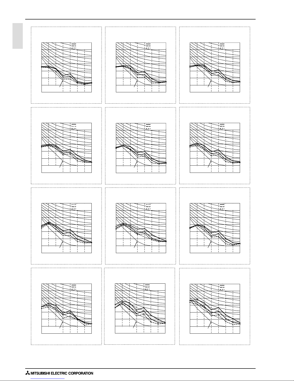
PEFY-WP32VMS1-E
External static pressure : 5Pa
Power source : 220,230,240V, 50/60Hz
PEFY-WP32VMS1-E
External static pressure : 15Pa
Power source : 220,230,240V, 50/60Hz
PEFY-WP32VMS1-E
External static pressure : 35Pa
Power source : 220,230,240V, 50/60Hz
PEFY-WP32VMS1-E
External static pressure : 50Pa
Power source : 220,230,240V, 50/60Hz
PEFY-WP40VMS1-E
External static pressure : 5Pa
Power source : 220,230,240V, 50/60Hz
PEFY-WP40VMS1-E
External static pressure : 15Pa
Power source : 220,230,240V, 50/60Hz
PEFY-WP40VMS1-E
External static pressure : 35Pa
Power source : 220,230,240V, 50/60Hz
PEFY-WP40VMS1-E
External static pressure : 50Pa
Power source : 220,230,240V, 50/60Hz
PEFY-WP50VMS1-E
External static pressure : 5Pa
Power source : 220,230,240V, 50/60Hz
PEFY-WP50VMS1-E
External static pressure : 15Pa
Power source : 220,230,240V, 50/60Hz
PEFY-WP50VMS1-E
External static pressure : 35Pa
Power source : 220,230,240V, 50/60Hz
PEFY-WP50VMS1-E
External static pressure : 50Pa
Power source : 220,230,240V, 50/60Hz
NC20
Approximate minimum
audible limit on
continuous noise
70
60
50
40
30
20
63 125 250 500 1000 2000 4000 8000
10
0
NC60
NC50
NC40
NC30
Approximate minimum
audible limit on
continuous noise
OCTAVE BAND PRESSURE LEVEL (dB) 0dB = 20µPa
OCTAVE BAND CENTER FREQUENCIES (Hz)
High speed
Low speed
Middle speed
Approximate minimum
audible limit on
continuous noise
70
60
50
40
30
20
63 125 250 500 1000 2000 4000 8000
10
0
NC60
NC50
NC40
NC30
NC20
Approximate minimum
audible limit on
continuous noise
OCTAVE BAND PRESSURE LEVEL (dB) 0dB = 20µPa
OCTAVE BAND CENTER FREQUENCIES (Hz)
High speed
Low speed
Middle speed
NC20
Approximate minimum
audible limit on
continuous noise
70
60
50
40
30
20
63 125 250 500 1000 2000 4000 8000
10
0
NC60
NC50
NC40
NC30
Approximate minimum
audible limit on
continuous noise
OCTAVE BAND PRESSURE LEVEL (dB) 0dB = 20µPa
OCTAVE BAND CENTER FREQUENCIES (Hz)
High speed
Low speed
Middle speed
Approximate minimum
audible limit on
continuous noise
70
60
50
40
30
20
63 125 250 500 1000 2000 4000 8000
10
0
NC60
NC50
NC40
NC30
NC20
Approximate minimum
audible limit on
continuous noise
OCTAVE BAND PRESSURE LEVEL (dB) 0dB = 20µPa
OCTAVE BAND CENTER FREQUENCIES (Hz)
High speed
Low speed
Middle speed
NC20
Approximate minimum
audible limit on
continuous noise
70
60
50
40
30
20
63 125 250 500 1000 2000 4000 8000
10
0
NC60
NC50
NC40
NC30
Approximate minimum
audible limit on
continuous noise
OCTAVE BAND PRESSURE LEVEL (dB) 0dB = 20µPa
OCTAVE BAND CENTER FREQUENCIES (Hz)
High speed
Low speed
Middle speed
Approximate minimum
audible limit on
continuous noise
70
60
50
40
30
20
63 125 250 500 1000 2000 4000 8000
10
0
NC60
NC50
NC40
NC30
NC20
Approximate minimum
audible limit on
continuous noise
OCTAVE BAND PRESSURE LEVEL (dB) 0dB = 20µPa
OCTAVE BAND CENTER FREQUENCIES (Hz)
High speed
Low speed
Middle speed
NC20
Approximate minimum
audible limit on
continuous noise
70
60
50
40
30
20
63 125 250 500 1000 2000 4000 8000
10
0
NC60
NC50
NC40
NC30
Approximate minimum
audible limit on
continuous noise
OCTAVE BAND PRESSURE LEVEL (dB) 0dB = 20µPa
OCTAVE BAND CENTER FREQUENCIES (Hz)
High speed
Low speed
Middle speed
Approximate minimum
audible limit on
continuous noise
70
60
50
40
30
20
63 125 250 500 1000 2000 4000 8000
10
0
NC60
NC50
NC40
NC30
NC20
Approximate minimum
audible limit on
continuous noise
OCTAVE BAND PRESSURE LEVEL (dB) 0dB = 20µPa
OCTAVE BAND CENTER FREQUENCIES (Hz)
High speed
Low speed
Middle speed
NC20
Approximate minimum
audible limit on
continuous noise
70
60
50
40
30
20
63 125 250 500 1000 2000 4000 8000
10
0
NC60
NC50
NC40
NC30
Approximate minimum
audible limit on
continuous noise
OCTAVE BAND PRESSURE LEVEL (dB) 0dB = 20µPa
OCTAVE BAND CENTER FREQUENCIES (Hz)
High speed
Low speed
Middle speed
Page 16
6. FAN CHARACTERISTICS CURVES
1 - 13INDOOR UNITS
PEFY
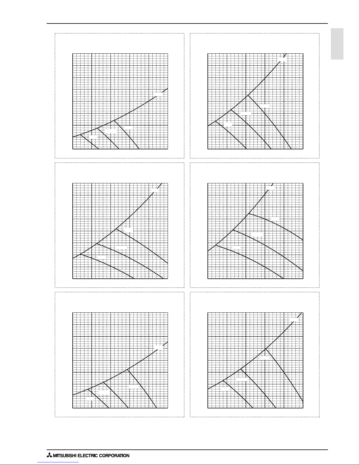
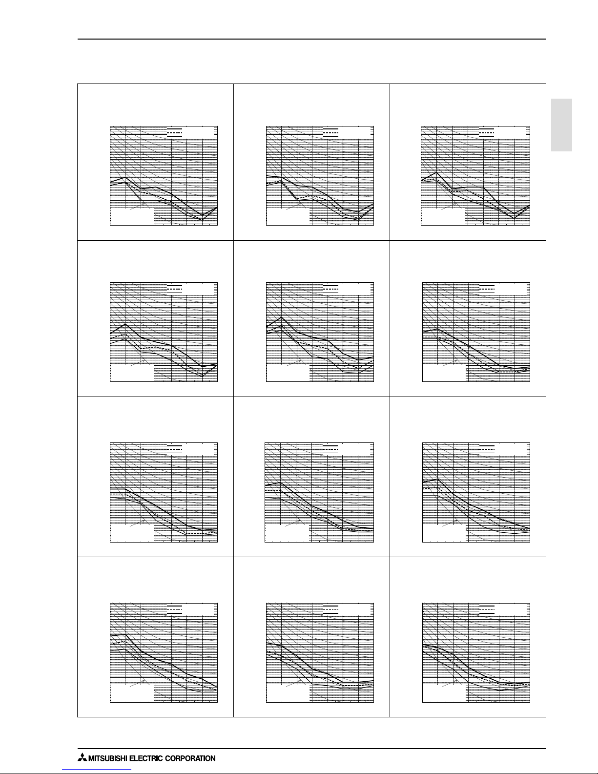
6. FAN CHARACTERISTICS CURVES
PEFY-WP15VMS1-E
External static pressure : 15Pa
Power source : 220,230,240V, 50/60Hz
Suction : Back inlet
PEFY-WP15VMS1-E
External static pressure : 5Pa
Power source : 220,230,240V, 50/60Hz
Suction : Back inlet
PEFY-WP15VMS1-E
External static pressure : 50Pa
Power source : 220,230,240V, 50/60Hz
Suction : Back inlet
PEFY-WP15VMS1-E
External static pressure : 35Pa
Power source : 220,230,240V, 50/60Hz
Suction : Back inlet
PEFY-WP20VMS1-E
External static pressure : 15Pa
Power source : 220,230,240V, 50/60Hz
Suction : Back inlet
PEFY-WP20VMS1-E
External static pressure : 5Pa
Power source : 220,230,240V, 50/60Hz
Suction : Back inlet
Airflow rate (m3/min)
Static pressure (Pa)
Airflow rate (m3/min)
Static pressure (Pa)
Airflow rate (m3/min)
Static pressure (Pa)
Airflow rate (m3/min)
Static pressure (Pa)
Airflow rate (m3/min)
Static pressure (Pa)
Airflow rate (m3/min)
Static pressure (Pa)
0
5
10
15
20
25
30
35
40
456789
0
5
10
15
20
25
30
35
40
456789
456789
0
10
20
30
40
50
60
70
80
456789
0
10
20
30
40
50
60
70
80
0
5
10
15
20
25
30
35
40
456789
0
5
10
15
20
25
30
35
40
456789
High
Limit
Limit
Low
Middle
High
Low
Middle
High
Limit
Low
Middle
High
Limit
Low
Middle
High
Limit
Limit
Low
Middle
High
Low
Middle
Page 17
6. FAN CHARACTERISTICS CURVES
INDOOR UNITS 1 - 14
PEFY
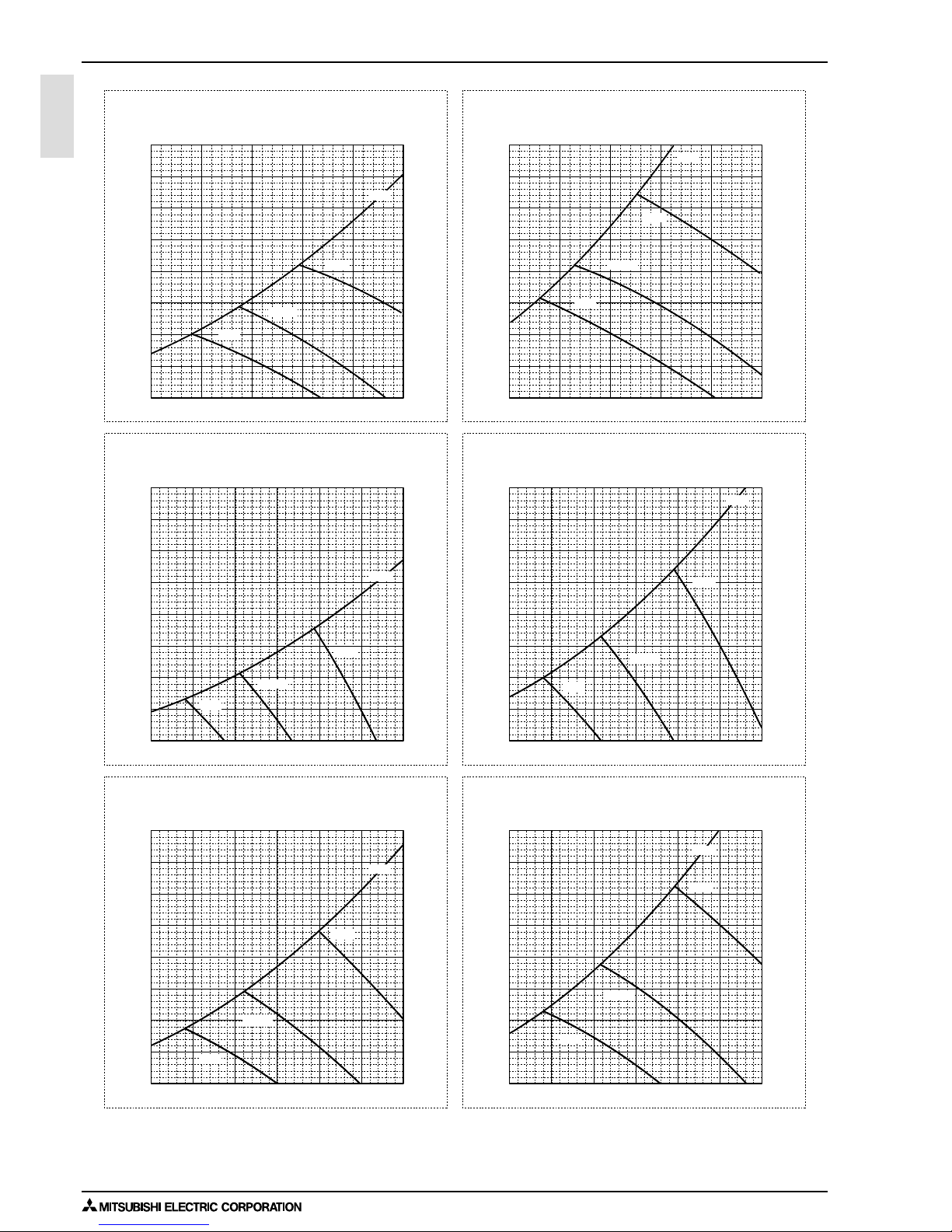
PEFY-WP20VMS1-E
External static pressure : 50Pa
Power source : 220,230,240V, 50/60Hz
Suction : Back inlet
PEFY-WP20VMS1-E
External static pressure : 35Pa
Power source : 220,230,240V, 50/60Hz
Suction : Back inlet
PEFY-WP25VMS1-E
External static pressure : 5Pa
Power source : 220,230,240V, 50/60Hz
Suction : Back inlet
PEFY-WP25VMS1-E
External static pressure : 15Pa
Power source : 220,230,240V, 50/60Hz
Suction : Back inlet
PEFY-WP25VMS1-E
External static pressure : 35Pa
Power source : 220,230,240V, 50/60Hz
Suction : Back inlet
PEFY-WP25VMS1-E
External static pressure : 50Pa
Power source : 220,230,240V, 50/60Hz
Suction : Back inlet
Airflow rate (m3/min)
Static pressure (Pa)
Airflow rate (m3/min)
Static pressure (Pa)
Airflow rate (m3/min)
Static pressure (Pa)
Airflow rate (m3/min)
Static pressure (Pa)
Airflow rate (m3/min)
Static pressure (Pa)
Airflow rate (m3/min)
Static pressure (Pa)
456789
0
10
20
30
40
50
60
70
80
456789
0
10
20
30
40
50
60
70
80
0
5
10
15
20
25
30
35
40
4 5678 910
0
5
10
15
20
25
30
35
40
45678910
45678910
0
10
20
30
40
50
60
70
80
45678910
0
10
20
30
40
50
60
70
80
High
Limit
Low
Middle
High
Limit
Low
Middle
High
Limit
Low
Middle
High
Limit
Low
Middle
High
Limit
Low
Middle
High
Limit
Low
Middle
Page 18
6. FAN CHARACTERISTICS CURVES
1 - 15INDOOR UNITS
PEFY
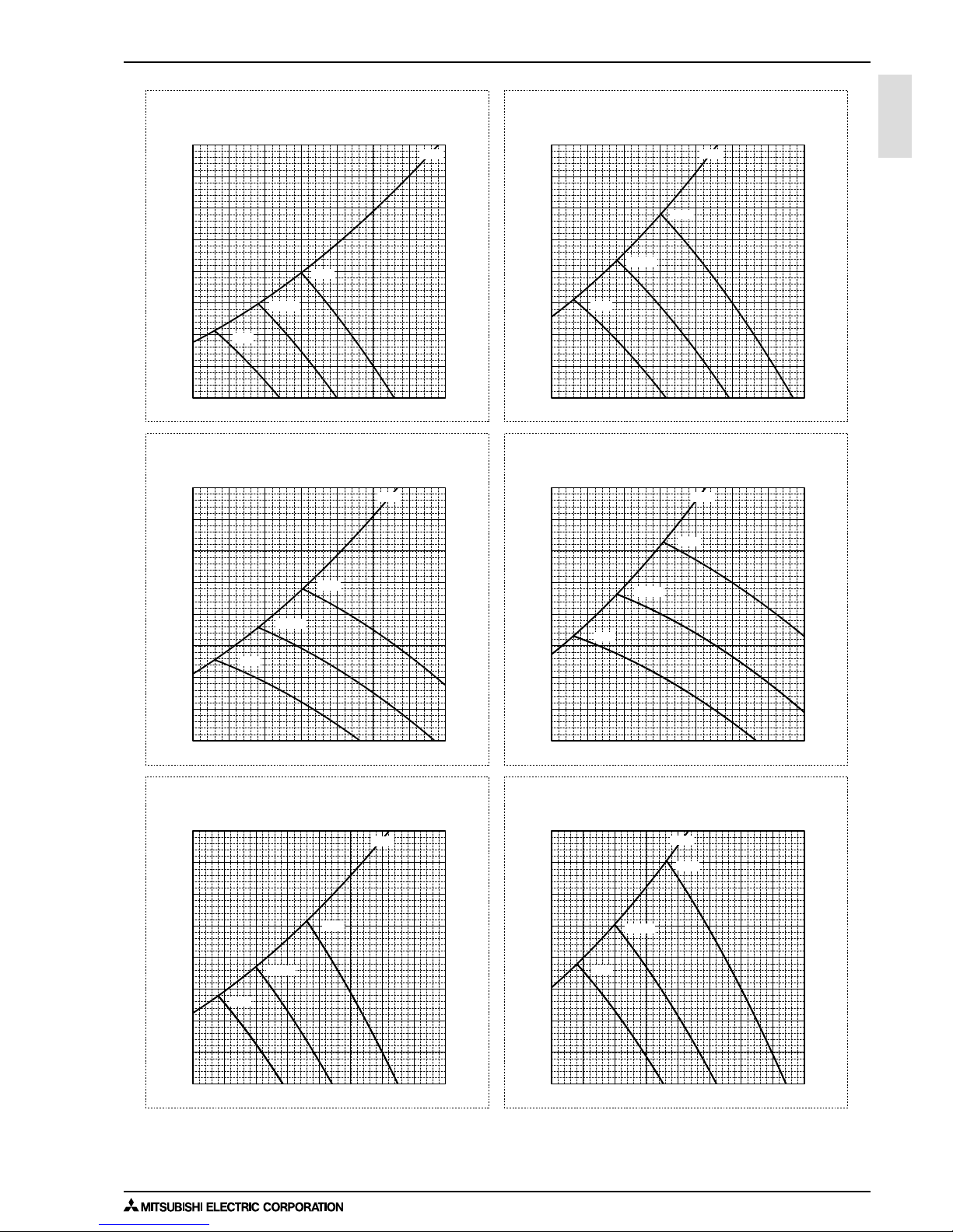
PEFY-WP32VMS1-E
External static pressure : 50Pa
Power source : 220,230,240V, 50/60Hz
Suction : Back inlet
PEFY-WP32VMS1-E
External static pressure : 35Pa
Power source : 220,230,240V, 50/60Hz
PEFY-WP40VMS1-E
External static pressure : 15Pa
Power source : 220,230,240V, 50/60Hz
Suction : Back inlet
PEFY-WP40VMS1-E
External static pressure : 5Pa
Power source : 220,230,240V, 50/60Hz
Suction : Back inlet
Suction : Back inlet
PEFY-WP32VMS1-E
External static pressure : 15Pa
Power source : 220,230,240V, 50/60Hz
Suction : Back inlet
PEFY-WP32VMS1-E
External static pressure : 5Pa
Power source : 220,230,240V, 50/60Hz
Suction : Back inlet
Airflow rate (m3/min)
Static pressure (Pa)
Airflow rate (m3/min)
Static pressure (Pa)
Airflow rate (m3/min)
Static pressure (Pa)
Airflow rate (m3/min)
Static pressure (Pa)
Airflow rate (m3/min)
Static pressure (Pa)
Airflow rate (m3/min)
Static pressure (Pa)
678910111213 678910111213
0
5
10
15
20
25
30
35
40
678910111213
0
5
10
15
20
25
30
35
40
678910111213
0
10
20
30
40
50
60
70
80
0
10
20
30
40
50
60
70
80
0
5
10
15
20
25
30
35
40
7 8 9 101112131415
0
5
10
15
20
25
30
35
40
7 8 9 101112131415
High
Limit
Low
Middle
High
Limit
Low
Middle
High
Limit
Low
Middle
High
Limit
Low
Middle
High
Limit
Low
Middle
High
Limit
Low
Middle
Page 19
6. FAN CHARACTERISTICS CURVES
INDOOR UNITS 1 - 16
PEFY
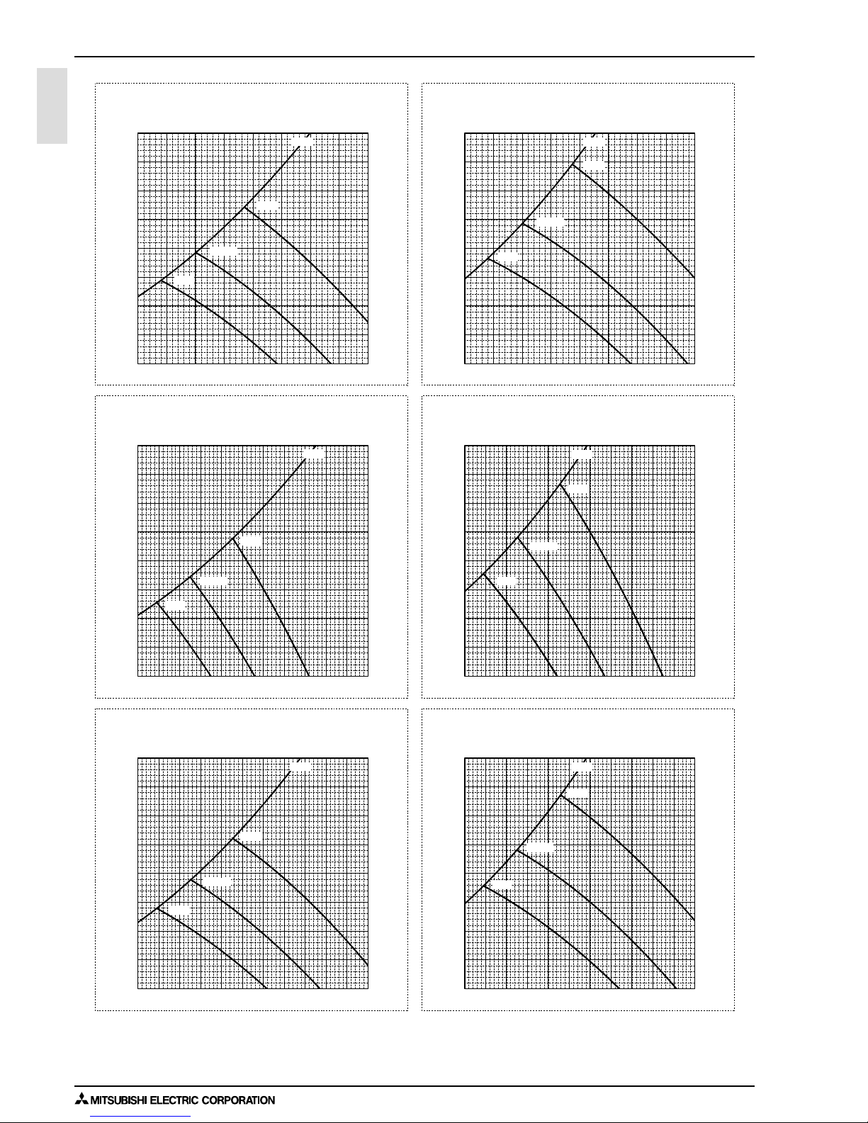
PEFY-WP40VMS1-E
External static pressure : 50Pa
Power source : 220,230,240V, 50/60Hz
Suction : Back inlet
PEFY-WP40VMS1-E
External static pressure : 35Pa
Power source : 220,230,240V, 50/60Hz
Suction : Back inlet
PEFY-WP50VMS1-E
External static pressure : 15Pa
Power source : 220,230,240V, 50/60Hz
Suction : Back inlet
PEFY-WP50VMS1-E
External static pressure : 5Pa
Power source : 220,230,240V, 50/60Hz
Suction : Back inlet
PEFY-WP50VMS1-E
External static pressure : 50Pa
Power source : 220,230,240V, 50/60Hz
Suction : Back inlet
PEFY-WP50VMS1-E
External static pressure : 35Pa
Power source : 220,230,240V, 50/60Hz
Suction : Back inlet
Airflow rate (m3/min)
Static pressure (Pa)
Airflow rate (m3/min)
Static pressure (Pa)
Airflow rate (m3/min)
Static pressure (Pa)
Airflow rate (m3/min)
Static pressure (Pa)
Airflow rate (m3/min)
Static pressure (Pa)
Airflow rate (m3/min)
Static pressure (Pa)
7 8 9 101112131415
0
10
20
30
40
50
60
70
80
7 8 9 101112131415
0
10
20
30
40
50
60
70
80
0
5
10
15
20
25
30
35
40
9 1011121314151617181920
0
5
10
15
20
25
30
35
40
9 1011121314151617181920
9 1011121314151617181920
0
10
20
30
40
50
60
70
80
9 1011121314151617181920
0
10
20
30
40
50
60
70
80
High
Limit
Low
Middle
High
Limit
Low
Middle
High
Limit
Low
Middle
High
Limit
Low
Middle
High
Limit
Low
Middle
High
Limit
Low
Middle
Page 20
7. OPTIONAL PARTS
1 - 17INDOOR UNITS
PEFY
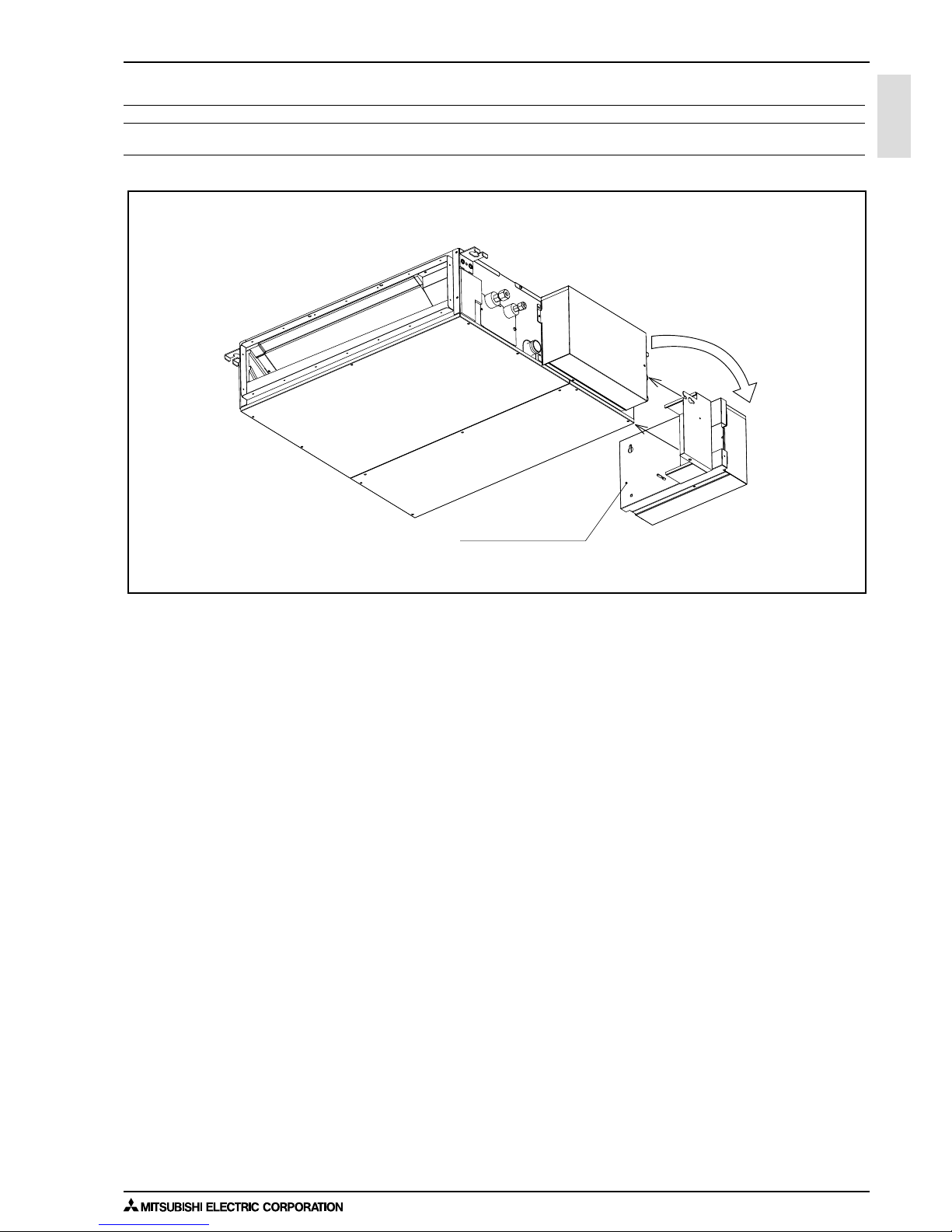
7. OPTIONAL PARTS
7-1. Optional parts line up for the Indoor unit
Control box replace kit
PEFY-WP15, 20, 25, 32, 40, 50VMS1-E PAC-KE70HS-E
Control box replace kit
PAC-KE70HS-E
PEFY-WP-VMS1-E
Page 21
7. OPTIONAL PARTS
INDOOR UNITS 1 - 18
PEFY
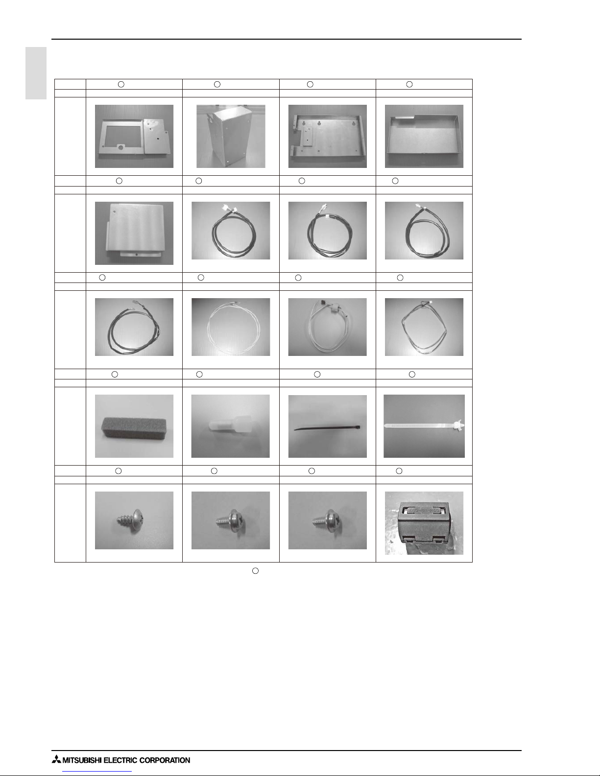
7-2. Control box replace kit
Shape
PLATE A
Q'ty
Parts
1
PLATE B
1
PLATE C
1
COVER A
1
Shape
COVER B
Q'ty
Parts
1
LEAD WIRE MOTOR
White 7-pin connector White 6-pin connector White 4-pin connector
Ring terminal on both endsRed 2-pin connector
4X10
Blue 3-pin connector
4X10 with a washer 5X10 with a washer
White 4-pin connector
1
LEAD WIRE LEV
1
LEAD WIRE THM A
1
Shape
LEAD WIRE THM B
Q'ty
Parts
1
LEAD WIRE EARTH
1
LEAD WIRE PUMP
1
LEAD WIRE FS
1
Shape
INSULATOR
Q'ty
Parts
3
Connecting terminals
4
BAND
6
CLAMP
4
Shape
SCREW 1
Q'ty
Parts
2
SCREW 2
4
SCREW 3
5
FERRITE CORE
1
When installing the control box replace kit on the air inlet on the unit, LEAD WIRE FS is not used.
12
10
9
5
11
12
13 14 15
17 18 19
16
20
6
7 8
4321
PAC-KE70HS-E
Page 22

1 - 19
Ceiling concealed (Middle static pressure type)
INDOOR UNITS
PEFY-WP-VMA-E
I.
Ceiling concealed (Middle static pressure type)
1. SPECIFICATIONS........................................................................................................................................... 1 - 20
2. EXTERNAL DIMENSIONS.............................................................................................................................. 1 - 22
3. CENTER OF GRAVITY ................................................................................................................................... 1 - 24
4. ELECTRICAL WIRING DIAGRAMS................................................................................................................ 1 - 25
5. SOUND LEVELS ............................................................................................................................................. 1 - 26
5-1. Sound levels ............................................................................................................................................ 1 - 26
5-2. NC curves ................................................................................................................................................ 1 - 27
6. FAN CHARACTERISTICS CURVES............................................................................................................... 1 - 31
7. OPTIONAL PARTS.......................................................................................................................................... 1 - 35
7-1. Optional parts line up for the Indoor unit.................................................................................................. 1 - 35
7-2. Filter box .................................................................................................................................................. 1 - 35
Page 23
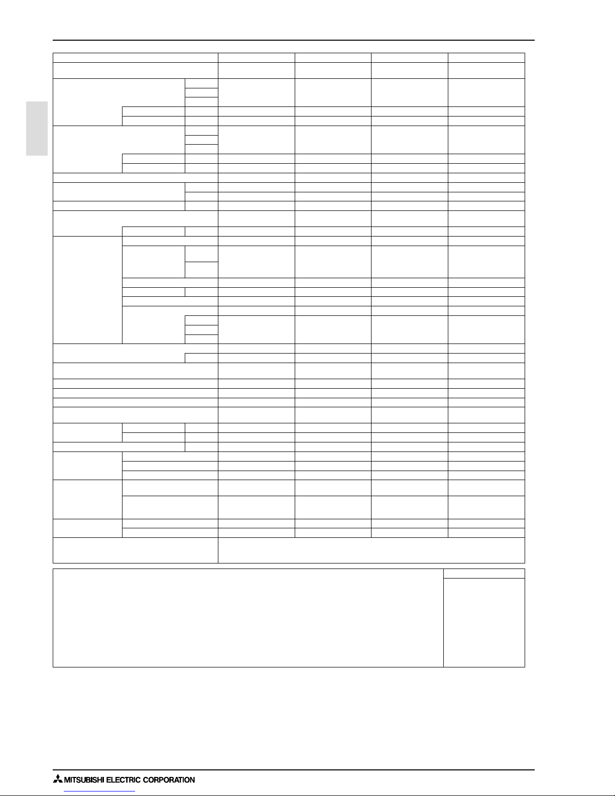
1. SPECIFICATIONS
INDOOR UNITS 1 - 20
PEFY-VMA
I.Ceiling concealed (Middle static pressure type)1. SPECIFICATIONS
Model PEFY-WP20VMA-E PEFY-WP25VMA-E PEFY-WP32VMA-E PEFY-WP40VMA-E
Power source
1-phase 220-230-240 V 50/
60 Hz
1-phase 220-230-240 V 50/
60 Hz
1-phase 220-230-240 V 50/
60 Hz
1-phase 220-230-240 V 50/
60 Hz
Cooling capacity *1 kW 2.2 2.8 3.6 4.5
(Nominal) *1 kcal/h 1,900 2,400 3,100 3,900
*1 BTU/h 7,500 9,600 12,300 15,400
*2 Power input kW 0.07 0.09 0.11 0.14
*2 Current input A 0.55 0.64 0.74 1.15
Heating capacity *3 kW 2.5 3.2 4.0 5.0
(Nominal) *3 kcal/h 2,200 2,800 3,400 4,300
*3 BTU/h 8,500 10,900 13,600 17,100
*2 Power input kW 0.05 0.07 0.09 0.12
*2 Current input A 0.44 0.53 0.63 1.04
External finish Galvanized steel plate Galvanized steel plate Galvanized steel plate Galvanized steel plate
External dimension HxWxD mm 250 x 700 x 732 250 x 900 x 732 250 x 900 x 732 250 x 1,100 x 732
in. 9-7/8 x 27-9/16 x 28-7/8 9-7/8 x 35-7/16 x 28-7/8 9-7/8 x 35-7/16 x 28-7/8 9-7/8 x 43-5/16 x 28-7/8
Net weight kg (lbs) 21 (47) 26 (58) 26 (58) 31 (69)
Heat exchanger
Cross fin (Aluminum fin and
copper tube)
Cross fin (Aluminum fin and
copper tube)
Cross fin (Aluminum fin and
copper tube)
Cross fin (Aluminum fin and
copper tube)
Water Volume L 0.7 1.0 1.0 1.8
FAN Type x Quantity Sirocco fan x 1 Sirocco fan x 1 Sirocco fan x 1 Sirocco fan x 2
*4 External static press. Pa
<35> - 50 - <70> - <100> -
<150>
<35> - 50 - <70> - <100> -
<150>
<35> - 50 - <70> - <100> -
<150>
<35> - 50 - <70> - <100> -
<150>
mmH
2
O
<3.6> - 5.1 - <7.1> - <10.2> -
<15.3>
<3.6> - 5.1 - <7.1> - <10.2> -
<15.3>
<3.6> - 5.1 - <7.1> - <10.2> -
<15.3>
<3.6> - 5.1 - <7.1> - <10.2> -
<15.3>
Motor Type DC motor DC motor DC motor DC motor
Motor output kW 0.085 0.085 0.085 0.121
Driving mechanism Direct-driven by motor Direct-driven by motor Direct-driven by motor Direct-driven by motor
Air flow rate (Low-Mid-High) (Low-Mid-High) (Low-Mid-High) (Low-Mid-High)
m
3
/min 7.5 - 9.0 - 10.5 10.0 - 12.0 - 14.0 12.0 - 14.5 - 17.0 14.5 - 18.0 - 21.0
L/s 125 - 150 - 175 167 - 200 - 233 200 - 242 - 283 242 - 300 - 350
cfm 265 - 318 - 371 353 - 424 - 494 424 - 512 - 600 512 - 636 - 742
Sound pressure level (measured in anechoic room) (Low-Mid-High) (Low-Mid-High) (Low-Mid-High) (Low-Mid-High)
*2 dB <A> 23-26-29 23-27-30 25-29-32 26-29-34
Insulation material
EPS, Polyethylene foam,
Urethane foam
EPS, Polyethylene foam,
Urethane foam
EPS, Polyethylene foam,
Urethane foam
EPS, Polyethylene foam,
Urethane foam
Air filter PP honeycomb fabric. PP honeycomb fabric. PP honeycomb fabric. PP honeycomb fabric.
Protection device Fuse Fuse Fuse Fuse
Refrigerant control device - - - -
Connectable outdoor unit/HBC controller
HYBRID CITY MULTI/CMB-
WP-V-G
HYBRID CITY MULTI/CMB-
WP-V-G
HYBRID CITY MULTI/CMB-
WP-V-G
HYBRID CITY MULTI/CMB-
WP-V-G
Diameter of water pipe Inlet in. Rc 3/4 screw Rc 3/4 screw Rc 3/4 screw Rc 3/4 screw
*5 *6 Outlet in. Rc 3/4 screw Rc 3/4 screw Rc 3/4 screw Rc 3/4 screw
Field drain pipe size mm (in.) O.D.32 (1-1/4) O.D.32 (1-1/4) O.D.32 (1-1/4) O.D.32 (1-1/4)
Drawing External KD94L918X01 KD94L918X01 KD94L918X01 KD94L918X01
Wiring KD94L919X01 KD94L919X01 KD94L919X01 KD94L919X01
Refrigerant cycle - - - -
Standard attachment Document
Installation Manual, Instruc-
tion Book
Installation Manual, Instruc-
tion Book
Installation Manual, Instruc-
tion Book
Installation Manual, Instruc-
tion Book
Accessory
Insulation pipe for water pipe,
Washer, Drain hose, Tie
band
Insulation pipe for water pipe,
Washer, Drain hose, Tie
band
Insulation pipe for water pipe,
Washer, Drain hose, Tie
band
Insulation pipe for water pipe,
Washer, Drain hose, Tie
band
Optional parts Filter box PAC-KE91TB-E PAC-KE92TB-E PAC-KE92TB-E PAC-KE93TB-E
Remarks * Details on foundation work, duct work, insulation work, electrical wiring, power source switch, and other items shall be
referred to the Installation Manual.
* Due to continuing improvement, above specifications may be subject to change without notice.
Notes : Unit converter
1.Nominal cooling conditions
Indoor: 27°CD.B./19°CW.B. (81°CD.B./66°CW.B.), Outdoor: 35°CD.B. (95°CD.B.)
Pipe length: 7.5 m (24-9/16 ft.), Level difference: 0 m (0 ft.)
2.The values are measured at the factory setting of external static pressure.
3.Nominal heating conditions
Indoor: 20°CD.B. (68°CD.B.), Outdoor: 7°CD.B./6°CW.B. (45°CD.B./43°CW.B.)
Pipe length: 7.5 m (24-9/16 ft.), Level difference: 0 m (0 ft.)
4.The factory setting of external static pressure is shown without < >.
Refer to "Fan characteristics curves", according to the external static pressure, in DATA BOOK for the usable
range of air flow rate.
5.Be sure to install a valve on the water outlet.
6.Install a strainer (40 mesh or more) on the pipe next to the valve to remove the foreign matters.
7.Group units that operate on 1 branch.
kcal =kW x 860
BTU/h =kW x 3,412
cfm =m
3
/min x 35.31
lbs =kg / 0.4536
*Above specification data is
subject to rounding variation.
Page 24

1 - 21
1. SPECIFICATIONS
INDOOR UNITS
PEFY-VMA
Model PEFY-WP50VMA-E
Power source
1-phase 220-230-240 V 50/
60 Hz
Cooling capacity *1 kW 5.6
(Nominal) *1 kcal/h 4,800
*1 BTU/h 19,100
*2 Power input kW 0.14
*2 Current input A 1.15
Heating capacity *3 kW 6.3
(Nominal) *3 kcal/h 5,400
*3 BTU/h 21,500
*2 Power input kW 0.12
*2 Current input A 1.04
External finish Galvanized steel plate
External dimension HxWxD mm 250 x 1,100 x 732
in. 9-7/8 x 43-5/16 x 28-7/8
Net weight kg (lbs) 31 (69)
Heat exchanger
Cross fin (Aluminum fin and
copper tube)
Water Volume L 1.8
FAN Type x Quantity Sirocco fan x 2
*4 External static press. Pa
<35> - 50 - <70> - <100> -
<150>
mmH
2
O
<3.6> - 5.1 - <7.1> - <10.2> -
<15.3>
Motor Type DC motor
Motor output kW 0.121
Driving mechanism Direct-driven by motor
Air flow rate (Low-Mid-High)
m
3
/min 14.5 - 18.0 - 21.0
L/s 242 - 300 - 350
cfm 512 - 636 - 742
Sound pressure level (measured in anechoic room) (Low-Mid-High)
*2 dB <A> 26-29-34
Insulation material
EPS, Polyethylene foam,
Urethane foam
Air filter PP honeycomb fabric.
Protection device Fuse
Refrigerant control device -
Connectable outdoor unit/HBC controller
HYBRID CITY MULTI/CMB-
WP-V-G
Diameter of water pipe Inlet in. Rc 3/4 screw
*5 *6 Outlet in. Rc 3/4 screw
Field drain pipe size mm (in.) O.D.32 (1-1/4)
Drawing External KD94L918X01
Wiring KD94L919X01
Refrigerant cycle -
Standard attachment Document
Installation Manual, Instruc-
tion Book
Accessory
Insulation pipe for water pipe,
Washer, Drain hose, Tie
band
Optional parts Filter box PAC-KE93TB-E
Remarks * Details on foundation work, duct work, insulation work, electrical wiring, power source switch, and other items shall be
referred to the Installation Manual.
* Due to continuing improvement, above specifications may be subject to change without notice.
Notes : Unit converter
1.Nominal cooling conditions
Indoor: 27°CD.B./19°CW.B. (81°CD.B./66°CW.B.), Outdoor: 35°CD.B. (95°CD.B.)
Pipe length: 7.5 m (24-9/16 ft.), Level difference: 0 m (0 ft.)
2.The values are measured at the factory setting of external static pressure.
3.Nominal heating conditions
Indoor: 20°CD.B. (68°CD.B.), Outdoor: 7°CD.B./6°CW.B. (45°CD.B./43°CW.B.)
Pipe length: 7.5 m (24-9/16 ft.), Level difference: 0 m (0 ft.)
4.The factory setting of external static pressure is shown without < >.
Refer to "Fan characteristics curves", according to the external static pressure, in DATA BOOK for the usable
range of air flow rate.
5.Be sure to install a valve on the water outlet.
6.Install a strainer (40 mesh or more) on the pipe next to the valve to remove the foreign matters.
7.Group units that operate on 1 branch.
kcal =kW x 860
BTU/h =kW x 3,412
cfm =m
3
/min x 35.31
lbs =kg / 0.4536
*Above specification data is
subject to rounding variation.
Page 25
2. EXTERNAL DIMENSIONS
INDOOR UNITS 1 - 22
PEFY-VMA
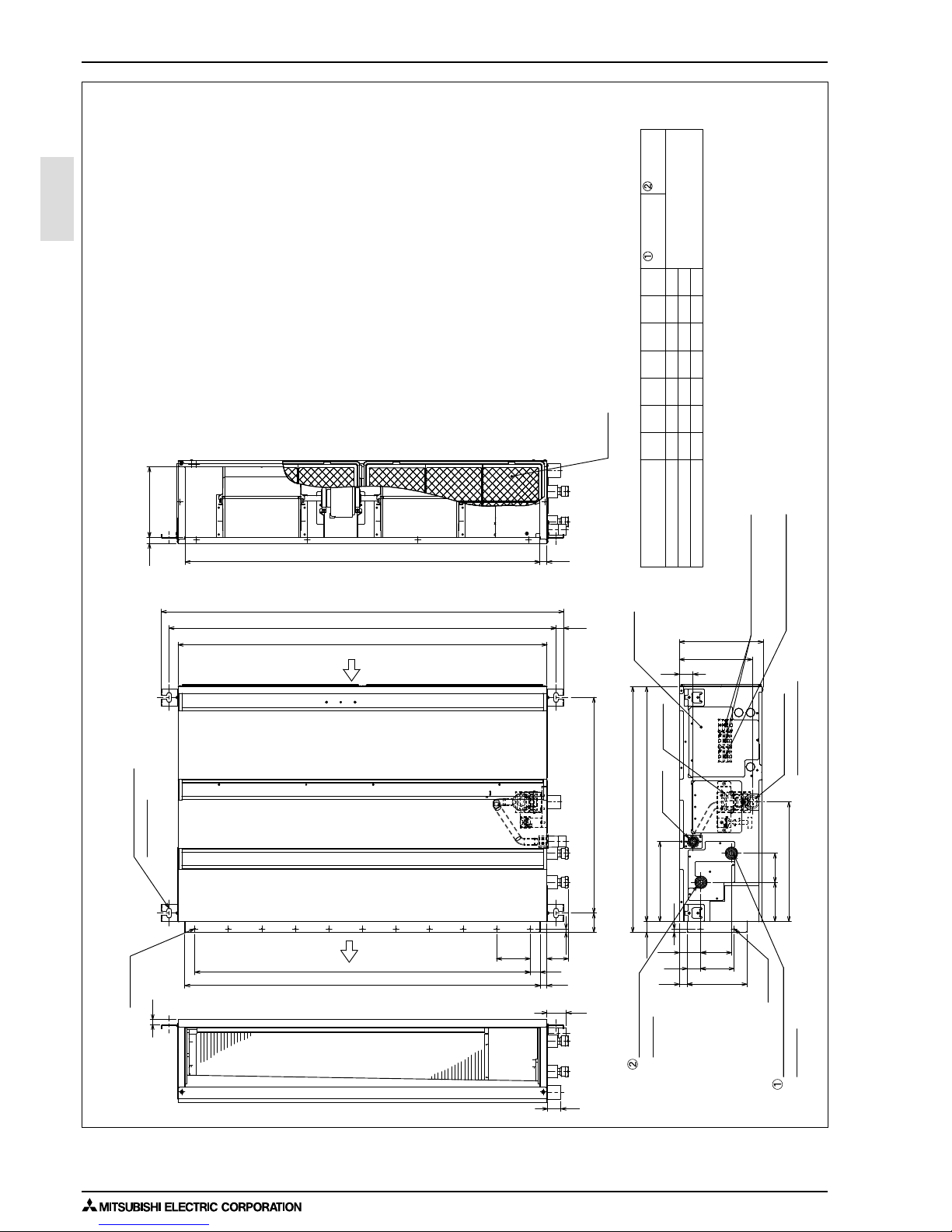
2. EXTERNAL DIMENSIONS
Unit : mm
Control box
Air
outlet
Air
inlet
Water pipe (To HBC unit)
Rc3/4 screw
Water pipe(From HBC unit)
Rc3/4 screw
Drain pump
Air Filter
Terminal block(Power source)
Terminal block(Transmission)
Drain pipe(O.D.
Ø
32)
(Spontaneous draining)
Drain pipe
(O.D.
Ø
32)
Suspension bolt hole
4-14x30 Slot
Rc3/4 screw
(To HBC unit)
(From HBC unit)
7
Model
A
660800
1200
700 754
900 954 860 9
E
11
D
1060
C
110 0
B
115 4
PEFY-WP40,50VMA-E
PEFY-WP25,32VMA-E
PEFY-WP20VMA-E
1000
1000
F
858800
G
658
1058
600
2×2-
Ø
2.9
2xE-
Ø
2.9
91 64
87117
20
64
40
250
40
D (Duct)
21018
G21
57
10
A
B (Suspension bolt pitch)
C
23
643 (Suspension bolt pitch)
178 (Duct)
23
10
238
32 700
732
356
100
41
217
100
30
100x(E-1)=F
58
15
Note 1. Use M10 screw for the Suspension bolt (field supply).
2. Keep the service space for the maintenance at the bottom.
3. This chart indicates for PEFY-WP40·50VMA-E models,
which have 2 fans.PEFY-WP20·25·32VMA-E models
have 1 fan.
4. In case of the inlet duct is used,remove the air filter
(supply with the unit), then install the filter
(field supply) at suction side.
Water pipe
Water pipe
PEFY-WP20, 25, 32, 40, 50VMA-E
Page 26
1 - 23
2. EXTERNAL DIMENSIONS
INDOOR UNITS
PEFY-VMA
<accessory>
Drain hose (I.D.
Ø
32)
10
J
30044 150
P
54 260 4 780 10
10
N
990
M
4
L
49
K
330
PEFY-WP40,50VMA-E
PEFY-WP25,32VMA-E
PEFY-WP20VMA-E
1000
800
1200
Model H
P-
Ø
2.9
(Actual length)
112 1111 2
J
KL
6
J
K
Kx(M-1)=N
Access door
Ceiling surface
Make the access door at the appointed position for service maintenance.
More than 10mm
More than 20mm
Required space for service and maintenance
More than 300
450
777
450
250~300
50
H
50
Access door
Note2
65
0
-10
Less than 300mm
Less than 700mm
PEFY-WP20, 25, 32, 40, 50VMA-E
Unit : mm
Page 27
3. CENTER OF GRAVITY
INDOOR UNITS 1 - 24
PEFY-VMA
3. CENTER OF GRAVITY
Model name
PEFY-WP20VMA-E
PEFY-WP25VMA-E
PEFY-WP32VMA-E
PEFY-WP40VMA-E
PEFY-WP50VMA-E
W
643 [25 - 6/16]
643 [25 - 6/16]
643 [25 - 6/16]
643 [25 - 6/16]
L
754 [29 - 11/16]
954 [37 - 9/16]
954 [37 - 9/16]
1154 [45 - 7/16]
X
330 [13]
340 [13 - 7/16]
340 [13 - 7/16]
325 [12 - 13/16]
Y
300 [11 -13/16]
375 [14 -13/16]
375 [14 -13/16]
525 [20 -11/16]
Z
130 [5 -2/16]
130 [5 -2/16]
130 [5 -2/16]
130 [5 -2/16]
643 [25 - 6/16] 1154 [45 - 7/16]
325 [12 - 13/16]
525 [20 -11/16] 130 [5 -2/16]
A : Center of gravity
YX
LW
A
Z
PEFY-WP20, 25, 32, 40, 50VMA-E
(mm)[in]
Page 28

1 - 25
4. ELECTRICAL WIRING DIAGRAMS
INDOOR UNITS
PEFY-VMA
4. ELECTRICAL WIRING DIAGRAMS
INSIDE SECTION OF CONTROL BOX
Drainpump
Fan motor
Thermistor (piping temp.detection/water in)
Thermistor (piping temp.detection/water out)
Switch (for mode selection)
Switch (for capacity code)
Switch (10ths digit address set)
Switch (for static pressure selection)
Switch (for static pressure selection)
Switch (BRANCH No.)
Switch (for mode selection)
Switch (for model selection)
Switch (for mode selection)
Connector (emergency operation)
Transmission terminal block
Fuse AC250V 6.3A
Arrester
Aux. relay
Aux. relay
AC reactor(Power factor improvement)
Varistor
TB15
F01
DSA
X01
X10
ACL
ZNR01,02
TH21
LED1
Thermistor (inlet air temp.detection)
LED(Power supply)
LED(Remote controller supply)
TH23
TH22
LED2
NAMESYMBOLSYMBOL
I.B.
P. B.
Indoor controller board
Power supply board
Switch (1s digit address set)
SW2(I.B.)
SW3(I.B.)
SW11(I.B.)
SW12(I.B.)
SWA(I.B.)
SW14(I.B.)
SWC(I.B.)
SW1(I.B.)
SW4(I.B.)
SW5(I.B.)
SWE(I.B.)
TB2
TB5
Transmission terminal block
Power source terminal block
SYMBOL EXPLANATION
NAME
CN27
CN41
CN51
CN52
CN90
CN2A
CN105
FS
Connector (HA terminal-A)
Connector (Centrally control)
Connector (Remote indication)
Connector (Wireless)
Connector (0-10V Analog input)
Connector (IT terminal)
Float switch
SYMBOL NAME
Connector (Damper)
CN32
Connector (Remote switch)
NOTE:Symbols used in wiring diagram above are,
:Connector
:Terminal
(Heavy dotted line):Field wiring
I.B.
P. B .
TH23
TH21
TH22
t° t°
t°
FS
(Blue)
(Blue)
(Blue)
(Blue)
(Blue)
(Black)
(Green)
(Red)
CN44
(Red)
(Red)
(Red)
CN27
ON
ZNR01
CNP
CND
ZNR02
DSA
OFF
F01
SW5
SWC
SW14
SW12
SW11
SW4
SWA
ACL
SW1
SW2
SW3
CNXC1
X01 X10
CNXA1CNXB1 CNMF
CNXC2
CN2A
CN2M
CNXB2
CNXA2
CN51
CN4F
CN41
CN105
CN90
CN20
SWE
CN52
CN32
CN3A
TB5
LED2
LED1
DC280-340V
Rectifier circuit
U
U
AC220-240V
50,60Hz
N
L
TB15
M2
2
TB2
M1
1
S(SHIELD)
M
MS
3~
1111
1
11
22752
5
33445 6 4
3
22
2
1
3
1
3
2 32
3
1 2
1
1
3
431454
1
2
4
1
2
2
1
1~
TO MA REMOTE
CONTROLLER
TO OUTDOOR UNIT
HBC CONTROLLER
REMOTE CONTROLLER
POWER SUPPLY
PULL BOX
BREAKER (16A)
FUSE (16A)
TO NEXT INDOOR UNIT
PEFY-WP20, 25, 32, 40, 50VMA-E
Page 29
5. SOUND LEVELS
INDOOR UNITS 1 - 26
PEFY-VMA
5. SOUND LEVELS
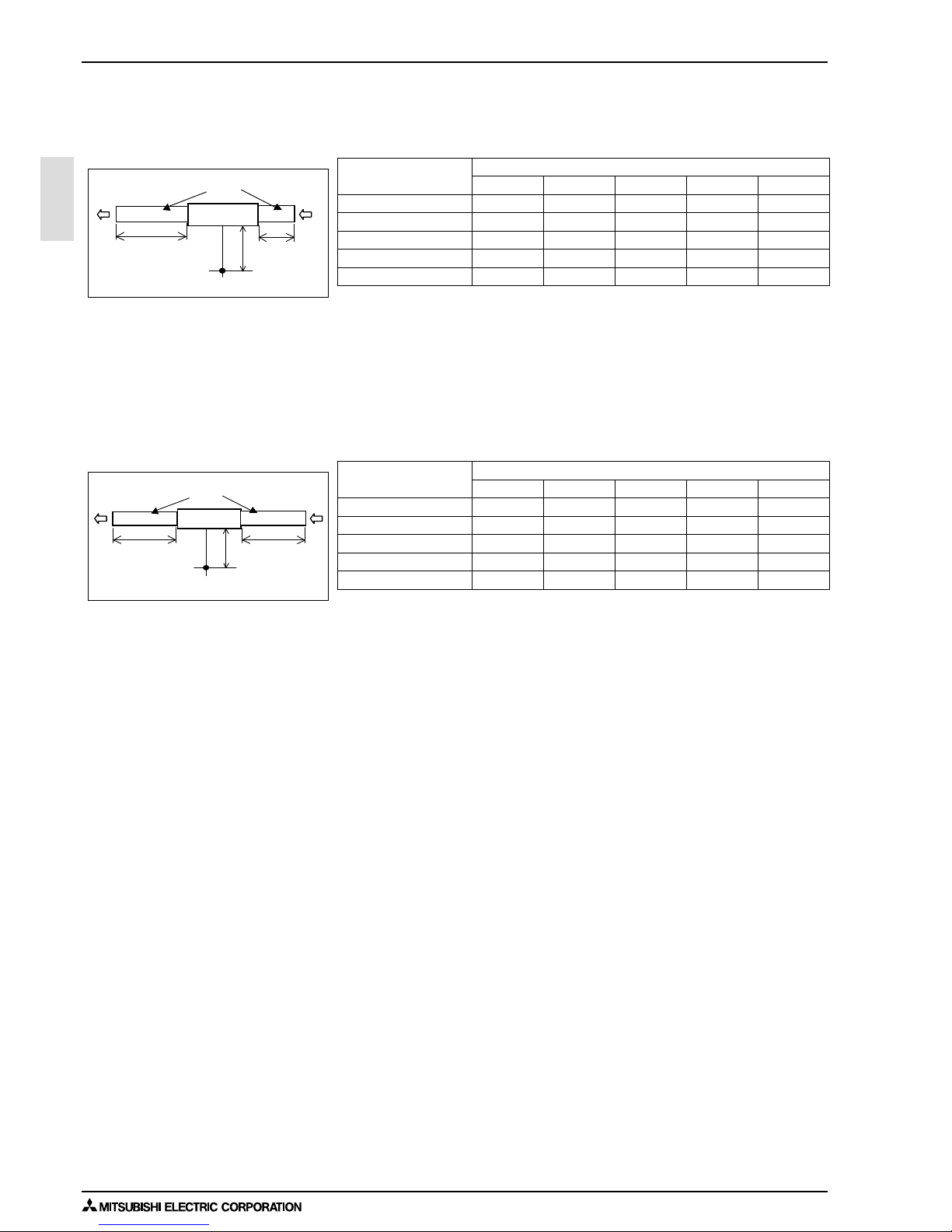
5-1. Sound levels
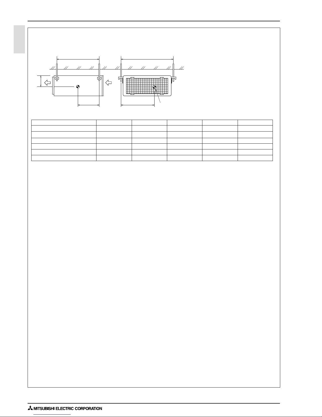
5-1-1. Sound levels (Measured condition : With 1m air inlet duct and 2m air outlet duct)
5-1-2. Sound levels (Measured condition : With 2m air inlet duct and 2m air outlet duct)
Sound level at anechoic room : Low-Mid-High
Model Sound level dB(A)
35Pa 50Pa 70Pa 100Pa 150Pa
PEFY-WP20VMA-E 28-30-34 28-30-34 29-32-36 29-33-37 31-35-40
PEFY-WP25VMA-E 28-30-34 28-30-34 29-32-36 29-33-37 32-36-40
PEFY-WP32VMA-E 28-31-35 28-32-35 29-33-37 30-34-38 32-37-41
PEFY-WP40VMA-E 30-33-37 30-34-38 31-36-39 33-37-41 36-41-44
PEFY-WP50VMA-E 30-33-37 30-34-38 31-36-39 33-37-41 36-41-44
*
Measured in anechoic room.
PEFY-WP-VMA-E
2m
1m
Aux. duct
1.5m
Measurement location
Sound level at anechoic room : Low-Mid-High
Model Sound level dB(A)
35Pa 50Pa 70Pa 100Pa 150Pa
PEFY-WP20VMA-E 23-25-28 23-26-29 24-27-30 25-28-32 28-32-36
PEFY-WP25VMA-E 23-26-29 23-27-30 24-28-31 26-29-33 29-33-37
PEFY-WP32VMA-E 24-28-31 25-29-32 26-30-33 27-31-34 29-34-38
PEFY-WP40VMA-E 26-29-33 26-29-34 26-30-35 29-33-37 32-37-41
PEFY-WP50VMA-E 26-29-33 26-29-34 26-30-35 29-33-37 32-37-41
Measurement location
Aux. duct
*
Measured in anechoic room.
PEFY-WP-VMA-E
2m 2m
1.5m
Page 30
1 - 27
5. SOUND LEVELS
INDOOR UNITS
PEFY-VMA
5-2. NC curves
5-2-1. NC curves (Sound level measured condition : With 1m air inlet duct and 2m air outlet duct)
10.0
15.0
20.0
25.0
30.0
35.0
40.0
45.0
50.0
55.0
60.0
65.0
70.0
63 125 250 500 1k 2k 4k 8k
NC-60
NC-50
Octave band pressure level (dB) 0dB=20μPa
Approximate minimum
audible limit on
continuous noise
NC-40
NC-30
NC-20
Octave band center frequencies (Hz)
High
Middle
50/60Hz
Low
50/60Hz
50/60Hz
PEFY-WP20VMA-E
External Static Pressure: 35Pa
Power Source: 220-240V(50/60Hz)
10.0
15.0
20.0
25.0
30.0
35.0
40.0
45.0
50.0
55.0
60.0
65.0
70.0
63 125 250 500 1k 2k 4k 8k
NC-60
NC-50
Octave band pressure level (dB) 0dB=20μPa
Approximate minimum
audible limit on
continuous noise
NC-40
NC-30
NC-20
Octave band center frequencies (Hz)
High
Middle
50/60Hz
Low
50/60Hz
50/60Hz
PEFY-WP20VMA-E
External Static Pressure: 50Pa
Power Source: 220-240V(50/60Hz)
10.0
15.0
20.0
25.0
30.0
35.0
40.0
45.0
50.0
55.0
60.0
65.0
70.0
63 125 250 500 1k 2k 4k 8k
NC-60
NC-50
Octave band pressure level (dB) 0dB=20μPa
Approximate minimum
audible limit on
continuous noise
NC-40
NC-30
NC-20
Octave band center frequencies (Hz)
High
Middle
50/60Hz
Low
50/60Hz
50/60Hz
PEFY-WP20VMA-E
External Static Pressure: 70Pa
Power Source: 220-240V(50/60Hz)
10.0
15.0
20.0
25.0
30.0
35.0
40.0
45.0
50.0
55.0
60.0
65.0
70.0
63 125 250 500 1k 2k 4k 8k
NC-60
NC-50
Octave band pressure level (dB) 0dB=20μPa
Approximate minimum
audible limit on
continuous noise
NC-40
NC-30
NC-20
Octave band center frequencies (Hz)
High
Middle
50/60Hz
Low
50/60Hz
50/60Hz
PEFY-WP20VMA-E
External Static Pressure: 100Pa
Power Source: 220-240V(50/60Hz)
10.0
15.0
20.0
25.0
30.0
35.0
40.0
45.0
50.0
55.0
60.0
65.0
70.0
63 125 250 500 1k 2k 4k 8k
NC-60
NC-50
Octave band pressure level (dB) 0dB=20μPa
Approximate minimum
audible limit on
continuous noise
NC-40
NC-30
NC-20
Octave band center frequencies (Hz)
High
Middle
50/60Hz
Low
50/60Hz
50/60Hz
PEFY-WP20VMA-E
External Static Pressure: 150Pa
Power Source: 220-240V(50/60Hz)
10.0
15.0
20.0
25.0
30.0
35.0
40.0
45.0
50.0
55.0
60.0
65.0
70.0
63 125 250 500 1k 2k 4k 8k
NC-60
NC-50
Octave band pressure level (dB) 0dB=20μPa
Approximate minimum
audible limit on
continuous noise
NC-40
NC-30
NC-20
Octave band center frequencies (Hz)
High
Middle
50/60Hz
Low
50/60Hz
50/60Hz
PEFY-WP25VMA-E
External Static Pressure: 35Pa
Power Source: 220-240V(50/60Hz)
10.0
15.0
20.0
25.0
30.0
35.0
40.0
45.0
50.0
55.0
60.0
65.0
70.0
63 125 250 500 1k 2k 4k 8k
NC-60
NC-50
Octave band pressure level (dB) 0dB=20μPa
Approximate minimum
audible limit on
continuous noise
NC-40
NC-30
NC-20
Octave band center frequencies (Hz)
High
Middle
50/60Hz
Low
50/60Hz
50/60Hz
PEFY-WP25VMA-E
External Static Pressure: 50Pa
Power Source: 220-240V(50/60Hz)
10.0
15.0
20.0
25.0
30.0
35.0
40.0
45.0
50.0
55.0
60.0
65.0
70.0
63 125 250 500 1k 2k 4k 8k
NC-60
NC-50
Octave band pressure level (dB) 0dB=20μPa
Approximate minimum
audible limit on
continuous noise
NC-40
NC-30
NC-20
Octave band center frequencies (Hz)
High
Middle
50/60Hz
Low
50/60Hz
50/60Hz
PEFY-WP25VMA-E
External Static Pressure: 70Pa
Power Source: 220-240V(50/60Hz)
10.0
15.0
20.0
25.0
30.0
35.0
40.0
45.0
50.0
55.0
60.0
65.0
70.0
63 125 250 500 1k 2k 4k 8k
NC-60
NC-50
Octave band pressure level (dB) 0dB=20μPa
Approximate minimum
audible limit on
continuous noise
NC-40
NC-30
NC-20
Octave band center frequencies (Hz)
High
Middle
50/60Hz
Low
50/60Hz
50/60Hz
PEFY-WP25VMA-E
External Static Pressure: 100Pa
Power Source: 220-240V(50/60Hz)
10.0
15.0
20.0
25.0
30.0
35.0
40.0
45.0
50.0
55.0
60.0
65.0
70.0
63 125 250 500 1k 2k 4k 8k
NC-60
NC-50
Octave band pressure level (dB) 0dB=20μPa
Approximate minimum
audible limit on
continuous noise
NC-40
NC-30
NC-20
Octave band center frequencies (Hz)
High
Middle
50/60Hz
Low
50/60Hz
50/60Hz
PEFY-WP25VMA-E
External Static Pressure: 150Pa
Power Source: 220-240V(50/60Hz)
10.0
15.0
20.0
25.0
30.0
35.0
40.0
45.0
50.0
55.0
60.0
65.0
70.0
63 125 250 500 1k 2k 4k 8k
NC-60
NC-50
Octave band pressure level (dB) 0dB=20μPa
Approximate minimum
audible limit on
continuous noise
NC-40
NC-30
NC-20
Octave band center frequencies (Hz)
High
Middle
50/60Hz
Low
50/60Hz
50/60Hz
PEFY-WP32VMA-E
External Static Pressure: 35Pa
Power Source: 220-240V(50/60Hz)
10.0
15.0
20.0
25.0
30.0
35.0
40.0
45.0
50.0
55.0
60.0
65.0
70.0
63 125 250 500 1k 2k 4k 8k
NC-60
NC-50
Octave band pressure level (dB) 0dB=20μPa
Approximate minimum
audible limit on
continuous noise
NC-40
NC-30
NC-20
Octave band center frequencies (Hz)
High
Middle
50/60Hz
Low
50/60Hz
50/60Hz
PEFY-WP32VMA-E
External Static Pressure: 50Pa
Power Source: 220-240V(50/60Hz)
Page 31

5. SOUND LEVELS
INDOOR UNITS 1 - 28
PEFY-VMA
10.0
15.0
20.0
25.0
30.0
35.0
40.0
45.0
50.0
55.0
60.0
65.0
70.0
63 125 250 500 1k 2k 4k 8k
NC-60
NC-50
Octave band pressure level (dB) 0dB=20μPa
Approximate minimum
audible limit on
continuous noise
NC-40
NC-30
NC-20
Octave band center frequencies (Hz)
High
Middle
50/60Hz
Low
50/60Hz
50/60Hz
PEFY-WP32VMA-E
External Static Pressure: 70Pa
Power Source: 220-240V(50/60Hz)
10.0
15.0
20.0
25.0
30.0
35.0
40.0
45.0
50.0
55.0
60.0
65.0
70.0
63 125 250 500 1k 2k 4k 8k
NC-60
NC-50
Octave band pressure level (dB) 0dB=20μPa
Approximate minimum
audible limit on
continuous noise
NC-40
NC-30
NC-20
Octave band center frequencies (Hz)
High
Middle
50/60Hz
Low
50/60Hz
50/60Hz
PEFY-WP32VMA-E
External Static Pressure: 100Pa
Power Source: 220-240V(50/60Hz)
10.0
15.0
20.0
25.0
30.0
35.0
40.0
45.0
50.0
55.0
60.0
65.0
70.0
63 125 250 500 1k 2k 4k 8k
NC-60
NC-50
Octave band pressure level (dB) 0dB=20μPa
Approximate minimum
audible limit on
continuous noise
NC-40
NC-30
NC-20
Octave band center frequencies (Hz)
High
Middle
50/60Hz
Low
50/60Hz
50/60Hz
PEFY-WP32VMA-E
External Static Pressure: 150Pa
Power Source: 220-240V(50/60Hz)
10.0
15.0
20.0
25.0
30.0
35.0
40.0
45.0
50.0
55.0
60.0
65.0
70.0
63 125 250 500 1k 2k 4k 8k
NC-60
NC-50
Octave band pressure level (dB) 0dB=20μPa
Approximate minimum
audible limit on
continuous noise
NC-40
NC-30
NC-20
Octave band center frequencies (Hz)
High
Middle
50/60Hz
Low
50/60Hz
50/60Hz
PEFY-WP40,50VMA-E
External Static Pressure: 35Pa
Power Source: 220-240V(50/60Hz)
10.0
15.0
20.0
25.0
30.0
35.0
40.0
45.0
50.0
55.0
60.0
65.0
70.0
63 125 250 500 1k 2k 4k 8k
NC-60
NC-50
Octave band pressure level (dB) 0dB=20μPa
Approximate minimum
audible limit on
continuous noise
NC-40
NC-30
NC-20
Octave band center frequencies (Hz)
High
Middle
50/60Hz
Low
50/60Hz
50/60Hz
PEFY-WP40,50VMA-E
External Static Pressure: 50Pa
Power Source: 220-240V(50/60Hz)
10.0
15.0
20.0
25.0
30.0
35.0
40.0
45.0
50.0
55.0
60.0
65.0
70.0
63 125 250 500 1k 2k 4k 8k
NC-60
NC-50
Octave band pressure level (dB) 0dB=20μPa
Approximate minimum
audible limit on
continuous noise
NC-40
NC-30
NC-20
Octave band center frequencies (Hz)
High
Middle
50/60Hz
Low
50/60Hz
50/60Hz
PEFY-WP40,50VMA-E
External Static Pressure: 70Pa
Power Source: 220-240V(50/60Hz)
10.0
15.0
20.0
25.0
30.0
35.0
40.0
45.0
50.0
55.0
60.0
65.0
70.0
63 125 250 500 1k 2k 4k 8k
NC-60
NC-50
Octave band pressure level (dB) 0dB=20μPa
Approximate minimum
audible limit on
continuous noise
NC-40
NC-30
NC-20
Octave band center frequencies (Hz)
High
Middle
50/60Hz
Low
50/60Hz
50/60Hz
PEFY-WP40,50VMA-E
External Static Pressure: 100Pa
Power Source: 220-240V(50/60Hz)
10.0
15.0
20.0
25.0
30.0
35.0
40.0
45.0
50.0
55.0
60.0
65.0
70.0
63 125 250 500 1k 2k 4k 8k
NC-60
NC-50
Octave band pressure level (dB) 0dB=20μPa
Approximate minimum
audible limit on
continuous noise
NC-40
NC-30
NC-20
Octave band center frequencies (Hz)
High
Middle
50/60Hz
Low
50/60Hz
50/60Hz
PEFY-WP40,50VMA-E
External Static Pressure: 150Pa
Power Source: 220-240V(50/60Hz)
Page 32

1 - 29
5. SOUND LEVELS
INDOOR UNITS
PEFY-VMA
5-2-2. NC curves (Sound level measured condition : With 2m air inlet duct and 2m air outlet duct)
10.0
15.0
20.0
25.0
30.0
35.0
40.0
45.0
50.0
55.0
60.0
65.0
70.0
63 125 250 500 1k 2k 4k 8k
NC-60
NC-50
Octave band pressure level (dB) 0dB=20μPa
Approximate minimum
audible limit on
continuous noise
NC-40
NC-30
NC-20
Octave band center frequencies (Hz)
High
Middle
50/60Hz
Low
50/60Hz
50/60Hz
PEFY-WP20VMA-E
External Static Pressure: 35Pa
Power Source: 220-230-240V(50/60Hz)
10.0
15.0
20.0
25.0
30.0
35.0
40.0
45.0
50.0
55.0
60.0
65.0
70.0
63 125 250 500 1k 2k 4k 8k
NC-60
NC-50
Octave band pressure level (dB) 0dB=20μPa
Approximate minimum
audible limit on
continuous noise
NC-40
NC-30
NC-20
Octave band center frequencies (Hz)
High
Middle
50/60Hz
Low
50/60Hz
50/60Hz
PEFY-WP20VMA-E
External Static Pressure: 50Pa
Power Source: 220-230-240V(50/60Hz)
10.0
15.0
20.0
25.0
30.0
35.0
40.0
45.0
50.0
55.0
60.0
65.0
70.0
63 125 250 500 1k 2k 4k 8k
NC-60
NC-50
Octave band pressure level (dB) 0dB=20μPa
Approximate minimum
audible limit on
continuous noise
NC-40
NC-30
NC-20
Octave band center frequencies (Hz)
High
Middle
50/60Hz
Low
50/60Hz
50/60Hz
PEFY-WP20VMA-E
External Static Pressure: 70Pa
Power Source: 220-230-240V(50/60Hz)
10.0
15.0
20.0
25.0
30.0
35.0
40.0
45.0
50.0
55.0
60.0
65.0
70.0
63 125 250 500 1k 2k 4k 8k
NC-60
NC-50
Octave band pressure level (dB) 0dB=20μPa
Approximate minimum
audible limit on
continuous noise
NC-40
NC-30
NC-20
Octave band center frequencies (Hz)
High
Middle
50/60Hz
Low
50/60Hz
50/60Hz
PEFY-WP20VMA-E
External Static Pressure: 100Pa
Power Source: 220-230-240V(50/60Hz)
10.0
15.0
20.0
25.0
30.0
35.0
40.0
45.0
50.0
55.0
60.0
65.0
70.0
63 125 250 500 1k 2k 4k 8k
NC-60
NC-50
Octave band pressure level (dB) 0dB=20μPa
Approximate minimum
audible limit on
continuous noise
NC-40
NC-30
NC-20
Octave band center frequencies (Hz)
High
Middle
50/60Hz
Low
50/60Hz
50/60Hz
PEFY-WP20VMA-E
External Static Pressure: 150Pa
Power Source: 220-230-240V(50/60Hz)
10.0
15.0
20.0
25.0
30.0
35.0
40.0
45.0
50.0
55.0
60.0
65.0
70.0
63 125 250 500 1k 2k 4k 8k
NC-60
NC-50
Octave band pressure level (dB) 0dB=20μPa
Approximate minimum
audible limit on
continuous noise
NC-40
NC-30
NC-20
Octave band center frequencies (Hz)
High
Middle
50/60Hz
Low
50/60Hz
50/60Hz
PEFY-WP25VMA-E
External Static Pressure: 35Pa
Power Source: 220-230-240V(50/60Hz)
10.0
15.0
20.0
25.0
30.0
35.0
40.0
45.0
50.0
55.0
60.0
65.0
70.0
63 125 250 500 1k 2k 4k 8k
NC-60
NC-50
Octave band pressure level (dB) 0dB=20μPa
Approximate minimum
audible limit on
continuous noise
NC-40
NC-30
NC-20
Octave band center frequencies (Hz)
High
Middle
50/60Hz
Low
50/60Hz
50/60Hz
PEFY-WP25VMA-E
External Static Pressure: 50Pa
Power Source: 220-230-240V(50/60Hz)
10.0
15.0
20.0
25.0
30.0
35.0
40.0
45.0
50.0
55.0
60.0
65.0
70.0
63 125 250 500 1k 2k 4k 8k
NC-60
NC-50
Octave band pressure level (dB) 0dB=20μPa
Approximate minimum
audible limit on
continuous noise
NC-40
NC-30
NC-20
Octave band center frequencies (Hz)
High
Middle
50/60Hz
Low
50/60Hz
50/60Hz
PEFY-WP25VMA-E
External Static Pressure: 70Pa
Power Source: 220-230-240V(50/60Hz)
10.0
15.0
20.0
25.0
30.0
35.0
40.0
45.0
50.0
55.0
60.0
65.0
70.0
63 125 250 500 1k 2k 4k 8k
NC-60
NC-50
Octave band pressure level (dB) 0dB=20μPa
Approximate minimum
audible limit on
continuous noise
NC-40
NC-30
NC-20
Octave band center frequencies (Hz)
High
Middle
50/60Hz
Low
50/60Hz
50/60Hz
PEFY-WP25VMA-E
External Static Pressure: 100Pa
Power Source: 220-230-240V(50/60Hz)
10.0
15.0
20.0
25.0
30.0
35.0
40.0
45.0
50.0
55.0
60.0
65.0
70.0
63 125 250 500 1k 2k 4k 8k
NC-60
NC-50
Octave band pressure level (dB) 0dB=20μPa
Approximate minimum
audible limit on
continuous noise
NC-40
NC-30
NC-20
Octave band center frequencies (Hz)
High
Middle
50/60Hz
Low
50/60Hz
50/60Hz
PEFY-WP25VMA-E
External Static Pressure: 150Pa
Power Source: 220-230-240V(50/60Hz)
10.0
15.0
20.0
25.0
30.0
35.0
40.0
45.0
50.0
55.0
60.0
65.0
70.0
63 125 250 500 1k 2k 4k 8k
NC-60
NC-50
Octave band pressure level (dB) 0dB=20μPa
Approximate minimum
audible limit on
continuous noise
NC-40
NC-30
NC-20
Octave band center frequencies (Hz)
High
Middle
50/60Hz
Low
50/60Hz
50/60Hz
PEFY-WP32VMA-E
External Static Pressure: 35Pa
Power Source: 220-230-240V(50/60Hz)
10.0
15.0
20.0
25.0
30.0
35.0
40.0
45.0
50.0
55.0
60.0
65.0
70.0
63 125 250 500 1k 2k 4k 8k
NC-60
NC-50
Octave band pressure level (dB) 0dB=20μPa
Approximate minimum
audible limit on
continuous noise
NC-40
NC-30
NC-20
Octave band center frequencies (Hz)
High
Middle
50/60Hz
Low
50/60Hz
50/60Hz
PEFY-WP32VMA-E
External Static Pressure: 50Pa
Power Source: 220-230-240V(50/60Hz)
Page 33

5. SOUND LEVELS
INDOOR UNITS 1 - 30
PEFY-VMA
10.0
15.0
20.0
25.0
30.0
35.0
40.0
45.0
50.0
55.0
60.0
65.0
70.0
63 125 250 500 1k 2k 4k 8k
NC-60
NC-50
Octave band pressure level (dB) 0dB=20μPa
Approximate minimum
audible limit on
continuous noise
NC-40
NC-30
NC-20
Octave band center frequencies (Hz)
High
Middle
50/60Hz
Low
50/60Hz
50/60Hz
PEFY-WP32VMA-E
External Static Pressure: 70Pa
Power Source: 220-230-240V(50/60Hz)
10.0
15.0
20.0
25.0
30.0
35.0
40.0
45.0
50.0
55.0
60.0
65.0
70.0
63 125 250 500 1k 2k 4k 8k
NC-60
NC-50
Octave band pressure level (dB) 0dB=20μPa
Approximate minimum
audible limit on
continuous noise
NC-40
NC-30
NC-20
Octave band center frequencies (Hz)
High
Middle
50/60Hz
Low
50/60Hz
50/60Hz
PEFY-WP32VMA-E
External Static Pressure: 100Pa
Power Source: 220-230-240V(50/60Hz)
10.0
15.0
20.0
25.0
30.0
35.0
40.0
45.0
50.0
55.0
60.0
65.0
70.0
63 125 250 500 1k 2k 4k 8k
NC-60
NC-50
Octave band pressure level (dB) 0dB=20μPa
Approximate minimum
audible limit on
continuous noise
NC-40
NC-30
NC-20
Octave band center frequencies (Hz)
High
Middle
50/60Hz
Low
50/60Hz
50/60Hz
PEFY-WP32VMA-E
External Static Pressure: 150Pa
Power Source: 220-230-240V(50/60Hz)
10.0
15.0
20.0
25.0
30.0
35.0
40.0
45.0
50.0
55.0
60.0
65.0
70.0
63 125 250 500 1k 2k 4k 8k
NC-60
NC-50
Octave band pressure level (dB) 0dB=20μPa
Approximate minimum
audible limit on
continuous noise
NC-40
NC-30
NC-20
Octave band center frequencies (Hz)
High
Middle
50/60Hz
Low
50/60Hz
50/60Hz
PEFY-WP40, 50VMA-E
External Static Pressure: 35Pa
Power Source: 220-230-240V(50/60Hz)
10.0
15.0
20.0
25.0
30.0
35.0
40.0
45.0
50.0
55.0
60.0
65.0
70.0
63 125 250 500 1k 2k 4k 8k
NC-60
NC-50
Octave band pressure level (dB) 0dB=20μPa
Approximate minimum
audible limit on
continuous noise
NC-40
NC-30
NC-20
Octave band center frequencies (Hz)
High
Middle
50/60Hz
Low
50/60Hz
50/60Hz
PEFY-WP40, 50VMA-E
External Static Pressure: 50Pa
Power Source: 220-230-240V(50/60Hz)
10.0
15.0
20.0
25.0
30.0
35.0
40.0
45.0
50.0
55.0
60.0
65.0
70.0
63 125 250 500 1k 2k 4k 8k
NC-60
NC-50
Octave band pressure level (dB) 0dB=20μPa
Approximate minimum
audible limit on
continuous noise
NC-40
NC-30
NC-20
Octave band center frequencies (Hz)
High
Middle
50/60Hz
Low
50/60Hz
50/60Hz
PEFY-WP40, 50VMA-E
External Static Pressure: 70Pa
Power Source: 220-230-240V(50/60Hz)
10.0
15.0
20.0
25.0
30.0
35.0
40.0
45.0
50.0
55.0
60.0
65.0
70.0
63 125 250 500 1k 2k 4k 8k
NC-60
NC-50
Octave band pressure level (dB) 0dB=20μPa
Approximate minimum
audible limit on
continuous noise
NC-40
NC-30
NC-20
Octave band center frequencies (Hz)
High
Middle
50/60Hz
Low
50/60Hz
50/60Hz
PEFY-WP40, 50VMA-E
External Static Pressure: 100Pa
Power Source: 220-230-240V(50/60Hz)
10.0
15.0
20.0
25.0
30.0
35.0
40.0
45.0
50.0
55.0
60.0
65.0
70.0
63 125 250 500 1k 2k 4k 8k
NC-60
NC-50
Octave band pressure level (dB) 0dB=20μPa
Approximate minimum
audible limit on
continuous noise
NC-40
NC-30
NC-20
Octave band center frequencies (Hz)
High
Middle
50/60Hz
Low
50/60Hz
50/60Hz
PEFY-WP40, 50VMA-E
External Static Pressure: 150Pa
Power Source: 220-230-240V(50/60Hz)
Page 34

1 - 31
6. FAN CHARACTERISTICS CURVES
INDOOR UNITS
PEFY-VMA
6. FAN CHARACTERISTICS CURVES
PEFY-WP20VMA-E
External static pressure : 35Pa
Power source : 220-240V
Static pressure (Pa)
Airflow rate (m3/min)
50
40
30
20
10
0
PEFY-WP20VMA-E
External static pressure : 50Pa
Power source : 220-240V
Static pressure (Pa)
Airflow rate (m3/min)
70
60
50
40
30
20
10
0
PEFY-WP20VMA-E
External static pressure : 70Pa
Power source : 220-240V
Static pressure (Pa)
Airflow rate (m3/min)
90
80
70
60
50
40
30
20
10
0
PEFY-WP20VMA-E
External static pressure : 100Pa
Power source : 220-240V
Static pressure (Pa)
Airflow rate (m3/min)
110
100
90
80
70
60
50
40
30
20
10
0
PEFY-WP20VMA-E
External static pressure : 150Pa
Power source : 220-240V
Static pressure (Pa)
Airflow rate (m3/min)
160
150
140
130
120
110
100
90
80
70
60
50
40
30
20
10
0
5 10 15 5 10 15
5 10 15 5 10 15
5 10 15
Middle
High
Middle
High
Middle
High
Middle
High
Middle
High
Low
Low
Low
Low
Low
Limit
Limit
Limit
Limit
Limit
Page 35

6. FAN CHARACTERISTICS CURVES
INDOOR UNITS 1 - 32
PEFY-VMA
PEFY-WP25VMA-E
External static pressure : 35Pa
Power source : 220-240V
Static pressure (Pa)
Airflow rate (m3/min)
60
50
40
30
20
10
0
PEFY-WP25VMA-E
External static pressure : 50Pa
Power source : 220-240V
Static pressure (Pa)
Airflow rate (m3/min)
70
60
50
40
30
20
10
0
PEFY-WP25VMA-E
External static pressure : 70Pa
Power source : 220-240V
Static pressure (Pa)
Airflow rate (m3/min)
90
80
70
60
50
40
30
20
10
0
PEFY-WP25VMA-E
External static pressure : 100Pa
Power source : 220-240V
Static pressure (Pa)
Airflow rate (m3/min)
120
110
100
90
80
70
60
50
40
30
20
10
0
PEFY-WP25VMA-E
External static pressure : 150Pa
Power source : 220-240V
Static pressure (Pa)
Airflow rate (m3/min)
170
160
150
140
130
120
110
100
90
80
70
60
50
40
30
20
10
0
7 9 11 13 15 17 19 21 7 9 11 13 15 17 19 21
7 9 11 13 15 17 19 21 7 9 11 13 15 17 19 21
7 9 11 13 15 17 19 21
Middle
High
Middle
High
Middle
High
Middle
High
Middle
High
Low
Low
Low
Low
Low
Limit
Limit
Limit
Limit
Limit
Page 36

1 - 33
6. FAN CHARACTERISTICS CURVES
INDOOR UNITS
PEFY-VMA
PEFY-WP32VMA-E
External static pressure : 35Pa
Power source : 220-240V
Static pressure (Pa)
Airflow rate (m3/min)
60
50
40
30
20
10
0
PEFY-WP32VMA-E
External static pressure : 50Pa
Power source : 220-240V
Static pressure (Pa)
Airflow rate (m3/min)
80
70
60
50
40
30
20
10
0
PEFY-WP32VMA-E
External static pressure : 70Pa
Power source : 220-240V
Static pressure (Pa)
Airflow rate (m3/min)
100
90
80
70
60
50
40
30
20
10
0
PEFY-WP32VMA-E
External static pressure : 100Pa
Power source : 220-240V
Static pressure (Pa)
Airflow rate (m3/min)
130
120
110
100
90
80
70
60
50
40
30
20
10
0
PEFY-WP32VMA-E
External static pressure : 150Pa
Power source : 220-240V
Static pressure (Pa)
Airflow rate (m3/min)
170
160
150
140
130
120
110
100
90
80
70
60
50
40
30
20
10
0
10 15 20 10 15 20
10 15 20 10 15 20
10 15 20
Middle
High
Middle
High
Middle
High
Middle
High
Middle
High
Low
Low
Low
Low
Low
Limit
Limit
Limit
Limit
Limit
Page 37

6. FAN CHARACTERISTICS CURVES
INDOOR UNITS 1 - 34
PEFY-VMA
PEFY-WP40,50VMA-E
External static pressure : 35Pa
Power source : 220-240V
Static pressure (Pa)
Airflow rate (m3/min)
60
50
40
30
20
10
0
PEFY-WP40,50VMA-E
External static pressure : 50Pa
Power source : 220-240V
Static pressure (Pa)
Airflow rate (m3/min)
70
60
50
40
30
20
10
0
PEFY-WP40,50VMA-E
External static pressure : 70Pa
Power source : 220-240V
Static pressure (Pa)
Airflow rate (m3/min)
90
80
70
60
50
40
30
20
10
0
PEFY-WP40,50VMA-E
External static pressure : 100Pa
Power source : 220-240V
Static pressure (Pa)
Airflow rate (m3/min)
120
110
100
90
80
70
60
50
40
30
20
10
0
PEFY-WP40,50VMA-E
External static pressure : 150Pa
Power source : 220-240V
Static pressure (Pa)
Airflow rate (m3/min)
170
160
150
140
130
120
110
100
90
80
70
60
50
40
30
20
10
0
10 15 20 25 30 10 15 20 25 30
10 15 20 25 30 10 15 20 25 30
10 15 20 25 30
Middle
High
Middle
High
Middle
High
Middle
High
Middle
High
Low
Low
Low
Low
Low
Limit
Limit
Limit
Limit
Limit
Page 38

1 - 35
7. OPTIONAL PARTS
INDOOR UNITS
PEFY-VMA
7. OPTIONAL PARTS
7-1. Optional parts line up for the Indoor unit
7-2. Filter box
Filter box
PEFY-WP20VMA-E
PEFY-WP25, 32VMA-E
PEFY-WP40, 50VMA-E
PAC-KE91TB-E
PAC-KE92TB-E
PAC-KE93TB-E
PEFY-WP-VMA-E
Filter box
PAC-KE·TB-E
PEFY-WP-VMA-E
PAC-KE-TB-E
Item Screw Filter box Installation manual
Quantity 30 1
FLANGE
11
Shape
Detailed installation information should be referred to its Installation Manual ( )WT05704X01
12 34
Page 39

1 - 36INDOOR UNITS
Page 40

1 - 37
Floor standing (Concealed type)
INDOOR UNITS
PFFY-WP-VLRMM-E
I.
Floor standing (Concealed type)
1. SPECIFICATIONS........................................................................................................................................... 1 - 38
2. EXTERNAL DIMENSIONS.............................................................................................................................. 1 - 40
3. CENTER OF GRAVITY ................................................................................................................................... 1 - 41
4. ELECTRICAL WIRING DIAGRAMS................................................................................................................ 1 - 42
5. SOUND LEVELS ............................................................................................................................................. 1 - 43
5-1. Sound levels ............................................................................................................................................ 1 - 43
5-2. NC curves ................................................................................................................................................ 1 - 43
6. FAN CHARACTERISTICS CURVES............................................................................................................... 1 - 45
Page 41

1. SPECIFICATIONS
INDOOR UNITS 1 - 38
PFFY
I.Floor standing (Concealed type)1. SPECIFICATIONS
Model PFFY-WP20VLRMM-E PFFY-WP25VLRMM-E PFFY-WP32VLRMM-E PFFY-WP40VLRMM-E
Power source
1-phase 220-230-240 V 50/60 Hz1-phase 220-230-240 V 50/60 Hz1-phase 220-230-240 V 50/60 Hz1-phase 220-230-240 V 50/60
Hz
Cooling capacity *1 kW 2.2 2.8 3.6 4.5
(Nominal) *1 kcal/h 1,900 2,400 3,100 3,900
*1 BTU/h 7,500 9,600 12,300 15,400
*2 Power input kW 0.040 0.040 0.050 0.050
*2 Current input A 0.35 0.35 0.47 0.47
Heating capacity *3 kW 2.5 3.2 4.0 5.0
(Nominal) *3 kcal/h 2,200 2,800 3,400 4,300
*3 BTU/h 8,500 10,900 13,600 17,100
*2 Power input kW 0.040 0.040 0.050 0.050
*2 Current input A 0.35 0.35 0.47 0.47
External finish Galvanized steel plate Galvanized steel plate Galvanized steel plate Galvanized steel plate
External dimension H x W x D mm 639 x 886 x 220 639 x 1,006 x 220 639 x 1,006 x 220 639 x 1,246 x 220
in. 25-3/16 x 34-15/16 x 8-11/16 25-3/16 x 39-5/8 x 8-11/16 25-3/16 x 39-5/8 x 8-11/16 25-3/16 x 49-1/16 x 8-11/16
Net weight kg (lbs) 22 (49) 25 (56) 25 (56) 29 (64)
Heat exchanger
Cross fin (Aluminum fin and
copper tube)
Cross fin (Aluminum fin and
copper tube)
Cross fin (Aluminum fin and
copper tube)
Cross fin (Aluminum fin and
copper tube)
Water Volume L 0.9 1.3 1.3 1.5
FAN Type x Quantity Sirocco fan x 1 Sirocco fan x 2 Sirocco fan x 2 Sirocco fan x 2
*4 External static press. Pa 20 - <40> - <60> 20 - <40> - <60> 20 - <40> - <60> 20 - <40> - <60>
mmH
2
O 2.0 - <4.1> - <6.1> 2.0 - <4.1> - <6.1> 2.0 - <4.1> - <6.1> 2.0 - <4.1> - <6.1>
Motor Type DC motor DC motor DC motor DC motor
Motor output kW 0.096 0.096 0.096 0.096
Driving mechanism Direct-driven by motor Direct-driven by motor Direct-driven by motor Direct-driven by motor
Air flow rate (Low-Mid-High) (Low-Mid-High) (Low-Mid-High) (Low-Mid-High)
m
3
/min 4.5 - 5.0 - 6.0 6.0 - 7.0 - 8.0 7.5 - 9.0 - 10.5 8.0 - 10.0 - 11.5
L/s 75 - 83 - 100 100 - 117 - 133 125 - 150 - 175 133 - 167 - 192
cfm 159 - 177 - 212 212 - 247 - 282 265 - 318 - 371 282 - 353 - 406
Sound pressure level (measured in anechoic room) (Low-Mid-High) (Low-Mid-High) (Low-Mid-High) (Low-Mid-High)
*2 dB <A> 31-33-38 31-33-38 31-35-38 34-37-40
Insulation material
Polyethylene foam, Urethane
foam
Polyethylene foam, Urethane
foam
Polyethylene foam, Urethane
foam
Polyethylene foam, Urethane
foam
Air filter PP honeycomb fabric. PP honeycomb fabric. PP honeycomb fabric. PP honeycomb fabric.
Protection device Fuse Fuse Fuse Fuse
Refrigerant control device - - - -
Connectable outdoor unit
HYBRID CITY MULTI
/CMB-WP-V-G
HYBRID CITY MULTI
/CMB-WP-V-G
HYBRID CITY MULTI
/CMB-WP-V-G
HYBRID CITY MULTI
/CMB-WP-V-G
Water piping diameter Inlet in. Rc 3/4 screw Rc 3/4 screw Rc 3/4 screw Rc 3/4 screw
*5 *6 Outlet in. Rc 3/4 screw Rc 3/4 screw Rc 3/4 screw Rc 3/4 screw
Field drain pipe size mm (in.)
I.D.26 (1) <Accessory hose
O.D.27 (1-3/32) (top end:
O.D.20 (13/16))>
I.D.26 (1) <Accessory hose
O.D.27 (1-3/32) (top end:
O.D.20 (13/16))>
I.D.26 (1) <Accessory hose
O.D.27 (1-3/32) (top end:
O.D.20 (13/16))>
I.D.26 (1) <Accessory hose
O.D.27 (1-3/32) (top end:
O.D.20 (13/16))>
Drawing External KD94T792X01 KD94T792X01 KD94T792X01 KD94T792X01
Wiring KD94T791X01 KD94T791X01 KD94T791X01 KD94T791X01
Refrigerant cycle - - - -
Standard attachment Document
Installation Manual, Instruc-
tion Book
Installation Manual, Instruc-
tion Book
Installation Manual, Instruc-
tion Book
Installation Manual, Instruc-
tion Book
Accessory
Insulation pipe for water pipe,
Drain hose (flexible joint),
Screw plate, Level adjusting
screw, Hose band
Insulation pipe for water pipe,
Drain hose (flexible joint),
Screw plate, Level adjusting
screw, Hose band
Insulation pipe for water pipe,
Drain hose (flexible joint),
Screw plate, Level adjusting
screw, Hose band
Insulation pipe for water pipe,
Drain hose (flexible joint),
Screw plate, Level adjusting
screw, Hose band
Optional parts
Remarks Details on foundation work, duct work, insulation work, electrical wiring, power source switch, and other items shall be referred
to the Installation Manual.
Due to continuing improvement, above specifications may be subject to change without notice.
Notes : Unit converter
1.Nominal cooling conditions
Indoor: 27 °CD.B./19 °CW.B. (81 °FD.B./66 °FW.B.), Outdoor: 35 °CD.B. (95 °FD.B.)
Pipe length: 7.5 m (24-9/16 ft.), Level difference: 0 m (0 ft.)
2.The values are measured at the factory setting of external static pressure.
3.Nominal heating conditions
Indoor: 20 °CD.B. (68 °FD.B.), Outdoor: 7 °CD.B./6 °CW.B. (45 °FD.B./43 °FW.B.)
Pipe length: 7.5 m (24-9/16 ft.), Level difference: 0 m (0 ft.)
4.The factory setting of external static pressure is shown without < >.
Refer to "Fan characteristics curves", according to the external static pressure, in DATA BOOK for the usable
range of air flow rate.
5.Be sure to install a valve on the water outlet.
6.Install a strainer (40 mesh or more) on the pipe next to the valve to remove the foreign matters.
7.Please group units that operate on 1 branch.
kcal =kW x 860
BTU/h =kW x 3,412
cfm =m
3
/min x 35.31
lbs =kg/0.4536
*Above specification data is
subject to rounding variation.
Page 42

1 - 39
1. SPECIFICATIONS
INDOOR UNITS
PFFY
Model PFFY-WP50VLRMM-E
Power source
1-phase 220-230-240 V 50/60
Hz
Cooling capacity *1 kW 5.6
(Nominal) *1 kcal/h 4,800
*1 BTU/h 19,100
*2 Power input kW 0.070
*2 Current input A 0.65
Heating capacity *3 kW 6.3
(Nominal) *3 kcal/h 5,400
*3 BTU/h 21,500
*2 Power input kW 0.070
*2 Current input A 0.65
External finish Galvanized steel plate
External dimension H x W x D mm 639 x 1,246 x 220
in. 25-3/16 x 49-1/16 x 8-11/16
Net weight kg (lbs) 29 (64)
Heat exchanger
Cross fin (Aluminum fin and
copper tube)
Water Volume L 1.5
FAN Type x Quantity Sirocco fan x 2
*4 External static press. Pa 20 - <40> - <60>
mmH
2
O 2.0 - <4.1> - <6.1>
Motor Type DC motor
Motor output kW 0.096
Driving mechanism Direct-driven by motor
Air flow rate (Low-Mid-High)
m
3
/min 10.5 - 13.0 - 15.0
L/s 175 - 217 - 250
cfm 371 - 459 - 530
Sound pressure level (measured in anechoic room) (Low-Mid-High)
*2 dB <A> 37-42-45
Insulation material
Polyethylene foam, Urethane
foam
Air filter PP honeycomb fabric.
Protection device Fuse
Refrigerant control device -
Connectable outdoor unit
HYBRID CITY MULTI
/CMB-WP-V-G
Water piping diameter Inlet in. Rc 3/4 screw
*5 *6 Outlet in. Rc 3/4 screw
Field drain pipe size mm (in.)
I.D.26 (1) <Accessory hose
O.D.27 (1-3/32) (top end:
O.D.20 (13/16))>
Drawing External KD94T792X01
Wiring KD94T791X01
Refrigerant cycle -
Standard attachment Document
Installation Manual, Instruc-
tion Book
Accessory
Insulation pipe for water pipe,
Drain hose (flexible joint),
Screw plate, Level adjusting
screw, Hose band
Optional parts
Remarks Details on foundation work, duct work, insulation work, electrical wiring , power source switch, and other items shall be referred
to the Installation Manual.
Due to continuing improvement, above specifications may be subject to change without notice.
Notes : Unit converter
1.Nominal cooling conditions
Indoor: 27 °CD.B./19 °CW.B. (81 °FD.B./66 °FW.B.), Outdoor: 35 °CD.B. (95 °FD.B.)
Pipe length: 7.5 m (24-9/16 ft.), Level difference: 0 m (0 ft.)
2.The values are measured at the factory setting of external static pressure.
3.Nominal heating conditions
Indoor: 20 °CD.B. (68 °FD.B.), Outdoor: 7 °CD.B./6 °CW.B. (45 °FD.B./43 °FW.B.)
Pipe length: 7.5 m (24-9/16 ft.), Level difference: 0 m (0 ft.)
4.The factory setting of external static pressure is shown without < >.
Refer to "Fan characteristics curves", according to the external static pressure, in DATA BOOK for the usable
range of air flow rate.
5.Be sure to install a valve on the water outlet.
6.Install a strainer (40 mesh or more) on the pipe next to the valve to remove the foreign matters.
7.Please group units that operate on 1 branch.
kcal =kW x 860
BTU/h =kW x 3,412
cfm =m
3
/min x 35.31
lbs =kg/0.4536
*Above specification data is
subject to rounding variation.
Page 43

2. EXTERNAL DIMENSIONS
INDOOR UNITS 1 - 40
PFFY
2. EXTERNAL DIMENSIONS
PFFY-WP20, 25, 32, 40, 50VLRMM-E
Unit : mm
Water pipe (From HBC unit)
Rc3/4 screw
Air purge valve
2
1
2-12X16
Floor mounting hole
Floor mounting
hole pitch
2XF-ø4.7
Duct mounting hole
Control box
2-ø4.7
Duct mounting hole
2X2-12X16
Terminal bed (Power souce)
Knockout hole ø27
(Power souce wiring)
Terminal bed (Transmission)
Knockout hole ø27
(Transmission wiring)
Level adjusting screw
4 pcs. (attached)
Air filter
Drain pan
Sub drain pan
Drain hose (accessory)
O.D.27mm (End O.D.20mm)
(Wall mounting hole pitch)
Wall mounting hole
Air outlet
Air inlet
Water pipe (To HBC unit)
R/c 3/4 screw
Rc3/4 screw
(From HBC unit)
(To HBC unit)
PFFY-WP40VLRMM-E
PFFY-WP32VLRMM-E
PFFY-WP50VLRMM-E
Model
Dimensions
PFFY-WP20VLRMM-E
PFFY-WP25VLRMM-E
400
60
63
410
G
108
48
61445
106
96
(75)
77 35
A
175
D
170 300
385 43
84
15
15
9
120
E
C
29
220
10
49
3098
76
90
639
B (Wall mounting hole pitch)
B (Floor mounting hole pitch)
8
2 Water pipe1 Water pipe
ABCDEFG
1246
760 780
1000 1020
692
932
730
970
480
720
5
7
1006
886 640 660572 610 360 4
45
Page 44

1 - 41
3. CENTER OF GRAVITY
INDOOR UNITS
PFFY
3. CENTER OF GRAVITY
PFFY-WP20, 25, 32, 40, 50VLRMM-E
PFFY-WP20VLRMM-E
PFFY-WP25VLRMM-E
PFFY-WP32VLRMM-E
PFFY-WP40VLRMM-E
PFFY-WP50VLRMM-E
WLXZ
(mm)[in]
Model name
335 [13-1/4]
335 [13-1/4]
335 [13-1/4]
335 [13-1/4]
335 [13-1/4]
17 [11/16]
17 [11/16]
17 [11/16]
17 [11/16]
17 [11/16]
100
[3-15/16]
100
[3-15/16]
100
[3-15/16]
100
[3-15/16]
100
[3-15/16]
640 [25-1/4]
760 [29-15/16]
1000 [39-3/8]
760 [29-15/16]
1000 [39-3/8]
XW
Z
L
Floor hole for fixing
Page 45

4. ELECTRICAL WIRING DIAGRAMS
INDOOR UNITS 1 - 42
PFFY
4. ELECTRICAL WIRING DIAGRAMS
PFFY-WP20, 25, 32, 40, 50VLRMM-E
3
3
2
2
0
0
1
1
9
9
8
8
7
7
5
5
4
4
6
6
7
6
5
4
3
2
1
8
0
F
E
D
C
B
A
9
SWC
I.B.
SW14
(Connection No.)
SW7
SW12
(10ths digit)
SW11
(1s digit)
SW1
A.B.
SW5
SWA
Fan motor
NOTE: Symbols used in wiring diagram above are,
(HEAVY DOTTED LINE): FIELD WIRING
(THIN DOTTED LINE): OPTIONAL PARTS
: CONNECTOR
: TERMINAL
Thermistor (piping temp.detection/water in)
Thermistor (piping temp.detection/water out)
Switch (for mode selection)
At receiving MA transmission power source → Lighting
Switch (for capacity code)
Switch (10ths digit address set)
Switch (for static pressure selection)
Switch (for static pressure selection)
Switch (connection No.set)
Switch (for mode selection)
Switch (for model selection)
Connector (emergency operation)
Switch (for mode selection)
Switch (for model selection)
Transmission terminal block
Fuse <AC250V 6.3A>
Arrester
AC reactor(Power factor improvement)
Varistor
TB15
FUSE
DSA
L1
ZNR01,02
TH21
Thermistor (inlet air temp.detection)
TH23
TH22
NAME
LED operation under normal state
SYMBOL
SYMBOL
SYMBOL
I.B.
A.B.
LED1
Indoor controller board
Address board
At applying main power source → Lighting
Switch (1s digit address set)
SW2
SW3
SW11
SW12
SWA
SW14
SWC
SW1
LED2
SW4
SWE
TB2
TB5
Transmission terminal block
Power source terminal block
SYMBOL EXPLANATION
NAME
SW5
SW7
CN27
CN41
CN51
CN52
CN90
CN100
Connector (HA terminal-A)
Connector (Centrally control)
Connector (Remote indication)
Connector (Wireless)
Connector (IT terminal)
Connector (Damper)
CN32
Connector (Remote switch)
12345
8145
MS
3~
5418
12345
31
12345
5418
1324
81324
3
567
1456
1
7
115226337448
12
1351324
12
4231
1213
IT terminal
CN100
CN52
(Green)
CN100
IT terminal
(PAC-IT51AD-E)
CN51
IT terminal
(PAC-IT52AD-E)
CN100
CN4F
(Green)
(Blue)
(Red)
(Red)
(Red)
(Red)
LED1
CN62
FUSE
CN82
ZNR02
DSA
LED2
DC310~340V
Rectify circuit
(Blue)
POWER SUPPLY
~220, 230, 240V
50, 60Hz
TO NEXT INDOOR UNIT
CN3A
CNMF
PULL BOX
CND
CN2M
SW2SW4SW3
CN90
BREAKER (16A)
CN42CN81CN32
CN27
CN20CN44CN41CN52
SWE
ON
OFF
CN51
U
(Black)
U
ZNR01
FUSE (16A)
L
N
TB2
L1
t°t°t°
TB5
TB15
M1
2
M2
1
S(SHIELD)
TH21TH23TH22
*A
*A
In connecting optional IT terminal,
use either CN51 or CN52 which is
not connected.
Be careful for connector colors.
INSIDE SECTION OF CONTROL BOX
OPERATION OF LED FOR INDOOR CIRCUIT BOARD SERVICE
only PFFY-WP40
·
50VLRMM-E
TO MA REMOTE
CONTROLLER
TO OUTDOOR UNIT
BC CONTROLLER
REMOTE CONTROLLER
Page 46

1 - 43
5. SOUND LEVELS
INDOOR UNITS
PFFY
5. SOUND LEVELS
5-1. Sound levels
5-2. NC curves
PFFY-WP-VLRMM-E
Sound level at anechoic room : Low-Middle-High
Sound level dB (A)
20Pa 40Pa 60Pa
PFFY-WP20VLRMM-E 31-33-38 32-37-39 36-38-42
PFFY-WP25VLRMM-E 31-33-38 32-37-39 36-38-42
PFFY-WP32VLRMM-E 31-35-38 34-37-40 36-40-42
PFFY-WP40VLRMM-E 34-37-40 37-39-43 37-41-44
PFFY-WP50VLRMM-E 37-42-45 38-44-47 39-45-48
* Measured in anechoic room
1.0m
1.0m
1.0m
Measurement location
Aux. duct
10.0
15.0
20.0
25.0
30.0
35.0
40.0
45.0
50.0
55.0
60.0
65.0
70.0
63 125 250 500 1k 2k 4k 8k
NC-60
NC-50
Octave band pressure level (dB) 0dB=20μPa
Approximate minimum
audible limit on
continuous noise
NC-40
NC-30
NC-20
Octave band center frequencies (Hz)
High
Middle
50/60Hz
Low
50/60Hz
50/60Hz
10.0
15.0
20.0
25.0
30.0
35.0
40.0
45.0
50.0
55.0
60.0
65.0
70.0
63 125 250 500 1k 2k 4k 8k
NC-60
NC-50
Octave band pressure level (dB) 0dB=20μPa
Approximate minimum
audible limit on
continuous noise
NC-40
NC-30
NC-20
Octave band center frequencies (Hz)
High
Middle
50/60Hz
Low
50/60Hz
50/60Hz
10.0
15.0
20.0
25.0
30.0
35.0
40.0
45.0
50.0
55.0
60.0
65.0
70.0
63 125 250 500 1k 2k 4k 8k
NC-60
NC-50
Octave band pressure level (dB) 0dB=20μPa
Approximate minimum
audible limit on
continuous noise
NC-40
NC-30
NC-20
Octave band center frequencies (Hz)
High
Middle
50/60Hz
Low
50/60Hz
50/60Hz
10.0
15.0
20.0
25.0
30.0
35.0
40.0
45.0
50.0
55.0
60.0
65.0
70.0
63 125 250 500 1k 2k 4k 8k
NC-60
NC-50
Octave band pressure level (dB) 0dB=20μPa
Approximate minimum
audible limit on
continuous noise
NC-40
NC-30
NC-20
Octave band center frequencies (Hz)
High
Middle
50/60Hz
Low
50/60Hz
50/60Hz
10.0
15.0
20.0
25.0
30.0
35.0
40.0
45.0
50.0
55.0
60.0
65.0
70.0
63 125 250 500 1k 2k 4k 8k
NC-60
NC-50
Octave band pressure level (dB) 0dB=20μPa
Approximate minimum
audible limit on
continuous noise
NC-40
NC-30
NC-20
Octave band center frequencies (Hz)
High
Middle
50/60Hz
Low
50/60Hz
50/60Hz
10.0
15.0
20.0
25.0
30.0
35.0
40.0
45.0
50.0
55.0
60.0
65.0
70.0
63 125 250 500 1k 2k 4k 8k
NC-60
NC-50
Octave band pressure level (dB) 0dB=20μPa
Approximate minimum
audible limit on
continuous noise
NC-40
NC-30
NC-20
Octave band center frequencies (Hz)
High
Middle
50/60Hz
Low
50/60Hz
50/60Hz
10.0
15.0
20.0
25.0
30.0
35.0
40.0
45.0
50.0
55.0
60.0
65.0
70.0
63 125 250 500 1k 2k 4k 8k
NC-60
NC-50
Octave band pressure level (dB) 0dB=20μPa
Approximate minimum
audible limit on
continuous noise
NC-40
NC-30
NC-20
Octave band center frequencies (Hz)
High
Middle
50/60Hz
Low
50/60Hz
50/60Hz
10.0
15.0
20.0
25.0
30.0
35.0
40.0
45.0
50.0
55.0
60.0
65.0
70.0
63 125 250 500 1k 2k 4k 8k
NC-60
NC-50
Octave band pressure level (dB) 0dB=20μPa
Approximate minimum
audible limit on
continuous noise
NC-40
NC-30
NC-20
Octave band center frequencies (Hz)
High
Middle
50/60Hz
Low
50/60Hz
50/60Hz
10.0
15.0
20.0
25.0
30.0
35.0
40.0
45.0
50.0
55.0
60.0
65.0
70.0
63 125 250 500 1k 2k 4k 8k
NC-60
NC-50
Octave band pressure level (dB) 0dB=20μPa
Approximate minimum
audible limit on
continuous noise
NC-40
NC-30
NC-20
Octave band center frequencies (Hz)
High
Middle
50/60Hz
Low
50/60Hz
50/60Hz
PFFY-WP25VLRMM-E
External Static Pressure: 20Pa
Power Source: 220-230-240V, 50/60Hz
PFFY-WP25VLRMM-E
External Static Pressure: 40Pa
Power Source: 220-230-240V, 50/60Hz
PFFY-WP25VLRMM-E
External Static Pressure: 60Pa
Power Source: 220-230-240V, 50/60Hz
PFFY-WP20VLRMM-E
External Static Pressure: 20Pa
Power Source: 220-230-240V, 50/60Hz
PFFY-WP20VLRMM-E
External Static Pressure: 40Pa
Power Source: 220-230-240V, 50/60Hz
PFFY-WP20VLRMM-E
External Static Pressure: 60Pa
Power Source: 220-230-240V, 50/60Hz
PFFY-WP32VLRMM-E
External Static Pressure: 40Pa
Power Source: 220-230-240V, 50/60Hz
PFFY-WP32VLRMM-E
External Static Pressure: 60Pa
Power Source: 220-230-240V, 50/60Hz
PFFY-WP32VLRMM-E
External Static Pressure: 20Pa
Power Source: 220-230-240V, 50/60Hz
Page 47

5. SOUND LEVELS
INDOOR UNITS 1 - 44
PFFY
10.0
15.0
20.0
25.0
30.0
35.0
40.0
45.0
50.0
55.0
60.0
65.0
70.0
63 125 250 500 1k 2k 4k 8k
NC-60
NC-50
Octave band pressure level (dB) 0dB=20μPa
Approximate minimum
audible limit on
continuous noise
NC-40
NC-30
NC-20
Octave band center frequencies (Hz)
High
Middle
50/60Hz
Low
50/60Hz
50/60Hz
10.0
15.0
20.0
25.0
30.0
35.0
40.0
45.0
50.0
55.0
60.0
65.0
70.0
63 125 250 500 1k 2k 4k 8k
NC-60
NC-50
Octave band pressure level (dB) 0dB=20μPa
Approximate minimum
audible limit on
continuous noise
NC-40
NC-30
NC-20
Octave band center frequencies (Hz)
High
Middle
50/60Hz
Low
50/60Hz
50/60Hz
10.0
15.0
20.0
25.0
30.0
35.0
40.0
45.0
50.0
55.0
60.0
65.0
70.0
63 125 250 500 1k 2k 4k 8k
NC-60
NC-50
Octave band pressure level (dB) 0dB=20μPa
Approximate minimum
audible limit on
continuous noise
NC-40
NC-30
NC-20
Octave band center frequencies (Hz)
High
Middle
50/60Hz
Low
50/60Hz
50/60Hz
10.0
15.0
20.0
25.0
30.0
35.0
40.0
45.0
50.0
55.0
60.0
65.0
70.0
63 125 250 500 1k 2k 4k 8k
NC-60
NC-50
Octave band pressure level (dB) 0dB=20μPa
Approximate minimum
audible limit on
continuous noise
NC-40
NC-30
NC-20
Octave band center frequencies (Hz)
High
Middle
50/60Hz
Low
50/60Hz
50/60Hz
10.0
15.0
20.0
25.0
30.0
35.0
40.0
45.0
50.0
55.0
60.0
65.0
70.0
63 125 250 500 1k 2k 4k 8k
NC-60
NC-50
Octave band pressure level (dB) 0dB=20μPa
Approximate minimum
audible limit on
continuous noise
NC-40
NC-30
NC-20
Octave band center frequencies (Hz)
High
Middle
50/60Hz
Low
50/60Hz
50/60Hz
10.0
15.0
20.0
25.0
30.0
35.0
40.0
45.0
50.0
55.0
60.0
65.0
70.0
63 125 250 500 1k 2k 4k 8k
NC-60
NC-50
Octave band pressure level (dB) 0dB=20μPa
Approximate minimum
audible limit on
continuous noise
NC-40
NC-30
NC-20
Octave band center frequencies (Hz)
High
Middle
50/60Hz
Low
50/60Hz
50/60Hz
PFFY-WP40VLRMM-E
External Static Pressure: 20Pa
Power Source: 220-230-240V, 50/60Hz
PFFY-WP40VLRMM-E
External Static Pressure: 40Pa
Power Source: 220-230-240V, 50/60Hz
PFFY-WP40VLRMM-E
External Static Pressure: 60Pa
Power Source: 220-230-240V, 50/60Hz
PFFY-WP50VLRMM-E
External Static Pressure: 20Pa
Power Source: 220-230-240V, 50/60Hz
PFFY-WP50VLRMM-E
External Static Pressure: 40Pa
Power Source: 220-230-240V, 50/60Hz
PFFY-WP50VLRMM-E
External Static Pressure: 60Pa
Power Source: 220-230-240V, 50/60Hz
Page 48

1 - 45
6. FAN CHARACTERISTICS CURVES
INDOOR UNITS
PFFY
6. FAN CHARACTERISTICS CURVES
50
40
30
20
10
0
0
10
20
30
70
60
50
40
30
20
10
0
70
60
50
40
30
20
10
0
PFFY-WP20VLRMM-E
External static pressure : 40Pa
Power source : 220-230-240V, 50/60Hz
PFFY-WP20VLRMM-E
External static pressure : 20Pa
Power source : 220-230-240V, 50/60Hz
PFFY-WP25VLRMM-E
External static pressure : 20Pa
Power source : 220-230-240V, 50/60Hz
PFFY-WP20VLRMM-E
External static pressure : 60Pa
Power source : 220-230-240V, 50/60Hz
PFFY-WP25VLRMM-E
External static pressure : 60Pa
Power source : 220-230-240V, 50/60Hz
PFFY-WP25VLRMM-E
External static pressure : 40Pa
Power source : 220-230-240V, 50/60Hz
Airflow rate (m3/min)
Static pressure (Pa)
Airflow rate (m3/min)
Static pressure (Pa)
Airflow rate (m3/min)
Static pressure (Pa)
Airflow rate (m3/min)
Static pressure (Pa)
Airflow rate (m3/min)
Static pressure (Pa)
Airflow rate (m3/min)
Static pressure (Pa)
45678
45678
0
10
20
30
45678
56 78910
56 7 8 910
High
Middle
Low
High
Middle
Low
High
Low
Middle
Limit
Limit
Limit
56 7 8 910
0
10
20
30
40
50
High
Low
Middle
Limit
Low
Middle
High
Limit
High
Low
Limit
Middle
High
Low
Limit
Middle
Page 49

6. FAN CHARACTERISTICS CURVES
INDOOR UNITS 1 - 46
PFFY
70
60
50
40
30
20
10
0
70
60
50
40
30
20
10
0
50
40
30
20
10
0
Airflow rate (m
3
/min)
Static pressure (Pa)
Airflow rate (m3/min)
Static pressure (Pa)
Airflow rate (m3/min)
Static pressure (Pa)
Static pressure (Pa)
Airflow rate (m3/min)
Airflow rate (m
3
/min)
Static pressure (Pa)
Airflow rate (m3/min)
Static pressure (Pa)
0
10
20
30
789 10111213
789 10111213 87 9 10 11 12 13 14
78 9101112131487 9 10 11 12 13 14
789 10111213
30
0
50
40
30
20
10
0
PFFY-WP32VLRMM-E
External static pressure : 40Pa
Power source : 220-230-240V, 50/60Hz
PFFY-WP32VLRMM-E
External static pressure : 20Pa
Power source : 220-230-240V, 50/60Hz
PFFY-WP40VLRMM-E
External static pressure : 20Pa
Power source : 220-230-240V, 50/60Hz
PFFY-WP32VLRMM-E
External static pressure : 60Pa
Power source : 220-230-240V, 50/60Hz
PFFY-WP40VLRMM-E
External static pressure : 60Pa
Power source : 220-230-240V, 50/60Hz
PFFY-WP40VLRMM-E
External static pressure : 40Pa
Power source : 220-230-240V, 50/60Hz
10
20
Limit
High
Low
Middle
Limit
High
Low
Middle
Limit
High
Low
Middle
Limit
Low
Middle
High
Limit
High
Low
Middle
Limit
High
Low
Middle
Page 50

1 - 47
6. FAN CHARACTERISTICS CURVES
INDOOR UNITS
PFFY
Airflow rate (m3/min)
Static pressure (Pa)
Airflow rate (m3/min)
Static pressure (Pa)
Airflow rate (m3/min)
Static pressure (Pa)
PFFY-WP50VLRMM-E
External static pressure : 40Pa
Power source : 220-230-240V, 50/60Hz
PFFY-WP50VLRMM-E
External static pressure : 20Pa
Power source : 220-230-240V, 50/60Hz
PFFY-WP50VLRMM-E
External static pressure : 60Pa
Power source : 220-230-240V, 50/60Hz
70
60
50
40
30
20
10
0
9 10 11 12 13 14 15 16 17 18 9 10 11 12 13 14 15 16 17 18
9 101112131415161718
30
20
10
0
50
40
30
20
10
0
Limit
High
Low
High
Limit
Middle
Low
Middle
Limit
High
Low
Middle
Page 51

1 - 48INDOOR UNITS
Page 52

1 - 49
HBC controller
INDOOR UNITS
CMB-WP-V-G
I.
HBC controller
1. SPECIFICATIONS........................................................................................................................................... 1 - 50
2. EXTERNAL DIMENSIONS.............................................................................................................................. 1 - 51
3. CENTER OF GRAVITY ................................................................................................................................... 1 - 53
4. ELECTRICAL WIRING DIAGRAMS................................................................................................................ 1 - 54
5. SOUND LEVELS ............................................................................................................................................. 1 - 56
5-1. Sound levels ............................................................................................................................................ 1 - 56
5-2. NC curves ................................................................................................................................................ 1 - 56
6. OPTIONAL PARTS.......................................................................................................................................... 1 - 57
6-1. Optional parts line up for the HBC controller ........................................................................................... 1 - 57
6-2. Sub drainpan ........................................................................................................................................... 1 - 57
Page 53

1. SPECIFICATIONS
INDOOR UNITS 1 - 50
HBC
I.HBC controller1. SPECIFICATIONS
Model name CMB-WP108V-G
Number of branch 8
Power source 220-230-240 V
50 Hz 60 Hz
Power input Cooling kW 0.450/0.460/0.470 0.450/0.460/0.470
(220/230/240) Heating kW 0.450/0.460/0.470 0.450/0.460/0.470
Current input Cooling A 2.89/2.83/2.79 2.89/2.83/2.79
(220/230/240) Heating A 2.89/2.83/2.79 2.89/2.83/2.79
Sound pressure level (measured in anechoice room) dB <A> 41
Applicable temperature range of installation site °C (D.B.) 0~32
External finish Galvanized steel plate
(Lower part drain pan: Pre-coated galvanized sheets + powder coating)
Connectable outdoor unit PURY-WP200/250YJM-A(-BS)
Indoor unit capacity connectable to 1 branch
Model P80 or smaller
(Use a joint pipe (field supply) combining 2 branches when the total unit capacity exceeds P80)
External dimension H x W x D
mm 300 x 1,600 x 541
in.
11-13/16 x 63 x 21-5/16
Refrigerant piping
diameter
(To outdoor unit)
Connectable outdoor unit capacity To WP200 To WP250
High press. Pipe
mm (in.)
O.D.
15.88 (5/8)
Brazed
19.05 (3/4)
Brazed
Low press. Pipe
mm (in.)
O.D.
19.05 (3/4)
Brazed
22.2 (7/8)
Brazed
Water piping
diameter
(To Indoor unit)
Inlet Pipe
mm (in.)
I.D.
20 (Rc3/4) screw
Outlet Pipe
mm (in.)
I.D.
20 (Rc3/4) screw
Field drain pipe size mm (in.) O.D. 32 (1-1/4)
Net weight kg (lbs) 92 (203) [102 (225) with water]
Standard
attachment
Document
–
Accessory
1.Reducer
2.Drain Connection pipe (with flexible hose and insulation)
Optional parts
Sub drainpan: PAC-HBC01DP-E
Note; 1.Works not included:
Installation / foundation work, electrical connection work, duct work, insulation work, power source switch,
and other items are not specified in this specification.
2.The equipment is for R410A refrigerant.
3.Install this product in a location where noise (refrigerant and water noise) emitted by the unit will not disturb the neighbours.
For use in quiet environments with low background noise, position the HBC CONTROLLER at least 5 m away from any indoor units.
4.Install the HBC controller in a place where noise will not be an issue.
5.Attach an expansion tank (field supply).
6.Use copper or plastic pipes for the water circuit. Do not use steel or stainless steel pipework.
Furthermore, when using copper pipe-work use a non-oxidative brazing method.
Oxidation of the pipe-work will reduce the pump life.
7.Install an air purge valve where air will gather in the water circuit.
8.Install a pressure reducing valve and a strainer on the water supply to the HBC controller. Also consider installing a non-return valve (check local regulations).
9.Refer to the databook or the installation manual for the specified water quality.
10.This unit is not designed for outside installation.
11.Always leave the power on or remove the circulation water completely when the power is off for an extended period.
*Do not use the circuit water as drinking water.
12.Do not use ground water or well water.
13.When installing the HBC unit in an environment which may drop below 0 °C, please add antifreeze to the circulating water.
(Refer to the data-book and the installation manual).
14.Use cover caps (field supply, dezincification resistant brass (DZR) or bronze only) on unused branches.
15.Install a sub drain pan (sold separately, PAC-HBC01DP-E). If leakage from underneath the HBC would cause no problem in the installed location,
installation of the sub drain pan is not necessary.
16.The system must be serviced at least once a year.
Page 54

1 - 51
2. EXTERNAL DIMENSIONS
INDOOR UNITS
HBC
2. EXTERNAL DIMENSIONS
Rc3/4 screw
(Lifting bolt pitch)
(Lifting bolt pitch)
Rc3/4 screw
Connection pipe to indoor unit
Connection pipe from indoor unit
Connection pipe of outdoor unit (Low pressure)
Drain pipe O.D.32(1-1/4")
Connection pipe of outdoor unit (High pressure)
Band (Accessory)
Water pipe (EXP.Tank)
Water pipe (Inlet)
Drain hose I.D.32(1-1/4") (Accessory)
<Accessories>
Refrigerant<Low pressure> conn.pipe·················1pc.
Refrigerant<High pressure> conn.pipe················1pc.
Drain hose I.D.32(1-1/4")·····································1pc.
Hose band····························································1pc.
Tie band································································1pc.
<Option>
Sub drainpan
Note1.Suspension bolt(ø10), washer(M10), and nut(M10)
prepare in the field.
2.Take notice of service space as follows.
(Please give attention not to occupy service space by
letting ducts and pipes through.)
3.Please use cover caps (field supply, brass only)
on unused branches.
Detail of X section
Detail of Y section
Control box
Rc3/4 screw
W(E)P200:ø15.88<Brazed> (use attachment pipe)
W(E)P250:ø19.05<Brazed>
W(E)P200:ø19.05<Brazed> (use attachment pipe)
W(E)P250:ø22.2<Brazed>
Rc3/4 screw
70
79
83 77
76
89
208
131
87
96
71
315
188
ø31
90
615
580
300
91450
388
53
271
70×7= 490
70
70×7= 490
70
200
1676
1600
294
127
30
14
12
S e r v i c e
s p a c e
S e r v i c e
s p a c e
Access
door
450□
Access
door
450□
120
(Note 2.)
Service
space
100
400 300
( 200 )
250
(700)
200
X
12345678
Y
CMB-WP108V-G
Unit : mm
Page 55

2. EXTERNAL DIMENSIONS
INDOOR UNITS 1 - 52
HBC
Connection pipe to indoor unit
Connection pipe from indoor unit
Drain pipe O.D.32(1-1/4")
Drain piping VP-25 connection
Water pipe (Inlet)
Water pipe (EXP.Tank)
Connection pipe of outdoor unit (High pressure)
Connection pipe of outdoor unit (Low pressure)
Sub drainpan
(Lifting bolt pitch)
(Lifting bolt pitch)
Drain hose I.D.32(1-1/4") (Accessory)
Band (Accessory)
554
9152 450
Control box
ø31
Detail of X section
Detail of Y section
<Accessories>
Drain hose I.D.32(1-1/4")·························1pc.
Hose band················································1pc. Note1.Suspension bolt(ø10),washer(M10),and nut(M10)
prepare in the field.
2.Take notice of service space as follows.
(Please give attention not to occupy service space by
letting ducts and pipes through.)
<Sub drainpan built-in specification>
1676
388
12
14
30
160064
1730200
114 300
Service
space
120
( 700 )
265
Service space
(Sub drainpan)
Access
door
450□
Access
door
450□
S e r v i c e
s p a c e
400 300
( 200 )
250100
Y
X
CMB-WP108V-G with sub drainpan
Unit : mm
Page 56

1 - 53
3. CENTER OF GRAVITY
INDOOR UNITS
HBC
3. CENTER OF GRAVITY
Center of gravity
CMB-WP108V-G
Indoor unit branching point
858
194
130
mm
388 1676
Page 57

4. ELECTRICAL WIRING DIAGRAMS
INDOOR UNITS 1 - 54
HBC
4. ELECTRICAL WIRING DIAGRAMS
CMB-WP108V-G
DSA001
F001
250VAC
6.3A F
X002
X006
X003
ACL
SV1
21S4Mb 21S4Ma
ZNR001
L001
ZNR002
C004
C010
C006
C008
X001
R004
DB001
PC101
IC101
T101
C011C012C101
R120
R119
R102
R101
C003
C009
C005
C002
C007
1
ON
OFF
1
OFF
ON
1
OFF
ON
SW3
1010
SW4
8
SW5
X(See next page for the details)
LEV1
WP1
WP2
LEV2 LEV3
1
3
1
7
2
6
3
5
4
4
5
3
6
2
1
2
32 1
7
1
2
1
1 1
1
123
2 2
2
3 3
34
11 24 45 56 6
PS1
FS
TH12
TH11
T31c
T31b
T31a
T31f
T31d
TH13
TH14
T31e
T31h
T31g
TH34
TH35
TH36
TH37
TH16
TH33
TH15
TH32
666
555
444
333222
111
Control Board
Power Board
1
1
1
1
1
11
1
3
1
1
1
1
2
2
2
2
2
22
2
1
2
2
2
2
3
3
3
3
3
33
3
3
3
3
3
4
4
4
4
4
55
4
4
4
4
4
5
5
5
5
5
77
5
5
5
6
6
6
667
7
99
6
653
1
1
355371
CNLEV1 CNLEV2 CNLEV3
CN005
CNAC
CN002
CN001
CN001
CN002
CN006
CN203
CN204
CN401
CN103
+13V
CN101
CN518
CN512
CN201 CN003
CN101
CN003
CN501
CN502(Red)
CN504(Yellow)
CN506(Blue)
CN505
CN510
CN503(Blue)
CN508(Red)
CN509(Blue)
CN511(Red)
TO NEXT INDOOR UNIT
PULL BOX
FUSE(16A)
BREAKER(16A)
POWER SUPPLY
~220V–240V
50Hz/60Hz
Indoor/outdoor
Transmission Line
t°
t°
t°
t°
t°
t°
t°t°t°
t°
t°
t°
t°
t°t°t°
t°t°t°
t°
MMM
S(SHIELD)
TB02
M2
M1
N
TB01
L
LED1
SW1SW2
SWP2SWP1 SWP3
110
(Blue)
(Yellow) (Green)
(Red)
(Green)
(Green)
(Blue)
(Blue)
(Yellow)
(Red)
(Red)
(Blue)
(Red)
(Red)
(Red)
(Red)
UU
Page 58

1 - 55
4. ELECTRICAL WIRING DIAGRAMS
INDOOR UNITS
HBC
M
MMMMMMMM
MMMMMMMMMMMMMMM
MV2a
MV1a MV1b MV1c MV1d MV1e MV1f MV1g MV1h
MV2b MV2c MV2d MV2e MV2f MV2g MV2hFCV3a FCV3b FCV3c FCV3d FCV3e FCV3f FCV3g FCV3h
1 11 11 11 11 11 11 11 1
2 22 22 22 21 11 11 11 1
2 22 22 22 22 22 22 22 2
3 33 33 33 3
3 33 33 33 33 33 33 33 34 44 44 44 45 55 55 55 5
4 44 44 44 45 55 55 55 56 66 66 66 67 77 77 77 78 88 88 88 8
8 88 88 88 87 77 77 77 76 66 66 66 65 55 55 55 54 44 44 44 43 33 33 33 32 22 22 22 21 11 11 11 1
NOTE:1.TB02 is transmission terminal block.
Never connect power line to it.
2.The initial set values of switch on
Control Board are as follows.
SW1:0
SW2:0
Pressure sensor
Symbol Symbol
Name Name
AC reactor
Thermister sensor
Expansion valve
TB01
Terminal block
(for power source)
TB02
Terminal block
(for Transmission)
Fuse AC250V 6.3A F
4 way valve
Pump
3 way valve
2 way valve
Float switch
F001
21S4Ma,21S4Mb
WP1,WP2
MV1a~h,MV2a~h
FCV3a~h
FS
Solenoid valve
SVM1
CN202 CN208 CN214
CN206 CN212CN204 CN210 CN216
CN201 CN207 CN213
CN205 CN211CN203 CN209 CN215
CN301 CN304 CN307
CN302(Red) CN305(Red) CN308(Red)
CN303(Yellow) CN306(Yellow)
CN801 CN804 CN807
CN802(Red) CN805(Red) CN808(Red)
CN803(Yellow) CN806(Yellow)
(Yellow) (Yellow)(Red) (Red) (Red)(Yellow) (Yellow)(Red) (Red) (Red)
LEV1~3
PS1
TH11~16,TH32~37,
T31a~h
ACL
(Symbol explanation)
CMB-WP108V-G (Detail of X section)
Page 59

5. SOUND LEVELS
INDOOR UNITS 1 - 56
HBC
5. SOUND LEVELS
5-1. Sound levels
(Measured point)
5-2. NC curves
*
Measured in anechoic room.
CMB-WP108V-G
1.5m
Measurement location
10.0
15.0
20.0
25.0
30.0
35.0
40.0
45.0
50.0
55.0
60.0
65.0
70.0
63 125 250 500 1k 2k 4k 8k
NC-60
NC-50
Octave band pressure level (dB) 0dB=20μPa
Approximate minimum
audible limit on
continuous noise
NC-40
NC-30
NC-20
Octave band center frequencies (Hz)
CMB-WP108V-G
External Static Pressure: 50Pa
Power Source: 220-240V(50/60Hz)
Page 60

1 - 57
6. OPTIONAL PARTS
INDOOR UNITS
HBC
6. OPTIONAL PARTS
6-1. Optional parts line up for the HBC controller
6-2. Sub drainpan
Filter box
CMB-WP108V-G PAC-HBC01DP-E
Drain piping VP-25 connection
(Lifting bolt pitch)
(Lifting bolt pitch)
Band(Accessory)
Drain hose I.D.32(1-1/4") (Accessory)
<Accessories>
Drain hose I.D.32(1-1/4")····································· 1pc.
Hose band···························································· 1pc.
Note1.This sub drainpan is an option only for HBC CONTROLLER.
Any other use is not permitted.
Detail of X section
14
122
339
554
1730
200
388
1676
Ø
31
X
PAC-HBC01DP-E
Page 61

1 - 58INDOOR UNITS
Page 62

1 - 59
CAPACITY TABLES
INDOOR UNITS
Capacity Table
I.
CAPACITY TABLES
1. Cooling [Ceiling concealed (Slim type)]........................................................................................................... 1 - 60
1-1. Cooling capacity with PURY-WP200-250YJM-A ..................................................................................... 1 - 60
2. Cooling [Ceiling concealed (Middle static pressure type)]............................................................................... 1 - 61
2-1. Cooling capacity with PURY-WP200-250YJM-A ..................................................................................... 1 - 61
3. Cooling [Floor standing (Concealed type)] ...................................................................................................... 1 - 62
3-1. Cooling capacity with PURY-WP200-250YJM-A ..................................................................................... 1 - 62
4. Heating [All indoor units].................................................................................................................................. 1 - 63
4-1. Heating capacity with PURY-WP200-250YJM-A..................................................................................... 1 - 63
4-2. Heating capacity with PURY-WP200-250YJM-A "COP priority mode".................................................... 1 - 64
Page 63

1. Cooling [Ceiling concealed (Slim type)]
INDOOR UNITS 1 - 60
CT
I.CAPACITY TABLES1. Co oling [Ceiling concealed (S lim type)]
1-1. Cooling capacity with PURY-WP200-250YJM-A
PEFY-WP-VMS1-E CA:Capacity(kW) , SHC:Sensible Heat Capacity(kW)
Model Outdoor Indoor air temp.
size air temp. 21.5°C D.B. 23°C D.B. 25°C D.B. 27°C D.B. 28°C D.B. 30°C D.B. 32°C D.B.
(Rated kW) 15°C W.B. 16°C W.B. 18°C W.B. 19°C W.B. 20°C W.B. 22°C W.B. 24°C W.B.
°C D.B. CA SHC CA SHC CA SHC CA SHC CA SHC CA SHC CA SHC
15
(1.7)
20.0 1.6 1.5 1.7 1.6 1.8 1.6 1.8 1.7 1.9 1.7 2.0 1.7 2.1 1.6
22.5 1.6 1.5 1.7 1.6 1.8 1.6 1.8 1.7 1.9 1.7 2.0 1.7 2.1 1.6
25.0 1.6 1.5 1.7 1.6 1.8 1.6 1.8 1.7 1.9 1.7 2.0 1.6 2.1 1.6
27.5 1.6 1.5 1.7 1.6 1.8 1.5 1.8 1.7 1.8 1.7 2.0 1.6 2.1 1.6
30.0 1.6 1.5 1.6 1.6 1.7 1.5 1.8 1.7 1.8 1.6 1.9 1.6 2.0 1.6
32.5 1.6 1.5 1.6 1.5 1.7 1.5 1.7 1.6 1.8 1.6 1.9 1.6 2.0 1.6
35.0 1.5 1.5 1.6 1.5 1.7 1.5 1.7 1.6 1.7 1.6 1.8 1.6 1.9 1.6
37.5 1.5 1.5 1.5 1.5 1.6 1.5 1.7 1.6 1.7 1.6 1.8 1.6 1.9 1.6
40.0 1.5 1.4 1.5 1.5 1.6 1.5 1.6 1.6 1.7 1.6 1.8 1.6 1.9 1.5
43.0 1.4 1.4 1.5 1.5 1.6 1.5 1.6 1.6 1.6 1.6 1.7 1.6 1.8 1.5
46.0 1.1 1.1 1.1 1.1 1.2 1.2 1.3 1.3 1.3 1.3 1.4 1.4 1.5 1.4
20
(2.2)
20.0 2.1 1.8 2.2 1.9 2.3 1.8 2.4 2.0 2.5 2.0 2.6 1.9 2.8 1.9
22.5 2.1 1.8 2.2 1.9 2.3 1.8 2.4 2.0 2.5 2.0 2.6 1.9 2.8 1.9
25.0 2.1 1.8 2.2 1.9 2.3 1.8 2.4 2.0 2.4 1.9 2.6 1.9 2.7 1.9
27.5 2.1 1.8 2.1 1.8 2.3 1.8 2.3 1.9 2.4 1.9 2.5 1.9 2.7 1.9
30.0 2.0 1.8 2.1 1.8 2.2 1.8 2.3 1.9 2.3 1.9 2.5 1.9 2.6 1.9
32.5 2.0 1.7 2.1 1.8 2.2 1.8 2.2 1.9 2.3 1.9 2.4 1.9 2.6 1.8
35.0 2.0 1.7 2.0 1.8 2.1 1.8 2.2 1.9 2.3 1.9 2.4 1.9 2.5 1.8
37.5 1.9 1.7 2.0 1.8 2.1 1.8 2.2 1.9 2.2 1.9 2.3 1.8 2.5 1.8
40.0 1.9 1.7 2.0 1.8 2.1 1.7 2.1 1.9 2.2 1.9 2.3 1.8 2.4 1.8
43.0 1.8 1.7 1.9 1.7 2.0 1.7 2.1 1.8 2.1 1.8 2.2 1.8 2.3 1.8
46.0 1.4 1.4 1.5 1.5 1.6 1.6 1.7 1.7 1.7 1.7 1.8 1.7 1.9 1.6
25
(2.8)
20.0 2.7 2.1 2.8 2.2 2.9 2.1 3.0 2.3 3.1 2.3 3.3 2.2 3.5 2.2
22.5 2.7 2.1 2.8 2.2 2.9 2.1 3.0 2.3 3.1 2.3 3.3 2.2 3.5 2.2
25.0 2.7 2.1 2.8 2.2 2.9 2.1 3.0 2.3 3.1 2.3 3.3 2.2 3.5 2.2
27.5 2.7 2.1 2.7 2.1 2.9 2.1 3.0 2.3 3.0 2.2 3.2 2.2 3.4 2.2
30.0 2.6 2.1 2.7 2.1 2.8 2.1 2.9 2.2 3.0 2.2 3.2 2.2 3.3 2.1
32.5 2.6 2.0 2.6 2.1 2.8 2.1 2.9 2.2 2.9 2.2 3.1 2.2 3.3 2.1
35.0 2.5 2.0 2.6 2.1 2.7 2.1 2.8 2.2 2.9 2.2 3.0 2.1 3.2 2.1
37.5 2.5 2.0 2.5 2.1 2.7 2.0 2.8 2.2 2.8 2.1 3.0 2.1 3.1 2.1
40.0 2.4 2.0 2.5 2.0 2.6 2.0 2.7 2.1 2.8 2.1 2.9 2.1 3.1 2.1
43.0 2.4 1.9 2.4 2.0 2.6 2.0 2.6 2.1 2.7 2.1 2.8 2.1 3.0 2.0
46.0 1.8 1.7 1.9 1.8 2.0 1.8 2.1 1.9 2.2 1.9 2.3 1.9 2.5 1.9
32
(3.6)
20.0 3.4 2.7 3.5 2.8 3.8 2.8 3.9 3.0 4.0 3.0 4.3 3.0 4.6 2.9
22.5 3.4 2.7 3.5 2.8 3.8 2.8 3.9 3.0 4.0 3.0 4.3 3.0 4.6 2.9
25.0 3.4 2.7 3.5 2.8 3.8 2.8 3.9 3.0 4.0 3.0 4.2 2.9 4.5 2.9
27.5 3.4 2.7 3.5 2.8 3.7 2.8 3.8 3.0 3.9 3.0 4.1 2.9 4.4 2.9
30.0 3.3 2.7 3.4 2.8 3.6 2.8 3.7 2.9 3.8 2.9 4.1 2.9 4.3 2.8
32.5 3.3 2.7 3.4 2.8 3.6 2.7 3.7 2.9 3.8 2.9 4.0 2.8 4.2 2.8
35.0 3.2 2.7 3.3 2.7 3.5 2.7 3.6 2.9 3.7 2.9 3.9 2.8 4.1 2.8
37.5 3.2 2.6 3.3 2.7 3.4 2.7 3.5 2.9 3.6 2.8 3.8 2.8 4.0 2.8
40.0 3.1 2.6 3.2 2.7 3.4 2.7 3.5 2.8 3.6 2.8 3.7 2.8 3.9 2.7
43.0 3.0 2.6 3.1 2.6 3.3 2.6 3.4 2.8 3.5 2.8 3.6 2.7 3.8 2.7
46.0 2.3 2.3 2.4 2.4 2.6 2.3 2.7 2.5 2.8 2.5 2.9 2.5 3.2 2.5
40
(4.5)
20.0 4.3 3.3 4.4 3.5 4.7 3.4 4.9 3.6 5.0 3.6 5.3 3.6 5.7 3.5
22.5 4.3 3.3 4.4 3.5 4.7 3.4 4.9 3.6 5.0 3.6 5.3 3.6 5.7 3.5
25.0 4.3 3.3 4.4 3.5 4.7 3.4 4.9 3.6 5.0 3.6 5.3 3.6 5.6 3.5
27.5 4.3 3.3 4.4 3.4 4.6 3.4 4.8 3.6 4.9 3.6 5.2 3.5 5.5 3.5
30.0 4.2 3.3 4.3 3.4 4.6 3.4 4.7 3.6 4.8 3.5 5.1 3.5 5.4 3.4
32.5 4.1 3.3 4.2 3.4 4.5 3.3 4.6 3.5 4.7 3.5 5.0 3.4 5.3 3.4
35.0 4.0 3.2 4.1 3.3 4.4 3.3 4.5 3.5 4.6 3.5 4.9 3.4 5.2 3.4
37.5 4.0 3.2 4.1 3.3 4.3 3.2 4.4 3.5 4.5 3.4 4.8 3.4 5.0 3.3
40.0 3.9 3.1 4.0 3.3 4.2 3.2 4.3 3.4 4.4 3.4 4.7 3.3 4.9 3.3
43.0 3.8 3.1 3.9 3.2 4.1 3.2 4.2 3.4 4.3 3.4 4.5 3.3 4.8 3.2
46.0 2.9 2.7 3.0 2.8 3.3 2.8 3.4 3.0 3.5 3.0 3.7 3.0 4.0 3.0
50
(5.6)
20.0 5.3 4.2 5.5 4.3 5.9 4.3 6.1 4.6 6.2 4.6 6.6 4.5 7.1 4.4
22.5 5.3 4.2 5.5 4.3 5.9 4.3 6.1 4.6 6.2 4.6 6.6 4.5 7.1 4.4
25.0 5.3 4.2 5.5 4.3 5.9 4.3 6.0 4.6 6.2 4.5 6.6 4.5 7.0 4.4
27.5 5.3 4.2 5.5 4.3 5.8 4.3 5.9 4.5 6.1 4.5 6.4 4.4 6.8 4.4
30.0 5.2 4.1 5.4 4.3 5.7 4.2 5.8 4.5 6.0 4.4 6.3 4.4 6.7 4.3
32.5 5.1 4.1 5.3 4.2 5.6 4.2 5.7 4.4 5.9 4.4 6.2 4.3 6.6 4.3
35.0 5.0 4.0 5.2 4.2 5.5 4.1 5.6 4.4 5.8 4.4 6.1 4.3 6.4 4.2
37.5 4.9 4.0 5.1 4.1 5.4 4.1 5.5 4.3 5.6 4.3 5.9 4.2 6.3 4.2
40.0 4.8 4.0 5.0 4.1 5.3 4.0 5.4 4.3 5.5 4.3 5.8 4.2 6.1 4.1
43.0 4.7 3.9 4.8 4.0 5.1 4.0 5.3 4.3 5.4 4.2 5.6 4.1 6.0 4.1
46.0 3.6 3.4 3.8 3.6 4.1 3.5 4.2 3.8 4.3 3.8 4.6 3.8 4.9 3.7
kcal/h=kW x 860 , BTU/h = kW x 3,412
Page 64

1 - 61
2. Cooling [Ceiling concealed (Middle static pressure type)]
INDOOR UNITS
CT
2. Cooling [Ceiling conc ealed (Middle stati c pressure type)]
2-1. Cooling capacity with PURY-WP200-250YJM-A
PEFY-WP-VMA-E CA:Capacity(kW) , SHC:Sensible Heat Capacity(kW)
Model Outdoor Indoor air temp.
size air temp. 21.5°C D.B. 23°C D.B. 25°C D.B. 27°C D.B. 28°C D.B. 30°C D.B. 32°C D.B.
(Rated kW) 15°C W.B. 16°C W.B. 18°C W.B. 19°C W.B. 20°C W.B. 22°C W.B. 24°C W.B.
°C D.B. CA SHC CA SHC CA SHC CA SHC CA SHC CA SHC CA SHC
20
(2.2)
20.0 2.1 1.8 2.2 1.9 2.3 1.9 2.4 2.0 2.5 2.0 2.6 2.0 2.8 2.0
22.5 2.1 1.8 2.2 1.9 2.3 1.9 2.4 2.0 2.5 2.0 2.6 2.0 2.8 2.0
25.0 2.1 1.8 2.2 1.9 2.3 1.9 2.4 2.0 2.4 2.0 2.6 2.0 2.7 2.0
27.5 2.1 1.8 2.1 1.9 2.3 1.9 2.3 2.0 2.4 2.0 2.5 2.0 2.7 2.0
30.0 2.0 1.8 2.1 1.9 2.2 1.9 2.3 2.0 2.3 2.0 2.5 2.0 2.6 1.9
32.5 2.0 1.8 2.1 1.9 2.2 1.9 2.2 2.0 2.3 2.0 2.4 1.9 2.6 1.9
35.0 2.0 1.8 2.0 1.9 2.1 1.8 2.2 2.0 2.3 2.0 2.4 1.9 2.5 1.9
37.5 1.9 1.8 2.0 1.8 2.1 1.8 2.2 2.0 2.2 1.9 2.3 1.9 2.5 1.9
40.0 1.9 1.8 2.0 1.8 2.1 1.8 2.1 1.9 2.2 1.9 2.3 1.9 2.4 1.9
43.0 1.8 1.7 1.9 1.8 2.0 1.8 2.1 1.9 2.1 1.9 2.2 1.9 2.3 1.9
46.0 1.4 1.4 1.5 1.5 1.6 1.6 1.7 1.7 1.7 1.7 1.8 1.7 1.9 1.7
25
(2.8)
20.0 2.7 2.5 2.8 2.7 2.9 2.6 3.0 2.8 3.1 2.8 3.3 2.8 3.5 2.8
22.5 2.7 2.5 2.8 2.7 2.9 2.6 3.0 2.8 3.1 2.8 3.3 2.8 3.5 2.8
25.0 2.7 2.5 2.8 2.7 2.9 2.6 3.0 2.8 3.1 2.8 3.3 2.8 3.5 2.8
27.5 2.7 2.5 2.7 2.6 2.9 2.6 3.0 2.8 3.0 2.8 3.2 2.8 3.4 2.7
30.0 2.6 2.5 2.7 2.6 2.8 2.6 2.9 2.8 3.0 2.8 3.2 2.7 3.3 2.7
32.5 2.6 2.5 2.6 2.6 2.8 2.6 2.9 2.8 2.9 2.8 3.1 2.7 3.3 2.7
35.0 2.5 2.5 2.6 2.6 2.7 2.6 2.8 2.8 2.9 2.7 3.0 2.7 3.2 2.7
37.5 2.5 2.5 2.5 2.5 2.7 2.5 2.8 2.7 2.8 2.7 3.0 2.7 3.1 2.6
40.0 2.4 2.4 2.5 2.5 2.6 2.5 2.7 2.7 2.8 2.7 2.9 2.7 3.1 2.6
43.0 2.4 2.4 2.4 2.4 2.6 2.5 2.6 2.6 2.7 2.7 2.8 2.6 3.0 2.6
46.0 1.8 1.8 1.9 1.9 2.0 2.0 2.1 2.1 2.2 2.2 2.3 2.3 2.5 2.4
32
(3.6)
20.0 3.4 3.1 3.5 3.2 3.8 3.2 3.9 3.5 4.0 3.4 4.3 3.4 4.6 3.4
22.5 3.4 3.1 3.5 3.2 3.8 3.2 3.9 3.5 4.0 3.4 4.3 3.4 4.6 3.4
25.0 3.4 3.1 3.5 3.2 3.8 3.2 3.9 3.5 4.0 3.4 4.2 3.4 4.5 3.3
27.5 3.4 3.1 3.5 3.2 3.7 3.2 3.8 3.4 3.9 3.4 4.1 3.4 4.4 3.3
30.0 3.3 3.1 3.4 3.2 3.6 3.2 3.7 3.4 3.8 3.4 4.1 3.3 4.3 3.3
32.5 3.3 3.1 3.4 3.2 3.6 3.1 3.7 3.4 3.8 3.4 4.0 3.3 4.2 3.3
35.0 3.2 3.0 3.3 3.1 3.5 3.1 3.6 3.3 3.7 3.3 3.9 3.3 4.1 3.2
37.5 3.2 3.0 3.3 3.1 3.4 3.1 3.5 3.3 3.6 3.3 3.8 3.2 4.0 3.2
40.0 3.1 3.0 3.2 3.1 3.4 3.1 3.5 3.3 3.6 3.3 3.7 3.2 3.9 3.2
43.0 3.0 2.9 3.1 3.1 3.3 3.0 3.4 3.3 3.5 3.2 3.6 3.2 3.8 3.1
46.0 2.3 2.3 2.4 2.4 2.6 2.6 2.7 2.7 2.8 2.8 2.9 2.9 3.2 2.9
40
(4.5)
20.0 4.3 3.9 4.4 4.0 4.7 4.0 4.9 4.3 5.0 4.3 5.3 4.2 5.7 4.2
22.5 4.3 3.9 4.4 4.0 4.7 4.0 4.9 4.3 5.0 4.3 5.3 4.2 5.7 4.2
25.0 4.3 3.9 4.4 4.0 4.7 4.0 4.9 4.3 5.0 4.3 5.3 4.2 5.6 4.2
27.5 4.3 3.9 4.4 4.0 4.6 4.0 4.8 4.3 4.9 4.2 5.2 4.2 5.5 4.1
30.0 4.2 3.8 4.3 4.0 4.6 3.9 4.7 4.2 4.8 4.2 5.1 4.1 5.4 4.1
32.5 4.1 3.8 4.2 3.9 4.5 3.9 4.6 4.2 4.7 4.2 5.0 4.1 5.3 4.0
35.0 4.0 3.8 4.1 3.9 4.4 3.9 4.5 4.2 4.6 4.1 4.9 4.1 5.2 4.0
37.5 4.0 3.7 4.1 3.9 4.3 3.8 4.4 4.1 4.5 4.1 4.8 4.0 5.0 4.0
40.0 3.9 3.7 4.0 3.8 4.2 3.8 4.3 4.1 4.4 4.1 4.7 4.0 4.9 3.9
43.0 3.8 3.6 3.9 3.8 4.1 3.8 4.2 4.1 4.3 4.0 4.5 4.0 4.8 3.9
46.0 2.9 2.9 3.0 3.0 3.3 3.3 3.4 3.4 3.5 3.5 3.7 3.7 4.0 3.6
50
(5.6)
20.0 5.3 4.3 5.5 4.5 5.9 4.5 6.1 4.8 6.2 4.7 6.6 4.7 7.1 4.6
22.5 5.3 4.3 5.5 4.5 5.9 4.5 6.1 4.8 6.2 4.7 6.6 4.7 7.1 4.6
25.0 5.3 4.3 5.5 4.5 5.9 4.5 6.0 4.8 6.2 4.7 6.6 4.7 7.0 4.6
27.5 5.3 4.3 5.5 4.5 5.8 4.4 5.9 4.7 6.1 4.7 6.4 4.6 6.8 4.6
30.0 5.2 4.3 5.4 4.4 5.7 4.4 5.8 4.7 6.0 4.6 6.3 4.6 6.7 4.5
32.5 5.1 4.2 5.3 4.4 5.6 4.3 5.7 4.6 5.9 4.6 6.2 4.5 6.6 4.5
35.0 5.0 4.2 5.2 4.3 5.5 4.3 5.6 4.6 5.8 4.6 6.1 4.5 6.4 4.4
37.5 4.9 4.2 5.1 4.3 5.4 4.3 5.5 4.5 5.6 4.5 5.9 4.4 6.3 4.4
40.0 4.8 4.1 5.0 4.3 5.3 4.2 5.4 4.5 5.5 4.5 5.8 4.4 6.1 4.3
43.0 4.7 4.1 4.8 4.2 5.1 4.2 5.3 4.5 5.4 4.4 5.6 4.3 6.0 4.3
46.0 3.6 3.6 3.8 3.7 4.1 3.7 4.2 4.0 4.3 4.0 4.6 4.0 4.9 3.9
kcal/h=kW x 860 , BTU/h = kW x 3,412
Page 65

3. Cooling [Floor standing (Concealed type)]
INDOOR UNITS 1 - 62
CT
3. Cooling [Floor standing (Conceal ed type)]
3-1. Cooling capacity with PURY-WP200-250YJM-A
PFFY-WP-VLRMM-E CA:Capacity(kW) , SHC:Sensible Heat Capacity(kW)
Model Outdoor Indoor air temp.
size air temp. 21.5°C D.B. 23°C D.B. 25°C D.B. 27°C D.B. 28°C D.B. 30°C D.B. 32°C D.B.
(Rated kW) 15°C W.B. 16°C W.B. 18°C W.B. 19°C W.B. 20°C W.B. 22°C W.B. 24°C W.B.
°C D.B. CA SHC CA SHC CA SHC CA SHC CA SHC CA SHC CA SHC
20
(2.2)
20.0 2.1 1.6 2.2 1.7 2.3 1.6 2.4 1.7 2.5 1.7 2.6 1.7 2.8 1.7
22.5 2.1 1.6 2.2 1.7 2.3 1.6 2.4 1.7 2.5 1.7 2.6 1.7 2.8 1.7
25.0 2.1 1.6 2.2 1.7 2.3 1.6 2.4 1.7 2.4 1.7 2.6 1.7 2.7 1.7
27.5 2.1 1.6 2.1 1.6 2.3 1.6 2.3 1.7 2.4 1.7 2.5 1.7 2.7 1.7
30.0 2.0 1.6 2.1 1.6 2.2 1.6 2.3 1.7 2.3 1.7 2.5 1.7 2.6 1.6
32.5 2.0 1.6 2.1 1.6 2.2 1.6 2.2 1.7 2.3 1.7 2.4 1.6 2.6 1.6
35.0 2.0 1.5 2.0 1.6 2.1 1.6 2.2 1.7 2.3 1.7 2.4 1.6 2.5 1.6
37.5 1.9 1.5 2.0 1.6 2.1 1.6 2.2 1.6 2.2 1.6 2.3 1.6 2.5 1.6
40.0 1.9 1.5 2.0 1.6 2.1 1.5 2.1 1.6 2.2 1.6 2.3 1.6 2.4 1.6
43.0 1.8 1.5 1.9 1.5 2.0 1.5 2.1 1.6 2.1 1.6 2.2 1.6 2.3 1.5
46.0 1.4 1.3 1.5 1.3 1.6 1.3 1.7 1.4 1.7 1.4 1.8 1.4 1.9 1.4
25
(2.8)
20.0 2.7 2.1 2.8 2.2 2.9 2.2 3.0 2.3 3.1 2.3 3.3 2.3 3.5 2.2
22.5 2.7 2.1 2.8 2.2 2.9 2.2 3.0 2.3 3.1 2.3 3.3 2.3 3.5 2.2
25.0 2.7 2.1 2.8 2.2 2.9 2.2 3.0 2.3 3.1 2.3 3.3 2.2 3.5 2.2
27.5 2.7 2.1 2.7 2.2 2.9 2.1 3.0 2.3 3.0 2.3 3.2 2.2 3.4 2.2
30.0 2.6 2.1 2.7 2.1 2.8 2.1 2.9 2.3 3.0 2.2 3.2 2.2 3.3 2.2
32.5 2.6 2.1 2.6 2.1 2.8 2.1 2.9 2.2 2.9 2.2 3.1 2.2 3.3 2.1
35.0 2.5 2.0 2.6 2.1 2.7 2.1 2.8 2.2 2.9 2.2 3.0 2.2 3.2 2.1
37.5 2.5 2.0 2.5 2.1 2.7 2.1 2.8 2.2 2.8 2.2 3.0 2.1 3.1 2.1
40.0 2.4 2.0 2.5 2.1 2.6 2.0 2.7 2.2 2.8 2.2 2.9 2.1 3.1 2.1
43.0 2.4 2.0 2.4 2.0 2.6 2.0 2.6 2.1 2.7 2.1 2.8 2.1 3.0 2.1
46.0 1.8 1.7 1.9 1.8 2.0 1.8 2.1 1.9 2.2 1.9 2.3 1.9 2.5 1.9
32
(3.6)
20.0 3.4 2.6 3.5 2.7 3.8 2.7 3.9 2.9 4.0 2.9 4.3 2.8 4.6 2.8
22.5 3.4 2.6 3.5 2.7 3.8 2.7 3.9 2.9 4.0 2.9 4.3 2.8 4.6 2.8
25.0 3.4 2.6 3.5 2.7 3.8 2.7 3.9 2.9 4.0 2.8 4.2 2.8 4.5 2.8
27.5 3.4 2.6 3.5 2.7 3.7 2.7 3.8 2.8 3.9 2.8 4.1 2.8 4.4 2.7
30.0 3.3 2.6 3.4 2.7 3.6 2.6 3.7 2.8 3.8 2.8 4.1 2.7 4.3 2.7
32.5 3.3 2.6 3.4 2.6 3.6 2.6 3.7 2.8 3.8 2.8 4.0 2.7 4.2 2.7
35.0 3.2 2.5 3.3 2.6 3.5 2.6 3.6 2.7 3.7 2.7 3.9 2.7 4.1 2.6
37.5 3.2 2.5 3.3 2.6 3.4 2.6 3.5 2.7 3.6 2.7 3.8 2.6 4.0 2.6
40.0 3.1 2.5 3.2 2.6 3.4 2.5 3.5 2.7 3.6 2.7 3.7 2.6 3.9 2.6
43.0 3.0 2.4 3.1 2.5 3.3 2.5 3.4 2.7 3.5 2.6 3.6 2.6 3.8 2.5
46.0 2.3 2.1 2.4 2.2 2.6 2.2 2.7 2.4 2.8 2.4 2.9 2.3 3.2 2.3
40
(4.5)
20.0 4.3 3.2 4.4 3.4 4.7 3.3 4.9 3.5 5.0 3.5 5.3 3.5 5.7 3.4
22.5 4.3 3.2 4.4 3.4 4.7 3.3 4.9 3.5 5.0 3.5 5.3 3.5 5.7 3.4
25.0 4.3 3.2 4.4 3.4 4.7 3.3 4.9 3.5 5.0 3.5 5.3 3.4 5.6 3.4
27.5 4.3 3.2 4.4 3.3 4.6 3.3 4.8 3.5 4.9 3.5 5.2 3.4 5.5 3.4
30.0 4.2 3.2 4.3 3.3 4.6 3.3 4.7 3.5 4.8 3.4 5.1 3.4 5.4 3.3
32.5 4.1 3.2 4.2 3.3 4.5 3.2 4.6 3.4 4.7 3.4 5.0 3.3 5.3 3.3
35.0 4.0 3.1 4.1 3.2 4.4 3.2 4.5 3.4 4.6 3.4 4.9 3.3 5.2 3.2
37.5 4.0 3.1 4.1 3.2 4.3 3.1 4.4 3.3 4.5 3.3 4.8 3.3 5.0 3.2
40.0 3.9 3.1 4.0 3.1 4.2 3.1 4.3 3.3 4.4 3.3 4.7 3.2 4.9 3.2
43.0 3.8 3.0 3.9 3.1 4.1 3.1 4.2 3.3 4.3 3.2 4.5 3.2 4.8 3.1
46.0 2.9 2.6 3.0 2.7 3.3 2.7 3.4 2.9 3.5 2.9 3.7 2.9 4.0 2.8
50
(5.6)
20.0 5.3 4.0 5.5 4.2 5.9 4.1 6.1 4.4 6.2 4.4 6.6 4.3 7.1 4.3
22.5 5.3 4.0 5.5 4.2 5.9 4.1 6.1 4.4 6.2 4.4 6.6 4.3 7.1 4.3
25.0 5.3 4.0 5.5 4.2 5.9 4.1 6.0 4.4 6.2 4.4 6.6 4.3 7.0 4.2
27.5 5.3 4.0 5.5 4.1 5.8 4.1 5.9 4.3 6.1 4.3 6.4 4.2 6.8 4.2
30.0 5.2 4.0 5.4 4.1 5.7 4.1 5.8 4.3 6.0 4.3 6.3 4.2 6.7 4.1
32.5 5.1 3.9 5.3 4.1 5.6 4.0 5.7 4.2 5.9 4.2 6.2 4.1 6.6 4.1
35.0 5.0 3.9 5.2 4.0 5.5 4.0 5.6 4.2 5.8 4.2 6.1 4.1 6.4 4.0
37.5 4.9 3.8 5.1 4.0 5.4 3.9 5.5 4.2 5.6 4.1 5.9 4.0 6.3 4.0
40.0 4.8 3.8 5.0 3.9 5.3 3.9 5.4 4.1 5.5 4.1 5.8 4.0 6.1 3.9
43.0 4.7 3.7 4.8 3.9 5.1 3.8 5.3 4.1 5.4 4.0 5.6 3.9 6.0 3.9
46.0 3.6 3.3 3.8 3.4 4.1 3.4 4.2 3.6 4.3 3.6 4.6 3.6 4.9 3.5
kcal/h=kW x 860 , BTU/h = kW x 3,412
Page 66

1 - 63
4. Heating [All indoor units]
INDOOR UNITS
CT
4. Heating [All indoor units]
4-1. Heating capacity with PURY-WP200-250YJM-A
All Indoor units SHC:Sensible Heat Capacity(kW)
Model Outdoor Indoor air temp.
size air temp. 15°C D.B. 20°C D.B. 25°C D.B. 27°C D.B.
(Rated kW) °C W.B. SHC SHC SHC SHC
15
(1.9)
-20.0 1.3 1.3 1.3 1.3
-15.0 1.4 1.4 1.4 1.3
-10.0 1.6 1.6 1.5 1.3
-5.0 1.8 1.8 1.5 1.3
0.0 1.9 1.9 1.5 1.3
2.5 1.9 1.9 1.5 1.3
6.0 1.9 1.9 1.5 1.3
7.5 2.0 1.9 1.5 1.3
10.0 2.1 1.9 1.5 1.3
12.5 2.2 1.9 1.5 1.3
15.5 2.4 1.9 1.5 1.3
20
(2.5)
-20.0 1.7 1.7 1.7 1.7
-15.0 1.9 1.9 1.8 1.7
-10.0 2.1 2.0 2.0 1.8
-5.0 2.3 2.3 2.0 1.8
0.0 2.5 2.5 2.0 1.8
2.5 2.5 2.5 2.0 1.8
6.0 2.5 2.5 2.0 1.8
7.5 2.6 2.5 2.0 1.8
10.0 2.7 2.5 2.0 1.8
12.5 2.9 2.5 2.0 1.8
15.5 3.1 2.5 2.0 1.8
25
(3.2)
-20.0 2.2 2.2 2.2 2.1
-15.0 2.4 2.4 2.3 2.2
-10.0 2.6 2.6 2.5 2.2
-5.0 3.0 3.0 2.6 2.2
0.0 3.2 3.2 2.6 2.2
2.5 3.2 3.2 2.6 2.2
6.0 3.2 3.2 2.6 2.2
7.5 3.3 3.2 2.6 2.2
10.0 3.5 3.2 2.6 2.2
12.5 3.7 3.2 2.6 2.2
15.5 4.0 3.2 2.6 2.2
32
(4.0)
-20.0 2.8 2.7 2.7 2.7
-15.0 3.0 3.0 2.9 2.8
-10.0 3.3 3.3 3.2 2.8
-5.0 3.7 3.7 3.2 2.8
0.0 4.0 4.0 3.2 2.8
2.5 4.0 4.0 3.2 2.8
6.0 4.0 4.0 3.2 2.8
7.5 4.1 4.0 3.2 2.8
10.0 4.4 4.0 3.2 2.8
12.5 4.6 4.0 3.2 2.8
15.5 5.0 4.0 3.2 2.8
40
(5.0)
-20.0 3.5 3.4 3.4 3.3
-15.0 3.7 3.7 3.6 3.5
-10.0 4.1 4.1 3.9 3.5
-5.0 4.7 4.6 4.0 3.5
0.0 5.1 5.0 4.0 3.5
2.5 5.1 5.0 4.0 3.5
6.0 5.1 5.0 4.0 3.5
7.5 5.2 5.0 4.0 3.5
10.0 5.5 5.0 4.0 3.5
12.5 5.8 5.0 4.0 3.5
15.5 6.3 5.0 4.0 3.5
50
(6.3)
-20.0 4.4 4.3 4.3 4.2
-15.0 4.7 4.7 4.5 4.4
-10.0 5.2 5.2 5.0 4.4
-5.0 5.9 5.8 5.0 4.4
0.0 6.4 6.3 5.0 4.4
2.5 6.4 6.3 5.0 4.4
6.0 6.4 6.3 5.0 4.4
7.5 6.5 6.3 5.0 4.4
10.0 6.9 6.3 5.0 4.4
12.5 7.3 6.3 5.0 4.4
15.5 7.9 6.3 5.0 4.4
kcal/h=kW x 860 , BTU/h = kW x 3,412
Page 67

4. Heating [All indoor units]
INDOOR UNITS 1 - 64
CT
4-2. Heating capacity with PURY-WP200-250YJM-A "COP priority mode"
All Indoor units SHC:Sensible Heat Capacity(kW)
Model Outdoor Indoor air temp.
size air temp. 15°C D.B. 20°C D.B. 25°C D.B. 27°C D.B.
(Rated kW) °C W.B. SHC SHC SHC SHC
15
(1.9)
-20.0 1.0 1.0 1.0 0.9
-15.0 1.2 1.2 1.1 1.1
-10.0 1.4 1.4 1.3 1.3
-5.0 1.6 1.6 1.5 1.3
0.0 1.8 1.8 1.5 1.3
2.5 1.9 1.9 1.5 1.3
6.0 2.0 1.9 1.5 1.3
7.5 2.0 1.9 1.5 1.3
10.0 2.2 1.9 1.5 1.3
12.5 2.3 1.9 1.5 1.3
15.5 2.4 1.9 1.5 1.3
20
(2.5)
-20.0 1.3 1.3 1.3 1.2
-15.0 1.6 1.5 1.5 1.5
-10.0 1.8 1.8 1.7 1.7
-5.0 2.1 2.1 2.0 1.8
0.0 2.4 2.3 2.0 1.8
2.5 2.5 2.5 2.0 1.8
6.0 2.6 2.5 2.0 1.8
7.5 2.7 2.5 2.0 1.8
10.0 2.8 2.5 2.0 1.8
12.5 3.0 2.5 2.0 1.8
15.5 3.2 2.5 2.0 1.8
25
(3.2)
-20.0 1.6 1.6 1.6 1.6
-15.0 2.0 2.0 1.9 1.9
-10.0 2.3 2.3 2.2 2.2
-5.0 2.7 2.6 2.6 2.2
0.0 3.0 3.0 2.6 2.2
2.5 3.2 3.2 2.6 2.2
6.0 3.3 3.2 2.6 2.2
7.5 3.4 3.2 2.6 2.2
10.0 3.6 3.2 2.6 2.2
12.5 3.9 3.2 2.6 2.2
15.5 4.1 3.2 2.6 2.2
32
(4.0)
-20.0 2.0 2.0 2.0 2.0
-15.0 2.5 2.4 2.4 2.4
-10.0 2.9 2.9 2.8 2.7
-5.0 3.3 3.3 3.2 2.8
0.0 3.8 3.7 3.2 2.8
2.5 4.0 4.0 3.2 2.8
6.0 4.1 4.0 3.2 2.8
7.5 4.3 4.0 3.2 2.8
10.0 4.6 4.0 3.2 2.8
12.5 4.8 4.0 3.2 2.8
15.5 5.1 4.0 3.2 2.8
40
(5.0)
-20.0 2.6 2.5 2.5 2.5
-15.0 3.1 3.1 3.0 3.0
-10.0 3.6 3.6 3.5 3.4
-5.0 4.2 4.1 4.0 3.5
0.0 4.7 4.7 4.0 3.5
2.5 5.0 4.9 4.0 3.5
6.0 5.2 5.0 4.0 3.5
7.5 5.4 5.0 4.0 3.5
10.0 5.7 5.0 4.0 3.5
12.5 6.0 5.0 4.0 3.5
15.5 6.4 5.0 4.0 3.5
50
(6.3)
-20.0 3.2 3.2 3.2 3.1
-15.0 3.9 3.8 3.8 3.7
-10.0 4.6 4.5 4.4 4.3
-5.0 5.3 5.2 5.0 4.4
0.0 6.0 5.9 5.0 4.4
2.5 6.3 6.2 5.0 4.4
6.0 6.5 6.3 5.0 4.4
7.5 6.8 6.3 5.0 4.4
10.0 7.2 6.3 5.0 4.4
12.5 7.6 6.3 5.0 4.4
15.5 8.1 6.3 5.0 4.4
kcal/h=kW x 860 , BTU/h = kW x 3,412
Page 68

2 - 1
HYBRID CITY MULTI
OUTDOOR UNITS
2. OUTDOOR UNITS
HYBRID CITY MULTI ............................................................................................................................. 2 - 3
Page 69

2 - 2OUTDOOR UNITS
Page 70

2 - 3
HYBRID CITY MULTI
OUTDOOR UNITS
OUTDOOR UNITS
I.
HYBRID CITY MULTI
1. SPECIFICATIONS........................................................................................................................................... 2 - 4
2. EXTERNAL DIMENSIONS.............................................................................................................................. 2 - 5
3. CENTER OF GRAVITY ................................................................................................................................... 2 - 7
4. ELECTRICAL WIRING DIAGRAMS................................................................................................................ 2 - 8
5. SOUND LEVELS ............................................................................................................................................. 2 - 9
6. CAPACITY TABLES........................................................................................................................................ 2 - 10
6-1. Correction by temperature....................................................................................................................... 2 - 10
6-2. Correction by total indoor......................................................................................................................... 2 - 12
6-3. Correction by piping length ...................................................................................................................... 2 - 13
6-4. Correction at frost and defrost ................................................................................................................. 2 - 15
6-5. Correction by brine concentration............................................................................................................ 2 - 16
6-6. Operation temperature range .................................................................................................................. 2 - 17
Page 71

1. SPECIFICATIONS
OUTDOOR UNITS 2 - 4
OUTDOOR
I.HYBRID CITY MULTI1. SPECIFICATIONS
Model PURY-WP200YJM-A PURY-WP250YJM-A
Power source 3-phase 4-wire 380-400-415 V 50/60 Hz 3-phase 4-wire 380-400-415 V 50/60 Hz
Cooling capacity Cooling 100% Cooling 100%
(Nominal) *1 kW 22.4 28.0
*1 kcal/h 19,300 24,100
*1 BTU/h 76,400 95,500
Power input kW 4.79 6.99
Current input A 8.0-7.6-7.4 11.8-11.2-10.8
COP kW/kW 4.67 4.00
Temp. range of Indoor W.B. 15.0~24.0 °C (59~75 °F) 15.0~24.0 °C (59~75 °F)
cooling Outdoor D.B. -5.0~46.0 °C (23~115 °F) -5.0~46.0 °C (23~115 °F)
Heating capacity Heating 100% Heating 100%
(Nominal) *2 kW 25.0 31.5
*2 kcal/h 21,500 27,100
*2 BTU/h 85,300 107,500
Power input kW 5.28 6.98
Current input A 8.9-8.4-8.1 11.7-11.1-10.7
COP kW/kW 4.73 4.51
Temp. range of Indoor D.B. 15.0~27.0 °C (59~81 °F) 15.0~27.0 °C (59~81 °F)
heating Outdoor W.B. -20.0~15.5 °C (-4~60 °F) -20.0~15.5 °C (-4~60 °F)
Indoor unit Total capacity 50~150% 50~150%
connectable Model / Quantity WP15~WP50/1~20 WP15~WP50/1~24
Sound pressure level (measured in anechoic room) dB <A> 60 60
Power pressure level (measured in anechoic room) dB <A> 80 80
Refrigerant High pressure mm (in.) 15.88 (5/8) Brazed 19.05 (3/4) Brazed
piping diameter Low pressure mm (in.) 19.05 (3/4) Brazed 22.2 (7/8) Brazed
FAN Type x Quantity Propeller fan x 1 Propeller fan x 1
Air flow rate m
3
/min 225 225
L/s 3,750 3,750
cfm 7,945 7,945
Control, Driving mechanism Inverter-control, Direct-driven by motor Inverter-control, Direct-driven by motor
Motor output kW 0.92 x 1 0.92 x 1
*3 External static press. 0 Pa (0 mmH
2
O) 0 Pa (0 mmH2O)
Compressor Type x Quantity Inverter scroll hermetic compressor Inverter scroll hermetic compressor
Manufacture AC&R Works, MITSUBISHI ELECTRIC CORPORATION AC&R Works, MITSUBISHI ELECTRIC CORPORATION
Starting method Inverter Inverter
Motor output kW 5.4 6.8
Case heater kW 0.045 (240 V) 0.045 (240 V)
Lubricant MEL32 MEL32
External finish
Pre-coated galvanized steel sheets (+powder coating for -BS
type)
Pre-coated galvanized steel sheets (+powder coating for -BS
type)
<MUNSELL 5Y 8/1 or similar> <MUNSELL 5Y 8/1 or similar>
External dimension HxWxD mm 1,710 (1,650 without legs) x 1,220 x 760 1,710 (1,650 without legs) x 1,220 x 760
in. 67-3/8 (65 without legs) x 48-1/16 x 29-15/16 67-3/8 (65 without legs) x 48-1/16 x 29-15/16
Protection devices High pressure protection
High pressure sensor, High pressure switch at 4.15 MPa (601
psi)
High pressure sensor, High pressure switch at 4.15 MPa (601
psi)
Inverter circuit (COMP./FAN) Over-current protection Over-current protection
Fan motor Thermal switch Thermal switch
Refrigerant Type x original charge R410A x 11.8 kg (27 lbs) R410A x 11.8 kg (27 lbs)
Control LEV and HIC circuit LEV and HIC circuit
Net weight kg (lbs) 270 (596) 270 (596)
Heat exchanger Salt-resistant cross fin & copper tube Salt-resistant cross fin & copper tube
HIC circuit (HIC: Heat Inter-Changer) - Defrosting method Auto-defrost mode (Reversed refrigerant cycle) Auto-defrost mode (Reversed refrigerant cycle)
Drawing External - -
Wiring - -
Standard attachment Document Installation Manual Installation Manual
Accessory Refrigerant conn. pipe Refrigerant conn. pipe
Optional parts
Remarks Details on foundation work, duct work, insulation work, electri-
cal wiring, power source switch, and other items shall be referred to the Installation Manual.
Due to continuing improvement, above specifications may be
subject to change without notice.
Details on foundation work, duct work, insulation work, electrical wiring, power source switch, and other items shall be referred to the Installation Manual.
Due to continuing improvement, above specifications may be
subject to change without notice.
Notes : Unit converter
1.Nominal HVRF cooling conditions
Indoor: 27 °CD.B./19 °CW.B. (81 °FD.B./66 °FW.B.), Outside: 35 °CD.B. (95 °FD.B.)
Water pipe length: 5 m (16-3/8 ft.), Refrigerant pipe length: 2.5 m (8-3/16 ft.), Level deference: 0 m (0 ft.)
2.Nominal HVRF heating conditions
Indoor: 20 °CD.B. (68 °FD.B.), Outside: 7 °CD.B./6 °CW.B. (45 °FD.B./43 °FW.B.)
Water pipe length: 5 m (16-3/8 ft.), Refrigerant pipe length: 2.5 m (8-3/16 ft.), Level deference: 0 m (0 ft.)
3.External static pressure option is available (30 Pa, 60 Pa/3.1 mmH
2
O, 6.1 mmH2O).
kcal =kW x 860
BTU/h =kW x 3,412
cfm =m3/min x 35.31
lbs =kg / 0.4536
*Above specification data is
subject to rounding variation.
Page 72

2. EXTERNAL DIMENSIONS
2 - 5OUTDOOR UNITS
OUTDOOR
2. EXTERNAL DIMENSIONS
2X5-ø4.6 Hole
(Make hole at the plastic fan guard
for snow hood attachment)
15015015015080
18 18
118 4
*1
*1
*1
PURY-WP250YJM
ø19.05 Brazed ø22.2 Brazed
8494
301 83
271 150
251
75
58
271
7790
217
146
235
2
4
5
7
140
Front through hole
Bottom through hole
Front through hole
Front through hole
Bottom through hole
Front through hole
Usage
For transmission cables
For wires
For pipes
NO.
Front through hole
(Uses when twinning kit (optional
parts) is mounted.)
ø65 Knockout hole
150X94 Knockout hole
140X77 Knockout hole
Specifications
ø65 or ø40 Knockout hole
ø52 or ø27 Knockout hole
ø34 Knockout hole
ø45 Knockout hole
(front and back,2 points)
Note 2*
Note 1.Please refer to the next page for information
regarding necessary spacing around the
unit and foundation work.
2.The detachable leg can be removed at site.
3.At brazing of pipes,wrap the refrigerant service
valve with wet cloth and keep the temperature of
refrigerant service valve under 120°C.
<Accessories>
Connecting pipe
<Low pressure> · Elbow(IDø19.05XΟDø19.05) · · ·WP200 1 pc.
· Pipe(IDø25.4XODø19.05) · · · · ·WP200 1 pc.
· Pipe(IDø25.4XIDø22.2) · · · · · · ·WP250 1 pc.
<High pressure> · Elbow(IDø15.88XIDø15.88) · · ·WP200 1 pc.
· Elbow(IDø19.05XΟDø19.05) · · ·WP250 1 pc.
· Pipe(IDø25.4XODø15.88) · · · · ·WP200 1 pc.
· Pipe(IDø25.4XODø19.05) · · · · ·WP250 1 pc.
55
*1.Connect by using the connecting pipes (for bottom piping and front piping)
that are supplied.
*1
3
6
Refrigerant service
valve <High pressure>
1
7790
Detachable leg
760
60
55
60
(60)
(Mounting pitch)
2X2-14X20 Oval hole
(Mounting pitch)
Refrigerant service
valve <Low pressure>
Refrigerant service
valve <High pressure>
Refrigerant service
valve <Low pressure>
ø19.05 Brazed
Low
pressure
Connection specifications for
the refrigerant service valve
High
pressure
ø15.88 Brazed
PURY-WP200YJM
Model
Connecting pipe specifications
(60)
1710
1220
760
1650
2401410
216
18724(721~727)
8080 1060
18
Intake
air
Control box
Intake
air
Service
panel
131
(760)
Discharge air
Intake
air
54
2525
145
263
145
<Snow hood attachment hole>
Left side view
Top view
Front view
Bottom view
1
2
4
3
567
PURY-WP200,250YJM-A
Unit : mm
Page 73

2. EXTERNAL DIMENSIONS
OUTDOOR UNITS 2 - 6
OUTDOOR
Secure enough space around the unit as shown in the figure below.
In case of single installation
1.Required space around the unit
2.Foundation work
When the height of the walls on the front,back or on the sides<H>
exceeds the wall height limit as defined below
add the height that exceeds the height limit <h> to the figures that
are marked with an asterisk.
<Wall height limit> Front :Up to the unit height
Back :Up to 500mm from
the unit bottom
Side :Up to the unit height
<Top view>
<Top view>
Front
Front
<To be left open>
Front
H
h
h
H
Unit height
30 min.
450 min.
450 min.
15 min.* 15 min.*
50 min.* 50 min.*
300 min.*
450 min.*
100 min.*
450 min.*
300 min.*450 min.*
15 min.*
500
<To be left open>
<To be left open>
<To be left open>
<To be left open>
<To be left open>
<To be left open>
<Side view>
100 min.*450 min.*
100 min.
450 min.*
450 min.
450 min.
100 min.*
300 min.*900 min.300 min.*
300 min.*900 min.
1000 min.*
Detachable leg
30mm max.
M10 anchor bolt
<field supply required>
Corner of the
installation leg
Corner of the
installation leg
M10 anchor bolt
<field supply required>
30mm max.
· With a space of at least
100mm to the wall on
the back of the unit
· With a space of at least
300mm to the wall on
the back of the unit
<field supply required>
<field supply required>
Detachable leg
<Unit:mm>
Wall <H>
Wall <H>
Front
Wall <H>
Front
Front
Front
Wall <H>
Wall <H>
Front
Front
Front
Front
<To be left open>
<To be left open>
Wall<H>
Wall <H>
Wall<H>
Front
<To be left open>
<Unit:mm>
Wall <H>
Wall <H>
Front
When multiple units are installed adjacent to each other, secure enough space to allow
for air circulation and walkway between groups of units as shown in the figures below.
At least two sides must be left open.
As with the single installation, add the height that exceeds the height limit <h>
to the figures that are marked with an asterisk.
If there is a wall at both the front and the rear of the unit, install up to six units
consecutively in the side direction and provide a space of 1000mm or more as inlet space/
passage space for each six units.
In case of collective installation
Take into consideration the surface strength,water drainage route,
piping route,and wiring route when preparing the installation site.
<Note that the drain water comes out of the unit during operation.>
Build the foundation in such way that the corner of the installation leg is
securely supported as shown in the right figure.(Fig.A,B)
When using a rubber isolating cushion, please ensure it is large enough
to cover the entire width of each of the unit's legs.
The protrusion length of the anchor bolt must not exceed 30mm.(Fig.A,B)
Use four fixing plates as shown in the right figure <field supply required>
when using post-installed anchor bolts.(Fig.C,D)
To prevent small animals and water and snow from entering the unit and damaging
its parts,close the gap around the edges of through holes for pipes and wires
with filler plates <field supply required>.
When the pipes or cables are routed at the bottom of the unit,
make sure that the through hole at the base of the unit does not get blocked
with the installation base.
Refer to the Installation Manual when installing units on an installation base.
Fig.A (without detachable legs)
Fig.B (with detachable legs)
Fixing plate
Fig.C (without detachable legs) Fig.D (with detachable legs)
Fixing plate
1
2
1
2
435
6
7
1
2
4
3
PURY-WP200,250YJM-A
Unit : mm
Page 74

3. CENTER OF GRAVITY
2 - 7OUTDOOR UNITS
OUTDOOR
3. CENTER OF GRAVITY
PURY-WP200, 250YJM-A
1060
80
Y
724
1470
Z
60
1220
X
760
Model X Y Z
450 322 630
PURY-WP200YJM-A
450 322 630
PURY-WP250YJM-A
Unit:mm
Page 75

4. ELECTRICAL WIRING DIAGRAMS
OUTDOOR UNITS 2 - 8
OUTDOOR
4. ELECTRICAL WIRING DIAGRAMS
+
-
+
++
+
2
1
+
++
++
32
32
L3L2L1
Noise
Filter
C11
R6
3
TB22
DB1
U
F1,F2,F3
AC250V
6.3A T
U
C5
C9
C2
1
1
1
L1 L2
TB23
5
C6
L3
U
3
CN1B
TB1
R1
U
C7
6
CN2
CN1A
R3
C1
TB21
C3
3
3
1
black
red
CN4
blue
C10
DSA
1
Z1
4
C4
U
Z2 Z3
F2
R2
Z4
F1
F3
R5
F4
AC250V
6.3A T
C8
white
Z5
R4
D1
CN5
red
TB24
N
L
N
1
CN3
green
3
L3 N
L1
L2
Power Source
3N~
50/60Hz
380/400/415V
Discharge suction bypass
SV2
SV2
SV9
SV4c
CN508
black
X10
5
1
*1.Single-dotted lines indicate wiring not supplied with the unit.
*2.Dot-dash lines indicate the control box boundaries.
*3.Refer to the Data book for connecting input/output signal connectors.
*4.Daisy-chain terminals (TB3) on the outdoor units in the
same refrigerant system together.
*5.Faston terminals have a locking function.
Make sure the terminals are securely locked
in place after insertion. Press the tab
on the terminals to remove them.
*6.Control box houses high-voltage parts.
Before inspecting the inside of the
control box,turn off the power,keep
the unit off for at least 10 minutes,
and confirm that the voltage between
FT-P and FT-N on INV Board has dropped
to DC20V or less.
X11
X12
356
1
CN509
blue1CN510
yellow
X09
3
6
Unit address
setting
CN504
green
CT12
C31
C33
SV4b
R631
X13
3
6
red
CNIT
yellow
CNS2
t
°
1
1
LED1
Display
setting
CN51
12V
Function
setting
SW1
10
1
CN212
CNTYP4
green
*3
3
2
Compressor ON/OFF output
Error detection output
CN201
Z25
1
4
1
1
1
TH3
3
ONOFF
SW2
10
1
SWU2
LED1
C35
C37
R31
R33
R30
ON
SW3
10
Control Board
TH7
CN40
63HS1
CN41
TH6
t
°
t
TH4
3
2
2
2
1
SW5
LED3:Lit when powered
1
3
R322R34 R35
C363C34
SC-V
CT22
SC-U
V
1
1
1
1
t
LED3:CPU in
operation
4
CNTYP2
black
6
yellow
CN3K
*3
3
5
U
blue
CN3N
544
CN21
blue
1
3
TB7 Power
selecting
connector
CN102
CNVDC
2
1
IPM
2
1
4
TP1
W
DCL
V
black
72C
white
red
321
ON
OFF
1
M-NET power
supply circuit
123
M-NET Board
12
1
Power failure
detection circuit
1
CNAC2
black
CN502
Indoor/Outdoor
transmission
cable
INV Board
red
3
CNT01
U
4
ON
2
1's
digit
THHS
1
CNIT
red
S
2
1
CN990
1
3
W
TB3
10's
digit
OFF
LED2:CPU in operation
5
2
CNS2
yellow
TB7
1
CNDC
pink
M1
2
2
red
6
MS
3~
1
1
t
C100
*5
3
3
U
1
4
LED1:Power supply to
Indoor/Outdoor
transmission line
SV4d
ZNR01
M2
32
M1
black
Central control
transmission
cable
*6
SC-L1
1
4
ONOFF
FT-N
R5
M
3~
Motor
(Compressor)
°
CN5V
yellow
5
2
3
3
3
red
CN3S
1
1
CN04
red
1
CN2
2
3
CN4
X05
2
2
Fan motor
(Heat exchanger)
SC-P2
P
1
CN211
CN202
red
TH5
°
N
CN1
M2
2
TP2
LED1:Normal operation(Lit)
/ Error(Blink)
2
CN503
blue
5
X04
4
*4
SC-W
C32
SC-L3
CH11
CN506
1
2
CN72
red
3
P
63H1
CN801
yellow
1
2
CN332
blue
21
OFF
SW4
10
black
1
CNT02
11
CN3D
432
1
21
CPU power
supply circuit
CNAC
red
2
1
F01
AC250V
3.15A T
1
t
CN507
red
ONOFF
10
SWU1
white
CN213
red
SC-L2
3
Z24
7
4
°
3 21122
7
1
2
CN5
1
CN4
red
CNINV
3
4
R630
1
1
C630
white
3
red
CN22
red
C631
5
F01
DC700V
4A T
1
CNTYP5
green
4
LED2:Error
21S4a
1
LED1:Normal
operation
2
3
2
X02
X03
CN18V
blue
5
1
7
CN4
3
CN6
2
°
IPM
4
SC-P1
FT-P
black
C30
red
CT3
72C
C1
CN2
CNTYP
black
R1
black
6
3
RSH1
CN102
1
1
1
FAN Board
63LS
ZNR1
U
3
SV5b
X08
SV4a
X07
356
SV1a
1
SV5c
SV5b
<Symbol explanation>
DCL
SV1a
SV4a,b,c,d
CT12,22,3
CH11
72C
63LS
63HS1
63H1
Symbol
21S4a
SV5c
Z24,25
THHS
TH7
TH6
TH5
TH4
TH3
TB7
TB3
TB1
SV9
DC reactor
Solenoid
valve
Crankcase heater(for heating the compressor)
Current sensor(AC)
Magnetic relay(inverter main circuit)
Low pressure
Discharge pressure
High pressure protection for the
outdoor unit
Pressure
switch
Pressure
sensor
Explanation
4-way valve(Cooling/Heating switching)
For opening/closing the bypass
circuit under the O/S
Heat exchanger capacity control
Liquid pipe temperatureThermistor
Discharge pipe temperature
ACC inlet pipe temperature
OA temperature
IPM temperature
Function setting connector
Power supply
Indoor/Outdoor transmission
cable
Central control transmission
cable
Terminal
block
Heat exchanger inlet pipe
temperature
For opening/closing the bypass
circuit
Heat exchanger low pressure
bypass
For opening/closing the bypass
circuit
PURY-WP200, 250YJM-A
Page 76

5. SOUND LEVELS
2 - 9OUTDOOR UNITS
OUTDOOR
5. SOUND LEVELS
Measurement condition
PURY-WP200,250YJM-A
Measurement
location
1m
1m
63 125 250 500 1k 2k 4k 8k dB(A)
Standard
50/60Hz 72.0 65.0 61.5 57.0 53.5 50.0 46.5 40.0 60.0
Low noise mode
50/60Hz 51.0 52.0 47.0 43.0 42.5 44.0 42.0 38.5 50.0
When Low noise mode is set, the A/C system's capacity is limited. The system could return to normal operation
from Low noise mode automatically in the case that the operation condition is severe.
10
20
30
40
50
60
70
80
90
63 125 250 500 1k 2k 4k 8k
NC-40
NC-30
NC-20
NC-60
NC-50
NC-70
Octave band central frequency (Hz)
Octave band sound level (dB)
Approximate minimum
audible limit on
continuous noise
Stand 50/60Hz
Low 50/60Hz
Sound level of PURY-WP200YJM-A
63 125 250 500 1k 2k 4k 8k dB(A)
Standard
50/60Hz 72.0 65.0 61.5 57.0 53.5 50.0 46.5 40.0 60.0
Low noise mode
50/60Hz 51.0 52.0 47.0 43.0 42.5 44.0 42.0 38.5 50.0
When Low noise mode is set, the A/C system's capacity is limited. The system could return to normal operation
from Low noise mode automatically in the case that the operation condition is severe.
10
20
30
40
50
60
70
80
90
63 125 250 500 1k 2k 4k 8k
NC-40
NC-30
NC-20
NC-60
NC-50
NC-70
Octave band central frequency (Hz)
Octave band sound level (dB)
Approximate minimum
audible limit on
continuous noise
Stand 50/60Hz
Low 50/60Hz
Sound level of PURY-WP250YJM-A
Page 77

6. CAPACITY TABLES
OUTDOOR UNITS 2 - 10
OUTDOOR
6. CAPACITY TABLES
6-1. Correction by temperature
CITY MULTI could have various capacities at different designing temperatures. Using the nominal cooling/heating capacity values
and the ratios below, the capacity can be found for various temperatures.
-5
230325411050155920682577308635954010445113
°CDB
°FDB
Outdoor Temperature
0.6
0.8
0.9
1.0
1.2
1.1
0.7
0.6
0.5
0.4
Ratio of power input
1.3
1.4
1.2
1.0
0.9
0.8
0.7
1.1
Ratio of cooling capacity
Ratio of cooling capacity and power input
Indoor Temperature
0.8
0.9
1.0
1.1
1.2
1.3
1.4
0.7
0.6
0.5
0.4
Ratio of power input
1.2
1.3
1.4
1.1
0.9
0.6
0.8
0.5
0.7
0.4
1.0
Ratio of heating capacity
Ratio of heating capacity and power input
-4 5 142332415059
-20 -15 -10 -5 0 5 10 15
°FWB
°CWB
Outdoor Temperature
Indoor Temperature
24°CWB
75°FWB
22°CWB
72°FWB
20°CWB
68°FWB
18°CWB
64°FWB
16°CWB
61°FWB
15°CWB
59°FWB
15°CDB
59°FDB
20°CDB
68°FDB
25°CDB
77°FDB
27°CDB
80°FDB
24°CWB
75°FWB
22°CWB
72°FWB
20°CWB
68°FWB
18°CWB
64°FWB
16°CWB
61°FWB
15°CWB
59°FWB
15°CDB
59°FDB
20°CDB
68°FDB
25°CDB
77°FDB
27°CDB
80°FDB
Nominal
Cooling
Capacity
Input
kW
BTU/h
kW
WP200YJM-A WP250YJM-A
PURY-
22.4
76,400
4.79
28.0
95,500
6.99
Nominal
Heating
Capacity
Input
kW
BTU/h
kW
WP200YJM-A WP250YJM-A
PURY-
25.0
85,300
5.28
31.5
107,500
6.98
Page 78

6. CAPACITY TABLES
2 - 11OUTDOOR UNITS
OUTDOOR
Correction by temperature (COP Priority Mode)
CITY MULTI could have various capacities at different designing temperatures. Using the nominal cooling/heating capacity values and the ratios below, the capacity can be found for various temperatures.
To select COP priority mode, DipSW 3-7 must be set to ON.
-5
230325411050155920682577308635954010445113
°CDB
°FDB
Outdoor Temperature
0.6
0.8
0.9
1.0
1.2
1.1
0.7
0.6
0.5
0.4
Ratio of power input
1.3
1.4
1.2
1.0
0.9
0.8
0.7
1.1
Ratio of cooling capacity
Ratio of cooling capacity and power input
Indoor Temperature
0.8
0.9
1.0
1.1
1.2
0.7
0.6
0.5
0.4
Ratio of power input
1.2
1.3
1.4
1.1
0.9
0.6
0.8
0.5
0.7
0.4
1.0
Ratio of heating capacity
Ratio of heating capacity and power input
-4 5 142332415059
-20 -15 -10 -5 0 5 10 15
°FWB
°CWB
Outdoor Temperature
Indoor Temperature
24°CWB
75°FWB
22°CWB
72°FWB
20°CWB
68°FWB
18°CWB
64°FWB
16°CWB
61°FWB
15°CWB
59°FWB
24°CWB
75°FWB
22°CWB
72°FWB
20°CWB
68°FWB
18°CWB
64°FWB
16°CWB
61°FWB
15°CWB
59°FWB
15°CDB
59°FDB
20°CDB
68°FDB
25°CDB
77°FDB
27°CDB
80°FDB
15°CDB
59°FDB
20°CDB
68°FDB
25°CDB
77°FDB
27°CDB
80°FDB
(There is no difference in cooling performance
between Standard Mode and COP Priority Mode.)
Nominal
Cooling
Capacity
Input
kW
BTU/h
kW
WP200YJM-A WP250YJM-A
PURY-
22.4
76,400
4.79
28.0
95,500
6.99
Nominal
Heating
Capacity
Input
kW
BTU/h
kW
WP200YJM-A WP250YJM-A
PURY-
25.0
85,300
5.28
31.5
107,500
6.98
Page 79

6. CAPACITY TABLES
OUTDOOR UNITS 2 - 12
OUTDOOR
6-2. Correction by total indoor
CITY MULTI system have different capacities and inputs when many combinations of indoor units with different total capacities
are connected. Using following tables, the maximum capacity can be found to ensure the system is installed with enough capacity
for a particular application.
Total capacity of indoor units
Ratio of capacity
Ratio of power input
PURY-WP200YJM-A
Cooling
Heating
50 100 200 300150 250 350
0.2
1.2
1.0
0.8
0.6
0.4
1.0
0.8
0.6
0.4
0.2
1.2
Total capacity of indoor units
50 200150100 250 300 400350
Ratio of capacity
Ratio of power input
1.2
1.0
0.8
0.6
0.2
0.4
1.0
0.8
0.6
0.2
0.4
1.2
Cooling
Heating
PURY-WP250YJM-A
Nominal
Cooling
Capacity
Input
kW
BTU/h
kW
PURY-WP250YJM-A
28.0
95,500
6.99
Nominal
Cooling
Capacity
Input
kW
BTU/h
kW
PURY-WP200YJM-A
22.4
76,400
4.79
Nominal
Heating
Capacity
Input
kW
BTU/h
kW
PURY-WP200YJM-A
25.0
85,300
5.28
Nominal
Heating
Capacity
Input
kW
BTU/h
kW
PURY-WP250YJM-A
31.5
107,500
6.98
Page 80

6. CAPACITY TABLES
2 - 13OUTDOOR UNITS
OUTDOOR
6-3. Correction by piping length
A decrease in cooling/heating capacity will occur due to piping length increase. Using the following correction factors according to
the equivalent length of the piping shown at 6-3-1 and 6-3-2 the capacity can be calculated. 6-3-3 shows how to obtain the equivalent length of piping. Refrigerant piping and water piping have separate correction factors.
6-3-1. Cooling capacity correction
PURY-WP200YJM-A
Total capacity of indoor unit
100
150
200
300
HBC to outdoor unit refrigerant piping equivalent length (m)
Cooling capacity correction factor
1
0.90
0.80
0.95
0.85
0.75
0.65
0.70
020
40
60 80 100 120
PURY-WP200YJM-A
Water piping equivalent length to farthest indoor unit (m)
Cooling capacity correction factor
1
0.98
0.96
0.99
0.97
0.95
0.93
0.94
010
20
30 40 50 60 70
PURY-WP250YJM-A
Total capacity of indoor unit
125
188
250
375
HBC to outdoor unit refrigerant piping equivalent length (m)
Cooling capacity correction factor
1
0.90
0.80
0.95
0.85
0.75
0.65
0.70
020
40
60 80 100 120
PURY-WP250YJM-A
Water piping equivalent length to farthest indoor unit (m)
Cooling capacity correction factor
1
0.98
0.96
0.99
0.97
0.95
0.93
0.94
010
20
30 40 50 60 70
Page 81

6. CAPACITY TABLES
OUTDOOR UNITS 2 - 14
OUTDOOR
6-3-2. Heating capacity correction
0.85
0 20 40 60 80 100 120
Heating capacity correction factor
0.90
0.95
1.00
HBC to outdoor unit refrigerant piping equivalent length (m)
PURY-WP200YJM-A
PURY-WP200YJM-A
Water piping equivalent length to farthest indoor unit (m)
Heating capacity correction factor
1
0.98
0.96
0.99
0.97
0.95
0.93
0.94
010
20
30 40 50 60 70
0.85
0 20 40 60 80 100 120
Heating capacity correction factor
0.90
0.95
1.00
HBC to outdoor unit refrigerant piping equivalent length (m)
PURY-WP250YJM-A
PURY-WP250YJM-A
Water piping equivalent length to farthest indoor unit (m)
Heating capacity correction factor
1
0.98
0.96
0.99
0.97
0.95
0.93
0.94
010
20
30 40 50 60 70
Page 82

6. CAPACITY TABLES
2 - 15OUTDOOR UNITS
OUTDOOR
6-3-3. How to obtain the equivalent piping length
Refrigerant pipe
1. PURY-WP200YJM-A
Equivalent length = (Actual piping length to the farthest indoor unit) + (0.35 × number of bends in the piping) [m]
2. PURY-WP250YJM-A
Equivalent length = (Actual piping length to the farthest indoor unit) + (0.42 × number of bends in the piping) [m]
Water pipe
3. PURY-WP200, 250YJM-A
Equivalent length = (Actual piping length to the farthest indoor unit) + (0.55 × number of bends in the piping) [m]
Water piping design
HBC water pipe connection sizes and pipe sizes.
6-4. Correction at frost and defrost
Due to frost at the outdoor heat exchanger and the automatic defrost operation, the heating capacity of the outdoor unit can be
calculated by multiplying the correction factor shown in the table below.
Table of correction factor at frost and defrost
Indoor unit
Connection size Pipe size
Water inlet Water outlet Water out Water return
PEFY-WP-VMA Rc 3/4 screw Rc 3/4 screw I.D.20mm I.D.20mm
*1
Water pipework is screw
connections
Up to three units for 1 branch hole;
total capacity: below 80
(but in same mode, cooling/heating)
Note:
*1. Connection of multiple indoor units with one connection (or joint pipe)
• Total capacity of connectable indoor units: Less than 80
• Number of connectable indoor units: Maximum 3 Sets
• Selection of water piping
Select the size according to the total capacity of indoor units to be installed downstream.
• Please group units that operate on 1 branch.
To outdoor unit
HBC controller
Indoor
unit
Indoor
unit
Indoor
unit
Indoor
unit
Indoor
unit
Indoor
unit
End connection (brazing)
Twinning pipe (field supply)
Outdoor inlet air temp. °C 64210-2-4-6-8-10-20
Outdoor inlet air temp. °F 43 39 36 34 32 28 25 21 18 14 -4
PURY-WP200YJM-A 1.00 0.98 0.89 0.88 0.89 0.90 0.92 0.95 0.95 0.95 0.95
PURY-WP250YJM-A 1.00 0.98 0.89 0.88 0.89 0.90 0.92 0.95 0.95 0.95 0.95
Page 83

6. CAPACITY TABLES
OUTDOOR UNITS 2 - 16
OUTDOOR
6-5. Correction by brine concentration
In HYBRID CITY MULTI system, brine should be used to prevent the system from freezing. Refer to the following graphs for the
capacity correction by brine.Refer to 6-5-1 for brine concentration, 6-5-2 and 6-5-3 for capacity correction by brine concentration.
6-5-1. Brine concentration
Use propylene glycol solution for antifreeze.
Refer to the following graph to estimate the brine concentration required for freeze protection.
6-5-2. Capacity correction by brine concentration (cooling)
6-5-3. Capacity correction by brine concentration (heating)
010203040506070
Freezing Temperature [
°C
]
0
-5
-10
-15
-20
-25
-30
Brine concentration [wt%]
01020304050
Ratio of cooling capacity
1
0.99
0.98
0.97
0.96
0.95
0.94
0.93
0.92
0.91
0.9
Brine concentration [wt%]
PURY-WP200, 250YJM-A
01020304050
Ratio of cooling input
1
0.99
0.98
0.97
0.96
0.95
0.94
0.93
0.92
0.91
0.9
Brine concentration [wt%]
01020304050
Ratio of heating capacity
1
0.99
0.98
0.97
0.96
0.95
0.94
0.93
0.92
0.91
0.9
Brine concentration [wt%]
PURY-WP200, 250YJM-A
01020304050
Ratio of heating input
1.2
1.18
1.16
1.14
1.12
1.1
1.08
1.06
1.04
1.02
1
Brine concentration [wt%]
Page 84

6. CAPACITY TABLES
2 - 17OUTDOOR UNITS
OUTDOOR
6-6. Operation temperature range
30
25
20
15
10
5
-20 -15 -10 -5 0 5 10 15 20 25 30 35 40 45 50
-4 5 14233241505968778695104113122
-4 5 14233241505968778695104113122
Indoor temperature
Outdoor temperature
30
25
20
15
10
5
86
77
68
59
50
41
86
77
68
59
50
41
-20 -15 -10 -5 0 5 10 15 20 25 30 35 40 45 50
Indoor temperature
Outdoor temperature
Outdoor temperature
-5 to 21 CDB (23 to 70 FDB)
-6 to 15.5 CWB (21 to 60 FWB) 15 to 24 CWB (59 to 75 FWB)
15 to 27 CDB (59 to 81 FDB)
Indoor temperature
Cooling Heating
Combination of cooling/heating operation (Cooling main or Heating main)
Page 85

2 - 18OUTDOOR UNITS
Page 86

3 - 1
HYBRID CITY MULTI
CONTROLLER
3. CONTROLLER
1. MITSUBISHI ELECTRIC's Air-conditioner Network System. (MELANS) ........................................................ 3 - 2
1-1.Function table of controllers ...................................................................................................................... 3 - 3
2. Local remote controller .................................................................................................................................... 3 - 4
2-1.MA remote controller [PAR-31MAA].......................................................................................................... 3 - 4
2-2.MA remote controller [PAR-21MAA].......................................................................................................... 3 - 5
2-3.ME remote controller [PAR-F27MEA]........................................................................................................ 3 - 6
2-4.Simple MA remote controller [PAC-YT52CRA] ......................................................................................... 3 - 7
2-5.Simple ME remote controller [PAC-SE51CRA] ......................................................................................... 3 - 8
2-6.Wireless remote controller [PAR-FL32MA / PAR-FA32MA]...................................................................... 3 - 9
2-7.LOSSNAY remote controller [PZ-52SF] .................................................................................................... 3 - 10
2-8.LOSSNAY remote controller for LGH-RX5-E [PZ-60DR-E]....................................................................... 3 - 11
3. System remote controller................................................................................................................................. 3 - 12
3-1.ON/OFF remote controller [PAC-YT40ANRA]........................................................................................... 3 - 12
3-2.Advanced touch controller [AT-50A].......................................................................................................... 3 - 14
3-3.Centralized controller [AG-150A]............................................................................................................... 3 - 22
3-4.Centralized controller [GB-50ADA-J]......................................................................................................... 3 - 31
3-5.Power supply unit [PAC-SC51KUA] .......................................................................................................... 3 - 38
3-6.Expansion Controller [PAC-YG50ECA]..................................................................................................... 3 - 41
3-7.Integrated centralized control software [TG-2000A] .................................................................................. 3 - 44
3-8.PLC software for general equipment [PAC-YG21CDA]............................................................................. 3 - 49
3-9.BACnet
®
interface [BAC-HD150] .............................................................................................................. 3 - 50
3-10.PLC software for demand input [PAC-YG41CDA]................................................................................... 3 - 52
3-11.L
ONWORKS
®
interface [LMAP04-E].......................................................................................................... 3 - 54
3-12.Transmission booster [PAC-SF46EPA]................................................................................................... 3 - 57
3-13.PI controller [PAC-YG60MCA]................................................................................................................. 3 - 58
3-14.DIDO controller [PAC-YG66DCA] ........................................................................................................... 3 - 64
3-15.AI controller [PAC-YG63MCA]................................................................................................................. 3 - 74
4. System component.......................................................................................................................................... 3 - 83
4-1.HYBRID CITY MULTI................................................................................................................................ 3 - 83
4-2.Outdoor unit input/output connector ......................................................................................................... 3 - 85
4-3.Indoor unit "-E" type input/output connector .............................................................................................. 3 - 86
Page 87

1. MITSUBISHI ELECTRIC's Air-conditioner Network System. (MELANS)
CONTROLLER 3 - 2
Controller
I.1. MITSUBISHI ELECTRIC's Air-conditioner Network System . (MELANS)
System Controller
MELANS
Use of our MELANS products enhances EFFICIENCY and QUALITY of air-conditioning, contributing to
ENERGY SAVING and reduction in running cost. We offer a wide variety of MELANS products to meet all
requirements - from the smallest and simplest to the largest and most complex.
We have individual remote controllers, various centralized controllers, and centralized integrated software, as
well as BMS interface hardware and software etc. Above all, with AG-150A/GB-50ADA, PC browser and long
distance remote control (monitoring and operating) via communication Network is possible and easy.
M-NET
MITSUBISHI ELECTRIC's Air-conditioner Network System (MELANS) leads air conditioner management a PC
browser and Network era.
All of the local remote controllers feature liquid
crystal and LED displays and are easy to operate.
PAR-F27MEA
PAR-FA32MA
PAC-SE51CRA
PAR-FL32MA
PAC-YT40ANRA
PAR-21MAA
PAC-YG60MCA
PAC-YG66DCA
PAC-YG63MCA
PAC-YG50ECAAG-150A
GB-50ADA
AT-50A
Advanced Touch
Controller
*Some controllers cannot be used in combination with certain models of devices.
Integrated centralized
control software TG-2000A
This is a specialized air conditioning management
system, in which up to 2000
indoor units can be centrally
controlled.
LMAP04-EBAC-HD150
Integrated centralized
control software
TG-2000A
MITSUBISHI ELECTRIC's CITYMULTI
can be easily connected to the building
management system through BACnet
.
PAC-YT52CRA
PAR-31MAA
OUTDOOR UNIT
HYBRID
INDOOR UNIT
PEFY
PURY-WP
Page 88

1. MITSUBISHI ELECTRIC's Air-conditioner Network System. (MELANS)
3 - 3CONTROLLER
Controller
1-1. Function table of controllers
*1. Group setting via wiring between Indoor units with cross-over cable;
*2. Installation possible at Initial setting web browser;
*3. Inter-lock is set at Local remote controller.
*4. AG-150A/GB-50ADA license registration to AG-150A/GB-50ADA is required to monitor and operate the units by browser and TG-2000A.
*5. AG-150A connected with PAC-YG50ECA is compatible with TG-2000A Ver.6.1* or later. GB-50ADA is compatible with TG-2000A Ver. 6.3* or later.
*6. This function can be set only on the ME/Simple ME remote controller. This function cannot be used with the MA/Simple MA remote controller.
(But, the validity of this function with the MA/Simple MA remote controller depends on the indoor unit model, and there are possibilities that this function can be used with them.)
*7. This function is available only when applying together with TG-2000A, AG-150A and GB-50ADA.
*8. Inter-lock is set from system controller. (Except PAC-YT40ANRA)
*9. The maximum number of controllable units decreases depending on the indoor unit model.
*
10
. For indoor use only.
Model
Controllable Groups / Indoors
(Group / Indoor)
Local remote controller
*10*10
*9
*4
System controller
■
Operating
ON / OFF
Mode (cool / heat / dry / fan)
Temperature-set
Local Permit / Prohibit
Fan speed
Air-flow direction
■
Status monitoring
ON / OFF
Mode (cool / heat / dry / fan)
Temperature-set
Local Permit / Prohibit
Fan speed
Air-flow direction
Indoor temperature
Filter sign
Error flashing
Error code
Operation hour
■
Scheduling
One-day
Times of ON / OFF per day
Weekly
Times of ON / OFF per week
Annual
Optimized start-up
Auto-off timer
Min. timer setting unit (minute)
■
Recording
Error record
Daily / monthly report
Electricity charge
■
Other
Temp-set limitation by Local R / C
Temp-set limitation by System controller
Operation-lock
Night setback
Sliding temperature control
■
Management (Group / Interlocked)
Ventilation interlock
Group setting
Block setting
Revision of electricity charge
■
Operating on LOSSNAY interlocked (Group / Interlocked)
ON / OFF
Fan speed
Ventilation mode
■
Status monitoring on LOSSNAY interlocked (Group / Interlocked)
ON / OFF
Fan speed
Ventilation mode
PAR -
FL32MA
1 / 16
N
N
N
10
N
N
N
1 / 1
N
N
N
N
N
N
N
N
N
N
N
N /
N
N
N
N
N
N
N
N
N
N
N
PAC -
SE51CRA
1 / 16
N
N
N
N
N
N
N
N
N
N
N
N
N
N
N
N
N
N
N
N
N
N /
N
N /
N
N
N
N
N
N
N
PAC -
YT40ANRA
16 / 50
N
N
N
N
N
N
N
N
N
N
N
N
N
N
N
N
N
N
N
N
N
N
N
N
N
N
N
N
/
*3
N
N
N
N
N
N
N
AG-150A
50 / 50
AG-150A Browser
*4
*2 *6
NN
N
1
24 x 7
24
( ) ( )
N
1
24 x 7
24
NNN
N
/
/
/ N
/
/ N
/
/
/ N
/
/
/
/ N
*2
*2
*2
*2
*2
N
/
N
N
N
NNN
PAR -
F27MEA
1 / 16
N
N
10
N
N
N
1 / 1
N
N
N
N
N
N
N
N /
N
N
N
N
N /
N
N
PAR -
21MAA
1 / 16
*6
*1
N
N
N
1
N
8 x 7
8
N
N
N
N /
N
N /
N /
N / N
N /
N
N
N /
N
N
PAR -
31MAA
1 / 16
*6
*1
N
N
N
5
N
8 x 7
1
N
N
N /
N
N /
N /
N / N
N /
N
N
N /
N
AT-5 0A
50 / 50
N
N
N
5
N
16 x 7
16
N
N
/
/ N
/
/
/
/ N
N
N
N
N
*6
: Each group / Batched ; : Each group ;
: Block
: AG-150A / GB-50ADA license registration possible.
N : Not Available (Not Used.)( ) : License registration for the optional functions required : Batched only ; : Batched handling (for maintenance)
04-E
L
ONWORKS
( )
AG-150A +
PAC-YG50ECA
AG-150A Browser*4
150 / 150
NN
N
1
24 x 7
24
N
1
24 x 7
24
NNN
N
/
/ N
/
/
/ N
/
/
/
/ N
/
/
/ N
*2
*2
*2
*2
*2
N
/
N
N
N
N
*2 *6
N
N
( )
*2
*2
*2
*2
*2
GB-50ADA
GB-50ADA
Browser*4
50 / 50
N
N
N
N
N
N
N
N
N
N
N
N
N
N
N
N
N
N
N
N
N
N
N
N
1
24 x 7
24
N
NNN
N
/
N / N
N / N
/
/ N
/
/
N / N
N / N
/
/
/ N
N
/
N
N
N
N
N
N
N
N
N
*2 *6
N
N
( )
TG-2000A
*4 *5
2000 / 2000
N
1
24 x 7
24
/
/ N
/
/
/
/ N
/
N
*6
N
N
( )
*7
*8
PAC-
YT52CRA
1 / 16
*6
N
N
N
N
N
N
N
N
N
N
N
N
N
N
N
N
N /
N
N
*1
N
N
N /
N
N
N /
Page 89

2. Local remote controller
CONTROLLER 3 - 4
Controller
2. Local remote controller
2-1. MA remote controller [PAR-31MAA]
1. Operation/Display
Functions
Item Description Setting Display
ON/OFF
Operation mode
switching
Room temp.
setting
*3
Fan speed
setting
Switches between ON and OFF.
Switches among Cool/Dry/Fan/Auto/Heat.
The temperature can be set within the following range.
Cool/Dry : 19°C - 30°C (14°C - 30°C) / 67°F - 87°F (57°F - 87°F)
Heat
: 17°C - 28°C (17°C - 28°C) / 63°F - 83°F (63°F - 83°F)
Auto : 19°C - 28°C (17°C - 28°C) / 67°F - 83°F (63°F - 83°F)
( ) For PEFY/PFFY by setting DipSW 7-1 to ON and limits to NI6H fan speed only.
Changes fan speed.
* Available fan speeds vary depending on the model.
Air flow direction
setting
Changes airflow direction.
* Available airflow directions vary depending on the model.
Louver setting
Switches between louver ON/OFF.
Ventilation
equipment
control
Interlocked setting and interlocked operation setting with the
City Multi LOSSNAY units can be made.
The Stop/Low/High settings of the ventilation equipment can
be controlled.
Auto descending
panel
*1
Raises and lowers the automatic elevating panel.
backlight
Pressing any button turns the backlight on and it will stay lit
for a certain period of time depending on the screen.
Main display
mode setting
The Main display can be displayed in two different modes:
"Full" and "Basic."
Clock
*2
Date (year/month/day) and time (hour/minute) can be set.
The set time as well as the day of the week will be displayed
on the Main display.
It is also possible to set not to display the time on the Main display.
Clock display
The clock can be displayed in 12-hour format (AM/PM before
or after the time) and 24-hour format.
Room temp.
display
*3
Displays the room temperature on the Main display in the
"Full" mode during operation.
Error information
When an error occurs, an error code and the unit address
appear.
Air conditioning unit model, serial number, and contact
number can be set to appear when an error occurs. (The
information above needs to be entered in advance.)
* An error code may not appear depending on the error.
Filter information
A filter sign will appear when it is time to clean the filter.
:Each group
:Not available
2. Schedule and timer setting
Item Description Setting Display
Timer ON/OFF timer
Turns ON and OFF daily at a set time.
• Time can be set in 5-minute increments.
• It is also possible to set the ON time only or the OFF time only.
Auto-OFF timer
Turns off the unit after a certain period of operation.
• Operation time can be set to a value from 30 to 240 minutes in
10-minute increments.
Weekly timer Weekly ON/OFF times and set temperatures can be set.
• Time can be set in 5-minute increments. Up to 8 schedule
patterns can be set per day of the week.
* Not valid when the ON/OFF timer is set.
Night setback The temperature range and the start/stop times can be set.
:Each group
:Not available
3. Restriction settings
Item Description Setting Display
Allows/disallows
local operation
Temperature
range restriction
The following operation can be prohibited by making certain
settings on the centralized controller: ON/OFF, operation mode
setting, temperature setting, and filter sign reset.
* While an operation is prohibited, the operation icon lights up
(only on the Main display in the "Full" mode).
Operation lock The following operation can be prohibited respectively: ON/OFF,
operation mode setting, temperature setting, and airflow direction
setting.
The room temperature range for each operation mode can be
restricted.
Auto return
The units operate at the preset temperature after a designated
period.
(Time can be set to a value from 30 to 120 in 10-minute
increments.)
* Not valid when the temperature setting range is restricted.
password
Administrator password (required for schedule setting etc.) and
Maintenance password (required for test run and function setting
etc.) can be set.
:Each group
:Not available
4. Miscellaneous items
Item Description Setting Display
Language
Selection
Manual
vane Angle
*1
Select the display language from the following 8 languages.
English, French, German, Spanish, Italian,Portuguese, Swedish,
and Russian
Contrast Adjusts LCD contrast.
Fixes the vane position for each air outlet.
Service
*1
Contains Test run, Function setting, Refrigerant volume check,
Refrigerant leak check, Smooth maintenance, Request code, and
Error history.
*1 This function is active only for the units that support the function.
*2 The clock is accurate within 50 seconds per month (at the temperature of 25ºC [77°F]). The clock is
backed up for 7 days.
*3
Temperature will be displayed either in Centigrade in 0.5- or 1-degree increments, or in Fahrenheit,
depending on the indoor unit model and the display mode setting on the remote controller.
:Each group
:Not available
MA
remote
controller
Non-polarized
2-wire
Non-polarized
2-wire
MA
remote
controller
System
*When a PAR-31MAA is connected to a group, no other MA remote
controllers can be connected to the same group.
example
3
/
4
[1- ]13/
16
[3- ]
9
/
32
(Front view) (Side view) (Rear view)
External dimension
Unit:mm[in.]
120
[ ]
46
19
83.5
[4- ]3/
4
120
[4- ]
3
/
4
Backlit LCD
Can be set and shown by 0.5°C degree.
Fri
Mode Temp. Fan
Room
Cool Auto
Set temp.
Page 90

2. Local remote controller
3 - 5CONTROLLER
Controller
2-2. MA remote controller [PAR-21MAA]
Functions
PAR-21MAA
ON/OFF
FILTER
CHECK
OPERATION
CLEAR
TEST
TEMP.
MENU
BACK DAY
MONITOR/SET
CLOCK
ON/OFF
ERROR CODE
AFTER
TIMER
TIME SUN MON TUE WED THU FRI SAT
ON
OFFHrAFTER
FILTER
FUNCTION
ONLY1Hr.
WEEKLY
SIMPLE
AUTO OFF
MA
remote
controller
Non-polarized
2-wire
Nonpolarized
2-wire
MA
remote
controller
High-quality white color body and light-green display.
Dot LCD is applied.
Choose from Japanese, Chinese, English, German,
Spanish, Russian, Italian, French displays.
Connectable to all HYBRID CITY MULTI indoor units, and
automatically adjust its function with the connected indoor unit.
Auto-stop timer is available.
Weekly scheduler is available.
ON/OFF/Temperature setting 8 times per day, 1 week
scheduling.
Grouping via cross-over wire directly.
Usable as the local remote controller for system controller (MELANS)
Combining ME remote controller and/or LOSSNAY
remote controller in a group is not possible.
System example
ON/OFF
ON and OFF operation for a single group
Operation mode
switching
Switches between Cool / Dry / Auto / Fan / Heat.
Operation modes vary depending on the air conditioner unit.
Temperature
setting
Fan speed
setting
Models with 4 air flow speed settings: Hi/Mid-
1/Mid-2/Low
Models with 3 air flow speed settings: Hi/Mid/Low
Models with 2 air flow speed settings: Hi/Low
Fan speed setting (including Auto) varies depending on the
model.
Air flow
direction
setting
Permit / Prohibit
local operation
Weekly
scheduler
Individually prohibit operation of each local remote control
function (ON/OFF, Change operation mode, Set
temperature, Reset filter).
1: When the local remote controller inactivation command
is received from the main system controller,
" " is displayed.
Indoor unit intake
temperature
Prohibition/permission
of specified mode
(Cooling prohibited
/heating prohibited
/cooling-heating prohibited)
Measures the intake temperature of the indoor unit when
the indoor unit is operating.
Error
When an error is currently occurring on an air conditioner
unit, the afflicted unit and the error code are displayed.
Test run This operates air conditioner units in test run mode.
Ventilation
equipment
Up to 16 indoor units can be connected to an interlocked
system that has one LOSSNAY. LOSSNAY items that can
be set are "Hi" "Low" "Stop". Ventilation mode switching is
not available.
Item
Description
Operations
Display
Air flow direction angles (4-angle, or 5-angle Swing) Auto
Louver ON/OFF
Air flow direction settings vary depending on the model.
ON/OFF/Temperature setting can be done up to 8 times one
day in the week.
The time can be set by the minute.
By the setting from System Controller, the operation for the
following modes is prohibited.
At cooling prohibited : Cool, Dry, Auto,
At heating prohibited : Heat, Auto,
At cooling-heating prohibited : Cool, Heat, Dry, Auto
1
:Each unit
:Collective
:Each block:Each group
:Each floor :Not available
Sets the temperature for a single group
Range of temperature setting
Cool/Dry :
:
Auto :
( ) For PEFY/PFFY by setting DipSW 7-1 to ON and limits to NI6H fan speed only.
Function to limit
the setting range
of room
temperature
(Set temperature
range limit)
Set temperature range limit to cooling, heating, or auto
mode.
Setting/releasing of simplified locking for remote control
switch can be performed.
· Locking of all switches
· Locking of all switches except ON/OFF switch
Easy-to-operate
simplified locking
function
(Auto lock function)
TEMP.
[4- ]
23
/
32
[5- ]1/
8
3
/
4
[1- ]13/
16
[3- ]
9
/
32
(Front view) (Side view) (Rear view)
External dimension
Unit:mm[in.]
Heat
120
130
19
[ ]
46
83.5
Limiting the temperature setting range is possible.
Helps to avoid over-cooling or over-heating. Saves energy.
Helps to avoid forgetting to turn off the air conditioner.
HBC
controller
Page 91

2. Local remote controller
CONTROLLER 3 - 6
Controller
2-3. ME remote controller [PAR-F27MEA]
Functions
This remote control requires non-polar wiring to
only one indoor unit.
Group operation over multiple outdoor units is
possible. Grouping can be changed without rewiring, which makes dividing rooms for tenant
easier.
Timer operation
Daily timer operation of one ON/OFF setting everyday
Auto-off timer : 0:30, 1:00, 1:30, 2:00...4:00
The setting is kept in nonvolatile memory.
Function lock
All f unctions or all f unctions except ON / OFF can
be selected.
Ability to limit the set temperature by oneself or
system controller (upper and lower temperature
can be set)
Interlock setting and operation of LOSSNAY
ME R/C
C
controller
ME R/C
External dimension
System example
Unit:mm[in.]
R/C : Remote Controller
ON and OFF operation for a single group
ON/OFF,
ON/OFF
Set temperature range limit to cooling, heating, or auto
mode.
Page 92

2. Local remote controller
3 - 7CONTROLLER
Controller
2-4. Simple MA remote controller [PAC-YT52CRA]
ON/OFF
Operation mode
switching
*1
Select from COOL, DRYING, FAN, AUTO, and HEAT.
Room temp.
Setting
*1
Fan speed
setting
Changes the fan speed.
*The settable fan speed varies depending on the indoor unit
model to be connected.
Vane setting
Ventilation
equipment
control
When the CITY MULTI indoor unit is connected, interlocked
setting of the CITY MULTI LOSSNAY unit is possible.
When the Mr. SLIM indoor unit (A-control) is connected,
interlocked operation of the microcomputer-type LOSSNAY unit
is possible.
Backlight
Pressing the button lights up a backlight.
The light automatically turns off after a certain period of time.
(The brightness settings can be selected from Bright, Dark,
and Light off.)
Error information
Displays the current error status with the address.
*The address may not be displayed depending on the error status.
Allows/disallows
local operation
By setting a centralized controller, the following local operations
are prohibited: ON/OFF; operation mode; preset temperature;
*The CENTRAL icon appears while the local operations are
prohibited.
Operation lock
Room temperature
detection
Locks all buttons.
The temperature sensor is built-in on the remote controller.
Various settings
The following settings can be made by setting the dip switches.
• Remote controller Main/Sub setting
• Temperature display unit setting (Celsius/Fahrenheit)
• Cooling/heating display in AUTO mode
• Indoor temperature display
Item
Description
Operations
Display
Switches the vane directions.
*The settable vane direction varies depending on the indoor unit
model to be connected.
:Each unit
:Collective
:Each block:Each group
:Each floor :Not available
Sets a room temperature.
*The preset temperature range varies depending on the indoor
unit model to be connected.
(The ranges for a standard model are as follows.)
Cool/Dry : 19°C - 30°C (14°C - 30°C) / 67°F - 87°F (57°F - 87°F)
Heat
: 17°C - 28°C (17°C - 28°C) / 63°F - 83°F (63°F - 83°F)
Auto : 19°C - 28°C (17°C - 28°C) / 67°F - 83°F (63°F - 83°F)
( ) For PEFY/PFFY by setting DipSW 7-1 to ON and limits to NI6H fan speed only.
Control: ON/OFF, room temperature, vane, fan
speed, and operation mode
The only wiring required is cross-over wiring based
on two-wire signal lines.
Room temperature sensors are built-in.
Set temperature range limit
Can operate all types of indoor units
: Since this controller has limited functions, it should always be
used in conjunction with standard controller or centralized controller.
External dimension
System example
Functions
Unit:mm[in.]
Simple
MA R/C
Simple
MA R/C
R/C :
Remote Controller
Changes between ON and OFF.
Temperature
range restriction
The preset temperature range can be restricted for
each operation mode (COOL/HEAT/AUTO).
Centralized controller
AG-150A
PAC-SC51KUA
(TB2 and TB3 used)
24VDC
CENTRALIZED CONTROLLER AG-150A
Backlit LCD
Flat back
14.5[9/16]
83.5[3-9/32]
120[4-23/32]
70[2-3/4]
*1 AUTO mode is settable only when those functions are available on the indoor unit.
Page 93

2. Local remote controller
CONTROLLER 3 - 8
Controller
2-5. Simple ME remote controller [PAC-SE51CRA]
Control: ON/OFF, room temperature, fan
speed.
The only wiring required is cross-over wiring
on based two-wire signal lines.
Room temperature sensors are built-in.
Ability to limit the set temperature by AG-150A/
GB-50A
(upper and lower temperature can be set)
Can operate all types of indoor units
: Since this controller has limited functions, it should always be
used in conjunction with standard controller or centralized controller.
External dimension
System example
Functions
Unit:mm[in.]
R/C : Remote Controller
ON and OFF operation for a single group
ON/OFF,
Centralized controller
AG-150A
PAC-SC51KUA
(TB2 and TB3 used)
HBC
controller
24VDC
CENTRALIZED CONTROLLER AG-150A
Page 94

2. Local remote controller
3 - 9CONTROLLER
Controller
2-6. Wireless remote controller [PAR-FL32MA / PAR-FA32MA]
( ) For PEFY/PFFY by setting DipSW 7-1 to ON and limits to NI6H fan speed only.
Set to PAR-FL32MA according to its Installation Manual 4 "Model setting".
ON/OFF
ON and OFF operation for a single group
Operation mode
switching
Switches between Cool / Dry / Fan / Heat / Auto.
Operation modes vary depending on the air conditioner unit.
Temperature
setting
Sets the temperature for a single group
Range of temperature setting
Cool/Dry :
Heat :
Auto :
Fan speed setting
Models with 4 air flow speed settings: Hi/Mid-1/Mid-2/Low
Models with 3 air flow speed settings: Hi/Mid/Low
Models with 2 air flow speed settings: Hi/Low
Auto setting varies depending on the model.
Air flow direction
setting
Timer operation One ON/OFF setting can be set for one day.
Permit / Prohibit
local operation
Individually prohibit operation of each local remote control
function (ON/OFF, Change operation mode, Set temperature,
Reset filter).
If operation is performed when the local remote controller
inactivation command is received from the main system
controller, a buzzer will ring and an LED will flash.
Indoor unit intake
temperature
Measures the intake temperature of the indoor unit when the
indoor unit is operating.
Error
When an error occurs on the air conditioner unit, the operation
lamp on the signal receiving unit will flash.
Test run
This operates air conditioner units in test run mode.
Ventilation
equipment
Up to 16 indoor units can be connected to an interlocked system
that has one LOSSNAY.
Item
Description
Operations
Display
Air flow direction angles (4-angle, Swing) Auto Louver ON/OFF.
Air flow direction settings vary depending on the model.
1
Some models will have different display for the air flowdirection and fan speed.
Set the air flow direction and fan speed when performing initial setting.
:Each unit
:Collective
:Each block:Each group
:Each floor :Not available
It can operate in a group system without requiring
address settings.
When operating, it displays LED lamps. When
errors occur, the error code can be shown by the
LED flash count.
If an indoor unit with different functionality is operating inside the
same group, please note there may be cases when functionality
is partially disabled for batch control.
Wireless remote controllers can only be used for a single refrig-
erant system.
If you use a system controller to centrally control a group, you
will need cross-wiring between indoor units when using a wireless remote controller.
Also ensure there is no difference between the group setting of
the main system controller and the cross wiring across indoor
units when wiring and setting cross wires.
Signal
HBC controller
receiving
unit
Non-polarized
2-wire
Wireless
remote
controller
External dimension
ON/OFF
COOLHEAT
9.9[3/8]
83.5[3-
9
/
32
]
19[
3
/
4
]
4.8[3/16]
35.2[1-
3
/
8
]
9.2[3/8]
4.6
[
3
/
16
]
22.5[7/8]
120[4-
23
/
32
]
70[2-3/4]
ON/OFF
COOLHEAT
PAR-FL32MA
PAR-FA32MA
PAR-FL32MA PAR-FA32MA
(Signal receiving unit)
System example
Functions
58[2-9/32]
159[6-
1
/
4
]
19[3/4]
ON/OFF TEMP
MODEL SELECT
NOT AVAILABLE
CHECK
TEST RUN
°C
AMPM
AMPM
Unit:mm[in.]
17°C - 28°C (17°C - 28°C) / 63°F - 83°F (63°F - 83°F)
19°C - 30°C (14°C - 30°C) / 67°F - 87°F (57°F - 87°F)
19°C - 28°C (17°C - 28°C) / 67°F - 83°F (63°F - 83°F)
Signal
receiving
unit
Nonpolarized
2-wire
Wireless
remote
controller
Nonpolarized
2-wire
Signal
receiving
unit
Wireless
remote
controller
Page 95

2. Local remote controller
CONTROLLER 3 - 10
Controller
2-7. LOSSNAY remote controller [PZ-52SF]
Power supply unit
LOSSNAY remote
controller
LOSSNAY
unit
LOSSNAY
unit
LOSSNAY remote
controller
LOSSNAY remote
controller
LOSSNAY
unit
LOSSNAY
unit
LOSSNAY
unit
LOSSNAY
unit
LOSSNAY
unit
LOSSNAY
unit
LOSSNAY remote
controller
Stand-alone LOSSNAY operation is possible by
commands from a centralized controller or LOSSNAY
remote controller. (AG-150A/GB-50A are centralized
controllers that support LOSSNAY operation.)
The LOSSNAY remote controller is capable of
changing the air flow and vent modes.
All the wiring is cross-wiring that uses non-polar
two wire system signal cables.
: When setting up a LOSSNAY stand-alone system or when set-
ting up a LOSSNAY and centralized controller system, connect a
power supply unit for the signal cables.
:
:
It is impossible to use a LOSSNAY remote controller for LOSSNAY unit that is interlocked with other indoor units (except for
some models).
This product is in short supply.
CENTRAL
HEAT EX.
BY-PASS
AUTO
CHECK
INTERLOCKED
FILTER
ON/OFF
NOT
AVAILABLE
FILTER
ON/OFF
ON and OFF operation for a LOSSNAY unit
Operation mode
switching
Switches between automatic ventilation/ vent - heat
interchange/ normal ventilation
Note: Operation modes vary depending on the model.
When connecting to only models without a damper,
these models cannot be used.("NOT AVAILABLE" will
appear in the display.)
Temperature
setting
Not available
Not available
Not available
Not available
Fan speed setting
Air flow direction
setting
Timer operation
Permit / Prohibit
local operation
Individually prohibit operation of each local remote control
function (ON/OFF, Reset filter).
1: When the local remote controller inactivation command is
received from a main system controller, " CENTRAL " is
displayed.
Indoor unit intake
temperature
Error
When an error occurs on the air conditioner unit, the operation
lamp on the signal receiving unit will flash.
Test run
Ventilation
equipment
Up to 16 indoor units can be connected to an interlocked system
that has one LOSSNAY.
Indicates it is being operated by an operation control unit's
external control terminal for an interlocked system that contains
LOSSNAY units and indoor units.
Interlocked
operation
Item
Description
Operations
Display
1
2
Models with 2 air flow speed settings: Hi/Low
When only connected to single notch models, this function is
disabled.
There is no test run switch for LOSSNAY remote controllers.
Set test run on a LOSSNAY by using the test run switch on the
LOSSNAY unit.
2: Cancel by operating the ON/OFF switch after switching off
the LOSSNAY unit test run switch.
:Each unit
:Collective
:Each block:Each group
:Each floor :Not available
External dimension
System example
ABS
PZ-52S F-E
REMOTE CONTROLLER
0.15kg
0.02A
DC30V
KT79C117H01
SERIAL No.
WEIGHT
INPUT VOLTAGE
MODEL
MADE IN JAPAN
3-
9
/
32
1-5/
16
1-5/
8
5
/
16
2-3/
4
1-7/
8
3-
1
/
16
4-
23
/
32
FILTER
ON/OFF
Functions
Unit:mm[in.]
120[ ]
83.5
[ ]
78
[ ]
8
[ ]
33
[ ]
(41[ ])
70
[ ]
48
[ ]
Page 96

2. Local remote controller
3 - 11CONTROLLER
Controller
2-8. LOSSNAY remote controller for LGH-RX5-E [PZ-60DR-E]
Stand-alone LOSSNAY operation is possible by
commands from a centralized controller or LOSSNAY
remote controller. (AG-150A/GB-50A are centralized
controllers that support LOSSNAY operation.)
The LOSSNAY remote controller is capable of
changing the air flow and vent modes.
All the wiring is cross-wiring that uses non-polar
two wire system signal cables.
: When setting up a LOSSNAY stand-alone system or when set-
ting up a LOSSNAY and centralized controller system, connect a
power supply unit for the signal cables.
::It is possible to use a LOSSNAY remote controller for LOSSNAY
It is not possible to connect to LGH-RX4-E.
unit that is interlocked with other indoor units.
External dimension
System example
Functions (in case of LGH-RX5-E)
Screw Position
46
130 19
120
83.5
LOSSNAY independent
Interlocked with Air conditioners
Interlocked with Indoor unit
Indoor unit
M-NET transmission line
LOSSNAY
RX
5
LOSSNAY remote
controller
PZ-60DR-E
LOSSNAY remote
controller
PZ-60DR-E
can be connected
LOSSNAY RX
5
(Max 15 unit)
PZ-52SF-E can be used instead of PZ-60DR-E,
However, function is limited and connecting
position is different.
PZ-41SLB-E can be connected however function
is limited.
New Function
Extra low fan speed (Except LGH-150RX
5
and 200RX5)
Weekly timer
Simple timer
Night Purge mode
Multi languages display
24-hours ventilation (Except LGH-150RX
5
and 200RX5)
Operation function limit
Clock display
Contact number setting for error situation
LOSSNAY core cleaning sign
Air volume display by external signal
Bypass display by external signal
Possible setting from the controller in addition to unit Dip-SW setting
Extra High / High switch setting
Multi Ventilation mode
Power supply / exhaust when operation starts
Pulse input
Inter locking mode
Automatic recovery following power supply interruption
Delay operation at heating or cooling start-up
Operation output monitor
Exhaust fan stop at outdoor air lower than -15°C
Exhaust fan stop during defrosting,exhaust fan Low speed operation at outdoor air lower than -15°C
Bypass automatic ventilation priority setting
Filter cleaning sign
Maintenance display
Total operated hours
T
otal LOSSNAY mode operated hours
Error history
Carry on function
In the use of MELANS M-NET
2 controllers display
"Central" indication(use prohibition)
Function(Communicating mode)
Page 97

3. System remote controller
CONTROLLER 3 - 12
Controller
3. System remote controller
3-1. ON/OFF remote controller [PAC-YT40ANRA]
16 groups/50 units can be controlled.
Up to 16 groups/50 units can be operated with
one ON/OFF remote controller.
A general-purpose interface is available for control, so general devices can also be turned ON
and OFF.
.
.
.
Just press a switch to start.
All of the units can be started and stopped by
pressing the main switch, and each unit in the
group can be started and stopped with individual
switches.
.
LED flashing during failure.
.
If any error should occur in the air conditioner, its
details can be confirmed easily with the flashing
LED.The LED also indicates whether each group
is running or stopped.
Interlock operation with external system possible.
.
It can be flexibly interlocked with a card reader,
fire alarm system or building management system, etc., using the incorporated external
input/output function.
Flexible group setting.
.
The groups can be easily configured, so the
group pattern can be freely set according to the
layout.
The ON/OFF remote controller can be connected
at the indoor/outdoor transmission line without
the power supply unit.
ON/OFF
Item
Description
Operations
Display
Not available
Not available
Not available
Not available
Compatible only with external input.
Not available
Not available
LED flashes during failure.
(The error code can be confirmed by removing the cover.)
Group operation of only LOSSNAY units possible.
Only ON/OFF of group.
Operation mode
switching
ON and OFF operation for the air conditioner units
Temperature setting
Fan speed setting
Room temperature display
Air flow direction setting
Error display
Schedule operation
Ventilation operation
(independent)
Ventilation operation
(interlocked)
Manual operation
prohibit/permit
(ON/OFF, operation mode,
setting temperature, filter reset)
Specific mode
operation prohibit
(Cooling prohibit, heating
prohibit, cooling/heating prohibit)
Not available
The LOSSNAY will run in interlock with the operation of indoor
unit.
The fan rate and mode cannot be changed. The LED will turn
ON only during operation after interlocking.
External output
(Error output,
operation output)
"ON/OFF" and "error/normal" are output with the level signal.
The optional output cable is required.
Functions
CENTRALIZED
CENTRALIZED
ON/OFF
ON/OFF
: Each unit
: Group or collective
: Each block: Each group
: Each floor : Not available
External input
(Timer connection,
emergency stop
input, etc.)
The following can be input with the level signals or pulse signals.
Level signal: "Emergency stop input" or "Collective ON/OFF"
Pulse signal: "Collective ON/OFF" or "Local remote controller
prohibit/permit"
One input can be selected from those above.
Page 98

3. System remote controller
3 - 13CONTROLLER
Controller
ON/OFF
remote
controller
(Front view) (Side view)
(Rear view)
4-
23
/
32
5-1/
8
3-
9
/
32
1-13/
16
3
/
4
23
/
32
External dimension
System example
Unit:mm[in.]
130
[ ]
120
[ ]
18.1
[ ]
19
[ ]
46
[ ]
83.5
[ ]
LOSSNAY
remote
controller
LOSSNAY
remote controller
LOSSNAYLOSSNAYLOSSNAY
MA remote
controller
HBC controller
MA remote
controller
CENTRALIZED
CENTRALIZED
ON/OFF
ON/OFF
Page 99

3. System remote controller
CONTROLLER 3 - 14
Controller
3-2. Advanced touch controller [AT-50A]
Operation mode
switching
Temperature setting
Fan speed setting
Air flow direction
setting
Permit / Prohibit
Operation lock
Error display
Schedule
operation
Ventilation
(independent)
Ventilation
(interlocked)
Temperature-set
limitation
System changeover
ON/OFF
Item
Description
Description
Operations Display
:Each unit
:Group or collective
:Each block:Each group
:Each floor :Not available
Functions
The temperature can be set within the following range.
Cool/Dry : 19°C - 30°C / 67°F - 87°F
Heat : 17°C - 28°C / 63°F - 83°F
Auto : 19°C - 28°C / 67°F - 83°F
Setback : [Upper limit] 19°C-30°C / 67°F-87°F
[Lower limit] 12°C-28°C / 53°F-83°F
* Set temperature range varies depending on the model.
Models with 5 air flow speed settings: Hi/Mid-1/Mid-2/Low, Auto
Models with 4 air flow speed settings: Hi/Mid-1/Mid-2/Low
Models with 3 air flow speed settings: Hi/Mid/Low
Models with 2 air flow speed settings: Hi/Low
* Fan speed setting (including Auto) varies depending on the model.
Air flow direction angles 4-angle or 5-angle, Swing, Auto
Louver ON/OFF
* Air flow direction settings vary depending on the model.
The ON/OFF, operation mode, setting temperature and filter sign reset operations
using the local remote controllers can be prohibited.
Only ON/OFF and filter reset can be prohibited for the LOSSNAY group.
When an error is currently occurring on an air conditioner unit, the afflicted
unit and the error code are displayed.
* When an error occurs, the "ON/OFF" LED flashes. The operation monitor
screen show abnormal icon over the unit. The error monitor screen shows
the abnormal unit address and error code. The error log monitor screen
shows the time and date, the abnormal unit address, error code and source
of detection.
Night setback
setting
Switches the mode "Bypass/Heat recovery/Auto" for LOSSNAY groups.
The LOSSNAY will run in interlock with the operation of indoor unit.
The mode cannot be changed. The LED will turn ON during operation after
interlocking.
Batch-setting to temperature range limit at cooling, heating, and auto mode.
This function cannot be used with the MA remote controller.
(Depends on the indoor unit model.)
Operation mode can be switched to an optimal mode depending on indoor
temperature setting and target temperature of each group or a representative
indoor unit.
* When this function is used, the system changeover function of the outdoor
unit cannot be used.
:Available
●
AT-50A features a 5 inch color LCD touch panel.
The settings for air conditioning units can be
changed by touching the corresponding icons on
the display.
On the panel of AT-50A are 3 buttons; ON/OFF,
F1 and F2 enabling simple and quick operation.
●
One AT-50A can control up to 50 groups/units
of air conditioners.
ON and OFF operation for the air conditioner units.
The Batch Operation ON/OFF button will light up when one or more air
conditioning units are operated.
Switches between Cool / Dry / Auto / Fan / Heat
Operation modes vary depending on the air conditioner unit.
The operation lock can be set to the input operation of AT-50A.
Each button can be set. (Function Button 1, Function Button2, Collective
ON/OFF,Touch Panel)
Each function can be set. (Operation mode, Setting temperature, Fan speed,
Menu button)
The password for the lock release can be set.
When set as the main controller, operation of the following modes with
the local remote controllers can be prohibited.
When cooling is prohibited: Cooling, dry, automatic can not be chosen.
When heating is prohibited: Heating, automatic can not be chosen.
When cooling/heating is prohibited: Cooling, dry, heating, automatic can not
be chosen.
Weekly schedule setting up to 12 pattern is available.
In one pattern, up to 16 setting of "ON/OFF", "Operation mode", "Set
Temperature", "Fan speed", "Air flow direction" and "Permit / Prohibit local
operation" can be scheduled.
Two types of weekly schedule(Summer/Winter) can be set.
Today's schedule setting up to 5 pattern in available.
* Time setting unit: 5 minute /unit
This function helps keep the indoor temperature in the
temperature range while the units are stopped and during the
time this function is effective.
Item
Operations Display
"ON/OFF" and "error/normal" are output with the
level signal.
* An external input/output adapter (PAC-YT41HAA
(sold separately)) is required.
Relays and DC power supply or other devices
must be prepared at the site.
Specific mode
operation prohibit
(Cooling prohibit,
heating
prohibit,
cooling/heating
prohibit)
External
output
(Error output,
operation
output)
The following input with level signals or pulse
signals are available.
Level signal: "Emergency stop input" or
"Collective ON/OFF"
Pulse signal: "Collective ON/OFF" or "Local
remote controller prohibit/permit"
One input can be selected from those above.
* An external input/output adapter (PAC-YT41HAA
(sold separately)) is required.
Relays and DC power supply or other devices
must be prepared at the site.
External
input
(Emergency
stop
input, etc.)
Main system
controller
/Sub system
controller
Function
Buttons
(F1 Button,
F2 Button)
AT-50A can be set to Sub System controller.
When connecting multiple system controllers,
designate the system controller with many
functions as the "Main", and set the system
controllers with few functions as the "Sub".
The F1 button and the F2 button can be set as a
run button of the following collective operation.
(Setback/Schedule/Operation Mode/Temperture
Correction/Remote Controller Prohibition)
External dimension
Unit:mm[in.]
180[7-2/16]
120[4-12/16]
30[1-3/16]
46[1-13/16] 46[1-13/16]
83.5[3-5/16]
Page 100

3. System remote controller
3 - 15CONTROLLER
Controller
System example
(1) Connection with HYBRID CITY MULTI units
Advanced touch controller
AT-50A
Power supply unit
PAC-SC51KUA
M-NET
HYBRID
CITY MULTI
ME remote
controller
HBC controller
M-NET
Indoor unit
LOSSNAY unit
 Loading...