

Mitsubishi Electric CMB-WP-V-GA1, CMB-WP-V-GB1, PEFY-WP-VMA-E, PLFY-WP-VBM-E, PFFY-WP-VLRMM-E Data Book
...Page 1
CMB-WP-V-GA1
CMB-WP-V-GB1
PEFY-WP-VMS1-E
PEFY-WP-VMA-E
PLFY-WP-VBM-E
PFFY-WP-VLRMM-E
MODEL
YLM 3rd edition
Page 2

HYBRID CITY MULTI
Databook
MEE15K052
1. INDOOR UNITS
Ceiling concealed (Slim type) ............................................................................................................ 1 - 3
PEFY-WP-VMS1-E
Ceiling concealed (Middle static pressure type) ................................................................................ 1 - 19
PEFY-WP-VMA-E
Ceiling cassette (4-way flow type) ..................................................................................................... 1 - 37
PLFY-WP-VBM-E
Floor standing (Concealed type)........................................................................................................ 1 - 49
PFFY-WP-VLRMM-E
HBC controller ................................................................................................................................... 1 - 61
CMB-WP-V-GA1, CMB-WP-V-GB1 (for YLM series only)
ELECTRICAL CHARACTERISTICS.................................................................................................. 1 - 77
CAPACITY TABLES .......................................................................................................................... 1 - 79
2. OUTDOOR/HEAT SOURCE UNITS
YLM R2 SERIES................................................................................................................................ 2 - 3
YLM WR2 SERIES ............................................................................................................................ 2 - 37
3. SYSTEM DESIGN
SYSTEM DESIGN YLM R2 SERIES ................................................................................................. 3 - 3
SYSTEM DESIGN YLM WR2 SERIES.............................................................................................. 3 - 17
INSTALLATION INFORMATION ....................................................................................................... 3 - 31
CAUTION FOR REFRIGERANT LEAKAGE ..................................................................................... 3 - 37
Page 3

MEE15K052
Page 4

1 - 1
HYBRID CITY MULTI
MEE15K052
1. INDOOR UNITS
Ceiling concealed (Slim type) ................................................................................................................. 1 - 3
PEFY-WP-VMS1-E
Ceiling concealed (Middle static pressure type) ..................................................................................... 1 - 19
PEFY-WP-VMA-E
Ceiling cassette (4-way flow type) .......................................................................................................... 1 - 37
PLFY-WP-VBM-E
Floor standing (Concealed type)............................................................................................................. 1 - 49
PFFY-WP-VLRMM-E
HBC controller......................................................................................................................................... 1 - 61
CMB-WP-V-GA1, CMB-WP-V-GB1 (for YLM series only)
ELECTRICAL CHARACTERISTICS....................................................................................................... 1 - 77
CAPACITY TABLES ............................................................................................................................... 1 - 79
Page 5

1 - 2
MEE15K052
Page 6

1 - 3
Ceiling concealed (Slim type)
PEFY-WP-VMS1-E
MEE15K052
I.Ceiling concealed (Slim type)
1. SPECIFICATIONS........................................................................................................................................... 1 - 4
2. EXTERNAL DIMENSIONS .............................................................................................................................. 1 - 6
3. CENTER OF GRAVITY ................................................................................................................................... 1 - 8
4. ELECTRICAL WIRING DIAGRAMS................................................................................................................ 1 - 9
5. SOUND LEVELS ............................................................................................................................................. 1 - 10
5-1. Sound levels ............................................................................................................................................ 1 - 10
5-2. NC curves ................................................................................................................................................ 1 - 11
6. FAN CHARACTERISTICS CURVES............................................................................................................... 1 - 13
7. OPTIONAL PARTS.......................................................................................................................................... 1 - 17
7-1. Optional parts line up for the Indoor unit.................................................................................................. 1 - 17
7-2. Control box replace kit ............................................................................................................................. 1 - 18
Page 7
1 - 4
PEFY
MEE15K052
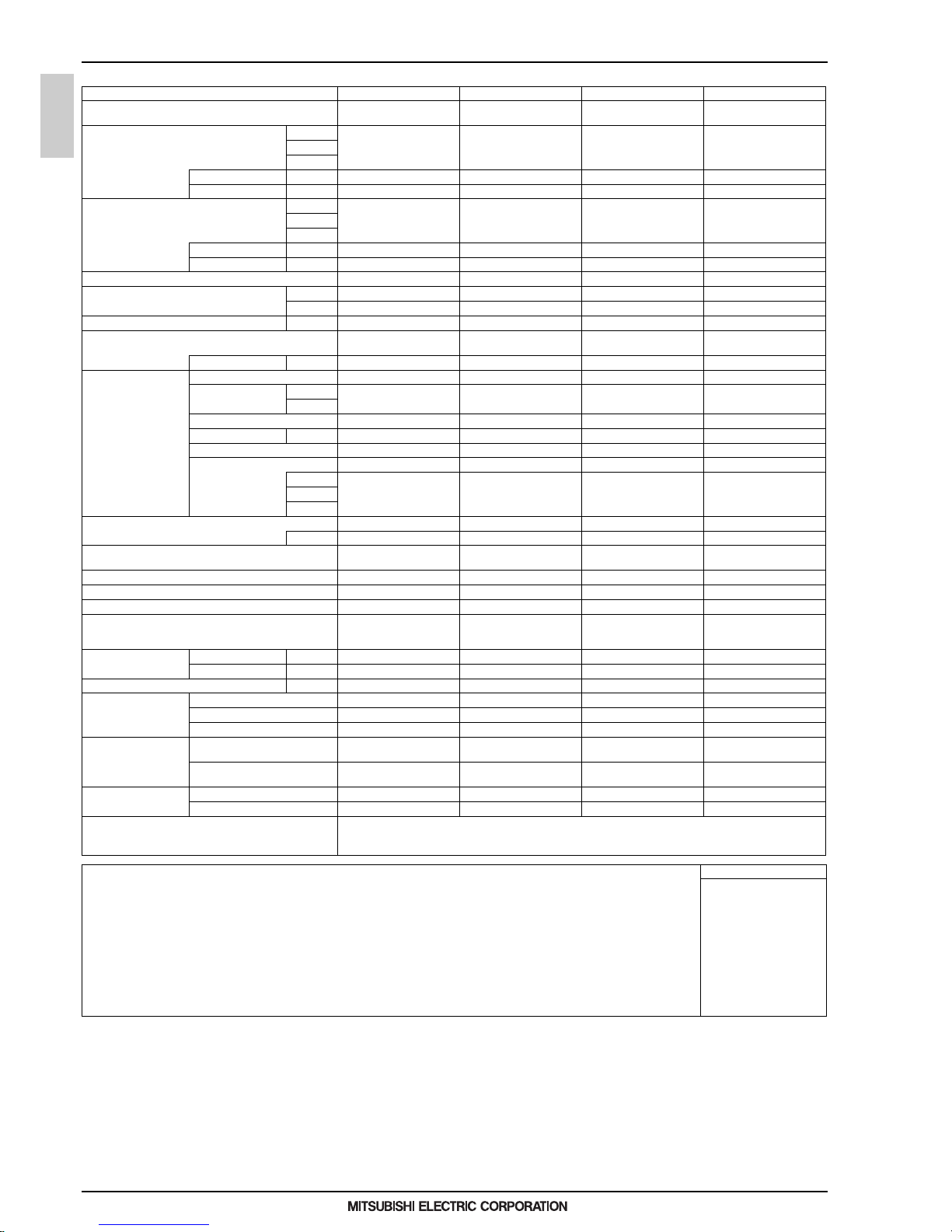
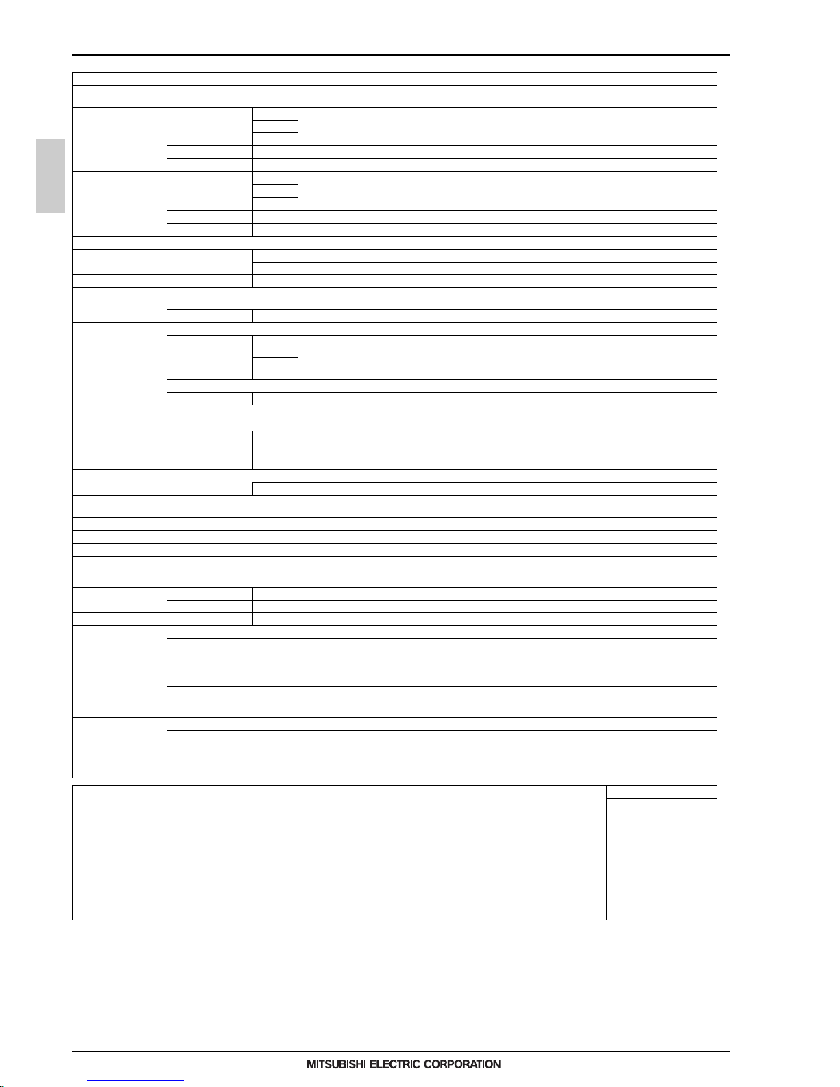
1. SPECIFICATIONS
I.Ceiling concealed (Slim type)1. SPECIFICATIONS
Model PEFY-WP15VMS1-E PEFY-WP20VMS1-E PEFY-WP25VMS1-E PEFY-WP32VMS1-E
Power source
1-phase 220-230-240 V 50/60 Hz1-phase 220-230-240 V 50/60 Hz1-phase 220-230-240 V 50/60 Hz1-phase 220-230-240 V 50/60
Hz
Cooling capacity *1 kW 1.7 2.2 2.8 3.6
(Nominal) *1 kcal/h 1,500 1,900 2,400 3,100
*1 BTU/h 5,800 7,500 9,600 12,300
*2 Power input kW 0.050 0.051 0.060 0.071
*2 Current input A 0.44 0.49 0.51 0.61
Heating capacity *3 kW 1.9 2.5 3.2 4.0
(Nominal) *3 kcal/h 1,600 2,200 2,800 3,400
*3 BTU/h 6,500 8,500 10,900 13,600
*2 Power input kW 0.030 0.031 0.040 0.051
*2 Current input A 0.33 0.38 0.40 0.50
External finish Galvanized steel plate Galvanized steel plate Galvanized steel plate Galvanized steel plate
External dimension H x W x D mm 200 x 790 x 700 200 x 790 x 700 200 x 790 x 700 200 x 990 x 700
in. 7-7/8 x 31-1/8 x 27-9/16 7-7/8 x 31-1/8 x 27-9/16 7-7/8 x 31-1/8 x 27-9/16 7-7/8 x 39 x 27-9/16
Net weight kg (lbs) 19 (42) 20 (45) 20 (45) 25 (56)
Heat exchanger
Cross fin (Aluminum fin and
copper tube)
Cross fin (Aluminum fin and
copper tube)
Cross fin (Aluminum fin and
copper tube)
Cross fin (Aluminum fin and
copper tube)
Water Volume L 0.7 0.9 0. 9 1.0
FAN Type x Quantity Sirocco fan x 2 Sirocco fan x 2 Sirocco fan x 2 Sirocco fan x 3
*4 External static press. Pa <5> - 15 - <35> - <50> <5> - 15 - <35> - <50> <5> - 15 - <35> - <50> <5> - 15 - <35> - <50>
mmH
2
O <0.5> - 1.5 - <3.6> - <5.1> <0.5> - 1.5 - <3.6> - <5.1> <0.5> - 1.5 - <3.6> - <5.1> <0.5> - 1.5 - <3.6> - <5.1>
Motor Type DC motor DC motor DC motor DC motor
Motor output kW 0.096 0.096 0.096 0.096
Driving mechanism Direct-driven by motor Direct-driven by motor Direct-driven by motor Direct-driven by motor
Air flow rate (Low-Mid-High) (Low-Mid-Hig h) (Low-Mid-High) (Low-Mid-High)
m
3
/min 5.0 - 6.0 - 7.0 5.5 - 6.5 - 8.0 5.5 - 7.0 - 9.0 8.0 - 9.0 - 11.0
L/s 83 - 100 - 117 92 - 108 - 133 92 - 117 - 150 133 - 150 - 183
cfm 177 - 212 - 247 194 - 230 - 282 194 - 247 - 318 282 - 318 - 388
Sound pressure level (measured in anechoic room) (Low-Mid-High) (Low-Mid-High) (Low- Mid-High) (Low-Mid-High)
*2 dB <A> 22-24-28 23-25-29 23-26-30 28-30-33
Insulation material
EPS, Polyethylene foam, Ure-
thane foam
EPS, Polyethylene foam, Ure-
thane foam
EPS, Polyethylene foam, Ure-
thane foam
EPS, Polyethylene foam, Ure-
thane foam
Air filter PP honeycomb fabric. PP honeycomb fabric. PP honeycomb fabric. PP honeycomb fabric.
Protection device Fuse Fuse Fuse Fuse
Refrigerant control device - - - -
Connectable outdoor unit/HBC controller
CITY MULTI YLM series/
CMB-WP-V-GA1, CMB-WP-
V-GB1
CITY MULTI YLM series/
CMB-WP-V-GA1, CMB-WP-
V-GB1
CITY MULTI YLM series/
CMB-WP-V-GA1, CMB-WP-
V-GB1
CITY MULTI YLM series/
CMB-WP-V-GA1, CMB-WP-
V-GB1
Water piping diameter Inlet in. Rc 3/4 screw Rc 3/4 screw Rc 3/4 screw Rc 3/4 screw
*5 *6 Outlet in. Rc 3/4 screw Rc 3/4 screw Rc 3/4 screw Rc 3/4 screw
Field drain pipe size mm (in.) O.D.32 (1-1/4) O.D.32 (1-1/4) O.D.32 (1-1/4) O.D.32 (1-1/4)
Drawing External KD94T794X01 KD94T794X01 KD94T794X01 KD94T794X01
Wiring KD94T793X01 KD94T793X01 KD94T793X01 KD94T793X01
Refrigerant cycle - - - -
Standard attachment Document
Installation Manual, Instruc-
tion Book
Installation Manual, Instruc-
tion Book
Installation Manual, Instruc-
tion Book
Installation Manual, Instruc-
tion Book
Accessory
Insulation pipe for water pipe,
Washer, Drain hose, Tie band
Insulation pipe for water pipe,
Washer, Drain hose, Tie b and
Insulation pipe for water pipe,
Washer, Drain hose, Tie ban d
Insulation pipe for water pipe,
Washer, Drain hose, Tie band
Optional parts Control box replace kit PAC-KE70HS-E PAC-KE70HS-E PAC-KE70HS-E PAC-KE70HS-E
Remarks Details on foundation work, duct work, insulation work, electrical wiring, power source switch, and other items shall be referred
to the Installation Manual.
Due to continuing improvement, above specifications may be subject to change without notice.
Notes: Unit converter
1.Nominal cooling conditions
Indoor: 27°CD.B./19°CW.B. (81°FD.B./66°FW.B.), Outdoor: 35°CD.B. (95°FD.B.)
Pipe length: 7.5 m (24-9/16 ft.), Level difference: 0 m (0 ft.)
2.The values are measured at the factory setting of external static pressure.
3.Nominal heating conditions
Indoor: 20°CD.B. (68°FD.B.), Outdoor: 7°CD.B./6°CW.B. (45°FD.B./43°FW.B.)
Pipe length: 7.5 m (24-9/16 ft.), Level difference: 0 m (0 ft.)
4.The factory setting of external static pressure is shown without < >.
Refer to "Fan characteristics curves", according to the external static pressure, in DATA BOOK for the usable
range of air flow rate.
5.Be sure to install a valve on the water outlet.
6.Install a strainer (40 mesh or more) on the pip e next to the valve to remove the foreign matters.
7.Please group units that operate on 1 branch.
kcal/h =kW x 860
BTU/h =kW x 3,412
cfm =m3/min x 35.31
lbs =kg/0.4536
*Above specification data is
subject to rounding variation.
Page 8
1 - 5
PEFY
MEE15K052
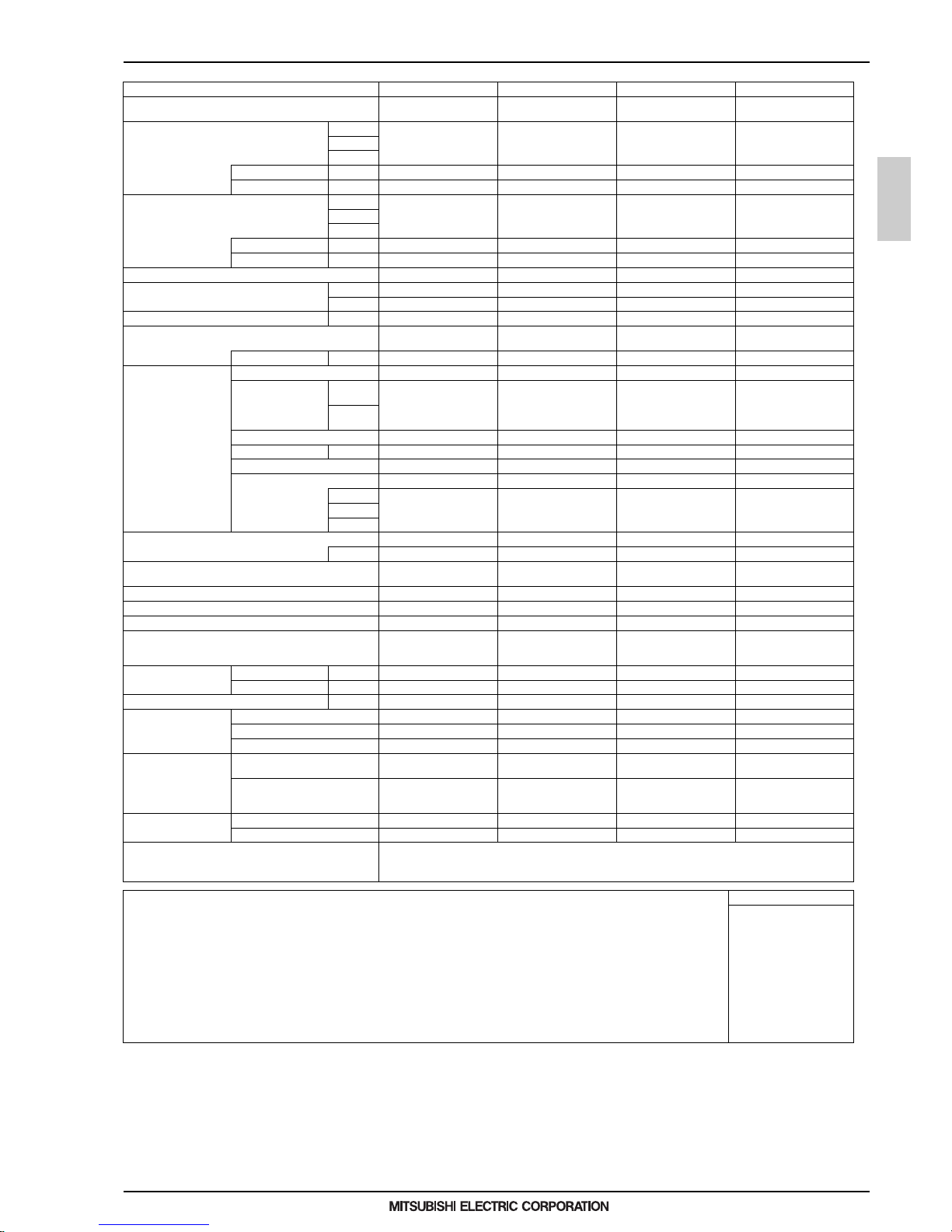
1. SPECIFICATIONS
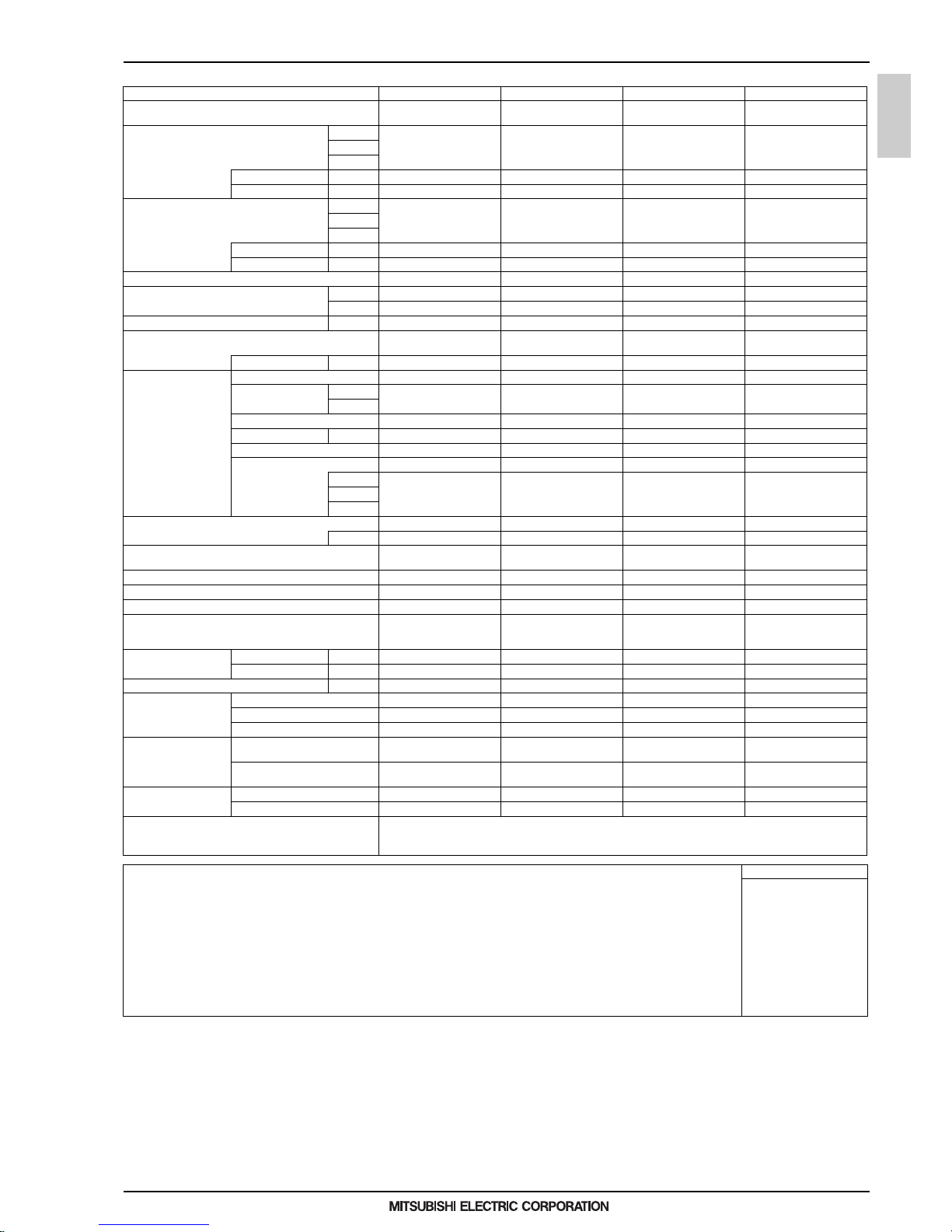
Model PEFY-WP40VMS1-E PEFY-WP50VMS1-E
Power source
1-phase 220-230-240 V 50/60 Hz1-phase 220-230-240 V 50/ 60
Hz
Cooling capacity *1 kW 4.5 5.6
(Nominal) *1 kcal/h 3,900 4,800
*1 BTU/h 15,400 19,100
*2 Power input kW 0.090 0.090
*2 Current input A 0.73 0.77
Heating capacity * 3 kW 5.0 6.3
(Nominal) *3 kcal/h 4,300 5,400
*3 BTU/h 17,100 21,500
*2 Power input kW 0.070 0.070
*2 Current input A 0.62 0.66
External finish Galvanized steel plate Galvanized steel plate
External dimension H x W x D mm 200 x 990 x 700 200 x 1,190 x 700
in. 7-7/8 x 39 x 27-9/16 7-7 /8 x 46-7/8 x 27-9/16
Net weight kg (lbs) 25 (56) 27 (60)
Heat exchanger
Cross fin (Aluminum fin and
copper tube)
Cross fin (Aluminum fin and
copper tube)
Water Volume L 1.0 1.7
FAN Type x Quantity Sirocco fan x 3 Sirocco fan x 4
*4 External static press. Pa <5> - 15 - <35> - <50> <5> - 15 - <35> - <50>
mmH
2
O <0.5> - 1.5 - <3.6> - <5.1> <0.5> - 1.5 - <3.6> - <5.1>
Motor Type DC motor DC motor
Motor output kW 0.096 0.096
Driving mechanism Direct-driven by motor Direct-driven by motor
Air flow rate (Low-Mid-High) (Low-Mi d-High)
m
3
/min 9.5 - 11.0 - 13.0 12.0 - 14.0 - 16.5
L/s 158 - 183 - 217 200 - 233 - 275
cfm 335 - 388 - 459 424 - 494 - 583
Sound pressure level (measured in anechoic room) (Low-Mid-High) (Low-Mid-High)
*2 dB <A> 30-32-35 30-33-36
Insulation material
EPS, Polyethylene foam, Ure-
thane foam
EPS, Polyethylene foam, Ure-
thane foam
Air filter PP honeycomb fabric. PP honeycomb fabric.
Protection device Fuse Fuse
Refrigerant control device - -
Connectable outdoor unit/HBC controlle r
CITY MULTI YLM series/
CMB-WP-V-GA1, CMB-WP-
V-GB1
CITY MULTI YLM series/
CMB-WP-V-GA1, CMB-WP-
V-GB1
Water piping diameter Inlet in. Rc 3/4 screw Rc 3/4 screw
*5 *6 Outlet in. Rc 3/4 screw Rc 3/4 screw
Field drain pipe size mm (in.) O.D.32 (1-1/4) O.D.32 (1-1/4)
Drawing External K D94T794X01 KD94T794X01
Wiring KD94T793X01 KD94T793X01
Refrigerant cycle - -
Standard attachment Document
Installation Manual, Instruc-
tion Book
Installation Manual, Instruc-
tion Book
Accessory
Insulation pipe for water pipe,
Washer, Drain hose, Tie band
Insulation pipe for water pipe,
Washer, Drain hose, Tie band
Optional parts Control box replace kit PAC-KE70HS-E PAC-KE70HS-E
Remarks Details on foundation work, duct work, insulation work, electrical wiring, power source switch, and other items shall be referred
to the Installation Manual.
Due to continuing improvement, ab ove specifications may be subject to change without notice.
Notes: Unit converter
1.Nominal cooling conditions
Indoor: 27°CD.B./19°CW.B. (81°FD.B./66°FW.B.), Outdoor: 35°CD.B. (95°FD.B.)
Pipe length: 7.5 m (24-9/16 ft.), Level difference: 0 m (0 ft.)
2.The values are measured at the factory setting of external static pressure.
3.Nominal heating conditions
Indoor: 20°CD.B. (68°FD.B.), Outdoor: 7°CD.B./6°CW.B. (45°FD.B./43°FW.B.)
Pipe length: 7.5 m (24-9/16 ft.), Level difference: 0 m (0 ft.)
4.The factory setting of external static pressure is shown without < >.
Refer to "Fan characteristics curves", according to the external static pressure, in DATA BOOK for the usable
range of air flow rate.
5.Be sure to install a valve on the water outlet.
6.Install a strainer (40 mesh or more) on the pipe next to the valve to remove the foreign matters.
7.Please group units that operate on 1 branch.
kcal/h =kW x 860
BTU/h =kW x 3,412
cfm =m3/min x 35.31
lbs =kg/0.4536
*Above specification data is
subject to rounding variation.
Page 9
1 - 6
PEFY
MEE15K052
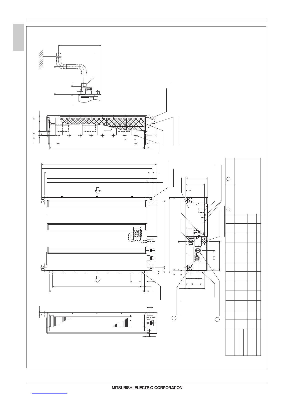
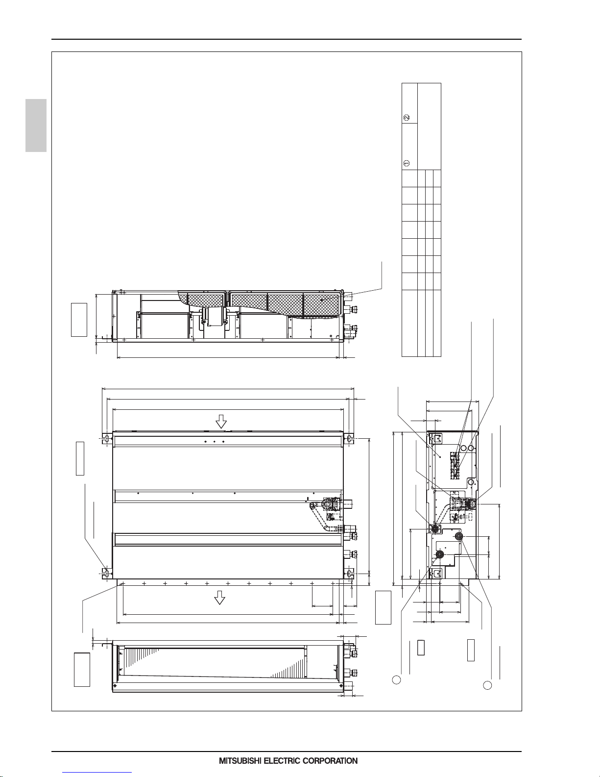
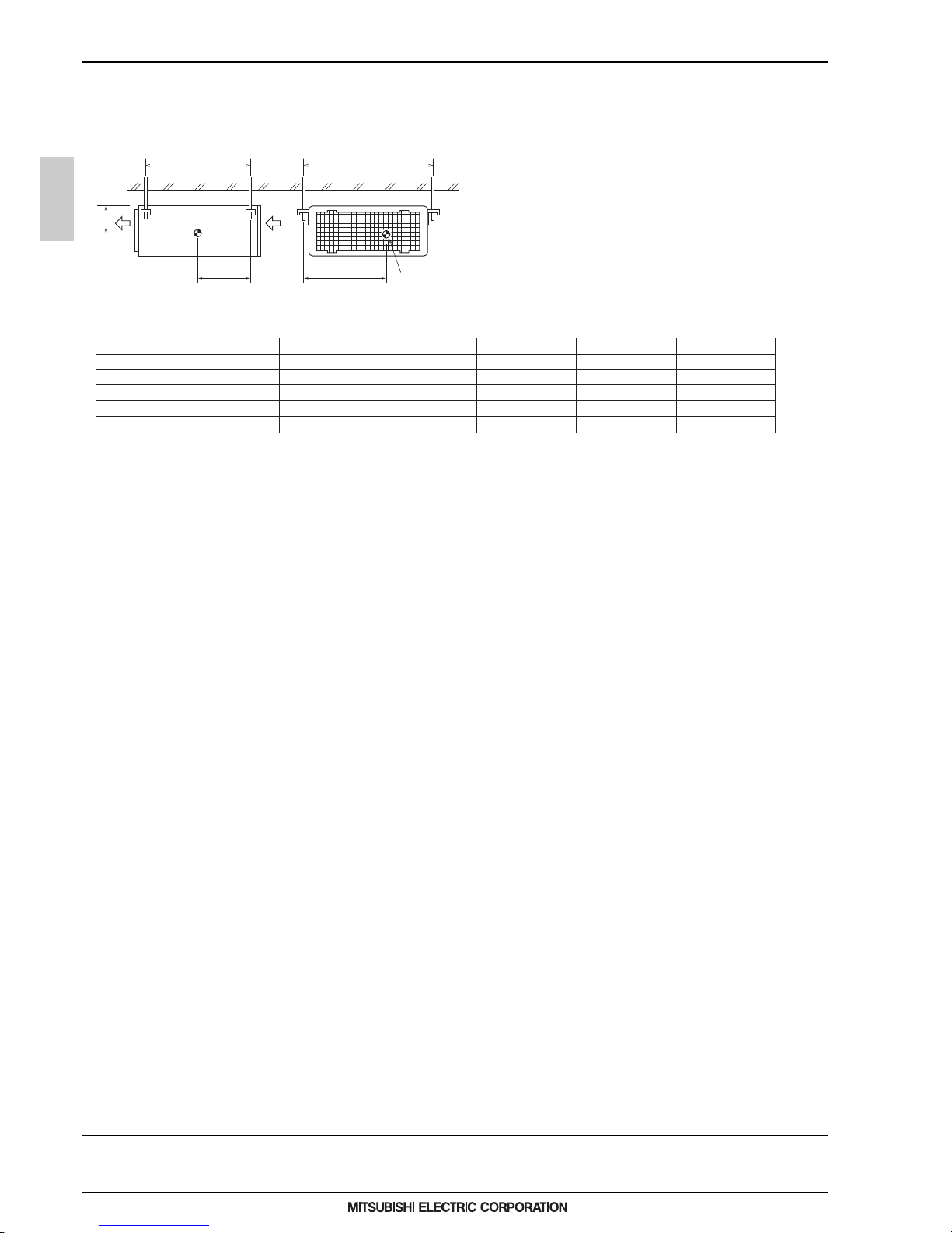
2. EXTERNAL DIMENSIONS
2. EXTERNAL DIMENSIONS
(Actual length)
<accessory>
Drain hose (I.D.ø32)
Less than 300mm
65
0
-10
Less than 550mm
Unit : mm
PEFY-WP15, 20, 25, 32, 40, 50VMS1-E
64
70116
10
102
Note1. Use M10 screw for the suspension bolt (field supply).
2. Keep the service space for the maintenance at the bottom.
3. This chart indicates for PEFY-WP32, 40VMS1-E models, which has 3 fans.
PEFY-WP15, 20, 25VMS1-E models have 2 fans.
PEFY-WP50VMS1-E models have 4 fans.
4. In case an inlet duct is used, remove the air filter (supply with
the unit), then install the filter (field supply) at suction side.
Water pipe(To HBC unit)
Rc3/4 screw
Rc3/4 screw
Water pipe(From HBC unit)
Air
outlet
Air
inlet
(O.D.
ø
32)
Drain pipe
Drain pump
Terminal bed(Transmission)
Drain pipe(O.D.
ø
32)
(Spontaneous draining)
1
2
Terminal bed(Power source)
Suspension bolt hole
4-14×30 Slot
Air filter
Control box
2
×
E-
ø
2.9
2
×
2-
ø
2.9
K-
ø
2.9
Knockout hole
ø
27
Knockout hole
ø
27
(Power source wiring)
(Transmission wiring)
PEFY-WP50VMS1-E
PEFY-WP40VMS1-E
PEFY-WP32VMS1-E
PEFY-WP25VMS1-E
PEFY-WP20VMS1-E
119 0
990
790
1239
1039
839
M
24
20
16
900
700
500
9
7
5
1060
860
660
LJHK
700 752 798 660 7 600
Rc3/4 screw
(To HBC unit)
(From HBC unit)
119 8
998
A
Model
PEFY-WP15VMS1-E
115 2
952
B
110 0
900
C
1060
860
D
11
9
E
1000
800
FG
57
15
700
150(Duct)
200
23
677
23
90
20
C
D (Duct)
A
M
L
49
625(Suspension bolt pitch)
23
B (Suspension bolt pitch)
270
48
270
170
10
100
100
×
(E-1)=F
30
25
100
25
20
100
100
×
H=J
12
88
37
100 37
88
12
157.5
20
G
10
Water pipe
1
Watetr pipe
2
To
HBC Unit
From
HBC Unit
Page 10
1 - 7
PEFY
MEE15K052
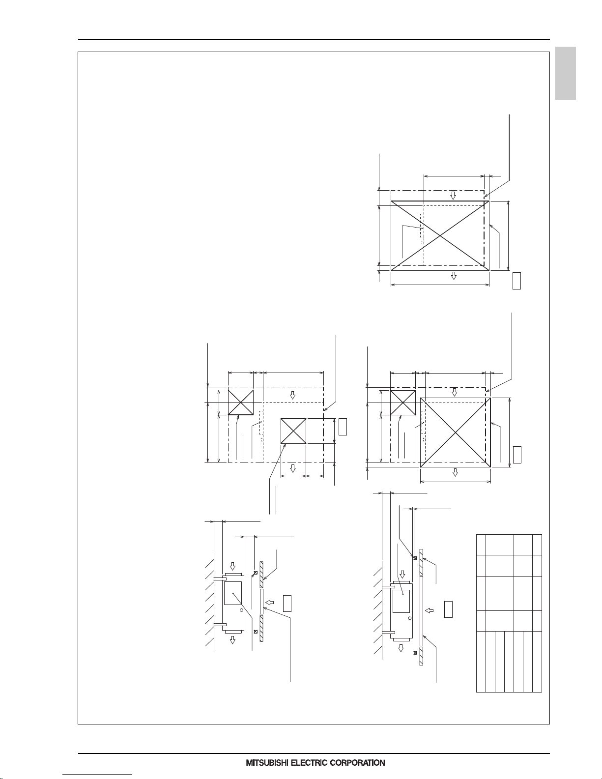
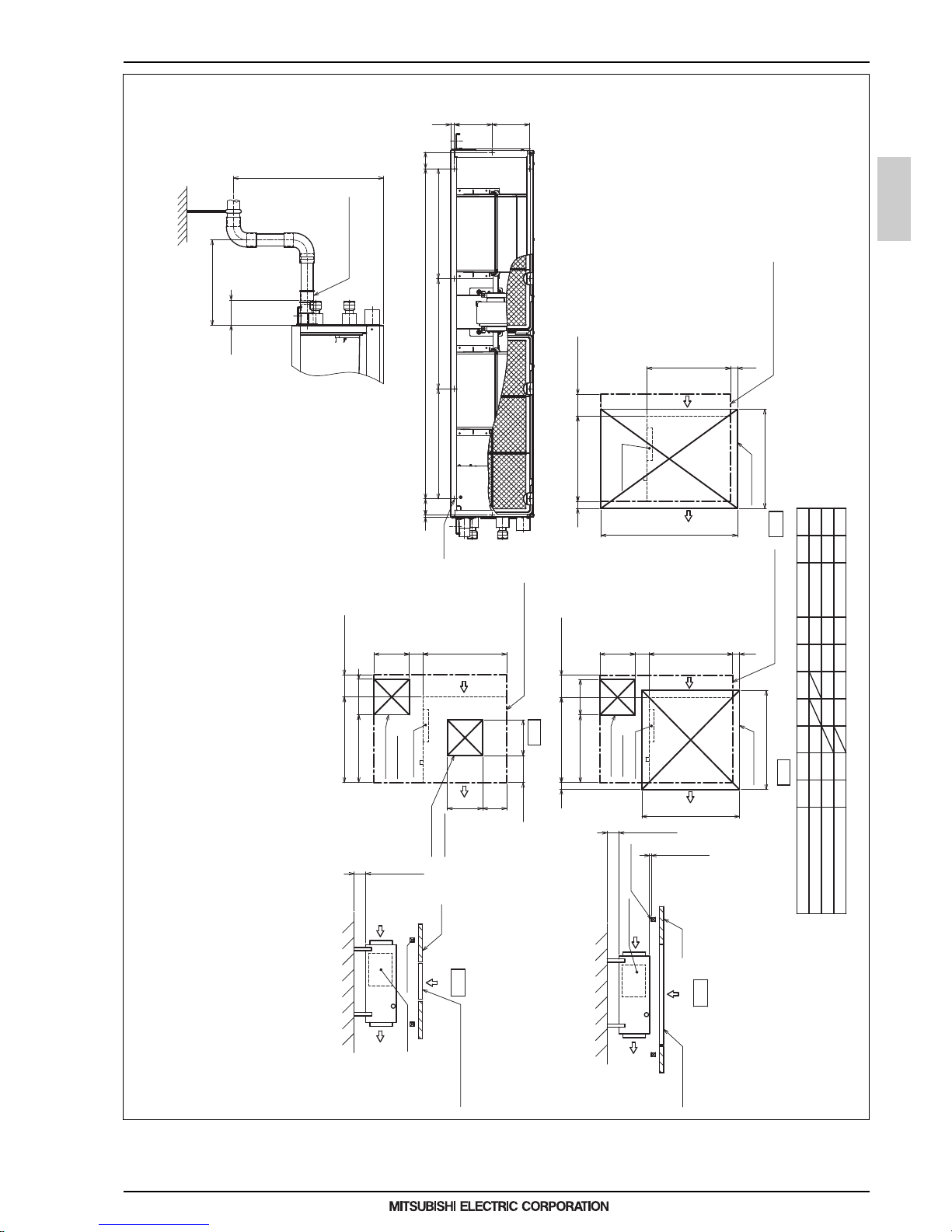
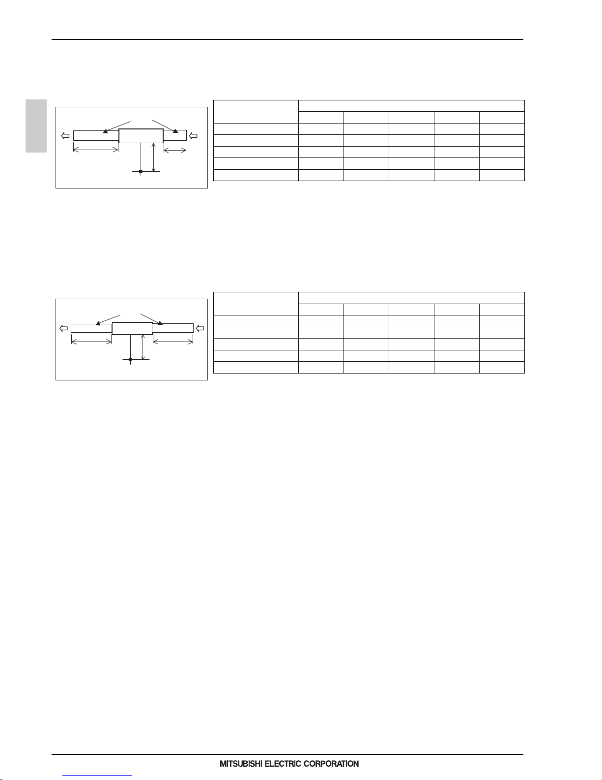
2. EXTERNAL DIMENSIONS
Unit : mm
PEFY-WP15, 20, 25, 32, 40, 50VMS1-E
Min.300mm
Access door 1
(450×450)
Access door 3
Electric box
Intake air
Access door 1
(450×450)
Ceiling beam
Access door 2 (450×450)
Electric box
Supply air
Supply air Intake air
Maintenance access space
Maintenance access space
Maintenance access space
Electric box
Access door 4
(Viewed from the direction
of the arrow B)
Access door 3
Electric box
Bottom of
indoor unit
(Viewed from the direction of the arrow B)
B
Ceiling beam
Ceiling
(Viewed from the direction of the arrow A)
Access door 2
(450×450)
Ceiling
A
Bottom of indoor unit
100~200
100~200
Electric box
Min.10mm
450
450
450
50~150
P
700
700
Min.300mm
N
50
50
R
777
777
50
Q
50
475
N
450
Min.20mm
Min.300mm
N
450
475
700
450
Min.300mm
Min.10mm
Fig.3
Fig.4
Fig.5
Fig.2
Fig.1
Bottom of
indoor unit
[Maintenance access space]
Secure enough access space to allow for the maintenance, inspection, and replacement of the motor, fan, drain pump, heat exchanger,
and electric box in one of the following ways.
Select an installation site for the indoor unit so that its maintenance access space will not be obstructed by beams or other objects.
(1) When a space of 300mm or more is available below the unit between the unit and the ceiling. (Fig.1)
·
Create access door 1 and 2 (450x450mm each) as shown in Fig.2.
(Access door 2 is not required if enough space is available below the unit for a maintenance worker to work in.)
(2) When a space of less than 300mm is available below the unit between the unit and the ceiling.
(At least 20mm of space should be left below the unit as shown in Fig.3.)
·
Create access door 1 diagonally below the electric box and access door 3 below the unit as shown in Fig.4.
or
PEFY-WP15VMS1-E
PEFY-WP20VMS1-E
PEFY-WP25VMS1-E
PEFY-WP32VMS1-E
PEFY-WP40VMS1-E
PEFY-WP50VMS1-E
700
N
Model
110 0
900
150~250
250~350
P
50~150
800
Q
1200
1000
R
1700
1500
1300
·
Create access door 4 below the electric box and the unit as shown in Fig.5.
Page 11
1 - 8
PEFY
MEE15K052
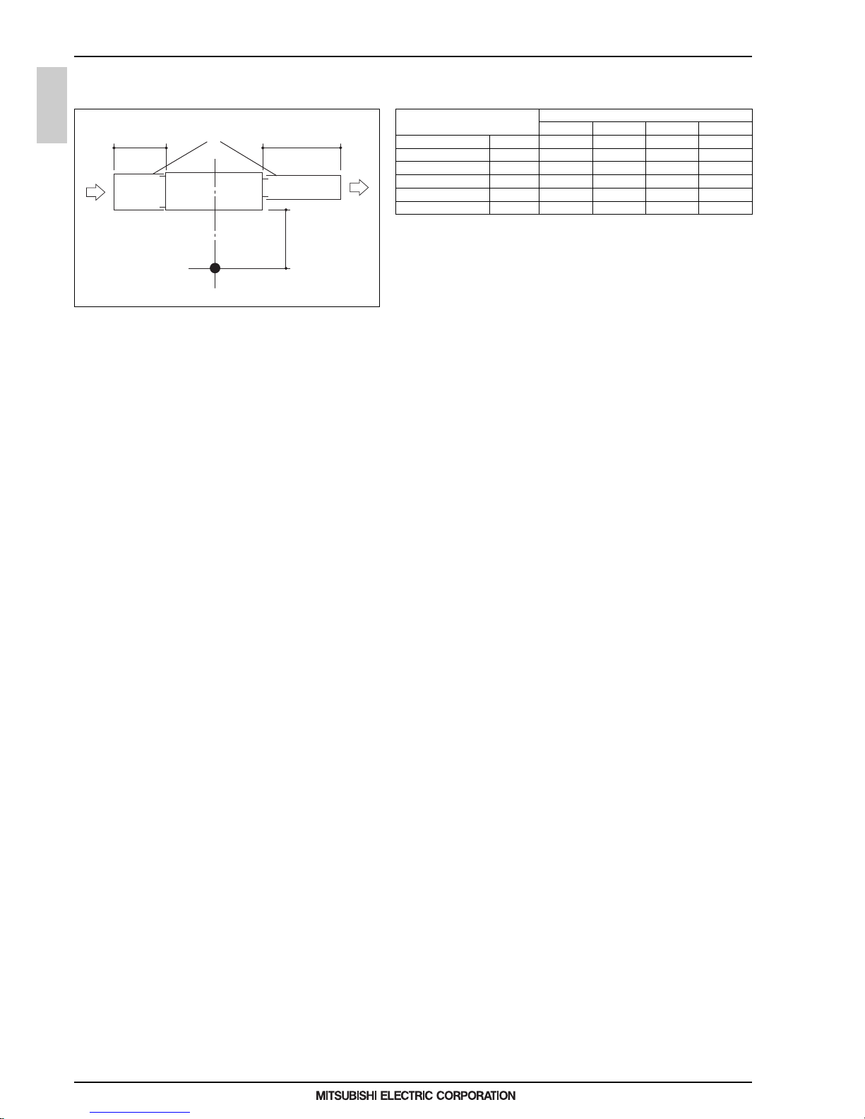
3. CENTER OF GRAVITY
3. CENTER OF GRAVITY
Model name
PEFY-WP15VMS1-E
PEFY-WP50VMS1-E
PEFY-WP40VMS1-E
PEFY-WP32VMS1-E
PEFY-WP25VMS1-E
PEFY-WP20VMS1-E
W
625 [24-5/8]
625 [24-5/8]
625 [24-5/8]
625 [24-5/8]
625 [24-5/8]
L
752 [29-5/8]
752 [29-5/8]
952 [37-1/2]
952 [37-1/2]
1152 [45-3/8]
X
263 [10-3/8]
263 [10-3/8]
280 [11-1/32]
280 [11-1/32]
285 [11-1/4]
Y
338 [13-5/16]
338 [13-5/16]
422 [16-5/8]
422 [16-5/8]
511 [20-1/8]
Z
105 [4-5/32]
625 [24-5/8] 752 [29-5/8] 263 [10-3/8] 338 [13-5/16] 105 [4-5/32]
105 [4-5/32]
104 [4-1/8]
104 [4-1/8]
104 [4-1/8]
A: Center of gravity
YX
L
W
A
Z
PEFY-WP15, 20, 25, 32, 40, 50VMS1-E
(mm)[in]
Page 12
1 - 9
PEFY
MEE15K052
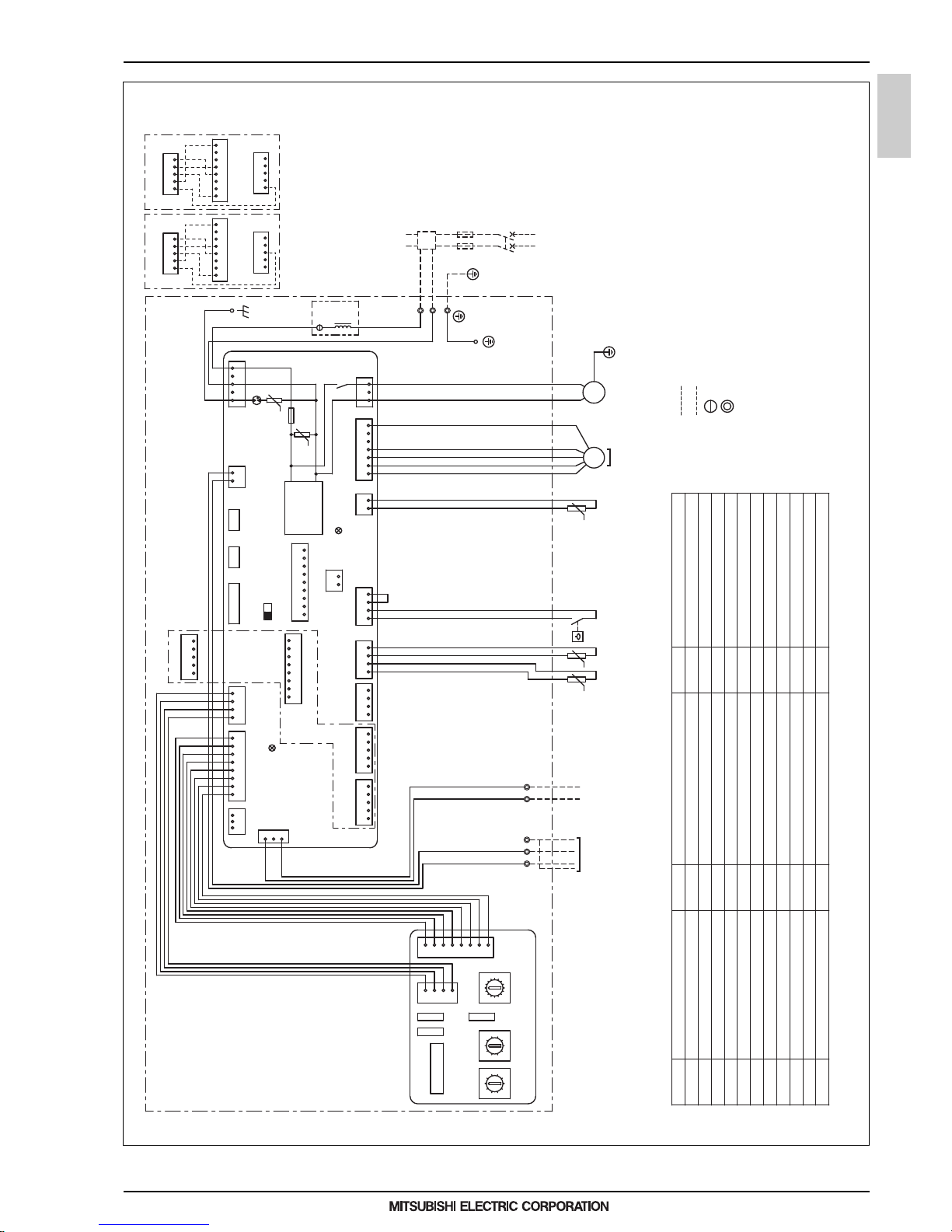
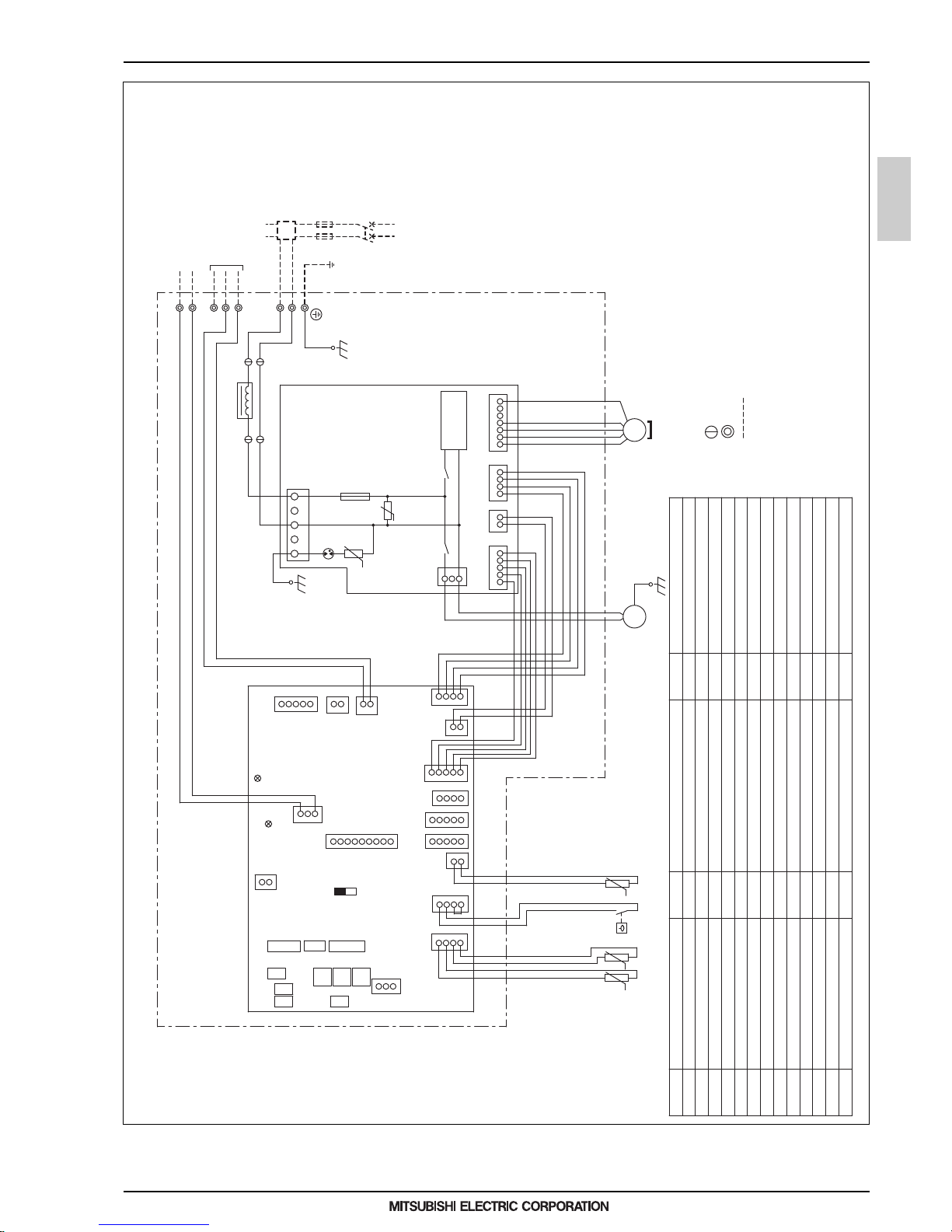
4. ELECTRICAL WIRING DIAGRAMS
4. ELECTRICAL WIRING DIAGRAMS
NOTE: Symbols used in wiring diagram above are,
(HEAVY DOTTED LINE):FIELD WIRING
(THIN DOTTED LINE) :OPTIONAL PARTS
: CONNECTOR
: TERMINAL
Connector (IT terminal)
CN100
Switch (for mode selection)
SW3(I.B.)
Switch (for model selection)
Connector (emergency operation)
Switch (for mode selection)
Switch (10ths digit address set)
Switch (connection No.set)
Switch (for static pressure selection)
Switch (for model selection)
Switch (for static pressure selection)
Switch (for capacity code)
Thermistor (piping temp.detection/water out)
Thermistor (piping temp.detection/water in)
SWB(A.B.)
AC reactor (Power factor improvement)
L1
SWA(A.B.)
SWC(A.B.)
Drainpump
Connector (Wireless)
X1
Aux. relay
Arrester
DSA
Varistor
ZNR01, 02
Fuse AC250V 6.3A
FUSE
Fan motor
SWE(I.B.)
Float switch
FS
Connector (Remote indication)
Connector (Centrally control)
CN90
Connector (Remote switch)
Connector (Damper)
CN32
CN52
CN51
CN41
Transmission terminal block
TB15
TH21
Thermistor (inlet air temp.detection)
TH23
TH22
NAME SYMBOL SYMBOL
I.B.
A.B.
Indoor controller board
Address board
Switch (1s digit address set)
SW2(I.B.)
SW11(A.B.)
SW12(A.B.)
SW14(A.B.)
SW1(A.B.)
SW4(I.B.)
TB2
TB5
Transmission terminal block
Power source terminal block
SYMBOL EXPLANATION
NAME
CN27
Connector (HA terminal-A)
SYMBOL NAME
*A
In connecting optional IT terminal,
use either CN51 or CN52 which is
not connected.
Be careful for connector colors.
*A
L1: only PEFY-WP50VMS1-E
INSIDE SECTION OF CONTROL BOX
TO MA REMOTE
CONTROLLER
TO OUTDOOR UNIT
BC CONTROLLER
REMOTE CONTROLLER
SW14
(Connection No.)
SWBSWA
SWC
SW12
(10ths digit)
SW11
(1s digit)
SW1
A. B.
I. B.
31
12345
54185418
12345
8145
34512
MS
3~
8765432
1
432
1
1~
M
4231 1324
12 14567
3
1
135
12
132481324567
13
0
1
2
3
4
5
6
7
8
9
A
B
C
D
E
F
0
1
2
3
4
5
6
7
8
9
0
1
2
3
4
5
6
7
8
9
IT terminal
(PAC-IT51AD-E)
IT terminal
(PAC-IT52AD-E)
CN52
(Green)
CN100
CN51
CN100
CN100
IT terminal
CN82
CN43
L1
t° t°
U
LED1
LED2
DC310~340V
Rectify circuit
ZNR01
POWER SUPPLY
~220, 230, 240V
50, 60Hz
TO NEXT INDOOR UNIT
FUSE (16A)
PULL BOX
BREAKER (16A)
FUSE
X1
ZNR02
DSA
U
t°
(Green)
(Blue)
(Red)
(Red)
(Red)
(Red)
(Blue)
(Blue)
(Black)
TB5
N
L
TB15
12
S(SHIELD)
M2
TB2
M1
FSTH22 TH23
TH21
CN3A
CNMF
CNP
CND
CN2M
SW2SW4SW3
CN90
CN42CN81CN32
CN27
CN20
CN4FCN44CN41CN52 CN51
SWE
ON
OFF
PEFY-WP15, 20, 25, 32, 40, 50VMS1-E
Page 13
1 - 10
PEFY
MEE15K052
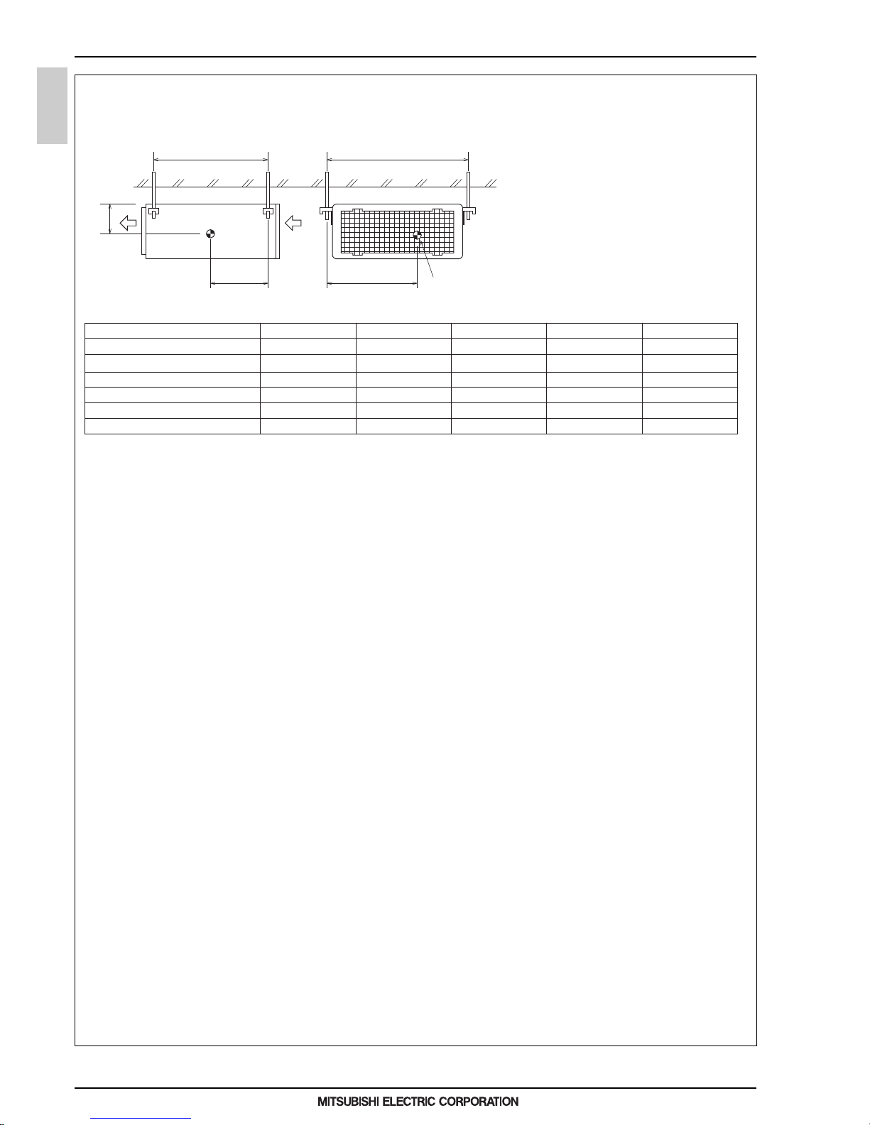
5. SOUND LEVELS
5. SOUND LEVELS
5-1. Sound levels
PEFY-WP-VMS1-E Sound level at anechoic room : Low-Mid-High
Sound level dB ( A )
5Pa 15Pa 35Pa 50Pa
PEFY-WP15VMS1-E 220-240V 22 - 24 - 26 22 - 24 - 28 23 - 26 - 29 23 - 27 - 30
PEFY-WP20VMS1-E 220-240V 22 - 25 - 28 23 - 25 - 29 24 - 27 - 30 25 - 28 - 32
PEFY-WP25VMS1-E 220-240V 22 - 25 - 29 23 - 26 - 30 24 - 28 - 31 25 - 29 - 33
PEFY-WP32VMS1-E 220-240V 26 - 28 - 30 28 - 30 - 33 30 - 32- 35 31 - 33 - 36
PEFY-WP40VMS1-E 220-240V 29 - 31 - 34 30 - 32 - 35 31 - 34 - 37 32 - 34 - 38
PEFY-WP50VMS1-E 220-240V 29 - 32 - 35 30 - 33 - 36 31 - 35 - 39 32 - 36 - 40
* Measured in anechoic room.
Aux.duct
1m
1.5m
Measurement location
2m
Page 14
1 - 11
PEFY
MEE15K052
5. SOUND LEVELS
5-2. NC curves
PEFY-WP15VMS1-E
External static pressure : 5Pa
Power source : 220,230,240V, 50/60Hz
PEFY-WP15VMS1-E
External static pressure : 15Pa
Power source : 220,230,240V, 50/60Hz
PEFY-WP15VMS1-E
External static pressure : 35Pa
Power source : 220,230,240V, 50/60Hz
PEFY-WP15VMS1-E
External static pressure : 50Pa
Power source : 220,230,240V, 50/60Hz
PEFY-WP20VMS1-E
External static pressure : 5Pa
Power source : 220,230,240V, 50/60Hz
PEFY-WP20VMS1-E
External static pressure : 15Pa
Power source : 220,230,240V, 50/60Hz
PEFY-WP20VMS1-E
External static pressure : 35Pa
Power source : 220,230,240V, 50/60Hz
PEFY-WP20VMS1-E
External static pressure : 50Pa
Power source : 220,230,240V, 50/60Hz
PEFY-WP25VMS1-E
External static pressure : 5Pa
Power source : 220,230,240V, 50/60Hz
PEFY-WP25VMS1-E
External static pressure : 15Pa
Power source : 220,230,240V, 50/60Hz
PEFY-WP25VMS1-E
External static pressure : 35Pa
Power source : 220,230,240V, 50/60Hz
PEFY-WP25VMS1-E
External static pressure : 50Pa
Power source : 220,230,240V, 50/60Hz
Approximate minimum
audible limit on
continuous noise
70
60
50
40
30
20
63 125 250 500 1000 2000 4000 8000
10
0
NC60
NC50
NC40
NC30
NC20
Approximate minimum
audible limit on
continuous noise
OCTAVE BAND PRESSURE LEVEL (dB) 0dB = 20µPa
OCTAVE BAND CENTER FREQUENCIES (Hz)
High speed
Low speed
Middle speed
NC20
Approximate minimum
audible limit on
continuous noise
70
60
50
40
30
20
63 125 250 500 1000 2000 4000 8000
10
0
NC60
NC50
NC40
NC30
Approximate minimum
audible limit on
continuous noise
OCTAVE BAND PRESSURE LEVEL (dB) 0dB = 20µPa
OCTAVE BAND CENTER FREQUENCIES (Hz)
High speed
Low speed
Middle speed
Approximate minimum
audible limit on
continuous noise
70
60
50
40
30
20
63 125 250 500 1000 2000 4000 8000
10
0
NC60
NC50
NC40
NC30
NC20
Approximate minimum
audible limit on
continuous noise
OCTAVE BAND PRESSURE LEVEL (dB) 0dB = 20µPa
OCTAVE BAND CENTER FREQUENCIES (Hz)
High speed
Low speed
Middle speed
NC20
Approximate minimum
audible limit on
continuous noise
70
60
50
40
30
20
63 125 250 500 1000 2000 4000 8000
10
0
NC60
NC50
NC40
NC30
Approximate minimum
audible limit on
continuous noise
OCTAVE BAND PRESSURE LEVEL (dB) 0dB = 20µPa
OCTAVE BAND CENTER FREQUENCIES (Hz)
High speed
Low speed
Middle speed
Approximate minimum
audible limit on
continuous noise
70
60
50
40
30
20
63 125 250 500 1000 2000 4000 8000
10
0
NC60
NC50
NC40
NC30
NC20
Approximate minimum
audible limit on
continuous noise
OCTAVE BAND PRESSURE LEVEL (dB) 0dB = 20µPa
OCTAVE BAND CENTER FREQUENCIES (Hz)
High speed
Low speed
Middle speed
NC20
Approximate minimum
audible limit on
continuous noise
70
60
50
40
30
20
63 125 250 500 1000 2000 4000 8000
10
0
NC60
NC50
NC40
NC30
Approximate minimum
audible limit on
continuous noise
OCTAVE BAND PRESSURE LEVEL (dB) 0dB = 20µPa
OCTAVE BAND CENTER FREQUENCIES (Hz)
High speed
Low speed
Middle speed
Approximate minimum
audible limit on
continuous noise
70
60
50
40
30
20
63 125 250 500 1000 2000 4000 8000
10
0
NC60
NC50
NC40
NC30
NC20
Approximate minimum
audible limit on
continuous noise
OCTAVE BAND PRESSURE LEVEL (dB) 0dB = 20µPa
OCTAVE BAND CENTER FREQUENCIES (Hz)
High speed
Low speed
Middle speed
NC20
Approximate minimum
audible limit on
continuous noise
70
60
50
40
30
20
63 125 250 500 1000 2000 4000 8000
10
0
NC60
NC50
NC40
NC30
Approximate minimum
audible limit on
continuous noise
OCTAVE BAND PRESSURE LEVEL (dB) 0dB = 20µPa
OCTAVE BAND CENTER FREQUENCIES (Hz)
High speed
Low speed
Middle speed
Page 15
1 - 12
PEFY
MEE15K052
5. SOUND LEVELS
PEFY-WP32VMS1-E
External static pressure : 5Pa
Power source : 220,230,240V, 50/60Hz
PEFY-WP32VMS1-E
External static pressure : 15Pa
Power source : 220,230,240V, 50/60Hz
PEFY-WP32VMS1-E
External static pressure : 35Pa
Power source : 220,230,240V, 50/60Hz
PEFY-WP32VMS1-E
External static pressure : 50Pa
Power source : 220,230,240V, 50/60Hz
PEFY-WP40VMS1-E
External static pressure : 5Pa
Power source : 220,230,240V, 50/60Hz
PEFY-WP40VMS1-E
External static pressure : 15Pa
Power source : 220,230,240V, 50/60Hz
PEFY-WP40VMS1-E
External static pressure : 35Pa
Power source : 220,230,240V, 50/60Hz
PEFY-WP40VMS1-E
External static pressure : 50Pa
Power source : 220,230,240V, 50/60Hz
PEFY-WP50VMS1-E
External static pressure : 5Pa
Power source : 220,230,240V, 50/60Hz
PEFY-WP50VMS1-E
External static pressure : 15Pa
Power source : 220,230,240V, 50/60Hz
PEFY-WP50VMS1-E
External static pressure : 35Pa
Power source : 220,230,240V, 50/60Hz
PEFY-WP50VMS1-E
External static pressure : 50Pa
Power source : 220,230,240V, 50/60Hz
NC20
Approximate minimum
audible limit on
continuous noise
70
60
50
40
30
20
63 125 250 500 1000 2000 4000 8000
10
0
NC60
NC50
NC40
NC30
Approximate minimum
audible limit on
continuous noise
OCTAVE BAND PRESSURE LEVEL (dB) 0dB = 20µPa
OCTAVE BAND CENTER FREQUENCIES (Hz)
High speed
Low speed
Middle speed
Approximate minimum
audible limit on
continuous noise
70
60
50
40
30
20
63 125 250 500 1000 2000 4000 8000
10
0
NC60
NC50
NC40
NC30
NC20
Approximate minimum
audible limit on
continuous noise
OCTAVE BAND PRESSURE LEVEL (dB) 0dB = 20µPa
OCTAVE BAND CENTER FREQUENCIES (Hz)
High speed
Low speed
Middle speed
NC20
Approximate minimum
audible limit on
continuous noise
70
60
50
40
30
20
63 125 250 500 1000 2000 4000 8000
10
0
NC60
NC50
NC40
NC30
Approximate minimum
audible limit on
continuous noise
OCTAVE BAND PRESSURE LEVEL (dB) 0dB = 20µPa
OCTAVE BAND CENTER FREQUENCIES (Hz)
High speed
Low speed
Middle speed
Approximate minimum
audible limit on
continuous noise
70
60
50
40
30
20
63 125 250 500 1000 2000 4000 8000
10
0
NC60
NC50
NC40
NC30
NC20
Approximate minimum
audible limit on
continuous noise
OCTAVE BAND PRESSURE LEVEL (dB) 0dB = 20µPa
OCTAVE BAND CENTER FREQUENCIES (Hz)
High speed
Low speed
Middle speed
NC20
Approximate minimum
audible limit on
continuous noise
70
60
50
40
30
20
63 125 250 500 1000 2000 4000 8000
10
0
NC60
NC50
NC40
NC30
Approximate minimum
audible limit on
continuous noise
OCTAVE BAND PRESSURE LEVEL (dB) 0dB = 20µPa
OCTAVE BAND CENTER FREQUENCIES (Hz)
High speed
Low speed
Middle speed
Approximate minimum
audible limit on
continuous noise
70
60
50
40
30
20
63 125 250 500 1000 2000 4000 8000
10
0
NC60
NC50
NC40
NC30
NC20
Approximate minimum
audible limit on
continuous noise
OCTAVE BAND PRESSURE LEVEL (dB) 0dB = 20µPa
OCTAVE BAND CENTER FREQUENCIES (Hz)
High speed
Low speed
Middle speed
NC20
Approximate minimum
audible limit on
continuous noise
70
60
50
40
30
20
63 125 250 500 1000 2000 4000 8000
10
0
NC60
NC50
NC40
NC30
Approximate minimum
audible limit on
continuous noise
OCTAVE BAND PRESSURE LEVEL (dB) 0dB = 20µPa
OCTAVE BAND CENTER FREQUENCIES (Hz)
High speed
Low speed
Middle speed
Approximate minimum
audible limit on
continuous noise
70
60
50
40
30
20
63 125 250 500 1000 2000 4000 8000
10
0
NC60
NC50
NC40
NC30
NC20
Approximate minimum
audible limit on
continuous noise
OCTAVE BAND PRESSURE LEVEL (dB) 0dB = 20µPa
OCTAVE BAND CENTER FREQUENCIES (Hz)
High speed
Low speed
Middle speed
NC20
Approximate minimum
audible limit on
continuous noise
70
60
50
40
30
20
63 125 250 500 1000 2000 4000 8000
10
0
NC60
NC50
NC40
NC30
Approximate minimum
audible limit on
continuous noise
OCTAVE BAND PRESSURE LEVEL (dB) 0dB = 20µPa
OCTAVE BAND CENTER FREQUENCIES (Hz)
High speed
Low speed
Middle speed
Page 16
1 - 13
PEFY
MEE15K052
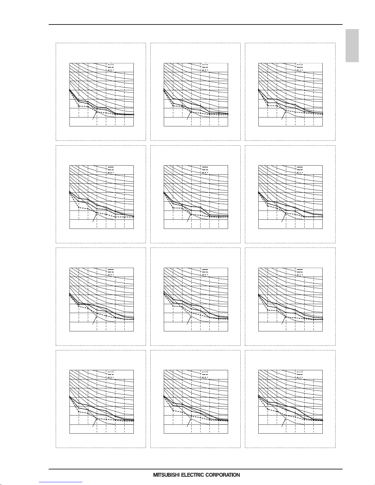
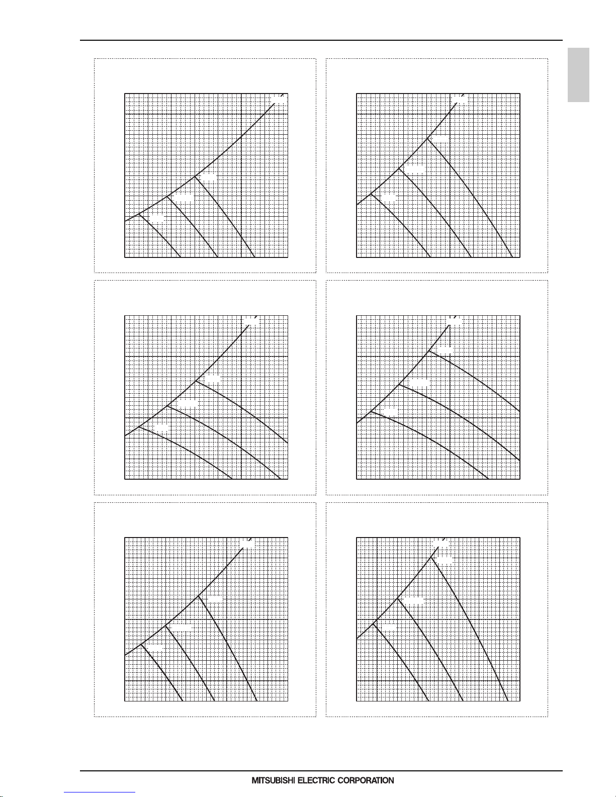
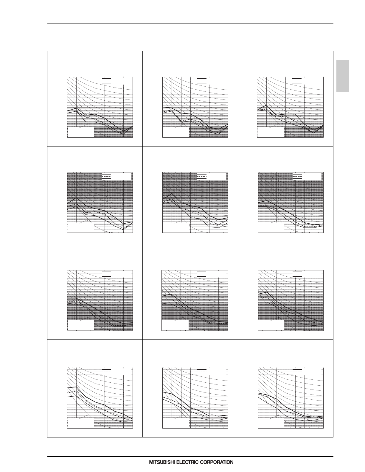
6. FAN CHARACTERISTICS CURVES
6. FAN CHARACTERISTICS CURVES
PEFY-WP15VMS1-E
External static pressure : 15Pa
Power source : 220,230,240V, 50/60Hz
Suction : Back inlet
PEFY-WP15VMS1-E
External static pressure : 5Pa
Power source : 220,230,240V, 50/60Hz
Suction : Back inlet
PEFY-WP15VMS1-E
External static pressure : 50Pa
Power source : 220,230,240V, 50/60Hz
Suction : Back inlet
PEFY-WP15VMS1-E
External static pressure : 35Pa
Power source : 220,230,240V, 50/60Hz
Suction : Back inlet
PEFY-WP20VMS1-E
External static pressure : 15Pa
Power source : 220,230,240V, 50/60Hz
Suction : Back inlet
PEFY-WP20VMS1-E
External static pressure : 5Pa
Power source : 220,230,240V, 50/60Hz
Suction : Back inlet
Airflow rate (m3/min)
Static pressure (Pa)
Airflow rate (m3/min)
Static pressure (Pa)
Airflow rate (m3/min)
Static pressure (Pa)
Airflow rate (m3/min)
Static pressure (Pa)
Airflow rate (m3/min)
Static pressure (Pa)
Airflow rate (m3/min)
Static pressure (Pa)
0
5
10
15
20
25
30
35
40
456789
0
5
10
15
20
25
30
35
40
456789
456789
0
10
20
30
40
50
60
70
80
456789
0
10
20
30
40
50
60
70
80
0
5
10
15
20
25
30
35
40
456789
0
5
10
15
20
25
30
35
40
456789
High
Limit
Limit
Low
Middle
High
Low
Middle
High
Limit
Low
Middle
High
Limit
Low
Middle
High
Limit
Limit
Low
Middle
High
Low
Middle
Page 17
1 - 14
PEFY
MEE15K052
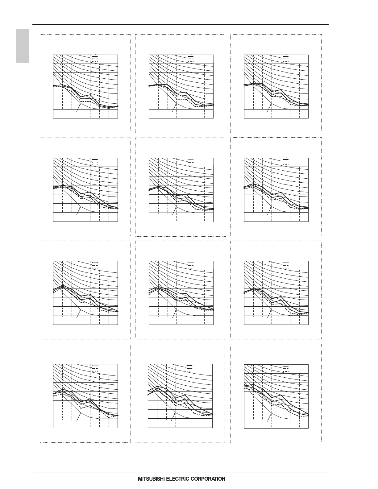
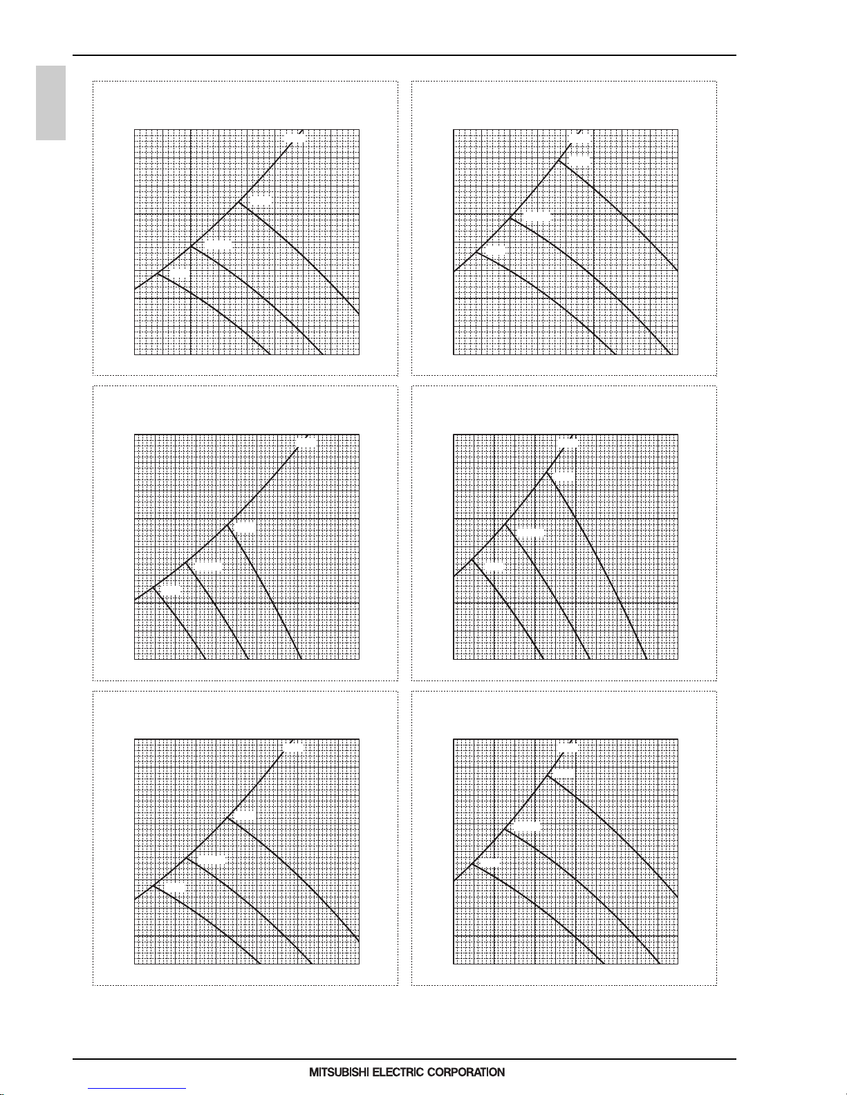
6. FAN CHARACTERISTICS CURVES
PEFY-WP20VMS1-E
External static pressure : 50Pa
Power source : 220,230,240V, 50/60Hz
Suction : Back inlet
PEFY-WP20VMS1-E
External static pressure : 35Pa
Power source : 220,230,240V, 50/60Hz
Suction : Back inlet
PEFY-WP25VMS1-E
External static pressure : 5Pa
Power source : 220,230,240V, 50/60Hz
Suction : Back inlet
PEFY-WP25VMS1-E
External static pressure : 15Pa
Power source : 220,230,240V, 50/60Hz
Suction : Back inlet
PEFY-WP25VMS1-E
External static pressure : 35Pa
Power source : 220,230,240V, 50/60Hz
Suction : Back inlet
PEFY-WP25VMS1-E
External static pressure : 50Pa
Power source : 220,230,240V, 50/60Hz
Suction : Back inlet
Airflow rate (m3/min)
Static pressure (Pa)
Airflow rate (m3/min)
Static pressure (Pa)
Airflow rate (m3/min)
Static pressure (Pa)
Airflow rate (m3/min)
Static pressure (Pa)
Airflow rate (m3/min)
Static pressure (Pa)
Airflow rate (m3/min)
Static pressure (Pa)
456789
0
10
20
30
40
50
60
70
80
456789
0
10
20
30
40
50
60
70
80
0
5
10
15
20
25
30
35
40
4 5678 910
0
5
10
15
20
25
30
35
40
45678910
45678910
0
10
20
30
40
50
60
70
80
45678910
0
10
20
30
40
50
60
70
80
High
Limit
Low
Middle
High
Limit
Low
Middle
High
Limit
Low
Middle
High
Limit
Low
Middle
High
Limit
Low
Middle
High
Limit
Low
Middle
Page 18
1 - 15
PEFY
MEE15K052
6. FAN CHARACTERISTICS CURVES
PEFY-WP32VMS1-E
External static pressure : 50Pa
Power source : 220,230,240V, 50/60Hz
Suction : Back inlet
PEFY-WP32VMS1-E
External static pressure : 35Pa
Power source : 220,230,240V, 50/60Hz
PEFY-WP40VMS1-E
External static pressure : 15Pa
Power source : 220,230,240V, 50/60Hz
Suction : Back inlet
PEFY-WP40VMS1-E
External static pressure : 5Pa
Power source : 220,230,240V, 50/60Hz
Suction : Back inlet
Suction : Back inlet
PEFY-WP32VMS1-E
External static pressure : 15Pa
Power source : 220,230,240V, 50/60Hz
Suction : Back inlet
PEFY-WP32VMS1-E
External static pressure : 5Pa
Power source : 220,230,240V, 50/60Hz
Suction : Back inlet
Airflow rate (m3/min)
Static pressure (Pa)
Airflow rate (m3/min)
Static pressure (Pa)
Airflow rate (m3/min)
Static pressure (Pa)
Airflow rate (m3/min)
Static pressure (Pa)
Airflow rate (m3/min)
Static pressure (Pa)
Airflow rate (m3/min)
Static pressure (Pa)
678910111213 678910111213
0
5
10
15
20
25
30
35
40
678910111213
0
5
10
15
20
25
30
35
40
678910111213
0
10
20
30
40
50
60
70
80
0
10
20
30
40
50
60
70
80
0
5
10
15
20
25
30
35
40
7 8 9 101112131415
0
5
10
15
20
25
30
35
40
7 8 9 101112131415
High
Limit
Low
Middle
High
Limit
Low
Middle
High
Limit
Low
Middle
High
Limit
Low
Middle
High
Limit
Low
Middle
High
Limit
Low
Middle
Page 19
1 - 16
PEFY
MEE15K052
6. FAN CHARACTERISTICS CURVES
PEFY-WP40VMS1-E
External static pressure : 50Pa
Power source : 220,230,240V, 50/60Hz
Suction : Back inlet
PEFY-WP40VMS1-E
External static pressure : 35Pa
Power source : 220,230,240V, 50/60Hz
Suction : Back inlet
PEFY-WP50VMS1-E
External static pressure : 15Pa
Power source : 220,230,240V, 50/60Hz
Suction : Back inlet
PEFY-WP50VMS1-E
External static pressure : 5Pa
Power source : 220,230,240V, 50/60Hz
Suction : Back inlet
PEFY-WP50VMS1-E
External static pressure : 50Pa
Power source : 220,230,240V, 50/60Hz
Suction : Back inlet
PEFY-WP50VMS1-E
External static pressure : 35Pa
Power source : 220,230,240V, 50/60Hz
Suction : Back inlet
Airflow rate (m3/min)
Static pressure (Pa)
Airflow rate (m3/min)
Static pressure (Pa)
Airflow rate (m3/min)
Static pressure (Pa)
Airflow rate (m3/min)
Static pressure (Pa)
Airflow rate (m3/min)
Static pressure (Pa)
Airflow rate (m3/min)
Static pressure (Pa)
7 8 9 101112131415
0
10
20
30
40
50
60
70
80
7 8 9 101112131415
0
10
20
30
40
50
60
70
80
0
5
10
15
20
25
30
35
40
9 1011121314151617181920
0
5
10
15
20
25
30
35
40
9 1011121314151617181920
9 1011121314151617181920
0
10
20
30
40
50
60
70
80
9 1011121314151617181920
0
10
20
30
40
50
60
70
80
High
Limit
Low
Middle
High
Limit
Low
Middle
High
Limit
Low
Middle
High
Limit
Low
Middle
High
Limit
Low
Middle
High
Limit
Low
Middle
Page 20
1 - 17
PEFY
MEE15K052
7. OPTIONAL PARTS
7. OPTIONAL PARTS
7-1. Optional parts line up for the Indoor unit
Control box replace kit
PEFY-WP15, 20, 25, 32, 40, 50VMS1-E PAC-KE70HS-E
Control box replace kit
PAC-KE70HS-E
PEFY-WP-VMS1-E
Page 21
1 - 18
PEFY
MEE15K052
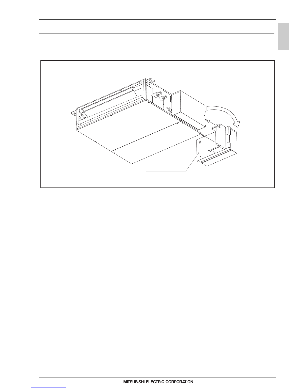
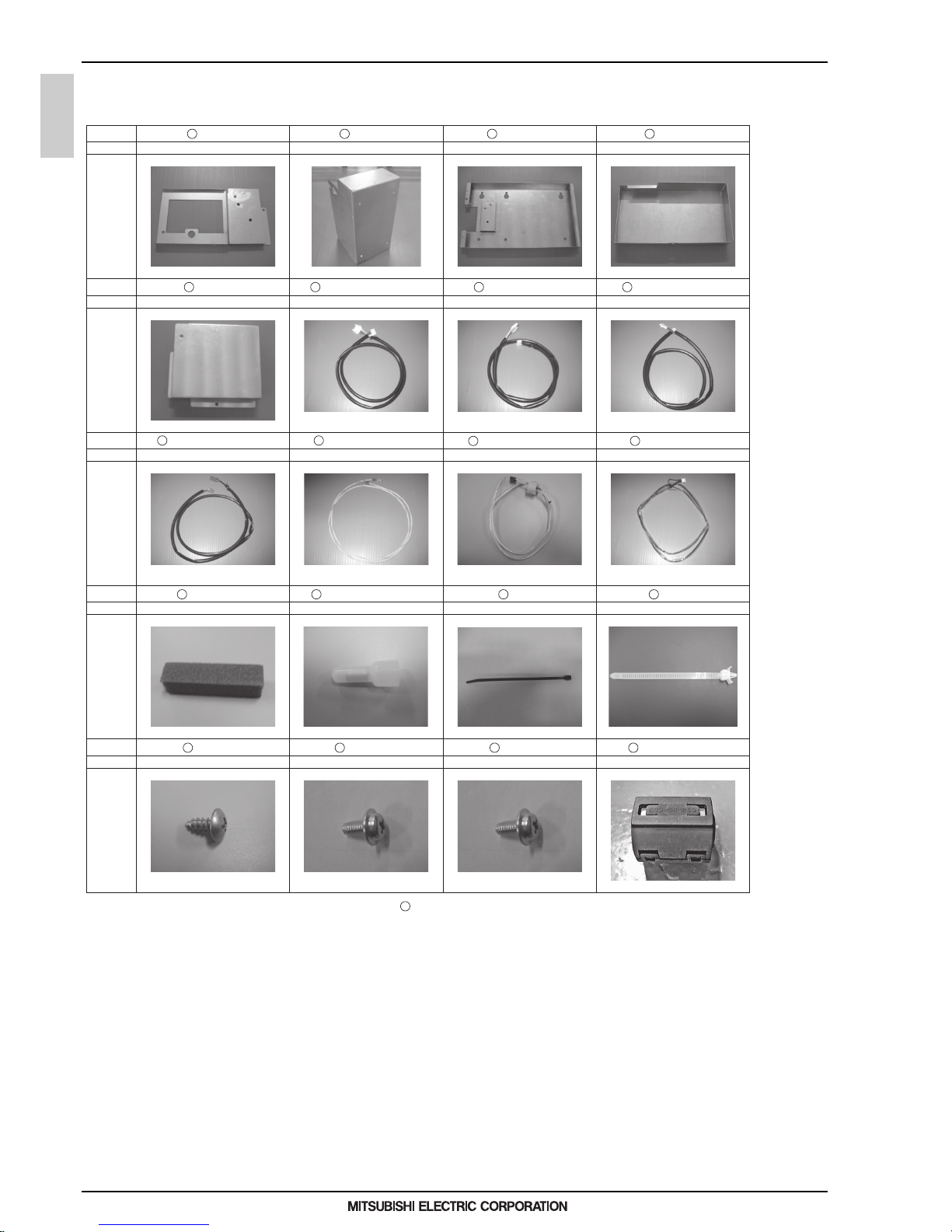
7. OPTIONAL PARTS
7-2. Control box replace kit
Shape
PLATE A
Q'ty
Parts
1
PLATE B
1
PLATE C
1
COVER A
1
Shape
COVER B
Q'ty
Parts
1
LEAD WIRE MOTOR
White 7-pin connector White 6-pin connector White 4-pin connector
Ring terminal on both endsRed 2-pin connector
4X10
Blue 3-pin connector
4X10 with a washer 5X10 with a washer
White 4-pin connector
1
LEAD WIRE LEV
1
LEAD WIRE THM A
1
Shape
LEAD WIRE THM B
Q'ty
Parts
1
LEAD WIRE EARTH
1
LEAD WIRE PUMP
1
LEAD WIRE FS
1
Shape
INSULATOR
Q'ty
Parts
3
Connecting terminals
4
BAND
6
CLAMP
4
Shape
SCREW 1
Q'ty
Parts
2
SCREW 2
4
SCREW 3
5
FERRITE CORE
1
When installing the control box replace kit on the air inlet on the unit, LEAD WIRE FS is not used.
12
10
9
5
11
12
13 14 15
17 18 19
16
20
6
7 8
4321
PAC-KE70HS-E
Page 22

1 - 19
Ceiling concealed (Middle static pressure type)
PEFY-WP-VMA-E
MEE15K052
I.Ceiling concealed (Middle static pressure type)
1. SPECIFICATIONS........................................................................................................................................... 1 - 20
2. EXTERNAL DIMENSIONS .............................................................................................................................. 1 - 22
3. CENTER OF GRAVITY ................................................................................................................................... 1 - 24
4. ELECTRICAL WIRING DIAGRAMS................................................................................................................ 1 - 25
5. SOUND LEVELS ............................................................................................................................................. 1 - 26
5-1. Sound levels ............................................................................................................................................ 1 - 26
5-2. NC curves ................................................................................................................................................ 1 - 27
6. FAN CHARACTERISTICS CURVES............................................................................................................... 1 - 31
7. OPTIONAL PARTS.......................................................................................................................................... 1 - 35
7-1. Optional parts line up for the Indoor unit.................................................................................................. 1 - 35
7-2. Filter box .................................................................................................................................................. 1 - 35
Page 23
1. SPECIFICATIONS
1 - 20
PEFY-VMA
MEE15K052
I.Ceiling concealed (Middle static pressure type)1. SPECIFICATIONS
Model PEFY-WP20VMA-E PEFY-WP25VMA-E PEFY-WP32VMA-E PEFY-WP40VMA-E
Power source
1-phase 220-230-240 V 50/
60 Hz
1-phase 220-230-240 V 50/
60 Hz
1-phase 220-230-240 V 50/
60 Hz
1-phase 220-230-240 V 50/
60 Hz
Cooling capacity *1 kW 2.2 2.8 3.6 4.5
(Nominal) *1 kcal/h 1,900 2,400 3,100 3,900
*1 BTU/h 7,500 9,600 12,300 15,400
*2 Power input kW 0.07 0.09 0.11 0.14
*2 Current input A 0.55 0.64 0.74 1.15
Heating capacity *3 kW 2.5 3.2 4.0 5.0
(Nominal) *3 kcal/h 2,200 2,800 3,400 4,300
*3 BTU/h 8,500 10,900 13,600 17,100
*2 Power input kW 0.05 0.07 0.09 0.12
*2 Current input A 0.44 0.53 0.63 1.04
External finish Galvanized steel plate Galvanized steel plate Galvanized steel plate Galvanized steel plate
External dimension HxWxD mm 250 x 700 x 732 250 x 900 x 732 250 x 900 x 732 250 x 1,100 x 732
in. 9-7/8 x 27-9/16 x 28-7/8 9-7/8 x 35-7/16 x 28-7/8 9-7/8 x 35-7/16 x 28-7/8 9-7/8 x 43-5/16 x 28-7/8
Net weight kg (lbs) 21 (47) 26 (58) 26 (58) 31 (69)
Heat exchanger
Cross fin (Aluminum fin and
copper tube)
Cross fin (Aluminum fin and
copper tube)
Cross fin (Aluminum fin and
copper tube)
Cross fin (Aluminum fin and
copper tube)
Water Volume L 0.7 1.0 1.0 1.8
FAN Type x Quantity Sirocco fan x 1 Sirocco fan x 1 Sirocco fan x 1 Sirocco fan x 2
*4 External static press. Pa
<35> - 50 - <70> - <100> -
<150>
<35> - 50 - <70> - <100> -
<150>
<35> - 50 - <70> - <100> -
<150>
<35> - 50 - <70> - <100> -
<150>
mmH
2
O
<3.6> - 5.1 - <7.1> - <10.2> -
<15.3>
<3.6> - 5.1 - <7.1> - <10.2> -
<15.3>
<3.6> - 5.1 - <7.1> - <10.2> -
<15.3>
<3.6> - 5.1 - <7.1> - <10.2> -
<15.3>
Motor Type DC motor DC motor DC motor DC motor
Motor output kW 0.085 0.085 0.085 0.121
Driving mechanism Direct-driven by motor Direct-driven by motor Direct-driven by motor Direct-driven by motor
Air flow rate (Low-Mid-High) (Low-Mid-High) (Low-Mid-High) (Low-Mid-High)
m
3
/min 7.5 - 9.0 - 10.5 10.0 - 12.0 - 14.0 12.0 - 14.5 - 17.0 14.5 - 18.0 - 21.0
L/s 125 - 150 - 175 167 - 200 - 233 200 - 242 - 283 242 - 300 - 350
cfm 265 - 318 - 371 353 - 4 24 - 494 424 - 512 - 600 512 - 636 - 742
Sound pressure level (measured in anechoic room) (Low-Mid-High) (Low-Mid-High) (Low-Mid-High) (Low-Mid-High)
*2 dB <A> 23-26-29 23-27-30 25-29-32 26-29-34
Insulation material
EPS, Polyethylene foam,
Urethane foam
EPS, Polyethylene foam,
Urethane foam
EPS, Polyethylene foam,
Urethane foam
EPS, Polyethylene foam,
Urethane foam
Air filter PP honeycomb fabric. PP honeycomb fabric. PP honeycomb fabric. PP honeycomb fabric.
Protection device Fuse Fuse Fuse Fuse
Refrigerant control device - - - -
Connectable outdoor unit/HBC controller
CITY MULTI YLM series/
CMB-WP-V-GA1, CMB-WP-
V-GB1
CITY MULTI YLM series/
CMB-WP-V-GA1, CMB-WP-
V-GB1
CITY MULTI YLM series/
CMB-WP-V-GA1, CMB-WP-
V-GB1
CITY MULTI YLM series/
CMB-WP-V-GA1, CMB-WP-
V-GB1
Diameter of water pipe Inlet in. Rc 3/4 screw Rc 3/4 screw Rc 3/4 screw Rc 3/4 screw
*5 *6 Outlet in. Rc 3/4 screw Rc 3/4 screw Rc 3/4 screw Rc 3/4 screw
Field drain pipe size mm (in.) O.D.32 (1-1/4) O.D.32 (1-1/4) O.D.32 (1-1/4) O.D.32 (1-1/4)
Drawing Exter nal KD94L918X 01 KD94L918X01 K D94L918X01 KD94L918X 01
Wiring KD94L919X01 KD94L919X01 KD94L919X01 KD94L919X01
Refrigerant cycle - - - -
Standard attachment Document
Installation Manual, Instruc-
tion Book
Installation Manual, Instruc-
tion Book
Installation Manual, Instruc-
tion Book
Installation Manual, Instruc-
tion Book
Accessory
Insulation pipe for water pipe,
Washer, Drain hose, Tie
band
Insulation pipe for water pipe,
Washer, Drain hose, Tie
band
Insulation pipe for water pipe,
Washer, Drain hose, Tie
band
Insulation pipe for water pipe,
Washer, Drain hose, Tie
band
Optional parts Filter box PAC-KE91TB-E PAC-KE92TB-E PAC-KE92TB-E PAC-KE93TB-E
Remarks * Details on foundation work, duct work, insulation work, electrical wiring, power source switch, and other items shall be
referred to the Installation Manual.
* Due to continuing improvement, above specifications may be subject to change without notice.
Notes: Unit converter
1.Nominal cooling conditions
Indoor: 27°CD.B./19°CW.B. (81°CD.B./66°CW.B.), Outdoor: 35°CD.B. (95°CD.B.)
Pipe length: 7.5 m (24-9/16 ft.), Level difference: 0 m (0 ft.)
2.The values are measured at the factory setting of external static pressure.
3.Nominal heating conditions
Indoor: 20°CD.B. (68°CD.B.), Outdoor: 7°CD.B./6°CW.B. (45°CD.B./43°CW.B.)
Pipe length: 7.5 m (24-9/16 ft.), Level difference: 0 m (0 ft.)
4.The factory setting of external static pressure is shown without < >.
Refer to "Fan characteristics curves", according to the external static pressure, in DATA BOOK for the usable
range of air flow rate.
5.Be sure to install a valve on the water outlet.
6.Install a strainer (40 mesh or more) on the pip e next to the valve to remove the foreign matters.
7.Group units that operat e on 1 branch.
kcal/h =kW x 860
BTU/h =kW x 3,412
cfm =m3/min x 35.31
lbs =kg / 0.4536
*Above specification data is
subject to rounding variation.
Page 24
1 - 21
1. SPECIFICATIONS
PEFY-VMA
MEE15K052
Model PEFY-WP50VMA-E
Power source
1-phase 220-230-240 V 50/
60 Hz
Cooling capacity *1 kW 5.6
(Nominal) *1 kcal/h 4,800
*1 BTU/h 19,100
*2 Power input kW 0.14
*2 Current input A 1.15
Heating capacity *3 kW 6.3
(Nominal) *3 kcal/h 5,400
*3 BTU/h 21,500
*2 Power input kW 0.12
*2 Current input A 1.04
External finish Galvanized steel plate
External dimension HxWxD mm 250 x 1,100 x 732
in. 9-7/8 x 43-5/16 x 28-7/8
Net weight kg (lbs) 31 (69)
Heat exchanger
Cross fin (Aluminum fin and
copper tube)
Water Volume L 1.8
FAN Type x Quantity Sirocco fan x 2
*4 External static press. Pa
<35> - 50 - <70> - <100> -
<150>
mmH
2
O
<3.6> - 5.1 - <7.1> - <10.2> -
<15.3>
Motor Type DC motor
Motor output kW 0.121
Driving mechanism Direct-d riven by motor
Air flow rate (Low-Mid-High)
m
3
/min 14.5 - 18.0 - 21.0
L/s 242 - 300 - 350
cfm 512 - 636 - 742
Sound pressure level (measured in anechoic room) (Low-Mid-High)
*2 dB <A> 26-29-34
Insulation material
EPS, Polyethylene foam,
Urethane foam
Air filter PP honeyco mb fabric.
Protection device Fus e
Refrigerant control device -
Connectable outdoor unit/HBC controlle r
CITY MULTI YLM series/
CMB-WP-V-GA1, CMB-WP-
V-GB1
Diameter of water pipe Inlet in. Rc 3/4 screw
*5 *6 Outlet in. Rc 3/4 screw
Field drain pipe size mm (in.) O.D.32 (1-1/4)
Drawing External KD94L918X01
Wiring KD94L919X01
Refrigerant cycle -
Standard attachment Document
Installation Manual, Instruc-
tion Book
Accessory
Insulation pipe for water pipe,
Washer, Drain hose, Tie
band
Optional parts Filter box PAC-KE93TB-E
Remarks * Details on foundation work, duct work, insulation work, electrical wiring, power source switch, and other items shall be
referred to the Installation Manual.
* Due to continuing improvement, ab ove specifications may be subject to chan ge without notice.
Notes : Unit converter
1.Nominal cooling conditions
Indoor: 27°CD.B./19°CW.B. (81°CD.B./66°CW.B.), Outdoor: 35°CD.B. (95°CD.B.)
Pipe length: 7.5 m (24-9/16 ft.), Level difference: 0 m (0 ft.)
2.The values are measured at the factory setting of external static pressure.
3.Nominal heating conditions
Indoor: 20°CD.B. (68°CD.B.), Outdoor: 7°CD.B./6°CW.B. (45°CD.B./43°CW.B.)
Pipe length: 7.5 m (24-9/16 ft.), Level difference: 0 m (0 ft.)
4.The factory setting of external static pressure is shown without < >.
Refer to "Fan characteristics curves", according to the external static pressure, in DATA BOOK for the usable
range of air flow rate.
5.Be sure to install a valve on the water outlet.
6.Install a strainer (40 mesh or more) on the pipe next to the valve to remove the foreign matters.
7.Group units that operate on 1 branch.
kcal/h =kW x 860
BTU/h =kW x 3,412
cfm =m3/min x 35.31
lbs =kg / 0.4536
*Above specification data is
subject to rounding variation.
Page 25
2. EXTERNAL DIMENSIONS
1 - 22
PEFY-VMA
MEE15K052
2. EXTERNAL DIMENSIONS
Control box
2×2-ø2.9
Air
outlet
Air
inlet
2×E-ø2.9
Water pipe(To HBC unit)
Rc3/4 screw
2
1
Water pipe(From HBC unit)
Rc3/4 screw
Drain pump
Air Filter
Terminal block(Power source)
Terminal block(Transmission)
Drain pipe(O.D.ø32)
(Spontaneous draining)
Drain pipe
(O.D.ø32)
Suspension bolt hole
4-14×30 Slot
Note 1.Use M10 screw for the Suspension bolt (field supply).
2.Keep the service space for the maintenance at the bottom.
3.This chart indicates for PEFY-WP40·50VMA-E models,
which have 2 fans.PEFY-WP20·25·32VMA-E models
have 1 fan.
4.In case of the inlet duct is used,remove the air filter
(supply with the unit),then install the filter
(field supply) at suction side.
Rc3/4 screw
Water pipe
(To HBC unit)
Water pipe
(From HBC unit)
7
Model
A
660800
1200
700 754
900 954 860 9
E
11
D
1060
C
1100
B
1154PEFY-WP40,50VMA-E
PEFY-WP25,32VMA-E
PEFY-WP20VMA-E
1000
1000
F
858800G658
1058
600
Outlet air
side view
Top view
Inlet air
side view
Piping
side view
To p
Bottom
91 64
87117
20
64
40
250
40
D (Duct)
21018
G21
57
10
A
B(Suspension bolt pitch)
C
23
643(Suspension bolt pitch)
178(Duct)
23
10
238
32 700
732
356
100
41
217
100
30
100×(E-1)=F
58
15
Unit: mm
PEFY-WP20, 25, 32, 40, 50VMA-E
Page 26
1 - 23
2. EXTERNAL DIMENSIONS
PEFY-VMA
MEE15K052
PEFY-WP20, 25, 32, 40, 50VMA-E
Unit: mm
N-ø2.9
(Actual length)
<accessory>
Drain hose (I.D.ø32)
Model H RQS
PEFY-WP20VMA-E 44 50~150 800 1300
K
300
PEFY-WP25,32VMA-E 1000150~250 150054
P
700
900
1100
N
101010
M
780
990
J
150
260
330PEFY-WP40,50VMA-E 1200250~350 1700
L
4
449
Maintenance access space
Maintenance access space
Maintenance access space
Access door 3
Access door 4
Access door 2
(450×450)
Ceiling
Ceiling
A
B
Fig.3
Fig.4
Fig.2
Fig.1
Fig.5
(Viewed from the direction of the arrow A)
(Viewed from the direction of the arrow B)
(Viewed from the direction
of the arrow B)
Intake air
Intake air
Supply air
Supply air
Access door 2(450×450)
Access door 3
Ceiling beam
Ceiling beam
Bottom of indoor unit
Bottom of
indoor unit
Bottom of
indoor unit
100~200
100~200
Access door 1
(450×450)
Access door 1
(450×450)
Electric box
Electric box
Electric box
Electric box
Electric box
[Maintenance access space]
Secure enough access space to allow for the maintenance, inspection, and replacement of the motor, fan, drain pump, heat exchanger,
and electric box in one of the following ways.
Select an installation site for the indoor unit so that its maintenance access space will not be obstructed by beams or other objects.
(1)When a space of 300mm or more is available below the unit between the unit and the ceiling. (Fig.1)
·Create access door 1 and 2 (450×450mm each) as shown in Fig.2.
(Access door 2 is not required if enough space is available below the unit for a maintenance worker to work in.)
(2)When a space of less than 300mm is available below the unit between the unit and the ceiling.
(At least 20mm of space should be left below the unit as shown in Fig.3.)
·Create access door 1 diagonally below the electric box and access door 3 below the unit as shown in Fig.4.
or
·Create access door 4 below the electric box and the unit as shown in Fig.5.
112 11112
H
JK
6 H
J
J×(L-1)=M
65
0
-10
Less than 300mm
Less than 700mm
700
700
475
Min.10mm
475
Min.10mm
450
450
50
Q
50~150
450
Min.300mm
450
450
450
50
50
Min.300mm50 700
777
777
R
S
P
P
P
Min.300mm
Min.20mm
Page 27
3. CENTER OF GRAVITY
1 - 24
PEFY-VMA
MEE15K052
3. CENTER OF GRAVITY
Model name
PEFY-WP20VMA-E
PEFY-WP25VMA-E
PEFY-WP32VMA-E
PEFY-WP40VMA-E
PEFY-WP50VMA-E
W
643 [25 - 6/16]
643 [25 - 6/16]
643 [25 - 6/16]
643 [25 - 6/16]
L
754 [29 - 11/16]
954 [37 - 9/16]
954 [37 - 9/16]
1154 [45 - 7/16]
X
330 [13]
340 [13 - 7/16]
340 [13 - 7/16]
325 [12 - 13/16]
Y
300 [11 -13/16]
375 [14 -13/16]
375 [14 -13/16]
525 [20 -11/16]
Z
130 [5 -2/16]
130 [5 -2/16]
130 [5 -2/16]
130 [5 -2/16]
643 [25 - 6/16] 1154 [45 - 7/16]
325 [12 - 13/16]
525 [20 -11/16] 130 [5 -2/16]
A : Center of gravity
YX
LW
A
Z
PEFY-WP20, 25, 32, 40, 50VMA-E
(mm)[in]
Page 28
1 - 25
4. ELECTRICAL WIRING DIAGRAMS
PEFY-VMA
MEE15K052
4. ELECTRICAL WIRING DIAGRAMS
INSIDE SECTION OF CONTROL BOX
Drainpump
Fan motor
Thermistor (piping temp.detection/water in)
Thermistor (piping temp.detection/water out)
Switch (for mode selection)
Switch (for capacity code)
Switch (10ths digit address set)
Switch (for static pressure selection)
Switch (for static pressure selection)
Switch (BRANCH No.)
Switch (for mode selection)
Switch (for model selection)
Switch (for mode selection)
Connector (emergency operation)
Transmission terminal block
Fuse AC250V 6.3A
Arrester
Aux. relay
Aux. relay
AC reactor(Power factor improvement)
Varistor
TB15
F01
DSA
X01
X10
ACL
ZNR01,02
TH21
LED1
Thermistor (inlet air temp.detection)
LED(Power supply)
LED(Remote controller supply)
TH23
TH22
LED2
NAMESYMBOLSYMBOL
I.B.
P. B.
Indoor controller board
Power supply board
Switch (1s digit address set)
SW2(I.B.)
SW3(I.B.)
SW11(I.B.)
SW12(I.B.)
SWA(I.B.)
SW14(I.B.)
SWC(I.B.)
SW1(I.B.)
SW4(I.B.)
SW5(I.B.)
SWE(I.B.)
TB2
TB5
Transmission terminal block
Power source terminal block
SYMBOL EXPLANATION
NAME
CN27
CN41
CN51
CN52
CN90
CN2A
CN105
FS
Connector (HA terminal-A)
Connector (Centrally control)
Connector (Remote indication)
Connector (Wireless)
Connector (0-10V Analog input)
Connector (IT terminal)
Float switch
SYMBOL NAME
Connector (Damper)
CN32
Connector (Remote switch)
NOTE:Symbols used in wiring diagram above are,
:Connector
:Terminal
(Heavy dotted line):Field wiring
I.B.
P. B .
TH23
TH21
TH22
t° t°
t°
FS
(Blue)
(Blue)
(Blue)
(Blue)
(Blue)
(Black)
(Green)
(Red)
CN44
(Red)
(Red)
(Red)
CN27
ON
ZNR01
CNP
CND
ZNR02
DSA
OFF
F01
SW5
SWC
SW14
SW12
SW11
SW4
SWA
ACL
SW1
SW2
SW3
CNXC1
X01 X10
CNXA1CNXB1 CNMF
CNXC2
CN2A
CN2M
CNXB2
CNXA2
CN51
CN4F
CN41
CN105
CN90
CN20
SWE
CN52
CN32
CN3A
TB5
LED2
LED1
DC280-340V
Rectifier circuit
U
U
AC220-240V
50,60Hz
N
L
TB15
M2
2
TB2
M1
1
S(SHIELD)
M
MS
3~
1111
1
11
22752
5
33445 6 4
3
22
2
1
3
1
3
2 32
3
1 2
1
1
3
431454
1
2
4
1
2
2
1
1~
TO MA REMOTE
CONTROLLER
TO OUTDOOR UNIT
HBC CONTROLLER
REMOTE CONTROLLER
POWER SUPPLY
PULL BOX
BREAKER (16A)
FUSE (16A)
TO NEXT INDOOR UNIT
PEFY-WP20, 25, 32, 40, 50VMA-E
Page 29
5. SOUND LEVELS
1 - 26
PEFY-VMA
MEE15K052
5. SOUND LEVELS
5-1. Sound levels
5-1-1. Sound levels (Measured condition : With 1m air inlet duct and 2m air outlet duct)
5-1-2. Sound levels (Measured condition : With 2m air inlet duct and 2m air outlet duct)
Sound level at anechoic room : Low-Mid-High
Model Sound level dB(A)
35Pa 50Pa 70Pa 100Pa 150Pa
PEFY-WP20VMA-E 28-30-34 28-30-34 29-32-36 29-33-37 31-35-40
PEFY-WP25VMA-E 28-30-34 28-30-34 29-32-36 29-33-37 32-36-40
PEFY-WP32VMA-E 28-31-35 28-32-35 29-33-37 30-34-38 32-37-41
PEFY-WP40VMA-E 30-33-37 30-34-38 31-36-39 33-37-41 36-41-44
PEFY-WP50VMA-E 30-33-37 30-34-38 31-36-39 33-37-41 36-41-44
*
Measured in anechoic room.
PEFY-WP-VMA-E
2m
1m
Aux. duct
1.5m
Measurement location
Sound level at anechoic room : Low-Mid-High
Model Sound level dB(A)
35Pa 50Pa 70Pa 100Pa 150Pa
PEFY-WP20VMA-E 23-25-28 23-26-29 24-27-30 25-28-32 28-32-36
PEFY-WP25VMA-E 23-26-29 23-27-30 24-28-31 26-29-33 29-33-37
PEFY-WP32VMA-E 24-28-31 25-29-32 26-30-33 27-31-34 29-34-38
PEFY-WP40VMA-E 26-29-33 26-29-34 26-30-35 29-33-37 32-37-41
PEFY-WP50VMA-E 26-29-33 26-29-34 26-30-35 29-33-37 32-37-41
Measurement location
Aux. duct
*
Measured in anechoic room.
PEFY-WP-VMA-E
2m 2m
1.5m
Page 30
1 - 27
5. SOUND LEVELS
PEFY-VMA
MEE15K052
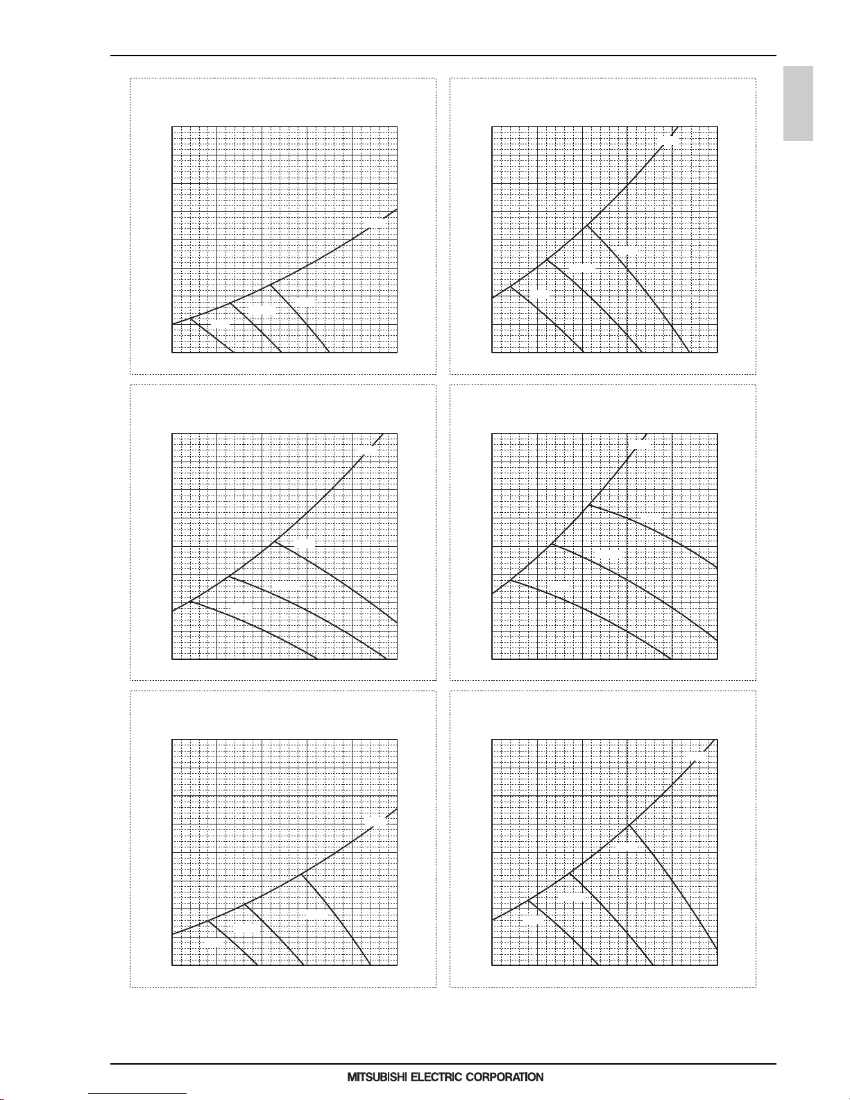
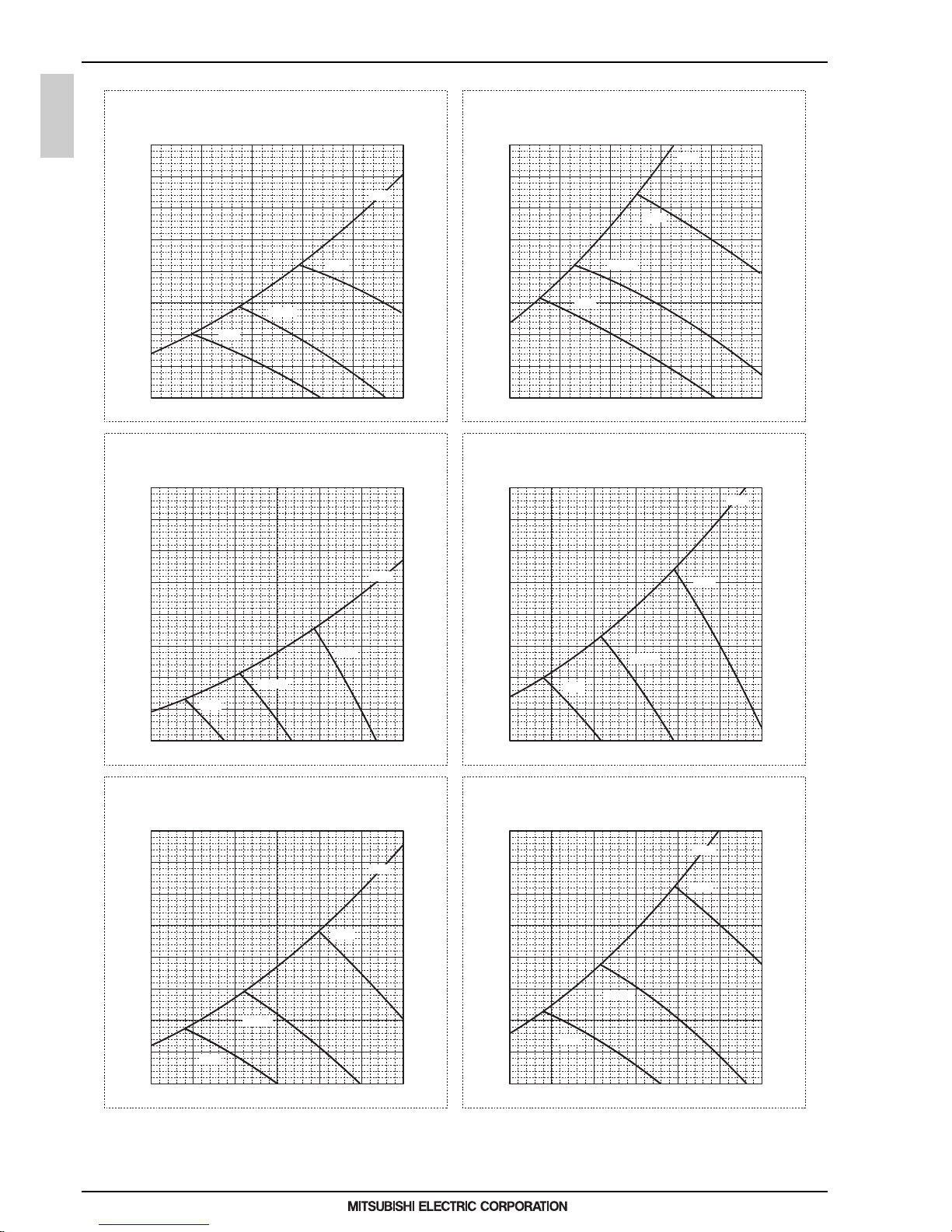
5-2. NC curves
5-2-1. NC curves (Sound level measured condition : With 1m air inlet duct and 2m air outlet duct)
10.0
15.0
20.0
25.0
30.0
35.0
40.0
45.0
50.0
55.0
60.0
65.0
70.0
63 125 250 500 1k 2k 4k 8k
NC-60
NC-50
Octave band pressure level (dB) 0dB=20μPa
Approximate minimum
audible limit on
continuous noise
NC-40
NC-30
NC-20
Octave band center frequencies (Hz)
High
Middle
50/60Hz
Low
50/60Hz
50/60Hz
PEFY-WP20VMA-E
External Static Pressure: 35Pa
Power Source: 220-240V(50/60Hz)
10.0
15.0
20.0
25.0
30.0
35.0
40.0
45.0
50.0
55.0
60.0
65.0
70.0
63 125 250 500 1k 2k 4k 8k
NC-60
NC-50
Octave band pressure level (dB) 0dB=20μPa
Approximate minimum
audible limit on
continuous noise
NC-40
NC-30
NC-20
Octave band center frequencies (Hz)
High
Middle
50/60Hz
Low
50/60Hz
50/60Hz
PEFY-WP20VMA-E
External Static Pressure: 50Pa
Power Source: 220-240V(50/60Hz)
10.0
15.0
20.0
25.0
30.0
35.0
40.0
45.0
50.0
55.0
60.0
65.0
70.0
63 125 250 500 1k 2k 4k 8k
NC-60
NC-50
Octave band pressure level (dB) 0dB=20μPa
Approximate minimum
audible limit on
continuous noise
NC-40
NC-30
NC-20
Octave band center frequencies (Hz)
High
Middle
50/60Hz
Low
50/60Hz
50/60Hz
PEFY-WP20VMA-E
External Static Pressure: 70Pa
Power Source: 220-240V(50/60Hz)
10.0
15.0
20.0
25.0
30.0
35.0
40.0
45.0
50.0
55.0
60.0
65.0
70.0
63 125 250 500 1k 2k 4k 8k
NC-60
NC-50
Octave band pressure level (dB) 0dB=20μPa
Approximate minimum
audible limit on
continuous noise
NC-40
NC-30
NC-20
Octave band center frequencies (Hz)
High
Middle
50/60Hz
Low
50/60Hz
50/60Hz
PEFY-WP20VMA-E
External Static Pressure: 100Pa
Power Source: 220-240V(50/60Hz)
10.0
15.0
20.0
25.0
30.0
35.0
40.0
45.0
50.0
55.0
60.0
65.0
70.0
63 125 250 500 1k 2k 4k 8k
NC-60
NC-50
Octave band pressure level (dB) 0dB=20μPa
Approximate minimum
audible limit on
continuous noise
NC-40
NC-30
NC-20
Octave band center frequencies (Hz)
High
Middle
50/60Hz
Low
50/60Hz
50/60Hz
PEFY-WP20VMA-E
External Static Pressure: 150Pa
Power Source: 220-240V(50/60Hz)
10.0
15.0
20.0
25.0
30.0
35.0
40.0
45.0
50.0
55.0
60.0
65.0
70.0
63 125 250 500 1k 2k 4k 8k
NC-60
NC-50
Octave band pressure level (dB) 0dB=20μPa
Approximate minimum
audible limit on
continuous noise
NC-40
NC-30
NC-20
Octave band center frequencies (Hz)
High
Middle
50/60Hz
Low
50/60Hz
50/60Hz
PEFY-WP25VMA-E
External Static Pressure: 35Pa
Power Source: 220-240V(50/60Hz)
10.0
15.0
20.0
25.0
30.0
35.0
40.0
45.0
50.0
55.0
60.0
65.0
70.0
63 125 250 500 1k 2k 4k 8k
NC-60
NC-50
Octave band pressure level (dB) 0dB=20μPa
Approximate minimum
audible limit on
continuous noise
NC-40
NC-30
NC-20
Octave band center frequencies (Hz)
High
Middle
50/60Hz
Low
50/60Hz
50/60Hz
PEFY-WP25VMA-E
External Static Pressure: 50Pa
Power Source: 220-240V(50/60Hz)
10.0
15.0
20.0
25.0
30.0
35.0
40.0
45.0
50.0
55.0
60.0
65.0
70.0
63 125 250 500 1k 2k 4k 8k
NC-60
NC-50
Octave band pressure level (dB) 0dB=20μPa
Approximate minimum
audible limit on
continuous noise
NC-40
NC-30
NC-20
Octave band center frequencies (Hz)
High
Middle
50/60Hz
Low
50/60Hz
50/60Hz
PEFY-WP25VMA-E
External Static Pressure: 70Pa
Power Source: 220-240V(50/60Hz)
10.0
15.0
20.0
25.0
30.0
35.0
40.0
45.0
50.0
55.0
60.0
65.0
70.0
63 125 250 500 1k 2k 4k 8k
NC-60
NC-50
Octave band pressure level (dB) 0dB=20μPa
Approximate minimum
audible limit on
continuous noise
NC-40
NC-30
NC-20
Octave band center frequencies (Hz)
High
Middle
50/60Hz
Low
50/60Hz
50/60Hz
PEFY-WP25VMA-E
External Static Pressure: 100Pa
Power Source: 220-240V(50/60Hz)
10.0
15.0
20.0
25.0
30.0
35.0
40.0
45.0
50.0
55.0
60.0
65.0
70.0
63 125 250 500 1k 2k 4k 8k
NC-60
NC-50
Octave band pressure level (dB) 0dB=20μPa
Approximate minimum
audible limit on
continuous noise
NC-40
NC-30
NC-20
Octave band center frequencies (Hz)
High
Middle
50/60Hz
Low
50/60Hz
50/60Hz
PEFY-WP25VMA-E
External Static Pressure: 150Pa
Power Source: 220-240V(50/60Hz)
10.0
15.0
20.0
25.0
30.0
35.0
40.0
45.0
50.0
55.0
60.0
65.0
70.0
63 125 250 500 1k 2k 4k 8k
NC-60
NC-50
Octave band pressure level (dB) 0dB=20μPa
Approximate minimum
audible limit on
continuous noise
NC-40
NC-30
NC-20
Octave band center frequencies (Hz)
High
Middle
50/60Hz
Low
50/60Hz
50/60Hz
PEFY-WP32VMA-E
External Static Pressure: 35Pa
Power Source: 220-240V(50/60Hz)
10.0
15.0
20.0
25.0
30.0
35.0
40.0
45.0
50.0
55.0
60.0
65.0
70.0
63 125 250 500 1k 2k 4k 8k
NC-60
NC-50
Octave band pressure level (dB) 0dB=20μPa
Approximate minimum
audible limit on
continuous noise
NC-40
NC-30
NC-20
Octave band center frequencies (Hz)
High
Middle
50/60Hz
Low
50/60Hz
50/60Hz
PEFY-WP32VMA-E
External Static Pressure: 50Pa
Power Source: 220-240V(50/60Hz)
Page 31

5. SOUND LEVELS
1 - 28
PEFY-VMA
MEE15K052
10.0
15.0
20.0
25.0
30.0
35.0
40.0
45.0
50.0
55.0
60.0
65.0
70.0
63 125 250 500 1k 2k 4k 8k
NC-60
NC-50
Octave band pressure level (dB) 0dB=20μPa
Approximate minimum
audible limit on
continuous noise
NC-40
NC-30
NC-20
Octave band center frequencies (Hz)
High
Middle
50/60Hz
Low
50/60Hz
50/60Hz
PEFY-WP32VMA-E
External Static Pressure: 70Pa
Power Source: 220-240V(50/60Hz)
10.0
15.0
20.0
25.0
30.0
35.0
40.0
45.0
50.0
55.0
60.0
65.0
70.0
63 125 250 500 1k 2k 4k 8k
NC-60
NC-50
Octave band pressure level (dB) 0dB=20μPa
Approximate minimum
audible limit on
continuous noise
NC-40
NC-30
NC-20
Octave band center frequencies (Hz)
High
Middle
50/60Hz
Low
50/60Hz
50/60Hz
PEFY-WP32VMA-E
External Static Pressure: 100Pa
Power Source: 220-240V(50/60Hz)
10.0
15.0
20.0
25.0
30.0
35.0
40.0
45.0
50.0
55.0
60.0
65.0
70.0
63 125 250 500 1k 2k 4k 8k
NC-60
NC-50
Octave band pressure level (dB) 0dB=20μPa
Approximate minimum
audible limit on
continuous noise
NC-40
NC-30
NC-20
Octave band center frequencies (Hz)
High
Middle
50/60Hz
Low
50/60Hz
50/60Hz
PEFY-WP32VMA-E
External Static Pressure: 150Pa
Power Source: 220-240V(50/60Hz)
10.0
15.0
20.0
25.0
30.0
35.0
40.0
45.0
50.0
55.0
60.0
65.0
70.0
63 125 250 500 1k 2k 4k 8k
NC-60
NC-50
Octave band pressure level (dB) 0dB=20μPa
Approximate minimum
audible limit on
continuous noise
NC-40
NC-30
NC-20
Octave band center frequencies (Hz)
High
Middle
50/60Hz
Low
50/60Hz
50/60Hz
PEFY-WP40,50VMA-E
External Static Pressure: 35Pa
Power Source: 220-240V(50/60Hz)
10.0
15.0
20.0
25.0
30.0
35.0
40.0
45.0
50.0
55.0
60.0
65.0
70.0
63 125 250 500 1k 2k 4k 8k
NC-60
NC-50
Octave band pressure level (dB) 0dB=20μPa
Approximate minimum
audible limit on
continuous noise
NC-40
NC-30
NC-20
Octave band center frequencies (Hz)
High
Middle
50/60Hz
Low
50/60Hz
50/60Hz
PEFY-WP40,50VMA-E
External Static Pressure: 50Pa
Power Source: 220-240V(50/60Hz)
10.0
15.0
20.0
25.0
30.0
35.0
40.0
45.0
50.0
55.0
60.0
65.0
70.0
63 125 250 500 1k 2k 4k 8k
NC-60
NC-50
Octave band pressure level (dB) 0dB=20μPa
Approximate minimum
audible limit on
continuous noise
NC-40
NC-30
NC-20
Octave band center frequencies (Hz)
High
Middle
50/60Hz
Low
50/60Hz
50/60Hz
PEFY-WP40,50VMA-E
External Static Pressure: 70Pa
Power Source: 220-240V(50/60Hz)
10.0
15.0
20.0
25.0
30.0
35.0
40.0
45.0
50.0
55.0
60.0
65.0
70.0
63 125 250 500 1k 2k 4k 8k
NC-60
NC-50
Octave band pressure level (dB) 0dB=20μPa
Approximate minimum
audible limit on
continuous noise
NC-40
NC-30
NC-20
Octave band center frequencies (Hz)
High
Middle
50/60Hz
Low
50/60Hz
50/60Hz
PEFY-WP40,50VMA-E
External Static Pressure: 100Pa
Power Source: 220-240V(50/60Hz)
10.0
15.0
20.0
25.0
30.0
35.0
40.0
45.0
50.0
55.0
60.0
65.0
70.0
63 125 250 500 1k 2k 4k 8k
NC-60
NC-50
Octave band pressure level (dB) 0dB=20μPa
Approximate minimum
audible limit on
continuous noise
NC-40
NC-30
NC-20
Octave band center frequencies (Hz)
High
Middle
50/60Hz
Low
50/60Hz
50/60Hz
PEFY-WP40,50VMA-E
External Static Pressure: 150Pa
Power Source: 220-240V(50/60Hz)
Page 32

1 - 29
5. SOUND LEVELS
PEFY-VMA
MEE15K052
5-2-2. NC curves (Sound level measured condition : With 2m air inlet duct and 2m air outlet duct)
10.0
15.0
20.0
25.0
30.0
35.0
40.0
45.0
50.0
55.0
60.0
65.0
70.0
63 125 250 500 1k 2k 4k 8k
NC-60
NC-50
Octave band pressure level (dB) 0dB=20μPa
Approximate minimum
audible limit on
continuous noise
NC-40
NC-30
NC-20
Octave band center frequencies (Hz)
High
Middle
50/60Hz
Low
50/60Hz
50/60Hz
PEFY-WP20VMA-E
External Static Pressure: 35Pa
Power Source: 220-230-240V(50/60Hz)
10.0
15.0
20.0
25.0
30.0
35.0
40.0
45.0
50.0
55.0
60.0
65.0
70.0
63 125 250 500 1k 2k 4k 8k
NC-60
NC-50
Octave band pressure level (dB) 0dB=20μPa
Approximate minimum
audible limit on
continuous noise
NC-40
NC-30
NC-20
Octave band center frequencies (Hz)
High
Middle
50/60Hz
Low
50/60Hz
50/60Hz
PEFY-WP20VMA-E
External Static Pressure: 50Pa
Power Source: 220-230-240V(50/60Hz)
10.0
15.0
20.0
25.0
30.0
35.0
40.0
45.0
50.0
55.0
60.0
65.0
70.0
63 125 250 500 1k 2k 4k 8k
NC-60
NC-50
Octave band pressure level (dB) 0dB=20μPa
Approximate minimum
audible limit on
continuous noise
NC-40
NC-30
NC-20
Octave band center frequencies (Hz)
High
Middle
50/60Hz
Low
50/60Hz
50/60Hz
PEFY-WP20VMA-E
External Static Pressure: 70Pa
Power Source: 220-230-240V(50/60Hz)
10.0
15.0
20.0
25.0
30.0
35.0
40.0
45.0
50.0
55.0
60.0
65.0
70.0
63 125 250 500 1k 2k 4k 8k
NC-60
NC-50
Octave band pressure level (dB) 0dB=20μPa
Approximate minimum
audible limit on
continuous noise
NC-40
NC-30
NC-20
Octave band center frequencies (Hz)
High
Middle
50/60Hz
Low
50/60Hz
50/60Hz
PEFY-WP20VMA-E
External Static Pressure: 100Pa
Power Source: 220-230-240V(50/60Hz)
10.0
15.0
20.0
25.0
30.0
35.0
40.0
45.0
50.0
55.0
60.0
65.0
70.0
63 125 250 500 1k 2k 4k 8k
NC-60
NC-50
Octave band pressure level (dB) 0dB=20μPa
Approximate minimum
audible limit on
continuous noise
NC-40
NC-30
NC-20
Octave band center frequencies (Hz)
High
Middle
50/60Hz
Low
50/60Hz
50/60Hz
PEFY-WP20VMA-E
External Static Pressure: 150Pa
Power Source: 220-230-240V(50/60Hz)
10.0
15.0
20.0
25.0
30.0
35.0
40.0
45.0
50.0
55.0
60.0
65.0
70.0
63 125 250 500 1k 2k 4k 8k
NC-60
NC-50
Octave band pressure level (dB) 0dB=20μPa
Approximate minimum
audible limit on
continuous noise
NC-40
NC-30
NC-20
Octave band center frequencies (Hz)
High
Middle
50/60Hz
Low
50/60Hz
50/60Hz
PEFY-WP25VMA-E
External Static Pressure: 35Pa
Power Source: 220-230-240V(50/60Hz)
10.0
15.0
20.0
25.0
30.0
35.0
40.0
45.0
50.0
55.0
60.0
65.0
70.0
63 125 250 500 1k 2k 4k 8k
NC-60
NC-50
Octave band pressure level (dB) 0dB=20μPa
Approximate minimum
audible limit on
continuous noise
NC-40
NC-30
NC-20
Octave band center frequencies (Hz)
High
Middle
50/60Hz
Low
50/60Hz
50/60Hz
PEFY-WP25VMA-E
External Static Pressure: 50Pa
Power Source: 220-230-240V(50/60Hz)
10.0
15.0
20.0
25.0
30.0
35.0
40.0
45.0
50.0
55.0
60.0
65.0
70.0
63 125 250 500 1k 2k 4k 8k
NC-60
NC-50
Octave band pressure level (dB) 0dB=20μPa
Approximate minimum
audible limit on
continuous noise
NC-40
NC-30
NC-20
Octave band center frequencies (Hz)
High
Middle
50/60Hz
Low
50/60Hz
50/60Hz
PEFY-WP25VMA-E
External Static Pressure: 70Pa
Power Source: 220-230-240V(50/60Hz)
10.0
15.0
20.0
25.0
30.0
35.0
40.0
45.0
50.0
55.0
60.0
65.0
70.0
63 125 250 500 1k 2k 4k 8k
NC-60
NC-50
Octave band pressure level (dB) 0dB=20μPa
Approximate minimum
audible limit on
continuous noise
NC-40
NC-30
NC-20
Octave band center frequencies (Hz)
High
Middle
50/60Hz
Low
50/60Hz
50/60Hz
PEFY-WP25VMA-E
External Static Pressure: 100Pa
Power Source: 220-230-240V(50/60Hz)
10.0
15.0
20.0
25.0
30.0
35.0
40.0
45.0
50.0
55.0
60.0
65.0
70.0
63 125 250 500 1k 2k 4k 8k
NC-60
NC-50
Octave band pressure level (dB) 0dB=20μPa
Approximate minimum
audible limit on
continuous noise
NC-40
NC-30
NC-20
Octave band center frequencies (Hz)
High
Middle
50/60Hz
Low
50/60Hz
50/60Hz
PEFY-WP25VMA-E
External Static Pressure: 150Pa
Power Source: 220-230-240V(50/60Hz)
10.0
15.0
20.0
25.0
30.0
35.0
40.0
45.0
50.0
55.0
60.0
65.0
70.0
63 125 250 500 1k 2k 4k 8k
NC-60
NC-50
Octave band pressure level (dB) 0dB=20μPa
Approximate minimum
audible limit on
continuous noise
NC-40
NC-30
NC-20
Octave band center frequencies (Hz)
High
Middle
50/60Hz
Low
50/60Hz
50/60Hz
PEFY-WP32VMA-E
External Static Pressure: 35Pa
Power Source: 220-230-240V(50/60Hz)
10.0
15.0
20.0
25.0
30.0
35.0
40.0
45.0
50.0
55.0
60.0
65.0
70.0
63 125 250 500 1k 2k 4k 8k
NC-60
NC-50
Octave band pressure level (dB) 0dB=20μPa
Approximate minimum
audible limit on
continuous noise
NC-40
NC-30
NC-20
Octave band center frequencies (Hz)
High
Middle
50/60Hz
Low
50/60Hz
50/60Hz
PEFY-WP32VMA-E
External Static Pressure: 50Pa
Power Source: 220-230-240V(50/60Hz)
Page 33

5. SOUND LEVELS
1 - 30
PEFY-VMA
MEE15K052
10.0
15.0
20.0
25.0
30.0
35.0
40.0
45.0
50.0
55.0
60.0
65.0
70.0
63 125 250 500 1k 2k 4k 8k
NC-60
NC-50
Octave band pressure level (dB) 0dB=20μPa
Approximate minimum
audible limit on
continuous noise
NC-40
NC-30
NC-20
Octave band center frequencies (Hz)
High
Middle
50/60Hz
Low
50/60Hz
50/60Hz
PEFY-WP32VMA-E
External Static Pressure: 70Pa
Power Source: 220-230-240V(50/60Hz)
10.0
15.0
20.0
25.0
30.0
35.0
40.0
45.0
50.0
55.0
60.0
65.0
70.0
63 125 250 500 1k 2k 4k 8k
NC-60
NC-50
Octave band pressure level (dB) 0dB=20μPa
Approximate minimum
audible limit on
continuous noise
NC-40
NC-30
NC-20
Octave band center frequencies (Hz)
High
Middle
50/60Hz
Low
50/60Hz
50/60Hz
PEFY-WP32VMA-E
External Static Pressure: 100Pa
Power Source: 220-230-240V(50/60Hz)
10.0
15.0
20.0
25.0
30.0
35.0
40.0
45.0
50.0
55.0
60.0
65.0
70.0
63 125 250 500 1k 2k 4k 8k
NC-60
NC-50
Octave band pressure level (dB) 0dB=20μPa
Approximate minimum
audible limit on
continuous noise
NC-40
NC-30
NC-20
Octave band center frequencies (Hz)
High
Middle
50/60Hz
Low
50/60Hz
50/60Hz
PEFY-WP32VMA-E
External Static Pressure: 150Pa
Power Source: 220-230-240V(50/60Hz)
10.0
15.0
20.0
25.0
30.0
35.0
40.0
45.0
50.0
55.0
60.0
65.0
70.0
63 125 250 500 1k 2k 4k 8k
NC-60
NC-50
Octave band pressure level (dB) 0dB=20μPa
Approximate minimum
audible limit on
continuous noise
NC-40
NC-30
NC-20
Octave band center frequencies (Hz)
High
Middle
50/60Hz
Low
50/60Hz
50/60Hz
PEFY-WP40, 50VMA-E
External Static Pressure: 35Pa
Power Source: 220-230-240V(50/60Hz)
10.0
15.0
20.0
25.0
30.0
35.0
40.0
45.0
50.0
55.0
60.0
65.0
70.0
63 125 250 500 1k 2k 4k 8k
NC-60
NC-50
Octave band pressure level (dB) 0dB=20μPa
Approximate minimum
audible limit on
continuous noise
NC-40
NC-30
NC-20
Octave band center frequencies (Hz)
High
Middle
50/60Hz
Low
50/60Hz
50/60Hz
PEFY-WP40, 50VMA-E
External Static Pressure: 50Pa
Power Source: 220-230-240V(50/60Hz)
10.0
15.0
20.0
25.0
30.0
35.0
40.0
45.0
50.0
55.0
60.0
65.0
70.0
63 125 250 500 1k 2k 4k 8k
NC-60
NC-50
Octave band pressure level (dB) 0dB=20μPa
Approximate minimum
audible limit on
continuous noise
NC-40
NC-30
NC-20
Octave band center frequencies (Hz)
High
Middle
50/60Hz
Low
50/60Hz
50/60Hz
PEFY-WP40, 50VMA-E
External Static Pressure: 70Pa
Power Source: 220-230-240V(50/60Hz)
10.0
15.0
20.0
25.0
30.0
35.0
40.0
45.0
50.0
55.0
60.0
65.0
70.0
63 125 250 500 1k 2k 4k 8k
NC-60
NC-50
Octave band pressure level (dB) 0dB=20μPa
Approximate minimum
audible limit on
continuous noise
NC-40
NC-30
NC-20
Octave band center frequencies (Hz)
High
Middle
50/60Hz
Low
50/60Hz
50/60Hz
PEFY-WP40, 50VMA-E
External Static Pressure: 100Pa
Power Source: 220-230-240V(50/60Hz)
10.0
15.0
20.0
25.0
30.0
35.0
40.0
45.0
50.0
55.0
60.0
65.0
70.0
63 125 250 500 1k 2k 4k 8k
NC-60
NC-50
Octave band pressure level (dB) 0dB=20μPa
Approximate minimum
audible limit on
continuous noise
NC-40
NC-30
NC-20
Octave band center frequencies (Hz)
High
Middle
50/60Hz
Low
50/60Hz
50/60Hz
PEFY-WP40, 50VMA-E
External Static Pressure: 150Pa
Power Source: 220-230-240V(50/60Hz)
Page 34

1 - 31
6. FAN CHARACTERISTICS CURVES
PEFY-VMA
MEE15K052
6. FAN CHARACTERISTICS CURVES
PEFY-WP20VMA-E
External static pressure : 35Pa
Power source : 220-240V
Static pressure (Pa)
Airflow rate (m3/min)
50
40
30
20
10
0
PEFY-WP20VMA-E
External static pressure : 50Pa
Power source : 220-240V
Static pressure (Pa)
Airflow rate (m3/min)
70
60
50
40
30
20
10
0
PEFY-WP20VMA-E
External static pressure : 70Pa
Power source : 220-240V
Static pressure (Pa)
Airflow rate (m3/min)
90
80
70
60
50
40
30
20
10
0
PEFY-WP20VMA-E
External static pressure : 100Pa
Power source : 220-240V
Static pressure (Pa)
Airflow rate (m3/min)
110
100
90
80
70
60
50
40
30
20
10
0
PEFY-WP20VMA-E
External static pressure : 150Pa
Power source : 220-240V
Static pressure (Pa)
Airflow rate (m3/min)
160
150
140
130
120
110
100
90
80
70
60
50
40
30
20
10
0
5 10 15 5 10 15
5 10 15 5 10 15
5 10 15
Middle
High
Middle
High
Middle
High
Middle
High
Middle
High
Low
Low
Low
Low
Low
Limit
Limit
Limit
Limit
Limit
Page 35

6. FAN CHARACTERISTICS CURVES
1 - 32
PEFY-VMA
MEE15K052
PEFY-WP25VMA-E
External static pressure : 35Pa
Power source : 220-240V
Static pressure (Pa)
Airflow rate (m3/min)
60
50
40
30
20
10
0
PEFY-WP25VMA-E
External static pressure : 50Pa
Power source : 220-240V
Static pressure (Pa)
Airflow rate (m3/min)
70
60
50
40
30
20
10
0
PEFY-WP25VMA-E
External static pressure : 70Pa
Power source : 220-240V
Static pressure (Pa)
Airflow rate (m3/min)
90
80
70
60
50
40
30
20
10
0
PEFY-WP25VMA-E
External static pressure : 100Pa
Power source : 220-240V
Static pressure (Pa)
Airflow rate (m3/min)
120
110
100
90
80
70
60
50
40
30
20
10
0
PEFY-WP25VMA-E
External static pressure : 150Pa
Power source : 220-240V
Static pressure (Pa)
Airflow rate (m3/min)
170
160
150
140
130
120
110
100
90
80
70
60
50
40
30
20
10
0
7 9 11 13 15 17 19 21 7 9 11 13 15 17 19 21
7 9 11 13 15 17 19 21 7 9 11 13 15 17 19 21
7 9 11 13 15 17 19 21
Middle
High
Middle
High
Middle
High
Middle
High
Middle
High
Low
Low
Low
Low
Low
Limit
Limit
Limit
Limit
Limit
Page 36

1 - 33
6. FAN CHARACTERISTICS CURVES
PEFY-VMA
MEE15K052
PEFY-WP32VMA-E
External static pressure : 35Pa
Power source : 220-240V
Static pressure (Pa)
Airflow rate (m3/min)
60
50
40
30
20
10
0
PEFY-WP32VMA-E
External static pressure : 50Pa
Power source : 220-240V
Static pressure (Pa)
Airflow rate (m3/min)
80
70
60
50
40
30
20
10
0
PEFY-WP32VMA-E
External static pressure : 70Pa
Power source : 220-240V
Static pressure (Pa)
Airflow rate (m3/min)
100
90
80
70
60
50
40
30
20
10
0
PEFY-WP32VMA-E
External static pressure : 100Pa
Power source : 220-240V
Static pressure (Pa)
Airflow rate (m3/min)
130
120
110
100
90
80
70
60
50
40
30
20
10
0
PEFY-WP32VMA-E
External static pressure : 150Pa
Power source : 220-240V
Static pressure (Pa)
Airflow rate (m3/min)
170
160
150
140
130
120
110
100
90
80
70
60
50
40
30
20
10
0
10 15 20 10 15 20
10 15 20 10 15 20
10 15 20
Middle
High
Middle
High
Middle
High
Middle
High
Middle
High
Low
Low
Low
Low
Low
Limit
Limit
Limit
Limit
Limit
Page 37

6. FAN CHARACTERISTICS CURVES
1 - 34
PEFY-VMA
MEE15K052
PEFY-WP40,50VMA-E
External static pressure : 35Pa
Power source : 220-240V
Static pressure (Pa)
Airflow rate (m3/min)
60
50
40
30
20
10
0
PEFY-WP40,50VMA-E
External static pressure : 50Pa
Power source : 220-240V
Static pressure (Pa)
Airflow rate (m3/min)
70
60
50
40
30
20
10
0
PEFY-WP40,50VMA-E
External static pressure : 70Pa
Power source : 220-240V
Static pressure (Pa)
Airflow rate (m3/min)
90
80
70
60
50
40
30
20
10
0
PEFY-WP40,50VMA-E
External static pressure : 100Pa
Power source : 220-240V
Static pressure (Pa)
Airflow rate (m3/min)
120
110
100
90
80
70
60
50
40
30
20
10
0
PEFY-WP40,50VMA-E
External static pressure : 150Pa
Power source : 220-240V
Static pressure (Pa)
Airflow rate (m3/min)
170
160
150
140
130
120
110
100
90
80
70
60
50
40
30
20
10
0
10 15 20 25 30 10 15 20 25 30
10 15 20 25 30 10 15 20 25 30
10 15 20 25 30
Middle
High
Middle
High
Middle
High
Middle
High
Middle
High
Low
Low
Low
Low
Low
Limit
Limit
Limit
Limit
Limit
Page 38

1 - 35
7. OPTIONAL PARTS
PEFY-VMA
MEE15K052
7. OPTIONAL PARTS
7-1. Optional parts line up for the Indoor unit
7-2. Filter box
Filter box
PEFY-WP20VMA-E
PEFY-WP25, 32VMA-E
PEFY-WP40, 50VMA-E
PAC-KE91TB-E
PAC-KE92TB-E
PAC-KE93TB-E
PEFY-WP-VMA-E
Filter box
PAC-KE·TB-E
PEFY-WP-VMA-E
PAC-KE-TB-E
Item Screw Filter box Installation manual
Quantity 30 1
FLANGE
11
Shape
Detailed installation information should be referred to its Installation Manual.
12 34
Page 39

1 - 36
MEE15K052
Page 40

1 - 37
Ceiling cassette (4-way flow type)
PLFY-WP-VBM-E
MEE15K052
I.Ceiling cassette (4-way flow type)
1. SPECIFICATIONS........................................................................................................................................... 1 - 38
2. EXTERNAL DIMENSIONS .............................................................................................................................. 1 - 39
3. CENTER OF GRAVITY ................................................................................................................................... 1 - 40
4. ELECTRICAL WIRING DIAGRAMS................................................................................................................ 1 - 41
5. SOUND LEVELS ............................................................................................................................................. 1 - 42
5-1. Sound levels ............................................................................................................................................ 1 - 42
5-2. NC curves ................................................................................................................................................ 1 - 42
6. TEMPERATURE/AIRFLOW DISTRIBUTIONS ............................................................................................... 1 - 43
6-1. Temperature distributions ........................................................................................................................ 1 - 43
6-2. Airflow distributions.................................................................................................................................. 1 - 44
7. OPTIONAL PARTS.......................................................................................................................................... 1 - 45
7-1. Optional parts line up for the Indoor unit.................................................................................................. 1 - 45
7-2. Air outlet shutter plate.............................................................................................................................. 1 - 45
7-3. High efficiency filter element.................................................................................................................... 1 - 46
7-4. Multi-function casement........................................................................................................................... 1 - 46
7-5. i-see sensor corner panel ........................................................................................................................ 1 - 47
7-6. Automatic filter elevation panel................................................................................................................ 1 - 47
7-7. Wireless signal receiver........................................................................................................................... 1 - 48
7-8. Space panel............................................................................................................................................. 1 - 48
7-9. Duct flange for fresh air intake ................................................................................................................. 1 - 48
Page 41

1 - 38
PLFY-VBM
MEE15K052
1. SPECIFICATIONS
I.Ceiling cassette (4-way flow type)1. SPECIFICATIONS
Model PLFY-WP32VBM-E
PLFY-WP40VBM-E
PLFY-WP50VBM-E
Power source
5.64.53.6kW*1Cooling capacity
4,8003,9003,100kcal/h*1
19,10015,40012,300BTU/h*1
0.050.040.04kWPower input
0.450.350.35ACurrent input
6.35.04.0kW*2Heating capacity
5,4004,3003,400kcal/h*2
21,50017,10013,600BTU/h*2
0.040.030.03kWPower input
0.380.280.28ACurrent input
External finish
External dimension H x W x D
in.
Net weight
kg(lbs)
Heat exchanger
LWater Volume
FAN Type x Quantity
PaExternal static press
Motor Type
kWMotor output
Driving mechanism
13-15-17-1913-14-15-1613-14-15-16nim/
3
m
in.
in.
Air flow rate
217-250-283-317
459-530-601-671
217-233-250-267
459-494-530-565
217-233-250-267
459-494-530-565
27-30-32-3427-29-30-31
27-29-30-31
s/L (Low-Mid1-Mid2-High)
cfm
dB<A>
Insulation material
Air filter
Protection device
Refrigerant control device
Connectable outdoor unit/HBC controller
Water piping diameter
*3*4
mm (in.) Field drain pipe size
Standard attachment
Optional parts
Automatic filter elevation panel **1
Space panel
Air outlet shutter plate
High efficiency filter element **2
Multi-function casement
i-see sensor corner panel
Flange for fresh air intake
Wireless signal receiver
**1.PLFY-P-VBM-E should use together with PLP-6BA(J).
**2.PAC-SH53TM-E is necessary to use with filter PAC-SH59KF-E.
Remarks
*Details on foundation work, duct work, insulation work, electrical wiring, power source switch,
and other items shall be referred to the Installation Manual.
*Due to continuing improvement, above specifications may be subject to change without notice.
Notes: Unit converter
1.Nominal cooling conditions kcal/h =kW x 860
BTU/h =kW x 3,412 Indoor: 27°CD.B./19°CW.B. (81°FD.B./66°FW.B.), Outdoor: 35°CD.B. (95°FD.B.)
Pipe length: 7.5 m (24-9/16 ft.), Level difference: 0 m (0 ft.) cfm =m
3
/min x 35.31
2.Nominal heating conditions lbs =kg/0.4536
Indoor: 20°CD.B. (68°FD.B.), Outdoor: 7°CD.B./6°CW.B. (45°FD.B./43°FW.B.)
Pipe length: 7.5 m (24-9/16 ft.), Level difference: 0 m (0 ft.)
3.Be sure to install a valve on the water outlet.
4.Install a strainer (40 mesh or more) on the pipe next to the valve to remove the foreign matters.
5.Please group units that operate on 1 branch.
PAR-SF9FA-E
PAC-SH51SP-E
PLP-6BAJ
PAC-SH48AS-E
PLP-6BA
PAC-SH59KF-E
PAC-SH53TM-E
PAC-SA1ME-E
PAC-SH65OF-E
Installation Manual, Instruction Book
DC motor
0.05
Direct-driven by motor
PS
PP honeycomb
Fuse
-
CITY MULTI YLM series/CMB-WP-V-GA1, CMB-WP-V-GB1
Rc 3/4 screw
Rc 3/4 screw
O.D.32 (1-1/4)
Sound pressure level
(Low-Mid1-Mid2-High)
1-phase 220-230-240 V 50/60Hz
Galvanized steel sheet
258 x 840 x 840
10-3/16 x 33-3/32 x 33-3/32
22(49)
Cross fin (Aluminum fin and copper tube)
1.5
Turbo Fan × 1
0
mm
Inlet
Outlet
Document accessory
Decoration panel **1
Page 42

1 - 39
PLFY-VBM
MEE15K052
2. EXTERNAL DIMENSIONS
2. EXTERNAL DIMENSIONS
PLFY-WP32, 40, 50VBM-E
Unit : mm
Page 43

1 - 40
PLFY-VBM
MEE15K052
3. CENTER OF GRAVITY
3. CENTER OF GRAVITY
280 [11-1/32]
280 [11-1/32]
280 [11-1/32]
400 [15-3/4]
400 [15-3/4]
400 [15-3/4]
105 [4-5/32]
105 [4-5/32]
105 [4-5/32]
PLFY-WP32VBM-E
PLFY-WP40VBM-E
PLFY-WP50VBM-E
XY Z
(mm) [in]
Model name
Water pipe side
Water pipe
PLFY-WP32, 40, 50VBM-E
Page 44

1 - 41
PLFY-VBM
MEE15K052
4. ELECTRICAL WIRING DIAGRAMS
4. ELECTRICAL WIRING DIAGRAMS
PLFY-WP32, 40, 50VBM-E
Page 45

1 - 42
PLFY-VBM
MEE15K052
5. SOUND LEVELS
5. SOUND LEVELS
5-1. Sound levels
5-2. NC curves
* Measured in anechoic room.
PLFY-WP-VBM-E
1.5m
Measurement location
PLFY-WP32VBM-E
PLFY-WP40VBM-E
PLFY-WP50VBM-E
27-29-30-31
27-29-30-31
27-30-32-34
Sound level dB (A)
Sound level at anechoic room: Low-Mid2-Mid1-High
10.0
15.0
20.0
25.0
30.0
35.0
40.0
45.0
50.0
55.0
60.0
65.0
70.0
NC-60
NC-50
Octave band pressure level (dB) 0dB=20μPa
Approximate minimum
audible limit on
continuous noise
NC-40
NC-30
NC-20
High
Middle
50Hz
Middle2
50Hz
Low
50Hz
50Hz
63 125 250 500 1k 2k 4k 8k
Octave band center frequencies (Hz)
PLFY-WP50VBM-E
External Static Pressure: 0Pa
Power Source: 220, 230, 240V, 50/60Hz
10.0
15.0
20.0
25.0
30.0
35.0
40.0
45.0
50.0
55.0
60.0
65.0
70.0
NC-60
NC-50
Octave band pressure level (dB) 0dB=20μPa
Approximate minimum
audible limit on
continuous noise
NC-40
NC-30
NC-20
High
Middle
50Hz
Middle2
50Hz
Low
50Hz
50Hz
63 125 250 500 1k 2k 4k 8k
Octave band center frequencies (Hz)
PLFY-WP32, 40VBM-E
External Static Pressure: 0Pa
Power Source: 220, 230, 240V, 50/60Hz
Page 46

1 - 43
PLFY-VBM
MEE15K052
6. TEMPERATURE/AIRFLOW DISTRIBUTIONS
6. TEMPERATURE/AIRFLOW DISTRIBUTIONS
6-1. Temperature distributions
• PLFY-WP32, 40VBM-E
<Cooling mode> Standard
Flow angle : 30° 4-way flow
ceiling height : 2.7 m
<Heating mode> Standard
Flow angle : 60° 4-way flow
ceiling height : 2.7 m
• PLFY-WP50VBM-E
<Cooling mode> Standard
Flow angle : 30° 4-way flow
ceiling height : 2.7 m
<Heating mode> Standard
Flow angle : 60° 4-way flow
ceiling height : 2.7 m
Note : These figures show typical temperature distributions in the conditions above. In the actual installation, they may differ
from these figures under the influence of air temperature conditions, ceiling height, cooling/heating load,obstacles,etc.
0
2.7
2.0
1.0
0
2.7
2.0
1.0
3 3221103 322110
Height <m>
Floor distance <m> Floor distance <m>
Height <m>
<˚C > <˚C >
0
2.7
2.0
1.0
0
2.7
2.0
1.0
3.5 3 3.5322110 3.5 3 3.5
3
2
2
110
Height <m>
Floor distance <m> Floor distance <m>
Height <m>
<˚C > <˚C >
23
23
25 25
27 27
30
28
2626
24 24
28
30
23
23
25 25
27
27
24
30 30
26 26
28 28
24
2424
22
27 27
Page 47

1 - 44
PLFY-VBM
MEE15K052
6. TEMPERATURE/AIRFLOW DISTRIBUTIONS
6-2. Airflow distributions
<Cooling mode>
Flow angle 30°
<Cooling mode>
Flow angle 30°
<Heating mode>
Flow angle 60°
<Heating mode>
Flow angle 60°
PLFY-WP32, 40VBM-E
PLFY-WP50VBM-E
Note : These figures show typical airflow distributions in the conditions above. In the actual installation, they may differ from
these figures under the influence of air temperature conditions, ceiling height, cooling/heating load,obstacles,etc.
0
2.7
2.0
1.0
0
2.7
2.0
1.0
3 3221103 322110
Height <m>
Floor distance <m> Floor distance <m>
Height <m>
0
2.7
2.0
1.0
0
2.7
2.0
1.0
3.5 3 3 3.5221103.5 3 3 3.522110
Height <m>
Floor distance <m> Floor distance <m>
Height <m>
<m/s> <m/s>
<m/s> <m/s>
2.5 2.5
1.5
1.5
2.0
1.0
0.5 0.5
1.0
2.0
1.5
1.0
0.5 0.5
1.0
1.5
2.0 2.0
3.0
2.5
1.0 1.0
2.5
3.0
2.0
1.0 1.0
2.0
1.5 1.5
0.5 0.5
0.5 0.5
2.0 2.0
1.5 1.5
Page 48

1 - 45
PLFY-VBM
MEE15K052
7. OPTIONAL PARTS
7. OPTIONAL PARTS
7-1. Optional parts line up for the Indoor unit
7-2. Air outlet shutter plate
Description Model
PLFY-WP-VBM-E
Air outlet shutter plate
Multi-function casement
High efficiency filter element
i-see Sensor corner panel
Automatic filter elevation panel
Wireless signal receiver
Space panel
Duct flange for fresh air intake
PAC-SH51SP-E
PAC-SH53TM-E
PAC-SH59KF-E
PAC-SA1ME-E
PLP-6BAJ
PAR-SA9FA-E
PAC-SH48AS-E
PAC-SH65OF-E
PLFY-WP-VBM-E
Multi-function casement
PAC-SH53TM-E
Air outlet shutter plate
PAC-SH51SP-E
High efficiency filter element
PAC-SH59KF-E
PAC-SH53TM-E is necessary to use with filter PAC-SH59KF-E.
Using the air outlet shutter plate to block the air outlet to modify the air-way from 4 to 3 or 2.
With 1 PAC-SH51SP-E, 4 air-ways can be changed to 3;
With 2 PAC-SH51SP-E, 4 air-ways can be changed to 2;
Changing to 1 way is not allowed.
Material: Foamed polyethylene + foamed urethane, color: Black
Item
1
Shutter plate
Quantity 2
Shape
2
Insulator
1
Detailed installation information should be referred to its Installation Manual.
Page 49

1 - 46
PLFY-VBM
MEE15K052
7. OPTIONAL PARTS
7-3. High efficiency filter element
7-4. Multi-function casement
Life span: 2,500 hr (Dust concentration 0.15mg/m ); Colorimetric method 65% (JIS 11 class); No re-production.
3
* The actual dust situation affects the filter life span, which should be considered at the applying site.
Material: Electrostatic polyolefin fiber
High efficiency filter element PAC-SH59KF-E should be used together with the Multi-function casement PAC-SH53TM-E. When using
PAC-SH59KF-E, switching on SWC of the Indoor unit address board is needed. Details should be referred to its Installation Manual.
Quantity 1
Shape
Detailed installation information is referred in its Installation Manual.
Multi-function casement is used for High efficiency filter element and/or fresh air intake from outdoor.
It should be used with High efficiency filter element PAC-SH59KF-E (Colorimetric method 65%).
Fresh air intake on the Multi-function casement is possible from any 2 or less corners among the 4 ones.
But duct and flange on the casement should be prepare locally.
Item Multi-functional casement
Insulator A for Decorative panel Insulator B for Decorative panel
Screw with washer (black) Screw
Quantity 1 4 8
4
Shape
M5X0.8X25
M5X0.8X12
Decoretive panel securing bracket
With insulator
Item
Quantity 11
Shape
Detailed installation information should be referred to its Installation Manual.
12 3
4
5
6
Page 50

1 - 47
PLFY-VBM
MEE15K052
7. OPTIONAL PARTS
7-5. i-see sensor corner panel
7-6. Automatic filter elevation panel
i-see sensor provides comfortable space as it detects the floor temperature to prevent spotty temperature.
And that enables the unit to save energy.
Attention
Make sure that there are no gaps between the unit and the grille, and the grille and ceiling.
It may cause dew dripping.
Item
1
i-see sensor corner panel
Quantity 1
Shape
2
Plastic fastener
2
Detailed installation information should be referred to its Installation Manual.
3
· Air intake grille can be lifted and lowered automatically by wired remote controller
(MA type) or wireless remote controller (Item 9).
· Lowering the air intake grille allows you to clean the filter easily.
· You can set up eight different stages of lowering distance for the air intake grille
according to the set up location if desired. (Maximum : 4m)
Item
Quantity 1
Shape
41
Plastic fastener
3
Item
Quantity 1
Shape
Item
Quantity 1
Shape
41
Detailed installation information should be referred to its Installation Manual.
Only three
are used
Wireless remote controller
Screw Screw Screw
Vane
M5X0.8X25
4X8 4X12 M5X10
(Used split into four pieces)
Decorative panel
Ta g
Screw with washer
Installation gauge
20
UP/DOWN
Machine 1
Wireless
signal
receiver
UP/DOWN
Machine 2
Wire 1b
Wire 1a
Wire 2a
Wire 2b
Fig.1
Detection
switch
Page 51

1 - 48
PLFY-VBM
MEE15K052
7. OPTIONAL PARTS
7-7. Wireless signal receiver
7-8. Space panel
7-9. Duct flange for fresh air intake
Wireless signal receiver PAR-SF9FA-E/PAR-SA9FA-E is necessary for using wireless remote controller
PAR-SF9FA-E/PAR-SA9FA-E is a corner panel with the signal receiver for wireless remote controller.
Item
Quantity
Shape
Detailed installation information should be referred to its Installation Manual.
Wireless signal receiver for VBM
1
Wireless signal receiver for VFM
1
Decorative cover for the installation when the ceiling height is low.
Quantity
Item
2 1
Shape
Space panel
Gauge for installation
*only for VBM
Part to attach a duct to take in fresh air from outdoors.
Item
Quantity 1
Shape
Duct flange
1
Insulator
3
Screws (M4 x 10)
*only for VBM
Page 52

1 - 49
Floor standing (Concealed type)
PFFY-WP-VLRMM-E
MEE15K052
I.Floor standing (Concealed type)
1. SPECIFICATIONS........................................................................................................................................... 1 - 50
2. EXTERNAL DIMENSIONS .............................................................................................................................. 1 - 52
3. CENTER OF GRAVITY ................................................................................................................................... 1 - 53
4. ELECTRICAL WIRING DIAGRAMS................................................................................................................ 1 - 54
5. SOUND LEVELS ............................................................................................................................................. 1 - 55
5-1. Sound levels ............................................................................................................................................ 1 - 55
5-2. NC curves ................................................................................................................................................ 1 - 55
6. FAN CHARACTERISTICS CURVES............................................................................................................... 1 - 57
Page 53

1 - 50
PFFY
1. SPECIFICATIONS
MEE15K052
I.Floor standing (Concealed type)1. SPECIFICATIONS
Model PFFY-WP20VLRMM-E PFFY-WP25VLRMM-E PFFY-WP32VLRMM-E PFFY-WP40VLRMM-E
Power source
1-phase 220-230-240 V 50/60 Hz1-phase 220-230-240 V 50/60 Hz1-phase 220-230-240 V 50/60 Hz1-phase 220-230-240 V 50/60
Hz
Cooling capacity *1 kW 2.2 2.8 3.6 4.5
(Nominal) *1 kcal/h 1,900 2,400 3,100 3,900
*1 BTU/h 7,500 9,600 12,300 15,400
*2 Power input kW 0.040 0.040 0.050 0.050
*2 Current input A 0.35 0.35 0.47 0.47
Heating capacity *3 kW 2.5 3.2 4.0 5.0
(Nominal) *3 kcal/h 2,200 2,800 3,400 4,300
*3 BTU/h 8,500 10,900 13,600 17,100
*2 Power input kW 0.040 0.040 0.050 0.050
*2 Current input A 0.35 0.35 0.47 0.47
External finish Galvanized steel plate Galvanized steel plate Galvanized steel plate Galvanized steel plate
External dimension H x W x D mm 639 x 886 x 220 639 x 1,006 x 220 639 x 1,006 x 220 639 x 1,246 x 220
in. 25-3/16 x 34-15/16 x 8-11/16 25-3/16 x 39-5/8 x 8-11/16 25-3/16 x 39-5/8 x 8-11/16 25-3/16 x 49-1/16 x 8-11/16
Net weight kg (lbs) 22 (49) 25 (56) 25 (56) 29 (64)
Heat exchanger
Cross fin (Aluminum fin and
copper tube)
Cross fin (Aluminum fin and
copper tube)
Cross fin (Aluminum fin and
copper tube)
Cross fin (Aluminum fin and
copper tube)
Water Volume L 0.9 1.3 1.3 1.5
FAN Type x Quantity Sirocco fan x 1 Sirocco fan x 2 Sirocco fan x 2 Sirocco fan x 2
*4 External static press. Pa 20 - <40> - <60> 20 - <40> - <60> 20 - <40> - <60> 20 - <40> - <60>
mmH
2
O 2.0 - <4.1> - <6.1> 2.0 - <4.1> - <6.1> 2.0 - <4.1> - <6.1> 2.0 - <4.1> - <6.1>
Motor Type DC motor DC motor DC motor DC motor
Motor output kW 0.096 0.096 0.096 0.096
Driving mechanism Direct-driven by motor Direct-driven by motor Direct-driven by motor Direct-driven by motor
Air flow rate (Low-Mid-High) (Low-Mid-High) (Low-Mid-High) (Low-Mid-High)
m
3
/min 4.5 - 5.0 - 6.0 6.0 - 7. 0 - 8.0 7.5 - 9.0 - 10. 5 8.0 - 10 .0 - 11.5
L/s 75 - 83 - 100 100 - 117 - 133 125 - 150 - 175 133 - 167 - 192
cfm 159 - 177 - 212 212 - 247 - 282 265 - 318 - 371 282 - 353 - 406
Sound pressure level (measured in anechoic room) (Low-Mid-High) (Low-Mid-High) (Low-Mid-High) (Low-Mid-High)
*2 dB <A> 31-33-38 31-33-38 31- 35-38 34-37-40
Insulation material
Polyethylene foam, Urethane
foam
Polyethylene foam, Urethane
foam
Polyethylene foam, Urethane
foam
Polyethylene foam, Urethane
foam
Air filter PP honeycomb fabric. PP honeycomb fabric. PP honeycomb fabric. PP honeycomb fabric.
Protection device Fuse Fuse Fuse Fuse
Refrigerant control device - - - -
Connectable outdoor unit
CITY MULTI YLM series/
CMB-WP-V-GA1, CMB-WP-
V-GB1
CITY MULTI YLM series/
CMB-WP-V-GA1, CMB-WP-
V-GB1
CITY MULTI YLM series/
CMB-WP-V-GA1, CMB-WP-
V-GB1
CITY MULTI YLM series/
CMB-WP-V-GA1, CMB-WP-
V-GB1
Water piping diameter Inlet in. Rc 3/4 screw Rc 3/4 screw Rc 3/4 screw Rc 3/4 screw
*5 *6 Outlet in. Rc 3/4 screw Rc 3/4 screw R c 3/4 screw Rc 3/4 screw
Field drain pipe size mm (in.)
I.D.26 (1) <Accessory hose
O.D.27 (1-3/32) (top end:
O.D.20 (13/16))>
I.D.26 (1) <Accessory hose
O.D.27 (1-3/32) (top end:
O.D.20 (13/16))>
I.D.26 (1) <Accessory hose
O.D.27 (1-3/32) (top end:
O.D.20 (13/16))>
I.D.26 (1) <Accessory hose
O.D.27 (1-3/32) (top end:
O.D.20 (13/16))>
Drawing Exter nal KD94T792X01 KD94T792X01 KD94T792X01 KD94T7 92X01
Wiring KD94T791X01 KD94T791X01 KD94T791X 01 KD94T791X01
Refrigerant cycle - - - -
Standard attachment Document
Installation Manual, Instruc-
tion Book
Installation Manual, Instruc-
tion Book
Installation Manual, Instruc-
tion Book
Installation Manual, Instruc-
tion Book
Accessory
Insulation pipe for water pipe,
Drain hose (flexible joint),
Screw plate, Level adjusting
screw, Hose band
Insulation pipe for water pipe,
Drain hose (flexible joint),
Screw plate, Level adjusting
screw, Hose band
Insulation pipe for water pipe,
Drain hose (flexible joint),
Screw plate, Level adjusting
screw, Hose band
Insulation pipe for water pipe,
Drain hose (flexible joint),
Screw plate, Level adjusting
screw, Hose band
Optional parts
Remarks Details on foundation work, duct work, insulation work, electrical wiring, power source switch, and other items shall be referred
to the Installation Manual.
Due to continuing improvement, above specifications may be subject to change without notice.
Notes: Unit converter
1.Nominal cooling conditions
Indoor: 27 °CD.B./19 °CW.B. (81 °FD.B./66 °FW.B.), Outdoor: 35 °CD.B. (95 °FD.B.)
Pipe length: 7.5 m (24-9/16 ft.), Level difference: 0 m (0 ft.)
2.The values are measured at the factory setting of external static pressure.
3.Nominal heating conditions
Indoor: 20 °CD.B. (68 °FD.B.), Outdoor: 7 °CD.B./6 °CW.B. (45 °FD.B./43 °FW.B.)
Pipe length: 7.5 m (24-9/16 ft.), Level difference: 0 m (0 ft.)
4.The factory setting of external static pressure is shown without < >.
Refer to "Fan characteristics curves", according to the external static pressure, in DATA BOOK for the usable
range of air flow rate.
5.Be sure to install a valve on the water outlet.
6.Install a strainer (40 mesh or more) on the pip e next to the valve to remove the foreign matters.
7.Please group units that operate on 1 branch.
kcal/h =kW x 860
BTU/h =kW x 3,412
cfm =m3/min x 35.31
lbs =kg/0.4536
*Above specification data is
subject to rounding variation.
Page 54

1 - 51
PFFY
1. SPECIFICATIONS
MEE15K052
Model PFFY-WP50VLRMM-E
Power source
1-phase 220-230-240 V 50/60
Hz
Cooling capacity *1 kW 5.6
(Nominal) *1 kcal/h 4,800
*1 BTU/h 19,100
*2 Power input kW 0.070
*2 Current input A 0.65
Heating capacity *3 kW 6.3
(Nominal) *3 kcal/h 5,400
*3 BTU/h 21,500
*2 Power input kW 0.070
*2 Current input A 0.65
External finish Galvanized steel plate
External dimension H x W x D mm 639 x 1,246 x 220
in. 25-3/16 x 49-1/16 x 8-11/16
Net weight kg (lbs) 29 (64)
Heat exchanger
Cross fin (Aluminum fin and
copper tube)
Water Volume L 1.5
FAN Type x Quantity Sirocco fan x 2
*4 External static press. Pa 20 - <40> - <60>
mmH
2
O 2.0 - <4.1> - <6.1>
Motor Type DC motor
Motor output kW 0.096
Driving mechanism Direct-driven by motor
Air flow rate (Low-Mid-High)
m
3
/min 10.5 - 13.0 - 15.0
L/s 175 - 217 - 250
cfm 371 - 459 - 530
Sound pressure level (measured in anechoic room) (Low-Mid-High)
*2 dB <A> 37-42-45
Insulation material
Polyethylene foam, Urethane
foam
Air filter PP honeycomb fabric.
Protection device Fus e
Refrigerant control device -
Connectable outdoor unit
CITY MULTI YLM series/
CMB-WP-V-GA1, CMB-WP-
V-GB1
Water piping diameter Inlet in. Rc 3/4 screw
*5 *6 Outlet in. Rc 3/4 screw
Field drain pipe size mm (in.)
I.D.26 (1) <Accessory hose
O.D.27 (1-3/32) (top end:
O.D.20 (13/16))>
Drawing External KD94T79 2X01
Wiring KD94T791X01
Refrigerant cycle -
Standard attachment Document
Installation Manual, Instruc-
tion Book
Accessory
Insulation pipe for water pipe,
Drain hose (flexible joint),
Screw plate, Level adjusting
screw, Hose band
Optional parts
Remarks Details on foundation work, duct work, insulation work, electrical wiring, power source switch, and o ther items shall be referred
to the Installation Manual.
Due to continuing improvement, ab ove specifications may be subject to change without notice.
Notes: Unit converter
1.Nominal cooling conditions
Indoor: 27 °CD.B./19 °CW.B. (81 °FD.B./66 °FW.B.), Outdoor: 35 °CD.B. (95 °FD.B.)
Pipe length: 7.5 m (24-9/16 ft.), Level difference: 0 m (0 ft.)
2.The values are measured at the factory setting of external static pressure.
3.Nominal heating conditions
Indoor: 20 °CD.B. (68 °FD.B.), Outdoor: 7 °CD.B./6 °CW.B. (45 °FD.B./43 °FW.B.)
Pipe length: 7.5 m (24-9/16 ft.), Level difference: 0 m (0 ft.)
4.The factory setting of external static pressure is shown without < >.
Refer to "Fan characteristics curves", according to the external static pressure, in DATA BOOK for the usable
range of air flow rate.
5.Be sure to install a valve on the water outlet.
6.Install a strainer (40 mesh or more) on the pipe next to the valve to remove the foreign matters.
7.Please group units that operate on 1 branch.
kcal/h =kW x 860
BTU/h =kW x 3,412
cfm =m3/min x 35.31
lbs =kg/0.4536
*Above specification data is
subject to rounding variation.
Page 55

1 - 52
PFFY
2. EXTERNAL DIMENSIONS
MEE15K052
2. EXTERNAL DIMENSIONS
PFFY-WP20, 25, 32, 40, 50VLRMM-E
Unit : mm
Water pipe (From HBC unit)
Rc3/4 screw
Air purge valve
2
1
2-12X16
Floor mounting hole
Floor mounting
hole pitch
2XF-ø4.7
Duct mounting hole
Control box
2-ø4.7
Duct mounting hole
2X2-12X16
Terminal bed (Power souce)
Knockout hole ø27
(Power souce wiring)
Terminal bed (Transmission)
Knockout hole ø27
(Transmission wiring)
Level adjusting screw
4 pcs. (attached)
Air filter
Drain pan
Sub drain pan
Drain hose (accessory)
O.D.27mm (End O.D.20mm)
(Wall mounting hole pitch)
Wall mounting hole
Air outlet
Air inlet
Water pipe (To HBC unit)
R/c 3/4 screw
Rc3/4 screw
(From HBC unit)
(To HBC unit)
PFFY-WP40VLRMM-E
PFFY-WP32VLRMM-E
PFFY-WP50VLRMM-E
Model
Dimensions
PFFY-WP20VLRMM-E
PFFY-WP25VLRMM-E
400
60
63
410
G
108
48
61445
106
96
(75)
77 35
A
175
D
170 300
385 43
84
15
15
9
120
E
C
29
220
10
49
3098
76
90
639
B (Wall mounting hole pitch)
B (Floor mounting hole pitch)
8
2 Water pipe1 Water pipe
ABCDEFG
1246
760 780
1000 1020
692
932
730
970
480
720
5
7
1006
886 640 660572 610 360 4
45
Page 56

1 - 53
PFFY
3. CENTER OF GRAVITY
MEE15K052
3. CENTER OF GRAVITY
PFFY-WP20, 25, 32, 40, 50VLRMM-E
PFFY-WP20VLRMM-E
PFFY-WP25VLRMM-E
PFFY-WP32VLRMM-E
PFFY-WP40VLRMM-E
PFFY-WP50VLRMM-E
WLX Z
(mm)[in]
Model name
335 [13-1/4]
335 [13-1/4]
335 [13-1/4]
335 [13-1/4]
335 [13-1/4]
17 [11/16]
17 [11/16]
17 [11/16]
17 [11/16]
17 [11/16]
100
[3-15/16]
100
[3-15/16]
100
[3-15/16]
100
[3-15/16]
100
[3-15/16]
640 [25-1/4]
760 [29-15/16]
1000 [39-3/8]
760 [29-15/16]
1000 [39-3/8]
XW
Z
L
Floor hole for fixing
Page 57

1 - 54
PFFY
4. ELECTRICAL WIRING DIAGRAMS
MEE15K052
4. ELECTRICAL WIRING DIAGRAMS
PFFY-WP20, 25, 32, 40, 50VLRMM-E
3
3
2
2
0
0
1
1
9
9
8
8
7
7
5
5
4
4
6
6
7
6
5
4
3
2
1
8
0
F
E
D
C
B
A
9
SWC
I.B.
SW14
(Connection No.)
SW7
SW12
(10ths digit)
SW11
(1s digit)
SW1
A.B.
SW5
SWA
Fan motor
NOTE: Symbols used in wiring diagram above are,
(HEAVY DOTTED LINE): FIELD WIRING
(THIN DOTTED LINE): OPTIONAL PARTS
: CONNECTOR
: TERMINAL
Thermistor (piping temp.detection/water in)
Thermistor (piping temp.detection/water out)
Switch (for mode selection)
At receiving MA transmission power source → Lighting
Switch (for capacity code)
Switch (10ths digit address set)
Switch (for static pressure selection)
Switch (for static pressure selection)
Switch (connection No.set)
Switch (for mode selection)
Switch (for model selection)
Connector (emergency operation)
Switch (for mode selection)
Switch (for model selection)
Transmission terminal block
Fuse <AC250V 6.3A>
Arrester
AC reactor(Power factor improvement)
Varistor
TB15
FUSE
DSA
L1
ZNR01,02
TH21
Thermistor (inlet air temp.detection)
TH23
TH22
NAME
LED operation under normal state
SYMBOL
SYMBOL
SYMBOL
I.B.
A.B.
LED1
Indoor controller board
Address board
At applying main power source → Lighting
Switch (1s digit address set)
SW2
SW3
SW11
SW12
SWA
SW14
SWC
SW1
LED2
SW4
SWE
TB2
TB5
Transmission terminal block
Power source terminal block
SYMBOL EXPLANATION
NAME
SW5
SW7
CN27
CN41
CN51
CN52
CN90
CN100
Connector (HA terminal-A)
Connector (Centrally control)
Connector (Remote indication)
Connector (Wireless)
Connector (IT terminal)
Connector (Damper)
CN32
Connector (Remote switch)
12345
8145
MS
3~
5418
12345
31
12345
5418
1324
81324
3
567
1456
1
7
115226337448
12
1351324
12
4231
1213
IT terminal
CN100
CN52
(Green)
CN100
IT terminal
(PAC-IT51AD-E)
CN51
IT terminal
(PAC-IT52AD-E)
CN100
CN4F
(Green)
(Blue)
(Red)
(Red)
(Red)
(Red)
LED1
CN62
FUSE
CN82
ZNR02
DSA
LED2
DC310~340V
Rectify circuit
(Blue)
POWER SUPPLY
~220, 230, 240V
50, 60Hz
TO NEXT INDOOR UNIT
CN3A
CNMF
PULL BOX
CND
CN2M
SW2SW4SW3
CN90
BREAKER (16A)
CN42CN81CN32
CN27
CN20CN44CN41CN52
SWE
ON
OFF
CN51
U
(Black)
U
ZNR01
FUSE (16A)
L
N
TB2
L1
t°t°t°
TB5
TB15
M1
2
M2
1
S(SHIELD)
TH21TH23TH22
*A
*A
In connecting optional IT terminal,
use either CN51 or CN52 which is
not connected.
Be careful for connector colors.
INSIDE SECTION OF CONTROL BOX
OPERATION OF LED FOR INDOOR CIRCUIT BOARD SERVICE
only PFFY-WP40
·
50VLRMM-E
TO MA REMOTE
CONTROLLER
TO OUTDOOR UNIT
BC CONTROLLER
REMOTE CONTROLLER
Page 58

1 - 55
PFFY
5. SOUND LEVELS
MEE15K052
5. SOUND LEVELS
5-1. Sound levels
5-2. NC curves
PFFY-WP-VLRMM-E
Sound level at anechoic room : Low-Middle-High
Sound level dB (A)
20Pa 40Pa 60Pa
PFFY-WP20VLRMM-E 31-33-38 32-37-39 36-38-42
PFFY-WP25VLRMM-E 31-33-38 32-37-39 36-38-42
PFFY-WP32VLRMM-E 31-35-38 34-37-40 36-40-42
PFFY-WP40VLRMM-E 34-37-40 37-39-43 37-41-44
PFFY-WP50VLRMM-E 37-42-45 38-44-47 39-45-48
* Measured in anechoic room
1.0m
1.0m
1.0m
Measurement location
Aux. duct
10.0
15.0
20.0
25.0
30.0
35.0
40.0
45.0
50.0
55.0
60.0
65.0
70.0
63 125 250 500 1k 2k 4k 8k
NC-60
NC-50
Octave band pressure level (dB) 0dB=20μPa
Approximate minimum
audible limit on
continuous noise
NC-40
NC-30
NC-20
Octave band center frequencies (Hz)
High
Middle
50/60Hz
Low
50/60Hz
50/60Hz
10.0
15.0
20.0
25.0
30.0
35.0
40.0
45.0
50.0
55.0
60.0
65.0
70.0
63 125 250 500 1k 2k 4k 8k
NC-60
NC-50
Octave band pressure level (dB) 0dB=20μPa
Approximate minimum
audible limit on
continuous noise
NC-40
NC-30
NC-20
Octave band center frequencies (Hz)
High
Middle
50/60Hz
Low
50/60Hz
50/60Hz
10.0
15.0
20.0
25.0
30.0
35.0
40.0
45.0
50.0
55.0
60.0
65.0
70.0
63 125 250 500 1k 2k 4k 8k
NC-60
NC-50
Octave band pressure level (dB) 0dB=20μPa
Approximate minimum
audible limit on
continuous noise
NC-40
NC-30
NC-20
Octave band center frequencies (Hz)
High
Middle
50/60Hz
Low
50/60Hz
50/60Hz
10.0
15.0
20.0
25.0
30.0
35.0
40.0
45.0
50.0
55.0
60.0
65.0
70.0
63 125 250 500 1k 2k 4k 8k
NC-60
NC-50
Octave band pressure level (dB) 0dB=20μPa
Approximate minimum
audible limit on
continuous noise
NC-40
NC-30
NC-20
Octave band center frequencies (Hz)
High
Middle
50/60Hz
Low
50/60Hz
50/60Hz
10.0
15.0
20.0
25.0
30.0
35.0
40.0
45.0
50.0
55.0
60.0
65.0
70.0
63 125 250 500 1k 2k 4k 8k
NC-60
NC-50
Octave band pressure level (dB) 0dB=20μPa
Approximate minimum
audible limit on
continuous noise
NC-40
NC-30
NC-20
Octave band center frequencies (Hz)
High
Middle
50/60Hz
Low
50/60Hz
50/60Hz
10.0
15.0
20.0
25.0
30.0
35.0
40.0
45.0
50.0
55.0
60.0
65.0
70.0
63 125 250 500 1k 2k 4k 8k
NC-60
NC-50
Octave band pressure level (dB) 0dB=20μPa
Approximate minimum
audible limit on
continuous noise
NC-40
NC-30
NC-20
Octave band center frequencies (Hz)
High
Middle
50/60Hz
Low
50/60Hz
50/60Hz
10.0
15.0
20.0
25.0
30.0
35.0
40.0
45.0
50.0
55.0
60.0
65.0
70.0
63 125 250 500 1k 2k 4k 8k
NC-60
NC-50
Octave band pressure level (dB) 0dB=20μPa
Approximate minimum
audible limit on
continuous noise
NC-40
NC-30
NC-20
Octave band center frequencies (Hz)
High
Middle
50/60Hz
Low
50/60Hz
50/60Hz
10.0
15.0
20.0
25.0
30.0
35.0
40.0
45.0
50.0
55.0
60.0
65.0
70.0
63 125 250 500 1k 2k 4k 8k
NC-60
NC-50
Octave band pressure level (dB) 0dB=20μPa
Approximate minimum
audible limit on
continuous noise
NC-40
NC-30
NC-20
Octave band center frequencies (Hz)
High
Middle
50/60Hz
Low
50/60Hz
50/60Hz
10.0
15.0
20.0
25.0
30.0
35.0
40.0
45.0
50.0
55.0
60.0
65.0
70.0
63 125 250 500 1k 2k 4k 8k
NC-60
NC-50
Octave band pressure level (dB) 0dB=20μPa
Approximate minimum
audible limit on
continuous noise
NC-40
NC-30
NC-20
Octave band center frequencies (Hz)
High
Middle
50/60Hz
Low
50/60Hz
50/60Hz
PFFY-WP25VLRMM-E
External Static Pressure: 20Pa
Power Source: 220-230-240V, 50/60Hz
PFFY-WP25VLRMM-E
External Static Pressure: 40Pa
Power Source: 220-230-240V, 50/60Hz
PFFY-WP25VLRMM-E
External Static Pressure: 60Pa
Power Source: 220-230-240V, 50/60Hz
PFFY-WP20VLRMM-E
External Static Pressure: 20Pa
Power Source: 220-230-240V, 50/60Hz
PFFY-WP20VLRMM-E
External Static Pressure: 40Pa
Power Source: 220-230-240V, 50/60Hz
PFFY-WP20VLRMM-E
External Static Pressure: 60Pa
Power Source: 220-230-240V, 50/60Hz
PFFY-WP32VLRMM-E
External Static Pressure: 40Pa
Power Source: 220-230-240V, 50/60Hz
PFFY-WP32VLRMM-E
External Static Pressure: 60Pa
Power Source: 220-230-240V, 50/60Hz
PFFY-WP32VLRMM-E
External Static Pressure: 20Pa
Power Source: 220-230-240V, 50/60Hz
Page 59

1 - 56
PFFY
5. SOUND LEVELS
MEE15K052
10.0
15.0
20.0
25.0
30.0
35.0
40.0
45.0
50.0
55.0
60.0
65.0
70.0
63 125 250 500 1k 2k 4k 8k
NC-60
NC-50
Octave band pressure level (dB) 0dB=20μPa
Approximate minimum
audible limit on
continuous noise
NC-40
NC-30
NC-20
Octave band center frequencies (Hz)
High
Middle
50/60Hz
Low
50/60Hz
50/60Hz
10.0
15.0
20.0
25.0
30.0
35.0
40.0
45.0
50.0
55.0
60.0
65.0
70.0
63 125 250 500 1k 2k 4k 8k
NC-60
NC-50
Octave band pressure level (dB) 0dB=20μPa
Approximate minimum
audible limit on
continuous noise
NC-40
NC-30
NC-20
Octave band center frequencies (Hz)
High
Middle
50/60Hz
Low
50/60Hz
50/60Hz
10.0
15.0
20.0
25.0
30.0
35.0
40.0
45.0
50.0
55.0
60.0
65.0
70.0
63 125 250 500 1k 2k 4k 8k
NC-60
NC-50
Octave band pressure level (dB) 0dB=20μPa
Approximate minimum
audible limit on
continuous noise
NC-40
NC-30
NC-20
Octave band center frequencies (Hz)
High
Middle
50/60Hz
Low
50/60Hz
50/60Hz
10.0
15.0
20.0
25.0
30.0
35.0
40.0
45.0
50.0
55.0
60.0
65.0
70.0
63 125 250 500 1k 2k 4k 8k
NC-60
NC-50
Octave band pressure level (dB) 0dB=20μPa
Approximate minimum
audible limit on
continuous noise
NC-40
NC-30
NC-20
Octave band center frequencies (Hz)
High
Middle
50/60Hz
Low
50/60Hz
50/60Hz
10.0
15.0
20.0
25.0
30.0
35.0
40.0
45.0
50.0
55.0
60.0
65.0
70.0
63 125 250 500 1k 2k 4k 8k
NC-60
NC-50
Octave band pressure level (dB) 0dB=20μPa
Approximate minimum
audible limit on
continuous noise
NC-40
NC-30
NC-20
Octave band center frequencies (Hz)
High
Middle
50/60Hz
Low
50/60Hz
50/60Hz
10.0
15.0
20.0
25.0
30.0
35.0
40.0
45.0
50.0
55.0
60.0
65.0
70.0
63 125 250 500 1k 2k 4k 8k
NC-60
NC-50
Octave band pressure level (dB) 0dB=20μPa
Approximate minimum
audible limit on
continuous noise
NC-40
NC-30
NC-20
Octave band center frequencies (Hz)
High
Middle
50/60Hz
Low
50/60Hz
50/60Hz
PFFY-WP40VLRMM-E
External Static Pressure: 20Pa
Power Source: 220-230-240V, 50/60Hz
PFFY-WP40VLRMM-E
External Static Pressure: 40Pa
Power Source: 220-230-240V, 50/60Hz
PFFY-WP40VLRMM-E
External Static Pressure: 60Pa
Power Source: 220-230-240V, 50/60Hz
PFFY-WP50VLRMM-E
External Static Pressure: 20Pa
Power Source: 220-230-240V, 50/60Hz
PFFY-WP50VLRMM-E
External Static Pressure: 40Pa
Power Source: 220-230-240V, 50/60Hz
PFFY-WP50VLRMM-E
External Static Pressure: 60Pa
Power Source: 220-230-240V, 50/60Hz
Page 60

1 - 57
PFFY
6. FAN CHARACTERISTICS CURVES
MEE15K052
6. FAN CHARACTERISTICS CURVES
50
40
30
20
10
0
0
10
20
30
70
60
50
40
30
20
10
0
70
60
50
40
30
20
10
0
PFFY-WP20VLRMM-E
External static pressure : 40Pa
Power source : 220-230-240V, 50/60Hz
PFFY-WP20VLRMM-E
External static pressure : 20Pa
Power source : 220-230-240V, 50/60Hz
PFFY-WP25VLRMM-E
External static pressure : 20Pa
Power source : 220-230-240V, 50/60Hz
PFFY-WP20VLRMM-E
External static pressure : 60Pa
Power source : 220-230-240V, 50/60Hz
PFFY-WP25VLRMM-E
External static pressure : 60Pa
Power source : 220-230-240V, 50/60Hz
PFFY-WP25VLRMM-E
External static pressure : 40Pa
Power source : 220-230-240V, 50/60Hz
Airflow rate (m3/min)
Static pressure (Pa)
Airflow rate (m3/min)
Static pressure (Pa)
Airflow rate (m3/min)
Static pressure (Pa)
Airflow rate (m3/min)
Static pressure (Pa)
Airflow rate (m3/min)
Static pressure (Pa)
Airflow rate (m3/min)
Static pressure (Pa)
45678
45678
0
10
20
30
45678
56 78910
56 7 8 910
High
Middle
Low
High
Middle
Low
High
Low
Middle
Limit
Limit
Limit
56 7 8 910
0
10
20
30
40
50
High
Low
Middle
Limit
Low
Middle
High
Limit
High
Low
Limit
Middle
High
Low
Limit
Middle
Page 61

1 - 58
PFFY
6. FAN CHARACTERISTICS CURVES
MEE15K052
70
60
50
40
30
20
10
0
70
60
50
40
30
20
10
0
50
40
30
20
10
0
Airflow rate (m
3
/min)
Static pressure (Pa)
Airflow rate (m3/min)
Static pressure (Pa)
Airflow rate (m3/min)
Static pressure (Pa)
Static pressure (Pa)
Airflow rate (m3/min)
Airflow rate (m
3
/min)
Static pressure (Pa)
Airflow rate (m3/min)
Static pressure (Pa)
0
10
20
30
789 10111213
789 10111213 87 9 10 11 12 13 14
78 9101112131487 9 10 11 12 13 14
789 10111213
30
0
50
40
30
20
10
0
PFFY-WP32VLRMM-E
External static pressure : 40Pa
Power source : 220-230-240V, 50/60Hz
PFFY-WP32VLRMM-E
External static pressure : 20Pa
Power source : 220-230-240V, 50/60Hz
PFFY-WP40VLRMM-E
External static pressure : 20Pa
Power source : 220-230-240V, 50/60Hz
PFFY-WP32VLRMM-E
External static pressure : 60Pa
Power source : 220-230-240V, 50/60Hz
PFFY-WP40VLRMM-E
External static pressure : 60Pa
Power source : 220-230-240V, 50/60Hz
PFFY-WP40VLRMM-E
External static pressure : 40Pa
Power source : 220-230-240V, 50/60Hz
10
20
Limit
High
Low
Middle
Limit
High
Low
Middle
Limit
High
Low
Middle
Limit
Low
Middle
High
Limit
High
Low
Middle
Limit
High
Low
Middle
Page 62

1 - 59
PFFY
6. FAN CHARACTERISTICS CURVES
MEE15K052
Airflow rate (m3/min)
Static pressure (Pa)
Airflow rate (m3/min)
Static pressure (Pa)
Airflow rate (m3/min)
Static pressure (Pa)
PFFY-WP50VLRMM-E
External static pressure : 40Pa
Power source : 220-230-240V, 50/60Hz
PFFY-WP50VLRMM-E
External static pressure : 20Pa
Power source : 220-230-240V, 50/60Hz
PFFY-WP50VLRMM-E
External static pressure : 60Pa
Power source : 220-230-240V, 50/60Hz
70
60
50
40
30
20
10
0
9 10 11 12 13 14 15 16 17 18 9 10 11 12 13 14 15 16 17 18
9 101112131415161718
30
20
10
0
50
40
30
20
10
0
Limit
High
Low
High
Limit
Middle
Low
Middle
Limit
High
Low
Middle
Page 63

1 - 60
MEE15K052
Page 64

1 - 61
HBC controller
CMB-WP-V-GA1, CMB-WP-V-GB1 (for YLM series only)
MEE15K052
I.HBC controller
1. SPECIFICATIONS........................................................................................................................................... 1 - 62
2. EXTERNAL DIMENSIONS .............................................................................................................................. 1 - 66
3. CENTER OF GRAVITY ................................................................................................................................... 1 - 70
4. ELECTRICAL WIRING DIAGRAMS................................................................................................................ 1 - 71
5. SOUND LEVELS ............................................................................................................................................. 1 - 75
5-1. Sound levels ............................................................................................................................................ 1 - 75
5-2. NC curves ................................................................................................................................................ 1 - 75
Page 65

1 - 62
HBC
1. SPECIFICATIONS
MEE15K052
I.HBC controller1. SPECIFICATIONS
Model name CMB-WP108V-GA1
Number of branch 8
Power source 1-phase 220-230-240 V
50 Hz 60 Hz
Power input Cooling kW 0.45/0.46/0.47 0.45/0.46/0.47
(220/230/240) Heating kW 0.45/0.46/0.47 0.45/0.46/0.47
Current input Cooling A 2.89/2.83/2.79 2.89/2.83/2.79
(220/230/240) Heating A 2.89/2.83/2.79 2.89/2.83/2.79
Sound pressure level (measured in anecho ice room) dB <A> 41
Applicable temperature rang e of installation site °C (D.B.) 0~32
External finish Galvanized steel plate
(Lower part drain pan: Pre-coated galvanized sheets + powder coatin g)
Connectable outdoor/heat source unit PURY-P200~500YLM-A1(-BS)/PURY-EP200~500YLM-A1(-BS)/PQRY-P200~500YLM-A(-BS)
Indoor unit capacity connectable to 1 branch
Model P80 or smaller
(Use optional joint pipe combing 2 b ranches when the total unit capa city exceeds P81)
External dimension H x W x D
mm 300 x 1,520 x 630
in.
11-13/16 x 59-7/8 x 24-13/16
Refrigerant piping
diameter
To outdoor/heat source unit
Connectable outdoor/heat source unit capacity
To P200 To P250/300 To P350 To P400 for each To P450/500 for each
High press. Pipe
mm (in.)
O.D.
15.88 (5/8)
Brazed
19.05 (3/4)
Brazed
19.05 (3/4)
Brazed
15.88 (5/8)
Brazed
19.05 (3/4)
Brazed
Low press. Pipe
mm (in.)
O.D.
19.05 (3/4)
Brazed
22.2 (7/8)
Brazed
28.58 (1-1/8)
Brazed
19.05 (3/4)
Brazed
22.2 (7/8)
Brazed
Water piping
diameter
To Indoor unit
Inlet Pipe
mm (in.)
I.D.
20 (3/4)
Outlet Pipe
mm (in.)
I.D.
20 (3/4)
Field drain pipe size mm (in.) O.D. 32 (1-1/4)
Net weight kg (lbs) 86 (190) [96 (212) with water]
Standard
attachment
Document
–
Accessory Drain Connection pipe (with flexible hose and insulation)
Optional parts
–
Note 1.Works not included:
Installation/foundation work, electrical connection work, duct work, insulation work, power source switch, and other items are not specified in this specifications.
2.The equipment is for R410A refrigerant.
3.Install this product in a location where noise (refrigerant noise) emitted by the unit will not disturb the neighbors.
(For use in quiet environments with low background noise, position the HBC CONTROLLER at least 5 m away from any indoor units.)
4.Please install the HBC controller in a place where noise will not be an issue.
5.Please attach an expansion vessel (field supply).
6.Please use copper or plastic pipes for the water circuit. Do not use steel or stainless steel pipework.
Furthermore, when using copper pip ework use a non-oxidative brazin g method.
Oxidation of the pipework will reduce the pump life.
7.When brazing the pipes, be sure to braze, after covering a wet cloth to the insulation pipes of the units in order to prevent it from burning and shrinking by heat.
8.Please install an air purge valve where air will gather in the water circuit.
9.Please install a pressure reducing valve and a strainer on the water supply to the HBC controller.
10.Please refer to the databook or the installation manual for the specified water quality.
11.This unit is not designed for outside installations.
12.Please always make water circulate or pull out the circulation water completely when not usin g it.
*Please do not use it as a drinking water.
13.Please do not use ground water and well water.
14.When installing the HBC unit in an environment which may drop below 0 °C, please add antifree ze to the circulating water.
(Refer to the databook and the installation manual).
Page 66

1 - 63
1. SPECIFICATIONS
HBC
MEE15K052
Model name CMB-WP1016V-GA1
Number of branch 16
Power source 1-phase 220-230-240 V
50 Hz 60 Hz
Power input Cooling kW 0.45/0.46/0.47 0.45/0.46/0.47
(220/230/240) Heating kW 0.45/0.46/0.47 0.45/0.46/0.47
Current input Cooling A 2.89/2.83/2.79 2.89/2.83/2.79
(220/230/240) Heating A 2.89/2.83/2.79 2.89/2.83/2.79
Sound pressure level (measured in anechoice room) dB <A> 41
Applicable temperature range of installation site °C (D.B.) 0~32
External finish
Galvanized steel plate
(Lower part drain pan: Pre-coated galvanized sheets + powder coating)
Connectable outdoor/heat source unit PURY-P200~500YLM-A1(-BS)/PURY-EP200~500YLM-A1(-BS)/PQRY-P200~500YLM-A(-BS)
Indoor unit capacity connectable to 1 branch
Model P80 or smaller
(Use optional joint pipe combing 2 branches when the total unit capacity exceeds P81)
External dimension H x W x D
mm 300 x 1,800 x 630
in.
11-13/16 x 70-7/8 x 24-13/16
Refrigerant piping
diameter
To outdoor/heat source unit
Connectable outdoor/heat sou rce unit capacity
To P200 To P250/300 To P350 To P400 for each To P450/500 for each
High press. Pipe
mm (in.)
O.D.
15.88 (5/8)
Brazed
19.05 (3/4)
Brazed
19.05 (3/4)
Brazed
15.88 (5/8)
Brazed
19.05 (3/4)
Brazed
Low press. Pipe
mm (in.)
O.D.
19.05 (3/4)
Brazed
22.2 (7/8)
Brazed
28.58 (1-1/8)
Brazed
19.05 (3/4)
Brazed
22.2 (7/8)
Brazed
Water piping
diameter
To Indoor unit
Inlet Pipe
mm (in.)
I.D.
20 (3/4)
Outlet Pipe
mm (in.)
I.D.
20 (3/4)
Field drain pipe size mm (in.) O.D. 32 (1-1/4)
Net weight kg (lbs) 98 (217) [111 (245) with water]
Standard
attachment
Document –
Accessory Drain Connection pipe (with flexible hose and insulation)
Optional parts
–
Note 1.Works not included:
Installation/foundation work, electrical connection work, duct work, insulation work, power source switch,
and other items are not specified in this specificatio ns.
2.The equipment is for R410A refrigerant.
3.Install this product in a location where noise (refrigerant noise) emitted by th e unit will not disturb the neighbors.
(For use in quiet environments with low background noise, position the HBC CONTROLLER at least 5 m awa y from any indoor units.)
4.Please install the HBC controller in a place where noi se will not be an issue.
5.Please attach an expansion vessel (field supply).
6.Please use copper or plastic pipes for the water circuit. Do not use steel or stainless steel pipework.
Furthermore, when using copper pipework use a non-oxidative brazing method.
Oxidation of the pipework will reduce the pump life.
7.When brazing the pipes, be sure to braze, after covering a wet cloth to the insulation pipes of the units in order to prevent it from burning and shrinking by heat.
8.Please install an air purge valve where air will gather in the water circuit.
9.Please install a pressure reducing valve and a strainer on the water supply to the HBC controller.
10.Please refer to the databook or the installation manual for the specified water quality.
11.This unit is not designed for outside installations.
12.Please always make water circulate or pull out the circulation water completely when not using it.
*Please do not use it as a drinking water.
13.Please do not use ground water and well water.
14.When installing the HBC unit in an environment which may drop below 0 °C, please add antifreeze to the circulating water.
(Refer to the databook and the installation manual).
Page 67

1 - 64
HBC
1. SPECIFICATIONS
MEE15K052
Model name CMB-WP108V-GB1
Number of branch 8
Power source 1-phase 220-230-240 V
50 Hz 60 Hz
Power input Cooling kW 0.01/0.01/0.01 0.01/0.01/0.01
(220/230/240) Heating kW 0.01/0.01/0.01 0.01/0.01/0.01
Current input Cooling A 0.05/0.05/0.05 0.05/0.05/0.05
(220/230/240) Heating A 0.05/0.05/0.05 0.05/0.05/0.05
Sound pressure level (measured in anecho ice room) dB <A> –
Applicable temperature rang e of installation site °C (D.B.) 0~32
External finish Galvanized steel plate
(Lower part drain pan: Pre-coated galvanized sheets + powder coatin g)
Connectable outdoor/heat source unit –
Indoor unit capacity connectable to 1 branch
Model P80 or smaller
(Use optional joint pipe combing 2 b ranches when the total unit capa city exceeds P81)
External dimension H x W x D
mm 300 x 1,520 x 630
in.
11-13/16 x 59-7/8 x 24-13/16
Refrigerant piping
diameter
To outdoor/heat source unit
Connectable outdoor/heat source unit capacity
–––––
High press. Pipe
mm (in.)
O.D.
–––––
Low press. Pipe
mm (in.)
O.D.
–––––
Water piping
diameter
To Indoor unit
Inlet Pipe
mm (in.)
I.D.
20 (3/4)
Outlet Pipe
mm (in.)
I.D.
20 (3/4)
Field drain pipe size mm (in.) O.D. 32 (1-1/4)
Net weight kg (lbs) 44 (98) [49 (109) with water]
Standard
attachment
Document
–
Accessory Drain Connection pipe (with flexible hose and insulation)
Optional parts
–
Note 1.Works not included:
Installation/foundation work, electrical connection work, duct work, insulation work, power source switch,
and other items are not specified in this specifications.
2.The equipment is for water.
3.Install this product in a location where noise (refrigerant noise) emitted by the unit will not disturb the neighbors.
(For use in quiet environments with low background noise, position the Sub HBC CONTROLLER at least 5 m away from any indoor units.)
4.Please install the Sub HBC controller in a place where noise will not be an issue.
5.Please attach an expansion vessel (field supply).
6.Please use copper or plastic pipes for the water circuit. Do not use steel or stainless steel pipework.
Furthermore, when using copper pip ework use a non-oxidative brazin g method.
Oxidation of the pipework will reduce the pump life.
7.When brazing the pipes, be sure to braze, after covering a wet cloth to the insulation pipes of the units in order to prevent it from burning and shrinking by heat.
8.Please install an air purge valve where air will gather in the water circuit.
9.Please refer to the databook or the installation manual for the specified water quality.
10.This unit is not designed for outside installations.
11.Please always make water circulate or pull out the circulation water completely when not usin g it.
*Please do not use it as a drinking wat er.
12.Please do not use ground water and well water.
13.When installing the Sub HBC unit in an environment which may drop below 0 °C, please add antifreeze to the circul ating water.
(Refer to the databook and the installation manual).
14.Can't use singleness. (MAIN HBC CONTROLLER is necessary)
Page 68

1 - 65
1. SPECIFICATIONS
HBC
MEE15K052
Model name CMB-WP1016V-GB1
Number of branch 16
Power source 1-phase 220-230-240 V
50 Hz 60 Hz
Power input Cooling kW 0.01/0.01/0.01 0.01/0.01/0.01
(220/230/240) Heating kW 0.01/0.01/0.01 0.01/0.01/0.01
Current input Cooling A 0.05/0.05/0.05 0.05/0.05/0.05
(220/230/240) Heating A 0.05/0.05/0.05 0.05/0.05/0.05
Sound pressure level (measured in anechoice room) dB <A> –
Applicable temperature range of installation site °C (D.B.) 0~32
External finish
Galvanized steel plate
(Lower part drain pan: Pre-coated galvanized sheets + powder coating)
Connectable outdoor/heat source unit –
Indoor unit capacity connectable to 1 branch
Model P80 or smaller
(Use optional joint pipe combing 2 branches when the total unit capacity exceeds P81)
External dimension H x W x D
mm 300 x 1,520 x 630
in.
11-13/16 x 59-7/8 x 24-13/16
Refrigerant piping
diameter
To outdoor/heat source unit
Connectable outdoor/heat sou rce unit capacity
–––––
High press. Pipe
mm (in.)
O.D.
–––––
Low press. Pipe
mm (in.)
O.D.
–––––
Water piping
diameter
To Indoor unit
Inlet Pipe
mm (in.)
I.D.
20 (3/4)
Outlet Pipe
mm (in.)
I.D.
20 (3/4)
Field drain pipe size mm (in.) O.D. 32 (1-1/4)
Net weight kg (lbs) 53 (117) [62 (137) with water]
Standard
attachment
Document –
Accessory Drain Connection pipe (with flexible hose and insulation)
Optional parts –
Note 1.Works not included:
Installation/foundation work, electrical connection work, duct work, insulation work, power source switch,
and other items are not specified in this specificatio ns.
2.The equipment is for water.
3.Install this product in a location where noise (refrigerant noise) emitted by th e unit will not disturb the neighbors.
(For use in quiet environments with low background noise, position the Sub HBC CONTROLLER at lea st 5 m away from any indoor units.)
4.Please install the Sub HBC controller in a place where noise will not be an issue.
5.Please attach an expansion vessel (field supply).
6.Please use copper or plastic pipes for the water circuit. Do not use steel or stainless steel pipework.
Furthermore, when using copper pipework use a non-oxidative brazing method.
Oxidation of the pipework will reduce the pump life.
7.When brazing the pipes, be sure to braze, after covering a wet cloth to the insulation pipes of the units in order to prevent it from burning and shrinking by heat.
8.Please install an air purge valve where air will gather in the water circuit.
9.Please refer to the databook or the installation manual for the specified water quality.
10.This unit is not designed for outside installations.
11.Please always make water circulate or pull out the circulation water completely when not using it.
*Please do not use it as a drinking water.
12.Please do not use ground water and well water.
13.When installing the Sub HBC unit in an environment which may drop below 0 °C, please add antifreeze to the circulating water.
(Refer to the databook and the installation manual).
14.Can't use singleness. (MAIN HBC CONTROLLER is necessary)
Page 69

1 - 66
HBC
2. EXTERNAL DIMENSIONS
MEE15K052
2. EXTERNAL DIMENSIONS
Cutting point
Drain hose I.D.32(1-1/4") (Accessory)
Band(Accessory)
Drain piping VP-25 Connection
Connection pipe to SUB HBC
Connection pipe from SUB HBC
Connection pipe from SUB HBC
Connection pipe to SUB HBC
Connection pipe from indoor unit
Connection pipe to indoor unit
Connection pipe from MAIN HBC
ø15.88<Brazed>
Water pipe(EXP.Tank)
Water pipe(Inlet)
X
Y
Z
(Lifting bolt pitch)
Control box
(Lifting bolt pitch)
12345678
ø22.0(use attachment pipe)
[Field supply]
ø22.0(use attachment pipe)
[Field supply]
(High pressure)
Connection pipe of outdoor/heat source unit
ø19.05<Brazed>
(Low pressure)
Connection pipe of outdoor/heat source unit
ø22.2<Brazed>
[Field supply]
ø22.0(use attachment pipe)
[Field supply]
ø22.0(use attachment pipe)
[Field supply]
ø22.0(use attachment pipe)
[Field supply]
ø22.0(use attachment pipe)
[Field supply]
ø22.0(use attachment pipe)
[Field supply]
ø22.0(use attachment pipe)
Detail of X section
Detail of Z section
Detail of Y section
Service space
Service space
Access
door
450
□
Access
door
450
□
<Accessories>
·Drain hose I.D.32(1-1/4")·····················1pc.
·Hose band········································1pc.
·Tie band···········································1pc.
·Wrench············································1pc.
Note1.Suspension bolt(ø10),washer(M10),and nut(M10)
prepare in the field.
2.Take notice of service space as follows.
(Please give attention not to occupy service space by
letting ducts and pipes through.)
412
70
70X7=490
447
70
70X7=490
74
148
153
180
84
154
73
103
151
181
43
61
63
63
540 90
157
216
224
272
286
1321
1391
1520
1379
543
3
300
200
44
276
31
ø31
12
30
14
100120
200
(700)
250
160
300
160
Service space
Service
space
CMB-WP108V-GA1
Unit : mm
Page 70

1 - 67
2. EXTERNAL DIMENSIONS
HBC
MEE15K052
Service space
Service
space
Cutting point
Drain hose I.D.32(1-1/4") (Accessory)
Band(Accessory)
Connection pipe to SUB HBC
Connection pipe from SUB HBC
Connection pipe from SUB HBC
Connection pipe to SUB HBC
Connection pipe to indoor unit
Connection pipe of outdoor/heat source unit
Connection pipe of outdoor/heat source unit
Connection pipe from MAIN HBC
Water pipe(EXP.Tank)
Water pipe(Inlet)
Connection pipe from indoor unit
X
Z
Y
Drain piping VP-25 Connection
(Lifting bolt pitch)
(Lifting bolt pitch)
12345678910111213141516
Control box
[Field supply]
[Field supply]
ø22.0(use attachment pipe)
[Field supply]
(High pressure)
ø22.2<Brazed>
(Low pressure)
[Field supply]
ø22.0(use attachment pipe)
[Field supply]
ø22.0(use attachment pipe)
[Field supply]
ø22.0(use attachment pipe)
ø22.0(use attachment pipe)
ø22.0(use attachment pipe)
[Field supply]
ø22.0(use attachment pipe)
[Field supply]
ø22.0(use attachment pipe)
ø15.88<Brazed>
ø19.05<Brazed>
Detail of X section
Detail of Z section
Detail of Y section
Service space
Service space
<Accessories>
·Drain hose I.D.32(1-1/4")·····················1pc.
·Hose band········································1pc.
·Tie band···········································1pc.
·Wrench············································1pc.
Note1.Suspension bolt(ø10),washer(M10),and nut(M10)
prepare in the field.
2.Take notice of service space as follows.
(Please give attention not to occupy service space by
letting ducts and pipes through.)
543
1800
70X15=1050
84
447
70
70X15=1050
70
412
74
148
153
180
73
103
151
181
157
216
224
272
286
1601
1671
1659
540 90
43
61
63
63
154
300
3
44
276
200
31
ø31
12
30
14
200
(700)
300300300
100120
250
Access
door
450
□
Access
door
450
□
CMB-WP1016V-GA1
Unit : mm
Page 71

1 - 68
HBC
2. EXTERNAL DIMENSIONS
MEE15K052
Service
space
Service space
(Lifting bolt pitch)
(Lifting bolt pitch)
Control box
ø22.0(use attachment pipe)
[Field supply]
ø22.0(use attachment pipe)
[Field supply]
12345678
[Field supply]
ø22.0(use attachment pipe)
[Field supply]
ø22.0(use attachment pipe)
[Field supply]
ø22.0(use attachment pipe)
[Field supply]
ø22.0(use attachment pipe)
Detail of X section
Detail of Z section
Detail of Y section
Service space
Service space
<Accessories>
·Drain hose I.D.32(1-1/4")·····················1pc.
·Hose band········································1pc.
·Tie band···········································1pc.
Note1.Suspension bolt(ø10),washer(M10),and nut(M10)
prepare in the field.
2.Take notice of service space as follows.
(Please give attention not to occupy service space by
letting ducts and pipes through.)
Drain hose I.D.32(1-1/4") (Accessory)
Band(Accessory)
Cutting point
Connection pipe from MAIN HBC
Drain piping VP-25 Connection
Connection pipe from MAIN HBC
Connection pipe to MAIN HBC
Connection pipe to MAIN HBC
Connection pipe from indoor unit
Connection pipe to indoor unit
X
Y
Z
73
103
141
171
84
154
290
70
70X7=490
325
70
70X7=490
540 90
543
1379
149
219
1520
300
66
63
3
200
276
44
ø31
12
30
14
100120
200
(700)
250
160300160
Access
door
450
□
Access
door
450
□
CMB-WP108V-GB1
Unit : mm
Page 72

1 - 69
2. EXTERNAL DIMENSIONS
HBC
MEE15K052
Drain hose I.D.32(1-1/4") (Accessory)
Band(Accessory)
Cutting point
Connection pipe from indoor unit
Connection pipe to indoor unit
Connection pipe from MAIN HBC
Drain piping VP-25 Connection
Connection pipe from MAIN HBC
Connection pipe to MAIN HBC
Connection pipe to MAIN HBC
X
Y
Z
73
103
141
171
84
154
290
70
70X15=1050
325
70
70X15=1050
540 90
543
1379
149
219
1520
300
66
63
3
44
276
200
ø31
12
30
14
100120
200
(700)
250
160
300
160
Service
space
Service space
(Lifting bolt pitch)
(Lifting bolt pitch)
Control box
ø22.0(use attachment pipe)
[Field supply]
ø22.0(use attachment pipe)
[Field supply]
1 2 3 4 5 6 7 8 9 10 11 12 13 14 15 16
[Field supply]
ø22.0(use attachment pipe)
[Field supply]
ø22.0(use attachment pipe)
[Field supply]
ø22.0(use attachment pipe)
[Field supply]
ø22.0(use attachment pipe)
Detail of X section
Detail of Z section
Detail of Y section
Service space
Service space
<Accessories>
·Drain hose I.D.32(1-1/4")·····················1pc.
·Hose band········································1pc.
·Tie band···········································1pc.
Note1.Suspension bolt(ø10),washer(M10),and nut(M10)
prepare in the field.
2.Take notice of service space as follows.
(Please give attention not to occupy service space by
letting ducts and pipes through.)
Access
door
450
□
Access
door
450
□
CMB-WP1016V-GB1
Unit : mm
Page 73

1 - 70
HBC
3. CENTER OF GRAVITY
MEE15K052
3. CENTER OF GRAVITY
CMB-WP108, 1016V-GA1
CMB-WP108, 1016V-GB1
xz
y
543 A
Center of gravity
Indoor unit branching point
A (mm)
x (mm)
y (mm)
z (mm)
CMB-WP108V-GA1
1379
680
145
285
CMB-WP1016V-GA1
1659
825
145
285
CMB-WP108V-GB1
1379
610
145
270
CMB-WP1016V-GB1
1379
680
145
270
Page 74

1 - 71
4. ELECTRICAL WIRING DIAGRAMS
HBC
MEE15K052
4. ELECTRICAL WIRING DIAGRAMS
DSA001
(Blue)
(Yellow) (Green)
(Red)
(Green)
(Green)
(Blue)
(Blue)
(Yellow)
(Red)
(Red)
(Blue)
(Red) (Red)
(Red)
(Red)
F001
250VAC
6.3A F
TO NEXT INDOOR UNIT
PULL BOX
FUSE(16A)
BREAKER(16A)
POWER SUPPLY
~
220V
–
240V
50Hz/60Hz
Indoor/outdoor
M
M
M
UU
SV1
21S4Mb 21S4Ma
ZNR001
L001
ZNR002
C004 C006
C003 C005
C002 C007
LEV1
LEV2
LEV3
WP1
WP2
PS1PS3
FS
TH12
TH11
TH31c
TH31b
TH31a
TH31f
TH31d
TH13
TH14
TH31e
TH31h
TH31g
TH34
TH35
TH16
TH33
TH15
TH32
S(SHIELD)
TB02
M2
M1
CNLEV1 CNLEV2 CNLEV3
CN005
CNAC
CN002
CN001
CN001
CN002
CN006
CN203
CN204
CN401
CN103
CN101
CN518
CN512CN513
CN201 CN003
CN101
CN003
CN501
CN502(Red)
CN504(Yellow)
CN506(Blue)
CN505
CN510
CN503(Blue)
CN508(Red)
CN509(Blue)
CN511(Red)
TB01
(Red)(Red) (Yellow)(Yellow)
(Red) (Red) (Yellow) (Yellow) (Red) (Red)
MMMMMMMM
CN202 CN201
CN203CN204 CN205CN206
CN207CN208
CN210 CN209 CN212 CN211
CN214 CN213
CN216 CN215
VB3a VB3b VB3c VB3d VB3e VB3f VB3g VB3h
operation operation operation operation operation operation operation operation
LEV1~3
TH11~16,TH32~35,
TH31a~h
ACL
PS1,PS3
Pressure sensor
AC reactor
Thermister sensor
Expansion valve
Terminal block
(for power source)
Terminal block
(for Transmission)
Fuse AC250V 6.3A F
F001
Solenoid valveSV1
21S4Ma,21S4Mb 4 way valve
WP1,WP2 Pump
VB3a~h
Valve block
FS
Float switch
Transmission Line
Control Board
LD1:CPU in LD1:CPU in LD1:CPU in LD1:CPU in LD1:CPU in LD1:CPU in LD1:CPU in LD1:CPU in
Power Board
Symbol
(Symbol explanation)
Name
TB01
TB02
NOTE:1.TB02 is transmission terminal block.
Never connect power line to it.
2.The initial set values of switch on
Control Board are as follows.
SW1:0
SW2:0
NameSymbol
t°t°t°t
°
t°t
°
t°t°t
°
t
°
t°t
°
t°t
°
t°t°t°t
°
ACL
32 12311456
1122335577
99
X006
1
3
X002
X003
653
1
123456172
1
355371
666
555
444
333222
111
N
L
X
32132145 43213215 4321321543213215 432132154321
3
2
1
54321321543213215
Detail of X section
11
1010
11
123
232456
3
1
18
765432 211
1
10
123
1234
12345
LED1
SW1SW2
SWP2SWP1 SWP3
ON
OFF
SW3
SW4
SW5
ON
OFF
ON
OFF
123451234123412345671234567
11
22
33
44
55
66
1
223344556
6
1
CMB-WP108V-GA1
Page 75

1 - 72
HBC
4. ELECTRICAL WIRING DIAGRAMS
MEE15K052
DSA001
(Blue)
(Yellow) (Green)
(Red)
(Green)
(Green)
(Blue)
(Blue)
(Blue)
(Yellow)
(Red)
(Red)
(Blue)
(Red) (Red)
(Red)
(Red)
(Red)
F001
250VAC
6.3A F
TO NEXT INDOOR UNIT
PULL BOX
FUSE(16A)
BREAKER(16A)
POWER SUPPLY
~
220V–240V
50Hz/60Hz
Indoor/outdoor
M
M
M
UU
SV1
21S4Mb 21S4Ma
ZNR001
L001
ZNR002
C004 C006
C003 C005
C002 C007
LEV1
LEV2
LEV3
WP1
WP2
PS1PS3
FS
Z
TH12
TH11
TH31c
TH31m
TH31b
TH31a
TH31f
TH31d
TH31n
TH13
TH31p
TH14
TH31o
TH31e
TH31h
TH31g
TH34
TH31i
TH31j
TH35
TH31k
TH31l
TH16
TH33
TH15
TH32
S(SHIELD)
TB02
M2
M1
CNLEV1 CNLEV2 CNLEV3
CN005
CNAC
CN002
CN001
CN001
CN002
CN006
CN203
CN204
CN401
CN103
CN101
CN518
CN507
CN512
CN515
CN516
CN513
CN514
CN201
CN003
CN101
CN003
CN501
CN502(Red)
CN504(Yellow)
CN506(Blue)
CN505
CN510
CN503(Blue)
CN508(Red)
CN509(Blue)
CN511(Red)
TB01
(Red)(Red)
(Yellow)
(Yellow)
(Red) (Red)
(Yellow) (Yellow)
MM MMMMMMMMMMM MMM
CN202 CN201
CN203CN204
CN205CN206
CN801
CN802(Red)
CN803(Yellow) CN806(Yellow)
CN805(Red)
CN804
CN207CN208
CN210 CN209
CN212 CN211
CN214
CN216
CN218
CN215
CN217
VB3k VB3a VB3bVB3l VB3cVB3m VB3dVB3n VB3eVB3o VB3fVB3p VB3g VB3jVB3h VB3i
operation
operation operation
operation operation
operation operation
operation operation
operation
operation
operation operation operation operation operation
(Symbol explanation)
LEV1
~
3
TH11
~
16,TH32
~
35,
TH31a
~
p
ACL
PS1,PS3
Pressure sensor
Symbol
Name
AC reactor
Thermister sensor
Expansion valve
TB01
Terminal block
(for power source)
TB02
Terminal block
(for Transmission)
Fuse AC250V 6.3A F
F001
Solenoid valve
SV1
21S4Ma,21S4Mb
4 way valve
WP1,WP2
Pump
Name
Symbol
VB3a
~
p
Valve block
Z
FS
Function setting connector
Float switch
1
(Red)
(Yellow)
(Red)
(Yellow)
CN220CN213 CN219
Power Board
3
1
11232456
123
SWP2SWP1 SWP3
1
ON
OFF
1
OFF
ON
1
OFF
ON
SW3
1010
SW4
8
SW5
765432 211
Transmission Line
123
12345
1234
10
LED1
SW1SW2
123
Control Board
3121123456
12357
9
12357
9
X002
X006
X003
1
3
653
1
12
1
355371
1234567
ACL
N
L
666
555
444
333222
111
87654321 87654321 8765432187654321 8765432187654321
32132145 43213215 4321321543213215 14321321543213215
LD1:CPU in LD1:CPU in LD1:CPU in LD1:CPU in LD1:CPU in LD1:CPU in
LD1:CPU in LD1:CPU in LD1:CPU in LD1:CPU in LD1:CPU in LD1:CPU in LD1:CPU in
X
4321325 4 43322113322115543213215
Detail of X section
LD1:CPU inLD1:CPU in LD1:CPU in
1
1
11
2
2
2
2
2
3
3
3
3
3
4
4
4
4
4
5
5
5
5
5
6
6
6
6
7
6
1
112233
234
t°
t°
t°t°t°
t°
t°
t°
t°
t°t°t°t°t°
t°
t°t°t°
t°t°t°
t°t°t°
t°
t°
111
1
1
2
2
2
2
3
3
3
3
4
4
4
455
6
7
NOTE:1.TB02 is transmission terminal block.
Never connect power line to it.
2.The initial set values of switch on
Control Board are as follows.
SW2:0
SW1:0
CMB-WP1016V-GA1
Page 76

1 - 73
4. ELECTRICAL WIRING DIAGRAMS
HBC
MEE15K052
X
DSA001
(Red)
(Green)
(Green)
(Red)
(Blue)
(Red)
F001
250VAC
6.3A F
TO NEXT INDOOR UNIT
PULL BOX
FUSE(16A)
BREAKER(16A)
POWER SUPPLY
~220V–240V
50Hz/60Hz
Indoor/outdoor
Transmission Line
UU
ZNR001
L001
ZNR002
C004 C006
C003 C005
C002 C007
FS
TH31c
TH31b
TH31a
TH31f
TH31d
TH31e
TH31h
TH31g
TH33
TH32
S(SHIELD)
TB02
M2
M1
CN005
CNAC
CN002
CN001
CN401
CN103
CN101
CN518
CN101
CN504(Yellow)
CN510
CN503(Blue)
CN508(Red)
CN509(Blue)
N
TB01
L
(Red)(Red) (Yellow)(Yellow) (Red) (Red) (Yellow) (Yellow) (Red) (Red)
MMMMMMMM
CN202 CN201
CN203CN204
CN205CN206
CN207CN208
CN210 CN209 CN212 CN211
CN214 CN213
CN216 CN215
VB3a VB3b VB3c VB3d VB3e VB3f VB3g VB3h
LD1:CPU in
operation
LD1:CPU in
operation
LD1:CPU in
operation
LD1:CPU in
operation
LD1:CPU in
operation
LD1:CPU in
operation
LD1:CPU in
operation
LD1:CPU in
operation
TH31a~h,TH32,TH33 Thermister sensor
Terminal block
(for power source)
Terminal block
(for Transmission)
Fuse AC250V 6.3A FF001
VB3a~h Valve block
FS Float switch
(Symbol explanation)
TB01
TB02
Symbol
Name
NOTE:1.TB02 is transmission terminal block.
Never connect power line to it.
2.The initial set values of switch on
Control Board are as follows.
SW1:0
SW2:0
t
°
t°t
°
t
°
t
°
t°t°t
°
t°t
°
Control Board
Power Board
Detail of X section
1
1
1
2
2
2
3
3
3
4
4
4
5
1
10
1234
11
1
1010
8
21
12
3
1
LED1
SW1SW2
SWP2SWP1 SWP3
ON
OFF
OFF
ON
OFF
ON
SW3
SW4
SW5
11
22
33
44
55
66
32132145 43213215 4321321543213215 43213215432132154321321543213215
12
531
1
357
3211
CMB-WP108V-GB1
Page 77

1 - 74
HBC
4. ELECTRICAL WIRING DIAGRAMS
MEE15K052
DSA001
(Red)
(Green)
(Green)
(Blue)
(Red)
(Blue)
(Red)
(Red)
F001
250VAC
6.3A F
TO NEXT INDOOR UNIT
PULL BOX
FUSE(16A)
BREAKER(16A)
POWER SUPPLY
~220V–240V
50Hz/60Hz
Indoor/outdoor
ZNR001
L001
ZNR002
C004 C006
C003 C005
C002 C007
FS
Z
TH31c
TH31m
TH31b
TH31a
TH31f
TH31d
TH31n
TH31p
TH31o
TH31e
TH31h
TH31g
TH31i
TH31j
TH31k
TH31l
TH33
TH32
S(SHIELD)
TB02
M2
M1
CN005
CNAC
CN002
CN001
CN401
CN103
CN101
CN518
CN507
CN515
CN516
CN514
CN101
CN504(Yellow)
CN506(Blue)
CN505
CN510
CN503(Blue)
CN508(Red)
CN509(Blue)
TB01
(Red)(Red) (Yellow)(Yellow) (Red) (Red) (Yellow) (Yellow) (Red) (Yellow)(Red) (Yellow)
MM MMMMMMMMMMM MMM
CN202 CN201
CN203CN204 CN205CN206
CN801
CN802(Red)
CN803(Yellow) CN806(Yellow)
CN805(Red)
CN804
CN207CN208
CN210 CN209 CN212 CN211
CN214 CN220CN213 CN219
CN216 CN218CN215 CN217
VB3k VB3a VB3bVB3l VB3cVB3m VB3dVB3n VB3eVB3o VB3fVB3p VB3g VB3jVB3h VB3i
operation
operation operation
operation operation
operation operation
operation operation
operation
operation
operation operation operation operation operation
TH31a~p,TH32,TH33 Thermister sensor
Terminal block
(for power source)
Terminal block
(for Transmission)
Fuse AC250V 6.3A FF001
VB3a~p Valve block
Z
TB02
TB01
FS
Function setting connector
Float switch
UU
(Symbol explanation)
Symbol
Name
NOTE:1.TB02 is transmission terminal block.
Never connect power line to it.
2.The initial set values of switch on
Control Board are as follows.
SW1:0
SW2:0
t°t
°
t°t
°
t°t
°
t°t°t°t
°
t°t
°
t
°
t
°
t
°
t°t°t
°
Transmission Line
Control Board
Power Board
123412341234567123456
7
11
22
33
44
55
66
1234
12345
3211
12
1
355371
11
10
2
1
1
2
3
1
10
18
SWP2SWP1 SWP3
ON
OFF
OFF
ON
OFF
ON
SW3
SW4
SW5
LED1
1
10
SW1SW2
123
1
112233
234
N
L
87654321 87654321 8765432187654321 8765432187654321
32132145 43213215 4321321543213215 43213215432132154321321543213215 43213215
43213215
LD1:CPU in LD1:CPU in LD1:CPU inLD1:CPU in LD1:CPU in
LD1:CPU in LD1:CPU in LD1:CPU in LD1:CPU in LD1:CPU in LD1:CPU in
LD1:CPU in LD1:CPU in LD1:CPU in LD1:CPU in LD1:CPU in
X
Detail of X section
CMB-WP1016V-GB1
Page 78

1 - 75
5. SOUND LEVELS
HBC
MEE15K052
5. SOUND LEVELS
5-1. Sound levels
(Measured point)
5-2. NC curves
*
Measured in anechoic room.
CMB-WP108V-GA1
CMB-WP1016V-GA1
1.5m
Measurement location
10.0
15.0
20.0
25.0
30.0
35.0
40.0
45.0
50.0
55.0
60.0
65.0
70.0
NC-60
NC-50
Octave band pressure level (dB) 0dB=20μPa
Approximate minimum
audible limit on
continuous noise
NC-40
NC-30
NC-20
63 125 250 500 1k 2k 4k 8k
Octave band center frequencies (Hz)
CMB-WP108V-GA1,CMB-WP1016V-GA1
Power Source: 230V, 50Hz
Page 79

1 - 76
MEE15K052
Page 80

1 - 77
ELECTRICAL CHARACTERISTICS
Electrical characteristics
MEE15K052
I.ELECTRICAL CHARACTERISTICS
1. Power supply for Indoor unit............................................................................................................................ 1 - 78
1-1. Electrical characteristics of Indoor unit .................................................................................................... 1 - 78
1-2. Electrical characteristics of HBC controller .............................................................................................. 1 - 78
Page 81

1. Power supply for Indoor unit
1 - 78
EC
MEE15K052
I.ELECTRICAL CHARACTERISTICS1. Power supply for Indoor unit
1-1. Electrical characteristics of Indoor unit
1-2. Electrical characteristics of HBC controller
Symbols: MCA: Max.Circuit Amps (=1.25xFLA) FLA: Full Load Amps
IFM: Indoor Fan Motor Output: Fan motor rated output
PEFY-WP-VMA-E
Power supply IFM
Volts / Hz Range +-10% MCA(A) Output (kW) FLA(A)
PEFY-WP20VMA-E
220-240V / 50Hz
220-240V / 60Hz
Max.: 264V
Min.: 198V
1.18 0.085 0.95
PEFY-WP25VMA-E 1.43 0.085 1.14
PEFY-WP32VMA-E 1.54 0.085 1.23
PEFY-WP40VMA-E 2.47 0.121 1.98
PEFY-WP50VMA-E 2.47 0.121 1.98
PEFY-WP-VMS1-E
Power supply IFM
Volts / Hz Range +-10% MCA(A) Output (kW) FLA(A)
PEFY-WP15VMS1-E
220-240V / 50Hz
220-240V / 60Hz
Max.: 264V
Min.: 198V
0.63 / 0.63 0.096 0.50 / 0.50
PEFY-WP20VMS1-E 0.70 / 0.70 0.096 0.56 / 0.56
PEFY-WP25VMS1-E 0.75 / 0.75 0.096 0.60 / 0.60
PEFY-WP32VMS1-E 0.83 / 0.82 0.096 0.66 / 0.65
PEFY-WP40VMS1-E 1.02 / 1.00 0.096 0.81 / 0.80
PEFY-WP50VMS1-E 1.08 / 1.07 0.096 0.86 / 0.85
PLFY-WP-VBM-E
Power supply IFM
Volts / Hz Range +-10% MCA(A) Output (kW) FLA(A)
PLFY-WP32VBM-E
220-240V / 50Hz
220-240V / 60Hz
Max.: 264V
Min.: 198V
0.44 0.050 0.35
PLFY-WP40VBM-E 0.44 0.050 0.35
PLFY-WP50VBM-E 0.57 0.050 0.45
PFFY-WP-VLRMM-E
Power supply IFM
Volts / Hz Range +-10% MCA(A) Output (kW) FLA(A)
PFFY-WP20VLRMM-E
220-240V / 50Hz
220-240V / 60Hz
Max.: 264V
Min.: 198V
0.61 0.096 0.49
PFFY-WP25VLRMM-E 0.69 0.096 0.55
PFFY-WP32VLRMM-E 0.93 0.096 0.74
PFFY-WP40VLRMM-E 0.93 0.096 0.74
PFFY-WP50VLRMM-E 1.28 0.096 1.02
Symbols: MCA: Max. Circuit Amps, MFA: Max. Fuse Amps, RLA: Rated Load Amps
HBC controller
Power supply
RLA(A)
Hz Volts Range+-10% MCA(A) MFA(A)
CMB-WP108V-GA1
CMB-WP1016V-GA1
50/60
220
Max.: 264V
Min.: 198V
3.49 15
2.89
230 2.83
240 2.79
CMB-WP108V-GB1
CMB-WP1016V-GB1
50/60
220
Max.: 264V
Min.: 198V
0.06 15
0.05
230 0.05
240 0.05
Page 82

1 - 79
CAPACITY TABLES
Capacity Tables
MEE15K052
I.CAPACITY TABLES
1. Cooling [Ceiling concealed (Slim type)] ........................................................................................................... 1 - 80
1-1. Cooling capacity with PURY-(E)P200-250YLM-A1 ................................................................................. 1 - 80
1-2. Cooling capacity with PURY-(E)P300-400YLM-A1 ................................................................................. 1 - 80
1-3. Cooling capacity with PURY-(E)P450-500YLM-A1 ................................................................................. 1 - 80
1-4. Cooling capacity with PQRY-P200-500YLM-A ........................................................................................ 1 - 80
2. Cooling [Ceiling concealed (Middle static pressure type)] ............................................................................... 1 - 81
2-1. Cooling capacity with PURY-(E)P200-250YLM-A1 ................................................................................. 1 - 81
2-2. Cooling capacity with PURY-(E)P300-400YLM-A1 ................................................................................. 1 - 81
2-3. Cooling capacity with PURY-(E)P450-500YLM-A1 ................................................................................. 1 - 81
2-4. Cooling capacity with PQRY-P200-500YLM-A ........................................................................................ 1 - 81
3. Cooling [Ceiling cassette (4-way flow type)] .................................................................................................... 1 - 82
3-1. Cooling capacity with PURY-(E)P200-250YLM-A1 ................................................................................. 1 - 82
3-2. Cooling capacity with PURY-(E)P300-400YLM-A1 ................................................................................. 1 - 82
3-3. Cooling capacity with PURY-(E)P450-500YLM-A1 ................................................................................. 1 - 82
3-4. Cooling capacity with PQRY-P200-500YLM-A ........................................................................................ 1 - 82
4. Cooling [Floor standing (Concealed type)] ...................................................................................................... 1 - 83
4-1. Cooling capacity with PURY-(E)P200-250YLM-A1 ................................................................................. 1 - 83
4-2. Cooling capacity with PURY-(E)P300-400YLM-A1 ................................................................................. 1 - 83
4-3. Cooling capacity with PURY-(E)P450-500YLM-A1 ................................................................................. 1 - 83
4-4. Cooling capacity with PQRY-P200-500YLM-A ........................................................................................ 1 - 83
5. Heating [All indoor units].................................................................................................................................. 1 - 84
5-1. Heating capacity with PURY-(E)P200-250YLM-A1 ................................................................................. 1 - 84
5-2. Heating capacity with PURY-(E)P300-400YLM-A1 ................................................................................. 1 - 84
5-3. Heating capacity with PURY-(E)P450-500YLM-A1 ................................................................................. 1 - 84
5-4. Heating capacity with PURY-(E)P200-250YLM-A1 "COP priority mode" ................................................ 1 - 85
5-5. Heating capacity with PURY-(E)P300-400YLM-A1 "COP priority mode" ................................................ 1 - 85
5-6. Heating capacity with PURY-(E)P450-500YLM-A1 "COP priority mode" ................................................ 1 - 85
5-7. Heating capacity with PQRY-P200-500YLM-A........................................................................................ 1 - 85
Page 83

1 - 80
CT
1. Cooling [Ceiling concealed (Slim type)]
MEE15K052
I.CAPACITY TABLES1. Co oling [Ceiling concealed (Sli m type)]
1-1. Cooling capacity with PURY-(E)P200-250YLM-A1
1-2. Cooling capacity with PURY-(E)P300-400YLM-A1
1-3. Cooling capacity with PURY-(E)P450-500YLM-A1
1-4. Cooling capacity with PQRY-P200-500YLM-A
PEFY-WP-VMS1-E CA: Capacity (kW), SHC: Sensible Heat Capacity (kW)
Model Indoor air temp.
size 21.5°C D.B. 23°C D.B. 25°C D.B. 27°C D.B. 28°C D.B. 30°C D.B. 32°C D.B.
(Rated kW) 15°C W.B. 16°C W.B. 18°C W.B. 19°C W.B. 20°C W.B. 22°C W.B. 24°C W.B.
CA SHC CA SHC CA SHC CA SHC CA SHC CA SHC CA SHC
15 (1.7) 1.5 1.5 1.6 1.5 1.7 1.5 1.7 1.6 1.7 1.6 1.8 1.6 1.9 1.6
20 (2.2) 2.0 1.7 2.0 1.8 2.1 1.8 2.2 1.9 2.3 1.9 2.4 1.9 2.5 1.8
25 (2.8) 2.5 2.0 2.6 2.1 2.7 2.1 2.8 2.2 2.9 2.2 3.0 2.1 3.2 2.1
32 (3.6) 3.2 2.7 3.3 2.7 3.5 2.7 3.6 2.9 3.7 2.9 3.9 2.8 4.1 2.8
40 (4.5) 4.0 3.2 4.1 3.3 4.4 3.3 4.5 3.5 4.6 3.5 4.9 3.4 5.2 3.4
50 (5.6) 5.0 4.0 5.2 4.2 5.5 4.1 5.6 4.4 5.8 4.4 6.0 4.3 6.4 4.2
* The capacity does not depend on the outdoor temperature. kcal/h = kW x 860, BTU/h = kW x 3,412
PEFY-WP-VMS1-E CA: Capacity (kW), SHC: Sensible Heat Capacity (kW)
Model Indoor air temp.
size 21.5°C D.B. 23°C D.B. 25°C D.B. 27°C D.B. 28°C D.B. 30°C D.B. 32°C D.B.
(Rated kW) 15°C W.B. 16°C W.B. 18°C W.B. 19°C W.B. 20°C W.B. 22°C W.B. 24°C W.B.
CA SHC CA SHC CA SHC CA SHC CA SHC CA SHC CA SHC
15 (1.7) 1.5 1.5 1.5 1.5 1.6 1.5 1.7 1.6 1.7 1.6 1.9 1.6 2.0 1.6
20 (2.2) 2.0 1.7 2.0 1.8 2.1 1.8 2.2 1.9 2.3 1.9 2.4 1.9 2.5 1.8
25 (2.8) 2.5 2.0 2.5 2.1 2.7 2.0 2.8 2.2 2.9 2.2 3.0 2.1 3.2 2.1
32 (3.6) 3.2 2.6 3.3 2.7 3.5 2.7 3.6 2.9 3.7 2.9 3.9 2.8 4.2 2.8
40 (4.5) 4.0 3.2 4.1 3.3 4.3 3.3 4.5 3.5 4.6 3.5 4.9 3.4 5.2 3.4
50 (5.6) 5.0 4.0 5.1 4.1 5.4 4.1 5.6 4.4 5.7 4.4 6.1 4.3 6.5 4.2
* The capacity does not depend on the outdoor temperature. kcal/h = kW x 860, BTU/h = kW x 3,412
PEFY-WP-VMS1-E CA: Capacity (kW), SHC: Sensible Heat Capacity (kW)
Model Indoor air temp.
size 21.5°C D.B. 23°C D.B. 25°C D.B. 27°C D.B. 28°C D.B. 30°C D.B. 32°C D.B.
(Rated kW) 15°C W.B. 16°C W.B. 18°C W.B. 19°C W.B. 20°C W.B. 22°C W.B. 24°C W.B.
CA SHC CA SHC CA SHC CA SHC CA SHC CA SHC CA SHC
15 (1.7) 1.5 1.5 1.5 1.5 1.7 1.5 1.7 1.6 1.8 1.6 1.9 1.6 2.0 1.6
20 (2.2) 2.0 1.7 2.0 1.8 2.1 1.8 2.2 1.9 2.3 1.9 2.5 1.9 2.6 1.9
25 (2.8) 2.5 2.0 2.5 2.1 2.7 2.0 2.8 2.2 2.9 2.2 3.1 2.2 3.3 2.1
32 (3.6) 3.2 2.6 3.3 2.7 3.5 2.7 3.6 2.9 3.8 2.9 4.0 2.9 4.3 2.8
40 (4.5) 4.0 3.2 4.1 3.3 4.4 3.3 4.5 3.5 4.7 3.5 5.0 3.5 5.4 3.4
50 (5.6) 5.0 4.0 5.1 4.1 5.4 4.1 5.6 4.4 5.8 4.4 6.2 4.4 6.7 4.3
* The capacity does not depend on the outdoor temperature. kcal/h = kW x 860, BTU/h = kW x 3,412
PEFY-WP-VMS1-E CA: Capacity (kW), SHC: Sensible Heat Capacity (kW)
Model Indoor air temp.
size 21.5°C D.B. 23°C D.B. 25°C D.B. 27°C D.B. 28°C D.B. 30°C D.B. 32°C D.B.
(Rated kW) 15°C W.B. 16°C W.B. 18°C W.B. 19°C W.B. 20°C W.B. 22°C W.B. 24°C W.B.
CA SHC CA SHC CA SHC CA SHC CA SHC CA SHC CA SHC
15 (1.7) 1.5 1.5 1.6 1.5 1.7 1.5 1.7 1.6 1.7 1.6 1.7 1.5 1.7 1.5
20 (2.2) 2.0 1.7 2.0 1.8 2.1 1.8 2.2 1.9 2.2 1.9 2.2 1.8 2.2 1.7
25 (2.8) 2.5 2.0 2.6 2.1 2.7 2.1 2.8 2.2 2.8 2.1 2.8 2.0 2.8 2.0
32 (3.6) 3.2 2.7 3.3 2.7 3.5 2.7 3.6 2.9 3.6 2.8 3.6 2.7 3.6 2.6
40 (4.5) 4.1 3.2 4.2 3.3 4.4 3.3 4.5 3.5 4.5 3.4 4.5 3.3 4.5 3.1
50 (5.6) 5.0 4.1 5.2 4.2 5.5 4.1 5.6 4.4 5.6 4.3 5.6 4.1 5.6 4.0
* The capacity does not depend on the inlet-water temperature. kcal/h = kW x 860, BTU/h = kW x 3,412
Page 84

1 - 81
2. Cooling [Ceiling concealed (Middle static pressure type)]
CT
MEE15K052
2. Cooling [Ceiling conc ealed (Middle stati c pressure type)]
2-1. Cooling capacity with PURY-(E)P200-250YLM-A1
2-2. Cooling capacity with PURY-(E)P300-400YLM-A1
2-3. Cooling capacity with PURY-(E)P450-500YLM-A1
2-4. Cooling capacity with PQRY-P200-500YLM-A
PEFY-WP-VMA-E CA: Capacity (kW), SHC: Sensible Heat Capacity (kW)
Model Indoor air temp.
size 21.5°C D.B. 23°C D.B. 25°C D.B. 27°C D.B. 28°C D.B. 30°C D.B. 32°C D.B.
(Rated kW) 15°C W.B. 16°C W.B. 18°C W.B. 19°C W.B. 20°C W.B. 22°C W.B. 24°C W.B.
CA SHC CA SHC CA SHC CA SHC CA SHC CA SHC CA SHC
20 (2.2) 2.0 1.8 2.0 1.9 2.1 1.8 2.2 2.0 2.3 2.0 2.4 1.9 2.5 1.9
25 (2.8) 2.5 2.5 2.6 2.6 2.7 2.6 2.8 2.8 2.9 2.7 3.0 2.7 3.2 2.7
32 (3.6) 3.2 3.0 3.3 3.1 3.5 3.1 3.6 3.3 3.7 3.3 3.9 3.3 4.1 3.2
40 (4.5) 4.0 3.8 4.1 3.9 4.4 3.9 4.5 4.2 4.6 4.1 4.9 4.1 5.2 4.0
50 (5.6) 5.0 4.2 5.2 4.3 5.5 4.3 5.6 4.6 5.8 4.6 6.0 4.5 6.4 4.4
* The capacity does not depend on the outdoor temperature. kcal/h = kW x 860, BTU/h = kW x 3,412
PEFY-WP-VMA-E CA: Capacity (kW), SHC: Sensible Heat Capacity (kW)
Model Indoor air temp.
size 21.5°C D.B. 23°C D.B. 25°C D.B. 27°C D.B. 28°C D.B. 30°C D.B. 32°C D.B.
(Rated kW) 15°C W.B. 16°C W.B. 18°C W.B. 19°C W.B. 20°C W.B. 22°C W.B. 24°C W.B.
CA SHC CA SHC CA SHC CA SHC CA SHC CA SHC CA SHC
20 (2.2) 2.0 1.8 2.0 1.8 2.1 1.8 2.2 2.0 2.3 2.0 2.4 1.9 2.5 1.9
25 (2.8) 2.5 2.5 2.5 2.5 2.7 2.5 2.8 2.8 2.9 2.7 3.0 2.7 3.2 2.7
32 (3.6) 3.2 3.0 3.3 3.1 3.5 3.1 3.6 3.3 3.7 3.3 3.9 3.3 4.2 3.2
40 (4.5) 4.0 3.7 4.1 3.9 4.3 3.8 4.5 4.2 4.6 4.1 4.9 4.1 5.2 4.0
50 (5.6) 5.0 4.2 5.1 4.3 5.4 4.3 5.6 4.6 5.7 4.5 6.1 4.5 6.5 4.4
* The capacity does not depend on the outdoor temperature. kcal/h = kW x 860, BTU/h = kW x 3,412
PEFY-WP-VMA-E CA: Capacity (kW), SHC: Sensible Heat Capacity (kW)
Model Indoor air temp.
size 21.5°C D.B. 23°C D.B. 25°C D.B. 27°C D.B. 28°C D.B. 30°C D.B. 32°C D.B.
(Rated kW) 15°C W.B. 16°C W.B. 18°C W.B. 19°C W.B. 20°C W.B. 22°C W.B. 24°C W.B.
CA SHC CA SHC CA SHC CA SHC CA SHC CA SHC CA SHC
20 (2.2) 2.0 1.8 2.0 1.8 2.1 1.8 2.2 2.0 2.3 2.0 2.5 2.0 2.6 1.9
25 (2.8) 2.5 2.5 2.5 2.5 2.7 2.6 2.8 2.8 2.9 2.8 3.1 2.7 3.3 2.7
32 (3.6) 3.2 3.0 3.3 3.1 3.5 3.1 3.6 3.3 3.8 3.3 4.0 3.3 4.3 3.3
40 (4.5) 4.0 3.7 4.1 3.9 4.4 3.9 4.5 4.2 4.7 4.2 5.0 4.1 5.4 4.1
50 (5.6) 5.0 4.2 5.1 4.3 5.4 4.3 5.6 4.6 5.8 4.6 6.2 4.5 6.7 4.5
* The capacity does not depend on the outdoor temperature. kcal/h = kW x 860, BTU/h = kW x 3,412
PEFY-WP-VMA-E CA: Capacity (kW), SHC: Sensible Heat Capacity (kW)
Model Indoor air temp.
size 21.5°C D.B. 23°C D.B. 25°C D.B. 27°C D.B. 28°C D.B. 30°C D.B. 32°C D.B.
(Rated kW) 15°C W.B. 16°C W.B. 18°C W.B. 19°C W.B. 20°C W.B. 22°C W.B. 24°C W.B.
CA SHC CA SHC CA SHC CA SHC CA SHC CA SHC CA SHC
20 (2.2) 2.0 1.8 2.0 1.9 2.1 1.8 2.2 2.0 2.2 1.9 2.2 1.9 2.2 1.8
25 (2.8) 2.5 2.5 2.6 2.6 2.7 2.6 2.8 2.8 2.8 2.7 2.8 2.6 2.8 2.5
32 (3.6) 3.2 3.0 3.3 3.1 3.5 3.1 3.6 3.3 3.6 3.3 3.6 3.2 3.6 3.1
40 (4.5) 4.1 3.8 4.2 3.9 4.4 3.9 4.5 4.2 4.5 4.1 4.5 3.9 4.5 3.8
50 (5.6) 5.0 4.2 5.2 4.4 5.5 4.3 5.6 4.6 5.6 4.5 5.6 4.3 5.6 4.2
* The capacity does not depend on the inlet-water temperature. kcal/h = kW x 860, BTU/h = kW x 3,412
Page 85

1 - 82
CT
3. Cooling [Ceiling cassette (4-way flow type)]
MEE15K052
3. Cooling [Ceiling cassette (4-way flow type)]
3-1. Cooling capacity with PURY-(E)P200-250YLM-A1
3-2. Cooling capacity with PURY-(E)P300-400YLM-A1
3-3. Cooling capacity with PURY-(E)P450-500YLM-A1
3-4. Cooling capacity with PQRY-P200-500YLM-A
PLFY-WP-VBM-E CA: Capacity (kW), SHC: Sensible Heat Capacity (kW)
Model Indoor air temp.
size 21.5°C D.B. 23°C D.B. 25°C D.B. 27°C D.B. 28°C D.B. 30°C D.B. 32°C D.B.
(Rated kW) 15°C W.B. 16°C W.B. 18°C W.B. 19°C W.B. 20°C W.B. 22°C W.B. 24°C W.B.
CA SHC CA SHC CA SHC CA SHC CA SHC CA SHC CA SHC
32 (3.6) 3.2 3.2 3.3 3.3 3.5 3.3 3.6 3.5 3.7 3.5 3.9 3.5 4.1 3.4
40 (4.5) 4.0 3.6 4.1 3.7 4.4 3.6 4.5 3.9 4.6 3.9 4.9 3.8 5.2 3.8
50 (5.6) 5.0 4.2 5.2 4.4 5.5 4.3 5.6 4.6 5.8 4.6 6.0 4.5 6.4 4.4
* The capacity does not depend on the outdoor temperature. kcal/h = kW x 860, BTU/h = kW x 3,412
PLFY-WP-VBM-E CA: Capacity (kW), SHC: Sensible Heat Capacity (kW)
Model Indoor air temp.
size 21.5°C D.B. 23°C D.B. 25°C D.B. 27°C D.B. 28°C D.B. 30°C D.B. 32°C D.B.
(Rated kW) 15°C W.B. 16°C W.B. 18°C W.B. 19°C W.B. 20°C W.B. 22°C W.B. 24°C W.B.
CA SHC CA SHC CA SHC CA SHC CA SHC CA SHC CA SHC
32 (3.6) 3.2 3.2 3.3 3.3 3.5 3.3 3.6 3.5 3.7 3.5 3.9 3.5 4.2 3.4
40 (4.5) 4.0 3.5 4.1 3.7 4.3 3.6 4.5 3.9 4.6 3.9 4.9 3.8 5.2 3.8
50 (5.6) 5.0 4.2 5.1 4.3 5.4 4.3 5.6 4.6 5.7 4.6 6.1 4.5 6.5 4.4
* The capacity does not depend on the outdoor temperature. kcal/h = kW x 860, BTU/h = kW x 3,412
PLFY-WP-VBM-E CA: Capacity (kW), SHC: Sensible Heat Capacity (kW)
Model Indoor air temp.
size 21.5°C D.B. 23°C D.B. 25°C D.B. 27°C D.B. 28°C D.B. 30°C D.B. 32°C D.B.
(Rated kW) 15°C W.B. 16°C W.B. 18°C W.B. 19°C W.B. 20°C W.B. 22°C W.B. 24°C W.B.
CA SHC CA SHC CA SHC CA SHC CA SHC CA SHC CA SHC
32 (3.6) 3.2 3.2 3.3 3.3 3.5 3.3 3.6 3.5 3.8 3.5 4.0 3.5 4.3 3.5
40 (4.5) 4.0 3.5 4.1 3.7 4.4 3.6 4.5 3.9 4.7 3.9 5.0 3.9 5.4 3.8
50 (5.6) 5.0 4.2 5.1 4.3 5.4 4.3 5.6 4.6 5.8 4.6 6.2 4.6 6.7 4.5
* The capacity does not depend on the outdoor temperature. kcal/h = kW x 860, BTU/h = kW x 3,412
PLFY-WP-VBM-E CA: Capacity (kW), SHC: Sensible Heat Capacity (kW)
Model Indoor air temp.
size 21.5°C D.B. 23°C D.B. 25°C D.B. 27°C D.B. 28°C D.B. 30°C D.B. 32°C D.B.
(Rated kW) 15°C W.B. 16°C W.B. 18°C W.B. 19°C W.B. 20°C W.B. 22°C W.B. 24°C W.B.
CA SHC CA SHC CA SHC CA SHC CA SHC CA SHC CA SHC
32 (3.6) 3.2 3.2 3.3 3.3 3.5 3.3 3.6 3.5 3.6 3.5 3.6 3.4 3.6 3.3
40 (4.5) 4.1 3.6 4.2 3.7 4.4 3.6 4.5 3.9 4.5 3.8 4.5 3.7 4.5 3.6
50 (5.6) 5.0 4.2 5.2 4.4 5.5 4.3 5.6 4.6 5.6 4.5 5.6 4.3 5.6 4.2
* The capacity does not depend on the inlet-water temperature. kcal/h = kW x 860, BTU/h = kW x 3,412
Page 86

1 - 83
4. Cooling [Floor standing (Concealed type)]
CT
MEE15K052
4. Cooling [Floor standing (Conceale d type)]
4-1. Cooling capacity with PURY-(E)P200-250YLM-A1
4-2. Cooling capacity with PURY-(E)P300-400YLM-A1
4-3. Cooling capacity with PURY-(E)P450-500YLM-A1
4-4. Cooling capacity with PQRY-P200-500YLM-A
PFFY-WP-VLRMM-E CA: Capacity (kW), SHC: Sensible Heat Capacity (kW)
Model Indoor air temp.
size 21.5°C D.B. 23°C D.B. 25°C D.B. 27°C D.B. 28°C D.B. 30°C D.B. 32°C D.B.
(Rated kW) 15°C W.B. 16°C W.B. 18°C W.B. 19°C W.B. 20°C W.B. 22°C W.B. 24°C W.B.
CA SHC CA SHC CA SHC CA SHC CA SHC CA SHC CA SHC
20 (2.2) 2.0 1.5 2.0 1.6 2.1 1.6 2.2 1.7 2.3 1.7 2.4 1.6 2.5 1.6
25 (2.8) 2.5 2.0 2.6 2.1 2.7 2.1 2.8 2.2 2.9 2.2 3.0 2.2 3.2 2.1
32 (3.6) 3.2 2.5 3.3 2.6 3.5 2.6 3.6 2.7 3.7 2.7 3.9 2.7 4.1 2.6
40 (4.5) 4.0 3.1 4.1 3.2 4.4 3.2 4.5 3.4 4.6 3.4 4.9 3.3 5.2 3.2
50 (5.6) 5.0 3.9 5.2 4.0 5.5 4.0 5.6 4.2 5.8 4.2 6.0 4.1 6.4 4.0
* The capacity does not depend on the outdoor temperature. kcal/h = kW x 860, BTU/h = kW x 3,412
PFFY-WP-VLRMM-E CA: Capacity (kW), SHC: Sensible Heat Capacity (kW)
Model Indoor air temp.
size 21.5°C D.B. 23°C D.B. 25°C D.B. 27°C D.B. 28°C D.B. 30°C D.B. 32°C D.B.
(Rated kW) 15°C W.B. 16°C W.B. 18°C W.B. 19°C W.B. 20°C W.B. 22°C W.B. 24°C W.B.
CA SHC CA SHC CA SHC CA SHC CA SHC CA SHC CA SHC
20 (2.2) 2.0 1.5 2.0 1.6 2.1 1.6 2.2 1.7 2.3 1.6 2.4 1.6 2.5 1.6
25 (2.8) 2.5 2.0 2.5 2.1 2.7 2.1 2.8 2.2 2.9 2.2 3.0 2.2 3.2 2.1
32 (3.6) 3.2 2.5 3.3 2.6 3.5 2.6 3.6 2.7 3.7 2.7 3.9 2.7 4.2 2.6
40 (4.5) 4.0 3.1 4.1 3.2 4.3 3.2 4.5 3.4 4.6 3.3 4.9 3.3 5.2 3.3
50 (5.6) 5.0 3.9 5.1 4.0 5.4 3.9 5.6 4.2 5.7 4.2 6.1 4.1 6.5 4.1
* The capacity does not depend on the outdoor temperature. kcal/h = kW x 860, BTU/h = kW x 3,412
PFFY-WP-VLRMM-E CA: Capacity (kW), SHC: Sensible Heat Capacity (kW)
Model Indoor air temp.
size 21.5°C D.B. 23°C D.B. 25°C D.B. 27°C D.B. 28°C D.B. 30°C D.B. 32°C D.B.
(Rated kW) 15°C W.B. 16°C W.B. 18°C W.B. 19°C W.B. 20°C W.B. 22°C W.B. 24°C W.B.
CA SHC CA SHC CA SHC CA SHC CA SHC CA SHC CA SHC
20 (2.2) 2.0 1.5 2.0 1.6 2.1 1.6 2.2 1.7 2.3 1.7 2.5 1.7 2.6 1.6
25 (2.8) 2.5 2.0 2.5 2.1 2.7 2.1 2.8 2.2 2.9 2.2 3.1 2.2 3.3 2.2
32 (3.6) 3.2 2.5 3.3 2.6 3.5 2.6 3.6 2.7 3.8 2.7 4.0 2.7 4.3 2.7
40 (4.5) 4.0 3.1 4.1 3.2 4.4 3.2 4.5 3.4 4.7 3.4 5.0 3.3 5.4 3.3
50 (5.6) 5.0 3.9 5.1 4.0 5.4 4.0 5.6 4.2 5.8 4.2 6.2 4.2 6.7 4.1
* The capacity does not depend on the outdoor temperature. kcal/h = kW x 860, BTU/h = kW x 3,412
PFFY-WP-VLRMM-E CA: Capacity (kW), SHC: Sensible Heat Capacity (kW)
Model Indoor air temp.
size 21.5°C D.B. 23°C D.B. 25°C D.B. 27°C D.B. 28°C D.B. 30°C D.B. 32°C D.B.
(Rated kW) 15°C W.B. 16°C W.B. 18°C W.B. 19°C W.B. 20°C W.B. 22°C W.B. 24°C W.B.
CA SHC CA SHC CA SHC CA SHC CA SHC CA SHC CA SHC
20 (2.2) 2.0 1.5 2.0 1.6 2.1 1.6 2.2 1.7 2.2 1.6 2.2 1.6 2.2 1.5
25 (2.8) 2.5 2.0 2.6 2.1 2.7 2.1 2.8 2.2 2.8 2.2 2.8 2.1 2.8 2.0
32 (3.6) 3.2 2.5 3.3 2.6 3.5 2.6 3.6 2.7 3.6 2.7 3.6 2.6 3.6 2.5
40 (4.5) 4.1 3.1 4.2 3.2 4.4 3.2 4.5 3.4 4.5 3.3 4.5 3.2 4.5 3.0
50 (5.6) 5.0 3.9 5.2 4.0 5.5 4.0 5.6 4.2 5.6 4.1 5.6 3.9 5.6 3.8
* The capacity does not depend on the inlet-water temperature. kcal/h = kW x 860, BTU/h = kW x 3,412
Page 87

1 - 84
CT
5. Heating [All indoor units]
MEE15K052
5. Heating [All indoor units]
5-1. Heating capacity with PURY-(E)P200-250YLM-A1
5-2. Heating capacity with PURY-(E)P300-400YLM-A1
5-3. Heating capacity with PURY-(E)P450-500YLM-A1
All Indoor units SHC: Sensible Heat Capacity (kW)
Model Indoor air temp.
size 15°C D.B. 20°C D.B. 25 °C D.B. 27°C D.B.
(Rated kW) SHC SHC SHC SHC
15 (1.9) 1.9 1.9 1.5 1.3
20 (2.5) 2.5 2.5 2.0 1.8
25 (3.2) 3.2 3.2 2.6 2.2
32 (4.0) 4.0 4.0 3.2 2.8
40 (5.0) 5.1 5.0 4.0 3.5
50 (6.3) 6.4 6.3 5.0 4.4
* The capacity does not depend on the outdoor temperature. kcal/h = kW x 860, BTU/h = kW x 3,412
All Indoor units SHC: Sensible Heat Capacity (kW)
Model Indoor air temp.
size 15°C D.B. 20°C D.B. 25 °C D.B. 27°C D.B.
(Rated kW) SHC SHC SHC SHC
15 (1.9) 1.9 1.9 1.4 1.2
20 (2.5) 2.6 2.5 1.9 1.6
25 (3.2) 3.3 3.2 2.4 2.0
32 (4.0) 4.1 4.0 3.0 2.6
40 (5.0) 5.1 5.0 3.7 3.2
50 (6.3) 6.5 6.3 4.7 4.0
* The capacity does not depend on the outdoor temperature. kcal/h = kW x 860, BTU/h = kW x 3,412
All Indoor units SHC: Sensible Heat Capacity (kW)
Model Indoor air temp.
size 15°C D.B. 20°C D.B. 25 °C D.B. 27°C D.B.
(Rated kW) SHC SHC SHC SHC
15 (1.9) 1.9 1.9 1.5 1.3
20 (2.5) 2.5 2.5 2.0 1.8
25 (3.2) 3.3 3.2 2.5 2.3
32 (4.0) 4.1 4.0 3.2 2.8
40 (5.0) 5.1 5.0 4.0 3.5
50 (6.3) 6.4 6.3 5.0 4.5
* The capacity does not depend on the outdoor temperature. kcal/h = kW x 860, BTU/h = kW x 3,412
Page 88

1 - 85
5. Heating [All indoor units]
CT
MEE15K052
5-4. Heating capacity with PURY-(E)P200-250YLM-A1 "COP priority mode"
5-5. Heating capacity with PURY-(E)P300-400YLM-A1 "COP priority mode"
5-6. Heating capacity with PURY-(E)P450-500YLM-A1 "COP priority mode"
5-7. Heating capacity with PQRY-P200-500YLM-A
All Indoor units SHC: Sensible Heat Capacity (kW)
Model I ndoor air temp.
size 15°C D.B. 20°C D.B. 25°C D.B. 27°C D.B.
(Rated kW) SHC SHC SHC SH C
15 (1.9) 1.9 1.9 1.5 1.3
20 (2.5) 2.5 2.5 2.0 1.8
25 (3.2) 3.3 3.2 2.6 2.2
32 (4.0) 4.1 4.0 3.2 2.8
40 (5.0) 5.1 5.0 4.0 3.5
50 (6.3) 6.4 6.3 5.0 4.4
* The capacity does not depend on the outdoor temperature. kcal/h = kW x 860, BTU/h = kW x 3,412
All Indoor units SHC: Sensible Heat Capacity (kW)
Model I ndoor air temp.
size 15°C D.B. 20°C D.B. 25°C D.B. 27°C D.B.
(Rated kW) SHC SHC SHC SH C
15 (1.9) 1.9 1.9 1.4 1.2
20 (2.5) 2.6 2.5 1.9 1.6
25 (3.2) 3.3 3.2 2.4 2.0
32 (4.0) 4.1 4.0 3.0 2.6
40 (5.0) 5.1 5.0 3.7 3.2
50 (6.3) 6.5 6.3 4.7 4.0
* The capacity does not depend on the outdoor temperature. kcal/h = kW x 860, BTU/h = kW x 3,412
All Indoor units SHC: Sensible Heat Capacity (kW)
Model I ndoor air temp.
size 15°C D.B. 20°C D.B. 25°C D.B. 27°C D.B.
(Rated kW) SHC SHC SHC SH C
15 (1.9) 2.0 1.9 1.5 1.3
20 (2.5) 2.6 2.5 2.0 1.8
25 (3.2) 3.3 3.2 2.5 2.3
32 (4.0) 4.1 4.0 3.2 2.8
40 (5.0) 5.1 5.0 4.0 3.5
50 (6.3) 6.5 6.3 5.0 4.5
* The capacity does not depend on the outdoor temperature. kcal/h = kW x 860, BTU/h = kW x 3,412
All indoor units SHC: Sensible Heat Capacity (kW)
Model I ndoor air temp.
size 15°C D.B. 20°C D.B. 25°C D.B. 27°C D.B.
(Rated kW) SHC SHC SHC SH C
15 (1.9) 1.9 1.9 1.9 1.6
20 (2.5) 2.5 2.5 2.5 2.1
25 (3.2) 3.2 3.2 3.2 2.6
32 (4.0) 4.0 4.0 4.0 3.3
40 (5.0) 5.0 5.0 5.0 4.1
50 (6.3) 6.3 6.3 6.3 5.2
* The capacity does not depend on the inlet-water temperature. kcal/h = kW x 860, BTU/h = kW x 3,412
Page 89

1 - 86
MEE15K052
Page 90

2 - 1
HYBRID CITY MULTI
2. OUTDOOR/HEAT SOURCE UNITS
MEE15K052
YLM R2 SERIES..................................................................................................................................... 2 - 3
YLM WR2 SERIES ............................................................................................................................... 2 - 37
Page 91

2 - 2
MEE15K052
Page 92

2 - 3
YLM R2 SERIES
OUTDOOR UNITS
MEE15K052
I.YLM R2 SERIES
1. SPECIFICATIONS........................................................................................................................................... 2 - 4
2. CAPACITY TABLES........................................................................................................................................ 2 - 14
2-1. Correction by temperature....................................................................................................................... 2 - 14
2-2. Correction by total indoor......................................................................................................................... 2 - 26
2-3. Correction by piping length ...................................................................................................................... 2 - 30
2-4. Correction at frost and defrost ................................................................................................................. 2 - 33
2-5. Correction by antifreeze solution concentration....................................................................................... 2 - 34
2-6. Operation temperature range .................................................................................................................. 2 - 35
Page 93

2 - 4
R2
MEE15K052
1. SPECIFICATIONS
I.YLM R2 SERIES1. SPECIFICATIONS
Model PURY-P200YLM-A1 (-BS) PURY-P250YLM- A1 (-BS)
Power source 3-phase 4-wire 380-400-415 V 50/60 Hz 3-phase 4-wire 380-400-415 V 50/60 Hz
Cooling capacity *1 kW 22.4 28.0
(Nominal) kcal/h 20,000 25,000
*1 BTU/h 76,400 95,500
Power input kW 7.00 9.92
Current input A 11.8-11.2-10.8 16.7-15.9-15.3
EER kW/kW 3.20 2.82
Temp. range of Indoor W.B. 15.0~24.0°C (59~75°F) 15.0~24.0°C (59~75°F)
cooling *3 Outdoor D.B. -5.0~46.0°C (23~115°F) -5.0~46.0°C (23~115°F)
Heating capacity *2 kW 25.0 31.5
(Nominal) kcal/h 21,500 27,100
*2 BTU/h 85,300 107,500
Power input kW 7.08 10.06
Current input A 11.9-11.3-10.9 16.9-16.1-15.5
COP kW/kW 3.53 3.13
Temp. range of Indoor D.B. 15.0~27.0°C (59~81°F) 15.0~27.0°C (59~81°F)
heating * 3 Outdoor W.B. -20.0~15.5°C (-4~60°F ) -20.0~15.5°C (-4~60°F)
Indoor unit Total capacity 50~150% of outdoor unit capacity 50~150% of outdoor unit capacity
connectable Model/Quantity WP15~WP50/2~20 WP15~WP50/3~25
Sound pressure level (measured in anechoic room) dB <A> 59 60
Sound power level (measured in anechoic room) dB <A> 82.5 83.5
Refrigerant High pressure mm (in.) 15.88 (5/8) Brazed 19.05 (3/4) Brazed
piping diameter Low pressure mm (in.) 1 9.05 (3/4) Brazed 22.2 (7/8) Brazed
FAN Type x Quantity Propeller fan x 1 Propeller fan x 1
Air flow rate m
3
/min 185 185
L/s 3,083 3,083
cfm 6,532 6,532
Control, Driving mechanism Inverter-control, Direct-driven by motor Inverter-control, Direct-driven by motor
Motor output kW 0.92 x 1 0.92 x 1
*4 External static press. 0 Pa (0 mmH
2
O) 0 Pa (0 mmH2O)
Compressor Type Inverter scroll he rmetic compressor Inverter scroll hermetic compressor
Manufacture AC&R Works, MITSUBISHI ELECTRIC CORPORATION AC&R Works, MITSUBISHI ELECTRIC CORPORATION
Starting method Inverter Inverter
Motor output kW 5.6 6.9
Case heater kW --
Lubricant MEL32 MEL32
External finish
Pre-coated galvanized steel sheets (+powder coating for -BS
type)
Pre-coated galvanized steel sheets (+powder coating for -BS
type)
<MUNSELL 5Y 8/1 or similar> <MUNSELL 5Y 8/1 or similar>
External dimension H x W x D mm 1,710 (1,650 without legs) x 920 x 740 1,710 (1,650 without legs) x 920 x 740
in. 67-3/8 (65 without legs) x 36-1/4 x 29-3/16 67-3/8 (65 without legs) x 36-1/4 x 29-3/16
Protection devices High pressure protection
High pressure sensor, High pressure switch at 4.15 MPa (601
psi)
High pressure sensor, High pressure switch at 4.15 MPa (601
psi)
Inverter circuit (COMP./FAN) Over-heat protection, Over-current protection Over-heat protection, Over-current protection
Compressor --
Fan motor --
Refrigerant Type x original charge R410A x 9.5 kg (21 lbs) R410A x 9.5 kg (21 lbs)
Control HBC controller HBC controller
Net weight kg (lbs) 205 (452) 205 (452)
Heat exchanger Salt-resistant cross fin & copper tube Salt-resistant cross fin & copper tube
HIC circuit (HIC: Heat Inter-Changer) - -
Defrosting method Auto-defrost mode (Reversed refrigerant cycle, Hot gas) Auto-defrost mode (Reversed refrigerant cycle, Hot gas)
Drawing External WKJ94T176 WKJ94T176
Wiring WKE94G041 WKE94G041
Standard attachment Document Installation Manual Installation Manual
Accessory Refrigerant conn. pipe Refrigerant conn. pipe
Optional parts
Main HBC controller: CMB-WP108,1016V-GA1 Main HBC co ntroller: CMB-WP108,1016V-GA1
Sub HBC controller: CMB-WP108,1016V-GB1 Sub HBC controller: CMB-WP108,1016V-GB1
Remarks Details on foundation work, duct work, insulation work, electri-
cal wiring, power source switch, and other items shall be referred to the Installation Manual.
Due to continuing improvement, above specifications may be
subject to change without notice.
Details on foundation work, duct work, insulation work, electrical wiring, power source switch, and other items shall be referred to the Installation Manual.
Due to continuing improvement, above specifications may be
subject to change without notice.
Notes: Unit converter
1.Nominal cooling conditions (subject to JIS B8615-2)
Indoor: 27°CD.B./19°CW.B. (81°FD.B./66°FW.B.), Outdoor: 35°CD.B./24°CW.B. (95°FD.B./75°FW.B.)
Pipe length: 7.5 m (24-9/16 ft.), Level difference: 0 m (0 ft.)
2.Nominal heating conditions (subject to JIS B8615-2)
Indoor: 20°CD.B. (68°FD.B.), Outdoor: 7°CD.B./6°CW.B. (45°FD.B./43°FW.B.)
Pipe length: 7.5 m (24-9/16 ft.), Level difference: 0 m (0 ft.)
3.-5°CD.B. (23°FD.B.)/-6°CW.B. (21°FW.B.) to 21°CD.B. (70°FD.B.)/15.5°CW.B. (60°FW.B.)
with cooling/heating mixed operation.
4.External static pressure option is available (30 Pa, 60 Pa/3.1 mmH2O, 6.1 mmH2O).
BTU/h =kW x 3,412
cfm =m3/min x 35.31
lbs =kg/0.4536
*Above specification data is
subject to rounding variatio n.
Page 94

2 - 5
R2
MEE15K052
1. SPECIFICATIONS
Model PURY-P300YLM-A1 (-BS)
Number of HBC controller Single HBC Double HBC
Power source 3-phase 4-wire 380-400-415 V 50/60 Hz
Cooling capacity *1 kW 33.5
(Nominal) kcal/h 28,800
*1 BTU/h 114,300
Power input kW 13.34 11.31
Current input A 22.5-21.3-20.6 19.0-18.1-17.4
EER kW/kW 2.51 2.96
Temp. range of Indo or W.B. 15.0~24.0°C (59~7 5°F)
cooling *3 Outdoor D.B. -5.0~46.0°C (23~115°F)
Heating capacity *2 kW 37.5
(Nominal) kcal/h 32,300
*2 BTU/h 128,000
Power input kW 12.71 11.94
Current input A 21.4-20.3-19.6 20.1-19.1-18.4
COP kW/kW 2. 95 3.14
Temp. range of Indo or D.B. 1 5.0~27.0°C (59~81°F)
heating * 3 Outdoor W. B. -20.0~15.5°C (-4~60° F)
Indoor unit Total capacity 50~150% of outdoor unit capacity
connectable Model/Quantity WP15~WP50/3~30
Sound pressure level (measured in anechoic room) dB <A> 62.5
Sound power level (measured in anechoic room) dB <A> 86
Refrigerant High pressure mm (in.) 19.05 (3/4) Brazed
piping diameter Low pressure mm (in.) 22.2 (7/8) Brazed
FAN Type x Quantity Propeller fan x 1
Air flow rate m3/min 230
L/s 3,833
cfm 8,121
Control, Driving mechanism Inverter-control, Direct-driven by motor
Motor output kW 0.92 x 1
*4 External static press. 0 Pa (0 mmH2O)
Compressor Type Inverter scroll hermetic compressor
Manufacture AC&R Works, MITSUBISHI ELECTRIC CORPORATION
Starting method Inverter
Motor output kW 8.1
Case heater kW -
Lubricant MEL32
External finish Pre-coated galvanized steel sheets (+powder coating for -BS type)
<MUNSELL 5Y 8/1 or similar>
External dimension H x W x D mm 1,710 (1,650 without legs) x 1,220 x 740
in. 67-3/8 (65 without legs) x 48-1/16 x 29-3/16
Protection devices High pressure protection High pressure sensor, High pressure switch at 4.15 MPa (601 psi)
Inverter circuit (COMP./FAN) Over-heat protec tion, Over-current protection
Compressor -
Fan motor -
Refrigerant Type x original charge R410A x 10.3 kg (23 lbs)
Control HBC controller
Net weight kg (lbs) 248 (547)
Heat exchanger Salt-resistant cross fin & copper tube
HIC circuit (HIC: Heat Inter-Changer) -
Defrosting method Auto-defrost mode (Reversed refrigerant cycle, Hot gas)
Drawing External WKJ94T177
Wiring WKE94G041
Standard attachment Document Installation Manual
Accessory Refrigerant conn. pipe
Optional parts Main HBC controller: CMB-WP10 8, 1016V-GA1
Sub HBC controller: CMB-WP108, 1016V-GB1
Remarks Details on foundation work, duct work, insulation work, electrical wiring, power source switch, and o ther items shall be referred
to the Installation Manual.
Due to continuing improvement, ab ove specifications may be subject to change without notice.
Notes: Unit converter
1.Nominal cooling conditions (subject to JIS B8615-2)
Indoor: 27°CD.B./19°CW.B. (81°FD.B./66°FW.B.), Outdoor: 35°CD.B. (95°FD.B.)
Pipe length: 7.5 m (24-9/16 ft.), Level difference: 0 m (0 ft.)
2.Nominal heating conditions (subject to JIS B8615-2)
Indoor: 20°CD.B. (68°FD.B.), Outdoor: 7°CD.B./6°CW.B. (45°FD.B./43°FW.B.)
Pipe length: 7.5 m (24-9/16 ft.), Level difference: 0 m (0 ft.)
3.-5°CD.B. (23°FD.B.)/-6°CW.B. (21°FW.B.) to 21°CD.B. (70°FD.B.)/15.5°CW.B. (60°FW.B.)
with cooling/heating mixed operation.
4.External static pressure option is available (30 Pa, 60 Pa/3.1 mmH2O, 6.1 mmH2O).
BTU/h =kW x 3,412
cfm =m3/min x 35.31
lbs =kg/0.4536
*Above specification data is
subject to rounding variation.
Page 95

2 - 6
R2
MEE15K052
1. SPECIFICATIONS
Model PURY-P350YLM-A1 (-BS)
Number of HBC controller Single HBC Double HBC
Power source 3-phase 4-wire 380-400-415 V 50/60 Hz
Cooling capacity *1 kW 40.0
(Nominal) kcal/h 34,400
*1 BTU/h 136,500
Power input kW 17.93 14.59
Current input A 30.2-28.7-27.7 24.6-23.3-22.5
EER kW/kW 2.23 2.74
Temp. range of Indoor W.B. 15.0~24.0°C (59~75°F)
cooling *3 Outdoor D.B. -5.0~46.0°C (23~115°F)
Heating capacity *2 kW 45.0
(Nominal) kcal/h 38,700
*2 BTU/h 153,500
Power input kW 15.51 14.35
Current input A 26.1-24.8-23.9 24.2-23.0-22.1
COP kW/kW 2.90 3.13
Temp. range of Indoor D.B. 15.0~27.0°C (59~81°F)
heating * 3 Outdoor W.B. -20. 0~15.5°C (-4~60°F)
Indoor unit Total capacity 50~150% of outdoor unit capacity
connectable Model/Quantity WP15~WP50/4~35
Sound pressure level (measured in anechoic room) dB <A> 62.5
Sound power level (measured in anechoic room) dB <A> 86
Refrigerant High pressure mm (in.) 19.05 (3/4) Brazed
piping diameter Low pressure mm (in.) 28.58 (1-1/8) Brazed
FAN Type x Quantity Propeller fan x 1
Air flow rate m3/min 230
L/s 3,833
cfm 8,121
Control, Driving mechanism Inverter-control, Direct-driven by motor
Motor output kW 0.92 x 1
*4 External static press. 0 Pa (0 mmH2O)
Compressor Type Inverter scroll hermetic compressor
Manufacture AC&R Works, MITSUBISHI ELECTRIC CORPORATION
Starting method Inverter
Motor output kW 10.5
Case heater kW -
Lubricant MEL32
External finish Pre-coated galvanized steel sheets (+powder coating for -BS type)
<MUNSELL 5Y 8/1 or similar>
External dimension H x W x D mm 1,710 (1,650 without legs) x 1,220 x 740
in. 67-3/8 (65 without legs) x 48-1/16 x 29-3/16
Protection devices High pressure protection High pressure sensor, High pressure switch at 4.15 MPa (601 psi)
Inverter circuit (COMP./FAN) Over-heat protection, Over-current protection
Compressor -
Fan motor -
Refrigerant Type x original charge R410A x 10.3 kg (23 lbs)
Control HBC controller
Net weight kg (lbs) 248 (547)
Heat exchanger Salt-resistant cross fin & copper tube
HIC circuit (HIC: Heat Inter-Changer) -
Defrosting method Auto-defrost mode (Reversed refrigerant cycle, Hot gas)
Drawing External WKJ94T177
Wiring WKE94G041
Standard attachment Document Installation Manual
Accessory Refrigerant conn. pipe
Optional parts Main HBC controller: CMB-WP108, 1016V-GA1
Sub HBC controller: CMB-WP108, 1016V-GB1
Remarks Details on foundation work, duct work, insulation work, electrical wiring, power source switch, and other items shall be referred
to the Installation Manual.
Due to continuing improvement, above specifications may be subject to change without notice.
Notes: Unit converter
1.Nominal cooling conditions (sub ject to JIS B8615-2)
Indoor: 27°CD.B./19°CW.B. (81°FD.B./66°FW.B.), Outdoor: 35°CD.B. (95°FD.B.)
Pipe length: 7.5 m (24-9/16 ft.), Level difference: 0 m (0 ft.)
2.Nominal heating conditions (subject to JIS B8615-2)
Indoor: 20°CD.B. (68°FD.B.), Outdoor: 7°CD.B./6°CW.B. (45°FD.B./43°FW.B.)
Pipe length: 7.5 m (24-9/16 ft.), Level difference: 0 m (0 ft.)
3.-5°CD.B. (23°FD.B.)/-6°CW.B. (21°FW.B.) to 21°CD.B. (70°FD.B.)/15.5°CW.B. (60°FW.B.)
with cooling/heating mixed operat ion.
4.External static pressure option is available (30 Pa, 60 Pa/3.1 mmH2O, 6.1 mmH2O).
BTU/h =kW x 3,412
cfm =m3/min x 35.31
lbs =kg/0.4536
*Above specification data is
subject to rounding variatio n.
Page 96

2 - 7
R2
MEE15K052
1. SPECIFICATIONS
Model PURY-P400YLM-A1 (-BS) PURY-P450YLM-A1 (-BS )
Power source 3-ph ase 4-wire 380-400-415 V 50/60 H z 3-phas e 4-wire 380-400-415 V 50/60 Hz
Cooling capacity *1 kW 45.0 50.0
(Nominal) kcal/h 40,000 45,000
*1 BTU/h 153,500 170,600
Power input kW 16.65 17.92
Current input A 28.1-26.7-25.7 30.2-28.7-27.7
EER kW/kW 2.70 2.79
Temp. range of Indo or W.B. 15.0~24 .0°C (59~75°F) 15.0~24.0°C (59~75°F)
cooling *3 Outdoor D.B. -5.0~46.0°C (23~115°F) -5.0~46.0°C (23~115°F)
Heating capacity *2 kW 45.0 56.0
(Nominal) kcal/h 40,000 50,000
*2 BTU/h 153,500 191,100
Power input kW 13.39 17.39
Current input A 22.6-21.4-20.6 29.3-27.8-26.8
COP kW/kW 3. 36 3.22
Temp. range of Indo or D.B. 15.0~27.0°C (5 9~81°F) 15.0~27.0°C (59~81°F)
heating * 3 Outdoor W.B . -20.0~15.5°C (-4~6 0°F) -20.0~15.5°C (-4~ 60°F)
Indoor unit Total capacity 50~150% of outdoor unit capacity 50~150% of outdoor unit capacity
connectable Model/Quantity WP15~WP50/4~40 WP15~WP50/5~45
Sound pressure level (measured in anechoic room) dB <A> 62.5 62.5
Sound power level (measured in anechoic room) dB <A> 86 86
Refrigerant High pressure mm (in.) 22.2 (7/8) Brazed 22.2 (7/8) Brazed
piping diameter Low pressure mm (in.) 28.58 (1-1/8) Brazed 28.58 (1-1/8) Brazed
FAN Type x Quantity Propeller fan x 1 Propeller fan x 2
Air flow rate m
3
/min 230 320
L/s 3,833 5,333
cfm 8,121 11,299
Control, Driving mechanism Inverter-control, Direct-driven by motor Inverter-control, Direct-driven by motor
Motor output kW 0.92 x 1 0.92 x 2
*4 External static press. 0 Pa (0 mmH
2
O) 0 Pa (0 mmH2O)
Compressor Type Inverter scroll hermetic compressor Inverter scroll hermetic compressor
Manufacture AC&R Works, MITSUBISHI ELECTRIC CORPORATION AC&R Works, MITSUBISHI ELECTRIC CORPORATION
Starting method Inverter Inverter
Motor output kW 10.9 12.4
Case heater kW --
Lubricant MEL32 MEL32
External finish
Pre-coated galvanized steel sheets (+powder coating for -BS
type)
Pre-coated galvanized steel sheets (+powder coating for -BS
type)
<MUNSELL 5Y 8/1 or similar> <MUNSELL 5Y 8/1 or similar>
External dimension H x W x D mm 1,710 (1,650 without legs) x 1,220 x 740 1,710 (1,650 without legs) x 1,750 x 740
in. 67-3/8 (65 without legs) x 48-1/16 x 29-3/16 67-3/8 (65 without legs) x 68-15/16 x 29-3/16
Protection devices High pressure protection
High pressure sensor, High pressure switch at 4.15 MPa (601
psi)
High pressure sensor, High pressure switch at 4.15 MPa (601
psi)
Inverter circuit (COMP./FAN) Over-heat prote ction, Over-current protection Over-heat protection, Over-current protection
Compressor --
Fan motor --
Refrigerant Type x original charge R410A x 10.3 kg (23 lbs) R410A x 11.8 kg (27 lbs)
Control HBC controller HBC controller
Net weight kg (lbs) 246 (543) 321 (708)
Heat exchanger Salt-resistant cross fin & copper tube Salt-resistant cross fin & copper tube
HIC circuit (HIC: Heat Inter-Changer) - -
Defrosting method Auto-defrost mode (Reversed refrigerant cycle, Hot gas) Auto-defrost mode (Reversed refrigerant cycle, Hot gas)
Drawing External WKJ94T177 WKJ94T178
Wiring WKE94G041 WKE94G042
Standard attachment Document Installation Manual Installation Manual
Accessory Refrigerant conn. pipe Refrigerant conn. pipe
Optional parts
Main HBC controller: CMB-WP108,1016V-GA1 Main HBC controller: CMB-WP108,1 016V-GA1
Sub HBC controller: CMB-WP108,1016V-GB1 Sub HBC controller: CMB-WP108,1016V-GB1
Remarks Details on foundation work, duct work, insulation work, electri-
cal wiring, power source switch, and other items shall be referred to the Installation Manual.
Due to continuing improvement, above specifications may be
subject to change without notice.
Details on foundation work, duct work, insulation work, electrical wiring, power source switch, and other items shall be referred to the Installation Manual.
Due to continuing improvemen t, above specifications may b e
subject to change without notice.
Notes: Unit converter
1.Nominal cooling conditions (subject to JIS B8615-2)
Indoor: 27°CD.B./19°CW.B. (81°FD.B./66°FW.B.), Outdoor: 35°CD.B./24°CW.B. (95°FD.B./75°FW.B.)
Pipe length: 7.5 m (24-9/16 ft.), Level difference: 0 m (0 ft.)
2.Nominal heating conditions (subjec t to JIS B8615-2)
Indoor: 20°CD.B. (68°FD.B.), Outdoor: 7°CD.B./6°CW.B. (45°FD.B./43°FW.B.)
Pipe length: 7.5 m (24-9/16 ft.), Level difference: 0 m (0 ft.)
3.-5°CD.B. (23°FD.B.)/-6°CW.B. (21°FW.B.) to 21°CD.B. (70°FD.B.)/15.5°CW.B. (60°FW.B.)
with cooling/heating mixed operation.
4.External static pressure option is available (30 Pa, 60 Pa/3.1 mmH2O, 6.1 mmH2O).
BTU/h =kW x 3,412
cfm =m3/min x 35.31
lbs =kg/0.4536
*Above specification data is
subject to rounding variation.
Page 97

2 - 8
R2
MEE15K052
1. SPECIFICATIONS
Model PURY-P500YLM-A1 (-BS)
Power source 3-phase 4-wire 380-400-415 V 50/6 0 Hz
Cooling capacity *1 kW 56.0
(Nominal) kcal/h 50,000
*1 BTU/h 191,100
Power input kW 22.67
Current input A 38.2-36.3-35.0
EER kW/kW 2.47
Temp. range of Indoor W.B. 15.0~24.0°C (59~75°F)
cooling *3 Outdoor D.B. -5.0~46.0°C (23~115°F)
Heating capacity *2 kW 58.0
(Nominal) kcal/h 50,000
*2 BTU/h 197,900
Power input kW 17.53
Current input A 29.5-28.1-27.0
COP kW/kW 3.30
Temp. range of Indoor D.B. 15.0~27.0°C (59~81°F)
heating * 3 Outdoor W. B. - 20.0~15.5°C (-4~60° F)
Indoor unit Tota l capacity 50~150% of outdoor unit capacity
connectable Model/Quantity WP15~WP50/5~50
Sound pressure level (measured in anechoic room) dB <A> 63.5
Sound power level (measured in anechoic room) dB <A> 87
Refrigerant High pressure mm (in.) 22.2 (7/8) Brazed
piping diameter Low pressure mm (in.) 28.58 (1-1/8) Brazed
FAN Type x Quantity Propeller fan x 2
Air flow rate m
3
/min 380
L/s 6,333
cfm 13,418
Control, Driving mechanism Inverter-control, Direct-driven by motor
Motor output kW 0.92 x 2
*4 External static press. 0 Pa (0 mmH
2
O)
Compressor Type Inverter scroll hermetic compressor
Manufacture AC&R Works, MITSUBISHI ELECTRIC CORPORATION
Starting method Inverter
Motor output kW 13.4
Case heater kW -
Lubricant MEL32
External finish Pre-coated galvanized steel sheets (+powder coating for -BS type)
<MUNSELL 5Y 8/1 or similar>
External dimension H x W x D mm 1,710 (1,650 withou t legs) x 1,750 x 740
in. 67-3/8 (65 without legs) x 68-15/16 x 29-3/16
Protection devices High pressure protecti on High pressure sensor, High pressure swit ch at 4.15 MPa (601 psi)
Inverter circuit (COMP./FAN) Over-heat protectio n, Over-current protection
Compressor -
Fan motor -
Refrigerant Type x original charge R410A x 11.8 kg (27 lbs)
Control HBC controller
Net weight kg (lbs) 321 (708)
Heat exchanger Salt-resistant cross fin & copper tube
HIC circuit (HIC: Heat Inter-Changer) -
Defrosting method Auto-defrost mode (Reversed refrigerant cycle, Hot gas)
Drawing External WKJ94T178
Wiring WKE94G042
Standard attachment Document Installati on Manual
Accessory Refrigerant conn. pipe
Optional parts
Main HBC controller: CMB-WP108,1016V-GA1
Sub HBC controller: CMB-WP108,1016V-GB1
Remarks Details on foundation work, duct work, insulation work , electrical wiring, power source switch, and other items shall be referred
to the Installation Manual.
Due to continuing improvement, above specifications may be subject to change without notice.
Notes: Unit converter
1.Nominal cooling conditions (subject to JIS B8615-2)
Indoor: 27°CD.B./19°CW.B. (81°FD.B./66°FW.B.), Outdoor: 35°CD.B./24°CW.B. (95°FD.B./75°FW.B.)
Pipe length: 7.5 m (24-9/16 ft.), Level difference: 0 m (0 ft.)
2.Nominal heating conditions (subject to JIS B8615-2)
Indoor: 20°CD.B. (68°FD.B.), Outdoor: 7°CD.B./6°CW.B. (45°FD.B./43°FW.B.)
Pipe length: 7.5 m (24-9/16 ft.), Level difference: 0 m (0 ft.)
3.-5°CD.B. (23°FD.B.)/-6°CW.B. (21°FW.B.) to 21°CD.B. (70°FD.B.)/15.5°CW.B. (60°FW.B.)
with cooling/heating mixed operation.
4.External static pressure option is available (30 Pa, 60 Pa/3.1 mmH2O, 6.1 mmH2O).
BTU/h =kW x 3,412
cfm =m3/min x 35.31
lbs =kg/0.4536
*Above specification data is
subject to rounding variatio n.
Page 98

2 - 9
R2
MEE15K052
1. SPECIFICATIONS
Model PURY-EP200YLM-A1 (-BS) PURY-EP250YLM-A1 (-BS)
Power source 3-ph ase 4-wire 380-400-415 V 50/60 H z 3-phas e 4-wire 380-400-415 V 50/60 Hz
Cooling capacity *1 kW 22.4 28.0
(Nominal) kcal/h 20,000 25,000
*1 BTU/h 76,400 95,500
Power input kW 6.27 8.77
Current input A 10.5-10.0-9.6 14.8-14.0-13.5
EER kW/kW 3.57 3.19
Temp. range of Indo or W.B. 15.0~24 .0°C (59~75°F) 15.0~24.0°C (59~75°F)
cooling *3 Outdoor D.B. -5.0~46.0°C (23~115°F) -5.0~46.0°C (23~115°F)
Heating capacity *2 kW 25.0 31.5
(Nominal) kcal/h 21,500 27,100
*2 BTU/h 85,300 107,500
Power input kW 6.92 9.84
Current input A 11.6-11.0-10.6 16.6-15.7-15.2
COP kW/kW 3. 61 3.20
Temp. range of Indo or D.B. 15.0~27.0°C (5 9~81°F) 15.0~27.0°C (59~81°F)
heating * 3 Outdoor W.B . -20.0~15.5°C (-4~6 0°F) -20.0~15.5°C (-4~ 60°F)
Indoor unit Total capacity 50~150% of outdoor unit capacity 50~150% of outdoor unit capacity
connectable Model/Quantity WP15~WP50/2~20 WP15~WP50/3~25
Sound pressure level (measured in anechoic room) dB <A> 59 60
Sound power level (measured in anechoic room) dB <A> 82.5 83.5
Refrigerant High pressure mm (in.) 15.88 (5/8) Brazed 19.05 (3/4) Brazed
piping diameter Low pressure mm (in.) 19.05 (3/4) Brazed 22.2 (7/8) Brazed
FAN Type x Quantity Propeller fan x 1 Propeller fan x 1
Air flow rate m
3
/min 185 185
L/s 3,083 3,083
cfm 6,532 6,532
Control, Driving mechanism Inverter-control, Direct-driven by motor Inverter-control, Direct-driven by motor
Motor output kW 0.92 x 1 0.92 x 1
*4 External static press. 0 Pa (0 mmH
2
O) 0 Pa (0 mmH2O)
Compressor Type Inverter scroll hermetic compressor Inverter scroll hermetic compressor
Manufacture AC&R Works, MITSUBISHI ELECTRIC CORPORATION AC&R Works, MITSUBISHI ELECTRIC CORPORATION
Starting method Inverter Inverter
Motor output kW 5.6 6.9
Case heater kW --
Lubricant MEL32 MEL32
External finish
Pre-coated galvanized steel sheets (+powder coating for -BS
type)
Pre-coated galvanized steel sheets (+powder coating for -BS
type)
<MUNSELL 5Y 8/1 or similar> <MUNSELL 5Y 8/1 or similar>
External dimension H x W x D mm 1,710 (1,650 without legs) x 920 x 740 1,710 (1,650 without legs) x 920 x 740
in. 67-3/8 (65 without legs) x 36-1/4 x 29-3/16 67-3/8 (65 without legs) x 36-1/4 x 29-3/16
Protection devices High pressure protection
High pressure sensor, High pressure switch at 4.15 MPa (601
psi)
High pressure sensor, High pressure switch at 4.15 MPa (601
psi)
Inverter circuit (COMP./FAN) Over-heat prote ction, Over-current protection Over-heat protection, Over-current protection
Compressor --
Fan motor --
Refrigerant Type x original charge R410A x 6.0 kg (14 lbs) R410A x 6.0 kg (14 lbs)
Control HBC controller HBC controller
Net weight kg (lbs) 202 (446) 202 (446)
Heat exchanger Salt-resistant cross fin & aluminium tube Salt-resistant cross fin & alumin ium tube
HIC circuit (HIC: Heat Inter-Changer) - -
Defrosting method Auto-defrost mode (Reversed refrigerant cycle, Hot gas) Auto-defrost mode (Reversed refrigerant cycle, Hot gas)
Drawing External WKJ94T756 WKJ94T756
Wiring WKE94G041 WKE94G041
Standard attachment Document Installation Manual Installation Manual
Accessory Refrigerant conn. pipe Refrigerant conn. pipe
Optional parts
Main HBC controller: CMB-WP108,1016V-GA1 Main HBC controller: CMB-WP108,1 016V-GA1
Sub HBC controller: CMB-WP108,1016V-GB1 Sub HBC controller: CMB-WP108,1016V-GB1
Remarks Details on foundation work, duct work, insulation work, electri-
cal wiring, power source switch, and other items shall be referred to the Installation Manual.
Due to continuing improvement, above specifications may be
subject to change without notice.
Details on foundation work, duct work, insulation work, electrical wiring, power source switch, and other items shall be referred to the Installation Manual.
Due to continuing improvemen t, above specifications may b e
subject to change without notice.
Notes: Unit converter
1.Nominal cooling conditions (subject to JIS B8615-2)
Indoor: 27°CD.B./19°CW.B. (81°FD.B./66°FW.B.), Outdoor: 35°CD.B./24°CW.B. (95°FD.B./75°FW.B.)
Pipe length: 7.5 m (24-9/16 ft.), Level difference: 0 m (0 ft.)
2.Nominal heating conditions (subjec t to JIS B8615-2)
Indoor: 20°CD.B. (68°FD.B.), Outdoor: 7°CD.B./6°CW.B. (45°FD.B./43°FW.B.)
Pipe length: 7.5 m (24-9/16 ft.), Level difference: 0 m (0 ft.)
3.-5°CD.B. (23°FD.B.)/-6°CW.B. (21°FW.B.) to 21°CD.B. (70°FD.B.)/15.5°CW.B. (60°FW.B.)
with cooling/heating mixed operation.
4.External static pressure option is available (30 Pa, 60 Pa/3.1 mmH2O, 6.1 mmH2O).
BTU/h =kW x 3,412
cfm =m3/min x 35.31
lbs =kg/0.4536
*Above specification data is
subject to rounding variation.
Page 99

2 - 10
R2
MEE15K052
1. SPECIFICATIONS
Model PURY-EP300YLM-A1 (-BS)
Number of HBC controller Single HBC Double HBC
Power source 3-phase 4-wire 380-400-415 V 50/60 Hz
Cooling capacity *1 kW 33.5
(Nominal) kcal/h 28,800
*1 BTU/h 114,300
Power input kW 12.05 10.24
Current input A 20.3-19.3-18.6 17.2-16.4-15.8
EER kW/kW 2.78 3.27
Temp. range of Indoor W.B. 15.0~24.0°C (59~75°F)
cooling *3 Outdoor D.B. -5.0~46.0°C (23~115°F)
Heating capacity *2 kW 37.5
(Nominal) kcal/h 32,300
*2 BTU/h 128,000
Power input kW 11.71 11.12
Current input A 19.7-18.7-18.1 18.7-17.8-17.1
COP kW/kW 3.20 3.37
Temp. range of Indoor D.B. 15.0~27.0°C (59~81°F)
heating * 3 Outdoor W.B. -20. 0~15.5°C (-4~60°F)
Indoor unit Total capacity 50~150% of outdoor unit capacity
connectable Model/Quantity WP15~WP50/3~30
Sound pressure level (measured in anechoic room) dB <A> 62.5
Sound power level (measured in anechoic room) dB <A> 86
Refrigerant High pressure mm (in.) 19.05 (3/4) Brazed
piping diameter Low pressure mm (in.) 22.2 (7/8) Braze d
FAN Type x Quantity Propeller fan x 1
Air flow rate m3/min 230
L/s 3,833
cfm 8,121
Control, Driving mechanism Inverter-control, Direct-driven by motor
Motor output kW 0.92 x 1
*4 External static press. 0 Pa (0 mmH2O)
Compressor Type Inverter scroll hermetic compressor
Manufacture AC&R Works, MITSUBISHI ELECTRIC CORPORATION
Starting method Inverter
Motor output kW 8.1
Case heater kW -
Lubricant MEL32
External finish Pre-coated galvanized steel sheets (+powder coating for -BS type)
<MUNSELL 5Y 8/1 or similar>
External dimension H x W x D mm 1,710 (1,650 without legs) x 1,220 x 740
in. 67-3/8 (65 without legs) x 48-1/16 x 29-3/16
Protection devices High pressure protection High pressure sensor, High pressure switch at 4.15 MPa (601 psi)
Inverter circuit (COMP./FAN) Over-heat protection, Over-current protection
Compressor -
Fan motor -
Refrigerant Type x original charge R410A x 8.0 kg (18 lbs)
Control HBC controller
Net weight kg (lbs) 244 (538)
Heat exchanger Salt-resistant cross fin & alum inium tube
HIC circuit (HIC: Heat Inter-Changer) -
Defrosting method Auto-defrost mode (Reversed refrigerant cycle, Hot gas)
Drawing External WKJ94T757
Wiring WKE94G041
Standard attachment Document Installation Manual
Accessory Refrigerant conn. pipe
Optional parts Main HBC controller: CMB-WP108, 1016V-GA1
Sub HBC controller: CMB-WP108, 1016V-GB1
Remarks Details on foundation work, duct work, insulation work, electrical wiring, power source switch, and other items shall be referred
to the Installation Manual.
Due to continuing improvement, above specifications may be subject to change without notice.
Notes: Unit converter
1.Nominal cooling conditions (sub ject to JIS B8615-2)
Indoor: 27°CD.B./19°CW.B. (81°FD.B./66°FW.B.), Outdoor: 35°CD.B. (95°FD.B.)
Pipe length: 7.5 m (24-9/16 ft.), Level difference: 0 m (0 ft.)
2.Nominal heating conditions (subject to JIS B8615-2)
Indoor: 20°CD.B. (68°FD.B.), Outdoor: 7°CD.B./6°CW.B. (45°FD.B./43°FW.B.)
Pipe length: 7.5 m (24-9/16 ft.), Level difference: 0 m (0 ft.)
3.-5°CD.B. (23°FD.B.)/-6°CW.B. (21°FW.B.) to 21°CD.B. (70°FD.B.)/15.5°CW.B. (60°FW.B.)
with cooling/heating mixed operat ion.
4.External static pressure option is available (30 Pa, 60 Pa/3.1 mmH2O, 6.1 mmH2O).
BTU/h =kW x 3,412
cfm =m3/min x 35.31
lbs =kg/0.4536
*Above specification data is
subject to rounding variatio n.
Page 100

2 - 11
R2
MEE15K052
1. SPECIFICATIONS
Model PURY-EP350YLM-A1 (-BS)
Number of HBC controller Single HBC Double HBC
Power source 3-phase 4-wire 380-400-415 V 50/60 Hz
Cooling capacity *1 kW 40.0
(Nominal) kcal/h 34,400
*1 BTU/h 136,500
Power input kW 17.16 13.98
Current input A 28.9-27.5-26.5 23.6-22.4-21.6
EER kW/kW 2.33 2.86
Temp. range of Indo or W.B. 15.0~24.0°C (59~7 5°F)
cooling *3 Outdoor D.B. -5.0~46.0°C (23~115°F)
Heating capacity *2 kW 45.0
(Nominal) kcal/h 38,700
*2 BTU/h 153,500
Power input kW 15.38 14.28
Current input A 25.9-24.6-23.7 24.1-22.9-22.0
COP kW/kW 2. 92 3.15
Temp. range of Indo or D.B. 1 5.0~27.0°C (59~81°F)
heating * 3 Outdoor W. B. -20.0~15.5°C (-4~60° F)
Indoor unit Total capacity 50~150% of outdoor unit capacity
connectable Model/Quantity WP15~WP50/4~35
Sound pressure level (measured in anechoic room) dB <A> 62.5
Sound power level (measured in anechoic room) dB <A> 86
Refrigerant High pressure mm (in.) 19.05 (3/4) Brazed
piping diameter Low pressure mm (in.) 28.58 (1-1/8) Brazed
FAN Type x Quantity Propeller fan x 1
Air flow rate m3/min 230
L/s 3,833
cfm 8,121
Control, Driving mechanism Inverter-control, Direct-driven by motor
Motor output kW 0.92 x 1
*4 External static press. 0 Pa (0 mmH2O)
Compressor Type Inverter scroll hermetic compressor
Manufacture AC&R Works, MITSUBISHI ELECTRIC CORPORATION
Starting method Inverter
Motor output kW 10.5
Case heater kW -
Lubricant MEL32
External finish Pre-coated galvanized steel sheets (+powder coating for -BS type)
<MUNSELL 5Y 8/1 or similar>
External dimension H x W x D mm 1,710 (1,650 without legs) x 1,220 x 740
in. 67-3/8 (65 without legs) x 48-1/16 x 29-3/16
Protection devices High pressure protection High pressure sensor, High pressure switch at 4.15 MPa (601 psi)
Inverter circuit (COMP./FAN) Over-heat protec tion, Over-current protection
Compressor -
Fan motor -
Refrigerant Type x original charge R410A x 8.0 kg (18 lbs)
Control HBC controller
Net weight kg (lbs) 244 (538)
Heat exchanger Salt-resistant cross fin & aluminium tube
HIC circuit (HIC: Heat Inter-Changer) -
Defrosting method Auto-defrost mode (Reversed refrigerant cycle)
Drawing External WKJ94LT757
Wiring WKE94G041
Standard attachment Document Installation Manual
Accessory Refrigerant conn. pipe
Optional parts Main HBC controller: CMB-WP10 8, 1016V-GA1
Sub HBC controller: CMB-WP108, 1016V-GB1
Remarks Details on foundation work, duct work, insulation work, electrical wiring, power source switch, and o ther items shall be referred
to the Installation Manual.
Due to continuing improvement, ab ove specifications may be subject to change without notice.
Notes: Unit converter
1.Nominal cooling conditions (subject to JIS B8615-2)
Indoor: 27°CD.B./19°CW.B. (81°FD.B./66°FW.B.), Outdoor: 35°CD.B. (95°FD.B.)
Pipe length: 7.5 m (24-9/16 ft.), Level difference: 0 m (0 ft.)
2.Nominal heating conditions (subject to JIS B8615-2)
Indoor: 20°CD.B. (68°FD.B.), Outdoor: 7°CD.B./6°CW.B. (45°FD.B./43°FW.B.)
Pipe length: 7.5 m (24-9/16 ft.), Level difference: 0 m (0 ft.)
3.-5°CD.B. (23°FD.B.)/-6°CW.B. (21°FW.B.) to 21°CD.B. (70°FD.B.)/15.5°CW.B. (60°FW.B.)
with cooling/heating mixed operation.
4.External static pressure option is available (30 Pa, 60 Pa/3.1 mmH2O, 6.1 mmH2O).
BTU/h =kW x 3,412
cfm =m3/min x 35.31
lbs =kg/0.4536
*Above specification data is
subject to rounding variation.
 Loading...