

Mitsubishi PEFY-WP63VMA-E, PEFY-WP25VMA-E, PEFY-WP71VMA-E, PEFY-WP80VMA-E, PEFY-WP125VMA-E Data Book
...Page 1
AIR CONDITIONING SYSTEMS
MODEL
PEFY-WP-VMA-E
Page 2
CONTENTS
Ceiling concealed (Medium static pressure type)
PEFY-WP-VMA-E
I.Ceiling concealed (Medium static pressure type)
1. SPECIFICATIONS .................................................................................................................................... 2
2. EXTERNAL DIMENSIONS ....................................................................................................................... 5
3. CENTER OF GRAVITY ............................................................................................................................ 9
4. ELECTRICAL WIRING DIAGRAMS ......................................................................................................... 10
5. SOUND LEVELS ...................................................................................................................................... 11
5-1. Sound levels .................................................................................................................................... 11
5-2. NC curves ........................................................................................................................................ 12
6. FAN CHARACTERISTICS CURVES........................................................................................................ 18
7. ELECTRICAL CHARACTERISTICS......................................................................................................... 24
8. OPTIONAL PARTS................................................................................................................................... 25
8-1. Optional parts line up for the Indoor unit .......................................................................................... 25
8-2. Filter box .......................................................................................................................................... 25
MEES17K198
1
Page 3
1. SPECIFICATIONS
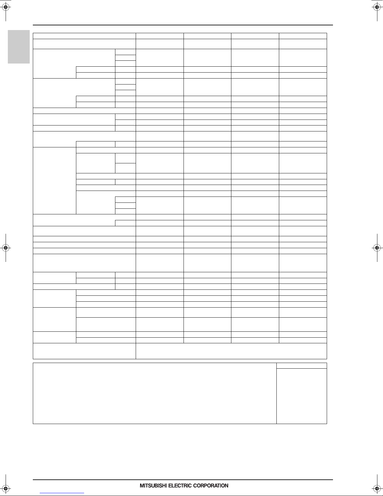
I.Ceiling concealed (Medium static pressure type)1. SPECIFICATIONS
Model PEFY-WP20VMA-E PEFY-WP25VMA-E PEFY-WP32VMA-E PEFY-WP40VMA-E
Power source
Cooling capacity *1 kW 2.2 2.8 3.6 4.5
(Nominal) *1 kcal/h 1,900 2,400 3,100 3,900
*2 Power input kW 0.07 0.09 0.11 0.14
Heating capacity *3 kW 2.5 3.2 4.0 5.0
(Nominal) *3 kcal/h 2,200 2,800 3,400 4,300
PEFY-WP-VMA-E
External finish Galvanized steel plate Galvanized steel plate Galvanized steel plate Galvanized steel plate
External dimension HxWxD mm 250 x 700 x 732 250 x 900 x 732 250 x 900 x 732 250 x 1,100 x 732
Net weight kg (lbs) 21 (47) 26 (58) 26 (58) 31 (69)
Heat exchanger
FAN Type x Quantity Sirocco fan x 1 Sirocco fan x 1 Sirocco fan x 1 Sirocco fan x 2
Sound pressure level (measured in anechoic room) (Low-Mid-High) (Low-Mid-High) (Low-Mid-Hig h) (Low-Mid-High)
Insulation material
Air filter PP honeycomb fabric. PP honeycomb fabric. PP honeycomb fabric. PP honeycomb fabric.
Protection device Fuse Fuse Fuse Fuse
Refrigerant control device - - - -
Connectable outdoor unit/HBC controller
Diameter of water pipe Inlet in. Rc 3 /4 screw Rc 3/4 screw Rc 3/4 screw Rc 3/4 screw
Field drain pipe size mm (in.) O.D.32 (1-1/4) O.D.32 (1-1/4) O.D.32 (1-1/4) O.D.32 (1-1/4)
Drawing External KD94L918X01 KD94L918X01 KD94L918X01 KD94L918X01
Standard attachment Document
Optional parts Filter box PAC-KE91TB-E PAC-KE92TB-E PAC-KE92TB-E PAC-KE93TB-E
*2 Current input A 0.55 0.64 0.74 1.15
*2 Power input kW 0.05 0.07 0.09 0.12
*2 Current input A 0.44 0.53 0.63 1.04
Water Volume L 0.7 1.0 1.0 1.8
*4 External static press. Pa
Motor Type DC motor DC motor DC motor DC motor
Motor output kW 0.085 0.085 0.085 0.121
Driving mechanism D irect-driven by motor Direct-driven by motor Direct-driven by motor Direct-driven by motor
Air flow rate (Low-Mid-High) (Low-Mid-Hi gh) (Low-Mid-High) (Low-Mid-High)
*5 *6 Outlet in. Rc 3/4 screw Rc 3/4 screw Rc 3/4 screw Rc 3/4 screw
Wiring KD94L919X01 KD94L919X01 KD94L919X01 KD94L919X01
Refrigerant cycle - - - -
Accessory
*1 BTU/h 7,500 9,600 12,300 15,400
*3 BTU/h 8,500 10,900 13,600 17,100
in. 9-7/8 x 27-9/16 x 28-7/8 9-7/8 x 35-7/16 x 28-7/8 9-7/8 x 35-7/16 x 28-7/8 9-7/8 x 43-5/16 x 28-7/8
mmH2O
3
m
L/s 125 - 150 - 175 167 - 200 - 233 200 - 242 - 283 2 42 - 300 - 350
cfm 265 - 318 - 371 353 - 424 - 494 424 - 512 - 600 512 - 636 - 742
*2 dB <A> 23-26-29 23-27-30 25-29-32 26-29-34
1-phase 220-230-240 V 50/
60 Hz
Cross fin (Aluminum fin and
copper tube)
<35> - 50 - <70> - <100> -
<150>
<3.6> - 5.1 - <7.1> - <10.2> -
<15.3>
/min 7.5 - 9.0 - 10.5 10.0 - 12.0 - 14.0 12.0 - 14.5 - 17.0 14.5 - 18.0 - 21.0
EPS, Polyethylene foam,
Urethane foam
HYBRID CITY MULTI/
CMB-WP-V-GA1, CMB-WP-
V-GB1, CMB-WM-V-AA,
CMB-WM-V-AB
Installation Manual, Instruc-
tion Book
Insulation pipe for water pipe,
Washer, Drain hose, Tie
band
1-phase 220-230-240 V 50/
60 Hz
Cross fin (Aluminum fin and
copper tube)
<35> - 50 - <70> - <100> -
<150>
<3.6> - 5.1 - <7.1> - <10.2> -
<15.3>
EPS, Polyethylene foam,
Urethane foam
HYBRID CITY MULTI/
CMB-WP-V-GA1, CMB-WP-
V-GB1, CMB-WM-V-AA,
CMB-WM-V-AB
Installation Manual, Instruc-
tion Book
Insulation pipe for water pipe,
Washer, Drain hose, Tie
band
Ceiling concealed (Medium static pressure type)
1-phase 220-230-240 V 50/
60 Hz
Cross fin (Aluminum fin and
copper tube)
<35> - 50 - <70> - <100> -
<150>
<3.6> - 5.1 - <7.1> - <10.2> -
<15.3>
EPS, Polyethylene foam,
Urethane foam
HYBRID CITY MULTI/
CMB-WP-V-GA1, CMB-WP-
V-GB1, CMB-WM-V-AA,
CMB-WM-V-AB
Installation Manual, Instruc-
tion Book
Insulation pipe for water pipe,
Washer, Drain hose, Tie
band
Remarks * Details on foundation work, duct work, insulation work, electrical wiring, power source switch, and other items shall be
Notes: Unit converter
1.Nominal cooling conditions
Indoor: 27°CD.B./19°CW.B. (81°CD.B./66°CW.B.), Outdoor: 35°CD.B. (95°CD.B.)
Pipe length: 7.5 m (24-9/16 ft.), Level difference: 0 m (0 ft.)
2.The values are measured at the factory setting of external static pressure.
3.Nominal heating conditions
Indoor: 20°CD.B. (68°CD.B.), Outdoor: 7°CD.B./6°CW.B. (45°CD.B./43°CW.B.)
Pipe length: 7.5 m (24-9/16 ft.), Level difference: 0 m (0 ft.)
4.The factory setting of external static pressure is shown without < >.
Refer to "Fan characteristics curves", according to the external static pressure, in DATA BOOK for the usable
range of air flow rate.
5.Be sure to install a valve on the water outlet.
6.Install a strainer (40 mesh or more) on the pipe n ext to the valve to remove the foreign matters.
7.Please group units that operate on 1 branch.
MEES17K198
referred to the Installation Manual.
* Due to continuing improvement, above specifications may be subject to change without notice.
kcal/h =kW x 860
BTU/h =kW x 3,412
cfm =m
lbs =kg / 0.4536
*Above specification data is
subject to rounding variation.
3
/min x 35.31
2
Page 4
1. SPECIFICATIONS
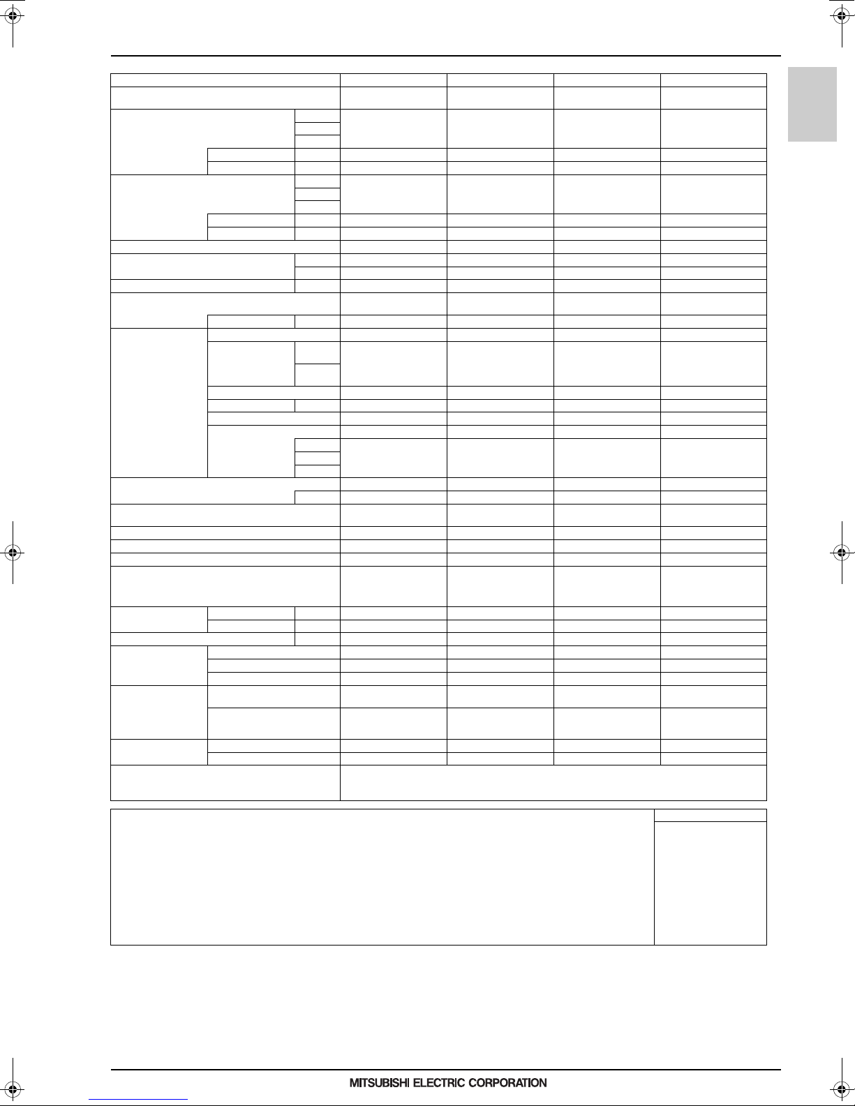
Ceiling concealed (Medium static pressure type)
Model PEFY-WP50VMA-E PEFY-WP63VMA-E PEFY-WP71VMA-E PEFY-WP80VMA-E
Power source
Cooling capacity *1 kW 5.6 7.1 8.0 9.0
(Nominal) *1 kcal/h 4,800 6,100 6,900 7,700
*2 Power input kW 0.14 0.14 0.24 0.24
*2 Current input A 1.15 1.15 1.47 1.47
Heating capacity *3 kW 6.3 8.0 9.0 10.0
(Nominal) *3 kcal/h 5,400 6,900 7,700 8,600
*2 Power input kW 0.12 0.12 0.22 0.22
*2 Current input A 1.04 1.04 1.36 1.36
External finish Galvanized steel plate Galvanized steel plate Galvanized steel plate Galvanized steel plate
External dimension HxWxD mm 250 x 1,100 x 732 250 x 1,100 x 732 250 x 1,400 x 732 250 x 1,400 x 732
Net weight kg (lbs) 31 (69) 31 (69) 40 (89) 40 (89)
Heat exchanger
Water Volume L 1.8 2.0 2.6 2.6
FAN Type x Quantity Sirocco fan x 2 Sirocco fan x 2 Sirocco fan x 2 Sirocco fan x 2
*4 External static press. Pa
Motor Type DC motor DC motor DC motor DC motor
Motor output kW 0.121 0.121 0.244 0.244
Driving mechanism Direct-driven by motor Direct-driven by motor Direct-driven by motor Direct-driven by motor
Air flow rate (Low-Mid-High) (Low-Mid-High) (Low-Mid-High) (Low-Mid-High)
Sound pressure level (measured in anechoic room) (Low-Mid-High) (Low-Mid-High) (Low-Mid-High) (Low-Mid-High)
Insulation material
Air filter PP honeycomb fabric. PP honeycomb fabric. PP honeycomb fabric. PP honeycomb fabric.
Protection device Fuse Fuse Fuse Fuse
Refrigerant control device - - - -
Connectable outdoor unit/HBC contro ller
Diameter of water pipe Inlet in. Rc 3/4 screw Rc 1-1/4 screw Rc 1-1/4 screw Rc 1-1/4 screw
*5 *6 Outlet in. Rc 3/4 screw Rc 1-1/4 screw Rc 1-1/4 screw Rc 1-1/4 screw
Field drain pipe size mm (in.) O.D.32 (1-1/4) O.D.32 (1-1/4) O.D.32 (1-1/4) O.D.32 (1-1/4)
Drawing External KD94L918X01 KL94G001X01 KL94G001X01 KL94G001X01
Wiring KD94L919X01 KD94L919X01 KD94L919X01 KD94L919X01
Refrigerant cycle - - - -
Standard attachment Document
Accessory
Optional parts Filter box PAC-KE93TB-E PAC-KE93TB-E PAC-KE94TB-E PAC-KE94TB-E
*1 BTU/h 19,100 2 4,200 27 ,300 30,70 0
*3 BTU/h 21,500 2 7,300 30 ,700 34,10 0
in. 9-7/8 x 43-5/16 x 28-7/8 9-7/8 x 43-5/16 x 28-7/8 9-7/8 x 55-1/8 x 28-7/8 9-7/8 x 55-1/8 x 28-7/8
mmH2O
3
m
L/s 242 - 300 - 350 242 - 300 - 350 383 - 467 - 550 383 - 467 - 550
cfm 512 - 636 - 742 512 - 636 - 742 812 - 989 - 1,165 812 - 989 - 1,165
*2 dB <A> 26-29-34 26-29-34 28-33-37 28-33-37
1-phase 220-230-240 V 50/
60 Hz
Cross fin (Aluminum fin and
copper tube)
<35> - 50 - <70> - <100> -
<150>
<3.6> - 5.1 - <7.1> - <10.2> -
<15.3>
/min 14.5 - 18.0 - 21.0 14.5 - 18.0 - 21.0 23.0 - 28.0 - 33.0 23.0 - 28.0 - 33.0
EPS, Polyethylene foam,
Urethane foam
HYBRID CITY MULTI/
CMB-WP-V-GA1, CMB-WP-
V-GB1, CMB-WM-V-AA,
CMB-WM-V-AB
Installation Manual, Instruc-
tion Book
Insulation pipe for water pipe,
Washer, Drain hose, Tie
band
1-phase 220-230-240 V 50/
60 Hz
Cross fin (Aluminum fin and
copper tube)
<35> - 50 - <70> - <100> -
<150>
<3.6> - 5.1 - <7.1> - <10.2> -
<15.3>
EPS, Polyethylene foam,
Urethane foam
HYBRID CITY MULTI/
CMB-WP-V-GA1, CMB-WP-
V-GB1, CMB-WM-V-AA,
CMB-WM-V-AB
Installation Manual, Instruc-
tion Book
Insulation pipe for water pipe,
Washer, Drain hose, Tie
band
PEFY-WP-VMA-E
Remarks * Details on foundation work, duct work, insulation work, electrical wiring, power source switch, and other items shall be
Notes : Unit converter
1.Nominal cooling conditions
Indoor: 27°CD.B./19°CW.B. (81°CD.B./66°CW.B.), Outdoor: 35°CD.B. (95°CD.B.)
Pipe length: 7.5 m (24-9/16 ft.), Level difference: 0 m (0 ft.)
2.The values are measured at the factory setting of external static pressure.
3.Nominal heating conditions
Indoor: 20°CD.B. (68°CD.B.), Outdoor: 7°CD.B./6°CW.B. (45°CD.B./43°CW.B.)
Pipe length: 7.5 m (24-9/16 ft.), Level difference: 0 m (0 ft.)
4.The factory setting of external static pressure is shown without < >.
Refer to "Fan characteristics curves", according to the external static pressure, in DATA BOOK for the usable
range of air flow rate.
5.Be sure to install a valve on the water outlet.
6.Install a strainer (40 mesh or more) on the pipe next to the valve to remove the foreign matters.
7.Please group units that operate on 1 branch.
MEES17K198
referred to the Installation Manual.
* Due to continuing improvement, ab ove specifications may be subject to change without notic e.
kcal/h =kW x 860
BTU/h =kW x 3,412
cfm =m
lbs =kg / 0.4536
*Above specification data is
subject to rounding variation.
3
/min x 35.31
3
Page 5

1. SPECIFICATIONS
Ceiling concealed (Medium static pressure type)
Model PEFY-WP100VMA-E PEFY-WP125VMA-E
Power source
Cooling capacity *1 kW 11.2 14.0
(Nominal) *1 kcal/h 9,6 00 12,000
*2 Power input kW 0.24 0.36
Heating capacity *3 kW 12.5 16.0
(Nominal) *3 kcal/h 10,800 13,800
PEFY-WP-VMA-E
External finish Galvanized steel plate Galvanized steel plate
External dimension HxWxD mm 250 x 1,400 x 732 250 x 1,600 x 732
Net weight kg (lbs) 40 (89) 42 (93)
Heat exchanger
FAN Type x Quantity Sirocco fan x 2 Sirocco fan x 2
Sound pressure level (measured in anechoic room) (Low-Mid-High) (Low-Mid-High)
Insulation material
Air filter PP honeycomb fabric. PP honeycomb fabric.
Protection device Fuse Fuse
Refrigerant control device - -
Connectable outdoor unit/HBC controller
Diameter of water pipe Inlet in. Rc 1-1/ 4 screw Rc 1-1/4 screw
Field drain pipe size mm (in.) O.D .32 (1-1/4) O.D.32 (1-1/4)
Drawing External KL94G001X01 KL94G001X01
Standard attachment Document
Optional parts Filter box PAC-KE94TB-E PAC-KE95TB-E
*2 Current input A 1.47 2.21
*2 Power input kW 0.22 0.34
*2 Current input A 1.36 2.10
Water Volume L 2.6 3.0
*4 External static press. Pa
Motor Type DC motor DC motor
Motor output kW 0.244 0.244
Driving mechanism D irect-driven by motor Direct-driven by motor
Air flow rate (Low-Mid-High) (Low-Mid-Hi gh)
*5 *6 Outlet in. Rc 1-1/4 screw Rc 1-1/4 screw
Wiring KD94L919X01 KD94L919X01
Refrigerant cycle - -
Accessory
*1 BTU/h 38,200 47,800
*3 BTU/h 42,700 54,600
in. 9-7/8 x 55-1/8 x 28-7/8 9-7/8 x 63 x 28-7/8
mmH2O
3
m
L/s 383 - 467 - 550 492 - 5 92 - 700
cfm 812 - 989 - 1,165 1,042 - 1,254 - 1,483
*2 dB <A> 28-33-37 32-36-40
1-phase 220-230-240 V 50/
60 Hz
Cross fin (Aluminum fin and
copper tube)
<35> - 50 - <70> - <100> -
<150>
<3.6> - 5.1 - <7.1> - <10.2> -
<15.3>
/min 23.0 - 28.0 - 33.0 29.5 - 35.5 - 42.0
EPS, Polyethylene foam,
Urethane foam
HYBRID CITY MULTI/
CMB-WP-V-GA1, CMB-WP-
V-GB1, CMB-WM-V-AA,
CMB-WM-V-AB
Installation Manual, Instruc-
tion Book
Insulation pipe for water pipe,
Washer, Drain hose, Tie
band
1-phase 220-230-240 V 50/
60 Hz
Cross fin (Aluminum fin and
copper tube)
<35> - 50 - <70> - <100> -
<150>
<3.6> - 5.1 - <7.1> - <10.2> -
<15.3>
EPS, Polyethylene foam,
Urethane foam
HYBRID CITY MULTI/
CMB-WP-V-GA1, CMB-WP-
V-GB1, CMB-WM-V-AA,
CMB-WM-V-AB
Installation Manual, Instruc-
tion Book
Insulation pipe for water pipe,
Washer, Drain hose, Tie
band
Remarks * Details on foundation work, duct work, insulation work, electrical wiring, power source switch, and other items shall be
Notes : Unit converter
1.Nominal cooling conditions
Indoor: 27°CD.B./19°CW.B. (81°CD.B./66°CW.B.), Outdoor: 35°CD.B. (95°CD.B.)
Pipe length: 7.5 m (24-9/16 ft.), Level difference: 0 m (0 ft.)
2.The values are measured at the factory setting of external static pressure.
3.Nominal heating conditions
Indoor: 20°CD.B. (68°CD.B.), Outdoor: 7°CD.B./6°CW.B. (45°CD.B./43°CW.B.)
Pipe length: 7.5 m (24-9/16 ft.), Level difference: 0 m (0 ft.)
4.The factory setting of external static pressure is shown without < >.
Refer to "Fan characteristics curves", according to the external static pressure, in DATA BOOK for the usable
range of air flow rate.
5.Be sure to install a valve on the water outlet.
6.Install a strainer (40 mesh or more) on the pipe n ext to the valve to remove the foreign matters.
7.Please group units that operate on 1 branch.
MEES17K198
referred to the Installation Manual.
* Due to continuing improvement, above specifications may be subject to change without notice.
kcal/h =kW x 860
BTU/h =kW x 3,412
cfm =m
lbs =kg / 0.4536
*Above specification data is
subject to rounding variation.
3
/min x 35.31
4
Page 6
2. EXTERNAL DIMENSIONS
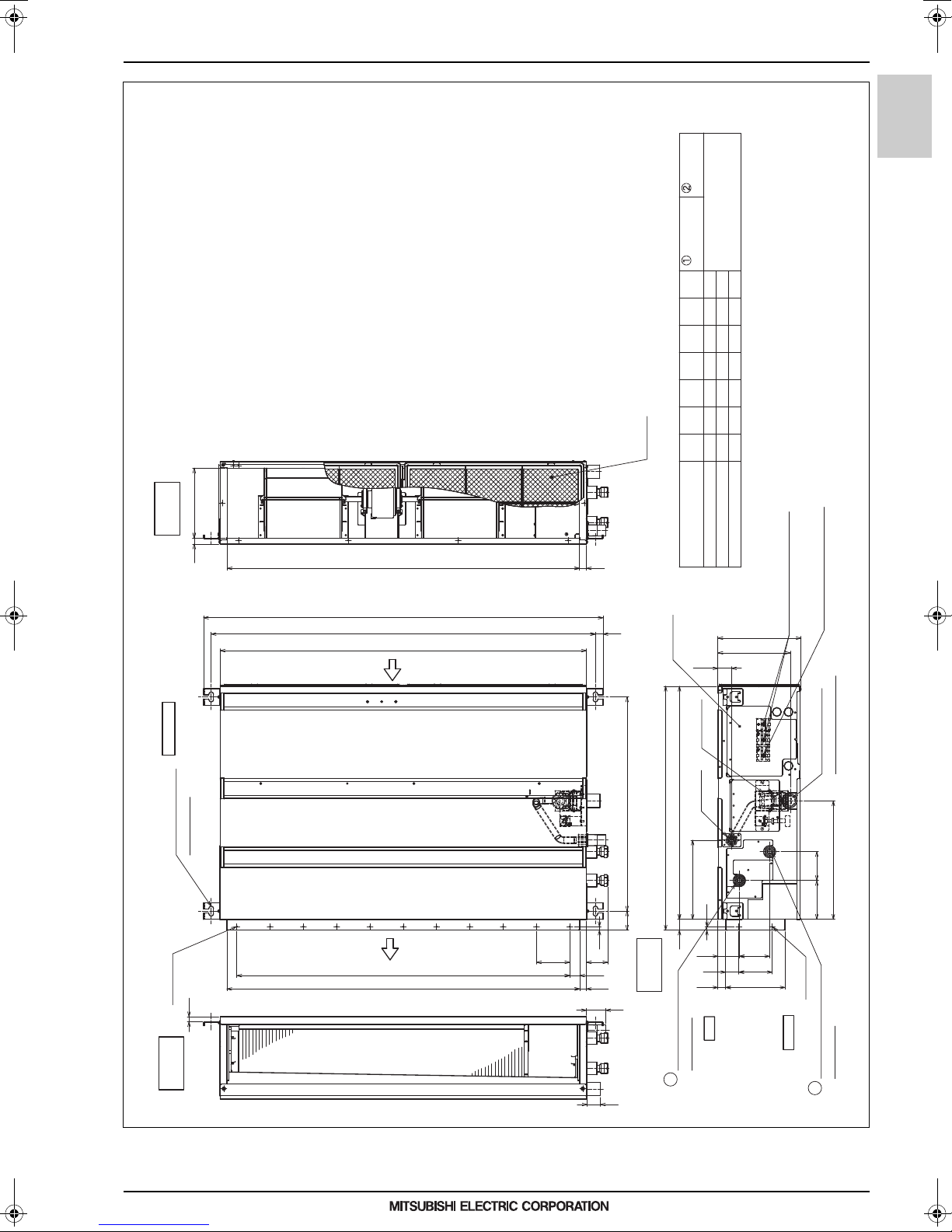
2. EXTERNAL DIMENSIONS
Ceiling concealed (Medium static pressure type)
PEFY-WP20, 25, 32, 40, 50VMA-E
Note 1.Use M10 screw for the Suspension bolt (field supply).
2.Keep the service space for the maintenance at the bottom.
3.This chart indicates for PEFY-WP40·50VMA-E models,
which have 2 fans.PEFY-WP20·25·32VMA-E models
have 1 fan.
4.In case of the inlet duct is used,remove the air filter
(supply with the unit),then install the filter
(field supply) at suction side.
21018
side view
Inlet air
Air Filter
Water pipe
(To HBC unit)
Rc3/4 screw
Water pipe
(From HBC unit)
858800G658
1058
F
600
1000
7
E
11
D
660800
1060
C
1000
1200
B
1154PEFY-WP40,50VMA-E
A
700 754
900 954 860 9
1100
Model
Unit: mm
PEFY-WP-VMA-E
Top view
Suspension bolt hole
4-14×30 Slot
2×E-ø2.9
15
Outlet air
side view
G21
C
B(Suspension bolt pitch)
A
Air
inlet
Air
outlet
10
100
100×(E-1)=F
D (Duct)
23
Control box
Drain pipe
732
643(Suspension bolt pitch)
238
57
32 700
64
30
20
side view
Piping
58
Water pipe(To HBC unit)
Rc3/4 screw
2
40
PEFY-WP20VMA-E
PEFY-WP25,32VMA-E
41
Drain pump
(O.D.ø32)
10
40
23
To p
250
217
91 64
100
178(Duct)
Terminal block(Power source)
Terminal block(Transmission)
Drain pipe(O.D.ø32)
(Spontaneous draining)
356
87117
2×2-ø2.9
Bottom
Water pipe(From HBC unit)
Rc3/4 screw
1
MEES17K198
5
Page 7
2. EXTERNAL DIMENSIONS
Ceiling concealed (Medium static pressure type)
PEFY-WP20, 25, 32, 40, 50VMA-E
PEFY-WP-VMA-E
Less than 300mm
0
-10
65
(Actual length)
H
Less than 700mm
<accessory>
Drain hose (I.D.ø32)
J×(L-1)=M
H
6
JK
J
N-ø2.9
Unit: mm
112 1111 2
Min.300mm50 700
P
Electric box
S
Bottom of
indoor unit
50
Maintenance access space
777
Access door 4
(Viewed from the direction
of the arrow B)
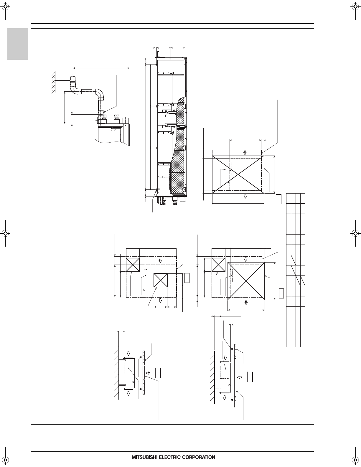
Fig.5
[Maintenance access space]
Secure enough access space to allow for the maintenance, inspection, and replacement of the motor, fan, drain pump, heat exchanger,
and electric box in one of the following ways.
Select an installation site for the indoor unit so that its maintenance access space will not be obstructed by beams or other objects.
(1)When a space of 300mm or more is available below the unit between the unit and the ceiling. (Fig.1)
·Create access door 1 and 2 (450×450mm each) as shown in Fig.2.
(Access door 2 is not required if enough space is available below the unit for a maintenance worker to work in.)
(2)When a space of less than 300mm is available below the unit between the unit and the ceiling.
(At least 20mm of space should be left below the unit as shown in Fig.3.)
·Create access door 1 diagonally below the electric box and access door 3 below the unit as shown in Fig.4.
or
·Create access door 4 below the electric box and the unit as shown in Fig.5.
Min.300mm
450
700
475
Access door 1
100~200
450
Electric box
(450×450)
Min.10mm
Intake air
Ceiling beam
Electric box
Supply air
Access door 2
P
Maintenance access space
450
Bottom of indoor unit
450
Q
50~150
(450×450)
Ceiling
A
Fig.1
Access door 2(450×450)
Min.300mm
(Viewed from the direction of the arrow A)
Fig.2
700
50
450
475
100~200
450
Access door 1
(450×450)
Electric box
Ceiling beam
Electric box
Intake air
Supply air
P
Bottom of
indoor unit
R
Min.10mm
Min.20mm
Ceiling
B
Fig.3
Access door 3
P
700
900
50
Maintenance access space
777
(Viewed from the direction of the arrow B)
Fig.4
Access door 3
N
M
L
K
J
101010
780
4
300
150
260
1100
990
449
330PEFY-WP40,50VMA-E 1200250~350 1700
Model H RQS
PEFY-WP20VMA-E 44 50~150 800 1300
PEFY-WP25,32VMA-E 1000150~250 150054
MEES17K198
6
Page 8
2. EXTERNAL DIMENSIONS
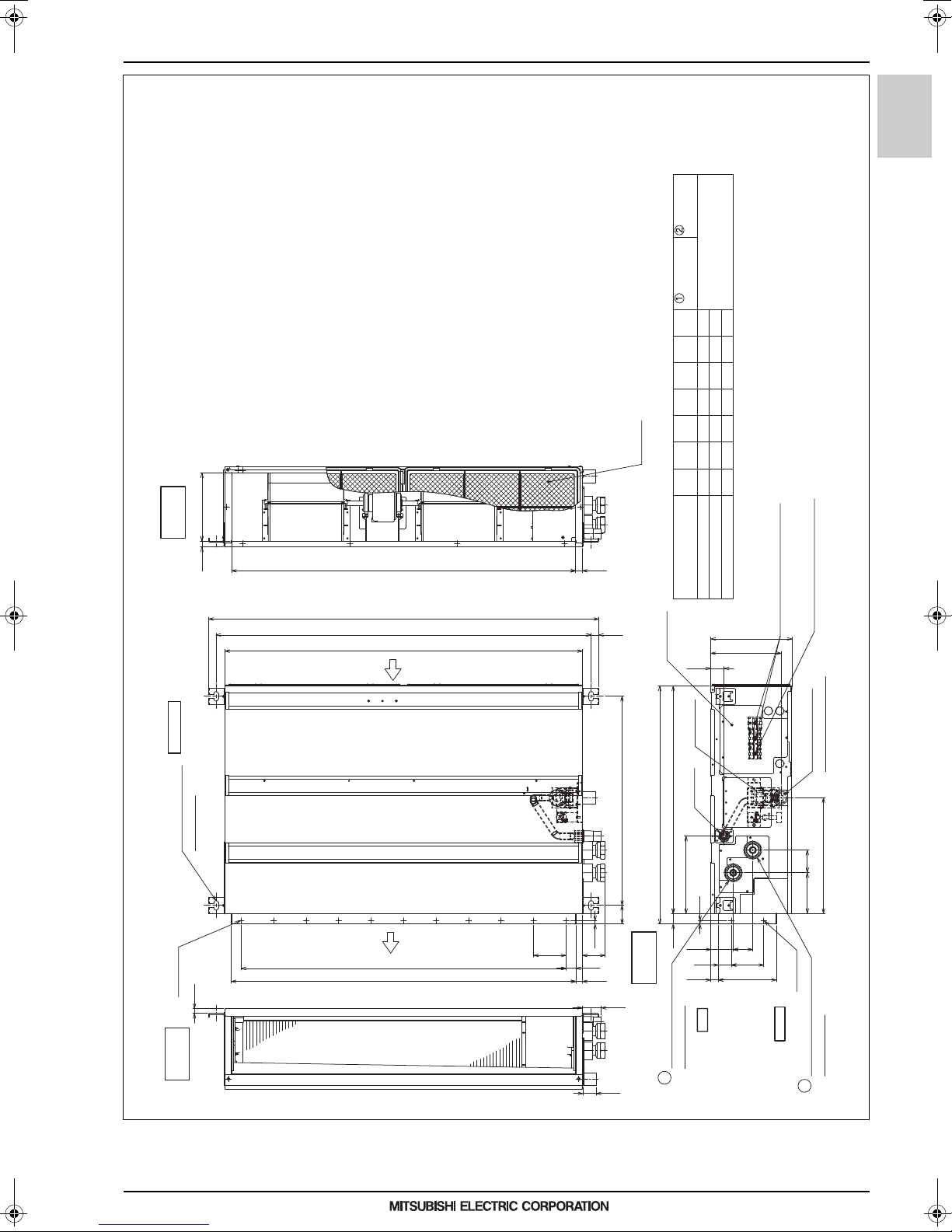
Ceiling concealed (Medium static pressure type)
PEFY-WP63, 71, 80, 100, 125VMA-E
(supply with the unit),then install the filter
(field supply) at suction side.
2. Keep the service space for the maintenance at the bottom.
3. In case of the inlet duct is used,remove the air filter
Note 1. Use an M10 screw for the Suspension bolt (field supply).
210
side view
Inlet air
Air Filter
Water pipe
(To HBC unit)
Rc1-1/4 screw
Water pipe
(From HBC unit)
1058
FG
1000
1300 1358
1500 1558
E
11
D
1060
C
1200
1700 1615601600 1654
1500 1413601400 1454
B
1154
1100
Unit: mm
PEFY-WP-VMA-E
18
Top view
Suspension bolt hole
4-14×30 Slot
15
2×E-ø2.9
G21
C
A
Air
inlet
Air
outlet
100×(E-1)=F
D (Duct)
B(Suspension
100
bolt pitch)
23
643(Suspension bolt pitch)
57
10
64
30
20
58
732
side view
Piping
Model A
Control box
41
Drain pump
Drain pipe
238
10
32 700
23
PEFY-WP63VMA-E
PEFY-WP71,80,100VMA-E
PEFY-WP125VMA-E
250
217
(O.D.ø32)
60 69
40
To p
100
178(Duct)
Terminal block(Power source)
Terminal block(Transmission)
Drain pipe(O.D.ø32)
(Spontaneous draining)
356
69126
2×2-ø2.9
Bottom
Outlet air
side view
MEES17K198
Water pipe(To HBC unit)
Rc1-1/4 screw
2
40
Water pipe(From HBC unit)
Rc1-1/4 screw
1
7
Page 9
2. EXTERNAL DIMENSIONS
Ceiling concealed (Medium static pressure type)
PEFY-WP63, 71, 80, 100, 125VMA-E
Less than 700mm
PEFY-WP-VMA-E
Drain hose (I.D.ø32)
Less than 300mm
0
-10
65
(Actual length)
<accessory>
H
JJ
J×(K-1)=L
J
H
6
M-ø2.9
Unit: mm
112 11112
indoor unit
Access door 4
50
777
of the arrow B)
(Viewed from the direction
Fig.5
20005
17004
Q
1200
1500
22005
1700
Min.300mm
50 700
Electric box
N
Bottom of
R
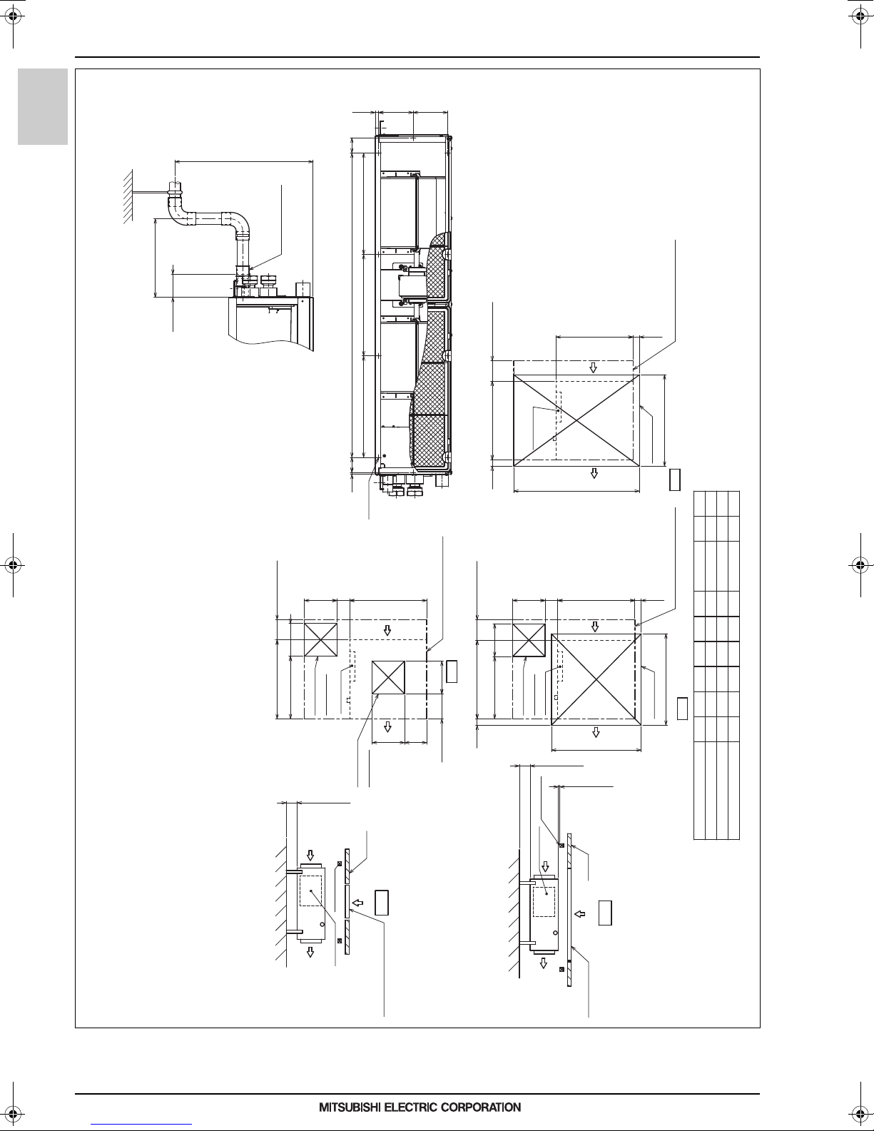
(1) When a space of 300mm or more is available below the unit between the unit and the ceiling. (Fig.1)
·Create access door 1 and 2 (450×450mm each) as shown in Fig.2.
(Access door 2 is not required if enough space is available below the unit for a maintenance worker to work in.)
(2) When a space of less than 300mm is available below the unit between the unit and the ceiling.
(At least 20mm of space should be left below the unit as shown in Fig.3.)
·Create access door 1 diagonally below the electric box and access door 3 below the unit as shown in Fig.4.
or
[Maintenance access space]
Secure enough access space to allow for the maintenance, inspection, and replacement of the motor, fan, drain pump, heat exchanger,
and electric box in one of the following ways.
Select an installation site for the indoor unit so that its maintenance access space will not be obstructed by beams or other objects.
·Create access door 4 below the electric box and the unit as shown in Fig.5.
Min.300mm
450
700
475
100~200
450
Electric box
Access door 1
(450×450)
Access door 2
Min.10mm
Intake air
Ceiling beam
Electric box
Supply air
N
Maintenance access space
450
Bottom of indoor unit
P
450
50~150
(450×450)
Ceiling
A
Fig.1
Access door 2(450×450)
(Viewed from the direction of the arrow A)
Fig.2
Min.300mm
450
700
475
50
100~200
450
Electric box
Access door 1
(450×450)
Ceiling beam
Electric box
Intake air
Supply air
N
Bottom of
indoor unit
Q
Min.10mm
Min.20mm
Ceiling
B
Fig.3
Access door 3
400~500
500~600
250~350
50
N
Maintenance access space Maintenance access space
1100
1600121480370
1400121280320
M
10
L
990
K
777
(Viewed from the direction of the arrow B)
JP
330
Fig.4
Access door 3
HR
54
54
49
Model
PEFY-WP63VMA-E
PEFY-WP71,80,100VMA-E
PEFY-WP125VMA-E
MEES17K198
8
Page 10

3. CENTER OF GRAVITY
Model name
PEFY-WP20VMA-E
PEFY-WP25VMA-E
PEFY-WP32VMA-E
W
643 [25 - 6/16]
643 [25 - 6/16]
643 [25 - 6/16]
L
754 [29 - 11/16]
954 [37 - 9/16]
954 [37 - 9/16]
X
330 [13]
340 [13 - 7/16]
340 [13 - 7/16]
Y
300 [11 -13/16]
375 [14 -13/16]
375 [14 -13/16]
Z
130 [5 -2/16]
130 [5 -2/16]
130 [5 -2/16]
PEFY-WP40VMA-E
PEFY-WP50VMA-E
643 [25 - 6/16]
1154 [45 - 7/16]
325 [12 - 13/16]
525 [20 -11/16]
130 [5 -2/16]
643 [25 - 6/16]
1154 [45 - 7/16]
325 [12 - 13/16]
525 [20 -11/16]
130 [5 -2/16]
PEFY-WP63VMA-E
643 [25 - 6/16]
1154 [45 - 7/16]
325 [12 - 13/16]
525 [20 -11/16]
130 [5 -2/16]
PEFY-WP71VMA-E
643 [25 - 6/16]
1454 [57 - 4/16]
330 [13]
675 [26 -10/16]
130 [5 -2/16]
PEFY-WP80VMA-E
643 [25 - 6/16]
1454 [57 - 4/16]
330 [13]
675 [26 -10/16]
130 [5 -2/16]
PEFY-WP100VMA-E
643 [25 - 6/16]
1454 [57 - 4/16]
330 [13]
675 [26 -10/16]
130 [5 -2/16]
PEFY-WP125VMA-E
643 [25 - 6/16]
1654 [65 - 2/16]
332 [13 - 2/16]
725 [28 -9/16]
130 [5 -2/16]
A : Center of gravity
YX
LW
A
Z
PEFY-WP20, 25, 32, 40, 50, 63, 71, 80, 100, 125VMA-E
(mm)[in]
3. CENTER OF GRAVITY
Ceiling concealed (Medium static pressure type)
PEFY-WP-VMA-E
MEES17K198
9
Page 11

4. ELECTRICAL WIRING DIAGRAMS
4. ELECTRICAL WIRING DIAGRAMS
PEFY-WP20, 25, 32, 40, 50, 63, 71, 80, 100, 125VMA-E
PULL BOX
FUSE (16A)
BREAKER (16A)
TO OUTDOOR UNIT
HBC CONTROLLER
PEFY-WP-VMA-E
TB15
INSIDE SECTION OF CONTROL BOX
TO MA REMOTE
CONTROLLER
1
2
REMOTE CONTROLLER
TO NEXT INDOOR UNIT
TB2
TB5
L
M1
M2
S(SHIELD)
11
22
ACL
P. B .
N
CND
(Red)
5
3
1
DSA
F01
U
ZNR01
ZNR02
AC220-240V
50,60Hz
POWER SUPPLY
U
(Blue)
DC280-340V
X01 X10
1
CNP
Rectifier circuit
(Blue)
3
33445 6 4
22752
CNXA1CNXB1 CNMF
1111
CNXC1
Ceiling concealed (Medium static pressure type)
3~
MS
Fan motor
NOTE:Symbols used in wiring diagram above are,
:Connector
:Terminal
(Heavy dotted line):Field wiring
I.B.
LED1
(Red)
CN27
SW4
(Red)
LED2
SW1
SWA
SW5
CN105
3
(Blue)
1
CN3A
SW2
SW14
CN2A
OFF
SWC
(Black)
SWE
ON
SW3
SW12
2
1
(Blue)
CN2M
CN90
SW11
CN32
1
(Blue)
CNXA2
2
CNXC2
54
2
1
431
32
CNXB2
CN41
CN51
CN52
(Green)
1
2
(Red)
CN20
4
2
1
3
CN4F
4
1
3
2
CN44
M
1~
TH21
t°
FS
TH23
TH22
t° t°
Drainpump
SYMBOL NAME
NAMESYMBOLSYMBOL
NAME
Switch (10ths digit address set)
Switch (for model selection)
Switch (for mode selection)
Switch (1s digit address set)
SW4(I.B.)
SW5(I.B.)
SW11(I.B.)
SW12(I.B.)
Connector (HA terminal-A)
Connector (Centrally control)
Connector (Remote indication)
Connector (Wireless)
CN41
CN51
CN52
CN90
Indoor controller board
Power supply board
Transmission terminal block
Power source terminal block
Switch (for static pressure selection)
Switch (for static pressure selection)
Switch (BRANCH No.)
Connector (emergency operation)
LED(Power supply)
LED(Remote controller supply)
LED2
LED1
SWA(I.B.)
SWE(I.B.)
SWC(I.B.)
SW14(I.B.)
Thermistor (piping temp.detection/water in)
Switch (for mode selection)
Switch (for capacity code)
Thermistor (inlet air temp.detection)
Connector (0-10V Analog input)
Connector (IT terminal)
Float switch
FS
TH22
TH21
CN2A
CN105
Transmission terminal block
Fuse AC250V 6.3A
Arrester
Aux. relay
Varistor
Switch (for mode selection)
Thermistor (piping temp.detection/water out)
TH23
SW2(I.B.)
SW3(I.B.)
SW1(I.B.)
Aux. relay
AC reactor(Power factor improvement)
Connector (Damper)
Connector (Remote switch)
MEES17K198
SYMBOL EXPLANATION
I.B.
TB2
TB5
TB15
F01
ZNR01,02
DSA
X01
X10
ACL
CN27
CN32
P. B.
10
Page 12

5. SOUND LEVELS
5. SOUND LEVELS
5-1. Sound levels
Ceiling concealed (Medium static pressure type)
5-1-1. Sound levels (Measured condition: With 1m air inlet duct and 2m air outlet duct)
PEFY-WP-VMA-E
Aux. duct
Model Sound level dB(A)
35Pa 50Pa 70Pa 100Pa 150Pa
Sound level at anechoic room : Low-Mid-High
PEFY-WP20VMA-E 28-30-34 28-30-34 29-32-36 29-33-37 31-35-40
2m
Measurement location
Measured in anechoic room.
*
1m
1.5m
PEFY-WP25VMA-E 28-30-34 28-30-34 29-32-36 29-33-37 32-36-40
PEFY-WP32VMA-E 28-31-35 28-32-35 29-33-37 30-34-38 32-37-41
PEFY-WP40VMA-E 30-33-37 30-34-38 31-36-39 33-37-41 36-41-44
PEFY-WP50VMA-E 30-33-37 30-34-38 31-36-39 33-37-41 36-41-44
PEFY-WP63VMA-E 30-33-37 30-34-38 31-36-39 33-37-41 36-41-44
PEFY-WP71VMA-E 31-36-40 32-37-41 33-38-42 35-39-43 37-42-45
PEFY-WP80VMA-E 31-36-40 32-37-41 33-38-42 35-39-43 37-42-45
PEFY-WP100VMA-E 31-36-40 32-37-41 33-38-42 35-39-43 37-42-45
PEFY-WP125VMA-E 36-41-45 36-41-45 38-42-46 39-43-47 40-45-48
5-1-2. Sound levels (Measured condition: With 2m air inlet duct and 2m air outlet duct)
PEFY-WP-VMA-E
2m 2m
Measurement location
Measured in anechoic room.
*
Aux. duct
Model Sound level dB(A)
35Pa 50Pa 70Pa 100Pa 150Pa
PEFY-WP20VMA-E 23-25-28 23-26-29 24-27-30 25-28-32 28-32-36
PEFY-WP25VMA-E 23-26-29 23-27-30 24-28-31 26-29-33 29-33-37
1.5m
PEFY-WP32VMA-E 24-28-31 25-29-32 26-30-33 27-31-34 29-34-38
PEFY-WP40VMA-E 26-29-33 26-29-34 26-30-35 29-33-37 32-37-41
PEFY-WP50VMA-E 26-29-33 26-29-34 26-30-35 29-33-37 32-37-41
PEFY-WP63VMA-E 26-29-33 26-29-34 26-30-35 29-33-37 32-37-41
PEFY-WP71VMA-E 28-32-36 28-33-37 30-35-39 31-36-40 33-38-43
PEFY-WP80VMA-E 28-32-36 28-33-37 30-35-39 31-36-40 33-38-43
PEFY-WP100VMA-E 28-32-36 28-33-37 30-35-39 31-36-40 33-38-43
PEFY-WP125VMA-E 31-35-40 33-37-42 34-38-43 35-38-44 37-41-45
Sound level at anechoic room : Low-Mid-High
PEFY-WP-VMA-E
MEES17K198
11
Page 13

5. SOUND LEVELS
10.0
15.0
20.0
25.0
30.0
35.0
40.0
45.0
50.0
55.0
60.0
65.0
70.0
63 125 250 500 1k 2k 4k 8k
NC-60
NC-50
Octave band pressure level (dB) 0dB=20μPa
Approximate minimum
audible limit on
continuous noise
NC-40
NC-30
NC-20
Octave band center frequencies (Hz)
High
Middle
50/60Hz
Low
50/60Hz
50/60Hz
PEFY-WP20VMA-E
External Static Pressure: 100Pa
Power Source: 220-240V(50/60Hz)
10.0
15.0
20.0
25.0
30.0
35.0
40.0
45.0
50.0
55.0
60.0
65.0
70.0
63 125 250 500 1k 2k 4k 8k
NC-60
NC-50
Octave band pressure level (dB) 0dB=20μPa
Approximate minimum
audible limit on
continuous noise
NC-40
NC-30
NC-20
Octave band center frequencies (Hz)
High
Middle
50/60Hz
Low
50/60Hz
50/60Hz
PEFY-WP20VMA-E
External Static Pressure: 150Pa
Power Source: 220-240V(50/60Hz)
10.0
15.0
20.0
25.0
30.0
35.0
40.0
45.0
50.0
55.0
60.0
65.0
70.0
63 125 250 500 1k 2k 4k 8k
NC-60
NC-50
Octave band pressure level (dB) 0dB=20μPa
Approximate minimum
audible limit on
continuous noise
NC-40
NC-30
NC-20
Octave band center frequencies (Hz)
High
Middle
50/60Hz
Low
50/60Hz
50/60Hz
PEFY-WP25VMA-E
External Static Pressure: 35Pa
Power Source: 220-240V(50/60Hz)
Ceiling concealed (Medium static pressure type)
5-2. NC curves
5-2-1. NC curves (Sound level measured condition : With 1m air inlet duct and 2m air outlet duct)
PEFY-WP20VMA-E
External Static Pressure: 35Pa
Power Source: 220-240V(50/60Hz)
70.0
65.0
60.0
55.0
PEFY-WP-VMA-E
50.0
45.0
40.0
35.0
30.0
25.0
20.0
Approximate minimum
audible limit on
15.0
Octave band pressure level (dB) 0dB=20μPa
continuous noise
10.0
63 125 250 500 1k 2k 4k 8k
Octave band center frequencies (Hz)
High
Middle
Low
50/60Hz
50/60Hz
50/60Hz
PEFY-WP20VMA-E
External Static Pressure: 50Pa
Power Source: 220-240V(50/60Hz)
70.0
65.0
NC-60
NC-50
NC-40
NC-30
NC-20
60.0
55.0
50.0
45.0
40.0
35.0
30.0
25.0
20.0
Approximate minimum
audible limit on
15.0
Octave band pressure level (dB) 0dB=20μPa
continuous noise
10.0
63 125 250 500 1k 2k 4k 8k
Octave band center frequencies (Hz)
High
Middle
Low
50/60Hz
50/60Hz
50/60Hz
PEFY-WP20VMA-E
External Static Pressure: 70Pa
Power Source: 220-240V(50/60Hz)
70.0
65.0
NC-60
NC-50
NC-40
NC-30
NC-20
60.0
55.0
50.0
45.0
40.0
35.0
30.0
25.0
20.0
Approximate minimum
audible limit on
15.0
Octave band pressure level (dB) 0dB=20μPa
continuous noise
10.0
63 125 250 500 1k 2k 4k 8k
Octave band center frequencies (Hz)
High
Middle
Low
50/60Hz
50/60Hz
50/60Hz
NC-60
NC-50
NC-40
NC-30
NC-20
PEFY-WP25VMA-E
External Static Pressure: 50Pa
Power Source: 220-240V(50/60Hz)
70.0
65.0
60.0
55.0
50.0
45.0
40.0
35.0
30.0
25.0
20.0
Approximate minimum
audible limit on
15.0
Octave band pressure level (dB) 0dB=20μPa
continuous noise
10.0
63 125 250 500 1k 2k 4k 8k
Octave band center frequencies (Hz)
High
Middle
Low
50/60Hz
50/60Hz
50/60Hz
NC-60
NC-50
NC-40
NC-30
NC-20
PEFY-WP25VMA-E
External Static Pressure: 150Pa
Power Source: 220-240V(50/60Hz)
70.0
65.0
60.0
55.0
50.0
45.0
40.0
35.0
30.0
25.0
20.0
Approximate minimum
audible limit on
15.0
Octave band pressure level (dB) 0dB=20μPa
continuous noise
10.0
63 125 250 500 1k 2k 4k 8k
Octave band center frequencies (Hz)
MEES17K198
High
Middle
Low
50/60Hz
50/60Hz
50/60Hz
NC-60
NC-50
NC-40
NC-30
NC-20
PEFY-WP25VMA-E
External Static Pressure: 70Pa
Power Source: 220-240V(50/60Hz)
70.0
65.0
60.0
55.0
50.0
45.0
40.0
35.0
30.0
25.0
20.0
Approximate minimum
audible limit on
15.0
Octave band pressure level (dB) 0dB=20μPa
continuous noise
10.0
63 125 250 500 1k 2k 4k 8k
Octave band center frequencies (Hz)
High
Middle
Low
PEFY-WP32VMA-E
External Static Pressure: 35Pa
Power Source: 220-240V(50/60Hz)
70.0
65.0
60.0
55.0
50.0
45.0
40.0
35.0
30.0
25.0
20.0
Approximate minimum
audible limit on
15.0
Octave band pressure level (dB) 0dB=20μPa
continuous noise
10.0
63 125 250 500 1k 2k 4k 8k
Octave band center frequencies (Hz)
High
Middle
Low
50/60Hz
50/60Hz
50/60Hz
50/60Hz
50/60Hz
50/60Hz
PEFY-WP25VMA-E
External Static Pressure: 100Pa
Power Source: 220-240V(50/60Hz)
70.0
65.0
NC-60
NC-50
NC-40
NC-30
NC-20
60.0
55.0
50.0
45.0
40.0
35.0
30.0
25.0
20.0
Approximate minimum
audible limit on
15.0
Octave band pressure level (dB) 0dB=20μPa
continuous noise
10.0
63 125 250 500 1k 2k 4k 8k
Octave band center frequencies (Hz)
PEFY-WP32VMA-E
External Static Pressure: 50Pa
Power Source: 220-240V(50/60Hz)
70.0
65.0
NC-60
NC-50
NC-40
NC-30
NC-20
60.0
55.0
50.0
45.0
40.0
35.0
30.0
25.0
20.0
Approximate minimum
audible limit on
15.0
Octave band pressure level (dB) 0dB=20μPa
continuous noise
10.0
63 125 250 500 1k 2k 4k 8k
Octave band center frequencies (Hz)
High
Middle
Low
High
Middle
Low
50/60Hz
50/60Hz
50/60Hz
50/60Hz
50/60Hz
50/60Hz
NC-60
NC-50
NC-40
NC-30
NC-20
NC-60
NC-50
NC-40
NC-30
NC-20
12
Page 14

5. SOUND LEVELS
Ceiling concealed (Medium static pressure type)
PEFY-WP32VMA-E
External Static Pressure: 70Pa
Power Source: 220-240V(50/60Hz)
70.0
65.0
60.0
55.0
50.0
45.0
40.0
35.0
30.0
25.0
20.0
Approximate minimum
audible limit on
15.0
Octave band pressure level (dB) 0dB=20μPa
continuous noise
10.0
63 125 250 500 1k 2k 4k 8k
Octave band center frequencies (Hz)
High
Middle
Low
PEFY-WP40,50,63VMA-E
External Static Pressure: 35Pa
Power Source: 220-240V(50/60Hz)
70.0
65.0
60.0
55.0
50.0
45.0
40.0
35.0
30.0
25.0
20.0
Approximate minimum
audible limit on
15.0
Octave band pressure level (dB) 0dB=20μPa
continuous noise
10.0
63 125 250 500 1k 2k 4k 8k
Octave band center frequencies (Hz)
High
Middle
Low
50/60Hz
50/60Hz
50/60Hz
50/60Hz
50/60Hz
50/60Hz
PEFY-WP32VMA-E
External Static Pressure: 100Pa
Power Source: 220-240V(50/60Hz)
70.0
65.0
NC-60
NC-50
NC-40
NC-30
NC-20
60.0
55.0
50.0
45.0
40.0
35.0
30.0
25.0
20.0
Approximate minimum
audible limit on
15.0
Octave band pressure level (dB) 0dB=20μPa
continuous noise
10.0
63 125 250 500 1k 2k 4k 8k
Octave band center frequencies (Hz)
PEFY-WP40,50,63VMA-E
External Static Pressure: 50Pa
Power Source: 220-240V(50/60Hz)
70.0
65.0
NC-60
NC-50
NC-40
NC-30
NC-20
60.0
55.0
50.0
45.0
40.0
35.0
30.0
25.0
20.0
Approximate minimum
audible limit on
15.0
Octave band pressure level (dB) 0dB=20μPa
continuous noise
10.0
63 125 250 500 1k 2k 4k 8k
Octave band center frequencies (Hz)
High
Middle
Low
High
Middle
Low
50/60Hz
50/60Hz
50/60Hz
50/60Hz
50/60Hz
50/60Hz
PEFY-WP32VMA-E
External Static Pressure: 150Pa
Power Source: 220-240V(50/60Hz)
70.0
65.0
NC-60
NC-50
NC-40
NC-30
NC-20
60.0
55.0
50.0
45.0
40.0
35.0
30.0
25.0
20.0
Approximate minimum
audible limit on
15.0
Octave band pressure level (dB) 0dB=20μPa
continuous noise
10.0
63 125 250 500 1k 2k 4k 8k
Octave band center frequencies (Hz)
PEFY-WP40,50,63VMA-E
External Static Pressure: 70Pa
Power Source: 220-240V(50/60Hz)
70.0
65.0
NC-60
NC-50
NC-40
NC-30
NC-20
60.0
55.0
50.0
45.0
40.0
35.0
30.0
25.0
20.0
Approximate minimum
audible limit on
15.0
Octave band pressure level (dB) 0dB=20μPa
continuous noise
10.0
63 125 250 500 1k 2k 4k 8k
Octave band center frequencies (Hz)
High
Middle
Low
High
Middle
Low
50/60Hz
50/60Hz
50/60Hz
50/60Hz
50/60Hz
50/60Hz
PEFY-WP-VMA-E
NC-60
NC-50
NC-40
NC-30
NC-20
NC-60
NC-50
NC-40
NC-30
NC-20
PEFY-WP40,50,63VMA-E
External Static Pressure: 100Pa
Power Source: 220-240V(50/60Hz)
70.0
65.0
60.0
55.0
50.0
45.0
40.0
35.0
30.0
25.0
20.0
Approximate minimum
audible limit on
15.0
Octave band pressure level (dB) 0dB=20μPa
continuous noise
10.0
63 125 250 500 1k 2k 4k 8k
Octave band center frequencies (Hz)
High
Middle
Low
PEFY-WP71,80,100VMA-E
External Static Pressure: 50Pa
Power Source: 220-240V(50/60Hz)
70.0
65.0
60.0
55.0
50.0
45.0
40.0
35.0
30.0
25.0
20.0
Approximate minimum
audible limit on
15.0
Octave band pressure level (dB) 0dB=20μPa
continuous noise
10.0
63 125 250 500 1k 2k 4k 8k
Octave band center frequencies (Hz)
High
Middle
Low
50/60Hz
50/60Hz
50/60Hz
50/60Hz
50/60Hz
50/60Hz
PEFY-WP40,50,63VMA-E
External Static Pressure: 150Pa
Power Source: 220-240V(50/60Hz)
70.0
65.0
NC-60
NC-50
NC-40
NC-30
NC-20
60.0
55.0
50.0
45.0
40.0
35.0
30.0
25.0
20.0
Approximate minimum
audible limit on
15.0
Octave band pressure level (dB) 0dB=20μPa
continuous noise
10.0
63 125 250 500 1k 2k 4k 8k
Octave band center frequencies (Hz)
PEFY-WP71,80,100VMA-E
External Static Pressure: 70Pa
Power Source: 220-240V(50/60Hz)
70.0
65.0
NC-60
NC-50
NC-40
NC-30
NC-20
60.0
55.0
50.0
45.0
40.0
35.0
30.0
25.0
20.0
Approximate minimum
audible limit on
15.0
Octave band pressure level (dB) 0dB=20μPa
continuous noise
10.0
63 125 250 500 1k 2k 4k 8k
Octave band center frequencies (Hz)
High
Middle
Low
High
Middle
Low
50/60Hz
50/60Hz
50/60Hz
50/60Hz
50/60Hz
50/60Hz
PEFY-WP71,80,100VMA-E
External Static Pressure: 35Pa
Power Source: 220-240V(50/60Hz)
70.0
65.0
NC-60
NC-50
NC-40
NC-30
NC-20
60.0
55.0
50.0
45.0
40.0
35.0
30.0
25.0
20.0
Approximate minimum
audible limit on
15.0
Octave band pressure level (dB) 0dB=20μPa
continuous noise
10.0
63 125 250 500 1k 2k 4k 8k
Octave band center frequencies (Hz)
PEFY-WP71,80,100VMA-E
External Static Pressure: 100Pa
Power Source: 220-240V(50/60Hz)
70.0
65.0
NC-60
NC-50
NC-40
NC-30
NC-20
60.0
55.0
50.0
45.0
40.0
35.0
30.0
25.0
20.0
Approximate minimum
audible limit on
15.0
Octave band pressure level (dB) 0dB=20μPa
continuous noise
10.0
63 125 250 500 1k 2k 4k 8k
Octave band center frequencies (Hz)
High
Middle
Low
High
Middle
Low
50/60Hz
50/60Hz
50/60Hz
50/60Hz
50/60Hz
50/60Hz
NC-60
NC-50
NC-40
NC-30
NC-20
NC-60
NC-50
NC-40
NC-30
NC-20
MEES17K198
13
Page 15

5. SOUND LEVELS
Ceiling concealed (Medium static pressure type)
PEFY-WP71,80,100VMA-E
External Static Pressure: 150Pa
Power Source: 220-240V(50/60Hz)
70.0
65.0
60.0
55.0
50.0
45.0
40.0
35.0
PEFY-WP-VMA-E
30.0
25.0
20.0
Approximate minimum
audible limit on
15.0
Octave band pressure level (dB) 0dB=20μPa
continuous noise
10.0
63 125 250 500 1k 2k 4k 8k
Octave band center frequencies (Hz)
PEFY-WP125VMA-E
External Static Pressure: 70Pa
Power Source: 220-240V(50/60Hz)
70.0
65.0
60.0
55.0
50.0
45.0
40.0
35.0
30.0
25.0
20.0
Approximate minimum
audible limit on
15.0
Octave band pressure level (dB) 0dB=20μPa
continuous noise
10.0
63 125 250 500 1k 2k 4k 8k
Octave band center frequencies (Hz)
High
Middle
Low
High
Middle
Low
50/60Hz
50/60Hz
50/60Hz
50/60Hz
50/60Hz
50/60Hz
PEFY-WP125VMA-E
External Static Pressure: 35Pa
Power Source: 220-240V(50/60Hz)
70.0
65.0
NC-60
NC-50
NC-40
NC-30
NC-20
60.0
55.0
50.0
45.0
40.0
35.0
30.0
25.0
20.0
Approximate minimum
audible limit on
15.0
Octave band pressure level (dB) 0dB=20μPa
continuous noise
10.0
63 125 250 500 1k 2k 4k 8k
Octave band center frequencies (Hz)
PEFY-WP125VMA-E
External Static Pressure: 100Pa
Power Source: 220-240V(50/60Hz)
70.0
65.0
NC-60
NC-50
NC-40
NC-30
NC-20
60.0
55.0
50.0
45.0
40.0
35.0
30.0
25.0
20.0
Approximate minimum
audible limit on
15.0
Octave band pressure level (dB) 0dB=20μPa
continuous noise
10.0
63 125 250 500 1k 2k 4k 8k
Octave band center frequencies (Hz)
High
Middle
Low
High
Middle
Low
50/60Hz
50/60Hz
50/60Hz
50/60Hz
50/60Hz
50/60Hz
PEFY-WP125VMA-E
External Static Pressure: 50Pa
Power Source: 220-240V(50/60Hz)
70.0
65.0
NC-60
NC-50
NC-40
NC-30
NC-20
60.0
55.0
50.0
45.0
40.0
35.0
30.0
25.0
20.0
Approximate minimum
audible limit on
15.0
Octave band pressure level (dB) 0dB=20μPa
continuous noise
10.0
63 125 250 500 1k 2k 4k 8k
Octave band center frequencies (Hz)
PEFY-WP125VMA-E
External Static Pressure: 150Pa
Power Source: 220-240V(50/60Hz)
70.0
65.0
NC-60
NC-50
NC-40
NC-30
NC-20
60.0
55.0
50.0
45.0
40.0
35.0
30.0
25.0
20.0
Approximate minimum
audible limit on
15.0
Octave band pressure level (dB) 0dB=20μPa
continuous noise
10.0
63 125 250 500 1k 2k 4k 8k
Octave band center frequencies (Hz)
High
Middle
Low
High
Middle
Low
50/60Hz
50/60Hz
50/60Hz
50/60Hz
50/60Hz
50/60Hz
NC-60
NC-50
NC-40
NC-30
NC-20
NC-60
NC-50
NC-40
NC-30
NC-20
MEES17K198
14
Page 16

5. SOUND LEVELS
Ceiling concealed (Medium static pressure type)
5-2-2. NC curves (Sound level measured condition : With 2m air inlet duct and 2m air outlet duct)
PEFY-WP20VMA-E
External Static Pressure: 35Pa
Power Source: 220-230-240V(50/60Hz)
70.0
65.0
60.0
55.0
50.0
45.0
40.0
35.0
30.0
25.0
20.0
Approximate minimum
audible limit on
15.0
Octave band pressure level (dB) 0dB=20μPa
continuous noise
10.0
63 125 250 500 1k 2k 4k 8k
Octave band center frequencies (Hz)
High
Middle
Low
50/60Hz
50/60Hz
50/60Hz
PEFY-WP20VMA-E
External Static Pressure: 100Pa
Power Source: 220-230-240V(50/60Hz)
70.0
65.0
60.0
55.0
50.0
45.0
40.0
35.0
30.0
25.0
20.0
Approximate minimum
audible limit on
15.0
Octave band pressure level (dB) 0dB=20μPa
continuous noise
10.0
63 125 250 500 1k 2k 4k 8k
Octave band center frequencies (Hz)
High
Middle
Low
50/60Hz
50/60Hz
50/60Hz
PEFY-WP20VMA-E
External Static Pressure: 50Pa
Power Source: 220-230-240V(50/60Hz)
70.0
65.0
NC-60
NC-50
NC-40
NC-30
NC-20
60.0
55.0
50.0
45.0
40.0
35.0
30.0
25.0
20.0
Approximate minimum
audible limit on
15.0
Octave band pressure level (dB) 0dB=20μPa
continuous noise
10.0
63 125 250 500 1k 2k 4k 8k
Octave band center frequencies (Hz)
PEFY-WP20VMA-E
External Static Pressure: 150Pa
Power Source: 220-230-240V(50/60Hz)
70.0
65.0
NC-60
NC-50
NC-40
NC-30
NC-20
60.0
55.0
50.0
45.0
40.0
35.0
30.0
25.0
20.0
Approximate minimum
audible limit on
15.0
Octave band pressure level (dB) 0dB=20μPa
continuous noise
10.0
63 125 250 500 1k 2k 4k 8k
Octave band center frequencies (Hz)
High
Middle
Low
High
Middle
Low
50/60Hz
50/60Hz
50/60Hz
50/60Hz
50/60Hz
50/60Hz
PEFY-WP20VMA-E
External Static Pressure: 70Pa
Power Source: 220-230-240V(50/60Hz)
70.0
65.0
NC-60
NC-50
NC-40
NC-30
NC-20
60.0
55.0
50.0
45.0
40.0
35.0
30.0
25.0
20.0
Approximate minimum
audible limit on
15.0
Octave band pressure level (dB) 0dB=20μPa
continuous noise
10.0
63 125 250 500 1k 2k 4k 8k
Octave band center frequencies (Hz)
PEFY-WP25VMA-E
External Static Pressure: 35Pa
Power Source: 220-230-240V(50/60Hz)
70.0
65.0
NC-60
NC-50
NC-40
NC-30
NC-20
60.0
55.0
50.0
45.0
40.0
35.0
30.0
25.0
20.0
Approximate minimum
audible limit on
15.0
Octave band pressure level (dB) 0dB=20μPa
continuous noise
10.0
63 125 250 500 1k 2k 4k 8k
Octave band center frequencies (Hz)
High
Middle
Low
High
Middle
Low
50/60Hz
50/60Hz
50/60Hz
50/60Hz
50/60Hz
50/60Hz
PEFY-WP-VMA-E
NC-60
NC-50
NC-40
NC-30
NC-20
NC-60
NC-50
NC-40
NC-30
NC-20
PEFY-WP25VMA-E
External Static Pressure: 50Pa
Power Source: 220-230-240V(50/60Hz)
70.0
65.0
60.0
55.0
50.0
45.0
40.0
35.0
30.0
25.0
20.0
Approximate minimum
audible limit on
15.0
Octave band pressure level (dB) 0dB=20μPa
continuous noise
10.0
63 125 250 500 1k 2k 4k 8k
Octave band center frequencies (Hz)
High
Middle
Low
50/60Hz
50/60Hz
50/60Hz
PEFY-WP25VMA-E
External Static Pressure: 150Pa
Power Source: 220-230-240V(50/60Hz)
70.0
65.0
60.0
55.0
50.0
45.0
40.0
35.0
30.0
25.0
20.0
Approximate minimum
audible limit on
15.0
Octave band pressure level (dB) 0dB=20μPa
continuous noise
10.0
63 125 250 500 1k 2k 4k 8k
Octave band center frequencies (Hz)
High
Middle
Low
50/60Hz
50/60Hz
50/60Hz
PEFY-WP25VMA-E
External Static Pressure: 70Pa
Power Source: 220-230-240V(50/60Hz)
70.0
65.0
NC-60
NC-50
NC-40
NC-30
NC-20
60.0
55.0
50.0
45.0
40.0
35.0
30.0
25.0
20.0
Approximate minimum
audible limit on
15.0
Octave band pressure level (dB) 0dB=20μPa
continuous noise
10.0
63 125 250 500 1k 2k 4k 8k
Octave band center frequencies (Hz)
PEFY-WP32VMA-E
External Static Pressure: 35Pa
Power Source: 220-230-240V(50/60Hz)
70.0
65.0
NC-60
NC-50
NC-40
NC-30
NC-20
60.0
55.0
50.0
45.0
40.0
35.0
30.0
25.0
20.0
Approximate minimum
audible limit on
15.0
Octave band pressure level (dB) 0dB=20μPa
continuous noise
10.0
63 125 250 500 1k 2k 4k 8k
Octave band center frequencies (Hz)
High
Middle
Low
High
Middle
Low
50/60Hz
50/60Hz
50/60Hz
50/60Hz
50/60Hz
50/60Hz
PEFY-WP25VMA-E
External Static Pressure: 100Pa
Power Source: 220-230-240V(50/60Hz)
70.0
65.0
NC-60
NC-50
NC-40
NC-30
NC-20
60.0
55.0
50.0
45.0
40.0
35.0
30.0
25.0
20.0
Approximate minimum
audible limit on
15.0
Octave band pressure level (dB) 0dB=20μPa
continuous noise
10.0
63 125 250 500 1k 2k 4k 8k
Octave band center frequencies (Hz)
PEFY-WP32VMA-E
External Static Pressure: 50Pa
Power Source: 220-230-240V(50/60Hz)
70.0
65.0
NC-60
NC-50
NC-40
NC-30
NC-20
60.0
55.0
50.0
45.0
40.0
35.0
30.0
25.0
20.0
Approximate minimum
audible limit on
15.0
Octave band pressure level (dB) 0dB=20μPa
continuous noise
10.0
63 125 250 500 1k 2k 4k 8k
Octave band center frequencies (Hz)
High
Middle
Low
High
Middle
Low
50/60Hz
50/60Hz
50/60Hz
50/60Hz
50/60Hz
50/60Hz
NC-60
NC-50
NC-40
NC-30
NC-20
NC-60
NC-50
NC-40
NC-30
NC-20
MEES17K198
15
Page 17

5. SOUND LEVELS
Ceiling concealed (Medium static pressure type)
PEFY-WP32VMA-E
External Static Pressure: 70Pa
Power Source: 220-230-240V(50/60Hz)
70.0
65.0
60.0
55.0
50.0
45.0
40.0
35.0
PEFY-WP-VMA-E
30.0
25.0
20.0
Approximate minimum
audible limit on
15.0
Octave band pressure level (dB) 0dB=20μPa
continuous noise
10.0
63 125 250 500 1k 2k 4k 8k
Octave band center frequencies (Hz)
PEFY-WP40, 50, 63VMA-E
External Static Pressure: 35Pa
Power Source: 220-230-240V(50/60Hz)
70.0
65.0
60.0
55.0
50.0
45.0
40.0
35.0
30.0
25.0
20.0
Approximate minimum
audible limit on
15.0
Octave band pressure level (dB) 0dB=20μPa
continuous noise
10.0
63 125 250 500 1k 2k 4k 8k
Octave band center frequencies (Hz)
High
Middle
Low
High
Middle
Low
50/60Hz
50/60Hz
50/60Hz
50/60Hz
50/60Hz
50/60Hz
PEFY-WP32VMA-E
External Static Pressure: 100Pa
Power Source: 220-230-240V(50/60Hz)
70.0
65.0
NC-60
NC-50
NC-40
NC-30
NC-20
60.0
55.0
50.0
45.0
40.0
35.0
30.0
25.0
20.0
Approximate minimum
audible limit on
15.0
Octave band pressure level (dB) 0dB=20μPa
continuous noise
10.0
63 125 250 500 1k 2k 4k 8k
Octave band center frequencies (Hz)
PEFY-WP40, 50, 63VMA-E
External Static Pressure: 50Pa
Power Source: 220-230-240V(50/60Hz)
70.0
65.0
NC-60
NC-50
NC-40
NC-30
NC-20
60.0
55.0
50.0
45.0
40.0
35.0
30.0
25.0
20.0
Approximate minimum
audible limit on
15.0
Octave band pressure level (dB) 0dB=20μPa
continuous noise
10.0
63 125 250 500 1k 2k 4k 8k
Octave band center frequencies (Hz)
High
Middle
Low
High
Middle
Low
50/60Hz
50/60Hz
50/60Hz
50/60Hz
50/60Hz
50/60Hz
PEFY-WP32VMA-E
External Static Pressure: 150Pa
Power Source: 220-230-240V(50/60Hz)
70.0
65.0
NC-60
NC-50
NC-40
NC-30
NC-20
60.0
55.0
50.0
45.0
40.0
35.0
30.0
25.0
20.0
Approximate minimum
audible limit on
15.0
Octave band pressure level (dB) 0dB=20μPa
continuous noise
10.0
63 125 250 500 1k 2k 4k 8k
Octave band center frequencies (Hz)
PEFY-WP40, 50, 63VMA-E
External Static Pressure: 70Pa
Power Source: 220-230-240V(50/60Hz)
70.0
65.0
NC-60
NC-50
NC-40
NC-30
NC-20
60.0
55.0
50.0
45.0
40.0
35.0
30.0
25.0
20.0
Approximate minimum
audible limit on
15.0
Octave band pressure level (dB) 0dB=20μPa
continuous noise
10.0
63 125 250 500 1k 2k 4k 8k
Octave band center frequencies (Hz)
High
Middle
Low
High
Middle
Low
50/60Hz
50/60Hz
50/60Hz
50/60Hz
50/60Hz
50/60Hz
NC-60
NC-50
NC-40
NC-30
NC-20
NC-60
NC-50
NC-40
NC-30
NC-20
PEFY-WP40, 50, 63VMA-E
External Static Pressure: 100Pa
Power Source: 220-230-240V(50/60Hz)
70.0
65.0
60.0
55.0
50.0
45.0
40.0
35.0
30.0
25.0
20.0
Approximate minimum
audible limit on
15.0
Octave band pressure level (dB) 0dB=20μPa
continuous noise
10.0
63 125 250 500 1k 2k 4k 8k
Octave band center frequencies (Hz)
High
Middle
Low
50/60Hz
50/60Hz
50/60Hz
PEFY-WP71, 80, 100VMA-E
External Static Pressure: 50Pa
Power Source: 220-230-240V(50/60Hz)
70.0
65.0
60.0
55.0
50.0
45.0
40.0
35.0
30.0
25.0
20.0
Approximate minimum
audible limit on
15.0
Octave band pressure level (dB) 0dB=20μPa
continuous noise
10.0
63 125 250 500 1k 2k 4k 8k
Octave band center frequencies (Hz)
High
Middle
Low
50/60Hz
50/60Hz
50/60Hz
PEFY-WP40, 50, 63VMA-E
External Static Pressure: 150Pa
Power Source: 220-230-240V(50/60Hz)
70.0
65.0
NC-60
NC-50
NC-40
NC-30
NC-20
60.0
55.0
50.0
45.0
40.0
35.0
30.0
25.0
20.0
Approximate minimum
audible limit on
15.0
Octave band pressure level (dB) 0dB=20μPa
continuous noise
10.0
63 125 250 500 1k 2k 4k 8k
Octave band center frequencies (Hz)
PEFY-WP71, 80, 100VMA-E
External Static Pressure: 70Pa
Power Source: 220-230-240V(50/60Hz)
70.0
65.0
NC-60
NC-50
NC-40
NC-30
NC-20
60.0
55.0
50.0
45.0
40.0
35.0
30.0
25.0
20.0
Approximate minimum
audible limit on
15.0
Octave band pressure level (dB) 0dB=20μPa
continuous noise
10.0
63 125 250 500 1k 2k 4k 8k
Octave band center frequencies (Hz)
High
Middle
Low
High
Middle
Low
50/60Hz
50/60Hz
50/60Hz
50/60Hz
50/60Hz
50/60Hz
PEFY-WP71, 80, 100VMA-E
External Static Pressure: 35Pa
Power Source: 220-230-240V(50/60Hz)
70.0
65.0
NC-60
NC-50
NC-40
NC-30
NC-20
60.0
55.0
50.0
45.0
40.0
35.0
30.0
25.0
20.0
Approximate minimum
audible limit on
15.0
Octave band pressure level (dB) 0dB=20μPa
continuous noise
10.0
63 125 250 500 1k 2k 4k 8k
Octave band center frequencies (Hz)
PEFY-WP71, 80, 100VMA-E
External Static Pressure: 100Pa
Power Source: 220-230-240V(50/60Hz)
70.0
65.0
NC-60
NC-50
NC-40
NC-30
NC-20
60.0
55.0
50.0
45.0
40.0
35.0
30.0
25.0
20.0
Approximate minimum
audible limit on
15.0
Octave band pressure level (dB) 0dB=20μPa
continuous noise
10.0
63 125 250 500 1k 2k 4k 8k
Octave band center frequencies (Hz)
High
Middle
Low
High
Middle
Low
50/60Hz
50/60Hz
50/60Hz
50/60Hz
50/60Hz
50/60Hz
NC-60
NC-50
NC-40
NC-30
NC-20
NC-60
NC-50
NC-40
NC-30
NC-20
MEES17K198
16
Page 18

5. SOUND LEVELS
Ceiling concealed (Medium static pressure type)
PEFY-WP71, 80, 100VMA-E
External Static Pressure: 150Pa
Power Source: 220-230-240V(50/60Hz)
70.0
65.0
60.0
55.0
50.0
45.0
40.0
35.0
30.0
25.0
20.0
Approximate minimum
audible limit on
15.0
Octave band pressure level (dB) 0dB=20μPa
continuous noise
10.0
63 125 250 500 1k 2k 4k 8k
Octave band center frequencies (Hz)
High
Middle
Low
50/60Hz
50/60Hz
50/60Hz
PEFY-WP125VMA-E
External Static Pressure: 70Pa
Power Source: 220-230-240V(50/60Hz)
70.0
65.0
60.0
55.0
50.0
45.0
40.0
35.0
30.0
25.0
20.0
Approximate minimum
audible limit on
15.0
Octave band pressure level (dB) 0dB=20μPa
continuous noise
10.0
63 125 250 500 1k 2k 4k 8k
Octave band center frequencies (Hz)
High
Middle
Low
50/60Hz
50/60Hz
50/60Hz
PEFY-WP125VMA-E
External Static Pressure: 35Pa
Power Source: 220-230-240V(50/60Hz)
70.0
65.0
NC-60
NC-50
NC-40
NC-30
NC-20
60.0
55.0
50.0
45.0
40.0
35.0
30.0
25.0
20.0
Approximate minimum
audible limit on
15.0
Octave band pressure level (dB) 0dB=20μPa
continuous noise
10.0
63 125 250 500 1k 2k 4k 8k
Octave band center frequencies (Hz)
PEFY-WP125VMA-E
External Static Pressure: 100Pa
Power Source: 220-230-240V(50/60Hz)
70.0
65.0
NC-60
NC-50
NC-40
NC-30
NC-20
60.0
55.0
50.0
45.0
40.0
35.0
30.0
25.0
20.0
Approximate minimum
audible limit on
15.0
Octave band pressure level (dB) 0dB=20μPa
continuous noise
10.0
63 125 250 500 1k 2k 4k 8k
Octave band center frequencies (Hz)
High
Middle
Low
High
Middle
Low
50/60Hz
50/60Hz
50/60Hz
50/60Hz
50/60Hz
50/60Hz
PEFY-WP125VMA-E
External Static Pressure: 50Pa
Power Source: 220-230-240V(50/60Hz)
70.0
65.0
NC-60
NC-50
NC-40
NC-30
NC-20
60.0
55.0
50.0
45.0
40.0
35.0
30.0
25.0
20.0
Approximate minimum
audible limit on
15.0
Octave band pressure level (dB) 0dB=20μPa
continuous noise
10.0
63 125 250 500 1k 2k 4k 8k
Octave band center frequencies (Hz)
PEFY-WP125VMA-E
External Static Pressure: 150Pa
Power Source: 220-230-240V(50/60Hz)
70.0
65.0
NC-60
NC-50
NC-40
NC-30
NC-20
60.0
55.0
50.0
45.0
40.0
35.0
30.0
25.0
20.0
Approximate minimum
audible limit on
15.0
Octave band pressure level (dB) 0dB=20μPa
continuous noise
10.0
63 125 250 500 1k 2k 4k 8k
Octave band center frequencies (Hz)
High
Middle
Low
High
Middle
Low
50/60Hz
50/60Hz
50/60Hz
50/60Hz
50/60Hz
50/60Hz
PEFY-WP-VMA-E
NC-60
NC-50
NC-40
NC-30
NC-20
NC-60
NC-50
NC-40
NC-30
NC-20
MEES17K198
17
Page 19

6. FAN CHARACTERISTICS CURVES
6. FAN CHARACTERISTICS CURVES
PEFY-WP20VMA-E
External static pressure : 35Pa
Power source : 220-240V
50
Ceiling concealed (Medium static pressure type)
PEFY-WP20VMA-E
External static pressure : 50Pa
Power source : 220-240V
70
40
Limit
30
PEFY-WP-VMA-E
20
Static pressure (Pa)
10
0
5 10 15 5 10 15
PEFY-WP20VMA-E
External static pressure : 70Pa
Power source : 220-240V
90
80
Limit
70
60
50
40
Static pressure (Pa)
30
20
10
0
5 10 15 5 10 15
Middle
Low
Airflow rate (m3/min)
Low
Airflow rate (m3/min)
High
Middle
High
60
Limit
50
40
30
Static pressure (Pa)
20
10
0
Airflow rate (m3/min)
PEFY-WP20VMA-E
External static pressure : 100Pa
Power source : 220-240V
110
100
90
Limit
80
70
60
50
Static pressure (Pa)
40
30
20
10
0
Airflow rate (m3/min)
High
Middle
Low
High
Middle
Low
PEFY-WP20VMA-E
External static pressure : 150Pa
Power source : 220-240V
160
150
140
130
Limit
120
110
100
90
80
70
60
Static pressure (Pa)
50
40
30
20
10
0
5 10 15
MEES17K198
Airflow rate (m3/min)
Middle
Low
High
18
Page 20

6. FAN CHARACTERISTICS CURVES
Ceiling concealed (Medium static pressure type)
PEFY-WP25VMA-E
External static pressure : 35Pa
Power source : 220-240V
60
50
Limit
40
30
Static pressure (Pa)
20
10
0
7 9 11 13 15 17 19 21 7 9 11 13 15 17 19 21
Low
Airflow rate (m3/min)
High
Middle
PEFY-WP25VMA-E
External static pressure : 70Pa
Power source : 220-240V
90
80
Limit
70
60
50
40
Static pressure (Pa)
30
20
10
0
7 9 11 13 15 17 19 21 7 9 11 13 15 17 19 21
Low
Airflow rate (m3/min)
High
Middle
PEFY-WP25VMA-E
External static pressure : 50Pa
Power source : 220-240V
70
60
Limit
50
40
30
Static pressure (Pa)
20
10
0
Airflow rate (m3/min)
PEFY-WP25VMA-E
External static pressure : 100Pa
Power source : 220-240V
120
110
100
Limit
90
80
70
60
50
Static pressure (Pa)
40
30
20
10
0
Airflow rate (m3/min)
Middle
Low
Middle
Low
PEFY-WP-VMA-E
High
High
PEFY-WP25VMA-E
External static pressure : 150Pa
Power source : 220-240V
170
160
150
140
Limit
130
120
110
100
90
80
70
Static pressure (Pa)
60
50
40
30
20
10
0
7 9 11 13 15 17 19 21
MEES17K198
Airflow rate (m3/min)
Low
High
Middle
19
Page 21

6. FAN CHARACTERISTICS CURVES
Ceiling concealed (Medium static pressure type)
PEFY-WP32VMA-E
External static pressure : 35Pa
Power source : 220-240V
60
50
Limit
40
PEFY-WP-VMA-E
30
Static pressure (Pa)
20
10
0
10 15 20 10 15 20
PEFY-WP32VMA-E
External static pressure : 70Pa
Power source : 220-240V
100
90
Limit
80
70
60
50
40
Static pressure (Pa)
30
20
10
0
10 15 20 10 15 20
Middle
Low
Airflow rate (m3/min)
Middle
Low
Airflow rate (m3/min)
High
High
PEFY-WP32VMA-E
External static pressure : 50Pa
Power source : 220-240V
80
70
Limit
60
50
40
30
Static pressure (Pa)
20
10
0
Airflow rate (m3/min)
PEFY-WP32VMA-E
External static pressure : 100Pa
Power source : 220-240V
130
120
110
Limit
100
90
80
70
60
50
Static pressure (Pa)
40
30
20
10
0
Airflow rate (m3/min)
High
Middle
Low
High
Middle
Low
PEFY-WP32VMA-E
External static pressure : 150Pa
Power source : 220-240V
170
160
150
140
Limit
130
120
110
100
90
80
70
Static pressure (Pa)
60
50
40
30
20
10
0
10 15 20
MEES17K198
Airflow rate (m3/min)
Middle
Low
High
20
Page 22

6. FAN CHARACTERISTICS CURVES
Ceiling concealed (Medium static pressure type)
PEFY-WP40, 50, 63VMA-E
External static pressure : 35Pa
Power source : 220-240V
60
50
Limit
40
30
Static pressure (Pa)
20
10
0
10 15 20 25 30 10 15 20 25 30
Low
Airflow rate (m3/min)
High
Middle
PEFY-WP40, 50, 63VMA-E
External static pressure : 70Pa
Power source : 220-240V
90
80
Limit
70
60
50
40
Static pressure (Pa)
30
20
10
0
10 15 20 25 30 10 15 20 25 30
Low
Airflow rate (m3/min)
High
Middle
PEFY-WP40, 50, 63VMA-E
External static pressure : 50Pa
Power source : 220-240V
70
60
Limit
50
40
30
Static pressure (Pa)
20
10
0
Airflow rate (m3/min)
PEFY-WP40, 50, 63VMA-E
External static pressure : 100Pa
Power source : 220-240V
120
110
100
Limit
90
80
70
60
50
Static pressure (Pa)
40
30
20
10
0
Airflow rate (m3/min)
Middle
Low
Middle
Low
PEFY-WP-VMA-E
High
High
PEFY-WP40, 50, 63VMA-E
External static pressure : 150Pa
Power source : 220-240V
170
160
150
140
Limit
130
120
110
100
90
80
70
Static pressure (Pa)
60
50
40
30
20
10
0
10 15 20 25 30
MEES17K198
Low
Airflow rate (m3/min)
High
Middle
21
Page 23

6. FAN CHARACTERISTICS CURVES
Ceiling concealed (Medium static pressure type)
PEFY-WP71, 80, 100VMA-E
External static pressure : 35Pa
Power source : 220-240V
70
60
Limit
50
40
PEFY-WP-VMA-E
30
Static pressure (Pa)
20
10
0
10 15 20 25 30 35 40 45 10 15 20 25 30 35 40 45
PEFY-WP71, 80, 100VMA-E
External static pressure : 70Pa
Power source : 220-240V
120
110
100
Limit
90
80
70
60
50
Static pressure (Pa)
40
30
20
10
0
10 15 20 25 30 35 40 45 10 15 20 25 30 35 40 45
Middle
Low
Airflow rate (m3/min)
Middle
Low
Airflow rate (m3/min)
High
High
PEFY-WP71, 80, 100VMA-E
External static pressure : 50Pa
Power source : 220-240V
100
90
Limit
80
70
60
50
40
Static pressure (Pa)
30
20
10
0
Airflow rate (m3/min)
PEFY-WP71, 80, 100VMA-E
External static pressure : 100Pa
Power source : 220-240V
150
140
130
Limit
120
110
100
90
80
70
60
Static pressure (Pa)
50
40
30
20
10
0
Airflow rate (m3/min)
High
Middle
Low
High
Middle
Low
PEFY-WP71, 80, 100VMA-E
External static pressure : 150Pa
Power source : 220-240V
200
190
180
170
Limit
160
150
140
130
120
110
100
90
80
Static pressure (Pa)
70
60
50
40
30
20
10
0
10 15 20 25 30 35 40 45
MEES17K198
Airflow rate (m3/min)
Low
High
Middle
22
Page 24

6. FAN CHARACTERISTICS CURVES
Ceiling concealed (Medium static pressure type)
PEFY-WP125VMA-E
External static pressure : 35Pa
Power source : 220-240V
70
Limit
60
50
40
Middle
30
Static pressure (Pa)
20
10
0
15 20 25 30 35 40 45 50 15 20 25 30 35 40 45 50
Low
Airflow rate (m3/min)
High
PEFY-WP125VMA-E
External static pressure : 70Pa
Power source : 220-240V
130
120
110
Limit
100
90
80
70
60
50
Static pressure (Pa)
40
30
20
10
0
15 20 25 30 35 40 45 50 15 20 25 30 35 40 45 50
Low
Airflow rate (m3/min)
High
Middle
PEFY-WP125VMA-E
External static pressure : 50Pa
Power source : 220-240V
100
90
Limit
80
70
60
50
40
Static pressure (Pa)
30
20
10
0
Airflow rate (m3/min)
PEFY-WP125VMA-E
External static pressure : 100Pa
Power source : 220-240V
160
150
140
130
Limit
120
110
100
90
80
70
60
Static pressure (Pa)
50
40
30
20
10
0
Airflow rate (m3/min)
Middle
Low
Middle
Low
PEFY-WP-VMA-E
High
High
PEFY-WP125VMA-E
External static pressure : 150Pa
Power source : 220-240V
200
190
180
170
Limit
160
150
140
130
120
110
100
90
80
Static pressure (Pa)
70
60
50
40
30
20
10
0
15 20 25 30 35 40 45 50
MEES17K198
Low
Airflow rate (m3/min)
High
Middle
23
Page 25

7. ELECTRICAL CHARACTERISTICS
7. ELECTRICAL CHARACTERISTICS
Ceiling concealed (Medium static pressure type)
Symbols: MCA: Max.Circuit Amps (=1.25xFLA) FLA: Full Load Amps
IFM: Indoor Fan Motor Output: Fan motor rated output
PEFY-WP-VMA-E
PEFY-WP20VMA-E
Volts/Hz Range +-10% MCA(A) Output (kW) FLA(A)
Power supply IFM
1.18 0.085 0.95
PEFY-WP25VMA-E 1.43 0.085 1.14
PEFY-WP32VMA-E 1.54 0.085 1.23
PEFY-WP40VMA-E 2.47 0.121 1.98
PEFY-WP50VMA-E 2.47 0.121 1.98
PEFY-WP-VMA-E
PEFY-WP63VMA-E 2.47 0.121 1.98
220-240V/50Hz
220-240V/60Hz
Max.: 264V
Min.: 198V
PEFY-WP71VMA-E 3.30 0.244 2.64
PEFY-WP80VMA-E 3.30 0.244 2.64
PEFY-WP100VMA-E 3.30 0.244 2.64
PEFY-WP125VMA-E 3.29 0.244 2.63
MEES17K198
24
Page 26

8. OPTIONAL PARTS
8. OPTIONAL PARTS
8-1. Optional parts line up for the Indoor unit
PEFY-WP20VMA-E
PEFY-WP25, 32VMA-E
PEFY-WP40, 50, 63VMA-E
PEFY-WP71, 80, 100VMA-E
PEFY-WP125VMA-E
PEFY-WP-VMA-E
Filter box
PAC-KE·TB-E
Filter box
PAC-KE91TB-E
PAC-KE92TB-E
PAC-KE93TB-E
PAC-KE94TB-E
PAC-KE95TB-E
Ceiling concealed (Medium static pressure type)
PEFY-WP-VMA-E
PEFY-WP-VMA-E
8-2. Filter box
PAC-KE-TB-E
Item Screw Filter box Installation manual
Quantity 30 1
Shape
Detailed installation information should be referred to its Installation Manual.
12 34
FLANGE
11
MEES17K198
25
Page 27

Ceiling concealed (Medium static pressure type)
MEES17K198
26
Page 28

Warning
■
Do not use refrigerant other than the type indicated in the manuals provided with the unit and on the nameplate.
- Doing so may cause the unit or pipes to burst, or result in explosion or fire during use, repair, or at the time of disposal of the unit.
- It may also be in violation of applicable laws.
- MITSUBISHI ELECTRIC CORPORATION cannot be held responsible for malfunctions or accidents resulting from the use of the wrong
type of refrigerant.
■
Our air conditioning equipment and heat pumps contain a fluorinated greenhouse gas, R410A.
MEES17K198
New publication effective May 2018
Specifications subject to change without notice
 Loading...