

Mitsubishi PEFY-P50VMA-E2, PEFY-P80VMA-E2, PEFY-P20VMA-E2, PEFY-P63VMA-E2, PEFY-P71VMA-E2 Installation Manual
...Page 1
<ORIGINAL>
Air-Conditioners
INDOOR UNIT
PEFY-P20,25,32,40,50,63,71,80,100,125,140VMA-E2
PEFY-P20,25,32,40,50,63,71,80,100,125,140VMAL-E2
GBDFEINLP
INSTALLATIONSHANDBUCH
Zum sicheren und ordnungsgemäßen Gebrauch der Klimageräte das Installationshandbuch gründlich durchlesen.
MANUEL D’INSTALLATION
Veuillez lire le manuel d’installation en entier avant d’installer ce climatiseur pour éviter tout accident et vous assurer d’une utilisation correcte.
MANUAL DE INSTALACIÓN
Para un uso seguro y correcto, lea detalladamente este manual de instalación antes de montar la unidad de aire acondicionado.
INSTALLATION MANUAL
For safe and correct use, please read this installation manual thoroughly before installing the air-conditioner unit.
MANUALE DI INSTALLAZIONE
Per un uso sicuro e corretto, leggere attentamente questo manuale di installazione prima di installare il condizionatore d’aria.
INSTALLATIEHANDLEIDING
Voor een veilig en juist gebruik moet u deze installatiehandleiding grondig doorlezen voordat u de airconditioner installeert.
MANUAL DE INSTALAÇÃO
Para segurança e utilização correctas, leia atentamente este manual de instalação antes de instalar a unidade de ar condicionado.
GRRUTR
ΕΓΧΕΙΡΙΔΙΟ ΟΔΗΓΙΩΝ ΕΓΚΑΤΑΣΤΑΣΗΣ
Για ασφάλεια και σωστή χρήση, παρακαλείστε διαβάσετε προσεχτικά αυτό το εγχειρίδιο εγκατάστασης πριν αρχίσετε την εγκατάσταση της
μονάδας κλιματισμού.
РУКОВОДСТВО ПО УСТАНОВКЕ
Для осторожного и правильного использования прибора необходимо тщательно ознакомиться с данным руководством по установке
до выполнения установки кондиционера.
MONTAJ ELKİTABI
Emniyetli ve doğru biçimde nasıl kullanılacağını öğrenmek için lütfen klima cihazını monte etmeden önce bu elkitabını dikkatle okuyunuz.
SVHGPO CZ
PŘÍRUČKA K INSTALACI
V zájmu bezpečného a správného používání si před instalací klimatizační jednotky důkladně pročtěte tuto příručku k instalaci.
NÁVOD NA INŠTALÁCIU
Pre bezpečné a správne použitie si pred inštalovaním klimatizačnej jednotky, prosím, starostlivo prečítajte tento návod na inštaláciu.
TELEPÍTÉSI KÉZIKÖNYV
A biztonságos és helyes használathoz, kérjük, olvassa el alaposan ezt a telepítési kézikönyvet, mielőtt telepítené a légkondicionáló egységet.
PODRĘCZNIK INSTALACJI
W celu bezpiecznego i poprawnego korzystania należy przed zainstalowaniem klimatyzatora dokładnie zapoznać się z niniejszym podręcznikiem instalacji.
SLSWHRBGRO
PRIROČNIK ZA NAMESTITEV
Za varno in pravilno uporabo pred namestitvijo klimatske naprave skrbno preberite priročnik za namestitev.
INSTALLATIONSHANDBOK
Läs den här installationshandboken noga innan luftkonditioneringsenheten installeras, för säker och korrekt användning.
PRIRUČNIK ZA UGRADNJU
Radi sigurne i ispravne uporabe, temeljito pročitajte ovaj priručnik prije ugradnje unutarnje jedinice.
РЪКОВОДСТВО ЗА МОНТАЖ
За безопасна и правилна употреба, моля, прочетете внимателно това ръководство преди монтажа на климатизатора.
MANUAL CU INSTRUCŢIUNI DE INSTALARE
Pentru o utilizare corectă şi sigură, vă rugăm să citiţi cu atenţie acest manual înainte de a instala unitatea de aer condiţionat.
Page 2
2
33.2
[Fig. 3.2.1] [Fig. 3.2.2] (Unit: mm)
[Fig. 3.2.3] [Fig. 3.2.4]
[Fig. 3.2.5]
Min. 300 mm
Min.
10 mm
G
A
H
A
C
B
D
G
H
I
F
700
450
475 450
Q
50~150
450
450
100~200
Min. 300 mm
P
E
A
D
(Viewed from the direction of the arrow A)
H
G
Min. 20 mm
Min.10 mm
B
C
A
B
J
P50
R
777
450
100~200
450475
70050
Min. 300 mm
E
A
I
J
F
G
H
(Viewed from the direction of the arrow B)
777
S
50
50 P
700
Min. 300 mm
G
H
K
F
A
I
(Viewed from the direction of the arrow B)
PEFY-P20,25,32VMA(L)-E2
PEFY-P40,50VMA(L)-E2
PEFY-P63,71,80VMA(L)-E2
PEFY-P100,125VMA(L)-E2
PEFY-P140VMA(L)-E2
P
700
900
1100
1400
1600
R
800
1000
1200
1500
1700
S
1300
1500
1700
2000
2200
Q
50~150
150~250
250~350
400~500
500~600
(mm)
Model
A Electric box
B Ceiling
C Ceiling beam
D Access door 2 (450 mm x 450 mm)
E Access door 1 (450 mm x 450 mm)
F Maintenance access space
G Supply air
H Intake air
I Bottom of indoor unit
J Access door 3
K Access door 4
Page 3
3
4
4.1
[Fig. 4.1.1]
5
5.1
[Fig. 5.1.1] [Fig. 5.1.2]
6
6.2
[Fig. 6.2.1]
YX
LW
A
Z
A Center of gravity
B
A
A Unit body
B Lifting machine
C
D
C
E
D
C Nuts (field supply)
D Washers (field supply)
E M10 hanging bolt (field supply)
137 67
239
357
122
33
41
217
C
A
B
D
A Refrigerant pipe (liquid pipe)
B Refrigerant pipe (gas pipe)
C Drain pipe (O.D. ø32)
D Drain pipe (O.D. ø32, spontaneous draining)
Page 4
4
77.1
[Fig. 7.1.1]
[Fig. 7.1.2]
[Fig. 7.1.3]
7.2
[Fig. 7.2.1]
[Fig. 7.2.2] [Fig. 7.2.3]
A Cut here
B Remove brazed cap
A
A Cool by a wet cloth
A
A
E
C
F
B
D
A Thermal insulation
B Pull out insulation
C Wrap with damp cloth
D Return to original position
E Ensure that there is no gap here
F Wrap with insulating tape
C
B
A
L
D
D
D
E
K
M
B
H
I
Max. 20m
1.5-2m
G
F
FF
B
J
O
N
F
Max. 300mm
Correct piping
Wrong piping
A Insulation (9 mm or more)
B Downward slope (1/100 or more)
C Support metal
K Air bleeder
L Raised
M Odor trap
Grouped piping
D O. D. ø32 PVC TUBE
E Make it as large as possible. About 10 cm.
F Indoor unit
G Make the piping size large for grouped piping.
H Downward slope (1/100 or more)
I O. D. ø38 PVC TUBE for grouped piping.
(9 mm or more insulation)
PEFY-P·VMA-E2 model
J Up to 700 mm
N Drain socket (accessory)
O Horizontal or slightly upgradient
B
CD D
G
F
E
H
A
3235 25
A Indoor unit
B Tie band (accessory)
C Visible part
D Insertion margin
E Drain socket (accessory)
F Drain pipe (O.D. ø32 PVC TUBE, field supply)
G Insulating material (field supply)
H Tie band (accessory)
C
D
G
F
E
B
525
A
A Indoor unit
B Tie band (accessory)
C Band fixing part
D Insertion margin
E Drain socket (accessory)
F Drain pipe (O.D. ø32 PVC TUBE, field supply)
G Insulating material (field supply)
Page 5
5
7.3
[Fig. 7.3.1] [Fig. 7.3.2]
8
[Fig. 8.0.1]
[Fig. 8.0.3]
[Fig. 8.0.2]
[Fig. 8.0.4]
9
9.1 9.2
[Fig. 9.1.1] [Fig. 9.2.1]
[Fig. 9.2.2]
A Insert pump's end 2 to 4 cm.
B Remove the water supply port.
C About 2500 cc
D Water
E Filling port
F Screw
A
B
F
C
D
E
A
B
G
F
A
CE
D
B
GH
F
A
C
D
<B> In case of bottom inlet
<A> In case of rear inlet
A Duct
B Air inlet
C Access door
D Canvas duct
E Ceiling surface
F Air outlet
G Leave distance
enough to prevent short cycle
H Min. 200 mm
A
B
A Filter
B Bottom plate
C Nail for the bottom inlet
D Nail for the rear inlet
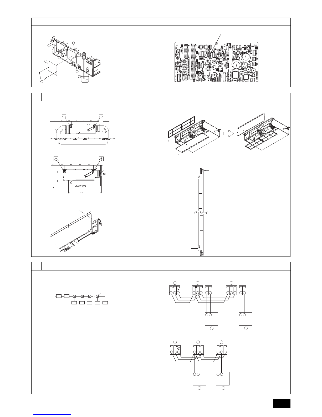
AB
CCCCDC
~220V
TB5 TB15 TB5 TB15
SM1M2 SM1M2
TB3
M1M2 21
21
AA
B
CC
TB5 TB5
SM1M2 SM1M2
TB3
M1M2
AA
B
CC
A Terminal block for indoor
transmission cable
B Terminal block for outdoor
transmission cable
C Remote controller
SWE
<Indoor controller board>
C
D
A Ground-fault interrupter
B Local switch/Wiring breaker
C Indoor unit
D Pull box
Page 6
6
9.2
[Fig. 9.2.3] [Fig. 9.2.4]
9.3
[Fig. 9.3.1]
[Fig. 9.3.3]
[Fig. 9.3.5]
[Fig. 9.3.2]
[Fig. 9.3.4]
9.5
[Fig. 9.5.1]
2
S
M2
M1
A
B
D
1
DC10~13V
AB
12
L
N
C
D
A
S
M2
M1
B
1
2
L
N
DC24~30V
(A, B)
12
C
A Non-polarized
B TB15
C Remote Controller
D TB5
A Screw holding cover (1pc)
B Cover
C Terminal box
D Knockout hole
E Remove
J
L
K
J Terminal block for power source
K Terminal block for indoor transmission
L Terminal block for remote controller
SW11
SW12
SWC
SW14
SW5
SWA
F Use PG bushing to keep the weight of the cable and external force from being ap-
plied to the power supply terminal connector. Use a cable tie to secure the cable.
G Power source wiring
H Use ordinary bushing
I Transmission wiring
<Indoor controller board>
C
D
E
M2 SM1
A
B
C
E
D
A Terminal block
B Round terminal
C Shield wire
D The earth wire from two cables are connected together to the S terminal. (Dead-end connection)
E Insulation tape (To keep the earth wire of the shielded cable from coming in contact with the trans-
mission terminal)
H
I
F
G
A
B
Page 7
GB
7
Contents
1. Safety precautions .................................................................................... 7
1.1. Before installation and electric work .........................................7
1.2. Precautions for devices that use R410A refrigerant .................7
1.3. Before getting installed .............................................................8
1.4. Before getting installed (moved) - electrical work .....................8
1.5. Before starting the test run........................................................ 8
2. Indoor unit accessories ............................................................................. 8
3. Selecting an installation site......................................................................8
3.1. Install the indoor unit on a ceiling strong enough to sustain
its weight ................................................................................... 9
3.2. Securing installation and service space....................................9
3.3. Combining indoor units with outdoor units ................................9
4. Fixing hanging bolts..................................................................................9
4.1. Fixing hanging bolts.................................................................. 9
5. Installing the unit ....................................................................................... 9
5.1. Hanging the unit body............................................................... 9
5.2. Confirming the unit’s position and fixing hanging bolts.............9
6. Refrigerant pipe and drain pipe specifications ........................................ 10
6.1. Refrigerant pipe and drain pipe specifications........................10
6.2. Refrigerant pipe, drain pipe..................................................... 10
7. Connecting refrigerant pipes and drain pipes......................................... 10
7.1. Refrigerant piping work........................................................... 10
7.2. Drain piping work .................................................................... 10
7.3. Confirming drain discharge..................................................... 11
8. Duct work ................................................................................................11
9. Electrical wiring ....................................................................................... 12
9.1. Power supply wiring ................................................................12
9.2. Connecting remote controller, indoor and outdoor
transmission cables ................................................................ 13
9.3. Connecting electrical connections .......................................... 13
9.4. External I/O specifications ......................................................13
9.5. Selecting the external static pressure ..................................... 13
9.6. Setting addresses ................................................................... 14
9.7. Sensing room temperature with the built-in sensor in
a remote controller .................................................................. 14
9.8. Changing the power voltage setting .......................................14
9.9. Electrical characteristics .........................................................14
1. Safety precautions
1.1. Before installation and electric work
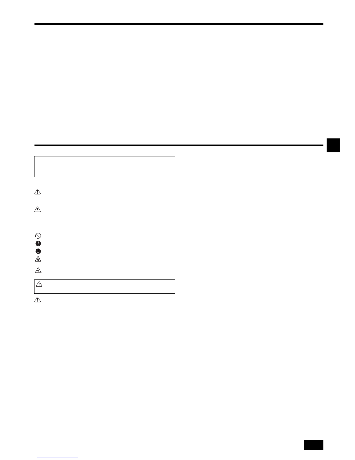
Symbols used in the text
Warning:
Describes precautions that should be observed to prevent danger of injury or
death to the user.
Caution:
Describes precautions that should be observed to prevent damage to the unit.
Symbols used in the illustrations
Warning:
• Ask the dealer or an authorized technician to install the air conditioner.
- Improper installation by the user may result in water leakage, electric shock, or
fire.
• Install the air unit at a place that can withstand its weight.
- Inadequate strength may cause the unit to fall down, resulting in injuries.
• Use the specified cables for wiring. Make the connections securely so that
the outside force of the cable is not applied to the terminals.
- Inadequate connection and fastening may generate heat and cause a fire.
• Prepare for typhoons and other strong winds and earthquakes and install
the unit at the specified place.
- Improper installation may cause the unit to topple and result in injury.
• Always use an air cleaner, humidifier, electric heater, and other accessories specified by Mitsubishi Electric.
- Ask an authorized technician to install the accessories. Improper installation by
the user may result in water leakage, electric shock, or fire.
• Never repair the unit. If the air conditioner must be repaired, consult the
dealer.
- If the unit is repaired improperly, water leakage, electric shock, or fire may
result.
• Do not touch the heat exchanger fins.
- Improper handling may result in injury.
• When handling this product, always wear protective equipment.
EG: Gloves, full arm protection namely boiler suit, and safety glasses.
- Improper handling may result in injury.
• If refrigerant gas leaks during installation work, ventilate the room.
- If the refrigerant gas comes into contact with a flame, poisonous gases will be
released.
• Install the air conditioner according to this Installation Manual.
- If the unit is installed improperly, water leakage, electric shock, or fire may
result.
• Have all electric work done by a licensed electrician according to “Electric
Facility Engineering Standard” and “Interior Wire Regulations” and the
instructions given in this manual and always use a special circuit.
- If the power source capacity is inadequate or electric work is performed improp-
erly, electric shock and fire may result.
• Keep the electric parts away from water (washing water etc.).
- It might result in electric shock, catching fire or smoke.
• Securely install the outdoor unit terminal cover (panel).
- If the terminal cover (panel) is not installed properly, dust or water may enter the
outdoor unit and fire or electric shock may result.
• Do not use refrigerant other than the type indicated in the manuals provided with the unit and on the nameplate.
- Doing so may cause the unit or pipes to burst, or result in explosion or fire dur-
ing use, during repair, or at the time of disposal of the unit.
- It may also be in violation of applicable laws.
- MITSUBISHI ELECTRIC CORPORATION cannot be held responsible for mal-
functions or accidents resulting from the use of the wrong type of refrigerant.
• If the air conditioner is installed in a small room, measures must be taken
to prevent the refrigerant concentration from exceeding the safety limit
even if the refrigerant should leak.
- Consult the dealer regarding the appropriate measures to prevent the safety
limit from being exceeded. Should the refrigerant leak and cause the safety
limit to be exceeded, hazards due to lack of oxygen in the room could result.
• When moving and reinstalling the air conditioner, consult the dealer or an
authorized technician.
- If the air conditioner is installed improperly, water leakage, electric shock, or fire
may result.
• After completing installation work, make sure that refrigerant gas is not
leaking.
- If the refrigerant gas leaks and is exposed to a fan heater, stove, oven, or other
heat source, it may generate noxious gases.
• Do not reconstruct or change the settings of the protection devices.
- If the pressure switch, thermal switch, or other protection device is shorted and
operated forcibly, or parts other than those specified by Mitsubishi Electric are
used, fire or explosion may result.
• To dispose of this product, consult your dealer.
• Do not use a leak detection additive.
• If the supply cord is damaged, it must be replaced by the manufacturer, its
service agent or similarly qualified persons in order to avoid a hazard.
• This appliance is not intended for use by persons (including children) with
reduced physical, sensory or mental capabilities, or lack of experience
and knowledge, unless they have been given supervision or instruction
concerning use of the appliance by a person responsible for their safety.
• Children should be supervised to ensure that they do not play with the
appliance.
• The installer and system specialist shall secure safety against leakage
according to local regulation or standards.
- The instructions in this manual may be applicable if local regulation are not available.
• Pay a special attention to the place, such as a basement, etc. where refrigeration gas can stay, since refrigeration is heavier than the air.
• This appliance is intended to be used by expert or trained users in shops,
in light industry and on farms, or for commercial use by lay persons.
1.2. Precautions for devices that use R410A refriger-
ant
Caution:
• Do not use the existing refrigerant piping.
- The old refrigerant and refrigerator oil in the existing piping contains a large amount of
chlorine which may cause the refrigerator oil of the new unit to deteriorate.
Before installing the unit, make sure you read all the “Safety precau-
tions”.
The “Safety precautions” provide very important points regarding safety.
Make sure you follow them.
: Indicates an action that must be avoided.
: Indicates that important instructions must be followed.
: Indicates a part which must be grounded.
: Indicates that caution should be taken with rotating parts. (This symbol is dis-
played on the main unit label.) <Color: yellow>
: Beware of electric shock (This symbol is displayed on the main unit label.)
<Color: yellow>
Warning:
Carefully read the labels affixed to the main unit.
Page 8
8
GB
• Use refrigerant piping made of C1220 (Cu-DHP) phosphorus deoxidized
copper as specified in the JIS H3300 “Copper and copper alloy seamless
pipes and tubes”. In addition, be sure that the inner and outer surfaces of
the pipes are clean and free of hazardous sulphur, oxides, dust/dirt, shaving particles, oils, moisture, or any other contaminant.
- Contaminants on the inside of the refrigerant piping may cause the refrigerant
residual oil to deteriorate.
• Store the piping to be used during installation indoors and keep both ends
of the piping sealed until just before brazing. (Store elbows and other
joints in a plastic bag.)
- If dust, dirt, or water enters the refrigerant cycle, deterioration of the oil and
compressor trouble may result.
• Use liquid refrigerant to fill the system.
- If gas refrigerant is used to seal the system, the composition of the refrigerant in
the cylinder will change and performance may drop.
• Do not use a refrigerant other than R410A.
- If another refrigerant (R22, etc.) is used, the chlorine in the refrigerant may
cause the refrigerator oil to deteriorate.
• Use a vacuum pump with a reverse flow check valve.
- The vacuum pump oil may flow back into the refrigerant cycle and cause the
refrigerator oil to deteriorate.
• Do not use the following tools that are used with conventional refrigerants.
(Gauge manifold, charge hose, gas leak detector, reverse flow check
valve, refrigerant charge base, vacuum gauge, refrigerant recovery equipment)
- If the conventional refrigerant and refrigerator oil are mixed in the R410A, the
refrigerant may deteriorated.
- If water is mixed in the R410A, the refrigerator oil may deteriorate.
- Since R410A does not contain any chlorine, gas leak detectors for conventional
refrigerants will not react to it.
• Do not use a charging cylinder.
- Using a charging cylinder may cause the refrigerant to deteriorate.
• Be especially careful when managing the tools.
- If dust, dirt, or water gets in the refrigerant cycle, the refrigerant may deteriorate.
1.3. Before getting installed
Caution:
• Do not install the unit where combustible gas may leak.
- If the gas leaks and accumulates around the unit, an explosion may result.
• Do not use the air conditioner where food, pets, plants, precision instruments, or artwork are kept.
- The quality of the food, etc. may deteriorate.
• Do not use the air conditioner in special environments.
- Oil, steam, sulfuric smoke, etc. can significantly reduce the performance of the
air conditioner or damage its parts.
• When installing the unit in a hospital, communication station, or similar
place, provide sufficient protection against noise.
- The inverter equipment, private power generator, high-frequency medical
equipment, or radio communication equipment may cause the air conditioner to
operate erroneously, or fail to operate. On the other hand, the air conditioner
may affect such equipment by creating noise that disturbs medical treatment or
image broadcasting.
• Do not install the unit on a structure that may cause leakage.
- When the room humidity exceeds 80% or when the drain pipe is clogged, condensation may drip from the indoor unit. Perform collective drainage work
together with the outdoor unit, as required.
• The indoor models should be installed the ceiling over than 2.5 m from
floor.
1.4. Before getting installed (moved) - electrical work
Caution:
• Ground the unit.
- Do not connect the ground wire to gas or water pipes, lightning rods, or telephone ground lines. Improper grounding may result in electric shock.
• Install the power cable so that tension is not applied to the cable.
- Tension may cause the cable to break and generate heat and cause a fire.
• Install an leak circuit breaker, as required.
- If an leak circuit breaker is not installed, electric shock may result.
• Use power line cables of sufficient current carrying capacity and rating.
- Cables that are too small may leak, generate heat, and cause a fire.
• Use only a circuit breaker and fuse of the specified capacity.
- A fuse or circuit breaker of a larger capacity or a steel or copper wire may result
in a general unit failure or fire.
• Do not wash the air conditioner units.
- Washing them may cause an electric shock.
• Be careful that the installation base is not damaged by long use.
- If the damage is left uncorrected, the unit may fall and cause personal injury or
property damage.
• Install the drain piping according to this Installation Manual to ensure
proper drainage. Wrap thermal insulation around the pipes to prevent condensation.
- Improper drain piping may cause water leakage and damage to furniture and
other possessions.
• Be very careful about product transportation.
- Only one person should not carry the product if it weighs more than 20 kg.
- Some products use PP bands for packaging. Do not use any PP bands for a
means of transportation. It is dangerous.
- Do not touch the heat exchanger fins. Doing so may cut your fingers.
- When transporting the outdoor unit, suspend it at the specified positions on the
unit base. Also support the outdoor unit at four points so that it cannot slip sideways.
• Safely dispose of the packing materials.
- Packing materials, such as nails and other metal or wooden parts, may cause
stabs or other injuries.
- Tear apart and throw away plastic packaging bags so that children will not play
with them. If children play with a plastic bag which was not torn apart, they face
the risk of suffocation.
1.5. Before starting the test run
Caution:
• Turn on the power at least 12 hours before starting operation.
- Starting operation immediately after turning on the main power switch can result
in severe damage to internal parts. Keep the power switch turned on during the
operational season.
• Do not touch the switches with wet fingers.
- Touching a switch with wet fingers can cause electric shock.
• Do not touch the refrigerant pipes during and immediately after operation.
- During and immediately after operation, the refrigerant pipes are may be hot
and may be cold, depending on the condition of the refrigerant flowing through
the refrigerant piping, compressor, and other refrigerant cycle parts. Your
hands may suffer burns or frostbite if you touch the refrigerant pipes.
• Do not operate the air conditioner with the panels and guards removed.
- Rotating, hot, or high-voltage parts can cause injuries.
• Do not turn off the power immediately after stopping operation.
- Always wait at least five minutes before turning off the power. Otherwise, water
leakage and trouble may occur.
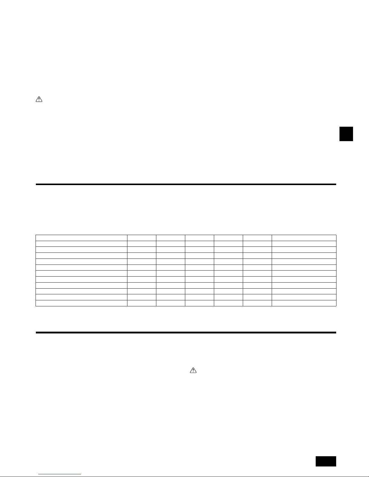
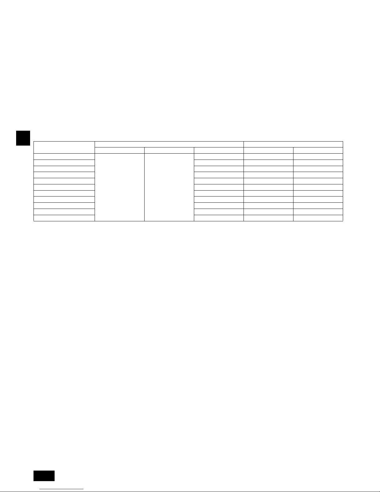
2. Indoor unit accessories
The unit is provided with the following accessories:
3. Selecting an installation site
• Select a site with sturdy fixed surface sufficiently durable against the weight of
unit.
• Before installing unit, the routing to carry in unit to the installation site should be
determined.
• Select a site where the unit is not affected by entering air.
• Select a site where the flow of supply and return air is not blocked.
• Select a site where refrigerant piping can easily be led to the outside.
• Select a site which allows the supply air to be distributed fully in room.
• Do not install unit at a site with oil splashing or steam in much quantity.
• Do not install unit at a site where combustible gas may generate, flow in, stagnate or leak.
• Do not install unit at a site where equipment generating high frequency waves
(a high frequency wave welder for example) is provided.
Part No.
Accessories Qty
1 Insulation pipe 1
2 Tie band 3
3 Drain socket 1
4 Washer 8
5 Installation manual 1
6 Operation manual 1
Part No.
Accessories Qty
Page 9
GB
9
• Do not install unit at a site where fire detector is located at the supply air side.
(Fire detector may operate erroneously due to the heated air supplied during
heating operation.)
• When special chemical product may scatter around such as site chemical plants
and hospitals, full investigation is required before installing unit. (The plastic
components may be damaged depending on the chemical product applied.)
• If the unit is run for long hours when the air above the ceiling is at high temperature/ high humidity (due point above 26 °C), due condensation may be produced
in the indoor unit. When operating the units in this condition, add insulation material (10-20 mm) to the entire surface of the indoor unit to avoid due condensation.
3.1. Install the indoor unit on a ceiling strong enough
to sustain its weight
Warning:
The unit must be securely installed on a structure that can sustain its weight.
If the unit is mounted on an unstable structure, it may fall down causing injuries.
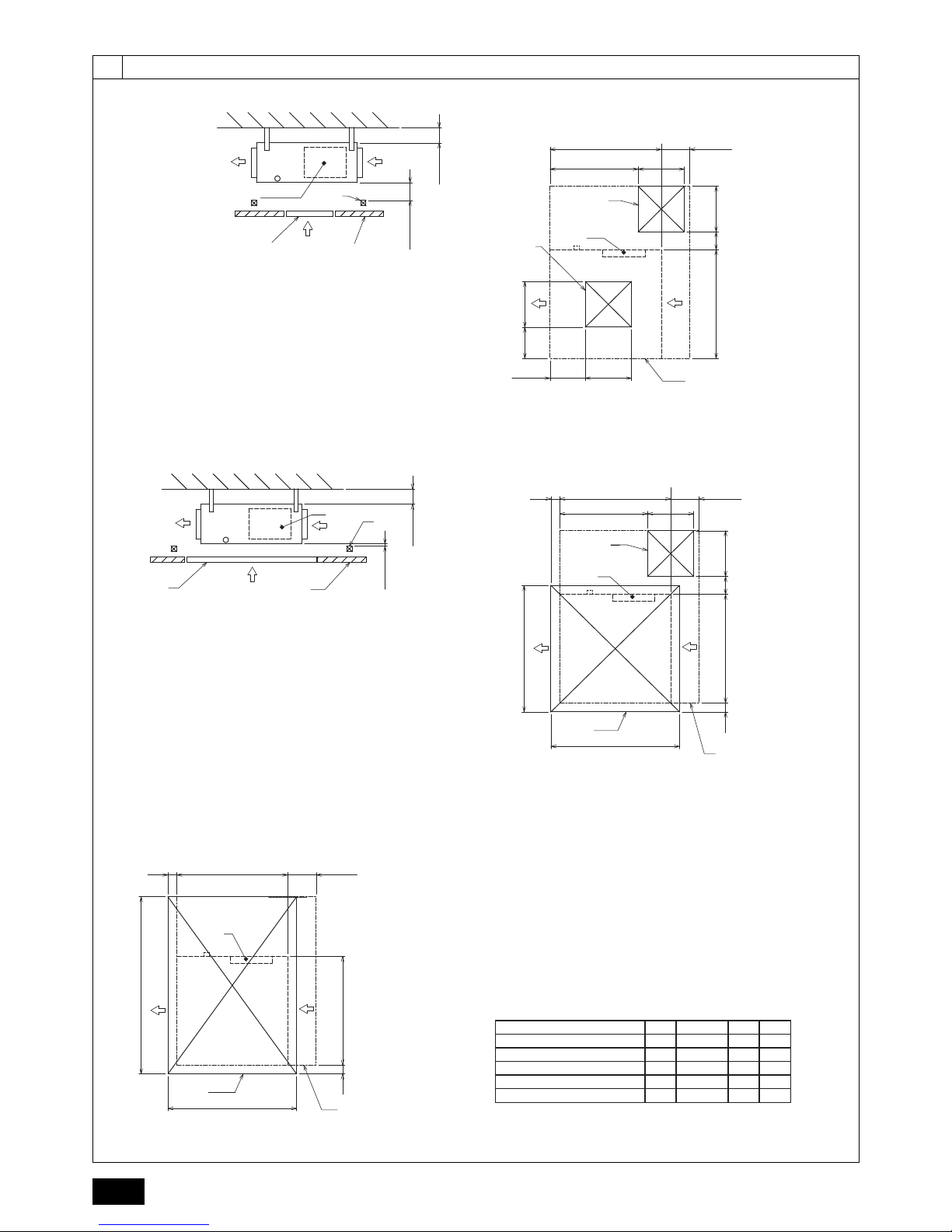
3.2. Securing installation and service space
Secure enough access space to allow for the maintenance, inspection, and replacement of the motor, fan, drain pump, heat exchanger, and electric box in one of the following ways.
Select an installation site for the indoor unit so that its maintenance access space will
not be obstructed by beams or other objects.
(1) When a space of 300 mm or more is available below the unit between the unit
and the ceiling (Fig. 3.2.1)
• Create access door 1 and 2 (450 x 450 mm each) as shown in Fig. 3.2.2.
(Access door 2 is not required if enough space is available below the unit for a
maintenance worker to work in.)
(2) When a space of less than 300 mm is available below the unit between the unit
and the ceiling (At least 20 mm of space should be left below the unit as shown in
Fig. 3.2.3.)
• Create access door 1 diagonally below the electric box and access door 3
below the unit as shown in Fig. 3.2.4.
or
• Create access door 4 below the electric box and the unit as shown in Fig. 3.2.5.
[Fig. 3.2.1] (P.2)
[Fig. 3.2.2] (Viewed from the direction of the arrow A) (P.2)
[Fig. 3.2.3] (P.2)
[Fig. 3.2.4] (Viewed from the direction of the arrow B) (P.2)
[Fig. 3.2.5] (Viewed from the direction of the arrow B) (P.2)
3.3. Combining indoor units with outdoor units
For combining indoor units with outdoor units, refer to the outdoor unit installation
manual.
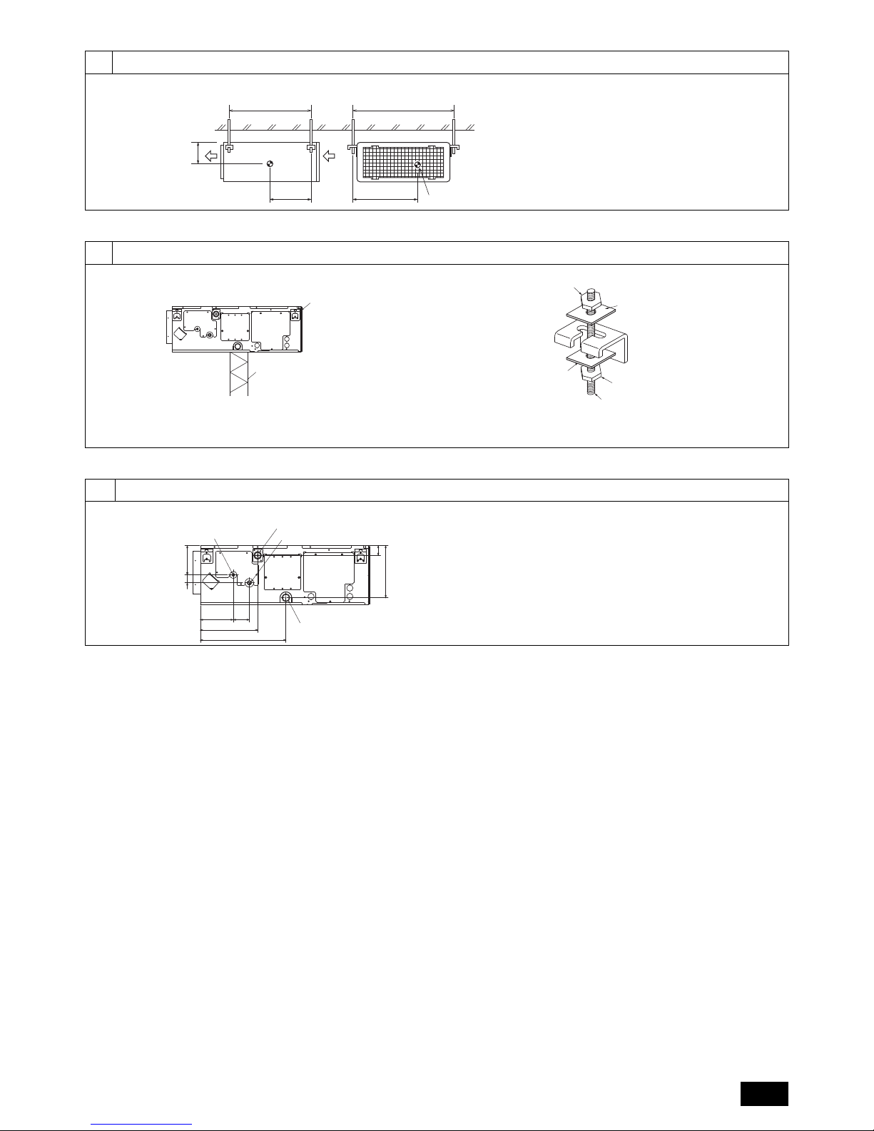
4. Fixing hanging bolts
4.1. Fixing hanging bolts
[Fig. 4.1.1] (P.3)
(Give site of suspension strong structure.)
Hanging structure
• Ceiling: The ceiling structure varies from building to one another. For detailed
information, consult your construction company.
• If necessary, reinforce the hanging bolts with anti-quake supporting members as
countermeasures against earthquakes.
* Use M10 for hanging bolts and anti-quake supporting members (field supply).
Center of gravity and Product Weight
The values in the parenthesis are for the PEFY-P·VMAL-E2 model.
5. Installing the unit
5.1. Hanging the unit body
Bring the indoor unit to an installation site as it is packed.
To hang the indoor unit, use a lifting machine to lift and pass through the
hanging bolts.
[Fig. 5.1.1] (P.3)
[Fig. 5.1.2] (P.3)
5.2. Confirming the unit’s position and fixing hanging
bolts
Ensure that the hanging bolt nuts are tightened to fix the hanging bolts.
To ensure that drain is discharged, be sure to hang the unit at level using
a level.
Caution:
Install the unit in horizontal position. If the side with drain port is installed
higher, water leakage may be caused.
A Electric box B Ceiling
C Ceiling beam D Access door 2 (450 mm x 450 mm)
E Access door 1 (450 mm x 450 mm) F Maintenance access space
G Supply air H Intake air
I Bottom of indoor unit J Access door 3
K Access door 4
A Center of gravity
Model name W L X Y Z Product Weight (kg)
PEFY-P20VMA(L)-E2 643 754 330 300 130 22 (21)
PEFY-P25VMA(L)-E2 643 754 330 300 130 22 (21)
PEFY-P32VMA(L)-E2 643 754 330 300 130 22 (21)
PEFY-P40VMA(L)-E2 643 954 340 375 130 26 (25)
PEFY-P50VMA(L)-E2 643 954 340 375 130 26 (25)
PEFY-P63VMA(L)-E2 643 1154 325 525 130 31 (30)
PEFY-P71VMA(L)-E2 643 1154 325 525 130 31 (30)
PEFY-P80VMA(L)-E2 643 1154 325 525 130 31 (30)
PEFY-P100VMA(L)-E2 643 1454 330 675 130 39 (38)
PEFY-P125VMA(L)-E2 643 1454 330 675 130 39 (38)
PEFY-P140VMA(L)-E2 643 1654 332 725 130 43 (42)
A Unit body
B Lifting machine
C Nuts (field supply)
D Washers (field supply)
E M10 hanging bolt (field supply)
Page 10
10
GB
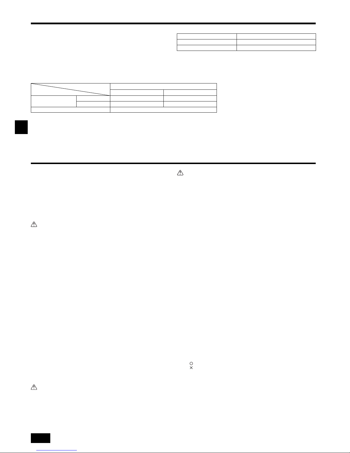
6. Refrigerant pipe and drain pipe specifications
To avoid dew drops, provide sufficient antisweating and insulating work to the refrigerant and drain pipes.
When using commercially available refrigerant pipes, be sure to wind commercially
available insulating material (with a heat-resisting temperature of more than 100 °C
and thickness given below) onto both liquid and gas pipes.
Insulate all indoor pipes with form polyethylene insulation with a minimum density of
0.03 and a thickness as specified in the table below.
1 Select the thickness of insulating material by pipe size.
2
If the unit is used on the highest story of a building and under conditions of high temperature and humidity, it is necessary to use pipe size and insulating material’s thickness more than those given in the table above.
3 If there are customer’s specifications, simply follow them.
6.1. Refrigerant pipe and drain pipe specifications
6.2. Refrigerant pipe, drain pipe
[Fig. 6.2.1] (P.3)
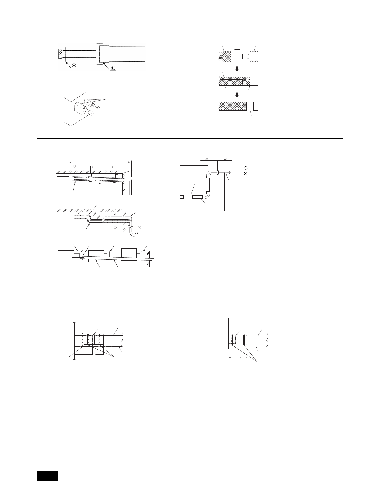
7. Connecting refrigerant pipes and drain pipes
7.1. Refrigerant piping work
This piping work must be done in accordance with the installation manuals for both
outdoor unit and BC controller (simultaneous cooling and heating series R2).
• Series R2 is designed to operate in a system that the refrigerant pipe from an
outdoor unit is received by BC controller and branches at the BC controller to
connect between indoor units.
• For constraints on pipe length and allowable difference of elevation, refer to the
outdoor unit manual.
• The method of pipe connection is brazing connection.
Caution:
• Install the refrigerant piping for the indoor unit in accordance with the fol-
lowing.
1. Cut the tip of the indoor unit piping, remove the gas, and then remove the brazed
cap.
[Fig. 7.1.1] (P.4)
2. Pull out the thermal insulation on the site refrigerant piping, braze the unit piping,
and replace the insulation in its original position.
Wrap the piping with insulating tape.
Note:
• When blazing the refrigerant pipes, be sure to blaze, after covering a wet
cloth to the pipes of the units in order to prevent it from burning and
shrinking by heat.
[Fig. 7.1.2] (P.4)
• Pay strict attention when wrapping the copper piping since wrapping the
piping may cause condensation instead of preventing it.
[Fig. 7.1.3] (P.4)
Cautions On Refrigerant Piping
Be sure to use non-oxidative brazing for brazing to ensure that no foreign
matter or moisture enter into the pipe.
Be sure to apply refrigerating machine oil over the flare connection seating
surface and tighten the connection using a double spanner.
Provide a metal brace to support the refrigerant pipe so that no load is
imparted to the indoor unit end pipe. This metal brace should be provided
50 cm away from the indoor unit’s flare connection.
Warning:
Do not use refrigerant other than the type indicated in the manuals provided
with the unit and on the nameplate.
- Doing so may cause the unit or pipes to burst, or result in explosion or fire during
use, during repair, or at the time of disposal of the unit.
- It may also be in violation of applicable laws.
- MITSUBISHI ELECTRIC CORPORATION cannot be held responsible for mal-
functions or accidents resulting from the use of the wrong type of refrigerant.
Caution:
• Use refrigerant piping made of C1220 (Cu-DHP) phosphorus deoxidized
copper as specified in the JIS H3300 “Copper and copper alloy seamless
pipes and tubes”. In addition, be sure that the inner and outer surfaces of
the pipes are clean and free of hazardous sulphur, oxides, dust/dirt, shaving particles, oils, moisture, or any other contaminant.
• Never use existing refrigerant piping.
- The large amount of chlorine in conventional refrigerant and refrigerator oil in
the existing piping will cause the new refrigerant to deteriorate.
• Store the piping to be used during installation indoors and keep both ends
of the piping sealed until just before brazing.
- If dust, dirt, or water gets into the refrigerant cycle, the oil will deteriorate and
the compressor may fail.
• Use Suniso 4GS or 3GS (small amount) refrigerator oil to coat the flare and
flange connection part. (For models using R22)
• Use ester oil, ether oil or alkylbenzene (small amount) as the refrigerator oil
to coat flares and flange connections. (For models using R410A or R407C)
- The refrigerant used in the unit is highly hygroscopic and mixes with water and
will degrade the refrigerator oil.
7.2. Drain piping work
• Ensure that the drain piping is downward (pitch of more than 1/100) to the outdoor (discharge) side. Do not provide any trap or irregularity on the way.
• Ensure that any cross-wise drain piping is less than 20 m (excluding the difference of elevation). If the drain piping is long, provide metal braces to prevent it
from waving. Never provide any air vent pipe. Otherwise drain may be ejected.
• Use a hard vinyl chloride pipe VP-25 (with an external diameter of 32 mm) for
drain piping.
• Ensure that collected pipes are 10 cm lower than the unit body’s drain port.
• Do not provide any odor trap at the drain discharge port.
• Put the end of the drain piping in a position where no odor is generated.
• Do not put the end of the drain piping in any drain where ionic gases are generated.
[Fig. 7.2.1] (P.4)
Grouped piping
Pipe size Insulating material’s thickness
6.4 mm to 25.4 mm More than 10 mm
28.6 mm to 38.1 mm More than 15 mm
PEFY-P·VMA(L)-E2
20·25·32·40·50 63·71·80·100·125·140
Refrigerant pipe
(Brazing connection)
Liquid pipe ø 6.35 ø 9.52
Gas pipe ø 12.7 ø 15.88
Drain pipe O.D. ø 32
Item
Model
A Refrigerant pipe (liquid pipe)
B Refrigerant pipe (gas pipe)
C Drain pipe (O.D. ø32)
D Drain pipe (O.D. ø32, spontaneous draining)
A Cut here
B Remove brazed cap
A Cool by a wet cloth
A Thermal insulation B Pull out insulation
C Wrap with damp cloth D Return to original position
E Ensure that there is no gap here F Wrap with insulating tape
Correct piping
Wrong piping
A Insulation (9 mm or more)
B Downward slope (1/100 or more)
C Support metal
K Air bleeder
L Raised
M Odor trap
D O. D. ø32 PVC TUBE
E Make it as large as possible. About 10 cm.
F Indoor unit
G Make the piping size large for grouped piping.
H Downward slope (1/100 or more)
I O. D. ø38 PVC TUBE for grouped piping. (9 mm or more insulation)
Page 11
GB
11
PEFY-P·VMA-E2 model
[PEFY-P·VMA model]
1. Insert the drain socket (accessory) into the drain port (insertion margin: 32mm).
(Attach the hose with glue, and fix it with the band (small, accessory).)
2. Attach the drain pipe (O.D. ø32 PVC TUBE PV-25, field supply).
(Attach the pipe with glue, and fix it with the band (small, accessory).)
3. Perform insulation work on the drain pipe (O.D. ø32 PVC TUBE PV-25) and on
the socket (including elbow).
4. Check the drainage. (Refer to [Fig. 7.3.1])
5. Attach the insulating material, and fix it with the band (large, accessory) to insu-
late the drain port.
[Fig. 7.2.2] (P.4) *only on the PEFY-P·VMA-E2 model
[PEFY-P·VMAL model]
1. Insert the drain socket (accessory) into the drain port.
The connecting part between the indoor unit and the drain socket may be disconncted at the maintenance. Fix the part with the accessory band, not be
adhered.
2. Attach the drain pipe (O.D. ø32 PVC TUBE, field supply).
(Attach the pipe with glue for the hard vinyl chloride pipe, and fix it with the band
(small, accessory).)
3. Perform insulation work on the drain pipe (O.D. ø32 PVC TUBE) and on the
socket (including elbow).
[Fig. 7.2.3] (P.4) *only on the PEFY-P·VMAL-E2 model
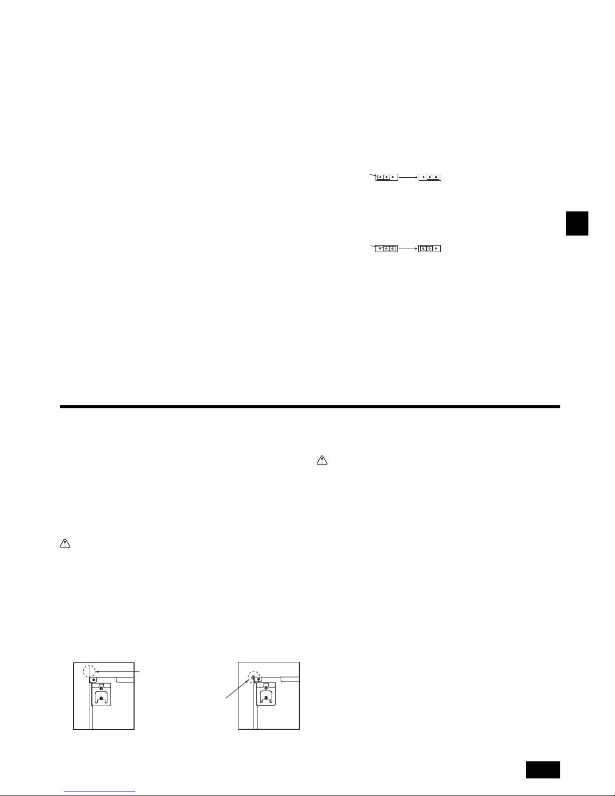
7.3. Confirming drain discharge
Make sure that the drain-up mechanism operates normally for discharge
and that there is no water leakage from the connections.
• Be sure to confirm the above in a period of heating operation.
• Be sure to confirm the above before ceiling work is done in the case of a new construction.
1. Remove the water supply port cover on the same side as the indoor unit piping.
2. Fill water into the feed water pump using a feed water tank. In filling, be sure to
put the end of the pump or tank in a drain pan. (If the insertion is incomplete,
water may flow over the machine.)
3. Perform the test run in cooling mode, or connect the connector to the ON side of
SWE on the Indoor controller board. (The drain pump and the fan are forced to
operate without any remote controller operation.) Make sure using a transparent
hose that drain is discharged.
4. After confirmation, cancel the test run mode, and turn off the main power. If the
connector is connected to the ON side of SWE, disconnect it and connect it to the
OFF side, and attach the water supply port cover into its original position.
[Fig. 7.3.1] (P.5)
[Fig. 7.3.2] (P.5)
8. Duct work
• In connecting duct, insert canvas duct between unit and duct.
• Use incombustible material for duct parts.
• Provide full insulation to inlet duct flange and outlet duct to prevent condensation.
• Be sure to change the position of air filter to the position where it can be serviced.
[Fig. 8.0.1] (P.5)
• Procedure for changing the rear inlet to the bottom inlet.
Caution:
When the duct is connected to the inlet at the bottom of the unit, the sound
pressure level will be greater by approximately 10 dB than when the duct is
connected to the inlet at the back of the unit.
For this reason, it is recommended to connect the duct to the back inlet.
When using the inlet at the bottom of the unit, offset the position of the inlet on
the indoor unit relative to the inlet on the ceiling as shown in Figures <A> and
<B> to minimize noise.
[Fig. 8.0.2] (P.5)
1. Remove air filter. (First remove filter lock screw.)
2. Remove the bottom plate.
3. Fit the bottom plate to the rear of the body. [Fig. 8.0.3] (P.5)
(Position of lug-holes on the plate are different from those for rear inlet.)
4. Fit filter to the underside of the body.
(Be careful of which side of the filter to fit.) [Fig. 8.0.4] (P.5)
[Fig. 8.0.4] (P.5)
Caution:
• Inlet duct of 850 mm or more should be constructed.
To connect the air conditioner main body and the duct for potential equalization.
• To reduce the risk of injury from metal sheet edges, wear protective gloves.
• To connect the air conditioner main body and the duct for potential equalization.
• The noise from the intake will increase dramatically if intake is fitted
directly beneath the main body. Intake should therefore be installed as far
away from the main body as possible.
Particular care is required when using it with bottom inlet specifications.
• Install sufficient thermal insulation to prevent condensation forming on
outlet duct flanges and outlet ducts.
• Keep the distance between the inlet grille and the fan over 850 mm. If it is
less than 850 mm, install a safety guard not to touch the fan.
• To avoid electrical noise interference, do not run transmission lines at the
bottom of the unit.
J Up to 700 mm
N Drain socket (accessory)
O Horizontal or slightly upgradient
A Indoor unit
B Tie band (accessory)
C Visible part
D Insertion margin
E Drain socket (accessory)
F Drain pipe (O.D. ø32 PVC TUBE, field supply)
G Insulating material (field supply)
H Tie band (accessory)
A Indoor unit
B Tie band (accessory)
C Band fixing part
D Insertion margin
E Drain socket (accessory)
F Drain pipe (O.D. ø32 PVC TUBE, field supply)
G Insulating material (field supply)
A Insert pump's end 2 to 4 cm.
B Remove the water supply port.
C About 2500 cc
D Wate r
E Filling port
F Screw
<Indoor controller board>
Connector
SWE
OFF ON OFF ON
SWE
<OFF> <ON>
Connector
SWE
OFF ON OFF ON
SWE
<ON> <OFF>
<A> In case of rear inlet
<B> In case of bottom inlet
A Duct B Air inlet
C Access door D Canvas duct
E Ceiling surface F Air outlet
G Leave distance enough to prevent short cycle
A Filter B Bottom plate
When the plate is attached on
the rear side, it exceeds the
height of the rear body panel.
Replicate the plate along
the slit when there is not
enough room above for the
entire unit.
C Nail for the bottom inlet D Nail for the rear inlet
Page 12
12
GB
9. Electrical wiring
Precautions on electrical wiring
Warning:
Electrical work should be done by qualified electrical engineers in accordance
with “Engineering Standards For Electrical Installation” and supplied
installa-
tion manuals. Special circuits should also be used. If the power circuit
lacks ca-
pacity or has an installation failure, it may cause a risk of electric
shock or fire.
1. Be sure to install an earth leakage breaker to the power.
2. Install the unit to prevent that any of the control circuit cables (remote controller,
transmission cables) is brought in direct contact with the power cable outside the
unit.
3. Ensure that there is no slack on all wire connections.
4. Some cables (power, remote controller, transmission cables) above the ceiling
may be bitten by mouses. Use as many metal pipes as possible to insert the
cables into them for protection.
5. Never connect the power cable to leads for the transmission cables. Otherwise
the cables would be broken.
6. Be sure to connect control cables to the indoor unit, remote controller, and the
outdoor unit.
7. Put the unit to the ground on the outdoor unit side.
8. Select control cables from the conditions given in page 12.
Caution:
• Be sure to put the unit to the ground on the outdoor unit side. Do not con-
nect the earth cable to any gas pipe, water pipe, lightening rod, or telephone earth cable. Incomplete grounding may cause a risk of electric
shock.
• If the supply cord is damaged, it must be replaced by the manufacturer, its
service agent or similarly qualified persons in order to avoid a hazard.
Transmission cable specifications
*1 Connected with simple remote controller.
9.1. Power supply wiring
• Use dedicated power supplies for the outdoor unit and indoor unit.
• Bear in mind ambient conditions (ambient temperature, direct sunlight, rain water, etc.) when proceeding with the wiring and connections.
• The wire size is the minimum value for metal conduit wiring. If the voltage drops, use a wire that is one rank thicker in diameter. Make sure the power-supply voltage does
not drop more than 10%.
• Specific wiring requirements should adhere to the wiring regulations of the region.
• Power supply cords of appliances shall not be lighter than design 245 IEC 57, 227 IEC 57, 245 IEC 53 or 227 IEC 53.
• A switch with at least 3 mm contact separation in each pole shall be provided by the Air conditioner installation.
[Fig. 9.1.1] (P.5)
Apply to IEC61000-3-3 about Max. Permissive System Impedance.
*1 The Ground-fault interrupter should support Inverter circuit.
The Ground-fault interrupter should combine using of local switch or wiring breaker.
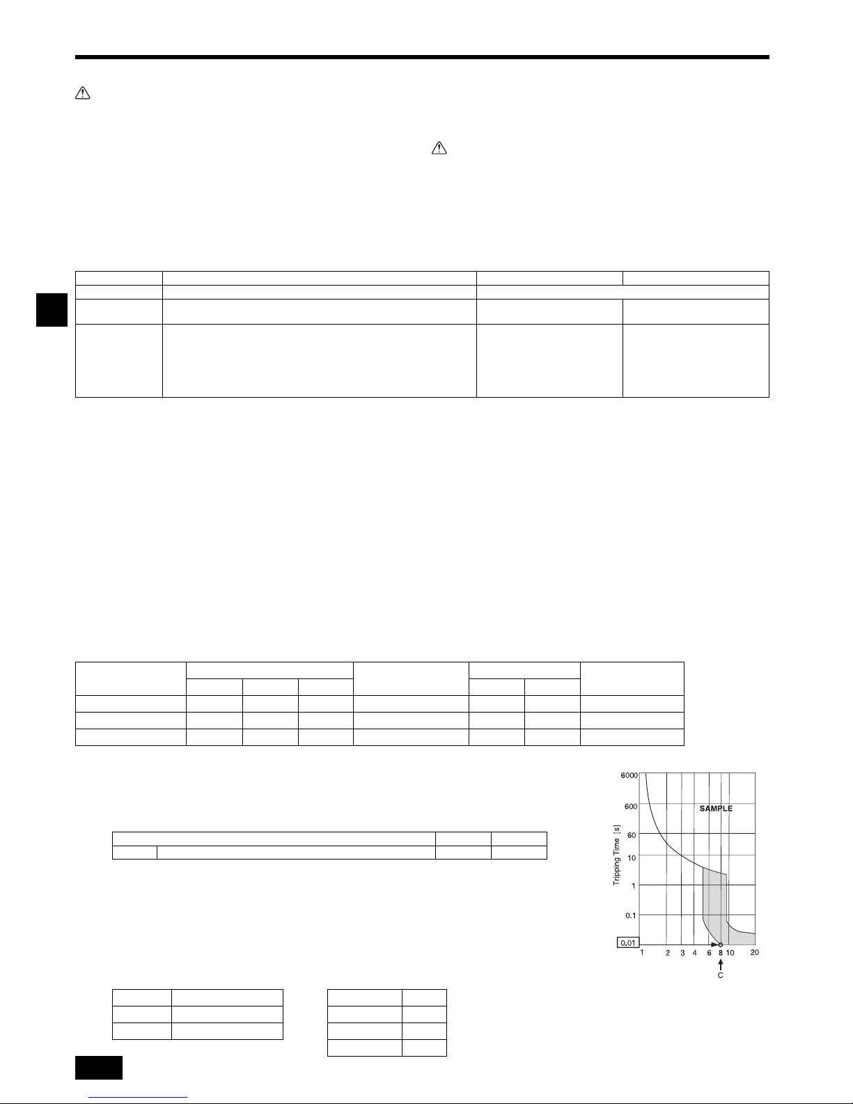
*2 Please take the larger of F1 or F2 as the value for F0.
F1 = Total operating maximum current of the indoor units 1.2
F2 = {V1 (Quantity of Type1)/C} + {V1 (Quantity of Type2)/C} + {V1 (Quantity of Type3)/C} + {V1 (Quantity of Others)/C}
C : Multiple of tripping current at tripping time 0.01s
Please pick up “C” from the tripping characteristic of the breaker.
<Example of “F2” calculation>
*Condition PEFY-VMA 3, C = 8 (refer to right sample chart)
F2 = 38 3/8
= 14.25
16 A breaker (Tripping current = 8 16 A at 0.01s)
*3 Current sensitivity is calculated using the following formula.
G1 = (V2 Quantity of Type1) + (V3 Wire length [km])
Transmission cables ME Remote controller cables MA Remote controller cables
Type of cable Shielding wire (2-core) CVVS, CPEVS or MVVS Sheathed 2-core cable (unshielded) CVV
Cable diameter More than 1.25 mm
2
0.3 ~ 1.25 mm2
(0.75 ~ 1.25 mm
2
)*1
0.3 ~ 1.25 mm
2
(0.75 ~ 1.25 mm
2
)*1
Remarks
Max length: 200 m
Maximum length of transmission lines for centralized control and indoor/
outdoor transmission lines (Maximum length via indoor units): 500 m MAX
The maximum length of the wiring between power supply unit for
transmission lines (on the transmission lines for centralized control) and
each outdoor unit and system controller is 200 m.
When 10 m is exceeded, use
cables with the same specification
as transmission cables.
Max length: 200 m
A Ground-fault interrupter
B Local switch/Wiring breaker
C Indoor unit
D Pull box
Total operating current of
the Indoor unit
Minimum wire thickness (mm
2
)
Ground-fault interrupter
*1
Local switch (A)
Breaker for wiring (A)
(Non-fuse breaker)
Main cable Branch Ground Capacity Fuse
F0 = 16 A or less
*2
1.5 1.5 1.5 20 A current sensitivity
*3
16 16 20
F0 = 25 A or less
*2
2.5 2.5 2.5 30 A current sensitivity
*3
25 25 30
F0 = 32 A or less
*2
4.0 4.0 4.0 40 A current sensitivity
*3
32 32 40
Indoor unit V1 V2
Type1 PEFY-VMA 38 1.6
G1 Current sensitivity Wire thickness V3
30 or less 30 mA 0.1 sec or less 1.5 mm
2
48
100 or less 100 mA 0.1 sec or less 2.5 mm
2
56
4.0 mm
2
66
CVVS, MVVS: PVC insulated PVC jacketed shielded control cable
CPEVS: PE insulated PVC jacketed shielded communication cable
CVV: PVC insulated PVC sheathed control cable
Rated Tripping current (x)
Sample chart
Page 13

GB
13
Warning:
• Be sure to use specified wires for connections and ensure no external force is imparted to terminal connections. If connections are not fixed firmly, heating or
fire may result.
• Be sure to use the appropriate type of overcurrent protection switch. Note that generated overcurrent may include some amount of direct current.
Caution:
• Some installation sites may require attachment of an earth leakage breaker for the inverter. If no earth leakage breaker is installed, there is a danger of electric
shock.
• Do not use anything other than the correct capacity breaker and fuse. Using fuse, wire or copper wire with too large capacity may cause a risk of malfunction
or fire.
Notes:
• This device is intended for the connection to a power supply system with a maximum permissible system impedance (Refer to IEC61000-3-3.) at the interface
point (power service box) of the user’s supply.
• The user must ensure that this device is connected only to a power supply system which fulfils the requirement above.
If necessary, the user can ask the public power supply company for the system impedance at the interface point.
9.2. Connecting remote controller, indoor and out-
door transmission cables
• Connect indoor unit TB5 and outdoor unit TB3. (Non-polarized 2-wire)
The “S” on indoor unit TB5 is a shielding wire connection. For specifications
about the connecting cables, refer to the outdoor unit installation manual.
• Install a remote controller following the manual supplied with the remote control-
ler.
• Connect the “1” and “2” on indoor unit TB15 to a MA remote controller. (Non-
polarized 2-wire)
• Connect the “M1” and “M2” on indoor unit TB5 to a M-NET remote controller.
(Non-polarized 2-wire)
• Connect the remote controller’s transmission cable within 10 m using a 0.75 mm
2
core cable. If the distance is more than 10 m, use a 1.25 mm2 junction cable.
[Fig. 9.2.1] (P.5) MA Remote controller
[Fig. 9.2.2] (P.5) M-NET Remote controller
• DC 9 to 13 V between 1 and 2 (MA remote controller)
• DC 24 to 30 V between M1 and M2 (M-NET remote controller)
[Fig. 9.2.3] (P.6) MA Remote controller
[Fig. 9.2.4] (P.6) M-NET Remote controller
• The MA remote controller and the M-NET remote controller cannot be used at
the same time or interchangeably.
Caution:
Install wiring so that it is not tight and under tension. Wiring under tension
may break, or overheat and burn.
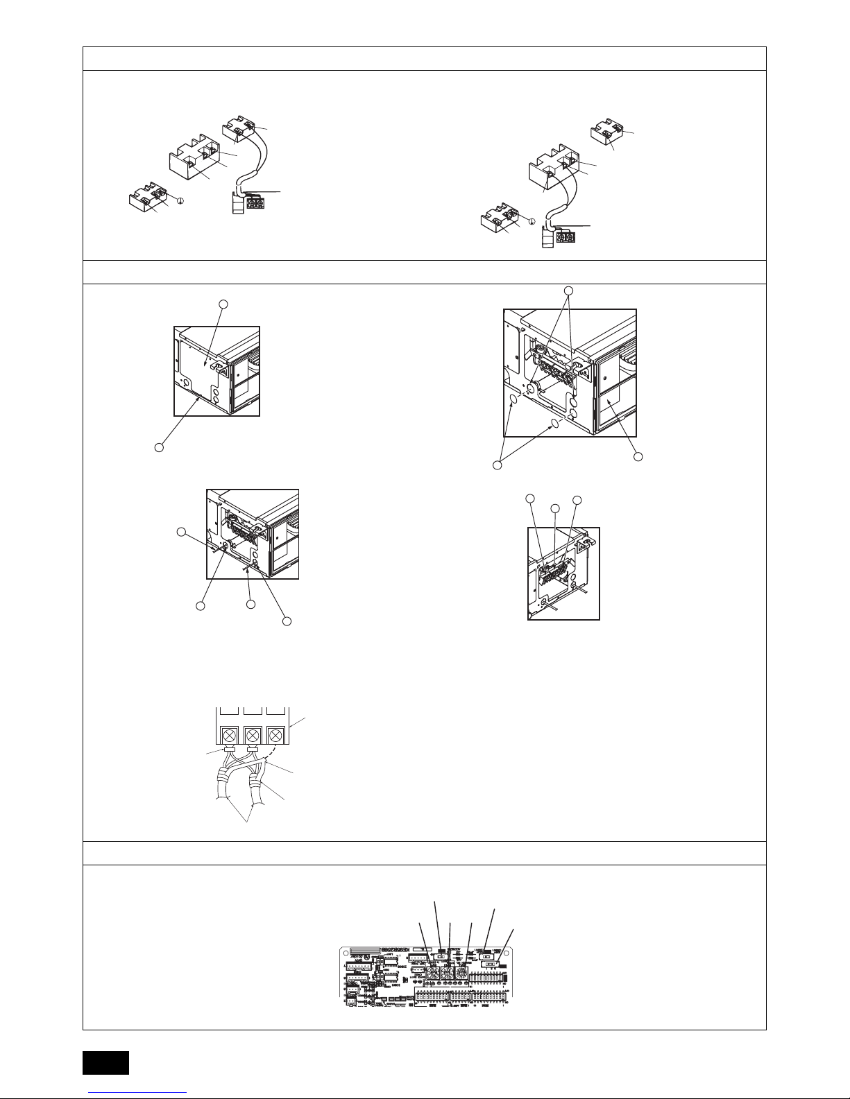
9.3. Connecting electrical connections
Please identify the model name of the operation manual attached on the terminal
box cover with that shown on the rating name plate.
1. Remove the screw (1pc) holding the cover to dismount the cover.
[Fig. 9.3.1] (P.6)
2. Open knockout holes
(Recommend to use a screwdriver or the like for this work.)
[Fig. 9.3.2] (P.6)
3. Fix power source wiring to terminal box by using buffer bushing for tensile
force. (PG connection or the like.) Connect transmission wiring to transmission
terminal block through the knockout hole of terminal box using ordinary bushing.
[Fig. 9.3.3] (P.6)
4. Connect the power source, Earth, transmission and remote controller wiring.
The dismounting of the terminal box is not needed.
[Fig. 9.3.4] (P.6)
[Shield wire connection]
[Fig. 9.3.5] (P.6)
5. After wiring is complete, make sure again that there is no slack on the connections, and attach the cover onto the terminal box in the reverse order of
removal.
Notes:
• Do not pinch the cables or wires when attaching the terminal box cover.
Doing so may cause a risk of disconnection.
• When accommodating the terminal box, make sure that the connectors on
the box side are not removed. If removed, it cannot operate normally.
9.4. External I/O specifications
Caution:
1. Wiring should be covered by insulation tube with supplementary insula-
tion.
2. Use relays or switches with IEC or equivalent standard.
3. The electric strength between accessible parts and control circuit should
have 2750 V or more.
9.5. Selecting the external static pressure
As the factory setting is for use under an external static pressure, no switch operation is needed when using under the standard condition.
[Fig. 9.5.1] (P.6)
A Terminal block for indoor transmission cable
B Terminal block for outdoor transmission cable
C Remote controller
A Non-polarized B TB15
C Remote Controller D TB5
A Screw holding cover (1pc) B Cover
C Terminal box D Knockout hole
E Remove
F Use PG bushing to keep the weight of the cable and external force from being
applied to the power supply terminal connector. Use a cable tie to secure the cable.
G Power source wiring H Use ordinary bushing
I Transmission wiring
J Terminal block for power source
K Terminal block for indoor transmission
L Terminal block for remote controller
A Terminal block B Round terminal
C Shield wire
D The earth wire from two cables are connected together to the S terminal. (Dead-end
connection)
E Insulation tape (To keep the earth wire of the shielded cable from coming in contact
with the transmission terminal)
External static pressure Switch operation
P20~P63: 35 Pa
P71~P100: 40 Pa
P20~P100: Factory setting
50 Pa
P125, P140: Factory setting
70 Pa
100 Pa
150 Pa
<Indoor controller board>
SWA
SWC
1
2
3
SWA
SWC
1
2
3
SWA
SWC
1
2
3
SWA
SWC
1
2
3
SWA
SWC
1
2
3
Page 14
14
GB
9.6. Setting addresses
(Be sure to operate with the main power turned OFF.)
[Fig. 9.5.1] (P.6)
• There are two types of rotary switch setting available: setting addresses 1 to 9
and over 10, and setting branch numbers.
• The rotary switches are all set to “0” when shipped from the factory. These
switches can be used to set unit addresses and branch numbers at will.
• The determination of indoor unit addresses varies with the system at site. Set
them referring to the Data Book.
9.7. Sensing room temperature with the built-in sensor in a remote controller
If you want to sense room temperature with the built-in sensor in a remote controller,
set SW1-1 on the control board to “ON”. The setting of SW1-7 and SW1-8 as nec-
essary also makes it possible to adjust the air flow at a time when the heating ther-
mometer is OFF.
9.8. Changing the power voltage setting
(Be sure to operate with the main power turned OFF.)
[Fig. 9.5.1] (P.6)
Please set the switch SW5 according to the power voltage.
• Set SW5 to 240V side when the power supply is 240 volts.
• When the power supply is 220 and 230 volts, set SW5 to 220V side.
9.9. Electrical characteristics
Symbols : MCA : Max. Circuit Amps ( = 1.25 x FLA) FLA : Full Load Amps
IFM : Indoor Fan Motor Output : Fan motor rated output
Refer to Data Book for other models.
<Indoor controller board>
1 How to set addresses
Example: If Address is “3”, remain SW12 (for over 10) at “0”, and match SW11 (for 1 to 9)
with “3”.
2 How to set branch numbers SW14 (Series R2 only)
The branch number assigned to each indoor unit is the port number of the BC controller
to which the indoor unit is connected.
Leave it to “0” on the non-R2 series of units.
PEFY-P-VMA(L)-E2
Power supply IFM
Volts / Hz Range +-10% MCA(A) Output(kW) FLA(A)
PEFY-P20VMA(L)-E2
220-240V / 50Hz
220-240V / 60Hz
Max.: 264V
Min.: 198V
0.92 0.085 0.74
PEFY-P25VMA(L)-E2 0.92 0.085 0.74
PEFY-P32VMA(L)-E2 1.07 0.085 0.86
PEFY-P40VMA(L)-E2 1.32 0.085 1.06
PEFY-P50VMA(L)-E2 1.40 0.085 1.12
PEFY-P63VMA(L)-E2 2.08 0.121 1.67
PEFY-P71VMA(L)-E2 2.32 0.121 1.86
PEFY-P80VMA(L)-E2 2.36 0.121 1.89
PEFY-P100VMA(L)-E2 2.53 0.300 2.02
PEFY-P125VMA(L)-E2 2.95 0.300 2.36
PEFY-P140VMA(L)-E2 2.73 0.300 2.18
Page 15
D
15
Inhalt
1. Sicherheitsvorkehrungen ........................................................................15
1.1. Vor Installations- und Elektroarbeiten .....................................15
1.2. Vorkehrungen für Geräte, die R410A-Kältemittel
verwenden ..............................................................................16
1.3. Vor der Aufstellung .................................................................16
1.4. Vor dem Einbau (der Ortsveränderung) -
Elektroarbeiten........................................................................16
1.5. Vor Installationsbeginn............................................................ 16
2. Versorgungseinrichtungen der Innenanlage........................................... 17
3. Einen Aufstellort wählen ......................................................................... 17
3.1. Die Innenanlage an einer Decke montieren,
die stark genug ist, um das Gewicht zu halten .......................17
3.2. Sicherstellen des Freiraums für Montage und Wartung/
Bedienung...............................................................................17
3.3. Innenanlagen mit Außenanlagen verbinden...........................17
4. Befestigung der Hängebolzen.................................................................17
4.1. Befestigung der Hängebolzen.................................................17
5. Aufstellen der Anlage..............................................................................17
5.1. Aufhängen des Anlagenkörpers..............................................17
5.2. Sich über die richtige Lage der Anlage vergewissern und die
Hängebolzen befestigen .........................................................18
6. Technische Daten der Kältemittel- und Kondensatablaufleitung............18
6.1. Technische Daten der Kältemittel- und
Kondensatablaufleitung .......................................................... 18
6.2. Kältemittelrohr, Kondensatablaufrohr und Einfüllöffnung .......18
7. Kältemittel- und Kondensatablaufleitungen anschließen........................18
7.1. Verrohrung der Kältemittelleitung ...........................................18
7.2. Verrohrung des Kondensatablaufs/der Dränage ....................19
7.3. Funktion der Ablassleitung prüfen .......................................... 19
8. Rohrleitungsarbeiten...............................................................................19
9. Elektroverdrahtung.................................................................................. 20
9.1. Netzstromverdrahtung ............................................................20
9.2. Anschluß der Fernbedienungs-, Innen- und
Außenübertragungskabel .......................................................21
9.3. Vornahme der Elektroanschlüsse........................................... 21
9.4. Technische Daten der externen Ein-/Ausgänge.....................22
9.5. Auswählen des statischen Außendrucks................................22
9.6. Adressen einsetzen ................................................................22
9.7. Messen der Raumtemperatur mit dem in eine
Fernbedienung eingebauten Temperaturfühler......................22
9.8. Die Netzspannungseinstellung ändern...................................22
9.9. Elektrische Charakteristiken ...................................................22
1. Sicherheitsvorkehrungen
1.1. Vor Installations- und Elektroarbeiten
Im Text verwendete Symbole
Warnung:
Beschreibt Vorkehrungen, die beachtet werden sollten, um den Benutzer vor
der Gefahr von Verletzungen oder tödlicher Unfälle zu bewahren.
Vorsicht:
Beschreibt Vorkehrungen, die beachtet werden sollten, um die Anlage vor
Schäden zu bewahren.
Innerhalb der Abbildungen verwendete Symbole
Warnung:
• Bitten Sie Ihren Fachhändler oder einen geprüften Fachtechniker, die Installation der Anlage vorzunehmen.
- Unsachgemäße Installation durch den Benutzer kann Wasseraustritt, Strom-
schläge oder Brände verursachen.
• Die Anlage an einer Stelle anbringen, die das Gewicht tragen kann.
- Bei ungenügender Tragkraft kann das Gerät herunterfallen und Verletzungen
verursachen.
• Zur Verdrahtung die angegebenen Kabel verwenden. Die Anschlüsse so
sichern, daß Zugspannung von außen nicht auf die Klemmen wirken kann.
- Falscher Anschluß und falsche Befestigung führen zu Wärmebildung und verur-
sachen Brände.
• Vorkehrungen gegen Stürme, starke Luftströme und Erdbeben treffen und
die Anlage an einem Ort aufstellen, der die beschriebenen Bedingungen
erfüllt.
- Durch unsachgemäße Installation kann die Anlage herunterfallen und Verletzun-
gen verursachen.
• Stets Luftreiniger, Luftbefeuchter, Elektroheizungen und sonstige, von Mitsubishi angegebene, Zubehöreinrichtungen verwenden.
- Einen geprüften Techniker bitten, die Zusatzeinrichtungen zu installieren.
Unsachgemäße Installation durch den Benutzer kann zu Wasseraustritt, Stromschlägen oder Bränden führen.
• Die Anlage niemals selbst reparieren. Wenn die Anlage repariert werden
muß, wenden Sie bitte sich an den Fachhändler.
- Wenn die Anlage unsachgemäß repariert wird, kann dies zu Wasseraustritt,
Stromschlägen oder Bränden führen.
• Nicht die Wärmetauscherleitung berühren.
- Unsachgemäße Handhabung kann zu Verletzungen führen.
• Tragen Sie bei der Handhabung dieses Erzeugnisses immer Schutzausrüstung, d.h. Handschuhe, vollen Armschutz wie einen Overall und eine
Schutzbrille.
- Unsachgemäße Handhabung kann zu Verletzungen führen.
• Wenn Kältemittelgas während der Installationsarbeiten austritt, den Raum
gründlich lüften.
- Wenn das Kältemittelgas auf offenes Feuer trifft, wird giftiges Gas freigesetzt.
• Die Anlage gemäß Anweisungen in diesem Installations-handbuch installieren.
- Bei unsachgemäßer Installation kann dies zu Wasseraustritt, Stromschlägen
oder Bränden führen.
• Elektroarbeiten durch einen zugelassenen Fachelektriker in Übereinstimmung mit dem “Electric Facility Engineering Standard” - (Technische Normen für Elektroeinrichtungen), den “Interior Wire Regulations” (Vorschriften zur Innenverdrahtung) und den in diesem Handbuch gegebenen Anweisungen vornehmen. Anlage auch immer an einen gesonderten
Stromkreis anschließen.
- Wenn die Leistung der Stromquelle ungenügend ist oder die Elektroarbeiten
unsachgemäß ausgeführt wurden, kann dies zu Stromschlägen und zu Bränden
führen.
• Halten Sie die elektrischen Teile fern von Wasser (Waschwasser usw.).
- Kontakt mit Wasser kann elektrischen Schlag, Feuer oder Rauch verursachen.
• Die Abdeckung der Elektroanschlüsse der Außenanlage (Abdeckplatte) fest
anbringen.
- Wenn die Abdeckung der Elektroanschlüsse (Abdeckplatte) nicht sachgemäß
angebracht wurde, kann Staub oder Wasser in die Außenanlage eindringen und
Brände oder Stromschläge verursachen.
• Verwenden Sie kein Kühlmittel eines Typs, welcher nicht in den mitgelieferten Anleitungen dieser Einheit oder auf der Namensplatte angegeben ist.
- Anderenfalls kann dies während Reparaturarbeiten oder beim Entsorgen der
Einheit zum Zerplatzen der Einheit oder der Leitungen, einer Explosion oder
Brand führen.
- Zudem kann dies gegen geltendes Recht verstoßen.
- Die MITSUBISHI ELECTRIC CORPORATION übernimmt keine Haftung bei
Fehlfunktionen oder Unfällen, die aufgrund der Verwendung eines falschen Kühlmitteltyps aufgetreten sind.
• Wenn die Anlage in einem kleinen Raum installiert wird, müssen Maßnahmen
ergriffen werden, damit die Kältemittelkonzentration auch bei Kältemittelaustritt den Sicherheitsgrenzwert nicht überschreitet.
- Befragen Sie einen Fachhändler bezüglich geeigneter Maßnahmen zur Verhin-
derung des Überschreitens des Grenzwertes. Sollte durch Austreten von Kältemittel das Überschreiten des Grenzwertes erfolgen, besteht wegen möglichem
Sauerstoffmangel im Raum Gesundheitsgefahr.
• Beim Verbringen der Anlage an einen anderen Ort einen Fachhändler oder
einen geprüften Techniker zur Neuaufstellung hinzuziehen.
- Bei unsachgemäßer Installation der Anlage kann Wasser austreten, und es kön-
nen Stromschlage oder Brände verursacht werden.
• Nach Abschluß der Installationsarbeiten sicherstellen, daß kein Kältemittelgas austritt.
- Wenn Kältemittelgas austritt und mit einem Heizgebläse, einem Ofen oder son-
stigen Wärmequellen in Berührung kommt, kann giftiges Gas erzeugt werden.
• Die Einstellungen der Schutzvorrichtungen nicht neu einrichten oder
ändern.
- Wenn Druckschalter, Thermoschalter oder eine andere Schutzvorrichtung kurz-
geschlossen oder mit Gewalt betätigt wird oder wenn andere als die von Mitsubishi Electric angegebenen Teile verwendet werden, besteht Brand- oder
Explosionsgefahr.
• Wenden Sie sich für die Entsorgung dieses Geräts an lhren Händler.
• Kein Zusatzmittel für Leckentdeckung verwenden.
Vor dem Einbau der Anlage vergewissern, daß Sie alle Informationen
über “Sicherheitsvorkehrungen” gelesen haben.
Die “Sicherheitsvorkehrungen” enthalten sehr wichtige Sicherheitsge-
sichtspunkte. Sie sollten sie unbedingt befolgen.
: Verweist auf eine Handlung, die unterbleiben muß.
: Verweist auf wichtige Anweisungen, die befolgt werden müssen.
: Verweist auf ein Teil, das geerdet werden muß.
: Zeigt an, daß bei rotierenden Teilen Vorsichtgeboten ist. (Dieses Symbol fin-
det sich als Aufkleber auf der Hauptanlage.) <Farbe: gelb>
: Gefahr von elektrischem Schlag. (Dieses Symbol findet sich als Aufkleber auf
der Hauptanlage.) <Farbe: gelb>
Warnung:
Die auf der Hauptanlage angebrachten Aufkleber sorgfältig lesen.
Page 16
16
D
• Falls das Stromversorgungskabel beschädigt ist, muss es zur Vermeidung
von Gefahren durch den Hersteller, dessen Serviceagentur oder ähnlich
qualifiziert Personen ausgetauscht werden.
• Dieses Gerät ist nicht für die Verwendung durch Personen (einschließlich Kinder)
mit verminderten physischen, Wahrnehmungs-oder geistigen Fähigkeiten oder
mit mangelnder Erfahrung oder mangelnden Kenntnissen vorgesehen, es sei
denn, sie wurden von einer für ihre Sicherheit verantwortliche Person in der
Verwendung des Geräts überwacht bzw. in diese eingewiesen.
• Kinder sollten beaufsichtigt werden, um zu gewährleisten, dass sie nicht mit
dem Gerät spielen.
• Der Installateur und Systemspezialist gewährleistet die Leckagesicherheit
im Einklang mit den örtlich geltenden Vorschriften bzw. Normen.
- Falls keine örtlich geltenden Vorschriften verfügbar sind, treffen die Anweisun-
gen in diesem Handbuch zu.
• Tragen Sie insbesondere dem Installationsort wie zum Beispiel einem Keller usw. wo sich Kältegas ansammeln kann - Rechnung, da Kältemittel schwerer als Luft ist.
• Diese Anlage ist für die Verwendung von Fachleuten oder geschulten
Anwendern in Ladengeschäften, in der Leichtindustrie oder auf Bauernhöfen
oder für eine gewerbliche Verwendung von Laien vorgesehen.
1.2. Vorkehrungen für Geräte, die R410A-Kältemittel
verwenden
Vorsicht:
• Niemals vorhandene Kältermttelrohrleitungen einsetzen.
- Das alte Kältemittel und das Kältemaschinenöl in der vorhandenen Rohrleitung
enthalten große Mengen Chlor, was zur Qualitätsminderung des Kältemaschinenöls der neuen Anlage führen kann.
• Kältemittelrohrleitungen aus phosphor-deoxidiertem Kupfer C1220 (CuDHP) gemäß Angaben in JIS H3300 “Nahtlose Rohrleitungen und Rohre aus
Kupfer und Kupferlegierung” verwenden. Außerdem vergewissern, daß die
Innen- und Außenflächen der Rohrleitungen sauber und frei von gefährlichem Kupfer, Oxyden, Staub/Schmutz, Metallbearbeitungsrückständen,
Ölen, Feuchtigkeit oder anderen Verunreinigungen sind.
- Verunreinigungen auf der Innenseite der Kältemittelrohrleitungen können dazu
führen, daß das Kältemittelrestöl verdirbt.
• Die bei der Installation verwendete Rohrleitung in einem geschlossenen
Raum aufbewahren und beide Enden bis unmittelbar vor dem Hartlöten
geschlossen halten. (Krümmer und andere Rohrverbinder in einem Kunststoffbeutel aufbewahren.)
- Wenn Staub, Schmutz oder Wasser in den Kältemittelkreislauf gelangt, kann dies
zu einer Qualitätsminderung des Öls und zu Kompressorstörungen führen.
• Zur Füllung des Systems flüssiges Kältemittel verwenden.
- Wenn Kältemittelgas zur Füllung des Systems verwendet wird, ändert sich die
Zusammensetzung des Kältemittels im Zylinder, so daß die Leistung abfallen kann.
• Kein anderes Kältemittel als R410A verwenden.
- Bei Verwendung eines anderen Kältemittels (R22 etc.) kann das Chlor zur Qua-
litätsminderung des Kältemaschinenöls führen.
• Eine Vakuumpumpe mit einem Reverse Flow(Gegenstrom)-Rückschlagventil
verwenden.
- Das Öl der Vakuumpumpe fließt in den Kältemittelkreislauf zurück und führt zur
Qualitätsminderung des Kältemaschinenöls.
• Folgende Vorrichtungen, die bei herkömmlichen Kältemitteln verwendet
werden, nicht einsetzen.
(Meßrohrleitung, Füllschlauch, Gasaustrittsdetektor, Reverse Flow(Gegenstrom)- Rückschlagventil, Kältemittelfüllständer, Vakuummeßgerät, Kältemittelaufbereitungseinrichtungen)
- Das Mischen von herkömmlichem Kältemittel und Kältemaschinenöl mit R410A
kann einen Güteverlust des Kältemittels verursachen.
- Das Mischen von Wasser und R410A kann einen Güteverlust des Kältemaschi-
nenöls verursachen.
- Da R410A vollkommen chlorfrei sind, sprechen für herkömmliche Kältemittel ver-
wendete Gasleckagesensoren unter Umständen nicht an.
• Keinen Füllzylinder verwenden.
- Bei Verwendung eines Füllzylinders kann das Kältemittel verderben.
• Beim Einsatz der Handhabungsvorrichtungen besondere Sorgfalt walten
lassen.
- Wenn Staub, Schmutz oder Wasser in den Kältemittelkreislauf gelangt, kann dies
zur Qualitätsminderung des Kältemittels führen.
1.3. Vor der Aufstellung
Vorsicht:
• Anlage nicht an Orten installieren, wo brennbares Gas austreten kann.
- Wenn Gas austritt und sich um die Anlage herum ansammelt, kann dies zu einer
Explosion führen.
• Anlage nicht an Orten verwenden, wo sich Lebensmittel, Tiere, Pflanzen,
Präzisionswerkzeuge oder Kunstgegenstände befinden.
- Die Qualität der Lebensmittel etc. kann sich verschlechtern.
• Anlage nicht unter besonderen Umfeldbedingungen einsetzen.
- Dichter Öldampf, Dampf oder schwefelhaltiger Rauch können die Leistung der
Klimageräte erheblich beeinträchtigen oder Teile der Anlage beschädigen.
• Bei Installation der Anlage in einem Krankenhaus, einer Rundfunkstation
oder an ähnlichen Orten für ausreichend Lärmschutz sorgen.
-
Der Betrieb der Anlage kann gestört oder unterbrochen werden, wenn sie durch Aufnahmegeräte, private Stromerzeugungseinrichtungen, medizinische Hochfrequenzgeräte oder Rundfunkeinrichtungen beeinflußt wird, und umgekehrt kann der Betrieb
der Anlage die Funktion dieser Geräte und Einrichtungen beeinträchtigen und Lärm
erzeugen, der ärztliche Behandlungen stört oder Bildübertragungen beeinträchtigt.
• Die Anlage nicht auf Baueinrichtungen installieren, die Wasseraustritt verursachen können.
- Wenn die Luftfeuchtigkeit 80 % übersteigt oder wenn die Abwasserleitung ver-
stopft ist, kann Kondenswasser aus der Innenanlage tropfen. Daher die vorgesehene Sammelabwasserleitung der Außenanlage einrichten.
• Die Innenanlagen sollten an der Decke in einer Höhe von mindestens 2,5 m
über dem Fußboden installiert werden.
1.4. Vor dem Einbau (der Ortsveränderung) -
Elektroarbeiten
Vorsicht:
• Erdung der Anlage.
- Die Erdungsleitung nicht an Gas- oder Wasserrohre, Beleuchtungsstäbe oder an
die Erdleitungen von Telefonen anschließen. Unsachgemäße Erdung kann zu
Stromschlägen führen.
• Netzstromleitungen so anbringen, daß keine Zugspannung auf die Kabel
ausgeübt wird.
- Zugspannung kann Kabelbruch, Wärmebildung und Brände verursachen.
• Einen Fehlerstromschutzschalter wie vorgesehen anbringen.
- Wenn kein Fehlerstromschutzschalter angebracht wird, können Stromschläge
verursacht werden.
• Netzstromkabel mit ausreichender Stromstärke und Nennwertauslegung
verwenden.
- Zu kleine Kabel können Fehlstrom verursachen, Wärme erzeugen und Brand
ausbrechen lassen.
• Nur Stromunterbrecher und Sicherungen der angegebenen Leistung verwenden.
- Eine Sicherung oder ein Stromunterbrecher von größerer Stärke oder Stahl- oder
Kupferdraht können zum Ausfall der Anlage oder zum Ausbruch von Bränden
führen.
• Klimageräte nicht waschen.
- Waschen der Anlage kann Stromschläge verursachen.
• Sorgfältig darauf achten, daß die Installationsplatte durch langen Gebrauch
nicht beschädigt wird.
- Wenn der Schaden nicht behoben wird, kann die Anlage herunterfallen und Per-
sonenschäden oder Schäden an der Einrichtung hervorrufen.
• Zur Gewährleistung eines ordnungsgemäßen Wasserablaufs die Abwasserleitung gemäß Anweisungen in diesem Installationshandbuch installieren.
Rohrleitungen mit Wärmeisolierung versehen, um Kondenswasserbildung
zu verhindern.
- Unsachgemäß angebrachte Abwasserleitungen können Wasseraustritt verursa-
chen und Schäden an Möbeln oder sonstigen Einrichtungsgegenständen nach
sich ziehen.
• Beim Transport der Anlage sehr sorgfältig vorgehen.
- Wenn der Gegenstand mehr als 20 kg wiegt, nicht nur eine Person zum Tragen
einsetzen.
- Bei einigen Produkten besteht die Verpackung aus Kunststoffbändern. Zum
Transport keine Kunststoffbänder verwenden.
- Nicht die Rippen des Wärmetauschers berühren. Man kann sich dadurch die Fin-
ger verletzen.
- Beim Transport der Außenanlage diese an den angegebenen Stellen der Grund-
platte der Anlage aufhängen. Auch die Außenanlage an vier Punkten unterstützen, damit sie nicht zur Seite wegrutschen kann.
• Verpackungsmaterial sicher entsorgen
- Verpackungsmaterial, wie Nägel und andere Metall- oder Holzteile, können
Stichwunden oder sonstige Verletzungen verursachen.
- Kunststoffbeutel zerreißen und entsorgen, damit Kinder nicht mit ihnen spielen.
Wenn Kinder mit Kunstoffbeutel spielen, die nicht zerrissen wurden, besteht
Erstickungsgefahr.
1.5. Vor Installationsbeginn
Vorsicht:
• Strom mindestens 12 Stunden vor Betriebsbeginn einschalten.
- Betriebsbeginn unmittelbar nach Einschalten des Netzschalters kann zu schwer-
wiegenden Schäden der Innenteile führen. Während der Saison Netzschalter
eingeschaltet lassen.
• Schalter nicht mit nassen Fingern berühren.
- Berühren eines Schalters mit nassen Fingern kann einen Stromschlag verursa-
chen.
• Kältemittelrohrleitung nicht während oder unmittelbar nach Betrieb berühren.
- Während und unmittelbar nach Betrieb sind die Kältemittelrohrleitungen, je nach
Durchfluß des Kältemittels durch die Kältemittelrohrleitung, den Kompressor und
andere Teile des Kältemittelkreislaufs, manchmal heiß und manchmal kalt. Sie
können sich die Hände verbrennen oder Frostverletzungen erleiden, wenn Sie
die Kältemittelrohrleitung berühren.
• Klimageräte nicht bei abgenommenen Verkleidungen und Schutzabdeckungen betreiben.
- Drehende, heiße oder unter Hochspannung stehende Teile können Verletzungen
verursachen.
• Netzstrom nicht unmittelbar nach Betriebsbeendigung ausschalten.
- Vor Ausschalten des Netzstroms immer mindestens 5 Minuten warten. Anderen-
falls kann es zu Wasseraustritt oder sonstigen Störungen kommen.
Page 17
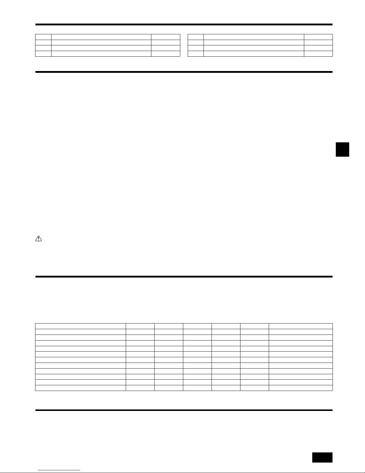
D
17
2. Versorgungseinrichtungen der Innenanlage
Die Anlage ist mit folgenden Versorgungseinrichtungen versehen:
3. Einen Aufstellort wählen
• Einen Aufstellort mit stabiler, fester Fläche, die für das Gewicht der Anlage haltbar
genug ist, wählen.
• Vor Einbau der Anlage muß der Weg zum Transport der Anlage an den Aufstellort
festgelegt werden.
• Einen Aufstellort wählen wo die Anlage nicht durch eindringende Luft beeinflußt
wird.
• Einen Aufstellort wählen wo der Strom der Zu- und Abluft nicht behindert ist.
• Einen Aufstellort wählen wo die Kältemittelrohrleitung problemlos nach außen
geleitet werden kann.
• Einen Aufstellort wählen wo die Luft aus der Anlage sich vollständig im Raum verteilen kann.
• Die Anlage nicht an einem Ort aufstellen, wo in größeren Mengen Öl verspritzt
oder Dampf erzeugt wird.
• Die Anlage nicht an einem Ort aufstellen, wo brennbares Gas erzeugt werden, hereinströmen, verbleiben oder austreten kann.
• Die Anlage nicht an einem Ort aufstellen, wo durch Einrichtungen Hochfrequenzwellen entstehen können (z.B. durch ein Hochfrequenz-Schweißgerät).
• Die Anlage nicht an einem Ort aufstellen, wo sich an der Seite, wo die Luftaustritt,
ein Feuermelder befindet. (Der Feuermelder kann versehentlich in Gang gesetzt
werden, wenn während des Heizbetriebs Warmluft austritt)
• Wo spezielle chemische Produkte im Raum verteilt sein können, wie in chemischen Anlagen und Krankenhäusern, ist vor Aufstellung der Anlage eine umfassende Untersuchung erforderlich. (Die Kunststoffteile können je nach Art der
chemischen Produkte, denen sie ausgesetzt sind, beschädigt werden)
• Wenn das Gerät lange Zeit betrieben wird, während eine hohe Temperatur/hohe
Luftfeuchtigkeit (Taupunkt über 26 °C) in der Decke herrscht, kann es zu Kondensation in der Inneneinheit kommen. Wenn Geräte in solchen Bedingungen betrieben werden, so fügen Sie Isolierungsmaterial (10 – 20 mm) über die gesamte
Oberfläche der Inneneinheit zu, um Kondensation zu verhindern.
3.1. Die Innenanlage an einer Decke montieren, die
stark genug ist, um das Gewicht zu halten
Warnung:
Die Anlage muß an einem Gebäudeteil, der das Gewicht tragen kann, sicher
angebracht werden. Wenn die Anlage an einem Gebäudeteil mit ungenügender
Tragkraft montiert wird, kann sie herunterfallen und Personenschäden verursachen.
3.2. Sicherstellen des Freiraums für Montage und Wartung/Bedienung
Sorgen Sie für ausreichend Zugangsraum für die Wartung, Inspektion und den Austausch des Motors, Ventilator, Entwässerungspumpe, Wärmeaustauscher und
Schaltschrank auf eine der folgenden Weisen.
Wählen Sie einen Installationsort für das Innengerät so, dass sein Wartungszugangsraum nicht von Strahlen oder anderen Objekten blockiert wird.
(1) Wenn ein Raum von 300 mm oder mehr unterhalb des Geräts zur Verfügung
steht, zwischen dem Gerät und der Decke (Fig. 3.2.1)
• Schaffen Sie Zugangstür 1 und 2 (jeweils 450 × 450 mm) wie in Fig. 3.2.2 gezeigt.
(Zugangstür 2 ist nicht erforderlich, wenn ausreichend Platz unterhalb des
Geräts für einen Wartungstechniker zur Verfügung steht, um dort zu arbeiten.)
(2) Wenn weniger als 300 mm Raum unterhalb des Geräts und der Decke zur Ver-
fügung steht (Mindestens 20 mm Raum sollte unterhalb des Geräts frei gelassen
werden, wie in Fig. 3.2.3 gezeigt.)
• Schaffen Sie die Zugangstür 1 diagonal unterhalb des Schaltschranks und
Zugangstür 3 unterhalb des Geräts, wie in Fig. 3.2.4 gezeigt.
oder
• Schaffen Sie die Zugangstür 4 unterhalb des Schaltschranks und des Geräts,
wie in Fig. 3.2.5 gezeigt.
[Fig. 3.2.1] (P.2)
[Fig. 3.2.2] (Gesehen von der Richtung des Pfeils A) (P.2)
[Fig. 3.2.3] (P.2)
[Fig. 3.2.4] (Gesehen von der Richtung des Pfeils B) (P.2)
[Fig. 3.2.5] (Gesehen von der Richtung des Pfeils B) (P.2)
3.3. Innenanlagen mit Außenanlagen verbinden
Zum Verbinden der Innenanlagen mit Außenanlagen im Montagehandbuch der
Außenanlagen nachschlagen.
4. Befestigung der Hängebolzen
4.1. Befestigung der Hängebolzen
[Fig. 4.1.1] (P.3)
(Die Aufhängeposition muß eine starke Baustruktur aufweisen.)
Baustruktur für die Aufhängung
• Decke: Die Deckenstruktur ist von Gebäude zu Gebäude unterschiedlich. Holen
Sie nähere Informationen bei der jeweiligen Bauunternehmung ein.
• Verstärken Sie die Aufhängungsbolzen erforderlichenfalls mit Erdbebenunterstützungen als Maßnahme gegen Erdbeben.
* Verwenden Sie M10 für Aufhängungsbolzen und Erdbebenunterstützungen
(lokal beizustellen).
Schwerpunkt und Erzeugnisgewicht
Die Werte in Klammern beziehen sich auf das Modell PEFY-P·VMAL-E2.
5. Aufstellen der Anlage
5.1. Aufhängen des Anlagenkörpers
Die Innenanlage in der Verpackung an den Aufstellungsort bringen.
Zum Aufhängen der Innenanlage diese mit einer Hebevorrichtung anheben
und durch die Hängebolzen führen.
[Fig. 5.1.1] (P.3)
[Fig. 5.1.2] (P.3)
Teilenr. Zubehör Menge
1 Isolationsrohr 1
2 Binder 3
3 Abfluss buchse 1
4 Unterlegscheibe 8
5 Installationshandbuch 1
6 Betriebshandbuch 1
Teilenr. Zubehör Menge
A Schaltschrank B Decke
C Deckenstrahler D Zugangstür 2 (450 mm × 450 mm)
E Zugangstür 1 (450 mm × 450 mm) F Wartungszugangsraum
G Zuluft H Ansaugluft
I Unterseite des Innengeräts J Zugangstür 3
K Zugangstür 4
A Schwerpunkt
Modellbezeichnung W L X Y Z Erzeugnisgewicht (kg)
PEFY-P20VMA(L)-E2 643 754 330 300 130 22 (21)
PEFY-P25VMA(L)-E2 643 754 330 300 130 22 (21)
PEFY-P32VMA(L)-E2 643 754 330 300 130 22 (21)
PEFY-P40VMA(L)-E2 643 954 340 375 130 26 (25)
PEFY-P50VMA(L)-E2 643 954 340 375 130 26 (25)
PEFY-P63VMA(L)-E2 643 1154 325 525 130 31 (30)
PEFY-P71VMA(L)-E2 643 1154 325 525 130 31 (30)
PEFY-P80VMA(L)-E2 643 1154 325 525 130 31 (30)
PEFY-P100VMA(L)-E2 643 1454 330 675 130 39 (38)
PEFY-P125VMA(L)-E2 643 1454 330 675 130 39 (38)
PEFY-P140VMA(L)-E2 643 1654 332 725 130 43 (42)
A Anlagenkörper
B Hebevorrichtung
C Muttern (Vor Ort zu beschaffen)
D Unterlegscheiben (Vor Ort zu beschaffen)
E M10-Hängebolzen (Vor Ort zu beschaffen)
Page 18
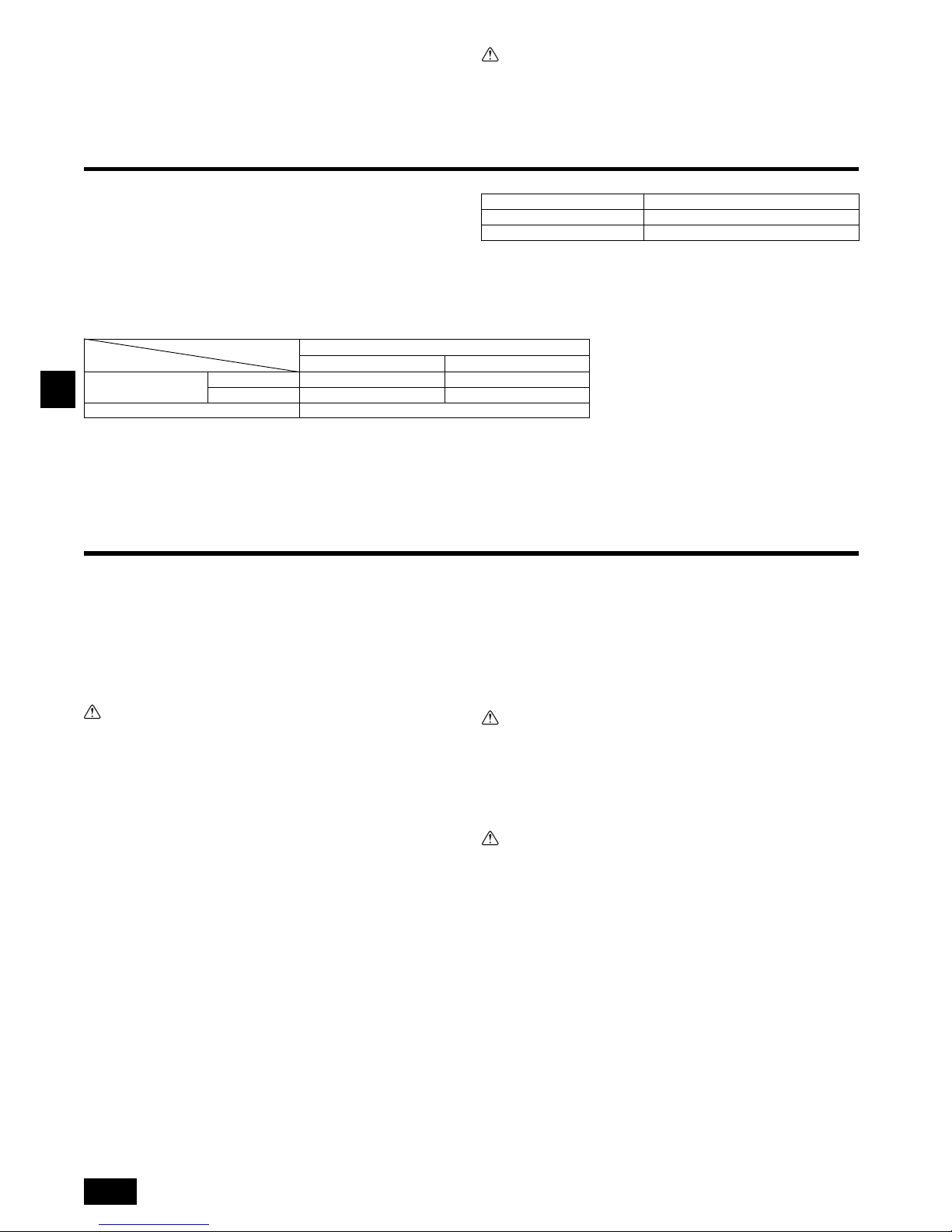
18
D
5.2. Sich über die richtige Lage der Anlage vergewissern und die Hängebolzen befestigen
Auch dafür sorgen, daß die Muttern der Hängebolzen fest angezogen sind,
um die Hängebolzen zu sichern.
Um zu gewährleisten, daß der Wasserauslauf stattfindet, mit einer Wasser-
waage sicherstellen, daß die Anlage in der Waagerechten hängt.
Vorsicht:
Installieren Sie die Anlage waagerecht. Wenn die Seite mit dem Drainageanschluss höher liegt, kann dies ein Auslaufen des Wassers bewirken.
6. Technische Daten der Kältemittel- und Kondensatablaufleitung
Um Tropfenbildung zu vermeiden, die Kältemittel- und Kondensatablaufleitung ausreichend gegen Schwitzwasserbildung sichern und mit Isoliermaterial ausstatten.
Bei Einsatz von handelsüblichen Kältemittelrohren dafür sorgen, daß handelsübliches Isoliermaterial (mit einer Hitzebeständigkeit von mehr als 100 °C und der nachstehend angegebenen Stärke) sowohl um die Flüssigkeits- als auch um die
Gasrohre gewickelt wird.
Isolieren Sie alle Innenrohre mit Polyäthylen-Formteilen mit einer minimalen Dichte
von 0,03 und einer Stärke, wie sie in folgender Tabelle angegeben ist.
a Auswahl der Stärke des Isoliermaterials nach Rohrgrößen.
b Wenn die Anlage im obersten Stockwerk eines Gebäudes und unter Umgebungs-
bedingungen mit hoher Temperatur und hoher Luftfeuchtigkeit eingesetzt wird, ist
es notwendig, Rohrgrößen und Isoliermaterialstärken zu verwenden, die über den
in der Tabelle angegebenen liegen.
c Wenn technische Angaben seitens des Kunden vorliegen, diese einfach befolgen.
6.1. Technische Daten der Kältemittel- und Kondensatablaufleitung
6.2. Kältemittelrohr, Kondensatablaufrohr und Einfüllöffnung
[Fig. 6.2.1] (P.3)
7. Kältemittel- und Kondensatablaufleitungen anschließen
7.1. Verrohrung der Kältemittelleitung
Die Verrohrung muß gemäß den Anweisungen im Aufstellhandbuch sowohl der
Außenanlage als auch der BC-Steuerung (Baureihe R2 für gleichzeitiges Kühlen
und Heizen) erfolgen.
• Die Baureihe R2 ist für den Betrieb in einem System ausgelegt, bei dem die Kälte-
mittelrohrleitung von einer Außenanlage durch eine BC-Steuerung übernommen
und von dieser zum Anschluß an Innenanlagen abgezweigt wird.
• Angaben über weitere Bedingungen bezüglich Rohrlänge und zulässiger Höhen-
differenz finden sich im Handbuch der Außenanlage.
• Die Rohrverbindung erfolgt im Wege des gelöteten Anschlusses.
Vorsicht:
• Die Kältemittelrohre für die Innenanlage gemäfl der folgenden Angaben
installieren.
1. Das Ende des Innenanlage-Rohres abschneiden, das Gas austreten lassen, und
dann die gelötete Muffe abnehmen.
[Fig. 7.1.1] (P.4)
2. Die Wärmeisolierung an der Seite des Kältemittelrohres herausziehen, die Rohr-
leitungen der Anlage löten, und die Isolierung wieder an der ursprünglichen Stelle
anbringen.
Die Rohrleitung mit Isolierband umwickeln.
Hinweis:
• Achten Sie beim Löten der Kühlmittelleitungen darauf, währenddessen die
Leitungen der Geräte mit einem nassen Tuch zu kühlen, damit diese durch
die Hitzeeinwirkung nicht verbrennen oder schrumpfen.
[Fig. 7.1.2] (P.4)
• Beim Umwickeln der Kupferrohre größte Vorsicht walten lassen, da sich
durch das Umwickeln der Rohrleitung Kondenswasser bilden kann, anstatt
dies zu verhindern.
[Fig. 7.1.3] (P.4)
Vorsichtsmaßregeln bei Kältemittelrohrleitungen
Dafür sorgen, daß zum Hartlöten nichtoxidierende Hartlötverfahren ange-
wendet werden, um zu gewährleisten, daß keine Fremdstoffe oder Feuchtigkeit in die Rohrleitung eindringen.
Kältemaschinenöl auf die Oberfläche des Sitzes der konischen Verbindung
auftragen und den Anschluß mit einem Doppelschraubenschlüssel fest
anziehen.
Eine Metallklammer (Rohrschelle) zum Halten des Kältemittelrohrs anbrin-
gen, damit die Last auf das Endrohr der Innenanlage verlegt wird. Diese
Metallklammer (Rohrschelle) sollte 50 cm vom Konusanschluß der Innenanlage entfernt angebracht werden.
Warnung:
Verwenden Sie kein Kühlmittel eines Typs, welcher nicht in den mitgelieferten
Anleitungen dieser Einheit oder auf der Namensplatte angegeben ist.
- Anderenfalls kann dies während Reparaturarbeiten oder beim Entsorgen der Einheit
zum Zerplatzen der Einheit oder der Leitungen, einer Explosion oder Brand führen.
- Zudem kann dies gegen geltendes Recht verstoßen.
- Die MITSUBISHI ELECTRIC CORPORATION übernimmt keine Haftung bei Fehlfunktionen oder Unfällen, die aufgrund der Verwendung eines falschen Kühlmitteltyps aufgetreten sind.
Vorsicht:
• Kältemittelrohrleitungen aus phosphor-deoxidiertem Kupfer C1220 (CuDHP) gemäß Angaben in JIS H3300 “Nahtlose Rohrleitungen und Rohre aus
Kupfer und Kupferlegierung” verwenden. Außerdem vergewissern, daß die
Innen- und Außenflächen der Rohrleitungen sauber und frei von gefährlichem Kupfer, Oxyden, Staub/Schmutz, Metallbearbeitungsrückständen,
Ölen, Feuchtigkeit oder anderen Verunreinigungen sind.
• Niemals vorhandene Kältemittelrohrleitungen einsetzen.
- Die große Menge Chlor in herkömmlichen Kältemitteln und Kältemaschinenöl in der
vorhandenen Rohrleitung führt zu einer Qualitätsminderung des neuen Kältemittels.
• Die zu verwendende Rohrleitung während der Installation in einem geschlossenen Raum aufbewahren und beide Enden der Rohrleitung bis unmittelbar
vor dem Hartlöten abgedichtet lassen.
- Wenn Staub, Schmutz oder Wasser in den Kältemittelkreislauf gelangen, wird die
Qualität des Öls gemindert, was zum Ausfall des Kompressors führen kann.
• Die aufgeweiteten Teile und den Flanschanschluß mit Kältemaschinenöl des
Typs Suniso 4GS oder 3GS (kleine Menge) bestreichen. (Für Modelle, die R22
verwenden)
• Zum Beschichten der Konus- und Flanschanschlüsse Esteröl/Ätheröl oder
Alkylbenzol (kleine Menge) als Kältemaschinenöl verwenden. (Für Modelle,
die R410A oder R407C verwenden)
- Das in der Anlage verwendete Kältemittel ist stark hygroskopisch, vermischt sich
mit Wasser und mindert die Qualität des Kältemaschinenöls.
Rohrgröße Stärke des Isoliermaterials
6,4 mm – 25,4 mm Mehr als 10 mm
28,6 mm – 38,1 mm Mehr als 15 mm
PEFY-P·VMA(L)-E2
20·25·32·40·50 63·71·80·100·125·140
Kältemittelrohr
(Gelöteter Anschluß)
Flüssigkeitsrohr ø 6,35 ø 9,52
Gasrohr ø 12,7 ø 15,88
Kondensatablauf Außendurchmesser ø 32
Position
Modell
A Kältemittelrohrleitung (Flüssigkeitsrohrleitung)
B Kältemittelrohrleitung (Gasrohrleitung)
C Kondensatablaufrohr (Außendurchmesser ø 32)
D Kondensatablaufrohr (Außendurchmesser ø 32, spontane Entwässerung)
A An dieser Stelle schneiden
B Gelötete Muffe abnehmen
A Kühlen mit einem nassen Tuch
A Wärmeisolierung B Isolierung abziehen
C Mit feuchtem Tuch umwickeln
D Wieder an ursprünglicher Stelle anbringen
E Dafür sorgen, dafl an dieser Stelle keine Lücke ist
F Mit Isolierband umwickeln
Page 19

D
19
7.2. Verrohrung des Kondensatablaufs/der Dränage
• Dafür sorgen, daß die Kondensatleitung in Richtung Außenanlage (Abwasserauslauf) geneigt ist (Verhältnis von mehr als 1/100). Keine Sammelgefäße oder nicht
vorgesehene Einrichtungen auf der Strecke einbauen.
• Dafür sorgen, daß abzweigende Kondensatleitungen weniger als 20 m lang sind
(unabhängig vom Steigungsunterschied). Bei langen Dränagerohren Metallklammern (Rohrschellen) anbringen, um Schwingungen zu verhindern. Niemals Luftabzugsrohre anbringen, da sonst Abwasser ausgestoßen wird.
• Ein Hartvinylchlorid-Rohr VP-25 (mit einem Außendurchmesser von 32 mm) als
Auslaufrohr verwenden.
• Achten Sie darauf, dass die Sammelrohrleitungen 10 cm tiefer liegen als der
Abwasserausgang des Anlagenkörpers.
• Am Abwasserausgang keinen Geruchsabzug anbringen.
• Das Ende des Auslaufrohrs an einer Stelle anbringen, an der kein Geruch entstehen kann.
• Das Ende der Auslaufleitung nicht in einen Ablauf verlegen, in dem sich IonenGase bilden können.
[Fig. 7.2.1] (P.4)
Sammelrohrleitungen
Modell PEFY-P·VMA-E2
[Modell PEFY-P·VMA]
1. Führen Sie die Abfluss buchse (Zubehör) in den Drainageanschluss ein (Einfüh-
rungsgrenze: 32mm).
(Montieren Sie den Schlauch mit Kleber, und fixieren Sie ihn mit einem Binder
(klein, Zubehör).)
2. Montieren Sie das Ablassrohr (Außendurchmesser ø 32 PVC-SCHLAUCH PV-
25, handelsüblich). (Montieren Sie das Rohr mit Kleber, und fixieren Sie es mit
einem Binder (klein, Zubehör).)
3. Führen Sie Isolierungsarbeiten am Ablassrohr (Außendurchmesser ø 32 PVC-
SCHLAUCH PV-25) und dem Anschlussstück (einschließlich Bogen) durch.
4. Prüfen Sie den korrekten Abfluss. (Näheres unter [Fig. 7.3.1])
5. Montieren Sie das Isolationsmaterial, und befestigen Sie es mit einem Binder
(groß, Zubehör), um den Drainageanschluss zu isolieren.
[Fig. 7.2.2] (P.4) *nur am Modell PEFY-P·VMA-E2
[Modell PEFY-P·VMAL]
1. Führen Sie die Abfluss buchse (Zubehör) in den Drainageanschluss ein.
Das Verbindungsteil zwischen Innenanlage und Abfluss buchse kann bei der
Wartung abgetrennt werden. Das Teil mit dem Zubehörband ohne Verwendung
von Klebstoff befestigen.
2. Montieren Sie das Ablassrohr (Außendurchmesser ø 32 PVC-SCHLAUCH, handelsüblich). (Die Leitung mit Klebstoff für Hart-PVC-Leitung anbringen und mit
dem Band befestigen (klein, Zubehör).)
3. Führen Sie Isolierungsarbeiten am Ablassrohr (Außendurchmesser ø 32 PVCSCHLAUCH) und dem Anschlussstück (einschließlich Bogen) durch.
[Fig. 7.2.3] (P.4) *nur am Modell PEFY-P·VMAL-E2
7.3. Funktion der Ablassleitung prüfen
Stellen Sie sicher, dass der Entwässerungsmechanismus normal arbeitet,
und dass kein Wasser aus den Verbindungen austritt.
• Achten Sie darauf, die Funktion in einer Heizbetriebsperiode zu überprüfen.
• Vergewissern Sie sich bei Neubauten, obige Punkte zu überprüfen, bevor Decken-
arbeiten ausgeführt werden.
1. Entfernen Sie die Abdeckung für die Wasserzuführung auf derselben Seite wie
die Rohrführung des Innengerätes.
2. Füllen Sie Wasser aus einem Speisewassertank in die Speisewasserpumpe. Achten Sie beim Befüllen darauf, das Ende der Pumpe oder des Tanks in eine Drainagepfanne zu führen. (Falls der Schlauch nicht ganz eingeführt wird, kann
Wasser über das Gerät laufen.)
3. Führen Sie den Testlauf im Kühlbetrieb aus oder schließen Sie die Steckbrücke
an der ON-Seite von SWE auf der Innengerätesteuerplatine an. (Die Drainagepumpe und der Lüfter werden ohne jede Verwendung der Fernbedienung
zwangsbetrieben.) Verwenden Sie einen transparenten Schlauch, um sicherzustellen, dass eine Drainage erfolgt.
4. Nach der Bestätigung den Testlauf abbrechen und die Hauptstromversorgung
ausschalten. Falls die Steckbrücke an der ON-Seite von SWE angebracht ist, die
Steckbrücke abnehmen, an der OFF-Seite anbringen und den Verschluss des
Wasserzufuhranschlusses in seiner ursprünglichen Position anbringen.
[Fig. 7.3.1] (P.5)
[Fig. 7.3.2] (P.5)
8. Rohrleitungsarbeiten
• Beim Anschluß des Strömungskanals Segeltuchteilstück zwischen Anlage und
Strömungskanal einsetzen.
• Als Strömungskanalteile nichtbrennbare Materialien verwenden.
• Eingangsflansch und Ausgangsflansch vollständig isolieren, um Kondenswasserbildung zu verhindern.
• Dafür sorgen, daß die Position des Luftfilters so gelegt wird, daß er unbehindert
gewartet werden kann.
[Fig. 8.0.1] (P.5)
• Verfahren für Änderung von Einlaß von der Rückseite her zu Einlaß von der Unterseite her.
Vorsicht:
Wenn der Kanal am Eingang unten am Gerät angeschlossen ist, wird der
Schalldruckpegel um etwa 10 dB größer als wenn der Kanal an den Eingang
auf der Rückseite des Geräts angeschlossen ist.
Aus diesem Grund wird empfohlen, den Kanal am Eingang an der Rückseite
anzuschließen.
Wenn Sie einen Eingang auf der Rückseite des Geräts verwenden, stellen Sie
die Position des Eingangs am Innengerät so ein, dass sie relativ zum Eingang
am Dach ist, wie es in den Abbildungen <A> und <B> gezeigt wird, um das Geräusch zu minimieren.
[Fig. 8.0.2] (P.5)
1. Luftfilter entfernen. (Zuerst die Filterverschlussschraube entfernen.)
2. Entfernen Sie die Platte an der Unterseite.
3. Die untere Platte an der Rückseite des Körpers anbringen. [Fig. 8.0.3] (P.5)
(Die Halteöffnungen am Blech befinden sich in einer anderen Position als die für
den hinteren Einlass.)
Korrekte Rohrführung
Falsche Rohrführung
A Isolierung (9 mm oder mehr)
B Abwärtsneigung (1/100 oder mehr)
C Metallträger
K Entlüftung
L Erhöht
M Geruchsverschluss
D Außendurchmesser ø32 PVC-SCHLAUCH
E So groß wie möglich auslegen. Etwa 10 cm.
F Innengerät
G Stellen Sie die Rohrführung für die Sammelrohrleitung ausreichend groß her.
H Abwärtsneigung (1% oder mehr)
I Außendurchmesser ø38 PVC-SCHLAUCH für Sammelrohrleitungen. (9 mm Isolierung
oder mehr)
J Bis zu 700 mm
N Abfluss buchse (Zubehör)
O Horizontal oder leicht aufwärts führend
A Innengerät
B Binder (Zubehör)
C Sichtbarer Teil
D Einführungsgrenze
E Abfluss buchse (Zubehör)
F Ablassrohr (Außendurchmesser ø 32 PVC-SCHLAUCH, handelsüblich)
G Isolierungsmaterial (handelsüblich)
H Binder (Zubehör)
A Innengerät
B Binder (Zubehör)
C Bandbefestigungsteil
D Einführungsgrenze
E Abfluss buchse (Zubehör)
F Ablassrohr (Außendurchmesser ø 32 PVC-SCHLAUCH, handelsüblich)
G Isolierungsmaterial (handelsüblich)
A Pumpenende 2 bis 4 cm einführen.
B Abdeckung für die Wasserzuführung entfernen.
C Etwa 2500 cc
D Wasser
E Wasseranschluss
F Schraube
<Innengerätsteuerplatine>
Steckbrücke
SWE
OFF ON OFF ON
SWE
<OFF> <ON>
Steckbrücke
SWE
OFF ON OFF ON
SWE
<ON> <OFF>
<A> Bei Eingang auf der Rückseite
<B> Bei Eingang von unten
A Strömungskanal B Lufteingang
C Zugangstür D Strömungskanalteilstück aus Segeltuch
E Deckenoberfläche F Luftausgang
G Genügend Abstand halten, um Kurzschluß zu verhindern
A Filter B Bodenplatte
Wenn das Blech an der
Rückseite angebracht ist, ragt
es oben über die hintere
Gehäuseverkleidung hinaus.
Das Blech entlang des
Schlitzes replizieren, wenn
oben kein ausreichender
Platz für die gesamte
Einheit vorhanden ist.
Page 20
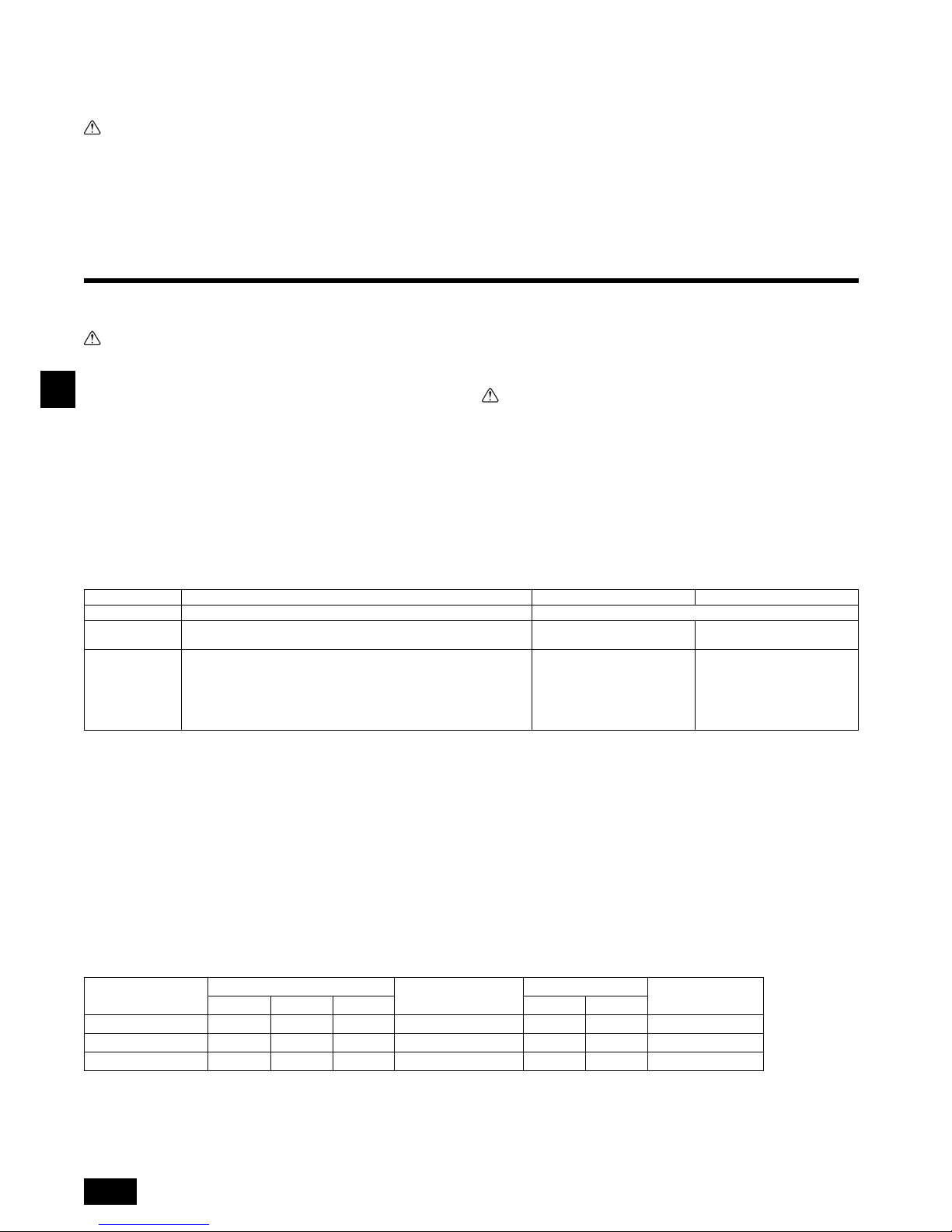
20
D
4. Passen Sie den Filter an die Geräteunterseite an.
(Darauf achten, auf welcher Seite des Filters die Montage erfolgt.) [Fig. 8.0.4]
(P.5)
[Fig. 8.0.4] (P.5)
Vorsicht:
• Es muß ein Eingangsströmungskanal von 850 mm oder mehr errichtet werden.
Hauptkörper der Klimaanlage und Strömungskanal zum potentiellen Ausgleich miteinander verbinden.
• Schutzhandschuhe tragen, um die Verletzungsgefahr durch Blechkanten zu
verringern.
• Den Hauptkörper der Klimaanlage und den Strömungskanal miteindander
verbinden, für die Ausgleichung des Potentials.
• Das Ansauggeräusch steigt dramatisch an, wenn Ansaugteil unmittelbar
neben dem Hauptkörper der Anlage angebracht wird. Ansaugteil mub daher
soweit wie möglich vom Hauptkörper der Anlage entfernt installiert werden.
Besondere Aufmerksamheit ist erforderlich, wenn die Anwendung gemäb
den technischen Daten für den Lufteingang von unten erfolgt.
• Zur Vermeidung von Kondenswasserbildung an den Flanschen des Strömungskanalausgangs und an den Strömungskanalausgängen ausreichend
Wärmeisolierung anbringen.
• Zwischen dem Einlaßgitter und dem Ventilator mehr als 850 mm Abstand einhalten.
Wenn der Abstand weniger als 850 mm beträgt, muß ein Schutzgitter angebracht werden, damit man nicht mit dem Ventilator in Berührung kommt.
• Keine Übertragungsleitungen unten am Gerät verlegen, um elektrische Störgeräusche zu vermeiden.
9. Elektroverdrahtung
Vorsichtsmaßnahmen bei der elektrischen Verdrahtung
Warnung:
Elektroarbeiten sollten nur durch qualifizierte Fachelektriker gemäß “Engineering Standards for Electrical Installation” - “Technische Normen für Elektroinstallation” und gemäß Installationshandbüchern vorgenommen werden. Es
sollten auch eigens eingerichtete Stromkreise verwendet werden. Wenn der
Stromkreis zu schwach ausgelegt ist oder Installationsfehler aufweist, besteht
die Gefahr von Stromschlägen oder Brand.
1. Dafür sorgen, daß ein Erdschlußstromunterbrecher in den Stromkreis installiert
wird.
2. Die Anlage so installieren, daß verhindert wird, daß eines der Steuerkreiskabel
(Fernbedienung, Übertragungskabel) in direkten Kontakt mit dem Netzstromkabel
außerhalb der Anlage gebracht werden kann.
3. Dafür sorgen, daß keiner der Elektroleitungsanschlüsse zu lose gespannt ist oder
einen Wackelkontakt aufweist.
4. Einige Kabel (für Netzstrom-, Fernbedienungs-Übertragungskabel), die oberhalb
der Decke angeordnet sind, können Mäuseverbiß ausgesetzt sein. Daher Kabel
zum Schutz soweit wie möglich in Metallrohre verlegen.
5. Netzstromkabel niemals an die Zuleitung für die Übertragungskabel anschließen,
da sonst die Kabel brechen können.
6. Dafür sorgen, daß die Innenanlage, die Fernbedienung und die Außenanlage mit
Steuerkabeln verbunden sind.
7. Die Anlage auf der Seite der Außenanlage erden.
8. Steuerkabel gemäß den auf Seite 20 angegebenen Betriebsbedingungen aus-
wählen.
Vorsicht:
• Dafür sorgen, daß die Anlage zur Seite der Außenanlage hin geerdet wird.
Die Erdleitung nicht an Gasrohre, Wasserrohre, Beleuchtungsstäbe oder
Telefonerdleitungen anschließen. Unsachgemäße Erdung kann zu Stromschlägen führen.
• Falls das Stromversorgungskabel beschädigt ist, muss es zur Vermeidung
von Gefahren durch den Hersteller, dessen Serviceagentur oder ähnlich qualifiziert Personen ausgetauscht werden.
Spezifikationen des Übetragungskabels
*1 Verbunden mit einfacher Fernbedienung.
9.1. Netzstromverdrahtung
• Verwenden Sie entsprechende Stromversorgungen für das Außengerät und das Innengerät.
• Achten Sie auf die Umweltbedingungen (Umgebungstemperatur, direktes Sonnenlicht, Regenwasser usw.) wenn Sie mit der Verdrahtung und den Verbindungen fortfahren.
• Die Drahtgröße ist der Mindestwert für Metallkabelkanäle. Wenn die Spannung abfällt, verwenden Sie einen Draht, der eine Stufe dicker im Durchmesser ist. Achten Sie darauf, dass die Stromspannung nicht um mehr als 10% abfällt.
• Spezielle Verdahtungsanforderungen müssen die Verdrahtungsanforderungen der Region erfüllen.
• Die Netzstromkabel für Geräte sollen mindestens dem Entwurf 245 IEC 57, 227 IEC 57, 245 IEC 53 oder 227 IEC 53 entsprechen.
• Bei der Installierung der Klimaanlage ist ein Schalter mit einem Kontaktabstand von mindestens 3 mm für jeden Pol vorzusehen.
[Fig. 9.1.1] (P.5)
Wenden Sie auf IEC61000-3-3 an mit etwa max. permissiver Systemimpedanz.
*1 Der FI-Schutzschalter muss den Inverter-Schaltkreis unterstützen.
Der FI-Schutzschalter muss mit dem lokalen Schalter oder Kabeltrennschalter kombiniert werden können.
C Nagel für den unteren Einlass D Nagel für den hinteren Einlass
Übertragungskabel ME-Fernbedienungskabel MA-Fernbedienungskabel
Kabeltyp Abschirmungsleitung (2-adrig) CVVS, CPEVS oder MVVS Ummanteltes 2-adriges Kabel (nicht abgeschirmt) CVV
Kabeldurchmesser Mehr als 1,25 mm
2
0,3 ~ 1,25 mm2
(0,75 ~ 1,25 mm
2
)*1
0,3 ~ 1,25 mm
2
(0,75 ~ 1,25 mm
2
)*1
Anmerkungen
Max. Länge: 200 m
Maximale Länge der Übertragungsleitungen für zentralisierte Steuerung und Innen-/
Außenübertragungsleitungen (maximale Länge über Innengeräte): 500 m MAX.
Die maximale Länge der Kabel zwischen Netzanschluss für Übertragungs-
leitungen (an Übertragungsleitungen für zentralisierte Steuerung) und jedes
Außengerät und jeden System-Controller beträgt 200 m.
Wenn 10 m überschritten werden,
verwenden Sie Kabel mit
derselben Spezifikation als
Übertragungskabel.
Max. Länge: 200 m
A FI-Schutzschalter
B Lokaler Schalter/Kabeltrennschalter
C Innenanlage
D Verteilerkasten
Gesamte Betriebsnetzspannung
der Innenanlage
Mindestkabeldicke (mm2)
FI-Schutzschalter
*1
Lokaler Schalter (A)
Kabeltrennschalter (A)
(kein Sicherungsschalter)
Hauptkabel Marke Erde Kapazität Sicherung
F0 = 16 A oder weniger
*2
1,5 1,5 1,5
20 A Stromempfindlichkeit
*3
16 16 20
F0 = 25 A oder weniger
*2
2,5 2,5 2,5
30 A Stromempfindlichkeit
*3
25 25 30
F0 = 32 A oder weniger
*2
4,0 4,0 4,0
40 A Stromempfindlichkeit
*3
32 32 40
CVVS, MVVS: PVC-isoliertes, abgeschirmtes Steuerkabel mit PVC-Ummantelung
CPEVS: PE-isoliertes, abgeschirmtes Kommunikationskabel mit PVC-Ummantelung
CVV: PVC-isoliertes Steuerkabel mit PVC-Ummantlung
Page 21
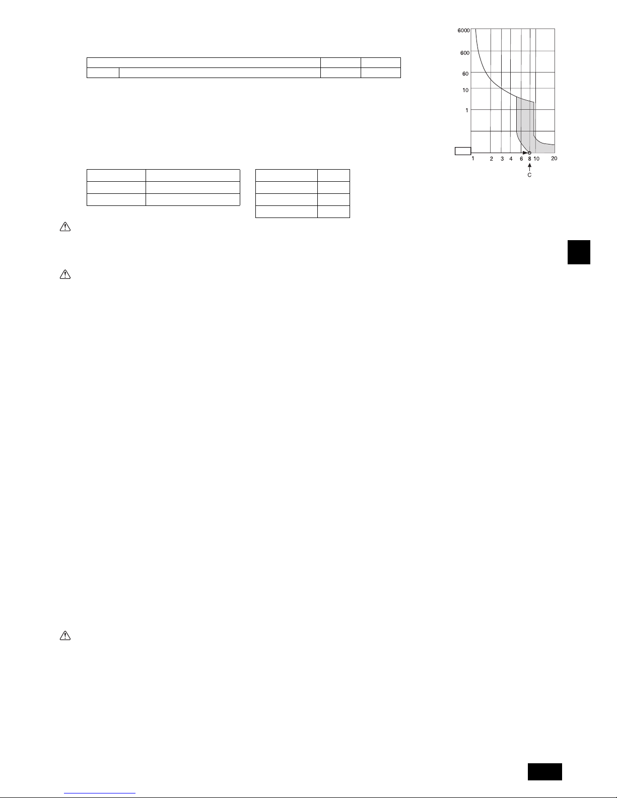
D
21
*2 Bitte nehmen Sie den größeren der F1 oder F2, was den Wert F0 betrifft.
F1 = Gesamte maximale Betriebsspannung der Innenanlagen 1,2
F2 = {V1 (Menge des Typs1)/C} + {V1 (Menge des Typs 2)/C} + {V1 (Menge des Typs3)/C} + {V1 (Menge der Anderen)/C}
C : Multipler Auslösestrom bei einer Auslösezeit von 0,01s
Bitte wählen Sie aus der Auslösecharakteristik des Trennschalters “C”.
<Beispiel der “F2” Berechnung>
*Bedingung PEFY-VMA 3, C = 8 (siehe rechte Beispieldarstellung)
F2 = 38 3/8
= 14,25
16 A Trennschalter (Auslösestrom = 8 16 A bei 0,01s)
*3 Die Stromempfindlichkeit wird anhand folgender Formel berechnet.
G1 = (V2 Menge des Typs1) + (V3 Kabellänge [km])
Warnung:
• Achten Sie darauf, spezielle Drähte für die Verbindungen zu verwenden und stellen Sie sicher, dass keine äußere Kraft auf die Anschlussverbindungen ausge-
übt wird. Wenn die Verbindungen nicht richtig befestigt wurden, kann es zu einer Überhitzung oder Brand kommen.
• Achten Sie darauf, den richtigen Typ eines Überstrom-Schutzschalters zu verwenden. Beachten Sie, dass der generierte Überstrom etwas Direktstrom beinhal-
ten kann.
Vorsicht:
• An einigen Installationsorten kann es sein, dass ein Erdschluss-Schutzschalter für den Inverter erforderlich ist. Wenn kein Erdschluss-Schutzschalter installiert
ist, besteht die Gefahr eines elektrischen Schlags.
• Nur Unterbrecher und Sicherungen mit der richtigen Kapazität verwenden. Bei Verwendung von Sicherungen, Leitungen oder Kupferleitungen mit einer zu gro-
ßen Leistungsaufnahme, besteht die Gefahr der Fehlfunktion oder Brandgefahr.
Hinweise:
• Dieses Gerät ist für die Verbindung mit einem Stromversorgungssystem mit einer maximal zulässigen Systemimpedanz (Siehe IEC61000-3-3.) an der Schnitt-
stelle (Strom-Service-Box) der Nutzerversorgung gedacht.
• Der Nutzer muss sicher stellen, dass dieses Gerät nur an einer Stromquelle angeschlossen ist, welche die oben beschriebenen Anforderungen erfüllt.
Falls notwendig, kann der Nutzer das öffentliche Energieversorgungsunternehmen um die Systemimpedanz an der Schnittstelle bitten.
9.2. Anschluß der Fernbedienungs-, Innen- und
Außenübertragungskabel
• Anschluß der Innenanlage TB5 und der Außenanlage TB3. (2-adrig, nichtpolari-
siert)
Das ’S’ auf der Innenanlage TB5 ist ein abgeschirmter Leitungsanschluß. Angaben
über die technischen Daten der Anschlußkabel finden sich in den Montagehandbüchern der Außenanlage.
• Eine Fernbedienung entsprechend den Angaben im zur Fernbedienung gehören-
den Handbuch installieren.
• “1” und “2” am TB15 der Innenanlage an eine MA-Fernbedienung anschließen
(nicht polarisierte, zweiadrige Elektroleitung).
• “M1” und “M2” am TB5 der Innenanlage an eine M-NET-Fernbedienung anschlie-
ßen (nicht polarisierte, zweiadrige Elektroleitung).
• Das Übertragungskabel der Fernbedienung mit einem Kernaderkabel von
0,75 mm
2
und einer Länge bis zu 10 m anschließen. Wenn die Entfernung mehr
als 10 m beträgt, ein Verbindungskabel von 1,25 mm
2
verwenden.
[Fig. 9.2.1] (P.5) MA Fernbedienung
[Fig. 9.2.2] (P.5) M-NET-Fernbedienung
• 9 – 13 V Gleichstrom zwischen 1 und 2 (MA-Fernbedienung)
• 24 – 30 V Gleichstrom zwischen M1 und M2 (M-NET-Fernbedienung)
[Fig. 9.2.3] (P.6) MA-Fernbedienung
[Fig. 9.2.4] (P.6) M-NET-Fernbedienung
• Die MA-Fernbedienung und die M-NET-Fernbedienung können nicht gleichzeitig
oder wechselweise verwendet werden.
Vorsicht:
Die Elektroleitung so verdrahten, daß sie weder zu eng ist noch unter Zugspannung steht. Verdrahtung unter Zudspannung kann zum Brechen, Überhitzen oder Verbrennen führen.
9.3. Vornahme der Elektroanschlüsse
Bitte die Modellbezeichnung im an der Abdeckung des Anschlusskastens angebrachten Betriebshandbuch mit der auf dem Typenschild angegebenen vergleichen.
1. Zum Abnehmen der Abdeckung die Halteschraube, die die Abdeckung hält (1
Stück), entfernen.
[Fig. 9.3.1] (P.6)
2. Dafür vorgesehene Öffnungen durchbrechen
(Für diese Arbeit wird ein Schraubenzieher oder ähnliches empfohlen.)
[Fig. 9.3.2] (P.6)
3. Stromversorgungskabel am Anschlussbrettkasten unter Verwendung einer Ausgleichsbuchse zur Aufnahme von Zugkräften anschließen. (PG-Anschluss oder
ähnlich.) Übertragungskabel an Übertragungsklemmbrett durch das Ausbrechloch des Anschlussbrettkastens mit normaler Buchse anschließen.
[Fig. 9.3.3] (P.6)
4. Stromzufuhr-, Erdungs-, Übertragungs- und Fernbedienungskabel anschließen.
Die Anschlussbrettkasten muss nicht abgebaut werden.
[Fig. 9.3.4] (P.6)
[Abgeschirmter Leitungsanschluß]
[Fig. 9.3.5] (P.6)
5. Nach Abschluss der Verkabelung die Anschlüsse auf festen Sitz prüfen und die
Abdeckung am Anschlussbrettkasten in umgekehrter Reihenfolge des Ausbaus
anbringen.
Hinweise:
• Beim Anbringen der Abdeckung des Anschlussbrettkastens darauf achten,
keine Kabel oder Drähte einzuklemmen. Andernfalls kann es zu einem Kontaktverlust kommen.
• Beim Anbringen des Anschlussbrettkastens darauf achten, dass die seitli-
chen Anschlüsse nicht entfernt werden. Andernfalls ist kein normaler
Betrieb möglich.
Innenanlage V1 V2
Typs1 PEFY-VMA 38 1,6
G1 Stromempfindlichkeit Kabeldicke V3
30 oder weniger 30 mA 0,1 Sek. oder weniger 1,5 mm
2
48
100 oder weniger 100 mA 0,1 Sek. oder weniger 2,5 mm
2
56
4,0 mm
2
66
A Klemmleiste für Übertragungskabel der Innenanlage
B Klemmleiste für Übertragungskabel der Außenanlage
C Fernbedienung
A Nicht polarisiert B TB15
C Fernbedienung D TB5
A Schraube, die die Abdeckung hält (1 Stück)
B Abdeckung
C Anschlusskasten D Loch zum Ausbrechen
E Entfernen
F Verwenden Sie eine PG-Durchführung, so dass das Gewicht des Kabels und externe
Kräfte nicht auf dem Stromversorgungsanschluss lasten. Verwenden Sie einen Kabelbinder, um das Kabel zu sichern.
G Netzstromleitung H Normale Buchsen verwenden
I Übertragungsleitung
J Anschlussblock für Stromversorgung
K Anschlussblock für Innengeräteübertragung
L Anschlussblock für Fernbedienung
A Anschlussblock B Runde Klemme
C Abgeschirmte Leitung
D Die Erdleiter beider Kabel werden gemeinsam zum Anschluss S geführt. (Stillgelegte
Verbindung)
E Isolierband (um zu verhindern, dass der Erdleiter des abgeschirmten Kabels mit dem
Übertragungsanschluss in Berührung kommt)
0,01
0,1
BEISPIEL
Auslösezeit [s]
Bemessungsdifferenzstrom (x)
Beispielgrafik
Page 22
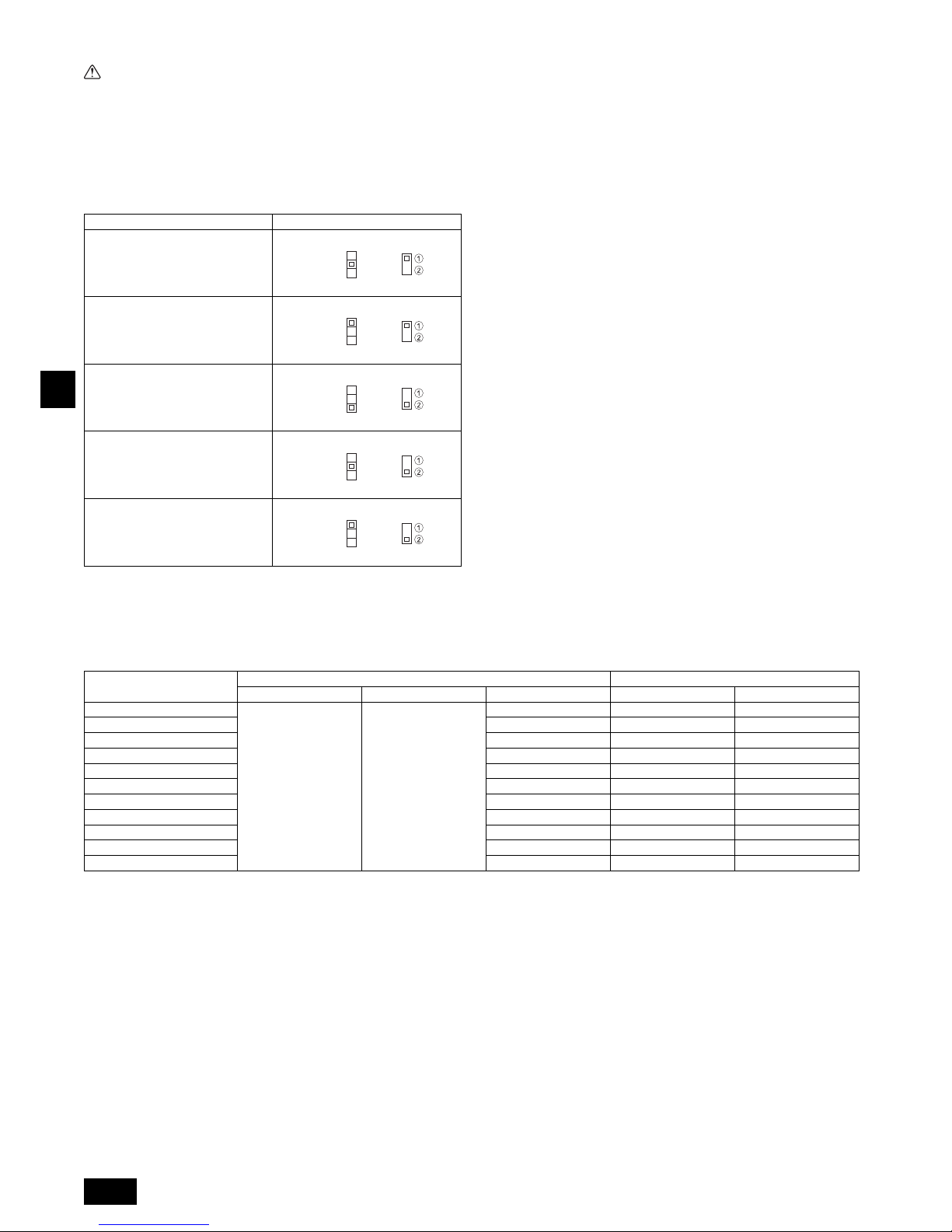
22
D
9.4. Technische Daten der externen Ein-/Ausgänge
Vorsicht:
1. Die Verdrahtung sollte durch ein Isolationsrohr mit zusätzlicher Isolierung
geführt werden.
2. Verwenden Sie Relais oder Schalter nach IEC-Standard oder gleichwertig.
3. Die Spannungsfestigkeit zwischen den zugänglichen Bauteilen und der
Steuerplatine sollte 2750 V oder mehr betragen.
9.5. Auswählen des statischen Außendrucks
Da die Werkseinstellung für den Gebrauch unter einem statischem Außendruck ausgelegt ist, ist bei Einsatz unter normalen Bedingungen kein Schaltvorgang notwendig.
[Fig. 9.5.1] (P.6)
9.6. Adressen einsetzen
(Dafür sorgen, daß bei den Arbeiten der Netzstrom auf AUS geschaltet ist.)
[Fig. 9.5.1] (P.6)
• Zur Einstellung gibt es zwei Arten von Rotationsschaltern: Zur Einstellung der
Adressen von 1 – 9 und über 10 sowie zur Einstellung der Abzweigungsnummern.
• Die Drehschalter sind bei Versand ab Werk alle auf “0” eingestellt.
Diese Schalter können beliebig zur Einstellung der Anlagenadressen und
Abzweignummern verwendet werden.
• Die Festlegung der Adressen der Innengeräte variiert mit der Anlage vor Ort. Stellen Sie diese mithilfe des Datenheftes (Data Book) ein.
9.7. Messen der Raumtemperatur mit dem in eine
Fernbedienung eingebauten Temperaturfühler
Wenn Sie die Raumtemperatur mit dem in eine Fernbedienung eingebauten Fühler
messen wollen, stellen Sie den Schalter SW1-1 auf der Schalttafel auf ’ON’/’EIN’.
Die Einstellung von SW1-7 und SW1-8 ermöglicht es auch, der Luftdurchsatz einzustellen für Phasen, in denen das Heizthermometer ausgeschaltet ist (OFF).
9.8. Die Netzspannungseinstellung ändern
(Dafür sorgen, daß bei den Arbeiten der Netzstrom auf AUS geschaltet ist.)
[Fig. 9.5.1] (P.6)
Stellen Sie den SW5-Schalter entsprechend der Netzspannung ein:
• Stellen Sie den SW5-Schalter auf 240V, wenn die Netzspannung 240 V
beträgt.
• Stellen Sie den SW5-Schalter auf 220V, wenn die Netzspannung 220 bis 230 V
beträgt.
9.9. Elektrische Charakteristiken
Symbole : MCA : Max. Strom-Ampere ( = 1,25 x FLA) FLA : Volllast Ampere
IFM : Lüftermotor Innenraum Ausgabe : Nennleistung des Lüftermotors
Schauen Sie sich das Datenbuch der anderen Modelle an.
Statischer Außendruck Schaltvorgang
P20~P63: 35 Pa
P71~P100: 40 Pa
P20~P100: Werkseinstellung
50 Pa
P125, P140: Werkseinstellung
70 Pa
100 Pa
150 Pa
<Innengerätsteuerplatine>
SWA
SWC
1
2
3
SWA
SWC
1
2
3
SWA
SWC
1
2
3
SWA
SWC
1
2
3
SWA
SWC
1
2
3
<Innengerätsteuerplatine>
a Wie stellt man Adressen ein
Beispiel: Wenn die Adresse ’3’ ist, SW12 (für größer als 10) bei ’0’ lassen und SW11 (für 1 –
9) auf ’3’ einstellen.
b Einstellen der Zweignummern SW14 (nur Serie R2)
Die Zweignummer für jedes Innengerät ist gleichzeitig die Anschlussnummer des BC-Controllers, an dem das Innengerät angeschlossen ist.
Lassen Sie dies bei Geräten, die nicht zur Reihe R2 gehören, auf „0“ eingestellt.
PEFY-P-VMA(L)-E2
Netzstromversorgung IFM
Volt / Hz Bereich +-10% MCA (A) Ausgabe (kW) FLA (A)
PEFY-P20VMA(L)-E2
220-240V / 50Hz
220-240V / 60Hz
Max.: 264V
Min.: 198V
0,92 0,085 0,74
PEFY-P25VMA(L)-E2 0,92 0,085 0,74
PEFY-P32VMA(L)-E2 1,07 0,085 0,86
PEFY-P40VMA(L)-E2 1,32 0,085 1,06
PEFY-P50VMA(L)-E2 1,40 0,085 1,12
PEFY-P63VMA(L)-E2 2,08 0,121 1,67
PEFY-P71VMA(L)-E2 2,32 0,121 1,86
PEFY-P80VMA(L)-E2 2,36 0,121 1,89
PEFY-P100VMA(L)-E2 2,53 0,300 2,02
PEFY-P125VMA(L)-E2 2,95 0,300 2,36
PEFY-P140VMA(L)-E2 2,73 0,300 2,18
Page 23
F
23
Table des matières
1. Consignes de sécurité ............................................................................23
1.1. Avant l’installation de l’appareil et l’installation électrique.......23
1.2. Précautions à prendre avec les dispositifs utilisant le
réfrigérant R410A.................................................................... 24
1.3. Avant de procéder à l’installation ............................................ 24
1.4. Avant de procéder à l’installation (déplacement)-installation
électrique ................................................................................24
1.5. Avant d’effectuer l’essai..........................................................24
2. Eléments qui accompagnent l’appareil intérieur .....................................25
3. Comment choisir le lieu d’installation......................................................25
3.1. Fixer l’appareil intérieur à un plafond suffisamment résistant
pour supporter son poids ........................................................25
3.2. Prévoir l’espace nécessaire pour l’installation et l’entretien....25
3.3. Association des appareils intérieurs et des appareils
extérieurs ................................................................................ 25
4. Fixation des boulons de suspension.......................................................25
4.1. Fixation des boulons de suspension....................................... 25
5. Installation de l’appareil ..........................................................................25
5.1. Suspension de l’appareil .........................................................25
5.2. Assurer l’emplacement de l’appareil et fixer les boulons de
suspension..............................................................................26
6. Spécifications techniques des tuyaux de réfrigérant et du tuyau
d’écoulement...........................................................................................26
6.1. Spécifications techniques des tuyaux de réfrigérant et
d’écoulement .......................................................................... 26
6.2. Tuyau de réfrigérant, tuyau d’écoulement et port de
remplissage ............................................................................ 26
7. Raccordement des tuyaux de réfrigérant et d’écoulement .....................26
7.1. Mise en place des tuyaux de réfrigérant .................................26
7.2. Travaux de mise en place du tuyau d’écoulement .................27
7.3. Confirmation des décharges d’écoulement ............................ 27
8. Raccords des conduites..........................................................................27
9. Câblage électrique .................................................................................. 28
9.1. Câblage de l’alimentation électrique.......................................28
9.2. Raccordement des câbles de la commande à distance
et des câbles de transmission intérieurs et extérieurs............29
9.3. Connexions électriques .......................................................... 29
9.4. Spécifications I/O externes .....................................................30
9.5. Sélection de la pression statique extérieure...........................30
9.6. Configuration des adresses ....................................................30
9.7. Détection de la température ambiante à l’aide du capteur
intégré de la commande à distance........................................30
9.8. Réglage de la tension d’alimentation......................................30
9.9. Caractéristiques électriques ...................................................30
1. Consignes de sécurité
1.1. Avant l’installation de l’appareil et l’installation
électrique
Symboles utilisés dans le texte
Avertissement:
Précautions à suivre pour éviter tout danger de blessure ou de décès de l’utilisateur.
Précaution:
Précautions à suivre pour éviter tout endommagement de l’appareil.
Symboles utilisés dans les illustrations
Avertissement:
• Demandez à votre revendeur ou à un technicien agréé d’installer le climati-
seur.
- En cas de mauvaise installation, il y aurait un risque de fuite d’eau, d’électrocution ou d’incendie.
• Installez l’appareil sur une structure capable de supporter son poids.
- Autrement l’appareil risque de tomber et de blesser quelqu’un.
• Utilisez les câbles mentionnées pour les raccordements. Assurez-vous que
les connexions soient effectués correctement de façon à ce que la force
externe du câble ne s’applique pas aux bornes.
- Un mauvais raccordement pourrait provoquer une surchauffe, voire un incendie.
• Prenez toutes les mesures nécessaires pour parer aux éventuels typhons ou
autres vents forts ainsi que les tremblements de terre, et installez l’appareil à
l’endroit spécifié.
- L’appareil pourrait tomber et par conséquent blesser quelqu’un si l’installation
n’est pas effectuée correctement.
• Utilisez toujours les filtres à air, déshumidificateurs, chauffages électriques
et autres accessoires indiqués par Mitsubishi Electric.
- Demandez à un technicien agréé d’installer les accessoires. Une mauvaise ins-
tallation par l’utilisateur pourrait provoquer des fuites d’eau, électrocution ou un
incendie.
• Ne réparez jamais vous-même l’appareil. En cas de réparation nécessaire,
veuillez consulter le revendeur.
- Toute mauvaise réparation pourrait résulter en des fuites d’eau, chocs élec-
triques ou incendies.
• Ne touchez jamais les ailettes de l’échangeur de chaleur.
- Vous risqueriez de vous blesser.
• Toujours revêtir des vêtements de protection pour manipuler ce produit.
Par ex.: gants, protection intégrale des bras par combinaison et lunettes de
sécurité.
- Vous risqueriez de vous blesser.
• En cas de fuite de gaz durant l’installation, aérez la pièce.
- Si le gaz réfrigérant entre en contact avec une flamme, il y aura émission de gaz
toxiques.
• Installez le climatiseur en respectant les instructions du manuel d’installation.
- En cas d’installation incorrecte, il y aura un risque de fuites d’eau, d’électrocution
ou d’incendie.
• Demandez à un électricien qualifié d’effectuer l’installation électrique conformément aux “Normes concernant les installations électriques” et les “Réglementations sur le câblage intérieur” ainsi que les instructions de ce manuel;
utilisez toujours un circuit différent.
- Si la capacité de la source d’alimentation n’est pas adéquate ou si l’installation
électrique n’est pas effectuée correctement, il y aura un risque d’électrocution ou
d’incendie.
• Maintenez les pièces électriques à l’abri de l’eau (eau de lavage etc.).
- Sinon une électrocution, un incendie ou de la fumée pourrait en résulter.
• Mettez fermement en place le couvercle des bornes de l’appareil extérieur
(panneau).
- Si le couvercle des bornes (panneau) n’est pas mis en place correctement, il se
peut que de la poussière ou de l’eau s’infiltre dans l’appareil extérieur et par
conséquent il y aura un risque d’incendie ou d’électrocution.
• Utilisez uniquement un réfrigérant de type indiqué dans les manuels fournis
avec l'unité et sur la plaque signalétique.
- Faute de quoi, l'unité ou la tuyauterie pourrait éclater, ou cela pourrait provoquer
une explosion ou un incendie pendant l'utilisation, la réparation ou la mise au
rebut de l'unité.
- Cela pourrait également constituer une violation des lois applicables.
- MITSUBISHI ELECTRIC CORPORATION ne peut être tenue responsable de
tout dysfonctionnement ou accident résultant de l'utilisation du mauvais type de
réfrigérant.
• Si le climatiseur est installé dans une pièce relativement petite, certaines
mesures doivent être prises pour éviter que la concentration de réfrigérant
ne dépasse le seuil de sécurité en tenant compte des possibilités de fuites de
réfrigérant.
- Consultez votre revendeur sur les précautions nécessaires à prendre afin que la
limite admissible ne soit pas dépassée. Si le réfrigérant fuit et que la limite admissible est dépassée, il pourrait se produire des accidents suite au manque d’oxygène dans la pièce.
• Veuillez consulter votre revendeur ou un technicien agréé lors du déplacement et de l’installation du climatiseur dans un différent endroit.
- Une mauvaise installation du climatiseur pourrait résulter en fuites d’eau, électro-
cution ou un incendie.
• L’installation terminée, assurez-vous qu’il n’y a aucune fuite de gaz.
- Si le gaz réfrigérant fuit et entre en contact avec un radiateur soufflant, un poêle,
un four ou toute autre source de chaleur, il se peut que des gaz toxiques soient
relâchés.
• Ne réarrangez pas et ne changez pas les réglages des dispositifs de sécurité.
- Si l’interrupteur de pression, l’interrupteur thermique ou tout autre dispositif de
sécurité sont court-circuités ou utilisés avec trop de force, ou si toutes autres
pièces que celles spécifiées par Mitsubishi Electric sont utilisées, il y aura un
risque d’incendie ou d’explosion.
• Demandez conseil à votre revendeur avant de mettre le produit aux rebuts.
Avant d’installer le climatiseur, lire attentivement toutes les “Consignes
de sécurité”.
Les “Consignes de sécurité” reprennent des points très importants
concernant la sécurité. Veillez bien à les suivre.
: Indique une action qui doit être évitée.
: Indique des instructions importantes à suivre.
: Indique un élément à mettre à la terre.
: Indique la nécessité de faire attention aux pièces tournantes. (Ce symbole se
trouve sur l’étiquette de l’appareil principal.) <Couleur: jaune>
: Danger d’électrocuition. (Ce symbole se trouve sur l’étiquette de l’appareil
principal.) <Couleur: jaune>
Avertissement:
Lisez soigneusement les étiquettes se trouvant sur l’appareil principal.
Page 24
F
24
• N’utilisez pas d’additif de détection des fuites.
• Si le cordon d’alimentation est endommagé, il doit être remplacé par le fabricant,
un agent d’entretien ou une personne qualifiée de manière à éviter tout risque.
• Cet appareil n’est pas conçu pour être utilisé par des personnes (enfants
inclus) dont les capacités mentales, sensorielles ou physiques sont réduites
ou qui ne disposent pas de l’expérience et des connaissances requises, sauf
si une personne responsable de leur sécurité assure leur surveillance ou
leur formation dans le cadre de l’utilisation de l’appareil.
• Il est nécessaire de surveiller les enfants de manière à ce qu’ils ne puissent
pas jouer avec l’appareil.
• L'installateur et le spécialiste système assureront la sécurité contre les
fuites conformément aux normes et règlements locaux.
- Les instructions de ce manuel peuvent être applicables si les règlements locaux
ne sont pas disponibles.
• Faites particulièrement attention au lieu de l'installation, telle qu'un sous-sol,
etc. où le gaz frigorigène peut s'accumuler étant donné qu'il est plus lourd
que l'air.
• Cet appareil est prévu pour être utilisé par des utilisateurs experts ou formés
dans les magasins, l'industrie légère et les fermes ou pour une utilisation
commerciale par des personnes non initiées.
1.2. Précautions à prendre avec les dispositifs utili-
sant le réfrigérant R410A
Précaution:
• N’utilisez pas les tuyaux de réfrigérant actuels.
- Le vieux réfrigérant et l’huile réfrigérante se trouvant dans les tuyaux contiennent
une large quantité de chlore qui pourrait abîmer l’huile réfrigérante du nouvel
appareil.
• Utilisez des tuyaux réfrigérants en cuivre désoxydé au phosphore C1220
(Cu-DHP) comme l’indique le chapitre “Tuyaux et tubes en cuivre ou en
alliage de cuivre sans soudure” du JIS H3300. Veillez également à ce que les
surfaces internes et externes des tuyaux soient propres et sans soufre,
oxyde, poussière/impuretés, rognures, huile, condensation ou autre particule contaminante.
- Tout contaminant à l’intérieur des tuyaux de réfrigérant pourrait provoquer la
détérioration de l’huile réfrigérante résiduelle.
• Gardez les tuyaux à l’intérieur de l’immeuble et gardez les deux extrémités
du tuyau couvertes jusqu’à ce que vous soyez prêt à les braser. (Gardez les
joints articulés et autres joints dans des sacs en plastique.)
- Si de la poussière, de la saleté ou de l’eau s’infiltre dans le cycle du réfrigérant, le
réfrigérant risque de se détériorer et le compresseur risque de ne pas fonctionner
correctement.
• Utilisez un réfrigérant liquide pour remplir le système.
- Si l’on utilise du gaz réfrigérant pour rendre le système hermétique, la composi-
tion du réfrigérant se trouvant dans le cylindre changera et il se peut que la performance ne soit plus aussi bonne.
• N'utilisez pas un réfrigérant autre que le R410A.
- Si on utilise un autre réfrigérant (R22, etc.), le chlore présent dans le réfrigérant
provoquera la détérioration de l’huile réfrigérante.
• Utilisez une pompe à vide équipée d’une valve de contrôle de flux inverse.
- Il se peut que l’huile de la pompe à vide reparte dans le cycle du réfrigérant ce qui
entraînerait la détérioration de l’huile réfrigérante.
• N’utilisez pas les outils énumérés ci-dessous, destinés aux réfrigérants traditionnels.
(Jauge collectrice, tuyau de charge, détecteur de fuite de gaz, valve de
contrôle de flux inverse, base de remplissage du réfrigérant, jauge à vide,
équipements de récupération de réfrigérant).
- Si le réfrigérant conventionnel et l'huile réfrigérante sont mélangés dans le
R410A, le réfrigérant peut se détériorer.
- Si de l'eau est mélangée dans le R410A, l’huile réfrigérante peut se détériorer.
- Puisque le R410A ne contient aucun chlore, les détecteurs de fuite de gaz pour
les réfrigérants conventionnels ne réagissent pas.
• N’utilisez pas de cylindre de charge.
- Autrement le réfrigérant pourrait se détériorer.
• Faites particulièrement attention lors de l’utilisation des outils.
- Si de la poussière, de la saleté ou de l’eau s’infiltre dans le cycle du réfrigérant, il
se peut que le réfrigérant se détériore.
1.3. Avant de procéder à l’installation
Précaution:
• N’installez pas l’appareil dans un endroit sujet aux fuites de gas inflammables.
- S’il y a une fuite de gaz et que le gaz s’accumule autour de l’appareil, il y aura
des risques d’explosion.
• N’utilisez pas le climatiseur près d’animaux ou de plantes ou près d’aliments, d’instruments de précision ou d’objets d’art.
- La qualité d’aliments etc. pourrait en souffrir.
• N’utilisez pas le climatiseur dans certains environnements.
- L’huile, la vapeur, la fumée sulfurique, etc. peuvent considérablement réduire la
performance du climatiseur ou en endommager les pièces.
• Lors de l’installation de l’appareil dans un hôpital, une station de communications ou tout endroit similaire, veillez à ce qu’il soit correctement protégé
contre le bruit.
- Les équipements onduleurs, générateurs privés, équipements médicaux à haute
fréquence ou de communication radiophonique peuvent empêcher le climatiseur
de fonctionner ou de fonctionner proprement. De plus, il se peut que le climatiseur ait un effet nuisible sur ce genre d’équipements en faisant du bruit qui gênerait les traitements médicaux ou l’envoi d’images.
• N’installez pas l’appareil sur une structure qui pourrait causer des fuites.
- Lorsque l’humidité de la pièce dépasse 80 % ou lorsque le tuyau d’écoulement
est bouché, il se peut que des gouttes d’eau tombent de l’appareil intérieur. Veillez à fournir une voie d’écoulement pour l’appareil intérieur et l’appareil extérieur
si nécessaire.
• Les modèles intérieurs doivent être installés à un plafond situé à plus de
2,5 m du sol.
1.4. Avant de procéder à l’installation (déplacement)-
installation électrique
Précaution:
• Mettez l’appareil à la terre.
- NNe branchez pas le fil de mise à la terre à un tuyau de gaz ou d’eau, un para-
tonnerre ou câble téléphonique de terre. Une mauvaise mise à la terre peut provoquer des risques d’électrocution.
• Installez le câble d’alimentation de façon à ce qu’il ne soit pas tendu.
- Autrement le fil pourrait se rompre, engendrant un surchauffage et par consé-
quent des risques d’incendie.
• Installez un disjoncteur, comme spécifié.
- Sans disjoncteur, il y aura risque d’électrocution.
• Utilisez des câbles d’alimentation dont la capacité à distribuer le courant et
la valeur nominale sont adéquates.
- Si les câbles sont trop petits, il est possible qu’il y ait des fuites, entraînant un sur-
chauffage qui en retour pourrait causer un incendie.
• Utilisez uniquement un disjoncteur et un fusible de la valeur indiquée.
- Si un fusible ou disjoncteur de plus grande valeur ou un fil en acier ou en cuivre
est utilisé, il se peut que l’appareil ne fonctionne pas ou qu’il y ait un risque
d’incendie.
• Ne lavez pas les différents éléments du climatiseur.
- Autrement il y aurait un risque de choc électrique.
• Assurez-vous que la base d’installation ne soit pas abîmée à cause d’un
usage prolongé.
- Si l’endommagement n’est pas réparé, l’appareil pourrait tomber et par consé-
quent blesser quelqu’un ou abîmer le mobilier ou d’autres biens.
• Installez les tuyaux d’écoulement conformément aux instructions du manuel
d’installation afin d’assurer que l’écoulement se fait correctement. Enveloppez
les tuyaux de matériaux isolants afin d’empêcher la formation de condensation.
- Si les tuyaux d’écoulement ne sont pas installés correctement, il se peut qu’il y ait
des fuites d’eau et par conséquent des dégâts au mobilier ou à d’autres biens.
• Faites attention pendant le transport de l’appareil.
- Cet appareil doit être porté par au moins deux personnes s’il pèse plus de 20 kg.
- Certains appareils sont empaquetés à l’aide de courroies PP. N’utilisez pas de
courroies PP pour le transport de l’appareil, car cela est dangereux.
- Ne touchez pas les ailettes de l’échangeur de chaleur. Vous pourriez vous cou-
per les doigts.
- Lors du transport de l’appareil extérieur, suspendez-le de la façon indiquée sur la
base de l’appareil. Fournir un support à quatre points à l’appareil extérieur afin de
l’empêcher de glisser sur les côtés.
• Jetez les emballages dans un endroit où ils ne présenteront aucun risque
pour quiconque.
- Il est possible de se blesser sur les matériaux utilisés pour l’emballage, par
exemple les clous ou autres pièces métalliques ou en bois.
- Déchirez et jetez les sacs d’emballage en plastique de façon à ce qu’ils soient
hors de la portée des enfants pour éviter tout risque de suffocation.
1.5. Avant d’effectuer l’essai
Précaution:
• Mettez l’appareil sous tension au moins 12 heures avant de le faire fonctionner.
- La mise en marche de l’appareil immédiatement après sa mise sous tension
pourrait provoquer de sérieux dégâts aux éléments internes. Ne mettez pas
l’appareil hors tension pendant la saison de fonctionnement.
• Ne touchez pas les interrupteurs avec les doigts mouillés.
- Vous risqueriez d’être électrocuté.
• Ne touchez pas les tuyaux de réfrigérant pendant ou immédiatement après le
fonctionnement.
- Les tuyaux sont parfois chauds ou froids pendant ou immédiatement après le
fonctionnement de l’appareil, selon la condition du réfrigérant coulant dans les
tuyaux de réfrigérant, le compresseur et les autres parties du cycle du réfrigérant. En les touchant vous risqueriez de brûler ou geler les mains.
• Ne faites pas fonctionner le climatiseur lorsque les panneaux et dispositifs
de sécurité ont été enlevés.
- Les éléments tournants, chauds ou sous haute tension peuvent en effet être dan-
gereux et vous risqueriez de vous blesser.
• Ne mettez pas l’appareil immédiatement hors tension après son fonctionnement.
- Attendez au moins cinq minutes avant de le mettre hors tension. Autrement, il y
aura un risque de fuite d’eau ou de mauvais fonctionnement.
Page 25
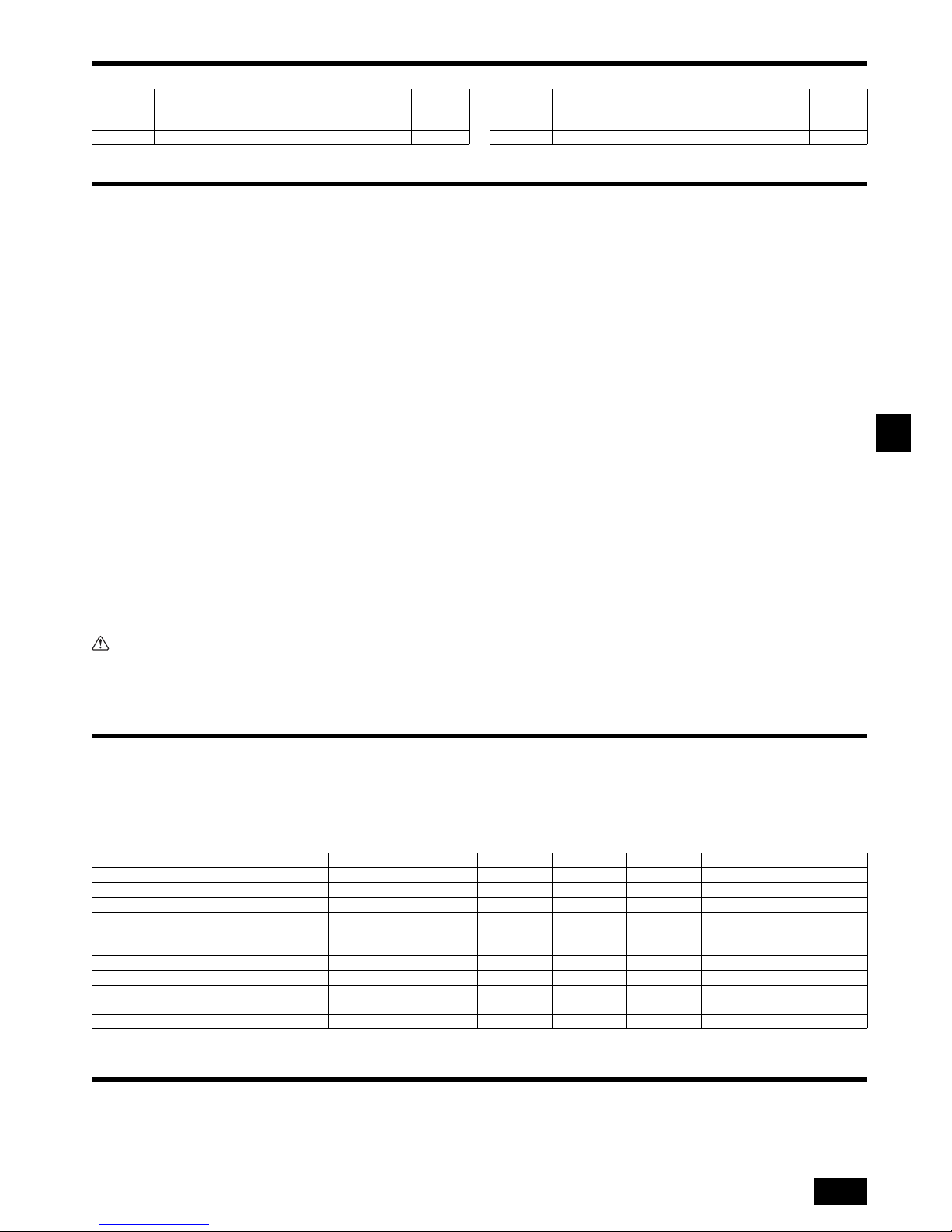
F
25
2. Eléments qui accompagnent l’appareil intérieur
L’appareil est livré avec les éléments suivants:
3. Comment choisir le lieu d’installation
• Choisir un endroit avec une surface stable suffisamment résistante pour le poids
de l’appareil.
• Avant d’installer l’appareil, déterminer la manière de l’acheminer au lieu d’installation.
• Choisir un endroit où le bon fonctionnement de l’appareil ne peut pas être affecté
par un courant d’air.
• Sélectionner un endroit où le débit d’alimentation en air et de retour d’air n’est pas
perturbé.
• Sélectionner un endroit où les tuyaux de réfrigérant peuvent facilement arriver à
l’extérieur.
• Sélectionner un emplacement qui permet de répartir l’air équitablement dans toute
la pièce.
• Ne pas installer l’appareil dans un endroit sujet à des éclaboussures de graisse ou
à de grandes quantités de vapeur.
• Ne pas installer l’appareil dans un endroit avec arrivée de gaz combustible, entrepôt de gaz ou sujet à des fuites de gaz.
• Ne pas installer l’appareil dans un endroit contenant des équipements qui produisent des ondes de haute fréquence (comme une machine à souder fonctionnant par ondes de haute fréquence).
• Ne pas installer l’appareil dans un endroit où le détecteur incendie est situé du côté
de l’arrivée d’air. (Le détecteur d’incendie risque de se déclencher par erreur suite
à l’alimentation en air chaud pendant le fonctionnement du chauffage.)
• En cas de présence de produits chimiques sur les lieux d’installation, comme dans
des usines chimiques ou des hôpitaux, une étude approfondie s’avère nécessaire
avant de procéder à l’installation de l’appareil. (Certains produits chimiques
peuvent en effet endommager les composants plastiques du climatiseur.)
• Si l’appareil doit fonctionner pendant longtemps quand l’air au-dessus du plafond
est à haute température/haute humidité (point de condensation supérieur à 26 °C),
la condensation d’humidité est possible dans l’appareil intérieur. Quand l’appareil
fonctionne dans cette situation, ajoutez un matériau isolant (10 – 20 mm) sur toute
la surface de l’appareil intérieur pour éviter la condensation d’humidité.
3.1. Fixer l’appareil intérieur à un plafond suffisam-
ment résistant pour supporter son poids
Avertissement:
L’appareil doit être fermement installé sur une structure capable de supporter
son poids. Si le climatiseur est monté sur une structure trop fragile, il risque
de tomber et de blesser quelqu’un.
3.2. Prévoir l’espace nécessaire pour l’installation et
l’entretien
Laissez assez d’espace d’accès pour permettre entretien, inspection, et remplacement du moteur, du ventilateur, de la pompe de vidange, de l’échangeur de chaleur,
et du boîtier électrique d’une des manières suivantes.
Sélectionnez un emplacement d’installation pour l’appareil intérieur sans poutres ou
autres objets pouvant obstruer son espace d’accès pour l’entretien.
(1) Lorsqu’un espace de 300 mm ou plus est disponible sous l’appareil entre l’appa-
reil et le plafond (Fig. 3.2.1)
• Créez les portes d’accès 1 et 2 (450 × 450 mm chacune) comme indiqué sur la
Fig. 3.2.2.
(La porte d’accès 2 n’est pas nécessaire si l’espace disponible sous l’appareil
permet à un ouvrier d’entretien de travailler.)
(2) Lorsqu’un espace inférieur à 300 mm est disponible sous l’appareil entre l’appa-
reil et le plafond (Il devrait subsister au moins 20 mm d’espace sous l’appareil
comme indiqué sur la Fig. 3.2.3.)
• Créez la porte d’accès 1 en diagonale sous le boîtier électrique et la porte
d’accès 3 sous l’appareil comme indiqué sur la Fig. 3.2.4.
ou
• Créez la porte d’accès 4 sous le boîtier électrique et l’appareil comme indiqué
sur la Fig. 3.2.5.
[Fig. 3.2.1] (P.2)
[Fig. 3.2.2] (Vu depuis la direction de la flèche A) (P.2)
[Fig. 3.2.3] (P.2)
[Fig. 3.2.4] (Vu depuis la direction de la flèche B) (P.2)
[Fig. 3.2.5] (Vu depuis la direction de la flèche B) (P.2)
3.3. Association des appareils intérieurs et des appareils extérieurs
Pour raccorder les appareils intérieurs aux appareils extérieurs, veuillez vous reporter au manuel d’installation des appareils extérieurs.
4. Fixation des boulons de suspension
4.1. Fixation des boulons de suspension
[Fig. 4.1.1] (P.3)
(Fournir une structure résistante à l’endroit de suspension de l’appareil.)
Cadre de suspension
• Plafond: La structure du plafond varie d’un édifice à un autre. Pour plus d’informa-
tions, veuillez prendre contact avec la société de construction de l’immeuble.
• Si nécessaire, renforcez les boulons de suspension avec des supports antisis-
miques comme mesure contre les tremblements de terre.
* Utilisez M10 pour les boulons de suspension et les supports antisismiques (à
fournir sur place).
Centre de gravité et poids du produit
Les valeurs entre parenthèses concernent le modèle PEFY-P·VMAL-E2.
5. Installation de l’appareil
5.1. Suspension de l’appareil
Apporter l’appareil intérieur emballé sur le lieu de son installation.
Pour le suspendre, utiliser une poulie de levage pour le soulever et le faire
passer par les boulons de suspension.
[Fig. 5.1.1] (P.3)
[Fig. 5.1.2] (P.3)
Elément N° Accessoires Qté
1 Tuyau isolant 1
2 Sangle 3
3 Prise d'écoulement 1
4 Rondelle 8
5 Notice d’installation 1
6 Manuel de fonctionnement 1
Elément N° Accessoires Qté
A Boîtier électrique B Plafond
C Poutre de plafond D Porte d’accès 2 (450 mm × 450 mm)
E Porte d’accès 1 (450 mm × 450 mm) F
Espace d’accès pour l’entretien
G Air fourni H Air entrant
I Dessous de l’appareil intérieur J Porte d’accès 3
K Porte d’accès 4
A Centre de gravité
Nom du modèle W L X Y Z Poids du produit (kg)
PEFY-P20VMA(L)-E2 643 754 330 300 130 22 (21)
PEFY-P25VMA(L)-E2 643 754 330 300 130 22 (21)
PEFY-P32VMA(L)-E2 643 754 330 300 130 22 (21)
PEFY-P40VMA(L)-E2 643 954 340 375 130 26 (25)
PEFY-P50VMA(L)-E2 643 954 340 375 130 26 (25)
PEFY-P63VMA(L)-E2 643 1154 325 525 130 31 (30)
PEFY-P71VMA(L)-E2 643 1154 325 525 130 31 (30)
PEFY-P80VMA(L)-E2 643 1154 325 525 130 31 (30)
PEFY-P100VMA(L)-E2 643 1454 330 675 130 39 (38)
PEFY-P125VMA(L)-E2 643 1454 330 675 130 39 (38)
PEFY-P140VMA(L)-E2 643 1654 332 725 130 43 (42)
A Corps de l’appareil
B Poulie de levage
C Boulons (fourni sur place)
D Rondelles (fourni sur place)
E Boulon de suspension M10 (fourni sur place)
Page 26
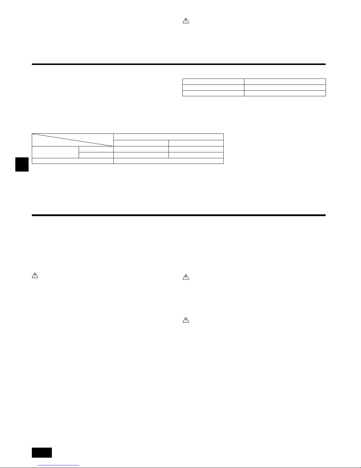
F
26
5.2. Assurer l’emplacement de l’appareil et fixer les
boulons de suspension
Veiller à ce que les écrous des boulons de fixation soient bien serrés avant
de fixer les boulons eux-mêmes.
Pour s’assurer du bon écoulement, toujours suspendre l’appareil bien à
l’horizontale en se servant d’un niveau.
Précaution:
Installer l’appareil en position horizontale. Si le côté comportant l’ouverture
d’écoulement est installé plus haut, des fuites risquent de se produire.
6. Spécifications techniques des tuyaux de réfrigérant et du tuyau d’écoulement
Pour éviter les gouttes de condensation, appliquer suffisamment de matériaux
d’étanchéité et isolant sur les tuyaux de réfrigérant et d’écoulement.
En cas d’utilisation de tuyaux de réfrigérant disponibles dans le commerce, toujours
les envelopper de matière isolante disponible sur le marché (avec une température
de résistance à la chaleur de plus de 100 °C et une épaisseur conforme à celle donnée ci-dessous). Cette mesure est tout autant valable pour les tuyaux de gaz que
pour les tuyaux de liquide.
Isoler tous les tuyaux intérieurs avec de la mousse polyéthylène présentant une densité minimale de 0,03 et une épaisseur conforme aux recommandations du tableau
ci-dessous.
a Sélectionner l’épaisseur de la matière isolante en fonction des dimensions des
tuyaux.
b Si l’appareil doit être utilisé au dernier étage d’un édifice et soumis à des tempé-
ratures élevées et à une humidité excessive, il convient d’utiliser des tuyaux de
dimensions supérieures et de la matière isolante plus épaisse que celles données
dans le tableau ci-dessus.
c Veuillez respecter toutes les spécifications techniques de l’utilisateur.
6.1. Spécifications techniques des tuyaux de réfrigérant et d’écoulement
6.2. Tuyau de réfrigérant, tuyau d’écoulement et port de remplissage
[Fig. 6.2.1] (P.3)
7. Raccordement des tuyaux de réfrigérant et d’écoulement
7.1. Mise en place des tuyaux de réfrigérant
Les travaux de raccordement des tuyaux doivent se faire conformément aux instructions des manuels d’installation de l’appareil extérieur et du contrôleur BC (pour la
série R2 à refroidissement et chauffage simultanés).
• La série R2 a été conçue pour fonctionner dans un système dans lequel le tuyau
de réfrigérant de l’appareil extérieur arrive au contrôleur BC où il se branche pour
se raccorder avec les appareils intérieurs.
• Pour les restrictions de longueur des tuyaux et le degré d’élévation permis, veuillez
vous reporter au manuel de l’appareil extérieur.
• Le raccordement des tuyaux se fait par brasure.
Précaution:
• Installer les tuyaux de réfrigérant pour l’appareil intérieur conformément aux
instructions suivantes.
1. Couper la pointe de la tuyauterie de l’appareil intérieur, vider le gaz puis déposer
le capuchon brasé.
[Fig. 7.1.1] (P.4)
2. Extraire l’isolation thermique des tuyaux de réfrigérant présents sur place, souder
la tuyauterie de l’appareil et remettre l’isolation en place, comme à l’origine.
Entourer les tuyauteries de ruban isolant.
Remarque:
• Lors du brasage des tuyaux de réfrigérant, veiller à recouvrir les tuyaux de
l’appareil d’un chiffon humide pour éviter de les brûler ou de les faire rétrécir
à la chaleur.
[Fig. 7.1.2] (P.4)
• Faire très attention lorsque vous entourez les tuyauteries en cuivre car une
mauvaise isolation peut provoquer de la condensation au lieu de l’empêcher.
[Fig. 7.1.3] (P.4)
Précautions concernant le raccordement des tuyaux
de réfrigérant
Toujours utiliser des soudures non oxydantes afin qu’aucun corps
étranger ni aucune humidité ne pénètre à l’intérieur du tuyau.
Revêtir le siège du goujon d’huile pour machine réfrigérante et le serrer
fermement à l’aide de deux clés.
Placer une entretoise métallique pour soutenir les tuyaux de réfrigérant de
telle sorte qu’aucune charge ne s’applique à la sortie des tuyaux de
l’appareil intérieur. Placer le support métallique à 50 cm ou plus de la
connexion avec goujon de l’appareil intérieur.
Avertissement:
Utilisez uniquement un réfrigérant de type indiqué dans les manuels fournis
avec l'unité et sur la plaque signalétique.
-
Faute de quoi, l'unité ou la tuyauterie pourrait éclater, ou cela pourrait provoquer une
explosion ou un incendie pendant l'utilisation, la réparation ou la mise au rebut de l'unité
.
- Cela pourrait également constituer une violation des lois applicables.
- MITSUBISHI ELECTRIC CORPORATION ne peut être tenue responsable de tout dysfonctionnement ou accident résultant de l'utilisation du mauvais type de réfrigérant.
Précaution:
• Utilisez des tuyaux réfrigérants en cuivre désoxydé au phosphore C1220
(Cu-DHP) comme l’indique le chapitre “Tuyaux et tubes en cuivre ou en
alliage de cuivre sans soudure” du JIS H3300. Veillez également à ce que les
surfaces internes et externes des tuyaux soient propres et sans soufre,
oxyde, poussière/impuretés, rognures, huile, condensation ou autre particule contaminante.
• N’utilisez jamais les tuyaux de réfrigérant déjà en place.
- La quantité importante de chlore contenue dans les réfrigérants traditionnels et
l’huile réfrigérante des tuyaux actuels provoquera la détérioration du nouveau
réfrigérant.
• Gardez les tuyaux d’installation dans l’immeuble et laissez les deux extrémités des tuyaux couvertes jusqu’au moment du brasage.
- L’huile se détériorera et il est possible que le compresseur tombe en panne si de
la poussière, des impuretés ou de l’eau s’infiltrent dans le cycle réfrigérant.
• Appliquez une petite quantité d’huile réfrigérante Suniso 4GS ou 3GS sur
l’évasement et la connexion à bride. (Pour les modèles utilisant du R22)
• Appliquez une petite quantité d’huile ester, d’huile éther ou d’alkylbenzène
sur les évasements et les connexions à brides. (pour les modèles utilisant
R410A ou R407C)
- Le réfrigérant utilisé dans l’appareil est extrêmement hydroscopique et ne doit
pas être mélangé avec de l’eau, autrement l’huile réfrigérante se détériorera.
Dimension du tuyau Epaisseur de la matière isolante
6,4 mm – 25,4 mm Plus de 10 mm
28,6 mm – 38,1 mm Plus de 15 mm
PEFY-P·VMA(L)-E2
20·25·32·40·50 63·71·80·100·125·140
Tuyau de réfrigérant
(Connexion par brasure)
Tuyau de liquide ø 6,35 ø 9,52
Tuyau de gaz ø 12,7 ø 15,88
Tuyau d’écoulement D.E. ø 32
Elément
Modèle
A Tuyau de réfrigérant (tuyau de liquide)
B Tuyau de réfrigérant (tuyau de gaz)
C Tuyau d’écoulement (D.E. ø 32)
D Tuyau d’écoulement (D.E. ø32, écoulement libre)
A Couper ici.
B Déposer le capuchon brasé
A Refroidir à l’aide d’un chiffon humide
A Isolation thermique B Ti rer
C Envelopper avec des chiffons humides
D Remettre dans sa position d’origine
E Veiller à ce qu’il n’y ait pas d’espace exposé à cet endroit
F Entourer avec du ruban isolant
Page 27
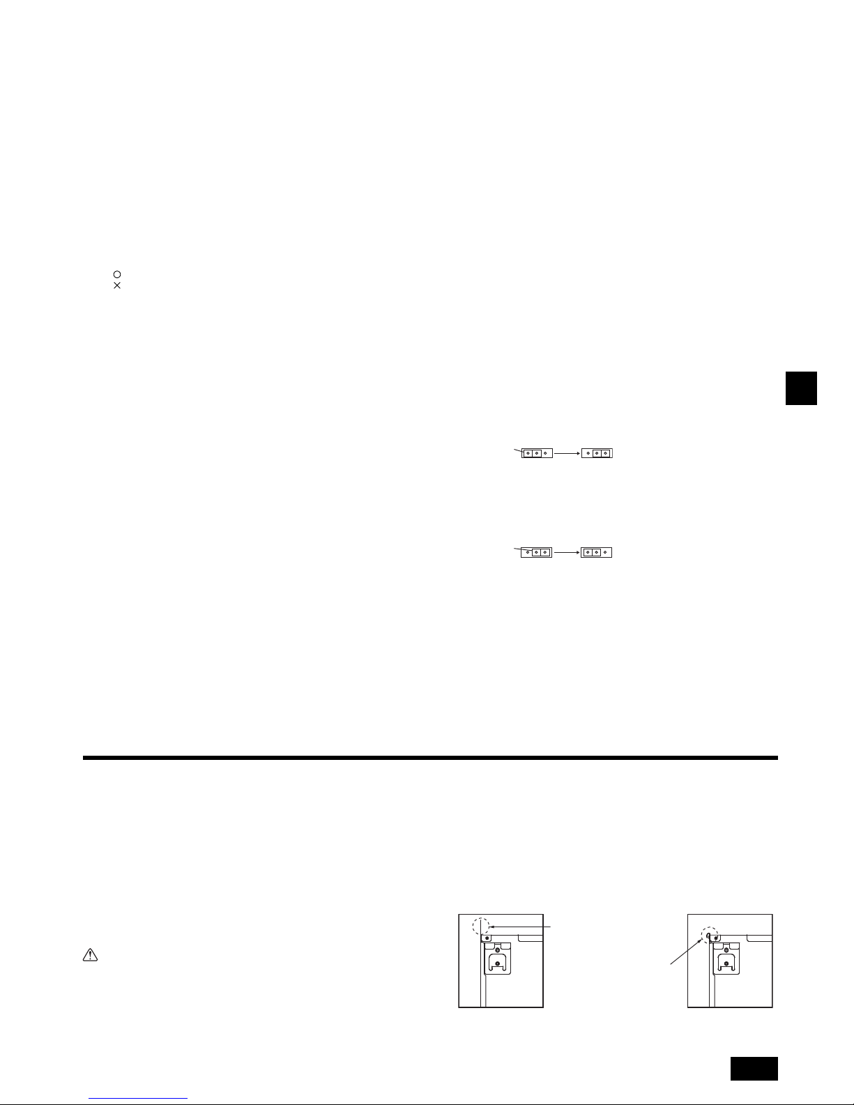
F
27
7.2. Travaux de mise en place du tuyau d’écoulement
• S’assurer que le tuyau d’écoulement soit placé en pente vers le bas (pente de plus
de 1 %) vers le côté extérieur (de la décharge). Eviter tout renfoncement ou toute
irrégularité sur le trajet du tuyau.
• S’assurer que les tuyaux d’écoulement de traverse ont moins de 20 m de long (non
compris la différence d’élévation). Si le tuyau d’écoulement est relativement long,
prévoir des crochets métalliques pour le soutenir et éviter qu’il n’ondule. Ne jamais
prévoir d’orifice de ventilation d’air par lequel l’écoulement risquerait de se
répandre.
• Utiliser un tuyau VP-25 solide en chlorure de vinyle (d’un diamètre extérieur de 32
mm) pour l’écoulement.
• Veiller à ce que les tuyaux groupés soient 10 cm en dessous de l’ouverture d’écoulement située sur le corps de l’appareil.
• Ne pas laisser de renfoncement pour les odeurs au port de décharge de l’écoulement.
• Placer l’extrémité du tuyau d’écoulement de façon à ne pas générer d’odeurs.
• Ne jamais placer les tuyaux d’écoulement dans un drainage générant des gaz
ioniques.
[Fig. 7.2.1] (P.4)
Tuyaux groupés
Modèle PEFY-P·VMA-E2
[Modèle PEFY-P·VMA]
1. Insérez la prise d'écoulement (accessoire) dans l’ouverture d’écoulement (marge
d'insertion : 32 mm).
(Fixer le tuyau avec la sangle et le coller avec de la glue (petit, accessoire).)
2. Fixer le tuyau d’écoulement (D.E. ø32 TUBE PVC PV-25, fourni sur place). (Fixer
le tuyau avec la sangle et le coller avec de la glue (petit, accessoire).)
3. Isoler le tuyau et la douille d’écoulement (D.E. ø32 TUBE PVC PV-25) (coude
inclus).
4. Contrôler l’écoulement. (Voir [Fig. 7.3.1])
5. Fixer le matériel d’isolation, et le fixer avec la sangle (large, accessoire) pour iso-
ler l’ouverture d’écoulement.
[Fig. 7.2.2] (P.4) *uniquement sur le modèle PEFY-P·VMA-E2
[Modèle PEFY-P·VMAL]
1. Insérez la prise d'écoulement (accessoire) dans l’ouverture d’écoulement.
La partie reliant l’unité intérieure et la prise d’écoulement peut être débranchée
pour l’entretien. Fixer la partie avec le ruban fourni en accessoire, sansadhésif.
2. Fixer le tuyau d’écoulement (D.E. ø32 TUBE PVC, fourni sur place).
(Rattacher le tuyau au tuyau en chlorure de vinyle dur avec de la colle et le fixer
avec le ruban (petit, accessoire).)
3. Isoler le tuyau et la douille d’écoulement (D.E. ø32 TUBE PVC) (coude inclus).
[Fig. 7.2.3] (P.4) *uniquement sur le modèle PEFY-P·VMAL-E2
7.3. Confirmation des décharges d’écoulement
Veiller à ce que le mécanisme de décharge d’écoulement fonctionne
normalement et que les raccordements ne présentent aucune fuite.
• Le point ci-dessus doit être respecté en mode de chauffage.
• Le point ci-dessus doit être respecté avant de procéder aux travaux du plafond
dans le cas d’une construction neuve.
1. Retirer le couvercle de l’ouverture d’arrivée d’eau du côté de la tuyauterie de
l’appareil intérieur.
2. Remplir la pompe d’alimentation en eau à l’aide d’un réservoir d’alimentation en
eau. Lors du remplissage, veiller à placer l’extrémité de la pompe ou du réservoir
dans un bac d’écoulement. (En cas d’insertion incomplète, de l’eau pourrait couler
sur l’appareil.)
3. Exécuter l'essai en mode de refroidissement ou relier le connecteur au côté ON
de SWE sur le panneau du contrôleur intérieur. (La pompe de drainage et le ventilateur sont contraints de fonctionner sans télécommande.) Veiller au bon écoulement en utilisant un tube transparent.
4. Après confirmation, annuler le mode d’essai et couper l’alimentation principale. Si
le connecteur est relié au côté ON de SWE, le débrancher et le rebrancher au
côté OFF, puis fixer capot du port d’alimentation en eau dans sa position initiale.
[Fig. 7.3.1] (P.5)
[Fig. 7.3.2] (P.5)
8. Raccords des conduites
• Lors du raccordement des différents conduits, introduire des tuyaux en canevas
entre l’appareil et le conduit.
• Utiliser des matériaux non-combustibles pour les éléments des conduits.
• Fournir une isolation complète à la bride du conduit d’entrée et au conduit de sortie
pour éviter la condensation.
• Ne pas oublier de modifier la position du filtre à air de sorte à pouvoir en assurer la
maintenance.
[Fig. 8.0.1] (P.5)
• Marche à suivre pour changer l’entrée du dos au bas.
Précaution:
Lorsque la conduite est raccordée à l’orifice d’entrée placé au bas de l’unité, le
niveau de pression acoustique est supérieur d’environ 10 dB que lorsqu’elle
est reliée à l’orifice d’entrée qui se trouve à l’arrière de l’appareil.
C’est pourquoi, il est recommandé de raccorder la conduite à l’orifice d’entrée
placé à l’arrière.
Lors de l’utilisation de l’orifice d’entrée placé au bas de l’unité, positionnez
l’orifice d’entrée qui figure sur l’unité intérieure par rapport à l’orifice d’entrée
qui se trouve au plafond. Effectuez ceci de la manière illustrée dans les Figures <A> et <B> pour minimiser le bruit.
[Fig. 8.0.2] (P.5)
1. Retirer le filtre à air. (Retirer d'abord la vis de blocage du filtre.)
2. Retirer la plaque inférieure.
3. Attacher la plaque de fond à l’arrière de l’appareil. [Fig. 8.0.3] (P.5)
(La position des trous de fixation sur la plaque diffère de ceux de l'orifice d'entrée
arrière.)
Tuyauterie correcte
Tuyauterie erronée
A Isolation (9 mm minimum)
B Pente descendante (1/100 minimum)
C Support métallique
K Purge d’air
L Levé
M Trappe anti-odeur
D D.E. ø32 TUBE PVC
E Elargir le plus possible. 10 cm environ.
F Appareil intérieur
G Elargir la tuyauterie pour recevoir les tuyaux groupés.
H Pente descendante (1/100 minimum)
I D.E. ø38 TUBE PVC pour les tuyaux groupés. (Isolation de 9 mm minimum)
J Jusqu’à 700 mm
N Prise d'écoulement (accessoire)
O Surface horizontale ou légèrement ascendante
A Appareil intérieur
B Sangle (accessoire)
C Partie visible
D Marge d’insertion
E Prise d'écoulement (accessoire)
F Tuyau d’écoulement (D.E. ø32 TUBE PVC, fourni sur place)
G Matériel d’isolation (fourni sur place)
H Sangle (accessoire)
A Appareil intérieur
B Sangle (accessoire)
C Partie fixée avec du ruban
D Marge d’insertion
E Prise d'écoulement (accessoire)
F Tuyau d’écoulement (D.E. ø32 TUBE PVC, fourni sur place)
G Matériel d’isolation (fourni sur place)
A Insérer l’extrémité de la pompe de 2 à 4 cm.
B Retirer l’ouverture d’arrivée d’eau.
C 2 500 cc environ
D Eau
E Ouverture de remplissage
F Vis
<Panneau du contrôleur intérieur>
Connecteur
SWE
OFF ON OFF ON
SWE
<OFF> <ON>
Connecteur
SWE
OFF ON OFF ON
SWE
<ON> <OFF>
<A> En cas d’arrivée par l’arrière
<B> En cas d’arrivée par le bas
A Conduit B Entrée d’air
C Porte d’accès D Conduit en canevas
E Surface du plafond F Sortie d’air
G Laisser suffisamment d’espace pour éviter tout court-circuit
A Filtre B Panneau inférieur
Si la plaque est fixée sur la face
arrière, elle est plus haute que le
panneau arrière.
Répliquer la plaque le long de
la fente lorsque l'espace est
insuffisant au-dessus de l'unité
complète.
Page 28
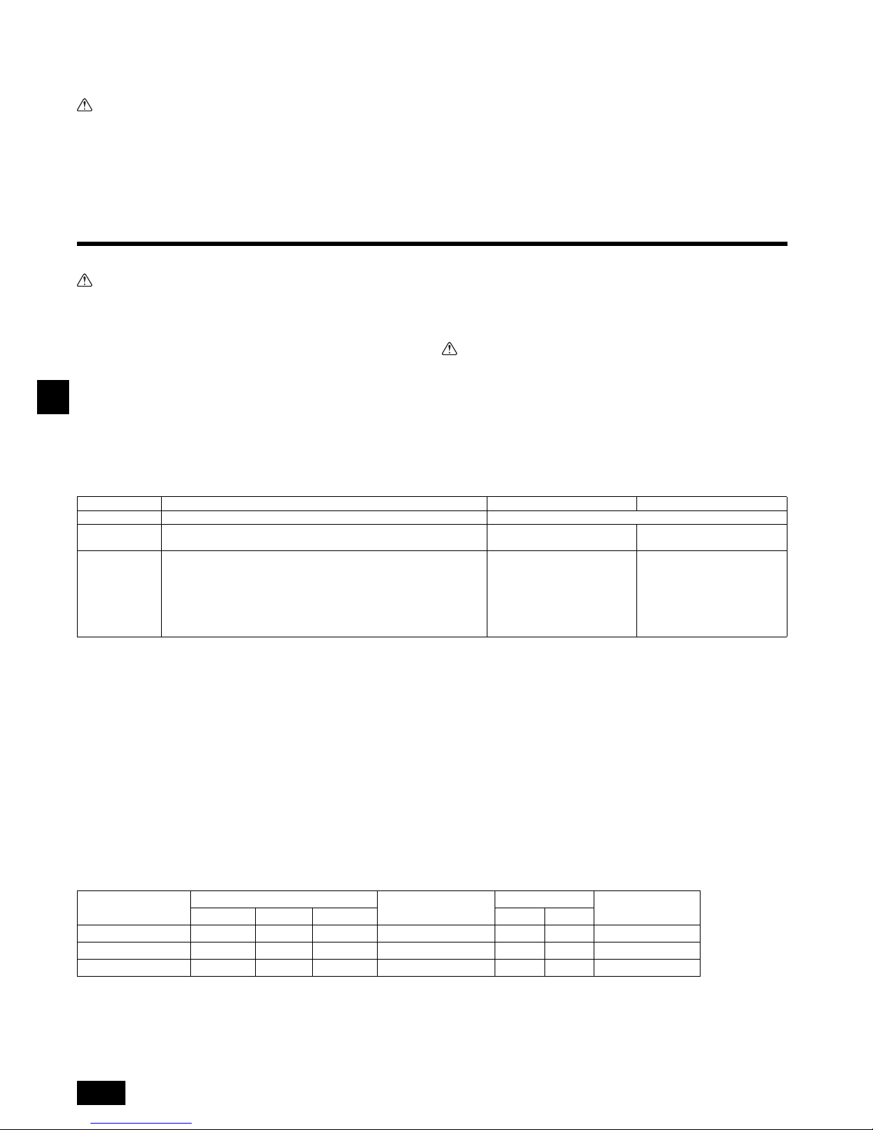
F
28
4. Fixer le filtre sous le corps.
(Vérifier le côté du filtre à ajuster.) [Fig. 8.0.4] (P.5)
[Fig. 8.0.4] (P.5)
Précaution:
• Construire un conduit d’arrivée de 850 mm ou plus.
L’unité principale du climatiseur et les conduits doivent avoir une alimentation électrique identique.
• Porter des gants de protection pour réduire les risques de blessure sur les
bords métalliques tranchants.
• Raccordez le corps principal du climatiseur et le conduit afin que leurs
potentiels correspondent.
• Le bruit du tuyau d’admission augmentera fortement si l’admission est attachée directement sous le corps principal. Il est donc impératif d’installer
l’admission le plus loin possible du corps principal.
Faire particulièrement attention lors de son installation pour une admission
par le bas.
• Utilisez suffisamment d’isolation thermique afin d’éviter toute condensation
sur les conduits de sortie et leurs brides.
• La distance entre la grille d’aspiration et le ventilateur doit rester supérieure
à 850 mm.
Si elle est inférieure à 850 mm, il convient d’installer un cache de sécurité
pour éviter de toucher le ventilateur.
• Pour éviter les interférences électriques, ne pas utiliser les lignes de transmission situées au bas de l'unité.
9. Câblage électrique
Précautions à prendre lors du câblage électrique
Avertissement:
Les travaux électriques doivent être menés à bien par des électriciens qualifiés, conformément aux normes à respecter “pour les installations électriques” et conformément aux explications données dans les manuels
d’installation. Des circuits spéciaux doivent être utilisés. Si l’installation électrique n’est pas suffisamment puissante ou si elle n’est pas conforme, elle
peut présenter un risque d’électrocution ou d’incendie.
1. Installer un coupe-circuit avec mise à la terre en cas de fuite de courant.
2. Installer l’appareil de sorte qu’aucun des câbles de commandes des circuits
(câbles de la commande à distance, de transmission) n’entre en contact direct
avec le câble d’alimentation situé à l’extérieur de l’appareil.
3. Vérifier qu’il n’y ait pas de jeu dans les raccordements des câbles.
4. Certains câbles (d’alimentation, de la commande à distance, de transmission)
situés au-dessus du plafond risquent d’être rongés par les souris. Utiliser autant
de gaines métalliques que possible pour y introduire les câbles en vue de les protéger.
5. Ne jamais raccorder le câble d’alimentation à des bornes pour câbles de transmission sinon les câbles risquent de se rompre.
6. Toujours raccorder les câbles de commandes à l’appareil intérieur, à la commande à distance et à l’appareil extérieur.
7. Mettre l’appareil à la terre du côté de l’appareil extérieur.
8. Sélectionner les câbles de commandes en fonction des conditions mentionnées à
la page 28.
Précaution:
• Mettre l’appareil à la terre du côté de l’appareil extérieur. Ne pas raccorder le
câble de terre à une conduite de gaz, à une conduite d’eau, à un paratonnerre
ou à un câble de terre téléphonique. Une mauvaise mise à la terre peut
constituer un danger d’électrocution.
• Si le cordon d'alimentation est endommagé, il doit être remplacé par le fabri-
cant, un agent d'entretien ou une personne qualifiée de manière à éviter tout
risque.
Spécifications de câble de transmission
*1 Connecté avec une simple télécommande.
9.1. Câblage de l’alimentation électrique
• Utilisez des alimentations dédiées pour les unités extérieures et intérieures.
• Gardez à l'esprit les conditions ambiantes (température ambiante, exposition directe à l'ensoleillement, eau de pluie etc.) lorsque vous procédéz au câblage et aux branchements.
• La taille du câble est de valeur minimum pour un câble à conduit métallique. Si la tension chute, utilisez un câble d’un rang plus épais en diamètre. Assurez-vous que la tension de l’alimentation ne chute pas de plus de 10 %.
• Les spécifications de câblage spécifiques doivent se conformer aux réglementations de câblage régionales.
• Les câbles d’alimentation électrique des appareils raccordés ne doivent pas être inférieurs aux normes 245 IEC 57, 227 IEC 57, 245 IEC 53 ou 227 IEC 53.
• Le climatiseur doit être équipé d’un interrupteur à écartement des contacts de 3 mm au minimum.
[Fig. 9.1.1] (P.5)
Conforme à la norme IEC61000-3-3 traitant de l'impédance de système max. autorisée.
*1 Le disjoncteur de fuite à la terre doit prendre en charge un circuit inverseur.
Le disjoncteur de fuite à la terre doit pouvoir combiner l'utilisation d'un interrupteur local ou d'un disjoncteur pour le câblage.
C Fixer l'orifice d'entrée inférieur D Fixer l'orifice d'entrée arrière
Câbles de transmission Câble de la télécommande ME Câble de la télécommande MA
Type de câble Fil blindé (2 âmes) CVVS, CPEVS ou MVVS Câble gainé à 2 âmes (non blindé) CVV
Diamètre du câble Supérieur à 1,25 mm
2
0,3 ~ 1,25 mm2
(0,75 ~ 1,25 mm
2
)*1
0,3 ~ 1,25 mm
2
(0,75 ~ 1,25 mm
2
)*1
Remarques
Longueur maximale : 200 m
Longueur maximale des lignes de transmission du contrôle centralisé et des
lignes de transmission intérieure/extérieur (longueur maximale via les unités
intérieures) : 500 m MAX.
La longueur maximale du câblage entre l'alimentation des lignes de transmis-
sion (sur les lignes de transmission du contrôle centralisé) et chaque unité
extérieure et le contrôleur du système est de 200 m.
Au-delà de 10 m, utilisez des
câbles ayant les mêmes
spécifications que les câbles de
transmission.
Longueur maximale : 200 m
A Disjoncteur de fuite à la terre
B Interrupteur local/Disjoncteur pour le câblage
C Appareil intérieur
D Boîtier de traction
Courant total de fonctionnement
de l'appareil intérieur
Épaisseur minimale du câble (mm2)
Disjoncteur de fuite à la terre
*1
Interrupteur local (A)
Disjoncteur pour le câblage
(A) (Disjoncteur sans fusible)
Câble principal
Branche
Mise à la terre
Capacité Fusible
F0 = 16 A ou inférieur
*2
1,5 1,5 1,5
Sensibilité en courant 20 A
*3
16 16 20
F0 = 25 A ou inférieur
*2
2,5 2,5 2,5
Sensibilité en courant 30 A
*3
25 25 30
F0 = 32 A ou inférieur
*2
4,0 4,0 4,0
Sensibilité en courant 40 A
*3
32 32 40
CVVS, MVVS : Câble de commande blindé à chemise PVC isolé en PVC
CPEVS : Câble de communication blindé à chemise PVC isolé en PE
CVV : Câble de commande gainé PVC isolé en PVC
Page 29
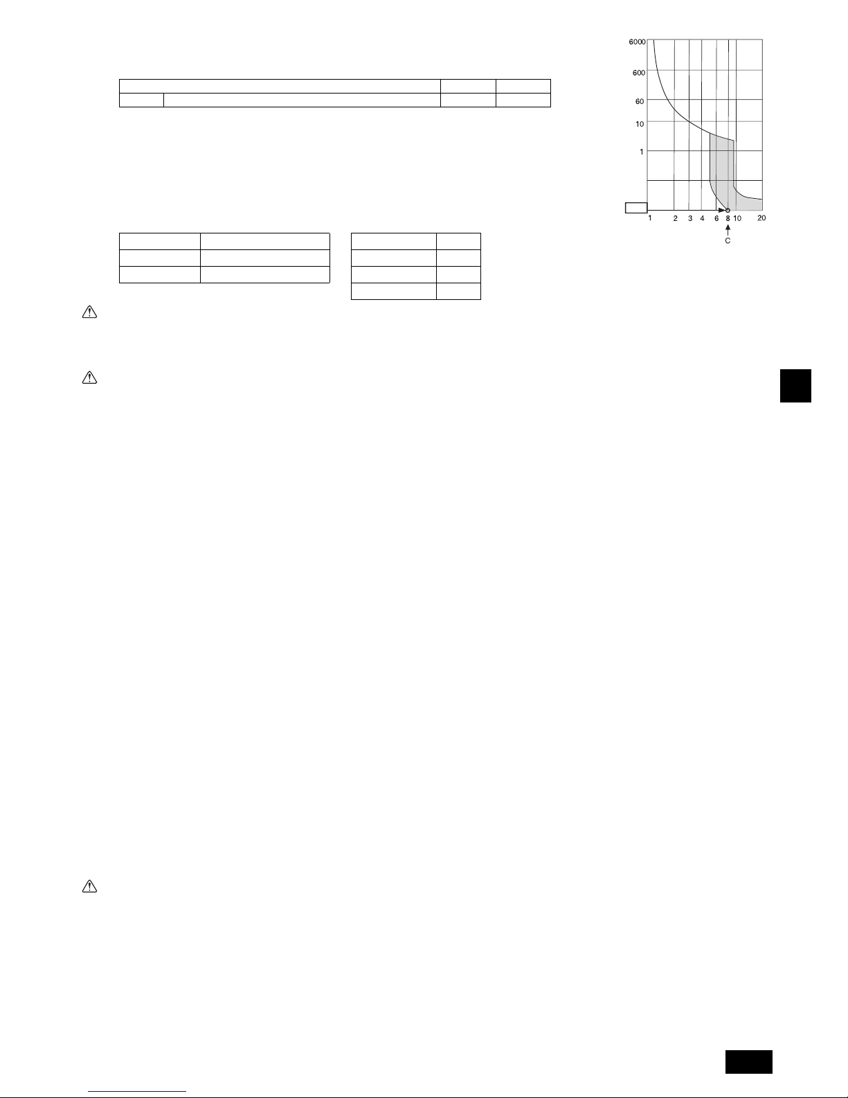
F
29
*2 Veuillez considérer la valeur la plus importante entre F1 et F2 comme étant la valeur pour F0.
F1 = Courant total de fonctionnement des appareils intérieurs 1,2
F2 = {V1 (Quantité du Type1)/C} + {V1 (Quantité du Type2)/C} + {V1 (Quantité du Type3)/C} + {V1 (Quantité des autres)/C}
C : Multiple de courant de déclenchement à une durée de déclenchement de 0,01s
Veuillez choisir “C” dans les caractéristiques de déclenchement du disjoncteur.
<Exemple de calcul “F2”>
*Condition PEFY-VMA 3, C = 8 (référez-vous au diagramme échantillon à droite)
F2 = 38 3/8
= 14,25
disjoncteur 16 A (Courant de déclenchement = 8 16 A à 0,01s)
*3 La sensibilité en courant est calculée à l'aide de la formule suivante.
G1 = (V2 Quantité du Type1) + (V3 Longueur de câble [km])
Avertissement:
• Veillez à utiliser les câbles indiqués pour les branchements, et assurez-vous qu'aucune force externe n'est appliquée sur les branchements de terminaux. Si les
branchements ne sont pas fermement fixés, un échauffement ou un incendie peut se produire.
• Veillez à utiliser un disjoncteur de protection contre les surintensités de type approprié. Notez que les surintensités peuvent inclure une certaine quantité de
courant direct.
Précaution:
• Certains sites d'installation peuvent nécessiter l'ajout d'un disjoncteur de fuite à la terre pour l'inverseur. Si aucun disjoncteur de fuite à la terre n'est installé, il
existe un risque d'électrocution.
• Toujours utiliser des coupe-circuits et des fusibles de la puissance indiquée. L’utilisation de fusibles, de fils ou de fils en cuivre à trop grande capacité peut provoquer un risque de mauvais fonctionnement ou d’incendie.
Remarques:
• Cet appareil est conçu pour être branché à un système d'alimentation avec une impédance système admissible maximum (consulter IEC61000-3-3) au point
d'interface (boîte d'alimentation) de l'alimentation de l'utilisateur.
• L'utilisateur doit s'assurer que cet appareil est branché uniquement à un système d'alimentation répondant aux spécifications ci-dessus. Le cas échéant, l'utilisateur peut demander à la compagnie d'électricité publique l'impédance du système au point d'interface.
9.2. Raccordement des câbles de la commande à dis-
tance et des câbles de transmission intérieurs et
extérieurs
• Raccorder l’unité intérieure TB5 et l’unité intérieure TB3. (2 fils non polarisés)
Le “S” sur l’unité intérieure TB5 est une connexion pour câbles blindé. Pour les
spécifications techniques des câbles de connexion, se reporter au manuel d’installation de l’appareil extérieur.
• Installer une commande à distance conformément aux instructions du manuel
fourni avec la commande à distance.
• Connecter les points “1” et “2” de la borne TB15 de l’appareil intérieur à une commande à distance MA. (2 fils non polarisés)
• Connecter les points “M1” et “M2” de la borne TB5 de l’appareil intérieur à une
commande à distance M-NET. (2 fils non polarisés)
• Raccorder le câble de transmission de la commande à distance à l’aide d’un câble
de 0,75 mm
2
de diamètre d’une longueur de 10 m maximum. Si la longueur néces-
saire est supérieure à 10 m, utiliser un câble de raccordement de 1,25 mm
2
de dia-
mètre.
[Fig. 9.2.1] (P.5) Commande à distance MA
[Fig. 9.2.2] (P.5) Commande à distance M-NET
• CC de 9 – 13 V entre 1 et 2 (Commande à distance MA)
• CC de 24 – 30 V entre M1 et M2 (Commande à distance M-NET)
[Fig. 9.2.3] (P.6) Commande à distance MA
[Fig. 9.2.4] (P.6) Commande à distance M-NET
• La commande à distance MA et la commande à distance M-NET ne peuvent pas
être utilisées simultanément et elles ne sont pas interchangeables.
Précaution:
Installer les câbles de sorte qu’ils ne soient pas tendus ou sous tension. Les
câbles sous tension peuvent en effet se rompre, chauffer ou brûler.
9.3. Connexions électriques
Veillez à ce que le nom du modèle indiqué dans le manuel d'utilisation fixé au couvercle du boîtier à bornes corresponde au nom indiqué sur la plaque d'identification
de l'appareil.
1. Retirer la vis (1 pc) qui tient le couvercle pour déposer celui-ci.
[Fig. 9.3.1] (P.6)
2. Découpe des orifices à dégager
(Il est conseillé d’utiliser un tournevis ou un outil similaire pour effectuer cette opération)
[Fig. 9.3.2] (P.6)
3. Fixer les câbles d'alimentation au boîtier à bornes à l'aide de colliers tampons
pour la force de tension. (Effectuer une connexion PG ou similaire.) Raccorder les
câbles de transmission au bloc terminal de transmission par l'orifice à dégager du
boîtier à bornes et à l'aide de colliers ordinaires.
[Fig. 9.3.3] (P.6)
4. Raccorder la source d'alimentation, les câbles de terre, de transmission et de télécommande. Il n'est pas nécessaire de démonter le boîtier à bornes.
[Fig. 9.3.4] (P.6)
[Raccordement des câbles blindés]
[Fig. 9.3.5] (P.6)
5. Lorsque le câblage est terminé, vérifier qu'il n'y ait pas de jeu dans les connexions
et fixer le couvercle au boîtier à bornes en procédant dans l'ordre inverse du
démontage.
Remarques:
• Faire attention à ne pas coincer les câbles ou les fils en rattachant le cou-
vercle du boîtier à bornes, sinon ceux-ci risquent de se débrancher.
• Lors de la fixation du boîtier à bornes, vérifier que les connecteurs du côté
du boîtier ne soient pas retirés sinon, celui-ci ne pourra pas fonctionner normalement.
Appareil intérieur V1 V2
Type1 PEFY-VMA 38 1,6
G1 Sensibilité en courant Épaisseur du câble V3
30 ou inférieur 30 mA 0,1 sec ou inférieur 1,5 mm
2
48
100 ou inférieur 100 mA 0,1 sec ou inférieur 2,5 mm
2
56
4,0 mm
2
66
A Bloc terminal pour le câble de transmission intérieur
B Bloc terminal pour le câble de transmission extérieur
C Commande à distance
A Non polarisé B TB15
C Commande à distance D TB5
A Vis du couvercle (1pc) B Couvercle
C Boîtier à bornes D Orifice à dégager
E Retirer
F Utiliser un manchon PG pour éviter que le poids du câble ne repose sur le connecteur
de la borne d’alimentation. Fixer le câble à l’aide d’un serre-câble.
G Câblage de la source d’alimentation H Utiliser une bague ordinaire
I Câbles de transmission
J Bloc terminal de la source d'alimentation
K Bloc terminal pour la transmission intérieure
L Bloc terminal de la télécommande
A Bloc terminal B Terminal rond
C Câble blindé
D Les câbles de terre des deux câbles sont raccordés ensemble à la borne S. (Raccor-
dement de fin de course)
E Ruban isolant (pour éviter tout contact entre le câble de terre du câble blindé et la
borne de transmission)
0,01
0,1
ÉCHANTILLON
Temps de déclenchement [s]
Diagramme d'échantillon du courant
de déclenchement nominal (x)
Page 30
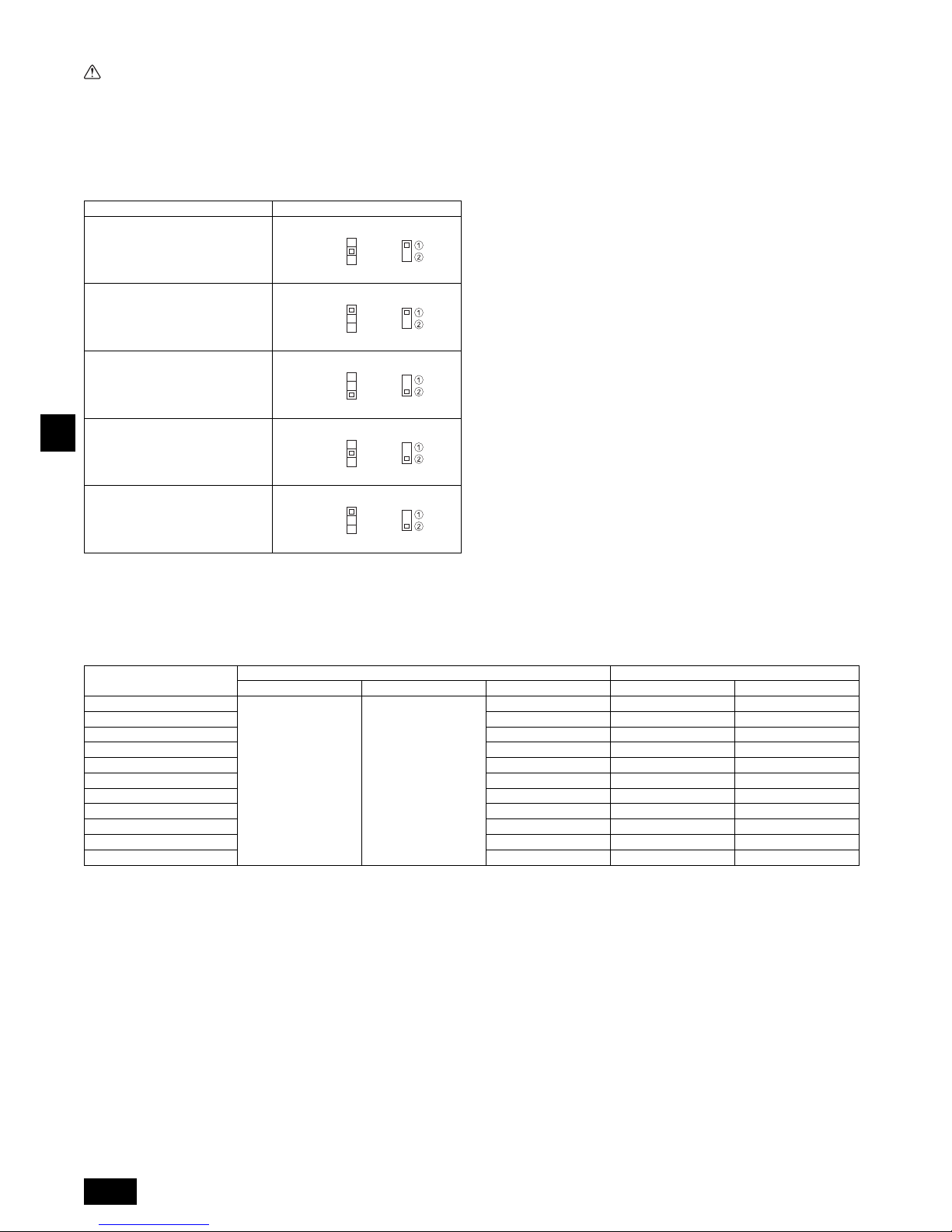
F
30
9.4. Spécifications I/O externes
Précaution:
1. Les câbles doivent être recouverts d’une gaine extra isolante.
2. Utiliser des relais ou des commutateurs répondant aux normes IEC ou équivalentes.
3. La puissance électrique entre les éléments accessibles et le circuit de
contrôle doit être de 2 750 V minimum.
9.5. Sélection de la pression statique extérieure
Le réglage d’usine admet une pression statique extérieure ; par conséquent, aucun
commutateur n’est nécessaire pour une utilisation en-deçà des conditions standard.
[Fig. 9.5.1] (P.6)
9.6. Configuration des adresses
(Toujours effectuer ces opérations lorsque le système est hors tension.)
[Fig. 9.5.1] (P.6)
• Il existe deux types de réglages de commutateurs rotatifs disponibles, pour le
réglage des adresses de 1 – 9 et au-dessus de 10 et pour le réglage du nombre de
ramifications.
• Les boutons rotatifs sont tous mis sur “0” à la sortie d’usine. Ils servent à définir les
adresses des appareils et les numéros de branches comme souhaité.
• Die Festlegung der Adressen der Innengeräte variiert mit der Anlage vor Ort. Stellen Sie diese mithilfe des Datenheftes (Data Book) ein.
9.7. Détection de la température ambiante à l’aide du
capteur intégré de la commande à distance
Si vous voulez détecter la température ambiante à l’aide du capteur intégré de la
commande à distance, mettre le switch SW1-1 du tableau de commandes sur “ON”.
Le réglage indispensable de SW1-7 et SW1-8 permet d’ajuster le flux d’air lorsque le
thermomètre est ETEINT.
9.8. Réglage de la tension d’alimentation
(Toujours effectuer ces opérations lorsque le système est hors tension.)
[Fig. 9.5.1] (P.6)
Veuillez réglez le commutateur SW5 conformément à la tension d’alimentation.
• Réglez SW5 sur 240 V lorsque l’alimentation est de 240 volts.
• Réglez SW5 sur 220 V lorsque l’alimentation est de 220 ou 230 volts.
9.9. Caractéristiques électriques
Symboles : MCA : Ampères max. du circuit ( = 1,25 x FLA) FLA : Courant à pleine charge
IFM : Moteur du ventilateur intérieur Sortie : Sortie nominale du moteur du ventilateur
Consultez le recueil de données (Data Book) pour les autres modèles.
Pression statique extérieure Commutateur
P20~P63: 35 Pa
P71~P100: 40 Pa
P20~P100: Réglage d’usine
50 Pa
P125, P140: Réglage d’usine
70 Pa
100 Pa
150 Pa
<Panneau du contrôleur intérieur>
SWA
SWC
1
2
3
SWA
SWC
1
2
3
SWA
SWC
1
2
3
SWA
SWC
1
2
3
SWA
SWC
1
2
3
<Panneau du contrôleur intérieur>
a Comment définir les adresses
Exemple: Si l’adresse est “3”, laisser le SW12 (pour les unités supérieures à 10) sur “0” et
faire correspondre le SW11 (pour 1 – 9) avec “3”.
b Comment définir les numéros des ramifications SW14 (série R2 seulement)
Le numéro de la branche assignée à chaque appareil intérieur correspond au numéro de
l’ouverture du boîtier de commandes BC sur lequel l’appareil intérieur est raccordé.
Le laisser sur “0” sur les appareils appartenant aux séries autres que R2.
PEFY-P-VMA(L)-E2
Alimentation électrique IFM
Volts / Hz Portée +-10% MCA (A) Sortie (kW) FLA (A)
PEFY-P20VMA(L)-E2
220-240V / 50Hz
220-240V / 60Hz
Max.: 264V
Min.: 198V
0,92 0,085 0,74
PEFY-P25VMA(L)-E2 0,92 0,085 0,74
PEFY-P32VMA(L)-E2 1,07 0,085 0,86
PEFY-P40VMA(L)-E2 1,32 0,085 1,06
PEFY-P50VMA(L)-E2 1,40 0,085 1,12
PEFY-P63VMA(L)-E2 2,08 0,121 1,67
PEFY-P71VMA(L)-E2 2,32 0,121 1,86
PEFY-P80VMA(L)-E2 2,36 0,121 1,89
PEFY-P100VMA(L)-E2 2,53 0,300 2,02
PEFY-P125VMA(L)-E2 2,95 0,300 2,36
PEFY-P140VMA(L)-E2 2,73 0,300 2,18
Page 31

E
31
Contenido
1. Medidas de seguridad.............................................................................31
1.1. Antes de la instalación y de las conexiones eléctricas ...........31
1.2. Precauciones para aparatos que utilizan
refrigerante R410A..................................................................32
1.3. Antes de la instalación ............................................................32
1.4. Montaje eléctrico previo a la instalación ................................. 32
1.5. Antes de iniciar el funcionamiento de prueba .........................32
2. Componentes suministrados con la unidad interior................................32
3. Selección de un lugar para la instalación ............................................... 33
3.1. Instale la unidad interior en un techo suficientemente
resistente como para aguantar su peso.................................. 33
3.2. Instalación de seguridad y espacio de mantenimiento...........33
3.3. Combinación de unidades interiores con unidades
exteriores ................................................................................ 33
4. Fijación de los pernos de suspensión..................................................... 33
4.1. Fijación de los pernos de suspensión..................................... 33
5. Instalación de la unidad ..........................................................................33
5.1. Suspensión de la unidad......................................................... 33
5.2. Confirmación de la posición de la unidad y fijación de los
pernos de suspensión.............................................................34
6. Especificaciones de los tubos del refrigerante y de drenaje...................34
6.1. Especificaciones de los tubos del refrigerante y
de drenaje...............................................................................34
6.2. Tubo del refrigerante, tubo de drenaje y abertura
de relleno ................................................................................34
7. Conexión de los tubos del refrigerante y de drenaje ..............................34
7.1. Tareas con el tubo del refrigerante.........................................34
7.2. Tareas con la tubería de drenaje............................................35
7.3. Confirmación de la descarga de drenaje ................................35
8. Empalme de los conductos..................................................................... 35
9. Cableado eléctrico ..................................................................................36
9.1. Cableado de alimentación eléctric..........................................36
9.2. Conexión de los cables de transmisión del mando
a distancia y de las unidades exterior e interior......................37
9.3. Realización de las conexiones eléctricas ............................... 37
9.4. Especificaciones de E/S externas ..........................................38
9.5. Selección de la presión estática externa ................................ 38
9.6. Configuración de las direcciones............................................38
9.7. Captar la temperatura de la sala con el sensor incorporado
en el mando a distancia ..........................................................38
9.8. Cambio del ajuste de voltaje de alimentación ........................38
9.9. Características eléctricas........................................................38
1. Medidas de seguridad
1.1. Antes de la instalación y de las conexiones eléctricas
Símbolos utilizados en el texto
Atención:
Describe precauciones que deben tenerse en cuenta para evitar el riesgo de
lesiones o muerte del usuario.
Cuidado:
Describe precauciones que deben tenerse en cuenta para evitar el riesgo de
dañar la unidad.
Símbolos utilizados en las ilustraciones
Atención:
• La instalación del aire acondicionado debe correr a cargo del distribuidor o
de un técnico autorizado.
- Una instalación incorrecta realizada por el usuario puede provocar fugas de
agua, descargas eléctricas o fuego.
• Instale la unidad en un lugar capaz de soportar su peso.
- Una resistencia inadecuada podría provocar la caída de la unidad provocando
lesiones.
• Utilice los cables especificados para la instalación eléctrica. Realice las
conexiones asegurándose de que cualquier tracción de los cables no afectará a los terminales.
- La conexión y fijación inadecuadas pueden provocar calor y causar un incendio.
• Tenga en cuenta posibles tifones o golpes fuertes de viento y terremotos e
instale la unidad en el lugar especificado.
-
La instalación inadecuada puede provocar que la unidad caiga y provoque lesiones
.
• Utilice sólo purificadores de aire, humidificadores, calefactores eléctricos y
otros accesorios especificados por Mitsubishi Electric.
- Solicite a un técnico autorizado que instale los accesorios. Una instalación inco-
rrecta realizada por el usuario puede provocar fugas de agua, descargas eléctricas o fuego.
• No repare nunca la unidad. Si la unidad requiere reparación, avise a su distribuidor.
- Si la unidad se repara incorrectamente, pueden producirse fugas de agua, des-
cargas eléctricas o fuego.
• No toque las aletas del intercambiador de calor.
- Una manipulación incorrecta podría provocar lesiones.
• Cuando manipule este producto, utilice siempre un equipo protector, por
ejemplo guantes, protección completa para los brazos como un overol y
gafas de seguridad.
- Una manipulación incorrecta podría provocar lesiones.
• Si hubiese alguna pérdida de gas refrigerante durante la instalación, ventile
bien la habitación.
- Si el gas refrigerante entra en contacto con una llama se producirán gases tóxi-
cos.
• Instale el aire acondicionado según se indica en este manual de instalación.
- Si la unidad se instala de forma incorrecta, pueden producirse fugas de agua,
descargas eléctricas o fuego.
• Las conexiones eléctricas deberán ir a cargo de un “electricista autorizado
según las leyes” y “disposiciones legales vigentes”, según este manual de
instrucciones y siempre con un circuito especial dedicado.
- Si el amperaje de la fuente de alimentación es inadecuada o el tendido eléctrico
es incorrecto, pueden producirse fugas de agua, descargas eléctricas o fuego.
• Mantenga las piezas eléctricas lejos del agua (agua de lavado, etc.).
- Puede provocar una descarga eléctrica, incendio o humo.
• Instale la tapa de terminales (panel) de la unidad exterior de forma segura.
- Si la tapa de terminales (panel) no se instala correctamente, pueden entrar polvo
o agua en la unidad exterior provocando fuego o descargas eléctricas.
• No utilice un refrigerante diferente del indicado en los manuales que se
entregan con la unidad y en la placa de identificación.
- Si lo hace, la unidad o las tuberías podrían explotar, o producirse una explosión o
incendio durante su uso, reparación o en el momento de la eliminación de la unidad.
- También podría suponer un quebrantamiento de la normativa aplicable.
- MITSUBISHI ELECTRIC CORPORATION no es responsable de cualquier ano-
malía o accidente derivantes del uso del tipo de refrigerante equivocado.
• Si el aire acondicionado se instala en una habitación pequeña deberán
tomarse medidas para prevenir que la concentración de refrigerante exceda
los límites de seguridad incluso si hubiese fugas.
- Consulte al distribuidor respecto a las medidas adecuadas para evitar exceder
los límites de seguridad. Si hubiese fuga de refrigerante y se excediese el límite
de seguridad, puede haber peligro por pérdida de oxígeno en la habitación.
• Cuando mueva o reinstale el acondicionador de aire, consulte con el distribuidor o con un técnico autorizado.
- Si el acondicionador de aire se instala incorrectamente, pueden producirse fugas
de agua,, descargas eléctricas o fuego.
• Una vez finalizada la instalación asegúrese de que no hay fugas de gas.
- Si hay fugas de gas refrigerante y se exponen a un calefactor de aire, estufa,
horno u otra fuente de calor, pueden producirse gases tóxicos.
• No reconstruya ni cambie los ajustes de los dispositivos de protección.
- Si se cortocircuitan o manipulan con fuerza los interruptores de presión, térmico
u otro sistema de protección o si se utilizan piezas distintas a las especificadas
por Mitsubishi Electric, puede producirse fuego o explosión.
• Para deshacerse de este producto consulte con su distribuidor.
• No utilice aditivo detector de fuga.
• Si el cable de alimentación eléctrica está dañado, deberá ser sustituido por
el fabricante, su agente de servicio o personas con una cualificación similar
con el fin de evitar riesgos.
• Este aparato no debe ser utilizado por personas (niños incluidos) con capacidades físicas, sensoriales o mentales reducidas, o falta de experiencia y
conocimiento, a menos que sean supervisadas o instruidas en cuanto al uso
del aparato por una persona que se responsabilice de su seguridad.
• Es necesario vigilar a los niños para asegurarse de que no jueguen con el
aparato.
Antes de instalar la unidad, asegúrese de haber leído el capítulo de
“Medidas de seguridad”.
Las “Medidas de seguridad” señalan aspectos muy importantes sobre
seguridad. Es importante que se cumplan todos.
: Indica una acción que debe impedirse.
: Indica que deben seguirse unas instrucciones importantes.
: Indica una pieza que debe conectarse a tierra.
: Indica que debe tenerse cuidado con piezas que giran (Este símbolo aparece
en la etiqueta de la unidad principal) <Color: amarillo>
: Peligro de descarga eléctrica (Este símbolo aparece en la etiqueta de la uni-
dad principal) <Color: amarillo>
Atención:
Lea atentamente las etiquetas adheridas a la unidad principal.
Page 32

E
32
• Las personas responsables de la instalación y del sistema deberán garantizar la seguridad frente al riesgo de posibles fugas de acuerdo con la normativa local.
- Las instrucciones de este manual pueden aplicarse si no hay regulaciones loca-
les disponibles.
• Preste mucha atención al lugar, como por ejemplo la base, donde el gas refrigerante no pueda dispersarse en la atmósfera, ya que el refrigerante pesa
más que el aire.
• Este equipo está diseñado para expertos o usuarios formados de tiendas, de la
industria de la iluminación y de granjas, o a personal lego para uso comercial.
1.2. Precauciones para aparatos que utilizan refrige-
rante R410A
Cuidado:
• No utilice los tubos de refrigerante existentes.
- El refrigerante antiguo y el aceite refrigerante en los tubos existentes contienen
una gran cantidad de cloro que puede deteriorar el aceite refrigerador de la unidad nueva.
• Utilice tubos de refrigerante de cobre fosforoso desoxidado C1220 (CuDHP), como se indica en la normativa JIS H3300 “Tubos sin costura de cobre
y de aleación de cobre”. Por otro lado, asegúrese de que tanto la superficie
interna de los tubos como la externa estén limpias y no contengan ninguna
substancia que pueda resultar peligrosa como, por ejemplo, azufre, óxido,
suciedad, polvo, restos de metal, aceites, humedad o cualquier otro elemento contaminante.
- Si entran substancias contaminantes en el interior de los tubos de refrigerante, el
aceite refrigerante residual se deteriorará.
• Guarde las tuberías que va a utilizar durante la instalación interior con los
dos extremos sellados hasta justo antes de la soldadura. (Guarde los codos
y las demás juntas en una bolsa de plástico.)
- Si entra polvo, suciedad o agua en el ciclo del refrigerante, el aceite puede dete-
riorarse y pueden producirse problemas en el compresor.
• Utilice líquido refrigerante para llenar el sistema.
- Si se utiliza gas refrigerante para sellar el sistema, cambiará la composición del
refrigerante en el cilindro, disminuyendo así el rendimiento.
• No utilice un refrigerante distinto al R410A.
- Si se utiliza otro refrigerante (R22, etc.), el cloro puede deteriorar el aceite refri-
gerador.
• Utilice una bomba de vacío con una válvula de retención.
- El aceite de la bomba de vacío podría introducirse en el circuito del refrigerante y
deteriorar el aceite refrigerador.
• No emplee las herramientas siguientes, que se utilizan con los refrigerantes
convencionales.
(Manómetro distribuidor, manguera de carga, detector de fugas de gas, base
de carga del refrigerante, manómetro, equipo de recuperación del refrigerante)
- Si se mezcla refrigerante convencional y aceite refrigerador con el R410A, el
refrigerante podría deteriorarse.
- Si se mezcla agua con el R410A, el aceite refrigerante podría deteriorarse.
- Los detectores de fugas para refrigerantes convencionales no reaccionan ante el
R410A, porque estos refrigerantes no contienen cloro.
• No utilice cilindros de carga
- El refrigerante podría estropearse.
• Vaya con mucho cuidado al manejar las herramientas.
- Si entra polvo, suciedad o agua en el ciclo del refrigerante, el refrigerante puede
deteriorarse.
1.3. Antes de la instalación
Cuidado:
• No instale la unidad en lugares donde puedan producirse fugas de gas.
- Si hay pérdidas de gas y éste se acumula alrededor de la unidad, podría produ-
cirse una explosión.
• No utilice el aire acondicionado en lugares en los que se guarde comida, animales domésticos, plantas, instrumentos de precisión u obras de arte.
- Podrían deteriorarse.
• No utilice el equipo de aire acondicionado en entornos especiales.
- Aceite, vapor, gas sulfúrico, etc. pueden reducir de forma considerable el rendi-
miento del aparato o deteriorar sus piezas.
• Si instala la unidad en un hospital, una central de comunicaciones u otro
lugar de características similares, proteja convenientemente el aparato para
que no produzca ruido.
- El equipo inversor, los generadores, el equipo médico de alta frecuencia o el de
emisión de radio pueden provocar que el aparato funcione de forma errónea o que
no funcione. A su vez, el aire acondicionado puede incidir en dicho equipo creando
ruido que distorsione el tratamiento médico o la transmisión de la imagen.
• No instale la unidad sobre una estructura en la que puedan producirse fugas.
- Cuando la humedad de la habitación supera el 80 % o cuando la tubería de drenaje está obstruida, puede que la unidad interior gotee a causa de la condensación. En tal caso, drene las dos unidades conjuntamente como se indica.
• Los modelos de unidades interiores deben instalarse en el techo a una altura
del suelo superior a 2,5 m.
1.4. Montaje eléctrico previo a la instalación
Cuidado:
• Conecte la unidad a tierra.
- No conecte la toma de tierra a tuberías de gas o agua, a un pararrayos o cables
del teléfono que vayan por el suelo. Una toma a tierra incorrecta puede producir
descargas eléctricas.
• Instale el cable de alimentación de modo que no quede tenso.
- Si está tenso, el cable puede romperse o calentarse hasta producir un incendio.
• Instale un interruptor para el circuito de fugas.
- Si no se instala, pueden producirse descargas eléctricas.
• Utilice cables de alimentación de capacidad y gama de corriente adecuadas.
- Si los cables son demasiado pequeños, pueden producirse fugas o pueden
recalentarse y causar un incendio.
• Utilice un interruptor de circuito y un fusible exclusivamente de la capacidad
indicada.
- Un fusible o un interruptor de circuito de mayor capacidad o uno de acero o
cobre podría provocar una avería o un incendio en la unidad.
• No lave las unidades de aire acondicionado con agua.
- Si lo hace, podría producirse una descarga eléctrica.
• Compruebe que la plataforma de instalación no se haya deteriorado a causa
de un uso prolongado.
- Si no se arregla, la unidad podría caerse y producir daños personales o materia-
les.
• Instale las tuberías de drenaje como se indica en este Manual de instalación
para asegurar un drenaje correcto. Forre las tuberías con un aislante térmico
para evitar que se produzca condensación.
- Un drenaje incorrecto de las tuberías producirá escapes de agua que pueden
dañar los muebles u otros bienes.
• Tenga cuidado con el transporte del producto.
- No conviene que lo cargue una sóla persona si el producto pesa más de 20 kg.
- En algunos productos se utilizan cintas de polipropileno (PP) para el embalaje.
No las utilice para transportar el producto, ya que resulta peligroso.
- No toque las láminas del intercambiador térmico, ya que podría cortarse los
dedos.
- Al transportar la unidad exterior, colóquela en su plataforma según se indica.
Además, fije la unidad exterior por cuatro puntos para que no resbale por un
lado.
• Retire los materiales de embalaje de forma segura.
- Los materiales de embalaje como clavos y otras piezas metálicas o de madera
pueden producir cortes u otras heridas.
- Separe y retire las bolsas de embalaje de plástico para que los niños no jueguen
con ellas y corran el riesgo de ahogarse.
1.5. Antes de iniciar el funcionamiento de prueba
Cuidado:
• Conecte la corriente al menos 12 horas antes de que empiece a funcionar el
equipo.
- Si se acciona inmediatamente después de haberlo conectado a la corriente, pue-
den producirse daños graves en las piezas internas. Mantenga la unidad conectada a la corriente durante la temporada de funcionamiento.
• No toque los enchufes con los dedos mojados.
- Si lo hace, puede producirse una descarga eléctrica.
• No toque las tuberías de refrigerante durante el funcionamiento e inmediatamente después de éste.
- En esos momentos, las tuberías estarán frías o calientes, según la temperatura
del refrigerante que pasa por ellas, el compresor y las demás piezas del circuito.
Si toca las tuberías en tal estado, puede sufrir quemaduras o congelación en las
manos.
• No accione el equipo de aire acondicionado cuando se hayan extraído los
paneles y las protecciones.
- Las piezas rotativas, calientes o con un alto voltaje podrían causar daños.
• No desconecte la corriente inmediatamente después de parar el funcionamiento del equipo.
- Espere al menos cinco minutos antes de hacerlo, ya que podría producirse un
escape de gas u otros problemas.
2. Componentes suministrados con la unidad interior
La unidad se suministra con los siguientes componentes:
N.º parte Accesorios Cantidad
1 Tubería aislante 1
2 Cinta de sujeción 3
3 Toma de drenaje 1
4 Arandela 8
5 Manual de instalación 1
6 Manual de instrucciones 1
N.º parte Accesorios Cantidad
Page 33

E
33
3. Selección de un lugar para la instalación
• Seleccione un lugar con una superficie fija resistente que pueda soportar el peso
de la unidad.
• Antes de instalar la unidad, debe determinarse el trayecto que debe recorrerse
para transportarla hasta el lugar de la instalación.
• Seleccione un lugar en el que la unidad no se vea afectada por las corrientes de
aire.
• Seleccione un lugar en el que el flujo del aire de entrada y de salida no quede bloqueado.
• Seleccione un lugar desde el que sea posible hacer salir con facilidad la tubería
del refrigerante.
• Seleccione un lugar desde el que sea posible distribuir el aire por toda la habitación.
• No instale la unidad en un lugar en donde puedan producirse salpicaduras de
aceite o vapor.
• No instale la unidad en un lugar en donde se puede generar, acumular o fugar gas
combustible.
• No instale la unidad en un lugar donde haya equipo que genere ondas de alta frecuencia (por ejemplo, un soldador de ondas de alta frecuencia).
• No instale la unidad en un lugar en el que haya un equipo detector de incendios
instalado en el lado de la salida del aire (El detector de incendios podría interpretar
erróneamente el calor producido por la unidad cuando funciona como calefacción).
• Cuando se haya de hacer la instalación en lugares donde puedan abundar los productos químicos, como hospitales o plantas químicas, conviene hacer algunos
estudios antes de instalar la unidad. (Los componentes de plástico podría dañarse
según el tipo de productos químicos de los que se trate.)
• Si se opera la unidad por largo tiempo cuando el aire arriba del techo esté con alta
temperatura/alta humedad (punto de condensación arriba de 26 º C), podrá haber
formación de gotas de rocio en la unidad interior. Al operar las unidades en estas
condiciones, añada material aislante (10 – 20 mm) en toda la superfície de la unidad interior para evitar la formación de gotas de rocio.
3.1. Instale la unidad interior en un techo suficiente-
mente resistente como para aguantar su peso
Atención:
La unidad se debe instalar de forma segura en una estructura que pueda
aguantar su peso. Si la unidad se monta en una estructura que no tenga la
fuerza suficiente, puede caer y causar daños.
3.2. Instalación de seguridad y espacio de mantenimiento
Asegúrese de dejar suficiente espacio de acceso para permitir el mantenimiento,
inspección y el cambio de motor, ventilador, bomba de drenaje, intercambiador de
calor y el cuadro eléctrico de una de las maneras siguientes.
Seleccione un sitio de instalación para la unidad interior de manera que el espacio
de acceso para mantenimiento no sea obstruido por vigas u otros objetos.
(1) Cuando hay disponible un espacio de 300 mm o más debajo de la unidad entre
la unidad y el techo (Fig. 3.2.1)
• Cree una puerta de acceso 1y 2 (450 × 450 mm cada una) como se muestra en
la Fig. 3.2.2.
(La puerta de acceso 2 no es necesaria si hay disponible suficiente espacio
debajo de la unidad para que se introduzca un trabajador de mantenimiento.)
(2) Cuando hay disponible un espacio de menos de 300 mm debajo de la unidad
entre la unidad y el techo (Por lo menos debería dejarse 20 mm de espacio
debajo de la unidad como se muestra en la Fig. 3.2.3.)
• Cree una puerta de acceso 1 diagonalmente debajo de la caja eléctrica y una
puerta de acceso 3 debajo de la unidad como se muestra en la Fig. 3.2.4.
o
• Cree una puerta de acceso 4 debajo del cuadro eléctrico y la unidad como se
muestra en la Fig. 3.2.5.
[Fig. 3.2.1] (P.2)
[Fig. 3.2.2] (Visto desde la dirección de la flecha A) (P.2)
[Fig. 3.2.3] (P.2)
[Fig. 3.2.4] (Visto desde la dirección de la flecha B) (P.2)
[Fig. 3.2.5] (Visto desde la dirección de la flecha B) (P.2)
3.3. Combinación de unidades interiores con unidades exteriores
Para combinar unidades interiores con unidades exteriores, consulte el manual de
instalación de la unidad exterior.
4. Fijación de los pernos de suspensión
4.1. Fijación de los pernos de suspensión
[Fig. 4.1.1] (P.3)
(Procure que el lugar de suspensión tenga una estructura resistente.)
Estructura de suspensión
• Techo: La estructura del techo varía de un edificio a otro. Consulte los detalles de
su edificio con la compañía constructora.
• Si necesario, refuerce los pernos de suspensión con soportes anti-terremotos
como medidas contra terremotos.
* Utilice M10 para pernos de suspensión y soportes anti-terremotos (suministra-
dos en obra).
Centro de gravedad y peso del produto
Los valores entre paréntesis corresponden al modelo PEFY-P·VMAL-E2.
5. Instalación de la unidad
5.1. Suspensión de la unidad
Lleve la unidad interior hasta el lugar de su instalación tal como viene
empaquetada.
Para colgar la unidad interior, use un aparato elevador para subirla y
pasarla a través de los pernos de suspensión.
[Fig. 5.1.1] (P.3)
[Fig. 5.1.2] (P.3)
A Cuadro eléctrico B Techo
C Viga del techo D Puerta de acceso 2 (450 mm × 450 mm)
E Puerta de acceso 1 (450 mm × 450 mm) F Espacio de acceso para mantenimiento
G Suministro de aire H Entrada de aire
I Parte inferior de la unidad J Puerta de acceso 3
K Puerta de acceso 4
A Centro de gravedad
Nombre del modelo W L X Y Z Peso del produto (kg)
PEFY-P20VMA(L)-E2 643 754 330 300 130 22 (21)
PEFY-P25VMA(L)-E2 643 754 330 300 130 22 (21)
PEFY-P32VMA(L)-E2 643 754 330 300 130 22 (21)
PEFY-P40VMA(L)-E2 643 954 340 375 130 26 (25)
PEFY-P50VMA(L)-E2 643 954 340 375 130 26 (25)
PEFY-P63VMA(L)-E2 643 1154 325 525 130 31 (30)
PEFY-P71VMA(L)-E2 643 1154 325 525 130 31 (30)
PEFY-P80VMA(L)-E2 643 1154 325 525 130 31 (30)
PEFY-P100VMA(L)-E2 643 1454 330 675 130 39 (38)
PEFY-P125VMA(L)-E2 643 1454 330 675 130 39 (38)
PEFY-P140VMA(L)-E2 643 1654 332 725 130 43 (42)
A Cuerpo de la unidad
B Montacargas
C Tuercas (Suministrado en obra)
D Arandelas (Suministrado en obra)
E Perno se suspensión M10 (Suministrado en obra)
Page 34

E
34
5.2. Confirmación de la posición de la unidad y fijación
de los pernos de suspensión
Asegúrese de que las tuercas de los pernos de suspensión están apreta-
das y de que estos quedan bien fijos.
Para asegurarse de que se produzca la descarga del drenaje, compruebe
con un nivel que la unidad ha quedado perfectamente horizontal.
Cuidado:
Instale la unidad en posición horizontal. Si el lado con la conexión de drenaje
se instala más alto, podrían producirse fugas de agua.
6. Especificaciones de los tubos del refrigerante y de drenaje
Para evitar la formación de gotas de rocío, instale suficiente material anticondensación y aislante en los tubos del refrigerante y del drenaje.
Cuando use tubos de refrigerante de los disponibles comercialmente, asegúrese de
envolver tanto los tubos del refrigerante como el del drenaje con material aislante
(con resistencia a temperaturas de más de 100 °C y del espesor indicado a continuación) también comercialmente disponible.
Aísle todas las tuberías interiores con un aislante de polietileno con una densidad
mínima de 0,03 y el espesor especificado en la tabla que se muestra a continuación.
a Seleccione el espesor del material de aislamiento según el tamaño del tubo.
b Si la unidad se usa en la planta superior de un edificio y bajo condiciones de
humedad y temperatura elevadas, será necesario usar tubos y material de aislamiento de tamaño y espesor superiores a los indicados en la tabla anterior.
c Si el cliente le indica alguna especificación especial, siga siempre sus indicacio-
nes.
6.1. Especificaciones de los tubos del refrigerante y de drenaje
6.2. Tubo del refrigerante, tubo de drenaje y abertura de relleno
[Fig. 6.2.1] (P.3)
7. Conexión de los tubos del refrigerante y de drenaje
7.1. Tareas con el tubo del refrigerante
La instalación de la tuberías debe hacerse de acuerdo con los manuales de instalación de la unidad exterior y del controlador BC (en la serie R2 de refrigeración y calefacción simultánea).
• La serie R2 ha sido diseñada para funcionar en un sistema en el que la tubería de
refrigerante de una unidad exterior llega al controlador BC y se bifurca en el controlador BC para conectarse entre unidades interiores.
• Consulte en el manual de la unidad exterior las limitaciones sobre la longitud de
los tubos y sobre la diferencia de elevación permitida.
• El método de conexión de los tubos es la soldadura.
Cuidado:
• Instale los tubos del refrigerante de la unidad interior de acuerdo con las
siguientes pautas.
1. Corte la punta de los tubos de la unidad interior, extraiga el gas y luego extraiga la
tapa soldada.
[Fig. 7.1.1] (P.4)
2. Extraiga el aislamiento térmico de los tubos de refrigerante suplementarios,
suelde la tubería de la unidad y vuelva a colocar el aislamiento en su posición original.
Envuelva la tubería con cinta aislante
Nota:
• Antes de soldar los tubos de refrigerante, asegúrese de cubrir con un paño
húmedo las tuberías de las unidades para evitar que se quemen y encojan
por el calor.
[Fig. 7.1.2] (P.4)
• Preste suma atención al envolver la tubería de cobre porque puede produ-
cirse una condensación en lugar de evitarla.
[Fig. 7.1.3] (P.4)
Precauciones con la tubería del refrigerante
Asegúrese de usar soldaduras no oxidadas para evitar que entren en el
tubo sustancias extrañas o suciedad.
Asegúrese de untar aceite refrigerante sobre la superficie de contacto de la
conexión por abocinamiento y de apretarla usando dos llaves inglesas.
Instale un soporte de metal para sujetar un tubo de refrigerante de forma
que no se ejerza ninguna fuerza sobre el extremo del tubo de la unidad
interior. Este soporte metálico deberá instalarse a más de 50 cm de la
conexión por abocinamiento de la unidad interior.
Atención:
No utilice un refrigerante diferente del indicado en los manuales que se entregan con la unidad y en la placa de identificación.
- Si lo hace, la unidad o las tuberías podrían explotar, o producirse una explosión o
incendio durante su uso, reparación o en el momento de la eliminación de la unidad.
- También podría suponer un quebrantamiento de la normativa aplicable.
- MITSUBISHI ELECTRIC CORPORATION no es responsable de cualquier anomalía o accidente derivantes del uso del tipo de refrigerante equivocado.
Cuidado:
• Utilice tubos de refrigerante de cobre fosforoso desoxidado C1220 (CuDHP), como se indica en la normativa JIS H3300 “Tubos sin costura de cobre
y de aleación de cobre”. Por otro lado, asegúrese de que tanto la superficie
interna de los tubos como la externa estén limpias y no contengan ninguna
substancia que pueda resultar peligrosa como, por ejemplo, azufre, óxido,
suciedad, polvo, restos de metal, aceites, humedad o cualquier otro elemento contaminante.
• No utilice tubos de refrigerante existentes
- La gran cantidad de cloro en los refrigerantes y en el aceite del refrigerador con-
vencionales que puede haber en los tubos existentes deteriorarían el nuevo
refrigerante.
• Almacene los tubos que vaya a utilizar en la instalación interior manteniendo
ambos extremos de los tubos sellados hasta justo antes de soldarlos.
- Si entrase polvo, suciedad o agua en el ciclo de refrigeración, el aceite se dete-
riorará y el compresor fallará.
• Utilice aceite de refrigerador Suniso 4GS o 3GS (en pequeñas cantidades)
para untar las piezas de conexión abocinadas o bridadas. (Para los modelos
que empleen R22)
• Utilice aceite estérico o alquilobenceno (en pequeñas cantidades) como
aceite refrigerante para untar las uniones abocardadas o bridadas. (Para
modelos que utilizan R410A o R407C.)
- El refrigerante utilizado en la unidad es muy higroscópico y si se mezcla con
agua degradará el aceite del refrigerador.
Tamaño del tubo Espesor del material de aislamiento
6,4 mm – 25,4 mm Más de 10 mm
28,6 mm – 38,1 mm More de 15 mm
PEFY-P·VMA(L)-E2
20·25·32·40·50 63·71·80·100·125·140
Tubo del refrigerante
(Conexión por soldadura)
Tubo del líquido ø 6,35 ø 9,52
Tubo del gas ø 12,7 ø 15,88
Tubo de drenaje Diám. ext. ø 32
Elemento
Modelo
A Tubo del refrigerante (lado del líquido)
B Tubo del refrigerante (lado del gas)
C Tubo de drenaje (Diám. ext. ø32)
D Tubo de drenaje (Diám. ext. ø32, drenaje espontáneo)
A Corte aquí
B Extraiga la tapa soldada
A Enfriar con un paño húmedo
A Aislamiento térmico B Tire
C Envuelva con un trapo mojado D Vuelva a la posición original
E Asegúrese de que no quede ningún espacio
F Envuelva con cinta aislante
Page 35

E
35
7.2. Tareas con la tubería de drenaje
• Asegúrese de que la tubería de drenaje tenga una inclinación descendente (de
más de 1/100) en el lado exterior (de descarga). No ponga ningún obstáculo o irregularidad en el recorrido.
• Asegúrese de que la longitud transversal de la tubería de drenaje es de menos de
20 m (sin incluir la diferencia de elevación). Si la tubería de drenaje es larga, instale abrazaderas metálicas para evitar que se formen ondulaciones. Nunca instale
un tubo agujereado para ventilación porque el agua de drenaje podría salir expulsada.
• Use un tubo rígido de cloruro de vinilo VP-25 (con un diámetro externo de 32 mm)
para la tubería de drenaje.
• Asegúrese de que las tuberías quedan 10 cm por debajo de la conexión de drenaje de la unidad.
• No instale ningún aparato de absorber olores en la abertura de descarga del drenaje.
• Ponga el extremo de la tubería de drenaje en una posición en que no se generen
malos olores.
• No ponga el extremo de la tubería de drenaje en un lugar en que se generen gases
iónicos.
[Fig. 7.2.1] (P.4)
Tuberías agrupadas
Modelo PEFY-P·VMA-E2
Modelo [PEFY-P·VMA]
1. Inserte la toma de drenaje (accesorio) en la conexión de drenaje (margen de
inserción: 32 mm).
(Sujete la manguera con adhesivo y fíjela con cinta (pequeña, accesorio)).
2. Sujete la tubería de drenaje (TUBO DE PVC PV-25 con diám. ext. ø 32, suminis-
trado en obra). (Sujete la tubería con adhesivo y fíjela con la cinta (pequeña,
accesoria)).
3. Realice los trabajos de aislamiento en la tubería de drenaje (TUBO DE PVC PV-
25 con diám. ext. ø 32) y en el zócalo (incluyendo el codo).
4. Compruebe el drenaje. (Consulte la [Fig. 7.3.1])
5. Sujete el material aislante y fíjelo con la cinta (grande, accesorio) para aislar la
conexión de drenaje.
[Fig. 7.2.2] (P.4) *sólo en el modelo PEFY-P·VMA-E2
Modelo [PEFY-P·VMAL]
1. Inserte la toma de drenaje (accesorio) en la conexión de drenaje.
La parte de conexión entre la unidad interior y la toma de drenaje podrá desconectarse para realizar los trabajos de mantenimiento. Fije la parte con la banda
accesoria, no la pegue.
2. Sujete la tubería de drenaje (TUBO DE PVC con diám. ext. ø 32, suministrado en
obra).
(Fije el tubo con pegamento para tubos de cloruro de vinilo rígidos, y sujételo con
la banda (pequeña, accesoria).)
3. Realice los trabajos de aislamiento en la tubería de drenaje (TUBO DE PVC con
diám. ext. ø 32) y en el zócalo (incluyendo el codo).
[Fig. 7.2.3] (P.4) *sólo en el modelo PEFY-P·VMAL-E2
7.3. Confirmación de la descarga de drenaje
Asegúrese de que el mecanismo de drenaje funciona normalmente para la
descarga y de que no hay fugas en las conexiones.
• Asegúrese de confirmar lo anterior en un periodo de funcionamiento de calefac-
ción.
• Asegúrese de confirmar lo anterior antes de terminar los trabajos de techo si se
trata de una construcción nueva.
1. Retire la cubierta de la conexión de entrada de agua por el mismo lado que las
tuberías de la unidad interior.
2. Vierta agua en la bomba de agua con un taque de alimentación de agua. Al
hacerlo, asegúrese de colocar el extremo de la bomba o del tanque en un depósito de drenaje. (Si la inserción es incorrecta, podría caer agua sobre la máquina).
3. Lleve a cabo la prueba de funcionamiento en modo de refrigeración, o conecte el
conector en la posición ON de SWE de la placa del controlador interior. (La
bomba de drenaje y el ventilador se accionan forzosamente, sin que se activen
por medio de ningún controlador remoto.) Asegúrese de utilizar una manguera
transparente para comprobar que el drenaje se efectúe correctamente.
4. Tras la confirmación, cancele el modo de prueba de funcionamiento y apague la
alimentación principal de la unidad. Si el conector está conectado en la posición
ON de SWE, desconéctelo y conéctelo a la posición OFF y, a continuación, coloque la tapa de la abertura de suministro de agua en su posición original.
[Fig. 7.3.1] (P.5)
[Fig. 7.3.2] (P.5)
8. Empalme de los conductos
• Para conectar el conducto, introduzca el conducto flexible entre la unidad y en
conducto.
• Use materiales no combustibles en las piezas del conducto.
• Aísle totalmente la brida del conducto de entrada y el conducto de salida para evitar la condensación.
• Asegúrese de cambiar la posición del filtro de aire a una posición que permita
acceder a él para tareas de mantenimiento.
[Fig. 8.0.1] (P.5)
• Procedimiento para el cambio de la entrada trasera a la entrada de abajo.
Cuidado:
Cuando el conducto está conectado a la entrada en la parte inferior de la unidad, el nivel de presión del sonido será mayor en aproximadamente 10 dB que
cuando el conducto está conectado a la entrada en la parte posterior de la unidad.
Por esta razón, se recomienda conectar el conducto a la entrada posterior.
Cuando se use la entrada en la parte inferior de la unidad, compense la posición de la entrada en la unidad interior en relación con la entrada en el techo
como se muestra en las Figuras <A> y <B> para minimizar el ruido.
[Fig. 8.0.2] (P.5)
1. Retire el filtro de aire. (Primero deberá quitar el tornillo de fijación del filtro.)
2. Extraiga la placa inferior.
3. Fije la placa de abajo en la parte trasera del cuerpo. [Fig. 8.0.3] (P.5)
(La posición de los orificios en la placa difiere de la posición de los orificios en la
entrada trasera.)
Tendido correcto
Tendido incorrecto
A Aislamiento (9 mm o más)
B Pendiente descendente (1/100 o más)
C Soporte metálico
K Purgador de aire
L Elevado
M Atrapaolores
D TUBO DE PVC con diám. ext. ø 32
E Lo más grande posible. Unos 10 cm.
F Unidad interior
G Asegúrese de que las tuberías agrupadas sean grandes.
H Pendiente descendente (1/100 o más)
I TUBO DE PVC con diám. ext. ø 38 para tuberías agrupadas (9 mm o más aislamiento)
J Hasta 700 mm
N Toma de drenaje (accesorio)
O Horizontal o ligeramente ascendente
A Unidad interior
B Cinta de sujeción (accesorio)
C Parte visible
D Margen de inserción
E Toma de drenaje (accesorio)
F Tubería de drenaje (TUBO DE PVC con diám. ext. ø 32, suministrado en obra)
G Material aislante (suministrado en obra)
H Cinta de sujeción (accesorio)
A Unidad interior
B Cinta de sujeción (accesorio)
C Parte de fijación de la banda
D Margen de inserción
E Toma de drenaje (accesorio)
F Tubería de drenaje (TUBO DE PVC con diám. ext. ø 32, suministrado en obra)
G Material aislante (suministrado en obra)
A Inserte el extremo de la bomba de 2 a 4 cm.
B Retire la conexión de entrada de agua.
C Aprox. 2.500 cc
D Agua
E Conexión de llenado
F Tornillo
<Placa controladora interior>
Conector
SWE
OFF ON OFF ON
SWE
<OFF> <ON>
Conector
SWE
OFF ON OFF ON
SWE
<ON> <OFF>
<A> Con entrada posterior
<B> Con entrada inferior
A Conducto B Entrada de aire
C Puerta de acceso D Conducto flexible
E Superficie del techo F Salida de aire
G Deje suficiente distancia para impedir un ciclo corto
A Filtro B Placa inferior
Cuando la placa está fijada al
lado trasero, supera la altura del
panel trasero de la estructura.
Replique la placa en toda la
ranura si no hay suficiente
espacio para toda la unidad por
encima.
Page 36

E
36
4. Coloque el filtro en la parte inferior del cuerpo de la unidad.
(Tenga cuidado con la posición de cada lado del filtro al colocarlo.) [Fig. 8.0.4] (P.5)
[Fig. 8.0.4] (P.5)
Cuidado:
• Debe construirse un conducto de entrada de 850 mm o superior.
Conecte el cuerpo principal del acondicionador de aire y el conducto para
conseguir una ecualización potencial.
• Para reducir el riesgo de lesionarse con los cantos de las placas metálicas,
le recomendamos que utilice guantes protectores.
• Raccordez le corps principal du climatiseur et le conduit afin que leurs
potentiels correspondent.
• Le bruit du tuyau d’admission augmentera fortement si l’admission est attachée directement sous le corps principal. Il est donc impératif d’installer
l’admission le plus loin possible du corps principal.
Faire particulièrement attention lors de son installation pour une admission
par le bas.
• Utilisez suffisamment d’isolation thermique afin d’éviter toute condensation
sur les conduits de sortie et leurs brides.
• Mantenga una distancia entre la rejilla de entrada y el ventilador superior a
850 mm.
Si es inferior a 850 mm, instale una protección de seguridad para que no se
pueda tocar el ventilador.
• Para evitar interferencias por ruido eléctrico, no haga pasar las líneas de
transmisión por la parte inferior de la unidad.
9. Cableado eléctrico
Precauciones con el cableado eléctrico
Atención:
Los trabajos eléctricos deben ser realizados por personal técnico cualificado
siguiendo las disposiciones “Normas técnicas para las instalaciones eléctricas” y de los manuales de instalación suministrados. También pueden usarse
circuitos especiales. Si la potencia del circuito es insuficiente o hay fallos en
la instalación, se corre el riesgo de que se produzca algún cortocircuito o incendio.
1. Asegúrese de instalar un interruptor de pérdidas a tierra.
2. Instale la unidad de forma que los cables del circuito de control (mando a distancia, cables de transmisión) no queden en contacto directo con los cables de alimentación fuera de la unidad.
3. Asegúrese de que no ha quedado ninguna conexión suelta.
4. Algunos cables (alimentación, mando a distancia, cables de transmisión) que van
por encima del techo pueden ser roídos por los ratones. Siembre que sea posible,
proteja los cables insertándolos en tubos metálicos.
5. Nunca conecte el cable de alimentación a las conexiones de los cables de transmisión. Si lo hace, los cables podrían romperse.
6. Asegúrese de conectar los cables de control en la unidad interior, el mando a distancia y la unidad exterior.
7. Ponga la unidad exterior en el suelo.
8. Seleccione cables de control que cumplan las condiciones indicadas en la página
36.
Cuidado:
• Asegúrese de poner la unidad exterior en el suelo. No conecte el cable de tie-
rra al tubo del gas, al tubo del agua, a la barra de un pararrayos o al cable de
tierra del teléfono. Si no se hace la toma de tierra de forma completa podría
producirse un cortocircuito.
• Si el cable de alimentación eléctrica está dañado, deberá ser sustituido por
el fabricante, su agente de servicio o personas con una cualificación similar
con el fin de evitar riesgos.
Especificaciones del cable de transmisión
*1 Conectado con un control remoto simple.
9.1. Cableado de alimentación eléctric
• Utilice fuentes de alimentación específicas para la unidad exterior y la unidad interior.
• Tenga en cuenta las condiciones medioambientales (temperatura ambiente, luz solar directa, agua de lluvia, etc.) cuando lleve a cabo el cableado y las conexiones.
• El tamaño del cable es el valor mínimo para cableado de conducto metálico. Si cae la tensión, utilice un cable con un diámetro de un calibre más grueso. Asegúrese de que
la caída del suministro de tensión no es superior al 10%.
• Los requisitos específicos de cableado deberían cumplir las regulaciones locales sobre cableado.
• Los cables de alimentación de los equipos no pueden tener un diseño menor a 245 IEC 57, 227 IEC 57, 245 IEC 53 o 227 IEC 53.
• La instalación del acondicionador de aire debe hacerse con un interruptor que tenga una separación de contactos de por lo menos 3 mm en cada polo.
[Fig. 9.1.1] (P.5)
Aplicar IEC61000-3-3 acerca de impedancia máxima permitida del sistema.
*1 El interruptor diferencial deberá admitir un circuito inversor.
El interruptor diferencial deberá combinar el uso de un interruptor local y un disyuntor de cableado.
C Clavo para la entrada inferior D Clavo para la entrada inferior
Cables de transmisión Cables del control remoto ME Cables del control remoto MA
Tipo de cable Cable blindado (2 conductores) CVVS, CPEVS or MVVS Cable enfundado de 2 conductores (no blindado) CVV
Diámetro del cable Más de 1,25 mm
2
0,3 ~ 1,25 mm2
(0,75 ~ 1,25 mm
2
)*1
0,3 ~ 1,25 mm
2
(0,75 ~ 1,25 mm
2
)*1
Observaciones
Longitud máxima: 200 m
Longitud máxima de las líneas de transmisión para el control centralizado y
las líneas de transmisión interior/exterior (longitud máxima a través de las
unidades interiores): 500 m MÁX.
La longitud máxima del cableado entre la unidad de suministro de energía
para las líneas de transmisión (en las líneas de transmisión para el control
centralizado) y cada unidad exterior y el controlador del sistema es de 200 m.
Cuando se superen los 10 m,
utilice cables con la misma
especificación que los cables de
transmisión.
Longitud máxima: 200 m
A Interruptor diferencial
B Interruptor local/Disyuntor de cableado
C Unidad interior
D Caja de derivación
Corriente de funcionamiento
total de la unidad interior
Grosor mínimo del cable (mm2)
Interruptor diferencial
*1
Interruptor local (A)
Disyuntor para cableado
(A) (disyuntor sin fusible)
Cable principal
Derivación
Tierra
Capacidad
Fusible
F0 = 16 A o menos
*2
1,5 1,5 1,5
Sensibilidad de corriente 20 A
*3
16 16 20
F0 = 25 A o menos
*2
2,5 2,5 2,5
Sensibilidad de corriente 30 A
*3
25 25 30
F0 = 32 A o menos
*2
4,0 4,0 4,0
Sensibilidad de corriente 40 A
*3
32 32 40
CVVS, MVVS: cable de control blindado con funda de PVC y aislamiento de PVC
CPEVS: cable de control blindado con funda de PVC y aislamiento de PE
CVV: cable de control con funda de PVC y aislamiento de PVC
Page 37

E
37
*2 Tome como valor de F0 el más grande de F1 o F2.
F1 = Corriente de funcionamiento máxima total de las unidades interiores 1,2
F2 = {V1 (Cantidad de tipo1)/C} + {V1 (Cantidad de tipo2)/C} + {V1 (Cantidad de tipo3)/C} + {V1 (Cantidad de otros)/C}
C : Múltiplo de corriente de activación en el tiempo de activación 0,01s
Escoja “C” de la característica de activación del disyuntor.
<Ejemplo de cálculo de “F2”>
*Condición PEFY-VMA 3, C = 8 (consulte el gráfico de muestra de la derecha)
F2 = 38 3/8
= 14,25
Disyuntor de 16 A (Corriente de activación = 8 16 A a 0,01 s)
*3 La sensibilidad de corriente se calcula utilizando la siguiente fórmula.
G1 = (V2 Cantidad de tipo1) + (V3 Longitud del cable [km])
Atención:
• Asegúrese de utilizar los cables especificados para las conexiones, así como de que las conexiones de los terminales no se vean sometidas a fuerzas externas.
Si las conexiones no se fijan firmemente, puede ocurrir un calentamiento o un incendio.
• Asegúrese de utilizar un interruptor de protección de sobrecorriente adecuado. Tenga en cuenta que la sobrecorriente generada puede incluir cierta cantidad
de corriente continua.
Cuidado:
• En algunas instalaciones será necesario colocar un disyuntor de fuga a tierra para el invertir. Si no se instala un disyuntor de fuga a tierra, existe el riesgo de
sufrir una descarga eléctrica.
• No use nada más que interruptores y fusibles de la capacidad correcta. Si utiliza un fusible, un cable o un hilo de cobre con demasiada capacidad, existe riesgo
de funcionamiento incorrecto o incendio.
Notas:
• Este aparato está diseñado para ser conectado a un sistema de alimentación eléctrica con la máxima impedancia de sistema permitida (consulte IEC61000-3-3.)
en el punto de interfaz (cuadro eléctrico) del suministro del usuario.
• El usuario debe asegurarse de que este aparato se conecte únicamente a un sistema de alimentación eléctrica que cumpla el requisito anterior.
Si fuera necesario, el usuario puede solicitar a la compañía eléctrica la impedancia del sistema en el punto de interfaz.
9.2. Conexión de los cables de transmisión del mando
a distancia y de las unidades exterior e interior
• Conecte TB5 de la unidad interior y TB3 de la unidad exterior (cable no polarizado
de 2 hilos).
La “S” en TB5 de la unidad interior indica una conexión de cable blindado. Consulte en el manual de instalación de la unidad exterior las especificaciones sobre
los cables de conexión.
• Instale el mando a distancia siguiendo las indicaciones del manual que se suministra con el mismo.
• Conecte el “1” y “2” de la unidad interior TB15 a un controlador remoto MA (2
cables no polarizados).
• Conecte el “M1” y “M2” de la unidad interior TB5 a un controlador remoto M-NET (2
cables no polarizados).
• Si el cable de transmisión del mando a distancia tiene menos de 10 m, use un
cable de conductor interno aislado de 0,75 mm
2
. Si la distancia es superior a los
10 m, use un cable de enlace de 1,25 mm
2
[Fig. 9.2.1] (P.5) Controlador remoto MA
[Fig. 9.2.2] (P.5) Controlador remoto M-NET
• CC 9 – 13 V entre 1 y 2 (controlador remoto MA)
• CC 24 – 30 V entre M1 y M2 (controlador remoto M-NET)
[Fig. 9.2.3] (P.6) Controlador remoto MA
[Fig. 9.2.4] (P.6) Controlador remoto M-NET
• El controlador remoto MA y el controlador remoto M-NET no pueden utilizarse al
mismo tiempo ni intercambiarse.
Cuidado:
Coloque los cables de modo que no queden muy rígidos o tirantes. Si quedan
demasiado tensos podrían romperse, o sobrecalentarse y quemarse.
9.3. Realización de las conexiones eléctricas
Identifique el nombre del modelo del manual de uso, que encontrará en la tapa de la
caja de terminales, y compruebe que concuerde con el indicado en la placa de identificación de la unidad.
1. Quite el tornillo (1 unidad) que sujeta la tapa para desmontarla.
[Fig. 9.3.1] (P.6)
2. Abrir los orificios marcados
(Se recomienda usar un destornillador o una herramienta similar.)
[Fig. 9.3.2] (P.6)
3. Fije el cableado de la fuente de alimentación a la caja de terminales utilizando un
buje de compensación para la fuerza de tensión. (Conexión PG o similar.)
Conecte el cableado de transmisión al bloque de terminales pertinente, haciéndolo pasar por el orificio ciego de la caja de terminales utilizando un buje
corriente.
[Fig. 9.3.3] (P.6)
4. Conecte el cableado de alimentación, tierra, transmisión y controlador remoto.
No es necesario desmontar el cuadro de control de los terminales.
[Fig. 9.3.4] (P.6)
[Conexión del cable blindado]
[Fig. 9.3.5] (P.6)
5. Una vez tendidos los cables, vuelva a comprobar que las conexiones no estén
sueltas y, a continuación, coloque la tapa a la caja de terminales, siguiendo el
orden inverso al de su extracción.
Notas:
• Evite que los cables queden atrapados al colocar la tapa de la caja de
terminales, ya que podrían desconectarse los cables.
• Cuando coloque la caja de terminales, asegúrese de que los conectores de
los laterales permanezcan en su sitio. De lo contrario, la caja no funcionará
correctamente.
Unidad interior V1 V2
Tipo1 PEFY-VMA 38 1,6
G1 Sensibilidad de corriente Grosor del cable V3
30 o menos 30 mA 0,1 s o menos 1,5 mm
2
48
100 o menos 100 mA 0,1 s o menos 2,5 mm
2
56
4,0 mm
2
66
A Bloque de terminales para los cables de transmisión interiores
B Bloque de terminales para los cables de transmisión exteriores
C Controlador remoto
A No polarizado B TB15
C Controlador remoto D TB5
A Tornillo que sujeta la tapa (1 ud.)
B Tap a
C Caja de terminales D Orificio marcado
E Quitar
F Utilice un casquillo PG para evitar que el peso del cable y ninguna fuerza externa cai-
gan sobre el conector del terminal de alimentación. Utilice una abrazadera para asegurar el cable.
G Cable de la fuente de alimentación H Use un casquillo ordinario
I Cable de transmisión.
J Bloque de terminales para la fuente de alimentación
K Bloque de terminales para la transmisión interior
L Bloque de terminales para el controlador remoto
A Bloque de terminales B Terminal redondo
C Cable blindado
D Los conductores de tierra de los cables se conectan juntos al terminal S (conexión ter-
minal)
E Cinta aislante (para evitar que el conductor de tierra del cable apantallado entre en
contacto con el terminal de transmisión)
0,01
0,1
MUESTRA
Tiempo de activación [s]
Corriente de activación nominal (x)
Gráfico de muestra
Page 38

E
38
9.4. Especificaciones de E/S externas
Cuidado:
1. El cableado debe estar cubierto por un tubo aislante con aislamiento suplementario.
2. Utilice relés o conmutadores con estándar IEC o equivalente.
3. La potencia eléctrica entre las piezas accesibles y el circuito de control
debe ser de 2.750 V o más.
9.5. Selección de la presión estática externa
Como el ajuste de fábrica se usa con una presión estática externa, no es necesario
manipular ningún interruptor en estas condiciones estándar.
[Fig. 9.5.1] (P.6)
9.6. Configuración de las direcciones
(Asegúrese de trabajar con la corriente desconectada)
[Fig. 9.5.1] (P.6)
• Hay disponibles dos tipos de configuraciones para los conmutadores giratorios:
uno para la configuración de las direcciones 1 – 9 y por encima de 10 y otro para
configurar los números de los ramales.
• Los conmutadores giratorios salen de fábrica puestos en “0”. Estos conmutadores
pueden usarse para configurar a voluntad las direcciones de la unidad y los números de cada ramal.
• Las direcciones de las unidades interiores se determinan de forma distinta en la
propia instalación según el sistema. Configúrelas según el manual de datos.
9.7. Captar la temperatura de la sala con el sensor
incorporado en el mando a distancia
Si desea captar la temperatura de la sala con el sensor incorporado en el mando a
distancia, ponga el conmutador SW-1-1 en “ON”. El ajuste de SW1-7 y SW1-8
(según sea necesario) también permite ajustar el flujo de aire cuando el termómetro
de calefacción está desconectado.
9.8. Cambio del ajuste de voltaje de alimentación
(Asegúrese de trabajar con la corriente desconectada)
[Fig. 9.5.1] (P.6)
Regule el conmutador SW5 al mismo voltaje que la corriente de alimentación.
• Oriente el SW5 hacia el lado de 240V cuando la alimentación eléctrica sea de
240 voltios.
• Cuando la alimentación eléctrica sea de 220 o de 230 voltios, oriente SW5
hacia el lado de 220V.
9.9. Características eléctricas
Símbolos: MCA: Máx. de amperios del circuito ( = 1,25 x FLA) FLA: Amperios a plena carga
IFM: Motor del ventilador interior Salida: Salida nominal del motor del ventilador
Consulte el libro de datos si desea información sobre otros modelos.
Presión estática externa Interruptores
P20~P63: 35 Pa
P71~P100: 40 Pa
P20~P100: Ajuste de fábrica
50 Pa
P125, P140: Ajuste de fábrica
70 Pa
100 Pa
150 Pa
<Placa controladora interior>
SWA
SWC
1
2
3
SWA
SWC
1
2
3
SWA
SWC
1
2
3
SWA
SWC
1
2
3
SWA
SWC
1
2
3
<Placa controladora interior>
a Cómo configurar las direcciones
Ejemplo: Si la Dirección es “3”, deje SW12 (por encima de 10) en “0” y ponga SW11 (para 1
– 9) en “3”.
b Como configurar los números de ramal SW14 (Sólo serie R2)
El número de ramal asignado a cada unidad interior es el número de conexión del controlador BC al que está conectada la unidad interior.
En las unidades que no pertenezcan a la serie R-2, deje “0”.
PEFY-P-VMA(L)-E2
Fuente de alimentación IFM
Voltios / Hz Rango +-10% MCA (A) Salida (kW) FLA (A)
PEFY-P20VMA(L)-E2
220-240V / 50Hz
220-240V / 60Hz
Máx.: 264 V
Mín.: 198 V
0,92 0,085 0,74
PEFY-P25VMA(L)-E2 0,92 0,085 0,74
PEFY-P32VMA(L)-E2 1,07 0,085 0,86
PEFY-P40VMA(L)-E2 1,32 0,085 1,06
PEFY-P50VMA(L)-E2 1,40 0,085 1,12
PEFY-P63VMA(L)-E2 2,08 0,121 1,67
PEFY-P71VMA(L)-E2 2,32 0,121 1,86
PEFY-P80VMA(L)-E2 2,36 0,121 1,89
PEFY-P100VMA(L)-E2 2,53 0,300 2,02
PEFY-P125VMA(L)-E2 2,95 0,300 2,36
PEFY-P140VMA(L)-E2 2,73 0,300 2,18
Page 39

I
39
Indice
1. Misure di sicurezza ................................................................................. 39
1.1. Prima dell’installazione e dell’esecuzione dei collegamenti
elettrici..................................................................................... 39
1.2. Precauzioni per le unità che utilizzano il refrigerante R410A...40
1.3. Prima di installare l’unità .........................................................40
1.4. Prima dell’installazione (trasporto) - collegamenti elettrici......40
1.5. Prima di iniziare la prova di funzionamento ............................40
2. Accessori della sezione interna ..............................................................40
3. Selezione del luogo d’installazione .........................................................41
3.1. Installare la sezione interna su un soffitto sufficientemente
solido da poterne sopportare il peso.......................................41
3.2. Sicurezza dell’installazione e spazio di servizio......................41
3.3. Combinazione delle sezioni interne con le sezioni esterne .... 41
4. Fissaggio dei bulloni di sospensione ......................................................41
4.1. Fissaggio dei bulloni di sospensione ......................................41
5. Installazione dell’unità .............................................................................41
5.1. Sospensione dell’unità............................................................41
5.2. Conferma della posizione dell’unità e fissaggio
dei bulloni di sospensione.......................................................42
6. Specifiche delle tubazioni del refrigerante e di drenaggio ......................42
6.1. Specifiche delle tubazioni del refrigerante e di drenaggio ......42
6.2. Tubo del refrigerante, tubo di drenaggio e apertura di
introduzione ............................................................................42
7. Collegamento delle tubazioni del refrigerante e di drenaggio.................42
7.1. Collegamento della tubazione del refrigerante.......................42
7.2. Collegamento della tubazione di drenaggio............................43
7.3. Conferma dell’uscita di scarico ............................................... 43
8. Sistemazione dei condotti ....................................................................... 43
9. Cablaggi elettrici ..................................................................................... 44
9.1. Cavi di alimentazione ..............................................................44
9.2. Collegamento del comando a distanza e dei cavi di
trasmissione delle sezioni interne ed esterne.........................45
9.3. Esecuzione dei collegamenti elettrici......................................45
9.4. Specifiche I/O esterno ............................................................ 46
9.5. Selezione della pressione statica esterna ..............................46
9.6. Impostazione degli indirizzi.....................................................46
9.7. Rilevazione della temperatura ambiente con il sensore
incorporato nel comando a distanza.......................................46
9.8. Cambiamento dell’impostazione di tensione ..........................46
9.9. Caratteristiche elettriche .........................................................46
1. Misure di sicurezza
1.1. Prima dell’installazione e dell’esecuzione dei collegamenti elettrici
Simboli utilizzati nel testo
Avvertenza:
Descrive le precauzioni da prendere per evitare il rischio di lesioni, anche mortali, per l’utente.
Cautela:
Descrive le precauzioni da prendere per evitare il danneggiamento dell’unità.
Simboli utilizzati nelle illustrazioni
Avvertenza:
• Chiedere al distributore o ad una società autorizzata di installare l’unità.
- Se l’unità non è installata correttamente, vi è il rischio di perdite d’acqua, di
scosse elettriche o di incendio.
• Fissare l’unità ad una struttura in grado di sostenere il suo peso.
- Se l’unità è montata su una struttura non adatta, vi è il rischio che cada con conseguenze anche gravi.
• Utilizzare solo cavi specifici per i cablaggi. I collegamenti devono essere
eseguiti in modo sicuro ed occorre evitare che i cavi siano troppo tesi
rispetto ai raccordi terminali.
- Collegamenti non corretti ed un’installazione impropria possono creare un surri-
scaldamento con rischio di incendio.
• Installare l’unità in un luogo adatto, minimizzando il rischio di danni provocati da terremoti, tifoni o venti di forte intensità.
- Un’installazione eseguita in modo non corretto rischia di cadere e di causare
danni o lesioni.
• Utilizzare solo filtri dell’aria, umidificatori, riscaldatori elettrici ed altri accessori autorizzati dalla Mitsubishi Electric.
- Chiedere al proprio distributore o ad una società autorizzata di installarli. Se que-
sti non sono installati correttamente, vi è il rischio di perdite d’acqua, di scosse
elettriche o di incendio.
• Non riparare mai l’unità. Qualora debba essere riparata, consultare il proprio
distributore.
- In caso di riparazione non effettuata correttamente, vi è il rischio di perdite
d’acqua, di scosse elettriche o di incendio.
• Non toccare le alette dello scambiatore di calore.
- Una manipolazione non corretta può essere alla base di lesioni.
• Per maneggiare questo prodotto indossare sempre abiti protettivi, ad esempio, guanti, protezioni complete per le braccia (abiti da lavoro specifici per
caldaie) e occhiali protettivi.
- Una manipolazione non corretta può essere alla base di lesioni.
• Ventilare la stanza se si verificano delle perdite di refrigerante durante
l’installazione dell’unità.
- In caso di contatto del refrigerante con una fiamma, vi sarà il rilascio di gas vele-
nosi.
• Installare l’unità conformemente a quanto indicato nel manuale di installazione.
- In caso di installazione non effettuata correttamente, vi è il rischio di perdite
d’acqua, di scosse elettriche o di incendio.
• Tutti i lavori elettrici devono essere eseguiti da un elettricista esperto, nel
pieno rispetto degli standard normativi locali sulle installazioni elettriche e
suoi circuiti interni, oltre che delle istruzioni contenute nel presente
manuale. Le unità devono essere alimentate da una linea specifica.
- Linee di alimentazione con una capacità insufficiente o raccordate in modo ina-
datto possono causare scosse elettriche o un incendio.
• Tenere le parti elettriche lontano dall’acqua (acqua di lavaggio, ecc.).
- Vi è il rischio di scosse elettriche, di incendio o di emissione di fumo.
• Fissare saldamente il coperchio del blocco terminale della sezione esterna
(pannello).
- Se il coperchio del blocco terminale (pannello) non è installato correttamente,
può consentire l’entrata di polvere o acqua, con un conseguente rischio di
scosse elettriche o incendio.
• Non utilizzare refrigeranti diversi dal tipo indicato nei manuali forniti con
l'unità e sulla placca di identificazione.
- In caso contrario l'unità o le tubazioni potrebbero rompersi o esplodere, o potreb-
bero verificarsi incendi durante l'utilizzo, le operazioni di riparazione o di smaltimento dell'unità.
- Potrebbe inoltre costituire una violazione delle normative vigenti.
- MITSUBISHI ELECTRIC CORPORATION non sarà ritenuta responsabile per
malfunzionamenti o incidenti risultanti dall'utilizzo di un tipo errato di refrigerante.
• Se il condizionatore d’aria viene installato in una stanza di piccole dimensioni, occorre adottare le misure necessarie per evitare la concentrazione di
refrigerante al di là dei limiti di sicurezza, in caso di perdite.
- Per quanto riguarda queste misure, rivolgersi al proprio distributore. Nel caso in
cui si verifichino le perdite di refrigerante e vengano oltrepassati i limiti di concentrazione, possono verificarsi degli incidenti seri a seguito della mancanza di ossigeno nella stanza.
• In caso di spostamento o di reinstallazione del condizionatore d’aria, consultare il proprio distributore od una società specializzata.
- In caso di installazione non effettuata correttamente, vi è il rischio di perdite
d’acqua, di scosse elettriche o di incendio.
• Una volta completata l’installazione, accertarsi che non vi siano perdite di
refrigerante.
- In caso di perdite di gas e di contatto di queste con un riscaldatore, uno scaldino,
un forno od un’altra sorgente elettrica, vi è il rischio di generazione di gas nocivi.
• Non rimodellare o modificare le caratteristiche dei dispositivi di protezione.
- Se il pressostato, l’interruttore termico od un altro dispositivo di protezione viene
messo in corto e fatto funzionare in modo non opportuno, o se vengono utilizzate
parti diverse da quelle specificate dalla Mitsubishi Electric, vi è il rischio di incendio o esplosione.
• Per lo smaltimento del prodotto, consultare il proprio distributore.
• Non utilizzare additivi rivelatori di perdite.
• Se il cavo di alimentazione è danneggiato, farlo sostituire dal produttore, da
un rappresentante autorizzato o da un tecnico qualificato per evitare pericoli.
Leggere attentamente la sezione “Misure di sicurezza” prima di far fun-
zionare l’unità.
La sezione “Misure di sicurezza” contiene informazioni importanti sulla
sicurezza di funzionamento dell’unità. Accertarsi che vengano seguite
perfettamente.
: Indica un’azione da evitare.
: Indica la necessità di rispettare un’istruzione importante.
: Indica la necessità di collegare un componente a massa.
: Indica che occorre operare con grande cautela con le parti rotanti. (Questo
simbolo è visualizzato sull’etichetta dell’unità principale.) <Colore: giallo>
: Attenzione alle scosse elettriche. (Questo simbolo è visualizzato sull’etichetta
dell’unità principale.) <Colore: giallo>
Avvertenza:
Leggere attentamente le etichette attaccate all’unità principale.
Page 40

40
I
•
L'apparecchio non è destinato all'uso da parte di persone (inclusi bambini) con
capacità fisiche, sensoriali o mentali ridotte, o con esperienza e conoscenza
insufficienti, a meno che siano sorvegliati o ricevano apposite istruzioni per
l'uso dell'apparecchio da una persona responsabile della loro sicurezza
.
• Sorvegliare i bambini affinché non giochino con l’apparecchio.
• L’installatore e l’impiantista devono garantire la sicurezza contro le perdite
secondo le normative o le disposizioni locali.
- In mancanza di normative locali, saranno valide le istruzioni del presente
manuale.
• Prestare particolare attenzione al luogo di installazione (base di appoggio, ecc.),
dove il gas refrigerante potrebbe accumularsi poiché è più pesante dell’aria.
• Questo apparecchio è destinato ad uso di utenti esperti o qualificati in negozi,
nell'industria leggera e aziende agricole o per uso commerciale da parte di non
professionisti.
1.2. Precauzioni per le unità che utilizzano il refrige-
rante R410A
Cautela:
• Non usare l’esistente tubazione del refrigerante.
- Il vecchio liquido refrigerante e l’olio refrigerante presenti nella tubazione esi-
stente contengono un’elevata quantità di cloro che può causare un deterioramento dell’olio della nuova unità.
• Utilizzare tubazioni del refrigerante fatte in rame fosforoso disossidato
C1220 (Cu-DHP), come specificato in JIS H3300 “Tubazioni e tubi senza saldature in rame e leghe di rame”. Oltre a ciò, accertarsi che le superfici interne
dei tubi siano perfettamente pulite e prive di tracce di zolfo, ossidi, polvere/
sporcizia, trucioli, oli, umidità e qualsiasi altro agente contaminante.
- Gli agenti contaminanti all’interno della tubazione del refrigerante possono cau-
sare un deterioramento dell’olio refrigerante residuo.
• Conservare la tubazione da usare per l’installazione all’interno e sigillare
entrambe le estremità della tubazione sino al momento della saldatura. (Conservare i gomiti e gli altri giunti in un sacco di plastica).
- In caso di ingresso di polvere, sporcizia o acqua nel circuito refrigerante, vi è il
rischio di un deterioramento dell’olio e di un cattivo funzionamento del compressore.
• Riempire il sistema di liquido refrigerante.
- In caso di uso di gas refrigerante per sigillare il sistema, la composizione del refrige-
rante nel cilindro subirà una modifica ed il rendimento può diminuire notevolmente.
• Non utilizzare refrigeranti diversi da R410A.
- In caso d’uso di un refrigerante di altro tipo (R22, ecc...), il cloro presente nel
refrigerante può causare un deterioramento dell’olio.
• Usare una pompa a vuoto con una valvola di controllo dell’inversione di
flusso.
- L’olio della pompa a vuoto può fluire nel circuito refrigerante e causare un dete-
rioramento dell’olio.
• Non usare i seguenti attrezzi, utilizzati di solito con i refrigeranti convenzionali.
(Raccordo del manometro, tubo flessibile di carica, rivelatore di perdite di
gas, valvola di controllo del flusso invertito, base di carica del refrigerante,
manometro del vuoto, equipaggiamento di recupero di refrigerante).
- Se l’R410A viene miscelato con il refrigerante convenzionale e l’olio refrigerante,
potrebbe deteriorarsi.
- Se l’R410A viene miscelato con acqua, l’olio refrigerante potrebbe deteriorarsi.
- Poiché i refrigeranti R410A non contengono cloro, i rilevatori di perdite di gas per
refrigeranti convenzionali non reagiscono.
• Non utilizzare una bombola di carica.
- L’uso di una bombola di carica può causare un deterioramento dell’olio refrige-
rante.
• Usare gli attrezzi con grande precauzione.
- In caso di ingresso di polvere, sporcizia o acqua nel circuito refrigerante, il refri-
gerante rischia di deteriorarsi.
1.3. Prima di installare l’unità
Cautela:
• Non installare l’unità in un luogo in cui potrebbero esservi perdite di gas.
- In caso di perdite di gas, questo potrebbe accumularsi all’attorno all’unità ed
esplodere.
• Non tenere generi alimentari, animali domestici, piante, strumenti di precisione od opere d’arte nella zona della portata d’aria del condizionatore.
- La qualità dei generi alimentari, ecc... potrebbe deteriorarsi.
• Non usare il condizionatore in ambienti speciali.
- Gli oli, i vapori, i fumi solforici, ecc.., possono ridurre in modo significativo il ren-
dimento dell’unità e danneggiare le sue parti interne.
• Durante l’installazione dell’unità in un ospedale, in un centro di trasmissione
o luogo simile, occorre prevedere una sufficiente protezione acustica.
- Il condizionatore d’aria può funzionare in modo errato o non funzionare del tutto
se disturbato da un’apparecchiatura inverter, da un generatore elettrico ad uso
privato, da un’apparecchiatura medica ad alta frequenza o da un equipaggiamento di comunicazione radio. Per converso, il condizionatore d’aria può influenzare negativamente il funzionamento di tali equipaggiamenti creando rumori in
grado di disturbare il trattamento medico o la trasmissione di immagini.
• Non installare l’unità su una struttura che potrebbe causare una perdita.
- Se l’umidità della stanza supera l’80 % o se il tubo di drenaggio è intasato,
l’acqua può gocciolare dalla sezione interna. Effettuare quindi un drenaggio sia
di questa che della sezione esterna se necessario.
• I modelli interni devono essere installati a soffitto a oltre 2,5 m dal suolo.
1.4. Prima dell’installazione (trasporto) - collegamenti
elettrici
Cautela:
• Messa a terra dell’unità.
- Non collegare mai il filo di massa ad un tubo del gas, ad un tubo dell’acqua, ad
un conduttore di illuminazione o ad un filo di messa a terra del telefono. Ciò può
infatti creare scosse elettriche.
• Installare le linee di alimentazione in modo che i cavi non siano in tensione.
- La tensione potrebbe causare una rottura dei cavi, con la generazione di calore e
il rischio di incendio.
• Installare un interruttore del circuito, se necessario.
- In mancanza di un interruttore del circuito, vi è il rischio di scosse elettriche.
• Utilizzare, per le linee di alimentazione, cavi standard con una capacità sufficiente.
- In caso contrario, vi è il rischio di perdite, di generazione di calore o di incendio.
• Usare soltanto un interruttore del circuito e fusibili della capacità specificata.
- In presenza di un interruttore del circuito o di fusibili di capacità superiore, un
cavo di acciaio o di rame può causare un guasto generale o un incendio.
• Non lavare un condizionatore d’aria.
- Ciò potrebbe causare una scossa elettrica.
• Accertarsi che la base di installazione non sia danneggiata dal lungo uso.
- Qualora non si provveda a rimediare a tale inconveniente, l’unità rischia di
cadere e di causare danni o lesioni.
• Installare la tubazione di drenaggio rispettando quanto raccomandato nel
presente manuale di installazione, in modo da assicurare un corretto drenaggio. Avvolgere nastro isolante termico attorno ai tubi per evitare la formazione di condensa.
- Una tubazione di drenaggio non conforme può causare perdite d’acqua e danni
ai mobili ed agli altri beni.
• Stare molto attenti durante il trasporto dell’unità.
- Se il suo peso supera i 20 kg, essa non deve essere trasportata da una persona
sola.
- Alcune unità sono imballate con nastri PP. Evitare di usare tali nastri come
mezzo di trasporto. Ciò può essere pericoloso.
- Non toccare le alette degli scambiatori di calore a mani nude, per evitare di
tagliarsi le mani.
- Durante il trasporto della sezione esterna, sospenderla nei punti specificati sulla
base dell’unità. Sostenere inoltre la sezione esterna nei quattro punti in modo da
non farla scivolare sui lati.
• Accertarsi di eliminare in modo sicuro i materiali di imballaggio.
- I materiali di imballaggio, come ganci e parti metalliche o di legno, possono pro-
vocare ferite.
- Rimuovere ed eliminare tutti i sacchetti di plastica in modo che i bambini non li
usino per giocare. I giochi con i sacchetti di plastica sono molto pericolosi in
quanto i bambini corrono il rischio di soffocamento.
1.5. Prima di iniziare la prova di funzionamento
Cautela:
• Accendere l’interruttore di alimentazione principale almeno dodici ore prima
dell’avvio dell’unità.
- Un immediato avvio dell’unità dopo l’accensione di questo interruttore può dan-
neggiare le parti interne della stessa. Tenere acceso l’interruttore di alimentazione principale durante la stagione di funzionamento.
• Non toccare alcun interruttore con le dita bagnate.
- Questo potrebbe causare una scossa elettrica.
• Non toccare i tubi del refrigerante con le mani nude durante ed immediatamente dopo il funzionamento.
- alvolta, questi tubi sono roventi o ghiacciati, in funzione delle condizioni del refri-
gerante, del compressore e degli altri componenti del circuito refrigerante. I tubi
potrebbero in questo caso causare scottature o congelamento.
• Prima di iniziare il funzionamento dell’unità, controllare che tutti i pannelli, e
le protezioni siano installate correttamente.
- Le parti rotanti, roventi o ad alta tensione possono produrre conseguenze gravi.
• Dopo aver arrestato l’unità, non spegnere immediatamente l’interruttore di
alimentazione principale.
- Attendere almeno cinque minuti prima di spegnere l’interruttore, per evitare per-
dite d’acqua o il rischio di un guasto.
2. Accessori della sezione interna
L’unità viene fornita con i seguenti accessori:
N. pezzo Accessori Qtà
1 Tubo di isolamento 1
2 Fascetta 3
3 Manicotto di scarico 1
4 Rondella 8
5 Manuale d’installazione 1
6 Manuale di istruzioni 1
N. pezzo Accessori Qtà
Page 41

I
41
3. Selezione del luogo d’installazione
• Selezionare un luogo provvisto di una superficie sufficientemente resistente per
sopportare il peso dell’unità.
• Prima di installare l’unità, definire con precisione il cammino da percorrere con la
stessa fino al luogo d’installazione.
• Selezionare un luogo in cui l’unità non si trovi esposta all’ingresso d’aria.
• Selezionare un luogo in cui l’ingresso e l’uscita dell’aria non siano bloccati.
• Selezionare un luogo in cui la tubazione del refrigerante possa essere condotta
facilmente all’esterno.
• Selezionare un luogo che consenta la completa distribuzione dell’aria all’interno
del locale.
• Non installare l’unità in un luogo caratterizzato dalla presenza di spruzzi d’olio o di
vapori in grandi quantità.
• Non installare l’unità in luoghi caratterizzati dalla generazione, dalla permanenza o
dalla fuoriuscita di gas combustibili.
• Non installare l’unità nei pressi di macchine generatrici di onde ad alta frequenza
(come una saldatrice ad alta frequenza, per esempio).
• Non installare l’unità in un luogo in cui un rilevatore d’incendio verrebbe a trovarsi
nei pressi dell’uscita dell’aria. (Il rilevatore d’incendio potrebbe infatti funzionare in
modo non corretto a seguito dell’aria calda soffiata durante l’attivazione della fase
di riscaldamento.)
• Qualora dei prodotti chimici siano stati sparsi sul luogo dell’installazione, come
all’interno di stabilimenti chimici o ospedali, occorre procedere ad un’attenta valutazione della situazione prima di installare l’unità. (I componenti di plastica potrebbero infatti essere danneggiati dai prodotti chimici presenti.)
• Se l’unità viene messa in funzione per un lungo periodo di tempo in un ambiente in
cui l’aria al di sopra del soffitto ha una temperatura o un livello di umidità elevato
(punto di condensa superiore ai 26 °C), possono formarsi gocce di condensa
nell’unità interna. Se l’unità verrà utilizzata in tali condizioni, applicare materiale
isolante (10 – 20 mm) sull’intera superficie dell’unità interna per evitare la formazione di condensa.
3.1. Installare la sezione interna su un soffitto suffi-
cientemente solido da poterne sopportare il peso
Avvertenza:
L’unità deve essere fissata saldamente ad una struttura in grado di sostenere
il suo peso. Se l’unità è montata su una struttura non adatta, vi è il rischio che
cada con conseguenze anche gravi.
3.2. Sicurezza dell’installazione e spazio di servizio
Predisporre uno spazio di accesso sufficiente per consentire gli interventi di
manutenzione, l'ispezione e la sostituzione del motore, della ventola, della pompa di
drenaggio, dello scambiatore di calore e della scatola elettrica in uno dei modi seguenti.
Scegliere un luogo di installazione per l'unità interna in modo che lo spazio di
accesso per la manutenzione non sia ostruito da travi o da altri oggetti.
(1) Se è disponibile uno spazio di almeno 300 mm sotto l'unità, tra l'unità stessa e il
soffitto (Fig. 3.2.1)
• Creare gli sportelli di accesso 1 e 2 (450 × 450 mm ognuno) come illustrato
nella Fig. 3.2.2.
(lo sportello di accesso 2 non è necessario se sotto l'unità è disponibile uno
spazio sufficiente che consenta all'addetto alla manutenzione di lavorare agevolmente).
(2) Se è disponibile uno spazio inferiore a 300 mm sotto l'unità, tra l'unità stessa e il
soffitto (sotto l'unità è necessario lasciare uno spazio di almeno 20 mm come
illustrato nella Fig. 3.2.3.)
• Creare lo sportello di accesso 1 diagonalmente, sotto la scatola elettrica, e lo
sportello di accesso 3 sotto l'unità, come illustrato nella Fig. 3.2.4.
o
• Creare lo sportello di accesso 4 sotto la scatola elettrica e l'unità, come illustrato nella Fig. 3.2.5.
[Fig. 3.2.1] (P.2)
[Fig. 3.2.2] (vista dalla direzione della freccia A) (P.2)
[Fig. 3.2.3] (P.2)
[Fig. 3.2.4] (vista dalla direzione della freccia B) (P.2)
[Fig. 3.2.5] (vista dalla direzione della freccia B) (P.2)
3.3. Combinazione delle sezioni interne con le sezioni
esterne
Per effettuare la corretta combinazione delle sezioni interne con le sezioni esterne,
fare riferimento al manuale d’installazione delle sezioni esterne.
4. Fissaggio dei bulloni di sospensione
4.1. Fissaggio dei bulloni di sospensione
[Fig. 4.1.1] (P.3)
(Procurarsi i dati relativi alla solidità della struttura di sospensione.)
Struttura di sospensione
• Soffitto: La struttura del soffitto varia da un edificio all’altro. Per le informazioni det-
tagliate, consultare il costruttore dell’edificio.
• Se necessario, rinforzare i bulloni di sospensione con supporti antisismici come
misura preventiva in caso di terremoti.
* Utilizzare M10 per i bulloni di sospensione e i supporti antisismici (di fornitura
locale).
Centro di gravità e peso dell’unità
I valori riportati tra parentesi si riferiscono al modello PEFY-P·VMAL-E2.
5. Installazione dell’unità
5.1. Sospensione dell’unità
Trasportare la sezione interna sul luogo dell’installazione senza toglierla
dall’imballaggio.
Per sospendere la sezione interna, utilizzare un apposito dispositivo di sol-
levamento e farla passare attraverso i bulloni di sospensione.
[Fig. 5.1.1] (P.3)
[Fig. 5.1.2] (P.3)
A Scatola elettrica B Soffitto
C Trav e D Sportello di accesso 2 (450 mm × 450 mm)
E
Sportello di accesso 1 (450 mm × 450 mm)FSpazio di accesso per interventi di manutenzione
G Uscita dell'aria H Ingresso dell'aria
I Parte inferiore dell'unità interna J Sportello di accesso 3
K Sportello di accesso 4
A Centro di gravità
Nome del modello W L X Y Z Peso dell’unità (kg)
PEFY-P20VMA(L)-E2 643 754 330 300 130 22 (21)
PEFY-P25VMA(L)-E2 643 754 330 300 130 22 (21)
PEFY-P32VMA(L)-E2 643 754 330 300 130 22 (21)
PEFY-P40VMA(L)-E2 643 954 340 375 130 26 (25)
PEFY-P50VMA(L)-E2 643 954 340 375 130 26 (25)
PEFY-P63VMA(L)-E2 643 1154 325 525 130 31 (30)
PEFY-P71VMA(L)-E2 643 1154 325 525 130 31 (30)
PEFY-P80VMA(L)-E2 643 1154 325 525 130 31 (30)
PEFY-P100VMA(L)-E2 643 1454 330 675 130 39 (38)
PEFY-P125VMA(L)-E2 643 1454 330 675 130 39 (38)
PEFY-P140VMA(L)-E2 643 1654 332 725 130 43 (42)
A Unità
B Dispositivo di sollevamento
C Dadi (di fornitura locale)
D Rondelle (di fornitura locale)
E Bullone di sospensione M10 (di fornitura locale)
Page 42

42
I
5.2. Conferma della posizione dell’unità e fissaggio dei
bulloni di sospensione
Accertarsi inoltre che i dadi dei bulloni di sospensione siano correttamente
serrati per bloccare i bulloni di sospensione.
Utilizzare una livella per accertarsi che l’unità sospesa sia a livello in modo
da scaricare correttamente il drenaggio.
Cautela:
Installare l’unità in posizione orizzontale. Se il lato con l’apertura di drenaggio
è installato più in alto, potrebbero verificarsi perdite di acqua.
6. Specifiche delle tubazioni del refrigerante e di drenaggio
Allo scopo di evitare la caduta di gocce di condensa, effettuare un corretto lavoro di
isolamento e contro il trasudamento dei tubi del refrigerante e di drenaggio.
Se vengono usati tubi del refrigerante disponibili in commercio, accertarsi di avvolgere del materiale isolante acquistato localmente (resistente ad una temperatura
superiore a 100 °C e avente lo spessore indicato qui sotto) attorno ai tubi del liquido
e del gas.
Isolare tutti i tubi interni con un isolamento a base di schiuma di polietilene con una
densità minima di 0,03 e uno spessore come indicato nella tabella qui di seguito.
a Selezionare lo spessore del materiale isolante in funzione del diametro dei tubi.
b Qualora l’unità venga utilizzata al piano più elevato di un edificio e in condizioni di
temperatura e umidità elevate, è necessario utilizzare tubi di diametro superiore e
materiale isolante di spessore più elevato rispetto ai valori indicati nella tabella di
cui sopra.
c Se il cliente fornisce delle specifiche particolari alle sue applicazioni, occorre
seguirle.
6.1. Specifiche delle tubazioni del refrigerante e di drenaggio
6.2. Tubo del refrigerante, tubo di drenaggio e apertura di introduzione
[Fig. 6.2.1] (P.3)
7. Collegamento delle tubazioni del refrigerante e di drenaggio
7.1. Collegamento della tubazione del refrigerante
Il collegamento delle tubazioni deve essere effettuato conformemente ai manuali di
installazione della sezione esterna e del controllore BC (per i modelli delle serie R2
con raffreddamento e riscaldamento simultanei).
• I modelli delle serie R2 sono adatti ad operare in un sistema in cui il tubo del refri-
gerante proveniente da una sezione esterna è collegato al controllore BC e si
dirama poi per collegare fra loro le sezioni interne.
• Per le specifiche relative alla lunghezza della tubazione ad al massimo dislivello
consentito, fare riferimento al manuale della sezione esterna.
• Il metodo di collegamento della tubazione è quello a cartella.
Cautela:
• Installare la tubazione del refrigerante della sezione interna conformemente
a quanto segue.
1. Tagliare la punta della tubazione della sezione interna, eliminare il gas e quindi
rimuovere il coperchio saldato.
[Fig. 7.1.1] (P.4)
2. Estrarre l’isolamento termico che copre le tubazioni del locale, saldarvi per brasa-
tura la tubazione dell’unità e sostituire l’isolante nella posizione originale.
Avvolgere del nastro isolante attorno alla tubazione.
Nota:
• Quando si saldano a fiamma i tubi del refrigerante, accertarsi prima di proce-
dere di coprire i tubi delle unità con un panno umido onde prevenire eventuali bruciature o restringimenti da calore.
[Fig. 7.1.2] (P.4)
• Fare molta attenzione durante l’avvolgimento del nastro attorno alla tuba-
zione, in quanto è possibile che questa operazione provochi la formazione di
condensa invece che impedirla.
[Fig. 7.1.3] (P.4)
Precauzioni da adottare con la tubazione del refrigerante
Accertarsi di usare un metodo di brasatura non ossidante, per evitare
l’ingresso nella tubazione di materiale estraneo o umidità.
Stendere olio per macchina refrigerante sulla superficie della connessione
a cartella e stringere saldamente usando due chiavi.
Prevedere un supporto di metallo della tubazione refrigerante in modo che
l’uscita della tubazione della sezione interna non debba sopportare alcun
carico. Posizionare detto supporto ad almeno 50 cm dalla connessione a
cartella della sezione interna.
Avvertenza:
Non utilizzare refrigeranti diversi dal tipo indicato nei manuali forniti con l'unità e sulla placca di identificazione.
- In caso contrario l'unità o le tubazioni potrebbero rompersi o esplodere, o potrebbero verificarsi incendi durante l'utilizzo, le operazioni di riparazione o di smaltimento dell'unità.
- Potrebbe inoltre costituire una violazione delle normative vigenti.
- MITSUBISHI ELECTRIC CORPORATION non sarà ritenuta responsabile per malfunzionamenti o incidenti risultanti dall'utilizzo di un tipo errato di refrigerante.
Cautela:
• Utilizzare tubazioni del refrigerante fatte in rame fosforoso disossidato
C1220 (Cu-DHP), come specificato in JIS H3300 “Tubazioni e tubi senza saldature in rame e leghe di rame”. Oltre a ciò, accertarsi che le superfici interne
dei tubi siano perfettamente pulite e prive di tracce di zolfo, ossidi, polvere/
sporcizia, trucioli, oli, umidità e qualsiasi altro agente contaminante.
• Non usare l’esistente tubazione del refrigerante.
- L’elevata quantità di cloro presente nel refrigerante convenzionale e nell’olio
refrigerante causerà un deterioramento del nuovo refrigerante.
• Conservare la tubazione da usare per l’installazione all’interno e sigillare
entrambe le estremità della tubazione sino al momento della saldatura.
- In caso di ingresso di polvere, sporcizia o acqua nel circuito refrigerante, vi è il
rischio di un deterioramento dell’olio e di un cattivo funzionamento del compressore.
• Usare olio refrigerante Suniso 4GS o 3GS (in quantità ridotta) per lubrificare
le connessioni a cartella o a flangia. (Per i modelli che usano R22)
• Usare olio a base di estere, olio a base di etere o alchilbenzene (in quantità
ridotta) come olio refrigerante per lubrificare le connessioni a cartella ed a
flangia. (Per i modelli che usano R410A o R407C)
- Il refrigerante usato nel condizionatore è altamente igroscopico. Durante l’uso, è
possibile che si mescoli con l’acqua,causando un deterioramento dell’olio refrigerante.
Diametro dei tubi Spessore del materiale isolante
6,4 mm – 25,4 mm Più di 10 mm
28,6 mm – 38,1 mm Più di 15 mm
PEFY-P·VMA(L)-E2
20·25·32·40·50 63·71·80·100·125·140
Tubo del refrigerante
(Connessione di saldatura)
Tubo del liquido ø 6,35 ø 9,52
Tubo del gas ø 12,7 ø 15,88
Tubo di drenaggio diam. est. ø 32
Componente
Modello
A Tubo del refrigerante (tubo del liquido)
B Tubo del refrigerante (tubo del gas)
C Tubo di drenaggio (diam. est. ø 32)
D Tubo di scarico (diam. est. ø 32, scarico spontaneo)
A Tagliare in questo punto
B Rimuovere il coperchio saldato
A Raffreddare con un panno umido
A Isolamento termico B Estrazione
C Avvolgere con panno umido D Ritorno alla posizione originale
E Accertarsi di non lasciare spazi in questo punto
F Avvolgere con nastro isolante
Page 43

I
43
7.2. Collegamento della tubazione di drenaggio
• Accertarsi che la tubazione di drenaggio sia inclinata verso il basso (gradiente di
almeno 1/100) rispetto alla sezione esterna (lato di drenaggio), ed evitare qualsiasi
sifone o rialzo in quella direzione.
• Mantenere la lunghezza orizzontale della tubazione di drenaggio sotto i 20 m (non
incluso il dislivello). Per le tubazioni di drenaggio particolarmente lunghe, prevedere un supporto di metallo disposto in modo tale da evitare le ondulazioni della
tubazione. Non installare mai un tubo di sfiato per non alterare il corretto funzionamento del drenaggio.
• Per la tubazione di drenaggio, usare tubi in cloruro di vinile (PVC) VP-25 (diametro
esterno 32 mm).
• Accertarsi che i tubi di raccolta si trovino 10 cm più in basso rispetto all’apertura di
drenaggio del corpo dell’unità.
• Non installare alcun intercettatore di odori sull’apertura di scarico del drenaggio.
• Posizionare l’uscita della tubazione di drenaggio in modo da evitare la generazione
di cattivi odori.
• Evitare di collegare direttamente la tubazione di drenaggio alle fogne per non
generare gas ionici.
[Fig. 7.2.1] (P.4)
Tubazioni raggruppate
Modello PEFY-P·VMA-E2
[Modello PEFY-P·VMA]
1. Inserire il manicotto di scarico (accessorio) nell'apertura di drenaggio (margine di
inserimento: 32mm).
(Collegare il flessibile mediante colla e fissarlo con la fascetta (piccola, accessoria).)
2. Collegare il tubo di scarico (TUBO in PVC diam.est. ø 32, di fornitura locale).(Col-
legare il tubo mediante colla e fissarlo con la fascetta (piccola, accessorio).)
3. Eseguire un lavoro di isolamento sul tubo di scarico (TUBO PV-25 in PVC
diam.est. ø 32) e sulla presa (gomito incluso).
4. Controllare lo scarico. (Fare riferimento a [Fig. 7.3.1])
5. Collegare il materiale di isolamento, e fissarlo con la fascetta (grande, accessorio)
per isolare l’apertura di drenaggio.
[Fig. 7.2.2] (P.4) *solo per il modello PEFY-P·VMA-E2
[Modello PEFY-P·VMAL]
1. Inserire il manicotto di scarico (accessorio) nell'apertura di drenaggio.
La parte di collegamento tra l'unità interna e il manicotto di scarico può essere
scollegata in caso di manutenzione. Essa dovrà quindi essere fissata con la
fascetta accessoria, e non per semplice adesione.
2. Collegare il tubo di scarico (TUBO in PVC diam.est. ø 32, di fornitura locale).
(Il tubo rigido di cloruro di vinile deve essere fissato con colla e quindi con la
fascetta piccola (piccola, accessorio).)
3. Eseguire un lavoro di isolamento sul tubo di scarico (TUBO in PVC diam.est.
ø 32) e sulla presa (gomito incluso).
[Fig. 7.2.3] (P.4) *solo per il modello PEFY-P·VMAL-E2
7.3. Conferma dell’uscita di scarico
Accertarsi che il meccanismo di drenaggio funzioni normalmente per lo
scarico e che non vi sia la presenza di perdite di acqua dai collegamenti.
• Accertarsi di confermare quanto detto in precedenza in un periodo di funziona-
mento in riscaldamento.
• Accertarsi di confermare quanto detto in precedenza prima di eseguire lavori su
soffitto nel caso di una nuova costruzione.
1. Rimuovere il coperchio dell’apertura dell’alimentazione dell’acqua sullo stesso
lato delle tubazioni dell’unità interna.
2. Versare acqua nella pompa di alimentazione dell’acqua mediante uno specifico
serbatoio. Nel riempire, accertarsi di collocare l’estremità della pompa o del serbatoio in una coppa di scarico. (Se l’inserimento non è completo, l’acqua potrebbe
scorrere sull’apparecchiatura.)
3. Eseguire la prova di funzionamento in modalità rinfrescamento, oppure collegare
il connettore con la posizione ON del commutatore SWE sulla scheda controller
interna. (La pompa di scarico e la ventola vengono forzate a funzionare indipendentemente dalle operazioni di comando a distanza.) Utilizzare un tubo trasparente per verificare che il drenaggio venga scaricato.
4. Dopo la verifica, uscire dalla modalità prova di funzionamento e scollegare l’alimentazione principale. Se il connettore è collegato con la posizione ON del commutatore SWE, scollegarlo e collegarlo con la posizione OFF, quindi rimontare in
posizione originale il coperchio dell’apertura dell’alimentazione dell’acqua.
[Fig. 7.3.1] (P.5)
[Fig. 7.3.2] (P.5)
8. Sistemazione dei condotti
• Per collegare i condotti, inserire un condotto in tela fra l’unità e i condotti da collegare.
• Utilizzare materiale incombustibile durante queste operazioni di raccordo dei condotti.
• Isolare completamente la flangia dei condotti di entrata e di uscita per evitare la formazione di condensa.
• Accertarsi di modificare la posizione del filtro dell’aria in modo da poterne effettuare agevolmente la manutenzione.
[Fig. 8.0.1] (P.5)
• Procedura per cambiare l’entrata posteriore nell’entrata inferiore.
Cautela:
Quando il condotto è collegato all'ingresso nella parte inferiore dell'unità, il livello di pressione sonora sarà maggiore di circa 10 dB rispetto a quando il
condotto è collegato all'ingresso nella parte posteriore dell'unità.
Perciò, si consiglia di collegare il condotto all'ingresso posteriore.
Quando si utilizza l'ingresso nella parte posteriore dell'unità compensare la
posizione dell'ingresso dell'unità interna rispetto all'ingresso sul soffitto come
illustrato nelle figure <A> e <B> per ridurre al minimo il rumore.
[Fig. 8.0.2] (P.5)
1. Rimuovere il filtro dell’aria. (Rimuovere prima la vite di blocco del filtro.)
2. Rimuovere la piastra inferiore.
3. Fissare la piastra inferiore al retro del corpo. [Fig. 8.0.3] (P.5)
(Le posizioni dei fori passanti sulla piastra sono diverse da quelle per l’ingresso
posteriore.)
Tubazione corretta
Tubazione errata
A Isolamento (9 mm o più)
B Pendenza verso il basso (1/100 o più)
C Metallo di supporto
K Sfiato aria
L Sollevato
M Pozzetto antiodori
D TUBO in PVC diam.est. ø 32
E Farlo il più largo possibile. Circa 10 cm.
F Unità interna
G Allargare le dimensioni delle tubazioni per tubazioni raggruppate.
H Pendenza verso il basso (1/100 o più)
I TUBO in PVC diam.est. ø 38 per tubazioni raggruppate. (isolamento di 9 mm o più)
J Fino a 700 mm
N Manicotto di scarico (accessorio)
O Orizzontale o leggermente verso l’alto
A Unità interna
B Fascetta (accessorio)
C Parte visibile
D Margine di inserimento
E Manicotto di scarico (accessorio)
F Tubo di scarico (TUBO in PVC diam.est. ø 32, di fornitura locale)
G Materiale di isolamento (di fornitura locale)
H Fascetta (accessorio)
A Unità interna
B Fascetta (accessorio)
C Parte di fissaggio fascetta
D Margine di inserimento
E Manicotto di scarico (accessorio)
F Tubo di scarico (TUBO in PVC diam.est. ø 32, di fornitura locale)
G Materiale di isolamento (di fornitura locale)
A Inserire l’estremità della pompa di 2 – 4 cm.
B Rimuovere l’apertura di alimentazione dell’acqua.
C Circa 2500 cc
D Acqua
E Apertura di riempimento
F Vite
<Scheda controller interna>
Connettore
SWE
OFF ON OFF ON
SWE
<OFF> <ON>
Connettore
SWE
OFF ON OFF ON
SWE
<ON> <OFF>
<A> In caso di entrata posterioret
<B> In caso di entrata sul fondo
A Condotto B Ingresso dell’aria
C Sportello di accesso D Condotto in tela
E Superficie del soffitto F Uscita dell’aria
G Lasciare una distanza sufficiente in modo da evitare un ciclo corto
A Filtro B Piastra base
Se la piastra viene fissata sul
lato posteriore, supera l’altezza
del pannello del corpo
posteriore.
Se in alto non vi è spazio
sufficiente per l’intera unità,
replicare la piastra lungo la
fessura.
Page 44

44
I
4. Inserire il filtro nel lato inferiore del corpo.
(Fare attenzione ad applicare il lato corretto del filtro.) [Fig. 8.0.4] (P.5)
[Fig. 8.0.4] (P.5)
Cautela:
• Predisporre condotto d’ingresso di 850 mm o più.
Questa condizione è essenziale per rispettare un perfetto allineamento dello
stesso con la sezione centrale del condizionatore d’aria.
• Per ridurre il rischio di lesioni provocate dai bordi delle lamine metalliche,
indossare guanti protettivi.
• Collegare il corpo principale del condizionatore e il condotto in modo che il
loro rispettivo potenziale sia uguale.
• Se la presa d’aria viene installata direttamente sotto al corpo principale, il
rumore aumenterà notevolmente. Pertanto la presa d’aria va installata più
lontano possibile dal corpo principale.
Usare particolare cautela in caso di utilizzo con le specifiche della presa
d’aria inferiore.
• Accertarsi che l’isolamento termico sia sufficiente, al fine di prevenire la formazione di condensa sulle flange e sui dotti di emissione dell’aria.
• Mantenere la distanza fra la griglia di ingresso e il ventilatore superiore a 850
mm.
Se è inferiore a 850 mm, installare una protezione per non entrare in contatto
con il ventilatore.
• Per evitare interferenza da disturbi elettrici, non utilizzare le linee di trasmissione sulla parte inferiore dell’unità.
9. Cablaggi elettrici
Precauzioni da adottare per i cablaggi elettrici
Avvertenza:
I collegamenti elettrici devono essere eseguiti da personale qualificato conformemente agli standard tecnici per le installazioni elettriche, forniti con i manuali d’installazione. Occorre inoltre usare circuiti speciali. Qualora il circuito
non possieda la capacità sufficiente o sia stato installato in modo non corretto, può esservi un rischio di cortocircuito o di incendio.
1. Accertarsi di installare un interruttore del circuito per dispersione verso terra sul
circuito di alimentazione.
2. Installare l’unità in modo da impedire che uno qualsiasi dei cavi del circuito di
comando (comando a distanza, cavi di trasmissione) entri in contatto diretto con il
cavo di alimentazione situato al di fuori dell’unità.
3. Accertarsi che le connessioni di tutti i cavi non siano allentate.
4. È possibile che alcuni cavi (di alimentazione, del comando a distanza o di trasmissione) sopra il soffitto siano morsi dai topi. Proteggere il più possibile i cavi inserendoli in tubi metallici.
5. Non collegare mai il cavo di alimentazione ai conduttori dei cavi di trasmissione,
per evitare che questi si rompano.
6. Accertarsi di collegare dei cavi di controllo alla sezione interna, al comando a
distanza ed alla sezione esterna.
7. Collegare l’unità a terra sul lato della sezione esterna.
8. Selezionare i cavi di controllo rispettando le condizioni indicate a pagina 44.
Cautela:
• Accertarsi di collegare l’unità a terra sul lato della sezione esterna. Non col-
legare il cavo di massa a qualsiasi tubo del gas, tubo dell’acqua, asta di illuminazione o cavo di messa a terra del telefono. In caso di non rispetto di
queste norme vi è il rischio di scosse elettriche.
• Se il cavo di alimentazione è danneggiato, farlo sostituire dal produttore, da
un rappresentante autorizzato o da un tecnico qualificato per evitare pericoli.
Specifiche cavo di trasmissione
*1 Collegato con il comando remoto semplice.
9.1. Cavi di alimentazione
• Usare le fonti di alimentazione dedicate per l'unità esterna e per l'unità interna.
• Considerare le condizioni ambientali (la temperatura ambientale, la luce solare diretta, l'acqua piovana, ecc.) quando si procede con il cablaggio e le connessioni.
• La dimensione del filo rappresenta il valore minimo per il cablaggio del condotto metallico. Se il voltaggio diminuisce, usare un filo con maggior spessore di diametro. Assicurarsi che il voltaggio dell’alimentazione elettrica non diminuisca più del 10%.
• I requisiti specifici di cablaggio devono essere conformi ai regolamenti di cablaggio della regione.
• I cavi di alimentazione delle apparecchiature non devono essere più leggeri dei modelli 245 IEC 57, 227 IEC 57, 245 IEC 53 o 227 IEC 53.
• Un interruttore con la separazione per contatto di almento 3 mm in ciascun polo sarà fornito con l'installazione del condizionatore d'aria.
[Fig. 9.1.1] (P.5)
Applicare a IEC61000-3-3 intorno a Max. Impedenza permissiva del sistema.
*1 L'interruttore differenziale deve supportare il circuito dell'inverter.
L'interruttore differenziale si deve abbinare utilizzando un interruttore locale o un interruttore di cablaggio.
C Chiodo per l’ingresso inferiore D Chiodo per l’ingresso posteriore
Cavi per la trasmissione Cavi comando remoto ME Cavi comando remoto MA
Tipo di cavo Cavo schermato (2 fili) CVVS, CPEVS o MVVS Cavo guainato a due fili (non schermato) CVV
Diametro del cavo Superiore a 1,25 mm
2
0,3 ~ 1,25 mm2
(0,75 ~ 1,25 mm
2
)*1
0,3 ~ 1,25 mm
2
(0,75 ~ 1,25 mm
2
)*1
Note
Lunghezza max.: 200 m
Lunghezza massima delle linee di trasmissione per il controllo centralizzato
e delle linee di trasmissione interne/esterne (lunghezza massima per unità
interne): 500 m max.
La lunghezza massima dei cavi tra l'unità di alimentazione per le linee di
trasmissione (sulle linee di trasmissione per il controllo centralizzato) e
ciascuna unità esterna e il controller del sistema è di 200 m.
Quando si supera una lunghezza
di 10 m, utilizzare cavi con le
stesse specifiche dei cavi di
trasmissione.
Lunghezza max.: 200 m
A Interruttore differenziale
B Interruttore locale/interruttore di cablaggio
C Unità interna
D Scatola di derivazione
Corrente d'impiego totale
dell'unità interna
Spessore minimo dei cavi (mm
2
)
Interruttore differenziale
*1
Interruttore locale (A)
Interruttore per il cablaggio
(A) (Interruttore non fusibile)
Cavo principale
Diramazione
Messa a terra
Capacità
Fusibile
F0 = 16 A o inferiore
*2
1,5 1,5 1,5
20 A senbilità della corrente
*3
16 16 20
F0 = 25 A o inferiore
*2
2,5 2,5 2,5
30 A senbilità della corrente
*3
25 25 30
F0 = 32 A o inferiore
*2
4,0 4,0 4,0
40 A senbilità della corrente
*3
32 32 40
CVVS, MVVS: Cavo di controllo schermato rivestito con PVC e isolato con PVC
CPEVS: Cavo di comunicazione schermato rivestito con PVC e isolato con PE
CVV: Cavo di controllo guainato con PVC e isolato con PVC
Page 45

I
45
*2 Prendere il più largo tra F1 o F2 come valore per F0.
F1 = Corrente d'impiego massima totale per le unità interne 1,2
F2 = {V1 (Quantità di Tipo1)/C} + {V1 (Quantità di Tipo2)/C} + {V1 (Quantità di Tipo3)/C} + {V1 (Quantità di altri)/C}
C : Multiplo della corrente di scatto al tempo di scatto di 0,01 s
Prendere “C” dalla caratteristica di scatto dell'interruttore.
<Esempio di calcolo “F2”>
*Condizione PEFY-VMA 3, C = 8 (fare riferimento al grafico campione a destra)
F2 = 38 3/8
= 14,25
16 A interruttore (Corrente di scatto = 8 16 A a 0,01 s)
*3 La sensibilità della corrente si calcola utilizzando la formula seguente.
G1 = (V2 Quantita di Tipo1) + (V3 Lunghezza del filo [km])
Avvertenza:
• Assicurarsi di usare i fili specifici per le connessioni e controllare che nessuna forza esterna sia trasmessa alle connessioni terminali. Se le connessioni non
sono saldamente fissate, si può verificare riscaldamento o incendio.
• Assicurarsi di usare il tipo di interruttore di protezione da sovracorrente adeguato. Osservare che la sovracorrente generata può comprendere una certa quan-
tità di corrente diretta.
Cautela:
• Alcuni punti di installazione possono richiedere l'attacco di un rilevatore di dispersione a terra per l'invertitore. Se non è installato nessun rilevatore di disper-
sione elettrica, c'è pericolo di scarica elettrica.
• Non utilizzare un interruttore di capacità e un fusibile diversi da quelli corretti. L'uso di un fusibile, un filo o un filo di rame con una capacità troppo grande può
essere causa di malfunzionamenti o incendi.
Notas:
• Questo dispositivo è progettato per la connessione ad un sistema di alimentazione elettrica con una impedenza del sistema massima ammissibile (Fare riferi-
mento alla IEC61000-3-3) nel punto di interfaccia (scatola del servizio di alimentazion) della dotazione dell'utente.
• L'utente deve assicurarsi che questo dispositivo sia collegato solo ad un sistema di alimentazione elettrica conforme al requisito di cui sopra.
Se necessario, l'utente può richiedere alla società fornitrice di energia elettrica pubblica l'impedenza del sistema nel punto di interfaccia.
9.2. Collegamento del comando a distanza e dei cavi di
trasmissione delle sezioni interne ed esterne
• Collegare la sezione interna TB5 e la sezione esterna TB3. (2 fili non polarizzati).
La sezione marcata “S” sulla sezione interna TB5 è una connessione protetta del
cavo. Per le specifiche dei cavi di collegamento, fare riferimento al manuale
d’installazione della sezione esterna.
• Installare il comando a distanza seguendo le istruzioni riprese nel manuale fornito
con l’unità.
• Collegare i terminali “1” e “2” della sezione interna TB15 ad un’unità del comando a
distanza MA, usando due fili non polarizzati.
• Collegare i terminali “M1” e “M2” della sezione interna TB5 ad un’unità del
comando a distanza M-NET, usando due fili non polarizzati.
• Collegare il cavo di trasmissione del comando a distanza con un un cavo avente
una sezione di 0,75 mm
2
fino a 10 m. Qualora la distanza superi i 10 m, utilizzare
un cavo di collegamento avente una sezione di 1,25 mm
2
.
[Fig. 9.2.1] (P.5) Unità del comando a distanza MA
[Fig. 9.2.2] (P.5) Unità del comando a distanza M-NET
• CC da 9 – 13 V tra 1 e 2 (Unità del comando a distanza MA)
• CC da 24 – 30 V fra M1 e M2 (Unità del comando a distanza M-NET)
[Fig. 9.2.3] (P.6) Unità del comando a distanza MA
[Fig. 9.2.4] (P.6) Unità del comando a distanza M-NET
• Le unità del comando a distanza MA e M-NET non possono essere usate contem-
poraneamente o in modo intercambiabile.
Cautela:
Disporre il cablaggio in modo che non rimanga teso. Tale condizione può causare rotture o surriscaldamento e bruciatura dei cavi.
9.3. Esecuzione dei collegamenti elettrici
Per identificare il nome del modello sulla scatola terminale nel manuale di funzionamento, vedere il nome del modello riportato sulla targhetta dei dati tecnici.
1. Rimuovere la vite (1) che sostiene il coperchio per smontarlo.
[Fig. 9.3.1] (P.6)
2. Aprire i fori già sagomati
(Si raccomanda di usare un cacciavite o uno strumento simile per effettuare questa operazione.)
[Fig. 9.3.2] (P.6)
3. Fissare il cablaggio di alimentazione alla scatola terminale utilizzando la speciale
boccola per forza di tensione (connessione PG o simile). Collegare il cablaggio di
trasmissione al blocco terminale corrispondente, attraverso il foro sagomato della
scatola terminale, usando una boccola di tipo normale.
[Fig. 9.3.3] (P.6)
4. Collegare il cablaggio per l’alimentazione, la terra, la trasmissione e il comando a
distanza. Non è necessario smontare la scatola terminale.
[Fig. 9.3.4] (P.6)
[Collegamento del filo protetto]
[Fig. 9.3.5] (P.6)
5. Dopo aver completato il cablaggio, accertarsi che le connessioni non siano allentate e fissare il coperchio alla scatola terminale seguendo la procedura di rimozione in ordine inverso.
Notas:
• Evitare di tirare troppo i cavi o i fili durante il montaggio del coperchio della
scatola terminale. In caso contrario potrebbero scollegarsi.
• Durante la sistemazione della scatola terminale, accertarsi che i connettori
sul lato della scatola non si stacchino. In tal caso, il sistema non funzionerebbe correttamente.
Unità interna V1 V2
Tipo1 PEFY-VMA 38 1,6
G1 Sensibilità della corrente Spessore del filo V3
30 o inferiore 30 mA 0,1 sec o inferiore 1,5 mm
2
48
100 o inferiore 100 mA 0,1 sec o inferiore 2,5 mm
2
56
4,0 mm
2
66
A Blocco terminale del cavo di trasmissione della sezione interna
B Blocco terminale del cavo di trasmissione della sezione esterna
C Unità del comando a distanza
A Non polarizzato B TB15
C Unità del comando a distanza D TB5
A Vite di fissaggio del coperchio (1) B Coperchio
C Scatola terminale D Foro sagomato
E Rimuovere
F
Utilizzare la boccola PG per evitare che il pe so del cavo e la forza esterna venga applicata
sul connettore terminale dell’alimentazione. Utilizzare una fascetta per fermare il cavo.
G Cablaggio di alimentazione H Utilizzare una boccola normale
I Cablaggio di trasmissione
J Blocco terminale del cavo di alimentazione
K Blocco terminale del cavo di trasmissione della sezione interna
L Blocco terminale del cavo del comando a distanza
A Blocco terminale B Terminale rotondo
C Filo protetto
D Il filo di terra dai due cavi è collegato insieme al terminale S. (Collegamento “dead-
end”)
E Nastro isolante (Per mantenere il filo di terra del cavo schermato dall’e ventuale venuta
a contatto con il terminale di trasmissione)
0,01
0,1
CAMPIONE
Tempo di scatto [s]
Corrente di scatto nominale (x)
Grafico campione
Page 46

46
I
9.4. Specifiche I/O esterno
Cautela:
1. Il cablaggio deve essere coperto da tubo isolante con ulteriore isolamento.
2. Usare relè o commutatori con standard IEC o equivalente.
3. La rigidità dielettrica tra le parti accessibili e il circuito di controllo deve
avere 2750 V od oltre.
9.5. Selezione della pressione statica esterna
Dal momento che le impostazioni di fabbrica sono per un uso sotto una pressione
statica esterna, non sono necessarie operazioni con i commutatori quando si utilizzano le condizioni standard.
[Fig. 9.5.1] (P.6)
9.6. Impostazione degli indirizzi
(Accertarsi di operare con l’alimentazione principale disattivata).
[Fig. 9.5.1] (P.6)
• È possibile impostare i commutatori a rotazione in due modi: impostazione degli
indirizzi da 1 – 9 e sopra 10, e impostazione dei numeri delle diramazioni.
• Tutti i commutatori a rotazione sono impostati su “0” al momento della spedizione
dalla fabbrica. È possibile usare questi commutatori per impostare a piacimento gli
indirizzi delle unità e i numeri delle diramazioni.
• La determinazione degli indirizzi dell’unità interna varia a seconda del sistema
presso il sito. Impostarli facendo riferimento al Data Book.
9.7. Rilevazione della temperatura ambiente con il sen-
sore incorporato nel comando a distanza
Se si desidera rilevare la temperatura ambiente con il sensore incorporato nel
comando a distanza, impostare SW1-1 del pannello di comando su “ON”. L’impostazione di SW1-7 e di SW1-8 secondo necessità rende anche possibile la regolazione
del flusso di aria quando il termometro per il riscaldamento si trova in posizione OFF.
9.8. Cambiamento dell’impostazione di tensione
(Accertarsi di operare con l’alimentazione principale disattivata).
[Fig. 9.5.1] (P.6)
Posizionare il microinterruttore SW5 a seconda della tensione di alimentazione.
• Impostare SW5 sul lato 240V in caso di alimentazione a 240 V.
• Se l’alimentazione è a 220 o 230 V, impostare SW5 sul lato 220V.
9.9. Caratteristiche elettriche
Simboli : MCA : Ampere massime del circuito ( = 1,25 x FLA) FLA : Ampere a pieno carico
IFM : Motore della ventola interna Produzione : Produzione nominale del motore della ventola
Fare riferimento al Data book per altri modelli.
Pressione statica esterna Operazioni con i commutatori
P20~P63: 35 Pa
P71~P100: 40 Pa
P20~P100: Impostazioni di fabbrica
50 Pa
P125, P140: Impostazioni di fabbrica
70 Pa
100 Pa
150 Pa
<Scheda controller interna>
SWA
SWC
1
2
3
SWA
SWC
1
2
3
SWA
SWC
1
2
3
SWA
SWC
1
2
3
SWA
SWC
1
2
3
<Scheda controller interna>
a Impostazione degli indirizzi
Esempio: se l’indirizzo è “3”, SW12 (sopra 10) rimane su “0” e SW11 (da 1 – 9) è impostato
su “3”.
b Come impostare i numeri delle diramazioni SW14 (solo i modelli delle serie R2)
Il numero delle diramazioni assegnate a ciascuna unità interna è rappresentato dal numero
di aperture del controller BC al quale l’unità interna è collegata.
Lasciarlo a “0” sulle serie non-R2 delle unità.
PEFY-P-VMA(L)-E2
Alimentazione IFM
Volt / Hz Intervallo +-10% MCA (A) Produzione (kW) FLA (A)
PEFY-P20VMA(L)-E2
220-240V / 50Hz
220-240V / 60Hz
Massimo: 264 V
Minimo: 198 V
0,92 0,085 0,74
PEFY-P25VMA(L)-E2 0,92 0,085 0,74
PEFY-P32VMA(L)-E2 1,07 0,085 0,86
PEFY-P40VMA(L)-E2 1,32 0,085 1,06
PEFY-P50VMA(L)-E2 1,40 0,085 1,12
PEFY-P63VMA(L)-E2 2,08 0,121 1,67
PEFY-P71VMA(L)-E2 2,32 0,121 1,86
PEFY-P80VMA(L)-E2 2,36 0,121 1,89
PEFY-P100VMA(L)-E2 2,53 0,300 2,02
PEFY-P125VMA(L)-E2 2,95 0,300 2,36
PEFY-P140VMA(L)-E2 2,73 0,300 2,18
Page 47

NL
47
Inhoud
1. Veiligheidsvoorschriften .......................................................................... 47
1.1. Voordat u gaat installeren en de elektrische aansluitingen
aanbrengt................................................................................47
1.2. Voorzorgsmaatregelen bij gebruik van de
koelvloeistof R410A ................................................................48
1.3. Voordat u het apparaat installeert...........................................48
1.4. Voordat u het apparaat installeert (verplaatst) - elektrische
bedrading................................................................................48
1.5. Voordat u het apparaat laat proefdraaien ............................... 48
2. Onderdelen van het binnenapparaat ......................................................49
3. Een plaats kiezen om het apparaat te monteren ....................................49
3.1. Monteer het binnenapparaat aan een plafond dat sterk
genoeg is om het gewicht van het apparaat te kunnen
dragen.....................................................................................49
3.2. Montage- en onderhoudsruimte vrijlaten ................................49
3.3. De binnenapparaten met buitenapparaten combineren.......... 49
4. De ophangbouten vastzetten..................................................................49
4.1. De ophangbouten vastzetten..................................................49
5. Het apparaat monteren ........................................................................... 49
5.1. Het apparaat ophangen..........................................................49
5.2. De juiste positie van het apparaat controleren en de
ophangbouten vastzetten........................................................50
6. Specificaties voor koelleidingen en afvoerleidingen ...............................50
6.1. Specificaties voor koelleidingen en afvoerleidingen ...............50
6.2. Koelleiding, afvoerleiding en vulopening ................................50
7. De koel- en afvoerleidingen aansluiten................................................... 50
7.1. Koelleidingwerk.......................................................................50
7.2. Afvoerleidingwerk ................................................................... 51
7.3. Afwatering bevestigen ............................................................ 51
8. Luchtkokers............................................................................................. 51
9. Elektrische bedrading ............................................................................. 52
9.1. Bedrading voedingskabel .......................................................52
9.2. De afstandsbediening en de transmissiekabels voor het
binnen- en buitenapparaat aansluiten .................................... 53
9.3. De elektrische aansluitingen maken.......................................53
9.4. Externe I/O-gegevens............................................................. 53
9.5. De externe statische druk selecteren .....................................54
9.6. De aansluitadressen instellen.................................................54
9.7. De kamertemperatuur oppikken met de ingebouwde
sensor in een afstandsbediening............................................54
9.8. Het stroomvoltage wijzigen.....................................................54
9.9. Elektrische eigenschappen.....................................................54
1. Veiligheidsvoorschriften
1.1. Voordat u gaat installeren en de elektrische aansluitingen aanbrengt
Symbolen die in de tekst worden gebruikt
Waarschuwing:
Beschrijft maatregelen die genomen moeten worden om het risico van verwonding of dood van degebruiker te voorkomen.
Voorzichtig:
Beschrijft maatregelen die genomen moeten worden om schade aan het apparaat te voorkomen.
Symbolen die in de afbeeldingen worden gebruikt
Waarschuwing:
• Vraag de dealer of een erkende installateur om de airconditioner te installe-
ren.
- Onjuiste installatie door de gebruiker kan resulteren in lekkage, een elektrische
schok of brand.
• Installeer de airconditioner op een plaats die het gewicht van het apparaat
kan dragen.
- Onvoldoende draagkracht kan ertoe leiden dat het apparaat valt, hetgeen licha-
melijk letsel kan veroorzaken.
• Gebruik de gespecificeerde verbindingskabels voor de verbindingen. Sluit
de kabels stevig aan om er zeker van te zijn dat er geen externe spankracht
wordt uitgeoefend op de aansluitingen.
- Als de aansluitingen niet goed zijn aangebracht, kan dit brand door oververhitting
veroorzaken.
• De installatie moet overeenkomstig de instructies worden uitgevoerd, zodat
het risico van beschadiging door aardbevingen, tyfonen of andere krachtige
winden tot een minimum wordt beperkt.
- Een apparaat dat niet juist is geïnstalleerd kan vallen en schade of verwondingen
veroorzaken.
• Bij de installatie van een luchtreiniger, luchtbevochtiger, elektrische verhitter
of andere accessoires mogen alleen de door Mitsubishi Electric gespecificeerde producten worden gebruikt.
- Alle toebehoren moeten door een erkende installateur worden geïnstalleerd. De
gebruiker mag niet zelf proberen accessoires te installeren. Verkeerd geïnstalleerde accessoires kunnen lekkage, elektrische schokken of brand veroorzaken.
• Probeer nooit zelf het apparaat te repareren. Als de airconditioner moet worden gerepareerd, dient u contact op te nemen met de dealer.
- Indien een reparatie niet juist wordt uitgevoerd, kan dit lekkage, elektrische
schokken of brand tot gevolg hebben.
• Raak de vinnen van de warmtewisselaar niet aan.
- Een onjuiste behandeling kan lichamelijk letsel veroorzaken.
• Zorg dat u altijd beschermende kleding draagt wanneer u aan dit product
werkt.
Bijvoorbeeld:handschoenen, kleding met lange mouwen zoals een overall en
vooral ook een veiligheidsbril.
- Een onjuiste behandeling kan lichamelijk letsel veroorzaken.
• Indien er koelgas lekt tijdens de installatie, dient u de ruimte te ventileren.
- Indien het koelgas in contact komt met vuur, zullen er giftige gassen ontstaan.
• Installeer de airconditioner volgens deze installatiehandleiding.
- Onjuiste installatie kan resulteren in lekkage, een elektrische schok of brand.
• Alle werkzaamheden met betrekking tot elektriciteit moeten worden uitgevoerd door een erkend elektricien, overeenkomstig de plaatselijke wetgeving
en de voorschriften die in deze handleiding worden gegeven en altijd op een
afzonderlijk elektrisch circuit.
- Een spanningsbron die onvoldoende stroom levert of elektrische bedrading die
niet goed is geïnstalleerd kan elektrische schokken of brand veroorzaken.
• Zorg dat er (bij schoonmaken e.d.) geen water op de elektrische onderdelen
komt.
- Dat zou gevaar voor brand of een elektrische schok kunnen veroorzaken.
• De afdekplaat van de aansluitkast van het buitenapparaat moet stevig zijn
bevestigd.
- Als de afdekplaat onjuist is bevestigd, kan er stof en vocht binnendringen, het-
geen elektrische schokken of brand kan veroorzaken.
• Gebruik uitsluitend het type koelmiddel dat in de meegeleverde handleidingen en op het typeplaatje wordt genoemd.
- Als u een ander type gebruikt, kunnen het toestel of leidingen barsten en bestaat
er gevaar voor ontploffing of brand tijdens gebruik, reparatie en verwijdering van
het toestel.
- Ook overtreedt u mogelijk toepasselijke wetgeving als u dit voorschrift niet volgt.
- MITSUBISHI ELECTRIC CORPORATION kan niet aansprakelijkheid worden
gesteld voor storingen en ongevallen die het gevolg zijn van gebruik van een verkeerd type koelmiddel.
• Als de airconditioner in een kleine ruimte wordt geïnstalleerd, moeten er
maatregelen worden genomen om te voorkomen dat de concentratie koelstof in de ruimte hoger is dan de veiligheidsgrens bij eventuele lekkage van
koelstof.
- Vraag uw leverancier om hulp voor het uitvoeren van deze maatregelen ter voor-
koming van overschrijding van de toegestane concentratie. Mocht er koelstof lekken en wordt de concentratiegrens daardoor overschreden, dan kunnen er
ongelukken gebeuren vanwege het zuurstofgebrek dat in de ruimte kan ontstaan.
• Wanneer u de airconditioner wilt verplaatsen, dient u contact op te nemen
met de dealer of een erkende installateur.
- Onjuiste installatie kan resulteren in lekkage, een elektrische schok of brand.
• Zodra de installatie is voltooid, dient u te controleren of er geen koelgas lekt.
- Als er koelgas weggelekt is en het blootgesteld wordt aan een ventilatorkachel,
fornuis, oven, kunnen er schadelijke gassen ontstaan.
• Breng geen wijzigingen aan in de instellingen van de beveiligingsmechanismen.
- Indien de drukschakelaar, thermische schakelaar of een ander beveiligingsme-
chanisme wordt kortgesloten en incorrect wordt bediend, of er andere onderdelen worden gebruikt dan gespecificeerd door Mitsubishi Electric, kan er brand
ontstaan of een explosie optreden.
Lees alle “Veiligheidsvoorschriften” voordat u het apparaat installeert.
In de “Veiligheidsvoorschriften” staan belangrijke instructies met betrek-
king tot de veiligheid. Volg ze zorgvuldig op.
: Geeft een handeling aan die u beslist niet moet uitvoeren.
: Geeft aan dat er belangrijke instructies moeten worden opgevolgd.
: Geeft een onderdeel aan dat moet worden geaard.
: Geeft aan dat u voorzichtig dient te zijn met roterende onderdelen. (Dit sym-
bool staat op de sticker op het apparaat.) <Kleur: geel>
: Geeft aan dat er een risico van elektrische schokken bestaat. (Dit symbool
staat op de sticker op het apparaat.) <Kleur: geel>
Waarschuwing:
Lees de stickers die op het apparaat zijn aangebracht aandachtig.
Page 48

48
NL
• Als u dit product wilt verwijderen of weggooien, neem dan contact op met uw
dealer.
• Gebruik geen toevoeging voor lekkagedetectie.
• Als de stroomkabel beschadigd is, moet deze worden vervangen door de
producent, diens ondershoudsinstallateur of een gelijkwaardig gekwalificeerde technicus om gevaar en problemen te voorkomen.
• Dit toestel is niet bedoeld voor gebruik door personen (inclusief kinderen)
met verminderde lichamelijke, sensorische of geestelijke vermogens of
onvoldoende ervaring en kennis, tenzij zij afdoende gecontroleerd worden of
geïnformeerd zijn over het gebruik van het toestel door degene die voor hun
veiligheid verantwoordelijk is.
• Kinderen moeten in het oog worden gehouden om te voorkomen dat ze met
het toestel zouden spelen.
• De installateur moet ervoor zorgen dat het systeem tegen lekkage is beveiligd zoals opgelegd door de plaatselijke wetgeving en normen.
- Indien er geen plaatselijke regelgeving voor bestaat, gelden de instructies in
deze handleiding.
• Besteed extra aandacht aan de plaats van de installatie als u het apparaat in
bijvoorbeeld een kelderverdieping wilt plaatsen waar zich makkelijker concentraties van het koelgas kunnen voordoen.
• Dit toestel is bedoeld voor gebruik door experts of opgeleide gebruikers in
winkels, in de lichte industrie, op boerderijen of voor commercieel gebruik
door amateurs.
1.2. Voorzorgsmaatregelen bij gebruik van de koel-
vloeistof R410A
Voorzichtig:
• Maak geen gebruik van de bestaande koelstofpijpen.
- De oude koelstof en koelmachine-olie in de bestaande buizen bevat een grote
hoeveelheid chloor die ervoor kan zorgen dat de koelmachine-olie van het
nieuwe apparaat verslechtert.
• Gebruik fosforhoudende, zuurstofarme C1220-koperpijpen (Cu-DHP) als
koelstofpijpen zoals opgegeven in JIS H3300 “Naadloze pijpen en buizen van
koper of koperlegeringen”. Daarnaast dient u ervoor te zorgen dat de binnenen buitenoppervlakken van de pijpen schoon zijn en vrij zijn van gevaarlijk
zwavel, oxiden, stof/vuil, deeltjes ten gevolge van nasnijden, olieresten,
vocht of andere verontreinigingen.
- Verontreinigingen aan binnenkant van de koelstofpijpen kunnen ervoor zorgen
dat de koelmachine-olieresten verslechteren.
• Sla de te gebruiken pijpen binnen op en zorg ervoor dat beide uiteinden van
de pijpen afgesloten zijn, tot vlak voordat deze worden gesoldeerd. (Sla ellebogen en andere verbindingsstukken op in een plastic zak.)
- Indien er stof, vuil of water in de koelcyclus terecht komt, kan dit verslechtering
van de olie of een storing in de compressor als gevolg hebben.
• Gebruik vloeibare koelstof om het systeem af te dichten.
- Indien gasvormige koelstof wordt gebruikt om het systeem af te dichten, zal de
samenstelling van de koelstof in de cilinder veranderen en kunnen de prestaties
verslechteren.
• Gebruik uitsluitend R410A.
- Indien een andere koelstof (R22, enz.) wordt gebruikt, kan het chloor in de koel-
stof ervoor zorgen dat de koelmachine-olie verslechtert.
• Gebruik een vacuümpomp met een keerklep voor terugstroming.
- De olie van de vacuümpomp kan terugstromen in de koelcyclus en kan ervoor
zorgen dat de koelmachine-olie verslechtert.
• Maak geen gebruik van het volgende gereedschap, dat wordt gebruikt bij
gangbare koelstoffen.
(Gasverdeelventiel, vulslang, gaslekdetector, keerklep voor terugstroming, vulslang voor koelstof, vacuümmeter, apparatuur voor het terugwinnen van koelstof.)
- Als de gewone koelvloeistof en koelmachineolie met R410A worden vermengd,
kan de koelvloeistof degenereren.
- Als water met R410A wordt vermengd, kan de koelmachineolie degenereren.
- Omdat R410A geen chloor bevatten, worden ze door gaslekdetectoren voor
gewone koelvloeistoffen niet gedetecteerd.
• U dient geen gebruik te maken van een vulcilinder.
- Door gebruik te maken van een vulcilinder kan de koelstof verslechteren.
• Wees uiterst voorzichtig bij het hanteren van het gereedschap.
- Indien er stof, vuil of water in de koelcyclus terecht komt, kan dit verslechtering
van de koelstof als gevolg hebben.
1.3. Voordat u het apparaat installeert
Voorzichtig:
• Installeer dit apparaat niet op een plaats waar het kan worden blootgesteld
aan ontvlambare gassen.
- Wanneer er zich een gaslekkage voordoet en dit gas zich rond het apparaat
ophoopt, kan dit een ontploffing veroorzaken.
• Gebruik de airconditioner niet in een ruimte waar zich voedsel, dieren, planten, precisie-instrumenten of kunstwerken bevinden.
- De kwaliteit van het voedsel enz., kan nadelig worden beïnvloed.
• Gebruik de airconditioner niet in speciale ruimtes.
- Olie, stoom en zwavelhoudende dampen enz., kunnen de prestaties van de air-
conditioner aanzienlijk verminderen of schade toebrengen aan de onderdelen.
• Wanneer het apparaat geïnstalleerd wordt in een ziekenhuis, communicatiestation, enz., dient te worden gezorgd voor afdoende bescherming tegen
geluidsoverlast.
- De airconditioner kan foutief werken of in het geheel niet werken omdat het wordt
beïnvloed door omzetapparatuur, een eigen stroomgenerator, hoogfrequente
medische apparatuur of communicatieapparatuur waarbij gebruik wordt gemaakt
van radiogolven. Omgekeerd kan de airconditioner van invloed zijn op zulke
apparatuur omdat het apparaat ruis produceert die een medische behandeling of
het uitzenden van beelden kan verstoren.
• Plaats het apparaat niet zo dat er lekkage kan optreden.
- Wanneer de luchtvochtigheid in de ruimte meer dan 80 % wordt of wanneer de
afvoerbuis is verstopt, kan er condensatie van het binnenapparaat aflopen. Zorg,
zoals vereist, tegelijk met het buitenapparaat voor afvoering.
• De binnenapparaten moeten tegen het plafond worden gemonteerd op meer
dan 2,5 m van de grond.
1.4. Voordat u het apparaat installeert (verplaatst) -
elektrische bedrading
Voorzichtig:
• Het apparaat aarden.
- Sluit de aardleiding niet aan op een gasleiding, waterleiding, bliksemafleider of
aardleiding voor de telefoon. Een tekortkoming in de aarding kan elektrische
schokken veroorzaken.
• Sluit het netsnoer zo aan dat er geen spanning op het snoer staat
- Spanning kan er voor zorgen dat het snoer breekt, kan zorgen voor oververhit-
ting en kan brand veroorzaken.
• Zorg dat er, zoals vereist, een stroomonderbreker wordt geïnstalleerd.
- Indien er geen stroomonderbreker wordt geïnstalleerd, kan er een elektrische
schok optreden.
• Gebruik voor de elektrische aansluitingen kabels met voldoende stroomcapaciteit.
- Kabels met een te lage capaciteit kunnen lekkage, oververhitting en brand ver-
oorzaken.
• Gebruik alleen een stroomonderbreker en zekeringen met de gespecificeerde capaciteit.
- Een zekering of een stroomonderbreker met een hogere capaciteit of een stalen
of koperen draad kan een algemene storing of brand veroorzaken.
• De onderdelen van de airconditioner mogen niet worden gewassen.
- Het wassen van de onderdelen kan elektrische schokken tot gevolg hebben.
• Zorg ervoor dat de installatie plaat niet wordt beschadigd door lang gebruik.
- Wanneer schade niet wordt hersteld, kan het apparaat naar beneden vallen en
persoonlijk letsel of schade aan uw eigendommen veroorzaken.
• Installeer de afvoerpijpen overeenkomstig deze installatiehandleiding, zodat
een goede afvoer is gewaarborgd. Zorg ervoor dat de pijpen thermisch
geïsoleerd zijn, om condensatie te voorkomen.
- Gebruik van verkeerde afvoerpijpen kan lekkage en schade aan het meubilair of
andere eigendommen veroorzaken.
• Wees uiterst voorzichtig bij het transport van het product.
- Indien het product meer dan 20 kg weegt, dient het door meer dan één persoon
te worden gedragen.
- Bij sommige producten worden PP-banden bij de verpakking gebruikt. Gebruik
geen PP-banden voor vervoer. Het is gevaarlijk.
- Raak de vinnen van de warmtewisselaar niet aan. Anders zou u zich kunnen snijden.
- Wanneer u het buitenapparaat draagt, dient u het op te tillen bij de gespecifi-
ceerde punten aan de onderkant van het apparaat. Ondersteun het buitenapparaat eveneens op vier punten zodat het niet opzij kan glijden.
• Wees voorzichtig als u het verpakkingsmateriaal wegdoet.
- Verpakkingsmateriaal zoals klemmen en andere metalen of houten onderdelen
kunnen snijwonden of andere verwondingen veroorzaken.
- Verscheur plastic verpakkingszakken en doe ze weg zodat kinderen er niet mee
kunnen spelen. Als kinderen spelen met een plastic zak die niet gescheurd is,
kan dit verstikkingsgevaar opleveren.
1.5. Voordat u het apparaat laat proefdraaien
Voorzichtig:
• Zet de netspanningschakelaar ruim twaalf uur voordat u de airconditioner
gaat gebruiken aan.
- Als u het apparaat meteen nadat u de netschakelaar heeft omgedraaid aanzet,
kunnen de interne onderdelen ernstig beschadigd worden. Gedurende het seizoen waarin u het apparaat gebruikt, moet u de netschakelaar altijd aan laten
staan.
• Raak schakelaars nooit met natte vingers aan.
- Het aanraken van een schakelaar met natte vingers kan een elektrische schok
veroorzaken.
• Raak de koelstofpijpen niet met blote handen aan terwijl de airconditioner
werkt of vlak nadat deze heeft gewerkt.
- Terwijl de airconditioner werkt of vlak nadat deze heeft gewerkt, zijn de koelstofpijpen
soms heet en soms koud, afhankelijk van de toestand van de vloeistof die circuleert
in de pijpen, de compressor en de andere onderdelen van de koelstofcyclus. Uw handen kunnen verbranden of bevriezen als u de koelstofpijpen aanraakt.
• Gebruik de airconditioner niet wanneer de panelen en beveiligingen zijn verwijderd.
- Roterende onderdelen, hete onderdelen en onderdelen onder hoge spanning
kunnen lichamelijk letsel veroorzaken.
• Zet de netspanning niet onmiddellijk na gebruik van het apparaat uit.
- Wacht altijd tenminste vijf minuten alvorens u de netspanning uit zet. Anders kun-
nen lekkages of storingen ontstaan.
Page 49

NL
49
2. Onderdelen van het binnenapparaat
Het apparaat wordt geleverd met de volgende onderdelen:
3. Een plaats kiezen om het apparaat te monteren
• Kies een plaats waar de constructie sterk genoeg is om het gewicht van het apparaat te kunnen dragen.
• Voordat u het apparaat monteert moet u bepalen hoe u het apparaat naar de plaats
waar u het wilt monteren krijgt.
• Kies een plaats waar het apparaat geen hinder heeft van binnenkomende lucht.
• Kies een plaats waar de inkomende en uitgaande luchtstroom niet geblokkeerd wordt.
• Kies een plaats waar vandaan de koelleiding makkelijk naar buiten geleid kan worden.
• Kies een plaats waar de uitgeblazen lucht volledig door de kamer gedistribueerd
kan worden.
• Monteer het apparaat niet op een plaats met veel oliespatten of stoom.
• Monteer het apparaat niet op een plaats waar brandbare gassen zich kunnen ontwikkelen, naar binnen kunnen komen of kunnen blijven hangen, of waar zich gaslekken kunnen voordoen.
• Monteer het apparaat niet op een plaats waar zich machines bevinden die radiogolven met een hoge frequentie ontwikkelen (zoals bijvoorbeeld een lasapparaat
met een hoge frequentie).
• Monteer het apparaat niet op een plaats waar zich een brandmelder bevindt aan
de kant waar de lucht uitgeblazen wordt. (De brandmelder kan afgaan als er hete
lucht uitgeblazen wordt als het apparaat op verwarmen staat.)
• Als de mogelijkheid bestaat dat er zich speciale chemische producten in de lucht verspreiden zoals in chemische fabrieken en ziekenhuizen, dan moet er eerst een volledig
onderzoek gedaan worden voordat u het apparaat monteert. (De plastic componenten
kunnen schade oplopen afhankelijk van welk chemisch product het betreft.)
• Als het apparaat langdurig moet werken terwijl de lucht boven het plafond een hoge temperatuur/vochtigheidsgraad heeft (condensatiepunt boven 26 ºC), kan er vocht uit de lucht
in het binnenapparaat condenseren. Als de apparaten toch onder dergelijke omstandigheden moeten werken, dient u een laag isolatiemateriaal (10 – 20 mm dik) aan te brengen
over het gehele oppervlak van het binnenapparaat, om condensatie tegen te gaan.
3.1. Monteer het binnenapparaat aan een plafond dat
sterk genoeg is om het gewicht van het apparaat
te kunnen dragen
Waarschuwing:
Het apparaat moet veilig worden geïnstalleerd op een structuur die het gewicht
van het apparaat kan dragen. Als het apparaat op een structuur wordt geïnstalleerd die niet sterk genoeg is, kan het vallen en verwondingen veroorzaken.
3.2. Montage- en onderhoudsruimte vrijlaten
Voorzie genoeg ruimte om toegang te hebben voor onderhoud, inspectie en vervanging van de motor, ventilator, afvoerpomp, warmtewisselaar en elektrische doos op
een van de volgende manieren.
Kies een standplaats voor het binnenapparaat zodat de toegangsruimte voor het
onderhoud niet wordt belemmerd door balken of andere voorwerpen.
(1) Wanneer een ruimte van 300 mm of meer beschikbaar is onder het apparaat tus-
sen het apparaat en het plafond (Fig. 3.2.1)
• Maak toegangsdeur 1 en 2 (450 × 450 mm elk) zoals getoond in Fig. 3.2.2.
(Toegangsdeur 2 is niet nodig als er voldoende ruimte beschikbaar is onder het
apparaat zodat arbeiders de onderhoidswerken kunnen uitvoeren.)
(2) Wanneer er een ruimte van minder dan 300 mm beschikbaar is onder de eenheid
tussen het apparaat en het plafond (onder het apparaat moet minstens 20 mm
ruimte worden gelaten, zoals getoond in Fig. 3.2.3.)
• Maak toegangsdeur 1 diagonaal onder de elektrische doos en toegangsdeur 3
onder het apparaat, zoals getoond in Fig. 3.2.4.
of
• Maak toegangsdeur 4 onder de elektrische doos en het apparaat, zoals
getoond in Fig. 3.2.5.
[Fig. 3.2.1] (P.2)
[Fig. 3.2.2] (Gezien vanuit de richting van de pijl A) (P.2)
[Fig. 3.2.3] (P.2)
[Fig. 3.2.4] (Gezien vanuit de richting van de pijl B) (P.2)
[Fig. 3.2.5] (Gezien vanuit de richting van de pijl B) (P.2)
3.3. De binnenapparaten met buitenapparaten combineren
Wij verwijzen voor het combineren van binnenapparaten met buitenapparaten naar
de installatie-instructies van het buitenapparaat.
4. De ophangbouten vastzetten
4.1. De ophangbouten vastzetten
[Fig. 4.1.1] (P.3)
(Zorg ervoor dat de plek waar u het apparaat bevestigt een sterke structuur heeft.)
Ophangconstructie
• Plafond: De plafondconstructie varieert van het ene gebouw tot het andere. Voor
gedetailleerde informatie moet u contact opnemen met uw aannemersbedrijf.
• Indien nodig kunt u naast de ophangbouten nog een stel steunbalken aanbrengen,
ter beveiliging tegen aardbevingen e.d.
* Gebruik M10 ophangbouten, ook voor de anti-aardbevingssteunbalken (zelf aan
te schaffen).
Zwaartepunt en gewicht product
De waarden tussen haakjes hebben betrekking op het type PEFY-P·VMAL-E2.
5. Het apparaat monteren
5.1. Het apparaat ophangen
Breng het binnenapparaat naar de plaats van montage voordat u het uit-
pakt.
Om het binnenapparaat op te hangen moet u het apparaat ophijsen met een
hefwerktuig en het ophangen door het door de ophangbouten te voeren.
[Fig. 5.1.1] (P.3)
[Fig. 5.1.2] (P.3)
Onderdeelnr. Accessoires Hoev
1 Isolatieleiding 1
2Klemband 3
3 Afvoermof 1
4 Ring 8
5 Installatiehandleiding 1
6 Bedieningshandleiding 1
Onderdeelnr. Accessoires Hoev
A Elektrische doos B Plafond
C Plafondbalk D Toegangsdeur 2 (450 mm × 450 mm)
E Toegangsdeur 1 (450 mm x 450 mm) F Toegangsruimte voor onderhoud
G Luchttoevoer H Luchtinlaat
I Onderkant van binnenapparaat J Toegangsdeur 3
K Toegangsdeur 4
A Zwaartepunt
Modelnaam W L X Y Z Gewicht product (kg)
PEFY-P20VMA(L)-E2 643 754 330 300 130 22 (21)
PEFY-P25VMA(L)-E2 643 754 330 300 130 22 (21)
PEFY-P32VMA(L)-E2 643 754 330 300 130 22 (21)
PEFY-P40VMA(L)-E2 643 954 340 375 130 26 (25)
PEFY-P50VMA(L)-E2 643 954 340 375 130 26 (25)
PEFY-P63VMA(L)-E2 643 1154 325 525 130 31 (30)
PEFY-P71VMA(L)-E2 643 1154 325 525 130 31 (30)
PEFY-P80VMA(L)-E2 643 1154 325 525 130 31 (30)
PEFY-P100VMA(L)-E2 643 1454 330 675 130 39 (38)
PEFY-P125VMA(L)-E2 643 1454 330 675 130 39 (38)
PEFY-P140VMA(L)-E2 643 1654 332 725 130 43 (42)
A Apparaat
B Hefwerktuig
C Moeren (zelf aan te schaffen)
D Ringen (zelf aan te schaffen)
E M10 ophangbout (zelf aan te schaffen)
Page 50

50
NL
5.2. De juiste positie van het apparaat controleren en
de ophangbouten vastzetten
Zorg ervoor dat de moeren van de ophangbouten goed vastgedraaid zijn
om de ophangbouten vast te zetten.
Om ervoor te zorgen dat de afvoer leeg kan lopen, moet u zich er met een
waterpas van verzekeren dat het apparaat horizontaal hangt.
Voorzichtig:
Monteer het apparaat in horizontale positie. Als de zijde met de afvoeruitlaat
hoger wordt gemonteerd, dan kan er water uit het apparaat lekken.
6. Specificaties voor koelleidingen en afvoerleidingen
Om dauwdruppels te voorkomen, moet u voldoende antizweet- en isolatiematerialen
op de koel- en afvoerleidingen aanbrengen.
Als u de koelleidingen plaatselijk koopt, moet u ervoor zorgen dat u plaatselijk te krijgen isolatiemateriaal (met een warmtebestendigheid van meer dan 100 °C en een
dikte zoals hieronder is aangegeven) op zowel de vloeistofleiding als de gasleiding
aanbrengt.
Isoleer alle binnenleidingen met een minimale zwaartekracht van 0,03 voor polyethyleen en een dikte zoals hieronder aangegeven.
a
Selecteer de dikte van het isolatiemateriaal aan de hand van de diameter van de leiding.
b
Als het apparaat gebruikt wordt op de hoogste verdieping van een gebouw en in
omstandigheden met een hoge temperatuur en luchtvochtigheid, moet u leidingen met
een grotere diameter en dikkere isolatie gebruiken dan die hierboven is aangegeven.
c Als de klant specificaties heeft, volg die dan simpelweg op.
6.1. Specificaties voor koelleidingen en afvoerleidingen
6.2. Koelleiding, afvoerleiding en vulopening
[Fig. 6.2.1] (P.3)
7. De koel- en afvoerleidingen aansluiten
7.1. Koelleidingwerk
Deze werkzaamheden aan de pijpleidingen dienen te worden uitgevoerd volgens de
installatiehandleiding van zowel het buitenapparaat als de BC-bedieningseenheid
(de R2-lijn van apparaten die zowel koelen als verwarmen).
• De R2-lijn is ontworpen voor gebruik in een systeem waarbij de koelstofpijp van
een buitenapparaat uitkomt bij de BC-bedieningseenheid en de pijp zich vertakt bij
de BC-bedieningseenheid om aan te sluiten op binnenapparaten.
• Voor beperkingen met betrekking tot pijplengtes en toegestane hoogteverschillen,
verwijzen wij u naar de installatie-instructies van het buitenapparaat.
• De verbinding tussen de leidingen is een hardsoldeer-verbinding.
Voorzichtig:
• Installeer de koelvloeistofleidingen voor het binnenapparaat volgens de
onderstaande procedure.
1. Zaag het uiteinde van de koelvloeistofleiding van het binnenapparaat af, laat het
gas weglopen en verwijder de hardgesoldeerde eindkap.
[Fig. 7.1.1] (P.4)
2. Trek de thermische isolatie van de koelstofleiding buiten het apparaat terug, sol-
deer het uiteinde van de koelstofleiding en schuif het isolatiemateriaal terug naar
de oorspronkelijke stand.
Omwikkel de leidingen met isolerende tape.
Opmerking:
• Als u de koelleidingen hardsoldeert, zorg er dan eerst voor dat u de leidingen
van de apparaten in een natte doek wikkelt zodat deze niet in brand kunnen
vliegen en door hitte kunnen krimpen.
[Fig. 7.1.2] (P.4)
• Ga bij het omwikkelen van koperen leidingen altijd zorgvuldig te werk. Slor-
dig omwikkelen van de leidingen kan de condensatievorming versterken in
plaats van tegengaan.
[Fig. 7.1.3] (P.4)
Pas op bij koelleidingen
Gebruik niet-oxyderend soldeersel bij het hardsolderen om er zeker van te
zijn dat er geen vreemde stoffen of vocht de pijp kunnen binnendringen.
Zorg ervoor dat u koelmachine-olie op het zittingsoppervlak van de “flare”-
aansluiting doet en dat u de leidingen stevig vastdraait met gebruik van een
dubbele steeksleutel.
Gebruik een metalen beugel om de koelleiding te ondersteunen zodat er
geen gewicht op de einde van de leiding aan het binnenapparaat komt te
staan. Monteer deze steunbeugel op 50 cm afstand van de “flare”-aansluiting van het binnenapparaat.
Waarschuwing:
Gebruik uitsluitend het type koelmiddel dat in de meegeleverde handleidingen
en op het typeplaatje wordt genoemd.
-
Als u een ander type gebruikt, kunnen het toestel of leidingen barsten en bestaat er
gevaar voor ontploffing of brand tijdens gebruik, reparatie en verwijdering van het toestel
.
- Ook overtreedt u mogelijk toepasselijke wetgeving als u dit voorschrift niet volgt.
- MITSUBISHI ELECTRIC CORPORATION kan niet aansprakelijkheid worden
gesteld voor storingen en ongevallen die het gevolg zijn van gebruik van een verkeerd type koelmiddel.
Voorzichtig:
• Gebruik fosforhoudende, zuurstofarme C1220-koperpijpen (Cu-DHP) als
koelstofpijpen zoals opgegeven in JIS H3300 “Naadloze pijpen en buizen van
koper of koperlegeringen”. Daarnaast dient u ervoor te zorgen dat de binnenen buitenoppervlakken van de pijpen schoon zijn en vrij zijn van gevaarlijk
zwavel, oxiden, stof/vuil, deeltjes ten gevolge van nasnijden, olieresten,
vocht of andere verontreinigingen.
• Maak geen gebruik van de bestaande koelstofpijpen.
- De oude koelstof en koelmachine-olie in de bestaande buizen bevat een grote
hoeveelheid chloor die ervoor kan zorgen dat de koelmachine-olie van het
nieuwe apparaat verslechtert.
• Sla de te gebruiken pijpen binnen op en zorg ervoor dat beide uiteinden van
de pijpen afgesloten zijn, tot vlak voordat deze worden gesoldeerd.
- Indien er stof, vuil of water in de koelcyclus terecht komt, kan dit verslechtering
van de olie of een storing in de compressor als gevolg hebben.
• Gebruik Suniso 4GS of 3GS (kleine hoeveelheid) als koelmachine-olie voor
de coating van optromp- en flensverbindingen. (Voor typen die gebruik
maken van R22)
• Gebruik esterolie, etherolie of alkylbenzeen (kleine hoeveelheid) als koelmachine-olie voor de coating van optromp- en flensverbindingen. (Voor typen
die gebruik maken van R410A of R407C)
- De koelstof die in de airconditioner wordt gebruikt is uiterst hygroscopisch, en
vermengd met water kan het de kwaliteit van de koelmachine-olie verslechteren.
Diameter leiding Dikte isolatiemateriaal
6,4 mm – 25,4 mm Minimaal 10 mm
28,6 mm – 38,1 mm Minimaal 15 mm
PEFY-P·VMA(L)-E2
20·25·32·40·50 63·71·80·100·125·140
Koelleiding
(Hardgesoldeerde aansluiting)
Vloeistofleiding ø 6,35 ø 9,52
Gasleiding ø 12,7 ø 15,88
Afvoerleiding Buitendiameter ø32
Item
Model
A Koelstofpijp (vloeistofpijp)
B Koelstofpijp (gaspijp)
C Afvoerleiding (Buitendiameter ø32)
D Afvoerleiding (Buitendiameter ø32, spontane afvoer)
A Hier afzagen
B Verwijder hardgesoldeerde eindkap
A Met een natte doek koelen
A Thermische isolatie B Trekken
C Omwikkelen met natte doeken
D Terugschuiven naar oorspronkelijke positie
E Zorg dat er hier geen ruimte tussen blijft
F Omwikkelen met isolerende tape
Page 51

NL
51
7.2. Afvoerleidingwerk
• Zorg ervoor dat de afvoerleiding naar beneden loopt (met een helling van tenminste 1/100), naar buiten (lozing). Monteer geen stankafsluiter of andere onregelmatigheid in de leiding.
• Zorg ervoor dat kruiselings gemonteerde afvoerleiding niet langer is dan 20 m (het
hoogteverschil niet meegerekend). Voor lange afvoerleidingen moet u een steunbeugel monteren om zakken van de leidingen te voorkomen. Monteer nooit een
ontluchtingspijp, omdat anders het afvalwater eruit kan komen.
• Gebruik een harde PVC-pijp VP-25 (buitendiameter ø 32 mm) voor de afvoerleidingen.
• Zorg ervoor dat de verzamelleidingen 10 cm lager dan de afvoeruitlaat van het
apparaat zijn gemonteerd.
• Monteer geen stankafsluiter op de afvoeruitlaatopening.
• Zorg ervoor dat u de uitlaat van de afvoerleiding zo monteert dat deze geen stank
veroorzaakt.
• Doe het uiteinde van de afvoerleiding niet in een afvoer waar zich ionische gassen
ontwikkelen.
[Fig. 7.2.1] (P.4)
Gegroepeerde leidingen
Type PEFY-P·VMA-E2
[Type PEFY-P·VMA]
1. Steek de afvoermof (accessoire) in de afvoeruitlaat (insteekmarge: 32mm).
(Bevestig de leiding met lijm en borg haar met de band (klein, accessoire).)
2. Bevestig de afvoerleiding (buitendiameter PVC-LEIDING PV-25 Buitendiameter
ø32, zelf aan te schaffen). (Bevestig de leiding met lijm en borg haar met de band
(klein, accessoire).)
3. Breng isolatiemateriaal aan op de afvoerleiding (buitendiameter PVC-LEIDING
PV-25 Buitendiameter ø32) en op de bus (inclusief kniestuk).
4. Controleer de afwatering. (Raadpleeg [Fig. 7.3.1])
5. Bevestig het isolatiemateriaal en borg haar met de band (groot, accessoire) om
de afvoeruitlaat te isoleren.
[Fig. 7.2.2] (P.4) *alleen op het type PEFY-P·VMA-E2
[Type PEFY-P·VMAL]
1. Steek de afvoermof (accessoire) in de afvoeruitlaat.
Het verbindingsstuk tussen het binnenapparaat en de afvoermof kan bij het
onderhoud worden losgemaakt. Maak het onderdeel vast met het bijgeleverde
stuk band, niet plakkend.
2. Bevestig de afvoerleiding (buitendiameter PVC-LEIDING Buitendiameter ø32,
zelf aan te schaffen).
(Bevestig de buis met lijm in het geval van een harde PVC-buis, en zet deze vast
met het band (klein, accessoire).)
3. Breng isolatiemateriaal aan op de afvoerleiding (buitendiameter PVC-LEIDING
Buitendiameter ø32) en op de bus (inclusief kniestuk).
[Fig. 7.2.3] (P.4) *alleen op het type PEFY-P·VMAL-E2
7.3. Afwatering bevestigen
Controleer dat het aanvoermechanisme op een normale manier het water
afvoert en dat er geen water uit de verbindingsstukken lekt.
• Controleer bovenstaande als het apparaat de omgeving verwarmt.
• Controleer bovenstaande voordat plafonds in nieuwbouw worden gemonteerd.
1. Verwijder de klep van de watertoevoeropening die zich aan dezelfde kant bevindt
als de leidingen van het binnenapparaat.
2. Vul de waterpomp met een watertank met water. Controleer dat u het uiteinde van
de pomp of tank tijdens het vullen in een afvoerbak steekt. (Als het uiteinde er niet
goed is ingestoken, dan kan er water over de machine stromen.)
3. Voer een test met het apparaat in koelmodus uit of sluit de connector aan op de
ON-zijde van de SWE-schakelaar op de printplaat voor de besturing van de binnenunit. (De afvoerpomp en de ventilator werken hierdoor zonder afstandsbediening.) Gebruik een transparante leiding zodat u kunt controleren of het water
wordt afgevoerd.
4. Na de controle annuleert u de testmodus en schakelt u de voeding uit. Als de connector is aangesloten op de ON-zijde van de SWE-schakelaar, maakt u deze los
en verbindt u deze met de OFF-zijde. Vervolgens brengt u de klep van de watertoevoeropening in de oorspronkelijke positie aan.
[Fig. 7.3.1] (P.5)
[Fig. 7.3.2] (P.5)
8. Luchtkokers
• Als u kokers aansluit, moet u een canvas koker tussen het apparaat en de koker
monteren.
• Gebruik niet-brandbare materialen voor kokerdelen.
• Isoleer de invoerkokerflens en de uitlaatkoker helemaal om condens te voorkomen.
• Zorg ervoor dat u de positie van het luchtfilter zodanig bepaalt dat u erbij kan voor
onderhoud.
[Fig. 8.0.1] (P.5)
• Werkwijze voor ombouwen van de achterinlaat in een onderinlaat.
Voorzichtig:
Als de leiding op de inlaat aan de onderkant van het apparaat is aangesloten,
is het niveau van de geluidsdruk ongeveer 10 dB groter dan wanneer de
leiding op de inlaat aan de achterkant van het apparaat is aangesloten.
Daarom is het aanbevolen om de leiding op de achterste inlaat aan te sluiten.
Wanneer de inlaat onderaan het apparaat wordt gebruikt, verplaats de positie
van de inlaat op het binnenapparaat ten opzichte van de inlaat aan het plafond,
zoals getoond in de afbeeldingen <A> en <B> om het geluid te beperken.
[Fig. 8.0.2] (P.5)
1. Verwijder de luchtfilter. (Verwijder eerst de bevestigingsschroef.)
2. Verwijder de bodemplaat.
3. Bevestig de onderplaat aan de achterkant van de behuizing. [Fig. 8.0.3] (P.5)
(De positie van de verbindingslippen op de plaat verschilt van die voor de achterinlaat.)
4. Plaats het filter aan de onderzijde van het apparaat.
(Let op de correcte oriëntatie van de filter.) [Fig. 8.0.4] (P.5)
[Fig. 8.0.4] (P.5)
Juiste gemonteerde leidingen
Onjuist gemonteerde leidingen
A solatie (9 mm of dikker)
B Naar beneden lopende helling (1/100 of groter)
C Steunbeugel
K Luchtuitlaat
L Opstaand
M Stankafsluiter
D Buitendiameter PVC-LEIDING Buitendiameter ø32
E Maak dit zo lang mogelijk. Ongeveer 10 cm.
F Binnenapparaat
G Maak de leidingen langer zodat deze kunnen worden gegroepeerd.
H Naar beneden lopende helling (1/100 of groter)
I Buitendiameter PVC-LEIDING Buitendiameter ø38 voor gegroepeerde leidingen.
(9 mm of dikkere isolatie)
J Max. 700 mm
N Afvoermof (accessoire)
O Horizontaal of licht naar boven hellend
A Binnenapparaat
B Klemband (accessoire)
C Zichtbaar deel
D Insteekmarge
E Afvoermof (accessoire)
F Afvoerleiding (buitendiameter PVC-LEIDING Buitendiameter ø32, zelf aan te schaffen)
G Isolatiemateriaal (zelf aan te schaffen)
H Klemband (accessoire)
A Binnenapparaat
B Klemband (accessoire)
C Band voor vastmaken van onderdelen
D Insteekmarge
E Afvoermof (accessoire)
F Afvoerleiding (buitendiameter PVC-LEIDING Buitendiameter ø32, zelf aan te schaffen)
G Isolatiemateriaal (zelf aan te schaffen)
A Steek het uiteinde van de pomp 2 to 4 cm in het apparaat.
B Verwijder de watertoevoeropening.
C Ongeveer 2500 cc
D Wate r
E Vulop ening
F Schroef
<Printplaat besturing binnenunit>
Connector
SWE
OFF ON OFF ON
SWE
<OFF> <ON>
Connector
SWE
OFF ON OFF ON
SWE
<ON> <OFF>
<A> Bij achterinlaat
<B> Bij onderinlaat
A Koker B Luchtinlaat
C Toegangsdeurtje D Canvas koker
E Plafondoppervlak F Luchtuitlaat
G Laat voldoende afstand om kortsluiting te voorkomen
A Filter B Bodemplaat
C Spijker voor bodeminlaat D Spijker voor achterinlaat
Wanneer de plaat achteraan
wordt bevestigd, steekt deze
boven het achterpaneel uit.
Buig de plaat om langs de
insnijding wanneer er boven de
unit niet voldoende ruimte overblijft.
Page 52

52
NL
Voorzichtig:
• Het inlaatkanaal moet ten minste 850 mm lang zijn.
Om de airconditioner en de luchtkoker aan te sluiten voor mogelijke gelijkschakeling.
• Draag beschermende handschoenen om verwonding door metalen randen te
voorkomen.
• Verbind de kast van de airconditioner met het kanaal, zodat hiertussen geen
statische ladingen kunnen ontstaan.
• Als u de luchtinlaat direct aan de onderzijde van de kast bevestigt, zal dit leiden tot een aanzienlijk hoger geluidsniveau. De afstand tussen inlaat en de
kast moet daarom zo groot mogelijk zijn.
Wanneer u gebruik wilt maken van de inlaat aan de onderzijde, is extra voorzichtigheid geboden.
• Gebruik voldoende thermisch isolatiemateriaal om condensvorming op de
kanaalflenzen en kanalen voor de uitlaat te voorkomen.
• Zorg dat de afstand tussen de gril van de inlaatopening en de ventilator minimaal 850 mm is.
Als deze afstand minder dan 850 mm is, plaats dan een beschermkap zodat
de ventilator niet aangeraakt kan worden.
• Leg geen signaaldraden onderaan de unit; zo wordt interferentie door elektrische ruis voorkomen.
9. Elektrische bedrading
Voorzorgsmaatregelen bij elektrische bedrading
Waarschuwing:
Elektrisch werk moet door gekwalificeerde elektriciens gedaan worden in
overeenstemming met de van toepassing zijnde “Technische Normen voor
Elektrische Installatie” en de bijgeleverde installatie-instructies. Speciale circuits moeten ook gebruikt worden. Als een voedingscircuit te weinig capaciteit of een installatiedefect heeft, kan het een elektrische schok of brand
veroorzaken.
1. Zorg ervoor om een aardlekschakelaar in het voedingscircuit te installeren.
2. Monteer het apparaat zodanig dat geen van de regelcircuitkabels (afstandsbediening, transmissiekabels) in direct contact met de voedingskabel buiten het apparaat kan komen.
3. Zorg ervoor dat er op geen enkele kabelaansluiting speling zit.
4. Sommige kabels (voedings-, afstandsbedienings- en transmissiekabels) boven
het plafond kunnen door muizen doorgebeten worden. Gebruik voor bescherming
zoveel mogelijk metalen pijpen om kabels doorheen te trekken.
5. Verbind het netsnoer nooit met de voedingsleidingen voor de transmissiekabels.
Als u dit wel doet, begeven de kabels het.
6. Zorg ervoor dat u de regelkabels aan het binnenapparaat, de afstandsbediening
en het buitenapparaat aansluit.
7. Aard het apparaat aan de kant van het buitenapparaat.
8. Selecteer regelkabels volgens de voorwaarden zoals op pagina 52 aangegeven.
Voorzichtig:
• Zorg ervoor dat u het apparaat aan de kant van het buitenapparaat aardt.
Sluit de aardingskabel niet op een gas- of waterleiding, een bliksemafleider
of een aardingskabel voor de telefoon aan. Een niet goed geïnstalleerde aardingskabel kan elektrische schokken veroorzaken.
• Als de stroomkabel beschadigd is, moet deze worden vervangen door de
producent, diens ondershoudsinstallateur of een gelijkwaardig gekwalificeerde technicus om gevaar en problemen te voorkomen.
Specificaties voor transmissiekabel
*1 Aangesloten met eenvoudige afstandsbediening.
9.1. Bedrading voedingskabel
• Gebruik toegewezen voedingen voor het buitenapparaat en binnenapparaat.
• Houd rekening met de omgevingsomstandigheden (temperatuur, direct zonlicht, regenwater, enz.) wanneer u de bedrading en aansluitingen uitvoert.
• De diameter van de bedrading is de minimale waarde voor bedrading in een metalen buis. Als de spanning daalt, gebruik dan een draad die een rang dikker is in diameter.
Zorg ervoor dat de voedingsspanning niet meer dan 10% daalt.
• Specifieke bedradingseisen moeten beantwoorden aan de bedradingsvoorschriften van de regio.
• De voedingskabels van de apparatuur mogen niet lichter zijn dan de 245 IEC 57, 227 IEC 57, 245 IEC 53 of 227 IEC 53-norm.
• Bij installatie moet er een schakelaar met een contactafstand van ten minste 3 mm tussen de polen worden opgenomen in het voedingscircuit van de airconditioning.
[Fig. 9.1.1] (P.5)
Toepassen op IEC61000-3-3 ongeveer Max. toegestane systeemimpedantie.
*1 De aardeonderbreker dient gelijkstroomcircuit te ondersteunen.
De aardeonderbreker dient het gebruik van een lokale schakelaar of de draadonderbreker te combineren.
Transmissiekabels
ME kabels voor de afstandsbediening MA kabels voor de afstandsbediening
Soort kabel Afgeschermde draad (2-draads) CVVS, CPEVS of MVVS Bemantelde 2-draads kabel (niet afgeschermd) CVV
Kabeldiameter Meer dan 1,25 mm
2
0,3 ~ 1,25 mm2
(0,75 ~ 1,25 mm
2
)*1
0,3 ~ 1,25 mm
2
(0,75 ~ 1,25 mm
2
)*1
Opmerkingen
Max. lengte: 200 m
De maximale lengte van de transmissiekabels voor central bediening en transmis-
siekabels voor binnen/buiten (Maximale lengte via binnenapparaten): 500 m MAX
De maximale lengte van de bedrading tussen de stroomvoorziening voor transmis-
siekabels (op de transmissiekabels voor cent ral bediening) en elk buitenapparaat en
de besturingseenheid van het systeem bedraagt 200 meter.
Gebruik voor lengtes langer dan
10 meter kabels met dezelfde
specificaties als
transmissiekabels.
Max. lengte: 200 m
A Stroomonderbreker
B Lokale schakelaar/Stroomonderbreker
C Binnenapparaat
D Trekdoos
Totale stroomsterkte van
het binnenapparaat
Minimale kabeldikte (mm
2
)
Aardeonderbreker
*1
Lokale schakelaar (A)
Onderbreker voor bekabeling
(A) (Circuitonderbreker)
Hoofdkabel Aftakking Aarde Capaciteit Zekering
F0 = 16 A of minder
*2
1,5 1,5 1,5
20 A stroomgevoeligheid
*3
16 16 20
F0 = 25 A of minder
*2
2,5 2,5 2,5
30 A stroomgevoeligheid
*3
25 25 30
F0 = 32 A of minder
*2
4,0 4,0 4,0
40 A stroomgevoeligheid
*3
32 32 40
CVVS, MVVS: PVC geïsoleerde PVC dubbelwandige, afgeschermde bedieningskabel
CPEVS: PE geïsoleerde PVC dubbelwandige, communicatiekabel
CVV: PVC geïsoleerde PVC bemantelde bedieningskabel
Page 53

NL
53
*2 Neem de grotere van F1 of F2 als de waarde voor F0.
F1 = Totale maximale werkstroom van de binnenapparaten 1,2
F2 = {V1 (hoeveelheid van type1)/C} + {V1 (hoeveelheid van type2)/C} + {V1 (hoeveelheid van type3)/C} + {V1 (hoeveelheid van overige)/C}
C : Meervoud van trippingstroom op trippingtijd 0,01s
Neem “C” van de trippingeigenschappen van de onderbreker.
<Voorbeeld van “F2” berekening>
*Conditie PEFY-VMA 3, C = 8 (zie rechter voorbeeldschema)
F2 = 38 3/8
= 14,25
16 A breker (Trippingstroom = 8 16 A op 0,01s)
*3 De stroomgevoeligheid wordt berekend met de volgende formule.
G1 = (V2 hoeveelheid van type1) + (V3 kabellengte [km])
Waarschuwing:
• Zorg ervoor dat u de opgegeven bedrading gebruikt voor de verbindingen en er geen externe kracht op de aansluitingen wordt uitgevoerd. Als de aansluitingen
niet stevig worden bevestigd, kan er verhitting of brand optreden.
• Zorg ervoor dat u het juiste type van overstroombeveiligingsschakelaar gebruikt. Merk op dat de opgewekte overstroom een gedeelte van de rechtstreekse
stroom kan bevatten.
Voorzichtig:
• Sommige sites kunnen de installatie van een aardlekschakelaar voor de omvormer vereisen. Indien geen aardlekschakelaar is geïnstalleerd, bestaat er gevaar
op elektrische schok.
• Gebruik niets anders dan de juiste stroomonderbreker en zekering. Het gebruik van zekeringen, kabels of koperen bedrading met teveel capaciteit kan leiden tot
storingen of brand.
Opmerkingen:
• Dit apparaat is bedoeld voor de aansluiting op een stroombron met een maximaal toelaatbare systeem impedantie (zie IEC61000-3-3.) aan het aansluit punt
(stroomvoorzieningskastje) van de gebruikersvoorziening.
• De gebruiker moet ervoor zorgen dat dit apparaat slechts verbonden wordt met een stroombron die aan de bovenstaande vereiste voldoet.
Indien nodig, kan de gebruiker het openbaar elektriciteitsbedrijf vragen naar de impedantie van het systeem bij het aansluitpunt.
9.2. De afstandsbediening en de transmissiekabels
voor het binnen- en buitenapparaat aansluiten
• Sluit binnenapparaat TB5 en buitenapparaat TB3 aan. (Apolair 2-draads)
De “S” op binnenapparaat TB5 is een gepantserde kabelaansluiting. Zie voor specificaties van de aansluitkabels de installatie-instructies van het buitenapparaat.
• Monteer een afstandsbediening in overeenstemming met de aanwijzingen die bij
de afstandsbediening zitten.
• Sluit de “1” en “2” op binnenapparaat TB15 aan op een MA-afstandbediening.
(Niet-gepolariseerde tweeaderige kabel)
• Sluit de “M1” en “M2” op binnenapparaat TB5 aan op een M-NET-afstandbedie-
ning. (Niet-gepolariseerde tweeaderige kabel)
• Sluit de transmissiekabel van de afstandsbediening aan binnen 10 m met gebruik
van een kabel van 0,75 mm
2
ader. Als de afstand meer dan 10 m is, gebruik dan
een 1,25 mm
2
aansluitkabel.
[Fig. 9.2.1] (P.5) MA-afstandbediening
[Fig. 9.2.2] (P.5) M-NET-afstandbediening
• DC 9 – 13 V tussen 1 en 2 (MA-afstandbediening)
• DC 24 – 30 V tussen M1 en M2 (M-NET-afstandbediening)
[Fig. 9.2.3] (P.6) MA-afstandbediening
[Fig. 9.2.4] (P.6) M-NET-afstandbediening
• De MA- en M-NET-afstandbediening kunnen niet tegelijkertijd of afwisselend wor-
den gebruikt.
Voorzichtig:
Leg de bedrading altijd zo aan dat de draden niet onder mechanische spanning staan of te strak worden getrokken. Als dit gebeurt, kunnen draden breken of oververhit raken en brand veroorzaken.
9.3. De elektrische aansluitingen maken
Identificeer a.u.b. het type in de bedieningshandleiding die bevestigd is aan de
afdekplaat van de aansluitdoos aan de hand van het type op het plaatje met de elektrische waarden.
1. Verwijder de schroef (1 stuk) om de afdekplaat los te maken.
[Fig. 9.3.1] (P.6)
2. Open de uitduwgaten
(Gebruik hier een schroevendraaier of iets dergelijks voor.)
[Fig. 9.3.2] (P.6)
3. Bevestig de bedrading van de stoombron aan de aansluitdoos m.b.v. een kabeldoorvoer die spankrachten kan opvangen (bijvoorbeeld een PG-aansluiting). Sluit
de signaaldraden op het aansluitblok aan via de doordrukopening in de aansluitdoos en een gewone kabeldoorvoer.
[Fig. 9.3.3] (P.6)
4. Sluit de bedrading van de voeding, aarde, transmissie en afstandsbediening aan.
Het is niet nodig om de aansluitdoos van het apparaat af te halen.
[Fig. 9.3.4] (P.6)
[Afgeschermde kabelaansluiting]
[Fig. 9.3.5] (P.6)
5. Wanneer u klaar bent met de bedrading, dient u zich er nogmaals van te verzekeren dat er op de aansluitingen geen speling meer is. Bevestig daarna de afdekplaat weer op de aansluitdoos in de omgekeerde volgorde van het verwijderen.
Opmerkingen:
• Zorg ervoor dat u de bedrading niet te sterk ombuigt wanneer u de afdek-
plaat opnieuw op de aansluitdoos aanbrengt. Als dit toch gebeurt kan de
kabelaansluiting loskomen.
• Tijdens werkzaamheden aan de aansluitdoos mogen de aansluitklemmen
niet worden verwijderd. Zonder aansluitklemmen werkt de aansluitdoos niet.
9.4. Externe I/O-gegevens
Voorzichtig:
1. De kabels moeten door een isolatiebuis met extra isolatiemateriaal worden
afgeschermd.
2. Gebruik relais of schakelaars die voldoen aan de IEC-norm of een vergelijkbare norm.
3. De diëlektrische sterkte tussen toegankelijke onderdelen en het regelcircuit
moet 2750 V of hoger bedragen.
Binnenapparaat V1 V2
Type1 PEFY-VMA 38 1,6
G1 Stroomgevoeligheid Kabeldikte V3
30 of minder 30 mA 0,1 sec of minder 1,5 mm
2
48
100 of minder 100 mA 0,1 sec of minder 2,5 mm
2
56
4,0 mm
2
66
A Klemmenblok voor transmissiekabel binnenapparaat
B Klemmenblok voor transmissiekabel buitenapparaat
C Aafstandsbediening
A Niet-gepolariseerd B TB15
C Afstandbediening D TB5
A Schroef om het deksel vast te schroeven (1 stuk)
B Deksel
C Aansluitdoos D Uitduwgat
E Haal weg
F Gebruik PG-doorvoer zodat het gewicht van de kabel en externe krachten geen trek-
belasting op de klemaansluiting van de voedingskabel uitoefent. Borg de kabel met
een kabelklem.
G Voedingsdraden H Gebruik een gewone bus.
I Transmissiedraden
J Aansluitblok voor de voedingskabel
K Aansluitblok voor de signaaldraden van de binnenunit
L Aansluitblok voor de afstandsbediening
A Aansluitblok B Ronde aansluitklem
C Afschermingsdraad
D De aarddraad van twee kabels worden samen op de S-aansluiting aangesloten.
(Eindaansluiting)
E Isolatietape (om te voorkomen dat de aarddraad in de afgeschermde kabel in contact
komt met de aansluitklem van de transmissiekabel)
0,01
0,1
VOORBEELD
Trippingtijd [s]
Nominale trippingstroom (x)
voorbeeldschema
Page 54

54
NL
9.5. De externe statische druk selecteren
De fabrieksinstelling voor externe statische druk is ingesteld. Er hoeft daarom niet te
worden geschakeld als het apparaat onder standaardomstandigheden wordt
gebruikt.
[Fig. 9.5.1] (P.6)
9.6. De aansluitadressen instellen
(Zorg ervoor dat er geen stroom op het apparaat staat als u de adressen instelt.)
[Fig. 9.5.1] (P.6)
• Er zijn twee types draaibare schakelinstellingen beschikbaar: voor het instellen
van adressen 1 – 9 en groter dan 10, en voor het instellen van aftakkingsnummers.
• De draaischakelaars worden in de fabriek allemaal op “0” gezet.Deze schakelaars
kunnen worden gebruikt om de addressen van de apparaten en de nummers van
de aftakkingen naar keuze in te stellen.
• De vaststelling van de aansluitadressen van het binnenapparaat varieert met het
systeem dat u gebruikt. Stel ze in overeenstemming met de technische gegevens
in.
9.7. De kamertemperatuur oppikken met de inge-
bouwde sensor in een afstandsbediening
Als u de kamertemperatuur wilt oppikken met de ingebouwde sensor in een
afstandsbediening, zet dan SW1-1 op het controlebord op “ON” (AAN). U kunt,
indien nodig, de instelling van SW1-7 en SW1-8 ook gebruiken om de luchtstroom
aan te passen als de thermometer van de verwarming op OFF (UIT) staat.
9.8. Het stroomvoltage wijzigen
(Zorg ervoor dat er geen stroom op het apparaat staat als u de adressen instelt.)
[Fig. 9.5.1] (P.6)
Gebruik schakelaar SW5 om de vereiste voedingsspanning te selecteren.
• Zet SW5 op 240V voor een voedingsspanning van 240 volt.
• Zet SW5 op 220V voor een voedingsspanning van 220 of 230 volt.
9.9. Elektrische eigenschappen
Symbolen : MCA : Maximale circuitampère ( = 1,25 x FLA) FLA : Ampère volledige belasting
IFM : Motor binnenventilator Vermogen : Nominale vermogen ventilatiemotor
Raadpleeg het gegevensboek voor andere modellen.
Externe statische druk Schakelaar
P20~P63: 35 Pa
P71~P100: 40 Pa
P20~P100: Fabrieksinstelling
50 Pa
P125, P140: Fabrieksinstelling
70 Pa
100 Pa
150 Pa
<Printplaat besturing binnenunit>
SWA
SWC
1
2
3
SWA
SWC
1
2
3
SWA
SWC
1
2
3
SWA
SWC
1
2
3
SWA
SWC
1
2
3
<Printplaat besturing binnenunit>
a Hoe u de aansluitadressen instelt
Voorbeeld: Als het adres “3” is, laat SW12 (voor groter dan 10) dan op “0” staan en breng
SW11 (voor 1 – 9) in overeenstemming met “3”.
b Hoe u de nummers van de aftakkingen instelt bij SW14 (alleen voor de R2-lijn)
Het aftakkingsnummer dat aan elk binnenapparaat is toegewezen, is het poortnummer van
de BC-bedieningseenheid waarop het binnenapparaat is aangesloten.
Laat de waarde op “0” voor apparaten die niet tot de R2-lijn behoren.
PEFY-P-VMA(L)-E2
Voeding IFM
Volt / Hz Reikwijdte +-10% MCA(A) Vermogen (kW) FLA(A)
PEFY-P20VMA(L)-E2
220-240V / 50Hz
220-240V / 60Hz
Max.: 264V
Min.: 198V
0,92 0,085 0,74
PEFY-P25VMA(L)-E2 0,92 0,085 0,74
PEFY-P32VMA(L)-E2 1,07 0,085 0,86
PEFY-P40VMA(L)-E2 1,32 0,085 1,06
PEFY-P50VMA(L)-E2 1,40 0,085 1,12
PEFY-P63VMA(L)-E2 2,08 0,121 1,67
PEFY-P71VMA(L)-E2 2,32 0,121 1,86
PEFY-P80VMA(L)-E2 2,36 0,121 1,89
PEFY-P100VMA(L)-E2 2,53 0,300 2,02
PEFY-P125VMA(L)-E2 2,95 0,300 2,36
PEFY-P140VMA(L)-E2 2,73 0,300 2,18
Page 55

P
55
Índice
1. Precauções de Segurança......................................................................55
1.1. Antes da instalação e do trabalho eléctrico ............................55
1.2. Precauções com dispositivos que utilizem o
refrigerante R410A..................................................................56
1.3. Antes da instalação................................................................. 56
1.4. Antes da instalação (retirada) - trabalho eléctrico .................. 56
1.5. Antes de efectuar o primeiro teste de funcionamento ............56
2. Componentes da Unidade Interior..........................................................56
3. Escolha do Local de Instalação ..............................................................57
3.1. Instale a unidade interior num tecto suficientemente
resistente para suportar o seu peso .......................................57
3.2. Fixação da instalação e espaço de manutenção....................57
3.3. Combinação das unidades interiores com as unidades
exteriores ................................................................................ 57
4. Fixação dos Parafusos de Suspensão ...................................................57
4.1. Fixação dos Parafusos de Suspensão ...................................57
5. Instalação da Unidade ............................................................................57
5.1. Suspensão do chassis da unidade.........................................57
5.2. Confirmação da posição da unidade e fixação dos
parafusos de suspensão.........................................................58
6. Especificações das Tubagens de Refrigerante e de Drenagem.............58
6.1. das tubagens de refrigerante e de drenagem.........................58
6.2. Tubagem de refrigerante, tubagem de drenagem
e orifício de enchimento ..........................................................58
7. Ligação das Tubagens de Refrigerante e de Drenagem........................58
7.1. Colocação da tubagem de refrigerante ..................................58
7.2. Colocação da tubagem de drenagem.....................................59
7.3. Confirmação da descarga de drenagem ................................ 59
8. Trabalho de Canalização ........................................................................ 59
9. Cablagem Eléctrica ................................................................................. 60
9.1. Cablagem de alimentação......................................................60
9.2. Ligação dos cabos de transmissão do controlo
remoto e das unidades interior e exterior ...............................61
9.3. Ligação dos terminais eléctricos.............................................61
9.4. Especificações de E/S externa ............................................... 61
9.5. Selecção da pressão estática externa ....................................62
9.6. Definição dos endereços ........................................................ 62
9.7. Medição da temperatura da peça com a sonda
incorporada no controlo remoto..............................................62
9.8. Alteração do ajuste da voltagem de funcionamento...............62
9.9. Características eléctricas........................................................62
1. Precauções de Segurança
1.1. Antes da instalação e do trabalho eléctrico
Símbolos utilizados no texto
Aviso:
Descreve as precauções a observar para evitar riscos de ferimentos ou morte
ao utilizador.
Cuidado:
Descreve as precauções a tomar para evitar danificar a unidade.
Símbolos utilizados nas ilustrações
Aviso:
• Peça ao seu concessionário ou a um electricista qualificado que instale o ar
condicionado.
- A deficiente instalação levada a cabo pelo utilizador poderá dar origem a fugas
de água, choques eléctricos ou incêndio.
• Instale a unidade de ar num local que possa suportar o seu peso.
- Uma resistência insuficiente poderá fazer com que a unidade caia, provocando
ferimentos.
• Utilize os cabos eléctricos indicados e efectue as ligações com segurança
de forma que a força exterior do cabo não seja aplicada nos terminais.
- A ligação e aperto inadequados poderão ocasionar formação de calor e provo-
car um incêndio.
• Prepare-se para a ocorrência de tufões ou outro tipo de ventos fortes e sismos, e instale a unidade no local especificado.
- A instalação imprópria poderá derrubar a unidade e provocar ferimentos.
• Utilize sempre um filtro, um humidificador, aquecedor e outros acessórios
especificados pela Mitsubishi Electric.
- Peça a um electricista qualificado que proceda à instalação dos acessórios. A
sua deficiente instalação poderá dar origem a fugas de água, choques eléctricos
ou incêndio.
• Nunca proceda à reparação da unidade. Caso o ar condicionado tenha de ser
reparado, consulte o seu concessionário.
- Se a unidade for mal reparada, poderão ocorrer fugas de água, choques eléctri-
cos ou incêndio.
• Não toque nas palhetas de refrigeração do permutador de calor.
- O seu manuseamento inadequado poderá provocar ferimentos.
• Sempre que for manusear este produto, use equipamento de proteção.
P. ex.: Luvas, proteção para todo o braço, ou seja, uma veste protetiva, e
óculos de segurança.
- O seu manuseamento inadequado poderá provocar ferimentos.
• Caso se verifiquem fugas de gás de refrigeração durante as operações de
instalação, proceda ao arejamento do compartimento.
- Se o gás refrigerante entrar em contacto com uma chama, liberar-se-ão gases
tóxicos.
• Instale o ar condicionado de acordo com o presente Manual de instruções.
- Se a unidade for mal instalada, poderão ocorrer fugas de água, choques eléctri-
cos ou incêndio.
• Peça a um electricista qualificado que proceda a todos os trabalhos de electricidade, em conformidade com as “Normas de Engenharia de Aparelhagem
Eléctrica” e as “Regulamentações sobre Cablagem de Interior” e com as instruções do presente manual, utilizando sempre um circuito especial.
- Caso a capacidade da fonte de energia seja inadequada ou a instalação eléc-
trica seja mal executada, poderão ocorrer choques eléctricos ou incêndio.
• Mantenha as partes eléctricas longe da água (água de lavagem, etc.).
- Isso pode provocar choque eléctrico, causando fogo ou fumaça.
• Instale com segurança a tampa (painel) do terminal da unidade exterior.
- Se a tampa (painel) do terminal ficar mal instalada, poderá deixar passar poeiras
ou água para a unidade exterior e provocar incêndios ou choques eléctricos.
• Não utilize outro tipo de refrigerante que não o indicado nos manuais fornecidos com a unidade e na placa de características.
- Se o fizer, a unidade ou os tubos podem rebentar, ou pode ocorrer uma explosão ou
um incêndio durante a utilização, durante a reparação ou quando deitar fora a unidade.
- Pode também estar a violar leis aplicáveis.
- A MITSUBISHI ELECTRIC CORPORATION não pode ser responsabilizada por
avarias ou acidentes decorrentes do uso de um tipo errado de refrigerante.
• Se instalar o ar condicionado num compartimento pequeno, deverá tirar
medidas por forma a evitar que a concentração do refrigerante exceda o
limite de segurança, mesmo que ocorram fugas de refrigerante.
- Informe-se junto do seu concessionário acerca das medidas adequadas para
evitar exceder o referido limite. Caso se verifiquem fugas de refrigerante e a consequente ultrapassagem do limite de segurança, corre o risco de provocar falta
de oxigénio no compartimento.
• Sempre que retirar e reinstalar o ar condicionado, consulte o seu concessionário ou um técnico qualificado.
- Se instalar mal o ar condicionado, poderá dar origem a fugas de água, choques
eléctricos ou um incêndio.
• Após a instalação, certifique-se de que não existem fugas de gás refrigerante.
- Se houver fugas de gás refrigerante e estas forem expostas a um aquecedor
com ventilador, um aquecedor, forno ou outra fonte de calor, poder-se-ão formar
gases tóxicos.
• Não refaça nem altere as programações dos dispositivos de segurança.
- Se o interruptor de pressão, o interruptor térmico ou outro dispositivo de protec-
ção for eliminado e funcionar à força, ou se utilizar outras peças que não as indicadas pela Mitsubishi Electric, poderá provocar um incêndio ou explosão.
• Para se desfazer deste produto, consulte o seu revendedor.
• Não utilize aditivo detector de fuga.
• Se o cabo de alimentação estiver danificado, tem de ser substituído pelo
fabricante o seu representante de assistência ou outra pessoa igualmente
qualificada, para evitar o risco de acidentes.
• Este aparelho não se destina a ser utilizado por pessoas (incluindo crianças)
com capacidades físicas, sensoriais ou mentais reduzidas, nem por quem
tenha falta de experiência ou conhecimentos, salvo se tiverem recebido instruções ou supervisão relativamente à utilização do aparelho, por parte de
uma pessoa responsável pela sua segurança.
• Supervisione as crianças para garantir que não brincam com o aparelho.
• O técnico do sistema e de instalação deverá assegurar segurança contra
fugas de acordo com os regulamentos locais ou normas.
- As instruções deste manual podem ser aplicadas se os regulamentos locais não
estiverem disponíveis.
• Tenha especial atenção com o local, tal como uma cave, etc. onde o gás de
refrigeração não se pode dispersar na atmosfera, visto que o gás refrigeração é mais pesado que o ar.
• Este aparelho destina-se a ser utilizado por profissionais ou utilizadores
com formação em lojas, pequenas indústrias e explorações agrícolas ou
para uso comercial por leigos.
Antes de instalar a unidade, leia atentamente as “Precauções de Segu-
rança”.
As “Precauções de Segurança” referem aspectos de grande importância
relativos à segurança. Observe-os.
: Indica uma acção a ser evitada.
: Indica que devem ser observadas instruções importantes.
: Indica uma peça que deve ser ligada à terra.
: Indica que se deve ter cuidado com peças em movimento. (Este símbolo
encontra-se afixado no rótulo da unidade principal.) <Cor: amarela>
: Pperigo de choques eléctricos. (Este símbolo encontra-se afixado no rótulo
da unidade principal.) <Cor: amarela>
Aviso:
Leia cuidadosamente os rótulos afixados na unidade principal.
Page 56

56
P
1.2. Precauções com dispositivos que utilizem o refrigerante R410A
Cuidado:
• Não utilize a tubagem de refrigeração existente.
- O refrigerante e o óleo de refrigeração precedentes da tubagem já existente contêm uma grande quantidade de cloro, podendo provocar a deterioração do óleo
de refrigeração da nova unidade.
• Utilize a tubagem de refrigerante feita de cobre fosfórico dioxidizado C1220
(Cu-DHP) como especificado em JIS H3300 “canos e tubos de liga de cobre e
cobre sem emenda”. Além disso, é preciso que as superfícies interna e
externa dos tubos estejam limpas e sem enxofre, óxidos, poeira/sujidade,
partículas de raspagem, óleos, humidade ou quaisquer outros contaminantes perigosos.
- A presença de contaminantes no interior da tubagem de refrigeração pode cau-
sar a deterioração do óleo residual refrigerante.
• Guarde a tubagem a ser utilizada durante a instalação ao abrigo das intempéries e com ambas as extremidades tapadas até ao momento de serem soldadas. (Guarde os cotovelos e outras juntas num saco de plástico.)
- Se entrar poeira, sujidade ou água para o ciclo do refrigerante, o óleo poderá
deteriorar-se e danificar o compressor.
• Utilize refrigerante líquido para encher o sistema.
- Se utilizar gás refrigerante para fechar o sistema, a composição do refrigerante
no cilindro alterar-se-á, podendo levar à diminuição do rendimento.
• Utilize unicamente refrigerante R410A.
- Se utilizar qualquer outro refrigerante (R22, etc.), o cloro do refrigerante poderá
deteriorar o óleo de refrigeração.
• Utilize uma bomba de vácuo com uma válvula de retenção de fluxo inverso.
- O óleo da bomba de vácuo poderá retroceder para o ciclo do refrigerante e fazer
com que o óleo de refrigeração se deteriore.
• Não utilize as seguintes ferramentas normalmente empregues com os refrigerantes tradicionais.
(Diversos instrumentos de medida, tubo flexível de carga, detector de fugas
de gás, válvula de retenção de fluxo inverso, base de carga do refrigerante,
manómetro de vácuo, equipamento de recuperação de refrigerante)
- Se o refrigerante convencional e o óleo de refrigeração forem misturados com o
R410A, o refrigerante poderá deteriorar-se.
- Se misturar água no R410A, o óleo de refrigeração poderá deteriorar-se.
- Uma vez que o R410A não contêm cloro, os detectores de fugas de gás dos
refrigerantes convencionais não apresentarão qualquer reacção na sua presença.
• Não utilize um cilindro de carga.
- A utilização de um cilindro de carga pode causar a deterioração do refrigerante.
• Seja muito cuidadoso ao utilizar as ferramentas.
- Se deixar entrar poeiras, sujidade ou água para o ciclo do refrigerante, este
poder-se-á deteriorar.
1.3. Antes da instalação
Cuidado:
• Não instale a unidade em locais onde possam ocorrer fugas de gás combustível.
- Se ocorrerem fugas de gás e este se acumular junto à unidade, poderá provocar
uma explosão.
• Não utilize o ar condicionado em compartimentos onde permaneçam alimentos, animais domésticos, plantas, instrumentos de precisão ou obras de
arte.
- A qualidade dos alimentos, etc. poder-se-á deteriorar.
• Não utilize ar condicionado em ambientes especiais.
- O óleo,ovapor e os fumos sulfúricos, etc. poderão diminuir significativamente o
rendimento do ar condicionado ou danificar as suas peças.
• Quando instalar a unidade num hospital, estação de comunicações ou num
local semelhante, tenha o cuidado de instalar protecção suficiente contra as
interferências.
- O equipamento inversor, gerador de energia privado, equipamento médico de
alta frequência ou equipamento de comunicação via rádio poderão provocar perturbações no funcionamento do ar condicionado, ou mesmo uma avaria. Por seu
turno, o ar condicionado poderá afectar esse equipamento ao criar interferências
que perturbem o tratamento médico ou a transmissão de imagens.
• Não instale a unidade numa estrutura que possa provocar fugas.
- Se a humidade ambiente do compartimento exceder 80 % ou se o tubo de dre-
nagem estiver obstruído, poderá ocorrer condensação na unidade interior. Se for
necessário , proceda a operações de recolha de drenagem juntamente com a
unidade exterior.
• Os modelos interiores deverão ser instalados no tecto a uma distância superior a 2,5 m do chão.
1.4. Antes da instalação (retirada) - trabalho eléctrico
Cuidado:
• Ligue a unidade à terra.
- Nunca ligue o fio de terra à tubagem de gás ou de água, haste de pára-raios ou
linhas de terra telefónicas. A deficiente ligação à terra poderá provocar a ocorrência de choques eléctricos.
• Instale o cabo eléctrico de forma que este não fique sujeito a tensões.
- A tensão poderá partir o cabo, provocar a formação de calor e consequentemente um incêndio.
• Se for necessário, instale um disjuntor de fugas de corrente.
- Se não estiver instalado um disjuntor de fugas de corrente poderão ocorrer choques eléctricos.
• Utilize cabos eléctricos de capacidade e potência nominal suficientes.
- Os cabos muito pequenos poderão ocasionar fugas de corrente, gerar calor e
provocar um incêndio.
• Utilize unicamente um disjuntor ou fusível com a capacidade indicada.
- Um fusível ou disjuntor de capacidade mais elevada ou um fio eléctrico de aço
ou cobre poderão provocar uma avaria geral da unidade ou um incêndio.
• Não lave as unidades do ar condicionado.
- Ao lavá-las poderá apanhar um choque eléctrico.
• Certifique-se de que a base de instalação não está danificada pelo uso
excessivo.
- Se não resolver este problema, a unidade poderá cair e provocar ferimentos
pessoais ou danos graves no equipamento.
• Instale a tubagem de drenagem de acordo com as indicações do presente
Manual, a fim de garantir uma drenagem adequada. Proceda ao isolamento
térmico da tubagem para evitar formação de condensação.
- Uma tubagem de drenagem deficiente poderá dar origem a fugas e danificar a
mobília e outros haveres.
• Ao proceder ao transporte, faça-o com muito cuidado.
- Uma pessoa só é incapaz de transportar o produto, caso este pese mais de 20
kg.
- Alguns produtos utilizam cintas PP para embalagem. Nunca utilize estas cintas
como meio de transporte. É perigoso.
- Não toque nas palhetas de refrigeração do permutador de calor, pois poderá cor-
tar-se.
- Ao transportar a unidade exterior, suspenda-a nas posições indicadas na base
da unidade. Além disso, prenda-a em quatro pontos de apoio para que não deslize para os lados.
• Elimine os materiais de embalagem segundo as normas de segurança.
- Os materiais de embalagem, como por exemplo pregos e outras peças de metal
ou de madeira, poderão provocar golpes ou outros ferimentos.
- Rasgue e deite fora sacos de plástico de embalagem, de forma que as crianças
não possam brincar com eles; caso contrário, correm o risco de asfixia.
1.5. Antes de efectuar o primeiro teste de funciona-
mento
Cuidado:
• Ligue a electricidade pelo menos 12 horas antes de dar início à operação.
- Se começar a operação imediatamente depois de ligar o interruptor principal
poderá danificar seriamente peças internas. Mantenha o interruptor ligado
durante a estação operacional.
• Não toque nos interruptores com os dedos molhados.
- Se tocar num interruptor com os dedos molhados poderá apanhar um choque
eléctrico.
• Não toque na tubagem de refrigeração durante e imediatamente após o seu
funcionamento.
- No decorrer e imediatamente após o seu funcionamento, as tubagens de refrige-
ração poderão estar quentes ou frias, consoante o local de passagem do respectivo fluxo - através da tubagem de refrigeração, do compressor e outras peças
do ciclo de refrigeração. Poderá sofrer queimaduras provocadas pelo calor ou
pelo frio excessivos.
• Não utilize o ar condicionado com os painéis e resguardos retirados.
- As peças rotativas, quentes ou em alta voltagem poderão dar origem a ferimen-
tos.
• Não desligue imediatamente a electricidade depois de terminar a operação.
- Aguarde sempre pelo menos cinco minutos antes de desligar a electricidade.
Caso contrário, poderão ocorrer fugas de água e problemas.
2. Componentes da Unidade Interior
A unidade interior é fornecida com os seguintes componentes:
Peça N.º Acessórios Quantidade
1 Tubo de isolamento 1
2 Faixa de união 3
3 Bocal de drenagem 1
4 Anilha 8
5 Manual de Instalação 1
6 Manual de Funcionamento 1
Peça N.º Acessórios Quantidade
Page 57

P
57
3. Escolha do Local de Instalação
• Escolha um lugar com uma superfície de fixação suficientemente forte para suportar o peso da unidade.
• Antes de instalar a unidade, é preciso determinar o percurso para transportar a
unidade para o lugar de instalação.
• Escolha um lugar onde a unidade não seja afectada pelo ar que entra.
• Escolha um lugar onde o fluxo de ar fornecido e retornado não seja bloqueado.
• Escolha um lugar onde a tubagem de refrigerante possa ser encaminhada facilmente para o exterior.
• Escolha um lugar que permita uma distribuição em toda a peça do ar de abastecimento.
• Não instale a unidade num lugar onde haja borrifos de óleo ou vapor em grande
quantidade.
• Não instale a unidade onde possa haver combustão, fluxo, estagnação e fugas de
gás.
• Não instale a unidade num lugar equipado com equipamento susceptível de gerar
ondas de alta frequência (soldador de ondas de alta frequência, por exemplo).
• Não instale a unidade num lugar onde haja um detector de incêndios colocado no
circuito de abastecimento de ar. (O detector de incêndios pode desencadear-se
inadequadamente devido ao ar quente fornecido quando o aquecimento estiver a
funcionar.)
• Havendo a possibilidade de emanação de produtos químicos especiais, como em
instalações químicas e hospitais, é necessário examinar previamente o caso antes
de instalar a unidade. (Os componentes de plástico podem ser deteriorados, consoante o produto químico aplicado.)
• Se a unidade funcionar por longo tempo quando o ar acima do tecto estiver com
alta temperatura/alta humidade (ponto de orvalho acima de 26 ºC), poderá haver
condensação de orvalho na unidade interior. Ao operar as unidades nestas condições, adicione material isolador (10 – 20 mm) em toda a superfície da unidade
interior para evitar a condensação de orvalho.
3.1. Instale a unidade interior num tecto suficiente-
mente resistente para suportar o seu peso
Aviso:
O aparelho deve ser instalado com segurança numa estrutura própria para suportar o seu peso. Se o aparelho for montado numa estrutura insuficientemente robusta, pode cair e causar ferimentos.
3.2. Fixação da instalação e espaço de manutenção
Certifique-se de que existe espaço de acesso suficiente para a manutenção,
inspecção e substituição do motor, ventoinha, bomba de drenagem, permutador de
calor e quadro eléctrico das formas apresentadas em seguida.
Seleccione um local de instalação para a unidade interior no qual o espaço de
acesso para a manutenção não fique obstruído por vigas ou outros objectos.
(1) Quando está disponível um espaço de 300 mm ou mais abaixo da unidade entre
a unidade e o tecto (Fig. 3.2.1)
• Crie a porta de acesso 1 e 2 (450 × 450 mm cada) tal como ilustrado na
Fig. 3.2.2.
(A porta de acesso 2 não é necessária se existir espaço suficiente disponível
abaixo da unidade para um técnico de manutenção trabalhar.)
(2) Quando está disponível um espaço de menos de 300 mm abaixo da unidade entre a
unidade e o tecto (deve existir um espaço de, pelo menos, 20 mm abaixo da unidade
tal como ilustrado na Fig. 3.2.3.)
• Crie a porta de acesso 1 na diagonal abaixo do quadro eléctrico e a porta de
acesso 3 abaixo da unidade tal como ilustrado na Fig.3.2.4.
ou
• Crie a porta de acesso 4 abaixo do quadro eléctrico e da unidade tal como ilustrado na Fig.3.2.5.
[Fig. 3.2.1] (P.2)
[Fig. 3.2.2] (Vista na direcção da seta A) (P.2)
[Fig. 3.2.3] (P.2)
[Fig. 3.2.4] (Vista na direcção da seta B) (P.2)
[Fig. 3.2.5] (Vista na direcção da seta B) (P.2)
3.3. Combinação das unidades interiores com as unidades exteriores
Para combinar as unidades interiores com as unidades exteriores, refira-se ao
manual de instalação da unidade exterior.
4. Fixação dos Parafusos de Suspensão
4.1. Fixação dos Parafusos de Suspensão
[Fig. 4.1.1] (P.3)
(Procure um lugar de suspensão com estrutura sólida.)
Estrutura de suspensão
• Tecto: A estrutura de tecto varia de um edifício para outro. Para informações mais
precisas, consulte a empresa de construção.
• Se necessário, reforce os parafusos de suspensão com suportes anti-terremotos
como medidas contra terremotos.
* Use M10 para parafusos de suspensão e suportes anti-terremotos (disponíveis
no comércio).
Centro de gravidade e peso do produto
Os valores entre parênteses referem-se ao modelo PEFY-P·VMAL-E2.
5. Instalação da Unidade
5.1. Suspensão do chassis da unidade
Transporte a unidade interior embalada para o lugar onde vai ser instalada.
Para suspender a unidade interior, utilize uma máquina elevatória para a
levantar e suspender nos parafusos.
[Fig. 5.1.1] (P.3)
[Fig. 5.1.2] (P.3)
A Quadro eléctrico B Tecto
C Viga de tecto D Porta de acesso 2 (450 mm × 450 mm)
E Porta de acesso 1 (450 mm × 450 mm) F Espaço de acesso para a manutenção
G Fornecimento de ar H Ar de admissão
I Parte inferior da unidade interior J Porta de acesso 3
K Porta de acesso 4
A Centro de gravidade
Nome do modelo W L X Y Z Peso do produto (kg)
PEFY-P20VMA(L)-E2 643 754 330 300 130 22 (21)
PEFY-P25VMA(L)-E2 643 754 330 300 130 22 (21)
PEFY-P32VMA(L)-E2 643 754 330 300 130 22 (21)
PEFY-P40VMA(L)-E2 643 954 340 375 130 26 (25)
PEFY-P50VMA(L)-E2 643 954 340 375 130 26 (25)
PEFY-P63VMA(L)-E2 643 1154 325 525 130 31 (30)
PEFY-P71VMA(L)-E2 643 1154 325 525 130 31 (30)
PEFY-P80VMA(L)-E2 643 1154 325 525 130 31 (30)
PEFY-P100VMA(L)-E2 643 1454 330 675 130 39 (38)
PEFY-P125VMA(L)-E2 643 1454 330 675 130 39 (38)
PEFY-P140VMA(L)-E2 643 1654 332 725 130 43 (42)
A Chassis da unidade
B Máquina elevatória
C Porcas (disponíveis no comércio)
D Anilhas (disponíveis no comércio)
E Parafuso de suspensão M10 (disponíveis no comércio)
Page 58

58
P
5.2. Confirmação da posição da unidade e fixação dos
parafusos de suspensão
Certifique-se de que as porcas dos parafusos de suspensão estão bem
apertadas para fixar os parafusos.
Para garantir um bom escoamento, utilize um nível e coloque a unidade
nivelada.
Cuidado:
Instale a unidade na horizontal. Se o lado do orifício de drenagem estiver instalado numa posição superior, poderão ocorrer fugas de água.
6. Especificações das Tubagens de Refrigerante e de Drenagem
Para evitar o gotejamento da condensação, efectue os trabalhos de anti-respiração
e isolação nas tubagens de refrigerante e de drenagem.
Se utilizar tubos de refrigerante disponíveis no comércio, envolva tubos de líquido e
de gás com materiais de isolação disponíveis no comércio (resistentes a 100 °C ou
mais e com a espessura indicada abaixo).
Isole todos os tubos interiores com isolamento de espuma de polietileno, com uma
densidade mínima de 0,03 e uma espessura em conformidade com o especificado
no quadro abaixo.
a Seleccione as espessuras do material de isolação segundo a dimensão do tubo.
b Se a unidade for utilizada na peça mais elevada de um edifício e em condições de
elevada temperatura e de muita humidade, é necessário utilizar uma dimensão
de tubo e uma espessura do material de isolação superior à indicada no quadro
acima.
c Se o cliente lhe fornecer especificações próprias, siga-as.
Especificações
6.1. das tubagens de refrigerante e de drenagem
6.2. Tubagem de refrigerante, tubagem de drenagem e orifício de enchimento
[Fig. 6.2.1] (P.3)
7. Ligação das Tubagens de Refrigerante e de Drenagem
7.1. Colocação da tubagem de refrigerante
O trabalho de instalação das tubagens deve ser executado segundo este Manual de
Instalação da unidade exterior e do controlador BC (série R2 de arrefecimento e
aquecimento simultâneos).
• A série R2 está concebida para funcionar num sistema cuja tubagem de refrige-
rante proveniente da unidade exterior é recebida pelo controlador BC, onde
bifurca para ligar as unidades interiores.
• Consulte no manual da unidade interior as indicações relativas ao tubo e à dife-
rença de elevação permitida.
• O método de ligação dos tubos é a ligação por soldadura.
Cuidado:
• Instale a tubagem do refrigerante para a unidade interior em conformidade
com as instruções que se seguem.
1. Corte a ponta da tubagem da unidade interior, retire o gás e retire a tampa sol-
dada.
[Fig. 7.1.1] (P.4)
2. Retire o isolamento térmico da tubagem do refrigerante, solde a tubagem da uni-
dade ao corpo principal e volte a colocar o isolamento na posição original.
Envolva a tubagem com fita isoladora.
Nota:
• Ao soldar os tubos de refrigerante, certifique-se de que o faz apenas depois
de cobrir com um pano húmido os tubos das unidades, no sentido de evitar
que ardam e encolham por acção do calor.
[Fig. 7.1.2] (P.4)
• Preste especial atenção ao envolver a tubagem de cobre uma vez que ao
envolver a tubagem pode provocar a condensação em vez de a evitar.
[Fig. 7.1.3] (P.4)
Precauções relativas à tubagem de refrigerante
Utilize soldadura não oxidável nas soldaduras para não deixar entrar na
tubagem matérias estranhas ou humidade.
Aplique óleo de máquina de refrigeração à superfície de apoio da ligação
de alargamento e aperte a ligação com uma chave de bocas dupla.
Preveja uma braçadeira metálica para suportar a tubagem de refrigerante
de maneira que o peso fique repartido entre a unidade interior e o tubo.
Esta braçadeira metálica deve ficar a 50 cm da ligação de alargamento da
unidade interior.
Aviso:
Não utilize outro tipo de refrigerante que não o indicado nos manuais fornecidos com a unidade e na placa de características.
- Se o fizer, a unidade ou os tubos podem rebentar, ou pode ocorrer uma explosão
ou um incêndio durante a utilização, durante a reparação ou quando deitar fora a
unidade.
- Pode também estar a violar leis aplicáveis.
- A MITSUBISHI ELECTRIC CORPORATION não pode ser responsabilizada por
avarias ou acidentes decorrentes do uso de um tipo errado de refrigerante.
Cuidado:
• Utilize a tubagem de refrigerante feita de cobre fosfórico dioxidizado C1220
(Cu-DHP) como especificado em JIS H3300 “canos e tubos de liga de cobre e
cobre sem emenda”. Além disso, é preciso que as superfícies interna e
externa dos tubos estejam limpas e sem enxofre, óxidos, poeira/sujidade,
partículas de raspagem, óleos, humidade ou quaisquer outros contaminantes perigosos.
• Nunca utilize a tubagem de refrigerante existente.
- Uma grande quantidade de cloro no refrigerante convencional e de óleo de refri-
geração na tubagem existente deteriora o novo refrigerante.
• Guarde a tubagem a utilizar durante a instalação no interior e mantenha
ambas as extremidades da mesma vedadas até à soldadura.
- Se entrar poeira, lixo ou água no ciclo refrigerante, o óleo deteriora-se e o com-
pressor pode avariar.
• Utilize óleo de refrigerador Suniso 4GS ou 3GS (pequenas quantidades) para
revestir a peça de ligação de alargamento e de flange. (Para modelos que utilizem R22)
• Utilize óleo de éster, óleo de éter ou alquilbenzeno (pequenas quantidades)
quando o óleo do refrigerador revestir as ligações de alargamento e de
flange. (Para os modelos que utilizam R410A ou R407C.)
- O refrigerante utilizado na unidade é altamente higroscópico e mistura-se com a
água, podendo deteriorar o óleo do refrigerador.
Dimensão do tubo Espessura do material de isolação
6,4 mm – 25,4 mm Mais de 10 mm
28,6 mm – 38,1 mm Mais de 15 mm
PEFY-P·VMA(L)-E2
20·25·32·40·50 63·71·80·100·125·140
Tubagem de refrigerante
(Ligação de soldagem)
Tubo de líquido ø 6,35 ø 9,52
Tubo de gás ø 12,7 ø 15,88
Tubagem de drenagem Diâmetro externo ø 32
Componente
Modelo
A Tubagem de refrigerante (tubo de líquido)
B Tubagem de refrigerante (tubo de gás)
C Tubagem de drenagem (Diâmetro externo ø 32)
D Tubagem de drenagem (Diâmetro externo ø32, drenagem espontânea)
A Corte aqui
B Retire a tampa soldada
A Arrefecer com um pano húmido
A Isolamento térmico B Puxe
C Enrole com pano húmido D Volte a colocar na posição original
E Certifique-se de que não existe aqui qualquer folga
F Envolva com fita isoladora
Page 59

P
59
7.2. Colocação da tubagem de drenagem
• Certifique-se de que a tubagem de drenagem tem uma inclinação descendente
(mais de 1/100) para o lado da unidade exterior (descarga). Não deixe nenhuma
abertura nem irregularidades no percurso.
• Certifique-se de que a tubagem de drenagem transversal tem menos de 20 m
(excluindo a diferença de elevação). Se a tubagem de drenagem for longa, preveja
braçadeiras de metal para evitar que ela dobre. Nunca deixe respiradouro na tubagem, senão pode haver ejecção.
• Utilize tubo de cloreto de vinilo resistente VP-25 (com um diâmetro externo de 32
mm) para tubagem de drenagem.
• Os tubos ligados devem estar assentes 10 cm abaixo do orifício de drenagem do
chassis da unidade.
• Não deixe nenhum sifão de odor no orifício de descarga de drenagem.
• Coloque a extremidade da tubagem de drenagem numa posição em que não
sejam gerados odores.
• Não coloque a extremidade da tubagem de drenagem em nenhum escoamento
onde sejam gerados gases iónicos.
[Fig. 7.2.1] (P.4)
Tubagem agrupada
Modelo PEFY-P·VMA-E2
[Modelo PEFY-P·VMA]
1. Insira o bocal de drenagem (acessório) no orifício de drenagem (margem de
inserção: 32 mm).
(Fixe a mangueira com cola e prenda-a com a faixa (pequena, acessório).)
2. Ligue o tubo de drenagem (TUBO EM PVC com diâmetro externo de ø32 PV-25,
disponível no comércio). (Fixe o tubo com cola e prenda-o com a faixa (pequena,
acessório).)
3. Proceda aos trabalhos de isolamento no tubo de drenagem (TUBO EM PVC com
diâmetro externo de ø32 PV-25) e no bocal (incluindo o cotovelo).
4. Verifique a drenagem. (Consulte a [Fig. 7.3.1])
5. Fixe o material de isolamento e prenda-o com a faixa (grande, acessório) para
isolar o orifício de drenagem.
[Fig. 7.2.2] (P.4) *apenas no modelo PEFY-P·VMA-E2
[Modelo PEFY-P·VMAL]
1. Insira o bocal de drenagem (acessório) no orifício de drenagem.
A peça de conexão entre a unidade interna e o bocal de drenagem pode ser desconectada durante a manutenção. Fixe a fita de acessório na peça, para que não
grude.
2. Ligue o tubo de drenagem (TUBO EM PVC com diâmetro externo de ø32, disponível no comércio).
(Coloque cola no tubo de cloreto de vinilo rígido e fixe-o com a fita (pequena,
acessório).)
3. Proceda aos trabalhos de isolamento no tubo de drenagem (TUBO EM PVC com
diâmetro externo de ø32) e no bocal (incluindo o cotovelo).
[Fig. 7.2.3] (P.4) *apenas no modelo PEFY-P·VMAL-E2
7.3. Confirmação da descarga de drenagem
Assegure-se de que o mecanismo de drenagem funciona normalmente
para a descarga e de que não existe qualquer fuga de água nas ligações.
• Certifique-se de que procede à confirmação supramencionada num período de
funcionamento para aquecimento.
• Certifique-se de que procede à confirmação supramencionada antes de se reali-
zarem obras no tecto, em caso de uma nova construção.
1. Retire a tampa da porta de fornecimento de água do mesmo lado que a tubagem
da unidade interior.
2. Insira água na bomba de água de alimentação utilizando um depósito de água de
alimentação. Ao fazê-lo, certifique-se de que coloca a extremidade da bomba ou
do depósito num reservatório de drenagem. (Se a inserção for incompleta, a água
pode ser derramada sobre a máquina.)
3. Efectue o teste em modo de arrefecimento ou ligue o conector ao lado ON de
SWE na placa de controlo interior. (A bomba de drenagem e a ventoinha são forçadas a trabalhar sem qualquer operação do controlo remoto.) Certifique-se de
que a drenagem é efectuada, utilizando para tal uma mangueira transparente.
4. Após confirmação, cancele o modo de teste e desligue a corrente principal. Se o
conector estiver ligado ao lado ON de SWE, desligue-o e ligue-o ao lado OFF, e
coloque a tampa da porta de fornecimento de água na sua posição original.
[Fig. 7.3.1] (P.5)
[Fig. 7.3.2] (P.5)
8. Trabalho de Canalização
• Ao ligar os condutos, introduza um conduto de lona entre a unidade e o conduto.
• Utilize material incombustível nas partes de conduto.
• Isole bem a flange do tubo de admissão e o tubo de saída para impedir a condensação.
• Não se esqueça de mudar a posição do filtro de ar para a posição mais adequada
à manutenção.
[Fig. 8.0.1] (P.5)
• Procedimento para mudar a entrada traseira para a entrada do fundo.
Cuidado:
Quando o tubo está ligado à entrada na parte inferior da unidade, o nível de
pressão sonora é aproximadamente 10 dB mais elevado do que quando o tubo
está ligado à entrada na parte posterior da unidade.
Por este motivo, recomendamos que o tubo seja ligado à entrada posterior.
Ao utilizar a entrada na parte inferior da unidade, desvie a posição da entrada
na unidade interior relativamente à entrada no tecto, conforme mostram as
Figuras <A> e <B>, para minimizar o ruído.
[Fig. 8.0.2] (P.5)
1. Retire o filtro de ar. (Retire primeiro o parafuso de fixação do filtro.)
2. Remova a placa do fundo.
3. Encaixe a placa do fundo para a traseira do corpo. [Fig. 8.0.3] (P.5)
(O posicionamento dos orifícios na placa é diferente em relação aos orifícios da
entrada posterior.)
4. Encaixe o filtro na parte inferior do painel.
(Tenha em atenção o lado do filtro que deve ser encaixado.) [Fig. 8.0.4] (P.5)
[Fig. 8.0.4] (P.5)
Tubagem correcta
Tubagem errada
A Isolamento (9 mm ou mais)
B Inclinação descendente (1/100 ou mais)
C Suporte metálico
K Purga de ar
L Elevado
M Sifão contra odores
D TUBO EM PVC com diâmetro externo de ø32
E Tão grande quanto possível. Cerca de 10 cm.
F Unidade interior
G Para a tubagem agrupada, utilize uma tubagem de grandes dimensões.
H Inclinação descendente (1/100 ou mais)
I TUBO EM PVC com diâmetro externo de ø38 para a tubagem agrupada. (isolamento
de 9 mm ou mais)
J Até 700 mm
N Bocal de drenagem (acessório)
O Horizontal ou ligeiramente ascendente
A Unidade interior
B Faixa de união (acessório)
C Parte visível
D Margem de inserção
E Bocal de drenagem (acessório)
F Tubo de drenagem (TUBO EM PVC com diâmetro externo de ø32, disponível no
comércio)
G Material de isolamento (disponível no comércio)
H Faixa de união (acessório)
A Unidade interior
B Faixa de união (acessório)
C Peça para fixar a fita
D Margem de inserção
E Bocal de drenagem (acessório)
F Tubo de drenagem (TUBO EM PVC com diâmetro externo de ø32, disponível no
comércio)
G Material de isolamento (disponível no comércio)
A Insira a extremidade da bomba 2 a 4 cm.
B Retire a porta de fornecimento de água.
C Cerca de 2500 cm
3
D Água
E Porta de enchimento
F Parafuso
<Placa de controlo interior>
Conector
SWE
OFF ON OFF ON
SWE
<OFF> <ON>
Conector
SWE
OFF ON OFF ON
SWE
<ON> <OFF>
<A> No caso de entrada traseira
<B> No caso de entrada do fundo
A Conduto B Admissão de ar
C Porta de acesso D Conduto de lona
E Superfície do tecto F Saída de ar
G Deixe distância suficiente para evitar falta de espaço.
A Filtro B Placa do fundo
C Prego para a entrada inferior D Prego para a entrada posterior
Quando a placa é colocada no
lado posterior, ultrapassa a
altura do painel posterior.
Dobre a placa ao longo da
ranhura quando não existir
espaço suficiente em cima
para toda a unidade.
Page 60

60
P
Cuidado:
• Deverá ser construída uma conduta com uma entrada de 850 mm ou mais.
Para ligar o bloco principal do ar condicionado e o conduto para um potencial equilíbrio.
• Para reduzir o risco de ferimentos provocados pelas extremidades de chapas metálicas, use luvas protectoras.
• Para ligar a estrutura principal do aparelho de ar condicionado e a conduta
para equalização de potencial.
• O ruído da admissão aumentará drasticamente se a admissão estiver instalada directamente por debaixo da estrutura principal. Por esse motivo, a
admissão deverá ser instalada o mais longe possível da estrutura principal.
É necessária uma atenção especial ao utilizá-la com as especificações de
entrada inferior.
• Coloque isolamento térmico suficiente para evitar a formação de condensação nas flanges das condutas de saída e nestas últimas.
• Mantenha a distância entre a grelha de entrada e a ventoinha a mais de 850
mm.
Se esta for menos de 850 mm, instale uma protecção de segurança para não
tocar a ventoinha.
• Para evitar interferências provocadas por ruído eléctrico, não passe linhas
de transmissão pela parte inferior da unidade.
9. Cablagem Eléctrica
Precauções relativas à cablagem eléctrica
Aviso:
Os trabalhos eléctricos devem ser efectuados por engenheiros de electricidade qualificados, de acordo com as “Normas de Engenharia de Instalação Eléctrica” e os manuais de instalação fornecidos. Devem também ser utilizados
circuitos especiais. Se o circuito eléctrico não tiver capacidade suficiente ou
for mal instalado, pode provocar choques eléctricos ou incêndios.
1. É necessário instalar um disjuntor de descarga para a terra.
2. Instale a unidade de maneira a evitar que qualquer cabo do circuito de controlo
(cabos do controlo remoto, de transmissão, etc.) entre em contacto com o cabo
de corrente exterior à unidade.
3. Faça que não haja folgas em nenhuma das ligações eléctricas.
4. É possível que alguns cabos (corrente, controlo remoto, transmissão) por cima do
tecto sejam mordidos pelos ratos. Utilize o mais possível condutos metálicos para
fazer passar os cabos.
5. Nunca ligue a cabo de corrente a cargas destinadas ao cabo de transmissão, porque os cabos podem queimar-se.
6. Ligue os cabos de controlo à unidade interior, ao controlo remoto e à unidade
exterior.
7. Ligue a unidade à terra do lado da unidade exterior.
8. Seleccione os cabos de controlo segundo as condições indicadas na página 60.
Cuidado:
• Certifique-se de que a unidade está ligada à terra do lado da unidade exte-
rior. Não ligue o cabo de massa a um tubo de gás, tubo de água, haste de
pára-raios ou cabo de terra de telefone. Uma ligação à terra incompleta pode
criar riscos de choques eléctricos.
• Se o cabo de alimentação estiver danificado, tem de ser substituído pelo
fabricante o seu representante de assistência ou outra pessoa igualmente
qualificada, para evitar o risco de acidentes.
Especificações do cabo de transmissão
*1 Ligado com um controlo remoto simples.
9.1. Cablagem de alimentação
• Utilize fontes de alimentação dedicadas para a unidade exterior e para a unidade interior.
• Tenha em atenção as condições ambientais (temperatura ambiente, luz solar directa, água pluvial, etc.) quando estiver a efectuar a instalação eléctrica e as ligações.
• O tamanho do fio é o valor mínimo para a instalação eléctrica do condutor metálico. Se ocorrer uma queda de tensão, utilize um fio que tenha um nível de diâmetro mais
espesso. Certifique-se de que a tensão da fonte de alimentação não diminui mais do que 10%.
• Os requisitos específicos da instalação eléctrica devem estar de acordo com as normas do país.
• Os cabos de alimentação de energia dos aparelhos não podem ser mais leves do que os dos aparelhos de design 245 IEC 57, 227 IEC 57, 245 IEC 53 ou 227 IEC 53.
• Na instalação do ar condicionado, deve ser colocado um interruptor com separação de contacto de no mínimo, 3 mm em cada pólo.
[Fig. 9.1.1] (P.5)
Consulte a norma IEC61000-3-3 relativa à impedância máxima permitida do sistema.
*1 O disjuntor de fuga à terra deve suportar o circuito inversor.
O disjuntor de fuga à terra deve permitir a utilização tanto de um interruptor local como de um disjuntor eléctrico.
Cabos de transmissão Cabos do controlo remoto ME Cabos do controlo remoto MA
Tipo de cabo Fio de blindagem (2 núcleos) CVVS, CPEVS ou MVVS Cabo revestido de 2 núcleos (não blindado) CVV
Diâmetro do cabo Mais de 1,25 mm
2
0,3 ~ 1,25 mm2
(0,75 ~ 1,25 mm
2
)*1
0,3 ~ 1,25 mm
2
(0,75 ~ 1,25 mm
2
)*1
Notas
Comprimento máximo: 200 m
Comprimento máximo das linhas de transmissão para o controlo centrali-
zado e linhas de transmissão interiores/exteriores (comprimento máximo via
unidades interiores): 500 m MÁX.
O comprimento máximo da cablagem entre a unidade de alimentação para
linhas de transmissão (nas linhas de transmissão para o controlo centrali-
zado) e cada unidade exterior e controlador do sistema é 200 m.
Em distâncias superiores a 10 m,
utilize cabos com a mesma
especificação do que os cabos
de transmissão.
Comprimento máximo: 200 m
A Disjuntor de fuga à terra
B Interruptor local/Disjuntor eléctrico
C Unidade interior
D Caixa de tracção
Corrente total em funcionamento
da unidade interior
Espessura mínima dos fios (mm2)
Disjuntor de fuga à terra
*1
Interruptor local (A)
Disjuntor para cablagem (A)
(Disjuntor não fusível)
Cabo de alimentaçã
Bifurcação Terra
Capacidade
Fusível
F0 = 16 A ou menos
*2
1,5 1,5 1,5
Sensibilidade da corrente de 20 A
*3
16 16 20
F0 = 25 A ou menos
*2
2,5 2,5 2,5
Sensibilidade da corrente de 30 A
*3
25 25 30
F0 = 32 A ou menos
*2
4,0 4,0 4,0
Sensibilidade da corrente de 40 A
*3
32 32 40
CVVS, MVVS: cabo de controlo blindado revestido a PVC com isolamento de PVC
CPEVS: cabo de comunicação blindado revestido a PVC com isolamento de PE
CVV: cabo de controlo revestido a PVC com isolamento de PVC
Page 61

P
61
*2 Assuma o valor superior de F1 ou F2 como o valor para F0.
F1 = Corrente máxima total em funcionamento das unidades interiores 1,2
F2 = {V1 (Quantidade do Tipo 1)/C} + {V1 (Quantidade do Tipo 2)/C} + {V1 (Quantidade do Tipo 3)/C} + {V1 (Quantidade de Outros)/C}
C : Múltiplo da corrente de disparo a 0,01 s do tempo de disparo
Recolha o valor de “C” das características de disparo do disjuntor.
<Exemplo do cálculo de “F2”>
*Condição PEFY-VMA 3, C = 8 (consulte o gráfico de amostra à direita)
F2 = 38 3/8
= 14,25
Disjuntor 16 A (Corrente de disparo = 8 16 A a 0,01 s)
*3 A sensibilidade da corrente é calculada através da fórmula seguinte.
G1 = (V2 Quantidade do Tipo 1) + (V3 Extensão dos fios [km])
Aviso:
• Certifique-se de que utiliza a cablagem especificada para as ligações e que não é exercida nenhuma força externa nas ligações dos terminais. Se as ligações
não estiverem firmemente fixas, poderá ocorrer aquecimento ou incêndio.
• Certifique-se de que utiliza o tipo adequado de disjuntor de protecção contra sobrecargas. Tenha em atenção que a sobrecarga gerada pode incluir alguma
quantidade de corrente directa.
Cuidado:
• Em alguns locais de instalação poderá ser necessário utilizar um disjuntor de fuga à terra para o inversor. Se não for instalado um disjuntor de fuga à terra,
existe o risco de ocorrer um choque eléctrico.
• Utilize apenas disjuntores e fusíveis com a capacidade correcta. Se utilizar um fusível, fio ou fio de cobre com uma capacidade demasiado elevada, pode haver
riscos de mau funcionamento e de incêndio.
Notas:
• Este dispositivo destina-se à ligação a um sistema de alimentação com uma impedância de sistema máxima permissível (consulte a norma IEC61000-3-3.) no
ponto de ligação (caixa de serviço de alimentação) do sistema do utilizador.
• O utilizador tem de garantir que este dispositivo é ligado apenas a um sistema de alimentação que cumpra os requisitos acima indicados.
Se necessário, o utilizador pode contactar a empresa pública de fornecimento de energia para saber qual a impedância do sistema no ponto de ligação.
9.2. Ligação dos cabos de transmissão do controlo
remoto e das unidades interior e exterior
• Ligue a unidade interior TB5 e a unidade exterior TB3. (2 fios não polarizados)
O “S” da unidade interior TB5 é uma ligação de fio blindado. Veja as especificações sobre os cabos de ligação no manual de instalação da unidade externa.
• Instale o controlo remoto segundo o respectivo manual fornecido.
• Ligue o “1” e “2” na unidade interior TB15 para um controlo remoto MA. (2 fios não-
polarizados)
• Ligue o “M1” e “M2” na unidade interior TB5 para um controlo remoto M-NET. (2
fios não-polarizados)
• Ligue o cabo de transmissão do controlo remoto utilizando cabo de secção de
0,75 mm
2
se a distância for inferior a 10 m. Se for mais de 10 m, utilize cabo de
junção de 1,25 mm
2
.
[Fig. 9.2.1] (P.5) Controlo remoto MA
[Fig. 9.2.2] (P.5) Controlo remoto M-NET
• CC 9 – 13 V entre 1 e 2 (Controlo remoto MA)
• CC 24 – 30 V entre M1 e M2 (Controlo remoto M-NET)
[Fig. 9.2.3] (P.6) Controlo remoto MA
[Fig. 9.2.4] (P.6) Controlo remoto M-NET
• O Controlo remoto MA e o Controlo remoto M-NET não podem ser utilizados ao
mesmo tempo ou de modo trocável.
Cuidado:
Instale a cablagem de modo a que não fique apertada e sob tensão. A cablagem sob tensão pode quebrar ou sobreaquecer e queimar-se.
9.3. Ligação dos terminais eléctricos
Identifique o nome do modelo do manual de operação fixado à tampa da caixa terminal com o nome mostrado na placa sinalética.
1. Retire o parafuso (1 pç) de fixação da tampa para a retirar.
[Fig. 9.3.1] (P.6)
2. Abra furos separadores
(Recomenda-se a utilização de uma chave-de-fendas ou algo do género para
este trabalho.)
[Fig. 9.3.2] (P.6)
3. Fixe a cablagem da fonte de alimentação à caixa terminal com um casquilho
amortecedor da força de tracção. (Ligação PG ou semelhante.) Ligue a cablagem
de transmissão ao bloco terminal de transmissão através do furo separador da
caixa terminal utilizando um casquilho normal.
[Fig. 9.3.3] (P.6)
4. Ligue os cabos de alimentação, de ligação terra, de transmissão e do controlo
remoto. Não é necessário desmontar a caixa terminal.
[Fig. 9.3.4] (P.6)
[Ligação do fio blindado]
[Fig. 9.3.5] (P.6)
5. Terminada a ligação, verifique mais uma vez se existe alguma folga nas ligações
e depois fixe a tampa da caixa terminal na ordem inversa à sua remoção.
Notas:
• Não entale os cabos nem os fios ao fixar a tampa da caixa terminal. Se o fizer,
os fios ou os cabos podem desligar-se.
• Ao arrumar a caixa terminal, certifique-se de que as fichas situadas no lado
da caixa não foram retiradas. Se as fichas estiverem retiradas, a caixa não
poderá funcionar normalmente.
9.4. Especificações de E/S externa
Cuidado:
1. A cablagem deverá ser coberta por um tubo de isolamento com isolamento
suplementar.
2. Utilize relés ou interruptores em conformidade com a IEC ou norma equivalente.
3. A potência eléctrica entre as partes acessíveis e o circuito de controlo
deverá ser de 2750 V ou mais.
Unidade interior V1 V2
Tipo1 PEFY-VMA 38 1,6
G1 Sensibilidade da corrente Espessura dos fios V3
30 ou menos 30 mA 0,1 seg ou menos 1,5 mm
2
48
100 ou menos 100 mA 0,1 seg ou menos 2,5 mm
2
56
4,0 mm
2
66
A Bloco terminal do cabo de transmissão da unidade interior
B Bloco terminal do cabo de transmissão da unidade exterior
C Controlo remoto
A Não-polarizado B TB15
C Controlo remoto D TB5
A Parafuso de suporte da tampa (1 pç)
B Tam p a
C Caixa terminal D Furo separador
E Retirar
F Utilize um casquilho PG para evitar que o peso do cabo ou qualquer força externa
sejam aplicados ao conector terminal da fonte de alimentação. Utilize uma união para
fixar o cabo.
G Cablagem de alimentação H Utilize um casquilho normal
I Cablagem de transmissão
J Bloco terminal para fonte de alimentação
K Bloco terminal para transmissão interior
L Bloco terminal para controlo remoto
A Bloco terminal B Terminal redondo
C Fio blindado
D Os fios de terra dos dois cabos estã o ligados simultaneamente ao terminal S. (Ligação
sem saída)
E Fita isoladora (para evitar que o fio de terra do cabo blindado entre em contacto com o
terminal de transmissão)
0,01
0,1
AMOSTRA
Tempo de disparo [s]
Corrente nominal de disparo (x)
Gráfico de amostra
Page 62

62
P
9.5. Selecção da pressão estática externa
Uma vez que a predefinição de origem se destina a uma utilização a uma pressão
estática externa, não é necessário alterar qualquer interruptor quando a utilização é
feita em condições normais.
[Fig. 9.5.1] (P.6)
9.6. Definição dos endereços
(Trabalhe sempre com a corrente DESLIGADA)
[Fig. 9.5.1] (P.6)
• Há dois tipos de regulação de interruptor rotativo: regulação dos endereços de 1 –
9 e mais de 10 e regulação dos números de bifurcação.
• Os interruptores rotativos estão todos regulados em “0” quando saem da fábrica.
Estes interruptores servem para os endereços da unidade e os números do orifício
de bifurcação, conforme queira.
• A determinação dos endereços das unidades interiores varia consoante o sistema
instalado no local. Defina-os consultando o Livro de Especificações.
9.7. Medição da temperatura da peça com a sonda
incorporada no controlo remoto
Se quiser medir a temperatura da peça com a sonda incorporada no controlo
remoto, coloque o SW1-1 do quadro de controlo na posição “ON”. A definição de
SW1-7 e SW1-8, conforme necessário, também possibilita a regulação do fluxo de
ar numa altura em que o termómetro de aquecimento esteja desligado (OFF).
9.8. Alteração do ajuste da voltagem de funcionamento
(Trabalhe sempre com a corrente DESLIGADA)
[Fig. 9.5.1] (P.6)
Coloque o interruptor SW5 na posição correspondente à voltagem de corrente.
• Coloque SW5 no lado 240V se a corrente for de 240 volts.
• Se a corrente for de 220 e 230 volts, coloque SW5 no lado 220V.
9.9. Características eléctricas
Simbologia: MCA : Amperagem máxima por circuito ( = 1,25 x FLA) FLA : Amperagem da carga total
IFM : Motor da ventoinha interna Potência : Potência nominal do motor da ventoinha
Consulte o Livro de Especificações para obter informações relativas a outros modelos.
Pressão estática externa Funcionamento do interruptor
P20~P63: 35 Pa
P71~P100: 40 Pa
P20~P100: Predefinição de origem
50 Pa
P125, P140: Predefinição de origem
70 Pa
100 Pa
150 Pa
<Placa de controlo interior>
SWA
SWC
1
2
3
SWA
SWC
1
2
3
SWA
SWC
1
2
3
SWA
SWC
1
2
3
SWA
SWC
1
2
3
<Placa de controlo interior>
a Como definir os endereços
Exemplo: se o endereço for “3”, mantenha o SW12 (mais de 10) em “0” e una o SW11 (de 1
– 9) a “3”.
b Como definir os números de bifurcações SW14 (Somente a série R2)
O número de bifurcação atribuído a cada unidade interior corresponde ao número de porta
do controlador BC a que a unidade interior está ligada.
Deixe-o em “0” nas unidades que não sejam da série R2.
PEFY-P-VMA(L)-E2
Alimentação IFM
Volts/Hz Intervalo +-10% MCA(A) Potência (kW) FLA(A)
PEFY-P20VMA(L)-E2
220-240V / 50Hz
220-240V / 60Hz
Máx.: 264 V
Mín.: 198 V
0,92 0,085 0,74
PEFY-P25VMA(L)-E2 0,92 0,085 0,74
PEFY-P32VMA(L)-E2 1,07 0,085 0,86
PEFY-P40VMA(L)-E2 1,32 0,085 1,06
PEFY-P50VMA(L)-E2 1,40 0,085 1,12
PEFY-P63VMA(L)-E2 2,08 0,121 1,67
PEFY-P71VMA(L)-E2 2,32 0,121 1,86
PEFY-P80VMA(L)-E2 2,36 0,121 1,89
PEFY-P100VMA(L)-E2 2,53 0,300 2,02
PEFY-P125VMA(L)-E2 2,95 0,300 2,36
PEFY-P140VMA(L)-E2 2,73 0,300 2,18
Page 63

GR
63
Περιεχόμενα
1. Προφυλακτικών μέτρων ασφαλείας ........................................................63
1.1. Πριν από την εγκατάσταση και τις ηλεκτρικές εργασίες ..........63
1.2. Μέτρα ασφαλείας για συσκευές που χρησιμοποιούν ψυκτικό
μέσο R410A ............................................................................64
1.3. Πριν από την εγκατάσταση .....................................................64
1.4. Πριν να γίνει η εγκατάσταση (ή μετακίνηση) - ηλεκτρικές
εργασίες .................................................................................. 64
1.5. Πριν αρχίσετε την δοκιμαστική λειτουργία .............................. 64
2. Προμήθειες εσωτερικής μονάδας............................................................65
3. Εκλογή σημείου εγκατάστασης...............................................................65
3.1. Εγκαταστήσατε την εσωτερική
μονάδα σε ταβάνι το οποίο
έχει αρκετή ανθεκτικότητα για το βάρος.................................. 65
3.2. Εξασφάλιση του χώρου εγκατάστασης και σέρβις..................65
3.3. Συνδιασμός εσωτερικής μονάδας με εξωτερική μονάδα ......... 65
4. Τοποθέτηση μπουλονιών κρεμάσματος .................................................65
4.1. Τοποθέτηση μπουλονιών κρεμάσματος .................................65
5. Εγκατάσταση της μονάδας...................................................................... 66
5.1. Κρέμασμα του σώματος μονάδας...........................................66
5.2. Εξακρίβωση της θέσης της μονάδας και τοποθέτηση των
μπουλονιών κρεμάσματος ...................................................... 66
6. Προδιαγραφές
σωλήνα ψυκτικού και σωλήνα αποστράγγισης...............66
6.1. Προδιαγραφές σωλήνα ψυκτικού και αποστράγγισης ............ 66
6.2. Σωλήνας ψυκτικού, σωλήνας αποστράγγισης και στόμιο
γεμίσματος .............................................................................. 66
7. Σύνδεση σωλήνων ψυκτικού και αποστράγγισης ...................................66
7.1. Σωλήνωση ψυκτικού............................................................... 66
7.2. Σωλήνωση αποστράγγισης..................................................... 67
7.3. Έλεγχος της εκβολής αποστράγγισης .................................... 67
8. Εργασία αγωγών ....................................................................................68
9. Ηλεκτρικές καλωδιώσεις .........................................................................68
9.1. Καλωδίωση παροχής ρεύματος..............................................69
9.2. Σύνδεση ελεγκτού εξ αποστάσεως, καλώδιων μεταφοράς
εξωτερικών και
εσωτερικών μονάδων ....................................70
9.3. Σύνδεση ηλεκτρικών επαφών ................................................. 70
9.4. Προδιαγραφές εξωτερικής εισόδου/εξόδου............................. 70
9.5. Επιλογή της εξωτερικής στατικής πίεσης................................70
9.6. Ρύθμιση διευθύνσεων............................................................. 70
9.7. ∆ιερεύνηση θερμοκρασίας δωματίου με το ενσωματωμένο
διερευνητικό σε ελεγκτή εξ αποστάσεως ................................ 70
9.8. Αλλαγή της ρύθμισης της τάσης τροφοδοσίας........................ 70
9.9. Ηλεκτρικά χαρακτηριστικά ......................................................71
1. Προφυλακτικών μέτρων ασφαλείας
1.1. Πριν από την εγκατάσταση και τις ηλεκτρικές
εργασίες
Σύμβολα που χρησιμοποιούνται στο κείμενο
Προειδοποίηση:
Περιγράφει τα μέτρα ασφαλείας που πρέπει να τηρούνται ώστε να
αποφεύγονται κίνδυνος τραυματισμού ή θάνατος του χρήστη.
Προσοχή:
Περιγράφει τα μέτρα ασφαλείας που πρέπει να τηρούνται ώστε να
αποφεύγεται βλάβη στη μονάδα.
Σύμβολα που χρησιμοποιούνται στις εικονογραφήσεις
Προειδοποίηση:
• Ζητήστε από έναν αντιπρόσωπο ή από έναν εξουσιοδοτημένο τεχνικό να
κάνουν την εγκατάσταση του κλιματιστικού.
- Ακατάλληλη εγκατάσταση της συσκευής από τον χρήστη μπορεί να έχει σαν
αποτέλεσμα διαρροή νερού, ηλεκτροπληξία ή πυρκαγιά.
• Εγκαταστήσετε την μονάδα κλιματισμού σε μέρος που μπορεί να αντέξει το
βάρος της.
- Ανεπαρκής σταθερότητα μπορεί να έχει
σαν αποτέλεσμα την πτώση της
μονάδας προκαλώντας τραυματισμό.
• Για την καλωδίωση, χρησιμοποιείτε μόνον τα προδιαγραφόμενα καλώδια.
Κάνετε τις συνδέσεις ασφαλώς έτσι ώστε οι εξωτερικές πιέσεις του καλωδίου
να μην έρχονται σε επαφή με τα τερματικά.
- Ανεπαρκής σύνδεση και στερέωση μπορεί να προκαλέσουν υπερθέρμανση και
κατά συνέπεια πυρκαγιά.
• Προετοιμαστείτε για τυφώνες και
άλλους δυνατούς ανέμους καθώς και για
σεισμούς, εγκαθιστώντας την μονάδα στο κατάλληλο μέρος.
- Ακατάλληλη εγκατάσταση μπορεί να προκαλέσει την κατάρρευση της μονάδας
και την προξένηση τραυματισμού.
• Χρησιμοποιείτε πάντοτε συσκευές, όπως καθαριστή ή υγροποιητή αέρος,
ηλεκτρική θερμάστρα καθώς και άλλες προσαρμόσιμες συσκευές που είναι
εξιουσιοδοτημένες από την Μitsubishi Electric.
- Ζητήστε από έναν
εξουσιοδοτημένο τεχνικό να εγκαταστήσει τις προσαρμόσιμες
συσκευές. Ακατάλληλη εγκατάσταση από τον χρήστη μπορεί να έχει σαν
αποτέλεσμα διαρροή νερού, ηλεκτροπληξία ή πυρκαγιά.
• Ποτέ μην επισκευάζετε μόνοι σας τη μονάδα. Εάν το κλιματιστικό πρέπει να
επισκευασθεί, συμβουλευθείτε τον αντιπρόσωπό σας.
- Εάν γίνει ακατάλληλη επισκευή στην μονάδα μπορεί να προκληθεί διαρροή
νερού, ηλεκτροπληξία ή
πυρκαγιά.
• Μην αγγίζετε τα πτερύγια εναλλαγής θερμότητας.
- Ακατάλληλος χειρισμός μπορεί να προκαλέσει τραυματισμό.
•Kατά το χειρισμό αυτού του προϊόντος να φοράτε πάντoτε προστατευτικό
εξοπλισμό.
π.χ.: Γάντια, πλήρη προστασία για τους βραχίονες, δηλαδή φόρμα
βραστήρα, και γυαλιά ασφαλείας.
- Ακατάλληλος χειρισμός μπορεί να προκαλέσει τραυματισμό.
• Εάν υπάρχει διαρροή ψυκτικού
αερίου κατά την διάρκεια της διαδικασίας
εγκατάστασης, αερίσετε το χώρο.
- Στην περίπτωση που το ψυκτικό αέριο έρθει σε επαφή με φλόγα, θα
ελευθερωθούν δηλητηριώδη αέρια.
• Εγκαταστήσετε το κλιματιστικό σύμφωνα με τον Οδηγό Εγκατάστασης.
- Εάν γίνει ακατάλληλη εγκατάσταση της μονάδας, μπορεί να προκληθεί διαρροή
νερού, ηλεκτροπληξία ή πυρκαγιά.
• Όλες οι ηλεκτρικές
εργασίες πρέπει να εκτελούνται από έναν πεπειραμένο
ηλεκτρολόγο, ο οποίος διαθέτει σχετική άδεια και να γίνονται σύμφωνα με
τους ισχύουσες τοπικές διατάξεις και κανονισμούς και τις οδηγίες που
δίνονται σε αυτόν τον οδηγό καθώς και πάντοτε να χρησιμοποιείται ειδικό
κύκλωμα.
- Εάν η χωρητικότητα της πηγής ισχύος είναι ανεπαρκής ή έχουν γίνει ακατάλληλα
οι ηλεκτρικές εργασίες, μπορεί να προκληθούν ηλεκτροπληξία ή πυρκαγιά.
• Τα ηλεκτρικά μέρη δεν πρέπει να βραχούν (καθαρισμός με νερό κτλ.).
- Μπορεί να προκληθεί ηλεκτροπληξία, πυρκαγιά ή καπνός.
• Το πο θετήσ τε ασφαλώς το προστατευτικό κάλυμμα στους ακροδέκτες
διανομής της εξωτερικής μονάδας (μεταλλικό φύλλο).
- Εάν το μεταλλικό φύλλο δεν έχει τοποθετηθεί σωστά, μπορεί
να εισέλθουν σκόνη
ή νερό στην εσωτερική μονάδα, και αυτό να έχει σαν αποτέλεσμα ηλεκτροπληξία
ή πυρκαγιά.
• Μη χρησιμοποιείτε διαφορετικό τύπο ψυκτικού από αυτόν που
υποδεικνύεται στα εγχειρίδια τα οποία συνοδεύουν τη μονάδα και στην
πινακίδα.
- Κάτι τέτοιο μπορεί να προκαλέσει θραύση της μονάδας ή των σωλήνων, είτε να
έχει ως αποτέλεσμα
έκρηξη ή πυρκαγιά κατά τη χρήση, την επισκευή ή τη στιγμή
απόρριψης της μονάδας.
- Επίσης, μπορεί να αποτελέσει παραβίαση των ισχυόντων νόμων.
- Η MITSUBISHI ELECTRIC CORPORATION δεν μπορεί να θεωρηθεί υπεύθυνη
για δυσλειτουργίες ή ατυχήματα που προκαλούνται από τη χρήση λανθασμένου
τύπου ψυκτικού.
• Εάν το κλιματιστικό εγκατασταθεί σε μικρό χώρο, πρέπει να γίνονται ειδικές
μετρήσεις ώστε να παρεμποδίζεται η υπέρβαση των ορίων ασφαλείας η
συμπύκνωση του ψυκτικού ακόμη και αν υπάρξει διαρροή του.
- Συμβουλευθείτε τον αντιπρόσωπό σας για τα μέτρα που πρέπει να λαμβάνονται
ώστε να παρεμποδίζεται η υπέρβαση των ορίων ασφαλείας. Στην περίπτωση
που υπάρξει διαρροή ψυκτικού που τυχόν υπερβεί τα όρια ασφαλείας, μπορεί να
προκληθούν ατυχήματα λόγω της έλλειψης οξυγόνου στο χώρο.
• Όταν πρόκειται να μετακινήσετε ή να εγκαταστήσετε το κλιματιστικό σε άλλο
μέρος, συμβουλευθείτε τον αντιπρόσωπό σας ή έναν εξουσιοδοτημένο τεχνικό.
- Εάν γίνει ακατάλληλη εγκατάσταση της μονάδας, μπορεί να προκληθεί διαρροή
νερού, ηλεκτροπληξία ή πυρκαγιά.
• Όταν ολοκληρωθεί η διαδικασία εγκατάστασης, βεβαιωθείτε ότι δεν υπάρχει
διαρροή ψυκτικού αερίου.
- Εάν υπάρχει διαρροή ψυκτικού αερίου και το αέριο έρθει σε επαφή με
θερμοσυσσωρευτή, σόμπα ή άλλη πηγή θερμότητας, μπορεί να ελευθερωθούν
δηλητηριώδη αέρια.
Πριν εγκαταστήσετε
την μονάδα, βεβαιωθείτε ότι έχετε διαβάσει όλα τα
“Προφυλακτικών μέτρων ασφαλείας”.
Τα “Προφυλακτικών μέτρων ασφαλείας” παρέχουν πολύ σημαντικά
σημεία σχετικά με την ασφάλεια. Βεβαιωθείτε ότι τα εφαρμόζετε.
: ∆είχνει την ενέργεια που πρέπει να αποφεύγεται.
: ∆είχνει ότι πρέπει να ακολουθούνται σημαντικές οδηγίες.
: ∆είχνει το μέρος της συσκευής που πρέπει να
γειώνεται.
: ∆είχνει ότι πρέπει να προσεχθούν ιδιαίτερα τα μέρη που περιστρέφονται.
(Αυτό το σύμβολο εμφανίζεται στην ετικέτα της κύριας μονάδας.)
<Χρώμα: κίτρινο>
: Προσοχή κίνδυνος ηλεκτροπληξίας (Αυτό το σύμβολο εμφανίζεται στην
ετικέτα της κύριας μονάδας.) <Χρώμα: κίτρινο>
Προειδοποίηση:
∆ιαβάστε προσεκτικά τις ετικέτες που είναι κολλημένες πάνω στην κύρια
μονάδα.
Page 64

64
GR
• Μην αλλάζετε ή τροποποιείτε τις ρυθμίσεις των προστατευτικών μέσων
ασφαλείας.
- Εάν ο διακόπτης πιέσεως, ο διακόπτης θερμότητας ή άλλες συσκευές ασφαλείας
επιταχυνθούν ή λειτουργηθούν βίαια ή αν χρησιμοποιηθούν εξαρτήματα
διαφορετικά από αυτά που προδιαγράφονται από την Μitsubishi Electric, μπορεί
να προκληθεί έκρηξη ή πυρκαγιά.
• Για την απαλλαγή σας από το προϊόν επικοινωνήστε με τον αντιπρόσωπό σας.
• Μη χρησιμοποιείτε προσθετικό ανίχνευσης διαρροής.
• Εάν το καλώδιο ηλεκτρικής τροφοδοσίας υποστεί ζημιά, θα πρέπει να
αντικατασταθεί από τον κατασκευαστή, έναν εξουσιοδοτημένο
αντιπρόσωπο σέρβις αυτού ή άλλο άτομο με αντίστοιχη τεχνική κατάρτιση,
για την αποφυγή κινδύνων.
• Αυτή η συσκευή δεν προορίζεται για χρήση από άτομα
(συμπεριλαμβανομένων παιδιών) με μειωμένες σωματικές, αισθητηριακές
ή
διανοητικές ικανότητες, ή με έλλειψη εμπειρίας και γνώσεων, εκτός και αν
επιτηρούνται ή έχουν λάβει καθοδήγηση σχετικά με τη χρήση της συσκευής
από άτομο υπεύθυνο για την ασφάλειά τους.
• Τα παιδιά πρέπει να επιτηρούνται, ώστε να διασφαλιστεί ότι δεν παίζουν με
τη συσκευή.
• Ο εξειδικευμένος εγκαταστάτης θα εξασφαλίσει προστασία έναντι διαρροής
σύμφωνα με τους τοπικούς κανονισμούς ή πρότυπα.
- Οι οδηγίες σε αυτό το εγχειρίδιο έχουν εφαρμογή εάν δεν υπάρχουν διαθέσιμοι
τοπικοί κανονισμοί.
•
Προσέξτε ιδιαίτερα σε χώρους εγκατάστασης, όπως υπόγεια, κλπ. όπου μπορεί
να συσσωρευτεί ψυκτικό αέριο, καθώς το ψυκτικό είναι βαρύτερο του αέρα
.
• Η συσκευή αυτή προορίζεται για χρήση από έμπειρους ή εκπαιδευμένους
χρήστες σε καταστήματα, στην ελαφρά βιομηχανία και σε αγροκτήματα ή για
εμπορική χρήση από μη ειδικούς.
1.2. Μέτρα ασφαλείας για συσκευές που
χρησιμοποιούν ψυκτικό μέσο R410A
Προσοχή:
• Μην χρησιμοποιείτε την υπάρχουσα σωλήνωση ψυκτικού.
- Το παλιό ψυκτικό υγρό και το ψυκτικό λάδι στην υπάρχουσα σωλήνωση περιέχει
μία μεγάλη ποσότητα χλωρίου που μπορεί να προκαλέσει την αλλοίωση του
ψυκτικού λαδιού στην καινούρια μονάδα.
• Χρησιμοποιήστε ψυκτικές σωληνώσεις κατασκευασμένες από C1220 (CuDΗP) αποξειδωμένο φωσφορικό χαλκό ως προδιαγραφόμενο στα JIS H3300
“Σωλήνες και αγωγοί
χωρίς ραφές, από χαλκό και πρόσμιξη κράματος
χαλκού”. Επίσης, βεβαιωθείτε ότι οι εσωτερικές και εξωτερικές επιφάνειες
των σωλήνων πρέπει να είναι καθαρές και να μην περιέχουν επικίνδυνο
θειάφι, οξείδια, σκόνη/βρωμιά, κόκκους ρινίσματος, λάδια, υγρασία ή
οποιεσδήποτε άλλες προσμίξεις.
- Προσμίξεις στο εσωτερικό των ψυκτικών σωληνώσεων ενδέχεται να
προκαλέσουν την αλλοίωση του ψυκτικού ιζηματικού
λαδιού.
• Αποθηκεύσετε τις σωληνώσεις που θα χρησιμοποιηθούν για την
εγκατάσταση σε εσωτερικό χώρο και φυλάξτε και τα δύο άκρα των
σωληνώσεων σφραγισμένα μέχρις ότου γίνει η συγκόλληση. (Φυλάξτε τους
συνδέσμους και τις γωνιές σε μιά πλαστική σακκούλα.)
- Εάν τυχόν εισέλθουν σκόνη, βρωμιά ή νερό στον ψυκτικό κύκλο, μπορεί να
αλλοιωθεί η
ποιότητα του λαδιού ή να δημιουργηθούν προβλήματα στην
συμπίεση.
• Για να γεμίσετε το σύστημα, χρησιμοποιείστε ψυκτικό υγρό.
- Αν χρησιμοποιηθεί ψυκτικό αέριο για να σφραγιστεί το σύστημα, θα αλλάξει η
σύνθεση του ψυκτικού στον κύλινδρο και μπορεί να διακοπεί η λειτουργία.
• Μη χρησιμοποιείτε άλλο ψυκτικό εκτός από R410A.
- Εάν χρησιμοποιηθεί άλλο ψυκτικό
(R22, κλπ.), το χλώριο στο ψυκτικό μπορεί να
προκαλέσει αλλοίωση στην ποιότητα του λαδιού.
• Χρησιμοποιήστε μία αεροστεγή αντλία με ρυθμιστική βαλβίδα αντίστροφης
ροής.
- Το λάδι της αεροστεγούς αντλίας μπορεί να ρεύσει προς τα πίσω μέσα στον
ψυκτικό κύκλο και έτσι να αλλοιωθεί το ψυκτικό λάδι.
• Μην χρησιμοποιείτε τα παρακάτω εργαλεία τα
οποία χρησιμοποιούνται με
συνηθισμένα ψυκτικά.
(Πολλαπλός μετρητής, σωλήνας φόρτισης, ανιχνευτής διαρροής αερίου,
ρυθμιστική βαλβίδα αντίστροφης ροής, βάση φόρτισης ψυκτικού, μετρητής
κενού αέρος, εξοπλισμός αναπλήρωσης ψυκτικού)
- Εάν το συμβατικό ψυκτικό και το ψυκτικό λάδι αναμιχθούν εντός του R410A, το
ψυκτικό μπορεί να αλλοιωθεί.
- Εάν αναμιχθεί νερό με R410A, το ψυκτικό λάδι μπορεί να αλλοιωθεί
.
- Καθώς το R410A δεν περιέχει καθόλου χλώριο, οι ανιχνευτές διαρροής αερίου
για τα συμβατικά ψυκτικά μέσα δεν θα αντιδράσουν σ' αυτό.
• Μην χρησιμοποιείτε κύλινδρο γόμωσης.
- Χρησιμοποιώντας κύλινδρο γόμωσης, μπορεί να αλλοιωθεί το ψυκτικό μίγμα.
• Να είστε ιδιαίτερα προσεκτικοί όταν χειρίζεστε τα εργαλεία.
- Αν εισέλθουν νερό, σκόνη ή βρωμιά στον
ψυκτικό κύκλο, μπορεί να αλλοιωθεί η
ποιότητα του ψυκτικού.
1.3. Πριν από την εγκατάσταση
Προσοχή:
• Μην εγκαθιστάτε τη μονάδα σε μέρη όπου μπορεί να υπάρχει διαρροή
εύφλεκτου αερίου.
- Εάν υπάρχει διαρροή αερίου το οποίο συσσωρευτεί γύρω από τη μονάδα,
μπορεί να προκληθεί έκρηξη.
• Μην χρησιμοποιείτε το κλιματιστικό σε μέρη όπου φυλάσσονται τρόφιμα,
κατοικίδια ζώα, φυτά, όργανα ακριβείας ή έργα τέχνης.
- Η ποιότητα των τροφίμων,
κλπ. μπορεί να αλλοιωθεί.
• Μη χρησιμοποιείτε το κλιματιστικό σε ειδικό περιβάλλον.
- Λάδι, ατμός, θειϊκός καπνός, κλπ., μπορεί να ελαττώσουν αισθητά την απόδοση
της λειτουργίας του κλιματιστικού ή να καταστρέψουν τμήματά του.
• Όταν πρόκειται να εγκαταστήσετε το κλιματιστικό σε νοσοκομεία, σταθμούς
τηλεπικοινωνίας ή παρόμοια μέρη, βεβαιωθείτε ότι εφαρμόσατε την
κατάλληλη και επαρκή
ηχητική μόνωση.
- Ο εξοπλισμός μετασχηματιστών συνεχούς ρεύματος, γεννήτριες ιδιωτικής
χρήσης, ιατρικά μηχανήματα υψηλής συχνότητας και πομποί ραδιοφωνίας,
μπορεί να προκαλέσουν την διακεκομμένη λειτουργία του κλιματιστικού ή την
ελλειπή λειτουργία του. Παράλληλα, το κλιματιστικό μπορεί να επενεργήσει σε
τέτοιου είδους εξοπλισμό, δημιουργώντας ήχους που παρεμποδίζουν τόσο την
θεραπευτική αγωγή όσο και την εκπομπή
τηλεοπτικής εικόνας.
• Μην εγκαθιστάτε την μονάδα κατά τέτοιο τρόπο που μπορεί να προκληθεί
διαρροή.
- Όταν η υγρασία στο χώρο ξεπερνά το 80 % ή όταν έχει βουλώσει ο σωλήνας
αποστράγγισης, μπορεί να στάξει η συμπύκνωση από την εσωτερική μονάδα.
Εκτελέστε τις εργασίες περισυλλογής αποστράγγισης μαζί με την εξωτερική
μονάδα, όπως συνιστάται.
• Τα
εσωτερικά μοντέλα πρέπει να εγκαθίστανται σε ύψος πάνω από 2,5 m
από το έδαφος.
1.4. Πριν να γίνει η εγκατάσταση (ή μετακίνηση) -
ηλεκτρικές εργασίες
Προσοχή:
• Γειώστε την μονάδα.
- Μη συνδέσετε το καλώδιο γείωσης με σωλήνες αερίου ή νερού, αλεξικέραυνα, ή
τηλεφωνικό σύρμα γείωσης. Αντικανονική γείωση ενδέχεται να προκαλέσει
ηλεκτροπληξία.
• Εγκαταστήσετε το καλώδιο τροφοδοσίας έτσι ώστε να μην είναι υπερβολικά
τεντωμένο.
- Υπερβολικό τέντωμα μπορεί να κάνει το καλώδιο να σπάσει και να
υπερθερμανθεί προκαλώντας πυρκαγιά.
• Εγκαταστήσετε
έναν διακόπτη κυκλώματος διαρροής, όπως απαιτείται.
- Εάν δεν εγκατασταθεί ένας διακόπτης κυκλώματος διαρροής, μπορεί να
προκληθεί ηλεκτροπληξία.
• Χρησιμοποιείστε καλωδιακές γραμμές τροφοδοσίας επαρκούς χωρητικότητας
και διαβάθμισης.
- Καλώδια, πολύ μικρής χωρητικότητας μπορεί να παρουσιάσουν διαρροή, να
υπερθερμανθούν και να προκαλέσουν πυρκαγιά.
• Χρησιμοποιήστε μόνον διακόπτη κυκλώματος και ασφάλεια της χωρητικότητας
που προδιαγράφεται.
- Μία ασφάλεια ή ένας διακόπτης κυκλώματος μεγαλύτερης χωρητικότητας ή ένα
ατσάλινο ή χάλκινο καλώδιο, μπορεί να κάψει την κεντρική μονάδα ή να
προκαλέσει πυρκαγιά.
• Μην πλένετε τις μονάδες του κλιματιστικού.
- Το πλύσιμο μπορεί να προκαλέσει ηλεκτροπληξία.
• Βεβαιωθείτε ότι η βάση εγκατάστασης της μονάδας δεν έχει χαλάσει απ' την
πολύκαιρη χρήση.
- Εάν η ζημιά δεν έχει διορθωθεί, η μονάδα ενδέχεται να πέσει και να προκαλέσει
προσωπικούς τραυματισμούς ή υλικές ζημιές.
• Εγκαταστήσετε τη σωλήνωση αποστράγγισης σύμφωνα με τις οδηγίες
ετούτου του Εγχειρίδιου Εγκατάστασης, ώστε να είστε σίγουροι για σωστή
αποστράγγιση. Τυλίξτε με τη θερμική μόνωση τους σωλήνες, ώστε να
αποφευχθεί η συμπύκνωση.
- Ακατάλληλη
σωλήνωση αποστράγγισης ενδέχεται να προκαλέσει διαρροή
νερού, με αποτέλεσμα τη φθορά επίπλων ή άλλων περουσιακών στοιχείων.
• Να είστε πολύ προσεκτικοί όσον αφορά την μεταφορά του προϊόντος.
- Εάν το προϊόν ζυγίζει πάνω από 20 kg, δεν πρέπει να μεταφέρεται από ένα
μόνον άτομο.
- Ορισμένα προϊόντα χρησιμοποιούν ιμάντες PP στη συσκευασία τους. Μην
χρησιμοποιήσετε ποτέ τους
ιμάντες PP για μεταφορά. Είναι επικίνδυνο.
- Μην αγγίζετε τα πτερύγια θερμοανταλλαγής. Εάν τα αγγίξετε, ενδέχεται να
κόψετε τα χέρια σας.
- Όταν μεταφέρετε την εξωτερική μονάδα, κρεμάστε την στις θέσεις που
προδιαγράφονται στη βάση της μονάδας. Επίσης, στερεώστε καλά τη μονάδα
και στις τέσσερις πλευρές, ώστε να μην μπορεί να γλιστρήσει από τα
πλάγια.
• Αχρηστέψτε ασφαλώς τα υλικά συσκευασίας.
- Υλικά συσκευασίας όπως καρφιά κι άλλα μεταλλικά ή ξύλινα μέρη ενδέχεται να
προκαλέσουν διαξιφισμούς ή άλλους τραυματισμούς.
- Βγάλτε και πετάξτε την συσκευασία από πλαστικές σακκούλες, έτσι ώστε τα
παιδιά να μην παίξουν με αυτές. Αν τα παιδιά παίζουν με πλαστικές σακκούλες
που δεν έχουν
αχρηστευθεί, διατρέχουν τον κίνδυνο να πάθουν ασφυξία.
1.5. Πριν αρχίσετε την δοκιμαστική λειτουργία
Προσοχή:
• Ανοίξτε τον διακόπτη τροφοδοσίας τουλάχιστον 12 ώρες πριν την έναρξη
λειτουργίας.
- Αρχίζοντας τη λειτουργία της συσκευής αμέσως μετά το άνοιγμα του κεντρικού
διακόπτη τροφοδοσίας, ενδέχεται να προκληθεί σοβαρή ζημιά σε εσωτερικά
τμήματα. Κατά την εποχή διάρκειας λειτουργίας της συσκευής, αφήστε τον
διακόπτη τροφοδοσίας αναμμένο.
• Μην αγγίζετε τους διακόπτες με βρεγμένα χέρια.
- Αγγίζοντας
έναν διακόπτη με βρεγμένα χέρια μπορεί να προκληθεί
ηλεκτροπληξία.
Page 65

GR
65
• Μην αγγίζετε τις ψυκτικές σωληνώσεις κατά την διάρκεια και αμέσως μετά
την λειτουργία.
- Κατάτην διάρκεια και αμέσως μετά την λειτουργία, οι ψυκτικές σωληνώσεις
ενδέχεται να είναι πολύ ζεστές ή πολύ κρύες, ανάλογα με την κατάσταση του
ψυκτικού που ρέει μέσα στις σωληνώσεις, το συμπιεστή και άλλα τμήματα του
ψυκτικού κυκλώματος. Σε περίπτωση
που αγγίξετε τις σωλήνες, τα χέρια σας
ενδέχεται να πάθουν εγκαύματα ή κρυοπαγήματα.
• Μην βάζετε σε λειτουργία το κλιματιστικό χωρίς να είναι τοποθετημένα τα
πλαίσια και τα ασφάλιστρα.
- Περιστρεφόμενα, καυτά ή υψηλής τάσεως μέρη μπορεί να προκαλέσουν
τραυματισμούς.
• Μην κλείνετε τον διακόπτη τροφοδοσίας αμέσως μετά την διακοπή
λειτουργίας.
- Περιμένετε πάντα
πέντε λεπτά το λιγότερο πριν κλείσετε τον διακόπτη
τροφοδοσίας. Στην αντίθετη περίπτωση, ενδέχεται να παρουσιαστεί διακοπή
νερού ή πρόβλημα.
2. Προμήθειες εσωτερικής μονάδας
Η μονάδα παρέχεται μαζί με τα ακόλουθα εξαρτήματα:
3. Εκλογή σημείου εγκατάστασης
• ∆ιαλέξτε μία θέση με σταθερή επιφάνεια και με αρκετή αντοχή για το βάρος της μονάδας.
• Πριν την εγκατάσταση της μονάδας, πρέπει να εξακριβώσετε την πορεία για τη
μεταφορά της μονάδας στο σημείο εγκατάστασης.
• ∆ιαλέξτε μία θέση όπου η μονάδα δε θα επιρρεάζεται από εισερχόμενο αέρα.
• ∆ιαλέξτε μία θέση όπου η ροή εισερχόμενου και εξερχόμενου αέρα δεν
παρεμποδίζεται.
• ∆ιαλέξτε μία θέση όπου η σωλήνωση ψυκτικού θα
μπορεί να περάσει εύκολα στο
εξωτερικό.
• ∆ιαλέξτε μία θέση η οποία επιτρέπει την πλήρη διανομή του αέρα στο δωμάτιο.
• Η εγκατάσταση της μονάδας δεν πρέπει να γίνεται σε μέρη όπου υπάρχουν
μεγάλες ποσότητες λαδερών υλικών και ατμών.
• Η εγκατάσταση της μονάδας δεν πρέπει να γίνεται σε μέρη όπου μπορεί να
δημιουργούνται, να ρέουν, να παραμένουν ή να διαρρέουν εύφλεκτα αέρια.
• Η εγκατάσταση της μονάδας δεν πρέπει να γίνεται σε μέρη όπου υπάρχει
εξοπλισμός ο οποίος δημιουργεί κύματα υψηλής συχνότητας (π.χ. μηχάνημα
συγκόλλησης με κύματα υψηλής συχνότητας).
• Η εγκατάσταση της μονάδας δεν πρέπει να γίνεται σε μέρη όπου υπάρχει
ανιχνευτική συσκευή
πυρκαϊάς στην πλευρά εισόδου αέρα. (Μπορεί η ανιχνευτική
συσκευή να λειτουργήσει λανθασμένα λόγω του θερμού αέρα που παράγεται κατά
τη διάρκεια της λειτουργίας θέρμανσης.)
• Σε περιπτώσεις όπου ειδικά χημικά προϊόντα μπορεί να σκορπίζονται, όπως σε
χημικά εργοστάσια και νοσοκομεία, πρέπει να γίνει πλήρης έρευνα πριν την
εγκατάσταση της μονάδας. (Τα πλαστικά εξαρτήματα
μπορεί να καταστραφούν
ανάλογα με το σχετικό χημικό προϊόν.)
•
Αν η μονάδα λειτουργεί για μεγάλο χρονικό διάστημα όταν ο αέρας πάνω από το
ταβάνι έχει υψηλή θερμοκρασία/υψηλή υγρασία (το σημείο σχηματισμού
δροσοσταλίδων είναι πάνω από τους 26 °C), μπορεί να προκληθεί συμπύκνωση
δροσοσταλίδων στην εσωτερική μονάδα. Όταν χρησιμοποιείτε τις μονάδες σε αυτές
τις συνθήκες, προσθέστε μονωτικό υλικό (10 - 20 mm) σε ολόκληρη την επιφάνεια
της εσωτερικής
μονάδας για να αποφευχθεί η συμπύκνωση δροσοσταλίδων
.
3.1. Εγκαταστήσατε την εσωτερική μονάδα σε ταβάνι
το οποίο έχει αρκετή ανθεκτικότητα για το βάρος
Προειδοποίηση:
Η εγκατάσταση πρέπει να είναι ασφαλής και να στερεώνεται η εξωτερική
μονάδα πάνω σε σταθερή βάση που να αντέχει το βάρος της. Εάν η
εγκατάσταση γίνει πάνω σε βάση που δεν είναι αρκετά ισχυρή, η μονάδα
ενδέχεται να πέσει και να προκαλέσει τραυματισμούς.
3.2. Εξασφάλιση του χώρου εγκατάστασης και σέρβις
∆ιασφαλίστε αρκετό χώρο πρόσβασης για συντήρηση, επιθεώρηση και αντικατάσταση του
κινητήρα, του ανεμιστήρα, της αντλίας αποστράγγισης, του εναλλάκτη θερμότητας και του
κουτιού ηλεκτρικών εξαρτημάτων με έναν από τους παρακάτω τρόπους.
Επιλέξτε θέση εγκατάστασης για την εσωτερική μονάδα ώστε ο χώρος της
πρόσβασης για συντήρηση δεν θα εμποδίζεται από δοκούς ή άλλα αντικείμενα.
(1) Όταν υπάρχει χώρος περισσότερο από 300 mm κάτω από την μονάδα μεταξύ
της μονάδας και της οροφής (Fig. 3.2.1)
• ∆ημιουργήστε θύρα πρόσβασης 1 και 2 (450 x 450 mm έκαστη) όπως φαίνεται
στο Fig. 3.2.2.
(Η θύρα πρόσβασης 2 δεν απαιτείται εάν
υπάρχει αρκετός χώρος κάτω από την
μονάδα για να εργαστεί ο τεχνικός συντήρησης.)
(2) Όταν υπάρχει χώρος λιγότερος από 300 mm κάτω από την μονάδα και μεταξύ της
μονάδας και της οροφής (Πρέπει να αφήνονται τουλάχιστον 20 mm κάτω από την μονάδα
όπως φαίνεται στο Fig. 3.2.3.)
• ∆ημιουργήστε θύρα πρόσβασης 1 διαγώνια κάτω από το κουτί ηλεκτρικών
εξαρτημάτων, και θύρα πρόσβασης 3 κάτω από τη μονάδα όπως φαίνεται στο
Fig. 3.2.4.
ή
• ∆ημιουργήστε θύρα πρόσβασης 4 κάτω από το κουτί ηλεκτρικών εξαρτημάτων
και την μονάδα, όπως φαίνεται στο Fig. 3.2.5.
[Fig. 3.2.1] (P.2)
[Fig. 3.2.2] (Όψη από την κατεύθυνση του βέλους A) (P.2)
[Fig. 3.2.3] (P.2)
[Fig. 3.2.4] (Όψη από την κατεύθυνση του βέλους Β) (P.2)
[Fig. 3.2.5] (
Όψη από την κατεύθυνση του βέλους Β) (P.2)
3.3. Συνδιασμός εσωτερικής μονάδας με εξωτερική μονάδα
Για το συνδιασμό εσωτερικής μονάδας με εξωτερική μονάδα βλέπετε τις οδηγίες
εγκατάστασης εξωτερικής μονάδας.
4. Τοποθέτηση μπουλονιών κρεμάσματος
4.1.Τοποθέτηση μπουλονιών κρεμάσματος
[Fig. 4.1.1] (P.3)
(Η τοποθεσία ανάρτησης πρέπει να έχει ισχυρή υποδομή.)
∆ομή κρεμάσματος
• Τα β ά ν ι : Η δομή του ταβανιού διαφέρει από κτήριο σε κτήριο. Για λεπτομερή
περιγραφή, συμβουλευθείτε την οικοδομική εταιρεία σας.
• Αν χρειαστεί, ενισχύστε τα μπουλόνια κρεμάσματος με αντισεισμικά στηρίγματα ως
μέτρα αντισεισμικής προστασίας.
* Χρησιμοποιήστε μπουλόνια μεγέθους Μ10 για τα μπουλόνια κρεμάσματος και τα
αντισεισμικά στηρίγματα (προμηθευτείτε τα τοπικά).
Κέντρο βάρους και βάρος προϊόντος
Οι τιμές στην παρένθεση αναφέρονται στο μοντέλο PEFY-P·VMAL-E2.
Αρ. Εξαρτήματα Τεμάχια
1 Μονωτικός σωλήνας 1
2 Συνδετική ταινία 3
3 Υποδοχή αποστράγγισης 1
4 Ροδέλα 8
5 Εγχειρίδιο εγκατάστασης 1
6 Εγχειρίδιο οδηγιών λειτουργίας 1
Αρ. Εξαρτήματα Τεμάχια
A Κουτί ηλεκτρικών εξαρτημάτων B Οροφή
C ∆οκός οροφής D Θύρα πρόσβασης 2 (450 mm x 450 mm)
E
Θύρα πρόσβασης 1 (450 mm x 450 mm)
F Χώρος πρόσβασης για συντήρηση
G Αέρας Παροχής H Αέρας Πρόσληψης
I Κάτω μέρος εσωτερικής μονάδας J Θύρα πρόσβασης 3
K Θύρα πρόσβασης 4
A Κέντρο βαρύτητας
Όνομα μοντέλου WLXY Z Βάρος προϊόντος (kg)
PEFY-P20VMA(L)-E2 643 754 330 300 130 22 (21)
PEFY-P25VMA(L)-E2 643 754 330 300 130 22 (21)
PEFY-P32VMA(L)-E2 643 754 330 300 130 22 (21)
PEFY-P40VMA(L)-E2 643 954 340 375 130 26 (25)
PEFY-P50VMA(L)-E2 643 954 340 375 130 26 (25)
PEFY-P63VMA(L)-E2 643 1154 325 525 130 31 (30)
PEFY-P71VMA(L)-E2 643 1154 325 525 130 31 (30)
PEFY-P80VMA(L)-E2 643 1154 325 525 130 31 (30)
PEFY-P100VMA(L)-E2 643 1454 330 675 130 39 (38)
PEFY-P125VMA(L)-E2 643 1454 330 675 130 39 (38)
PEFY-P140VMA(L)-E2 643 1654 332 725 130 43 (42)
Page 66

66
GR
5. Εγκατάσταση της μονάδας
5.1. Κρέμασμα του σώματος μονάδας
Μεταφέρετε την εσωτερική μονάδα στο χώρο εγκατάστασης όπως είναι
πακεταρισμένη.
Για να κρεμάσετε την εσωτερική μονάδα χρησιμοποιήστε ένα μηχάνημα
ανύψωσης για να σηκώσετε τη συσκευή και για να περάσετε τα μπουλόνια
κρεμάσματος.
[Fig. 5.1.1] (P.3)
[Fig. 5.1.2] (P.3)
5.2. Εξακρίβωση της θέσης της μονάδας και
τοποθέτηση των μπουλονιών κρεμάσματος
Εξασφαλίστε ότι τα παξιμάδια των μπουλονιών κρεμάσματος είναι σφιχτά
για να στερεώσουν καλά τα μπουλόνια κρεμάσματος.
Για να εξακριβώσετε ότι ο σωλήνας αποστράγγισης είναι άδειος,
φροντίστε να κρεμάσετε τη μονάδα στο σωστό επίπεδο χρησιμοποιώντας
ένα αλφάδι.
Προσοχή:
Εγκαταστήστε τη μονάδα σε οριζόντια θέση. Εάν η πλευρά που φέρει το
στόμιο αποστράγγισης εγκατασταθεί σε υψηλότερο σημείο, ενδέχεται να
προκληθεί διαρροή νερού.
6. Προδιαγραφές σωλήνα ψυκτικού και σωλήνα αποστράγγισης
Για να αποφύγετε το σχηματισμό δροσοσταλίδων, προσθέστε αρκετό αντι-ιδρωτικό
και μονωτικό υλικό στους σωλήνες ψυκτικού και αποστράγγισης.
Όταν χρησιμοποιείτε σωλήνες της αγοράς για το ψυκτικό, φροντίστε να περιτυλίξετε
μονωτικό υλικό της αγοράς (με όριο αντίστασης θερμότητας πάνω από 100 °C και
πάχος που παρέχεται παρακάτω) και στους σωλήνες υγρού και στους σωλήνες
αερίου.
Μονώστε
όλους τους εσωτερικούς σωλήνες με αφρό πολυαιθυλενίου ελάχιστης
πυκνότητας 0,03 και πάχους σύμφωνα με όσα ορίζονται στον παρακάτω πίνακα.
a Εκλέξτε το πάχος του μονωτικού υλικού ανάλογα με το μέγεθος σωλήνα.
b Αν η μονάδα χρησιμοποιείται στον τελευταίο όροφο του κτηρίου και κάτω από
συνθήκες υψηλής θερμοκρασίας και υγρασίας, είναι απαραίτητο να
χρησιμοποιήσετε μέγεθος
σωλήνα και πάχος μονωτικού υλικού μεγαλύτερο απ'
αυτό που δίνεται στον παραπάνω πίνακα.
c Αν υπάρχουν προδιαγραφές απ' τον πελάτη, απλώς ακολουθήστε τες.
6.1. Προδιαγραφές σωλήνα ψυκτικού και αποστράγγισης
6.2. Σωλήνας ψυκτικού, σωλήνας αποστράγγισης και στόμιο γεμίσματος
[Fig. 6.2.1] (P.3)
7. Σύνδεση σωλήνων ψυκτικού και αποστράγγισης
7.1. Σωλήνωση ψυκτικού
Η εργασία αυτή σωληνώσεων πρέπει να γίνεται σύμφωνα με τις οδηγίες στα
εγχειρίδια εγκατάστασης τόσο της εξωτερικής μονάδας όσο και του μηχανισμού
ελέγχου BC (μοντέλα της σειράς R2 ταυτόχρονου κλιματισμού κρύου και θερμού
αέρα).
• Τα μοντέλα της σειράς R2 είναι σχεδιασμένα έτσι ώστε να λειτουργούν σε σύστημα
όπου ο σωλήνας ψυκτικού από την εξωτερική μονάδα
καταλήγει στο μηχανισμό
ελέγχου BC και από εκεί διακλαδίζεται για να γίνεται η σύνδεση με τις εσωτερικές
μονάδες.
• Γι α περιορισμούς σχετικά με το μήκος σωλήνα και δεκτές διαφορές ύψους, βλέπετε
τις οδηγίες εξωτερικής μονάδας.
• Η μέθοδος σύνδεσης σωλήνων είναι με ξεχυλωμένο άκρο.
Προσοχή:
• Εγκαταστήστε τις ψυκτικές σωληνώσεις για την εσωτερική μονάδα
σύμφωνα με τα παρακάτω.
1. Κόψτε την άκρη του σωλήνα της εσωτερικής μονάδας, βγάλτε το αέριο κι έπειτα
αφαιρέστε το καπάκι συγκόλλησης.
[Fig. 7.1.1] (P.4)
2. Τραβήξτε προς τα έξω τη θερμική μόνωση της καθορισμένης ψυκτικής
σωλήνωσης,συγκολλήστε τη σωλήνωση της μονάδας και επανατοποθετήστε τη
μόνωση στην αρχική
της θέση.
Περιτυλίξτε τη σωλήνωση με μονωτική ταινία.
Σημείωση:
• Κατά τη συγκόλληση των σωλήνων ψυκτικού, βεβαιωθείτε ότι έχετε
προηγουμένως καλύψει τους σωλήνες των μονάδων με ένα υγρό πανί,
προκειμένου να αποφύγετε το κάψιμο ή τη συρρίκνωσή τους από τη
θερμότητα.
[Fig. 7.1.2] (P.4)
• ∆ώστε μεγάλη προσοχή όταν περιτυλίγετε τους χάλκινους σωλήνες γιατί το
τύλιγμα μπορεί να προκαλέσει τη δημιουργία συμπύκνωσης αντί να την
προλαμβάνει.
[Fig. 7.1.3] (P.4)
A Σώμα μονάδας
B Μηχάνημα ανύψωσης
C Παξιμάδια (Τοπική προμήθεια)
D Ροδέλλες (Τοπική προμήθεια)
E Μπουλόνι κρεμάσματος Μ10 (Τοπική προμήθεια)
Μέγεθος σωλήνα Πάχος μονωτικού υλικού
6,4 mm – 25,4 mm Πάνω από 10 mm
28,6 mm – 38,1 mm Πάνω από 15 mm
PEFY-P·VMA(L)-E2
20·25·32·40·50 63·71·80·100·125·140
Σωλήνας ψυκτικού
(Σύνδεση συγκόλλησης)
Σωλήνας υγρού ø 6,35 ø 9,52
Σωλήνας αερίου ø 12,7 ø 15,88
Σωλήνας αποστράγγισης Εξ. δ. ø 32
Τεμάχιο
Μοντέλο
A Σωλήνας ψυκτικού (σωλήνας υγρού)
B Σωλήνας ψυκτικού (σωλήνας αερίου)
C Σωλήνας αποστράγγισης (Εξ. δ. ø 32)
D Σωλήνας αποστράγγισης (Εξ. δ. ø 32, αυτόματη αποστράγγιση)
A Κόψτε εδώ
B Αφαιρέστε το καπάκι συγκόλλησης
A Χρησιμοποιήστε υγρό πανί για ψύξη
A Θερμική μόνωση B Τραβήξτε
C Τυλίξτε με υγρό πανί
D Επαναφέρετε στην αρχική θέση
E Βεβαιωθείτε ότι δεν υπάρχει κενό εδώ.
F Περιτυλίξτε με μονωτική ταινία
Page 67

GR
67
Σημεία προσοχής στη σωλήνωση ψυκτικού
Βεβαιωθείτε ότι χρησιμοποιείτε για τις χαλκοσυγκολλήσεις χαλκό που δεν
οξειδώνεται ώστε να μην εισέρχονται μέσα στον σωλήνα ξένα αντικείμενα
ή υγρασία.
Φροντίστε να βάλετε λάδι ψυκτικής μηχανής στις συνδέσεις με
ξεχειλωμένα άκρα και σφίξτε τις συνδέσεις χρησιμοποιώντας ένα διπλό
κλειδί.
Τοποθετήστε ένα μεταλλικό στήριγμα για την υποστήριξη του σωλήνα
ψυκτικού ούτως ώστε
να μήν πιέζεται με το βάρος το άκρο του σωλήνα της
εσωτερικής μονάδας. Αυτό το μεταλλικό στήριγμα πρέπει να τοποθετείται
50 cm από την ξεχειλωμένη σύνδεση της εσωτερικής μονάδας.
Προειδοποίηση:
Μη χρησιμοποιείτε διαφορετικό τύπο ψυκτικού από αυτόν που υποδεικνύεται
στα εγχειρίδια τα οποία συνοδεύουν τη μονάδα και στην πινακίδα.
- Κάτι τέτοιο μπορεί να προκαλέσει θραύση της μονάδας ή των σωλήνων, είτε να
έχει ως αποτέλεσμα έκρηξη ή πυρκαγιά κατά τη χρήση, την επισκευή ή τη στιγμή
απόρριψης της μονάδας.
- Επίσης, μπορεί
να αποτελέσει παραβίαση των ισχυόντων νόμων.
- Η MITSUBISHI ELECTRIC CORPORATION δεν μπορεί να θεωρηθεί υπεύθυνη
για δυσλειτουργίες ή ατυχήματα που προκαλούνται από τη χρήση λανθασμένου
τύπου ψυκτικού.
Προσοχή:
• Χρησιμοποιήστε ψυκτικές σωληνώσεις κατασκευασμένες από C1220 (CuDΗP) αποξειδωμένο φωσφορικό χαλκό ως προδιαγραφόμενο στα JIS H3300
“Σωλήνες και αγωγοί χωρίς ραφές, από χαλκό και πρόσμιξη κράματος
χαλκού”. Επίσης, βεβαιωθείτε ότι οι εσωτερικές και εξωτερικές επιφάνειες
των σωλήνων πρέπει να είναι καθαρές και να μην περιέχουν επικίνδυνο
θειάφι, οξείδια, σκόνη/βρωμιά, κόκκους ρινίσματος, λάδια, υγρασία ή
οποιεσδήποτε άλλες προσμίξεις.
• Μη χρησιμοποιείτε ποτέ τις παλιές σωληνώσεις ψυκτικού.
- Η μεγάλη ποσότητα χλωρίου στο συνηθισμένο ψυκτικό και το ψυκτικό λάδι στην
παλιά σωλήνωση, θα προκαλέσουν την αλλοίωση του νέου ψυκτικού.
• Αποθηκεύσετε τις σωληνώσεις που θα χρησιμοποιηθούν για την
εγκατάσταση σε εσωτερικό χώρο και φυλάξτε και τα δύο άκρα των
σωληνώσεων
σφραγισμένα μέχρις ότου γίνει η συγκόλληση.
- Εάν τυχόν εισέλθουν σκόνη, βρωμιά ή νερό στον ψυκτικό κύκλο, ενδέχεται να
αλλοιωθεί η ποιότητα του λαδιού ή να δημιουργηθούν προβλήματα στο
συμπιεστή.
• Χρησιμοποιείστε τα ψυκτικά λάδια Suniso 4GS ή 3GS (μικρή ποσότητα), για
να κάνετε επίστρωση στην διαπλάτυνση και στα τμήματα σύνδεσης της
φλάντζας. (Για μοντέλα που
χρησιμοποιούν R22)
• Χρησιμοποιήστε λάδι εστέρα, λάδι αιθέρα ή αλκυλιοβενζόλη (μικρή
ποσότητα) σαν ψυκτικό λάδι για επίστρωση των διαπλατύνσεων και τις
συνδέσεις της φλάντζας. (Για μοντέλα που χρησιμοποιούν το R410A ή το
R407C)
- Το ψυκτικό που χρησιμοποιείται στη μονάδα είναι υψηλά υγροσκοπικό και
αναμιγνύεται με νερό, που σημαίνει ότι θα αλλοιώσει το ψυκτικό λάδι.
7.2. Σωλήνωση αποστράγγισης
• Εξασφαλίστε ότι οι σωλήνες αποστράγγισης είναι προς τα κάτω (κλίση πάνω από
1/100) προς την πλευρά (εκβολής) της εξωτερικής μονάδας. Μην τοποθετείτε
ουδεμία παγίδα ή ανωμαλία στη γραμμή.
• Εξασφαλίστε ότι οποιοιδήποτε διαγώνιοι σωλήνες αποστράγγισης είναι κάτω από
20 m μήκος (εκτός από τη διαφορά ανύψωσης). Αν η σωλήνωση αποστράγγισης
είναι μεγάλου μήκους, τοποθετήστε μεταλλικά
στηρίγματα για τη σταθεροποίηση
της σωλήνωσης. Μην τοποθετείτε ποτέ σωλήνες εξαέρωσης διότι μπορεί να γίνει
εκβολή της αποστράγγισης.
• Χρησιμοποιήστε σωλήνα από σκληρό χλωρικό βινύλιο VP-25 (με εξωτερική
διάμετρο 32 mm) για τη σωλήνωση αποστράγγισης.
• Βεβαιωθείτε ότι οι ομάδες σωλήνων βρίσκονται 10 cm χαμηλότερα από το στόμιο
αποστράγγισης του σώματος της μονάδας.
• Μην τοποθετείτε παγίδες κακοσμίας στο
στόμιο εκβολής της αποστράγγισης.
• Τοποθετήστε το άκρο του σωλήνα αποστράγγισης σε μία θέση όπου δε
δημιουργείται κακοσμία.
• Μην τοποθετείτε το άκρο του σωλήνα αποστράγγισης σε οποιοδήποτε οχετό όπου
είναι πιθανό να δημιουργούνται ιονικά αέρια.
[Fig. 7.2.1] (P.4)
Ομάδική σωλήνωση
Μοντέλο PEFY-P·VMA-E2
[Μοντέλο PEFY-P·VMA]
1. Εισάγετε την υποδοχή αποστράγγισης (παρελκόμενο) στη θύρα αποστράγγισης
(περιθώριο εισαγωγής: 32mm).
(Στερεώστε
το σωλήνα χρησιμοποιώντας κόλλα και την ταινία (μικρή,
συμπληρωματική).)
2. Συνδέστε το σωλήνα αποστράγγισης (ΣΩΛΗΝΑΣ PVC PV-25 Εξ. δ. ø32, δεν
παρέχεται). (Στερεώσ τε το σωλήνα χρησιμοποιώντας κόλλα και την ταινία (μικρή,
συμπληρωματική).)
3. Εκτελέστε τις μονωτικές εργασίες στο σωλήνα αποστράγγισης (ΣΩΛΗΝΑΣ PVC
PV-25 Εξ. δ. ø32) και στην υποδοχή (συμπεριλαμβανομένης της γωνίας).
4. Ελέγξτε την αποστράγγιση. (Ανατρέξτε στην
[Fig. 7.3.1])
5. Εφαρμόστε το μονωτικό υλικό και στερεώστε το με την ταινία (μεγάλη,
συμπληρωματική) για τη μόνωση του στομίου αποστράγγισης.
[Fig. 7.2.2] (P.4) * μόνο στο μοντέλο PEFY-P·VMA-E2
[Μοντέλο PEFY-P·VMAL]
1. Εισάγετε την υποδοχή αποστράγγισης (παρελκόμενο) στη θύρα αποστράγγισης.
Το τμήμα της σύνδεσης μεταξύ της εσωτερικής μονάδας και της υποδοχής
αποστράγγισης μπορεί να αποσυνδεθεί κατά τη συντήρηση. Στερεώστε
το τμήμα
με τη παρερχόμενη ταινία, για να μην την κολλήσετε.
2. Συνδέστε το σωλήνα αποστράγγισης (ΣΩΛΗΝΑΣ PVC Εξ. δ. ø32, δεν παρέχεται).
(Κολλήστε τον σωλήνα με την κόλλα για τον σκληρό σωλήνα χλωριούχου
βινυλίου, και στερεώστε τον με την ταινία (μικρή, συμπληρωματική).)
3. Εκτελέστε τις μονωτικές εργασίες στο σωλήνα αποστράγγισης (ΣΩΛΗΝΑΣ PVC
Εξ. δ
. ø32) και στην υποδοχή (συμπεριλαμβανομένης της γωνίας).
[Fig. 7.2.3] (P.4) * μόνο στο μοντέλο PEFY-P·VMAL-E2
7.3. Έλεγχος της εκβολής αποστράγγισης
Βεβαιωθείτε ότι ο μηχανισμός εκβολής αποστράγγισης λειτουργεί
κανονικά και ότι δεν υπάρχει διαρροή νερού από τις συνδέσεις.
• Φροντίστε να κάνετε τον παραπάνω έλεγχο κατά τη λειτουργία θέρμανσης.
• Φροντίστε να κάνετε τον παραπάνω έλεγχο προτού εκτελεστούν οι εργασίες
οροφής, σε περίπτωση νέας κατασκευής.
1. Αφαιρέστε το καπάκι του στομίου παροχής νερού που
βρίσκεται στην ίδια πλευρά
με τις σωληνώσεις της εσωτερικής μονάδας.
2. Γεμίστε με νερό μια αντλία νερού τροφοδοσίας χρησιμοποιώντας ένα δοχείο
νερού τροφοδοσίας. Κατά τη διαδικασία αυτή, φροντίστε να τοποθετήσετε το άκρο
της αντλίας ή του δοχείου σε μια λεκάνη αποστράγγισης. (Εάν δεν ολοκληρωθεί η
εισαγωγή, ενδέχεται να παρουσιαστεί υπερχείλιση νερού στο μηχάνημα
.)
3. Πραγματοποιήστε τη δοκιμαστική λειτουργία σε λειτουργία ψύξης, ή συνδέστε το
συνδετήρα στην πλευρά ON του διακόπτη SWE στην πλακέτα ελέγχου
εσωτερικής μονάδας. (Η αντλία αποχέτευσης και ο ανεμιστήρας εξαναγκάζονται
σε λειτουργία χωρίς εντολή από το τηλεχειριστήριο.) Βεβαιωθείτε ότι το
συμπύκνωμα αποχετεύεται χρησιμοποιώντας διάφανο εύκαμπτο σωλήνα.
Σωστές σωληνώσεις
Εσφαλμένες σωληνώσεις
A Μόνωση (9 mm ή περισσότερο)
B Κλίση προς τα κάτω (1/100 ή περισσότερο)
C Μεταλλικό στοιχείο στήριξης
K Βαλβίδα εκροής αέρα
L Ανυψωμένο
M Συλλέκτης οσμών
D ΣΩΛΗΝΑΣ PVC Εξ. δ. ø32
E Να είναι όσο το δυνατόν πιο φαρδύ. Περίπου 10 cm.
F Εσωτερική μονάδα
G Το μέγεθος των σωλήνων θα πρέπει να είναι μεγάλο για την ομάδική σωλήνωση.
H Κλίση προς τα κάτω (1/100 ή περισσότερο)
I ΣΩΛΗΝΑΣ PVC Εξ. δ. ø38 για ομάδες σωλήνων. (μόνωση 9 mm ή περισσότερο)
J Έως 700 mm
N Υποδοχή αποστράγγισης (συμπληρωματικός)
O Οριζόντια θέση
ή με ελαφριά κλίση προς τα πάνω
A Εσωτερική μονάδα
B Συνδετική ταινία (συμπληρωματική)
C Εμφανές μέρος
D Περιθώριο εισαγωγής
E Υποδοχή αποστράγγισης (συμπληρωματικός)
F Σωλήνας αποστράγγισης (ΣΩΛΗΝΑΣ PVC Εξ. δ. ø32, δεν παρέχεται)
G Μονωτικό υλικό (δεν παρέχεται)
H Συνδετική ταινία (συμπληρωματική)
A Εσωτερική μονάδα
B Συνδετική ταινία (συμπληρωματική)
C Τμήμα στερέωσης με χρήση ταινίας
D Περιθώριο εισαγωγής
E Υποδοχή αποστράγγισης (
συμπληρωματικός)
F Σωλήνας αποστράγγισης (ΣΩΛΗΝΑΣ PVC Εξ. δ. ø32, δεν παρέχεται)
G Μονωτικό υλικό (δεν παρέχεται)
Συνδετήρας
SWE
OFF ON OFF ON
SWE
< OFF > < ON >
Page 68

68
GR
4. Μετά την επιβεβαίωση, ακυρώστε την επιλογή δοκιμαστικής λειτουργίας και
διακόψτε την ηλεκτρική τροφοδοσία. Εάν έχετε συνδέσει το συνδετήρα στην
πλευρά ON του διακόπτη SWE, αποσυνδέστε τον και συνδέστε τον στην πλευρά
OFF και στη συνέχεια τοποθετήστε στην αρχική του θέση το κάλυμμα της
υποδοχής παροχής νερού.
[Fig. 7.3.1] (P.5)
[Fig. 7.3.2] (P.5)
8. Εργασία αγωγών
• Όταν κάνετε τη σύνδεση του αγωγού, εισχωρήστε τον καμβά αγωγού μεταξύ
μονάδας και αγωγού.
• Γι α μέρη του αγωγού χρησιμοποιείτε μη εύφλεκτα υλικά.
• Γι α ν'αποφεύγεται συμπύκνωση υδρατμών οι φλάντζες των αγωγών εισαγωγής και
εξαγωγής πρέπει να μονώνονται πλήρως.
• Βεβαιωθείτε ότι αλλάζετε τη θέση του φίλτρου αέρα σε θέση από την
οποία να
μπορεί να γίνεται η συντήρησή του.
[Fig. 8.0.1] (P.5)
• ∆ιαδικασία για την αλλαγή εισόδου του αέρα από την πίσω πλευρά στη βάση.
Προσοχή:
Όταν ο αγωγός είναι συνδεδεμένος στην είσοδο στην κάτω πλευρά της
μονάδας, το επίπεδο ηχητικής πίεσης θα είναι μεγαλύτερο κατά περίπου 10
dB απ' ότι όταν ο αγωγός είναι συνδεδεμένος στην είσοδο στην πίσω πλευρά
της μονάδας.
Για αυτόν τον λόγο, συνιστάται η σύνδεση του αγωγού στην πίσω είσοδο.
Όταν χρησιμοποιείτε την είσοδο στην κάτω πλευρά της μονάδας, μετατοπίστε τη
θέση της εισαγωγής στην εσωτερική μονάδα σχετικά με την εισαγωγή στην
οροφή, όπως παρουσιάζεται στις Εικόνες <A> και <B>, για να ελαχιστοποιήσετε
τον θόρυβο.
[Fig. 8.0.2] (P.5)
1. Αφαιρέστε το φίλτρο αέρα. (Αφαιρέστε πρώτα τη βίδα συγκράτησης του φίλτρου.)
2. Αφαιρέστε την κάτω πλάκα.
3. Το π ο θ ε τ ή σ τ ε το κάτω πλαίσιο στην πίσω πλευρά της μονάδας.
[Fig. 8.0.3] (P.5)
(Οι θέσεις των οπών συγκράτησης στην πλάκα είναι διαφορετικές από αυτές για
πίσω εισαγωγή.)
4. Τοποθετήστε το φίλτρο στην κάτω πλευρά της μονάδας.
(Προσέξτε
από ποια πλευρά του φίλτρου να τοποθετήσετε.) [Fig. 8.0.4] (P.5)
[Fig. 8.0.4] (P.5)
Προσοχή:
• Ο αεραγωγός εισόδου πρέπει να έχει μήκος 850 mm ή μεγαλύτερο.
Για τη σύνδεση του κορμού της μονάδας κλιματισμού με τον αγωγό για
πιθανή ισορροπία.
• Για να μειωθεί ο κίνδυνος τραυματισμού από μεταλλικές αιχμηρές άκρες,
φοράτε γάντια προστασίας.
• Για τη σύνδεση του κυρίως σώματος του κλιματιστικού με τον αεραγωγό και
πιθανή εξίσωση
της στάθμης τους.
• Ο θόρυβος από την εισαγωγή αέρα θα αυξηθεί δραματικά εάν η εισαγωγή
αέρα τοποθετηθεί αμέσως κάτω από το κυρίως σώμα της μονάδας. Η
εισαγωγή αέρα πρέπει επομένως να βρίσκεται σε όσο το δυνατόν
μεγαλύτερη απόσταση από το κυρίως σώμα της μονάδας.
Ιδιαίτερη προσοχή πρέπει να δοθεί σε περίπτωση αναρρόφησης
από την
κάτω πλευρά.
• Τοποθ ετή σ τε επαρκή θερμομόνωση για να αποφευχθεί ο σχηματισμός
συμπύκνωσης στις φλάντζες των αεραγωγών εξόδου αέρα και στους ίδιους
τους αεραγωγούς.
• ∆ιατηρήστε την απόσταση ανάμεσα στη γρίλια εισαγωγής και τον
ανεμιστήρα πάνω από 850 mm.
Εάν είναι μικρότερη από 850 mm τοποθετήστε ένα προστατευτικό για την
αποφυγή επαφής με τον ανεμιστήρα.
• Για
την αποφυγή ηλεκτρομαγνητικού θορύβου, μην περνάτε καλώδια
μεταφοράς σήματος από τη βάση της μονάδας.
9. Ηλεκτρικές καλωδιώσεις
Προφυλάξεις στην ηλεκτρική καλωδίωση
Προειδοποίηση:
Η ηλεκτρική εργασία πρέπει να εκτελείται από εξειδικευμένους ηλεκτρικούς
μηχανολόγους και σύμφωνα με τα “Μηχανολογικά Πρότυπα Για Ηλεκτρικές
Εγκαταστάσεις” και τις οδηγίες εγκατάστασης που παρέχονται με το προϊόν.
Πρέπει επίσης να χρησιμοποιηθούν ειδικά κυκλώματα. Αν το κύκλωμα ισχύος
δεν έχει αρκετή χωριτικότητα ή αν γίνει διακοπή της εγκατάστασης, μπορεί να
δημιουργηθεί κίνδυνος ηλεκτροπληξίας
ή πυρκαϊάς.
1. Φροντίστε να εγκαταστήσετε μία ασφάλεια με διακόπτη στο κύκλωμα ισχύος.
2. Εγκαταστήστε τη μονάδα με τέτοιο τρόπο ούτως ώστε να αποφύγετε την επαφή
οποιουδήποτε από τα καλώδια κυκλώματος ελέγχου (ελεγκτής εξ αποστάσεως,
καλώδια μεταφοράς) με το καλώδιο ρεύματος έξω από τη μονάδα.
3. Φροντίστε να μην υπάρχει καθόλου χαλάρωμα
σε όλες τις καλωδιώσεις.
4. Μερικά καλώδια (ρεύμα, ελεγκτής εξ αποστάσεως, καλώδια μεταφοράς) πάνω
από το ταβάνι, μπορεί να φαγωθούν από ποντίκια. Χρησιμοποιήστε όσο το
δυνατόν πιό πολλούς μεταλλικούς σωλήνες για να περάσουν από μέσα τα
καλώδια για προστασία.
5. ∆εν πρέπει ποτέ να συνδέετε το ηλεκτρικό καλώδιο με τα καλώδια μετάδοσης.
Εάν
το κάνετε τα καλώδια θα σπάσουν.
6. Φροντίστε να συνδέσετε τα καλώδια ελέγχου στην εσωτερική μονάδα και στην
εξωτερική μονάδα.
7. Τοποθετήστε τη μονάδα στο έδαφος προς την πλευρά της εξωτερικής μονάδας.
8. Εκλέξτε τα καλώδια ελέγχου από τις συνθήκες που περέχονται στη σελίδα 69.
Προσοχή:
• Φροντίστε να τοποθετήσετε τη μονάδα στο έδαφος προς την πλευρά της
εξωτερικής μονάδας. Μη συνδέετε το καλώδι ο γείωσης σε οποιοδήποτε
σωλήνα αερίου, σωλήνα νερού, αλεξικέραυνο ή γείωση τηλεφωνικής
γραμμής. Η ατελής γείωση μπορεί να προκαλέσει κίνδυνο ηλεκτροπληξίας.
• Εάν το καλώδιο ηλεκτρικής τροφοδοσίας υποστεί ζημιά, θα πρέπει να
αντικατασταθεί από τον κατασκευαστή, έναν
εξουσιοδοτημένο
αντιπρόσωπο σέρβις αυτού ή άλλο άτομο με αντίστοιχη τεχνική κατάρτιση,
για την αποφυγή κινδύνων.
Συνδετήρας
SWE
OFF ON OFF ON
SWE
< ON > < OFF >
A Εισαγάγετε το άκρο της αντλίας σε απόσταση από 2 έως 4 cm.
B Αφαιρέστε το στόμιο παροχής νερού.
C Περίπου 2500 cc
D Νερό
E Στόμιο γεμίσματος
F Βίδα
<Πλακέτα ελέγχου εσωτερικής μονάδας>
<A> Σε περίπτωση εισόδου αέρα από πίσω
<B> Σε περίπτωση εισόδου αέρα από τη βάση
A Αγωγός B Είσοδος αέρα
C Θυρίδα πρόσβασης D Καμβάς αγωγού
E Επιφάνεια ταβανιού F Έξοδος αέρα
G Αφήστε αρκετή απόσταση για ν'αποφεύγεται βραχύ κύκλωμα
A Φίλτρο B Κάτω πλαίσιο
C Σημείο στήριξης για εισαγωγή από κάτω
D Σημείο στήριξης για πίσω εισαγωγή
Όταν η πλάκα είναι στην πίσω
πλευρά, υπερβαίνει το ύψος του
πίσω καλύμματος της μονάδας.
Αντιγράψτε την πλάκα κατά
μήκος της σχισμής όταν δεν
υπάρχει αρκετός χώρος
πάνω από όλη τη μονάδα.
Page 69

GR
69
Προδιαγραφές καλωδίου μετάδοσης
*1 Σύνδεση με απλό τηλεχειριστήριο.
9.1. Καλωδίωση παροχής ρεύματος
• Χρησιμοποιείτε αποκλειστικές παροχές για την εξωτερική και εσωτερική μονάδα.
• Λαμβάνετε υπόψη τις περιβαλλοντικές συνθήκες (θερμοκρασία περιβάλλοντος, ηλιακή ακτινοβολία, βρόχινο νερό κλπ) όταν πραγματοποιείτε τις καλωδιώσεις και τις
συνδέσεις.
• Το μέγεθος του σύρματος είναι η ελάχιστη τιμή για καλωδίωση μεταλλικού αγωγού. Εάν πέσει η τάση, χρησιμοποιήστε σύρμα που είναι ένα μέγεθος
παχύτερο σε διάμετρο.
Βεβαιωθείτε ότι η τάση της τροφοδοσίας δεν πέφτει περισσότερο από 10%.
• Οι ειδικές απαιτήσεις καλωδίωσης πρέπει να τηρούν τους κανονισμούς καλωδίωσης της περιοχής.
• Τα καλώδια ηλεκτρικής παροχής των συσκευών δεν πρέπει να είναι ελαφρύτερα από τις προδιαγραφές του σχεδίου 245 IEC 57, 227 IEC 57, 245 IEC 53 ή 227 IEC 53.
• Κατά την εγκατάσταση του Κλιματιστικού πρέπει να
τοποθετηθεί διακόπτης με τουλάχιστον 3 mm απόσταση μεταξύ των επαφών σε κάθε πόλο.
[Fig. 9.1.1] (P.5)
Εφαρμόστε το IEC61000-3-3 περί της Μέγ. Επιτρεπόμενης Αντίστασης του Συστήματος.
*1 Ο διακόπτης σφάλματος γείωσης πρέπει να υποστηρίζει κύκλωμα αντιστροφέα.
Ο διακόπτης σφάλματος γείωσης πρέπει να συνδυάζει τη χρήση τοπικού διακόπτη ή διακόπτη καλωδίωσης.
*2 Παρακαλούμε να λαμβάνετε την μεγαλύτερη τιμή
των F1 ή F2 ως τιμή για το F0.
F1 = Συνολικό ρεύμα λειτουργίας των εσωτερικών μονάδων 1,2
F2 = {V1 (Ποσότητα Τύπου 1)/C} + {V1 (Ποσότητα Τύπου 2)/C} + {V1 (Ποσότητα Τύπου 3)/C} + {V1 (Ποσότητα Άλλων)/C}
C : Πολλαπλή ρεύματος ενεργοποίησης κατά τη χρονική στιγμή ενεργοποίησης 0,01 δευτ
Παρακαλούμε να λαμβάνετε το "C" από τις ιδιότητες ενεργοποίησης του ασφαλειοδιακόπτη.
<Παράδειγμα υπολογισμού "F2">
*Συνθήκη PEFY-VMA 3, C = 8 (
ανατρέξτε στο σωστό διάγραμμα δείγματος)
F2 = 38 3/8
= 14,25
Ασφαλειοδιακόπτης 16 A (Ρεύμα ενεργοποίησης = 8 16 A στα 0,01s)
*3 Η ευαισθησία στο ρεύμα υπολογίζεται με τη χρήση του παρακάτω τύπου.
G1 = (V2 Ποσότητα Τύπου 1) + (V3 Μήκος καλωδίου [km])
Προειδοποίηση:
• Βεβαιωθείτε ότι χρησιμοποιείτε τα καθορισμένα σύρματα για συνδέσεις και ότι διασφαλίζετε ότι δεν ακούνται εξωτερικές δυνάμεις στις τερματικές συνδέσεις.
Εάν οι συνδέσεις δεν είναι σταθερές, μπορεί να προκληθεί υπερθέρμανση ή φωτιά.
• Βεβαιωθείτε ότι χρησιμοποιείτε κατάλληλο τύπο διακόπτη προστασίας από υπερένταση. Σημειώστε ότι η δημιουργούμενη υπέρταση μπορεί να περιλαμβάνει
κάποιο ποσό
συνεχούς ρεύματος.
Προσοχή:
• Κάποιοι χώροι εγκατάστασης μπορεί να απαιτούν σύνδεση ασφαλειοδιακόπτη διαρροής γείωσης για τον μετατροπέα. Εάν δεν υπάρχει εγκατεστημένος
ασφαλειοδιακόπτης διαρροής γείωσης, υπάρχει κίνδυνος ηλεκτροπληξίας.
• Μην χρησιμοποιείτε ο,τιδήποτε άλλο εκτός από ασφαλειοδιακόπτη σωστής χωρητικότητας και σωστή ασφάλεια. Η χρήση ασφάλειας, καλωδίου ή χάλκινου
καλωδίου με πολύ μεγάλη χωρητικότητα μπορεί να προκαλέσει κίνδυνο
δυσλειτουργίας ή πυρκαγιά.
Σημείωση:
• Αυτή η συσκευή προορίζεται για σύνδεση σε σύστημα παροχής ισχύος με μέγιστη επιτρεπτή εμπέδηση (Ανατρέξτε στο IEC61000-3-3.) στο σημείο διασύνδεσης
(κουτί τροφοδοσίας) της παροχής του χρήστη.
• Ο χρήστης πρέπει να διασφαλίσει ότι αυτή η συσκευή είναι συνδεδεμένη μόνο σε σύστημα τροφοδοσίας που πληροί την παραπάνω απαίτηση.
Εάν απαιτείται, ο χρήστης μπορεί να ζητήσει από την εταιρεία παροχής ρεύματος την εμπέδηση του συστήματος στο σημείο της διασύνδεσης.
Καλώδια μετάδοσης Καλώδια ME τηλεχειριστηρίου Καλώδια MΑ τηλεχειριστηρίου
Τύπ ο ς καλωδίου Θωράκιση καλωδίου (2 πόλων) CVVS, CPEVS ή MVVS Προστατευμένο καλώδιο 2 πόλων (μη θωρακισμένο) CVV
∆ιάμετρος καλωδίου
Περισσότερο από 1,25 mm
2
0,3 ~ 1,25 mm2
(0,75 ~ 1,25 mm
2
)*1
0,3 ~ 1,25 mm
2
(0,75 ~ 1,25 mm
2
)*1
Παρατηρήσεις
Μέγ. μήκος: 200 m
Μέγιστο μήκος γραμμών μετάδοσης για κεντρικό έλεγχο και εσωτερικές /
εξωτερικές γραμμές μετάδοσης (Μέγιστο μήκος μέσω εσωτερικών
μονάδων): ΜΕΓ 500 m
Το μέγιστο μήκος της καλωδίωσης μεταξύ της μονάδας παροχής ισχύος και
των γραμμών μετάδοσης (στις γραμμές μετάδοσης για κεντρικό έλεγχο) και
την κάθε εξωτερική μονάδα και ελεγκτή συστήματος είναι 200 m.
Όταν
υπερβαίνονται τα 10 m,
χρησιμοποιείτε καλώδια με τις
ίδιες προδιαγραφές όπως και τα
καλώδια μετάδοσης.
Μέγ. μήκος: 200 m
A ∆ιακόπτης σφάλματος γείωσης
B Τοπ ι κ ό ς διακόπτης / ∆ιακόπτης καλωδίωσης
C Εσωτερική μονάδα
D Κουτί ελέγχου
Συνολικό ρεύμα λειτουργίας
της Εσωτερικής μονάδας
Ελάχιστο πάχος καλωδίου (mm2)
∆ιακόπτης σφάλματος
γείωσης
*1
Τοπ ι κό ς διακόπτης (Α)
∆ιακόπτης καλωδίωσης (Α)
(διακόπτης χωρίς ασφάλεια)
Κύριο καλώδιο ∆ιακλάδωση
Γείωση
Χωρητικότητα
Ασφάλεια
F0 = 16 A ή λιγότερο
*2
1,5 1,5 1,5
20 A ευαισθησία στο ρεύμα
*3
16 16 20
F0 = 25 A ή λιγότερο
*2
2,5 2,5 2,5
30 A ευαισθησία στο ρεύμα
*3
25 25 30
F0 = 32 A ή λιγότερο
*2
4,0 4,0 4,0
40 A ευαισθησία στο ρεύμα
*3
32 32 40
Εσωτερική μονάδα V1 V2
Τύπ ος 1 PEFY-VMA 38 1,6
G1 Ευαισθησία στο ρεύμα Πάχος καλωδίου V3
30 ή λιγότερο 30 mA 0,1 δευτ. ή λιγότερο 1,5 mm
2
48
100 ή λιγότερο 100 mA 0,1 δευτ. ή λιγότερο 2,5 mm
2
56
4,0 mm
2
66
CVVS, MVVS: Καλώδιο ελέγχου θωρακισμένο και καλυμμένο με PVC και μονωμένο με PVC
CPEVS: Καλώδιο επικοινωνίας θωρακισμένο και καλυμμένο με PVC και μονωμένο με PΕ
CVV: Καλώδιο ελέγχου καλυμμένο με PVC και μονωμένο με PVC
0,01
0,1
ΠΑΡΑΔΕΙΓΜΑ
Χρόνος Ενεργοποίησης [s]
∆ιάγραμμα παραδειγμάτων Ονομαστικού
ρεύματος Ενεργοποίησης (x)
Page 70

70
GR
9.2. Σύνδεση ελεγκτού εξ αποστάσεως, καλώδιων
μεταφοράς εξωτερικών και εσωτερικών μονάδων
• Συνδέστε την εσωτερική μονάδα ΤΒ5 και την εξωτερική μονάδα ΤΒ3. (∆ιπλό μη-
πολικό καλώδιο)
Το “S” στην εσωτερική μονάδα ΤΒ5 είναι μία σύνδεση καλωδίου προστασίας. Για
προδιαγραφές σχετικά με τη σύνδεση καλωδίων, βλέπετε τις οδηγίες
εγκατάστασης της εξωτερικής μονάδας.
• Το π ο θ ε τ ή σ τ ε τον ελεγκτή εξ αποστάσεως σύμφωνα με τις οδηγίες που παρέχονται
με τον
ελεγκτή εξ αποστάσεως.
• Συνδέστε τα τερματικά “1” και “2” του ΤΒ15 της εσωτερικής μονάδας σε ένα
τηλεχειριστήριο ΜA. (Χρησιμοποιήστε δύο μη πολωμένα καλώδια.)
• Συνδέστε τα τερματικά “Μ1” και “Μ2” του ΤΒ5 της εσωτερικής μονάδας σε ένα
τηλεχειριστήριο Μ-ΝΕΤ. (Χρησιμοποιήστε δύο μη πολωμένα καλώδια.)
• Συνδέστε το καλώδιο μεταφοράς του ελεγκτού εξ αποστάσεως
εντός 10 m.
χρησιμοποιώντας καλώδιο διαμέτρου 0,75 mm
2
. Αν η απόσταση είναι πάνω από
10 m, χρησιμοποιήστε καλώδιο διαμέτρου 1,25 mm
2
.
[Fig. 9.2.1] (P.5) Τηλεχειριστήριο ΜΑ
[Fig. 9.2.2] (P.5) Τηλεχειριστήριο Μ-ΝΕΤ
• Συν. ρ. 9 – 13 V μεταξύ 1 και 2 (Τηλ εχε ιρι στ ήρι ο ΜΑ)
• Συν. ρ. 24 – 30 V μεταξύ M1 και M2 (Τηλεχειριστήριο Μ-ΝΕΤ)
[Fig. 9.2.3] (P.6) Τηλεχειριστήριο ΜΑ
[Fig. 9.2.4] (P.6) Τηλεχειριστήριο Μ-ΝΕΤ
• Το τηλεχειριστήριο ΜΑ και το τηλεχειριστήριο Μ-ΝΕΤ δεν μπορούν να
χρησιμοποιούνται ταυτόχρονα ή εναλλακτικά.
Προσοχή:
Συνδέστε τα καλώδια, προσέχοντας να μην είναι σφιχτά και τεντωμένα. Όταν
τα καλώδια είναι υπερβολικά τεντωμένα, μπορεί να σπάσουν ή να
υπερθερμανθούν και να καούν.
9.3. Σύνδεση ηλεκτρικών επαφών
Παρακαλούμε επιβεβαιώστε ότι η ονομασία μοντέλου στο εγχειρίδιο λειτουργίας που
βρίσκεται στο κάλυμμα του κιβωτίου ακροδεκτών ταυτίζεται με αυτήν που
αναγράφεται στην πινακίδα ονομασίας και χαρακτηριστικών.
1. Αφαιρέστε τη βίδα (1 τεμ) συγκράτησης του καλύμματος για να το αφαιρέσετε.
[Fig. 9.3.1] (P.6)
2. Ανοίξτε τις τρύπες με τα πρόσθετα
(Συνιστούμε τη χρήση ενός κατσαβιδιού ή παρομοίου
εργαλείου γι' αυτή την
εργασία.)
[Fig. 9.3.2] (P.6)
3. Συνδέστε το καλώδιο ηλεκτρικής τροφοδοσίας στο κιβώτιο ακροδεκτών
χρησιμοποιώντας δακτύλιο απόσβεσης δύναμης εφελκυσμού. (Σύνδεση PG ή
παρόμοια.) Συνδέστε το καλώδιο μεταφοράς στο συγκρότημα ακροδεκτών
μεταφοράς μέσω της προβλεπόμενης οπής του κιβωτίου ακροδεκτών
χρησιμοποιώντας συνήθη δακτύλιο.
[Fig. 9.3.3] (P.6)
4. Συνδέστε τα καλώδια ηλεκτρικής τροφοδοσίας, γείωσης, μεταφοράς σήματος και
τηλεχειριστηρίου. ∆εν απαιτείται αφαίρεση
του κιβωτίου ακροδεκτών.
[Fig. 9.3.4] (P.6)
[Σύνδεση προστατευτικού καλωδίου]
[Fig. 9.3.5] (P.6)
5. Αφού ολοκληρώσετε τις συνδέσεις των καλωδίων και βεβαιωθείτε ότι δεν
υπάρχουν χαλαρές συνδέσεις, τοποθετήστε το κάλυμμα στο κιβώτιο ακροδεκτών
με την αντίστροφη σειρά από αυτήν της αφαίρεσης.
Σημείωση:
• Προσέξτε να μη μαγκώσετε τα καλώδια καθώς τοποθετείτε το κάλυμμα του
κιβωτίου ακροδεκτών. Υπάρχει κίνδυνος
αποσύνδεσης.
• Όταν τοποθετείτε το κιβώτιο ακροδεκτών, προσέξτε να μην αφαιρεθούν οι
συνδετήρες στην πλευρά του κιβωτίου. Εάν γίνει αυτό, δεν θα λειτουργεί
κανονικά.
9.4. Προδιαγραφές εξωτερικής εισόδου/εξόδου
Προσοχή:
1. Η καλωδίωση πρέπει να καλύπτεται από μονωτικό σωλήνα με
συμπληρωματική μόνωση.
2. Χρησιμοποιήστε ρελέ ή διακόπτες με IEC ή αντίστοιχο πρότυπο.
3. Η διηλεκτρική αντοχή μεταξύ προσβάσιμων μερών και κυκλώματος ελέγχου
θα πρέπει να είναι κατάλληλη για τουλάχιστον 2750 V.
9.5. Επιλογή της εξωτερικής στατικής πίεσης
Εφόσον η εργοστασιακή ρύθμιση επιτρέπει τη χρήση του μηχανήματος υπό
εξωτερική στατική πίεση, δεν απαιτείται λειτουργία διακόπτη κατά τη χρήση σε
κανονικές συνθήκες.
[Fig. 9.5.1] (P.6)
9.6. Ρύθμιση διευθύνσεων
(Εξασφαλίστε ότι κατά τη διάρκεια εργασίας, ο διακόπτης ρεύματος είναι κλειστός)
[Fig. 9.5.1] (P.6)
• Υπάρχουν δύο τύποι ρύθμισης περιστρεφόμενου διακόπτη: ρύθμιση διευθύνσεων
1 – 9, και πάνω από 10, και ρύθμιση αριθμών διακλαδώσεων.
• Οι περιστρεφόμενοι διακόπτες είναι όλοι τοποθετημένοι από το εργοστάσιο στη
θέση “0”. Αυτοί οι διακόπτες μπορούν να χρησιμοποιηθούν για να ρυθμίσετε τις
διευθύνσεις και τους
αριθμούς διακλαδώσεων της μονάδας με τον τρόπο που
θέλετε.
• Ο καθορισμός των διευθύνσεων εσωτερικής μονάδας διαφέρει ανάλογα με το
σύστημα στο χώρο εργασίας. Ρυθμίστε τις διευθύνσεις σύμφωνα με το Βιβλίο
Προδιαγραφών.
9.7. ∆ιερεύνηση θερμοκρασίας δωματίου με το
ενσωματωμένο διερευνητικό σε ελεγκτή εξ
αποστάσεως
Αν θέλετε να διερευνήσετε τη θερμοκρασία δωματίου με το ενσωματωμένο
διερευνητικό σε έναν ελεγκτή εξ αποστάσεως, θέστε το SW1-1 του πίνακα ελέγχου
στη θέση “ΟΝ”. Η κατάλληλη ρύθμιση του SW1-7 και του SW1-8 καθιστά επίσης
δυνατή την προσαρμογή της ροής αέρα όταν το θερμόμετρο της λειτουργίας
θέρμανσης είναι ΚΛΕΙΣΤΟ.
9.8. Αλλαγή της ρύθμισης της τάσης τροφοδοσίας
(Εξασφαλίστε ότι κατά τη διάρκεια εργασίας, ο διακόπτης ρεύματος είναι κλειστός)
[Fig. 9.5.1] (P.6)
Ρυθμίστε το διακόπτη SW5 σύμφωνα με την τάση τροφοδοσίας.
• Εάν η τάση τροφοδοσίας είναι 240 Volt, ρυθμίστε το διακόπτη SW5 στη θέση
240V.
• Εάν η τάση τροφοδοσίας είναι 220 ή 230 Volt, ρυθμίστε το διακόπτη SW5 στη
θέση 220V.
A Τερ μ ι κ ό σύνδεσης για εσωτερικό καλώδιο μεταφοράς
B Τερμικό σύνδεσης για εξωτερικό καλώδιο μεταφοράς
C Τηλεχειριστήριο
A Μη πολωμένο B ΤΒ15
C Τηλεχειριστήριο D TB5
A Βίδα στερέωσης καλύμματος (1 τεμ)
B Κάλυμμα
C Κιβώτιο ακροδεκτών D Τρύπα με πρόσθετο
E Αφαίρεση
F Χρησιμοποιήστε μόνωση PG ώστε το βάρος των καλωδίων και η εξωτερική πίεση να
μην εφαρμόζονται στην υποδοχή σύνδεσης παροχής ρεύματος. Χρησιμοποιήστε ένα
συνδετικό καλώδιο για να ασφαλίσετε το καλώδιο.
G Καλωδίωση παροχής ρεύματος H Χρησιμοποιήστε κοινούς συνδετήρες
I Καλωδίωση μεταφοράς
J Συγκρότημα ακροδεκτών ηλεκτρικής τροφοδοσίας
K Συγκρότημα ακροδεκτών μεταφοράς σήματος στην εσωτερική μονάδα
L Συγκρότημα ακροδεκτών τηλεχειριστηρίου
A Συγκρότημα ακροδεκτών B Κυκλικό τερματικό
C Προστατευτικό καλώδιο
D
Ο αγωγός γείωσης από τα δύο καλώδια συνδέεται στον ακροδέκτη S. (∆ιακλάδωση Τ)
E Μονωτική ταινία (για να αποφευχθεί η επαφή του αγωγού γείωσης του θωρακισμένου
καλωδίου με τον ακροδέκτη μετάδοσης)
Εξωτερική στατική πίεση Λειτουργία διακόπτη
P20~P63: 35 Pa
P71~P100: 40 Pa
P20~P100: Εργοστασιακή ρύθμιση
50 Pa
P125, P140: Εργοστασιακή ρύθμιση
70 Pa
100 Pa
150 Pa
<Πλακέτα ελέγχου εσωτερικής μονάδας>
<Πλακέτα ελέγχου εσωτερικής μονάδας>
a Μέθοδος ρύθμισης διευθύνσεων
Παράδειγμα: Αν η διεύθυνση είναι “3”, αφήστε το SW12 (για πάνω από 10) στο
“0”, και τοποθετήστε το SW11 (για 1 – 9) στο “3”.
b Μέθοδος ρύθμισης των αριθμών διακλαδώσεων SW14 (Μόνο για τη σειρά R2)
Ο αριθμός διακλάδωσης που έχει εκχωρηθεί σε κάθε εσωτερική μονάδα είναι ο
αριθμός θύρας του μηχανισμού ελέγχου BC με τον οποίο είναι συνδεδεμένη
η
εσωτερική μονάδα.
∆ιατηρήστε τη ρύθμιση “0” στις μονάδες που δεν ανήκουν στη σειρά R2.
SWA
SWC
1
2
3
SWA
SWC
1
2
3
SWA
SWC
1
2
3
SWA
SWC
1
2
3
SWA
SWC
1
2
3
Page 71

GR
71
9.9. Ηλεκτρικά χαρακτηριστικά
Σύμβολα: MCA : Μέγ. Αμπέρ Κυκλώματος ( = 1,25 x FLA) FLA : Αμπέρ Πλήρους Φορτίου
IFM : Μοτέρ Εσωτερικού Ανεμιστήρα Έξοδος : Ονομαστική έξοδος μοτέρ ανεμιστήρα
Ανατρέξτε στο Βιβλίο ∆εδομένων για άλλα μοντέλα.
PEFY-P-VMA(L)-E2
Παροχή ρεύματος IFM
Volts / Hz Εύρος +-10% MCA(A) Έξοδος (kW) FLA(A)
PEFY-P20VMA(L)-E2
220-240V / 50Hz
220-240V / 60Hz
Μέγ.: 264V
Ελάχ.: 198V
0,92 0,085 0,74
PEFY-P25VMA(L)-E2 0,92 0,085 0,74
PEFY-P32VMA(L)-E2 1,07 0,085 0,86
PEFY-P40VMA(L)-E2 1,32 0,085 1,06
PEFY-P50VMA(L)-E2 1,40 0,085 1,12
PEFY-P63VMA(L)-E2 2,08 0,121 1,67
PEFY-P71VMA(L)-E2 2,32 0,121 1,86
PEFY-P80VMA(L)-E2 2,36 0,121 1,89
PEFY-P100VMA(L)-E2 2,53 0,300 2,02
PEFY-P125VMA(L)-E2 2,95 0,300 2,36
PEFY-P140VMA(L)-E2 2,73 0,300 2,18
Page 72

72
RU
Содержание
1. Меры предосторожности......................................................................72
1.1. Перед установкой прибора и выполнением
электроработ.........................................................................72
1.2. Меры предосторожности для приборов, в которых
используется хладагент R410A ...........................................73
1.3. Перед выполнением установки ........................................... 73
1.4. Выполнение электроработ до установки
(перемещения) ...................................................................... 73
1.5. Перед началом пробной эксплуатации ............................... 73
2. Материалы для прибора, устанавливаемого в помещении.............. 74
3. Выбор места для установки ................................................................. 74
3.1. Устанавливайте прибор, предназначенный для
помещения, на достаточно прочном
потолочном
перекрытии, способном выдержать его вес .......................74
3.2. Обеспечение достаточного пространства для
установки и техобслуживания.............................................. 74
3.3.
Сочетание приборов, устанавливаемых внутри и снаружи
...74
4. Закрепление навесных болтов ............................................................ 74
4.1. Закрепление навесных болтов ............................................ 74
5. Установка прибора................................................................................ 75
5.1. Подвешивание корпуса прибора .........................................75
5.2. Проверка положения прибора и укрепление навесных
болтов ....................................................................................75
6. Техничиеские условия трубы хладагента и дренажной трубы .........75
6.1. Техничиеские условия трубы хладагента и дренажной
трубы...................................................................................... 75
6.2. Труба хладагента, дренажная труба и заливочный
канал ......................................................................................75
7. Соединение труб хладагента и дренажных труб ............................... 75
7.1.
Прокладка труб хладагента ................................................. 75
7.2. Прокладка дренажных труб .................................................76
7.3. Подтверждение сброса воды............................................... 77
8. Вентиляционный канал ........................................................................77
9. Электрическая проводка ...................................................................... 77
9.1. Проводка подачи электропитания.......................................78
9.2. Подсоединение пульта дистанционного управления,
кабелей передачи внутри и снаружи.................................. 79
9.3. Выполнение электросоединений......................................... 79
9.4. Внешние спецификации ввода-вывода ..............................79
9.5. Выбор внешнего статического давления ...........................79
9.6. Установка адресов................................................................ 80
9.7. Определение температуры в помещении встроенным
датчиком пульта дистанционного
управления .................. 80
9.8. Изменение установки наперяжения питания..................... 80
9.9. Электрические характеристики............................................ 80
1. Меры предосторожности
1.1. Перед установкой прибора и
выполнением электроработ
Символика, используемая в тексте
Предупреждение:
Описывает меры предосторожности, необходимые для предотвращения
получения травмы или гибели пользователя.
Осторожно:
Описывает меры предосторожности, необходимые для предотвращения
повреждения прибора.
Символика, используемая в иллюстрациях
Предупреждение:
•
Обратитесь к дилеру или квалифицированному технику для выполнения
установки кондиционера воздуха.
- Неправильная установка, выполненная пользователем, может вызвать
утечку воды, электрошок или пожар.
• Установите прибор на такой конструкции, которая выдержит его вес.
- Недостаточно прочное основание может вызвать падение прибора и
привести к т равме.
• Используйте указанные кабели для электропроводки. Выполняйте
соединения с соблюдением требований безопасности, чтобы кабели
не приводили к повреждению клемм.
-
Недостаточно надежные соединения могут вызвать перегрев и стать
причиной пожара.
• Подготовьтесь к возможным сильным ураганам и ветрам,
землетрясениям: установите прибор в соответствующем месте.
- Неправильная установка может вызвать падение прибора и причинить
травму.
• Всегда используйте освежители воздуха, увлажнители,
электрообогреватели и другие средства, рекомендуемые Митцубиси
Электрик.
- Обратитесь к услугам квалифицированногоу техника для
установки
дополнительных приспоосблений. Неправильная установка, выполненная
пользователем, может вызвать утечку воды, электрошок или пожар.
• Никогда не ремонтируйте прибор самостоятельно. Если требуется
ремонт кондиционера воздуха, обратитесь к дилеру.
- Если прибор неправильно отремонтирован, это может вызвать утечку
воды, электрошок или пожар.
• Не прикасайтесь к лопастям теплообменника.
- Неправильное обращение с прибором может привести к
травме.
• При работе с этим продуктом, всегда надевайте защитную спецодежду,
НAПP. перчатки, полную защиту рук, т.е. комбинезон, и защитные очки.
- Неправильное обращение с прибором может привести к травме.
• При утечке газа охлаждения во время установки проветрите
помещение.
- При контакте газа охлаждения с огнем будут выделяться ядовитые газы
.
• Устанавливайте кондиционер согласно инструкциям, приведенным в
данном Руководстве по установке.
- Неправильная установка может вызвать утечку воды, электрошок или
пожар.
• Все электроработы должны выполняться квалифицированным
лицензированным электриком согласно Электротехническим
Станадартам и Нормам проведения внутренней проводки и
инструкциям, приведенным в данном руководстве; всегда
используйте отдельную схему.
- При недостаточной мощности источника питания или неправильном
выполнении
электроработ может возникнуть электрошок или пожар.
• Не допускайте попадания на электрические детали воды
(используемой для мытья и т.д.).
- Это может привести к электрошоку, пожару или задымлению.
• Надежно установите крышку (панель) коробки терминала выводов
наружного прибора.
- Если крышка (панель) коробки терминала выводов не установлена
надлежащим образом, то в наружный
прибор может попасть пыль или
вода, что, в свою очередь, может привести к пожару или электрошоку.
• Не используйте хладагент другого типа, кроме указанного в
руководствах из комплекта поставки блока и на паспортной табличке.
- Это может повлечь за собой прорыв трубопроводов или бл ок а либо стать
причиной взрыва или возгорания в процессе эксплуатации,
ремонта или
утилизации блока.
- Также это может нарушать действующее законодательство.
- MITSUBISHI ELECTRIC CORPORATION не несет ответственности за
неисправности или несчастные случаи, причиной которых стало
использование хладагента неподходящего типа.
• Если кондиционер установлен в небольшом помещении, необходимо
принять меры для предотвращения концентрации хладагента свыше
безопасных пределов в случае утечки хладагента.
- Проконсультируйтесь с дилером относительно соответствующих мер
по
предотвращению превышения допустимой концетрации. В случае утечки
хладагента и превышения допустимых лимитов концентрации может
возникнуть опасносная ситуация в связи с недостатком кислорода в
помещении.
• При перемещении и повторной установке кондиционера
проконсультируйтесь с дилером или квалифицированным техником.
- Неправильная установка, выполненная пользователем, может вызвать
утечку воды, электрошок или пожар.
• По завершении установки убедитесь
в отсутствии утечки газа
охлаждения.
- При утечке газа охлаждения и попадании его под воздействие
обогревателя, печи, духовки или другого источника тепла могут
образоваться ядовитые газы.
До установки прибора убедитесь, что Вы прочли все “Меры
предосторожности”.
“Меры предосторожности” содержат важные указания по технике
безопасности. Убедитесь, что Вы им следуете.
: Указывает действие,
которое следует избегать.
: Указывает на важную инструкцию.
: Указывает, что данная часть должна быть заземлена.
: Указывает на необходимость проявлять осторожность по отношению к
вращающимся частям. (Этот символ указан на этикетке основного
прибора.) <Цвет: желтый>
: Опасайтесь электрошока (Этот символ указан на этикетке основного
прибора.) <Цвет: желтый>
Предупреждение:
Внимательно прочтите текст на этикетках главного прибора.
Page 73

RU
73
• Не переделывайте и не изменяйте предохранительных установок на
защитных устройствах.
- При коротком замыкании и насильственном включении выключателей
давления, термовыключателей или других элементов, кроме тех, которые
указаны Митцубиси Элек трик, может возникнуть пожар или взрыв.
• Если Вы хотите избавиться от этого изделия, проконсультируйтесь с
Вашим дилером.
• Не пользуйтесь добавкой для определения утечки.
• Если провод питания поврежден, производитель, обслуживающий
персонал производителя или квалифицированный персонал должен
его заменить, чтобы исключить опасность для пользователей.
• Данное устройство не предназначено для использования лицами (включая
детей) со сниженными физическими, сенсорными и умственными
способностями, а также лицами, без достаточных знаний и опыта, за
исключением случаев, когда устройство используется под присмотром
или руководством человека, ответственного за безопасность таких лиц.
• Необходимо наблюдать за детьми, чтобы они не играли с
устройством.
• Мастер монтажа и электрик должны обеспечить защиту системы от
протечек в соответствии с требованиями местного законодательства
и стандартов.
- Инструкции из данного руководства применимы в том случае, если
отсутствуют местные стандарты.
• Особое внимание необходимо уделять области установки изделия, и
особенно его основанию,
где возможно скопление паров
охлаждающего газа, который тяжелее воздуха.
• Данное действие должны выполнять эксперты или персонал,
прошедший специальное обучение а цехах, помещениях легкой
промышленности или на фермах, или же в случаях коммерческого
использования – неспециалисты.
1.2. Меры предосторожности для
приборов, в которых используется
хладагент R410A
Осторожно:
• Не используйте имеющиеся трубы хладагента.
- Использование старых труб хладагента и старого масла охлажднения,
содержащих большие количества хлорина, может привести к порче
масла охлаждения нового прибора.
• Используйте трубы хладагента, изготовленные из раскисленной
фосфором меди типа С1220 (Cu-DHP), как указано в JIS H3300
“Бесшовные трубы из меди и медных сплавов”. Кроме этого
убедитесь, что внутренняя
и внешняя поверхность труб чистая, без
частиц серы, окисей, пыли/грязи, частиц стружки, масел, влаги или
других загрязнений.
- Загрязнение внутренней поверхности труб хладагента может вызвать
ухудшение остаточного масла охлаждения.
• Храните предназначенные для установки трубы в помещении,
герметически закрытыми с обоих концов до припайки. (Углы и другие
соединнеия храните в пластмассовом пакете.)
-
Попадание в цикл охлаждения пыли, грязи или воды, может ухудшить
масло и вызвать проблемы с компрессором.
• Используйте для заполнения системы жидкий хладагент.
- При использовании газового хладагента для герметизации системы,
состав хладагента в баллоне изменится, а рабочие показатели прибора
могут ухудшиться.
• Разрешается использовать исключительно хладагент R410A.
- При использовании другого агента (например, R22), наличие
в нем
хлорина может вызвать сбой цикла охлаждения и привести к ухудшению
масла охлаждения.
• Используйте вакуумный насос с контрольным клапаном обратного
хода.
- Масло вакуумного насоса может проникнуть обратно в цикл охлаждения
и привести к ухудшению масла охлаждения.
• Не используйте указанные ниже инструменты с обычным
хладагентом.
(Манифольд, зарядный шланг, детектор обнаружения
утечки газа,
конт рольный клапан, основу заряда хладагентом, вакуумный
датчик, оборудование для сбора хладагента)
- Попадание обычного хладагента и холодильного масла в R410A может
привести к ухудшению эксплуатационных свойств хладагента.
- Попадание воды в R410A приведет к ухудшению эксплуатационных
свойств холодильного масла.
- Поскольку в состав R410A хлор не входит, течеискатели, используемые
для работы с обычными хладагентами,
неприменимы.
• Не используйте зарядный баллон.
- Использовние зарядного баллона может вызвать ухудшение хладагента.
• Обращайтесь с инструментами особенно внимательно.
- Попадание в цикл охлаждения пыли, грязи или воды может вызвать
ухудшение масла охлаждения.
1.3. Перед выполнением установки
Осторожно:
• Не устанавливайте прибор там, где возможна утечка горючего газа.
- При утечке газа и его скоплении около прибора может произойти взрыв.
• Не используйте кондиционер воздуха в местах содержания
продуктов, домашних животных, растений, точных приборов или
предметов искусства.
- Качество продуктов и т.д. может ухудшиться.
• Не используйте кондиционер воздуха в особых
условиях.
- Наличие масел, пара, сульфурных испарений и т.д. может вызвать
значительное ухудшение рабочих показателей кондиционера или
повредить его элементы.
• При установке прибора в больнице, на станции связи или в
аналогичном помещении обеспечьте достаточную защиту от шума.
- Преобразовательное оборудование, частный электрогенератор,
высоковольтное медицинское оборудование или оборудование для
радиосвязи могут вызвать сбой
в работе кондиционера или его
отключение. С другой стороны, кондиционер может мешать работе такого
оборудования создаваемым шумом, который нарушает ход медицинских
процедур или радиовещания.
• Не устанавливайте прибор на конструкции, которая может стать
причиной утечки.
- При влажности в помещении свыше 80 % или при засорении дренажной
трубы, с внутреннего прибора может капать конденсирующаяся влага.
Выполняйте
дренаж одновременно внутреннего прибора и наружного
прибора, когда это требуется.
• Внутренние модели следует устанавливать на потолке на высоте не
менее 2,5 м.
1.4. Выполнение электроработ до
установки (перемещения)
Осторожно:
• Заземлите прибор.
- Не подсоединяйте провод заземления к газовой трубе, водяной трубе,
громоотводу или линии заземления телефонной проводки. При
неправильном заземлении может возникнуть электрошок.
• Проложите сетевой кабель так, чтобы он не был натянут.
- Натяжение может привести к разрыву кабеля и стать источником
перегрева и пожара.
• Установите прерыватель цепи, если требуется.
- Если прерываетль цепи не установлен, это может приветси к
электрошоку.
• Используйте сетевой кабель достаточной мощности напряжения.
- Кабели слишком малой мощности могут прогореть, вызвать перегрев и
пожар.
• Используйте прерыватель цепи и предохранитель указанной
мощности.
- Предохранитель или прерыватель большей мощности или стальной или
медный провод могут вызвать поломку прибора или пожар.
• Не
мойте детали кондиционера.
- Мытье деталей кондиционера может вызвать электрошок.
• Проявляйте осторожность, следите, чтобы установочное основание
не было повреждено после длительного использования.
- При неустранении повреждения основания прибор может упасть и
причинить травму или повреждение имущества.
• Проложите дренажные трубы в соответствии с инструкциями в
данном Руководстве по установке для обеспечения надлежащего
дренирования.
Оберните трубы термоизоляционным материалом
для предотвращения конденсации.
- Неправильная прокладка дренажных труб может вызвать утечку воды и
повредить мебель и другое имущество.
• Будьте очень внимательным при транспортировке прибора.
- Нельзя, чтобы перемещение прибора выполнял один человек, если вес
прибора превышает 20 кг.
- Для упаковки некоторых изделий используются пластиковые ленты. Не
применяйте их для транспортировки
, это опасно.
- Не трогайте лопасти теплообменника голыми руками. Вы можете
порезаться.
- При перемещении наружного прибора подвешивайте его в указанных
точках основания прибора. Также поддерживайте его в четырех точках,
чтобы он не соскользнул.
• Утилизируйте упаковочные материалы с соблюдением правил
безопасности.
- Такие упаковочные материалы, как гвозди и другие металлические или
деревянные части,
могут причинить порез и другую травму.
- Уда лит е пластиковый упаковочный пакет и устраните его так, чтобы он
был недоступен детям. Дети могут задохнуться и умереть, если будут
играть с пластиковым упаковочным пакетом.
1.5. Перед началом пробной
эксплуатации
Осторожно:
• Подключите электропитание прибора не менее чем за 12 часов до
начала работы.
- Запуск прибора сразу после подключения сетевого питания может
серьезно повредить внутренние части прибора. Сетевой выключатель
должен оставаться во включенном положении в течение всего периода
эксплуатации прибора.
• Не прикасайтесь к выключателям мокрыми руками.
- Прикосновение к выключателю мокрыми руками может вызвать
электрошок.
Page 74

74
RU
• Не прикасайтесь к трубам хладагента во время работы и сразу после
выключения прибора.
- В течение и сразу после эксплуатации прибора трубы хладагента могут
быть горячими или холодными, в зависимости от условий протекающего в
трубах, компрессоре и других элементах цикла охлаждения хладагента.
Вы можете обжечь или обморозить руки при прикосновении к трубам
хладагента.
• Не используйте кондиционер воздуха, если его панели и крышки
сняты.
- Вращающиеся, горячие части или части под напряжением могут причинить
травму.
• Не отключайте питание немедленно после выключения прибора.
- Всегда подождите не менее пяти минут до отключения питания. Иначе
может возникнуть утечка воды и другие проблемы.
2. Материалы для прибора, устанавливаемого в помещении
Прибор поставляется вместе со следующими материалами:
3. Выбор места для установки
• Выберите место с прочной стабильной поверхностью, достаточно прочной,
чтобы выдержать вес прибора.
• До установки прибора следует определить маршрут переноса прибора и
место установки.
• Выберите такое место, где прибор не будет подвергаться воздействию
входящего воздуха.
• Выберите такое место, где поток подачи и возврата воздуха не будет
заблокирован.
• Выберите такое место, где
легко будет проложиь трубы хладагента.
• Выберте такое место, которое позволит полностью распределять входящий
воздух в помещение.
• Не устанавливайте прибор в таком месте, где возможно разбрызгивание
масла или большие объемы пара.
• Не устанавливайте прибор в таком месте, где возможно образование,
приток, застой или утечка горючего газа.
• Не устанавливайте прибор в
таком месте, где функционирование другого
оборудования приводит к образованию высокочастотных волн (например,
оборудование высокочастотной сварки).
• Не устанавливайте прибор в таком месте, где со стороны подачи воздуха
расположен детектор пожарной сигнализации. (Детектор пожарной
сигнализации может функционировать неправильно из-за подачи
подогретого воздуха в период использования отопления.)
• Если в помещении возможно рассеивание какого-либо
специального
химического продукта, например, если установка происходит на
химическом предприятии или в больнице, то до установки прибора
необходимо провести соответствующее исследование. (В зависимости от
типа химического продукта некоторые детали из пластика могут быть
повреждены им.)
• Если прибор работает долгое время в условиях высокой температуры/
влажности воздуха над потолком (температура конденсации - выше 26 °C),
во
внутреннем приборе может произойти конденсация влаги. При
использовании прибора в таких условиях добавьте изоляционный
материал (10 – 20 мм) на всю поверхность внутреннего прибора, чтобы
избежать конденсации.
3.1. Устанавливайте прибор,
предназначенный для помещения, на
достаточно прочном потолочном
перекрытии, способном выдержать
его вес
Предупреждение:
Данный прибор должен быть прочно установлен на такой
конструкции, которая способна выдерживать его вес. При
установке прибора на непрочную конструкцию он может упасть,
причинив личную травму.
3.2. Обеспечение достаточного
пространства для установки и
техобслуживания
Обеспечьте достаточное пространство доступа для осуществления технического
обслуживания, инспекции и замены двигателя, вентилятора, дренажного насоса,
теплообменника и электрического блока одним из следующих способов.
Выберите монтажную площадку для внутреннего модуля таким образом,
чтобы пространство доступа к нему для осуществления технического
обслуживания не было заграждено балками или иными объектами.
(1) При наличии промежутка в 300 мм или более под устройством, между
устройством и потолком (Fig. 3.2.1)
• Выполните смотровые дверцы 1 и 2 (каждая размерами 450 x 450 мм)
согласно Fig. 3.2.2.
(Смотровая дверца 2 не требуется, если
под устройством имеется
достаточное пространство для работы сервисного специалиста).
(2) При наличии промежутка менее 300 мм под устройством, между
устройством и потолком (Под устройством должно быть оставлено
пространство, как минимум, 20 мм согласно Fig. 3.2.3.)
• Выполните смотровую дверцу 1 по диагонали под электрическим блоком и
смотровой дверцей 3 под устройством согласно Fig. 3.2.4.
или
• Выполните смотровую дверцу 4 под электрическим блоком и
устройством
согласно Fig. 3.2.5.
[Fig. 3.2.1] (P.2)
[Fig. 3.2.2] (Вид согласно направлению стрелки A) (P.2)
[Fig. 3.2.3] (P.2)
[Fig. 3.2.4] (Вид согласно направлению стрелки В) (P.2)
[Fig. 3.2.5] (Вид согласно направлению стрелки В) (P.2)
3.3. Сочетание приборов,
устанавливаемых внутри и снаружи
Сочетание приборов, устанавливаемых внутри и снаружи, описано в
руководстве по установке наружных приборов.
4. Закрепление навесных болтов
4.1. Закрепление навесных болтов
[Fig. 4.1.1] (P.3)
(Убедитесь в конструктивной прочности места подвески.)
Навесная конструкция
• Потолок: Потолочные перекрытия разные в разных зданиях. Для получения
детальной информации обратитесь в соответствующую строительную
фирму.
• При необходимости, укрепите подвесные болты противосейсмичными
креплениями для защиты от землетрясений.
* Используйте M10 для подвесных болтов и противосейсмичных креплений
(приобретаются на месте).
№
Дополнительные принадлежности Количество
1 Трубопровод изоляции 1
2 Стяжной хомут 3
3 Отвеодящее гнездо 1
4 Шайба 8
5 Руководство по установке 1
6 Руководство по эксплуатации 1
№
Дополнительные принадлежности Количество
A Электрический бл ок B Потолок
C Потолочная балка D Смотровая дверца 2 (450 мм x 450 мм)
E
Смотровая дверца 1 (450 мм x 450 мм)
F Пространство доступа для выполнения
технического обслуживания
G Приточный воздух H Всасываемый воздух
I Нижняя часть внутреннего модуля J Смотровая дверца 3
K Смотровая дверца 4
A Центр тяжести
Page 75

RU
75
Центр тяжести и вес прибора
Данные в скобках указаны для модели PEFY-P·VMAL-E2.
5. Установка прибора
5.1. Подвешивание корпуса прибора
Принесите прибор, предназначенный для установки в помещении, к
месту установки в упакованном виде.
Чтобы подвесить прибор, предназначенный для установки в
помещении, используйте подъемное оборудование, с помощью
которого следует поднять прибор и пропустить его через навесные
болты.
[Fig. 5.1.1] (P.3)
[Fig. 5.1.2] (P.3)
5.2. Проверка положения прибора и
укрепление навесных болтов
Убедитесь, чтобы гайки навесных болтов были плотно завинчены
при закреплении навесных болтов.
Чтобы обеспечить дренаж, убедитесь в том, что прибор установлен
ровно, используйте для этого уровень.
Осторожно:
Смонтируйте установку в горизонтальном положении. Если
сторона с дренажным отверстием монтируется выше, то это
может привести к утечке воды.
6. Техничиеские условия трубы хладагента и дренажной трубы
Обеспечьте достаточную защиту от конденсации и изоляцию трубы хладагента
и дренажной трубы, чтобы предотвратить образование влаги.
Если используются имеющиеся в массовой продаже трубы хладагента,
обязательно оберните изоляционный материал (имеющийся в широкой
продаже, обладающий устойчивостью к температуре свыше 100 °С и
толщиной, указанной в таблице ниже) вокруг труб с жидкостью и с газом.
Произведите
изоляцию всех внутренних труб, используя полиэтиленовую
изоляцию, придающую форму, минимальной плотностью 0,03 и толщиной,
согласно данным, указанным в таблице ниже.
1 Тол щин у изоляционного материала выбирайте в соответствии с размером
труб.
2 Если прибор используется на самом верхнем этаже здания, в условиях
высокой температуры и влажности, необходимо использовать трубы
большего размера и изоляционный материал большей толщины
по
сравнению с теми параметрами, которые указаны в таблице выше.
3 Если имеются технические условия заказчика, следуйте им.
6.1. Техничиеские условия трубы хладагента и дренажной трубы
6.2. Труба хладагента, дренажная труба и заливочный канал
[Fig. 6.2.1] (P.3)
7. Соединение труб хладагента и дренажных труб
7.1. Прокладка труб хладагента
Это соединение труб должно быть выполнено в соответствии с руководствами
по установке внешнего прибора и регулятора ВС (серия приборов R2,
обеспечивающих охлаждение и обогрев).
• Серия приборов R2 сконструирована так, чтобы работать в системе, в
которой труба хладагента от внешнего прибора принимается регулятором
ВС и разветвляется по регулятору ВС для соединения между внутренними
приборами.
• Ограничения
параметров длины трубы и допустимые перепады
возвышения указаны в руководстве к прибору, предназначенному для
установки снаружи.
• Методом трубного соединения является метод пайки.
Осторожно:
• Установите трубы хладагента для внутреннего прибора в
соответствии со следующими инструкциями.
1. Обрежьте конец трубы внутреннего прибора, удалите газ, затем удалите
припаянный колпачок.
[Fig. 7.1.1] (P.4)
2. Вытяните термоизоляцию труб хладагента на площадке, пропаяйте трубу
на приборе и установите изоляцию в исходное положение.
Оберните трубы изолирующей лентой.
Название модели WL X Y Z Вес прибора (kg)
PEFY-P20VMA(L)-E2 643 754 330 300 130 22 (21)
PEFY-P25VMA(L)-E2 643 754 330 300 130 22 (21)
PEFY-P32VMA(L)-E2 643 754 330 300 130 22 (21)
PEFY-P40VMA(L)-E2 643 954 340 375 130 26 (25)
PEFY-P50VMA(L)-E2 643 954 340 375 130 26 (25)
PEFY-P63VMA(L)-E2 643 1154 325 525 130 31 (30)
PEFY-P71VMA(L)-E2 643 1154 325 525 130 31 (30)
PEFY-P80VMA(L)-E2 643 1154 325 525 130 31 (30)
PEFY-P100VMA(L)-E2 643 1454 330 675 130 39 (38)
PEFY-P125VMA(L)-E2 643 1454 330 675 130 39 (38)
PEFY-P140VMA(L)-E2 643 1654 332 725 130 43 (42)
A Корпус прибора
B Подъемное оборудование
C Гайк и (приобретается на месте)
D Шайбы (приобретается на месте)
E Навесной болт М10 (приобретается на месте)
Размер трубы Толщина изоляционного материала
6,4 мм – 25,4 мм Свыше 10 мм
28,6 мм – 38,1 мм Свыше 15 мм
PEFY-P·VMA(L)-E2
20·25·32·40·50 63·71·80·100·125·140
Труба хладагента
(Паяный шов)
Труба жидкости ø 6,35 ø 9,52
Труба газа ø 12,7 ø 15,88
Дренажная труба Внешний диаметр ø32
Предмет
Модель
A Труба хладагента (труба для жидкости)
B Труба хладагента (труба для газа)
C Дренажная труба (Внешний диаметр ø32)
D Дренажная труба (Внешний диаметр ø32, спонтанный слив)
A Обрезать здесь
B Уда лит ь припаянный колпачок
Page 76

76
RU
Примечание:
• Перед пайкой труб хладагента накройте влажной тканью трубки
установки в целях предотвращения их от сгорания и усадки под
воздействием тепла.
[Fig. 7.1.2] (P.4)
• Будьте очень внимательны, оборачивая медные трубы, так как
оборачивание труб может привести к образованию конденсации
вместо предотвращения от нее.
[Fig. 7.1.3] (P.4)
Меры предосторожности при прокладке труб
хладагента
Используйте только неокисляющийся припой для пайки с тем, чтобы
предотвратить попадание в трубу посторонних веществ или влаги.
Необходимо нанести на поверхность седла колокообразного
соединения охлаждающее машинное масло и затянуть соединение
двусторонним гаечным ключем.
Установите металлическую скобу для поддержки трубы хладагента
таким образом, чтобы на конечную трубу прибора, устанавливаемого
внутри, не было нагрузки
. Металлическая скоба должна быть
установлена на расстоянии 50 см от колокообразного соединения
прибора, устанавливаемого внутри.
Предупреждение:
Не используйте хладагент другого типа, кроме указанного в
руководствах из комплекта поставки блока и на паспортной
табличке.
- Это может повлечь за собой прорыв трубопроводов или блока либо стать
причиной взрыва или возгорания в процессе эксплуатации, ремонта или
утилизации блока.
- Также это может нарушать действующее законодательство.
- MITSUBISHI ELECTRIC CORPORATION не несет ответственности за
неисправности или несчастные случаи, причиной которых стало
использование хладагента неподходящего типа.
Осторожно:
• Используйте трубы хладагента, изготовленные из раскисленной фосфором
меди типа С1220 (Cu-DHP), как указано в JIS H3300 “Бесшовные трубы из меди
и медных сплавов”. Кроме этого убедитесь, что внутренняя и внешняя
поверхность труб чистая, без частиц серы, окисей, пыли/грязи, частиц
стружки, масел, влаги или других загрязнений.
• Никогда не пользуйтесь имеющимися трубами хладагента.
- Большое количество хлорина в обычном хладагенте и масле охлаждения
в имеющихся трубах вызовет ухудшение нового хладагента.
• Храните трубы, предназначенные для установки, в помещении; оба
конца труб должны быть герметически закрыты до
непосредственного момента спайки.
- При попадании пыли, грязи или воды в цикл охлаждения масло ухудшится
и может выйти из строя компрессор.
• Используйте для покрытия раструбов и фланцевых соединений масло
охлаждения Сунисо 4-GS или 3-GS (небольшие количества). (Для
моделей, использующих R22)
• Используйте для покрытия раструбов и фланцевых соединений эфирное
масло или алкилбензол (небольшие количества) в качестве масла
охлаждения. (Для моделей, использующих R410A или R407C)
- Применяемый в приборе хладагент очень гигроскопичен и смешивается с
водой, что ухудшит качество масла охлаждения.
7.2. Прокладка дренажных труб
• Убедитесь, что дренажные трубы наклонены вниз (наклон свыше 1/100) к наружной
(выпускной) стороне. На этом пути не должно быть никакой ловушки или помехи.
• Убедитесь, что любые поперечные дренажные трубы менее 20 м (не считая разницы
в высоте). Если дренажные трубы длинные, укрепите металлические скобы, чтобы
трубы были устойчивы. Никогда не устанавливайте здесь трубы
воздушной
вентиляции. В противном случае сток может выталктваться обратно.
• Используйте трубу из твердого винилхлорида VP-25 (с внешним диаметром
32 мм) для дренажной трубы.
• Убедитесь в том, что собранные трубки на 10 см ниже дренажного
отверстия корпуса установки.
• На выпускном дренажном канале не должно быть никаких ловушек запаха.
• Установите дренажные трубы в такое место, где не вырабатывается запах.
• Не устанавливайте конец дренажных
труб в такой сток, где не образуются
ионные газы.
[Fig. 7.2.1] (P.4)
Сгруппированная сеть трубопроводов
PEFY-P·VMA-E2 модель
[PEFY-P·VMA модель]
1. Вставьте отводящее гнездо (дополнительная принадлежность) в дренажное
отверстие (допустимый предел для ввода: 32 мм).
(Прикрепите шланг с помощью клея и закрепите его стяжным хомутом
(небольшой, дополнительная принадлежность).)
2. Прикрепите дренажную трубу (Внешний диаметр ø32 ТРУБА PV-25 ИЗ
ПОЛИВИНИЛХЛОРИДА, приобретаются на
месте). (Прикрепите трубку с
помощью клея и закрепите его стяжным хомутом (небольшой,
дополнительная принадлежность).)
3. Произведите изоляционные работы на дренажной трубке (Внешний
диаметр ø32 ТРУБА PV-25 ИЗ ПОЛИВИНИЛХЛОРИДА) и на раструбе
(включая колено).
4. Проверьте водоотвод. (Ссылка на [Fig. 7.3.1])
5. Прикрепите изоляционный материал и закрепите его посредством стяжного
хомута (большой, дополнительная принадлежность) для изоляции
дренажного отверстия.
[Fig. 7.2.2] (P.4) *
только для модели PEFY-P·VMA-E2
[PEFY-P·VMAL модели]
1. Вставьте отводящее гнездо (дополнительная принадлежность) в дренажное
отверстие.
Подсоединенная часть между внутренним блоком и сливным гнездом
может быть отсоединена во время технического обслуживания.
Зафиксируйте часть с помощью дополнительной ленты, но не закрепляйте
ее жестко. (небольшой, дополнительная принадлежность).
2. Прикрепите дренажную трубу (Внешний диаметр ø32 ТРУБА ИЗ
ПОЛИВИНИЛХЛОРИДА, приобретаются на
месте).
(Прикрепите трубу с помощью клея для жесткой винилхлоридной трубы и
зафиксируйте ее с помощью ленты (небольшой, дополнительная
принадлежность).)
3. Произведите изоляционные работы на дренажной трубке (Внешний
диаметр ø32 ТРУБА ИЗ ПОЛИВИНИЛХЛОРИДА) и на раструбе (включая
колено).
[Fig. 7.2.3] (P.4) *только для модели PEFY-P·VMAL-E2
A Охладить влажной тканью
A Термоизо ляция B Потянуть
C Обернуть влажной тряпкой D Установить в исходное положение
E Убедитесь в отсутствии здесь зазора
F Оберните изолирующей лентой
Отрегулируйте систему трубопроводов
Неправильная установка системы трубопроводов
A Изоляция (9 мм и более)
B Низовой откос (1/100 или более)
C Металлические опоры
K Клапан для выпуска воздуха
L Поднятый
M Ловушка запаха
D Внешний диаметр ø32 ТРУБА ИЗ ПОЛИВИНИЛХЛОРИДА
E Сделайте ее как можно больше. Около 10 cм.
F Внутренний прибор
G Сделайте большой размер сети трубопроводов для сгруппированной сети
трубопроводов.
H Низовой откос (1/100 или
более)
I Внешний диаметр ø38 ТРУБА ИЗ ПОЛИВИНИЛХЛОРИДА для сгруппированной
сети трубопроводов. (изоляция 9 мм и более)
J До 700 мм
N Отвеодящее гнездо (дополнительная принадлежность)
O Горизо нт ал ьн ый или слегка направленный вверх
A Внутренний прибор
B Стяжной хомут (дополнительная принадлежность)
C Видимая деталь
D Допустимый предел для ввода
E Отвеодящее гнездо (дополнительная принадлежность)
F Дренажная труба (Bнешний диаметр ø32 ТРУБА ИЗ ПОЛИВИНИЛХЛОРИДА,
приобретается на месте)
G Изоляционный материал (приобретается на месте)
H Стяжной хомут (дополнительная принадлежность)
A Внутренний прибор
B Стяжной хомут (дополнительная принадлежность)
C Часть для фиксирования лентой
D Допустимый предел для ввода
E Отвеодящее гнездо (дополнительная принадлежность)
F Дренажная труба (Bнешний диаметр ø32 ТРУБА ИЗ ПОЛИВИНИЛХЛОРИДА,
приобретается на месте)
G Изоляционный материал (приобретается на месте)
Page 77

RU
77
7.3. Подтверждение сброса воды
Убедитесь в том, что механизм отвода работает нормально для
сброса воды и что в местах соединений нет утечки воды.
• Убедитесь в вышеуказанном во время операции нагрева.
• Убедитесь в вышеуказанном до выполнения потолочных работ в случае,
если это новая конструкция.
1. Снимите крышку отверстия водоснабжения с той же стороны, где
расположена сеть
трубопроводов внутреннего прибора.
2. Наполните питательный насос водой из бака питательной воды. При
наполнении убедитесь в том, что конечная часть насоса или бака находится
на поддоне. (При неплотно и не полностью вставленном шланге вода может
залить машину.)
3. Выполняйте тестовый режим только в режиме охлаждения либо
подсоедините разъем к стороне ON SWE на плате контроллера
внутреннего
блок а. (Дренажный насос и вентилятор включаются принудительно вне
зависимости от работу пульта ДУ.) Для слива отстоя использовать
прозрачную трубку.
4. После подтверждения отмените режим тестового запуска и выключите
питание. Если разъем подключен к стороне ON SWE, отсоедините его и
подключите к стороне OFF, затем установите крышку отверстия подачи
воды в исходное положение.
[Fig. 7.3.1] (P.5)
[Fig. 7.3.2] (P.5)
8. Вентиляционный канал
• При соединении вентиляционных труб вставьте брезентовые соединения
между прибором и вентиляционным каналом.
• При прокладке вентиляционного канала используйте
невоспламеняющиеся материалы.
• Для предотвращения образования конденсации обеспечьте полную
изоляцию входного вентиляционного фланца и выходного вентиляционного
канала.
• Обязательно выберите такое месторасположение воздушного фильтра, где
возможно проведение его технического обслуживания.
[Fig. 8.0.1] (P.5)
• Процедура изменения заднего выходного отверстия
на нижнее.
Осторожно:
При подключении воздуховода к впускному отверстию внизу модуля
уровень звукового давления будет выше приблизительно на 10 дБ, чем
при подключении воздуховода к впускному отверстию сзади модуля.
Поэтому рекомендуется подключать воздуховод к заднему впускному
отверстию.
При использовании впускного отверстия внизу модуля измените
положение впускного отверстия на внутреннем модуле по отношению к
отверстию в потолке, как
показано на Рис. <A> и <B> для уменьшения
шума.
[Fig. 8.0.2] (P.5)
1. Снимите воздушный фильтр. (Сначала снимается винт крепления фильтра.)
2. Снимите нижнюю панель.
3. Установите нижнюю пластину на корпусе. [Fig. 8.0.3] (P.5)
(Положение отверстий на пластине отличается от заднего впускного
патрубка.)
4. Устан ови те фильтр в нижнюю часть корпуса.
(Устан авлив айте фильтр правильной стороной.) [Fig. 8.0.4] (P.5)
[Fig. 8.0.4] (P.5)
Осторожно:
• Длина входного вентиляционного канала должна составлять не
менее 850 мм.
Для соединения основного корпуса кондиционера воздуха с
вентиляционым каналом в целях потенциалього выравнивания.
• Для снижения риска травмирования острыми металлическими
краями используйте защитные перчатки.
• Для соединения основного корпуса кондиционера воздуха с
вентиляционым каналом в целях потенциалього выравнивания.
• Шум от всасывания будет ощутимо сильнее
, если впускное
отверстие расположено непосредственно за корпусом блока.
Следовательно, впускное отверстие должно быть расположено как
можно дальше от корпуса блока.
При использовании его со спецификациями для нижнего впускного
отверстия требуется особая осторожность.
• Установите достаточное количество термоизоляции для
предотвращения образования конденсации на фланцах
вентиляционных каналов воздухозаборника и выхода воздуха.
• Расстояние между впускной решеткой
и вентилятором должно быть
больше 850 мм.
Если это расстояние меньше 850 мм, установите защитное
ограждение для предотвращения случайного прикосновения к
вентилятору.
• Во избежание возникновения электрических помех не прокладывайте
кабеля передачи данных в нижней части блока.
9. Электрическая проводка
Меры предосторожности при проводке
электричества
Предупреждение:
Электрическая проводка должна выполняться квалифицированными
электриками в соответствии со “Стандартами электротехнических работ
при установке электрооборудования” и инструкциями, указанными в
поставляемых руководствах. Также следует использовать специальные
линии. Если мощность электролинии недостаточна, или если имеется
неполадка в проводке, это может вызвать электрошок или пожар.
1. Обязательно установите прерыватель цепи с заземлением.
2. Устан ови те прибор таким образом, чтобы предотвратить прямой контакт
кабелей схемы управления (кабелей пульта дистанционного управления,
кабелей передачи) с кабелями электропитания, находящимися за
пределами прибора.
3. Убедитесь в отсутствии провисания или слабины в соединениях проводов.
4. Некоторые кабели над потолком (кабели электропитания, пульта
дистанционного управления, кабели передачи)
могут прокусить мыши. По
возможности максимально используйте защитные металлические кожухи, в
которые вставляются кабели.
Разъем
SWE
OFF ON OFF ON
SWE
<OFF> <ON>
A Вставьте концевой шланг насоса на 2 – 4 cм.
B Откройте отверстие водоснабжения.
C Около 2500 cc
D Вода
E Отверстие для наполнения
F Винт
<Плата контроллера внутреннего блок а>
Разъем
SWE
OFF ON OFF ON
SWE
<ON> <OFF>
<A> Если входное отверстие расположено сзади
<B> Если входное отверстие расположено внизу
A Вентиляционный канал B Воздухозабор
C Дверь для доступа
D Брезентовый вентиляционный канал
E Поверхность потолка F Выходное воздушное отверстие
G Оставьте достаточное расстояние для предотвращения закорачивания цикла.
A Фильтр B Нижняя пластина
C Гвоз дь нижнего патрубка D Гвоздь заднего патрубка
Если пластина
устанавливается на задней
стороне, ее высота будет
больше, чем у задней панели.
Переместите пластину по
прорези, если над блок ом
недостаточно места.
Page 78

78
RU
5. Никогда не подсоединяйте силовой кабель питания к проводам для кабелей
передачи. В противном случае кабели могут быть порваны.
6. Убедитесь в том, что кабели схемы управления подсоединены к прибору,
установленному внутри, к пульту дистанционного управления и к прибору,
установленному снаружи.
7. Заземлите прибор со стороны прибора, установленного снаружи.
8. Выбирайте кабели схемы
управления с учетом условий, указанных на стр.
78.
Осторожно:
• Обязательно заземлите прибор со стороны прибора, установленного
снаружи. Не соединяйте кабель заземления с каком-либо кабелем
заземления газовой трубы, трубы для воды, громоотвода или
телефонной линии. Недостаточное заземление может вызвать
электрошок или пожар.
• Если провод питания поврежден, производитель, обслуживающий
персонал производителя или квалифицированный персонал должен
его заменить, чтобы исключить опасность для пользователей.
Технические
характеристики сигнальных кабелей
*1 Подключается к обычному пульту дистанционного управления.
9.1. Проводка подачи электропитания
• Используйте выделенные источники питания для внешнего и внутреннего модулей.
• Учитывайте внешние условия (температура окружающей среды, прямой солнечный свет, дождевая вода и т.п.) при монтаже проводки и соединений.
• Размер провода соответствует минимальному значению проводки для металлического кабелепровода. В случае падения напряжения используйте провод,
который на одну единицу толще в
диаметре. Убедитесь в том, что напряжения источника питания не падает более чем на 10%.
• Конкретные требования в отношении проводки должны быть согласованы с местными нормами.
• Шнуры электропитания для приборов не должны быть легче конструктивных исполнений 245 IEC 57, 227 IEC 57, 245 IEC 53 или 227 IEC 53.
• При установке кондиционера необходимо использовать выключатель с зазором между контактами на каждом полюсе не
менее 3 мм.
[Fig. 9.1.1] (P.5)
Максимальное допустимое полное сопротивление системы см. в документе IEC61000-3-3.
*1 Прерыватель замыкания на землю должен поддерживать инверторную схему.
В нем должен использоваться как вводной выключатель, так и прерыватель для электропроводки.
*2 В качестве значения F0 используйте большее из значений F1 и F2.
F1 = максимальный общий рабочий ток внутренних приборов 1,2
F2 =
{V1 (количество приборов типа 1)/C} + {V1 (количество приборов типа 2)/C} + {V1 (количество приборов типа 3)/C} + {V1 (количество приборов других типов)/C}
C : кратное току отключения при времени отключения 0,01 с
Пожалуйста, возьмите “C” из характеристики отключения прерывателя.
<Пример расчета “F2”>
*Пусть PEFY-VMA 3, C = 8 (см. график справа)
F2 = 38 3/8
= 14,25
Прерыватель на 16 A (ток отключения = 8 16 A при времени отключения 0,01с)
*3 Токовая чувствительность рассчитывается по следующей формуле.
G1 = (V2 количество приборов типа 1) + (V3 длина провода [км])
Предупреждение:
• Используйте для соединений указанные провода и убедитесь в том, что к клеммным соединениям не прилагаются внешние усилия. Если
соединения не закреплены плотно, возможен нагрев или возгорание.
• Обязательно используйте надлежащий выключатель для защиты от избыточного тока. Помните о том, что генерируемый избыточный ток может
частично содержать постоянный ток.
Осторожно:
• На некоторых установочных площадках может требоваться подключение прерывателя замыкания на землю. Если прерыватель не установлен,
существует риск поражения электрическим током.
Кабели передачи
Кабели пульта дистанционного управления ME Кабели пульта дистанционного управления MA
Тип кабеля Экранированный провод (2-жильный) CVVS, CPEVS или MVVS 2-жильный кабель в оболочке (неэкранированный) CVV
Диаметр кабеля Более 1,25 мм
2
0,3 ~ 1,25 мм
2
(0,75 ~ 1,25 мм2)*1
0,3 ~ 1,25мм
2
(0,75 ~ 1,25 мм2)*1
Примечания
Макс. длина: 200 м
Максимальная длина линий передачи централизованного управления
и внутренних/внешних линий передачи (максимальная длина при
использовании внутренних модулей): макс. 500 м
Максимальная длина линий передачи между источником питания
(линии передачи централизованного управления) и каждым внешним
модулем и системным контроллером составляет 200 м.
При превышении на 10 м
используйте кабели с такими
же характеристиками, как
у
кабелей передачи
Макс. длина: 200 м
A Прерыватель замыкания на землю
B Вводной выключатель/прерыватель
C Внутренний прибор
D Коробка пенального типа
Общий рабочий ток
внутреннего прибора
Минимальное сечение жилы (мм
2
)
Прерыватель замыкания
на землю
*1
Вводной выключатель (А)
Прерыватель для электропроводки ( А)
(неплавкий предохранитель)
Основной кабель Ответвительный кабель
Заземление
Номинальный ток Плавкий предохранитель
F0 = не более 16 A
*2
1,5 1,5 1,5
Ток о вая чувствительность 20 А
*3
16 16 20
F0 = не более 25 A
*2
2,5 2,5 2,5
Ток о вая чувствительность 30 А
*3
25 25 30
F0 = не более 32 A
*2
4,0 4,0 4,0
Ток о вая чувствительность 40 А
*3
32 32 40
Внутренний прибор V1 V2
Тип 1 PEFY-VMA 38 1,6
G1 То ков ая чувствительность Сечение жилы V3
не более 30 не более 30 мА при 0,1 с 1,5 мм
2
48
не более 100 не более 100 мА при 0,1 с 2,5 мм
2
56
4,0 мм
2
66
CVVS, MVVS: экранированный управляющий кабель с ПВХ изоляцией и оболочкой
CPEVS: экранированный кабель связи с полиэтиленовой изоляцией и ПВХ оболочкой
CVV: управляющий кабель с ПВХ изоляцией и оболочкой
0,01
0,1
ПРИМЕР
Время отключения [с]
Расчетный ток отключения (х)
Пример графика
Page 79

RU
79
• Используйте прерыватель и предохранитель только соответствующего номинала. Использование предохранителя, провода или медного провода
слишком большого номинального тока может стать причиной неполадки оборудования или пожара.
Примечания:
• Данное устройство предназначено для подключения к системе источника питания с максимально разрешенным полным сопротивлением системы
(см. IEC61000-3-3.) в точке интерфейса (распределитель электроснабжения) источника пользователя.
• Пользователю необходимо
убедиться в том, что устройство подключено только к источнику питания, который соответствует вышеуказанным
требованиям.
При необходимости пользователь должен обратиться к компании-производителю источника питания, чтобы выяснить полное сопротивление
системы в точке интерфейса.
9.2. Подсоединение пульта
дистанционного управления,
кабелей передачи внутри и снаружи
• Подсоедините внутренний прибор ТВ5 к внешнему прибору ТВ3
(неполяризованный двужильный провод).
“S” на внутреннем приборе ТВ5 - это соединение экранированного
провода. Технические условия соединения кабелей указаны в руководстве
по установке наружного прибора.
• Установите пульт дистанционного управления, следуя инструкциям,
приведенным в поставленном вместе с ним руководстве.
• Подсоедините “1” и “2” на TB15 внутреннего блока кондиционера
к
контроллеру ДУ “MA”. (Неполяризованный 2-жильный кабель)
• Подсоедините “M1” и “M2” на TB5 внутреннего блок а кондиционера к
контроллеру ДУ “M-NET”. (Неполяризованный 2-жильный кабель)
• Подсоедините кабель передачи пульта дистанционного управления в
пределах 10 м с помощью 0,75 мм
2
. Если расстояние превышает 10 м,
используйте для соединения кабель 1,25 мм
2
.
[Fig. 9.2.1] (P.5) Контроллер ДУ “MA”
[Fig. 9.2.2] (P.5) Контроллер ДУ “M-NET”
• Между 1 и 2 постоянный ток 9 – 13 V (Контроллер ДУ “MA”)
• Между M1 и M2 постоянный ток 24 – 30 V (Контроллер ДУ “M-NET”)
[Fig. 9.2.3] (P.6) Контроллер ДУ “MA”
[Fig. 9.2.4] (P.6) Контроллер ДУ “M-NET”
• Контроллер ДУ “MA” и контроллер ДУ “M-NET” нельзя использовать
одновременно или для замены друг друга.
Осторожно:
Проводите электропроводку без натяжения и растяжения
проводов. Натянутые провода могут оборваться или
перегреться и сгореть.
9.3. Выполнение электросоединений
Название модели руководства по эксплуатации указано на закрепленной на
клеммной коробке паспортной табличке.
1. Для снятия крышки снимите винт (1 шт.) крепления.
[Fig. 9.3.1] (P.6)
2. Откройте отверстия выколотки
(Рекомендуется пользоваться отверткой или аналогичным инструментом
для выполнения этой работы)
[Fig. 9.3.2] (P.6)
3. Крепите проводку источника питания к клеммной коробке, используя
демпферную втулку, смягчающую растягивающие усилия. (Соединение
PG или подобное.) Подсоединяйте
кабеля передачи данных через
отверстие в клеммной коробке, используя обычную втулку.
[Fig. 9.3.3] (P.6)
4. Подсоедините источник питания, заземление, кабеля питания и проводку
пульта ДУ. Демонтаж клеммной коробки на требуется.
[Fig. 9.3.4] (P.6)
[Соединение экранированного провода]
[Fig. 9.3.5] (P.6)
5. После завершения подсоединения проводки убедитесь в отсутствии
слабины соединений, затем установите крышку клеммной коробки в
порядке, обратном снятию.
Примечания:
• При установке крышки старайтесь не защемить провода или кабеля.
Это может привести к их отсоединению.
• При установке клеммной коробки старайтесь, чтобы разъемы не
отсоединились. Отсоединение приведет к нарушению
функционирования.
9.4. Внешние спецификации ввода-
вывода
Осторожно:
1. Провода должны быть защищены изоляционной трубой с
дополнительной изоляцией.
2. Используйте реле или переключатели IEC или эквивалентного
стандарта.
3. Электрическая прочность между имеющимися деталями и цепью
управления должна составлять 2750 V и более.
9.5. Выбор внешнего статического
давления
Поскольку заводские установки предназначены для применения внешнего
статического давления, нет необходимости в операции переключения
посредством выключателя при применении в нормальных типовых условиях.
[Fig. 9.5.1] (P.6)
A Блок выводов для внутреннего кабела передачи
B Блок выводов для внешнего кабеля передачи
C Контроллер ДУ
A Неполяризованный B TB15
C Контроллер ДУ D TB5
A Винт, удерживающ ий крышку (1 шт.)
B Крышка
C Клеммная коробка D Отверстие выколотки
E Уда ли ть
F Используйте ввод защитного заземления с тем, чтобы на кабель не было
весовой нагрузки и чтобы внешняя сила не воздействовала на соединительную
клемму подачи электроэнергии. Используйте кабельную стяжку для
закрепления кабеля.
G Проводка источника питания
H Используйте обычный проходной изолятор
I Проводка трансмиссии
J Клеммная колодка источника питания
K Клеммная колодка кабелей передачи данных внутреннего блока
L Клеммная колодка пульта ДУ
A Клеммная колодка B Вокруг терминала
C Экранированный провод
D От двух кабелей провод заземления подсоединяется к клемме S.
(Соединение заглушенной части)
E Изоляционная лента (для предотвращения контакта провода заземления
экранированного кабеля с выводом передачи)
Внешнее статическое давление
Операция переключения
посредством выключателя
P20~P63: 35 Па
P71~P100: 40 Па
P20~P100: Заводские установки
50 Па
P125, P140: Заводские установки
70 Па
100 Па
150 Па
<Плата контроллера внутреннего блок а>
SWA
SWC
1
2
3
SWA
SWC
1
2
3
SWA
SWC
1
2
3
SWA
SWC
1
2
3
SWA
SWC
1
2
3
Page 80

80
RU
9.6. Установка адресов
(Убедитесь, что при выполнении этой работы подача электроэнергии
отключена)
[Fig. 9.5.1] (P.6)
• Имеются два способа установки повортного переключателя: установка
адресов от 1 – 9 и свыше 10, и установка номеров ветвей.
• Все поворотные переключатели настраиваются на заводе на “0”. Эти
переключатели могут использоваться для задания адресов и номеров
ответвлений труб по желанию.
• Определение адресов внутреннего прибора меняется при
нахождении
системы на сборочной площадке. Установите их с помощью справочника.
9.7. Определение температуры в
помещении встроенным датчиком
пульта дистанционного управления
Если Вы желаете определять температуру в помещении с помощью датчика,
встроенного в пульт дистанционного управления, установите SW1-1 на щите
управления в положение “ВКЛ”. При необходимости установка SW1-7 и SW1- 8
также дает возможность для регулирования потока воздуха в то время, когда
термометр показаний нагрева ОТКЛЮЧЕН.
9.8. Изменение установки наперяжения
питания
(Убедитесь, что при выполнении этой работы подача электроэнергии
отключена)
[Fig. 9.5.1] (P.6)
Установите cooтветcтвующее напряжение дпя выключателя SW5.
• Для напряжения 240 В установите рeгулятор выключателя SW5 на
240 В.
• Для напряжения 220 В и 230 В установите рeгулятор выключателя
SW5 на 220 В.
9.9. Электрические характеристики
Обозначения: MCA : Макс. ток (= 1,25 x FLA) FLA : Ток при полной нагрузке
IFM : Внутренний вентилятор Выходная мощность : Номинальная выходная мощность вентилятора
Информацию по другим моделям см. в справочнике.
<Плата контроллера внутреннего блока>
1 Уста новка адресов
Пример: Если адрес “3”, оставьте SW12 (для свыше 10) на “0” и сопоставьте SW11
(для 1 – 9) с “3”.
2 Как установить номера отделе ний SW14 (Тол ьк о для серии R2)
Номер ветвей, присвоенный каждому внутреннему прибору представляет собой
номер порта контроллера двоичного кода, к которому подключен внутренний
прибор.
Оставьте значение “0” на установках, отличных от серии R2.
PEFY-P-VMA(L)-E2
Электропитание IFM
В / Гц Диапазон +-10% MCA(A)
Выходная мощность (кВт)
FLA(A)
PEFY-P20VMA(L)-E2
220-240 В / 50 Гц
220-240 В / 60 Гц
Макс.: 264 В
Мин.: 198 В
0,92 0,085 0,74
PEFY-P25VMA(L)-E2 0,92 0,085 0,74
PEFY-P32VMA(L)-E2 1,07 0,085 0,86
PEFY-P40VMA(L)-E2 1,32 0,085 1,06
PEFY-P50VMA(L)-E2 1,40 0,085 1,12
PEFY-P63VMA(L)-E2 2,08 0,121 1,67
PEFY-P71VMA(L)-E2 2,32 0,121 1,86
PEFY-P80VMA(L)-E2 2,36 0,121 1,89
PEFY-P100VMA(L)-E2 2,53 0,300 2,02
PEFY-P125VMA(L)-E2 2,95 0,300 2,36
PEFY-P140VMA(L)-E2 2,73 0,300 2,18
Page 81

TR
81
İçindekiler
1. Güvenlik Önlemleri.................................................................................. 81
1.1. Montaj ve elektrik tesisatı işlerinden önce ..............................81
1.2. R410A soğutucusu kullanan cihazlar için alınması gereken
önlemler .................................................................................. 82
1.3. Montajdan önce ......................................................................82
1.4. Montajdan (yer değiştirmeden) önce elektrik işleri..................82
1.5. Çalıştırma denemesine başlamadan önce..............................82
2. İç Ünite Malzemeleri ............................................................................... 82
3. Montaj Yerinin Seçilmesi.........................................................................82
3.1. İç üniteyi, ağırlığını kaldırabilecek sağlamlıkta bir tavana
monte ediniz............................................................................ 83
3.2. Montaj ve servis için gerekli yerin sağlanması........................83
3.3. İç ünitelerle dış ünitelerin birleştirilmesi .................................. 83
4. Askı Cıvatalarının Takılması ................................................................... 83
4.1. Askı Cıvatalarının Takılması ................................................... 83
5. Ünitenin Montajı ...................................................................................... 83
5.1. Ünite gövdesinin asılması.......................................................83
5.2. Ünitenin konumunun teyid edilmesi ve askı
cıvatalarının
takılması..................................................................................83
6. Soğutucu Borusu ve Drenaj Borusu Spesifikasyonları ........................... 83
6.1. Soğutucu borusu ve drenaj borusu spesifikasyonları .............84
6.2. Soğutucu borusu, drenaj borusu ve doldurma deliği ..............84
7. Soğutucu Borularının ve Drenaj Borularının Bağlanması .......................84
7.1. Soğutucu tesisatı işleri............................................................ 84
7.2. Drenaj tesisatı işleri ................................................................ 84
7.3. Drenaj tahliyesinin kontrol edilmesi ........................................85
8. Boru İşleri................................................................................................ 85
9. Elektrik Tesisatı.......................................................................................86
9.1. Güç kaynağı tesisatı ............................................................... 86
9.2. Uzaktan kumanda ünitesi, iç ve dış iletim kablolarının
bağlanması .............................................................................87
9.3. Elektrik bağlantılarının yapılması ............................................87
9.4. Harici G/Ç özellikleri ...............................................................87
9.5. Harici statik basıncın seçilmesi...............................................87
9.6. Adreslerin düzenlenmesi ........................................................ 87
9.7. Oda sıcaklığının uzaktan kumanda ünitesindeki entegre
sensörle algılanması............................................................... 88
9.8. Elektrik voltajı ayarının değiştirilmesi ......................................88
9.9. Elektrik karakteristikleri ...........................................................88
1. Güvenlik Önlemleri
1.1. Montaj ve elektrik tesisatı işlerinden önce
Metinde kullanılan simgeler
Uyarı:
Kullanıcının yaralanması veya ölümü ile sonuçlanabilecek tehlikeleri önlemek
için alınması gereken önlemleri açıklar.
Dikkat:
Cihazın hasar görmesini önlemek için alınması gereken önlemleri açıklar.
Resimlerde kullanılan simgeler
Uyarı:
•Satıcıdan veya yetkili bir teknisyenden klimanın montajını yapmasını
isteyiniz.
-Kullanıcı tarafından yanlış monte edilirse su kaçaklarına, elektrik çarpmalarına
ve yangına neden olur.
•Cihaz, ağırlığını kaldırabilcek bir yapı üzerine sağlam bir şekilde monte
edilmelidir.
-Eğer cihaz yeterince sağlam olmayan bir yapı üzerine monte edilirse aşağıya
düşerek yaralanmalara yol açabilir.
• Elektriksel bağlantılar için yalnız belirtilen nitelikteki kabloları kullanınız.
Kabloların terminalleri zorlamaması için kablo bağlantıları sağlam bir şekilde
yapılmalıdır.
-Bağ
lantıların veya montaj işleminin doğru yapılmaması ısınmaya veya yangına
yol açabilir.
• Deprem, tayfun veya diğer şiddetli fırtınalara hazırlıklı olun. Üniteyi
talimatlarda belirtilen yere kuru.
-Doğru monte edilmeyen cihazlar aşağıya düşerek hasara veya yaralanmalara
yol açabilirler.
• Her zaman Mitsubishi Elektrik tarafından belirtilen hava temizleyici,
nemlendirici, elektrik ısıtıcı ve diğer aksesuarları kullanın.
- Bütün aksesuvarlar yetkili teknisyen tarafından monte edilmelidir. Doğru monte
edilmeyen aksesuarlar su kaçağına, elektrik çarpmasına veya yangına yol
açabilirler.
•Cihazı asla kendiniz onarmayınız. Eğer onarım gerekliyse satıcınıza
başvurun.
-Eğer onar
ım doğru yapılmazsa su kaçağı, elektrik çarpması veya yangın söz
konusu olabilir.
•Isı eşanjörünün kanatçıklarına dokunmayınız.
-Doğru olmayan tutuş yaralanmalara yol açar.
• Bu ürünü taşırken daima koruyucu donanım kullanın.
Örneğin: Eldiven, tüm kolunuzu koruyan tulum ve emniyet gözlüğü.
-Doğru olmayan tutuş yaralanmalara yol açar.
•Montaj işlemi sırasında soğutucu gazı sızarsa, odayı havalandırın.
-Soğutucu gaz alevle temas ederse, zehirli gazlar ortaya çıkar.
•Montajı montaj elkitabında belirtildiği gibi gerçekleştirin.
- Yanlış montaj su kaçaklarına, elektrik çarpmalarına ve yangına neden olabilir.
•Tüm elektrik işleri ruhsatlı bir elektrikçi tarafından “Elektrik Tesisi
Mühendislik Standartlar
ına” ve “Dahili Kablo Düzenleme” lerine ve bu
elkitabındaki talimatlara uygun olarak yapılmalıdır ve her zaman özel bir
elektrik devresi kullanılmalıdır.
- Elektrik sağlama kapasitesi yeterli değilse ve elektrik işleri düzgün
gerçekleştirmezse elektrik çarpmasına ve yangına yol açabilir.
• Elektrik parçalarını sudan uzak tutunuz (yıkama suyu vs.).
- Elektrik çarpmasına, alev almaya veya dumana sebep olabilir.
•Dış Ünite terminal kapağını (panelini) emniyetli bir biçimde monte ediniz.
-Dış ünitenin terminal kapağı usulüne uygun takılmazsa, toz ve su dış ünite
girebilir ve bu da elektrik çarpmasına ve yangına yol açabilir.
• Üniteyle birlikte verilen kılavuzlarda ve isim plakası üzerinde belirtilen tip
dışında soğutucu kullanmayın.
- Aksi halde ünitede veya borularda patlak oluşabilir ya da ünitenin kullanımı,
tamiri veya bertaraf edilmesi sırasında patlama ya da yangın meydana gelebilir.
-Aynı zamanda uygulanabilir yasalara aykır
ı da olabilir.
- MITSUBISHI ELECTRIC CORPORATION yanlış tipte soğutucu kullanmaktan
kaynaklanan arızalardan veya kazalardan sorumlu tutulamaz.
•Eğer klima cihazı küçük bir odaya kurulacaksa, soğutucu kaçağı olması
halinde bile odadaki soğutucu yoğunluğunun güvenlik sınırını aşmasını
önlemek üzere önlem alınmalıdır.
- Geçerli yoğunluğun aşılmasını önlemeye yönelik önlemler konusunda yetkili
satıcınıza danışınız. Soğutucunun dışarı sızarak yoğunluk sınırının aşması
halinde, odadaki oksijen seviyesinin yetersiz kalmasından kaynaklanan kazalara
yol açabilir.
• Klimay
ı taşırken veya tekrar monte ederken, satıcınıza veya yetkili bir
teknisyene başvurun.
-Klimanın yanlış montajı su kaçaklarına, elektrik çarpmalarına ve yangına neden
olabilir.
•Montajı tamamlandıktan sonra, soğutucu gaz kaçağı olmamasını sağlayınız.
-Soğutucu gaz kaçağı olursa ve de bir elektrik ısıtıcısına, fırına veya herhangi ısı
kaynağıyla temas ederse zehirli gaz üretebilir.
• Koruma cihazlarının ayarlarını yeniden kurmayın ya da değiştirmeyin.
-Basınç anahtarı, ısı anahtarı
veya diğer koruma cihazları devreden çıkartılırsa,
zorla işletilirse veya Mitsubishi Elektrik tarafından belirtilen parçalardan başka
parçalar kullanılırsa, patlamaya ve yangına neden olabilir.
• Bu ürünü uzaklaştırmak için yetkili satıcınıza danışın.
• Kaçak tespit katkı maddesi kullanmayın.
• Elektrik kablosu hasar görmüşse, herhangi bir tehlikeye meydan vermemek
için üretici, yetkili servis veya benzer yetkili kişiler tarafından değiştirilmelidir.
• Bu cihaz, gözetim altında olmadıkları veya güvenliklerinden sorumlu bir kişi
tarafından cihazın kullanımı ile ilgili talimat almadıkları sürece, fiziksel duyu
kaybı veya zihinsel yetenekleri zayıf veya tecrübe ve bilgi yetersizliği olan
kişiler tarafından (çocuklar dahil) kullanılmak üzere tasarlanmamıştır.
•Çocukların cihazla oynamamalarını sağlamak için gözetim altında tutulmaları
gerekir.
•Montajcı ve sistem uzmanı, yerel yönetmeliğe veya standartlara uygun
olarak, kaçak olasılığına karşı gerekli güvenlik önlemlerini almanızda
yardımcı olurlar.
- İlgili yerel yönetmelikler mevcut değilse, bu kılavuzdaki talimatlar göz önünde
bulundurulur.
• Havadan daha ağır olan soğutucu gazın atmosferde dağılamayacağı
yerlerde, örneğ
in bodrum vb. alanlarda, cihazı monte ettiğiniz yere özel
önem gösterin.
• Bu cihaz mağazalar, ışık sektörü veya çiftliklerde uzmanlar ya da eğitimli
kullanıcılar tarafından veya normal kişiler tarafından ticari amaçlı olarak
kullanılmak için tasarlanmıştır.
Cihazı çalıştırmadan önce “Güvenlik Önlemleri”nin hepsini okumalısınız.
Güvenlikle ilgili önemli noktalar “Güvenlik Önlemleri”nde belirtilmiştir.
Lütfen bunlara kesinlikle uyunuz.
:Kaçınılması gereken hareketleri gösterir.
: Önemli talimatlara mutlaka uymak gerektiğini gösterir.
: Topraklanması gereken parçaları gösterir.
: Dönen parçalara dikkat edilmesini gösterir. (Bu simge, ana üniteye
yapıştırılmış etiket üzerinde kullanılır.) <Renk: sarı>
: Elektrik çarpmasından sakınınız (Bu simge, ana üniteye yapışt
ırılmış etiket
üzerinde kullanılır.) <Renk: sarı>
Uyarı:
Ana üniteye yapıştırılmış olan etiketleri dikkatle okuyunuz.
Page 82

82
TR
1.2. R410A soğutucusu kullanan cihazlar için alınması
gereken önlemler
Dikkat:
• Varolan soğutucu borularını kullanmayın.
- Varolan borulardaki eski soğutucu ve soğutucu yağı çok yüksek miktarda klorin
içerir. Bu da yeni ünitenin soğutucu yağının bozulmasına neden olabilir.
• JIS H3300 “Bakır ve bakır alaşımlı kaynaksız boru ve tüpler” kapsamında
belirtildiği gibi, C1220 (Cu-DHP) fosforlu, oksijeni çıkarılmış bakırdan
yapılmış soğutucu borularını kullanın. Ayrıca, borunun iç ve dış yüzeylerini
zararlı sülfür, oksitler, kir/toz, talaş, yağlar, nem ve diğer kirletici
maddelerden koruyun ve temiz tutun.
-Soğutucu borularının içindeki kirletici maddeler kalan soğutucu yağının
bozumasına sebep olabilir.
• Montajda kullanı
lacak boruları içerde depolayınız ve boruların iki ağzını da
bağlanmadan önceye kadar kapalı tutunuz. (Dirsekleri ve diğer bağlantıları
bir plastik torbanın içinde saklayın.)
- Toz, pislik veya su soğutucu devresine girerse, soğutucu yağının bozulmasına ve
kompresör arızalarına yol açabilir.
• Sistemi doldurmak için sıvı soğutucu kullanın.
-Sistemin sızdırmazlığı için gaz soğutucu kullanılırsa, kazandaki soğutucunun
bileşimi değişecektir ve bu performans kaybına yol açabilir.
• R410A'dan başka bir soğutucu kullanmayın.
-Başka bir soğutucu (örnegin R22 vb.) kullanılırsa, soğ
utucudaki klorin, soğutucu
yağının bozulmasına neden olabilir.
• Ters akıntı kontrol vanası olan bir vakum pompas kullanın.
- Vakum pompas yağı soğutucu devresine geri girebilir ve soğutucu yağının
bozulmasına neden olabilir.
• Geleneksel soğutucularda kullanılan aşağıdaki aletleri kullanamayın.
(Ölçeme manifoldu, şarz hortumu, gaz kaçağı detektörü, ters akıntı kontrol
vanası, soğutucu şarz kaidesi, vakum ölçer, soğutucu canlandırma
donanımı)
- Geleneksel soğutucu ve soğutucu yağı R410A ile karışırsa, soğutucu bozulabilir.
- R410A'ya su karışırsa, soğutucu yağı bozulabilir.
- R410A klor içermediğinden, normal so
ğutucuların gaz kaçağı detektörleri ona
karşı reaksiyon göstermez.
• Şarz silinidiri kullanmayın.
- Şarz silidirini kullanmak soğutucunun bozulmasına yol açabilir.
• Aletleri kullanırken özellikle dikkatli olun.
- Toz, pislik ve su soğutucu devresine girerse, soğutucu bozulabilir.
1.3. Montajdan önce
Dikkat:
• Cihaz, yanıcı gaz kaçaklarının meydana gelebileceği yerlerin yakınına monte
edilmemelidir.
-Eğer gaz kaçağı olursa ve cihazın çevresinde gaz birikirse patlamaya yol açabilir.
•Klimayı yiyecek maddeleri, bitki, hayvanlar, sanat eserleri ya da hassas
cihazların bulundurulduğu yerlerde kullanmayın.
- Yiyeceklerin kalitesi vs., bozulabilir.
• Özel ortamlarda klimayı kullanmayın.
- Buhar, yağ, kükürtlü duman vb. klimanın performansını önemli ölçüde düşürebilir
ve cihazın içindeki parçalara zarar verebilirler.
• Üniteyi hastane, iletişim merkezi ya da benzeri yerlere monte edeceğiniz
zaman gürültüye karşı yeterli koruma sağlayınız.
-Klima cihazı, inverter donanımlı, özel elektrik jeneratörü, yüksek frekanslı tıbbı
teçhizat veya telsize dayalı iletişim donanımından etkilendiği için hatalı çalışabilir
veya çalışmayabilir. Di
ğer yandan, klima çıkardığı gürültüyle tıbbi tedavi ya da
imaj yayını yapan teçhizatları etkileyebilir.
• Üniteyi kaçaklara neden olacak bir yerin üstüne monte etmeyin.
- Odadaki nem oranı % 80’i aşınca veya drenaj borusu tıkanınca iç üniteden su
sızabilir. İç üniteyi bu tür su sızmalarının zarar verebileceği bir yere kurmayınız.
Toplu drenaj çalışmasını dış üniteyle beraber, gerektikçe yapın.
• İç mekan modelleri yerden 2,5 m yükseklikteki tavana monte edilmelidir.
1.4. Montajdan (yer değiştirmeden) önce elektrik işleri
Dikkat:
• Üniteye topraklayın.
- Toprak hattını asla gaz veya su borularına, paratönere veya telefon toprak
hattına bağlamayınız. Cihazın doğru biçimde topraklanmaması elektrik
çarpmasına yol açabilir.
• Elektrik kablolarını döşerken kabloları fazla germemeye dikkat ediniz.
- Gerginlik, kabloların kopmasına ve ısınmasına yol açar ve yangına neden
olabilir.
• Gerektiğinde, devre kesicisi takılmasını sağlayınız.
- Devre kesicisi takılmadığında, elektrik çarpması meydana gelebilir.
• Elektrik kabloları için yeterli akım kapasitesine sahip standart kablo
kullanınız.
- Çok küçük kablolar, kaçak yapabilir, ısı yaratabilir ve yangına neden olabilir.
• Sadece belirtilen kapasitede sigorta ve devre kesici kullanınız.
- Gerekenden daha yüksek kapasiteli bir sigorta ya da devre kesici ya da çelik
veya bakır tel kullan
ılması ünitenin arızalanmasına veya yangına yol açabilir.
• Klima cihazı ünitelerini yıkamayınız.
-Yıkama işlemi elektrik çarpmasına yol açabilir.
• Montaj temelinin uzun kullanmadan ötürü hasar görmemiş olduğuna dikkat
edin.
- Hasar tamir edilmezse, ünitenin düşmesine, yaralanmalara ve mal hasarına yol
açabilir.
•Drenaj tesisatını bu Montaj Elkitabına uygun olarak döşeyiniz.
Kondansasyonunu önlemek için boruların üzerine ısı izolasyonu ile
kaplayınız.
- Uygun olmayan drenaj boruları döşemesi, su kaçaklarına neden olabilir ve ev
eşyalarının ve diğer malların hasar görmesine yol açabilir.
• Donanımın taşınması sırasında çok dikkatli olunuz.
- Cihazın ağırlığı 20 kg’den fazla olduğ
unda tek kişi tarafından taşınmamalıdır.
-Bazı mamulerin ambalajında PP bantları kullanılmıştır. PP bantlarını taşıma
amacıyla kullanmayınız. Bu tehlikelidir.
-Isı eşanjörlerinin kanatçıklarına çıplak elle dokunmayınız. Ellerinizi kesebilirler.
-Dış üniteyi taşırken, ünitenin kaidesinde belirtilen pozisyonda durmasını
sağlayın. Ayrıca, yanlara kaymasını önlemek için dış üniteye dört noktadan
destek verin.
• Ambalaj malzemelerinin emniyetli şekilde atılmasını sağlayın.
- Mandal gibi ambalaj malzemeleri ve diğer metal ya da tahta parçalar
saplanmalara veya diğer yaralanmalara yol açabilir.
- Çocukları
n oynamasını engellemek için plastik ambalaj torbalarını yırtıp atınız.
Yırtılmamış bir plastik torbanın çocukların eline geçmesi, onunla oynamaları
sırasında boğulma tehlikesi yaratabilir.
1.5. Çalıştırma denemesine başlamadan önce
Dikkat:
•Cihazı çalıştırmadan en az 12 saat önce ana elektrik şalterini açınız.
- Ana elektrik şalterini açtıktan hemen sonra cihazı çalıştırmak iç parçaların ciddi
hasar görmesine yol açabilir. Cihazın çalıştırılacağı mevsimde ana elektrik
şalterini açık bırakınız.
• Anahtarlara ıslak elle dokunmayınız.
- Anahtarlara ıslak elle dokunulması elektrik çarpmasına yol açabilir.
•Soğutucu madde borularına cihaz çalışırken ve duruduktan hemen sonra,
çıplak elle dokunmayınız.
-Çalışırken ve durduktan hemen sonra soğutucu boruları Soğutucu boruları,
soğutucunun soğutucu borularında, kompresörede ve di
ğer soğutucu devre
parçalarındaki durumuna göre sıcak bazen de soğuk olabilir. Soğutucu borusuna
dokunursanız elleriniz yanabilir veya donabilir.
•Klimayı panel ve mahfazalar çıkarılmış olarak çalıştırmayın.
- Dönen, sıcak veya yüksek voltajlı parçalar yaralanmalara yol açabilir.
•Cihazın çalışmasını durdurduktan hemen sonra ana elektrik şalterini
kapatmayın.
- Ana elektrik şalterini kapatmadan önce muhakkak en az beş dakika bekleyiniz.
Aksi takdirde su sızması olabilir veya cihaz arızalanabilir.
2. İç Ünite Malzemeleri
Ünite aşağıdaki malzemelerle birlikte teslim edilir:
3. Montaj Yerinin Seçilmesi
• Ünitenin ağırlı ğını kaldırabilecek kadar dayanıklı, sağlam bir sabit yüzeyi olan bir
yer seçiniz.
• Üniteyi monte etmeden önce ünitenin montaj alanına hangi yoldan geçirilerek
getirileceği saptanmalıdır.
• Ünitenin içeri giren hava tarafından etkilenmeyeceği bir yer seçiniz.
• Besleme ve dönüş hava akımının engellenmeyeceği bir yer seçiniz.
•Soğutucu borularının kolayca dışarıya verilebileceği bir yer seçiniz.
• Havanın oda içinde iyice dağıtılmasına imkân veren bir yer seçiniz.
• Üniteyi üzerine yağ sıçrayabilecek veya önemli miktarda buhar bulunan bir yere
monte etmeyiniz.
• Üniteyi parlayıcı gazların oluşabileceği, içinden geçebileceği, toplanabileceği veya
kaçak yapabileceği bir yere monte etmeyiniz.
Parça No. DonatımAdet
1Yalıtım borusu 1
2Bağlama bandı 3
3 Drenaj yuvası 1
4Yıkayıcı 8
5 Montaj el kitabı 1
6 Kullanım el kitabı 1
Parça No. DonatımAdet
Page 83

TR
83
• Üniteyi yüksek frekanslı dalgalar üreten (örneğin yüksek frekans dalga kaynak
makinesi) donanımın bulunduğu yere monte etmeyiniz.
• Üniteyi hava besleme tarafında yangın dedektörü bulunan bir yere monte
etmeyiniz. (Isıtma işlemi sırasında çıkarılan sıcak hava yangın dedektörünün
yanlış olarak çalışmasına neden olabilir.)
• Özel kimyasal ürünlerin etrafa saçılabileceği fabrika kimyasal tesisleri ve
hastaneler gibi mekânlarda üniteyi monte etmeden önce kapsamlı bir inceleme
yapılmalıdır. (Uygulanacak olan kimyasal maddeye bağlı olarak plastik
komponentler zarar görebilir.)
• Tavan üstündeki havada yüksek ısı/yüksek nem (çiğ noktası 26 °C üzeri) olduğu
zaman ünite uzun süre çalışırsa, iç ünitenin içinde çiğ yoğunlaşması oluşabilir.
Üniteler bu koşullarda işletilirken, yoğunlaşmayı önlemek için iç ünitenin tüm
yüzeyine izolasyon malzemesi (10 – 20 mm) ekleyin.
3.1. İç üniteyi, ağırlığını kaldırabilecek sağlamlıkta bir
tavana monte ediniz
Uyarı:
Cihaz, ağırlığını kaldırabilecek bir yapı üzerine sağlam bir şekilde monte
edilmelidir. Eğer cihaz yeterince sağlam olmayan bir yapı üzerine monte
edilirse aşağıya düşerek yaralanmalara yol açabilir.
3.2. Montaj ve servis için gerekli yerin sağlanması
Bakım, kontrol ve motor,pervane, tahliye borusu, ısı değiştiricisi ve elektrik kutusunu
aşağıdaki yollardan biri aracılığıyla değiştirmek için yeterli yer bırakın.
İç ünite için bakım erişimine imkan sağlayan yeterli alan ayrılabilecek ve ışımalarla
diğer cisimlerden etkilenmeyecek bir kurulum sahası seçin.
(1) Ünite altında, ünite ile tavan arasında 300 mm'lik veya daha fazla bir alan mev-
cutsa (Fig. 3.2.1)
• Fig. 3.2.2'de gösterildiği biçimde erişim kapısı 1 ve 2'yi oluşturun (her biri 450 x
450 mm).
(eğer ünitenin altında bir bakım işçisinin çalışmasına yetecek kadar alan mevcutsa, erişim kapısı 2'ye gerek yoktur.)
(2) Eğer ünitenin altında ve ünite ile tavan arasında 300mm'den az bir açıklık varsa
(Ünite altı
nda en az 20 mm'lik bir alan bırakılmalıdır Fig. 3.2.3'de gösterildiği
biçimde.)
• Elektrik kutusunun altında çapraz bir konumda erişim kapısı 1'i ve ünitenin
altında erişim kapısı 3'ü oluşturun Fig. 3.2.4'de gösterildiği biçimde.
veya
• Elektrik kutusu veya ünitenin altında erişim kapısı 4'ü oluşturun Fig. 3.2.5'de
gösterildiği biçimde
[Fig. 3.2.1] (P.2)
[Fig. 3.2.2] (A okunun yönünden bakılır) (P.2)
[Fig. 3.2.3] (P.2)
[Fig. 3.2.4] (B okunun yönünden bakılır) (P.2)
[Fig. 3.2.5] (B okunun yönünden bakılır) (P.2)
3.3. İç ünitelerle dış ünitelerin birleştirilmesi
İç ünitelerle dış üniteleri birleştirmek için dış ünite montaj elkitabına bakınız.
4. Askı Cıvatalarının Takılması
4.1. Askı Cıvatalarının Takılması
[Fig. 4.1.1] (P.3)
(Asma yerinin sağlam yapıda olmasını sağlayın.)
Askı konstrüksiyonu
• Tavan: Tavanın konstrüksiyonu binadan binaya değişir. Ayrıntılı bilgi için inşaat
şirketinize danışınız.
• Gerekli olduğunda, depremlere karşı tedbir olarak askı cıvatalarını anti-deprem
destekleri ile güçlendirin.
* M10 askı cıvataları ve anti-deprem destekleri kullanın. (yerel tedarik)
Ağırlık merkezi ve ürünün ağırlığı
Parantez içindeki değerler PEFY-P·VMAL-E2 modeli içindir.
5. Ünitenin Montajı
5.1. Ünite gövdesinin asılması
İç üniteyi montaj alanına ambalajı içinde getiriniz.
İç üniteyi asmak için bir kaldırma makinesiyle kaldırınız ve askı cıvatalarına
geçiriniz.
[Fig. 5.1.1] (P.3)
[Fig. 5.1.2] (P.3)
5.2. Ünitenin konumunun teyid edilmesi ve askı
cıvatalarının takılması
Askı cıvatası somunlarının sıkıldı ğını ve askı cıvatalarının böylece tespit
edildiğini kontrol ediniz.
Drenajın gerçekleşmesini sağlamak için üniteyi bir su terazisi yardımıyla
yatay olarak asmaya dikkat ediniz.
Dikkat:
Üniteyi dikey konumda monte ediniz. Drenaj çıkışı olan tarafının daha yüksek
gelecek şekilde monte edilmesi su sızıntısına sebep olabilir.
6. Soğutucu Borusu ve Drenaj Borusu Spesifikasyonları
Çiğ damlacıklarının oluşmasını önlemek açısından soğutucu ve drenaj borularına
yeterli terlemeyi önleyici işlem yapınız ve izolasyon sağlayınız.
Piyasadan temin edilen soğutucu borularını kullandığınız zaman hem sıvı hem de
gaz borularınız piyasadan temin edilen (100 °C’den yüksek sıcaklığa dayanıklı ve
aşağıda belirtilen kalınlıkta) izole bantla sarmayı ihmal etmeyiniz.
Tüm iç mekan borularını en az 0,03 değerinde yoğunluk ve aşağıdaki tabloda
gösterildiği kalınlıkta polietilen yalı
tım tabakası ile yalıtınız.
a İzolasyon malzemesini boru çapına göre satın alınız.
b Eğer ünite binanın en üst katında ve sıcaklık ve nem oranının yüksek olduğu
koşullarda kullanılacaksa, yukarıdaki tabloda verilenlerden daha büyük boru
çaplarının ve izolasyon malzemesi kalınlıklarının kullanılması gerekir.
c Eğer müşterinin spesifikasyonları farklıysa, onları uygulayınız.
A Elektrik kutusu B Tavan
C Tav a n ışıması D Erişim kapısı 2 (450 mm x 450 mm)
E Erişim kapısı 1 (450 mm x 450 mm) F Bakım Erişim Alanı
G Verilen hava H Alınan hava
I İç ünitenin tabanı J Erişim kapısı 3
K Erişim kapısı 4
A Ağırlık merkezi
Model adı W L X Y Z Ürünün ağırlığı (kg)
PEFY-P20VMA(L)-E2 643 754 330 300 130 22 (21)
PEFY-P25VMA(L)-E2 643 754 330 300 130 22 (21)
PEFY-P32VMA(L)-E2 643 754 330 300 130 22 (21)
PEFY-P40VMA(L)-E2 643 954 340 375 130 26 (25)
PEFY-P50VMA(L)-E2 643 954 340 375 130 26 (25)
PEFY-P63VMA(L)-E2 643 1154 325 525 130 31 (30)
PEFY-P71VMA(L)-E2 643 1154 325 525 130 31 (30)
PEFY-P80VMA(L)-E2 643 1154 325 525 130 31 (30)
PEFY-P100VMA(L)-E2 643 1454 330 675 130 39 (38)
PEFY-P125VMA(L)-E2 643 1454 330 675 130 39 (38)
PEFY-P140VMA(L)-E2 643 1654 332 725 130 43 (42)
A Ünite gövdesi
B Kaldırma makinesi
C Somunlar (yerel tedarik)
D Rondelalar (yerel tedarik)
E M10 Askı cıvataları (yerel tedarik)
Boru çapı İzolasyon malzemesi kalınlığı
6,4 mm – 25,4 mm 10 mm’den fazla
28,6 mm – 38,1 mm 15 mm’den fazla
Page 84

84
TR
6.1. Soğutucu borusu ve drenaj borusu spesifikasyonları
6.2. Soğutucu borusu, drenaj borusu ve doldurma deliği
[Fig. 6.2.1] (P.3)
7. Soğutucu Borularının ve Drenaj Borularının Bağlanması
7.1. Soğutucu tesisatı işleri
Bu tesisat işleri, hem dış ünitenin hem de BC kontrol biriminin montaj elkitaplarına
uygun olarak gerçekleştirilmelidir (aynı anda ısıtmalı ve soğutmalı R2 serisi).
• R2 serisi, bir dış üniteden gelen soğutucu borusunun BC kontrol biriine geldikten
sonra iç ünitelere bağlanmak üzere BC kontrol biriminde kollaraayrıldığı bir
sistemde çalışacak şekilde tasarlanmıştır.
• Boru uzunluğu ve izin verilen elevasyon farkı sınırlamaları için dış ünite elkitabına
bakınız.
• Boru bağlantı yöntemi, pirinç kaynaklı bağlantıdır.
Dikkat:
• İç ünitenin soğutucu borularını aşağıdaki talimatlara uygun olarak monte
edin.
1. İç ünite borusunun ucunu kesin, gazı boşaltın ve sonra da sarı kaynaklı tapayı
çıkarın.
[Fig. 7.1.1] (P.4)
2. Montaj yerindeki soğutucu borusunun üzerindeki termal izolasyonu çıkarın, ünite
borusuna pirinç kaynağı yapın, sonra da izolasyonu tekrar yerine takın.
Boruyu izolasyon bantıyla sarınız.
Not:
•Soğutucu borularını kaynak ederken, üniteleri alev almaktan veya aşırı
sıcaklıktan dolayı erimekten korumak için, kaynağa başlamadan ıslak bir bez
ile örtmüş olduğunuzdan emin olunuz.
[Fig. 7.1.2] (P.4)
• Boruyu sarma yoğuşlaşmaya yol açılabileceğinden, bakır boruyu sararken
özel dikkat gösteriniz.
[Fig. 7.1.3] (P.4)
Soğutucu borularıyla ilgili uyarılar
Boruya yabancı madde veya nem girmesini önlemek için oksitlenmeyen
pirinç kaynağı kullanmaya dikkat edin.
Geçme bağlantının temas yüzeyine soğutma makine yağı sürünüz ve
somun anahtarı kullanarak bağlantıyı sıkınız.
İç üniteye ve boruya herhangi bir ağırlık binmemesi için soğutucu
borusunu bir metal parçayla destekleyiniz. Bu destek parçası iç ünite
geçme bağlantısından en az 50 cm mesafede uygulanmalıdır.
Uyarı:
Üniteyle birlikte verilen kılavuzlarda ve isim plakası üzerinde belirtilen tip
dışında soğutucu kullanmayın.
- Aksi halde ünitede veya borularda patlak oluşabilir ya da ünitenin kullanımı, tamiri
veya bertaraf edilmesi sırasında patlama ya da yangın meydana gelebilir.
-Aynı zamanda uygulanabilir yasalara aykırı da olabilir.
- MITSUBISHI ELECTRIC CORPORATION yanlış tipte soğutucu kullanmaktan
kaynaklanan arızalardan veya kazalardan sorumlu tutulamaz.
Dikkat:
• JIS H3300 ‘Bakır ve bakır alaşımlı kaynaksız boru ve tüpler’ kapsamında
belirtildiği gibi, C1220 (Cu-DHP) fosforlu, oksijeni çıkarılmış bakırdan
yapılmış soğutucu borularını kullanın. Ayrıca, borunun iç ve dış yüzeylerini
zararlı sülfür, oksitler, kir/toz, talaş, yağlar, nem ve diğer kirletici
maddelerden koruyun ve temiz tutun.
• Hiçbir zaman varolan soğutucu borularını kullanmayın.
- Geleneksel soğutuculardaki aşırı miktardaki klorin ve varolan borulardaki
soğutucu yağı, yeni soğutucunun bozulmasına neden olacaktır.
• Montajda kullanılacak boruları içerde depolayınız ve kaynaklaya kadar
boruların iki ağzını
kapalı tutunuz.
- Toz, pislik veya su soğutucu devresine girerse, soğutucu yağının bozulmasına ve
kompresör arızalarına yol açabilir.
• Tevzi ve flenç bağlantı parçalarını kaplamak için Suniso 4GS ya da 3GS
soğutucu yağını (az miktarda) kullanın. (R22 kullanan modeller için)
• Tevzi ve flenç bağlantılarını kaplamak için soğutucu yağı olarak ester yağy,
eter yağı ya da alkil benzol (az miktarda) kullanın. (R410A veya R407C
kullanan modeller için)
- Ünitede kullanylan soğutucu oldukça higroskopiktir ve suyla karyğyr ayyca
soğutucu yağyny da bozabilir.
7.2. Drenaj tesisatı işleri
• Drenaj tesisatının dış (boşaltma) tarafta (1/100’den fazla) aşağıya doğru meyilli
olmasını sağlayınız. Boru üzerinde sifon veya herhangi bir çıkıntı sağlamayınız.
• Varsa çapraz drenaj borusunun 20 m’den kısa olmasını sağlayınız (elevasyon farkı
dışında). Eğer drenaj borusu uzun olursa, salınmasını önlemek için metal
payandalarla destekleyiniz. Asla havalık borusu yapmayınız. Aksi takdirde boru
muhtevası dışarı atılabilir.
• Drenaj tesisatında VP-25 (32 mm dış çap) sert vinil klorür boru kullanınız.
•Müşterek boruların ünite gövdesinin drenaj çık
ışının 10 cm altında bulunmasını
sağlayınız.
•Drenaj boşaltma çıkışına herhangi bir koku sifonu koymayınız.
• Drenaj tesisatının çıkışını koku çıkarmayacak şekilde düzenleyiniz.
• Drenaj borusunun ucunu iyonik gaz üreten lağımlara bağlamayınız.
[Fig. 7.2.1] (P.4)
Müşterek boru
PEFY-P·VMA-E2 modeli
[PEFY-P·VMA modeli]
1. Drenaj yuvasını (donatı) drenaj çıkışına sokunuz (giriş mesafesi: 32mm).
(Hortumu tutkal ile tutturup, bantlayınız (küçük, donatı).)
2. Drenaj borusunu tutturunuz (Dış çapı ø32 PVC BORU PV-25, temin edilmeli).
(Hortumu tutkal ile tutturup, bantlayınız (küçük, donatı).)
3. Drenaj borusunu (Dı
ş çapı ø32 PVC BORU PV-25) ve yuvasını (dirsek dahil)
yalıtınız.
4. Drenajı kontrol ediniz. ([Fig. 7.3.1]’e bakınız)
5. Drenaj çıkışını yalıtmak için yalıtım malzemesini tutturup bantlayınız (büyük,
donatı).
[Fig. 7.2.2] (P.4) *sadece PEFY-P·VMA-E2 modelinde
PEFY-P·VMA(L)-E2
20·25·32·40·50 63·71·80·100·125·140
Soğutucu borusu
(Sarı kaynaklı bağlantı)
Sıvı borusu ø 6,35 ø 9,52
Gaz borusu ø 12,7 ø 15,88
Drenaj borusu Dış çapı ø 32
Sıra
Model
A Soğutucu borusu (sıvı borusu)
B Soğutucu borusu (gaz borusu)
C Drenaj borusu (Dış çapı ø 32)
D Drenaj borusu (Dış çapı ø32, kendiliğinden drenajlı)
A Buradan kesin
B Sarı kaynaklı tapayı çıkarın
A Islak bir bez ile soğutunuz
A Termal izolasyon B Çekin
C Nemli bezle sarın D İlk konumuna getirin
E Burada boşluk olmamasını sağlayın F İzolasyon bantıyla sarınız
Doğru boru bağlantısı
Yanlış boru bağlantısı
A Yal ıt
ım (9 mm veya daha fazlası)
B Aşağıya meyil (1/100 veya daha fazla)
C Destek metali
K Havalandırma menfezi
L Yükseltilmiş
M Koku engeli
D Dış çapı ø32 PVC BORU
E Olabildiğince uzun bırakınız. Yaklaşık 10 cm.
F İç ünite
G Müşterek boru döşenmesi için boru uzunluklarını bol hesaplayınız.
H Aşağıya meyil (1/100 veya daha fazla)
I Dış çapı ø38 PVC BORU müşterek boru döşemesi için (9 mm veya daha fazla yalıtım)
J 700 mm kadar.
N Drenaj yuvası (donatı)
O Yatay veya hafifçe dik
A İç ünite
B Bağlama bandı (donatı)
C Görünen kısım
D Giriş mesafesi
E Drenaj yuvası (donatı)
F Drenaj borusu (Dış çapı ø32, PVC BORU, temin edilmeli)
G Yal ıtım malzemesi (temin edilmeli)
H Bağlama bandı (donatı)
Page 85

TR
85
[PEFY-P·VMAL modeli]
1. Drenaj yuvasını (donatı) drenaj çıkışına sokunuz.
İç ünite ve drenaj yuvasını birbirine bağlayan parça bakım sırasında ayrılmış
olabilir. Parçayı aksesuar bandı ile onarın; yapıştırılmaması lazım.
2. Drenaj borusunu tutturunuz (Dış çapı ø32 PVC BORU, temin edilmeli).
(Sert kalıp vinil klorür borularda, boruyu yapıştırıcı kullanarak takın ve çevresine
bant sarın (küçük, donatı).)
3. Drenaj borusunu (Dış çapı ø32 PVC BORU) ve yuvasını (dirsek dahil) yalıtınız.
[Fig. 7.2.3] (P.4) *sadece PEFY-P·VMAL-E2 modelinde
7.3. Drenaj tahliyesinin kontrol edilmesi
Drenaj mekanizmasının tahliye fonksiyonunun normal şekilde çalıştığından
ve bağlantılardaa su sızıntısı olmamasından emin olunuz.
• Yukarıda yazılan hususları ısıtma periyodu esnasında kontrol ediniz.
• Yukarıdaki hususlardan duvar çalışmaları bitmeden emin olunuz ki, duvarda
yeniden çalışmalar gerekmesin.
1. Su tedarik giriş kapağını iç ünite borularının geçtiği tarafında sökünüz.
2. Besleme su pompasına bir ibrik ile su doldurunuz. Doldururken, ibrik ya da
pompanın ucunun drenaj tablasında leğeninde olmasından emin olunuz. (Tam
olarak içine sokulmazsa, makineye su akacaktır.)
3. Deneme çalışmasını soğutma modunda gerçekleştirin veya konnektörü iç
kumanda paneli üzerindeki SWE anahtarın
ın ON kısmına takın. (Drenaj pompası
ve fan, herhangi bir uzaktan kumanda fonksiyonu olmadan çalışmaya zorlanır.)
Şeffaf bir hortum kullanarak drenaj suyunun tahliye edildiğinden emin olun.
4. Onayladıktan sonra deneme çalışması modunu iptal edin ve ana gücü kapatın.
Konnektör SWE anahtarının ON kısmına bağlıysa, çıkarıp OFF kısmına bağlayın
ve su kaynağı bağlantı noktası kapağını orijinal konumuna takın.
[Fig. 7.3.1] (P.5)
[Fig. 7.3.2] (P.5)
8. Boru İşleri
• Borunun bağlantısını yaparken ünite ile borunun arasına branda boruyu sokunuz.
• Boru aksamı için yanıcı olmayan malzeme kullanınız.
• Kondansasyonu önlemek için giriş borusu flanşını ve çıkış borusunu tamamen
tecrit ediniz.
• Hava filtresinin konumunu servis için erişilecek şekilde değiştirmeyi unutmayınız.
[Fig. 8.0.1] (P.5)
• Arka girişi alt girişe değiştirmek için yapılacak işlemler:
Dikkat:
Kanal ünitenin altındaki girişe bağlandığında, ses basınç düzeyi, ünitenin
arkasındaki girişine bağlandığındakinden yaklaşık 10 dB daha fazla olacaktır.
Bu nedenle kanalın arka girişe bağlanması önerilir.
Ünitenin altındaki giriş kullanılırken, gürültüyü en aza indirmek için, iç ünitedeki girişin konumunu Şekil <A> ve <B> ile gösterildiği gibi tavandaki girişle
dengeleyin.
[Fig. 8.0.2] (P.5)
1. Hava filtresini sökün. (Önce filtre kilit vidasını çıkarın.)
2. Alt plakayı çıkarın.
3. Alt levhayı gövdenin arkasına takın. [Fig. 8.0.3] (P.5)
(Plaka üzerindeki bijon deliklerinin konumu arka giriş deliklerinden farklıdır.)
4. Filtreyi gövdenin alt kısmına takın.
(Filtrenin hangi tarafını takt
ığınız konusunda dikkatli olun.) [Fig. 8.0.4] (P.5)
[Fig. 8.0.4] (P.5)
Dikkat:
• En az 850 mm’lik bir giriş kanalı yapılmalıdır.
Potansiyel farkını eşitlemek için klima cihazı gövdesiyle borunun
bağlanması.
• Metal plaka kenarlarından yaralanma riskini azaltmak için koruyucu
eldivenler giyin.
• Klimanın ana gövdesiyle kanalı potansiyel eşitlemede bağlamak için.
•Giriş ana gövdenin doğrudan altına takılırsa, girişten gelen ses belirgin
düzeyde artar. Bu yüzden, giriş ana gövdeden mümkün olduğu kadar uzağa
monte edilmelidir.
Alttan giriş özellikleriyle kullanırken özellikle dikkat edilmelidir.
• Hava giriş ve çıkış kanal flanşlarında ve hava çıkış kanallarında
kondansasyon oluşmasını önlemek için yeterli termal izolasyon uygulayın.
•Giriş ızgarası ile fan arasındaki uzaklı
ğın 850 mm’den fazla olmasını
sağlayın.
Eğer uzaklık 850 mm’den azsa, fana teması önlemek için bir emniyet siperi
monte edin.
• Elektriksel gürültüyü önlemek için birimin alt kısmından iletim hattı
çekmeyin.
A İç ünite
B Bağlama bandı (donatı)
C Bant onarım parçası
D Giriş mesafesi
E Drenaj yuvası (donatı)
F Drenaj borusu (Dış çapı ø32, PVC BORU, temin edilmeli)
G Yal ıtım malzemesi (temin edilmeli)
A Pompanın ucunu 2 ila 4 cm arası kadar sokunuz.
B Su tedarik giriş kapağını çıkarınız.
C Yaklaşık 2500 ml
D Su
E Doldurma girişi
F Cıvata
<İç kumanda paneli>
Konnektör
SWE
OFF ON OFF ON
SWE
<OFF> <ON>
Konnektör
SWE
OFF ON OFF ON
SWE
<ON> <OFF>
<A> Arka giriş için
<B> Alt giriş için
A Boru B Hava girişi
C Giriş kapağı D Branda boru
E Tavan yüzeyi F Hava çıkışı
G Kısa devre olasılığını önlemek için yeterli mesafe bırakınız.
A Filtre B Alt levha
C Alt giriş için tırnak D Arka giriş için tırnak
Plaka arka tarafa takıldığında,
arka gövde panelinin
yüksekliğini geçer.
Tüm birim için yukarıda yeteri
kadar boşluk olmadığında
plakayı yarık boyunca katlayın.
Page 86

86
TR
9. Elektrik Tesisatı
Elektrik tesisatıyla ilgili önlemler
Uyarı:
Elektrik işleri, “Elektrik Montajlarına İlişkin Fenni Standartlar” ve donanımla
birlikte verilen montaj elkitapları uyarınca kalifiye elektrik teknisyenleri
tarafından yapılmalıdır. Özel devreler de kullanılmalıdır. Eğer güç devresinin
kapasitesi yeterli değilse veya montaj hatası varsa, elektrik çarpması veya
yangın tehlikesi yaratabilir.
1. Elektrik hattına bir toprak kaçağı devre kesicisi takmaya dikkat ediniz.
2. Üniteyi kontrol kutusu kablolarından herhangi birinin (uzaktan kumanda ünitesi,
iletim kabloları) ünite dışındaki elektrik kablolarına doğrudan doğruya temas
etmesini önleyecek şekilde monte ediniz.
3. Kablo bağlantılarından hiçbirinde gevşeklik olmamasını sağlayınız.
4. Tavanın üzerindeki bazı kabloların (elektrik, uzaktan kumanda ünitesi, iletim
kabloları) fareler tarafından kemirilmesi mümkündür. Kabloları
korumak için yeterli
miktarda metal boru kullanarak kabloları bunların içinden geçiriniz.
5. Elektrik kablosunu asla iletim kablolarına bağlamayın. Aksi takdirde kablolar
bozulur.
6. Kontrol kablolarını iç üniteye, uzaktan kumanda ünitesine ve dış üniteye
bağlamayı unutmayınız.
7. Üniteyi dış ünite tarafında topraklayınız.
8. Sayfa 86 ’deki şartlara göre kontrol kablolarını seçiniz.
Dikkat:
• Üniteyi dış ünite tarafında topraklamaya dikkat ediniz. Toprak kablosunu
hiçbir gaz borusuna, su borusuna, paratonere veya telefon toprak kablosuna
bağlamayınız. Topraklama işleminin doğru yapılmaması elektrik çarpması
tehlikesi doğurur.
• Elektrik kablosu hasar görmüşse, herhangi bir tehlikeye meydan vermemek
için üretici, yetkili servis veya benzer yetkili kişiler tarafından değiştirilmelidir.
İletim kablosu teknik özellikleri
*1 Basit uzaktan kumandayla bağlı.
9.1. Güç kaynağı tesisatı
•Dış ve iç ünite için özel güç kaynaklarını kullanın.
• Kablo tesisatı ve bağlantı işlemlerine devam etmeden önce ortam koşullarını (ortam sıcaklığı, doğrudan güneş ışığı, yağmur suyu, vb.) dikkate alın.
• Tel boyutu, metal oluk tesisatı için minimum değerdir. Gerilim düşerse, çap olarak bir derece kalın tel kullanın. Güç kaynağı geriliminin %10 oranından fazla düşmediğinden
emin olun.
• Özel kablo tesisatı gereksinimleri, bölgenin kablo tesisatı yönetmeliklerine uymalıdır.
• Aletlerin güç kaynağı kabloları, 245 IEC 57, 227 IEC 57, 245 IEC 53 ya da 227 IEC 53 tasarımından daha hafif olmayacaktır.
• Klima kurulumunca, her kutupta en az 3 mm temas ayırması olan bir anahtar sağlanacaktır.
[Fig. 9.1.1] (P.5)
Maks. İzin Verici Sistem Empedans
ı konusunda IEC61000-3-3'e başvurun.
*1 Toprak kaçağı kesici, İnvertör devresini desteklemelidir.
Toprak kaçağı kesici, yerel anahtar ya da tesisat kesicinin kullanımını birleştirmelidir.
*2 Lütfen F0 değeri olarak, F1 ve F2 arasından büyük olanını alın.
F1 = İç ünitelerin toplam çalışma maksimum akımı 1,2
F2 = {V1 (Tip1'in Miktarı)/C} + {V1 (Tip2'nin Miktarı)/C} + {V1 (Tip3'ün Miktarı)/C} + {V1 (Diğerlerinin Miktarı)/C}
C : 0,01s trip zamanında trip akımının katı
Lütfen “C” değerini, kesicinin trip karakteristiğinden alın.
<“F2” hesaplama örneği >
*Koşul PEFY-VMA 3, C = 8 (sağdaki örnek şemaya başvurun)
F2 = 38 3/8
= 14,25
16 A kesici (Trip akı
mı = 0,01s zamanında 8 16 A)
*3 Akım hassasiyeti aşağıdaki formül kullanılarak hesaplanır.
G1 = (V2 Tip1'in Miktarı) + (V3 Kablo uzunluğu [km])
Aktarım kabloları ME Uzaktan kumanda kabloları MA Uzaktan kumanda kabloları
Kablo türü Blendaj teli (2 göbek) CVVS, CPEVS ya da MVVS Kılıflı 2 göbek kablo (blendajsız) CVV
Kablo çapı 1,25 mm
2
’den fazla
0,3 ~ 1,25 mm
2
(0,75 ~ 1,25 mm
2
)*1
0,3 ~ 1,25 mm
2
(0,75 ~ 1,25 mm
2
)*1
Notlar
Maks. uzunluk: 200 m
Merkezi kontrole yönelik aktarım hatları ve iç/dış aktarım hatları için maksimum
uzunluk (iç üniteler aracılığıyla maksimum uzunluk): 500 m MAKS.
Aktarım hatlarına yönelik güç kaynağı ünitesiyle (merkezi kontrol için aktarım
hatlarında), her bir iç ünite ve sistem denetleyicisi arasındaki maksimum
kablolama uzunluğu 200 metredir.
10 m aşıldığında, aktarım
kablolarıyla aynı özelliklere sahip
kabloları kullanın.
Maks. uzunluk: 200 m
A Toprak kaçağı kesici
B Yerel anahtar/Kablo kesici
C İç ünite
D Kablo çekme kutusu
İç ünitenin toplam
çalışma akımı
Minimum kablo kalınlığı (mm
2
)
Toprak kaçağı kesici
*1
Yerel anahtar (A)
Tesisat için kesici (A)
(Sigortasız kesici)
Ana kablo Dallanma Toprak Kapasite Sigorta
F0 = 16 A ya da az
*2
1,5 1,5 1,5 20 A akım hassasiyeti
*3
16 16 20
F0 = 25 A ya da az
*2
2,5 2,5 2,5 30 A akım hassasiyeti
*3
25 25 30
F0 = 32 A ya da az
*2
4,0 4,0 4,0 40 A akım hassasiyeti
*3
32 32 40
İç ünite V1 V2
Tip 1 PEFY-VMA 38 1,6
G1 Akım hassasiyeti Kablo kalınlığı V3
30 ya da daha az 30 mA 0,1 sn. ya da daha az 1,5 mm
2
48
100 ya da daha az 100 mA 0,1 sn. ya da daha az 2,5 mm
2
56
4,0 mm
2
66
CVVS, MVVS: PVC yalıtımlı PVC kılıflı korumalı kontrol kablosu
CPEVS: PE yalıtımlı PVC kılıflı korumalı iletişim kablosu
CVV: PVC yalıtımlı PVC kılıflı kontrol kablosu
0,01
0,1
ÖRNEK
Trip Zamanı [s]
Nominal Trip akımı (x)
Örnek şema
Page 87

TR
87
Uyarı:
•Bağlantılar için belirtilen telleri kullandığınızdan ve terminal bağlantılarına hiçbir harici güç uygulanmadığından emin olun. Bağlantılar sıkı biçimde
sabitlenmezse, ısınma ya da yangınla sonuçlanabilir.
• Uygun türde bir aşırı akım koruması anahtarı kullandığınızdan emin olun. Üretilen aşırı akımın, bir miktar doğru akım içerebildiğini unutmayın.
Dikkat:
•Bazı kurulum alanları, çevirici için bir toprak kaçağı şalteri takılmasını gerektirebilir. Toprak kaçağı şalteri takılmazsa, elektrik çarpması tehlikesi vardır.
•Doğru kapasite kesici ve sigortadan başka bir şey kullanmayın. Çok geniş kapasiteli sigorta, kablo ya da bakır tel kullanımı, hatalı çalışma ya da yangına neden
olabilir.
Notlar:
• Bu cihazın, kullanıcının kaynağının arabirim noktasındaki (güç hizmet kutusu) izin verilen en fazla sistem empedansına sahip (IEC61000-3-3'e başvurun) bir güç
kaynağına bağlanması amaçlanmıştır.
•Kullanıcı, bu cihazın, yalnızca yukarıdaki gereksinimi karşılayan bir güç kaynağ
ı sistemine bağlandığından emin olmalıdır.
Kullanıcı gerekirse, arabirim noktasındaki sistem empedansını kamusal güç tedarik şirketine sorabilir.
9.2. Uzaktan kumanda ünitesi, iç ve dış iletim
kablolarının bağlanması
• TB5 iç ünitesinin ve TB3 dış ünitesinin bağlanması. (Kutupsuz 2 tel)
TB5 iç ünitedeki “S” blendajlı kablo bağlantısıdır. Kablo bağlantılarına ilişkin
spesifikasyonlar için dış ünite talimat elkitabına bakınız.
• Uzaktan kumanda ünitesini birlikte verilen elkitabına göre monte ediniz.
• TB15 iç ünitesindeki “1” ve “2”’yi bir MA uzaktan kumanda ünitesine bağlayın.
(Kutupsuz çift tel)
• TB5 iç ünitesindeki “M1” ve “M2”’yi bir M-NET uzaktan kumanda ünitesine
bağlayın. (Kutupsuz çift tel)
• Uzaktan kumanda ünitesinin iletim kablosunu 0,75 mm
2
göbekli kabloyla 10 m’yi
aşmayacak şekilde bağlayınız. Eğer mesafe 10 m’den fazlaysa, 1,25 mm
2
’lik
jonksiyon kablosu kullanınız.
[Fig. 9.2.1] (P.5) MA Uzaktan kumanda ünitesi
[Fig. 9.2.2] (P.5) M-NET Uzaktan kumanda ünitesi
• 1 ile 2 arasında Doğru Akım 9 – 13 V (MA uzaktan kumanda ünitesi)
• M1 ile M2 arasında Doğru Akım 24 – 30 V (M-NET Uzaktan kumanda ünitesi)
[Fig. 9.2.3] (P.6) MA Uzaktan kumanda ünitesi
[Fig. 9.2.4] (P.6) M-NET Uzaktan kumanda ünitesi
• MA uzaktan kumanda ünitesi ile M-NET uzaktan kumanda ünitesi aynı anda veya
birbirlerinin yerine kullanılamaz.
Dikkat:
Kabloları çekildiğinde gerilmeyecek şekilde monte edin. Gerilen kablolar
kopabilir, ısınabilir ve yanabilir.
9.3. Elektrik bağlantılarının yapılması
Lütfen terminal kutusu kapağına iliştirilmiş olan çalıştırma kılavuzunda yazan model
adının anma değerlerini gösteren plakadaki model adı ile aynı olduğunu doğrulayın.
1. Kapağı sökmek için kapağı tutan vidayı (1 adet) çıkarın.
[Fig. 9.3.1] (P.6)
2. Hazı rlanmış delik yerlerini açınız
(Bu iş için tornavida veya benzeri alet kullanılması önerilir.)
[Fig. 9.3.2] (P.6)
3. Gerilme kuvveti sağlamak için tampon burcu kullanarak güç kaynağı kablolarını
terminal kutusuna tespit edin. (PG bağlantısı veya benzeri.) Normal bir burç
kullanarak iletim kablolarını terminal kutusunun hazırlanmış delik yerinden
geçirerek iletim terminal bloğuna bağlayın.
[Fig. 9.3.3] (P.6)
4. Güç kaynağı
, Topraklama, veri iletim ve uzaktan kumanda kablolarını bağlayın.
Terminal kutusunun sökülmesine gerek yoktur.
[Fig. 9.3.4] (P.6)
[Blendajlı kablo bağlantısı]
[Fig. 9.3.5] (P.6)
5. Kablo bağlantıları tamamlandıktan sonra bağlantılarda gevşeklik olmadığını
saptamak üzere bir kere daha kontrol edin ve çıkarırken izlediğiniz işlemleri
tersine yaparak kapağı terminal kutusuna takın.
Notlar:
• Terminal kutusu kapağını takarken kablo veya tellerin sıkışmamasına dikkat
edin. Böyle yapılması durumunda bağlantıların kopma riski vardır.
• Terminal kutusunu yerleştirirken kutu tarafındaki konnektörlerin
çıkmamasına dikkat edin.
9.4. Harici G/Ç özellikleri
Dikkat:
1. Kablolar bir ek yalıtım tabakası olan bir yalıtım borusuyla örtülmelidir.
2. IEC veya denk standartlara uygun röle veya şalterleri kullanınız.
3. Çalıştırılabilen parçalar ve kontrol devresi arasındaki kaldırılabilen elektrik
şiddeti 2750 V veya daha üzeri olmalı. Konnektörlerin çıkması durumunda
normal bir şekilde çalışamazlar.
9.5. Harici statik basıncın seçilmesi
Fabrika ayarı dış statik basınç altında kullanıma uygun olduğu için, standart
kullanımda ek ayarların yapılmasına gerek yoktur.
[Fig. 9.5.1] (P.6)
9.6. Adreslerin düzenlenmesi
(bu işlemi ana elektrik kaynağı kapatılmış (OFF) durumda yapmaya dikkat ediniz.)
[Fig. 9.5.1] (P.6)
• İki tür döner anahtar ayarı vardır: 1 – 9 arasındaki ve 10’un üzerindeki adreslerin
düzenlenmesi ve şube numaralarının düzenlenmesi.
•
Tüm döner anahtarlar fabrikadan “0”a düzenlenmiş olarak sevkedilir. Bu anahtarlar,
ünite adreslerini ve branşman num aralarını isteğe göre düzenlemek için kullanılabilir.
• İç ünite adresleri tesiste kullanılan sisteme göre değişir. Onları ayarlamak için veri
kitabına başvurunuz.
A İç iletim kablosu terminal bloğu
B Dış iletim kablosu terminal bloğu
C Uzaktan Kumanda Ünitesi
A Kutupsuz B TB15
C Uzaktan Kumanda Ünitesi D TB5
A Kapağı tutan vida (1 adet) B Kapak
C Terminal kutusu D Hazırlanmış delik yeri
E Çıkarınız
F Kablonun ağırlığını korumak ve güç kaynağı terminal konektörüne dışarıdan güç
uygulanmasını önlemek için PG kovanını kullanınız. Kabloyu sabitlemek için kablo
bağını kullanınız.
G Güç kaynağı kablosu H Olağan burç kullanınız
I İletim kablosu
J Güç kaynağı terminal bloğu
K Bina içi iletim için terminal bloğu
L Uzaktan kumanda için terminal bloğu
A Terminal bloğu B Yuvarlak terminal
C Blendajlı kablo
D İki kablodan gelen toprak hatları S bağlantısına birlikte monte edilir. (Ölü-sonlu
bağlantı)
E İzolasyon bandı (Yalıtımlı kablonun toprak hattının veri aktarım bağlantısına temas
etmesini önleyiniz.)
Harici statik basınç Şalter ayarı
P20~P63: 35 Pa
P71~P100: 40 Pa
P20~P100: Fabrika ayarı
50 Pa
P125, P140: Fabrika ayarı
70 Pa
100 Pa
150 Pa
<İç kumanda paneli>
<İç kumanda paneli>
a Adreslerin düzenlenmesi
Örnek: Eğer Adres “3” ise, SW12’yi (10’un üstü için) “0” olarak bırakınız ve SW11’i (1 – 9
için) “3” ile eşleyiniz.
b SW14 Branşman numaralarının düzenlenmesi (Yalnız R2 serileri)
Her iç ünitesine ait kol numarası, iç ünitesinin bağlı olduğu BC-kontrolör port numarasıdır.
R2-olmayan iç ünite serileri için “0” olarak bırakın.
SWA
SWC
1
2
3
SWA
SWC
1
2
3
SWA
SWC
1
2
3
SWA
SWC
1
2
3
SWA
SWC
1
2
3
Page 88

88
TR
9.7. Oda sıcaklığının uzaktan kumanda ünitesindeki
entegre sensörle algılanması
Oda sıcaklığını uzaktan kumanda ünitesindeki entegre sensörle saptamak istiyorsanız,
kontrol levhasındaki SW1-1 anahtarını “ON” konumuna getiriniz. SW1- 7 ve SW1-8
şalterlerinin ayarlanmasıyla ısıtıcı termometresi OFF durumundayken de hava
akımının ayarlanması mümkündür.
9.8. Elektrik voltajı ayarının değiştirilmesi
(bu işlemi ana elektrik kaynağı kapatılmış (OFF) durumda yapmaya dikkat ediniz.)
[Fig. 9.5.1] (P.6)
SW5 düğmesini lütfen şebeke gerilimine göre ayarlayın.
• Şebeke gerilimi 240 volt ise SW5 düğmesini 240V tarafına alın.
• Şebeke gerilimi 220 ile 230 volt ise SW5 düğmesini 220V tarafına alın.
9.9. Elektrik karakteristikleri
Semboller: MCA : Maks. Devre Amperi ( = 1,25 x FLA) FLA : Tam Yük Amperi
IFM : İç Fan Motoru Çıkış : Fan motoru nominal çıkışı
Diğer modeller için Veri Kitabına başvurun.
PEFY-P-VMA(L)-E2
Güç kaynağı IFM
Volt / Hz Aralık +-10% MCA(A) Çıkış (kW) FLA(A)
PEFY-P20VMA(L)-E2
220-240V / 50Hz
220-240V / 60Hz
Maks.: 264V
Min.: 198V
0,92 0,085 0,74
PEFY-P25VMA(L)-E2 0,92 0,085 0,74
PEFY-P32VMA(L)-E2 1,07 0,085 0,86
PEFY-P40VMA(L)-E2 1,32 0,085 1,06
PEFY-P50VMA(L)-E2 1,40 0,085 1,12
PEFY-P63VMA(L)-E2 2,08 0,121 1,67
PEFY-P71VMA(L)-E2 2,32 0,121 1,86
PEFY-P80VMA(L)-E2 2,36 0,121 1,89
PEFY-P100VMA(L)-E2 2,53 0,300 2,02
PEFY-P125VMA(L)-E2 2,95 0,300 2,36
PEFY-P140VMA(L)-E2 2,73 0,300 2,18
Page 89

CZ
89
Obsah
1. Bezpečnostní opatření ............................................................................ 89
1.1. Před instalací a elektroinstalací ..............................................89
1.2. Opatření pro zařízení, která používají chladivo R410A ..........90
1.3. Před instalací .......................................................................... 90
1.4. Před instalací (přesunutím) – elektroinstalace ........................90
1.5. Před zkušebním provozem .....................................................90
2. Příslušenství vnitřní jednotky ..................................................................90
3. Výběr místa instalace..............................................................................90
3.1. Instalujte vnitřní jednotku na dostatečně pevný podhled,
který je schopen unést její hmotnost.......................................91
3.2. Zabezpečení instalace a servisní prostor ...............................91
3.3. Kombinování vnitřních jednotek s vnějšími jednotkami ..........91
4. Montáž závěsných šroubů ......................................................................91
4.1. Montáž závěsných šroubů ......................................................91
5. Instalace jednotky ................................................................................... 91
5.1. Zavěšení tělesa jednotky........................................................ 91
5.2.
Potvrzení polohy jednotky a připevnění závěsných šroubů
......91
6. Specifikace chladicího potrubí a odtokového potrubí .............................91
6.1. Specifikace chladicího potrubí a odtokového potrubí .............92
6.2. Chladicí potrubí, odtokové potrubí a místo plnění ..................92
7. Připojení chladicího a odtokového potrubí..............................................92
7.1. Chladicí potrubí.......................................................................92
7.2. Odtokové potrubí ....................................................................92
7.3. Kontrola odtoku.......................................................................93
8. Klimatizační vedení.................................................................................93
9. Elektrické zapojení .................................................................................. 93
9.1. Zapojení napájení...................................................................94
9.2. Připojení dálkového ovladače a vnitřních a vnějších
přenosových kabelů................................................................ 95
9.3. Zapojení elektrických kontaktů ............................................... 95
9.4. Specifikace vnějšího vstupu/výstupu ......................................95
9.5. Volba vnějšího statického tlaku ..............................................95
9.6. Nastavení adres......................................................................95
9.7. Snímání pokojové teploty snímačem vestavěným
v dálkovém ovládání ...............................................................95
9.8. Změna nastavení napájecího napětí ...................................... 95
9.9. Elektrické vlastnosti ................................................................96
1. Bezpečnostní opatření
1.1. Před instalací a elektroinstalací
Symboly používané v textu
Varování:
Popisuje opatření, jejichž dodržování chrání uživatele před zraněním nebo
smrtí.
Upozornění:
Popisuje opatření, jejichž dodržování chrání jednotku před poškozením.
Symboly používané ve vyobrazeních
Varování:
•Svěřte instalaci klimatizace prodejci nebo oprávněnému technikovi.
- Nesprávná instalace uživatelem může způsobit únik vody, úraz elektrickým
proudem nebo požár.
• Instalujte jednotku na místo, které vydrží její váhu.
- Nedostatečná pevnost může způsobit pád jednotky a následná zranění.
• K zapojení použijte určené kabely. Zajistěte řádně spoje, aby vnější síla
kabelu nepůsobila na svorky.
- Neodpovídající spoj a upevnění může mít za následek únik tepla a následný
požár.
•Při instalaci jednotky na konkrétní místo počítejte s větrnými bouřemi či
zemětřesením.
- Nesprávná instalace může mít za následek pád jednotky a zranění.
• Vždy používejte čistič vzduchu, zvlhčovač, elektrické topení a další
příslušenství určené společností Mitsubishi Electric.
-Svěřte instalaci příslušenství oprávněnému technikovi. Nesprávná instalace
uživatelem může způsobit únik vody, úraz elektrickým proudem nebo požár.
• Nikdy jednotku neopravujte. Pokud musí být klimatizační jednotka opravena,
kontaktujte prodejce.
-Vpřípadě nesprávné opravy jednotky může dojít k úniku vody, úrazu elektrickým
proudem nebo požáru.
• Nedotýkejte se lamel výměníku tepla.
- Nesprávná manipulace může mít za následek zranění.
•Při manipulaci s produktem vždy používejte ochranné prostředky,
například rukavice, ochranu celých paží, konkrétně montérky, a ochranné
brýle.
- Nesprávná manipulace může mít za následek zranění.
•Pokud při instalaci uniká chladicí plyn, větrejte místnost.
- Pokud se chladicí plyn dostane do kontaktu s ohněm, vznikají jedovaté plyny.
• Instalujte klimatizační jednotku podle této příručky k instalaci.
-Vpřípadě nesprávné instalace jednotky může dojít k úniku vody, úrazu
elektrickým proudem nebo požáru.
• Veškeré elektroinstalační práce svěřte oprávněnému elektrotechnikovi
v souladu s předpisy Průmyslové normy pro elektrická zařízení („Electric
Facility Engineering Standard“), Předpisů pro vnitřní rozvody („Interior Wire
Regulations“) a pokyny uvedenými v této příručce. Vždy používejte
samostatný okruh.
- Pokud kapacita zdroje energie neodpovídá nebo pokud je elektroinstalace
nesprávně provedená, hrozí úraz elektrickým proudem nebo požár.
•Zabraňte kontaktu elektroinstalačních částí s vodou (při omývání atd.).
- Mohlo by to mít za následek úraz elektrickým proudem, vzplanutí nebo vznik
kouře.
• Řádně nainstalujte kryt svorkovnice (panel) vnější jednotky.
- Nebude-li kryt svorkovnice (panel)
řádně nainstalován, může do vnější jednotky
vnikat prach nebo voda, což může mít za následek požár nebo úraz elektrickým
proudem.
• Nepoužívejte takový typ chladiva, který je odlišný od typu uvedeného v
příručkách dodávaných s jednotkou a na typovém štítku.
- Použijete-li nesprávný typ, během používání, během provádění opravy nebo v
okamžiku likvidace jednotky může dojít k prasknutí jednotky nebo potrubí,
explozi nebo vzniku požáru.
-Může to být také v rozporu s platnými zákony.
-Společnost MITSUBISHI ELECTRIC CORPORATION není zodpovědná za
poruchy nebo nehody způsobené použitím nesprávného typu chladiva.
• Pokud je klimatizační jednotka instalována v malé místnosti, je nutné
provést opatření proti překročení bezpečnostního limitu koncentrace
chladiva pro případ úniku chladiva.
-Příslušná opatření proti překročení bezpečnostního limitu konzultujte
s prodejcem. V případě úniku chladiva a překročení bezpečnostního limitu hrozí
nebezpečí nedostatku kyslíku v místnosti.
•Při instalaci a přesunu klimatizační jednotky kontaktujte prodejce nebo
oprávněného technika.
-Vpřípadě nesprávné instalace klimatizační jednotky může dojít k úniku vody,
úrazu elektrickým proudem nebo požáru.
• Po dokon
čení instalačních prací zkontrolujte, zda neuniká chladicí plyn.
- Pokud chladicí plyn uniká a dostává se do styku s teplovzdušným topidlem,
vařičem, troubou nebo jiným zdrojem tepla, mohou vznikat jedovaté plyny.
•Neměňte konstrukci nebo nastavení ochranných zařízení.
- Pokud bude zkratován a úmyslně spuštěn tlakový spínač, tepelný spínač nebo
jiné ochranné zařízení nebo pokud budou používány jiné díly, než díly určené
společností Mitsubishi Electric, hrozí nebezpečí požáru nebo výbuchu.
•Při likvidaci produktu kontaktujte prodejce.
• Nepoužívejte přísady pro hledání úniku plynu.
• Je-li napájecí kabel poškozený, musí jej z důvodu bezpečnosti vyměnit
výrobce, jeho servisní zástupce nebo obdobně kvalifkované osoby.
• Toto zařízení nesmí používat osoby (včetně dětí) se sníženou fyzickou,
smyslovou nebo duševní schopností, bez dostatečných zkušeností a
znalostí, pokud nejsou pod dohledem nebo nebyly proškoleny o používání
zařízení osobou, která nese za jejich bezpečnost odpovědnost.
•Děti musí být pod dohledem, aby bylo zaručeno, že si se zařízením nebudou
hrát.
•Instalační technik a systémový specialista musí zajistit zabezpečení před
únikem podle místních předpisů anebo standardů.
- Nejsou-li k dispozici místní předpisy, platí pokyny uvedené v této příručce.
•Věnujte zvláštní pozornost místu instalace, například sklepů atd., kde se
může akumulovat plynné chladivo, protože v tomto stavu je chladivo těžší
než vzduch.
•Předpokládaní uživatelé zařízení jsou odborníci nebo školení uživatelé v
dílnách, v lehkém průmyslu nebo na farmách nebo laici pro komerční účely.
Před instalací jednotky si pročtěte všechna „Bezpečnostní opatření“.
„Bezpečnostní opatření“ poskytují velmi důležité pokyny týkající se
bezpečnosti. Dbejte na jejich dodržování.
:Označuje činnost, jíž je třeba zamezit.
:Označuje důležité pokyny, které je třeba dodržovat.
:Označuje díl, který musí být uzemněn.
:Označuje, že je třeba věnovat pozornost otáčivým částem. (Tento symbol je
zobrazen na štítku hlavní jednotky.) <Barva: žlutá>
: Nebezpečí úrazu elektrickým proudem (Tento symbol je zobrazen na štítku
hlavní jednotky.) <Barva: žlutá>
Varování:
Důkladně si přečtěte štítky na hlavní jednotce.
Page 90

90
CZ
1.2. Opatření pro zařízení, která používají chladivo
R410A
Upozornění:
• Nepoužívejte stávající chladicí potrubí.
- Staré chladivo a chladicí olej ve stávajícím potrubí obsahuje velké množství
chlóru, který může způsobit znehodnocení chladicího oleje v nové jednotce.
• Používejte chladicí potrubí z materiálu C1220 (Cu-DHP) – fosforová
odkysličená měď – podle normy JIS H3300 – Bezešvé potrubí a trubky z mědi
a měděných slitin (Copper and copper alloy seamless pipes and tubes). Dále
zkontrolujte, zda je vnitřní i vnější povrch potrubí čistý a bez nebezpečné
síry, oxidů, prachu/nečistot, jehel, oleje, vlhkosti nebo jiného znečištění.
-Znečištění uvnitř chladicího potrubí může způsobit znehodnocení zbytkového
chladicího oleje.
• Potrubí, jež se bude používat během instalace, skladujte ve vnitřních
prostorech a s oběma konci utěsněnými až do okamžiku těsně před pájením.
(Kolena a jiné spoje skladujte v igelitovém sáčku.)
- Pokud se do chladicího okruhu dostane prach, nečistoty nebo voda, může dojít
ke znehodnocení oleje a kompresoru.
•Kplnění soustavy používejte kapalné chladivo.
- Pokud je k utěsnění soustavy použito plynné chladivo, složení chladiva ve válci
se změní a může se snížit výkon.
• Nepoužívejte chladivo jiného typu, než R410A.
- Pokud je použito jiné chladivo (R22 atd.), chlór v chladivu může způsobit
znehodnocení chladicího oleje.
• Použijte podtlakové č
erpadlo se zpětným pojistným ventilem.
- Olej podtlakového čerpadla může natéci zpět do chladicího okruhu a znehodnotit
chladicí olej.
• Nepoužívejte následující přístroje používané s tradičními chladivy.
(Měřicí potrubí, hadice náplně, detektor úniku plynu, zpětný pojistný ventil,
báze chladicí náplně, vakuoměr, zařízení na regeneraci chladiva.)
- Pokud smícháte konvenční chladivo a chladicí olej s chladivem R410A, může
dojít k degradaci chladiva.
- Pokud s chladivem R410A smícháte vodu, chladicí olej může degradovat.
- Protože chladivo R410A neobsahuje žádný chlór, nebudou na něj ani reagovat
detektory úniku plynu, které se používají pro konvenční chladiva.
• Nepoužívejte plnicí válec.
- Použitím plnicího válce může dojít ke znehodnocení chladiva.
• Zvláštní opatrnosti dbejte při ovládání přístrojů.
- Pokud se do chladicího okruhu dostane prach, nečistota nebo voda, chladivo se
může znehodnotit.
1.3. Před instalací
Upozornění:
• Neinstalujte jednotku v místech s možným únikem výbušného plynu.
- Pokud se unikající plyn nahromadí v okolí jednotky, může dojít k výbuchu.
• Nepoužívejte klimatizační jednotku v místech uchovávání potravin, výskytu
domácích zvířat, rostlin, přesných nástrojů nebo uměleckých předmětů.
-Může dojít ke snížení kvality potravin atd.
• Nepoužívejte klimatizační jednotku ve zvláštním prostředí.
- Olej, pára, sirné plyny atd. mohou výrazně snížit výkon klimatizační jednotky
nebo poškodit její části.
•Při instalaci jednotky v nemocnici, v místech komunikace nebo podobných
místech zajistěte dostatečnou ochranu proti hluku.
-Převodníky, soukromé generátory energie, vysokofrekvenční medicínská
zařízení nebo radiokomunikační zařízení mohou způsobovat nesprávnou funkci
klimatizační jednotky nebo její funkci znemožnit. Dále může klimatizační
jednotka ovlivnit tato zařízení produkováním hluku, který narušuje lékařskou péči
nebo vysílání.
• Neinstalujte jednotku na konstrukcích, jež mohou způsobit únik.
- Pokud přesáhne vlhkost v místnosti 80 % nebo dojde k ucpání odtokového
potrubí, z vnitřní jednotky může odkapávat vysrážená voda. Zajistěte společný
odtok s vnější jednotkou, jak je požadováno.
•Vnitřní modely by mě
ly být instalovány nad podhledy, výše než 2,5 m nad
podlahou.
1.4. Před instalací (přesunutím) – elektroinstalace
Upozornění:
•Uzemněte jednotku.
-Nepřipojujte zemnicí kabel k plynovému nebo vodnímu potrubí, hromosvodu
nebo telefonnímu podzemnímu vedení. Nesprávné uzemnění může způsobit
úraz elektrickým proudem.
• Instalujte napájecí kabel tak, aby na něj nepůsobily žádné síly pnutí.
- Pnutí může způsobit přetržení kabelu a následně únik tepla a požár.
• Nainstalujte jistič při úniku, jak je požadováno.
- Nebude-li jistič při úniku instalován, může dojít k úrazu elektrickým proudem.
• Používejte síůové kabely dostatečné proudové kapacity a jmenovité
hodnoty.
-Příliš malé kabely mohou způsobovat únik a tvorbu tepla a následně požár.
• Používejte pouze jističe a pojistky určené kapacity.
- Pojistka nebo jistič větší kapacity nebo ocelový či měděný vodič mohou mít za
následek všeobecné selhání jednotky nebo požár.
• Neomývejte klimatizační jednotku.
-Při omývání může dojít k úrazu elektrickým proudem.
• Dbejte, aby se instalační základna nepoškodila dlouhým používáním.
- Pokud bude poškození ponecháno bez nápravy, jednotka může spadnout a
způsobit zranění nebo poškození majetku.
• Instalací odtokového potrubí dle této příručky k instalaci zajistěte řádný
odtok. Obalením potrubí tepelnou izolací zamezte kondenzaci.
- Nesprávné odtokové potrubí může způsobovat únik vody a poškození zařízení a
jiného majetku.
•Věnujte zvláštní pozornost přepravě produktu.
- Pokud hmotnost produktu přesahuje 20 kg, nesmí jej nést pouze jedna osoba.
-Některé produkty jsou baleny pomocí PP pásky. Nepoužívejte PP pásku jako
prostředek při přepravě. Je to nebezpečné.
- Nedotýkejte se lamel výměníku tepla. Mohli byste se pořezat.
-Při přepravě snižte vnější jednotku do určené polohy na základně. Vnější
jednotku rovněž podepřete ve čtyřech bodech, aby nemohla sklouznout.
•Bezpečně zlikvidujte obalový materiál.
- Obalový materiál, například hřebíky a další kovové nebo dřevěné části, mohou
způsobit propíchnutí nebo jiná zranění.
- Roztrhejte a zlikvidujte igelitové obalové pytle, aby si s nimi nemohly hrát děti.
Pokud se dětem dostane do rukou ke hře neroztrhaný igelitový pytel, hrozí riziko
udušení.
1.5. Před zkušebním provozem
Upozornění:
•Zapněte napájení nejméně 12 hodin před spuštěním provozu.
- Spuštěním provozu okamžitě po zapnutí hlavního vypínače napájení můžete
způsobit vážné poškození vnitřních částí. V průběhu provozní sezóny nechejte
hlavní vypínač zapnutý.
• Nedotýkejte se vypínačů mokrýma rukama.
- Dotykem mokrou rukou můžete utrpět úraz elektrickým proudem.
• Nedotýkejte se chladicího potrubí během provozu a těsně po něm.
-Během provozu a těsně po něm může být potrubí horké nebo studené, podle
stavu chladiva procházejícího potrubím, kompresorem a dalšími součástmi
chladicího okruhu. Při dotyku můžete utrpět popáleniny nebo omrznutí rukou.
• Nespouštějte klimatizační jednotku s odkrytými panely a sejmutými kryty.
-Otáčivé, horké nebo vysokonapěůové části mohou způsobit zranění.
• Nevypínejte napájení okamžitě po zastavení provozu.
-Před vypnutím napájení vždy vyčkejte nejméně pět minut. V opačném p
řípadě
může dojít k úniku vody a problémům.
2. Příslušenství vnitřní jednotky
Jednotka se dodává s následujícím příslušenstvím:
3. Výběr místa instalace
• Vyberte místo s pevným dostatečně trvanlivým povrchem, který udrží hmotnost
jednotky.
•Před instalací jednotky je třeba určit manipulační cestu jednotky na místo
instalace.
• Vyberte místo, kde nebude jednotku ovlivňovat vstupující vzduch.
• Vyberte místo, kde nebude blokován přiváděný ani odváděný vzduch.
• Vyberte místo, kde může chladicí potrubí snadno prostoupit ven.
• Vyberte místo, které umožňuje úplné rozptýlení přiváděného vzduchu v místnosti.
• Neinstalujte jednotku na místě v dosahu rozstřiku oleje nebo úniku páry.
• Neinstalujte jednotku na místě, kde se může tvořit, je přiváděn, hromadí se nebo
kde může unikat výbušný plyn.
Díl č.Příslušenství Množství
1Izolační trubka 1
2 Spojovací páska 3
3 Odtoková objímka 1
4 Podložka 8
5Příručka k instalaci 1
6 Provozní příručka 1
Díl č.Příslušenství Množství
Page 91

CZ
91
• Neinstalujte jednotku v místě, kde se nachází zařízení generující vysokofrekvenční
vlnění (např. svářečka s vysokofrekvenčním vlněním).
• Neinstalujte jednotku na místě, kde je na straně přístupu vzduchu umístěn požární
hlásič. (Požární hlásič může fungovat nesprávně následkem toku ohřátého
vzduchu během topného provozu.)
• Pokud se v okolí mohou vyskytovat chemické produkty, např. v chemičkách nebo
nemocnicích, před instalací jednotky je nutný kompletní výzkum. (Podle
konkrétního chemického produktu může dojít k poškození plastových součástí.)
• Pokud je jednotka v provozu dlouhou dobu při vysoké teplotě/vlhkosti vzduchu
(rosný bod nad 26 °C) vyskytujícího se nad podhledem, ve vnitřní jednotce může
docházet ke kondenzaci. Při provozu jednotek v takovýchto podmínkách zamezte
kondenzaci přidáním izolačního materiálu (10 – 20 mm) na celý povrch vnitřní
jednotky.
3.1. Instalujte vnitřní jednotku na dostatečně pevný
podhled, který je schopen unést její hmotnost
Varování:
Jednotka musí být bezpečně instalovaná na konstrukci, která je schopna
unést její hmotnost. Je-li jednotka upevněna na nestabilní konstrukci, může
spadnout a způsobit zranění.
3.2. Zabezpečení instalace a servisní prostor
Jedním z následujících zpusobu zajistete dostatek prostoru pro prístup k údržbe, prohlídkám
a výmene motoru, ventilátoru, vypouštecího cerpadla, výmeníku tepla a k rozvodné skríni.
Místo instalace vnitrní jednotky vyberte tak, aby prostor pro prístup údržby nebyl
zablokován nosníky ani jinými predmety.
(1) Je-li pod jednotkou mezi jednotkou a stropem prostor 300 mm nebo víc
(Fig. 3.2.1)
• Podle Fig. 3.2.2. vytvorte prístupová dvírka 1 a 2 (450 x 450 mm).
(Prístupová dvírka 2 nejsou nutná, pokud je pod jednotkou pro pracovníka
údržby dostatek místa pro práci.)
(2) Je-li pod jednotkou mezi jednotkou a stropem k dispozici prostor menší než
300 mm (Jak je znázorneno na Fig. 3.2.3, pod jednotkou musí být ponecháno
minimálne 20 mm volného místa.)
• Podle Fig. 3.2.4 vytvorte prístupová dvírka 1 diagonálne pod rozvodnou skríní a
prístupová dvírka 3 pod jednotkou.
nebo
• Podle Fig. 3.2.5 vytvorte prístupová dvírka 4 diagonálne pod rozvodnou skríní.
[Fig. 3.2.1] (P.2)
[Fig. 3.2.2] (Pohled ze smeru šipky A) (P.2)
[Fig. 3.2.3] (P.2)
[Fig. 3.2.4] (Pohled ze smeru šipky B) (P.2)
[Fig. 3.2.5] (Pohled ze smeru šipky B) (P.2)
3.3.
Kombinování vnitřních jednotek s vnějšími jednotkami
Informace o kombinování vnitřních jednotek s vnějšími naleznete v příručce
k instalaci vnější jednotky.
4. Montáž závěsných šroubů
4.1. Montáž závěsných šroubů
[Fig. 4.1.1] (P.3)
(Zajistěte pevnou konstrukci místa zavěšení.)
Závěsná konstrukce
• Podhled: Konstrukce podhledu se liší budovu od budovy. Podrobnosti získáte u
stavební firmy.
•Vpřípadě potřeby vyztužte závěsné šrouby pomocnými členy jako ochranou před
zemětřesením.
* Použijte závěsné šrouby M10 a pomocné členy proti zemětřesení (dodává se na
místě).
Těžiště a váha produktu
Hodnoty v závorkách jsou uvedeny pro model PEFY-P·VMAL-E2.
5. Instalace jednotky
5.1. Zavěšení tělesa jednotky
Přineste vnitřní jednotku na místo instalace tak, jak byla zabalena.
K zavěšení vnitřní jednotky (zdvižení a nasazení na závěsné šrouby)
použijte zdvižné zařízení.
[Fig. 5.1.1] (P.3)
[Fig. 5.1.2] (P.3)
5.2. Potvrzení polohy jednotky a připevnění závěsných
šroubů
Zajistěte, aby matky závěsných šroubů byly utaženy a držely tak závěsné
šrouby.
Pro zajištění řádného výstupu odtoku zkontrolujte vodováhou rovnou
polohu jednotky.
Upozornění:
Jednotku nainstalujte ve vodorovné poloze. Pokud bude strana s místem
odtoku nainstalována výše, může dojít k úniku vody.
6. Specifikace chladicího potrubí a odtokového potrubí
Chcete-li zamezit odkapávání kondenzátu, zajistěte dostatečná protikondenzační a
izolační opatření na chladicím a odtokovém potrubí.
Používáte-li komerčně dostupné chladicí potrubí (jak pro kapalnou, tak pro plynnou
náplň), zajistěte obalení běžně dostupným izolačním materiálem (s odolností vůči
teplu vyšší než 100 °C a níže uvedenou tloušůkou).
Veškeré vnitřní potrubí izolujte tvarovanou polyetylénovou izolací s minimální
měrnou hmotností 0,03 a tloušůkou specifikovanou v níže uvedené tabulce.
a Zvolte tloušůku izolačního materiálu podle rozměrů potrubí.
b
Pokud se jednotka používá v nejvyšším patře budovy a za vysokých teplot a vlhkosti, je
nutné použít rozměry potrubí a tloušůku izolačního materiálu větší, než uvádí tabulka
.
c Pokud jsou k dispozici specifikace zákazníka, postupujte podle nich.
A Rozvodná skrín B Strop
C Stropní nosník D Prístupová dvírka 2 (450 mm x 450 mm)
E Prístupová dvírka 1 (450 mm x 450 mm) F Prostor pro prístup údržby
G Rozvod vzduchu H Nasávaní vzduchu
I Spodní cást vnitrní jednotky J Prístupová dvírka 3
K Prístupová dvírka 4
A Těžiště
Název modelu W L X Y Z Váha produktu (kg)
PEFY-P20VMA(L)-E2 643 754 330 300 130 22 (21)
PEFY-P25VMA(L)-E2 643 754 330 300 130 22 (21)
PEFY-P32VMA(L)-E2 643 754 330 300 130 22 (21)
PEFY-P40VMA(L)-E2 643 954 340 375 130 26 (25)
PEFY-P50VMA(L)-E2 643 954 340 375 130 26 (25)
PEFY-P63VMA(L)-E2 643 1154 325 525 130 31 (30)
PEFY-P71VMA(L)-E2 643 1154 325 525 130 31 (30)
PEFY-P80VMA(L)-E2 643 1154 325 525 130 31 (30)
PEFY-P100VMA(L)-E2 643 1454 330 675 130 39 (38)
PEFY-P125VMA(L)-E2 643 1454 330 675 130 39 (38)
PEFY-P140VMA(L)-E2 643 1654 332 725 130 43 (42)
A Těleso jednotky
B Zdvižné zařízení
C Matky (montážní dodávka)
D Podložky (montážní dodávka)
E Závěsný šroub M10 (montážní dodávka)
Rozměr potrubí Tloušůka izolačního materiál
6,4 mm – 25,4 mm Více než 10 mm
28,6 mm – 38,1 mm Více než 15 mm
Page 92

92
CZ
6.1. Specifikace chladicího potrubí a odtokového potrubí
6.2. Chladicí potrubí, odtokové potrubí a místo plnění
[Fig. 6.2.1] (P.3)
7. Připojení chladicího a odtokového potrubí
7.1. Chladicí potrubí
Chladicí potrubí musí být provedeno podle příruček k instalaci pro vnější jednotku i
ovladač BC (současné chlazení a topení - řada R2).
• Řada R2 je zkonstruována pro provoz v soustavě, kde chladicí potrubí přechází
zvnější jednotky do ovladače BC a v něm se dělí a propojuje vnitřní jednotky.
• Informace o omezeních délky potrubí a povolených rozdílech v převýšení
naleznete v příručce pro vnější jednotku.
• Metodou spojování potrubí je pájení.
Upozornění:
• Chladicí potrubí pro vnitřní jednotku instalujte podle následujících pokynů.
1. Odřízněte konec potrubí vnitřní jednotky, odstraňte plyn a poté odstraňte pájenou
čepičku.
[Fig. 7.1.1] (P.4)
2. Stáhněte tepelnou izolaci na místním chladicím potrubí, spájejte potrubí jednotky
a vraůte izolaci do původní polohy.
Obalte potrubí izolační páskou.
Poznámka:
•Před pájením chladicího potrubí nejprve zakryjte potrubí jednotek mokrou
textilií, aby nedošlo k jeho spálení a smrštění ohřevem.
[Fig. 7.1.2] (P.4)
•Věnujte velkou pozornost obalování měděného potrubí, protože by mohlo
namísto předcházení kondenzaci naopak kondenzaci způsobovat.
[Fig. 7.1.3] (P.4)
Upozornění - chladicí potrubí
Používejte neokysličující pájení, aby se zajistilo, že do potrubí nevniknou
žádná cizí tělesa nebo vlhkost.
Zajistěte používání chladicího strojního oleje na rozšířené spoje a utáhněte
spoje pomocí dvojitého klíče.
K nesení chladicího potrubí použijte kovovou vzpěru, aby na koncové
potrubí vnitřní jednotky nepůsobila žádná zátěž. Tato kovová vzpěra musí
být 50 cm od rozšířeného spoje vnitřní jednotky.
Varování:
Nepoužívejte takový typ chladiva, který je odlišný od typu uvedeného v
příručkách dodávaných s jednotkou a na typovém štítku.
- Použijete-li nesprávný typ, během používání, během provádění opravy nebo v
okamžiku likvidace jednotky může dojít k prasknutí jednotky nebo potrubí, explozi
nebo vzniku požáru.
-Může to být také v rozporu s platnými zákony.
- Společnost MITSUBISHI ELECTRIC CORPORATION není zodpovědná za
poruchy nebo nehody způsobené použitím nesprávného typu chladiva.
Upozornění:
• Používejte chladicí potrubí z materiálu C1220 (Cu-DHP) – fosforová
odkysličená měď – podle normy JIS H3300 – Bezešvé potrubí a trubky z mědi
a měděných slitin (Copper and copper alloy seamless pipes and tubes.). Dále
zkontrolujte, zda je vnitřní i vnější povrch potrubí čistý a bez nebezpečné
síry, oxidů, prachu/nečistot, jehel, oleje, vlhkosti nebo jiného znečištění.
• Nikdy nepoužívejte stávající chladicí potrubí.
- Velké množství chlóru v tradičních chladivech a chladicí olej ve stávajících
potrubích způsobí znehodnocení nového chladiva.
• Potrubí, jež se bude používat během instalace, skladujte ve vnitřních
prostorech a s oběma konci utěsněnými až do okamžiku těsně před pájením.
- Pokud se do chladicího okruhu dostane prach, nečistoty nebo voda, může dojít
ke znehodnocení oleje a poruše kompresoru.
• Ke krytí rozšíření a přírubových spojů použijte chladicí olej Suniso 4GS nebo
3GS (malé množství). (Pro modely využívající R22)
• Jako chladicí olej pro krytí rozšíření a přírubových spojů používejte esterový
olej, éterový olej nebo alkylbenzen (malé množství). (Pro modely využívající
R410A nebo R407C)
- Chladivo použité v jednotce je vysoce hydroskopické – mísí se tedy s vodou a
znehodnocuje chladicí olej.
7.2. Odtokové potrubí
• Zajistěte, aby bylo odtokové potrubí ve spádu (více než 1/100) směrem dolů
kvnější (odtokové) straně. Na trase neprovádějte žádné odlučovače nebo jiné
nerovnoměrnosti.
• Zajistěte, aby bylo jakékoli příčné odtokové potrubí kratší než 20 m (bez ohledu na
převýšení). Pokud je odtokové potrubí dlouhé, pomocí kovových vzpěr zamezte
vlnění. Nikdy neinstalujte žádné odvzdušňovací potrubí. V opačném případě může
dojít k úniku odtoku.
• Pro odtokové potrubí používejte trubku z tvrdého vinylchloridu VP-25 (vnější
průměr 32 mm).
• Zajistěte, aby byly sběrné trubky o 10 cm níže než místo odtoku tělesa jednotky.
•Vmístě odtoku neinstalujte žádné digestoře.
•Umístěte konec odtokového potrubí do polohy, v níž se nevytváří žádný zápach.
• Neumísůujte konec odtokového potrubí do potrubí, v němž se tvoří iontové plyny.
[Fig. 7.2.1] (P.4)
Propojovací potrubí
Model PEFY-P·VMA-E2
[Model PEFY-P·VMA]
1. Připojte odtokovou objímku (příslušenství) k místu odtoku (hloubka zasunutí:
32mm).
(Hadici přilepte lepidlem a zajistěte ji páskou (malá, součást příslušenství).)
2. Připojte odtokové potrubí (PVC TRUBKA PV-25 S VNĚJŠÍM PR
ŮMĚREM ø32,
montážní dodávka). (Potrubí přilepte lepidlem a zajistěte ho páskou (malá,
součást příslušenství).)
3. Zaizolujte odtokové potrubí (PVC TRUBKA PV-25 S VNĚJŠÍM PRŮMĚREM ø32)
a hrdlo (včetně kolena).
4. Zkontrolujte odtok. (Viz [Fig. 7.3.1])
5. Nasaďte izolační materiál a zajistěte ho páskou (velká, součást příslušenství),
aby bylo odizolováno místo odtoku.
[Fig. 7.2.2] (P.4) * Pouze u modelu PEFY-P·VMA-E2
PEFY-P·VMA(L)-E2
20·25·32·40·50 63·71·80·100·125·140
Chladicí potrubí
(pájené spoje)
Potrubí pro kapalinu
ø 6,35 ø 9,52
Plynové potrubí ø 12,7 ø 15,88
Odtokové potrubí Vnější průměr ø 32
Položka
Model
A Chladicí potrubí (pro kapalnou náplň)
B Chladicí potrubí (pro plynnou náplň)
C Odtokové potrubí (Vnější průměr
ø 32)
D Odtokové potrubí (vnější průměr
ø 32, samovolný odtok)
A Zde odřízněte
B odstraňte pájenou čepičku
A Chlaďte mokrou textilií
A Tepelná izolace B Stáhněte izolaci
C Obalte ji mokrou textilií
D Vraůte do původní poloh
E Zkontrolujte, zda zde není žádná mezera
F Obalte izolační páskou
Správné vedení potrubí
Nesprávné vedení potrubí
A Izolace (9 mm nebo více)
B Spád (1/100 nebo větší)
C Kovová vzpěra
K Odvzdušňovací otvor
L Zvýšené
M Digestoř
D PVC TRUBKA S VNĚJŠÍM PRŮMĚREM ø32
E Pokud možno co největší. Cca 10 cm.
F Vnitřní jednotka
G Propojovací potrubí musí mít velký rozměr.
H Spád (1/100 nebo větší)
I PVC TRUBKA S VNĚJŠÍM PRŮMĚREM ø38 pro propojovací potrubí. (9 mm izolace
nebo silnější)
J Až 700 mm
N Odtoková objímka (příslušenství)
O Vodorovně nebo s mírným stoupáním
A Vnitřní jednotka
B Spojovací páska (příslušenství)
C Viditelná část
D Hloubka zasunutí
E Odtoková objímka (příslušenství)
F Odtokové potrubí (PVC TRUBKA S VNĚJŠÍM PRŮMĚREM ø32, montážní dodávka)
G Izolační materiál (montážní dodávka)
H Spojovací páska (příslušenství)
Page 93

CZ
93
[Model PEFY-P·VMAL]
1. Připojte odtokovou objímku (příslušenství) k místu odtoku.
Spojovací část mezi vnitřní jednotkou a odtokovou objímkou lze při údržbě
odpojit. Připevněte díl pomocí přiložené pásky, ne pomocí lepidla.
2. Připojte odtokové potrubí (PVC TRUBKA S VNĚJŠÍM PRŮMĚREM ø32,
montážní dodávka).
(Připevněte trubku pomocí lepidla na tvrdé vinylchloridové trubky a zajistěte
pomocí přiložené pásky (malá, součást příslušenství).)
3. Zaizolujte odtokové potrubí (PVC TRUBKA S VNĚJŠÍM PRŮMĚREM ø32) a
hrdlo (včetně kolena).
[Fig. 7.2.3] (P.4) * Pouze u modelu PEFY-P·VMAL-E2
7.3. Kontrola odtoku
Přesvědčte se, že odtoková soustava funguje normálně a že ve spojích
nedochází k úniku vody.
• Výše uvedenou kontrolu musíte provést během topného provozu.
• U novostavby musíte provést výše uvedenou kontrolu ještě před pracemi na
podhledu.
1. Oddělejte kryt otvoru přívodu vody umístěného na stejné straně jako potrubí
vnitřní jednotky.
2. Naplňte napájecí vodní čerpadlo vodou z napájecí vodní nádrže. Při plnění
musíte umístit vývod čerpadla nebo nádrže do odtokové pánve. (Při neúplném
zasunutí může ze zařízení přetékat voda.)
3. Proveďte zkušební provoz v režimu chlazení nebo připojte konektor ke straně ON
na SWE na vnitřní ovládací desce. (Odčerpávací čerpadlo a ventilátor musejí
fungovat bez jakéhokoli zásahu dálkového ovládání.) Zásadně používejte
průhlednou hadici a ověřte, zda probíhá vypouštění.
4. Po potvrzení zrušte režim spuštění testu a vypněte síťové napájení. Když zapnete
spínač SWE, vypněte jej a nasaďte kryt přívodu vodu do jeho původní polohy.
[Fig. 7.3.1] (P.5)
[Fig. 7.3.2] (P.5)
8. Klimatizační vedení
• Do spojovacího kanálu vložte mezi jednotkou a kanál látkovou vložku.
•Pro součásti kanálu používejte nehořlavý materiál.
•Zajistěte úplné izolování příruby vstupního a výstupního kanálu, abyste zabránili
kondenzaci.
• Nezapomeňte změnit polohu vzduchového filtru tak, aby bylo možné provádět jeho
údržbu.
[Fig. 8.0.1] (P.5)
• Postup změny zadního vstupu na dolní vstup.
Upozornění:
Pokud je potrubí připojeno k přívodu ve spodní části jednotky, bude úroveň
akustického tlaku přibližně o 10 dB vyšší, než když je potrubí připojeno k
přívodu v zadní části jednotky.
Z tohoto důvodu doporučujeme potrubí připojit k zadnímu přívodu.
Při použití přívodu ve spodní části jednotky kvůli minimalizaci hluku pozici
přívodu na vnitřní jednotce zarovnejte s přívodem na stropě, jak je znázorněno
na obrázcích <A>, a <B>.
[Fig. 8.0.2] (P.5)
1. Demontujte vzduchový filtr. (Nejprve demontujte pojistný šroub filtru.)
2. Sejměte dolní desku.
3. Namontujte dolní desku na zadní stranu těla. [Fig. 8.0.3] (P.5)
(Umístění otvorů pro patky na desce se liší od situace na zadním vstupu.)
4. Nasaďte filtru na spodní stranu těla.
(Dávejte pozor, na kterou stranu filtru provedete montáž.) [Fig. 8.0.4] (P.5)
[Fig. 8.0.4] (P.5)
Upozornění:
•Měl by být vytvořen vstupní kanál 850 mm nebo více.
Připojení hlavního těla klimatizace a kanálu pro vyrovnání potenciálu.
• Pro snížení rizika zranění od okrajů kovových plátů používejte ochranné
rukavice.
•Připojení hlavního těla klimatizace a kanálu pro vyrovnání potenciálu.
• Hluk sání se velmi zvýší v případě, že bude namontován přímo pod hlavním
tělem. Sání by proto mělo být namontováno co nejdále od hlavního těla.
Obzvláštní péči je nutné věnovat používání s dolním vstupem.
• Namontujte dostatečnou tepelnou izolaci, abyste zabránili vytváření
kondenzace na přírubách výstupních kanálů a výstupních kanálech.
• Udržujte vzdálenost mezi přívodní mřížkou a ventilátorem větší než 850 mm.
Pokud bude menší než 850 mm, nainstalujte bezpečnostní kryt, aby se
mřížka nedotkla ventilátoru.
• Aby nedošlo k rušení elektrickým hlukem, neveďte převodová vedení na
spodní straně přístroje.
9. Elektrické zapojení
Opatření pro elektrické zapojení
Varování:
Elektrické zapojení musí provádět kvalifikovaný elektrotechnik v souladu
sPrůmyslovými normami pro elektroinstalace (Engineering Standards For
Electrical Installation) a s dodanými příručkami k instalaci. Rovněž je třeba
používat zvláštních okruhů. Pokud bude mít napájecí obvod nedostatečnou
kapacitu nebo dojde k poruše instalace, může dojít k úrazu el. proudem nebo
požáru.
1. Nezapomeňte na instalaci ochranného jističe proti zemnímu spojení.
2. Instalujte jednotku tak, abyste zamezili přímému kontaktu jakéhokoli kabelu
ovládacího obvodu (dálkové ovládání, přenosové kabely) s napájecím kabelem
vně jednotky.
3. Zkontrolujte, zda nejsou připojené vodiče prověšené.
4. Některé kabely (napájecí, dálkový ovladač, přenosové kabely) nad podhledem by
mohly rozkousat myši. Použijte co nejvíce kovových trubek k ochraně kabelů.
5. Nikdy nepřipojujte napájecí kabel ke svazkům přenosových kabelů. V opačném
případě by mohlo dojít k porušení kabelů.
6. Připojte ovládací kabely k vnitřní jednotce, dálkovému ovladači a vnější jednotce.
7. Na straně vnější jednotky umístěte jednotku na zem.
8. Vyberte ovládací kabely podle podmínek uvedených na straně 94.
Upozornění:
•Na straně vnější jednotky umístěte jednotku na zem. Nepřipojujte zemnicí
kabel k plynovému potrubí nebo vodnímu potrubí, hromosvodu nebo
telefonnímu podzemnímu vedení. Neúplné uzemnění může způsobit úraz el.
proudem.
• Je-li napájecí kabel poškozený, musí jej z důvodu bezpečnosti vyměnit
výrobce, jeho servisní zástupce nebo obdobně kvalifkované osoby.
A Vnitřní jednotka
B Spojovací páska (příslušenství)
C Část připevňovaná páskou
D Hloubka zasunutí
E Odtoková objímka (příslušenství)
F Odtokové potrubí (PVC TRUBKA S VNĚJŠÍM PRŮMĚREM ø32, montážní dodávka)
G Izolační materiál (montážní dodávka)
A Zasuňte vývod čerpadla 2 až 4 cm hluboko.
B Oddělejte kryt otvoru přívodu vody.
C Cca 2.500 cm3
D Voda
E Plnicí otvor
F Šroub
<Vnitřní ovládací deska>
Konektor
SWE
OFF ON OFF ON
SWE
<OFF (Vypnout)> <ON (Zapnout)>
Konektor
SWE
OFF ON OFF ON
SWE
<ON (Zapnout)> <OFF (Vypnout)>
<A> V případě zadního vstupu
<B> V případě dolního vstupu
A Kanál B Vstup vzduchu
C Přístupový kryt D Látkový kanál
E Povrch stropu F Výstup vzduchu
G Ponechte dostatečnou vzdálenost, která zabrání krátkému cyklu
A Filtr B Dolní deska
C Hřebík pro dolní vstup D Hřebík pro zadní vstup
Když je deska připevněna na
zadní straně, překračuje výšku
panelu zadního trupu.
Přehněte desku podél štěrbiny,
pokud nemáte dostatek
prostoru nahoře pro celou
jednotku.
Page 94

94
CZ
Parametry přenosového kabelu
*1 Spojeno s jednoduchým dálkovým ovladačem.
9.1. Zapojení napájení
• Pro venkovní jednotkou a vnitřní jednotkou použijte vyhrazené elektrické přípojky.
•Během provádění zapojení a připojování dbejte na okolní podmínky (teplota, přímé sluneční záření, dešťová voda, apod.).
•Rozměr drátu představuje minimální hodnotu pro vedení elektroinstalace. Pokud poklesne napětí, použijte drát, který má o jednu hodnotu větší průměr. Dbejte na to, aby
napájecí napětí nepokleslo o víc než 10%.
• Specifické požadavky na vedení musí odpovídat předpisům na vedení v oblasti.
• Napájecí kabely zařízení nesmí být konstrukce lehčí než stanovují normy 245 IEC 57, 227 IEC 57, 245 IEC 53 nebo 227 IEC 53.
•Před instalací klimatizační jednotky musí být vypínač s mezerou mezi kontakty nejméně 3 mm.
[Fig. 9.1.1] (P.5)
Napojte na IEC61000-3-3 asi Max. přípustná impedance systému.
*1 Ochranný jistič proti zemnímu spojení by měl podporovat obvod invertoru.
Jistič proti zemnímu spojení by měl kombinovat využití místního spínače nebo jističe.
*2 Jako hodnotu pro F0 použijte větší z hodnot F1 nebo F2.
F1 = Celkový maximální provozní proud vnitřních jednotek 1,2
F2 = {V1 (Množství Typ1)/C} + {V1 (Množství Typ2)/C} + {V1 (Množství Typ3)/C} + {V1 (Množství jiných)/C}
C : Násobek spínacího proudu v čase sepnutí 0,01 s
Vezměte hodnotu “C” z vlastností přepnutí jističe.
<P
říklad výpočtu “F2”>
*Podmínka PEFY-VMA 3, C = 8 (viz vzorová tabulka vpravo)
F2 = 38 3/8
= 14,25
16 A jistič (Spínací proud = 8 16 A v 0,01 s)
*3 Citlivost proudu se vypočítá následujícím vzorcem.
G1 = (V2 Množství Typ1) + (V3 Délka kabelu [km])
Varování:
• Používejte pouze vodiče specifikované pro připojení a zajistěte, aby na svorky nepůsobila předána žádná vnější síla. Pokud nebudou svorky pevně připojeny,
může dojít k přehřátí nebo k požáru.
• Dbejte na to, abyste používali vhodný typ spínače nadproudové ochrany. Nezapomeňte, že generovaný nadproud může obsahovat určité množství
stejnosměrného proudu.
Upozornění:
•Na některých místech instalace může být vyžadováno připojení ochranného zemnicího jističe k měniči. Není-li ochranný jistič nainstalován, hrozí nebezpečí
úrazu elektrickým proudem.
• Co nedělat Nepoužívejte jiné než správné jističe a pojistky. Používání pojistek, kabelů nebo měděných kabelů s příliš vysokou kapacitou může dojít k riziku
poruchy nebo požáru.
Poznámky:
•Tento přístroj je určen pro připojení do elektrické sítě s maximální přípustnou systémovou impedancí (viz IEC61000-3-3.) v místě rozhraní (elektrická přípojka) v
síti uživatele.
• Uživatel musí zajistit, aby toto zařízení bylo připojeno pouze k takové elektrické síti, která splňuje výše uvedený požadavek.
V případě potřeby může uživatel požádat dodavatele elektrické energie o impedanci systému v místě rozhraní.
Přenosové kabely Kabely vzdálené řídicí jednotky ME Kabely vzdálené řídicí jednotky MA
Typ kabelu Stíněný vodič (2žilový) CVVS, CPEVS nebo MVVS Opláštěný 2žilový kabel (nestíněný) CVV
Průměr kabelu Více než 1,25 mm
2
0,3 ~ 1,25 mm2
(0,75 ~ 1,25 mm
2
)*1
0,3 ~ 1,25 mm
2
(0,75 ~ 1,25 mm
2
)*1
Poznámky
Maximální délka: 200 m
Maximální délka přenosového vedení pro centrální řízení a vnitřní / venkovní
přenosová vedení (maximální délka přes venkovní jednotky): 500 m MAX
Maximální délka vodičů mezi napájecí jednotkou pro přenosová vedení
(na přenosových vedeních pro centrální řízení) a každou venkovní jednotku
a řídicí jednotkou systému je 200 m.
Je-li přesažena délka 10 m,
použijte kabely se stejnými
specifikacemi jako mají
přenosové kabely.
Maximální délka: 200 m
A Jistič proti zemnímu spojení
B Místní spínač/přerušovač kabelů
C Vnitřní jednotka
D Instalační krabice
Celkový provozní proud
vnitřní jednotky
Minimální tloušťka kabelu (mm
2
)
Vypínač poruchy
uzemnění
*1
Místní spínac (A)
Přerušovač kabelů (A)
(nepojistkový jistič)
Hlavní kabel
Větev Uzemnění Kapacita Pojistka
F0 = 16 A nebo méně
*2
1,5 1,5 1,5 20 A proudová citlivost
*3
16 16 20
F0 = 25 A nebo méně
*2
2,5 2,5 2,5 30 A proudová citlivost
*3
25 25 30
F0 = 32 A nebo méně
*2
4,0 4,0 4,0 40 A proudová citlivost
*3
32 32 40
Vnitřní jednotka V1 V2
Typ1 PEFY-VMA 38 1,6
G1 Citlivost proudu Tloušťka kabelu V3
30 nebo méně 30 mA 0,1 s nebo méně 1,5 mm
2
48
100 nebo méně 100 mA 0,1 s nebo méně 2,5 mm
2
56
4,0 mm
2
66
CVVS, MVVS: PVC izolovaný a PVC opláštěný stíněný ovládací kabel
CPEVS: PE izolovaný a PVC opláštěný stíněný komunikační kabel
CVV: PVC izolovaný a PVC stíněný ovládací kabel
0,01
0,1
VZOR
Č
as sepnutí [s]
Nominální spínací proud (x)
Tabulka příkladu
Page 95

CZ
95
9.2. Připojení dálkového ovladače a vnitřních a
vnějších přenosových kabelů
•Připojte vnitřní jednotku TB5 a vnější jednotku TB3 (nepolarizovaná dvoulinka).
Písmeno „S“ na vnitřní jednotce TB5 značí připojení stíněným kabelem.
Specifikace připojovacích kabelů naleznete v příručce k instalaci vnější jednotky.
•Podle příručky dálkového ovládání nainstalujte dálkové ovládání.
•Připojte svorky „1“ a „2“ na vnitřní jednotce TB15 k dálkovému ovládání MA.
(nepolarizovaná dvoulinka)
•Připojte svorky „M1“ a „M2“ na vnitřní jednotce TB5 k dálkovému ovládání M-NET.
(nepolarizovaná dvoulinka)
•Připojte přenosový kabel dálkového ovládání do délky 10 m kabelem o průřezu
0,75 mm
2
. Pokud je vzdálenost větší než 10 m, použijte spojovací kabel o průřezu
1,25 mm
2
.
[Fig. 9.2.1] (P.5) Dálkové ovládání MA
[Fig. 9.2.2] (P.5) Dálkové ovládání M-NET
• DC 9 – 13 V mezi sv. 1 a 2 (dálkové ovládání MA)
• DC 24 – 30 V mezi sv. M1 a M2 (dálkové ovládání M-NET)
[Fig. 9.2.3] (P.6) Dálkové ovládání MA
[Fig. 9.2.4] (P.6) Dálkové ovládání M-NET
• Dálková ovládání MA a M-NET nelze používat současně nebo střídavě.
Upozornění:
Kabeláž nesmí být napnutá a v tahu. Kabeláž v tahu se může porušit nebo
přehřát a spálit.
9.3. Zapojení elektrických kontaktů
Identifikujte název modelu provozní příručky připevněný ke krytu skříně svorek podle
údajů vyznačeného na štítku s parametry.
1. Vyjměte šroub (1 ks) a přidržte kryt pro demontáž krytu.
[Fig. 9.3.1] (P.6)
2. Vyrazte otvory
(doporučuje se použít šroubovák nebo podobný nástroj.)
[Fig. 9.3.2] (P.6)
3. Upevněte kabely napájení ke skříňce svorek pomocí nárazníkového těsnění kvůli
tahové síle. (Spojení PG a podobné.) Připojte kabely převodovek ke svorkovnici
převodovky přes vyklepávací otvor skříně svorek pomocí obvyklého těsnění.
[Fig. 9.3.3] (P.6)
4. Připojte uzemnění, napájení, převod a kabely dálkového ovládání. Demontáž
skříně svorek není potřeba.
[Fig. 9.3.4] (P.6)
[Připojení stíněného kabelu]
[Fig. 9.3.5] (P.6)
5. Až dokončíte rozvody, znovu se přesvědčte, zda nejsou spojení uvolněná, a
připevněte kryt na skříň
svorek v opačném pořadí oproti demontáži.
Poznámky:
• Nesvírejte kabely ani lanka při připevňování krytu skříně svorek. Mohli byste
tím způsobit riziko odpojení.
• Když upravujete skříň svorek, ověřte, zda nejsou konektory na straně skříně
demontovány. Pokud jsou demontovány, běžný provoz není možný.
9.4. Specifikace vnějšího vstupu/výstupu
Upozornění:
1. Kabeláž musí být zakryta izolační trubicí s dodatečnou izolací.
2. Použitá relé nebo přepínače musí vyhovovat IEC nebo ekvivalentnímu
standardu.
3. Elektrická pevnost mezi přístupnými částmi a řídicím obvodem musí být
2.750 V nebo více.
9.5. Volba vnějšího statického tlaku
Zařízení je od výrobce nastaveno pro používání při vnějším statickém tlaku a při
používání v běžných podmínkách tedy není třeba měnit nastavení přepínačů.
[Fig. 9.5.1] (P.6)
9.6. Nastavení adres
(Pozor - pracujte při VYPNUTÉM (OFF) hlavním vypínači.)
[Fig. 9.5.1] (P.6)
• K dispozici jsou dva typy nastavení otočného přepínače: nastavení adres od 1 – 9
a nad 10 a nastavení čísel větví.
• Z výroby jsou všechny otočné přepínače nastaveny na hodnotu „0“. Tyto
přepínače lze použít k libovolnému nastavení adres jednotky a čísel větví.
•Určení adres vnitřních jednotek se liší dle soustavy v daném místě. Nastavte je
podle datové příručky.
9.7. Snímání pokojové teploty snímačem vestavěným
v dálkovém ovládání
Chcete-li snímat pokojovou teplotu snímačem vestavěným v dálkovém ovládání,
nastavte přepínač SW1-1 na ovládacím panelu do polohy „ON“ (ZAP). Nastavení
přepínačů SW1-7 a SW1-8 podle potřeby také umožňuje upravit proudění vzduchu
vdobě, kdy je vypnutý (OFF) teploměr topení.
9.8. Změna nastavení napájecího napětí
(Pozor - pracujte při VYPNUTÉM (OFF) hlavním vypínači.)
[Fig. 9.5.1] (P.6)
Nastavte spínač SW5 podle napájecího napětí.
•Přepněte spínač SW5 do polohy 240 V, kde je napájecí napětí 240 V.
• Pokud je napájecí napětí 220 a 230 V, přepněte spínač SW5 do polohy 220 V.
A Svorkovnice pro vnitřní přenosový kabel
B Svorkovnice pro vnější přenosový kabel
C Dálkové ovládání
A Nepolarizovaný B TB15
C Dálkové ovládání D TB5
A Šroub držící kryt (1 ks) B Kryt
C Skříňka svorek D Vyrážecí otvor
E Odstranění
F Použijte průchodku PG, aby hmotnost kabelu a vnější síla nezatěžovaly napájecí
svorku. Kabel zajistěte kabelovou spojkou.
G Zapojení napájení H Použití běžné vložky
I Zapojení přenosových kabelů
J Svorkovnice pro napájení
K Svorkovnice pro vnitřní přenos
L Svorkovnice pro dálkové ovládání
A Svorkovnice B Kruhová svorka
C Stíněný kabel
D Zemnicí vodiče dvou kabelů jsou navzájem propojeny na svorce S. (Připojení se
slepým koncem)
E Izolační páska (Aby zemnicí vodič stíněného kabelu nepřišel do kontaktu
spřenosovou svorkou.)
Vnější statický tlak Nastavení přepínačů
P20~P63: 35 Pa
P71~P100: 40 Pa
P20~P100: Tovární nastavení
50 Pa
P125, P140: Tovární nastavení
70 Pa
100 Pa
150 Pa
<Vnitřní ovládací deska>
<Vnitřní ovládací deska>
a Jak nastavit adresy
Příklad: Pokud je adresa „3“, nechejte SW12 (pro hodnoty nad 10 ) na hodnotě „0“ a nastavte
SW11 (pro hodnoty do 9) na hodnotu „3“.
b Jak nastavit čísla větví SW14 (pouze řada R2)
Čísla větví přiřazená jednotlivým vnitřním jednotkám jsou čísla portů ovladače BC, k nimž
jsou příslušné vnitřní jednotky připojeny.
Na jednotkách, které nepatří k řadě R2, ponechejte toto nastavení na hodnotě „0“.
SWA
SWC
1
2
3
SWA
SWC
1
2
3
SWA
SWC
1
2
3
SWA
SWC
1
2
3
SWA
SWC
1
2
3
Page 96

96
CZ
9.9. Elektrické vlastnosti
Symboly : MCA : Max. obvod Amp ( = 1,25 x FLA) FLA : Amp plného zatížení
IFM : Motor vnitřního ventilátoru Výstup : Nominální výkon motoru ventilátoru
Popis dalších modelů najdete v datové brožuře.
PEFY-P-VMA(L)-E2
Napětí IFM
Volty / Hz Rozsah +-10% MCA(A) Výstup (kW) FLA(A)
PEFY-P20VMA(L)-E2
220-240V / 50Hz
220-240V / 60Hz
Max.: 264V
Min.: 198V
0,92 0,085 0,74
PEFY-P25VMA(L)-E2 0,92 0,085 0,74
PEFY-P32VMA(L)-E2 1,07 0,085 0,86
PEFY-P40VMA(L)-E2 1,32 0,085 1,06
PEFY-P50VMA(L)-E2 1,40 0,085 1,12
PEFY-P63VMA(L)-E2 2,08 0,121 1,67
PEFY-P71VMA(L)-E2 2,32 0,121 1,86
PEFY-P80VMA(L)-E2 2,36 0,121 1,89
PEFY-P100VMA(L)-E2 2,53 0,300 2,02
PEFY-P125VMA(L)-E2 2,95 0,300 2,36
PEFY-P140VMA(L)-E2 2,73 0,300 2,18
Page 97

SV
97
Obsah
1. Bezpečnostné opatrenia .........................................................................97
1.1. Pred inštaláciou a elektroinštalačnými prácami ......................97
1.2. Upozornenia pre zariadenia, ktoré používajú chladiacu
zmes R410A ...........................................................................98
1.3. Pred nainštalovaním ............................................................... 98
1.4. Pred nainštalovaním (premiestnením) - elektroinštalácia.......98
1.5. Pred začatím skúšobnej prevádzky ........................................98
2. Príslušenstvo vnútornej jednotky ............................................................98
3. Výber miesta pre inštaláciu.....................................................................99
3.1. Inštalujte vnútornú jednotku na strop, ktorý je
dostatočne silný, aby uniesol jej váhu.....................................99
3.2. Zabezpečenie dostatočného miesta na inštaláciu
a servis.................................................................................... 99
3.3. Kombinácia vnútorných jednotiek s vonkajšími
jednotkami............................................................................... 99
4. Upevnenie závesných skrutiek ...............................................................99
4.1. Upevnenie závesných skrutiek ...............................................99
5. Inštalovanie jednotky ..............................................................................99
5.1. Zavesenie hlavnej časti jednotky ............................................ 99
5.2. Overenie umiestnenia jednotky a upevnenie závesných
skrutiek.................................................................................... 99
6. Špecifikácie chladiacej rúry a odtokovej rúry ........................................100
6.1. Špecifikácia chladiacej rúry a odtokovej rúry ........................100
6.2. Chladiaca rúra, odtoková rúra a plniaci otvor .......................100
7. Spájanie chladiacich rúr a odtokových rúr ............................................100
7.1. Inštalácia chladiaceho potrubia ............................................ 100
7.2. Inštalácia odtokového potrubia .............................................100
7.3. Potvrdenie vypustenia odtoku...............................................101
8. Zapojenie potrubia ................................................................................ 101
9. Elektrické zapojenie .............................................................................. 102
9.1. Zapojenie sieťového prívod ..................................................102
9.2. Pripojenie diaľkového ovládača, vnútorných a vonkajších
prenosových káblov.............................................................. 103
9.3. Pripojenie elektrických spojov...............................................103
9.4. Externé špecifikácie vstupu a výstupu (I/O).......................... 103
9.5. Výber externého statického tlaku.......................................... 103
9.6. Nastavenie adries ................................................................. 103
9.7. Snímanie teploty miestnosti pomocou zabudovaného
senzora v diaľkovom ovládači............................................... 104
9.8. Zmena nastavenia napätia ................................................... 104
9.9. Elektrické vlastnosti ..............................................................104
1. Bezpečnostné opatrenia
1.1. Pred inštaláciou a elektroinštalačnými prácami
Symboly použité v texte
Varovanie:
Popisuje opatrenia, ktoré musia byť dodržané, aby sa predišlo
nebezpečenstvu úrazu alebo ohrozenia života.
Upozornenie:
Popisuje opatrenia, ktoré musia byť dodržané, aby sa predišlo poškodeniu
zariadenia.
Symboly použité v ilustráciách
Varovanie:
• O inštaláciu klimatizácie požiadajte predajcu alebo autorizovaného technika.
- Nesprávna inštalácia používateľom môže viesť k presakovaniu vody, úrazu
elektrickým prúdom alebo požiaru.
• Inštalujte zariadenie na mieste, ktoré unesie jeho hmotnosť.
- Nedostatočné upevnenie môže spôsobiť pád zariadenia a spôsobiť zranenie.
• Na elektroinštaláciu používajte označené káble. Spojte káble bezpečne tak,
aby vlastná váha káblov nepôsobila na ich koncovky.
- V mieste nedostatočného spojenia sa môže vytvárať teplo a spôsobiť požiar.
• Pripravte sa na možnosť silného vetra a zemetrasenia a nainštalujte
zariadenie na špecifikované miesto.
- Nesprávna inštalácia môže spôsobiť rozkývanie zariadenia a mať za následok
zranenie.
• Vždy používajte čistič vzduchu, zvlhčovač, elektrický ohrievač, a iné doplnky
určené spoločnosťou Mitsubishi Electric.
- O inštaláciu doplnkov požiadajte autorizovaného technika. Nesprávna inštalácia
používateľom môže viesť k presakovaniu vody, úrazu elektrickým prúdom alebo
požiaru.
• Nikdy zariadenie neopravujte. Ak si klimatizačné zariadenie vyžaduje
opravu, spojte sa s predajcom.
- Ak je zariadenie nesprávne opravené, môže to viesť k presakovaniu vody, úrazu
elektrickým prúdom alebo požiaru.
• Nedotýkajte sa lamiel výmenníka tepla.
- Pri nesprávnom zaobchádzaní so zariadením sa môžete zraniť.
• Ak narábate s týmto výrobkom, vždy používajte ochranné pomôcky.
Napr: rukavice, ochranu celej ruky, najmä špeciálny pracovný odev, a
ochranné okuliare.
- Pri nesprávnom zaobchádzaní so zariadením sa môžete zraniť.
•Ak počas inštalácie uniká chladiaci plyn, vetrajte miestnosť.
- Ak chladiaci plyn dostane do kontaktu s plameňom, vznikajú jedovaté plyny.
• Klimatizáciu nainštalujte podľa tohto návodu na inštaláciu.
- Ak je zariadenie nainštalované nesprávne, môže to viesť k presakovaniu vody,
úrazu elektrickým prúdom alebo požiaru.
• Zverte elektroinštalačné práce odborne spôsobilému elektroinštalatérovi
podľa „Normy pre elektrické zariadenia“ a „Predpisov o bytových
elektroinštaláciách“ a pokynov uvedených v tomto návode a vždy používajte
špeciálny napájací obvod.
- Ak je kapacita zdroja napätia nedostatočná alebo sú elektroinštalačné práce
vykonané neprávne, môže to viesť k úrazu elektrickým prúdom alebo požiaru.
• Uchovávajte elektrické časti mimo dosahu vody (voda na umývanie atď.).
-Vopačnom prípade môžete spôsobiť úraz elektrickým prúdom, vznietenie sa
alebo dymenie.
•Bezpečne nainštalujte vrchný kryt (panel) vonkajšej jednotky.
- Ak vrchný kryt (panel) nie je nainštalovaný správne, do vonkajšej jednotky sa
môže dostať prach alebo voda, čo môže viesť k vzniku požiaru alebo zásahu
elektrickým prúdom.
• Nepoužívajte chladiacu zmes iného typu, než je uvedená v návodoch
dodávaných s jednotkou a na výrobnom štítku.
- V opačnom prípade sa môže jednotka alebo rúry prasknúť, alebo môže vzniknúť
explózia alebo požiar počas prevádzky, opravy alebo likvidácie jednotky.
- Môže to znamenať aj porušenie platných zákonov.
-Spoločnosť MITSUBISHI ELECTRIC CORPORATION nemôže byť zodpovedný
za poruchy alebo nehody spôsobené použitím nesprávneho typu chladiacej
zmesi.
• Ak je klimatizácia nainštalovaná v malej miestnosti, musia byť prijaté
opatrenia, aby sa predišlo prekročeniu bezpečnostného limitu koncentrácie
chladiacej zmesi, ak by chladiaca zmes unikala.
- O primeraných opatreniach na zamedzenie prekročenia bezpečnostného limitu
sa poraďte s predajcom. Ak by chladiaca zmes unikla a spôsobila prekročenie
bezpečnostného limitu, môže to viesť k riziku v dôsledku nedostatku kyslíka v
miestnosti.
• Ak premiestňujete alebo znova inštalujete klimatizáciu, poraďte sa a
predajcom alebo autorizovaným technikom.
- Ak je klimatizácia nainštalovaná nesprávne, môže to viesť k presakovaniu vody,
úrazu elektrickým prúdom alebo požiaru.
• Po ukončení inštalácie skontrolujte, či neuniká chladiaci plyn.
- Ak chladiaci plyn uniká v blízkosti teplovzdušného kúrenia, sporáku, rúry alebo
iného zdroja tepla, môže sa vytvárať škodlivý plyn.
• Neprestavujte a nemeň
te nastavenia ochranných prvkov.
- Ak je tlakový spínač, teplotný spínač alebo iné ochranné zariadenie skratované
alebo obsluhované neprimeraným spôsobom alebo ak používate iné súčasti,
ako sú určené spoločnosťou Mitsubishi Electric, môžete spôsobiť požiar alebo
výbuch.
• O likvidácii tohto výrobku sa poraďte s predajcom.
• Nepoužívajte prísadu na zistenie úniku.
• Ak sa poškodí napájací kábel, musí ho vymenit výrobca, jeho
servisnýtechnik alebo podobne kvalifikovaná osoba, aby ste sa vyhli
nebezpeciu.
• Toto zariadenie nie je urcené na používanie osobami (vrátane detí),ktoré
majú znížené fyzické, zmyslové alebo mentálne schopnosti alebonedostatok
skúseností a vedomostí, ak pri obsluhe zariadenia nie súpod dohladom
alebo vedením osoby zodpovednej za ich bezpecnost.
• Dozerajte na deti, aby ste sa uistili, že sa nehrajú so zariadením.
• Inštalatér a systémový odborník musia zaistit bezpecnost voci prípadnými
únikmi v súlade s miestnymi predpismi alebo normami.
- Ak nie sú k dispozícii miestne predpisy, smerodajné sú pokyny uvedené v tomto
návode.
Pred nainštalovaním zariadenia si nezabudnite prečítať celú kapitolu
„Bezpečnostné opatrenia“.
V kapitole „Bezpečnostné opatrenia“ sú uvedené veľmi dôležité
ustanovenia týkajúce sa bezpečnosti. Uistite sa, že ich dodržiavate.
:Označuje činnosť, ktorú nesmiete vykonať.
:Označuje dôležitý pokyn, ktorý musíte dodržať.
:Označuje časť, ktorá musí byť uzemnená.
:Označuje, že si je potrebné dávať pozor na rotujúce časti. (Tento symbol je
zobrazený na štítku hlavnej časti zariadenia.) <Farba: žltá>
: Pozor, nebezpečenstvo úrazu elektrickým prúdom. (Tento symbol je
zobrazený na štítku hlavnej časti zariadenia.) <Farba: žltá>
Varovanie:
Pozorne si prečítajte štítky pripevnené na hlavnej časti zariadenia.
Page 98

98
SV
• Budte obzvlášt obozretní pri výbere miesta inštalácie, napr. v priestoroch
suterénu atd., kde môže dôjst ku nahromadeniu chladiaceho plynu, kedže
chladiaci plyn je tažší ako vzduch.
• Toto zariadenie je určené na použitie odborníkmi alebo vyškolenými
používateľmi v dielňach, v ľahkom priemysle a na farmách, alebo na
komerčné použitie neodborníkmi.
1.2. Upozornenia pre zariadenia, ktoré používajú
chladiacu zmes R410A
Upozornenie:
• Nepoužívajte doterajšie chladiace potrubie.
- Stará chladiaca zmes a starý chladiaci olej v doterajšom potrubí obsahujú
vysoké množstvo chlóru, ktoré môže znehodnotiť chladiaci olej novej jednotk.
• Používajte chladiace potrubie vyrobené z medi odkysličenej fosforom C1220
(Cu-DHP) podľa normy JIS H3300 „Bezzvarové rúry a trúbky vyrobené z
medi a z medenej zliatiny“. Okrem toho sa uistite, že vnútorný a vonkajší
povrch rúr je čistý a bez nebezpečnej síry, oxidov, prachu/nečistoty, zvyškov
z obrusovania, olejov, vlhkosti alebo akéhokoľvek iného znečistenia.
-Znečistenie vo vnútri chladiaceho potrubia môže spôsobiť znehodnotenie
zvyškového chladiaceho oleja.
• Potrubie, ktoré sa má použiť pri inštalácii, skladujte vo vnútri a oba konce
potrubia nechajte utesnené až do okamihu spájania. (Kolená a iné spájacie
časti skladujte v plastovom obale.)
- Ak sa prach, nečistoty alebo voda dostanú do chladiaceho cyklu, môže to viesť k
znehodnoteniu oleja a problémom s kompresorom.
• Používajte tekutú chladiacu zmes na naplnenie systému.
- Ak je na uzavretie systému použitá plynná chladiaca zmes, zloženie chladiacej
zmesi vo valci sa zmení a môže sa znížiť výkon.
• Nepoužívajte iné chladiace zmesi ako R410A.
- Ak je použitá iná chladiaca zmes (R22, atď.), chlór v chladiacej zmesi môže
spôsobiť znehodnotenie chladiaceho oleja.
• Použite vákuové čerpadlo s kontrolným ventilom spätného toku.
- Olej z vákuového čerpadla by mohol prúdiť späť do chladiaceho cyklu a spôsobiť
znehodnotenie chladiaceho oleja.
• Nepoužívajte nasledujúce nástroje, ktoré sú používané pri bežných
chladiacich zmesiach.
(Potrubné meradlo, plniaca hadica, detektor unikajúceho plynu, kontrolný
ventil spätného toku, podstavec na napĺňanie chladiacej zmesi, vákuové
meradlo, nástroje na obnovu chladiacej zmesi.)
- Ak sa s chladiacou zmesou R410A zmiešajú bežná chladiaca zmes a chladiaci
olej, chladiaca zmes sa môže znehodnotiť.
- Ak sa s chladiacou zmesou R410A zmieša voda, chladiaci olej sa môže
znehodnotiť.
-Keďže zmesi R410A neobsahujú chlór, detektory úniku plynu pre bežné
chladiace zmesi na ne nebudú reagovať.
• Nepoužívajte napĺňaciu fľašu.
- Použitie napĺňacej fľaše môže spôsobiť
znehodnotenie chladiacej zmesi.
•Buďte obzvlášť opatrný najmä pri manipulácii s týmito nástrojmi.
- Ak sa do chladiaceho cyklu dostane prach, nečistoty alebo voda, chladiaca
zmes môže byť znehodnotená.
1.3. Pred nainštalovaním
Upozornenie:
• Neinštalujte zariadenie na miestach, kde môže unikať horľavý plyn.
- Ak sa unikajúci plyn nahromadí v okolí zariadenia, môže nastať explózia.
• Nepoužívajte klimatizáciu na miestach, kde sa nachádzajú potraviny,
domáce zvieratá, rastliny, presné meracie prístroje alebo umelecké diela.
- Kvalita potravín, atď. sa môže znížiť.
• Nepoužívajte klimatizáciu v špeciálnom prostredí.
- Olej, para, sírový dym atď. môžu podstatne znížiť výkon klimatizácie alebo
poškodiť jej časti.
• Ak inštalujete jednotku v nemocnici, komunikačných staniciach alebo
podobných miestach, zabezpečte dostatočnú ochranu proti hluku.
- Zariadenie na menenie prúdu, vlastný generátor prúdu, vysokofrekvenčné
lekárske prístroje alebo rádiokomunikačné zariadenie môže spôsobiť poruchový
chod klimatizácie alebo jej nefunkčnosť. Na druhej strane, klimatizácia môže
ovplyvňovať takéto zariadenia vytváraním rušenia, ktoré ovplyvňuje lekárske
prístroje alebo prenos obrazu.
• Neinštalujte jednotku na konštrukciu, ktorá môže spôsobiť unikanie.
- Ak vlhkosť v miestnosti prekročí 80 % alebo ak je odtoková rúra zapchatá, môže
z vnútornej jednotky kvapkať kondenzát. Ak je to potrebné, vykonajte inštaláciu
spoločného odtoku spolu s vonkajšou jednotkou.
• Modely pre inštaláciu vo vnútri budov by mali byť nainštalované pod
stropom vo výške viac ako 2,5 m od podlahy.
1.4. Pred nainštalovaním (premiestnením) -
elektroinštalácia
Upozornenie:
• Uzemnite jednotku.
- Nepripájajte uzemňovací vodič na plynové alebo vodovodné rúry, bleskozvody
alebo telefónne káble. Nesprávne uzemnenie môže spôsobiť úraz elektrickým
prúdom.
• Nainštalujte napájací kábel tak, aby nebol napnutý.
- Napnutie kábla môže spôsobiť jeho zlomenie, vytvárať teplo a spôsobiť požiar.
• Nainštalujte požadovaný ochranný prerušovač napájania.
- Ak prerušovač napájania nie je nainštalovaný, môže to viesť k úrazu elektrickým
prúdom.
• Požívajte káble na prívod prúdu s dostatočnou prenosovou kapacitou a
klasifikačnou triedou.
- Káble s nedostatočnou kapacitou môžu byť preťažené, vytvárať teplo a spôsobiť
požiar.
• Používajte iba okruhový istič a poistku s určenou kapacitou.
- Poistka alebo okruhový istič s vyššou kapacitou alebo železný alebo medený
vodič môže spôsobiť celkové zlyhanie zariadenia alebo požiar.
•Klimatizačné zariadenia neumývajte.
- Ich umývanie môže spôsobiť úraz elektrickým prúdom.
• Dajte pozor, aby inštalačný podstavec nebol poškodený dlhým používaním.
- Ak poškodenie nie je odstránené, jednotka môže spôsobiť zranenie osoby alebo
škodu na majetku.
• Nainštalujte odtokové potrubie podľa tohto návodu na inštaláciu, aby ste
zabezpečili správne odvodňovanie. Okolo potrubia umiestnite tepelnú
izoláciu, aby sa zabránilo kondenzácii.
- Nesprávne odtokové potrubie môže spôsobiť presakovanie vody a poškodenie
nábytku a iného majetku.
• Pri prevážaní výrobku postupujte veľmi opatrne.
- Ak výrobok váži viac ako 20 kg, nemala by ho prenášať jedna osoba.
- Niektoré výrobky používajú na balenie polypropylénové pásky. Nepoužívajte
polypropylénové pásky ako spôsob prepravy. Je to nebezpečné.
- Nedotýkajte sa lamiel výmenníka tepla. Mohli by ste si tak porezať prsty.
- Pri preprave vonkajšej jednotky ju umiestnite do určenej polohy na podstavci
jednotky. Taktiež upevnite vonkajšiu jednotku na štyroch miestach, aby sa
nemohla zošmyknúť nabok.
• Baliaci materiál bezpečne zlikvidujte.
- Baliaci materiál, ako sú klince a iné železné alebo drevené časti, môžu spôsobiť
bodnutia alebo iné zranenia.
- Roztrhnite a zahoďte plastové baliace vrecia tak, aby sa s nimi nemohli hrať deti.
Ak sa deti hrajú s plastovými vrecami, ktoré neboli roztrhnuté, môžu sa zadusiť.
1.5. Pred začatím skúšobnej prevádzky
Upozornenie:
• Zapnite napájanie zariadenia aspoň 12 hodín pred začatím prevádzky.
-Začatie prevádzky hneď po zapnutí hlavného spínača môže viesť k vážnemu
poškodeniu vnútorných častí zariadenia. Nechajte spínač zapnutý počas celej
doby prevádzky.
• Nedotýkajte sa spínačov s mokrými prstami.
- Dotýkanie sa spínačov s mokrými prstami môže spôsobiť úraz elektrickým
prúdom.
• Nedotkajte sa chladiacich rúr počas prevádzky zariadenia a tesne po jej
skončení.
-Počas prevádzky a tesne po jej skončení sú chladiace rúry horúce alebo
studené, v závislosti od stavu chladiacej zmesi pretekajúcej cez chladiace
potrubie, kompresor a iné časti chladiaceho cyklu. Pri dotyku chladiacich rúr
môžete utrpieť popáleniny alebo omrzliny na rukách.
• Nepoužívajte klimatizáciu s demontovanými panelmi alebo ochrannými
prvkami.
- Rotujúce, horúce alebo vysokonapäťové časti môžu spôsobiť zranenia.
• Nevypínajte zariadenie okamžite po skončení prevádzky.
- Pred vypnutím napájania zariadenia čakajte vždy najmenej päť minút. V
opačnom prípade sa môže vyskytnúť presakovanie vody alebo iný problém.
2. Príslušenstvo vnútornej jednotky
Jednotka je vybavená nasledovným príslušenstvom:
Č. dielu Príslušenstvo Mn.
1Izolačná rúra 1
2 Pásnica 3
3 Odtoková objímka 1
4 Podložka 8
5 Návod na inštaláciu 1
6 Návod na obsluhu 1
Č. dielu Príslušenstvo Mn.
Page 99

SV
99
3. Výber miesta pre inštaláciu
• Vyberte miesto s pevným stabilným povrchom, ktoré udrží váhu jednotky.
• Spôsob umiestnenia jednotky na miesto inštalácie by mal byť určený pred
nainštalovaním jednotky.
• Vyberte miesto, na ktorom nie je jednotka vystavená vstupujúcemu vzduchom.
• Vyberte miesto, kde nie je blokované prúdenie prichádzajúceho a odchádzajúceho
vzduchu.
• Vyberte miesto, z ktorého môže byť chladiace potrubie jednoducho vyvedené von.
• Vyberte miesto, ktoré umožní, aby bol privádzaný vzduchu rozptýlený do celej
miestnosti.
• Neinštalujte jednotku na mieste, kde vo väčšom množstve strieka olej alebo sa
tvorí para.
• Neinštalujte jednotku na mieste, kde sa môže vytvárať, vtekať, vyskytovať sa alebo
unikať horľavý plyn.
• Neinštalujte jednotku na mieste, kde sa nachádza zariadenie vytvárajúce
vysokofrekvenčné vlny (napríklad zváračka pracujúca na princípe
vysokofrekvenčných vĺn).
• Neinštalujte jednotku na mieste, kde je požiarny detektor umiestnený na strane
prívodu vzduchu. (Požiarny detektor môže pracovať chybne kvôli prehriatemu
vzduchu dodávanému počas vykurovania.)
• V prípade, že na miestach ako chemické továrne alebo nemocnice môže dôjsť k
rozptýleniu špeciálnych chemických prípravkov, pred nainštalovaním jednotky je
potrebné komplexné preverenie. (Plastové prvky môžu byť poškodené v závislosti
od použitých chemických látok.)
• Ak je zariadenie spustené dlhší čas v prípade, že vzduch pri strope má vysokú
teplotu/vysokú vlhkosť (rosný bod nad 26 °C), vo vnútornej jednotke môže
dochádzať ku kondenzácii vlhkosti. Ak prevádzkujete zariadenie v takýchto
podmienkach, pridajte izolačný materiál (10 – 20 mm) na celú plochu vnútornej
jednotky, aby sa zabránilo kondenzácii.
3.1. Inštalujte vnútornú jednotku na strop, ktorý je
dostatočne silný, aby uniesol jej váhu
Varovanie:
Jednotka musí byť bezpečne nainštalovaná na konštrukcii, ktorá dokáže
uniesť jej váhu. Ak je jednotka nainštalovaná na nedostatočne pevnej
konštrukcii, môže spadnúť, a tým spôsobiť zranen.
3.2. Zabezpečenie dostatočného miesta na inštaláciu
a servis
Jedným z nasledovných spôsobov zabezpecte dostatocný priestor umožnujúci vykonanie údržby, kontroly a výmenu motora, ventilátora, vypúštacieho cerpadla, výmenníka tepla a elektrickej skrinky.
Miesto inštalácie interiérovej jednotky zvolte tak, aby sa v priestore na prístup s cielom vykonat jej údržbu nenachádzali nosníky ani iné predmety.
(1) Ked sa pod jednotkou, medzi jednotkou a stropom (Fig. 3.2.1) nachádza priestor
aspon 300 mm
• Vytvorte prístupové dvierka 1 a 2 (každé s rozmermi 450 x 450 mm), ako je to
znázornené na Fig. 3.2.2.
(Prístupové dvierka 2 sa nevyžadujú, ak je pod jednotkou dostatocný priestor pre
údržbára, aby mohol vykonávat na jednotke svoju prácu.)
(2) Ked sa pod jednotkou, medzi jednotkou a stropom nachádza priestor do 300 mm
(Pre jednotku je potrebné ponechat aspon 20 mm priestor, ako je to znázornené
na Fig. 3.2.3.)
• Vytvorte prístupové dvierka 1 uhlopriecne pod elektrickou skrinkou a prístupovými dvierkami 3 pod jednotkou, ako je to znázornené na Fig. 3.2.4.
alebo
• Vytvorte prístupové dvierka 4 pod elektrickou skrinkou a jednotkou, ako je to
znázornené na Fig. 3.2.5.
[Fig. 3.2.1] (P.2)
[Fig. 3.2.2] (Pri pohlade zo smeru šípky A) (P.2)
[Fig. 3.2.3] (P.2)
[Fig. 3.2.4] (Pri pohlade zo smeru šípky B) (P.2)
[Fig. 3.2.5] (Pri pohlade zo smeru šípky B) (P.2)
3.3. Kombinácia vnútorných jednotiek s vonkajšími
jednotkami
Pri kombinácii vnútorných jednotiek s vonkajšími jednotkami použite návod na
inštaláciu pre vonkajšie jednotky.
4. Upevnenie závesných skrutiek
4.1. Upevnenie závesných skrutiek
[Fig. 4.1.1] (P.3)
(Zaveste na dostatočne silnú konštrukciu.)
Závesný systém
• Strop: Štruktúra stropu jednej budovy sa líši od štruktúry stropu inej budovy. Pre
presné informácie sa poraďte s vašou stavebnou firmou.
• Ak je potrebné, spevnite závesné skrutky podporou proti chveniu ako prostriedok
ochrany proti zemetraseniam.
* Použite M10 pre závesné skrutky a podporu proti chveniu (montážna dodávka).
Ťažisko a váha výrobku
Hodnoty v zátvorkách platia pre model PEFY-P·VMAL-E2.
5. Inštalovanie jednotky
5.1. Zavesenie hlavnej časti jednotky
Prineste vnútornú jednotku na miesto inštalácie tak, ako je zabalená.
Na zavesenie vnútornej jednotky použite zdvíhacie zariadenie a prevlečte ju
cez závesné skrutky.
[Fig. 5.1.1] (P.3)
[Fig. 5.1.2] (P.3)
5.2. Overenie umiestnenia jednotky a upevnenie
závesných skrutiek
Matice závesných skrutiek utiahnite tak, aby boli závesné skrutky
zafixované.
Zabezpečte, ťe sa odtok dá vyprázdňovať tým, ťe vodováhou overíte, či je
jednotka zavesená v vodorovnej polohe.
Upozornenie:
Nainštalujte jednotku vo vodorovnej polohe. Ak je strana s odtokovým
otvorom nainštalovaná vyššie, môže začať presakovať voda.
A Elektrická skrinka B Strop
C Stropný nosník D Prístupové dvierka 2 (450 mm x 450 mm)
E Prístupové dvierka 1 (450 mm x 450 mm) F Prístupový priestor na vykonanie údržby
G Privádzaný vzduch H Nasávaný vzduch
I Spodná cast interiérovej jednotky J Prístupové dvierka 3
K Prístupové dvierka 4
A Ťažisk
Názov modelu W L X Y Z Váha výrobku (kg)
PEFY-P20VMA(L)-E2 643 754 330 300 130 22 (21)
PEFY-P25VMA(L)-E2 643 754 330 300 130 22 (21)
PEFY-P32VMA(L)-E2 643 754 330 300 130 22 (21)
PEFY-P40VMA(L)-E2 643 954 340 375 130 26 (25)
PEFY-P50VMA(L)-E2 643 954 340 375 130 26 (25)
PEFY-P63VMA(L)-E2 643 1154 325 525 130 31 (30)
PEFY-P71VMA(L)-E2 643 1154 325 525 130 31 (30)
PEFY-P80VMA(L)-E2 643 1154 325 525 130 31 (30)
PEFY-P100VMA(L)-E2 643 1454 330 675 130 39 (38)
PEFY-P125VMA(L)-E2 643 1454 330 675 130 39 (38)
PEFY-P140VMA(L)-E2 643 1654 332 725 130 43 (42)
A Hlavná časť jednotky
B Zdvíhacie zariadenie
C Matice (montážna dodávka)
D Podložky (montážna dodávka)
E M10 závesná skrutka (montážna dodávka)
Page 100

100
SV
6. Špecifikácie chladiacej rúry a odtokovej rúry
Aby sa predišlo odkvapkávaniu skondenzovanej kvapaliny, vykonajte dostatočnú
izoláciu proti pretekaniu a vlhnutiu na chladiacej a odtokovej rúre.
Ak pouťijete beťne dostupné chladiace rúry, zaizolujte kvapalinové aj plynové rúry
beťne dostupným izolačným materiálom (s tepelnou odolnosťou viac ako 100 °C a
hrúbkou uvedenou niťšie).
Zaizolujte všetky vnútorné rúry tvarovanou polyetylénovou izoláciou s minimálnou
hustotou 0,03 a takou hrúbkou, aká je uvedená niťšie v tabuľke.
a Vyberte hrúbku izolačného materiálu podľa veľkosti rúry.
b Ak je jednotka použitá na najvyššom poschodí budovy v podmienkach vysokej
teploty a vlhkosti, je potrebné použiť väčšiu veľkosť rúr a hrúbku izolačného
materiálu, než je uvedené v predchádzajúcej tabuľke.
c Ak máte pokyny od zákazníka, postupujte podľa nich.
6.1. Špecifikácia chladiacej rúry a odtokovej rúry
6.2. Chladiaca rúra, odtoková rúra a plniaci otvor
[Fig. 6.2.1] (P.3)
7. Spájanie chladiacich rúr a odtokových rúr
7.1. Inštalácia chladiaceho potrubia
Inštalácia potrubia musí byť vykonaná v súlade s návodom na inštaláciu pre
vonkajšiu jednotku aj pre riadiaci obvod BC (séria R2 so súčasným chladením aj
vykurovaním).
• Riadiaci obvod (séria R2) je navrhnutý tak, aby pracoval v systéme, v ktorom je
chladiaca rúra z vonkajšej jednotky vedená do riadiaceho obvodu, v ktorom sa
vetví k vnútorným jednotkám.
• Čo sa týka obmedzenia dĺžky rúry a prípustného rozdielu sklonu, pozrite si návod
pre vonkajšiu jednotku.
• Metóda spájania rúr je spájkované spojenie.
Upozornenie:
• Nainštalujte chladiace potrubie pre vonkajšiu jednotku podľa nasledujúcich
pokynov.
1. Odrežte koniec potrubia vnútornej jednotky, odstráňte plyn a potom odstráňte
spájkovaný uzáver.
[Fig. 7.1.1] (P.4)
2. Stiahnite tepelnú izoláciu na mieste chladiaceho potrubia, prispájkujte potrubie
jednotky a vráťte izoláciu na pôvodné miesto.
Oviňte potrubie izolačnou páskou.
Poznámka:
•Keď opaľujete plameňom chladiace potrubie, dbajte na to, aby ste najprv
prikryli rúry jednotiek mokrou handričkou, aby sa predišlo ich spáleniu alebo
zdeformovaniu teplom.
[Fig. 7.1.2] (P.4)
• Zvláštnu pozornosť venujte izolácii medeného potrubia, pretože za určitých
podmienok môže ovinutie potrubia spôsobiť kondenzáciu namiesto toho,
aby jej zabránilo.
[Fig. 7.1.3] (P.4)
Upozornenia týkajúce sa chladiaceho potrubia
Použite neoxidujúce spájkovanie, aby ste zabezpečili, že sa do rúry
nedostane žiadna cudzorodá látka alebo vlhkosť.
Na povrch rozširovacieho spojenia naneste chladiaci strojový olej a
utiahnite ho použitím dvojitého skrutkového kľúča.
Použite kovovú svorku na upevnenie chladiacej rúry tak, aby sa zaťaženie
neprenášalo na koniec rúry vnútornej jednotky. Táto kovová svorka by sa
mala použiť vo vzdialenosti 50 cm od rozširovacieho spojenia vnútornej
jednotky.
Varovanie:
Nepoužívajte chladiacu zmes iného typu, než je uvedená v návodoch
dodávaných s jednotkou a na výrobnom štítku.
- V opačnom prípade sa môže jednotka alebo rúry prasknúť, alebo môže vzniknúť
explózia alebo požiar počas prevádzky, opravy alebo likvidácie jednotky.
- Môže to znamenať aj porušenie platných zákonov.
- Spoločnosť MITSUBISHI ELECTRIC CORPORATION nemôže byť zodpovedný za
poruchy alebo nehody spôsobené použitím nesprávneho typu chladiacej zmesi.
Upozornenie:
• Používajte chladiace potrubie vyrobené z medi odkysličenej fosforom C1220
(Cu-DHP), ktorá je špecifikovaná v norme JIS H3300 „Bezzvarové rúry
a trúbky vyrobené z medi a z medenej zliatiny“. Okrem toho sa uistite, že
vnútorný a vonkajší povrch rúr je čistý a bez nebezpečnej síry, oxidov,
prachu/špiny, pozostatkov z obrusovania, olejov, vlhkosti alebo
akéhokoľvek znečistenia.
• Nikdy nepoužívajte chladiace potrubie predchádzajúceho zariadenia.
-Veľké množstvo chlóru v bežnej chladiacej zmesi a chladiacom oleji v potrubí
predchádzajúceho zariadenia spôsobí znehodnotenie novej chladiacej zmesi.
• Potrubie, ktoré sa použije pri inštalácii, skladujte vo vnútri a oba konce
potrubia nechajte utesnené, až do momentu tesne pred spájkovaním.
- Ak sa do chladiaceho cyklu dostane prach, špina alebo voda, olej bude
znehodnotený a môže nastať porucha kompresora.
• Na prírubové a lemové spoje naneste chladiaci olej Suniso 4GS alebo 3GS
(malé množstvá). (Pre modely používajúce R22)
• Na prírubové a lemové spoje naneste ako chladiacu látku esterový olej,
éterový olej alebo alkylbenzén (malé množstvá). (Pre modely používajúce
R410A alebo R407C)
- Chladiaca zmes použitá v jednotke je vysoko hygroskopická (pohlcujúca vlhkosť) a
zmiešava sa s vodou, čím spôsobuje zníženie kvality chladiaceho oleja.
7.2. Inštalácia odtokového potrubia
• Zabezpečte, aby bolo odtokové potrubie vedené nadol (rozstup viac než 1/100)
smerom von (výtok). Nevytvárajte na ceste žiadne prekážky alebo nerovnosti.
• Zabezpečte, aby akékoľvek krížne odtokové potrubie bolo kratšie ako 20 m (bez
rozdielu výšky). Ak je odtokové potrubie dlhé, použite kovové svorky na
zabránenie jeho vlneniu. Nikdy nepoužívajte odvzdušňovaciu rúru. V opačnom
prípade môže odtok vyraziť.
• Pre odtokové potrubie použite pevnú vinyl-chloridovú rúru VP-25 (s vonkajším
priemerom 32 mm).
• Skontrolujte, či sú zberné rúry o 10 cm nižšie ako odtokový otvor hlavnej časti
jednotky.
• Pri vyústení odtokového otvoru nepoužívajte pohlcovač pachov.
• Koniec odtokového potrubia umiestnite tam, kde sa nevytvára žiaden pach.
• Koniec odtokového potrubia nezavádzajte do odpadovej rúry, v ktorej sa tvoria
iónové plyny.
[Fig. 7.2.1] (P.4)
Zoskupené potrubie
Veľkosť rúry Hrúbka izolačného materiálu
6,4 mm – 25,4 mm Viac ako 10 mm
28,6 mm – 38,1 mm Viac ako 15 mm
PEFY-P·VMA(L)-E2
20·25·32·40·50 63·71·80·100·125·140
Chladiaca rúra
(Spájkované spojenie)
Rúra na kvapalinu ø 6,35 ø 9,52
Rúra na plyn ø12,7 ø 15,88
Odtoková rúra Vonkajší priemer ø 32
Položka
Model
A Chladiaca rúra (rúra na kvapalinu)
B Chladiaca rúra (rúra na plyn)
C Odtoková rúra (Vonkajší priemer ø 32)
D Odtoková rúra (Vonkajší priemer ø 32, samovoľný odtok)
A Odrežte tu
B Odstráňte spájkovaný uzáver
A Ochlaďte mokrou handričkou
A Tepelná izolácia B Vytiahnite izoláciu
C Omotajte s navlhčenou látkou D Návrat do pôvodnej pozície
E Zabezpečte, aby tu nebola žiadna medzera
F Omotajte izolačnou páskou
Správne potrubie
Nesprávne potrubie
A Izolácia (9 mm alebo viac)
B Klesajúci sklon (1/100 alebo viac)
C Podporný kov
K Odvzdušňovací otvor
L Zvýšený
M Lapač pachu
D Vonkajší priemer ø32 HADICA z PVC
E Čo najväčšmi ho zväčšite. Približne 10 cm.
F Vnútorná jednotka
G Zväčšite veľkosť rúry pre zoskupené potrubie.
H Klesajúci sklon (1/100 alebo viac)
I Vonkajší priemer ø38 HADICA z PVC pre zoskupené potrubie (izolácia 9 mm alebo
viac)
 Loading...