

Mitsubishi PEFY-P80VMHS-E, PEFY-P40VMHS-E, PEFY-P50VMHS-E, PEFY-P63VMHS-E, PEFY-P100VMHS-E Technical & Service Manual
...Page 1
AIR CONDITIONERS
TECHNICAL & SERVICE MANUAL
Model name
<Indoor unit>
Model name
<Indoor unit>
PEFY-P40VMHS-E, PEFY-P50VMHS-E
PEFY-P63VMHS-E, PEFY-P71VMHS-E
PEFY-P80VMHS-E, PEFY-P100VMHS-E
PEFY-P125VMHS-E, PEFY-P140VMHS-E
Series PEFY
Ceiling Concealed
2017
Indoor unit
Page 2
SAFETY PRECAUTIONS
Read before installation and performing electrical work
Symbol explanations
Thoroughly read the following safety precautions prior to installation.
Observe these safety precautions for your safety.
This equipment may have adverse effects on the equipment on the same power supply system.
Contact the local power authority before connecting to the system.
This symbol indicates that failure to follow the instructions exactly as stated poses the risk of serious injury or death.
This symbol indicates that failure to follow the instructions exactly as stated poses the risk of serious injury or dam-
age to the unit.
Indicates an action that must be avoided.
Indicates important instructions.
Indicates a parts that requires grounding.
Indicates that caution must be taken with rotating parts. (This symbol is on the main unit label.) <Color: Yell ow>
Indicates that the parts that are marked with this symbol pose a risk of electric shock. (This symbol is on the main
unit label.) <Color: Yel low>
Carefully read the labels affixed to the main unit.
Ask your dealer or a qualified technician to install the unit.
Improper installation by the user may result in water leakage, electric shock, or fire.
Properly install the unit on a surface that can withstand its
weight.
Unit installed on an unstable surface may fall and cause injury.
Only use specified cables. Securely connect each cable so
that the terminals do not carry the weight of the cable.
Improperly connected cables may produce heat and start a
fire.
Take appropriate safety measures against wind gusts and
earthquakes to prevent the unit from toppling over.
Improper installation may cause the unit to topple over and
cause injury or damage to the unit.
Only use accessories (i.e., air cleaners, humidifiers, electric
heaters) recommended by Mitsubishi Electric.
Do not make any modifications or alterations to the unit.
Consult your dealer for repair.
Improper repair may result in water leakage, electric shock,
or fire.
Do not touch the heat exchanger fins with bare hands.
The fins are sharp and pose a risk of cuts.
In the event of a refrigerant leak, thoroughly ventilate the
room.
If gaseous refrigerant leaks out and comes in contact with
an open flame, toxic gases will be generated.
Properly install the unit according to the instructions in the
Installation Manual.
Improper installation may result in water leakage, electric
shock, or fire.
Have all electrical work performed by an authorized electrician according to the local regulations and the instructions
in this manual. Use a dedicated circuit.
Insufficient power supply capacity or improper installation
of the unit may result in malfunctions of the unit, electric
shock, or fire.
WARNING
CAUTION
WARNING
WARNING
1
Page 3
Keep electrical parts away from water.
Wet electrical parts pose a risk of electric shock, smoke, or
fire.
Securely attach the control box cover.
If the cover is not installed properly, dust or water may infil-
trate and pose a risk of electric shock, smoke, or fire.
Only use the type of refrigerant that is indicated on the unit
when installing or relocating the unit.
Infiltration of any other types ofrefrigerant or airinto the unit
may adversely affect the refrigerant cycle and may cause
the pipes to burst or explode.
When installing the unit in a small space, take appropriate
precautions to prevent leaked refrigerant from reaching the
limiting concentration.
Leaked refrigerant gas will displace oxygen and may cause
oxygen starvation. Consult your dealer b efore installing the
unit.
Consult your dealer or a qualified technician when moving
or reinstalling the unit.
Improper installation may result in water leakage, electric
shock, or fire.
After completing the service work, check for a refrigerant
leak.
If leaked refrigerant is exposed to a heat source, such as a
fan heater, stove, or electric grill, toxic gases will be gener-
ated.
Do not try to defeat the safety features of the unit.
Forced operation of the pressure switch or the temperature
switch by defeating the safety features for these devices, or
the use of accessories other than the ones that are recom-
mended by Mitsubishi Electric may result in smoke, fire, or
explosion.
Consult your dealer for proper disposal method.
Do not use a leak detection additive.
Do not use the existing refrigerant piping.
A large amount of chlorine that may be contained in the re-
sidual refrigerant and refrigerator oil in the existing piping
may cause the refrigerator oil in the new unit to deteriorate.
Use refrigerant piping materials made of phosphorus deox-
idized copper. Keep the inner and outer surfaces of the
pipes clean and free of such contaminants as sulfur, oxides,
dust, dirt, shaving particles, oil, and moisture.
Contaminants in the refrigerant piping may cause the refrig-
erator oil to deteriorate.
Store the piping materials indoors, and keep both ends of
the pipes sealed until immediately before brazing. (Keep el-
bows and other joints wrapped in plastic.)
Infiltration of dust, dirt, or water into the refrigerant system
may cause the refrigerator oil to deteriorate or cause the
compressor to malfunction.
Use a small amount of ester oil, ether oil, or alkyl benzene
to coat flares and flanges.
Infiltration of a large amount of mineral oil may cause the re-
frigerator oil to deteriorate.
Charge the system with refrigerant in the liquid phase.
If gaseous refrigerant is drawn out of the cylinder first, the
composition of the remaining refrigerant in the cylinder will
change and become unsuitable for use.
Only use R410A.
The use of other types of refrigerant that contain chloride
may cause the refrigerator oil to deteriorate.
Useavacuum pump with a check valve.
If a vacuum pump that is not equipped with a check valve is
used, the vacuum pump oil may flow into the refrigerant cy-
cle and cause the refrigerator oil to deteriorate.
Prepare tools for exclusive use with R410A. Do not use the
following tools if they have been used with the conventional
refrigerant: gauge manifold, charging hose, gas leak detec-
tor, check valve, refrigerant charge base, vacuum gauge,
and refrigerant recovery equipment.
If the refrigerant or the refrigerator oil that may be left on these
tools are mixed in with R410A, it may cause the refrigerator oil
in the new system to deteriorate.
Infiltration of water may cause the refrigerator oil to deteriorate.
Leak detectors for conventional refrigerants will not detect an
R410A leak because R410A is free of chlorine.
Do not use a charging cylinder.
If a charging cylinder is used, the composition of the refrigerant
in the cylinder will change and become unsuitable for use.
Exercise special care when handling tools for use with R410A.
Infiltration of dust, dirt, or water into the refrigerant system
may cause the refrigerator oil to deteriorate.
2
Page 4

CONTENTS
SAFETY PRECAUTIONS ·························································································· 1
1. FEATURES ··········································································································· 4
2. PART NAMES AND FUNCTIONS ········································································ 5
3. SPECIFICATION ··································································································· 8
4. OUTLINES AND DIMENSIONS ·········································································· 11
5. WIRING DIAGRAM ······························································································ 13
6. REFRIGERANT SYSTEM DIAGRAM ································································· 14
7. TROUBLE SHOOTING ························································································ 15
8. DISASSEMBLY PROCEDURE ············································································· 22
3
Page 5
PEFY-P40VMHS-E
PEFY-P50VMHS-E
PEFY-P63VMHS-E
PEFY-P71VMHS-E
PEFY-P80VMHS-E
PEFY-P100VMHS-E
PEFY-P125VMHS-E
PEFY-P140VMHS-E
4.5 / 5.0
5.6 / 6.3
7.1 / 8.0
8.0 / 9.0
9.0 / 10.0
11.2 / 12.5
14.0 / 16.0
16.0 / 18.0
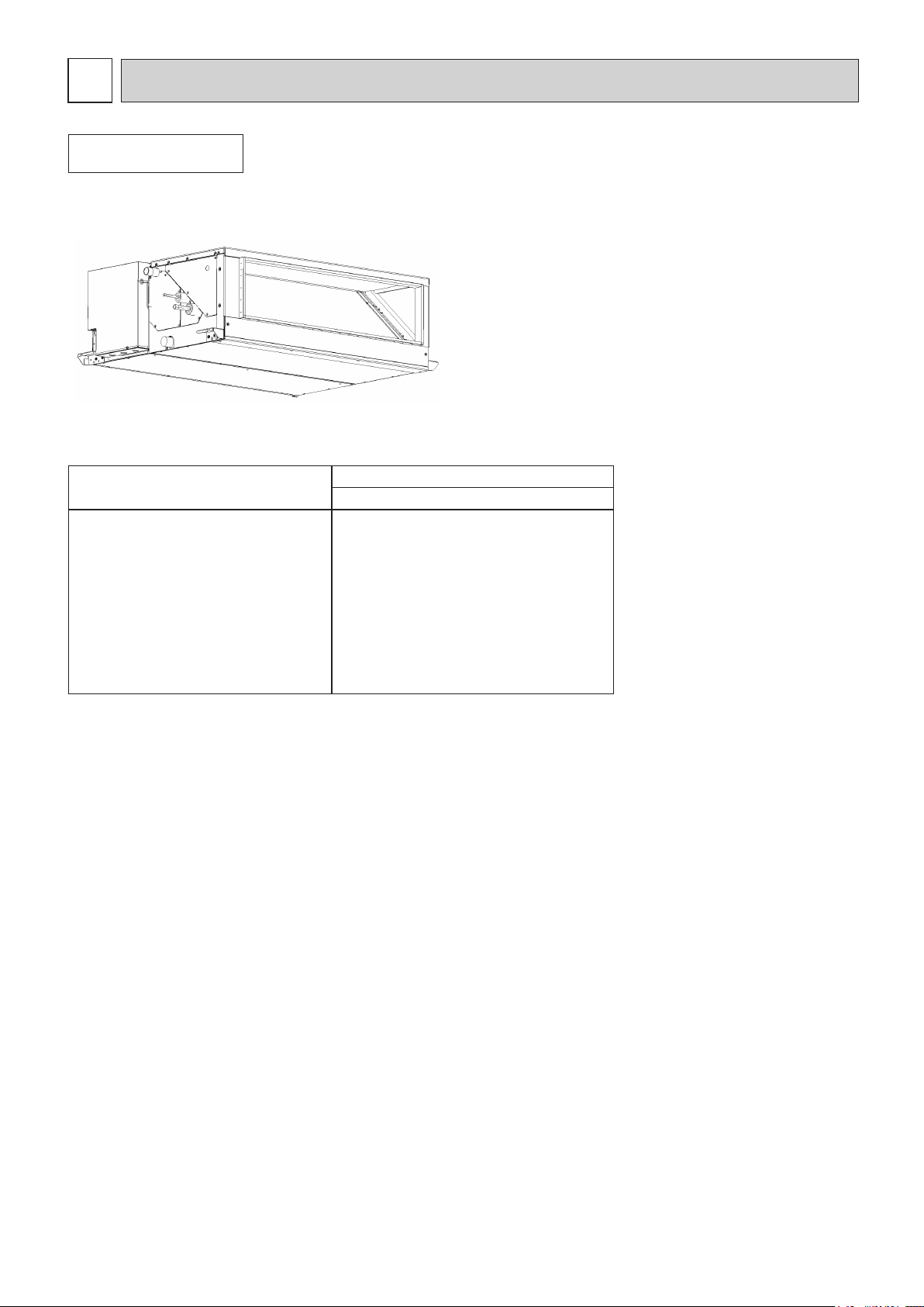
FEATURES
1
Indoor unit
Ceiling Concealed
Series PEFY
Models
Cooling capacity/Heating capacity
kW
4
Page 6
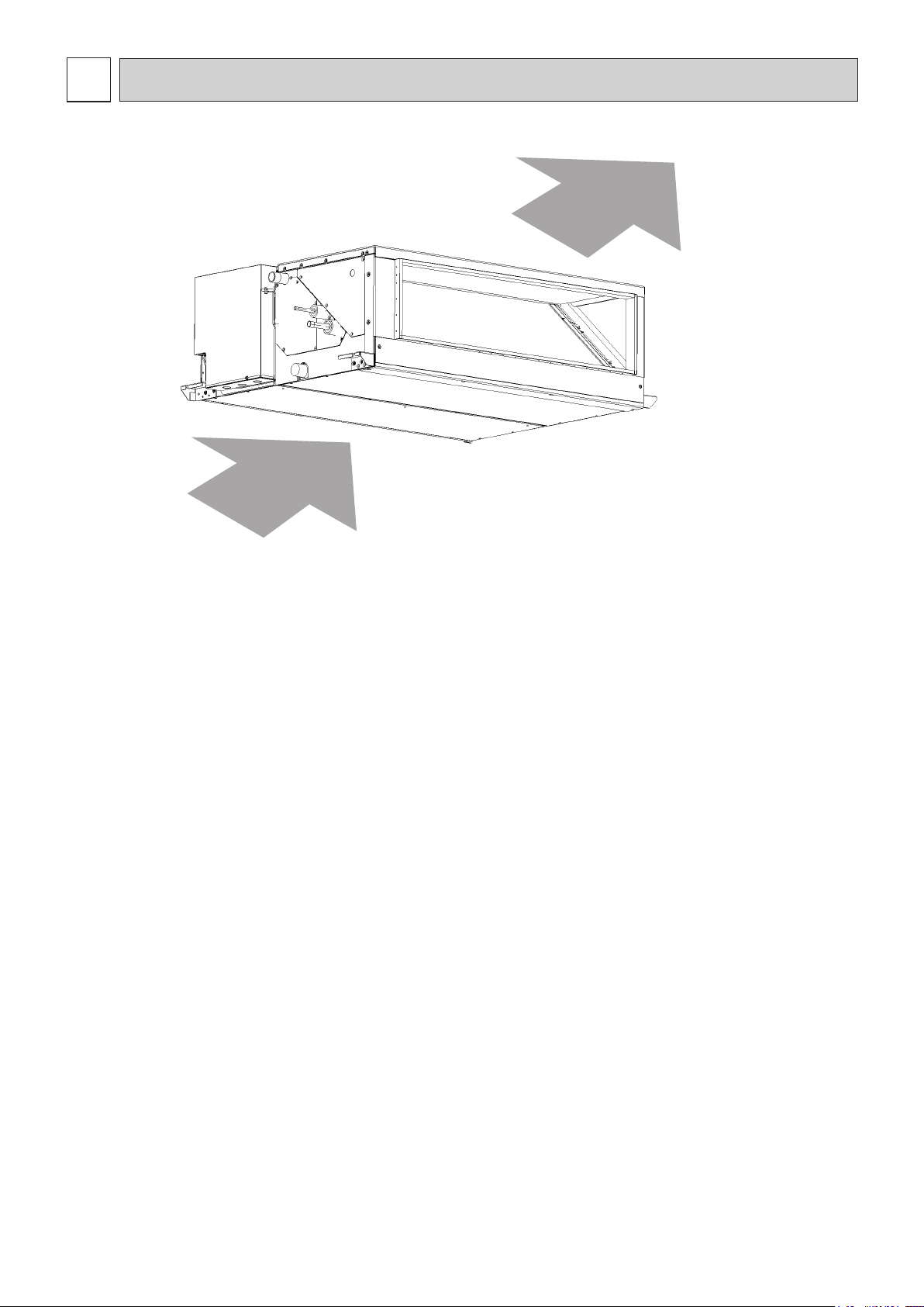
PART NAMES AND FUNCTIONS
2
Air inlet
Air outlet
2-1. Indoor (Main) Unit
5
Page 7
Fri
Room
Set temp.
Mode Temp. Fan
Cool Auto
Main
Main display:
Cursor Page
Main menu
Vane
•
Louver
•
Vent. (Lossnay)
High power
Timer
Weekly timer
OU silent mode
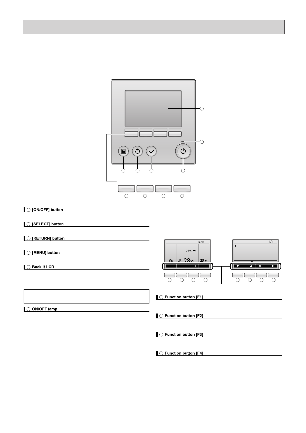
2-2. Remote Controller
[PAR-32MAA]
Once the operation mode is selected, the unit will remain in the selected mode until changed.
(1) Remote Controller Buttons
Function buttons
The functions of the function buttons change depending on the screen.
Refer to the button function guide that appears at the bottom of the LCD for
the functions they serve on a given screen.
When the system is centrally controlled, the button function guide that
corresponds to the locked button will not appear.
Function guide
Main menuMain display
Press to turn ON/OFF the indoor unit.
Press to save the setting.
Press to return to the previous screen.
Press to bring up the Main menu.
Operation settings will appear.
When the backlight is off, pressing any button turns the backlight on and it will
stay lit for a certain period of time depending on the screen.
When the backlight is off, pressing any button turns the backlight on
and does not perform its function. (except for the [ON/OFF] button)
This lamp lights up in green while the unit is in operation. It blinks while the
remote controller is starting up or when there is an error.
Main display: Press to change the operation mode.
Main menu: Press to move the cursor down.
Main display: Press to decrease temperature.
Main menu: Press to move the cursor up.
Main display: Press to increase temperature.
Main menu: Press to go to the previous page.
Main display: Press to change the fan speed.
Main menu: Press to go to the next page.
E
F
I
J
G
H
A
B
C
D
E
F
I JG H
ABCD
I JG H I JG H
6
Page 8
Fri
Mode Temp. Fan
Room
Cool Auto
Set temp.
Fri
Cool
Mode Temp. Fan
AutoSet temp.
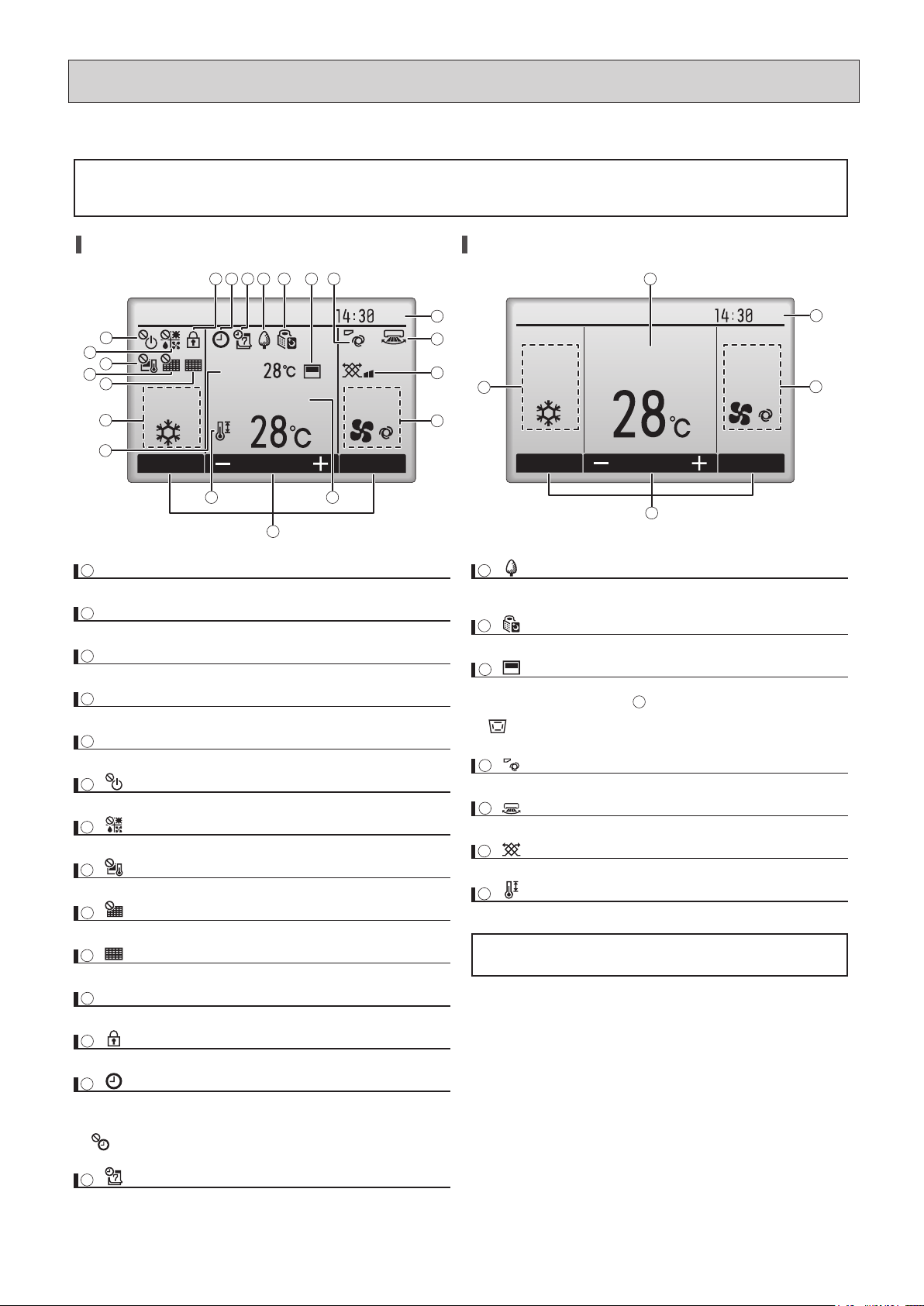
(2) Remote Controller Display
The main display can be displayed in two different modes: "Full" and "Basic."
The factory setting is "Full." To switch to the "Basic" mode, change the setting on the "Main display" setting screen (Main menu > Initial setting >
Main display).
Full mode Basic mode
* All icons are displayed for explanation.
Indoor unit operation mode appears here.
Set temperature appears here.
Current time appears here.
Fan speed setting appears here.
Functions of the corresponding buttons appear here.
Appears when the ON/OFF operation is centrally controlled.
Appears when the operation mode is centrally controlled.
Appears when the set temperature is centrally controlled.
Appears when the filter reset function is centrally controlled.
Current room temperature appears here.
Appears when the buttons are locked.
Appears when the On/Off timer, Night setback, or Auto-off timer function is
enabled.
appears when the timer is disabled by the centralized control system.
Appears when the Weekly timer is enabled.
Appears while the units are operated in the energy-save mode. (Will not
appear on some models of indoor units)
Appears while the outdoor units are operated in the silent mode.
Appears when the built-in thermistor on the remote controller is activated to
monitor the room temperature ( ).
appears when the thermistor on the indoor unit is activated to monitor the
room temperature.
Indicates the vane setting.
Indicates the louver setting.
Indicates the ventilation setting.
Appears when the set temperature range is restricted.
Most settings (except ON/OFF, mode, fan speed, temperature) can
be made from the Main menu.
Indicates when filter needs maintenance.
11
12 13 14 15 16 17 18
19
20
1
3
4
9
21
2
5
7
10
11
1
6
8
2
3
4
5
15
16
17
18
19
20
21
9
10
12
13
14
6
7
8
11Room temperature
Operation mode
1
Set temperature
2
Clock
Fan speed
Button function guide
3
4
5
7
Page 9
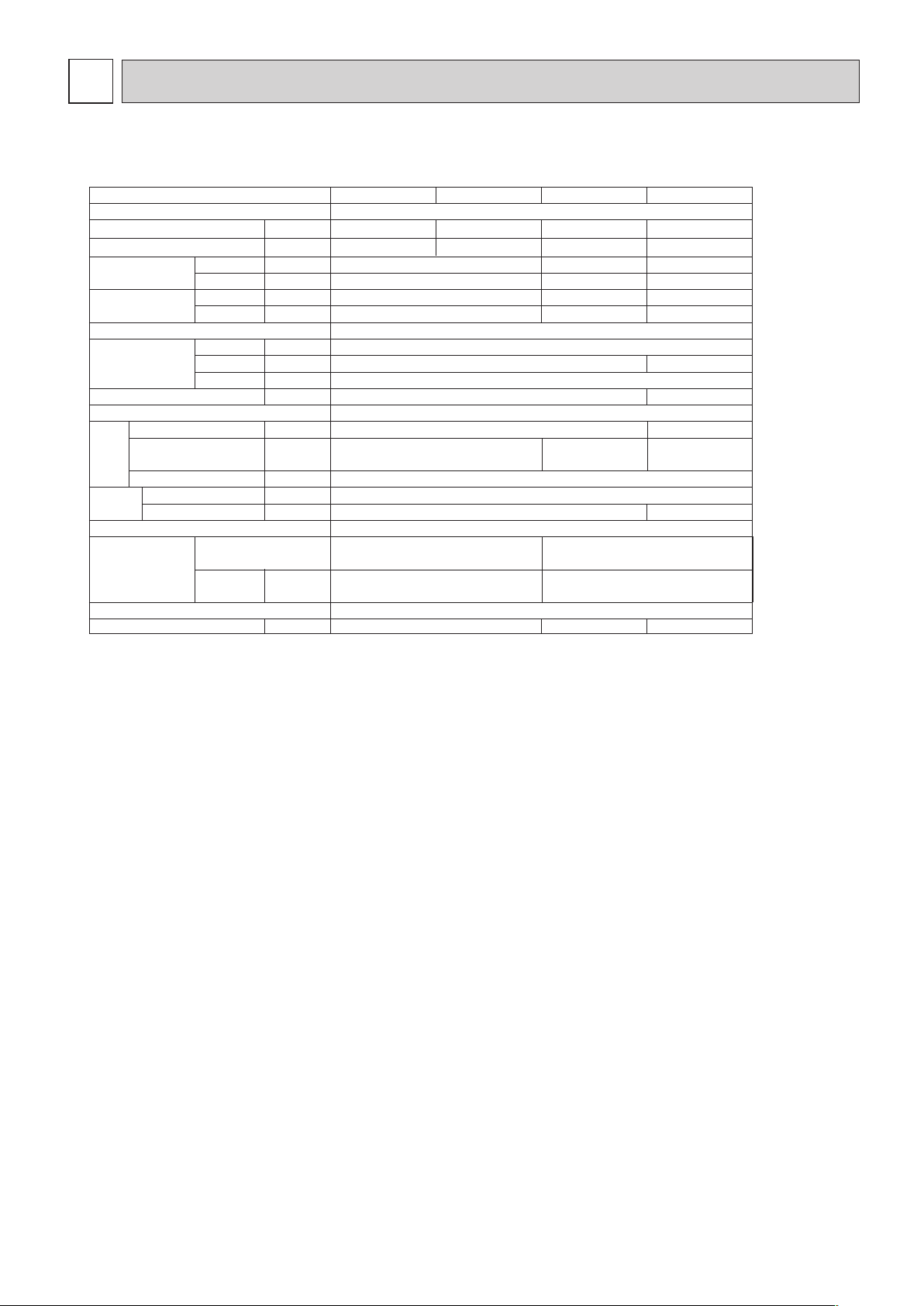
3
SPECIFICATION
3-1. Specification
Power source
Model
kWCooling capacity ❇1
kW
kWCooling
Heating
Cooling
Heating
kW
A
A
mm
mm
mm
kg
m
3
/min
Pa 50/100/150/200
kW
mm
mm
dB(A)
20-23-27 24-27-32 24-26-30
Heating capacity ❇1
Power
consumption
Current
External finish
Dimension
Height
Width
Depth
Net weight
Heat exchanger
Fan
Type
Airflow rate
(Lo-Mid-Hi)
External static pressure
❇
2
Motor
Output
Type
Air filter (option)
Refrigerant
pipe dimension
Gas
(Brazed)
Liquid
(Brazed)
Drain pipe dimension
Noise level (Lo-Mid-Hi)
745 1030
35
Cross fin (Aluminum plate fin and copper tube)
Sirocco fan
✕
DC motor
Synthethic fiber unwoven cloth filter(long life)
10.0-12.0-14.0
~
220-240V 50Hz /60Hz
PEFY-P40VMHS-E PEFY-P50VMHS-E
5.64.5
6.35.0
Galvanizing
380
900
1 Sirocco fan✕2
12.7
6.35
32 (1-1/4 inch)
0.121
0.055
0.055
0.41
0.41
0.090
0.090
0.64
0.64
0.075
0.075
0.54
0.54
45
ø
ø
9.52
ø
PEFY-P63VMHS-E
7.1
8.0
ø
15.88
13.5-16.0-19.0
0.244
PEFY-P71VMHS-E
8.0
9.0
15.5-18.0-22.0
Note: ❇1 Cooling/Heating capacity indicates the maximum value at operation under the following condition.
Cooling : Indoor 27˚CDB/19 ˚CWB,Outdoor 35˚CDB (WR2: water 30˚C)
Heating : Indoor 20˚CDB,Outdoor 7˚CDB/6˚CWB (WR2: water 20˚C)
❇
2 The external static pressure is set to 50Pa at factory shipment.
8
Page 10
Power source
kWCooling capacity ❇1
kW
kWCooling
Heating
Cooling
Heating
kW
A
A
mm
mm
mm
kg
m
3
/min
Pa 50/100/150/200
kW
mm
mm
dB(A) 25-27-30 27-31-34 27-32-36
Heating capacity ❇1
Power
consumption
Current
External finish
Dimension
Height
Width
Depth
Net weight
Heat exchanger
Fan
Type
Airflow rate
(Lo-Mid-Hi)
Motor
Output
Type
Air filter (option)
Refrigerant
pipe dimension
Gas
(Brazed)
Liquid
(Brazed)
Drain pipe dimension
Noise level (Lo-Mid-Hi)
~
1030 1195
45
Cross fin (Aluminum plate fin and copper tube)
DC motor
Synthethic fiber unwoven cloth filter(long life)
18.0-21.5-25.0
220-240V 50Hz /60Hz
PEFY-P80VMHS-E
PEFY-P100VMHS-E
11.29.0
12.510.0
Galvanizing
380
900
Sirocco fan
✕
2
32 (1-1/4 inch)
0.244
0.160
0.160
1.05
1.05
0.190
0.190
1.24
1.24
0.090
0.090
0.63
0.63
51 53
15.88
ø
9.52
ø
PEFY-P125VMHS-E
14.0
16.0
26.5-32.0-38.0
0.375
PEFY-P140VMHS-E
16.0
18.0
28.0-34.0-40.0
Note: ❇1 Cooling/Heating capacity indicates the maximum value at operation under the following condition.
Cooling : Indoor 27˚CDB/19 ˚CWB,Outdoor 35˚CDB (WR2: water 30˚C)
Heating : Indoor 20˚CDB,Outdoor 7˚CDB/6˚CWB (WR2: water 20˚C)
❇
2 The external static pressure is set to 50Pa at factory shipment.
Model
External static pressure
❇
2
9
Page 11

DC12V Stepping motor
0~1800pulse
DC12V Stepping motor
0~1800pulse
DC12V
Stepping motor
0~1800pulse
LEV
MF1,2
3-2. Electrical parts specifications
Model
Parts
name
TH21 Resistance 0˚C/15kΩ,10˚C/9.6kΩ,20˚C/6.3kΩ,25˚C/5.4kΩ,30˚C/4.3kΩ,40˚C/3.0kΩ
TH22 Resistance 0˚C/15kΩ,10˚C/9.6kΩ,20˚C/6.3kΩ,25˚C/5.4kΩ,30˚C/4.3kΩ,40˚C/3.0kΩ
Gas pipe
thermistor
FUSE 250V 6.3A
TB2 (L,N, ) 250V 20A
TB5
TB15
(M1,M2,S) 250V 20A
(1,2) 250V 15A
Fuse
(Indoor con-
troller board)
Power supply
terminal bed
Transmission
terminal bed
Room
temperature
thermistor
Fan motor
(with Inner-
thermostat)
8-pole, output 121W
SIC-70CW-D8121-3
8-pole, output 244W
SIC-101CW-D8244-3
10-pole, output 375W
KMUC4E1MW
Symbol
TH23 Resistance 0˚C/15kΩ,10˚C/9.6kΩ,20˚C/6.3kΩ,25˚C/5.4kΩ,30˚C/4.3kΩ,40˚C/3.0kΩ
Liquid pipe
thermistor
Linear
expansion valve
PEFY-
P40VMHS-E
PEFY-
P50VMHS-E
PEFY-
P63VMHS-E
PEFY-
P71VMHS-E
PEFY-
P80VMHS-E
PEFY-
P100VMHS-E
PEFY-
P125VMHS-E
PEFY-
P140VMHS-E
10
Page 12

4
OUTLINES AND DIMENSIONS
Unit : mm
4-1. OUTLINES AND DIMENSIONS
Drain hose (I.D.ø32)
(Actual length)
<Accessory>
Note 1.
2.
3.
Use an M10 screw for the suspension bolt (field supply).
This drawing is for PEFY-P71
·
80
·
100
·
125
·
140VMHS-E models,
which have 2 fans.PEFY-P40
·
50
·
63VMHS-E models have 1 fan.
Make sure to install the air filter (field supply) on the air intake side.
In case field supplied air filter is used, attach it
where the filter service is easily done.
DE GHFACB
Liquid pipe
ø6.35ø12.7
ø9.52ø15.88
1085
1250
Gas pipe
PEFY-P71
·
80VMHS-E
PEFY-P100
·
125
·
140VMHS-E
1039
1204
754
965
1130
680
885
1050
600
835
1000
550
42.5
25
50
17
21
11
800
1000
700
900
J
67
50
50
LK
800
15
19
10
500 450
PEFY-P63VMHS-E
PEFY-P40
·
50VMHS-E
Model
Inlet air
side view
To p
view
Outlet air
side view
To p
Bottom
Piping
side view
Air inlet Air outlet
2x5-ø3 holes
15
L
50
50x(J-1)=K
23
B(Suspension bolt pitch)
A
814
904
900
847
10
41
E(Duct)
94250
2xJ-ø3 holes
143
25
50x4=200
45 50x5=250
380
F
50
40
65 C
50x(G-1)=H
10
16 340
D(Duct)
(Duct)
Suspension bolt hole
(Suspension bolt pitch)
80
4-14x30 Slot
2xG-ø3 holes
(Duct)
Te rminal block
(Power source)
Control box
brazing connection (gas)
Drain pipe
2x6-ø3 holes
brazing connection (liquid)
(O.D.ø32)
(Gravity drain)
Refrigerant piping
Refrigerant piping
115
44.5
115
(Transmission)
29
60
24 29
15
50
Te rminal block
187
69
344.5
58
50
32
0
-10
2
2
1
1
11
Page 13

Unit : mm
Model C M N
PEFY-P40
·
50VMHS-E
680 780 0~50
PEFY-P63VMSH-E
PEFY-P71
·
80VMHS-E 965 1065 100~150
PEFY-P100
·
125
·
140VMHS-E 1130 1230 200~250
[Maintenance access space]
Secure enough access space to allow for the maintenance, inspection, and replacement of the motor, fan, heat exchanger,
drain pan and control box in one of the following ways.
Select an installation site for the indoor unit so that it's maintenance access space will not be obstructed by
beam or other objects.
Create access door 1 (450x450mm) for the maintenance from the unit side when the thermistor, LEV
and control box is exchanged. (Fig.2,4)
(1) When a space of 300mm or more is available below the unit between the unit and the ceiling.
Create access door 2 (600x600mm) for the maintenance from the bottom when the motor, fan, heat exchanger and drain pan is
cleaned (exchanged). (Fig.2)
(2) When a space of less than 300mm is available below the unit between the unit and the ceiling.
(At least 20mm of space should be left below the unit as shown in Fig.3.)
Create access door 3 for the maintenance from the bottom when the motor, fan, heat exchanger and drain pan is
cleaned (exchanged). (Fig.4)
Supply air
Intake air
Control box
Access door 1
Ceiling Ceiling beam
Min. 20mm
Min. 20mm
Control box
Access door 3
Access door 1
(450x450)
50900
450
100~200
1000
M
50 C
150~200
450
Bottom of
indoor unit
(Viewed from the direction
of the arrow Y)
Maintenance
access space
Fig.4
Supply
air
Intake
air
Y
Fig.3
Supply air
Intake air
Control box
Access door 1
Ceiling Ceiling beam
Min. 20mm
Min. 300mm
Control box
Access door 2
(600x600)
Access door 1
(450x450)
450100~200
C
150~200
450
Bottom of
indoor unit
(Viewed from the direction
of the arrow Z)
Maintenance
access space
Fig.2
Supply
air
Intake
air
Z
Fig.1
600
600
900
150~200
N
50
12
Page 14

5
WIRING DIAGRAM
FS
LEV
TH21 TH22TH23
1
3
INSIDE SECTION OF CONTROL BOX
M
CN2A
*Optional parts
1
2
43
CN4F
1
2
t˚ t˚ t˚
CN3A
(Blue)
(Black)
1
2
43
1
2
43
CN20
(Red)
CN41
LED2
CN44
CN4F
CN60
CN51
23456
: Connector, : Terminal,
(Heavy dotted line): Field wiring,
(Thin dotted line): Optional parts.
test or test run.
* Be sure to turn off the SWE after completing a drainage
To perform a drainage test for the drain pump turn on the
SWE on the control board while the indoor unit is being
powered.
5.
CN52
(Green)
SW1
SW2
SW3
SW4
Since the outdoor side electric wiring may change be sure
to check the outdoor unit electric wiring for servicing.
Symbols used in wiring diagram are
2.
NOTE)1.
Have all electric work done by a licensed electrician
according to the local regulations.
Earth leakage circuit breaker should be set up on the
wiring of the power supply.
3.
4.
CN32
0
1
0
0
1
9
2
8
3
7
4
6
5
SW12
(10ths digit)
1
9
2
8
3
7
4
6
5
SW11
(1s digit)
2
1
TB15
TO MA
CONTROLLER
REMOTE
F
2
E
3
D
4
C
5
B
6
A
7
9
SW21
8
SW22
1
SW14
(BRANCH No.)
CNE
456723 89
1
CN90
(Red)
CN105
SWE
OFF
ON
LED1
CN2M
(Blue)
2
1
CNP
3
1
3
21
(White)
3
21
(SHEILD)
S
M2
M1
TB5
TO
OUT DOOR UNIT
BC CONTROLLER
M
DP
1~
REMOTE
CONTROLLER
Switch (for static pressure selection)
Switch (for static pressure selection)
Switch (BRANCH No.)
SW14
SW21
Connector (emergency operation)
LED (Power supply)
LED (Remote controller supply)
SW22
SWE
LED1
LED2
Switch (10ths digit address set)
Indoor controller board
SW12
I.B.
Wireless remote controller board
Switch (Heating on/off)
Buzzer
LED (Run indicstor)
Receiving unit
BZ1
LED1
RU
SW1
Switch (Cooling on/off)
SW2
W.B .
*Optional parts
13
MF
DB
NAME SYMBOL NAMENAME
Var istor
Connector (0-10V Analog input)
Indoor controller board
ZNR001,002
CN2A
I.B.
TO NEXT INDOOR UNIT
Connector (Remote switch)
Connector (HA terminal-A)
Connector (Centrally control)
Connector (Remote indication)
Connector (Wireless)
CN32
CN41
CN51
CN52
CN90
Connector (IT terminal)
Switch (for mode selection)
Switch (for capacity code)
Switch (for mode selection)
CN105
SW1
SW2
SW3
Switch (for model selection)
Switch (1s digit address set)
SW4
SW11
ZNR001
U
DC280
~340V
ZNR002
U
CND
(Red)
SA
31
5
N
L
CNACL
M
1~
1
+-
2
3
4
4321
7
CNMF1
531
7
CNDB
(Black)
3
1
F1
I.B.
TB2
FUSE(16A)
SW1SW2
W.B .
BZ1
LED1
RU
RECEIVER
CN1
543216789
ACL
*Optional parts
PULL BOX
POWER SUPPLY
BREAKER(16A)
50/60Hz
SYMBOL EXPLANATION
~220,230,240V
AC reactor (Power factor improvement)
ACL
SYMBOL SYMBOL
Diode Bridge
DB
Drain Pump
Float switch
FS
DP
Fan Motor
Electrical linear expansion valve
MF
LEV
Power source terminal block
TB2
Transmission ter minal block
TB5
Transmission ter minal block
TB15
Thermistor (inlet air temp.detection)
Thermistor (piping temp.detection/liquid)
Thermistor (piping temp.detection/gas)
Indoor controller board
TH21
TH22
TH23
I.B.
Arrester
Fuse AC250V 6.3A
SA
F1
Page 15

REFRIGERANT SYSTEM DIAGRAM
6
Gas pipe
PEFY-P40,50VMHS-E
Liquid pipe
Capacity
Item
ø 12.7 <1/2F>
ø 6.35 <1/4F>
ø 15.88 <5/8F>
ø 9.52 <3/8F>
PEFY-P63,71,80,100,125,140VMHS-E
Gas pipe thermistor TH23
Liquid pipe thermistor TH22
Heat exchanger
Linear expansion valve
Strainer (#100mesh)
Room temperature thermistor TH21
Strainer (#100mesh)
Gas pipe
Brazed joints
14
Page 16

7
TROUBLE SHOOTING
7-1. Check methods
1. Component and check points
(1) Thermistor
Room temperature thermistor (TH21)
Liquid pipe thermistor (TH22)
Gas pipe thermistor (TH23)
Disconnect the connector and measure the resistance between terminals with a tester.
(Ambient temperature 10°C - 30°C)
AbnormalNormal
4.3k
- 9.6k Open or short
1) Thermistor characteristic graph
(Refer to the thermistor characteristic graph below.)
Low-temperature thermistor
Room temperature thermistor (TH21)
Liquid pipe thermistor (TH22)
Gas pipe thermistor (TH23)
Drain sensor (DS)
Thermistor R
0
= 15 k 3%
Multiplier of B = 3480 k 2%
9.6k
6.3k
5.2k
4.3k
3.0k
(A) Temperature (°C)
(B) Resistance (k )
Rt = 15 exp { 3480( ) }
1
273+t
1
273
(B)
10
20
30
40
50
-20 -10 0 10 20 30 40 50
(A)
0
(2) Fan motor (CNMF)
Refer to the page on "DC fan motor (fan motor/indoor control board)."
(3) Linear expansion valve
Disconnect the connector, and measure the resistance between terminals with a tester.
Refer to the next page for details.
(A) Red (E) Yellow
(C) Blue (F) White
(D) Orange
AbnormalNormal
1-6 2-6 3-6 4-6 Open or short
White-Red Yellow-Red Orange-Red Blue-Red
(150 ) 10%
1
2
3
4
6
M
(A)
(C)
(D)
(E)
(F)
CN60
LEV
15k0°C
10°C
20°C
25°C
30°C
40°C
15
Page 17

1) Summary of linear expansion valve (LEV) operation
The LEV is operated by a stepping motor, which operates by receiving a pulse signal from the indoor control board.
The LEV position changes in response to the pulse signal.
Indoor control board and LEV connection
(G)
Pulse signal output and valve operation
The output pulse changes in the following order:
When the valve closes 1 -> 2 -> 3 -> 4 -> 1
When the valve opens 4 -> 3 -> 2 -> 1 -> 4
When the valve position remains the same, all output signals will be OFF.
If any output signal is missing or if the signal remains ON, the motor vibrates and makes clicking noise.
(A) Red (G) Control board
(C) Blue (H) Connection (CN60)
(D) Orange (I) Drive circuit
(E) Yellow (J) Linear expansion valve
(F) White
Phase
number
1ONOFF OFF ON
2ONONOFF OFF
3 OFF ON ON OFF
4 OFF OFF ON ON
Output pulse
1234
1
(H)
(J)
(A)
(A)
(B)
(C)
(C)
(D)
(D)
(E)
(E)
(F)
(F)
M
4
6
2
3
5
1
4
3
6
5
2
(I)
12VDC
16
Page 18

6
5
4
3
2
1
1 k
LED
When the power is turned on, a pulse signal of fully open pulse + 10% pulse is output (valve closure signal), to bring the valve
to position A.
When the valve is operating normally, it is free of vibration noise. If the valve locks or when it goes from point E to A in the
figure, it makes louder noise than would be heard when there is an open phase.
Check for abnormal sound/vibration by placing the metal tip of a screwdriver against the valve and the handle side against
your ear.
3) Troubleshooting
RemedyChecking CriteriaSymptom
Circuit failure on
the microcomputer
Disconnect the connectors on the control board, and connect LEDs to test the circuit as shown below.
Pulse signals are output for 10 seconds when the main power is turned on. If there
are LEDs that do not light up at all or remain lit after the pulses are turned off, there
is a problem with the driving circuit.
Replace the indoor control
board if driving
circuit failure is
detected.
If this clicking noise is heard both when the valve is fully closed and while it is being
opened, it indicates a problem.
Replace the LEV.
Measure the resistance between the coils with a tester (red-white, red-orange,
Red-yellow, Red-blue). The normal range of resistance is 150 10%
Replace the LEV.
2) LEV operation
(a) Close
(b) Open
(c) Fully open valve (2000 pulses)
(d) No. of pulses
(e) Extra tightening (41 pulses)
(f) Valve opening degree
(f)
(e)
(a)
(b)
(d)
(c)
Locked LEV
Disconnected or
shorted LEV motor
coils
The motor will idle and make small clicking noise if it is run while the LEV is locked.
17
Page 19

Disconnect the connector, and measure the resistance between terminals with a tester.
2. Check if the drain pump works and drains water properly in cooling operation.
3. If no water drains, confirm that the check code 2502 will not be displayed 10 minutes after the
operation starts.
Note: The drain pump for this model is driven by the internal DC motor of controller board, so it is not
possible to measure the resistance between the terminals.
The fan starts to rotate.
Purple
-
Black: Abnormal (check code 2502) if it outputs 0-13 V square wave (5 pulses/rotation), and
the number of rotaion is not normal.
(A) Moving part
(B) Switch
(C) Magnet
Position of the moving part Normal Abnormal
Up Short (any position but short)
Down Open (any position but open)
(5) Drain float switch (CN4F)
1. Check if the drain float switch works properly.
Normal
Red
-
Black: Input 13V DC
(4) Drain pump
Valve closure failure (leaky valve)
To check the LEV on the indoor unit, check the indoor unit liquid pipe temperature
that appears on the operation monitor on the outdoor unit's multi control board while
operating the indoor unit in question in the FAN mode and the other indoor units in
the cooling mode.
Replace the LEV
if the amount of
leakage is great.
(A)Termistor (TH21)
Normally, the LEV is fully closed while the unit is in the FAN mode. If the valve is
leaky, liquid pipe thermistor reading will be lower than normal. If it is significantly
lower than the inlet temperature on the remote controller, valve closure failure is
suspected. If the amount of leakage is insignificant, replacement of LEV is unnecessary unless it is causing a problem.
Misconnections of
connectors or contact failure
Perform a visual check for disconnected connectors.
Perform a visual check of lead wire color.
Disconnect the
connectors on
the control board
and perform a
continuity test.
(A)
LEV
Red
Purple
Black
1
2
3
1
2
3
4
(A)
(A)
(B)
(C)
18
Page 20

7-2. DC fan motor (fan motor/indoor control board)
1. CAUTION
A high voltage is applied to the connector for connection to the fan motor (CNMF1).
Do not unplug the connector CNMF1 with the unit energized to avoid damage to the indoor control board and fan motor.
2. Troubleshooting
Symptom: Indoor unit fan does not run.
Check fan motor connector contact
(CNMF1).
Fix the connection.
Yes
No
Is the fan motor connector
(CNMF1) fully inserted?
Replace the indoor control board.
Yes
No
Is the voltage within the
normal range?
Check the power supply.
Measure the voltage at the indoor control board.
15VDC (same with the voltage between fan connector 5 (+) and 4(-))
1 - 6.5VDC (same with the voltage between fan connector 6 (+) and 4(-))
[Values for Vsp are the values that are measured with the fan motor in operation.
Vsp is 0V when the fan motor is stopped.]
Power supply voltage
310 - 340VDC (same with the voltage between fan connector 1 (+) and 4(-))
VDC
Check the fan motor position thermistor signal.
Get the motor to make a full rotation or more, and measure the voltage at the test point
V
FG
.
(same with the voltage between fan connector 7 (+) and 4(-))
Replace the indoor control board.
Yes
No
Replace the motor.
Are 0VDC and 15VDC
displayed alternately?
19
Page 21

7-3. Setting of address switch
Make sure that power source is turning off.
1)
* It is not necessary setting address in case of using unit remote controller.
2)
Refer to install manual of outdoor unit, operate the address setting.
3)
Address " 3 " setting is composed SW11 " 3 " and SW12 " 0 " .
Address " 25 " setting is composed SW11 " 5 " and SW12 " 2 " .
Indoor unit do not run without address setting in field.
Incase using network remote controller, address is set by rotary switches.(SW11,SW12)
Indoor unit address setting rule is different by each field work.
Setting the address is combination of SW11(1st digit address setting) and SW12(2nd digit address setting).
SW22
0
1
2
3
4
5
6
7
8
9
A
B
C
D
E
F
0
1
2
3
4
5
6
7
8
9
0
1
2
3
4
5
6
7
8
9
Indoor unit control board
SW2SW1 SW4SW3
SW21
SW12SW14 SW11
20
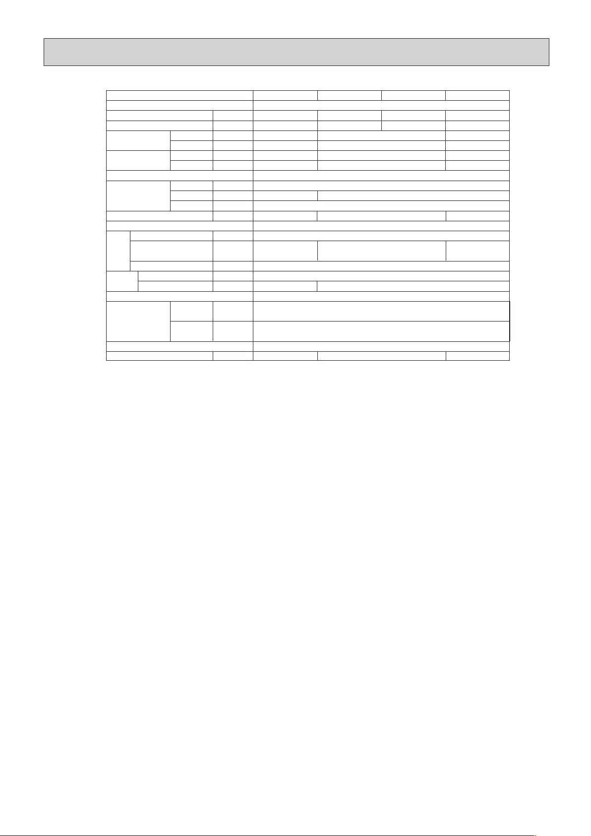
Page 22

SWESW22SW21SW4SW3SW2SW1Models
Symbol Silk display
Main power source
Tr ansmission power source
LED operation under normal state
At applying main power source (indoor unit 200V) Lighting
At receiving M-NET transmission power source Lighting
LED1
LED2
PEFY-P40VMHS-E
PEFY-P50VMHS-E
PEFY-P63VMHS-E
PEFY-P71VMHS-E
PEFY-P80VMHS-E
PEFY-P100VMHS-E
PEFY-P125VMHS-E
PEFY-P140VMHS-E
ON
1
2345678910
The figure at left shows that the switches 1 through 5 are set to ON and 6 through 10 are set to OFF.
ON
1
2345678910
ON
1
23456
ON
1
2345678910
ON
1
23456
ON
1
234
ON
1
2345678
ON
1
ON
1
2345678910
ON
1
23456
ON
1
2345678910
ON
1
23456
ON
1
2345678910
ON
1
23456
ON
1
234
ON
1
2345678
ON
1
ON
1
2345678910
ON
1
23456
ON
1
2345678910
ON
1
23456
ON
1
234
ON
1
2345678
ON
1
ON
1
2345678910
ON
1
23456
ON
1
2345678910
ON
1
23456
ON
1
234
ON
1
2345678
ON
1
ON
1
2345678910
ON
1
23456
ON
1
2345678910
ON
1
23456
ON
1
234
ON
1
2345678
ON
1
ON
1
2345678910
ON
1
23456
ON
1
2345678910
ON
1
23456
ON
1
234
ON
1
2345678
ON
1
ON
1
2345678910
ON
1
23456
ON
1
234
ON
1
2345678
ON
1
ON
1
2345678910
ON
1
23456
ON
1
2345678910
ON
1
23456
ON
1
234
ON
1
2345678
ON
1
7-4. Setting of Dip-switch (at delivery)
7-5. Function the LED of the indoor unit service board
21
Page 23

Fixing screws
8
DISASSEMBLY PROCEDURE
1.Removing the control box cover
(1) Remove the fixing screws (three) of the control box (A), and
remove the cover.(Fig.1)
*At this stage, the following servicing is possible. (Fig.2)
1 Operation and check of the switches (listed below) which
are on the control board.
• Dip switch SW1 ············· Function change
• Dip switch SW2 ·············· Capacity code setting
• Dip switch SW3 ·············· Function change
• Dip switch SW4 ·············· Model code setting
• Dip switch SW21 ············ Static pressure setting
• Dip switch SW22 ············ Function setting
• Rotary switches SW11, 12 ··· Address setting
• Rotary switch SW14 ········· Branch port setting
2 Connection check of the lead wires (listed below) which are
connected to the controller board.
• Power supply lead wire.
• Network remote contoller transmission lead wire.
• Fan motor lead wire.
• LEV lead wire
• Intake air sensor lead wire
• Liquid piping sensor lead wire
• Gas piping sensor lead wire
(• Drain pump lead wire)
(• Drain sensor lead wire)
3 Control board exchange
4 Condenser exchange
5 Fuse (Fuse holder) exchange
6 Relay exchange
7 Intake air sensor exchange
( ):Optional parts
8Power supply terminal bed exchange
9Transmission terminal bed exchange x 2
8-1. CONTROL BOX
Be careful on removing heavy parts.
Fig.1
Fig.2
FIGURES
OPERATING PROCEDURE
22
Page 24

Connector CNMF1
Fig.1
Fig.2
Fig.3
8-2. FAN and FAN MOTOR
FIGURES
OPERATING PROCEDURE
1. Remove the control box cover according to the procedure
in section 8-1. CONTROL BOX.
2. Removing the fan motor cable
(1) Disconnect the connector (CNMF1) from the control board.
(2) Remove the cable through the rubber bush.
3. Removing the bottom plate
(2) Pull out the fan motor in the direction of the arrow.
(1) Remove the fifteen fixing screws on the bottom plate to
remove it.
4. Removing the fan case
(1) Remove the eight fixing screws on the fan case to remove
it.
5. Removing the fan and fan motor
Exercise caution when removing heavy parts.
(1) Remove the two fixing screws and attachment on the fan
motor.
Be careful on removing heavy parts.
23
Page 25

Fig.4
Fig.5
FIGURES
OPERATING PROCEDURE
6. Precautions for reinstalling the removed motor in its
original position
(1) P40-80
Fix the motor in place so that the stamp printed on the
motor faces front when viewed from the air inlet. (Fig.4)
(2) P100-140
Fix the motor in place so that the protruding portion
on the motor and the stopper of the motor leg are
positioned as shown in Fig. 5.
Be careful on removing heavy parts.
Viewed from left
Stamp
Protruding portion
Stopper
24
Page 26

(A)
LEV
Fixing screws
Thermister
8-3.
LEV,THERMISTOR (Liquid/Gas piping temperature detection)
1.Removing the LEV.
(1) Remove the control box cover with procedure 8-1.
(2) Remove the fixing screws (five) of the heat exchanger cover
(A),and remove the cover (A).(Fig.1)
(3) Remove the LEV driving motor.(Fig.2)
2.Removing the thermistors.
(1) Remove the thermistors from the thermistor holders which
are installed on the piping.(Fig.3)
(liquid piping :large piping , gas piping :small piping)
Fig.1
Fig.2
Fig.3
Be careful on removing heavy parts.
FIGURES
OPERATING PROCEDURE
25
Page 27

Bottom plate
Drainpan
Fixing
screws
Fixing
screws
Cover(A)
Cover(B)
8-4. HEAT EXCHANGER
1.Removing the heat exchanger.
(1) Remove the heat exchanger cover with procedure 8-3-1.
(2) Remove the bottom plate which is air outlet side. (fixing
screws : twelve) (Fig.1)
(3) Remove the drainpan.(Fig.2)
(4) Remove the cover (A), (B).
(fixing screws : two x 2)(Fig.3)
Fig.1
Fig.2
Fig.3
Be careful on removing heavy parts.
FIGURES
OPERATING PROCEDURE
26
Page 28

Fixing
screws
Fixing screws
Fixing screws
Maintenance cover
(5) Remove the maintenance cover. (fixing screws : four) (Fig.5)
(6) Remove the heat exchanger. (fixing screws : four) (Fig.4,6)
*Removerd heat exchanger is as shown Fig.7
Fig.4
Fig.5
Fig.6
Fig.7
Be careful on removing heavy parts.
FIGURES
OPERATING PROCEDURE
27
Page 29

8-5. CONTROL BOX INSIDE LAYOUT
Power source
terminal bed
Tr ansmission terminal bed
AC reactor
Diode bridge
28
Page 30

8-6. SENSOR POSITION
Liquid sensor
Liquid sensor
Liquid sensor
Gas sensor
Liquid sensor
Gas sensor
Gas sensor
Gas sensor
Liquid sensor
Gas sensor
PEFY-P40,50,63VMHS-E
PEFY-P125VMHS-E
PEFY-P71,80VMHS-E
PEFY-P140VMHS-E
PEFY-P100VMHS-E
29
Page 31

Page 32

www.MitsubishiElectric.com
HWE17060
New publication effective Oct. 2017
Specifications subject to change without notice
 Loading...