

Mitsubishi PEFY-P25VMA-E, PEFY-P63VMA-E, PEFY-P40VMA-E, PEFY-P50VMA-E, PEFY-P71VMA-E Installation Manual
...Page 1
Air-Conditioners
INDOOR UNIT
PEFY-P20,25,32,40,50,63,71,80,100,125,140VMA-E
PEFY-P20,25,32,40,50,63,71,80,100,125,140VMAL-E
GB
PO
HG
SV
CZ
TR
RU
GR
P
NL
I
E
F
D
SL
SW
HR
BG
RO
INSTALLATION MANUAL
For safe and correct use, please read this installation manual thoroughly before installing the air-conditioner unit.
INSTALLATIONSHANDBUCH
Zum sicheren und ordnungsgemäßen Gebrauch der Klimageräte das Installationshandbuch gründlich durchlesen.
MANUEL D’INSTALLATION
Veuillez lire le manuel d’installation en entier avant d’installer ce climatiseur pour éviter tout accident et vous assurer d’une utilisation correcte.
MANUAL DE INSTALACIÓN
Para un uso seguro y correcto, lea detalladamente este manual de instalación antes de montar la unidad de aire acondicionado.
MANUALE DI INSTALLAZIONE
Per un uso sicuro e corretto, leggere attentamente questo manuale di installazione prima di installare il condizionatore d’aria.
INSTALLATIEHANDLEIDING
Voor een veilig en juist gebruik moet u deze installatiehandleiding grondig doorlezen voordat u de airconditioner installeert.
MANUAL DE INSTALAÇÃO
Para segurança e utilização correctas, leia atentamente este manual de instalação antes de instalar a unidade de ar condicionado.
E°XEIPI¢IO O¢H°IøN E°KATA™TA™H™
°И· ·ЫК¿ПВИ· О·И ЫˆЫЩ‹ ¯Ъ‹ЫЛ, ·Ъ·О·ПВ›ЫЩВ ‰И·‚¿ЫВЩВ ЪФЫВ¯ЩИО¿ ·˘Щfi ЩФ ВБ¯ВИЪ›‰ИФ ВБО·Щ¿ЫЩ·ЫЛ˜ ЪИУ ·Ъ¯›ЫВЩВ ЩЛУ
ВБО·Щ¿ЫЩ·ЫЛ ЩЛ˜ МФУ¿‰·˜ ОПИМ·ЩИЫМФ‡.
РУКОВОДСТВО ПО УСТАНОВКЕ
Для осторожного и правильного использования прибора необходимо тщательно ознакомиться с данным руководством по
установке до выполнения установки кондиционера.
MONTAJ ELK‹TABI
Emniyetli ve do¤ru biçimde nas›l kullan›laca¤›n› ö¤renmek için lütfen klima cihaz›n› monte etmeden önce bu elkitab›n› dikkatle okuyunuz.
INSTALLATIONSHANDBOK
Läs den här installationshandboken noga innan luftkonditioneringsenheten installeras, för säker och korrekt användning.
РЪКОВОДСТВО ЗА МОНТАЖ
За безопасна и правилна употреба, моля, прочетете внимателно това ръководство преди монтажа на климатизатора.
Page 2
2
3
3.2
[Fig. 3.2.1]
4
4.1
[Fig. 4.1.1]
A Refrigerant pipe (liquid pipe)
B Refrigerant pipe (gas pipe)
C Drain pipe (O.D. ø32)
D Drain pipe (O.D. ø32, spontaneous draining)
A Unit body
B Lifting machine
C Nuts (field supply)
D Washers (field supply)
E M10 hanging bolt (field supply)
5
5.2
[Fig. 5.1.1] [Fig. 5.1.2] [Fig. 5.2.1]
5.1
6
6.2
[Fig. 6.2.1]
A Center of gravity
A Access door
B Electrical parts box
C Air inlet
D Air outlet
E Ceiling surface
F Service space (viewed from the side)
G Service space (viewed from the direction of arrow)
1 600 mm or more
2 100 mm or more
3 20 mm or more
4 300 mm or more
A Indoor unit’s bottom surface
YX
LW
A
Z
A
C
D
C
E
D
B
C
D
A
F
G
3
4
E
A
50~150 450
450
49
625
777
20
100
23
C
B
A
D
C
E
250
1
2
B
A
137 67
239
357
122
33
41
217
C
A
B
D
Model
PEFY-P20,25,32VMA(L)-E
PEFY-P40,50VMA(L)-E
PEFY-P63,71,80VMA(L)-E
PEFY-P100,125VMA(L)-E
PEFY-P140VMA(L)-E
A
700
900
1100
1400
1600
B
754
954
1154
1454
1654
C
800
1000
1200
1500
1700
D
660
860
1060
1360
1560
E
800
1000
1200
1500
1700
(mm)
Page 3
3
A Cut here
B Remove brazed cap
A
A
E
C
F
B
D
A Thermal insulation
B Pull out insulation
C Wrap with damp cloth
D Return to original position
E Ensure that there is no gap here
F Wrap with insulating tape
7
[Fig. 7.1.1]
7.1
[Fig. 7.1.3]
B
J
O
N
F
Max. 300mm
[Fig. 7.2.1]
Correct piping
Wrong piping
A Insulation (9 mm or more)
B Downward slope (1/100 or more)
C Support metal
K Air bleeder
L Raised
M Odor trap
Grouped piping
D O. D. ø32 PVC TUBE
E Make it as large as possible. About 10 cm.
F Indoor unit
G Make the piping size large for grouped piping.
H Downward slope (1/100 or more)
I O. D. ø38 PVC TUBE for grouped piping.
(9 mm or more insulation)
J Up to 550 mm
N Drain hose (accessory)
O Horizontal or slightly upgradient
7.2
[Fig. 7.2.2]
C
B
A
L
D
D
D
E
K
M
B
H
I
Max. 20m
1.5-2m
G
F
FF
B
CD D
G
F
E
H
A
3235 25
A Indoor unit
B Tie band (accessory)
C Visible part
D Insertion margin
E Drain hose (accessory)
F Drain pipe (O.D. ø32 PVC TUBE, field supply)
G Insulating material (field supply)
H Tie band (accessory)
A
[Fig. 7.1.2]
A Cool by a wet cloth
A Indoor unit
B Tie band (accessory)
C Band fixing part
D Insertion margin
E Drain hose (accessory)
F Drain pipe (O.D. ø32 PVC TUBE, field supply)
G Insulating material (field supply)
C
D
G
F
E
B
525
A
[Fig. 7.2.3]
Page 4
4
AB
DE
CCCCCCC
8
[Fig. 8.0.1]
9
9.1
[Fig. 9.1.1] [Fig. 9.2.1]
[Fig. 9.2.2]
TB5 TB5
SM1M2 SM1M2
TB3
M1M2
AA
B
CC
TB5 TB15 TB5 TB15
SM1M2 SM1M2
TB3
M1M2 21 21
AA
B
CC
A Switch 16 A
B Overcurrent protection 16 A
C Indoor unit
D Total operating current be less than 16 A
E Pull box
A Te r minal block for indoor
transmission cable
B Te rminal block for outdoor
transmission cable
C Remote controller
9.2
[Fig. 7.3.1]
7.3
A Insert pump's end 2 to 4 cm.
B Remove the water supply port.
C About 2500 cc
D Water
E Filling port
F Screw
[Fig. 8.0.2]
SWE
[Fig. 7.3.2]
[Fig. 8.0.3]
[Fig. 8.0.4]
<Indoor controller board>
A
B
F
C
D
E
A
B
G
F
A
A
B
C
D
E
F
G
CE
Duct
Air inlet
Access door
Canvas duct
Ceiling surface
Air outlet
Leave distance
enough to prevent short cycle
<A> In case of rear inlet
D
A
B
G
C
E
A
F
<B> In case of bottom inlet
D
A
B
A Filter
B Bottom plate
C
D
Page 5
5
F Use PG bushing to keep the weight of the cable and external force from being
applied to the power supply terminal connector. Use a cable tie to secure the
cable.
G Power source wiring
H Use ordinary bushing
I Transmission wiring
J Te r minal block for power source
K Te r minal block for indoor transmission
L Te r minal block for remote controller
A Te r minal block
B Round terminal
C Shield wire
D The earth wire from two cables are connected together to the S terminal. (Dead-end connection)
E Insulation tape (To keep the earth wire of the shielded cable from coming in contact with the transmis-
sion terminal)
9.3
[Fig. 9.3.3]
[Fig. 9.3.4]
[Fig. 9.3.5]
C Te r minal box
D Knockout hole
E Remove
A Screw holding cover (1pc)
B Cover
[Fig. 9.3.1] [Fig. 9.3.2]
A Non-polarized
B TB15
C Remote Controller
D TB5
[Fig. 9.2.3] [Fig. 9.2.4]
2
S
M2
M1
A
B
D
1
DC10~13V
AB
12
L
N
C
D
A
S
M2
M1
B
1
2
L
N
DC24~30V
(A, B)
12
C
M2 SM1
A
B
C
E
D
9.5
[Fig. 9.5.1]
<Indoor controller board>
9.2
A
B
C
D
E
H
I
F
G
J
L
K
SWA
SW5
SW14
SW12
SWC
SW11
Page 6

D
13
Inhalt
1. Sicherheitsvorkehrungen ........................................................................13
1.1. Vor Installations- und Elektroarbeiten .....................................13
1.2.
Vorkehrungen für Geräte, die R410A-Kältemittel verwenden
......14
1.3. Vor der Aufstellung .................................................................14
1.4. Vor dem Einbau (der Ortsveränderung) - Elektroarbeiten...... 14
1.5. Vor Installationsbeginn............................................................ 14
2. Versorgungseinrichtungen der Innenanlage...........................................15
3. Einen Aufstellort wählen .........................................................................15
3.1. Die Innenanlage an einer Decke montieren,
die stark genug ist, um das Gewicht zu halten ....................... 15
3.2. Sicherstellen des Freiraums für Montage und Wartung/
Bedienung...............................................................................15
3.3. Innenanlagen mit Außenanlagen verbinden...........................15
4. Befestigung der Hängebolzen.................................................................15
4.1. Befestigung der Hängebolzen.................................................15
5. Aufstellen der Anlage ..............................................................................15
5.1. Aufhängen des Anlagenkörpers..............................................15
5.2. Sich über die richtige Lage der Anlage vergewissern und die
Hängebolzen befestigen .........................................................16
6. Technische Daten der Kältemittel- und Kondensatablaufleitung............ 16
6.1. Technische Daten der Kältemittel- und
Kondensatablaufleitung ..........................................................16
6.2. Kältemittelrohr, Kondensatablaufrohr und Einfüllöffnung .......16
7. Kältemittel- und Kondensatablaufleitungen anschließen........................16
7.1. Verrohrung der Kältemittelleitung ...........................................16
7.2. Verrohrung des Kondensatablaufs/der Dränage ....................17
7.3. Funktion der Ablassleitung prüfen .......................................... 17
8. Rohrleitungsarbeiten...............................................................................17
9. Elektroverdrahtung..................................................................................18
9.1. Netzstromverdrahtung ............................................................18
9.2. Anschluß der Fernbedienungs-, Innen- und
Außenübertragungskabel .......................................................19
9.3. Vornahme der Elektroanschlüsse........................................... 19
9.4. Technische Daten der externen Ein-/Ausgänge.....................19
9.5. Auswählen des statischen Außendrucks................................19
9.6. Adressen einsetzen ................................................................19
9.7. Messen der Raumtemperatur mit dem in eine
Fernbedienung eingebauten Temperaturfühler......................19
9.8. Die Netzspannungseinstellung ändern...................................19
1. Sicherheitsvorkehrungen
1.1. Vor Installations- und Elektroarbeiten
Im Text verwendete Symbole
Warnung:
Beschreibt Vorkehrungen, die beachtet werden sollten, um den Benutzer vor
der Gefahr von Verletzungen oder tödlicher Unfälle zu bewahren.
Vorsicht:
Beschreibt Vorkehrungen, die beachtet werden sollten, um die Anlage vor
Schäden zu bewahren.
Innerhalb der Abbildungen verwendete Symbole
Warnung:
• Bitten Sie Ihren Fachhändler oder einen geprüften Fachtechniker, die Installation der Anlage vorzunehmen.
- Unsachgemäße Installation durch den Benutzer kann Wasseraustritt, Strom-
schläge oder Brände verursachen.
• Die Anlage an einer Stelle anbringen, die das Gewicht tragen kann.
- Bei ungenügender Tragkraft kann das Gerät herunterfallen und Verletzungen
verursachen.
• Zur Verdrahtung die angegebenen Kabel verwenden. Die Anschlüsse so
sichern, daß Zugspannung von außen nicht auf die Klemmen wirken kann.
- Falscher Anschluß und falsche Befestigung führen zu Wärmebildung und verur-
sachen Brände.
• Vorkehrungen gegen Stürme, starke Luftströme und Erdbeben treffen und
die Anlage an einem Ort aufstellen, der die beschriebenen Bedingungen
erfüllt.
- Durch unsachgemäße Installation kann die Anlage herunterfallen und Verletzun-
gen verursachen.
• Stets Luftreiniger, Luftbefeuchter, Elektroheizungen und sonstige, von Mitsubishi angegebene, Zubehöreinrichtungen verwenden.
- Einen geprüften Techniker bitten, die Zusatzeinrichtungen zu installieren.
Unsachgemäße Installation durch den Benutzer kann zu Wasseraustritt, Stromschlägen oder Bränden führen.
• Die Anlage niemals selbst reparieren. Wenn die Anlage repariert werden
muß, wenden Sie bitte sich an den Fachhändler.
- Wenn die Anlage unsachgemäß repariert wird, kann dies zu Wasseraustritt,
Stromschlägen oder Bränden führen.
• Nicht die Wärmetauscherleitung berühren.
- Unsachgemäße Handhabung kann zu Verletzungen führen.
• Tragen Sie bei der Handhabung dieses Erzeugnisses immer Schutzausrüstung, d.h. Handschuhe, vollen Armschutz wie einen Overall und eine
Schutzbrille.
- Unsachgemäße Handhabung kann zu Verletzungen führen.
• Wenn Kältemittelgas während der Installationsarbeiten austritt, den Raum
gründlich lüften.
- Wenn das Kältemittelgas auf offenes Feuer trifft, wird giftiges Gas freigesetzt.
• Die Anlage gemäß Anweisungen in diesem Installations-handbuch installieren.
- Bei unsachgemäßer Installation kann dies zu Wasseraustritt, Stromschlägen
oder Bränden führen.
• Elektroarbeiten durch einen zugelassenen Fachelektriker in Übereinstimmung mit dem “Electric Facility Engineering Standard” - (Technische Normen für Elektroeinrichtungen), den “Interior Wire Regulations” (Vorschriften zur Innenverdrahtung) und den in diesem Handbuch gegebenen Anweisungen vornehmen. Anlage auch immer an einen gesonderten
Stromkreis anschließen.
- Wenn die Leistung der Stromquelle ungenügend ist oder die Elektroarbeiten
unsachgemäß ausgeführt wurden, kann dies zu Stromschlägen und zu Bränden
führen.
• Halten Sie die elektrischen Teile fern von Wasser (Waschwasser usw.).
- Kontakt mit Wasser kann elektrischen Schlag, Feuer oder Rauch verursachen.
• Die Abdeckung der Elektroanschlüsse der Außenanlage (Abdeckplatte) fest
anbringen.
- Wenn die Abdeckung der Elektroanschlüsse (Abdeckplatte) nicht sachgemäß
angebracht wurde, kann Staub oder Wasser in die Außenanlage eindringen und
Brände oder Stromschläge verursachen.
• Beim Verbringen der Anlage an einen anderen Standort, Anlage nicht mit
einem anderen Kältemittel als dem auf der Anlage angegebenen Kältemittel
füllen.
- Wenn das ursprüngliche Kältemittel mit einem anderen Kältemittel oder mit Luft
vermischt wird, kann dies zu Fehlfunktionen des Kältemittelkreislaufs führen und
die Anlage beschädigt werden.
• Wenn die Anlage in einem kleinen Raum installiert wird, müssen Maßnahmen
ergriffen werden, damit die Kältemittelkonzentration auch bei Kältemittelaustritt den Sicherheitsgrenzwert nicht überschreitet.
- Befragen Sie einen Fachhändler bezüglich geeigneter Maßnahmen zur Verhin-
derung des Überschreitens des Grenzwertes. Sollte durch Austreten von Kältemittel das Überschreiten des Grenzwertes erfolgen, besteht wegen möglichem
Sauerstoffmangel im Raum Gesundheitsgefahr.
• Beim Verbringen der Anlage an einen anderen Ort einen Fachhändler oder
einen geprüften Techniker zur Neuaufstellung hinzuziehen.
- Bei unsachgemäßer Installation der Anlage kann Wasser austreten, und es kön-
nen Stromschlage oder Brände verursacht werden.
• Nach Abschluß der Installationsarbeiten sicherstellen, daß kein Kältemittelgas austritt.
- Wenn Kältemittelgas austritt und mit einem Heizgebläse, einem Ofen oder son-
stigen Wärmequellen in Berührung kommt, kann giftiges Gas erzeugt werden.
• Die Einstellungen der Schutzvorrichtungen nicht neu einrichten oder
ändern.
- Wenn Druckschalter, Thermoschalter oder eine andere Schutzvorrichtung kurz-
geschlossen oder mit Gewalt betätigt wird oder wenn andere als die von Mitsubishi Electric angegebenen Teile verwendet werden, besteht Brand- oder
Explosionsgefahr.
• Wenden Sie sich für die Entsorgung dieses Geräts an lhren Händler.
• Kein Zusatzmittel für Leckentdeckung verwenden.
` Vor dem Einbau der Anlage vergewissern, daß Sie alle Informationen
über “Sicherheitsvorkehrungen” gelesen haben.
` Die “Sicherheitsvorkehrungen” enthalten sehr wichtige Sicherheitsge-
sichtspunkte. Sie sollten sie unbedingt befolgen.
: Verweist auf eine Handlung, die unterbleiben muß.
: Verweist auf wichtige Anweisungen, die befolgt werden müssen.
: Verweist auf ein Teil, das geerdet werden muß.
: Zeigt an, daß bei rotierenden Teilen Vorsichtgeboten ist. (Dieses Symbol fin-
det sich als Aufkleber auf der Hauptanlage.) <Farbe: gelb>
: Gefahr von elektrischem Schlag. (Dieses Symbol findet sich als Aufkleber auf
der Hauptanlage.) <Farbe: gelb>
Warnung:
Die auf der Hauptanlage angebrachten Aufkleber sorgfältig lesen.
Page 7

14
D
1.2. Vorkehrungen für Geräte, die R410A-Kältemittel
verwenden
Vorsicht:
• Niemals vorhandene Kältermttelrohrleitungen einsetzen.
- Das alte Kältemittel und das Kältemaschinenöl in der vorhandenen Rohrleitung
enthalten große Mengen Chlor, was zur Qualitätsminderung des Kältemaschinenöls der neuen Anlage führen kann.
• Kältemittelrohrleitungen aus phosphor-deoxidiertem Kupfer C1220 (CuDHP) gemäß Angaben in JIS H3300 “Nahtlose Rohrleitungen und Rohre aus
Kupfer und Kupferlegierung” verwenden. Außerdem vergewissern, daß die
Innen- und Außenflächen der Rohrleitungen sauber und frei von gefährlichem Kupfer, Oxyden, Staub/Schmutz, Metallbearbeitungsrückständen,
Ölen, Feuchtigkeit oder anderen Verunreinigungen sind.
- Verunreinigungen auf der Innenseite der Kältemittelrohrleitungen können dazu
führen, daß das Kältemittelrestöl verdirbt.
• Die bei der Installation verwendete Rohrleitung in einem geschlossenen
Raum aufbewahren und beide Enden bis unmittelbar vor dem Hartlöten
geschlossen halten. (Krümmer und andere Rohrverbinder in einem Kunststoffbeutel aufbewahren.)
- Wenn Staub, Schmutz oder Wasser in den Kältemittelkreislauf gelangt, kann dies
zu einer Qualitätsminderung des Öls und zu Kompressorstörungen führen.
• Zur Füllung des Systems flüssiges Kältemittel verwenden.
- Wenn Kältemittelgas zur Füllung des Systems verwendet wird, ändert sich die
Zusammensetzung des Kältemittels im Zylinder, so daß die Leistung abfallen
kann.
• Kein anderes Kältemittel als R410A verwenden.
- Bei Verwendung eines anderen Kältemittels (R22 etc.) kann das Chlor zur Qua-
litätsminderung des Kältemaschinenöls führen.
• Eine Vakuumpumpe mit einem Reverse Flow(Gegenstrom)-Rückschlagventil
verwenden.
- Das Öl der Vakuumpumpe fließt in den Kältemittelkreislauf zurück und führt zur
Qualitätsminderung des Kältemaschinenöls.
• Folgende Vorrichtungen, die bei herkömmlichen Kältemitteln verwendet
werden, nicht einsetzen.
(Meßrohrleitung, Füllschlauch, Gasaustrittsdetektor, Reverse Flow(Gegenstrom)- Rückschlagventil, Kältemittelfüllständer, Vakuummeßgerät, Kältemittelaufbereitungseinrichtungen)
- Das Mischen von herkömmlichem Kältemittel und Kältemaschinenöl mit R410A
kann einen Güteverlust des Kältemittels verursachen.
- Das Mischen von Wasser und R410A kann einen Güteverlust des Kältemaschi-
nenöls verursachen.
- Da R410A vollkommen chlorfrei sind, sprechen für herkömmliche Kältemittel ver-
wendete Gasleckagesensoren unter Umständen nicht an.
• Keinen Füllzylinder verwenden.
- Bei Verwendung eines Füllzylinders kann das Kältemittel verderben.
• Beim Einsatz der Handhabungsvorrichtungen besondere Sorgfalt walten
lassen.
- Wenn Staub, Schmutz oder Wasser in den Kältemittelkreislauf gelangt, kann dies
zur Qualitätsminderung des Kältemittels führen.
1.3. Vor der Aufstellung
Vorsicht:
• Anlage nicht an Orten installieren, wo brennbares Gas austreten kann.
- Wenn Gas austritt und sich um die Anlage herum ansammelt, kann dies zu einer
Explosion führen.
• Anlage nicht an Orten verwenden, wo sich Lebensmittel, Tiere, Pflanzen,
Präzisionswerkzeuge oder Kunstgegenstände befinden.
- Die Qualität der Lebensmittel etc. kann sich verschlechtern.
• Anlage nicht unter besonderen Umfeldbedingungen einsetzen.
- Dichter Öldampf, Dampf oder schwefelhaltiger Rauch können die Leistung der
Klimageräte erheblich beeinträchtigen oder Teile der Anlage beschädigen.
• Bei Installation der Anlage in einem Krankenhaus, einer Rundfunkstation
oder an ähnlichen Orten für ausreichend Lärmschutz sorgen.
- Der Betrieb der Anlage kann gestört oder unterbrochen werden, wenn sie durch
Aufnahmegeräte, private Stromerzeugungseinrichtungen, medizinische Hochfrequenzgeräte oder Rundfunkeinrichtungen beeinflußt wird, und umgekehrt
kann der Betrieb der Anlage die Funktion dieser Geräte und Einrichtungen
beeinträchtigen und Lärm erzeugen, der ärztliche Behandlungen stört oder Bildübertragungen beeinträchtigt.
• Die Anlage nicht auf Baueinrichtungen installieren, die Wasseraustritt verursachen können.
- Wenn die Luftfeuchtigkeit 80 % übersteigt oder wenn die Abwasserleitung ver-
stopft ist, kann Kondenswasser aus der Innenanlage tropfen. Daher die vorgesehene Sammelabwasserleitung der Außenanlage einrichten.
• Die Innenanlagen sollten an der Decke in einer Höhe von mindestens 2,5 m
über dem Fußboden installiert werden.
1.4. Vor dem Einbau (der Ortsveränderung) Elektroarbeiten
Vorsicht:
• Erdung der Anlage.
- Die Erdungsleitung nicht an Gas- oder Wasserrohre, Beleuchtungsstäbe oder an
die Erdleitungen von Telefonen anschließen. Unsachgemäße Erdung kann zu
Stromschlägen führen.
• Netzstromleitungen so anbringen, daß keine Zugspannung auf die Kabel
ausgeübt wird.
- Zugspannung kann Kabelbruch, Wärmebildung und Brände verursachen.
• Einen Fehlerstromschutzschalter wie vorgesehen anbringen.
- Wenn kein Fehlerstromschutzschalter angebracht wird, können Stromschläge
verursacht werden.
• Netzstromkabel mit ausreichender Stromstärke und Nennwertauslegung
verwenden.
- Zu kleine Kabel können Fehlstrom verursachen, Wärme erzeugen und Brand
ausbrechen lassen.
• Nur Stromunterbrecher und Sicherungen der angegebenen Leistung verwenden.
- Eine Sicherung oder ein Stromunterbrecher von größerer Stärke oder Stahl- oder
Kupferdraht können zum Ausfall der Anlage oder zum Ausbruch von Bränden
führen.
• Klimageräte nicht waschen.
- Waschen der Anlage kann Stromschläge verursachen.
• Sorgfältig darauf achten, daß die Installationsplatte durch langen Gebrauch
nicht beschädigt wird.
- Wenn der Schaden nicht behoben wird, kann die Anlage herunterfallen und Per-
sonenschäden oder Schäden an der Einrichtung hervorrufen.
• Zur Gewährleistung eines ordnungsgemäßen Wasserablaufs die Abwasserleitung gemäß Anweisungen in diesem Installationshandbuch installieren.
Rohrleitungen mit Wärmeisolierung versehen, um Kondenswasserbildung
zu verhindern.
- Unsachgemäß angebrachte Abwasserleitungen können Wasseraustritt verursa-
chen und Schäden an Möbeln oder sonstigen Einrichtungsgegenständen nach
sich ziehen.
• Beim Transport der Anlage sehr sorgfältig vorgehen.
- Wenn der Gegenstand mehr als 20 kg wiegt, nicht nur eine Person zum Tragen
einsetzen.
- Bei einigen Produkten besteht die Verpackung aus Kunststoffbändern. Zum
Transport keine Kunststoffbänder verwenden.
- Nicht die Rippen des Wärmetauschers berühren. Man kann sich dadurch die Fin-
ger verletzen.
- Beim Transport der Außenanlage diese an den angegebenen Stellen der Grund-
platte der Anlage aufhängen. Auch die Außenanlage an vier Punkten unterstützen, damit sie nicht zur Seite wegrutschen kann.
• Verpackungsmaterial sicher entsorgen
- Verpackungsmaterial, wie Nägel und andere Metall- oder Holzteile, können
Stichwunden oder sonstige Verletzungen verursachen.
- Kunststoffbeutel zerreißen und entsorgen, damit Kinder nicht mit ihnen spielen.
Wenn Kinder mit Kunstoffbeutel spielen, die nicht zerrissen wurden, besteht
Erstickungsgefahr.
1.5. Vor Installationsbeginn
Vorsicht:
• Strom mindestens 12 Stunden vor Betriebsbeginn einschalten.
- Betriebsbeginn unmittelbar nach Einschalten des Netzschalters kann zu schwer-
wiegenden Schäden der Innenteile führen. Während der Saison Netzschalter
eingeschaltet lassen.
• Schalter nicht mit nassen Fingern berühren.
- Berühren eines Schalters mit nassen Fingern kann einen Stromschlag verursa-
chen.
• Kältemittelrohrleitung nicht während oder unmittelbar nach Betrieb berühren.
- Während und unmittelbar nach Betrieb sind die Kältemittelrohrleitungen, je nach
Durchfluß des Kältemittels durch die Kältemittelrohrleitung, den Kompressor und
andere Teile des Kältemittelkreislaufs, manchmal heiß und manchmal kalt. Sie
können sich die Hände verbrennen oder Frostverletzungen erleiden, wenn Sie
die Kältemittelrohrleitung berühren.
• Klimageräte nicht bei abgenommenen Verkleidungen und Schutzabdeckungen betreiben.
- Drehende, heiße oder unter Hochspannung stehende Teile können Verletzungen
verursachen.
• Netzstrom nicht unmittelbar nach Betriebsbeendigung ausschalten.
- Vor Ausschalten des Netzstroms immer mindestens 5 Minuten warten. Anderen-
falls kann es zu Wasseraustritt oder sonstigen Störungen kommen.
Page 8

D
15
2. Versorgungseinrichtungen der Innenanlage
Die Anlage ist mit folgenden Versorgungseinrichtungen versehen:
3. Einen Aufstellort wählen
• Einen Aufstellort mit stabiler, fester Fläche, die für das Gewicht der Anlage haltbar
genug ist, wählen.
• Vor Einbau der Anlage muß der Weg zum Transport der Anlage an den Aufstellort
festgelegt werden.
• Einen Aufstellort wählen wo die Anlage nicht durch eindringende Luft beeinflußt
wird.
• Einen Aufstellort wählen wo der Strom der Zu- und Abluft nicht behindert ist.
• Einen Aufstellort wählen wo die Kältemittelrohrleitung problemlos nach außen
geleitet werden kann.
• Einen Aufstellort wählen wo die Luft aus der Anlage sich vollständig im Raum verteilen kann.
• Die Anlage nicht an einem Ort aufstellen, wo in größeren Mengen Öl verspritzt
oder Dampf erzeugt wird.
• Die Anlage nicht an einem Ort aufstellen, wo brennbares Gas erzeugt werden, hereinströmen, verbleiben oder austreten kann.
• Die Anlage nicht an einem Ort aufstellen, wo durch Einrichtungen Hochfrequenzwellen entstehen können (z.B. durch ein Hochfrequenz-Schweißgerät).
• Die Anlage nicht an einem Ort aufstellen, wo sich an der Seite, wo die Luftaustritt,
ein Feuermelder befindet. (Der Feuermelder kann versehentlich in Gang gesetzt
werden, wenn während des Heizbetriebs Warmluft austritt)
• Wo spezielle chemische Produkte im Raum verteilt sein können, wie in chemischen Anlagen und Krankenhäusern, ist vor Aufstellung der Anlage eine umfassende Untersuchung erforderlich. (Die Kunststoffteile können je nach Art der
chemischen Produkte, denen sie ausgesetzt sind, beschädigt werden)
• Wenn das Gerät lange Zeit betrieben wird, während eine hohe Temperatur/hohe
Luftfeuchtigkeit (Taupunkt über 26 °C) in der Decke herrscht, kann es zu Kondensation in der Inneneinheit kommen. Wenn Geräte in solchen Bedingungen betrieben werden, so fügen Sie Isolierungsmaterial (10 – 20 mm) über die gesamte
Oberfläche der Inneneinheit zu, um Kondensation zu verhindern.
3.1. Die Innenanlage an einer Decke montieren, die
stark genug ist, um das Gewicht zu halten
Warnung:
Die Anlage muß an einem Gebäudeteil, der das Gewicht tragen kann, sicher
angebracht werden. Wenn die Anlage an einem Gebäudeteil mit ungenügender
Tragkraft montiert wird, kann sie herunterfallen und Personenschäden verursachen.
3.2. Sicherstellen des Freiraums für Montage und Wartung/Bedienung
• Entsprechend der Raumanordnung und der Aufstellposition die optimale Strö-
mungsrichtung der Luft aus der Anlage feststellen und auswählen.
• Wenn Rohrleitungen und Elektroleitungen an den Boden- und Seitenflächen ange-
schlossen sind und die Bedienung und Wartung an der gleichen Fläche vorgenommen wird, genügend Freiraum vorsehen. Zur effizienten Vornahme der
Aufhängungsarbeiten und zur Sicherheit soviel Freiraum wie möglich vorsehen.
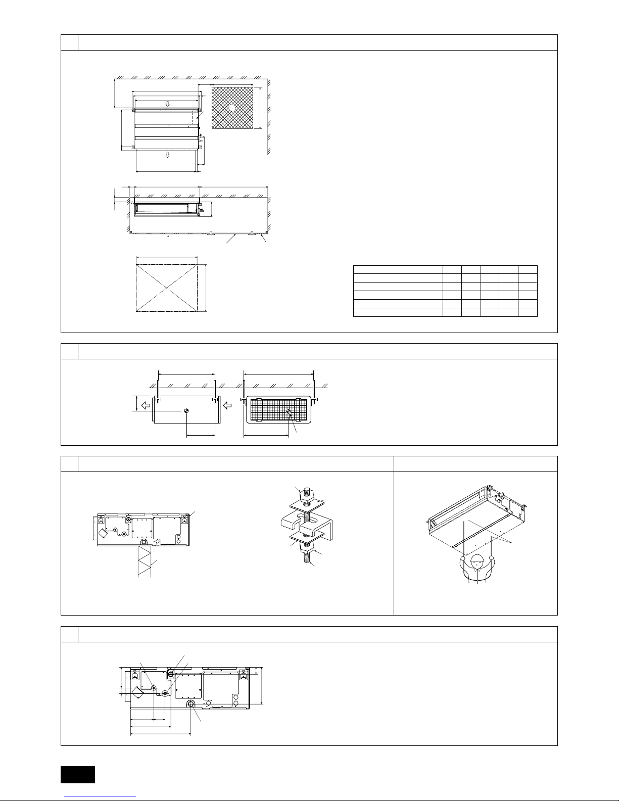
[Fig. 3.2.1] (P.2)
3.3. Innenanlagen mit Außenanlagen verbinden
Zum Verbinden der Innenanlagen mit Außenanlagen im Montagehandbuch der
Außenanlagen nachschlagen.
4. Befestigung der Hängebolzen
4.1. Befestigung der Hängebolzen
[Fig. 4.1.1] (P.2)
(Die Aufhängeposition muß eine starke Baustruktur aufweisen.)
Baustruktur für die Aufhängung
• Decke: Die Deckenstruktur ist von Gebäude zu Gebäude unterschiedlich. Holen
Sie nähere Informationen bei der jeweiligen Bauunternehmung ein.
• Verstärken Sie die Aufhängungsbolzen erforderlichenfalls mit Erdbebenunterstüt-
zungen als Maßnahme gegen Erdbeben.
* Verwenden Sie M10 für Aufhängungsbolzen und Erdbebenunterstützungen
(lokal beizustellen).
Schwerpunkt und Erzeugnisgewicht
Die Werte in Klammern beziehen sich auf das Modell PEFY-P·VMAL-E.
5. Aufstellen der Anlage
5.1. Aufhängen des Anlagenkörpers
` Die Innenanlage in der Verpackung an den Aufstellungsort bringen.
` Zum Aufhängen der Innenanlage diese mit einer Hebevorrichtung anheben
und durch die Hängebolzen führen.
[Fig. 5.1.1] (P.2)
[Fig. 5.1.2] (P.2)
Teilenr. Zubehör Menge
1 Isolationsrohr 1
2 Binder 3
3 Abflussleitung 1
4 Unterlegscheibe 8
5 Installationshandbuch 1
6 Betriebshandbuch 1
Teilenr. Zubehör Menge
A Zugangstür B Kasten für Elektroteile
C Lufteingang D Luftausgang
E Deckenfläche F Wartungsöffnung (Seitenansicht)
G Wartungsöffnung (Ansicht aus Pfeilrichtung)
a 600 mm oder mehr b 100 mm oder mehr
c 20 mm oder mehr d 300 mm oder mehr
A Schwerpunkt
Modellbezeichnung W L X Y Z Erzeugnisgewicht (kg)
PEFY-P20VMA(L)-E 643 754 330 300 130 23 (22)
PEFY-P25VMA(L)-E 643 754 330 300 130 23 (22)
PEFY-P32VMA(L)-E 643 754 330 300 130 23 (22)
PEFY-P40VMA(L)-E 643 954 340 375 130 26 (25)
PEFY-P50VMA(L)-E 643 954 340 375 130 26 (25)
PEFY-P63VMA(L)-E 643 1154 325 525 130 32 (31)
PEFY-P71VMA(L)-E 643 1154 325 525 130 32 (31)
PEFY-P80VMA(L)-E 643 1154 325 525 130 32 (31)
PEFY-P100VMA(L)-E 643 1454 330 675 130 42 (41)
PEFY-P125VMA(L)-E 643 1454 330 675 130 42 (41)
PEFY-P140VMA(L)-E 643 1654 332 725 130 46 (45)
A Anlagenkörper
B Hebevorrichtung
C Muttern (Vor Ort zu beschaffen)
D Unterlegscheiben (Vor Ort zu beschaffen)
E M10-Hängebolzen (Vor Ort zu beschaffen)
Page 9

16
D
5.2. Sich über die richtige Lage der Anlage vergewissern und die Hängebolzen befestigen
` Mit der mit der Füllplatte gelieferten Lehre vergewissern, daß der Anlagen-
körper und die Hängebolzen sich in der richtigen Lage befinden. Wenn sie
nicht richtig angeordnet sind, kann dies aufgrund von Luftdurchgangsöffnungen zur Tropfenbildung führen.
Vergewissern, daß das Lageverhältnis genau überprüft wird.
` Mit einer Wasserwaage vergewissern, daß sich die mit A gekennzeichnete
Fläche in der Waagerechten befindet. Auch dafür sorgen, daß die Muttern
der Hängebolzen fest angezogen sind, um die Hängebolzen zu sichern.
` Um zu gewährleisten, daß der Wasserauslauf stattfindet, mit einer Wasser-
waage sicherstellen, daß die Anlage in der Waagerechten hängt.
[Fig. 5.2.1] (P.2)
Vorsicht:
Installieren Sie die Anlage waagerecht. Wenn die Seite mit dem Drainageanschluss höher liegt, kann dies ein Auslaufen des Wassers bewirken.
6. Technische Daten der Kältemittel- und Kondensatablaufleitung
Um Tropfenbildung zu vermeiden, die Kältemittel- und Kondensatablaufleitung ausreichend gegen Schwitzwasserbildung sichern und mit Isoliermaterial ausstatten.
Bei Einsatz von handelsüblichen Kältemittelrohren dafür sorgen, daß handelsübliches Isoliermaterial (mit einer Hitzebeständigkeit von mehr als 100 °C und der nachstehend angegebenen Stärke) sowohl um die Flüssigkeits- als auch um die
Gasrohre gewickelt wird.
Isolieren Sie alle Innenrohre mit Polyäthylen-Formteilen mit einer minimalen Dichte
von 0,03 und einer Stärke, wie sie in folgender Tabelle angegeben ist.
a Auswahl der Stärke des Isoliermaterials nach Rohrgrößen.
b Wenn die Anlage im obersten Stockwerk eines Gebäudes und unter Umgebungs-
bedingungen mit hoher Temperatur und hoher Luftfeuchtigkeit eingesetzt wird, ist
es notwendig, Rohrgrößen und Isoliermaterialstärken zu verwenden, die über den
in der Tabelle angegebenen liegen.
c Wenn technische Angaben seitens des Kunden vorliegen, diese einfach befolgen.
6.1. Technische Daten der Kältemittel- und Kondensatablaufleitung
6.2. Kältemittelrohr, Kondensatablaufrohr und Einfüllöffnung
[Fig. 6.2.1] (P.2)
7. Kältemittel- und Kondensatablaufleitungen anschließen
7.1. Verrohrung der Kältemittelleitung
Die Verrohrung muß gemäß den Anweisungen im Aufstellhandbuch sowohl der
Außenanlage als auch der BC-Steuerung (Baureihe R2 für gleichzeitiges Kühlen
und Heizen) erfolgen.
• Die Baureihe R2 ist für den Betrieb in einem System ausgelegt, bei dem die Kälte-
mittelrohrleitung von einer Außenanlage durch eine BC-Steuerung übernommen
und von dieser zum Anschluß an Innenanlagen abgezweigt wird.
• Angaben über weitere Bedingungen bezüglich Rohrlänge und zulässiger Höhen-
differenz finden sich im Handbuch der Außenanlage.
• Die Rohrverbindung erfolgt im Wege des gelöteten Anschlusses.
Vorsicht:
• Die Kältemittelrohre für die Innenanlage gemäfl der folgenden Angaben
installieren.
1. Das Ende des Innenanlage-Rohres abschneiden, das Gas austreten lassen, und
dann die gelötete Muffe abnehmen.
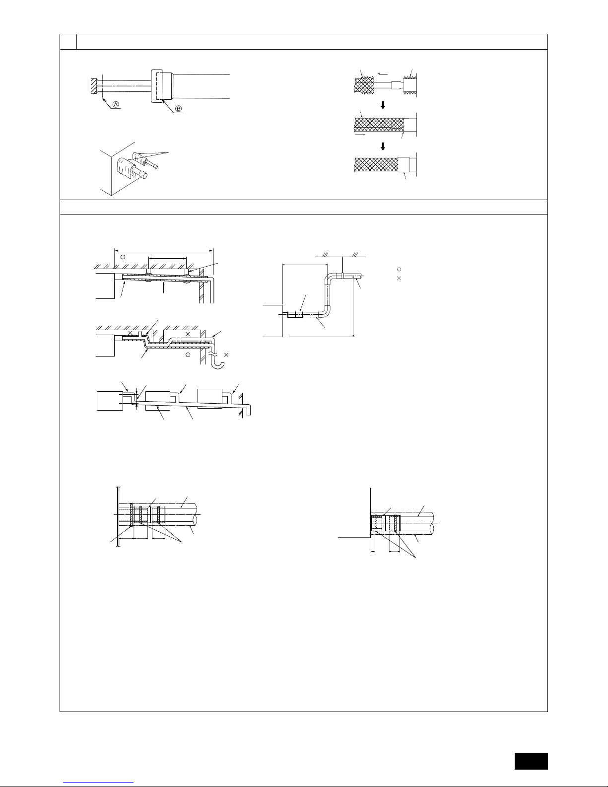
[Fig. 7.1.1] (P.3)
2. Die Wärmeisolierung an der Seite des Kältemittelrohres herausziehen, die Rohr-
leitungen der Anlage löten, und die Isolierung wieder an der ursprünglichen Stelle
anbringen.
Die Rohrleitung mit Isolierband umwickeln.
Hinweis:
• Achten Sie beim Löten der Kühlmittelleitungen darauf, währenddessen die
Leitungen der Geräte mit einem nassen Tuch zu kühlen, damit diese durch
die Hitzeeinwirkung nicht verbrennen oder schrumpfen.
[Fig. 7.1.2] (P.3)
• Beim Umwickeln der Kupferrohre größte Vorsicht walten lassen, da sich
durch das Umwickeln der Rohrleitung Kondenswasser bilden kann, anstatt
dies zu verhindern.
[Fig. 7.1.3] (P.3)
Vorsichtsmaßregeln bei Kältemittelrohrleitungen
` Dafür sorgen, daß zum Hartlöten nichtoxidierende Hartlötverfahren ange-
wendet werden, um zu gewährleisten, daß keine Fremdstoffe oder Feuchtigkeit in die Rohrleitung eindringen.
` Kältemaschinenöl auf die Oberfläche des Sitzes der konischen Verbindung
auftragen und den Anschluß mit einem Doppelschraubenschlüssel fest
anziehen.
` Eine Metallklammer (Rohrschelle) zum Halten des Kältemittelrohrs anbrin-
gen, damit die Last auf das Endrohr der Innenanlage verlegt wird. Diese
Metallklammer (Rohrschelle) sollte 50 cm vom Konusanschluß der Innenanlage entfernt angebracht werden.
Warnung:
Beim Installieren und Verlegen der Anlage kein anderes Kältemittel als das auf
der Anlage angegebene Kältemittel einfüllen.
- Vermischung mit einem anderen Kältemittel, mit Luft etc. kann zu Fehlfunktionen
des Kältemittelkreislaufs und zu schweren Schäden an der Anlage führen.
Vorsicht:
• Kältemittelrohrleitungen aus phosphor-deoxidiertem Kupfer C1220 (CuDHP) gemäß Angaben in JIS H3300 “Nahtlose Rohrleitungen und Rohre aus
Kupfer und Kupferlegierung” verwenden. Außerdem vergewissern, daß die
Innen- und Außenflächen der Rohrleitungen sauber und frei von gefährlichem Kupfer, Oxyden, Staub/Schmutz, Metallbearbeitungsrückständen,
Ölen, Feuchtigkeit oder anderen Verunreinigungen sind.
• Niemals vorhandene Kältemittelrohrleitungen einsetzen.
- Die große Menge Chlor in herkömmlichen Kältemitteln und Kältemaschinenöl in
der vorhandenen Rohrleitung führt zu einer Qualitätsminderung des neuen Kältemittels.
• Die zu verwendende Rohrleitung während der Installation in einem geschlossenen Raum aufbewahren und beide Enden der Rohrleitung bis unmittelbar
vor dem Hartlöten abgedichtet lassen.
- Wenn Staub, Schmutz oder Wasser in den Kältemittelkreislauf gelangen, wird die
Qualität des Öls gemindert, was zum Ausfall des Kompressors führen kann.
• Die aufgeweiteten Teile und den Flanschanschluß mit Kältemaschinenöl des
Typs Suniso 4GS oder 3GS (kleine Menge) bestreichen. (Für Modelle, die R22
verwenden)
• Zum Beschichten der Konus- und Flanschanschlüsse Esteröl/Ätheröl oder
Alkylbenzol (kleine Menge) als Kältemaschinenöl verwenden. (Für Modelle,
die R410A oder R407C verwenden)
- Das in der Anlage verwendete Kältemittel ist stark hygroskopisch, vermischt sich
mit Wasser und mindert die Qualität des Kältemaschinenöls.
A Bodenfläche der Innenanlage
Rohrgröße Stärke des Isoliermaterials
6,4 mm – 25,4 mm Mehr als 10 mm
28,6 mm – 38,1 mm Mehr als 15 mm
PEFY-P·VMA(L)-E
20·25·32·40·50 63·71·80·100·125·140
Kältemittelrohr
(Gelöteter Anschluß)
Flüssigkeitsrohr ø 6,35 ø 9,52
Gasrohr ø 12,7 ø 15,88
Kondensatablauf Außendurchmesser ø 32
Position
Modell
A Kältemittelrohrleitung (Flüssigkeitsrohrleitung)
B Kältemittelrohrleitung (Gasrohrleitung)
C Kondensatablaufrohr (Außendurchmesser ø 32)
D Kondensatablaufrohr (Außendurchmesser ø 32, spontane Entwässerung)
A An dieser Stelle schneiden
B Gelötete Muffe abnehmen
A Kühlen mit einem nassen Tuch
A Wärmeisolierung B Isolierung abziehen
C Mit feuchtem Tuch umwickeln
D Wieder an ursprünglicher Stelle anbringen
E Dafür sorgen, dafl an dieser Stelle keine Lücke ist
F Mit Isolierband umwickeln
Page 10

D
17
7.2. Verrohrung des Kondensatablaufs/der Dränage
• Dafür sorgen, daß die Kondensatleitung in Richtung Außenanlage (Abwasserauslauf) geneigt ist (Verhältnis von mehr als 1/100). Keine Sammelgefäße oder nicht
vorgesehene Einrichtungen auf der Strecke einbauen.
• Dafür sorgen, daß abzweigende Kondensatleitungen weniger als 20 m lang sind
(unabhängig vom Steigungsunterschied). Bei langen Dränagerohren Metallklammern (Rohrschellen) anbringen, um Schwingungen zu verhindern. Niemals Luftabzugsrohre anbringen, da sonst Abwasser ausgestoßen wird.
• Ein Hartvinylchlorid-Rohr VP-25 (mit einem Außendurchmesser von 32 mm) als
Auslaufrohr verwenden.
• Achten Sie darauf, dass die Sammelrohrleitungen 10 cm tiefer liegen als der
Abwasserausgang des Anlagenkörpers.
• Am Abwasserausgang keinen Geruchsabzug anbringen.
• Das Ende des Auslaufrohrs an einer Stelle anbringen, an der kein Geruch entstehen kann.
• Das Ende der Auslaufleitung nicht in einen Ablauf verlegen, in dem sich IonenGase bilden können.
[Fig. 7.2.1] (P.3)
Sammelrohrleitungen
Modell PEFY-P·VMA-E
[Modell PEFY-P·VMA]
1. Führen Sie den Ablassschlauch (Zubehör) in den Drainageanschluss ein (Einfüh-
rungsgrenze: 32 mm). (Der Ablassschlauch darf nicht mehr als um 45° gebogen
werden, um ein Brechen oder Zusetzen des Schlauches zu vermeiden.)
(Montieren Sie den Schlauch mit Kleber, und fixieren Sie ihn mit einem Binder
(klein, Zubehör).)
2. Montieren Sie das Ablassrohr (Außendurchmesser ø 32 PVC-SCHLAUCH PV-
25, handelsüblich). (Montieren Sie das Rohr mit Kleber, und fixieren Sie es mit
einem Binder (klein, Zubehör).)
3. Führen Sie Isolierungsarbeiten am Ablassrohr (Außendurchmesser ø 32 PVC-
SCHLAUCH PV-25) und dem Anschlussstück (einschließlich Bogen) durch.
4. Prüfen Sie den korrekten Abfluss. (Näheres unter [Fig. 7.3.1])
5. Montieren Sie das Isolationsmaterial, und befestigen Sie es mit einem Binder
(groß, Zubehör), um den Drainageanschluss zu isolieren.
[Fig. 7.2.2] (P.3) *nur am Modell PEFY-P·VMA-E
[Modell PEFY-P·VMAL-E]
1. Führen Sie den Ablassschlauch (Zubehör) in den Drainageanschluss ein.
(Der Ablassschlauch darf nicht mehr als um 45° gebogen werden, um ein Brechen oder Zusetzen des Schlauches zu vermeiden.)
Das Verbindungsteil zwischen Innenanlage und Ablaufschlauch kann bei der
Wartung abgetrennt werden. Das Teil mit dem Zubehörband ohne Verwendung
von Klebstoff befestigen.
2. Montieren Sie das Ablassrohr (Außendurchmesser ø 32 PVC-SCHLAUCH, handelsüblich). (Die Leitung mit Klebstoff für Hart-PVC-Leitung anbringen und mit
dem Band befestigen (klein, Zubehör).)
3. Führen Sie Isolierungsarbeiten am Ablassrohr (Außendurchmesser ø 32 PVCSCHLAUCH) und dem Anschlussstück (einschließlich Bogen) durch.
[Fig. 7.2.3] (P.3) *nur am Modell PEFY-P·VMAL-E
7.3. Funktion der Ablassleitung prüfen
` Stellen Sie sicher, dass der Entwässerungsmechanismus normal arbeitet,
und dass kein Wasser aus den Verbindungen austritt.
• Achten Sie darauf, die Funktion in einer Heizbetriebsperiode zu überprüfen.
• Vergewissern Sie sich bei Neubauten, obige Punkte zu überprüfen, bevor Decken-
arbeiten ausgeführt werden.
1. Entfernen Sie die Abdeckung für die Wasserzuführung auf derselben Seite wie
die Rohrführung des Innengerätes.
2. Füllen Sie Wasser aus einem Speisewassertank in die Speisewasserpumpe. Achten Sie beim Befüllen darauf, das Ende der Pumpe oder des Tanks in eine Drainagepfanne zu führen. (Falls der Schlauch nicht ganz eingeführt wird, kann
Wasser über das Gerät laufen.)
3. Führen Sie den Testlauf im Kühlbetrieb aus oder schließen Sie die Steckbrücke
an der ON-Seite von SWE auf der Innengerätesteuerplatine an. (Die Drainagepumpe und der Lüfter werden ohne jede Verwendung der Fernbedienung
zwangsbetrieben.) Verwenden Sie einen transparenten Schlauch, um sicherzustellen, dass eine Drainage erfolgt.
4. Nach der Bestätigung den Testlauf abbrechen und die Hauptstromversorgung
ausschalten. Falls die Steckbrücke an der ON-Seite von SWE angebracht ist, die
Steckbrücke abnehmen, an der OFF-Seite anbringen und den Verschluss des
Wasserzufuhranschlusses in seiner ursprünglichen Position anbringen.
[Fig. 7.3.1] (P.4)
[Fig. 7.3.2] (P.4)
8. Rohrleitungsarbeiten
• Beim Anschluß des Strömungskanals Segeltuchteilstück zwischen Anlage und
Strömungskanal einsetzen.
• Als Strömungskanalteile nichtbrennbare Materialien verwenden.
• Eingangsflansch und Ausgangsflansch vollständig isolieren, um Kondenswasserbildung zu verhindern.
• Dafür sorgen, daß die Position des Luftfilters so gelegt wird, daß er unbehindert
gewartet werden kann.
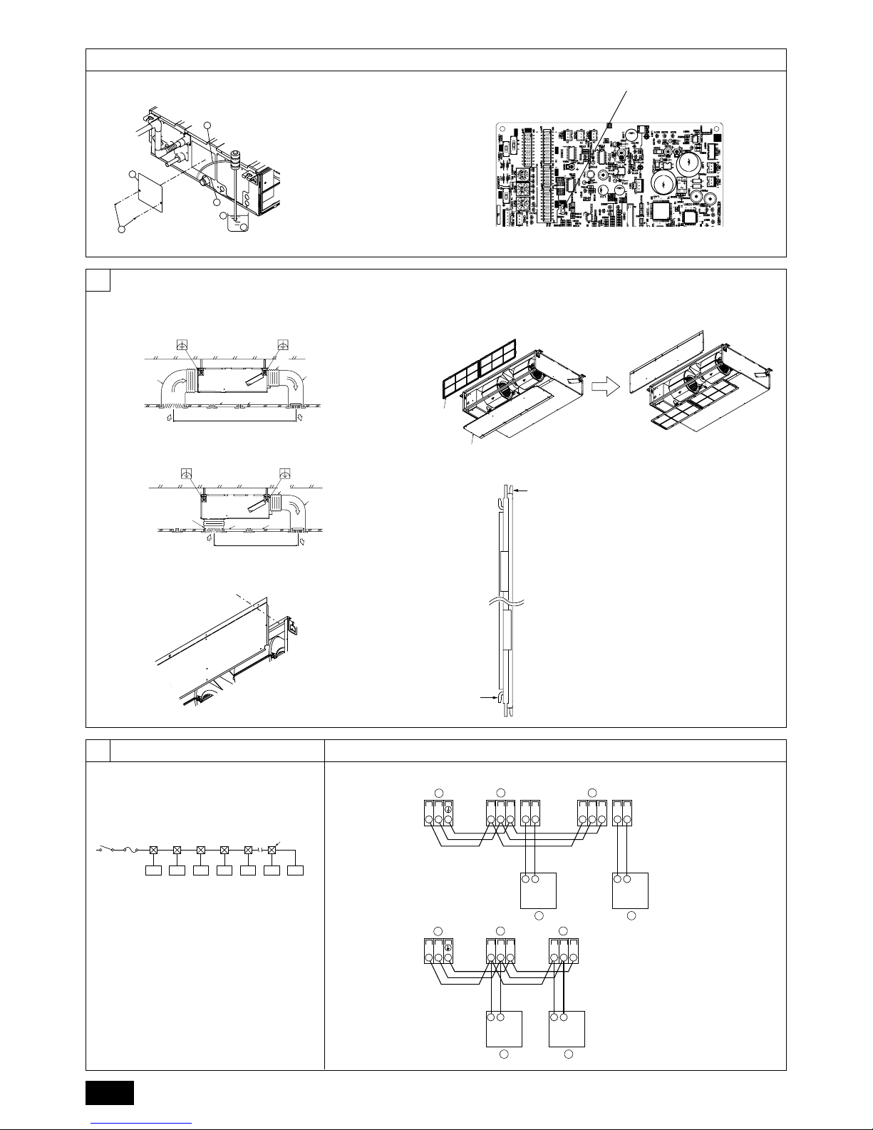
[Fig. 8.0.1] (P.4)
• Verfahren für Änderung von Einlaß von der Rückseite her zu Einlaß von der Unterseite her.
[Fig. 8.0.2] (P.4)
1. Luftfilter entfernen. (Zuerst die Filterverschlussschraube entfernen.)
2. Entfernen Sie die Platte an der Unterseite.
3. Die untere Platte an der Rückseite des Körpers anbringen. [Fig. 8.0.3] (P.4)
(Die Halteöffnungen am Blech befinden sich in einer anderen Position als die für
den hinteren Einlass.)
4. Passen Sie den Filter an die Geräteunterseite an.
(Darauf achten, auf welcher Seite des Filters die Montage erfolgt.) [Fig. 8.0.4]
(P.4)
[Fig. 8.0.4] (P.4)
Korrekte Rohrführung
Falsche Rohrführung
A Isolierung (9 mm oder mehr)
B Abwärtsneigung (1/100 oder mehr)
C Metallträger
K Entlüftung
L Erhöht
M Geruchsverschluss
D Außendurchmesser ø32 PVC-SCHLAUCH
E So groß wie möglich auslegen. Etwa 10 cm.
F Innengerät
G Stellen Sie die Rohrführung für die Sammelrohrleitung ausreichend groß her.
H Abwärtsneigung (1% oder mehr)
I Außendurchmesser ø38 PVC-SCHLAUCH für Sammelrohrleitungen. (9 mm Isolierung
oder mehr)
J Bis zu 550 mm
N Ablassschlauch (Zubehör)
O Horizontal oder leicht aufwärts führend
A Innengerät
B Binder (Zubehör)
C Sichtbarer Teil
D Einführungsgrenze
E Ablassschlauch (Zubehör)
F Ablassrohr (Außendurchmesser ø 32 PVC-SCHLAUCH, handelsüblich)
G Isolierungsmaterial (handelsüblich)
H Binder (Zubehör)
A Innengerät
B Binder (Zubehör)
C Bandbefestigungsteil
D Einführungsgrenze
E Ablassschlauch (Zubehör)
F Ablassrohr (Außendurchmesser ø 32 PVC-SCHLAUCH, handelsüblich)
G Isolierungsmaterial (handelsüblich)
A Pumpenende 2 bis 4 cm einführen.
B Abdeckung für die Wasserzuführung entfernen.
C Etwa 2500 cc
D Wasser
E Wasseranschluss
F Schraube
<Innengerätsteuerplatine>
Steckbrücke
SWE
OFF ON OFF ON
SWE
<OFF> <ON>
Steckbrücke
SWE
OFF ON OFF ON
SWE
<ON> <OFF>
<A> Bei Eingang auf der Rückseite
<B> Bei Eingang von unten
A Strömungskanal B Lufteingang
C Zugangstür D Strömungskanalteilstück aus Segeltuch
E Deckenoberfläche F Luftausgang
G Genügend Abstand halten, um Kurzschluß zu verhindern
A Filter B Bodenplatte
C Nagel für den unteren Einlass D Nagel für den hinteren Einlass
Wenn das Blech an der
Rückseite angebracht ist, ragt
es oben über die hintere
Gehäuseverkleidung hinaus.
Das Blech entlang des
Schlitzes replizieren, wenn
oben kein ausreichender
Platz für die gesamte
Einheit vorhanden ist.
Page 11

18
D
Vorsicht:
• Es muß ein Eingangsströmungskanal von 850 mm oder mehr errichtet werden.
Hauptkörper der Klimaanlage und Strömungskanal zum potentiellen Ausgleich miteinander verbinden.
• Schutzhandschuhe tragen, um die Verletzungsgefahr durch Blechkanten zu
verringern.
• Den Hauptkörper der Klimaanlage und den Strömungskanal miteindander
verbinden, für die Ausgleichung des Potentials.
• Das Ansauggeräusch steigt dramatisch an, wenn Ansaugteil A unmittelbar
neben dem Hauptkörper der Anlage angebracht wird. Ansaugteil A mub
daher soweit wie möglich vom Hauptkörper der Anlage entfernt installiert
werden.
Besondere Aufmerksamheit ist erforderlich, wenn die Anwendung gemäb
den technischen Daten für den Lufteingang von unten erfolgt.
• Zur Vermeidung von Kondenswasserbildung an den Flanschen des Strömungskanalausgangs und an den Strömungskanalausgängen ausreichend
Wärmeisolierung anbringen.
• Zwischen dem Einlaßgitter und dem Ventilator mehr als 850 mm Abstand einhalten.
Wenn der Abstand weniger als 850 mm beträgt, muß ein Schutzgitter angebracht werden, damit man nicht mit dem Ventilator in Berührung kommt.
• Keine Übertragungsleitungen unten am Gerät verlegen, um elektrische Störgeräusche zu vermeiden.
9. Elektroverdrahtung
Vorsichtsmaßnahmen bei der elektrischen Verdrahtung
Warnung:
Elektroarbeiten sollten nur durch qualifizierte Fachelektriker gemäß “Engineering Standards for Electrical Installation” - “Technische Normen für Elektroinstallation” und gemäß Installationshandbüchern vorgenommen werden. Es
sollten auch eigens eingerichtete Stromkreise verwendet werden. Wenn der
Stromkreis zu schwach ausgelegt ist oder Installationsfehler aufweist, besteht
die Gefahr von Stromschlägen oder Brand.
1. Dafür sorgen, daß ein Erdschlußstromunterbrecher in den Stromkreis installiert
wird.
2. Die Anlage so installieren, daß verhindert wird, daß eines der Steuerkreiskabel
(Fernbedienung, Übertragungskabel) in direkten Kontakt mit dem Netzstromkabel
außerhalb der Anlage gebracht werden kann.
3. Dafür sorgen, daß keiner der Elektroleitungsanschlüsse zu lose gespannt ist oder
einen Wackelkontakt aufweist.
4. Einige Kabel (für Netzstrom-, Fernbedienungs-Übertragungskabel), die oberhalb
der Decke angeordnet sind, können Mäuseverbiß ausgesetzt sein. Daher Kabel
zum Schutz soweit wie möglich in Metallrohre verlegen.
5. Netzstromkabel niemals an die Zuleitung für die Übertragungskabel anschließen,
da sonst die Kabel brechen können.
6. Dafür sorgen, daß die Innenanlage, die Fernbedienung und die Außenanlage mit
Steuerkabeln verbunden sind.
7. Die Anlage auf der Seite der Außenanlage erden.
8. Steuerkabel gemäß den auf Seite 18 angegebenen Betriebsbedingungen auswählen.
Vorsicht:
Dafür sorgen, daß die Anlage zur Seite der Außenanlage hin geerdet wird. Die
Erdleitung nicht an Gasrohre, Wasserrohre, Beleuchtungsstäbe oder Telefonerdleitungen anschließen. Unsachgemäße Erdung kann zu Stromschlägen
führen.
Steuerkabelarten
1. Übertragungskabel für die Verdrahtung
• Übertragungskabelarten
Den Schaltplan für die Verdrahtung gemäß der nachstehenden Tabelle <Tabelle
1> gestalten.
• Kabeldurchmesser
Mehr als 1,25 mm
2
<Tabelle 1>
2. Fernbedienungskabel
9.1. Netzstromverdrahtung
• Die Netzstromkabel für Geräte sollen mindestens dem Entwurf 245 IEC 57 oder
227 IEC 57 entsprechen.
• Bei der Installierung der Klimaanlage ist ein Schalter mit einem Kontaktabstand
von mindestens 3 mm für jeden Pol vorzusehen.
Netzstromkabelgröße: mehr als 1,5 mm
2
[Fig. 9.1.1] (P.4)
[Wahl des Schutzunterbrechers (NF) oder des Erdschlußunterbrechers (NV)]
Bei Wahl eines NF oder NV anstelle der Kombination einer Sicherung der Klasse B
mit einem Schalter wie folgt vorgehen:
• Wenn die Sicherung der Klasse B auf 15 A oder 20 A ausgelegt ist,
NF Modellbezeichnung (MITSUBISHI): NF30-CS (15 A) (20 A)
NV Modellbezeichnung (MITSUBISHI): NV30-CA (15 A) (20 A)
Einen Erdschlußunterbrecher mit einer Empfindlichkeit von weniger als 30 mA
0,1 Sek. verwenden.
Vorsicht:
Nur Unterbrecher und Sicherungen mit der richtigen Kapazität verwenden. Bei
Verwendung von Sicherungen, Leitungen oder Kupferleitungen mit zu großer
Leistungsaufnahme besteht die Gefahr der Fehlfunktion oder Brandgefahr.
Systemkonfiguration Für ein einzelnes Kühlsystem Für ein mehrteiliges Kühlsystem
Länge des Übertragungskabels Weniger als 120 m Mehr als 120 m Unabhängig von der Länge
Beispiel für eine Einrichtung
(zur Geräuschbeurteilung)
Bleibende oder bewegliche Lagerung
ohne Lärmentwicklung
Gebäude, Klinik, Krankenhaus oder Kommunikationsstation ohne Lärm, der vermutlich von Inverter-Einrichtungen,
privaten Stromgeneratoren, medizinischen Hochfrequenzeinrichtungen, Rundfunkeinrichtungen etc. erzeugt wird.
Alle Einrichtungen
Arten von Übertragungskabeln
VCTF, VCTFK, CVV, CVS, VVR, VVF,
VCT oder abgeschirmte Elektroleitungen CVVS oder CPEVS
Abgeschirmte Elektroleitungen CVVS oder CPEVS
Länge Weniger als 120 m Weniger als 200 m
MA-Fernbedienung M-NET-Fernbedienung
Kabelarten Umhüllte, 2-adrige Leitung (nicht abgeschirmt) CVV Umhüllte, 2-adrige Leitung (nicht abgeschirmt) CVV
Kabeldurchmesser 0,3 – 1,25 mm
2
0,3 – 1,25 mm2
Länge Weniger als 200 m
Beliebige Stücke von mehr als 10 m bis zu der größten, zulässigen Übertragungskabellänge von 200 m hinzufügen (Abschirmanteil beträgt mehr als 1,25 mm
2
)
A Schalter 16 A B Überstromschutz 16 A
C Innenanlage
D Gesamter Betriebsstrom muß weniger als 16 A betragen
E Verteilerkasten
Page 12

D
19
9.2. Anschluß der Fernbedienungs-, Innen- und
Außenübertragungskabel
• Anschluß der Innenanlage TB5 und der Außenanlage TB3. (2-adrig, nichtpolari-
siert)
Das ’S’ auf der Innenanlage TB5 ist ein abgeschirmter Leitungsanschluß. Angaben
über die technischen Daten der Anschlußkabel finden sich in den Montagehandbüchern der Außenanlage.
• Eine Fernbedienung entsprechend den Angaben im zur Fernbedienung gehören-
den Handbuch installieren.
• “1” und “2” am TB15 der Innenanlage an eine MA-Fernbedienung anschließen
(nicht polarisierte, zweiadrige Elektroleitung).
• “M1” und “M2” am TB5 der Innenanlage an eine M-NET-Fernbedienung anschlie-
ßen (nicht polarisierte, zweiadrige Elektroleitung).
• Das Übertragungskabel der Fernbedienung mit einem Kernaderkabel von
0,75 mm
2
und einer Länge bis zu 10 m anschließen. Wenn die Entfernung mehr
als 10 m beträgt, ein Verbindungskabel von 1,25 mm
2
verwenden.
[Fig. 9.2.1] (P.4) MA Fernbedienung
[Fig. 9.2.2] (P.4) M-NET-Fernbedienung
• 9 – 13 V Gleichstrom zwischen 1 und 2 (MA-Fernbedienung)
• 24 – 30 V Gleichstrom zwischen M1 und M2 (M-NET-Fernbedienung)
[Fig. 9.2.3] (P.5) MA-Fernbedienung
[Fig. 9.2.4] (P.5) M-NET-Fernbedienung
• Die MA-Fernbedienung und die M-NET-Fernbedienung können nicht gleichzeitig
oder wechselweise verwendet werden.
Vorsicht:
Die Elektroleitung so verdrahten, daß sie weder zu eng ist noch unter Zugspannung steht. Verdrahtung unter Zudspannung kann zum Brechen, Überhitzen oder Verbrennen führen.
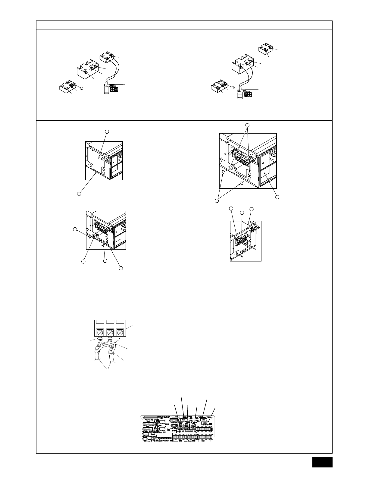
9.3. Vornahme der Elektroanschlüsse
Bitte die Modellbezeichnung im an der Abdeckung des Anschlusskastens angebrachten Betriebshandbuch mit der auf dem Typenschild angegebenen vergleichen.
1. Zum Abnehmen der Abdeckung die Halteschraube, die die Abdeckung hält (1
Stück), entfernen.
[Fig. 9.3.1] (P.5)
2. Dafür vorgesehene Öffnungen durchbrechen
(Für diese Arbeit wird ein Schraubenzieher oder ähnliches empfohlen.)
[Fig. 9.3.2] (P.5)
3. Stromversorgungskabel am Anschlussbrettkasten unter Verwendung einer Aus-
gleichsbuchse zur Aufnahme von Zugkräften anschließen. (PG-Anschluss oder
ähnlich.) Übertragungskabel an Übertragungsklemmbrett durch das Ausbrechloch des Anschlussbrettkastens mit normaler Buchse anschließen.
[Fig. 9.3.3] (P.5)
4. Stromzufuhr-, Erdungs-, Übertragungs- und Fernbedienungskabel anschließen.
Die Anschlussbrettkasten muss nicht abgebaut werden.
[Fig. 9.3.4] (P.5)
[Abgeschirmter Leitungsanschluß]
[Fig. 9.3.5] (P.5)
5. Nach Abschluss der Verkabelung die Anschlüsse auf festen Sitz prüfen und die
Abdeckung am Anschlussbrettkasten in umgekehrter Reihenfolge des Ausbaus
anbringen.
Hinweise:
• Beim Anbringen der Abdeckung des Anschlussbrettkastens darauf achten,
keine Kabel oder Drähte einzuklemmen. Andernfalls kann es zu einem Kontaktverlust kommen.
• Beim Anbringen des Anschlussbrettkastens darauf achten, dass die seitli-
chen Anschlüsse nicht entfernt werden. Andernfalls ist kein normaler
Betrieb möglich.
9.4. Technische Daten der externen Ein-/Ausgänge
Vorsicht:
1. Die Verdrahtung sollte durch ein Isolationsrohr mit zusätzlicher Isolierung
geführt werden.
2. Verwenden Sie Relais oder Schalter nach IEC-Standard oder gleichwertig.
3. Die Spannungsfestigkeit zwischen den zugänglichen Bauteilen und der
Steuerplatine sollte 2750 V oder mehr betragen.
9.5. Auswählen des statischen Außendrucks
Da die Werkseinstellung für den Gebrauch unter einem statischen Außendruck von
50 Pa ausgelegt ist, ist bei Einsatz unter normalen Bedingungen kein Schaltvorgang
notwendig.
[Fig. 9.5.1] (P.5)
9.6. Adressen einsetzen
(Dafür sorgen, daß bei den Arbeiten der Netzstrom auf AUS geschaltet ist.)
[Fig. 9.5.1] (P.5)
• Zur Einstellung gibt es zwei Arten von Rotationsschaltern: Zur Einstellung der
Adressen von 1 – 9 und über 10 sowie zur Einstellung der Abzweigungsnummern.
• Die Drehschalter sind bei Versand ab Werk alle auf “0” eingestellt.
Diese Schalter können beliebig zur Einstellung der Anlagenadressen und
Abzweignummern verwendet werden.
• Die Festlegung der Adressen der Innengeräte variiert mit der Anlage vor Ort. Stel-
len Sie diese mithilfe des Datenheftes (Data Book) ein.
9.7. Messen der Raumtemperatur mit dem in eine
Fernbedienung eingebauten Temperaturfühler
Wenn Sie die Raumtemperatur mit dem in eine Fernbedienung eingebauten Fühler
messen wollen, stellen Sie den Schalter SW1-1 auf der Schalttafel auf ’ON’/’EIN’.
Die Einstellung von SW1-7 und SW1-8 ermöglicht es auch, der Luftdurchsatz einzustellen für Phasen, in denen das Heizthermometer ausgeschaltet ist (OFF).
9.8. Die Netzspannungseinstellung ändern
(Dafür sorgen, daß bei den Arbeiten der Netzstrom auf AUS geschaltet ist.)
[Fig. 9.5.1] (P.5)
Stellen Sie den SW5-Schalter entsprechend der Netzspannung ein:
• Stellen Sie den SW5-Schalter auf 240V, wenn die Netzspannung 240 V
beträgt.
• Stellen Sie den SW5-Schalter auf 220V, wenn die Netzspannung 220 bis 230 V
beträgt.
A Klemmleiste für Übertragungskabel der Innenanlage
B Klemmleiste für Übertragungskabel der Außenanlage
C Fernbedienung
A Nicht polarisiert B TB15
C Fernbedienung D TB5
A Schraube, die die Abdeckung hält (1 Stück)
B Abdeckung
C Anschlusskasten D Loch zum Ausbrechen
E Entfernen
F Verwenden Sie eine PG-Durchführung, so dass das Gewicht des Kabels und externe
Kräfte nicht auf dem Stromversorgungsanschluss lasten. Verwenden Sie einen Kabelbinder, um das Kabel zu sichern.
G Netzstromleitung H Normale Buchsen verwenden
I Übertragungsleitung
J Anschlussblock für Stromversorgung
K Anschlussblock für Innengeräteübertragung
L Anschlussblock für Fernbedienung
A Anschlussblock B Runde Klemme
C Abgeschirmte Leitung
D Die Erdleiter beider Kabel werden gemeinsam zum Anschluss S geführt. (Stillgelegte
Verbindung)
E Isolierband (um zu verhindern, dass der Erdleiter des abgeschirmten Kabels mit dem
Übertragungsanschluss in Berührung kommt)
Statischer Außendruck Schaltvorgang
35 Pa
50 Pa
70 Pa
100 Pa
150 Pa
<Innengerätsteuerplatine>
<Innengerätsteuerplatine>
a Wie stellt man Adressen ein
Beispiel: Wenn die Adresse ’3’ ist, SW12 (für größer als 10) bei ’0’ lassen und SW11 (für 1 –
9) auf ’3’ einstellen.
b Einstellen der Zweignummern SW14 (nur Serie R2)
Die Zweignummer für jedes Innengerät ist gleichzeitig die Anschlussnummer des BC-Controllers, an dem das Innengerät angeschlossen ist.
Lassen Sie dies bei Geräten, die nicht zur Reihe R2 gehören, auf „0“ eingestellt.
3
2
1
SWA SWC
a
b
3
2
1
SWA SWC
a
b
3
2
1
SWA SWC
a
b
3
2
1
SWA SWC
a
b
3
2
1
SWA SWC
a
b
Page 13

Page 14

KB79M254H02
Please be sure to put the contact address/telephone number on
this manual before handing it to the customer.
This product is designed and intended for use in the residential,
commercial and light-industrial environment.
The product at hand is
based on the following
EU regulations:
• Low Voltage Directive 2006/95/EC
• Electromagnetic Compatibility Directive
2004/108/EC
HEAD OFFICE: TOKYO BLDG., 2-7-3, MARUNOUCHI, CHIYODA-KU, TOKYO 100-8310, JAPAN
Authorized representative in EU: MITSUBISHI ELECTRIC EUROPE B.V.
HARMAN HOUSE, 1 GEORGE STREET, UXBRIDGE, MIDDLESEX UB8 1QQ, U.K.
 Loading...