

Mitsubishi PKA-RP2.5FAL, PCA-RP2GA, PCA-RP3GA, PCA-RP4GA, PCA-RP5GA Service Technical Manual
...
SPLIT-TYPE, HEAT PUMP AIR CONDITIONERS
SERVICE TECHNICAL GUIDE
<Indoor unit>
[Model names] [Service Ref.]
PLA-RP·AA PLA-RP·AA
PLA-RP·AA1
PLA-RP·AA.UK
PLA-RP·AA1.UK
PKA-RP·GAL PKA-RP·GAL
PKA-RP·FAL PKA-RP·FAL
PCA-RP·GA PCA-RP·GA
PEA-RP·EA PEA-RP·EA.TH-A
PEAD-RP·EA PEAD-RP·EA.UK
PEAD-RP·EA1.UK
PEAD-RP·GA PEAD-RP·GA.UK
<Outdoor unit>
[Model names] [Service Ref.]
No. OCT04
REVISED EDITION-A
R410A
Revision:
• PKA-RP•GAL, PKA-RP•FAL,
PCA-RP•GA, PEAD-RP•GA,
PUHZ-RP•VHA1 and
PUHZ-RP•VHA1-A are added in
REVISED EDITION-A.
• Please void OCT04.
PUHZ-RP·VHA PUHZ-RP·VHA
PUHZ-RP·VHA1
PUHZ-RP·VHA-A
PUHZ-RP·VHA1-A
CONTENTS
1. PAIRING TABLE OF THE INDOOR AND OUTDOOR UNIT·····2
2. SPECIFICATIONS FOR ELECTRICAL WORK ·························3
3. WIRING DIAGRAM·····································································6
4. REFRIGERANT SYSTEM DIAGRAM ······································15
5. HOW TO CHECK THE PARTS ················································24
6. MICROPROCESSOR CONTROL·············································33
7. INDOOR UNIT CONTROL························································39
8. OUTDOOR UNIT CONTROL····················································47
9. DIP SWITCH FUNCTION ·························································63
10. FUNCTION SETTING ·······························································76
11. TEST RUN • REPLACEMENT OPERATION
& EMERGENCY OPERATION···················································86
12. SELF-DIAGNOSIS····································································92
13. TEST POINT DIAGRAM·························································118
14. TROUBLESHOOTING····························································127
15. SYSTEM CONTROL·······························································131
1
Heat pump type
Outdoor unit
PUHZ-RP
PEAD-RP·EA.UK
PEAD-RP·EA1.UK
PLA-RP·AA.UK
PLA-RP·AA1.UK
PEAD-RP·GA.UK
PLA-RP·AA
PLA-RP·AA1
—
—
OC293
REVISED EDITION-B
OC297
REVISED EDITION-C
PKA-RP·GAL
OC301
REVISED EDITION-A
PKA-RP·FAL
OC305
PCA-RP·GA
OC311
Indoor unit
Service
Manual No.
Service Ref.
45
Heat pump
without
electric heater
VHA VHA
VHA
1
VHA
VHA
1
VHA
VHA
1
6
3
2 2.5
VHA VHA VHA
1.6
——
—
—
—
—
—
————
———
Heat pump type
Outdoor unit
PUHZ-RP
PEA-RP·
EA.TH-A
PLA-RP·AA
PLA-RP·AA1
OC293
REVISED EDITION-B
OC299
REVISED EDITION-A
PKA-RP·FAL
PCA-RP·GA OC311
OC301
REVISED EDITION-A
Indoor unit
Service
Manual No.
Service Ref.
45
Heat pump
without
electric heater
VHA-A
VHA-A
VHA1-A
VHA-A
VHA1-A
—
VHA-A
VHA1-A
—
6
3
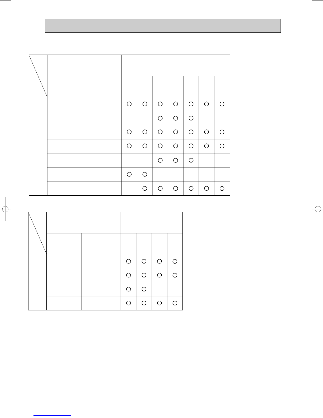
PAIRING TABLE OF THE INDOOR AND OUTDOOR UNITS
2
2
Outdoor unit p
ower supply
*1
*2
*3
*4
*4
*4
*4
Outdoor unit power supply earth
Indoor unit - Outdoor unit
Indoor unit - Outdoor unit earth
Remote controller - Indoor unit
Outdoor unit L-N
Indoor unit-Outdoor unit S1-S2
Indoor unit-Outdoor unit S2-S3
Remote controller - Indoor unit
16A
2 o Min. 1.5
1 o Min. 1.5
1 o Min. 2.5
25A
2 o Min. 2.5
1 o Min. 2.5
1 o Min. 2.5
32A
2 o Min. 4
1 o Min. 4
1 o Min. 2.5
40A
2 o Min. 6
1 o Min. 6
1 o Min. 2.5
Indoor unit model
~ / N (Single) 50Hz,
220-230-240V
2 o 0.69 (Non-polar)
AC 220-230-240V
AC220-230-240V
DC24V
DC14V
Outdoor unit power supply
Outdoor unit input capacity
Main switch (Breaker)
Wiring
Wire No. o size (mm
2
)
Circuit
rating
RP1.6, 2V RP2.5, 3V RP4, 5V RP6V
3 o 2.5 (polar)
1
2
S1
S2
S3
S1
S2
S3
Indoor/outdoor
unit connection
cable
Indoor
unit
Unit
power
supply
Outdoor
unit
Remote
controller
L
N
Grounding
L
N
1
2
1
2
S1
Indoor
unit
S2
S3
S1
S2
S3
S1
S2
S3
Unit
power
supply
Indoor/outdoor
unit connection
cable
Indoor
unit
Outdoor
unit
Remote
controller
Grounding
1
2
1
2
1
2
S1
S2
S3
S1
S2
S3
S1
S2
S3
S1
S2
S3
Indoor/outdoor
connection cable
Indoor
unit
Unit
power
supply
Indoor
unit
Indoor
unit
Outdoor
unit
Remote
controller
L
N
Grounding
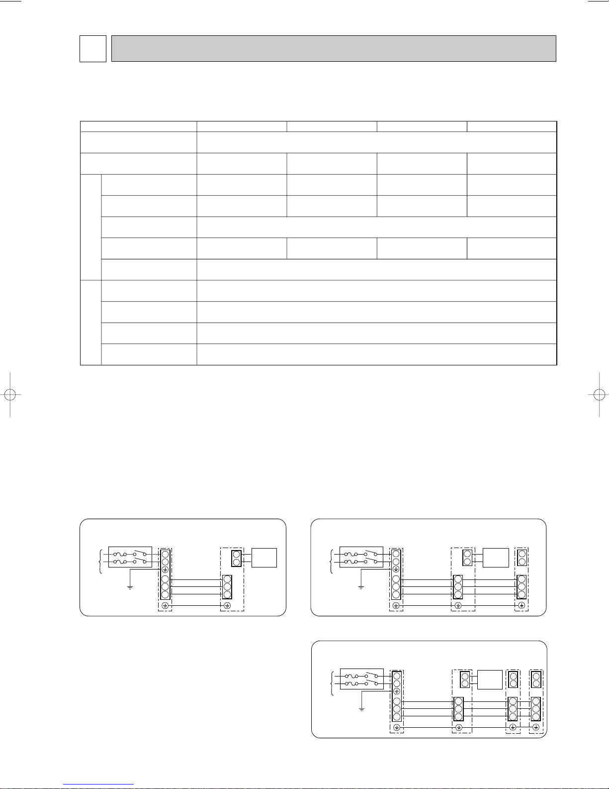
SPECIFICATIONS FOR ELECTRICAL WORK
2-1. Field electrical wiring(power wiring specifications)
PUHZ-RP•VHA
PUHZ-RP•VHA-A
*1 Abreaker with at least 3mm contact separation in each poles shall be provided.
Use non-fuse breaker (NF) or earth leakage breaker (NV).
*2 Max. 50m Total Max, including all indoor/ indoor connection is 80m.
*3 10m wire is attached in the remote controller accessory.
*4 The figures are NOT always against the ground.
S3 terminal has DC24V against S2 terminal. However, between S3 and S1, these terminals are NOT electrically insulated
by the transformer or other device.
Notes: 1. Wiring size must comply with the applicable local and national code.
2. Power supply cords and indoor/ Outdoor unit connecting cords shall not be lighter than polychloroprene
sheathed flexible cord. (design 254 IEC 57)
3. Install an earth longer and thicker than other cables.
1:1 system Synchronized twin and triple system Electrical wiring
• Synchronized twin
• Synchronized triple
3
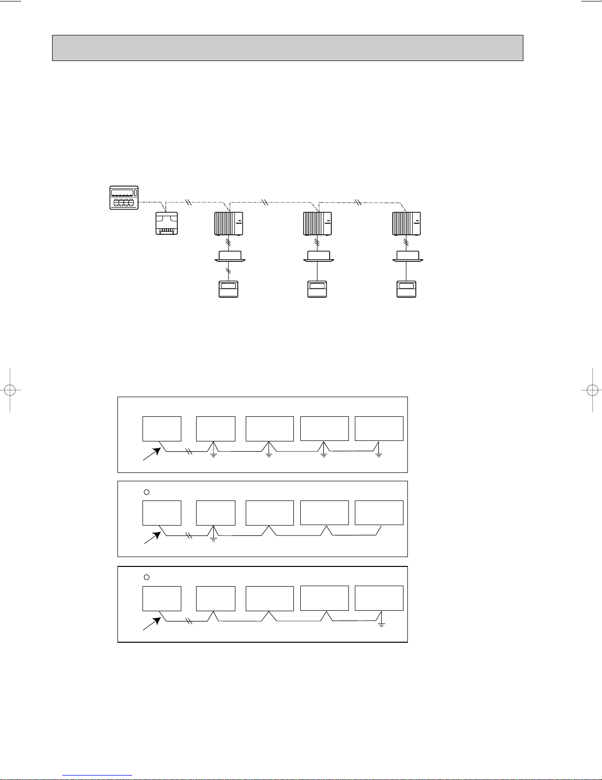
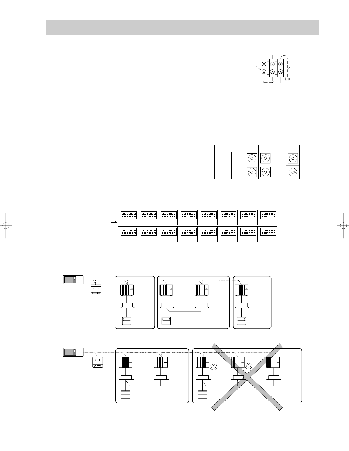
2-2. M-NET wiring method
Group
remote
controller
Refrigerant
address 00
M-NET
address 01
A-control
remote
controller
A-control
remote
controller
A-control
remote
controller
Refrigerant
address 00
M-NET
address 02
Refrigerant
address 00
M-NET
address 03
Power
supply
unit for
transmission
wire
Central
remote
controller
M-NET transmission wire
✕ Bad example (Multi spot grounding of shield wire)
Good example 1 (Single spot grounding of shield wire)
Power
supply
appliance
M-NET type
outdoor unit
Central
remote
controller
Power
supply
appliance
M-NET type
outdoor unit
M-NET type
outdoor unit
M-NET type
outdoor unit
M-NET transmission wire
M-NET type
outdoor unit
M-NET type
outdoor unit
Central
remote
controller
Power
supply
appliance
M-NET type
outdoor unit
M-NET transmission wire
M-NET type
outdoor unit
M-NET type
outdoor unit
Good example 2 (Single spot grounding of shield wire)
(Points to notice)
(1) Outside the unit, transmission wires should stay away from electric wires in order to prevent electromagnetic noise from
making an influence on the signal communication. Place them at intervals of more than 5cm. Do not put them in the same
conduit tube.
(2) Terminal block (TB7) for transmission wires should never be connected to 220~240V power supply. If it is connected,
electronic parts on M-NET p.c. board may be burn out.
(3) Use 2-core x 1.25mm2shield wire (CVVS, CPEVS) for the transmission wire. Transmission signals may not be sent or
received normally if different types of transmission wires are put together in the same multi-conductor cable. Never do this
because this may cause a malfunction.
It would be ok if M-NET wire (non-polar, 2-cores) is arranged in addition to the wiring for A-control.
(4) Ground only one of any appliances through M-NET transmission wire (shield wire). Communication error may occur due to
the influence of electromagnetic noise.
“Ed” error will appear on the LED display of outdoor unit.
“0403” error will appear on the central-control remote controller.
If there are more than two grounding spots on the shield wire, noise may enter into the shield wire because the ground wire
To avoid communication errors caused by noise, make sure to observe the single spot grounding method described in the
and shield wire form one circuit and the electric potential difference occurs due to the impedance difference among grounding spots. In case of single spot grounding, noise does not enter into the shield wire because the ground wire and shield
wire do not form one circuit.
installation manual.
4
1
2
3
4
5
6
7
8
9
0
1
2
3
4
5
6
7
8
9
0
1
2
3
4
5
6
7
8
9
0
1
2
3
4
5
6
7
8
9
0
1
2
3
4
5
6
7
8
9
0
1
2
3
4
5
6
7
8
9
0
12
~
50
M-NET Address No.
<Setting example>
Switng
setting
SW11
ones
digit
SW12
tens
digit
OFF
ON
1
2
3
4
5
6
1
2
3
4
5
6
1
2
3
4
5
6
1
2
3
4
5
6
1
2
3
4
5
6
1
2
3
4
5
6
1
2
3
4
5
6
1
2
3
4
5
6
1
2
3
4
5
6
1
2
3
4
5
6
1
2
3
4
5
6
1
2
3
4
5
6
1
2
3
4
5
6
1
2
3
4
5
6
1
2
3
4
5
6
1
2
3
4
5
6
0
Refuigrant
address
OFF
ON
8
OFF
ON
1
OFF
ON
9
OFF
ON
10
OFF
ON
11
OFF
ON
12
OFF
ON
13
OFF
ON
14
OFF
ON
15
OFF
ON
2
OFF
ON
3
OFF
ON
4
OFF
ON
5
OFF
ON
6
OFF
ON
7
System
controller
A-control
remote
controller
Group A Group B Group C
A-control
remote
controller
TB5
A-control
remote
controller
Refrigerant
address 00
M-NET
address 01
Refrigerant
address 00
M-NET
address 02
Refrigerant
address 01
M-NET
address 03
Refrigerant
address 00
M-NET
address 04
Power
supply
unit for
transmission
wire
A-control
remote
controller
A-control
remote
controller
TB5
Group A Group B
Refrigerant
address 00
M-NET
address 01
Refrigerant
address 01
M-NET
address 02
Refrigerant
address 00
M-NET
address 04
Refrigerant
address 01
M-NET
address 03
Refrigerant
address 02
M-NET
address 05
System
controller
Power
supply
unit for
transmission
wire
● M-NET wiring
(1) Use 2-core x 1.25mm
(Excluding the case connecting to system controller.)
(2) Connect the wire to the M-NET terminal block.Connect one core of the
transmission wire (non-polar) to Aterminal and the other to B. Peel the
shield wire, twist the shield part to a string and connect it to S terminal.
(3) In the system which several outdoor units are being connected, the terminal
(A, B, S) on M-NET terminal block should be individually wired to the other
2
shield wire for electric wires.
M-NET
terminal
block
ABS
Transmission
wire
Shield
part
Ground
wire
outdoor unit’s terminal, i.e. Ato A, B to B and S to S.In this case, choose one of those outdoor units and drive a screw
to fix an ground wire on the plate as shown on the right figure.
2-2-1. M-NET address setting
In A-control models, M-NET address and refrigerant address should be set only for the outdoor unit. Similar to Free Combo
system, there is no need to set the address of outdoor unit and remote controller. To construct a central control system, the
setting of M-NET address should be conducted only upon the outdoor unit. The setting range should be 1 to 50 (the same as
that of the indoor unit in Free Combo system), and the address number should be consecutively set in a same group.
Address number can be set by using rotary switches
(SW11 for ones digit and SW12 for tens digit), which
is located on the M-NET board of outdoor unit.
(Factory setting: all addresses are set to “0”.)
2-2-2. Refrigerant address setting
In case of multiple grouping system (multiple refrigerant circuits in one group), indoor units should be connected by remote
controller wiring (TB5) and the refrigerant address needs to be set. Leave the refrigerant addresses to “00” if the group setting is not conducted. Set the refrigerant address by using DIP SW1-3 to -6 on the outdoor controller board. [Factory setting:
all switches are OFF. (All refrigerant addresses are “00”.)]
2-2-3. Regulations in address settings
In case of multiple grouping system, M-NET and refrigerant address settings should be done as explained in the above section. Set the lowest number in the group for the outdoor unit whose refrigerant address is “00” as its M-NET address.
w Refrigerant addresses can be overlapped if they are in the different group.
w In group B, M-NET address of the outdoor unit whose refrigerant address is “00” is not set to the minimum in the group. As
“3” is right for this situation, the setting is wrong. Taking group A as a good sample, set the minimum M-NET address in
the group for the outdoor unit whose refrigerant address is “00”.
5
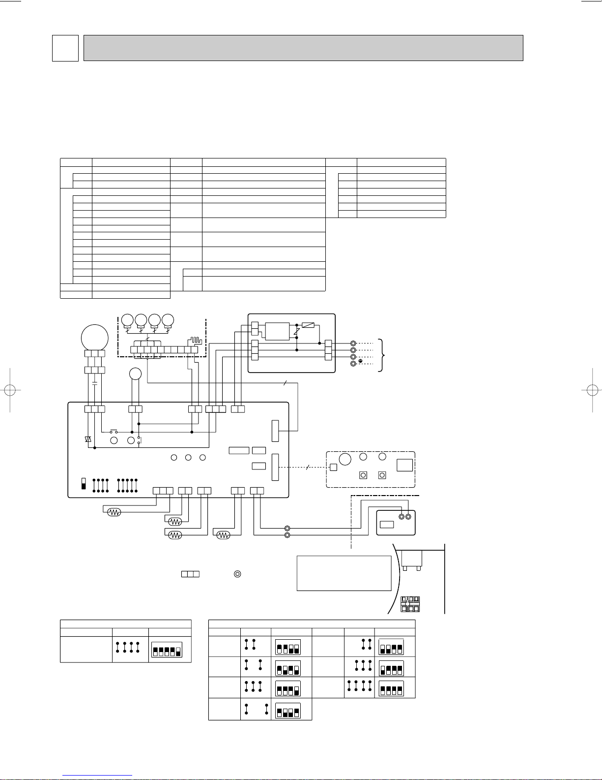
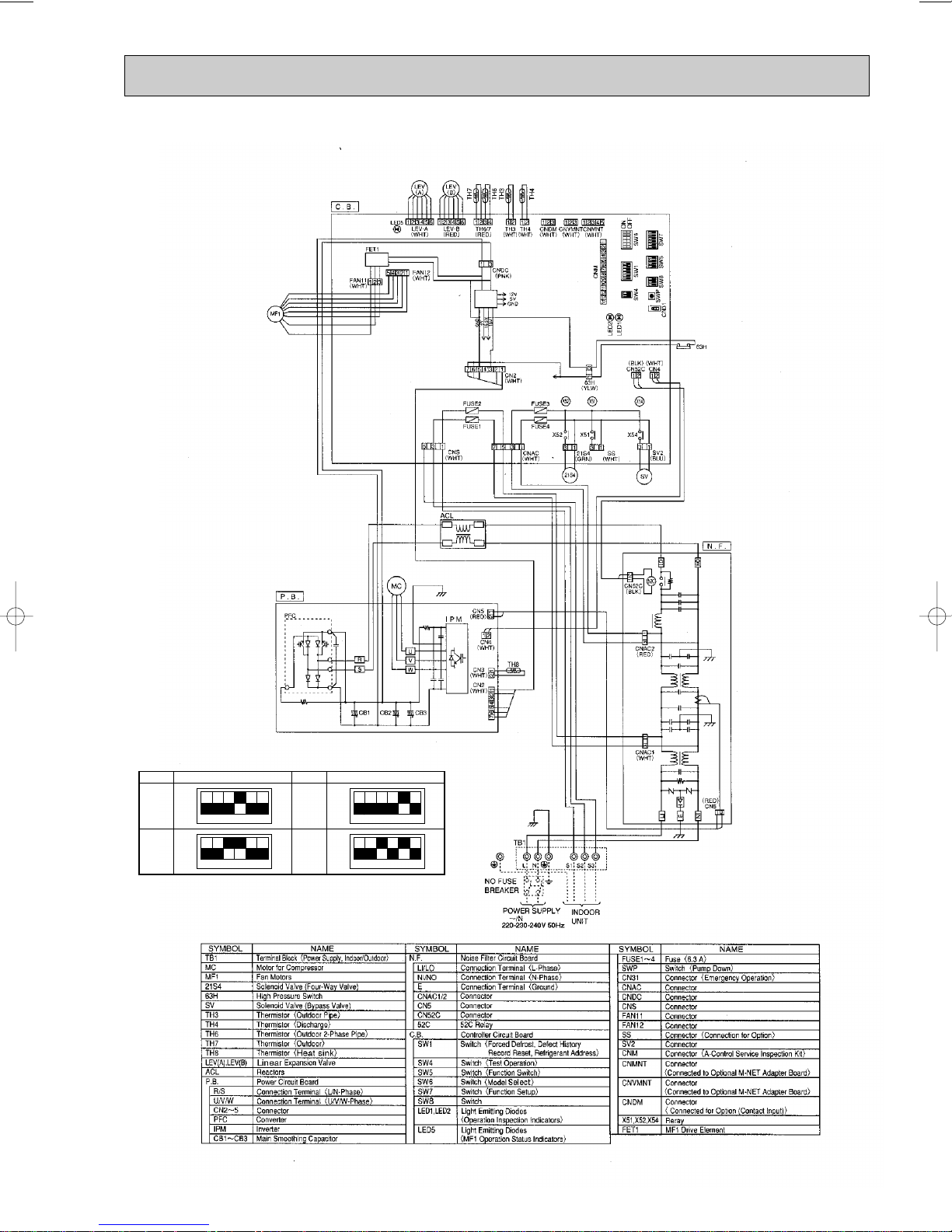
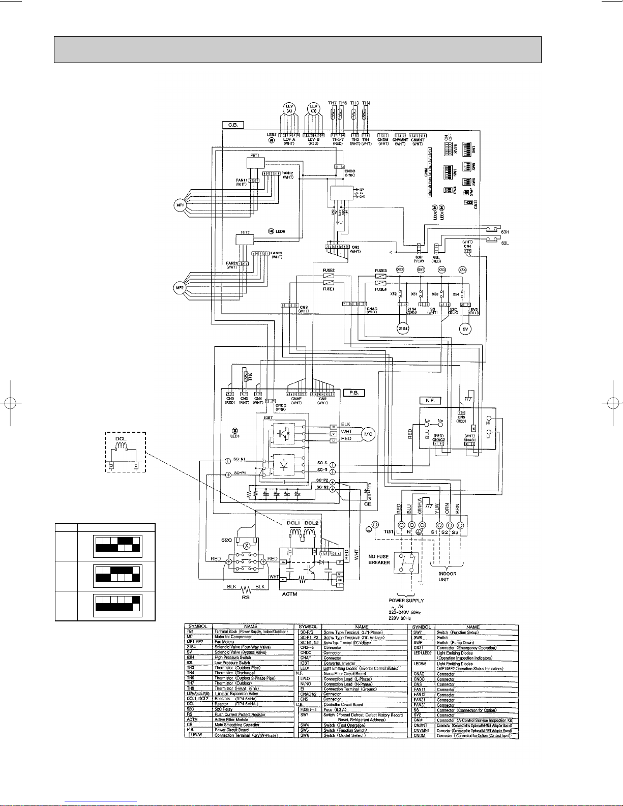
3 WIRING DIAGRAM
[Servicing]
Fasten terminal of the terminal board "TB4" equips lock system.
To remove the fastened terminal, pull it while pressing the protruding portion (locking lever) of
the terminal. The fastened terminal protruding portion should face upward.
NOTES:
1.Since the outdoor side electric wiring may change be sure to
check the outdoor unit electric wiring for servicing.
2.Indoor and outdoor connecting wires are made with polarities, make
wiring matching terminal numbers (S1,S2,S3).
3.Symbols used in wiring diagram above are, :Connector, :Terminal (block).
Please set the voltage using
the remote controller.
For the setting method, please
refer to the indoor unit Installation
Manual.
TO OUTDOOR UNIT
C
TB4
H2
5
GRILLE
MV
MVMVMV
5
5
5
5
PLA-RP4AA
PLA-RP4AA1
TRANSMISSION
WIRES DC12V
MODELS
Manufacture
Service board
MODELS
Manufacture
Service board
SW1
BLK
BLK
BLK
BLK
BLK
BLK
BLU
BLU
TH5
12
PIPE
CN29
(BLK)
REMOCON
CN22
(BLU)
WIRELESS
CN90
(WHT)
SW1
SW2
SWE
VANE
CN6V
(WHT)
POWER
CN03
(RED)
POWER
CN2D
(WHT)
LIQUID
CN21
(WHT)
INTAKE
CN20
(RED)
D.SENSOR
CN31
(WHT)
D.HEATER
CNC (RED)
D.U.M
CNP
(BLU)
FAN
(WHT)
BRN
ORN
YLW
CONTROLLER BOARD
CN02 (WHT)
OUTDOOR UNIT
CN01 (BLU)
CN2S(WHT)
BLK
WHT
YLW
ORN
BRN
YLW
YLW
YLW
YLW
BLK
RED
WHT
CNB
W.B
LED1
LED2
BZ
RU
SW1 SW2
X4
X4
J15
J22J21 J24J23
J22J21 J24J23
J22J21 J24J23
J22J21 J24J23
OFF
ON
OFF
ON
4321
OFF
ON
4321
OFF
ON
4321
OFF
ON
4321
4321
J21J22J23J24
PLA-RP3AA
PLA-RP3AA1
R.B
9
X1
X1
5
31
CN32
CN2LCN41
123
12315
TH1
2
TB5
1
12
TB6
CN2
TH2
DS
3
2
1
DC14V
1
2
3
12
J11
J12
J13
J14
2
121
LED1LED2LED3
ZNR
DP
3
FC
531
1
1
2
ON
OFF
J21
J22
J23
J24
C
MF
I.B
321
P.B
F1
TB4
S1
S2
S3
PLA-RP1.6,2,2.5AA
PLA-RP3,4,5,6AA
PLA-RP3,4,5,6AA
1
1
J11J12J13J142J15
345
ON
OFF
SW2
PLA-RP5AA1
PLA-RP6AA
PLA-RP6AA1
MODELS
Manufacture
Service board
J22J21 J24J23
OFF
ON
OFF
ON
4321
4321
J21J22J23J24
PLA-RP5AA
PLA-RP1.6AA
PLA-RP2AA
PLA-RP2.5AA
10
5
984
7
6321
123
CONNECTOR (PROGRAM TIMER)
TRANSMISSION LINE)
TERMINAL BLOCK (REMOTE CONTROLLER
REMOTE CONTROLLER BOARD
(0:/15kΩ, 25:/5.4kΩ DETECT)
COND./EVA. TEMPERATURE THERMISTOR
(0:/15kΩ, 25:/5.4kΩ DETECT)
PIPE TEMPERATURE THERMISTOR/LIQUID
(0:/15kΩ, 25:/5.4kΩ DETECT)
ROOM TEMPERATURE THERMISTOR
TRANSMISSION LINE)
TERMINAL BLOCK (REMOTE CONTROLLER
TERMINAL BLOCK (INDOOR/OUTDOOR CONNECTING LINE)
CN2
TB6
R.B
TH5
TH2
TH1
TB5
TB4
DEW PREVENTION HEATERH2
W.B
SYMBOL NAME
WIRELESS REMOTE CONTROLLER BOARD
RECEIVING UNIT
BUZZER
LED (HOT ADJUST)
SWITCH (HEATING ON/OFF)
LED (RUN INDICATOR)
BZ
LED1
RU
LED2
SW1
SW2
SWITCH (COOLING ON/OFF)
SYMBOL
SYMBOL
NAME
NAME
I.B
INDOOR POWER BOARD
FUSE (4A)
VARISTOR
INDOOR CONTROLLER BOARD
CN2L
CN32
CN41
SW1
SW2
SWE
X1
X4
FC
CONNECTOR (LOSSNAY)
CONNECTOR (REMOTE SWITCH)
CONNECTOR (HA TERMINAL-A)
JUMPER WIRE (MODEL SELECTION)
JUMPER WIRE (CAPACITY CORD)
SWITCH (EMERGENCY OPERATION)
RELAY (DRAIN PUMP)
RELAY (FAN MOTOR)
FAN PHASE CONTROL
C
CAPACITOR (FAN MOTOR)
MF
FAN MOTOR
DP
DS DRAIN SENSOR
P.B
ZNR
F1
DRAIN PUMP
LED1
LED2
POWER SUPPLY (I.B)
POWER SUPPLY (I.B)
MV
VANE MOTOR
LED3
TRANSMISSION (INDOOR-OUTDOOR)
[LEGEND]
PLA-RP1.6AA PLA-RP2AA PLA-RP2.5AA
PLA-RP1.6AA.UK PLA-RP2AA.UK PLA-RP2.5AA.UK
PLA-RP3AA PLA-RP4AA PLA-RP5AA PLA-RP6AA
PLA-RP3AA1 PLA-RP4AA1 PLA-RP5AA1 PLA-RP6AA1
PLA-RP3AA.UK PLA-RP4AA.UK PLA-RP5AA.UK PLA-RP6AA.UK
PLA-RP3AA1.UK PLA-RP4AA1.UK PLA-RP5AA1.UK PLA-RP6AA1.UK
6
PKA-RP1.6GAL PKA-RP2GAL
3.While pointing the remote controller toward the unit's
receiver, press the h button.
· The check code will be indicated by the number of times
that the buzzer sounds from the receiver section and the
number of blinks of the operation lamp.
4.While pointing the remote controller toward the unit's
receiver, press the ON/OFF button.
· Self-check mode is canceled.
▲
▼
An explanation of the wireless remote controller self checking operations,check codes,buzzer sounds and LED signals are given
below. For check codes and symptom see the table below please.
Triple beep
No sound
Sounds other than
above
Double beepo1
Single beepo2
Single beepo8
Single beepo6
Single beepo2
Single beepo1
Buzzer sound
No trouble generated in the past.
Check code
P1
P2
Abnormality of room temperature thermistor(TH1).
Symptom
Abnormality of pipe temperature thermistor/Liquid(TH2).
P6
P8
E6~EF
F1~F9
---FFFF
Abnormality of signal transmission between indoor unit and outdoor unit
("EE" indicates abnormality of combination).
Freezing /overheating protection is working.
Abnormality of pipe temperature.
No corresponding unit.
P9
Abnormality of pipe temperature thermistor/ Cond./Eva.(TH5).
Abnormality in outdoor unit. Refer to outdoor unit wiring diagram.
U0~UL
Operation lamp
1SEC.FLASHo1
1SEC.FLASHo2
1SEC.FLASHo6
1SEC.FLASHo8
1SEC.FLASHo2
(0.4+0.4)SEC.FLASHo1
OFF
OFF
DIFFERENT FROM ABOVE
1.Press the CHECK button twice continuously.
· CHECK begins to light and refrigerant address display
"00" begins to blink.
· Start this operation from the status of remote controller
display turned off.
2.Press the TEMP , buttons.
· Set the refrigerant address of the indoor unit that is to
be self-diagnosed.
· Set the refrigerant address of outdoor unit by outdoor unit
dip switch "SW1".
(Refer to installation manual of outdoor unit for the detail.)
6
MV
VANE
CN6V
(WHT)
TO OUTDOOR UNIT
9
[Self-diagnosis]
TERMINAL BLOCK(INDOOR/OUTDOOR
Manufacture Service board
J24J23J22J21
OFF
1ON432
MODELS
2GAL
SW2
J24J23J22J21
Manufacture
OFF
1ON432
Service board
MODELS
1.6GAL
SW1
Manufacture Service board
J15J14J13J12J11
OFF
ON
54321
BUZZERBZ
RU RECEIVING UNIT
WIRELESS REMOTE CONTROLLER BOARDW.B
REMOTE CONTROLLER BOARD(OPTION)R.B
CN2
TB6
CONNECTOR(PROGRAM TIMER)
TRANSMISSION LINE)
TERMINAL BLOCK(REMOTE CONTROLLER
Please set the voltage using the
remote controller.
For the setting method,please refer to
the indoor unit Installation Manual.
9
TRANSMISSION(INDOOR-OUTDOOR)LED3
VANE MOTORMV
POWER SUPPLY(R.B)
POWER SUPPLY(I.B)
LED2
LED1
NOTES:
:Connector, :Terminal (block).
2.Indoor and outdoor connecting wires are made with polarities,make wiring matching terminal numbers(S1,S2,S3).
4.Symbols used in wiring diagram above are,
3.Make sure that the main power supply of the booster heater is independent.
1.Since the outdoor side electric wiring may change be sure to check the outdoor unit electric wiring for servicing.
SWITCH(COOLING ON/OFF)SW2
SW1
LED2
LED1 LED(RUN INDICATOR)
SWITCH(HEATING ON/OFF)
LED(HOT ADJUST)
COND./EVA.TEMP.THERMISTOR
(0°C/15k",25°C/5.4k" DETECT)
NAME
TRANSMISSION LINE)(OPTION)
TERMINAL BLOCK(REMOTE CONTROLLER
TB5
F1
ZNR
P.B
PIPE TEMP.THERMISTOR/LIQUID
TH5
TH2
TH1 ROOM TEMP.THERMISTOR
(0°C/15k",25°C/5.4k" DETECT)
(0°C/15k",25°C/5.4k" DETECT)
CONNECTING LINE)
TB4
FAN MOTORMF
CAPACITOR(FAN MOTOR)C
FAN PHASE CONTROL
RELAY(FAN MOTOR)
SWITCH(EMERGENCY OPERATION)
JUMPER WIRE(CAPACITY CORD)
JUMPER WIRE(MODEL SELECTION)
CONNECTOR(HA TERMINAL-A)
CONNECTOR(REMOTE SWITCH)
CONNECTOR(LOSSNAY)
FC
X4
SWE
SW2
SW1
CN41
CN32
CN2L
INDOOR CONTROLLER BOARD
VARISTOR
FUSE(4A)
INDOOR POWER BOARD
I.B
NAME SYMBOL
NAME SYMBOLSYMBOL
ZNR
R.B
F1
OUTDOOR
CN01(BLU)
P.B
3
2
1
CONT.BOARD
CN02(WHT)
CN2S(WHT)
DC14V
CN2
TB6
21
1
TB5
2
FAN
(WHT)
LED3 LED2 LED1
INDOOR UNIT
12 12
J14
J13
J12
J11
OFF
ON
SWE SW1SW2
21
D.SENSOR
CN31
(WHT)
INTAKE
CN20
(RED)
LIQUID
CN21
(WHT)
REMOCON
CN22
(BLU)
POWER
CN2D(WHT)
POWER
CN03
(RED)
123
1
2
3
2
1
1
I.B
TH1
5
MF
C
35
FC
13 21
321
CN41
CN2L
X4
J15
X4
TH2 TH5
PIPE
CN29
(BLK)
2
1
WIRELESS
CN90
(WHT)
RED
YLW
CN25
CN32
BRN
ORN
BRN
ORN
YLW
WHT
BLK
WHT
BLK
TRANSMISSION WIRES DC12V
TB4
S1
S2
S3
RECEIVER
RU
CNB
LED2
BZ
LED1 SW1SW2
W.B
J21
J22
J23
J24
21
HEATER
CN24
(YLW)
]
7
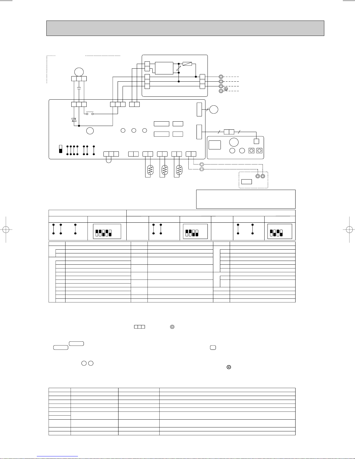
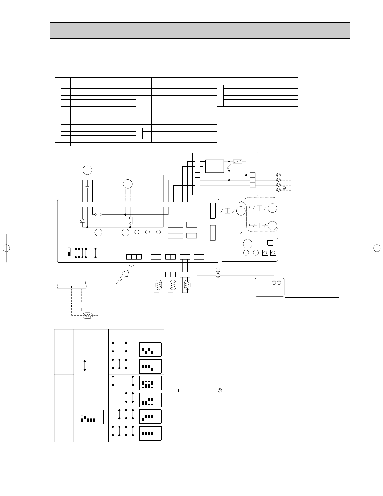
PKA-RP2.5FAL PKA-RP3FAL PKA-RP4FAL
INDOOR POWER BOARD
P.B
F1
FUSE(4A)
ZNR
VARISTOR
INDOOR CONTROLLER BOARD
I.B
CN2L
CONNECTOR(LOSSNAY)
CN32
CONNECTOR(REMOTE SWITCH)
CN41
CONNECTOR(HA TERMINAL-A)
SW1
JUMPER WIRE(MODEL SELECTION)
SW2
JUMPER WIRE(CAPACITY CODE)
SWE
SWITCH(EMERGENCY OPERATION)
X4
RELAY(FAN MOTOR)
FC
FAN PHASE CONTROL
LED1
POWER SUPPLY(I.B)
LED2
POWER SUPPLY(R.B)
LED3
TRANSMISSION(INDOOR-OUTDOOR)
INDOOR UNIT
MF
321
C
I.B
FAN
(WHT)
ON
OFF
Manufacture
Service board
1
FC
SWE SW1SW2
SW1
54321
ON
OFF
WHT
RED
35
J21
J15J14J13J12J11
BLK
J22
J23
J24
MODELS
2.5FAL
3FAL
4FAL
X4
X4
J11
POWER
J13
J12
CN03
(RED)
J14
J15
Manufacture
BRN
YLW
ORN
5
13 21
LED3LED2LED1
SW2
Service board
1ON432
J24J23J22J21
1ON432
J24J23J22J21
1ON432
J24J23J22J21
MF FAN MOTOR
TB4
TB5
TH1 ROOM TEMPERATURE THERMISTOR
TH2
TH5
POWER
CN2D (WHT)
CAPACITOR(FAN MOTOR)C
VANE MOTORMV
TERMINAL BLOCK(INDOOR/OUTDOOR
CONNECTING LINE)
TERMINAL BLOCK(REMOTE CONTROLLER
TRANSMISSION LINE)(OPTION)
(0°C/15kΩ, 25°C/5.4kΩ DETECT)
PIPE TEMPERATURE THERMISTOR/LIQUID
(0°C/15kΩ, 25°C/5.4kΩ DETECT)
CONDENSER / EVAPORATOR TEMPERATURE
THERMISTOR (0°C/15kΩ, 25°C/5.4kΩ DETECT)
CN2S(WHT)
2
DC14V
1
3
2
1
CONT.BOARD
CN02 (WHT)
WHT
BLK
CN41 CN2L
CN25 CN32
LIQUID
INTAKE
HEATER
CN20
CN24
(YLW)
OFF
OFF
OFF
21
CN21
(RED)
(WHT)
12 12
TH1
NOTES:
1.Since the outdoor side electric wiring may change be sure to check the outdoor unit electric wiring for servicing.
2.Indoor and outdoor connecting wires are made with polarities, make wiring matching terminal numbers(S1, S2, S3).
3.Symbols used in wiring diagram above are, :Connector, :Terminal (block).
[Self-diagnosis]
An explanation of the wireless remote controller self checking operations, check codes, buzzer sounds and LED signals are given
below. For check codes and symptom see the table below please.
1.Press the CHECK button twice continuously.
• CHECK begins to light and refrigerant address display
"00" begins to blink.
• Start this operation from the status of remote controller
display turned off.
2.Press the TEMP ▼ , ▲ buttons.
• Set the refrigerant address of the indoor unit that is to
be self-diagnosed.
• Set the refrigerant address of outdoor unit by outdoor unit
dip switch "SW1".
(Refer to installation manual of outdoor unit for the detail.)
Check code
U0~UL
F1~F9
E6~EF
Operation lamp
1SEC.FLASH ✕ 1
P1
1SEC.FLASH ✕ 2
P2
P4 1SEC.FLASH ✕ 4 Abnormality of drain sensor(DS).
P5 1SEC.FLASH ✕ 5 Malfunction of drain-up machine.
1SEC.FLASH ✕ 6
P6
1SEC.FLASH ✕ 8
P8
1SEC.FLASH ✕ 2
P9
(0.4+0.4)SEC.FLASH ✕ 1
DIFFERENT FROM ABOVE
OFF
---OFF
FFFF
Buzzer sound
Single beep ✕ 1
Single beep ✕ 2
Single beep ✕ 4
Single beep ✕ 5
Single beep ✕ 6
Single beep ✕ 8
Single beep ✕ 2
Double beep ✕ 1
Sounds other than
above
No sound
Triple beep
Abnormality of room temperature thermistor(TH1).
Abnormality of pipe temperature thermistor/Liquid(TH2).
Freezing /overheating protection is working.
Abnormality of pipe temperature.
Abnormality of pipe temperature thermistor/ Condenser/Evaporator(TH5).
Abnormality in outdoor unit. Refer to outdoor unit wiring diagram.
Abnormality of signal transmission between indoor unit and outdoor unit
("EE" indicates abnormality of combination).
No trouble generated in the past.
No corresponding unit.
NAME SYMBOLNAME SYMBOLSYMBOL
ZNR
OUTDOOR
CN01 (BLU)
VANE
CN6V
(WHT)
WIRELESS
CN90
(WHT)
REMOCON
PIPE
CN22
CN29
(BLU)
(BLK)
21
F1
21
W.B
R.B
P.B
YLW
1
ORN
2
BRN
3
MV
6
2
1
TH2 TH5
3.While pointing the remote controller toward the unit's
receiver, press the h button.
• The check code will be indicated by the number of times
that the buzzer sounds from the receiver section and the
number of blinks of the operation lamp.
4.While pointing the remote controller toward the unit's
receiver, press the ON/OFF button.
• Self-check mode is canceled.
TB5
WIRELESS REMOTE CONTROLLER BOARD
RU RECEIVING UNIT
BUZZERBZ
LED1 LED(RUN INDICATOR)
LED2
LED(HOT ADJUST)
SW1
SWITCH(HEATING ON/OFF)
SWITCH(COOLING ON/OFF)SW2
REMOTE CONTROLLER BOARD(OPTION)
CN2
CONNECTOR(SCHEDULE TIMER)
TERMINAL BLOCK(REMOTE CONTROLLER
TB6
TRANSMISSION LINE)
TB4
S1
S2
TO OUTDOOR UNIT
S3
9
W.B
RECEI
-VER
RU
CNB
BZ
LED2
LED1 SW1SW2
TRANSMISSION WIRES DC12V
Please set the voltage
using the remote controller.
For the setting method,
please refer to the indoor
unit Installation Manual.
Symptom
NAME
TB6
R.B
12
CN2
8
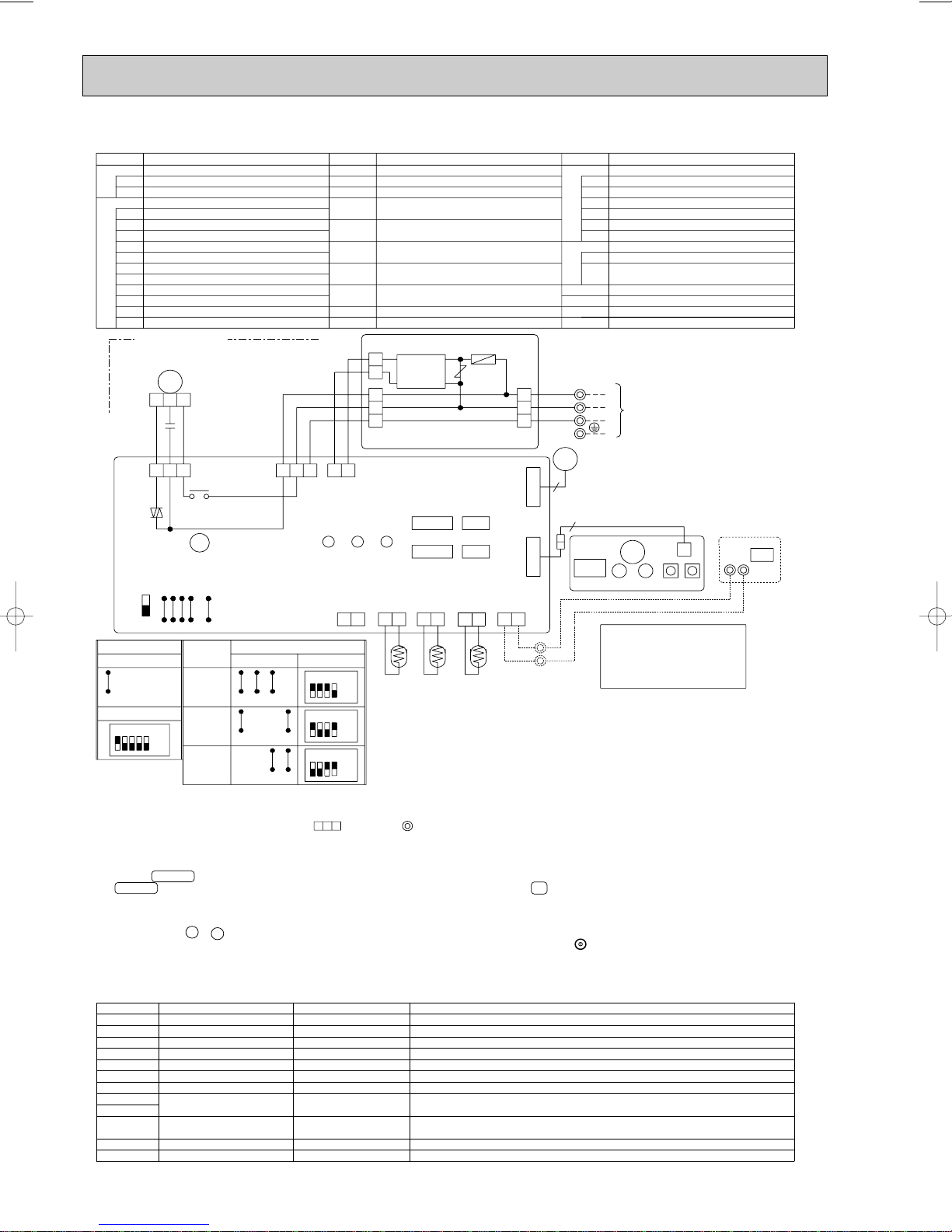
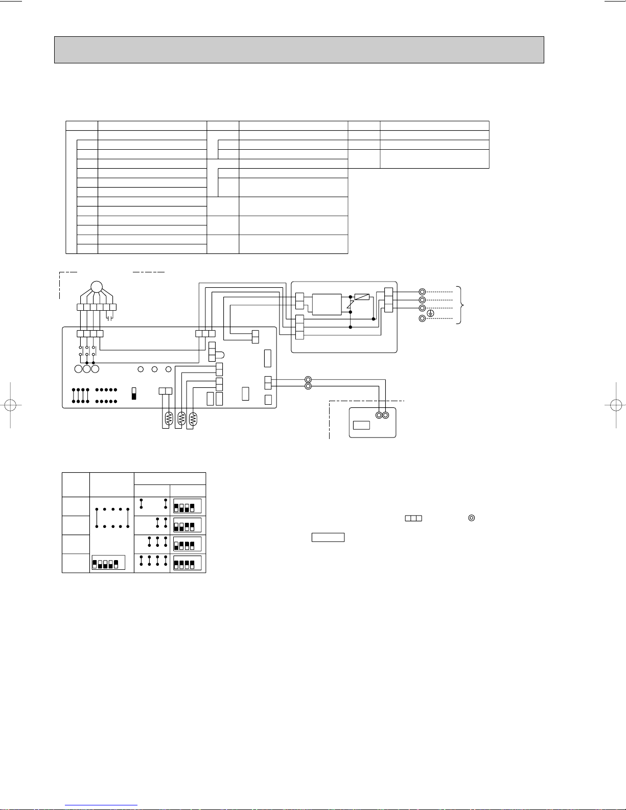
PCA-RP2GA PCA-RP2.5GA PCA-RP3GA
Service board
234
ON
1
OFF
234ON1
OFF
234ON1
OFF
234ON1
OFF
234ON1
OFF
OFF
ON
4321
Manufacture
<For service board>
<For manufacture>
OFF
ON
54321
J21
J21
J21
J21
J21
J21
J22
J22
J22
J22
J22
J22J23
J23
J23
J23
J23
J23
J24
J24
J24
J24
J24
J24
J15J14J13J12J11
MODELS
SW1
SW2
2GA
2.5GA
3GA
4GA
5GA
6GA
[Self-diagnosis]
1.For details on how to operate self-diagnosis with the wireless
remote control,refer to the technical manuals etc.
[Emergency operation procedure]
1.When the wired remote control or the indoor unit microcomputer has failed,but all other
components work properly, if you set the switch(SWE) on the indoor control panel ON,the indoor
unit will begin Emergency Operation.
When Emergency Operation is activated, the indoor unit operates as follows:
(1)Indoor fan is running at high speed.
(2)Drain-up machine(optional) is working.
NOTES:
2.Indoor and outdoor connecting wires are made with polarities,make
wiring matching terminal numbers(S1,S2,S3).
4.Symbols used in wiring diagram above are,
3.Make sure that the main power supply of the booster heater is
independent.
1.Since the outdoor side electric wiring may change be sure to
check the outdoor unit electric wiring for servicing.
:Connector, : Terminal (block).
[Servicing]
CN31 DRAIN SENSOR
When installing drain-up
machine(Optional part).
WWhen installing optional
drain-up machine,disconnect
the CN31 jumper connector
and replace it with the
drain sensor(DS).
Fasten terminal of the terminal board "TB4" equips lock system.
To remove the fastened terminal,pull it while pressing the protruding
portion(locking lever)of the terminal.The fastened terminal protruding
portion should face upward.
TRANSMISSION(INDOOR-OUTDOOR)LED3
VANE MOTORMV
POWER SUPPLY(R.B)
POWER SUPPLY(I.B)
LED2
LED1
SWITCH(COOLING ON/OFF)SW2
SW1
LED2
RU
BZ
W.B
LED(RUN INDICATOR)
SWITCH(HEATING ON/OFF)
LED(HOT ADJUST)
BUZZER
RECEIVING UNIT
WIRELESS REMOTE CONTROLLER BOARD(OPTION)
TERMINAL BLOCK(REMOTE CONTROLLER
TRANSMISSION LINE)
CONNECTOR(SCHEDULE TIMER)
REMOTE CONTROLLER BOARD
TB6
CN2
COND./EVA.TEMP.THERMISTOR
(0:/15k",25:/5.4k" DETECT)
NAME
R.B
DRAIN-UP MACHINE(OPTION)
TRANSMISSION LINE)
TERMINAL BLOCK(REMOTE CONTROLLER
TB5
F1
ZNR
P.B
PIPE TEMP.THERMISTOR/LIQUID
TH5
TH2
TH1 ROOM TEMP.THERMISTOR
(0:/15k",25:/5.4k" DETECT)
(0:/15k",25:/5.4k" DETECT)
TERMINAL BLOCK(INDOOR/OUTDOOR CONNECTING LINE)
TB4
DRAIN SENSOR(OPTION)DS
DP
FAN MOTORMF
CAPACITOR(FAN MOTOR)C
FAN PHASE CONTROL
RELAY(FAN MOTOR)
RELAY(DRAIN PUMP)
SWITCH(EMERGENCY OPERATION)
JUMPER WIRE(CAPACITY CORD)
JUMPER WIRE(MODEL SELECTION)
CONNECTOR(HA TERMINAL-A)
CONNECTOR(REMOTE SWITCH)
CONNECTOR(LOSSNAY)
FC
X4
X1
SWE
SW2
SW1
CN41
CN32
CN2L
INDOOR CONTROLLER BOARD
VARISTOR
FUSE(4A)
INDOOR POWER BOARD
NAME SYMBOLNAME SYMBOLSYMBOL
TB2 TERMINAL BLOCK(HEATER)
LED1
312
DS
(WHT)
12
TH1 TH2 TH5
BLK
BLK21BLU
BLK
BLK
BLU
R.B
CN2
TB6
21
1
TB5
2
TRANSMISSION WIRES DC12V
Please set the voltage using
the remote controller.
For the setting method,
please refer to the indoor
unit Installation Manual.
I.B
D.SENSOR
CN31
(WHT)
INTAKE
CN20
(RED)
LIQUID
CN21
(WHT)
REMOCON
CN22
(BLU)
PIPE
CN29
(BLK)
12 12 2132121
SWE SW1SW2
OFF
ON
J14
J13
J12
J11
J15
J21
J22
J23
J24
FAN
(WHT)
FC
POWER
CN03
(RED)
D.U.M
CNP
(BLU)
X1
X4
X1X4
LED3LED2 LED1
VANE
CN6V
(WHT)
POWER
CN2D(WHT)
WIRELESS
CN90
(WHT)
CN41 CN2L
CN25 CN32
513 21
BRN
ORN
YLW
WHT
BLK
(OPTION)
1DP3
ZNR
F1
OUTDOOR
CN01(BLU)
P.B
3
2
1
CONT.BOARD
CN02(WHT)
CN2S(WHT)
DC14V
1
2
3
2
1
YLW
BRN
ORN
TO
OUTDOOR
UNIT
TB4
S1
S2
S3
}
RECEIVER
RU
CNB
LED2
BZ
LED1 SW1SW2
W.B
P4~P6 TYPE
6
MV
6
MV
55
P2,P3 TYPE
9
6MV6
INDOOR UNIT
123
1
I.B
MF
C
35
RED
BLK
WHT
PCA-RP4GA PCA-RP5GA PCA-RP6GA
9
PEA-RP3EA.TH-A PEA-RP5EA.TH-A
TO OUTDOOR UNIT
12
TB6
R.B
562341
PIPE TEMPERATURE THERMISTOR/LIQUID
(0˚C/15kΩ, 25˚C/5.4kΩ DETECT)
COND./EVA. TEMPERATURE THERMISTOR
(0˚C/15kΩ, 25˚C/5.4kΩ DETECT)
ROOM TEMPERATURE THERMISTOR
(0˚C/15kΩ, 25˚C/5.4kΩ DETECT)
TH5
TH2
TH1
CN24
NAME
SYMBOL
NAME
SYMBOL SYMBOL
NAME
CN2
R.B
CONNECTOR(PROGRAM TIMER)
REMOTE CONTROLLER BOARD
TERMINAL BLOCK(REMOTE
CONTROLLER TRANSMISSON LINE)
TB6
RELAY(FAN MOTOR)
X6
X5
X4
SWE
SW2
SW1
JUMPER WIRE(MODEL SELECTION)
JUMPER WIRE(CAPACITY CORD)
SWITCH(EMERGENCY OPERATION)
RELAY(FAN MOTOR)
RELAY(FAN MOTOR)
LED3
LED2
POWER SUPPLY(R.B)
TRANSMISSOION(INDOOR • OUTDOOR)
I.B
CN2L
CN41
CN32
LED1
INDOOR CONTROLLER BOARD
CONNECTOR(LOSSNAY)
CONNECTOR(HA TERMINAL-A)
CONNECTOR(REMOTE SWITCH))
POWER SUPPLY(I.B)
FUSE(4A)
INDOOR POWER BOARD
VARISTOR
P.B
F1
ZNR
CAPACITOR(FAN MOTOR)
FAN MOTOR
MF
TB4
TERMINAL BLOCK
(INDOOR/OUTDOOR CONNECTING LINE)
C
J21J22J23J24
J21J22J23J24
J21J22J23J24
J24J23J22
1
BLU
2
3
2
1
CN31
2
1
2
1
1
2
1
2
J24
J23
J22
P.B
ZNR
X4X5
X6 X5
X6
1357
RED
C
ORN
MF
1.Since the outdoor side electric wiring may change be sure to check the
outdoor unit electric wiring for servicing.
2.Indoor and outdoor connecting wires are made with polarities,make wiring
matching terminal numbers(S1,S2,S3).
3.Symbols used in wiring diagram above are, :Connector, :Terminal (block).
FAN
(WHT)
1.When pressing the CHECK switch twice on the remote controller,the unit
changes to the self-diagnosis mode and will display the check code by
LED(light Emitting Diode)
Refer to the right table for the check codes and abnormarities.
LED3 LED2 LED1
INDOOR UNIT
TRANSMISSION WIRE
DC12V
OFF
ON
4321
Manufacture
<For manufacture>
SW1
[Self diagnosis]
[NOTES]
J21
OFF
ON
SWE
SW2
WIRELESS
INTAKE
CN20
(RED)
LIQUID
CN21
(WHT)
REMOCON
CN22
(BLU)
CN90
(WHT)
POWER
CN2D
(WHT)
POWER
CN03
(RED)
S3
S2
S1
F1
OUTDOOR
CN01(BLU)
3
2
1
CONT.BOARD
CN02(WHT)
CN2S(WHT)
DC14V
1
2
3
2
1
TH1
CN2
TB5
I.B
TH2
513
CN41
CN2L
CN32
X4
BLK
BLU
BRN
WHT
YLW
ORN
BRN
WHT
BLK
YLW
ORN
BRN
SW1
J11
J12
J13
J14
J15
TB4
TH5
1
2
PIPE
CN29
(BLK)
BLU
SW2
MODELS
J14J13J12J11 J15
Service board
OFF
ON
4321
OFF
ON
4321
J21
OFF
ON
4321
3EA
4EA
5EA
6EA
123 5
ON
OFF
4
<For service board>
PEA-RP4EA.TH-A PEA-RP6EA.TH-A
10
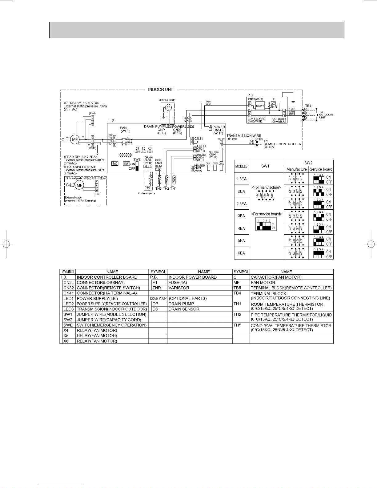
PEAD-RP1.6EA.UK PEAD-RP2EA.UK PEAD-RP2.5EA.UK
PEAD-RP3EA.UK PEAD-RP4EA.UK PEAD-RP5EA.UK PEAD-RP6EA.UK
PEAD-RP3EA1.UK PEAD-RP4EA1.UK PEAD-RP5EA1.UK PEAD-RP6EA1.UK
11
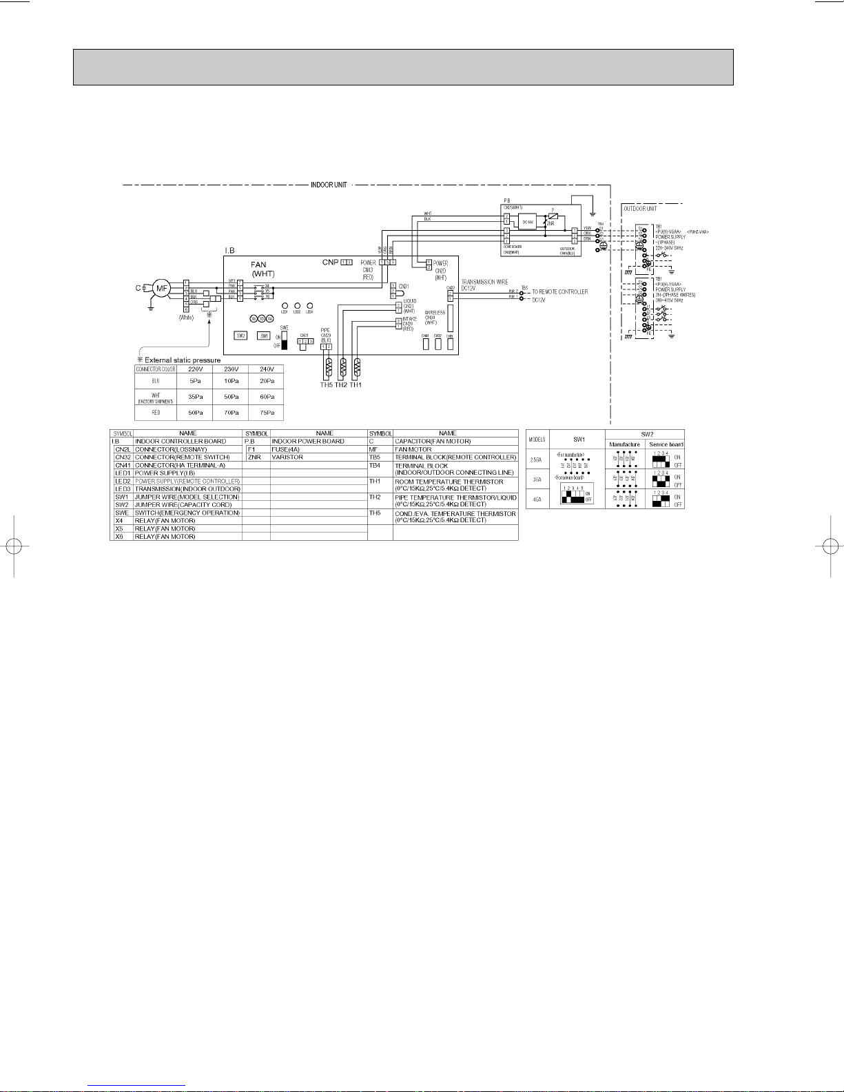
PEAD-RP2.5GA
PEAD-RP3GA
PEAD-RP4GA
12
PUHZ-RP1.6VHA
MODELS
SW6
W1 MODEL SELECT
1.6V
2V
MODELS
SW6
2.5V
3V
1
ON
OFF
23456
1
ON
OFF
23456
1
ON
OFF
23456
1
ON
OFF
23456
PUHZ-RP2VHA
PUHZ-RP2.5VHA
PUHZ-RP3VHA
PUHZ-RP3VHA-A
W1
W2 Only PUHZ-RP2.5, 3VHA.
W2
13
PUHZ-RP4VHA
MODELS
SW6
W1 MODEL SELECT
4V
5V
6V
1
ON
OFF
23456
1
ON
OFF
23456
1
ON
OFF
23456
PUHZ-RP5VHA
PUHZ-RP6VHA
PUHZ-RP4VHA1
PUHZ-RP5VHA1
PUHZ-RP6VHA1
PUHZ-RP4VHA-A
PUHZ-RP5VHA-A
PUHZ-RP6VHA-A
PUHZ-RP4VHA1-A
PUHZ-RP5VHA1-A
PUHZ-RP6VHA1-A
W1
Only PUHZ-RP4VHA1
PUHZ-RP5VHA1
PUHZ-RP6VHA1
14
4
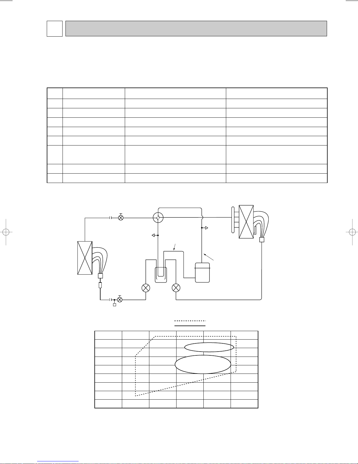
Measurement item
COOL: 2.3 ~ 3.0 HEAT: 2.0 ~ 3.2
0.55 ~ 1.0
50 ~ 100
-2 ~ +18
COOL: 27: HEAT: 20:
COOL: 8 ~ 20
HEAT: 30 ~ 50
COOL: 35 HEAT: 7
COOL: 40 ~ 50 HEAT: 0 ~ 5
Measurement method, remarks
Connect the pressure gauge to the high-pressure check valve.
Connect the pressure gauge to the low-pressure check valve.
Measured with piping surface thermometer.
Measured with piping surface thermometer.
Can be displayed on remote controller.
Measured with piping surface thermometer.
Measured with piping surface thermometer.
High pressure (MPa)
Low pressure (MPa)
Discharge pipe temperature (:)
Suction pipe temperature (:)
Indoor intake temperature (:)
Indoor outlet temperature (:)
Outdoor intake temperature (:)
Outdoor outlet temperature (:)
Pressure/temperature near JIS
standard operating conditions
A
B
C
D
E
F
G
H
Notes : The operation statuses vary depending on the compressor's operating frequency because units are inverter-type.
Outdoor
heat exchanger
Stop valve
(with service port)
Power
receiver
Linear
expansion
valve B Linear
expansion
valve A
4-way valve
Compressor
Ball valve
Indoor heat
exchanger
A
B
C
D
Overload operation
Standard operation
Permissible operation range
Normal operation range
0 0.2 0.4 0.6 0.8 1 1.2
Suction pressure (MPa)
Discharge pressure (MPa)
4.5
4
3.5
3
2.5
2
1.5
1
0.5
0
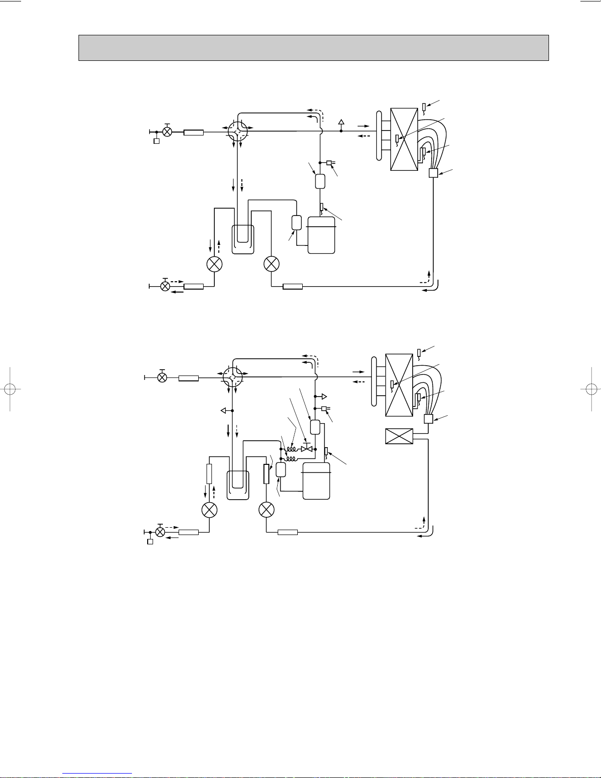
REFRIGERANT SYSTEM DIAGRAM
4-1. Checking operation statuses PUHZ-RP • HA
4-1-1. Measurement points and items
•The table and diagrams below show the measurement item for each measurement point, and the pressure and temperature
near the ISO T1 standard operating conditions.
•Measure the temperature and pressure of each part by following the descriptions in the table.
•Measurement time: Be sure to wait until the refrigerant circuit has stabilized (30 minutes to 1 hour) before taking
measurements.
4-1-2. Operation pressure ranges
15
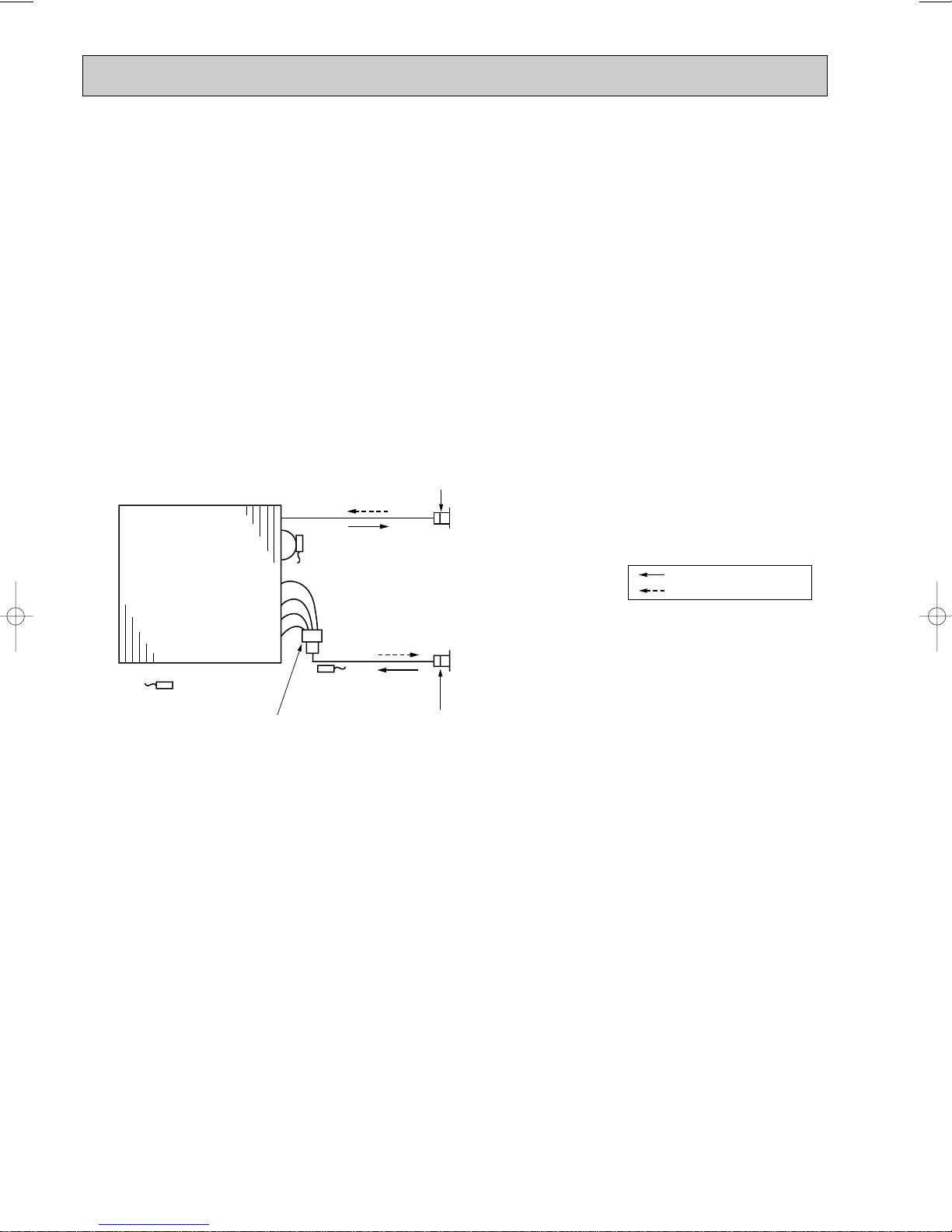
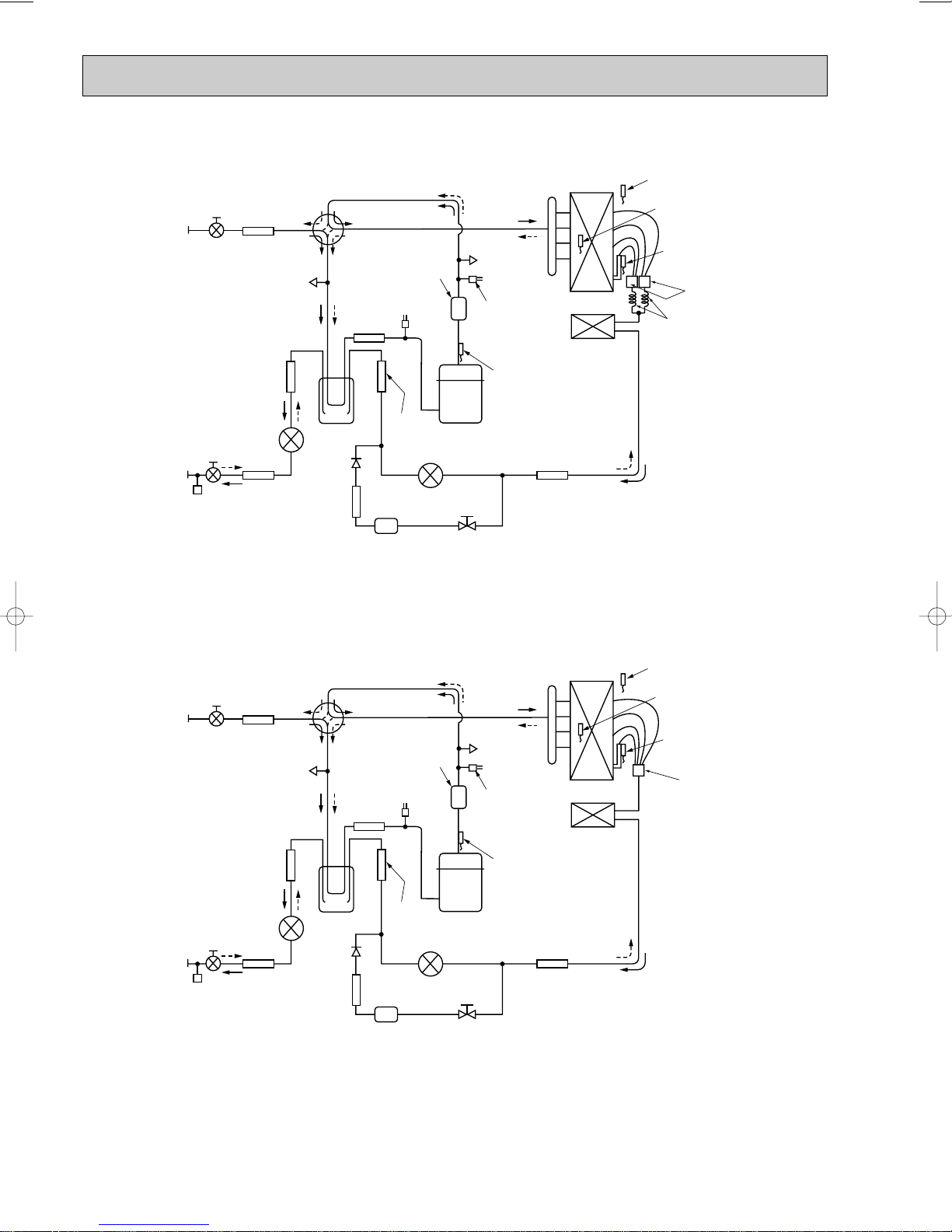
4-2. Refrigerant System Diagram
Pipe temperature
thermistor/liquid
(TH2)
Distributor
with strainer
#50
Condenser/evaporator
temperature thermistor
(TH5)
Room temperature
thermistor (TH1)
Refrigerant flow in cooling
Refrigerant flow in heating
Strainer
#50
Strainer
#50
Heat exchanger
Refrigerant GAS pipe connection
(Flare)
Refrigerant LIQUID pipe connection
(Flare)
PLA-RP1.6AA PLA-RP2AA PLA-RP2.5AA
PLA-RP1.6AA.UK PLA-RP2AA.UK PLA-RP2.5AA.UK
PLA-RP3AA PLA-RP4AA PLA-RP5AA PLA-RP6AA
PLA-RP3AA.UK PLA-RP4AA.UK PLA-RP5AA.UK PLA-RP6AA.UK
PLA-RP3AA
1 PLA-RP4AA1 PLA-RP5AA1 PLA-RP6AA1
PLA-RP3AA1.UK PLA-RP4AA1.UK PLA-RP5AA1.UK PLA-RP6AA1.UK
PKA-RP1.6GAL PKA-RP2GAL
PKA-RP2.5FAL PKA-RP3FAL PKA-RP4FAL
PCA-RP2GA PCA-RP2.5GA
PCA-RP3GA PCA-RP4GA PCA-RP5GA PCA-RP6GA
PEA-RP3EA.TH-A PEA-RP4EA.TH-A PEA-RP5EA.TH-A PEA-RP6EA.TH-A
PEAD-RP1.6EA.UK PEAD-RP2EA.UK PEAD-RP2.5EA.UK
PEAD-RP3EA.UK PEAD-RP4EA.UK PEAD-RP5EA.UK PEAD-RP6EA.UK
PEAD-RP3EA
1.UK PEAD-RP4EA1.UK PEAD-RP5EA1.UK PEAD-RP6EA1.UK
PEAD-RP2.5GA.UK PEAD-RP3GA.UK PEAD-RP4GA.UK
16
Distributor
Thermistor TH7
(Outdoor)
Heat exchanger
Refrigerant GAS pipe
connection(5/8F)
Refrigerant LIQUID pipe
connection(3/8F)
Stop valve
(with service port)
Strainer
#100
Power
receiver
Linear
expansion
valve B
Linear expansion valve A
Strainer
#100
Strainer
#100
Strainer
#100
Thermistor TH6
(Outdoor 2-phase pipe)
Thermistor TH3
(Outdoor pipe)
Service port
(Low pressure)
Service port
(High pressure)
High pressure
switch 63H
Bypass valve
Oil separator
Thermistor TH4
(Discharge)
Muffler
Strainer
#50
4-way valve
Compressor
Ball valve
Capillary tube
O.D.4.0OI.D.2.4OL500
Capillary tube
O.D.2.5OI.D.0.6OL1000
PUHZ-RP1.6VHA
Thermistor TH7
(Outdoor)
Heat exchanger
Refrigerant GAS pipe
connection(1/2F)
Refrigerant LIQUID pipe
connection(1/4F)
Stop valve
Strainer
#100
Power
receiver
Linear
expansion valve B
Thermistor TH6
(Outdoor 2-phase pipe)
Thermistor TH3
(Outdoor pipe)
Service port
High pressure
switch 63H
Thermistor TH4
(Discharge)
Compressor
Strainer
#50
Solenoid valve
(Four-way valve)
Muffler
Distributor
Linear expansion valve A
Strainer
#100
Muffler
Stop valve
(with service port)
PUHZ-RP2VHA
PUHZ-RP2.5VHA
PUHZ-RP3VHA
PUHZ-RP3VHA-A
17
PUHZ-RP4VHA PUHZ-RP4VHA-A
Distributor
Thermistor TH7
(Outdoor)
Heat exchanger
Refrigerant GAS pipe
connection(5/8F)
Refrigerant LIQUID pipe
connection(3/8F)
Stop valve
(with service port)
Strainer
#100
Power
receiver
Linear
expansion valve B
Linear expansion valve A
Strainer
#100
Strainer
#100
Strainer
#100
Thermistor TH6
(Outdoor 2-phase pipe)
Thermistor TH3
(Outdoor pipe)
Service port
(Low pressure)
Service port
(High pressure)
High pressure
switch 63H
Replace filter
Thermistor TH4
(Discharge)
Compressor
Strainer
#50
Solenoid valve
(Four-way valve)
Capillary tube
(O.D.4.0OI.D.3.0OL200)O2pcs
Strainer
#100
Strainer
#100
Low pressure
switch 63L
Muffler
Ball valve
Restrictor
valve
Solenoid valve
(Bypass valve)
Distributor
Thermistor TH7
(Outdoor)
Heat exchanger
Refrigerant GAS pipe
connection(5/8F)
Refrigerant LIQUID pipe
connection(3/8F)
Stop valve
(with service port)
Strainer
#100
Power
receiver
Linear
expansion valve B
Linear expansion valve A
Strainer
#100
Strainer
#100
Strainer
#100
Thermistor TH6
(Outdoor 2-phase pipe)
Thermistor TH3
(Outdoor pipe)
Service port
(Low pressure)
Service port
(High pressure)
High pressure
switch 63H
Replace filter
Thermistor TH4
(Discharge)
Compressor
Strainer
#50
Solenoid valve
(Four-way valve)
Strainer
#100
Strainer
#100
Low pressure
switch 63L
Muffler
Ball valve
Restrictor
valve
Solenoid valve
(Bypass valve)
PUHZ-RP5VHA PUHZ-RP5VHA-A
PUHZ-RP6VHA PUHZ-RP6VHA-A
PUHZ-RP4VHA1 PUHZ-RP4VHA1-A
PUHZ-RP5VHA
PUHZ-RP6VHA
1 PUHZ-RP5VHA1-A
1 PUHZ-RP6VHA1-A
18
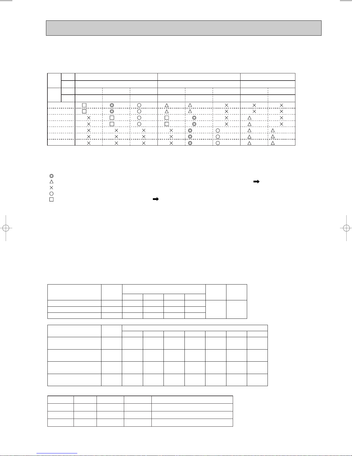
4-3. Applicable extension pipe for each model
15
30m or
above
31 — 40m
0.2kg
0.6Kg
0.6kg
10m or below
41 — 50m
0.4kg
1.2Kg
1.2kg
51 — 60m
—
—
1.8kg
61 — 75m
—
—
2.4kg
<Table 2> Additional refrigerant charging amount for pipe of standard diameter
<Table 3>
Outdoor unit
Permitted
pipe length
Additional refrigerant charging amount for pipe
length exceeding 30 m (kg)
PUHZ-RP1.6, 2V
PUHZ-RP2.5, 3V
PUHZ-RP4-6V, RP4-6V
1
Outdoor unit
PUHZ-RP1.6, 2V
PUHZ-RP2.5, 3V
PUHZ-RP4-6V
PUHZ-RP4-6V
1
Number of
bends
Height
difference
50m or less
50m or less
75m or less
Permitted
pipe length
50m or less
50m or less
75m or less
75m or less
2.1
3.1
5.1
4.6
11 — 20m 21 — 30m
2.3
3.3
5.3
4.8
2.5
3.5
5.5
5.0
31 — 40m
2.7
0.2
4.1
0.6
6.1
0.6
5.6
0.6
2.9
0.4
4.7
1.2
6.7
1.2
6.2
1.2
—
—
—
—
7.3
1.8
6.8
1.8
—
—
—
—
7.9
2.4
7.4
2.4
41 — 50m 51 — 60m 61 — 75m
Additional refrigerant charging amount for recharging (above) and pipe length exceeding 30m (below) (kg)
Liquid
pipe
(mm)
Gas
pipe
(mm)
[6.35
[9.52 [12.7
[9.52
OD
Thick-
ness
OD
Thick-
ness
RP1.6
RP2
RP2.5
RP3
RP4
RP5
RP6
t0.8
[12.7
t0.8
[15.88
t1.0
[12.7
t0.8
[15.88
t1.0
[19.05
t1.0
[15.88
t1.0
[19.05
t1.0
t0.8
t0.8
: Normal piping
: It can be used, however, additional refrigerant charge is required when the pipe length exceeds 20m. Refer to <table 4>.
: It cannot be used.
: It can be used.
: It can be used, however, the capacity is lowered. Refer to (c) Capacity correction.
<Table 1> Pipe length for 1:1 system
*1: Set DIP SW8-1 on outdoor unit controller board to ON.
*2: The maximum length is 50 m in case of using existing pipes.
*3: The height difference between indoor and outdoor unit should be kept within 30 m for all models.
[Marks in the table above]
50m
t0.8
30m 30m
10m 30m 30m
50m
30m
50m
50m
10m
50m
(*1)
75m
(*2)
50m
10m 30m 30m10m 50m
75m
(*2)
75m
(*2)
50m
(*1)
30m
(*1)
50m
(*1)
50m
(*1)
50m
(*1)
50m
(*1)
50m10m 30m 30m 30m
(*1)
<Table 4>
Additional refrigerant charging amount for liquid pipe which is one size larger than standard diameter
[9.52
[12.7
[12.7
RP1.6, 2
RP2.5, 3
RP4-6
Liquid pipe dia
Chargeless
30m
30m
50m
60 g addition per 1 m when pipe length exceeds 20 m
100 g addition per 1 m when pipe length exceeds 20 m
100 g addition per 1 m when pipe length exceeds 20 m
20m
20m
20m
Max. pipe length
Additional refrigerant charging amount
4-3-1. 1:1 system
(a) Pipe length
(b) Adjusting the amount of refrigerant
• Additional refrigerant charge is not necessary for the pipe length up to 30 m. When the pipe length exceeds 30 m or service
(refrigerant replacement) is performed, charge proper amount of refrigerant for each pipe length referring to table below.
Use refrigerant R410A. Use charge hose exclusive for R410A.
• When charging additional refrigerant, charge the refrigerant from low-pressure side of the port valve using a safety charger.
• Make sure that air purge for this unit at refrigerant replacement is performed from both high-pressure check valve and ser-
vice port. (If air purge is performed only from one of them, air in not purged enough.)
• When replacing refrigerant, charge the refrigerant from service port. When charged refrigerant is less than specified amount,
charge the refrigerant again from low pressure side of the port valve using a safety charger.
• Tighten the service port cap (nut) of stop valve firmly. The tightening torque is 12 to 16 N·m. (For the prevention of slow-leak)
• Check additional refrigerant charging amount referring to table 4 when liquid pipe is one size larger than standard diameter,
and table 2 when the pipe is standard diameter.
19
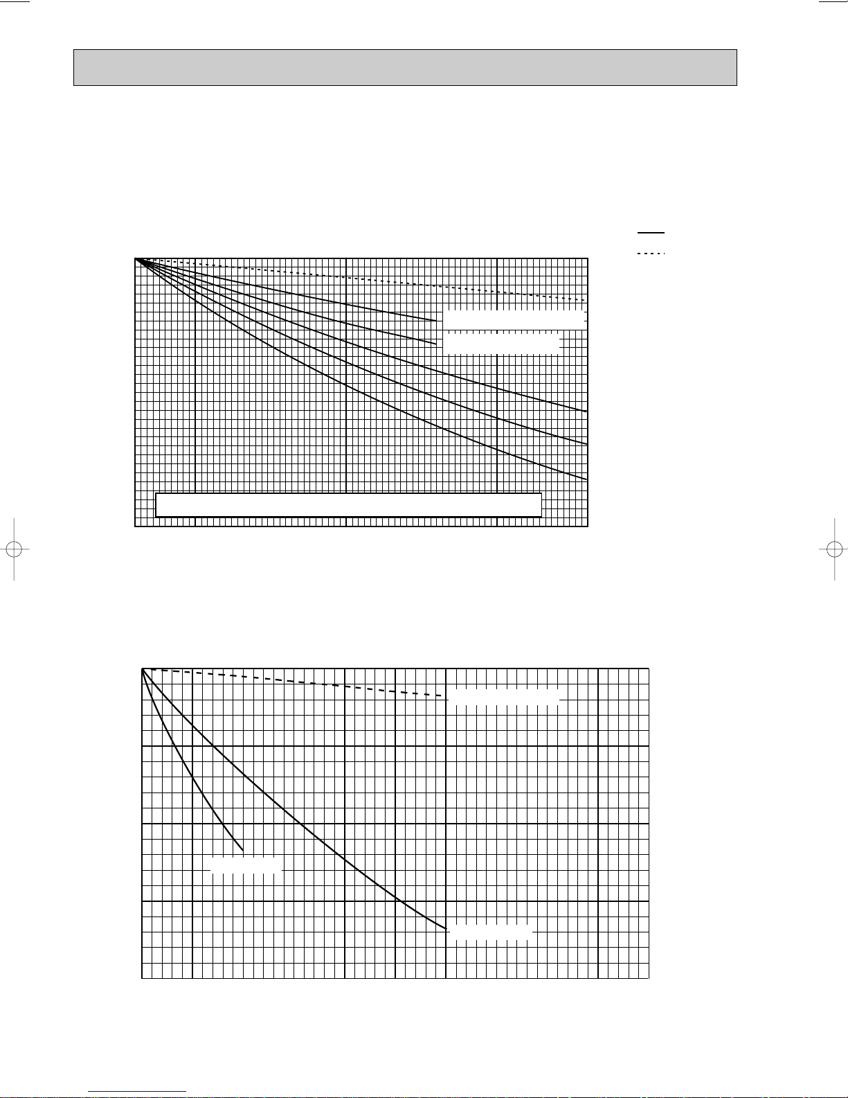
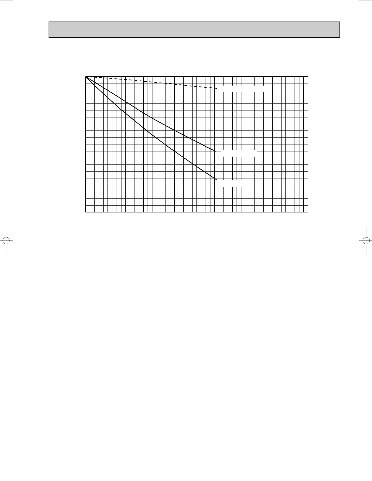
(c) Capacity correction
Cooling
Heating
Cooling and heating capacity is lowered according to pipe length. Capacity can be obtained by referring to the capacity
curves below. When the diameter of gas pipe is one size smaller than standard diameter, cooling capacity is lowered comparing to the standard diameter. The lowered capacity can be obtained by referring to capacity curves for gas pipe which is
one size smaller than standard size.
Corrected pipe length (m) = actual pipe length (m) + number of bends x 0.3 (m)
11
Capacity curves for PUHZ-RP • HA model <Standard size>
100
95
Cooling RP1.6, 2.5 models
90
Cooling RP3 model
85
80
Capacity ratio [%]
75
Note: The permitted pipe length is up to 55m for RP1.6, 2, 2.5, 3 model.
70
5 101520253035404550556065707580
Corrected pipe length
22
Capacity curve for PUHZ-RP1.6, 2 models
<When gas pipe is one size smaller than standard size>
100
Heating RP1.6, RP2
Heating RP1.6, 2, 2.5,
3, 4, 5 and 6 models
(Up to 55m for RP1.6,
2, 2.5, 3 model)
Cooling RP2, 4 models
(Up to 55m for RP2
model)
Cooling RP5 model
Cooling RP6 model
95
90
Cooling RP2
Capacity ratio [%]
85
80
5 10152025303540455055
Cooling RP1.6
Corrected pipe length
20
33
Capacity curve for PUHZ-RP2.5, 3 models
<When gas pipe is one size smaller than standard size>
100
95
90
Capacity ratio [%]
85
80
5 10152025303540455055
Corrected pipe length
Heating RP2.5, RP3
Cooling RP2.5
Cooling RP3
44
When gas pipe is one size larger than standard size for PUHZ-RP4, 5 and 6.
1 Capacity can be obtained by referring to capacity curves of standard size.
21
4-3-2. Synchronized twin and triple
(a) Pipe length
Please note that refrigerant piping length, bend number and height difference of indoor units are specified for each unit
combination.
Note: Be sure to use our Multi-distributor for distributing pipe to use existing piping.
<Table 5>
Synchronized twin
Outdoor
unit
<Table 6>
Outdoor
unit
Note 1: If total piping length exceeds charge-less piping length of 30 m, charge additional refrigerant according to the table 7.
PUHZ-RP3VHA
PUHZ-RP3VHA-A
PUHZ-RP4-6VHA
PUHZ-RP4-6VHA-A
Synchronized twin
PUHZ-RP6VHA
PUHZ-RP6VHA-A
Permitted total piping
length A + B + C
50 m or less
75 m or less
Permitted total piping
length A + B + C + D
Chargeless piping
length A + B + C
30 m or less
Charge-less piping
length A + B + C + D
30 m or less70 m or less
Indoor unit’s height
difference [B and C]
8 m or less
Indoor unit’s height difference
[B and C] [C and D] [B and D]
8 m or less
Bend number
w 2
15 at most
Bend number
w 2
15 at most
<Table 7>
Outdoor unit
30 m or less
PUHZ-RP3VHA
PUHZ-RP3VHA-A
PUHZ-RP4-6VHA
PUHZ-RP4-6VHA-A
Note 2: Bends number (w 2) should be within 8 for each combination, A + B, A +C and A + D, and 15 in all.
Note 3: Height difference between indoor and outdoor unit is referred to no matter which unit is located higher or lower.
<Table 8> Pipe length for twin of RP 3 - 6 (Piping length: A + B + C)
RP3 Twin (RP1.6✕2)
Liquid [6.35
Gas [12.7
Branch pipe
diameter
[B and C]
<Table 9> Pipe length for triple of RP6 (Piping length: A + B + C + D)
Branch pipe
diameter
[B,C and D]
Liquid [6.35
Gas [12.7
Liquid [9.52
Gas [15.88
Liquid [12.7
Gas [19.05
Liquid [6.35
Gas [12.7
Liquid [9.52
Gas [15.88
Liquid [12.7
Gas [19.05
Main pipe diameter [A]
Liquid [9.52
Gas [15.88
75 m(✽2)
50 m
✕
✕
✕
✕
Not required
Liquid [9.52
Gas [15.88
50 m
50 m
Liquid [12.7
Gas [19.05
50 m(✽1)
50 m(✽1)
Additional refrigerant to be charged (kg)
31 - 40 m 41 - 50 m 51 - 60 m 61 - 75 m
RP4 Twin (RP2✕2) RP5 Twin (RP2.5✕2) RP6 T win (RP3✕2)
Liquid [9.52
Gas [15.88
75 m(✽2)
✕
✕
A + B + C (+D)
0.6
50 m
✕
✽1 ··· Set DIP SW8-1 on outdoor unit control circuit board to ON.
✽2 ··· When using existing piping, pipe length should be 50 m at most.
✽3 ··· Height difference between indoor and outdoor unit should be
kept within 30 m in every case.
[Marks in table]
··· Normal piping
··· It can be used with some changes of piping length and the
amount of refrigerant to be charged.
✕ ··· It cannot be used.
1.2
1.8 2.4
Main pipe diameter [A]
Liquid [12.7
Gas [19.05
50 m(✽1)
50 m(✽1)
✕
Liquid [9.52
Gas [15.88
✕
75 m(✽2)
✕
Liquid [12.7
Gas [19.05
50 m(✽1)
w Charge additional
refrigerant from
the check valve
connected to the
pipe of low-pressure
side in indoor unit.
Liquid [9.52
Gas [15.88
✕
✕
✕
75 m(✽2)
✕
Liquid [12.7
Gas [19.05
50 m(✽1)
✕
✕
22
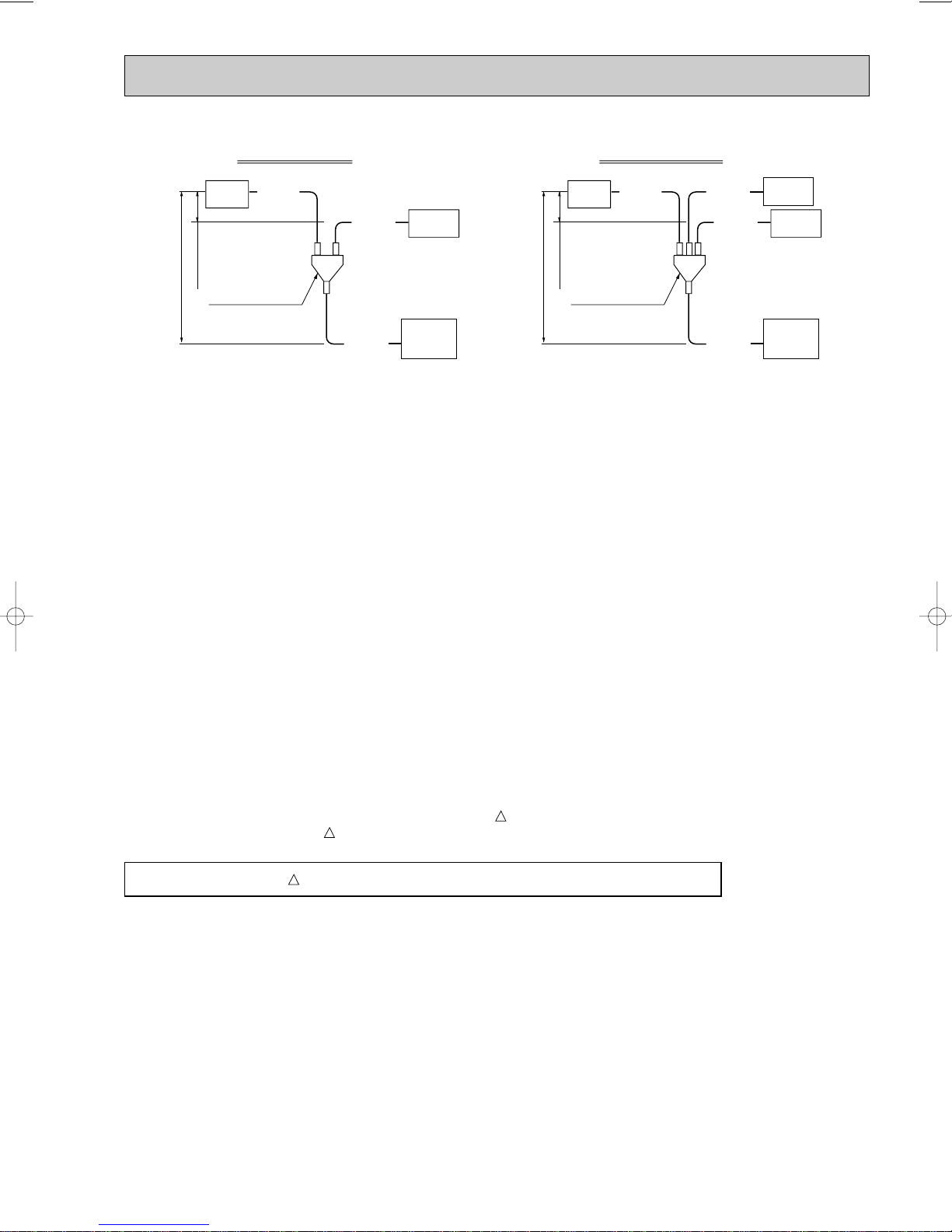
Synchronized twin
Synchronized triple
Indoor
unit
Optional
distributing pipe
1 m or less
Multi-distributor
30 m or less
Branch
pipe B
Branch
pipe C
Main
pipe A
Indoor
unit
Outdoor
unit
Indoor
unit
Optional
distributing pipe
1 m or less
Multi-distributor
30 m or less
Branch
pipe B
Branch
pipe C
Branch
pipe D
Main
pipe A
Indoor
unit
Indoor
unit
Outdoor
unit
1. Keep Stop valve in outdoor unit fully closed (as it is shipped), and after completing refrigerant piping connection, conduct air
purge from service port of stop valve at outdoor unit.
2. After air purging, make the valve rod of stop valve at outdoor unit fully open.
Now refrigerating cycle is complete between indoor and outdoor unit.
Handle stop valve following the indication on outdoor unit.
Caution:
• Be sure to apply refrigerating oil to flare sheet face. Never apply it to screws. (As it causes flare nut loosening.)
• Use double spanner for piping connection.
• Be sure to check gas leak by using leak detector or soapy water.
• Use attached parts for refrigerant piping to provide correct insulation to the connection of indoor unit side in accordance with
attached explanation sheet.
• Be sure to provide anoxidized brazing.
(b) Adjusting the amount of refrigerant
(i) In case of RP 3 twin
Check the additional refrigerant to be charged referring to table 2 when using pipe of size referred in table 8.
(ii) In case of RP4 - 6 twin or RP6 triple
When using liquid pipe one size larger than standard diameter for main pipe A, calculate the amount of additional
refrigerant referring to 2 below.
1 When using piping of standard diameter or gas pipe one size larger than standard diameter for main pipe A.
Check the additional refrigerant to be charged referring to table 2 like 1:1 system.
2 When using liquid pipe one size larger than standard diameter for main pipe A.
[In case of RP4-6 using liquid pipe of [12.7]
• When total length of extension pipe (main pipe and branch pipe) is less than 20 m.
No adjustment is required for refrigerant. (Chargeless)
• When total length of extension pipe (main pipe and branch pipe) is more than 20 m.
Calculate the amount of additional refrigerant, referred to as W (g) in the following, using the equation below and add
proper amount of refrigerant. If W is less than or equal to 0, no additional charge is required. (Chargeless)
[Additional refrigerant] W (g) = {100(g) ✕ L1} + {60(g) ✕ L2} + {30(g) ✕ L3} - 2000(g)
Note: Put “0” in L1-3 if it is not used. L1: Liquid pipe length of [12.7 (m)
(c) Capacity correction
Apply pipe length between indoor and outdoor unit which is the longest of all for the calculation of capacity lowering according
to each pipe length.
L2: Liquid pipe length of [9.52 (m)
L3: Liquid pipe length of [6.35 (m)
23
5
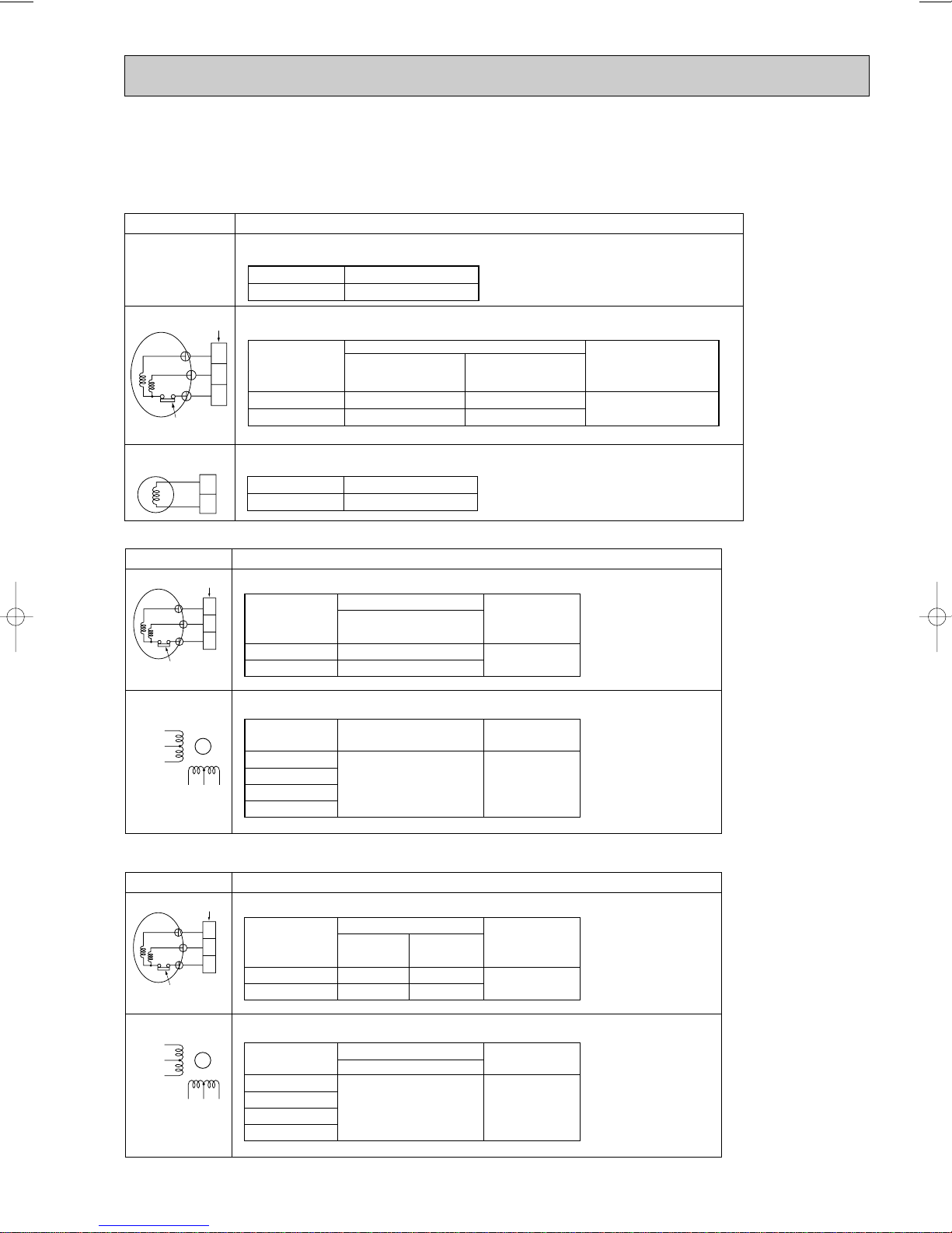
Parts name Check points
Disconnect the connector then measure the resistance using a tester.
(Surrounding temperature 10:~30:)
Drain sensor
(Refer to below for a detail.)
(Refer to below for a detail.)
Room temperature
thermistor (TH1)
Pipe temperature
thermistor/ liguid (TH2)
Condenser/evaporator
temperature thermistor
(TH5)
1
2
3
Normal
4.3k"~9.6k"
Abnormal
Open or short
Abnormal
Open or short
Normal
0.6k"~6.0k"
Measure the resistance between the terminals using a tester.
Measure the resistance after 3 minutes have passed since the power supply was intercepted.
(Surrounding temperature 0:~60:)
-200 20406080
< Thermistor for drain sensor >
Temperature (:)
0
1
2
3
4
5
6
7
8
9
10
Resistance (k")
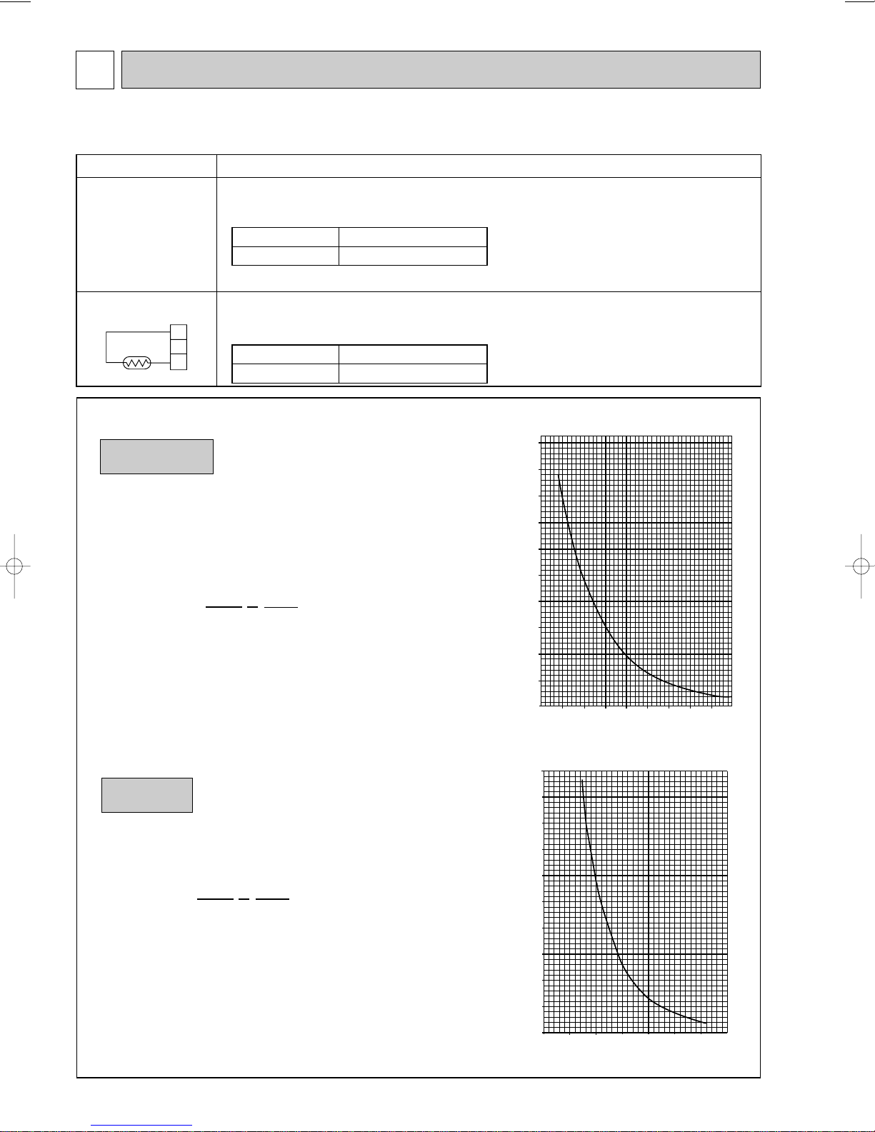
HOW TO CHECK THE PARTS
5-1. INDOOR UNIT
• Common parts
<Thermistor Characteristic graph>
Thermistor for
lower temperature
Thermistor R0=15kΩ ±3%
Fixed number of B=3480K ± 2%
Rt=15exp { 3480( ) }
0: 15kΩ
10: 9.6kΩ
20: 6.3kΩ
25: 5.2kΩ
30: 4.3kΩ
40: 3.0kΩ
Drain sensor
Room temperature thermistor(TH1)
Pipe temperature thermistor(TH2)
Condenser/evaporator temperature
thermistor(TH5)
1
273+t
1
273
< Thermistor for lower temperature >
50
40
30
20
Resistance (k")
10
0
-20 -10 0 10 20 30 40 50
Temperature (:)
Thermistor R0=6.0kΩ ±5%
Fixed number of B=3390K ±2%
Rt=6exp { 3390( ) }
1
273+t
0: 6.0kΩ
10: 3.9kΩ
20: 2.6kΩ
25: 2.2kΩ
30: 1.8kΩ
40: 1.3kΩ
60: 0.6kΩ
1
273
24
PLA-RP1.6AA PLA-RP2AA PLA-RP2.5AA
1
1
2
2
3
3
Red
White
Black
Relay connector
Protector
OPEN : 125i5:
CLOSE : 79i 15:
4
5
2
361
Orange
Red
Pink
Yellow Brown Blue
M
Parts name Check points
Measure the resistance between the terminals using a tester.
(Winding temperature 20:)
Fan motor (MF)
Abnormal
Open or short
Red – Black
White – Black
Motor terminal
or
Relay connector
RP1.6 , RP2
120.5"
111.3"
Normal
Open or short
Abnormal
Brown – Yellow
Brown – Blue
Red – Orange
Red – Pink
Connector
Normal
186~214"
Measure the resistance between the terminals using a tester.
(Surrounding temperature 20:~30:)
Vane motor (MV)
1
1
2
2
3
3
Red
White
Black
Relay connector
Protector
OPEN : 130i5:
CLOSE : 80i 20:
4
5
2
361
Orange
Red
Pink
Yellow Brown Blue
M
Parts name Check points
Measure the resistance between the terminals using a tester.
(Winding temperature 20:)
Fan motor (MF)
Abnormal
Open or short
Red – Black
White – Black
Motor terminal
or
Relay connector
RP2.5
RP3
99.5"
103.9"
RP4
62.6"
74.0"
Normal
Open or short
Abnormal
Brown –Y ellow
Brown – Blue
Red – Orange
Red – Pink
Connector
Normal
RP2.5, RP3, RP4
186~214"
Measure the resistance between the terminals using a tester.
(Surrounding temperature 20:~30:)
Vane motor (MV)
PLA-RP1.6AA.UK PLA-RP2AA.UK PLA-RP2.5AA.UK
PLA-RP3AA PLA-RP4AA PLA-RP5AA PLA-RP6AA
PLA-RP3AA
1 PLA-RP4AA1 PLA-RP5AA1 PLA-RP6AA1
PLA-RP3AA.UK PLA-RP4AA.UK PLA-RP5AA.UK PLA-RP6AA.UK
PLA-RP3AA
Parts name Check points
Vane motor
Fan motor
Relay connector
1
3
Protector
OPEN :130:
CLOSE:80i20:
Drain pump
Red
Red
1.UK PLA-RP4AA1.UK PLA-RP5AA1.UK PLA-RP6AA1.UK
Measure the resistance between the terminals using a tester.
(Surrounding temperature20:)
Normal Abnormal
15k" Open or short
Measure the resistance between the terminals using a tester.
(Winding temperature 20:)
Red
1
2
3
Motor terminal
or
Relay connector
Red-Black
White
2
Black
White-Black
PLA-RP1.6, 2, 2.5, 3AA
PLA-RP1.6, 2, 2.5, 3AA.UK
PLA-RP3AA
PLA-RP3AA1.UK
1
87.2"
104.1"
Normal
PLA-RP4, 5, 6AA
PLA-RP4, 5, 6AA.UK
PLA-RP4, 5, 6AA
PLA-RP4, 5, 6AA1.UK
28.7"
41.6"
1
Abnormal
Open or short
Measure the resistance between the terminals using a tester.
(Winding temperature 20:)
1
2
Normal Abnormal
290" Open or short
PKA-RP1.6GAL PKA-RP2GAL
PKA-RP2.5FAL PKA-RP3FAL PKA-RP4FAL
25

PCA-RP2GA PCA-RP2.5GA PCA-RP3GA
1
1
2
2
3
3
Red
White
Black
Relay connector
Protector
1
2
Gray
Gray
4
5
2
361
Orange
Red
Pink
Yellow Brown Blue
M
4
2
5
31
Pink
Orange
Red
Yellow Blue
M
OFF:130i 5:
ON :80i 20:
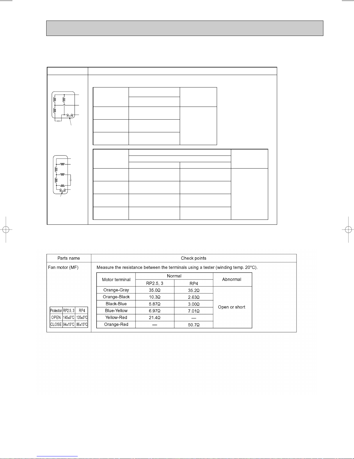
Parts name Check points
Measure the resistance between the terminals using a tester.
(Winding temperature 20:)
Measure the resistance between the terminals using a tester.
(Winding temperature 20:)
Drain-up
mechanism (Option)
Fan motor
Abnormal
Open or short
Normal
195"
Abnormal
Open or short
Red – Black
White – Black
Motor terminal
or
Relay connector
RP2
70.6"
69.6"
RP2.5, RP3
45.0"
44.8"
RP4
43.7"
55.3"
RP5, RP6
20.4"
20.7"
Normal
Open or short
Abnormal
Brown – Yellow
Brown – Blue
Red – Orange
Red – Pink
Connector
RP2
186~214"
RP2.5, RP3
140~160"
Normal
Open or short
Abnormal
Brown – Yellow
Brown – Blue
Red – Orange
Red – Pink
Connector
RP4, RP5, RP6
140~160"
Normal
Vane motor
Parts name Check points
Measure the resistance between the terminals using a tester.
(Winding temperature 20:)
Fan motor (MF)
Brown
White
Blue
Red
Orange
Black
Protector
(PEA-RP3,4,5EA)
OPEN :135:
CLOSE:86i15:
(PEA-RP6EA)
OPEN :150:
CLOSE:96i15:
Abnormal
Open or short
White – Black
Black – Blue
Blue – Brown
Brown – Red
Motor terminal
or
Relay connector
Normal
PEA-
RP3EA.TH-A RP4EA.TH-A RP5EA.TH-A RP6EA.TH-A
28.6"
12.5"
4.3"
23.6"
20.6"
8.1"
3.2"
16.0"
15.3"
5.1"
2.7"
14.5"
10.2"
5.2"
3.1"
12.1"
PCA-RP4GA PCA-RP5GA PCA-RP6GA
PEA-RP3EA.TH-A PEA-RP4EA.TH-A PEA-RP5EA.TH-A PEA-RP6EA.TH-A
26
PEAD-RP1.6EA.UK PEAD-RP2EA.UK PEAD-RP2.5EA.UK
PEAD-RP3EA.UK PEAD-RP4EA.UK PEAD-RP5EA.UK PEAD-RP6EA.UK
PEAD-RP3EA
Parts name Check points
Fan motor (MF)
PEAD-RP3EA(1).UK
WhiteRed
Protector
OPEN :150:
CLOSE:96i15:
1.UK PEAD-RP4EA1.UK PEAD-RP5EA1.UK PEAD-RP6EA1.UK
Measure the resistance between the terminals using a tester.
(Winding temperature 20:)
Black
Relay connector
Blue
Gray
(White or Red open)
(White or Red open)
(White or Red open)
Motor terminal
or
Gray – Black
Black – Blue
Blue – Red
PEAD-RP1.6, 2, 2.5EA.UK
Normal
PEAD-RP3EA
43.5"
14.74"
57.5"
Abnormal
(1).UK
Open or short
PEAD-RP4,5,6EA
Protector
OPEN :135:
CLOSE:86i15:
Black
Blue
Red
White
Gray
(1)
.UK
PEAD-RP2.5GA
PEAD-RP3GA
PEAD-RP4GA
Motor terminal
or
Relay connector
Gray-Black
(White or Red open)
Blue – Black
Black – Red
(White or Red open)
Gray – Red
(White or Red open)
RP4EA
24.76"
4.78"
18.99"
36.63"
(1).UK
Normal
PEAD-
RP5EA
(1)
.UK RP6EA
10.27"
2.11"
20.75"
25.44"
(1)
Abnormal
.UK
Open or short
27
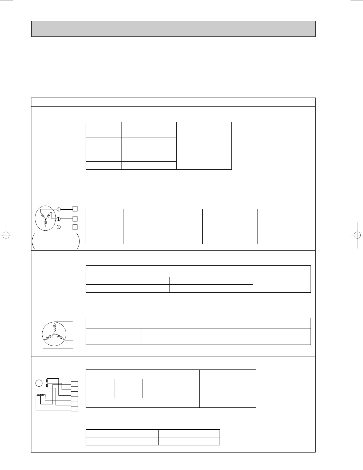
5-2. OUTDOOR UNIT
4
6
2
3
1
2
3
4
5
6
5
1
M
Blue
Brown
Yellow
Orange
Red
White
Parts name
Check points
Disconnect the connector then measure the resistance using a tester.
(Surrounding temperature 10:~30:)
Disconnect the connector then measure the resistance using a tester.
(
Winding temperature 20
:)
Thermistor (TH3)
<Outdoor pipe>
Thermistor (TH4)
<Discharge>
Thermistor (TH6)
<Outdoor 2-phase pipe>
Thermistor (TH7)
<Outdoor>
Thermistor (TH8)
<Heat sink>
Normal
160k"~410k"
4.3k"~9.6k"
39k"~105k"
TH4
TH3
TH6
TH7
TH8
Abnormal
Open or short
Normal
(1) - (6)
Red - White
(1) - (4)
Red - Orange
(2) - (5)
Brown - Yellow
(2) - (3)
Brown - Blue
Abnormal
46±4"
Measure the resistance between the terminals using a tester.
(Surrounding temperature 20
:
)
Solenoid valve coil
<Four-way valve>
(21S4)
Pin number of relay
connector is different
from that motor
connector
Motor for compressor
(MC)
Linear expansion valve
( LEV(A),LEV(B) )
Normal
Abnormal
Open or short
RP1.6-3V RP4-6V
Open or short
Measure the resistance between the terminals using a tester.
(Surrounding temperature 20
:
)
Normal
1197±10"
Abnormal
Open or short
Solenoid valve coil
<Bypass valve>
(SV)
RP2.5-6VHA only
Measure the resistance between the terminals using a tester.
(Winding temperature 20:)
Fan motor(MF1,MF2)
Normal
RP1.6V, 2V
66.5±3.3"
RP2.5-6V
15.1±0.5"
2350±170" 1370±100"
RP1.6V, 2V RP4-6V
0.300"~0.340"
RP2.5V, 3V
0.865"~0.895" 0.266"
Measure the resistance between the terminals using a tester.
(Winding temperature 20:)
Normal
Abnormal
Open or short
Relay connector
Abnormal
Open or short
Red — Black
Black — White
White — Red
Red
W
V
U
W
V
U
White
Black
PUHZ-RP1.6HA PUHZ-RP2VHA PUHZ-RP2.5VHA PUHZ-RP3VHA
PUHZ-RP4VHA PUHZ-RP5VHA PUHZ-RP6VHA
PUHZ-RP4VHA1 PUHZ-RP5VHA1 PUHZ-RP6VHA1
PUHZ-RP4VHA-A PUHZ-RP5VHA-A PUHZ-RP6VHA-A
PUHZ-RP4VHA1-A PUHZ-RP5VHA1-A PUHZ-RP6VHA1-A
28
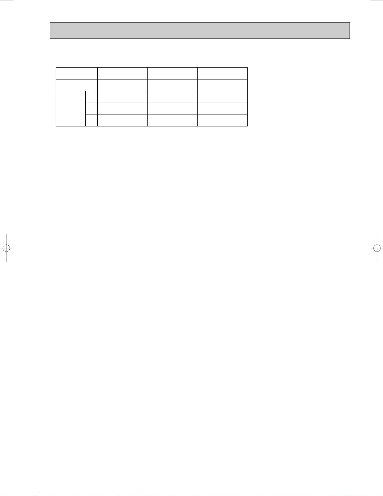
5-3. COMPRESSOR TECHNICAL DATA
U-V
U-W
W-V
Unit
Compressor model
Winding
Resistance
( " )
ANV33FDAMT
(at 20°C)
0.266
0.266
0.266
SNB130FLBH
0.300 ~ 0.340
0.300 ~ 0.340
0.300 ~ 0.340
PUHZ-RP4,5,6VHA
PUHZ-RP1.6,2VHA
TNB220FMBH
0.865 ~ 0.895
0.865 ~ 0.895
0.865 ~ 0.895
PUHZ-RP2.5,3VHA
29

HOW TO CHECK THE COMPONENTS
0
10
20
30
40
50
-20 -10 0 10 20 30 40 50
Temperature (:)
Resistance (k")
200
150
100
50
0
25 50 75 100 125
Temperature (:)
Resistance (k")
500
400
300
200
100
0
25
50 75 100 120
Temperature (:)
Resistance (k")
<Thermistor feature chart>
Low temperature thermistors
• Thermistor <Outdoor pipe> (TH3)
• Thermistor <Outdoor 2-phase pipe> (TH6)
• Thermistor <Outdoor> (TH7)
Thermistor R0 = 15k' ±3%
B constant = 3480K ± 2%
1
R
t =15exp{3480(
0: 15k'
10: 9.6k'
20: 6.3k'
25: 5.2k'
Medium temperature thermistor
• Thermistor <Heat sink> (TH8)
Thermistor R50 = 17k' ±2%
B constant = 4150K ± 3%
t =17exp{4150(
R
0: 180k'
25: 50k'
50: 17k'
70: 8k'
90: 4k'
1
273+t – 273
30: 4.3k'
40: 3.0k'
1
1
273+t – 323
)}
)}
High temperature thermistor
• Thermistor <Discharge> (TH4)
Thermistor R120 = 7.465k' ±2%
B constant = 4057K ± 2%
1
t =7.465exp{4057(
R
20: 250k'
30: 160k'
40: 104k'
50: 70k'
60: 48k'
1
273+t – 393
)}
70: 34k'
80: 24k'
90: 17.5k'
100: 13.0k'
110: 9.8k'
30
 Loading...