

Page 1
SPLIT-TYPE, HEAT PUMP AIR CONDITIONERS
TECHNICAL & SERVICE MANUAL
<indoor unit> Service ref.
Models
PEAD-RP3EA
PEAD-RP4EA
PEAD-RP5EA
PEAD-RP6EA
TM
1. SAFETY PRECAUTION ···························· 2
2. PART NAMES AND FUNCTIONS ············· 4
3. SPECIFICATION ······································· 7
4. DATA ························································ 9
5. REFRIGERANT SYSTEM DIAGRAM ······ 19
6. OUTLINES & DIMENSIONS ···················· 20
7. WIRING DIAGRAM ·································· 21
8. TROUBLE SHOOTING ···························· 22
9. DISASSEMBLY INSTRUCTIONS ············ 32
10
. PARTS LIST ············································· 34
11
. OPTIONAL PARTS ·································· 38
CONTENTS
INDOOR UNIT
REMOTE CONTROLLER
ON/OFF
TEMP.
Series PEAD
R410A
2003
• Refer to the OCT04 as for control
relation.This manual does not cover
outdoor units.
When serving them, please refer to
the service manual No.OC294 and
this manual as a set.
Page 2
2
SAFETY PRECAUTION
1
<Cautions for units utilizing refrigerant R410A>
CAUTIONS RELATED TO NEW REFRIGERANT
Use new refrigerant pipes.
In case of using the existing pipes for R22, be careful with
the followings.
· For RP4, 5 and 6, be sure to perform replacement opera tion before test run.
· Change flare nut to the one provided with this product.
Use a newly flared pipe.
· Avoid using thin pipes. For the detail, please refer to the
outdoor unit service manual No. OC294.
Do not use refrigerant other than R410A.
If other refrigerant (R22 etc.) is used, chlorine in refrigerant can cause deterioration of refrigerant oil etc.
Use a vacuum pump with a reverse flow check
valve.
If no reverse flow check valve is used, vacuum pump oil
may flow back into refrigerant cycle and that can cause
deterioration of refrigerant oil etc.
Use the following tools specifically designed for
use with R410A refrigerant.
The following tools are necessary to use R410A refrigerant.
Keep the tools with care.
If dirt, dust or moisture enter into refrigerant cycle, that can
cause deterioration of refrigerant oil or malfunction of compressor.
Do not use a charging cylinder.
If a charging cylinder is used, the composition of refrigerant will change and the efficiency will be lowered.
Flare tool
Electronic refrigerant
charging scale
Vacuum pump adaptor
Size adjustment gauge
Gauge manifold
Torque wrench
Gas leak detector
Charge hose
Tools (for R410A)
Make sure that the inside and outside of refrigerant piping is clean and it has no contamination
such as sulfur which is hazardous for use,
oxides, dirt, shaving particles, etc.
In addition, use pipes with specified thickness.
Store the piping to be used during installation
indoors and keep both ends of the piping sealed
until just before brazing. (Leave elbow joints, etc.
in their packaging.)
Use ester oil, ether oil or alkylbenzene oil (small
amount) as the refrigerant oil applied to flares
and flange connections.
Charge refrigerant from liquid phase of gas
cylinder.
If the refrigerant is charged from gas phase, composition
change may occur in refrigerant and the efficiency will be
lowered.
Contamination inside refrigerant piping can cause deterioration of refrigerant oil etc.
If dirt, dust or moisture enter into refrigerant cycle, that can
cause deterioration of refrigerant oil or malfunction of compressor.
If large amount of mineral oil enter, that can cause deterioration of refrigerant oil etc.
Ventilate the room if refrigerant leaks during
operation. If refrigerant comes into contact with
a flame, poisonous gases will be released.
[1] Cautions for service
(1) Perform service after collecting the refrigerant left in unit completely.
(2) Do not release refrigerant in the air.
(3) After completing service, charge the cycle with specified amount of refrigerant.
(4) When performing service, install a filter drier simultaneously.
Be sure to use a filter drier for new refrigerant.
[2] Additional refrigerant charge
When charging directly from cylinder
Check that cylinder for R410A on the market is syphon type.
Charging should be performed with the cylinder of syphon type stood vertically. (Refrigerant is charged from liquid phase.)
Page 3
3
Gravimeter
Unit
[3] Service tools
Use the below service tools as exclusive tools for R410A refrigerant.
No. Specifications
1
Gauge manifold ·Only for R410A
·Use the existing fitting
specifications
. (UNF1/2)
·Use high-tension side pressure of 5.3MPa·G or over.
2
Charge hose ·Only for R410A
·Use pressure performance of 5.09MPa·G or over.
3
Electronic scale
4
Gas leak detector ·Use the detector for R134a, R407C or R410A.
5
Adaptor for reverse flow check ·Attach on vacuum pump.
6
Refrigerant charge base
7
Refrigerant cylinder ·Only for R410A Top of cylinder (Pink)
Cylinder with syphon
8
Refrigerant recovery equipment
Page 4
4
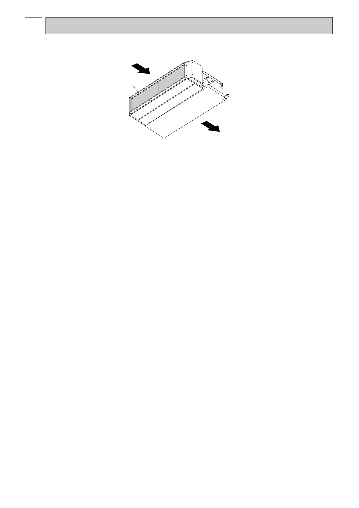
PART NAMES AND FUNCTIONS
2
•
Indoor Unit
Air intake (sucks
the air inside the
room into the
unit)
Air outlet
A
Page 5
5
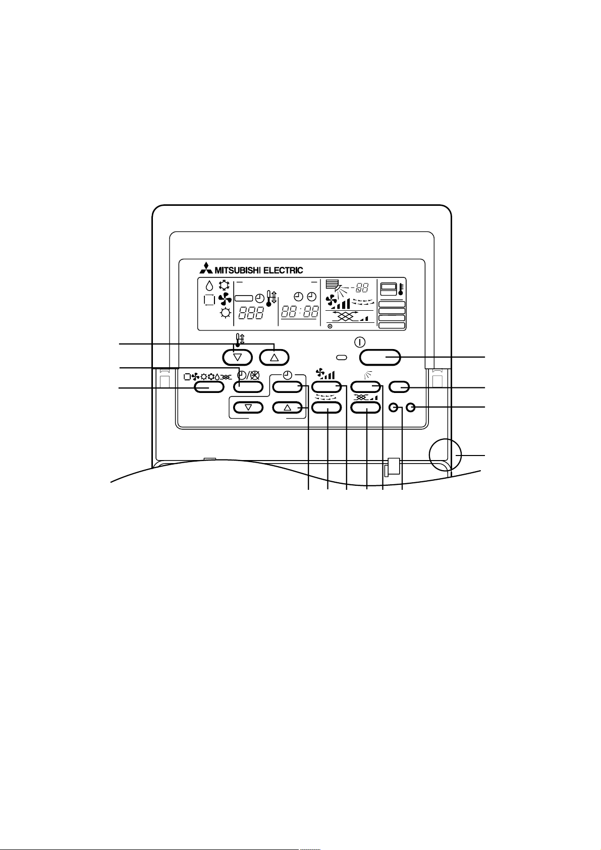
• Remote controller
• Operation buttons
• Once the operation of the unit is set, subsequent operations can
be performed only by pressing the ON/OFF button repeatedly.
1
[Room temperature adjustment] Button
2
[Timer/continuous] Button
3
[Selecting operation] Button
4
[Time selection] Button
[Time-setting] Button
5
[Louver] Button (This button does not operate in this model)
6
[Fan speed adjustment] Button
7
[Up/down airflow direction] Button (This button does not operate in this model)
8
[Ventilation] Button
9
[Checking/built-in] Button
0
[Test run] Button
A
[Filter] Button (This button does not operate in this model)
B
[ON/OFF] Button
C
Position of built-in room temperature
• Never expose the remote controller to direct sunlight. Doing so can result in the erroneous measurement of room temperature.
• Never place any obstacle around the lower right-hand section of the remote controller. Doing so can result in the erroneous
measurement of room temperature.
PAR-20MAA
ON/OFF
CENTRALLY CONTROLLED
ERROR CODE
CLOCK
ON OFF
˚C
CHECK
CHECK MODE
FILTER
TEST RUN
FUNCTION
˚C
1Hr.
NOT AVAILABLE
STAND BY
DEFROST
FILTER
CHECK TEST
TEMP.
TIMER SET
1
2
B
3
456 879
A
0
C
Page 6
6
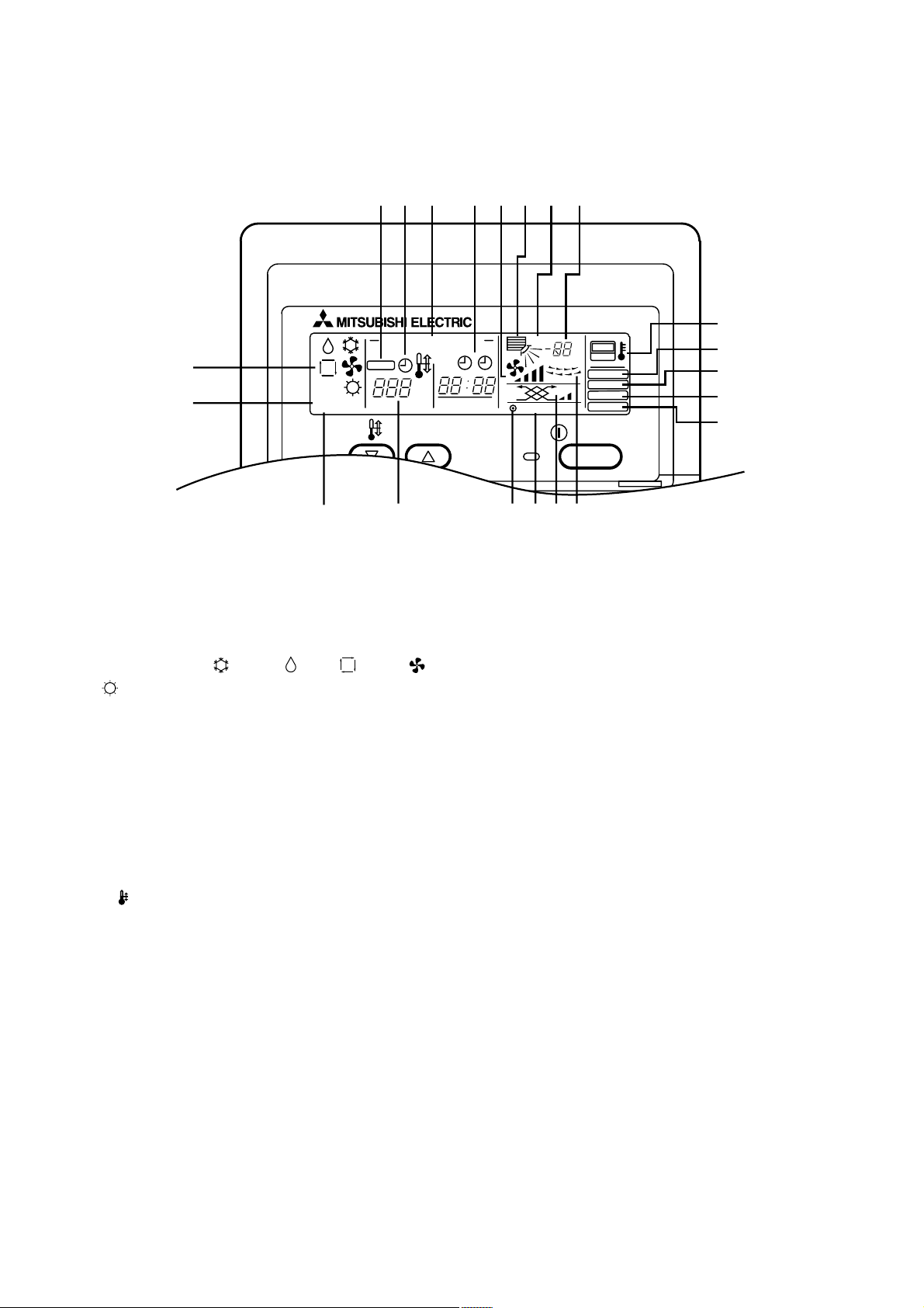
• Display
A Current time/Timer
B Centralized control
C Timer ON
D Abnormality occurs
E Operation mode: COOL, DRY, AUTO, FAN,
HEAT
F Preparing for Heating mode
G Defrost mode
H Set temperature
I Power ON
J Louver
K Not available function
L Ventilation
M Function setting mode
N Test run mode
O Error check mode
P Filter sign
Q Set effective for 1 hr.
R Sensor position
S Room temperature
T Airflow
U Fan speed
Caution
• Power ON display lights up when unit is in standby mode.
• When power is turned ON for the first time the (CENTRAL CTRL) display appears to go off momentarily but this is not a mal-
function.
• When the central control remote control unit, which is sold separately, is used the ON-OFF button, operation switch button
and TEMP. adjustment button do not operate.
•“NOT AVAILABLE”is displayed when the Airflow direction button or Louver button are pressed.This indicates that this room
unit is not equipped with the fan direction adjustment function and the louver function.
• When power is turned ON for the first time, it is normal that “H0” is displayed on the room temperature indication (For max.
2minutes). Please wait until this “H0” indication disappear then start the operation.
ABCD
SQTU
R
E
F
STAND BY
DEFROST
CENTRALLY CONTROLLED
CHECK
˚C
ON OFF
CLOCK
ERROR CODE
TEMP.
G
HIKLJ
1Hr.
NOT AVAILABLE
ON/OFF
˚C
FILTER
CHECK MODE
TEST RUN
FUNCTION
P
O
N
M
Page 7
7
SPECIFICATION
3
Item
Function
Capacity
Total input kW
Service Ref.
Power supply
External finish
Heat exchanger
Fan
Booster heater kW
Operation control & Thermostat
Noise level (Lo-Hi) dB
Unit drain pipe O.D mm (in.)
Dimensions
Weight
Service Ref
Power supply
External finish
Refrigerant control
Compressor
Input kW
Running current A
Starting current A
Fan (drive) × No.
Fan motor output kW
Airflow (Lo-Hi)
External static pressure Pa (mmAq)
W mm (in.)
D mm (in.)
H mm (in.)
.
Running current
Model
Motor output kW
Starter type
Protection devices
Heat exchanger
Fan
OUTDOOR UNITREFRIGERANT PIPING INDOOR UNIT
Defrost method
Noise level
Dimensions
Weight
Refrigerant
Pipe size O.D
Connection method
Between the indoor &
outdoor unit
Crankcase heater W
Fan (drive) × No.
Fan motor output kW
Airflow
Cooling dB
Heating dB
W mm (in.)
D mm (in.)
H mm (in.)
Charge kg (lbs)
Oil (Model) L
Liquid mm (in.)
Gas mm (in.)
Indoor side
Outdoor side
Height difference
Piping length
m3/min (CFM)
Service Ref.
Btu/h
W
3
m
/min (CFM)
kg (lbs)
A
kg (lbs)
PEAD-RP3EA PEAD-RP4EA
Cooling Heating Cooling Heating
24,200 27,300 34,100 38,200
7,100 (3,300-8,100)
2.15 2.34 3.08 3.48
0.35 0.35 0.57 0.57
1.55 1.55 2.53 2.53
2.0 2.0 3.2 3.2
20-25 <706-883> 27-34 <953-1,200>
1,175 (46-1/8) 1,415 (55-11/16)
PUHZ-RP3VHA PUHZ-RP4VHA
8.04 9.74 12.33 13.94
TNB220FMBH ANV33FDAMT
HP switch, Discharge thermo. HP switch, Discharge thermo. LP switch.
Propeller (direct)
330+30 (13+1-3/16) 330+30 (13+1-3/16)
8,000
(3,500-10,200)
PEAD-RP3EA PEAD-RP4EA
Single phase,50Hz,220-230-240V
Galvanized sheets
Centrifugal (direct)
0.15 0.27
Built in remote controller
37-41 41-46
325 (12-13/16)
44 (97) 62 (136)
Single phase,50Hz,220-230-240V
Munsell 3Y 7.8/1.1
Linear Expansion Valve
1.6 1.9
× 1 Propeller (direct) × 2
0.060 0.060+0.060
55 (1,940) 100 (3,530)
Reverse cycle
47 49
48 51
950 (37-3/8) 950 (37-3/8)
943(37-1/8) 1,350(53-1/8)
75 (165) 121 (267)
3.5 (7.7) 5.5 (12.1)
0.87 (NE022) 1.4 (MEL 56)
Max.50m Max.75m
10,000
Plate fin coil
70 (130)
–
32 (1-1/4)
740 (29-1/8)
Hermetic
Line start
–
Plate fin coil
R410A
9.52 (3/8)
15.88 (5/8)
Flared
Flared
Max.30m
(5,000-11,400)
× 2
11,200
(5,600-14,000)
Notes 1. Rating Conditions (ISO 13253 T1)
Cooling: Indoor: D.B.27°C (80°F), W.B.19°C (66°F)
Outdoor: D.B.35°C (95°F), W.B.24°C (75°F)
Heating: Indoor: D.B.20°C (68°F)
Outdoor: D.B.7°C (45°F), W.B.6°C (43°F)
Refrigerant piping length (one way): 5m (16ft)
3. Above data based on indicated voltage
Indoor Unit: Single phase 230V 50Hz
Outdoor Unit: Single phase 230V 50Hz
2. Guaranteed operating range
Cooling
Heating
Upper limit D.B.35°C, W .B.22.5°C D.B.46°C
Lower limi D.B.19°C, W.B .15°C D.B.-5°C
Upper limit D.B.28°C D.B.21°C, W.B.15°C
Lower limi D.B.17°C D.B.-11°C , W.B.-12°C
Indoor Outdoor
Page 8
8
Item
Service Ref.
PEAD-RP5EA PEAD-RP6EA
Function Cooling Heating Cooling Heating
Capacity
Btu/h 42,700 47,800 47,800 54,600
W
12,500 (6,000-14,000) 14,000 (6,000-16,000) 14,000 (6,200-15,300) 16,000 (6,200-18,000)
Total input kW 3.69 4.11 4.91 4.76
Service Ref.
PEAD-RP5EA PEAD-RP6EA
Power supply Single phase, 50Hz,220-230-240V
Input kW 0.59 0.59 0.61 0.61
Running current A 2.62 2.69
2.62 2.69
Starting current A 3.4 3.4 3.5 3.5
External finish Galvanized sheets
Heat exchanger Plate fin coil
Fan
Fan (drive) × No. Centrifugal (direct) × 2
Fan motor output kW 0.40
Airflow (Lo-Hi)
3
m
/min (CFM)
33.5-42 <1,183-1,483> 36.5-46 <1,288-1,624>
External static pressure Pa (mmAq) 70 (130)
Booster heater kW
–
Operation control & Thermostat Built in remote controller
Noise level (Lo-Hi) dB 44-50 46-51
Unit drain pipe O.D mm (in.) 32 (1-1/4)
W mm (in.) 1,415 (55-11/16) 1,715 (67-1/2)
Dimensions
D mm (in.) 740 (29-1/8)
H mm (in.) 325 (12-13/16)
Weight
kg (lbs) 65 (143) 70 (154)
Service Ref. PUHZ-RP5VHA PUHZ-RP6VHA
Power supply Single phase, 50Hz,220-230-240V
Running current A 15.80 17.50 20.73 20.37
External finish Munsell 3Y 7.8/1.1
Refrigerant control Linear Expansion Valve
Compressor Hermetic
Model ANV33FDAMT ANV33FDAMT
Motor output kW 2.4 2.9
Starter type Line start
Protection de
vices
Crankcase heater
W
LP switch, HP switch, Discharge thermo
–
Heat exchanger Plate fin coil
Fan
OUTDOOR UNITREFRIGERANT PIPING INDOOR UNIT
Fan (drive) × No. Propeller (direct) × 2
Fan motor output kW 0.060+0.060
Airflow
m3/min (CFM)
100 (3,530) 100 (3,530)
Defrost method Reverse cycle
Noise level
Cooling dB 50 50
Heating dB 52 52
Dimensions
W mm (in.) 950 (37-3/8)
D mm (in.) 330+30 (13+1-3/16)
H mm (in.) 1,350 (53-1/8)
Weight kg (lbs) 121 (267)
Refrigerant R410A
Charge kg (lbs) 5.5 (12.1)
Oil (Model) L 1.4 (MEL56)
Pipe size O.D
Liquid mm (in.) 9.52 (3/8)
Gas mm (in.) 15.88 (5/8)
Connection method
Indoor side Flared
Outdoor side Flared
Between the indoor &
outdoor unit
Height difference Max.30m
Piping length Max.75m
Notes 1. Rating Conditions (ISO 13253 T1)
Cooling: Indoor: D.B.27°C (80°F), W.B.19°C (66°F)
Outdoor: D.B.35°C (95°F), W.B.24°C (75°F)
Heating: Indoor: D.B.20°C (68°F)
Outdoor: D.B.7°C (45°F), W.B.6°C (43°F)
Refrigerant piping length (one way): 5m (16ft)
3. Above data based on indicated voltage
Indoor Unit: Single phase 230V 50Hz
Outdoor Unit: Single phase 230V 50Hz
2. Guaranteed operating range
Cooling
Heating
Upper limit D.B.35°C, W .B.22.5°C D.B.46°C
Lower limi D.B.19°C, W.B .15°C D.B.-5°C
Upper limit D.B.28°C D.B.21°C, W.B.15°C
Lower limi D.B.17°C D.B.-11°C , W.B.-12°C
Indoor Outdoor
Page 9
9
4
DA T A
20 30
CA SHC(W) SHF P.C. CA
SHC(W)
SHF P.C. CA SHC(W) SHF P.C.
16
18
20
16
18
20
16
18
20
22
16
18
20
22
16
18
20
22
16
18
20
22
16
18
20
22
16
18
20
22
35 40 45
CA
SHC(W)
SHF P.C. CA SHC(W) SHF P.C. CA
SHC(W)
SHF P.C.
16
18
20
16
18
20
16
18
20
22
16
18
20
22
16
18
20
22
16
18
20
22
16
18
20
22
16
18
20
22
7,029 5,061 0.72 1.72 6,816 4,908 0.72 1.81 6,603 4,754 0.72 1.92
7,526 4,365 0.58 1.76 7,313 4,242 0.58 1.84 7,065 4,098 0.58 1.98
8,094 3,642 0.45 1.80 7,917 3,563 0.45 1.89 7,704 3,467 0.45 2.02
7,029 5,693 0.81 1.72 6,816 5,521 0.81 1.81 6,603 5,348 0.81 1.92
7,526 5,042 0.67 1.76 7,313 4,900 0.67 1.84 7,065 4,734 0.67 1.98
8,094 4,371 0.54 1.80 7,917 4,275 0.54 1.89 7,704 4,160 0.54 2.02
7,029 6,326 0.90 1.72 6,816 6,134 0.90 1.81 6,603 5,943 0.90 1.92
7,526 5,720 0.76 1.76 7,313 5,558 0.76 1.84 7,065 5,369 0.76 1.98
8,094 5,099 0.63 1.80 7,917 4,988 0.63 1.89 7,704 4,854 0.63 2.02
8,627 4,227 0.49 1.84 8,449 4,140 0.49 1.95 8,236 4,036 0.49 2.08
7,029 6,959 0.99 1.72 6,816 6,748 0.99 1.81 6,603 6,537 0.99 1.92
7,526 6,397 0.85 1.76 7,313 6,216 0.85 1.84 7,065 6,005 0.85 1.98
8,094 5,828 0.72 1.80 7,917 5,700 0.72 1.89 7,704 5,547 0.72 2.02
8,627 5,004 0.58 1.84 8,449 4,900 0.58 1.95 8,236 4,777 0.58 2.08
7,029 7,029 1.00 1.72 6,816 6,816 1.00 1.81 6,603 6,603 1.00 1.92
7,526 7,074 0.94 1.76 7,313 6,874 0.94 1.84 7,065 6,641 0.94 1.98
8,094 6,556 0.81 1.80 7,917 6,413 0.81 1.89 7,704 6,240 0.81 2.02
8,627 5,780 0.67 1.84 8,449 5,661 0.67 1.95 8,236 5,518 0.67 2.08
7,029 7,029 1.00 1.72 6,816 6,816 1.00 1.81 6,603 6,603 1.00 1.92
7,526 7,526 1.00 1.76 7,313 7,313 1.00 1.84 7,065 7,065 1.00 1.98
8,094 7,285 0.90 1.80 7,917 7,125 0.90 1.89 7,704 6,934 0.90 2.02
8,627 6,557 0.76 1.84 8,449 6,421 0.76 1.95 8,236 6,259 0.76 2.08
7,029 7,029 1.00 1.72 6,816 6,816 1.00 1.81 6,603 6,603 1.00 1.92
7,526 7,526 1.00 1.76 7,313 7,313 1.00 1.84 7,065 7,065 1.00 1.98
8,094 8,013 0.99 1.80 7,917 7,838 0.99 1.89 7,704 7,627 0.99 2.02
8,627 7,333 0.85 1.84 8,449 7,182 0.85 1.95 8,236 7,001 0.85 2.08
7,029 7,029 1.00 1.72 6,816 6,816 1.00 1.81 6,603 6,603 1.00 1.92
7,526 7,526 1.00 1.76 7,313 7,313 1.00 1.84 7,065 7,065 1.00 1.98
8,094 8,094 1.00 1.80 7,917 7,917 1.00 1.89 7,704 7,704 1.00 2.02
8,627 8,109 0.94 1.84 8,449 7,942 0.94 1.95 8,236 7,742 0.94 2.08
6,319 4,550 0.72 2.06 6,035 4,345 0.72 2.22 5,751 4,141 0.72 2.40
6,816 3,953 0.58 2.12 6,603 3,830 0.58 2.28 6,177 3,583 0.58 2.46
7,384 3,323 0.45 2.17 7,100 3,195 0.45 2.32 6,674 3,003 0.45 2.50
6,319 5,118 0.81 2.06 6,035 4,888 0.81 2.22 5,751 4,658 0.81 2.40
6,816 4,567 0.67 2.12 6,603 4,424 0.67 2.28 6,177 4,139 0.67 2.46
7,384 3,987 0.54 2.17 7,100 3,834 0.54 2.32 6,674 3,604 0.54 2.50
6,319 5,687 0.90 2.06 6,035 5,432 0.90 2.22 5,751 5,176 0.90 2.40
6,816 5,180 0.76 2.12 6,603 5,018 0.76 2.28 6,177 4,695 0.76 2.46
7,384 4,652 0.63 2.17 7,100 4,473 0.63 2.32 6,674 4,205 0.63 2.50
7,952 3,896 0.49 2.22 7,668 3,757 0.49 2.39 7,242 3,549 0.49 2.53
6,319 6,256 0.99 2.06 6,035 5,975 0.99 2.22 5,751 5,693 0.99 2.40
6,816 5,794 0.85 2.12 6,603 5,613 0.85 2.28 6,177 5,250 0.85 2.46
7,384 5,316 0.72 2.17 7,100 5,112 0.72 2.32 6,674 4,805 0.72 2.50
7,952 4,612 0.58 2.22 7,668 4,447 0.58 2.39 7,242 4,200 0.58 2.53
6,319 6,319 1.00 2.06 6,035 6,035 1.00 2.22 5,751 5,751 1.00 2.40
6,816 6,407 0.94 2.12 6,603 6,207 0.94 2.28 6,177 5,806 0.94 2.46
7,384 5,981 0.81 2.17 7,100 5,751 0.81 2.32 6,674 5,406 0.81 2.50
7,952 5,328 0.67 2.22 7,668 5,138 0.67 2.39 7,242 4,852 0.67 2.53
6,319 6,319 1.00 2.06 6,035 6,035 1.00 2.22 5,751 5,751 1.00 2.40
6,816 6,816 1.00 2.12 6,603 6,603 1.00 2.28 6,177 6,177 1.00 2.46
7,384 6,646 0.90 2.17 7,100 6,390 0.90 2.32 6,674 6,007 0.90 2.50
7,952 6,044 0.76 2.22 7,668 5,828 0.76 2.39 7,242 5,504 0.76 2.53
6,319 6,319 1.00 2.06 6,035 6,035 1.00 2.22 5,751 5,751 1.00 2.40
6,816 6,816 1.00 2.12 6,603 6,603 1.00 2.28 6,177 6,177 1.00 2.46
7,384 7,310 0.99 2.17 7,100 7,029 0.99 2.32 6,674 6,607 0.99 2.50
7,952 6,759 0.85 2.22 7,668 6,518 0.85 2.39 7,242 6,156 0.85 2.53
6,319 6,319 1.00 2.06 6,035 6,035 1.00 2.22 5,751 5,751 1.00 2.40
6,816 6,816 1.00 2.12 6,603 6,603 1.00 2.28 6,177 6,177 1.00 2.46
7,384 7,384 1.00 2.17 7,100 7,100 1.00 2.32 6,674 6,674 1.00 2.50
7,952 7,475 0.94 2.22 7,668 7,208 0.94 2.39 7,242 6,807 0.94 2.53
Indoor
Intake air
D.B. (°C)
Indoor
Intake air
W.B. (°C)
Outdoor intake air D.B. (°C)
Indoor
Intake air
D.B. (°C)
Indoor
Intake air
W.B. (°C)
Outdoor intake air D.B. (°C)
1. PERFORMANCE DATA
1) COOLING CAPACITY
PEAD-RP3EA/PUHZ-RP3VHA
20
22
24
26
28
30
32
34
20
22
24
26
28
30
32
34
Notes CA: Capacity (W) SHC: Sensible heat capacity (W)
P.C.: Power consumption (kW) SHF: Sensible heat factor
(230V)
Page 10
10
PEAD-RP4EA/PUHZ-RP4VHA
Indoor
Intake air
D.B. (°C)
20
22
24
26
28
30
32
34
Indoor
Intake air
D.B. (°C)
20
22
24
26
28
30
32
34
Indoor
Intake air
W.B. (°C)
16
18
20
16
18
20
16
18
20
22
16
18
20
22
16
18
20
22
16
18
20
22
16
18
20
22
16
18
20
22
Indoor
Intake air
W.B. (°C)
16
18
20
16
18
20
16
18
20
22
16
18
20
22
16
18
20
22
16
18
20
22
16
18
20
22
16
18
20
22
CA SHC(W) SHF P.C. CA SHC(W) SHF P.C. CA SHC(W) SHF P.C.
9,900 7,128 0.72 2.46 9,600 6,912 0.72 2.60 9,300 6,696 0.72 2.75
10,600 6,254 0.59 2.51 10,300 6,077 0.59 2.65 9,950 5,871 0.59 2.84
11,400 5,130 0.45 2.59 11,150 5,018 0.45 2.71 10,850 4,883 0.45 2.90
9,900 8,019 0.81 2.46 9,600 7,776 0.81 2.60 9,300 7,533 0.81 2.75
10,600 7,208 0.68 2.51 10,300 7,004 0.68 2.65 9,950 6,766 0.68 2.84
11,400 6,156 0.54 2.59 11,150 6,021 0.54 2.71 10,850 5,859 0.54 2.90
9,900 8,910 0.90 2.46 9,600 8,640 0.90 2.60 9,300 8,370 0.90 2.75
10,600 8,056 0.76 2.51 10,300 7,828 0.76 2.65 9,950 7,562 0.76 2.84
11,400 7,182 0.63 2.59 11,150 7,025 0.63 2.71 10,850 6,836 0.63 2.90
12,150 6,075 0.50 2.65 11,900 5,950 0.50 2.81 11,600 5,800 0.50 2.99
9,900 9,702 0.98 2.46 9,600 9,408 0.98 2.60 9,300 9,114 0.98 2.75
10,600 9,010 0.85 2.51 10,300 8,755 0.85 2.65 9,950 8,458 0.85 2.84
11,400 8,208 0.72 2.59 11,150 8,028 0.72 2.71 10,850 7,812 0.72 2.90
12,150 7,169 0.59 2.65 11,900 7,021 0.59 2.81 11,600 6,844 0.59 2.99
9,900 9,900 1.00 2.46 9,600 9,600 1.00 2.60 9,300 9,300 1.00 2.75
10,600 9,964 0.94 2.51 10,300 9,682 0.94 2.65 9,950 9,353 0.94 2.84
11,400 9,234 0.81 2.59 11,150 9,032 0.81 2.71 10,850 8,789 0.81 2.90
12,150 8,262 0.68 2.65 11,900 8,092 0.68 2.81 11,600 7,888 0.68 2.99
9,900 9,900 1.00 2.46 9,600 9,600 1.00 2.60 9,300 9,300 1.00 2.75
10,600 10,600 1.00 2.51 10,300 10,300 1.00 2.65 9,950 9,950 1.00 2.84
11,400 10,260 0.90 2.59 11,150 10,035 0.90 2.71 10,850 9,765 0.90 2.90
12,150 9,234 0.76 2.65 11,900 9,044 0.76 2.81 11,600 8,816 0.76 2.99
9,900 9,900 1.00 2.46 9,600 9,600 1.00 2.60 9,300 9,300 1.00 2.75
10,600 10,600 1.00 2.51 10,300 10,300 1.00 2.65 9,950 9,950 1.00 2.84
11,400 11,172 0.98 2.59 11,150 10,927 0.98 2.71 10,850 10,633 0.98 2.90
12,150 10,328 0.85 2.65 11,900 10,115 0.85 2.81 11,600 9,860 0.85 2.99
9,900 9,900 1.00 2.46 9,600 9,600 1.00 2.60 9,300 9,300 1.00 2.75
10,600 10,600 1.00 2.51 10,300 10,300 1.00 2.65 9,950 9,950 1.00 2.84
11,400 11,400 1.00 2.59 11,150 11,150 1.00 2.71 10,850 10,850 1.00 2.90
12,150 11,421 0.94 2.65 11,900 11,186 0.94 2.81 11,600 10,904 0.94 2.99
CA SHC(W) SHF P.C. CA SHC(W) SHF P.C. CA
8,900 6,408 0.72 2.96 8,500 6,120 0.72 3.17 8,100 5,832 0.72 3.44
9,600 5,664 0.59 3.03 9,300 5,487 0.59 3.26 8,700 5,133 0.59 3.51
10,400 4,680 0.45 3.11 10,000 4,500 0.45 3.32 9,400 4,230 0.45 3.57
8,900 7,209 0.81 2.96 8,500 6,885 0.81 3.17 8,100 6,561 0.81 3.44
9,600 6,528 0.68 3.03 9,300 6,324 0.68 3.26 8,700 5,916 0.68 3.51
10,400 5,616 0.54 3.11 10,000 5,400 0.54 3.32 9,400 5,076 0.54 3.57
8,900 8,010 0.90 2.96 8,500 7,650 0.90 3.17 8,100 7,290 0.90 3.44
9,600 7,296 0.76 3.03 9,300 7,068 0.76 3.26 8,700 6,612 0.76 3.51
10,400 6,552 0.63 3.11 10,000 6,300 0.63 3.32 9,400 5,922 0.63 3.57
11,200 5,600 0.50 3.17 10,800 5,400 0.50 3.42 10,200 5,100 0.50 3.64
8,900 8,722 0.98 2.96 8,500 8,330 0.98 3.17 8,100 7,938 0.98 3.44
9,600 8,160 0.85 3.03 9,300 7,905 0.85 3.26 8,700 7,395 0.85 3.51
10,400 7,488 0.72 3.11 10,000 7,200 0.72 3.32 9,400 6,768 0.72 3.57
11,200 6,608 0.59 3.17 10,800 6,372 0.59 3.42 10,200 6,018 0.59 3.64
8,900 8,900 1.00 2.96 8,500 8,500 1.00 3.17 8,100 8,100 1.00 3.44
9,600 9,024 0.94 3.03 9,300 8,742 0.94 3.26 8,700 8,178 0.94 3.51
10,400 8,424 0.81 3.11 10,000 8,100 0.81 3.32 9,400 7,614 0.81 3.57
11,200 7,616 0.68 3.17 10,800 7,344 0.68 3.42 10,200 6,936 0.68 3.64
8,900 8,900 1.00 2.96 8,500 8,500 1.00 3.17 8,100 8,100 1.00 3.44
9,600 9,600 1.00 3.03 9,300 9,300 1.00 3.26 8,700 8,700 1.00 3.51
10,400 9,360 0.90 3.11 10,000 9,000 0.90 3.32 9,400 8,460 0.90 3.57
11,200 8,512 0.76 3.17 10,800 8,208 0.76 3.42 10,200 7,752 0.76 3.64
8,900 8,900 1.00 2.96 8,500 8,500 1.00 3.17 8,100 8,100 1.00 3.44
9,600 9,600 1.00 3.03 9,300 9,300 1.00 3.26 8,700 8,700 1.00 3.51
10,400 10,192 0.98 3.11 10,000 9,800 0.98 3.32 9,400 9,212 0.98 3.57
11,200 9,520 0.85 3.17 10,800 9,180 0.85 3.42 10,200 8,670 0.85 3.64
8,900 8,900 1.00 2.96 8,500 8,500 1.00 3.17 8,100 8,100 1.00 3.44
9,600 9,600 1.00 3.03 9,300 9,300 1.00 3.26 8,700 8,700 1.00 3.51
10,400 10,400 1.00 3.11 10,000 10,000 1.00 3.32 9,400 9,400 1.00 3.57
11,200 10,528 0.94 3.17 10,800 10,152 0.94 3.42 10,200 9,588 0.94 3.64
Outdoor intake air D.B. (°C)
20 25 30
Outdoor intake air D.B. (°C)
35 40 45
SHC(W)
Notes CA: Capacity (W) SHC: Sensible heat capacity (W)
P.C.: Power consumption (kW) SHF: Sensible heat factor
(230V)
SHF P.C.
Page 11
11
PEAD-RP5EA/PUHZ-RP5VHA
Indoor
Intake air
D.B. (°C)
20
22
24
26
28
30
32
34
Indoor
Intake air
W.B. (°C)
16
18
20
16
18
20
16
18
20
22
16
18
20
22
16
18
20
22
16
18
20
22
16
18
20
22
16
18
20
22
CA SHC(W) SHF P.C. CA SHC(W) SHF P.C. CA
12,375 8,910 0.72 2.95 12,000 8,640 0.72 3.12 11,625 8,370 0.72 3.30
13,250 7,685 0.58 3.01 12,875 7,468 0.58 3.18 12,438 7,214 0.58 3.40
14,250 6,413 0.45 3.10 13,938 6,272 0.45 3.24 13,563 6,103 0.45 3.47
12,375 10,024 0.81 2.95 12,000 9,720 0.81 3.12 11,625 9,416 0.81 3.30
13,250 8,878 0.67 3.01 12,875 8,626 0.67 3.18 12,438 8,333 0.67 3.40
14,250 7,695 0.54 3.10 13,938 7,527 0.54 3.24 13,563 7,324 0.54 3.47
12,375 11,138 0.90 2.95 12,000 10,800 0.90 3.12 11,625 10,463 0.90 3.30
13,250 10,070 0.76 3.01 12,875 9,785 0.76 3.18 12,438 9,453 0.76 3.40
14,250 8,978 0.63 3.10 13,938 8,781 0.63 3.24 13,563 8,545 0.63 3.47
15,188 7,442 0.49 3.18 14,875 7,289 0.49 3.36 14,500 7,105 0.49 3.58
12,375 12,251 0.99 2.95 12,000 11,880 0.99 3.12 11,625 11,509 0.99 3.30
13,250 11,263 0.85 3.01 12,875 10,944 0.85 3.18 12,438 10,572 0.85 3.40
14,250 10,260 0.72 3.10 13,938 10,035 0.72 3.24 13,563 9,765 0.72 3.47
15,188 8,809 0.58 3.18 14,875 8,628 0.58 3.36 14,500 8,410 0.58 3.58
12,375 12,375 1.00 2.95 12,000 12,000 1.00 3.12 11,625 11,625 1.00 3.30
13,250 12,455 0.94 3.01 12,875 12,103 0.94 3.18 12,438 11,692 0.94 3.40
14,250 11,543 0.81 3.10 13,938 11,290 0.81 3.24 13,563 10,986 0.81 3.47
15,188 10,176 0.67 3.18 14,875 9,966 0.67 3.36 14,500 9,715 0.67 3.58
12,375 12,375 1.00 2.95 12,000 12,000 1.00 3.12 11,625 11,625 1.00 3.30
13,250 13,250 1.00 3.01 12,875 12,875 1.00 3.18 12,438 12,438 1.00 3.40
14,250 12,825 0.90 3.10 13,938 12,544 0.90 3.24 13,563 12,207 0.90 3.47
15,188 11,543 0.76 3.18 14,875 11,305 0.76 3.36 14,500 11,020 0.76 3.58
12,375 12,375 1.00 2.95 12,000 12,000 1.00 3.12 11,625 11,625 1.00 3.30
13,250 13,250 1.00 3.01 12,875 12,875 1.00 3.18 12,438 12,438 1.00 3.40
14,250 14,108 0.99 3.10 13,938 13,799 0.99 3.24 13,563 13,427 0.99 3.47
15,188 12,910 0.85 3.18 14,875 12,644 0.85 3.36 14,500 12,325 0.85 3.58
12,375 12,375 1.00 2.95 12,000 12,000 1.00 3.12 11,625 11,625 1.00 3.30
13,250 13,250 1.00 3.01 12,875 12,875 1.00 3.18 12,438 12,438 1.00 3.40
14,250 14,250 1.00 3.10 13,938 13,938 1.00 3.24 13,563 13,563 1.00 3.47
15,188 14,277 0.94 3.18 14,875 13,983 0.94 3.36 14,500 13,630 0.94 3.58
Outdoor intake air D.B. (°C)
20 25 30
SHC(W)
(230V)
SHF P.C.
Indoor
Intake air
D.B. (°C)
20
22
24
26
28
30
32
34
Indoor
Intake air
W.B. (°C)
16
18
20
16
18
20
16
18
20
22
16
18
20
22
16
18
20
22
16
18
20
22
16
18
20
22
16
18
20
22
Outdoor intake air D.B. (°C)
35 40 45
CA SHC(W) SHF P.C. CA SHC(W) SHF P.C. CA
11,125 8,010 0.72 3.54 10,625 7,650 0.72 3.80 10,125 7,290 0.72 4.12
12,000 6,960 0.58 3.63 11,625 6,743 0.58 3.91 10,875 6,308 0.58 4.20
13,000 5,850 0.45 3.73 12,500 5,625 0.45 3.98 11,750 5,288 0.45 4.28
11,125 9,011 0.81 3.54 10,625 8,606 0.81 3.80 10,125 8,201 0.81 4.12
12,000 8,040 0.67 3.63 11,625 7,789 0.67 3.91 10,875 7,286 0.67 4.20
13,000 7,020 0.54 3.73 12,500 6,750 0.54 3.98 11,750 6,345 0.54 4.28
11,125 10,013 0.90 3.54 10,625 9,563 0.90 3.80 10,125 9,113 0.90 4.12
12,000 9,120 0.76 3.63 11,625 8,835 0.76 3.91 10,875 8,265 0.76 4.20
13,000 8,190 0.63 3.73 12,500 7,875 0.63 3.98 11,750 7,403 0.63 4.28
14,000 6,860 0.49 3.80 13,500 6,615 0.49 4.10 12,750 6,248 0.49 4.35
11,125 11,014 0.99 3.54 10,625 10,519 0.99 3.80 10,125 10,024 0.99 4.12
12,000 10,200 0.85 3.63 11,625 9,881 0.85 3.91 10,875 9,244 0.85 4.20
13,000 9,360 0.72 3.73 12,500 9,000 0.72 3.98 11,750 8,460 0.72 4.28
14,000 8,120 0.58 3.80 13,500 7,830 0.58 4.10 12,750 7,395 0.58 4.35
11,125 11,125 1.00 3.54 10,625 10,625 1.00 3.80 10,125 10,125 1.00 4.12
12,000 11,280 0.94 3.63 11,625 10,928 0.94 3.91 10,875 10,223 0.94 4.20
13,000 10,530 0.81 3.73 12,500 10,125 0.81 3.98 11,750 9,518 0.81 4.28
14,000 9,380 0.67 3.80 13,500 9,045 0.67 4.10 12,750 8,543 0.67 4.35
11,125 11,125 1.00 3.54 10,625 10,625 1.00 3.80 10,125 10,125 1.00 4.12
12,000 12,000 1.00 3.63 11,625 11,625 1.00 3.91 10,875 10,875 1.00 4.20
13,000 11,700 0.90 3.73 12,500 11,250 0.90 3.98 11,750 10,575 0.90 4.28
14,000 10,640 0.76 3.80 13,500 10,260 0.76 4.10 12,750 9,690 0.76 4.35
11,125 11,125 1.00 3.54 10,625 10,625 1.00 3.80 10,125 10,125 1.00 4.12
12,000 12,000 1.00 3.63 11,625 11,625 1.00 3.91 10,875 10,875 1.00 4.20
13,000 12,870 0.99 3.73 12,500 12,375 0.99 3.98 11,750 11,633 0.99 4.28
14,000 11,900 0.85 3.80 13,500 11,475 0.85 4.10 12,750 10,838 0.85 4.35
11,125 11,125 1.00 3.54 10,625 10,625 1.00 3.80 10,125 10,125 1.00 4.12
12,000 12,000 1.00 3.63 11,625 11,625 1.00 3.91 10,875 10,875 1.00 4.20
13,000 13,000 1.00 3.73 12,500 12,500 1.00 3.98 11,750 11,750 1.00 4.28
14,000 13,160 0.94 3.80 13,500 12,690 0.94 4.10 12,750 11,985 0.94 4.35
Notes CA: Capacity (W) SHC: Sensible heat capacity (W)
P.C.: Power consumption (kW) SHF: Sensible heat factor
SHC(W)
SHF P.C.
Page 12
12
PEAD-RP6EA/PUHZ-RP6VHA
Indoor
Intake air
D.B. (°C)
20
22
24
26
28
30
32
34
Indoor
Intake air
W.B. (°C)
16
18
20
16
18
20
16
18
20
22
16
18
20
22
16
18
20
22
16
18
20
22
16
18
20
22
16
18
20
22
CA
13,860 9,702 0.70 3.93 13,440 9,408 0.70 4.15 13,020 9,114 0.70 4.40
14,840 8,459 0.57 4.00 14,420 8,219 0.57 4.22 13,930 7,940 0.57 4.52
15,960 6,863 0.43 4.12 14,610 6,282 0.43 4.32 15,190 6,532 0.43 4.61
13,860 11,088 0.80 3.93 13,440 10,752 0.80 4.15 13,020 10,416 0.80 4.40
14,840 9,794 0.66 4.00 14,420 9,517 0.66 4.22 13,930 9,194 0.66 4.52
15,960 8,299 0.52 4.12 14,610 7,597 0.52 4.32 15,190 7,899 0.52 4.61
13,860 12,335 0.89 3.93 13,440 11,962 0.89 4.15 13,020 11,588 0.89 4.40
14,840 11,130 0.75 4.00 14,420 10,815 0.75 4.22 13,930 10,448 0.75 4.52
15,960 9,736 0.61 4.12 14,610 8,912 0.61 4.32 15,190 9,266 0.61 4.61
17,010 7,995 0.47 4.22 16,660 7,830 0.47 4.47 16,240 7,633 0.47 4.76
13,860 13,583 0.98 3.93 13,440 13,171 0.98 4.15 13,020 12,760 0.98 4.40
14,840 12,466 0.84 4.00 14,420 12,113 0.84 4.22 13,930 11,701 0.84 4.52
15,960 11,172 0.70 4.12 14,610 10,227 0.70 4.32 15,190 10,633 0.70 4.61
17,010 9,696 0.57 4.22 16,660 9,496 0.57 4.47 16,240 9,257 0.57 4.76
13,860 13,860 1.00 3.93 13,440 13,440 1.00 4.15 13,020 13,020 1.00 4.40
14,840 13,950 0.94 4.00 14,420 13,555 0.94 4.22 13,930 13,094 0.94 4.52
15,960 12,768 0.80 4.12 14,610 11,688 0.80 4.32 15,190 12,152 0.80 4.61
17,010 11,227 0.66 4.22 16,660 10,996 0.66 4.47 16,240 10,718 0.66 4.76
13,860 13,860 1.00 3.93 13,440 13,440 1.00 4.15 13,020 13,020 1.00 4.40
14,840 14,840 1.00 4.00 14,420 14,420 1.00 4.22 13,930 13,930 1.00 4.52
15,960 14,204 0.89 4.12 14,610 13,003 0.89 4.32 15,190 13,519 0.89 4.61
17,010 12,758 0.75 4.22 16,660 12,495 0.75 4.47 16,240 12,180 0.75 4.76
13,860 13,860 1.00 3.93 13,440 13,440 1.00 4.15 13,020 13,020 1.00 4.40
14,840 14,840 1.00 4.00 14,420 14,420 1.00 4.22 13,930 13,930 1.00 4.52
15,960 15,641 0.98 4.12 14,610 14,318 0.98 4.32 15,190 14,886 0.98 4.61
17,010 14,288 0.84 4.22 16,660 13,994 0.84 4.47 16,240 13,642 0.84 4.76
13,860 13,860 1.00 3.93 13,440 13,440 1.00 4.15 13,020 13,020 1.00 4.40
14,840 14,840 1.00 4.00 14,420 14,420 1.00 4.22 13,930 13,930 1.00 4.52
15,960 15,960 1.00 4.12 14,610 14,610 1.00 4.32 15,190 15,190 1.00 4.61
17,010 15,989 0.94 4.22 16,660 15,660 0.94 4.47 16,240 15,266 0.94 4.76
Outdoor intake air D.B. (°C)
20 25 30
SHC(W)
SHF P.C. CA SHC(W) SHF P.C. CA SHC(W) SHF P.C.
(230V)
Indoor
Intake air
D.B. (°C)
20
22
24
26
28
30
32
34
Indoor
Intake air
W.B. (°C)
16
18
20
16
18
20
16
18
20
22
16
18
20
22
16
18
20
22
16
18
20
22
16
18
20
22
16
18
20
22
Outdoor intake air D.B. (°C)
35 40 45
CA SHC(W) SHF P.C. CA SHC(W) SHF P.C. CA SHC(W) SHF P.C.
12,460 8,722 0.70 4.71 11,900 8,330 0.70 5.06 11,340 7,938 0.70 5.47
13,440 7,661 0.57 4.84 13,020 7,421 0.57 5.21 12,180 6,943 0.57 5.60
14,560 6,261 0.43 4.96 14,000 6,020 0.43 5.30 13,160 5,659 0.43 5.70
12,460 9,968 0.80 4.71 11,900 9,520 0.80 5.06 11,340 9,072 0.80 5.47
13,440 8,870 0.66 4.84 13,020 8,593 0.66 5.21 12,180 8,039 0.66 5.60
14,560 7,571 0.52 4.96 14,000 7,280 0.52 5.30 13,160 6,843 0.52 5.70
12,460 11,089 0.89 4.71 11,900 10,591 0.89 5.06 11,340 10,093 0.89 5.47
13,440 10,080 0.75 4.84 13,020 9,765 0.75 5.21 12,180 9,135 0.75 5.60
14,560 8,882 0.61 4.96 14,000 8,540 0.61 5.30 13,160 8,028 0.61 5.70
15,680 7,370 0.47 5.06 15,120 7,106 0.47 5.45 14,280 6,712 0.47 5.80
12,460 12,211 0.98 4.71 11,900 11,662 0.98 5.06 11,340 11,113 0.98 5.47
13,440 11,290 0.84 4.84 13,020 10,937 0.84 5.21 12,180 10,231 0.84 5.60
14,560 10,192 0.70 4.96 14,000 9,800 0.70 5.30 13,160 9,212 0.70 5.70
15,680 8,938 0.57 5.06 15,120 8,618 0.57 5.45 14,280 8,140 0.57 5.80
12,460 12,460 1.00 4.71 11,900 11,900 1.00 5.06 11,340 11,340 1.00 5.47
13,440 12,634 0.94 4.84 13,020 12,239 0.94 5.21 12,180 11,449 0.94 5.60
14,560 11,648 0.80 4.96 14,000 11,200 0.80 5.30 13,160 10,528 0.80 5.70
15,680 10,349 0.66 5.06 15,120 9,979 0.66 5.45 14,280 9,425 0.66 5.80
12,460 12,460 1.00 4.71 11,900 11,900 1.00 5.06 11,340 11,340 1.00 5.47
13,440 13,440 1.00 4.84 13,020 13,020 1.00 5.21 12,180 12,180 1.00 5.60
14,560 12,958 0.89 4.96 14,000 12,460 0.89 5.30 13,160 11,712 0.89 5.70
15,680 11,760 0.75 5.06 15,120 11,340 0.75 5.45 14,280 10,710 0.75 5.80
12,460 12,460 1.00 4.71 11,900 11,900 1.00 5.06 11,340 11,340 1.00 5.47
13,440 13,440 1.00 4.84 13,020 13,020 1.00 5.21 12,180 12,180 1.00 5.60
14,560 14,269 0.98 4.96 14,000 13,720 0.98 5.30 13,160 12,897 0.98 5.70
15,680 13,171 0.84 5.06 15,120 12,701 0.84 5.45 14,280 11,995 0.84 5.80
12,460 12,460 1.00 4.71 11,900 11,900 1.00 5.06 11,340 11,340 1.00 5.47
13,440 13,440 1.00 4.84 13,020 13,020 1.00 5.21 12,180 12,180 1.00 5.60
14,560 14,560 1.00 4.96 14,000 14,000 1.00 5.30 13,160 13,160 1.00 5.70
15,680 14,739 0.94 5.06 15,120 14,213 0.94 5.45 14,280 13,423 0.94 5.80
Notes CA: Capacity (W) SHC: Sensible heat capacity (W)
P.C.: Power consumption (kW) SHF: Sensible heat factor
Page 13

13
Cooling capacity correction factors
Service Ref.
PEAD-RP3EA
5m 10m 15m 20m 25m 30m 35m 40m 45m 50m 55m 60m 65m 70m 75m 80m
1.00
0.989
0.978
0.967
0.956
Refrigerant piping length (one way)
0.947
0.938
0.930
0.913
0.905
PEAD-RP4EA
PEAD-RP5EA
PEAD-RP6EA
1.4
1.2
1.0
0.8
1.2
1.0
0.8
0.6
TOTAL INPUT (RATIO) CAPACITY (RATIO)
0.4
1.00
1.00
1.00
0.985
0.971
0.982
0.963
0.976
0.953
10
20 30 46400-5
OUTDOOR D.B.(°C)
0.958
0.947
0.932
0.943
0.931
0.930
0.914
0.912
0.893
INDOOR W.B.(°C)
22
20
18
16
INDOOR W.B.(°C)
22
20
18
16
0.919
0.900
0.876
0.908
0.885
0.858
0.898
0.871
0.842
0.887
0.858
0.828
0.876
0.845
0.813
0.865
0.834
0.800
0.855
0.823
0.788
0.847
0.812
0.776
0.838
0.802
0.764
0.829
0.792
0.753
Page 14

14
2) HEATING CAPACITY
PUHZ-RP3VHA, PUHZ-RP4VHA, PUHZ-RP5VHA, PUHZ-RP6VHA
Indoor
Service Ref.
PEAD-RP3EA
PEAD-RP4EA
PEAD-RP5EA
PEAD-RP6EA
Note CA: Capacity (W)
P.C.: Power consumption (kW)
intake are
D.B. (˚C)
15
20
25
15
20
25
15
20
25
15
20
25
-10 -5 0 5 10 15
CA
P.C. CA P.C. CA P.C. CA P.C. CA P.C. CA P.C.
5,080
4,880
4,720
7,112
6,832
6,608
8,890
8,540
8,260
10,160
9,760
9,440
1.38
1.50
1.59
2.05
2.23
2.37
2.43
2.63
2.79
2.81
3.04
3.24
5,520
5,280
5,120
7,728
7,392
7,168
9,660
9,240
8,960
11,040
10,560
10,240
1.52
1.64
1.78
2.26
2.43
2.65
2.68
2.88
3.13
3.09
3.34
3.62
Outdoor intake air W.B. (:)
6,160
5,840
5,600
8,624
8,176
7,840
10,780
10,220
9,800
12,320
11,680
11,200
Heating capacity correction factors
Service Ref.
PEAD-RP3EA
5m 10m 15m 20m 25m 30m 35m 40m 45m 50m 55m 60m 65m 70m 75m 80m
1.00
0.997
0.994
0.991
0.988
Refrigerant piping length (one way)
0.985
0.982
0.979
1.76
1.90
2.06
2.61
2.82
3.06
3.08
3.33
3.62
3.57
3.86
4.19
0.976
8,080
7,800
7,360
11,312
10,920
10,304
14,140
13,650
12,880
16,160
15,600
14,720
0.973
2.11
2.27
2.41
3.13
3.38
3.58
3.70
3.98
4.24
4.29
4.61
4.91
9,120
8,800
8,480
12,768
12,320
11,872
15,960
15,400
14,840
18,240
17,600
16,960
2.34
2.53
2.70
3.48
3.76
4.02
4.11
4.44
4.75
4.76
5.14
5.50
10,160
9,800
9,440
14,224
13,720
13,216
17,780
17,150
16,520
20,320
19,600
18,880
(230V)
2.53
2.71
2.91
3.76
4.03
4.33
4.44
4.76
5.12
5.14
5.53
5.92
PEAD-RP4EA
PEAD-RP5EA
PEAD-RP6EA
1.00
1.00
1.00
0.997
0.997
0.997
0.994
0.994
0.994
0.991
0.991
0.991
0.988
0.988
0.988
0.985
0.985
0.985
0.982
0.982
0.982
0.979
0.979
0.979
0.976
0.976
0.976
0.973
0.973
0.973
0.970
0.970
0.970
0.967
0.967
0.967
0.964
0.964
0.964
0.961
0.961
0.961
0.958
0.958
0.958
0.955
0.955
0.955
Page 15

15
1.4
1.2
1.0
15
20
25
25
20
15
0.8
0.6
0.4
1.4
1.2
1.0
0.8
0.6
0.4
-12 -10 -5 0 5 10 15
INDOOR
D.B.(°C)
INDOOR
D.B.(°C)
OUTDOOR W.B.(°C)
CAPACITY (RATIO)TOTAL INPUT (RATIO)
Correcting the capacity line influenced by frosting
Not correcting the capacity line influenced by frosting
In some cases, heating operation
cannot be conducted with the maximum
frequency in the area below the slanting line.
In some cases, heating operation
cannot be conducted with the maximum
frequency in the area above the slanting line.
Heating
Page 16

16
PEAD-RP4EA
2 .FAN PERFORMANCE AND CORRECTED AIR FLOW
PEAD-RP3EA
Fan performance <130pa>
Recommended range
200
180
160
140
120
100
80
=
60
40
(1Pa 0.1mmAg)
20
Extemal static pressure (Pa)
12 16 20 24 28 32
Air flow
Corrected Air Flow
Cooling
1.1
1.0
0.9
Correction factor
0.8
12 16 20 24 28 32
Hi
Lo
(CMM)
Capacity
Input
Air flow (CMM)
Fan performance <70pa>
Recommended range
180
160
140
120
100
80
=
60
40
(1Pa 0.1mmAg)
20
Extemal static pressure (Pa)
12 16 20 24 28 32
Air flow
Heating
1.3
1.2
1.1
1.0
Correction factor
0.9
0.8
12 16 20 24 28 32
Lo
Hi
(CMM)
Air flow (CMM)
Fan performance <130pa>
Recommended range
200
180
160
140
120
100
80
=
60
40
(1Pa 0.1mmAg)
20
Extemal static pressure (Pa)
Lo
26 28 30 32 34 36 38 40
Air flow
Corrected Air Flow
Cooling
1.1
1.0
0.9
Correction factor
0.8
24 26 28 30 32 34 36 38 40
Hi
(CMM)
Air flow (CMM)
Capacity
Input
Fan performance <70pa>
Recommended range
220
200
180
160
140
120
100
80
=
60
40
(1Pa 0.1mmAg)
20
Extemal static pressure (Pa)
24 26 28 30 32 34 36 38
Air flow
Heating
1.2
1.1
1.0
0.9
Correction factor
0.8
24 26 28 30 32 34 36 38 40
Hi
Lo
(CMM)
Air flow (CMM)
Page 17

17
PEAD-RP5EA
PEAD-RP6EA
Fan performance <130pa>
Recommended range
220
200
180
160
140
120
100
80
=
60
(1Pa 0.1mmAg)
40
20
Extemal static pressure (Pa)
Lo
Hi
Fan performance <70pa>
Recommended range
220
200
180
160
140
120
100
80
=
60
(1Pa 0.1mmAg)
40
20
Extemal static pressure (Pa)
Hi
Lo
32 34 36 38 40 42 44 46 48
Air flow
(CMM)
Corrected Air Flow
Cooling
1.1
1.0
0.9
Correction factor
0.8
32 34 36 38 40 42 44 46 48
Air flow (CMM)
Fan performance <130pa>
Recommended range
220
200
180
160
140
120
100
=
80
60
(1Pa 0.1mmAg)
40
20
Extemal static pressure (Pa)
Lo
38 40 42 44 46 48 50
36
Air flow
Hi
52
(CMM)
Corrected Air Flow Capacity
Cooling
1.1
Capacity
Input
Input
32 34 36 38 40 42 44 46
Air flow
(CMM)
Heating
1.2
1.1
1.0
0.9
Correction factor
0.8
32 34 36 38 40 42 44 46 48
Fan performance <70pa>
Recommended range
200
180
160
140
120
=
100
80
(1Pa 0.1mmAg)
60
40
Extemal static pressure (Pa)
20
Lo
38 40 42 44 46 48
36
Air flow
(CMM)
Heating
1.2
1.1
Air flow (CMM)
Hi
50
1.0
0.9
Correction factor
0.8
36 38 40 42 44 46
Air flow (CMM)
48 50
52
1.0
0.9
Correction factor
0.8
36 38 40 42 44 46
Air flow (CMM)
48
50 52
Page 18

18
3. STANDARD OPERATION DATA
TotalElectrical circuitRefrigerant circuitIndoor side
Outdoor
side
Service Ref.
Heat pump type
SHF
BF
V
kW
A
V
A
MPa
MPa
°C
°C
°C
m
°C
°C
°C
°C
°C
Mode
Phase, Hz
Volts
Input
Amperes
Outdoor unit Service Ref.
Phase, Hz
Volts
Amperes
Discharge pressure
Suction pressure
Discharge temperature
Condensing temperature
Suction temperature
Ref. pipe length
Intake air temperature
Discharge air temperature
Intake air temperature
1 , 50
230
PUHZ-RP6VHA
1, 50
230
0.61
2.69
20.73
2.88
0.88
77.0
48.1
10.4
5
27
19
14.9
35
24
0.82
0.14
(29.4)
(9.0)
(27.7)
(7.0)
(kgf/F)
(kgf/F)
0.61
2.69
20.37
2.72
0.69
72.9
—
-0.2
5
20
15
38.6
7
6
—
—
Indoor unit Service Ref.
PEAD-RP6EA
Capacity
Input
W
kW
Cooling
14,000
4.91
1 , 50
230
PUHZ-RP5VHA
1, 50
230
0.59
2.62
15.80
2.69
0.95
69.0
46.0
10.1
5
27
19
15.1
35
24
0.83
0.14
(27.4)
(9.7)
(25.0)
(6.9)
0.59
2.62
17.50
2.45
0.68
65.7
—
-0.7
5
20
15
37.8
7
6
—
—
PEAD-RP5EA
Cooling
12,500
3.69
1 , 50
230
PUHZ-RP4VHA
1, 50
230
0.57
2.53
12.33
2.65
0.92
70.1
45.1
10.0
5
27
19
15.2
35
24
0.83
0.15
(27.0)
(9.4)
(30.8)
(7.7)
0.57
2.53
13.94
3.02
0.75
79.1
—
1.9
5
20
15
37.6
7
6
—
—
PEAD-RP4EA
Cooling
10,000
3.08
0.35
1.55
8.04
2.69
0.95
69.4
45.8
9.8
5
27
19
15.5
35
24
0.83
0.18
(27.4)
(9.7)
(26.2)
(7.0)
0.35
1.55
9.74
2.57
0.69
68.8
—
0.9
5
20
15
37.0
7
6
—
—
PEAD-RP3EA
PEAD-RP6EAPEAD-RP5EAPEAD-RP4EAPEAD-RP3EA
Cooling
7,100
2.15
D.B.
W.B.
D.B.
D.B.
W.B.
The unit of pressure has been changed to Mpa based on international SI system.
The conversion factor is : 1 (Mpa) = 10.2 (kgf/cm
2
)
Heating
8,000
2.34
Heating
11,200
3.48
Heating
14,000
4.11
Heating
16,000
4.76
1 , 50
230
PUHZ-RP3VHA
1, 50
230
Page 19

19
5
REFRIGERANT SYSTEM DIAGRAM
PEAD-RP3, 4, 5, 6EA
Indoor unit
Indoor
heat
exchanger
Thermistor TH5
(Cond./Eva.
temperature)
Strainer
Refrigerant flow in cooling
Refrigerant flow in heating
Refrigerant GAS pipe connection
Thermistor TH1
(Room temperature)
Thermistor TH2
Pipe temperature
(Liquid)
Distributor
with strainer
Refrigerant LIQUID pipe connection
Page 20

20
2. REMOTE CONTROLLER
6
OUTLINES & DIMENSIONS
1. INDOOR UNIT
PEAD-RP3, 4, 5, 6EA
Model
2801012
RP3
1252
RP4.5
1
Refrigerant piping flare connection (liquid ø9.52 copper tube) : HP
Refrigerant piping flare connection (gas øF copper tube) : LP
2
Drain 25A (male screw)
3
Electrical parts box
4
5
Drain Pump (Option)
6
Drain Pipe (Option) Flexible joint VP25(I.D.ø32)
7
Filter
Air inlet
. . .
30
30
319
261
181 40
7
3 3
EDCBA
12841310370360
F
15.8810441070290
For PUHZ-RP type :15.88
For PU(H)-P type :19.05158416104704601552RP6
680
282
4
Service space:500 or more
450
Access door
450
365-465
Set
30
1053
1
2
35
20
122
210
140
Air outlet
307
45
323
50-150
81
55
197
308
81
13
44
75
243
6
113
5
3
A
C B 81
C B 81
A
E 13
12-ø3
10
Lifting bolt hole
375
80
10
30D
(4X22)
12-ø3
Keep duct-work length 850mm or more.
Be sure to apply the air filter (field supply) near the air inlet grille.
(Front view) (Side view) (Rear view)
120
130
19
83.5
46
Page 21

21
7
WIRING DIAGRAM
MF
C
(White)
External static pressure : 70Pa(7mmAq)
Optional parts
MF
C
External static
pressure 130Pa(13mmAq)
INDOOR UNIT
P.B
Optional parts
DP
I.B
3
CNP
(BLU)
PIPE
CN29
(BLK)
21
1
LED3 LED3 LED3
SWE
ON
OFF
Optional parts
DRAIN PUMP
DRAIN
CN31
(WHT)
12
DS
FAN
(WHT)
GRE
1
3
5
6
(Red)
7
PNK
PNK
BLK
1
3
5
6
5
3
1
SW2
X6 X5 X4
SW1
X4
X5
X6
3
TH1TH2TH5
POWER
CN03
(RED)
YLW
13
ORN
BRN
5
3
2
1
1
2
CN31
LIQUID
2
CN21
1
(WHT)
INTAKE
2
CN20
1
(RED)
HEATER
CN24
(YLW)
WHT
BLK
1
2
WIRELESS
CN90
(WHT)
POWER
CN2D
(WHT)
TRANSMISSION WIRE
CN22
DC12V
2
1
CN32CN41
CN2L
CN2S(WHT)
2
DC14V
1
3
2
1
CONT.BOARD
CN02(WHT)
ZNR
TB5
2
PUR
TO RMOTE CONTROLLER
PUR
1
DC12V
F
OUTDOOR
CN01(BLU)
TB4
YLW
ORN
BRN
S1
S2
S3
TO OUTDOOR UNIT
1
2
3
SYMBOL
I.B
INDOOR CONTROLLER BOARD
CN2L
CONNECTOR(LOSSNAY)
CONNECTOR(REMOTE SWITCH)
CN32
CONNECTOR(HA TERMINAL-A)
CN41
POWER SUPPLY(I.B)
LED1
POWER SUPPLY(REMOTE CONTROLLER)
LED2
TRANSMISSION(INDOOR/OUTDOOR)
LED3
JUMPER WIRE(MODEL SELECTION)
SW1
JUMPER WIRE(CAPACITY CORD)
SW2
SWITCH(EMERGENCY OPERATION)
SWE
RELAY(FAN MOTOR)
X4
RELAY(FAN MOTOR)
X5
RELAY(FAN MOTOR)
X6
NAME
SYMBOL
P.B
INDOOR POWER BOARD
FUSE(4A)
F1
VARISTOR
ZNR
DRAIN PUMP
(OPTIONAL PARTS)
DPDSDRAIN PUMP
DRAIN SENSOR
NAME NAME
SYMBOL
C
CAPACITOR(FAN MOTOR)
FAN MOTOR
MF
TERMINAL BLOCK(REMOTE CONTROLLER)
TB5
TB4
TERMINAL BLOCK
(INDOOR/OUTDOOR CONNECTING LINE)
TH1
ROOM TEMPERATURE THERMISTOR
(0ºC/15KΩ,25ºC/5.4KΩ DETECT)
TH2
PIPE TEMPERATURE THERMISTOR/LIQUID
(0ºC/15KΩ,25ºC/5.4KΩ DETECT)
TH5
COND./EVA. TEMPERATURE THERMISTOR
(0ºC/15KΩ,25ºC/5.4KΩ DETECT)
MODELS
<For manufacture>
RP3EA
J11
RP4EA
<For service board>
RP5EA
RP6EA
J12
SW1
J13
J14
54321
J15
ON
OFF
Manufacture
J21
J22
J23
J24
J21
J22
J23
J24
J21
J22
J23
J24
J21
J22
J23
J24
SW2
Service board
1 2 3 4
1 2 3 4
1 2 3 4
1 2 3 4
ON
OFF
ON
OFF
ON
OFF
ON
OFF
Page 22

22
8
TROUBLESHOOTING
<Error code display by self-diagnosis and actions to be taken for service (summary)>
Present and past error codes are logged and displayed on the wired remote controller and control board of outdoor unit.
Actions to be taken for service, which depends on whether or not the inferior phenomenon is reoccurring at service, are summarized in the table below. Check the contents below before investigating details.
8-1.TROUBLESHOOTING
Unit conditions at service
Error code
Actions to be taken for service (summary)
The inferior phenomenon is
reoccurring.
Displayed
Not displayed
Judge what is wrong and take a corrective action according to “Self-diagnosis action table” (P.23).
Conduct trouble shooting and ascertain the cause of the
inferior phenomenon according to “Trouble shooting by
inferior phenomena” (P.26).
The inferior phenomenon is
not reoccurring.
Logged
Not logged
1Consider the temporary defects such as the work of
protection devices in the refrigerant circuit including
compressor, poor connection of wiring, noise and etc.
Re-check the symptom, and check the installation en vironment, refrigerant amount, weather when the infe rior phenomenon occurred, matters related to wiring
and etc.
2Reset error code logs and restart the unit after finishing
service.
3There is no abnormality concerning of parts such as
electrical component, controller board, remote controll er and etc.
1Recheck the abnormal symptom.
2Conduct trouble shooting and ascertain the cause of
the inferior phenomenon according to “Trouble shooting
by inferior phenomena” (P.26).
3Continue to operate unit for the time being if the cause
is not ascertained.
4There is no abnormality concerning of parts such as el ectrical component, controller board, remote controller
and etc.
Page 23

23
8-2. SELF-DIAGNOSIS ACTION TABLE
Error Code
Meaning of error code and detection method
Case
Judgment and action
P1
Abnormality of room temperature thermistor (TH1)
1 The unit is in three-minute resume pre-
vention mode if short/open of thermistor
is detected. Abnormal if the unit does
not reset normally after three minutes.
(The unit returns to normal operation, if
it has normally reset.)
2 Constantly detected during cooling, dr y-
ing, and heating operation.
Short: 90: or more
Open: -40: or less
1 Defective thermistor character-
istics
2 Contact failure of connector
(Insert failure)
3 Breaking of wire or contact fail-
ure of thermistor wiring
4 Defective indoor control p.c.
board
1–3 Check resistance value of thermistor.
0: ······15.0k"
10: ····9.6k"
20: ····6.3k"
30: ····4.3k"
40: ····3.0k"
If you put force on (draw or bend) the lead wire
with measuring resistance value of thermistor
breaking of wire or contact failure can be
detected.
2 Check contact failure of connector.
Put the power on again and check restart
after inserting connector again.
4 Check room temperature display on remote
controller
Replace indoor control p.c.board if there is
abnormal difference with actual room temperature.
There is no abnormality if none of above
comes within the unit.
Put the power off, and on again to operate.
P2
Abnormality of pipe temperature thermistor/Liquid (TH2)
1 The unit is in three-minute resume pre-
vention mode if short/open of thermistor
is detected. Abnormal if the unit does
not reset normally after three minutes.
(The unit returns to normal operation, if
it has normally reset.)
2 Constantly detected during cooling, dr y-
ing, and heating (except defrosting)
operation.
Short: 90: or more
Open: -40: or less
1 Defective thermistor character-
istics
2 Contact failure of connector
(Insert failure)
3 Breaking of wire or contact fail-
ure of thermistor wiring
4 Defective refrigerant circuit is
causing thermistor temperature
of 90: or more or -40: or
less.
5 Defective indoor control p.c.
board.
1–3 Check resistance value of thermistor.
For characteristics, refer to (P1) above.
2 Check contact failure of connector
Put the power on and check restart after
inserting connector again.
4 Check pipe <liquid> temperature with remote
controller in test run mode. If pipe <liquid>
temperature is exclusively low (in cooling
mode) or high (in heating mode), refrigerant
circuit may have defective.
5 Check pipe <liquid> temperature with remote
controller in test run mode. If there is exclusive difference with actual pipe <liquid> temperature, replace indoor control p.c.board.
There is no abnormality if none of above
comes within the unit.
Put the power off, and on again to operate.
P4
Abnormality of drain sensor (DS)
1 Suspensive abnormality, if short/open of
thermistor is detected for 30 seconds
continuously.
Put off compressor and indoor fan.
2 Shor t/open is detected for 30 seconds
continuously during suspensive abnormality.
(The unit returns to normal operation, if
it has normally reset.)
3 Detect the following condition.
• During cooling and drying operation.
• In case that pipe <liquid> temperature-
room temperature <-10deg
(Except defrosting)
• When pipe <liquid> temperature or
room temperature is short/open temperature.
• During drain pomp operation.
1 Defective thermistor character-
istics
2 Contact failure of connector
(Insert failure)
3 Breaking of wire or contact fail-
ure of drain sensor wiring
4 Defective indoor control p.c.
board.
1–3 Check resistance value of thermistor.
0: ······6.0k"
10: ····3.9k"
20: ····2.6k"
30: ····1.8k"
40: ····1.3k"
2 Check contact failure of connector.
Put the power on again and check restart
after inserting connector again.
4 Replace indoor control p.c. board if drain
pump operates with the line of drain sensor
connector CN31-1 and 2 is short-circuited,
and abnormality reappears.
There is no abnormality if none of above
comes within the unit. Put the power off, and
on again to operate.
P5
Malfunction of drain pump
1 Suspensive abnormality, if thermistor of
drain sensor is let heat itself and temperature rises slightly. Put off compressor and indoor fan.
2 Drain pomp is abnormal if the condition
above is detected during suspensive
abnormality.
3 Constantly detected during drain pomp
operation.
1 Malfunction of drain pump
2 Defective drain
Clogged drain pump
Clogged drain pipe
3 Attached drop of water at the
drain sensor
• Drops of drain trickles from
lead wire.
• Clogged filter is causing
wave of drain.
4 Defective indoor control p.c.
board.
1 Check if drain-up machine works.
2 Check drain function.
3 Check the setting of lead wire of drain sensor
and check clogs of the filter.
4 Replace indoor control p.c. board if drain
pump operates with the line of drain sensor
connector CN31-1 and 2 is short-circuited
and abnormality reappears.
There is no abnormality if none of above
comes within the unit. Put the power off, and
on again to operate.
Note: Refer to the manual of outdoor unit for the details of display such as F,
U, and other E.
Page 24

24
Error Code
Meaning of error code and detection method
Case
Judgment and action
P6
Freezing/overheating protection is
working
1 Freezing protection (Cooling mode)
The unit is in six-minute resume prevention mode if pipe <liquid or condenserevaporator> temperature stays under
-15: for three minutes, three minutes
after the compressor started. Abnormal
if it stays under -15: for three minutes
again within 16 minutes after six-minute
resume prevention mode.
2 Frost abnormality (Only for the combina-
tion with inverter-type outdoor unit)
Suspensive abnormal if unit operates in
frost prevention mode (below) for 9
minutes or more. After that, when frost
prevention mode is released and
compressor restarts its operation, unit is
not detected as abnormal if compressor
keeps operating for 20 minutes continuously and abnormal if compressor stops
operating within 20 minutes and unit
operates in frost prevention mode for
more than 9 minutes again. (Not abnormal if unit stops operating in frost prevention mode within 9 minutes)
<Frost prevention mode>
If pipe <liquid or condenser-evaporator>
temperature is 2: or below when 16
minutes has passed after compressor
starts operating, unit will start operating
in frost prevention mode which stops
compressor operation. After that, when
pipe <liquid or condenser-evaporator>
temperature stays 10: or more for 3
minutes, frost prevention mode will be
released and compressor will restart its
operation.
3 Overheating protection (Heating mode)
The units is in six-minute resume prevention mode if pipe <condenser-evaporator> temperature is detected as over
74: after the compressor started.
Abnormal if the temperature of over
74: is detected again within 10 minutes
after six-minute resume prevention
mode.
P8
1 Slight temperature difference
between indoor room temperature and pipe <liquid or condenser-evaporator> temperature thermistor
• Shortage of refrigerant
• Disconnected holder of pipe
<liquid or condenser-evaporator> thermistor
• Defective refrigerant circuit
2 Converse connection of exten-
sion pipe (on plural units connection)
3 Converse wiring of indoor/out-
door unit connecting wire (on
plural units connection)
4 Defective detection of indoor
room temperature and pipe
<liquid or condenser-evaporator> temperature thermistor
5 Defective stop valve action
(It does not open fully.)
14Check pipe <liquid or condenser-evapora-
tor> temperature with room temperature
display on remote controller and outdoor
control board.
23Check converse connection of extension
pipe or converse wiring of indoor/outdoor
unit connecting wire.
(Cooling or drying mode)
1 Clogged filter (reduced airflow)
2 Shor t cycle of air path
3 Low-load (low temperature)
operation beyond the tolerance
range
4 Defective indoor fan motor
Fan motor is defective.
Control board is defective.
5 Defective outdoor fan control
(middle season, winter season)
6 Overcharge of refrigerant
7 Defective refrigerant circuit
(clogs)
(Heating mode)
1 Clogged filter (reduced airflow)
2 Short cycle of air path
3 Over-load (high temperature)
operation beyond the tolerance
range
4 Defective indoor fan motor
Fan motor is defective.
Control board is defective.
5 Malfunction of outdoor fan.
(Season when air conditioner
is not used.)
6 Overcharge of refrigerant
7 Defective refrigerant circuit
(clogs)
8 Bypass circuit of outdoor unit
is defective.
(Cooling or drying mode)
1 Check clogs of the filter.
2 Remove shields.
4 Measure the resistance of fan motor's wind-
ing.
Measure the output voltage of fan's connector (FAN) on control board.
WThe control board should be normal when
a current of AC100V to 240V is detected
while fan motor is connected.
5 Check action of outdoor fan motor.
67Check operating condition of refrigerant cir-
cuit.
(Heating mode)
1 Check clogs of the filter.
2 Remove shields.
4 Measure the resistance of fan motor's wind-
ing.
Measure the output voltage of fan's connector (FAN) on control board.
WThe control board should be normal when
a current of AC100V to 240V is detected
while fan motor is connected.
5Check the operation of fan motor in outdoor
unit.
6~8Check operating condition of refrigerant
circuit.
Abnormality of pipe temperature
(Cooling mode)
Detected as abnormal when the pipe temperature is not in the cooling range 3 minutes later of compressor start and 6 minutes later of the liquid or condenser/evaporator pipe is out of cooling range.
Note 1) It takes at least 9 min. to detect
abnormality.
Note 2) Abnormality P8 is not detected in
drying mode.
Cooling range- = TH – intake temperature
[ 3 deg
TH: Lower temperature between: liquid
pipe temperature and condenser/ evaporator temperature
(Heating mode)
When 10 seconds have passed after the
compressor starts operation and the hot
adjustment mode has finished, the unit is
detected as abnormal when
condenser/evaporator pipe temperature is
not in heating range within 20 minutes.
Note 3) It takes at least 27 minutes to
detect abnormality.
Note 4) It excludes the period of defrosting
(Detection restarts when defrosting mode is over)
Heating operation = 3 deg [ (Condenser/
Evaporator temperature – intake
temperature)
123456
ON
OFF
123456
ON
OFF
123456
ON
OFF
123456
ON
OFF
A-Control Service Tool SW2 setting
Temperature display of indoor liquid pipe
Indoor 1
Temperature display of indoor liquid pipe
Indoor 2
Temperature display of indoor condenser/
evaporator pipe Indoor 1
Temperature display of indoor condenser/
evaporator pipe Indoor 2
In case of checking pipe temperature
with outdoor control board, be sure to
connect A-control service tool
(PAC-SK52ST).
(
)
Page 25

25
Error Code
Meaning of error code and detection method
Case
Judgment and action
P9
Abnormality of pipe temperature thermistor / Condenser-Evaporator (TH5)
1 The unit is in three-minute resume pro-
tection mode if short/open of thermistor
is detected. Abnormal if the unit does
not get back to normal within three minutes. (The unit returns to normal operation, if it has normally reset.)
2 Constantly detected during cooling, dr y-
ing, and heating operation (except
defrosting)
Short: 90: or more
Open: -40: or less
1 Defective thermistor character-
istics
2 Contact failure of connector
(Insert failure)
3 Breaking of wire or contact fail-
ure of thermistor wiring
4 Temperature of thermistor is
90: or more or -40: or less
caused by defective refrigerant
circuit.
5 Defective indoor control p.c.
board
1–3 Check resistance value of thermistor.
For characteristics, refer to (P1) above.
2 Check contact failure of connector
Put the power on and check restart after
inserting connector again.
4 Operate in test run mode and check pipe
<condenser- evaporator> temperature with
outdoor control p.c.board. If pipe <condenser-evaporator> temperature is exclusively low (in cooling mode) or high (in heating mode), refrigerant circuit may have
defective.
5 Operate in test run mode and check pipe
<condenser- evaporator> temperature with
outdoor control p.c.board. If there is exclusive difference with actual pipe <condenserevaporator> temperature replace indoor control p.c.board
There is no abnormality if none of above
comes within the unit.
Put the power off and on again to operate.
E4
Remote controller signal receiving error
1 Abnormal if indoor control p.c. board can
not receive normally any data from
remote controller or from other indoor
control p.c.board for three minutes.
2 Indoor control p.c.board cannot receive
any signal from remote controller for two
minutes.
1 Check disconnection or looseness of indoor
unit or transmission wire of remote controller.
2 Set one of the remote controllers “main”.
If there is no problem with the action above.
3 Diagnose remote controllers.
a) When “RC OK” is displayed,
Remote controllers have no problem.Put
the power off, and on again to check.If
abnormality generates again, replace
indoor control p.c.board.
b) When “RC NG” is displayed,
Replace remote controller.
c) When “RC E3” is displayed,
d) When “ERC 00-06” is displayed,
➜Noise may be causing abnormality.
✽ If the unit is not normal after replacing
indoor control p.c.board in group control, indoor control p.c.board of address
“0” may be abnormal.
E5
Remote controller transmitting error
1 Abnor mal if indoor control p.c. board
cannot check the blank of transmission
path for three minutes.
2 Abnor mal if indoor control p.c. board
cannot finish transmitting 30 times
consecutively.
12 Put the power off, and on again to check. If
abnormality generates again, replace
indoor control p.c.board.
1 Contact failure at transmission
wire of remote controller
2 All remote controllers are set
as “sub” remote controller. In
this case, E0 is displayed on
remote controller, and E4 is
displayed at outdoor LED.
3 Defective transmitting receiving
circuit of remote controller
4 Defective transmitting receiving
circuit of indoor control p.c.
board
5 Noise has entered into the
transmission wire of remote
controller.
1 Defective transmitting receiving
circuit of indoor control p.c.
board
2 Noise has entered into the
transmittion wire of remote
controller.
E6
(
e6)
1 Contact failure, short circuit or,
mis-wiring (converse wiring) of
indoor/outdoor unit connecting
wire
2 Defective transmitting receiving
circuit of indoor control p.c.
board
3 Defective transmitting receiving
circuit of indoor control p.c.
board
4 Noise has entered into
indoor/outdoor unit connecting
wire.
✽ Check LED display on outdoor control p.c.
board.
Refer to EA-EC item (on outdoor unit section) if LED displays EA-EC.
1 Check disconnection or looseness of indoor/
outdoor unit connecting wire of indoor unit or
outdoor unit.
Check all the units in case of twin triple
indoor unit system.
2-4 Put the power off, and on again to check.
If abnormality generates again, replace
indoor control p.c.board or outdoor control p.c.board.
✽ Other indoor control p.c.board may have
defective in case of twin triple indoor unit
system.
E7
Indoor/outdoor unit communication
error (Transmitting error)
Abnormal if “1” receiving is detected 30
times continuously though indoor control
p.c.board has transmitted “0”.
1 Defective transmitting receiving
circuit of indoor control p.c.
board
2 Noise has entered into power
supply.
3 Noise has entered into outdoor
control wire.
1-3 Put the power off, and on again to check.
If abnormality generates again, replace
indoor control p.c.board.
Indoor/outdoor unit communication
error (Signal receiving error)
1 Abnor mal if indoor control p.c. board
cannot receive any signal normally for
six minutes after putting the power on.
2 Abnor mal if indoor control p.c. board
cannot receive any signal normally for
three minutes.
3 Consider the unit abnor mal under the
following condition:When two or more
indoor units are connected to one outdoor unit, indoor control p.c.board cannot receive a signal for three minutes
from outdoor control p.c.board, a signal
which allows outdoor controller board to
transmit signals.
123456
ON
OFF
123456
ON
OFF
A-Control Service Tool SW2 setting
Temperature display of indoor condenser/
evaporator pipe Indoor 1
Temperature display of indoor condenser/
evaporator pipe Indoor 2
In case of checking pipe temperature
with outdoor control p.c.board, be
sure to connect A-control service tool
(PAC-SK52ST).
(
)
Page 26

26
8-3.TROUBLESHOOTING BY INFERIOR PHENOMENA
Phenomena
Factor
Countermeasure
Note: Refer to the manual of outdoor unit for the detail of remote
controller.
(1)LED2 on indoor control p.c.
board is off.
• When LED1 on indoor control p.c.board is also off.
1 Power supply of 220~240V is not supplied to outdoor
unit.
2 Defective outdoor control p.c. board
3 Power supply of 220~240V is not supplied to indoor
unit.
4 Defective indoor power board
5 Defective indoor control p.c. board
1 Check the voltage of outdoor power sup-
ply terminal block (L, N)
• When AC 220~240V is not detected.
Check the power wiring to outdoor unit
and the breaker.
• When AC 220~240V is detected.
—Check 2 (below).
2 Check the voltage between outdoor ter-
minal block S1 and S2.
• When AC 220~240V is not detected.
Check the fuse on outdoor control p.c.
board (10A).
Check the wiring connection.
• When AC 220~240V is detected.
—Check 3 (below).
3 Check the voltage between indoor termi-
nal block S1 and S2.
• When AC 220~240V is not detected.
Check indoor/outdoor unit connecting
wire for mis-wiring.
• When AC 220~240V is detected.
—Check 4 (below).
4 Check voltage output from CN2S on
indoor power board (DC14V).
• When no voltage is output.
Check the fuse on power board.
Check the wiring connection.
• When output voltage is between 12.6V
and 16V.
—Check 5 (below).
5 Check the wiring connection between
indoor control p.c.board and power
board.
If no problems are found, indoor control
p.c.board is defective.
• When LED1 on indoor control p.c.board is lit.
1 Mis-setting of refrigerant address for outdoor unit
(There is no unit corresponding to refrigerant
address “0”.)
1 Reconfirm the setting of refrigerant
address for outdoor unit
Set the refrigerant address to “0”.
(For grouping control system under
which 2 or more outdoor units are connected, set one of the units to “0”.)
Set refrigerant address using SW1 (3-6)
on outdoor control p.c.board.
(2)LED2 on indoor control p.c.
board is blinking.
• When LED1 on indoor control p.c.board is also
blinking.
Connection failure of indoor/outdoor unit connecting
wire
• When LED1 is lit.
Mis-wiring of remote controller wires
Under twin triple indoor unit system, 2 or more indoor
units are wired together.
1 Refrigerant address for outdoor unit is wrong or not
set.
Under grouping control system, there are some units
whose refrigerant address is 0.
2 Short-cut of remote controller wires
3 Defective remote controller
Check indoor/outdoor unit connecting wire
for connection failure.Check the connection
of remote controller wires in case of twin
triple indoor unit system. When 2 or more
indoor units are wired in one refrigerant system, connect remote controller wires to one
of those units.
1 Check the setting of refrigerant address
in case of grouping control system.
If there are some units whose refrigerant
addresses are 0 in one group, set one of
the units to 0 using SW1 (3-6) on outdoor
control p.c.board.
23 Remove remote controller wires and
check LED2 on indoor control p.c.
board.
• When LED2 is blinking, check the
short-cut of remote controller wires.
• When LED2 is lit, connect remote controller wires again and:
if LED2 is blinking, remote controller is
defective;if LED2 is lit, connection failure of remote controller terminal block
etc. has returned to nor mal.
Page 27

27
8-4. EMERGENCY OPERATION
8-4-1.When wired remote controller or indoor unit micro computer troubles
1. If there is not any other wrong when trouble occures, emergency operation starts as the indoor control board switch (SWE)
is set to ON.
During the emergency operation the indoor unit is as follows;
(1) Indoor fan high speed operation (2) Drain-up machine operation
2.When emergency operating for COOL or HEAT, setting of the switch (SWE) in the indoor control p.c.board and outdoor unit
emergency operation are necessary.
3. Check items and notices as the emergency operation
(1) Emergency operation cannot be used as follows;
• When the outdoor unit is something wrong.
• When the indoor fan is something wrong.
• When drain over flow protected operation is detected during self-diagnosis. (Error code : P5)
(2) Emergency operation will be serial operation by the power supply ON/OFF.
ON/OFF or temperature, etc. adjustment is not operated by the remote controller.
(3) Do not operate for a long time as cold air is blown when the outdoor unit starts defrosting operation during heat emer-
gency operation.
(4) Cool emergency operation must be within 10 hours at most. It may cause heat exchanger frosting in the indoor unit.
(5) After completing the emergency operation, return the switch setting, etc. in former state.
(6) Since vane does not work at emergency operation, position the vane manually and slowly.
Page 28

28
8-5.TEST POINT DIAGRAM
8-5-1. Power board
PEAD-RP3EA
PEAD-RP4EA
PEAD-RP5EA
PEAD-RP6EA
CN2S
Connect to the Indoor controller
board (CN2D)
(DC12.6~15.4V)
CN02
Connect to the Indoor
controller board (CN03)
Between 1 and 2 DC 0~24V
(Indoor/Outdoor transmission)
Between 2 and 3
AC 220~240V
CN01
Connect to the Terminal Block (TB4)
(Indoor/outdoor connecting line)
Between 1 and 2 AC 220~240V
Between 2 and 3 DC 0~24V
(Indoor/outdoor transmission)
Fuse 4A/250V
Page 29

29
CN6V
Vane motor output
(12 pulse)
CN32
Remote ON/OFF
adaptor
CN90
Connect to the wireless
remote controller
board/remote operation
adaptor
CN2D
Connect to the indoor
power board (CN2S)
DC12.6~15.4V
CN22
Remote controller connecting line
DC10.4~14.6V
CN21
Pipe temperature
thermistor/Liquid
CN20
Room temperature
thermistor
CN2L
Connect to LOSSNAY (Serial
signal output)
CN41
Connect to JEMA standard
HA terminal-A/remote operation adaptor
CN31
Connector (Drain sensor)
CN29
Cond./Eva. temperature
thermistor
CN24
Elect heater output (DC12V)
CN25
Humidifier output (DC12V)
Jumper connector J11~J15
Unit setting
Jumper connector J21~J24
Capacity setting
SWE
Emergency operation
LED1
Display of supplied
power for controller
board
LED2
Display of
supplied power for
remote controller
LED3
Display of
indoor/outdoor unit
communication
CN03
Connect to the indoor power
board (CN02)
Between 1 and 3
AC220~240V
Between 3 and 5 DC0~24V
(Indoor/outdoor transmission)
CNC
Dew prevention heater
output
(AC220~240V)
CNP
Drain-up machine output
(AC220~240V)
FAN
Fan motor output
(Pulsation control)
8-5-2. Controller board
PEAD-RP3EA
PEAD-RP4EA
PEAD-RP5EA
PEAD-RP6EA
Jumper connector J41 and
J42
Pair No.
(For wireless remote controller)
Jumper connector J51
Switching of unit type
Page 30

30
8-6. FUNCTIONS OF JUMPER WIRE
Each function is controlled by the jumper wire on control p.c.board. For service parts, J11- J15 and J21-J24, DIP switches
(SW1 and SW2) are equipped with jumper wire.
J11~J15
(SW1)
Open/short of jumper wire
Functions
Jumper wire
Model
settings
Capacity
settings
Heater-less
Models : PEAD-RP3~6
Remarks
J11 J12 J13 J14 J15
Models
RP3
RP4
RP5
RP6
J21 J22 J23 J24
J21~J24
(SW2)
(Marks in the table below) Jumper wire ( : Short : Open)
DIP switch ( : ON : OFF)
Page 31

31
8-7. HOW TO CHECK THE PAR TS
PEAD-RP3EA
PEAD-RP4EA
PEAD-RP5EA
PEAD-RP6EA
Parts name Check points
Disconnect the connector then measure the resistance using a tester.
(Surrounding temperature 10:~30:)
(Refer to the thermistor)
Room temperature
thermistor (TH1)
Pipe temperature
thermistor (TH2)
Condenser/Evaporator
temperature thermistor
(TH5)
Normal
4.3k"~9.6k"
Abnormal
Open or short
0
10
20
30
40
50
-20 -10 0 10 20 30 40 50
< Thermistor for lower temperature >
Temperature (:)
Resistance (K")
<Thermistor Characteristic graph>
Room temperature thermistor(TH1)
Pipe temperature thermistor(TH2)
Condenser/evaporator temperature
thermistor(TH5)
Thermistor R
0=15k' ±3%
Fixed number of B=3480k' ±2%
Rt=15exp { 3480( ) }
0: 15k'
10: 9.6k'
20: 6.3k'
25: 5.2k'
30: 4.3k'
40: 3.0k'
Thermistor R
0=6.0k' ±5%
Fixed number of B=3390k' ±2%
Rt= 6 exp { 3390( ) }
0: 6.0k'
10: 3.9k'
20: 2.6k'
25: 2.2k'
30: 1.8k'
40: 1.3k'
Thermistor for
lower temperature
1
273+t
1
273
1
273+t
1
273
-200 20406080
< Thermistor for drain sensor >
Temperature (:)
0
1
2
3
4
5
6
7
8
9
10
Resistance (K")
Thermistor for
drain sensor
Page 32

32
9
DISASSEMBLY INSTRUCTIONS
Figure1.
1. Removing the fan motor
1. Removing the 9 screws that fix the bottom plate A,
and remove it.
2. Removing the drain pan as follows:
(1) Remove the screw that fix the drain pan.
(2) Slide the drain pan in the direction
1, Figure1
and unhook the drain pan catch near the drain
pipe.
(3) Slide the drain pan in the direction
2, Figure1
and unhook the 2 catches on the other side of
the drain pipe.
3. Remove the 8 screws that fix the bottom plate
assembly, and remove it.
4. Disconnect the fan motor connector from the con-
troller box.
5. Remove the fan base plate as follow:
Figure2.
(1) Remove the 4 screws
1
(2) Slide down the fan base plate to remove.
6. Remove the sirocco fan setting screw and the
motor fixture setting screw to remove the motor
fixture.
Remove the other motor fixture as well, and then
remove the fan motor. (Figure 3)
Drain pan
catches (Hidden)
Disconnect the fan motor connecter
(and the booster heater connector)
Filter
1
2
Bottom plate
A
Drain pan
1
Heat exchanger
Bottom plate
assembly
Drain pan
catches (Hidden)
Fan base
1
Page 33

33
Figure3.
Fan base
Sirocco fan
Motor
Housing
assembly
Piece
Bush
Piece
Leg
Bush
Motor base
(Only PEAD-RP3)
Sirocco fan
Housing assembly
Page 34

34
10
PARTS LIST
PEAD-RP3EA
PEAD-RP4EA
PEAD-RP5EA
PEAD-RP6EA
EXTERNAL PARTS
14.15.16
1.2.3
11.12.13
4.5.6
7.8.9.10
No.
1
2
3
4
5
6
7
8
9
10
11
12
13
14
15
16
Part No. Part Name Drawing No.
S70 041 669
S70 042 669
S70 040 669
S70 051 669
S70 052 669
S70 050 669
S70 032 480
S70 R36 480
S70 R37 480
S70 R38 480
S70 050 529
S70 060 529
S70 040 529
S70 050 500
S70 040 500
S70 010 500
Bottom plate 1
Bottom plate 2 ass’y
H.EX.General ass’y
Drain pan ass’y
Filter
Filter
Filter
W634050Z01Bottom plate 1
W634028Z01Bottom plate 1
W631101Z04
W634052G01Bottom plate 2 ass’y
W634030G01Bottom plate 2 ass’y
W631188G02
W268528G01H.EX.General ass’y
W268528G04H.EX.General ass’y
W268528G05H.EX.General ass’y
W268529G02
W634056G01Drain pan ass’y
W634034G01Drain pan ass’y
W631186G01
W645497G01
W645497G02
W645497G03
PEAD-
RP3EA
1
1
1
1
1
PEADRP4EA
1
PEAD-
RP5EA
11
11
1
11
11
Qt’y/set
PEADRP6EA
1
1
1
1
1
Spec.
Page 35

35
PEAD-RP3EA
PEAD-RP4EA
PEAD-RP5EA
PEAD-RP6EA
8
9
2
1
2
1.17
6.7
6.7
10.11.12
13.14
18
9
8
3.4.5
15.16
No.
1
2
3
4
5
6
7
8
9
10
11
12
13
14
15
16
17
18
Part No. Part Name Drawing No.
Qt’y/set
R02K338H02 2
2
1
2
2
2
1
1
2
22
22
22
22
2
2
2
1
1
1
1
2
2
2
2
1
1
1
1
1
1
1
R02K338G82
W631187G02
W860050H02
W631126G02
W631120G02
W241060H03
P714614X02
W631122Z04
P412223X01
W353715H01
W634069Z01
with a nut
20-25L
<MF>250W,1Phase 220~ 240V
<MF>240W,1Phase 220~ 240V
<MF>150W,1Phase 220~ 240V
<C>
<C>
Piece
Piece
Fan base ass’y
W634036G02Fan base ass’y
W634058G02Fan base ass’y
Bush
Sirocco fan
Housing ass’y
Motor
Motor support
P714659X02Motor
P714661X01Motor
Leg
Capacitor 16
Attachment
Motor base
P412172X01Capacitor 6
W491760H02
S70 508 131
S70 508 132
S70 070 677
S70 Y01 105
S70 Y07 114
S70 001 110
S70 652 130
S70 Y17 220
S70 Y08 130
S70 020 255
S70 652 131
S70 090 130
S70 072 677
S70 073 677
S70 Y16 220
S70 Y15 220
S70 010 255
S70 766 105 Bush
PEAD-
RP6EA
PEADRP5EA
PEAD-
RP4EA
PEADRP3EA
Page 36

36
PEAD-RP3EA
PEAD-RP4EA
PEAD-RP5EA
PEAD-RP6EA
CONTROL BOX PARTS
4
5
6
7.8.9.10
No.
Part No. Part Name Drawing No.
S70 979 717
1
S70 435 717
2
S70 E00 313
3
4
S70 070 202
5
S70 080 202
6
S70 090 202
7
S70 203 310
8
9
10
Terminalbed
Terminalbed
P.W.B DENGEN-E
Thermistor
Thermistor
Thermistor
P.W.B
P436110X01
BA73S950H02
BG00V727H08
P425455X01
P425459X02
P425458X02
BG00V680BA9
3
PEAD-
RP3EA
1
PEAD-
RP4EA
Qt’y/set
PEAD-
PEAD-
RP6EA
RP5EA
1111
111
1
111
1
111
1
111
1
111
1
111
< TB4 >
< TB5 >
< T H1>
< TH2 >
<
TH5>
I.B
1
2
Spec.
Page 37

37
PEAD-RP3EA
PEAD-RP4EA
PEAD-RP5EA
PEAD-RP6EA
ELECTRICAL PARTS
1
TEMP.
ON/OFF
2
No. Part No. Part Name Drawing No.
1
2
S70 030 305
Remote controllerS70 030 713
Remote controller cable
W267102G60
W873334G05
PEADRP3EA
PEADRP4EA
PEAD-
RP5EA
111
1
Qt’y/set
PEAD-
RP6EA
1
111
Spec.
MA Remo-con
10 m
Page 38

38
11
OPTIONAL PARTS
Part No. PAC-YT32PTA
1. PROGRAM TIMER
SMTWTFS
SET BACK
MODE A MODE B
0369
12
12 15 18 21 24
SET
M
O
NITOR
SET/MONITOR
ON/OFF/SET BACK
WEEKLY SETTING
PAC-YT32PTA
CLOCK
TODAY
DAILY SETTING
MODE A/B/OFF
DAY SET BACK
DAILY TIMER MODE A/B
1-1. Names and functions
<PAC-YT32PTA>
ABCDEFG
A SET/MONITOR DISPLA Y :
When SET is displayed, clock adjustment,
change of day , and daily and weekly timer
settings can be performed. When MONITOR is displayed, all s witches except SET/
MONITOR SW are invalidated. This is normal status.
B Y WEEKL AY:
Used to select whether the operation pattern set using the P A TTERN canSETTING
be applied to different days of the week.
C CURRENT DA AY:Y DISPL
Indicates the current day.
D CURRENT TIME DISPLAY:
During MONITOR status, current time is
display.
During daily timer setting, a time desire
for timer setting is displayed.
E OPERA AY:TION MODE DISPL
Indicates the operation mode.
F DAILY AYTIMER SETTING DISPL :
24 hours is divided into 48 blocks and each
block is expressed in 30 minutes.
The block display consists of 3 patterns.
G SET BACK DISPLAY
Indicates the set back value.
TIMER SETTING DISPL
123457 9
1 SET/MONITOR Button
Using this switch, select “MONITOR” or “SET” Mode.
“MONITOR”: Indicates the current timer setting. All switches expect
“SET”: Set to “SET” mode for clock adjustment, change of day
2 MODE A/B/OFF Button
Used for setting timer in day of week unit.
3 CLOCK ADJUSTMENT Button
Used for adjustment of the current time.
Push [
the time advances by 1 minute, pushing continuously adv ances b y
1 minute at 0.5 second intervals, and when the lower digit of the
minute becomes “0” the time advances in 10 minute units.
[
pushed the time reverses by 1 minute, pushing continuously reverses the time by 1 minute at 0.5 second intervals, and when the
lower digit of the minute becomes “0” the time reverses in 10 minute
units.
4 DAY SETTING Button
Used when setting the day.
5 WEEK DAY SETTING Button
Used for week day setting.
Pushing [
T W ... enabling to set the week day.
6 SET BACK SETTING Button
Used for set back setting.
Set back can be done in the range of 1, 2, 4, 6 and 8
16
F).
7 ON/OFF/SET BACK Button
Used to specify the time setting pattern.
8 DAIL Y TIMER Button
Used for timer setting in 30 minute units.
9 MODE A/B Button
Used to set A Mode or B Mode when specifying the operation time.
6
MODE SELECTOR SW are inv
normal status.
and daily and weekly timer settings.
] SW to advance the time. Each time the button is pushed
] SW is used for reversing the time. Each time the button is
] SW moves the week day light display in order of S M
8
alidated
then. This is the
C (2, 4, 8, 12 and
Page 39

39
2. OPTIONAL MOTOR
The external static pressure of 130Pa allows long ducts to be used more extensively to enable the most convenient positioning of indoor units.
3. DRAIN WATER LIFT-UP MECHANISM
This allows more versatility when selecting drain piping layouts.
4. REMOTE SENSOR
5. REMOTE OPERATION ADAPTER
6. REMOTE ON/OFF ADAPTER
Part No. PAC-SK005MT-F PAC-SK004MT-F PAC-SK003MT-F
PEAD-RP3EA PEAD-RP4EA PEAD-RP5,6EAApplied model
Part No. PAC-KE03DM-F
PEAD-RP3,4,5,6EAApplied model
Part No. PAC-SE41TS-E
PEAD-RP3,4,5,6EAApplied model
Part No. PAC-SF40RM-E
Part No. PAC-SE55RA-E
PEAD-RP3,4,5,6EAApplied model
PEAD-RP3,4,5,6EAApplied model
Page 40

HEAD OFFICE MITSUBISHI DENKI BLDG. MARUNOUCHI TOKYO100 TELEX J24532 CABLE MELCO TOKYO
MEE 03K186
Issued in July 2003
Printed in Japan
New publication, effective July 2003.
Specifications subject to change without notice.
TM
 Loading...