

Mitsubishi Electric PEAD-RP100, PEAD-RP140JAA, PEAD-RP125, PEAD-RP71JAA, MPEAD-RP100JAA Installation Manual
...
INSTALLATION MANUAL
For safe and correct use, please read this installation manual thoroughly before installing the air-conditioner unit.
Air-Conditioners
PEAD-RP71, 100, 125, 140JAA
English
FOR INSTALLER
2
3
[Fig. 3-1]
4
[Fig. 4-1]
C
D
C
E
D
A Unit body
B Lifting machine
5
[Fig. 5-1] [Fig. 5-2] [Fig. 5-3]
A Center of gravity
A Indoor unit’s bottom surface
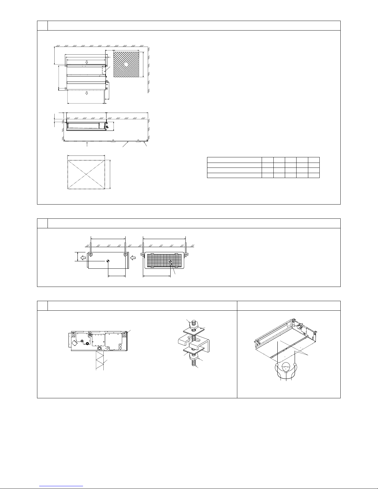
5.25.1
A Access door
B Electrical parts box
C Air inlet
D Air outlet
E Ceiling surface
F Service space (viewed from the side)
G Service space (viewed from the direction of arrow)
1 600 mm or more
2 100 mm or more
3 10 mm or more
4 300 mm or more
YX
LW
A
Z
C Nuts (field supply)
D Washers (accessory)
E M10 hanging bolt (field supply)
B
C
D
A
F
G
3
4
E
A
50~150 450
450
57
643
777
30
98
23
C
B
A
D
B
E
250
1
2
B
A
Model
PEAD-RP71
PEAD-RP100, 125
PEAD-RP140
A
1100
1400
1600
B
1154
1454
1654
C
1200
1500
1700
D
1060
1360
1560
E
1200
1500
1700
(mm)
4.1
3.1
A
3
6
øB
øA
a
b
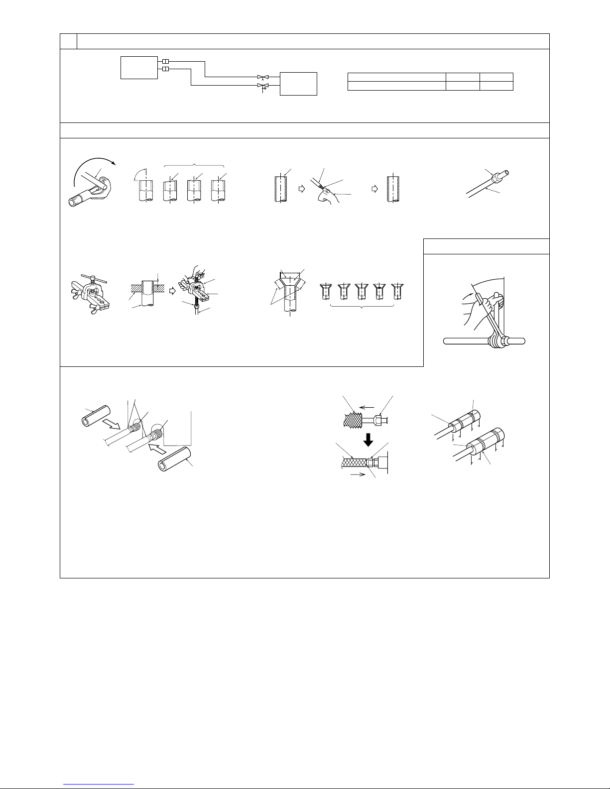
[Fig. 6-1]
a Indoor unit
b Outdoor unit
a
dcbef
90°
d
c
b
a
b
a
a
b
e
b
c
d
c
A
c
b
a
defg h
i
[Fig. 6-9]
A Pipe cover (small) (accessory)
B Caution:
Pull out the thermal insulation on the refrigerant piping at the
site, insert the flare nut to flare the end, and replace the insulation in its original position.
Take care to ensure that condensation does not form on exposed copper piping.
C Liquid end of refrigerant piping
D Gas end of refrigerant piping
E Site refrigerant piping
F Main body
G Pipe cover (large) (accessory)
H Thermal insulation (field supply)
I Pull
J Flare nut
K Return to original position
A
B
C
D
F
G
E
H
H
K
L
J
I
J
O
O
N
N
20
20
20
20
[Fig. 6-3]
[Fig. 6-6]
[Fig. 6-4] [Fig. 6-5]
a Flare nut
b Copper tube
a Burr
b Copper tube/pipe
c Spare reamer
d Pipe cutter
[Fig. 6-7]
[Fig. 6-8]
a Flaring tool
b Die
c Copper tube
d Flare nut
e Yoke
a Smooth all around
b Inside is shining without
any scratches
c Even length all around
d Too much
e Tilted
f Scratch on
flared plane
g Cracked
h Uneven
i Bad examples
L Ensure that there is no gap here
M Plate on main body
N Band (accessory)
O Ensure that there is no gap here. Place join upwards.
6.1
6.2
a Copper tubes
b Good
c No good
d Tilted
e Uneven
f Burred
6.3
Model
PEAD-RP71, 100, 125, 140
A
ø15.88Bø9.52
4
[Fig. 6-10]
[Fig. 6-11]
6
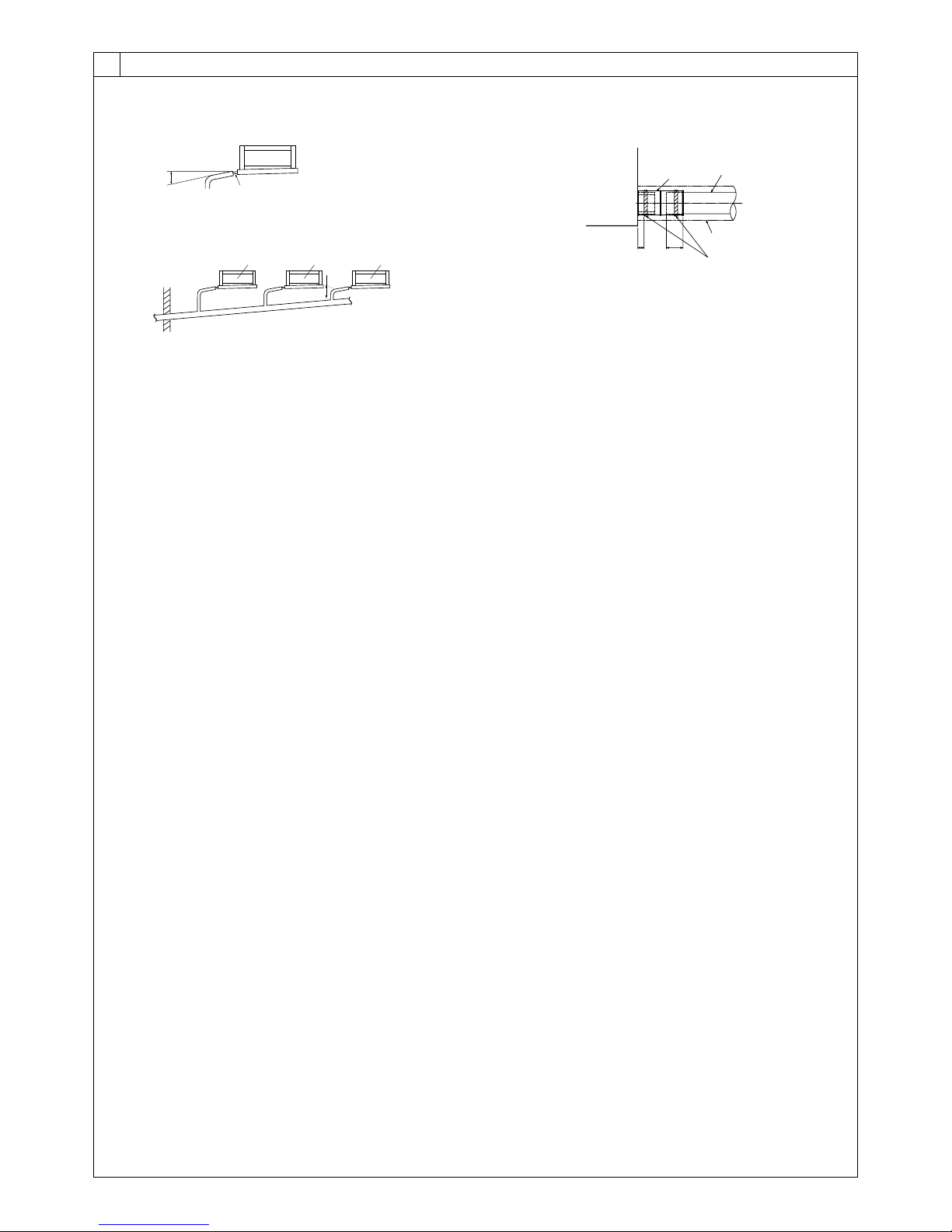
6.5
C
D
G
F
E
B
525
A
A Indoor unit
B Tie band (accessory)
C Band fixing part
D Insertion margin
E Drain socket (accessory)
F Drain pipe (O.D. ø32 PVC TUBE, field supply)
G Insulating material (field supply)
A
B1
C C C
D2
E
A Downward slope 1/100 or more
B Connection dia. R1 external thread
C Indoor un it
D Collective piping
E Maximize this length to approx. 10 cm
5
8
[Fig. 8-1]
8.1
7
7.1
A Outdoor unit power supply
B Earth leakage breaker
C Wiring circuit breaker or isolating switch
D Outdoor unit
E Indoor unit/outdoor unit connecting cords
F Remote controller (option)
G Indoor unit
S1
S2
L
N
1
2
S1
S2
S3
S3
AB C
D
E
F
G
A Outdoor unit power supply
B Earth leakage breaker
C Wiring circuit breaker or isolating switch
D Outdoor unit
E Indoor unit/outdoor unit connecting cords
F Remote controller (option)
G Indoor unit
S1
S2
L
N
1
2
S1
S2
S3
1
2
S1
S2
S3
S3
1
2
S1
S2
S3
1
2
S1
S2
S3
ABC
D
E
F
GGGG
A Outdoor unit power supply
B Earth leakage breaker
C Wiring circuit breaker or isolating switch
D Outdoor unit
E Indoor unit/outdoor unit connecting cords
F Remote controller (option)
G Indoor unit
H Option
J Indoor unit power supply
S1
S2
L
N
1
2
L
N
S1
S2
S3
S3
A
CB
D
JEB
C
F
G
H
A Outdoor unit power supply
B Earth leakage breaker
C Wiring circuit breaker or isolating switch
D Outdoor unit
E Indoor unit/outdoor unit connecting cords
F Remote controller (option)
G Indoor unit
H Option
J Indoor unit power supply
S1
S2
L
N
1
2
L
N
S1
S2
S3
1
2
L
N
S1
S2
S3
1
2
L
N
S1
S2
S3
1
2
L
N
S1
S2
S3
S3
ABC
D
E
JBC
F
H
GGGG
[Fig. 8-2]
[Fig. 8-3] [Fig. 8-4]
[Fig. 7-1] [Fig. 7-2]
[Fig. 7-3]
[Fig. 7-4]
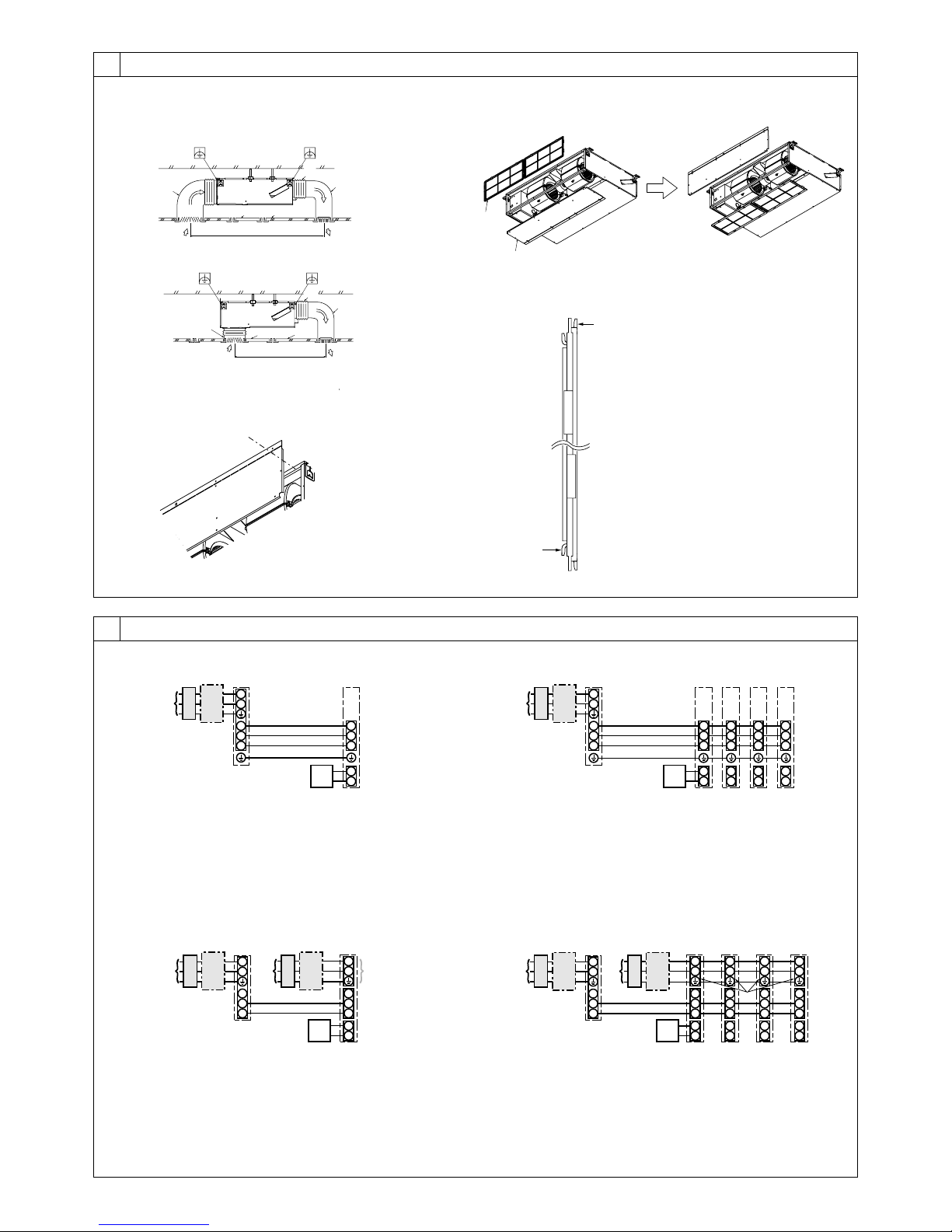
Duct
Air inlet
Access door
Canvas duct
Ceiling surface
Air outlet
Leave distance
enough to prevent short cycle
<A> In case of rear inlet
A
B
G
F
A
A
B
C
D
E
F
G
D
CE
<B> In case of bottom inlet
A
B
G
C
E
A
F
D
A
B
A Filter
B Bottom plate
C
D
C Nail for the bottom inlet
D Nail for the rear inlet
6
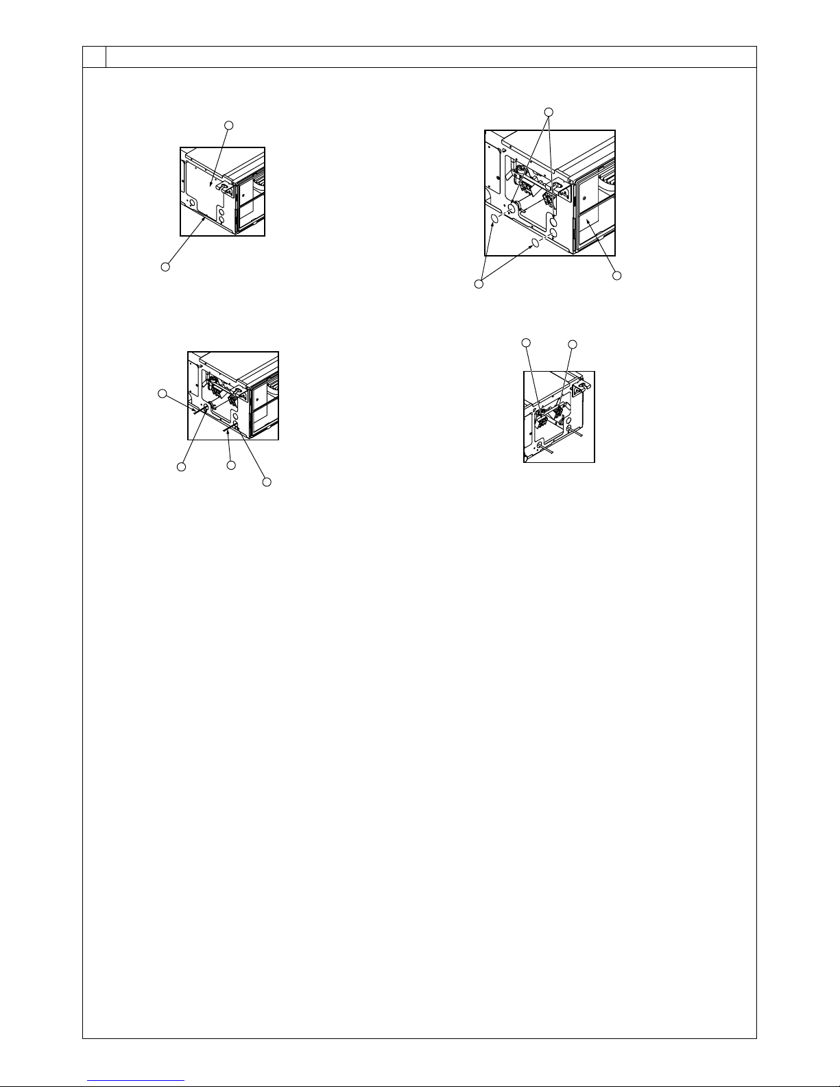
8.2
F Use PG bushing to keep the weight of the cable and external force from being applied to
the power supply terminal connector. Use a cable tie to secure the cable.
G Power source wiring
H Use ordinary bushing
I Transmission wiring
J Terminal block for power source and indoor transmission
K Terminal block for remote controller
[Fig. 8-2-3] [Fig. 8-2-4]
C Terminal box
D Knockout hole
E Remove
A Screw holding cover (1pc)
B Cover
[Fig. 8-2-1]
[Fig. 8-2-2]
8
A
B
C
D
E
H
I
F
G
J
K
7
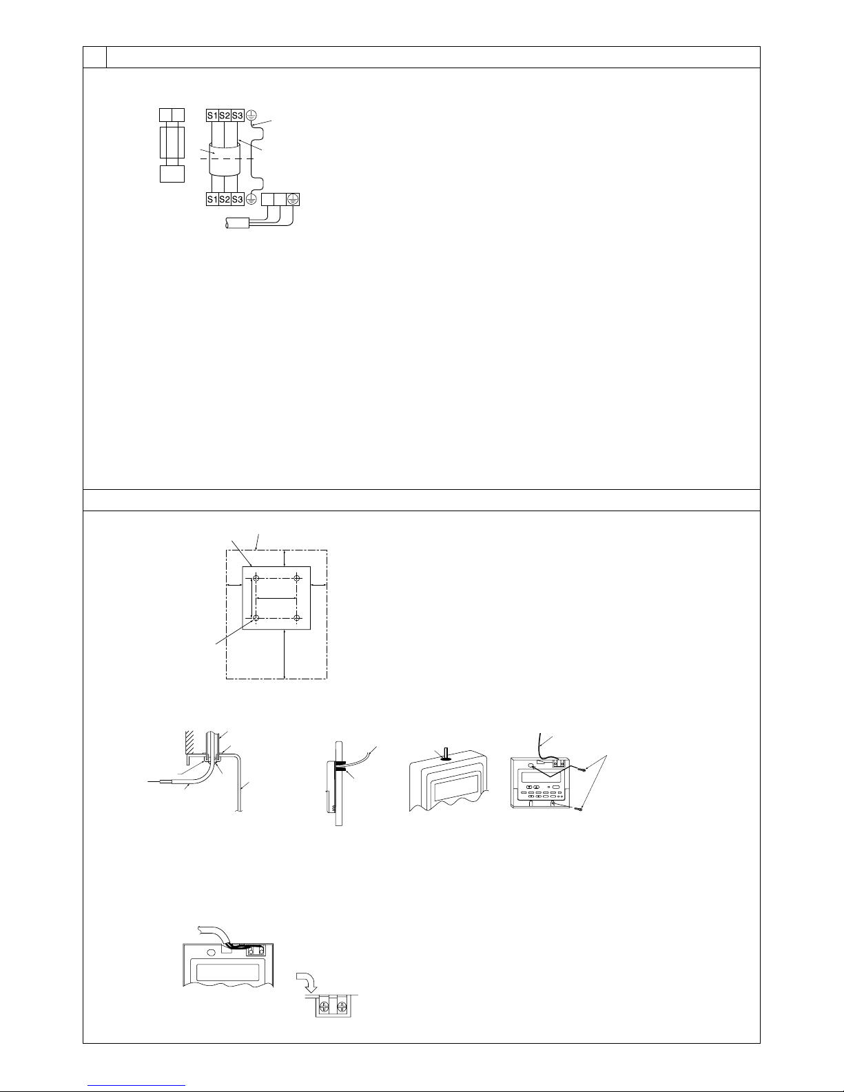
A For installation in the switch box:
B For direct installation on the wall select one of the following:
• Prepare a hole through the wall to pass the remote controller cord (in order to run the remote controller cord from
the back), then seal the hole with putty.
• Run the remote controller cord through the cut-out upper case, then seal the cut-out notch with putty similarly as
above.
C Wall
D Conduit
E Lock nut
F Bushing
G Switch box
H Remote controller cord
I Seal with putty
J Wood screw
F
A
H
C
D
E
G
I
I
I
H
B
J
H
B-1. B-2.
[Fig. 8-5]
8
A
AB TB6
B
A To the terminal block on the indoor unit
B TB6 (No polarity)
[Fig. 8-6]
8.2
30
46
30
30120
83.5
A
B
C
A Remote controller profile
B Required clearances surrounding the remote controller
C Installation pitch
[Fig. 8-4]
[Fig. 8-3]
A Indoor terminal block
B Earth wire (green/yellow)
C Indoor/outdoor unit connecting wire 3-
core 1.5 mm2 or more
D Outdoor terminal block
E Power supply cord : 2.0 mm2 or more
1 Connecting cable
Cable 3-core 1.5 mm2, in conformity
with Design 245 IEC 57.
2 Indoor terminal block
3 Outdoor terminal block
A Indoor terminal block
4 Always install an earth wire (1-core 1.5 mm2)
longer than other cables
5 Remote controller cable
Wire No × size (mm2) : Cable 2C × 0.3
This wire accessory of remote controller
(wire length : 10m, non-polar. Max. 500m)
6 Wired remote controller (option)
7 Power supply cord
Cable 3-core 2.0 mm2 or more, in conformity with Design 245 IEC 57.
12
6
5
2
4
3
7
L
N
1
C Indoor/outdoor unit
connecting wire
3-core 1.5 mm2 or
more
D Outdoor terminal block
B Earth wire (green/yellow)
E Power supply cord : 2.0 mm2 or more
8.3
8
A
B
C
D
E
G
H
F
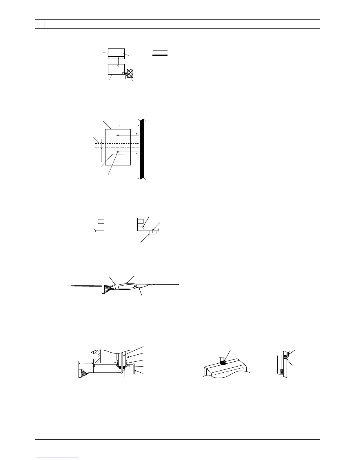
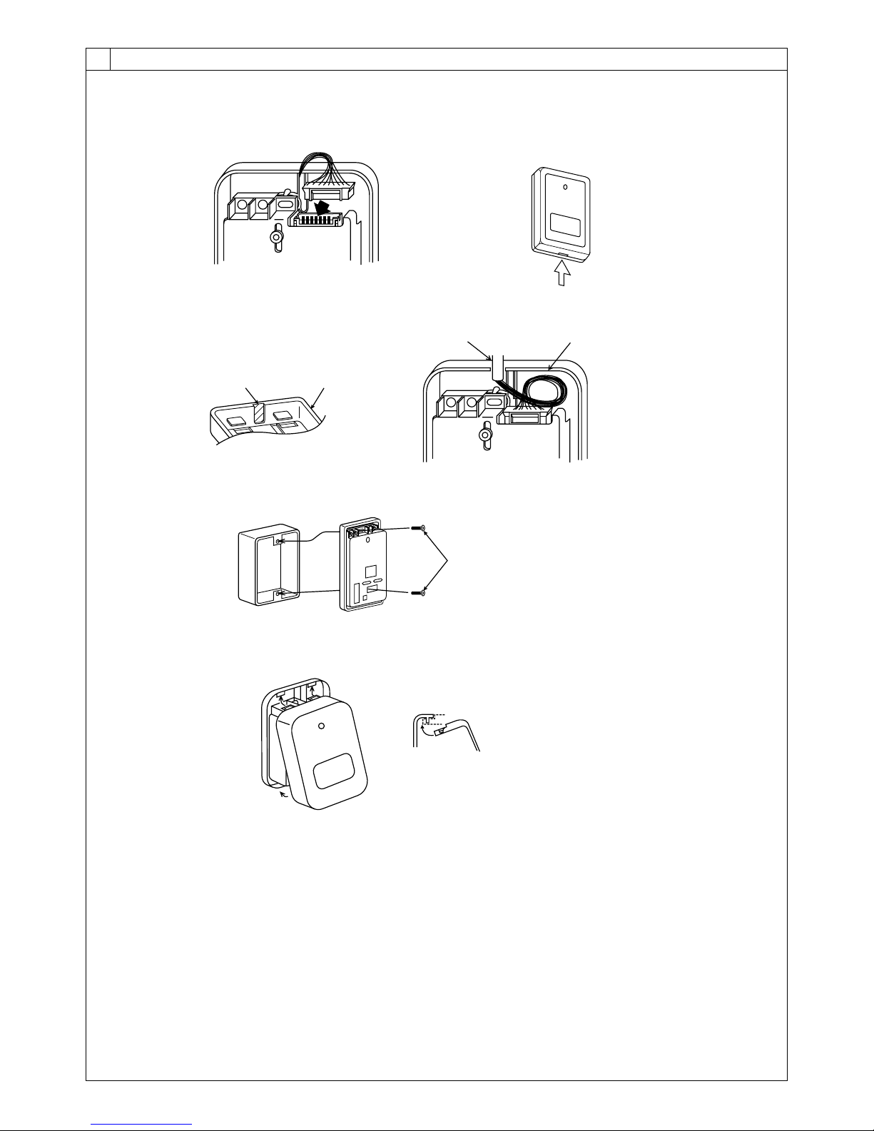
A Signal receiving unit external
B Center of Switch box
C Switch box
D Installation pitch
E 6.5 mm (1/4 inch)
F 70 mm (2 - 3/4 inch)
G 83.5 ± 0.4 mm (3 - 9/32 inch)
H Protrusion (pillar, etc)
[Fig. 8-9]
A
B
C
A Remote controller wire
B Hole (drill a hole on the ceiling to pass the remote controller wire.)
C Signal Receiving Unit
Ceiling cassette type, Ceiling concealed type
[Fig. 8-10]
A
B
C
A Fix tightly with tape.
B Remote controller wire
C Order wire
Indoor unit
[Fig. 8-8]
[Fig. 8-11]
H
J
I
When using the switch box
When installing directly on the wall
A 150 mm (5 - 15/16 inch)
B Remote controller wire
C Wiring pipe
D Locknut
H Seal around here with putty
I Remote controller wire
J Seal around here with putty
E Bushing
F Switch box
G Seal around here with putty
C
D
B
F
E
G
A
Wall
8
8.4
IC
OC(00)
CN90
TB1
TB4
1
D
C
A
B
Standard 1:1
[Fig. 8-7]
A Outdoor unit
B Refrigerant address
C Indoor unit
D Signal receiving unit
Indoor/outdoor wiring
Signal receiving unit wiring
9
8
8.4
[Fig. 8-12]
[Fig. 8-13]
AB
C
D
A Thin-wall portion
B Bottom case
C Remote controller wire
D Conducting wire
[Fig. 8-14]
A
A Screw (M4 x 30)
* When installing the lower case directly on the wall or the ceiling,
use wood screws.
Insert the minus screwdriver toward the
arrow pointed and wrench it to remove the
cover.
A flat screwdriver whose width of blade is
between 4 and 7mm (5/32 - 9/32inch)
must be used.
[Fig. 8-15]
1
1
2
A
1 Hang the cover to the upper hooks (2 places).
2 Mount the cover to the lower case
A Cross-section of upper hooks
 Loading...