

Mitsubishi PEAD-RP60JAQ, PEAD-RP100JAQ, PEAD-RP50JAQ, PEAD-RP71JAQ, PEAD-RP125JAQ Installation Manual
...
Air-Conditioners
PEAD-RP35,50,60,71,100,125,140JAQ
PEAD-RP35,50,60,71,100,125,140JALQ
FOR INSTALLER
INSTALLATION MANUAL
For safe and correct use, please read this installation manual thoroughly before installing the air-conditioner
unit.
INSTALLATIONSHANDBUCH
Zum sicheren und ordnungsgemäßen Gebrauch der Klimaanlage das Installationshandbuch gründlich
durchlesen.
MANUEL D’INSTALLATION
Veuillez lire le manuel d’installation en entier avant d’installer ce climatiseur pour éviter tout accident et vous
assurer d’une utilisation correcte.
MANUAL DE INSTALACIÓN
Para un uso seguro y correcto, lea detalladamente este manual de instalación antes de montar la unidad de
aire acondicionado.
MANUALE DI INSTALLAZIONE
Per un uso sicuro e corretto, leggere attentamente questo manuale di installazione prima di installare il condizionatore
d’aria.
INSTALLATIEHANDLEIDING
Voor een veilig en juist gebruik moet u deze installatiehandleiding grondig doorlezen voordat u de airconditioner
installeert.
INSTALLATIONSMANUAL
Läs denna installationsmanual noga för säkert och korrekt bruk innan luftkonditioneringen installeras.
FOR INSTALLER
FÜR INSTALLATEURE
POUR L’INSTALLATEUR
PARA EL INSTALADOR
PER L’INSTALLATORE
VOOR DE INSTALLATEUR
FÖR INSTALLATÖREN
English
Deutsch
Français
Español
Italiano
Nederlands
Svenska
INSTALLATIONSMANUAL
Læs venligst denne installationsmanual grundigt, før De installerer airconditionanlægget, af hensyn til sikker og
korrekt anvendelse.
MANUAL DE INSTALAÇÃO
Para segurança e utilização correctas, leia atentamente este manual de instalação antes de instalar a unidade
de ar condicionado.
E°XEIPI¢IO O¢H°IøN E°KATA™TA™H™
°И· ·ЫК¿ПВИ· О·И ЫˆЫЩ‹ ¯Ъ‹ЫЛ, ·Ъ·О·ПВ›ЫЩВ ‰И·‚¿ЫВЩВ ЪФЫВ¯ЩИО¿ ·˘Щfi ЩФ ВБ¯ВИЪ›‰ИФ ВБО·Щ¿ЫЩ·ЫЛ˜
ЪИУ ·Ъ¯›ЫВЩВ ЩЛУ ВБО·Щ¿ЫЩ·ЫЛ ЩЛ˜ МФУ¿‰·˜ ОПИМ·ЩИЫМФ‡.
РУКОВОДСТВО ПО УСТАНОВКЕ
Для осторожного и правильного использования прибора необходимо тщательно ознакомиться с данным
руководством по установке до выполнения установки кондиционера.
MONTAJ ELK‹TABI
Emniyetli ve do¤ru biçimde nas›l kullan›laca¤›n› ö¤renmek için lütfen klima cihaz›n› monte etmeden önce bu
elkitab›n› dikkatle okuyunuz.
TIL INSTALLATØREN
Dansk
PARA O INSTALADOR
Português
°π∞ ∞ÀΔ√¡ ¶√À ∫∞¡∂π Δ∏¡ ∂°∫∞Δ∞™Δ∞™∏
∂ППЛУИО¿
ДЛЯ УСТАНОВИТЕЛЯ
Русский
MONTÖR ‹Ç‹N
Türkçe
3
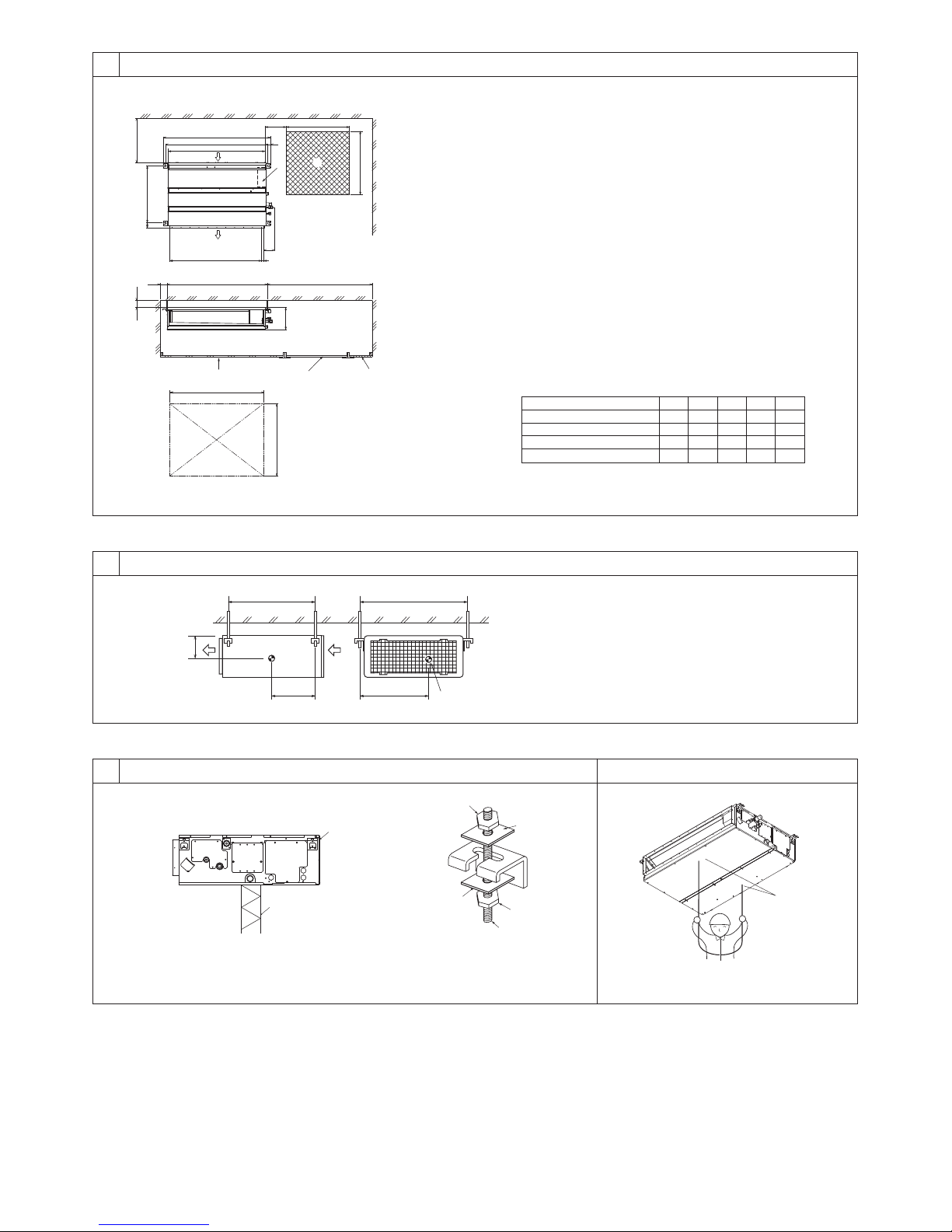
[Fig. 3-1]
4
625
3.1
C
50~150 450
23
B
A
450
C
B
A
4
49
2
3
[Fig. 4-1]
D
100
D
C
E
20
1
250
F
A
E
A Access door
B Electrical parts box
C Air inlet
D Air outlet
E Ceiling surface
F Service space (viewed from the side)
G Service space (viewed from the direction of arrow)
1 600 mm or more
2 100 mm or more
3 10 mm or more
4 300 mm or more
(mm)
E
C
1000
1200
1500
1700
D
860
1060
1360
1560
1000
1200
1500
1700
B
Model
PEAD-RP35, 50
G
777
PEAD-RP60, 71
PEAD-RP100, 125
PEAD-RP140
A
900
1100
1400
1600
954
1154
1454
1654
4.1
LW
Z
YX
A
A Center of gravity
5
[Fig. 5-1] [Fig. 5-2] [Fig. 5-3]
A
B
A Unit body
B Lifting machine
C
D
D
C
E
C Nuts (field supply)
D Washers (accessory)
E M10 hanging bolt (field supply)
5.25.1
A
A Indoor unit’s bottom surface
2
6
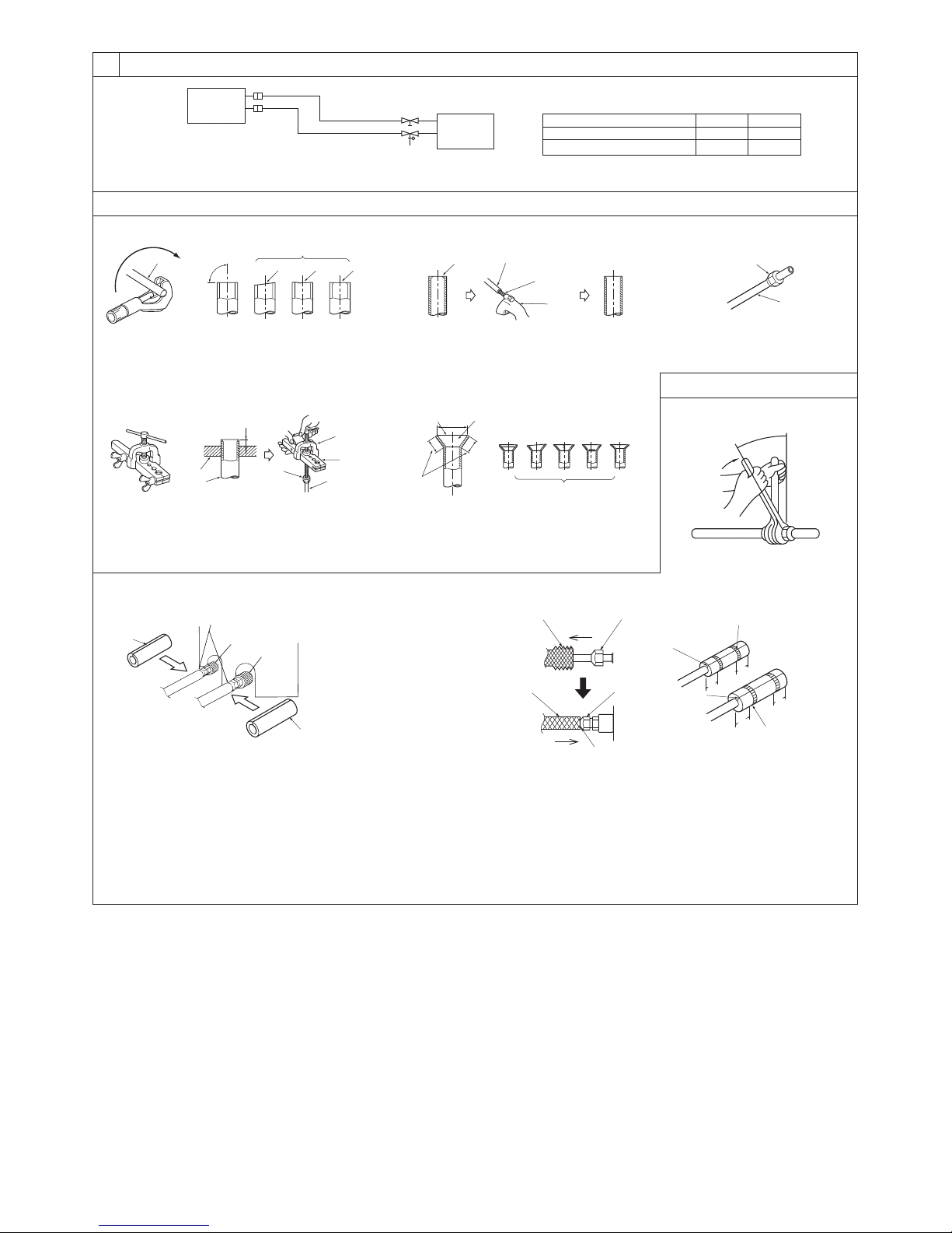
[Fig. 6-1]
[Fig. 6-3]
6.1
a
øA
øB
b
a Indoor unit
b Outdoor unit
PEAD-RP35, 50
Model
PEAD-RP60, 71, 100, 125, 140
A
ø12.7
ø15.88
B
ø6.35
ø9.52
6.2
[Fig. 6-4] [Fig. 6-5]
a
a Copper tubes
b Good
90°
c No good
d Tilted
dcbef
e Uneven
f Burred
[Fig. 6-6]
a
a Flaring tool
b Die
c Copper tube
b
c
A
d
d Flare nut
e Yo k e
[Fig. 6-9]
B
A
C
D
F
E
G
A Pipe cover (small) (accessory)
B Caution:
Pull out the thermal insulation on the refrigerant piping at the
site, insert the flare nut to flare the end, and replace the insulation in its original position.
Take care to ensure that condensation does not form on exposed copper piping.
C Liquid end of refrigerant piping
e
b
c
a Smooth all around
b Inside is shining without
c Even length all around
a
a Burr
b Copper tube/pipe
[Fig. 6-7]
b
a
c
any scratches
D Gas end of refrigerant piping
E Site refrigerant piping
F Main body
G Pipe cover (large) (accessory)
H Thermal insulation (field supply)
I Pull
J Flare nut
K Return to original position
b
c
d
c Spare reamer
d Pipe cutter
defg h
i
d Too much
e Tilted
f Scratch on
flared plane
H
H
g Cracked
h Uneven
i Bad examples
I
J
L
K
L Ensure that there is no gap here
M Plate on main body
N Band (accessory)
O Ensure that there is no gap here. Place join upwards.
a
b
a Flare nut
b Copper tube
6.3
[Fig. 6-8]
J
O
N
20
20
O
20
20
N
3
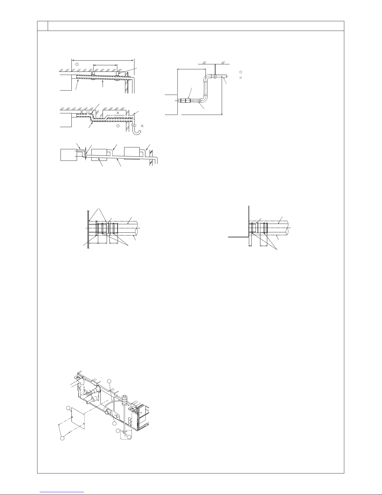
6
[Fig. 6-10]
F
6.5
Max. 20m
1.5-2m
C
A
B
K
L
B
D
E
D
FF
I
H
M
D
G
Max. 300mm
N
F
J
O
Correct piping
Wrong piping
A Insulation (9 mm or more)
B
B Downward slope (1/100 or more)
C Support metal
K Air bleeder
L Raised
M Odor trap
Grouped piping
D O. D. ø32 PVC TUBE
E Make it as large as possible. About 10 cm.
F Indoor unit
G Make the piping size large for grouped piping.
H Downward slope (1/100 or more)
I O. D. ø38 PVC TUBE for grouped piping.
(9 mm or more insulation)
PEAD-RP·JALQ model
J Up to 700 mm
N Drain hose (accessory)
O Horizontal or slightly upgradient
[Fig. 6-11]
I
E
F
A
323525
CD D
B
A Indoor unit
B Tie band (accessory)
C Visible part
D Insertion margin
E Drain hose (accessory)
F Drain pipe (O.D. ø32 PVC TUBE, field supply)
G Insulating material (field supply)
H Tie band (accessory)
I To be gap free. The joint section of the insulation material meet must be at the top.
G
H
[Fig. 6-13]
[Fig. 6-12]
A
A Indoor unit
B Tie band (accessory)
C Band fixing part
D Insertion margin
E Drain hose (accessory)
F Drain pipe (O.D. ø32 PVC TUBE, field supply)
G Insulating material (field supply)
E
525
D
C
F
G
B
A
B
E
C
F
D
4
A Insert pump's end 2 to 4 cm.
B Remove the water supply port.
C About 2500 cc
D Water
E Filling port
F Screw
7
7.1
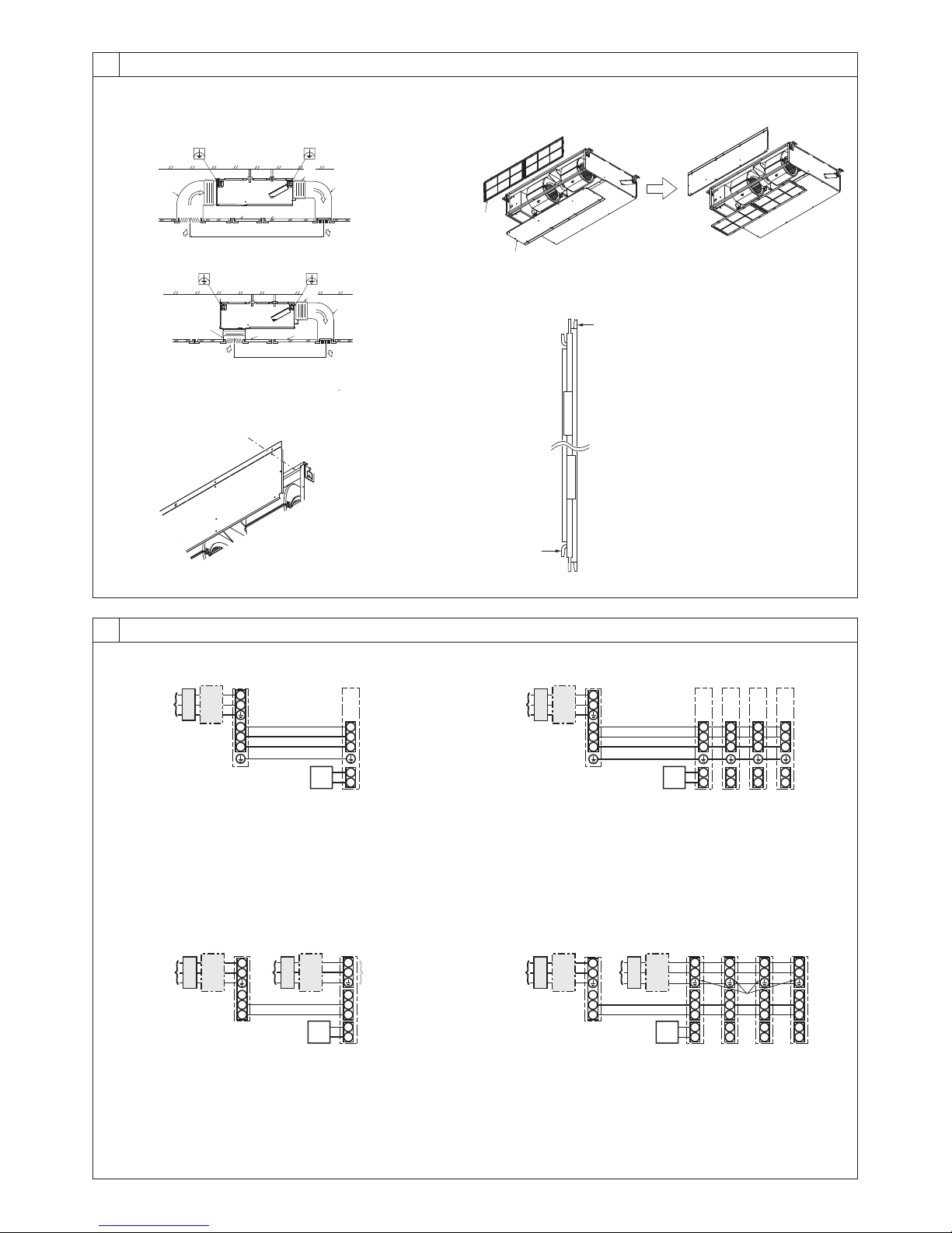
[Fig. 7-1]
<A> In case of rear inlet
A
B
<B> In case of bottom inlet
[Fig. 7-3]
A
B
CE
G
C
G
[Fig. 7-2]
Duct
A
Air inlet
D
B
Access door
C
A
Canvas duct
D
Ceiling surface
E
Air outlet
F
Leave distance
G
F
enough to prevent short cycle
A
B
A Filter
B Bottom plate
D
A
E
[Fig. 7-4]
C
F
D
8
[Fig. 8-1]
D
L
AB C
N
S1
S2
S3
E
A Outdoor unit power supply
B Earth leakage breaker
C Wiring circuit breaker or isolating switch
D Outdoor unit
E Indoor unit/outdoor unit connecting cords
F Remote controller (option)
G Indoor unit
[Fig. 8-3] [Fig. 8-4]
D
L
N
S1
S2
S3
JEB
CB
A
A Outdoor unit power supply
B Earth leakage breaker
C Wiring circuit breaker or isolating switch
D Outdoor unit
E Indoor unit/outdoor unit connecting cords
F Remote controller (option)
G Indoor unit
H Option
J Indoor unit power supply
G
S1
S2
S3
1
F
2
G
L
N
C
F
H
S1
S2
S3
1
2
8.1
[Fig. 8-2]
D
L
ABC
N
S1
S2
S3
A Outdoor unit power supply
B Earth leakage breaker
C Wiring circuit breaker or isolating switch
D Outdoor unit
E Indoor unit/outdoor unit connecting cords
F Remote controller (option)
G Indoor unit
D
L
N
ABC
JBC
S1
S2
S3
A Outdoor unit power supply
B Earth leakage breaker
C Wiring circuit breaker or isolating switch
D Outdoor unit
E Indoor unit/outdoor unit connecting cords
F Remote controller (option)
G Indoor unit
H Option
J Indoor unit power supply
GGGG
S1
S1
S1
S2
S2
S3
S3
E
F
1
1
2
2
S1
S2
S2
S3
S3
1
1
2
2
GGGG
L
L
L
N
N
S1
S1
S2
E
S3
1
F
2
H
S2
S3
1
2
L
N
N
S1
S1
S2
S2
S3
S3
1
1
2
2
5
8
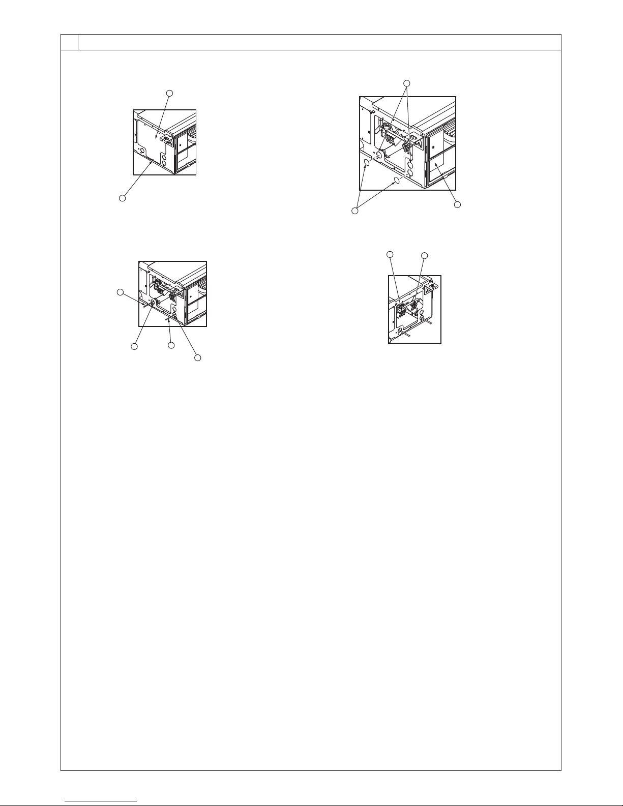
8.2
[Fig. 8-2-1]
B
A
A Screw holding cover (1pc)
B Cover
[Fig. 8-2-2]
E
[Fig. 8-2-3] [Fig. 8-2-4]
G
F
I
H
D
C Terminal box
D Knockout hole
C
E Remove
J
K
F Use PG bushing to keep the weight of the cable and external force from being applied to
the power supply terminal connector. Use a cable tie to secure the cable.
G Power source wiring
H Use ordinary bushing
I Transmission wiring
J Terminal block for power source and indoor transmission
K Terminal block for remote controller
6
8
8.2
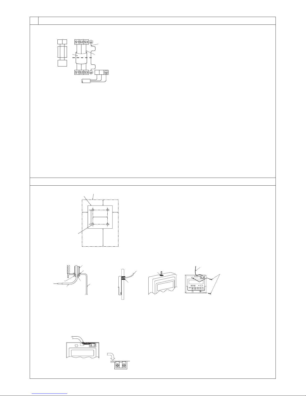
[Fig. 8-3]
A Indoor terminal block
2
12
5
1
6
3
D Outdoor terminal block
E Power supply cord : 2.0 mm
A Indoor terminal block
B Earth wire (green/yellow)
4
C Indoor/outdoor unit
connecting wire
3-core 1.5 mm
more
L
N
7
2
or more
2
or
B Earth wire (green/yellow)
C Indoor/outdoor unit connecting wire 3-
core 1.5 mm
D Outdoor terminal block
E Power supply cord : 2.0 mm
1 Connecting cable
Cable 3-core 1.5 mm
with Design 245 IEC 57.
2 Indoor terminal block
3 Outdoor terminal block
2
or more
2
or more
2
, in conformity
4 Always install an earth wire (1-core 1.5 mm
longer than other cables
5 Remote controller cable
Wire No × size (mm
This wire accessory of remote controller
(wire length : 10m, non-polar. Max. 500m)
6 Wired remote controller (option)
7 Power supply cord
Cable 3-core 2.0 mm
ity with Design 245 IEC 57.
2
) : Cable 2C × 0.3
2
or more, in conform-
2
)
8.3
[Fig. 8-4]
C
[Fig. 8-5]
A
C
F
H
A For installation in the switch box:
B For direct installation on the wall select one of the following:
• Prepare a hole through the wall to pass the remote controller cord (in order to run the remote controller cord from
the back), then seal the hole with putty.
• Run the remote controller cord through the cut-out upper case, then seal the cut-out notch with putty similarly as
above.
B
A
30120
30
83.5
D
E
I
G
30
46
A Remote controller profile
B Required clearances surrounding the remote controller
C Installation pitch
B-1. B-2.
B
H
I
I
H
J
C Wall
D Conduit
E Lock nut
F Bushing
G Switch box
H Remote controller cord
I Seal with putty
J Wood screw
[Fig. 8-6]
A
A To the terminal block on the indoor unit
B TB6 (No polarity)
AB TB6
B
7
8
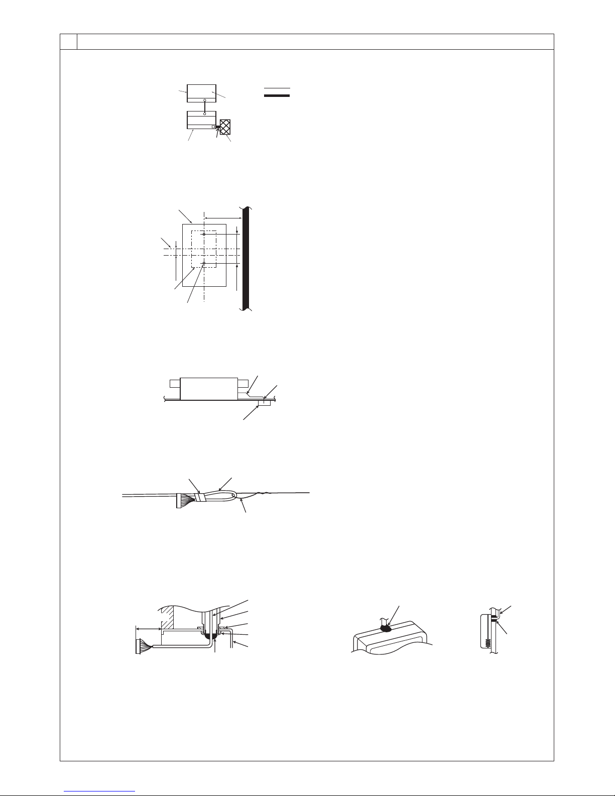
8.4
[Fig. 8-7]
[Fig. 8-8]
[Fig. 8-9]
Standard 1:1
OC(00)
A
C
A
B
TB1
TB4
IC
CN90
1
D
F
B
E
G
C
D
H
Ceiling cassette type, Ceiling concealed type
Indoor unit
Indoor/outdoor wiring
Signal receiving unit wiring
A Outdoor unit
B Refrigerant address
C Indoor unit
D Signal receiving unit
A
B
A Signal receiving unit external
B Center of Switch box
C Switch box
D Installation pitch
E 6.5 mm (1/4 inch)
F 70 mm (2 - 3/4 inch)
G 83.5 ± 0.4 mm (3 - 9/32 inch)
H Protrusion (pillar, etc)
A Remote controller wire
B Hole (drill a hole on the ceiling to pass the remote controller wire.)
C Signal Receiving Unit
[Fig. 8-10]
[Fig. 8-11]
When using the switch box
Wall
A
A 150 mm (5 - 15/16 inch)
B Remote controller wire
C Wiring pipe
D Locknut
C
A
B
A Fix tightly with tape.
B Remote controller wire
C Order wire
C
When installing directly on the wall
B
C
H
I
D
E
J
F
G
E Bushing
F Switch box
G Seal around here with putty
H Seal around here with putty
I Remote controller wire
J Seal around here with putty
8
 Loading...