

Page 1
TECHNICAL & SERVICE MANUAL
SPLIT-TYPE, AIR CONDITIONERS
CONTENTS
1.
TYPES OF CONNECTED OUTDOOR UNITS
···2
2. SAFETY FOR USE·································3
3. PART NAMES AND FUNCTIONS··········5
4. SPECIFICATIONS ··································7
5. DATA·····················································11
6. OUTLINES AND DIMENSIONS···········18
7. WIRING DIAGRAM·······························20
8.
REFRIGERANT SYSTEM DIAGRAM
········21
9. TROUBLESHOOTING··························22
10. FUNCTION SETTING ···························35
11. SYSTEM CONTROL·····························39
12. SERVICE DATA (PARTS NAME)·········48
13. OPTIONAL PARTS ·······························50
No. HWE07050
Indoor unit
Ceiling Concealed
Series PE
ON/OFF
TEMP.
Remote controller
NOTE:
• This service manual describes technical data of indoor units.
• RoHS compliant products have <G> mark on the spec name plate.
August 2007
[Model names]
PE-5GAK
PE-5GAKT
PE-6GAK
PE-6GAKT
Page 2
2
1
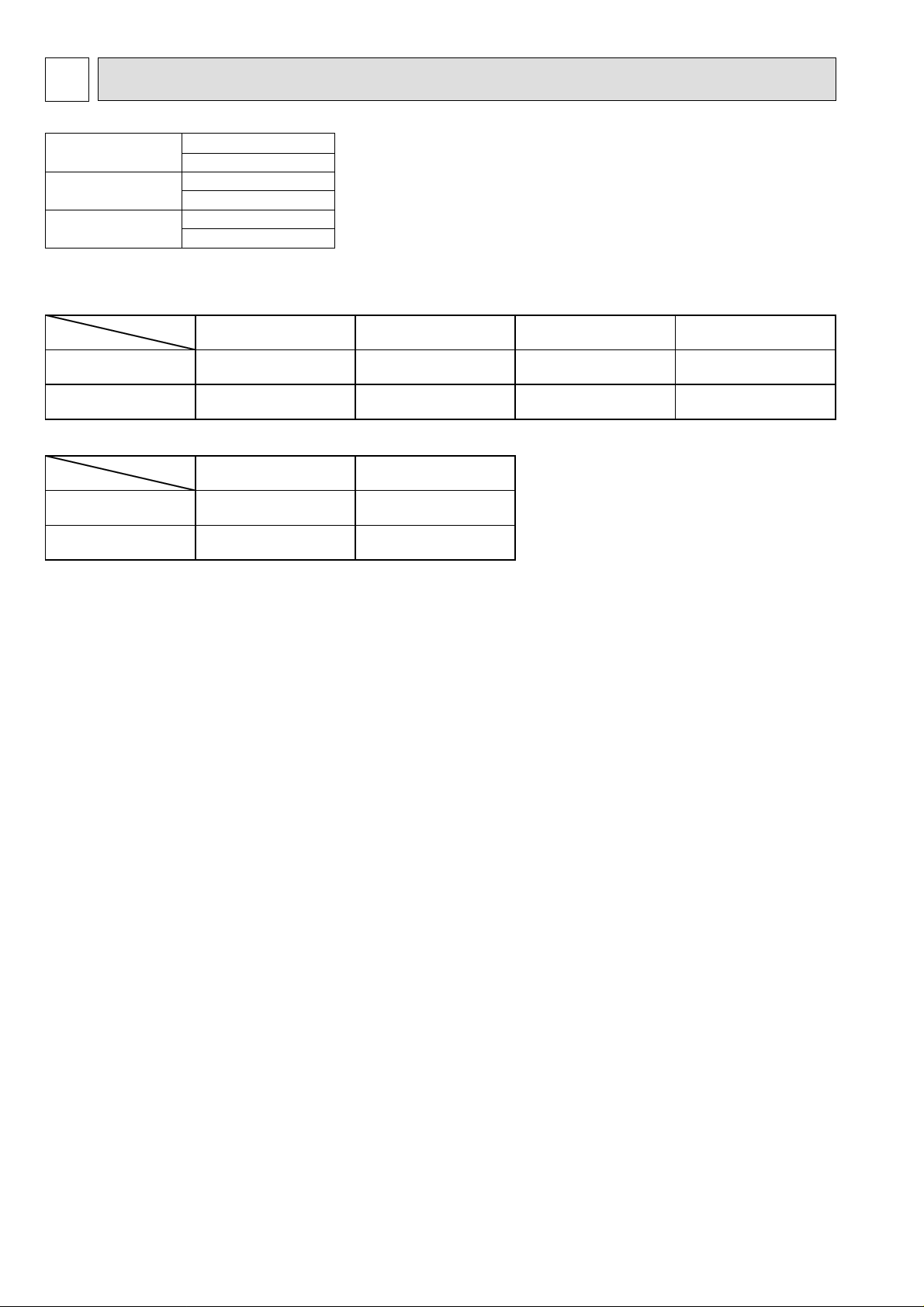
TYPES OF CONNECTED OUTDOOR UNITS
Outdoor Unit List
Indoor unit
PE-5GAK(T)
PE-6GAK(T)
Specification
Model name
PE-5GAK PE-5GAK.TH PE-5GAK.TH-SP PE-5GAK.TH-MF PE-5GAK.TH-SPMF
PE-6GAK PE-6GAK.TH PE-6GAK.TH-SP PE-6GAK.TH-MF PE-6GAK.TH-SPMF
Specification
Model name
PE-5GAKT PE-5GAKT.TH PE-5GAKT.TH-SP
PE-6GAKT PE-6GAKT.TH
Outdoor unit
Model name
PU-5YAKD
PU-5YJSA
PU-6YAKD
PU-6YJSA
Standard Model High static pressure motor Steel fan
Standard Model High static pressure motor
PE-6GAKT.TH-SP
High static pressure
motor/steel fan
Page 3
3
SAFETY FOR USE
2
Before conducting installation work, please read this ''SAFETY FOR USE'' carefully
for
correct installation.
Since the caution items shown here contain important description relative to safety, please
observe them without fail.
After reading, please keep it with you together the Instruction Manual, and read it again at the
movement of the unit.
The unit should not be installed by the user.
If the unit is installed improperly, explosion, water
leakage, electric shock or fire may be result.
Consult your dealer or specialist subcontractor for
repair and movement.
For installation, conduct the work correctly by
following the Installation Manual.
Improper installation may cause a fire, electrical shock
or water leakage.
Install the unit on a spot sufficiently durable against
the unit weight.
Insufficient durability can cause an injury by the falling
down of unit.
All electric work must be performed by licensed
technician, according to local regulations and the
instructions given in this manual.
The units should be powered by dedicated power lines.
Power lines with insufficient capacity or improper
electrical work may result in electric shock or fire.
Use only the specified cables for wiring. The
connections must be made secured without
tension the terminals.
Improper connection or fastening can cause a fire or
electrical shock.
The unit should be installed according to the
instructions in order to minimize the risk of damage
from earthquakes, typhoons or strong winds.
Improper installation work can cause an injury by the
falling down of the unit.
The outdoor unit must be installed on stable, level
surface, in a place where there is no accumulation
of snow , leaves or rubbish.
The outdoor unit should be installed in a location
where air and noise emitted by the unit will not
disturb the neighbors. The indoor unit should be
securely installed.
When installing or relocating the unit, make sure that
no substance other than the specified refrigerant
enters the refrigerant circuit.
Any presence of foreign substance such as air can
cause abnormal pressure rise or explosion.
If the unit is loosely mounted, it may fall, and cause injury.
Never repair the unit, remodel or transfer it to
another site by yourself.
If they are performed improperly, water leakage, electric
shock or fire may result. If you need to have the unit
repaired or moved, consult your dealer.
Use only the specified refrigerant (R-22) to charge
the refrigerant circuit.
Do not mix it with any other refrigerant and do not
allow air to remain in the circuit.
Air enclosed in the circuit can cause high pressure resulting
in a rupture and other hazards.
Ventilate the room if refrigerant leaks during
Installation.
The refrigerant heated generates poisonous gas by
decomposition which can cause poisoning.
After completing installation work, make sure that
refrigerant gas has not leaked.
If refrigerant gas has leaked and exposed to fan heater,
stove, oven and so on, it may generate noxious gases.
Take a proper measure to suppress the critical
concentration of refrigerant if leaked when
installing the unit in a small room.
The limit density is made not to be exceeded even if the
refrigerant leaks by any chance.
You are necessary to ventilation measures to prevent
the accident. If the refrigerant leaks, hypoxia accident
may caused.
For the countermeasure to be taken, consult your
dealer.
The terminal block cover of unit must be firmly
attached to prevent entry of dust and moisture.
Improper mounting of the cover cause electric shock or
fire.
Use only optional parts authorised by Mitsubishi
Electric.
If the accessories are installed improperly, water
leakage, electric shock or fire may result.
Ask your dealer or an authorised company to install
them.
Erroneous handling gives a high possibility to induce serious results such as
death or heavy injury.
Erroneous handling may induce serious injury depending on the situation.
Warning
Warning
Caution
Page 4
4
Caution
Never install on the place where a combustible gas
might leak.
The gas may ignite or explode when the gas leaks and
collects in surrounding of the unit.
When the unit is installed at telecommunication
centers or hospitals, take a proper provision
against noise.
The erroneous operation of air conditioner may be
induced by inverter equipment, independent power
device, medical equipment or communication
equipment.
While the erroneous operation of medical equipment or
communication equipment may caused by the air
conditioner.
For special use as for foods, animals/plants,
precision equipment or art objects, the applicability
should be confirmed beforehand.
As the use for the applications other than that
designed originally may result in the deterioration of the
quality. Consult your dealer in this regard.
Do not use the unit under a special atmosphere.
Installing the unit at the following places may cause a
trouble, a place where much machine oil, salt sonnet,
humidity or dust, spa district, a place full of sulfur gas,
volatile gas, or corrosive gas, a place near high
frequency processing machine.
Thermal insulation of the drain pipes is necessary
prevent dew condensation.
If the drain pipes are not properly insulated,
condensation will result and drip on ceiling, floor or other
possessions.
The drain piping must process by surely,and insulate
the drain piping not to be dewy.
When the room humidity exceeds 80% or when the
drain pipe is clogged, water may drip from the indoor
unit. The outdoor unit produces condensation during the
heating operation.
Make sure to provide drainage around the outdoor unit if
such condensation is likely to cause damage.
Install drain piping according to this Installation
Manual to ensure proper drainage.
Place thermal insulation on the pipes to prevent
condensation.
Improper drain piping may cause water leakage and
damage to furniture or other possessions.
The unit must be properly earth connected.
Do not connect the earth wire to gas pipe, city water
pipe, lightning rod or telephone earth wire.
Improper earth connection may cause electrical shock.
When installing at a watery place, provide an
electric leak breaker.
Failure to mount the electric leak breaker may cause
electrical shock.
Use breaker or fuse with proper capacity.
Make sure that there is a main power switch.
Using a wire or a copper wire instead of proper capacity
of fuse can cause fire or trouble.
Other appliances connected to the same line could cause
an overload.
For the power lines, use standard cables of
sufficient current capacity.
Otherwise, current leakage, overheating or fire may
occur.
When installing the power lines, do not apply
tension to the cables.
The tighten or loosen the connections may cause generate
heat and cause fire.
Remote controller is not pushed with the thing
sharpening ahead.
It occasionally causes the electric shock and the
breakdown.
Arrange the configuration of wiring not to bring up
the panel and terminal cover, and fasten the panel
and terminal cover securely.
The poor mounting of the panel or terminal cover may
cause the heat generation of the terminal connection,
a fire or electrical shock.
Do not wash the unit with water.
If washed with water, electrical shock may be caused.
Do not handle the switch with wet hands.
Otherwise electrical shock can be resulted.
Be very careful on handling the unit.
When carrying in outdoor unit, be sure to support it at
four points.
Carrying in and lifting with 3-point support may make
outdoor unit unstable, resulting in a fall of it.
The unit should not be carried by only one person if it is
more than 20kg.
Some units use PP bands for packing.
Do not use any PP band for delivery purpose.
Do not touch the heat exchanger fins with your bear
hands.
Doing so may cut your hands.
Be sure to safely dispose the packaging materials.
Packaging materials, such as catches and other metal
or wooden parts, may cause stabs or other injuries.
Tear off and discard plastic packing bags so that
children will not play any of them.
If children play with a plastic bag which was not torn off,
it may cause a risk of suffocation.
Do not leave the mounting base being damaged.
The damaged base may cause the falling down of
the unit which may give injury.
Turn on the main power switch more than 6 hours
before starting operation.
Do not turn the main power switch OFF during seasons
of heavy use, doing so can result in failure.
Do not touch the compressor or refrigerant piping
without wearing glove on your hands.
Touching directly such part can cause a burn or
frostbite as it becomes high or low temperature
according to the refrigerant state.
Do not touch the metal edges inside the unit
without wearing glove on your hands.
Touching directly it may injure your hands.
Do not remove the panel or the fan guard from
the outdoor unit when it is running.
You could be injured if you touch rotating, hot or highvoltage parts.
Do not operate the air conditioner without the air
filter set place.
Dust may accumulate, and cause a failure.
At emergency (if you smell something burning), stop
operation and turn the power source switch off.
Continuing the operation without eliminating the
emergency state may cause a machine trouble, fire, or
electrical shock.
After stopping operation, be sure to wait for five
minutes before turning off the main power switch.
Otherwise, water leakage or unit failure may
Remote controller is not installed for the place
where direct sunshine strikes.
occur.
Page 5
5
3
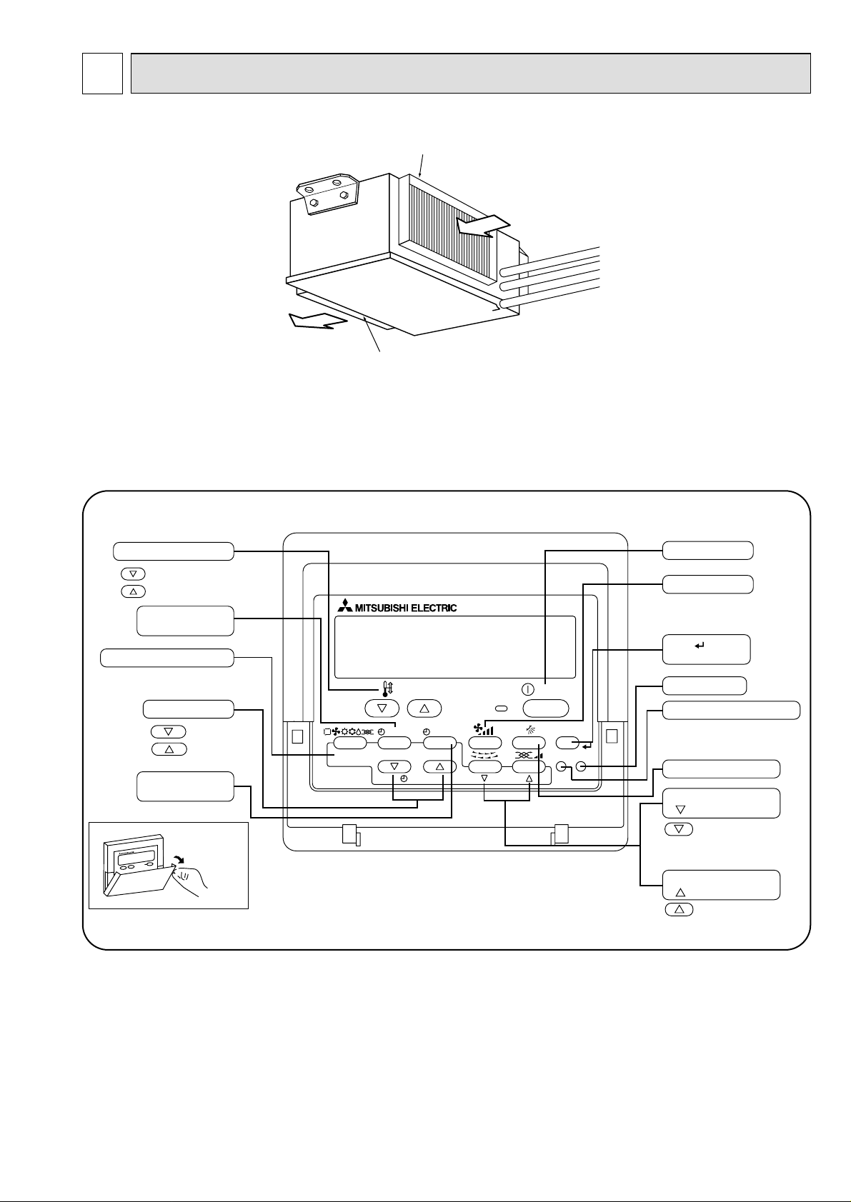
PART NAMES AND FUNCTIONS
● Indoor (Main) Unit
Air intake duct flange
Air outlet duct flange
Air outlet
Air intake
(sucks the air inside the room into the unit)
● Remote controller
Once the controls are set, the same operation mode can be repeated by simply pressing the ON/OFF button.
● Operation buttons
PAR-21MAA
ON/OFF
FILTER
CHECK
OPERATION
CLEAR
TEST
TEMP.
MENU
BACK DAY
MONITOR/SET
CLOCK
ON/OFF
Set Temperature buttons
Down
Up
Timer Menu button
(Monitor/Set button)
Mode button (Return button)
Set Time buttons
Back
Ahead
Timer On/Off button
(Set Day button)
Opening the
door.
ON/OFF button
Fan Speed button
Filter button
(<Enter> button)
Test Run button
Check button (Clear button)
Airflow Up/Down button
Louver button
(
Operation button)
To preceding operation
number.
Ventilation button
(
Operation button)
To next operation number.
Page 6
6
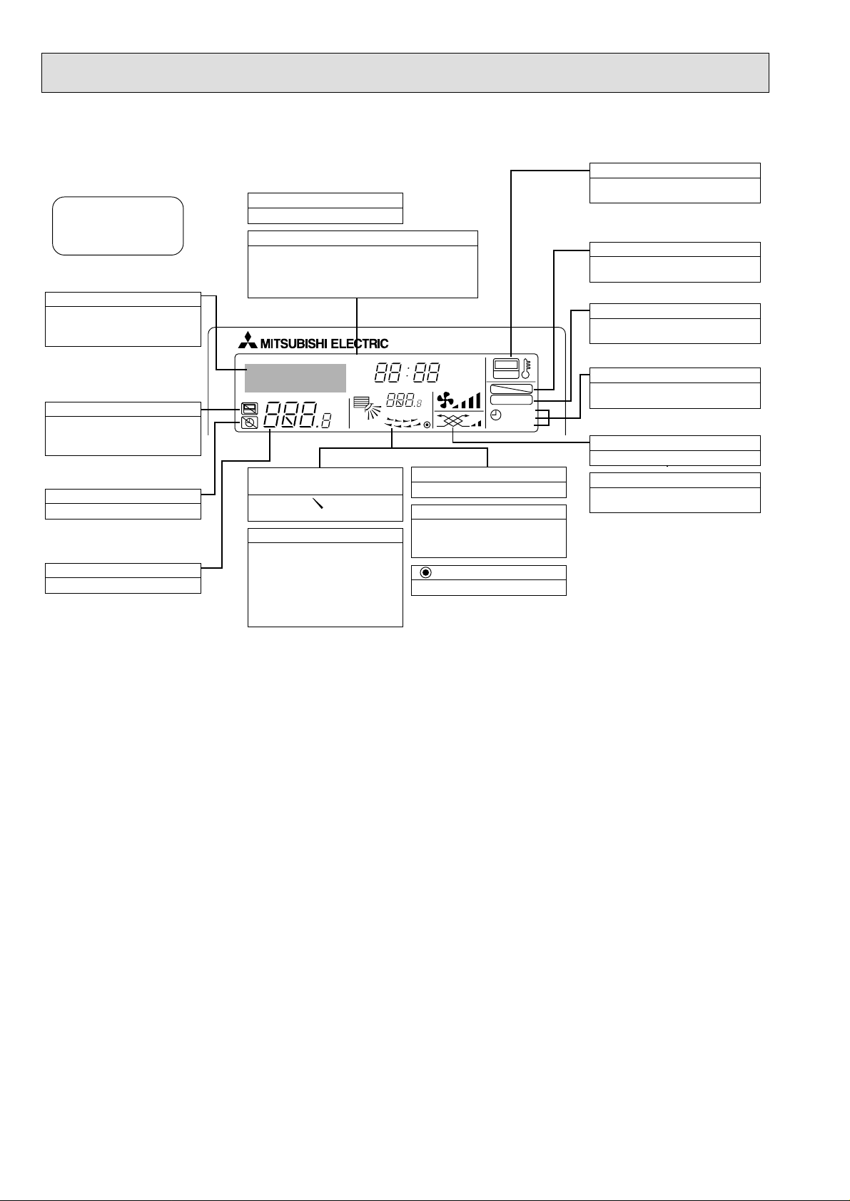
● Display
For purposes of this explanation,
all parts of the display are shown
as lit. During actual operation, only
the relevant items will be lit.
˚F˚C
˚F˚C
ERROR CODE
AFTER
TIMER
TIME SUN MON TUE WED THU FRI SAT
ON
OFF
Hr
AFTER
FILTER
FUNCTION
ONLY1Hr.
WEEKLY
SIMPLE
AUTO OFF
Identifies the current operation
Shows the operating mode, etc.
* Multilanguage display is sup-
ported.
“Centrally Controlled” indicator
Indicates that operation of the remote controller has been prohibited by a master controller.
“Timer Is Off” indicator
Indicates that the timer is off.
Temperature Setting
Shows the target temperature.
Day-of-Week
Shows the current day of the week.
Time/Timer Display
Shows the current time, unless the simple or Auto Off
timer is set.
If the simple or Auto Off timer is set, shows the time
remaining.
“Sensor” indication
Displayed when the remote controller
sensor is used.
“Locked” indicator
Indicates that remote controller buttons have been locked.
“Clean The Filter” indicator
Comes on when it is time to clean the
filter.
Timer indicators
The indicator comes on if the corresponding timer is set.
Up/Down Air Direction indicator
The indicator shows the direction of the outcoming airflow.
“One Hour Only” indicator
Displayed if the airflow is set to
weak and downward during COOL
or DRY mode. (Operation varies
according to model.)
The indicator goes off after one
hour, at which time the airflow direction also changes.
Room Temperature display
Shows the room temperature.
Louver display
Indicates the action of the swing
louver. Does not appear if the
louver is stationary.
(Power On indicator)
Indicates that the power is on.
Fan Speed indicator
Shows the selected fan speed.
Ventilation indicator
Appears when the unit is running in
Ventilation mode.
Caution
● Only the Power on indicator lights when the unit is stopped and power supplied to the unit.
● If you press a button for a feature that is not installed at the indoor unit, the remote controller will display the “Not Available”
message.
If you are using the remote controller to drive multiple indoor units, this message will appear only if he feature is not
present at the parent unit.
●
When power is turned ON for the first time, it is normal that “PLEASE WAIT” is displayed on the room temperature indication
(For max. 2minutes). Please wait until this “PLEASE WAIT” indication disappear then start the operation.
Page 7
7
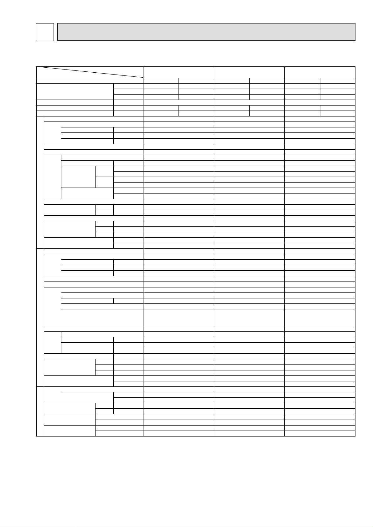
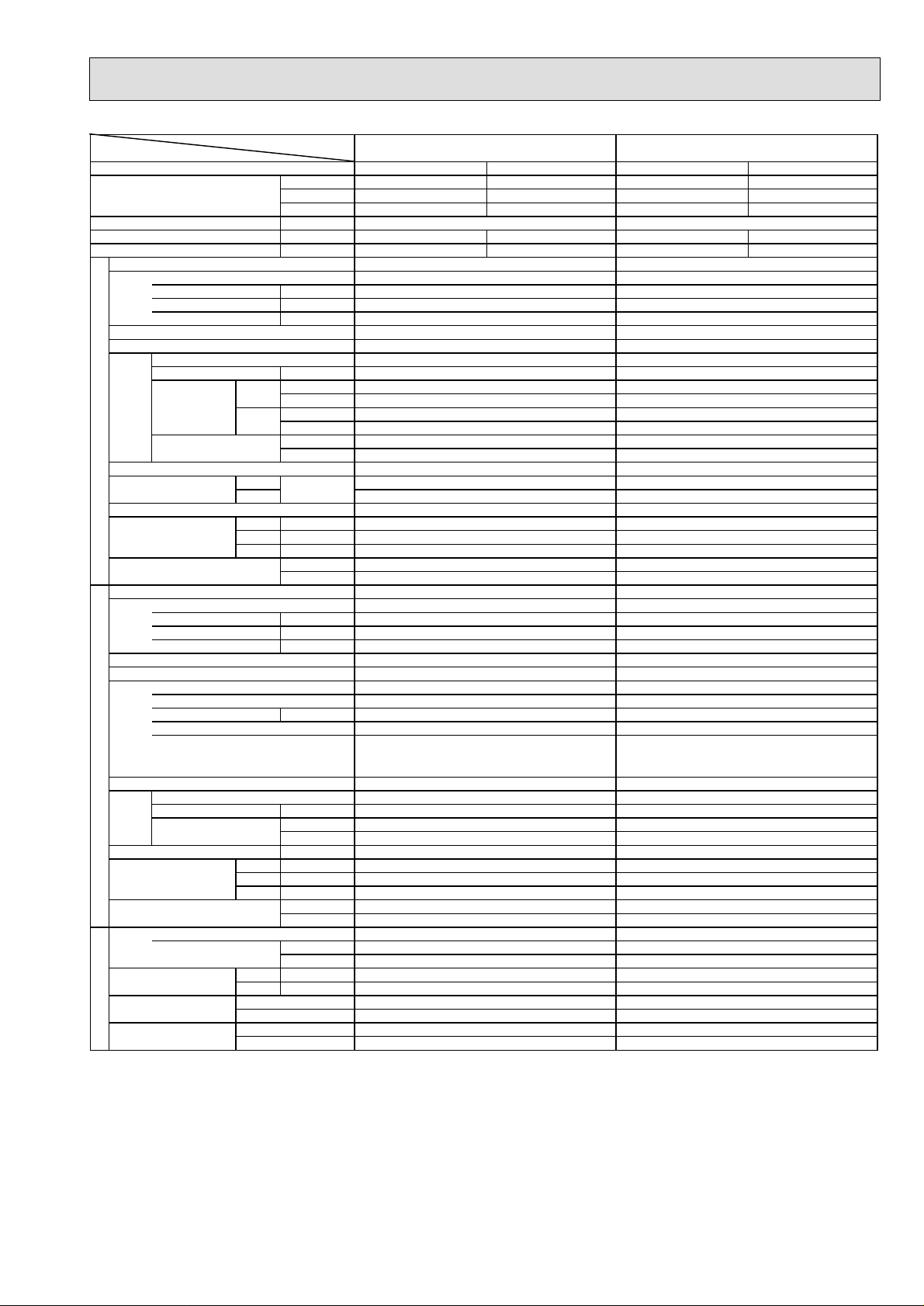
SPECIFICATIONS4
4-1 STANDARD SPECIFICATIONS
Item
Capacity *1
Total input
EER
COP
Model name
Power supply(phase,cycle,voltage)
Input
Running current
Starting current
External finish
Heat exchanger
Fan(drive) × No.
Fan motor output
Fan
Airflow
INDOOR UNIT
REFRIGERANT PIPING OUTDOOR UNIT
*1 Rating condition
Refrigerant piping length (one way):5m
*2 Noise level is measured in an unacoustic room based on JIS conditions.
*3 In case of PU-5,6YAKD, guaranteed operating range is;
Outdoor D.B.21-46˚C Indoor W.B.15.5-22.5˚C
In case of PU-5,6YJSA, guaranteed operating range is;
Outdoor D.B.21-52˚C Indoor W.B.15.5-22.5˚C
*4 Above data based on indicated voltage
External static pressure
Operation control & Thermostat
Noise level *2
Cond. Drain connection O.D.
Dimensions
Weight
Model name
Power supply(phase,cycle,voltage)
Input
Running current
Starting current
External finish
Refrigerant control
Compressor
Model
Motor output
Starter type
Protection devices
Heat exchanger
Fan(drive) × No.
Fan motor output
Fan
Airflow
Noise level *2
Dimensions
Weight
Refrigerant
Charge
Pipe size O.D.
Connection method
Between the indoor &
outdoor unit
Cooling: Indoor unit D.B.27˚C, W.B.19˚C
Outdoor unit D.B.35˚C
Indoor unit : 1phase 240V 50Hz
Outdoor unit : 3phase 415V 50Hz
Liquid mm
Gas mm
Indoor side
Outdoor side
Height difference
Piping length
Model name
Btu/h 44,000 41,000 44,000 41,000 54,000 51,000
kW 12.9 12.0 12.9 12.0 15.8 14.9
kcal/h 11,000 10,300 11,000 10,300 13,500 12,800
kW
kcal/h.W 2.17 2.03 1.98 1.86 2.23 2.12
W/W 2.54 2.37 2.33 2.17 2.62 2.47
kW
A
A
kW
Hi
Lo
Hi
Lo
Hmm
Wmm
Dmm
Hmm
Wmm
Dmm
CMM
L/s
CMM
L/s
Pa
mmAq
dB(A)
kg
lbs
kW
A
A
kW
kW
3
/min
m
L/s
dB(A)
kg
lbs
kg
lbs
PE-5GAK(T)
Gross Net Gross Net Gross Net
PE-5GAK(T) PE-6GAK(T)
1PH 50Hz 220-240V 1PH 50Hz 220-240V
Galvanized steel
Cross fin coil
Centrifugal (direct) × 1
Remote control & built in
3PH 4W 50Hz 380-415V
Munsell 3Y 7.8/1.1
Capillary tube
Thermal relay, Thermal switch
HP switch, LP switch,
Anti-phase protector
Cross fin coil
Propeller (direct) × 2
5.06
0.87
4.0
6.1
0.46 0.46
50
833
40
667
100
10
46
42
R1
400
1,180
634
56
123
PU-5YAKD
4.19
6.86 7.63
64
Hermetic
BH82YEHT
3.5
Line start
Thermal relay, Thermal switch
0.100 × 2
100
1,667
55
1,258
970
345+24
119
262
R-22
5.1
11.2
9.52
19.05
Flared
Flared
Max. 50m
Max. 50m
5.53
PE-5GAK(T)
1PH 50Hz 220-240V
0.87
4.0
6.1 6.1
Galvanized steel
Cross fin coil
Centrifugal (direct) × 1
0.46
50
833
40
667
100
10
Remote control & built in
46
42
R1
400
1,180
634
56
123
PU-5YJSA
3PH 4W 50Hz 380-415V
4.66
66
Munsell 3Y 7.8/1.1
Capillary tube
Hermetic
ZR61KC-TFD
3.5
Line start Line start
Thermal relay, Thermal switch
HP switch,
Anti-phase protector
Cross fin coil
Propeller (direct) × 2
0.100 × 2
100
1,667 1,667
1,258
970
345+24
114
251
R-22
5.1
11.2
9.52
19.05
Flared
Flared
Max. 50m
Max. 50m Max. 50m
Galvanized steel
Centrifugal (direct) × 1
Remote control & built in
3PH 4W 50Hz 380-415V
Munsell 3Y 7.8/1.1
HP switch, LP switch,
Anti-phase protector
Propeller (direct) × 2
PE-6GAK(T)PE-5GAK(T)
6.03
0.87
4.0
Cross fin coil
55
917
44
733
100
10
49
45
R1
400
1,180
634
59
130
PU-6YAKD
5.16
8.45
68
Capillary tube
Hermetic
BH96YEHT
4.2
Cross fin coil
0.100 × 2
100
5655
1,258
970
345+24
120
265
R-22
5.7
12.6
9.52
19.05
Flared
Flared
Max. 50m
Page 8

8
Item
Capacity *1
Total input
EER
COP
Model name
Power supply(phase,cycle,voltage)
Input
Running current
Starting current
External finish
Heat exchanger
Fan(drive) × No.
Fan motor output
Fan
Airflow
INDOOR UNIT
REFRIGERANT PIPING OUTDOOR UNIT
*1 Rating condition
Refrigerant piping length (one way):5m
*2 Noise level is measured in an unacoustic room based on JIS conditions.
*3 In case of PU-5,6YAKD, guaranteed operating range is;
Outdoor D.B.21-46˚C Indoor W.B.15.5-22.5˚C
In case of PU-5,6YJSA, guaranteed operating range is;
Outdoor D.B.21-52˚C Indoor W.B.15.5-22.5˚C
*4 Above data based on indicated voltage
External static pressure
Operation control & Thermostat
Noise level *2
Cond. Drain connection O.D.
Dimensions
Weight
Model name
Power supply(phase,cycle,voltage)
Input
Running current
Starting current
External finish
Refrigerant control
Compressor
Model
Motor output
Starter type
Protection devices
Heat exchanger
Fan(drive) × No.
Fan motor output
Fan
Airflow
Noise level *2
Dimensions
Weight
Refrigerant
Charge
Pipe size O.D.
Connection method
Between the indoor &
outdoor unit
Cooling: Indoor unit D.B.27˚C, W.B.19˚C
Outdoor unit D.B.35˚C
Indoor unit : 1phase 240V 50Hz
Outdoor unit : 3phase 415V 50Hz
Liquid mm
Gas mm
Indoor side
Outdoor side
Height difference
Piping length
Model name
Btu/h 54,000 51,000 44,000 41,000 44,000 41,000
kW 15.8 14.9 12.9 12.0 12.9 12.0
kcal/h 13,500 12,800 11,000 10,300 11,000 10,300
kW
kcal/h.W 2.23 2.11 2.17 2.03 1.98 1.86
W/W 2.61 2.46 2.54 2.37 2.33 2.17
kW
A
A
kW
Hi
Lo
Hi
Lo
Hmm
Wmm
Dmm
Hmm
Wmm
Dmm
CMM
L/s
CMM
L/s
Pa
mmAq
dB(A)
kg
lbs
kW
A
A
kW
kW
3
/min
m
L/s
dB(A)
kg
lbs
kg
lbs
PE-6GAK(T)
Gross Net Gross Net Gross Net
PE-6GAK(T)
1PH 50Hz 220-240V
Galvanized steel
Cross fin coil
Centrifugal (direct) × 1
3PH 4W 50Hz 380-415V
Munsell 3Y 7.8/1.1
Capillary tube
ZR72KC-TFD
Thermal relay, Thermal switch
Anti-phase protector
(With a high static pressure motor)
6.05 5.06 5.53
0.87
4.0
6.1
0.46
55
917
44
733
100
10
49
400
59
130
PU-6YJSA
5.18
8.48
74
Hermetic
HP switch,
56
PE-5GAK(T)
PE-5GAK(T) PE-5GAK(T)
~ 50Hz 220-240V ~ 50Hz 220-240V
0.87 0.87
4.0 4.0
7.8
Galvanized steel Galvanized steel
Cross fin coil Cross fin coil
Centrifugal (direct) × 1
833 833
40
667 667
150
15
Remote control & built in Remote control & built inRemote control & built in
48 48
4545
R1R1
400
1,180
634
56
123 123
PU-5YAKD PU-5YJSA
3PH 4W 50Hz 380-415V
4.19 4.66
6.86 7.63
64 66
Munsell 3Y 7.8/1.1 Munsell 3Y 7.8/1.1
Capillary tube
Hermetic Hermetic
BH82YEHT
Thermal relay, Thermal switch
HP switch, LP switch,
Anti-phase protector
Cross fin coilCross fin coil
100100
1,6671,667 1,667
55
1,2581,258
970970
345+24345+24 345+24
119117
5.15.7 5.1
11.212.6
FlaredFlared Flared
FlaredFlared
(With a high static pressure motor)
Centrifugal (direct) × 1
3PH 4W 50Hz 380-415V
Capillary tube
ZR61KC-TFD
Thermal relay, Thermal switch
Anti-phase protector
Propeller (direct) × 2Propeller (direct) × 2Propeller (direct) × 2
PE-5GAK(T)
7.8
0.540.54
5050
40
150
15
45
R1
400
1,1801,180
634634
56
3.53.54.2
Line startLine startLine start
HP switch,
Cross fin coil
0.100 × 20.100 × 20.100 × 2
100
55
1,258
970
114
251262258
R-22R-22R-22
11.2
9.529.529.52
19.0519.0519.05
Flared
Max. 50mMax. 50mMax. 50m
Max. 50mMax. 50mMax. 50m
Page 9
9
Item
Capacity *1
Total input
EER
COP
Model name
Power supply(phase,cycle,voltage)
Input
Running current
Starting current
External finish
Heat exchanger
Fan
INDOOR UNIT
Operation control & Thermostat
Noise level *2
Cond. Drain connection O.D.
Dimensions
Weight
Model name
Power supply(phase,cycle,voltage)
External finish
Refrigerant control
Compressor
Heat exchanger
Fan
Noise level *2
Dimensions
Weight
Refrigerant
Pipe size O.D.
Connection method
Between the indoor &
REFRIGERANT PIPING OUTDOOR UNIT
outdoor unit
*1 Rating condition
Cooling: Indoor unit D.B.27˚C, W.B.19˚C
Outdoor unit D.B.35˚C
Refrigerant piping length (one way):5m
*2 Noise level is measured in an unacoustic room based on JIS conditions.
*3 In case of PU-5,6YAKD, guaranteed operating range is;
Outdoor D.B.21-46˚C Indoor W.B.15.5-22.5˚C
In case of PU-5,6YJSA, guaranteed operating range is;
Outdoor D.B.21-52˚C Indoor W.B.15.5-22.5˚C
*4 Above data based on indicated voltage
Indoor unit : 1phase 240V 50Hz
Outdoor unit : 3phase 415V 50Hz
× No.
Fan(drive)
Fan motor output
Airflow
External static pressure
Input
Running current
Starting current
Model
Motor output
Starter type
Protection devices
× No.
Fan(drive)
Fan motor output
Airflow
Charge
Liquid mm
Gas mm
Indoor side
Outdoor side
Height difference
Piping length
Model name
Btu/h
kW
kcal/h
kW
kcal/h.W
W/W
kW
A
A
kW
Hi
Lo
Hi
Lo
Hmm
Wmm
Dmm
Hmm
Wmm
Dmm
CMM
L/s
CMM
L/s
Pa
mmAq
dB(A)
kg
lbs
kW
A
A
kW
kW
3
/min
m
L/s
dB(A)
kg
lbs
kg
lbs
(With a high static pressure motor)
Gross
54,000
15.8
13,500
2.23
2.62
PE-6GAK(T)
Net
51,000
14.9
6.03
PE-6GAK(T)
~ 50Hz 220-240V
0.87
4.0
7.8
Galvanized steel
Cross fin coil
Centrifugal (direct) ×
0.54
55
917
44
733
150
15
Remote control & built in
51
48
R1
400
1,180
634
59
130
PU-6YAKD
3PH 4W 50Hz 380-415V
5.16
8.45
68
Munsell 3Y 7.8/1.1
Capillary tube
Hermetic
BH96YEHT
4.2
Line start
Thermal relay, Thermal switch
HP switch, LP switch,
Anti-phase protector
Cross fin coil
Propeller (direct) ×
0.100
100
1,667
56
970
1,258
345+24
120
265
R-22
5.7
12.6
9.52
19.05
Flared
Flared
Max. 50m
Max. 50m
12,800
2.12
2.47
1
2
× 2
(With a high static pressure motor)
Gross
54,000
15.8
13,500
2.23
2.61
PE-6GAK(T)
51,000
14.9
6.05
PE-6GAK(T)
~ 50Hz 220-240V
0.87
4.0
7.8
Galvanized steel
Cross fin coil
Centrifugal (direct) ×
0.54
55
917
44
733
150
15
Remote control & built in
51
48
R1
400
1,180
634
59
130
PU-6YJSA
3PH 4W 50Hz 380-415V
5.18
8.48
74
Munsell 3Y 7.8/1.1
Capillary tube
Hermetic
ZR72KC-TFD
4.2
Line start
Thermal relay, Thermal switch
HP switch,
Anti-phase protector
Cross fin coil
Propeller (direct) ×
0.100
100
1,667
56
970
1,258
345+24
117
258
R-22
5.7
12.6
9.52
19.05
Flared
Flared
Max. 50m
Max. 50m
12,800
2.11
2.46
1
2
× 2
Net
Page 10
10
4-2. ELECTRICAL SPECIFICATIONS
Rating conditions
—
JIS B 8616
Indoor : D.B. 27°C (80°F), W.B. 19°C (66°F)
Outdoor : D.B. 35°C (95°F), W.B. 24°C (75°F)
Indoor unit
Input kW 0.87 0.87 0.87 0.87
Current A 4.0 4.0 4.0 4.0
Starting current A 6.1 6.1 7.8 7.8
Outdoor unit
PE-5GAK(T) PE-6GAK(T)
PU-5YAKD
PU-5YJSA
PU-6YAKD
PU-6YJSA
PE-5GAK(T)
(With a high static pressure motor)
PU-5YAKD
PU-5YJSA
PE-6GAK(T)
(With a high static pressure motor)
PU-6YAKD
PU-6YJSA
Page 11
11
DATA5
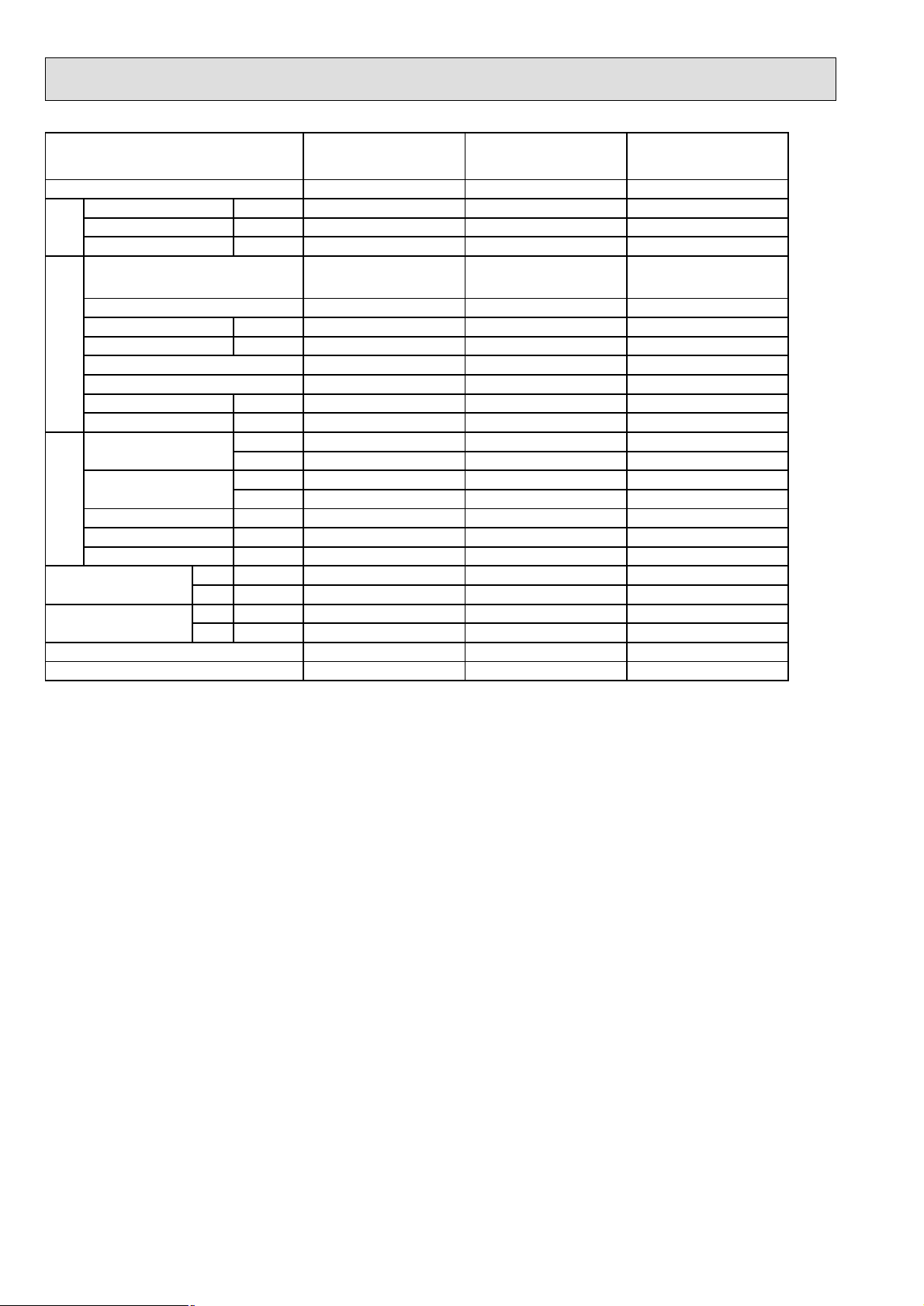
Cooling capacity correction factors
5-1. PERFORMANCE DATA
Cooling capacity
Notes : CA: Capacity (kW)
P.C.: Power can sweeping (kW)
Model name
PE-5GAK(T)
PU-5YAKD
PE-6GAK(T)
PU-6YAKD
Model name
PE-5GAK(T)
PU-5YJSA
PE-6GAK(T)
PU-6YJSA
Indoor
Intake
air W.B.˚C
16 13.0 4.06 12.7 4.23 12.2 4.55 11.7 4.88 11.2 5.21 10.6 5.54
18 13.9 4.14 13.5 4.31 13.0 4.66 12.5 5.00 11.9 5.34 11.4 5.69
20 14.7 4.22 14.4 4.40 13.9 4.76 13.3 5.12 12.8 5.49 12.2 5.86
22 15.6 4.29 15.3 4.49 14.7 4.86 14.2 5.24 13.6 5.64 13.0 6.05
16 13.6 4.83 13.2 5.04 12.8 5.43 12.2 5.82 11.7 6.21 11.1 6.60
18 14.5 4.93 14.1 5.14 13.6 5.55 13.1 5.96 12.5 6.37 11.9 6.78
20 15.4 5.02 15.0 5.24 14.5 5.67 13.9 6.10 13.4 6.54 12.7 6.98
22 16.3 5.12 16.0 5.35 15.4 5.79 14.9 6.25 14.3 6.72 13.6 7.21
Indoor
Intake
air W.B.˚C
16 12.9 4.48 12.7 4.65 12.2 4.98 11.7 5.31 11.2 5.70 10.7 6.08 9.5 6.41 8.4 6.58
18 13.8 4.53 13.5 4.70 13.0 5.09 12.5 5.47 11.9 5.86 11.4 6.19 10.2 6.58 9.1 6.75
20 14.6 4.65 14.4 4.81 13.9 5.20 13.3 5.59 12.8 5.97 12.2 6.41 11.0 6.80 9.7 6.97
22 15.6 4.76 15.2 4.92 14.7 5.31 14.2 5.75 13.6 6.14 13.0 6.64 11.3 7.08 10.0 7.24
16 13.5 4.90 13.3 5.08 12.7 5.45 12.3 5.81 11.7 6.23 11.2 6.66 9.9 7.02 8.8 7.20
18 14.4 4.96 14.2 5.14 13.6 5.57 13.1 5.99 12.5 6.41 11.9 6.78 10.7 7.20 9.5 7.38
20 15.3 5.08 15.1 5.26 14.5 5.69 13.9 6.11 13.4 6.53 12.7 7.02 11.5 7.44 10.2 7.62
22 16.3 5.20 16.0 5.38 15.4 5.81 14.8 6.29 14.3 6.72 13.6 7.26 11.8 7.74 10.5 7.93
21 25 30 35 40 45
CA P.C. CA P.C. CA P.C. CA P.C. CA P.C. CA P.C.
CA P.C. CA P.C. CA P.C. CA P.C. CA P.C. CA P.C. CA P.C. CA P.C.
PE-5
5m (16ft)
1.0
10m (33ft)
0.978
15m (49ft)
Outdoor intake air D.B.˚C
20m (66ft)
0.962
Outdoor intake air D.B.˚C
Refrigerant piping length (one way)
35m (115ft)
0.948
25m (82ft)
0.934
30m (98ft)
0.921
0.908
5021 25 30 35 40 45
40m (131ft)
0.896
52
45m (148ft)
0.884
50m (164ft)
0.875
PE-6
1.0
0.971
0.950
0.931
0.912
0.896
0.880
0.864
0.850
0.840
Page 12
12
The unit of pressure has been changed to Mpa based on SI (International System of Units) in accordance with I.S.O.
(International Organization for Standardization).
The conversion factor is : 1(Mpa) =10.2 (OOf/FF)
5-2. STANDARD OPERATION DATA
Mode
Capacity (GROSS)
Capacity (NET)
Total
Input
Indoor unit
Phase, Hz
Volts
Amperes
Outdoor unit
Phase, Hz
Electrical circuit
Volts
Amperes
Discharge
Pressure
Suction
Pressure
Discharge temp.
Suction temp.
Refrigerant circuit
Ref. pipe length
Indoor intake
air temp.
Outdoor intake
air temp.
Model name
D.B. ˚C27
W.B. ˚C19 19 19
D.B. ˚C35 35 35
W.B. ˚C24 24 24
SHF
BF
PE-5GAK(T) PE-5GAK(T) PE-6GAK(T)
Cooling Cooling Cooling
kW 12.9 12.9 15.8
kW 12.0 12.0 14.9
kW 5.06 5.53 6.03
PE-5GAK(T) PE-5GAK(T) PE-6GAK(T)
1, 50 1, 50 1, 50
V 240 240 240
A 4.0 4.0 4.0
PU-5YAKD PU-5YJSA PU-6YAKD
3, 50 3, 50 3, 50
V 415 415 415
A 6.86 7.63 8.45
MPa 1.87 1.90 2.03
2
kgf/cm
MPa 0.40 0.42 0.40
2
kgf/cm
˚C74 73 82
˚C
m
19.1 19.4 20.7
4.1 4.3 4.1
2
5
0.82 0.82 0.82
0.27 0.27 0.19
9
5
27 27
2
5
Page 13
13
Mode
The unit of pressure has been changed to Mpa based on SI (International System of Units) in accordance with I.S.O.
(International Organization for Standardization).
The conversion factor is : 1(Mpa) =10.2 (OOf/FF)
Capacity (GROSS)
Capacity (NET)
Total
Input
Indoor unit
Phase, Hz
Volts
Amperes
Outdoor unit
Phase, Hz
Electrical circuit
Volts
Amperes
Discharge
Pressure
Suction
Pressure
Discharge temp.
Suction temp.
Refrigerant circuit
Ref. pipe length
Indoor intake
air temp.
Outdoor intake
air temp.
Model name
D.B. ˚C27
W.B. ˚C19
D.B. ˚C35
W.B. ˚C24
SHF
BF
PE-6GAK(T)
Cooling
kW 15.8
kW 14.9
kW 6.05
PE-6GAK(T)
1, 50
V 240
A 4.0
PU-6YJSA
3, 50
V 415
A 8.48
MPa 1.99
2
kgf/cm
MPa 0.42
2
kgf/cm
˚C79
˚C11
m5
20.3
4.3
0.82
0.19
PE-5GAK(T)
(With a high static pressure motor)
Cooling
12.9
12.0
5.06
PE-5GAK(T)
(With a high static pressure motor)
1, 50
240
4.0
PU-5YAKD
3, 50
415
6.86
1.87
19.1
0.40
4.1
74
2
5
27
19
35
24
0.82
0.27
Page 14
14
Mode
The unit of pressure has been changed to Mpa based on SI (International System of Units) in accordance with I.S.O.
(International Organization for Standardization).
The conversion factor is : 1(Mpa) =10.2 (OOf/FF)
Capacity (GROSS)
Capacity (NET)
Total
Input
Indoor unit
Phase, Hz
Volts
Amperes
Outdoor unit
Phase, Hz
Electrical circuit
Volts
Amperes
Discharge
Pressure
Suction
Pressure
Discharge temp.
Suction temp.
Refrigerant circuit
Ref. pipe length
Indoor intake
air temp.
Outdoor intake
air temp.
Model name
D.B. ˚C27 27 27
W.B. ˚C19 19 19
D.B. ˚C35 35 35
W.B. ˚C24 24 24
SHF
BF
PE-5GAK(T)
(With a high static pressure motor)
Cooling Cooling Cooling
kW 12.9 15.8 15.8
kW 12.0 14.9 14.9
kW 5.53 6.03 6.05
PE-5GAK(T)
(With a high static pressure motor)
1, 50 1, 50 1, 50
V 240 240 240
A 4.0 4.0 4.0
PU-5YJSA PU-6YAKD PU-6YJSA
3, 50 3, 50 3, 50
V 415 415 415
A 7.63 8.45 8.48
MPa 1.90 2.03 1.99
2
kgf/cm
MPa 0.42 0.40 0.42
2
kgf/cm
˚C738279
˚C9 2 11
m5 5 5
19.4 20.7 20.3
4.3 4.1 4.3
0.82 0.82 0.82
0.27 0.19 0.19
PE-6GAK(T)
(With a high static pressure motor)
PE-6GAK(T)
(With a high static pressure motor)
PE-6GAK(T)
(With a high static pressure motor)
PE-6GAK(T)
(With a high static pressure motor)
Page 15
15
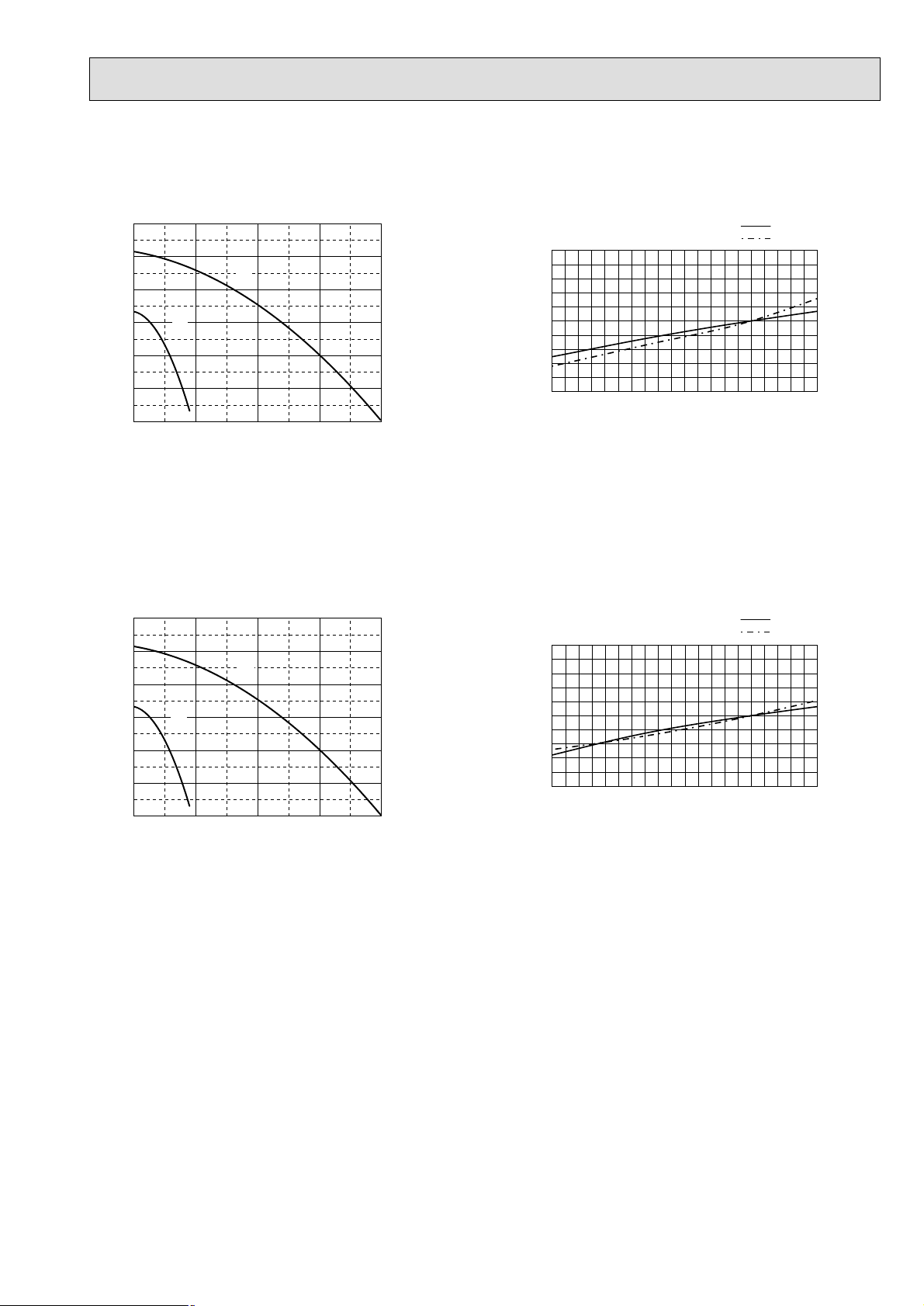
Service Ref. : PE-6GAK(T)
5-3. FAN PERFORMANCE AND CORRECTED AIRFLOW
Service Ref. : PE-5GAK(T)
Corrected Air flow
Corrected Air flow
Fan Performance Curve
Fan Performance Curve
300
250
200
150
100
External static pressure (Pa)
50
0
35.0 40.0 45.0 50.0 55.0
Lo
Hi
Air flow
300
250
200
Hi
(CMM)
1.1
1.0
Capacity/ input factor
0.9
35 40 45 50 55
1.1
Capacity
input
(CMM)
Air flow
Capacity
input
150
100
External static pressure (Pa)
50
0
40.0 45.0 50.0 55.0 60.0
Lo
Air flow
(CMM)
1.0
Capacity/ input factor
0.9
40 45 50 55 60
Air flow
(CMM)
Page 16
16
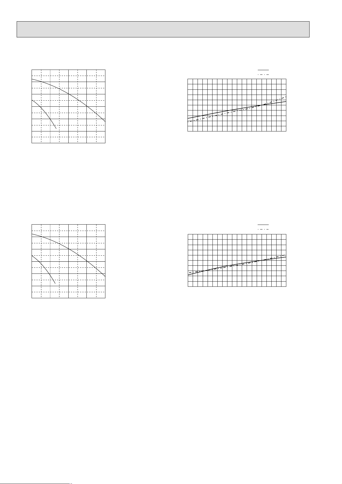
Service Ref. : PE-5GAK(T) (With a high static pressure motor)
Service Ref. : PE-6GAK(T) (With a high static pressure motor)
Fan Performance Corrected Air flow
Fan Performance Corrected Air flow
300
250
1.1
Capacity
input
200
150
100
External static pressure (Pa)
50
Lo
Hi
1.0
Capacity/ input factor
0.9
35 40 45 50 55
0
35.0 40.0 45.0 50.0 55.0
Air flow
(CMM)
300
250
200
150
Hi
1.1
1.0
(CMM)
Air flow
Capacity
input
100
External static pressure (Pa)
50
0
40.0 45.0 50.0 55.0 60.0
Lo
Air flow
(CMM)
Capacity/ input factor
0.9
40 45 50 55 60
Air flow
(CMM)
Page 17

17
5-4. SOUND DATA
Indoor units
1) Sound Levels
Model
PE-5
PE-6
PE-5
(High static pressure motor)
PE-6
(High static pressure motor)
SPL
dB(A) 63Hz 125Hz 250Hz 500Hz 1000Hz 2000Hz 4000Hz 8000Hz
46 50 49 46 44 42 38 28 22
42 44 44 41 40 38 34 23 15
49 54 53 51 47 43 34 29 25
45 51 51 47 44 40 31 25 21
48 52 51 48 46 44 40 30 24
45 47 47 44 43 41 37 26 18
51 55 54 51 49 47 43 33 27
48 50 50 47 46 44 40 29 21
Position measurement
Indoor unit
2m
Outlet
PEH-5,6: Upper High/Lower Low
OCTAVE BAND FREQ.Hz
1m
Inlet
Measurement point
1.5m
Page 18

18
6
OUTLINES AND DIMENSIONS
6-1. INDOOR UNIT
PE-5,6 GAK (T)
Unit : mm
199
3 Holes
20-
34124
882
51
6X130(=780)51
Return air
duct flange
10
130
20
1080
200
131
3.1 Holes
14-
12 Holes
4-
For hanging bolt M10
[Field supply]
10
55
130
3X130(=390)
Top view
55
Supply air
duct flange
1180
1120
11 250 95
1064
Front view
361 500 179
42
2pcs.
62
1pc.
20
462
Control box
Remote
Rubber bush
controller wiring
40
70 1295575
Outdoor unit
Rubber bush
Rubber bush
connection wiring
A
Power supply
wiring
<
40 1040 40
54
10
634
530
50
10
Return air
sensor
400
376
2510010025
262 73
130
35
144
22330
Supply air
A
130
145
56539
35
89
Drain R1
Left side view
9.52 (3/8 flare)
Refrigerant pipe
Accessory
Pipe cover
(For dew condensation prevention of
local piping and unit connection.)
Remote controller
19.05 (3/4 flare)
Refrigerant pipe
Return air
Page 19

19
6-2. REMOTE CONTROLLER
130
120
19
Unit : mm
Page 20

20
7
WIRING DIAGRAM
PE-5,6GAK(T)
ROOM TEMP
LIQUID PIPE TEMP
NAME
FERRITE COREFB
SURGE KILLERCR
AUXILIARY RELAY (INDOOR FAN MOTOR<HIGH SPEED>)
OVER CURRENT RELAY (INDOOR FAN MOTOR)
MAGNETIC CONTACTOR (INDOOR FAN MOTOR)
FAN MOTOR (INDOOR)
TERMINAL BLOCK
52F
51F
MF1
SYMBOL NAME
TB2,4,5
INDOOR UNIT
AUXILIARY RELAY (INDOOR FAN MOTOR<LOW SPEED>)
THERMISTOR
FUSE FUSE (T6.3AL250V)
ZNR VARISTOR
C CAPACITOR
TH1
TH2
X2Hi
X1Lo
INDOOR
CONTROLLER
C
5
6
(*1)
MF1
124
C01
X2Hi
X1Lo
RED
BLUE
WHITE
L2L3N
GREEN/YELLOW
REDL1
TB2 52F 51F
INDOOR UNIT
CONNECTOR (DRAIN SENSOR)CN31
CONNECTOR (REMOTE SWITCH)CN32
CONNECTOR (LOSSNAY)CN2L
AUXILIARY RELAYX4-6
SWITCH (MODEL SELECTION)
SWITCH (SYSTEM SELECTION)
SW5
SW1
LED (POWER SUPPLY <REMOTE CONTROLLER>)
SWITCH (EMERGENCY OPERATION)
CONNECTOR (EMERGENCY OPERATION)
LED (POWER SUPPLY)
SW6
SWE
LED1
LED2
BOARD
DSA
DSR
ZNR5~7
SNB BOARD 1
BLACK
ARRESTER
CONNECTOR (WIRELESS REMOTE CONTROLLER)
CONNECTOR (CENTRALLY CONTROL)
CONNECTOR (HA TERMINAL-A)
VARISTOR
CN90
CN51
CN41
DSA,DSR
ZNR5~7
SYMBOL
SNB BOARD 1
REMOTE CONTROLLER
TB6 TERMINAL BLOCK
matching wiring and terminal.
2.Color of earth wire is yellow and green twisting.
3.Specification subject to change without notice.
4.Indoor and outdoor connecting wires are made with polarities,make sure
Note:1.The dotted lines show field wiring.
LCD
BOARD
REMOTE CONTROLLER
TB6
REMOTE CONTROLLER
FB
12
LED1
CN2D
2
1
TAB1
DC
INDOOR
13.1V
POWER BOARD
3
1
X1
Hi Lo
X2
CR
52F
CN2S
CNSK
X2
Lo Hi
X1
51F
DC13.1V
CND
FUSE
13 1 3
CNDK
X5 X4
1357
X6
FAN
ZNR
X6 X5 X4
If a trouble occurs with either the remote controller or the indoor microcom-
puter and no other trouble exists, emergency operation for cooling or heating
can be performed by changing the setting of connector (SWE) and switch (SW6)
on the indoor controller board.
SWE : ON / Indoor fan is running high speed.
SW6-1 : ON / Emargency operation of cooling mode.
6. mark is connector. mark is terminal.
5.Emergency operation
7.This motor(*1) includes auto reset type internal thermostat.
Therefore, do not change factory set value of over current relays.
1.To protect fan motor from abnormal current,over current relays is installed.
Caution,
OUTDOOR UNIT
TO OUTDOOR UNIT
CONNECTING WIRES
(POLAR)
TB5
121
1
LED2
CN32 CN31
CN2L
CN41
CN51
21
SW6
ON
OFF
INDOOR
CONTROLLER BOARD
TB4
2
2
123
CN22
CN30
121
2
CN20
CN21
CN90
ON
OFF
5
SW5
3214
ON
OFF
54321 678
SW1
SWE
ON
OFF
TH1
TH2
CIRCUIT BREAKER
(FIELD SUPPLY)
PE-5,6GAK(T) : 15A
POWER SUPPLY
~PE
220/230/240V
50Hz
PE
Page 21

21
REFRIGERANT SYSTEM DIAGRAM8
PE-5GAK(T) / PU-5YJSA
PE-6GAK(T) / PU-6YJSA
PE-5GAK(T)/PU-5YAKD
PE-6GAK(T)/PU-6YAKD
Unit : mm
INDOOR UNIT
Indoor heat
exchanger
Indoor coil
thermistor
TH2
Distributor
Strainer
Refrigerant pipe 19.05 (3/4")
(With insulator)
Flared
connection
Refrigerant pipe 9.52 (3/8")
(With insulator)
Flared
connection
plug
Ball
valve
Check plugCharge
High
pressure
switch
Thermal switch
Accumulator
Capillary tube
PU-5YJSA
(O.D. 4.0 × I.D. 2.4 – L840) × 2pcs
PU-6YJS A
(O.D. 4.0 × I.D. 2.4 – L1200) × 2pcs
Compressor
Ball valve
(with service port)
Capillary tube
PU-5YJSA (O.D. 4.0 × I.D. 2.4 – L400)
PU-6YJSA (O.D. 4.0 × I.D. 2.4 – L200)
OUTDOOR UNIT
Outdoor heat
exchanger
Strainer
DPR
Refrigerant pipe 19.05
(with insulator)
Indoor heat
exchanger
Indoor coil
thermistor
TH2
Distributor
Refrigerant pipe 9.52
(with insulator)
Flared
Connection
Ball
valve
Strainer
Accumulator
Strainer
Flow of refrigerant
Charge plug
Compressor
switch
Strainer
Compressor
High
pressure
switch
Thermal
switch
OUTDOOR UNITINDOOR UNIT
Outdoor heat
exchanger
Strainer
Capillary tube
PU-5YAKD
(O.D.4.0×I.D.2.4
PU-6YAKD
(O.D.4.0×I.D.2.4
–
L840)
–
L1200)
Strainer
Ball valve
(with charge plug)
Flow of refrigerant
Page 22

22
9 TROUBLESHOOTING
<Error code display by self-diagnosis and actions to be taken for service (summary)>
Present and past error codes are logged and displayed on the wired remote controller or controller board of outdoor unit.
Actions to be taken for service,which depends on whether or not the the inferior phenomenon is reoccurring at service, are
summarized in the table below. Check the contents below before investigating details.
9-1. TROUBLESHOOTING
Unit conditions at service
Error code
Actions to be taken for service (summary)
The inferior phenomenon is
reoccurring.
Displayed
Not displayed
Judge what is wrong and take a corrective action
according to “SELF-DIAGNOSIS ACTION TABLE” (7-3).
Identify the cause of the inferior phenomenon and take
a corrective action according to “TROUBLESHOOTING
BY INFERIOR PHENOMENA ” (7-4).
The inferior phenomenon is
not reoccurring.
Logged
Not logged
1Consider the temporary defects such as the work of
protection devices in the refrigerant circuit including
compressor, poor connection of wiring, noise and etc.
Re-check the symptom, and check the installation
environment, refrigerant amount, weather when the
inferior phenomenon occurred, and wiring related.
2Reset error code logs and restart the unit after finishing
service.
3There is no abnormality in electrical components,
controller boards, and remote controller.
1Recheck the abnormal symptom.
2Identify the cause of the inferior phenomenon and take
a corrective action according to “TROUBLESHOOTING
BY INFERIOR PHENOMENA ” (7-4).
3Continue to operate unit for the time being if the cause
is not ascertained.
4There is no abnormality in electrical components,
controller boards, remote controller etc.
PAR-21MAA
ON/OFF
FILTER
CHECK
OPERATION
CLEAR
TEST
TEMP.
MENU
BACK DAY
MONITOR/SET
CLOCK
ON/OFF
ERROR CODE
ERROR CODE
ERROR CODE
1 Turn on the power.
2 Press the [CHECK] button twice.
3 Set address with [TEMP] button if system control is used.
4 Press the [ON/OFF] button to stop the self-check.
A CHECK button
B Address
C TEMP. button
D IC : Indoor unit
OC: Outdoor unit
E Check code
F Unit No.
G Timer ON/OFF button
A
F
C
BBEED
G
<To delete check code>
1 Display the error code at the self-check result display screen.
2 The address for self-check will blink when the
G ON/OFF
button is pressed twice within three seconds.
– – – – : No trouble generated in the past.
F F F F : No corresponding unit.
9-2. MALFUNCTION-DIAGNOSIS METHOD BY REMOTE CONTROLLER
<In case of trouble during operation>
When a malfunction occurs to air conditioner, both indoor unit and outdoor unit will stop and operation lamp blinks to inform
unusual stop.
■ Wired remote controller
Page 23

23
Errors detected by indoor unit
Wired remote controller
1 Check code
Symptom Remark
P1
Intake sensor error
P2 Pipe (TH2) sensor error
P4 Drain sensor error
P5
PA
Drain pump error
Forced compressor stop
P6 Freezing/ Overheating safeguard operation
P8 Pipe temperature error / Outdoor unit error
E4, E5 Remote controller signal receiving error
–
–
–
–
Fb Indoor unit control system error (memory error, etc.)
E0, E3
Remote controller transmission error
E1, E2 Remote controller control board error
• On wired remote controller
1Check code displayed in the LCD.
If the unit cannot be operated properly after test run has been performed, refer to the following table to remove the cause.
•
Wired remote controller
PLEASE WAIT
Symptom
For about 2
minutes following power-on
•For about 2 minutes following power-on,operation of the remote controller is not possible
due to system start-up. (Correct operation)
Cause
•Connector for the outdoor unit’s protection
PLEASE WAIT → Error code
Display messages do not
appear even when operation
switch is turned ON (operation
lamp does not light up).
After about 2
minutes has
expired following power-on
device is not connected.
•Reverse or open phase wiring for the outdoor
unit’s power terminal block
•Incorrect wiring between indoor and outdoor
units
•Remote controller wire short
Note:
Operation is not possible for about 30 seconds after cancellation of function selection. (Correct operation)
For description of each LED (LED1, 2) provided on the indoor controller, refer to the following table.
LED1 (power for microcomputer) Indicates whether control power is supplied. Make sure that this LED is
always lit.
LED2 (power for wired remote controller)
Indicates whether power is supplied to the wired remote controller.
This LED lights only in the case of the main indoor unit.
Page 24

24
9-3. SELF-DIAGNOSIS ACTION TABLE
Error Code
Meaning of error code and detection method
Cause
Countermeasure
P1
Abnormality of room temperature
thermistor (TH1)
1 The unit is in three-minute resume
prevention mode if short/open of
thermistor is detected. Abnormal if the
unit does not reset normally after three
minutes. (The unit returns to normal
operation, if it has normally reset.)
2 Constantly detected during cooling,
drying, and heating operation.
Short: 90
: or more
Open: -40
: or less
1 Defective thermistor
characteristics.
2 Contact failure of connector
(CN20) on the indoor controller
board. (Insert failure)
3 Breaking of wire or contact
failure of thermistor wiring.
4 Defective indoor controller
board.
1–3 Check resistance value of thermistor.
0
: ····15.0k"
10: ······9.6k"
20: ······6.3k"
30: ······4.3k"
40: ······3.0k"
If you put force on (draw or bend) the lead wire
with measuring resistance value of thermistor
breaking of wire or contact failure can be
detected.
2 Check contact failure of connector (CN20)
on the indoor controller board. Refer to 9-7.
Turn the power on again and check restart
after inserting connector again.
4 Check room temperature display on remote
controller.
Replace indoor controller board if there is
abnormal difference with actual room
temperature.
Turn the power off, and on again to operate
after check.
P2
Abnormality of pipe temperature
thermistor/Liquid (TH2)
1 The unit is in three-minute resume
prevention mode if short/open of
thermistor is detected. Abnormal if the
unit does not reset normally after three
minutes. (The unit returns to normal
operation, if it has normally reset.)
2 Constantly detected during cooling,
drying, and heating (except defrosting)
operation.
Short: 90
: or more
Open: -40
: or less
1 Defective thermistor
characteristics.
2 Contact failure of connector
(CN21) on the indoor controller
board. (Insert failure)
3 Breaking of wire or contact
failure of thermistor wiring.
4 Defective refrigerant circuit is
causing thermistor temperature
of 90
: or more or -40: or
less.
5 Defective indoor controller board.
1–3 Check resistance value of thermistor.
For characteristics, refer to (P1) above.
2 Check contact failure of connector (CN21)
on the indoor controller board. Refer to 9-7.
Turn the power on and check restart after
inserting connector again.
4 Check pipe <liquid> temperature with remote
controller in test run mode. If pipe <liquid>
temperature is exclusively low (in cooling
mode) or high (in heating mode), refrigerant
circuit may have defective.
5 Check pipe <liquid> temperature with remote
controller in test run mode. If there is exclusive
difference with actual pipe <liquid> temperature,
replace indoor controller board.
Turn the power off, and on again to operate
after check.
P4
Abnormality of drain sensor (DS)
1 Suspensive abnormality, if short/open of
thermistor is detected for 30 seconds
continuously.
Turn off compressor and indoor fan.
2 Short/open is detected for 30 seconds
continuously during suspensive
abnormality.
(The unit returns to normal operation,
if it has normally reset.)
3 Detect the following condition.
• During cooling and drying operation.
• In case that pipe <liquid> temperature
- room temperature <-10deg
(Except defrosting)
• When pipe <liquid> temperature or
room temperature is short/open
temperature.
• During drain pump operation.
1 Defective thermistor
characteristics
2 Contact failure of connector
(CN31) on the indoor controller
board. (Insert failure).
3 Breaking of wire or contact
failure of drain sensor wiring.
4 Defective indoor controller board.
1–3 Check resistance value of thermistor.
0
: ······6.0k"
10: ····3.9k"
20: ····2.6k"
30: ····1.8k"
40: ····1.3k"
2 Check contact failure of connector (CN31)
on the indoor controller board. Refer to 9-7.
Turn the power on again and check restart
after inserting connector again.
4 Replace indoor controller board if drain
pump operates with the line of drain sensor
connector CN31-
1 and 2 is short-circuited,
and abnormality reappears.
Turn the power off, and on again to operate
after check.
P5
Malfunction of drain pump (DP)
1 Suspensive abnormality, if thermistor
of drain sensor is let heat itself and
temperature rises slightly. Turn off
compressor and indoor fan.
2 Drain pump is abnormal if the condition
above is detected during suspensive
abnormality.
3 Constantly detected during drain pump
operation.
1 Malfunction of drain pump
2 Defective drain
Clogged drain pump
Clogged drain pipe
3 Attached drop of water at the
drain sensor
• Drops of drain trickles from
lead wire.
• Clogged filter is causing
wave of drain.
4 Defective indoor controller board.
1 Check if drain-up machine works.
2 Check drain function.
3 Check the setting of lead wire of drain
sensor and check clogs of the filter.
4 Replace indoor controller board if drain
pump operates with the line of drain sensor
connector CN31-1 and 2 is short-circuited
and abnormality reappears.
Refer to 9-7.
Turn the power off, and on again to operate
after check.
Page 25

25
Error Code
Meaning of error code and detection method
Cause
Countermeasure
P6
Freezing/overheating protection is
working
1 Freezing protection (Cooling mode)
The unit is in six-minute resume prevention
mode if pipe temperature stays under
-15: for three minutes, three minutes
after the compressor started. Abnormal
if it stays under -15: for three minutes
again within 16 minutes after six-minute
resume prevention mode.
<Frost prevention mode>
If pipe temperature is 1: or below
when 16 minutes has passed after compressor starts operating, unit will start
operating in frost prevention mode which
stops compressor operation. After that,
when pipe temperature stays 10: or
more for 3 minutes, frost prevention
mode will be released and compressor
will restart its operation.
P8
1 Slight temperature difference
between indoor room
temperature and pipe temperature thermistor
• Shortage of refrigerant
• Disconnected holder of pipe
thermistor
• Defective refrigerant circuit
2 Converse connection of
extension pipe (on plural units
connection)
3 Converse wiring of indoor/
outdoor unit connecting wire
(on plural units connection)
4 Defective detection of indoor
room temperature and pipe
temperature thermistor
5 Stop valve is not opened
completely.
(Cooling or drying mode)
1 Clogged filter (reduced airflow)
2 Short cycle of air path
3 Low-load (low temperature)
operation beyond the tolerance
range
4 Defective indoor fan motor
• Fan motor is defective.
• Indoor controller board is
defective.
5 Defective outdoor fan control
6 Overcharge of refrigerant
7 Defective refrigerant circuit
(clogs)
(Cooling or drying mode)
1 Check clogs of the filter.
2 Remove shields.
4 Measure the resistance of fan motor's winding.
Measure the output voltage of fan's connector
(Relay for FAN) onthe indoor controller
board.
* The indoor controller board should be
normal when voltage of AC 220~240V is
detected while fan motor is connected.
Refer to 9-7.
5 Check outdoor fan motor.
67 Check operating condition of refrigerant
circuit.
Abnormality of pipe temperature
<Cooling mode>
Detected as abnormal when the pipe temperature is not in the cooling range 3 minutes later of compressor start and 6 minutes later of the liquid pipe is out of cooling
range.
Note 1) It takes at least 9 min. to detect.
Note 2) Abnormality P8 is not detected in
drying mode.
Cooling range : -5 deg ] (TH2-TH1)
TH2: Liquid pipe temperature
TH1: Intake temperature
1~4 Check pipe temperature with room
temperature display on remote
controller.
23Check converse connection of extension
pipe or converse wiring of indoor/outdoor
unit connecting wire.
1 Wrong wiring of indoor/outdoor
connecting wire
2 Reversed phase
3 Protection device is working
4 Damaged outdoor coil thermis-
tor
Abnormality in outdoor unit
1 Check the indoor/outdoor connecting wire.
2 Change the connection of electric wiring.
3 Check the protection device.
4 Measure the resistance of the outdoor coil
thermistor. If the resistance is normal,
replace the outdoor controller board.
Page 26

26
Error Code
Meaning of error code and detection method
Cause
Countermeasure
E0
or
E4
Remote controller transmission
error(E0)/signal receiving error(E4)
1 Abnormal if main or sub remote con-
troller can not receive normally any
transmission from indoor unit of refrigerant address “0” for three minutes.
(Error code : E0)
2 Abnormal if sub remote controller could
not receive for any signal for two minutes. (Error code: E0)
1 Abnormal if indoor controller board can
not receive normally any data from
remote controller board or from other
indoor controller board for three minutes.
(Error code: E4)
2 Indoor controller board cannot receive
any signal from remote controller for two
minutes. (Error code: E4)
1 Check disconnection or looseness of indoor
unit or transmission wire of remote controller.
2 Set one of the remote controllers “main”.
If there is no problem with the action above.
3 Check wiring of remote controller.
• Total wiring length: max.500m
(Do not use cable x 3 or more)
• The number of connecting indoor units:
max.16units
• The number of connecting remote controller: max.2units
When it is not the above-mentioned problem of
1~3
4 Diagnose remote controllers.
a) When “RC OK” is displayed,
Remote controllers have no problem.
Put the power off, and on again to check.
If abnormality generates again, replace
indoor controller board.
b) When “RC NG” is displayed,
Replace remote controller.
c) When “RC E3” is displayed,
d) When “ERC 00-06” is displayed,
[ c),d)→Noise may be causing abnormality. ]
* If the unit is not normal after replacing
indoor controller board in group control,
indoor controller board of address “0”
may be abnormal.
E3
or
E5
Remote controller transmission
error(E3)/signal receiving error(E5)
1 Abnormal if remote controller could not
find blank of transmission path for six
seconds and could not transmit.
(Error code: E3)
2 Remote controller receives transmitted
data at the same time, compares the
data, and when detecting it, judges
different data to be abnormal 30
continuous times. (Error code: E3)
1 Abnormal if indoor controller board could
not find blank of transmission path.
(Error code: E5)
2 Indoor controller board receives trans-
mitted data at the same time, compares
the data,and when detecting it, judges
different data to be abnormal 30
continuous times. (Error code: E5)
1 Set a remote controller to main, and the
other to sub.
2 Remote controller is connected with only one
indoor unit.
3 The address changes to a separate setting.
4~6 Diagnose remote controller.
a) When “RC OK”is displayed, remote con-
trollers have no problem.
Put the power off,and on again to check.
When becoming abnormal again, replace
indoor controller board.
b) When “RC NG”is displayed, replace
remote controller.
c)
When “RC E3”or “ERC 00-66”is displayed,
noise may be causing abnormality.
1 Contact failure at transmission
wire of remote controller
2 All remote controllers are set
as “sub” remote controller. In
this case, E0 is displayed on
remote controller, and E4 is
displayed at LED (LED1, LED2)
on the outdoor controller circuit
board.
3 Mis-wiring of remote controller.
4 Defective transmitting receiving
circuit of remote controller
5 Defective transmitting receiving
circuit of indoor controller board
of refrigerant address “0”.
6 Noise has entered into the
transmission wire of remote
controller.
1 Two remote controller are set
as “main.”
(In case of 2 remote con-
trollers)
2 Remote controller is connected
with two indoor units or more.
3 Repetition of refrigerant
address.
4 Defective transmitting receiving
circuit of remote controller.
5 Defective transmitting receiving
circuit of indoor controller
board.
6 Noise has entered into trans-
mission wire of remote controller.
Page 27

27
Error Code
Meaning of error code and detection method
Cause
Countermeasure
Fb
Abnormality of indoor controller board
Abnormal if data cannot be normally read
from the nonvolatile memory of the indoor
controller board.
1 Defective indoor controller
board.
1 Replace indoor controller board.
E1
or
E2
Abnormality of remote controller control
board
1 Abnormal if data cannot be normally
read from the nonvolatile memory of the
remote controller control board.
(Error code: E1)
2 Abnormal if the clock function of remote
controller cannot be normally operated.
(Error code: E2)
1 Defective remote controller. 1 Replace remote controller.
PA
(2502)
(2500)
Forced compressor stop
(due to water leakage abnormality)
1 When the intake temperature subtracted
with liquid pipe temperature is less than
-10
:, drain sensor is detected whether
it is soaked in the water or not at the interval
of 90 seconds. (Drain pump will start operating
when the drain sensor is detected to be
soaked in the water.)
2 The unit has a water leakage abnormality
when the following conditions, a and b, are
satisfied while the above-mentioned detection
is performed.
a) The drain sensor is detected to be
soaked in the water 10 times in a row.
b) The intake temperature subtracted with
liquid pipe temperature is detected to be
less than -10
: for a total of 30 minutes.
(When the drain sensor is detected to
be NOT soaked in the water, the detection
record of a and b will be cleared.)
3 The drain sensor detection is performed
in operations other than cooling. (When
the unit stops operating, during heating
or fan operation, when the unit stops
because of some abnormality)
*Once the water leakage abnormality is
detected, abnormality state will not be
released until the main power is reset.
1 Drain pump trouble
2 Drain defective
· Drain pump clogging
· Drain pipe clogging
3 Open circuit of drain sensor
side heater
4 Contact failure of drain sensor
connector
5 Dew condensation on drain
sensor
· Drain water descends along
lead wire.
· Drain water waving due to filter
clogging.
6 Extension piping connection
difference at twin, triple,
quadruple system.
7 Mis-wiring of indoor/ outdoor
connecting at twin, triple,
quadruple system.
8 Room temperature thermistor /
liquid pipe temperature thermistor detection is defective.
1Check the drain pump.
Performance
2Please confirm whether water can be
drained.
3Confirm the resistance of the drain sensor
side heater.
4Check the connector contact failure.
5 Check the drain sensor leadwire mounted.
Check the filter clogging
6Check the piping connection.
7Check the indoor/ outdoor connecting wires.
8Check the room temperature display of
remote controller.
Check the indoor liquid pipe temperature
display of outdoor controller board.
Page 28

28
• When LED1 on indoor controller board is also off.
1 Power supply of 220~240V AC is not supplied to
indoor unit.
2 Defective indoor controller board.
3 Defective indoor power board.
9-4. TROUBLESHOOTING BY INFERIOR PHENOMENA
Phenomena
Cause
Countermeasure
(1)LED2 on indoor controller board
is off.
• When LED1 on indoor controller board is lit.
1 Mis-setting of main/sub for indoor unit
(There is no unit corresponding to main unit.)
1 Reconfirm the setting of main/sub for
indoor unit
Set the main unit.
Set main/sub using SW5-3 on indoor
controller board.
1 Check the voltage of indoor power supply
terminal block (L,N).
• When AC220~240V is not detected.
Check the power supply wiring.
• When AC220~240V is detected.
-Check 2 (below).
2 Check voltage output from CNDK on
indoor controller board.
• When AC220~240V is not detected.
Check the fuse on indoor controller
board.
Check the wiring connection between
indoor power supply terminal block and
CND on indoor controller board.
• When AC220~240V is detected.
-Check 3 (below).
3 Check voltage output from CN2S on
indoor power board.
• When no voltage output.
Check the wiring connection between
CNDK on indoor controller board and
CNSK on indoor power board.
If no problem are found,indoor power
board is defective.
• When DC12.5~13.7V is detected.
Check the wiring connection between
CN2S on indoor power board and
CN2D on indoor power board.
If no problem are found,indoor controller
board is defective.
(2)LED2 on indoor controller board
is blinking.
• When LED1 on indoor controller board is also blinking.
Connection failure of indoor/outdoor unit connecting
wire
• When LED1 is lit.
1 Mis-wiring of remote controller wires
When 2 indoor units are wired in one refrigerant
system, each indoor unit sets main unit. (SW5-3)
2 Short-cut of indoor/outdoor unit connecting wire.
3 Short-cut of remote controller wires
4 Defective remote controller
Check indoor/outdoor unit connecting wire
for connection failure.
1 Check the connection of remote con-
troller wires in case of twin triple indoor
unit system. When 2 or more indoor units
are wired in one refrigerant system,
connect remote controller wires to one of
those units.
2 Remove indoor/outdoor connecting wires
and check LED2 on indoor controller
board.
• When LED2 is blinking, check the shortcut of indoor/outdoor connecting wires.
• When LED2 is lit, connect indoor/outdoor
connecting wires again, and; if LED2 is
blinking, outdoor unit’s controller board is
defective; if LED2 is lit, connection failure
of indoor/outdoor terminal block etc. has
returned to normal.
34 Remove remote controller wires and
check LED2 on indoor controller board.
• When LED2 is blinking, check the
short-cut of remote controller wires.
• When LED2 is lit, connect remote
controller wires again and:
if LED2 is blinking, remote controller
is defective; if LED2 is lit, connection
failure of remote controller terminal
block etc. has returned to normal.
Page 29

29
(3)Upward/downward vane
performance failure
1 The vane is not downward during defrosting and
heat preparation and when the thermostat is OFF in
HEAT mode. (Working of COOLprotection function)
2 Vane motor does not rotate.
• Defective vane motor
• Breaking of wire or connection failure of connector
• Up/down vane setting is “No vanes”.
3 Upward/downward vane does not work.
• The vane is set to fixed position.
1 Normal operation (The vane is set to hor-
izontal regardless of remote control.)
2 Check 2 (left).
• Check the vane motor. (Refer to “How
to check the parts”.)
• Check for breaking of wire or connection failure of connector.
• Check “Up/down vane setting”. (Unit
function selection by remote controller).
3 Normal operation (Each connector on
vane motor side is disconnected.)
Phenomena
Cause
Countermeasure
9-5. TEST RUN AND EMERGENCY OPERATION
9-5-1. Before test run
9-5-2. Test run (Using wired remote controller)
B
EF
C
H
G
IM
A
D
ûC
ûC
SIMPLE
PAR-21MAA
ON/OFF
FILTER
CHECK
OPERATION
CLEAR
TEST
TEMP.
MENU
BACK DAY
MONITOR/SET
CLOCK
ON/OFF
TEST RUN
COOL, HEAT
A ON/OFF button
B Test run display
C Indoor temperature liquid line
temperature display
D ON/OFF lamp
E Power display
F Error code display
Test run remaining time display
G Set temperature button
H Mode selection button
I Fan speed button
M TEST button
1 Turn on the power at least 12 hours before the test run.
2 Press the [TEST] button twice. ➜ "TEST RUN" liquid crystal display
3 Press the [Mode selection] button. Make sure that wind is blown out.
4 Press the [Mode selection] button and switch to the cooling mode.
➜ Make sure that cold wind is blown out.
5 Press the [Fan speed] button. ➜ Make sure that the wind speed is switched.
6 Check operation of the outdoor unit fan.
7 Release test run by pressing the [ON/OFF] button. ➜ Stop
8 Register a telephone number.
The telephone number of the repair shop, sales office, etc., to contact if an error
occurs can be registered in the remote controller. The telephone number will be
displayed when an error occurs. For registration procedures, refer to the operation
manual for the indoor unit.
• After completing installation and the wiring and piping of the indoor and outdoor units, check for refrigerant leakage,
looseness in the power supply or control wiring, wrong polarity, and no disconnection of one phase in the supply.
• Use a 500-volt megohmmeter to check that the resistance between the power supply terminals and ground is
at least 1.0M .
• Do not carry out this test on the control wiring (low voltage circuit) terminals.
Warning:
Do not use the air conditioner if the insulation resistance is less than 1.0M .
Page 30

30
1.When the wired remote control or the indoor unit microcomputer has failed,but all other components work if you set the
switch(SWE,SW6) on the indoor control board,the indoor unit will begin properly Emergency Operation.
2.When you activate emergency operation of the cooling, you have to set the connector(SWE) and switch(SW6)on the
indoor controller.
SWE:ON • Indoor fan is running high speed.
SW6-1:ON • Emergency operation of cooling mode.
3.Before you activate emergency operation,check the following points:
(1)Emergency operation cannot be activated when:
• the outdoor unit malfunctions.
• the indoor fan malfunctions.
(2)Emergency operation becomes continuous only by switching the power source on/off. ON/OFF on the remote
control or temperature control etc. does not function.
(3)Emergency cooling should be limited to 10 hours maximum
(The indoor unit heat exchanger may freeze).
(4)After emergency operation has been deactivated,set the switches etc. to their original positions.
9-5-3. When wired remote controller or indoor unit micro computer troubles
Page 31

31
9-6. HOW TO CHECK THE PARTS
PE-5GAK(T) PE-6GAK(T)
0
10
20
30
40
50
-20 -10 0 10 20 30 40 50
< Thermistor for lower temperature >
Temperature (:)
Resistance (K")
<Thermistor Characteristic graph>
Room temperature thermistor(TH1)
Indoor coil thermistor(TH2)
Thermistor R
0=15k' ±3%
Fixed number of B=3480 ± 2%
Rt=15exp { 3480( ) }
0
:: 15k'
10:: 9.6k'
20:: 6.3k'
25:: 5.2k'
30:: 4.3k'
40:: 3.0k'
Thermistor for
lower temperature
1
273+t
1
273
Parts name
Room temperature
thermistor (TH1)
Disconnect the connector, then measure the resistance using a tester.
(Surrounding temperature 10˚C-30˚C)
Indoor coil thermistor
(TH2)
Fan motor
Brown
Red
Lo
220~240V
50Hz
Hi
220~240V
50Hz
Blue
Thermal protector
17AM037E5-4
Operating temperature150˚C
P
Orange
A1
M
A2
White
Measure the resistance between the terminals using a tester.
(Surrounding temperature 20˚C)
Check points
Nomal Abnormal
4.3kr -9.6kr Open or short
Red-Orange 7.15
PE-5,6
Brown-White 11.71
Red-Brown 5.12
PE-5,6
(High static pressure motor)
Red-Orange 5.34
Brown-White 10.12
Red-Brown 3.35
Nomal
(Refer to the thermistor)
Abnormal
Open or short
Page 32

32
9-7. TEST POINT DIAGRAM
9-7-1. Power board
PE-5GAK(T) PE-6GAK(T)
CNSK
Connect to the indoor controller board
(CNDK)
Between
1 to 3 220-240V AC
CN2S
Connect to the indoor controller board (CN2D)
Between
1 to 3 12.6-13.7V DC (Pin1 (+))
Page 33

33
9-7-2. Indoor controller board
PE-5GAK(T) PE-6GAK(T)
FAN
Fan motor output
CNP
Drain-pump output
(DP)
(220~240V AC)
CNC
Dew prevention
heater (H2)
(220~240V AC)
CNDK
Connect to the indoor
power board (CNSK)
(220~240V AC)
FUSE
(6.3A 250V)
CND
Power
supply input
(220~240V AC)
SWE
Emergency operation
SW1
Model setting
CN2L
Connector
(LOSSNAY)
CN51
Centrally control
CN6V
Vane motor output
(MV)
CN90
Connect to the wireless remote controller board (CNB)
CN31
Drain sensor (DS)
CN21
Pipe temperature
thermistor/Liquid
(TH2)
CN20
Room temperature
thermistor (TH1)
CN22
Remote controller
connecting wire
(10.4~14.6V DC)
LED2
Power supply
(R.B)
LED1
Power supply
(I.B)
CN2D
Connector to the indoor
power board (CN2S)
(12.5~13.7V DC)
}
}
+
–
+
–
SW5
System Setting
CN32
Remote Switch
CN41
Connector
(HA terminal-A)
CN105/ CN92
(RED)
SW6
Emergency
operation
CN30
Transmission
(indoor/outdoor)
Page 34

34
9-8. FUNCTIONS OF DIP SWITCH AND JUMPER WIRE
Each function is controlled by the dip switch and the jumper wire on control p.c. board.
SW1
Setting by the dip switch and jumper wire
Functions
Jumper wire
Model
settings
SW5
System
settings
Remarks
(Marks in the table below) Jumper wire ( : Short : Open)
SW5-3 Main/Sub setting
OFF : Main ON : Sub
SW5-4 Rotaion operation setting
OFF : Not avairable ON : avairable
8761
SW5
OFF
ON
5432
OFF
ON
54321
SW1
Page 35

35
10-1. UNIT FUNCTION SETTING BY THE REMOTE CONTROLLER
Each function can be set according to necessity using the remote controller. The setting of function for each unit can only be
done by the remote controller. Select function available from the table 1.
(1) Functions available when setting the unit number to 00 (Select 00 referring to
4 setting the indoor unit number.)
*1 The functions below are available only when the wired remote controller is used.The functions are not available for floor
standing models.
<Table 1> Function selections
(2) Functions available when setting the unit number to 01-02 or AL (07 in case of wireless remote controller)
• When setting functions for an indoor unit in an independent system, set the unit number to 01 referring to
4 setting the
indoor unit number.
• When setting functions for a simultaneous Twin-indoor unit system, set the unit number to 01 to 02 for each indoor
unit in case of selecting different functions for each unit referring to
4 setting the indoor unit number.
• When setting the same functions for an entire simultaneous Twin-indoor unit system, set refrigerant address to AL
(07 in case of wireless remote controller) referring to
4 setting the indoor unit number.
10
FUNCTION SETTING
Function
Power failure
automatic recovery
Indoor temperature
detecting
LOSSNAY
connectivity
Power supply
voltage
Frost prevention
temperature
Humidifier control
Rotation
Settings
OFF
ON
Indoor unit's (Main) internal sensor
Remote controller's internal sensor *1
Not supported
Supported (indoor unit not equipped with outdoor air intake)
Supported (indoor unit equipped with outdoor air intake)
240V
220V,230V
1
Mode No.
Initial setting
(when sent from the factory)
01
02
03
04
15
16
20
Setting No.
1
2
1
2
3
1
2
3
1
2
1
2
1
2
1
2
3
Remarks
The setting is
applied to all
the units in the
same
refrigerant
system.
Initial setting (Factory setting
Function Settings
Mode
No.
Setting
No.
- : Not available
PE-GAK(T)
Filter sign 100Hr 1
2500Hr 07 2
No filter sign indicator
3
Air flow Quiet 1 (
Fan speed
)
Standard 08 2 High ceiling 3 -
No.of air outlets 4 directions 1 -
3 directions 09 2 2 directions
Optional high efficiency
Not supported
filter Supported
Vane setting
No vanes (Vane No.3 setting:PL-AAKonly
Vane No.1 setting
Vane No.2 setting
Energy saving air Disabled
flow (Heating mode
Vane differential setting No.1 setting (TH2: 24-28˚C
)
Enabled
)
in heating mode No.2 setting (Standard, TH2:28-32˚C
(
cold wind prevention
)
No.3 setting (TH2: 32-38˚C
)
Swing Not available
Available
Fan speed when the
Set fan speed
cooling thermostat is OFF Stop
Detection of abnormality of Available
the pipe temperature (P8
)
Not available
10
)
11 2 -
12
)
14 2 -
23
27
28
31
2
-
-
1-
31
2
-
-
1-
31
2
-
-
1
2
1
2
)
Page 36

36
[Operating Procedure]
1 Check the setting items provided by function selection.
If settings for a mode are changed by function selection, the functions of that mode will be changed accordingly. Check all the current settings according to steps 2
to 7 , fill in the "Check" column in Table 1, and then change them as necessary. For factory settings, refer to the indoor unit's installation manual.
2 Switch off the remote controller.
A Hold down the
B ( mode 15 or more) and
buttons
simultaneously for at least two seconds.
will start to flash,
and then the remote controller's display content will change as shown below.
3 Set the outdoor address.
C Press the [
CLOCK] buttons ( and ) to select the desired
address. The address changes from "00" to "15".
* If the unit stops after
flashed for two seconds or "88" flashes in the room temperature display area for two seconds, a transmission error may have occurred.
Check to see if there are any sources of noise or interference near the transmission path.
Note
If you have made operational mistakes during this procedure, exit function selection (see step 0), and then restart from step 2 .
4 Set the indoor unit number.
D Press the
button so that " - -" flashes in the unit number display
area.
C Press the [
CLOCK] buttons ( and ) to select the unit number
of the indoor unit for which you want to perform function selection. The unit
number changes to "00", "01", "02","03",04" and "AL" each time a button is
pressed.
* To set modes 01 to 06 or 15 to 22 select unit number "00".
* To set modes 07 to 14 or 23 to 28 carry out as follows:
• To set each indoor unit individually, select "01" to "04".
• To set all the indoor units collectively, select "AL".
5 Confirm the address and unit number.
E Press the
button to confirm the address and unit
number.
After a while, "- - " will start to flash in the mode number display area.
E When the address and unit number are confirmed by pressing the
button, the corresponding indoor unit will start fan operation. This
helps you find the location of the indoor unit for which you want to perform function
selection. However, if "00" or "AL" is selected as the unit number, all the indoor
units corresponding to the specified address will start fan operation.
* "88" will flash in the room temperature display area if the selected address
does not exist in the system.
Furthermore, if
"F"
appears and flashes in the unit number display area and the
address display area also flashes, there are no units that correspond to the
selected unit number. In this case, the address and unit number may be incorrect,
so repeat steps 2 and 3 to set the correct ones.
* When grouping different systems, if an indoor unit other than the
one to which the address has been set performs fan operation,
there may be another address that is the same as the specified one.
In this case, check the DIP switch of the outdoor unit to see
whether such a address exists.
6 Select the mode number.
F Press the [
TEMP] buttons ( and ) to set the desired mode
number.
(Only the selectable mode numbers can be selected.)
7 Select the setting content for the selected mode.
G Press the
button. The currently selected setting number will
flash, so check the currently set content.
F Press the [
TEMP] buttons ( and ) to select the desired setting
number.
8 Register the settings you have made in steps 3 to 7 .
E Press the
button. The mode number and setting number will start
to flash and registration starts.
The mode number and setting number will stop flashing and remain lit, indicating the
end of registration.
* If " - - - " is displayed for both the mode number and setting number and "
" flashes in the room temperature display area, a transmission error may have occurred.
Check to see if there are any sources of noise or interference near the transmission path.
9 If you wish to continue to select other functions, repeat steps 3 to 8 .
0 Complete function selection.
A Hold down the
buttons simultaneously for at least two seconds.
After a while, the function selection screen will disappear and the air conditioner OFF screen will reappear.
* Do not operate the remote controller for at least 30 seconds after completing
function selection. (No operations will be accepted even if they are made.)
Note If a function of an indoor unit is changed by function selection after installation is complete, make sure that a " " mark, etc., is given in the "Check"
column of Table 1 to indicate the change.
Unit number
display section
Mode number
display section
00 address
Indoor unit
Fan draft
Remote controller
Main Sub
Outdoor unit
Designate operation
Example) When the address is set to 01 and the unit number is 02.
Mode number
display section
Mode number 02 = Indoor temperature detection
Setting number display section
Setting number 3 = Remote controller built-in sensor
Setting number 1 = Indoor unit operating average
( mode 15 or more) and
FILTER
Address
display section
FUNCTION
SELECTION
FUNCTION
SELECTION
TEST
ON/OFF
MODE
MODE
MENU
MODE
FILTER TEST
Page 37

37
10-2. FUNCTION SELECTION OF REMOTE CONTROLLER
The setting of the following remote controller functions can be changed using the remote controller function selection mode.
Change the setting when needed.
Item 1
1.Change Language
("CHANGE LANGUAGE")
2.Function limit
("FUNCTION SELECTION")
3.Mode selection
("MODE SELECTION")
4.Display change
("DISP MODE SETTING")
Item 3 (Setting content)
• Display in multiple languages is possible.
• Setting the range of operation limit (operation lock)
• Setting the use or non-use of "automatic" operation mode
• Setting the temperature adjustable range (maximum, minimum)
• Selecting main or sub remote controller
*
When two remote controllers are connected to one group, one controller must be set to sub.
• Setting the use or non-use of clock function
• Setting the timer type
• Contact number display in case of error
• Setting the telephone number
• Setting the temperature unit (: or °F) to display
• Setting the use or non-use of the display of indoor (suction) air temperature
• Setting the use or non-use of the display of "Cooling" or "Heating" display during
operation with automatic mode
Item 2
Language setting to display
(1)
Operation function limit setting (operation lock) ("LOCKING FUNCTION")
(2)
Use of automatic mode setting ("SELECT AUTO MODE")
(3)
Temperature range limit setting ("LIMIT TEMP FUNCTION")
(1)
Remote controller main/sub setting ("CONTROLLER MAIN/SUB")
(2) Use of clock setting ("CLOCK")
(3) Timer function setting ("WEEKLY TIMER")
(4) Contact number setting for error situation ("CALL.")
(1) Temperature display :/°F setting ("TEMP MODE :/°F")
(2)
Suction air temperature display setting ("ROOM TEMP DISP SELECT")
(3)
Automatic cooling/heating display setting ("AUTO MODE DISP C/H")
[Function selection flowchart] Refer to next page.
[1] Stop the air conditioner to start remote controller function selection mode. [2] Select from item1. [3] Select from item2. [4] Make the setting.
(Details are specified in item3) [5] Setting completed. [6] Change the display to the normal one. (End)
➔➔➔
➔➔
[Detailed setting]
[4] -1. CHANGE LANGUAGE setting
The language that appears on the dot display can be selected.
• Press the [
MENU] button to change the language.
1 Japanese (JP), 2 English (GB), 3 German (D), 4 Spanish (E),
5 Russian (RU), 6 Italian (I), 7 Chinese (CH),8 French (F)
[4] -2. Function limit
(1) Operation function limit setting (operation lock)
• To switch the setting, press the [ ON/OFF] button.
1 no1: Operation lock setting is made on all buttons other than
the [
ON/OFF] button.
2 no2: Operation lock setting is made on all buttons.
3 OFF (Initial setting value) : Operation lock setting is not made
* To make the operation lock setting valid on the normal screen, it is
necessary to press buttons (Press and hold down the [FILTER]
and [ ON/OFF] buttons at the same time for two seconds.) on
the normal screen after the above setting is made..
(2) Use of automatic mode setting
When the remote controller is connected to the unit that has automatic operation mode, the following settings can be made.
• To switch the setting, press the [ ON/OFF] button.
1 ON (Initial setting value) : The automatic mode is displayed when
the operation mode is selected.
2 OFF : The automatic mode is not display
when the operation mode is selected.
[4] -3. Mode selection setting
(1) Remote controller main/sub setting
• To switch the setting, press the [ ON/OFF] button.
1 Main : The controller will be the main controller.
2 Sub : The controller will be the sub controller.
(2) Use of clock setting
• To switch the setting, press the [ ON/OFF] button.
1 ON : The clock function can be used.
2 OFF:The clock function cannot be used.
(3) Timer function setting
• To switch the setting, press the [ ON/OFF] button (Choose one of
the followings.).
1 WEEKLY TIMER (initial setting on MA deluxe):
The weekly timer can be used.
2 AUTO OFF TIMER: The auto off timer can be used.
SIMPLE TIMER (Default setting on MA smooth):
The simple timer can be used.
4
3
TIMER MODE OFF: The timer mode cannot be used.
* When the use of clock setting is OFF , the "WEEKLY TIMER" cannot be
used.
(4) Contact number setting for error situation
• To switch the setting, press the [ ON/OFF] button.
1 CALL OFF:
The set contact numbers are not displayed in case of error.
2 CALL **** *** **** : The set contact numbers are displayed in case
of error.
(3) Temperature range limit setting
After this setting is made, the temperature can be changed within the set range.
• To switch the setting, press the [ ON/OFF] button.
1 LIMIT TEMP COOL MODE :
The temperature range can be changed on cooling/dry mode.
2 LIMIT TEMP HEAT MODE :
The temperature range can be changed on heating mode.
3 LIMIT TEMP AUTO MODE :
The temperature range can be changed on automatic mode.
4 OFF (initial setting) : The temperature range limit is not active.
*
When the setting, other than OFF, is made, the temperature range limit setting
on cooling, heating and automatic mode is made at the same time. However
the range cannot be limited when the set temperature range has not changed.
•
To increase or decrease the temperature, press the [ TEMP ( ) or ( )] button.
•
To switch the upper limit setting and the lower limit setting, press the
[ ]
button. The selected setting will flash and the temperature can be set.
• Settable range
Cooling/Dry mode : Lower limit: 19 : ~ 30: Upper limit: 30 : ~ 19:
Heating mode : Lower limit: 17 : ~ 28: Upper limit: 28 : ~ 17:
Automatic mode : Lower limit: 19 : ~ 28: Upper limit: 28 : ~ 19:
CALL_ : The contact number can be set when the display is as
shown on the left.
• Setting the contact numbers
To set the contact numbers, follow the following procedures.
Move the flashing cursor to set numbers. Press the [
TEMP. ( ) and
( )] button to move the cursor to the right (left). Press the [ CLOCK
(
) and ( )] button to set the numbers.
[4] -4. Display change setting
(1) Temperature display :/ F setting
• To switch the setting, press the [ ON/OFF] button.
1 : : The temperature unit : is used.
2 F: The temperature unit
°
°°
F is used.
(2) Suction air temperature display setting
• To switch the setting, press the [ ON/OFF] button.
1 ON : The suction air temperature is displayed.
2 OFF:The suction air temperature is not displayed.
(3) Automatic cooling/heating display setting
• To switch the setting, press the [ ON/OFF] button.
1 ON : One of "A utomatic cooling" and "A utomatic heating" is displa yed
under the automatic mode is running.
2 OFF:Only "Automatic" is displayed under the automatic mode.
Page 38

38
Hold down the E button and press the D button for 2 seconds.
Hold down the E button and press the D button for 2 seconds.
Remote controller function selection mode
E Press the operation mode button.
G Press the TIMER MENU button.
D Press the TIMER ON/OFF button.
Item1 Item2
Dot display
Item3
Room air temperature is not displayed.
One of "Automatic cooling" and "Automatic heating" is displayed
under the automatic mode is running. (Initial setting value)
Only "Automatic" is displayed under the automatic mode.
Normal display
(Display when the air condition is not running)
Change
Language
Function
selection
Mode
selection
Display
mode setting
Operation lock setting is not used.
(Initial setting value)
Operation lock setting is except On/Off buttons.
Operation lock setting is All buttons.
The automatic mode is displayed when the operation mode is
selected. (Initial setting value)
The automatic mode is not displayed when the operation mode
is selected.
The temperature range limit is not active. (Initial setting value)
The temperature range can be changed on cooling/dry mode.
The temperature range can be changed on heating mode.
The temperature range can be changed on automatic mode.
The remote controller will be the main controller. (Initial setting value)
The remote controller will be the sub controller.
The clock function can be used. (Initial setting value)
The clock function can not be used.
Weekly timer can be used. (Initial setting value)
Auto off timer can be used.
Simple timer can be used.
Timer mode can not be used.
The set contact numbers are not displayed in case of error.
(Initial setting value)
The set contact numbers are displayed in case of error.
The temperature unit
:
is used. (Initial setting value)
The temperature unit °F is used.
Room air temperature is displayed. (Initial setting value)
Flowchart of Function Setting
Setting language (English)
E
E
G
EN
GE
ES
RU
G
IT
ZH
FR
F
TEMP.
MENU
E
PAR-21MAA
G
MONITOR/SET
BACK DAY
CLOCK
ON/OFF
C
OPERATION
D
ON/OFF
FILTER
CHECK
CLEAR
I
A
TEST
B
H
JA
D
OFF
D
on1
D
D
D
D
D
D
on2
ON
D
OFF
OFF
D
G
G
E
G
G
G
D
G
D
D
E
G
D
D
G
G
D
D
D
G
G
D
D
D
G
G
D
D
D
ON
D
OFF
D
OFF
D
CALL-
:
D
°F
ON
D
OFF
ON
D
OFF
Page 39

39
11 SYSTEM CONTROL
11-1. VARIETY OF SYSTEM CONTROL FUNCTIONS
System Name System Diagram Features
A.Remote control-
ler operation
Use of two controllers enables
operation of the air
conditioner both
from a distance
and nearby.
B.Group control
operation
Use of one remote
controller to control multiple air
conditioners with
the same settings
simultaneously.
Indoor
unit
Remote
Controller
* One of the wired remote con-
trollers must be set as a sub
remote controller.
Inter face
Indoor
unit
Outdoor
Remote
Controller
unit
• Up to two remote controllers can be connected to
one group.
• Operation control by the latest command (last entered priority)
• Wired remote controllers can be combined as
a pair.
• One group can consist of up to 16 indoor units, and
they can be started sequentially by connecting the
remote controller to them and assigning an address
to each inter face.
• All the units belonging to the same group are operated in the same mode, but thermostats can be
turned ON/OFF individually for each indoor unit.
• Up to two remote controllers can be connected.
Parts Required in Addition to Standard System
Components (Indoor/Outdoor Units, Remote Controller)
Wired remote controller (additional)
(PAR-21MAA)
Inter face MAC-397IF-E
Page 40

40
System Nam
e
m
es
y
m
)
n
l
.
y
,
/
-
-
.
:
e
.
e
.
e
n
).
t
f
.
s
.
o
ed.
er
(
)
C. Timer operatio
Enables contro
of start and stop
For control b
external timer
refer to Remote
handheld com
bined control op
eration"
System Diagra
Featur
Weekly timer
In addition to ON/OFF, up to eight temperatur
patterns can be set for each day of the week
Only one timer can be selected; the auto off, simpl
and weekly timers cannot be combined
Simple timer: Start and stop operations can each b
performed once within 72 hours (ca
be set in 1-hour increments
Auto off timer:Operation is stopped when the prese
time elapses following the start o
operation
The time can be set from 30 minute
to 4 hours in 30-minute increments
Only one timer can be selected; the simple and aut
off timers cannot be combin
Parts Required in Addition to Standard S
Components (Indoor/Outdoor Units, Remote Controller
MA Remote controll
PAR-21MAA
ste
Page 41

41
11-2. ONE REMOTE CONTROLLER (STANDARD) OPERATION
(1) One Wired Remote Controller
(OC: Outdoor unit IC: Indoor unit R: Remote controller (for wireless type: optical receiver adapter)
(Reference)
Electrical wiring diagram
OC IC
1
2
LN
Power source wiring
1
2
1
2
1
2
R
(No polarity)
Outdoor unit Indoor unit Remote controller
Power
source
wiring
(Polarity)
• Power supply terminal block L, N
• Indoor/outdoor connection cable terminal
block 1,2 (Polarity)
• Remote controller cable terminal block
1,2 (No polarity)
11-3. TWO-REMOTE CONTROLLER OPERATION
(1) Two Wired Remote Controllers
(Reference)
Set one of the remote controllers as the main controller (factory setting) and the other as the sub controller using the
remote controller's function selection.
Slim Air Conditioners System
Remote controller
connection circuit
(Controller cable)
Outdoor unit
OC
Indoor unit
IC
Wired
remote
controller R
Standard 1:1
Indoor/Outdoor
connection
cable
Remote
controller
cable
OC
IC-1
R
2
2
(R: Wired remote controller)
Slim Air Conditioner System
Outdoor unit
OC
Indoor unit IC
Remote
controller
connection
circuit
(Controller
cable)
Wired remote
controller R
Outdoor unit
OC
Indoor unit IC
Wired remote
controller R
Standard 1:1
Indoor/outdoor
connection cable
Remote
controller
cable
OC
2
IC
2
R-1 R-2
OC
IC
R-1
2
2
2
R-2
2
Page 42

42
Indoor control board
CN105
or
CN92
2.Connecting the remote control interface with each system
(For details on each system, see the relevant instruction manual.)
• Replace the interface unit mounting cord clamp with a supplied mounting cord clamp based on the thickness of the
connecting cable used for each system.
• The cables connected to the Indoor unit should be mounted on or near the Indoor unit.
If the connecting cable is not securely mounted, the connector may detach, break, or malfunction.
• Set the interface dip switch (SW500–502) settings before turning on the power.
• If the interface dip switch (SW500–502) settings are not set correctly, the system will not function properly.
Connecting cable for each system
Mounting screws 4 o 16
Electrical wire mounting
bracket
Mounting cord clamp
Mounting screws 4 o 10
Mounting cord clamp
Connect the connecting cable that comes with the
interface unit to the connector
CN105 or CN92 on the indoor control board.
INDOOR
Mounting screws (black) 3.5 o 12
Interface unit mounting cord clamp or mounting
cord clamps
11-4. GROUP CONTROL OPERATION
(COLLECTIVE OPERATION AND CONTROL OF MULTIPLE REFRIGERANT SYSTEMS (2 to 16))
●
Group control can be operated by using MAC-397IF-E.
●
The setting of wired remote controller is subjected to variation according to the function of the indoor unit.
(for mode operation, setting temperature, fan step, air direction)
The display of remote controller and operating the indoor unit might be different.
●
Neither the test run nor the function setting can be done by MA remote controller connected with MAC-397IF-E.
●
1.Connecting the MA& CONTACT TERMINAL Interface to the Indoor Unit
• Connect the interface unit and the indoor control board using the connecting cable that came with the interface.
• Extending or shortening the connecting cable that comes out of the interface may cause it to malfunction. Also,
keep the connecting cable as far as possible away from the electrical wires and ground wire. Do not bundle them together.
Page 43

43
Use as a Wired Remote Control (Using the MA Remote Controller)
Note:
1.Be sure the Auto Heating/Cooling Display Setting on the MA remote controller is set to OFF before use.
•For information on how to set the Auto/Heating Cooling Display Setting, see the MA remote controller
instruction manual.
•The actual operating status of the unit may differ from what is shown on the remote controller display
2.A test run cannot be initiated using the test run switch on the MA remote controller..
3.The horizontal vanes on the unit cannot be operated using the louver switch.
The range of room temperature indication is between 10 and 38 .
4.
Indoor unit
Interface unit
CN560
TB580
1
2
A
B
Remote control cord that came with
the MA remote controller (Non polarity)
2
MA remote controller
(PAR-21MAA)
PAR-20MAA cannot be used
*
with this interface.
Dip switch settings
SW500 does not have to be set.
SW501:
SW501- No. 1-4: Refrigerant address
Set this switch when multiple indoor units (and remote control interfaces) are connected to a single MA remote controller.
Always start the refrigerant address at "0".
Even when connecting multiple outdoor units, set a different refrigerant address for each indoor unit.
Refrigerant
address
0
1
2
15
1
3
4
Refrigerant
address "0"
5
21
3
3
44
Refrigerant
address "1"
Outdoor unit
Outdoor unit
Indoor unit
Interface
MA remote controller
Refrigerant
address "2"
ON
1 2 34
ON
2 3 4
1
ON
1 2 34
ON
2 34
1
SW501- No. 5–6
ON
No. 5 should normally be set to OFF.
Under the following conditions, No.6 should normally be set to ON.
5 6
When the model of Mr. SLIM exists in the same group, it sets it to turning ON.
Set them to ON only when using the room temperature sensor installed in the MA remote controller.
* This can be switched when an accurate room temperature cannot be detected by the air conditioner unit.
PE-GAK(T) series do not have a room temperature sensor on their MA remote controllers.
Page 44

44
SW501: Settings to accommodate MA remote controller and settings to accommodate outdoor units
SW No.
No. 1
No. 2
No. 3
No. 4
Functions OFF ON Comments
Only specify these settings when connecting an
MA remote controller.
Functions
Room temperature detector
The model of Mr. SLIM exists in the
same group.
This should normally be set to ON.
ON
1
2 3 4 5 6
ON
1 2 3 4 5 6
ON
1
2 3 4 5 6
ON
1
2 3 4 5 6
ON
1 2 3 4 5 6
ON
1
2 3 4 5 6
ON
1
2 3 4 5 6
ON
1 2 3 4 5 6
ON
1 2 3 4 5 6
ON
1
2 3 4 5 6
ON
1
2 3 4 5 6
ON
1
2 3 4 5 6
ON
1
2 3 4 5 6
ON
1
2 3 4 5 6
ON
1 2 3 4 5 6
ON
1
2 3 4 5 6
Refrigerant address 0
Refrigerant address 1
Refrigerant address 2
Refrigerant address 3
Refrigerant address 4
Refrigerant address 5
Refrigerant address 6
Refrigerant address 7
Refrigerant address 8
Refrigerant address 9
Refrigerant address 10
Refrigerant address 11
Refrigerant address 12
Refrigerant address 13
Refrigerant address 14
Refrigerant address 15
OFF
Indoor unit
Not mixed
ON
Remote control
Mixed
Comments
This should normally be set to OFF.
SW No.
No. 5
No. 6
Page 45

45
SW502 : Air Conditioner Function Settings
Interface unit
Wall mounting
brackets
Mounting screws
Mounting screws
Mounting screws
Cord clamp for
wiring
SW No.
Cooling only type/ Heat pump type
No. 1
No. 2
Auto mode
No. 3
No. 4
Fan speed
No. 5
Vane
No. 6
Swing
No. 7
Not in use
No. 8
Fan mode
* Fan speed 2 step model : An actual fan speed is 2 step though the display of remote controller becomes 4 step or 3 step.
Functions
OFF
Heat pump type
Not available
(setting No.3 disabled)
Available
(unit)
4 speeds
Available
Available
–
Not available
ON
Cooling only type
Available
(setting No.3 enabled)
Available
(remote controller)
3 speeds (1-speed and
2-speed models
set ON)
Not available
Not available
–
Available
Set the mode in accordance with the operation
manual for the indoor unit.
Heat pump type : Set to ON.
Cooling only type : Set to OFF.
Set to OFF.
When operating 2-speed model with the 3-speed
setting (ON), the MA remote controller display
will indicate 3 fan speeds.
The table below shows the displays and the actual
outputs at that time.
Display Meaning Indoor unit output
Medium speed High speed
The Vane function of either of indoor unit :
When the function is provided, it is Available (OFF).
When the function is not provided, it is Not available (ON).
The Swing function of either of indoor unit :
When the function is provided, it is Available (OFF).
When the function is not provided, it is Not available (ON).
Permanently set to OFF.
Set to ON.
Comments
High speed
Low speedLow speed
High speed
3. Test Run (Check Operations)
Interface status monitor
You can check the status of the interface by the LED lamp on the interface unit board.
LED lamp no.
LED521
LED522
LED523
Lamp off
DC 12 V is not being supplied from the
air conditioner.
Device is not communicating properly
with the air conditioner.
Device is not communicating properly
with the MA remote controller.
Lamp on
DC 12 V is being supplied from the air
conditioner.
–
–
Blinking at approx. 1 second intervals: Device is
communicating normally with the air conditioner.
Blinking at approx. 8 second intervals: Device is communicating normally with the MA remote controller.
Blinking
–
* Use the table above to check the device operations.
4. Mounting the Remote Control Interface Unit
The Interface unit should be placed in a location where the connecting cable from the interface can reach an indoor unit.
The device will not function properly if the connecting cable is extended so the connecting cable should not be extended.
Mount the interface unit securely to a pillar or wall using 2 or more screws.
■ When Using Wall Mounting Brackets
2
1
Attach the wall mounting brackets to the interface unit
using 2 mounting screws.
Mount the unit to a pillar or wall using 2 mounting screws.
Page 46

46
■ When Mounting Directly to a Wall
Mount the interface unit case to the wall using the mounting
screws.
Interface case
mounting screws
Mounting
screws
When mounting the interface unit inside a ceiling
or wall, install an access door to facilitate maintenance.
When the interface unit is mounted
above an indoor unit, it should be
positioned 40 mm or more away from the
unit to ensure that ceiling grills can be
removed.
40 mm or more
Attach the interface unit connecting cable here.
Store extra connecting cable in the ductwork space
behind the indoor unit.
* If there is any slack in the connecting cable, use a
fastener to keep it in place.
* When mounting the interface unit using a cushioning
material , be sure to mount it in a location where it will not
fall.
Interface unit
Cushioning material
Page 47

47
11-5. POWER OUTAGE AUTOMATIC RECOVERY OPERATION
• Whenever a power outage or switching of the power supply causes the power supply of an operating air conditioner to go
from OFF to ON, this function will automatically restore the operation of the air conditioner to its previous operating mode.
w If the power is turned from OFF to ON when the air conditioner is not in operation, the air conditioner will not automatically
be turned on. However, the timer operation will be cancelled if the air conditioner is in timer operation (including when the
unit is waiting for its start time). Setting for timer operation must be performed once again.
• If there is a momentary power outage of less than one second while the air conditioner is in operation, there may not be a
clear determination of whether or not there was a power failure. When it has been determined that there has been a power
failure, recovery will take approximately four minutes after the power is restored. Please wait. (Once "PLEASE WAIT" has
appeared on the display, a protection system will operate to prevent the unit from restarting for three minutes.)
When it has been determined that there has been no power failure, operation will continue as is.
• Settings can be made by function selections from the remote controller.
• When there is group control, selection of all refrigerants is required.
11-6. INDIVIDUAL CONTROL OPERATION FROM A SEPARATE ROOM
• By simply centralizing the remote controllers installed in each room in a separate control room, individual control or centralized monitoring of the air conditioners in each room can be attained.
• Air conditioner control can be performed up to a total of 500 meters away by connecting the indoor units and remote controllers with 0.3 to 1.25 mm
2
2-core cable.
• If a remote controller is installed in a room and control room, refer to the section on operating with two remote controllers.
Indoor unit Indoor unit Indoor unit
Remote controller
Control room room 1 room 2 room 3
11-7. TIMER OPERATION
● Timer operation can be performed by setting the wired timer. Start and stop times can be set in 10-minute increments within
a 24-hour period.
● When used in combination with the central control remote controller of the M-NET control system for the outdoor unit, one
program timer can be used for individual timer settings for each group of the central control system. (Each timer setting can
be stored in data memory so timer settings for up to 50 groups can be set individually.)
* Please refer to the MELANS catalog or technical information for details about the central control remote controller.
Page 48

48
SERVICE DATA (PARTS NAME)
12
Indoor unit
11
External parts
• PE-5,6GAK(T)
Drain pan
Drain pipe connection
(R1)
Control box
Fan motor
Sirocco fan
Suspension bracket
Special washer
Drain pan
Heat exchanger
Liquid pipe
Gas pipe
Inlet thermistor
(TH1)
Liquid pipe thermistor
(TH2)
Strainer
Page 49

49
22
Control box parts
• PE-5,6GAK(T)
Magnetic contactor (Fan motor)
Capacitor
Power supply board
Ferrite core
Control board
Terminal block for
remote controller
Terminal block for
outdoor/indoor control
wiring connection
Power supply
terminal block
TB5
2121
52F
TB4
51F
TB2
L1 L3 NL2
A
FB
I/D
POWER BOARD
I/D
CAPACITOR
X1Lo X2Hi
CONTROLLER BOARD
SNB
board
Relay
view A
Page 50

50
OPTIONAL PARTS
13
Individual order numberItem
MAC-397IF-E
Group control operation
M-NET operation
1
2
MAC-399IF-E
Page 51

Page 52

HEAD OFFICE : TOKYO BLDG., 2-7-3, MARUNOUCHI, CHIYODA-KU TOKYO 100-8310, JAPAN
CCopyright 2007 MITSUBISHI ELECTRIC ENGINEERING CO., LTD.
Distributed in August 2007 No.HWE07050 PDF 5
Printed in Japan.
New publication, effective August 2007.
Specifications subject to change without notice.
TM
 Loading...