

Mitsubishi PCFY-P40VKM-E, PCFY-P63VKM-E, PCFY-P100VKM-E, PCFY-P125VKM-E Service Manual
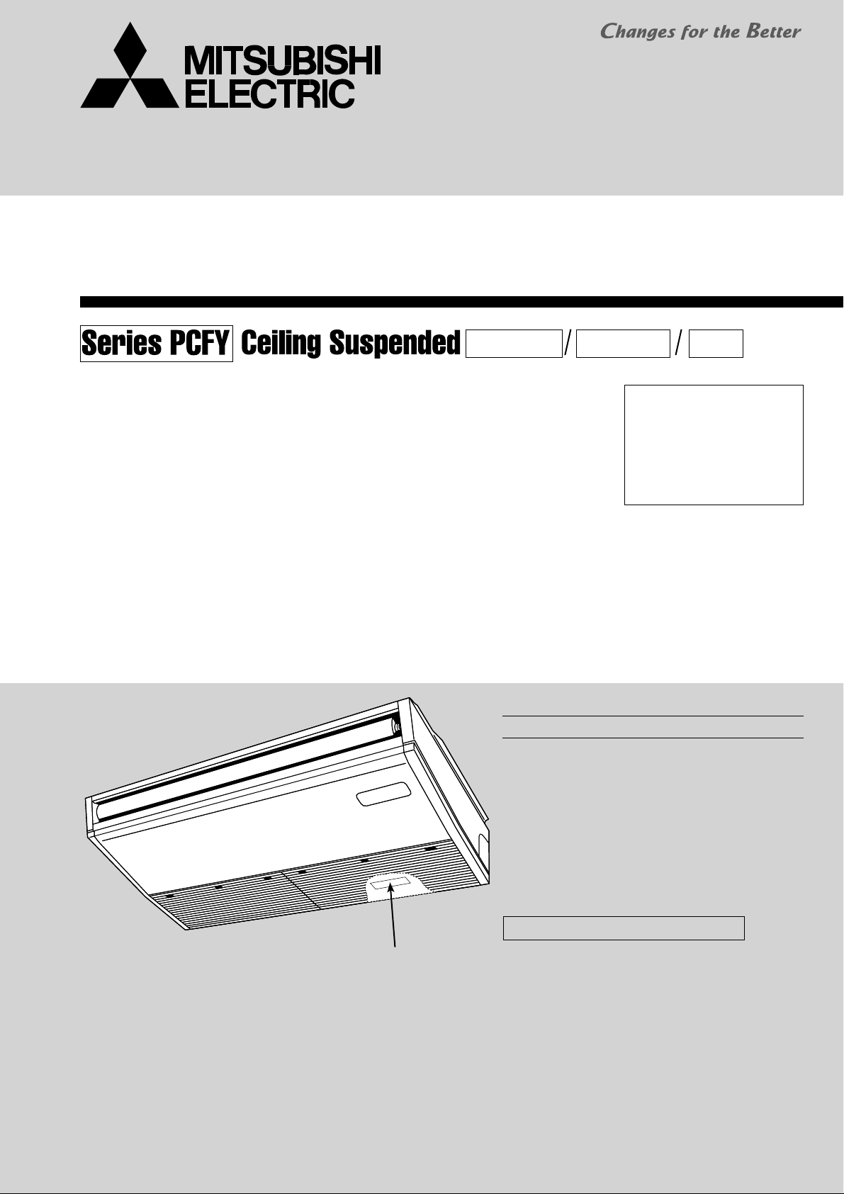
SPLIT-TYPE, HEAT PUMP AIR CONDITIONERS
TECHNICAL & SERVICE MANUAL
R407C R22R410A
December 2008
No. OCH449
Indoor unit
[Model names] [Service Ref.]
PCFY-P40VKM-E
PCFY-P63VKM-E
PCFY-P100VKM-E
PCFY-P125VKM-E
PCFY-P40VKM-E
PCFY-P63VKM-E
PCFY-P100VKM-E
PCFY-P125VKM-E
Note:
• This manual describes only
service data of the indoor
units.
• RoHS compliant products
have <G> mark on the spec
name plate.
CONTENTS
1. SAFETY PRECAUTION
2. PART NAMES AND FUNCTIONS
3. SPECIFICATION
4. OUTLINES AND DIMENSIONS
5. WIRING DIAGRAM
6. REFRIGERANT SYSTEM DIAGRAM
7. TROUBLESHOOTING
8. DISASSEMBLY PROCEDURE
.....................................
..........................
...............................
..........................
.............
..........
............
........
2
5
7
11
14
15
16
25
INDOOR UNIT
PARTS CATALOG (OCB449)
Model name
indication
1
SAFETY PRECAUTION
CAUTIONS RELATED TO NEW REFRIGERANT
Cautions for units utilizing refrigerant R407C
Do not use the existing refrigerant piping.
The old refrigerant and lubricant in the existing piping
contain a large amount of chlorine which may cause the
lubricant deterioration of the new unit.
Use “low residual oil piping”
If there is a large amount of residual oil (hydraulic oil, etc.)
inside the piping and joints, deterioration of the lubricant
will result.
Store the piping to be used indoors during
installation and both ends sealed until just before
brazing.
(Store elbows and other joints in a plastic bag.)
If dust, dirt, or water enters the refrigerant cycle,
deterioration of the oil and compressor trouble may result.
Use ESTR , ETHER or HAB as the lubricant to
coat flares and flange connection parts.
If large amount of mineral oil enters, that can cause
deterioration of refrigerant oil etc.
Use liquid refrigerant to charge the system.
If gas refrigerant is used to seal the system, the composition
of the refrigerant in the cylinder will change and performance
may drop.
Do not use a refrigerant other than R407C.
If another refrigerant (R22, etc.) is used, the chlorine in the
refrigerant may cause the lubricant deterioration.
Use a vacuum pump with a reverse flow check valve.
The vacuum pump oil may flow back into the refrigerant
cycle and cause the lubricant deterioration.
Ventilate the room if refrigerant leaks during
operation. If refrigerant comes into contact with
a flame, poisonous gases will be released.
[1] Cautions for service
·After recovering all the refrigerant in the unit, proceed to working.
·Do not release refrigerant in the air.
·After completing the repair service, recharge the cycle with the specified amount of liquid refrigerant.
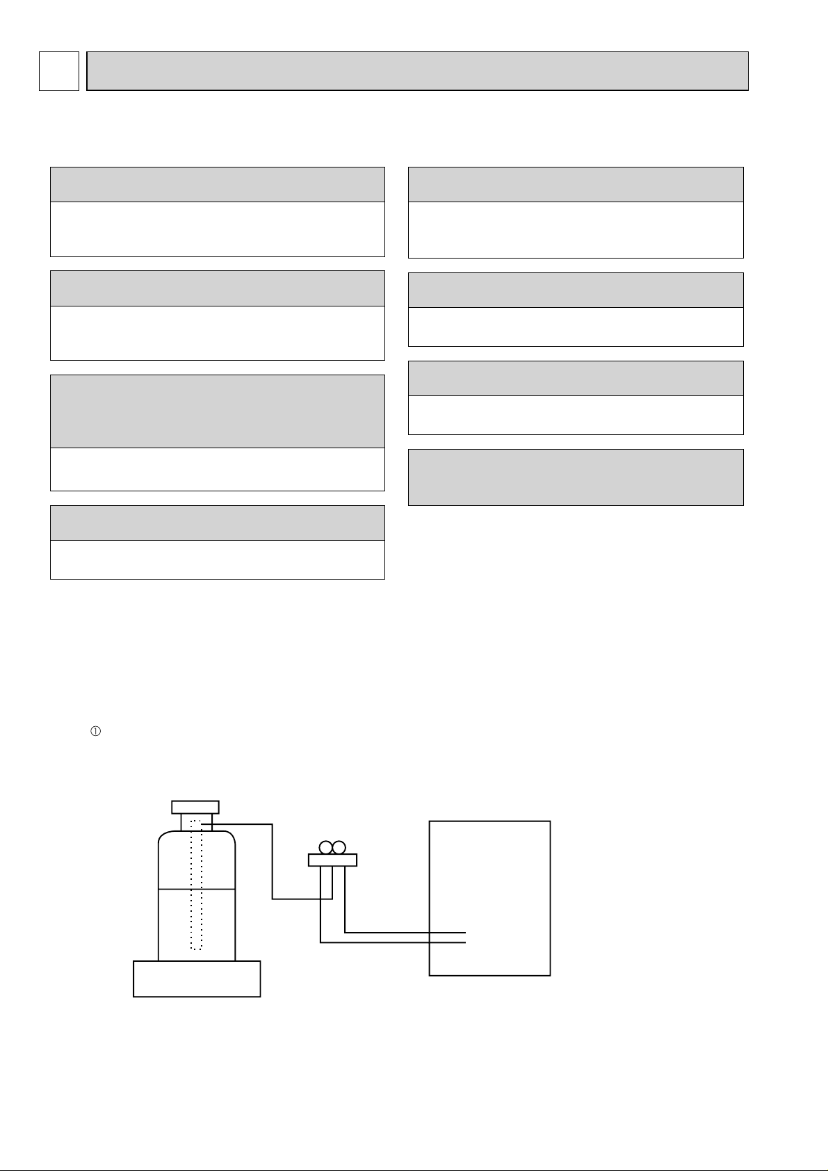
[2] Refrigerant recharging
(1) Refrigerant recharging process
Direct charging from the cylinder.
·R407C cylinder available on the market has a syphon pipe.
·Leave the syphon pipe cylinder standing and recharge it.
(By liquid refrigerant)
Unit
Gravimeter
(2) Recharge in refrigerant leakage case
·After recovering the all refrigerant in the unit, proceed to working.
·Do not release the refrigerant in the air.
·After completing the repair service, recharge the cycle with the specified amount of
liquid refrigerant.
2
[3] Service tools
Use the below service tools as exclusive tools for R407C refrigerant.
No.
Gauge manifold ·Only for R407C
Charge hose ·Only for R407C
Electronic scale
Gas leak detector ·Use the detector for R134a or R407C.
Adapter for reverse flow check ·Attach to vacuum pump.
Refrigerant charge base
Refrigerant cylinder ·For R407C ·Top of cylinder (Brown)
Refrigerant recovery equipment
Cautions for units utilizing refrigerant R410A
Tool name
·Use the existing fitting SPECIFICATIONS. (UNF7/16)
·Use high-tension side pressure of 3.43MPa·G or over.
·Use pressure performance of 5.10MPa·G or over.
Do not use the existing refrigerant piping.
The old refrigerant and lubricant in the existing piping
contains a large amount of chlorine which may cause the
lubricant deterioration of the new unit.
Use “low residual oil piping”
If there is a large amount of residual oil (hydraulic oil, etc.)
inside the piping and joints, deterioration of the lubricant
will result.
Store the piping to be used indoors during
installation and both ends of the piping sealed
until just before brazing. (Leave elbow joints, etc.
in their packaging.)
If dirt, dust or moisture enters into refrigerant cycle, that can
cause deterioration of refrigerant oil or malfunction of compressor.
Use ester oil, ether oil or alkylbenzene oil (small
amount) as the refrigerant oil applied to flares
and flange connections.
If large amount of mineral oil enters, that can cause deterioration of refrigerant oil etc.
Specifications
—
—
·Cylinder with syphon
—
Use a vacuum pump with a reverse flow check
valve.
Vacuum pump oil may flow back into refrigerant cycle and
that can cause deterioration of refrigerant oil etc.
Use the following tools specifically designed for
use with R410A refrigerant.
The following tools are necessary to use R410A refrigerant.
Tools for R410A
Gauge manifold
Charge hose
Gas leak detector
Torque wrench
Flare tool
Size adjustment gauge
Vacuum pump adaptor
Electronic refrigerant
charging scale
Handle tools with care.
If dirt, dust or moisture enters into refrigerant cycle, that can
cause deterioration of refrigerant oil or malfunction of compressor.
Do not use a charging cylinder.
If a charging cylinder is used, the composition of refrigerant will change and the efficiency will be lowered.
Charge refrigerant from liquid phase of gas
cylinder.
If the refrigerant is charged from gas phase, composition
change may occur in refrigerant and the efficiency will be
lowered.
Do not use refrigerant other than R410A.
If other refrigerant (R22 etc.) is used, chlorine in refrigerant can cause deterioration of refrigerant oil etc.
Ventilate the room if refrigerant leaks during
operation. If refrigerant comes into contact with
a flame, poisonous gases will be released.
33
[1] Cautions for service
(1) Perform service after recovering the refrigerant left in unit completely.
(2) Do not release refrigerant in the air.
(3) After completing service, charge the cycle with specified amount of refrigerant.
(4) When performing service, install a filter drier simultaneously.
Be sure to use a filter drier for new refrigerant.
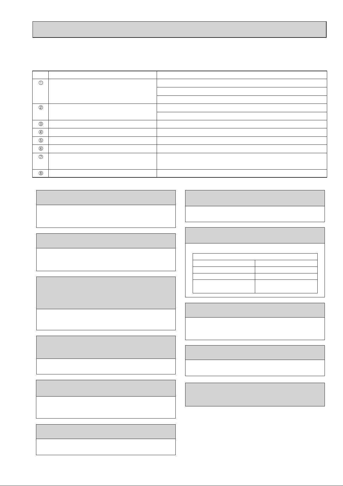
[2] Additional refrigerant charge
When charging directly from cylinder
· Check that cylinder for R410A on the market is syphon type.
· Charging should be performed with the cylinder of syphon stood vertically. (Refrigerant is charged from liquid phase.)
Unit
Gravimeter
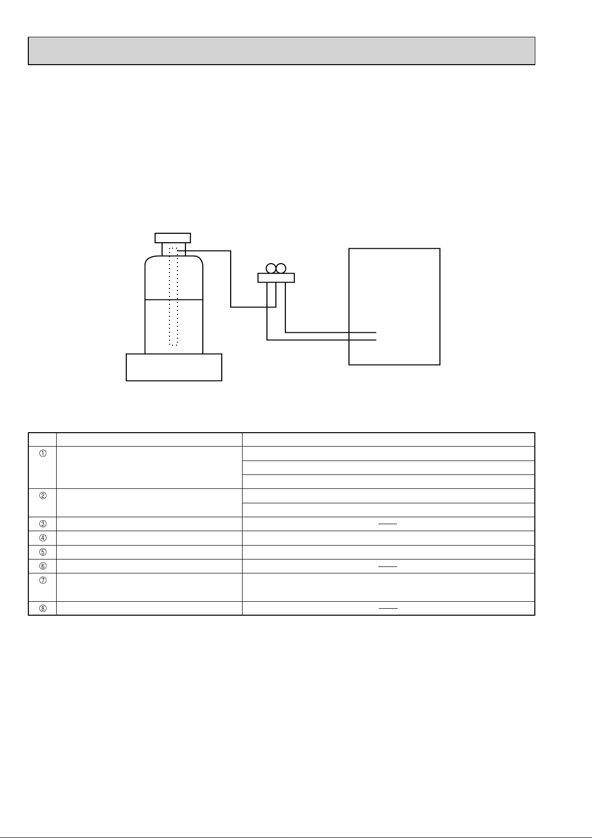
[3] Service tools
Use the below service tools as exclusive tools for R410A refrigerant.
No. Tool name Specifications
Gauge manifold ·Only for R410A
·Use the existing fitting
·Use high-tension side pressure of 5.3MPa·G or over.
Charge hose ·Only for R410A
·Use pressure performance of 5.09MPa·G or over.
Electronic scale
Gas leak detector ·Use the detector for R134a, R407C or R410A.
Adaptor for reverse flow check ·Attach to vacuum pump.
Refrigerant charge base
Refrigerant cylinder ·Only for R410A ·Top of cylinder (Pink)
·Cylinder with syphon
Refrigerant recovery equipment
specifications
. (UNF1/2)
4
2
PART NAMES AND FUNCTIONS
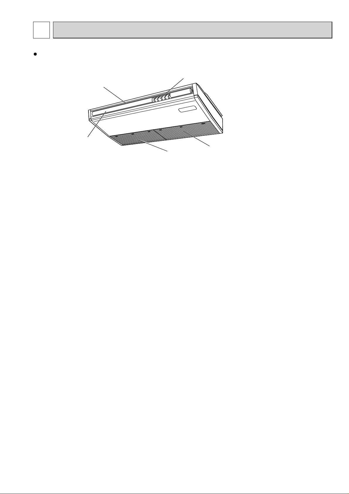
Indoor unit
Vane
Air outlet
Louver
Air intake
Filter
(Inside of Air intake)
55
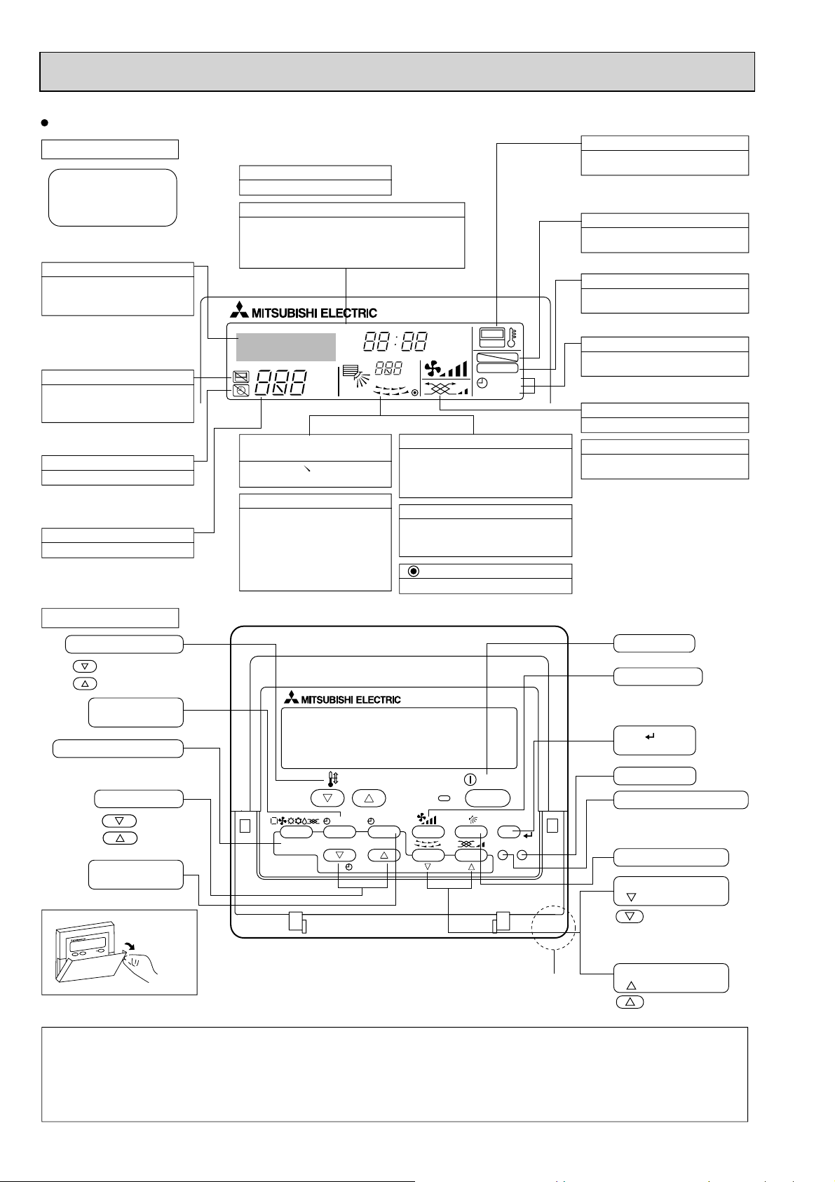
Wired remote controller
Display Section
For purposes of this explanation,
all parts of the display are shown
as lit. During actual operation, only
the relevant items will be lit.
Identifies the current operation
Shows the operating mode, etc.
*Multilanguage display is available.
“Centrally Controlled” indicator
Indicates that operation from the
remote controller has been prohibited by a master controller.
“Timer is Off” indicator
Indicates that the timer is off.
Temperature Setting
Shows the target temperature.
Day-of-Week
Shows the current day of the week.
Time/Timer Display
Shows the current time, unless the simple or Auto Off
timer is set.
If the simple or Auto Off timer is set, the time to be
switched off is shown.
TIME SUN MON TUE WED THU FRI SAT
TIMER
AFTER
ERROR CODE
°F°C
Hr
AFTER
°F°C
ONLY1Hr.
Up/Down Air Direction indicator
The indicator shows the direction of the outcoming airflow.
“One Hour Only” indicator
Displayed if the airflow is set to
Low or downward during COOL
or DRY mode. (Operation varies
according to model.)
The indicator goes off in one hour,
at which time the airflow direction
also changes.
Room Temperature display
Shows the room temperature. The room
temperature display range is 8–39°C.
The display blinks if the temperature
is less than 8°C or 39°C or more.
Louver display
Indicates the action of the swing louver.
Does not appear if the louver is not
running.
(Power On indicator)
Indicates that the power is on.
ON
OFF
FUNCTION
FILTER
WEEKLY
SIMPLE
AUTO OFF
“Sensor” indication
Displayed when the remote controller
sensor is used.
“Locked” indicator
Indicates that remote controller buttons have been locked.
“Clean The Filter” indicator
To be displayed on when it is time to
clean the filter.
Timer indicators
The indicator comes on if the corresponding timer is set.
Fan Speed indicator
Shows the selected fan speed.
Ventilation indicator
Appears when the unit is running in
Ventilation mode.
Operation Section
Temperature setting buttons
Down
Up
Timer Menu button
(Monitor/Set button)
Mode button (Return button)
Set Time buttons
Back
Ahead
Timer On/Off button
(Set Day button)
Opening the
lid
Note:
“PLEASE WAIT” message
TEMP.
MENU
BACK DAY
MONITOR/SET
PAR-21MAA
CLOCK
ON/OFF
OPERATION
ON/OFF
FILTER
CHECK
TEST
CLEAR
Built-in temperature sensor
This message is displayed for approximately 3 minutes when power is supplied to the indoor unit or when the unit is recovering from a power failure.
“NOT A V AILABLE” message
This message is displayed if an invalid button is pressed (to operate a function that the indoor unit does not have).
If a single remote controller is used to operate multiple indoor units simultaneously that are different types, this message will not be displayed as
far as any of the indoor units is equipped with the function.
ON/OFF button
Fan Speed button
Filter button
(<Enter> button)
Test Run button
Check button (Clear button)
Airflow Up/Down button
Louver button
( Operation button)
T o return operation
number
Ventilation button
( Operation button)
To go to next operation
number
6

3
SPECIFICATION
3-1. SPECIFICATIONS
Model PCFY-P40VKM-E PCFY-P63VKM-E PCFY-P100VKM-E PCFY-P125VKM-E
Power source 1-phase 220-240V 50Hz, 1-phase 220V 60Hz
Cooling capacity *1
(
)
Nominal
Power input
Current input
Heating capacity
(
)
Nominal
Power input
Current input
External finish MUNSELL (6.4Y 8.9/0.4
External dimensions H x W x D mm 230×960×680 230×1280×680 230×1600×680
Net weight kg (lb)
Heat exchanger Cross fin (Aluminum fin and copper tube
FAN
Type x quantity Sirocco fan × 2 Sirocco fan × 3 Sirocco fan × 4
External Pa 0
static press.
Motor type DC motor
Motor output kW
Driving mechanism Direct-driven by motor
Airflow rate
(
Low-Mid2-Mid1-High
Noise level (Low-Mid2-Mid1-High
(
measured in anechoic room
Insulation material Polyeter sheet
Air filter PP honeycomb
Protection device
Refrigerant control device LEV
Connectable outdoor unit R410A, R407C, R22 CITY MULTI
(
Diameter of Liquid
R22, R407C
refrigerant pipe
(
R22, R407C
Gas
Field drain pipe size mm(in.
Standard
attachment
Document
Accessory Installation Manual, Instruction Book
kW 4.5 7.1 11.2 14.0
*1
kcal/h 3,900 6,100 9,600 12,000
*1
Btu/h 15,400 24,200 38,200 47,800
*2
kcal/h 4,000 6,300 10,000 12,500
kW 0.040 0.050 0.090 0.110
A 0.28 0.33 0.65 0.76
*3
kW 5.0 8.0 12.5 16.0
*3
kcal/h 4,300 6,900 10,800 13,800
*3
Btu/h 17,100 27,300 42,700 54,600
kW 0.040 0.050 0.090 0.110
A 0.28 0.33 0.65 0.76
)
in. 9-1/16×37-13/16×26-3/4 9-1/16×50-3/8×26-3/4 9-1/16×63×26-3/4
24 (53
)
32 (71
)
36 (79
)
)
mmH2O0
0.090
3
m
/min
)
L/s 167-183-200-217 233-250-267-300 350-400-433-467 350-400-450-517
cfm
)
dB <A>
10-11-12-13 14-15-16-18 21-24-26-28 21-24-27-31
353-388-424-459 494-530-565-636 742-847-918-989 742-847-953-1095
29-32-34-36
)
0.095 0.160
31-33-35-37 36-38-41-43 36-39-42-44
Fuse
)
)
(
R410A
(
R410A
mm(in.
)
)
mm(in.
)
ø6.35 (ø1/4) Flare ø9.52 (ø3/8) Flare ø9.52 (ø3/8) Flare ø9.52 (ø3/8) Flare
ø6.35 (ø1/4) Flare ø9.52 (ø3/8) Flare ø9.52 (ø3/8) Flare ø9.52 (ø3/8) Flare
)
ø12.7 (ø1/2) Flare ø15.88 (ø5/8) Flare ø15.88 (ø5/8) Flare ø15.88 (ø5/8) Flare
ø12.7 (ø1/2) Flare ø15.88 (ø5/8) Flare ø19.05 (ø3/4) Flare ø19.05 (ø3/4) Flare
)
O.D. 26mm (1
)
38 (84
)
Optional parts
Drain pump kit
High efficiency filter
PAC-SH83DM-E PAC-SH84DM-E
PAC-SH88KF-E PAC-SH89KF-E
Wireless remote controller kit
Details on foundation work, insulation work, electrical wiring, power source switch, and other items shall be referred to the
Installation Manual.
*2 Nominal cooling conditions
27°CDB/19.5°CWB (81°FDB/67°FWB)
35°CDB (95°FDB)
5 m (16-3/8 ft)
0 m (0 ft)
Indoor :
Outdoor :
Pipe length :
Installation
*1 Nominal cooling conditions
27°CDB/19°CWB (81°FDB/66°FWB)
35°CDB (95°FDB)
7.5 m (24-9/16 ft)
0 m (0 ft)
Remarks
Note :
Level difference :
* Nominal conditions *1, *3 are subject to JIS B8615-1.
* Due to continuing improvement, above specification may be subject to change without notice.
PAR-SL94B-E
*3 Nominal heating conditions
20°CDB (68°FDB)
7°CDB/6°CWB (45°FDB/43°FWB)
7.5 m (24-9/16 ft)
0 m (0 ft)
PAC-SH90KF-E
*Above specification data is
subject to rounding variation.
Unit converter
kcal/h = kW
Btu/h = kW × 3,412
cfm = m
lb = kg/0.4536
× 860
3
/min × 35.31
77
3-2. ELECTRICAL PARTS SPECIFICATIONS
Service Ref.
Parts name
Room temperature
thermistor
Liquid pipe thermistor
Gas pipe thermistor
Fuse
(Indoor controller board)
Fan motor
Vane motor
Drain-pump
(Option)
Drain float switch
Linear expansion valve
Power supply terminal
block
Symbol
TH21
TH22
TH23
FUSE
MF
MV
DP
FS
LEV
TB2
PCFY-P63VKM-EPCFY-P40VKM-E
PCFY-P100VKM-E
PCFY-P125VKM-E
Resistance 0°C/15k, 10°C/9.6k, 20°C/6.3k, 25°C/5.4k, 30°C/4.3k, 40°C/3.0k
Resistance 0°C/15k, 10°C/9.6k, 20°C/6.3k, 25°C/5.4k, 30°C/4.3k, 40°C/3.0k
Resistance 0°C/15k, 10°C/9.6k, 20°C/6.3k, 25°C/5.4k, 30°C/4.3k, 40°C/3.0k
250V 6.3A
8-pole OUTPUT 90W 8-pole OUTPUT 95W
8-pole OUTPUT 160W
MSBPC20
DC12V 300/phase
INPUT 12/10.8W 24 /Hr
Open / Short detection DC 5V
DC12V Stepping motor drive
Port dimension ø3.2 (0~2000pulse)
EFM-40YGME
DC12V Stepping motor drive
Port dimension ø5.2 (0~2000pulse)
EFM-80YGME
(L, N, ) Rated to 330V 30A
Transmission terminal
block
MA remote controller
terminal block
3-3. SOUND LEVEL
PCFY-P•VKM-E
1m
Measurement
location
* Measured in anechoic room.
1m
TB5
TB15
(M1, M2, S) Rated to 250V 20A
(1, 2) Rated to 250V 10A
Note : Refer to WIRING DIAGRAM for the supplied voltage.
Sound level at anechoic room : Low-
Service Ref.
PCFY-P40VKM-E
PCFY-P63VKM-E 31-33-35-37
PCFY-P100VKM-E 36-38-41-43
PCFY-P125VKM-E 36-39-42-44
Sound level dB (A)
29-32-34-36
Mid2-Mid1-High
8
A
A
A
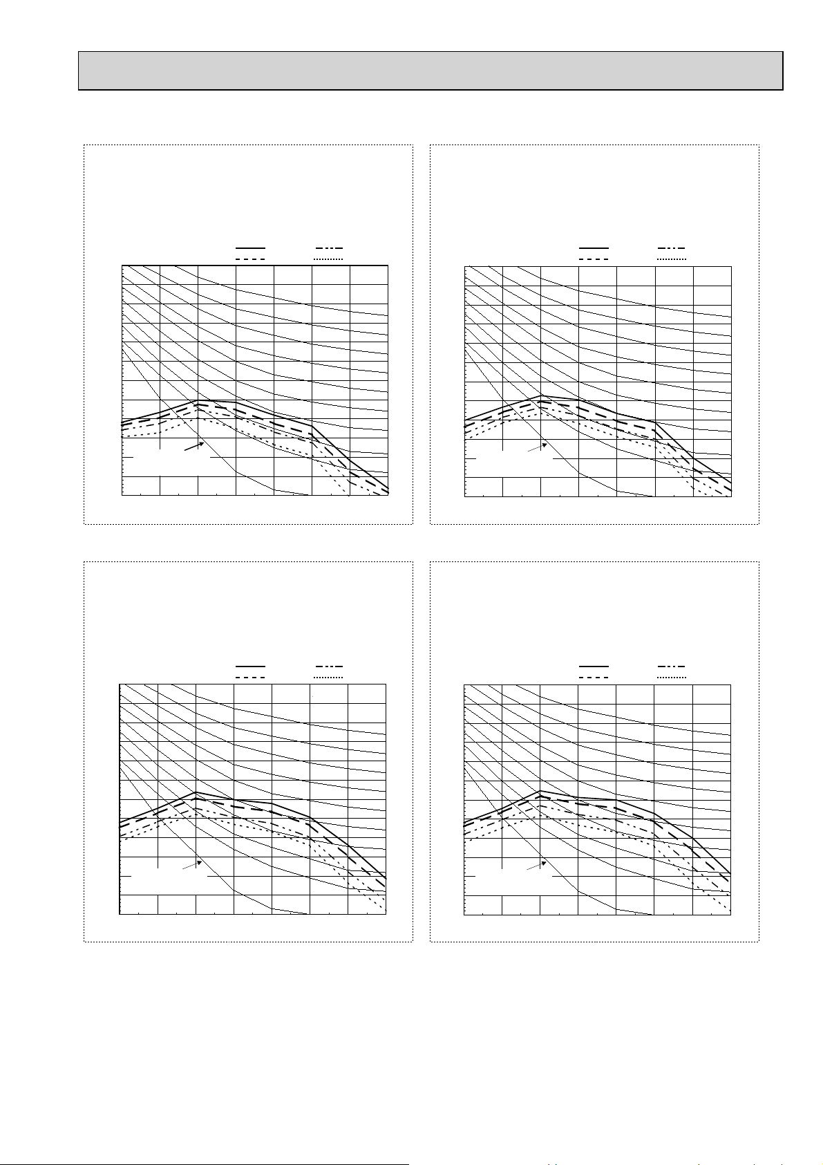
3-4. NC CURVES
PCFY-P40VKM-E
External static pressure : 0Pa
Power source :
70.0
65.0
60.0
55.0
50.0
45.0
40.0
35.0
30.0
25.0
Approximate minimum
20.0
audible limit on
continuous noise
15.0
Octave band pressure level (dB) 0dB=20PaOctave band pressure level (dB) 0dB=20Pa
10.0
63 125 250 500 1k 2k 4k 8k
220,230,240V, 50Hz / 220V, 60Hz
High
Middle1
Octave band center frequencies (Hz)
Middle2
Low
NC-60
NC-50
NC-40
NC-30
NC-20
PCFY-P63VKM-E
External static pressure : 0Pa
Power source :
70.0
65.0
60.0
55.0
50.0
45.0
40.0
35.0
30.0
25.0
pproximate minimum
20.0
audible limit on
continuous noise
15.0
Octave band pressure level (dB) 0dB=20Pa
10.0
63 125 250 500 1k 2k 4k 8k
220,230,240V, 50Hz / 220V, 60Hz
High
Middle1
Octave band center frequencies (Hz)
Middle2
Low
NC-60
NC-50
NC-40
NC-30
NC-20
PCFY-P100VKM-E
External static pressure : 0Pa
Power source :
70.0
65.0
60.0
55.0
50.0
45.0
40.0
35.0
30.0
25.0
pproximate minimum
20.0
audible limit on
continuous noise
15.0
10.0
63 125 250 500 1k 2k 4k 8k
220,230,240V, 50Hz / 220V, 60Hz
High
Middle1
Octave band center frequencies (Hz)
Middle2
Low
NC-60
NC-50
NC-40
NC-30
NC-20
PCFY-P125VKM-E
External static pressure : 0Pa
Power source :
70.0
65.0
60.0
55.0
50.0
45.0
40.0
35.0
30.0
25.0
pproximate minimum
20.0
audible limit on
continuous noise
Octave band pressure level (dB) 0dB=20Pa
15.0
10.0
63 125 250 500 1k 2k 4k 8k
220,230,240V, 50Hz / 220V, 60Hz
High
Middle1
Octave band center frequencies (Hz)
Middle2
Low
NC-60
NC-50
NC-40
NC-30
NC-20
9
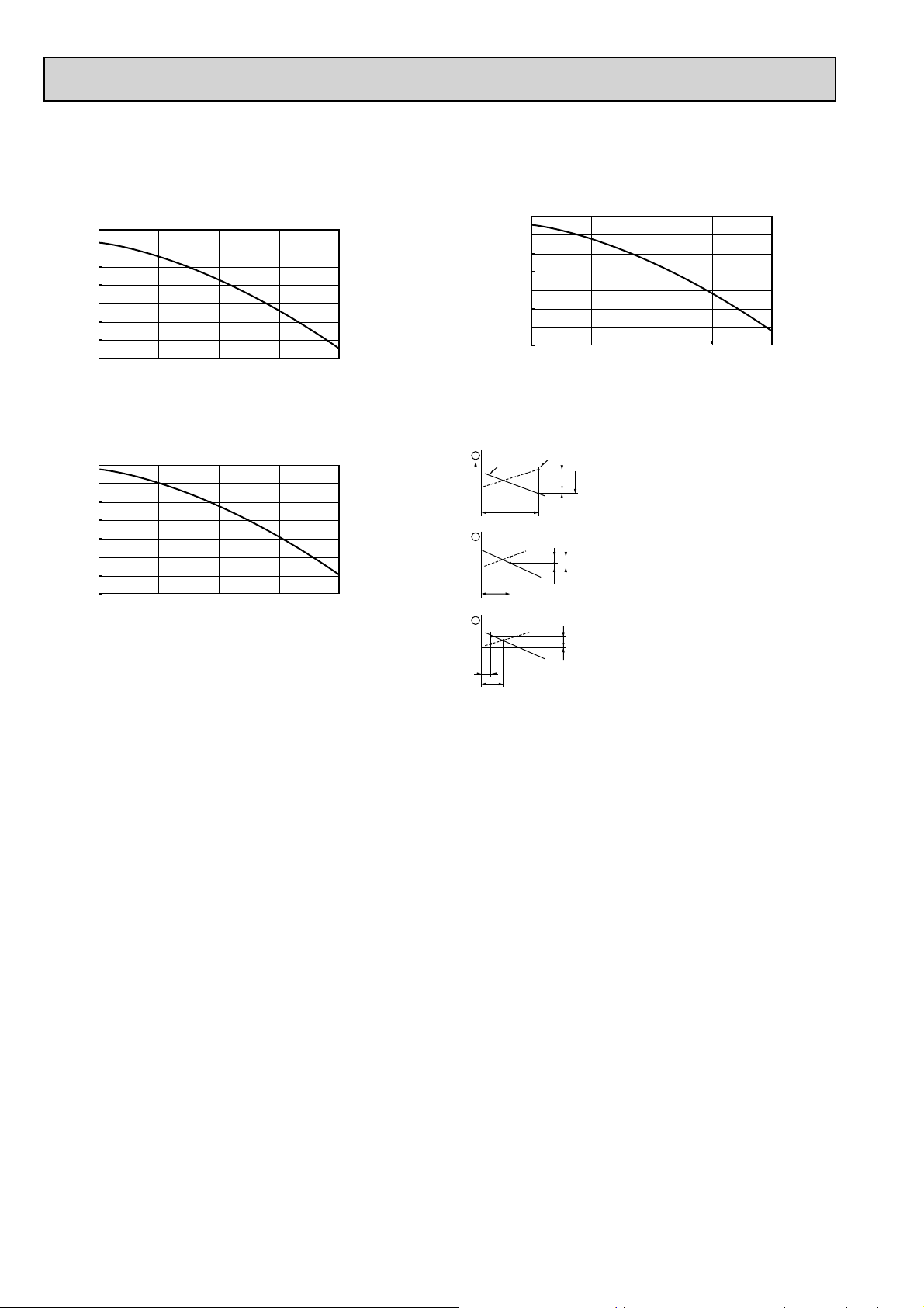
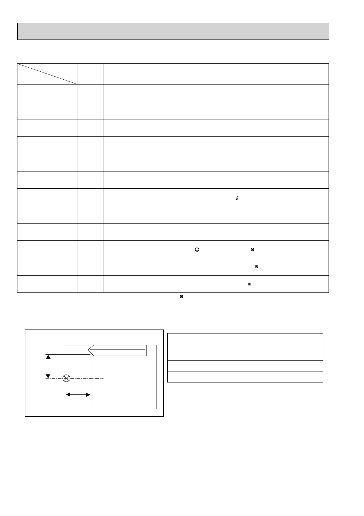
3-5. FRESH AIR INTAKE AMOUNT & STATIC PRESSURE CHARACTERISTICS
PCFY-P40VKM-E
PCFY-P63VKM-E
50
0
-50
-100
-150
-200
-250
Static pressure[Pa]
-300
0 1 2 3 4
Airflow rate[m³/min]
PCFY-P100, 125VKM-E
50
0
-50
-100
-150
-200
-250
Static pressure[Pa]
-300
0 1 2 3 4
Airflow rate[m³/min]
50
0
-50
-100
-150
-200
-250
Static pressure[Pa]
-300
0 1 2 3 4
How to read curves
Q
Q
Duct characteristics
at site
A
C
B
A
EC
AD
1
0
2
3
Q
Qa
Curve in the
graphs
Airflow rate[m³/min]
Q…Designed amount of fresh air intake
A…Static pressure loss of fresh air
intake duct system with airflow
amount Q <Pa>
…
Forced static pressure at air conditioner
B
inlet with airflow amount Q
C…Static pressure of booster fan with
airflow amount Q <Pa>
D…Static pressure loss increase amount
of fresh air intake duct system for
airflow amount Q <Pa>
E…Static pressure of indoor unit with
airflow amount Q <Pa>
Qa…Estimated amount of fresh air
intake without D <m3/min>
<m3/min>
<Pa>
10
 Loading...