

Page 1
SPLIT-TYPE, HEAT PUMP AIR CONDITIONERS
TECHNICAL & SERVICE MANUAL
July 2006
No. OC308
REVISED EDITION-A
Series PCFY
<Indoor unit>
[Model name] [Service Ref.]
PCFY-P40VGM-E
PCFY-P63VGM-E
PCFY-P100VGM-E
PCFY-P125VGM-E
INDOOR UNIT
Ceiling Suspended
PCFY-P40VGM-E
PCFY-P63VGM-E
PCFY-P100VGM-E
PCFY-P125VGM-E
R410A
CONTENTS
1. SAFETY PRECAUTION ······················2
2. PART NAMES AND FUNCTIONS ·······6
3. SPECIFICATIONS ·······························8
4. OUTLINES AND DIMENSIONS·········11
5. WIRING DIAGRAM····························15
6.
REFRIGERANT SYSTEM DIAGRAM
7. TROUBLE SHOOTING······················17
8. DISASSEMBLY PROCEDURE··········24
9. PARTS LIST·······································28
10. RoHS PARTS LIST ···························35
11. OPTIONAL PARTS ··························42
R407C
Revision:
•
RoHS PARTS LIST
• Some descriptions have
been modified.
• Please void OC308.
Note:
• This manual describes only
service data of the indoor
units.
• RoHS compliant products
have <G> mark on the spec
name plate.
• For servicing of RoHS compliant products, refer to the
RoHS Parts List.
R22
is added.
··16
Page 2
1
Do not use the existing refrigerant piping.
The old refrigerant and lubricant in the existing piping
contains a large amount of chlorine which may cause the
lubricant deterioration of the new unit.
Use “low residual oil piping”
If there is a large amount of residual oil (hydraulic oil, etc.)
inside the piping and joints, deterioration of the lubricant
will result.
Use ESTR , ETHER or HAB as the lubricant to
coat flares and flange connection parts.
If large amount of mineral oil enter, that can cause
deterioration of refrigerant oil etc.
Use liquid refrigerant to seal the system.
If gas refrigerant is used to seal the system, the composition
of the refrigerant in the cylinder will change and performance
may drop.
Do not use a refrigerant other than R407C.
If another refrigerant (R22, etc.) is used, the chlorine in the
refrigerant may cause the lubricant deterioration.
Use a vacuum pump with a reverse flow check valve.
The vacuum pump oil may flow back into the refrigerant
cycle and cause the lubricant deterioration.
Store the piping to be used during installation
indoors with keep both ends sealed until just
before brazing.
(Store elbows and other joints in a plastic bag.)
If dust, dirt, or water enters the refrigerant cycle,
deterioration of the oil and compressor trouble may result.
Ventilate the room if refrigerant leaks during
operation. If refrigerant comes into contact with
a flame, poisonous gases will be released.
Gravimeter
Unit
SAFETY PRECAUTION
CAUTIONS RELATED TO NEW REFRIGERANT
Cautions for units utilizing refrigerant R407C
[1] Cautions for service
·After recovering the all refrigerant in the unit, proceed to working.
·Do not release refrigerant in the air.
·After completing the repair service, recharge the cycle with the specified amount of
liquid refrigerant.
[2] Refrigerant recharging
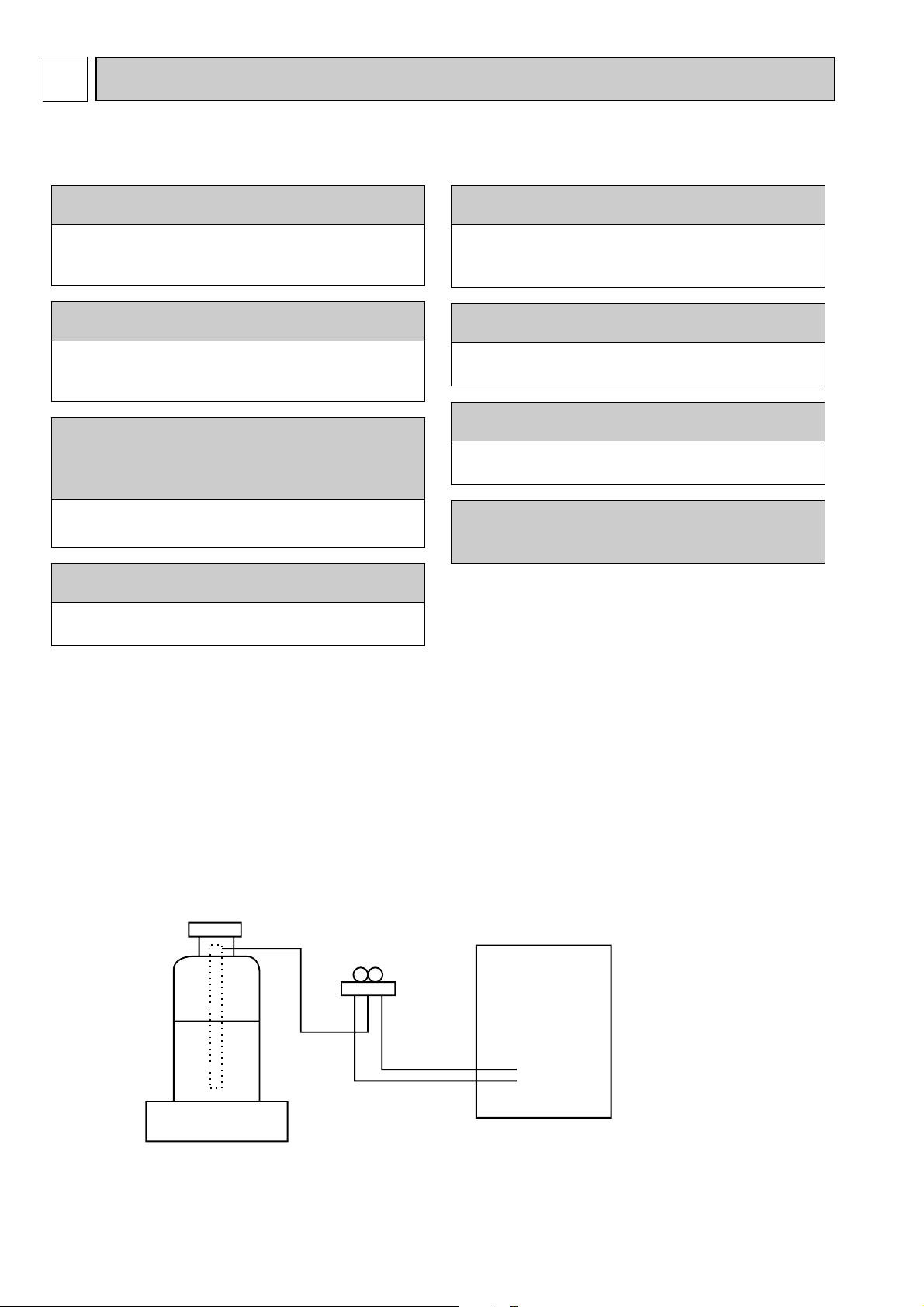
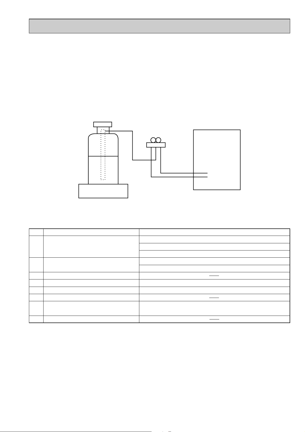
(1) Refrigerant recharging process
1Direct charging from the cylinder.
·R407C cylinder are available on the market has a syphon pipe.
·Leave the syphon pipe cylinder standing and recharge it.
(By liquid refrigerant)
(2) Recharge in refrigerant leakage case
·After recovering the all refrigerant in the unit, proceed to working.
·Do not release the refrigerant in the air.
·After completing the repair service, recharge the cycle with the specified amount of
liquid refrigerant.
2
Page 3
[3] Service tools
Use the below service tools as exclusive tools for R407C refrigerant.
No. Tool name Specifications
1 Gauge manifold ·Only for R407C.
·Use the existing fitting SPECIFICATIONS. (UNF7/16)
·Use high-tension side pressure of 3.43MPa·G or over.
2 Charge hose ·Only for R407C.
·Use pressure performance of 5.10MPa·G or over.
3 Electronic scale
4 Gas leak detector ·Use the detector for R134a or R407C.
5 Adapter for reverse flow check. ·Attach on vacuum pump.
6 Refrigerant charge base.
7 Refrigerant cylinder. ·For R407C ·Top of cylinder (Brown)
·Cylinder with syphon
8 Refrigerant recovery equipment.
3
Page 4
Cautions for units utilizing refrigerant R410A
Store the piping to be used during installation
indoors and keep both ends of the piping sealed
until just before brazing. (Leave elbow joints, etc.
in their packaging.)
Use ester oil, ether oil or alkylbenzene oil (small
amount) as the refrigerant oil applied to flares
and flange connections.
Charge refrigerant from liquid phase of gas
cylinder.
If the refrigerant is charged from gas phase, composition
change may occur in refrigerant and the efficiency will be
lowered.
Do not use refrigerant other than R410A.
If other refrigerant (R22 etc.) is used, chlorine in refrigerant can cause deterioration of refrigerant oil etc.
Use a vacuum pump with a reverse flow check
valve.
Vacuum pump oil may flow back into refrigerant cycle and
that can cause deterioration of refrigerant oil etc.
Use the following tools specifically designed for
use with R410A refrigerant.
The following tools are necessary to use R410A refrigerant.
Keep the tools with care.
If dirt, dust or moisture enter into refrigerant cycle, that can
cause deterioration of refrigerant oil or malfunction of compressor.
Do not use a charging cylinder.
If a charging cylinder is used, the composition of refrigerant will change and the efficiency will be lowered.
Flare tool
Electronic refrigerant
charging scale
Vacuum pump adaptor
Size adjustment gauge
Gauge manifold
Torque wrench
Gas leak detector
Charge hose
Tools for R410A
If dirt, dust or moisture enter into refrigerant cycle, that can
cause deterioration of refrigerant oil or malfunction of compressor.
If large amount of mineral oil enter, that can cause deterioration of refrigerant oil etc.
Do not use the existing refrigerant piping.
The old refrigerant and lubricant in the existing piping
contains a large amount of chlorine which may cause the
lubricant deterioration of the new unit.
Use “low residual oil piping”
If there is a large amount of residual oil (hydraulic oil, etc.)
inside the piping and joints, deterioration of the lubricant
will result.
Ventilate the room if refrigerant leaks during
operation. If refrigerant comes into contact with
a flame, poisonous gases will be released.
4
Page 5
[1] Cautions for service
Gravimeter
Unit
(1) Perform service after collecting the refrigerant left in unit completely.
(2) Do not release refrigerant in the air.
(3) After completing service, charge the cycle with specified amount of refrigerant.
(4) When performing service, install a filter drier simultaneously.
Be sure to use a filter drier for new refrigerant.
[2] Additional refrigerant charge
When charging directly from cylinder
· Check that cylinder for R410A on the market is syphon type.
· Charging should be performed with the cylinder of syphon stood vertically. (Refrigerant is charged from liquid phase.)
[3] Service tools
Use the below service tools as exclusive tools for R410A refrigerant.
No. Specifications
1 Gauge manifold ·Only for R410A
·Use the existing fitting
·Use high-tension side pressure of 5.3MPa·G or over.
2 Charge hose ·Only for R410A
·Use pressure performance of 5.09MPa·G or over.
3 Electronic scale
4 Gas leak detector ·Use the detector for R134a, R407C or R410A.
5 Adaptor for reverse flow check ·Attach on vacuum pump.
6 Refrigerant charge base
7 Refrigerant cylinder ·Only for R410A Top of cylinder (Pink)
8 Refrigerant recovery equipment
specifications
Cylinder with syphon
. (UNF1/2)
5
Page 6
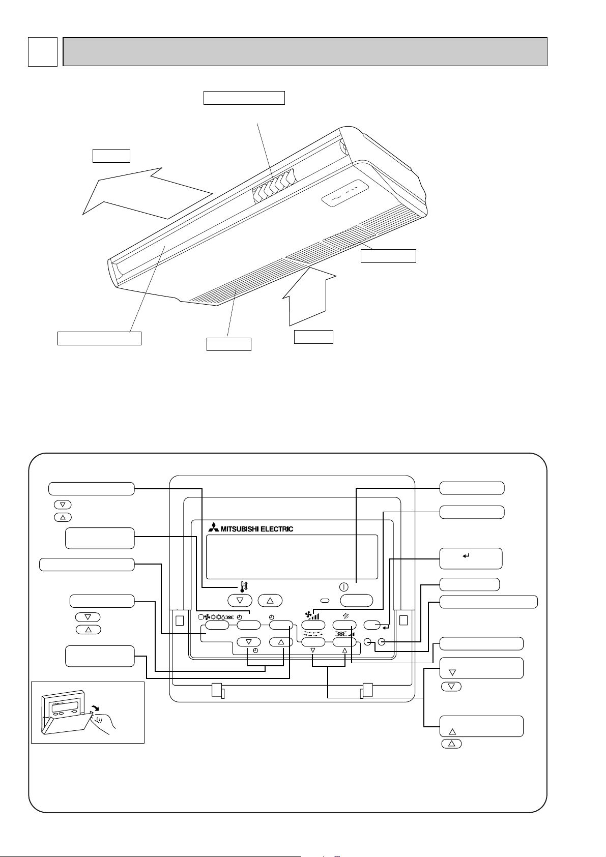
2
Air outlet
Intake grille
Air intake
Left/right guide vanes
Change the direction of airflow
from the horizontal blower.
Long-life fillter
Removes dust and foreigh matter from air coming in
through the grille (Recommended cleaning interval :
Approx, every 2,500 operating hours)
Up/down guide vanes
Change the direction of airflow from the
vartical blower.
PAR-21MAA
ON/OFF
FILTER
CHECK
OPERATION
CLEAR
TEST
TEMP.
MENU
BACK DAY
MONITOR/SET
CLOCK
ON/OFF
Set Temperature buttons
Down
Up
Timer Menu button
(Monitor/Set button)
Mode button (Return button)
Set Time buttons
Back
Ahead
Timer On/Off button
(Set Day button)
Opening the
door.
ON/OFF button
Fan Speed button
Filter button
(<Enter> button)
Test Run button
Check button (Clear button)
Airflow Up/Down button
Louver button
( Operation button)
To preceding operation
number.
Ventilation button
(
Operation button)
To next operation number.
PART NAMES AND FUNCTIONS
● Indoor Unit
● Wired remote controller
On the controls are set, the same operation mode can be repeated by simply pressing the ON/OFF button.
● Operation buttons
6
Page 7
● Display
For purposes of this explanation,
all parts of the display are shown
as lit. During actual operation, only
the relevant items will be lit.
˚F˚C
˚F˚C
ERROR CODE
AFTER
TIMER
TIME SUN MON TUE WED THU FRI SAT
ON
OFF
Hr
AFTER
FILTER
FUNCTION
ONLY1Hr.
WEEKLY
SIMPLE
AUTO OFF
Identifies the current operation
Shows the operating mode, etc.
* Multilanguage display is sup-
ported.
“Centrally Controlled” indicator
Indicates that operation of the remote controller has been prohibited by a master controller.
“Timer Is Off” indicator
Indicates that the timer is off.
Temperature Setting
Shows the target temperature.
Day-of-Week
Shows the current day of the week.
Time/Timer Display
Shows the current time, unless the simple or Auto Off
timer is set.
If the simple or Auto Off timer is set, shows the time
remaining.
“Sensor” indication
Displayed when the remote controller
sensor is used.
“Locked” indicator
Indicates that remote controller buttons have been locked.
“Clean The Filter” indicator
Comes on when it is time to clean the
filter.
Timer indicators
The indicator comes on if the corresponding timer is set.
Up/Down Air Direction indicator
The indicator shows the direction of the outcoming airflow.
“One Hour Only” indicator
Displayed if the airflow is set to
weak and downward during COOL
or DRY mode. (Operation varies
according to model.)
The indicator goes off after one
hour, at which time the airflow direction also changes.
Room Temperature display
Shows the room temperature.
Louver display
Indicates the action of the swing
louver. Does not appear if the
louver is stationary.
(Power On indicator)
Indicates that the power is on.
Fan Speed indicator
Shows the selected fan speed.
Ventilation indicator
Appears when the unit is running in
Ventilation mode.
Caution
● Only the Power on indicator lights when the unit is stopped and power supplied to the unit.
● If you press a button for a feature that is not installed at the indoor unit, the remote controller will display the “Not Available”
message.
If you are using the remote controller to drive multiple indoor units, this message will appear only if he feature is not
present at the parent unit.
● When power is turned ON for the first time, it is normal that “PLEASE WAIT” is displayed on the room temperature indication (For max. 2minutes). Please wait until this “PLEASE WAIT” indication disappear then start the operation.
7
Page 8
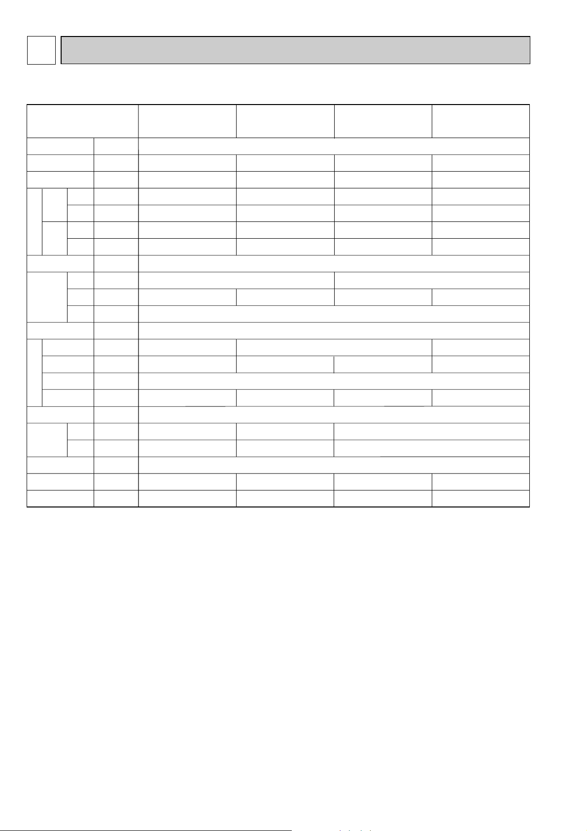
3
Item
V
·Hz
kW
kW
kW
kW
A
A
—
mm
mm
mm
—
—
k/min
Pa
kW
—
[mm(in.)
[mm(in.)
[mm
dB
kg
Cooling capacity
Power
Heat exchanger
Air filter
Fan ✕ No
Air flow W
Pipe
dimensions
Unit drain pipe size
Noise level W
Product weight
Exterior
(munsell symbol)
Fan motor
output
External
static pressure
Liquid
side
Gas
side
Heating capacity
F
a
n
Dimensions
Height
Width
Depth
Electric characteristic
Input
Cooling
Heating
Cooling
Heating
Current
PCFY-P40VGM-E PCFY-P63VGM-E PCFY-P100VGM-E PCFY-P125VGM-E
Single phase 220-230-240V 50Hz / 220V 60Hz
4.5
5.0
0.10
0.10
0.46
0.46
7.1
8.0
0.13
0.13
0.60
0.60
11.2
12.5
0.16
0.16
0.73
0.73
14.0
16.0
0.24
0.24
1.10
1.10
1310
18 -16 -14 -12
0.07
15.88(5/8")
9.52(3/8")
39 -37 -34 -32
34
Unit : Munsell<0.70Y 8.59/0.97>
680
Cross fin (Aluminum plate fine and copper tube)
Sirocco fan ✕ 3
0
PP honey comb
I.D.26 (PVC pipe VP-20 connectable)
15.88(5/8") / 19.05(3/4")
9.52(3/8")
210 270
1310
25 -23 -20 -18
0.09
43 -41 -38 -36
37
1620
Sirocco fan ✕ 4
35 -32 -28 -26
0.15
44 -42 -39 -37
43
1000
Sirocco fan ✕ 2
12 -11 -10 -8
0.054
12.7(1/2")
6.35(1/4")
38 -36 -33 -29
27
SPECIFICATIONS
3-1. SPECIFICATIONS
Note 1. Rating conditions(JIS B 8615-1)
W Air flow and the noise level are indicated as High – Middium1 – Middium2 – Low.
Cooling : Indoor : D.B. 27°C W.B. 19°C
Heating : Indoor : D.B. 20°C
outdoor : D.B. 35°C
outdoor : D.B. 7°C W.B. 6°C
8
Page 9
3-2. ELECTRICAL PARTS SPECIFICATIONS
Parts name
Model
Symbol
TH21
TH22
TH23
FUSE
MF
C1
MV
LEV
TB2
TB5
TB15
Resistance 0:/15k", 10:/9.6k", 20:/6.3k", 25:/5.4k", 30:/4.3k", 40:/3.0k"
Resistance 0:/15k", 10:/9.6k", 20:/6.3k", 25:/5.4k", 30:/4.3k", 40:/3.0k"
Resistance 0:/15k", 10:/9.6k", 20:/6.3k", 25:/5.4k", 30:/4.3k", 40:/3.0k"
250V 6.3A
OFF 130: I5:
(L, N, ;) 330V 30A
(M1, M2, S) 250V 20A
(1, 2) 250V 10A
3µF ✕ 440V
Inner-thermostat
4µF ✕ 440V 4µF ✕ 440V 6µF ✕ 440VFan motor capacitor
Vane motor
Linear expansion valve
PCFY-P40VGM-E PCFY-P63VGM-E PCFY-P100VGM-E PCFY-P125VGM-E
Room temperature
thermistor
Liquid pipe temperature
thermistor
Gas pipe temperature
thermistor
Fuse
(Indoor controller board)
Fan motor
(with inner-thermostat)
Power supply
terminal block
Transmission
terminal block
MA remote controller
terminal block
DC12V Stepping
motor drive
[3.2 (0~2000pulse)
4-Pole Output 54W
D09B4P54MS
MP35EA
DC12V
MP42EA
DC12V
4-Pole Output 70W
D09C4P70MS
4-Pole Output 90W
D10B4P90MS
4-Pole Output 150W
D10B4P150MS
DC12V Stepping motor drive
[3.2 (0~2000pulse)
9
Page 10
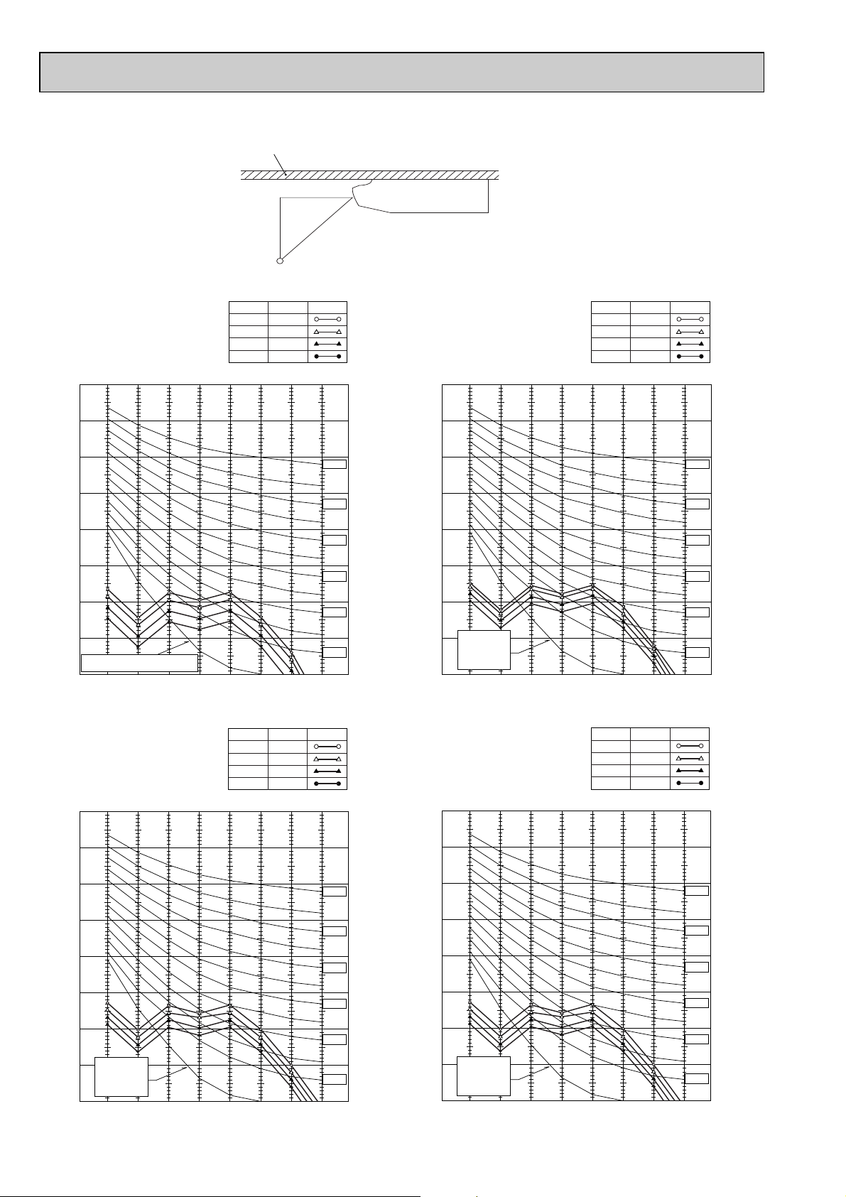
3-3. NOISE CRITERION CURVES
90
80
70
60
50
40
30
20
10
63 125 250 500 1000 2000 4000 8000
APPROXIMATE THRESHOLD OF HEARING
FOR CONTINUOUS NOISE
NC-60
NC-50
NC-40
NC-30
NC-20
NC-70
OCTAVE BAND SOUND PRESSURE LEVEL, dB (0 dB = 0.0002 µbar)
BAND CENTER FREQUENCIES, Hz
PCFY-P40VGM-E
Hi
NOTCH
Mi1
Mi2
Lo
35
SPL(dB)
33
30
27
LINE
90
80
70
60
50
40
30
20
10
63 125 250 500 1000 2000 4000 8000
APPROXIMATE
THRESHOLD OF
HEARING FOR
CONTINUOUS
NOISE
NC-60
NC-50
NC-40
NC-30
NC-20
NC-70
OCTAVE BAND SOUND PRESSURE LEVEL, dB (0 dB = 0.0002 µbar)
BAND CENTER FREQUENCIES, Hz
PCFY-P63VGM-E
Hi
NOTCH
Mi1
Mi2
Lo
37
SPL(dB)
36
34
32
LINE
90
80
70
60
50
40
30
20
10
63 125 250 500 1000 2000 4000 8000
APPROXIMATE
THRESHOLD OF
HEARING FOR
CONTINUOUS
NOISE
NC-60
NC-50
NC-40
NC-30
NC-20
NC-70
OCTAVE BAND SOUND PRESSURE LEVEL, dB (0 dB = 0.0002 µbar)
BAND CENTER FREQUENCIES, Hz
PCFY-P100VGM-E
Hi
NOTCH
Mi1
Mi2
Lo
39
SPL(dB)
37
35
33
LINE
90
80
70
60
50
40
30
20
10
63 125 250 500 1000 2000 4000 8000
APPROXIMATE
THRESHOLD OF
HEARING FOR
CONTINUOUS
NOISE
NC-60
NC-50
NC-40
NC-30
NC-20
NC-70
OCTAVE BAND SOUND PRESSURE LEVEL, dB (0 dB = 0.0002 µbar)
BAND CENTER FREQUENCIES, Hz
PCFY-P125VGM-E
Hi
NOTCH
Mi1
Mi2
Lo
39
SPL(dB)
37
35
33
LINE
UNIT
About 1.4m
MICROPHONE
CEILING
1m
1m
10
Page 11
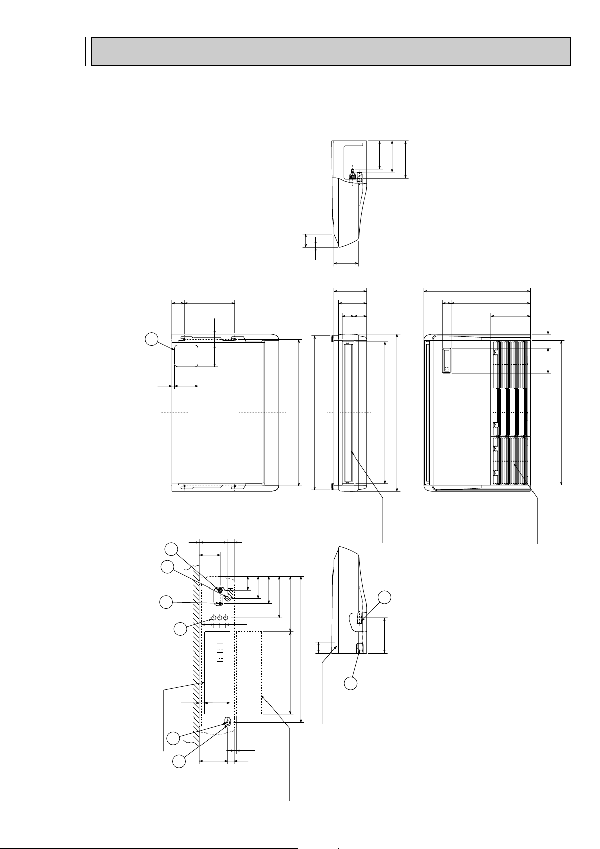
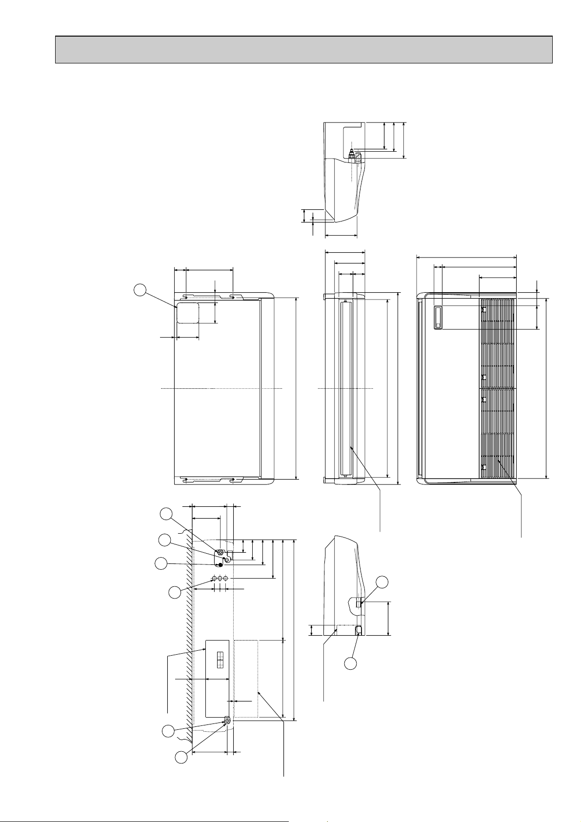
OUTLINES AND DIMENSIONS4
2
1
Air intake
When electrical box
is pulled down
Electrical box
Air outlet
7
8
5
4
3
2
6
Electrical box
(Drainage)
(1/2F)gas
(1/4F)liquid
( FRONT VIEW )
Ceiling
56506
161 90
904
933 (Suspension bolt pitch)
157
70
15
85
81
210
226
241
201
182
180
76
680
254
150 18
70140
320 80
918
1000
983
6 ~ 7
928
525
42 179
161 32
46
175
131
1
352
171
138
86
263
38
38
79
INDOOR UNIT
PCFY-P40VGM-E
refrigerant pipe will be only upper drain pipe arrangement.
NOTES:
1. Use M10 or W3/8 screws for anchor bolt.
2. Please be sure when installing the drain-up machine (option parts).
Unit : mm
1 Drainage pipe connection (26mm I.D.) 5 Refrigerant-pipe connection (liquid pipe side/flared connection)
2 Drainage pipe connection (for the left arrangement) 6 Knock out hole for upper drain pipe arrangement
3 Knock out hole for left drain-piping arrangement 7 Knock out hole for left drain pipe arrangement
4 Refrigerant-pipe connection (gas pipe side/flared connection) 8 Knock out hole for wiring arrangement
11
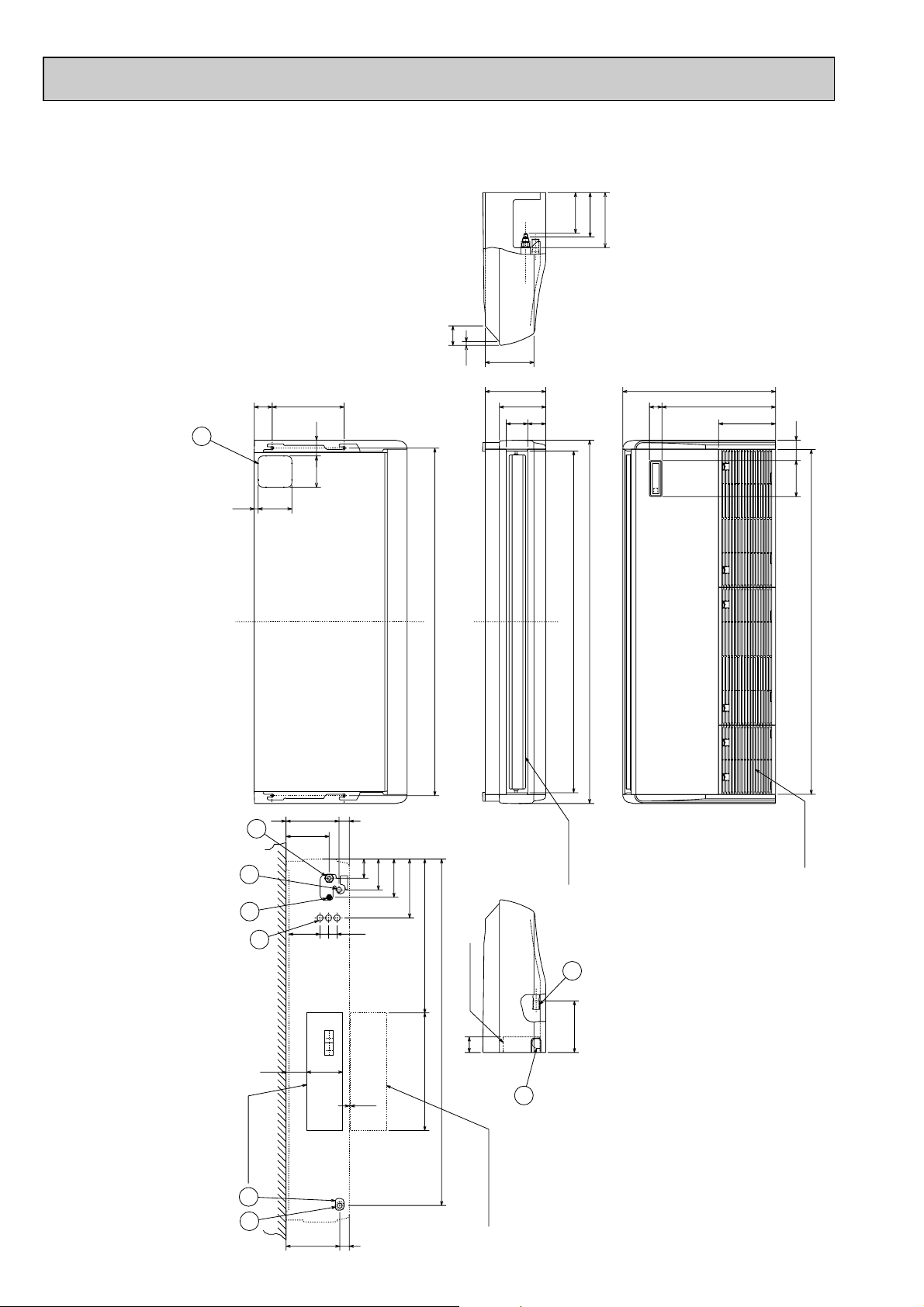
Page 12
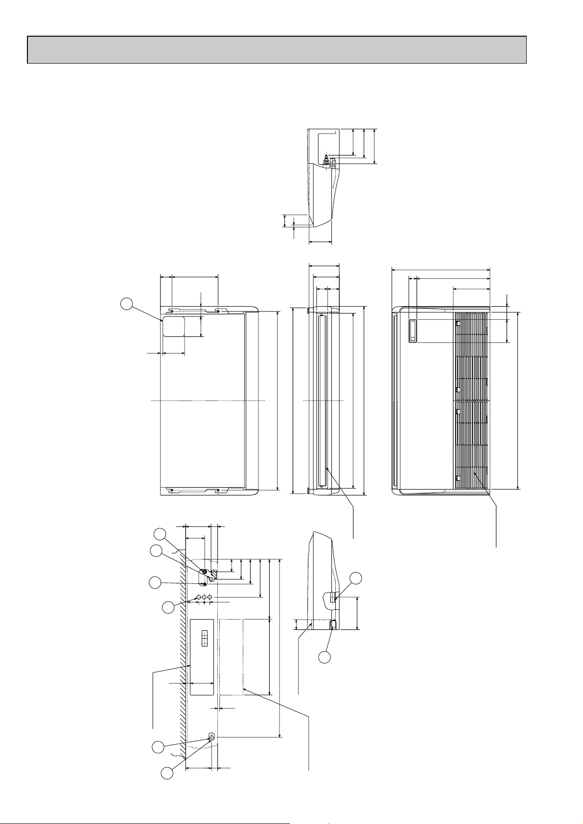
(Drainage)
(5/8F)gas
(3/8F)liquid
Air intake
Air outlet
Electrical box
When electrical box
is pulled down
Ceiling
( FRONT VIEW )
Electrical box
6
4
1
5
8
2
3
7
2
506 56
90161
1240 (Suspension bolt pitch)
157
1228
1310
1214
1290
15
85
81
210
226
241
201
182
180
76
680
254
150 18
70140
320 80
70
6 ~ 7
1235
416525
42 179
161 32
46
175
131
1
171
138
86
263
38
38
79
PCFY-P63VGM-E
Unit : mm
refrigerant pipe will be only upper drain pipe arrangement.
NOTES:
1. Use M10 or W3/8 screws for anchor bolt.
2. Please be sure when installing the drain-up machine (option parts).
1 Drainage pipe connection (26mm I.D.) 5 Refrigerant-pipe connection (liquid pipe side/flared connection)
2 Drainage pipe connection (for the left arrangement) 6 Knock out hole for upper drain pipe arrangement
3 Knock out hole for left drain-piping arrangement 7 Knock out hole for left drain pipe arrangement
4 Refrigerant-pipe connection (gas pipe side/flared connection) 8 Knock out hole for wiring arrangement
12
Page 13
(3/8F)liquid
(5/8F or 3/4F)gas
(Drainage)
Air intake
Air outlet
1240 (Suspension bolt pitch)
Electrical box
When electrical box
is pulled down
( FRONT VIEW )
Ceiling
Electrical box
6
2
7
4
1
5
8
2
3
506
56
90161
229
217
70
70140
18150
80320
1214
1310
81 96
207
270
680
254
1228
182
198
245
16
87
38
38
140
525
6 ~ 7
160 93
42
239
1235
687
263
171
138
86
45
192
236 1
PCFY-P100VGM-E
Unit : mm
refrigerant pipe will be only upper drain pipe arrangement.
NOTES:
1. Use M10 or W3/8 screws for anchor bolt.
2. Please be sure when installing the drain-up machine (option parts).
1 Drainage pipe connection (26mm I.D.) 5 Refrigerant-pipe connection (liquid pipe side/flared connection)
2 Drainage pipe connection (for the left arrangement) 6 Knock out hole for upper drain pipe arrangement
3 Knock out hole for left drain-piping arrangement 7 Knock out hole for left drain pipe arrangement
4 Refrigerant-pipe connection (gas pipe side/flared connection) 8 Knock out hole for wiring arrangement
13
Page 14
Air intake
Air outlet
Electrical box
When electrical box
is pulled down
( FRONT VIEW )
Ceiling
Electrical box
(Drainage)
(5/8F or 3/4F)gas
(3/8F)liquid
6
2
2
7
4
1
5
8
3
506
56
90161
229
217
1545
1547 (Suspension bolt pitch)
1524
1620
1535
198
87
270
81 96
207
182
245
16
680
254
80
150 18
140 70
320
70
525 687
263
171
138
86
38
38
140
6 ~ 7
160 93
42
239
45
192
236
1
PCFY-P125VGM-E
Unit : mm
refrigerant pipe will be only upper drain pipe arrangement.
NOTES:
1. Use M10 or W3/8 screws for anchor bolt.
2. Please be sure when installing the drain-up machine (option parts).
1 Drainage pipe connection (26mm I.D.) 5 Refrigerant-pipe connection (liquid pipe side/flared connection)
2 Drainage pipe connection (for the left arrangement) 6 Knock out hole for upper drain pipe arrangement
3 Knock out hole for left drain-piping arrangement 7 Knock out hole for left drain pipe arrangement
4 Refrigerant-pipe connection (gas pipe side/flared connection) 8 Knock out hole for wiring arrangement
14
Page 15

5
(GRN)
(BLU)
5
RED
ORN
YLW
WHT
BLU
CN6V
VANE
(GRN)
MV
MODEL
PCFY-P125VGM
P.B
INDOOR POWER BOARD
DS(OPTION)
(WHT)
DRAIN
CN31
Power supply for MA-Remote controller
on ➔ lamp is lit
Main power supply(Indoor unit:220-240V)
power on ➔ lamp is lit
LED on indoor board for service
Power supply for
MA-Remote controller
Function
Main power supply
Meaning
LED2
LED1
Mark
(OPTION)
NameNameName SymbolSymbolSymbol
SW3
21
OFF
ON
345678910
1098756
ON
OFF
1234
Option selector
Ceiling heigh selector
SWC
SWA
Linear expansion valve
LEV
Varistor
ZNR
Model selection
Capacity code
Mode selection
Remote indication
Centrally control
Remote switch
Legend
I.B
Indoor controller board
Connector
CN32
CN51
CN52
Switch
SW2
SW3
SW4
CNP
PCFY-P100VGM
ON
OFF
123456
[w1]
ON
OFF
123456
PCFY-P125VGM
PCFY-P63VGM
654321
OFF
ON
654321
OFF
ON
PCFY-P40VGM
Models
SW2
Voltage selection
Address setting 2nd digit
Connection No.
Address setting 1st digit
Mode selection
Address
Power supply
Vane motor
Circuit board
Switch
Terminal
block
SW5
A.B
SW1
SW11
SW12
SW14
TB2
MV
Capacitor(fan motor)
C1
FUSE (6.3A)
Pipe temperature,detection/Gas
Pipe temperature,detection/liguid
Room temperature,detection
Fan phase control
Thermistor
(0˚C/15k",25˚C/5.4k")
(0˚C/15k",25˚C/5.4k")
(0˚C/15k",25˚C/5.4k")
F.C
FUSE
TH21
TH22
TH23
Aux.Relay
Fan motor
X4
X1
Drain-up machine
Fan motor(with inner thermo)
MF
Drain-up machine
6
BRN
RED
ORN
YLW
WHT
BLU
MV
CN6V
VANE
(GRN)
MODEL
PCFY-P100VGM
LED2
5432
TH22
1
4
1 1234567891023456
6
6
8
LEV
TH21 TH23
0N
SW4
0N
SW3SW2
0FF
0FF
P.B
TRANS
CN2S
DC13.1V
(RED)
AC220~240V
CNSK
X1
X4
CNDK
CN2D
WHT
ORN
ORN
1
CN41
4
CNP
X1
13
51
51
X4
LED1
FAN
F.C
CND
FUSE
250V
6.3A
HA
ZNR
CN51
CN31
I.B
C1
CN3A
DRAIN
{
TB15
1
2
{
MV
CN6V
VANE
(GRN)
ADDRESS
(RED)
CN81
ADDRESS
(RED)
CN42
See fig:w1
REMOTE
INDICATION
CN52
CENTRALLY
CONTROL
(WHT)
(WHT)
LEV
CN60
(WHT)
CN32
REMOTE
SWITCH
(RED)
CN20
INTAKE
CN21
LIQUID
(WHT)
CN29
GAS
(BLK)
CN2M
M-NET
(BLU)
(BLU)
BLU
BLU
(WHT)
(WHT)
(WHT)
BLK
(WHT)
(RED)
(RED)
(WHT)
RED
WHT
BLK
WHT
BLK
WHT
WHT
YLW
YLW
ORN
ORN
BLU
BLU
RED
RED
BRN
BRN
CONTROLLER
DC8.7-13V
TO MA-REMOTE
M1
M2
S(SHIELD)
DC24-30V
BC CONTROLLER
BLU
RED
REMOTE CONTROLLER
TO OUTDOOR UNIT
~/N 220V 60Hz
BREAKER
(15A)
FUSE(15A)
~/N 220-240V 50Hz
TO NEXT INDOOR UNIT
PULL BOX
N
L
TB5
TB2
GRN/YLW
BLU
RED
Drain sensor (OPTION)
Drain-up machine (OPTION)
DS
DP
TB5
Transmission
TB15
MA-remote controller
DS
I.B
Note
1. At servicing for outdoor unit,always follow the wiring diagram of outdoor unit.
2. In case of using MA-Remote controller,please connect to TB15.
(Remote controller wire is non-polar.)
3. In case of using M-NET,please connect to TB5.(Transmission line is non-polar.)
4. Symbol[S] of TB5 is the shield wire connection.
5. Symbols used in wiring diagram above are, :terminal block, :connector.
6. The setting of the SW2 dip switches differs in the capacity.
For the detail,refer to the fig: w 1.
7. Please set the switch SW5 according to the power supply voltage.
Set SW5 to 240V side when the power supply is 230 and 240 volts.
When the power supply is 220 volts,set SW5 to 220V side.
8. Fasten terminal of the terminal board "TB5" equips lock system.
To remove the fasten terminal,pull it while pressing the protruding portion (locking level)
of the terminal. Connection of the fasten terminal,protruding portion shouid face upward.
432165
432165
A.B
0
SWA
SWC
SW5
220V 240V
2ND
DIGIT
CN82
ADDRESS
(RED)
ON
OFF
12345678910
SW1
SW12 SW11
3RD
DIGIT
00
1ST
DIGIT
CONNECTION
NO.
SW14
0
ADDRESS
(RED)
CN43
3
1
2
4
3
2
1
8
7
6
5
4
3
2
1
432165
432165
12
1221
432165
21
12
432165 87654321 4321
321
MF
315
315
654321
2
1
13
2
1
3
DP
13
1
2
31
1
2
3
1
2
432165
123
WIRING DIAGRAM
PCFY-P40VGM-E PCFY-P63VGM-E PCFY-P100VGM-E PCFY-P125VGM-E
15
Page 16

6
Strainer (#50mesh)
Strainer (#100mesh)
Strainer (#100mesh)
Heat exchanger
Room temperature thermistor TH21
Gas pipe temperature
thermistor TH23
Liquid pipe temperature
thermistor TH22
Linear expansion valve
Gas pipe
Liquid pipe
Flare connection
REFRIGERANT SYSTEM DIAGRAM
PCFY-P40VGM-E
PCFY-P63VGM-E
PCFY-P100VGM-E
PCFY-P125VGM-E
Item
Gas pipe
Liquid pipe
Capacity
PCFY-P40VGM-E
{12.7(1/2”)
PCFY-P63VGM-E
{15.88(5/8”)
PCFY-P100VGM-E
PCFY-P125VGM-E
{15.88(5/8”) or
{19.05(3/4”)
{6.35(1/4”) {9.52(3/8”) {9.52(3/8”)
16
Page 17

7
Parts name Check points
Disconnect the connector then measure the resistance using a tester.
(Surrounding temperature 10:~30:)
Disconnect the connector then measure the resistance valve using a tester.
Measure the resistance between the terminals using a tester.
(Surrounding temperature 20:~30:)
Measure the resistance after 3 minutes have passed since the power supply was intercepted.
(Surrounding temperature 0:~60:)
Linear expansion
valve
Drain-up machine
(Optional)
Drain sensor
(Optional)
Refer to the next page for the details.
Room temperature
thermistor (TH21)
Liquid pipe temperature
thermistor (TH22)
Gas pipe temperature
thermistor (TH23)
1
3
Gray
Gray
1
2
3
Normal
4.3k"~9.6k"
Abnormal
Open or short
Abnormal
Open or short
Normal
0.6k"~6.0k"
Abnormal
Open or short
Normal
150k" i10%
(1)-(5)
White-Red
(2)-(6)
Yellow-Brown
(3)-(5)
Orange-Red
(4)-(6)
Blue-Brown
Normal Abnormal
92" Open or short
Orange
Red
White
Blue
Brown
Yellow
3
6
1
5
4
2
M
Measure the resistance between the terminals using a tester.Fan motor
1
1
3
3
5
5
Red
White
Black
Connector
Protector
P40VGM-E
70.6"
69.6"
P63VGM-E
45.0"
44.8"
P100VGM-E
43.7"
53.3"
P125VGM-E
20.4"
20.7"
Abnormal
Open or short
Red-Black
White-Black
Motor terminal
or
Connector
Normal
PCFY-
Measure the resistance between the terminals using a tester.
(Surrounding temperature 20:~30:)
Vane motor
Normal
PCFY-P40VGM-E PCFY-P63VGM-E
Connector
Abnormal
186~214" 140~160" Open or short
Brown — Yellow
Brown — Blue
Red — Orange
Red — Pink
Normal
PCFY-P100VGM-E, PCFY-P125VGM-E
Connector
Abnormal
140~160" Open or short
Red — Blue
Red —Yellow
Red — Pink
Red — Orange
Refer to the next
page for the details.
BlueYellow Brown
Orange
Red
Pink
2
3
Yellow
3
4
5
Orange
Red
Pink
2
4
5
61
Blue
1
Connector
Pin No.
Connector
Pin No.
M
M
TROUBLE SHOOTING
7-1. How to check the parts
PCFY-P40VGM-E PCFY-P63VGM-E PCFY-P100VGM-E PCFY-P125VGM-E
17
Page 18

<Thermistor Characteristic graph>
4
[4
3
62
5
[3
2
[2
1
[1
[4
[3
[2
[1
Controller board
Drive circuit
Relay connector
Connector(CN60)
DC12V
Brown
Red
Blue
Orange
Yellow
White
5
1
3
4
6
M
4
6
2
3
5
1
Blue
Brown
Yellow
Orange
Red
White
Linear expansion valve
Thermistor at
lower temperature
Room temperature thermistor(TH21)
Liquid pipe temperature thermistor(TH22)
Gas pipe temperature thermistor(TH23)
Thermistor R0=15k' ±3%
Fixed number of B=3480K ± 2%
Rt=15exp { 3480( ) }
1
273+t
1
273
0: 15k'
10: 9.6k'
20: 6.3k'
25: 5.4k'
30: 4.3k'
40: 3.0k'
< Thermistor at lower temperature >
50
40
30
Resistance (K")
20
10
0
-20 -10 0 10 20 30 40 50
Temperature (:)
Linear expansion valve
11
Operation summary of the linear expansion valve.
• Linear expansion valve open/close through stepping motor after receiving the pulse signal from the indoor controller board.
• Valve opening can be changed in proportion to the number of pulse signal.
<Connection between the indoor controller board and the linear expansion valve>
Note : Since the number of the connector at the controller board side and the relay connector are different, follow the color of
the lead wire.
18
Page 19

<Output pulse signal and the valve operation>
D
A
E
B
C
Open
Extra tightning (80~100pulse)
Pulse number
2000 pulse
Open the valve
all the way
Close
6
5
4
3
2
1
LED1T
Thermistor
(Liquid pipe)
Linear
expansion
valve
Output
Output
(Phase)
number
{1
{2
{3
{4
Linear expansion valve operation
22
1
ON
ON
OFF
OFF
2
OFF
ON
ON
OFF
3
OFF
OFF
ON
ON
4
ON
OFF
OFF
ON
Closing a valve : 1 → 2 → 3 → 4 → 1
Opening a valve : 4 → 3 → 2 → 1 → 4
The output pulse shift as above order.
❈ 1. When linear expansion valve operation stops, all output phase
become OFF.
2. At phase interruption or when phase does not shift in order,
motor does not rotate smoothly and motor will lock and vibrate.
❈ When the switch is turned on, 2200 pulse closing valve signal
will be send till it goes to
A point in order to define the valve
position.
When the valve move smoothly, there is no noise or vibration
occur from the linear expansion valve : however, when the pulse
number moves from E to A or when the valve is locked, more
noise can be hear than normal situation.
❈ Noise can be detected by placing the ear against the screw dri-
ver handle while putting the screw driver to the linear expansion
valve.
Trouble shooting
33
Symptom
Operation circuit failure of the micro
processor.
Linear expansion
valve mechanism is
locked.
Short or breakage of
the motor coil of the
linear expansion
valve.
Valve doesn't close
completely (thermistor leaking).
Wrong connection of
the connector or
contact failure.
Disconnect the connector on the controller board, then connect LED for checking.
Pulse signal will be sent out for 10 seconds as soon as the
main switch is turn on. If there is LED with lights on or lights
off, it means the operation circuit is abnormal.
Motor will idle and make ticking noise when motor is operated
while the linear expansion valve is locked. This ticking sound
is the sign of the abnormality.
Measure the resistance between the each coil (red-white,
red-orange, brown-yellow, brown-blue) using a tester. It is
normal if the resistance is in the range of 150"I10%
To check the linear expansion valve, operate the indoor unit
in fan mode and at the same time operate other indoor units
in cooling mode, then check the pipe temperature <liquid
controller, it means the valve is not closed all the way. It is
not necessary to exchange the linear expansion valve, if the
leakage is small and not making any trouble.
Check the color of lead wire and missing terminal of the connector.
Check points
pipe temperature> of the indoor unit by the
outdoor multi controller board operation
monitor. During fan operation, linear
expansion valve is closed completely and if
there are some leaking, detecting temperature of the thermistor will go lower. If the
detected temperature is much lower than
the temperature indicated in the remote
19
Countermeasures
Exchange the indoor controller board at drive circuit
failure.
Exchange the linear
expansion vale.
Exchange the linear
expansion valve.
If large amount of thermistor is leaked, exchange the
linear expansion valve.
Disconnect the connector
at the controller board,
then check the continuity.
Page 20

7-2. FUNCTION OF DIP SWITCH
PCFY-P40VGM-E PCFY-P63VGM-E PCFY-P100VGM-E PCFY-P125VGM-E
Operation by switch
Switch Pole
Function Remarks
ON OFF
SW1
Mode
Selection
10
Room temperature Thermistor
1
position
Filter clogging detection Provided Not provided
2
Filter cleaning sign 2500hr 100hr
3
Air intake Effective Not effective
4
Remote indication switching Thermostat ON signal indication Fan output indication
5
Humidifier control
6
Air flow set in case of Fix to LOW w3 Fix to EXTRA lOW w3
7
heat thermostat OFF
8
Auto reset function Effective Not effective
9
Built-in remote controller
Always operated while the heating mode
Depends on setting remote controller
Power resource ON/OFF Effective Not effective
Indoor unit
w1
Operated depends on the condition
w2
w3 Depends on SW1-7
NOTE:
w1 At Heating mode, fan
w2 At Heater mode, operating
w3 SW1-7=OFF, SW1-8=ON
Indoor controller board
Set while the unit is off.
Set for each capacity.
SW2
Capacity
code
1~6
setting
Capacity SW2 Capacity SW2 Capacity SW2
PCFYP40VGM-E
PCFYP125VGM-E
ON
OFF
ON
OFF
123456
123456
PCFYP63VGM-E
ON
OFF
123456
PCFYP100VGM-E
ON
OFF
123456
Address board
<At delivery>
ON
OFF
12345678910
operating.
heat thermostat ON.
→Setting air flow.
SW1-7=ON, SW1-8=ON
→Indoor fan stop.
<At delivery>
SW3
Function
Selection
10
SW4
Unit
1~4
Selection
Heat pump/Cool only Cooling only Heat pump
1
Louver Available Not available
2
Vane Available Not available
3
Vane swing function Available Not available
4
Vane horizontal angle Second setting First setting
5
Vane cooling limit angle setting
6
Indoor linear expansion
7
valve opening
Heater 4degrees up Not effective Effective
8
Target Superheat setting
9
w4 Horizontal angle Down B,C
Effective Not effective
w5 9degrees 6degrees
Target Subcool setting 15degrees 10degrees
ON
OFF
12345
Indoor controller board
Set while the unit is off.
<At delivery>
ON
OFF
12345678910
NOTE:
w4 At cooling mode, each
angle can be used only 1
hour.
w5 SW3-9 setting
P40 = ON
P63,P100,P125 = OFF
Indoor controller board
Set while the unit is off.
<At delivery>
ON
OFF
12345
20
Page 21

Operation by switchSwitch Remarks
220V 240V
220V 240V
SWA
Set the
ceiling
height
SWC
Option
SW11
1st digit
address
setting
SW12
2nd digit
address
setting
(High)
1~3
(Standard)
(Low)
2
Rotary switch
Option
(Standard)
SW12
0
1
9
2
8
3
7
4
6
5
10 1
3
2
1
SW11
0
9
8
7
6
5
❈ Ceiling height can be changed depends on
Address board
SW A setting.
<At delivery>
3
2
1
Address board
When the optional high performance filter elements (filter casement) is attached to the unit,
be sure to set switch to the option side in
order to prevent the airflow reducing.
<At delivery>
Option
Address board
Address can be set while the
unit is stopped.
1
Address setting should be done when M-NET
2
remote controller is being used.
3
4
<At delivery>
SW12
SW11
0
9
8
7
6
0
1
5
1
9
2
8
3
7
4
6
5
2
3
4
SW14
Connection
No. setting
SW5
Voltage
selection
Rotary switch
2
SW14
0
F
E
D
C
B
A
8
9
Address board
1
2
3
4
5
6
7
This is the switch to be used when the indoor
unit is operated with R2 series outdoor unit
as a set.
<At delivery>
SW14
0
1
2
F
3
E
4
D
5
C
6
B
7
A
8
9
Address board
If the unit is used at the 230V or 240V area,
set the switch to 240V side.
If the unit is used at the 220V, set the switch
to 220V side.
<At delivery>
21
Page 22

7-3. TEST POINT DIAGRAM
7-3-1. Indoor controller board
PCFY-P40VGM-E
PCFY-P63VGM-E
PCFY-P100VGM-E
PCFY-P125VGM-E
CN2D
Connect to the indoor
power board (CN2S)
12.5-13.7V DC (Pin11(+))
CN2M
Connect to the terminal block (TB5)
(M-NET transmission connecting wire)
24-30V DC (non-polar)
CN3A
Connect to the terminal block (TB15)
(MA-Remote controller connecting wire)
11
Between
to 338.7-13V DC (Pin11(+))
CN29
Pipe temperature
thermistor/Gas (TH23)
CN21
Pipe temperature
thermistor/Liquid (TH22)
LED1
Main power supply
(Indoor unit : 220-240V)
CND
Power supply for
indoor controller board
Between
CNP
Drain-up machine output (DP)
Between
CNDK
Connect to the indoor power
Between
11
11
board (CNSK)
11
to 33220-240V AC
to 33220-240V AC
FUSE
6.3A 250V
to 33220-240V AC
LED2
Power supply for
MA-Remote controller
CN20
Room temperature
thermistor (TH21)
CN32
Connector
(Remote switch)
SW4
Model selection
CN60
Linear expansion valve
output (LEV)
CN31
Drain sensor (DS)
SW3
Mode selection
CN51
Centrally control
SW2
Capacity setting
CN52
Remote indication
FAN
Fan motor output (MF)
CN6V
Vane moter output (MV)
22
Page 23

7-3-2. Indoor power board
PCFY-P40VGM-E
PCFY-P63VGM-E
PCFY-P100VGM-E
PCFY-P125VGM-E
CN2S
Connect to the indoor power board (CN2D)
11
Between
33
to
12.6-13.7V DC (Pin11(+))
CNSK
Connect to the indoor controller board (CNDK)
11
Between
to 33220-240V AC
23
Page 24

8
slide
intake grille
intake grille
holding knobs
hinges
Pull out the intake grille
electrical cover
screws(electrical cover)
screws(electrical box)
Slide to the left
beam
clamp
DISASSEMBLY PROCEDURE
PCFY-P40VGM-E PCFY-P63VGM-E PCFY-P100VGM-E PCFY-P125VGM-E
OPERATING PROCEDURE
1. Removing the air intake grille
(1) Slide the intake grille holding the knobs at backward to
open the intake grille.
(2) When the intake grille left open, push the stoppers on the
rear hinges (at two locations) to pull out the intake grille.
2. Removing the electrical box
(1) Remove the air intake grille.
(2) Remove the screw from the beam and remove the beam.
(3) Remove the screws from the electrical cover, and remove
the electrical cover.
(4) Disconnect the following wires from the indoor control
board.
• Fan motor : FAN
• Vane motor : CN6V
• Linear expansion valve : CN60
• Room temperature thermistor : CN20
• Liquid pipe temperature thermistor : CN21
• Gas pipe temperature thermistor : CN29
PHOTOS & ILLUSTRATIONS
Figure 1
Figure 2
(5) Remove the screws from the electrical box and pull out
the electrical box.
<Electrical parts in the electrical box>
Terminal block (for power supply)
Terminal block (for transmission)
Terminal block (for MA remote controller)
Indoor control board
Address board
Power board
Capacitor
24
Photo 1
Capacitor
Power board
Indoor
control
board
Address board
Terminal block
(transmission)
Terminal block
(power supply)
Terminal block
(MA remote
controller)
Page 25

OPERATING PROCEDURE PHOTOS & ILLUSTRATIONS
screw
side panel
sliding the panel
to the front
3. Removing the fan motor
(1) Remove the air intake grille.
(2) Disconnect the fan motor guard.
(3) Unscrew screws for removing the motor guard.
(4) Unscrew screws for removing the fan guard.
(5) Remove the screw for removing the motor support at
both left and right side.
(6) Loosen the set screws at the fan motor side of the
connecting joint.
(7) Slide the fan motor to the left side and pull it out.
4. Removing the sirocco fan
(1) Remove the air intake grille.
(2) Remove 1 beam.
(3) Unscrew screws for removing the motor guard.
(4) Unscrew screws for removing the fan guard.
(5) Remove the lower casing while pressing the stoppers at
upper side of the casing.
(6) Loosen the set screws at the connecting joint.
(7) Remove the sirocco fan and shaft together by sliding the
shaft to the left.
Photo 2
Photo 3
Screws
Motor support
Motor guard
Motor guard
Motor
Set screw
Connecting joint
Fan guard
(Note)
Make sure that the upper side casing is snapped to the fan
plate securely with catch.
5. Removing the side panel
(1) Remove the air intake grille.
(2) Remove the screw from the side panel, and remove the
side panel by sliding the panel to the front.
Figure 3
Sirocco fan
Connecting
joint
CasingMotor
Bearing
25
Page 26

OPERATING PROCEDURE PHOTOS & ILLUSTRATIONS
6. Removing the vane motor
(1) Remove the air intake.
(2) Remove the left side panel.
(3) Remove the relay connector of vane motor.
(4) Remove the electrical box.
(5) Remove the screws of vane motor, then remove vane
motor.
(Note)
Connect the lead wires and connectors properly and place
them in the proper position so that the wires are not pinched
by other parts.
7. Removing the pipe temperature thermistor
(1) Remove the air intake grille.
(2) Remove the right side panel.
(3) Remove the relay connector of the pipe temperature thermistor.
(4) Remove the screw, and remove the check panel.
(5) Extract the pipe temperature thermistor from the holder.
<Caution for the installation>
There is a possibility for the short circuit when connector gets
wet by water through the thermistor lead wire.
Therefore, lead wire of the pipe temperature thermistor
should be trapped as shown in photo 6.
(6) Gas pipe temperature thermistor is inserted to the holder
of the gas pipe (Header)
Figure 4
Check panel
Liquid pipe thermistor
Photo 4
Relay connector of
the vane motor
Photo 5
Left side
panel
Photo 6
Screw
Check
panel
Screws
Vane motor
Relay connector of
the pipe temperature
thermistor
Gas pipe (Header)
Gas pipe thermistor
8. Removing the under panel
(1) Remove the air intake grille.
(2) Remove the beam.
(3) Remove the side panel (right and left).
(4) Unscrew the screws of the under panel, then remove the
lower panel.
❈ Weight of the lower panel : Approx. 2kg.
26
Hold Pipe temperature thermistor Trap
Photo 7
Screws
Under panel
Page 27

OPERATING PROCEDURE PHOTOS & ILLUSTRATIONS
9. Removing the drain pan
(1) Remove the air intake grille.
(2) Remove the beam.
(3) Remove the side panel (right and left).
(4) Remove the under panel. Remove the screws of the right
and left side drain pan.
(5) Remove the insulation in centre of the drain pan, and
after removing the screw, remove the drain pan.
(Note)
Please aware that there might be drain left in the drain pan
when you remove the drain pan.
10. Removing the guide vane
(1) Remove the intake grille.
(2) Remove the beam.
(3) Remove the side panel (right and left).
(4) Remove the under panel.
(5) Remove the drain pan.
(6) Remove the screw from the guide vane, then remove the
guide vane.
Photo 8
Screw
Photo 9
Drain pan
Screws
(Insulation)
Screw
11. Removing the Auto vane
(1) Remove the intake grille.
(2) Remove the left side panel.
(3) Remove the left side box.
(4) Remove the under panel.
(5) Remove the screw from the auto vane.
(6) Slide the auto vane to the right side and pull the auto
vane out.
Drain pan
Photo 10
Guide vane
Auto vane
Screw
Screw
27
Page 28

9
No.
Parts No. Parts Name Specifications
P63 P100
Wiring
Diagram
Symbol
Recom-
mended
Q'ty
Unit
Amount
Q'ty/set
PCFY- • VGM-E
Price
1
2
3
4
5
6
7
8
9
10
11
12
P40
Remarks
(Drawing No.)
P125
R01 30L 255
T7W 39J 255
R01 A13 255
T7W 520 239
T7W E34 310
T7W A14 716
T7W E00 716
T7W 515 716
—
T7W B01 294
R01 05A 304
R01 E02 313
—
—
—
—
CAPACITOR
CAPACITOR
CAPACITOR
FUSE
INDOOR CONTROLLER BOARD
TERMINAL BLOCK
TERMINAL BLOCK
TERMINAL BLOCK
CONTROL BOX
ADDRESS BOARD
ADDRESS CABLE
POWER BOARD
BOX COVER
BOX COVER
BOX COVER
REMOTE CONTROLLER
3= 440V
4
= 440V
6
= 440V
250V 6.3A
3P(L,N,;)
3P(M1,M2,S)
2P(1,2)
PAR-21MAA
1
1
1
1
1
1
1
1
1
1
1
1
1
1
1
1
1
1
1
1
1
1
1
1
1
1
1
1
1
1
1
1
1
1
1
1
1
1
1
1
1
1
1
1
1
1
1
1
(BG00N015G31)
(BG02A804G20)
(BG02A804G21)
(BG02A804G22)
C1
C1
C1
I.B
TB2
TB5
TB15
A.B
P.B
ON/OFF
TEMP.
PARTS LIST (non-RoHS compliant)
ELECTRICAL PARTS
PCFY-P40VGM-E
PCFY-P63VGM-E
PCFY-P100VGM-E
PCFY-P125VGM-E
9
10
8
1
2
3
4
5
6
7
11
28
12
Page 29

STRUCTURAL PART
No.
Parts No. Parts Name Specifications
PCFY-
P40VGM-E
Q'ty/set
Wiring
Diagram
Symbol
Recommended
Q'ty
Unit
Amount
Price
1
2
3
4
5
6
7
8
9
10
11
12
13
14
15
16
17
18
19
20
21
22
23
24
25
26
27
1
1
4
1
1
4
1
1
1
2
1
1
1
1
1
1
1
1
1
1
1
1
1
1
1
1
1
(BG02H454K01)
(BG17H464H08)
(BG02R321G07)
MV
Remarks
(Drawing No.)
R01 57N 666
R01 A15 500
R01 17J 061
R01 18J 691
R01 17J 691
R01 17J 054
R01 A14 500
—
R01 17J 669
—
T7W E00 070
R01 18J 665
R01 17J 808
R01 17J 668
R01 17J 661
R01 17J 067
R01 17J 085
—
R01 17J 651
R01 17J 002
R01 18J 086
R01 A14 676
R01 17J 068
R01 E03 223
R01 17J 809
R01 17J 662
R01 17J 523
S.PLATE-L
L.L FILTER
GRILLE HINGE
GRILLE ASSY
GRILLE ASSY
GRILLE CATCH
L.L FILTER
REAR SUPPORT
UNDER PANEL
BEAM(GA)
W.BOARD CASE
S.PLATE-R
RIGHT LEG (R)
SERVICE PANEL
RIGHT SIDE PANEL
RIGHT SIDE BOX
G.V ASSY-6R
VANE SUPPORT
FRONT PANEL
AUTO VANE
G.V ASSY-6L
REAR PANEL
LEFT SIDE BOX
VANE MOTOR
LEFT LEG (L)
LEFT SIDE PANEL
JOINT SOCKET
PCFY-P40VGM-E
1
2
3
4
5
20212223242526
19
18
17
16
15
Part number that is circled is not shown in the figure.
6
7
8
9
11
10
12
13
14
29
Page 30

STRUCTURAL PART
No.
Parts No. Parts Name
Specifications
P63
Wiring
Diagram
Symbol
Recom-
mended
Q'ty
Unit
Amount
Q'ty/set
PCFY- • VGM-E
Price
1
1
1
1
4
4
2
2
1
1
1
2
1
1
1
1
1
1
1
2
1
1
1
1
1
1
P100
1
1
1
1
4
4
2
2
1
1
1
2
1
1
1
1
1
1
1
2
1
1
1
1
1
1
MV
MV
Remarks
(Drawing No.)
1
2
3
4
5
6
7
8
9
10
11
12
13
14
15
16
17
18
19
20
21
22
23
24
25
26
R01 17J 662
R01 35J 662
R01 17J 809
R01 57N 666
R01 35J 666
R01 A15 676
R01 A16 676
R01 17J 061
R01 17J 054
R01 17J 691
R01 A14 500
R01 29J 669
T7W E00 070
—
—
R01 18J 665
R01 E00 665
R01 17J 661
R01 35J 661
R01 17J 808
R01 17J 668
R01 18J 668
R01 17J 067
R01 35J 067
R01 29J 651
R01 36J 651
R01 29J 002
R01 E03 002
—
—
R01 17J 085
R01 37J 085
R01 29J 087
R01 37J 087
R01 18J 086
R01 37J 086
R01 17J 068
R01 E00 068
R01 29J 223
R01 35J 223
R01 17J 523
(BG02H454K01)
(BG17H464H08)
(BG02R321G07)
(BG02R805G05)
LEFT SIDE PANEL
LEFT SIDE PANEL
LEFT LEG
S.PLATE-L
S.PLATE-L
REAR PANEL
REAR PANEL
GRILLE HINGE
GRILLE CATCH
GRILLE ASSY
L.L FILTER
UNDER PANEL
W.BOARD CASE
REAR SUPPORT
BEAM (GA)
S.PLATE-R
S.PLATE-R
RIGHT SIDE PANEL
RIGHT SIDE PANEL
RIGHT LEG
SERVICE PANEL
SERVICE PANEL
RIGHT SIDE BOX
RIGHT SIDE BOX
FRONT PANEL
FRONT PANEL
AUTO VANE
AUTO VANE
VANE SUPPORT
VANE SUPPORT
G.V ASSY-6R
G.V ASSY-6R
G.V ASSY-6C
G.V ASSY-6C
G.V ASSY-6L
G.V ASSY-6L
LEFT SIDE BOX
LEFT SIDE BOX
VANE MOTOR
VANE MOTOR
JOINT SOCKET
PCFY-P63VGM-E
PCFY-P100VGM-E
Part number that is circled is not show in the figure.
1
2
3
4
5
6 7 8 9 10 11 12 13
23
2425
2122
20
19
18
17
16
15
14
30
Page 31

STRUCTURAL PART
No.
Parts No.
Parts Name
Specifications
PCFY-
P125VGM-E
Q'ty/set
Wiring
Diagram
Symbol
Recom-
mended
Q'ty
Unit
Amount
Price
1
2
3
4
5
6
7
8
9
10
11
12
13
14
15
16
17
18
19
20
21
22
23
24
25
26
27
28
1
1
1
1
6
1
6
2
2
1
1
1
3
1
1
1
1
1
1
1
1
2
3
1
1
1
1
1
(BG02H454K01)
(BG17H464H08)
(BG02R805G05)
MV
Remarks
(Drawing No.)
R01 35J 662
R01 35J 666
R01 A17 676
R01 A15 500
R01 17J 061
R01 18J 691
R01 17J 054
R01 17J 691
R01 A14 500
R01 41J 669
T7W E00 070
—
—
R01 35J 661
R01 17J 808
R01 18J 668
R01 35J 067
R01 E00 665
R01 41J 651
R01 E04 002
R01 41J 085
R01 43J 087
—
R01 42J 086
R01 E00 068
R01 35J 223
R01 17J 809
R01 17J 523
LEFT SIDE PANEL
S.PLATE-L
REAR PANEL
L.L FILTER
GRILLE HINGE
GRILLE ASSY
GRILLE CATCH
GRILLE ASSY
L.L FILTER
UNDER PANEL
W.BOARD CASE
REAR SUPPORT
BEAM(GA)
RIGHT SIDE PANEL
RIGHT LEG
SERVICE PANEL
RIGHT SIDE BOX
S.PLATE-R
FRONT PANEL
AUTO VANE
G.V ASSY-5R
G.V ASSY-5C
VANE SUPPORT
G.V ASSY-5L
LEFT SIDE BOX
VANE MOTOR
LEFT LEG
JOINT SOCKET
PCFY-P125VGM-E
1
27
26 25 24
23
22
21
2
3
4
5
6
7
8
Part number that is circled is not shown in the figure.
9
31
10
11
12
13
20
19
18
17
16
15
14
Page 32

No.
Parts No.
Parts Name
Specifications
PCFY-
P40VGM-E
Q'ty/set
Wiring
Diagram
Symbol
Recommended
Q'ty
Unit
Amount
Price
1
2
3
4
5
6
7
8
9
10
11
12
13
14
15
16
1
2
2
1
1
1
1
1
1
1
1
1
1
1
1
1
TH21
MF
TH22
LEV
TH23
D09B4P54MS
2pcs/set
Remarks
(Drawing No.)
R01 17J 130
T7W B06 110
R01 17J 114
T7W 19J 675
R01 E26 202
R01 43E 126
T7W 23J 762
R01 17J 524
T7W 17J 675
R01 A14 529
T7W 18J 675
R01 E27 202
R01 E60 401
R01 17J 202
R01 H47 480
T7W E00 072
MOTOR LEG
CASING
SIROCCO FAN
FAN GUARD
ROOM TEMPERATURE THERMISTOR
PIECE (MOTOR)
FAN MOTOR
DRAIN PLUG
FAN GUARD
DRAIN PAN ASSY
FAN GUARD
LIQUID PIPE TEMPERATURE THERMISTOR
LINEAR EXPANSION VALVE
GAS PIPE TEMPERATURE THERMISTOR
HEAT EXCHANGER
DRAIN HOSE COVER
FAN AND HEATER PARTS
PCFY-P40VGM-E
2
3
15
1
14
4
5
6
7
8
10
9
Part number that is circled is not shown in the figure.
11
13
12
3
2
32
Page 33

FAN AND HEATER PARTS
PCFY-P63VGM-E
PCFY-P100VGM-E
1
20
2
3
4
5
6
7
8
9
Part number that is circled is not shown in the figure.
No.
Parts No.
R01 29J 130
1
R01 35J 130
R01 43E 126
2
T7W 30J 762
3
T7W 39J 762
R01 700 116
4
R01 29J 114
5
R01 35J 114
T7W 20J 675
6
T7W 22J 675
R01 E26 202
7
R01 29J 100
8
T7W 21J 675
9
T7W 23J 675
R01 E00 103
10
R01 29J 145
11
R01 35J 145
R01 17J 524
12
R01 A15 529
13
R01 A16 529
T7W 18J 675
14
T7W 24J 675
T7W B06 110
15
T7W B07 110
R01 33J 114
16
R01 39J 114
R01 E27 202
17
R01 E60 401
18
R01 E61 401
R01 17J 202
19
R01 H49 480
20
R01 H52 480
T7W E00 072
21
Parts Name
MOTOR LEG
MOTOR LEG
PIECE(MOTOR)
FAN MOTOR
FAN MOTOR
FAN JOINT
SIROCCO FAN
SIROCCO FAN
FAN GUARD
FAN GUARD
ROOM TEMPERATURE THERMISTOR
SHAFT
FAN GUARD
FAN GUARD
SLEEVE BEARING
BEARING SUPPORT
BEARING SUPPORT
DRAIN PLUG
DRAIN PAN ASSY
DRAIN PAN ASSY
FAN GUARD
FAN GUARD
CASING
CASING
SIROCCO FAN
SIROCCO FAN
LIQUID PIPE TEMPERATURE THERMISTOR
LINEAR EXPANSION VALVE
LINEAR EXPANSION VALVE
GAS PIPE TEMPERATURE THERMISTOR
HEAT EXCHANGER
HEAT EXCHANGER
DRAIN HOSE COVER
Specifications
D09C4P70MS
D10B4P90MS
10
11
Q'ty/set
PCFY- • VGM-E
P63
P100
1
1
1
1
1
2
1
1
1
2
1
1
1
1
1
3
1
1
1
1
1
1
1
1
1
2
1
1
1
2
1
1
1
1
1
3
1
1
1
1
1
1
16
15
14
13
12
Remarks
(Drawing No.)
2pcs/set
Wiring
Diagram
Symbol
MF
MF
TH21
TH22
LEV
LEV
TH23
17
Recommended
Q'ty
18
Unit
19
Price
Amount
33
Page 34

No.
Parts No.
Parts Name
Specifications
PCFY-
P125VGM-E
Q'ty/set
Wiring
Diagram
Symbol
Recom-
mended
Q'ty
Unit
Amount
Price
1
2
3
4
5
6
7
8
9
10
11
12
13
14
15
16
17
18
19
20
21
22
23
1
1
1
1
1
1
1
1
2
1
1
2
1
1
1
4
1
1
1
1
1
1
1
TH21
MF
TH22
LEV
TH23
D10B4P150MS
2pcs/set
Remarks
(Drawing No.)
R01 29J 100
R01 41J 130
R01 43E 126
R01 41J 114
R01 E26 202
T7W 26J 675
T7W 25J 675
T7W 43J 762
R01 35J 114
R01 A17 529
R01 700 116
T7W 23J 675
R01 39J 114
R01 17J 524
T7W 24J 675
T7W B07 110
R01 E00 103
R01 35J 145
R01 E27 202
R01 E61 401
R01 17J 202
R01 H53 480
T7W E00 072
SHAFT
MOTOR LEG
PIECE (MOTOR)
SIROCCO FAN
ROOM TEMPERATURE THERMISTOR
FAN GUARD
FAN GUARD
FAN MOTOR
SIROCCO FAN
DRAIN PAN ASSY
FAN JOINT
FAN GUARD
SIROCCO FAN
DRAIN PLUG
FAN GUARD
CASING
SLEEVE BEARING
BEARING SUPPORT
LIQUID PIPE TEMPERATURE THERMISTOR
LINEAR EXPANSION VALVE
GAS PIPE TEMPERATURE THERMISTOR
HEAT EXCHANGER
DRAIN HOSE COVER
FAN AND HEATER PARTS
PCFY-P125VGM-E
2
3
4
5
6
7
8
9
10
11
12
13
Part number that is circled is not shown in the figure.
1
22
21
20
19
17·18
16
15
14
34
Page 35

10
No.
Parts No. Parts Name Specifications
P63
P100
Wiring
Diagram
Symbol
Recommended
Q'ty
Unit
Amount
Q'ty/set
PCFY- • VGM-E
Price
1
2
3
4
5
6
7
8
9
10
11
12
RoHS
G
G
G
G
G
G
G
G
G
G
G
G
G
G
G
G
P40
Remarks
(Drawing No.)
P125
R01 A15 255
T7W E13 255
R01 A14 255
R01 E06 239
T7W E53 310
T7W E32 716
T7W E35 716
T7W E36 716
—
T7W E01 294
R01 A01 304
R01 E38 313
—
—
—
—
CAPACITOR
CAPACITOR
CAPACITOR
FUSE
INDOOR CONTROLLER BOARD
TERMINAL BLOCK
TERMINAL BLOCK
TERMINAL BLOCK
CONTROL BOX
ADDRESS BOARD
ADDRESS CABLE
POWER BOARD
BOX COVER
BOX COVER
BOX COVER
REMOTE CONTROLLER
3= 440V
4
= 440V
6
= 440V
250V 6.3A
3P(L,N,;)
3P(M1,M2,S)
2P(1,2)
PAR-21MAA
1
1
1
1
1
1
1
1
1
1
1
1
1
1
1
1
1
1
1
1
1
1
1
1
1
1
1
1
1
1
1
1
1
1
1
1
1
1
1
1
1
1
1
1
1
1
1
1
(BG00N015G31)
(BG02A804G20)
(BG02A804G21)
(BG02A804G22)
C1
C1
C1
I.B
TB2
TB5
TB15
A.B
P.B
ON/OFF
TEMP.
RoHS PARTS LIST
ELECTRICAL PARTS
PCFY-P40VGM-E
PCFY-P63VGM-E
PCFY-P100VGM-E
PCFY-P125VGM-E
9
10
8
1
2
3
4
5
6
7
35
11
12
Page 36

STRUCTURAL PART
No.
Parts No. Parts Name Specifications
PCFY-
P40VGM-E
Q'ty/set
Wiring
Diagram
Symbol
Recommended
Q'ty
Unit
Amount
Price
1
2
3
4
5
6
7
8
9
10
11
12
13
14
15
16
17
18
19
20
21
22
23
24
25
26
27
RoHS
G
G
G
G
G
G
G
G
G
G
G
G
G
G
G
G
G
G
G
G
G
G
G
G
G
G
G
1
1
4
1
1
4
1
1
1
2
1
1
1
1
1
1
1
1
1
1
1
1
1
1
1
1
1
(BG02H454K01)
(BG17H464H08)
(BG02R321G07)
MV
Remarks
(Drawing No.)
R01 E00 666
R01 A30 500
R01 18J 061
R01 20J 691
R01 19J 691
R01 19J 054
R01 A29 500
—
R01 31J 669
—
T7W E03 070
R01 19J 665
R01 18J 808
R01 19J 668
R01 18J 661
R01 18J 067
R01 40J 085
—
R01 37J 651
R01 31J 002
R01 40J 086
R01 A18 676
R01 18J 068
R01 E11 223
R01 18J 809
R01 18J 662
R01 18J 523
S.PLATE-L
L.L FILTER
GRILLE HINGE
GRILLE ASSY
GRILLE ASSY
GRILLE CATCH
L.L FILTER
REAR SUPPORT
UNDER PANEL
BEAM(GA)
W.BOARD CASE
S.PLATE-R
RIGHT LEG (R)
SERVICE PANEL
RIGHT SIDE PANEL
RIGHT SIDE BOX
G.V ASSY-6R
VANE SUPPORT
FRONT PANEL
AUTO VANE
G.V ASSY-6L
REAR PANEL
LEFT SIDE BOX
VANE MOTOR
LEFT LEG (L)
LEFT SIDE PANEL
JOINT SOCKET
PCFY-P40VGM-E
1
2
3
4
5
20212223242526
19
18
17
16
15
Part number that is circled is not shown in the figure.
6
7
8
9
10
11
13
12
14
36
Page 37

STRUCTURAL PART
No.
Parts No. Parts Name
Specifications
P63
Wiring
Diagram
Symbol
Recommended
Q'ty
Unit
Amount
Q'ty/set
PCFY- • VGM-E
Price
1
1
1
1
4
4
2
2
1
1
1
2
1
1
1
1
1
1
1
2
1
1
1
1
1
1
P100
1
1
1
1
4
4
2
2
1
1
1
2
1
1
1
1
1
1
1
2
1
1
1
1
1
1
MV
MV
Remarks
(Drawing No.)
1
2
3
4
5
6
7
8
9
10
11
12
13
14
15
16
17
18
19
20
21
22
23
24
25
26
RoHS
G
G
G
G
G
G
G
G
G
G
G
G
G
G
G
G
G
G
G
G
G
G
G
G
G
G
G
G
G
G
G
G
G
G
G
G
G
R01 18J 662
R01 36J 662
R01 18J 809
R01 E00 666
R01 E01 666
R01 30J 676
R01 A21 676
R01 18J 061
R01 19J 054
R01 19J 691
R01 A29 500
R01 30J 669
T7W E03 070
—
—
R01 19J 665
R01 E01 665
R01 18J 661
R01 36J 661
R01 18J 808
R01 19J 668
R01 20J 668
R01 18J 067
R01 36J 067
R01 30J 651
R01 38J 651
R01 30J 002
R01 E14 002
—
—
R01 40J 085
R01 38J 085
R01 40J 087
R01 38J 087
R01 40J 086
R01 38J 086
R01 18J 068
R01 E01 068
R01 E10 223
R01 E12 223
R01 18J 523
(BG02H454K01)
(BG17H464H08)
(BG02R321G07)
(BG02R805G05)
LEFT SIDE PANEL
LEFT SIDE PANEL
LEFT LEG
S.PLATE-L
S.PLATE-L
REAR PANEL
REAR PANEL
GRILLE HINGE
GRILLE CATCH
GRILLE ASSY
L.L FILTER
UNDER PANEL
W.BOARD CASE
REAR SUPPORT
BEAM (GA)
S.PLATE-R
S.PLATE-R
RIGHT SIDE PANEL
RIGHT SIDE PANEL
RIGHT LEG
SERVICE PANEL
SERVICE PANEL
RIGHT SIDE BOX
RIGHT SIDE BOX
FRONT PANEL
FRONT PANEL
AUTO VANE
AUTO VANE
VANE SUPPORT
VANE SUPPORT
G.V ASSY-6R
G.V ASSY-6R
G.V ASSY-6C
G.V ASSY-6C
G.V ASSY-6L
G.V ASSY-6L
LEFT SIDE BOX
LEFT SIDE BOX
VANE MOTOR
VANE MOTOR
JOINT SOCKET
PCFY-P63VGM-E
PCFY-P100VGM-E
Part number that is circled is not show in the figure.
1
2
3
4
5
6 7 8 9 10 11 12 13
23
2425
2122
20
19
18
17
16
15
14
37
Page 38

STRUCTURAL PART
No.
Parts No.
Parts Name
Specifications
PCFY-
P125VGM-E
Q'ty/set
Wiring
Diagram
Symbol
Recom-
mended
Q'ty
Unit
Amount
Price
1
2
3
4
5
6
7
8
9
10
11
12
13
14
15
16
17
18
19
20
21
22
23
24
25
26
27
28
RoHS
G
G
G
G
G
G
G
G
G
G
G
G
G
G
G
G
G
G
G
G
G
G
G
G
G
G
1
1
1
1
6
1
6
2
2
1
1
1
3
1
1
1
1
1
1
1
1
2
3
1
1
1
1
1
(BG02H454K01)
(BG17H464H08)
(BG02R805G05)
MV
Remarks
(Drawing No.)
R01 36J 662
R01 E01 666
R01 A19 676
R01 A30 500
R01 18J 061
R01 20J 691
R01 19J 054
R01 19J 691
R01 A29 500
R01 32J 669
T7W E03 070
—
—
R01 36J 661
R01 18J 808
R01 20J 668
R01 36J 067
R01 E01 665
R01 39J 651
R01 E15 002
R01 39J 085
R01 39J 087
—
R01 39J 086
R01 E01 068
R01 E12 223
R01 18J 809
R01 18J 523
LEFT SIDE PANEL
S.PLATE-L
REAR PANEL
L.L FILTER
GRILLE HINGE
GRILLE ASSY
GRILLE CATCH
GRILLE ASSY
L.L FILTER
UNDER PANEL
W.BOARD CASE
REAR SUPPORT
BEAM(GA)
RIGHT SIDE PANEL
RIGHT LEG
SERVICE PANEL
RIGHT SIDE BOX
S.PLATE-R
FRONT PANEL
AUTO VANE
G.V ASSY-5R
G.V ASSY-5C
VANE SUPPORT
G.V ASSY-5L
LEFT SIDE BOX
VANE MOTOR
LEFT LEG
JOINT SOCKET
PCFY-P125VGM-E
1
27
26 25 24
23
22
21
2
3
4
5
6
7
Part number that is circled is not shown in the figure.
8
9
38
11
12
10
13
20
19
18
17
16
15
14
Page 39

FAN AND HEATER PARTS
PCFY-P40VGM-E
2
3
15
1
14
4
5
6
7
8
10
9
Part number that is circled is not shown in the figure.
No.
Parts No.
Parts Name
RoHS
10
11
12
13
14
15
16
G
1
G
2
G
3
G
4
G
5
G
6
G
7
G
8
G
9
G
G
G
G
G
G
G
R01 31J 130
R01 18J 110
R01 E16 114
T7W 31J 675
R01 H08 202
R01 45E 126
R01 18J 220
R01 18J 524
T7W 30J 675
R01 E27 529
T7W 29J 675
R01 H10 202
R01 H02 401
R01 H09 202
R01 J20 480
T7W E01 072
MOTOR LEG
CASING
SIROCCO FAN
FAN GUARD
ROOM TEMPERATURE THERMISTOR
PIECE (MOTOR)
FAN MOTOR
DRAIN PLUG
FAN GUARD
DRAIN PAN ASSY
FAN GUARD
LIQUID PIPE TEMPERATURE THERMISTOR
LINEAR EXPANSION VALVE
GAS PIPE TEMPERATURE THERMISTOR
HEAT EXCHANGER
DRAIN HOSE COVER
Specifications
D09B4P54MS
11
3
Q'ty/set
PCFY-
P40VGM-E
1
2
2
1
1
1
1
1
1
1
1
1
1
1
1
1
2
Remarks
(Drawing No.)
2pcs/set
Wiring
Diagram
Symbol
TH21
MF
TH22
LEV
TH23
Recommended
Q'ty
12
13
Unit
Price
Amount
39
Page 40

No.
Parts No.
Parts Name
Specifications
Wiring
Diagram
Symbol
Recommended
Q'ty
Unit
Amount
Price
1
2
3
4
5
6
7
8
9
10
11
12
13
14
15
16
17
18
19
20
21
RoHS
G
G
G
G
G
G
G
G
G
G
G
G
G
G
G
G
G
G
G
G
G
G
G
G
G
G
G
G
G
G
G
G
G
1
1
1
1
2
1
1
1
2
1
1
1
1
1
3
1
1
1
1
1
1
MF
MF
TH21
TH22
LEV
LEV
TH23
D09C4P70MS
D10B4P90MS
2pcs/set
Remarks
(Drawing No.)
PCFY- • VGM-E
Q'ty/set
P63
P100
1
1
1
1
2
1
1
1
2
1
1
1
1
1
3
1
1
1
1
1
1
R01 30J 130
R01 32J 130
R01 45E 126
T7W 40J 762
R01 19J 220
R01 800 116
R01 E17 114
R01 E19 114
T7W 27J 675
T7W 32J 675
R01 H08 202
R01 30J 100
T7W 28J 675
T7W 34J 675
R01 E02 103
R01 30J 145
R01 36J 145
R01 18J 524
R01 A18 529
R01 E28 529
T7W 29J 675
T7W 35J 675
R01 18J 110
R01 19J 110
R01 E15 114
R01 E20 114
R01 H10 202
R01 H02 401
R01 E86 401
R01 H09 202
R01 J25 480
R01 H99 480
T7W E01 072
MOTOR LEG
MOTOR LEG
PIECE(MOTOR)
FAN MOTOR
FAN MOTOR
FAN JOINT
SIROCCO FAN
SIROCCO FAN
FAN GUARD
FAN GUARD
ROOM TEMPERATURE THERMISTOR
SHAFT
FAN GUARD
FAN GUARD
SLEEVE BEARING
BEARING SUPPORT
BEARING SUPPORT
DRAIN PLUG
DRAIN PAN ASSY
DRAIN PAN ASSY
FAN GUARD
FAN GUARD
CASING
CASING
SIROCCO FAN
SIROCCO FAN
LIQUID PIPE TEMPERATURE THERMISTOR
LINEAR EXPANSION VALVE
LINEAR EXPANSION VALVE
GAS PIPE TEMPERATURE THERMISTOR
HEAT EXCHANGER
HEAT EXCHANGER
DRAIN HOSE COVER
FAN AND HEATER PARTS
PCFY-P63VGM-E
PCFY-P100VGM-E
1
20
2
3
4
5
6
Part number that is circled is not shown in the figure.
7
8
9
10
11
40
15
14
13
12
16
17
19
18
Page 41

FAN AND HEATER PARTS
PCFY-P125VGM-E
2
3
4
5
6
7
8
9
10
11
12
13
Part number that is circled is not shown in the figure.
No.
1
2
3
4
5
6
7
8
9
10
11
12
13
14
15
16
17
18
19
20
21
22
23
Parts No.
RoHS
G
R01 30J 100
G
R01 33J 130
G
R01 45E 126
G
R01 E18 114
G
R01 H08 202
G
T7W 36J 675
G
T7W 33J 675
G
R01 20J 220
G
R01 E19 114
G
R01 E29 529
G
R01 800 116
G
T7W 34J 675
G
R01 E20 114
G
R01 18J 524
G
T7W 35J 675
G
R01 19J 110
G
R01 E02 103
G
R01 36J 145
G
R01 H10 202
G
R01 E86 401
G
R01 H09 202
G
R01 J00 480
G
T7W E01 072
Parts Name
SHAFT
MOTOR LEG
PIECE (MOTOR)
SIROCCO FAN
ROOM TEMPERATURE THERMISTOR
FAN GUARD
FAN GUARD
FAN MOTOR
SIROCCO FAN
DRAIN PAN ASSY
FAN JOINT
FAN GUARD
SIROCCO FAN
DRAIN PLUG
FAN GUARD
CASING
SLEEVE BEARING
BEARING SUPPORT
LIQUID PIPE TEMPERATURE THERMISTOR
LINEAR EXPANSION VALVE
GAS PIPE TEMPERATURE THERMISTOR
HEAT EXCHANGER
DRAIN HOSE COVER
1
Specifications
D10B4P150MS
15
14
Q'ty/set
P125VGM-E
PCFY-
1
1
1
1
1
1
1
1
2
1
1
2
1
1
1
4
1
1
1
1
1
1
1
16
22
17·18
Remarks
(Drawing No.)
2pcs/set
20
19
Wiring
Diagram
Symbol
TH21
MF
TH22
LEV
TH23
21
Recommended
Q'ty
Unit
Price
Amount
41
Page 42

11
Part No.
Applied Service Ref.
PCFY-P40VGM-E
PCFY-P63VGM-E
PCFY-P100VGM-E
PCFY-P125VGM-E
PAC-SE84DMA-E
PAC-SE85DMA-E
PAC-SE86DMA-E
Part No.
Applied Service Ref.
PCFY-P40VGM-E
PCFY-P63VGM-E
PCFY-P100VGM-E
PCFY-P125VGM-E
PAC-SE80KF-E PAC-SE81KF-E PAC-SE82KF-E
11-1. DRAIN-UP MACHINE
11-2. HIGH EFFICIENCY FILTER
OPTIONAL PARTS
42
Page 43

43
Page 44

HEAD OFFICE : TOKYO BLDG., 2-7-3, MARUNOUCHI, CHIYODA-KU, TOKYO100-8310, JAPAN
cCopyright 2004 MITSUBISHI ELECTRIC ENGINEERING CO., LTD.
Distributed in Jul. 2006 No. OC308 REVISED EDITION-A PDF8
Distributed in Apr. 2004 No. OC308 PDF 9
Made in Japan
New publication, effective Jul. 2006
Specifications subject to change without notice
 Loading...