

Page 1
TECHNICAL & SERVICE MANUAL
SPLIT-TYPE, HEAT PUMP AIR CONDITIONERS
CONTENTS
1. FEATURES ···········································2
2. PART NAMES AND FUNCTIONS········4
3. SPECIFICATION···································6
4. OUTLINES AND DIMENSIONS············8
5. WIRING DIAGRAM·····························12
6.
REFRIGERANT SYSTEM DIAGRAM
···13
7. TROUBLE SHOOTING·······················14
8. DISASSEMBLY PROCEDURE···········19
9. PARTS LIST········································23
<Indoor unit>
PCFY-40VGM
PCFY-63VGM
PCFY-100VGM
PCFY-125VGM
No. OC122
REVISED EDITION-A
1997
Models
INDOOR UNIT
Ceiling Suspended
Series PCFY
Revision
• Parts List has been partially modified.
• Please destroy OC122.
Page 2
2
1
FEATURES
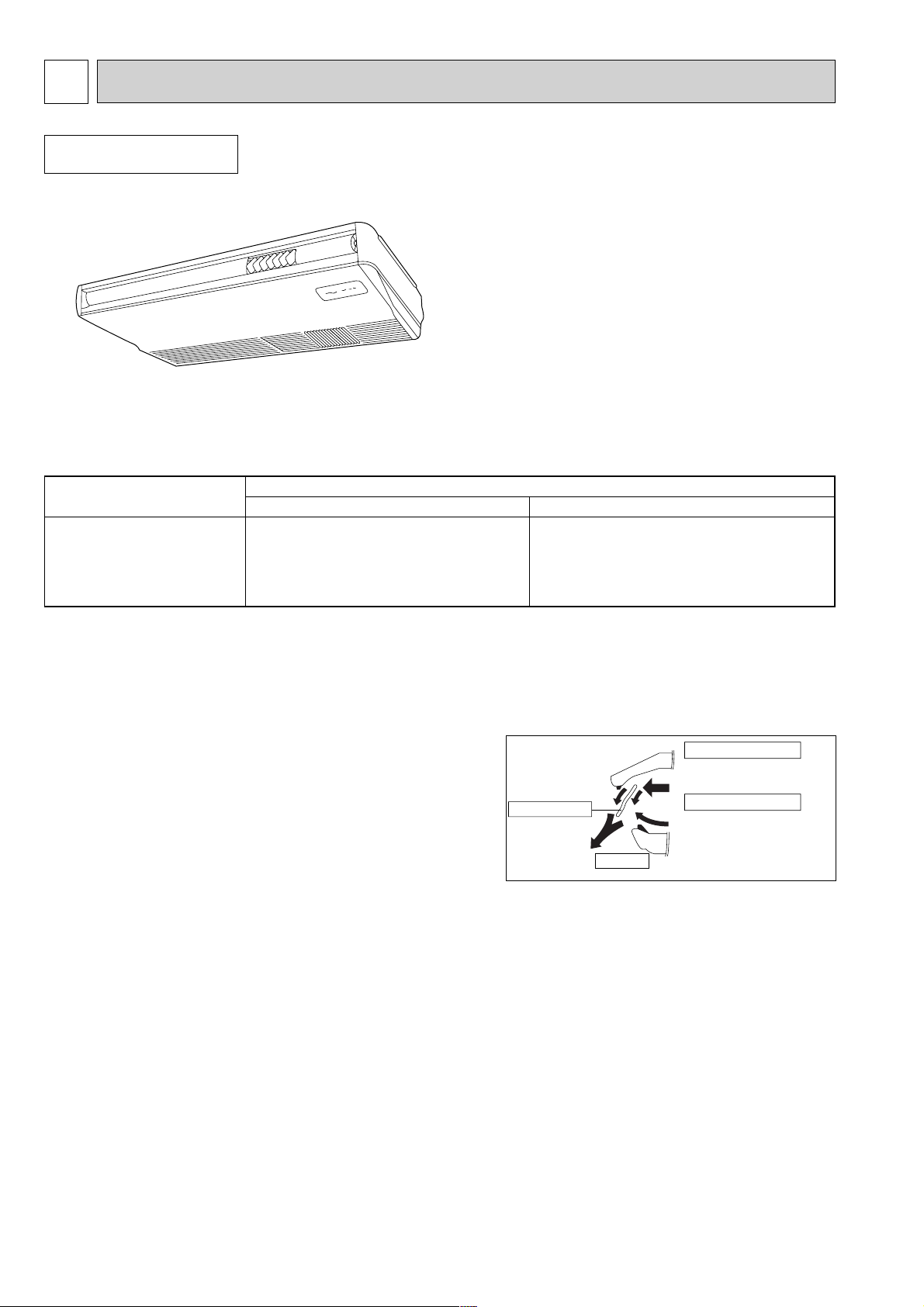
1. AIR OUTLET
New PCFY series models have 1 air outlet (auto vane switching of horizontal air flow / down flow by switched by auto vane)
instead of 2 (horizontal, and down frows).
2. EASY TO CLEAN ; FLOCKLESS VANE
With our original air current control mechanism, a flockless vane is
newly adapted.
The flockless vane prevents the condensation on the vane.
By changing the vane to the flockless type, the unit can be cleaned
much easier with mild household detergent.
3. NEW MATERIALS FOR BETTER OIL RESISTANCE
We have changed the materials of grill, filer, fan and fan casing from ABS to P.P. (polypropylene) for better oil resistance. As
a result, oil crazing is cut in half.
Indoor unit
Ceiling Suspended
Series PCFY
B
A
Unifies the air speed
with the vane.
+
=
Sending the air to the upper
area of the vane
Prevents the air comes from
outside the unit
Flockless vane
Protruding portion A
Protruding portion B
Air outlet
Cooling capacity / Heating capacity
Models
W Kcal/h
PCFY-40VGM 4,700/5,200 4,000/4,500
PCFY-63VGM 7,300/8,300 6,300/7,100
PCFY-100VGM 11,600/13,000 10,000/11,200
PCFY-125VGM 14,500/16,300 12,500/14,000
Page 3
3
1 Removed the knockout work by separating the piping space
from the air outlet for efficiency of the piping work.
❈ Knockout work is needed for the top part. When optional
drain-up machine is installed, the refrigerant pipe exits out
from the top.
2 Improved the flexibility by making it possible for drainage
pipe to exit not only from the right side back but also from
the left side back.
❈ Please move the rubber plug for the unit to the right joint
when drainage pipe exits from the left side.
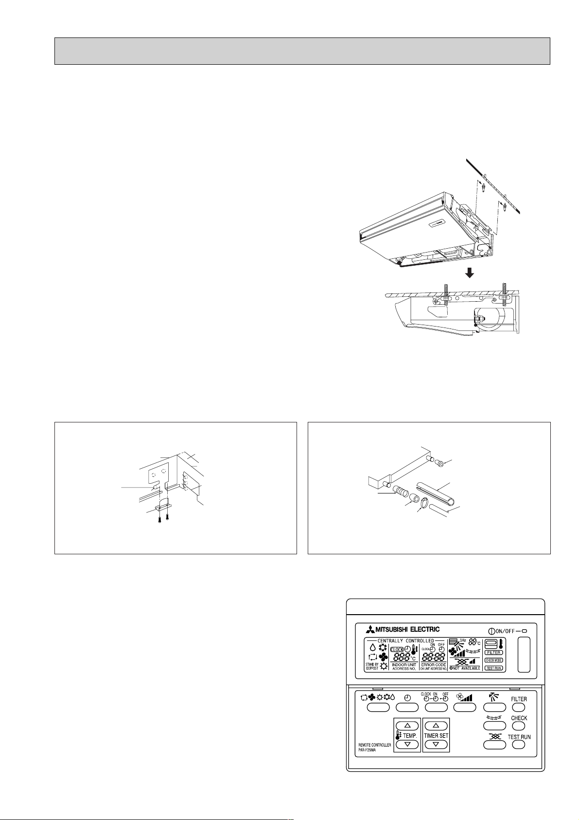
4. SIMPLIFIED INSTALLATION WORK (DIRECT SUSPENDING METHOD)
Simplified the installation work by changing the suspending method to the direct suspending method (suspending the unit
directly from the suspension fixture).
In this way, the unit can be attached to the suspension fixture without removing the installation parts off (Only the side cover
is removed). This method is much simpler than the ¨One-time installation method¨.
5. IMPROVING EFFICIENCY OF PIPING WORK
U-cut
Back panel
L
D
G
Open
Open
L
G
D
Side panel
L : Liquid pipe
G: Gas pipe
D: Drain pipe
6.ADVANCED MICROPROCESSOR [PAR-F25MA]
(1)Easy to use microprocessor
1)Ultra-thin remote controller
The streamlinde,square controller is designed to blend well with
any interior.Also,the sophisticated microproceeor allows you to
easily carry out a wide range of operations.
2)Attractive liquid crystal display(LCD)
The unit´s operation mode,set temperature,room
temperature,timer setting,fan speed,louver oper-ation,and air flow
direction are displayed on the remote controller´s easy-to-read
Liquid Crystal Dis-play(LCD).
3)Convenient 24-hour ON-OFF timer
The timer switches Mr.SLIM on and off automati-cally at the time
you set. Once the timer is set,the remaining time is shown on the
LCD.
Rubber plug
Insulation cover
(attached)
Drain pipe
(purchased locally)
Joint coupliy
(attached)
Drain pan
Insulation
cover
Band
(attached)
Page 4
4
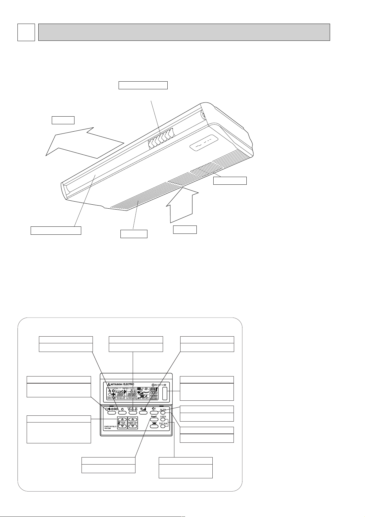
PART NAMES AND FUNCTION
2
● Indoor (Main) Unit
Air outlet
Intake grille
Air intake
Left/right guide vanes
Change the direction of airflow
from the horizontal blower.
Long-life fillter
Removes dust and foreigh matter from air coming in
through the grille (Recommended cleaning interval :
Approx, every 2,500 operating hours)
Up/down guide vanes
Change the direction of airflow from the
vartical blower.
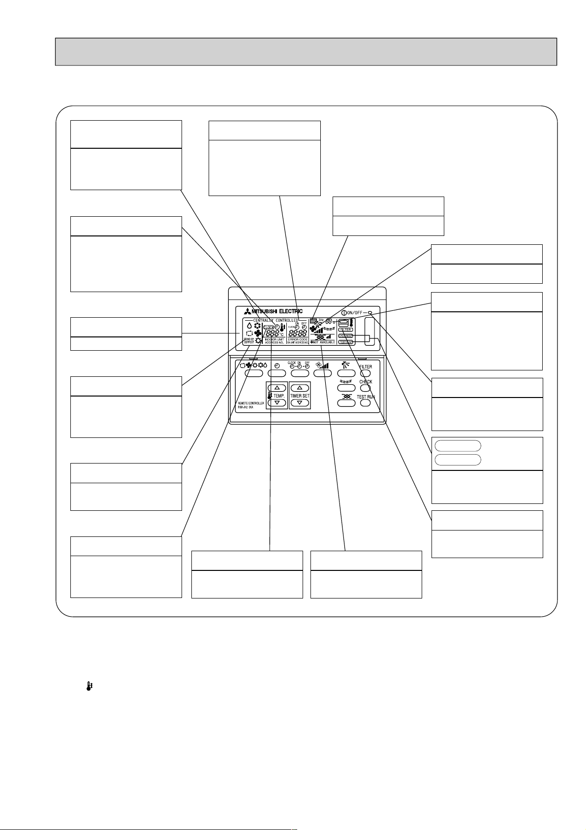
● Remote controller
● Operation buttons
[PAR-F25MA]
● Once the controls are set, the same operation mode can
be repeated by simply pressing the ON/OFF button.
This switches between continuous
operation and the timer operation.
TIMER button
This sets the ventilation fan speed.
AIR SPEED button
Press this button to switch the cooler
electronic dry (dehumidify) automatic and
heater modes.
OPERATION SWITCH button
This sets the room temparature The
temparature setting can be performed in 1°C
units
Setting range
Cooler 19°C to 30°C
TEMP ADJUSTMENT button
This sets of switches the current time.
start time and stop time.
TIME SETTING button
(This button does not operate in this
model)
This switches the horizontal fan
motion ON and OFF.
LOUVER button
This swiches between the operation
and stop modes each time it is
pressed. The lamp on this button
lights during operation.
ON/OFF button
This adjusts the vertical angle of the
ventilation.
AIR DIRECTION button
Only press this button to perform an
inspection check or test operation Do
not use it for nomal operation.
CHECK-TEST RUN button
This resets the filter service indication
display.
FILTER button
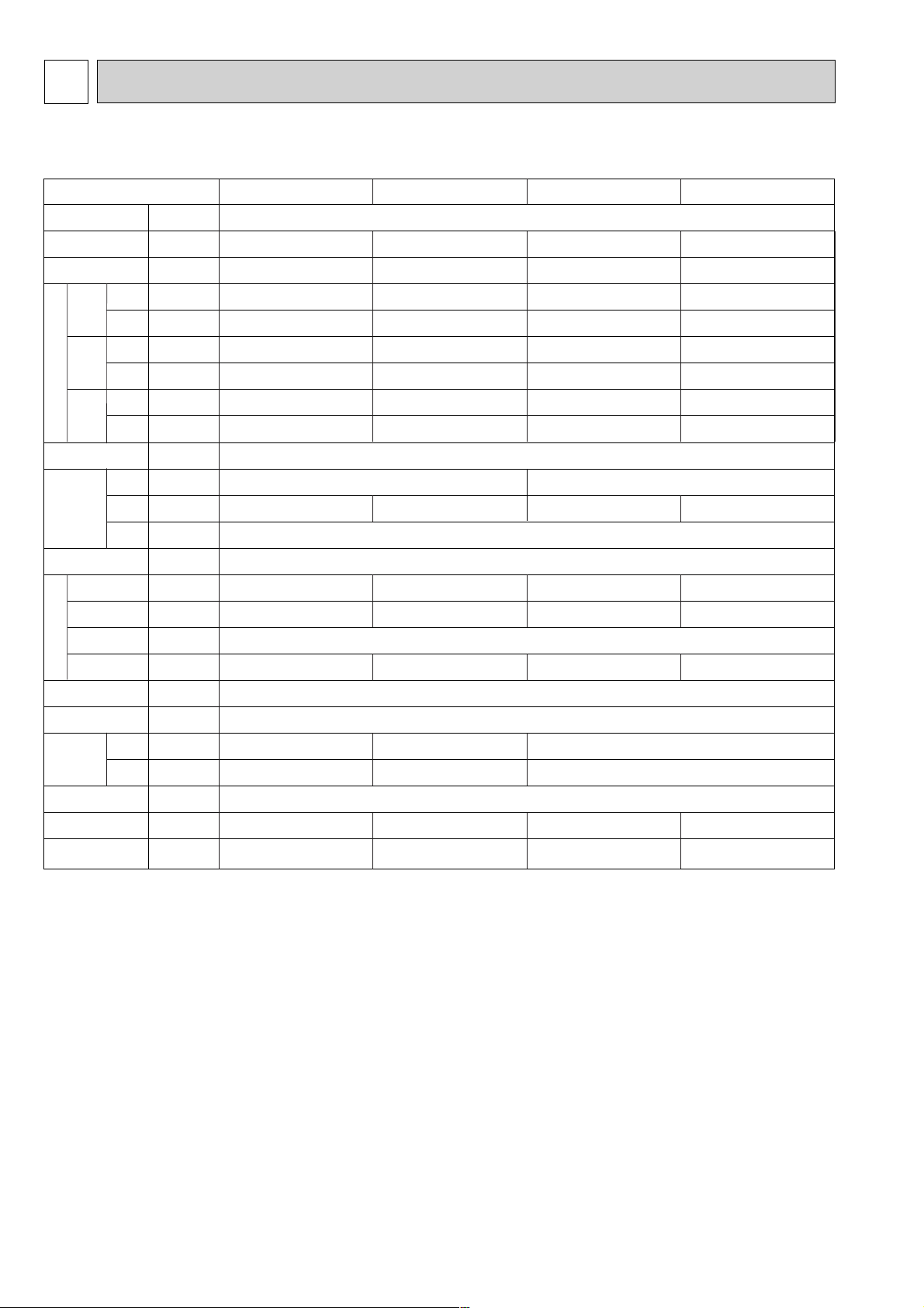
Page 5
5
Caution
● Only the Power display lights when the unit is stopped and power supplied to the unit.
● When power is turned ON for the first time the (CENTRAL CTRL) display appears to go off momentarily but this is not a
malfunction.
● When the central control remote control unit, which is sold separately, is used the ON-OFF button, operation switch button
and TEMP adjustment button do not operate.
● “NOT AVAILABLE” is displayed when the Air speed button are pressed.This indicates that this room unit is not equipped
with the fan direction adjustment function and the louver function.
●When power is turned ON for the first time, it is normal that “HO” is displayed on room temperature indecation (For
max.2minutes). Please wait until this “HO” indication disappear then start the operation.
4
CENTRALLY
CONTROLLED display
This indicates when the unit is
controlled by optional features such
as central control type remote
controller.
TIMER display
This indicates when the continous
operation and time operation modes
are set.
It also display the time for the timer
operation at the same time as when
it is set.
OPERATION MODE display
This indicates the operation mode.
STANDBY display
This indicates when the standby
mode is set from the time the sleep
operation starts until the heating air
is discharged.
DEFROST display
This indicates when the defrost
operation is performed.
CHECK display
This indicates when a malfunction
has occurred in the unit which should
be checked.
CLOCK display
The current time , start time and stop
time can be displayed in tensecond
intervals by pressing the time switch
button. The start time or stop time is
always displayed during the timer
operation.
● Display
In this display example on the
bottom left, a condition where all
display lamps light is shown for
explanation purposes although this
differs from actual operation.
Operation lamp
This lamp lights during operation,
goes off when the unit stops and
flashes when amalfunction occurs.
POWER display
This lamp lights when electricity is
supplied to the unit.
SET TEMPERATURE display
This displays the selected setting
temperature.
FAN SPEED display
This displays the air direction.
ROOM TEMPERATURE display
The temperature of the suction air is
displayed during operation. The
display range is 8° to 39°C. The
display flashes 8°C when the actual
temperature is less than 8° and
flashes 39°C when the actual
temperature is greater than 39°C.
display
This display lights in the check mode
or when a test operation is
performed.
CHECK MODE
TEST RUN
FILTER display
This lamp lights when the filter need
to be cleaned.
AIR DIRECTION display
The selected fan speed is displayed.
Page 6
6
SPECIFICATIONS
3
3-1. Specification
PCFY-40VGM PCFY-63VGM PCFY-100VGM PCFY-125VGM
kW 4.7 7.3 11.6 14.5
kW 5.2 8.3 13.0 14.5
kw 0.10 0.13 0.16 0.24
kW 0.10 0.13 0.16 0.24
A 0.43 0.55 0.70 1.06
A 0.43 0.55 0.70 1.06
%92 93 92 92
%92 93 92 92
– Unit : Munsell<0.70Y 8.59/0.97>
mm 210 270
mm 1000 1310 1310 1620
mm 680
- crosfin
- Sirocco fan
✕
2 Sirocco fan ✕ 3 Sirocco fan ✕ 3 Sirocco fan ✕ 4
k/min 12-11-10-8 18-16-14-12 25-23-20-18 35-32-28-26
Pa 0
kW 0.054 0.07 0.09 0.15
Polyethylene sheet
PP honey comb
[mm 12.7<1/2”> 15.88<5/8”> 19.05<3/4”>
[mm 6.35<1/4”> 9.52<3/8”> 9.52<3/8”>
[mm PVC pipe VP-25 connectable
dB(A) 38-36-33-29 39-37-34-32 43-41-38-36 44-42-39-37
kg 27 34 37 43
V•Hz Single phase 220V-240V 50 HZ
Note 1. Rating conditions(JIS B 8616)
Cooling: Indoor: 27°C DB. 19.5°C WB
outdoor: 35°C DB. 24°C WB
Heating: Indoor: 21°C
outdoor: 7°C DB. 6°C WB
Note 2. Air flow and the noise level are indicated as High-Middium 1-Middium 2-Low.
Item
Power
Cooling capacity
Heating capacity
Cooling
Heating
Cooling
Heating
Cooling
Heating
Exteior
(munsell symbol)
Height
Width
Depth
Heat exchanger
Insulator
Air filter
Gas
side
Pipe
dimensions
Drain pipe size
Noise level
Product weight
Liquid
side
F
a
n
Fan motor
Output
Fan ✕ No
Air flow #3
External
static pressure
Outdimensions
Electric charocteristic
Power
supply
Startin
g
current
Power
factor
Page 7
7
3-2. Electrical parts specifications
Model
Parts
name
Symbol PCFY-40VGM PCFY-63VGM PCFY-100VGM PCFY-125VGM
Tranrsformer T (Primary) 50/60Hz 220-240V (Secondary) (18.4V 1.7A)
Room temperature
thermistor TH21
Resistance: 0:/15k',10:/9.6k',20:/6.3k',25:/5.4k',30:/4.3k',40:/3.0k
'
Liquid pipe
thermistor TH22
Resistance: 0:/15k',10:/9.6k',20:/6.3k',25:/5.4k',30:/4.3k',40:/3.0k
'
Gas pipe
Thermistor TH23
Resistance: 0:/15k',10:/9.6k',20:/6.3k',25:/5.4k',30:/4.3k',40:/3.0k
'
Fuse FUSE 250V 6.3A
Fan motor MF1,2
Inner-thermostat
Fan motor capacitor C1 3uF x 440V 4uF x 440V 4uF x 440V 6uF x 440V
Vane motor MV
Linear expansion valve LEV
Power supply
terminal block TB2 (L,N,;) 330V 30A
Transmission
terminal block TB5 (M1,M2,S) 330V 30A
(Indoor controller board)
(with Inner-thermostat)
OFF 130:±5:
MP35EA
DC12V
MP35EA
DC12V
MP42EA
DC12V
DC12V Stepping motor
drive
{ 3.2 (0~2000pulse)
EDM-402ME
DC12V Stepping motor drive
{ 5.2 (0~2000pulse)
EDM-804ME
4-Pole OUTPUT 54W
D09B4P54MS
4-Pole Output 90W
D10B4P90MS
4-Pole Output 150W
D10B4P150MS
4-Pole Output 70W
D09B4P70MS
Page 8
8
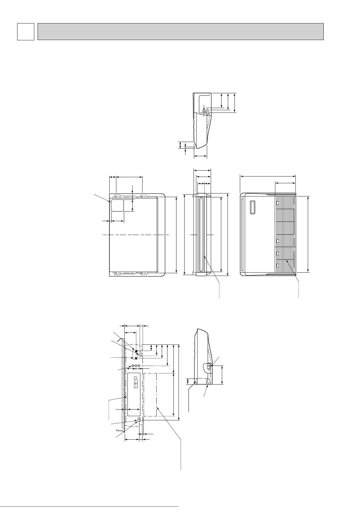
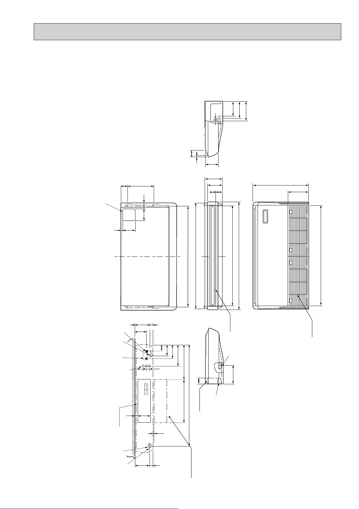
OUTLINES AND DIMENSIONS4
INDOOR UNIT
PCFY-40VGM
180
210
157
15
85
182 (3/8F) liquid
201 (5/8F) gas
241 (Drainage)
Air intake
918
254
680
Electrical box
226
70
525
928
352
263
171
138
86
46 175 1
131
38
3879
161
32
179
42
6-7
Celling
Electrical box
[FRONT VIEW]
When electrical
box is pulled
down
3
2
8
5
1
4
6
2
1
17
150
140
70
320
80
933 (suspension bolt pitch)
983
1000
Air outlet
81
904
76
Gap to ceiling
1 Drainage pipe connection (26mm I.D.) 5 Refrigerant-pipe connection (liquid pipe side/flared connection)
2 Drainage pipe connection (for the left arrangement) 6 Knock out hole for upper drain pipe arrangement
3 Knock out hole for left drain-piping arrangement 7 Knock out hole for left drain pipe arrangement
4 Refrigerant-pipe connection (gas pipe side/flared connection) 8 Knock out hole for wining arrangement
NOTES:
1. Use M10 or W3/8 screws for anchor bolt.
2. Please be sure when installing the drain-up machine (option parts).
refrigerant pipe will be only upper drain pipe arrangement.
Page 9
9
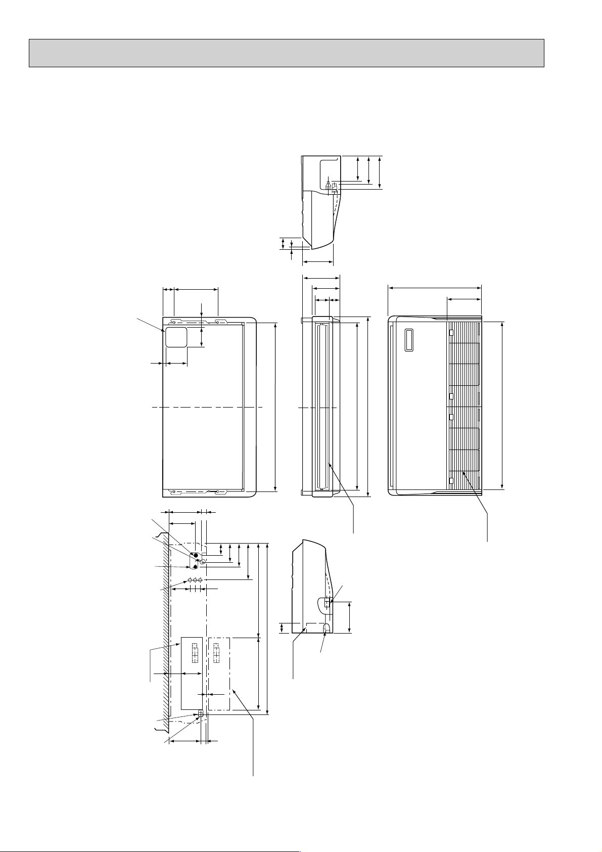
PCFY-63VGM
1240 (suspension bolt pitch)
140
150
320 80
17
70
6
1290
1214
210
180
81 76
1310
Air outlet
1228
680
254
Air intake
85
182
201
241
15
157
(3/8F liquid)
(5/8F gas)
(Drainage)
3
2
8
5
1
4
Electnical box
When electrical
box is pulled
down
[ FRONT VIEW ]
Celling
32
179
161
38
3879
42
6~7
525
1235
416
263
171
138
86
131
175 1
46
1
2
Electrical box
70
226
Gap to ceiling
1 Drainage pipe connection (26mm I.D.) 5 Refrigerant-pipe connection (liquid pipe side/flared connection)
2 Drainage pipe connection (for the left arrangement) 6 Knock out hole for upper drain pipe arrangement
3 Knock out hole for left drain-piping arrangement 7 Knock out hole for left drain pipe arrangement
4 Refrigerant-pipe connection (gas pipe side/flared connection) 8 Knock out hole for wining arrangement
NOTES:
1. Use M10 or W3/8 screws for anchor bolt.
2. Please be sure when installing the drain-up machine (option parts).
refrigerant pipe will be only upper drain pipe arrangement.
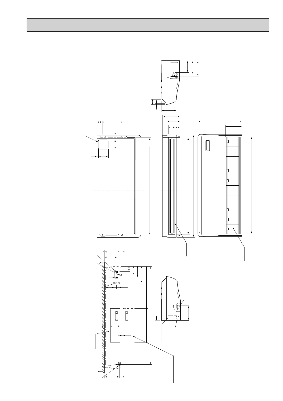
Page 10
10
1228
680
254
Air intake
1214
270
207
81 96
1310
Air outlet
1240 (suspension bolt pitch)
140
150
320 80
17
70
6
87
182
198
245
16
217
(3/8F liquid)
(5/8F gas)
(Drainage)
3
2
8
5
1
4
Electnical box
When electrical
box is pulled
down
[ FRONT VIEW ]
Celling
93
160
38
38 140
42 239
6~7
525
1235
687
263
171
138
86
192
236
1
45
1
2
Electrical box
70
229
Gap to ceiling
PCFY-100VGM
1 Drainage pipe connection (26mm I.D.) 5 Refrigerant-pipe connection (liquid pipe side/flared connection)
2 Drainage pipe connection (for the left arrangement) 6 Knock out hole for upper drain pipe arrangement
3 Knock out hole for left drain-piping arrangement 7 Knock out hole for left drain pipe arrangement
4 Refrigerant-pipe connection (gas pipe side/flared connection) 8 Knock out hole for wining arrangement
NOTES:
1. Use M10 or W3/8 screws for anchor bolt.
2. Please be sure when installing the drain-up machine (option parts).
refrigerant pipe will be only upper drain pipe arrangement.
Page 11
11
PCFY-125VGM
1 Drainage pipe connection (26mm I.D.) 5 Refrigerant-pipe connection (liquid pipe side/flared connection)
2 Drainage pipe connection (for the left arrangement) 6 Knock out hole for upper drain pipe arrangement
3 Knock out hole for left drain-piping arrangement 7 Knock out hole for left drain pipe arrangement
4 Refrigerant-pipe connection (gas pipe side/flared connection) 8 Knock out hole for wining arrangement
NOTES:
1. Use M10 or W3/8 screws for anchor bolt.
2. Please be sure when installing the drain-up machine (option parts).
refrigerant pipe will be only upper drain pipe arrangement.
6
(3/8F liquid)
(3/4F gas)
(Drainage)
182
198
245
87
16
320 80
70
140
150
18
217
270
207
680
81 96
254
Gap to ceiling
1
4
1
5
8
Celling
[ FRONT VIEW ]
93
Electrical box
236
192
38 140
160
1535
1620
1524
1547(suspension bolt pitch)
45
86
138
171
687
263
38
Air outlet
Air intake
2
229
1
6~7
525
1545
70
Electrical box
2
3
When electrical
box is pulled
42 239
down
Page 12

12
5
WIRING DIAGRAM
MODELS : PCFY-40~125VGM WIRING DIAGRAM
SYMBOL
NAME
I.B
SYMBOL
T TRANSFORMER
DRAIN SENSOR
DRAIN WATER LIFTING-UP MACH.
FAN MOTOR (WITH INNER THERMO.)
FAN MOTOR CAPACITOR
VANE MOTOR
POWER SUPPLY TERMINAL BLOCK
TRANSMISSION TERMINAL BLOCK
LINEAR EXPANSION VALVE
CIRCUIT BOARD
MODE SELECTOR
DS
DP
MF
C1
MV
TB2
TB5
LEV
A,B
SW1(A,B)
SW5(A,B)
SW11(A,B)
SW12(A,B)
SW14(A,B)
SWA(A,B)
SWC(A,B)
INDOOR CONTROLLER BOARD
REMOTE SWITCH CONNECTOR
CENTRALLY CONTROL CONNECTOR
REMOTE INDICATION CONNECTOR
DRAIN-UP MACHINE CONNECTOR
CAPACITY CORD SWITCH
FUNCTION SELECTOR
UNIT SELECTOR
DRAIN UP MECH. RELAY
FAN MOTOR RELAY
CN32
CN51
CN52
CNP
SW2
SW3
SW4
X1
X4
F.C
ZNR
FUSE
VARISTOR
FUSE(6.3A)
FAN PHASE CONTROL
TH21
TH22
TH23
ROOM TEMPERATURE THERMISTOR
(0:/15k',25:/5.4k')
LIQUID PIPE THERMISTOR
(0:/15k',25:/5.4k')
GAS PIPE THERMISTOR
(0:/15k',25:/5.4k')
VOLTAGE SELECTOR
1ST DIGIT ADDRESS SETTING
2ND DIGIT ADDRESS SETTING
CONNCTION NO.
CEILING HEIGHT SELECTOR
OPTION SELECTOR
NAME
SYMBOL
NAME
NOTE
1.At servicing for outdoor unit,always follow the wiring diagram of outdoor unit.
2.Symbol(S) of TB5 is the shield wire connection.
3.Symbols used in wiring diagram above are, :Terminal block, :Connector.
4.The setting of the SW2 dip switches differs in the capacity.
For the detail,see the table below.
5.Please set the switch SW5 according to the power supply voltage.
Set SW5 to 240V side when the power supply is 230 and 240 volts.
When the power supply is 220 volts,set SW5 to 220V side.
MF
51 3
BLK
RED
WHT
C1
I.B
FAN1
51 3
(WHT)
X4
F.C
X4 X1
(GRN)
VANE
CN6V
6
RED
WHT
YEL
ORN
BRN
MV
BLU
WHT
RED
CNT
(WHT)
13
(RED)
ADDRESS
8
DP
CNP
(BLU)
(OPTION)
1
3
(RED)
ADDRESS
RED
BLU
AC220-240V
31
(RED)
CND
T
AC18.4V
BLU
BLU
31
CN3T
(RED)
(WHT)
(WHT)
REMOTO
LEV
SWITCH
CN32
CN60
123456
135151
(BLK)
SW4
YEL
432
WHT
0N
0FF
(WHT)
GAS
LIQUID
CN29 CN21
12 2 1
13 2 1
TH23
SW3SW2
1
6
BLU
RED
ORN
BRN
56123456 1234
LEV
TH22
LED5LED2LED1LED3LED4
(RED)
DRAIN
CN50
(RED)
INTAKE
CN20
TH21
CN2M
1
(BLU)
2
M-NET
12345
12
RED
BLU
FUSE
(WHT)
REMOTE
INDICATION
CN52
0N
0FF
12341234567856 1234
1
6.3A
250V
ZNR
(WHT)
CENTRALLY
CONTROL
CN51
1234567891023456
X1
CN42CN81
See fig:*1
4
TO NEXT INDOOR UNIT
TB2
L
N
GRN/YEL
BLU
BLU
MODELS
PCFY-100,125VGM
(GRN)
VANE
CN6V
56 1234
RED
ORN
BRN
56 1234
PULL BOX
FUSE(15A)
BREAKER(15A)
POWER SUPPLY
~/N 220-240VÅ@50Hz
TB5
S(SHIELD)
{
M2
TO OUTDOOR UNIT
BC CONTROLLER
M1
REMOTE CONTROLLER
DC24-30V
6
BLU
WHT
YEL
MV
(RED)
DRAIN
54
GRY
CN50
3
1
2
BLK
DS(OPTION)
Models SW2
PCFY-40VGM
PCFY-100VGM
A.B
OFF
3RD
DIGIT
SW5
220V 240V
SW1
ON
12345678910
SW12 SW11
00
2ND
DIGIT
ON
OFF
ON
OFF
1ST
DIGIT
654321
SW2Models
123456
SWA
ADDRESS
3
2
1
SWC
CONNECTION
NO.
Models
PCFY-63VGM
Models
PCFY-125VGM
4
(RED)
3
CN43
2
1
(RED)
ADDRESS
CN82
SW14
0
OFF
OFF
8
7
6
5
4
3
2
1
SW2
ON
SW2
ON
123456
654321
Page 13

13
6
REFRIGERANT SYSTEM DIAGRAM
Strainer (#50mesh)
Strainer (#100mesh)
Strainer (#100mesh)
Heat exchanger
Room temperature thermistor TH21
Gas pipe thermistor TH23
Liquid pipe thermistor TH22
Linear expansion valve
Gas pipe
Flare connection
Gas pipe
PCFY-40VGM
{12.7<1/2F>
PCFY-63VGM
{15.88<5/8F>
PCFY-100,125VGM
{19.05<3/4F>
Liquid pipe
{6.35<1/4F> {9.52<3/8F> {9.52<3/8F>
Capacity
Item
Page 14

14
7
TROUBLE SHOOTING
7-1. How to check the parts PCFY-VGM
Room temperature thermistor
(TH21)
Liquid pipe thermistor (TH22)
Gas pipe thermistor (TH23)
Parts name
Check points
Trans
Fan motor
Linear expansion
valve
Drain-up mechanism
(Optional)
Drain sensor
(Optional)
Vane motor
Disconnect the connector, then measure the resistance using a tester.
(Sorrounding temperature 10°C~30°C)
Disconnect the connector and measure the resistance using a tester.
Measure the resistance between the terminals using a tester.
Disconnect the connector then measure the resistance valve using a tester.
Refer to the next page for a detail.
Measure the resistance between the terminals using a tester.(Surrounding temperature
20;~30;)
Measure the resistance between the terminals using a tester.(Surrounding temperature
20;~30;)
Measure the resistance between the terminals using a tester.
(Refer to the thermistor)
(Refer to the thermistor)
Normal
4.3k'~9.6k'
Abnormal
Open or short
Normal
92'
Abnormal
Open or short
CNT(1)-(3)
Normal
App.45'
CN3T(1)-(3)
App.1'
Abnormal
Open or short
Motor terminal
or
Relay connector
Normal
PCFY-VGM
40 63 100 125
Abnormal
Red-Black
70.6' 45.0' 43.7' 20.4'
Open or short
White-Black
69.6' 44.8' 53.3'
Connector
Normal
PCFY-40VGM PCFY-63VGM
Abnormal
Brown-Yellow
186~214' 140~160'
Open or short
Brown-Blue
Brown-Orange
Brown-Pink
Connector PCFY-100,125VGM Abnormal
Red-Blue
140~160'
Open or short
Red-Yellow
Red-Pink
Red-Orange
20.7'
(1)-(3)
Normal
82'
(4)-(5)
4.3k'~9.6k'
Abnormal
Open or short
Normal
(1)-(5)
White-Red
150' ±10%
Abnormal
Open or short
(2)-(6)
Yellow-
Blown
(3)-(5)
Orange-Red
(4)-(6)
Blue-Brown
CNT T CN3T
Red Blue
1
2
3
White
Blue
1
2
3
Relay connector
1
Red
1
White
2
2
3
Black
3
Protector
LEV
White
Yellow
Orange
Blue
Red
Brown
CN60
1
2
3
4
5
6
Gray
Gray
1
2
4
Orange
5
Red
2
Pink
Connector
Pin No.
2
Pink
4
Orange
5
Red
Connector
Pin No.
3
Yellow
3
1
2
3
4
5
61
BlueYellow Brown
Blue
1
Page 15

15
<Thermistor Characteristic graph>
Room temperature thermistor(TH21)
Liquid pipe thermistor(TH22)
Gas pipe thermistor(TH23)
Drain sensor(THD)
Thermistor R
0=15k' ±3%
Fixed number of B=3480k' ±2%
Rt=15exp { 3480( ) }
0: 15k'
10: 9.6k'
20: 6.3k'
25: 5.2k'
30: 4.3k'
40: 3.0k'
Thermistor at
lower temperature
Linear expansion valve
① Operation summary of the linear expansion valve.
• Linear expansion valve open/close through stepping motor after receiving the pulse signal from the indoor controller board.
• Valve opening can be changed in proportion to the number of pulse signal.
<Connection between the indoor controller board and the linear expasion valve>
4
[4
3
62
5
[3
2
[2
1
[1
[4
[3
[2
[1
Controller board
Drive circuit
Relay connector
Connector(CN60)
DC12V
Brown
Red
Blue
Orange
Yellow
White
5
1
3
4
6
M
4
6
2
3
5
1
Blue
Brown
Yellow
Orange
Red
White
Linear expansion valve
1
273+t
1
273
Note : Since the number of the connector at the controller board side and the relay connector are different, follow the color of
the lead wire.
< Thermistor at lower temperature >
50
40
30
Resistance (K")
20
10
0
-20 -10 0 10 20 30 40 50
Temperature (:)
Page 16

16
Output
(Phase)
number
Output
{1
1
ON
{2
ON
{3
OFF
{4
OFF
2
OFF
ON
ON
OFF
3
OFF
OFF
ON
ON
4
ON
OFF
OFF
ON
Closing a valve : 1 → 2 → 3 → 4 → 1
Opening a valve : 4 → 3 → 2 → 1 → 4
The output pulse shift as above order.
❈ 1. When linear expasion valve operation stops, all output phase
become OFF.
2. At phase interruption or when phase does not shift in order,
motor does not rotate smoothly and motor will lock and vibrate.
❈ When the switch is turned on, 2200 pulse opening valve signal
will be send till it goes to
A point in order to define the valve
position.
When the valve move smoothly, there is no noise or vibration
occur from the linear expansion valve : however, when the pulse
number moves from
E to A or when the valve is locked, more
noise can be hear than normal situation.
❈ Noise can be detected by placing the ear against the screw
driver handle while putting the screw driver to the linear
expansion valve.
<Output pulse signal and the valve operation>
➁
Linear expansion valve operation
➂
Trouble shooting
D
A
E
B
C
Open
extra tightning (80~100pulse)
Pulse number
2000 pulse
Open the valve
all the way
Close
Symptom
Check points
Operation circuit
failure of the micro
processor
Disconnect the connector on the controller board, then
connect LED for checking.
Pulse signal will be sending out for 10 seconds as soon as
the main switch is rurned on. If there is LRD with lights on or
lights off, it means the operation circuit is abnormal.
Countermeasures
Exchange the indoor
controller board at drive
circuit failure.
Lock at the linear
expansion valve
mechanism area.
Valve doesn’t close
completely(thermisto
r leaking)
Wrong connection of
the connector or
contact failure.
To check the linear expansion valve of the indoor unit,
operate the indoor unit in fan mode and operate other indoor
units in cooling mode then check the pipe temperature <liquid
pipe temperature> of the indoor unit by
monitorring the outdoor multi controller
board operation. During fan operation,
linear expansion valve is closed completely
and if there are some leaking, detecting
temperature of the thermistor will go lower.
If the detected temperature is much lower
than the temperature indicated in the
remote contoroller, it means the valve is not closed all the
way. It is not necessary to exchange the linear expasion
valve, if the leakage is small or does not make any trouble.
Liquid pipe
thermistor
Linear
expansion
valve
Morter will idle and make ticking noise when motor is
operated while the linear expansion valve is locked. This
ticking noise is the sign of the abnormality.
Check the color of lead wire and missing terminal of the
connector.
Check the color of lead wire and missing terminal of the
connector.
Exchange the linear
expansion valve.
Exchange the linear
expasion valve.
If large amount of
thermistor is leaked,
exchande the linear
expasion valve.
Disconnect the connecttor
at the controller board,
then check the continuity.
Measure the resistance between the each coil(red-white, redorange, brown-yellow, brown-blue) using atester. It is normal
if the resistance is in the range of 150 '±10%.
Short or breakage of
the motor coil of the
linear expansion
valve.
LED1S
6
5
4
3
2
1
Page 17

17
3-2. FUNCTION OF DIPSWITCH
PCFY-VGM
1
2
3
4
5
6
7
8
9
10
1~6
1
2
3
4
5
6
7
8
9
10
1~4
Thermistor<Intake temperature
detection>position
ON OFF
Filter crogging detection ProvidedNot provided
Filter life 2,500hr 100hr
Air intake Effective Not effective
Remote indication switching Thermostat ON signal indication Fan output indication
Humidifier control
Always operated while the heat is ON
Operated depends on the condition
Air flow st Low Extra low
Heat thermostat OFF Setting air flow Reset to SW1-7
Auto reset function Effective Not effective
Power ON/OFF Effective Not effective
Heat pump/Cool only Cooling only Heat pump
Louver Available Not available
Vane Available Not available
Vane swing function Available Not available
Vane holizontal angle Second setting First setting
Vane cooling limit angle setting
Horizontal angle Down B,C
Effective Not effective
Heater 4deg. up Not effective Effective
Superheat setting temparature
5deg 2deg
Sybcool setting 15deg 10deg
ON
OFF
ON
OFF
123
1234
ON
OFF
12345678910
ON
OFF
12345678910
ON
OFF
123456
ON
OFF
123456
ON
OFF
123456
ON
OFF
123456
MODELS SW2 MODELS SW2 MODELS SW2
PCFY-40VGM PCFY-63VGM
PCFY-100VGM
PCFY-125VGM
Address board
<At delivery>
Indoor controller board
Indoor controller board
Indoor controller board
<At delivery>
<At delivery>
SW4
Unit
Selection
SW3
Function
Selection
SW2
Capacity
code
setting
SW1
Mode
Selection
Switch Pole
Function Remarks
Operation by switch
Bult-in remote controller
Indoor unit
Indoor linear expansion
valve opening
(Note1) Fan operation at Heating
mode
(Note2) Heater thermo ON is
operating.
(Note3) SW1-7=OFF, SW1-8=ON
→Setting air flow.
SW1-7=OFF, SW1-8=ON
→Indoor fan stop.
Set while the unit is off.
<At delivery>
Set for each capacity.
Set while the unit is off.
(Note1) At cooling mode, each
angle can be used only 1
hour.
Set while the unit is off.
Page 18

18
Address board
Address board
Address board
Address board
Operation by switchSwitch Remarks
❈ Ceiling height can be changed depends on
SWB setting.
<At delivery>
<At delivery>
<At delivery>
<At delivery>
1~3
SWA
Set the
Ceiling
height
2
SWC
Option
SW11
1st digit
address
setting
SW12
2st digit
address
setting
Rotary switch
SW14
Conne-
ction
No.
Setting
Rotary switch
When attach the optional high performance
filter elementsm (filter casement) to the unit,
be sure to attach it to the option side in order
to prevent the airflow reducing.
Address setting should be done when network
remote controller (OAR-F25M) is being used.
This is the switch to be used when the indoor
unit is operated with R2, R3 series outdoor
unit as a set.
Address can be set while the
unit is stopped.
220V 240V
220V 240V
Address board
<At delivery>
2
SW5
Voltage
selection
If the unit is used at the 230V or 240V area,
set the voltage to 240V.
If the unit is used at the 220V, set the voltage
to 220V.
(High)
(Standard)
(Low)
Option
standard
SW12
0
1
9
2
8
3
7
4
6
5
10
3
2
1
SW11
0
9
8
7
6
5
1
3
2
1
Option
1
2
3
4
SW12
SW11
0
0
1
9
8
7
6
5
1
9
2
8
3
7
4
6
5
2
3
4
SW14
0
1
F
E
D
C
B
A
8
9
2
3
4
5
6
7
SW14
0
1
2
F
3
E
4
D
5
C
6
B
7
A
8
9
Page 19

19
DISASSEMBLY INSTRUCTIONS
8
OPERATING PROCEDURE PHOTOS&ILLUSTRATIONS
1. Removing the air intake grill
(1) Slide the intake grill holding knobs (at two locations)
backward to open the intake grill.
(2) When the intake grill left open, push the stoppers on the
rear hinges (at two locations) to pull out the intake grill.
2. Removing the electrical box
(1) Remove the air intake grill.
(2) Remove the screw from the beam and remove the beam.
(3) Remove the screws from the electrical cover, and remove
the electrical cover.
(4) Disconnectors including CN6V and CN21.
(5) Remove the screws from the electrical box and pull out
the electrical box.
<Electrical parts in the electrical box>
Terminal block (for power supply)
Terminal block (for in/outdoor connecting wire)
Operation condenser
Indoor control board
Power Trans
Figure 1
Figure 2
Photo 1
slide
intake grill
intake grill
hoiding knobs
shinges
Pull out the intake grill
electrical cover
screw(electrical cover)
screw(electrical box)
Slide to the left
beam
clamp
INDOOR UNIT PCFY-63VGM
Operation
condenser
Power
trans
Indoor
control
board
terminal
block
(in / out conncting)
Addoress board
Terminal
block(power supply)
Page 20

20
Figure 2
OPERATING PROCEDURE PHOTOS&ILLUSTRATIONS
3. Removing the fan motor
(1) Remove the air intake grill.
(2) Disconnect the fan motor guard.
(3) Unscrew screws for removing the motor guard.
(4) Unscrew screws for removing the fan guard.
(5) Remove the screw for removing the motor support at both
left and right side.
(6) Loosen the set screws at the fan motor side of the
connecting joint.
(7) Slide the fan motor to the left side and pull it out.
4. Removing the sirocco fan
(1) Remove the air intake grill.
(2) Remove 1 beam.
(3) Unscrew screws for removing the motor guard.
(4) Unscrew screws for removing the fan guard.
(5) Remove the lower casing while pressing the stoppers at
upper side of the casing.
(6) Loosen the set screws at the connecting joint.
(7) Remove the sirocco fan and shaft together by sliding the
shaft to the left.
(Note)
Make sure that the upper side casing is snaped to the fan
plate securely with catch.
5. Removing the side panel
(1) Remove the air intake grill.
(2) Remove the screw from the side panel, and remove the
side panel by sliding the panel to the front.
screw
side panel
sliding the panel
to the front
Photo 2
Photo 3
Screws
Motor
Motor guard
Motor support
Connecting joint
Motor guard
Fan guard
Connecting
joint
Sirocco fan
Bearing
CasingMotor
Page 21

21
OPERATING PROCEDURE PHOTOS&ILLUSTRATIONS
7. Removing the pipe thermistor
(1) Remove the air intake grill.
(2) Remove the right side panel.
(3) Remove the relay connector of the pipe thermistor.
(4) Remove the screw, and remove the check panel.
(5) Extract the pipe thermistor from the holder.
<Caution for the installation>
There is a possibility for the short circuit when connector gets
wet by water through the thermistor lead wire.
Therefore, lead wire of the pipe thermistor should be traped
as shown in the picture.
(5)Gas pipe thermistor is inserted to the holder of the gas
pipe (heater)
8. Removing the under panel
(1) Remove the air intake grill.
(2) Remove the beam.
(3) Remove the side panel (right and left).
(4) Unscrew the screws of the under panel, then remove the
lower panel.
❈ Weight of the lower panel : app. 2kg.
6. Removing the vane motor
(1) Remove the air intake.
(2) Remove the left side panel.
(3) Remove the relay connector of vane motor.
(4) Remove the electrical box.
(5) Remove the screws of vane motor, then remove vane
motor.
(Note)
Connect the lead wires and connectors properly and place
them in the proper position so that the wires are not pinched
by other parts.
Photo 5
Photo 6
Photo 4
Photo 7
Screw
Screw
Screw
Hold Pipe thermistor Trap
Check
panel
Relay connector of
the vane motor
Vane motor
Under panel
Relay connector of
the pipe thermistor
Left side
panel
Check panel
Liquid pipe thermistor
Gas pipe (Header)
Gas pipe thermistor
Page 22

22
OPERATING PROCEDURE PHOTOS&ILLUSTRATIONS
9. Removing the drain pan
(1) Remove the air intake grill.
(2) Remove the beam.
(3) Remove the side panel (right and left).
(4) Remove the under panel. Remove the screws of the right
and left side drain pan.
(5) Remove the insiation in center of the drain pan, and after
removing the screw, remove the drain pan.
(Note)
Please aware that there might be drain left in the drain pan
when you remove the drain pan.
10. Removing the guide vane
(1) Remove the intake grill.
(2) Remove the beam.
(3) Remove the side panel (right and left).
(4) Remove the under panel.
(5) Remove the drain pan.
(6) Remove the screw from the guide vane, then remove the
guide vane.
11. Removing the Auto vane
(1) Remove the intake grill.
(2) Remove the left side panel.
(3) Remove the left side box.
(4) Remove the under panel.
(5) Remove the screw from the auto vane.
(6) Slide the auto vane to the right side and pull the auto vane
out.
Photo 8
Screw
Screw
Screw
Guide vane
Auto vane
Drain pan
Screw
Drain pan
Screw
(Insulation)
Photo 9
Photo 10
Page 23

23
No.
Parts No. Parts Name Specifications
63
VGM
100
VGM
Wiring
Diagram
Symbol
Recommended
Q'ty
Unit
Amount
Q'ty / set Price
1
2
3
4
5
6
7
8
9
10
11
12
CONTROLLER BOARD
FUSE
TRANSFORMER
ADDRESS BOARD
CONTROL BOX
CAPACITOR
RUN CAPACITOR
RUN CAPACITOR
TERMINAL BLOCK
TERMINAL BLOCK
ADDRESS CABLE
BOX COVER
REMOTE CONTROLLER
REMOTE CONTROLLER
CABLE
1
1
1
1
1
1
1
1
1
1
1
1
1
1
1
1
1
1
1
1
1
1
1
1
40
VGM
1
1
1
1
1
1
1
1
1
1
1
1
(BG00N015G12)
(BG02A804G12)
(BG02A804G13)
(BG02A804G14)
I.B
F1,2
T
A.B
C
C
C
TB2
TB4
R.B
250V 6.3A
3 440V
3P(L,N,;)
3P(1,2,3)
10m
Remarks
(Drawing No.)
125
VGM
1
1
1
1
1
1
1
1
1
1
1
1
T7W B06 310
T7W 520 239
T7W B06 260
T7W B01 294
—
R01 30L 255
T7W 39J 255
T7W 43J 255
T7W A14 716
T7W A02 716
R01 05A 304
—
—
—
T7W B00 713
T7W A00 305
10
8
9
4
11
12
1
ELECTRICAL PARTS
PCFY-40VGM
PCFY-63VGM
PCFY-100VGM
PCFY-125VGM
PARTS LIST
9
Page 24

24
STRUCTURAL PART
PCFY-40VGM
23
5
17
7
8
1
962632024
25
18
14
11
10
27
161241513192
22
Page 25

25
No.
Parts No. Parts Name Specifications
1
R01 17J 661
2
R01 17J 662
3
R01 17J 669
4
R01 17J 676
5
R01 17J 500
6
R01 18J 500
7
R01 17J 691
8
R01 18J 691
9
R01 17J 054
10
R01 17J 651
11
R01 17J 085
12
R01 18J 086
13
R01 29J 223
14
R01 17J 067
15
R01 17J 068
16
R01 17J 002
17
R01 17J 061
18
R01 17J 808
19
R01 17J 809
20
R01 17J 070
21
R01 17J 523
22
T7W B06 665
23
R01 57N 666
24
R01 17J 668
25
26
27
—
—
—
RIGHT SIDE PANEL
LEFT SIDE PANEL
UNDER PANEL
REAR PANEL
L.L FILTER
L.L FILTER
GRILLE ASSY
GRILLE ASSY
GRILLE CATCH
FRONT PANEL
G.V ASSY-6L
G.V ASSY-6F
VANE MOTOR
RIGHT SIDE BOX
LEFT SIDE BOX
AUTO VANE
GRILLE HINGE
RIGHT LEG
LEFT LEG
W.BOARD CASE
JOINT SOCKET
S.PLATE-R
S.PLATE-L
SERVICE PANEL
BEAM(GA)
REAR SUPPORT
VANE SUPPORT
Q'ty / set Price
PCFY-40
VGM
Remarks
(Drawing No.)
Wiring
Diagram
Symbol
Recom-
mended
Q'ty
Unit
Amount
1
1
1
1
1
1
1
1
4
1
1
1
1
MV
1
1
1
4
1
1
1
1
1
1
1
2
1
1
(BG17H464H08)
(BG02H454H04)
(BG02R321G07)
Page 26

26
STRUCTURAL PART
PCFY-63VGM
PCFY-100VGM
22
18
2
4
8
9 6 3 7 19 25 24 21
1
17
23
10
5
15
26
1214131116
Page 27

27
No.
Parts No. Parts Name Specifications
Q'ty / set Price
PCFY-63
VGM
PCFY-100
VGM
Remarks
(Drawing No.)
Wiring
Diagram
Symbol
Recommended
Q'ty
Unit
Amount
R01 17J 661
1
R01 35J 661
R01 17J 662
2
R01 35J 662
3
R01 17J 500
R01 29J 676
4
R01 35J 676
R01 29J 651
5
R01 36J 651
6
R01 17J 691
7
R01 29J 669
8
R01 17J 061
9
R01 17J 054
R01 17J 067
10
R01 35J 067
R01 17J 068
11
R01 35J 068
12
R01 17J 085
13
R01 18J 086
14
R01 29J 087
R01 29J 002
15
R01 35J 002
R01 29J 223
16
R01 35J 223
17
R01 17J 808
18
R01 17J 809
19
R01 17J 070
20
R01 17J 523
T7W B06 665
21
T7W B07 665
R01 18J 666
22
R01 35J 666
23
R01 17J 668
24
25
26
—
—
—
—
RIGHT SIDE PANEL
RIGHT SIDE PANEL
LEFT SIDE PANEL
LEFT SIDE PANEL
L.L FILTER
REAR PANEL
REAR PANEL
FRONT PANEL
FRONT PANEL
GRILLE ASSY
UNDER PANEL
GRILLE HINGE
GRILLE CATCH
RIGHT SIDE BOX
RIGHT SIDE BOX
LEFT SIDE BOX
LEFT SIDE BOX
G.V ASSY-6R
G.V ASSY-6L
G.V ASSY-6C
AUTO VANE
AUTO VANE
VANE MOTOR
VANE MOTOR
RIGHT LEG
LEFT LEG
W.BOARD CASE
JOINT SOCKET
S.PLATE-R
S.PLATE-R
S.PLATE-L
S.PLATE-L
SERVICE PANEL
BEAM(GA)
REAR SUPPORT
VANE SUPPORT
VANE SUPPORT
1
1
1
1
2
2
1
1
1
1
2
1
4
4
2
1
4
4
1
1
1
1
1
1
1
1
1
1
1
1
1
1
1
1
1
1
1
1
1
1
MV
MV
1
1
1
1
1
2
1
2
1
2
(BG17H464H08)
1
(BG02H454H04)
(BG02R321G07)
(BG02R805G05)
2
Page 28

28
STRUCTURAL PART
PCFY-125VGM
28
24
26
27
23
25
Page 29

29
No.
Parts No. Parts Name Specifications
1
R01 35J 661
2
R01 35J 662
3
R01 41J 669
4
R01 41J 676
5
R01 17J 500
6
R01 18J 500
7
R01 17J 691
8
R01 18J 691
9
R01 17J 054
10
R01 41J 651
11
R01 41J 085
12
R01 42J 086
13
R01 43J 087
14
R01 35J 223
15
R01 35J 067
16
R01 35J 068
17
R01 41J 002
18
R01 17J 061
19
R01 17J 808
20
R01 17J 809
21
R01 17J 070
22
R01 17J 523
23
T7W B07 665
24
R01 35J 666
25
R01 17J 668
26
27
28
—
—
—
RIGHT SIDE PANEL
LEFT SIDE PANEL
UNDER PANEL
REAR PANEL
L.L FILTER
L.L FILTER
GRILLE ASSY
GRILLE ASSY
GRILLE CATCH
FRONT PANEL
G.V ASSY-5R
G.V ASSY-5L
G.V ASSY-5C
VANE MOTOR
RIGHT SIDE BOX
LEFT SIDE BOX
AUTO VANE
GRILLE HINGE
RIGHT LEG
LEFT LEG
W.BOARD CASE
JOINT SOCKET
S.PLATE-R
S.PLATE-L
SERVICE PANEL
BEAM(GA)
REAR SUPPORT
VANE SUPPORT
Q'ty / set Price
PCFY-125
VGM
Remarks
(Drawing No.)
Wiring
Diagram
Symbol
Recommended
Q'ty
Unit
1
1
1
1
2
1
2
1
4
1
1
1
2
1
MV
1
1
1
4
1
1
1
1
1
1
1
3
1
3
(BG17H464H08)
(BG02H454H04)
(BG02R805G05)
Amount
Page 30

30
No.
Parts No.
Parts Name
Specifications
PCFY-40
VGM
Wiring
Diagram
Symbol
Recom-
mended
Q'ty
Unit
Amount
Q'ty / set
Price
1
2
3
4
5
6
7
8
9
10
11
12
13
14
15
FAN MOTOR
MOTOR LEG
PIECE (MOTOR)
CASING
SIROCCO FAN
GAS PIPE THERMISTOR
DRAIN PAN ASSY
ROOM TEMPERATURE THERMISTOR
HEAT EXCHANGER
DRAIN PLUG
FAN GUARD
FAN GUARD
FAN GUARD
LIQUID PIPE THERMISTOR
EXPANSION VALVE
1
1
1
2
2
1
1
1
1
1
1
1
1
1
1
MF
TH21
TH23
TH22
LEV
[R&L:2
Q'ty
/
set
]
Remarks
(Drawing No.)
T7W 23J 762
R01 17J 130
R01 43E 126
T7W B06 110
R01 17J 114
R01 17J 202
R01 17J 529
R01 18J 202
R01 57N 480
R01 17J 524
T7W 17J 675
T7W 18J 675
T7W 19J 675
R01 57N 202
R01 P21 401
FAN AND HEATER PARTS
PCFY-40VGM
Part numbers that are circled are not shown in the figure.
9
6
14
4
4
3
5
8
5
13
10
7
12
11
15
Page 31

31
FAN AND HEATER PARTS
PCFY-63VGM
11
13
15
16
3
7
9
19
6
10
8
18
12
17
14
20
No.
Parts No.
1
T7W 30J 762
2
R01 29J 116
3
R01 29J 100
4
R01 705 103
5
R01 29J 130
6
R01 29J 114
7
R01 33J 114
8
T7W B06 110
9
R01 17J 202
10
R01 18J 202
11
R01 61N 480
12
R01 29J 529
13
R01 17J 524
14
R01 29J 145
15
T7W 20J 675
16
T7W 21J 675
17
T7W 18J 675
18
R01 43E 126
19
R01 57N 202
20
R01 P21 401
Parts Name
FAN MOTOR
FAN JOINT
SHAFT(FAN)
SLEEVE BEARING
MOTOR LEG
SIROCCO FAN
SIROCCO FAN
CASING
GAS PIPE THERMISTOR
ROOM TEMPERATURE THERMISTOR
HEAT EXCHANGER
DRAIN PAN ASSY
DRAIN PLUG
BEARING SUPPORT
FAN GUARD
FAN GUARD
FAN GUARD
PIECE(MOTOR)
LIQUID PIPE THERMISTOR
EXPANSION VALVE
Specifications
Q'ty
[R&L:2
/
set
]
Q'ty / set
PCFY-63
VGM
1
1
1
1
1
2
1
3
1
1
1
1
1
1
1
2
1
1
1
1
Remarks
(Drawing No.)
Wiring
Diagram
Symbol
Recom-
mended
Q'ty
Unit
Price
Amount
MF
TH21
TH23
TH22
LEV
Page 32

32
No.
Parts No.
Parts Name
Specifications
PCFY-100
VGM
Wiring
Diagram
Symbol
Recommended
Q'ty
Unit
Amount
Q'ty / set
Price
1
2
3
4
5
6
7
8
9
10
11
12
13
14
15
16
17
18
19
20
FAN MOTOR
FAN JOINT
SHAFT
SLEEVE BEARING
MOTOR LEG
SIROCCO FAN
SIROCCO FAN
CASING
GAS PIPE THERMISTOR
ROOM TEMPERATURE THERMISTOR
HEAT EXCHANGER
DRAIN PAN ASSY
DRAIN PLUG
BEARING SUPPORT
FAN GUARD
FAN GUARD
FAN GUARD
PIECE(MOTOR)
LIQUID PIPE THERMISTOR
EXPANSION VALVE
1
1
1
1
1
2
1
3
1
1
1
1
1
1
1
2
1
1
1
1
MF
TH21
TH23
TH22
LEV
[R&L:2
Q'ty
/
set
]
Remarks
(Drawing No.)
T7W 39J 762
R01 29J 116
R01 29J 100
R01 705 103
R01 35J 130
R01 35J 114
R01 39J 114
T7W B07 110
R01 17J 202
R01 18J 202
R01 67N 480
R01 35J 529
R01 17J 524
R01 35J 145
T7W 22J 675
T7W 23J 675
T7W 24J 675
R01 43E 126
R01 57N 202
R01 P25 401
FAN AND HEATER PARTS
PCFY-100VGM
11
18
10
13
15
16
19
3
8
6
9
7
12
17
14
20
Page 33

33
No.
Parts No. Parts Name
Specifications
PCFY-125
VGM
Wiring
Diagram
Symbol
Recom-
mended
Q'ty
Unit
Amount
Q'ty / set
Price
1
2
3
4
5
6
7
8
9
10
11
12
13
14
15
16
17
18
19
20
21
22
FAN MOTOR
FAN JOINT
SHAFT
SLEEVE BEARING
MOTOR LEG
SIROCCO FAN
SIROCCO FAN
SIROCCO FAN
CASING
GAS PIPE THERMISTOR
ROOM TEMPERATURE THERMISTOR
HEAT EXCHANGER
DRAIN PAN ASSY
DRAIN PLUG
BEARING SUPPORT
FAN GUARD
FAN GUARD
FAN GUARD
FAN GUARD
PIECE(MOTOR)
LIQUID PIPE THERMISTOR
EXPANSION VALVE
1
1
1
1
1
1
2
1
4
1
1
1
1
1
1
1
2
1
1
1
1
1
MF
TH21
TH23
TH22
LEV
[R&L:2
Q'ty
/
set
]
Remarks
(Drawing No.)
T7W 43J 762
R01 29J 116
R01 29J 100
R01 705 103
R01 41J 130
R01 41J 114
R01 39J 114
R01 35J 114
T7W B07 110
R01 17J 202
R01 18J 202
R01 69N 480
R01 41J 529
R01 17J 524
R01 35J 145
T7W 25J 675
T7W 23J 675
T7W 24J 675
T7W 26J 675
R01 43E 126
R01 57N 202
R01 P25 401
FAN AND HEATER PARTS
PCFY-125VGM
12
10
4·15
18
21
13
14
19
16
6
9
7
8
11
17
20
22
Page 34

HEAD OFFICE MITSUBISHI DENKI BLDG.MARUNOUCHI TOKYO100 TELEX J24532 CABLE MELCO TOKYO
CCopyright 1997 MITSUBISHI ELECTRIC ENGINEERING CO.,LTD.
Issued in Feb. 1998. No. OC0122 Revised edition-A 60
Issued in Mar. 1997. No. OC0122 1700
Printed in Japan
New publication, effective Feb. 1998
Specifications subject to change without notice
 Loading...