

Page 1
ON/OFF
CENTRALLY CONTROLLED
ERROR CODE
CLOCK
ON OFF
˚C
CHECK
CHECK MODE
FILTER
TEST RUN
FUNCTION
˚C
1Hr.
NOT AVAILABLE
STAND BY
DEFROST
TEMP.
SPLIT-TYPE, HEAT PUMP AIR CONDITIONERS
SPLIT-TYPE, AIR CONDITIONERS
TECHNICAL & SERVICE MANUAL
2003
No. OC289
Series PCA
Ceiling Suspended
Indoor unit
[Model names] [Service Ref.]
PCA-P3HA PCA-P3HA
PCA-P5HA PCA-P5HA
INDOOR UNIT
R407C
• Refer to the OCT03
REVISED EDITION-E as
regarding control relation.
• This manual does not cover
outdoor units.When serving
them, please refer to the
service manual No.OC261
REVISED EDITION-B and
this manual in a set.
CONTENTS
1. SAFETY PRECAUTION···································2
2. PART NAMES AND FUNCTIONS····················4
3. SPECIFICATIONS············································6
4. DATA·······························································10
5. OUTLINES AND DIMENSIONS·····················21
6.
WIRING DIAGRAM
7.
REFRIGERANT SYSTEM DIAGRAM
8. TROUBLESHOOTING ···································25
9. DISASSEMBLY PROCEDURE······················26
10. PARTS LIST···················································30
11. OPTIONAL PARTS·········································33
············································23
··················24
REMOTE CONTROLLER
Page 2

1
SAFETY PRECAUTION
Cautions for using with the outdoor unit which adopts R407C refrigerant.
· Do not use the existing refrigerant piping.
-The old refrigerant and refrigerant oil in the existing piping contains a large amount of chlorine which may cause the refrigerant oil of the new unit to deteriorate.
· Do not use copper pipes which are broken, deformed or discolour .
In addition, be sure that the inner surfaces of the pipes are clean, free of hazardous sulphur and oxides, or have no dust /
dirt, shaving particles, oils, moisture or any other contamination.
-If there is a large amount of residual oil (hydraulic oil, etc.) inside the piping and joints, deterioration of the refrigerant oil will
result.
· Store the piping to be used during installation indoors and keep both ends of the piping sealed until just before
brazing. (Store elbows and other joints in a plastic bag.)
-If dust, dirt, or water enters the refrigerant cycle, deterioration of the oil and compressor trouble may result.
· Use ester oil, ether oil or alkyl benzene (small amount) as the refrigerant oil to coat flares and flange connections.
-The refrigerant oil will degrade if it is mixed with a large amount of mineral oil.
Use liquid refrigerant to fill the system.
-If gas refrigerant is used to fill the system, the composition of the refrigerant in the cylinder will change and performance
may drop.
· Do not use a refrigerant other than R407C.
-If another refrigerant (R22, etc.) is used, the chlorine in the refrigerant may cause the refrigerant oil to deteriorate.
· Use a vacuum pump with a reverse flow check valve.
-The vacuum pump oil may flow back into the refrigerant cycle and cause the refrigerant oil to deteriorate.
· Do not use the following tools that are used with conventional refrigerant.
(Gauge manifold , charge hose, gas leak detector, reverse flow check valve, refrigerant charge base, vacuum gauge,
refrigerant recovery equipment)
-If the conventional refrigerant and refrigerant oil are mixed in the R407C, the refrigerant may deteriorated.
-If water is mixed in the R407C, the refrigerant oil may deteriorate.
-Since R407C does not contain any chlorine, gas leak detectors for conventional refrigerant will not react to it.
· Do not use a charging cylinder.
-Using a charging cylinder may cause the refrigerant to deteriorate.
· Be especially careful when managing the tools.
-if dust, dirt, or water gets in the refrigerant cycle, the refrigerant may deteriorate.
· Do not use the drier which is sold in the field.
-The drier for R407C refrigerant is per-attached to outdoor unit refrigerant circuit.
-Some drier in the field are not in conformity with R407C refrigerant .
2
Page 3
Gravimeter
Unit
[1] Service tools
Use the below service tools as exclusive tools for R407C refrigerant.
No. Tool name Specifications
1 Gauge manifold ·Only for R407C.
·Use the existing fitting SPECIFICATIONS. (UNF7/16)
·Use high-tension side pressure of 3.43MPa or over.
2 Charge hose ·Only for R407C.
·Use pressure performance of 5.10MPa or over.
3 Electronic scale
4 Gas leak detector ·Use the detector for R407C.
5 Adapter for reverse flow check. ·Attach on vacuum pump.
6 Refrigerant charge base.
7 Refrigerant cylinder. ·For R407C ·Top of cylinder (Brown)
·Cylinder with syphon
8 Refrigerant recovery equipment.
[2] Notice on repair service
·After recovering the all refrigerant in the unit, proceed to working.
·Do not release refrigerant in the air.
·After completing the repair service, recharge the cycle with the specified amount of
liquid refrigerant.
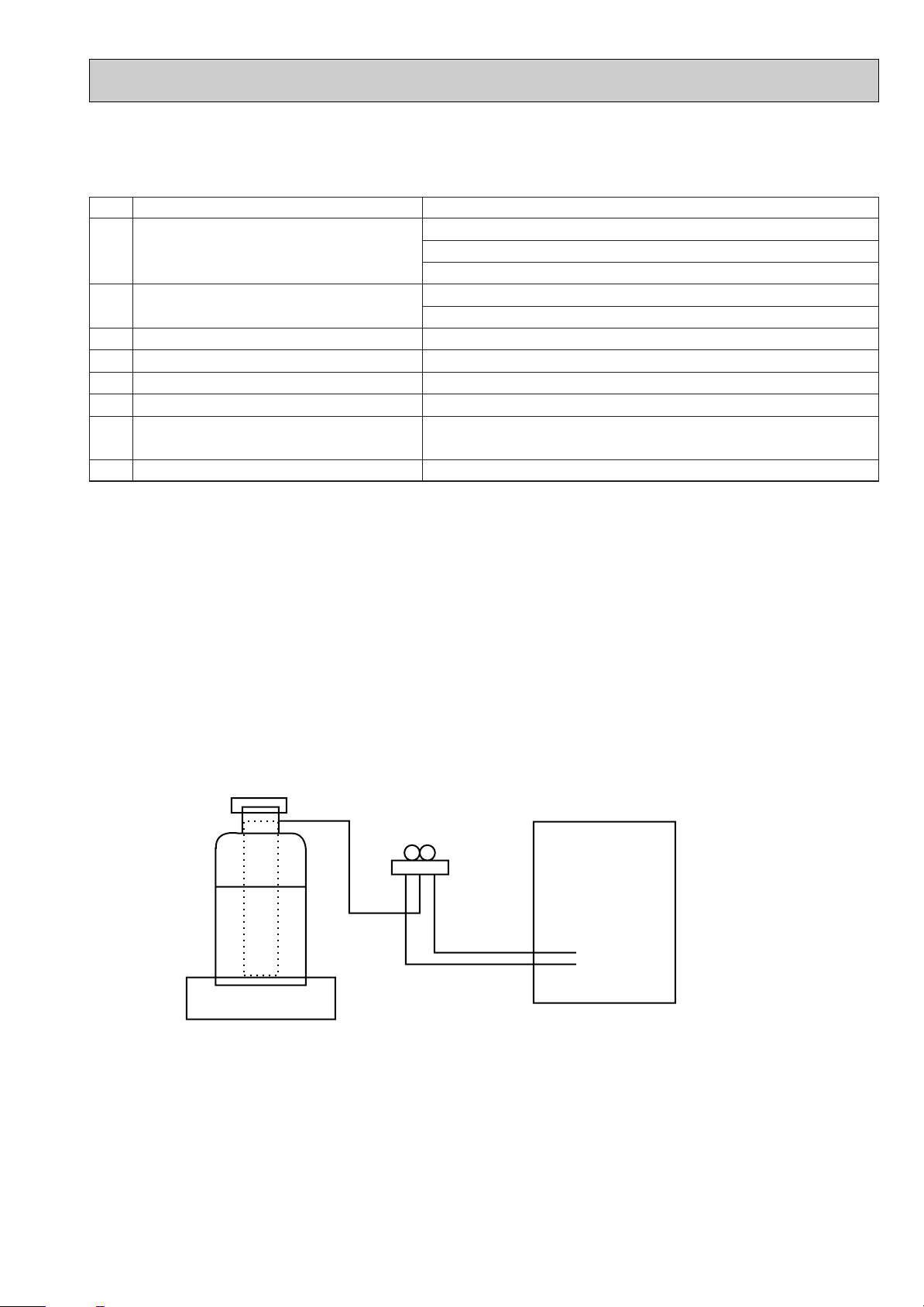
[3] Refrigerant recharging
(1) Refrigerant recharging process
1Direct charging from the cylinder.
·R407C cylinder are available on the market has a syphon pipe.
·Leave the syphon pipe cylinder standing and recharge it.
(By liquid refrigerant)
(2) Recharge in refrigerant leakage case
·After recovering the all refrigerant in the unit, proceed to working.
·Do not release the refrigerant in the air.
·After completing the repair service, recharge the cycle with the specified amount of
liquid refrigerant.
3
Page 4
2
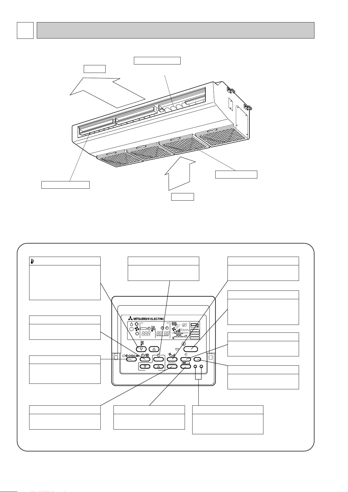
Air outlet
Air intake
Oil filter (Air intake)
w It prevents oil from
getting into the unit.
Left/right guide vanes
Change the direction of airflow
from the horizontal blower.
Up/down guide vanes
Change the direction of airflow from the
vartical blower.
PAR-20MAA
ON/OFF
CENTRALLY CONTROLLED
ERROR CODE
CLOCK
ON OFF
˚C
CHECK
CHECK MODE
FILTER
TEST RUN
FUNCTION
˚C
1Hr.
NOT AVAILABLE
STAND BY
DEFROST
FILTER
CHECK TEST
TEMP.
TIMER SET
Press this button to switch the cooler,
electronic dry (dehumidify), automatic
and heater modes.
OPERATION SWITCH button
This sets the room temperature. The
temperature setting can be performed
in 1: units
Setting range
Cooler 19: to 30:
Heater 17: to 28:
TEMP. ADJUSTMENT button
This switches between continuous
operation and the timer operation.
TIMER button
This switches between the operation
and stop modes each time it is pressed.
The lamp on this button lights during
operation.
ON/OFF button
Only press this button to perform an
inspection check or test operation.
Do not use it for normal operation.
CHECK-TEST RUN button
This switch the horizontal fan motion
ON and OFF.
(Not available for this model.)
LOUVER button
This sets the ventilation fan speed.
VENTILATION button
This adjusts the vertical angle of the
ventilation.
AIR DIRECTION button
This resets the filter service indication
display
FILTER button
This sets the current time, start time
and stop time.
TIME SETTING button
This sets the ventilation fan speed.
AIR SPEED button
PART NAMES AND FUNCTIONS
● Indoor (Main) Unit
● Remote controller
Once the controls are set, the same operation mode can be repeated by simply pressing the ON/OFF button.
● Operation buttons
4
Page 5
PAR-20MAA
ON/OFF
CENTRALLY CONTROLLED
ERROR CODE
CLOCK
ON OFF
˚C
CHECK
CHECK MODE
FILTER
TEST RUN
FUNCTION
˚C
1Hr.
NOT AVAILABLE
STAND BY
DEFROST
FILTER
CHECK TEST
TEMP.
TIMER SET
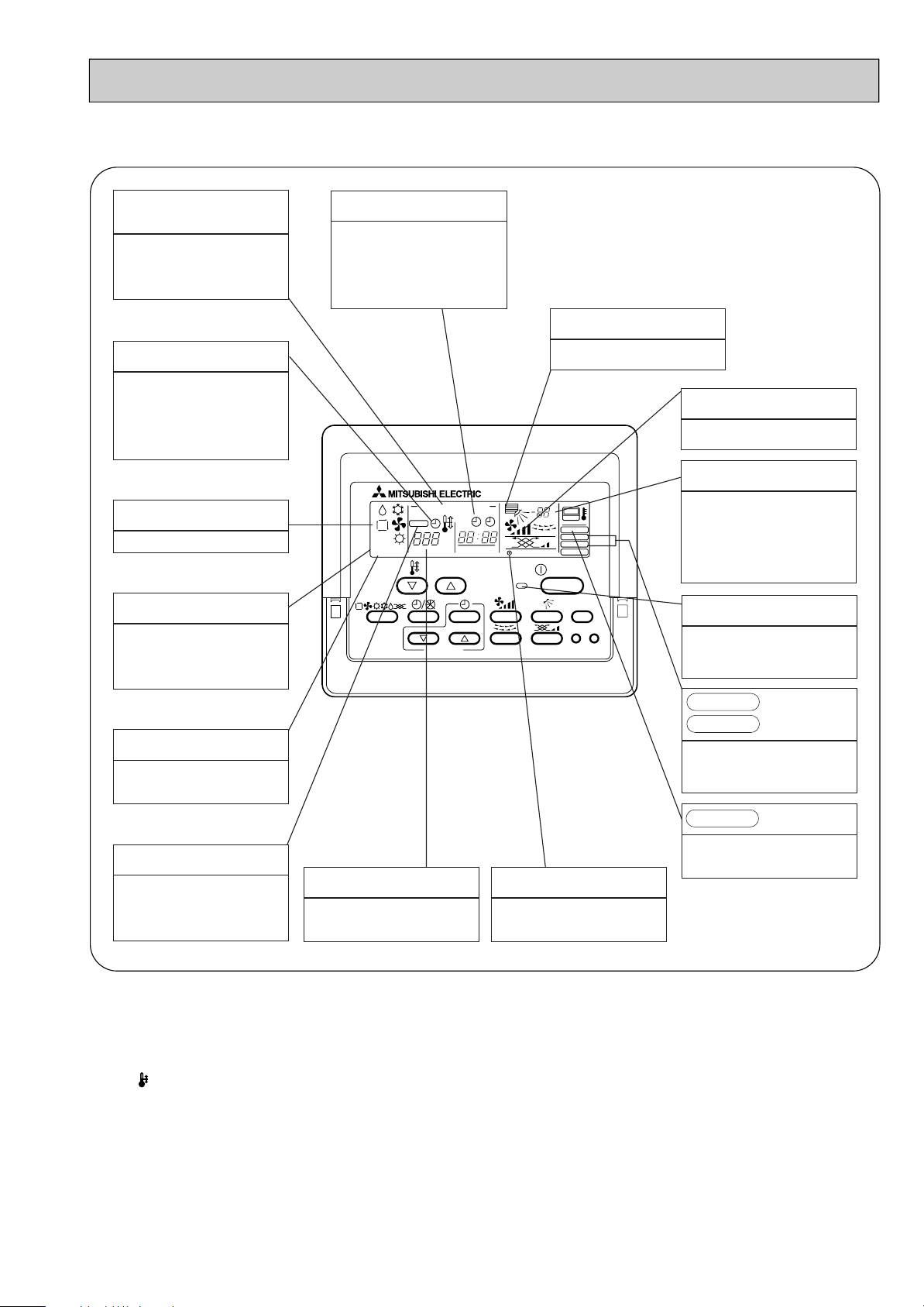
● Display
CENTRALLY
CONTROLLED display
This indicates when the unit is controlled by optional features such as
central control type remote controller.
TIMER display
This indicates when the continuous
operation and time operation modes
are set.
It also display the time for the timer
operation at the same time as when
it is set.
OPERATION MODE display
This indicates the operation mode.
STANDBY display
This indicates when the standby
mode is set from the time the sleep
operation starts until the heating air
is discharged.
DEFROST display
This indicates when the defrost operation is performed.
CLOCK display
The current time , start time and stop
time can be displayed in ten second
intervals by pressing the time switch
button. The start time or stop time is
always displayed during the timer
operation.
In this display example on the bottom left, a condition where all display lamps light is shown for explanation purposes although this differs
from actual operation.
AIR DIRECTION display
This displays the air direction.
FAN SPEED display
The selected fan speed is displayed.
ROOM TEMPERATURE display
The temperature of the suction air is
displayed during operation. The display range is 8° to 39°C. The display
flashes 8°C when the actual temperature is less than 8° and flashes
39°C when the actual temperature is
greater than 39°C.
Operation lamp
This lamp lights during operation,
goes off when the unit stops and
flashes when a malfunction occurs.
CHECK MODE
TEST RUN
This display lights in the check mode
or when a test operation is performed.
display
CHECK display
This indicates when a malfunction
has occurred in the unit which should
be checked.
SET TEMPERATURE display
This displays the selected setting
temperature.
FILTER
This lamp lights when the filter need
to be cleaned.
POWER display
This lamp lights when electricity is
supplied to the unit.
display
Caution
● Only the Power display lights when the unit is stopped and power supplied to the unit.
● When power is turned ON for the first time the (CENTRAL CTRL) display appears to go off momentarily but this is not a
malfunction.
● When the central control remote control unit, which is sold separately, is used the ON-OFF button, operation switch button
and TEMP. adjustment button do not operate.
● “NOT AVAILABLE” is displayed when the Air speed button are pressed.This indicates that this room unit is not equipped
with the fan direction adjustment function and the louver function.
● When power is turned ON for the first time, it is normal that “H0” is displayed on the room temperature indication (For max.
2minutes). Please wait until this “H0” indication disappear then start the operation.
5
Page 6
3
Service Ref.
Item
Btu/h
W
kW
kW
A
A
kW
K/min(CFM)
Pa(mmAq)
dB
mm(in.)
mm(in.)
mm(in.)
mm(in.)
kg(lbs)
A
A
kW
W
kW
K
/min(CFM
)
dB
dB
mm(in.)
mm(in.)
mm(in.)
kg(lbs)
kg(lbs)
L
mm(in.)
mm(in.)
Function
Capacity
Total input
Service Ref.
Power supply
Input
Running current
Starting current
External finish
Heat exchanger
Fan Fan(drive) x No.
Fan motor output
Airflow(Lo-Hi)
External static pressure
Operation control & Thermostat
Noise level(Lo-Hi)
Unit drain pipe I.D.
Dimensions
Weight
Service Ref.
Power supply
Running current
Starting current
External finish
Refrigerant control
Compressor
Model
Motor output
Starter type
Protection devices
Crankcase heater
Heat exchanger
Fan Fan(drive) x No.
Fan motor output
Airflow
Defrost method
Noise level
Dimensions
Weight
Refrigerant
Charge
Oil (Model)
Pipe size O.D.
Connection method
Between the indoor &
outdoor unit
PCA-P3HA
Cooling
25,600
7,500
3.36
0.09
0.43
0.86
14.83 / 4.96
Heating
31,400
9,200
3.41
0.09
0.43
0.86
14.85/ 5.04
W
D
H
Cooling
Heating
W
D
H
Liquid
Gas
Indoor side
Outdoor side
Height difference
Piping length
PCA-P3HA
Single phase, 50Hz, 220-230-240V
Stainless steel
Plate fin coil
Sirocco (direct) x 2
0.04
17-19 <600-670>
0 (direct blow)
Remote controller & built-in
34-38
26(1)
1,136(44-3/4)
650(25-5/8)
280(11)
41(90)
PUH-P3VGAA
1.UK / PUH-P3YGAA1.UK
Single phase, 50Hz, 220-230-240V / 3 phase, 50Hz, 380-400-415V (4wires)
93 / 47
Munsell 5Y 7/1
Linear Expansion Valve
Hermetic
NE52VNJMT / NE52YDKMT
2.5
Line start
38
Plate fin coil
Propeller (direct) x 1
0.070
50(1,770)
Reverse cycle
49
51
900(35-7/16)
330+20(13+3/4)
855(33-5/8)
79(174)
R407C
3.3(7.3)
1.3 (Ester) MEL56
9.52(3/8)
15.88(5/8)
Flared
Flared
Max. 50m
Max. 50m
Inner thermostat,
HP switch, Discharge thermo.
Anti-phase protector, Thermal relay,
HP switch, Discharge thermo.
Notes1. Rating Conditions (ISO T1)
Cooling : Indoor : D.B. 27˚C(80˚F), W.B. 19˚C (66˚F) Outdoor : D.B. 35˚C(95˚F), W.B. 24˚C (75˚F)
Heating : Indoor : D.B. 20˚C(68˚F) Outdoor : D.B. 7˚C(45˚F), W.B. 6˚C (43˚F)
Refrigerant piping length (one way) : 5m (16ft)
2. Guaranteed operating range
3. Above data based on indicated voltage
Indoor Unit Single phase 230V 50Hz
Outdoor Unit Single phase 230V 50Hz / 3 phase 400V 50Hz
Upper limit
Lower limit
Upper limit
Lower limit
Indoor
D.B. 35˚C, W.B. 22.5˚C
D.B. 19˚C, W.B. 15˚C
D.B. 28˚C
D.B. 17˚C
Outdoor
D.B. 46˚C
D.B. -5˚C
D.B. 24˚C, W.B. 18˚C
D.B. -11˚C, W.B. -12˚C
Cooling
Heating
OUTDOOR UNIT INDOOR UNIT
REFRIGERANT PIPING
SPECIFICATIONS
1. Heat pump type Rating Conditions (ISO T1)
6
Page 7
Rating Conditions (ISO T1)
Service Ref.
Item
Btu/h
W
kW
kW
A
A
kW
K/min(CFM)
Pa(mmAq)
dB
mm(in.)
mm(in.)
mm(in.)
mm(in.)
kg(lbs)
A
A
kW
W
kW
K
/min(CFM
)
dB
dB
mm(in.)
mm(in.)
mm(in.)
kg(lbs)
kg(lbs)
L
mm(in.)
mm(in.)
Function
Capacity
Total input
Service Ref.
Power supply
Input
Running current
Starting current
External finish
Heat exchanger
Fan Fan(drive) x No.
Fan motor output
Airflow(Lo-Hi)
External static pressure
Operation control & Thermostat
Noise level(Lo-Hi)
Unit drain pipe I.D.
Dimensions
Weight
Service Ref.
Power supply
Running current
Starting current
External finish
Refrigerant control
Compressor
Model
Motor output
Starter type
Protection devices
Crankcase heater
Heat exchanger
Fan Fan(drive) x No.
Fan motor output
Airflow
Defrost method
Noise level
Dimensions
Weight
Refrigerant
Charge
Oil (Model)
Pipe size O.D.
Connection method
Between the indoor &
outdoor unit
PCA-P5HA
Cooling
44,400
13,000
4.90
0.26
1.19
2.38
6.85
Heating
54,600
16,000
4,98
0.26
1.19
2.38
7.07
W
D
H
Cooling
Heating
W
D
H
Liquid
Gas
Indoor side
Outdoor side
Height difference
Piping length
PCA-P5HA
Single phase, 50Hz, 220-230-240V
Stainless steel
Plate fin coil
Sirocco (direct) x 4
0.08+0.08
30-38 <1,060-1,350>
0 (direct blow)
Remote controller & built-in
44-50
26(1)
1,520(59-7/8)
650(25-5/8)
280(11)
56(124)
PUH-P5YGAA
1.UK
3 phase, 50Hz, 380-400-415V (4wires)
65.5
Munsell 5Y 7/1
Linear Expansion Valve
Hermetic
ZR61KCW-TFD
3.5
Line start
Anti-phase protector, Internal thermostat, HP switch,Thermal relay, Discharge thermo
38
Plate fin coil
Propeller (direct) x 2
0.070+0.070
95(3,360)
Reverse cycle
55
56
1,050(41-5/16)
330+20(13+3/4)
1,260(49-5/8)
112(247)
R407C
4.6(10.1)
1.690 (Ester) 3MAW-POE
9.52(3/8)
19.05(3/4)
Flared
Flared
Max. 50m
Max. 50m
Notes1. Rating Conditions (ISO T1)
Cooling : Indoor : D.B. 27˚C(80˚F), W.B. 19˚C (66˚F) Outdoor : D.B. 35˚C(95˚F), W.B. 24˚C (75˚F)
Heating : Indoor : D.B. 20˚C(68˚F) Outdoor : D.B. 7˚C(45˚F), W.B. 6˚C (43˚F)
Refrigerant piping length (one way) : 5m (16ft)
2. Guaranteed operating range
3. Above data based on indicated voltage
Indoor Unit Single phase 230V 50Hz
Outdoor Unit 3 phase 400V 50Hz
Upper limit
Lower limit
Upper limit
Lower limit
Indoor
D.B. 35˚C, W.B. 22.5˚C
D.B. 19˚C, W.B. 15˚C
D.B. 28˚C
D.B. 17˚C
Outdoor
D.B. 46˚C
D.B. -5˚C
D.B. 24˚C, W.B. 18˚C
D.B. -11˚C, W.B. -12˚C
Cooling
Heating
OUTDOOR UNIT INDOOR UNIT
REFRIGERANT PIPING
7
Page 8
OUTDOOR UNIT
REFRIGERANT
PIPING
Service Ref.
Power supply
External finish
Heat exchanger
Fan
Operation control & Thermostat
Noise level(Lo-Hi)
Unit drain pipe I.D.
Dimensions
Weight
Service Ref.
Power supply
External finish
Refrigerant control
Compressor
Crankcase heater
Heat exchanger
Fan
Defrost method
Noise level
Dimensions
Weight
Refrigerant
Pipe size O.D.
Connection method
Between the indoor & outdoor unit
Indoor side
Outdoor side
Height difference
Piping length
Liquid
Gas
Cooling
W
D
H
Input
Running current
Starting current
Fan(drive))No.
Fan motor output
Airflow(Lo-Hi)
External static pressure
Running current
Starting current
Model
Motor output
Starter type
Protection devices
Fan(drive))No.
Fan motor output
Airflow
Charge
Compressor oil (Model)
W
D
H
Item
Service Ref.
PCA-P3HA
Function
Total input
2. Guaranteed operating range
Upper limit
Lower limit
Indoor
D.B. 35:, D.B. 22.5:
D.B. 19:, D.B. 15:
Outdoor
D.B. 46:
D.B. -5:
Cooling
INDOOR UNIT
Cooling
25,600
7,500
3.36
PCA-P3HA
Single phase, 50Hz, 220-230-240V
0.09
0.41
0.86
Stainless steel
Plate fin coil
Sirocco (direct) ✕ 2
0.04
17-19 <600-670>
0 (direct blow)
Remote controller & built-in
34-38
26(1)
1,136(44-3/4)
650(25-5/8)
280(11)
41(90)
PU-P3VGAA
1.UK / PU-P3YGAA1.UK
Single-phase, 50Hz, 220-230-240V / 3-phase, 50Hz, 380-400-415V (4wires)
14.02 / 4.78
93 / 47
Munsell 5Y 7/1
Linear Expansion Valve
Hermetic
NE52VNJMT / NE52YDKMT
2.5
Line start
38
Plate fin coil
Propeller (direct) ✕ 1
0.070
50(1,770)
—
49
900(35-7/16)
330+20(13+3/4)
855(33-5/8)
79(174)
R407C
3.3(7.3)
1.3 (Ester) MEL56
9.52(3/8)
15.88(5/8)
Flared
Flared
Max. 50m
Max. 50m
Btu/h
W
kW
kW
A
A
kW
K/min <CFM>
Pa(mmAq)
dB
mm(in.)
mm(in.)
mm(in.)
mm(in.)
kg(lbs)
A
A
KW
W
kW
K/min <CFM>
dB
mm(in.)
mm(in.)
mm(in.)
kg(lbs)
kg(lbs)
L
mm(in.)
mm(in.)
Anti-phase protector, Thermal relay,
HP switch, Discharge thermo
Inner thermostat,
HP switch, Discharge thermo
Capacity
Rating Conditions (ISO T1)
Notes1. Rating Conditions (ISO T1)
Cooling : Indoor : D.B. 27:(80°F), W.B. 19:(66°F)
Outdoor : D.B. 35:(95°F), W.B. 24:(75°F)
Refrigerant piping length (one way) : 5m(16ft)
3. Above data based on indicated voltage
Indoor Unit Single phase 230V 50Hz
Outdoor Unit Single phase 230V 50Hz / 3 phase 400V 50Hz
8
Page 9
Rating Conditions (ISO T1)
OUTDOOR UNIT
REFRIGERANT
PIPING
Service Ref.
Power supply
External finish
Heat exchanger
Fan
Operation control & Thermostat
Noise level(Lo-Hi)
Unit drain pipe I.D.
Dimensions
Weight
Service Ref.
Power supply
External finish
Refrigerant control
Compressor
Crankcase heater
Heat exchanger
Fan
Defrost method
Noise level
Dimensions
Weight
Refrigerant
Pipe size O.D.
Connection method
Between the indoor & outdoor unit
Indoor side
Outdoor side
Height difference
Piping length
Liquid
Gas
Cooling
W
D
H
Input
Running current
Starting current
Fan(drive))No.
Fan motor output
Airflow(Lo-Hi)
External static pressure
Running current
Starting current
Model
Motor output
Starter type
Protection devices
Fan(drive))No.
Fan motor output
Airflow
Charge
Compressor oil (Model)
W
D
H
Item
Service Ref.
PCA-P5HA
Function
Total input
Upper limit
Lower limit
Indoor
D.B. 35:, D.B. 22.5:
D.B. 19:, D.B. 15:
Outdoor
D.B. 46:
D.B. -5:
Cooling
INDOOR UNIT
Cooling
44,400
13,000
4.90
PCA-P5HA
Single phase, 50Hz, 220-230-240V
0.26
1.19
2.38
Stainless steel
Plate fin coil
Sirocco (direct) ✕ 4
0.08+0.08
30-38 <1,060-1,350>
0 (direct blow)
Remote controller & built-in
44-50
26(1)
1,520(59-7/8)
650(25-5/8)
280(11)
56(124)
PU-P5YGAA
1.UK
3-phase, 50Hz, 380-400-415V (4wires)
6.85
65.5
Munsell 5Y 7/1
Linear Expansion Valve
Hermetic
ZR61KCW-TFD
3.5
Line start
Anti-phase protector, Internal thermostat, HP switch, Thermal relay, Discharge thermo
38
Plate fin coil
Propeller (direct) ✕ 2
0.070+0.070
95(3,360)
—
55
1,050(41-5/16)
330+20(13+3/4)
1,260(49-5/8)
112(247)
R407C
4.6(10.1)
1.690 (Ester) 3MAW-POE
9.52(3/8)
19.05(3/4)
Flared
Flared
Max. 50m
Max. 50m
Btu/h
W
kW
kW
A
A
kW
K/min <CFM>
Pa(mmAq)
dB
mm(in.)
mm(in.)
mm(in.)
mm(in.)
kg(lbs)
A
A
KW
W
kW
K/min <CFM>
dB
mm(in.)
mm(in.)
mm(in.)
kg(lbs)
kg(lbs)
L
mm(in.)
mm(in.)
2. Guaranteed operating range
Capacity
Notes1. Rating Conditions (ISO T1)
Cooling : Indoor : D.B. 27:(80°F), W.B. 19:(66°F)
Refrigerant piping length (one way) : 5m(16ft)
3. Above data based on indicated voltage
Indoor Unit Single phase 230V 50Hz
Outdoor Unit 3 phase 400V 50Hz
Outdoor : D.B. 35:(95°F), W.B. 24:(75°F)
9
Page 10

4 DATA
Outdoor intake air D.B.(°C)
20 25 30
Indoor
Intake air
D.B.(°C)
Indoor
Intake air
W.B.(°C)
20
20
20
22
22
22
24
24
24
26
26
26
28
28
28
30
30
30
32
32
32
34
34
34
16
18
20
16
18
20
16
18
20
16
18
20
16
18
20
16
18
20
16
18
20
16
18
20
CA
7,425
7,950
8,550
7,425
7,950
8,550
7,425
7,950
8,550
7,425
7,950
8,550
7,425
7,950
8,550
7,425
7,950
8,550
7,425
7,950
8,550
7,425
7,950
8,550
SHC(W)
4,604
3,975
3,249
5,198
4,611
3,933
5,792
5,247
4,617
6,386
5,883
5,301
6,980
6,519
5,985
7,425
7,155
6,669
7,425
7,791
7,353
7,425
7,950
8,037
SHF
0.62
0.50
0.38
0.70
0.58
0.46
0.78
0.66
0.54
0.86
0.74
0.62
0.94
0.82
0.70
1.00
0.90
0.78
1.00
0.98
0.86
1.00
1.00
0.94
P.C.
2.69
2.74
2.82
2.69
2.74
2.82
2.69
2.74
2.82
2.69
2.74
2.82
2.69
2.74
2.82
2.69
2.74
2.82
2.69
2.74
2.82
2.69
2.74
2.82
CA
7,200
7,725
8,363
7,200
7,725
8,363
7,200
7,725
8,363
7,200
7,725
8,363
7,200
7,725
8,363
7,200
7,725
8,363
7,200
7,725
8,363
7,200
7,725
8,363
SHC(W)
4,464
3,863
3,178
5,040
4,481
3,847
5,616
5,099
4,516
6,192
5,717
5,185
6,768
6,335
5,854
7,200
6,953
6,523
7,200
7,571
7,192
7,200
7,725
7,861
SHF
0.62
0.50
0.38
0.70
0.58
0.46
0.78
0.66
0.54
0.86
0.74
0.62
0.94
0.82
0.70
1.00
0.90
0.78
1.00
0.98
0.86
1.00
1.00
0.94
P.C.
2.84
2.89
2.96
2.84
2.89
2.96
2.84
2.89
2.96
2.84
2.89
2.96
2.84
2.89
2.96
2.84
2.89
2.96
2.84
2.89
2.96
2.84
2.89
2.96
CA
6,975
7,463
8,138
6,975
7,463
8,138
6,975
7,463
8,138
6,975
7,463
8,138
6,975
7,463
8,138
6,975
7,463
8,138
6,975
7,463
8,138
6,975
7,463
8,138
SHC(W)
4,325
3,731
3,092
4,883
4,328
3,743
5,441
4,925
4,394
5,999
5,522
5,045
6,557
6,119
5,696
6,975
6,716
6,347
6,975
7,313
6,998
6,975
7,463
7,649
SHF
0.62
0.50
0.38
0.70
0.58
0.46
0.78
0.66
0.54
0.86
0.74
0.62
0.94
0.82
0.70
1.00
0.90
0.78
1.00
0.98
0.86
1.00
1.00
0.94
P.C.
3.01
3.09
3.16
3.01
3.09
3.16
3.01
3.09
3.16
3.01
3.09
3.16
3.01
3.09
3.16
3.01
3.09
3.16
3.01
3.09
3.16
3.01
3.09
3.16
1. PERFORMANCE DATA (240V)
1) COOLING CAPACITY<1>
PCA-P3HA
Notes CA : Capacity (W) SHC(W) : Sensible heat capacity
P.C. : Power consumption (kW) SHF : Sensible heat factor
10
Page 11

COOLING CAPACITY<2>
PCA-P3HA
Indoor
Intake air
D.B.(°C)
20
20
20
22
22
22
24
24
24
26
26
26
28
28
28
30
30
30
32
32
32
34
34
34
Indoor
Intake air
W.B.(°C)
16
18
20
16
18
20
16
18
20
16
18
20
16
18
20
16
18
20
16
18
20
16
18
20
CA
6,675
7,200
7,800
6,675
7,200
7,800
6,675
7,200
7,800
6,675
7,200
7,800
6,675
7,200
7,800
6,675
7,200
7,800
6,675
7,200
7,800
6,675
7,200
7,800
Outdoor intake air D.B.(°C)
35 40 45
SHC(W)
4,139
3,600
2,964
4,673
4,176
3,588
5,207
4,752
4,212
5,741
5,328
4,836
6,275
5,904
5,460
6,675
6,480
6,084
6,675
7,056
6,708
6,675
7,200
7,332
SHF
0.62
0.50
0.38
0.70
0.58
0.46
0.78
0.66
0.54
0.86
0.74
0.62
0.94
0.82
0.70
1.00
0.90
0.78
1.00
0.98
0.86
1.00
1.00
0.94
P.C.
3.23
3.31
3.39
3.23
3.31
3.39
3.23
3.31
3.39
3.23
3.31
3.39
3.23
3.31
3.39
3.23
3.31
3.39
3.23
3.31
3.39
3.23
3.31
3.39
CA
6,375
6,975
7,500
6,375
6,975
7,500
6,375
6,975
7,500
6,375
6,975
7,500
6,375
6,975
7,500
6,375
6,975
7,500
6,375
6,975
7,500
6,375
6,975
7,500
SHC(W)
3,953
3,488
2,850
4,463
4,046
3,450
4,973
4,604
4,050
5,483
5,162
4,650
5,993
5,720
5,250
6,375
6,278
5,850
6,375
6,836
6,450
6,375
6,975
7,050
SHF
0.62
0.50
0.38
0.70
0.58
0.46
0.78
0.66
0.54
0.86
0.74
0.62
0.94
0.82
0.70
1.00
0.90
0.78
1.00
0.98
0.86
1.00
1.00
0.94
P.C.
3.46
3.56
3.63
3.46
3.56
3.63
3.46
3.56
3.63
3.46
3.56
3.63
3.46
3.56
3.63
3.46
3.56
3.63
3.46
3.56
3.63
3.46
3.56
3.63
6,075
6,525
7,050
6,075
6,525
7,050
6,075
6,525
7,050
6,075
6,525
7,050
6,075
6,525
7,050
6,075
6,525
7,050
6,075
6,525
7,050
6,075
6,525
7,050
CA
SHC(W)
3,767
3,263
2,679
4,253
3,785
3,243
4,739
4,307
3,807
5,225
4,829
4,371
5,711
5,351
4,935
6,075
5,873
5,499
6,075
6,395
6,063
6,075
6,525
6,627
SHF
0.62
0.50
0.38
0.70
0.58
0.46
0.78
0.66
0.54
0.86
0.74
0.62
0.94
0.82
0.70
1.00
0.90
0.78
1.00
0.98
0.86
1.00
1.00
0.94
P.C.
3.75
3.83
3.90
3.75
3.83
3.90
3.75
3.83
3.90
3.75
3.83
3.90
3.75
3.83
3.90
3.75
3.83
3.90
3.75
3.83
3.90
3.75
3.83
3.90
Notes CA : Capacity (W) SHC(W) : Sensible heat capacity
P.C. : Power consumption (kW) SHF : Sensible heat factor
11
Page 12

Outdoor intake air D.B.(°C)
20 25 30
Indoor
Intake air
D.B.(°C)
Indoor
Intake air
W.B.(°C)
20
20
20
22
22
22
24
24
24
26
26
26
28
28
28
30
30
30
32
32
32
34
34
34
16
18
20
16
18
20
16
18
20
16
18
20
16
18
20
16
18
20
16
18
20
16
18
20
CA
12,870
13,780
14,820
12,870
13,780
14,820
12,870
13,780
14,820
12,870
13,780
14,820
12,870
13,780
14,820
12,870
13,780
14,820
12,870
13,780
14,820
12,870
13,780
14,820
SHC(W)
8,366
7,303
6,076
9,395
8,406
7,262
10,425
9,508
8,447
11,454
10,611
9,633
12,484
11,713
10,819
12,870
12,815
12,004
12,870
13,780
13,190
12,870
13,780
14,375
SHF
0.65
0.53
0.41
0.73
0.61
0.49
0.81
0.69
0.57
0.89
0.77
0.65
0.97
0.85
0.73
1.00
0.93
0.81
1.00
1.00
0.89
1.00
1.00
0.97
P.C.
3.92
3.99
4.12
3.92
3.99
4.12
3.92
3.99
4.12
3.92
3.99
4.12
3.92
3.99
4.12
3.92
3.99
4.12
3.92
3.99
4.12
3.92
3.99
4.12
CA
12,480
13,390
14,495
12,480
13,390
14,495
12,480
13,390
14,495
12,480
13,390
14,495
12,480
13,390
14,495
12,480
13,390
14,495
12,480
13,390
14,495
12,480
13,390
14,495
SHC(W)
8,112
7,097
5,943
9,110
8,168
7,103
10,109
9,239
8,262
11,107
10,310
9,422
12,106
11,382
10,581
12,480
12,453
11,741
12,480
13,390
12,901
12,480
13,390
14,060
SHF
0.65
0.53
0.41
0.73
0.61
0.49
0.81
0.69
0.57
0.89
0.77
0.65
0.97
0.85
0.73
1.00
0.93
0.81
1.00
1.00
0.89
1.00
1.00
0.97
P.C.
4.14
4.21
4.31
4.14
4.21
4.31
4.14
4.21
4.31
4.14
4.21
4.31
4.14
4.21
4.31
4.14
4.21
4.31
4.14
4.21
4.31
4.14
4.21
4.31
CA
12,090
12,935
14,105
12,090
12,935
14,105
12,090
12,935
14,105
12,090
12,935
14,105
12,090
12,935
14,105
12,090
12,935
14,105
12,090
12,935
14,105
12,090
12,935
14,105
SHC(W)
7,859
6,856
5,783
8,826
7,890
6,911
9,793
8,925
8,040
10,760
9,960
9,168
11,727
10,995
10,297
12,090
12,030
11,425
12,090
12,935
12,553
12,090
12,935
13,682
SHF
0.65
0.53
0.41
0.73
0.61
0.49
0.81
0.69
0.57
0.89
0.77
0.65
0.97
0.85
0.73
1.00
0.93
0.81
1.00
1.00
0.89
1.00
1.00
0.97
P.C.
4.39
4.51
4.61
4.39
4.51
4.61
4.39
4.51
4.61
4.39
4.51
4.61
4.39
4.51
4.61
4.39
4.51
4.61
4.39
4.51
4.61
4.39
4.51
4.61
COOLING CAPACITY<3>
PCA-P5HA
Notes CA : Capacity (W) SHC(W) : Sensible heat capacity
P.C. : Power consumption (kW) SHF : Sensible heat factor
12
Page 13

COOLING CAPACITY<4>
PCA-P5HA
Indoor
Intake air
D.B.(°C)
20
20
20
22
22
22
24
24
24
26
26
26
28
28
28
30
30
30
32
32
32
34
34
34
Indoor
Intake air
W.B.(°C)
16
18
20
16
18
20
16
18
20
16
18
20
16
18
20
16
18
20
16
18
20
16
18
20
CA
11,570
12,480
13,520
11,570
12,480
13,520
11,570
12,480
13,520
11,570
12,480
13,520
11,570
12,480
13,520
11,570
12,480
13,520
11,570
12,480
13,520
11,570
12,480
13,520
Outdoor intake air D.B.(°C)
35 40 45
SHC(W)
7,521
6,614
5,543
8,446
7,613
6,625
9,372
8,611
7,706
10,297
9,610
8,788
11,223
10,608
9,870
11,570
11,606
10,951
11,570
12,480
12,033
11,570
12,480
13,114
SHF
0.65
0.53
0.41
0.73
0.61
0.49
0.81
0.69
0.57
0.89
0.77
0.65
0.97
0.85
0.73
1.00
0.93
0.81
1.00
1.00
0.89
1.00
1.00
0.97
P.C.
4.70
4.83
4.95
4.70
4.83
4.95
4.70
4.83
4.95
4.70
4.83
4.95
4.70
4.83
4.95
4.70
4.83
4.95
4.70
4.83
4.95
4.70
4.83
4.95
CA
11,050
12,090
13,000
11,050
12,090
13,000
11,050
12,090
13,000
11,050
12,090
13,000
11,050
12,090
13,000
11,050
12,090
13,000
11,050
12,090
13,000
11,050
12,090
13,000
SHC(W)
7,183
6,408
5,330
8,067
7,375
6,370
8,951
8,342
7,410
9,835
9,309
8,450
10,719
10,277
9,490
11,050
11,244
10,530
11,050
12,090
11,570
11,050
12,090
12,610
SHF
0.65
0.53
0.41
0.73
0.61
0.49
0.81
0.69
0.57
0.89
0.77
0.65
0.97
0.85
0.73
1.00
0.93
0.81
1.00
1.00
0.89
1.00
1.00
0.97
P.C.
5.05
5.19
5.29
5.05
5.19
5.29
5.05
5.19
5.29
5.05
5.19
5.29
5.05
5.19
5.29
5.05
5.19
5.29
5.05
5.19
5.29
5.05
5.19
5.29
10,530
11,310
12,220
10,530
11,310
12,220
10,530
11,310
12,220
10,530
11,310
12,220
10,530
11,310
12,220
10,530
11,310
12,220
10,530
11,310
12,220
10,530
11,310
12,220
CA
SHC(W)
6,845
5,994
5,010
7,687
6,899
5,988
8,529
7,804
6,965
9,372
8,709
7,943
10,214
9,614
8,921
10,530
10,518
9,898
10,530
11,310
10,876
10,530
11,310
11,853
SHF
0.65
0.53
0.41
0.73
0.61
0.49
0.81
0.69
0.57
0.89
0.77
0.65
0.97
0.85
0.73
1.00
0.93
0.81
1.00
1.00
0.89
1.00
1.00
0.97
P.C.
5.46
5.59
5.68
5.46
5.59
5.68
5.46
5.59
5.68
5.46
5.59
5.68
5.46
5.59
5.68
5.46
5.59
5.68
5.46
5.59
5.68
5.46
5.59
5.68
Notes CA : Capacity (W) SHC(W) : Sensible heat capacity
P.C. : Power consumption (kW) SHF : Sensible heat factor
13
Page 14

Refrigerant piping length (one way)
Service Ref.
5m 10m 15m 20m 25m 30m 35m 40m 45m 50m
PCA-P3HA
PCA-P5HA
1.00
1.00
0.981
0.981
0.968
0.968
0.952
0.952
0.940
0.940
0.925
0.925
0.913
0.913
0.900
0.900
0.886
0.886
0.874
0.874
Cooling capacity correction factors
OUTDOOR D.B.(°C)
TOTAL INPUT (RATIO) CAPACITY (RATIO)
INDOOR W.B.(°C)
INDOOR W.B.(°C)
1.4
1.2
1.0
0.8
10
22
20
18
16
22
20
18
16
20 30 46400-5
1.2
1.0
0.8
0.6
0.4
Cooling
14
Page 15

Refrigerant piping length (one way)
Service Ref.
5m 10m 15m 20m 25m 30m 35m 40m 45m 50m
PCA-P3HA
PCA-P5HA
1.00
1.00
0.998
0.998
0.995
0.995
0.993
0.993
0.990
0.990
0.988
0.988
0.985
0.985
0.983
0.983
0.980
0.980
0.978
0.978
2) HEATING CAPACITY
Service Ref.
15
20
25
15
20
25
CA
-10 -5 0 5 10 15
Outdoor intake air W.B.(°C)Indoor
Intake
air
D.B.(°C)
P.C.
2.01
2.18
2.32
2.94
3.19
3.39
CA P.C. CA P.C. CA P.C. CA P.C. CA P.C.
5,842
5,612
5,428
10,160
9,760
9,440
2.22
2.39
2.59
3.24
3.49
3.78
6,348
6,072
5,888
11,040
10,560
10,240
2.56
2.76
3.00
3.74
4.03
4.38
7,084
6,716
6,440
12,320
11,680
11,200
3.07
3.31
3.51
4.48
4.83
5.13
9,292
8,970
8,464
16,160
15,600
14,720
3.41
3.68
3.94
4.98
5.38
5.75
10,488
10,120
9,752
18,240
17,600
16,960
3.68
3.96
4.25
5.38
5.78
6.20
11,684
11,270
10,856
20,320
19,600
18,880
PCA-P3HA
PCA-P5HA
Notes CA : Capacity (W)
P.C. : Power consumption (kW)
Heating capacity correction factors
Heating
Correcting the capacity line influenced by frosting.
Not correcting the capacity line influenced by frosting.
1.4
1.2
15
20
INDOOR D.B. (°C)
25
1.0
0.8
0.6
0.4
1.4
1.2
1.0
0.8
0.6
TOTAL INPUT (RATIO) CAPACITY (RATIO)
0.4
-12 -10 -5 0 5 10 15
OUTDOOR W.B. (°C)
INDOOR D.B. (°C)
25
20
15
15
Page 16

2. ELECTRICAL DATA
Indoor
Outdoor
Input (kW)
Current (A)
Current (A)
Starting current (A)
Mode
Capacity (W)
Total Input (kW) (In + Out)
Service
Ref.
Indoor unit
Outdoor unit
Cooling
7,500
3.36
0.09
0.44
15.31
85
Heating
9,200
3.41
0.09
0.44
15.54
85
Cooling
7,500
3.36
0.09
0.44
5.23
43
Heating
9,200
3.41
0.09
0.44
5.32
43
Cooling
13,000
4.90
0.26
1.24
7.22
65.5
Heating
16,000
4.98
0.26
1.24
7.46
65.5
PUH-P3VGAA1.UK PUH-P3YGAA1.UK PUH-P5YGAA1.UK
PCA-P3HA PCA-P5HA
Cooling
13,000
4.90
0.26
1.19
6.85
65.5
Heating
16,000
4.98
0.26
1.19
7.07
65.5
PUH-P5YGAA1.UK
PCA-P5HA
Cooling
13,000
4.90
0.27
1.14
6.61
65.5
Heating
16,000
4.98
0.27
1.14
6.82
65.5
PUH-P5YGAA1.UK
PCA-P5HA
Indoor
Outdoor
Input (kW)
Current (A)
Current (A)
Starting current (A)
Mode
Capacity (W)
Total Input (kW) (In + Out)
Service
Ref.
Indoor unit
Outdoor unit
Cooling
7,500
3.36
0.09
0.43
14.63
89
Heating
9,200
3.41
0.09
0.43
14.85
89
Cooling
7,500
3.36
0.09
0.43
4.96
45
Heating
9,200
3.41
0.09
0.43
5.04
45
PUH-P3VGAA1.UK PUH-P3YGAA1.UK
PCA-P3HA
Indoor
Outdoor
Input (kW)
Current (A)
Current (A)
Starting current (A)
Mode
Capacity (W)
Total Input (kW) (In + Out)
Service
Ref.
Indoor unit
Outdoor unit
Cooling
7,500
3.36
0.09
0.41
14.02
93
Heating
9,200
3.41
0.09
0.41
14.24
93
Cooling
7,500
3.36
0.09
0.41
4.78
47
Heating
9,200
3.41
0.09
0.41
4.86
47
PUH-P3VGAA1.UK PUH-P3YGAA1.UK
PCA-P3HA
Indoor·······220V 50Hz Single phase
Outdoor····220V 50Hz Singel phase / 380V 50Hz 3 phase
Indoor·······230V 50Hz Single phase
Outdoor····230V 50Hz Singel phase / 400V 50Hz 3 phase
Indoor·······240V 50Hz Single phase
Outdoor····240V 50Hz Singel phase / 415V 50Hz 3 phase
2.1. Heat pump type
Rating Conditions (ISO T1)
16
Page 17

2.2. Cooling only type
Indoor
Outdoor
Input (kW)
Current (A)
Current (A)
Starting current (A)
Mode
Capacity (W)
Total Input (kW) (In + Out)
Service
Ref.
Indoor unit
Outdoor unit
Cooling
7,500
3.36
0.09
0.44
15.31
85
Cooling
7,500
3.36
0.09
0.44
5.23
43
Cooling
13,000
4.90
0.26
1.24
7.22
65.5
PU-P3VGAA1.UK PU-P3YGAA1.UK PU-P5YGAA1.UK
PCA-P3HA PCA-P5HA
Indoor
Outdoor
Input (kW)
Current (A)
Current (A)
Starting current (A)
Mode
Capacity (W)
Total Input (kW) (In + Out)
Service
Ref.
Indoor unit
Outdoor unit
Cooling
7,500
3.36
0.09
0.43
14.63
89
Cooling
7,500
3.36
0.09
0.43
4.96
45
Cooling
13,000
4.90
0.26
1.19
6.85
65.5
PU-P3VGAA1.UK PU-P3YGAA1.UK PU-P5YGAA1.UK
PCA-P3HA PCA-P5HA
Indoor
Outdoor
Input (kW)
Current (A)
Current (A)
Starting current (A)
Mode
Capacity (W)
Total Input (kW) (In + Out)
Service
Ref.
Indoor unit
Outdoor unit
Cooling
7,500
3.36
0.09
0.41
14.02
93
Cooling
7,500
3.36
0.09
0.41
4.78
47
Cooling
13,000
4.90
0.26
1.14
6.61
65.5
PU-P3VGAA1.UK PU-P3YGAA1.UK PU-P5YGAA1.UK
PCA-P3HA PCA-P5HA
Indoor·······220V 50Hz Single phase
Outdoor····220V 50Hz Singel phase / 380V 50Hz 3 phase
Indoor·······230V 50Hz Single phase
Outdoor····230V 50Hz Singel phase / 400V 50Hz 3 phase
Indoor·······240V 50Hz Single phase
Outdoor····240V 50Hz Singel phase / 415V 50Hz 3 phase
Rating Conditions (ISO T1)
17
Page 18

3. STANDARD OPERATION DATA
Electrical circuit Total Refrigerant circuitIndoor side
Outdoor
side
Capacity
Input
Indoor unit Service Ref.
Phase, Hz
Volts
Amperes
Outdoor unit Service Ref.
Phase, Hz
Volts
Amperes
Discharge pressure
Suction pressure
Discharge temperature
Condensing temperature
Suction temperature
Ref. pipe length
Intake air temperature
Discharge air temperature
Intake air temperature
Mode
Service Ref.
SHF
BF
W
KW
V
A
V
A
°C
°C
°C
m
°C
°C
°C
°C
°C
Cooling
7,500
3.36
0.43
14.63/4.96
84
59
2.9
5
27
19
13
35
24
0.72
0.14
Heating
9,200
3.41
0.43
14.85/5.04
89
62
-0.7
5
20
15
47
7
6
—
—
PCA-P3HA
1, 50
230
PUH-P3VGAA
1.UK
/PUH-P3YGAA
1.UK
1, 50/3, 50
230/400
2.31
(23.5)
0.45
(4.6)
2.43
(24.8)
0.39
(4.0)
MPa
(Of/F)
MPa
(Of/F)
D.B.
W.B.
D.B.
D.B.
W.B.
PCA-P3HA
Cooling
13,000
4.90
1.19
6.85
73
54
4.8
5
27
19
15
35
24
0.72
0.19
Heating
16,000
4.98
1.19
7.07
73
55
-0.3
5
20
15
43
7
6
—
—
PCA-P5HA
1, 50
230
PUH-P5YGAA
1.UK
3, 50
400
2.01
(20.5)
0.46
(4.6)
2.07
(21.1)
0.38
(3.8)
PCA-P5HA
3.1 Heat pump type
Rating Conditions (ISO T1)
The unit of pressure has been changed to Mpa on the international system of unit (SI unit system).
The converted score against the traditional unit system can be gotten according to the formula below.
1(Mpa)=10.2(
OOf/FF
)
18
Page 19

3.2 Cooling only type
Electrical circuit Total Refrigerant circuitIndoor side
Outdoor
side
Capacity
Input
Indoor unit Service Ref.
Phase, Hz
Volts
Amperes
Outdoor unit Service Ref.
Phase, Hz
Volts
Amperes
Discharge pressure
Suction pressure
Discharge temperature
Condensing temperature
Suction temperature
Ref. pipe length
Intake air temperature
Discharge air temperature
Intake air temperature
Mode
Service Ref.
SHF
BF
W
KW
V
A
V
A
°C
°C
°C
m
°C
°C
°C
°C
°C
Cooling
7,500
3.36
PCA-P3HA
1, 50
230
0.43
PU-P3VGAA
1.UK
/PU-P3YGAA
1.UK
1, 50/3, 50
230/400
14.63/4.96
84
59
2.9
5
27
19
13
35
24
0.72
0.14
2.31
(23.5)
0.45
(4.6)
MPa
(Of/F)
MPa
(Of/F)
D.B.
W.B.
D.B.
D.B.
W.B.
PCA-P3HA
Cooling
13,000
4.90
PCA-P5HA
1, 50
230
1.19
PU-P5YGAA
1.UK
3, 50
400
6.85
73
54
4.8
5
27
19
15
35
24
0.75
0.19
2.01
(20.5)
0.46
(4.6)
PCA-P5HA
Rating Conditions (ISO T1)
The unit of pressure has been changed to Mpa on the international system of unit (SI unit system).
The converted score against the traditional unit system can be gotten according to the formula below.
1(Mpa)=10.2(OOf/FF)
4. OUTLET AIR SPEED AND COVERAGE RANGE
Air flow
Air speed
Coverage range
m3/min
m/sec
m
PCA-P3HA PCA-P5HA
19
2.9
7.9
13.2
38
4.2
19
Page 20

90
80
70
60
50
40
30
20
10
63 125 250 500 1000 2000 4000 8000
APPROXIMATE
TERESHOLD OF
HEARING FOR
CONTINUOUS
NOISE
NC-60
NC-50
NC-40
NC-30
NC-20
NC-70
OCTAVE BAND SOUND PRESSURE LEVEL, dB re 0.0002 MICRO BAR
BAND CENTER FREQUENCIES, Hz
PCA-P3HA
NOTCH
Hi
Lo
SPL(dB)
38
34
LINE
90
80
70
60
50
40
30
20
10
63 125 250 500 1000 2000 4000 8000
APPROXIMATE
TERESHOLD OF
HEARING FOR
CONTINUOUS
NOISE
NC-60
NC-50
NC-40
NC-30
NC-20
NC-70
OCTAVE BAND SOUND PRESSURE LEVEL, dB re 0.0002 MICRO BAR
BAND CENTER FREQUENCIES, Hz
PCA-P5HA
NOTCH
Hi
Lo
SPL(dB)
50
44
LINE
5. NOISE CRITERION CURVES
1m
1m
unit
about 1.4m
MICROPHONE
ceiling
20
Page 21

5
Ceiling
Less than
Less than
or more
Less than
or more
or more
300
<Suspension bolt pitch>
model:PAC-SG38KF-E (12pcs.)
Filter element for the exchange
1.Use M10 or W3/8 screw for anchor bolt.
NOTES.
Option parts:duct flange( [ 200). model: PAC-SF28OF-E(1 pcs.)
Knock out hole for wiring arrangement : 2- [ 27
(122)
<Filter contour dimension>
16
handle
100
1001136
366
480
176
318
650
<Flexible hose(accessory)>
Terminal block
9
Terminal block(remote controller)
8
Terminal block(indoor/outdoor connecting line)
78
Inspection port
(pipe sensor)
The half bottom of FAN CASING
can be separated.
Adjustable part
288
360
<Air outlet>
<Suspension bolt pitch>
<Air outlet>
<Air intake>
<Air intake>
Filter
Terminal block
5
2
1
4
3
Knock out hole for upper Refrigerant-pipe arrangement
6
9
2
1
Flexible hose(accessory)➔Drainage pipe connection(VP-25:pipe outside diameter [ 32)
2
Refrigerant-pipe connection(gas pipe side/flared connection : 5/8F)
38
105
85
90˚
Electrical box
Rear wall
500
250
2 ~ 3
(Gap to ceiling)
Allowing clearances
<gas>
<liquid>
7
Knock out hole (duct for fresh air intake): 2- [ 200
6
5
1
3
4
Knock out hole for left Refrigerant-pipe arrangement
Refrigerant-pipe connection(liquid pipe side/flared connection : 3/8F)
Suspension bolt
130
210
45
165
120
1224
1180
75
1136
986
1098
70
243
254
175
197
110
21
130 15
258 110 102
320 80
90
14018
75
70~90
650
13
289
75
280
495
43
295
[222
[200
OUTLINES AND DIMENSIONS
PCA-P3HA
Unit : mm
21
Page 22

Ceiling
Less than
Less than
Less than
or more
or more
or more
4
3156728
9
Refrigerant-pipe connection(gas pipe side/flared connection : 5/8F)
Knock out hole (duct for fresh air intake) : 2- [ 200
Option parts:duct flange( [ 200). model: PAC-SF28OF-E(1 pcs.)
Flexible hose(accessory)➔Drainage pipe connection(VP-25 : pipe outside diameter [ 32)
Terminal block(indoor/outdoor connecting line)
Terminal block(remote controller)
Refrigerant-pipe connection(liquid pipe side/flared connection : 3/8F)
Knock out hole for left Refrigerant-pipe arrangement
Knock out hole for upper Refrigerant-pipe arrangement
Knock out hole for wiring arrangement : 2- [ 27
Allowing clearances
Rear wall
(Gap to ceiling)
NOTES.
1.Use M10 or W3/8 screw for anchor bolt.
model:PAC-SG38KF-E (12pcs.)
Filter element for the exchange
<Suspension bolt pitch>
(122)246
handle
16
<Flexible hose(accessory)>
Terminal block
78
<Filter contour dimension>
Inspection port
(pipe sensor)
The half bottom of FAN CASING
can be separated.
Adjustable part
288
360
<Air outlet>
<Suspension bolt pitch>
<Air outlet>
<Air intake>
<Air intake>
Filter
Terminal block
5
2
1
4
3
6
9
2
1
176
38 210
105
8545
165
[222
[200
440440298
130
90˚
650
300
1001520100
Electrical box
500
250
2~3
<gas>
<liquid>
Suspension bolt
70
243
254
175
197
110
21
130 15
258
1482
110 102
1370 75
1608
320 801564
1520
90 120
14018
75
70~90
650
13
289
75
280
495
43
295
PCA-P5HA
Unit : mm
22
Page 23

6
J15
Service board
SW1
Manufacture
J14J13J12J11
4
OFF
ON
5321
PCA-P5HA
PCA-P3HA
1234
ON
OFF
Service board
MODELS
SW2
Manufacture
1234
ON
OFF
J24J23J22J21
J24J23J22J21
N
L
LEGEND
NAME
WHT
WHT
BLK
BLK
BLU
Symptom
Check code
Abnormality of room temperature thermistor(TH1).
Abnormality of pipe temperature thermistor/Liquid(TH2).
Freezing /overheating protection is working.
Abnormality of pipe temperature.
Abnormality of pipe temperature thermistor/ Condenser/Evaporator(TH5).
Abnormality of the signal transmission between remote
controller and indoor unit.
Abnormality of the signal transmission between indoor unit and
outdoor unit("EE" indicates abnormality of combination).
Abnormality in outdoor unit. Refer to outdoor unit wiring diagram.
Abnormality in outdoor unit. Refer to outdoor unit wiring diagram.
No trouble generated in the past.
No corresponding unit.
FFFF
----
F✱
U✱
E6—EF
E0—E5
P9
P8
P6
P2
P1
CONNECTING LINE)
SYMBOL
C1,C2
MF1,MF2 FAN MOTOR
CAPACITOR(FAN MOTOR)
CN2
TB6
TRANSMISSION LINE)
TERMINAL BLOCK(REMOTE CONTROLLER
CONNECTOR(PROGRAM TIMER)
REMOTE CONTROLLER BOARDR.B
(0˚C/15kΩ, 25˚C/5.4kΩ DETECT)
CONDENSER / EVAPORATOR TEMPERATUR THERMISTOR
TH5
(0˚C/15kΩ, 25˚C/5.4kΩ DETECT)
PIPE TEMPERATUR THERMISTOR/LIQUID
TH2
(0˚C/15kΩ, 25˚C/5.4kΩ DETECT)
ROOM TEMPERATUR THERMISTOR
TH1
TRANSMISSION LINE)
TB5
TERMINAL BLOCK(INDOOR/OUTDOOR
TB4
DEW PREVENTION HEATERH2
TERMINAL BLOCK(REMOTE CONTROLLER
SYMBOL NAME
X1
X4
X5
X6 RELAY(FAN MOTOR)
RELAY(FAN MOTOR)
RELAY(FAN MOTOR)
RELAY(DEW PREVENTION HEATER)
JUMPER WIRE(MODEL SELECTION)
JUMPER WIRE(CAPACITY CODE)
SWITCH(EMERGENCY OPERATION)
SWE
SW2
SW1
POWER SUPPLY(I.B)
POWER SUPPLY(R.B)
TRANSMISSION(INDOOR-OUTDOOR)
LED3
LED2
LED1
CONNECTOR(HA TERMINAL-A)CN41
CONNECTOR(REMOTE SWITCH)
CN32
CONNECTOR(LOSSNAY)CN2L
INDOOR CONTROLLER BOARDI.B
INDOOR POWER BOARD
FUSE(4A)
VARISTORZNR
F1
P.B
[Servicing]
Fasten terminal of the terminal board "TB4" equips lock system.
To remove the fastened terminal,pull it while pressing the protruding
portion(locking lever)of the terminal.The fastened terminal protruding
portion should face upward.
Please set the voltage using the
remote controller.
For the setting method,please refer to
the indoor unit installation Manual.
S1
S3
S2
TB1
TB1
S1
S2
S3
L1
L2
L3
N
POWER SUPPLY
3N~(3PHASE 4WIRES)
380-400-415V 50Hz
<PU(H)-P3/5YGAA
1.UK>
POWER SUPPLY
~(1PHASE)
220-230-240V 50Hz
<PU(H)-P3VGAA
1.UK>
OUTDOOR UNIT
WHT
BLK
BRN
ORN
YLW
BLU
BLU
YLW
WHT
BLK
BLU
YLW
WHT
YLW
YLW
BLK
RED
ORN
RED
BLK
BLU
YLW
WHT
WHT
YLW
BLU
BLK
RED
ORN
X4
CN32
CN2LCN41
1231X15
TH1
I.B
2
TB5
1
12
TB6
CN2
TH2
1
2
3
2
1
DC14V
CN2S(WHT)
CONT.BOARD
CN02(WHT)
1
2
3
OUTDOOR
CN01(BLU)
F1
TB4
S1
S2
S3
YLW
ORN
BRN
POWER
CN03
(RED)
POWER
CN2D(WHT)
REMOCON
CN22
(BLU)
LIQUID
CN21
(WHT)
INTAKE
CN20
(RED)
12
SW2
SWE
ON
OFF
J23
NOTES:
TRANSMISSION WIRES
DC12V
2121
INDOOR UNIT
R.B
LED1LED2LED3
FAN
(WHT)
1.Since the outdoor side electric wiring may change be sure to
check the outdoor unit electric wiring for servicing.
2.Indoor and outdoor connecting wires are made with polarities,make
wiring matching terminal numbers(S1,S2,S3).
3.Symbols used in wiring diagram above are, :Connector, :Terminal (block).
MF1
ORN
C1
23514
7531
6
X6
X5X6
31
X5 X4
D.HEATER
CNC (RED)
H2
ZNR
P.B
J24
X1
11
MF2
123456
C2
BRN
GRY
For
PCA-P5HA
J22
J21
SW1
J11
J12
J13
J14
J15
TH5
12
PIPE
CN29
(BLK)
12 13
WIRING DIAGRAM
PCA-P3HA
PCA-P5HA
23
Page 24

7 REFRIGERANT SYSTEM DIAGRAM
Indoor unit
Outdoor unit
Thermistor
(TH1)
Strainer
(#50)
Flared
connection
Flexible tube
Service
port
Accumulator
Ball valve
Compressor
Refrigerant pipe
15.88A({5/8")
(with heat insulator)
Refrigerant pipe
9.52A({3/8")
(with heat insulator)
Stop valve
(with service port)
4-way valve
Service
port
High pressure
protect switch
Outdoor heat exchanger
Thermistor
(TH3)
Distributor
with
strainer
Thermistor
(TH6)
Distributor
with
strainer
Indoor coil
thermistor
(TH2)
Thermistor
(TH5)
Muffler
Thermistor(TH4)
Linear expansion valve
Refrigerant flow in cooling
Refrigerant flow in heating
(#50)
Strainer
(#100)
Strainer
(#100)
Strainer
Indoor unit
Outdoor unit
Thermistor
(TH2)
Flexible tube
Service
port
Accumulator
Compressor
Refrigerant pipe
19.05A({3/4")
(with heat insulator)
Refrigerant pipe
9.52A({3/8")
(with heat insulator)
Stop valve
(with service port)
4-way valve
Service
port
High pressure
protect switch
Thermistor
(TH3)
Capillary tube
(O.D.4.0✕I.D.3.0-L200)✕2pcs
Distributor
with
strainer
Flared
connection
Drier
Liner expansion valve
Bypass
valve
Thermistor
(TH5)
Thermistor
(TH1)
Muffler
Thermistor
(TH4)
Thermistor
(TH6)
Distributor
with
strainer
Capillary
tube w1
Refrigerant flow in cooling
Refrigerant flow in heating
w1 : O.D.4.0✕I.D.2.0-L400(PUH-P5YGAA
1.UK)
O.D.4.0✕I.D.3.0-L450(PUH-P6YGAA
1.UK)
Ball valve
(#50)
Strainer
Strainer
(#100)
Strainer
(#100)
Strainer
(#50)
Strainer
(#50)
Indoor unit
Outdoor unit
Thermistor
(TH1)
Flared
connection
Flexible tube
Service
port
Accumulator
Compressor
Refrigerant pipe
15.88A({5/8")
(with heat insulator)
Refrigerant pipe
9.52A({3/8")
(with heat insulator)
Stop valve
(with service port)
Service
port
High pressure
protect switch
Outdoor heat exchanger
Thermistor
(TH3)
Distributor
with
strainer
Thermistor
(TH6)
Distributor
with
strainer
Indoor coil
thermistor
(TH2)
Thermistor
(TH5)
Thermistor(TH4)
Linear expansion valve
Refrigerant flow in cooling
Ball valve
(#50)
Strainer
(#100)
Strainer
(#100)
Strainer
Strainer
(#50)
Indoor unit
Outdoor unit
Thermistor
(TH2)
Flexible tube
Service
port
Accumulator
Compressor
Refrigerant pipe
19.05A({3/4")
(with heat insulator)
Refrigerant pipe
9.52A({3/8")
(with heat insulator)
Service
port
High pressure
protect switch
Thermistor
(TH3)
Capillary tube
(O.D.4.0✕I.D.3.0-L200)✕2pcs
Distributor
with
strainer
Flared
connection
Drier
Thermistor
(TH5)
Thermistor
(TH1)
Thermistor
(TH4)
Thermistor
(TH6)
Distributor
with
strainer
Refrigerant flow in cooling
Stop valve
(with service port)
Liner expansion valve
Ball valve
(#50)
Strainer
Strainer
(#100)
Strainer
(#100)
(#50)
Strainer
Strainer
(#50)
PCA-P3HA / PUH-3VGAA1.UK, PUH-3YGAA1.UK
PCA-P5HA / PUH-5YGAA1.UK
Unit : mm
<4-way valve solenoid coil>
Heating : ON
Cooling : OFF
PCA-P3HA / PU-3VGAA1.UK, PU-3YGAA1.UK
PCA-P5HA / PU-5YGAA1.UK
24
Page 25

8
Measure the resistance between the terminals using a tester.
(Winding temperature 20:)
Fan motor
Open or short
Abnormal
White
Orange
Yellow
Blue
Black
Red
Relay
connector
Protector
Protector
OPEN : 135i 5:
CLOSE: 95i 15:
White–Black
Brown–Blue
Blue–Yellow
Yellow–Red
Connector
PCH-P3HA
140.5"
15.4"
28.5"
80.4"
PCH-P5HA
75.6"
36.7"
23.6"
47.8"
Normal
Parts name Check points
Disconnect the connector then measure the resistance using a tester.
(Surrounding temperature 10:~30:)
(Refer to the next pege for a detail.)
Room temperature
thermistor (TH1)
Pipe temperature
thermistor (TH2)
Condenser/Evaporator
temperature thermistor
(TH5)
Normal
4.3k"~9.6k"
Abnormal
Open or short
TROUBLESHOOTING
HOW TO CHECK THE PARTS
PCA-P3HA
PCA-P5HA
<Thermistor Characteristic graph>
Thermistor for
lower temperature
Room temperature thermistor(TH1)
Pipe temperature thermistor(TH2)
Condenser/evaporator temperature
thermistor(TH5)
Thermistor R0=15kΩ ±3%
Fixed number of B=3480kΩ ±2%
Rt=15exp { 3480( ) }
0: 15kΩ
10: 9.6kΩ
20: 6.3kΩ
25: 5.4kΩ
30: 4.3kΩ
40: 3.0kΩ
1
273+t
1
273
25
< Thermistor for lower temperature >
50
40
30
20
Resistance (K")
10
0
-20 -10 0 10 20 30 40 50
Temperature (:)
Page 26

9
Slide
DISASSEMBLY PROCEDURE
PCA-P5HA
OPERATING PROCEDURE PHOTOS&ILLUSTRATIONS
1. Removing the oil filter
(1) Slide the oil filter towards you to remove. (See figure 1.)
2. Removing the terminal block box cover
(1) Remove the oil filter. (See figure 1.)
(2) Remove a screw for terminal block box cover, and remove
the terminal block box cover. (See photo 1.)
Figure 1
Oil filter
Photo 1
Filter rail Fan guard
Terminal
block box
Screw
Terminal
block box
cover
Clamp for
wiring
3. Removing the control box
(1) Remove the oil filter. (See figure 1.)
(2) Loosen a screw for control box cover to remove the con-
trol box cover. (See photo 2.)
(3) Remove the lead wire from the 2 clips.
(4) Remove the 2 white cord heater relay connectors (1P✕2)
and 2 fan motor relay connectors (6P✕2) in the control
box.
(5) Remove the 2 screws for control box to slide the control
box downward.
Electrical parts in the control box
• Fan motor capacitor
• Indoor controller board
• Power board
Photo 2
Screws for
control box
Screw for
control box
cover
Photo 3
Cord heater
relay
connectors
Power board
Fan motor
relay connectors
Clip for
lead wire
Pipe
temperature
thermistor
connector
(CN21)
Room
temperature
thermistor
connector
(CN20)
26
Fan motor
capacitor
Indoor
controller
board
Page 27

OPERATING PROCEDURE PHOTOS&ILLUSTRATIONS
4. Removing the fan motor
(1) Remove the oil filter. (See figure 1.)
(2) Remove the control box cover. (See photo 2.)
(3) Remove the room temperature thermistor connector
(CN20) on the indoor controller board. (See photo 3.)
(4) Remove a filter rail that is the nearest to the control box.
(See photo 4.)
(5) Remove the fan guard. (See photo 5.)
(6) Remove the room temperature thermistor together with the
holder at the right side of the casing.
Photo 4
Screws for
filter reil
Photo 5
Control box
cover
Screws for Fan guard
Room
temperature
thermistor
Filter reil
Room
temperature
thermistor
Fan guard
Screws for Fan guard
5. Removing the fan motor and the sirocco fan
(1) Remove the oil filter. (See figure 1.)
(2) Remove the control box cover.
(See photo 2.)
(3) Remove the fan motor relay connectors (6P) in the control
box. (See photo 3.)
(4) Remove the 3 filter rails.
(5) Remove the fan guard.
(6) Remove the lower casing.
(See photo 1, 4.)
(See photo 5.)
(See photo 6.)
(7) Remove the green earth wire from the motor support.
(See photo 7.)
(8) Remove the 2 screws (M5 ✕ 12) for motor support, and
remove the left and right motor supports.
(9) Remove the fan motor together with the sirocco fan.
(10) Remove the 2 set screws (M6) to separate the fan motor
from the sirocco fan.
Photo 6
Screws for casing
Control box
cover
Photo 7
casing
Earth wire
Fan motor
Set screw
Screws for casing
casing
27
Sirocco fan
Screws for
motor support
Motor
support
Sirocco fan
Page 28

OPERATING PROCEDURE PHOTOS
6. Removing the pipe temperature thermistor
(1) Remove the oil filter. (See figure 1.)
(2) Remove the fan guard.
(See photo 1.)
(3) Remove the terminal block box cover.
(4) Remove the white relay connector (2P) in the terminal
block box. (See photo 8.)
(5) Remove the service panel. (See photo 9.)
(6) Remove the pipe temperature thermistor from the holder.
(See photo 10.)
Caution for installation
When installing the pipe temperature
thermistor, slack off its lead wire as
shown in the photo. Otherwise, water
trickled down the lead wire may splash
on the connector and this could cause
a short circuit of the connector.
Photo 8
Photo 9
Photo 10
Relay connector
Terminal block box
Service panel
Screw for
service panel
Inspection port
7. Removing the under panel
(1) Remove the oil filter. (See figure 1.)
(2) Remove the 3 filter rails. (See photo 1, 4.)
(3) Remove the 12 screws (left: 1, right: 1, Bottom: 10) for
under panel, and remove the under panel.
(See photo 11.)
8. Removing the drain pan
(1) Remove the oil filter. (See Figure 1)
(2) Remove the 3 filter rails. (See photo 1, 4.)
(3) Remove the under panel. (See photo 11.)
(4) Pull the blue lead wire for cord heater towards you to
slack off. (See photo 12.)
(5) Remove the 3 screws at the center of the drain pan, and
remove the drain pan.
Photo 11
Screw for
under panel
(left:1)
Photo 12
Pipe temperature
thermistor
Under panel
Slack off
Screw for under panel
(right:1)
Screws for under panel (Bottom:10)
Lead wire for
cord heater
(Note) Remove the drain pan carefully since the drain could
remain in it.
Screws for
drain pan
Drain pan
28
Page 29

OPERATING PROCEDURE PHOTOS
9. Removing the guide vane
(1) Remove the oil filter. (See figure 1.)
(2) Remove the 3 filter rails. (See photo 1, 4.)
(3) Remove the under panel. (See photo 11.)
(4) Remove the drain pan. (See photo 12.)
(5) Remove the 3 screws (4 ✕ 10) for guide vane, and
remove the guide vane. (See photo 13.)
10. Removing the vane
(1) Slide the vane to the center of the unit, and pull it towards
you to remove. (See photo 14.)
Caution for installation
When installing the vane, check that its
projection is on the left-rear side.
Projection
11. Removing the heat exchanger
(1) Remove the oil filter. (See figure 1.)
(2) Remove the 3 filter rails. (See photo 1, 4.)
(3) Remove the under panel. (See photo 11.)
(4) Remove the drain pan. (See photo 12.)
(5) Remove the 2 screws (4 ✕ 10) for pipe cover, and
remove the pipe cover. (See photo 15.)
(6) Remove the 3 screws (4 ✕ 10, left: 2, right: 1) for heat
exchanger. (See photo 15, 16.)
(7) Remove the 2 screws (4 ✕ 10) for heat exchanger at the
top of the unit, and remove the heat exchanger.
(See photo 17.)
Photo 13
Photo 14
Slide
Photo 15
Heat exchanger
Guide vane
Screws for guide vaneDrain pan
Vane
Slide
pipe cover
Screw for
Heat exchanger
(right)
Screw for
pipe cover
Screws for
Heat exchanger
(top)
Photo 16Photo 17
Heat exchanger
Heat exchanger
Screws for
Heat exchanger
(left)
29
Page 30

10
No.
Parts No. Parts Name
Specifications
PCA-
P3HA
Wiring
Diagram
Symbol
Recommended
Q'ty
Unit
Amount
Q'ty / set
Price
Remarks
(Drawing No.)
P5HA
1
2
3
4
5
6
7
8
9
10
11
12
13
14
15
16
17
18
19
LEG-L
SIDE PLATE-L
REAR PANER
REAR PANER
UNDER PANEL
UNDER PANEL
FILTER RAIL
OIL FILTER
DRAIN HOSE SUPPORT
SIDE COVER
LEG-R
SERVICE PANEL
SIDE PLATE-R
FRONT PANEL
FRONT PANEL
VANE ASSY
VANE ASSY
GUIDE VANE ASSY-6L
GUIDE VANE ASSY-6C
GUIDE VANE ASSY-6R
VANE HOLDER
VANE SUPPORT
FRONT SUPPORT
R01 13N 809
R01 13N 662
T7W E02 676
T7W E03 676
R01 12N 669
R01 13N 669
R01 13N 503
R01 E05 500
—
R01 13N 667
R01 13N 808
R01 13N 668
R01 13N 661
T7W E02 651
T7W E03 651
R01 12N 002
R01 13N 002
R01 13N 086
R01 13N 087
R01 13N 085
R01 13N 533
—
—
2
1
1
1
2
3
1
1
2
1
1
1
2
1
1
1
1
1
2
1
1
1
3
4
1
1
2
1
1
1
3
1
1
1
1
2
2
(BG00K145G02)
(BG00K146G02)
(BG00T773G01)
PARTS LIST
STRUCTURAL PART
PCA-P3HA
PCA-P5HA
1
2
3
4
5
6
19
18
17
16
15
14
13
12
11
10
9
30
7
8
Page 31

No.
Parts No. Parts Name
Specifications
PCA-
P3HA
Wiring
Diagram
Symbol
Recom-
mended
Q'ty
Unit
Amount
Q'ty / set
Price
Remarks
(Drawing No.)
P5HA
TH1
TH2
TH5
MF1
MF1,2
PA6V40-CB
PA4V80-CA
1
2
3
4
5
6
7
8
9
10
11
12
13
14
15
16
17
18
19
20
21
22
23
T. CASING ASSY
T. CASING ASSY
SIROCO FAN
SIROCO FAN
UNDER CASING-L
UNDER CASING-L
FAN GUARD-S
ROOM TEMPERATUR TERMISTOR
FAN GUARD-L
FAN GUARD-L
UNDER CASING-R
UNDER CASING-R
FAN GUARD-S
DRAINPAN ASSY
DRAINPAN ASSY
FAN PLATE
FAN PLATE
PIPE SUPPORT
PIPE TEMPERATURE TERMISTOR
CONDENSER / EVAPORATOR TEMPERATURE TERMISTOR
HEAT EXCHANGER
HEAT EXCHANGER
FAN PLATE SUPPORT-R
FAN PLATE SUPPORT-C
FAN MOTOR
FAN MOTOR
MOTOR LEG
PIECE FOR MOTOR
FAN PLATE SUPPORT-L
PIPE COVER
DRAIN HOSE COVER
RUBBER MOUNT
(BG00N756G15)
(BG00N756G14)
(BG02T500H04)
(BG00N893G15)
(BG00N893G14)
(BG00N893G13)
R01 12N 110
R01 13N 110
R01 12N 114
R01 13N 114
T7W E02 111
T7W E03 111
T7W E12 675
R01 E51 202
T7W E14 675
T7W E13 675
T7W E00 111
T7W E01 111
T7W E11 675
R01 12N 529
R01 13N 529
—
—
—
R01 13N 202
R01 E63 202
R01 H04 480
R01 E75 480
—
—
T7W E20 762
T7W E21 762
R01 45K 130
R01 83E 126
—
R01 13N 521
R01 13N 072
R01 811 105
2
2
1
1
1
1
1
1
1
1
1
1
1
1
1
1
1
1
1
1
1
1
2
4
4
2
2
1
2
2
2
1
2
1
1
1
1
1
1
2
2
2
1
1
1
4
20 15
18,19 17
FAN AND HEATER PARTS
PCA-P3HA
PCA-P5HA
1
2
3
4
5
4
6
7
8
Part numbers that are circled are not shown in the figure.
9
16
14
13
6
12
8
11
10
31
Page 32

TO REMOTE
CONTROLLER
TO OUTDOOR
UNIT
21
S3S2S1
CN29
CNC
CN21
CN2D
CN22
CN20
CN03
FAN
CN2S
CN02
CN01
ELECTRICAL PARTS
ON/OFF
CENTRALLY CONTROLLED
ERROR CODE
CLOCK
ON OFF
˚C
CHECK
CHECK MODE
FILTER
TEST RUN
FUNCTION
˚C
1Hr.
NOT AVAILABLE
STAND BY
DEFROST
TEMP.
No.
Parts No. Parts Name
Specifications
PCA-
P3HA
Wiring
Diagram
Symbol
Recommended
Q'ty
Unit
Amount
Q'ty / set
Price
Remarks
(Drawing No.)
P5HA
(BG02N713H05)
(BG00T759G12)
1
2
3
4
5
6
7
8
9
10
11
SUPPORT
CONTROLLER BOARD
FUSE
P0WER BOARD
RUN CAPACITOR
RUN CAPACITOR
CONTROL BOX COVER
CONTROL BOX
TERMINAL BLOCK
TERMINAL BLOCK
REMOTE CONTROLLER
R01 18J 054
T7W E30 310
R01 E00 239
T7W E01 313
R01 A00 255
R01 576 255
—
—
R01 17J 246
R01 556 246
—
9
1
1
1
1
1
1
1
1
1
I.B
P.B
C1
C1,C2
TB4
TB5
R.B
250V 4A
3P(S1, S2, S3)
2P(1, 2)
9
1
1
1
2
1
1
1
1
1
PCA-P3HA
PCA-P5HA
7, 8
1
6
5
2
3
1
11
4
9 10
32
Page 33

11
28˚C
26
˚C
8:00
Normal
operation
23:00
Setback
operation
8:00
Normal
operation
1. TIMER
OPTIONAL PARTS
Part No.
Model Name
1-1. Program timer specifications
Part name
Parts No.
Exterior dimensions (inch)
Installation
Type of clock
Clock accuracy
Display-Time
-Week
-Timer setting unit
Program cycle
Timer setting unit
No. of set points
Power rating
1-2. Feature of program timer
(1) Daily timer function
Daily timer can be set in 30 minutes units for up to 24 hours.
Each unit can be set for unit ON, unit OFF, or setback operation.
(2) Setback operation
Set back operation is useful for reducing running costs
e.g. At a hotel with a 24-hour system
8:00~23:00 Cooling operation with set temperature at 26°C
23:00~8:00 Setback operation with 2 degrees of setback
As shown in the chart on the right, the set temperature rises 2 degrees
automatically during the setback operation. When the setback operation
ends, normal operation will begin.
(3) Weekly timer function
Daily timer function can apply to each day of the week.
+
_
PAC-SC32PTA(with set back function)
Program timer
PAC-SC32PTA
5-4/32
✕4-23/32✕23/32 (130✕120✕18mm)
Wall mount
Quartz
50 second / month at 25:
Liquid crystal display
Liquid crystal display
Liquid crystal display
24 hours
30 minutes
48 / day
+
_
5V DC 5% (Supplied by Remote Controller)
Program timer
33
Page 34

SET/MONITOR
SET
SMTWTF S
MONITOR
PROERAN TIMER
PAC-SC32PTA
TODAY
ON
WEEKLY
SETTING
OFF
ON
SET BACK
OFF
CLOCK DAILY TIMER
SET BACK
SET BACK
DAILY
SETTING
12 15 18 21 24
0361215
FILTER
CHECK MODE
TEST RUN
Connect to indoor unit
with 2-wire cable.
Use 5-wire cable
Connect to CN1 Connect to CN1
4
1-3. How to connect program timer
SET/MONITOR
SET
SMTWT FS
MONITOR
PROERAN TIMER
PAC-SC32PTA
TODAY
ON
WEEKLY
SETTING
OFF
ON
SET BACK
OFF
CLOCK DAILY TIMER
SET BACK
SET BACK
DAILY
SETTING
12 15 18 21 24
0361215
(1) Install the program timer next to the remote controller the same way as the remote controller is installed.
(2) Connect the program timer and the remote controller with a 5-wire cable as shown in the figure below
NOTE:While the program timer is connected to the remote controller, the
24hour ON/OFF timer on the remote controller will not operate.
1-4. Names and functions
<PAC-SC32PTA>
WEEKLY TIMER SETTING DISPLAY
CURRENT TIME DISPLAY
SET BACK DISPLAY
DAILY TIMER SETTING DISPLAY
Used for selection of if or not the day operation pattern set by PATTERN SETTING is to
be applied in weekly day unit,
setting.
SET/MONITOR DISPLAY
During SET is display, clock adjustment,
change of weekly day, daily and weekly timer
setting can be performed.
During MONITOR is display, all switches
except SET/MONITOR SW are invalidated.
This is normal status.
WEEK DAY SETTING SW
Used for week day setting.
MODE SELECTOR SW
Using this switch select “MONITOR” or “SET”
Mode.
“MONITOR” :Indicates the current timer set-
“SET”: Set to “SET” mode for clock adjust-
ting. All switch expect MODE
SELECTOR SW are invalidated
then.This is the normal status.
ment, charge of week day, daily and
weekly timer setting.
During MONITOR status,current
time is display.
During Daily timer setting, a
Indicates the setting set
back range.
time desire for timer setting is
displayed.
CLOCK ADJUSTMENT SW
Used for adjustment of the current time.
Push SW to advance the time. Each time the button is
pushed the time advance by 1 minute, pushing continuously
advances by 1 minute at 0.5 second interval, and when the
lower digit of minute becomes 0 indication advances in 10 minutes unit.
SW is used for reversing the time. Each time the button is
pushed the time reverses by 1 minute, pushing continuously
reverses the time by 1 minute at 0.5 second interval, and when
the lower digit of minute becomes 0 indication reverses in 10
minutes unit.
24 hours is divided into 48 blocks and each
block express 30 minutes.
The block display consists of 3 pattern.
Set back can be done in the range of 1,2,4,6
and 8°C.
SET BACK SETTING SW
Used for set back setting.
ON/SET BACK/OFF SW
Used to specify the time setting pattern.
DAILY TIMER SW
Used for timer setting in 30 minutes unit.
WEEKLY TIMER SW
Used for setting timer in day of week unit.
Pushing SW moves the week day light
display in order of
S → M → T → W
enabling to set the week day.
…
34
Page 35

2. Duct flange for frech air
Part No. PAC-SF28OF-E
Applied Service Ref.
PCA-P3HA, PCA-P5HA
3. Filter element
Part No. PAC-SG38KF-E
Applied Service Ref.
PCA-P3HA, PCA-P5HA
4. Decoration cover (Front + Susupending bracket cover)
Part No. PAC-SF81KC-E PAC-SF82KC-E
Applied Service Ref.
PCA-P3HA PCA-P5HA
5. Remote sensor
Part No. PAC-SE41TS-E
Applied Service Ref.
PCA-P3HA, PCA-P5HA
6. Remote operation adapter
Part No. PAC-SF40RM-E
Applied Service Ref.
PCA-P3HA, PCA-P5HA
7. Remote ON/OFF adapter
Part No. PAC-SF55RA-E
Applied Service Ref.
PCA-P3HA, PCA-P5HA
35
Page 36

HEAD OFFICE : MITSUBISHI DENKI BLDG., 2-2-3, MARUNOUCHI, CHIYODA-KU TOKYO 100-8310, JAPAN
TM
cCopyright 2003 MITSUBISHI ELECTRIC ENGINEERING CO.,LTD.
Distribted in Mar. 2003. No. CO289 41
Made in Japan
New publication, effective Mar. 2003.
Specifications subject to change without notice.
 Loading...