

Page 1
MITSUBISHI
,mrlELECTRIC
Air-Con i
PCA-A.GA
=r. Llllm
m
|oners
INSTALLATION MANUAL i FO_iNS_ _ i
For safe and correct use, read this manual and the outdoor unit installation manual thoroughly before installing
the air-conditioner unit.
MANUAL DE INSTALACION
Para un uso correcto y seguro, lea detalladamente este manual y el manual de instalaci6n de la unidad exterior
antes de instalar la unidad de aire acondicionado.
Page 2
Contents
1. Safety precautions ................................................................................... 2 5. Drainage piping work ............................................................................... 6
2. Installation location .................................................................................. 3 6. Electricalwork .......................................................................................... 6
3. Installing the indoor unit ........................................................................... 3 7. Test run .................................................................................................. 13
4. Installing the refrigerant piping ................................................................. 5 8. Easy maintenance function .................................................................... 16
1. Safety precautions
Before installing the unit, make sure you read all the "Safety precau-
tions".
Please report to your supply authority or obtain their consent before
connecting this equipment to the power supply system.
Warning:
Describes precautions that must be observed to prevent danger of injury or
death to the user.
z_ Caution:
Describes precautions that must be observed to prevent damage to the unit.
Z_ Warning:
= Ask a dealer or an authorized technician to install the unit.
= For installation work, follow the instructions in the Installation Manual and
use tools and pipe components specifically made for use with refrigerant
specified in the outdoor unit installation manual.
• The unit must be installed according to the instructions in order to minimize
the risk of damage from earthquakes, typhoons, or strong winds. An incor-
rectly installed unit may fall down and cause damage or injuries.
= The unit must be securely installed on a structure that can sustain its weight.
= if the air conditioner is installed in a small room, measures must be taken to
prevent the refrigerant concentration in the room from exceeding the safety
limit in the event of refrigerant leakage. Should the refrigerant leak and cause
the concentration limit to be exceeded, hazards due to lack of oxygen in the
room may result.
1.1. Before installation (Environment)
Caution:
• Do not use the unit in an unusual environment, if the air conditioner is in-
stalled in areas exposed to steam, volatile oil (including machine oil), or sulfuric
gas, areas exposed to high salt content such as the seaside, the performance
can be significantly reduced and the internal parts can be damaged.
= Do not install the unit where combustible gases may leak, be produced, flow,
or accumulate, if combustible gas accumulates around the unit, fire or explo-
sion may result.
= Do not keep food, plants, caged pets, artwork, or precision instruments in the
direct airflow of the indoor unit or too close to the unit, as these items can be
damaged by temperature changes or dripping water.
1.2. Before installation or relocation
Z_ Caution:
• Be extremely careful when transporting the units.Two or more persons are
needed to handle the unit, as it weighs 20 kg, 44 Ibs or more. Do not grasp
the packaging bands. Wear protective gloves as you can injure your hands
on the fins or other parts.
• Be sure to safely dispose of the packaging materials. Packaging materials,
such as nails and other metal or wooden parts may cause stabs or other
injuries.
1.3. Before electric work
Caution:
= Be sure to install circuit breakers, if not installed, electric shock may result.
= For the power lines, use standard cables of sufficient capacity. Otherwise, a
short circuit, overheating, or fire may result.
= When installing the power lines, do not apply tension to the cables.
After installation work has been completed, explain the 'Safety Precautions," use,
and maintenance of the unit to the customer according to the information in the Op-
eration Manual and perform the test run to ensure normal operation. Both the Instal-
lation Manual and Operation Manual must be given to the user for keeping. These
manuals must be passed on to subsequent users.
a
(_: Indicates which must be
part grounded.
Z_ Warning:
Carefully read the labels affixed to the main unit,
• Ventilate the room if refrigerant leaks during operation, if refrigerant comes
into contact with a flame, poisonous gases will be released.
• All electric work must be performed by a qualified technician according to
local regulations and the instructions given in this manual.
• Use only specified cables for wiring.
• The terminal block cover panel of the unit must be firmly attached.
• Use only accessories authorized by Mitsubishi Electric and ask a dealer or
an authorized technician to install them.
• The user should never attempt to repair the unit or transfer it to another loca-
tion.
• After installation has been completed, check for refrigerant leaks, if refriger-
ant leaks into the room and comes into contact with the flame of a heater or
portable cooking range, poisonous gases will be released.
• When the room humidity exceeds 80% or when the drainpipe is clogged, wa-
ter may drip from the indoor unit. Do not install the indoor unit where such
dripping can cause damage.
• When installing the unit in a hospital or communications office, be prepared
for noise and electronic interference, inverters, home appliances, high-fre-
quency medical equipment, and radio communications equipment can cause
the air conditioner to malfunction or breakdown.The air conditioner may also
affect medical equipment, disturbing medical care, and communications equip-
ment, harming the screen display quality.
• Thermal insulation of the refrigerant pipe is necessary to prevent condensa-
tion. if the refrigerant pipe is not properly insulated, condensation will be formed.
• Place thermal insulation on the pipes to prevent condensation, if the drain-
pipe is installed incorrectly, water leakage and damage to the ceiling, floor,
furniture, or other possessions may result.
• Do not clean the air conditioner unit with water. Electric shock may result.
• Tighten all flare nuts to specification using a torque wrench, if tightened too
much, the flare nut can break after an extended period.
• Be sure to ground the unit. if the unit is not properly grounded, electric shock
may result.
= Use circuit breakers (ground fault interrupter, isolating switch (+B fuse), and
molded case circuit breaker) with the specified capacity, if the circuit breaker
capacity is larger than the specified capacity, breakdown or fire may result.
1.4. Before starting the test run
Z_ Caution:
= Turn on the main power switch more than 12 hours before starting operation.
Starting operation just after turning on the power switch can severely dam-
age the internal parts.
• Before starting operation, check that all panels, guards and other protective
parts are correctly installed. Rotating, hot, or high voltage parts can cause
injuries.
2
= Do not operate the air conditioner without the air filter set in place, if the air
filter is not installed, dust may accumulate and breakdown may result.
= Do not touch any switch with wet hands. Electric shock may result.
= Do not touch the refrigerant pipes with bare hands during operation.
= After stopping operation, be sure to wait at least five minutes before turning off
the main power switch. Otherwise, water leakage or breakdown may result.
Page 3
2. Installation location
w
Fig. 2=1
3. Installing the indoor unit
Z_ Caution:
Install the indoor unit at least 2.4 m, 8 ft above floor or grade level.
®
®
@ i®
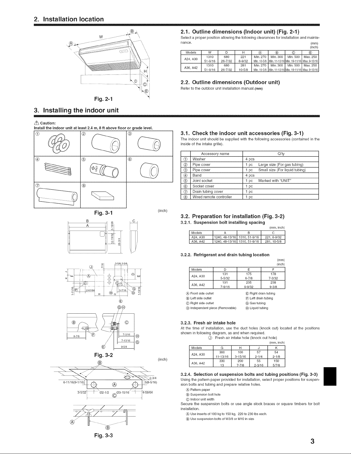
2.1. Outline dimensions (Indoor unit) (Fig. 2=1)
Select a proper position allowing the following clearances for installation and mainte-
nance. (mm)
Models W D m _ ® @ ®
A24, A30 61-9/16 26-7/32 8-9/32 Min,10-5/8 Min,11-13/1(Min,19-11/1( Max,9-13/16
A36, A42 51-9/16 26-7/32 10-5/8 Min,10-5/8 Min,11-13/1(Min,19-11/1( Max,9-13/16
1310 680 221 Min. 270 Min. 300 Min. 500 Max. 250
1310 680 281 Min. 270 Min. 300 Min. 500 Max. 250
2.2. Outline dimensions (Outdoor unit)
Refer to the outdoor unit installation manual.(rnrn)
3.1. Check the indoor unit accessories (Fig. 3=1)
The indoor unit should be supplied with the following accessories (contained in the
inside of the intake grille).
® Washer 4 pcs
® Pipe cover 1 pc Large size (For gas tubing)
(_) Band 4 pcs
® Joint socket 1 pc Marked with 'UNIT"
® Socket cover 1 pc
_7_ Drain tubing cover 1 pc
® Wired remote controller 1 pc
Accessory name Q'ty
Pipe cover 1 pc Small size (For liquid tubing)
(inch)
6-11/16(9-1/16)]_ Q
3-5/32
Fig. 3=1
Fig. 3=2
(inch)
3.2.
Preparation for installation (Fig. 3=2)
3.2.1
c
. Suspension bolt installing spacing
Models A B C
A24, A30 1240, 48-13/16 1310, 61-9/16 221,8-9/32
A36, A42 1240, 48-13/16 1310, 51-9/16 281,10-5/8
(mm, inch)
3.2.2. Refrigerant and drain tubing location
(mm)
Models D
A24, A30 5-5/32
A36, A42 7-9/16
Front side outlet
®
®
®
Left side outlet
®
Right side outlet
®
Independent piece (Removable)
3.2,3. Fresh air intake hole
At the time of installation, use the duct holes (knock out) located at the positions
shown in following diagram, as and when required.
Models G H J K
A24, A30
(inch)
A36, A42 13 7-7/8 2-3/16 6/7/8
3.2.4. Selection of suspension bolts and tubing positions (Fig. 3-3)
®
_ ]_(8-5/16)
Using the pattern paper provided for installation, select proper positions for suspen-
sion bolts and tubing and prepare relative holes.
_A_Pattern paper
® Suspension bolt hole
(07Indoor unit width
Secure the suspension bolts or use angle stock braces or square timbers for bolt
installation.
_A_Use inserts of 100 kg to 150 kg, 220 to 230 Ibseach.
® Use suspension bolts of W3/8 orM10 in size
131
191
Fresh air intake hole (knock out hole)
300 100 67 64
11-13/16 3-16/16 2-1/4 2-1/8
330 200 65 160
E F
175 178
6-7/8 7-3/32
235 238
9-9/32 9-3/8
® Right drain tubing
(_) Left drain tubing
Gas tubing
Liquid tubing
(inch)
(mm, inch)
Fig. 3=3
3
Page 4
3. Installing the indoor unit
Fig. 3=4
Fig. 3=5
Fig. 3=6
®
I
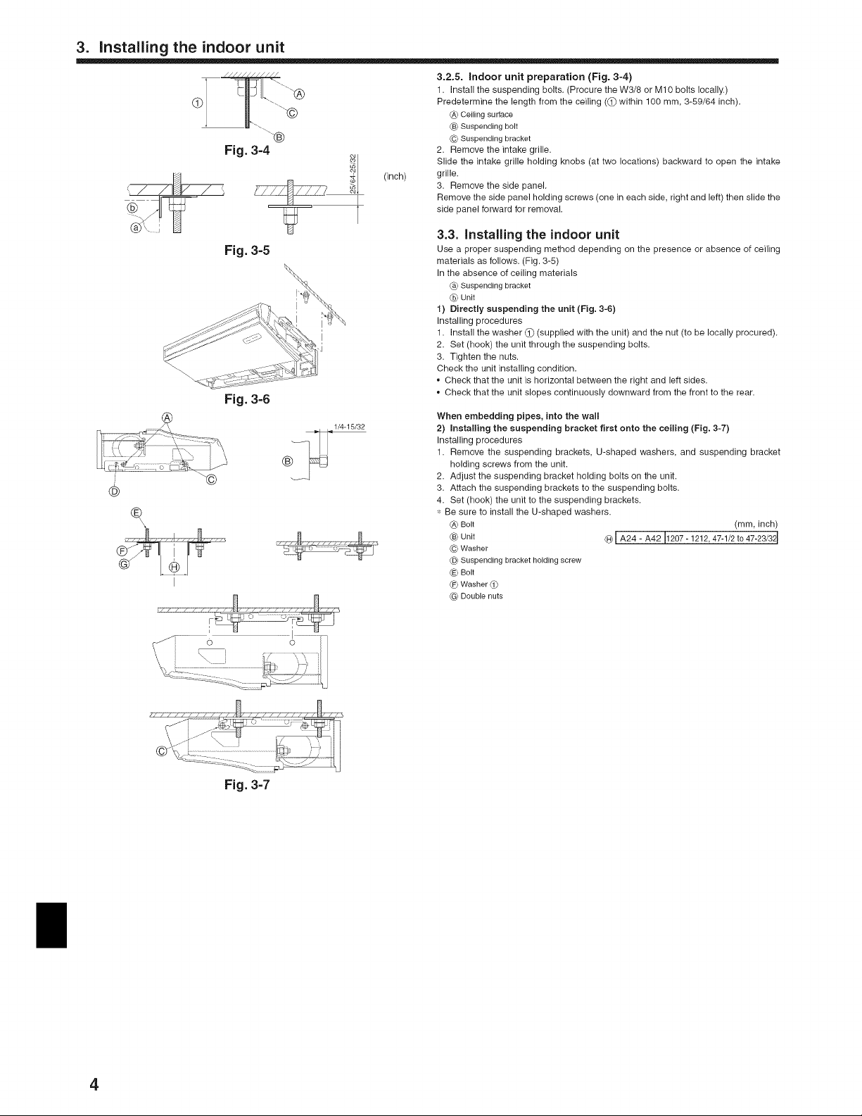
3.2.5. indoor unit preparation (Fig. 3-4)
1. Install the suspending bolts. (Procure the W3/8 or M 10 bolts locally.)
Predetermine the length from the ceiling ((j) within 100 ram, 3-59/64 inch).
(A) Ceiling surface
_) Suspending bolt
© Suspending bracket
2. Remove the intake grille.
Slide the intake grille holding knobs (at two locations) backward to open the intake
(inch)
I
grille.
3. Remove the side panel.
Remove the side panel holding screws (one in each side, right and left) then slide the
side panel forward for removal.
3.3. installing the indoor unit
Use a proper suspending method depending on the presence or absence of ceiling
materials as follows. (Fig. 3-5)
In the absence of ceiling materials
Cb)Suspending bracket
@ Unit
1) Directly suspending the unit (Fig. 3-6)
Installing procedures
1. Install the washer 1_ (supplied with the unit) and the nut (to be locally procured).
2. Set (hook) the unit through the suspending bolts.
3. Tighten the nuts.
Check the unit installing condition.
• Check that the unit is horizontal between the right and left sides.
• Check that the unit slopes continuously downward from the front to the rear.
When embedding pipes, into the wall
2) Installing the suspending bracket first onto the ceiling (Fig. 3-7)
Installing procedures
1. Remove the suspending brackets, U-shaped washers, and suspending bracket
holding screws from the unit.
2. Adjust the suspending bracket holding bolts on the unit.
3. Attach the suspending brackets to the suspending bolts.
4. Set (hook) the unit to the suspending brackets.
_: Be sure to install the U-shaped washers.
(A) Bolt (ram, inch)
(_ Unit CbblA24 - A42 11207-1212, 47-1/2 to 47-23/32 I
© Washer
@ Suspending bracket holding screw
(E_Bolt
(F) Washer (1)
@ Double nuts
Fig. 3=7
4
Page 5
4. Installing the refrigerant piping
2,
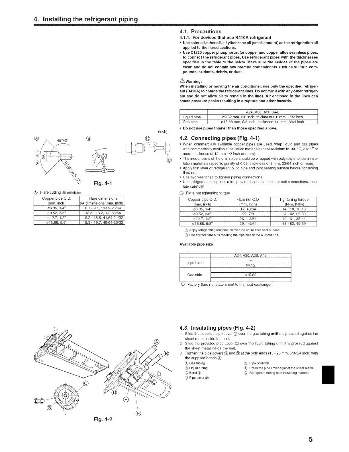
_° Fig. 4-1
(_ Flare cutting dimensions
Copper pipe O.D. Flare dimensions
(mm, inch) sA dimensions (mm, inch)
e6.35, 1/4" 8.7- 9.1, 11/32-23/64
e9.52, 3/8" 12.8 - 13.2, 1/2-33/64
o12.7, 1/2" 16.2 - 16.6, 41/64-21/32
e15.88, 5/8" 19.3 - 19.7, 49/64-25/32
(inch)
4.1. Precautions
4.1.1. For devices that use R410A refrigerant
• Use ester oil, ether oil, alkylbenzene oil (small amount) as the refrigeration oil
applied to the flared sections.
• Use Cl 220 copper phosphorus, for copper and copper alloy seamless pipes,
to connect the refrigerant pipes. Use refrigerant pipes with the thicknesses
specified in the table to the below. Make sure the insides of the pipes are
clean and do not contain any harmful contaminants such as sulfuric com-
pounds, oxidants, debris, or dust.
Z_ Warning:
When installing or moving the air conditioner, use only the specified refriger-
ant (R410A) to charge the refrigerant lines. Do not mix it with any other refriger-
ant and do not allow air to remain in the lines. Air enclosed in the lines can
cause pressure peaks resulting in a rupture and other hazards.
Liquid pipe 09.52 mm, 3/8 inch thickness 0.8 mm, 1/32 inch
I A24, A30, A36, A42
Gas pipe o15.88 mm, 5/8 inch thickness 1.0 mm, 3/64 inch
= Do not use pipes thinner than those specified above.
4.2. Connecting pipes (Fig. 4-1)
+ When commercially available copper pipes are used, wrap liquid and gas pipes
with commercially available insulation materials (heat-resistant to 100 °C, 212 °F or
more, thickness of 12 mm 1/2 inch or more).
+ The indoor parts of the drain pipe should be wrapped with polyethylene foam insu-
®
lation materials (specific gravity of 0.03, thickness of 9 mm, 23/64 inch or more).
+ Apply thin layer of refrigerant oil to pipe and joint seating surface before tightening
flare nut.
+ Use two wrenches to tighten piping connections.
+ Use refrigerant piping insulation provided to insulate indoor unit connections. Insu-
late carefully.
(_) Flare nut tightening torque
Copper pipe O.D.
(mm, inch)
e6.35, 1/4"
e9.52, 3/8"
o12.7, 1/2"
o15.88, 5/8"
(c) Apply refrigerating machine oil over the entire flare seat surface.
_@Use correct flare nuts meeting the pipe size of the outdoor unit.
Available pipe size
Flare nut O.D. Tightening torque
(mm, inch) (N.m, ft.lbs)
17, 43/64 14- 18, 10-13
22, 7/8 34 - 42, 25-30
26, 1-3/64 49 - 61,35-44
29, 1-9/64 68 - 82, 49-59
L_ipL<
A24, A30, A36, A42
Liquid side 09.52
Gas side e15.88
O : Factory flare nut attachment to the heat-exchanger.
(2
®
4.3. insulating pipes (Fig. 4=2)
1. Slide the supplied pipe cover (2_ over the gas tubing until it is pressed against the
sheet metal inside the unit.
2. Slide the provided pipe cover 3_ over the liquid tubing until it is pressed against
the sheet metal inside the unit.
3. Tighten the pipe covers (2_and _ at the both ends (15 - 20 mm, 5/8-3/4 inch) with
the supplied bands (_).
_A_Gas tubing _E_ Pipe cover (_
(B_Liquid tubing (_) Press the pipe cover against the sheet metal.
(C) Band @ @ Refrigerant tubing heat insulating material
_@Pipe cover (_)
+I+
Fig. 4-2
5
Page 6

5, Drainage piping work
©
Drain pan
_) Drain tubing (VP2O)
@_Socket cover (6_
(_ Joint socket (_)
Drain tubing cover (_)
®, 5.1. Preparation for leftside tubing installation (Fig, 5=1)
_) Drain pan - For left side tubing, be sure to insert the rubber plug into the right drain port.
(_) Plug • Install the drain tubing as it slopes continuously downward.
• After completion of work, check that correct drain is available from the outflow port
of the drain tubing.
Fig. 5=1
5.2. installing procedures (Fig. 5=2)
1. Attach the joint socket _ supplied with the unit to the drain port on the unit with a
vinym chloride adhesive.
2. Fasten the socket cover (_ supplied with the unit to the joint socket (_.
.® 3.®
3. Attach a PVC pipe (O.D. e26 mm, 1-1/32 inch) to the joint socket _ with a vinyl
chloride adhesive.
4. Wrap the drain tubing cover (_) supplied with the unit. (Seam taping)
Fig. 5=2
®
(_ Drain tubing sensor
5.3. Drain check (Fig. 5-3)
1. Fill the drain pan with water of about 1 L, 1/4 gal from the tubing sensor access
port.
2. Check the drainage.
3. After checking for correct drainage, repmace the tubing sensor access port cover.
6, Electrical work
/ \\
J \
I
i
Fig. 5=3
6.1. Electric wiring (Fig. 6=1)
Wiring procedures
1. Remove the (two) tapping screws then remove the electric part cover.
2. Connect the electric wires securely to the corresponding terminals.
3. Replace the removed parts.
®
4. Tie the emectric wires with the toccatawiring clamp mocated in the right side of the
junction box.
Cover
Set screws
(_) Beam
(_ Wiring clamp
_E_Power supply board
(_ Control board
_') Wire service entrance
(_ Terminal block for indoor and outdoor units connection
Terminal block for remote controller
Grounding cable connector
Fig. 6=1
6
Page 7

6, Electrical work
6.1.1. indoor unit power supp|ied from outdoor unit (A=control app|ication)
The following connection patterns are available.
The outdoor unit power suppmy patterns vary on models.
©
@ I i _) Remote controller
(_) (_)Wiring circuit breaker or isolatingswitch
[-7 I _ Outdoor unit
I I @ Indoor unit/outdoor unit connecting cords
!_! (#)indoor unit
_sl_l _lnd ..... it earth
@
* Affix a label A that is included with the manuals near each wiring diagram for the indoor and outdoor units.
Indoor unit model PCA
Minimum circuit ampacity 1A
Maximum rating of overcurrent protective device 15A
Indoor unit-Outdoor unit _1 3 x AWG16 (polar)
#×
Indoor unit earth 1 x Min. AWG16
_: Remote controller-Indoor unit _2 2 x AWG22 (Non-polar)
Indoor unit-Outdoor unit $1-$2 _3 AC 208/230 V
o5 .-_' Indoor unit-Outdoor unit S2-S3 _3 D024 V
Remote controller-Indoor unit _3 DC12 V
"1. Max. 50 m, 165ft
*2. The 10 m, 30 ft wire is attached in the remote controller accessory. Max. 500 m, 1500 ft
*3. The figures are NOT always against the ground.
S3 terminal has DC 24 V against S2 terminal. However between S3 and Sl, these terminals are not electrically insulataed by the transformer or other device.
Notes: 1. Wiring size must comply with the applicable local and national code.
2. Use copper supply wires.
3. Use wires rated 3OOVor more for the power supply cables and the indoor unit/outdoor unit connecting cables.
4. Instafl an earth longer than other cables.
@ Outdoor unit power supply
7
Page 8

6. Electrical work
®
®
i .........................-_..........................
i,.__ _ I,-_!
i _,i--i !
' _' ' I
I
I
L
Fig. 6=2
® B-I.
/
/
/
®
Fig. 6=5
Indoor
PLA, PCA, PKA (A12, A18)
PKA (A24, A30, A36)
®
B-2.
Fig. 6=3
Fig. 6=4 ®
Outdoor
heat pump models
cooling only model _
heat pump models
cooling only model. _
Fig. 6=6
(inch) 6.2. Remote controller
6,2.1, For wired remote controller
1) Installing procedures
(1) Select an installing position for the remote controller. (Fig. 6-2)
The temperature sensors are located on both remote controller and indoor unit.
Procure the following parts locally:
Two piece switch box
Thin copper conduit tube
Lock nuts and bushings
CA)Remotecontrollerprofile
_) Requiredclearancessurroundingtheremotecontroller
© Installationpitch
(2) Seal the service entrance for the remote controller cord with putty to prevent pos-
sible invasion of dew drops, water, cockroaches or worms. (Fig. 6-3)
® For installation in the switch box:
® For direct installation on the wall select one of the following:
• Prepare a hole through the wall to pass the remote controller cord (in order to run
the remote controller cord from the back), then seal the hole with putty.
Run the remote controller cord through the cut-out upper case, then seal the cut-
out notch with putty similarly as above.
/
/
//
//
B-t. To lead the remote controller cord from the back of the controller:
B-2. To run the remote controller cord through the upper portion:
(3) For direct installation on the wall
(_ Wall CG_Switch box
C-@Conduit CH)Remotecontrollercord
CE_Locknut (1_Sealwith putty
CF)Bushing _) Wood screw
2) Connecting procedures (Fig. 6-4)
(j) Connect the remote controller cord to the terminal block.
CA)ToTB5 on theindoor unit
_) TB6 (Nopolarity)
3) Two remote controllers setting.
If two remote controllers are connected, set one to"Main" and the other to "Sub". For
setting procedures, refer to 'Function selection of remote controller" in the operation
manual for the indoor unit.
6.2.2. For wireless remote controller
1) Installation area
• Area in which the remote controller is not exposed to direct sunshine.
• Area in which there is no nearby heating source.
• Area in which the remote controller is not exposed to cold (or hot) winds.
• Area in which the remote controller can be operated easily.
• Area in which the remote controller is beyond the reach of children.
2) Installation method (Fig. 6-5)
Attach the remote controller holder to the desired location using two tapping screws.
® Place the lower end of the controller into the holder.
CA)Remotecontroller
_) Wall
Cc)Displaypanel
C-D)Receiver
The signal can travel up to approximately 7meters, 23 ft (in a straight line) within 45
degrees to both right and left of the center line of the receiver.
3) Setting (Fig. 6-6)
(j) Insert batteries.
® Press the SET button with something sharp at the end.
® Press the temp (_ (_,_button to set the Model No.
® Model No.
001
033
003
035
(4) Press the SET button with something sharp at the end.
4) Assigning a remote controller to each unit (Fig. 6-7)
Each unit can be operated only by the assigned remote controller.
Make sure each pair of an indoor unit PC board and a remote controller isassigned
to the same pair No.
5) Wireless remote controller pair number setting operation
Press the SET button with something sharp at the end.
Start this operation from the status of remote controller display turned off.
® Press the [f_!f_]button twice continuously.
Pair No. "0" blinks.
® Press the temp _ _A_button to set the pair number you want to set.
(4) Press the SET button with something sharp at the end.
Set pair number is lighted for three seconds then turned off.
_) Pair No. of wireless remote controller Indoor PC board
blinks and Model No. is lighted.
and Model No. are lighted for three seconds, then turned off.
blinks and Model No. is lighted.
0 Factory setting
1 Cut J41
2 Cut J42
3-9 Cut J41, J42
Fig. 6=7
8
Page 9

6. Electrical work
® ®
uu UL/
_7127 *
Fig. 6-8
®--
3_ m
Fig. 6=9
-®
pq. NCTI_ IN
Lc"7 '2I
2 I_/_
(_ Mode number
_[_Setting number
_) Refrigerant address
@ Unit number
uu Lu s
L/Lf L_LJ
@ _ I_/-
i
6.3. Function settings
6.3.1 Function setting on the unit (Selecting the unit functions)
1) For wired remote controller (Fig. 6-8)
Changing the power voltage setting
• Be sure to change the power voltage setting depending on the voltage used.
® Go to the function setting mode.
Switch OFF the remote controller.
Press the _) and ® buttons simultaneously and hold them for at least 2
seconds. FUNCTION will start to flash.
® Use the ® button to set the refrigerant address (]][) to 00.
® Press ® and [--] will start to flash in the unit number (_) display.
4(4(4(4(4(4(4(4(4(&_Use the ® button to set the unit number (_) to 00.
® Press the _ MODE button to designate the refrigerant address/unit number. [--]
will flash in the mode number ( [ ) display momentarily.
® Press the (_ buttons to set the mode number ( [ ) to 04.
(7) Press the ® button and the current set setting number (][ ) will flash.
Use the _ button to switch the setting number in response to the power supply
voltage to be used.
Power supply voltage
i-_lq
®
® Press the MODE button ® and mode and the setting number ( [ ) and ( _ ) will
change to being on constantly and the contents of the setting can be confirmed.
® Press the FILTER ® and TEST RUN ® buttons simultaneously for at least two
seconds. The function selection screen will disappear momentarily and the air
conditioner OFF display will appear.
2) For wireless remote controller (Fig. 6-9)
Changing the power voltage setting
• Be sure to change the power voltage setting depending on the voltage used.
® Go to the function select mode
Press the _ button (_)twice continuously.
(Start this operation from the status of remote controller display turned off.)
is lighted and '00" blinks.
Press the temp _ button ® once to set "50". Direct the,,wireless remote controller
toward the receiver of the indoor unit and press the :::::::::::::::::::::::::button (_).
zIC' '_
® Setting the unit number
Press the temp _ <A) button ® and ® to set the unit number "00". Direct the wire-
less remote controller toward the receiver of the indoor unit and press the [_
button ®.
3_ Selecting a mode
Enter 04 to change the power voltage setting using the _ ® and _ ® buttons,
Direct the wireless remote controller toward the receiver of the indoor unit and press
the [_ button _).
Current setting number: 1 = 1 beep (one second)
(4) Selecting the setting number
Use the
Direct the wireless remote controller toward the sensor of the indoor unit and press
the [_ button _).
® To select multiple functions continuously
Repeat steps @ and 4(4)to change multiple function settings continuously,
® Complete function selection
Direct the wireless remote controller toward the sensor of the indoor unit and press
the _o> button ®.
Note:
Whenever changes are made to the function settings after installation or main-
tenance, be sure to record the changes with a mark in the "Setting" column of
the Function table.
230V : setting number = 1
208V : setting number =2
CHECK
2 = 2 beeps (one second each)
3 = 3 beeps (one second each)
® and <A)® buttons to change the power voltage setting to 01 (240 V).
Function table
Select unit number 00
Mode
Power failure automatic recovery
Indoor temperature detecting
LOSSNAY connectivity
Power voltage
Auto mode (only for PUZ)
6.3.2 Function setting on the remote controller
Refer to the indoor unit operation manual.
Settings Mode no. Setting no. Initial setting
Not available 01 1
Available "1 2 O
Indoor unit operating average 1 O
Set by indoor unit's remote controller 02 2
Remote controller's internal sensor 3
Not Supported 1 O
Supported (indoor unit is not equipped with outdoor-air intake) 03 2
Supported (indoor unit is equipped with outdoor-air intake) 3
230 V 1 O
208 V 04 2
Energy saving cycle automatically enabled 05 1 O
Energy saving cycle automatically disabled 2
Setting
9
Page 10

6. Electrical work
Select unit numbers 01 to 03 or all units (AL [wired remote controller]/07 [wireless remote controller])
Mode Settings
Filter sign 100 Hr
Fan speed
No. of air outlets
Installed options (high-performance filter)
Up/down vane setting
Energy saving air flow
(Heating mode)
"1 When the power supply returns, the air conditioner will start 3 minutes later.
2500 Hr
No filter sign indicator
Standard (PLA)/Silent (PCA)
High ceiling 1C_(PLA)/Standard (PCA)
High ceiling C2_(PLA)/High ceiling (PCA)
4 directions
3 directions
2 directions
Not supported 10
Supported
No vanes
Equipped with vanes (vanes angle setup 1C_) 11
Equipped with vanes (vanes angle setup C2_)
Disabled 12
Enabled
Mode no. Setting no. nitialsetting
07 2 O
08 2 O
09 2 --
1
3
1
3
1
3
1
2
1
2
3
1
2
o
O
O
7. Test run
7.1. Before test run
After completing installation and the wiring and piping of the indoor and outdoor _ Do not carry out this test on the control wiring (low voltage circuit) termi-
units, check for refrigerant leakage, looseness in the power supply or control nals.
wiring, wrong polarity, and no disconnection of one phase in the supply, z_ Warning:
Use a 500-volt megohmmeter to check that the resistance between the power Do not use the air conditioner if the insulation resistance is less than 1.0 M_.
supply terminals and ground is at least 1.0 M_. insulation resistance
©
CA)ON/OFF button
_) Test run display
CC)Indoor temperature liquid line
temperature display
_@ON/OFF lamp
CE_Power display
CF)Error code display
Test run remaining time dis-
play
_) Set temperature button
_) Mode selection button
Fan speed button
_) TEST button
Fig. 7=1
®
7.2. Test run
The following 3 methods are available.
7,2.1. Using wired remote controller (Fig. 7-1)
1C_Turn on the power at least 12 hours before the test run.
Press the [TEST] button twice, m "TEST RUN" liquid crystal display
® Press the [Mode selection] button. _ Make sure that wind is blown out.
(_) Press the [Mode selection] button and switch to the cooling (or heating) mode.
Make sure that cold (or warm) wind is blown out.
Press the [Fan speed] button. ,_ Make sure that the wind speed is switched.
C6_Check operation of the outdoor unit fan.
_) Release test run by pressing the [ON/OFF] button. _ Stop
® Register atelephone number.
The telephone number of the repair shop, sales office, etc., to contact if an error
occurs can be registered in the remote controller. The telephone number will be
displayed when an error occurs. For registration procedures, refer to the operation
manual for the indoor unit.
7,2.2. Using wireless remote controller (Fig. 7-2)
1C_Turn on the power to the unit at least 12 hours before the test run.
Press the _ button twice® continuously.
(Start this operation from the status of remote controller display turned off.)
CA)_ and current operation mode are displayed.
® Press the NgP.E] (O 6_, _ 'O,) button to activate C0OLOmode,
cool air is blown out from the unit.
(_) Press the [_ (O 6"_, _ I_) button to activate HEAT_ mode, then check whether
warm air is blown out from the unit.
Press the _ button and check whether fan speed changes.
C6_Press the E 1_: ] button and check whether the auto vane operates properly.
_) Press the ON/OFF button to stop the test run.
Note:
• Point the remote controller towards the indoor unit receiver while following
steps _ to C7_.
• it is not possible to run the in FAN, DRY or AUTO mode.
FAN
VANE
then check whether
Setting
10
7.2.3. Using SW4 in outdoor unit
Refer to the outdoor unit installation manual.
Page 11

7. Test run
®
Fig. 7=3
o Refer to the following tables for details on the check codes.
[Output pattern A]
Beepersounds Beep
OPERATION J_
INDICATOR _
lamp flash
_attern
[Output pattern B]
Beepersounds Beep
OPERATION
INDICATOR
lamp flash
pattern
Self-check
starts
(Start signal
received)
M [
Self-check Approx. 2.Ssec,
starts
(Start signal
received)
[Output pattern A]
Wireless remote controller
Beeper sounds/OPERATION
INDICATOR lamp flashes
(Number of times)
1
2
3
4
5
6
7
8
9
10
11
12
No sound
..... _4
Off On On On On Off
Approx. 2.5 sec. 0.5 sec. 0.5sec, 0.5 sec, 0.5 sec. Approx. 2.5 sec.
Off
Errors detected by indoor unit
I P1 Intake sensor error
i P2, P9 Pipe (Liquid or 2-phase pipe) sensor error
i P4 Drain sensor error
i P5 Drain pump error
I
i P6 Freezing/Overheating safeguard operation
i P8 Pipe temperature error
i E4 Remote controller signal receiving error
i Fb
Beep Beep Beep Beep
\ /
Number of flashes/beeps in pattern indicates the check
code in the following table (i.e., n=B for "PB")
On On On On On Off
Approx.3 sec, 0.5sec. 0,5sec. 0.5sec, 0,5 sec. Approx.2.5 sec,
Number of flashes/beeps in pattern indicates the check
code in the following table (i.e,, n=5 for'U2")
Wired remote
controller
Checkcode
E6, E7 Indoor/outdoor unit communication error
EE Communication error between indoor and outdoor units
Indoor unit control system error (memory error, etc.)
No corresponding
7.3. Self=check
7.3.1. Wired remote controller (Fig. 7-3)
(j) Turn on the power.
Press the [CHECK] button twice.
Set refrigerant address with [TEMP] button if system control is used.
(4) Press the [ON/OFF] button to stop the self-check.
_A_CHECK button
_B.bRefrigerant address
(C)TEMR button
@ IC: Indoor unit
OC: Outdoor unit
(_ Check code
(_ Unit address
7.3.2. Wireless remote controller (Fig. 7-4)
(j) Turn on the power.
Fig. 7=4
Beep Beep Beep Beep Beep Beep
3_ While pointing the remote controller toward the unit's receiver, press the
(4) Press the ON/OFF button to stop the self-check.
LFLrq_rT
k /
-y-
Symptom
CHECK
Press the _ button twice.
(Start this operation from the status of remote controller display turned off.)
_A__ begins to light.
(B_'00" begins to blink.
button. The check code will be indicated by the number of times that the buzzer
sounds from the receiver section and the number of blinks of the operation lamp.
Beep Beep
J-_ --- Repeated
On On
0,5sec. 0,5 sec.
k
-y-
Number of flashes/beeps in pattern indicates
the check code in the following table
I
÷
On
Approx. 3 sec.
0,5sec. 0.5 sec.
Number of flashes/beeps in pattern indicates
the check code in the following table
On On
\
- - -Repeated
Y
Remark
11
Page 12

7. Test run
[Output pattern B] Errors detected by unit other than indoor unit (outdoor unit, etc.)
Wireless remote controller
Beeper sounds/OPERATION
INDICATOR lamp flashes
(Number of times)
1
2
3
4
5
6
7
8
9
10
11
12 - -
13 - -
14 Others Other errors (Refer to the technical manual for the outdoor unit.)
*1 If the beeper does not sound again after the initial two beeps to confirm the self-check start signal was received and the OPERATION INDICATOR lamp does not come on,
there are no error records.
*2 If the beeper sounds three times continuously "beep, beep, beep (0.4 + 0.4 + 0.4 sec.)" after the initial two beeps to confirm the self-check start signal was received, the
specified refrigerant address is incorrect.
. On wireless remote controller
The continuous buzzer sounds from receiving section of indoor unit.
Blink of operation lamp
On wired remote controller
Check code displayed in the LCD.
If the unit cannot be operated properly after the above test run has been performed, refer to the following table to remove the cause.
Wired remote controller
PLEASE WAIT
PLEASE WAIT _ Error code
Display messages do not appear even
when operation switch is turned ON
(operation lamp does not light up).
Wired remote
controller
Check code
E9 Indoor/outdoor unit communication error (Transmitting error) (Outdoor unit)
UP Compressor overcurrent interruption
U3, U4 Open/short of outdoor unit thermistors
UF Compressor overcurrent interruption (When compressor locked)
U2 Abnormal high discharging temperature/49C worked/insufficient refrigerant
U1, Ud Abnormal high pressure (63H worked)/Overheating safeguard operation
U5 Abnormal temperature of heat sink For details, check the LED display
U8 Outdoor unit fan safeguard stop of the outdoor controller board.
U6 Compressor overcurrent interruption/Abnormal of power module
U7 Abnormality of super heat due to low discharge temperature
U9, UH Abnormality such as overvoltage or voltage shortage and abnormal synchronous
signal to main circuit/Current sensor error
Symptom
For about 2
minutes following
3ower-on
After about 2
minutes has
expired following
3ower-on
After LED 1,2 are lighted, LED 2 is turned off,
then only LED 1 is lighted. (Correct operation)
Only LED 1 is lighted. _ LED 1,2 blink.
Only LED 1 is lighted. _ LED 1 blinks twice,
LED 2 blinks once.
LED 1,2 (PCB in outdoor unit)
Symptom
Cause
For about 2 minutes following power-on, operation of the
remote controller is not possible due to system start-up. (Cor-
rect operation)
Connector for the outdoor unit's protection device is not con-
nected.
• Reverse or open phase wiring for the outdoor unit's power
terminal block (L1, L2, GR)
• Incorrect wiring between indoor and outdoor units (incorrect
polarity of Sl, $2, $3)
Remote controller wire short
Remark
On the wireless remote controller with condition above, following phenomena takes place.
No signals from the remote controller are accepted.
• OPE lamp is blinking.
• The buzzer makes a short piping sound.
Note:
Operation is not possible for about 30 seconds after cancellation of function selection, (Correct operation)
For description of each LED (LED1,2, 3) provided on the indoor controller, refer to the following table.
LED 1 (power for microcomputer) Indicates whether control power is supplied. Make sure that this LED is always lit.
LED 2 (power for remote controller) Indicates whether power is supplied to the remote controller. This LED lights only in the case of the
indoor unit which is connected to the outdoor unit refrigerant address "0".
LED 3 (communication between indoor and outdoor units only Indicates state of communication between the indoor and outdoor units. Make sure that this LED is
A-control) always blinking.
12
Page 13

8. Easy maintenance function [This function only for A-control]
Display example (Comp discharge temperature 147°F) By using the maintenance mode, you can display many types of maintenance data
(1) Press the button for three seconds to DisplayO
activate the maintenance mode.
(2) Press the TEMP. buttons to set the refrigeran ! add!usa. ............)
Display e r* Ou0 4-_ ..... l
on the remote controller such as the heat exchanger temperature and compressor
current consumption for the indoor and outdoor units.
This function can be used whether the air conditioner is operating or not.
During air conditioner operation, data can be checked during either normal operation
or maintenance mode stable operation.
* This function cannot be used during the test run.
* The availability ofthis function depends on the connecting outdoor unit. Refer to the
brochures.
4,
r(3) Select the data you want to display.
Compressor
information
Outdoor unit
information
Cumulative _ ON/OFF Operation
Heatexchanger_ temperature temperature q
number ----__u!!t"! --1
CompdischargeI........_Outdoorambient
_r_ ; f_f7 i/
Ind..... it _ tempera!u[e time I]
information NDOCIR t,_ t ]N_ _N_.......... /l
* The filter operation time displayed is the number of hours the filter has been
used since the filter reset was performed.
\
((4) press the button. 1
I(5) The data is displayed in _. (Airflowmperature display example) "]
/ Display e _ i'_ _ _
/ { Approx.
[. * Repeat steps (2) to (5) to check another date.
Indoorroom Heatexchanger_ Filteroperation
8 @ !LT_8 8_8 J
÷
4,
Flashing
Waiting for 10 sec. 147°F
__ response
%
1
4,
(6) Press the button for three seconds or press the button to
deactivate the maintenance mode.
I "
Stable operation
Using the maintenance mode, the operation frequency can be fixed and the op-
eration can be stabilized. If the air conditioner is stopped, use the following proce-
dure to start this operation.
Press the button to select the operation mode.
Stable cooling Stable heating Stable operation
operation _ operation _ cancellation 1
i
i Press the _) button.
Waiting for stable operation
operation
Display e
You can check the data using steps (3) to (5) of the maintenance mode opera-
tion procedures while waiting for the stable operation.
10-20 min.
Stable
13
Page 14
This product is designed and intended for use in the residential,
commercial and light-industrial environment.
Please be sure to put the contact address/telephone number on
this manual before handing it to the customer.
,,_ MITSUBISNI ELECTRIC CORPORATION
HEAD OFFICE.':; TOKYO BLDG., 2-7=3, MARUNOUCNI, CHIYODA=KU, "TOKYO 100-8310, JAPAN
BG79U827H02-A Printed in Japan
 Loading...