

Page 1
jf_ MITSUBISHI
ELECTRIC
Air-C n
indoor unit
iti
n
PKA-A.HA/PKA-A.
PCA-A.KA
AL
OPERATION MANUAL
For safe and correct use, please read this operation manual thoroughly before operating the air-conditioner unit.
MANUEL D'UTILISATION
Pour une utilisation correcte sans risques, veuillez lire le manuel d'utilisation en entier avant de vous servir du
climatiseur.
MANUAL DE INSTRUCCIONES
Lea este manual de instrucciones hasta el final antes de porter en marcha la unidad de aire acondicionado para
garantizar un uso seguro y correcto.
m
Page 2
Contents
1. Safety Precautions ............................................................... 2
2. Parts Names ........................................................................ 2
3. Screen Configuration ........................................................... 5
4. Setting the Day of the Week and Time ................................. 5
5. Operation ............................................................................. 5
6. Timer .................................................................................... 7
7. Other Functions .................................................................. 10
8. Function Selection .............................................................. 11
9. Emergency Operation for Wireless Remote-controller ....... 15
10. Care and Cleaning ............................................................. 15
11. Trouble Shooting ................................................................ 15
12. Specifications ..................................................................... 17
1. Safety Precautions
i_ Before installing the unit, make sure you read all the
"Safety Precautions".
i_ The "Safety Precautions" provide very important
points regarding safety. Make sure you follow them.
i_ Please report to or take consent by the supply author-
ity before connection to the system.
Symbols used in the text
Z_ Warning:
Describes precautions that should be observed to prevent danger
of injury or death to the user.
z_ Caution:
Describes precautions that should be observed to prevent damage
to the unit.
Symbols used in the illustrations
(_ - Indicates apart which must be grounded.
Z_ Warning:
• The unit must not be installed by the user. Ask the dealer or an
authorized company to install the unit. If the unit is installed im-
properly, water leakage, electric shock or fire may result.
• Do not stand on, or place any items on the unit.
• Do not splash water over the unit and do not touch the unit with
wet hands. An electric shock may result.
• Do not spray combustible gas close to the unit. Fire may result.
• Do not place a gas heater or any other open-flame appliance
where it will be exposed to the air discharged from the unit. In-
complete combustion may result.
• Do not remove the front panel or the fan guard from the outdoor
unit when it is running.
• When you notice exceptionally abnormal noise or vibration, stop
operation, turn off the power switch, and contact your dealer.
• Never insert fingers, sticks etc. into the intakes or outlets.
• If you detect odd smells, stop using the unit, turn off the power
switch and consult your dealer. Otherwise, a breakdown, electric
shock or fire may result.
• This air conditioner is NOT intended for use by children or infirm
persons without supervision.
• Young children must be supervised to ensure that they do not
play with the air conditioner.
• If the refrigeration gas blows out or leaks, stop the operation of
the air conditioner, thoroughly ventilate the room, and contact
your dealer.
Z_ Caution:
• Do not use any sharp object to push the buttons, as this may
damage the remote controller.
• Never block or cover the indoor or outdoor unit's intakes or out-
lets.
Disposing of the unit
When you need to dispose of the unit, consult your dealer.
2. Parts Names
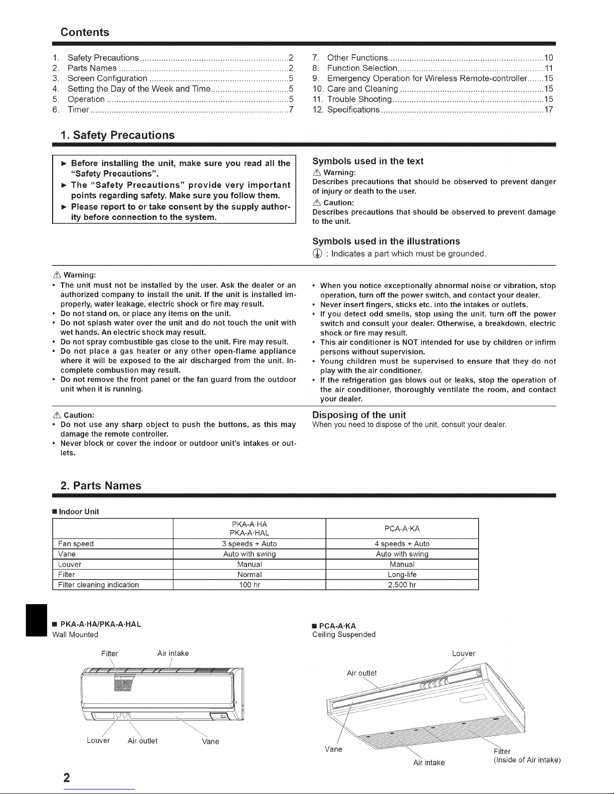
[] Indoor Unit
PKA-A. HA PCA-A. KA
PKA-A. HAL
Fan speed 3 speeds + Auto 4 speeds + Auto
Vane Auto with swing Auto with swing
Louver Manual Manual
Filter Normal Long-life
Filter cleaning indication 100 hr 2,500 hr
[] PKA-A.HA/PKA-A.HAL
Wall Mounted
Filter Air intake
Louver Air outlet Vane
2
[] PCA-A.KA
Ceiling Suspended
Air outlet
Vane
\
Air intake
Louver
Filter
(Inside of Air intake)
Page 3
2. Parts Names
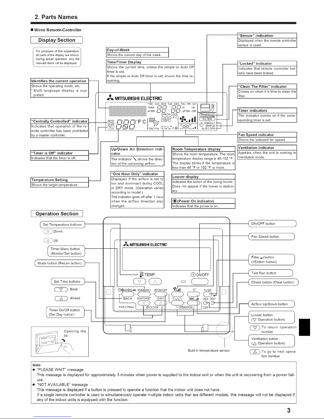
[] Wired Remote-Controller
I Display Section I
For purposes of this explanation,
all parts of the display are shown.
During actual operation, only the
relevant items will be displayed.
J
/
Identifies the current operation
Shows the operating mode, etc. |
Multi language display is sup-|
ported. |
of the re- I
Imote controller has been prohibited I
Iby a master controller. I
s Off" indicator
that the timer is off. /
Setting
et temperature.
[ Operation Section ]
Set Temperature buttons
@ Down
(_Up
Timer Menu button
(Monitor!Set button)
_,Returnbutton)
Set Time buttons )--
C_ Back
Ahead
I imer On/Off button _-]
(Set Day button)
Opening the
lid
Day=of-Week I
Shows the current day of the week.
Tirne/Timer Display fl
Shows the current time, unless the simple or Auto Of
timer is set.
If the simple or Auto Off timer is set, shows the time re- I
|
maining.
m_ MITSUBISHI ELEITRIC
"Sensor" indication contro!ler
Displayed when the remote
sensor is used.
"'Locked" indicator but-
Indicates that remote controller
tons have been locked.
"Clean The Filter" indicator
1
Comes on when it is time to clean the
filter.
aTimer indicators corre-
The indicator comes on if the
sponding timer is set.
WEEKLY _ '
SIMPLE
AUTO OFF-J "-_ I
[Fan Speed indicator speed. ]
[Shows the selected fan
Up/Down Air Direction indi- I
____ ----_
or '% shows the direc- I
It!on of the outcoming airflow. !
"One Hour Only" indicator
Displayed if the airflow is set to
low and downward during COOL
or DRY mode. (Operation varies
according to model.)
The indicator goes off after 1 hour
when the airflow direction also
changes.
Temperaturedisplay ] indica tthe room temperature. The room I IAppears when the unit is running in
ature display range is 46-102 °F. I IVentilati°n mode.
play blinks if the temperature isI
n 46 °F or 102 °F or more. I
display louver, t
the action of the swing
t appear if the louver is station 1
[(_)(Power On indicator)
_lndicates that the power is on.
MITSUBISHI ELECTRIC
I
Built-in temperature sensor
button
Speed button
button 1
(<Enter> button)
button
i ( Check button (Clear button)
Aifflow Up/Down button )
-L-'_ L°u(L_Vo rpeb:t_°n but t° n )1
_To return operation
number
--f Ventilation button !(A Operation button)
(_To go opera-
to next
tion number
Note:
• "PLEASE WAIT" message
This message is displayed for approximately 3 minutes when power is supplied to the indoor unit or when the unit is recovering from a power fail-
ure.
• "NOT AVAILABLE" message
This message is displayed if a button is pressed to operate a function that the indoor unit does not have.
If a single remote controller is used to simultaneously operate multiple indoor units that are different models, this message will not be displayed if
any of the indoor units is equipped with the function.
3
Page 4

2. Parts Names
[] Wireless Remote-Controller
_ Transmission area )
'Remote controller disp(ay)
* For explanation purposes, all of the items
that appear in the display are shown.
* All items are displayed when the Reset
button is pressed.
_ ON!OFF button)
Set Temperature buttons)
_Fan Speed button (Changes fan speed)_
'Airflow button (Changes up/down airflow _ [-
, I
Mode button (Changes operation mode)_
( Check button_)_
Test Run button_ F ):
Transmission indicator
Timer indicator
(_Operation areas )
)
button
-- _Minute button ._
"Set Time button (Sets the time) )
Louver button (Changes left/right airflow direction) )
" Reset button )
[] When using the wireless remote controller, point it towards the receiver on the indoor unit.
[] If the remote controller is operated within approximately 2 minutes after power is supplied
to the indoor unit, the indoor unit may beep twice as the unit is performing the initial auto-
matic check.
[] The indoor unit beeps to confirm that the signal transmitted from the remote controller has
been received. Signals can be received up to approximately 7 meters in a direct line from
the indoor unit in an area 45 ° to the left and right of the unit. However, illumination such as
fluorescent lights and strong light can affect the ability of the indoor unit to receive signals.
[] If the operation lamp near the receiver on the indoor unit is blinking, the unit needs to be
inspected. Consult your dealer for service.
[] Handle the remote controller carefully) Do not drop the remote controller or subject it to
strong shocks. In addition, do not get the remote controller wet or leave it in a location with
high humidity.
[] To avoid misplacing the remote controller, install the holder included with the remote con-
troller on a wall and be sure to always place the remote controller in the holder after use.
[] Outdoor unit
iiii)))J))))))))))))....................................................................................................
Power
Ref. Pipes _
Indoor-Outdoor
Connection wire
Battery instal(ationlreplacement
1. Remove the top cover, insert 2 AAA batteries,
and then install the top cover.
1
4
Top cover
2. Press the Reset butto
_3
2 AAA batteries
Insert the negative (-) (
end of each battery(
first, Install the bat- I
teries in the correct I
directions (+,-)! (
Press the Reset but-I
ton with an object that
has a narrow end.
Panel
Earth
///////_///////
4
Page 5
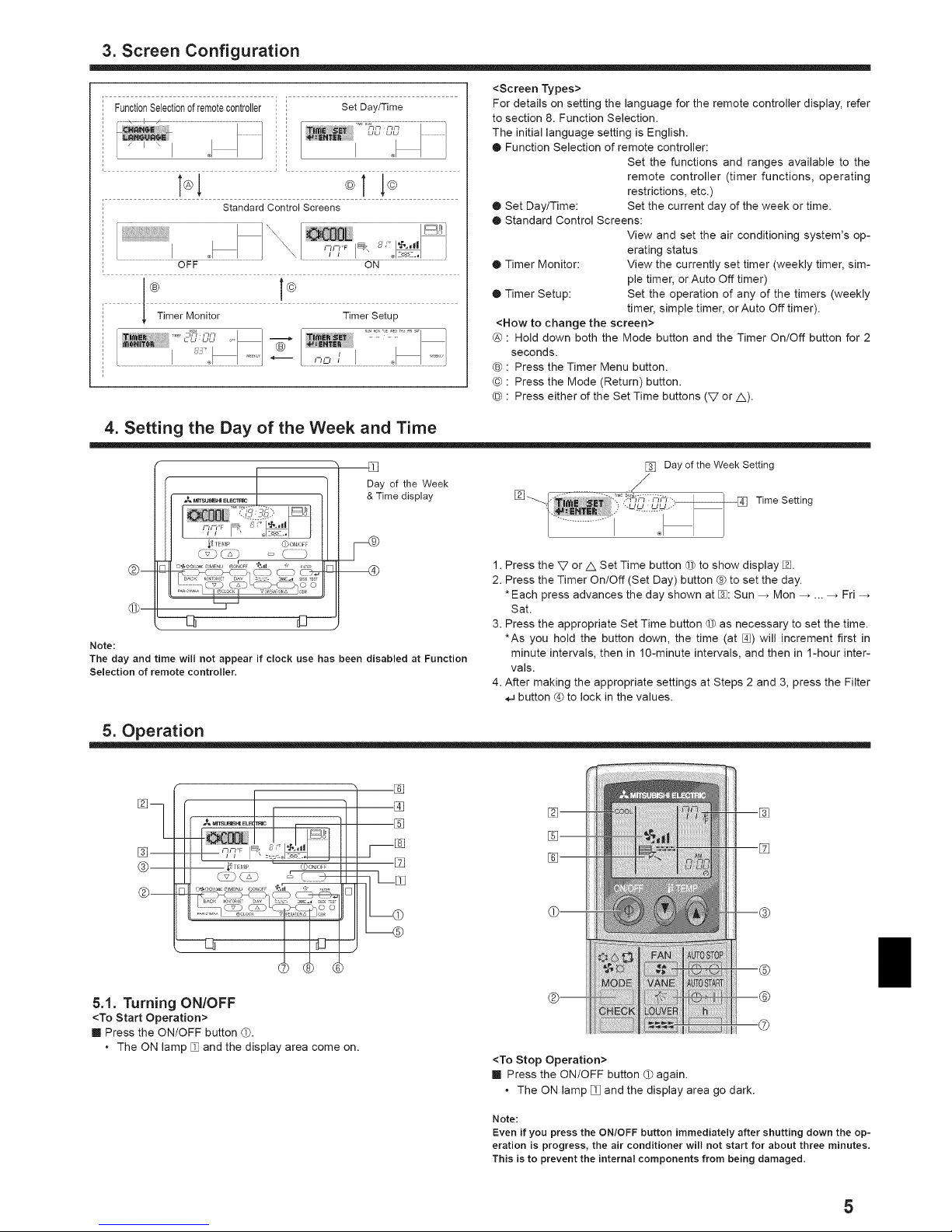
3. Screen Configuration
FunctionSelectionofremotecontroller Set Day/Time
Standard Control Screens
OFF ON
Timer Monitor TimerSetup
T,_,j,_,..... , I iT,%%,,_i _v_:_':'_........
<Screen Types>
For details on setting the language for the remote controller display, refer
to section 8. Function Selection.
The initial language setting is English.
® Function Selection of remote controller:
Set the functions and ranges available to the
remote controller (timer functions, operating
restrictions, etc.)
• Set Day/Time: Set the current day of the week or time.
• Standard Control Screens:
View and set the air conditioning system's op-
erating status
• Timer Monitor: View the currently set timer (weekly timer, sim-
ple timer, or Auto Off timer)
• Timer Setup: Set the operation of any of the timers (weekly
timer, simple timer, orAuto Off timer).
<How to change the screen>
@ : Hold down both the Mode button and the Timer On/Off button for 2
seconds.
® : Press the Timer Menu button.
© : Press the Mode (Return) button.
® : Press either of the Set Time buttons (V or/k).
4. Setting the Day of the Week and Time
_ TE_4P (_ ON/OFF
[3 d3-----
[] [] Day of the Week Setting
Day of the Week /
& Time display [] Time Setting
@
Note:
The day and time will not appear if clock use has been disabled at Function
Selection of remote controller,
1. Press the V or/k Set Time button @ to show display %.
2. Press the Timer On/Off (Set Day) button @ to set the day.
* Each press advances the day shown at %: Sun _ Mon ..... Fri
Sat.
3. Press the appropriate Set Time button @ as necessary to set the time.
*As you hold the button down, the time (at %) will increment first in
minute intervals, then in 10-minute intervals, and then in 1-hour inter-
vals.
4. After making the appropriate settings at Steps 2 and 3, press the Filter
button @ to lock in the values.
5. Operation
[]
@
[]
[]
[]
[]
5.1. Turning ON/OFF
<To Start Operation>
[] Press the ON/OFF button ®.
• The ON lamp [] and the display area come on.
%
.®
.@
.©
<To Stop Operation>
[] Press the ON/OFF button ® again.
• The ON lamp [] and the display area go dark.
Note:
Even if you press the ON/OFF button immediately after shutting down the op-
eration is progress, the air conditioner will not start for about three minutes,
This is to prevent the internal components from being damaged.
5
Page 6
5. Operation
5.2. Mode select
[] Press the operation mode (I-1_OO6) button ® and select the opera-
tion mode [_.
---__t: (COOL) Cooling mode
(DRY) Drying mode
(FAN) Fan mode
•.O-(HEAT) Heating mode
I--I (AUTO) Automatic (cooling/heating) mode
J _ Ventillation mode
Only indicated on the following condition
Wired remote controller used
LOSSNAY connected
Automatic operation
[] According to a set temperature, cooling operation starts if the room
temperature is too hot and heating operation starts if the room tem-
perature is too cold.
[] During automatic operation, if the room temperature changes and
remains 2 °C, 4 °F or more above the set temperature for 15 minutes,
the air conditioner switches to cooling mode. In the same way, if the
room temperature remains 2 °C, 4 °F or more below the set tempera-
ture for 15 minutes, the air conditioner switches to heating mode.
Coolingmode
15minutes (switches
from heatingto cooling)
Set temperature +2°C, +4°F
Set temperature
/
*l
_-.-_-.-_ ........ Set temperature -2°C, -4°F
15 minutes (switches
from cooling to heating )
[] Because the room temperature is automatically adjusted in order to
maintain a fixed effective temperature, cooling operation is performed
a few degrees warmer and heating operation is performed a few de-
grees cooler than the set room temperature once the temperature is
reached (automatic energy-saving operation).
5.3. Temperature setting
_. To decrease the room temperature:
Press (2D button ® to set the desired temperature.
The selected temperature is displayed [].
_- To increase the room temperature:
Press GD button ® to set the desired temperature.
The selected temperature isdisplayed [].
Available temperature ranges are as follows:
Cooling/Drying: 19 - 30 °C, 67 - 87 °F
Heating: 17 - 28 °C, 63 - 83 °F
Automatic: 19 - 28 °C, 67 - 83 °F
The display [] flashes either 8 °C - 39 °C, 46 °F - 102 °F to inform you
if the room temperature is lower or higher than the displayed tempera-
ture. (This display does not appear on the wireless remote controller.)
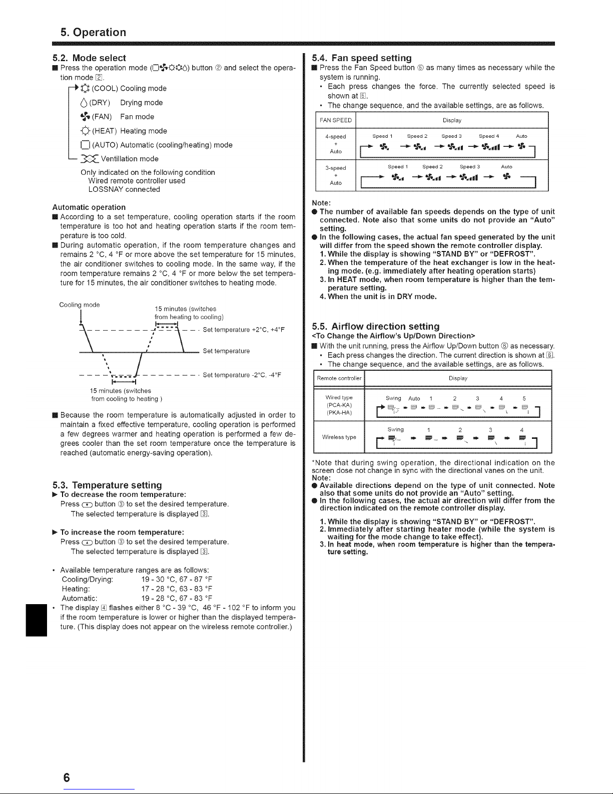
5.4. Fan speed setting
[] Press the Fan Speed button @ as many times as necessary while the
system is running.
• Each press changes the force. The currently selected speed is
shown at %.
• The change sequence, and the available settings, are as follows.
FAN SPEED Display
4-speed
+
Auto
3-speed
+
Auto
Speed 1 Speed 2 Speed 3 Speed 4 Auto
"t,. -'_ "t,.t --_ "t,.d -'_ "_,.dl -'_ '_' -
Speed 1 Speed 2 Speed 3 Auto
F--" -" -" "'" " --1
Note:
• The number of available fan speeds depends on the type of unit
connected. Note also that some units do not provide an "Auto"
setting.
• In the following cases, the actual fan speed generated by the unit
will differ from the speed shown the remote controller display.
1. While the display is showing "STAND BY" or "DEFROST".
2. When the temperature of the heat exchanger is low in the heat-
ing mode. (e.g. immediately after heating operation starts)
3. In HEAT mode, when room temperature is higher than the tem-
perature setting.
4. When the unit is in DRY mode.
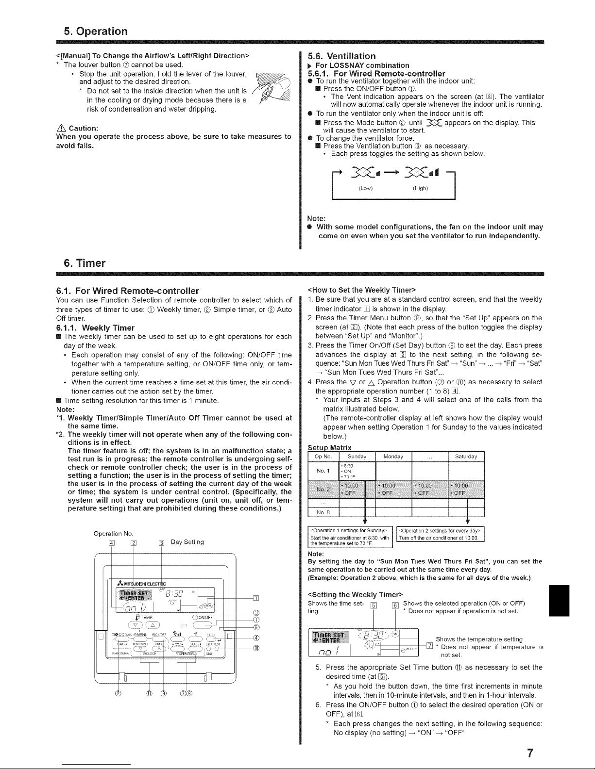
5.5. Airflow direction setting
<To Change the Airflow's Up/Down Direction>
[] With the unit running, press the Airflow Up/Down button ® as necessary.
• Each press changes the direction. The current direction isshown at [_.
• The change sequence, and the available settings, are as follows.
Remote controller Display
Wiled type
(PCA-KA)
(PKA-HA)
Wireless type
Swing Auto 1 2 3 4 5
['_7 . D . D_ .D. . ._\ . D, . DI 3
Swing 1 2 3 4
*Note that during swing operation, the directional indication on the
screen dose not change in sync with the directional vanes on the unit.
Note:
O Available directions depend on the type of unit connected. Note
also that some units do not provide an "Auto" setting.
O in the following cases, the actual air direction will differ from the
direction indicated on the remote controller display.
1. While the display is showing "STAND BY" or "DEFROST".
2. immediately after starting heater mode (while the system is
waiting for the mode change to take effect).
3. In heat mode, when room temperature is higher than the tempera=
ture setting.
6
Page 7
5. Operation
<[Manual] To Change the Airflow's Left/Right Direction>
* The louver button G cannot be used.
o Stop the unit operation, hold the lever of the louver,
and adjust to the desired direction.
* Do not set to the inside direction when the unit is
in the cooling or drying mode because there is a
risk of condensation and water dripping.
Z_ Caution:
When you operate the process above, be sure to take measures to
avoid falls.
5.6. Ventillation
For LOSSNAY combination
5.6.1. For Wired Remote-controller
• To run the ventilator together with the indoor unit:
[] Press the ON/OFF button @.
• The Vent indication appears on the screen (at []). The ventilator
will now automatically operate whenever the indoor unit is running.
• To run the ventilator only when the indoor unit is off:
[] Press the Mode button @ until _ appears on the display. This
will cause the ventilator to start.
• To change the ventilator force:
[] Press the Ventilation button ® as necessary.
• Each press toggles the setting as shown below.
(Low) (High)
Note:
• With some model configurations, the fan on the indoor unit may
come on even when you set the ventilator to run independently.
6. Timer
6.1. For Wired Remote=controller
You can use Function Selection of remote controller to select which of
three types of timer to use: (_ Weekly timer, _ Simple timer, or (_ Auto
Off timer.
6.1.1. Weekly Timer
[] The weekly timer can be used to set up to eight operations for each
day of the week.
• Each operation may consist of any of the following: ON/OFF time
together with a temperature setting, or ON/OFF time only, or tem-
perature setting only.
• When the current time reaches a time set at this timer, the air condi-
tioner carries out the action set by the timer.
[] Time setting resolution for this timer is 1 minute.
Note:
"1. Weekly Timer/Simple Timer/Auto Off Timer cannot be used at
the same time.
•2. The weekly timer will not operate when any of the following con-
ditions is in effect.
The timer feature is off; the system is in an malfunction state; a
test run is in progress; the remote controller is undergoing self-
check or remote controller check; the user is in the process of
setting a function; the user is in the process of setting the timer;
the user is in the process of setting the current day of the week
or time; the system is under central control. (Specifically, the
system will not carry out operations (unit on, unit off, or tem-
perature setting) that are prohibited during these conditions.)
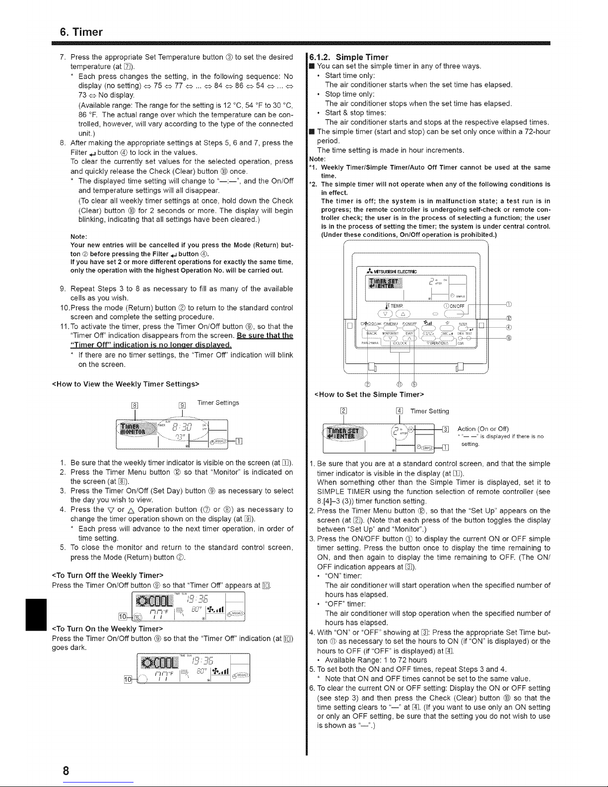
Operation No.
[] [] [] Day Setting
<How to Set the Weekly Timer>
1. Be sure that you are at a standard control screen, and that the weekly
timer indicator [] is shown in the display.
2. Press the Timer Menu button @, so that the "Set Up" appears on the
screen (at []). (Note that each press of the button toggles the display
between "Set Up" and "Monitor".)
3. Press the Timer On/Off (Set Day) button @ to set the day. Each press
advances the display at [] to the next setting, in the following se-
quence: "Sun Mon Tues Wed Thurs Fri Sat" _ "Sun" _ .... "Fri" _ "Sat"
"Sun Mon Tues Wed Thurs Fri Sat"...
4. Press the V or Z& Operation button ((_ or ®) as necessary to select
the appropriate operation number (1 to 8) [].
* Your inputs at Steps 3 and 4 will select one of the cells from the
matrix illustrated below.
(The remote-controller display at left shows how the display would
appear when setting Operation 1 for Sunday to the values indicated
below.)
Matrix
Op No. Sunday Monday ... Saturday
No. 1
No. 8
" 8:30
" ON
" 73 °F
<Operation 1 settings for Sunday> <Operation 2 settings for every day> I
Start the air conditioner at 8:38, with Turn off the a r cond t oner at 10:00. J
the emperature se to 73 °F.
Note:
By setting the day to "Sun Mort Tues Wed Tburs Fri Sat", you can set the
same operation to be carried out at the same time every day.
(Example: Operation 2 above, which is the same for all days of the week.)
<Setting the Weekly Timer>
Shows thetime set- [] [] Shows the selected operation (ON or OFF)
ting i * Does not appear if operation is not set.
l
I
"--_-_( ........"l Shows the temperature setting
""q'" []
/ ",,!_-" ©,,.EE_ * Does not appear if temperature is
_-/_ / ®l i j notset.
5. Press the appropriate Set Time button @ as necessary to set the
desired time (at []).
* As you hold the button down, the time first increments in minute
intervals, then in 10-minute intervals, and then in 1-hour intervals.
6. Press the ON/OFF button (_ to select the desired operation (ON or
OFF), at [].
* Each press changes the next setting, in the following sequence:
No display (no setting) _ "ON" _ "OFF"
7
Page 8
6. Timer
7. Press the appropriate Set Temperature button (_ to set the desired
temperature (at []).
* Each press changes the setting, in the foNowing sequence: No
display (no setting) <=>75 <=>77 <=>... <=>84 <=>86 <=>54 <=>... <=>
73 <=>No display.
(Available range: The range for the setting is 12 °C, 54 °F to 30 °C,
86 °F. The actual range over which the temperature can be con-
trolled, however, will vary according to the type of the connected
unit.)
8. After making the appropriate settings at Steps 5, 6 and 7, press the
Filter # button @ to lock in the values.
To clear the currently set values for the selected operation, press
and quickly release the Check (Clear) button (_ once.
* The displayed time setting will change to "--:--", and the On/Off
and temperature settings will all disappear.
(To clear all weekly timer settings at once, hold down the Check
(Clear) button (_ for 2 seconds or more. The display will begin
blinking, indicating that all settings have been cleared.)
Note:
Your new entries will be cancelled if you press the Mode (Return) but-
ton ® before pressing the Filter _.Jbutton Q.
If you have set 2 or more different operations for exactly the same time,
only the operation with the highest Operation No. will be carried out.
9. Repeat Steps 3 to 8 as necessary to fill as many of the available
ceNs as you wish.
10.Press the mode (Return) button _ to return to the standard control
screen and complete the setting procedure.
11.To activate the timer, press the Timer On/Off button @, so that the
"Timer Off" indication disappears from the screen. Be sure that the
"Timer Off" indication is no lonaer disDlaved_
* if there are no timer settings, the "Timer Off" indication win blink
on the screen.
<How to View the Weekly Timer Settings>
[] [] Timer Settings
1. Be sure that the weekly timer indicator is visible on the screen (at [_).
2. Press the Timer Menu button @ so that "Monitor" is indicated on
the screen (at []).
3. Press the Timer On/Off (Set Day) button @ as necessary to select
the day you wish to view.
4. Press the V or A Operation button (G or @) as necessary to
change the timer operation shown on the display (at _]).
* Each press will advance to the next timer operation, in order of
time setting.
5. To close the monitor and return to the standard control screen,
press the Mode (Return) button _.
<To Turn Off the Weekly Timer>
Press the Timer On/Off button @ so that "Timer Off" appears at [_.
/_I • _l I_I
<To Turn On the Weekly Timer>
Press the Timer On/Off button @ so that the "Timer Off" indication (at _)
goes dark.
I I • ILl
6.1.2. Simple Timer
[] You can set the simple timer in any of three ways.
• Start time only:
The air conditioner starts when the set time has elapsed.
• Stop time only:
The air conditioner stops when the set time has elapsed.
• Start & stop times:
The air conditioner starts and stops at the respective elapsed times.
[] The simple timer (start and stop) can be set only once within a 72-hour
period.
The time setting is made in hour increments.
Note:
"1. Weekly Timer/Simple Timer/Auto Off Timer cannot be used at the same
time.
•2. The simple timer will not operate when any of the following conditions is
in effect.
The timer is off; the system is in malfunction state; a test run is in
progress; the remote controller is undergoing self-check or remote con-
troller check; the user is in the process of selecting a function; the user
is in the process of setting the timer; the system is under central control.
(Under these conditions, On/Off operation Jsprohibited.)
_ MITSUBISHI ELECTRIC
Sk/_ J"Z "
J
@
@
@
®
<How to Set the Simple Timer>
[] [] Timer Setting
I
i'Zl¢_--Jr.---" "',4;," [] Action (On or Off)
'_[_ * <'-- --" is displayed if there is no
I [] setting.
1. Be sure that you are at a standard control screen, and that the simple
timer indicator is visible in the display (at [_).
When something other than the Simple Timer is displayed, set it to
SIMPLE TIMER using the function selection of remote controller (see
8.[4]-3 (3)) timer function setting.
2. Press the Timer Menu button @, so that the "Set Up" appears on the
screen (at []). (Note that each press of the button toggles the display
between "Set Up" and "Monitor".)
3. Press the ON/OFF button (_ to display the current ON or OFF simple
timer setting. Press the button once to display the time remaining to
ON, and then again to display the time remaining to OFR (The ON/
OFF indication appears at _).
• "ON" timer:
The air conditioner will start operation when the specified number of
hours has elapsed.
• "OFF" timer:
The air conditioner will stop operation when the specified number of
hours has elapsed.
4. With "ON" or "OFF" showing at _]: Press the appropriate Set Time but-
ton @ as necessary to set the hours to ON (if "ON" is displayed) or the
hours to OFF (if "OFF" is displayed) at [_.
• Available Range: 1 to 72 hours
5. To set both the ON and OFF times, repeat Steps 3 and 4.
• Note that ON and OFF times cannot be set to the same value.
6. To clear the current ON or OFF setting: Display the ON or OFF setting
(see step 3) and then press the Check (Clear) button @ so that the
time setting clears to "--" at [_. (If you want to use only an ON setting
or only an OFF setting, be sure that the setting you do not wish to use
isshown as "--".)
8
Page 9
6. Timer
7. After completing steps 3 to 6 above, press the Filter _J button @ to
lock in the value.
Note:
Your new settings will be cancelled if you press the Mode (Return) button G
before pressing the Filter_J button (_.
8. Press the Mode (Return) button (D to return to the standard control
screen.
9. Press the Timer On/Off button @ to start the timer countdown. When
the timer is running, the timer value is visible on the display. Be sure
that the timer value is visible and a_riate.
<Viewing the Current Simple Timer Settings>
[] [] Timer Setting
1. Be sure that the simple timer indicator is visible on the screen (at []).
2. Press the Timer Menu button @, so that the "Monitor" appears on the
screen (at []).
• if the ON or OFF simple timer is running, the current timer value will
appear at [].
• if ON and OFF values have both been set, the 2 values appear al-
ternately.
3. Press the Mode (Return) button (D to close the monitor display and
return to the standard control screen.
<To Turn Off the Simple Timer...>
Press the Timer On/Off button @ so that the timer setting no longer
appears on the screen (at []).
[]
<To Turn On the Simple Timer...>
Press the Timer On/Off button @ so that the timer setting becomes
visible at [].
[]
Examples
If ON and OFF times have both been set at the simple timer, operation
and display are as indicated below.
Example 1:
Start the timer, with ON time set sooner than OFF time
ON Setting: 3 hours
OFF Setting: 7 hours
..-%.......p
:, 7 AF,EROFF
qm'_ ......
-At Timer Start
Display shows the timer's ON setting (hours
remaining to ON).
m _
At 3 hours after timer startj
- Display changes to show the timer's OFF set-
ting (hours remaining to OFF).
The time displayed is OFF setting (7 hours) -
ON setting (3 hours) = 4 hours.
At 7 hours after timer start
The air conditioner goes off, and wUi remain
off until someone restarts it.
Example 2:
Start the timer, with OFF time is sooner than ON time
ON Setting: 5 hours
OFF Setting: 2 hours
iiillliii!!!i!!!!!!!!!!!ii
€
N J _,TER
-At Timer Start
Display shows the timer's OFF setting (hours
remaining to OFF).
At 2 hoursafter timer start)
Display changes to show the timer's ON set-
ting (hours remaining to ON).
The time displayed is ON setting (5 hours) -
OFF setting (2 hours) = 3 hours.
.... At 5 hours after timer start
F
_h12' _%11| The air conditioner comes on, and will con-
e _ @ SM_E tinue to run until someone turns it off.
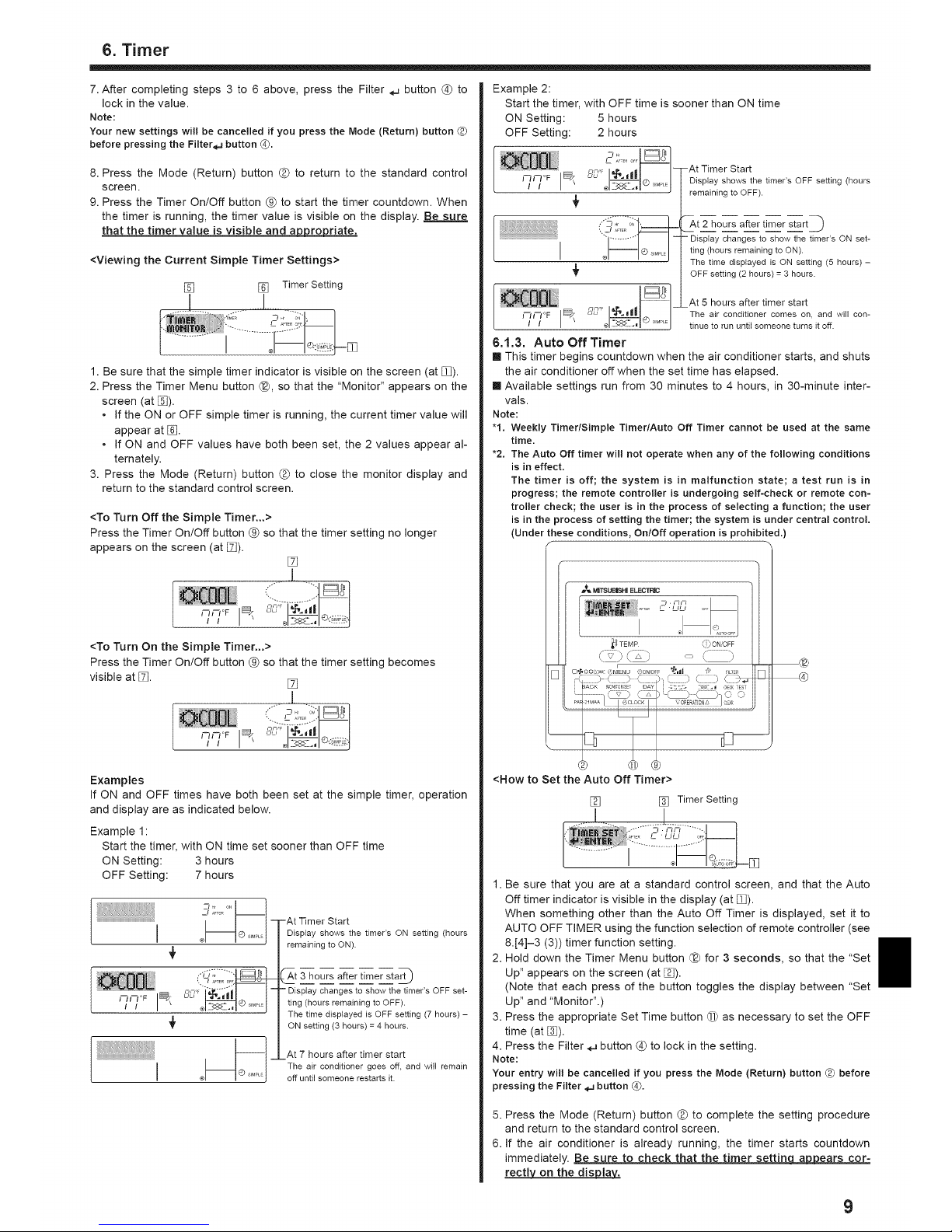
6.1.3. Auto Off Timer
[] This timer begins countdown when the air conditioner starts, and shuts
the air conditioner off when the set time has elapsed.
[] Available settings run from 30 minutes to 4 hours, in 30-minute inter-
vals.
Note:
"1. Weekly Timer/Simple Timer/Auto Off Timer cannot be used at the same
time.
"2. The Auto Off timer will not operate when any of the following conditions
is in effect.
The timer is off; the system is in malfunction state; a test run is in
progress; the remote controller is undergoing serf-check or remote con-
troller check; the user is in the process of selecting a function; the user
is in the process of setting the timer; the system is under central control.
(Under these conditions, On/Off operation is prohibited.)
f
MWSUBISHI ELECTRIC
I
_ TEMP ()I0N'OFF
f :z
\ j'
r
CI'_OO6:_ 8MENU (I)ON/OFF "_'.lll 7,' F_LTER
@
@
<How to Set the Auto Off Timer>
[] [] Timer Setting
1. Be sure that you are at a standard control screen, and that the Auto
Off timer indicator is visible in the display (at m).
When something other than the Auto Off Timer is displayed, set it to
AUTO OFF TIMER using the function selection of remote controller (see
8.[4]-3 (3)) timer function setting.
2. Hold down the Timer Menu button @ for 3 seconds, so that the "Set
Up" appears on the screen (at []).
(Note that each press of the button toggles the display between "Set
Up" and "Monitor".)
3. Press the appropriate Set Time button @ as necessary to set the OFF
time (at _]).
4. Press the Filter 4J button @ to lock in the setting.
Note:
Your entry will be cancelled if you press the Mode (Return) button G before
pressing the Filter_ button Q,
5. Press the Mode (Return) button (D to complete the setting procedure
and return to the standard control screen.
6. if the air conditioner is already running, the timer starts countdown
immediately. Be sure to check that the timer settin ag__o__ears cor-
rectly on the display_.
9
Page 10
6. Timer
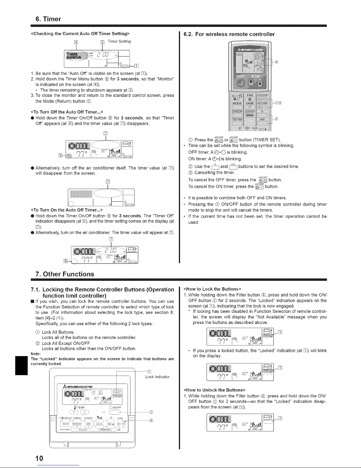
<Checking the Current Auto Off Timer Setting> 6.2. For wireless remote controller
[] [] Timer Setting
1. Be sure that the "Auto Off" is visible on the screen (at _).
2. Hold clown the Timer Menu button @ for 3 seconds, so that "Monitor"
is indicated on the screen (at []).
• The timer remaining to shutdown appears at [_.
3. To close the monitor and return to the standard control screen, press
the Mode (Return) button _.
<To Turn Off the Auto Off Timer...>
® Hold down the Timer On/Off button @ for 3 seconds, so that "Timer
Off" appears (at [_) and the timer value (at []) disappears.
[]
® Alternatively, turn off the air conditioner itself. The timer value (at [])
will disappear from the screen.
[]
<To Turn On the Auto Off Timer...>
® Hold down the Timer On/Off button @ for 3 seconds. The "Timer Off"
indication disappears (at %), and the timer setting comes on the display (at
[]).
[] Alternatively, turn on the air conditioner. The timer value will appear at [].
[]
AUT0STOP AUTOSTART
(_ Press the _ or I_ button (TIMER SET).
Time can be set while the following symbol is blinking.
OFF timer: A(_-O is blinking.
ON timer: AC)=I is blinking.
h •in
Use the CZ and C_ buttons to set the desired time.
(_ Cancelling the timer.
To cancel the OFF timer, press the _ button.
To cancel the ON timer, press the _ button.
• It is possible to combine both OFF and ON timers.
• Pressing the (_ ON/OFF button of the remote controller during timer
mode to stop the unit will cancel the timers.
• if the current time has not been set, the timer operation cannot be
used.
7. Other Functions
7.1. Locking the Remote Controller Buttons (Operation
function limit controller)
[] If you wish, you can lock the remote controller buttons. You can use
the Function Selection of remote controller to select which type of lock
to use. (For information about selecting the lock type, see section 8,
item [4]-2 (1)).
Specifically, you can use either of the following 2 lock types.
Lock All Buttons:
Locks all of the buttons on the remote controller.
(D LockAII Except ON/OFF:
Locks all buttons other than the ON/OFF button.
Note:
The "Locked" indicator appears on the screen to indicate that buttons are
currently locked.
TEMP _i) ONOFF
[]
[]
Lock Indicator
@
®
<How to Lock the Buttons>
1. While holding down the Filter button @, press and hold down the ON/
OFF button _ for 2 seconds. The "Locked" indication appears on the
screen (at []), indicating that the lock is now engaged.
* if locking has been disabled in Function Selection of remote control-
ler, the screen will display the "Not Available" message when you
press the buttons as described above.
i
o If you press a locked button, the "Locked" indication (at _) will blink
on the display.
<How to Unlock the Buttons>
1. While holding down the Filter button @, press and hold down the ON/
OFF button (_ for 2 seconds--so that the "Locked" indication disap-
pears from the screen (at []).
'w I
t0
Page 11
7. Other Functions
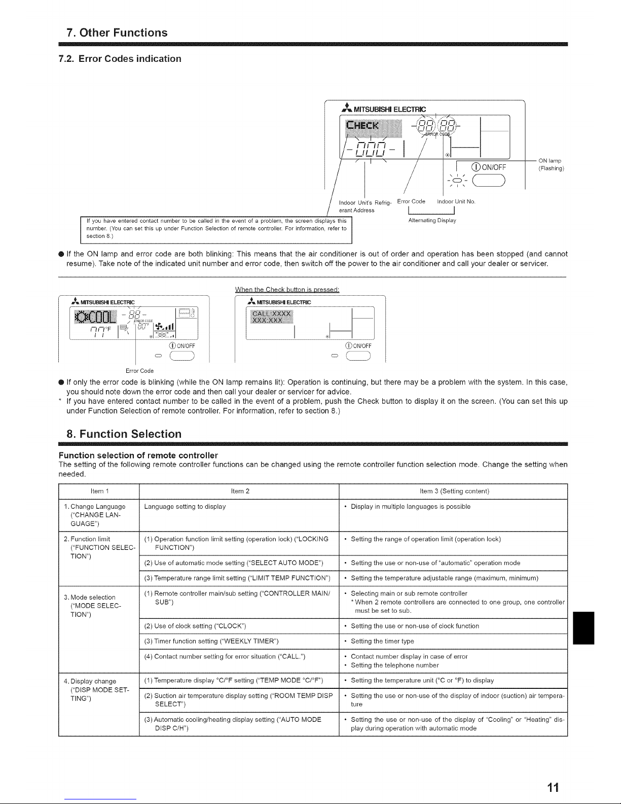
7.2. Error Codes indication
MITSUBISHI ELECTRIC
iCldi'_/OO,
--:,/ I/ I/_,1 II i/-
mmr-,_/__
I (_)ON/OFF
Indoor Unit's Refrig- Error Code Indoor Unit No.
erantAddress [ J
If you have entered contact number to be called in the event of a problem, the screen displays this Alternating Display
number. (You can set this up under Function Selection of remote controller. For information, refer to
section 8.)
ON lamp
(Flashing)
• If the ON lamp and error code are both blinking: This means that the air conditioner is out of order and operation has been stopped (and cannot
resume). Take note of the indicated unit number and error code, then switch off the power to the air conditioner and call your dealer or servicer.
....................... M'TS"B'S.;ELEOT"iC.............................................................................................................................................................."
i .........................................................................................................\ # / ,.......
:'_":_ / _T ° , I I
I °F uL'l¢-' ll I
_ONIOFF
Error Code
When the Check button is Dressed:
_ MITSUBISH|ELECTRIC
(_)ON/OFF
o
® If only the error code is blinking (while the ON lamp remains lit): Operation is continuing, but there may be a problem with the system. In this case,
you should note down the error code and then call your dealer or servicer for advice.
* If you have entered contact number to be called in the event of a problem, push the Check button to display it on the screen. (You can set this up
under Function Selection of remote controller. For information, refer to section 8.)
8. Function Selection
Function selection of remote controller
The setting of the following remote controller functions can be changed using the remote controller function selection mode. Change the setting when
needed.
Item 1 Item 2 Item 3 (Setting content)
1. Change Language Language setting to display • Display in multiple languages is possible
("CHANGE LAN-
GUAGE")
2. Function limit (1) Operation function limit setting (operation lock) ("LOCKING • Setting the range of operation limit (operation lock)
("FUNCTION SELEC- FUNCTION")
TION")
(2) Use of automatic mode setting ("SELECT AUTO MODE") • Setting the use or non-use of "automatic" operation mode
(3) Temperature range limit setting ("LIMIT TEMP FUNCTION") • Setting the temperature adjustable range (maximum, minimum)
3. Mode selection (1) Remote controller main/sub setting ("CONTROLLER MAIN/ • Selecting main or sub remote controller
("MODE SELEC- SUB") * When 2 remote controllers are connected to one group, one controller
TION") must be set to sub.
(2) Use of clock setting ("CLOCK") • Setting the use or non-use of clock function
(3) Timer function setting ("WEEKLY TIMER") • Setting the timer type
(4) Contact number setting for error situation ("CALL.") • Contact number display in case of error
• Setting the telephone number
4. Display change (1) Temperature display °C/°F setting ("TEMP MODE °C/°F '') • Setting the temperature unit (°C or °F) to display
("DISP MODE SET-
TING") (2) Suction air temperature display setting ("ROOM TEMP DISP • Setting the use or non-use of the display of indoor (suction) air tempera-
SELECT") ture
(3) Automatic cooling/heating display setting ("AUTO MODE • Setting the use or non-use of the display of "Cooling" or "Heating" dis-
DISP C/H") ptay during operation with automatic mode
tl
Page 12
8. Function Selection
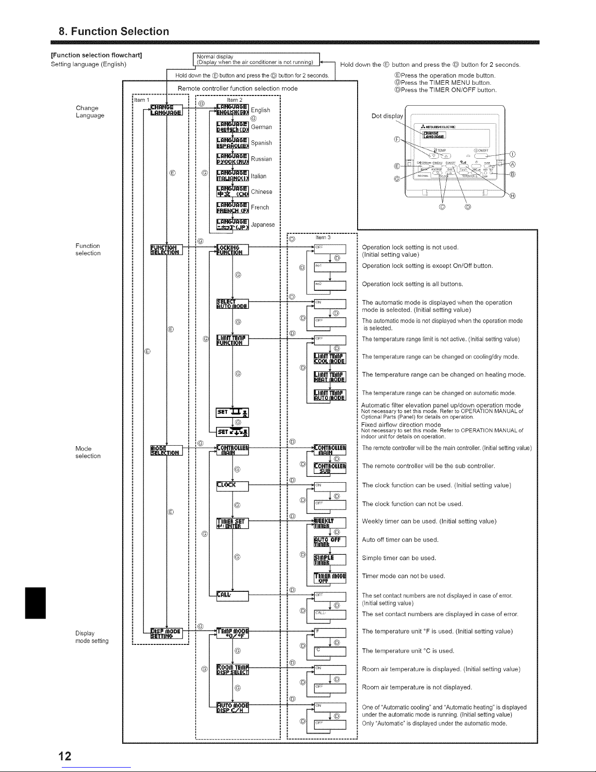
[Function selection flowchart]
Setting language (English)
Change
Language
Function
selection
Mode
selection
Display
mode setting
Item 1
Remote controller function selection mode
' i i (_ Item2
_ _nglish
I _ German
I _ Spanish
_l _ Russian
(_) _) _ _ Italian
_r_ Chinese
_ French
_[_ _ Japanese
I
I
®
i
I
I
i
' G _
i
©
Normal display
IjD sp ay when the a r cond t oner is not running) Hold down the (_) button and press the © button for 2 seconds.
Hold down the (_) button and press the © button for 2 seconds. [ (_)Press the operation mode button.
(_)Press the TIMER MENU button.
©Press the TIMER ON/OFF button.
Dot display
(_
G_
© ©
-®
-®
item 3
)
)
©
Operation lock setting is not used.
(Initial setting value)
Operation lock setting is except On/Off button.
Operation lock setting is all buttons.
The automatic mode is displayed when the operation
mode is selected. (Initial setting value)
The automatic mode is not displayed when the operation mode
is selected.
The temperature range limit is not active. (Initial setting value)
The temperature range can be changed on cooling/dry mode.
The temperature range can be changed on heating mode.
The temperature range can be changed on automatic mode.
Automatic filter elevation panel up/down operation mode
Not necessaryto set this mode.Refer to OPERATION MANUAL of
Optionat Parts (Panel) for details on operation.
Fixed airflow direction mode
Not necessaryto set this mode.Refer to OPERATION MANUAL of
indoor unit for details on operation.
The remotecontroller will be the main controller. (initial setting value)
The remote controller will be the sub controller.
The clock function can be used. (Initial setting value)
The clock function can not be used.
Weekly timer can be used. (Initial setting value)
Auto off timer can be used.
Simple timer can be used.
Timer mode can not be used.
The set contact numbers are not displayed in case of error.
(Initial setting value)
The set contact numbers are displayed in case of error.
The temperature unit °F is used. (Initial setting value)
The temperature unit °C is used.
Room air temperature is displayed. (Initial setting value)
Room air temperature is not displayed.
One of "Automatic cooling" and "Automatic heating" is displayed
under the automatic mode is running. (Initial setting value)
Only "Automatic" is displayed under the automatic mode.
t2
Page 13
8. Function Selection
[Detailed setting]
[4]-1. CHANGE LANGUAGE setting
The language that appears on the dot display can be selected.
• Press the [Q MENU] button @ to change the language.
(_ English (GB), (_) German (D), (_ Spanish (E), (_ Russian (RU),
(_) Italian (I), (_ Chinese (CH), (_ French (F), (_ Japanese (JP)
Refer to the dot display table.
[4]-2. Function limit
(1) Operation function limit settin¢l (operation lock)
• To switch the setting, press the [@ ON/OFF] button @.
(_ no1 : Operation lock setting ismade on all buttons other
than the [Q ON/OFF] button O.
(D no2 : Operation lock setting is made on all buttons.
(_ OFF (initial setting value): Operation lock setting is not made.
• To make the operation lock setting valid on the normal screen, it is
necessary to press buttons (Press and hold down the [FILTER] @
and [_ ON/OFF] O buttons at the same time for 2 seconds.) on
the normal screen after the above setting is made.
(2) Use of automatic mode settinq
When the remote controller is connected to the unit that has auto-
matic operation mode, the following settings can be made.
• To switch the setting, press the [@ ON/OFF] button @.
(_ ON (Initial setting value):
The automatic mode is displayed when the operation mode is
selected.
(D OFF:
The automatic mode is not displayed when the operation
mode is selected.
(3) Temperature ranqe limit settinq
After this setting is made, the temperature can be changed within
the set range.
• To switch the setting, press the [@ ON/OFF] button @.
C) LIMITTEMP COOL MODE:
The temperature range can be changed on cooling/dry mode.
LIMIT TEMP HEAT MODE:
The temperature range can be changed on heating mode.
(_ LIMITTEMPAUTO MODE:
The temperature range can be changed on automatic mode.
@ OFF (initial setting): The temperature range limit is not active.
• When the setting, other than OFF, is made, the temperature
range limit setting on cooling, heating and automatic mode is
made at the same time. However, the range cannot be limited
when the set temperature range has not changed.
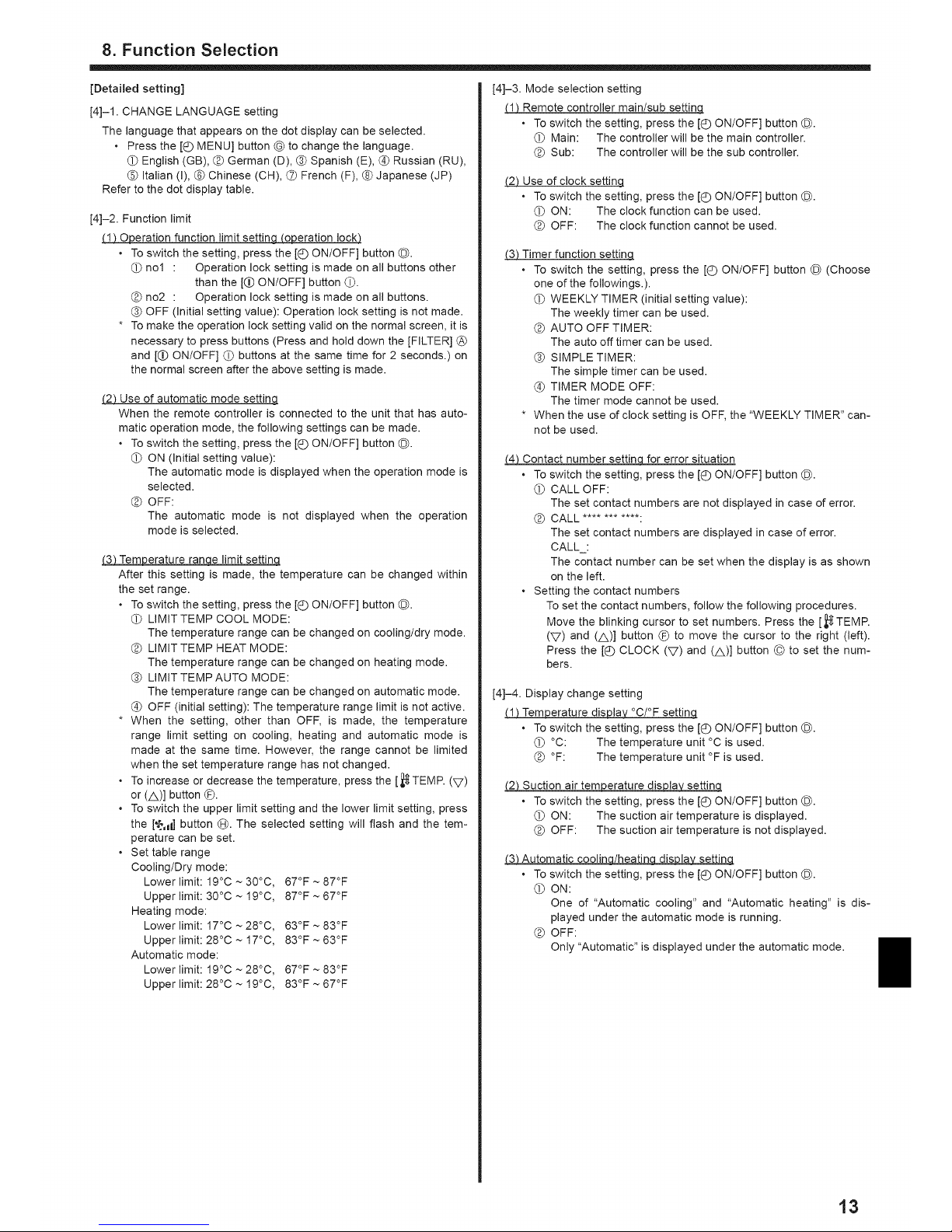
• To increase or decrease the temperature, press the [_TEMP. (V)
or (A)] button (_.
• To switch the upper limit setting and the lower limit setting, press
the [¢,d ] button @. The selected setting will flash and the tem-
perature can be set.
• Set table range
Cooling/Dry mode:
Lower limit: 19°C ~ 30°C, 67°F ~ 87°F
Upperlimit:30°C~19°C, 87°F~67°F
Heating mode:
Lower limit: 17°C ~ 28°C, 63°F ~ 83°F
Upper limit: 28°C ~ 17°C, 83°F ~ 63°F
Automatic mode:
Lower limit: 19°C ~ 28°C, 67°F ~ 83°F
Upperlimit:28°C~19°C, 83°F~67°F
[4]-3. Mode selection setting
(1) Remote controller main/sub settinq
• To switch the setting, press the [Q ON/OFF] button @.
(_ Main: The controller will be the main controller.
(D Sub: The controller will be the sub controller.
(2) Use of clock settinq
• To switch the setting, press the [@ ON/OFF] button @.
(_ ON: The clock function can be used.
OFF: The clock function cannot be used.
(3) Timer function setting
• To switch the setting, press the [@ ON/OFF] button @ (Choose
one of the followings.).
(_ WEEKLY TIMER (initial setting value):
The weekly timer can be used.
(_) AUTO OFF TIMER:
The auto off timer can be used.
(_ SIMPLE TIMER:
The simple timer can be used.
@ TIMER MODE OFF:
The timer mode cannot be used.
• When the use of clock setting is OFF, the "WEEKLY TIMER" can-
not be used.
(4) Contact number settinq for error situation
• To switch the setting, press the [Q ON/OFF] button @.
(_ CALL OFF:
The set contact numbers are not displayed in case of error.
(_) CALL ............
The set contact numbers are displayed in case of error.
CALL :
The contact number can be set when the display is as shown
on the left.
• Setting the contact numbers
To set the contact numbers, follow the following procedures.
Move the blinking cursor to set numbers. Press the [,_TEMP.
(V) and (A)] button _ to move the cursor to the right (left).
Press the [Q CLOCK (V) and (A)] button © to set the num-
bers.
[4]-4. Display change setting
(1) Temperature dis lily °C/°F settinq
• To switch the setting, press the [@ ON/OFF] button @.
(_ °C: The temperature unit °C is used.
°F: The temperature unit °F is used.
(2) Suction air temperature display settinq
• To switch the setting, press the [Q ON/OFF] button @.
(_ ON: The suction air temperature is displayed.
OFF: The suction air temperature is not displayed.
f3_ Automatic coolina/heatinq disdispla_q
, To switch the setting, press the [Q ON/OFF] button @.
(_ ON:
One of "Automatic cooling" and "Automatic heating" is dis-
played under the automatic mode is running.
(_) OFF:
Only "Automatic" is displayed under the automatic mode.
t3
Page 14

8. Function Selection
[Dot display table]
Selecting language English German Spanish Russian italian Chinese French Japanese
Waiting for start-up 4--- 4--- _ 4--- <-_ 4-_ <---
Operation mode
DSJHUml;
BESHg
_LNZiONE
_LnT|OH _L_TION
Coo(
Dry
Heat
Auto
Auto (Cool)
Auto (Heat)
Fan
Ventilation
Stand by
(Hot adiust )
Defrost
Set temperature
Fan speed
i Not use button
Check (Error)
Test run
Self check
Unit function selection
Setting of ventilation
Selecting language
CHANGE LANGUAGE
Function selection
Operation function limit setting
Use of automatic mode setting
i
i Temperature range limit setting
i
I
i Limit temperature cooling/day
i mode
i Limit temperature heating mode
Limit temperature auto mode
Mode selection
Remote controller setting MAIN
Remote controller setting SUB
Use of clock setting
Setting the day of the week and
time
Timer set
Timer monitor
Weekly timer
Timer mode off
Auto off timer
Simple timer
Contact number setting of error
situation
Display change
Temperature display °C/°F setting
Room air temperature display set-
ting
Automatic cooling/heating display
setting
t4
Page 15
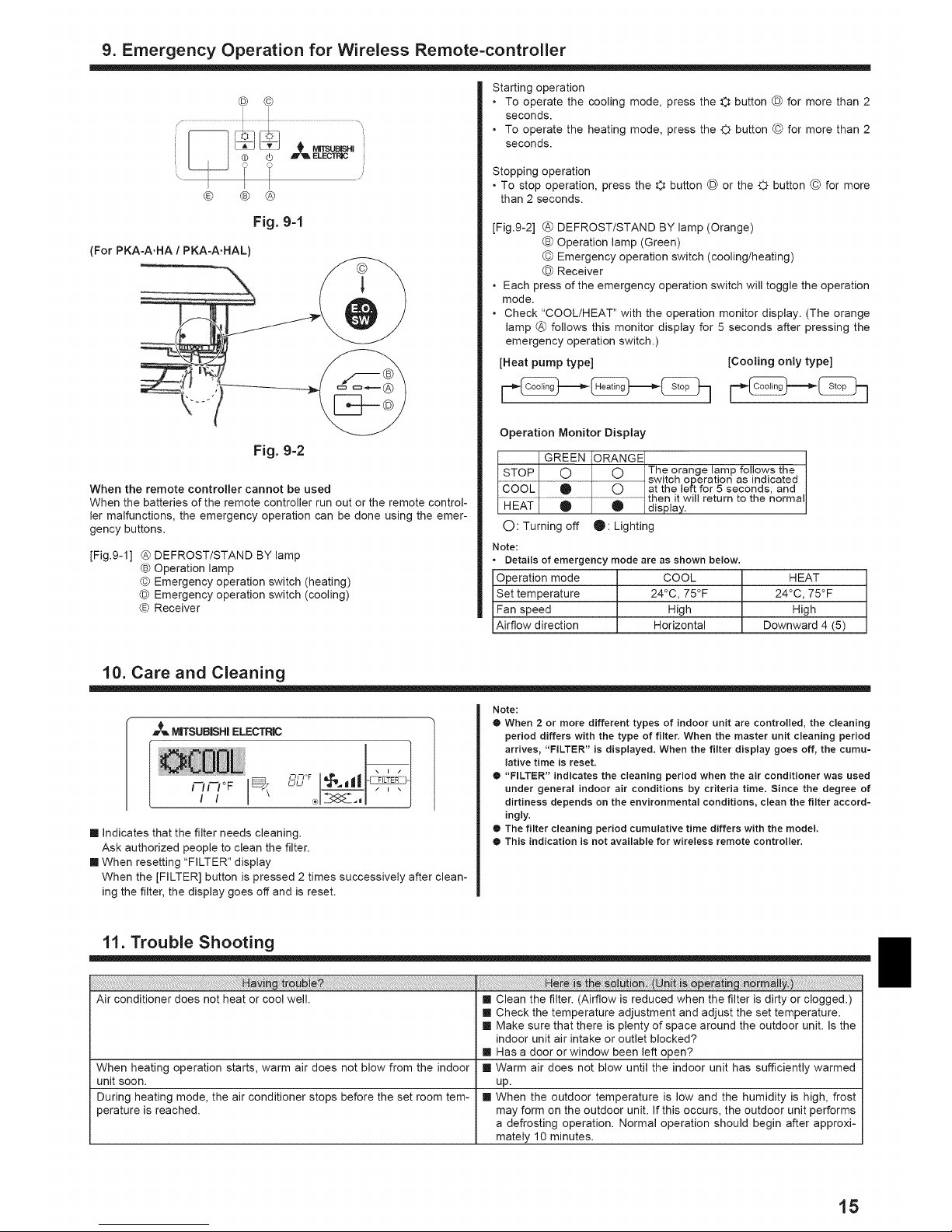
9. Emergency Operation for Wireless Remote=controller
© ©
® ® ®
Fig. 9-1
(For PKA-A.HA / PKA-A.HAL)
Fig. 9=2
When the remote contro((er cannot be used
When the batteries of the remote control(er run out or the remote contro(-
(er malfunctions, the emergency operation can be done using the emer-
gency buttons.
[Fig.9-1] @ DEFROST/STAND BY lamp
® Operation lamp
© Emergency operation switch (heating)
© Emergency operation switch (cooling)
® Receiver
Starting operation
• To operate the cooling mode, press the © button @ for more than 2
seconds.
• To operate the heating mode, press the O button © for more than 2
seconds.
Stopping operation
• To stop operation, press the O button @ or the C_button © for more
than 2 seconds.
[Fig.9-2] @ DEFROST/STAND BY lamp (Orange)
(_ Operation lamp (Green)
© Emergency operation switch (cooling/heating)
© Receiver
• Each press of the emergency operation switch will toggle the operation
mode.
• Check "COOL/HEAT" with the operation monitor display. (The orange
lamp @ follows this monitor display for 5 seconds after pressing the
emergency operation switch.)
[Heat pump type] [Cooling only type]
Operation Monitor Display
GREEN ORANGE
STOP O O The orange lamp follows the
...........................................................................................................................................................................................switch operation as indicated
COOL O O at the left for 5 seconds, and
then it will return to the normal
HEAT O _ display.
O: Turning off _: Lighting
Note:
• Details of emergency mode are as shown below.
Operation mode COOL
Set temperature 24°C, 75°F
Fan speed High
Airflow direction Horizontal
HEAT
24°C, 75°F
High
Downward 4 (5)
10. Care and Cleaning
[] indicates that the filter needs cleaning.
Ask authorized people to clean the filter.
[] When resetting "FILTER" display
When the [FILTER] button is pressed 2 times successively after clean-
ing the filter, the display goes off and is reset.
Note:
® When 2 or more different types of indoor unit are controlled, the cleaning
period differs with the type of filter. When the master unit cleaning period
arrives, "FILTER" is displayed, When the filter display goes off, the cumu=
lative time is reset.
® "FILTER" indicates the cleaning period when the air conditioner was used
under general indoor air conditions by criteria time, Since the degree of
dirtiness depends on the environmental conditions, clean the filter accord=
ingly.
® The filter cleaning period cumulative time differs with the model,
® This indication is not available for wireless remote controller.
11. Trouble Shooting
Air conditioner does not heat or cool well. [] Clean the filter. (Airflow is reduced when the filter is dirty or clogged.)
[] Check the temperature adjustment and adjust the set temperature.
[] Make sure that there is plenty of space around the outdoor unit. Is the
indoor unit air intake or outlet blocked?
[] Has a door or window been left open?
When heating operation starts, warm air does not blow from the indoor [] Warm air does not blow until the indoor unit has sufficiently warmed
unit soon. up.
During heating mode, the air conditioner stops before the set room tem- [] When the outdoor temperature is low and the humidity is high, frost
perature is reached, may form on the outdoor unit. If this occurs, the outdoor unit performs
a defrosting operation. Normal operation should begin after approxi-
mately 10 minutes.
i5
Page 16

11. Trouble Shooting
!%!ii_ii_!i_!i_!i_i_%_!_!i!_!!_!!i!!_!_!!i_i_iii!_!_i_!_!_!_!_!_!_!_!!_!i_!ii!iii!i!i!i_i_ii¸_!i_i_!_i!_!_i!_ii_!ii!_i_i_!_!i!_!_!_!_!_!_!_:_l_i_!!i!_i_!_!i!i¸ii!i_ii!i_i_i_i_i!iiiiiiiiiii!_ii_ii_i_!_i_i!_!I_i!iiii_!!_ilil_il_il_i_!_!_!ii_!_!_!i_!j_!ii_!ii_i_i%i_iiiii!i!_!!!i_!_!iii_iiii_i_i_i_i_i_i_ii_ii_i!_ii_i!_ii_i!_ii_i!_ii%!_i!ii_!_!ii_i_i
[] During cooling mode, the vanes automatically move to the horizontal
(down) position after 1 hour when the down (horizontal) airflow direc-
tion is selected. This is to prevent water from forming and dripping
from the vanes.
[] During heating mode, the vanes automatically move to the horizontal
airflow direction when the airflow temperature is low or during defrost-
ing mode.
[] When the airflow direction is changed, the vanes move to the set po-
sition after detecting the base position.
[] These sounds can be heard when refrigerant is flowing in the air con-
ditioner or when the refrigerant flow is changing.
[] These sounds can be heard when parts rub against each due to ex-
pansion and contraction from temperature changes.
[] The indoor unit draws in air that contains gases produced from the
walls, carpeting, and furniture as well as odors trapped in clothing,
and then blows this air back intothe room.
[] if the indoor temperature and the humidity are high, this condition
may occur when operation starts.
[] During defrosting mode, cool airflow may blow down and appear like
a mist.
[] During cooling mode, water may form and drip from the cool pipes
and joints.
[] During heating mode, water may form and drip from the heat ex-
changer.
[] During defrosting mode, water on the heat exchanger evaporates and
water vapor may be emitted.
[] Turn on the power switch. "®" will appear inthe remote controller display.
[] During central control, "_" appears in the remote controller display
and air conditioner operation cannot be started or stopped using the
remote controller.
[] Wait approximately three minutes.
(Operation has stopped to protect the air conditioner.)
[] is the on timer set?
Press the ON/OFF button to stop operation.
[] is the air conditioner connected to a central remote controller?
Consult the concerned people who control the air conditioner.
[] Does "_" appear in the remote controller display?
Consult the concerned people who control the air conditioner.
[] Has the auto recovery feature from power failures been set?
Press the ON/OFF button to stop operation.
[] is the off timer set?
Press the ON/OFF button to restart operation.
[] is the air conditioner connected to a central remote controller?
Consult the concerned people who control the air conditioner.
[] Does "B" appear in the remote controller display?
Consult the concerned people who control the air conditioner.
[] Are timer settings invalid?
if the timer can be set, _, _, or _ appears in
the remote controller display.
[] The initial settings are being performed. Wait approximately 3 min-
utes.
[] The protection devices have operated to protect the air conditioner.
[] Do not attempt to repair this equipment by yourself.
Turn off the power switch immediately and consult your dealer. Be
sure to provide the dealer with the model name and information that
appeared in the remote controller display.
[] When cooling operation stops, the drain pump operates and then
stops. Wait approximately 3 minutes.
[] The indoor operation sound level is affected by the acoustics of the
particular room as shown in the following table and will be higher than
the noise specification, which was measured in an echo-free room.
Airflow direction changes during operation or airflow direction cannot be
set.
When the airflow direction is changed, the vanes always move up and
down past the set position before finally stopping at the position.
A flowing water sound or occasional hissing sound is heard.
A cracking or creaking sound is heard.
The room has an unpleasant odor.
A white mist or vapor is emitted from the indoor unit.
Water or vapor is emitted from the outdoor unit.
The operation indicator does not appear in the remote controller display.
"_" appears in the remote controller display.
When restarting the air conditioner soon after stopping it, it does not op-
erate even though the ON/OFF button is pressed.
Air conditioner operates without the ON/OFF button being pressed.
Air conditioner stops without the ON/OFF button being pressed.
Remote controller timer operation cannot be set.
"PLEASE WAIT" appears in the remote controller display.
An error code appears in the remote controller display.
Draining water or motor rotation sound is heard.
Noise is louder than specifications.
Nothing appears in the wireless remote controller display, the display
is faint, or signals are not received by the indoor unit unless the remote
controller is close.
The operation lamp near the receiver for the wireless remote controller
on the indoor unit is blinking.
Low sound-ab-
High sound- Normal rooms sorbing rooms
absorbing rooms
Location Broadcasting Reception Office, hotel
studio, music room, hotel
examples room, etc. lobby, etc. room
Noise levels 3to7dB 6to 10dB 9to13dB
[] The batteries are low.
Replace the batteries and press the Reset button.
[] if nothing appears even after the batteries are replaced, make sure
that the batteries are installed in the correct directions (% -).
[] The self diagnosis function has operated to protect the air conditioner.
[] Do not attempt to repair this equipment by yourself.
Turn off the power switch immediately and consult your dealer. Be
sure to provide the dealer with the model name.
t6
Page 17

12. Specifications
Model
Power source (Phase, Voltage <V>,
Frequency <Hz>)
Fan motor
MCA
MOCP
Dimension (Height)
Dimension (Width)
Dimension (Depth)
Airflow
(Low-Middle-High)
Noise level (Low-Middle-High)
Net weight
PKA-A12HAJ PKA-A18HA
Single 208/230, 60
<FLA> 0.33
<A> 1 J 1
<A> 15 ] 15
<inch> 11-5/8
<inch> 35-3/8
<inch> 9-13/16
J DRY<CFM>
WET<CFM>
<dB>
320-370-425
290-335-380
36-40-43
29<lbs>
PKA-A12HALJ PKA-A18HAL
Single 208/230, 60
<FLA> 0.33
<A> 1 J 1
<A> 15 ] 15
<inch> 11-5/8
<inch> 35-3/8
<inch> 9-13/16
Model
Power source (Phase, Voltage <V>,
Frequency <Hz>)
Fan motor
MCA
MOCP
Dimension (Height)
Dimension (Width)
Dimension (Depth)
Airflow
(Low-Middle-High)
Noise level (Low-Middle-High)
Net weight
I DRY<CFM>WET<CFM>
<dB>
<lbs>
320-370-425
290-335-380
36-40-43
29
Model
Power source (Phase, Voltage <V>,
Frequency <Hz>)
Fan motor <FLA>
MCA <A>
MOCP <A>
Dimension (Height) <inch>
Dimension (Width) <inch>
Dimension (Depth) <inch>
Airflow DRY <CFM>
(Low-Middle2-Middlel-High) WET <CFM>
Noise level (Low-Middle2-Middlel-High) <dB>
Net weight <lbs>
PCA-A24KA PCA-A3OKA PCA-A36KA PCA-A42KA
Single 208/230, 60
0.49 0.54 0.83 0.97
1 1 2 2
15 15 15 15
9-1/6
50-3/8 63
26-3/4
530-565-600-670565-600-635-705
495-530-565-635530-565-600-670
33-35-37-40 35-37-39-41
71
775-850-920-990
705-775-850-920
37-39-41-43
79
810-885-955-1025
740-810-885-955
39-41-43-45
84
t7
Page 18

index
1. Consignes de securit6 ........................................................ 18
2. Nomenclature ..................................................................... 18
3. Configuration d'ecran ......................................................... 21
4. Regter le jour de ta semaine et l'heure ............................... 21
5. Fonctionnement ................................................................. 21
6. Minuterie ............................................................................ 23
7. Autres fonctions ................................................................. 26
8. Selection des fonctions ...................................................... 27
9. Fonctionnement d'urgence de ta tel6commande sans fil...31
10. Entretien et nettoyage ........................................................ 31
11. Guide de depannage .......................................................... 32
12. Specifications techniques ................................................... 33
1. Consignes de s6curit6
Avant d'Jnstaller le clJrnatiseur, life attentivernent
routes les "Consignes de securite'.
i_ Les "Consignes de securite" reprennent des points
tres Jrnportants concernant la securite. Veillez bien
les suivre.
Veuillez consulter ou obtenir la permission votre corn=
pagnie d'electricite avant de connecter votre systerne.
Symboles utilis_s darts le texte
Avertissement:
Precautions & suivre pour _viter tout danger de blessure ou de
d_c_s de I'utilisateur.
z:_ Precaution:
D_crit les precautions qui doivent _tre prises pour _viter d'endom-
mager rappareil.
Symboles utilis_s darts les illustrations
(_ - Indique un et6ment qui dolt 6tre mis a la terre.
Z_ Avertissement:
• Cet appareil ne dolt pas _tre install_ par rutilisateur. Demander
au revendeur ou & une soci_t_ agr_e de rinstaller. Si I'appareil n'
est pas correctement install_ il peut y avoir un risque de fuite d'
eau, d'_lectrocution ou d'incendie.
• Ne pas marcher sur I'appareil ni y d_poser des objets.
• Ne jamais _clabousser I'appareil ni le toucher avec des mains hu-
mides. II pourrait en r_sulter un risque d'_lectrocution.
• Ne pas vaporiser de gaz inflammable _ proximit_ de l'appareil
sous risque d'incendie.
• Ne pas placer de chauffage au gaz ou tout autre appareil fonc-
tionnant avec une flamme vive I_ o_ il serait e×pos_ & I'_chappe-
merit d'air du climatiseur. Cela risquerait de provoquer une mau-
valse combustion.
• Ne pas retirer la face avant ou la protection du ventilateur de l'ap-
pareil ext_rieur pendant son fonctionnement.
• Si vous remarquez des vibrations ou des bruits particuli_rement
anormau×, arr6ter I'appareil, _teindre l'interrupteur et prendre
contact avec le revendeur.
• Ne jamais mettre des doigts, des b_tons, etc. darts les entr_es et
sorties d'air.
• Si vous sentez des odeurs _tranges, arr_ter I'appareil, le mettre
hors tension et contacter le revendeur. Si vous ne proc_dez pas
de cette fa£on, il pourrait y avoir risque de panne, d'_lectrocution
ou d'incendie.
• Ne JAMAIS laisser des enfants ou des personnes handicap_es
utiliser le climatiseur sans surveillance.
• Toujours surveiller que les jeunes enfants ne jouent pas avec le
climatiseur.
° Si le gaz de r_frig_rant fuit, arr_ter le fonctionnement du clima-
tiseur, a_rer convenablement la piece et prendre contact avec le
revendeur.
Z_ Precaution:
°Ne pas utiliser d'objet pointu pour enfoncer les boutons car cela
risquerait d'endommager la commande & distance.
• Ne jamais obstruer les entrees et sorties des appareJls exterieurs et
interieurs.
Rangement de I'appareil
Lorsque vous devez ranger I'appareil, veuillez consulter votre revendeur.
2. Nomenclature
[] Unit_ interne
PKA-A'HA
PKA-A" HAL PCA-A" KA
Vitesse du ventilateur 3 Vitesses + Auto 4 VJtesses + Auto
AJlette Auto avec variation Auto avec variation
Louvre Manuel Manuel
Filtre Normal Longue duree
Temoin de nettoyage du filtre 100 heures 2.500 heures
[] PKA-A.HA/PKA-A.HAL
Fixe au Mur
Filtre Admission d'air
[] PCA-A'KA
Suspendu au Plafond
Grille de refoule-
ment d'air
Admission d'air
t8
Louvre Grille de refoule- Ailette
ment d'air Ailette
\
Air intake
-FJltre
(Int@ieur de I'arrivee
d'air)
Page 19

2. Nomenclature
[] Pour la t_l_commande _ fil
ISection de I'affichage I
fPoui des buis explicatifs, tous ies_
el6mentsde I'affichagesontaffiches. I
Lors de I'utilisation de l'appareil, I
seuls les el6ments utilisesseront I
affiches. J
el'l cours
ctionnement,
t 6tre en ptu-
_ entrale" __
ement de ta
et6 desac-
Itivee par une commande maTtresse.
1
Jour de la semaine |
/Indique te jour de ta semaine.
Affichage heure/programmateur
Affiche t'heure, a moins que le programmateur simple I
ou arr6t auto soit active. |
Si te programmateur simple ou arr&t auto est en active,|
t'affichage indique le temps restant. |
,_,_ MITSUBISHI ELEI;TRIC
T6rnoin "Capteur" du
S'affiche Iors de I'utitisation
capteur de la t61ecommande.
_r_Nlndicateur "Verrouill_" I
Indique que les boutons de ta com- I
mande _ distance ont &te bloqu&s. I
"T_moin "Nettoyer le filtre" I
S'altume quand il est temps de net- I
SIMPLE"}---I-J-_--I IT_moin de vitesse du ventilateurl
AuT°°FF I
lie ventilateur.
_ "Prograrnmateur _teint"
que le programmateur est
16teint.
de temperature
temp@ature souhaitee.
[ Section de commandes ]
Boutons de r6glage de temp@ature)
Baisser
Monter
Bouton de menu du program-_
ateur (Bouton Monitor!Set) I
glage horaire
Boutons de reglage horaire) --
Reculer
Avancer
outon marche/arr_t du _
rogrammatsur
outon de reglage de la
ate)
Ouvrir la
porte.
T_rnoin de mont_e/descente
in X_ indique dans quelle
souffle Fair sortant.
T_moin "une heure seulement"
S'affiche si le courant d'air est
regt6 sur faible et descendant en
mode FROID ou SEC. (L'op@a-
tion varie en fonction du mod61e.)
Le temoin s'eteint au bout d'une
heure, et _ ce moment-la le flux
d'air change aussi.
Affichage de _ _ ventilation tDonne la temp@ature ambiante. La plageJ IApparaft quand I'unite fonctionne en
d'affichage de la temp@ature de la pi6ce estI Im°de Ventilation,
comprise entre46_affichage clignote I
si la temp@ature descend au-dessous deI
46 °F ou monte au-dessus de 102 °F. J
Affichage du louvre
Montre Faction de la grille de transfert.
N'apparaft pas si la grille reste station-
naire.
(_)(T6moin de marche)
Indique que l'appareil est en marche.
ON/OFF
de vitesse du
ventilateur
Capteur de temp@ature int6gre
--f Bouton du filtre _J 1
(Bouton 4J)
--( B0uton detest defonctionnement)
i__ Bouton Check
(bouton d'effacement)
Bouton de ventilation mon--')
tante/descendante .,,)
Bouton de louvre 1
_Bouton op@ation V) J
(_ pour ta prec6dente
operation
--f Bouton de ventilation ](bouton op@ation /X)
(_ pour I'operation
suivante
}
Remarque:
o Message "PLEASE WAIT" (VEUILLEZ PATIENTER)
Ce message s'affiche pendant 3 minutes environ Iorsque I'appareil int@ieur est aiimente ou suite a une coupure d'electricit&
Message "NOT AVAILABLE" (INDISPONIBLE)
Ce message s'affiche quand vous appuyez sur une touche pour lancer une fonction qui est indisponible pour cet appareil int@ieur.
Si une telecommande unique est utilisee pour contr61er simultanement plusieurs appareils int@ieurs de modele diff@ent, ce message ne
s'affichera pas si I'un des appareils int@ieurs presente cette fonction.
t9
Page 20

2. Nomenclature
[] Pour la t_l_commande sans fil
Zone de transmission )
(Ecran d'affichage de la tel6commande).
*A des fins de clarification, tous tes el6ments
qui apparaissent sur l'ecran d'affichage sont
illustres.
*Tousles el6ments sont iliustres Iorsque ta
touche "Reset" (Reinitialiser) est sollicitee.
(Bouton ON/OFF) I
Boutons de reglage de temperature)
I Bouton de vitesse du ventilateur 1
(Modifie la vitesse du ventiiateur)
Bouton Airflow (Debit d air) (Modlfle la [
Idirection haute/"basse'du'd_bit d'aili 1
Bouton de mode (Modifie le mode de fonctionnemenl
'Bouton Check)__
Bouton de test de fonctionnement)
Temoin de transmission
Temoin de la minuterie
• de fonctionnement)
Off" (Arr6t de ta minuterie))
-- " Bouton "Timer On" (Marchede laminuterie))
" Bouton de r>agehoraire (Permet de regler I'heure)')
I Bouton de louvre (Modifie la direction gauche/droite "_
dudebit d'air) J
( Bouton "Reset" (Reinitialiser))
[] Pour utiliser la tel6commande sans ill, pointez-la vers le recepteur de I'appareil interieur.
[] Si la tel6commande est utilisee dens les deux minutes qui suivent I'alimentation de I'appareil
interieur, I'appareil peut emettre deux bips successifs indiquant que le contr61e automatique
initial est en cours.
[] L'apparefl interieur emet des bips pour confirmer que le signal transmis par la tel6commande
a et6 regu. Les signaux peuvent 6tre regus jusqu'a 7 metres environ en figne droite a partir de
I'appareil interieur et dens une zone de 45° vers la gauche ou la droite de I'appareil. Cependant,
une lumiere vive ou fluorescente peut g_ner la reception de signaux de I'appareil interieur.
[] L'appareil doit 6tre contr61e si le voyant d'operation pres du recepteur de I'unite interieure
clignote. Consultez votre revendeur pour le service.
[] Manipulez la tel6commande avec precaution ! Ne la faites pas tomber et ne lui infligez pas de
chocs violents. De plus, evitez de mouiller la tel6commande et ne la laissez pas dens un en-
droit humide.
[] Pour eviter de chercher la tel6commande, placez le support fourni avec la tel6commande sur
un mur et veillez a replacer la tel6commande dens le support apres cheque utifisation.
[] Unit_ externe
Alimentation
Insertionlrernplacement de la pile
1. Retirez le couvercle superieur, inserez deux
piles AAA, puis reposer le couvercle.
Couvercle
superieur
L D_UX _-es AAA
Inserez d'abord le p61e
(-) negatif de chaque
pile, Inserez les piles
en respectant la po-
larite indiquee (+, -)!
2. Appuyez sur la touche "Reset" (Reinitiafiser).
Appuyez sur la touche
"Reset" (Reinitialiser)
avec un objet dont I'ex-
trem te est etro te.
iiiiiiiiiiiiiiiiiiii....................................................................................................
Panneau d'entretien
Masse
///////0///////
20
Page 21

3. Configuration d'6cran
Selection des fonctions
Regle date/heure
°1 l*
Filtresde contr61estandards
OFF ON
1
Moniteur du programmateur Configuration du programmateur
<Types d'6crans>
Le parametrage de la langue d'affichage peut 6tre modifie pour que le
frangais devienne la langue par defaut en selectionnant la fonction ap-
propriee sur la tel6commande. Voyez la section 8, paragraphe [4]-1 pour
modifier la langue.
La langue de base est I'Anglais.
o Selection des fonctions:
Regle les fonctions et les plages disponibles
pour la tel6commande (fonctions du program-
mateur, restrictions de fonctionnement, etc.)
o Regler date/heure: Regle le jour de la semaine et I'heure.
o Ecrans de contr61e standards:
Visualise et regle le fonctionnement du sys-
teme de conditionnement.
o Moniteurduprogrammateur:Affiche le programmateur en place (hebdoma-
daire, simple ou arr6t automatique)
o Configurationduprogrammatsur:Reglele fonctionnement des programmateurs
(hebdomadaire, simple ou arr6t automatique)
<Comment changer d'_cran>
Pour aller a @ : Appuyer sur les boutons Mode et On/Off du programma-
teur durant 2 secondes.
Pour after a ® : Appuyez sur le bouton Menu du programmateur.
Pour after a ® : Appuyez sur le bouton Mode (Entree).
Pour aller a © : Appuyez sur Fun ou I'autre des boutons de reglage ho-
raire ( vou A).
4. R6gler le jour de la semaine et I'heure
_ TEI//P (i) ON/OFF
£y-----
, []
Affichage dujour
de ta semaine et
de l'heure
@
Remarque:
Le jour et I'heure n'apparaitront pas si I'horloge a _t(_ deconnect_e darts la
s_lection des fonctions,
5. Fonctionnement
[] Reglage du jour de la semaine
/
[]Reglage de I'heure
1. Appuyez sur le bouton de reglage horaire @ V ou A pour appeler I'
affichage [_.
2. Appuyez sur le bouton ® Timer On/Off pour regler le jour.
* ik chaque fois que vous appuyez, vous avancez le jour affiche en [] :
Dim _ Lun ..... Ven _ Sam.
3. Appuyez sur le bouton de reglage correspondant @ afin de regler I'
heure.
* Lorsque vous appuyez sur le bouton, le reglage horaire (a [_) aug-
mente tout d'abord en intervalle d'une minute, puis en intervalle de
10 minutes, puis en intervalle d'une heure.
4. Apres avoir effectue les reglages necessaires des etapes 2 et 3, ap-
puyez sur le bouton @ Filter _ pour valider ces informations.
[_]--
[]
®
__
[]
[]
[]
[]
5.1. MARCHE/ARRET
<Pour commencer top,ration>
[] Appuyez sur le bouton ON/OFF @.
• Le temoin de marche [] et la zone d'affichage s'allument.
<Pour arrCter le fonctionnement>
[] Appuyez de nouveau sur le bouton ON/OFF (_.
• Le temoin de marche [] et la zone d'affichage s'eteignent.
Remarque:
M_me si vous appuyez sur le bouton ON/OFF immediatement apr_s avoir
arr_te la fonction en cours, le climatiseur ne se remettra en route que trois
minutes plus tard. Ceci est une precaution pour _viter I'endommagement de
tout composant interne.
%
__
.®
.®
.©
21
Page 22

5. Fonctionnement
5.2. Choix du mode
[] Appuyer sur la touche du mode de fonctionnement (1_-I%%C_©6)®
pour selectionner le mode de fonctionnement souhaite %.
----FO (COOL) Mode de refroidissement
(_ (DRY) Mode de assechement
%%(FAN) Mode de soufflerie
•.O.-(HEAT) Mode de chauffage <type de pompede chaleurseulement>
IZI (AUTO) Mode automatique (refroidissement/chauffage)
J _ Mode de ventilation
Indique uniquement dans les conditions suivantes
Tel6commande reliee utiiisee
Avec un appareil LOSSNAY branche
Fonctionnement automatique
[] En foncfion de la temp@ature definie prealablement, rop@ation de re-
froidissement debutera si la temp@ature de la piece est trop eJev6e ;
I'inverse, rop@ation de chauffage debutera si la temp@ature de la
piece est trop basse.
[] En mode de fonctionnement automatique, le climatiseur passera en
mode de refroidissement si la temp@ature de la piece varie et affiche
2 °C, 4 °F ou plus audessus de la temp@ature definie pendant 15 min-
utes. De Ja m_me fagon, le climatiseur passera en mode de chauffage
si la temp@ature de la piece affiche 2 °C, 4 °F ou plus au-dessous de
la temp@ature definie pendant 15 minutes.
Mode de refroidissement 15 minutes (passage du mode de
L chauffage au mode de refroidissement)
__=__==_.=
_ Temp@ature definie +2 °C, +4°CF
/ Temp@ature definie
J
_'_" _--'=" ........ Temp@ature definie -2 °C, -4°F
15 minutes (passage du mode de re-
froidissement au mode de chauffage)
[] La temp@ature de la piece etant ajustee automatiquement de fagon
rester stable, rop@ation de refroidissement se met en marche
quelques degres au-dessus, et rop@ation de chauffage a quelques
degres au-dessous, de la temp@ature definie Iorsque cette derni@e
est atteinte (fonction automatique d'economie d'energie).
5.3. R_glage de la temperature
i_ Pour r_duire la temperature ambiante:
Appuyer sur le bouton (W_ ® pour selectionner la temp@ature desir6e.
La temp@ature selectionn6e est affichee [_.
i_ Pour augmenter la temperature ambiante:
Appuyer sur le bouton (_i_ ® pour selectionner la temp@ature desir6e.
La temp@ature selectionn6e est affichee [_.
Plages de temp@atures a votre disposition:
Rafraichissement et Assechement: 19 - 30 °C, 67 - 87 °F
Chauffage: 17 - 28 °C, 63 - 83 °F
Automatique: 19 - 28 °C, 67 - 83 °F
8 °C ou 39 °C, 46°F ou 102°F clignote sur raffichage [] pour Jndiquer
que la temp@ature de la piece est plus basse ou plus elev6e que la
temp@ature affichee.
(Cet affichage n'apparaTt pas sur la tel6commande sans ill.)
5.4. R_glage de la vitesse du ventilateur
[] Appuyez sur le bouton de vitesse du ventilateur @ autant de fois que
necessaire alors que le systeme est en fonction.
• ik chaque fois que vous appuyez sur le bouton, vous changez la
force. La vitesse actuelle est indiquee en %.
• La sequence de changement, et les reglages disponibles sont les
suivants.
Vitessedu ventilateur
4 vitesses
+
Auto
3 vitesses
+
Auto
Affichage
vitesses 1 vitesses 2 vitesses 3 vitesses 4 Auto
F* "" -*"" "3
vitesses 1 vitesses 2 vitesses 3 Auto
"-' "-" ---,,..,t ,, --1
Remarque:
® Le nombre de ventilateurs disponible d_pend du type d'unit_ connect_e,
®Dans les cas suivants, la vJtesse de ventilation actuelle g_n_r_e par I'unite
diff_rera de la vitesse indJqu_e au niveau de la commande a distance.
1. Quand I'affichage indique "PRECHAFFAGE" ou "DEGIVRAGE".
2. Lorsque la temperature de I'_changeur thermique est basse en mode de
chauffage. (par ex, imm_diatement apres le lancement de I'operation de
chauffage)
3. En mode CHAUFFAGE, quand la temperature ambiante darts la piece est
sup_rieure a la temperature r_gl_e.
4. Quand I'unit_ est en mode SEC.
5.5. Reglagede la directiondu debitd'air
<Pour changer la direction de fair (montant/descendant)>
[] Quand runite est en fonction, appuyez sur le bouton ® de ventilation
montante/descendante autant de fois que necessaire.
• /k chaque fois que vous appuyez sur le bouton, vous changez la di-
rection. La direction actuelle est affichee sur %.
• La sequence de changement, et les reglages disponibles sont les
suivants:
Tetecommande
CSblee
(PCA-KA)
(PKA-HA)
Sans fil
Affichage
Bascule Auto 1 2 3 4 5
r_7 * -_ -_--_. - -_s- _\ - _13
Bascule 1 2 3 4
* Notez que Iors de I'op@ation de basculement, rindication direction-
nelle a I'ecran ne change pas en synchronisation avec les ailettes
de I'unite.
Remarque:
® Les directions disponJbJes dependent du type d'unJtes connect_es,
®Dans les cas suivants, la direction actuelle de I'air diff_rera de la direction
indiqu_e au niveau de la commande & distance,
1. Quand I'affichage indique "PRECHAFFAGE" ou "DEGIVRAGE".
2. Imm_diatement apr_s le d_marrage du mode CHAUFFAGE (alors que le
systeme attend que le changement de mode se fasse).
3. En mode chauffage, quand la temperature ambiante darts la piece est
sup_rieure a la temperature r_gl_e.
22
Page 23

5. Fonctionnement
<[Manuel] Pour modifier la direction gauche/droite du flux d'air>
* II est impossible d'utiliser le bouton du deflecteur G.
o Arr_ter I'appareil, maintenir le deflecteur de
I'appareil et ajuster la direction souhaitee.
* Ne pas regler la direction interne Iorsque I'appareil
est en mode refroidissement ou deshumidification car
il y a un risque de condensation ou d'egouttement.
z_ Precaution:
Lorsque vous suivez le processus ci-dessus, prenez des precautions
pour _viter toute chute.
5.6. Ventilation
Pour les appareils combin_s LOSSNAY
5.6.1. Pour la tel6comrnande a fil
o Pour lancer le ventilateur conjointement a I'unite int@ieure:
[] Appuyez sur le bouton ON/OFF @.
• Quand I'indicaticnde ventilationapparaTta I'@ran (en [_). Le ventilateursera
desormaislanceautomatiquementachaqueloisqueI'uniteint@ieuredemarrera.
® Pour lancer le ventilateur uniquement quand runite int@ieure est eteinte :
[] Appuyez sur le bouton Mode ® jusqu'a ce que _ apparaisse
I'affichage. Cela lancera le ventilateur.
® Changer la force du ventilateur :
[] Appuyez sur le bouton de ventilation ® autant que necessaire.
• ik chaque fois que vous appuyez sur le bouton, vous changez le
reglage comme indique ci-dessous.
--,- -1
Faibte Forte
Remarque :
®Dans certaines configurations, le ventilateur de I'unit_ int_rieure
peut s'allumer m_me quand vous demandez au ventilateur de
fonctionner ind_pendamment.
6. IVlinuterie
6.1. Pour la t@l@commande a fil
Vous pouvez utiliser la selection des fonctions pour selectJonner le type
de programmateur, entre les trois disponibles. @ Hebdomadaire,
® Simple, ou ® Arr_t auto.
6.1.1. MinuterJe hebdornadaire
[] Le programmateur hebdomadaire peut servir a regler les huit op@a-
tions pour chaque jour de la semaine.
• Chaque op@ation permet I'une ou I'autre des fonctions suivantes:
Programmateur Marche/Arr6t avec un reglage de temp@ature ou
programmateur Marche/Arr_t seulement, ou reglage de temp@ature
seulement.
• ik I'heure dite, le conditionneur d'air effectue Faction programmee.
[] La precision horaire de ce programmateur est de 1 minute.
Remarque:
"1. Les programmateurs hebdomadaire/simple/Arr_t auto ne peuvent _tre
utilis_s en m_me temps.
•2, Le programmateur hebdomadaire ne fonctJonne pas dans les conditions
suivantes,
La fonction de temporisateur est d_sactiv_e; le systeme est dans un _tat
anormal; une execution de test est en cours; la tel_commande est sou-
raise & un auto-diagnostic ou & un diagnostic externe; I'utilisateur est en
train de d6finir une fonction; I'utilisateur est en train de regler le tempori-
sateur; I'utilisateur est en train de r6gler I'heure ou le jour de la semaine;
le systeme est sous commande centralisee. (Pr_cis_ment, le systeme
n'ex_cute pas les operations (allumage, extinction ou r_glage de la tem-
perature) d_sactiv_es dans ces situations.)
N° de fonctionnement
[] [] [] Reglage du jour
<Comment r_gler le programmateur hebdomadaire>
1. Assurez-vous que vous 6tes sur I'ecran de contr61e standard, et que
le temoin du programmateur hebdomadaire [] is'affiche.
2. Appuyez sur le bouton Menu du programmateur @, de mani@e ace que le
"Reglage" apparaisse a I'_cran (en []). (Notez qu'a chaque fois que vous ap-
puyez sur le bouton, vous passez de "Reglage" a "Moniteur" (moniteur).))
3. Appuyez sur le bouton On/Off du programmateur ® pour regler le jour.
Ik chaque fois que vous appuyez, vous changez le reglage en [], selon
la sequence suivante : "Dim Lun Mar Mer Jeu Ven Sam" _ "Dim" _ ...
"Ven" _ "Sam" --_ "Dim Lun Mar Mer Jeu Ven Sam"...
4. Appuyez sur le bouton (_ ou ®) d'op@ation V ou Z&autant de fois que
necessaire pour selectionner le num@o d'op@ation approprie (1 & 8) [].
* Vos choix aux etapes 3 et 4 selectionneront I'une des cellules de la
matrice affichee ci-dessous.
(l'affichage de la commande a distance a gauche montre comment
I'affichage devrait apparaftre Iors du reglage de I'op@ation 1 pour
dimanche aux valeurs indiquees ci-dessous).
Matrice de r_glage
Op No. Sunday
• 8:30
No. 1 • ON
• 73 °F
No. 8
<Regiage de rop@ation 1 pour dimanche>
Demarrer le conditionneur d'air a 8:30, avec
la temperature a 73 °F.
Remarque:
Monday ... Saturday
!
<Reglage de I'operatiol
Ete ndre e cond t onne
pour tous les jours>
10:00.
i
En reglant le jour sur "Dim Lun Mar Met Jeu Yen Sam", vous pouvez r_gler la
m_me operation & effectuer au m_me moment tousles jours.
(Exemple: L'op_ration 2 ci-dessus, qui est la m6me pour tous les jours de la
semaine,)
<R_gler le programmateur hebdomadaire>
Affiche te reglage
de rheure
[] [] Affiche I'op@ation choisie (Marche ou Arret)
* N'appara_t pas si I'op@ation n'est pas reglee.
s;'-'-_5:_}}_"-., ,,'o,";I I Affiche le regiage de la temp@ature
....._11__l_d......... / []_]* N'apparaft pas si la temp¢rat .... 'est
'..t !-" © ,'_'.LY/ pas reglee.
®
J
5. Appuyez sur le bouton de reglage de I'heure @ approprie autant de
fois que necessaire pour regler I'heure choisie (en %).
* Quand vous maintenez le bouton appuye, I'heure augmentera d'
abord toutes les minutes, puis toutes les 10 minutes, puis toutes les
heures.
6. Appuyez sur le bouton ON/OFF @ pour selectionner I'op@ation
cho,isie (Marche ou Arr_t: marche ou arr_t), en %.
* A chaque fois que vous appuyez vous passez au reglage suivant,
selon la sequence suivante: aucun affichage (pas de reglage)
"MARCHE" _ "ARRET"
23
Page 24

6. Minuterie
7. Appuyez sur le bouton de reglage de temp@ature ® approprie pour
reg,ler la temp@ature choisie (en %).
* A chaque lois que vous appuyez vous changez le reglage, selon la
sequence suivante: aucun affichage (pas de reglage) <:::>75 <:::>77
<:z>... <z> 84 <=>86 <=>54 <z:>... <z> 73 <:z>pas d'affichage.
(Plage disponible: La plage disponible pour ce reglage va de 12 °C,
54 °F a 30 °C, 86 °F. La plage reelle au-dela de laquelle la tem-
p@ature peut _tre contr61ee, toutefois, peut changer en fonction du
type d'unite connectee.)
8. Apres avoJr effectue les reglages necessaires des etapes 5, 6 et 7,
appuyez sur le bouton @ Filter *_ pour valider ces informations.
pour effacer les valeurs actuelles de I'op@ation choisie, appuyez et
rel_chez rapidement le bouton @ Check (Clear) une fois.
* Le reglage du temps affiche devient ,,i:i,,, et les reglages de tem-
p@ature et On/Off s'eteignent tous.
(Pour effacer tousles reglages du programmateur hebdomadaire d'
un coup, appuyez sur le bouton ® Check (Clear) pendant 2 sec-
ondes ou plus. L'affichage commence a clignoter, indiquant que
tousles reglages ont et6 effaces.)
Remarque:
Vos nouvelles informations seront effac6es si vous tapez le bouton ®
Mode (Entree) avant d'appuyer sur le bouton @Filter #.
Si vous avez r_gl_ deux operations diff@entes ou plus pour lem6me temps
exactement, seule I'op6ration ayant le n °le plus elev_ sera effectu_e.
9. Rep6tez les etapes 3 a 8 autant de fois que necessaire pour remplir
les cellules disponibles que vous souhaitez.
10.Appuyez sur le bouton ® Mode (Retour) pour revenir a I'ecran de
contr61e standard et terminer la procedure de reglage.
11.Pour activer le programmateur, appuyez sur le bouton Timer On/Off
(programmateur Marche/arr_t) ®, de mani@e ace que I'indication
"Timer Off" (arr6t programmateur) disparaisse de I'ecran. Veillez _ ce
I'indication "Timer Off" ne s'affiche _.
* Si le programmateur n'est pas regl6, I'indicateur <<arr6tprogramma-
teur>>clignote sur I'ecran.
<Comment visualiser les r6glages du programmateur hebdomadaire>
[] [] Reglage du programmateur
1.Assurez-vous que I'indication du programmateur hebdomadaire ap-
paraisse a I'ecran (en [_).
2. Appuyez sur le bouton Menu du programmateur @, de mani@e ace
que I'ecran affiche "Moniteur" (en %).
3. Appuyez sur le bouton Marche/Arr6t du programmateur ® tant qu'il
faut pour choisir le jour.
4. Appuyez sur le bouton (® ou ®) d'op@ation V ou A autant que
necessaire pour changer I'op@ation du programmateur a I'affichage
(en [_).
* A chaque lois que vous appuyez, vous passez a I'op@ation du
programmateur suivante, dans I'ordre du reglage horaire.
5. Pour fermer le moniteur et retourner a I'ecran de contr61e standard,
appuyez sur le bouton Mode (Entree) ®.
<Pour 6teindre le programmateur hebdomadaire>
Appuyez sur le bouton Marche/Arr6t du programmateur ®, de mani@e
ce que I'indication "arr6t programmateur" apparaisse en IT61.
<Pour allumer le programmateur hebdomadaire>
Appuyez sur le bouton Marche/Arr6t du programmateur ®, de mani@e
ce que I'indication "arr6t programmateur" s'eteigne en F&
I_I • ILl
8g'_®
6.1.2. Minuterie simple
[] Vous pouvez regler le programmateur simple de trois mani@es possible.
• Heure de demarrage uniquement:
Le conditionneur d'air demarre quand le temps indique s'est ecoul6.
• Heure d'arr6t uniquement:
Le conditionneur d'air s'arr6te quand le temps indique s'est ecoul6.
• Horaires de marche & d'arr6t:
Le conditionneur d'air demarre et s'arr6te quand les temps indiques
se sont ecoules.
[] Le programmateur simple (demarrage et arr6t) peut 6tre regler une
fois seulement sur une p@iode de 72 heures.
Le reglage se fait heure par heure.
Remarque:
"1. Les programmateurs hebdomadaire/simple/Arr_t auto ne peuvent _tre
utilis_s en m6me temps.
"2. Le programmateur simple n'op_rera pas clans les cas suivants,
La fonction programmateur est _teinte; anomalie du systeme; un test
est en cours; la commande & distance effectue un auto=test ou un diag-
nostic; I'utilisateur est en train de s_lectionner unefonction; I'utilisateur
est en train de r6gler le programmateur; le systeme est sous contr61e
central, (Dans ces conditions, I'operatJonMarche/Arr_t est d6sactiv_e.)
_ MITSUBJSHI ELECTRIC
_ TEMP _ 0N'0FF
@
®
@
@
<Comment r_gler le programmateur simple>
[] [] R6glage du programmateur
I
/'ZI _ "%;," [] Action (Marche ou Arr_t)
:'_ A_TER_"'* * "----" s'affiche s'il n' y a pas de
1.Assurez-vous que vous 6tes sur un ecran de contr61e standard, et que
le temoin du programmateur simple s'affiche (en [_).
Lorsque qu'une fonction autre que le temporisateur simple est af-
fichee, reglez la telecommande sur SIMPLE TIMER en utilisant le
parametre de fonction temporisateur de la selection des fonctions (voir
8.[4]-3(3)).
2. Appuyez sur le bouton Menu @, de mani@e a ce que le "Reglage" ap-
paraisse a I'ecran (en %). (Notez qu'a chaque fois que vous appuyez
sur le bouton, vous passez de "Reglage" a "Moniteur".)
3. Appuyez sur le bouton ON/OFF @ pour afficher le reglage du pro-
grammateur simple (Marche ou Arr6t : marche ou arr6t). Appuyez une
fois sur le bouton pour afficher le temps restant sur Marche, et une fois
encore pour afficher le temps restant sur Arr6t (l'indication Marche/Ar-
r6t apparaft en %):
• Programmateur "Marche":
Le conditionneur d'air demarre quand le nombre d'heures indique
s'est ecoule.
• Programmateur "Arr6t":
Le conditionneur d'air s'arr6te quand le nombre d'heures indique
s'est ecoule.
4. Avec I'indication "Marche" ou "Arr6t" en %: Appuyez sur le bouton de
reglage d'heure @ approprie autant de fois que necessaire pour regler
I'heure sur Marche (si "Marche" s'affiche) ou sur Arr6t (si "Arr6t" s'af-
fiche en [_).
• Plage disponible: 1 a 72 heures
5. Pour regler a la fois pour Marche et pour Arr6t, repeter les etapes 3 et 4.
• Notez que les temps pour Marche et Arr6t ne peuvent avoir la m6me
valeur.
6. Pour effacer le reglage Marche ou Arr6t actuel: Afficher le reglage
Marche ou Arr6t (voir etape 3) puis appuyer sur le bouton Check (Clear)
® de mani@e ace que le reglage passe a ,i,, en [_. (Si vous sou-
haitez utiliser un reglage Marche ou Arr6t uniquement, assurez-vous
que le reglage dont vous ne voulez pas est bien sur ,i,,.)
24
Page 25

6. Minuterie
7. Apres avoir effectue les etapes 3 a 6, appuyez sur le bouton @ Filter .._
pour valider ces informations.
Rernarque:
Vos nouveiles inforrnations seront effacees si vous tapez le bouton ® Mode
(Entr6e) avant d'appuyer sur le bouton @ Filter .J.
8. Appuyez sur le bouton ® Mode (Entree) pour retourner a I'ecran de
contr61e standard.
9. Appuyez sur le bouton Marche/Arr6t du programmateur ® pour lancer
le compte a rebours. Pendant que le programme s'execute, I'affichage
indique I'etat du programmateur. Veillez _ ce ucluela valeur du rpro-
=g_rammateur soit visible et convenable.
<Afficher les r6glages actuels du programmateur simple>
[] [] Reglagedu programmateur
1.Assurez-vous que I'indication du programmateur simple apparaisse
I'ecran (sur %).
2. Appuyez sur le bouton Menu @, de mani@e ace que le "Moniteur" ap-
paraisse a I'ecran (en [_).
• Si le programmateur simple Marche ou Arr6t est en fonction, son
etat actuel apparaTtra en [_.
• Si les valeurs Marche et Arr6t ont et6 regl6es toutes les deux, les
deux valeurs apparaftront alternativement.
3. Appuyez sur le bouton ® Mode (Entree) pour fermer le moniteur et
retourner a I'ecran de contr61e standard.
<Pour 6teindre le programmateur simple...>
Appuyez sur le bouton Marche/Arr6t du programmateur ®, de mani@e
ce que le reglage du programmateur n'apparaisse plus a I'ecran (en %).
[]
I
<Pour lancer le programmateur simple...>
Appuyez sur le bouton Marche/Arr6t du programmateur ®, de mani@e
ce que le reglage du programmateur apparaisse en %.
[]
,J,
..,lI
Exemples
Si les horaires de marche et d'arr6t ont et6 regl6s pour le programma-
teur simple, I'op@ation et I'affichage sont comme indiques comme ci-
dessous.
Exemple 1:
Lancer le programmateur avec I'heure de demarrage regl6e avant I'
heure d'arr6t
Reglage Marche: 3 heures
Reglage Arr6t: 7 heures
I
4'
4'
AFTER
®--
', / _FTe_OFF
,n*'_ .......
c,L, '€',.,11_
®=_-,i j
Au demarrage du programmateur
Affiche le regtage de demarrage du program-
mateur (les heures restant avant le demar-
rage).
3 heuresapres le demarragedu programmateur )
I'Affichage change pour montrer le reglage d'arr6t
du programmateur (les heures restant avant I'arr6t).
L'affichage indique I'horaire de la mani@e
suivante: ARRET (7 heures) - MARCHE (3
heures) = 4 heures.
=7 heures apr6s ie demarrage du pro-
grammateur
Le conditionneur d'air s'eteint, et restera
eteint jusqu'a ce que queiqu'un le relance.
Exemple 2:
Lancer le programmateur avec I'heure d'arr6t reglee avant I'heure de
demarrage
Reglage Marche: 5 heures
Reglage Arr6t: 2 heures
/_/--i OF
I I
i
4,
4'
,-7,TFI
Au demarrage du programmateur
Affiche le regiage d'arr6t du programmateur
i (les heures restant avant I'arr6t).
2 heuresapresle demarragedu prograrnmateur }
-"_-Affi=c'_age change pour montrer le reglage
de demarrage du programmateur (tes heures
restant avant le demarrage).
L'affichage indique I'horaire de la mani@e
suivante: MARCHE (5 heures) - ARRET (2
heures) = 3 heures.
_5 heures apres le d6marrage du programma-
teur
Le ciimatiseur s'altume, et fonctionne jusqu'a
ce qu'il soit eteint.
6.1.3. Minuterie "Auto Off" (Arr6t auto)
[] Ce programmateur commence le compte a rebours au demarrage du
conditionneur d'air, et eteint le conditionneur quand le temps indique s'
est ecoul&
[] les reglages possibles vont de 30 minutes a 4 heures, par tranches de
30 minutes.
Remarque:
"1. Les prograrnrnateurs hebdomadaire/sirnple/Arr6t auto ne peuvent 6tre
utilises en rn6rne temps,
"2. Le prograrnrnateur Arr6t Auto n'op6rera pas quand I'une des conditions
suivantes est en fonction.
La fonction prograrnrnateur est eteinte; anornaiie du syst6rne; un test
est en cours; la cornrnande & distance effectue un auto-test ou un diag-
nostic; I'utilisateur est en train de selectionner une fonction; I'utilisateur
est en train de r6gler le prograrnrnateur; le syst_rne est sous contr61e
central. (Sous ces conditions, I'op6ration Marche/Arr6t est desactJv6e.)
/-
_$_ MITSUBISHI ELECTRIC
I
TEMP ()I 0N'OFF
@
@
<Comment r6gler le programmateur Arr6t Auto>
[] [] Regtage du programmateur
1. Assurez-vous que vous 6tes sur un ecran de contr61e standard, et que
le temoin du programmateur Arr6t Auto s'affiche (en %).
Lorsque qu'une fonction autre que le temporisateur a extinction au-
tomatique est affichee, reglez la telecommande sur AUTO OFF TIM-
ER en utilisant le parametre de fonction temporisateur de la selection
des fonctions (voir 8.[4]-3 (3)).
2. Appuyez sur le bouton Menu du programmateur @ pendant 3 sec-
ondes, de maniere a ce que le "Reglage" apparaisse a 1'6cran (en [_).
(Notez qu'a chaque fois que vous appuyez sur le bouton, vous passez
de "Reglage" a "Moniteur".)
3. Appuyez sur le bouton de reglage d'heure ® approprie autant de fois
que necessaire pour regler I'heure d'arr6t (en %).
4. Appuyez sur le bouton @ Filter _ pour enregistrer le reglage.
Remarque:
Vos informations seront effac6es si vous tapez le bouton ® Mode (Entr6e)
avant d'appuyer sur lebouton (4)Filter ._.
5. Appuyez sur le bouton ® Mode (Entree) pour terminer la procedure de
reglage et retourner a I'ecran de contr61e standard.
6. Si le conditionneur d'air est deja en fonction, le programmateur de-
marre le compte a rebours immediatement. Veillez _ v6rifler ueLle
_rammateur apJ_araisse correctement _ l'6cran.
25
Page 26

6. Minuterie
<V_rifier le r_glage actuel du programmateur Arr_t Auto>
[] [] Reglagedu programmateur
1 Assurez-vous que I'indication "Arr6t Auto" apparaisse a I'ecran (sur %)
2 Appuyez sur le bouton Menu du programmateur ¢2}pendant 3 sec-
ondes, de mani@e ace que "Moniteur" apparaJsse a I'ecran (en [])
• Le temps restant avant I'extinction apparaft en []
3 Pour fermer le moniteur et retourner a I'ecran de contr61e standard,
appuyez sur le bouton Mode (Entree) ®
<Pour _teindre le programmateur Arr6t Auto...>
o Appuyez sur le bouton Marche/Arr6t du programmateur ® pendant 3
secondes, de mani@e ace que I'indication "Arr6t programmateur" ap-
paraisse en [] et que la valeur du programmateur (en [3) disparaisse.
[]
o Sinon, il est possible d'eteindre le conditionneur d'air lui-m6me La
valeur du programmateur (en [3) disparaftra de I'ecran
[]
<Pour d_marrer le programmateur Arr_t Auto...>
o Appuyez sur le bouton Marche/Arr_t du programmateur ® pendant 3
secondes. L'indication "Arr_t programmateur" disparaft (en []), et le
reglage du programmateur apparaTt (en [3).
o Sinon, il est possible d'allumer le conditJonneur d'air lui-m_me. La val-
eur du programmateur apparaft en [3.
[]
6.2. Pour la t_l_commande sans fil
@ Pousser le bouton arr6t ou marche ( _ ou _) (Reglage du
mJnuteur).
• Vous pouvez regler I'heure Iorsque le symbole suivant clignote.
Minuteur d'arr6t: @ G-Q clignote.
MJnuteur de mJse en marche: @ Gq clignote.
® UtJliser les boutons [Z_ et C_ pour regler I'heure.
® Annuler le mJnuteur.
AUTOSTOP
Pour annuler le mJnuteur d'arr_t, pousser le bouton _.
Pour annuler le mJnuteur de marche, pousser le bouton AUTOST_RT
8:E:S"
° il est possible de combiner les mJnuteurs marche et arr_t (ON et OFF).
• Si I'on pousse le bouton marche/arr_t (_ ON/OFF de la tel6commande
alors que le minuteur est actif, I'appareil annulera les mJnuteurs.
• Si I'horloge n'a pas et6 raise a I'heure, il n'est pas possible d'utJliser le
mJnuteur.
7. Autres fonctions
7.1. Verrouiller les boutons de la t_l@commande (limite
de fonctionnement d'op@ration)
[] Vous pouvez verrouillez les boutons de la tel6commande si vous le
souhaitez. Vous pouvez utiliser la selection de fonction de la tel6com-
mande pour selectionner le type de verrouJllage.
(Pour de plus amples informations sur comment selectionner ce ver-
rouillage, voyez la section 8, paragraphe [4]-2(1).)
Vous pouvez utiliser specifiquement I'un ou I'autre des verrouillages
cJ-dessous.
(_ Biocage de tousles boutons:
Bioque tousles boutons de la tel6commande.
® Biocage de tout sauf ON/OFF (Marche/Arr6t):
BIoque tous les boutons autres que ON/OFF.
Remarque:
L'indicateur "verrouill_" apparait & I'ecran pour indiquer que les boutons
sont actuellement bloqu_s.
TEMP =_i)ONOFF
PAR 21 MAA ........... _£_ ................. _gE_gE .......... BR
[]
26
[]
Indicateurs de
btocage
@
®
<Comment bloquer les boutons>
1. Tout en pressant le bouton Filter @, maintenez appuye le bouton ON/
OFF (_ pendant 2 secondes. L'indicateur "verrouille" apparaft a I'ecran
(en %), indiquant que le verrouillage est enclench&
* Si le verrouillage a et6 desactive pour la selection des fonctions,
I'ecran affichera le message "indisponible" quand vous appuyez sur
les boutons de la mani@e indiquee ci-dessus.
I
Si vous appuyez sur un bouton bloque, I'indication "Verrouille"
(en %) clignotera a I'ecran.
<Comment d_bloquer les boutons>
1. Tout en pressant le bouton Filter @, maintenez appuye le bouton ON/
OFF (_ pendant 2 secondes--de mani@e ace que I'indication "ver-
rouilW' disparaJsse de I'ecran (en %).
Page 27

7. Autres fonctions
7.2. indication des codes d'erreur
,_ MITSUBISHI ELECTRIC
--:,/ I/ Ij_,l II I,'r-
mmm / __
I (_)ON/OFF
r6frigerant Code d'erreur N° d'unite intedeure.
de runite interieure [ J
Si vousavez entre un nurnero de t@l@phonea appeler en cas de probleme, I'@cranaffiche ce num@ro.(Vous pouvez ef- [ Affichage alternant
fectuer ce reg age sous ase ect on des fonct ons. Pour de pus amp es nformat ons, reportez-vous sect on 8. 1
T@moin de
marche
(Clignotant)
o Si ie voyant ON et le code d'erreur clignotent: Ceia signifie que le conditionneur d'air est hors service et que le fonctionnement est arr@te(et qu'il ne peut @tre
relance). Notez le num@rod'unit@et le code d'erreur, puis @teignezI'alimentation du conditionneur et appelez votre fournisseur ou votre technicien de maintenance.
,=_'_ MiTSUBISH| ELECTRIC
................ ........ _1Z . ;_
b', LR o,
/ _].F° ,//
....... _m;F ,_j\ _','_' ,_.,ll /
I I I ,.,1_.,I j
ON/OFF
Code d' erreur
Quand on appuie sur le bouton Check •
_ MITSUBISH[ELECTRIC
_L
I
(_)ON/OFF
o SJ seul le code d'erreur clignote (alors que le temoin de marche reste allume): L'operation continue, maJs il se peut que ie systeme aJt un probleme.
Dans ce cas, vous devez noter le code d'erreur, puis appeler votre fournisseur ou votre technicJen pour lui demander son avis.
* Si vous avez entre un numero de tel6phone a appeler en cas de probleme, appuyez sur le bouton Check pour I'afficher a I'ecran. (Vous pouvez ef-
fectuer ce reglage sous ia selection des fonctions. Pour de plus amples informations, reportez-vous section 8.)
8. S61ection des fonctions
Selection des fonctions de la cornrnande a distance
Le reglage des fonctions de lacommande suivantes peut @tremodifie a I'aJdedu mode de selection des fonctions de la commande a distance. Modi-
fiez le reglage au besoin.
Element 1 Element 2 Element 3 (contenu de reglage)
1. Modification de la langue Reglage des langues d'affichage • L'affichage en plusieurs langues est possible
("CHANGE
LANGUAGE")
2. Limitation des fonctions (1) Reglage de la limitation des fonctions de fonctionnement • Reglage de la plage de limitation de fonctionnement (verrouillage de
("SELECTION (verrouillage de fonctionnement) ("BLOCAGE FONC- fonctionnement)
FONCTIONS") TIONS")
(2) Utilisation du reglage du mode automatique ("SELECTION • Activation ou desactivation du mode de fonctionnement "automatique"
DU MODE AUTO")
(3) Reglage de ta limitation de la plage de temperatures ("LIMI- • Reglage de la plage de temperatures ajustabte (maximum, minimum)
TATION TEMPERATURE")
3. Selection des modes (1) Reglage de ta commande _ distance principale/secondaire • Selection de la commande _ distance principale ou secondaire
("SELECTION DU ("TELCOMMANDE MAITRE/ESCLAVE") * Lorsque deux commandes a distance sont connectees _ un groupe,
MODE") I'une des deux dolt @tre reglee en tant que commande secondaire.
(2) Utilisation du reglage de I'horloge ("AFFICHAGE HOR- • Activation ou desactivation de la fonction d'horloge
LOGE")
(3) Reglage de la fonction de minuterie ("PROG HEBDO MA- • Reglage du type de minuterie
DAIRE")
(4) Reglage du numero _ contacter en cas d'erreur ("CALL.") • Affichage du numero a contacter en cas d'erreurr
• Reglage du numero de telephone
4. Modification de I'affichage (1) Regtage de I'affichage de la temperature °C/°F ("TEMPERA- • Reglage de I'unite de temperature (°C ou °F) _ afficher
("AFFICHAGE TURE °C/°F '')
SOUS MENU") (2) Reglage de t'affichage de ta temperature de I'air d'aspiration • Activation ou desactivation de l'affichage de la temperature de I'air (d'
("TEMPERATURE AMBIANTE") aspiration) interieur
(3) Regtage de l'affichage du refroidissement/chauffage au- • Activation ou desactivation de t'affichage "Cooling" (Refroidissement) ou
tomatique ("AFFICHAGE AUTO F/C") "Heating" (Chauffage) pendant te fonctionnement en mode automatique
27
Page 28

8. S61ection des fonctions
[Organigramme de s_lection
des fonctions]
Langue par defaut (Anglais)
Modification de la
langue
Selection des
fonctions
Selection des modes
Modification
de I'affichage
Affichage normal l
I(affiohage [orsque [e climati ...... foncti ..... pas) r---" ]
Maintenezlatouche® enf0nceeetappuyezsur latouche@ pendantdeuxsec0ndes ]
Mode de selection des fonctions de la commande a distance
[Element 1 [ [ .......... E?emen't_ ............
_ English
| ii I ,-_.g_®
| ii em ao
| ii I|
Spanish[_
| ii I ussao
@ ' ' @ Italian
l ii I _ chinese
[
I 1
, Japanese
I _IoN '. '.- ¢¢KING
IIII_ r G _III_IIIIIIII
I
I
I
I
I
I iil I i
I I 1
1
1
I _ ' _ _ CNmOLLB
i°°i
m
1
[(_ Element 3
© _
©
©
©
©
Maintenez [atouche ® enfoncee et appuyez sur [a touche @ pendant deux secondes.
® Appuyez sur [a touche "operation mode" (mode de fonctionnement).
Appuyez sur la touche "TIMER MENU" (MENU DE LA MINUTERIE).
@Appuyez sur la touche "TIMER ON/OFF" (MINUTERIE MARCHE/ARRET).
Ecran a pixels F
' TEk_P (i?ON/OFF
" ?.............. O
@_ ............... -®,®
© ®
Le parametrage de verrouiIiage des operations est inactif.
(Vateur de parametrage initiale)
Le parametrage de verrouillage des operations est actif sauf pour
les touche "On/Off" (Marche/Arr_t).
Le parametrage de verrouiIiage des operations concerne toutes les
touches.
Le mode automatique s'affiche [orsque le mode de fonctionnement
est se_ectionne. (Valeur de parametrage initiate)
Le mode automatique ne s'affiche pas Iorsque le mode de fonc-
tionnement est selectionne.
Les limites de [a plage de temperature sont inactives. (Vaieur de
parametrage initiale)
La piage de temperature peut _tre modifiee en mode de refroidisse-
ment/sechage.
La ptage de temperature peut _tre modifiee en mode de chauffage.
La ptage de temperature peut _tre modifiee en mode automatique.
Mode d'operation du panneau du filtre automatique
It n'est pas necessaire de regler ce mode. Veuitlez consulter le MANUEL
D'OPERATtON des parties optionnelles (panneau) pour plus de details.
Mode de direction du courant d'air fixe
It n'est pas necessaire de regler ce mode. VeuiHez consulter le
MANUEL D'OPERATION de ['appareil interieur pour plus de details.
La telecommande deviendra alors la commande principaie.
(Vateur de parametrage initiale)
La telecommande deviendra alors [a commande auxiliaire.
La fonction hodoge peut 6tre utilisee. (Vaieur de parametrage initiale)
La fonction hodoge ne peut pas 6tre utilisee.
La minuterie hebdomadaire peut _tre utilisee. (Valeur de
parametrage initiate)
La minuterie "Auto off" (Arr_t auto) peut 6tre utiIisce.
La minuterie simple peut 6tre utiIisee.
Le mode minuterie ne peut pas 6tre utiIise.
Les numeros programmes ne s'affichent pas en cas d'erreur.
(Vateur de parametrage initiale)
Les numeros programmes s'affichent en cas d'erreur.
La temperature de ['appareil est affichee en °F. (Valeur de parame-
trage initiale)
La temperature de I'appareil est affichee en °C.
La temperature de I'air de la piece est affichee. (Valeur de parame-
trage initiaie)
La temperature de I'air de [a piece n'est pas affichee.
Le mode "Automatic cooling" (refroidissement auto) ou "Automatic
heating" (chauffage auto) s'affiche en mode automatique. (Vaieur de
parametrage initiale)
Seul "Automatic" s'affiche en mode automatique.
28
Page 29

8. S61ection des fonctions
[R_glage d_taill_]
[4]-1 Reglage CHANGE LANGUAGE (Modification de la langue)
La langue d'affichage de I'ecran a pJxels peut 6tre selectionn6e.
• Appuyez sur la touche [ (_ MENU] @ pour modifier la langue.
(_ Anglais (GB), ® Allemand (D), ® Espagnol (E), @ Russe (RU),
@ Italien (I), ® Chinois (CH), @ FrangaJs (F), ® Japonais (JP)
Consultez le tableau d'affichage par point.
[4]-2 Limitation des fonctions
__le de la limitation des fonctions de fonctionnement (ver-
rouJfla_le de fonctJonnement)
• Pour commuter le reglage, appuyez sur la touche [ (DON/OFF] ©.
@ no1: Le reglage du verrouillage de fonctionnement est applique
toutes les touches autres que la touche [ _ ON/OFF] G.
® no2: Le reglage du verrouillage de fonctionnement est applique
toutes les touches.
® OFF (valeur de reglage initial): Le reglage du verrouillage de
fonctionnement n'est pas appliqu&
• Pour appliquer le reglage du verrouillage de fonctionnement
I'ecran normal, il est necessaire d'appuyer sur les touches (Ap-
puyez simultanement sur les touches [FILTER] @ et [ (D ON/
OFF] G en m_me temps et les maintenir enfoncees pendant deux
secondes.) sur I'ecran normal apres avoir effectue le reglage ci-
dessus.
(2) Utilisation du reIcg__gedu mode automatique
Lorsque la commande a distance est connectee a I'appareil dis-
posant du mode de fonctJonnement automatique, les reglages suiv-
ants peuvent 6tre effectues.
• Pour commuter le reglage, appuyez sur la touche [ @ ON/OFF] ©.
(_ ON (valeur de reglage initial):
Le mode automatique s'affiche Iorsque ce mode de fonc-
tionnement est selectionn&
® OFF:
Le mode automatique ne s'affiche pas Iorsque ce mode de
fonctionnement est selectionn&
_¢le de la limitation de la pla_le de temp@atures
Une fois ce reglage effectu& la temperature peut _tre modifiee dans
la plage definie.
• Pour commuter le reglage, appuyez sur la touche [ @ ON/OFF] ©.
@ LIMITE TEMP MODE FROID:
Le mode de la plage de temperatures peut _tre modifie en
mode refroidissement/deshumidification.
® LIMITE TEMP MODE CHAUD:
Le mode de la plage de temperatures peut _tre modifie en
mode chauffage.
® LIMITE TEMP MODE AUTO:
Le mode de la plage de temperatures peut _tre modifie en
mode automatique.
@ OFF (programmation Jnitiale): La limitation de la plage de
temperatures n'est pas active.
• Lorsqu'un reglage autre que OFF est selectionn& le reglage
de la limitation de la plage de temperatures des modes re-
froidissement, chauffage et automatique s'effectue en m_me
temps. Toutefois, la plage ne peut pas _tre fimitee Iorsque la
plage de temperatures regl6e n'a pas et6 modifiee.
• Pour augmenter ou dimJnuer la temperature, appuyez sur la tou-
che [_ TEMP.(:7) or (_)] ®.
• Pour commuter entre le reglage maximal et minimal, appuyez sur
la touche [_,tl] @. Le reglage selectionn6 clignote et la tempera-
ture peut _tre regl6e.
• Plage reglable
Mode refroidissement/deshumidification:
Limite inferieure: 19°C a 30°C, 67°F a 87°F
Limite superieure: 30°C a 19°C, 87°F a 67°F
Mode chauffage:
Limite inf_rieure: 17°C a 28°C, 63°F a 83°F
Limite superieure: 28°C a 17°C, 83°F a 63°F
Mode automatJque:
Limite inf@eure: 19°C a 28°C, 67°F a 83°F
Limite superieure: 28°C a 19°C, 83°F a 67°F
[4]-3 Reglage de la selection des modes
_ae de la commande a distance DrinciDale/secondaire
• Pour commuter le reglage, appuyez sur la touche [ Q ON/OFF] ©.
@ Maitre: La commande devJent la commande principale.
® Esclave: La commande devient la commande secondaire.
(2)oUtilJsation du reIgJAqede I'horloCL_.
Pour commuter le reglage, appuyez sur la touche [ (D ON/OFF] ©.
@ ON: La fonction d'horloge peut 6tre utilisee.
® OFF: La fonction d'horloge ne peut pas 6tre utilisee.
_¢le de la fonctJon de minuterie
• Pour commuter le reglage, appuyez sur la touche [ (D ON/OFF] ©
(Choisissez I'une des fonctions suivantes.).
(_ PROG HEBDO MADAIRE (Valeur de reglage initial):
La mJnuterJe hebdomadaire peut 6tre utilisee.
® PROG HORAIRE ARRET AUTO:
L'arr6t differe automatique peut 6tre utilis&
® PROG HORAIRE SIMPLIFIE:
La minuterie simple peut 6tre utilisee.
@ PROG HORAIRE INACTIF:
Le mode de minuterie ne peut pas 6tre utilis&
• Lorsque I'utilJsation du reglage de I'horloge est definie sur OFF, la
fonction "PROG HEBDO MADAIRE" ne peut pas 6tre utilisee.
_ae du numero a contacter en cas d'erreur
• Pour commuter le reglage, appuyez sur la touche [ Q ON/OFF] ©.
@ CALL OFF:
Les numeros a contacter definis ne s'affichent pas en cas d'erreur.
® CALL ............
Les numeros a contacter definis s'affichent en cas d'erreur.
CALL :
Le numero de contact peut 6tre regle quand I'affichage est indi-
que comme ci-dessus.
• Reglage des num@os a contacter
Pour regler les num6ros a contacter, effectuez la procedure suivante.
Deplacez le curseur clignotant pour regler les nombres. Ap-
puyez sur la touche [ _: TEMP. (V) and (_)] ® pour deplacer
le curseur vers la droite (gauche). Appuyez sur la touche [ (D
CLOCK (V) and (_)] © pour regler les num@os.
[4]-4 Reglage de I'affichage
_CLIAqe de I'affichaqe de la temp@ature °C/°F
• Pour commuter le reglage, appuyez sur la touche [@ ON/OFF] ©.
@ °C: L'unite de temperature °C est utilisee.
® °F: L'unite de temperature °C est utilisee.
_ae de I'affichaae de la temperature de la piece
• Pour commuter le reglage, appuyez sur la touche [ _ ON/OFF] ©.
@ ON: La temperature de Fair d'aspiration s'affiche.
® OFF: La temperature de Fair d'aspiration ne s'affiche pas.
__le de I'affichaCle du refroidJssement/chauffaqe automatique
• Pour commuter le reglage, appuyez sur la touche [ _ ON/OFF] ©.
@ ON:
L'une des fonctions "Automatic cooling" (Refroidissement
automatlque) ou "Automatic heating" (Chauffage automatique)
s'affiche en mode automatique.
® OFF:
Seule la fonction "Automatic" (Automatique) s'affiche en mode
automatlque.
29
Page 30

8. S61ection des fonctions
Tableau d'affichage par point]
Langue par defaut
Attendre le demarrage
Attendre le Refroidissement
demarrage
German Spanish Russian Italian Chinese
Assechement
gOiFiiiiilN
Chauffage
Automatique
_,utornatique
Refroidissement)
French
<--
Japanese
<---
+,utomatique
:ohau++e>
Soufflerie
Ventilation _1_
Attente
(Pre-chauffage)
Degivrage
Temperature definie
Vitesse du ventilateur
Touche indisponible
Contr61e (Erreur)
Marche d'essai
Auto-contr61e
Selection des fonctions
Reglage de la ventilation
Langue par defaut
Modification de la langue
Selection des fonctions
Blocage des fonctions
S_lection du mode automatique
Limites de la plage de temperature
Limitesde temperature mode
refroidissement
Limitesdetemperaturemode
ohauffage
Limites de temperature mode auto
Selection du mode
ReglagetelecommandePRINCIPALE
ReglagetelecommandeAUXlLIAIRE
Reglage de I'hofloge
Reglage jour/heure
Reglage minutefie
Contr61e minutefie
Minutefie hebdomadaire
Mode de minutefie "off" (Arr6t)
Minuterie "Auto Off" (Arr_t auto)
Minutefie simple
Parametrage des numeros en
situation d'erreur
Modification de I'affichage
Regtage de I'affichagede latem-
peratureen °C/°F
Reglage de I'affichage de la tem-
)erature de I'airde la pi6ce
Reglage de t'affichage refroidisse-
ment/chauffage automatique
30
Page 31

9. Fonctionnement d'urgence de la t616commande sans fil
© ©
® ® ®
Fig. 9-1
(Pour PKA=A.HA/PKA-A.HAL)
Fig. 9=2
Lorsqu'il n'est pas possible d'utiliser la t_l_commande
Lorsque les piles de la telecommande sont usees ou lorsque la telecom-
mande ne fonctionne pas correctement, vous pouvez activer le mode de
fonctionnement d'urgence a I'aide des touches d'urgence situees.
[Fig.9-1]
@ Temoin DEFROST/STAND BY (degivrage/veilleuse)
® Temoin de fonctionnement
© Interrupteur de fonctionnement d'urgence (chauffage)
© Interrupteur de fonctionnement d'urgence (refroidissement)
® Capteur
Operation de mise en marche
• Appuyez plus de 2 secondes sur la touche © © pour utiliser le mode
de refroidissement.
• Appuyez plus de 2 secondes sur la touche O © pour utiliser le mode
de chauffage.
Pour arr6ter le fonctionnement
• Pour arr6ter I'appareil, appuyer plus de 2 secondes sur la touche O ©
ou sur la touche O ©.
[Fig.9-2]
@ Temoin DEFROST/STAND BY (degivrage/veilleuse) (Orange)
® Temoin de fonctionnement (Vert)
© Interrupteur de fonctionnement d'urgence (chauffage/refroidissement)
© Capteur
• Chaque fois que vous appuyez sur I'interrupteur de fonctionnement d'
urgence, le mode de fonctionnement change.
• Selectionnez "FROID/CHAUD" sur le moniteur. (L'affichage est orange
pendant 5 secondes apres le basculement.)
[ModUles de chauffage et de refroidissement]
[4_ Refroidissement _-t Chauffage __
[ModUles de refroidissement seulement]
[-_Refroid issement_r__ _
Moniteur
VERT
ARRET ©
FROID ®
CHAUD ®
O Eteint
Remarque:
ORANGE
O
O
O
L'affichage est orange pendant
5 secondes apres le basculement
comme indique a gauche, puis il
redevient normal.
@Allume
• Lesdetails concernantle mode d'urgence sont telsqu'indiquesci-dessous.
Mode de fonctionnement Refroidissement(COOL) Chauffage (HEAT)
Temperature programmee 24°C, 75°F 24°C, 75°F
Vitesse de ventilation Elevee (High) Elevee (High)
Sens de la soufflerie Horizontal Vers le bas 4 (5)
10. Entretien et nettoyage
[] Affiche qu'il faut nettoyer le filtre.
Le nettoyage du filtre doit 6tre effectue par un service autorise.
[] Pour reinitialiser I'affichage "FILTER" (filtre)
Si vous appuyez deux fois successives sur la touche [FILTER] (filtre)
apres avoir nettoye le filtre, I'affichage s'eteint puis est reinitialis6.
Remarque:
• Si deux types d'appareils int_rieurs (ou plus) sont control,s, la
p_riode entre les nettoyages d_pend du type de filtre. Si vous
devez nettoyer le filtre de I'appareil principal, "FILTER" (filtre) s'
affiche. Si I'affichage s'_teint, la p_riode cumul_e est r_initialis_e,
• "FILTER" (filtre) indique la p_riode entre les nettoyages en heure
si le climatiseur est utilis_ dans des conditions d'air int_rieur
normales. Toutefois, le degr_ d'encrassement du filtre d_pend
des conditions environnementales; nettoyez-le donc en con-
s_quence.
• La p_riode cumul_e avant le nettoyage du filtre varie selon les
modules.
• Cette indication est indisponible pour la t_l_commande sans ill.
11. Guide de d_pannage
_iiiii!i!!!!ii!iii_i_i_iiiii!i!iiiiiliiiliiiiiiliiiiiiiii!!!!!!!!!!i!i!i!_i!i!i!i!i!i!i!i!iii!iiiii:i:i_iliiiiili!i!i!iiiiiiiii!iiii!i!i!i!i!!!iii!i!i!ii!!iiiiiiiiiiiii!!!!!!!iiiiliiiiiiiiiiiiiiiiiiiiiiiiiiiiiiiiiiiiiiiiiilii!!i:_i_i(ii_i_:i:i:i_81__i_i_i_!_!!_!_i!_i_:!_:!:!_:!iii!iii_ii_ii_ii_ii_!i_ii_i_i_i_i_i_i_i_i_i_i_ii_ii_ii_ii_ii_ii_ii_iiiiiii_i!i_iiiilili!i!i:iiiiiiiii!i_!i!ii!ii!ii!ii!ii!ii!ii!ii!ii!ii!ii!i!!:i!ii_ii_ii_ii_ii_ii_iiii_i_iiiiii!i!ili!i!i;!ii!ii!ii!ii!ii!iiiiiiili_;i_!i_!i_;i_il;ii_ii_ii_ii_ii_iiiiili_ii_ii_i!_!i_iii!ii_ii_ii_ii_ii_iiii_ii_ii_ii_i!_ii_iiiiiiiiiiiiiiiiiiiiiiiiiiiiiiiii!iii!iiiiiiiiiiiiiiiiiiiiiiiiii_i:il
Le climatiseur ne chauffe nine refroidit correctement.
Lorsque I'operation de chauffage debute, de I'air chaud n'est pas ex-
pulse immediatement de I'appareil interieur.
En mode de chauffage, le climatiseur s'arr6te avant que la temperature
definie pour la piece soit atteinte.
31
•' Nettoyez le filtre. (Le debit d'air est reduit Iorsque le filtre est sale ou
colmate.)
•' Contr61ez la temperature et ajustez la temperature definie en con-
sequence.
•' Assurez-vous qu'il y a suffisamment d'espace autour de I'appareil
exterieur.
L'admission ou la sortie d'air de I'appareil interieur est-elle bloquee ?
•' Une porte ou une fen6tre a-t-elle ete laissee ouverte ?
•' De I'air chaud est expulse uniquement Iorsque I'appareil interieur est
suffisamment chaud.
•' Lorsque la temperature exterieure est basse et I'humidite de I'air
importante, du givre peut se former sur I'appareil exterieur. Dans ce
cas, I'appareil exterieur procede a une operation de degivrage. Un
fonctionnement normal de I'appareil devrait debuter au bout de 10
minutes environ.
Page 32

11. Guide de d6pannage
)_)_%!_%)!i_!ii!ii%i_i_:_:i_i!:_!:_)ii_i!!i_i_i_!i:_:i_Ii_!_i_!_!i_ii!ii!_i!i:!i_)ii!_;_i_!!i_i_(!_():)i:i_i_i_!i)_:!!_!i_!i:!i_!_!i_!_!_!!2!,_(_iiEl!_i_i!_i!_%_i!_i_!i%_ii%_!))!))i
[] En mode de refroidissement, les ailettes se placent automatiquement
en position horizontale (basse) au bout d'une (1) heure Iorsqu'une di-
rection de debit d'air basse (horizontale) est selectionn6e. Ceci evite
la formation d'eau sur les ailettes et previent tout suintement.
[] En mode de chauffage, les ailettes se placent automatiquement en
position hodzontale Iorsque la temperature du debit d'air est basse
ou pendant le mode de degivrage.
Lorsque la direction du debit d'air est mod(fiee, les ailettes se deplacent [] Lorsque la direction du debit d'air est modifiee, les ailettes se pla-
toujours vers le haut et vers le bas au-dela de la position determin6e cent sur la position determin6e apres 6tre passees par la position de
avant de s'arr6ter sur la position souhaitee, base.
Un bruit d'eau qui ruisselle ou plus rarement un souffle peut 6tre pergu. [] Ces bruits peuvent 6tre pergus Iorsque le refrig6rant circule dans le
climatiseur ou Iorsque le flux du refrig6rant a et6 modifie.
Un craquement ou un grincement peut 6tre pergu. [] Ces bruits peuvent 6tre pergus Iorsque les pieces du climatiseur frot-
tent les unes contre les autres en raison de I'expansion et de la con-
traction qui resultent des variations de temperature.
La piece a une odeur desagr6able. [] L'appareil interieur aspire de I'air qui contient des gaz produits par les
murs, les moquettes et les meubles ains( que des odeurs vehicul6es
par les v6tements, puis il les expulse a nouveau dans la piece.
Une buee ou vapeur blanche sort de I'appareil interieur. [] Si la temperature interieure et I'humidite de I'air sont elevees, cette
situation peut se produire en debut d'operation.
[] En mode de degivrage, de I'air froid peut 6tre expulse et avoir I'ap-
parence de la buee.
De I'eau ou de la vapeur sort de I'appareil exterieur. [] En mode de refroidissement, de I'eau peut se former et suinter des
tuyaux et des raccords froids.
[] En mode de chauffage, de I'eau peut se former et suinter de I'
echangeur thermique.
[] En mode de degivrage, I'eau present sur I'echangeur thermique s'
evapore provoquant ainsi une emission de vapeur d'eau.
Le temoin de fonctionnement n'apparak pas sur I'ecran de la telecommande. [] Mettez I'appareil sous tension. Le signe "®" apparaftra sur I'ecran de la
telecommande.
Le signe "_" apparaft sur I'ecran de la telecommande. [] Lors du contr61e centralise, le signe "[_" apparaft sur I'ecran de la
telecommande et le fonctionnement du climatiseur ne peut 6tre lance
ou arr6te a I'aide de la telecommande.
Lorsque le climatiseur est redemarre (mmediatement apres avoir ete [] Patientez trois minutes environ.
eteint, son fonctionnement est bloque m6me si la touche "ON/OFF" (Le fonctionnement s'est arr6te pour proteger le climatiseur.)
(Marche/Arr6t) est sollicitee.
Le climatiseur fonctionne sans que la touche "ON/OFF' (Marche/Arr6t)
soit soll(citee.
La direction du debit d'air varie pendant I'operation ou la direction ne
peut 6tre definie.
[] La fonction de marche de la minuterie a-t-elle ete reglee ?
Appuyez sur la touche "ON/OFF' (Marche/Arr6t) pour I'arr6ter.
[] Le climatiseur est-il relie a une telecommande centralisee ?
Veuillez consulter les personnes responsables du contr61e du climatiseur.
[] Le signe "_" apparaft-il sur I'ecran de la telecommande ?
Veuillez consulter les personnes responsables du contr61e du climatiseur.
[] La fonction de recouvrement auto en cas de coupure d'electricite a-t-
elle ete reglee ?
Appuyez sur la touche "ON/OFF' (Marche/Arr_t) pour I'arr_ter.
[] La fonction d'arr_t de la minuterie a-t-elle ete reglee ?
Appuyez sur la touche "ON/OFF' (Marche/Arr_t) pour relancer I'operation.
[] Le climatiseur est-il relie a une telecommande centralisee ?
Veuillez consulter les personnes responsables du contr61e du climatiseur.
[] Le signe "_" appara_t-il sur I'ecran de la telecommande ?
Veuillez consulter les personnes responsables du contr61e du climatiseur.
[] Les parametrages de la minuterie sont-ils (nvalides ?
Si la minuterie peut _tre reglee, les signes _, _, ou
doivent appara_tre sur I'ecran de la telecommande.
[] Les parametrages initiaux sont en cours d'execution. Patientez trois
minutes environ.
[] Les dispositifs de protection ont fonctionne pour proteger le climatiseur.
[] N'essayez pas de reparer cet appareil vous-m_me.
Mettez I'appareil hors tension immediatement et consultez votre re-
vendeur. Vous devrez fournir au revendeur le nom du modele et les
informations qui apparaissent sur I'ecran de la telecommande.
[] A I'arr_t de I'operation de refroidissement, la pompe de vidange se
met en marche puis s'arr_te. Patientez 3 minutes environ.
[] Le niveau sonore du fonctionnement interieur depend de I'acoustique
de la piece dans laquelle I'appareil est installe (voir tableau suivant),
et sera superieur aux caracteristiques sonores (mesurees dans une
piece sans echo).
Le climatiseur s'arr6te sans que la touche "ON/OFF" (Marche/Arr6t) soit
sollicitee.
Le message "PLEASE WAIT" (VEUILLEZ PATIENTER) apparaft sur I'
ecran de la telecommande.
Un code d'erreur apparaft sur I'ecran de la telecommande.
Un bruit de goutte a goutte ou de moteur qui tourne peut 6tre per£u.
Le bruit per£u est superieur aux caracteristiques sonores.
Rien n'appara_t sur I'ecran de la telecommande sans fil, I'ecran est flou,
ou I'appareil interieur ne revolt aucun signal sauf si la telecommande
est eteinte.
Le temoin de fonctionnement situe pres du recepteur de la telecom-
mande sans fil sur I'appareil interieur clignote.
The operation lamp near the receiver for the wireless remote controller
on the indoor unit is blinking.
Exempies de
piece
Niveaux sonores
Pieces presentant Pi_ces presentant Pi_ces presentant
une absorption une absorption une absorption
phonique elev_e phonique normale phonique faibie
Studio de radiod- Salle de recep- Bureau, chambre
iffusion, salle de tion, entree d'
musique, etc, h6tel, etc, d'h6tel
3a7dB 6_lOdB 9a13dB
[] Les piles sont faibles.
Remplacez les piles et appuyez sur la touche "Reset" (Reinitialiser).
[] Si rien n'appara_t suite au remplacement des piles, assurez-vous que
les piles sont inserees conformement a la polarite indiquee (+, -).
[] La fonction d'auto-diagnostic a fonctionne pour proteger le climatiseur.
[] N'essayez pas de reparer cet appareil vous-m_me.
Mettez I'appareil hors tension immediatement et consultez votre rev-
endeur. Veuillez fournir au revendeur le nom du modele.
32
Page 33

12. Sp6cifications techniques
Modele
Alimentation de I'appareil
(Phase, Tension <V> / Frequence <Hz>)
Moteur du ventilateur
MCA
MOCP
Dimensions (Hauteur)
Dimensions (Largeur)
Dimensions (Profondeur)
Debit d'air
(Faible - Moyenne - Elev6)
Niveaudebruit (Faible- Moyenne-Eleve)
Poids net
PKA-A12HA J PKA-A18HA
Monophase 208/230, 60
<FLA> 0,33
<A> 1 _ 1
<A> 15 ] 15
<inch> 11-5/8
<inch> 35-3/8
<inch> 9-13/16
J DRY<CFM>
WET<CFM>
<dB>
320-370-425
290-335-380
36-40-43
29<lbs>
PKA-A12HALJ PKA-A18HAL
Monophase 208/230, 60
<FLA> 0,33
<A> 1 1 1
<A> 15 ] 15
<inch> 11-5/8
<inch> 35-3/8
<inch> 9-13/16
Modele
Alimentation de I'appareil
(Phase, Tension <V> / Frequence <Hz>)
Moteur du ventilateur
MCA
MOCP
Dimensions (Hauteur)
Dimensions (Largeur)
Dimensions (Profondeur)
Debit d'air
(Faible - Moyenne - Elev6)
Niveaudebruit (Faible- Moyenne-Eleve)
Poids net
I DRY <CFM>WET <CFM>
<dB>
<lbs>
320-370-425
290-335-380
36-40-43
29
Modele
Alimentation de I'appareil
(Phase, Tension <V> / Frequence <Hz>)
Moteur du ventilateur <FLA>
MCA <A>
MOCP <A>
Dimensions (Hauteur) <inch>
Dimensions (Largeur) <inch>
Dimensions (Profondeur) <inch>
Debit d'air DRY <CFM>
(Faible-Moyenne 2-Moyenne 1-Elev6) WET <CFM>
Niveaudebruit (Faible-Moyenne2-Moyenne1-Eleve) <dB>
Poids net <lbs>
PCA-A24KA PCA-A30KA PCA-A36KA PCA-A42KA
Monophase 208/230, 60
0,49 0,54 0,83 0,97
1 1 2 2
15 15 15 15
9-1/6
50-3/8 63
26-3/4
530-565-600-670565-600-635-705
495-530-565-635530-565-600-670
33-35-37-40 35-37-39-41
71
775-850-920-990
705-775-850-920
37-39-41-43
79
810-885-955-1025
740-810-885-955
39-41-43-45
84
33
Page 34

Contenido
1. Medidas de Seguridad .................................... 34
2. Nombres de aaspiezas ................................... 34
3. Configuraci6n de la pantaala ............................... 37
4. Configuraci6n de dia de la semana y hora .................... 37
5. Manejo ............................................... 37
6. Temporizador .......................................... 39
7. Otras funciones ........................................ 42
8. Selecci6n de funci6n .................................... 43
9. Funci0namient0de emergenciadelc0ntr01ad0rrem0t0inalambric0............. 47
10. Mantenimiento y limpieza ................................ 47
11. Localizaci6n de fallos ................................... 47
12. Especificaciones ....................................... 49
1. Medidas de Seguridad
_- Antes de instalar Naunidad, asegurese de haber leido
el capituio de "Medidas de seguridad'.
_- Las "Medidas de seguridad" se£1alan aspectos muy
importantes sobre seguridad. Es importante que se
cumplan todos.
_- Antes de conectar el sistema, informe al servicio de
suministro o pidale permiso para efectuar la conexi6n.
Simbolos utilizados en el texto
Z_ Atenci6n:
Describe precauciones que deben tenerse en cuenta para evitar el
riesgo de lesiones o muerte del usuario.
z_ Cuidado:
Describe las precauciones que se deben tener para evitar daSos en
la unidad.
Simbolos utilizados en las ilustraciones
(_ - Indica unapieza que debe estar conectada a tierra.
/_ Atenci6n:
° La unidad no debe ser instalada por el usuario. Pida a su dis-
tribuidor o a una empresa debidamente autorizada que se Io
instale. La incorrecta instalaci6n de la unidad puede dar lugar a
goteo de agua, descarga el_ctrica o fuego.
° No se suba encima ni coloque objetos sobre la unidad.
° No vierta agua sobre la unidad ni la toque con las manos h_me-
das. Puede producirse una descarga el_ctrica.
° No rocie gases combustibles en las proximidades de la unidad.
Puede haber riesgo de incendio.
° No coloque calentadores de gas o cualquier otto aparato de
llama abierta expuestos a la corriente de aire descargada por la
unidad. Puede dar lugar a una combusti6n incompleta.
° No extraiga el panel frontal del ventilador de la unidad exterior
mientras est_ en funcionamiento.
° Cuando note ruidos o vibraciones que no sean normales, pare la
unidad, desconecte la fuente de alimentaci6n y p6ngase en con-
tacto con su proveedor.
° No inserte nunca dedos, palos, etc. en las tomas o salidas de aire.
° Si detecta olores taros pare la unidad, desconecte el interrup-
tot de red y consulte con su distribuidor. De Io contrario puede
haber una rotura, una descarga el_ctrica o fuego.
• Este aparato de aire acondicionado NO debe set utilizado pot niSos
ni por personas inv_lidas sin el control de una persona adulta.
• Los nihos pequehos deben estar vigilados por personas adultas
para impedir que jueguen con el equipo de aire acondicionado.
• Si se producen fugas de gas refrigerante, pare la unidad, ventile
bien la habitaci6n y avise a su proveedor.
Z_ Cuidado:
• No utilice objetos puntiagudos para apretar los botones ya que
podria daharse el controlador remoto.
• No bloquee ni cubra nunca las tomas y salidas de las unidades
interior y exterior.
Eliminaci6n de la unidad
Cuando deba eliminar la unidad, consulte con su distribuidor.
2. Nombres de las piezas
[] Unidad interior
PKA-A" HA PCA-A" KA
PKA-A" HAL
Velocidad del ventilador 3 velocidades + Auto 4 velocidades + Auto
Deflector Automatico oscilante Automatico oscilante
Rejilla Manual Manual
Ffltro Normal Larga duraci6n
Indicaci6n de fimpieza de filtro 100 horas 2,500 horas
[] PKA-A.HA/PKA-A.HAL
Modelo montado en pared
Filtro Entrada de aire
[] PCA-A'KA
Modelo montado en techo
Salida de aire
Re ilia
Rejilla Salida de aire
Deflector Deflector
Entrada de aire
Filtro
(Dentrodela entradadeaire)
34
Page 35

2. Nombres de las piezas
[] Para controlador remoto cableado
I Seccidn de pantalla I
_Por
cuestiones de claridad, sq
muestrantodos los componentesI
de la pantaila.Buranteel funciona-I
mientoreal, solose yenlos elemen-I
tosrelevantes, j
Identifica el funcionamiento b
actual. |
Muestra el modo de funcionamiento,|
etc. |
* Admite visualizaci6n en mQItiples|
d omas. /
lndicador "Centrally
/
principal ha|
amiento de!|
!
Tir.erOff"
temporizador esta des-|
I activad°. |
_uraci6n de temperatura p___
la temperatura objetivo. |
[ Secci6n de control
Botones Set Tem
@ Down (Abajo)
@ Up (Arriba)
Bot6n Timer Menu
(bot6n Monitor!Set
Mode (bot6n Return)
Botones Set Time ,,_--
Back (Atras)
Ahead (Adelante)
I ot6n Timer On/Off
(bot6n Set Day)
Apertura de
la puerta.
_n_a J
la semana actual. |
Pantalla Time/Timer ]
Muestra ta hera actual, a menos que se haya configu- I
rado el temporizador simple o de apagado automgtico,|
en cuyo case, muestra el tiempo restante. |
lndicador "Sensor" sensor
Aparece cuando se utiliza el
de! mando a distancia.
Indicador "Locked" ]
Indica que se han bloqueado los bo-
tches del mando a distancia.
Indicador "Clean The Filter"
encende cuando debe mparseJ
m_ MITSUBISHI ELE TRIC slfiltro.
i' i ii AFTERL/LI "L/LI AFTEROFFb- Indicadores del temporizador
ERROR CODE I(
/ _ OO_ FCJIJ_. ,llJ |i indicador se enciende si se ha
--Jr-[_ _/_l °F°C I_l_ ,_1,_,,,_1_r',,tll I_( configuradoe! tem3orizador
-JE_ IIIXILI | ONLY1Hr -. :_._ 1_)1
tlndicador de velocidad del venti-
_lador
IMuestra la velocidad del vent ador
Jlndicadorde direcci6n de aire |PantaHa de ternperatura arnbiente ! /selecci°nada"
JMuestra la temperatura.ambiente. El ran- I Flndicador de ventilaci6n ]
go de temperatura amblente que muestra
IEI indicador "% muestra la direcci6n
la pantalla va de 46 a 102 F funciona
lde _6n del aire de salida. ° " I Aparece cuando la unidad
__ i__ La pantalla parpadea si ta temperatura no I en modo Vent ac 6n.
_ "--O_ne _ [ ega a 46 °F ° supera °s 102 °F"
Aparece cuando la circulaci6n del
aire se ha fijado en debil o hacia
abajo durante et modo COOL o DRY.
(El funcionamiento varia segOn el
mode!o).
El indicador se apaga despues de
una hora, momento en que cambia
tambien la direcci6n de circulaci6n
del aire.
de rejilla
acci6n de la rejilla basculante.
e si ta rejilla se encuentra fija.
(_) (Indicador Power On)
Indica que esta encendido.
ON/OFF
Fan Speed
4J Filter 1
(Bot6n _J)
Test Run
MITSUBISRI ELECTRIC
I
Sensor de temperatura integrado
Bot6n Check (bot6n Clear) ,_
Bot6n Airflow Up!Down
Bot6n Louver 1(Bot6n '_7 Operation)
At nQmero de funcio-
namiento anterior.
--f Botdn Ventilation !(bot6n /k, Operation)
AI nOmero de funcio-
namiento posterior.
Nota:
e Mensaje "PLEASE WAIT" (POR FAVOR, ESPERE)
Este mensaje aparece durante aprox. 3 minutos cuando la unidad interior recibe alimentaci6n o cuando la unidad se esta recuperando de una
caida de tensi6n.
e Mensaje "NOT AVAILABLE" (NO DISPONIBLE)
Este mensaje aparece si se pulsa un bot6n para activar una funci6n que la unidad interior no presenta.
Siesta utilizando un controlador remoto para controlar simultaneamente distintos modelos de unidades interiores, este mensaje no aparecera si
alguna de las unidades interiores dispone de la funci6n.
35
Page 36

2. Nombres de las piezas
[] Pare controlador remoto inal_lmbrico
(/krea de transmisi6n
Pantalla del controlador remoto_
*Por cuestiones de claridad, se muestran todos los
elementos que pueden aparecer en la pantalla.
*AI pulsar el bot6n Reset (Restablecer) aparecen
todos los elementos en pantalla.
Bot6n ON/OFF_
(Botones Set Temperature')
(Bot6n Fan Speed (cambia la velocidad del ventilador_
r
I Bot6n Airflow (Ftujode sire, cambia hacia arriba oq
abajo la direcci6n de!flujo) J /
/
" Bot6n Mode (cambia el modo defuncionamiento)_)J
( Bot6n Check_)_
Bot6n Test Run)--I:
/
Indicador de transmisi6n
Indicador Timer (Temporizador)
-,&,reasde funcionamiento
__ _-Bot6n Timer Off (Desactivar temporizador)
-- _Bot6n Timer On (Aotivar temporizador)
Hour
-- _Bot6n Minute (Minuto)
Bot6n Set Time (ajusta la bore)
Bot6n Louver (cambia a derecha/izquierda ladirecci6n del flujo de sire)
(Bot6n Reset (Restabtecer)_
[] Cuando utilice el controlador remoto inalambrico, apunte hacia el receptor de la unidad inte-
rior.
[] Si el controlador remoto se utilize unos dos minutos despues de encender la unidad interior,
esta puede pitar dos veces, ya que estara realizando la comprobaci6n automatics inicial.
[] La unidad interior pitara pare confirmar que ha recibido la seSal transmitida desde el con-
trolador remoto. La unidad interior puede recibir seSales emitidas aun maximo de 7 metros
en lines recta en un rango de 45 ° a derecha e izquierda de la unidad. Sin embargo, ciertos
sistemas de iluminaci6n, con fluorescentes o luces fuertes, pueden afectar ala capacidad de
recepci6n de sepal de la unidad interior.
[] Si la luz de funcionamiento situada cerca del receptor de la unidad interior parpadea, sera
necesario inspeccionar la unidad. Pare el servicio tecnico, consulte a su distribuidor.
[] Trate el controlador remoto con cuidado. Procure que no se le caiga ni sufra golpes. Ademas,
no Io moje ni Io deje en un lugar con un alto grado de humedad.
[] Pare impedir que el controlador remoto se pierda, instale el soporte incluido con el controla-
dor remoto en una pared y asegQrese de colocar el mando en su soporte tras su uso.
[] Unidad exterior
Alimentaci6n
Ref. tuberias
Cable de conexi6n
unidad interior/exterior
Tierra
Instalacion/sustituci6n de piles
1. Retire la cubierta superior, inserte dos piles
AAA y vuelva a colocar la cubierta.
cui Tos as
___iaSlas pilas co-
[menzando por el polo
I negativo (-). AI inserter
I las piles, respete la po-
I laridad (+, -).
2. Pulse el botdn Reset (Restablecer).
,I,
Pulse el bot6n Reset
(Restablecer) con un
objeto terminado en
punts.
Panel de servicio
36
Page 37

3. Configuraci6n de la pantalla
Selecci6n de Funci6n
Config Reloj
PantallasStandard Contro!
_iiiliiiiii:iiiii!!i!!i!!i!!i!!i!!i!!i!!i!!!i
qq°FI_
OFF ON
VisualizarTemporizad Temporizador
<Tipos de pantallas>
El ajuste de idioma de la pantalla se puede cambiar a espaSol utilizando
la selecci6n de funcJ6n del controlador remoto. Consulte la secci6n 8,
punto [4]-1 para cambiar el ajuste de idioma.
El ajuste JnicJales ingles.
e Selecci6n de FuncJ6n:
configure las funciones y rangos dJsponibles para el
mando a distancJa (funcJones de temporizador, restric-
clones de funcionamJento, etc.).
e Config Reloj: configure el dia de la semana u hora actual.
e Pantallas Standard Control:
visualice y configure el estado de funcionamJento del
sJstema de acondicionamJento de aJre.
e Visualizar Temporizad:
visualice el temporizador configurado actualmente (se-
manal, temporizador simple o apagado automatico).
e Temporizador: configure el funcJonamJento de cualquiera de los tem-
porizadores (semanal, simple o apagado automatico).
<C6mo cambiar la pantalia>
Para dirigJrse a @ : mantenga pulsado el bot6n Mode y el bot6n Timer
On/Off durante 2 segundos.
Para dirigJrse a ® : presJone el bot6n Timer Menu.
Para dirigJrse a © : presJone el bot6n Mode (Return).
Para dirigJrse a ® : presione cualquiera de los botones Set Time ( v o A).
4. Configuraci6n de dia de la semana y hora
@
Nota:
d3---
[] Visualizaci6n de dia=
de la semana y hora
@
El dia y la hora no aparecer&rt si se ha desactivado la utHJzaci6n del reloj en
la Selecci6n de Funci6n,
5. Nlanejo
[] Configuraci6n del dia de la semana
/
/
[] Configuraci6n de la hora
1. Pulse V o A del bot6n Set Time @ para que muestre el indicador %.
2. Pulse el bot6n Timer On/Off (Set Day) ® para fijar el dia.
* Cada pulsaci6n avanza el dia que se muestra en [_:
Sun _ Mon ..... Fri _ Sat.
3. Pulse el bot6n Set Time apropiado @ segQn sea necesario para con-
figurar la hora.
* Mientras mantiene pulsado el bot6n, la hora (en [_) avanzara prim-
ero en intervalos de un mJnuto, luego en intervalos de diez mJnutos
y despues en intervalos de una hora.
4. Despues de realizar las configuracJones apropiadas en los Pasos 2 y 3,
pulse el bot6n _J Filter @ para fijar los valores.
[]
®
m
[]
[]
[]
[]
5.1. Encendido y apagado
<Para porter en marcha>
[] Pulse el bot6n ON/OFF (_.
• Se encienden la lampara de encendido [] y la pantalla.
<Para detener el funcionarniento>
[] Pulse de nuevo el bot6n ON/OFF ®.
• Se oscurecen la lampara de encendido [] y la pantalla.
Nota:
Aunque pulse una vez m_s el bot6n de encendido ON/OFF inmediatamente
despu@s de apagar el aparato, el acondicionador de aire no se pondr& en
marcha hasta pasados tres minutos. Esto tiene como fin evitar dahos en los
componentes internos.
%
%
37
Page 38

5. IVlanejo
5.2. Selecci6n de modo
[] Pulse el bot6n de modos de funcionamJento (1_-I_C_O6) ® y seiecci-
one el modo de funcJonamJento %.
--_ O (COOL) Modo de enfriamJento
(_ (DRY) Modo secado
(FAN) Modo de ventilador
•._.- (HEAT) Modo de calefacci6n <solo el tipo bomba de calor>
IZI (AUTO) Modo automatico (enfriamJento/calefacci6n)
-- _ Modo de ventilaci6n
S61o Jndicado si se cumple Io siguiente
Uso de controlador remoto cableado
Combinaci6n LOSSNAY conectada
Funcionamiento autom&tico
[] De acuerdo con la temperatura ajustada, el funcionamiento de refrig-
eraci6n comenzara si la temperatura de la sala es demasiado alta. El
modo de calefacci6n comenzara si la temperatura de la sala es dema-
siado baja.
[] Durante el funcionamiento automatico, si la temperatura de la sala
cambia y permanece 2 °C, 4 °F o mas por encima de la temperatura
ajustada durante 15 minutos, el acondicionador de aire cambiara a
modo de refrigeraci6n. Asimismo, si la temperatura permanece 2 °C,
4 °F o mas por debajo de la temperatura ajustada durante 15 minutos,
el acondicionador de aire cambiara a modo de calefacci6n.
Modo de enfriamiento
15 minutos (cambio de cale-
._ facci6na refrigeraci6n)
f -----_-----_ Temperaturaajustada +2°C,+4°F
J Temperaturaajustada
/
_-.-a-=-_ ........ Temperatura ajustada -2°C, -4°F
15 minutos (cambio de re-
frigeracidn a calefaccidn)
[] Como la temperatura ambiente se ajusta automaticamente para man-
tener una temperatura efectiva fija, el modo de refrigeraci6n se activa
un par de grados por encima de la temperatura ajustada (y el modo
de calefacci6n, un par de grados por debajo) una vez alcanzada dicha
temperatura (modo automatico de ahorro de energia).
5.3. Ajuste de la temperatura
Para disminuir la temperatura de la habitaci6n:
Pulse el bot6n CO ® para fijar la temperatura deseada. En el visor
aparecera la temperatura seleccionada [].
Para aumentar la temperatura de la habitaci6n:
Pulse el bot6n ® para fijar la temperatura deseada.
En el visor aparecera la temperatura seleccionada [_.
Las gamas de ajuste de temperaturas disponibies son las siguientes:
Enfriamiento y secado: 19 - 30 °C, 67 - 87 °F
Calefacci6n: 17 - 28 °C, 63 - 83 °F
Automatico: 19 - 28 °C, 67 - 83 °F
La pantalla [] parpadea 8 °C - 39 °C, 46 °F - 102 °F para informar si la
temperatura de la habitaci6n es inferior o superior a la que se visualiza
(esta visualizaci6n no aparece en el controlador remoto inalambrico).
5.4. Ajuste de la velocidad del ventilador
[] Pulse el bot6n Fan Speed @ tantas veces como sea necesario con el
sistema en funcionamiento.
• Cada pulsaci6n cambia la potencia. La velocidad seleccionada actual-
mente se muestra en %.
• La secuencia de cambio y las configuraciones disponibles son las
siguientes.
Vel0cidaddelventi]ad0r
4 velocidades y
automatico
3 velocidades y
automatico
Nota:
Pantatla
Velocidad 1 Velocidad 2 Velocidad 3 Velocidad 4 Auto
Ve}ocidad 1 Vetocidad 2 Velocidad 3 Auto
e El numero de velocidades del ventilador disponibles depende del tipo de
unidad conectada.
e En los siguientes casos, la velocidad real del ventilador generada por la un-
idad diferir& de la velocidad mostrada en la pantalla del mando a distancia.
1. Mientras la pantalla muestra "STAND BY" (CALENTANDO) o "DEFROST"
(DESCONGELAClON).
2. Cuando la temperatura del intercambiador de calor es baja en modo de
calefaccion (por ejemplo, inmediatamente despu_s de que se active el
modo de calefaccion}.
3. En modo HEAT, cuando la temperatura ambiente de la habitacion es su-
perior al valor de configuraci6n de la temperatura,
4. Cuando la unidad est_ en modo DRY.
5.5. Ajuste de la direcci6n del flujo de aire
<Para cambiar la direcci6n de circulaci6n del aire hacia Arriba/Abajo>
[] Con la unidad en funcionamiento, pulse el bot6n Airflow Up/Down ®
tantas veces como sea necesario.
• Cada pulsaci6n cambia la direcci6n. La direcci6n actual se muestra
en %.
• La secuencia de cambio y las configuraciones disponibles son las
siguientes.
Controtador
remoto
Tipo cableado
(PCA-KA)
(PKA-HA)
Tipo inalambrico
Pantatla
Oscilaci6n Auto 1 2 3 4 5
[_E_I_7 . D . D- .D. . .D . D\ " _1 ]
Oscitaci6n 1 2 3 4
Recuerde que durante el funcionamiento oscilante (Swing), la indi-
caci6n direccional en la pantalla no cambia en sincronizaci6n con los
alabes direccionales en la unidad.
Nota:
e Las direcciones disponibles dependen del tipo de unidad conectada.
e En los siguientes casos, la direccion real del aire diferir& de la direcci6n
indicada en la pantalla del mando a distancia.
1. Mientras la pantalla muestra "STAND BY" (CALENTANDO) o "DEFROST"
(DESCONGELAClON).
2. Inmediatamente despu_s de iniciar el modo calentador (durante la es-
pera para la realizacion del cambio).
3. En modo calentador, cuando la temperatura ambiente de la sala sea su-
perior a la configuracion de la temperatura,
38
Page 39

5. Manejo
<[Manual]Para cambiar la direcci6n dei fiujo del aire ala daracha o izquierda>
* No es posible utilizar el bot6n de las rejillas G.
o Detenga el funcionamiento de la unidad, sujete la
palanca de las rejillas y ajuste la direcci6n deseada.
* No se debe ajustar con la direcci6n hacia
el interior si la unidad se encuentra en eJ
modo de enfriamiento o secado, ya que existe el riesgo de
condensaci6n y de goteo de agua.
Z_ Cuidado:
AI realizar el procedimiento anterior, asegQrese de tomar Ins
medidas necesarias para evitar caidas.
5.6. Ventilaci6n
_, Para combinaci6n LOSSNAY
5.6.1. Para controlador remoto cableado
e Para hacer funcionar el renovador de aire junto con la unidad interior:
[] Pulse el bot6n ON/OFF (_.
• El indicador Vent aparece en la pantalla (en [_). Ahora el renovador de
aire funcionara automaticamente cuando funcione la unidad interior.
® Para hacer funcionar s61o el renovador de aire cuando la unidad
interior no este funcionando:
[] Pulse el bot6n Mode ® hasta que aparezca en la pantalla _.
Esto hara que el renovador de aire comience a funcionar.
® Para cambiar Ja potencia del renovador de aire:
[] Pulse el bot6n Ventilation @ seg0n sea necesario.
• Cada pulsaci6n cambia la configuraci6n segQn se muestra a
continuaci6n.
(Baja) (Alta)
Nota:
o En las configuraciones de algunos modelos, el ventilador en
la unidad interior puede activarse aun cuando se configure el
renovador de aire para que funcione independientemente.
6. Temporizador
6.1. Para controlador remoto cableado
Puede utilizar la Selecci6n de Funci6n para seleccionar cual de los tres
tipos de temporizador utilizar: @ temporizador semanal, ® temporizador
simple o ® temporizador automatico.
6.1.1. TemporJzador semanal
[] El temporizador semanal puede utilizarse para configurar hasta ocho
funcJones para cada dia de la semana.
• Cada funci6n puede consistir en cualquiera de las siguientes: hora de
encendido y apagado junto a una configuraci6n de la temperatura, s61o
horn de encendido y apagado o s61oconfiguraci6n de la temperatura.
• Cuando la hora actual alcanza la hora configurada en este temporizador, el
acondicionador de aire realiza la acci6n configurada por el temporizador.
[] El tiempo necesario para la configuraci6n de la hora para este tempo-
rizador es de 1 minuto.
Nota:
"1. El temporizador semanal, el temporizador simple y el temporizador au-
tom&tico no pueden utilizarse al mismo tiempo.
"2. El temporizador semanal no funcionar& si se da alguna de las siguientes
condiciones.
La funci6n de temporizador est_ desactivada; el sistema se encuentra en un estado
an6malo; hay una sesi6n de prueba en curso; se est_ Ilevando a cabo una autoprue-
ba o una prueba del mando a distancia; el usuario est& configurando una funcJ6n; el
usuario est_ configurando el temporizador; el usuario est_ configurando eldia actual
de la semana o la horn; el sistema se encuentra bajo el control central. En concreto,
el sistema no Ilevar& a cabo operaciones (encendido o apagado de la unidad, con-
figuraci6n de la temperatura) qua est_n desactivadas cuando se produzcan estas
condiciones.
N°de Funcionamiento.
[] [] [] Configuracion deldia
<C6mo conflgurar el temporizador semanal>
1. AsegQrese de que se encuentra en la pantalla de control estandar y de
que el indicador del temporizador semanal [] se muestra en la pantalla.
2. Pulse el bot6n Timer Menu @, de modo que aparezca en la pantalla
"Set Up" (an [_). (Recuerde que cada pulsaci6n del bot6n cambia la
pantalla entre "Set Up" y "Monitor").
3. Pulse el bot6n Timer On/Off (Set Day) (_ para configurar el dia. Cada
pulsaci6n avanza la pantalla [] a la pr6xima configuraci6n en la se-
cuencia que se indica a continuaci6n: "Sun Mon Tues Wed Thurs Fri
Sat" _ "Sun" --, ... (Domingo Lunes Martes Mi@coles Jueves Viernes
Sabado _ Domingo) _ "Fri" _ "Sat" _ "Sun Mon Tues Wed Thurs
Fri Sat"... (Viernes --_ Sabado _ Domingo Lunes Martes Mi@coles
Jueves Viernes Sabado).
4. Pulse el bot6n V o _ Operation ((_ o ®) seg0n sea necesario para
seleccionar el nQmero de operaci6n apropJado (1 a 8) [].
* La informaci6n introducida en los Pasos 3 y 4 seleccionara una de
las celdas de la matriz ilustrada a continuaci6n.
(La pantalla del mando a distancia en la izquierda muestra c6mo se
mostraria la pantalla cuando se configura Operaci6n 1 para el domingo
con los valores indicados a continuaci6n).
Matriz de confi_ uraci6n
N ° de op. Sunday Monday ... Saturday
• 8:30
NO. 1 " ON
• 73 °F
NO. 8
<Valores de Operaci6n 1 para el domingo> J<Valores de Operaci6n 2 para todos los dias>
/
lniciar el funcionamiento deI acondicionador de
I [Apagar e acond c onador de a re a as 10:00..
[a re a as 8:30, con a temperatura f ada en 73 °F.
Nota:
Configurando el alia a "Sun Mon Tues Wed Thurs Fri Sat", puede configurar
la misma operacion a la mJsma hora todos los dias.
(Por ejemplo: la Operacibn 2 arriba mencionada es la misma para todos los
dias de la semana).
<Configuraci6n del temporizador semanal>
Muestra la configuracion [] [] Muestra la operacion seleccionada (encendido o apagado)
de la hora / * No aparece si no se ha configurado la operaci6n.
[
ia_ SE#
", CI _II I ,,' ",-,"
l-IL_ / I ©J [] Muestra la temperatura fijada
"" _1 I /'EEF' YJ * No aparece si no se ha fijado la tem-
peratura.
39
Page 40

6. Temporizador
5. Pulse el bot6n Set Time apropiado ¢_ segQn sea necesario para fijar
la hora deseada (en []).
* Durante su pulsaci6n, la hora avanza primero en intervalos de un minuto,
luego en intervalos de diez minutos y finalmente en intervalos de una hora.
6. Pulse el bot6n ON/OFF @ para seleccionar la operaci6n deseada
(encendido o apagado), en [].
* Cada pulsaci6n cambia al siguiente valor en la secuencia que se indica
a continuaci6n: sin indicaci6n (sin configuraci6n) -_ "ON" -_ "OFF".
7. Pulse el bot6n Set Temperature apropiado (_ para fijar la temperatura
deseada (en []).
* Cada pulsaci6n cambia la configuraci6n en la secuencia que se
indica a continuaci6n: sin indicaci6n (sin configuraci6n) <::>75 <::>
77 <::>... <::>84 <:> 86 <>54 <> ... <> 73 <> sin indicaci6n.
(Rango disponible: el rango de configuraci6n es de 12 °C, 54 °F a
30 °C, 86 °F. El rango real de control de temperatura, sin embargo,
variara segQn el tipo de unidad conectada).
8. Despues de realizar las configuraciones apropiadas en los Pasos 5, 6
y 7, pulse el bot6n *" Filter @ para guardar los valores.
Para borrar los valores actualmente configurados para la operaci6n selec-
cionada, pulse y suelte rapidamente el bot6n Check (Clear) (_ una vez.
* El valor de la hora mostrada cambiara a "1:1" y desapareceran
tanto los valores de encendido/apagado como el de temperatura.
(Para borrar todas las configuraciones del temporizador semanal de
una vez, mantenga pulsado el bot6n Check (Clear) (_ durante dos o
mas segundos. La pantalla empezara a parpadear, indicando que se
han borrado todos los ajustes).
Nota:
Sus datos nuevos se cancelar&n si pulsa el bot6n Mode (Return) (_ antes de
pulsar el boton # Filter (_.
Si ha configurado dos o m&s operacJones diferentes para la misma hora ex-
actamente, s61o se realizar& la operaci6n con el nQmero m&s elevado.
9. Repita los Pasos 3 a 8 segQn sea necesario para completar tantas
celdas disponibles como desee.
10.Pulse el bot6n Mode (Return) _ para regresar a la pantalla de control
estandar y completar el procedimiento de configuraci6n.
11.Para activar el temporizador, pulse el bot6n Timer On/Off (_, de modo
que el indicador "Timer Off" desaparezca de la pantalla.
_va no se muestre el indicador "Timer Off".
* Si no hay ajustes del temporizador, el indicador "Timer Off" par-
padeara en la pantalla
<C6mo visualizar los valores fijados del temporizador semanal>
[] [] Valores fijados de{ temporizador
1.AsegQrese de que se muestra en la pantalla el indicador del tempori-
zador semanal (en []).
2. Pulse el bot6n Timer Menu @ de modo que se indique en la pantalla
"Monitor" (en []).
3. Pulse el bot6n Timer On/Off (Set Day) (_ segQn sea necesario para
seleccionar el dia que desea visualizar.
4. Pulse el bot6n Operation V o _ ( (_ o (_) segQn sea necesario para cam-
biar el funcionamiento del temporizador mostrado en la pantalla (en []).
* Cada pulsaci6n, avanzara a la pr6xima operaci6n del temporizador,
en el orden de configuraci6n de la hora.
5. Para cerrar el monitor y regresar a la pantalla Standard Control, pulse
el bot6n Mode (Return) de (_).
<Para desactivar el temporizador semanal>
Pulse el bot6n Timer On/Off (_ de modo que aparezca "Timer Off" en []
/_I • _1 I_I
on'_
uu @
<Para activar el temporizador semanal>
Pulse el bot6n Timer On/Off (_ de modo que el indicador "Timer Off" (en
[] ) se oscurezca.
6.1.2. Temporizador simple
[] Puede configurar el temporizador simple de cualquiera de las tres for-
mas siguientes.
• $61o hora de puesta en marcha:
el acondicionador de aire comenzara a funcionar cuando haya trans-
currido el tiempo fijado.
• S61o hora de parada:
ei acondicionadordeaire se detendracuando hayatranscurridoei tiempo fijado.
• Horas de puesta en marcha y de parada:
el acondicionador de aire comienza a funcionar y se detiene cuando
hayan transcurrido las horas respectivas.
[] El temporizador simple (puesta en marcha y parada) puede configu-
rarse s61o una vez en un periodo de 72 horas. La configuraci6n de la
hora se realiza en aumentos de una hora.
Nota:
"1. El temporizador semanal, el temporizador simple y el temporizador au-
tom&tico no pueden utJlizarse al mismo tiempo.
•2. El temporizador simple no funcionar& si se da cualquiera de las condicio-
nes siguientes.
El temporizador est& desactivado, el sistema est_ en estado an6malo,est_ re-
aliz&ndoseuna prueba de funcionamiento, el mando a distancia est_ realizando
una autoevaluaci6n o diagn6stico, el usuario est& seleccionando una funci6n
o configurando el temporizador, el sistema est_ bajo control central. (En estas
condicJones,la operaci6n deencendidoy apagadoest&deshabilitada).
II
///
1_OOO:_: C}DIENU OON/OFF _11|
'_ FI_ER
@
_8
@
®
<C6mo conflgurar el temporizador simple>
[]
[] Configuracion del temporizador
J,,.
""-i _ '";_,:' [] Accion (encendido o apagado)
_ AFTER_*'" * Se muestra "I I" si no hay
__[_ configuracion.
1.AsegOrese de que se encuentra en una pantalla de control estandar y
de que el indicador de temporizador simple se muestra en la pantalla
(en [_). Cuando aparezca una indicaci6n distinta de la del temporiza-
dor simple, cambielo a SIMPLE TIMER (TEMPORIZADOR SIMPLE)
utilizando la selecci6n n de funciones del temporizador del mando a
distancia (vease 8.[4]-3(3)).
2. Pulse el bot6n Timer Menu @, de modo que aparezca en la pantalla
"Set Up" (en []). (Recuerde que cada pulsaci6n del bot6n cambia la
pantalla entre "Set Up" y "Monitor").
3. Pulse el bot6n ON/OFF (_ para mostrar los valores configurados actu-
ales de encendido o apagado del temponzador simple. Pulse el bot6n
una vez para ver el tiempo restante hasta el encendido y luego de
nuevo para ver el tiempo restante hasta el apagado. (El indicador ON/
OFF aparece en _).
• Temporizador "ON":
el acondicionador de aire comenzara a funcionar cuando haya trans-
curddo el nQmero de horas especificado.
• Temporizador "OFF":
el acondicionador de aire se detendra cuando haya transcurddo el
nQmero de horas especificado.
4. Mostrando "ON" u "OFF" en [_: pulse el bot6n Set Time @ apropiado
segQnsea necesario para fijar las horas hasta el encendido (si se muestra
"ON") o las horas hasta el apagado (si se muestra "OFF" en [_).
• Rango disponible: 1 a 72 horas
5. Para fijar las horas hasta el encendido y el apagado, repita los Pasos 3 y 4.
• Recuerde que las horas de encendido y apagado no pueden fijarse
en el mismo valor.
6. Para borrar la configuraci6n de encendido o apagado actual: Muestre
el valor configurado de encendido o apagado (vease el paso 3) y luego
pulse el bot6n Check (Clear) (_) para borrar la configuraci6n de la hora
a "1" en [_. (Si desea utilizar s61o un valor de configuraci6n de encen-
dido o una configuraci6n de apagado, asegQrese de que la configura-
ci6n que no desea utilizar se muestra como "1").
40
Page 41

6. Temporizador
7. Despues de completar los Pasos 3 y 6 arriba mencionados, pulse el
bot6n *_ Filter @ para fijar el valor.
Nota:
Sus eonfiguraciones nuevas se cancelar&n si pulsa el boron Mode (Return)
G antes de pulsar el boton _ Filter @.
8. Pulse el bot6n Mode (Return) ® para regresar a la pantalla de control
estandar.
9. Pulse el bot6n Timer On/Off ® para iniciar la cuenta atras del tempo-
rizador. Cuando el temporizador esta funcionando, su valor es visible
en la pantalla. Ase Qrese de ue el valor del temporizador sea
visible _iado.
<Visualizaci6n de las configuraciones actuales del temporizador simple>
[] [] Configuraci6n del temporizador
1.AsegQrese de que el indicador del temporizador simple esta visible en
la pantalla (en [_).
2. Pulse el bot6n Timer Menu ¢2),para que aparezca "Monitor" en la
pantalla (en []).
• Si el temporizador simple de encendido o apagado esta funciona-
ndo, su valor actual aparecera en [].
• Si se han fijado ambos valores, encendido y apagado, aparecen
alternativamente ambos valores.
3. Pulse el bot6n Mode (Return) ® para cerrar la pantalla del monitor y
regresar a la pantalla de control estandar.
<Para desactivar el temporizador simple...>
Pulse el bot6n Timer On/Off ® para que la configuraci6n del temporiza-
dor ya no aparezca en la pantalla (en []).
[]
,1,
i
qq°F
i r,
<Para iniciar el temporizador simple..,>
Pulse el bot6n Timer On/Off ® para que la configuraci6n del temporiza-
dor sea visible en [].
[]
I
qq,°F
Ejemplos
Si se han configurado las horas de encendido y apagado en el tempo-
rizador simple, el funcionamiento y la pantalla son segQn se indica a
continuaci6n.
Ejemplo 1:
tnicieeltemp0rizad0rconla horade encendid0fijadarnasternpranoquelade apagado.
Configuraci6n de encendido: 3 horas
Configuraci6n de apagado: 7 horas
:, A,TEROFF
,, .,"
-AI inicio del temporizador
La pantalla muestra la configuraci6n de
encendido del temporizador (las horas
restantes para Itegar al encendido).
3 horasdespuesdeliniciodel temporizador )
-La pantalla cambia para rnostrar el valor de
apagado del temporizador (las horas restant-
espara el apagado).
La hora rnostrada es el valor configurado de
apagado (7 horas) "- et valor" configurado de
encendido (3 horas) = 4 horas.
-7 horas despues de! inicio del tempo-
rizador
Et acondicionador de aire se desactiva y
permanece asi hasta que alguien Io reinicie.
Ejemplo 2:
Inicieel temp0rizad0rconlahoradeapagad0fijadarnastempran0quela deencendid0.
Configuraci6n de encendido: 5 horas
Configuraci6n de apagado: 2 horas
8:8E
!
iiillliii!!!i!!!!!!!!!!!ii
O:O
qqo p,
,"'q'_r 0:"
N J A,TER
-At inicio del temporizador
La pantalla muestra el valor de apagado del
temporizador (las horas restantes para el
apagado).
3 horas delinicio del )despues ternporizador
-La pantalta cambia para mostrar el valor de
encendido del temporizador (tas horas restan-
tes para el encendido).
La hora indicada es el valor configurado de
encendido (5 horas) "- et valor" configurado de
apagado (2 horas) = 3 horas.
-5 horasdespuesdel iniciodeltemporizador
El acondicionador de aire se activa y continua
funcionando hasta que atguien Io apague.
6.1.3. Temporizador de apagado autom_tico
[] Estetemporizadorcomienzala cuentaatrascuandoel acondicionadordeairecomienza
afuncionaryapagael acondicionadorcuandohayatranscurridoeltiempofijado.
[] Los valores disponibles abarcan desde 30 minutos a 4 horas, en inter-
valos de 30 minutos.
Nota:
"1. El temporizador semanal, el temporizador simple y el temporizador au-
tom&tico no pueden utilizarse al mismo tiempo.
"2. El temporizador Auto Off no funcionar& si se dan eualquiera de las
siguientes condieiones.
El temporizador est_ desactivado,el sistema est_ en estadoan6malo, est& re-
aliz&ndoseunapruebadefuncionamiento, el mando a distancia est_realizando
una autoevaluacibno diagn6stico, el usuario est&seleccionando una funci6n
o configurando eltemporizador, el sistema est& bajo control central. (En estas
condiciones, la operaci6n de encendido y apagado esta deshabilitada).
MITSUBISHI ELECTRIC
_.'l_H _ _ - ....
I
_[TEMP ()'ON'OFF
\ .)
<C6mo conflgurar el temporizador de apagado autom&tico>
[] [] Configuraci6n del temporizador
1. AsegQrese de que usted se encuentre en una pantalla de control estan-
dar y que el indicador del tempodzador de apagado automatico Auto
Off se muestre en la pantalla (en [_).
Cuando aparezca una indicaci6n distinta de la del temporizador de
apagado automatico, cambielo a AUTO OFF TIMER (TEMPORIZA-
DOR DE APAGADO AUTOMA, TICO) utilizando la selecci6n de funcJo-
nes de la configuraci6n de funciones del temporizador del mando a
distancia (vease 8.[4]-3 (3)).
2. Mantenga pulsado el bot6n Timer Menu @ durante 3 segundos, para
que aparezca "Set Up" en la pantalla (en _).
(Recuerde que cada pulsaci6n del bot6n cambia la pantalla entre "Set
Up" y "Monitor").
3. Pulse el bot6n Set Time apropiado <r_segQn sea necesario para con-
figurar la hora de apagado (en _).
4. Pulse el bot6n ._ Filter @ para fijar la configuraci6n.
Nota:
Los datos introducidos se cancelar_n si pulsa el bot6n Mode (Return) ® antes
de pulsar el boton ._ Filter @.
5. Pulse el bot6n Mode (Return) @ para completar el procedimiento de
configuraci6n y regresar a la pantalla de control estandar.
6. Si el acondicionador de aire ya esta funcionando, el temporizador comienza
Jnmediatamentela cuenta atras. AsecJ_rese de eom_ el valor
f_ado del tem_arece eorreetamente en _an_alla,
41
Page 42

6. Temporizador
<Comprobaci6nde la configurationactualdeltemporizadordeapagadoautom_tico>
[] [] Configuraci6n det temporizador
1.AsegOrese de que "Auto Off" este visible en la pantalla (en []).
2. Mantenga pulsado el bot6n Timer Menu _2_durante 3 segundos, para
que se indique en la pantalla "Monitor" (en []).
• El tiempo restante para el apagado aparece en [].
3. Para cerrar el monitor y regresar a la pantalla Standard Control, pulse
el bot6n Mode (Return) de ®.
<Para desactivar temporizador de apagado autom&tico...>
• Mantenga pulsado el bot6n Timer On/Off ® durante 3 segundos para
que aparezca "Timer Off" (en []) y desaparezca el valor del tempori-
zador (en []). []
• AIternativamente, desconecte el acondicionador de aire. El valor del
temporizador (en []) desaparecera de la pantalla.
[]
<Para iniciar el temporizador de apagado autom&tico...>
• Mantenga pulsado el bot6n Timer On/Off ® durante 3 segundos.
Desaparece la indicaci6n "Timer Off" (en []) y la configuraci6n del
temporizador aparece en la pantalla (en [_).
• AIternativamente, encienda el acondicionador de aire. El valor del
temporizador aparecera en [].
[]
6.2. Para controlador remoto inal_mbrico
AUTOSTOP AUTOSTART
® Presione el bot6n I_ o _ (TIMER SET).
• Se puede fijar la hora mientras parpadee el simbolo siguiente.
Tempofizador de apagado: Parpadea ® ©_©.
Temporizador de encendido: Parpadea ® ©_l.
® Use los botones C]Z3 YCZZ3m_npara fijar la hora deseada.
® Cancelaci6n del temporizador.
Para cancelar el temporizador de apagado, presione el bot6n m
Para cancelar el temporizador de encendido, presione el bot6n AUTOSTART
° ES posible combinar el temporizador de encendido con el de apagado.
• AI presionar el bot6n (_ ON/OFF del mando a distancia durante el
modo de temporizador para parar la unidad se cancelaran los tempo-
rizadores.
• Si no ha ajustado la hora actual, no podra utJlizar la funci6n del tem-
porizador.
7. Otras funciones
7.1. Bloqueo de los botones del mando a distancia
(limite de funci6n de Operaci6n)
[] Si Io desea, puede bloquear los botones del mando a distancia. Puede
utilizar la selecci6n de funciones del mando a distancia para elegir el
tipo de bioqueo que desea usar. (Para mas informaci6n sobre seiec-
ci6n del tipo de bloqueo, consulte la secci6n 8, punto [4]-2(1)).
Especificamente, puede utilizar cualquiera de los dos tipos de bioqueo
que se indican a continuad6n.
® Bioquear todos los botones:
bloquea todos los botones en el mando a distancia.
® Bioquear todo excepto ON/OFF (encendido/apagado):
bloquea todos los botones excepto el bot6n ON/OFF.
Nota:
Aparece en la pantal]a el indicador "Locked" (bloqueado) para indicar que
los botones est&n bloqueados en este momento.
_ TEMP (1) ON,OFF
_t_OO6_: OMENU _)ONJOFF _l! '<' FI_TER
BAOK _CITORSq DAY / :::'_ :_:_1 :_:._ EST
C:v:::)(A:::) _:1) _::::: () o
PAR 21M_ _ GCLOOK _J 0PERAT!0N £_ _CBR
[]
[]
Indicador
de bloqueo
®
®
<C6mo bloquear los botones>
1. Mientras pulsa el bot6n Filter @, pulse y mantenga pulsado el bot6n
ON/OFF (_ durante 2 segundos. Aparece en la pantalla el indicador
"Locked" (en []) indicando que esta activado el bloqueo.
* Si el bloqueo se ha deshabilitado en Function Selection, la pantalla
mostrara el mensaje "Not Available" (no disponible) cuando pulse
los botones segQn se describe anteriormente.
Si pulsa un bot6n bloqueado, parpadeara en la pantalla el indicador
"Locked" (en []).
<C6mo desbloquear los botones>
1. Mientras pulsa el bot6n Filter ®, pulse y mantenga pulsado el bot6n
ON/OFF ® durante 2 segundos para que el indicador "Locked" desa-
parezca de la pantalla (en []).
I
42
Page 43

7. Otras funciones
7.2. Indicaci6n de c6digos de error
_ MITSUBISHI ELECTRIC
Lampara ON
(parpadeando)
Pantatlaatternante
L i ha introduoidoun nOmerotelef6nioo al cual Itamaren caso de problemas, la pantalla mostrara este /nOmero.(Puede configurado en la Selecci6nde Funci6n. Para mas informaci6n, consutte lasecci6n 8).
1
• Si parpadean la lampara ON y el c6digo de error: esto significa que el acondicionador de aire esta estropeado y su funcionamJento se ha detenido
(y no puede reanudarse). Tome nota del nQmero de unidad indicado y del c6digo de error; luego desconecte la alimentaci6n del acondicionador de
aire y Ilame a su distribuidor o proveedor de servicio tecnico.
,_ MJTSUBISH!ELECTRIC
,,,
..................... OO _]
! : [ - l I - t,
"'" -- .... ...... J n-_m
n,-,oF _ o,-, "_,.,11|
ON/OFF
c)
Cuando se pulsa el bot6n Check:
,_'e,MJTSUBISHI ELECTRIC
I
_ON/OFF
Error Code
® Si S610 parpadea el c6digo de error (mlentras la lampara ON permanece encendida): contin0a el funcionamiento, pero puede existir un problema en
el sistema. En este caso, debe anotar el c6digo de error y luego Ilamar a su distribuidor o proveedor de servicio tecnico para asesoramlento.
* Si ha introducido un n0mero de telefono al cual Ilamar en caso de problemas, pulse el bot6n Check para mostrarlo en la pantalla. (Puede config-
urarlo en la Selecci6n de Funci6n. Para mas informaci6n, consulte la secci6n 8).
8. Selecci6n de funci6n
Selecci6n de funciones del controlador remoto
El ajuste de las siguientes funciones del controlador remoto se puede cambiar utilizando el modo Selecci6n de funci6n del controlador remoto. Cam-
bie el ajuste cuando sea necesario.
ttem 1
1. Cambio de idioma
("CHANGE LAN-
GUAGE")
2. Limite de funciones
("SELECCION DE
FUNCIONES")
ttem 2
Ajuste de! idioma que aparece en el indicador
item 3 (Contenido de ajuste)
, El indicador puede aparecer en distintos idiomas
(1) Ajuste del limite de funciones (b!oqueo de funciones) ("FUN- , Ajuste del rango de limite de funcionamiento (bloqueo de funciona-
ClON BLOQUEADA") miento)
(2) Uso del ajuste de modo automgtico ("SELECCION MODO , Ajuste del uso (o no) de! modo de funcionamiento "automgtico"
AUTO")
(3) Ajuste del limite de rango de temperatura ("LIMIT TEMP , Ajuste del rango de temperatura (mgximo, minimo)
CONSlGNA")
3. Selecci6n de modo (1) Ajuste del controlador remoto principal/secundario ("CON- , Selecci6n del controlador remoto principal o secundario
("SELECCION DE TROL PRINCIPAL/SECUNDARIO") * Si se conectan dos controladores remotos a un grupo, uno de los
MODO") controladores debe seleccionarse como secundario.
(2) Uso del ajuste del reloj ("RELOJ") • Ajuste del uso (o no) de la funci6n de reloj
(3) Ajuste de ta funci6n de temporizador ("TEMPORIZA-DOR , Ajuste del tipo de temporizador
SEMANAL")
(4) Ajuste de nQmero de contacto en caso de error ("CALL.") , Indicador del nQmero de contacto en caso de error
• Ajuste del nQmero de telefono
4. Cambio de indicador (1) Ajuste de! indicador de temperatura °C/°F ("TEMP. GRADOS , Ajuste de la unidad de temperatura (°C o °F) que debe aparecer en el
("MOSTRAR MODO") °C/°F '') indicador
(2) Ajuste del indicador de temperatura del aire de aspiraci6n , Ajuste del uso (o no) de! indicador de temperatura del aire (aspiraci6n)
("MOSTRAR TEMP.") del interior
(3) Ajuste del indicador de refrigeraci6n/calefacci6n automgtica , Ajuste del uso (o no) del indicador de "Cooling" (Refrigeraci6n) o
("MOSTRAR F/C EN AUTO") "Heating" (Calefacci6n) durante e! funcionamiento en modo automatico
43
Page 44

8. Selecci6n de funci6n
[Diagramadeflujo de sele¢ci6n defunci6n] [Indicador normaJ (Indicadorque aparece cuando|
Idioma ajustado (ingl6s) Eelacondioionador de aire esta apagado) _ Mantenga pulsado et bot6n ® y presione el bot6n @ durante dos segundos.
Mantengapulsad0el boton ® y presione el bet6n@ durantedes segandos [ ® Pu se e boton de modo de func onam ento
@ Pulse el boton TIMER MENU (MEN0 DE TEMPORIZADOR).
Cambio de
idioma
Selecci6n de
funcion
Selecci6n de
mode
iiteml
®
Cambio de
indicador
®
®
Modo de selecci6n de funci6n del controlador remoto
Item2
English
@
German
Spanish
Russian
(D Italian
Chinese
French
Japanese
@
@
@
@
@
@
@
[S....... ...........
@ Pulse el boton TIMER ON/OFF (ACTIVAR/DESACTIVAR TEMPO-
RIZADOR).
lndicador de
puntos
®..
®-
@/
-O
-®
-®
@
© ©
El ajuste de funci6n bloqueada no se utiliza
(valor de ajuste iniciat).
El bloquee de funcionamiento esta ajustado excepto para los boton
On/Off (encendido y apagado).
El btoqueo de funcionamiento esta ajustado para todos los botones.
El mode automatico aparece at seleccionar el modo de funciona-
miento (valor de ajuste iniciat).
El modo automatico no aparece at seleccionar el modo de funciona-
miento.
El limite de range de temperatura no esta active (valor de ajuste
iniciat).
El rango de temperatura se puede cambiar en modo de refrigeraci6n/
secado.
El rango de temperatura se puede cambiar en modo de secado.
El rango de temperatura se puede cambiar en modo automatico.
Modo de funci0namiento arfiba/abajo para panel de elevaci6n del filtr0 automatic0
No es necesario ajustar este modo. Para mas informaci6nsobre el funcionarni-
ento, consulte el MANUAL DE INSTRUCCIONES de piezas opcionales (panel).
Modo de circulaci6n del aire en direcci6n fija
No es necesario ajustar este modo. Para mas informacion sobre el funcion-
amiento, consulte el MANUAL DE [NSTRUCCIONES de la unidad interior.
El controlador remoto sera el controlador principal (valor de ajuste
iniciat}.
El controlador remote sera el controlador secundario.
Se puede utilizar la funci6n de retoj (valor de ajuste iniciat}.
La funci6n de reloj no se puede utilizar.
Se puede utilizar el temporizador semanal (valor de ajuste inicial).
Se puede utilizar el temporizador de apagado automatico.
Se puede utilizar el temporizador simple.
No se puede utilizar el modo de temporizador.
Los nl:lmeros de contacto ajustados no aparecen en case de error
(valor de ajuste iniciat}.
Los numeros de contacto ajustados aparecen en caso de error.
Se utiliza la unidad de temperatura °F (valor de ajuste inicial).
Se utiliza la unidad de temperatura °C.
Aparece la temperatura del aire de la habitaci6n (valor de ajuste
inicial).
No aparece la temperatura det aire de la habitaci6n.
"Automatic cooting" (Refrigeracion automatica) o "Automatic heating"
(Calefaccion automatica) aparece cuando esta en funcionamiento el
modo automatico (valor de ajuste inicial).
En el modo automatico, s6to aparece "Automatic" (Automatico).
44
Page 45

8. Selecci6n de funci6n
[Ajuste detallado]
[4]-1. Ajuste de Cambio de idioma
Se puede seleccionar el idioma que aparece en el indicador de puntos.
• Presione el bot6n [ (D MENU] @ para cambiar el idioma.
(_ Ingles (GB), ® Aleman (D), ® EspaSol (E), @ Ruso (RU),
@ Italiano (I), ® Chino (CH), G Frances (F), ® Japones (JP)
Consulte la tabla del indicador de puntos.
[4]-2. LJmite de funciones
(1) Aiuste del iimite de funciones (bloqueo de funciones)
• Para cambiar el ajuste, presione el bot6n [ Q ON/OFF] ©.
(_ no1: Se reaiiza el ajuste de bloqueo de funcionamiento en to-
dos los botones salvo en el bot6n [ (D ON/OFF] G.
® no2: Se realiza el ajuste de bloqueo de funcionamiento en to-
dos los botones.
® OFF (Valor del ajuste inicial): No se reaiiza el bloqueo de func-
ionamiento.
• Para que el bloqueo de funcionamiento sea valido en Ja pantalla
normal, hay que presionar los botones (Presione y mantenga pul-
sados a la vez los botones [FILTER] @ y [ (D ON/OFF] G durante
dos segundos) en la pantalla normal una vez que se ha realizado
el ajuste anterior.
(2) Uso del ajuste de modo automatico
Cuando se conecta el controlador remoto a la unidad que tiene
ajustaclo eJmodo funcionamiento automatico, se pueden realizar los
siguientes ajustes.
• Para cambiar el ajuste, presione el bot6n [ Q ON/OFF] ©.
@ ON (Valor del ajuste inicial):
Aparece el modo automatico cuando se selecciona el modo de
funcionamiento.
@OFF:
No aparece el modo automatico cuando se selecciona el modo
de funcionamiento.
(3) A]uste del limite de ranqo de temperatura
Una vez que se realiza el ajuste, se puede cambiar la temperatura
dentro del rango establecido.
• Para cambiar el ajuste, presione el bot6n [ Q ON/OFF] ©.
@ LIMIT TEMP MODO FRJO:
El rango de temperatura se puede cambiar en modo refriger-
aci6n/secado.
® LIMIT TEMP MODO CALOR:
El tango de temperatura se puede cambiar en modo calefacci6n.
® LIMIT TEMP MODO AUTO:
El tango de temperatura se puede cambiar en modo automatico.
@ OFF (ajuste inicial):
No esta activo el limite de rango de temperatura.
• Cuando se ajusta una posici6n distinta de la de desactivaci6n
(OFF), se ajusta a la vez el limite de rango de temperatura en
modo refrigeraci6n, calefacci6n y automatico. No obstante, no
se puede limitar el rango cuando no ha cambiado el rango de
temperatura establecido.
• Para disminuir o aumentar la temperatura, presione el bot6n
[_ TEMP. (V) o (_)] ®.
• Para cambiar el ajuste de limite superior y el ajuste de limJte infe-
rior, presione el bot6n [_dl] @. El ajuste seleccionado parpadeara
y la temperatura podra ajustarse.
Modo Refrigeraci6n/Secado:
Limite inferior: 19°C a 30°C, 67°F a 87°F
Limite superior: 30°C a 19°C, 87°F a 67°F
Modo Calefacci6n:
Limite inferior: 17°C a 28°C, 63°F a 83°F
Limite superior: 28°C a 17°C, 83°F a 63°F
Modo Automatico:
LimJte inferior: 19°C a 28°C, 67°F a 83°F
Limite superior: 28°C a 19°C, 83°F a 67°F
[4]-3. Ajuste de selecci6n de modo
fl_ Aiuste del controlador remoto DrinciDal/secundario
• Para cambiar el ajuste, presione el bot6n [ Q ON/OFF] ©.
@ Principal: El controlador sera el principal.
® Secundario: El controlador sera el secundario.
(2)oUso del ajuste del reloi
Para cambiar el ajuste, presione el bot6n [ (D ON/OFF] ©.
(_ ON: Se puede usar la funci6n de reloj.
® OFF: No se puede usar la funci6n de reloj.
(3) ,_iuste de la funci6n de tempodzador
• Para cambiar el ajuste, presione el bot6n [ Q ON/OFF] © (Elija
una de las siguientes funciones).
@ TEMPORIZADOR SEMANAL (Valor del ajuste inicial):
Se puede usar el tempodzador semanal.
® APAGADO AUTOMATICO:
Se puede usar el temporizador de desactivaci6n automatica.
®TEMPORIZADOR SIMPLE:
Se puede usar el temporizador simple.
@ TEMPORIZADOR APAGADO:
No se puede usar el modo temporizador.
• Cuando el uso del ajuste de reloj esta desactivado (OFF), no se
puede usar el "TEMPORIZADOR SEMANAL".
f4_ Aiuste de nOmero de contacto en caso de error
• Para cambiar el ajuste, presione el bot6n [ (_ ON/OFF] ©.
@ CALL OFF:
Los nOmeros de contacto establecidos no aparecen en el in-
dicador en caso de error.
® CALL ............
Los nOmeros de contacto establecidos aparecen en el indica-
dor en caso de error.
CALL :
El nOmero de contacto se puede ajustar cuando la pantalla
aparece segOn se muestra arriba.
• Ajuste de los nOmeros de contacto
Para ajustar los nOmeros de contacto, proceda del siguiente
modo. Mueva el cursor parpadeante para ajustar los nOmeros.
Presione el bot6n [ _ TEMP. (V) Y(z_)] ® para mover el cursor
a la derecha (izquierda). Presione el bot6n [ Q CLOCK (W) Y
(A)] (Reloj) © para ajustar los nQmeros.
[4]-4. Ajuste del cambio de indicador
(1) Aiuste del indicador de temperatura °C/°F
• Para cambiar el ajuste, presione el bot6n [ (D ON/OFF] ©.
(_ °C: Se utiliza la unidad de temperatura en °C.
® °F: Se utiliza la unidad de temperatura en °F.
(2)oAiuste del indicador de temperatura del aire ambiente
Para cambiar el ajuste, presione el bot6n [ Q ON/OFF] ©.
@ ON: Aparece la temperatura del aire de aspiraci6n.
® OFF: No aparece la temperatura del aire de aspiraci6n.
f3_ Aiuste del indicador de refriqeraci6n/calefacci6n automatica
• Para cambiar el ajuste, presione el bot6n [ (_)ON/OFF] ©.
@ON:
Aparece la posici6n "Automatic cooling" (Refrigeraci6n au-
tomatica) o "Automatic heating" (Calefacci6n automatica) en el
modo automatico.
@OFF:
$61o aparece la posici6n "Automatic" (Automatico) en el modo
automatico.
45
Page 46

8. Selecci6n de funci6n
[Tabla del indicador de puntos]
Idioma ajustado
Tiempo de espera de arranque
Mode de Enfriamiento
funcionamiento
Secado
Calefacci6n
Automatico
Automatico
(Enfriamiento)
Automatico
(Calefacci6n)
VentiIador
Ventilaci6n
Espera
(calentando)
Descongelaci6n
English German Spanish
<-- <-
P!_H_m!
_DI_KA_I_N
Qin_tli_n
_ERTIL_
Temperatura ajustada
Velocidad del ventflador
3ot6n no disponible
Somprobaci6n (error)
Prueba de funcionamiento
Auto-revisi6n
Selecci6n de funci6n en la unidad
Ajuste de ventiIaci6n
Russian Italian
4--- <---
_MB|_A TEMPI_URN
=
Chinese French Japanese
4-- 4-- 4---
..........
i
_EHTI_I_H
Idioma ajustado English German Spanish Russian Italian Chinese French Japanese
Cambio de idioma
4---- 4--- 4---- 4---- <-'-- 4---
Selecci6n de funci6n _U_W_|_ _|_U_|_H_ ..............._t_lJ
Ajuste de limite de funcionamiento
de una operaci6n NLO_:_ _;NH_KN
Utilizaci6n del ajuste de mode au- _U_| _,_
tomatico _@_::_8_ __ I_ _ _ _" I1'|_=/_,'TL
Ajuste de limite d .... go de tem- _i_iT_i_B : :
Limite de temperat ....... do refrig-
88D| _81D
,m,tedetemperat.......de,eco,-,
efacci6n _1_| _UD _ _;;_
a u -
Limite de temperat ..... do _,4,_.Jl_"_"_r_"_
tomatico _ _
Selecoi6n de mode
.......
Ajuste d.... tro{ad ....... to SUB
SECUNDARtO) _i_ _ _,_,_'
Utilizaci6n del ajuste del reloj
Ajuste del dia de la semana y la
hera
Ajuste del temporizador
Visualizacion del temporizador
Temporizador semanal
Mode de temporizador apagado
Temporizador de apagado automatico
Temporizador simple
Ajuste de nL]mero de contacto en
case de averia
Cambio de indicaci6n
li_l_B]]]]]]]]]]]]]]]]]]]]]]]]]]]]]]]]+
_i_iT_E_
<__
i
i
:::::::::::::::::::::::::
<--- 4---'¢---
Ajuste de visualizaci6n de temperatura
oC/OF
Ajuste de visuatizaci6n de la temp .... T_I_[[M_: _P_R_U_E
tura del aire de la habitacion
Ajustecalefacci6ndevisualizaCiautomatica6nde refrig .... ion/
46
Page 47

9. Funcionamiento de emergencia del controlador remoto inal&mbrico
© ©
® ® ®
Fig. 9-1
(Para PKA=A.HA / PKA-A.HAL)
Fig. 9=2
Cuando no puede utilizar el controlador remoto
Cuando se agoten las pilas del controlador remoto o este tenga algOn
fallo, puede Ilevar a cabo el funcionamiento de emergencia mediante los
botones de emergencia que se encuentran del controlador.
[Fig.9-1]
@ Luz DEFROST/STAND BY (DESCONGELACION/RESERVA)
® Luz de funcionamiento
© Interruptor de funcionamiento de emergencia (calefacci6n)
© Interruptor de funcionamiento de emergencia (refrigeraci6n)
® Receptor
Inicio del funcionamiento
• Para poner en funcionamiento el modo de enfriamiento, mantenga
apretado el bot6n © © durante mas de 2 segundos.
• Para poner en funcionamiento el modo de calefacci6n, mantenga
apretado el bot6n Q- © durante mas de 2 segundos.
Parada del funcionamiento
• Para detener el funcionamiento, pulse el bot6n O © o el bot6n C- ©
durante mas de 2 segundos.
[Fig.9-2]
@ Luz DEFROST/STAND BY (DESCONGELACION/RESERVA)
(Naranja)
® Luz de funcionamiento (Verde)
© Interruptor de funcionamiento de emergencia (calefacci6n/reffigeraci6n)
© Receptor
• Cada vez que se pulsa el interruptor de funcionamiento de emergencia,
se cambia de modo de funcionamiento.
• Compruebe "COOL/HEAT" con la pantalla del monitor de funciona-
miento. (La pantalla aparecera de color naranja durante 5 segundos
tras el accionamiento del interruptor.)
[Modelos con combinaci6n de refrigeraci6n y calefacci6n]
[-_1Refrigeracidn_'l Calafaccidn _'1 Parada h
[Modelos con s61o refrigeraci6n]
[_ Refrigeracidn _
Pantalla del monitor de funcionamiento
VERDE
STOP O
COOL •
HEAT •
O Apagado
Nota:
NARANJA
O
O
O
La pantalla aparecera en naranja durante
5 segundos despu_s de accionar el
interruptor como se indica a la izquierda, y
luego volvera a aparecer la pantalla normal.
® Encendido
• Los detalles correspondientes al modo de emergencia aparecen a continu-
acion.
Modo de funcionamiento REFRIGERACION CALEFACCION
Temperatura 24°C, 75°F 24°C, 75°F
Velocidad del ventilador Alta AIta
Direcci6n del flujo de aire Horizontal Hacia abajo 4 (5)
10. Mantenimiento y limpieza
[] Indica que el filtro necesita una limpieza.
Solicite al personal autorizado que limpie el filtro.
[] Cuando restablezca el indicador "FILTER" (Filtro)
Cuando presiona el bot6n [FILTER] (Filtro) dos veces sucesivamente
despues de haber limpiado el filtro, el indicador se apagara y se restablecer&
Nota:
® Cuando se controlan dos o m&s tipos diferentes de unidad interior, el peri-
odo de limpieza difiere con el tipo de filtro. Cuando Ilega el momento de
limpiar la unidad principal, aparece "FILTER" (Filtro), Cuando se apague el
indicador del filtro, el tiempo acumulado se reajustar&.
® "FILTER" (Filtro) indica el periodo de limpieza en que se us6 el acondicio=
nador de aire bajo las condiciones generales de aire interior por tiempo. Ya
que el grado de suciedad depende de las condiciones ambientales, limpie
el filtro de acuerdo con las circunstancias.
® El periodo acumulado de Iimpieza del filtro difiere segun el modelo,
® Esta indicaci6n no esta disponible en el controlador remoto inal&mbrico.
11. Localizaci6n de fallos
Cuando comienza el modo de calefacci6n, al principio no sale aire
caliente de la unidad interior.
Durante el modo de calefacci6n, el acondicionador de aire se detiene
antes de alcanzar la temperatura ajustada para la habitaci6n.
[] Limpie el filtro (el flujo de aire se reduce cuando el filtro esta sucio o
atascado).
[] Compruebe el ajuste de temperatura y modifique la temperatura ajustada.
[] Asegt_rese de que hay espacio suficiente alrededor de la unidad exteri-
or. _,Esta bloqueada la entrada o la salida de aire de la unidad interior?
[] 6Ha dejado abierta una puerta o ventana?
[] El aire caliente no empieza a salir hasta que la unidad interior se ha
calentado Io suficiente.
[] Cuando la temperatura exterior es baja y la humedad es alta, puede
formarse escarcha en la unidad exterior. Si esto sucede, la unidad
exterior iniciara la operaci6n de descongelaci6n. Una vez transcur-
ridos unos 10 minutos, se reanudara el funcionamiento normal.
47
Page 48

11. Localizaci6n de fallos
Cuando cambia la direcci6n del flujo de aire, los deflectores siempre se
mueven arriba y abajo antes de detenerse en la posici6n ajustada.
Se oye un sonido de agua fluyendo o, en ocasiones, una especie de
silbido.
Se oye un traqueteo o un chirrido.
Hay un olor desagradable en la sala.
La unidad interior expulsa un vahoo humo blanco.
La unidad exterior expulsa agua o vapor.
El indicador de operaci6n no aparece en la pantalla del controlador remoto.
En la pantalla del controlador remoto aparece "_".
AI reiniciar el acondicionador de aire poco despues de apagarlo, no fun-
ciona al pulsar el bot6n ON/OFF (ENCENDIDO/APAGADO).
El acondicionador de aire funciona sin haber pulsado el bot6n ON/OFF
(ENCENDIDO/APAGADO).
El acondicionador de aire se detiene sin haber pulsado el bot6n ON/
OFF (ENCENDIDO/APAGADO).
No es posible ajustar el funcionamiento del temporizador del contro-
lador remoto.
En la pantalla del controlador remoto aparece "PLEASE WAIT" (POR
FAVOR, ESPERE).
En la pantalla del controlador remoto aparece un c6digo de error.
Se oye un ruido de drenaje de agua o rotaci6n de motor.
El ruido es mayor de Io indicado en las especificaciones.
No aparece nada en la pantalla del controlador remoto inalambrico, las
indicaciones apenas se yen o la unidad interior no recibe las seSales a
menos que el controlador remoto este muy cerca.
!_i_!i!!i!i!iiii!ii:il!iii__%_!!ii!i_i!!!i!ii_!_!,ii_i__i_!_i_:i!i_!i,i!i_ii_ii_i_ili_iiliiiltii_!_iii__ii_i_i!_i;_:a!i!!;_:i_!_ii_!_i_iiiiii_ii_!_i_ii__!_!ii_ii!_i_i__ii_i_!_i_i_iiiiiiiiiiiiiiii_iiiiiiii!!i_!iiiiiiiiiiiiiiiii_iiiiiiii!!i_i!_iil;ii_i_i_i_i
[] Durante el modo de refrigeraci6n, los cleflectores se mueven automati-
camente a la posici6n horizontal (inferior) tras 1 hora cuando se ha
seleccionado la direcci6n de flujo de aire inferior (horizontal). De esta
forma se evita que se acumule agua y caiga desde los deflectores.
[] Durante el moclo de calefacci6n, los deflectores se mueven automati-
camente a la posici6n de flujo de aire horizontal si la temperatura del
flujo de aire es baja o clurante el moclo de descongelaci6n.
[] Cuanclo cambia la direcci6n del flujo de aire, los deflectores se
mueven a la posici6n ajustada tras haber detectado la posici6n base.
[] Estos sonidos se pueden oir cuando el refrigerante fluye pot el acon-
dicionador de aire o cuando cambia el flujo del refrigerante.
[] Estos ruidos se oyen cuando las piezas rozan entre si debido a la
expansi6n y contracci6n provocadas pot los cambios de temperatura.
[] La unidad interior recoge aire que contiene gases producidos por
las paredes, moquetas y muebles, asi como olores atrapados en las
ropas y despues Io devuelve a la sala.
[] Si la temperatura y la humedad de la unidad interior son altas, esto
puede suceder inmediatamente tras encender el acondicionador de aire.
[] Durante el modo de descongelaci6n, el aire frio puede salir hacia
abajo con la apariencia de vaho.
[] Durante el modo de refrigeraci6n, puede acumularse agua y gotear
de las tuberias y juntas de refrigeraci6n.
[] Durante el modo de calefacci6n, puede acumularse agua y gotear
del intercambiador de calor.
[] Durante el modo de descongelaci6n, el agua del intercambiador de
calor se evapora, pot Io que se emite vapor de agua.
[] Encienda el equipo. En la pantalla del controlador remoto aparecer& el
indicador "®".
[] Durante el control central, "_" aparece en la pantalla del controlador
remoto. El funcionamiento del acondicionador de aire no se puede
iniciar ni detener con el controlador remoto.
[] Espere unos tres minutos.
(El funcionamiento se ha detenido para proteger el acondicionador de aire).
[] _,Esta ajustado el temporizador de encendido?
Pulse el bot6n ON/OFF (ENCENDIDO/APAGADO) para detener el
funcionamiento.
[] _,EIacondicionador de aire esta conectado a un controlador remoto central?
Consulte a la persona encargada de controlar el acondicionador de aire.
[] 6Aparece "_" en la pantalla del controlador remoto?
Consulte a la persona encargada de controlar el acondicionador de aire.
[] 6Se ha ajustado la funci6n de auto-recuperaci6n para caidas de
tensi6n? Pulse el bot6n ON/OFF (ENCENDIDO/APAGADO) para de-
tenet el funcionamiento.
[] _,Esta ajustado el temporizador de apagado?
Pulse el bot6n ON/OFF (ENCENDIDO/APAGADO) para reiniciar el
funcionamiento.
[] _,EIacondicionador de aire esta conectado a un controlador remoto central?
Consulte a la persona encargada de controlar e] acondicionador de aire.
[] _,Aparece "_" en la pantalla del controlador remoto?
Consulte a la persona encargada de controlar el acondicionador de aire.
[] 6Los ajustes del temporizador no son validos?
Si el temporizador se puede ajustar, (_, _, o
apareceran en la pantalla del controlador remoto.
[] Se han realizado los ajustes iniciales. Espere unos 3 minutos.
[] Los dispositivos de protecci6n se han activado para proteger el acon-
dicionador de aire.
[] No intente reparar el equipo usted mismo.
Apague inmediatamente el acondicionador de aire y p6ngase en contacto
con su distribuidor. AsegQrese de indicar al distribuidor el nombre del mod-
elo y la informaci6n que aparecia en la pantalla del controlador remoto.
[] Cuando se detiene el funcionamiento de refrigeraci6n, la bomba de
drenaje se activa y luego se detiene. Espere unos 3 minutos.
[] El nivel de ruido del funcionamiento interior depende de la acQstica
de la sala en cuesti6n tal y como se indica en la siguiente tabla, pot
Io que puede ser superior a los valores de las especificaciones, que
se midieron en salas sin eco.
Salas de atta ab- Salas de baja ab-
sorbencia del sonido Salas normales sorbencia delsonido
Ejemptos de Estudio de radi- Sala de re- Oficina, habit-
otransmisi6n, salas cepci6n, hall de aci6n de hotel
lugares de mezclas, etc. un hotel, etc.
Niveles de ruido 3a7dB 6al0dB 9a13dB
[] Las pilas apenas tienen carga.
SustitQyalas y pulse el bot6n Reset (Restablecimiento).
[] Si la situaci6n no cambia al sustituir las pilas, asegQrese de que es-
tan colocadas con la polaridad correcta (+, -).
48
Page 49

12. Especificaciones
Modelo
Alimentaci6n
(Fase, Voltaje <V>/Frecuencia <Hz>)
Motor del ventilador <FLA>
MCA <A>
MOCP <A>
Dimensi6n (altura) <inch>
Dimensi6n (ancho) <inch>
Dimensi6n (profundidad) <inch>
Flujo de aire / DRY <CFM>
(Bajo - Media - Alto) JWET <CFM>
Nivel de ruido (Bajo - Media -Alto) <dB>
Peso neto <lbs>
PKA-A12HA] PKA-A18HA
Monofase 208/230, 60
0,33
1 t 1
15 15
11-5/8
35-3/8
9-13/16
320-370-425
290-335-380
36-40-43
29
Modelo
Alimentaci6n
(Fase, Voltaje <V>/Frecuencia <Hz>)
Motor del ventilador <FLA>
MCA <A>
MOCP <A>
Dimensi6n (altura) <inch>
Dimensi6n (ancho) <inch>
Dimensi6n (profundidad) <inch>
Flujo de aire / DRY <CFM>
(Bajo - Media - Alto) JWET <CFM>
Nivel de ruido (Bajo - Media -Alto) <dB>
Peso neto <lbs>
PKA-A12HAL] PKA-A18HAL
Monofase 208/230, 60
0,33
1 t 1
15 15
11-5/8
35-3/8
9-13/16
320-370-425
290-335-380
36-40-43
29
Modelo
Alimentaci6n
(Fase, Voltaje <V>/Frecuencia <Hz>)
Motor del ventilador <FLA>
MCA <A>
MOCP <A>
Dimensi6n (altura) <inch>
Dimensi6n (ancho) <inch>
Dimensi6n (profundidad) <inch>
Flujo de aire DRY <CFM>
(Bajo-Media 2-Media 1-Alto) WET <CFM>
Nivel de ruido (Bajo-Media 2-Media 1-Alto) <dB>
Peso neto <lbs>
PCA-A24KA PCA-A3OKA PCA-A36KA PCA-A42KA
Monofase 208/230, 60
0,49 0,54 0,83 0,97
1 1 2 2
15 15 15 15
9-1/6
50-3/8 63
26-3/4
530-565-600-670565-600-635-705
495-530-565-635530-565-600-670
33-35-37-40 35-37-39-41
71
775-850-920-990
705-775-850-920
37-39-41-43
79
810-885-955-1025
740-810-885-955
39-41-43-45
84
49
Page 50

This product is designed and intended for use in the residential,
commercial and light-industrial environment.
Please be sure to put the contact address/telephone number on
this manual before handing it to the customer.
,_ MITSUBISHIELECTRIC CORPORATION
HEAD OFFICE: TOKYO BLDG., 2-7-3, MARUNOUCHI, CHIYODA-KU, TOKYO 100-8310, JAPAN
BG79U794H04 Printed in JAPAN
 Loading...