

Page 1
SE037611113E Ver.ppt11E
CONTENTS
● DISASSEMBLING PROCEDURES .......................................... 2~23
● PARTS LIST....................................................................................24
● ELECTRICAL PARTS LIST..................................................... 25~48
NR-261UM-07LAN5
2012 Sep.
MITSUBISHI MOTORS
SERVICE MANUAL
HDD/DVD CAR NAVIGATION SYSTEM
Model No. : NR-261UM-07LAN5
MELCO Model Code : 3AP253
PART No. : 8750A322
MITSUBISHI ELECTRIC CORP. SANDA WORKS
Your company internal use only.Copyright (C) Mitsubishi Electric Corporation.
Page 2
DISASSEMBLING PROCEDURES
NR-261UM-07LAN5
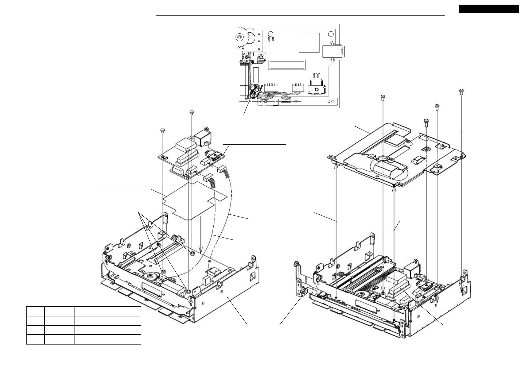
● Disassembling procedures
In reverse of assembling procedures.
● Assembling procedures
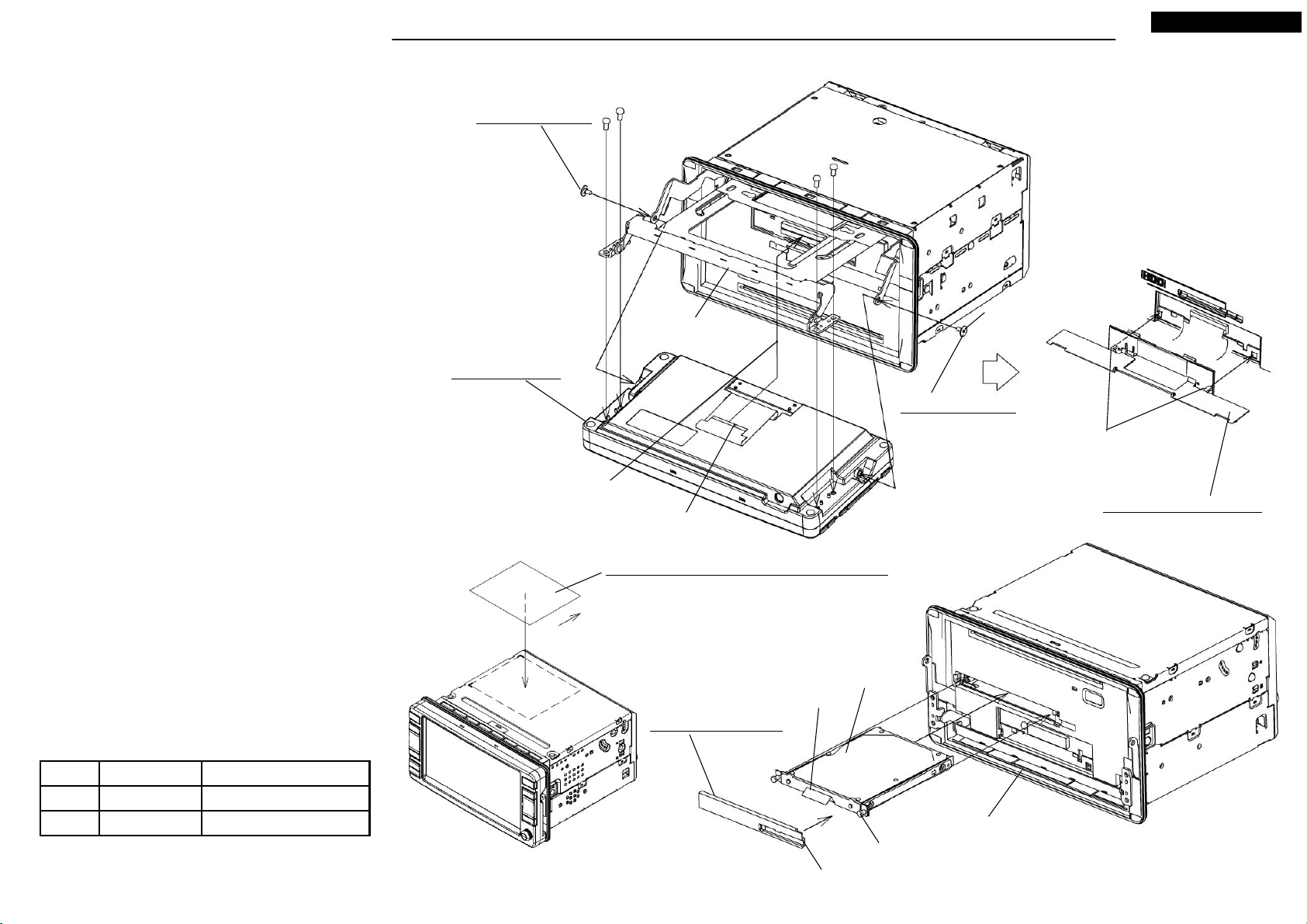
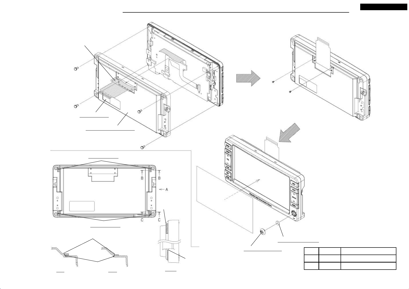
1.Insert the S7-HDD to the S2-CHASSIS, and screw the two screws.
2.Set M051.
3.Pull out the slide part of the S2-CHASSIS, and screw M086 with
the four screws (Ⓑ), and M024.
4.Insert the FPC of M086 to the S2-CHASSIS.
5.Set back the slide after M068 set.
M024: PIN-MONI
M086: S2-MONI
Lock after FPC inserted.
Ⓑ x 4
Do not break hexagon socket.
Slide
M024: PIN-MONI
Latch the hook at right and left,
then push the top. (After
assembling, check if M068
and the panel is seamless.)
M068: ASSY-COVER-F
Continuity side
Ⓑ 0.7 +0.2/-0.1M3X6
M084: NAME-CARD(NR-261UM-07LAN5)
Top
S7-HDD
Fold and set.
M051: PANEL-HDD
Tighten torque(N・m)Screw/NameNo.
0.4 +0.15/-0.05PIN-MONIM024
S2-CHASSIS
Two screws
Set this hook at first.
2
Your company internal use only.Copyright (C) Mitsubishi Electric Corporation.
Page 3
DISASSEMBLING PROCEDURES
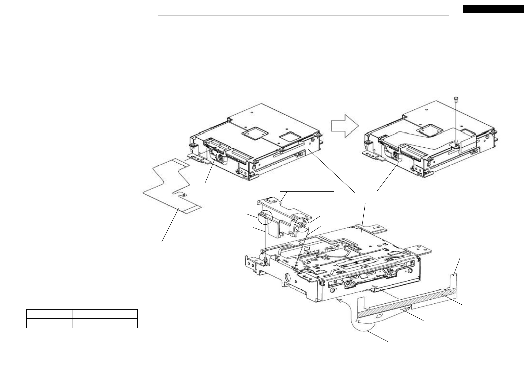
● Disassembling procedures
In reverse of assembling procedures.
● Assembling procedures
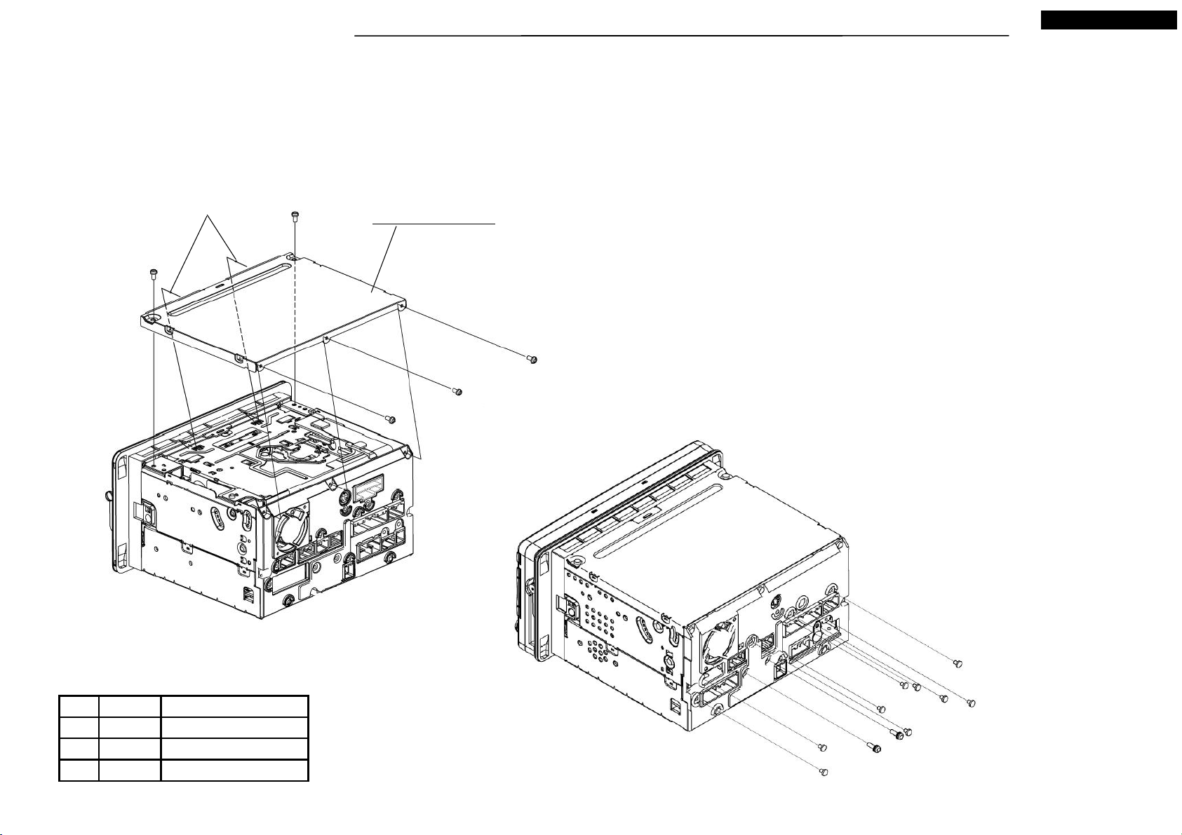
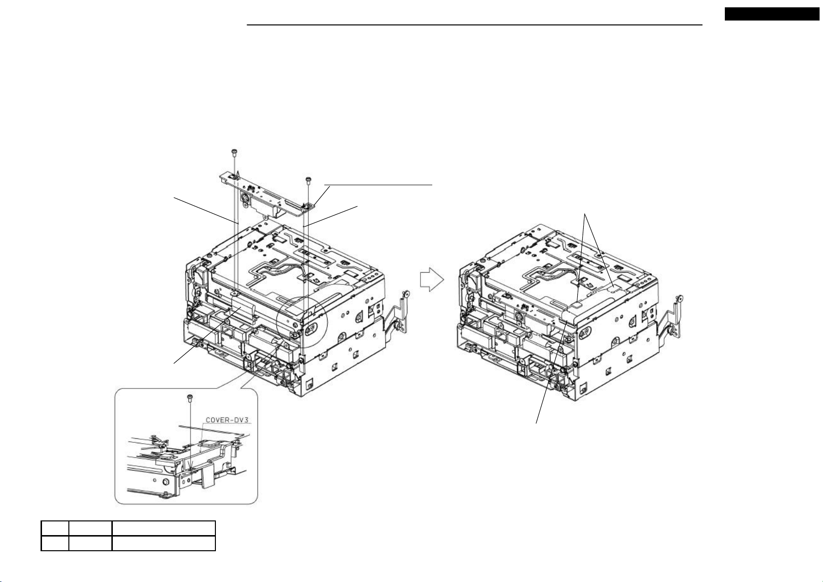
1.Screw M016 with the two screws(Ⓐ) and the three screws(Ⓒ).
2.Screw the nine screws(Ⓒ) and the two screws(Ⓚ).
NR-261UM-07LAN5
Latch the two hooks.
Ⓐ x 2
M016: COVER-TOP
Ⓒ x 3
Tighten torque(N ・m) : 0.4 +0.2/-0.1
M3X6 0.4 +0.2/-0.1Ⓐ
Ⓚ 0.7 +0.2/-0.1M3X10
Ⓒ x 9
Tighten torque(N ・m) : 0.3 +0.05/-0.05
Tighten torque(N・m)ScrewNo.
Refer in the fig.2.6X4Ⓒ
3
Ⓚ x 2
Your company internal use only.Copyright (C) Mitsubishi Electric Corporation.
Page 4
DISASSEMBLING PROCEDURES
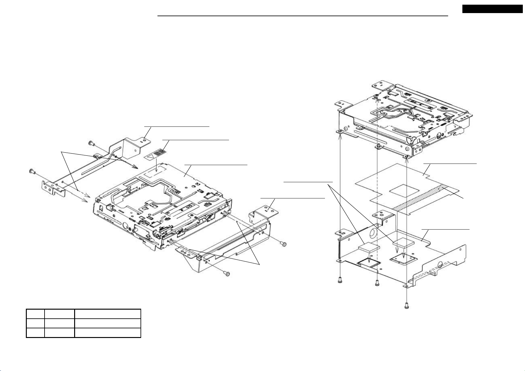
● Disassembling procedures
In reverse of assembling procedures.
● Assembling procedures
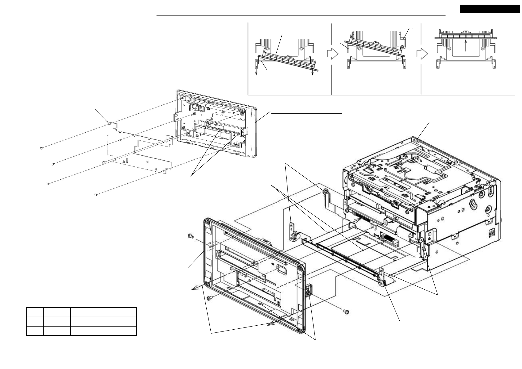
1.Hook M076 to M070, and screw the five screws(Ⓙ).
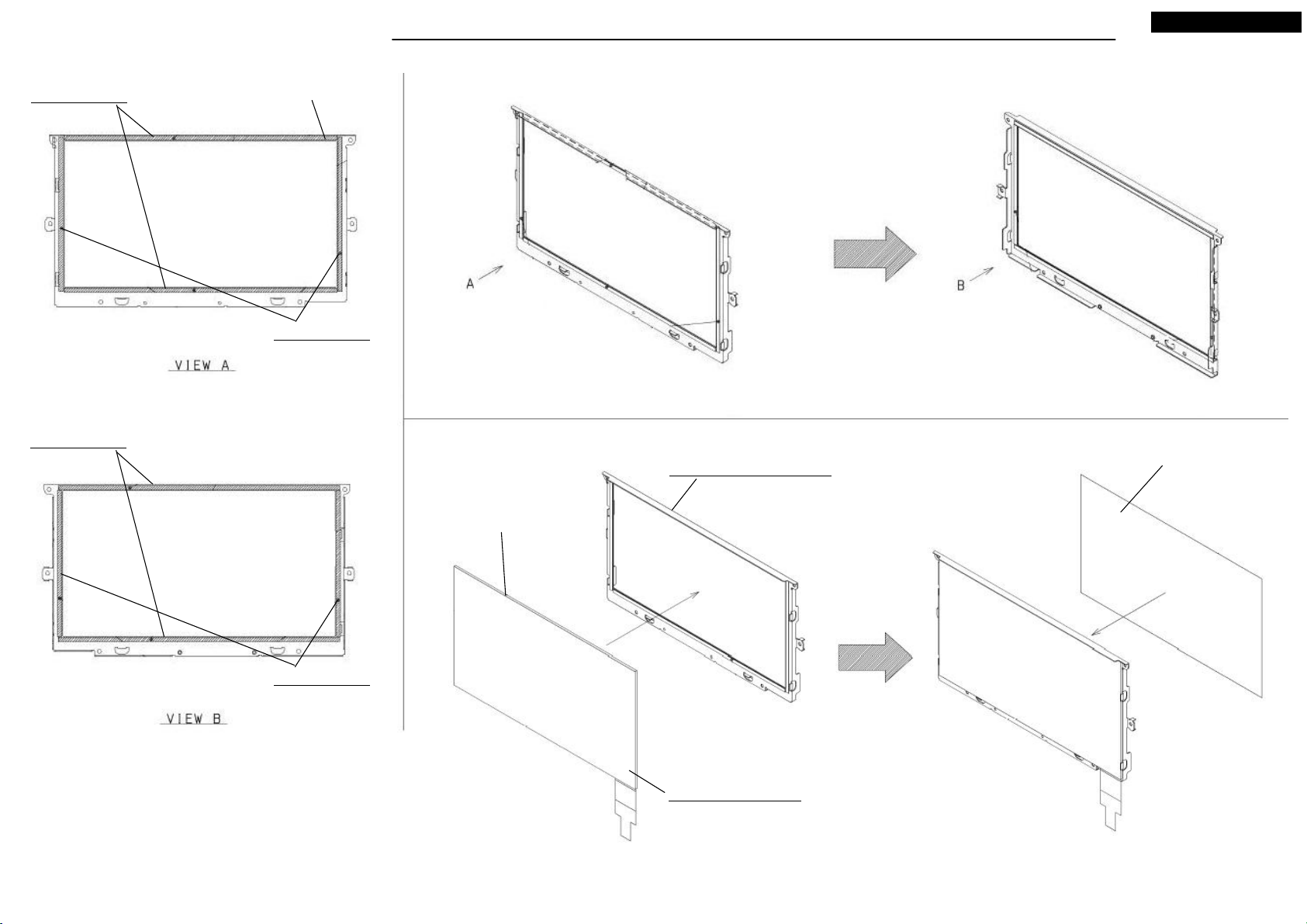
2.Pull out the slide part of the S3-CHASSIS, and pass the arm through
to the hole of the S3-PANEL-SUB.<Step1~3>
3.Screw the three screws(Ⓐ).
S3-PANEL-SUB
Slide chassis
<Step1> Pass the tip of slide chassis
through to panel by each.
Arm
<Step2> After passed the arm of one
side, pass the another side of arms.
NR-261UM-07LAN5
Arm
<Step3> Push the front of panel.
M076: ASSY-PCB-PANEL
Ⓙ x 5
Latch M076 to the hooks.
Ⓐ x 3
S3-PANEL-SUB
M070: ASSY-PANEL-SUB
S3-CHASSIS
Remove the arm protector.
(3)Push the front of panel to
connector mating. <Step3>
Remove the arm protector.
Tighten torque(N・m)ScrewNo.
M3X6 0.7 +0.2/-0.1Ⓐ
0.12 +0.01/-0.012X4Ⓙ
(2)After passed the one arm, pass another
arm with bending it internally. <Step2>
Do not give scratch to panel by arms.
(4) Push the square holes at side(two places) and
downside(three places), till the hooks set.<Step3>
4
(1)After pull out the slide chassis till it stops, pass the
tip through to panel each one side. <Step1>
Your company internal use only.Copyright (C) Mitsubishi Electric Corporation.
Page 5
DISASSEMBLING PROCEDURES
● Disassembling procedures
In reverse of assembling procedures.
● Assembling procedures
1.Screw M010 to M025 with two screws(Ⓚ).
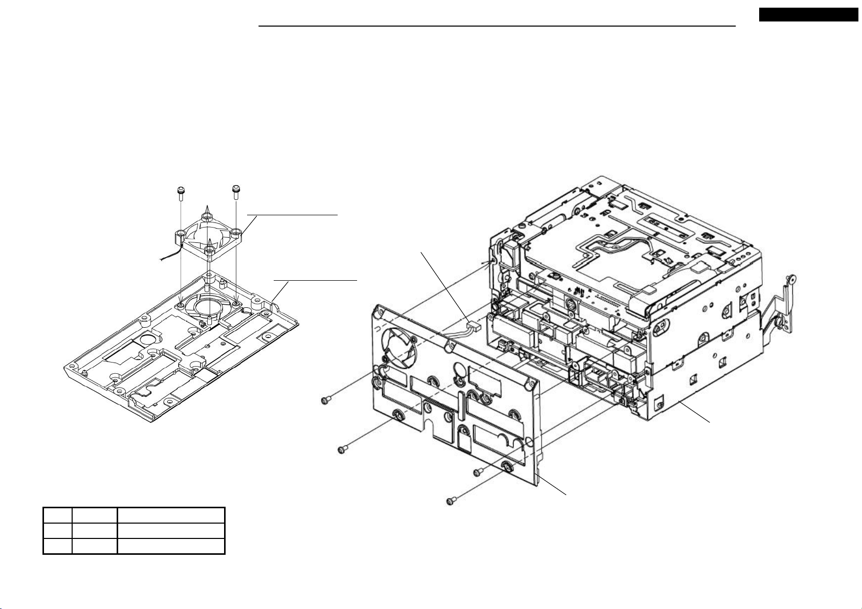
2.Connect LEAD-CONNECTOR of the S4-HEAT SINK to the S4-CHASSIS.
3.Screw the S4-HEAT-SINK with four screws(Ⓐ).
Ⓚ x 2
M010: MOTOR-FAN
M025: HEAT-SINK
NR-261UM-07LAN5
LEAD-CONNECTOR
Ⓐ x 4
S4-CHASSIS
S4-HEAT-SINK
Tighten torque(N・m)ScrewNo.
M3X6 0.7 +0.2/-0.1Ⓐ
0.7 +0.2/-0.1M3X10Ⓚ
5
Your company internal use only.Copyright (C) Mitsubishi Electric Corporation.
Page 6
DISASSEMBLING PROCEDURES
● Disassembling procedures
In reverse of assembling procedures.
● Assembling procedures
1.Screw M082 with the two screws(Ⓐ).
2.Screw the COVER-DV3 with the one screw(Ⓐ).
3.Connect the FPC to M082.
Ⓐ x 2
NR-261UM-07LAN5
Pass salient to the square hole
on the circuit board.
FPC
Ⓐ
M082: ASSY-PCB-CONN
Fit reentrant on the circuit board
to salient.
Set FPC to COVER-DV3.
Lock after FPC connected.
Tighten torque(N・m)ScrewNo.
M3X6 0.7 +0.2/-0.1Ⓐ
6
Your company internal use only.Copyright (C) Mitsubishi Electric Corporation.
Page 7
DISASSEMBLING PROCEDURES
● Disassembling procedures
In reverse of assembling procedures.
● Assembling procedures
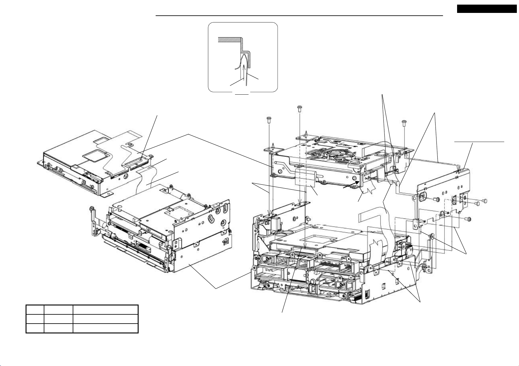
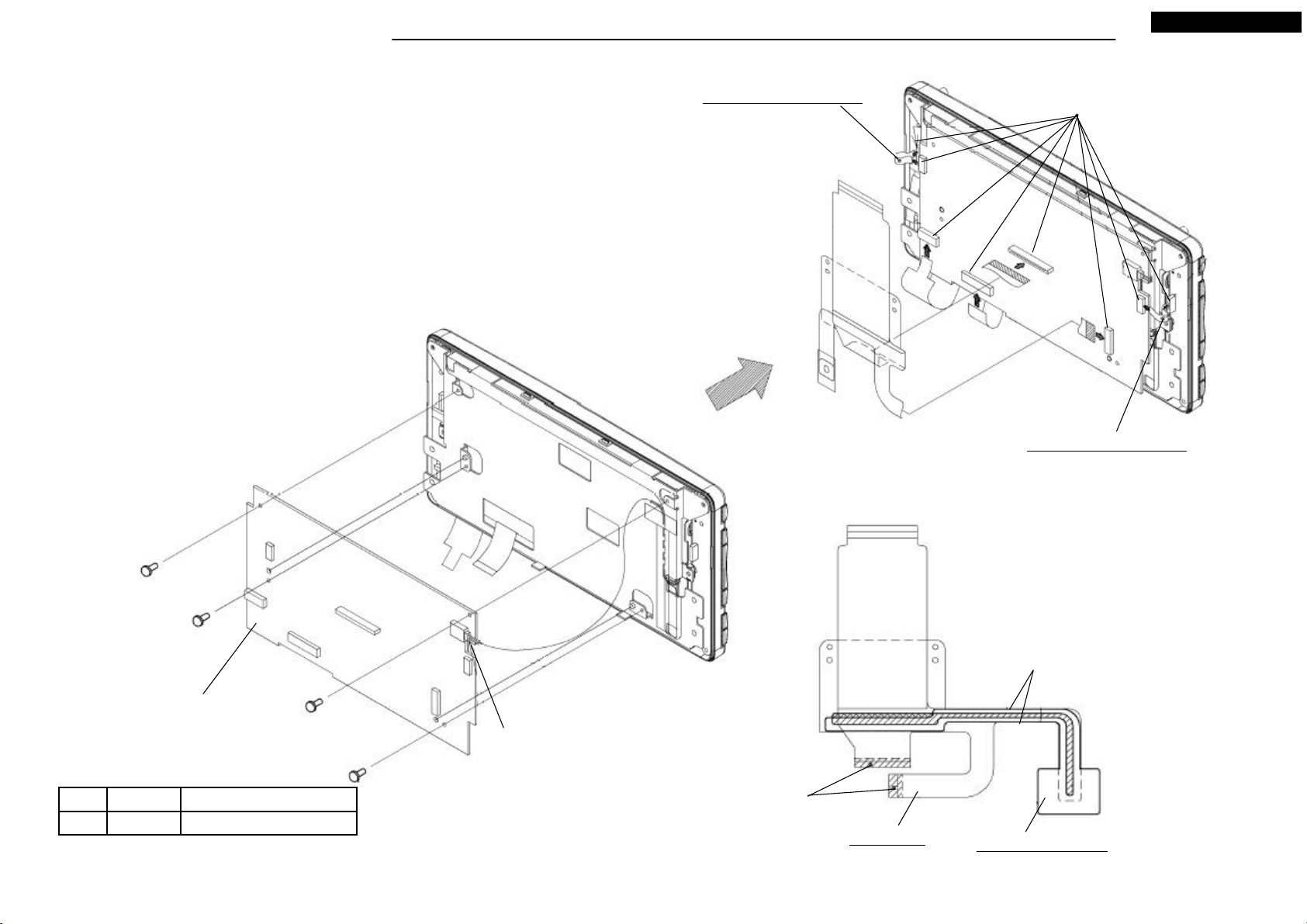
1.Connect FFC from S5-CHASSSIS to S5-DECK.
2.Fit the salients and put S5-DECK to S5-CHASSIS.
3.Set FPC-1 at the hooks of S5-DECK.
4.Insert the FFC to the cover of the S5-DECK. (View J)
5.Set M012, and screw the five screws(Ⓐ) and two screws(Ⓒ).
6.Connect FPC-2 from S5-DECK to S5-CHASSIS.
Lock after FFC connected.
S5-DECK
Continuity side
Insert
View J
FFC
Ⓐ x 3
NR-261UM-07LAN5
Set FPC-1 at these hooks.
Fit the dowels.
Insert M012 from downside surely.
M012: CHASSIS-L
FFC
Fit the square holes
to the salients.
View J
FPC-2
FFC
FPC-1
Ⓒ x 2
Ⓐ x 2
Latch the hooks to the
square holes.
S5-CHASSIS
Tighten torque(N・m)ScrewNo.
M3X6 0.7 +0.2/-0.1Ⓐ
Lock after FPC connected.
Fit the dowels.
0.4 +0.2/-0.12.6X4Ⓒ
7
Your company internal use only.Copyright (C) Mitsubishi Electric Corporation.
Page 8
DISASSEMBLING PROCEDURES
● Disassembling procedures
In reverse of assembling procedures.
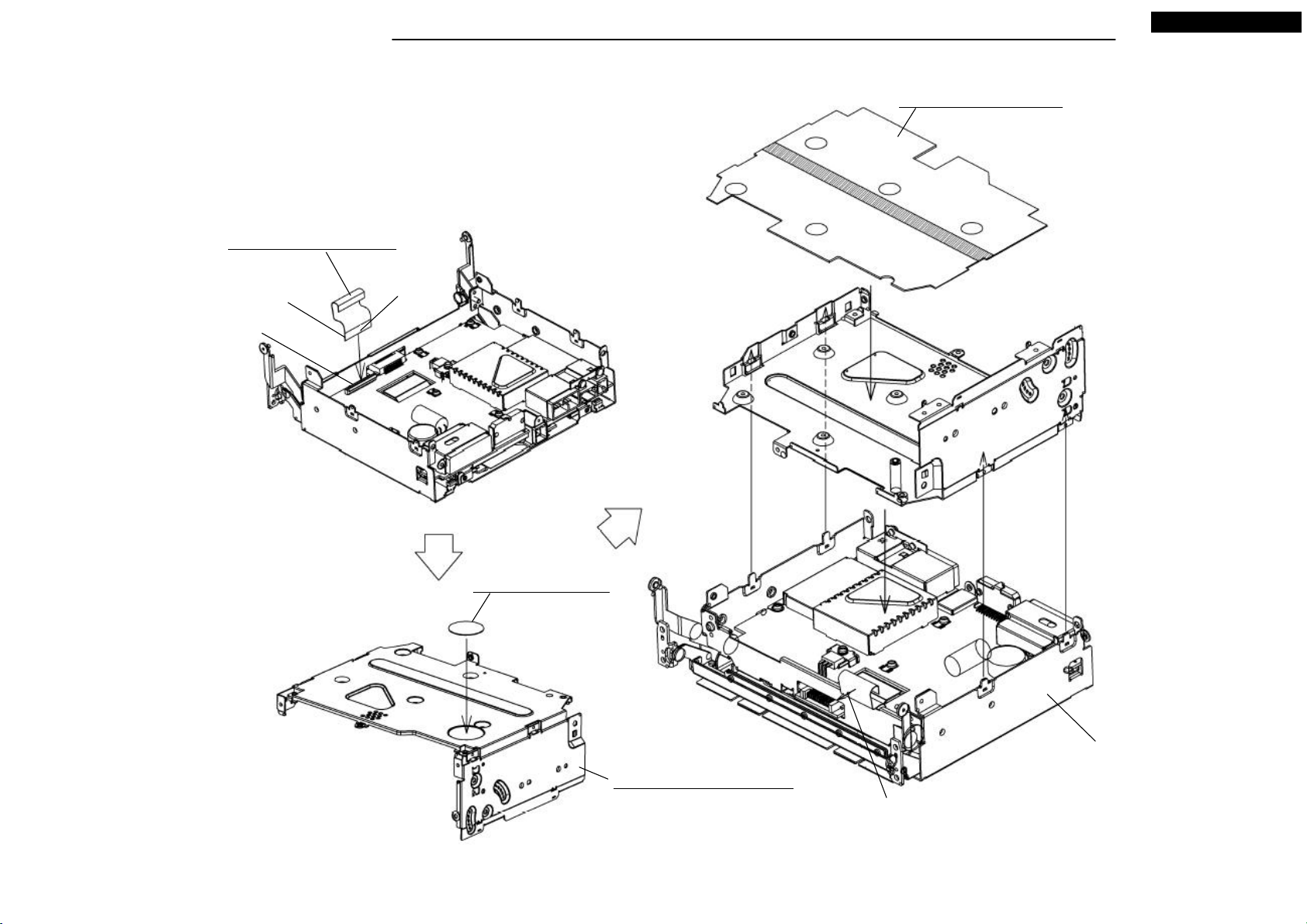
● Assembling procedures
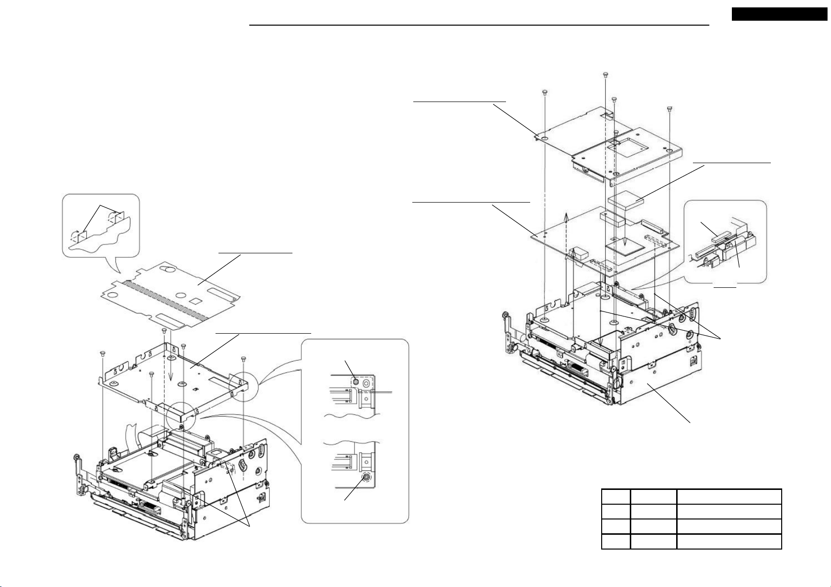
1.Set M015 and screw the five screws(Ⓒ).
2.Remve the separator and stick M035 to M015.
3.Set M077 to S5-CHASSIS while matching the two salients.
4.Connect FFC from HDD circuit on S5-CHASSIS to M077.(View F)
5.Stick M029 to Navicore of M077.
6.Set M067, and screw the one screw(Ⓓ) and the four screws(Ⓔ).
M067: ASSY-SHIELD
Be careful to not change
the shape when
assembling.
NR-261UM-07LAN5
Ⓓ
Ⓔ x 4
M029: SHEET-HS
Put on the Navicore.
Fold
Ⓒ x 5
M035: SHEET-DI
M015: CASE-DIGITAL
Fit the dowel to the hole.
M077: ASSY-PCB-DIGITAL
Lock after FFC
connected.
FFC from HDD.
View F
Engage the connectors.
(Push “PUSH” on circuit board)
S5-CHASSIS
Fit the salient of post to
the hole.
Remove the connector covers.
8
Tighten torque(N・m)ScrewNo.
2.6X4 0.4 +0.2/-0.1Ⓒ
0.4 +0.2/-0.1M2.6X3Ⓓ
0.4 +0.2/-0.1M2.6X6Ⓔ
Your company internal use only.Copyright (C) Mitsubishi Electric Corporation.
Page 9
DISASSEMBLING PROCEDURES
● Disassembling procedures
In reverse of assembling procedures.
● Assembling procedures
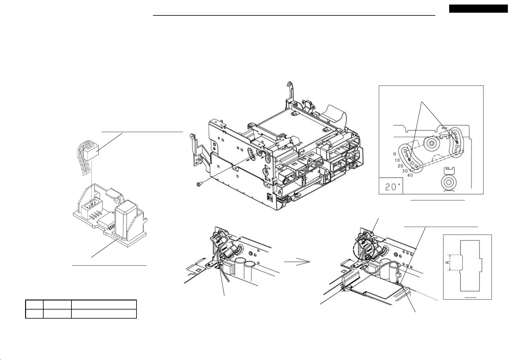
1.Connect M007 to M083. (Either direction of the connector can be connected.)
2.Screw the M083 with the one screw(Ⓐ).
3.Latch the hook of M007 to the hook.
4.Connect M007 to M081.
M007: LEAD-CONNECTOR 4P
NR-261UM-07LAN5
Hook latch position.
Ⓐ
Assembling Angle of M083
Pass the Lead-Connector
to area A of Fig. A.
M081: ASSY-PCB-ANALOG
M083: ASSY-PCB-SENSOR
Latch the Lead-Connector
Tighten torque(N・m)ScrewNo.
M3X6 0.7 +0.2/-0.1Ⓐ
to the hook.
9
Remove the adsorption sheet
of P604.
Your company internal use only.Copyright (C) Mitsubishi Electric Corporation.
Fig. A
Page 10

DISASSEMBLING PROCEDURES
● Disassembling procedures
In reverse of assembling procedures.
● Assembling procedures
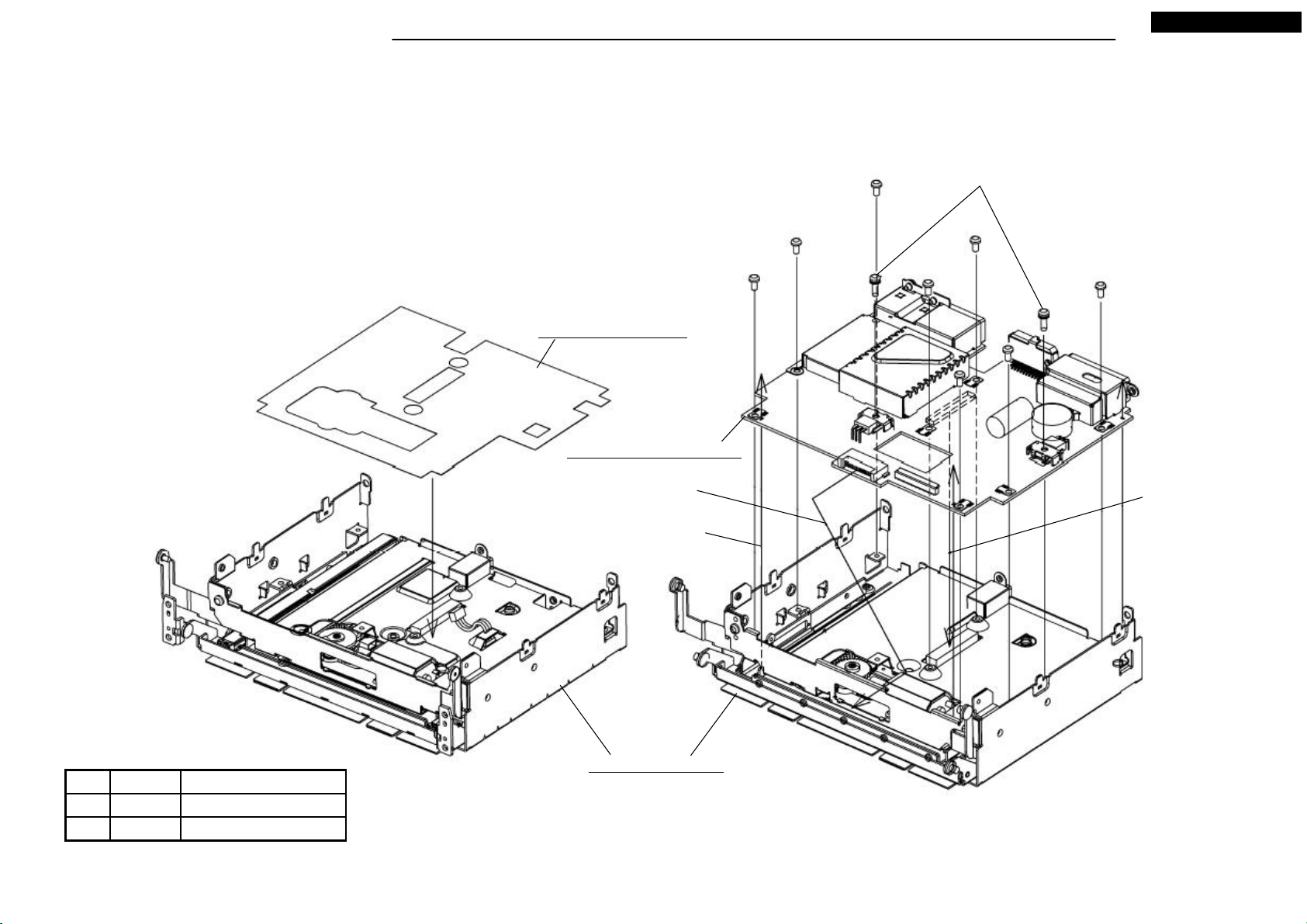
1.Screw M081 with the five screws(Ⓐ).
2.Screw the S5-HOLDER with the four screws(Ⓐ) from a→b→c→d.
3.Latch the square hole of M021 to the hook, and set the dowel to the hole. (Fig. B)
4.Screw M021 with the one screw(Ⓐ).
S5-HOLDER
NR-261UM-07LAN5
b
a
d
Ⓐ x 9
c
M081: ASSY-PCB-ANALOG
M021: BRACKET-NAVI
Tighten torque(N・m)ScrewNo.
Dowel
M3X6 0.7 +0.2/-0.1Ⓐ
Hook
There must be no space after
tightening of the screw.
Fig. B
10
Ⓐ
Your company internal use only.Copyright (C) Mitsubishi Electric Corporation.
Page 11
DISASSEMBLING PROCEDURES
● Disassembling procedures
In reverse of assembling procedures.
● Assembling procedures
1.Set the hook of chassis to M081. (View A)
2.Connect M001, M004, M006 to the connectors.
NR-261UM-07LAN5
M001: FPC-CON
M081: ASSY-PCB-ANALOG
Continuity side
Himeron
M004: FLAT-CABLE 30P
Pin 1 (white marking)
M006: FLAT-CABLE 50P
11
Set M081 from left to right.
View A
Your company internal use only.Copyright (C) Mitsubishi Electric Corporation.
Page 12
DISASSEMBLING PROCEDURES
● Disassembling procedures
In reverse of assembling procedures.
● Assembling procedures
1.Connect M006 and pull it forward.
2.Remove the separator and stick M032 to M011(revers side).
3.Remove the separator and stick M031 to M011(face side).
4.Set M011 to guide salient, and assemble.
M006: FLAT-CABLE 50P
Continuity side
Pin 1 (white marking)
Lock after FFC connected.
(reverse side)
NR-261UM-07LAN5
M031: SHEET-ANALOG
M032: SHEET-COIL
M011: CHASSIS-ANALOG
12
S5-CHASSIS
Pull forward
Your company internal use only.Copyright (C) Mitsubishi Electric Corporation.
Page 13
DISASSEMBLING PROCEDURES
● Disassembling procedures
In reverse of assembling procedures.
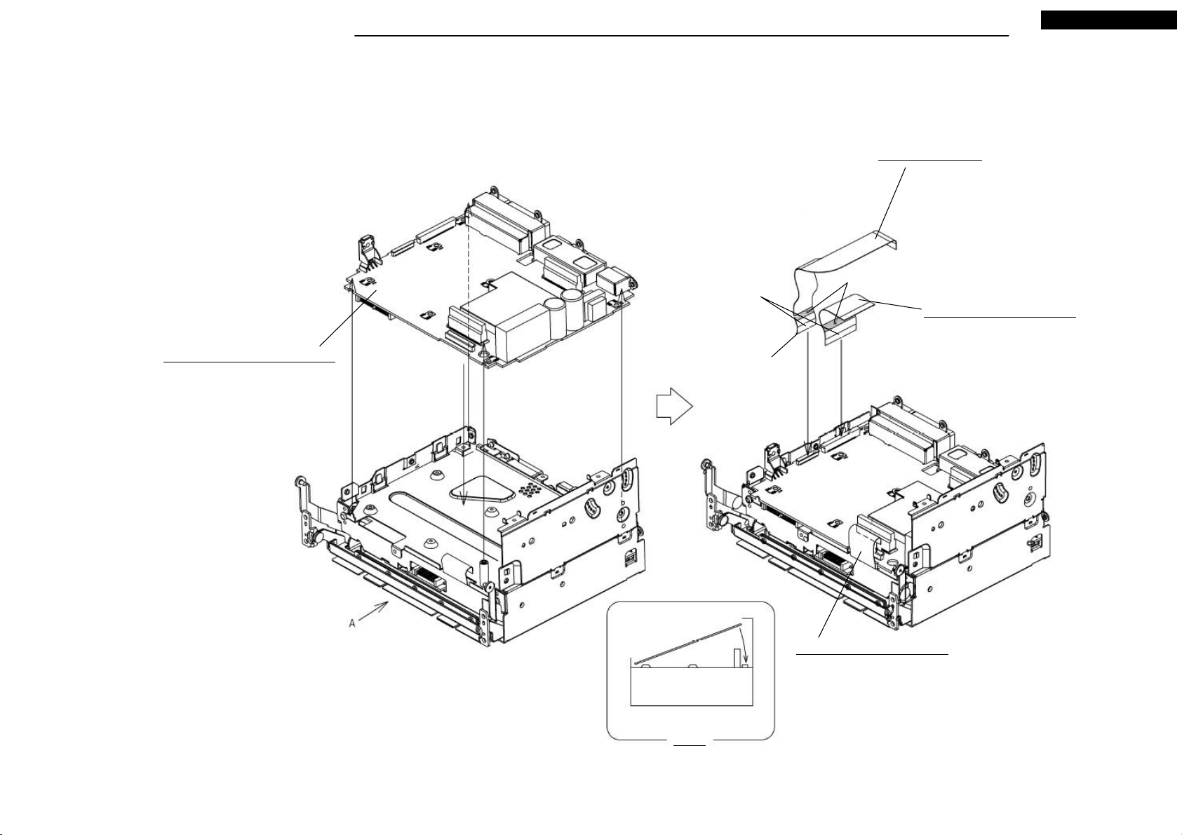
● Assembling procedures
1.Set M033 to M069.
2.Set M079 to M069, from front connector side with a slope.
3.Pass the salients to the circuit square holes, and insert the central connector.
4.Screw M079 with eight screws(Ⓐ) and the two screws(Ⓚ).
M033: SHEET-AUDIO
M079: ASSY-PCB-AUDIO
Ⓐ x 8
NR-261UM-07LAN5
Ⓚ x 2
Insert the front connector
side to the square hole.
Pass the salients to the circuit
square holes. (three places)
Connector mating
(Push ”PUSH” on the circuit)
M069: ASSY-SLIDE
Tighten torque(N・m)ScrewNo.
M3X6 0.7 +0.2/-0.1Ⓐ
0.7 +0.2/-0.1M3X10Ⓚ
13
Your company internal use only.Copyright (C) Mitsubishi Electric Corporation.
Page 14
DISASSEMBLING PROCEDURES
● Disassembling procedures
In reverse of assembling procedures.
● Assembling procedures
1.Remove the tape from Lead-Connector 1 and Lead-Connector 2.
2.See three posts as a guide, put M027 on M069.
3.Screw M080 with the three screws(Ⓒ).
4.Connect Lead-Connector 1 and Lead-Connector 2 to M080.
5.Hold two Lead-Connectors with the stylepin.
6.Screw M013 with the three screws(Ⓐ) and the one screw(Ⓚ).
NR-261UM-07LAN5
Ⓐ x 3
M027: SHEET-BTM
Post
Ⓒ x 3
Stylepin
M080: ASSY-PCB-GPS
Lead-Connector 2
Lead-Connector 1
Ⓚ
M013: PLATE
Set the dowel.
Set the dowel.
M3X6 0.7 +0.2/-0.1Ⓐ
Ⓚ 0.7 +0.2/-0.1M3X10
Tighten torque(N・m)ScrewNo.
0.4 +0.2/-0.12.6X4Ⓒ
M069: ASSY-SLIDE
14
Remove the connector cover.
Your company internal use only.Copyright (C) Mitsubishi Electric Corporation.
Page 15
DISASSEMBLING PROCEDURES
● Disassembling procedures
In reverse of assembling procedures.
● Assembling procedures
1.Connect M002 to S10-DECK.
2.Screw the one screw(Ⓒ).
3.Latch the Hook A to the S10-DECK, and latch the Hook B.
4.Remove the separator and stick M034.
5.Insert the folded part of M034 to under space of the S10-DECK.
NR-261UM-07LAN5
Ⓒ
Lock after FFC connected.
M026: COVER-DV3
S10-DECK
Hook B
Latch the Hook B.
Hook A
Latch
M002: FPC-DVD
M034: SHEET-FRONT
Tighten torque(N・m)ScrewNo.
2.6X4 0.4 +0.2/-0.1Ⓒ
Insert after stuck.
15
Set and stick here.
Your company internal use only.Copyright (C) Mitsubishi Electric Corporation.
Double-faced tape
Remove the separator.
Page 16
DISASSEMBLING PROCEDURES
● Disassembling procedures
In reverse of assembling procedures.
● Assembling procedures
1.Screw M017 with the two screws(Ⓐ).
2.Screw M023 with the two screws(Ⓐ).
3.Stick M064 to M075.
4.Remove the separator and stick M036.
5.Attach M030 to M018.
6.Screw M018 with the three screws(Ⓒ) from bottom.
M023: BRACKET-DV3R
NR-261UM-07LAN5
Set the dowels.
M3X6 0.7 +0.2/-0.1Ⓐ
Tighten torque(N・m)ScrewNo.
Ⓐ x 2
0.4 +0.2/-0.12.6X4Ⓒ
M064: LABEL-CAUTION
M075: DV3DP(950850)
M036: SHEET-DVD
M030: SHEET-HS
M017: BRACKET-DV3F
Double-faced tape.
Remove the separator
and stick to M018.
M018: PLATE-HS
Set the dowels.
Ⓐ x 2
Ⓒ x 3
16
Your company internal use only.Copyright (C) Mitsubishi Electric Corporation.
Page 17
DISASSEMBLING PROCEDURES
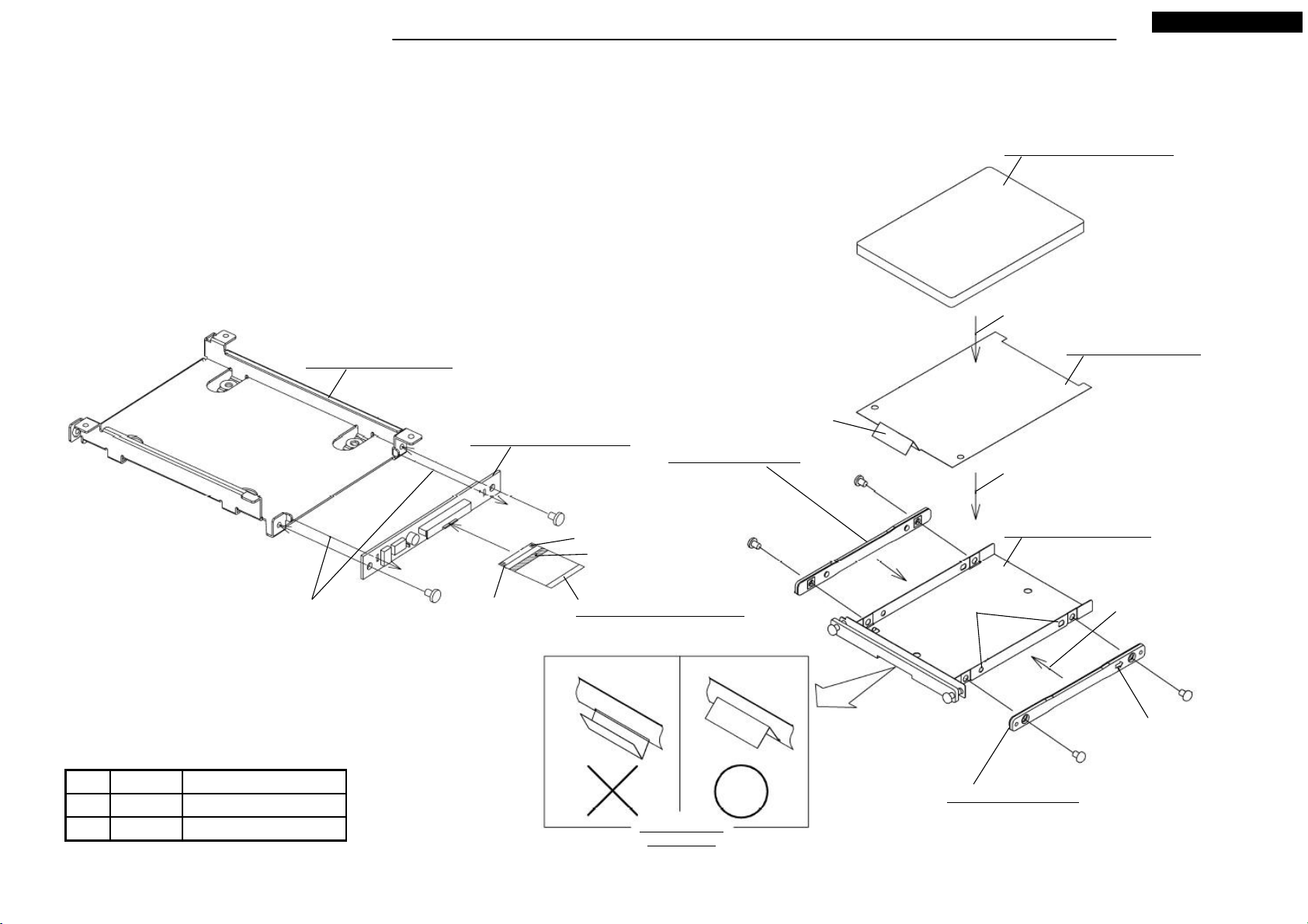
● Disassembling procedures
In reverse of assembling procedures.
● Assembling procedures
1.Screw M078 with the two screws(Ⓒ), and connect M005.
NR-261UM-07LAN5
M074: ASSY-ROM(HDD)
Assemble
M022: HOLDER-HDD
M028: SHEET-HDD
Tongue
M078: ASSY-PCB-HDD
M050: PLATE-HDD
Assemble while inserting tongue into the
slit of the plate.
Ⓒ x 2
Through the circuit hole
to the hook.
Pin 1 on the other side
(black marking)
Continuity side
Himeron
M005: FLAT-CABLE 50P
Ⓛ x 2
Positioning hole
M020: HOLDER-HDD
Set the salients to the
positioning holes and assemble.
Arrow must be the side of
connector. (other side too)
Ⓛ x 2
Tighten torque(N・m)ScrewNo.
2.6X4 0.4 +0.2/-0.1Ⓒ
0.3 +0.15/-0.05M3X4Ⓛ
Tongue position
after inserted
M050: PLATE-HDD
17
Your company internal use only.Copyright (C) Mitsubishi Electric Corporation.
Page 18
DISASSEMBLING PROCEDURES
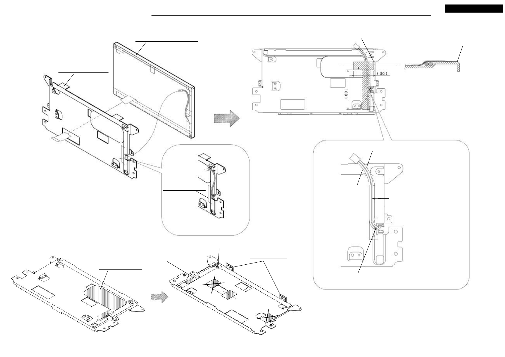
*It is assembling procedure. Disassembling procedure is in reverse.
Also pass the black sheet from
the hole.
Ⓗ x 4
M063: LABEL
M072: ASSY-PANEL-R
NR-261UM-07LAN5
Ⓕ x 2
B - B
(symmetry)
M088: SHEET
M039: SHEET
Do not run aground on the slope.
Attachment position
C - C
(symmetry)
Attachment position
(R end)
View A
Attachment position
(R end)
18
M049: SHEET-ENT
M073: ASSY-ENT
Tighten torque(mN・m)ScrewNo.
2X4 100 +10/-10Ⓕ
280 +10/-102X8Ⓗ
Your company internal use only.Copyright (C) Mitsubishi Electric Corporation.
Page 19
DISASSEMBLING PROCEDURES
*It is assembling procedure. Disassembling procedure is in reverse.
M008: FLAT-CABLE 8P
Blue reinforced plate side
NR-261UM-07LAN5
Lock after FFC connected.
M008: FLAT-CABLE 8P
Blue reinforced plate side
PCB-MONITOR
Screw with the screw that made by
Iwata bolt.
Tighten torque(mN・m)ScrewNo.
2X4 200 +100/-40Ⓜ
Ⓜ x 4
After inserting the connector till it is
locked, screw.
Reverse side of reinforced plate
19
M003: FPC
Attachment position of M046
M046: SHEET-FPC
Your company internal use only.Copyright (C) Mitsubishi Electric Corporation.
Page 20
DISASSEMBLING PROCEDURES
*It is assembling procedure. Disassembling procedure is in reverse.
NR-261UM-07LAN5
Re-attach the protecting sheet
that removed.
A
Remove the protecting sheet .
Ⓕ x 4
View A
Remove the protecting sheet .
Ⓕ x 2
Tighten torque(mN・m)ScrewNo.
2X4 145 +10/-10Ⓕ
20
Remove the separator from
M041, M042.(4 places)
Your company internal use only.Copyright (C) Mitsubishi Electric Corporation.
Page 21
DISASSEMBLING PROCEDURES
NR-261UM-07LAN5
*It is assembling procedure. Disassembling procedure is in reverse.
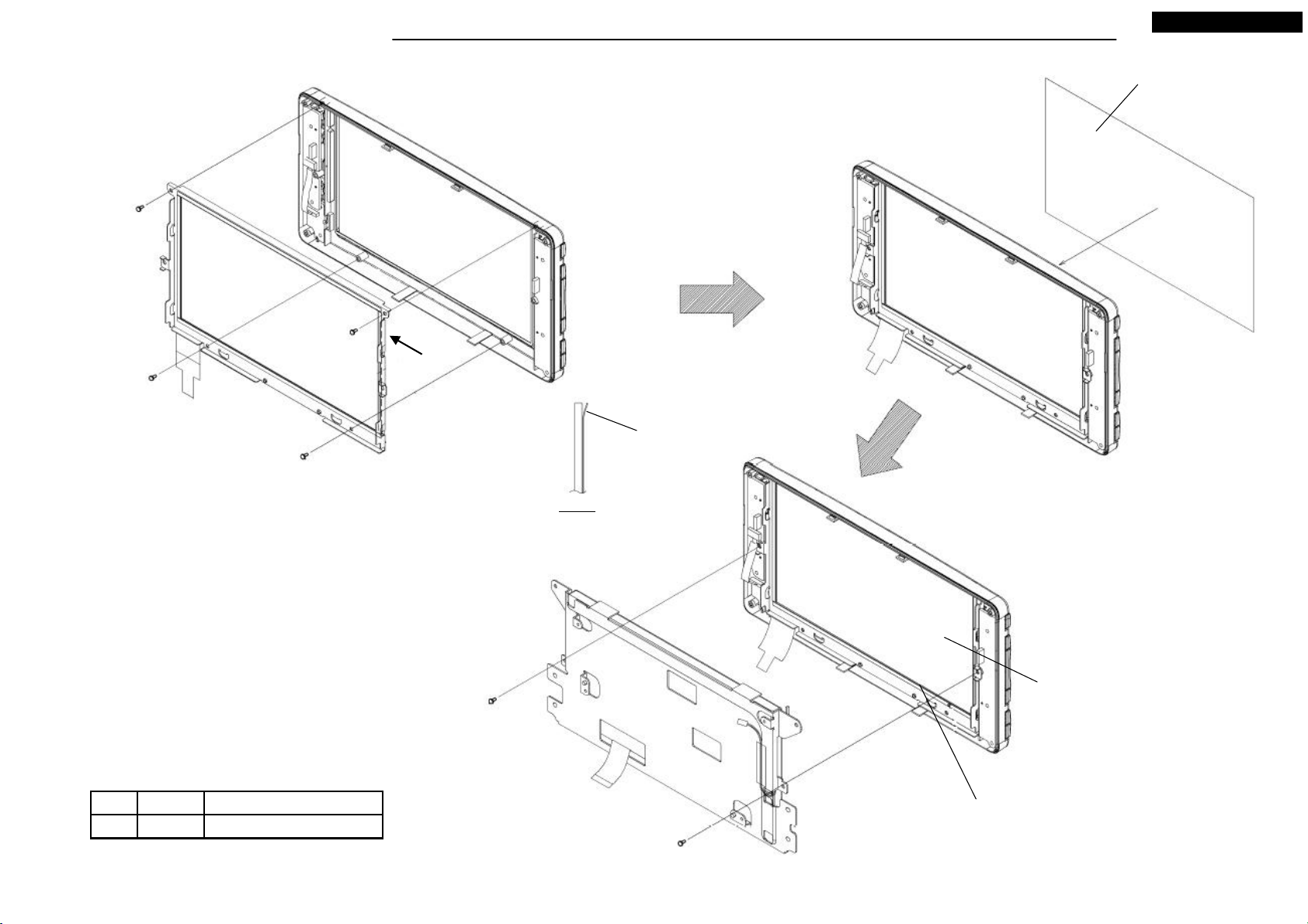
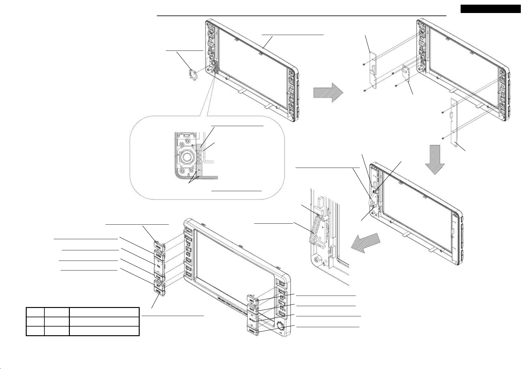
M062: PRISM
Attachment position
M071: ASSY-PANEL-F
M047: SHEET-LCD
Note that M047 is not touched
to the edge of M071.
Attach M047 after inserted
M062.
M047 Attachment Detail
Blue reinforced plate
PCB-KEY-NAVI
Ⓖ x 2
Lock after FFC connected.
M009: FLAT-CABLE 8P
Ⓕ x 2
PCB-KEY-JOY
Blue reinforced plate side
Ⓖ x 2
PCB-KEY-AUDIO
M054: BUTTON-MODE
M055: BUTTON-AUDIO
M052: BUTTON-VOL
M056: BUTTON-PWR
M057: BUTTON-SET
Tighten torque(mN・m)ScrewNo.
2X4 125 +10/-10Ⓕ
185 +10/-102X6Ⓖ
M058: BUTTON-OPEN
M043: SHEET
After insert M009, attach
M043 to touch on the blue
reinforced plate.
M059: BUTTON-INFO
M060: BUTTON-NAVI
M053: BUTTON-SCALE
M061: BUTTON-MENU
21
Lock after FFC
connected.
Your company internal use only.Copyright (C) Mitsubishi Electric Corporation.
Page 22
DISASSEMBLING PROCEDURES
*It is assembling procedure. Disassembling procedure is in reverse.
NR-261UM-07LAN5
M038: SHEET
Attach to be not touched to the
edge of M019.
M042: SHEET
Attach according to the corner.
M037: SHEET
Re-attach the protecting sheet
that removed from M066.
M019: PLATE-T-PANEL
Remove the protecting sheet
on the attachment side.
Attach to be not touched to the
edge of M019.
M041: SHEET
M066: ASSY-PANE
22
Your company internal use only.Copyright (C) Mitsubishi Electric Corporation.
Page 23
DISASSEMBLING PROCEDURES
NR-261UM-07LAN5
*It is assembling procedure. Disassembling procedure is in reverse.
M065: PLATE-T-PANEL
M014: PLATE-LCD
M045: SHEET-L
Attachment position
(horizontal direction)
Pink wire
Black wire
Attachment position
(R end)
Along the shape of M014.
M048: SHEET-B
Pass the wire from slit of M045.
M045: SHEET-L
M040: SHEET
M044: SHEET
23
Black wire must pass on Pink wire.
Your company internal use only.Copyright (C) Mitsubishi Electric Corporation.
Page 24
PARTS LIST
NR-261UM-07LAN5
Ref. No . Parts No. Parts Nam e Pag e Ref. No . Parts No. Parts Nam e Page
M001 241L91810 FPC-CON P.11 M050 645L21310 PLATE-HDD P.17
M002 241L91910 FPC-DVD P.15 M051 707L24214 PANEL-HDD P.2
M003 210K45110 FPC P.19 M052 734K03710 BUTTON-VOL P.21
M004 246L55611 FLAT-CABLE 30P P.11 M053 734K03810 BUTTON-SCALE P.21
M005 246L45025 FLAT-CABLE 50P P.17 M054 734K03910 BUTTON-MODE P.21
M006 246L45026 FLAT-CABLE 50P P.11,12 M055 734K04010 BUTTON-AUDIO P.21
M007 246L47114 LEAD-CONNECTOR 4P P.9 M056 734K04110 BUTTON-PWR P.21
M008 246L47226 FLAT-CABLE 8P P.19 M057 734K04210 BUTTON-SET P.21
M009 246L47227 FLAT-CABLE 8P P.21 M058 734K04310 BUTTON-OPEN P.21
M010 288P08415 MOTOR-FAN P.5 M059 734K04410 BUTTON-INFO P.21
M011 560J33413 CHASSIS-ANALOG P.12 M060 734K04510 BUTTON-NAVI P.21
M012 560K29023 CHASSIS-L P.7 M061 734K04610 BUTTON-MENU P.21
M013 590J39812 PLATE P.14 M062 761L62110 PRISM P.21
M014 590J42711 PLATE-LCD P.23 M063 850L96010 LABEL P.18
M015 591K54511 CASE-DIGITAL P.8 M064 851L262O4 LABEL-CAUTION P.16
M016 591K56620 COVER-TOP P.3 M065 890P11220 ASSY-LCD P.23
M017 591K56710 BRACKET-DV3F P.16 M066 890P11813 ASSY-PANE P.22
M018 591K56811 PLATE-HS P.16 M067 891K25210 ASSY-SHIELD P.8
M019 591K62910 PLATE-T-PANEL P.22 M068 891L65816 ASSY-COVER-F P.2
M020 593L68211 HOLDER-HDD P.17 M069 892J02655 ASSY-SLIDE P.12,13
M021 593L75210 BRACKET-NAVI P.10 M070 892K52111 ASSY-PANEL-SUB P.4
M022 593L75320 HOLDER-HDD P.17 M071 892L45337 ASSY-PANEL-F P.21
M023 593L75420 BRACKET-DV3R P.16 M072 892L45412 ASSY-PANEL-R P.18
M024 630L36511 PIN-MONI P.2 M073 892L45512 ASSY-ENT P.18
M025 635J09611 HEAT-SINK P.5 M074 937L57311 ASSY-ROM(HDD) P.17
M026 641K40412 COVER-DV3 P.15 *M075 940L42710 DV3DP(950850) P.16
M027 643L15011 SHEET-BTM P.14 M076 943M216O2 ASSY-PCB-PANEL P.4
M028 643L15110 SHEET-HDD P.17 M077 943M268O1 ASSY-PCB-DIGITAL P.8
M029 643L41915 SHEET-HS P.8 M078 943M268O2 ASSY-PCB-HDD P.17
M030 643L41916 SHEET-HS P.16 M079 943M383O5 ASSY-PCB-AUDIO P.13
M031 643L47510 SHEET-ANALOG P.12 M080 943M383O6 ASSY-PCB-GPS P.14
M032 643L47610 SHEET-COIL P.12 M081 943M330O7 ASSY-PCB-ANALOG P.9,10,11
M033 643L47811 SHEET-AUDIO P.13 M082 943M330O8 ASSY-PCB-CONN P.6
M034 643L47910 SHEET-FRONT P.15 M083 943M330O9 ASSY-PCB-SENSOR P.9
M035 643L55410 SHEET-DI P.8 M084 943M383O7 NAME-CARD(NR-261UM-07LAN5) P.2
M036 643L60310 SHEET-DVD P.16 M086 967L16518 S2-MONI P.2
M037 643L60812 SHEET P.22 M088 643L60821 SHEET P.18
M038 643L60813 SHEET P.22 A 653P01046 SCREW-MC-PAN M3X6 M039 643L60815 SHEET P.18 B 653P01446 SCREW-MC-PAN M3X6 M040 643L60816 SHEET P.23 C 653P03026 SCREW-MC-BIND 2.6X4 M041 643L60817 SHEET P.22 D 653P03425 SCREW-MC-BIND M2.6X3 M042 643L60818 SHEET P.22 E 653P06027 SCREW-MC-SEMS M2.6X6 M043 643L60819 SHEET P.21 F 653P21662 SCREW-B-PAN 2X4 M044 643L60820 SHEET P.23 G 653P21766 SCREW-B-PAN 2X6 M045 643L60910 SHEET-L P.23 H 653P41616 SCREW-MC-PAN 2X8 M046 643L61010 SHEET-FPC P.19 J 669L11110 SCREW-TAP 2X4 M047 643L61110 SHEET-LCD P.21 K 669L11210 SCREW-SEMS M3X10 M048 643L61210 SHEET-B P.23 L 669L12610 SCREW-FH M3X4 M049 643L61310 SHEET-ENT P.18 M 669L13710 SCREW-S-BIND 2X4 -
* Marked part is the ASSY replacement.
24
Your company internal use only.Copyright (C) Mitsubishi Electric Corporation.
Page 25

ELECTRICAL PARTS LIST
Ref. No. Parts No. Parts Name Note Spec. Base Parts No. Ref. No. Parts No. Parts Name Note Spec. Base Parts No.
ANT001 449L076O8 SOCKET N931L16318 C1009 141L069O7 C-CERAMIC-CHIP GRM21BB10J106KE01L B 6.3V 106K2125 N937L27117
C003 141L164O6 C-CERAMIC-CHIP GRM188B11C104KA01D B 16V 104K 1608 N931L16418 C101 141L185O1 C-CERAMIC-CHIP GRM1882C1H471JA01D CH 50V 471J1608 N931L16418
C004 141L160O9 C-CERAMIC-CHIP GRM188B11H102KA01D B 50V 102K 1608 N931L16418 C1010 141L069O7 C-CERAMIC-CHIP GRM21BB10J106KE01L B 6.3V 106K2125 N937L27117
C005 141L181O1 C-CERAMIC-CHIP GRM1882C1H100RZ01D CH50V100C 1608 N931L16418 C1011 141L069O7 C-CERAMIC-CHIP GRM21BB10J106KE01L B 6.3V 106K2125 N937L27117
C006 141L160O9 C-CERAMIC-CHIP GRM188B11H102KA01D B 50V 102K 1608 N931L16418 C1012 141L164O6 C-CERAMIC-CHIP GRM188B11C104KA01D B 16V 104K 1608 N931L16418
C007 141L160O9 C-CERAMIC-CHIP GRM188B11H102KA01D B 50V 102K 1608 N931L16418 C1014 141L164O6 C-CERAMIC-CHIP GRM188B11C104KA01D B 16V 104K 1608 N931L16418
C008 141L181O1 C-CERAMIC-CHIP GRM1882C1H100RZ01D CH50V100C 1608 N931L16418 C1015 141L069O7 C-CERAMIC-CHIP GRM21BB10J106KE01L B 6.3V 106K2125 N937L27117
C009 141L162O1 C-CERAMIC-CHIP GRM188B11H103KA01D B 50V 103K 1608 N931L16418 C1016 181P80853 C-ELECTROLYTIC-CHIP EMZA350ADA470MF61G 35V 470M N937L05211
C009E 181P80726 C-ELECTROLYTIC-CHIP UZT1C470MCLASEGB 16V 470M N931L16418 C1017 141L182O3 C-CERAMIC-CHIP GRM1882C1H330JZ01D CH 50V 330J1608 N937L05211
C011 141L160O9 C-CERAMIC-CHIP GRM188B11H102KA01D B 50V 102K 1608 N931L16418 C1018 141L182O3 C-CERAMIC-CHIP GRM1882C1H330JZ01D CH 50V 330J1608 N937L05211
C012 141L160O9 C-CERAMIC-CHIP GRM188B11H102KA01D B 50V 102K 1608 N931L16418 C1019 141L182O3 C-CERAMIC-CHIP GRM1882C1H330JZ01D CH 50V 330J1608 N937L05211
C013 141L160O9 C-CERAMIC-CHIP GRM188B11H102KA01D B 50V 102K 1608 N931L16418 C102 141L185O1 C-CERAMIC-CHIP GRM1882C1H471JA01D CH 50V 471J1608 N931L16418
C014 141L160O9 C-CERAMIC-CHIP GRM188B11H102KA01D B 50V 102K 1608 N931L16418 C1020 141L182O3 C-CERAMIC-CHIP GRM1882C1H330JZ01D CH 50V 330J1608 N937L05211
C01G 141L069O5 C-CERAMIC-CHIP GRM21BB11C105KC01L B 16V 105K 2125 N931L16418 C1021 141L182O3 C-CERAMIC-CHIP GRM1882C1H330JZ01D CH 50V 330J1608 N937L05211
C01P 141L160O9 C-CERAMIC-CHIP GRM188B11H102KA01D B 50V 102K 1608 N931L16418 C1022 141L182O3 C-CERAMIC-CHIP GRM1882C1H330JZ01D CH 50V 330J1608 N937L05211
C02G 141P159O0 C-CERAMIC-CHIP GRM155B11A104KA01D B 10V 104K1005 N937L27117 C1023 141L164O6 C-CERAMIC-CHIP GRM188B11C104KA01D B 16V 104K 1608 N931L16418
C02P 141L160O9 C-CERAMIC-CHIP GRM188B11H102KA01D B 50V 102K 1608 N931L16418 C1024 141L164O6 C-CERAMIC-CHIP GRM188B11C104KA01D B 16V 104K 1608 N931L16418
C03G 141P153O1 C-CERAMIC-CHIP GRM155B11E103KA01D B 25V 103K1005 N937L27117 C1025 141L164O6 C-CERAMIC-CHIP GRM188B11C104KA01D B 16V 104K 1608 N931L16418
C03P 141L160O9 C-CERAMIC-CHIP GRM188B11H102KA01D B 50V 102K 1608 N931L16418 C1026 141L164O6 C-CERAMIC-CHIP GRM188B11C104KA01D B 16V 104K 1608 N931L16418
C04P 141L160O9 C-CERAMIC-CHIP GRM188B11H102KA01D B 50V 102K 1608 N931L16418 C1027 141L183O5 C-CERAMIC-CHIP MCH185A101JK CH 50V 101J1608 N931L16418
C05P 141L160O9 C-CERAMIC-CHIP GRM188B11H102KA01D B 50V 102K 1608 N931L16418 C1028 141L169O2 C-CERAMIC-CHIP C1608JB1A105KT B10V 105K 1608 N937L05211
C06P 141L160O9 C-CERAMIC-CHIP GRM188B11H102KA01D B 50V 102K 1608 N931L16418 C1029 141L182O3 C-CERAMIC-CHIP GRM1882C1H330JZ01D CH 50V 330J1608 N937L05211
C090 141L164O6 C-CERAMIC-CHIP GRM188B11C104KA01D B 16V 104K 1608 N931L16418 C103 181P73123 C-ELECTROLYTIC-CHIP RV0-16V100MD55P2U-R2 16V100M 4X5.3 N931L16418
C092 141L069O5 C-CERAMIC-CHIP GRM21BB11C105KC01L B 16V 105K 2125 N931L16418 C1030 141L183O9 C-CERAMIC-CHIP CM105CH151J50AT CH 50V 151J1608 N937L05211
C093 181P80127 C-ELECTROLYTIC-CHIP UWX1C101MCL1GB 16V 101M N931L16418 C1031 141L164O6 C-CERAMIC-CHIP GRM188B11C104KA01D B 16V 104K 1608 N931L16418
C094 181P80127 C-ELECTROLYTIC-CHIP UWX1C101MCL1GB 16V 101M N931L16418 C1032 141L164O6 C-CERAMIC-CHIP GRM188B11C104KA01D B 16V 104K 1608 N931L16418
C0D1 181P80161 C-ELECTROLYTIC-CHIP UWX1H010MCL1GB 50V 010M N931L16418 C1033 141L164O6 C-CERAMIC-CHIP GRM188B11C104KA01D B 16V 104K 1608 N9 31L16418
C0D3 141L162O1 C-CERAMIC-CHIP GRM188B11H103KA01D B 50V 103K 1608 N931L16418 C1034 141L164O6 C-CERAMIC-CHIP GRM188B11C104KA01D B 16V 104K 1608 N931L16418
C0D4 181P80124 C-ELECTROLYTIC-CHIP UWR1C220MCL1GB 16V 220M N931L16418 C1035 141L164O6 C-CERAMIC-CHIP GRM188B11C104KA01D B 16V 104K 1608 N931L16418
C0D5 181P80126 C-ELECTROLYTIC-CHIP UWR1C470MCL1GB 16V 470M N931L16418 C1036 141L184O7 C-CERAMIC-CHIP GRM1882C1H331JA01D CH 50V 331J1608 N937L05211
C0D6 141L162O1 C-CERAMIC-CHIP GRM188B11H103KA01D B 50V 103K 1608 N931L16418 C1037 141L161O6 C-CERAMIC-CHIP GRM188B11H392KA01D B 50V 392K 1608 N937L05211
C0D8 141L162O1 C-CERAMIC-CHIP GRM188B11H103KA01D B 50V 103K 1608 N931L16418 C1038 141L161O6 C-CERAMIC-CHIP GRM188B11H392KA01D B 50V 392K 1608 N937L05211
C0D9 181P80149 C-ELECTROLYTIC-CHIP UWX1V4R7MCL1GB 35V 4R7M N931L16418 C1039 141L184O7 C-CERAMIC-CHIP GRM1882C1H331JA01D CH 50V 331J1608 N937L05211
C0E0 141L163O3 C-CERAMIC-CHIP GRM188B11E223KA01D B 25V 223K 1608 N931L16418 C104 181P73123 C-ELECTROLYTIC-CHIP RV0-16V100MD55P2U-R2 16V100M 4X5.3 N931L16418
C0E1 141L161O1 C-CERAMIC-CHIP GRM188B11H152KA01D B 50V 152K 1608 N931L16418 C1040 141L164O6 C-CERAMIC-CHIP GRM188B11C104KA01D B 16V 104K 1608 N931L16418
C0E2 141L163O3 C-CERAMIC-CHIP GRM188B11E223KA01D B 25V 223K 1608 N931L16418 C1044 141L164O6 C-CERAMIC-CHIP GRM188B11C104KA01D B 16V 104K 1608 N931L16418
C0E3 141L161O1 C-CERAMIC-CHIP GRM188B11H152KA01D B 50V 152K 1608 N931L16418 C1045 141L069O7 C-CERAMIC-CHIP GRM21BB10J106KE01L B 6.3V 106K2125 N937L27117
C0E4 141L164O9 C-CERAMIC-CHIP CM105W5R474K10AT B 10V 474K 1608 N931L16418 C1046 141L164O6 C-CERAMIC-CHIP GRM188B11C104KA01D B 16V 104K 1608 N931L16418
C0E5 141L164O9 C-CERAMIC-CHIP CM105W5R474K10AT B 10V 474K 1608 N931L16418 C1047 141L164O6 C-CERAMIC-CHIP GRM188B11C104KA01D B 16V 104K 1608 N931L16418
C0E6 141L164O9 C-CERAMIC-CHIP CM105W5R474K10AT B 10V 474K 1608 N931L16418 C1048 141L164O6 C-CERAMIC-CHIP GRM188B11C104KA01D B 16V 104K 1608 N931L16418
C0E7 141L164O9 C-CERAMIC-CHIP CM105W5R474K10AT B 10V 474K 1608 N931L16418 C105 141L183O5 C-CERAMIC-CHIP MCH185A101JK CH 50V 101J1608 N931L16418
C0E8 141L069O5 C-CERAMIC-CHIP GRM21BB11C105KC01L B 16V 105K 2125 N931L16418 C1050 141L164O6 C-CERAMIC-CHIP GRM188B11C104KA01D B 16V 104K 1608 N931L16418
C0E9 141L069O5 C-CERAMIC-CHIP GRM21BB11C105KC01L B 16V 105K 2125 N931L16418 C1051 141L164O6 C-CERAMIC-CHIP GRM188B11C104KA01D B 16V 104K 1608 N931L16418
C0F1 181P80163 C-ELECTROLYTIC-CHIP UWX1H3R3MCL1GB 50V 3R3M N931L16418 C1052 141L069O7 C-CERAMIC-CHIP GRM21BB10J106KE01L B 6.3V 106K2125 N937L27117
C0F2 141L164O8 C-CERAMIC-CHIP GRM188B11A224KA01D B 10V 224K 1608 N931L16418 C1053 141L164O6 C-CERAMIC-CHIP GRM188B11C104KA01D B 16V 104K 1608 N931L16418
C0F3 141L164O3 C-CERAMIC-CHIP GRM188B11C333KA01D B16V333K1608 N931L16418 C1054 141L164O6 C-CERAMIC-CHIP GRM188B11C104KA01D B 16V 104K 1608 N931L16418
C0F4 141L164O5 C-CERAMIC-CHIP GRM188B11C683KA01D B16V683K1608 N931L16418 C1055 141L164O6 C-CERAMIC-CHIP GRM188B11C104KA01D B 16V 104K 1608 N931L16418
C0F5 141L164O3 C-CERAMIC-CHIP GRM188B11C333KA01D B16V333K1608 N931L16418 C1056 141L164O6 C-CERAMIC-CHIP GRM188B11C104KA01D B 16V 104K 1608 N931L16418
C0F6 141L164O3 C-CERAMIC-CHIP GRM188B11C333KA01D B16V333K1608 N931L16418 C1057 141L180O9 C-CERAMIC-CHIP GRM1882C1H8R0CZ01D CH50V 8R0C 1608 N937L05211
C0F7 141L164O8 C-CERAMIC-CHIP GRM188B11A224KA01D B 10V 224K 1608 N931L16418 C1058 141L180O9 C-CERAMIC-CHIP GRM1882C1H8R0CZ01D CH50V 8R0C 1608 N937L05211
C0F8 141L164O3 C-CERAMIC-CHIP GRM188B11C333KA01D B16V333K1608 N931L16418 C1059 141L164O6 C-CERAMIC-CHIP GRM188B11C104KA01D B 16V 104K 1608 N931L16418
C0F9 141L161O5 C-CERAMIC-CHIP GRM188B11H332KA01D B 50V 332K 1608 N931L16418 C106 141L183O5 C-CERAMIC-CHIP MCH185A101JK CH 50V 101J1608 N931L16418
C0G1 141L162O1 C-CERAMIC-CHIP GRM188B11H103KA01D B 50V 103K 1608 N931L16418 C1060 141L164O6 C-CERAMIC-CHIP GRM188B11C104KA01D B 16V 104K 1608 N931L16418
C0G2 141L162O1 C-CERAMIC-CHIP GRM188B11H103KA01D B 50V 103K 1608 N931L16418 C1061 141L162O3 C-CERAMIC-CHIP GRM188B11H153KA01D B 50V 153K 1608 N937L05211
C0G3 181P80127 C-ELECTROLYTIC-CHIP UWX1C101MCL1GB 16V 101M N931L16418 C1062 141L164O9 C-CERAMIC-CHIP CM105W5R474K10AT B 10V 474K 1608 N931L16418
C0G4 141L164O8 C-CERAMIC-CHIP GRM188B11A224KA01D B 10V 224K 1608 N931L16418 C1063 141L164O6 C-CERAMIC-CHIP GRM188B11C104KA01D B 16V 104K 1608 N931L16418
C0G6 181P80124 C-ELECTROLYTIC-CHIP UWR1C220MCL1GB 16V 220M N931L16418 C1065 141L184O1 C-CERAMIC-CHIP CM105CH181J50AT CH 50V 181J1608 N937L05211
C0G7 141L162O1 C-CERAMIC-CHIP GRM188B11H103KA01D B 50V 103K 1608 N931L16418 C1066 181P02010 C-ELECTROLYTIC-SOL APXA160ARA390MF60G 16V 390M N937L05211
C0G8 141L063O1 C-CERAMIC-CHIP GRM21BB11H683KD01L B 50V 683K2125 N931L16418 C1067 181P02010 C-ELECTROLYTIC-SOL APXA160ARA390MF60G 16V 390M N937L05211
C0G9 141L063O1 C-CERAMIC-CHIP GRM21BB11H683KD01L B 50V 683K2125 N931L16418 C1068 141L164O6 C-CERAMIC-CHIP GRM188B11C104KA01D B 16V 104K 1608 N931L16418
C0H1 181P80123 C-ELECTROLYTIC-CHIP UWX1C100MCL1GB 16V 100M N931L16418 C1069 141L164O6 C-CERAMIC-CHIP GRM188B11C104KA01D B 16V 104K 1608 N9 31L16418
C100 172P27099 C-STACKED-METAL ECHU1C332JX5 16V 332J 2125 N931L16418 C107 181P73123 C-ELECTROLYTIC-CHIP RV0-16V100MD55P2U-R2 16V100M 4X5.3 N931L16418
C1001 141L164O6 C-CERAMIC-CHIP GRM188B11C104KA01D B 16V 104K 1608 N931L16418 C1070 141L164O6 C-CERAMIC-CHIP GRM188B11C104KA01D B 16V 104K 1608 N931L16418
C1008 141L069O7 C-CERAMIC-CHIP GRM21BB10J106KE01L B 6.3V 106K2125 N937L27117 C1071 141L164O6 C-CERAMIC-CHIP GRM188B11C104KA01D B 16V 104K 1608 N931L16418
25
Page 26

ELECTRICAL PARTS LIST
Ref. No. Parts No. Parts Name Note Spec. Base Parts No. Ref. No. Parts No. Parts Name Note Spec. Base Parts No.
C1072 141L184O3 C-CERAMIC-CHIP GRM1882C1H221JA01D CH 50V 221J1608 N931L16418 C1143 141L164O9 C-CERAMIC-CHIP CM105W5R474K10AT B 10V 474K 1608 N931L16418
C1073 141L184O3 C-CERAMIC-CHIP GRM1882C1H221JA01D CH 50V 221J1608 N931L16418 C1144 141L164O6 C-CERAMIC-CHIP GRM188B11C104KA01D B 16V 104K 1608 N931L16418
C1074 141L162O1 C-CERAMIC-CHIP GRM188B11H103KA01D B 50V 103K 1608 N931L16418 C1145 141L181O1 C-CERAMIC-CHIP GRM1882C1H100RZ01D CH50V100C 1608 N931L16418
C1075 141L164O6 C-CERAMIC-CHIP GRM188B11C104KA01D B 16V 104K 1608 N931L16418 C1146 141L169O2 C-CERAMIC-CHIP C1608JB1A105KT B10V 105K 1608 N937L05211
C1076 141L164O6 C-CERAMIC-CHIP GRM188B11C104KA01D B 16V 104K 1608 N931L16418 C1147 141L164O6 C-CERAMIC-CHIP GRM188B11C104KA01D B 16V 104K 1608 N931L16418
C1077 141L164O6 C-CERAMIC-CHIP GRM188B11C104KA01D B 16V 104K 1608 N931L16418 C1148 181P80127 C-ELECTROLYTIC-CHIP UWX1C101MCL1GB 16V 101M N931L16418
C1078 141L164O6 C-CERAMIC-CHIP GRM188B11C104KA01D B 16V 104K 1608 N931L16418 C1149 141L164O6 C-CERAMIC-CHIP GRM188B11C104KA01D B 16V 104K 1608 N931L16418
C1079 141L164O6 C-CERAMIC-CHIP GRM188B11C104KA01D B 16V 104K 1608 N931L16418 C1150 141L164O6 C-CERAMIC-CHIP GRM188B11C104KA01D B 16V 104K 1608 N931L16418
C1080 141L164O6 C-CERAMIC-CHIP GRM188B11C104KA01D B 16V 104K 1608 N931L16418 C1151 141L164O6 C-CERAMIC-CHIP GRM188B11C104KA01D B 16V 104K 1608 N931L16418
C1081 141L164O6 C-CERAMIC-CHIP GRM188B11C104KA01D B 16V 104K 1608 N931L16418 C1152 141L160O9 C-CERAMIC-CHIP GRM188B11H102KA01D B 50V 102K 1608 N931L16418
C1082 141L164O6 C-CERAMIC-CHIP GRM188B11C104KA01D B 16V 104K 1608 N931L16418 C1153 141L164O6 C-CERAMIC-CHIP GRM188B11C104KA01D B 16V 104K 1608 N931L16418
C1083 141L164O6 C-CERAMIC-CHIP GRM188B11C104KA01D B 16V 104K 1608 N931L16418 C1154 141L183O9 C-CERAMIC-CHIP CM105CH151J50AT CH 50V 151J1608 N937L05211
C1084 141L164O6 C-CERAMIC-CHIP GRM188B11C104KA01D B 16V 104K 1608 N931L16418 C1155 141L185O1 C-CERAMIC-CHIP GRM1882C1H471JA01D CH 50V 471J1608 N931L16418
C1085 141L164O6 C-CERAMIC-CHIP GRM188B11C104KA01D B 16V 104K 1608 N931L16418 C1156 141L185O1 C-CERAMIC-CHIP GRM1882C1H471JA01D CH 50V 471J1608 N931L16418
C1086 141L164O6 C-CERAMIC-CHIP GRM188B11C104KA01D B 16V 104K 1608 N931L16418 C1157 103L299O9 R-CHIP RMC1/16JTP 1/10W 0 1608 N931L16418
C1087 141L164O6 C-CERAMIC-CHIP GRM188B11C104KA01D B 16V 104K 1608 N931L16418 C1158 141L164O6 C-CERAMIC-CHIP GRM188B11C104KA01D B 16V 104K 1608 N931L16418
C1088 141L164O6 C-CERAMIC-CHIP GRM188B11C104KA01D B 16V 104K 1608 N931L16418 C1160 141L164O6 C-CERAMIC-CHIP GRM188B11C104KA01D B 16V 104K 1608 N931L16418
C1089 141L164O6 C-CERAMIC-CHIP GRM188B11C104KA01D B 16V 104K 1608 N931L16418 C1161 141L164O6 C-CERAMIC-CHIP GRM188B11C104KA01D B 16V 104K 1608 N931L16418
C109 172P210O8 C-STACKED-METAL-TAPE ECQV1H224B46 50V 224J N931L16418 C1162 141L164O6 C-CERAMIC-CHIP GRM188B11C104KA01D B 16V 104K 1608 N931L16418
C1090 141L164O6 C-CERAMIC-CHIP GRM188B11C104KA01D B 16V 104K 1608 N931L16418 C1163 141L164O8 C-CERAMIC-CHIP GRM188B11A224KA01D B 10V 224K 1608 N931L16418
C1091 141L164O6 C-CERAMIC-CHIP GRM188B11C104KA01D B 16V 104K 1608 N931L16418 C1164 141L164O6 C-CERAMIC-CHIP GRM188B11C104KA01D B 16V 104K 1608 N931L16418
C1092 141L164O6 C-CERAMIC-CHIP GRM188B11C104KA01D B 16V 104K 1608 N931L16418 C1166 141L164O6 C-CERAMIC-CHIP GRM188B11C104KA01D B 16V 104K 1608 N931L16418
C1093 141L164O6 C-CERAMIC-CHIP GRM188B11C104KA01D B 16V 104K 1608 N931L16418 C1167 141L164O6 C-CERAMIC-CHIP GRM188B11C104KA01D B 16V 104K 1608 N931L16418
C1094 141L164O6 C-CERAMIC-CHIP GRM188B11C104KA01D B 16V 104K 1608 N931L16418 C1170 141L164O6 C-CERAMIC-CHIP GRM188B11C104KA01D B 16V 104K 1608 N931L16418
C1095 141L164O6 C-CERAMIC-CHIP GRM188B11C104KA01D B 16V 104K 1608 N931L16418 C1171 141L164O6 C-CERAMIC-CHIP GRM188B11C104KA01D B 16V 104K 1608 N931L16418
C1096 141L164O6 C-CERAMIC-CHIP GRM188B11C104KA01D B 16V 104K 1608 N931L16418 C1172 141L164O6 C-CERAMIC-CHIP GRM188B11C104KA01D B 16V 104K 1608 N931L16418
C1097 141L164O6 C-CERAMIC-CHIP GRM188B11C104KA01D B 16V 104K 1608 N931L16418 C1173 181P80149 C-ELECTROLYTIC-CHIP UWX1V4R7MCL1GB 35V 4R7M N931L16418
C1098 141L164O6 C-CERAMIC-CHIP GRM188B11C104KA01D B 16V 104K 1608 N931L16418 C1174 181P80149 C-ELECTROLYTIC-CHIP UWX1V4R7MCL1GB 35V 4R7M N931L16418
C1099 141L180O5 C-CERAMIC-CHIP GRM1882C1H4R0CZ01D CH50V 040C 1608 N937L05211 C1175 141L164O6 C-CERAMIC-CHIP GRM188B11C104KA01D B 16V 104K 1608 N931L16418
C1100 141L169O2 C-CERAMIC-CHIP C1608JB1A105KT B10V 105K 1608 N937L05211 C1176 141L164O6 C-CERAMIC-CHIP GRM188B11C104KA01D B 16V 104K 1608 N931L16418
C1104 141L160O9 C-CERAMIC-CHIP GRM188B11H102KA01D B 50V 102K 1608 N931L16418 C1177 141L164O6 C-CERAMIC-CHIP GRM188B11C104KA01D B 16V 104K 1608 N931L16418
C1105 141L160O9 C-CERAMIC-CHIP GRM188B11H102KA01D B 50V 102K 1608 N931L16418 C1178 141L164O6 C-CERAMIC-CHIP GRM188B11C104KA01D B 16V 104K 1608 N931L16418
C1106 141L160O9 C-CERAMIC-CHIP GRM188B11H102KA01D B 50V 102K 1608 N931L16418 C1179 141L164O6 C-CERAMIC-CHIP GRM188B11C104KA01D B 16V 104K 1608 N931L16418
C1107 141L160O9 C-CERAMIC-CHIP GRM188B11H102KA01D B 50V 102K 1608 N931L16418 C1180 181P80149 C-ELECTROLYTIC-CHIP UWX1V4R7MCL1GB 35V 4R7M N931L16418
C1108 141L160O9 C-CERAMIC-CHIP GRM188B11H102KA01D B 50V 102K 1608 N931L16418 C1182 181P80149 C-ELECTROLYTIC-CHIP UWX1V4R7MCL1GB 35V 4R7M N931L16418
C1109 141L160O9 C-CERAMIC-CHIP GRM188B11H102KA01D B 50V 102K 1608 N931L16418 C1184 181P80127 C-ELECTROLYTIC-CHIP UWX1C101MCL1GB 16V 101M N931L16418
C1110 141L160O9 C-CERAMIC-CHIP GRM188B11H102KA01D B 50V 102K 1608 N931L16418 C1185 141L182O3 C-CERAMIC-CHIP GRM1882C1H330JZ01D CH 50V 330J1608 N937L05211
C1111 141L160O9 C-CERAMIC-CHIP GRM188B11H102KA01D B 50V 102K 1608 N931L16418 C1187 141L182O3 C-CERAMIC-CHIP GRM1882C1H330JZ01D CH 50V 330J1608 N937L05211
C1112 141L164O6 C-CERAMIC-CHIP GRM188B11C104KA01D B 16V 104K 1608 N931L16418 C1188 141L160O9 C-CERAMIC-CHIP GRM188B11H102KA01D B 50V 102K 1608 N931L16418
C1113 141L164O6 C-CERAMIC-CHIP GRM188B11C104KA01D B 16V 104K 1608 N931L16418 C1189 141L164O6 C-CERAMIC-CHIP GRM188B11C104KA01D B 16V 104K 1608 N931L16418
C1114 141L164O6 C-CERAMIC-CHIP GRM188B11C104KA01D B 16V 104K 1608 N931L16418 C1190 141L183O5 C-CERAMIC-CHIP MCH185A101JK CH 50V 101J1608 N931L16418
C1115 141L164O6 C-CERAMIC-CHIP GRM188B11C104KA01D B 16V 104K 1608 N931L16418 C1191 141L183O5 C-CERAMIC-CHIP MCH185A101JK CH 50V 101J1608 N931L16418
C1116 265P10812 VARISTOR-CHIP AVR-M1608C270KT2AB N937L05211 C1192 141L164O6 C-CERAMIC-CHIP GRM188B11C104KA01D B 16V 104K 1608 N931L16418
C1121 141L164O6 C-CERAMIC-CHIP GRM188B11C104KA01D B 16V 104K 1608 N931L16418 C1193 141L069O8 C-CERAMIC-CHIP C2012JB1A335KT B 10V 335K2125 N937L05211
C1122 141L066O6 C-CERAMIC-CHIP GRM21BF11E225ZA01L F 25V 225Z2125 N937L05211 C1194 172P28024 C-PPS-CHIP MML-E-2A-154JTF 100V 154J N937L05211
C1123 141L069O7 C-CERAMIC-CHIP GRM21BB10J106KE01L B 6.3V 106K2125 N937L27117 C1198 141L066O6 C-CERAMIC-CHIP GRM21BF11E225ZA01L F 25V 225Z2125 N937L05211
C1124 141L164O6 C-CERAMIC-CHIP GRM188B11C104KA01D B 16V 104K 1608 N931L16418 C120 172P27099 C-STACKED-METAL ECHU1C332JX5 16V 332J 2125 N931L16418
C1125 141L069O7 C-CERAMIC-CHIP GRM21BB10J106KE01L B 6.3V 106K2125 N937L27117 C1200 181P80127 C-ELECTROLYTIC-CHIP UWX1C101MCL1GB 16V 101M N931L16418
C1126 141L164O6 C-CERAMIC-CHIP GRM188B11C104KA01D B 16V 104K 1608 N931L16418 C1202 141L163O8 C-CERAMIC-CHIP GRM188B11E104KA01D B 25V 104K 1608 N937L27117
C1127 141L164O6 C-CERAMIC-CHIP GRM188B11C104KA01D B 16V 104K 1608 N931L16418 C1203 141L164O6 C-CERAMIC-CHIP GRM188B11C104KA01D B 16V 104K 1608 N931L16418
C1128 141L164O6 C-CERAMIC-CHIP GRM188B11C104KA01D B 16V 104K 1608 N931L16418 C1205 141L163O8 C-CERAMIC-CHIP GRM188B11E104KA01D B 25V 104K 1608 N937L27117
C1129 141L164O6 C-CERAMIC-CHIP GRM188B11C104KA01D B 16V 104K 1608 N931L16418 C1206 141L164O6 C-CERAMIC-CHIP GRM188B11C104KA01D B 16V 104K 1608 N931L16418
C1130 141L164O6 C-CERAMIC-CHIP GRM188B11C104KA01D B 16V 104K 1608 N931L16418 C1207 181P80853 C-ELECTROLYTIC-CHIP EMZA350ADA470MF61G 35V 470M N937L05211
C1131 141L164O6 C-CERAMIC-CHIP GRM188B11C104KA01D B 16V 104K 1608 N931L16418 C1208 141L164O6 C-CERAMIC-CHIP GRM188B11C104KA01D B 16V 104K 1608 N931L16418
C1132 141L164O6 C-CERAMIC-CHIP GRM188B11C104KA01D B 16V 104K 1608 N931L16418 C1209 141L164O6 C-CERAMIC-CHIP GRM188B11C104KA01D B 16V 104K 1608 N931L16418
C1133 141L164O6 C-CERAMIC-CHIP GRM188B11C104KA01D B 16V 104K 1608 N931L16418 C121 141L185O1 C-CERAMIC-CHIP GRM1882C1H471JA01D CH 50V 471J1608 N931L16418
C1135 141L162O1 C-CERAMIC-CHIP GRM188B11H103KA01D B 50V 103K 1608 N931L16418 C1210 141L164O6 C-CERAMIC-CHIP GRM188B11C104KA01D B 16V 104K 1608 N931L16418
C1136 141L181O1 C-CERAMIC-CHIP GRM1882C1H100RZ01D CH50V100C 1608 N931L16418 C1212 141L161O7 C-CERAMIC-CHIP GRM188B11H472KA01D B 50V 472K 1608 N931L16418
C1137 141L169O6 C-CERAMIC-CHIP GRM188B10J225KE01D B6.3V 225K1608 N937L27117 C1213 181P02010 C-ELECTROLYTIC-SOL APXA160ARA390MF60G 16V 390M N937L05211
C1138 141L164O6 C-CERAMIC-CHIP GRM188B11C104KA01D B 16V 104K 1608 N931L16418 C1214 141L164O6 C-CERAMIC-CHIP GRM188B11C104KA01D B 16V 104K 1608 N931L16418
C1139 141L181O9 C-CERAMIC-CHIP GRM1882C1H220JZ01D CH50V220J 1608 N931L16418 C1215 141L185O5 C-CERAMIC-CHIP GRM1882C1E681JA01D CH 25V 681J1608 N931L16418
C1140 141L181O9 C-CERAMIC-CHIP GRM1882C1H220JZ01D CH50V220J 1608 N931L16418 C1216 141L164O6 C-CERAMIC-CHIP GRM188B11C104KA01D B 16V 104K 1608 N931L16418
C1141 141L181O9 C-CERAMIC-CHIP GRM1882C1H220JZ01D CH50V220J 1608 N931L16418 C1217 141L183O5 C-CERAMIC-CHIP MCH185A101JK CH 50V 101J1608 N931L16418
C1142 181P02010 C-ELECTROLYTIC-SOL APXA160ARA390MF60G 16V 390M N937L05211 C122 141L185O1 C-CERAMIC-CHIP GRM1882C1H471JA01D CH 50V 471J1608 N931L16418
26
Page 27

ELECTRICAL PARTS LIST
Ref. No. Parts No. Parts Name Note Spec. Base Parts No. Ref. No. Parts No. Parts Name Note Spec. Base Parts No.
C1220 141L169O2 C-CERAMIC-CHIP C1608JB1A105KT B10V 105K 1608 N937L05211 C1C5 141L183O5 C-CERAMIC-CHIP MCH185A101JK CH 50V 101J1608 N931L16418
C1221 141L164O6 C-CERAMIC-CHIP GRM188B11C104KA01D B 16V 104K 1608 N931L16418 C1C6 141L183O5 C-CERAMIC-CHIP MCH185A101JK CH 50V 101J1608 N931L16418
C1222 141L069O7 C-CERAMIC-CHIP GRM21BB10J106KE01L B 6.3V 106K2125 N937L27117 C1D1 141L069O5 C-CERAMIC-CHIP GRM21BB11C105KC01L B 16V 105K 2125 N931L16418
C1223 141L164O6 C-CERAMIC-CHIP GRM188B11C104KA01D B 16V 104K 1608 N931L16418 C1D2 141L069O5 C-CERAMIC-CHIP GRM21BB11C105KC01L B 16V 105K 2125 N931L16418
C1226 141L164O6 C-CERAMIC-CHIP GRM188B11C104KA01D B 16V 104K 1608 N931L16418 C1D3 141L069O5 C-CERAMIC-CHIP GRM21BB11C105KC01L B 16V 105K 2125 N931L16418
C1227 141L164O6 C-CERAMIC-CHIP GRM188B11C104KA01D B 16V 104K 1608 N931L16418 C1D4 141L185O5 C-CERAMIC-CHIP GRM1882C1E681JA01D CH 25V 681J1608 N931L16418
C1228 264P56927 DIODE-ZENER-CHIP EDZ TE61 18B N937L05211 C1D5 141L185O5 C-CERAMIC-CHIP GRM1882C1E681JA01D CH 25V 681J1608 N931L16418
C1229 141L160O9 C-CERAMIC-CHIP GRM188B11H102KA01D B 50V 102K 1608 N931L16418 C1D6 141L185O5 C-CERAMIC-CHIP GRM1882C1E681JA01D CH 25V 681J1608 N931L16418
C123 181P73123 C-ELECTROLYTIC-CHIP RV0-16V100MD55P2U-R2 16V100M 4X5.3 N931L16418 C1G1 181P80149 C-ELECTROLYTIC-CHIP UWX1V4R7MCL1GB 35V 4R7M N931L16418
C124 181P73123 C-ELECTROLYTIC-CHIP RV0-16V100MD55P2U-R2 16V100M 4X5.3 N931L16418 C1G2 181P80149 C-ELECTROLYTIC-CHIP UWX1V4R7MCL1GB 35V 4R7M N931L16418
C125 141L183O5 C-CERAMIC-CHIP MCH185A101JK CH 50V 101J1608 N931L16418 C1G3 141L160O5 C-CERAMIC-CHIP GRM188B11H471KD01D B 50V 471K 1608 N931L16418
C126 141L183O5 C-CERAMIC-CHIP MCH185A101JK CH 50V 101J1608 N931L16418 C1G4 141L160O5 C-CERAMIC-CHIP GRM188B11H471KD01D B 50V 471K 1608 N931L16418
C127 181P73123 C-ELECTROLYTIC-CHIP RV0-16V100MD55P2U-R2 16V100M 4X5.3 N931L16418 C1G5 141L187O7 C-CERAMIC-CHIP GRM1882C1H102JA01D CH 50V 102J1608 N931L16418
C129 172P210O8 C-STACKED-METAL-TAPE ECQV1H224B46 50V 224J N931L16418 C1G6 141L187O7 C-CERAMIC-CHIP GRM1882C1H102JA01D CH 50V 102J1608 N931L16418
C1301 141L162O1 C-CERAMIC-CHIP GRM188B11H103KA01D B 50V 103K 1608 N931L16418 C1G7 141L162O1 C-CERAMIC-CHIP GRM188B11H103KA01D B 50V 103K 1608 N931L16418
C1302 141L162O1 C-CERAMIC-CHIP GRM188B11H103KA01D B 50V 103K 1608 N931L16418 C1H0 141L187O7 C-CERAMIC-CHIP GRM1882C1H102JA01D CH 50V 102J1608 N931L16418
C1303 141L162O1 C-CERAMIC-CHIP GRM188B11H103KA01D B 50V 103K 1608 N931L16418 C1H1 141L162O1 C-CERAMIC-CHIP GRM188B11H103KA01D B 50V 103K 1608 N931L16418
C1304 141L162O1 C-CERAMIC-CHIP GRM188B11H103KA01D B 50V 103K 1608 N931L16418 C1K8 181P80125 C-ELECTROLYTIC-CHIP UWR1C330MCL1GB 16V 330M N931L16418
C1305 141L162O1 C-CERAMIC-CHIP GRM188B11H103KA01D B 50V 103K 1608 N931L16418 C1P1 141L069O5 C-CERAMIC-CHIP GRM21BB11C105KC01L B 16V 105K 2125 N931L16418
C1306 141L162O1 C-CERAMIC-CHIP GRM188B11H103KA01D B 50V 103K 1608 N931L16418 C1P2 181P74826 C-ELECTROLYTIC R3A-16V470MFOP2#-T36 16V470M 6.3X5 N931L16418
C1307 141L162O1 C-CERAMIC-CHIP GRM188B11H103KA01D B 50V 103K 1608 N931L16418 C1P3 172P211O2 C-STACKED-METAL-TAPE ECQV1H105B46 50V 105J N931L16418
C141 141L185O1 C-CERAMIC-CHIP GRM1882C1H471JA01D CH 50V 471J1608 N931L16418 C1P4 141L069O5 C-CERAMIC-CHIP GRM21BB11C105KC01L B 16V 105K 2125 N931L16418
C142 141L185O1 C-CERAMIC-CHIP GRM1882C1H471JA01D CH 50V 471J1608 N931L16418 C201 141L164O6 C-CERAMIC-CHIP GRM188B11C104KA01D B 16V 104K 1608 N931L16418
C143 181P73123 C-ELECTROLYTIC-CHIP RV0-16V100MD55P2U-R2 16V100M 4X5.3 N931L16418 C202 141L164O6 C-CERAMIC-CHIP GRM188B11C104KA01D B 16V 104K 1608 N931L16418
C144 181P73123 C-ELECTROLYTIC-CHIP RV0-16V100MD55P2U-R2 16V100M 4X5.3 N931L16418 C203 141L164O6 C-CERAMIC-CHIP GRM188B11C104KA01D B 16V 104K 1608 N931L16418
C145 141L183O5 C-CERAMIC-CHIP MCH185A101JK CH 50V 101J1608 N931L16418 C204 141L181O5 C-CERAMIC-CHIP GRM1882C1H150JZ01D CH50V150J 1608 N931L16418
C146 141L183O5 C-CERAMIC-CHIP MCH185A101JK CH 50V 101J1608 N931L16418 C205 141L181O5 C-CERAMIC-CHIP GRM1882C1H150JZ01D CH50V150J 1608 N931L16418
C147 181P73123 C-ELECTROLYTIC-CHIP RV0-16V100MD55P2U-R2 16V100M 4X5.3 N931L16418 C206 141L183O5 C-CERAMIC-CHIP MCH185A101JK CH 50V 101J1608 N931L16418
C149 172P210O8 C-STACKED-METAL-TAPE ECQV1H224B46 50V 224J N931L16418 C207 141L183O5 C-CERAMIC-CHIP MCH185A101JK CH 50V 101J1608 N931L16418
C161 141L185O1 C-CERAMIC-CHIP GRM1882C1H471JA01D CH 50V 471J1608 N931L16418 C208 141L163O3 C-CERAMIC-CHIP GRM188B11E223KA01D B 25V 223K 1608 N931L16418
C162 141L185O1 C-CERAMIC-CHIP GRM1882C1H471JA01D CH 50V 471J1608 N931L16418 C209 141L160O9 C-CERAMIC-CHIP GRM188B11H102KA01D B 50V 102K 1608 N931L16418
C163 181P73123 C-ELECTROLYTIC-CHIP RV0-16V100MD55P2U-R2 16V100M 4X5.3 N931L16418 C210 141L164O6 C-CERAMIC-CHIP GRM188B11C104KA01D B 16V 104K 1608 N931L16418
C164 181P73123 C-ELECTROLYTIC-CHIP RV0-16V100MD55P2U-R2 16V100M 4X5.3 N931L16418 C211 141L164O6 C-CERAMIC-CHIP GRM188B11C104KA01D B 16V 104K 1608 N931L16418
C165 141L183O5 C-CERAMIC-CHIP MCH185A101JK CH 50V 101J1608 N931L16418 C221 141L160O9 C-CERAMIC-CHIP GRM188B11H102KA01D B 50V 102K 1608 N931L16418
C166 141L183O5 C-CERAMIC-CHIP MCH185A101JK CH 50V 101J1608 N931L16418 C222 141L160O9 C-CERAMIC-CHIP GRM188B11H102KA01D B 50V 102K 1608 N931L16418
C167 181P73123 C-ELECTROLYTIC-CHIP RV0-16V100MD55P2U-R2 16V100M 4X5.3 N931L16418 C223 141L160O9 C-CERAMIC-CHIP GRM188B11H102KA01D B 50V 102K 1608 N931L16418
C169 172P210O8 C-STACKED-METAL-TAPE ECQV1H224B46 50V 224J N931L16418 C224 141L069O5 C-CERAMIC-CHIP GRM21BB11C105KC01L B 16V 105K 2125 N931L16418
C182 181P73126 C-ELECTROLYTIC-CHIP RV0-16V470MF55P2U-R2 16V470M 6.3X5.3 N931L16418 C225 141L069O5 C-CERAMIC-CHIP GRM21BB11C105KC01L B 16V 105K 2125 N931L16418
C183 141L162O1 C-CERAMIC-CHIP GRM188B11H103KA01D B 50V 103K 1608 N931L16418 C247 141L162O1 C-CERAMIC-CHIP GRM188B11H103KA01D B 50V 103K 1608 N931L16418
C184 181P73111 C-ELECTROLYTIC-CHIP RV0-10V221MG68P2U-R2 10V221M 8X6.5 N931L16418 C261 141L162O1 C-CERAMIC-CHIP GRM188B11H103KA01D B 50V 1 03K 1608 N931L16418
C190 181P73127 C-ELECTROLYTIC-CHIP RV0-16V101MG68P2U-R2 16V101M 8X6.5 N931L16418 C262 141L164O6 C-CERAMIC-CHIP GRM188B11C104KA01D B 16V 1 04K 1608 N931L16418
C191 141L164O6 C-CERAMIC-CHIP GRM188B11C104KA01D B 16V 104K 1608 N931L16418 C263 141L164O6 C-CERAMIC-CHIP GRM188B11C104KA01D B 16V 104K 1608 N931L16418
C193 181P74827 C-ELECTROLYTIC R3A-16V101MGOP2#-T36 16V101M 8X5 N931L16418 C265 141L162O1 C-CERAMIC-CHIP GRM188B11H103KA01D B 50V 103K 1608 N931L16418
C194 141L162O1 C-CERAMIC-CHIP GRM188B11H103KA01D B 50V 103K 1608 N931L16418 C271 141L164O6 C-CERAMIC-CHIP GRM188B11C104KA01D B 16V 104K 1608 N931L16418
C195 141L187O7 C-CERAMIC-CHIP GRM1882C1H102JA01D CH 50V 102J1608 N931L16418 C272 141L160O9 C-CERAMIC-CHIP GRM188B11H102KA01D B 50V 102K 1608 N931L16418
C196 181P74827 C-ELECTROLYTIC R3A-16V101MGOP2#-T36 16V101M 8X5 N931L16418 C273 181P73123 C-ELECTROLYTIC-CHIP RV0-16V100MD55P2U-R2 16V100M 4X5.3 N931L16418
C197 141L161O3 C-CERAMIC-CHIP GRM188B11H222KA01D B 50V 222K 1608 N931L16418 C274 141L164O6 C-CERAMIC-CHIP GRM188B11C104KA01D B 16V 104K 1608 N931L16418
C1A1 141L165O0 C-CERAMIC-CHIP GRM188B10J105KC01D B6.3V 105K 1608 N931L16418 C275 181P73110 C-ELECTROLYTIC-CHIP RV0-10V101MF55P2U-R2 10V101M 6.3X5.3 N931L16418
C1A2 141L165O0 C-CERAMIC-CHIP GRM188B10J105KC01D B6.3V 105K 1608 N931L16418 C276 141L169O8 C-CERAMIC-CHIP GRM188B30J475KE18D B 6.3V 475K1608 N931L16418
C1A3 141L161O7 C-CERAMIC-CHIP GRM188B11H472KA01D B 50V 472K 1608 N931L16418 C277 181P73126 C-ELECTROLYTIC-CHIP RV0-16V470MF55P2U-R2 16V470M 6.3X5.3 N931L16418
C1A4 181P73110 C-ELECTROLYTIC-CHIP RV0-10V101MF55P2U-R2 10V101M 6.3X5.3 N931L16418 C278 189P01711 C-DOUBLE-LAYER DX-5R5V104PUM 5.5V 104Z N931L16318
C1A5 181P73124 C-ELECTROLYTIC-CHIP RV0-16V220ME55P2U-R2 16V220M 5X5.3 N931L16418 C279 181P73110 C-ELECTROLYTIC-CHIP RV0-10V101MF55P2U-R2 10V101M 6.3X5.3 N931L16418
C1A6 141L161O7 C-CERAMIC-CHIP GRM188B11H472KA01D B 50V 472K 1608 N931L16418 C280 141L160O9 C-CERAMIC-CHIP GRM188B11H102KA01D B 50V 102K 1608 N931L16418
C1A7 181P73110 C-ELECTROLYTIC-CHIP RV0-10V101MF55P2U-R2 10V101M 6.3X5.3 N931L16418 C2A1 141L162O1 C-CERAMIC-CHIP GRM188B11H103KA01D B 50V 103K 1608 N931L16418
C1B1 141L069O5 C-CERAMIC-CHIP GRM21BB11C105KC01L B 16V 105K 2125 N931L16418 C2A2 141L184O3 C-CERAMIC-CHIP GRM1882C1H221JA01D CH 50V 221J1608 N931L16418
C1B2 141L069O5 C-CERAMIC-CHIP GRM21BB11C105KC01L B 16V 105K 2125 N931L16418 C2A3 141L162O1 C-CERAMIC-CHIP GRM188B11H103KA01D B 50V 103K 1608 N931L16418
C1B3 141L069O5 C-CERAMIC-CHIP GRM21BB11C105KC01L B 16V 105K 2125 N931L16418 C2A5 141L164O6 C-CERAMIC-CHIP GRM188B11C104KA01D B 16V 104K 1608 N931L16418
C1B4 141L184O3 C-CERAMIC-CHIP GRM1882C1H221JA01D CH 50V 221J1608 N931L16418 C2A6 141L183O5 C-CERAMIC-CHIP MCH185A101JK CH 50V 101J1608 N93 1L16418
C1B5 141L184O3 C-CERAMIC-CHIP GRM1882C1H221JA01D CH 50V 221J1608 N931L16418 C2A7 141L187O7 C-CERAMIC-CHIP GRM1882C1H102JA01D CH 50V 102J1608 N931L16418
C1B6 141L184O3 C-CERAMIC-CHIP GRM1882C1H221JA01D CH 50V 221J1608 N931L16418 C2A8 141L184O3 C-CERAMIC-CHIP GRM1882C1H221JA01D CH 50V 221J1608 N931L16418
C1C1 141L069O5 C-CERAMIC-CHIP GRM21BB11C105KC01L B 16V 105K 2125 N931L16418 C2B1 181P75087 C-ELECTROLYTIC R2W-16V472MI8P#S-T92 16V472M 12.5X35 N931L16318
C1C2 141L069O5 C-CERAMIC-CHIP GRM21BB11C105KC01L B 16V 105K 2125 N931L16418 C2B2 181P80130 C-ELECTROLYTIC-CHIP UUR1C471MNL6GS 16V 471M N931L16418
C1C3 141L069O5 C-CERAMIC-CHIP GRM21BB11C105KC01L B 16V 105K 2125 N931L16418 C2B3 172P431O0 C-POLYESTER-TAPE ECQB1H153JA3 50V 153J N931L16418
C1C4 141L183O5 C-CERAMIC-CHIP MCH185A101JK CH 50V 101J1608 N931L16418 C2B4 141L187O7 C-CERAMIC-CHIP GRM1882C1H102JA01D CH 50V 102J1608 N931L16418
27
Page 28

ELECTRICAL PARTS LIST
Ref. No. Parts No. Parts Name Note Spec. Base Parts No. Ref. No. Parts No. Parts Name Note Spec. Base Parts No.
C2B5 141L162O1 C-CERAMIC-CHIP GRM188B11H103KA01D B 50V 103K 1608 N931L16418 C317 141P159O0 C-CERAMIC-CHIP GRM155B11A104KA01D B 10V 104K1005 N937L27117
C2F1 181P74823 C-ELECTROLYTIC R3A-16V100MDOP2#-T36 16V100M 4X5 N931L16418 C318 141P159O0 C-CERAMIC-CHIP GRM155B11A104KA01D B 10V 104K1005 N937L27117
C2F2 181P74823 C-ELECTROLYTIC R3A-16V100MDOP2#-T36 16V100M 4X5 N931L16418 C319 141P159O0 C-CERAMIC-CHIP GRM155B11A104KA01D B 10V 104K1005 N937L27117
C2F3 141L164O6 C-CERAMIC-CHIP GRM188B11C104KA01D B 16V 104K 1608 N931L16418 C320 141P159O0 C-CERAMIC-CHIP GRM155B11A104KA01D B 10V 104K1005 N937L27117
C2F4 141L069O5 C-CERAMIC-CHIP GRM21BB11C105KC01L B 16V 105K 2125 N931L16418 C321 141P159O0 C-CERAMIC-CHIP GRM155B11A104KA01D B 10V 104K1005 N937L27117
C2F6 141L164O6 C-CERAMIC-CHIP GRM188B11C104KA01D B 16V 104K 1608 N931L16418 C322 141P159O0 C-CERAMIC-CHIP GRM155B11A104KA01D B 10V 104K1005 N937L27117
C2F7 172P27052 C-STACKED-METAL ECHU1H103JX5 50V 103J 3216 N931L16418 C323 141P159O0 C-CERAMIC-CHIP GRM155B11A104KA01D B 10V 104K1005 N937L27117
C2F8 141L164O8 C-CERAMIC-CHIP GRM188B11A224KA01D B 10V 224K 1608 N931L16418 C324 141P159O0 C-CERAMIC-CHIP GRM155B11A104KA01D B 10V 104K1005 N937L27117
C2F9 141L164O8 C-CERAMIC-CHIP GRM188B11A224KA01D B 10V 224K 1608 N931L16418 C325 141P159O0 C-CERAMIC-CHIP GRM155B11A104KA01D B 10V 104K1005 N937L27117
C2G0 141L164O6 C-CERAMIC-CHIP GRM188B11C104KA01D B 16V 104K 1608 N931L16418 C326 141P159O0 C-CERAMIC-CHIP GRM155B11A104KA01D B 10V 104K1005 N937L27117
C2G1 181P73123 C-ELECTROLYTIC-CHIP RV0-16V100MD55P2U-R2 16V100M 4X5.3 N931L16418 C327 141P159O0 C-CERAMIC-CHIP GRM155B11A104KA01D B 10V 104K1005 N937L27117
C2G2 141L181O7 C-CERAMIC-CHIP GRM1882C1H180JZ01D CH50V180J 1608 N931L16418 C328 141P159O0 C-CERAMIC-CHIP GRM155B11A104KA01D B 10V 104K1005 N937L27117
C2G3 141L181O9 C-CERAMIC-CHIP GRM1882C1H220JZ01D CH50V220J 1608 N931L16418 C329 141P159O0 C-CERAMIC-CHIP GRM155B11A104KA01D B 10V 104K1005 N937L27117
C2G4 141L164O6 C-CERAMIC-CHIP GRM188B11C104KA01D B 16V 104K 1608 N931L16418 C330 141P159O0 C-CERAMIC-CHIP GRM155B11A104KA01D B 10V 104K1005 N937L27117
C2G5 141L164O6 C-CERAMIC-CHIP GRM188B11C104KA01D B 16V 104K 1608 N931L16418 C331 141P159O0 C-CERAMIC-CHIP GRM155B11A104KA01D B 10V 104K1005 N937L27117
C2G6 141L164O6 C-CERAMIC-CHIP GRM188B11C104KA01D B 16V 104K 1608 N931L16418 C332 141L069O7 C-CERAMIC-CHIP GRM21BB10J106KE01L B 6.3V 106K2125 N937L27117
C2G7 181P73123 C-ELECTROLYTIC-CHIP RV0-16V100MD55P2U-R2 16V100M 4X5.3 N931L16418 C333 141P159O0 C-CERAMIC-CHIP GRM155B11A104KA01D B 10V 104K1005 N937L27117
C2G8 141L168O5 C-CERAMIC-CHIP CM105B154K16AT-N B 16V 154K 1608 N931L16418 C334 141P159O0 C-CERAMIC-CHIP GRM155B11A104KA01D B 10V 104K1005 N937L27117
C2G9 181P74826 C-ELECTROLYTIC R3A-16V470MFOP2#-T36 16V470M 6.3X5 N931L16418 C335 141P159O0 C-CERAMIC-CHIP GRM155B11A104KA01D B 10V 104K1005 N937L27117
C2H0 141L164O6 C-CERAMIC-CHIP GRM188B11C104KA01D B 16V 104K 1608 N931L16418 C336 141P159O0 C-CERAMIC-CHIP GRM155B11A104KA01D B 10V 104K1005 N937L27117
C2H1 103L199O9 R-CHIP RMC1/10JPATP 1/8W 0 2125 N931L16418 C337 141P159O0 C-CERAMIC-CHIP GRM155B11A104KA01D B 10V 104K1005 N937L27117
C2H2 103L199O9 R-CHIP RMC1/10JPATP 1/8W 0 2125 N931L16418 C338 141P159O0 C-CERAMIC-CHIP GRM155B11A104KA01D B 10V 104K1005 N937L27117
C2P2 141L164O6 C-CERAMIC-CHIP GRM188B11C104KA01D B 16V 104K 1608 N931L16418 C339 141P159O0 C-CERAMIC-CHIP GRM155B11A104KA01D B 10V 104K1005 N937L27117
C2P4 181P74827 C-ELECTROLYTIC R3A-16V101MGOP2#-T36 16V101M 8X5 N931L16418 C340 141P159O0 C-CERAMIC-CHIP GRM155B11A104KA01D B 10V 104K1005 N937L27117
C2P5 141L162O1 C-CERAMIC-CHIP GRM188B11H103KA01D B 50V 103K 1608 N931L16418 C341 141L069O7 C-CERAMIC-CHIP GRM21BB10J106KE01L B 6.3V 106K2125 N937L27117
C2P6 141L162O1 C-CERAMIC-CHIP GRM188B11H103KA01D B 50V 103K 1608 N931L16418 C342 141P159O0 C-CERAMIC-CHIP GRM155B11A104KA01D B 10V 104K1005 N937L27117
C2P7 181P74827 C-ELECTROLYTIC R3A-16V101MGOP2#-T36 16V101M 8X5 N931L16418 C343 141P159O0 C-CERAMIC-CHIP GRM155B11A104KA01D B 10V 104K1005 N937L27117
C2Q1 141L162O1 C-CERAMIC-CHIP GRM188B11H103KA01D B 50V 103K 1608 N931L16418 C344 141P159O0 C-CERAMIC-CHIP GRM155B11A104KA01D B 10V 104K1005 N937L27117
C2Q2 181P74810 C-ELECTROLYTIC R3A-10V101MFOP2#-T36 10V101M 6.3X5 N931L16418 C345 141P159O0 C-CERAMIC-CHIP GRM155B11A104KA01D B 10V 104K1005 N937L27117
C2Q3 141L162O1 C-CERAMIC-CHIP GRM188B11H103KA01D B 50V 103K 1608 N931L16418 C346 141L069O7 C-CERAMIC-CHIP GRM21BB10J106KE01L B 6.3V 106K2125 N937L27117
C2Q4 141L160O9 C-CERAMIC-CHIP GRM188B11H102KA01D B 50V 102K 1608 N931L16418 C347 141L069O7 C-CERAMIC-CHIP GRM21BB10J106KE01L B 6.3V 106K2125 N937L27117
C2R1 141L162O1 C-CERAMIC-CHIP GRM188B11H103KA01D B 50V 103K 1608 N931L16418 C348 141P153O1 C-CERAMIC-CHIP GRM155B11E103KA01D B 25V 103K1005 N937L27117
C2R2 181P74810 C-ELECTROLYTIC R3A-10V101MFOP2#-T36 10V101M 6.3X5 N931L16418 C349 141P159O0 C-CERAMIC-CHIP GRM155B11A104KA01D B 10V 104K1005 N937L27117
C2R3 141L162O1 C-CERAMIC-CHIP GRM188B11H103KA01D B 50V 103K 1608 N931L16418 C350 141P159O0 C-CERAMIC-CHIP GRM155B11A104KA01D B 10V 104K1005 N937L27117
C2R4 141L160O9 C-CERAMIC-CHIP GRM188B11H102KA01D B 50V 102K 1608 N931L16418 C351 141L069O7 C-CERAMIC-CHIP GRM21BB10J106KE01L B 6.3V 106K2125 N937L27117
C2S3 141L160O9 C-CERAMIC-CHIP GRM188B11H102KA01D B 50V 102K 1608 N931L16418 C352 141P159O0 C-CERAMIC-CHIP GRM155B11A104KA01D B 10V 104K1005 N937L27117
C2S4 141L164O6 C-CERAMIC-CHIP GRM188B11C104KA01D B 16V 104K 1608 N931L16418 C353 141P159O0 C-CERAMIC-CHIP GRM155B11A104KA01D B 10V 104K1005 N937L27117
C2V0 141L162O1 C-CERAMIC-CHIP GRM188B11H103KA01D B 50V 103K 1608 N931L16418 C354 141P159O0 C-CERAMIC-CHIP GRM155B11A104KA01D B 10V 104K1005 N937L27117
C2V1 141L185O1 C-CERAMIC-CHIP GRM1882C1H471JA01D CH 50V 471J1608 N931L16418 C355 141L069O7 C-CERAMIC-CHIP GRM21BB10J106KE01L B 6.3V 106K2125 N937L27117
C2V2 141L160O9 C-CERAMIC-CHIP GRM188B11H102KA01D B 50V 102K 1608 N931L16418 C356 141P159O0 C-CERAMIC-CHIP GRM155B11A104KA01D B 10V 104K1005 N937L27117
C2W0 181P80123 C-ELECTROLYTIC-CHIP UWX1C100MCL1GB 16V 100M N931L16418 C357 141P159O0 C-CERAMIC-CHIP GRM155B11A104KA01D B 10V 104K1005 N937L27117
C2W1 141L163O3 C-CERAMIC-CHIP GRM188B11E223KA01D B 25V 223K 1608 N931L16418 C358 141L069O7 C-CERAMIC-CHIP GRM21BB10J106KE01L B 6.3V 106K2125 N937L27117
C2Y0 141L049O7 C-CERAMIC-CHIP GRM31CB10J106KC01L B 6.3V 106K3216 N931L16418 C359 141P159O0 C-CERAMIC-CHIP GRM155B11A104KA01D B 10V 104K1005 N937L27117
C2Z0 141L164O6 C-CERAMIC-CHIP GRM188B11C104KA01D B 16V 104K 1608 N931L16418 C360 141P161O9 C-CERAMIC-CHIP GRM1552C1H220JZ01D CH 50V 220J1005 N937L27117
C2Z1 141L164O6 C-CERAMIC-CHIP GRM188B11C104KA01D B 16V 104K 1608 N931L16418 C363 141P159O0 C-CERAMIC-CHIP GRM155B11A104KA01D B 10V 104K1005 N937L27117
C2Z4 141L181O9 C-CERAMIC-CHIP GRM1882C1H220JZ01D CH50V220J 1608 N931L16418 C364 141P159O0 C-CERAMIC-CHIP GRM155B11A104KA01D B 10V 104K1005 N937L27117
C2Z5 141L181O9 C-CERAMIC-CHIP GRM1882C1H220JZ01D CH50V220J 1608 N931L16418 C367 141P160O6 C-CERAMIC-CHIP GRM1552C1H5R0CZ01D CH 50V 050C1005 N937L16612
C2Z7 141L164O6 C-CERAMIC-CHIP GRM188B11C104KA01D B 16V 104K 1608 N931L16418 C368 141P160O6 C-CERAMIC-CHIP GRM1552C1H5R0CZ01D CH 50V 050C1005 N937L16612
C301 141P159O0 C-CERAMIC-CHIP GRM155B11A104KA01D B 10V 104K1005 N937L27117 C371 141P150O9 C-CERAMIC-CHIP GRM155B11H102KD01D B 50V 102K1005 N937L27117
C302 141P159O0 C-CERAMIC-CHIP GRM155B11A104KA01D B 10V 104K1005 N937L27117 C372 141P161O1 C-CERAMIC-CHIP CM05CH100D50AH CH 50V 100D1005 N937L27117
C303 141P159O0 C-CERAMIC-CHIP GRM155B11A104KA01D B 10V 104K1005 N937L27117 C374 141P159O0 C-CERAMIC-CHIP GRM155B11A104KA01D B 10V 104K1005 N937L27117
C304 141P159O0 C-CERAMIC-CHIP GRM155B11A104KA01D B 10V 104K1005 N937L27117 C375 141P159O0 C-CERAMIC-CHIP GRM155B11A104KA01D B 10V 104K1005 N937L27117
C305 141L069O7 C-CERAMIC-CHIP GRM21BB10J106KE01L B 6.3V 106K2125 N937L27117 C376 141P159O0 C-CERAMIC-CHIP GRM155B11A104KA01D B 10V 104K1005 N937L27117
C306 141L069O7 C-CERAMIC-CHIP GRM21BB10J106KE01L B 6.3V 106K2125 N937L27117 C380 141P159O0 C-CERAMIC-CHIP GRM155B11A104KA01D B 10V 104K1005 N937L27117
C307 141P159O0 C-CERAMIC-CHIP GRM155B11A104KA01D B 10V 104K1005 N937L27117 C381 141P159O0 C-CERAMIC-CHIP GRM155B11A104KA01D B 10V 104K1005 N937L27117
C308 141P159O0 C-CERAMIC-CHIP GRM155B11A104KA01D B 10V 104K1005 N937L27117 C382 141L165O0 C-CERAMIC-CHIP GRM188B10J105KC01D B6.3V 105K 1608 N931L16418
C309 141P159O0 C-CERAMIC-CHIP GRM155B11A104KA01D B 10V 104K1005 N937L27117 C388 141P161O5 C-CERAMIC-CHIP GRM1552C1H150JZ01D CH 50V 150J1005 N937L16612
C310 141P159O0 C-CERAMIC-CHIP GRM155B11A104KA01D B 10V 104K1005 N937L27117 C389 141P161O5 C-CERAMIC-CHIP GRM1552C1H150JZ01D CH 50V 150J1005 N937L16612
C311 141P159O0 C-CERAMIC-CHIP GRM155B11A104KA01D B 10V 104K1005 N937L27117 C392 141P161O1 C-CERAMIC-CHIP CM05CH100D50AH CH 50V 100D1005 N937L27117
C312 141P159O0 C-CERAMIC-CHIP GRM155B11A104KA01D B 10V 104K1005 N937L27117 C393 141P161O1 C-CERAMIC-CHIP CM05CH100D50AH CH 50V 100D1005 N937L27117
C313 141P159O0 C-CERAMIC-CHIP GRM155B11A104KA01D B 10V 104K1005 N937L27117 C396 103P159O9 R-CHIP RMC1/16SJPTH 1/16W 0 1005 N937L27117
C314 141P159O0 C-CERAMIC-CHIP GRM155B11A104KA01D B 10V 104K1005 N937L27117 C397 141P161O5 C-CERAMIC-CHIP GRM1552C1H150JZ01D CH 50V 150J1005 N937L16612
C315 141P159O0 C-CERAMIC-CHIP GRM155B11A104KA01D B 10V 104K1005 N937L27117 C398 141P161O5 C-CERAMIC-CHIP GRM1552C1H150JZ01D CH 50V 150J1005 N937L16612
C316 141P159O0 C-CERAMIC-CHIP GRM155B11A104KA01D B 10V 104K1005 N937L27117 C399 141P159O0 C-CERAMIC-CHIP GRM155B11A104KA01D B 10V 104K1005 N937L27117
28
Page 29

ELECTRICAL PARTS LIST
Ref. No. Parts No. Parts Name Note Spec. Base Parts No. Ref. No. Parts No. Parts Name Note Spec. Base Parts No.
C3C0 141P159O0 C-CERAMIC-CHIP GRM155B11A104KA01D B 10V 104K1005 N937L27117 C461 141P159O0 C-CERAMIC-CHIP GRM155B11A104KA01D B 10V 104K1005 N937L27117
C3C1 141P159O0 C-CERAMIC-CHIP GRM155B11A104KA01D B 10V 104K1005 N937L27117 C462 141P159O0 C-CERAMIC-CHIP GRM155B11A104KA01D B 10V 104K1005 N937L27117
C3C2 141P159O0 C-CERAMIC-CHIP GRM155B11A104KA01D B 10V 104K1005 N937L27117 C463 141P159O0 C-CERAMIC-CHIP GRM155B11A104KA01D B 10V 104K1005 N937L27117
C3C3 141P159O0 C-CERAMIC-CHIP GRM155B11A104KA01D B 10V 104K1005 N937L27117 C464 141L165O0 C-CERAMIC-CHIP GRM188B10J105KC01D B6.3V 105K 1608 N931L16418
C3C4 141P153O1 C-CERAMIC-CHIP GRM155B11E103KA01D B 25V 103K1005 N937L27117 C465 141P159O0 C-CERAMIC-CHIP GRM155B11A104KA01D B 10V 104K1005 N937L27117
C3C5 141P153O1 C-CERAMIC-CHIP GRM155B11E103KA01D B 25V 103K1005 N937L27117 C466 141P159O0 C-CERAMIC-CHIP GRM155B11A104KA01D B 10V 104K1005 N937L27117
C3C6 141L069O7 C-CERAMIC-CHIP GRM21BB10J106KE01L B 6.3V 106K2125 N937L27117 C467 141P159O0 C-CERAMIC-CHIP GRM155B11A104KA01D B 10V 104K1005 N937L27117
C3C7 141P153O1 C-CERAMIC-CHIP GRM155B11E103KA01D B 25V 103K1005 N937L27117 C468 141P159O0 C-CERAMIC-CHIP GRM155B11A104KA01D B 10V 104K1005 N937L27117
C3C8 141P153O1 C-CERAMIC-CHIP GRM155B11E103KA01D B 25V 103K1005 N937L27117 C469 141P159O0 C-CERAMIC-CHIP GRM155B11A104KA01D B 10V 104K1005 N937L27117
C3C9 141L069O7 C-CERAMIC-CHIP GRM21BB10J106KE01L B 6.3V 106K2125 N937L27117 C470 141L165O0 C-CERAMIC-CHIP GRM188B10J105KC01D B6.3V 105K 1608 N931L16418
C3D0 141P153O1 C-CERAMIC-CHIP GRM155B11E103KA01D B 25V 103K1005 N937L27117 C471 141P159O0 C-CERAMIC-CHIP GRM155B11A104KA01D B 10V 104K1005 N937L27117
C3D1 141P153O1 C-CERAMIC-CHIP GRM155B11E103KA01D B 25V 103K1005 N937L27117 C472 141P159O0 C-CERAMIC-CHIP GRM155B11A104KA01D B 10V 104K1005 N937L27117
C3D2 141P153O1 C-CERAMIC-CHIP GRM155B11E103KA01D B 25V 103K1005 N937L27117 C473 141P159O0 C-CERAMIC-CHIP GRM155B11A104KA01D B 10V 104K1005 N937L27117
C3D3 141P153O1 C-CERAMIC-CHIP GRM155B11E103KA01D B 25V 103K1005 N937L27117 C474 141P159O0 C-CERAMIC-CHIP GRM155B11A104KA01D B 10V 104K1005 N937L27117
C3D4 141P153O1 C-CERAMIC-CHIP GRM155B11E103KA01D B 25V 103K1005 N937L27117 C475 141P159O0 C-CERAMIC-CHIP GRM155B11A104KA01D B 10V 104K1005 N937L27117
C3D7 141P153O1 C-CERAMIC-CHIP GRM155B11E103KA01D B 25V 103K1005 N937L27117 C476 141P159O0 C-CERAMIC-CHIP GRM155B11A104KA01D B 10V 104K1005 N937L27117
C3D8 141P153O1 C-CERAMIC-CHIP GRM155B11E103KA01D B 25V 103K1005 N937L27117 C477 141P159O0 C-CERAMIC-CHIP GRM155B11A104KA01D B 10V 104K1005 N937L27117
C3D9 141P153O1 C-CERAMIC-CHIP GRM155B11E103KA01D B 25V 103K1005 N937L27117 C478 141P159O0 C-CERAMIC-CHIP GRM155B11A104KA01D B 10V 104K1005 N937L27117
C3E2 141P159O0 C-CERAMIC-CHIP GRM155B11A104KA01D B 10V 104K1005 N937L27117 C479 141P159O0 C-CERAMIC-CHIP GRM155B11A104KA01D B 10V 104K1005 N937L27117
C3E3 141P159O0 C-CERAMIC-CHIP GRM155B11A104KA01D B 10V 104K1005 N937L27117 C480 141P159O0 C-CERAMIC-CHIP GRM155B11A104KA01D B 10V 104K1005 N937L27117
C3E4 141P159O0 C-CERAMIC-CHIP GRM155B11A104KA01D B 10V 104K1005 N937L27117 C481 141L165O0 C-CERAMIC-CHIP GRM188B10J105KC01D B6.3V 105K 1608 N931L16418
C3E5 141P159O0 C-CERAMIC-CHIP GRM155B11A104KA01D B 10V 104K1005 N937L27117 C482 141L165O0 C-CERAMIC-CHIP GRM188B10J105KC01D B6.3V 105K 1608 N931L16418
C3E6 141P153O1 C-CERAMIC-CHIP GRM155B11E103KA01D B 25V 103K1005 N937L27117 C483 141P159O0 C-CERAMIC-CHIP GRM155B11A104KA01D B 10V 104K1005 N937L27117
C3E7 141P153O1 C-CERAMIC-CHIP GRM155B11E103KA01D B 25V 103K1005 N937L27117 C484 141P159O0 C-CERAMIC-CHIP GRM155B11A104KA01D B 10V 104K1005 N937L27117
C3E8 141L069O7 C-CERAMIC-CHIP GRM21BB10J106KE01L B 6.3V 106K2125 N937L27117 C485 141P159O0 C-CERAMIC-CHIP GRM155B11A104KA01D B 10V 104K1005 N937L27117
C3E9 141P153O1 C-CERAMIC-CHIP GRM155B11E103KA01D B 25V 103K1005 N937L27117 C486 141P159O0 C-CERAMIC-CHIP GRM155B11A104KA01D B 10V 104K1005 N937L27117
C3F0 141P153O1 C-CERAMIC-CHIP GRM155B11E103KA01D B 25V 103K1005 N937L27117 C487 141P159O0 C-CERAMIC-CHIP GRM155B11A104KA01D B 10V 104K1005 N937L27117
C3F1 141L069O7 C-CERAMIC-CHIP GRM21BB10J106KE01L B 6.3V 106K2125 N937L27117 C488 141P159O0 C-CERAMIC-CHIP GRM155B11A104KA01D B 10V 104K1005 N937L27117
C3F2 141P153O1 C-CERAMIC-CHIP GRM155B11E103KA01D B 25V 103K1005 N937L27117 C489 141L165O0 C-CERAMIC-CHIP GRM188B10J105KC01D B6.3V 105K 1608 N931L16418
C3F3 141P153O1 C-CERAMIC-CHIP GRM155B11E103KA01D B 25V 103K1005 N937L27117 C490 141P159O0 C-CERAMIC-CHIP GRM155B11A104KA01D B 10V 104K1005 N937L27117
C3F4 141P153O1 C-CERAMIC-CHIP GRM155B11E103KA01D B 25V 103K1005 N937L27117 C491 141P159O0 C-CERAMIC-CHIP GRM155B11A104KA01D B 10V 104K1005 N937L27117
C3F5 141P153O1 C-CERAMIC-CHIP GRM155B11E103KA01D B 25V 103K1005 N937L27117 C492 141P159O0 C-CERAMIC-CHIP GRM155B11A104KA01D B 10V 104K1005 N937L27117
C3F8 141P153O1 C-CERAMIC-CHIP GRM155B11E103KA01D B 25V 103K1005 N937L27117 C493 141P159O0 C-CERAMIC-CHIP GRM155B11A104KA01D B 10V 104K1005 N937L27117
C3F9 141P153O1 C-CERAMIC-CHIP GRM155B11E103KA01D B 25V 103K1005 N937L27117 C494 141P159O0 C-CERAMIC-CHIP GRM155B11A104KA01D B 10V 104K1005 N937L27117
C3G0 141P153O1 C-CERAMIC-CHIP GRM155B11E103KA01D B 25V 103K1005 N937L27117 C495 141L165O0 C-CERAMIC-CHIP GRM188B10J105KC01D B6.3V 105K 1608 N931L16418
C3G1 141P153O1 C-CERAMIC-CHIP GRM155B11E103KA01D B 25V 103K1005 N937L27117 C496 141P159O0 C-CERAMIC-CHIP GRM155B11A104KA01D B 10V 104K1005 N937L27117
C413 141P159O0 C-CERAMIC-CHIP GRM155B11A104KA01D B 10V 104K1005 N937L27117 C497 141L165O0 C-CERAMIC-CHIP GRM188B10J105KC01D B6.3V 105K 1608 N931L16418
C430 141L165O0 C-CERAMIC-CHIP GRM188B10J105KC01D B6.3V 105K 1608 N931L16418 C498 141P159O0 C-CERAMIC-CHIP GRM155B11A104KA01D B 10V 104K1005 N937L27117
C431 141P159O0 C-CERAMIC-CHIP GRM155B11A104KA01D B 10V 104K1005 N937L27117 C4B0 141P159O0 C-CERAMIC-CHIP GRM155B11A104KA01D B 10V 104K1005 N937L27117
C432 141P159O0 C-CERAMIC-CHIP GRM155B11A104KA01D B 10V 104K1005 N937L27117 C4B1 141P159O0 C-CERAMIC-CHIP GRM155B11A104KA01D B 10V 104K1005 N937L27117
C433 141P159O0 C-CERAMIC-CHIP GRM155B11A104KA01D B 10V 104K1005 N937L27117 C4B2 141L165O0 C-CERAMIC-CHIP GRM188B10J105KC01D B6.3V 105K 1608 N931L16418
C434 141P159O0 C-CERAMIC-CHIP GRM155B11A104KA01D B 10V 104K1005 N937L27117 C4B3 141P159O0 C-CERAMIC-CHIP GRM155B11A104KA01D B 10V 104K1005 N937L27117
C435 141L165O0 C-CERAMIC-CHIP GRM188B10J105KC01D B6.3V 105K 1608 N931L16418 C4B6 141P159O0 C-CERAMIC-CHIP GRM155B11A104KA01D B 10V 104K1005 N937L27117
C436 141P159O0 C-CERAMIC-CHIP GRM155B11A104KA01D B 10V 104K1005 N937L27117 C4B8 141L049O8 C-CERAMIC-CHIP CM316B226K06AT-N B 6.3V 226K3216 N937L27117
C437 141P159O0 C-CERAMIC-CHIP GRM155B11A104KA01D B 10V 104K1005 N937L27117 C4B9 189P05729
C438 141L165O0 C-CERAMIC-CHIP GRM188B10J105KC01D B6.3V 105K 1608 N931L16418 C4C1 189P05729
C439 409P034O1 LC-MULTIPLE-CHIP NFM21HC471R1H3D N937L16612 C4D0 141P159O0 C-CERAMIC-CHIP GRM155B11A104KA01D B 10V 104K1005 N937L27117
C440 141L069O7 C-CERAMIC-CHIP GRM21BB10J106KE01L B 6.3V 106K2125 N937L27117 C4D1 141P159O0 C-CERAMIC-CHIP GRM155B11A104KA01D B 10V 104K1005 N937L27117
C441 141P159O0 C-CERAMIC-CHIP GRM155B11A104KA01D B 10V 104K1005 N937L27117 C4D2 141L165O0 C-CERAMIC-CHIP GRM188B10J105KC01D B6.3V 105K 1608 N931L16418
C443 141L165O0 C-CERAMIC-CHIP GRM188B10J105KC01D B6.3V 105K 1608 N931L16418 C4D3 141P159O0 C-CERAMIC-CHIP GRM155B11A104KA01D B 10V 104K1005 N937L27117
C444 141P159O0 C-CERAMIC-CHIP GRM155B11A104KA01D B 10V 104K1005 N937L27117 C4D4 141P159O0 C-CERAMIC-CHIP GRM155B11A104KA01D B 10V 104K1005 N937L27117
C445 141P159O0 C-CERAMIC-CHIP GRM155B11A104KA01D B 10V 104K1005 N937L27117 C4D5 141P159O0 C-CERAMIC-CHIP GRM155B11A104KA01D B 10V 104K1005 N937L27117
C446 141P159O0 C-CERAMIC-CHIP GRM155B11A104KA01D B 10V 104K1005 N937L27117 C502 141L069O7 C-CERAMIC-CHIP GRM21BB10J106KE01L B 6.3V 106K2125 N937L27117
C447 141P159O0 C-CERAMIC-CHIP GRM155B11A104KA01D B 10V 104K1005 N937L27117 C503 141P159O0 C-CERAMIC-CHIP GRM155B11A104KA01D B 10V 104K1005 N937L27117
C448 141P159O0 C-CERAMIC-CHIP GRM155B11A104KA01D B 10V 104K1005 N937L27117 C504 141P159O0 C-CERAMIC-CHIP GRM155B11A104KA01D B 10V 104K1005 N937L27117
C449 141L165O0 C-CERAMIC-CHIP GRM188B10J105KC01D B6.3V 105K 1608 N931L16418 C505 141L165O0 C-CERAMIC-CHIP GRM188B10J105KC01D B6.3V 105K 1608 N931L16418
C450 141P159O0 C-CERAMIC-CHIP GRM155B11A104KA01D B 10V 104K1005 N937L27117 C508 141P159O0 C-CERAMIC-CHIP GRM155B11A104KA01D B 10V 104K1005 N937L27117
C451 141P159O0 C-CERAMIC-CHIP GRM155B11A104KA01D B 10V 104K1005 N937L27117 C509 141P159O0 C-CERAMIC-CHIP GRM155B11A104KA01D B 10V 104K1005 N937L27117
C452 141P159O0 C-CERAMIC-CHIP GRM155B11A104KA01D B 10V 104K1005 N937L27117 C510 141P159O0 C-CERAMIC-CHIP GRM155B11A104KA01D B 10V 104K1005 N937L27117
C453 141P159O0 C-CERAMIC-CHIP GRM155B11A104KA01D B 10V 104K1005 N937L27117 C511 141L069O7 C-CERAMIC-CHIP GRM21BB10J106KE01L B 6.3V 106K2125 N937L27117
C454 141P159O0 C-CERAMIC-CHIP GRM155B11A104KA01D B 10V 104K1005 N937L27117 C512 103P159O9 R-CHIP RMC1/16SJPTH 1/16W 0 1005 N937L27117
C458 141L165O0 C-CERAMIC-CHIP GRM188B10J105KC01D B6.3V 105K 1608 N931L16418 C513 141P159O0 C-CERAMIC-CHIP GRM155B11A104KA01D B 10V 104K1005 N937L27117
C459 141P159O0 C-CERAMIC-CHIP GRM155B11A104KA01D B 10V 104K1005 N937L27117 C517 141P160O8 C-CERAMIC-CHIP GRM1552C1H7R0DZ01D CH 50V 070D1005 N937L16612
C460 141P159O0 C-CERAMIC-CHIP GRM155B11A104KA01D B 10V 104K1005 N937L27117 C518 141P160O8 C-CERAMIC-CHIP GRM1552C1H7R0DZ01D CH 50V 070D1005 N937L16612
29
C-ELECTROLYTIC-POL-CHIP
C-ELECTROLYTIC-POL-CHIP
6TPC150M 6.3V 151M N937L27117
6TPC150M 6.3V 151M N937L27117
Page 30

ELECTRICAL PARTS LIST
Ref. No. Parts No. Parts Name Note Spec. Base Parts No. Ref. No. Parts No. Parts Name Note Spec. Base Parts No.
C521 141P159O0 C-CERAMIC-CHIP GRM155B11A104KA01D B 10V 104K1005 N937L27117 C602 141P153O1 C-CERAMIC-CHIP GRM155B11E103KA01D B 25V 103K1005 N937L27117
C544 141P159O0 C-CERAMIC-CHIP GRM155B11A104KA01D B 10V 104K1005 N937L27117 C603 141P153O1 C-CERAMIC-CHIP GRM155B11E103KA01D B 25V 103K1005 N937L27117
C545 141P159O0 C-CERAMIC-CHIP GRM155B11A104KA01D B 10V 104K1005 N937L27117 C604 141P159O0 C-CERAMIC-CHIP GRM155B11A104KA01D B 10V 104K1005 N937L27117
C550 141L165O0 C-CERAMIC-CHIP GRM188B10J105KC01D B6.3V 105K 1608 N931L16418 C605 141P159O0 C-CERAMIC-CHIP GRM155B11A104KA01D B 10V 104K1005 N937L27117
C551 141L069O7 C-CERAMIC-CHIP GRM21BB10J106KE01L B 6.3V 106K2125 N937L27117 C606 141L165O0 C-CERAMIC-CHIP GRM188B10J105KC01D B6.3V 105K 1608 N931L16418
C552 141L069O7 C-CERAMIC-CHIP GRM21BB10J106KE01L B 6.3V 106K2125 N937L27117 C607 141P159O0 C-CERAMIC-CHIP GRM155B11A104KA01D B 10V 104K1005 N937L27117
C553 141L165O0 C-CERAMIC-CHIP GRM188B10J105KC01D B6.3V 105K 1608 N931L16418 C608 141L165O0 C-CERAMIC-CHIP GRM188B10J105KC01D B6.3V 105K 1608 N931L16418
C554 141P161O9 C-CERAMIC-CHIP GRM1552C1H220JZ01D CH 50V 220J1005 N937L27117 C609 141P159O0 C-CERAMIC-CHIP GRM155B11A104KA01D B 10V 104K1005 N937L27117
C555 141P175O1 C-CERAMIC-CHIP C3225X5R0J107MT X5R6.3V107K3225 N937L16612 C610 141P161O1 C-CERAMIC-CHIP CM05CH100D50AH CH 50V 100D1005 N937L27117
C556 141L069O7 C-CERAMIC-CHIP GRM21BB10J106KE01L B 6.3V 106K2125 N937L27117 C611 141P161O1 C-CERAMIC-CHIP CM05CH100D50AH CH 50V 100D1005 N937L27117
C557 141P150O5 C-CERAMIC-CHIP CM05W5R471K50AH B 50V 471K1005 N937L27117 C612 141L069O5 C-CERAMIC-CHIP GRM21BB11C105KC01L B 16V 105K 2125 N931L16418
C558 141P163O5 C-CERAMIC-CHIP GRM1552C1H101JZ01D CH 50V 101J1005 N937L27117 C613 141P159O0 C-CERAMIC-CHIP GRM155B11A104KA01D B 10V 104K1005 N937L27117
C559 141P150O9 C-CERAMIC-CHIP GRM155B11H102KD01D B 50V 102K1005 N937L27117 C614 141P159O0 C-CERAMIC-CHIP GRM155B11A104KA01D B 10V 104K1005 N937L27117
C560 141P159O0 C-CERAMIC-CHIP GRM155B11A104KA01D B 10V 104K1005 N937L27117 C615 141P159O0 C-CERAMIC-CHIP GRM155B11A104KA01D B 10V 104K1005 N937L27117
C561 141P159O0 C-CERAMIC-CHIP GRM155B11A104KA01D B 10V 104K1005 N937L27117 C620 141L069O7 C-CERAMIC-CHIP GRM21BB10J106KE01L B 6.3V 106K2125 N937L27117
C562 141L069O7 C-CERAMIC-CHIP GRM21BB10J106KE01L B 6.3V 106K2125 N937L27117 C621 141P159O0 C-CERAMIC-CHIP GRM155B11A104KA01D B 10V 104K1005 N937L27117
C563 141P161O9 C-CERAMIC-CHIP GRM1552C1H220JZ01D CH 50V 220J1005 N937L27117 C622 141L069O7 C-CERAMIC-CHIP GRM21BB10J106KE01L B 6.3V 106K2 125 N937L27117
C564 141L049O8 C-CERAMIC-CHIP CM316B226K06AT-N B 6.3V 226K3216 N937L27117 C623 141P159O0 C-CERAMIC-CHIP GRM155B11A104KA01D B 10V 104K1005 N937L27117
C565 141L049O8 C-CERAMIC-CHIP CM316B226K06AT-N B 6.3V 226K3216 N937L27117 C624 141L069O6 C-CERAMIC-CHIP GRM21BB10J475KA11L B 6.3V 475K2125 N937L27117
C566 141L165O0 C-CERAMIC-CHIP GRM188B10J105KC01D B6.3V 105K 1608 N931L16418 C625 141L069O6 C-CERAMIC-CHIP GRM21BB10J475KA11L B 6.3V 475K2125 N937L27117
C567 141L165O0 C-CERAMIC-CHIP GRM188B10J105KC01D B6.3V 105K 1608 N931L16418 C626 141P159O0 C-CERAMIC-CHIP GRM155B11A104KA01D B 10V 104K1005 N937L27117
C568 141P175O1 C-CERAMIC-CHIP C3225X5R0J107MT X5R6.3V107K3225 N937L16612 C627 141L069O6 C-CERAMIC-CHIP GRM21BB10J475KA11L B 6.3V 475K2125 N937L27117
C569 141L049O8 C-CERAMIC-CHIP CM316B226K06AT-N B 6.3V 226K3216 N937L27117 C628 141P161O9 C-CERAMIC-CHIP GRM1552C1H220JZ01D CH 50V 220J1005 N937L27117
C570 141P150O5 C-CERAMIC-CHIP CM05W5R471K50AH B 50V 471K1005 N937L27117 C629 141L181O9 C-CERAMIC-CHIP GRM1882C1H220JZ01D CH50V220J 1608 N931L16418
C571 141P163O5 C-CERAMIC-CHIP GRM1552C1H101JZ01D CH 50V 101J1005 N937L27117 C630 141L069O6 C-CERAMIC-CHIP GRM21BB10J475KA11L B 6.3V 475K2 125 N937L27117
C572 141P150O9 C-CERAMIC-CHIP GRM155B11H102KD01D B 50V 102K1005 N937L27117 C631 141P159O0 C-CERAMIC-CHIP GRM155B11A104KA01D B 10V 104K1005 N937L27117
C573 141P159O0 C-CERAMIC-CHIP GRM155B11A104KA01D B 10V 104K1005 N937L27117 C632 141L069O7 C-CERAMIC-CHIP GRM21BB10J106KE01L B 6.3V 106K2125 N937L27117
C574 141P159O0 C-CERAMIC-CHIP GRM155B11A104KA01D B 10V 104K1005 N937L27117 C633 141P159O0 C-CERAMIC-CHIP GRM155B11A104KA01D B 10V 104K1005 N937L27117
C575 141P159O0 C-CERAMIC-CHIP GRM155B11A104KA01D B 10V 104K1005 N937L27117 C634 141L069O7 C-CERAMIC-CHIP GRM21BB10J106KE01L B 6.3V 106K2125 N937L27117
C576 141P153O1 C-CERAMIC-CHIP GRM155B11E103KA01D B 25V 103K1005 N937L27117 C635 141P159O0 C-CERAMIC-CHIP GRM155B11A104KA01D B 10V 104K1005 N937L27117
C577 141P153O1 C-CERAMIC-CHIP GRM155B11E103KA01D B 25V 103K1005 N937L27117 C636 141P153O1 C-CERAMIC-CHIP GRM155B11E103KA01D B 25V 103K1005 N937L27117
C578 141L069O5 C-CERAMIC-CHIP GRM21BB11C105KC01L B 16V 105K 2125 N931L16418 C637 141L069O6 C-CERAMIC-CHIP GRM21BB10J475KA11L B 6.3V 475K2125 N937L27117
C579 141P159O0 C-CERAMIC-CHIP GRM155B11A104KA01D B 10V 104K1005 N937L27117 C638 141L069O6 C-CERAMIC-CHIP GRM21BB10J475KA11L B 6.3V 475K2125 N937L27117
C580 141P159O0 C-CERAMIC-CHIP GRM155B11A104KA01D B 10V 104K1005 N937L27117 C639 181P309O6 C-ELECTROLYTIC-CHIP UWX0J331MCL1PB 6.3V 331M N937L27117
C581 141L069O5 C-CERAMIC-CHIP GRM21BB11C105KC01L B 16V 105K 2125 N931L16418 C640 141L069O6 C-CERAMIC-CHIP GRM21BB10J475KA11L B 6.3V 475K2125 N937L27117
C584 181P80195 C-ELECTROLYTIC-CHIP UWR0J221MCL1GB 6.3V 221M N937L27117 C641 141L069O6 C-CERAMIC-CHIP GRM21BB10J475KA11L B 6.3V 475K2125 N937L27117
C585 141L185O1 C-CERAMIC-CHIP GRM1882C1H471JA01D CH 50V 471J1608 N931L16418 C642 141P161O9 C-CERAMIC-CHIP GRM1552C1H220JZ01D CH 50V 220J1005 N937L27117
C587 141L185O1 C-CERAMIC-CHIP GRM1882C1H471JA01D CH 50V 471J1608 N931L16418 C643 141P161O9 C-CERAMIC-CHIP GRM1552C1H220JZ01D CH 50V 220J1005 N937L27117
C589 141P159O0 C-CERAMIC-CHIP GRM155B11A104KA01D B 10V 104K1005 N937L27117 C644 141P159O0 C-CERAMIC-CHIP GRM155B11A104KA01D B 10V 104K1005 N937L27117
C591 141L069O7 C-CERAMIC-CHIP GRM21BB10J106KE01L B 6.3V 106K2125 N937L27117 C645 141P159O0 C-CERAMIC-CHIP GRM155B11A104KA01D B 10V 104K1005 N937L27117
C592 181P80195 C-ELECTROLYTIC-CHIP UWR0J221MCL1GB 6.3V 221M N937L27117 C646 141P159O0 C-CERAMIC-CHIP GRM155B11A104KA01D B 10V 104K1005 N937L27117
C593 181P80195 C-ELECTROLYTIC-CHIP UWR0J221MCL1GB 6.3V 221M N937L27117 C651 141P159O0 C-CERAMIC-CHIP GRM155B11A104KA01D B 10V 104K1005 N937L27117
C594 181P80127 C-ELECTROLYTIC-CHIP UWX1C101MCL1GB 16V 101M N931L16418 C656 181P73086 C-ELECTROLYTIC-CHIP EEEFK0J221P 6.3V 221M N937L27117
C595 141L161O7 C-CERAMIC-CHIP GRM188B11H472KA01D B 50V 472K 1608 N931L16418 C658 141L162O1 C-CERAMIC-CHIP GRM188B11H103KA01D B 50V 103K 1608 N931L16418
C596 141L161O7 C-CERAMIC-CHIP GRM188B11H472KA01D B 50V 472K 1608 N931L16418 C659 141L162O1 C-CERAMIC-CHIP GRM188B11H103KA01D B 50V 103K 1608 N931L16418
C5A0 141L161O7 C-CERAMIC-CHIP GRM188B11H472KA01D B 50V 472K 1608 N931L16418 C660 141L162O1 C-CERAMIC-CHIP GRM188B11H103KA01D B 50V 103K 1608 N931L16418
C5A1 141L069O7 C-CERAMIC-CHIP GRM21BB10J106KE01L B 6.3V 106K2125 N937L27117 C671 141P159O0 C-CERAMIC-CHIP GRM155B11A104KA01D B 10V 104K1005 N937L27117
C5A5 141L161O7 C-CERAMIC-CHIP GRM188B11H472KA01D B 50V 472K 1608 N931L16418 C672 181P80127 C-ELECTROLYTIC-CHIP UWX1C101MCL1GB 16V 101M N931L16418
C5B0 141P153O1 C-CERAMIC-CHIP GRM155B11E103KA01D B 25V 103K1005 N937L27117 C674 141L069O5 C-CERAMIC-CHIP GRM21BB11C105KC01L B 16V 105K 2125 N931L16418
C5B1 141L161O7 C-CERAMIC-CHIP GRM188B11H472KA01D B 50V 472K 1608 N931L16418 C675 141P159O0 C-CERAMIC-CHIP GRM155B11A104KA01D B 10V 104K1005 N937L27117
C5B2 141L161O7 C-CERAMIC-CHIP GRM188B11H472KA01D B 50V 472K 1608 N931L16418 C683 141L043O4 C-CERAMIC-CHIP GRM31CR61C475KA45L B 16V 475K 3216 N937L27117
C5B3 141L161O7 C-CERAMIC-CHIP GRM188B11H472KA01D B 50V 472K 1608 N931L16418 C684 141P159O0 C-CERAMIC-CHIP GRM155B11A104KA01D B 10V 104K1005 N937L27117
C5B4 141L161O7 C-CERAMIC-CHIP GRM188B11H472KA01D B 50V 472K 1608 N931L16418 C687 141P159O0 C-CERAMIC-CHIP GRM155B11A104KA01D B 10V 104K1005 N937L27117
C5B5 141L161O7 C-CERAMIC-CHIP GRM188B11H472KA01D B 50V 472K 1608 N931L16418 C689 141P159O0 C-CERAMIC-CHIP GRM155B11A104KA01D B 10V 104K1005 N937L27117
C5B6 141L161O7 C-CERAMIC-CHIP GRM188B11H472KA01D B 50V 472K 1608 N931L16418 C693 141L069O6 C-CERAMIC-CHIP GRM21BB10J475KA11L B 6.3V 475K2125 N937L27117
C5B7 141L161O7 C-CERAMIC-CHIP GRM188B11H472KA01D B 50V 472K 1608 N931L16418 C697 141L069O7 C-CERAMIC-CHIP GRM21BB10J106KE01L B 6.3V 106K2125 N937L27117
C5B8 141L161O7 C-CERAMIC-CHIP GRM188B11H472KA01D B 50V 472K 1608 N931L16418 C698 141L069O7 C-CERAMIC-CHIP GRM21BB10J106KE01L B 6.3V 106K2125 N937L27117
C5B9 141L069O7 C-CERAMIC-CHIP GRM21BB10J106KE01L B 6.3V 106K2125 N937L27117 C699 141P159O0 C-CERAMIC-CHIP GRM155B11A104KA01D B 10V 104K1005 N937L27117
C5C0 141L069O7 C-CERAMIC-CHIP GRM21BB10J106KE01L B 6.3V 106K2125 N937L27117 C6A0 141P159O0 C-CERAMIC-CHIP GRM155B11A104KA01D B 10V 104K1005 N937L27117
C5C1 141L069O7 C-CERAMIC-CHIP GRM21BB10J106KE01L B 6.3V 106K2125 N937L27117 C6A1 141L069O6 C-CERAMIC-CHIP GRM21BB10J475KA11L B 6.3V 475K2125 N937L27117
C5C2 141P161O9 C-CERAMIC-CHIP GRM1552C1H220JZ01D CH 50V 220J1005 N937L27117 C6A2 141L043O4 C-CERAMIC-CHIP GRM31CR61C475KA45L B 16V 475K 3216 N937L27117
C5D0 141L069O7 C-CERAMIC-CHIP GRM21BB10J106KE01L B 6.3V 106K2125 N937L27117 C6A3 141L069O6 C-CERAMIC-CHIP GRM21BB10J475KA11L B 6.3V 475K2125 N937L27117
C5D2 141L069O7 C-CERAMIC-CHIP GRM21BB10J106KE01L B 6.3V 106K2125 N937L27117 C6A4 141P165O5 C-CERAMIC-CHIP CM05CH221J25AH CH 25V 221J1005 N937L27117
C601 141P153O1 C-CERAMIC-CHIP GRM155B11E103KA01D B 25V 103K1005 N937L27117 C6A5 141P165O5 C-CERAMIC-CHIP CM05CH221J25AH CH 25V 221J1005 N937L27117
30
Page 31

ELECTRICAL PARTS LIST
Ref. No. Parts No. Parts Name Note Spec. Base Parts No. Ref. No. Parts No. Parts Name Note Spec. Base Parts No.
C6A6 141L069O7 C-CERAMIC-CHIP GRM21BB10J106KE01L B 6.3V 106K2125 N937L27117 C6P5 141P159O0 C-CERAMIC-CHIP GRM155B11A104KA01D B 10V 104K1005 N937L27117
C6A8 141P159O0 C-CERAMIC-CHIP GRM155B11A104KA01D B 10V 104K1005 N937L27117 C6P6 141L069O7 C-CERAMIC-CHIP GRM21BB10J106KE01L B 6.3V 106K2125 N937L27117
C6B0 141L161O7 C-CERAMIC-CHIP GRM188B11H472KA01D B 50V 472K 1608 N931L16418 C6P7 141L185O1 C-CERAMIC-CHIP GRM1882C1H471JA01D CH 50V 471J1608 N931L16418
C6B1 141L161O7 C-CERAMIC-CHIP GRM188B11H472KA01D B 50V 472K 1608 N931L16418 C6P8 141L185O1 C-CERAMIC-CHIP GRM1882C1H471JA01D CH 50V 471J1608 N931L16418
C6B2 141L161O7 C-CERAMIC-CHIP GRM188B11H472KA01D B 50V 472K 1608 N931L16418 C6P9 141P165O5 C-CERAMIC-CHIP CM05CH221J25AH CH 25V 221J1005 N937L27117
C6B3 141L161O7 C-CERAMIC-CHIP GRM188B11H472KA01D B 50V 472K 1608 N931L16418 C6Q0 141P150O9 C-CERAMIC-CHIP GRM155B11H102KD01D B 50V 102K1005 N937L27117
C6B4 141L161O7 C-CERAMIC-CHIP GRM188B11H472KA01D B 50V 472K 1608 N931L16418 C6Q1 141P150O9 C-CERAMIC-CHIP GRM155B11H102KD01D B 50V 102K1005 N937L27117
C6B5 141L161O7 C-CERAMIC-CHIP GRM188B11H472KA01D B 50V 472K 1608 N931L16418 C6Q2 141P165O5 C-CERAMIC-CHIP CM05CH221J25AH CH 25V 221J1005 N937L27117
C6B6 141L161O7 C-CERAMIC-CHIP GRM188B11H472KA01D B 50V 472K 1608 N931L16418 C6Q3 141P162O3 C-CERAMIC-CHIP GRM1552C1H330JZ01D CH 50V 330J1005 N937L27117
C6B7 141L161O7 C-CERAMIC-CHIP GRM188B11H472KA01D B 50V 472K 1608 N931L16418 C6Q4 141P159O0 C-CERAMIC-CHIP GRM155B11A104KA01D B 10V 104K1005 N937L27117
C6B8 141L160O9 C-CERAMIC-CHIP GRM188B11H102KA01D B 50V 102K 1608 N931L16418 C6Q5 141P159O0 C-CERAMIC-CHIP GRM155B11A104KA01D B 10V 104K1005 N937L27117
C6B9 141L160O9 C-CERAMIC-CHIP GRM188B11H102KA01D B 50V 102K 1608 N931L16418 C6Q6 141P162O3 C-CERAMIC-CHIP GRM1552C1H330JZ01D CH 50V 330J1005 N937L27117
C6C0 141L161O7 C-CERAMIC-CHIP GRM188B11H472KA01D B 50V 472K 1608 N931L16418 C6Q7 141P153O1 C-CERAMIC-CHIP GRM155B11E103KA01D B 25V 103K1005 N937L27117
C6C1 141L161O7 C-CERAMIC-CHIP GRM188B11H472KA01D B 50V 472K 1608 N931L16418 C6Q8 141M02113 C-CERAMIC-CHIP GRM32DR71E106KA12E X7S25V106K3225 N937L27117
C6C2 181P80127 C-ELECTROLYTIC-CHIP UWX1C101MCL1GB 16V 101M N931L16418 C6Q9 141L163O8 C-CERAMIC-CHIP GRM188B11E104KA01D B 25V 104K 1608 N937L27117
C6C3 181P73082 C-ELECTROLYTIC-CHIP EEEFK1C101P 16V 101M N937L27117 C6S0 141M02113 C-CERAMIC-CHIP GRM32DR71E106KA12E X7S25V106K3225 N937L27117
C6C4 141L163O8 C-CERAMIC-CHIP GRM188B11E104KA01D B 25V 104K 1608 N937L27117 C6S2 141M02113 C-CERAMIC-CHIP GRM32DR71E106KA12E X7S25V106K3225 N937L27117
C6C5 141L163O8 C-CERAMIC-CHIP GRM188B11E104KA01D B 25V 104K 1608 N937L27117 C6S3 141M02113 C-CERAMIC-CHIP GRM32DR71E106KA12E X7S25V106K3225 N937L27117
C6C6 141L163O8 C-CERAMIC-CHIP GRM188B11E104KA01D B 25V 104K 1608 N937L27117 C6S4 141L043O4 C-CERAMIC-CHIP GRM31CR61C475KA45L B 16V 475K 3216 N937L27117
C6C7 141L163O8 C-CERAMIC-CHIP GRM188B11E104KA01D B 25V 104K 1608 N937L27117 C6S5 141L069O5 C-CERAMIC-CHIP GRM21BB11C105KC01L B 16V 105K 2125 N931L16418
C6H0 141L049O8 C-CERAMIC-CHIP CM316B226K06AT-N B 6.3V 226K3216 N937L27117 C6S6 141L163O8 C-CERAMIC-CHIP GRM188B11E104KA01D B 25V 104K 1608 N937L27117
C6H1 141L069O7 C-CERAMIC-CHIP GRM21BB10J106KE01L B 6.3V 106K2125 N937L27117 C6S7 141L163O8 C-CERAMIC-CHIP GRM188B11E104KA01D B 25V 104K 1608 N937L27117
C6H2 141L069O7 C-CERAMIC-CHIP GRM21BB10J106KE01L B 6.3V 106K2125 N937L27117 C6S8 189P05729
C6H3 141L043O4 C-CERAMIC-CHIP GRM31CR61C475KA45L B 16V 475K 3216 N937L27117 C6S9 189P05742
C6H4 141P159O0 C-CERAMIC-CHIP GRM155B11A104KA01D B 10V 104K1005 N937L27117 C6T0 189P05742
C6H5 141P159O0 C-CERAMIC-CHIP GRM155B11A104KA01D B 10V 104K1005 N937L27117 C6T1 141L049O8 C-CERAMIC-CHIP CM316B226K06AT-N B 6.3V 226K3216 N937L27117
C6H7 141L043O4 C-CERAMIC-CHIP GRM31CR61C475KA45L B 16V 475K 3216 N937L27117 C6T2 141L163O8 C-CERAMIC-CHIP GRM188B11E104KA01D B 25V 104K 1608 N937L27117
C6H8 141L043O4 C-CERAMIC-CHIP GRM31CR61C475KA45L B 16V 475K 3216 N937L27117 C6T3 141L043O4 C-CERAMIC-CHIP GRM31CR61C475KA45L B 16V 475K 3 216 N937L27117
C6J5 141P159O0 C-CERAMIC-CHIP GRM155B11A104KA01D B 10V 104K1005 N937L27117 C6T4 141P173O1 C-CERAMIC-CHIP CT32B106K16AT B 16V 106 3225 N937L27117
C6J6 141P167O3 C-CERAMIC-CHIP GRM1552C1H561JA01D CH 50V 561J1005 N937L27117 C6T5 141L069O7 C-CERAMIC-CHIP GRM21BB10J106KE01L B 6.3V 106K2125 N937L27117
C6K0 141L049O8 C-CERAMIC-CHIP CM316B226K06AT-N B 6.3V 226K3216 N937L27117 C6T6 141L068O0 C-CERAMIC-CHIP GRM21BB11E104KA01L B 25V 104K2125 N937L27117
C6K1 141P151O3 C-CERAMIC-CHIP CM05W5R222K50AH B 50V 222K1005 N937L27117 C6T7 141L185O1 C-CERAMIC-CHIP GRM1882C1H471JA01D CH 50V 471J1608 N931L16418
C6K2 141P173O2 C-CERAMIC-CHIP EMK325BJ226KM-T B 16V 226K 3225 N937L27117 C6T8 141L185O1 C-CERAMIC-CHIP GRM1882C1H471JA01D CH 50V 471J1608 N931L16418
C6K3 141L049O8 C-CERAMIC-CHIP CM316B226K06AT-N B 6.3V 226K3216 N937L27117 C6T9 141P161O9 C-CERAMIC-CHIP GRM1552C1H220JZ01D CH 50V 220J1005 N937L27117
C6K4 181P73082 C-ELECTROLYTIC-CHIP EEEFK1C101P 16V 101M N937L27117 C6U0 141P150O9 C-CERAMIC-CHIP GRM155B11H102KD01D B 50V 102K1005 N937L27117
C6K5 141L045O7 C-CERAMIC-CHIP GRM31MB11E334KD01L B 25V 334K 3216 N937L27117 C6U1 141P165O5 C-CERAMIC-CHIP CM05CH221J25AH CH 25V 221J1005 N937L27117
C6K6 141P159O0 C-CERAMIC-CHIP GRM155B11A104KA01D B 10V 104K1005 N937L27117 C6U2 141P151O3 C-CERAMIC-CHIP CM05W5R222K50AH B 50V 222K1005 N937L27117
C6K7 141P159O0 C-CERAMIC-CHIP GRM155B11A104KA01D B 10V 104K1005 N937L27117 C6U3 141P159O0 C-CERAMIC-CHIP GRM155B11A104KA01D B 10V 104K1005 N937L27117
C6K8 141P159O0 C-CERAMIC-CHIP GRM155B11A104KA01D B 10V 104K1005 N937L27117 C6U4 141P162O3 C-CERAMIC-CHIP GRM1552C1H330JZ01D CH 50V 330J1005 N937L27117
C6K9 141L069O7 C-CERAMIC-CHIP GRM21BB10J106KE01L B 6.3V 106K2125 N937L27117 C6U5 141P162O3 C-CERAMIC-CHIP GRM1552C1H330JZ01D CH 50V 330J1005 N937L27117
C6L2 141P153O1 C-CERAMIC-CHIP GRM155B11E103KA01D B 25V 103K1005 N937L27117 C6U6 141P159O0 C-CERAMIC-CHIP GRM155B11A104KA01D B 10V 104K1005 N937L27117
C6L3 141L165O0 C-CERAMIC-CHIP GRM188B10J105KC01D B6.3V 105K 1608 N931L16418 C6U7 141P153O1 C-CERAMIC-CHIP GRM155B11E103KA01D B 25V 103K1005 N937L27117
C6L6 141P159O0 C-CERAMIC-CHIP GRM155B11A104KA01D B 10V 104K1005 N937L27117 C6V4 141L049O8 C-CERAMIC-CHIP CM316B226K06AT-N B 6.3V 226K3216 N937L27117
C6L7 141L069O5 C-CERAMIC-CHIP GRM21BB11C105KC01L B 16V 105K 2125 N931L16418 C6V5 141L049O8 C-CERAMIC-CHIP CM316B226K06AT-N B 6.3V 226K3216 N937L27117
C6L8 141P159O0 C-CERAMIC-CHIP GRM155B11A104KA01D B 10V 104K1005 N937L27117 C6V6 141L165O0 C-CERAMIC-CHIP GRM188B10J105KC01D B6.3V 105K 1608 N931L16418
C6L9 141L069O5 C-CERAMIC-CHIP GRM21BB11C105KC01L B 16V 105K 2125 N931L16418 C6V7 141P161O9 C-CERAMIC-CHIP GRM1552C1H220JZ01D CH 50V 220J1005 N937L27117
C6M5 141P159O0 C-CERAMIC-CHIP GRM155B11A104KA01D B 10V 104K1005 N937L27117 C6V8 172P27046 C-STACKED-METAL ECHU1H102JX5 50V 102J 2125 N937L27117
C6M7 141P151O3 C-CERAMIC-CHIP CM05W5R222K50AH B 50V 222K1005 N937L27117 C6V9 141L047O6 C-CERAMIC-CHIP GRM31MB11E105KC01L B 25V 105K 3216 N937L27117
C6M8 141L169O6 C-CERAMIC-CHIP GRM188B10J225KE01D B6.3V 225K1608 N937L27117 C6X1 141P150O5 C-CERAMIC-CHIP CM05W5R471K50AH B 50V 471K1005 N937L27117
C6M9 141L184O5 C-CERAMIC-CHIP GRM1882C1H271JA01D CH 50V 271J1608 N937L27117 C6X2 141P163O5 C-CERAMIC-CHIP GRM1552C1H101JZ01D CH 50V 101J1005 N937L27117
C6N0 141L043O4 C-CERAMIC-CHIP GRM31CR61C475KA45L B 16V 475K 3216 N937L27117 C6X3 141L161O3 C-CERAMIC-CHIP GRM188B11H222KA01D B 50V 222K 1608 N931L16418
C6N1 141M02113 C-CERAMIC-CHIP GRM32DR71E106KA12E X7S25V106K3225 N937L27117 C6X4 141P167O9 C-CERAMIC-CHIP GRM1552C1H102JA01D CH 50V 102J1005 N937L27117
C6N3 141M02113 C-CERAMIC-CHIP GRM32DR71E106KA12E X7S25V106K3225 N937L27117 C6X5 141P161O9 C-CERAMIC-CHIP GRM1552C1H220JZ01D CH 50V 220J1005 N937L27117
C6N4 141M02113 C-CERAMIC-CHIP GRM32DR71E106KA12E X7S25V106K3225 N937L27117 C6X6 181P73110 C-ELECTROLYTIC-CHIP RV0-10V101MF55P2U-R2 10V101M 6.3X5.3 N931L16418
C6N5 141L163O8 C-CERAMIC-CHIP GRM188B11E104KA01D B 25V 104K 1608 N937L27117 C6X7 141P18639 C-CERAMIC-CHIP TMK432C476MMUT C 25V 476M 4532 N937L27117
C6N6 141L069O5 C-CERAMIC-CHIP GRM21BB11C105KC01L B 16V 105K 2125 N931L16418 C6X9 141L161O7 C-CERAMIC-CHIP GRM188B11H472KA01D B 50V 472K 1608 N931L16418
C6N7 141L163O8 C-CERAMIC-CHIP GRM188B11E104KA01D B 25V 104K 1608 N937L27117 C6Y1 141L161O7 C-CERAMIC-CHIP GRM188B11H472KA01D B 50V 472K 1608 N931L16418
C6N8 141L163O8 C-CERAMIC-CHIP GRM188B11E104KA01D B 25V 104K 1608 N937L27117 C6Y3 141L161O7 C-CERAMIC-CHIP GRM188B11H472KA01D B 50V 472K 1608 N931L16418
C6N9 189P05729
C6P0 189P05729
C6P1 141L069O7 C-CERAMIC-CHIP GRM21BB10J106KE01L B 6.3V 106K2125 N937L27117 C6Y8 141P159O0 C-CERAMIC-CHIP GRM155B11A104KA01D B 10V 104K1005 N937L27117
C6P2 141L049O8 C-CERAMIC-CHIP CM316B226K06AT-N B 6.3V 226K3216 N937L27117 C6Y9 141L187O7 C-CERAMIC-CHIP GRM1882C1H102JA01D CH 50V 102J1608 N931L16418
C6P3 141P159O0 C-CERAMIC-CHIP GRM155B11A104KA01D B 10V 104K1005 N937L27117 C6Z0 141P159O0 C-CERAMIC-CHIP GRM155B11A104KA01D B 10V 104K1005 N937L27117
C6P4 141L049O8 C-CERAMIC-CHIP CM316B226K06AT-N B 6.3V 226K3216 N937L27117 C6Z1 141P162O3 C-CERAMIC-CHIP GRM1552C1H330JZ01D CH 50V 330J1005 N937L27117
C-ELECTROLYTIC-POL-CHIP
C-ELECTROLYTIC-POL-CHIP
6TPC150M 6.3V 151M N937L27117 C6Y5 141L161O7 C-CERAMIC-CHIP GRM188B11H472KA01D B 50V 472K 1608 N931L16418
6TPC150M 6.3V 151M N937L27117 C6Y7 141L161O7 C-CERAMIC-CHIP GRM188B11H472KA01D B 50V 472K 1608 N931L16418
31
C-ELECTROLYTIC-POL-CHIP
C-ELECTROLYTIC-POL-CHIP
C-ELECTROLYTIC-POL-CHIP
6TPC150M 6.3V 151M N937L27117
10TPC68M 10V 680M N937L27117
10TPC68M 10V 680M N937L27117
Page 32

ELECTRICAL PARTS LIST
Ref. No. Parts No. Parts Name Note Spec. Base Parts No. Ref. No. Parts No. Parts Name Note Spec. Base Parts No.
C6Z2 141P162O3 C-CERAMIC-CHIP GRM1552C1H330JZ01D CH 50V 330J1005 N937L27117 C7J8 141L063O2 C-CERAMIC-CHIP GRM21BB11H104KA11L B 50V 104K2125 N937L27117
C6Z5 141P159O0 C-CERAMIC-CHIP GRM155B11A104KA01D B 10V 104K1005 N937L27117 C7J9 141P159O0 C-CERAMIC-CHIP GRM155B11A104KA01D B 10V 104K1005 N937L27117
C6Z6 141P159O0 C-CERAMIC-CHIP GRM155B11A104KA01D B 10V 104K1005 N937L27117 C7K0 141L069O7 C-CERAMIC-CHIP GRM21BB10J106KE01L B 6.3V 106K2125 N937L27117
C6Z7 141L187O7 C-CERAMIC-CHIP GRM1882C1H102JA01D CH 50V 102J1608 N931L16418 C7K9 141P159O0 C-CERAMIC-CHIP GRM155B11A104KA01D B 10V 104K1005 N937L27117
C6Z8 141L187O7 C-CERAMIC-CHIP GRM1882C1H102JA01D CH 50V 102J1608 N931L16418 CN1001 452P19350 CONNECTOR FH12-50S-0.5SV 50P TOP N937L05211
C6Z9 141L187O7 C-CERAMIC-CHIP GRM1882C1H102JA01D CH 50V 102J1608 N931L16418 CN1003 452P35198 CONNECTOR-TAPE 9632S-08Y933 8P SIDE N937L05211
C700 141L069O7 C-CERAMIC-CHIP GRM21BB10J106KE01L B 6.3V 106K2125 N937L27117 CN1004 452P35198 CONNECTOR-TAPE 9632S-08Y933 8P SIDE N937L05211
C701 141P159O0 C-CERAMIC-CHIP GRM155B11A104KA01D B 10V 104K1005 N937L27117 CN1005 452P31698 CONNECTOR-TAPE SFW8R-1STGE1LF 8PIN SIDE N937L0 5211
C702 141P159O0 C-CERAMIC-CHIP GRM155B11A104KA01D B 10V 104K1005 N937L27117 CN1006 452P29410 CONNECTOR-TAPE SM02B-BHSS-1-TB(LF)(SN) 2P SIDE F3.5 N937L05211
C703 141L069O7 C-CERAMIC-CHIP GRM21BB10J106KE01L B 6.3V 106K2125 N937L27117 CN1007 452P34732 CONNECTOR-TAPE 9632S-32Y934 32P SIDE N937L05211
C704 141L069O7 C-CERAMIC-CHIP GRM21BB10J106KE01L B 6.3V 106K2125 N937L27117 CN1008 452P35120 CONNECTOR-TAPE 9632S-20Y933 20P SIDE N937L05211
C709 141L063O2 C-CERAMIC-CHIP GRM21BB11H104KA11L B 50V 104K2125 N937L27117 CN1301 452P35098 CONNECTOR-TAPE 9639S-08Y982 8P TOP N937L05211
C70M 141L163O3 C-CERAMIC-CHIP GRM188B11E223KA01D B 25V 223K 1608 N931L16418 CN1302 452P35098 CONNECTOR-TAPE 9639S-08Y982 8P TOP N937L05211
C711 141P159O0 C-CERAMIC-CHIP GRM155B11A104KA01D B 10V 104K1005 N937L27117 CN1303 452P35198 CONNECTOR-TAPE 9632S-08Y933 8P SIDE N937L05211
C715 141P159O0 C-CERAMIC-CHIP GRM155B11A104KA01D B 10V 104K1005 N937L27117 CN1305 452P35098 CONNECTOR-TAPE 9639S-08Y982 8P TOP N937L05211
C717 141L163O8 C-CERAMIC-CHIP GRM188B11E104KA01D B 25V 104K 1608 N937L27117 COG5 141L160O9 C-CERAMIC-CHIP GRM188B11H102KA01D B 50V 102K 1608 N931L16418
C718 141P153O1 C-CERAMIC-CHIP GRM155B11E103KA01D B 25V 103K1005 N937L27117 D01P 264P66210 DIODE-LE TLSV1060(T18,MBS-S N927L91811
C739 141L163O8 C-CERAMIC-CHIP GRM188B11E104KA01D B 25V 104K 1608 N937L27117 D02P 264P66210 DIODE-LE TLSV1060(T18,MBS-S N927L91811
C769 141L160O3 C-CERAMIC-CHIP GRM188B11H331KD01D B 50V 331K 1608 N937L27117 D05P 264P66210 DIODE-LE TLSV1060(T18,MBS-S N927L91811
C773 141L187O7 C-CERAMIC-CHIP GRM1882C1H102JA01D CH 50V 102J1608 N931L16418 D06P 264P66210 DIODE-LE TLSV1060(T18,MBS-S N927L91811
C774 141L187O7 C-CERAMIC-CHIP GRM1882C1H102JA01D CH 50V 102J1608 N931L16418 D07P 264P66210 DIODE-LE TLSV1060(T18,MBS-S N927L91811
C775 141L187O7 C-CERAMIC-CHIP GRM1882C1H102JA01D CH 50V 102J1608 N931L16418 D090 264P584O9 DIODE-ZENER-CHIP MA8091-L-TX N931L16418
C783 141L187O7 C-CERAMIC-CHIP GRM1882C1H102JA01D CH 50V 102J1608 N931L16418 D1001 264P560O4 DIODE-ZENER-CHIP UDZS-TE-17 6.8B N937L05211
C784 141L187O7 C-CERAMIC-CHIP GRM1882C1H102JA01D CH 50V 102J1608 N931L16418 D1002 264P560O4 DIODE-ZENER-CHIP UDZS-TE-17 6.8B N937L05211
C785 141L187O7 C-CERAMIC-CHIP GRM1882C1H102JA01D CH 50V 102J1608 N931L16418 D1004 264P56810 DIODE-ZENER-TAPE UMZ6.8ENTR N937L05211
C788 141L187O7 C-CERAMIC-CHIP GRM1882C1H102JA01D CH 50V 102J1608 N931L16418 D1005 264P69010 DIODE-CHIP M1FM3-6063 N937L05211
C794 141L187O7 C-CERAMIC-CHIP GRM1882C1H102JA01D CH 50V 102J1608 N931L16418 D1006 264P69010 DIODE-CHIP M1FM3-6063 N937L05211
C795 141L187O7 C-CERAMIC-CHIP GRM1882C1H102JA01D CH 50V 102J1608 N931L16418 D1007 264P521O1 DIODE-CHIP DAN217 HRAT146 N937L05211
C797 141L187O7 C-CERAMIC-CHIP GRM1882C1H102JA01D CH 50V 102J1608 N931L16418 D1010 264P64211 DIODE-CHIP RB521S-30 N937L05211
C7A1 141L184O3 C-CERAMIC-CHIP GRM1882C1H221JA01D CH 50V 221J1608 N931L16418 D1011 264P64210 DIODE-CHIP RB520S-30 N937L05211
C7A2 141L187O7 C-CERAMIC-CHIP GRM1882C1H102JA01D CH 50V 102J1608 N931L16418 D1012 264P68910 DIODE-CHIP MA3X71600L N937L05211
C7B0 141L067O3 C-CERAMIC-CHIP GRM21BR11E105KA99L R 25V 105K 2125 N937L27117 D1013 264P560O1 DIODE-ZENER-CHIP UDZS-TE-17 5.1B N937L05211
C7B1 141P153O1 C-CERAMIC-CHIP GRM155B11E103KA01D B 25V 103K1005 N937L27117 D1014 264P560O4 DIODE-ZENER-CHIP UDZS-TE-17 6.8B N937L05211
C7B2 141L187O7 C-CERAMIC-CHIP GRM1882C1H102JA01D CH 50V 102J1608 N931L16418 D1015 264P560O4 DIODE-ZENER-CHIP UDZS-TE-17 6.8B N937L05211
C7B3 141L163O8 C-CERAMIC-CHIP GRM188B11E104KA01D B 25V 104K 1608 N937L27117 D1016 264P560O4 DIODE-ZENER-CHIP UDZS-TE-17 6.8B N937L05211
C7C1 141L184O3 C-CERAMIC-CHIP GRM1882C1H221JA01D CH 50V 221J1608 N931L16418 D1017 264P560O4 DIODE-ZENER-CHIP UDZS-TE-17 6.8B N937L05211
C7D1 141L045O7 C-CERAMIC-CHIP GRM31MB11E334KD01L B 25V 334K 3216 N937L27117 D1018 264P560O4 DIODE-ZENER-CHIP UDZS-TE-17 6.8B N937L05211
C7D2 141L163O8 C-CERAMIC-CHIP GRM188B11E104KA01D B 25V 104K 1608 N937L27117 D1019 264L060O1 DIODE-CHIP 1SS355 FNTE-17 N931L16418
C7D3 141P173O1 C-CERAMIC-CHIP CT32B106K16AT B 16V 106 3225 N937L27117 D1020 264L060O1 DIODE-CHIP 1SS355 FNTE-17 N931L16418
C7D6 141L187O7 C-CERAMIC-CHIP GRM1882C1H102JA01D CH 50V 102J1608 N931L16418 D1021 264P560O4 DIODE-ZENER-CHIP UDZS-TE-17 6.8B N937L05211
C7E5 141L184O3 C-CERAMIC-CHIP GRM1882C1H221JA01D CH 50V 221J1608 N931L16418 D1022 264P560O4 DIODE-ZENER-CHIP UDZS-TE-17 6.8B N937L05211
C7E6 141P173O1 C-CERAMIC-CHIP CT32B106K16AT B 16V 106 3225 N937L27117 D1023 264L060O1 DIODE-CHIP 1SS355 FNTE-17 N931L16418
C7G0 141L187O7 C-CERAMIC-CHIP GRM1882C1H102JA01D CH 50V 102J1608 N931L16418 D1024 264L060O1 DIODE-CHIP 1SS355 FNTE-17 N931L16418
C7G2 141P159O0 C-CERAMIC-CHIP GRM155B11A104KA01D B 10V 104K1005 N937L27117 D1025 264P69010 DIODE-CHIP M1FM3-6063 N937L05211
C7G3 141L163O8 C-CERAMIC-CHIP GRM188B11E104KA01D B 25V 104K 1608 N937L27117 D1026 264P560O4 DIODE-ZENER-CHIP UDZS-TE-17 6.8B N937L05211
C7G4 141P153O1 C-CERAMIC-CHIP GRM155B11E103KA01D B 25V 103K1005 N937L27117 D1027 264P560O4 DIODE-ZENER-CHIP UDZS-TE-17 6.8B N937L05211
C7G9 141P153O1 C-CERAMIC-CHIP GRM155B11E103KA01D B 25V 103K1005 N937L27117 D1028 264P560O4 DIODE-ZENER-CHIP UDZS-TE-17 6.8B N937L05211
C7H0 181P73083 C-ELECTROLYTIC-CHIP EEEFK1E331P 25V 331M N937L27117 D1029 264P560O4 DIODE-ZENER-CHIP UDZS-TE-17 6.8B N937L05211
C7H1 181P73083 C-ELECTROLYTIC-CHIP EEEFK1E331P 25V 331M N937L27117 D1030 264L060O1 DIODE-CHIP 1SS355 FNTE-17 N931L16418
C7H2 181P74056 C-ELECTROLYTIC EEUFK1E332(B) 25V 332M N937L27017 D1031 264L060O1 DIODE-CHIP 1SS355 FNTE-17 N931L16418
C7H3 181P74056 C-ELECTROLYTIC EEUFK1E332(B) 25V 332M N937L27017 D1032 264P560O4 DIODE-ZENER-CHIP UDZS-TE-17 6.8B N937L05211
C7H5 181P73083 C-ELECTROLYTIC-CHIP EEEFK1E331P 25V 331M N937L27117 D1301 264P66210 DIODE-LE TLSV1060(T18,MBS-S N927L91811
C7H6 141L045O4 C-CERAMIC-CHIP GRM319B11H104KA01D B 50V 104K 3216 N937L27117 D1302 264P66210 DIODE-LE TLSV1060(T18,MBS-S N927L91811
C7H7 141L045O4 C-CERAMIC-CHIP GRM319B11H104KA01D B 50V 104K 3216 N937L27117 D1303 264P66210 DIODE-LE TLSV1060(T18,MBS-S N927L91811
C7H8 141L045O4 C-CERAMIC-CHIP GRM319B11H104KA01D B 50V 104K 3216 N937L27117 D1304 264P66210 DIODE-LE TLSV1060(T18,MBS-S N927L91811
C7H9 141L045O4 C-CERAMIC-CHIP GRM319B11H104KA01D B 50V 104K 3216 N937L27117 D1305 264P66210 DIODE-LE TLSV1060(T18,MBS-S N927L91811
C7J0 141L045O4 C-CERAMIC-CHIP GRM319B11H104KA01D B 50V 104K 3216 N937L27117 D1306 264P66210 DIODE-LE TLSV1060(T18,MBS-S N927L91811
C7J1 141L163O8 C-CERAMIC-CHIP GRM188B11E104KA01D B 25V 104K 1608 N937L27117 D1307 264P66210 DIODE-LE TLSV1060(T18,MBS-S N927L91811
C7J2 141P153O1 C-CERAMIC-CHIP GRM155B11E103KA01D B 25V 103K1005 N937L27117 D1308 264P66210 DIODE-LE TLSV1060(T18,MBS-S N927L91811
C7J3 189P01510 C-DOUBLE-LAYER DXN-5R5V473PUM 5.5V 473Z N937L27017 D1309 264P66210 DIODE-LE TLSV1060(T18,MBS-S N927L91811
C7J4 141L047O7 C-CERAMIC-CHIP GRM319R71H334KA01D X7R 50V334K3216 N937L27117 D1310 264P66210 DIODE-LE TLSV1060(T18,MBS-S N927L91811
C7J5 141L069O7 C-CERAMIC-CHIP GRM21BB10J106KE01L B 6.3V 106K2125 N937L27117 D1311 264P66210 DIODE-LE TLSV1060(T18,MBS-S N927L91811
C7J6 141P159O0 C-CERAMIC-CHIP GRM155B11A104KA01D B 10V 104K1005 N937L27117 D1312 264P66210 DIODE-LE TLSV1060(T18,MBS-S N927L91811
C7J7 181P80195 C-ELECTROLYTIC-CHIP UWR0J221MCL1GB 6.3V 221M N937L27117 D1313 264P66210 DIODE-LE TLSV1060(T18,MBS-S N927L91811
32
Page 33

ELECTRICAL PARTS LIST
Ref. No. Parts No. Parts Name Note Spec. Base Parts No. Ref. No. Parts No. Parts Name Note Spec. Base Parts No.
D1314 264P66210 DIODE-LE TLSV1060(T18,MBS-S N927L91811 D616 264P583O4 DIODE-ZENER-CHIP MA8056-L-TX N931L16418
D1315 264P66210 DIODE-LE TLSV1060(T18,MBS-S N927L91811 D617 264P583O4 DIODE-ZENER-CHIP MA8056-L-TX N931L16418
D1316 264P66210 DIODE-LE TLSV1060(T18,MBS-S N927L91811 D624 264P583O4 DIODE-ZENER-CHIP MA8056-L-TX N931L16418
D1317 264P66210 DIODE-LE TLSV1060(T18,MBS-S N927L91811 D625 264P583O4 DIODE-ZENER-CHIP MA8056-L-TX N931L16418
D1318 264P66210 DIODE-LE TLSV1060(T18,MBS-S N927L91811 D626 264P583O4 DIODE-ZENER-CHIP MA8056-L-TX N931L16418
D1319 264P66210 DIODE-LE TLSV1060(T18,MBS-S N927L91811 D627 264P583O4 DIODE-ZENER-CHIP MA8056-L-TX N931L16418
D1320 264P66210 DIODE-LE TLSV1060(T18,MBS-S N927L91811 D628 264P583O4 DIODE-ZENER-CHIP MA8056-L-TX N931L16418
D1321 264P66210 DIODE-LE TLSV1060(T18,MBS-S N927L91811 D630 264P64511 DIODE-CHIP RR264M-400TR N931L16418
D1322 264P66210 DIODE-LE TLSV1060(T18,MBS-S N927L91811 D641 264P64511 DIODE-CHIP RR264M-400TR N931L16418
D1323 264P560O9 DIODE-ZENER-CHIP UDZS-TE-17 18B N937L05211 D642 264P64511 DIODE-CHIP RR264M-400TR N931L16418
D1324 264P560O9 DIODE-ZENER-CHIP UDZS-TE-17 18B N937L05211 D643 264L060O1 DIODE-CHIP 1SS355 FNTE-17 N931L16418
D1325 264P560O9 DIODE-ZENER-CHIP UDZS-TE-17 18B N937L05211 D671 264P66510 DIODE-CHIP RB160M-60TR 1A N937L27117
D1326 264P560O9 DIODE-ZENER-CHIP UDZS-TE-17 18B N937L05211 D672 264P66510 DIODE-CHIP RB160M-60TR 1A N937L27117
D1327 264P66210 DIODE-LE TLSV1060(T18,MBS-S N927L91811 D673 264L060O1 DIODE-CHIP 1SS355 FNTE-17 N931L16418
D1328 264P66210 DIODE-LE TLSV1060(T18,MBS-S N927L91811 D674 264L060O1 DIODE-CHIP 1SS355 FNTE-17 N931L16418
D1329 264P560O9 DIODE-ZENER-CHIP UDZS-TE-17 18B N937L05211 D675 264P62510 DIODE-CHIP RB050L-40TE25 N937L27117
D1330 264P560O9 DIODE-ZENER-CHIP UDZS-TE-17 18B N937L05211 D676 264P62510 DIODE-CHIP RB050L-40TE25 N937L27117
D1331 264P66210 DIODE-LE TLSV1060(T18,MBS-S N927L91811 D677 264P66510 DIODE-CHIP RB160M-60TR 1A N937L27117
D1332 264P66210 DIODE-LE TLSV1060(T18,MBS-S N927L91811 D678 264P66510 DIODE-CHIP RB160M-60TR 1A N937L27117
D1334 264P66210 DIODE-LE TLSV1060(T18,MBS-S N927L91811 D679 264L060O1 DIODE-CHIP 1SS355 FNTE-17 N931L16418
D1335 264P560O9 DIODE-ZENER-CHIP UDZS-TE-17 18B N937L05211 D680 264L060O1 DIODE-CHIP 1SS355 FNTE-17 N931L16418
D1336 264P66210 DIODE-LE TLSV1060(T18,MBS-S N927L91811 D681 264P62510 DIODE-CHIP RB050L-40TE25 N937L27117
D1338 264P560O9 DIODE-ZENER-CHIP UDZS-TE-17 18B N937L05211 D682 264P62510 DIODE-CHIP RB050L-40TE25 N937L27117
D1339 264P560O9 DIODE-ZENER-CHIP UDZS-TE-17 18B N937L05211 D700 264L060O1 DIODE-CHIP 1SS355 FNTE-17 N931L16418
D1340 264P560O9 DIODE-ZENER-CHIP UDZS-TE-17 18B N937L05211 D704 264P610O1 DIODE-CHIP MC2850-T111-1 N931L16418
D1341 264P560O9 DIODE-ZENER-CHIP UDZS-TE-17 18B N937L05211 D705 264P64511 DIODE-CHIP RR264M-400TR N931L16418
D1342 264P560O9 DIODE-ZENER-CHIP UDZS-TE-17 18B N937L05211 D70M 264L060O1 DIODE-CHIP 1SS355 FNTE-17 N931L16418
D181 264P583O1 DIODE-CHIP MA8051-L-TX N931L16418 D710 264P618O2 DIODE-CHIP MC2848-T150-1 N937L27117
D191 264P584O9 DIODE-ZENER-CHIP MA8091-L-TX N931L16418 D711 264P584O6 DIODE-ZENER-CHIP MA8082-L-TX N937L27117
D1G1 264P588O6 DIODE-ZENER-CHIP MA8270-M-TX N931L16418 D712 264P585O9 DIODE-CHIP MA8120-M-TX N937L27117
D1G2 264P588O6 DIODE-ZENER-CHIP MA8270-M-TX N931L16418 D743 264L060O1 DIODE-CHIP 1SS355 FNTE-17 N931L16418
D1G3 264L067O2 DIODE-ZENER-CHIP MA8056-H(TX) N931L16418 D747 264P587O4 DIODE-ZENER-CHIP MA8180-M-TX N937L27117
D1G4 264L067O2 DIODE-ZENER-CHIP MA8056-H(TX) N931L16418 D748 264L060O1 DIODE-CHIP 1SS355 FNTE-17 N931L16418
D1K0 264P618O1 DIODE-CHIP MC2838-T150-1 N931L16418 D749 264L060O1 DIODE-CHIP 1SS355 FNTE-17 N931L16418
D202 264P584O0 DIODE-ZENER-CHIP MA8068-L-TX N931L16418 D750 264L060O1 DIODE-CHIP 1SS355 FNTE-17 N931L16418
D203 264L060O1 DIODE-CHIP 1SS355 FNTE-17 N931L16418 D751 264P587O4 DIODE-ZENER-CHIP MA8180-M-TX N937L27117
D221 264P610O1 DIODE-CHIP MC2850-T111-1 N931L16418 D753 264L060O1 DIODE-CHIP 1SS355 FNTE-17 N931L16418
D222 264P610O1 DIODE-CHIP MC2850-T111-1 N931L16418 D755 264L060O1 DIODE-CHIP 1SS355 FNTE-17 N931L16418
D223 264P610O1 DIODE-CHIP MC2850-T111-1 N931L16418 D756 264L060O1 DIODE-CHIP 1SS355 FNTE-17 N931L16418
D250 264L060O1 DIODE-CHIP 1SS355 FNTE-17 N931L16418 D758 264P587O4 DIODE-ZENER-CHIP MA8180-M-TX N937L27117
D271 264P607O2 DIODE-CHIP 1SR154-400TE25 N931L16418 D759 264P587O4 DIODE-ZENER-CHIP MA8180-M-TX N937L27117
D272 264L067O2 DIODE-ZENER-CHIP MA8056-H(TX) N931L16418 D760 264P587O4 DIODE-ZENER-CHIP MA8180-M-TX N937L27117
D2A2 264P588O6 DIODE-ZENER-CHIP MA8270-M-TX N931L16418 D761 264P587O4 DIODE-ZENER-CHIP MA8180-M-TX N937L27117
D2A4 264P64511 DIODE-CHIP RR264M-400TR N931L16418 D762 264P587O4 DIODE-ZENER-CHIP MA8180-M-TX N937L27117
D2A5 264P583O4 DIODE-ZENER-CHIP MA8056-L-TX N931L16418 D763 264P587O4 DIODE-ZENER-CHIP MA8180-M-TX N937L27117
D2A6 264L060O1 DIODE-CHIP 1SS355 FNTE-17 N931L16418 D764 264P587O4 DIODE-ZENER-CHIP MA8180-M-TX N937L27117
D2B1 264P516O1 DIODE-CHIP S3D6600 N931L16418 D765 264P587O4 DIODE-ZENER-CHIP MA8180-M-TX N937L27117
D2P1 264P584O9 DIODE-ZENER-CHIP MA8091-L-TX N931L16418 D770 264L060O1 DIODE-CHIP 1SS355 FNTE-17 N931L16418
D2V0 264P585O3 DIODE-ZENER-CHIP MA8100-M-TX N931L16418 D780 264P64511 DIODE-CHIP RR264M-400TR N931L16418
D2W0 264P585O0 DIODE-ZENER-CHIP MA8091-M-TX N931L16418 D783 264L060O1 DIODE-CHIP 1SS355 FNTE-17 N931L16418
D530 264P64511 DIODE-CHIP RR264M-400TR N931L16418 D790 264P610O1 DIODE-CHIP MC2850-T111-1 N931L16418
D531 264P62210 DIODE RB161L-40-TE25 N937L16612 D7A3 264P63110 DIODE-CHIP DE5LC20U N937L27117
D533 S740P10404 DIODE RB717FT106 N937L16612 D7A4 264P63110 DIODE-CHIP DE5LC20U N937L27117
D534 S740P10404 DIODE RB717FT106 N937L16612 D7A5 264P587O4 DIODE-ZENER-CHIP MA8180-M-TX N937L27117
D535 S740P10150 DIODE RB715FT106 N937L16612 D7A6 264P587O4 DIODE-ZENER-CHIP MA8180-M-TX N937L27117
D601 264L060O1 DIODE-CHIP 1SS355 FNTE-17 N931L16418 D7A7 264P56510 DIODE-ZENER-CHIP Z5W27VJ/P 5W 27V N937L27117
D602 264P610O1 DIODE-CHIP MC2850-T111-1 N931L16418 D7A8 264P64511 DIODE-CHIP RR264M-400TR N931L16418
D603 264P610O1 DIODE-CHIP MC2850-T111-1 N931L16418 D7A9 264P64511 DIODE-CHIP RR264M-400TR N931L16418
D610 264P583O4 DIODE-ZENER-CHIP MA8056-L-TX N931L16418 F002 284P014O1 FILTER-CHIP GFWB1 FILTER-FM N931L16418
D611 264P610O1 DIODE-CHIP MC2850-T111-1 N931L16418 F1001 299P137O6 PROTECTOR-CHIP ICP-S2.3TN N937L05211
D612 264P583O4 DIODE-ZENER-CHIP MA8056-L-TX N931L16418 F1002 299P137O6 PROTECTOR-CHIP ICP-S2.3TN N937L05211
D613 264P610O1 DIODE-CHIP MC2850-T111-1 N931L16418 F1003 299P137O6 PROTECTOR-CHIP ICP-S2.3TN N937L05211
D614 264P610O1 DIODE-CHIP MC2850-T111-1 N931L16418 FB1001 351P16613 COIL-CHIP MPZ1608S221AT N937L05211
D615 264P610O1 DIODE-CHIP MC2850-T111-1 N931L16418 FB1002 351P16613 COIL-CHIP MPZ1608S221AT N937L05211
33
Page 34
ELECTRICAL PARTS LIST
Ref. No. Parts No. Parts Name Note Spec. Base Parts No. Ref. No. Parts No. Parts Name Note Spec. Base Parts No.
FB1003 351P16613 COIL-CHIP MPZ1608S221AT N937L05211 IC2R1 266P59010 IC-TAPE LF33AB-DT-TR DPAK N931L16418
FB1004 351P16613 COIL-CHIP MPZ1608S221AT N937L05211 IC2W0 266L067O2 IC-TAPE BA6920FP-Y N931L16418
FB1005 351P16613 COIL-CHIP MPZ1608S221AT N937L05211 IC300 262P51612 IC-TRAY R8A77700BDA01BGV SH7770 VER.B N937L16612
FB1006 351P16613 COIL-CHIP MPZ1608S221AT N937L05211 IC312 262P15413 IC-TAPE TC7SH08FU-TE85L_JF 1G 2IN-AND N937L27117
FB1007 351P16613 COIL-CHIP MPZ1608S221AT N937L05211 IC313 262P15411 IC-TAPE TC7SH02FU-TE85L_JF 1G 2IN-NOR N937L16612
FB1008 351P16613 COIL-CHIP MPZ1608S221AT N937L05211 IC314 262P15415 IC-TAPE TC7SH32FU-TE85L_JF 1G 2IN-OR N937L27117
FB1009 351P16613 COIL-CHIP MPZ1608S221AT N937L05211 IC316 262P10110 IC-TAPE TC7WH14FU(TE12L_F) SSOP8-P N937L16612
FB1010 351P16613 COIL-CHIP MPZ1608S221AT N937L05211 IC351 262P15413 IC-TAPE TC7SH08FU-TE85L_JF 1G 2IN-AND N937L27117
FB1011 351P16613 COIL-CHIP MPZ1608S221AT N937L05211 IC352 263P07010 IC-TAPE SN74LVC1G3157DCK3 N937L16612
FB1012 351P16613 COIL-CHIP MPZ1608S221AT N937L05211 IC353 262P14310 IC-TAPE
FB1013 351P16613 COIL-CHIP MPZ1608S221AT N937L05211 IC370 262P55616 IC-TRAY EDD2516KCTA-7A60-E 256MB DDR_SDRAM N937L16612
FB1014 409P05110 LC-MULTIPLE-CHIP MEM2012T10R0T CUT OFF 10MHZ N937L05211 IC371 262P55616 IC-TRAY EDD2516KCTA-7A60-E 256MB DDR_SDRAM N937L16612
FB1015 351P16613 COIL-CHIP MPZ1608S221AT N937L05211 IC372 262P55616 IC-TRAY EDD2516KCTA-7A60-E 256MB DDR_SDRAM N937L16612
FB1016 409P05110 LC-MULTIPLE-CHIP MEM2012T10R0T CUT OFF 10MHZ N937L05211 IC373 262P55616 IC-TRAY EDD2516KCTA-7A60-E 256MB DDR_SDRAM N937L16612
FB1017 351P16613 COIL-CHIP MPZ1608S221AT N937L05211 IC374 263P07310 IC-TAPE SN74LVC1G07DCKR BUFFER N937L27117
FB1018 351P16613 COIL-CHIP MPZ1608S221AT N937L05211 IC375 262P15410 IC-TAPE TC7SH00FU-TE85L_JF 1G 2IN-NAND N937L16612
FB1019 351P16613 COIL-CHIP MPZ1608S221AT N937L05211 IC401 937L17910 ASSY-ROM N937L16612
FB1020 351P12420 COIL-CHIP FBMH2016HM251NT HM251 2016 N937L05211 IC430 262P06610 IC SN74AVC16245DGGR N937L16612
FE0D1 295P21631 TUNER MX-A196FM2 NAS N931L16318 IC431 263P09811 IC-TRAY D610A003BPYPA225 DSP N937L16612
FE701 295P21811 TUNER-TMC MX-E28 TMC N937L27017 IC432 262P15414 IC-TAPE TC7SH14FU-TE85L_JF 1G SCHMITT INV N937L16612
G1002 443P01013 TERMINAL SD01218-21 5P N937L05211 IC433 263P18831 IC-TRAY HY57V641620FLTP-HI-C 64M-SDRAM N937L16612
G1003 443P01013 TERMINAL SD01218-21 5P N937L05211 IC434 262P15415 IC-TAPE TC7SH32FU-TE85L_JF 1G 2IN-OR N937L27117
G1004 443P01013 TERMINAL SD01218-21 5P N937L05211 IC460 262P07310 IC-TAPE SN74LVC16245ADGGR N937L16612
G1009 442P01510 TERMINAL OG-603060 N937L05211 IC461 263P99610 IC-TAPE SN74LVC244APWR OCTAL BUFFER N937L16612
GPS2Z0 927L98911 GPSRF-N N931L16318 IC462 263P99610 IC-TAPE SN74LVC244APWR OCTAL BUFFER N937L16612
H-ANT01 594L36212 HOLDER-CON2 SPTE T0.3 N931L16318 IC463 262P15414 IC-TAPE TC7SH14FU-TE85L_JF 1G SCHMITT INV N937L16612
H-ANT02 591K61311 HOLDER-ANT N931L16318 IC480 262P07310 IC-TAPE SN74LVC16245ADGGR N937L16612
HCON2A1 593L75510 HOLDER-CON N931L16318 IC481 262P15414 IC-TAPE TC7SH14FU-TE85L_JF 1G SCHMITT INV N937L16612
H-GPS01 593L67810 HOLDER-CN1 N931L16318 IC482 262P15415 IC-TAPE TC7SH32FU-TE85L_JF 1G 2IN-OR N937L27117
HICP1 593L75610 HOLDER-IC N931L16318 IC483 262P15410 IC-TAPE TC7SH00FU-TE85L_JF 1G 2IN-NAND N937L16612
HTR191 593L34010 HOLDER-TR N931L16318 IC484 262P14510 IC-TAPE TC7WH125FU-TE12L_F DUAL BUS BUFFER N931L16418
HTR2P1 593L34010 HOLDER-TR N931L16318 IC502 263P07510 IC-TAPE PLL1708DBQR N937L16612
HTR2V3 593L34010 HOLDER-TR N931L16318 IC503 263P07010 IC-TAPE SN74LVC1G3157DCK3 N937L16612
H-TUN01 591K61410 COVER-TUNER N931L16318 IC504 263P99110 IC-TAPE SN74AHC74PWR N937L16612
IC0F1 266L067O1 IC-TAPE HA12181FP-EL N931L16418 IC506 263P07010 IC-TAPE SN74LVC1G3157DCK3 N937L16612
IC100 266P511O2 IC-TAPE NJM4580E EMP 8P N931L16418 IC510 263P07010 IC-TAPE SN74LVC1G3157DCK3 N937L16612
IC1001 262P55811 IC-TRAY TC90A64AFG(PD_BS_L) N937L05211 IC511 263P07010 IC-TAPE SN74LVC1G3157DCK3 N937L16612
IC1002 266L068O2 IC BA9743AFV-E2 SW REG N937L05211 IC530 262P08510 IC-TAPE LTC3412EFE#TRA1PBF REGULATOR 2.5A N937L27117
IC1003 262P15413 IC-TAPE TC7SH08FU-TE85L_JF 1G 2IN-AND N937L27117 IC531 263P23526 IC-TAPE S-812C26AUA-C2GT2G REGULATOR 2.6V N937L16612
IC1004 262P09211 IC-TAPE BR24L04FV-W 4KBIT EEPROM N937L05211 IC532 263P97915 IC-TAPE PST3623NR RESET N937L16612
IC1005 263L050O4 IC-TAPE HA16117FPBJ RESET WATCH DOG N937L05211 IC533 262P08510 IC-TAPE LTC3412EFE#TRA1PBF REGULATOR 2.5A N937L27117
IC1006 266P67210 IC-TAPE NJM2886DL3-33 N937L05211 IC534 262P14410 IC-TAPE TC7WH74FU-TE12L_F D-TYPE FLIP N937L16612
IC1007 262P50161 IC M30621M8A-HD4GP U-COM N937L05211 IC535 263P97916 IC-TAPE PST3628NR RESET N937L16612
IC1008 263P08010 IC-TAPE SN74AHCT125PWR 3-STATE BUFFER N937L05211 IC536 266P56310 IC-TAPE UPC1555G2-E1-A N937L16612
IC1009 266L065O6 IC-TAPE NJM4580V N937L05211 IC537 262P05510 IC-TAPE SN74LV4040APWR BINARY COUNTER N937L16612
IC1010 266P71710 IC-TAPE LMH6644MTX/NOPB 4CH OP AMP N937L05211 IC538 263P97916 IC-TAPE PST3628NR RESET N937L16612
IC1011 266P64710 IC-TAPE NJM2880U1-25(TE1) 2.5V REG. IC N937L05211 IC539 262P10110 IC-TAPE TC7WH14FU(TE12L_F) SSOP8-P N937L16612
IC1012 263P175O1 IC-TRAY LZ9GJ24 N937L05211 IC540 262P14410 IC-TAPE TC7WH74FU-TE12L_F D-TYPE FLIP N937L16612
IC1013 266L068O2 IC BA9743AFV-E2 SW REG N937L05211 IC542 262P15415 IC-TAPE TC7SH32FU-TE85L_JF 1G 2IN-OR N937L27117
IC1015 262P15610 IC-TAPE BD9781HFP N937L05211 IC543 262P15413 IC-TAPE TC7SH08FU-TE85L_JF 1G 2IN-AND N937L27117
IC1016 262P15710 IC-TAPE TC7MH273FK(TB_EL) D-F/F N937L05211 IC600 263L081O0 IC-TAPE BU1924F-E2 RDS DEMODULATOR N937L27117
IC1017 266L065O5 IC-TAPE NJM2115V-TE1 N937L05211 IC601 262P57454 IC-TRAY M30624MGP-C07GP U-COM(MASK) N937L27117
IC120 266P511O2 IC-TAPE NJM4580E EMP 8P N931L16418 IC602 262P15415 IC-TAPE TC7SH32FU-TE85L_JF 1G 2IN-OR N937L27117
IC1A1 266P434O2 IC-TAPE BA3131FS-E2 SWITCHED OPEAMP N931L16418 IC604 263P98310 IC-TAPE TC7WT125FU(T2LMBSF 3STATE BUFFER N937L27117
IC1G1 266P66310 IC-TAPE HA12240FPEL-E N931L16418 IC605 263P07110 IC-TAPE SN74LVC3G07DCT3 BUFFER N937L27117
IC1P1 266P61210 IC-MAG TDA7386 4CH*40W N931L16318 IC610 272P291O2 IC-TAPE NJM2235V(TE1) 3CH VIDEO SW N937L27117
IC201 262P59638 IC-TRAY UPD703270YGC-344-8EA-A LQFP 100P N931L16418 IC611 272P291O2 IC-TAPE NJM2235V(TE1) 3CH VIDEO SW N937L27117
IC261 263P05229 IC-TAPE PST-3429 CMOS_RESET N931L16418 IC612 272P291O2 IC-TAPE NJM2235V(TE1) 3CH VIDEO SW N937L27117
IC263 262P14510 IC-TAPE TC7WH125FU-TE12L_F DUAL BUS BUFFER N931L16418 IC613 266L060O8 IC-TAPE NJM2246M VIDEO SW(W AMP) N937L27117
IC265 263L081O5 IC-TAPE BR24L02F-WE2 EEPROM N931L16418 IC615 262P15413 IC-TAPE TC7SH08FU-TE85L_JF 1G 2IN-AND N937L27117
IC271 266P68410 IC-TAPE NJM2845DL1-33 3.3V 0.8A N931L16418 IC616 262P15413 IC-TAPE TC7SH08FU-TE85L_JF 1G 2IN-AND N937L27117
IC2A1 263P97911 IC-TAPE PST3630NR RESET N931L16418 IC620 263P03810 IC-TAPE PCM1748KE/2KG4 N937L27117
IC2F1 263P08811 IC-TARY AK7744XR N931L16418 IC621 263L032O2 IC-TAPE TC9260F(EL) N937L27117
IC2Q1 266P59010 IC-TAPE LF33AB-DT-TR DPAK N931L16418 IC622 266P57711 IC-TAPE AN77L09M-E1 N937L27117
34
TC7WHU04FU-TE12L_F BR_SB_FREE
TRIPLE INVERTER N937L16612
Page 35

ELECTRICAL PARTS LIST
Ref. No. Parts No. Parts Name Note Spec. Base Parts No. Ref. No. Parts No. Parts Name Note Spec. Base Parts No.
IC623 266P509O1 IC-TAPE NJM78M05DLA N937L27117 L1028 351P14277 COIL-CHOKE-CHIP SLF7045T-470MR90-H 47UH N937L05211
IC624 266L065O9 IC-TAPE NJM4565V-TE1 N937L27117 L1029 351P16777 COIL-CHOKE-CHIP NLFC322519T-470K-PF 47UH N937L05211
IC626 266L065O9 IC-TAPE NJM4565V-TE1 N937L27117 L13P 351P07636 COIL-CHOKE-CHIP CDRH104RNP-101NC N927L91811
IC627 266L065O9 IC-TAPE NJM4565V-TE1 N937L27117 L15P 351P07636 COIL-CHOKE-CHIP CDRH104RNP-101NC N927L91811
IC630 263P07110 IC-TAPE SN74LVC3G07DCT3 BUFFER N937L27117 L16P 351P096O2 COIL-CHIP BK1608TS601-T TS601 1608 N931L16418
IC650 263P07110 IC-TAPE SN74LVC3G07DCT3 BUFFER N937L27117 L17P 351P095O4 COIL-CHOKE-CHIP BK1608LM252-T N931L16418
IC651 263P07110 IC-TAPE SN74LVC3G07DCT3 BUFFER N937L27117 L18P 351P095O4 COIL-CHOKE-CHIP BK1608LM252-T N931L16418
IC663 266P65615 IC BA08CC0FP-E2 REG_IC 8V/1A N937L27117 L19P 351P095O4 COIL-CHOKE-CHIP BK1608LM252-T N931L16418
IC664 266L031O5 IC-TAPE RC78L05UA/NJM78L05UA N937L27117 L209 351P095O4 COIL-CHOKE-CHIP BK1608LM252-T N931L16418
IC665 263P07610 IC-TAPE LTC1861IMS#TRA1PBF N937L27117 L20P 351P095O4 COIL-CHOKE-CHIP BK1608LM252-T N931L16418
IC667 262P15415 IC-TAPE TC7SH32FU-TE85L_JF 1G 2IN-OR N937L27117 L21P 351P095O4 COIL-CHOKE-CHIP BK1608LM252-T N931L16418
IC670 263P07710 IC-TAPE LTC3707IGN#TRA1PBF N937L27117 L22P 351P096O2 COIL-CHIP BK1608TS601-T TS601 1608 N931L16418
IC671 263P07710 IC-TAPE LTC3707IGN#TRA1PBF N937L27117 L23P 351P095O4 COIL-CHOKE-CHIP BK1608LM252-T N931L16418
IC672 263P07310 IC-TAPE SN74LVC1G07DCKR BUFFER N937L27117 L24P 351P095O4 COIL-CHOKE-CHIP BK1608LM252-T N931L16418
IC675 262P08510 IC-TAPE LTC3412EFE#TRA1PBF REGULATOR 2.5A N937L27117 L25P 351P091O6 COIL-CHIP BK1608HS121-T HS121 1608 N937L27117
IC676 263P07310 IC-TAPE SN74LVC1G07DCKR BUFFER N937L27117 L26P 351P091O6 COIL-CHIP BK1608HS121-T HS121 1608 N937L27117
IC700 263P03810 IC-TAPE PCM1748KE/2KG4 N937L27117 L271 351P082O0 COIL-CHOKE-CHIP LB2016T4R7M 4R7M N931L16418
IC703 262P15415 IC-TAPE TC7SH32FU-TE85L_JF 1G 2IN-OR N937L27117 L27P 351P091O6 COIL-CHIP BK1608HS121-T HS121 1608 N937L27117
IC705 262P15415 IC-TAPE TC7SH32FU-TE85L_JF 1G 2IN-OR N937L27117 L28P 351P091O6 COIL-CHIP BK1608HS121-T HS121 1608 N937L27117
IC706 266P61810 IC NJM2903V(TE1) N937L27117 L29P 351P091O6 COIL-CHIP BK1608HS121-T HS121 1608 N937L27117
IC740 266P62010 IC-MAG BA00CC0WT VARIABLE-OUT,1A N937L27017 L2A3 351P095O4 COIL-CHOKE-CHIP BK1608LM252-T N931L16418
IC750 262P15415 IC-TAPE TC7SH32FU-TE85L_JF 1G 2IN-OR N937L27117 L2A4 351P095O4 COIL-CHOKE-CHIP BK1608LM252-T N931L16418
IC751 266P61810 IC NJM2903V(TE1) N937L27117 L2A5 351P095O4 COIL-CHOKE-CHIP BK1608LM252-T N931L16418
IC752 266P61810 IC NJM2903V(TE1) N937L27117 L2A6 351P095O4 COIL-CHOKE-CHIP BK1608LM252-T N931L16418
IC753 266P73710 IC-TAPE NCV4274DT50RKG N937L27117 L2B1 351P11511 COIL-CHOKE ALD-16-8 380UH 5A N931L16318
IC754 263P23534 IC-TAPE S-812C34AUA-C2OT2G REGULATOR 3.4V N937L27117 L2F1 351P12334 COIL BK1005HM102 N931L16418
J1001 451P00810 JACK-TAPE LGY3319-0111 N937L05211 L2F2 351P12334 COIL BK1005HM102 N931L16418
L001 351P082O0 COIL-CHOKE-CHIP LB2016T4R7M 4R7M N931L16418 L2F3 351P12334 COIL BK1005HM102 N931L16418
L010 351P081O6 COIL-CHOKE-CHIP LB2016T2R2M 2R2M 2125 N931L16418 L2F4 351P12334 COIL BK1005HM102 N931L16418
L011 351L090O7 COIL-CHOKE-CHIP ELJFAR39MF R39M N931L16418 L2F5 351P12334 COIL BK1005HM102 N931L16418
L01C 351P12430 COIL-CHIP FBMH3216HM501NT HM501 3216 N937L27117 L2F6 351P12334 COIL BK1005HM102 N931L16418
L01P 351P096O2 COIL-CHIP BK1608TS601-T TS601 1608 N931L16418 L2F7 351P12334 COIL BK1005HM102 N931L16418
L0D3 351P072O4 COIL-CHIP FBMJ2125HS250NT-T N931L16418 L2Q1 351P082O0 COIL-CHOKE-CHIP LB2016T4R7M 4R7M N931L16418
L0F1 351P083O6 COIL-CHOKE-CHIP LB2016T101K 101K N931L16418 L2Q3 351P096O3 COIL-CHIP BK1608TS102-T TS102 1608 N931L16418
L0G3 351P095O4 COIL-CHOKE-CHIP BK1608LM252-T N931L16418 L2R1 351P082O0 COIL-CHOKE-CHIP LB2016T4R7M 4R7M N931L16418
L0G4 351P095O4 COIL-CHOKE-CHIP BK1608LM252-T N931L16418 L2R3 351P096O3 COIL-CHIP BK1608TS102-T TS102 1608 N931L16418
L0G5 351P095O4 COIL-CHOKE-CHIP BK1608LM252-T N931L16418 L2Y0 351P096O2 COIL-CHIP BK1608TS601-T TS601 1608 N931L16418
L0G6 351P095O4 COIL-CHOKE-CHIP BK1608LM252-T N931L16418 L2Z3 351P095O4 COIL-CHOKE-CHIP BK1608LM252-T N931L16418
L1001 351P16777 COIL-CHOKE-CHIP NLFC322519T-470K-PF 47UH N937L05211 L2Z4 351P095O4 COIL-CHOKE-CHIP BK1608LM252-T N931L16418
L1002 351P14277 COIL-CHOKE-CHIP SLF7045T-470MR90-H 47UH N937L05211 L301 351P12430 COIL-CHIP FBMH3216HM501NT HM501 3216 N937L27117
L1003 351P16777 COIL-CHOKE-CHIP NLFC322519T-470K-PF 47UH N937L05211 L302 351P12430 COIL-CHIP FBMH3216HM501NT HM501 3216 N937L27117
L1004 351P16777 COIL-CHOKE-CHIP NLFC322519T-470K-PF 47UH N937L05211 L303 351P072O8 COIL-CHIP FBMJ4516HS111-T HS111 4516 N937L27117
L1005 351P16777 COIL-CHOKE-CHIP NLFC322519T-470K-PF 47UH N937L05211 L304 351P096O2 COIL-CHIP BK1608TS601-T TS601 1608 N931L16418
L1006 351P16777 COIL-CHOKE-CHIP NLFC322519T-470K-PF 47UH N937L05211 L305 351P096O2 COIL-CHIP BK1608TS601-T TS601 1608 N931L16418
L1007 351P16777 COIL-CHOKE-CHIP NLFC322519T-470K-PF 47UH N937L05211 L30P 351P091O6 COIL-CHIP BK1608HS121-T HS121 1608 N937L27117
L1008 351P16777 COIL-CHOKE-CHIP NLFC322519T-470K-PF 47UH N937L05211 L311 351P096O2 COIL-CHIP BK1608TS601-T TS601 1608 N931L16418
L1009 351P16777 COIL-CHOKE-CHIP NLFC322519T-470K-PF 47UH N937L05211 L350 351P096O2 COIL-CHIP BK1608TS601-T TS601 1608 N931L16418
L1010 351P14277 COIL-CHOKE-CHIP SLF7045T-470MR90-H 47UH N937L05211 L430 351P096O2 COIL-CHIP BK1608TS601-T TS601 1608 N931L16418
L1011 351P14277 COIL-CHOKE-CHIP SLF7045T-470MR90-H 47UH N937L05211 L431 351P096O2 COIL-CHIP BK1608TS601-T TS601 1608 N931L16418
L1012 351P16777 COIL-CHOKE-CHIP NLFC322519T-470K-PF 47UH N937L05211 L432 351P096O2 COIL-CHIP BK1608TS601-T TS601 1608 N931L16418
L1013 351P16777 COIL-CHOKE-CHIP NLFC322519T-470K-PF 47UH N937L05211 L433 351P096O2 COIL-CHIP BK1608TS601-T TS601 1608 N931L16418
L1014 351P16777 COIL-CHOKE-CHIP NLFC322519T-470K-PF 47UH N937L05211 L434 351P096O2 COIL-CHIP BK1608TS601-T TS601 1608 N931L16418
L1015 351P16777 COIL-CHOKE-CHIP NLFC322519T-470K-PF 47UH N937L05211 L435 351P096O2 COIL-CHIP BK1608TS601-T TS601 1608 N931L16418
L1016 351P14277 COIL-CHOKE-CHIP SLF7045T-470MR90-H 47UH N937L05211 L436 351P096O2 COIL-CHIP BK1608TS601-T TS601 1608 N931L16418
L1017 351P12430 COIL-CHIP FBMH3216HM501NT HM501 3216 N937L27117 L437 351P096O2 COIL-CHIP BK1608TS601-T TS601 1608 N931L16418
L1019 351P16777 COIL-CHOKE-CHIP NLFC322519T-470K-PF 47UH N937L05211 L438 351P096O2 COIL-CHIP BK1608TS601-T TS601 1608 N931L16418
L1020 351P14277 COIL-CHOKE-CHIP SLF7045T-470MR90-H 47UH N937L05211 L439 351P096O2 COIL-CHIP BK1608TS601-T TS601 1608 N931L16418
L1021 351P16777 COIL-CHOKE-CHIP NLFC322519T-470K-PF 47UH N937L05211 L440 351P096O2 COIL-CHIP BK1608TS601-T TS601 1608 N931L16418
L1022 351P14277 COIL-CHOKE-CHIP SLF7045T-470MR90-H 47UH N937L05211 L441 351P096O2 COIL-CHIP BK1608TS601-T TS601 1608 N931L16418
L1023 351P14862 COIL-CHOKE-CHIP NLV25T-2R7J-EFD 2.7UF N937L05211 L442 351P096O2 COIL-CHIP BK1608TS601-T TS601 1608 N931L16418
L1024 351P10298 COIL-CHOKE-CHIP 7B12NA-101M-R 100UH N937L05211 L460 351P096O2 COIL-CHIP BK1608TS601-T TS601 1608 N931L16418
L1025 351P16777 COIL-CHOKE-CHIP NLFC322519T-470K-PF 47UH N937L05211 L461 351P072O8 COIL-CHIP FBMJ4516HS111-T HS111 4516 N937L27117
L1026 351P16777 COIL-CHOKE-CHIP NLFC322519T-470K-PF 47UH N937L05211 L480 351P096O2 COIL-CHIP BK1608TS601-T TS601 1608 N931L16418
L1027 351P16410 COIL-CHIP ACM0706-102-2P-T01 N937L05211 L501 351P096O2 COIL-CHIP BK1608TS601-T TS601 1608 N931L16418
35
Page 36

ELECTRICAL PARTS LIST
Ref. No. Parts No. Parts Name Note Spec. Base Parts No. Ref. No. Parts No. Parts Name Note Spec. Base Parts No.
L502 351P096O2 COIL-CHIP BK1608TS601-T TS601 1608 N931L16418 L681 351P072O8 COIL-CHIP FBMJ4516HS111-T HS111 4516 N937L27117
L503 351P096O2 COIL-CHIP BK1608TS601-T TS601 1608 N931L16418 L700 103P159O9 R-CHIP RMC1/16SJPTH 1/16W 0 1005 N937L27117
L530 351P10559 COIL-CHOKE-CHIP 7E06NB-1R5M-T N937L27117 L701 103P159O9 R-CHIP RMC1/16SJPTH 1/16W 0 1005 N937L27117
L531 351P072O8 COIL-CHIP FBMJ4516HS111-T HS111 4516 N937L27117 L702 103P159O9 R-CHIP RMC1/16SJPTH 1/16W 0 1005 N937L27117
L532 351P072O8 COIL-CHIP FBMJ4516HS111-T HS111 4516 N937L27117 L703 351P091O6 COIL-CHIP BK1608HS121-T HS121 1608 N937L27117
L533 351P10559 COIL-CHOKE-CHIP 7E06NB-1R5M-T N937L27117 L704 351P091O6 COIL-CHIP BK1608HS121-T HS121 1608 N937L27117
L534 351P072O8 COIL-CHIP FBMJ4516HS111-T HS111 4516 N937L27117 L705 351P091O6 COIL-CHIP BK1608HS121-T HS121 1608 N937L27117
L535 351P072O8 COIL-CHIP FBMJ4516HS111-T HS111 4516 N937L27117 L706 351P12330 COIL-CHIP BK1005HM121 N937L27117
L551 351P096O2 COIL-CHIP BK1608TS601-T TS601 1608 N931L16418 L707 351P12330 COIL-CHIP BK1005HM121 N937L27117
L552 103P52799 R-CHIP RPC33T0R0 1/3W 0 3225 N937L16612 L708 351P12330 COIL-CHIP BK1005HM121 N937L27117
L553 351P12322 COIL-CHIP BK1005HS601 N937L27117 L709 351P091O6 COIL-CHIP BK1608HS121-T HS121 1608 N937L27117
L554 351P12322 COIL-CHIP BK1005HS601 N937L27117 L710 351P091O6 COIL-CHIP BK1608HS121-T HS121 1608 N937L27117
L555 351P12322 COIL-CHIP BK1005HS601 N937L27117 L711 351P091O6 COIL-CHIP BK1608HS121-T HS121 1608 N937L27117
L556 351P12322 COIL-CHIP BK1005HS601 N937L27117 L712 351P12330 COIL-CHIP BK1005HM121 N937L27117
L557 103P52799 R-CHIP RPC33T0R0 1/3W 0 3225 N937L16612 L713 351P12330 COIL-CHIP BK1005HM121 N937L27117
L558 351P12322 COIL-CHIP BK1005HS601 N937L27117 L716 351P096O2 COIL-CHIP BK1608TS601-T TS601 1608 N931L16418
L559 351P12322 COIL-CHIP BK1005HS601 N937L27117 L717 351P096O2 COIL-CHIP BK1608TS601-T TS601 1608 N931L16418
L560 351P12322 COIL-CHIP BK1005HS601 N937L27117 L718 351P12322 COIL-CHIP BK1005HS601 N937L27117
L561 351P12322 COIL-CHIP BK1005HS601 N937L27117 L721 351P12322 COIL-CHIP BK1005HS601 N937L27117
L562 351P12322 COIL-CHIP BK1005HS601 N937L27117 L722 351P12322 COIL-CHIP BK1005HS601 N937L27117
L563 351P12322 COIL-CHIP BK1005HS601 N937L27117 L723 351P12322 COIL-CHIP BK1005HS601 N937L27117
L565 351P12322 COIL-CHIP BK1005HS601 N937L27117 L724 351P12322 COIL-CHIP BK1005HS601 N937L27117
L569 351P12322 COIL-CHIP BK1005HS601 N937L27117 L725 351P12322 COIL-CHIP BK1005HS601 N937L27117
L572 351P12322 COIL-CHIP BK1005HS601 N937L27117 L726 351P12322 COIL-CHIP BK1005HS601 N937L27117
L575 351P12322 COIL-CHIP BK1005HS601 N937L27117 L727 351P12322 COIL-CHIP BK1005HS601 N937L27117
L576 351P12322 COIL-CHIP BK1005HS601 N937L27117 L728 351P12322 COIL-CHIP BK1005HS601 N937L27117
L577 351P12322 COIL-CHIP BK1005HS601 N937L27117 L729 351P12322 COIL-CHIP BK1005HS601 N937L27117
L578 351P12322 COIL-CHIP BK1005HS601 N937L27117 L730 351P12322 COIL-CHIP BK1005HS601 N937L27117
L580 351P10869 COIL-CHOKE-CHIP CDH53NP-100LC N937L27117 L731 351P095O4 COIL-CHOKE-CHIP BK1608LM252-T N931L16418
L581 351P096O2 COIL-CHIP BK1608TS601-T TS601 1608 N931L16418 L732 351P096O2 COIL-CHIP BK1608TS601-T TS601 1608 N931L16418
L590 351P10869 COIL-CHOKE-CHIP CDH53NP-100LC N937L27117 L733 351P096O2 COIL-CHIP BK1608TS601-T TS601 1608 N931L16418
L601 351P096O2 COIL-CHIP BK1608TS601-T TS601 1608 N931L16418 L734 351P12334 COIL BK1005HM102 N931L16418
L610 351P10869 COIL-CHOKE-CHIP CDH53NP-100LC N937L27117 L750 351P12430 COIL-CHIP FBMH3216HM501NT HM501 3216 N937L27117
L630 351P072O8 COIL-CHIP FBMJ4516HS111-T HS111 4516 N937L27117 L780 351P091O9 COIL-CHIP BK1608HS102-T HS102 1608 N937L27117
L631 351P12430 COIL-CHIP FBMH3216HM501NT HM501 3216 N937L27117 L781 351P091O9 COIL-CHIP BK1608HS102-T HS102 1608 N937L27117
L632 351P096O2 COIL-CHIP BK1608TS601-T TS601 1608 N931L16418 L786 351P091O9 COIL-CHIP BK1608HS102-T HS102 1608 N937L27117
L633 351P072O8 COIL-CHIP FBMJ4516HS111-T HS111 4516 N937L27117 L787 351P091O9 COIL-CHIP BK1608HS102-T HS102 1608 N937L27117
L634 351P12330 COIL-CHIP BK1005HM121 N937L27117 L788 351P095O4 COIL-CHOKE-CHIP BK1608LM252-T N931L16418
L635 351P12322 COIL-CHIP BK1005HS601 N937L27117 L789 351P095O4 COIL-CHOKE-CHIP BK1608LM252-T N931L16418
L636 351P12322 COIL-CHIP BK1005HS601 N937L27117 L790 351P095O4 COIL-CHOKE-CHIP BK1608LM252-T N931L16418
L637 351P12322 COIL-CHIP BK1005HS601 N937L27117 L791 351P095O4 COIL-CHOKE-CHIP BK1608LM252-T N931L16418
L638 351P12330 COIL-CHIP BK1005HM121 N937L27117 L792 351P095O4 COIL-CHOKE-CHIP BK1608LM252-T N931L16418
L639 351P12322 COIL-CHIP BK1005HS601 N937L27117 L793 351P095O4 COIL-CHOKE-CHIP BK1608LM252-T N931L16418
L640 351P12322 COIL-CHIP BK1005HS601 N937L27117 L794 351P095O4 COIL-CHOKE-CHIP BK1608LM252-T N931L16418
L641 351P12322 COIL-CHIP BK1005HS601 N937L27117 L795 351P095O4 COIL-CHOKE-CHIP BK1608LM252-T N931L16418
L642 351P12322 COIL-CHIP BK1005HS601 N937L27117 L798 351P091O9 COIL-CHIP BK1608HS102-T HS102 1608 N937L27117
L643 351P12322 COIL-CHIP BK1005HS601 N937L27117 L799 351P091O9 COIL-CHIP BK1608HS102-T HS102 1608 N937L27117
L644 351P12322 COIL-CHIP BK1005HS601 N937L27117 L7A0 351P095O4 COIL-CHOKE-CHIP BK1608LM252-T N931L16418
L645 351P12322 COIL-CHIP BK1005HS601 N937L27117 L7A1 351P095O4 COIL-CHOKE-CHIP BK1608LM252-T N931L16418
L660 351P096O2 COIL-CHIP BK1608TS601-T TS601 1608 N931L16418 L7A2 351P095O4 COIL-CHOKE-CHIP BK1608LM252-T N931L16418
L662 351P096O2 COIL-CHIP BK1608TS601-T TS601 1608 N931L16418 L7A3 351P095O4 COIL-CHOKE-CHIP BK1608LM252-T N931L16418
L663 351P096O2 COIL-CHIP BK1608TS601-T TS601 1608 N931L16418 L7A5 351P095O4 COIL-CHOKE-CHIP BK1608LM252-T N931L16418
L664 351P095O4 COIL-CHOKE-CHIP BK1608LM252-T N931L16418 L7A6 351P095O4 COIL-CHOKE-CHIP BK1608LM252-T N931L16418
L670 351P07624 COIL-CHOKE-CHIP CDRH104RNP-100NC N937L27117 L7A7 351P095O4 COIL-CHOKE-CHIP BK1608LM252-T N931L16418
L671 351P10559 COIL-CHOKE-CHIP 7E06NB-1R5M-T N937L27117 L7A8 351P095O4 COIL-CHOKE-CHIP BK1608LM252-T N931L16418
L672 351P14571 COIL-CHOKE-CHIP 7E10NA150M 15UH 3.1A N937L27117 L7A9 351P095O4 COIL-CHOKE-CHIP BK1608LM252-T N931L16418
L673 351P14571 COIL-CHOKE-CHIP 7E10NA150M 15UH 3.1A N937L27117 L7B0 351P095O4 COIL-CHOKE-CHIP BK1608LM252-T N931L16418
L674 351P10559 COIL-CHOKE-CHIP 7E06NB-1R5M-T N937L27117 L7B3 351P095O4 COIL-CHOKE-CHIP BK1608LM252-T N931L16418
L675 351P07624 COIL-CHOKE-CHIP CDRH104RNP-100NC N937L27117 L7B4 351P095O4 COIL-CHOKE-CHIP BK1608LM252-T N931L16418
L676 351P10559 COIL-CHOKE-CHIP 7E06NB-1R5M-T N937L27117 L7B5 351P095O4 COIL-CHOKE-CHIP BK1608LM252-T N931L16418
L677 351P14571 COIL-CHOKE-CHIP 7E10NA150M 15UH 3.1A N937L27117 L7B6 351P095O4 COIL-CHOKE-CHIP BK1608LM252-T N931L16418
L678 351P14571 COIL-CHOKE-CHIP 7E10NA150M 15UH 3.1A N937L27117 L7B7 351P10568 COIL-CHOKE-CHIP 7E06NB-8R2M-T N937L27117
L679 351P10559 COIL-CHOKE-CHIP 7E06NB-1R5M-T N937L27117 L7C0 351P096O2 COIL-CHIP BK1608TS601-T TS601 1608 N931L16418
L680 351P10563 COIL-CHOKE-CHIP 7E06NB-3R3M-T N937L27117 L7C1 351P095O4 COIL-CHOKE-CHIP BK1608LM252-T N931L16418
36
Page 37

ELECTRICAL PARTS LIST
Ref. No. Parts No. Parts Name Note Spec. Base Parts No. Ref. No. Parts No. Parts Name Note Spec. Base Parts No.
L7C2 351P095O4 COIL-CHOKE-CHIP BK1608LM252-T N931L16418 P716 443P01012 TERMINAL SD01123-21 N931L16418
L7C3 351P095O4 COIL-CHOKE-CHIP BK1608LM252-T N931L16418 P717 443P01012 TERMINAL SD01123-21 N931L16418
L7C4 351P095O4 COIL-CHOKE-CHIP BK1608LM252-T N931L16418 P718 443P01012 TERMINAL SD01123-21 N931L16418
L7C6 351P091O6 COIL-CHIP BK1608HS121-T HS121 1608 N937L27117 P719 443P01012 TERMINAL SD01123-21 N931L16418
L7C7 351P091O6 COIL-CHIP BK1608HS121-T HS121 1608 N937L27117 Q001 260P474O1 TRANSISTOR-CHIP 2SC4703-T1-AZ (SF) NPN HFE:80-160 N931L16418
L7C8 351P096O2 COIL-CHIP BK1608TS601-T TS601 1608 N931L16418 Q01P 260L017O4 TRANSISTOR-CHIP 2SA1576AR,S N937L27117
L7C9 351P091O6 COIL-CHIP BK1608HS121-T HS121 1608 N937L27117 Q02P 260L017O4 TRANSISTOR-CHIP 2SA1576AR,S N937L27117
L7D0 351P091O6 COIL-CHIP BK1608HS121-T HS121 1608 N937L27117 Q03P 260L017O4 TRANSISTOR-CHIP 2SA1576AR,S N937L27117
L7D1 351P095O4 COIL-CHOKE-CHIP BK1608LM252-T N931L16418 Q04P 260L059O5 TRANSISTOR-CHIP DTC124EUA N931L16418
L7D2 351P091O6 COIL-CHIP BK1608HS121-T HS121 1608 N937L27117 Q05P 260L059O5 TRANSISTOR-CHIP DTC124EUA N931L16418
L7D5 351P091O6 COIL-CHIP BK1608HS121-T HS121 1608 N937L27117 Q090 260L100O1 TRANSISTOR-CHIP 2SD1760-Q N931L16418
L7E5 351P095O4 COIL-CHOKE-CHIP BK1608LM252-T N931L16418 Q091 260P109O1 TRANSISTOR-CHIP DTA124EUA N931L16418
L7E6 351P095O4 COIL-CHOKE-CHIP BK1608LM252-T N931L16418 Q092 260P108O1 TRANSISTOR-CHIP DTC144EUA N931L16418
L7G2 351P091O6 COIL-CHIP BK1608HS121-T HS121 1608 N937L27117 Q0D1 260P68510 TRANSISTOR-TAPE 2SB1243 TV2 Q N931L16418
L7G3 351P12430 COIL-CHIP FBMH3216HM501NT HM501 3216 N937L27117 Q0D2 260P108O2 TRANSISTOR-CHIP DTC143EUA N931L16418
L7G6 351P095O4 COIL-CHOKE-CHIP BK1608LM252-T N931L16418 Q0D3 260M061O5 TRANSISTOR-CHIP 2SC2412K T146 S N931L16418
L7G7 351P095O4 COIL-CHOKE-CHIP BK1608LM252-T N931L16418 Q0E1 260M061O5 TRANSISTOR-CHIP 2SC2412K T146 S N931L16418
L7H6 351P095O4 COIL-CHOKE-CHIP BK1608LM252-T N931L16418 Q0E2 260M061O5 TRANSISTOR-CHIP 2SC2412K T146 S N931L16418
L7K0 351P095O4 COIL-CHOKE-CHIP BK1608LM252-T N931L16418 Q0F1 260M061O5 TRANSISTOR-CHIP 2SC2412K T146 S N931L16418
L7K1 351P095O4 COIL-CHOKE-CHIP BK1608LM252-T N931L16418 Q0H1 260P11410 TRANSISTOR 2SB1561-T100Q N931L16418
L7K6 351P07411 COIL-CHOKE DN-MB550 N937L27017 Q0H2 260M061O5 TRANSISTOR-CHIP 2SC2412K T146 S N931L16418
P001 452P26210 CONNECTOR GT13SHA-1/1PP-DS 4PIN SIDE N931L16318 Q0H3 260M061O5 TRANSISTOR-CHIP 2SC2412K T146 S N931L16418
P01C 452P35636 CONNECTOR-TAPE 52559-3652 36P TOP N937L27117 Q0H4 260P11710 TRANSISTOR-CHIP 2SA1364-T113-1E SC-62 N931L16418
P01G 452P30494 CONNECTOR B4B-PH-SM4-TBT(LF)(SN) 4P TOP N937L27117 Q0H5 260P108O2 TRANSISTOR-CHIP DTC143EUA N931L16418
P01P 452P23530 CONNECTOR 9850S-30Y900 30PIN TOP N931L16418 Q1004 260L051O8 TRANSISTOR-CHIP DTC114EUA T106 N931L16418
P02C 452L317O2 CONNECTOR-TAPE S2B-PH-SM4-TB(LF)(SN) 2P SIDE N937L27117 Q1005 260L016O4 TRANSISTOR-CHIP 2SC4081 T106 R,S N937L27117
P02P 452P23518 CONNECTOR-TAPE 9850S-18Y900 18PIN TOP N927L91811 Q1006 260L016O4 TRANSISTOR-CHIP 2SC4081 T106 R,S N937L27117
P03P 452P27390 CONNECTOR-TAPE CFP5460-0370G 60P SIDE N927L91811 Q1007 260L016O4 TRANSISTOR-CHIP 2SC4081 T106 R,S N937L27117
P04P 443P01012 TERMINAL SD01123-21 N931L16418 Q1008 260L051O8 TRANSISTOR-CHIP DTC114EUA T106 N931L16418
P05C 443P01012 TERMINAL SD01123-21 N931L16418 Q1009 260L016O4 TRANSISTOR-CHIP 2SC4081 T106 R,S N937L27117
P06C 443P01012 TERMINAL SD01123-21 N931L16418 Q101 260P13210 TRANSISTOR-CHIP 2SC5232B(TE85L_F) N931L16418
P1G1 452L276O8 CONNECTOR IL-AG5-7P-S3L2 7P SIDE N931L16318 Q1010 260L016O4 TRANSISTOR-CHIP 2SC4081 T106 R,S N937L27117
P201 452P32350 CONNECTOR-TAPE 51374-5093 50P TOP N931L16418 Q1011 260L016O4 TRANSISTOR-CHIP 2SC4081 T106 R,S N937L27117
P202 452P27818 CONNECTOR-TAPE 9850B-18Y903 18PIN SIDE N931L16418 Q1012 260L016O4 TRANSISTOR-CHIP 2SC4081 T106 R,S N937L27117
P203 452P23530 CONNECTOR 9850S-30Y900 30PIN TOP N931L16418 Q1013 260L017O4 TRANSISTOR-CHIP 2SA1576AR,S N937L27117
P20C 449P03511 SOCKET-DIN TCS7246-0123177 4PIN MINIDIN N937L27017 Q1014 260L017O4 TRANSISTOR-CHIP 2SA1576AR,S N937L27117
P2A1 452P29817 CONNECTOR MX34017NFA 17P SIDE N931L16318 Q1015 260L017O4 TRANSISTOR-CHIP 2SA1576AR,S N937L27117
P2V0 452P19880 CONNECTOR-TAPE 9855B-30Y905 30P TOP N931L16418 Q1016 260L016O4 TRANSISTOR-CHIP 2SC4081 T106 R,S N937L27117
P2V1 452L317O4 CONNECTOR-TAPE S4B-PH-SM4-TB(LF)(SN) 4P SIDE N931L16418 Q1017 260L017O4 TRANSISTOR-CHIP 2SA1576AR,S N937L27117
P2W0 452L317O5 CONNECTOR-TAPE S5B-PH-SM4-TB(LF)(SN) 5P SIDE N931L16418 Q1018 260P71310 TRANSISTOR-TAPE BC817UPN N937L05211
P2Z0 452P27910 CONNECTOR GT5-1P-DS(70) N931L16318 Q1019 260P71310 TRANSISTOR-TAPE BC817UPN N937L05211
P460 452P19116 CONNECTOR 54132-5092 50P SIDE N937L16612 Q1020 260P71210 TRANSISTOR-TAPE RSQ035P03TR N937L05211
P480 452P38430 CONNECTOR-TAPE 52610-3072 30P TOP N937L27117 Q1021 260P71210 TRANSISTOR-TAPE RSQ035P03TR N937L05211
P550 452P40615 CONNECTOR-TAPE 9828S-80Y906 80P TOP N937L16612 Q1022 260L016O4 TRANSISTOR-CHIP 2SC4081 T106 R,S N937L27117
P551 452P40615 CONNECTOR-TAPE 9828S-80Y906 80P TOP N937L16612 Q1023 260P71310 TRANSISTOR-TAPE BC817UPN N937L05211
P560 452P25611 CONNECTOR-TAPE 9293S-50Y905 50P TOP N937L16612 Q1024 260L031O3 TRANSISTOR-CHIP 2SB1132Q T100 Q,R PNP N937L05211
P561 452P32350 CONNECTOR-TAPE 51374-5093 50P TOP N931L16418 Q1025 260L032O2 TRANSISTOR-CHIP 2SD1664 T100 Q_R N937L05211
P602 452P38430 CONNECTOR-TAPE 52610-3072 30P TOP N937L27117 Q1026 260L051O8 TRANSISTOR-CHIP DTC114EUA T106 N931L16418
P603 452P26212 CONNECTOR GT13SH-1/1PP-DS(A) 4PIN SIDE N937L27017 Q1027 260P71210 TRANSISTOR-TAPE RSQ035P03TR N937L05211
P604 452P30494 CONNECTOR B4B-PH-SM4-TBT(LF)(SN) 4P TOP N937L27117 Q1028 260L051O8 TRANSISTOR-CHIP DTC114EUA T106 N931L16418
P701 452P32350 CONNECTOR-TAPE 51374-5093 50P TOP N931L16418 Q1029 260P71210 TRANSISTOR-TAPE RSQ035P03TR N937L05211
P702 452P35636 CONNECTOR-TAPE 52559-3652 36P TOP N937L27117 Q1030 260P71210 TRANSISTOR-TAPE RSQ035P03TR N937L05211
P703 452P29871 CONNECTOR MX34032NF2 32P SIDE N937L27017 Q1031 260L051O8 TRANSISTOR-CHIP DTC114EUA T106 N931L16418
P704 452P27830 CONNECTOR-TAPE 9850B-30Y903 30PIN SIDE N937L27117 Q1034 260L017O4 TRANSISTOR-CHIP 2SA1576AR,S N937L27117
P705 452P29812 CONNECTOR MX34012NF1 12P SIDE N937L27017 Q1035 260L031O3 TRANSISTOR-CHIP 2SB1132Q T100 Q,R PNP N937L05211
P707 452P29893 CONNECTOR MX34003NF1 3P SIDE N937L27017 Q1036 260L032O2 TRANSISTOR-CHIP 2SD1664 T100 Q_R N937L05211
P708 452P29895 CONNECTOR MX34005NF1 5P SIDE N937L27017 Q1038 260L051O9 TRANSISTOR-CHIP DTC123EUA T106 N937L05211
P709 452P31315 CONNECTOR-TAPE 9860B-80Y908 80P TOP N937L27117 Q1039 260L051O9 TRANSISTOR-CHIP DTC123EUA T106 N937L05211
P710 452P31315 CONNECTOR-TAPE 9860B-80Y908 80P TOP N937L27117 Q1040 260L051O9 TRANSISTOR-CHIP DTC123EUA T106 N937L05211
P711 443P01012 TERMINAL SD01123-21 N931L16418 Q1041 260L017O4 TRANSISTOR-CHIP 2SA1576AR,S N937L27117
P712 443P01012 TERMINAL SD01123-21 N931L16418 Q1042 260L059O8 TRANSISTOR-CHIP DTA114EUAT106 N931L16418
P713 443P01012 TERMINAL SD01123-21 N931L16418 Q1043 260L051O8 TRANSISTOR-CHIP DTC114EUA T106 N931L16418
P714 443P01012 TERMINAL SD01123-21 N931L16418 Q1044 260L059O8 TRANSISTOR-CHIP DTA114EUAT106 N931L16418
P715 443P01012 TERMINAL SD01123-21 N931L16418 Q1045 260L017O4 TRANSISTOR-CHIP 2SA1576AR,S N937L27117
37
Page 38

ELECTRICAL PARTS LIST
Ref. No. Parts No. Parts Name Note Spec. Base Parts No. Ref. No. Parts No. Parts Name Note Spec. Base Parts No.
Q1046 260L017O4 TRANSISTOR-CHIP 2SA1576AR,S N937L27117 Q534 260L016O4 TRANSISTOR-CHIP 2SC4081 T106 R,S N937L27117
Q1047 260P18310 TRANSISTOR-CHIP 2SD1802S/T-TL-E N937L05211 Q535 260L016O4 TRANSISTOR-CHIP 2SC4081 T106 R,S N937L27117
Q1048 260P18310 TRANSISTOR-CHIP 2SD1802S/T-TL-E N937L05211 Q536 260L016O4 TRANSISTOR-CHIP 2SC4081 T106 R,S N937L27117
Q1049 260P71210 TRANSISTOR-TAPE RSQ035P03TR N937L05211 Q537 260L016O4 TRANSISTOR-CHIP 2SC4081 T106 R,S N937L27117
Q1050 260L051O8 TRANSISTOR-CHIP DTC114EUA T106 N931L16418 Q538 260P109O1 TRANSISTOR-CHIP DTA124EUA N931L16418
Q11P 260L059O5 TRANSISTOR-CHIP DTC124EUA N931L16418 Q539 260L059O5 TRANSISTOR-CHIP DTC124EUA N931L16418
Q121 260P13210 TRANSISTOR-CHIP 2SC5232B(TE85L_F) N931L16418 Q540 260L017O4 TRANSISTOR-CHIP 2SA1576AR,S N937L27117
Q12P 260L059O5 TRANSISTOR-CHIP DTC124EUA N931L16418 Q541 260L016O4 TRANSISTOR-CHIP 2SC4081 T106 R,S N937L27117
Q141 260P13210 TRANSISTOR-CHIP 2SC5232B(TE85L_F) N931L16418 Q542 260L016O4 TRANSISTOR-CHIP 2SC4081 T106 R,S N937L27117
Q161 260P13210 TRANSISTOR-CHIP 2SC5232B(TE85L_F) N931L16418 Q543 260L059O5 TRANSISTOR-CHIP DTC124EUA N931L16418
Q181 260P13210 TRANSISTOR-CHIP 2SC5232B(TE85L_F) N931L16418 Q544 260P15710 TRANSISTOR-CHIP RTQ040P02 TR N937L16612
Q191 260P68210 TRANSISTOR 2SD2375OP 2W 60V 3A N931L16318 Q545 260L016O4 TRANSISTOR-CHIP 2SC4081 T106 R,S N937L27117
Q192 260L059O3 TRANSISTOR-CHIP DTA143EUA N931L16418 Q546 260L017O4 TRANSISTOR-CHIP 2SA1576AR,S N937L27117
Q193 260P108O2 TRANSISTOR-CHIP DTC143EUA N931L16418 Q601 260L059O5 TRANSISTOR-CHIP DTC124EUA N931L16418
Q1G1 260L051O8 TRANSISTOR-CHIP DTC114EUA T106 N931L16418 Q602 260L059O5 TRANSISTOR-CHIP DTC124EUA N931L16418
Q1G2 260L059O3 TRANSISTOR-CHIP DTA143EUA N931L16418 Q603 260L016O4 TRANSISTOR-CHIP 2SC4081 T106 R,S N937L27117
Q1G3 260L059O5 TRANSISTOR-CHIP DTC124EUA N931L16418 Q604 260L059O6 TRANSISTOR-CHIP DTC143TUA N937L27117
Q1K1 260P14210 TRANSISTOR-CHIP DTC623TU N931L16418 Q605 260L017O4 TRANSISTOR-CHIP 2SA1576AR,S N937L27117
Q1K2 260L059O5 TRANSISTOR-CHIP DTC124EUA N931L16418 Q610 260L016O4 TRANSISTOR-CHIP 2SC4081 T106 R,S N937L27117
Q1K3 260L059O5 TRANSISTOR-CHIP DTC124EUA N931L16418 Q611 260L017O4 TRANSISTOR-CHIP 2SA1576AR,S N937L27117
Q1K5 260P14210 TRANSISTOR-CHIP DTC623TU N931L16418 Q612 260L017O4 TRANSISTOR-CHIP 2SA1576AR,S N937L27117
Q1K7 260P109O1 TRANSISTOR-CHIP DTA124EUA N931L16418 Q613 260L017O4 TRANSISTOR-CHIP 2SA1576AR,S N937L27117
Q1K9 260L051O8 TRANSISTOR-CHIP DTC114EUA T106 N931L16418 Q631 260L033O1 TRANSISTOR-CHIP DTC323TK T146 N937L27117
Q1L1 260P14210 TRANSISTOR-CHIP DTC623TU N931L16418 Q635 260L016O4 TRANSISTOR-CHIP 2SC4081 T106 R,S N937L27117
Q1L2 260L059O5 TRANSISTOR-CHIP DTC124EUA N931L16418 Q636 260P109O1 TRANSISTOR-CHIP DTA124EUA N931L16418
Q1L3 260L059O5 TRANSISTOR-CHIP DTC124EUA N931L16418 Q650 260L016O4 TRANSISTOR-CHIP 2SC4081 T106 R,S N937L27117
Q1L4 260L059O5 TRANSISTOR-CHIP DTC124EUA N931L16418 Q651 260L016O4 TRANSISTOR-CHIP 2SC4081 T106 R,S N937L27117
Q1L5 260P14210 TRANSISTOR-CHIP DTC623TU N931L16418 Q660 260L016O3 TRANSISTOR-CHIP 2SC2412K T146 S N937L27117
Q1L7 260P109O1 TRANSISTOR-CHIP DTA124EUA N931L16418 Q661 260L017O4 TRANSISTOR-CHIP 2SA1576AR,S N937L27117
Q1L8 260P109O1 TRANSISTOR-CHIP DTA124EUA N931L16418 Q662 260L059O5 TRANSISTOR-CHIP DTC124EUA N931L16418
Q1P1 260L059O5 TRANSISTOR-CHIP DTC124EUA N931L16418 Q670 260P69410 TRANSISTOR-TAPE SP8K3 TB N937L27117
Q202 260P109O2 TRANSISTOR-CHIP DTA144EUA N931L16418 Q671 260P69410 TRANSISTOR-TAPE SP8K3 TB N937L27117
Q205 260L059O5 TRANSISTOR-CHIP DTC124EUA N931L16418 Q674 260P11410 TRANSISTOR 2SB1561-T100Q N931L16418
Q206 260L059O5 TRANSISTOR-CHIP DTC124EUA N931L16418 Q675 260L016O4 TRANSISTOR-CHIP 2SC4081 T106 R,S N937L27117
Q207 260M06210 TRANSISTOR-CHIP 2SA1576A R_S N931L16418 Q676 260P69410 TRANSISTOR-TAPE SP8K3 TB N937L27117
Q209 260L059O8 TRANSISTOR-CHIP DTA114EUAT106 N931L16418 Q677 260P69410 TRANSISTOR-TAPE SP8K3 TB N937L27117
Q210 260L051O8 TRANSISTOR-CHIP DTC114EUA T106 N931L16418 Q700 260L016O4 TRANSISTOR-CHIP 2SC4081 T106 R,S N937L27117
Q211 260M06210 TRANSISTOR-CHIP 2SA1576A R_S N931L16418 Q702 260L059O5 TRANSISTOR-CHIP DTC124EUA N931L16418
Q212 260M061O5 TRANSISTOR-CHIP 2SC2412K T146 S N931L16418 Q703 260L017O4 TRANSISTOR-CHIP 2SA1576AR,S N937L27117
Q213 260L014O7 TRANSISTOR-CHIP DTC115EKAT146 N931L16418 Q704 260P11410 TRANSISTOR 2SB1561-T100Q N931L16418
Q214 260L059O5 TRANSISTOR-CHIP DTC124EUA N931L16418 Q705 260L016O4 TRANSISTOR-CHIP 2SC4081 T106 R,S N937L27117
Q215 260L059O5 TRANSISTOR-CHIP DTC124EUA N931L16418 Q70M 260L016O4 TRANSISTOR-CHIP 2SC4081 T106 R,S N937L27117
Q216 260L059O5 TRANSISTOR-CHIP DTC124EUA N931L16418 Q710 260L062O1 TRANSISTOR-CHIP 2SD2153 T100 V N937L27117
Q230 260L059O5 TRANSISTOR-CHIP DTC124EUA N931L16418 Q711 260P109O1 TRANSISTOR-CHIP DTA124EUA N931L16418
Q231 260P109O1 TRANSISTOR-CHIP DTA124EUA N931L16418 Q712 260L059O5 TRANSISTOR-CHIP DTC124EUA N931L16418
Q271 260P102O1 TRANSISTOR-CHIP 2SD2318 TL V N931L16418 Q713 260L059O5 TRANSISTOR-CHIP DTC124EUA N931L16418
Q2A1 260M061O5 TRANSISTOR-CHIP 2SC2412K T146 S N931L16418 Q714 260L059O5 TRANSISTOR-CHIP DTC124EUA N931L16418
Q2A2 260L016O5 TRANSISTOR-CHIP 2SC4081S N931L16418 Q740 260L017O4 TRANSISTOR-CHIP 2SA1576AR,S N937L27117
Q2P1 260P68210 TRANSISTOR 2SD2375OP 2W 60V 3A N931L16318 Q741 260L016O4 TRANSISTOR-CHIP 2SC4081 T106 R,S N937L27117
Q2P2 260L059O3 TRANSISTOR-CHIP DTA143EUA N931L16418 Q742 260L017O4 TRANSISTOR-CHIP 2SA1576AR,S N937L27117
Q2P3 260P108O2 TRANSISTOR-CHIP DTC143EUA N931L16418 Q743 260L016O4 TRANSISTOR-CHIP 2SC4081 T106 R,S N937L27117
Q2V0 260P109O1 TRANSISTOR-CHIP DTA124EUA N931L16418 Q744 260L017O4 TRANSISTOR-CHIP 2SA1576AR,S N937L27117
Q2V1 260P108O1 TRANSISTOR-CHIP DTC144EUA N931L16418 Q745 260L016O4 TRANSISTOR-CHIP 2SC4081 T106 R,S N937L27117
Q2V2 260M061O5 TRANSISTOR-CHIP 2SC2412K T146 S N931L16418 Q746 260L059O5 TRANSISTOR-CHIP DTC124EUA N931L16418
Q2V3 260P68210 TRANSISTOR 2SD2375OP 2W 60V 3A N931L16318 Q747 260L017O4 TRANSISTOR-CHIP 2SA1576AR,S N937L27117
Q2V4 260M061O5 TRANSISTOR-CHIP 2SC2412K T146 S N931L16418 Q748 260L059O5 TRANSISTOR-CHIP DTC124EUA N931L16418
Q2W0 260L047O1 TRANSISTOR-CHIP 2SA1369-T113-1G PB-FREE(SN-2BI) N931L16418 Q749 260L017O4 TRANSISTOR-CHIP 2SA1576AR,S N937L27117
Q2W1 260L059O5 TRANSISTOR-CHIP DTC124EUA N931L16418 Q750 260L059O5 TRANSISTOR-CHIP DTC124EUA N931L16418
Q370 260L017O4 TRANSISTOR-CHIP 2SA1576AR,S N937L27117 Q751 260L017O4 TRANSISTOR-CHIP 2SA1576AR,S N937L27117
Q460 260P15710 TRANSISTOR-CHIP RTQ040P02 TR N937L16612 Q752 260L016O4 TRANSISTOR-CHIP 2SC4081 T106 R,S N937L27117
Q461 260L016O4 TRANSISTOR-CHIP 2SC4081 T106 R,S N937L27117 Q753 260L017O4 TRANSISTOR-CHIP 2SA1576AR,S N937L27117
Q530 260P15710 TRANSISTOR-CHIP RTQ040P02 TR N937L16612 Q756 260L016O4 TRANSISTOR-CHIP 2SC4081 T106 R,S N937L27117
Q531 260L016O4 TRANSISTOR-CHIP 2SC4081 T106 R,S N937L27117 Q757 260L017O4 TRANSISTOR-CHIP 2SA1576AR,S N937L27117
Q533 260L016O4 TRANSISTOR-CHIP 2SC4081 T106 R,S N937L27117 Q758 260L017O4 TRANSISTOR-CHIP 2SA1576AR,S N937L27117
38
Page 39

ELECTRICAL PARTS LIST
Ref. No. Parts No. Parts Name Note Spec. Base Parts No. Ref. No. Parts No. Parts Name Note Spec. Base Parts No.
Q759 260L059O5 TRANSISTOR-CHIP DTC124EUA N931L16418 R0F6 103L294O5 R-CHIP RMC1/16473JTP 1/10W 473J 1608 N931L16418
Q770 260L017O4 TRANSISTOR-CHIP 2SA1576AR,S N937L27117 R0F7 103L293O7 R-CHIP RMC1/16103JTP 1/10W 103J 1608 N931L16418
Q771 260L016O4 TRANSISTOR-CHIP 2SC4081 T106 R,S N937L27117 R0F8 103L293O7 R-CHIP RMC1/16103JTP 1/10W 103J 1608 N931L16418
Q772 260L016O4 TRANSISTOR-CHIP 2SC4081 T106 R,S N937L27117 R0F9 103L293O7 R-CHIP RMC1/16103JTP 1/10W 103J 1608 N931L16418
Q773 260L016O4 TRANSISTOR-CHIP 2SC4081 T106 R,S N937L27117 R0G1 103L292O5 R-CHIP RMC1/16102JTP 1/10W 102J 1608 N931L16418
Q774 260L017O4 TRANSISTOR-CHIP 2SA1576AR,S N937L27117 R0G2 103L293O7 R-CHIP RMC1/16103JTP 1/10W 103J 1608 N931L16418
Q775 260L016O4 TRANSISTOR-CHIP 2SC4081 T106 R,S N937L27117 R0H1 103L293O7 R-CHIP RMC1/16103JTP 1/10W 103J 1608 N931L16418
Q784 260L059O5 TRANSISTOR-CHIP DTC124EUA N931L16418 R0H2 103L293O3 R-CHIP RMC1/16472JTP 1/10W 472J 1608 N931L16418
Q785 260L017O4 TRANSISTOR-CHIP 2SA1576AR,S N937L27117 R0H3 103L293O3 R-CHIP RMC1/16472JTP 1/10W 472J 1608 N931L16418
Q7A1 260L059O6 TRANSISTOR-CHIP DTC143TUA N937L27117 R0H4 103L292O5 R-CHIP RMC1/16102JTP 1/10W 102J 1608 N931L16418
Q7A3 260L059O6 TRANSISTOR-CHIP DTC143TUA N937L27117 R0H5 103L293O3 R-CHIP RMC1/16472JTP 1/10W 472J 1608 N931L16418
Q7A5 260L059O6 TRANSISTOR-CHIP DTC143TUA N937L27117 R0H6 103L293O3 R-CHIP RMC1/16472JTP 1/10W 472J 1608 N931L16418
Q7A6 260L059O6 TRANSISTOR-CHIP DTC143TUA N937L27117 R0H7 103L293O7 R-CHIP RMC1/16103JTP 1/10W 103J 1608 N931L16418
Q7A7 260L059O6 TRANSISTOR-CHIP DTC143TUA N937L27117 R0H8 103L293O1 R-CHIP RMC1/16332JTP 1/10W 332J 1608 N931L16418
Q7A8 260P68810 TRANSISTOR-TAPE 2SJ530-91(S)TL-E N937L27117 R0K1 103L294O9 R-CHIP RMC1/16104JTP 1/10W 104J 1608 N931L16418
Q7A9 260L016O4 TRANSISTOR-CHIP 2SC4081 T106 R,S N937L27117 R0K2 103L294O9 R-CHIP RMC1/16104JTP 1/10W 104J 1608 N931L16418
Q7B0 260L016O4 TRANSISTOR-CHIP 2SC4081 T106 R,S N937L27117 R0K3 103L294O9 R-CHIP RMC1/16104JTP 1/10W 104J 1608 N931L16418
Q7B1 260P11410 TRANSISTOR 2SB1561-T100Q N931L16418 R0K4 103L294O9 R-CHIP RMC1/16104JTP 1/10W 104J 1608 N931L16418
Q7B2 260L059O6 TRANSISTOR-CHIP DTC143TUA N937L27117 R0K5 103L293O7 R-CHIP RMC1/16103JTP 1/10W 103J 1608 N931L16418
Q7B3 260L017O4 TRANSISTOR-CHIP 2SA1576AR,S N937L27117 R0K6 103L293O7 R-CHIP RMC1/16103JTP 1/10W 103J 1608 N931L16418
Q7B4 260L059O6 TRANSISTOR-CHIP DTC143TUA N937L27117 R101 103P503O1 R-CHIP RPC05T332F 1/10W 332F 1608 N931L16418
R001 103L291O7 R-CHIP RMC1/16221JTP 1/10W 221J 1608 N931L16418 R1012 103L293O1 R-CHIP RMC1/16332JTP 1/10W 332J 1608 N931L16418
R002 103L299O9 R-CHIP RMC1/16JTP 1/10W 0 1608 N931L16418 R1013 103L293O9 R-CHIP RMC1/16153JTP 1/10W 153J 1608 N931L16418
R003 103L291O5 R-CHIP RMC1/16151JTP 1/10W 151J 1608 N931L16418 R1014 103L294O9 R-CHIP RMC1/16104JTP 1/10W 104J 1608 N931L16418
R004 103L190O1 R-CHIP RMC1/10100JATP 1/8W 100J 2125 N931L16418 R1015 103L293O9 R-CHIP RMC1/16153JTP 1/10W 153J 1608 N931L16418
R005 103L292O9 R-CHIP RMC1/16222JTP 1/10W 222J 1608 N931L16418 R1016 103L294O9 R-CHIP RMC1/16104JTP 1/10W 104J 1608 N931L16418
R006 103L291O7 R-CHIP RMC1/16221JTP 1/10W 221J 1608 N931L16418 R1017 103L293O9 R-CHIP RMC1/16153JTP 1/10W 153J 1608 N931L16418
R007 103L292O6 R-CHIP RMC1/16122JTP 1/10W 122J 1608 N931L16418 R1018 103L294O9 R-CHIP RMC1/16104JTP 1/10W 104J 1608 N931L16418
R008 103L190O4 R-CHIP RMC1/10180JATP 1/8W 180J 2125 N931L16418 R1019 103L293O7 R-CHIP RMC1/16103JTP 1/10W 103J 1608 N931L16418
R010 103L299O9 R-CHIP RMC1/16JTP 1/10W 0 1608 N931L16418 R102 103P503O1 R-CHIP RPC05T332F 1/10W 332F 1608 N931L16418
R011 103L299O9 R-CHIP RMC1/16JTP 1/10W 0 1608 N931L16418 R1020 103L292O4 R-CHIP RMC1/16821JTP 1/10W 821J 1608 N937L05211
R012 103L299O9 R-CHIP RMC1/16JTP 1/10W 0 1608 N931L16418 R1021 103L292O4 R-CHIP RMC1/16821JTP 1/10W 821J 1608 N937L05211
R013 103L249O9 R-CHIP RMC1/8JPATP 1/4W 0 3216 N931L16418 R1022 103L292O4 R-CHIP RMC1/16821JTP 1/10W 821J 1608 N937L05211
R01G 103P152O9 R-CHIP RMC1/16S222JTH 1/16W 222J 1005 N937L27117 R1023 103L291O9 R-CHIP RMC1/16331JTP 1/10W 331J 1608 N937L27117
R01P 103L293O7 R-CHIP RMC1/16103JTP 1/10W 103J 1608 N931L16418 R1024 103L291O9 R-CHIP RMC1/16331JTP 1/10W 331J 1608 N937L27117
R02G 103P154O9 R-CHIP RMC1/16S104JTH 1/16W 104J 1005 N937L27117 R1025 103L291O9 R-CHIP RMC1/16331JTP 1/10W 331J 1608 N937L27117
R02P 103L293O3 R-CHIP RMC1/16472JTP 1/10W 472J 1608 N931L16418 R1026 103L293O8 R-CHIP RMC1/16123JTP 1/10W 123J 1608 N931L16418
R03P 103L293O7 R-CHIP RMC1/16103JTP 1/10W 103J 1608 N931L16418 R1027 103L294O9 R-CHIP RMC1/16104JTP 1/10W 104J 1608 N931L16418
R04P 103L293O3 R-CHIP RMC1/16472JTP 1/10W 472J 1608 N931L16418 R1028 103L293O1 R-CHIP RMC1/16332JTP 1/10W 332J 1608 N931L16418
R06P 103L194O0 R-CHIP RMC1/10183JATP 1/8W 183J 2125 N927L91811 R1029 103P52837 R-CHIP RGC1/16C103DTP 1/16W 103D 1608 N937L05211
R07P 103L194O0 R-CHIP RMC1/10183JATP 1/8W 183J 2125 N927L91811 R103 103P503O6 R-CHIP RMC1/16822FTP 1/10W 822F 1608 N931L16418
R08P 103L192O3 R-CHIP RMC1/10681JATP 1/8W 681J 2125 N927L91811 R1030 103P52837 R-CHIP RGC1/16C103DTP 1/16W 103D 1608 N937L05211
R091 103L292O6 R-CHIP RMC1/16122JTP 1/10W 122J 1608 N931L16418 R1031 103L291O9 R-CHIP RMC1/16331JTP 1/10W 331J 1608 N937L27117
R0D1 103L293O7 R-CHIP RMC1/16103JTP 1/10W 103J 1608 N931L16418 R1032 103L291O9 R-CHIP RMC1/16331JTP 1/10W 331J 1608 N937L27117
R0D2 103L243O0 R-CHIP RMC1/8272JATP 1/4W 272J 3216 N931L16418 R1033 103L291O9 R-CHIP RMC1/16331JTP 1/10W 331J 1608 N937L27117
R0D3 103L293O7 R-CHIP RMC1/16103JTP 1/10W 103J 1608 N931L16418 R1034 103L293O7 R-CHIP RMC1/16103JTP 1/10W 103J 1608 N931L16418
R0D4 103L243O0 R-CHIP RMC1/8272JATP 1/4W 272J 3216 N931L16418 R1035 103L292O4 R-CHIP RMC1/16821JTP 1/10W 821J 1608 N937L05211
R0D6 103L294O4 R-CHIP RMC1/16393JTP 1/10W 393J 1608 N931L16418 R1036 103P52837 R-CHIP RGC1/16C103DTP 1/16W 103D 1608 N937L05211
R0D7 103L294O7 R-CHIP RMC1/16683JTP 1/10W 683J 1608 N931L16418 R1037 103P52837 R-CHIP RGC1/16C103DTP 1/16W 103D 1608 N937L05211
R0D8 103L293O3 R-CHIP RMC1/16472JTP 1/10W 472J 1608 N931L16418 R1038 103L291O9 R-CHIP RMC1/16331JTP 1/10W 331J 1608 N937L27117
R0D9 103L294O5 R-CHIP RMC1/16473JTP 1/10W 473J 1608 N931L16418 R1039 103L291O8 R-CHIP RMC1/16271JTP 1/10W 271J 1608 N937L05211
R0E0 103L291O7 R-CHIP RMC1/16221JTP 1/10W 221J 1608 N931L16418 R104 103P503O6 R-CHIP RMC1/16822FTP 1/10W 822F 1608 N931L16418
R0E1 103L291O7 R-CHIP RMC1/16221JTP 1/10W 221J 1608 N931L16418 R1040 103L292O3 R-CHIP RMC1/16681JTP 1/10W 681J 1608 N937L05211
R0E2 103L293O9 R-CHIP RMC1/16153JTP 1/10W 153J 1608 N931L16418 R1041 103L292O3 R-CHIP RMC1/16681JTP 1/10W 681J 1608 N937L05211
R0E3 103L293O9 R-CHIP RMC1/16153JTP 1/10W 153J 1608 N931L16418 R1042 103L292O3 R-CHIP RMC1/16681JTP 1/10W 681J 1608 N937L05211
R0E4 103L294O9 R-CHIP RMC1/16104JTP 1/10W 104J 1608 N931L16418 R1043 103L291O3 R-CHIP RMC1/16101JTP 1/10W 101J 1608 N931L16418
R0E5 103L294O9 R-CHIP RMC1/16104JTP 1/10W 104J 1608 N931L16418 R1044 103L291O3 R-CHIP RMC1/16101JTP 1/10W 101J 1608 N931L16418
R0E6 103L292O5 R-CHIP RMC1/16102JTP 1/10W 102J 1608 N931L16418 R1045 103P52843 R-CHIP HPC05CT333D 1/16W 333D 1608 N937L05211
R0E7 103L292O5 R-CHIP RMC1/16102JTP 1/10W 102J 1608 N931L16418 R1046 103L292O1 R-CHIP RMC1/16471JTP 1/10W 471J 1608 N937L05211
R0F1 103L294O9 R-CHIP RMC1/16104JTP 1/10W 104J 1608 N931L16418 R1047 103L292O1 R-CHIP RMC1/16471JTP 1/10W 471J 1608 N937L05211
R0F2 103L293O8 R-CHIP RMC1/16123JTP 1/10W 123J 1608 N931L16418 R1048 103L292O1 R-CHIP RMC1/16471JTP 1/10W 471J 1608 N937L05211
R0F3 103L295O2 R-CHIP RMC1/16184JTP 1/10W 184J 1608 N931L16418 R1049 103L292O3 R-CHIP RMC1/16681JTP 1/10W 681J 1608 N937L05211
R0F4 103L294O0 R-CHIP RMC1/16183JTP 1/10W 183J 1608 N931L16418 R105 103P503O9 R-CHIP RMC1/16153FTP 1/10W 153F 1608 N931L16418
R0F5 103L294O7 R-CHIP RMC1/16683JTP 1/10W 683J 1608 N931L16418 R1050 103P52843 R-CHIP HPC05CT333D 1/16W 333D 1608 N937L05211
39
Page 40

ELECTRICAL PARTS LIST
Ref. No. Parts No. Parts Name Note Spec. Base Parts No. Ref. No. Parts No. Parts Name Note Spec. Base Parts No.
R1051 103L291O3 R-CHIP RMC1/16101JTP 1/10W 101J 1608 N931L16418 R1117 103L291O3 R-CHIP RMC1/16101JTP 1/10W 101J 1608 N931L16418
R1052 103L294O1 R-CHIP RMC1/16223JTP 1/10W 223J 1608 N931L16418 R1118 103L293O7 R-CHIP RMC1/16103JTP 1/10W 103J 1608 N931L16418
R1053 103L292O1 R-CHIP RMC1/16471JTP 1/10W 471J 1608 N937L05211 R1119 103P52845 R-CHIP HPC05CT473D 1/16W 473D 1608 N937L05211
R1054 103L299O9 R-CHIP RMC1/16JTP 1/10W 0 1608 N931L16418 R112 103L292O9 R-CHIP RMC1/16222JTP 1/10W 222J 1608 N931L16418
R1055 103L299O9 R-CHIP RMC1/16JTP 1/10W 0 1608 N931L16418 R1120 103L293O7 R-CHIP RMC1/16103JTP 1/10W 103J 1608 N931L16418
R1056 103L299O9 R-CHIP RMC1/16JTP 1/10W 0 1608 N931L16418 R1121 103L292O5 R-CHIP RMC1/16102JTP 1/10W 102J 1608 N931L16418
R1057 103P513O3 R-CHIP RPC05T512F 1/10W 512F 1608 N937L05211 R1122 103L292O5 R-CHIP RMC1/16102JTP 1/10W 102J 1608 N931L16418
R1058 103P513O3 R-CHIP RPC05T512F 1/10W 512F 1608 N937L05211 R1123 103P52832 R-CHIP HPC05CT392D 1/16W 392D 1608 N937L05211
R1059 103L290O1 R-CHIP RMC1/16100JTP 1/10W 100J 1608 N937L27117 R1124 103P52829 R-CHIP RGC1/16C222DTP 1/16W 222D 1608 N937L05211
R106 103P503O9 R-CHIP RMC1/16153FTP 1/10W 153F 1608 N931L16418 R1125 103P52829 R-CHIP RGC1/16C222DTP 1/16W 222D 1608 N937L05211
R1063 103L299O9 R-CHIP RMC1/16JTP 1/10W 0 1608 N931L16418 R1126 103P52832 R-CHIP HPC05CT392D 1/16W 392D 1608 N937L05211
R1064 103L290O9 R-CHIP RMC1/16470JTP 1/10W 470J 1608 N931L16418 R1127 103L294O5 R-CHIP RMC1/16473JTP 1/10W 473J 1608 N931L16418
R1065 103L290O9 R-CHIP RMC1/16470JTP 1/10W 470J 1608 N931L16418 R1128 103L293O7 R-CHIP RMC1/16103JTP 1/10W 103J 1608 N931L16418
R1066 103L292O9 R-CHIP RMC1/16222JTP 1/10W 222J 1608 N931L16418 R1129 103L190O1 R-CHIP RMC1/10100JATP 1/8W 100J 2125 N931L16418
R1067 103L292O9 R-CHIP RMC1/16222JTP 1/10W 222J 1608 N931L16418 R1130 103L190O1 R-CHIP RMC1/10100JATP 1/8W 100J 2125 N931L16418
R1069 103L290O1 R-CHIP RMC1/16100JTP 1/10W 100J 1608 N937L27117 R1131 103L291O3 R-CHIP RMC1/16101JTP 1/10W 101J 1608 N931L16418
R1070 103L290O1 R-CHIP RMC1/16100JTP 1/10W 100J 1608 N937L27117 R1132 103L291O3 R-CHIP RMC1/16101JTP 1/10W 101J 1608 N931L16418
R1071 103L291O3 R-CHIP RMC1/16101JTP 1/10W 101J 1608 N931L16418 R1133 103L291O3 R-CHIP RMC1/16101JTP 1/10W 101J 1608 N931L16418
R1072 103L296O1 R-CHIP RMC1/16105JTP 1/10W 105J 1608 N937L05211 R1134 103L293O7 R-CHIP RMC1/16103JTP 1/10W 103J 1608 N931L16418
R1073 103L293O7 R-CHIP RMC1/16103JTP 1/10W 103J 1608 N931L16418 R1135 103L293O7 R-CHIP RMC1/16103JTP 1/10W 103J 1608 N931L16418
R1074 103L293O8 R-CHIP RMC1/16123JTP 1/10W 123J 1608 N931L16418 R1136 103L293O7 R-CHIP RMC1/16103JTP 1/10W 103J 1608 N931L16418
R1075 103L294O9 R-CHIP RMC1/16104JTP 1/10W 104J 1608 N931L16418 R1137 103L294O5 R-CHIP RMC1/16473JTP 1/10W 473J 1608 N931L16418
R1076 103L294O2 R-CHIP RMC1/16273JTP 1/10W 273J 1608 N937L05211 R1139 103L299O9 R-CHIP RMC1/16JTP 1/10W 0 1608 N931L16418
R1077 103L294O6 R-CHIP RMC1/16563JTP 1/10W 563J 1608 N937L05211 R1140 103P52841 R-CHIP HPC05CT223D 1/16W 223D 1608 N937L05211
R1079 103L291O3 R-CHIP RMC1/16101JTP 1/10W 101J 1608 N931L16418 R1141 103P52945 R-CHIP HPC05CT513D 1/16W 513D 1608 N937L05211
R108 103L293O9 R-CHIP RMC1/16153JTP 1/10W 153J 1608 N931L16418 R1142 103P52843 R-CHIP HPC05CT333D 1/16W 333D 1608 N937L05211
R1080 103L292O5 R-CHIP RMC1/16102JTP 1/10W 102J 1608 N931L16418 R1143 103P52843 R-CHIP HPC05CT333D 1/16W 333D 1608 N937L05211
R1081 103L293O1 R-CHIP RMC1/16332JTP 1/10W 332J 1608 N931L16418 R1144 103L293O7 R-CHIP RMC1/16103JTP 1/10W 103J 1608 N931L16418
R1082 103L293O1 R-CHIP RMC1/16332JTP 1/10W 332J 1608 N931L16418 R1145 103L299O9 R-CHIP RMC1/16JTP 1/10W 0 1608 N931L16418
R1083 103L295O5 R-CHIP RMC1/16334JTP 1/10W 334J 1608 N931L16418 R1146 103P52841 R-CHIP HPC05CT223D 1/16W 223D 1608 N937L05211
R1084 103L295O8 R-CHIP RMC1/16564JTP 1/10W 564J 1608 N937L05211 R1147 103P52945 R-CHIP HPC05CT513D 1/16W 513D 1608 N937L05211
R1085 103P52849 R-CHIP HPC05CT104D 1/16W 104D 1608 N937L05211 R1148 103L292O2 R-CHIP RMC1/16561JTP 1/10W 561J 1608 N937L05211
R1086 103P52840 R-CHIP HPC05CT183D 1/16W 183D 1608 N937L05211 R1150 103P52849 R-CHIP HPC05CT104D 1/16W 104D 1608 N937L05211
R1087 103P52843 R-CHIP HPC05CT333D 1/16W 333D 1608 N937L05211 R1151 103L293O8 R-CHIP RMC1/16123JTP 1/10W 123J 1608 N931L16418
R1088 103P52837 R-CHIP RGC1/16C103DTP 1/16W 103D 1608 N937L05211 R1152 103P52857 R-CHIP HPC05CT474D 1/16W 474D 1608 N937L05211
R1089 103L293O7 R-CHIP RMC1/16103JTP 1/10W 103J 1608 N931L16418 R1153 103P52857 R-CHIP HPC05CT474D 1/16W 474D 1608 N937L05211
R109 103L294O5 R-CHIP RMC1/16473JTP 1/10W 473J 1608 N931L16418 R1154 103L290O1 R-CHIP RMC1/16100JTP 1/10W 100J 1608 N937L27117
R1090 103L292O7 R-CHIP RMC1/16152JTP 1/10W 152J 1608 N931L16418 R1156 103L291O7 R-CHIP RMC1/16221JTP 1/10W 221J 1608 N931L16418
R1091 103L291O9 R-CHIP RMC1/16331JTP 1/10W 331J 1608 N937L27117 R1157 103L291O7 R-CHIP RMC1/16221JTP 1/10W 221J 1608 N931L16418
R1092 103L292O5 R-CHIP RMC1/16102JTP 1/10W 102J 1608 N931L16418 R1158 103L295O3 R-CHIP RMC1/16224JTP 1/10W 224J 1608 N931L16418
R1093 103L299O9 R-CHIP RMC1/16JTP 1/10W 0 1608 N931L16418 R1159 103L293O1 R-CHIP RMC1/16332JTP 1/10W 332J 1608 N931L16418
R1095 103L293O3 R-CHIP RMC1/16472JTP 1/10W 472J 1608 N931L16418 R1160 103L291O3 R-CHIP RMC1/16101JTP 1/10W 101J 1608 N931L16418
R1096 103L293O3 R-CHIP RMC1/16472JTP 1/10W 472J 1608 N931L16418 R1161 103L292O5 R-CHIP RMC1/16102JTP 1/10W 102J 1608 N931L16418
R1097 103L299O9 R-CHIP RMC1/16JTP 1/10W 0 1608 N931L16418 R1162 103L291O7 R-CHIP RMC1/16221JTP 1/10W 221J 1608 N931L16418
R1098 103P52843 R-CHIP HPC05CT333D 1/16W 333D 1608 N937L05211 R1164 103L291O7 R-CHIP RMC1/16221JTP 1/10W 221J 1608 N931L16418
R1099 103P52841 R-CHIP HPC05CT223D 1/16W 223D 1608 N937L05211 R1165 103L291O3 R-CHIP RMC1/16101JTP 1/10W 101J 1608 N931L16418
R110 103L292O9 R-CHIP RMC1/16222JTP 1/10W 222J 1608 N931L16418 R1166 103L291O3 R-CHIP RMC1/16101JTP 1/10W 101J 1608 N931L16418
R1100 103L291O3 R-CHIP RMC1/16101JTP 1/10W 101J 1608 N931L16418 R1167 103L291O3 R-CHIP RMC1/16101JTP 1/10W 101J 1608 N931L16418
R1101 103L291O3 R-CHIP RMC1/16101JTP 1/10W 101J 1608 N931L16418 R1170 103L291O3 R-CHIP RMC1/16101JTP 1/10W 101J 1608 N931L16418
R1102 103L293O7 R-CHIP RMC1/16103JTP 1/10W 103J 1608 N931L16418 R1171 103L291O3 R-CHIP RMC1/16101JTP 1/10W 101J 1608 N931L16418
R1103 103L291O3 R-CHIP RMC1/16101JTP 1/10W 101J 1608 N931L16418 R1172 103L291O3 R-CHIP RMC1/16101JTP 1/10W 101J 1608 N931L16418
R1104 103P52837 R-CHIP RGC1/16C103DTP 1/16W 103D 1608 N937L05211 R1174 103L291O3 R-CHIP RMC1/16101JTP 1/10W 101J 1608 N931L16418
R1105 103P52929 R-CHIP HPC05CT242D 1/16W 242D 1608 N937L05211 R1175 103L291O3 R-CHIP RMC1/16101JTP 1/10W 101J 1608 N931L16418
R1106 103P52836 R-CHIP RGC1/16C822DTP 1/16W 822D 1608 N937L05211 R1176 103L292O5 R-CHIP RMC1/16102JTP 1/10W 102J 1608 N931L16418
R1107 103L299O9 R-CHIP RMC1/16JTP 1/10W 0 1608 N931L16418 R1177 103L292O5 R-CHIP RMC1/16102JTP 1/10W 102J 1608 N931L16418
R1108 103L293O7 R-CHIP RMC1/16103JTP 1/10W 103J 1608 N931L16418 R1178 103L291O3 R-CHIP RMC1/16101JTP 1/10W 101J 1608 N931L16418
R1109 103P52841 R-CHIP HPC05CT223D 1/16W 223D 1608 N937L05211 R1179 103P52945 R-CHIP HPC05CT513D 1/16W 513D 1608 N937L05211
R111 103L292O9 R-CHIP RMC1/16222JTP 1/10W 222J 1608 N931L16418 R1180 103P52833 R-CHIP RGC1/16C472DTP 1/16W 472D 1608 N937L05211
R1110 103L299O9 R-CHIP RMC1/16JTP 1/10W 0 1608 N931L16418 R1181 103P52857 R-CHIP HPC05CT474D 1/16W 474D 1608 N937L05211
R1111 103P52829 R-CHIP RGC1/16C222DTP 1/16W 222D 1608 N937L05211 R1182 103P52843 R-CHIP HPC05CT333D 1/16W 333D 1608 N937L05211
R1112 103P52832 R-CHIP HPC05CT392D 1/16W 392D 1608 N937L05211 R1183 103L294O5 R-CHIP RMC1/16473JTP 1/10W 473J 1608 N931L16418
R1113 103L292O5 R-CHIP RMC1/16102JTP 1/10W 102J 1608 N931L16418 R1184 103L296O1 R-CHIP RMC1/16105JTP 1/10W 105J 1608 N937L05211
R1115 103P52839 R-CHIP RGC1/16C153DTP 1/16W 153D 1608 N937L05211 R1185 103L294O5 R-CHIP RMC1/16473JTP 1/10W 473J 1608 N931L16418
R1116 103P52845 R-CHIP HPC05CT473D 1/16W 473D 1608 N937L05211 R1189 103L292O0 R-CHIP RMC1/16391JTP 1/10W 391J 1608 N937L05211
40
Page 41
ELECTRICAL PARTS LIST
Ref. No. Parts No. Parts Name Note Spec. Base Parts No. Ref. No. Parts No. Parts Name Note Spec. Base Parts No.
R1191 103L293O0 R-CHIP RMC1/16272JTP 1/10W 272J 1608 N937L05211 R1259 103L294O9 R-CHIP RMC1/16104JTP 1/10W 104J 1608 N931L16418
R1192 103L294O9 R-CHIP RMC1/16104JTP 1/10W 104J 1608 N931L16418 R126 103P503O9 R-CHIP RMC1/16153FTP 1/10W 153F 1608 N931L16418
R1193 103L294O9 R-CHIP RMC1/16104JTP 1/10W 104J 1608 N931L16418 R1260 103L294O9 R-CHIP RMC1/16104JTP 1/10W 104J 1608 N931L16418
R1194 103L293O7 R-CHIP RMC1/16103JTP 1/10W 103J 1608 N931L16418 R1261 103L294O9 R-CHIP RMC1/16104JTP 1/10W 104J 1608 N931L16418
R1195 103L295O8 R-CHIP RMC1/16564JTP 1/10W 564J 1608 N937L05211 R1262 103L294O9 R-CHIP RMC1/16104JTP 1/10W 104J 1608 N931L16418
R1196 103L295O8 R-CHIP RMC1/16564JTP 1/10W 564J 1608 N937L05211 R1263 103L294O9 R-CHIP RMC1/16104JTP 1/10W 104J 1608 N931L16418
R1197 103L293O3 R-CHIP RMC1/16472JTP 1/10W 472J 1608 N931L16418 R1264 103L294O9 R-CHIP RMC1/16104JTP 1/10W 104J 1608 N931L16418
R1198 103P52833 R-CHIP RGC1/16C472DTP 1/16W 472D 1608 N937L05211 R1265 103L294O9 R-CHIP RMC1/16104JTP 1/10W 104J 1608 N931L16418
R1199 103P512O8 R-CHIP RPC05T202F 1/10W 202F 1608 N937L05211 R1266 103L294O5 R-CHIP RMC1/16473JTP 1/10W 473J 1608 N931L16418
R11P 103L293O7 R-CHIP RMC1/16103JTP 1/10W 103J 1608 N931L16418 R1267 103P52837 R-CHIP RGC1/16C103DTP 1/16W 103D 1608 N937L05211
R1200 103P52837 R-CHIP RGC1/16C103DTP 1/16W 103D 1608 N937L05211 R1268 103P52831 R-CHIP RGC1/16C332DTP 1/16W 332D 1608 N937L05211
R1201 103P512O8 R-CHIP RPC05T202F 1/10W 202F 1608 N937L05211 R1269 103P52938 R-CHIP HPC05CT133D 1/16W 133D 1608 N937L05211
R1202 103L291O3 R-CHIP RMC1/16101JTP 1/10W 101J 1608 N931L16418 R1270 103P52837 R-CHIP RGC1/16C103DTP 1/16W 103D 1608 N937L05211
R1203 103P52847 R-CHIP HPC05CT683D 1/16W 683D 1608 N937L05211 R1271 103L291O3 R-CHIP RMC1/16101JTP 1/10W 101J 1608 N931L16418
R1204 103P52843 R-CHIP HPC05CT333D 1/16W 333D 1608 N937L05211 R1272 103L291O3 R-CHIP RMC1/16101JTP 1/10W 101J 1608 N931L16418
R1205 103L290O1 R-CHIP RMC1/16100JTP 1/10W 100J 1608 N937L27117 R1273 103L293O3 R-CHIP RMC1/16472JTP 1/10W 472J 1608 N931L16418
R1206 103L290O1 R-CHIP RMC1/16100JTP 1/10W 100J 1608 N937L27117 R1274 103L293O3 R-CHIP RMC1/16472JTP 1/10W 472J 1608 N931L16418
R1207 103L294O5 R-CHIP RMC1/16473JTP 1/10W 473J 1608 N931L16418 R1275 103L292O5 R-CHIP RMC1/16102JTP 1/10W 102J 1608 N931L16418
R1208 103L293O7 R-CHIP RMC1/16103JTP 1/10W 103J 1608 N931L16418 R1276 103L293O7 R-CHIP RMC1/16103JTP 1/10W 103J 1608 N931L16418
R1209 103L293O7 R-CHIP RMC1/16103JTP 1/10W 103J 1608 N931L16418 R1278 103L299O9 R-CHIP RMC1/16JTP 1/10W 0 1608 N931L16418
R121 103P503O1 R-CHIP RPC05T332F 1/10W 332F 1608 N931L16418 R128 103L293O9 R-CHIP RMC1/16153JTP 1/10W 153J 1608 N931L16418
R1210 103L293O7 R-CHIP RMC1/16103JTP 1/10W 103J 1608 N931L16418 R1280 103L291O3 R-CHIP RMC1/16101JTP 1/10W 101J 1608 N931L16418
R1211 103L290O1 R-CHIP RMC1/16100JTP 1/10W 100J 1608 N937L27117 R1281 103L291O3 R-CHIP RMC1/16101JTP 1/10W 101J 1608 N931L16418
R1212 103L290O1 R-CHIP RMC1/16100JTP 1/10W 100J 1608 N937L27117 R1282 103L294O9 R-CHIP RMC1/16104JTP 1/10W 104J 1608 N931L16418
R1213 103L292O1 R-CHIP RMC1/16471JTP 1/10W 471J 1608 N937L05211 R1283 103L299O9 R-CHIP RMC1/16JTP 1/10W 0 1608 N931L16418
R1214 103L292O1 R-CHIP RMC1/16471JTP 1/10W 471J 1608 N937L05211 R1284 103L299O9 R-CHIP RMC1/16JTP 1/10W 0 1608 N931L16418
R1215 103L292O1 R-CHIP RMC1/16471JTP 1/10W 471J 1608 N937L05211 R129 103L294O5 R-CHIP RMC1/16473JTP 1/10W 473J 1608 N931L16418
R1216 103L292O1 R-CHIP RMC1/16471JTP 1/10W 471J 1608 N937L05211 R1299 103L299O9 R-CHIP RMC1/16JTP 1/10W 0 1608 N931L16418
R1217 103P52940 R-CHIP HPC05CT203D 1/16W 203D 1608 N937L05211 R12P 103L293O3 R-CHIP RMC1/16472JTP 1/10W 472J 1608 N931L16418
R1218 103P52843 R-CHIP HPC05CT333D 1/16W 333D 1608 N937L05211 R130 103L292O9 R-CHIP RMC1/16222JTP 1/10W 222J 1608 N931L16418
R1219 103P52843 R-CHIP HPC05CT333D 1/16W 333D 1608 N937L05211 R1302 103L293O7 R-CHIP RMC1/16103JTP 1/10W 103J 1608 N931L16418
R122 103P503O1 R-CHIP RPC05T332F 1/10W 332F 1608 N931L16418 R1303 103L293O7 R-CHIP RMC1/16103JTP 1/10W 103J 1608 N931L16418
R1220 103L292O5 R-CHIP RMC1/16102JTP 1/10W 102J 1608 N931L16418 R1304 103L293O7 R-CHIP RMC1/16103JTP 1/10W 103J 1608 N931L16418
R1221 103P52845 R-CHIP HPC05CT473D 1/16W 473D 1608 N937L05211 R1305 103L292O4 R-CHIP RMC1/16821JTP 1/10W 821J 1608 N937L05211
R1222 103P52835 R-CHIP RGC1/16C682DTP 1/16W 682D 1608 N937L05211 R1306 103L290O9 R-CHIP RMC1/16470JTP 1/10W 470J 1608 N931L16418
R1223 103L299O9 R-CHIP RMC1/16JTP 1/10W 0 1608 N931L16418 R1307 103L290O9 R-CHIP RMC1/16470JTP 1/10W 470J 1608 N931L16418
R1225 103L299O9 R-CHIP RMC1/16JTP 1/10W 0 1608 N931L16418 R1308 103L290O9 R-CHIP RMC1/16470JTP 1/10W 470J 1608 N931L16418
R1226 103L299O9 R-CHIP RMC1/16JTP 1/10W 0 1608 N931L16418 R1309 103P52829 R-CHIP RGC1/16C222DTP 1/16W 222D 1608 N937L05211
R1229 103L299O9 R-CHIP RMC1/16JTP 1/10W 0 1608 N931L16418 R131 103L292O9 R-CHIP RMC1/16222JTP 1/10W 222J 1608 N931L16418
R123 103P503O6 R-CHIP RMC1/16822FTP 1/10W 822F 1608 N931L16418 R1310 103P52932 R-CHIP HPC05CT432D 1/16W 432D 1608 N937L05211
R1230 103L291O3 R-CHIP RMC1/16101JTP 1/10W 101J 1608 N931L16418 R1311 103P52829 R-CHIP RGC1/16C222DTP 1/16W 222D 1608 N937L05211
R1231 103P52945 R-CHIP HPC05CT513D 1/16W 513D 1608 N937L05211 R1312 103P52930 R-CHIP RGC1/16C302DTP 1/16W 302D 1608 N937L05211
R1232 103P52945 R-CHIP HPC05CT513D 1/16W 513D 1608 N937L05211 R1313 103L292O6 R-CHIP RMC1/16122JTP 1/10W 122J 1608 N931L16418
R1236 103L299O9 R-CHIP RMC1/16JTP 1/10W 0 1608 N931L16418 R1314 103L291O6 R-CHIP RMC1/16181JTP 1/10W 181J 1608 N937L05211
R1237 103L299O9 R-CHIP RMC1/16JTP 1/10W 0 1608 N931L16418 R1315 103L291O6 R-CHIP RMC1/16181JTP 1/10W 181J 1608 N937L05211
R1238 103L299O9 R-CHIP RMC1/16JTP 1/10W 0 1608 N931L16418 R1316 103P52930 R-CHIP RGC1/16C302DTP 1/16W 302D 1608 N937L05211
R124 103P503O6 R-CHIP RMC1/16822FTP 1/10W 822F 1608 N931L16418 R1317 103P52930 R-CHIP RGC1/16C302DTP 1/16W 302D 1608 N937L05211
R1241 103L299O9 R-CHIP RMC1/16JTP 1/10W 0 1608 N931L16418 R1318 103P52932 R-CHIP HPC05CT432D 1/16W 432D 1608 N937L05211
R1244 103L293O7 R-CHIP RMC1/16103JTP 1/10W 103J 1608 N931L16418 R1319 103P52930 R-CHIP RGC1/16C302DTP 1/16W 302D 1608 N937L05211
R1245 103L299O9 R-CHIP RMC1/16JTP 1/10W 0 1608 N931L16418 R132 103L292O9 R-CHIP RMC1/16222JTP 1/10W 222J 1608 N931L16418
R1246 103L299O9 R-CHIP RMC1/16JTP 1/10W 0 1608 N931L16418 R1320 103L292O6 R-CHIP RMC1/16122JTP 1/10W 122J 1608 N931L16418
R1247 103L299O9 R-CHIP RMC1/16JTP 1/10W 0 1608 N931L16418 R1321 103L292O1 R-CHIP RMC1/16471JTP 1/10W 471J 1608 N937L05211
R1248 103L293O7 R-CHIP RMC1/16103JTP 1/10W 103J 1608 N931L16418 R1322 103L292O1 R-CHIP RMC1/16471JTP 1/10W 471J 1608 N937L05211
R1249 103L299O9 R-CHIP RMC1/16JTP 1/10W 0 1608 N931L16418 R1323 103P52930 R-CHIP RGC1/16C302DTP 1/16W 302D 1608 N937L05211
R125 103P503O9 R-CHIP RMC1/16153FTP 1/10W 153F 1608 N931L16418 R1324 103P52930 R-CHIP RGC1/16C302DTP 1/16W 302D 1608 N937L05211
R1250 103L294O9 R-CHIP RMC1/16104JTP 1/10W 104J 1608 N931L16418 R1325 103P52930 R-CHIP RGC1/16C302DTP 1/16W 302D 1608 N937L05211
R1251 103L294O9 R-CHIP RMC1/16104JTP 1/10W 104J 1608 N931L16418 R1327 103L292O7 R-CHIP RMC1/16152JTP 1/10W 152J 1608 N931L16418
R1252 103L294O9 R-CHIP RMC1/16104JTP 1/10W 104J 1608 N931L16418 R1328 103L291O6 R-CHIP RMC1/16181JTP 1/10W 181J 1608 N937L05211
R1253 103L294O9 R-CHIP RMC1/16104JTP 1/10W 104J 1608 N931L16418 R1331 103P52930 R-CHIP RGC1/16C302DTP 1/16W 302D 1608 N937L05211
R1254 103L294O9 R-CHIP RMC1/16104JTP 1/10W 104J 1608 N931L16418 R1332 103L290O9 R-CHIP RMC1/16470JTP 1/10W 470J 1608 N931L16418
R1255 103L294O9 R-CHIP RMC1/16104JTP 1/10W 104J 1608 N931L16418 R1333 103L293O7 R-CHIP RMC1/16103JTP 1/10W 103J 1608 N931L16418
R1256 103L294O9 R-CHIP RMC1/16104JTP 1/10W 104J 1608 N931L16418 R1334 103L291O6 R-CHIP RMC1/16181JTP 1/10W 181J 1608 N937L05211
R1257 103L294O9 R-CHIP RMC1/16104JTP 1/10W 104J 1608 N931L16418 R1335 103L290O9 R-CHIP RMC1/16470JTP 1/10W 470J 1608 N931L16418
R1258 103L294O9 R-CHIP RMC1/16104JTP 1/10W 104J 1608 N931L16418 R1336 103P52821 R-CHIP RGC1/16C471DTP 1/16W 471D 1608 N937L05211
41
Page 42

ELECTRICAL PARTS LIST
Ref. No. Parts No. Parts Name Note Spec. Base Parts No. Ref. No. Parts No. Parts Name Note Spec. Base Parts No.
R1337 103L291O6 R-CHIP RMC1/16181JTP 1/10W 181J 1608 N937L05211 R1G5 103L290O9 R-CHIP RMC1/16470JTP 1/10W 470J 1608 N931L16418
R1338 103L299O9 R-CHIP RMC1/16JTP 1/10W 0 1608 N931L16418 R1G6 103L290O9 R-CHIP RMC1/16470JTP 1/10W 470J 1608 N931L16418
R1339 103L292O1 R-CHIP RMC1/16471JTP 1/10W 471J 1608 N937L05211 R1G8 103L241O4 R-CHIP RMC1/8121JATP 1/4W 121J 3216 N931L16418
R1340 103L292O1 R-CHIP RMC1/16471JTP 1/10W 471J 1608 N937L05211 R1G9 103L241O3 R-CHIP RMC1/8101JATP 1/4W 101J 3216 N931L16418
R1341 103L299O9 R-CHIP RMC1/16JTP 1/10W 0 1608 N931L16418 R1H2 103L241O1 R-CHIP RMC1/8680JATP 1/4W 680J 3216 N931L16418
R1344 103L290O9 R-CHIP RMC1/16470JTP 1/10W 470J 1608 N931L16418 R1H3 103L241O3 R-CHIP RMC1/8101JATP 1/4W 101J 3216 N931L16418
R1345 103L291O7 R-CHIP RMC1/16221JTP 1/10W 221J 1608 N931L16418 R1H4 103L241O3 R-CHIP RMC1/8101JATP 1/4W 101J 3216 N931L16418
R13P 103L293O8 R-CHIP RMC1/16123JTP 1/10W 123J 1608 N931L16418 R1H5 103L293O3 R-CHIP RMC1/16472JTP 1/10W 472J 1608 N931L16418
R1402 103L293O7 R-CHIP RMC1/16103JTP 1/10W 103J 1608 N931L16418 R1K1 103L292O5 R-CHIP RMC1/16102JTP 1/10W 102J 1608 N931L16418
R1403 103L293O7 R-CHIP RMC1/16103JTP 1/10W 103J 1608 N931L16418 R1K2 103L294O0 R-CHIP RMC1/16183JTP 1/10W 183J 1608 N931L16418
R1404 103L293O7 R-CHIP RMC1/16103JTP 1/10W 103J 1608 N931L16418 R1K3 103L293O7 R-CHIP RMC1/16103JTP 1/10W 103J 1608 N931L16418
R141 103P503O0 R-CHIP RMC1/16272FTP 1/10W 272F 1608 N931L16418 R1K4 103L293O7 R-CHIP RMC1/16103JTP 1/10W 103J 1608 N931L16418
R142 103P503O0 R-CHIP RMC1/16272FTP 1/10W 272F 1608 N931L16418 R1K5 103L293O7 R-CHIP RMC1/16103JTP 1/10W 103J 1608 N931L16418
R143 103P503O8 R-CHIP RMC1/16123FTP 1/10W 123F 1608 N931L16418 R1K6 103L293O4 R-CHIP RMC1/16562JTP 1/10W 562J 1608 N931L16418
R144 103P503O8 R-CHIP RMC1/16123FTP 1/10W 123F 1608 N931L16418 R1K7 103L295O5 R-CHIP RMC1/16334JTP 1/10W 334J 1608 N931L16418
R145 103P503O9 R-CHIP RMC1/16153FTP 1/10W 153F 1608 N931L16418 R1K8 103L242O5 R-CHIP RMC1/8102JATP 1/4W 102J 3216 N931L16418
R146 103P503O9 R-CHIP RMC1/16153FTP 1/10W 153F 1608 N931L16418 R1K9 103L292O5 R-CHIP RMC1/16102JTP 1/10W 102J 1608 N931L16418
R148 103L293O9 R-CHIP RMC1/16153JTP 1/10W 153J 1608 N931L16418 R1L1 103L292O5 R-CHIP RMC1/16102JTP 1/10W 102J 1608 N931L16418
R149 103L294O5 R-CHIP RMC1/16473JTP 1/10W 473J 1608 N931L16418 R1L2 103L294O0 R-CHIP RMC1/16183JTP 1/10W 183J 1608 N931L16418
R14P 103L293O3 R-CHIP RMC1/16472JTP 1/10W 472J 1608 N931L16418 R1L3 103L293O7 R-CHIP RMC1/16103JTP 1/10W 103J 1608 N931L16418
R150 103L292O9 R-CHIP RMC1/16222JTP 1/10W 222J 1608 N931L16418 R1L4 103L293O7 R-CHIP RMC1/16103JTP 1/10W 103J 1608 N931L16418
R151 103L292O9 R-CHIP RMC1/16222JTP 1/10W 222J 1608 N931L16418 R1L5 103L293O7 R-CHIP RMC1/16103JTP 1/10W 103J 1608 N931L16418
R152 103L292O9 R-CHIP RMC1/16222JTP 1/10W 222J 1608 N931L16418 R1L6 103L293O4 R-CHIP RMC1/16562JTP 1/10W 562J 1608 N931L16418
R161 103P503O0 R-CHIP RMC1/16272FTP 1/10W 272F 1608 N931L16418 R1L7 103L295O5 R-CHIP RMC1/16334JTP 1/10W 334J 1608 N931L16418
R162 103P503O0 R-CHIP RMC1/16272FTP 1/10W 272F 1608 N931L16418 R1P1 103L293O7 R-CHIP RMC1/16103JTP 1/10W 103J 1608 N931L16418
R163 103P503O8 R-CHIP RMC1/16123FTP 1/10W 123F 1608 N931L16418 R1P2 103L294O5 R-CHIP RMC1/16473JTP 1/10W 473J 1608 N931L16418
R164 103P503O8 R-CHIP RMC1/16123FTP 1/10W 123F 1608 N931L16418 R1P4 103L293O7 R-CHIP RMC1/16103JTP 1/10W 103J 1608 N931L16418
R165 103P503O9 R-CHIP RMC1/16153FTP 1/10W 153F 1608 N931L16418 R201 103L299O9 R-CHIP RMC1/16JTP 1/10W 0 1608 N931L16418
R166 103P503O9 R-CHIP RMC1/16153FTP 1/10W 153F 1608 N931L16418 R202 103L294O5 R-CHIP RMC1/16473JTP 1/10W 473J 1608 N931L16418
R168 103L293O9 R-CHIP RMC1/16153JTP 1/10W 153J 1608 N931L16418 R203 103L294O5 R-CHIP RMC1/16473JTP 1/10W 473J 1608 N931L16418
R169 103L294O5 R-CHIP RMC1/16473JTP 1/10W 473J 1608 N931L16418 R204 103L294O1 R-CHIP RMC1/16223JTP 1/10W 223J 1608 N931L16418
R170 103L292O9 R-CHIP RMC1/16222JTP 1/10W 222J 1608 N931L16418 R205 103L293O7 R-CHIP RMC1/16103JTP 1/10W 103J 1608 N931L16418
R171 103L292O9 R-CHIP RMC1/16222JTP 1/10W 222J 1608 N931L16418 R208 103L292O5 R-CHIP RMC1/16102JTP 1/10W 102J 1608 N931L16418
R172 103L292O9 R-CHIP RMC1/16222JTP 1/10W 222J 1608 N931L16418 R209 103L292O5 R-CHIP RMC1/16102JTP 1/10W 102J 1608 N931L16418
R181 103L292O5 R-CHIP RMC1/16102JTP 1/10W 102J 1608 N931L16418 R210 103L294O5 R-CHIP RMC1/16473JTP 1/10W 473J 1608 N931L16418
R182 103L291O3 R-CHIP RMC1/16101JTP 1/10W 101J 1608 N931L16418 R211 103L299O9 R-CHIP RMC1/16JTP 1/10W 0 1608 N931L16418
R183 103L293O3 R-CHIP RMC1/16472JTP 1/10W 472J 1608 N931L16418 R212 103L293O7 R-CHIP RMC1/16103JTP 1/10W 103J 1608 N931L16418
R191 103L292O6 R-CHIP RMC1/16122JTP 1/10W 122J 1608 N931L16418 R214 103L294O1 R-CHIP RMC1/16223JTP 1/10W 223J 1608 N931L16418
R192 103L293O3 R-CHIP RMC1/16472JTP 1/10W 472J 1608 N931L16418 R220 103L294O5 R-CHIP RMC1/16473JTP 1/10W 473J 1608 N931L16418
R1A1 103L293O9 R-CHIP RMC1/16153JTP 1/10W 153J 1608 N931L16418 R221 103L294O5 R-CHIP RMC1/16473JTP 1/10W 473J 1608 N931L16418
R1A2 103L293O9 R-CHIP RMC1/16153JTP 1/10W 153J 1608 N931L16418 R222 103L293O4 R-CHIP RMC1/16562JTP 1/10W 562J 1608 N931L16418
R1B1 103P504O1 R-CHIP RPC05T223F 1/10W 223F 1608 N931L16418 R223 103L294O3 R-CHIP RMC1/16333JTP 1/10W 333J 1608 N931L16418
R1B2 103P504O1 R-CHIP RPC05T223F 1/10W 223F 1608 N931L16418 R224 103L293O1 R-CHIP RMC1/16332JTP 1/10W 332J 1608 N931L16418
R1B3 103P504O1 R-CHIP RPC05T223F 1/10W 223F 1608 N931L16418 R225 103L292O6 R-CHIP RMC1/16122JTP 1/10W 122J 1608 N931L16418
R1B4 103P503O4 R-CHIP RMC1/16562FTP 1/10W 562F 1608 N931L16418 R226 103L295O3 R-CHIP RMC1/16224JTP 1/10W 224J 1608 N931L16418
R1B5 103P503O4 R-CHIP RMC1/16562FTP 1/10W 562F 1608 N931L16418 R227 103L294O5 R-CHIP RMC1/16473JTP 1/10W 473J 1608 N931L16418
R1B6 103P503O4 R-CHIP RMC1/16562FTP 1/10W 562F 1608 N931L16418 R228 103L294O5 R-CHIP RMC1/16473JTP 1/10W 473J 1608 N931L16418
R1C1 103P504O2 R-CHIP RMC1/16273FTP 1/10W 273F 1608 N931L16418 R229 103L294O5 R-CHIP RMC1/16473JTP 1/10W 473J 1608 N931L16418
R1C2 103P504O2 R-CHIP RMC1/16273FTP 1/10W 273F 1608 N931L16418 R230 103L293O7 R-CHIP RMC1/16103JTP 1/10W 103J 1608 N931L16418
R1C3 103P504O2 R-CHIP RMC1/16273FTP 1/10W 273F 1608 N931L16418 R231 103L294O5 R-CHIP RMC1/16473JTP 1/10W 473J 1608 N931L16418
R1C4 103P503O9 R-CHIP RMC1/16153FTP 1/10W 153F 1608 N931L16418 R232 103L294O9 R-CHIP RMC1/16104JTP 1/10W 104J 1608 N931L16418
R1C5 103P503O9 R-CHIP RMC1/16153FTP 1/10W 153F 1608 N931L16418 R233 103L293O7 R-CHIP RMC1/16103JTP 1/10W 103J 1608 N931L16418
R1C6 103P503O9 R-CHIP RMC1/16153FTP 1/10W 153F 1608 N931L16418 R234 103L294O1 R-CHIP RMC1/16223JTP 1/10W 223J 1608 N931L16418
R1D1 103P503O6 R-CHIP RMC1/16822FTP 1/10W 822F 1608 N931L16418 R247 103L193O7 R-CHIP RMC1/10103JATP 1/8W 103J 2125 N931L16418
R1D2 103P503O6 R-CHIP RMC1/16822FTP 1/10W 822F 1608 N931L16418 R248 103L253O3 R-CHIP RMC1/10472FATP 1/8W 472F 2125 N931L16418
R1D3 103P503O6 R-CHIP RMC1/16822FTP 1/10W 822F 1608 N931L16418 R250 103P503O9 R-CHIP RMC1/16153FTP 1/10W 153F 1608 N931L16418
R1D4 103P502O9 R-CHIP RMC1/16222FTP 1/10W 222F 1608 N931L16418 R251 103L293O7 R-CHIP RMC1/16103JTP 1/10W 103J 1608 N931L16418
R1D5 103P502O9 R-CHIP RMC1/16222FTP 1/10W 222F 1608 N931L16418 R252 103P503O9 R-CHIP RMC1/16153FTP 1/10W 153F 1608 N931L16418
R1D6 103P502O9 R-CHIP RMC1/16222FTP 1/10W 222F 1608 N931L16418 R253 109P01218 R-NETWORK-CHIP RAC164D102JCTP 1/16W 102J 3216 N931L16418
R1G0 103L241O3 R-CHIP RMC1/8101JATP 1/4W 101J 3216 N931L16418 R255 103L293O7 R-CHIP RMC1/16103JTP 1/10W 103J 1608 N931L16418
R1G1 103L293O3 R-CHIP RMC1/16472JTP 1/10W 472J 1608 N931L16418 R256 109P01230 R-NETWORK-CHIP RAC164D224JCTP 1/16W 224J 3216 N931L16418
R1G2 103L293O3 R-CHIP RMC1/16472JTP 1/10W 472J 1608 N931L16418 R258 103L299O9 R-CHIP RMC1/16JTP 1/10W 0 1608 N931L16418
R1G3 103L293O6 R-CHIP RMC1/16822JTP 1/10W 822J 1608 N931L16418 R261 103L294O5 R-CHIP RMC1/16473JTP 1/10W 473J 1608 N931L16418
R1G4 103L293O6 R-CHIP RMC1/16822JTP 1/10W 822J 1608 N931L16418 R263 103L293O7 R-CHIP RMC1/16103JTP 1/10W 103J 1608 N931L16418
42
Page 43

ELECTRICAL PARTS LIST
Ref. No. Parts No. Parts Name Note Spec. Base Parts No. Ref. No. Parts No. Parts Name Note Spec. Base Parts No.
R264 103L293O7 R-CHIP RMC1/16103JTP 1/10W 103J 1608 N931L16418 R319 103P151O3 R-CHIP RMC1/16S101JTH 1/16W 101J 1005 N937L27117
R265 103L292O5 R-CHIP RMC1/16102JTP 1/10W 102J 1608 N931L16418 R320 103P114O1 R-CHIP RGC1/16SC223DTH 1/16W 223D 1005 N937L27117
R266 103L294O5 R-CHIP RMC1/16473JTP 1/10W 473J 1608 N931L16418 R324 103P114O1 R-CHIP RGC1/16SC223DTH 1/16W 223D 1005 N937L27117
R267 103L292O5 R-CHIP RMC1/16102JTP 1/10W 102J 1608 N931L16418 R328 103P153O7 R-CHIP RMC1/16S103JTH 1/16W 103J 1005 N937L27117
R268 103L292O9 R-CHIP RMC1/16222JTP 1/10W 222J 1608 N931L16418 R329 103P159O9 R-CHIP RMC1/16SJPTH 1/16W 0 1005 N937L27117
R269 103L292O9 R-CHIP RMC1/16222JTP 1/10W 222J 1608 N931L16418 R330 103P153O7 R-CHIP RMC1/16S103JTH 1/16W 103J 1005 N937L27117
R26P 103L293O7 R-CHIP RMC1/16103JTP 1/10W 103J 1608 N931L16418 R331 103P153O7 R-CHIP RMC1/16S103JTH 1/16W 103J 1005 N937L27117
R271 103L293O9 R-CHIP RMC1/16153JTP 1/10W 153J 1608 N931L16418 R332 103P150O5 R-CHIP RMC1/16S220JTH 1/16W 220J 1005 N937L16612
R27P 103L299O9 R-CHIP RMC1/16JTP 1/10W 0 1608 N931L16418 R335 103P153O7 R-CHIP RMC1/16S103JTH 1/16W 103J 1005 N937L27117
R283 103L293O7 R-CHIP RMC1/16103JTP 1/10W 103J 1608 N931L16418 R336 103P153O7 R-CHIP RMC1/16S103JTH 1/16W 103J 1005 N937L27117
R286 109P01213 R-NETWORK-CHIP RAC164D103JCTP 1/16W 103J 3216 N931L16418 R337 103P153O7 R-CHIP RMC1/16S103JTH 1/16W 103J 1005 N937L27117
R287 103L294O5 R-CHIP RMC1/16473JTP 1/10W 473J 1608 N931L16418 R350 103P153O7 R-CHIP RMC1/16S103JTH 1/16W 103J 1005 N937L27117
R288 109P01216 R-NETWORK-CHIP RAC164D473JCTP 1/16W 473J 3216 N931L16418 R353 103P151O1 R-CHIP RMC1/16S680JTH 1/16W 680J 1005 N937L27117
R2A1 103L294O9 R-CHIP RMC1/16104JTP 1/10W 104J 1608 N931L16418 R354 103P150O7 R-CHIP RMC1/16S330JTH 1/16W 330J 1005 N937L27117
R2A4 103L242O1 R-CHIP RMC1/8471JATP 1/4W 471J 3216 N931L16418 R358 103P151O1 R-CHIP RMC1/16S680JTH 1/16W 680J 1005 N937L27117
R2A5 103L242O1 R-CHIP RMC1/8471JATP 1/4W 471J 3216 N931L16418 R359 103P151O1 R-CHIP RMC1/16S680JTH 1/16W 680J 1005 N937L27117
R2A6 103L292O9 R-CHIP RMC1/16222JTP 1/10W 222J 1608 N931L16418 R360 103P151O1 R-CHIP RMC1/16S680JTH 1/16W 680J 1005 N937L27117
R2A7 103L294O1 R-CHIP RMC1/16223JTP 1/10W 223J 1608 N931L16418 R361 103P153O7 R-CHIP RMC1/16S103JTH 1/16W 103J 1005 N937L27117
R2A8 103L293O7 R-CHIP RMC1/16103JTP 1/10W 103J 1608 N931L16418 R362 103P153O7 R-CHIP RMC1/16S103JTH 1/16W 103J 1005 N937L27117
R2B0 103L244O5 R-CHIP RMC1/8473JATP 1/4W 473J 3216 N931L16418 R363 103P151O1 R-CHIP RMC1/16S680JTH 1/16W 680J 1005 N937L27117
R2B2 103L194O9 R-CHIP RMC1/10104JATP 1/8W 104J 2125 N931L16418 R364 103P151O1 R-CHIP RMC1/16S680JTH 1/16W 680J 1005 N937L27117
R2B3 103P52131 R-CHIP RMC1/8K332FATP 1/4W 332F 3216 N931L16418 R365 103P151O1 R-CHIP RMC1/16S680JTH 1/16W 680J 1005 N937L27117
R2B4 103P52228 R-CHIP RMC1/8K202FATP 1/4W 202F 3216 N931L16418 R366 103P151O1 R-CHIP RMC1/16S680JTH 1/16W 680J 1005 N937L27117
R2B5 103L194O5 R-CHIP RMC1/10473JATP 1/8W 473J 2125 N931L16418 R367 103P113O7 R-CHIP RGC1/16SC103DTH 1/16W 103D 1005 N937L27117
R2F1 103P503O3 R-CHIP RMC1/16472FTP 1/10W 472F 1608 N931L16418 R368 103P153O7 R-CHIP RMC1/16S103JTH 1/16W 103J 1005 N937L27117
R2F2 103P503O3 R-CHIP RMC1/16472FTP 1/10W 472F 1608 N931L16418 R369 103P114O2 R-CHIP RGC1/16SC273DTH 1/16W 273D 1005 N937L16612
R2F3 103P503O6 R-CHIP RMC1/16822FTP 1/10W 822F 1608 N931L16418 R370 103P52816 R-CHIP RGC1/16C181DTP 1/16W 181D 1608 N937L16612
R2F4 103P503O6 R-CHIP RMC1/16822FTP 1/10W 822F 1608 N931L16418 R371 103P52816 R-CHIP RGC1/16C181DTP 1/16W 181D 1608 N937L16612
R2F5 103L293O7 R-CHIP RMC1/16103JTP 1/10W 103J 1608 N931L16418 R372 103P52816 R-CHIP RGC1/16C181DTP 1/16W 181D 1608 N937L16612
R2F6 103L293O7 R-CHIP RMC1/16103JTP 1/10W 103J 1608 N931L16418 R374 103P150O7 R-CHIP RMC1/16S330JTH 1/16W 330J 1005 N937L27117
R2F8 103L294O5 R-CHIP RMC1/16473JTP 1/10W 473J 1608 N931L16418 R375 103P150O7 R-CHIP RMC1/16S330JTH 1/16W 330J 1005 N937L27117
R2G1 103L299O9 R-CHIP RMC1/16JTP 1/10W 0 1608 N931L16418 R376 103P153O7 R-CHIP RMC1/16S103JTH 1/16W 103J 1005 N937L27117
R2G2 103L299O9 R-CHIP RMC1/16JTP 1/10W 0 1608 N931L16418 R377 103P159O9 R-CHIP RMC1/16SJPTH 1/16W 0 1005 N937L27117
R2L4 109P01218 R-NETWORK-CHIP RAC164D102JCTP 1/16W 102J 3216 N931L16418 R382 103P153O7 R-CHIP RMC1/16S103JTH 1/16W 103J 1005 N937L27117
R2P1 103L293O3 R-CHIP RMC1/16472JTP 1/10W 472J 1608 N931L16418 R383 103P159O9 R-CHIP RMC1/16SJPTH 1/16W 0 1005 N937L27117
R2P2 103L292O6 R-CHIP RMC1/16122JTP 1/10W 122J 1608 N931L16418 R384 103P151O1 R-CHIP RMC1/16S680JTH 1/16W 680J 1005 N937L27117
R2V0 103L292O5 R-CHIP RMC1/16102JTP 1/10W 102J 1608 N931L16418 R385 103P151O1 R-CHIP RMC1/16S680JTH 1/16W 680J 1005 N937L27117
R2V1 103L293O3 R-CHIP RMC1/16472JTP 1/10W 472J 1608 N931L16418 R386 103P151O1 R-CHIP RMC1/16S680JTH 1/16W 680J 1005 N937L27117
R2V2 103L293O7 R-CHIP RMC1/16103JTP 1/10W 103J 1608 N931L16418 R387 103P151O1 R-CHIP RMC1/16S680JTH 1/16W 680J 1005 N937L27117
R2V3 103L293O7 R-CHIP RMC1/16103JTP 1/10W 103J 1608 N931L16418 R388 103P151O1 R-CHIP RMC1/16S680JTH 1/16W 680J 1005 N937L27117
R2V4 103L291O3 R-CHIP RMC1/16101JTP 1/10W 101J 1608 N931L16418 R389 103P151O1 R-CHIP RMC1/16S680JTH 1/16W 680J 1005 N937L27117
R2V5 103L292O7 R-CHIP RMC1/16152JTP 1/10W 152J 1608 N931L16418 R391 103P153O7 R-CHIP RMC1/16S103JTH 1/16W 103J 1005 N937L27117
R2V6 103L294O5 R-CHIP RMC1/16473JTP 1/10W 473J 1608 N931L16418 R392 103P150O5 R-CHIP RMC1/16S220JTH 1/16W 220J 1005 N937L16612
R2W0 103L294O1 R-CHIP RMC1/16223JTP 1/10W 223J 1608 N931L16418 R393 103P153O3 R-CHIP RMC1/16S472JTH 1/16W 472J 1005 N937L27117
R2W1 103L248O6 R-CHIP RMC1/83R3JATP 1/4W 3R3J 3216 N931L16418 R394 103P156O1 R-CHIP RMC1/16S105JTH 1/16W 105J 1005 N937L27117
R2W2 103L248O6 R-CHIP RMC1/83R3JATP 1/4W 3R3J 3216 N931L16418 R395 103P153O3 R-CHIP RMC1/16S472JTH 1/16W 472J 1005 N937L27117
R2W3 103L293O1 R-CHIP RMC1/16332JTP 1/10W 332J 1608 N931L16418 R396 103P159O9 R-CHIP RMC1/16SJPTH 1/16W 0 1005 N937L27117
R2W4 103L293O1 R-CHIP RMC1/16332JTP 1/10W 332J 1608 N931L16418 R397 103P152O5 R-CHIP RMC1/16S102JTH 1/16W 102J 1005 N937L27117
R2W5 103L294O1 R-CHIP RMC1/16223JTP 1/10W 223J 1608 N931L16418 R398 103P153O3 R-CHIP RMC1/16S472JTH 1/16W 472J 1005 N937L27117
R2W6 103L248O0 R-CHIP RMC1/81R0JATP 1/4W 1R0J 3216 N931L16418 R399 103P153O7 R-CHIP RMC1/16S103JTH 1/16W 103J 1005 N937L27117
R2Z1 103L294O9 R-CHIP RMC1/16104JTP 1/10W 104J 1608 N931L16418 R3A1 103P152O9 R-CHIP RMC1/16S222JTH 1/16W 222J 1005 N937L27117
R2Z5 103L294O9 R-CHIP RMC1/16104JTP 1/10W 104J 1608 N931L16418 R3A2 103P152O5 R-CHIP RMC1/16S102JTH 1/16W 102J 1005 N937L27117
R2Z6 103L290O7 R-CHIP RMC1/16330JTP 1/10W 330J 1608 N931L16418 R3A3 103P152O5 R-CHIP RMC1/16S102JTH 1/16W 102J 1005 N937L27117
R2Z7 103L299O9 R-CHIP RMC1/16JTP 1/10W 0 1608 N931L16418 R3A4 103P153O7 R-CHIP RMC1/16S103JTH 1/16W 103J 1005 N937L27117
R301 103L299O9 R-CHIP RMC1/16JTP 1/10W 0 1608 N931L16418 R3A5 103P153O7 R-CHIP RMC1/16S103JTH 1/16W 103J 1005 N937L27117
R302 103L299O9 R-CHIP RMC1/16JTP 1/10W 0 1608 N931L16418 R3A6 103P152O5 R-CHIP RMC1/16S102JTH 1/16W 102J 1005 N937L27117
R310 103P150O5 R-CHIP RMC1/16S220JTH 1/16W 220J 1005 N937L16612 R3A7 103P152O5 R-CHIP RMC1/16S102JTH 1/16W 102J 1005 N937L27117
R311 103P151O3 R-CHIP RMC1/16S101JTH 1/16W 101J 1005 N937L27117 R3A9 103P152O5 R-CHIP RMC1/16S102JTH 1/16W 102J 1005 N937L27117
R312 103P150O5 R-CHIP RMC1/16S220JTH 1/16W 220J 1005 N937L16612 R3B0 103P152O5 R-CHIP RMC1/16S102JTH 1/16W 102J 1005 N937L27117
R313 103P150O5 R-CHIP RMC1/16S220JTH 1/16W 220J 1005 N937L16612 R3B2 103P159O9 R-CHIP RMC1/16SJPTH 1/16W 0 1005 N937L27117
R314 103P153O7 R-CHIP RMC1/16S103JTH 1/16W 103J 1005 N937L27117 R3B5 103P153O7 R-CHIP RMC1/16S103JTH 1/16W 103J 1005 N937L27117
R315 103P159O9 R-CHIP RMC1/16SJPTH 1/16W 0 1005 N937L27117 R3B7 103P153O7 R-CHIP RMC1/16S103JTH 1/16W 103J 1005 N937L27117
R316 103P150O5 R-CHIP RMC1/16S220JTH 1/16W 220J 1005 N937L16612 R3C0 103P153O7 R-CHIP RMC1/16S103JTH 1/16W 103J 1005 N937L27117
R318 103P152O5 R-CHIP RMC1/16S102JTH 1/16W 102J 1005 N937L27117 R3C1 103P153O7 R-CHIP RMC1/16S103JTH 1/16W 103J 1005 N937L27117
43
Page 44

ELECTRICAL PARTS LIST
Ref. No. Parts No. Parts Name Note Spec. Base Parts No. Ref. No. Parts No. Parts Name Note Spec. Base Parts No.
R3C2 103P153O7 R-CHIP RMC1/16S103JTH 1/16W 103J 1005 N937L27117 R525 103P152O5 R-CHIP RMC1/16S102JTH 1/16W 102J 1005 N937L27117
R3C3 103P153O7 R-CHIP RMC1/16S103JTH 1/16W 103J 1005 N937L27117 R526 103P153O3 R-CHIP RMC1/16S472JTH 1/16W 472J 1005 N937L27117
R3C4 103P153O7 R-CHIP RMC1/16S103JTH 1/16W 103J 1005 N937L27117 R527 103P153O8 R-CHIP RMC1/16S123JTH 1/16W 123J 1005 N937L16612
R430 103P152O8 R-CHIP RMC1/16S182JTH 1/16W 182J 1005 N937L16612 R528 103P159O9 R-CHIP RMC1/16SJPTH 1/16W 0 1005 N937L27117
R431 103P153O7 R-CHIP RMC1/16S103JTH 1/16W 103J 1005 N937L27117 R530 103P114O6 R-CHIP RGC1/16SC563DTH 1/16W 563D 1005 N937L16612
R432 103P153O3 R-CHIP RMC1/16S472JTH 1/16W 472J 1005 N937L27117 R532 103P153O7 R-CHIP RMC1/16S103JTH 1/16W 103J 1005 N937L27117
R433 103P153O3 R-CHIP RMC1/16S472JTH 1/16W 472J 1005 N937L27117 R533 103P156O1 R-CHIP RMC1/16S105JTH 1/16W 105J 1005 N937L27117
R434 103P150O7 R-CHIP RMC1/16S330JTH 1/16W 330J 1005 N937L27117 R534 103P115O5 R-CHIP RGC1/16SC334DTH 1/16W 334D 1005 N937L16612
R435 103P150O7 R-CHIP RMC1/16S330JTH 1/16W 330J 1005 N937L27117 R535 103P153O9 R-CHIP RMC1/16S153JTH 1/16W 153J 1005 N937L27117
R436 103P150O7 R-CHIP RMC1/16S330JTH 1/16W 330J 1005 N937L27117 R536 103P155O0 R-CHIP RMC1/16S124JTH 1/16W 124J 1005 N937L16612
R437 103P150O7 R-CHIP RMC1/16S330JTH 1/16W 330J 1005 N937L27117 R537 103P115O2 R-CHIP HPC03CT184D 1/16W 184D 1005 N937L27117
R438 103P150O7 R-CHIP RMC1/16S330JTH 1/16W 330J 1005 N937L27117 R538 103P153O7 R-CHIP RMC1/16S103JTH 1/16W 103J 1005 N937L27117
R439 103P150O7 R-CHIP RMC1/16S330JTH 1/16W 330J 1005 N937L27117 R539 103P154O9 R-CHIP RMC1/16S104JTH 1/16W 104J 1005 N937L27117
R440 103P153O7 R-CHIP RMC1/16S103JTH 1/16W 103J 1005 N937L27117 R540 103P153O7 R-CHIP RMC1/16S103JTH 1/16W 103J 1005 N937L27117
R441 103P150O7 R-CHIP RMC1/16S330JTH 1/16W 330J 1005 N937L27117 R541 103P153O8 R-CHIP RMC1/16S123JTH 1/16W 123J 1005 N937L16612
R442 103P150O7 R-CHIP RMC1/16S330JTH 1/16W 330J 1005 N937L27117 R542 103P153O3 R-CHIP RMC1/16S472JTH 1/16W 472J 1005 N937L27117
R443 103P150O7 R-CHIP RMC1/16S330JTH 1/16W 330J 1005 N937L27117 R543 103P112O6 R-CHIP RGC1/16SC122DTH 1/16W 122D 1005 N937L16612
R444 103P150O7 R-CHIP RMC1/16S330JTH 1/16W 330J 1005 N937L27117 R545 103P156O1 R-CHIP RMC1/16S105JTH 1/16W 105J 1005 N937L27117
R445 103P150O7 R-CHIP RMC1/16S330JTH 1/16W 330J 1005 N937L27117 R546 103P153O7 R-CHIP RMC1/16S103JTH 1/16W 103J 1005 N937L27117
R446 103P150O7 R-CHIP RMC1/16S330JTH 1/16W 330J 1005 N937L27117 R547 103P154O9 R-CHIP RMC1/16S104JTH 1/16W 104J 1005 N937L27117
R447 103P150O7 R-CHIP RMC1/16S330JTH 1/16W 330J 1005 N937L27117 R548 103P114O9 R-CHIP RGC1/16SC104DTH 1/16W 104D 1005 N937L27117
R448 103P153O7 R-CHIP RMC1/16S103JTH 1/16W 103J 1005 N937L27117 R549 103P153O9 R-CHIP RMC1/16S153JTH 1/16W 153J 1005 N937L27117
R449 103P153O7 R-CHIP RMC1/16S103JTH 1/16W 103J 1005 N937L27117 R550 103P153O8 R-CHIP RMC1/16S123JTH 1/16W 123J 1005 N937L16612
R450 103P153O7 R-CHIP RMC1/16S103JTH 1/16W 103J 1005 N937L27117 R551 103P155O0 R-CHIP RMC1/16S124JTH 1/16W 124J 1005 N937L16612
R451 103P153O7 R-CHIP RMC1/16S103JTH 1/16W 103J 1005 N937L27117 R552 103P154O9 R-CHIP RMC1/16S104JTH 1/16W 104J 1005 N937L27117
R452 103P153O7 R-CHIP RMC1/16S103JTH 1/16W 103J 1005 N937L27117 R553 103P115O2 R-CHIP HPC03CT184D 1/16W 184D 1005 N937L27117
R453 103P152O8 R-CHIP RMC1/16S182JTH 1/16W 182J 1005 N937L16612 R554 103P153O3 R-CHIP RMC1/16S472JTH 1/16W 472J 1005 N937L27117
R454 103P151O2 R-CHIP RMC1/16S820JTH 1/16W 820J 1005 N937L16612 R555 103P153O7 R-CHIP RMC1/16S103JTH 1/16W 103J 1005 N937L27117
R460 103P153O7 R-CHIP RMC1/16S103JTH 1/16W 103J 1005 N937L27117 R556 103P153O7 R-CHIP RMC1/16S103JTH 1/16W 103J 1005 N937L27117
R461 103P153O3 R-CHIP RMC1/16S472JTH 1/16W 472J 1005 N937L27117 R557 103P153O7 R-CHIP RMC1/16S103JTH 1/16W 103J 1005 N937L27117
R462 103P153O3 R-CHIP RMC1/16S472JTH 1/16W 472J 1005 N937L27117 R558 103P154O9 R-CHIP RMC1/16S104JTH 1/16W 104J 1005 N937L27117
R463 103P153O4 R-CHIP RMC1/16S562JTH 1/16W 562J 1005 N937L16612 R559 103P153O7 R-CHIP RMC1/16S103JTH 1/16W 103J 1005 N937L27117
R464 103P153O7 R-CHIP RMC1/16S103JTH 1/16W 103J 1005 N937L27117 R560 103P154O9 R-CHIP RMC1/16S104JTH 1/16W 104J 1005 N937L27117
R465 103P153O4 R-CHIP RMC1/16S562JTH 1/16W 562J 1005 N937L16612 R561 103P153O7 R-CHIP RMC1/16S103JTH 1/16W 103J 1005 N937L27117
R466 103P153O7 R-CHIP RMC1/16S103JTH 1/16W 103J 1005 N937L27117 R562 103P153O7 R-CHIP RMC1/16S103JTH 1/16W 103J 1005 N937L27117
R467 103P153O7 R-CHIP RMC1/16S103JTH 1/16W 103J 1005 N937L27117 R563 103P153O7 R-CHIP RMC1/16S103JTH 1/16W 103J 1005 N937L27117
R468 103P154O1 R-CHIP RMC1/16S223JTH 1/16W 223J 1005 N937L27117 R564 103P153O7 R-CHIP RMC1/16S103JTH 1/16W 103J 1005 N937L27117
R469 103P154O1 R-CHIP RMC1/16S223JTH 1/16W 223J 1005 N937L27117 R565 103P153O7 R-CHIP RMC1/16S103JTH 1/16W 103J 1005 N937L27117
R470 103P152O9 R-CHIP RMC1/16S222JTH 1/16W 222J 1005 N937L27117 R566 103P153O8 R-CHIP RMC1/16S123JTH 1/16W 123J 1005 N937L16612
R472 103P153O7 R-CHIP RMC1/16S103JTH 1/16W 103J 1005 N937L27117 R567 103P154O9 R-CHIP RMC1/16S104JTH 1/16W 104J 1005 N937L27117
R473 103P153O7 R-CHIP RMC1/16S103JTH 1/16W 103J 1005 N937L27117 R568 103P152O5 R-CHIP RMC1/16S102JTH 1/16W 102J 1005 N937L27117
R474 103P153O7 R-CHIP RMC1/16S103JTH 1/16W 103J 1005 N937L27117 R569 103P153O3 R-CHIP RMC1/16S472JTH 1/16W 472J 1005 N937L27117
R476 103P153O7 R-CHIP RMC1/16S103JTH 1/16W 103J 1005 N937L27117 R570 103P153O7 R-CHIP RMC1/16S103JTH 1/16W 103J 1005 N937L27117
R477 103P153O7 R-CHIP RMC1/16S103JTH 1/16W 103J 1005 N937L27117 R571 103P153O7 R-CHIP RMC1/16S103JTH 1/16W 103J 1005 N937L27117
R480 103P153O7 R-CHIP RMC1/16S103JTH 1/16W 103J 1005 N937L27117 R572 103P153O3 R-CHIP RMC1/16S472JTH 1/16W 472J 1005 N937L27117
R481 103P150O7 R-CHIP RMC1/16S330JTH 1/16W 330J 1005 N937L27117 R573 103P152O5 R-CHIP RMC1/16S102JTH 1/16W 102J 1005 N937L27117
R482 103P153O7 R-CHIP RMC1/16S103JTH 1/16W 103J 1005 N937L27117 R574 103P154O9 R-CHIP RMC1/16S104JTH 1/16W 104J 1005 N937L27117
R483 103P150O7 R-CHIP RMC1/16S330JTH 1/16W 330J 1005 N937L27117 R575 103P153O7 R-CHIP RMC1/16S103JTH 1/16W 103J 1005 N937L27117
R484 103P150O7 R-CHIP RMC1/16S330JTH 1/16W 330J 1005 N937L27117 R576 103P153O7 R-CHIP RMC1/16S103JTH 1/16W 103J 1005 N937L27117
R490 103P153O7 R-CHIP RMC1/16S103JTH 1/16W 103J 1005 N937L27117 R577 103P153O7 R-CHIP RMC1/16S103JTH 1/16W 103J 1005 N937L27117
R491 103P153O7 R-CHIP RMC1/16S103JTH 1/16W 103J 1005 N937L27117 R578 103P153O3 R-CHIP RMC1/16S472JTH 1/16W 472J 1005 N937L27117
R492 103P153O7 R-CHIP RMC1/16S103JTH 1/16W 103J 1005 N937L27117 R579 103P153O7 R-CHIP RMC1/16S103JTH 1/16W 103J 1005 N937L27117
R493 103P153O7 R-CHIP RMC1/16S103JTH 1/16W 103J 1005 N937L27117 R580 103P159O9 R-CHIP RMC1/16SJPTH 1/16W 0 1005 N937L27117
R494 103P151O1 R-CHIP RMC1/16S680JTH 1/16W 680J 1005 N937L27117 R581 103L298O0 R-CHIP RMC1/161R0JTP 1/10W 1R0J 1608 N937L27117
R505 103P150O7 R-CHIP RMC1/16S330JTH 1/16W 330J 1005 N937L27117 R584 103P159O9 R-CHIP RMC1/16SJPTH 1/16W 0 1005 N937L27117
R506 103P150O7 R-CHIP RMC1/16S330JTH 1/16W 330J 1005 N937L27117 R585 103L298O0 R-CHIP RMC1/161R0JTP 1/10W 1R0J 1608 N937L27117
R508 103P152O9 R-CHIP RMC1/16S222JTH 1/16W 222J 1005 N937L27117 R588 103P153O8 R-CHIP RMC1/16S123JTH 1/16W 123J 1005 N937L16612
R509 103P156O1 R-CHIP RMC1/16S105JTH 1/16W 105J 1005 N937L27117 R589 103P153O3 R-CHIP RMC1/16S472JTH 1/16W 472J 1005 N937L27117
R510 103P159O9 R-CHIP RMC1/16SJPTH 1/16W 0 1005 N937L27117 R590 103P159O9 R-CHIP RMC1/16SJPTH 1/16W 0 1005 N937L27117
R511 103P150O7 R-CHIP RMC1/16S330JTH 1/16W 330J 1005 N937L27117 R591 103P159O9 R-CHIP RMC1/16SJPTH 1/16W 0 1005 N937L27117
R512 103P150O7 R-CHIP RMC1/16S330JTH 1/16W 330J 1005 N937L27117 R592 103P159O9 R-CHIP RMC1/16SJPTH 1/16W 0 1005 N937L27117
R515 103P153O7 R-CHIP RMC1/16S103JTH 1/16W 103J 1005 N937L27117 R593 103P159O9 R-CHIP RMC1/16SJPTH 1/16W 0 1005 N937L27117
R519 103P153O7 R-CHIP RMC1/16S103JTH 1/16W 103J 1005 N937L27117 R594 103P159O9 R-CHIP RMC1/16SJPTH 1/16W 0 1005 N937L27117
R524 103P153O7 R-CHIP RMC1/16S103JTH 1/16W 103J 1005 N937L27117 R595 103P159O9 R-CHIP RMC1/16SJPTH 1/16W 0 1005 N937L27117
44
Page 45

ELECTRICAL PARTS LIST
Ref. No. Parts No. Parts Name Note Spec. Base Parts No. Ref. No. Parts No. Parts Name Note Spec. Base Parts No.
R596 103P159O9 R-CHIP RMC1/16SJPTH 1/16W 0 1005 N937L27117 R665 103P52115 R-CHIP RMC1/8K151FATP 1/4W 151F 3216 N937L27117
R597 103P159O9 R-CHIP RMC1/16SJPTH 1/16W 0 1005 N937L27117 R666 103P52115 R-CHIP RMC1/8K151FATP 1/4W 151F 3216 N937L27117
R598 103P159O9 R-CHIP RMC1/16SJPTH 1/16W 0 1005 N937L27117 R668 103P154O9 R-CHIP RMC1/16S104JTH 1/16W 104J 1005 N937L27117
R599 103P159O9 R-CHIP RMC1/16SJPTH 1/16W 0 1005 N937L27117 R671 103P154O9 R-CHIP RMC1/16S104JTH 1/16W 104J 1005 N937L27117
R5A0 103P159O9 R-CHIP RMC1/16SJPTH 1/16W 0 1005 N937L27117 R672 103L242O5 R-CHIP RMC1/8102JATP 1/4W 102J 3216 N931L16418
R5A1 103P150O7 R-CHIP RMC1/16S330JTH 1/16W 330J 1005 N937L27117 R673 103L249O9 R-CHIP RMC1/8JPATP 1/4W 0 3216 N931L16418
R5A2 103P159O9 R-CHIP RMC1/16SJPTH 1/16W 0 1005 N937L27117 R674 103P150O1 R-CHIP RMC1/16S100JTH 1/16W 100J 1005 N937L27117
R5A3 103P159O9 R-CHIP RMC1/16SJPTH 1/16W 0 1005 N937L27117 R675 103L242O5 R-CHIP RMC1/8102JATP 1/4W 102J 3216 N931L16418
R5A4 103P150O7 R-CHIP RMC1/16S330JTH 1/16W 330J 1005 N937L27117 R676 103L249O9 R-CHIP RMC1/8JPATP 1/4W 0 3216 N931L16418
R5A8 103P159O9 R-CHIP RMC1/16SJPTH 1/16W 0 1005 N937L27117 R677 103P150O1 R-CHIP RMC1/16S100JTH 1/16W 100J 1005 N937L27117
R5A9 103P151O1 R-CHIP RMC1/16S680JTH 1/16W 680J 1005 N937L27117 R678 103L242O5 R-CHIP RMC1/8102JATP 1/4W 102J 3216 N931L16418
R5B4 103P159O9 R-CHIP RMC1/16SJPTH 1/16W 0 1005 N937L27117 R679 103L249O9 R-CHIP RMC1/8JPATP 1/4W 0 3216 N931L16418
R5C0 103P159O9 R-CHIP RMC1/16SJPTH 1/16W 0 1005 N937L27117 R680 103P150O1 R-CHIP RMC1/16S100JTH 1/16W 100J 1005 N937L27117
R5C1 103P159O9 R-CHIP RMC1/16SJPTH 1/16W 0 1005 N937L27117 R681 103L191O3 R-CHIP RMC1/10101JATP 1/8W 101J 2125 N937L27117
R601 103P153O7 R-CHIP RMC1/16S103JTH 1/16W 103J 1005 N937L27117 R682 103L191O3 R-CHIP RMC1/10101JATP 1/8W 101J 2125 N937L27117
R602 103P153O7 R-CHIP RMC1/16S103JTH 1/16W 103J 1005 N937L27117 R691 103P113O7 R-CHIP RGC1/16SC103DTH 1/16W 103D 1005 N937L27117
R603 103P151O1 R-CHIP RMC1/16S680JTH 1/16W 680J 1005 N937L27117 R694 103P113O7 R-CHIP RGC1/16SC103DTH 1/16W 103D 1005 N937L27117
R604 103P153O7 R-CHIP RMC1/16S103JTH 1/16W 103J 1005 N937L27117 R696 103P153O7 R-CHIP RMC1/16S103JTH 1/16W 103J 1005 N937L27117
R605 103P151O1 R-CHIP RMC1/16S680JTH 1/16W 680J 1005 N937L27117 R697 103P155O3 R-CHIP RMC1/16S224JTH 1/16W 224J 1005 N937L27117
R606 103P151O1 R-CHIP RMC1/16S680JTH 1/16W 680J 1005 N937L27117 R6A5 103P155O3 R-CHIP RMC1/16S224JTH 1/16W 224J 1005 N937L27117
R610 103P151O1 R-CHIP RMC1/16S680JTH 1/16W 680J 1005 N937L27117 R6A6 103P153O7 R-CHIP RMC1/16S103JTH 1/16W 103J 1005 N937L27117
R611 103P153O7 R-CHIP RMC1/16S103JTH 1/16W 103J 1005 N937L27117 R6A7 103L194O1 R-CHIP RMC1/10223JATP 1/8W 223J 2125 N937L27117
R614 103P153O7 R-CHIP RMC1/16S103JTH 1/16W 103J 1005 N937L27117 R6A8 103L191O7 R-CHIP RMC1/10221JATP 1/8W 221J 2125 N937L27117
R616 103P113O7 R-CHIP RGC1/16SC103DTH 1/16W 103D 1005 N937L27117 R6A9 103P113O7 R-CHIP RGC1/16SC103DTH 1/16W 103D 1005 N937L27117
R618 103P116O0 R-CHIP RGC1/16SC824DTH 1/16W 824D 1005 N937L27117 R6B0 103P153O7 R-CHIP RMC1/16S103JTH 1/16W 103J 1005 N937L27117
R619 103P153O7 R-CHIP RMC1/16S103JTH 1/16W 103J 1005 N937L27117 R6B1 103P114O1 R-CHIP RGC1/16SC223DTH 1/16W 223D 1005 N937L27117
R620 103P151O1 R-CHIP RMC1/16S680JTH 1/16W 680J 1005 N937L27117 R6B2 103P114O3 R-CHIP RGC1/16SC333DTH 1/16W 333D 1005 N937L27117
R622 103P159O9 R-CHIP RMC1/16SJPTH 1/16W 0 1005 N937L27117 R6B3 103P114O1 R-CHIP RGC1/16SC223DTH 1/16W 223D 1005 N937L27117
R624 103P153O7 R-CHIP RMC1/16S103JTH 1/16W 103J 1005 N937L27117 R6B8 103P153O3 R-CHIP RMC1/16S472JTH 1/16W 472J 1005 N937L27117
R625 103P153O3 R-CHIP RMC1/16S472JTH 1/16W 472J 1005 N937L27117 R6B9 103P152O5 R-CHIP RMC1/16S102JTH 1/16W 102J 1005 N937L27117
R626 103P153O7 R-CHIP RMC1/16S103JTH 1/16W 103J 1005 N937L27117 R6C0 103P152O5 R-CHIP RMC1/16S102JTH 1/16W 102J 1005 N937L27117
R627 103P153O3 R-CHIP RMC1/16S472JTH 1/16W 472J 1005 N937L27117 R6C1 103P152O5 R-CHIP RMC1/16S102JTH 1/16W 102J 1005 N937L27117
R628 103P153O7 R-CHIP RMC1/16S103JTH 1/16W 103J 1005 N937L27117 R6C2 103P150O7 R-CHIP RMC1/16S330JTH 1/16W 330J 1005 N937L27117
R630 103P153O7 R-CHIP RMC1/16S103JTH 1/16W 103J 1005 N937L27117 R6C3 103P151O1 R-CHIP RMC1/16S680JTH 1/16W 680J 1005 N937L27117
R631 103P153O7 R-CHIP RMC1/16S103JTH 1/16W 103J 1005 N937L27117 R6C4 103P151O1 R-CHIP RMC1/16S680JTH 1/16W 680J 1005 N937L27117
R632 103P153O3 R-CHIP RMC1/16S472JTH 1/16W 472J 1005 N937L27117 R6C5 103P154O5 R-CHIP RMC1/16S473JTH 1/16W 473J 1005 N937L27117
R633 103P153O7 R-CHIP RMC1/16S103JTH 1/16W 103J 1005 N937L27117 R6C6 103P153O7 R-CHIP RMC1/16S103JTH 1/16W 103J 1005 N937L27117
R634 103L191O3 R-CHIP RMC1/10101JATP 1/8W 101J 2125 N937L27117 R6C9 103P154O1 R-CHIP RMC1/16S223JTH 1/16W 223J 1005 N937L27117
R635 103L191O3 R-CHIP RMC1/10101JATP 1/8W 101J 2125 N937L27117 R6D0 103P154O1 R-CHIP RMC1/16S223JTH 1/16W 223J 1005 N937L27117
R636 103P153O7 R-CHIP RMC1/16S103JTH 1/16W 103J 1005 N937L27117 R6D1 103P154O1 R-CHIP RMC1/16S223JTH 1/16W 223J 1005 N937L27117
R638 103P153O7 R-CHIP RMC1/16S103JTH 1/16W 103J 1005 N937L27117 R6D2 103P154O1 R-CHIP RMC1/16S223JTH 1/16W 223J 1005 N937L27117
R640 103P151O3 R-CHIP RMC1/16S101JTH 1/16W 101J 1005 N937L27117 R6D5 351P096O2 COIL-CHIP BK1608TS601-T TS601 1608 N931L16418
R641 103L191O3 R-CHIP RMC1/10101JATP 1/8W 101J 2125 N937L27117 R6D7 103P151O1 R-CHIP RMC1/16S680JTH 1/16W 680J 1005 N937L27117
R643 103P156O1 R-CHIP RMC1/16S105JTH 1/16W 105J 1005 N937L27117 R6D8 103P153O7 R-CHIP RMC1/16S103JTH 1/16W 103J 1005 N937L27117
R644 103P156O1 R-CHIP RMC1/16S105JTH 1/16W 105J 1005 N937L27117 R6D9 351P096O2 COIL-CHIP BK1608TS601-T TS601 1608 N931L16418
R645 103P156O1 R-CHIP RMC1/16S105JTH 1/16W 105J 1005 N937L27117 R6E1 103P152O5 R-CHIP RMC1/16S102JTH 1/16W 102J 1005 N937L27117
R647 103P501O2 R-CHIP RPC05T820F 1/10W 820F 1608 N937L27117 R6E5 103P152O5 R-CHIP RMC1/16S102JTH 1/16W 102J 1005 N937L27117
R648 103L196O1 R-CHIP RMC1/10105JATP 1/8W 105J 2125 N937L27117 R6E7 103P153O7 R-CHIP RMC1/16S103JTH 1/16W 103J 1005 N937L27117
R649 103P156O1 R-CHIP RMC1/16S105JTH 1/16W 105J 1005 N937L27117 R6F9 103P153O7 R-CHIP RMC1/16S103JTH 1/16W 103J 1005 N937L27117
R650 103P156O1 R-CHIP RMC1/16S105JTH 1/16W 105J 1005 N937L27117 R6G0 103P153O7 R-CHIP RMC1/16S103JTH 1/16W 103J 1005 N937L27117
R651 103P52115 R-CHIP RMC1/8K151FATP 1/4W 151F 3216 N937L27117 R6G1 103P153O7 R-CHIP RMC1/16S103JTH 1/16W 103J 1005 N937L27117
R652 103P52115 R-CHIP RMC1/8K151FATP 1/4W 151F 3216 N937L27117 R6H0 103P153O7 R-CHIP RMC1/16S103JTH 1/16W 103J 1005 N937L27117
R653 103P151O3 R-CHIP RMC1/16S101JTH 1/16W 101J 1005 N937L27117 R6H2 103P153O3 R-CHIP RMC1/16S472JTH 1/16W 472J 1005 N937L27117
R654 103P151O3 R-CHIP RMC1/16S101JTH 1/16W 101J 1005 N937L27117 R6H3 103P153O7 R-CHIP RMC1/16S103JTH 1/16W 103J 1005 N937L27117
R655 103P52211 R-CHIP RMC1/8K750FATP 1/4W 750F 3216 N937L27117 R6H4 103P153O3 R-CHIP RMC1/16S472JTH 1/16W 472J 1005 N937L27117
R656 103P156O1 R-CHIP RMC1/16S105JTH 1/16W 105J 1005 N937L27117 R6H5 103P151O1 R-CHIP RMC1/16S680JTH 1/16W 680J 1005 N937L27117
R657 103P156O1 R-CHIP RMC1/16S105JTH 1/16W 105J 1005 N937L27117 R6H6 103P151O1 R-CHIP RMC1/16S680JTH 1/16W 680J 1005 N937L27117
R658 103L196O1 R-CHIP RMC1/10105JATP 1/8W 105J 2125 N937L27117 R6H7 103P151O1 R-CHIP RMC1/16S680JTH 1/16W 680J 1005 N937L27117
R659 103P156O1 R-CHIP RMC1/16S105JTH 1/16W 105J 1005 N937L27117 R6H9 103P153O7 R-CHIP RMC1/16S103JTH 1/16W 103J 1005 N937L27117
R660 103L196O1 R-CHIP RMC1/10105JATP 1/8W 105J 2125 N937L27117 R6J0 103P153O7 R-CHIP RMC1/16S103JTH 1/16W 103J 1005 N937L27117
R661 103L196O1 R-CHIP RMC1/10105JATP 1/8W 105J 2125 N937L27117 R6J1 103P151O1 R-CHIP RMC1/16S680JTH 1/16W 680J 1005 N937L27117
R662 103L241O1 R-CHIP RMC1/8680JATP 1/4W 680J 3216 N931L16418 R6J2 103P151O1 R-CHIP RMC1/16S680JTH 1/16W 680J 1005 N937L27117
R663 103P52115 R-CHIP RMC1/8K151FATP 1/4W 151F 3216 N937L27117 R6K1 103L293O3 R-CHIP RMC1/16472JTP 1/10W 472J 1608 N931L16418
R664 103P52115 R-CHIP RMC1/8K151FATP 1/4W 151F 3216 N937L27117 R6K2 103L299O9 R-CHIP RMC1/16JTP 1/10W 0 1608 N931L16418
45
Page 46

ELECTRICAL PARTS LIST
Ref. No. Parts No. Parts Name Note Spec. Base Parts No. Ref. No. Parts No. Parts Name Note Spec. Base Parts No.
R6K3 103P151O1 R-CHIP RMC1/16S680JTH 1/16W 680J 1005 N937L27117 R6V7 103P52010 R-CHIP RLC32KR050FTP 1/2W R050F 3216 N937L27117
R6K4 103L193O7 R-CHIP RMC1/10103JATP 1/8W 103J 2125 N931L16418 R6V8 103P113O9 R-CHIP RGC1/16SC153DTH 1/16W 153D 1005 N937L27117
R6K5 103L193O7 R-CHIP RMC1/10103JATP 1/8W 103J 2125 N931L16418 R6V9 103P52010 R-CHIP RLC32KR050FTP 1/2W R050F 3216 N937L27117
R6K7 103L299O9 R-CHIP RMC1/16JTP 1/10W 0 1608 N931L16418 R700 351P096O2 COIL-CHIP BK1608TS601-T TS601 1608 N931L16418
R6K8 103L299O9 R-CHIP RMC1/16JTP 1/10W 0 1608 N931L16418 R701 103P152O5 R-CHIP RMC1/16S102JTH 1/16W 102J 1005 N937L27117
R6L1 103P153O7 R-CHIP RMC1/16S103JTH 1/16W 103J 1005 N937L27117 R702 351P096O2 COIL-CHIP BK1608TS601-T TS601 1608 N931L16418
R6L2 103P153O7 R-CHIP RMC1/16S103JTH 1/16W 103J 1005 N937L27117 R703 103P153O7 R-CHIP RMC1/16S103JTH 1/16W 103J 1005 N937L27117
R6L3 103P153O7 R-CHIP RMC1/16S103JTH 1/16W 103J 1005 N937L27117 R705 103P153O3 R-CHIP RMC1/16S472JTH 1/16W 472J 1005 N937L27117
R6L4 103P159O9 R-CHIP RMC1/16SJPTH 1/16W 0 1005 N937L27117 R706 103P153O7 R-CHIP RMC1/16S103JTH 1/16W 103J 1005 N937L27117
R6L5 103P159O9 R-CHIP RMC1/16SJPTH 1/16W 0 1005 N937L27117 R707 103P153O3 R-CHIP RMC1/16S472JTH 1/16W 472J 1005 N937L27117
R6L7 103P153O7 R-CHIP RMC1/16S103JTH 1/16W 103J 1005 N937L27117 R708 103P159O9 R-CHIP RMC1/16SJPTH 1/16W 0 1005 N937L27117
R6L8 103P153O7 R-CHIP RMC1/16S103JTH 1/16W 103J 1005 N937L27117 R70M 103L193O4 R-CHIP RMC1/10562JATP 1/8W 562J 2125 N937L27117
R6L9 103P151O1 R-CHIP RMC1/16S680JTH 1/16W 680J 1005 N937L27117 R711 103L240O3 R-CHIP RMC1/8150JATP 1/4W 150J 3216 N937L27117
R6M3 103P152O9 R-CHIP RMC1/16S222JTH 1/16W 222J 1005 N937L27117 R715 103P153O3 R-CHIP RMC1/16S472JTH 1/16W 472J 1005 N937L27117
R6M9 103L299O9 R-CHIP RMC1/16JTP 1/10W 0 1608 N931L16418 R717 103P153O3 R-CHIP RMC1/16S472JTH 1/16W 472J 1005 N937L27117
R6N0 103L298O0 R-CHIP RMC1/161R0JTP 1/10W 1R0J 1608 N937L27117 R719 103P151O9 R-CHIP RMC1/16S331JTH 1/16W 331J 1005 N937L27117
R6N1 103P52010 R-CHIP RLC32KR050FTP 1/2W R050F 3216 N937L27117 R720 103P153O3 R-CHIP RMC1/16S472JTH 1/16W 472J 1005 N937L27117
R6N2 103P114O1 R-CHIP RGC1/16SC223DTH 1/16W 223D 1005 N937L27117 R723 103P154O9 R-CHIP RMC1/16S104JTH 1/16W 104J 1005 N937L27117
R6N3 103L298O0 R-CHIP RMC1/161R0JTP 1/10W 1R0J 1608 N937L27117 R724 103P154O9 R-CHIP RMC1/16S104JTH 1/16W 104J 1005 N937L27117
R6N4 103P114O9 R-CHIP RGC1/16SC104DTH 1/16W 104D 1005 N937L27117 R725 103L193O4 R-CHIP RMC1/10562JATP 1/8W 562J 2125 N937L27117
R6N5 103P114O5 R-CHIP RGC1/16SC473DTH 1/16W 473D 1005 N937L27117 R726 103P113O3 R-CHIP RGC1/16SC472DTH 1/16W 472D 1005 N937L27117
R6N6 103P114O1 R-CHIP RGC1/16SC223DTH 1/16W 223D 1005 N937L27117 R727 103L192O5 R-CHIP RMC1/10102JATP 1/8W 102J 2125 N937L27117
R6N7 103P114O1 R-CHIP RGC1/16SC223DTH 1/16W 223D 1005 N937L27117 R728 103P113O9 R-CHIP RGC1/16SC153DTH 1/16W 153D 1005 N937L27117
R6N8 103P113O9 R-CHIP RGC1/16SC153DTH 1/16W 153D 1005 N937L27117 R72M 103P153O7 R-CHIP RMC1/16S103JTH 1/16W 103J 1005 N937L27117
R6N9 103P113O9 R-CHIP RGC1/16SC153DTH 1/16W 153D 1005 N937L27117 R730 103P154O5 R-CHIP RMC1/16S473JTH 1/16W 473J 1005 N937L27117
R6P0 103L193O3 R-CHIP RMC1/10472JATP 1/8W 472J 2125 N937L27117 R759 103L192O5 R-CHIP RMC1/10102JATP 1/8W 102J 2125 N937L27117
R6P1 103L193O3 R-CHIP RMC1/10472JATP 1/8W 472J 2125 N937L27117 R760 103P153O7 R-CHIP RMC1/16S103JTH 1/16W 103J 1005 N937L27117
R6P2 103P153O7 R-CHIP RMC1/16S103JTH 1/16W 103J 1005 N937L27117 R762 103P153O7 R-CHIP RMC1/16S103JTH 1/16W 103J 1005 N937L27117
R6P3 103P154O9 R-CHIP RMC1/16S104JTH 1/16W 104J 1005 N937L27117 R764 103L193O3 R-CHIP RMC1/10472JATP 1/8W 472J 2125 N937L27117
R6P4 103P154O9 R-CHIP RMC1/16S104JTH 1/16W 104J 1005 N937L27117 R770 103P153O7 R-CHIP RMC1/16S103JTH 1/16W 103J 1005 N937L27117
R6P5 103P153O7 R-CHIP RMC1/16S103JTH 1/16W 103J 1005 N937L27117 R774 103P153O7 R-CHIP RMC1/16S103JTH 1/16W 103J 1005 N937L27117
R6P9 103L290O1 R-CHIP RMC1/16100JTP 1/10W 100J 1608 N937L27117 R777 103P153O7 R-CHIP RMC1/16S103JTH 1/16W 103J 1005 N937L27117
R6Q0 103L290O1 R-CHIP RMC1/16100JTP 1/10W 100J 1608 N937L27117 R778 103P153O7 R-CHIP RMC1/16S103JTH 1/16W 103J 1005 N937L27117
R6Q1 103P52010 R-CHIP RLC32KR050FTP 1/2W R050F 3216 N937L27117 R779 103P153O7 R-CHIP RMC1/16S103JTH 1/16W 103J 1005 N937L27117
R6Q2 103P52010 R-CHIP RLC32KR050FTP 1/2W R050F 3216 N937L27117 R77M 103P153O7 R-CHIP RMC1/16S103JTH 1/16W 103J 1005 N937L27117
R6Q3 103L298O0 R-CHIP RMC1/161R0JTP 1/10W 1R0J 1608 N937L27117 R781 103P153O7 R-CHIP RMC1/16S103JTH 1/16W 103J 1005 N937L27117
R6Q4 103P52010 R-CHIP RLC32KR050FTP 1/2W R050F 3216 N937L27117 R782 103P153O7 R-CHIP RMC1/16S103JTH 1/16W 103J 1005 N937L27117
R6Q5 103L298O0 R-CHIP RMC1/161R0JTP 1/10W 1R0J 1608 N937L27117 R783 103P153O7 R-CHIP RMC1/16S103JTH 1/16W 103J 1005 N937L27117
R6Q6 103P114O0 R-CHIP RGC1/16SC183DTH 1/16W 183D 1005 N937L27117 R784 103P153O7 R-CHIP RMC1/16S103JTH 1/16W 103J 1005 N937L27117
R6Q7 103P113O9 R-CHIP RGC1/16SC153DTH 1/16W 153D 1005 N937L27117 R785 103P153O7 R-CHIP RMC1/16S103JTH 1/16W 103J 1005 N937L27117
R6Q8 103P55525 R-CHIP HPC03CT102B 1/16W 102B 1005 N937L27117 R786 103L191O3 R-CHIP RMC1/10101JATP 1/8W 101J 2125 N937L27117
R6Q9 103P55525 R-CHIP HPC03CT102B 1/16W 102B 1005 N937L27117 R788 103L191O3 R-CHIP RMC1/10101JATP 1/8W 101J 2125 N937L27117
R6S0 103P115O2 R-CHIP HPC03CT184D 1/16W 184D 1005 N937L27117 R789 103L191O3 R-CHIP RMC1/10101JATP 1/8W 101J 2125 N937L27117
R6S1 103P114O9 R-CHIP RGC1/16SC104DTH 1/16W 104D 1005 N937L27117 R790 103L191O3 R-CHIP RMC1/10101JATP 1/8W 101J 2125 N937L27117
R6S2 103P114O1 R-CHIP RGC1/16SC223DTH 1/16W 223D 1005 N937L27117 R7B8 103L191O9 R-CHIP RMC1/10331JATP 1/8W 331J 2125 N937L27117
R6S3 103P114O1 R-CHIP RGC1/16SC223DTH 1/16W 223D 1005 N937L27117 R7B9 103L191O9 R-CHIP RMC1/10331JATP 1/8W 331J 2125 N937L27117
R6S4 103P159O9 R-CHIP RMC1/16SJPTH 1/16W 0 1005 N937L27117 R7C0 103P151O1 R-CHIP RMC1/16S680JTH 1/16W 680J 1005 N937L27117
R6S5 103P55525 R-CHIP HPC03CT102B 1/16W 102B 1005 N937L27117 R7C1 103L199O9 R-CHIP RMC1/10JPATP 1/8W 0 2125 N931L16418
R6S6 103P55525 R-CHIP HPC03CT102B 1/16W 102B 1005 N937L27117 R7C2 103P152O5 R-CHIP RMC1/16S102JTH 1/16W 102J 1005 N937L27117
R6S7 103P113O9 R-CHIP RGC1/16SC153DTH 1/16W 153D 1005 N937L27117 R7C3 103P112O5 R-CHIP RGC1/16SC102DTH 1/16W 102D 1005 N937L27117
R6S8 103P113O9 R-CHIP RGC1/16SC153DTH 1/16W 153D 1005 N937L27117 R7C4 103P153O7 R-CHIP RMC1/16S103JTH 1/16W 103J 1005 N937L27117
R6T2 103P159O9 R-CHIP RMC1/16SJPTH 1/16W 0 1005 N937L27117 R7C5 103P154O1 R-CHIP RMC1/16S223JTH 1/16W 223J 1005 N937L27117
R6T3 103P113O3 R-CHIP RGC1/16SC472DTH 1/16W 472D 1005 N937L27117 R7C6 103L242O3 R-CHIP RMC1/8681JATP 1/4W 681J 3216 N937L27117
R6T4 103P156O1 R-CHIP RMC1/16S105JTH 1/16W 105J 1005 N937L27117 R7C7 103L291O9 R-CHIP RMC1/16331JTP 1/10W 331J 1608 N937L27117
R6T5 103P115O8 R-CHIP HPC03CT564D 1/16W 564D 1005 N937L27117 R7C8 103L291O9 R-CHIP RMC1/16331JTP 1/10W 331J 1608 N937L27117
R6T6 103P153O9 R-CHIP RMC1/16S153JTH 1/16W 153J 1005 N937L27117 R7C9 103L193O0 R-CHIP RMC1/10272JATP 1/8W 272J 2125 N937L27117
R6T7 103L298O0 R-CHIP RMC1/161R0JTP 1/10W 1R0J 1608 N937L27117 R7D0 103L193O3 R-CHIP RMC1/10472JATP 1/8W 472J 2125 N937L27117
R6T9 103P155O9 R-CHIP RMC1/16S684JTH 1/16W 684J 1005 N937L27117 R7D1 103P153O7 R-CHIP RMC1/16S103JTH 1/16W 103J 1005 N937L27117
R6U0 103P115O2 R-CHIP HPC03CT184D 1/16W 184D 1005 N937L27117 R7D2 103L192O7 R-CHIP RMC1/10152JATP 1/8W 152J 2125 N937L27117
R6V0 103P154O9 R-CHIP RMC1/16S104JTH 1/16W 104J 1005 N937L27117 R7D3 103L193O3 R-CHIP RMC1/10472JATP 1/8W 472J 2125 N937L27117
R6V1 103P154O9 R-CHIP RMC1/16S104JTH 1/16W 104J 1005 N937L27117 R7D4 103L193O7 R-CHIP RMC1/10103JATP 1/8W 103J 2125 N931L16418
R6V4 103L290O1 R-CHIP RMC1/16100JTP 1/10W 100J 1608 N937L27117 R7D5 103L193O7 R-CHIP RMC1/10103JATP 1/8W 103J 2125 N931L16418
R6V5 103L290O1 R-CHIP RMC1/16100JTP 1/10W 100J 1608 N937L27117 R7D6 103L193O7 R-CHIP RMC1/10103JATP 1/8W 103J 2125 N931L16418
R6V6 103P52010 R-CHIP RLC32KR050FTP 1/2W R050F 3216 N937L27117 R7D8 103L193O7 R-CHIP RMC1/10103JATP 1/8W 103J 2125 N931L16418
46
Page 47

ELECTRICAL PARTS LIST
Ref. No. Parts No. Parts Name Note Spec. Base Parts No. Ref. No. Parts No. Parts Name Note Spec. Base Parts No.
R7D9 103L193O7 R-CHIP RMC1/10103JATP 1/8W 103J 2125 N931L16418 R7V0 103L241O3 R-CHIP RMC1/8101JATP 1/4W 101J 3216 N931L16418
R7E0 103L191O3 R-CHIP RMC1/10101JATP 1/8W 101J 2125 N937L27117 R7X3 103P153O7 R-CHIP RMC1/16S103JTH 1/16W 103J 1005 N937L27117
R7E1 103L193O7 R-CHIP RMC1/10103JATP 1/8W 103J 2125 N931L16418 RA310 109P020O1 R-NETWORK-CHIP RAC104D330JCTH 1/16W 330J 2010 N937L16612
R7E2 103L193O7 R-CHIP RMC1/10103JATP 1/8W 103J 2125 N931L16418 RA311 109P020O7 R-NETWORK-CHIP RAC104D220JCTH 1/16W 220J 2010 N937L16612
R7E3 103L193O7 R-CHIP RMC1/10103JATP 1/8W 103J 2125 N931L16418 RA312 109P020O2 R-NETWORK-CHIP RAC104D103JCTH 1/16W 103J 2010 N937L27117
R7E5 103P152O9 R-CHIP RMC1/16S222JTH 1/16W 222J 1005 N937L27117 RA313 109P020O1 R-NETWORK-CHIP RAC104D330JCTH 1/16W 330J 2010 N937L16612
R7E6 103P152O9 R-CHIP RMC1/16S222JTH 1/16W 222J 1005 N937L27117 RA314 109P020O2 R-NETWORK-CHIP RAC104D103JCTH 1/16W 103J 2010 N937L27117
R7E7 103L241O4 R-CHIP RMC1/8121JATP 1/4W 121J 3216 N931L16418 RA315 109P020O1 R-NETWORK-CHIP RAC104D330JCTH 1/16W 330J 2010 N937L16612
R7E9 103L291O7 R-CHIP RMC1/16221JTP 1/10W 221J 1608 N931L16418 RA316 109P020O7 R-NETWORK-CHIP RAC104D220JCTH 1/16W 220J 2010 N937L16612
R7F0 103L291O9 R-CHIP RMC1/16331JTP 1/10W 331J 1608 N937L27117 RA317 109P020O1 R-NETWORK-CHIP RAC104D330JCTH 1/16W 330J 2010 N937L16612
R7F2 103L191O9 R-CHIP RMC1/10331JATP 1/8W 331J 2125 N937L27117 RA318 109P020O7 R-NETWORK-CHIP RAC104D220JCTH 1/16W 220J 2010 N937L16612
R7F3 103P152O5 R-CHIP RMC1/16S102JTH 1/16W 102J 1005 N937L27117 RA319 109P020O2 R-NETWORK-CHIP RAC104D103JCTH 1/16W 103J 2010 N937L27117
R7F4 103L191O9 R-CHIP RMC1/10331JATP 1/8W 331J 2125 N937L27117 RA320 109P020O1 R-NETWORK-CHIP RAC104D330JCTH 1/16W 330J 2010 N937L16612
R7F5 103P112O5 R-CHIP RGC1/16SC102DTH 1/16W 102D 1005 N937L27117 RA321 109P020O7 R-NETWORK-CHIP RAC104D220JCTH 1/16W 220J 2010 N937L16612
R7F6 103P152O5 R-CHIP RMC1/16S102JTH 1/16W 102J 1005 N937L27117 RA322 109P020O2 R-NETWORK-CHIP RAC104D103JCTH 1/16W 103J 2010 N937L27117
R7F7 103P153O7 R-CHIP RMC1/16S103JTH 1/16W 103J 1005 N937L27117 RA323 109P020O1 R-NETWORK-CHIP RAC104D330JCTH 1/16W 330J 2010 N937L16612
R7F9 103L242O7 R-CHIP RMC1/8152JATP 1/4W 152J 3216 N937L27117 RA324 109P020O7 R-NETWORK-CHIP RAC104D220JCTH 1/16W 220J 2010 N937L16612
R7G0 103L193O5 R-CHIP RMC1/10682JATP 1/8W 682J 2125 N937L27117 RA325 109P020O1 R-NETWORK-CHIP RAC104D330JCTH 1/16W 330J 2010 N937L16612
R7G5 103P152O9 R-CHIP RMC1/16S222JTH 1/16W 222J 1005 N937L27117 RA326 109P020O1 R-NETWORK-CHIP RAC104D330JCTH 1/16W 330J 2010 N937L16612
R7G6 103P152O9 R-CHIP RMC1/16S222JTH 1/16W 222J 1005 N937L27117 RA327 109P020O1 R-NETWORK-CHIP RAC104D330JCTH 1/16W 330J 2010 N937L16612
R7G7 103L241O4 R-CHIP RMC1/8121JATP 1/4W 121J 3216 N931L16418 RA328 109P020O1 R-NETWORK-CHIP RAC104D330JCTH 1/16W 330J 2010 N937L16612
R7G8 103L291O9 R-CHIP RMC1/16331JTP 1/10W 331J 1608 N937L27117 RA329 109P020O1 R-NETWORK-CHIP RAC104D330JCTH 1/16W 330J 2010 N937L16612
R7G9 103L291O9 R-CHIP RMC1/16331JTP 1/10W 331J 1608 N937L27117 RA330 109P020O1 R-NETWORK-CHIP RAC104D330JCTH 1/16W 330J 2010 N937L16612
R7H0 103L192O5 R-CHIP RMC1/10102JATP 1/8W 102J 2125 N937L27117 RA331 109P020O2 R-NETWORK-CHIP RAC104D103JCTH 1/16W 103J 2010 N937L27117
R7H1 103P153O3 R-CHIP RMC1/16S472JTH 1/16W 472J 1005 N937L27117 RA332 109P020O1 R-NETWORK-CHIP RAC104D330JCTH 1/16W 330J 2010 N937L16612
R7H2 103P153O3 R-CHIP RMC1/16S472JTH 1/16W 472J 1005 N937L27117 RA333 109P020O1 R-NETWORK-CHIP RAC104D330JCTH 1/16W 330J 2010 N937L16612
R7H5 103L191O9 R-CHIP RMC1/10331JATP 1/8W 331J 2125 N937L27117 RA334 109P020O1 R-NETWORK-CHIP RAC104D330JCTH 1/16W 330J 2010 N937L16612
R7J6 103P153O3 R-CHIP RMC1/16S472JTH 1/16W 472J 1005 N937L27117 RA335 109P020O1 R-NETWORK-CHIP RAC104D330JCTH 1/16W 330J 2010 N937L16612
R7J7 103P153O3 R-CHIP RMC1/16S472JTH 1/16W 472J 1005 N937L27117 RA336 109P020O1 R-NETWORK-CHIP RAC104D330JCTH 1/16W 330J 2010 N937L16612
R7J8 103L192O9 R-CHIP RMC1/10222JATP 1/8W 222J 2125 N937L27117 RA337 109P020O1 R-NETWORK-CHIP RAC104D330JCTH 1/16W 330J 2010 N937L16612
R7J9 103P152O5 R-CHIP RMC1/16S102JTH 1/16W 102J 1005 N937L27117 RA338 109P020O2 R-NETWORK-CHIP RAC104D103JCTH 1/16W 103J 2010 N937L27117
R7K0 103L192O9 R-CHIP RMC1/10222JATP 1/8W 222J 2125 N937L27117 RA339 109P020O2 R-NETWORK-CHIP RAC104D103JCTH 1/16W 103J 2010 N937L27117
R7K1 103P152O5 R-CHIP RMC1/16S102JTH 1/16W 102J 1005 N937L27117 RA340 109P020O2 R-NETWORK-CHIP RAC104D103JCTH 1/16W 103J 2010 N937L27117
R7K2 103P152O5 R-CHIP RMC1/16S102JTH 1/16W 102J 1005 N937L27117 RA350 109P020O2 R-NETWORK-CHIP RAC104D103JCTH 1/16W 103J 2010 N937L27117
R7M1 103L192O9 R-CHIP RMC1/10222JATP 1/8W 222J 2125 N937L27117 RA351 109P020O1 R-NETWORK-CHIP RAC104D330JCTH 1/16W 330J 2010 N937L16612
R7M5 103L253O0 R-CHIP RMC1/10272FATP 1/8W 272F 2125 N937L27117 RA352 109P020O1 R-NETWORK-CHIP RAC104D330JCTH 1/16W 330J 2010 N937L16612
R7M6 103L253O5 R-CHIP RMC1/10682FATP 1/8W 682F 2125 N937L27117 RA353 109P020O1 R-NETWORK-CHIP RAC104D330JCTH 1/16W 330J 2010 N937L16612
R7M7 103L252O9 R-CHIP RMC1/10222FATP 1/8W 222F 2125 N937L27117 RA354 109P020O1 R-NETWORK-CHIP RAC104D330JCTH 1/16W 330J 2010 N937L16612
R7N3 103L193O7 R-CHIP RMC1/10103JATP 1/8W 103J 2125 N931L16418 RA355 109P020O1 R-NETWORK-CHIP RAC104D330JCTH 1/16W 330J 2010 N937L16612
R7N4 103L193O7 R-CHIP RMC1/10103JATP 1/8W 103J 2125 N931L16418 RA356 109P020O1 R-NETWORK-CHIP RAC104D330JCTH 1/16W 330J 2010 N937L16612
R7P3 103L198O4 R-CHIP RMC1/102R2JATP 1/8W 2R2J 2125 N937L27117 RA357 109P020O4 R-NETWORK-CHIP RAC104D472JCTH 1/16W 472J 2010 N937L16612
R7S3 103P114O3 R-CHIP RGC1/16SC333DTH 1/16W 333D 1005 N937L27117 RA358 109P020O2 R-NETWORK-CHIP RAC104D103JCTH 1/16W 103J 2010 N937L27117
R7S4 103P153O7 R-CHIP RMC1/16S103JTH 1/16W 103J 1005 N937L27117 RA359 109P020O2 R-NETWORK-CHIP RAC104D103JCTH 1/16W 103J 2010 N937L27117
R7S6 103P113O9 R-CHIP RGC1/16SC153DTH 1/16W 153D 1005 N937L27117 RA360 109P020O2 R-NETWORK-CHIP RAC104D103JCTH 1/16W 103J 2010 N937L27117
R7S8 103P113O9 R-CHIP RGC1/16SC153DTH 1/16W 153D 1005 N937L27117 RA361 109P020O2 R-NETWORK-CHIP RAC104D103JCTH 1/16W 103J 2010 N937L27117
R7S9 103P114O3 R-CHIP RGC1/16SC333DTH 1/16W 333D 1005 N937L27117 RA362 109P020O2 R-NETWORK-CHIP RAC104D103JCTH 1/16W 103J 2010 N937L27117
R7T2 103P114O3 R-CHIP RGC1/16SC333DTH 1/16W 333D 1005 N937L27117 RA363 109P020O2 R-NETWORK-CHIP RAC104D103JCTH 1/16W 103J 2010 N937L27117
R7T3 103P153O7 R-CHIP RMC1/16S103JTH 1/16W 103J 1005 N937L27117 RA370 109P020O1 R-NETWORK-CHIP RAC104D330JCTH 1/16W 330J 2010 N937L16612
R7T4 103P113O9 R-CHIP RGC1/16SC153DTH 1/16W 153D 1005 N937L27117 RA371 109P020O1 R-NETWORK-CHIP RAC104D330JCTH 1/16W 330J 2010 N937L16612
R7T5 103P114O5 R-CHIP RGC1/16SC473DTH 1/16W 473D 1005 N937L27117 RA372 109P020O1 R-NETWORK-CHIP RAC104D330JCTH 1/16W 330J 2010 N937L16612
R7T6 103P114O0 R-CHIP RGC1/16SC183DTH 1/16W 183D 1005 N937L27117 RA373 109P020O1 R-NETWORK-CHIP RAC104D330JCTH 1/16W 330J 2010 N937L16612
R7T7 103L243O3 R-CHIP RMC1/8472JATP 1/4W 472J 3216 N937L27117 RA374 109P020O1 R-NETWORK-CHIP RAC104D330JCTH 1/16W 330J 2010 N937L16612
R7T8 103L242O5 R-CHIP RMC1/8102JATP 1/4W 102J 3216 N931L16418 RA375 109P020O1 R-NETWORK-CHIP RAC104D330JCTH 1/16W 330J 2010 N937L16612
R7T9 103L242O5 R-CHIP RMC1/8102JATP 1/4W 102J 3216 N931L16418 RA376 109P020O1 R-NETWORK-CHIP RAC104D330JCTH 1/16W 330J 2010 N937L16612
R7U0 103P153O7 R-CHIP RMC1/16S103JTH 1/16W 103J 1005 N937L27117 RA377 109P020O1 R-NETWORK-CHIP RAC104D330JCTH 1/16W 330J 2010 N937L16612
R7U1 103P153O7 R-CHIP RMC1/16S103JTH 1/16W 103J 1005 N937L27117 RA378 109P020O1 R-NETWORK-CHIP RAC104D330JCTH 1/16W 330J 2010 N937L16612
R7U2 103L242O5 R-CHIP RMC1/8102JATP 1/4W 102J 3216 N931L16418 RA379 109P020O1 R-NETWORK-CHIP RAC104D330JCTH 1/16W 330J 2010 N937L16612
R7U3 103P114O9 R-CHIP RGC1/16SC104DTH 1/16W 104D 1005 N937L27117 RA380 109P020O1 R-NETWORK-CHIP RAC104D330JCTH 1/16W 330J 2010 N937L16612
R7U4 103P153O7 R-CHIP RMC1/16S103JTH 1/16W 103J 1005 N937L27117 RA381 109P020O1 R-NETWORK-CHIP RAC104D330JCTH 1/16W 330J 2010 N937L16612
R7U5 103P114O3 R-CHIP RGC1/16SC333DTH 1/16W 333D 1005 N937L27117 RA382 109P020O1 R-NETWORK-CHIP RAC104D330JCTH 1/16W 330J 2010 N937L16612
R7U6 103P115O2 R-CHIP HPC03CT184D 1/16W 184D 1005 N937L27117 RA383 109P020O1 R-NETWORK-CHIP RAC104D330JCTH 1/16W 330J 2010 N937L16612
R7U7 103L248O6 R-CHIP RMC1/83R3JATP 1/4W 3R3J 3216 N931L16418 RA384 109P020O1 R-NETWORK-CHIP RAC104D330JCTH 1/16W 330J 2010 N937L16612
R7U8 103P114O4 R-CHIP RGC1/16SC393DTH 1/16W 393D 1005 N937L27117 RA385 109P020O1 R-NETWORK-CHIP RAC104D330JCTH 1/16W 330J 2010 N937L16612
R7U9 103L248O6 R-CHIP RMC1/83R3JATP 1/4W 3R3J 3216 N931L16418 RA430 109P020O1 R-NETWORK-CHIP RAC104D330JCTH 1/16W 330J 2010 N937L16612
47
Page 48

ELECTRICAL PARTS LIST
Ref. No. Parts No. Parts Name Note Spec. Base Parts No. Ref. No. Parts No. Parts Name Note Spec. Base Parts No.
RA431 109P020O1 R-NETWORK-CHIP RAC104D330JCTH 1/16W 330J 2010 N937L16612 SW1306 432P02411 SW-PUSH SKRKAEE010 2P H2 N927L91811
RA432 109P020O1 R-NETWORK-CHIP RAC104D330JCTH 1/16W 330J 2010 N937L16612 SW1307 432P02411 SW-PUSH SKRKAEE010 2P H2 N927L91811
RA433 109P020O1 R-NETWORK-CHIP RAC104D330JCTH 1/16W 330J 2010 N937L16612 SW1308 432P02411 SW-PUSH SKRKAEE010 2P H2 N927L91811
RA434 109P020O1 R-NETWORK-CHIP RAC104D330JCTH 1/16W 330J 2010 N937L16612 SW1309 432P02411 SW-PUSH SKRKAEE010 2P H2 N927L91811
RA435 109P020O1 R-NETWORK-CHIP RAC104D330JCTH 1/16W 330J 2010 N937L16612 SW1310 432P02411 SW-PUSH SKRKAEE010 2P H2 N927L91811
RA436 109P020O1 R-NETWORK-CHIP RAC104D330JCTH 1/16W 330J 2010 N937L16612 SW1311 432P02411 SW-PUSH SKRKAEE010 2P H2 N927L91811
RA437 109P020O1 R-NETWORK-CHIP RAC104D330JCTH 1/16W 330J 2010 N937L16612 SW1313 439P00712 SW-JOG HXW1768-210020 N937L05311
RA438 109P020O2 R-NETWORK-CHIP RAC104D103JCTH 1/16W 103J 2010 N937L27117 SW1314 432P02411 SW-PUSH SKRKAEE010 2P H2 N927L91811
RA460 109P020O1 R-NETWORK-CHIP RAC104D330JCTH 1/16W 330J 2010 N937L16612 T001 321P01112 COIL-CHOKE #617DS-1588 6PIN SIDE N931L16418
RA461 109P020O3 R-NETWORK-CHIP RAC104D104JCTH 1/16W 104J 2010 N937L27117 T1001 350P04310 TRANS-TRAY CPUL236-G18 8.2VIN-920VOUT N937L05211
RA462 109P020O2 R-NETWORK-CHIP RAC104D103JCTH 1/16W 103J 2010 N937L27117 TH1001 265P103O1 THERMISTOR NCP21XW223J03RA N937L05211
RA463 109P020O1 R-NETWORK-CHIP RAC104D330JCTH 1/16W 330J 2010 N937L16612 X1001 285P12318 CRYSTAL-CHIP NX5032GA 42.000MHZ 42.000MHZ N937L05211
RA464 109P020O3 R-NETWORK-CHIP RAC104D104JCTH 1/16W 104J 2010 N937L27117 X1002 299P15713 CERAMIC-OSCILLATOR CSTCE10M0G55A-R0 10.00MHZ N937L05211
RA465 109P020O2 R-NETWORK-CHIP RAC104D103JCTH 1/16W 103J 2010 N937L27117 X201 285P11433 CRYSTAL SMD-49 4.71825MHZ 4.71825MHZ N931L16418
RA466 109P020O1 R-NETWORK-CHIP RAC104D330JCTH 1/16W 330J 2010 N937L16612 X2F1 285P11422 CRYSTAL-TAPE SMD-49 22.5792MHZ N931L16418
RA467 109P020O3 R-NETWORK-CHIP RAC104D104JCTH 1/16W 104J 2010 N937L27117 X303 285P11328 CRYSTAL-TAPE DSX840GA-19.1875MHZ 19.1875MHZ N937L16612
RA468 109P020O2 R-NETWORK-CHIP RAC104D103JCTH 1/16W 103J 2010 N937L27117 X304 285P098O2 CRYSTAL DMX-26S SN PB-FREE 32.768KHZ,10PPM N937L16612
RA469 109P020O1 R-NETWORK-CHIP RAC104D330JCTH 1/16W 330J 2010 N937L16612 X310 285P11326 CRYSTAL-TAPE DSX840GA-33.330MHZ 33.330MHZ N937L16612
RA470 109P020O3 R-NETWORK-CHIP RAC104D104JCTH 1/16W 104J 2010 N937L27117 X501 285P11324 CRYSTAL-TAPE DSX840GA-26.965MHZ 26.965MHZ N937L16612
RA471 109P020O2 R-NETWORK-CHIP RAC104D103JCTH 1/16W 103J 2010 N937L27117 X601 285P11322 CRYSTAL-TAPE DSX840GA-10.000MHZ 10.000MHZ N937L27117
RA472 109P020O5 R-NETWORK-CHIP RAC104D820JCTH 1/16W 820J 2010 N937L16612 X701 285P111O3 CRYSTAL-CHIP DSX151GA 4.332MHZ N937L27117
RA473 109P020O1 R-NETWORK-CHIP RAC104D330JCTH 1/16W 330J 2010 N937L16612
RA474 109P020O1 R-NETWORK-CHIP RAC104D330JCTH 1/16W 330J 2010 N937L16612
RA480 109P020O1 R-NETWORK-CHIP RAC104D330JCTH 1/16W 330J 2010 N937L16612
RA481 109P020O2 R-NETWORK-CHIP RAC104D103JCTH 1/16W 103J 2010 N937L27117
RA482 109P020O1 R-NETWORK-CHIP RAC104D330JCTH 1/16W 330J 2010 N937L16612
RA483 109P020O2 R-NETWORK-CHIP RAC104D103JCTH 1/16W 103J 2010 N937L27117
RA484 109P020O1 R-NETWORK-CHIP RAC104D330JCTH 1/16W 330J 2010 N937L16612
RA485 109P020O2 R-NETWORK-CHIP RAC104D103JCTH 1/16W 103J 2010 N937L27117
RA486 109P020O2 R-NETWORK-CHIP RAC104D103JCTH 1/16W 103J 2010 N937L27117
RA487 109P020O1 R-NETWORK-CHIP RAC104D330JCTH 1/16W 330J 2010 N937L16612
RA601 109P020O2 R-NETWORK-CHIP RAC104D103JCTH 1/16W 103J 2010 N937L27117
RA602 109P020O2 R-NETWORK-CHIP RAC104D103JCTH 1/16W 103J 2010 N937L27117
RA603 109P020O2 R-NETWORK-CHIP RAC104D103JCTH 1/16W 103J 2010 N937L27117
RA604 109P020O2 R-NETWORK-CHIP RAC104D103JCTH 1/16W 103J 2010 N937L27117
RA605 109P020O2 R-NETWORK-CHIP RAC104D103JCTH 1/16W 103J 2010 N937L27117
RA620 109P020O2 R-NETWORK-CHIP RAC104D103JCTH 1/16W 103J 2010 N937L27117
RA640 109P020O3 R-NETWORK-CHIP RAC104D104JCTH 1/16W 104J 2010 N937L27117
RA650 109P020O2 R-NETWORK-CHIP RAC104D103JCTH 1/16W 103J 2010 N937L27117
RA701 109P020O2 R-NETWORK-CHIP RAC104D103JCTH 1/16W 103J 2010 N937L27117
RG201 443P01012 TERMINAL SD01123-21 N931L16418
RG202 443P01012 TERMINAL SD01123-21 N931L16418
RG2A1 443P01012 TERMINAL SD01123-21 N931L16418
RG2F1 443P01012 TERMINAL SD01123-21 N931L16418
RG2F2 443P01012 TERMINAL SD01123-21 N931L16418
RG2W0 443P01011 TERMINAL SD00405-21 N931L16418
RG2Y0 443P01011 TERMINAL SD00405-21 N931L16418
RT0D1 265P104O4 THERMISTOR-PTC-TAPE PTGL09AR4R7M3B51A0 N931L16418
RT601 265L009O6 THERMISTOR-CHIP TH20-3S104GT N937L27117
RT602 265L009O6 THERMISTOR-CHIP TH20-3S104GT N937L27117
RT701 265P11612 THERMISTOR-CHIP NANOSMDC035F 16V/0.35A N937L27117
RT710 265P11610 THERMISTOR-CHIP NANOSMDC050F/13.2 13.2V/0.50A N937L27117
S01P 432P02411 SW-PUSH SKRKAEE010 2P H2 N927L91811
SA001 299P136O1 PROTECTOR-CHIP CSA30-201M N931L16418
SA0D1 299P136O2 PROTECTOR-CHIP CSA30-141N N931L16418
SA701 299P136O1 PROTECTOR-CHIP CSA30-201M N931L16418
SG01G 299P16610 SENSOR-TAPE MEV-50A-R GYRO SENSOR N937L27117
SH001 643L96010 SHEET-DLAY N931L16318
STYLE1 540M023O1 PIN-STYL IMSA-199900042 6028-A N931L16318
SW1301 432P02411 SW-PUSH SKRKAEE010 2P H2 N927L91811
SW1302 432P02411 SW-PUSH SKRKAEE010 2P H2 N927L91811
SW1303 432P02411 SW-PUSH SKRKAEE010 2P H2 N927L91811
SW1304 432P02411 SW-PUSH SKRKAEE010 2P H2 N927L91811
SW1305 432P02411 SW-PUSH SKRKAEE010 2P H2 N927L91811
48
 Loading...