

Mitsubishi NR-261UM-07LAN4, NR-261UM-07-5WS Service Manual
SE036711083E Ver.ppt11E
CONTENTS
● FEATURES and SPECIFICATIONS.................................................. 2
● OPERATION ..................................................................................... 3
● CONNECTORS .......................................................................... 4~5
● COMPOSITION ................................................................................6
NR-261UM-07LAN4,-07-5WS
2012 Jun.
MITSUBISHI MOTORS
SERVICE MANUAL
HDD/DVD CAR NAVIGATION SYSTEM
● SYSTEM CONFIGURATION .........................................................7,8
● BLOCK DIAGRAM ............................................................................ 9
● DISASSEMBLING PROCEDURES ........................................ 10~31
● PARTS LIST....................................................................................32
● ELECTRICAL PARTS LIST..................................................... 33~56
● PARTS LAYOUT ON PRINTED CIRCUIT BOARD ................. 57~72
● SCHEMATIC DIAGRAM ....................................................... 73~106
● VOLTAGE ..................................................................................... 107
● WAVEFORM .................................................................................108
*This service manual is for model revision E(NR-261UM-07LAN4), and
F(NR-261UM-07-5WS) and later revision.
MITSUBISHI ELECTRIC CORP. SANDA WORKS
Model No. : NR-261UM-07LAN4,-07-5WS
MELCO Model Code : 3AP211,213
PART No. : 8750A238,MZ360390EX
Your company internal use only.Copyright (C) Mitsubishi Electric Corporation.

FEATURES and SPECIFICATIONS
NR-261UM-07LAN4,-07-5WS
FEATURES
< Navi Part >
● HDD (Hard Disk Drive) navigation.
● Detecting the car position by GPS (Global Positioning System) signal, gyro
sensor and speed pulse signal.
● Calculating the route.
● Navigating the route by voice and display guidance.
< Audio Part >
● Receiving AM / FM.
● Supporting CD, CD-R / RW, DVD Video, MP3, WMA.
● CD recording / play.
● 4ch Amplifier / Fixed EQ (6 bands x 4 ch).
< Monitor Part >
● 6.95" wide TFT LCD.
● Brightness adjustment function.
● Supporting Touch Panel.
● Supporting Tactile Switch.
● Illumination function for Tactile Switch.
< Others >
● External VTR connectable.
● Supporting RSES connection.
● Supporting Premium Amplifier connection.
● Steering Remote Control function.
● CAN-BOX operating function.
● Hands-free module operating function.
● Sirius tuner operating function.
● Supported iPod / Bluetooth Audio Hands-free Module connection.
● Supported USB-BOX connection.
SPECIFICATIONS
● Power supply : DC 13.2V
● Operating voltage : 10 ~ 16V (BATTERY, ACCESSORY Line)
● Ground polarity : Negative ground
● Dark current : Max. 2.5mA (*1)
● Consumption current : Max. 13A / Typ. 5A (*2)
● Output : 45W x 4 (max.) (14.4V)
● Storage temperature range : -30 ~ +85℃
● Working temperature range : -20 ~ +65℃
● Dimensions (W × D × H) : 207.8mm × 191.1mm × 106.3mm
● Weight : 3650g
(*1)...Measured 90 sec. after from ACC-OFF, at normal temperature, option
unconnected, CD uninserted, power supply voltage 13.2V.
(*2)...At normal temperature, CD 1kHz, 0dB, output 1W, monitor brightness MAX,
power supply 13.2V.
2
Your company internal use only.Copyright (C) Mitsubishi Electric Corporation.

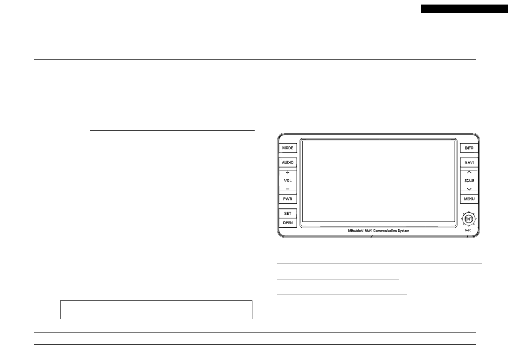
OPERATION
PANEL CLOSE
NR-261UM-07LAN4,-07-5WS
MODE Button
AUDIO Button
VOL Button
PWR Button
SET Button
OPEN Button
PANEL OPEN
INFO Button
NAVI Button
SCALE Button
MENU Button
JOY Key
(ENT Button)
Guide LED
Disc In Indicator
Disc Insertion Slot
J1001
Version Up Key Terminal 4P
3
Disc Eject Button
Your company internal use only.Copyright (C) Mitsubishi Electric Corporation.
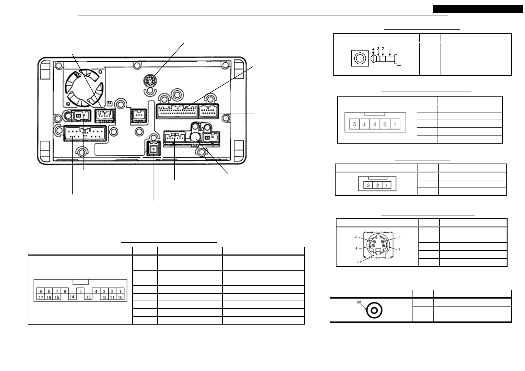
CONNECTORS
P708
Navi Power Supply
Connector 5P
P2A1
Audio Power Supply
Connector 17P
P2A1 PinNo. Signal Name PinNo. Signal Name
P603
TMC Antenna
Connector 3P
P20C
P707
Digital Sound Output Connector 4P
RSES Connector 3P
P1G1
External Equipment
Connector 7P
P2Z0
GPS Antenna Connector 2P
Audio Power Supply Connector 17P
1 MAIN GN D 10 BATTER Y (+ )
2 SPEAKER RR- 11 SPEAKER RR+
3 SPEAKER FR- 12 SPEAKER FR+
4 AMP DATA 13 ACCESSORY (+)
5 - 14VSS
6 SHIELD (AMP DATA) 15 SPEAKER FL+
7 SPEAKER FL- 16 SPEAKER RL+
8 SPEAKER RL- 17 ILL+
9 ILL CONTROL
P703
VTR & Remote Control
Connector P32
P705
Rear Camera
Connector 12P
P001
TMC Antenna Distribution
Output Connector 3P
ANT001
Radio Antenna
Connector 1P
NR-261UM-07LAN4,-07-5WS
Version Up Key Terminal 4P
J1001 PinNo. Signal Name
1I2C-SDA
2GND
3I2C-SCL
4I2C-VCC
Navi Power Supply Connector 5P
P708 PinNo. Signal Name
1GND
2PS-R
3 4 5BATTERY (+)
RSES Connector 3P
P707 PinNo. Signal Name
1 SHIELD (REAR)
2 REAR SIGNAL
3 -
Digital Sound Output Connector 4P
P20C PinNo. Signal Name
1234-
SH SHIELD
Radio Antenna Connector 1P
ANT001 PinNo. Signal Name
1 R AD IO AN TE NN A SIGN AL
SH SHIELD
4
*Connector figures are view where it faced the unit.
*Attention of pin numbering different from schematic diagram.
Your company internal use only.Copyright (C) Mitsubishi Electric Corporation.
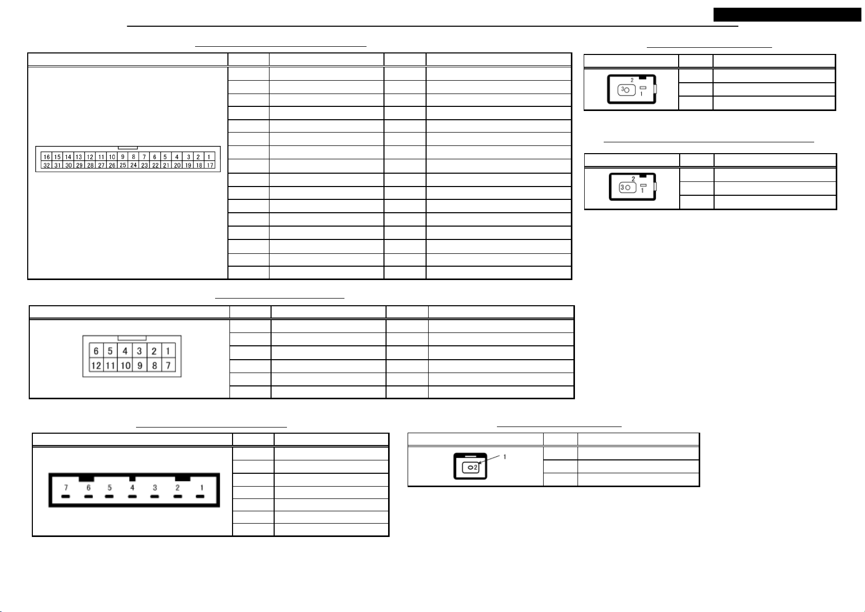
CONNECTORS
P703 PinNo. Signal Name PinNo. Signal Name
P705 PinNo. Signal Name PinNo. Signal Name
VTR & Remote Control Connector P32
1 - 17 2 - 18 3TEL MUTE 19 4 STEERING REMOTE 20 SHIEL D (STEER ING REMOTE)
5 - 21 SHIELD (CAN-BOX DATA)
6 - 22 7 - 23 -
8 SHIELD (VIDEO-2L/R) 24 VIDEO2 DETECT
9 VIDEO2-R 25 VIDEO2-L
10 VIDEO2-IN 26 SHIELD (VIDEO2-IN)
11 HFM SIGNAL (-)-GND 27 12 HFM SIGNAL (+)-R 28 HFM SIGNAL(+)-L
13 - 29 -
14 CAN-BOX DATA RX 30 CAN-BOX DATA TX
15 - 31 CAN-BOX DATA CLK
16 - 32 -
Rear Camera Connector 12P
1CAMERA DETECT 7 2 SHIELD (CAMERA) 8 -
3 - 9 4 C AME R A SIGN AL 10 5GND (RC) 11 6VCC (RC6.5V) 12 -
NR-261UM-07LAN4,-07-5WS
TMC Antenna Connector 3P
P603 PinNo. Signal Name
1 TMC DETECT IN
2 TMC ANTENNA GND
3 TMC ANTENNA SIGNAL
TMC Antenna Distribution Output Connector 3P
P001 PinNo. Signal Name
1 TMC DETECT OUT
2 ANTENN A OUT GND
3ANTENNA OUT
External Equipment Connector 7P
P1G1 PinNo. Signal Name
1SIRIUS-R
2 S-GND (SIRIU S-L/R)
3SIRIUS-L
4BUS(-)
5BUS(+)
6AMP POWER ON
7 ANTENNA-POWER
GPS Antenna Connector 2P
P2Z0 PinNo. Signal Name
1 GND-GPS
2 GPS ANTENNA SIGNAL
*Connector figures are view where it faced the unit.
*Attention of pin numbering different from schematic diagram.
5
Your company internal use only.Copyright (C) Mitsubishi Electric Corporation.
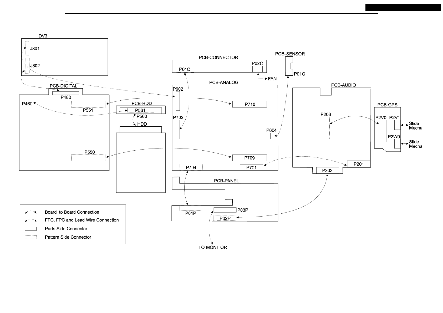
COMPOSITION
NR-261UM-07LAN4,-07-5WS
6
Your company internal use only.Copyright (C) Mitsubishi Electric Corporation.
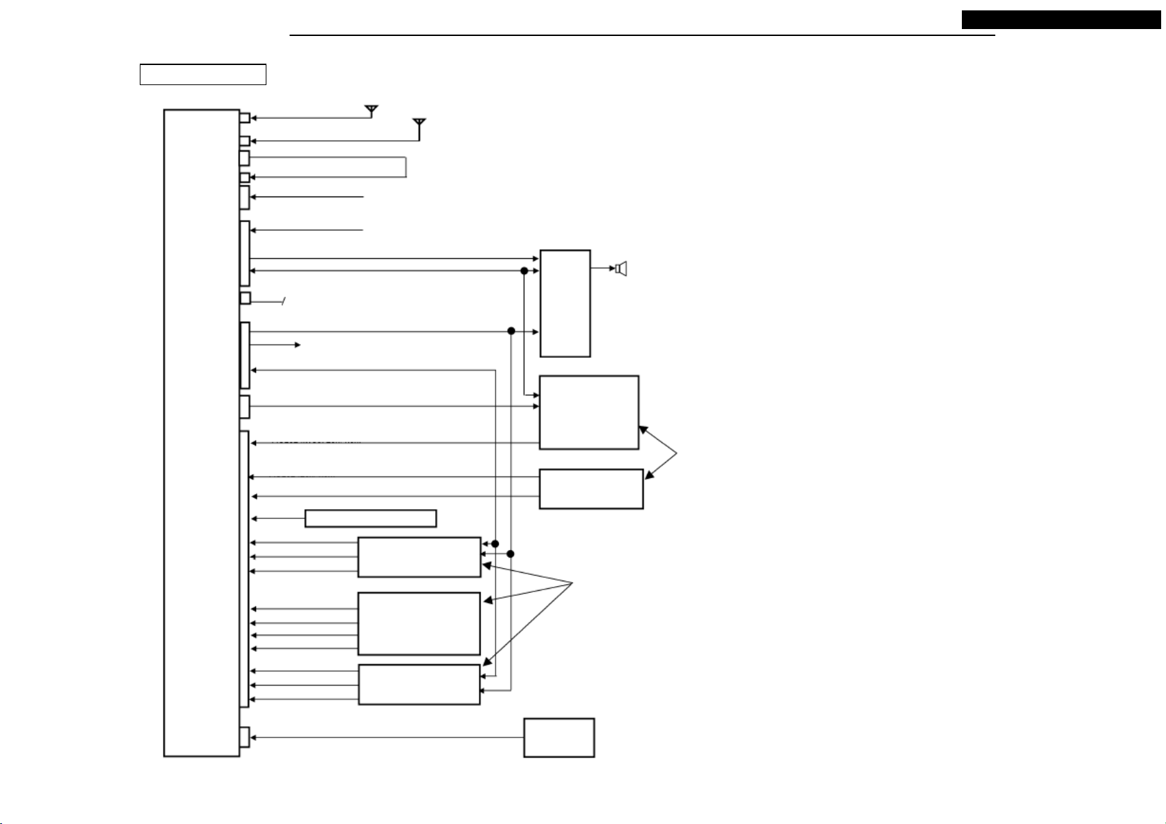
SYSTEM CONFIGURATION
CAN Unsupported
GPS Antenna Connector
Radio Antenna Connector
Antenna Distribution Output Connector
TMC Antenna Connector
Navi Power Supply Connector
Audio Power Supply
Connector
Speaker Output
(Premium AMP Connected : FL,FR / Unconnected : FL,FR,RL,RR)
UART Connection (half duplex )
Digital Voice Output Connector
External Equipment Connector
POWER ON
10MY-NAS
2DIN
Audio Navi
All-in-one
ANT+B
BUS(+), BUS(-)
RSES Connector
NTSC (DVD Video)
VTR & Remote Control Connector
VIDEO2 (NTSC, Lch / Rch)
VIDEO2 (Lch / Rch)
VIDEO2 DETECT
HFM SIGNAL (+) : Lch
HFM SIGNAL (-) : GND
HFM SIGNAL (+) : Rch
HFM SIGNAL (-) : GND
HFM SIGNAL (+) : Rch
HFT MUTE
VIDEO1 DETECT
HFM SIGNAL (+) : Lch
HFM SIGNAL (-) : GND
HFM SIGNAL (+) : Rch
GPS Antenna
Radio Antenna
Antenna Distribution Cable
Power Supply (+B, GND, BACK)
Vehicle Power Supply, Signal (+B, ACC, ILL+ / -, VSS, GND)
Steering Remote Control
Hands-free Module
(IE-Bus Supported option)
Hands-free Module
(Current after option)
USB-BOX
(IE-Bus Supported option)
External
AMP
(5.1ch
Unsupported)
(option)
RSES
[Backseat
Display]
(option)
External Voice
Device (option)
Connect either
NR-261UM-07LAN4,-07-5WS
Connect either
Rear Camera Connector
NTSC
Rear Camera
(option)
7
Your company internal use only.Copyright (C) Mitsubishi Electric Corporation.
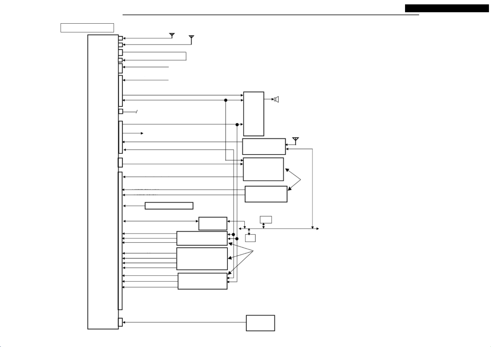
SYSTEM CONFIGURATION
NR-261UM-07LAN4,-07-5WS
CAN Supported
10MY-NAS
2DIN
Audio Navi
All-in-one
GPS Antenna
GPS Antenna Connector
Radio Antenna Connector
Antenna Distribution Output Connector
TMC Antenna Connector
Navi Power Supply Connector
Audio Power Supply
Connector
Speaker Output
(Premium AMP Connected : FL,FR / Unconnected : FL,FR,RL,RR)
UART Connection (half duplex )
Digital Voice Output Connector
External Equipment Connector
POWER ON
ANT+B
Lch/ Rch/ SHIELD
BUS(+), BUS(-)
RSES Connector
NTSC (DVD Video)
VTR & Remote Control Connector
VIDEO2 (NTSC, Lch / Rch)
VIDEO2 (Lch / Rch)
VIDEO2 DETECT
Steering Remote Control
Radio Antenna
Antenna Distribution Cable
Power Supply (+B, GND, BACK)
Vehicle Power Supply, Signal (+B, ACC, ILL+, VSS, GND)
External
AMP
(5.1ch
Unsupported)
(option)
Sirius Tuner
(option)
RSES
[Backseat
Display]
(option)
External Voice
Device (option)
Antenna
Connect
either
Connection
HFM SIGNAL (+) : Lch
HFM SIGNAL (-) : GND
HFM SIGNAL (+) : Rch
HFM SIGNAL (-) : GND
HFM SIGNAL (+) : Rch
HFT MUTE
VIDEO1 DETECT
HFM SIGNAL (+) : Lch
HFM SIGNAL (-) : GND
HFM SIGNAL (+) : Rch
Rear Camera Connector
NTSC
CAN-BOX
Hands-free Module
(IE-Bus Supported option)
Hands-free Module
(Current after option)
USB-BOX
(IE-Bus Supported option)
ECU
ECU
Connect either
Rear Camera
(option)
8
CAN-B
Your company internal use only.Copyright (C) Mitsubishi Electric Corporation.
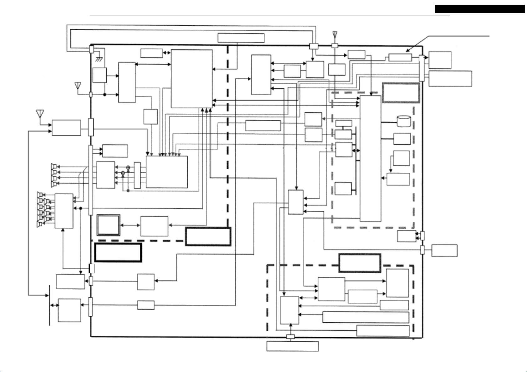
BLOCK DIAGRAM
Steering Remote Control
GPS Antenna
NR-261UM-07LAN4,-07-5WS
IE-Bus supported. Additional connection
with USB-BOX, JCI Hands-free module.
CAN-B
FL
FR
RL
RR
Sirius
Tuner
Premium
AMP
RSES
CAN
-BOX
Distri-
FM
bute
Circuit
AM
POWER
SUPPLY
POWER
IC
Open /
Close
Mecha
Navi part
(PCB-ANALOG)
VIDEO SIGNAL
EEPROM
0.25kB
AM/
FM
Tuner
FM
AM
M
U
T
E
Operation Sound
Open / Close
VIDEO
AMP
I / F
AM
NK
Mecha
Drive
VIDEO2
Hands-free
Voice
Play Music (HDD)
DSP
Audio
μ-com
CD / DVD
Guide Voice
Audio part
(PCB-AUDIO)
A/D
Navi
Sub
μ-com
Volume
Adjustment
TMC
Decoder
Video
Switch
Monitor
μ-com
D/A
Converter
Converter
DVDVIDEO
VIDEO2
CAMERA
RGB
VIDEO
Detect
TMC
Tuner
D/A
GPS
RF
SDRAM
DSP
CD/
DVD
Flash
ROM
8MB
2MB
Navi
μ-com
(Navi
core)
Display part
(PCB-MONITOR)
Image
Signal
Processing
Timing
Controller
Operation Key
(AUDIO,SET,INFO,NAVI,SCALE,MENU,JOY)
Operation Key
(MODE,VOL,POWER,OPEN)
IE-Bus I/F
Navi part
(PCB-DIGITAL)
HDD
40GB
DDRSDRAM
128MB
Gyro
Sensor
A/ D
Converter
POWER
SUPPLY
LCD
Module
(6.95
inch)
Touch Panel
Hands-free
Module
The machine for CAN is
controlled by CAN-BOX.
VIDEO2
(RSES / AUX)
Rear
Camera
VERSION UP KEY
9
Your company internal use only.Copyright (C) Mitsubishi Electric Corporation.
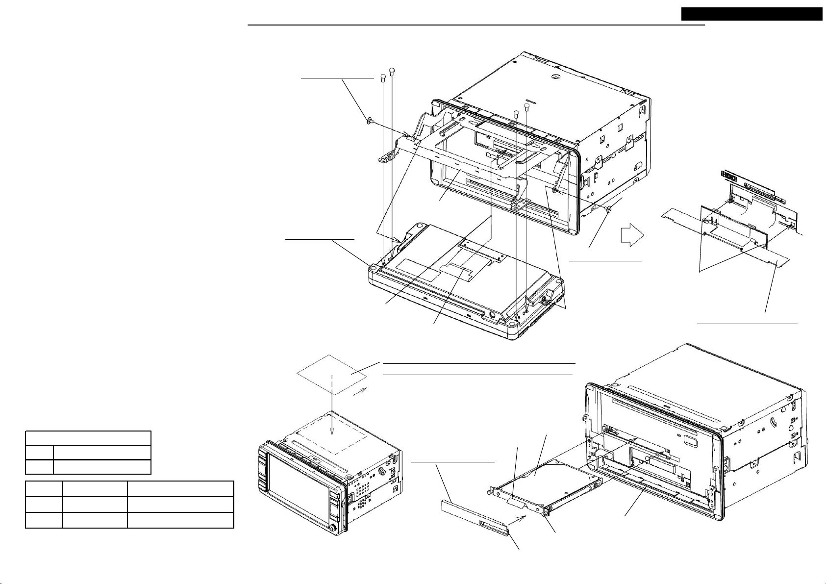
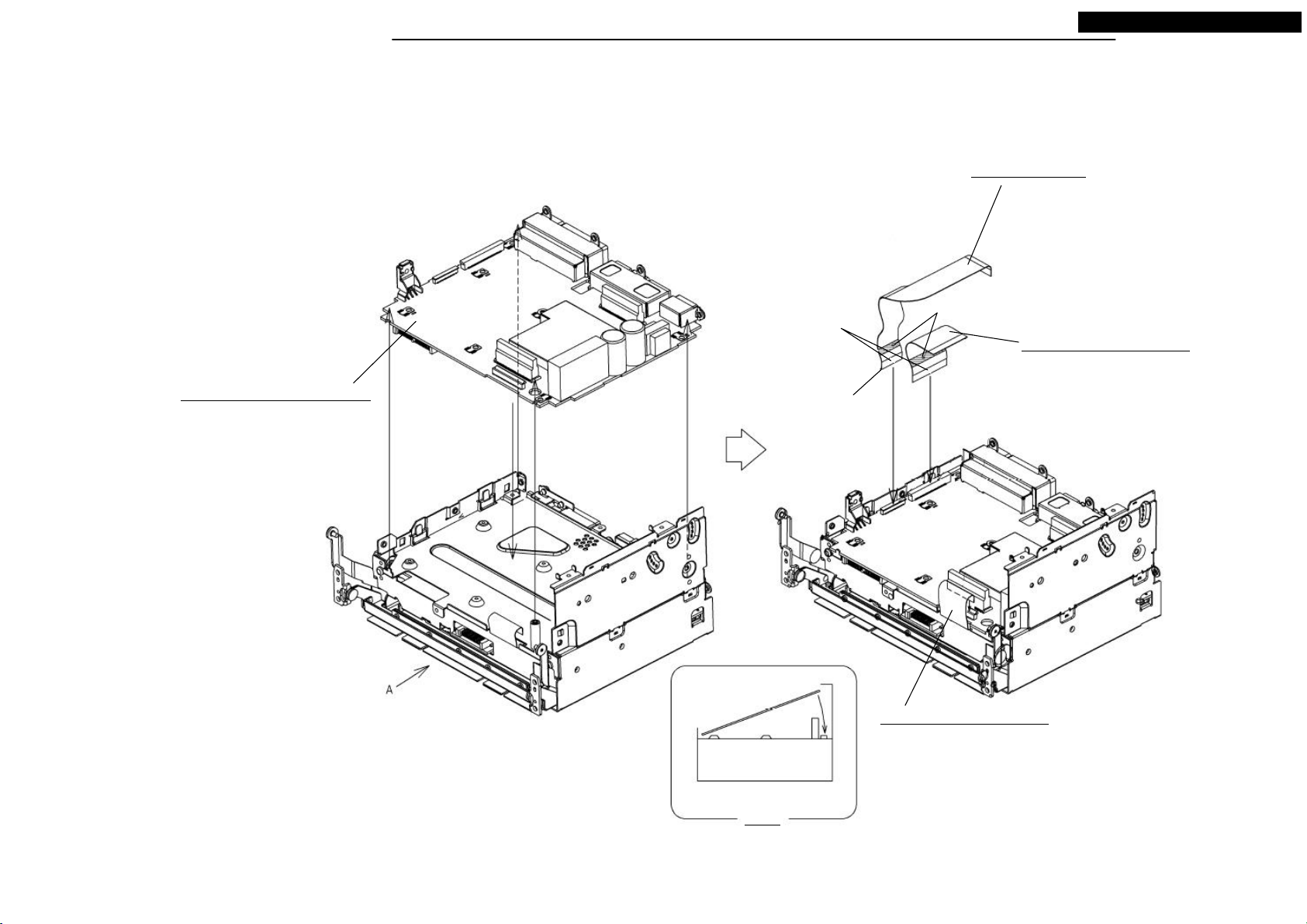
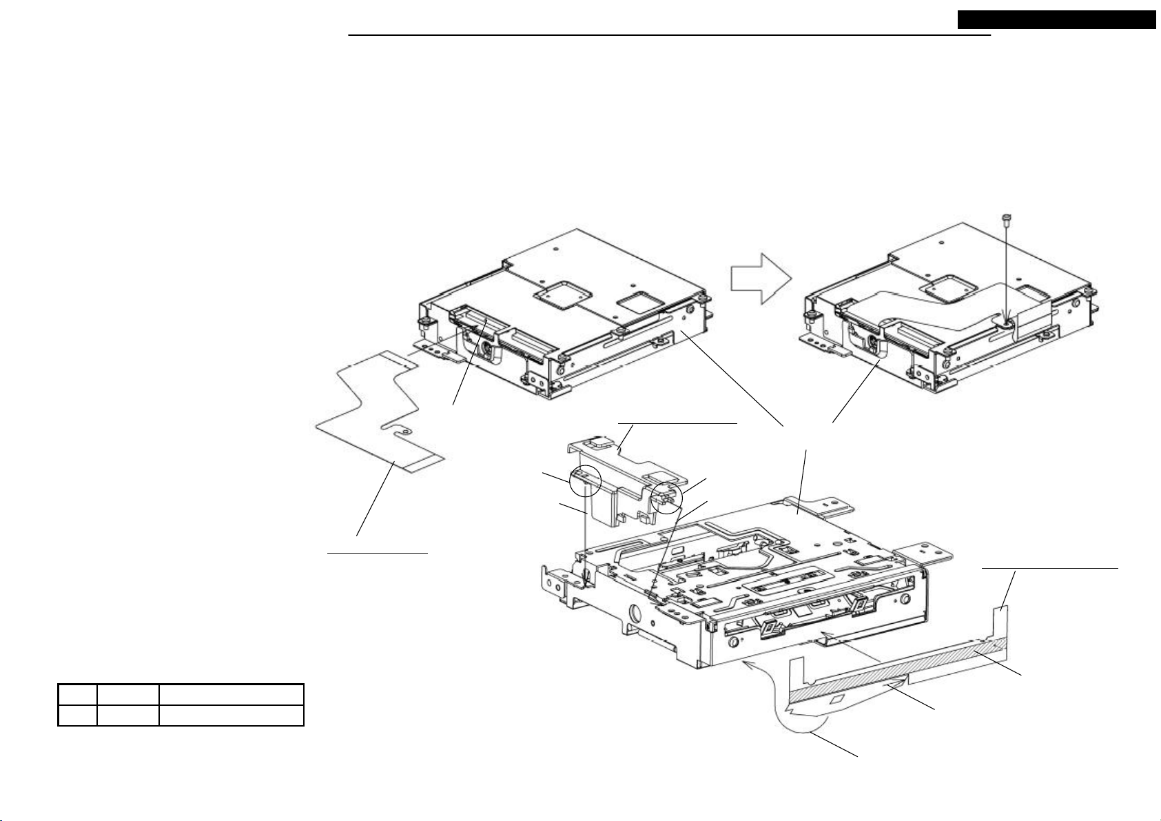
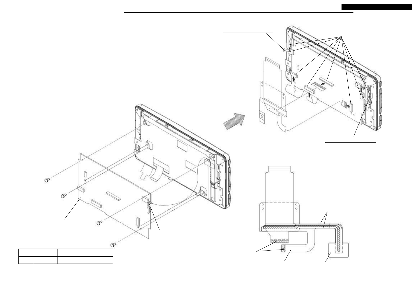
DISASSEMBLING PROCEDURES
NR-261UM-07LAN4,-07-5WS
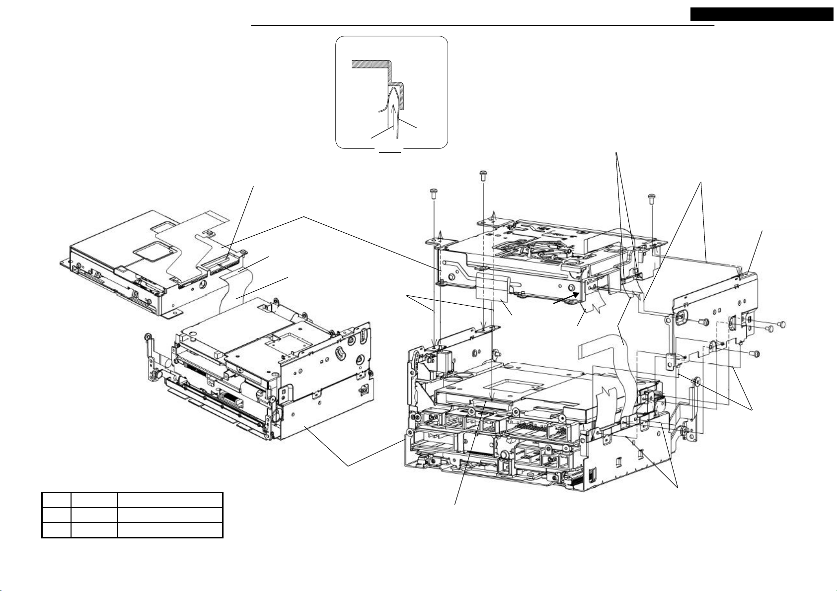
● Disassembling procedures
In reverse of assembling procedures.
● Assembling procedures
1.Insert the S7-HDD to the S2-CHASSIS, and screw the two screws.
2.Set M051.
3.Pull out the slide part of the S2-CHASSIS, and screw M086 with
the four screws (Ⓑ), and M024.
4.Insert the FPC of M086 to the S2-CHASSIS.
5.Set back the slide after M068 set.
M024: PIN-MONI
M086: S2-MONI
Lock after FPC inserted.
Ⓑ x 4
Do not break hexagon socket.
Slide
M024: PIN-MONI
Latch the hook at right and left,
then push the top. (After
assembling, check if M068
and the panel is seamless.)
M068: ASSY-COVER-F
Continuity side
Mod el
(1) NR-261UM-07LAN4
(2) NR-261UM-07-5WS
Tighten torque(N・m)Screw/NameNo.
Ⓑ 0.7 +0.2/-0.1M3X6
M084(1): NAME-CARD(NR-261UM-07LAN4)/
M085(2): NAME-CARD(NR-261UM-07-5WS)
Top
S7-HDD
Fold and set.
M051: PANEL-HDD
0.4 +0.15/-0.05PIN-MONIM024
S2-CHASSIS
Two screws
Set this hook at first.
10
Your company internal use only.Copyright (C) Mitsubishi Electric Corporation.
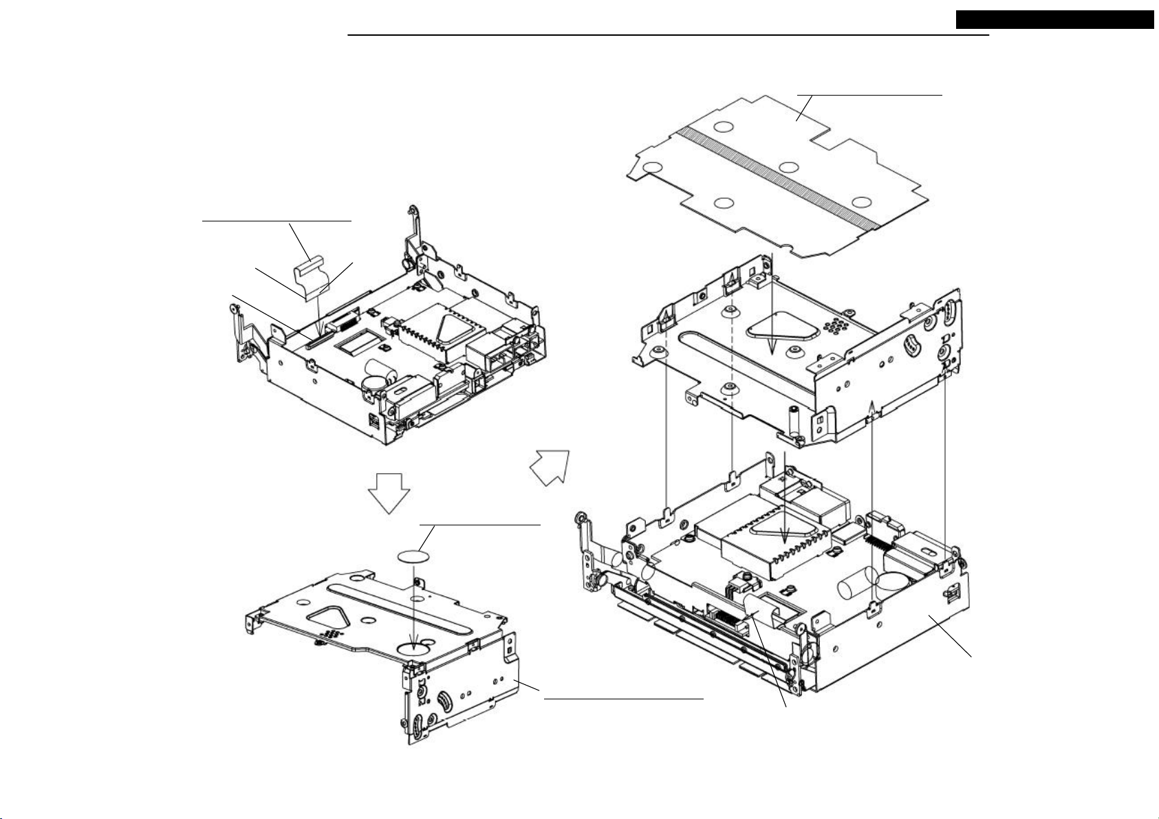
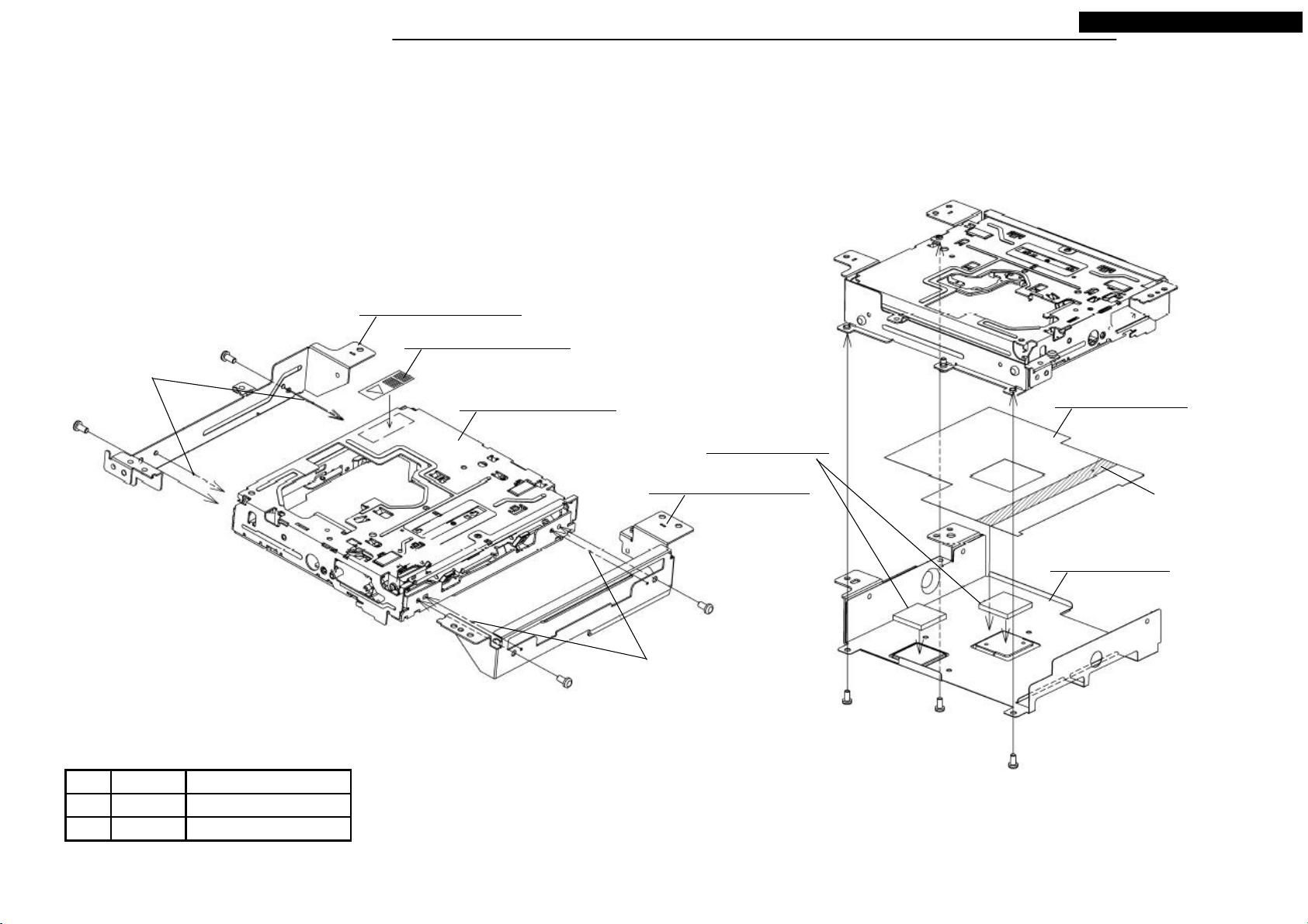
DISASSEMBLING PROCEDURES
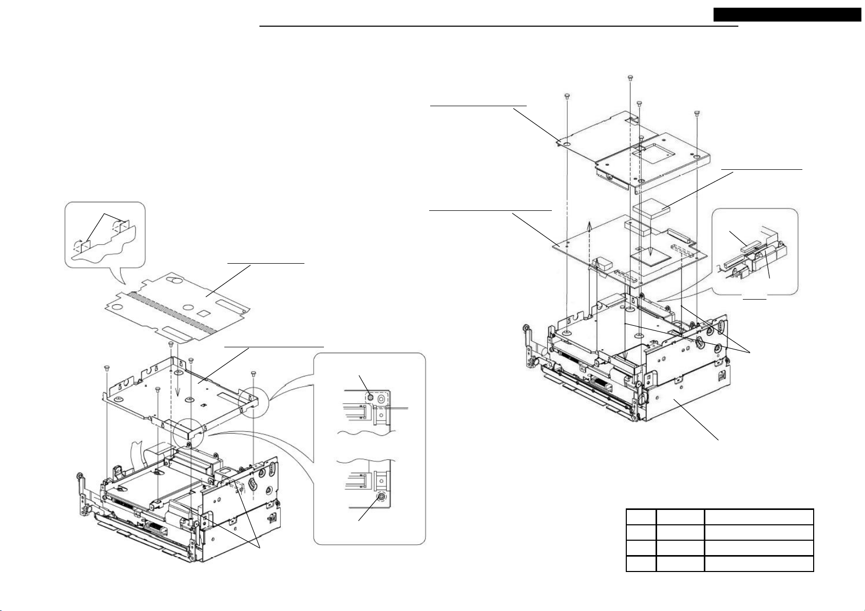
● Disassembling procedures
In reverse of assembling procedures.
● Assembling procedures
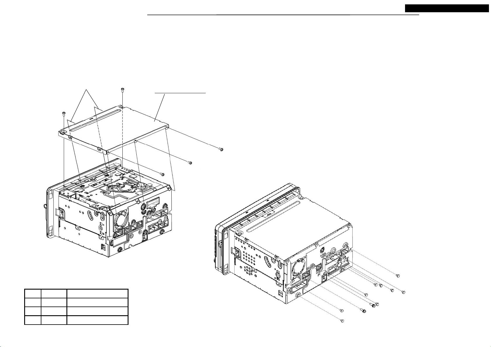
1.Screw M016 with the two screws(Ⓐ) and the three screws(Ⓒ).
2.Screw the nine screws(Ⓒ) and the two screws(Ⓚ).
NR-261UM-07LAN4,-07-5WS
Latch the two hooks.
Ⓐ x 2
M016: COVER-TOP
Ⓒ x 3
Tighten torque(N ・m) : 0.4 +0.2/-0.1
M3X6 0.4 +0.2/-0.1Ⓐ
Ⓚ 0.7 +0.2/-0.1M3X10
Ⓒ x 9
Tighten torque(N ・m) : 0.3 +0.05/-0.05
Tighten torque(N・m)ScrewNo.
Refer in the fig.2.6X4Ⓒ
11
Ⓚ x 2
Your company internal use only.Copyright (C) Mitsubishi Electric Corporation.
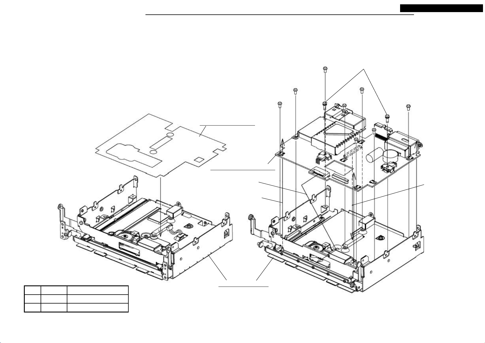
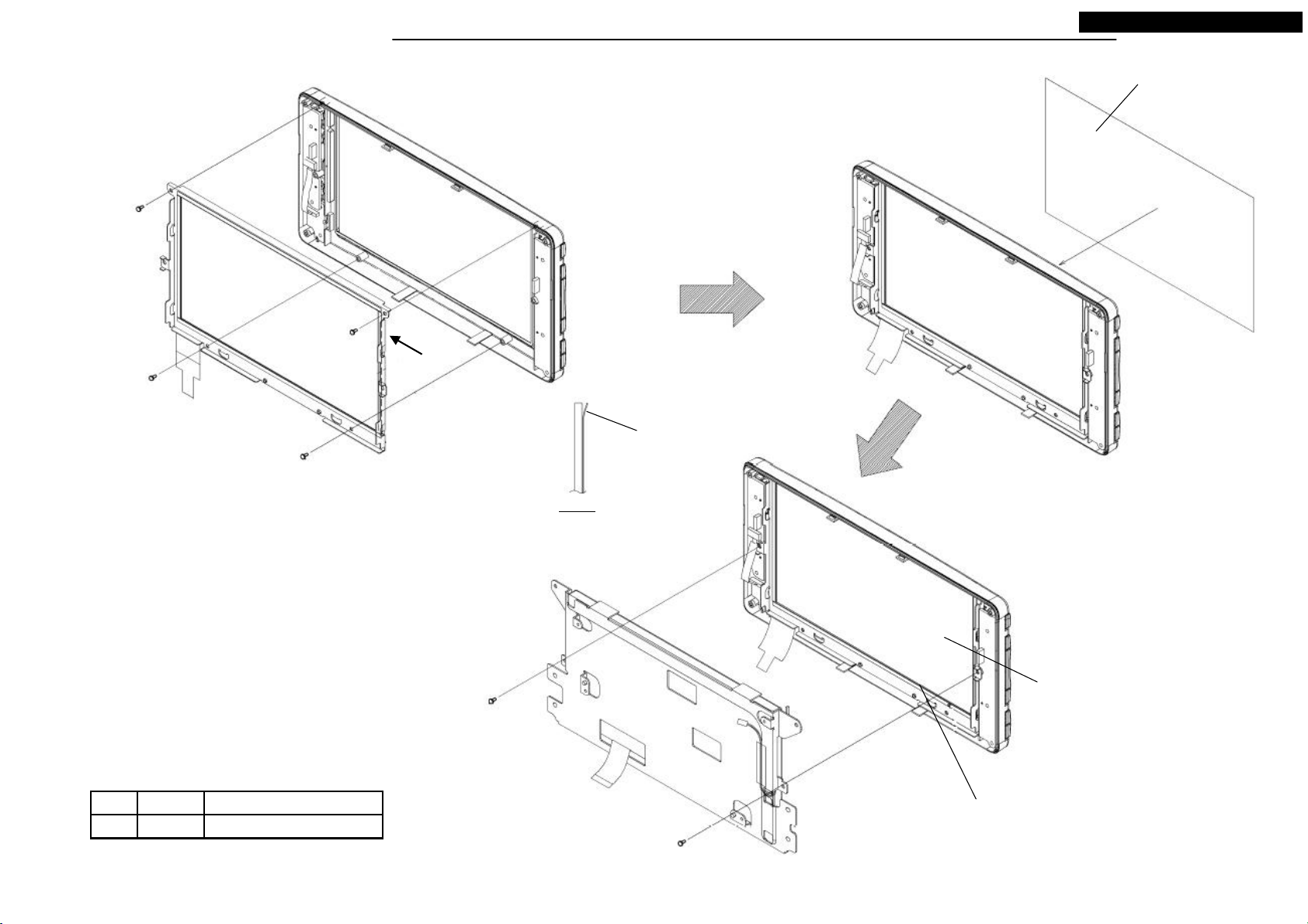
DISASSEMBLING PROCEDURES
● Disassembling procedures
In reverse of assembling procedures.
● Assembling procedures
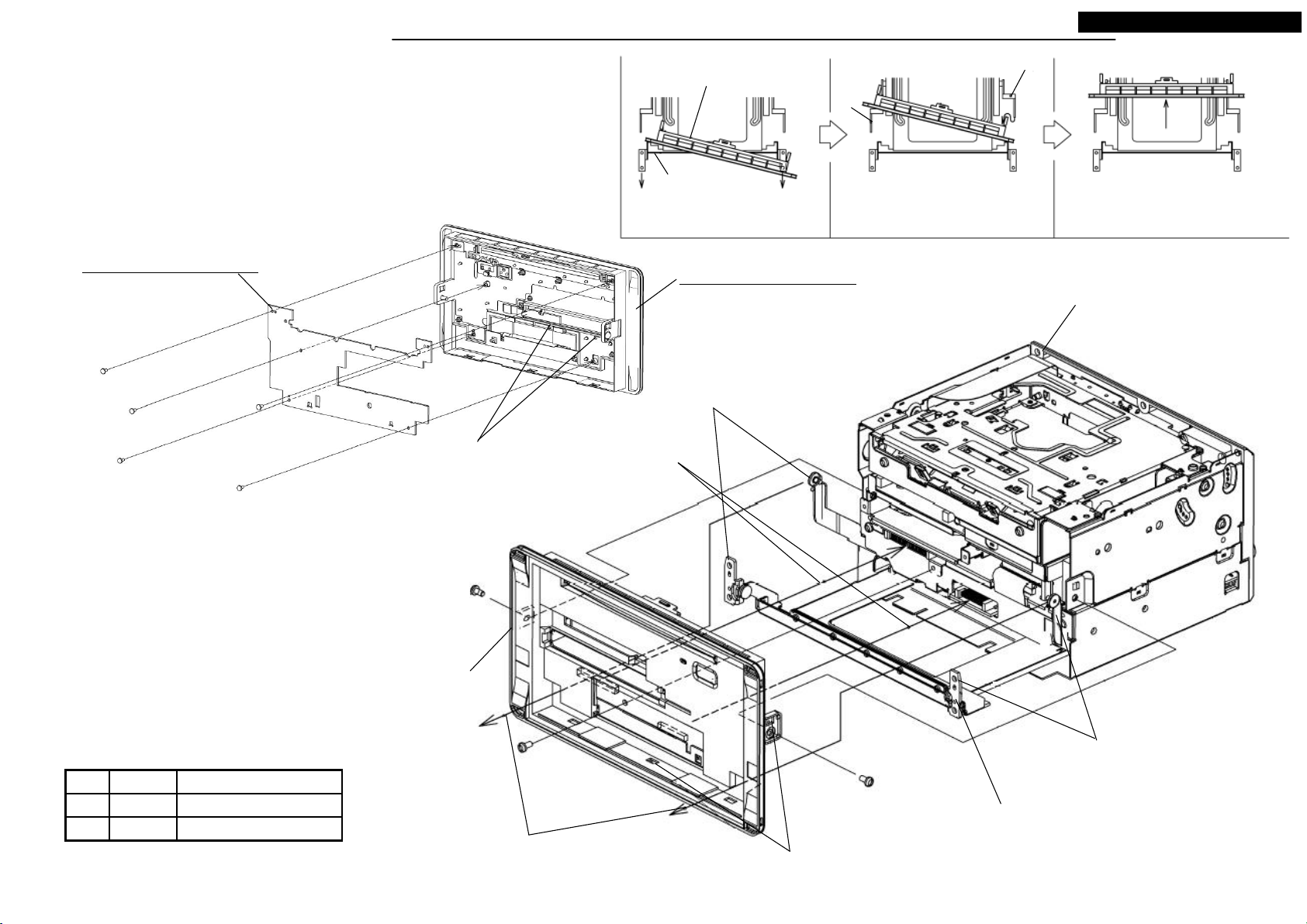
1.Hook M076 to M070, and screw the five screws(Ⓙ).
2.Pull out the slide part of the S3-CHASSIS, and pass the arm through
to the hole of the S3-PANEL-SUB.<Step1~3>
3.Screw the three screws(Ⓐ).
S3-PANEL-SUB
Slide chassis
<Step1> Pass the tip of slide chassis
through to panel by each.
Arm
<Step2> After passed the arm of one
side, pass the another side of arms.
NR-261UM-07LAN4,-07-5WS
Arm
<Step3> Push the front of panel.
M076: ASSY-PCB-PANEL
Ⓙ x 5
Latch M076 to the hooks.
Ⓐ x 3
S3-PANEL-SUB
M070: ASSY-PANEL-SUB
S3-CHASSIS
Remove the arm protector.
(3)Push the front of panel to
connector mating. <Step3>
Remove the arm protector.
Tighten torque(N・m)ScrewNo.
M3X6 0.7 +0.2/-0.1Ⓐ
0.12 +0.01/-0.012X4Ⓙ
(2)After passed the one arm, pass another
arm with bending it internally. <Step2>
Do not give scratch to panel by arms.
(4) Push the square holes at side(two places) and
downside(three places), till the hooks set.<Step3>
12
(1)After pull out the slide chassis till it stops, pass the
tip through to panel each one side. <Step1>
Your company internal use only.Copyright (C) Mitsubishi Electric Corporation.
DISASSEMBLING PROCEDURES
● Disassembling procedures
In reverse of assembling procedures.
● Assembling procedures
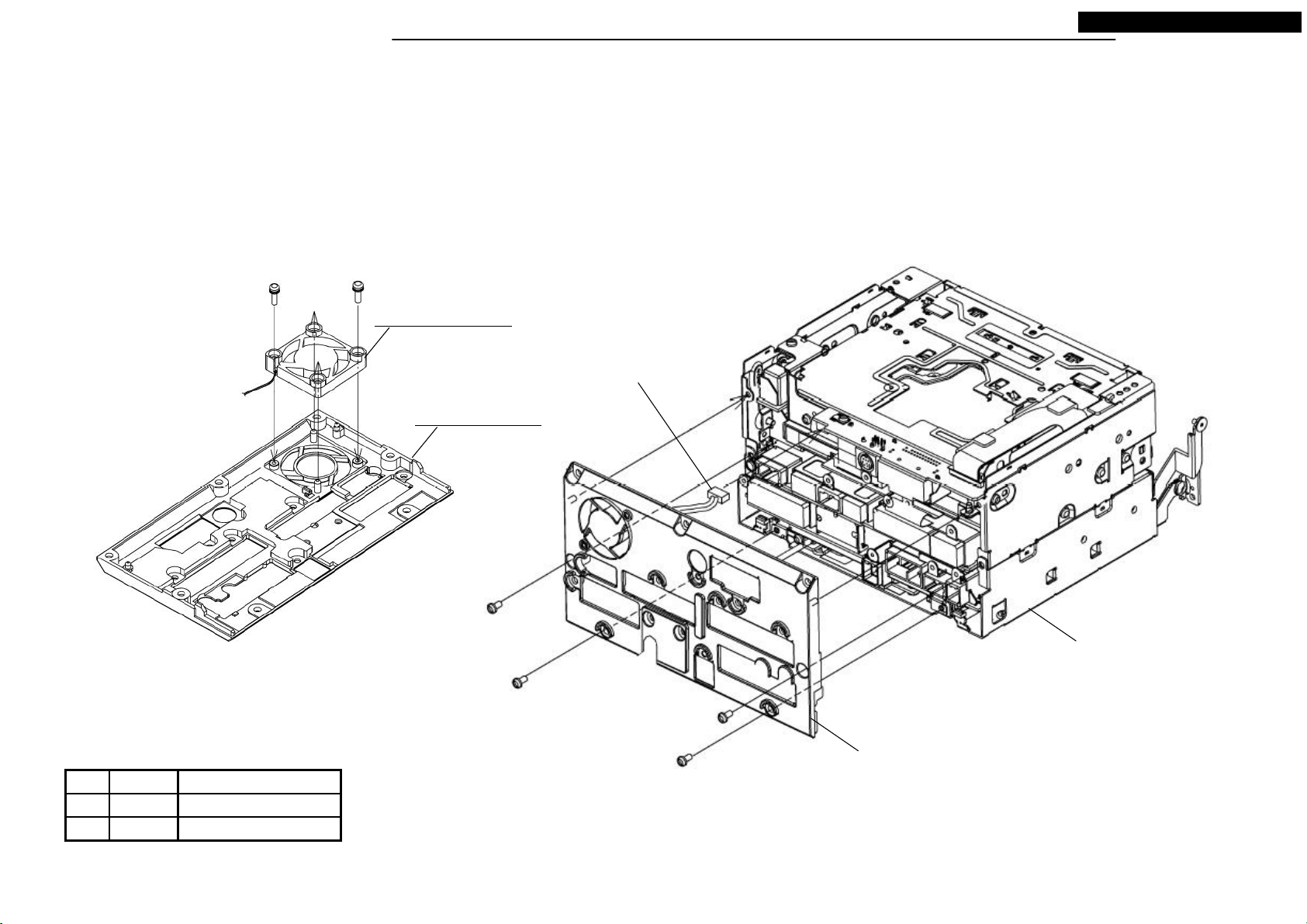
1.Screw M010 to M025 with two screws(Ⓚ).
2.Connect LEAD-CONNECTOR of the S4-HEAT SINK to the S4-CHASSIS.
3.Screw the S4-HEAT-SINK with four screws(Ⓐ).
Ⓚ x 2
M010: MOTOR-FAN
M025: HEAT-SINK
NR-261UM-07LAN4,-07-5WS
LEAD-CONNECTOR
Ⓐ x 4
S4-CHASSIS
S4-HEAT-SINK
Tighten torque(N・m)ScrewNo.
M3X6 0.7 +0.2/-0.1Ⓐ
0.7 +0.2/-0.1M3X10Ⓚ
13
Your company internal use only.Copyright (C) Mitsubishi Electric Corporation.
DISASSEMBLING PROCEDURES
● Disassembling procedures
In reverse of assembling procedures.
● Assembling procedures
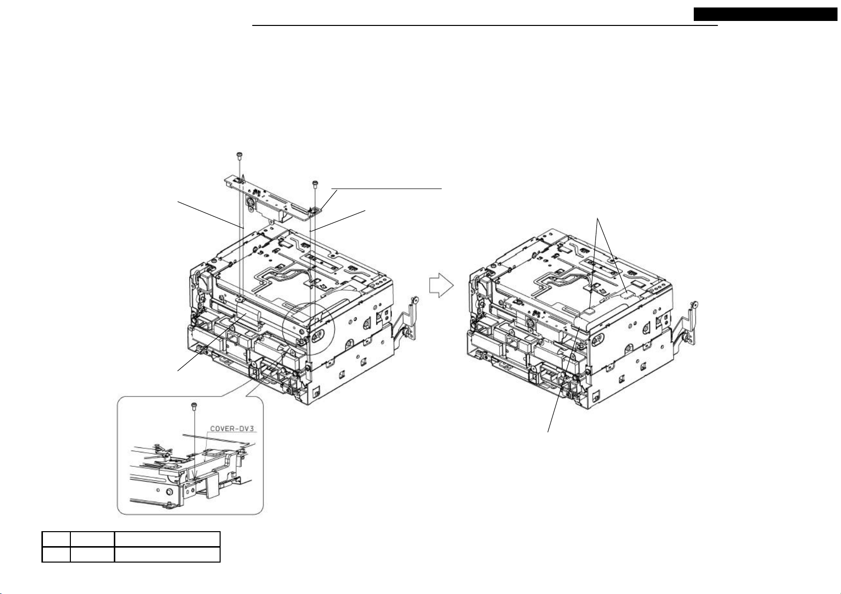
1.Screw M082 with the two screws(Ⓐ).
2.Screw the COVER-DV3 with the one screw(Ⓐ).
3.Connect the FPC to M082.
Ⓐ x 2
NR-261UM-07LAN4,-07-5WS
Pass salient to the square hole
on the circuit board.
FPC
Ⓐ
M082: ASSY-PCB-CONN
Fit reentrant on the circuit board
to salient.
Set FPC to COVER-DV3.
Lock after FPC connected.
Tighten torque(N・m)ScrewNo.
M3X6 0.7 +0.2/-0.1Ⓐ
14
Your company internal use only.Copyright (C) Mitsubishi Electric Corporation.
DISASSEMBLING PROCEDURES
● Disassembling procedures
In reverse of assembling procedures.
● Assembling procedures
1.Connect FFC from S5-CHASSSIS to S5-DECK.
2.Fit the salients and put S5-DECK to S5-CHASSIS.
3.Set FPC-1 at the hooks of S5-DECK.
4.Insert the FFC to the cover of the S5-DECK. (View J)
5.Set M012, and screw the five screws(Ⓐ) and two screws(Ⓒ).
6.Connect FPC-2 from S5-DECK to S5-CHASSIS.
Lock after FFC connected.
S5-DECK
Continuity side
Insert
View J
FFC
Ⓐ x 3
NR-261UM-07LAN4,-07-5WS
Set FPC-1 at these hooks.
Fit the dowels.
Insert M012 from downside surely.
M012: CHASSIS-L
FFC
Fit the square holes
to the salients.
View J
FPC-2
FFC
FPC-1
Ⓒ x 2
Ⓐ x 2
Latch the hooks to the
square holes.
S5-CHASSIS
Tighten torque(N・m)ScrewNo.
M3X6 0.7 +0.2/-0.1Ⓐ
Lock after FPC connected.
Fit the dowels.
0.4 +0.2/-0.12.6X4Ⓒ
15
Your company internal use only.Copyright (C) Mitsubishi Electric Corporation.
DISASSEMBLING PROCEDURES
● Disassembling procedures
In reverse of assembling procedures.
● Assembling procedures
1.Set M015 and screw the five screws(Ⓒ).
2.Remve the separator and stick M035 to M015.
3.Set M077 to S5-CHASSIS while matching the two salients.
4.Connect FFC from HDD circuit on S5-CHASSIS to M077.(View F)
5.Stick M029 to Navicore of M077.
6.Set M067, and screw the one screw(Ⓓ) and the four screws(Ⓔ).
M067: ASSY-SHIELD
Be careful to not change
the shape when
assembling.
NR-261UM-07LAN4,-07-5WS
Ⓓ
Ⓔ x 4
M029: SHEET-HS
Put on the Navicore.
Fold
Ⓒ x 5
M035: SHEET-DI
M015: CASE-DIGITAL
Fit the dowel to the hole.
M077: ASSY-PCB-DIGITAL
Lock after FFC
connected.
FFC from HDD.
View F
Engage the connectors.
(Push “PUSH” on circuit board)
S5-CHASSIS
Fit the salient of post to
the hole.
Remove the connector covers.
16
Tighten torque(N・m)ScrewNo.
2.6X4 0.4 +0.2/-0.1Ⓒ
0.4 +0.2/-0.1M2.6X3Ⓓ
0.4 +0.2/-0.1M2.6X6Ⓔ
Your company internal use only.Copyright (C) Mitsubishi Electric Corporation.
DISASSEMBLING PROCEDURES
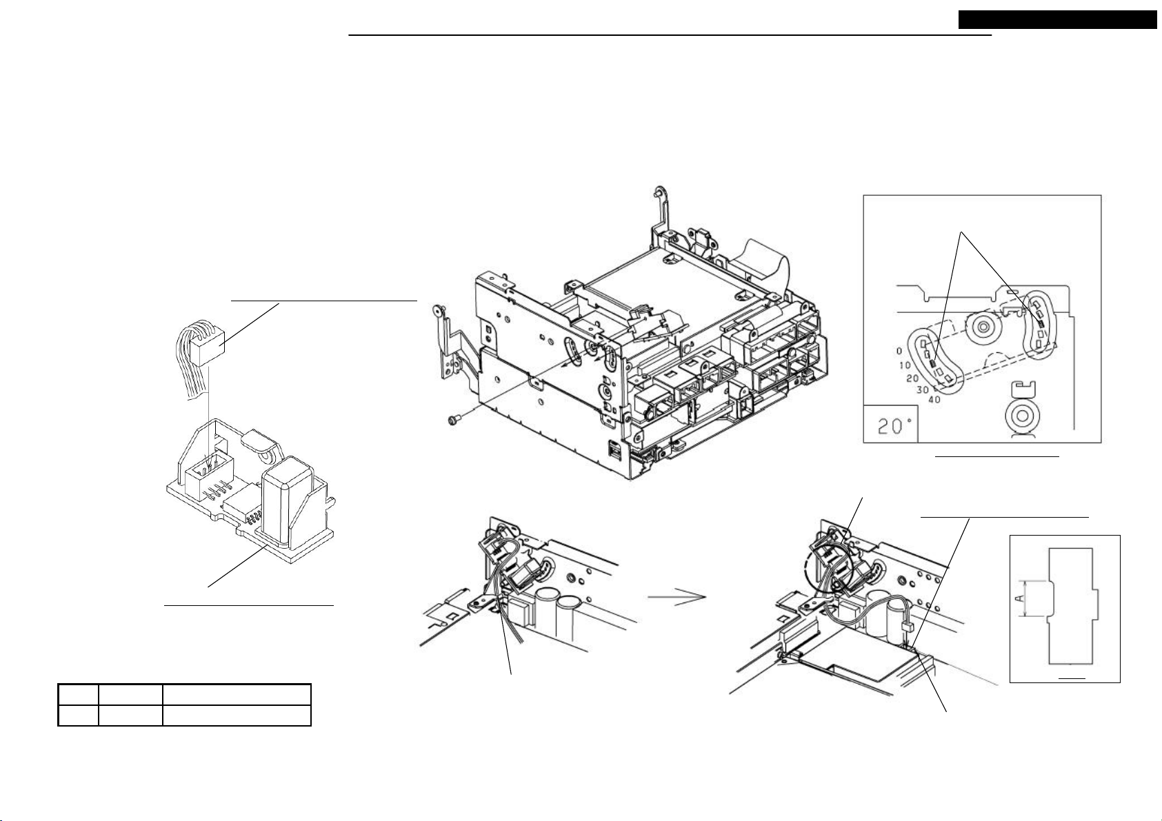
● Disassembling procedures
In reverse of assembling procedures.
● Assembling procedures
1.Connect M007 to M083. (Either direction of the connector can be connected.)
2.Screw the M083 with the one screw(Ⓐ).
3.Latch the hook of M007 to the hook.
4.Connect M007 to M081.
M007: LEAD-CONNECTOR 4P
NR-261UM-07LAN4,-07-5WS
Hook latch position.
Ⓐ
Assembling Angle of M083
Pass the Lead-Connector
to area A of Fig. A.
M081: ASSY-PCB-ANALOG
M083: ASSY-PCB-SENSOR
Latch the Lead-Connector
Tighten torque(N・m)ScrewNo.
M3X6 0.7 +0.2/-0.1Ⓐ
to the hook.
17
Remove the adsorption sheet
of P604.
Your company internal use only.Copyright (C) Mitsubishi Electric Corporation.
Fig. A
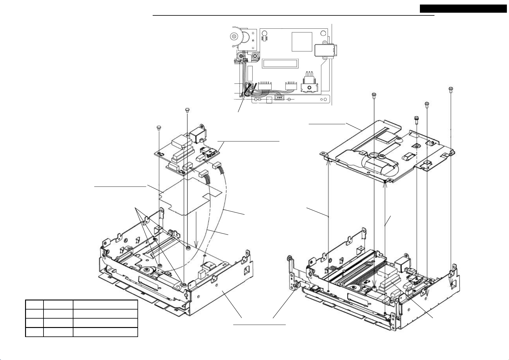
DISASSEMBLING PROCEDURES
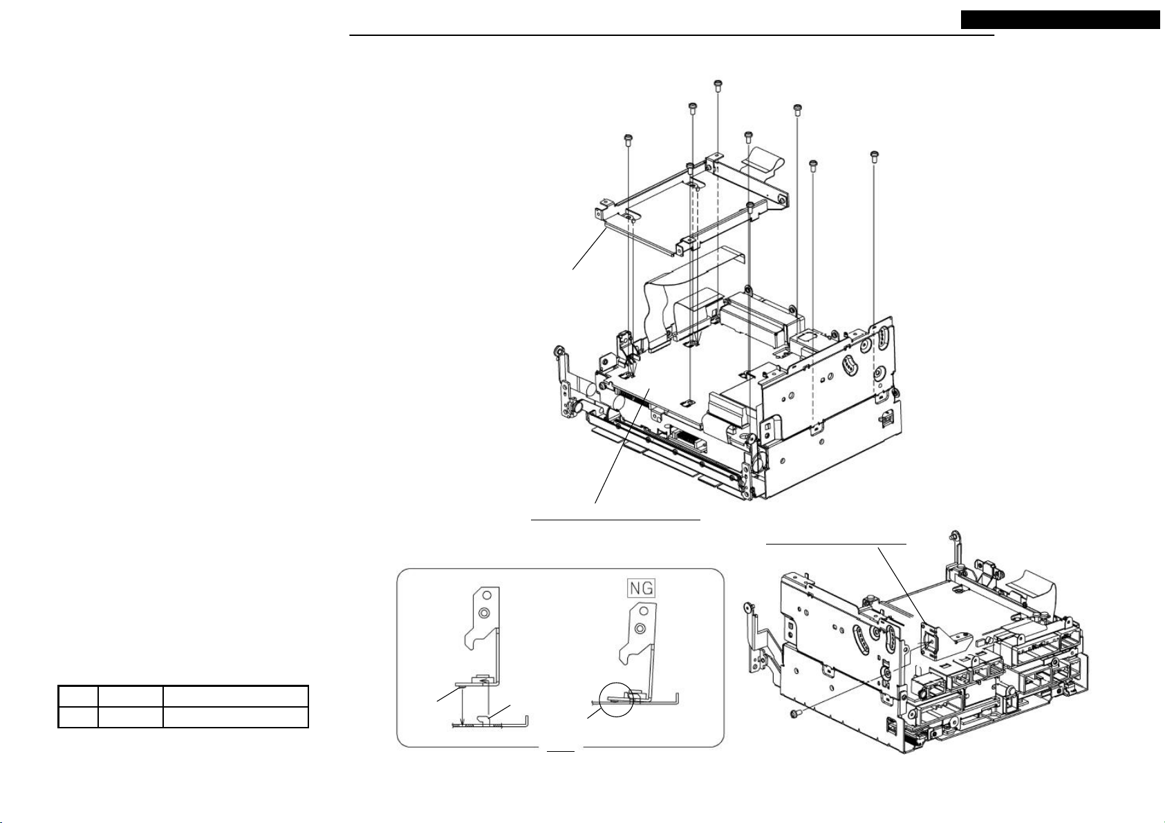
● Disassembling procedures
In reverse of assembling procedures.
● Assembling procedures
1.Screw M081 with the five screws(Ⓐ).
2.Screw the S5-HOLDER with the four screws(Ⓐ) from a→b→c→d.
3.Latch the square hole of M021 to the hook, and set the dowel to the hole. (Fig. B)
4.Screw M021 with the one screw(Ⓐ).
S5-HOLDER
NR-261UM-07LAN4,-07-5WS
b
a
d
Ⓐ x 9
c
M081: ASSY-PCB-ANALOG
M021: BRACKET-NAVI
Tighten torque(N・m)ScrewNo.
Dowel
M3X6 0.7 +0.2/-0.1Ⓐ
Hook
There must be no space after
tightening of the screw.
Fig. B
18
Ⓐ
Your company internal use only.Copyright (C) Mitsubishi Electric Corporation.
DISASSEMBLING PROCEDURES
● Disassembling procedures
In reverse of assembling procedures.
● Assembling procedures
1.Set the hook of chassis to M081. (View A)
2.Connect M001, M004, M006 to the connectors.
NR-261UM-07LAN4,-07-5WS
M001: FPC-CON
M081: ASSY-PCB-ANALOG
Continuity side
Himeron
M004: FLAT-CABLE 30P
Pin 1 (white marking)
M006: FLAT-CABLE 50P
19
Set M081 from left to right.
View A
Your company internal use only.Copyright (C) Mitsubishi Electric Corporation.
DISASSEMBLING PROCEDURES
● Disassembling procedures
In reverse of assembling procedures.
● Assembling procedures
1.Connect M006 and pull it forward.
2.Remove the separator and stick M032 to M011(revers side).
3.Remove the separator and stick M031 to M011(face side).
4.Set M011 to guide salient, and assemble.
M006: FLAT-CABLE 50P
Continuity side
Pin 1 (white marking)
Lock after FFC connected.
(reverse side)
NR-261UM-07LAN4,-07-5WS
M031: SHEET-ANALOG
M032: SHEET-COIL
M011: CHASSIS-ANALOG
20
S5-CHASSIS
Pull forward
Your company internal use only.Copyright (C) Mitsubishi Electric Corporation.
DISASSEMBLING PROCEDURES
● Disassembling procedures
In reverse of assembling procedures.
● Assembling procedures
1.Set M033 to M069.
2.Set M079 to M069, from front connector side with a slope.
3.Pass the salients to the circuit square holes, and insert the central connector.
4.Screw M079 with eight screws(Ⓐ) and the two screws(Ⓚ).
M033: SHEET-AUDIO
M079: ASSY-PCB-AUDIO
Ⓐ x 8
NR-261UM-07LAN4,-07-5WS
Ⓚ x 2
Insert the front connector
side to the square hole.
Pass the salients to the circuit
square holes. (three places)
Connector mating
(Push ”PUSH” on the circuit)
M069: ASSY-SLIDE
Tighten torque(N・m)ScrewNo.
M3X6 0.7 +0.2/-0.1Ⓐ
0.7 +0.2/-0.1M3X10Ⓚ
21
Your company internal use only.Copyright (C) Mitsubishi Electric Corporation.
DISASSEMBLING PROCEDURES
● Disassembling procedures
In reverse of assembling procedures.
● Assembling procedures
1.Remove the tape from Lead-Connector 1 and Lead-Connector 2.
2.See three posts as a guide, put M027 on M069.
3.Screw M080 with the three screws(Ⓒ).
4.Connect Lead-Connector 1 and Lead-Connector 2 to M080.
5.Hold two Lead-Connectors with the stylepin.
6.Screw M013 with the three screws(Ⓐ) and the one screw(Ⓚ).
NR-261UM-07LAN4,-07-5WS
Ⓐ x 3
M027: SHEET-BTM
Post
Ⓒ x 3
Stylepin
M080: ASSY-PCB-GPS
Lead-Connector 2
Lead-Connector 1
Ⓚ
M013: PLATE
Set the dowel.
Set the dowel.
M3X6 0.7 +0.2/-0.1Ⓐ
Ⓚ 0.7 +0.2/-0.1M3X10
Tighten torque(N・m)ScrewNo.
0.4 +0.2/-0.12.6X4Ⓒ
M069: ASSY-SLIDE
22
Remove the connector cover.
Your company internal use only.Copyright (C) Mitsubishi Electric Corporation.
DISASSEMBLING PROCEDURES
● Disassembling procedures
In reverse of assembling procedures.
● Assembling procedures
1.Connect M002 to S10-DECK.
2.Screw the one screw(Ⓒ).
3.Latch the Hook A to the S10-DECK, and latch the Hook B.
4.Remove the separator and stick M034.
5.Insert the folded part of M034 to under space of the S10-DECK.
NR-261UM-07LAN4,-07-5WS
Ⓒ
Lock after FFC connected.
M026: COVER-DV3
S10-DECK
Hook B
Latch the Hook B.
Hook A
Latch
M002: FPC-DVD
M034: SHEET-FRONT
Tighten torque(N・m)ScrewNo.
2.6X4 0.4 +0.2/-0.1Ⓒ
Insert after stuck.
23
Set and stick here.
Your company internal use only.Copyright (C) Mitsubishi Electric Corporation.
Double-faced tape
Remove the separator.
DISASSEMBLING PROCEDURES
● Disassembling procedures
In reverse of assembling procedures.
● Assembling procedures
1.Screw M017 with the two screws(Ⓐ).
2.Screw M023 with the two screws(Ⓐ).
3.Stick M064 to M075.
4.Remove the separator and stick M036.
5.Attach M030 to M018.
6.Screw M018 with the three screws(Ⓒ) from bottom.
M023: BRACKET-DV3R
NR-261UM-07LAN4,-07-5WS
Set the dowels.
M3X6 0.7 +0.2/-0.1Ⓐ
Tighten torque(N・m)ScrewNo.
Ⓐ x 2
0.4 +0.2/-0.12.6X4Ⓒ
M064: LABEL-CAUTION
M075: DV3DP(950850)
M036: SHEET-DVD
M030: SHEET-HS
M017: BRACKET-DV3F
Double-faced tape.
Remove the separator
and stick to M018.
M018: PLATE-HS
Set the dowels.
Ⓐ x 2
Ⓒ x 3
24
Your company internal use only.Copyright (C) Mitsubishi Electric Corporation.
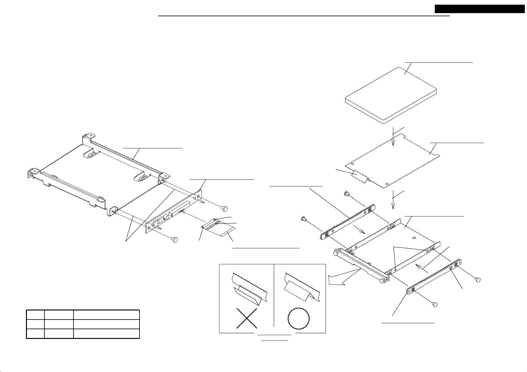
DISASSEMBLING PROCEDURES
● Disassembling procedures
In reverse of assembling procedures.
● Assembling procedures
1.Screw M078 with the two screws(Ⓒ), and connect M005.
NR-261UM-07LAN4,-07-5WS
M074: ASSY-ROM(HDD)
Assemble
M022: HOLDER-HDD
M028: SHEET-HDD
Tongue
M078: ASSY-PCB-HDD
M050: PLATE-HDD
Assemble while inserting tongue into the
slit of the plate.
Ⓒ x 2
Through the circuit hole
to the hook.
Pin 1 on the other side
(black marking)
Continuity side
Himeron
M005: FLAT-CABLE 50P
Ⓛ x 2
Positioning hole
M020: HOLDER-HDD
Set the salients to the
positioning holes and assemble.
Arrow must be the side of
connector. (other side too)
Ⓛ x 2
Tighten torque(N・m)ScrewNo.
2.6X4 0.4 +0.2/-0.1Ⓒ
0.3 +0.15/-0.05M3X4Ⓛ
Tongue position
after inserted
M050: PLATE-HDD
25
Your company internal use only.Copyright (C) Mitsubishi Electric Corporation.
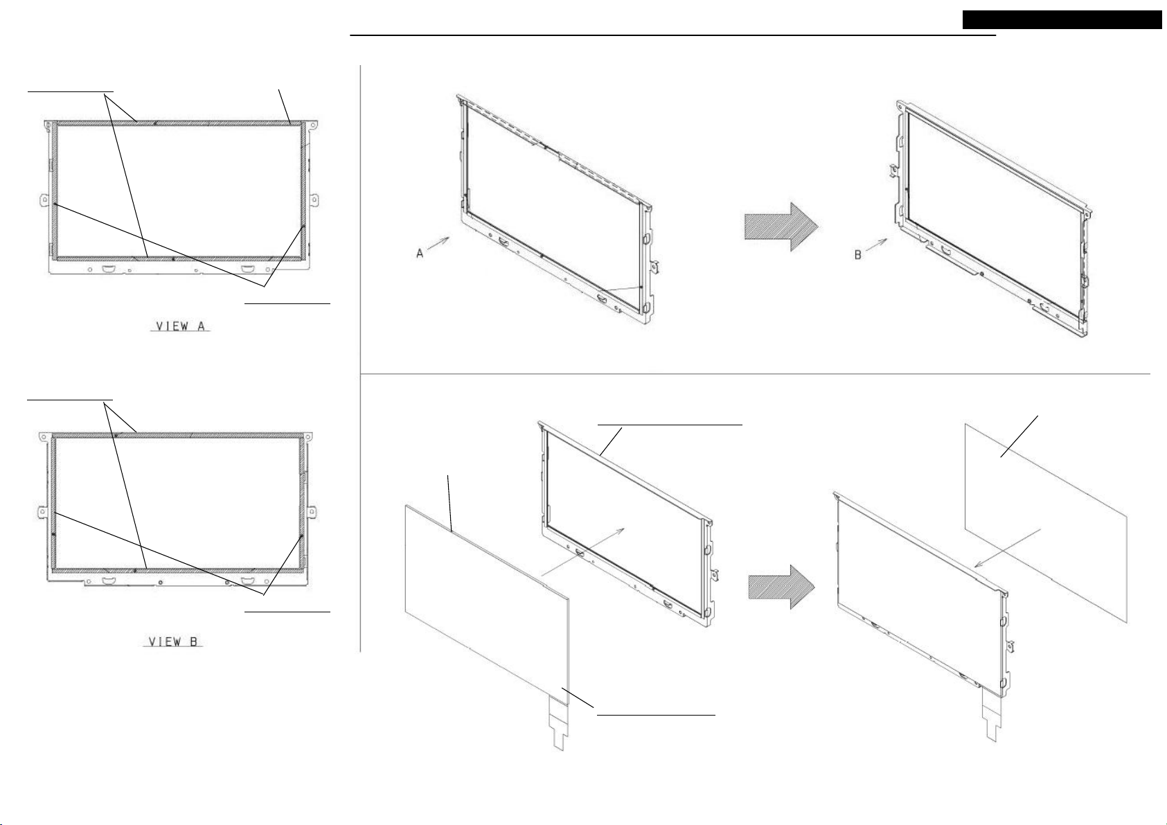
DISASSEMBLING PROCEDURES
*It is assembling procedure. Disassembling procedure is in reverse.
Also pass the black sheet from
the hole.
Ⓗ x 4
M063: LABEL
M072: ASSY-PANEL-R
NR-261UM-07LAN4,-07-5WS
Ⓕ x 2
B - B
(symmetry)
M088: SHEET
M039: SHEET
Do not run aground on the slope.
Attachment position
C - C
(symmetry)
Attachment position
(R end)
View A
Attachment position
(R end)
26
M049: SHEET-ENT
M073: ASSY-ENT
Tighten torque(mN・m)ScrewNo.
2X4 100 +10/-10Ⓕ
280 +10/-102X8Ⓗ
Your company internal use only.Copyright (C) Mitsubishi Electric Corporation.
DISASSEMBLING PROCEDURES
*It is assembling procedure. Disassembling procedure is in reverse.
M008: FLAT-CABLE 8P
Blue reinforced plate side
NR-261UM-07LAN4,-07-5WS
Lock after FFC connected.
M008: FLAT-CABLE 8P
Blue reinforced plate side
PCB-MONITOR
Screw with the screw that made by
Iwata bolt.
Tighten torque(mN・m)ScrewNo.
2X4 200 +100/-40Ⓜ
Ⓜ x 4
After inserting the connector till it is
locked, screw.
Reverse side of reinforced plate
27
M003: FPC
Attachment position of M046
M046: SHEET-FPC
Your company internal use only.Copyright (C) Mitsubishi Electric Corporation.
DISASSEMBLING PROCEDURES
*It is assembling procedure. Disassembling procedure is in reverse.
A
NR-261UM-07LAN4,-07-5WS
Re-attach the protecting sheet
that removed.
Remove the protecting sheet .
Ⓕ x 4
View A
Remove the protecting sheet .
Ⓕ x 2
Tighten torque(mN・m)ScrewNo.
2X4 145 +10/-10Ⓕ
28
Remove the separator from
M041, M042.(4 places)
Your company internal use only.Copyright (C) Mitsubishi Electric Corporation.
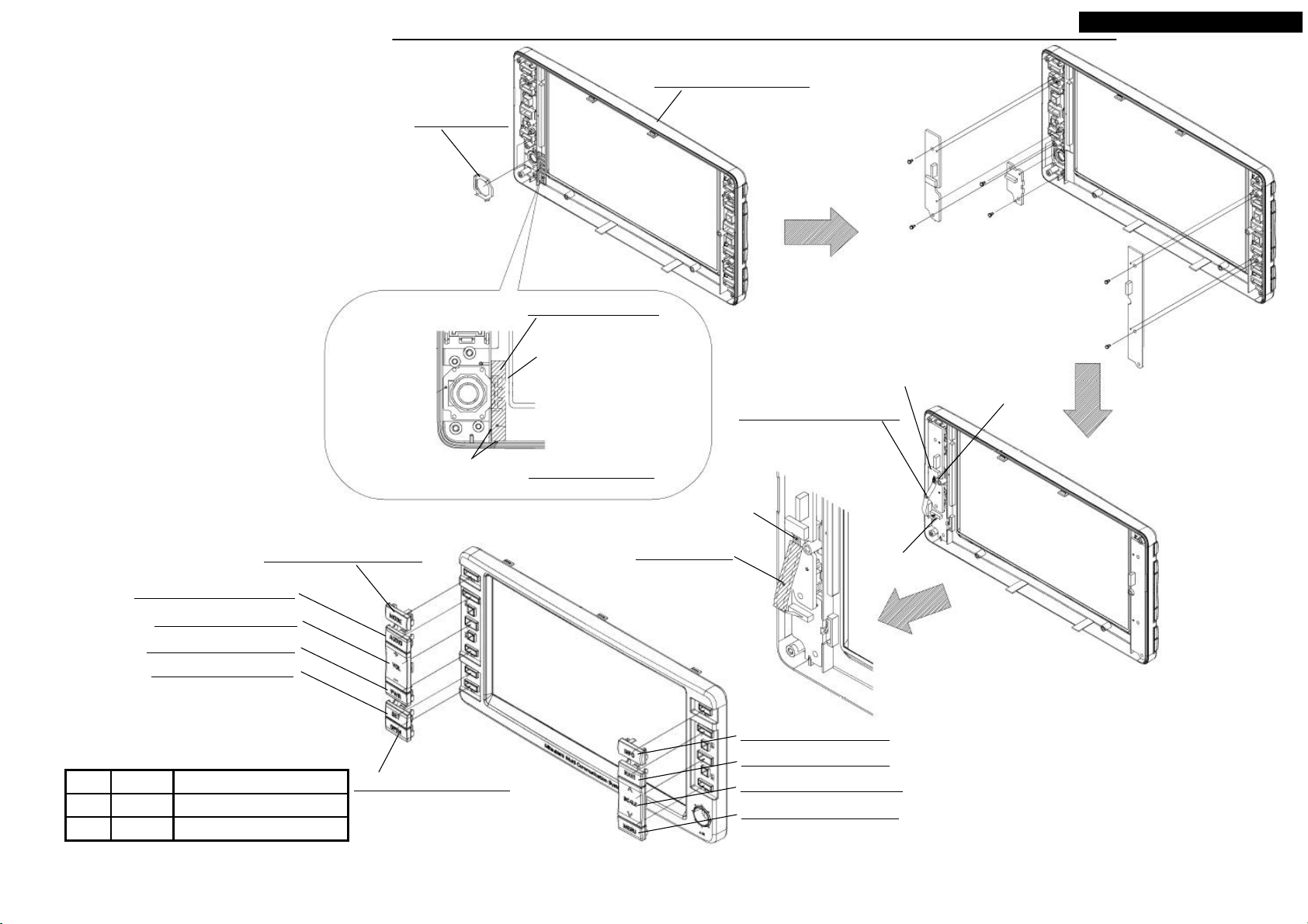
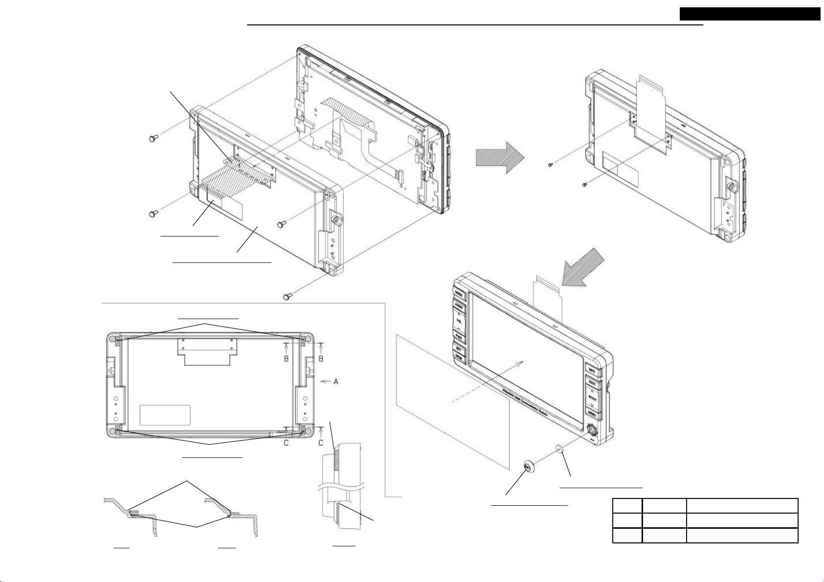
DISASSEMBLING PROCEDURES
NR-261UM-07LAN4,-07-5WS
*It is assembling procedure. Disassembling procedure is in reverse.
M062: PRISM
Attachment position
M071: ASSY-PANEL-F
M047: SHEET-LCD
Note that M047 is not touched
to the edge of M071.
Attach M047 after inserted
M062.
M047 Attachment Detail
Blue reinforced plate
Ⓖ x 2
Ⓕ x 2
Ⓖ x 2
Lock after FFC connected.
Blue reinforced plate side
M009: FLAT-CABLE 8P
M054: BUTTON-MODE
M055: BUTTON-AUDIO
M052: BUTTON-VOL
M056: BUTTON-PWR
M057: BUTTON-SET
Tighten torque(mN・m)ScrewNo.
2X4 125 +10/-10Ⓕ
185 +10/-102X6Ⓖ
M058: BUTTON-OPEN
M043: SHEET
After insert M009, attach
M043 to touch on the blue
reinforced plate.
M059: BUTTON-INFO
M060: BUTTON-NAVI
M053: BUTTON-SCALE
M061: BUTTON-MENU
29
Lock after FFC
connected.
Your company internal use only.Copyright (C) Mitsubishi Electric Corporation.
DISASSEMBLING PROCEDURES
*It is assembling procedure. Disassembling procedure is in reverse.
NR-261UM-07LAN4,-07-5WS
M038: SHEET
Attach to be not touched to the
edge of M019.
M042: SHEET
Attach according to the corner.
M037: SHEET
Re-attach the protecting sheet
that removed from M066.
M019: PLATE-T-PANEL
Remove the protecting sheet
on the attachment side.
Attach to be not touched to the
edge of M019.
M041: SHEET
M066: ASSY-PANE
30
Your company internal use only.Copyright (C) Mitsubishi Electric Corporation.
 Loading...