

Mitsubishi NR-242UM-13LND0, NR-242UM-13-WS Service Manual
SE045513053E Ver.pptx14E
CONTENTS
● FEATURES ....................................................................................... 2
● SPECIFICATIONS ............................................................................ 3
● APPEARANCE ................................................................................. 4
● CONNECTORS ................................................................................ 5
NR-242UM-13LND0,13-WS
2014 Mar.
MITSUBISHI MOTORS
SERVICE MANUAL
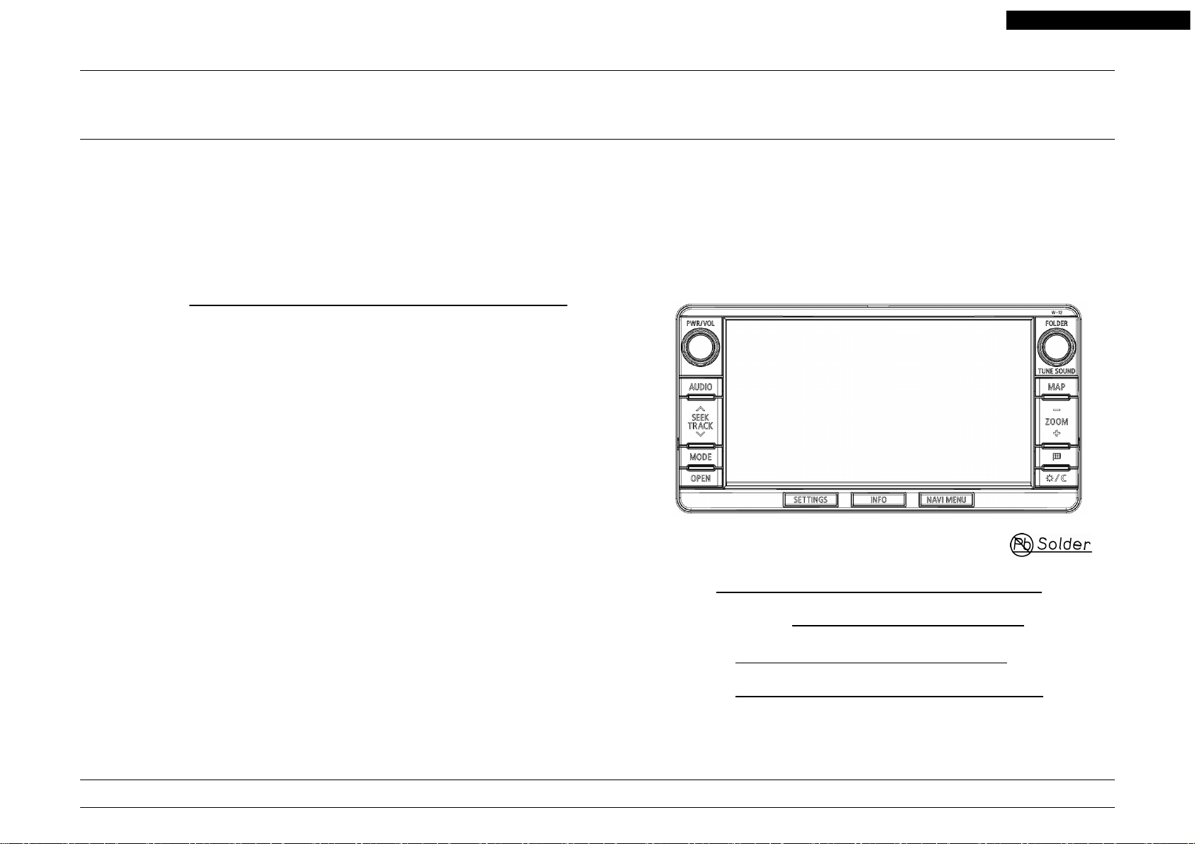
SD CARD/CD CAR NAVIGATION SYSTEM
● COMPOSITION ................................................................................ 6
● SYSTEM CONFIGURATION ............................................................ 7
● BLOCK DIAGRAM ............................................................................ 8
● DISASSEMBLING PROCEDURES ............................................ 9~26
● PARTS LIST ............................................................................... 27,28
● ELECTRICAL PARTS LIST ....................................................... 29~57
● PARTS LAYOUT ON PRINTED CIRCUIT BOARD ................... 58~81
● SCHEMATIC DIAGRAM ......................................................... 82~134
● VOLTAGE ............................................................................. 135~137
MITSUBISHI ELECTRIC CORP. SANDA WORKS
Model : NR-242UM-13LND0
NR-242UM-13-WS
MELCO Code : 3AP258, 3AP316
PART No. : 8750A319, MZ360408EX
Your company internal use only.Copyright (C) Mitsubishi Electric Corporation.

FEATURES
< Display Part >
● Panel design : Wide 2DIN size
● Button illumination : Umber
● LCD : 6.95inch WVGA
● Touch panel : Resistive type (Glass-Glass, Retardation film)
● Display U-com : M16C
< Navigation Part >
● Navi U-com : NaviJ3 (Working frequency : 533MHz)
● Work / Program memory
● Boot memory : Flash memory 16MB
● Back up memory : SRAM 2MB
● SD card (MAP data)
● GPS receiver : Built-in GPS-IP
● Gyro sensor : MEMS Gyro (Murata manufacturing)
● Voice recognition function
< Audio Part >
● Audio U-com : V850ES / SJ3
● DSP : SAF7741HV / N125 (DiRaNa2)
● Radio tuner : TEF7000HV / V3 (LeafDice x2)
● RBDS
● Traffic Information : NAVTEQ Traffic RDS
● HD Radio : SAF3560HV / V1102 HD1.5 (Cayman)
● CD drive : Mitsubishi 8th CD mecha (8cm disc not supported)
● SD card (USER) : (Supported Media : SD, SDHC)
● USB Audio play : via JCI external hands free module, or via Mitsubishi USB-BOX
● iPod Audio play : via JCI external hands free module, or via Mitsubishi USB-BOX
● Bluetooth Audio play
: DDR2-SDRAM 512MB
: Panasonic RP-SDP16G Series (16GB)
: HD-Traffic
(Supported Media : CD, CD-R, CD-RW)
(Supported Format : CD-DA, CD-ROM)
(Supported File : MP3, WMA, AAC)
(Supported File : MP3, WMA, AAC, WAV)
: via JCI external hands free module
NR-242UM-13LND0,13-WS
< External Connect Part >
● Steering switch
● Cell phone : via JCI external hands free module
● iPod : via JCI external hands free module, or via Mitsubishi USB-BOX
● USB memory : via JCI external hands free module, or via Mitsubishi USB-BOX
● Rear camera
● Camera ECU connector (OUTLANDER and OUTLANDER PHEV)
: via outside CAN-BOX (MS-CAN-C)
Camera ECU connector (OUTLANDER SPORT, LANCER and LANCER SPORT BACK)
: via outside CAN-BOX (CAN-B)
● Premium amp : CV-0MW3R45-2, CV-0MW3R45-4, CV-0MW3R45-5,
CV-0MW3B45
● RSES : Built-in DISC drive
● VTR : via RSES
● Sirius tuner : CQ-0MU3IEB, CQ-0MU3IEB-C
● Hands free module
: JCI external hands free module,
For after JCI external hands free module
● USB-BOX : Mitsubishi
2
Your company internal use only.Copyright (C) Mitsubishi Electric Corporation.
SPECIFICATIONS
NR-242UM-13LND0,13-WS
● Power supply : DC 13.2V
● Operating voltage : 10V ~ 16V (BATTERY, ACCESSORY Line)
● Ground polarity : Negative ground
● Backup current : Max. 2.5mA (*1)
● Consumption current : Max. 13A Typ.5A (*2)
● Output : 45W x 4ch (Max.) (14.4V)
● Operating temperature (Reference information) of FAN (Back, Undersurface).
FAN OFF → ON : The ambient temperature of the set more than +50℃.
FAN ON → OFF : The ambient temperature of the set is lower than +40℃.
● Storage temperature range : -40 ~ +85℃
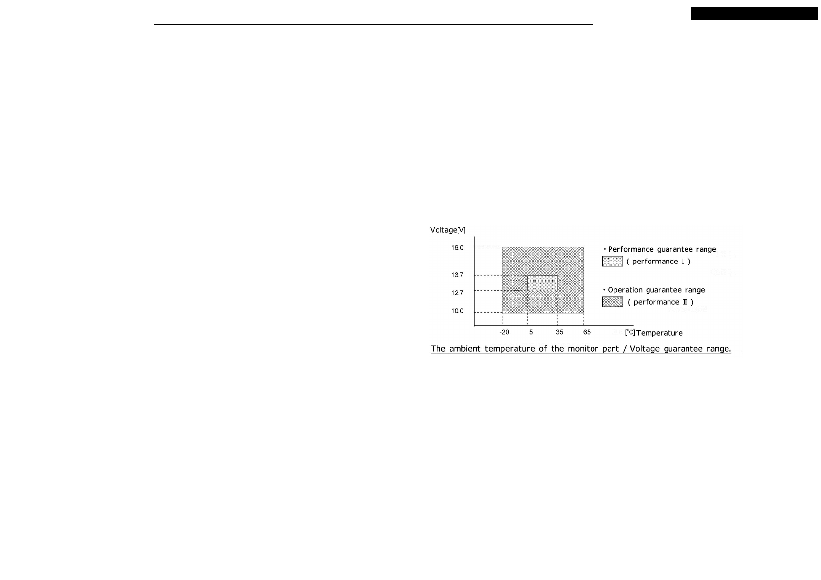
● Working temperature range : -30 ~ +65℃ (*3)
● Dimensions : 207.9(W) × 106.5(H) × 194.9(D)mm
● Weight : 3.3kg
(*1) Measured 90 sec. after from ACC-OFF, at normal temperature, option
unconnected, CD non-insertion, power supply voltage 13.2V.
(*2) At normal temperature, CD 1kHz, 0dB, output 1W, monitor brightness MAX,
power supply 13.2V.
(*3) < Use temperature range >
● The performance assurance of the radio / audio system : -20℃ ~ +60℃
● Display part see below.
● CD drive : When it is less than -20℃, guaranteed only movement
such as the insertion or the takeoff of the disc which does not include
reproduction movement.
3
Your company internal use only.Copyright (C) Mitsubishi Electric Corporation.
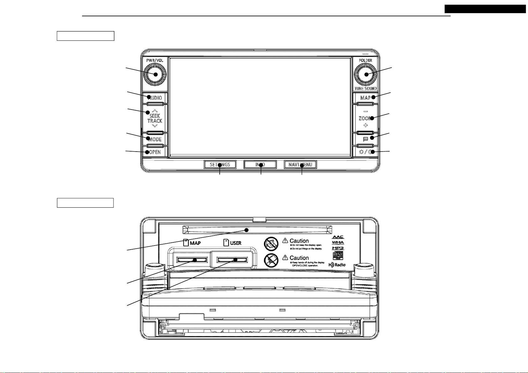
APPEARANCE
PANEL CLOSE
NR-242UM-13LND0,13-WS
PWR/VOL
SEEK TRACK
PANEL OPEN
AUDIO
MODE
OPEN
SETTINGS
INFO
FOLDER TUNE SOUND
MAP
ZOOM IN/OUT
DESTINATION
DAY/NIGHT
NAVI MENU
Disc Insertion Slot
SD Card Slot (MAP)
SD Card Slot (USER)
4
Your company internal use only.Copyright (C) Mitsubishi Electric Corporation.
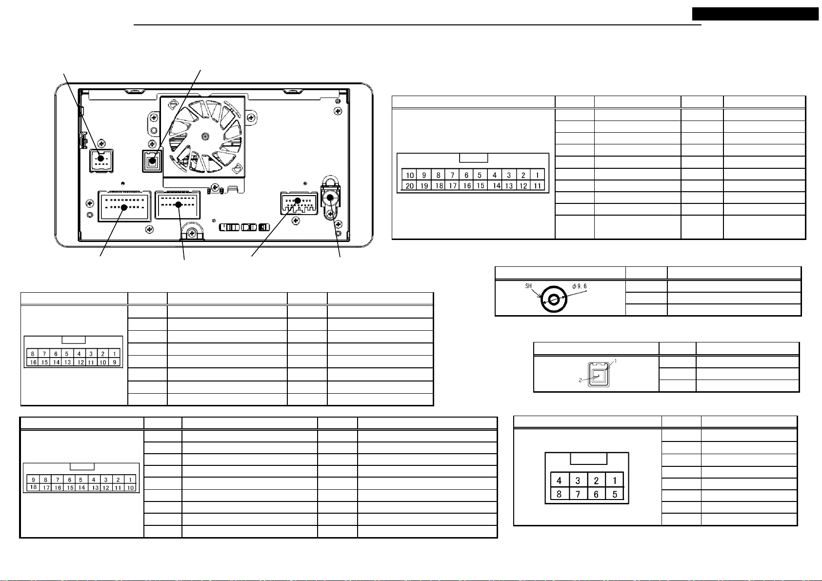
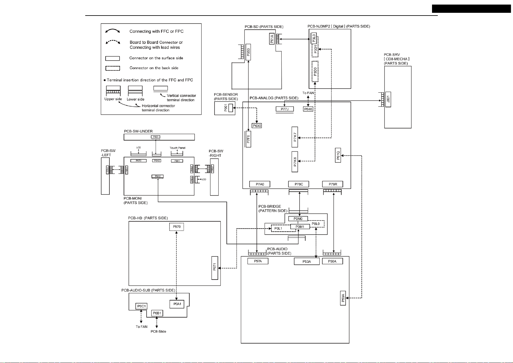
CONNECTORS
NR-242UM-13LND0,13-WS
Navi Power 8P
Connector
Audio Power Supply
20P Connector
AUX 16P Connector PinNo. Signal Name PinNo. Signal Name
GPS Antenna 2P Connector
Audio Sub
AUX 16P Connector
18P Connector
1 HFM MIC OU T 9 HFM MIC OUT GND
2 MIC DETECT 10 SH(HFM MIC OUT)
3 SHIELD(MIC) 11 MIC SIGNAL
4 - 12MIC GND
5 VIDEO DETECT 13 -
6 - 14 7
SHIE L D ( C AN BOX D AT A)
8 CAN BOX DATA TX 16 CAN BOX DATA RX
Radio Antenna
Connector
15
CAN BOX DATA CLK
*Connector figures are view where it faced the unit.
Audio Power Supply 20P Connector PinNo. Signal Name PinNo. Signal Name
1 BATTERY (+) 11 POWER GND
2 ILLUMINATION(+) 12 ILLUMINATION(-)
3 SPEAKER FL(+) 13 SPEAKER FL(-)
4 SPEAKER RL(+) 14 SPEAKER RL(-)
5 SPEAKER FR(+) 15 SPEAKER FR(-)
6 SPEAKER RR(+) 16 SPEAKER RR(-)
7 - 17ANTENNA +B
8 - 189 REMOCON 19 REMOCON GN D
VEHICLE SPEED
2010 ACCESSORY(+)
PULSE
Radio Antenna Connector PinNo. Signal Name
1 AM/FM ANTENNA SIGNAL
SH SHIELD
GPS Antenna 2P Connector PinNo. Signal Name
1GND_GPS
2 GPS AN TEN NA S IGN AL
Audio Sub 18P Connector PinNo. Signal Name PinNo. Signal Name
1 IE BUS(+) 10 IE BUS(-)
2 IE-BUS POWER ON 11 3 IE-BUS INPUT LEFT(+) 12 IE-BUS INPUT LEFT(-)
4 IE-BUS INPUT R IGHT(+) 13 IE-BUS INPUT RIGHT(-)
5 TEL INPUT 14 TEL MUTE
6 HFM/USB S-INPUT LEFT 15 TEL INPUT GND
7 HFM/USB S-INPUT RIGHT 16 HFM/USB INPUT GND
8 AUX/RSES INPUT L EFT 17 AUX/RSES/HFM/USB SHIELD
9 AUX/RSES INPUT RIGHT 18 AUX/RSES INPUT GND
5
Navi Power 8P Connector PinNo. Signal Name
1BATTERY(+)
2 PS-R
3
CAMERA DETECT
4 VCC(RC6.5V)
5GND
6 SHIELD(CAMERA)
7 CAMER A SIG N AL
8 GND(RC)
Your company internal use only.Copyright (C) Mitsubishi Electric Corporation.
COMPOSITION
NR-242UM-13LND0,13-WS
6
Your company internal use only.Copyright (C) Mitsubishi Electric Corporation.
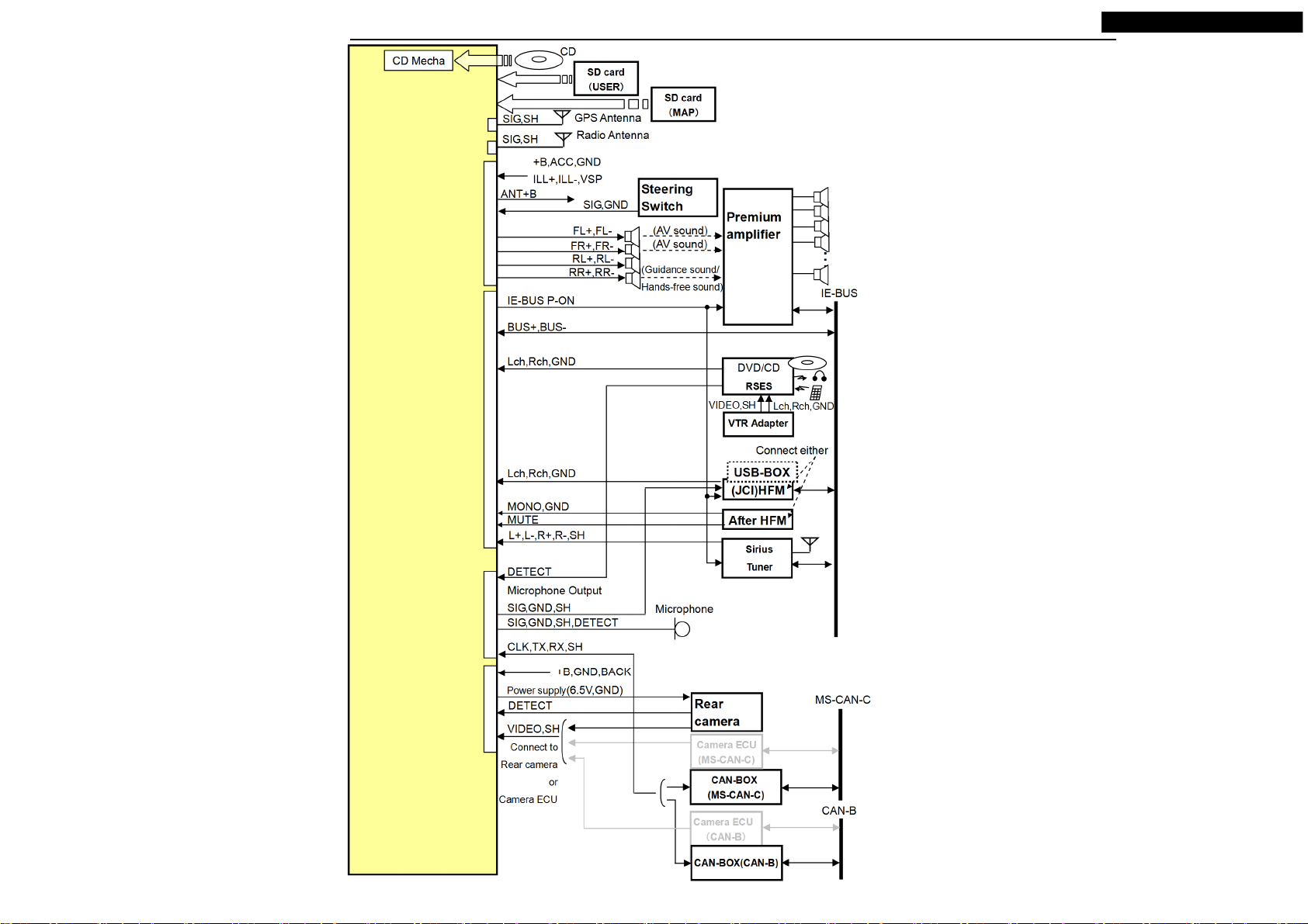
SYSTEM CONFIGURATION
NR-242UM-13LND0,13-WS
GPS Antenna
2P Connector
Radio Antenna
Connector
Audio Power
Supply 20P
Connector
Audio Sub 18P
Connector
AUX 16P Connector
NAVI Power 8P
Connector
7
(OUTLANDER and OUTLANDER PHEV)
(OUTLANDER SPORT, LANCER and LANCER SPORT BACK)
Your company internal use only.Copyright (C) Mitsubishi Electric Corporation.
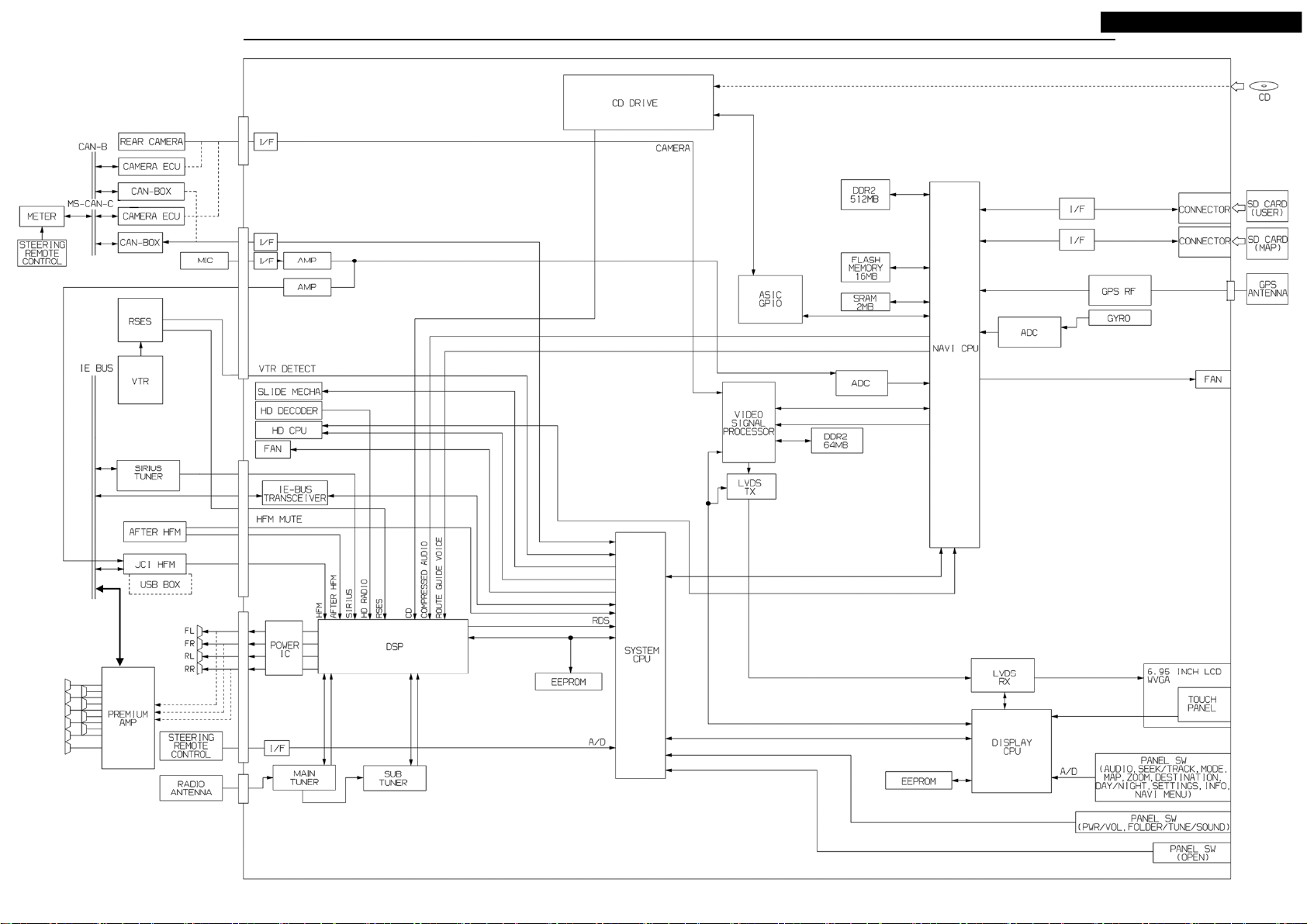
BLOCK DIAGRAM
NR-242UM-13LND0,13-WS
8
Your company internal use only.Copyright (C) Mitsubishi Electric Corporation.

DISASSEMBLING PROCEDURES
*It is assembling procedure. Disassembling procedure is in reverse.
M039(1): NAME-CARD(NR-242UM-13LND0)
M048(2): NAME-CARD(NR-242UM-13-WS)
NR-242UM-13LND0,13-WS
Stick M039/M048 along the stamp of the cover.
Don't stick M039/M048 diagonally.
Model
(1) NR-242UM-13LND0
(2) NR-242UM-13-WS
9
Your company internal use only.Copyright (C) Mitsubishi Electric Corporation.
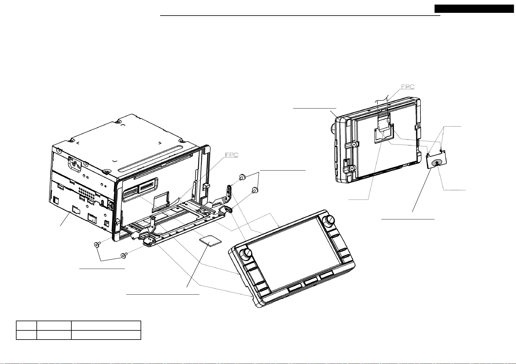
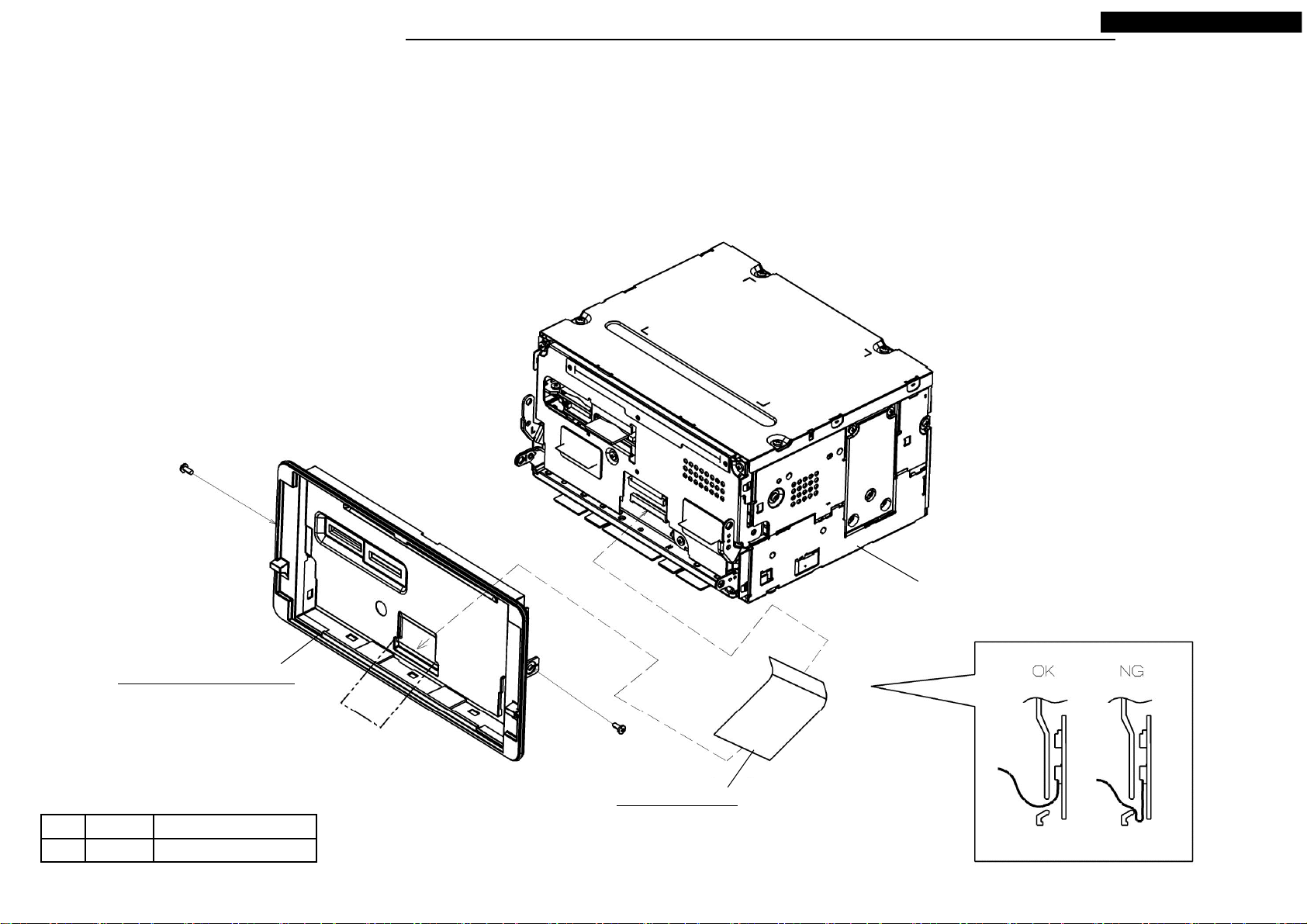
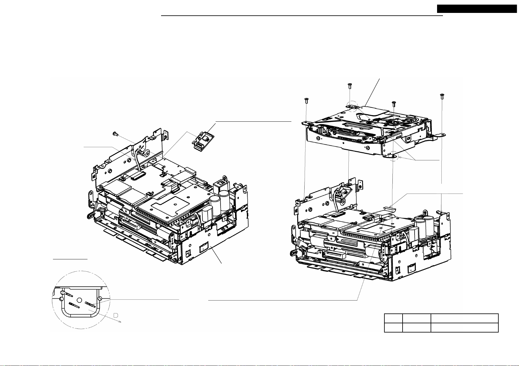
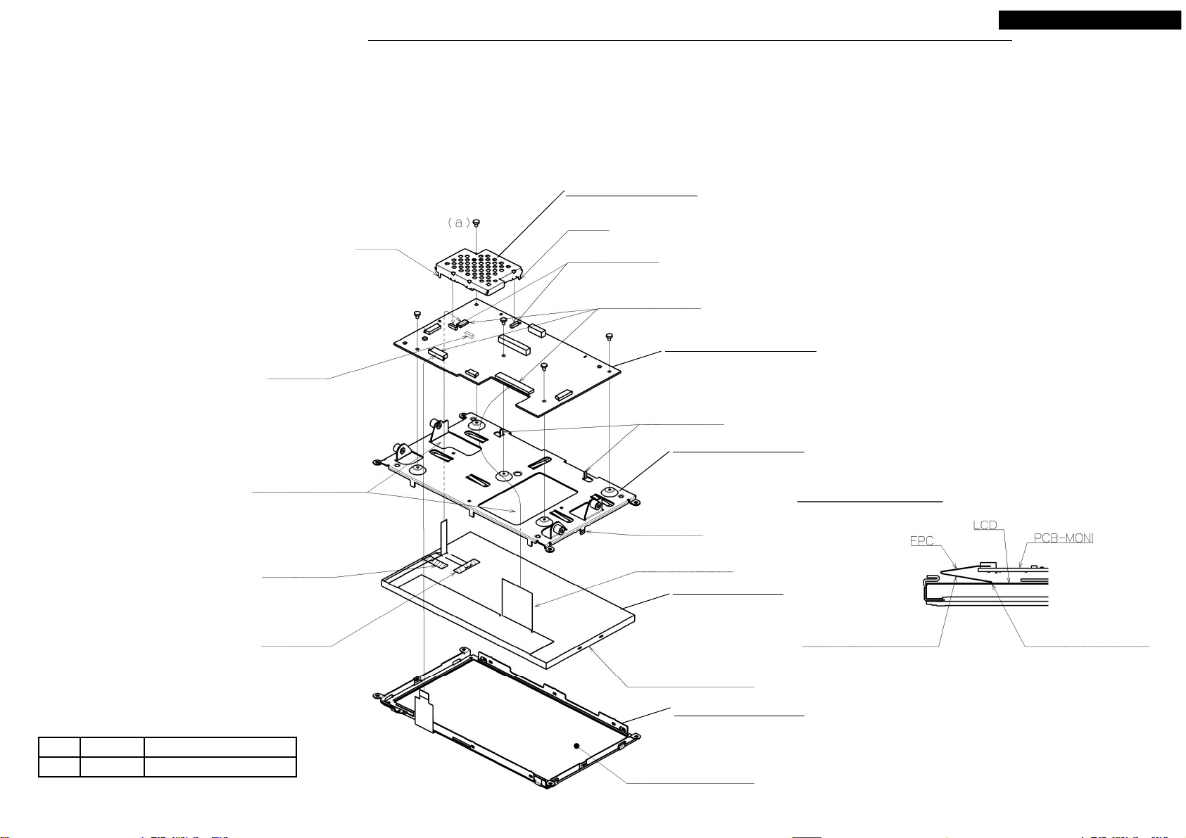
DISASSEMBLING PROCEDURES
● Disassembling procedures
In reverse of assembling procedures.
● Assembling procedures
1.Insert M051 in S2-CHASSIS.
2.Screw M052 and S2-CHASSIS with M026 (4 places), after set M052 in the fastening point of S2-CHASSIS.
3.Insert the FPC of S2-CHASSIS to the connector of M052, and lock.
4.Insert hook of M037 to M052, and press the shaded area and make fit.
M026: PIN-MONI
Do not destroy a
hexagon hole.
NR-242UM-13LND0,13-WS
M052: S2-MONI
Hook
Shaded area
Connecter
S2-CHASSIS
M026: PIN-MONI
Do not destroy a
hexagon hole.
No. Name
M026 PIN-MONI 0.4 +0.15/-0.05
Tighten torque(N・m)
M051: ASSY-ROM(SD16G)
10
M037: COVER-FPC
Your company internal use only.Copyright (C) Mitsubishi Electric Corporation.
DISASSEMBLING PROCEDURES
● Disassembling procedures
In reverse of assembling procedures.
● Assembling procedures
1.Screw M047 and S3-CHASSIS with Ⓐ (2 places), after draw out M001 from the hole of M047.
When assemble M047, tighten a screw in condition pushing M047 into S3-CHASSIS side (attach it and hold it) and do it.
When assemble M047, do not touch the tip section of the slide of S3-CHASSIS.
Ⓐ
NR-242UM-13LND0,13-WS
M047: ASSY-PANEL-SUB
No. Screw
Ⓐ
2.6X6 0.4 +0.2/-0.1
Tighten torque(N・m)
Ⓐ
M001: FPC-MONI
11
S3-CHASSIS
NAVI side
Terminal surface in the bottom.
And do not bend it.
MONI side
Do not let FFC crawl
into a subpanel.
Your company internal use only.Copyright (C) Mitsubishi Electric Corporation.
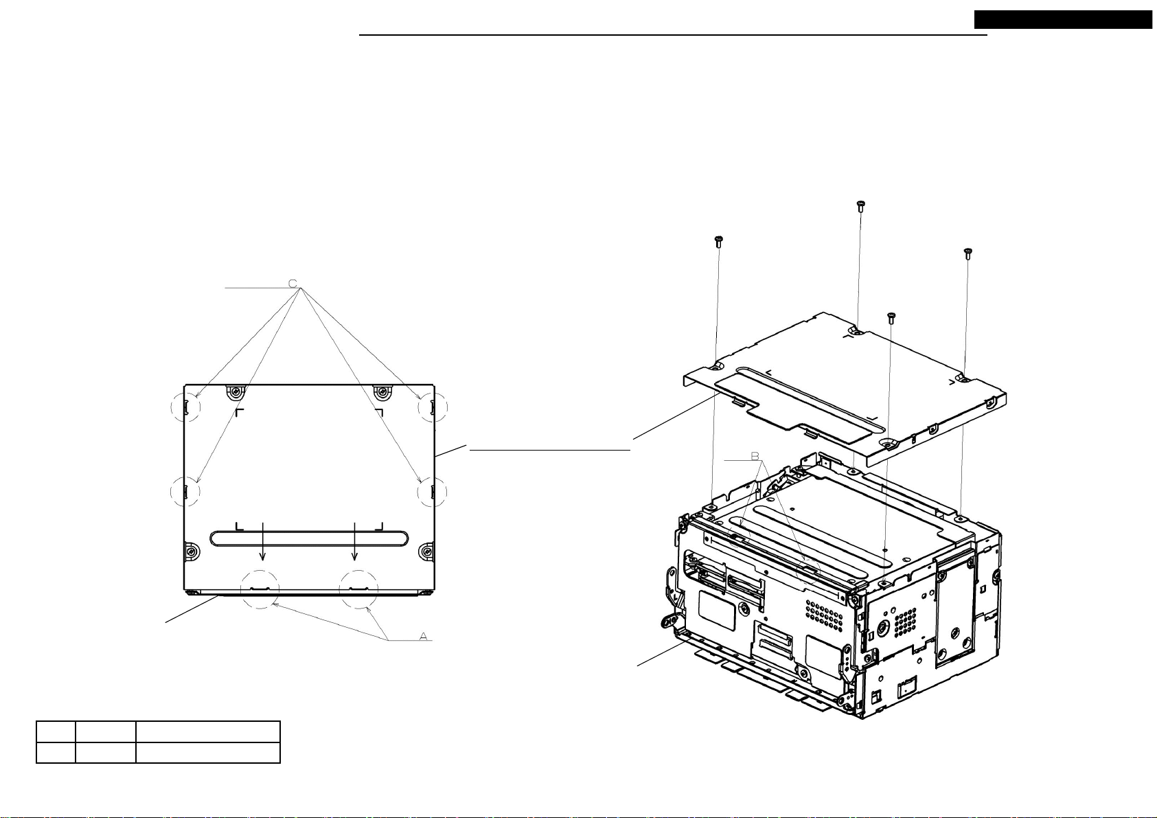
DISASSEMBLING PROCEDURES
● Disassembling procedures
In reverse of assembling procedures.
● Assembling procedures
1.Screw M055 and S3-CHASSIS with Ⓐ (4 places), after fit the tab A of M055 in hole B of S3-CHASSIS and fit side tab C. (4 places)
NR-242UM-13LND0,13-WS
Ⓐ x 4
S3-CHASSIS
The side
tab
Tab
M055: ASSY-COVER-TOP
Attach it after approaching to the
direction (direction of the arrow) of
S3-CHASSIS.
S3-CHASSIS
Hole
No. Screw
Ⓐ
2.6X6 0.4 +0.2/-0.1
Tighten torque(N・m)
12
Your company internal use only.Copyright (C) Mitsubishi Electric Corporation.

DISASSEMBLING PROCEDURES
● Disassembling procedures
In reverse of assembling procedures.
● Assembling procedures
1.Screw S3-CHASSIS and M058 with Ⓐ (2 places), after remove the back connector cap of M058
and set it to positioning A of S3-CHASSIS and insert M058 BtoB connectors.
Insert the FPC(a) of S3-CHASSIS to the connector of M058, and lock.
2.Insert the M001 to the connector of M058, and lock.
3.Set M044 to positioning B and screw with Ⓐ. (4 places)
<Turn to tighten a screw> Tighten a screw in order of ⓐ → ⓑ → ⓒ → ⓓ.
Positioning B
M044: ASSY-CHASSIS-F
NR-242UM-13LND0,13-WS
No. Screw
Ⓐ
2.6X6 0.4 +0.2/-0.1
Ⓐ x 4
Tighten torque(N・m)
Ⓐ x 2
M058: ASSY-PCB-BRIDGE
M001: FPC-MONI
13
S3-CHASSIS
Positioning A
Detail of M058
Press the neighborhood of both ends of the lock.
There is fear of being warped in the lock center neighborhood.
Locke press direction
(press it in rotatory direction)
Your company internal use only.Copyright (C) Mitsubishi Electric Corporation.
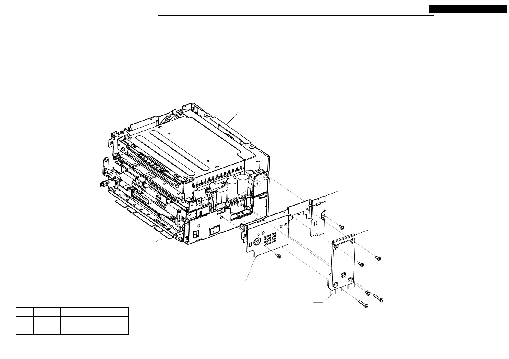
DISASSEMBLING PROCEDURES
● Disassembling procedures
In reverse of assembling procedures.
● Assembling procedures
1.Screw M016 and S4-CHASSIS with Ⓐ (2 places), after set M016 to positioning G of S4-CHASSIS.
2.Screw M023 and S4-CHASSIS with Ⓐ (3 places) and Ⓑ (2 places), after set M023 on the basis of a D side.
S4-CHASSIS
NR-242UM-13LND0,13-WS
No. Screw
Ⓐ
2.6X6 0.4 +0.2/-0.1
Ⓑ
M2.6X16 0.4 +0.2/-0.1
Tighten torque(N・m)
Positioning G
At the time of assembling,
do not run.
14
M016: CHASSIS-SIDE
M023: HEAT-SINK
Ⓐ x 3
Ⓐ x 2
Tighten a screw in order of Ⓑ → Ⓐ.
D side
Ⓑ x 2
Your company internal use only.Copyright (C) Mitsubishi Electric Corporation.
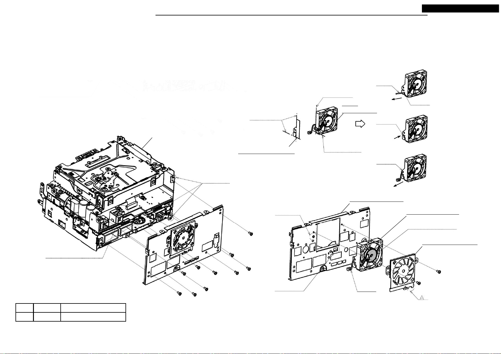
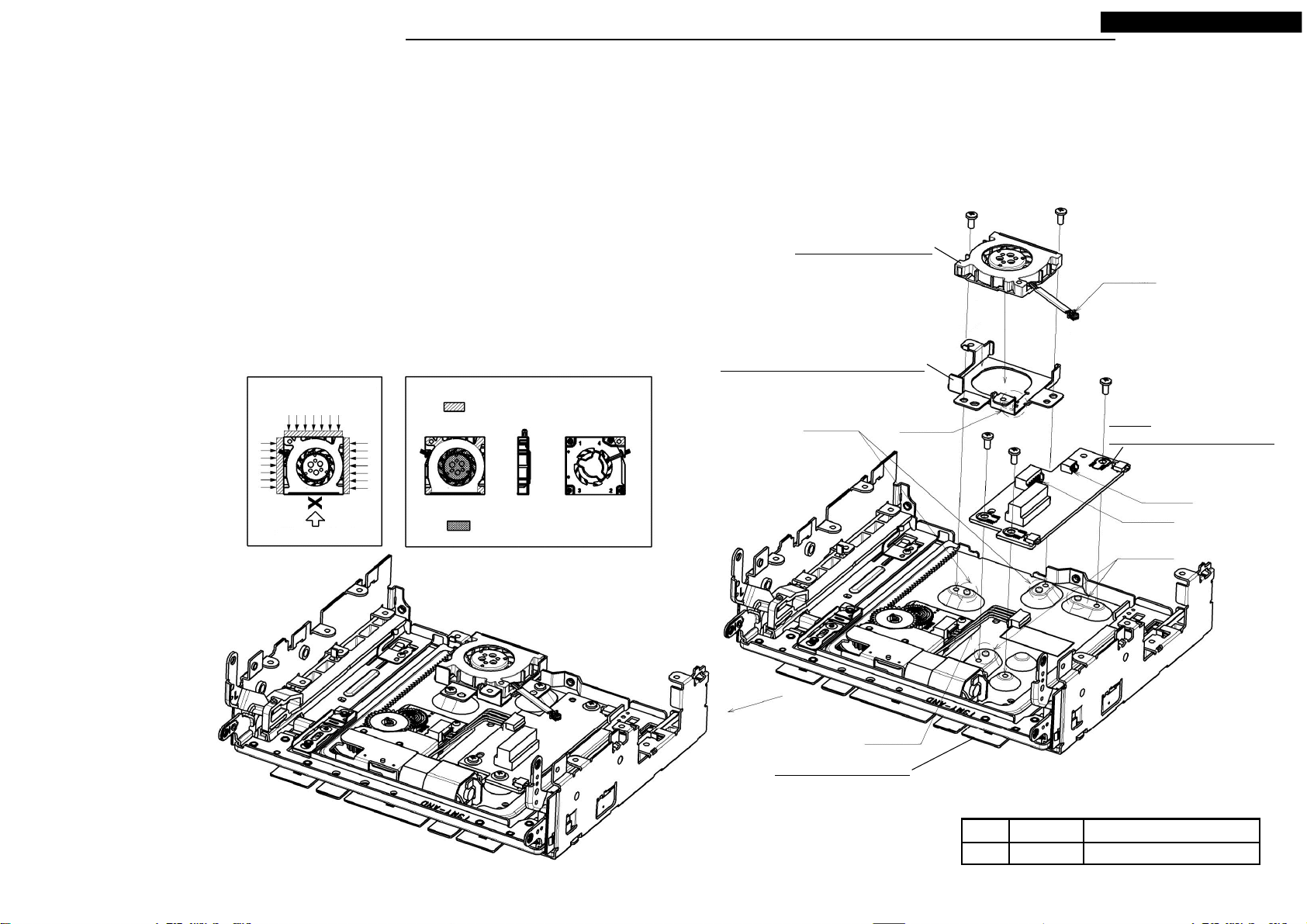
DISASSEMBLING PROCEDURES
● Disassembling procedures
In reverse of assembling procedures.
● Assembling procedures
1.Match pasting position of M034 with sidepiece of M012 and fan end face and R end ridgeline, and put it.
2.Through on a lead of M012 in order of a number.*Slit (1) → Slit (2) → Slit (3)
3.Attach M012 to the square hole of M020 and hang a A point of M022 on the bending point of M020.
And set it in positioning E, and screw them with Ⓐ. (2 places)
* At that time do not press the central part of FAN.
4.Insert the lead of M012 to the connector of S4-CHASSIS and set M020 to positioning F of S4-CHASSIS.
And screw with Ⓐ. (10 places) * At this time, the lead be careful not to be caught .
Pasting position
S4-CHASSIS
End face
of FAN
M012:
MOTOR-FAN
Lead
Slit(2)
NR-242UM-13LND0,13-WS
1)Put a lead through the
direction of the arrow.
Slit(1)
2)Put a lead through the
direction of the arrow.
Insert the connector
of the fan.
No. Screw
Ⓐ
2.6X6 0.4 +0.2/-0.1
Tighten torque(N・m)
Positioning F
Ⓐ x 10
M034: SHEET-FAN-R
Positioning E
Bending point
R end ridgeline
M020: PLATE-REAR
Lead
Slit(3)
3)Put a lead through the
direction of the arrow.
M012: MOTOR-FAN
Do not press the central
part.
M022: HOLDER-FAN
Ⓐ x 2
15
Your company internal use only.Copyright (C) Mitsubishi Electric Corporation.
DISASSEMBLING PROCEDURES
● Disassembling procedures
In reverse of assembling procedures.
● Assembling procedures
1.Hang M057 on slit (20 degrees) of S4-CHASSIS, and screw with Ⓐ. (Refer to a detail drawing)
And insert the lead of S4-CHASSIS in a connector of M057.
2.Insert FFC of S4-CHASSIS in a connector of S4-DECK, and lock.
3.Push FFC of S4-CHASSIS into inward, and assemble positioning D of S4-DECK to S4-CHASSIS,
and screw with Ⓐ. (4 places)
M057: ASSY-PCB-SENSOR
Ⓐ
Lead
NR-242UM-13LND0,13-WS
S4-DECK
Ⓐ x 4
Positioning D
Detail of M057
*Slide it to the direction of arrow D.
Use a 20 degrees slit hole.
S4-CHASSIS
As shown, bend FFC between S4-CHASSIS and S4-DECK
and set it.
16
Insert FFC in S4-DECK
No. Screw
Ⓐ
2.6X6 0.4 +0.2/-0.1
Tighten torque(N・m)
Your company internal use only.Copyright (C) Mitsubishi Electric Corporation.
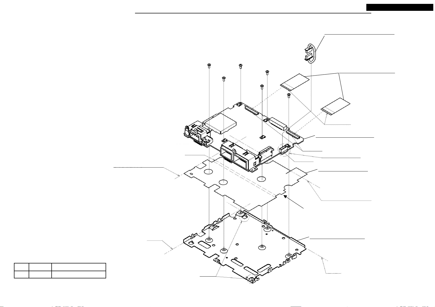
DISASSEMBLING PROCEDURES
● Disassembling procedures
In reverse of assembling procedures.
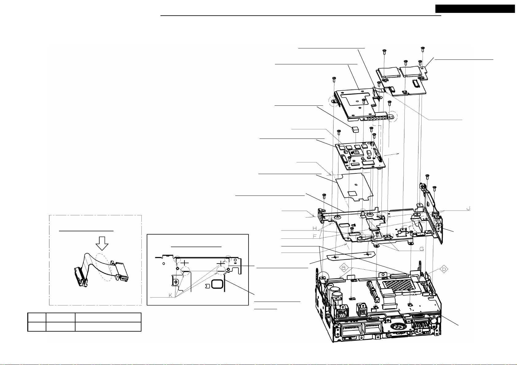
● Assembling procedures
1.Stick M030 on a pasting position of M015.
2.Stick M035 on positioning K of M015.
* At this time, M035 fit positioning K and stick.
3.Set positioning F of M015 to positioning L of S5-CHASSIS, and screw with Ⓐ. (6 places)
* At this time, FFC(b) of S5-CHASSIS let a hole of M015 go through.
4.Remove the cap of the connector of M053(Pattern side: 2 places) and set M053 to
positioning G of M015 and push the part of silk after inserting BtoB connector.
And screw with Ⓐ. (4 places)
5.Stick M029 on the center of electric parts A of M053. (Slanted line part area)
6.Set M042 to positioning H of M015, and screw with Ⓐ. (4 places)
7.Set M061 to positioning J of M015, and screw with Ⓐ. (4 places)
8.Insert M007 in a connector of M053 and M061 and lock.
* After having locked it, push it into the lower direction so that M007
does not swell out in the upper direction.
9.Insert FFC(b) of S5-CHASSIS in a connector of M061 and lock.
M007: FLAT-CABLE 24P
M042: ASSY-COVER-DIGITAL
M029: SHEET-HS
Electric parts A
M053: S4-PCB-DIGITAL
Pasting position
M030: SHEET-DIGITAL
NR-242UM-13LND0,13-WS
Ⓐ x 4
M061: ASSY-PCB-SD
Ⓐ x 4
The upper part of the
terminal surface.
Ⓐ x 4
Terminal surface
Ⓐ x 6
Detail of M007
assembly work
Push M007 into the inside not to
swell out on the top.
No. Screw
Ⓐ
2.6X6 0.4 +0.2/-0.1
Tighten torque(N・m)
Detail of M035 pasting position
Positioning
M015: CHASSIS-DIGITAL
Fit norm
Positioning
Positioning
Positioning L
End face norm
M035: SHEET-TAP
M015: CHASSISDIGITAL
17
Positioning
Hole
positioning
S5-CHASSIS
Your company internal use only.Copyright (C) Mitsubishi Electric Corporation.
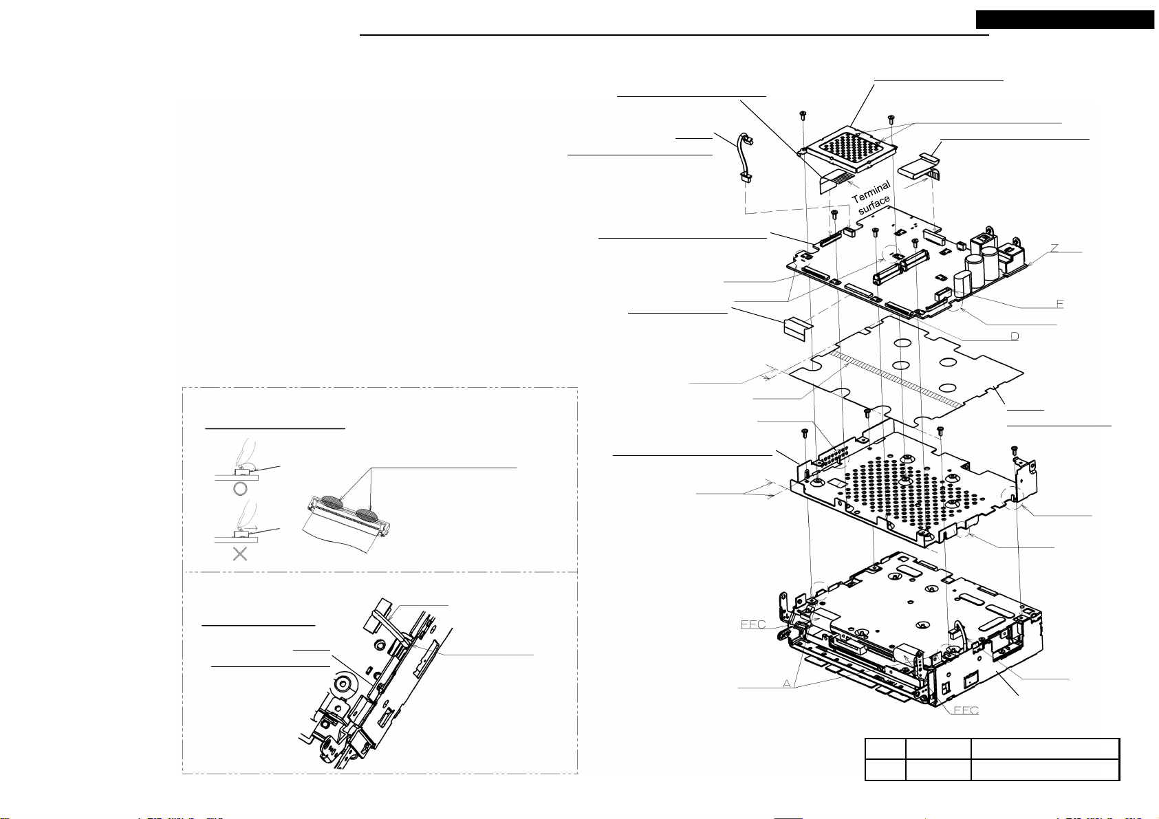
DISASSEMBLING PROCEDURES
NR-242UM-13LND0,13-WS
● Disassembling procedures
In reverse of assembling procedures.
● Assembling procedures
1.Remove the separator of M027 and stick it on a fit norm of M014.
2.Set M014 in positioning A of S5-CHASSIS, and screw with Ⓐ. (4 places)
At that time, let through a lead of S5-CHASSIS to the notch point(1) of M014.
* Do not transform M014 at the time of assembling.
3.Set M056 from the Z side to positioning B and screw with Ⓐ. (3 places)
* Put the lead of S5-CHASSIS at the position of the notch point(2) and set it.
4.Set M024 in positioning C of M056 and screw with Ⓐ. (2 places)
5.Remove the connector cap and adsorption sheet of M056 and
insert M009 and M008 and M006 and M002 in M056.
When lock M002, turn an FFC fixation department, and lock it.
* When lock M002, be careful about the transformation of the fixation department (reel parts).
6.Insert M009 in a connector of M056.
7.Insert FFC (2 pieces) of S5-CHASSIS and the lead in a connector D/E/F of M056 and lock.
* Process the lead, and it does not swell out than an external form of S5-CHASSIS.
Detail of M002
Press the neighborhood of both ends of
the lock.
There is fear of being warped in the lock
center neighborhood.
M006: FLAT-CABLE 40P
M009:
LEAD-CONNECTOR 5P
M056: ASSY-PCB-ANALOG
M002: FPC-ANA
The bottom of the terminal surface.
Insert the side with the mark of "A"
in a connector. * Do not bend it.
Pasting position
M014: CHASSIS-ANALOG
Connector E
Positioning C
Separator
Positioning B
Terminal
surface
Ⓐ x 2
M024: COVER-DDR2
Match a △ mark with the
connector side of the set.
Ⓐ x 3
M008: FLAT-CABLE 18P
side
Connector
Notch point(2)
Connector
M027:
SHEET-ANALOG
Ⓐ x 4
Detail of Lead
M014:
CHASSIS-ANALOG
Locke press direction
(press it in rotatory direction)
Lead
Hole through the lead
18
Fit norm
Positioning
No. Screw
Ⓐ
2.6X6 0.4 +0.2/-0.1
Positioning B
Notch point(1)
Lead
S5-CHASSIS
Tighten torque(N・m)
Your company internal use only.Copyright (C) Mitsubishi Electric Corporation.
DISASSEMBLING PROCEDURES
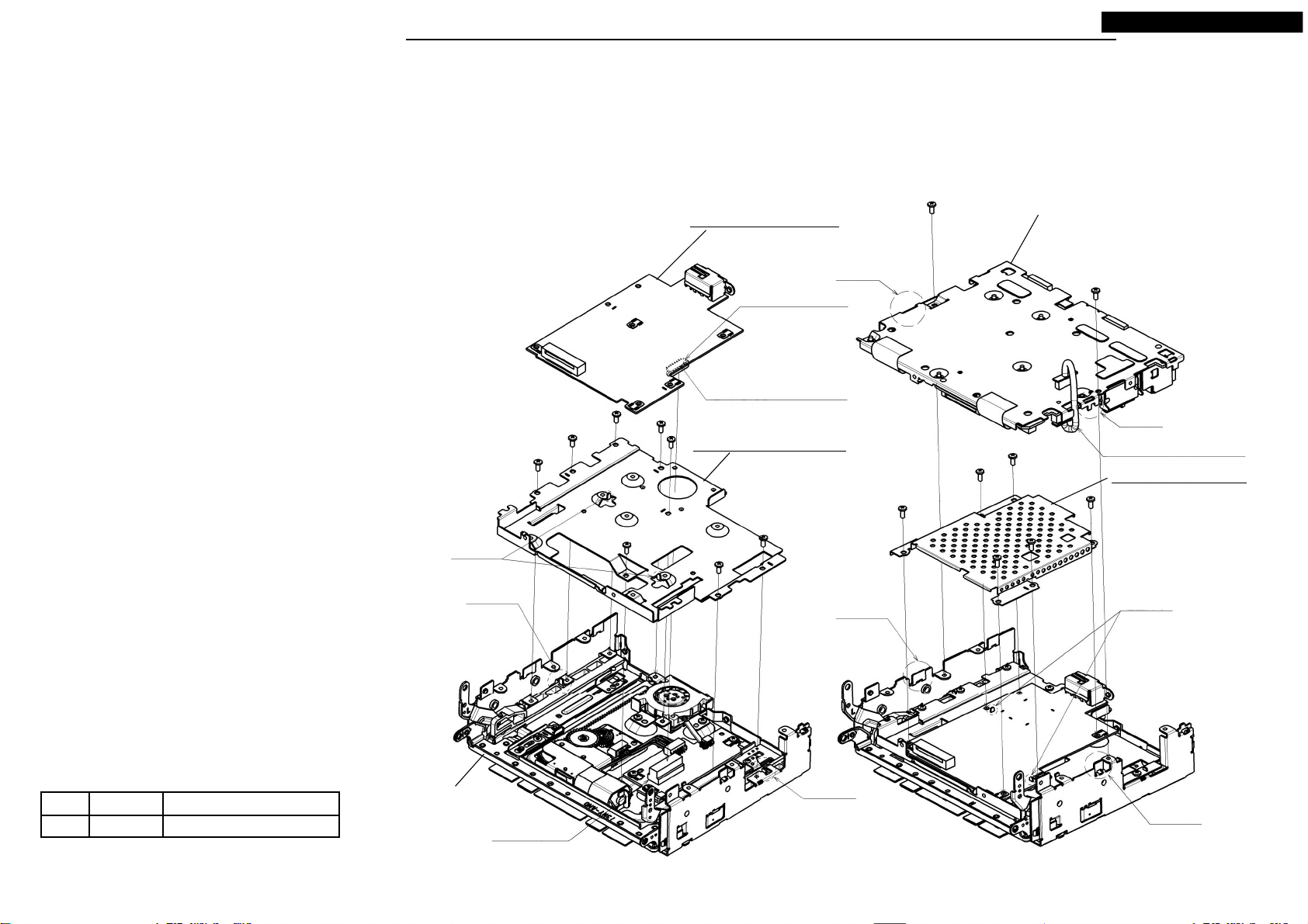
● Disassembling procedures
In reverse of assembling procedures.
● Assembling procedures
1.Set M019 in positioning A of ASSY-SLIDE, and screw with Ⓐ. (8 places)
2.Remove the seat of the back connector of M066, and set to positioning B,
and insert BtoB connector of M066 in BtoB connectors of ASSY-SLIDE.
3.Set M021 in positioning C of ASSY-SLIDE, and screw with Ⓐ. (6 places)
4.Set S6-ASSY-AUDIO (a,b) in positioning D of ASSY-SLIDE, and screw with Ⓐ. (2 places)
* At this time, a lead be careful not to be caught.
* At the time of combination, check a combination in the fig. below.
Ⓐ x 8
M066: ASSY-PCB-HD
BtoB connector
(Pattern side)
After having put BtoB connectors
together, push it lightly.
M019: BRACKET-DTV
NR-242UM-13LND0,13-WS
S6-ASSY-AUDIO
b
Ⓐ x 2
a
Draw out a lead from this
part and attach it.
M021: COVER-DTV
Ⓐ x 6
No. Screw
Ⓐ
2.6X6 0.4 +0.2/-0.1
Tighten torque(N・m)
Positioning B
Positioning A
ASSY-SLIDE
BtoBconnector
19
Positioning D
Positioning A
Positioning C
Positioning D
Your company internal use only.Copyright (C) Mitsubishi Electric Corporation.
DISASSEMBLING PROCEDURES
● Disassembling procedures
In reverse of assembling procedures.
● Assembling procedures
1.Assemble M011 to positioning A of M046.
* Assemble M011 so that a label becomes the upper part.
* Refer to permission load and the weight bearing of the fig. below for M011 handling.
2.Assemble M046 (After work process1) to positioning B of M043, and screw with Ⓐ. (2 places)
* At this time, a lead be careful not to be caught .
3.Assemble M060 to positioning C of M043, and screw with Ⓐ. (3 places)
4.Connect lead A of M011 to connector B of M060.
5.Connect lead C of M043 to connector D of M060.
NR-242UM-13LND0,13-WS
Ⓐ x 2
M011: MOTOR-FAN
Lead A
A permission load and load domain
Handling possibility area
XY direction
exhaust outlet side NG
Permission load: To 1kgf
Load NG area
M046: ASSY-HOLDER-FAN-B
Positioning B Positioning A
Lead C
M043: ASSY-SLIDE
Ⓐ x 3
M060:
ASSY-PCB-AUDIO-SUB
Connector B
Connector D
Positioning C
20
No. Screw
Ⓐ
2.6X6 0.4 +0.2/-0.1
Tighten torque(N・m)
Your company internal use only.Copyright (C) Mitsubishi Electric Corporation.
DISASSEMBLING PROCEDURES
● Disassembling procedures
In reverse of assembling procedures.
● Assembling procedures
1.Remove the separator of M028 and stick M028 on pasting position of M013.
2.Set M059 to positioning point of M013, screw with Ⓐ. (6 places)
3.Insert M003 in a connector A of M059 and lock. (2 places)
4.Insert M010 in a connector B of M059.
NR-242UM-13LND0,13-WS
M010: LEAD-CONNECTOR 7P
Ⓐ x 6
M003: FLAT-CABLE 50P
The upper part of the
terminal surface.
M059: ASSY-PCB-AUDIO
No. Screw
Ⓐ
2.6X6 0.4 +0.2/-0.1
Match this aspect with fit norm of M013, and stick it.
Tighten torque(N・m)
Fit norm
Separator
Positioning point
Connector A
Connector B
Remove the separator.
M013: CHASSIS-AUDIO
Remove an adsorption sheet and insert a connector.
M028: SHEET-AUDIO
Match this aspect with fit norm of M013, and stick it.
Fit norm
21
Your company internal use only.Copyright (C) Mitsubishi Electric Corporation.
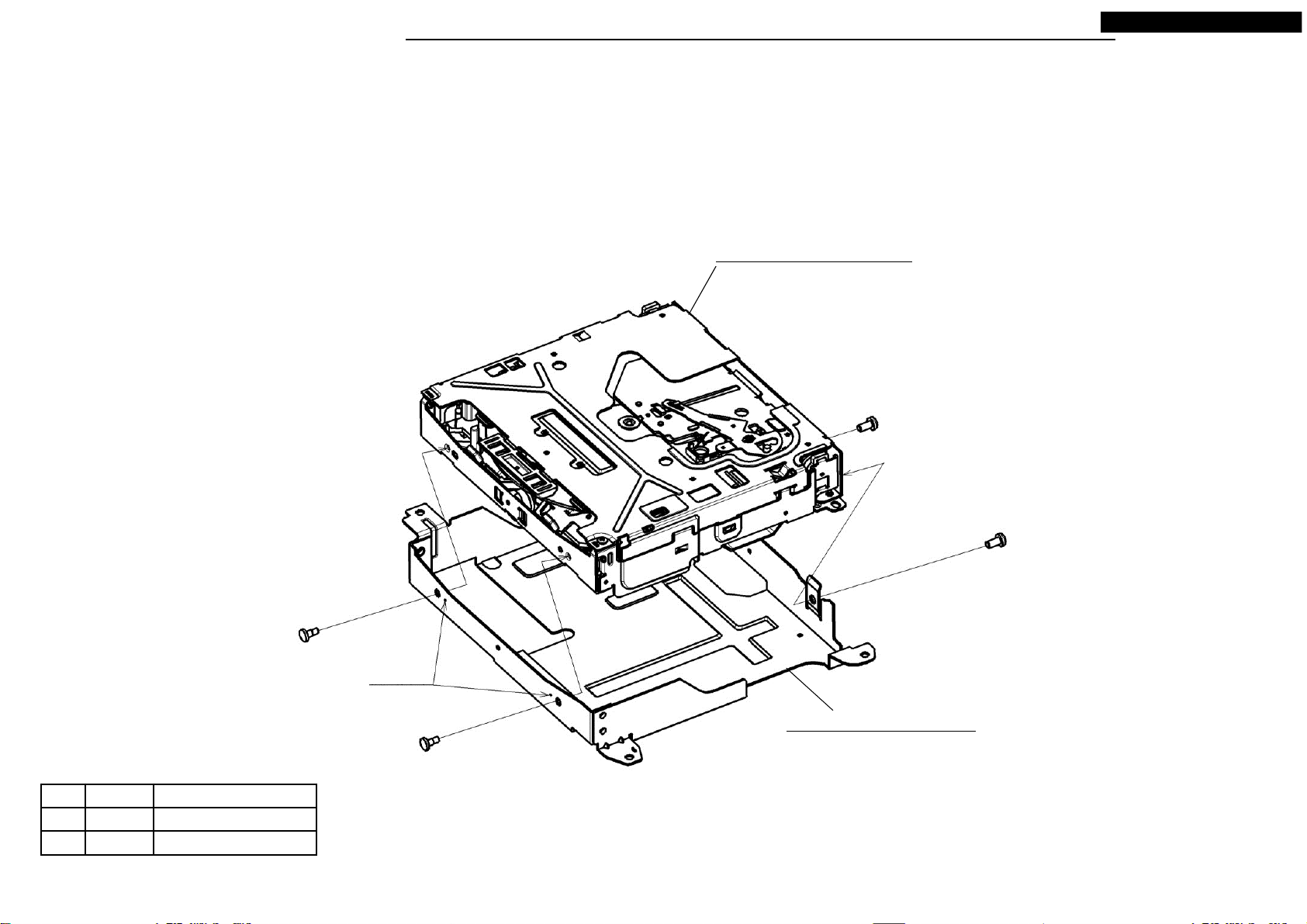
DISASSEMBLING PROCEDURES
● Disassembling procedures
In reverse of assembling procedures.
● Assembling procedures
1.Set M054 in positioning point of M045 then screw with Ⓕ (2 places) and Ⓖ (2 places).
NR-242UM-13LND0,13-WS
M054: CD8-MECHA(955827)
Ⓕ x 2
No. Screw
Ⓕ
Ⓖ
3X6 0.7 +0.2/-0.1
2.6X6
Ⓖ x 2
Tighten torque(N・m)
0.5 ±0.2
Positioning
point
22
M045: ASSY-BRACKET-CD
Your company internal use only.Copyright (C) Mitsubishi Electric Corporation.

DISASSEMBLING PROCEDURES
● Disassembling procedures
In reverse of assembling procedures.
● Assembling procedures
1.Attach M036 to S3-MONI and screw with Ⓓ. (4 places)
* When assemble it, use the jig for positioning.
2.Stick M031,M032 and M033 on M036.
3.Attach M050 to S3-MONI.
4.Stick a SHEET on the LCD surface of the S3-MONI.
5.Stick M038 on M036.
M032: CUSHION-REAR
M038: LABEL
Pasting up point of the cushion
M036: PANEL-R
M033:
CUSHION-REAR
Thickness:1.5mm
NR-242UM-13LND0,13-WS
M031:
CUSHION-REAR
Thickness:1.0mm
No. Screw
Ⓓ
2X8
Ⓓ x 4
S3-MONI
Tighten torque(N・m)
0.16~0.35
Joint tab
M036: PANEL-R
Joint tab
Chamfering shape
*Only M032
SHEET
(About 170×100)
M038: LABEL
M032: CUSHION-REAR
S3-MONI
M050: ASSY-KNOB
Match M050 with the D cut part of
the encoder and attach it.
23
Your company internal use only.Copyright (C) Mitsubishi Electric Corporation.
DISASSEMBLING PROCEDURES
● Disassembling procedures
In reverse of assembling procedures.
● Assembling procedures
1.Attach M065 to M049 and screw with Ⓒ. (4 places)
2.Connect M005 to M065.
3.Attach S4-LCD to M049 and screw with Ⓒ. (4 places)
* When assemble it, use the jig for positioning.
4.Attach M064 and M063 to M049 and screw with Ⓒ. (By 4 places)
5.In the same way as a lower fig., connect M004 and M005 to
PCB and S4-LCD.
Lock a connector after
the insertion in FFC.
Ⓒ x 4
NR-242UM-13LND0,13-WS
M004:FLAT-CABLE 16P
The upper part of the
terminal surface.
Ⓒ x 4
No. Screw
Ⓒ
2X6
Tighten torque(N・m)
0.16~0.24
M063: ASSY-PCB-SW-RIGHT
Lock a connector after
the insertion in FFC.
M005:
FLAT-CABLE 10P
The blue reinforcement
board side.
M065:ASSY-PCB-SW-UNDER
M049: ASSY-PAN
After having read QR code, take off LABEL-QR.
Positioning
Ⓒ x 4
Ⓒ x 4
M064:
ASSY-PCB-SW-LEFT
Lock a connector after
the insertion in FFC.
S4-LCD
Take off a protection sheet of the touch
panel surface.
Lock a connector after
the insertion in FFC.
24
Your company internal use only.Copyright (C) Mitsubishi Electric Corporation.
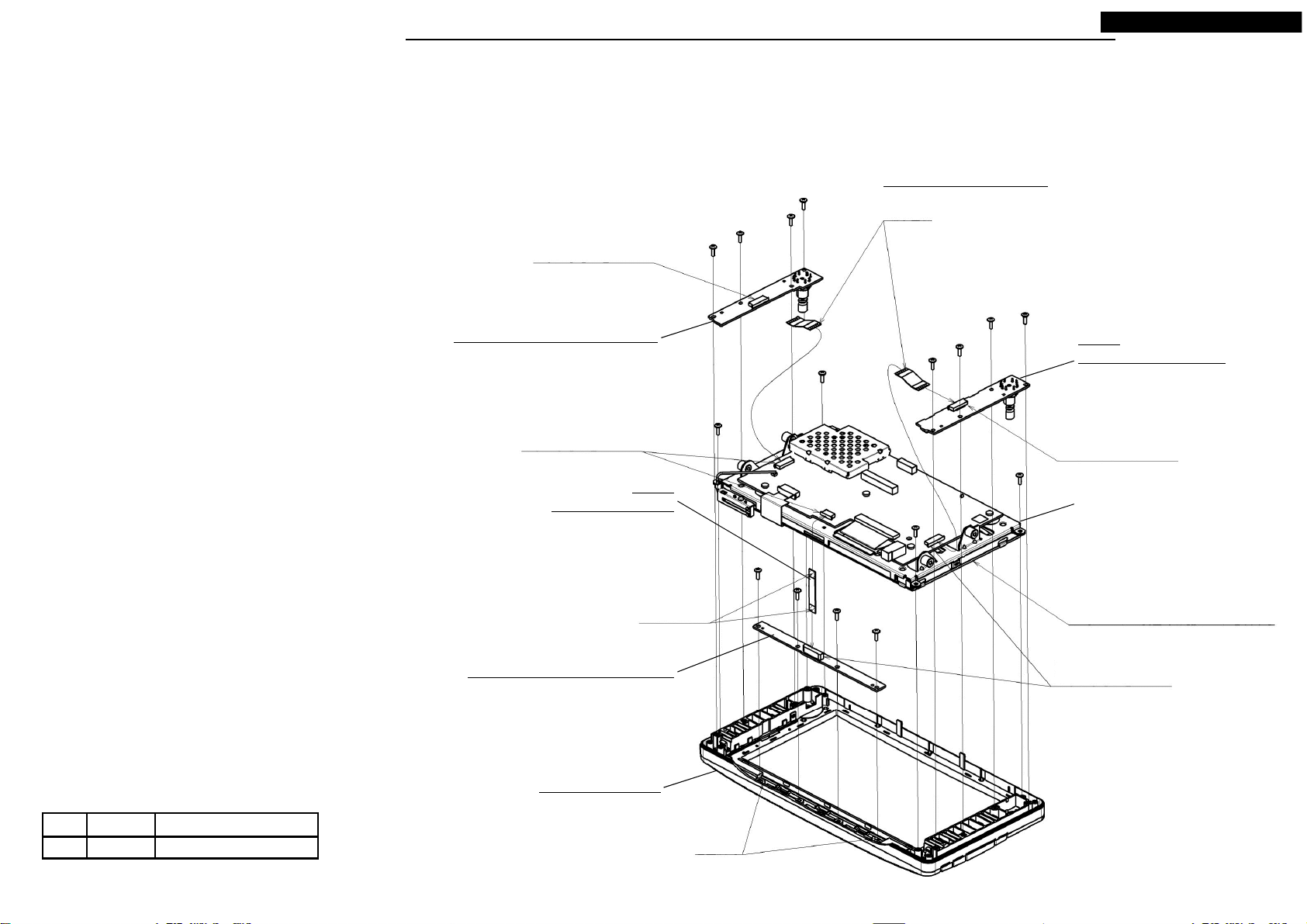
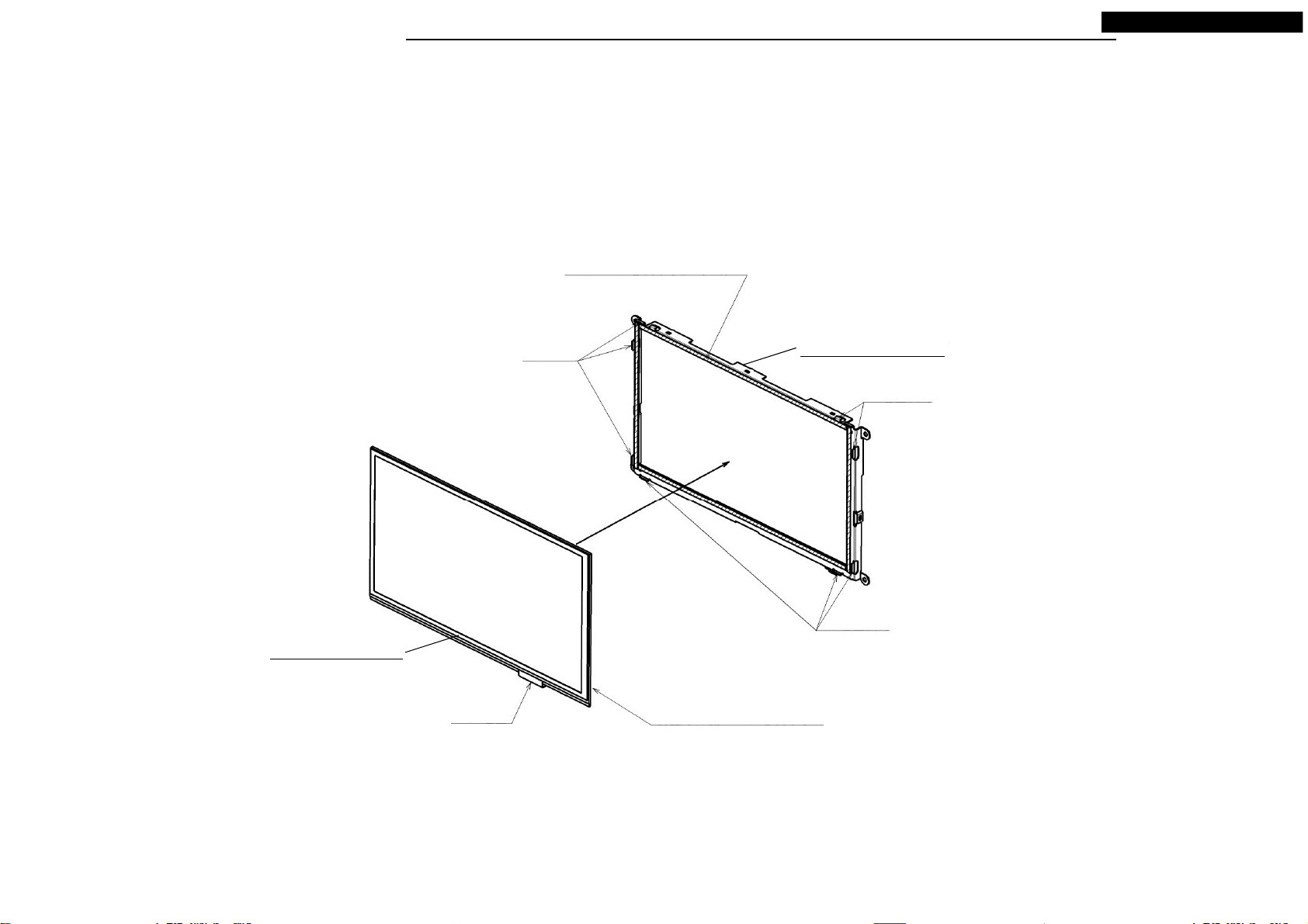
DISASSEMBLING PROCEDURES
● Disassembling procedures
In reverse of assembling procedures.
● Assembling procedures
1.Attach M041 to M017.
2.Attach M018 to M017.
* Do not forget to let an FPC go through from LCD.
3.Attach M062 to M018 and screw with Ⓔ. [4 places. except Ⓔ(a)]
4.Connect FPC of LCD and FPC of the touch panel to connector of M062.
5.Attach M025 to M062 and screw with Ⓔ(a).
Positioning
There is no clip.
Ⓔ
NR-242UM-13LND0,13-WS
M025: SHIELD-MONI
Positioning
After having attached M025, tighten together
with M025 and M062 with this screw.
Lock a connector after
the insertion in FFC.
Ⓔ x 4
M062: ASSY-PCB-MONI
Positioning (2 places)
No. Screw
Ⓔ
M2X3
Put an FPC through the
hole of M018.
Remove the tape.
Remove the tape.
Tighten torque(N・m)
0.16~0.3
25
M018: HOLDER-PCB
Tab joint (8 places)
Arrange it like the
right figure.
M041: ASSY-LCD
Arrange it after drawing an FPC
to the outside of M062.
Remove a surface protection
sheet.
M017: HOLDER-LCD
Remove a protection sheet of
the back side.
Detail of FPC
*60 pins side of the LCD part
Bend it near the pasting up
end face of the FPC.
Your company internal use only.Copyright (C) Mitsubishi Electric Corporation.
DISASSEMBLING PROCEDURES
● Disassembling procedures
In reverse of assembling procedures.
● Assembling procedures
1.Remove the separator of M017 and stick M040 on M017.
* M040 is careful not to ride on a positioning of M017.
NR-242UM-13LND0,13-WS
Remove the separator
M040: ASSY-PANE
FPC position
Positioning
M017: HOLDER-LCD
Positioning
Positioning
Remove a protection sheet of
the back side.
After having stick M040 on
HOLDER-LCD, stick a protection
sheet on touch panel.
26
Your company internal use only.Copyright (C) Mitsubishi Electric Corporation.

PARTS LIST
< NR-242UM-13LND0 >
NR-242UM-13LND0,13-WS
Ref. No . Pa rts N o. Parts Nam e Page Ref. No. Parts No. Parts Nam e Page
M001 241L90620
M002 241L90711
M003 246L52028
M004 246L52070
M005 246L52071
M006 246L52073
M007 246L52095
M008 246L55613
M009 246L58210
M010 246L58310
M011 288P11610
M012 288P11710
M013 560J43410
M014 560J43510
M015 560J43610
M016 560K31310
M017
M018 590J55612
M019 590J56210
M020 590J56310
M021 591K86610
M022 591K87210
M023 591K87410
M024 591K87610
M025 591K87810
M026 630L36511
M027 642K15310
M028 642K15410
M029 643L89610
M030 643L95010
M031 643L95510
M032 643L95511
M033 643L95512
M034 643L95710
M035 643L95810
M036 702J92312
590J55511
FPC-MONI P.11,13
FPC-ANA P.18
FLAT-CABLE 50P P.21 M039
FLAT-CABLE 16P P.24 M040
FLAT-CABLE 10P P.24
FLAT-CABLE 40P P.18
FLAT-CABLE 24P P.17
FLAT-CABLE 18P P.18
LEAD-CONNECTOR 5P P.18
LEAD-CONNECTOR 7P P.21
MOTOR-FAN P.20 M047
MOTOR-FAN P.15 M049
CHASSIS-AUDIO P.21
CHASSIS-ANALOG P.1 8 M0 51
CHASSIS-DIGITAL P.17 M052
CHASSIS-SIDE P.14 M053
HOLDER-LCD P.25,26
HOLDER-PCB P.25
BRACKET-DTV P.19 M056 943M406O9 ASSY-PCB-ANALOG P.18
PLATE-REAR P.15 M057 943M407O1 ASSY-PCB-SENSOR P.16
COVER-DTV P.19
HOLDER-FAN P.15 M059 943M406O5 ASSY-PCB-AUDIO P.21
HEAT-SINK P.14 M060 943M406O6 ASSY-PCB-AUDIO-SUB P.20
COVER-DDR2 P.18 M061 943M406O7 ASSY-PCB-SD P.17
SHIELD-MONI P.25 M062 943M407O2 ASSY-PCB-MONI P.25
PIN-MONI P.10 M063 943M407O3 ASSY-PCB-SW-RIGHT P.24
SHEET-ANALOG P.18 M064 943M407O4 ASSY-PCB-SW-LEFT P.24
SHEET-AUDIO P.21 M065 943M407O5 ASSY-PCB-SW-UNDER P.24
SHEET-HS P.17 M066 943M406O8 ASSY-PCB-HD P.19
SHEET-DIGITAL P.17
CUSHION-REAR P.23
CUSHION-REAR P.23
CUSHION-REAR P.23
SHEET-FAN-R P.15
SHEET-TAP P.17
PANEL-R P.23
M037 761L69710
M038 850L96010
943M407O6
890P11821
M041 890P19412
M042 891J08610
M043 891K31011
M044 891L72210
M045 891L72510
M046 891L72710
892K55140
892L53013
M050 892L53110
937L78012
967L18313
937L66512
*M054
M055 891K31920
M058
940L24418 CD8-MECHA(955827) P.22
943M402O9 ASSY-PCB-BRIDGE P.13
A 653P03028
B 653P03036
C 653P33014
D 653P33016
E 653P63411
F 655P01046
G 655P03028
COVER-FPC P.10
LABEL P.23
NAME-CARD(NR-242UM-13LND0) P.9
ASSY- PAN E P.2 6
ASSY-LCD P.25
ASSY-COVER-DIGITAL P.17
ASSY-SLIDE P.20
ASSY-CHASSIS-F P.13
ASSY-BRACKET-CD P.22
ASSY-HOLDER-FAN-B P.20
ASSY- PAN EL -SU B P.1 1
ASSY- PAN P.2 4
ASSY- KN OB P .2 3
ASSY-ROM(SD16G) P.10
S2-MONI P.10
S4-PCB-DIGITAL P.17
ASSY-COVER-TOP P.12
SCREW-MC-BIND 2.6X6 -
SCREW-MC-BIND M2.6X16 -
SCREW-P-BIND 2X6 -
SCREW-P-BIND 2X8 -
SCREW-MC-BIND-PWB M2X3 -
SCREW-D-PAN 3X6 -
SCREW-D-BIND 2.6X6 -
* Marked part is the ASSY replacement.
27
Your company internal use only.Copyright (C) Mitsubishi Electric Corporation.
PARTS LIST
< NR-242UM-13-WS >
NR-242UM-13LND0,13-WS
Ref. No . Pa rts N o. Parts Nam e Page Ref. No. Parts No. Parts Nam e Page
M001 241L90620
M002 241L90711
M003 246L52028
M004 246L52070
M005 246L52071
M006 246L52073
M007 246L52095
M008 246L55613
M009 246L58210
M010 246L58310
M011 288P11610
M012 288P11710
M013 560J43410
M014 560J43510
M015 560J43610
M016 560K31310
M017
M018 590J55612
M019 590J56210
M020 590J56310
M021 591K86610
M022 591K87210
M023 591K87410
M024 591K87610
M025 591K87810
M026 630L36511
M027 642K15310
M028 642K15410
M029 643L89610
M030 643L95010
M031 643L95510
M032 643L95511
M033 643L95512
M034 643L95710
M035 643L95810
M036 702J92312
590J55511
FPC-MONI P.11,13
FPC-ANA P.18
FLAT-CABLE 50P P.21 M040
FLAT-CABLE 16P P.24
FLAT-CABLE 10P P.24
FLAT-CABLE 40P P.18
FLAT-CABLE 24P P.17
FLAT-CABLE 18P P.18
LEAD-CONNECTOR 5P P.18
LEAD-CONNECTOR 7P P.21 M047
MOTOR-FAN P.20 M048
MOTOR-FAN P.15 M049
CHASSIS-AUDIO P.21
CHASSIS-ANALOG P.1 8 M0 51
CHASSIS-DIGITAL P.17 M052
CHASSIS-SIDE P.14 M053
HOLDER-LCD P.25,26
HOLDER-PCB P.25
BRACKET-DTV P.19 M056 943M406O9 ASSY-PCB-ANALOG P.18
PLATE-REAR P.15 M057 943M407O1 ASSY-PCB-SENSOR P.16
COVER-DTV P.19
HOLDER-FAN P.15 M059 943M406O5 ASSY-PCB-AUDIO P.21
HEAT-SINK P.14 M060 943M406O6 ASSY-PCB-AUDIO-SUB P.20
COVER-DDR2 P.18 M061 943M406O7 ASSY-PCB-SD P.17
SHIELD-MONI P.25 M062 943M407O2 ASSY-PCB-MONI P.25
PIN-MONI P.10 M063 943M407O3 ASSY-PCB-SW-RIGHT P.24
SHEET-ANALOG P.18 M064 943M407O4 ASSY-PCB-SW-LEFT P.24
SHEET-AUDIO P.21 M065 943M407O5 ASSY-PCB-SW-UNDER P.24
SHEET-HS P.17 M066 943M406O8 ASSY-PCB-HD P.19
SHEET-DIGITAL P.17
CUSHION-REAR P.23
CUSHION-REAR P.23
CUSHION-REAR P.23
SHEET-FAN-R P.15
SHEET-TAP P.17
PANEL-R P.23
M037 761L69710
M038 850L96010
890P11821
M041 890P19412
M042 891J08610
M043 891K31011
M044 891L72210
M045 891L72510
M046 891L72710
892K55140
943M407O7
892L53013
M050 892L53110
937L78012
967L18313
937L66512
*M054
M055 891K31920
M058
940L24418 CD8-MECHA(955827) P.22
943M402O9 ASSY-PCB-BRIDGE P.13
A 653P03028
B 653P03036
C 653P33014
D 653P33016
E 653P63411
F 655P01046
G 655P03028
COVER-FPC P.10
LABEL P.23
ASSY- PAN E P.2 6
ASSY-LCD P.25
ASSY-COVER-DIGITAL P.17
ASSY-SLIDE P.20
ASSY-CHASSIS-F P.13
ASSY-BRACKET-CD P.22
ASSY-HOLDER-FAN-B P.20
ASSY- PAN EL -SU B P.1 1
NAME-CARD(NR-242UM-13-WS) P.9
ASSY- PAN P.2 4
ASSY- KN OB P .2 3
ASSY-ROM(SD16G) P.10
S2-MONI P.10
S4-PCB-DIGITAL P.17
ASSY-COVER-TOP P.12
SCREW-MC-BIND 2.6X6 -
SCREW-MC-BIND M2.6X16 -
SCREW-P-BIND 2X6 -
SCREW-P-BIND 2X8 -
SCREW-MC-BIND-PWB M2X3 -
SCREW-D-PAN 3X6 -
SCREW-D-BIND 2.6X6 -
* Marked part is the ASSY replacement.
28
Your company internal use only.Copyright (C) Mitsubishi Electric Corporation.
A
A
A
ELECTRICAL PARTS LIST
Ref. No. Parts No. Parts Name Note Spec.
C005 141P159O0 C-CERAMIC-CHIP GRM155B11A104KA01D B 10V 104K1005 N937L54512 C117 141L069O7 C-CERAMIC-CHIP GRM21BB10J106KE01L B 6.3V 106K2125 N937L55412
C007 141P162O3 C-CERAMIC-CHIP GRM1552C1H330JZ01D CH 50V 330J1005 N937L54512 C118 141P22310 C-CERAMIC-CHIP LLL153C80J104ME01E X6S6.3V104M0510 N937L55412
C008 141P159O0 C-CERAMIC-CHIP GRM155B11A104KA01D B 10V 104K1005 N937L54512 C119 141P150O9 C-CERAMIC-CHIP GRM155B11H102KD01D B 50V 102K1005 N937L55412
C009 141P162O3 C-CERAMIC-CHIP GRM1552C1H330JZ01D CH 50V 330J1005 N937L54512 C120 141L069O7 C-CERAMIC-CHIP GRM21BB10J106KE01L B 6.3V 106K2125 N937L55412
141P153O1 C-CERAMIC-CHIP GRM155B11E103KA01D B 25V 103K1005 N937L54512 C121 141P22310 C-CERAMIC-CHIP LLL153C80J104ME01E X6S6.3V104M0510 N937L55412
C00
C00B 141L169O2 C-CERAMIC-CHIP C1608JB1A105KT B10V 105K 1608 N937L54512 C122 141P150O9 C-CERAMIC-CHIP GRM155B11H102KD01D B 50V 102K1005 N937L55412
C00C 141P159O0 C-CERAMIC-CHIP GRM155B11A104KA01D B 10V 104K1005 N937L54512 C123 141L069O7 C-CERAMIC-CHIP GRM21BB10J106KE01L B 6.3V 106K2125 N937L55412
C00D 141P159O0 C-CERAMIC-CHIP GRM155B11A104KA01D B 10V 104K1005 N937L54512 C124 141P22310 C-CERAMIC-CHIP LLL153C80J104ME01E X6S6.3V104M0510 N937L55412
141L165O0 C-CERAMIC-CHIP GRM188B10J105KC01D B6.3V 105K 1608 N931L64713 C125 141P150O9 C-CERAMIC-CHIP GRM155B11H102KD01D B 50V 102K1005 N937L55412
C01
C01B 141P159O0 C-CERAMIC-CHIP GRM155B11A104KA01D B 10V 104K1005 N931L64713 C126 141P150O9 C-CERAMIC-CHIP GRM155B11H102KD01D B 50V 102K1005 N937L55412
C01C 141L169O6 C-CERAMIC-CHIP GRM188B10J225KE01D B6.3V 225K1608 N931L64713 C127 141P22310 C-CERAMIC-CHIP LLL153C80J104ME01E X6S6.3V104M0510 N937L55412
C01D 141P159O0 C-CERAMIC-CHIP GRM155B11A104KA01D B 10V 104K1005 N931L64713 C128 141P22310 C-CERAMIC-CHIP LLL153C80J104ME01E X6S6.3V104M0510 N937L55412
C01F 141P159O0 C-CERAMIC-CHIP GRM155B11A104KA01D B 10V 104K1005 N931L64713 C129 141P22310 C-CERAMIC-CHIP LLL153C80J104ME01E X6S6.3V104M0510 N937L55412
C01G 141L162O1 C-CERAMIC-CHIP GRM188B11H103KA01D B 50V 103K 1608 N931L64713 C130 141P22310 C-CERAMIC-CHIP LLL153C80J104ME01E X6S6.3V104M0510 N937L55412
C01H 141P151O5 C-CERAMIC-CHIP CM05W5R332K50AH B 50V 332K1005 N931L64713 C131 141P22310 C-CERAMIC-CHIP LLL153C80J104ME01E X6S6.3V104M0510 N937L55412
C01J 141P159O0 C-CERAMIC-CHIP GRM155B11A104KA01D B 10V 104K1005 N931L64713 C132 141L069O7 C-CERAMIC-CHIP GRM21BB10J106KE01L B 6.3V 106K2125 N937L55412
C01K 141L162O1 C-CERAMIC-CHIP GRM188B11H103KA01D B 50V 103K 1608 N931L64713 C133 141P150O9 C-CERAMIC-CHIP GRM155B11H102KD01D B 50V 102K1005 N937L55412
C01L 141L069O9 C-CERAMIC-CHIP GRM21BB30J226ME38L B 6.3V 226M2125 N931L64713 C134 141P22310 C-CERAMIC-CHIP LLL153C80J104ME01E X6S6.3V104M0510 N937L55412
C01M 141P159O0 C-CERAMIC-CHIP GRM155B11A104KA01D B 10V 104K1005 N931L64713 C135 141P22310 C-CERAMIC-CHIP LLL153C80J104ME01E X6S6.3V104M0510 N937L55412
C01N 141L162O1 C-CERAMIC-CHIP GRM188B11H103KA01D B 50V 103K 1608 N931L64713 C136 141P22310 C-CERAMIC-CHIP LLL153C80J104ME01E X6S6.3V104M0510 N937L55412
C01Q 141L069O9 C-CERAMIC-CHIP GRM21BB30J226ME38L B 6.3V 226M2125 N931L64713 C137 141P22310 C-CERAMIC-CHIP LLL153C80J104ME01E X6S6.3V104M0510 N937L55412
C01R 141L069O9 C-CERAMIC-CHIP GRM21BB30J226ME38L B 6.3V 226M2125 N931L64713 C138 141P22310 C-CERAMIC-CHIP LLL153C80J104ME01E X6S6.3V104M0510 N937L55412
C01S 141L045O5 C-CERAMIC-CHIP GRM31CB30J476KE18L B 6V 476K 3216 N931L64713 C139 141L069O7 C-CERAMIC-CHIP GRM21BB10J106KE01L B 6.3V 106K2125 N937L55412
C020 141L069O7 C-CERAMIC-CHIP GRM21BB10J106KE01L B 6.3V 106K2125 N931L64713 C140 141P150O9 C-CERAMIC-CHIP GRM155B11H102KD01D B 50V 102K1005 N937L55412
C030 141P159O0 C-CERAMIC-CHIP GRM155B11A104KA01D B 10V 104K1005 N931L64713 C141 141P22310 C-CERAMIC-CHIP LLL153C80J104ME01E X6S6.3V104M0510 N937L55412
C031 141L162O1 C-CERAMIC-CHIP GRM188B11H103KA01D B 50V 103K 1608 N931L64713 C142 141P22310 C-CERAMIC-CHIP LLL153C80J104ME01E X6S6.3V104M0510 N937L55412
C032 141L165O0 C-CERAMIC-CHIP GRM188B10J105KC01D B6.3V 105K 1608 N931L64713 C143 141P22310 C-CERAMIC-CHIP LLL153C80J104ME01E X6S6.3V104M0510 N937L55412
C033 141P159O0 C-CERAMIC-CHIP GRM155B11A104KA01D B 10V 104K1005 N931L64713 C144 141P22310 C-CERAMIC-CHIP LLL153C80J104ME01E X6S6.3V104M0510 N937L55412
C034 141L169O6 C-CERAMIC-CHIP GRM188B10J225KE01D B6.3V 225K1608 N931L64713 C145 141P22310 C-CERAMIC-CHIP LLL153C80J104ME01E X6S6.3V104M0510 N937L55412
C035 141P159O0 C-CERAMIC-CHIP GRM155B11A104KA01D B 10V 104K1005 N931L64713 C146 141P150O9 C-CERAMIC-CHIP GRM155B11H102KD01D B 50V 102K1005 N937L55412
C036 141P159O0 C-CERAMIC-CHIP GRM155B11A104KA01D B 10V 104K1005 N931L64713 C147 141P22310 C-CERAMIC-CHIP LLL153C80J104ME01E X6S6.3V104M0510 N937L55412
C037 141P151O5 C-CERAMIC-CHIP CM05W5R332K50AH B 50V 332K1005 N931L64713 C148 141P22310 C-CERAMIC-CHIP LLL153C80J104ME01E X6S6.3V104M0510 N
C038 141L069O7 C-CERAMIC-CHIP GRM21BB10J106KE01L B 6.3V 106K2125 N931L64713 C149 141P22310 C-CERAMIC-CHIP LLL153C80J104ME01E X6S6.3V104M0510 N937L55412
C039 141L162O1 C-CERAMIC-CHIP GRM188B11H103KA01D B 50V 103K 1608 N931L64713 C170 141P161O5 C-CERAMIC-CHIP GRM1552C1H150JZ01D CH 50V 150J1005 N937L55412
141L069O9 C-CERAMIC-CHIP GRM21BB30J226ME38L B 6.3V 226M2125 N931L64713 C171 141P161O5 C-CERAMIC-CHIP GRM1552C1H150JZ01D CH 50V 150J1005 N937L55412
C03
C03B 141P159O0 C-CERAMIC-CHIP GRM155B11A104KA01D B 10V 104K1005 N931L64713 C1A0 141P22310 C-CERAMIC-CHIP LLL153C80J104ME01E X6S6.3V104M0510 N937L55412
C03D 141L162O1 C-CERAMIC-CHIP GRM188B11H103KA01D B 50V 103K 1608 N931L64713 C1A1 141P22310 C-CERAMIC-CHIP LLL153C80J104ME01E X6S6.3V104M0510 N937L55412
C03G 141P159O0 C-CERAMIC-CHIP GRM155B11A104KA01D B 10V 104K1005 N931L64713 C1A2 141P150O9 C-CERAMIC-CHIP GRM155B11H102KD01D B 50V 102K1005 N937L55412
C03H 141L069O9 C-CERAMIC-CHIP GRM21BB30J226ME38L B 6.3V 226M2125 N931L64713 C1A3 141P150O9 C-CERAMIC-CHIP GRM155B11H102KD01D B 50V 102K1005 N937L55412
C03J 141L069O9 C-CERAMIC-CHIP GRM21BB30J226ME38L B 6.3V 226M2125 N931L64713 C1F0 141P161O1 C-CERAMIC-CHIP CM05CH100D50AH CH 50V 100D1005 N937L55412
C03K 141L045O5 C-CERAMIC-CHIP GRM31CB30J476KE18L B 6V 476K 3216 N931L64713 C1F1 141P161O1 C-CERAMIC-CHIP CM05CH100D50AH CH 50V 100D1005 N937L55412
C0A2 141P154O2 C-CERAMIC-CHIP EMK105BJ223KV-F B 16V 223K1005 N931L64713 C1F2 141P159O0 C-CERAMIC-CHIP GRM155B11A104KA01D B 10V 104K1005 N937L55412
C0A3 181P80423 C-ELECTROLYTIC-CHIP UZS1C100MCLSHDGB 16V 100M N931L64713 C1F3 141L165O0 C-CERAMIC-CHIP GRM188B10J105KC01D B6.3V 105K 1608 N937L55412
C0B0 141L069O7 C-CERAMIC-CHIP GRM21BB10J106KE01L B 6.3V 106K2125 N931L64713 C1G0 141P22310 C-CERAMIC-CHIP LLL153C80J104ME01E X6S6.3V104M0510 N937L55412
C0B1 141L069O7 C-CERAMIC-CHIP GRM21BB10J106KE01L B 6.3V 106K2125 N931L64713 C1G1 141P153O1 C-CERAMIC-CHIP GRM155B11E103KA01D B 25V 103K1005 N937L55412
C0B3 141L069O7 C-CERAMIC-CHIP GRM21BB10J106KE01L B 6.3V 106K2125 N931L64713 C1G2 141P153O1 C-CERAMIC-CHIP GRM155B11E103KA01D B 25V 103K1005 N937L55412
C0B4 141L164O6 C-CERAMIC-CHIP GRM188B11C104KA01D B 16V 104K 1608 N931L64713 C200 141P22310 C-CERAMIC-CHIP LLL153C80J104ME01E X6S6.3V104M0510 N937L55412
C100 141L069O7 C-CERAMIC-CHIP GRM21BB10J106KE01L B 6.3V 106K2125 N937L55412 C201 141P150O9 C-CERAMIC-CHIP GRM155B11H102KD01D B 50V 102K1005 N937L55412
C101 141P22310 C-CERAMIC-CHIP LLL153C80J104ME01E X6S6.3V104M0510 N937L55412 C202 141P22310 C-CERAMIC-CHIP LLL153C80J104ME01E X6S6.3V104M0510 N937L55412
C102 141P22310 C-CERAMIC-CHIP LLL153C80J104ME01E X6S6.3V104M0510 N937L55412 C203 141P150O9 C-CERAMIC-CHIP GRM155B11H102KD01D B 50V 102K1005 N937L55412
C103 141P22310 C-CERAMIC-CHIP LLL153C80J104ME01E X6S6.3V104M0510 N937L55412 C204 141P22310 C-CERAMIC-CHIP LLL153C80J104ME01E X6S6.3V104M0510 N937L55412
C104 141P22310 C-CERAMIC-CHIP LLL153C80J104ME01E X6S6.3V104M0510 N937L55412 C205 141P22310 C-CERAMIC-CHIP LLL153C80J104ME01E X6S6.3V104M0510 N937L55412
C105 141P22310 C-CERAMIC-CHIP LLL153C80J104ME01E X6S6.3V104M0510 N937L55412 C206 141P22310 C-CERAMIC-CHIP LLL153C80J104ME01E X6S6.3V104M0510 N937L55412
C106 141P150O9 C-CERAMIC-CHIP GRM155B11H102KD01D B 50V 102K1005 N937L55412 C207 141P22310 C-CERAMIC-CHIP LLL153C80J104ME01E X6S6.3V104M0510 N937L55412
C107 141P22310 C-CERAMIC-CHIP LLL153C80J104ME01E X6S6.3V104M0510 N937L55412 C208 141L165O0 C-CERAMIC-CHIP GRM188B10J105KC01D B6.3V 105K 1608 N937L55412
C108 141P22310 C-CERAMIC-CHIP LLL153C80J104ME01E X6S6.3V104M0510 N937L55412 C209 141P22310 C-CERAMIC-CHIP LLL153C80J104ME01E X6S6.3V104M0510 N937L55412
C109 141P22310 C-CERAMIC-CHIP LLL153C80J104ME01E X6S6.3V104M0510 N937L55412 C210 141P22310 C-CERAMIC-CHIP LLL153C80J104ME01E X6S6.3V104M0510 N937L55412
C110 141P22310 C-CERAMIC-CHIP LLL153C80J104ME01E X6S6.3V104M0510 N937L55412 C211 141P22310 C-CERAMIC-CHIP LLL153C80J104ME01E X6S6.3V104M0510 N937L55412
C111 141P22310 C-CERAMIC-CHIP LLL153C80J104ME01E X6S6.3V104M0510 N937L55412 C212 141P150O9 C-CERAMIC-CHIP GRM155B11H102KD01D B 50V 102K1005 N937L55412
C112 141P22310 C-CERAMIC-CHIP LLL153C80J104ME01E X6S6.3V104M0510 N937L55412 C213 141P22310 C-CERAMIC-CHIP LLL153C80J104ME01E X6S6.3V104M0
C113 141P150O9 C-CERAMIC-CHIP GRM155B11H102KD01D B 50V 102K1005 N937L55412 C214 141P150O9 C-CERAMIC-CHIP GRM155B11H102KD01D B 50V 102K1005 N937L55412
C114 141L069O7 C-CERAMIC-CHIP GRM21BB10J106KE01L B 6.3V 106K2125 N937L55412 C215 141P22310 C-CERAMIC-CHIP LLL153C80J104ME01E X6S6.3V104M0510 N937L55412
C115 141P22310 C-CERAMIC-CHIP LLL153C80J104ME01E X6S6.3V104M0510 N937L55412 C216 141P22310 C-CERAMIC-CHIP LLL153C80J104ME01E X6S6.3V104M0510 N937L55412
C116 141P150O9 C-CERAMIC-CHIP GRM155B11H102KD01D B 50V 102K1005 N937L55412 C217 141P22310 C-CERAMIC-CHIP LLL153C80J104ME01E X6S6.3V104M0510 N937L55412
Base Parts No.
Ref. No. Parts No. Parts Name Note Spec.
29
Copyright (C) Mitsubishi Electric Corporation. Your company internal use only.
Base Parts No.
937L55412
510 N937L55412

A
ELECTRICAL PARTS LIST
Ref. No. Parts No. Parts Name Note Spec.
C218 141P22310 C-CERAMIC-CHIP LLL153C80J104ME01E X6S6.3V104M0510 N937L55412 C2C9 141P159O0 C-CERAMIC-CHIP GRM155B11A104KA01D B 10V 104K1005 N937L55412
C219 141L165O0 C-CERAMIC-CHIP GRM188B10J105KC01D B6.3V 105K 1608 N937L55412 C2D0 141L164O6 C-CERAMIC-CHIP GRM188B11C104KA01D B 16V 104K 1608 N937L55412
C220 141P22310 C-CERAMIC-CHIP LLL153C80J104ME01E X6S6.3V104M0510 N937L55412 C2D1 141P159O0 C-CERAMIC-CHIP GRM155B11A104KA01D B 10V 104K1005 N937L55412
C221 141P22310 C-CERAMIC-CHIP LLL153C80J104ME01E X6S6.3V104M0510 N937L55412 C2D2 141P163O5 C-CERAMIC-CHIP GRM1552C1H101JZ01D CH 50V 101J1005 N937L55412
C222 141L069O7 C-CERAMIC-CHIP GRM21BB10J106KE01L B 6.3V 106K2125 N937L55412 C2D3 141P159O0 C-CERAMIC-CHIP GRM155B11A104KA01D B 10V 104K1005 N937L55412
C223 141L069O7 C-CERAMIC-CHIP GRM21BB10J106KE01L B 6.3V 106K2125 N937L55412 C2D4 141P159O0 C-CERAMIC-CHIP GRM155B11A104KA01D B 10V 104K1005 N937L55412
C224 141L069O6 C-CERAMIC-CHIP GRM21BB10J475KA11L B 6.3V 475K2125 N937L55412 C2D5 141P159O0 C-CERAMIC-CHIP GRM155B11A104KA01D B 10V 104K1005 N937L55412
C225 141L069O6 C-CERAMIC-CHIP GRM21BB10J475KA11L B 6.3V 475K2125 N937L55412 C300 141L049O8 C-CERAMIC-CHIP CM316B226K06AT-N B 6.3V 226K3216 N937L55412
C226 141L069O6 C-CERAMIC-CHIP GRM21BB10J475KA11L B 6.3V 475K2125 N937L55412 C301 141L049O8 C-CERAMIC-CHIP CM316B226K06AT-N B 6.3V 226K3216 N937L55412
C227 141L069O6 C-CERAMIC-CHIP GRM21BB10J475KA11L B 6.3V 475K2125 N937L55412 C302 141L165O0 C-CERAMIC-CHIP GRM188B10J105KC01D B6.3V 105K 1608 N937L55412
C228 141P22310 C-CERAMIC-CHIP LLL153C80J104ME01E X6S6.3V104M0510 N937L55412 C303 141L049O8 C-CERAMIC-CHIP CM316B226K06AT-N B 6.3V 226K3216 N937L55412
C229 141P22310 C-CERAMIC-CHIP LLL153C80J104ME01E X6S6.3V104M0510 N937L55412 C305 141P167O9 C-CERAMIC-CHIP GRM1552C1H102JA01D CH 50V 102J1005 N937L55412
C250 141P22310 C-CERAMIC-CHIP LLL153C80J104ME01E X6S6.3V104M0510 N937L55412 C307 141P162O7 C-CERAMIC-CHIP GRM1552C1H470JZ01D CH 50V 470J1005 N937L55412
C251 141P150O9 C-CERAMIC-CHIP GRM155B11H102KD01D B 50V 102K1005 N937L55412 C308 141L164O6 C-CERAMIC-CHIP GRM188B11C104KA01D B 16V 104K 1608 N937L55412
C252 141P22310 C-CERAMIC-CHIP LLL153C80J104ME01E X6S6.3V104M0510 N937L55412 C309 141P175O1 C-CERAMIC-CHIP C3225X5R0J107MT X5R6.3V107K3225 N937L55412
C253 141P150O9 C-CERAMIC-CHIP GRM155B11H102KD01D B 50V 102K1005 N937L55412 C310 141P173O3 C-CERAMIC-CHIP GRM32EB31C476ME15L B 16V 476M 3225 N937L55412
C254 141P22310 C-CERAMIC-CHIP LLL153C80J104ME01E X6S6.3V104M0510 N937L55412 C331 141L049O8 C-CERAMIC-CHIP CM316B226K06AT-N B 6.3V 226K3216 N937L55412
C255 141P22310 C-CERAMIC-CHIP LLL153C80J104ME01E X6S6.3V104M0510 N937L55412 C332 141L165O0 C-CERAMIC-CHIP GRM188B10J105KC01D B6.3V 105K 1608 N937L55412
C256 141P22310 C-CERAMIC-CHIP LLL153C80J104ME01E X6S6.3V104M0510 N937L55412 C333 141L049O8 C-CERAMIC-CHIP CM316B226K06AT-N B 6.3V 226K3216 N937L55412
C257 141P22310 C-CERAMIC-CHIP LLL153C80J104ME01E X6S6.3V104M0510 N937L55412 C335 141P167O9 C-CERAMIC-CHIP GRM1552C1H102JA01D CH 50V 102J1005 N937L55412
C258 141L165O0 C-CERAMIC-CHIP GRM188B10J105KC01D B6.3V 105K 1608 N937L55412 C337 141P162O7 C-CERAMIC-CHIP GRM1552C1H470JZ01D CH 50V 470J1005 N937L55412
C259 141P22310 C-CERAMIC-CHIP LLL153C80J104ME01E X6S6.3V104M0510 N937L55412 C338 141L164O6 C-CERAMIC-CHIP GRM188B11C104KA01D B 16V 104K 1608 N937L55412
C260 141P22310 C-CERAMIC-CHIP LLL153C80J104ME01E X6S6.3V104M0510 N937L55412 C339 141P175O1 C-CERAMIC-CHIP C3225X5R0J107MT X5R6.3V107K3225 N937L55412
C261 141P22310 C-CERAMIC-CHIP LLL153C80J104ME01E X6S6.3V104M0510 N937L55412 C340 141P173O3 C-CERAMIC-CHIP GRM32EB31C476ME15L B 16V 476M 3225 N937L55412
C262 141P150O9 C-CERAMIC-CHIP GRM155B11H102KD01D B 50V 102K1005 N937L55412 C350 141P159O0 C-CERAMIC-CHIP GRM155B11A104KA01D B 10V 104K1005 N937L55412
C263 141P22310 C-CERAMIC-CHIP LLL153C80J104ME01E X6S6.3V104M0510 N937L55412 C351 141P163O5 C-CERAMIC-CHIP GRM1552C1H101JZ01D CH 50V 101J1
C264 141P150O9 C-CERAMIC-CHIP GRM155B11H102KD01D B 50V 102K1005 N937L55412 C378 141P159O0 C-CERAMIC-CHIP GRM155B11A104KA01D B 10V 104K1005 N937L55412
C265 141P22310 C-CERAMIC-CHIP LLL153C80J104ME01E X6S6.3V104M0510 N937L55412 C3A0 141L069O7 C-CERAMIC-CHIP GRM21BB10J106KE01L B 6.3V 106K2125 N937L55412
C266 141P22310 C-CERAMIC-CHIP LLL153C80J104ME01E X6S6.3V104M0510 N937L55412 C3A1 141P159O0 C-CERAMIC-CHIP GRM155B11A104KA01D B 10V 104K1005 N937L55412
C267 141P22310 C-CERAMIC-CHIP LLL153C80J104ME01E X6S6.3V104M0510 N937L55412 C3A2 141P150O9 C-CERAMIC-CHIP GRM155B11H102KD01D B 50V 102K1005 N937L55412
C268 141P22310 C-CERAMIC-CHIP LLL153C80J104ME01E X6S6.3V104M0510 N937L55412 C3A4 141P150O9 C-CERAMIC-CHIP GRM155B11H102KD01D B 50V 102K1005 N937L55412
C269 141L165O0 C-CERAMIC-CHIP GRM188B10J105KC01D B6.3V 105K 1608 N937L55412 C3A5 141P159O0 C-CERAMIC-CHIP GRM155B11A104KA01D B 10V 104K1005 N937L55412
C270 141P22310 C-CERAMIC-CHIP LLL153C80J104ME01E X6S6.3V104M0510 N937L55412 C3A6 141L069O7 C-CERAMIC-CHIP GRM21BB10J106KE01L B 6.3V 106K2125 N937L55412
C271 141P22310 C-CERAMIC-CHIP LLL153C80J104ME01E X6S6.3V104M0510 N937L55412 C3A7 141P150O9 C-CERAMIC-CHIP GRM155B11H102KD01D B 50V 102K1005 N937L55412
C272 141L069O7 C-CERAMIC-CHIP GRM21BB10J106KE01L B 6.3V 106K2125 N937L55412 C3A8 141P159O0 C-CERAMIC-CHIP GRM155B11A104KA01D B 10V 104K1005 N937L55412
C273 141L069O7 C-CERAMIC-CHIP GRM21BB10J106KE01L B 6.3V 106K2125 N937L55412 C3A9 141L069O7 C-CERAMIC-CHIP GRM21BB10J106KE01L B 6.3V 106K2125 N937L55412
C274 141L069O6 C-CERAMIC-CHIP GRM21BB10J475KA11L B 6.3V 475K2125 N937L55412 C3B2 141P160O8 C-CERAMIC-CHIP GRM1552C1H7R0DZ01D CH 50V 070D1005 N937L55412
C275 141L069O6 C-CERAMIC-CHIP GRM21BB10J475KA11L B 6.3V 475K2125 N937L55412 C3B3 141P160O8 C-CERAMIC-CHIP GRM1552C1H7R0DZ01D CH 50V 070D1005 N937L55412
C276 141L069O6 C-CERAMIC-CHIP GRM21BB10J475KA11L B 6.3V 475K2125 N937L55412 C3B4 141P159O0 C-CERAMIC-CHIP GRM155B11A104KA01D B 10V 104K1005 N937L55412
C277 141L069O6 C-CERAMIC-CHIP GRM21BB10J475KA11L B 6.3V 475K2125 N937L55412 C3D0 141L045O5 C-CERAMIC-CHIP GRM31CB30J476KE18L B 6V 476K 3216 N937L55412
C278 141P22310 C-CERAMIC-CHIP LLL153C80J104ME01E X6S6.3V104M0510 N937L55412 C3D2 141L045O5 C-CERAMIC-CHIP GRM31CB30J476KE18L B 6V 476K 3216 N937L55412
C279 141P22310 C-CERAMIC-CHIP LLL153C80J104ME01E X6S6.3V104M0510 N937L55412 C3D4 141L049O8 C-CERAMIC-CHIP CM316B226K06AT-N B 6.3V 226K3216 N937L55412
C280 141P159O0 C-CERAMIC-CHIP GRM155B11A104KA01D B 10V 104K1005 N937L55412 C3D6 141P159O0 C-CERAMIC-CHIP GRM155B11A104KA01D B 10V 104K1005 N937L55412
C281 141P159O0 C-CERAMIC-CHIP GRM155B11A104KA01D B 10V 104K1005 N937L55412 C3D7 141P159O0 C-CERAMIC-CHIP GRM155B11A104KA01D B 10V 104K1005 N937L55412
C283 141P159O0 C-CERAMIC-CHIP GRM155B11A104KA01D B 10V 104K1005 N937L55412 C401 141P161O9 C-CERAMIC-CHIP GRM1552C1H220JZ01D CH 50V 220J1005 N931L64713
C284 141P159O0 C-CERAMIC-CHIP GRM155B11A104KA01D B 10V 104K1005 N937L55412 C403 141P161O5 C-CERAMIC-CHIP GRM1552C1H150JZ01D CH 50V 150J1005 N931L64713
C290 141P159O0 C-CERAMIC-CHIP GRM155B11A104KA01D B 10V 104K1005 N937L55412 C404 141P167O9 C-CERAMIC-CHIP GRM1552C1H102JA01D CH 50V 102J1005 N931L64713
C291 141P159O0 C-CERAMIC-CHIP GRM155B11A104KA01D B 10V 104K1005 N937L55412 C405 141P160O7 C-CERAMIC-CHIP GRM1552C1H6R0DZ01D CH 50V 060D1005 N931L64713
C292 141P159O0 C-CERAMIC-CHIP GRM155B11A104KA01D B 10V 104K1005 N937L55412 C406 141P165O7 C-CERAMIC-CHIP GRM1552C1E271JD01D CH 25V 271J1005 N931L64713
C293 141P159O0 C-CERAMIC-CHIP GRM155B11A104KA01D B 10V 104K1005 N937L55412 C407 141P161O9 C-CERAMIC-CHIP GRM1552C1H220JZ01D CH 50V 220J1005 N931L64713
C294 141P160O7 C-CERAMIC-CHIP GRM1552C1H6R0DZ01D CH 50V 060D1005 N937L55412 C408 141P162O5 C-CERAMIC-CHIP GRM1552C1H390JZ01D CH 50V 390J1005 N931L64713
C2A0 141P159O0 C-CERAMIC-CHIP GRM155B11A104KA01D B 10V 104K1005 N937L55412 C40
C2A1 141P159O0 C-CERAMIC-CHIP GRM155B11A104KA01D B 10V 104K1005 N937L55412 C40B 141P167O9 C-CERAMIC-CHIP GRM1552C1H102JA01D CH 50V 102J1005 N931L64713
C2A2 141P159O0 C-CERAMIC-CHIP GRM155B11A104KA01D B 10V 104K1005 N937L55412 C40D 141P160O6 C-CERAMIC-CHIP GRM1552C1H5R0CZ01D CH 50V 050C1005 N931L64713
C2A3 141P159O0 C-CERAMIC-CHIP GRM155B11A104KA01D B 10V 104K1005 N937L55412 C40E 141P161O9 C-CERAMIC-CHIP GRM1552C1H220JZ01D CH 50V 220J1005 N931L64713
C2A7 141P159O0 C-CERAMIC-CHIP GRM155B11A104KA01D B 10V 104K1005 N937L55412 C40F 141P160O1 C-CERAMIC-CHIP GRM1554C1H1R0CZ01D CK 50V 010C1005 N931L64713
C2A8 141P159O0 C-CERAMIC-CHIP GRM155B11A104KA01D B 10V 104K1005 N937L55412 C410 141P159O0 C-CERAMIC-CHIP GRM155B11A104KA01D B 10V 104K1005 N931L64713
C2C0 141P159O0 C-CERAMIC-CHIP GRM155B11A104KA01D B 10V 104K1005 N937L55412 C411 141P164O3 C-CERAMIC-CHIP GRM1552C1H221JA01D CH 50V 221J1005 N931L64713
C2C1 141P159O0 C-CERAMIC-CHIP GRM155B11A104KA01D B 10V 104K1005 N937L55412 C412 141L161O6 C-CERAMIC-CHIP GRM188B11H392KA01D B 50V 392K 1608 N931L64713
C2C2 141P159O0 C-CERAMIC-CHIP GRM155B11A104KA01D B 10V 104K1005 N937L55412 C413 141P153O1 C-CERAMIC-CHIP GRM155B11E103KA01D B 25V 103K1005 N931L64713
C2C3 141P159O0 C-CERAMIC-CHIP GRM155B11A104KA01D B 10V 104K1005 N937L55412 C414 141P153O1 C-CERAMIC-CHIP GRM155B11E103KA01D B 25V 103K1005 N931L64713
C2C4 141P159O0 C-CERAMIC-CHIP GRM155B11A104KA01D B 10V 104K1005 N937L55412 C415 141P154O6 C-CERAMIC-CHIP GRM155B31C104KA87D B 16V 104K 1005 N931L64713
C2C5 141P150O9 C-CERAMIC-CHIP GRM155B11H102KD01D B 50V 102K1005 N937L55412 C416 141P151O3 C-CERAMIC-CHIP CM05W5R222K50AH B 50V 222K1005 N931L64713
C2C6 141P163O5 C-CERAMIC-CHIP GRM1552C1H101JZ01D CH 50V 101J1005 N937L55412 C417 141P173O3 C-CERAMIC-CHIP GRM32EB31C476ME15L B 16V 476M 3225 N931L64713
Base Parts No.
Ref. No. Parts No. Parts Name Note Spec.
141P167O9 C-CERAMIC-CHIP GRM1552C1H102JA01D CH 50V 102J1005 N931L64713
30
Copyright (C) Mitsubishi Electric Corporation. Your company internal use only.
Base Parts No.
005 N937L55412
 Loading...