

Page 1

MOULDED CASE CIRCUIT BREAKERS
TECHNICAL NOTES
ADVANCED AND EVER ADVANCING
00
A
Page 2

We have the pleasure of providing all our customers with the technical information for Mitsubishi
moulded case circuit breakers. This indicates the fundamental data of our circuit breakers
regarding the applicable standards, constructional principles, and operational performances.
Please refer to the catalogue of our circuit breakers for details of specifications.
Also please stand in need of the handling and maintenance manual for maintaning the circuit
breakers in service continuously.
We do hope they are available for all our customers to built more efficient systems.
CONTENTS
1. INTRODUCTION ...............................................2
2. FEATURES .......................................................3
2.1 Arc-Extinguishing Device – ISTAC.................. 3
2.2 Digital ETR ......................................................... 4
3. CONSTRUCTION AND OPERATION............... 6
4. CHARACTERISTICS AND
PERFORMANCE............................................. 11
4.1 Overcurrent-Trip Characteristics ................... 11
4.2 Short-Circuit Trip Characteristics.................. 11
4.3 Effects of Mounting Attitudes ........................ 12
4.4 DC Tripping Characteristics of AC-Rated
MCCBs.............................................................. 12
4.5 Frequency Characteristics ............................. 12
4.6 Switching Characteristics............................... 13
4.7 Dielectric Strength........................................... 13
5. CIRCUIT BREAKERS SELECTION ............... 14
5.1 Circuit Breakers Selection Table ................... 14
6. PROTECTIVE CO-ORDINATION ................... 39
6.1 General ............................................................. 39
6.2 Interrupting Capacity Consideration ............. 40
6.3 Selective-Interruption...................................... 41
6.4 Cascade Back-up Protection.......................... 46
2
t Let-Through Characteristics and Current
6.5 I
Limiting Characteristics.................................. 48
6.6 Protective Coordination with Wiring ............. 49
6.7 Protective Coordination with
Motor Starters .................................................. 52
6.8 Coordination with Devices on the
High-Voltage Circuit ........................................ 54
7. SELECTION .................................................... 57
7.1 For Motor Branch Circuits .............................. 57
7.2 For Lighting and Heating Branch Circuits .... 57
7.3 For Main Circuit ............................................... 58
7.4 For Welding Circuits ....................................... 58
7.5 For Transformer-Primary Use ........................ 60
7.6 For Capacitor Circuits..................................... 61
7.7 For Thyristor Circuits...................................... 62
7.8 Selection of MCCBs in inverter circuit .......... 68
8. ENVIRONMENTAL CHARACTERISTICS ...... 70
8.1 Atmospheric Environment.............................. 70
8.2 Vibration-Withstand Characteristics ............. 71
8.3 Shock-Withstand Characteristics .................. 72
9. SHORT-CIRCUIT CURRENT
CALCULATIONS ............................................ 73
9.1 Purpose ............................................................ 73
9.2 Definitions ........................................................ 73
9.3 Impedances and Equivalent Circuits of
Circuit Components ........................................ 73
9.4 Classification of Short-Circuit Current.......... 76
9.5 Calculation Procedures .................................. 77
1
Page 3

1. INTRODUCTION
Mitsubishi Advancing Technology
Mitsubishi, the leading manufacturer of circuit breakers, has been providing customers with a wide range
of highly reliable and safe moulded case circuit breakers (MCCB) and earth-leakage circuit breakers
(ELCB), corresponding to the needs of the age.
Since production began in 1933 many millions of
Mitsubishi ACBs, MCCBs and MCBs have been sold
throughout many countries.
In 1985 a new design concept for controlling arc energies within MCCBs – vapour jet control (VJC) – was
introduced and significantly improved performance. It
is provided the technological advance for a new ‘super series’ range of MCCBs and is used in all present
ratings from 3 to 1600 amps.
In 1995 Mitsubishi offers the new PSS (Progressive
Super Series) breakers having ratings from 3 to 250
amps that concentrate the most advanced technologies into a compact body. Their four major features
are:
• New circuit-breaking technology ISTAC for a higher
current-limiting performance, upgrading the circuitbreaking capability.
• Electronic circuit breakers with the Digital ETR protecting the circuit accurately.
• One-frame, one-size design allowing efficient panel
design.
• Cassette-type internal accessories that allow installation by the user.
Progressive Super Series, an integration of technology and know-how from this comprehensive electronic
product manufacturer, will create its own fields of application with its excellent performance.
A Brief Chronology
1933 Moulded case circuit breaker production
begins.
1952 Miniature circuit breaker production be-
gins.
1968 Manufacture commences of short-time-
delayed breakers.
1969 Production and sale of first residual cur-
rent circuit breakers.
1970 170kA breaking level ‘permanent power
fuse’ integrated MCCBs is introduced.
1973 Introduction of first short-time delay and
current-limiting selectable breakers go on
sale.
1974 First MELNIC solid-state electronic trip
unit MCCBs are introduced.
1975 ELCBs with solid-state integrated circuit
sensing devices are introduced.
1977-1979 Four new ranges of MCCBs are intro-
duced – economy, standard, current limiting, ultra current limiting and motor rated
designs – a comprehensive coverage of
most application requirements.
1982 Compact ACBs with solid-state trip de-
vices and internally mounted accessories
introduced.
1985-1989 Super series MCCBs with VJC and ETR
are developed and launched – awarded
the prestigious Japanese MInister of Construction Prize.
1990 New 200kA level U-series MCCBs super
current limiting breakers are introduced.
1991 Super-NV ELCBs and Super-AE ACBs
are introduced.
1995 Progressive Super Series 30~250 amps
are introduced.
1997 Progressive Super Series 400~800 amps
are introduced.
2
Page 4
2. FEATURES – Advanced MCCB Design Technol-
ogy & Performance
2.1 Arc-Extinguishing Device – ISTAC
Mitsubishi has developed an epoch-making ISTAC
technology to realize an improved current-limiting and
breaking performance within a smaller breaking space.
Introduction of ISTAC technology upgrades the cur-
rent-limiting, selective-breaking, and cascade-breaking performance. The maximum peak let-through cur-
rent Ip decreases to about 80% (compared with
Mitsubishi’s 100AF). The passing energy I2t decreases to about 65% (compared with Mitsubishi’s
100AF). The smaller breaking space has led to an
improved function, a smaller size, and a standardization of the breakers.
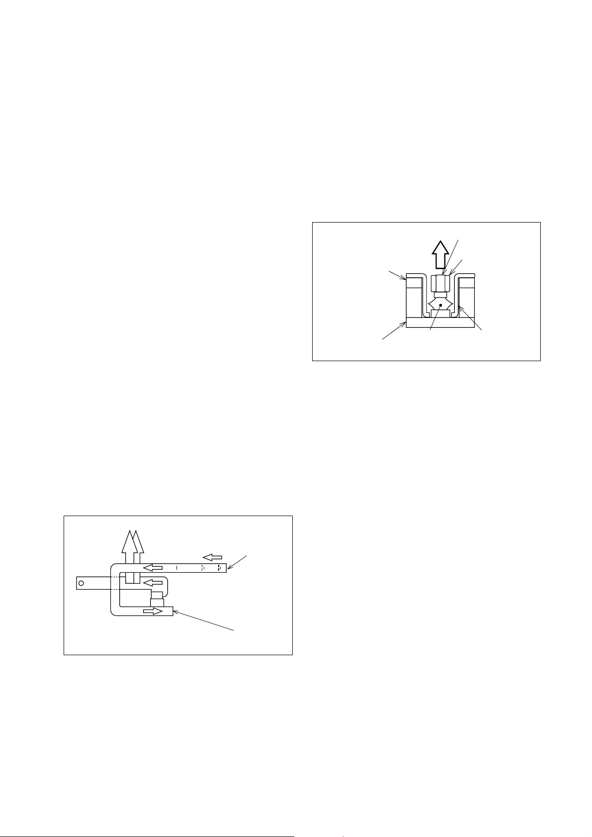
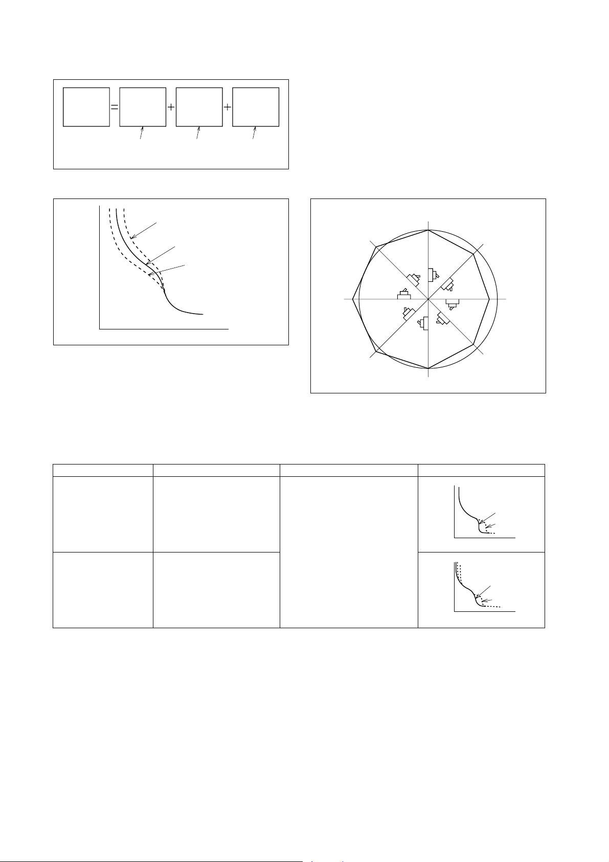
Triple forces accelerating
The triple forces generated by a newly designed current pass and the Vapor Jet Control (VJC) insulating materials which makes up a slot-type breaking
construction accelerate the movable conductor, and
separate the contacts faster than ever before in shortbreaking.
Electromagnetic attractive force which works between
a current of the movable conductor and a current of
the fixed upper conductor.
Electromagnetic repulsive force which works between
a current of the movable conductor and a current of
the fixed lower conductor.
Pressure which works on the movable conductor by
gas generated in the slot.
The VJC suppresses the emergence of carbide products in breaking a current and contribute to the recovery of insulation immediately thereafter.
The VJCs on the fixed and movable contacts work
together to forcefully reduce the arc spot and rapidly
contract the total arc being extinguished.
Movable contact
Upper,
fixed-contact
conductor
Lower,
fixed-contact
conductor
Pressure
Arc
3
Movable
contact VJC
Fixed contact
VJC
Vapor jet control (VJC)
Vapor Jet Controllers made of insulating material are
arranged around the contacts where they control the
arc as follows:
1. The arc spot is forcibly reduced by the arrangement of the insulating material.
2. The arc column is contracted.
3. Adiabatic expansion cools the arc.
4. The arc is transferred at the optimum moment to
the arc-extinguishing chamber by the arrangement
of the Vapor Jet Controllers.
Repulsive
force
Movable
contact
2
1
Attractive
force
Current A
Current B
Current C
Current
Upper,
fixed-contact
conductor
Lower,
fixed-contact
conductor
Arc control by slot-breaking
The VJC of the fixed contact incorporates newly developed insulation made of ceramic fiber and metal
hydroxide. The substantially improves the VJC effect.
The arc-extinguishing gas energies to improve the
capability of extinguishing the arc.
3
Page 5
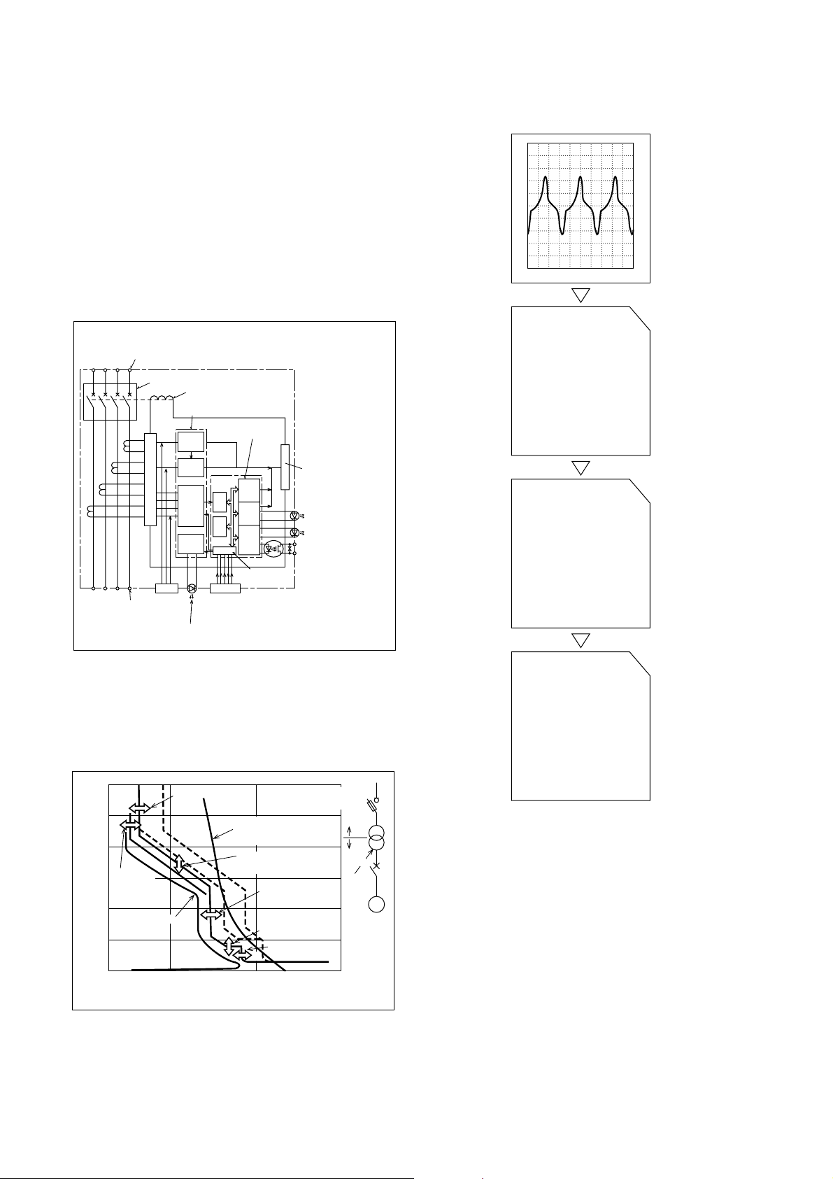
2.2 Digital ETR (Electronic Trip Relay)
Sampling and A/D
conversion
Calculating
the digitally
effective value
Processing
the long time-delay
pre-alarm
characteristics
Mitsubishi’s electronic MCCBs are equipped with a
digital ETR to enable fine protection.
The digital ETR contains Mitsubishi’s original double
IC (8 bit microcomputer and custom-IC).
Digital detection of the effective value
Electronic devices such as an inverter distort the current waveform. Mitsubishi’s PSS electronic breakers
are designed to detect digitally the effective value of
the current to minimize over-current tripping errors.
This enables fine protection for the system.
I : Instantaneous
Power-source side terminal
Breaking mechanism
CT
CT
CT
CT
Load-side
terminal
Load-current indication LED (70%)
PSS
Rectifying circuit
WDT
Test input
Trip coil
Custom IC
Microcomputer
I
CV
A/D
convertor
CPU
Characteristics
setting part
SSW
LSW
PSW
Input and
output
circuit
CV : Constant
voltage
circuit
Phaseselection
sampling
circuit
Short
time-delay
soft ware
Trigger circuit
Over-current
indication LED
Pre-alarm
indication LED
Pre-alarm
output
LSW : Long
time-delay
soft ware
PSW : Pre-alarm
soft ware
WDT : Watch-dog
timer
circuit
Processing of the digital ETR
Standard equipped pre-alarm system
Mitsubishi’s PSS electronic breakers have a pre-alarm
system as a standard. When the load current exceeds
the set pre-alarm current, the breaker lights up an LED
and outputs a pre-alarm signal.
4
1×10
3
1×10
I
P
2
1×10
Pre-alarm
10
current
Time (s)
0.1
0.01
1
Load current
4
I
r
10
Current setting
T
L
I
s
T
s
Current (A)
High-voltage fuseAllowable short-time
characteristics
Long time-delay
operating time
Short time-delay
tripping current
Short time-delay
operating time
Instantaneous
tripping current
I
i
2
10
Current-Converted value
on the high-voltage side
Switch
with fuse
High
voltage
Low
voltage
Transformer
MCCB
(electronic)
3
10
M
Load
Page 6

2.3 Equipment of High Technology
Series
NF-S
NF-C
NF-U
Type
NF30-SP
NF50-HP
NF50-HRP
NF60-HP
NF100-SP
NF100-HP
NF100-SEP
NF100-HEP
NF160-SP
NF160-HP
NF250-SP
NF250-HP
NF250-SEP
NF250-HEP
NF400-SP
NF400-SEP
NF400-HEP
NF400-REP
NF630-SP
NF630-SEP
NF630-HEP
NF630-REP
NF800-SEP
NF800-HEP
NF800-REP
NF1000-SS
NF1250-SS
NF1600-SS
NF50-CP
NF60-CP
NF100-CP
NF250-CP
NF400-CP
NF630-CP
NF800-CEP
NF100-RP
NF100-UP
NF225-RP
NF225-UP
NF400-UEP
NF630-UEP
NF800-UEP
NF1250-UR
ISTAC
●
●
●
●
●
●
●
●
●
●
●
●
Advanced Technology
VJC
Digital-ETR
●
●
●
●
●
●
●
●
●
●
●
●
●
●
●
●
●
●
●
●
●
●
●
●
●
●
●
●
●
●
Analog-ETR
●
●
●
●
●
●
●
●
●
●
●
●
●
●
●
●
●
●
●
●
●
5
Page 7
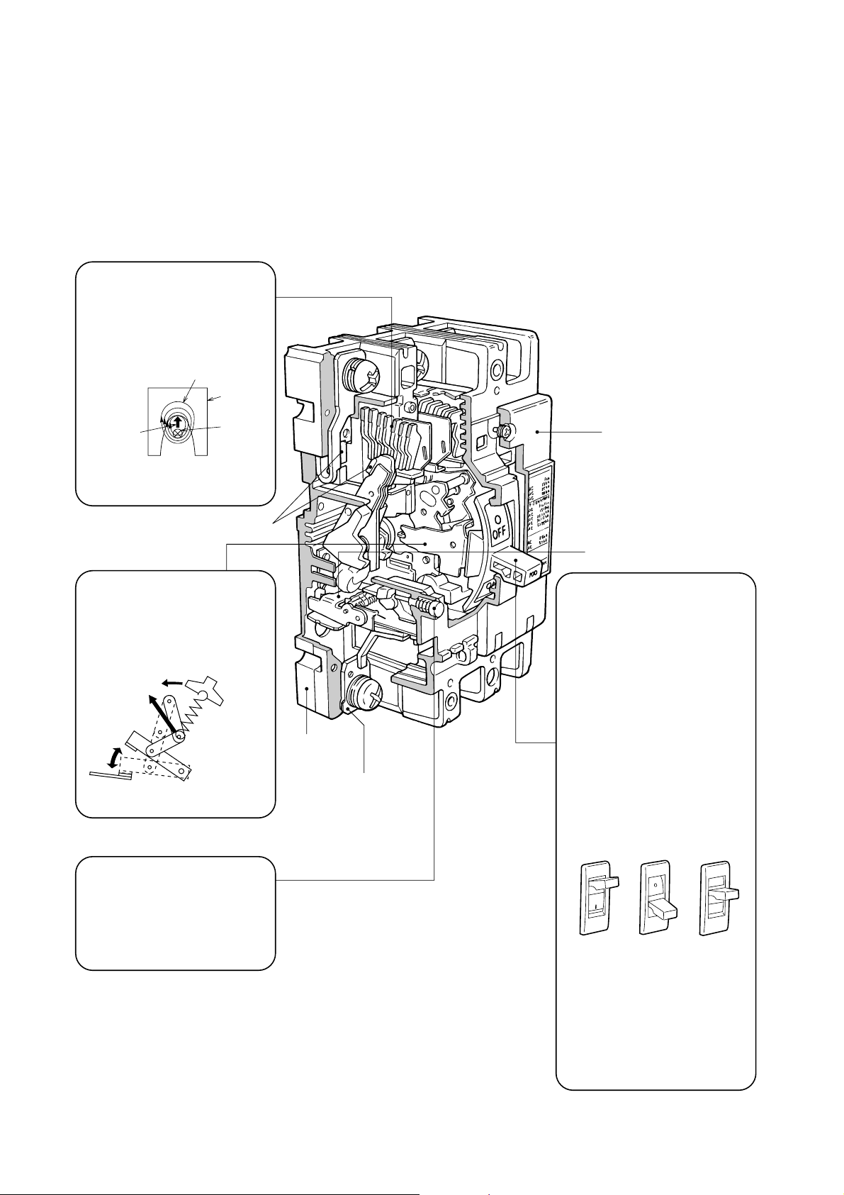
3. CONSTRUCTION AND OPERATION
3.1 General
The primary components are: a switching mechanism,
an automatic tripping device (and manual trip button),
contacts, an arc-extinguishing device, terminals and
a molded case.
Arc-Extinguishing Device
Mitsubishi MCCBs feature excellent arc-extinguishing performance by virtue of the optimum
combination of grid gap, shape,
and material.
Magnetic flux
Grid
Magnetic
force
Arc extinction
Switching Mechanism
The contacts open and close rapidly, regardless of the moving
speed of the handle, minimizing
contact wear and ensuring safety.
Rapid
movement
Arc
Contact
Link-mechanism
operation
Molded case
(Base)
Terminal
Molded case
(Cover)
Automatic tripping device
Handle
1. Trip indication
The automatically tripped condition is indicated by the handle in
the center position between ON
and OFF, the yellow (or white)
line cannot be seen in this position.
2. Resetting
Resetting after tripping is performed by first moving the handle to the OFF position to engage the mechanism, then returning the handle to ON to reclose the circuit.
3. Trip-Free
Even if the handle is held at
ON, the breaker will trip if an
overcurrent flows.
Trip Button (Push to Trip)
Enables tripping mechanically
from outside, for confirming the
operation of the accessory switches and the manual resetting function.
6
Fig. 3.1 Type NF100-SP Construction
ON
ON OFF Trip
4. Contact On Mechanism
Even in the worst case in which
welding occurs owing to an
overcurrent, the breaker will trip
and the handle will maintain to
ON, indicating the energizing
state.
OFF
Handle indication
OFF
ON
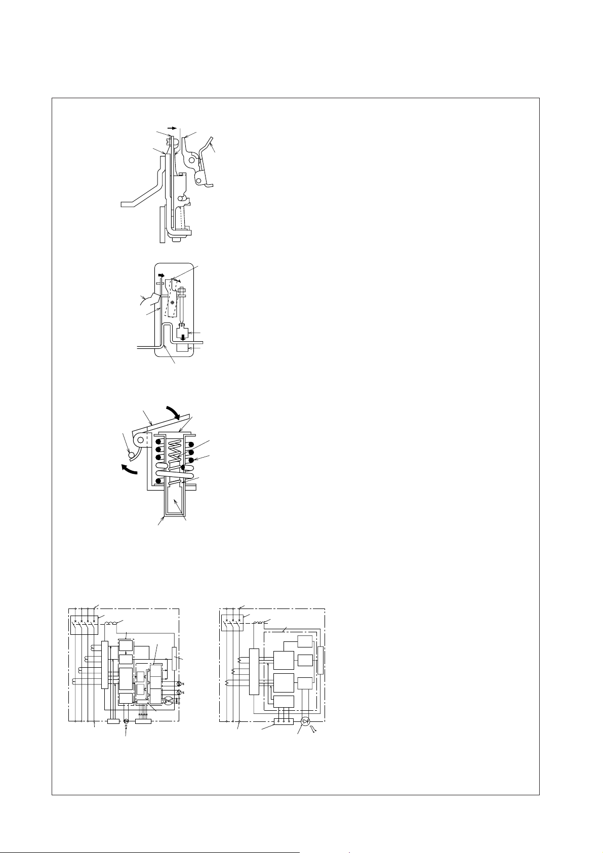
Page 8
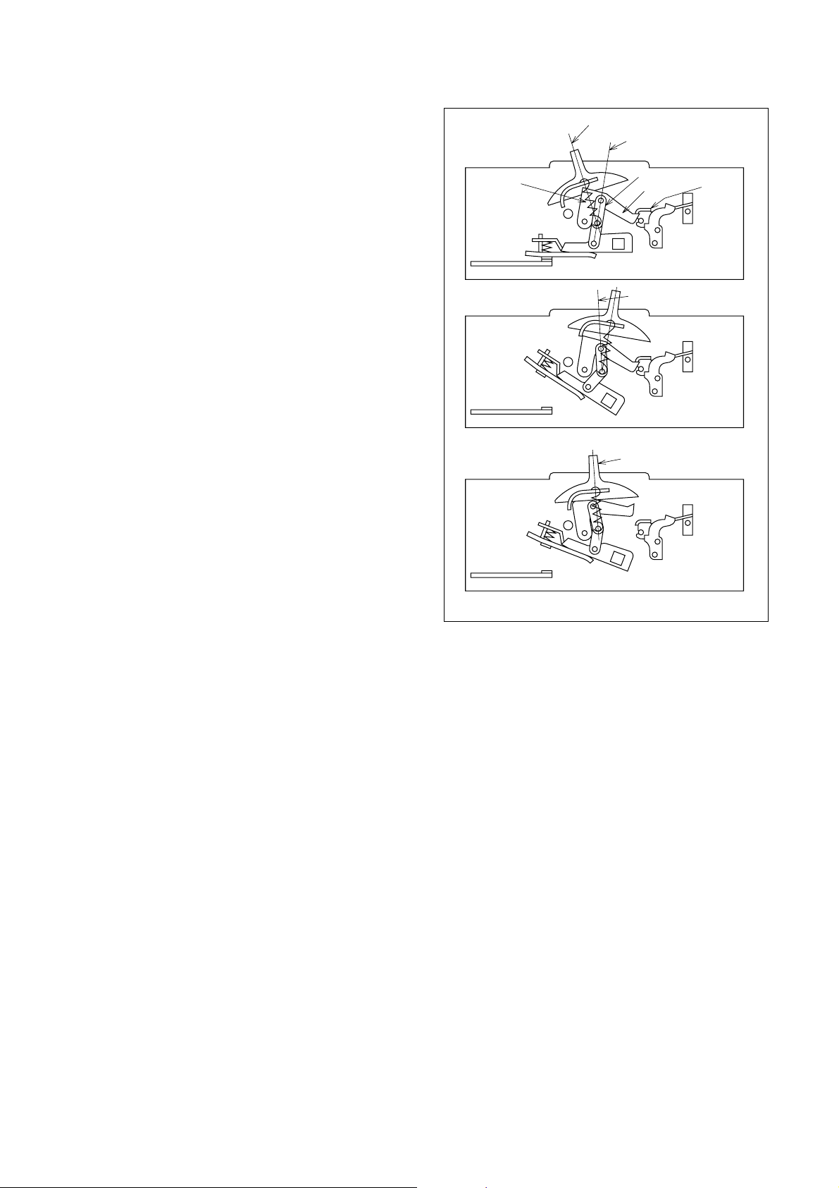
3.2 Switching Mechanism
Spring tension line
Toggle link
Cradle
Bracket
Spring
a) On
b) Off
c) Tripped
ON to OFF dead-point line
OFF to ON dead-point line
Handle centered; indicates
tripped condition
The ON, OFF and TRIPPED conditions are shown in
Fig. 3.2. In passing from ON to OFF, the handle tension spring passes through alignment with the toggle
link (“dead point” condition). In so doing, a positive,
rapid contact-opening action is produced; the OFF to
ON contact closing acts in a similar way (“quick make”
and “quick break” actions). In both cases the action of
the contacts is always rapid and positive, and independent of the human element – i.e., the force or
speed of the handle.
In auto tripping a rotation of the bracket releases
the cradle and operates the toggle link to produce the
contact-opening action described above. In the tripped
condition the handle assumes the center position between on and off, providing a visual indication of the
tripped condition. Also, auto trip is “trip free,” so that
the handle cannot be used to hold the breaker in the
ON condition. The protective contact-opening function cannot be defeated.
In multipole breakers the poles are separated by
integral barriers in the molded case. The moving contacts of the poles are attached to the central toggle
link by a common-trip bar, however, so that tripping,
opening and closing of all poles is always simultaneous. This is the “common trip” feature, by which
single phasing and similar unbalance malfunctions are
effectively prevented.
Fig. 3.2 Switching Mechanism Action
3.3 Automatic Tripping Device
There are three types of device, the thermal-magnetic
type, the hydraulic-magnetic type and the electronic
trip relay type.
7
Page 9
■Automatic Tripping Devices
●Thermal-Magnetic Type (100~630A Frame)
Bimetal
Heater
●Thermal-Magnetic Type (1000~4000A Frame)
Latch
Bimetal
Armature
Heater
Trip bar
Latch
Trip bar
Armature
Stationary core
1. Time-Delay Operation
An overcurrent heats and warps the bimetal to actuate the trip bar.
2. Instantaneous Operation
If the overcurrent is excessive, the
amature is attracted and the trip bar actuated.
Fig. 3.3
1. Time-Delay Operation
An overcurrent heats and warps the bimetal to actuate the trip bar.
2. Instantaneous Operation
If the overcurrent is excessive, magnetization of the stationary core is strong
enough to attract the armature and actuate the trip bar.
Fig. 3.4
●Hydraulic-Magnetic Type (30~60A Frame)
Armature
Trip bar
Pipe
Pole piece
Damping spring
Coil
Silicon oil
Moving core
Fig. 3.5
●Principle of Electronic Trip Relay (ETR) Operation
(100~800A Frame)
Power-source side terminal
Breaking mechanism
Custom IC
CT
CT
CT
Load-side
terminal
CT
CV
PSS
Rectifying circuit
WDT
Test input
Load-current indication LED (70%)
Trip coil
Microcomputer
I
A/D
convertor
CPU
Characteristics
setting part
SSW
LSW
PSW
Input and
output
Trigger circuit
Over-current
indication LED
Pre-alarm
indication LED
Pre-alarm
output
(1000~1600A Frame)
Power-supply side terminal
Switching mechanism
Trip coil
Special IC
Peak
conversion
Rectifier circuit
Test
terminals
and
largest-phase
selection
Effective value
conversion
and
largest-phase
selection
Test-signal
generator
circuit
Overcurrent display
LED
Fig. 3.6
CT
Load-side
terminal
CT
CT
Instantaneous
circuit
Shortdelay
circuit
Longdelay
circuit
1. Time-Delay Operation
At an overcurrent flow, the magnetic
force of the coil overcomes the spring,
the core closes to the pole piece, attracts
the armature, and actuates the trip bar.
The delay is obtained by the viscosity of
silicon oil.
2. Instantaneous Operation
If the overcurrent is excessive, the armature is instantly attracted, without the
influence of the moving core.
1. The current flowing in each phase is
monitored by a current transformer (CT).
2. Each phase of the transformed current
undergoes full-phase rectification in the
rectifier circuit.
3. After rectification, each of the currents
are converted by a peak-conversion and
an effective-value conversion circuit.
4. The largest phase is selected from the
Trigger circuit
converted currents.
5. Each time-delay circuit generates a time
delay corresponding to the largest
phase.
6. The trigger circuit outputs a trigger signal.
7. The trip coil is excited, operating the
switching mechanism.
8
Page 10
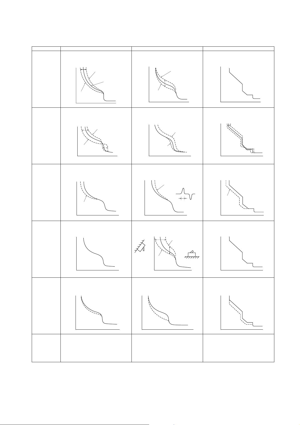
Table 3.1 Comparison of Thermal-Magnetic, Hydraulic-Magnetic and Electronic Types
Item
Operating current is affected by ambient
temperature (bimetal responds to absolute
temperature not temperature rise).
Ambient
temperature
Thermal-magnetic type
Low temperature
Standard temperature
Hydraulic-magnetic type
Affected only to the extent that the damping-oil viscosity is affected.
Low temperature
Negligible effect
Electronic type
Frequency
Distorted
wave
Operating time
High temperature
Current
Negligible effect up to several hundred Hz;
above that the instantaneous trip is affected due to increased iron losses.
Low frequency
High frequency
Operating time
Current
Negligible effect up to 630A;
Above that operating current decreases
due to increase of a fever.
Above 700A
Operating time
Current
Negligible effect.
Operating time
High temperature
Current
Trip current increases with frequency, due
to increased iron losses.
High frequency
Low frequency
Operating time
Current
IF distortion is big, minimum operating current increases.
Small current width
Current width
Operating time
Current
Mounting attitude changes the effective
weight of the magnetic core.
Operating time
Current
Tripping current of some types decrease
due to CT or condition of operating circuit
with high frequency, and others increase.
Operating time
Current
For peak value detection, operating current
drops.
Peak value
detection
Operating time
Current
Negligible effect
Mounting
attitude
Flexibility
of operating
characteristics
Flexibility of
rated current
Operating time
Current
Bimetal must provide adequate deflection
force and desired temperature characteristic. Operating time range is limited.
Operating time
Current
Units for small rated currents are physically
impractical.
Horizontal
ON OFF
Current
OFF
ON
Ceiling
Operating time
Oil viscosity, cylinder, core and spring design, etc., allow a wide choice of operating
times.
Operating time
Current
Coil winding can easily be designed to suit
any ampere rating.
Operating time
Current
Operating time can be easily shortened.
To lengthen operating time is not.
Operating time
Current
Within the range of 50(60)~100% of rated
current, any ampere rating are practical.
Also, to lower the value of short-time delay
or instantaneous trip can be easily done
comparatively.
9
Page 11
3.4 Contacts
A pair of contacts comprises a moving contact and a
fixed contact. The instants of opening and closing
impose the most severe duty. Contact materials must
be selected with consideration to three major criteria:
1. Minimum contact resistance
2. Maximum resistance to wear
3. Maximum resistance to welding
Silver or silver-alloy contacts are low in resistance,
but wear rather easily. Tungsten, or majority-tungsten
alloys are strong against wear due to arcing, but rather
high in contact resistance. Where feasible, 60%+ silver alloy (with tungsten carbide) is used for contacts
primarily intended for current carrying, and 60%+ tungsten alloy (with silver) is used for contacts primarily
intended for arc interruption. Large-capacity MCCBs
employ this arrangement, having multicontact pairs,
with the current-carrying and arc-interruption duties
separated.
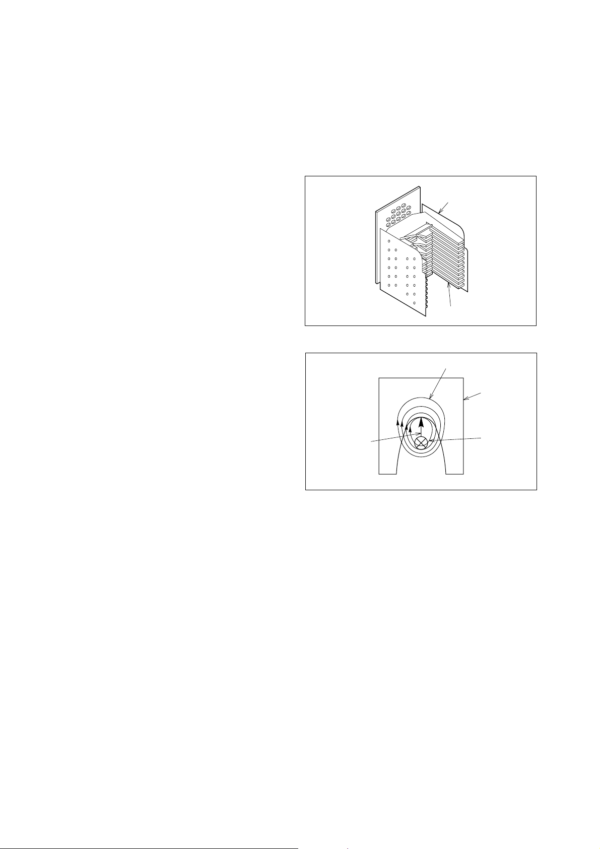
3.5 Arc-Extinguishing Device
Arcing, an inevitable aspect of current interruption,
must be extinguished rapidly and effectively, in normal switching as well as protective tripping, to minimize deterioration of contacts and adjacent insulating materials. In Mitsubishi MCCBs a simple, reliable,
and highly effective “de-ion arc extinguisher,” consisting of shaped magnetic plates (grids) spaced apart in
an insulating supporting frame, is used (Fig. 3.7). The
arc (ionized-path current) induces a flux in the grids
that attracts the arc, which tends to “lie down” on the
grids, breaking up into a series of smaller arcs, and
also being cooled by the grid heat conduction. The
arc (being effectively longer) thus requires far more
voltage to sustain it, and (being cooler) tends to lose
ionization and extinguish. If these two effects do not
extinguish the arc, as in a very large fault, the elevated
temperature of the insulating frame will cause gassing-out of the frame material, to de-ionize the arc.
Ac arcs are generally faster extinguishing due to the
zero-voltage point at each half cycle.
3.8 Trip Button
This is a pushbutton for external, mechanical tripping
of the MCCB locally, without operating the externalaccessory shunt trip or undervoltage trip, etc. It enables easy checking of breaker resetting, control-circuit devices associated with alarm contacts, etc., and
resetting by external handle.
Supporting
frame
Grids
Fig. 3.7 The De-Ion Arc Extinguisher
Induced flux
Grid
Attraction force
Fig. 3.8 The Induced-Flux Effect
Arc
3.6 Molded Case
The integral molded cases used in Mitsubishi MCCBs
are constructed of the polyester resin containing glass
fibers, the phenolic resin or glass reinforced nylon.
They are designed to be suitably arc-, heat- and gasresistant, and to provide the necessary insulating
spacings and barriers, as well as the physical strength
required for the purpose.
3.7 Terminals
These are constructed to assure electrical efficiency
and reliability, with minimized possibility of localized
heating. A wide variety of types are available for ease
of mounting and connection. Compression-bonded
types and bar types are most commonly used.
10
Page 12
Rated current
(A)
30 or less
31~63
64~100
101~250
251~400
401~630
631~800
801~1000
1001~1250
1251~1600
1601~2000
2001~4000
Tripping time
(minutes, max.)
200%
8.5
4
8.5
8
10
12
14
16
18
20
22
24
130%
60
60
120
120
120
120
120
120
120
120
120
120
120
120
120
120
120
120
120
120
120
60
60
120
105%
Non-Tripping time
(minutes, max.)
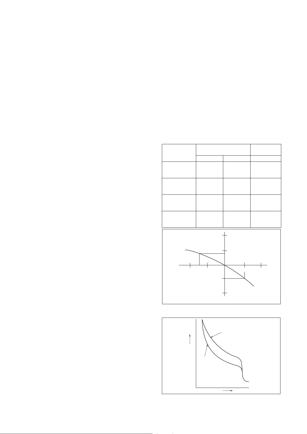
4. CHARACTERISTICS AND PERFORMANCE
4.1 Overcurrent-Trip Characteristics (Delay
Tripping)
Tripping times for overcurrents of 130 and 200% of
rated current are given in Table 4.1, assuming ambient temperatures of 40°C, a typical condition inside
of panelboards. The figures reflect all poles tested together for 130% tripping, and 105% non-tripping.
Within the range of the long-delay-element (thermal
or hydraulic) operation, tripping times are substantially linear, in inverse relationship to overcurrent magnitude.
The tripping times are established to prevent excessive conductor-temperature rise; although times
may vary among MCCBs of different makers, the lower
limit is restricted by the demands of typical loads: tungsten-lamp inrush, starting motor, mercury-arc lamps,
etc. The tripping characteristics of Mitsubishi MCCBs
are established to best ensure protection against abnormal currents, while avoiding nuisance tripping.
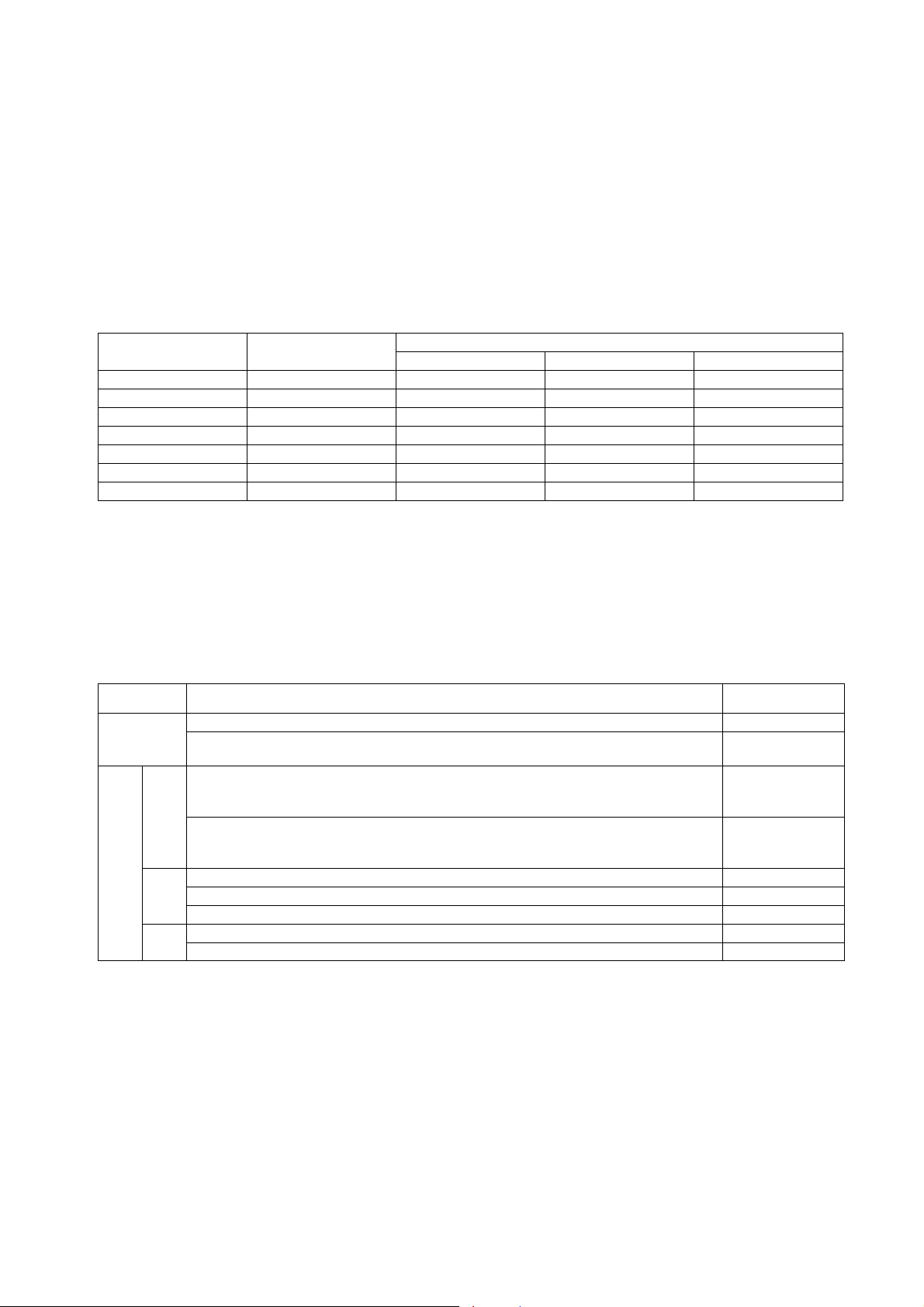
4.1.1 Ambient Temperature and Thermal Tripping
Fig. 4.1 is a typical ambient compensation curve
(curves differ according to types and ratings), showing that an MCCB rated for 40°C ambient use must
be derated to 90% if used in a 50°C environment. In
an overcurrent condition, for the specified tripping time,
tripping would occur at 180% rated current, not 200%.
At 25°C, for the same tripping time, tripping would
occur at 216%, not 200%.
4.1.2 Hot-State Tripping
The tripping characteristics described above reflect
“cold-state tripping” – i.e., overloads increased from
zero – and the MCCB stabilized at rated ambient. This
is a practical parameter for most uses, but in intermittent operations, such as resistance welding, motor
pulsing, etc., the “hot state” tripping characteristic must
be specified, since over-loads are most likely to occur with the MCCB in a heated state, while a certain
load current is already flowing.
Where the MCCB is assumed to be at 50% of rating when the overload occurs, the parameter is called
the 50% hot-state characteristic; if no percentage is
specified, 100% is assumed. Hot-state ratings of 50%
and 75% are common.
4.2 Short-Circuit Trip Characteristics (In-
stantaneous Tripping)
For Mitsubishi MCCBs with thermal-magnetic trip units
the instantaneous-trip current can be specified independently of the delay characteristic, and in many
cases this parameter is adjustable offering considerable advantage in coordination with other protection
and control devices. For example, in coordination with
motor starters, it is important to set the MCCB instantaneous-trip element at a lower value than the fusing
(destruction) current of the thermal overload relay
(OLR) of the starter.
For selective tripping, it must be remembered that
even though the branch-MCCB tripping time may be
shorter than the total tripping time of the main MCCB,
in a fault condition the latter may also be tripped because its latching curve overlaps the tripping curve of
the former. The necessary data for establishing the
required compatibility is provided in the Mitsubishi
MCCB sales catalogues.
The total clearing time for the “instantaneous” tripping feature is shown in Fig. 4.3; actual values differ
for each MCCB type.
Table 4.1 Overcurrent Tripping Times
120
110
108
100
20 25
% rating compensation
Fig. 4.1 Typical Temperature-Compensation Curve
Hot state
Operating time
Fig. 4.2 Hot-State-Tripping Curve
40
30
90
80
Ambient temperature (:)
Cold state
Current
50 60
11
Page 13
Total
clearing
time
Fig. 4.3 Instantaneous Tripping Sequence
Latching
(relay)
time
Electromagnet
oparating
time
Floor-mounted
Mechanical
delay
time
Time for
contacts to
open
Arcing
time
Arcextinguishing
time
4.3 Effects of Mounting Attitudes
Instantaneous tripping is negligibly affected by mounting attitude, for all types of MCCB. Delay tripping is
also negligibly affected in the thermal types, but in
the hydraulic-magnetic types the core-weight effect
becomes a factor. Fig. 4.4 shows the effect, for vertical-surface mounting and for two styles of horizontalsurface mounting.
(vertical plane)
100%
Wall-mounted
(horiz. or vert. attitude)
Ceiling-mounted
Tripping time
Overcurrent
Fig. 4.4 Effect of Mounting Attitude on the Hydraulic-
Magnetic MCCB Tripping Curves
Fig. 4.5 Effects of Nonvertical-Plane Mounting on Current
4.4 DC Tripping Characteristics of AC-Rated MCCBs
Table 4.2 DC Tripping Characteristics
Trip unit
Thermal
magnetic
Hydraulic
magnetic
Long delay
No effect below 630A
frame. Above this, AC
types cannot be used
for DC.
DC minimum-trip
values are 110~140%
of AC values.
Instantaneous
DC inst.-trip current is
approx. 130% of AC
value.
107%
107%
Rating
ON
ON
ON
ON
ON
ON
100%
93%
ON
ON
93%
Tripping curve
AC
Tripping time
Tripping time
DC
Overcurrent
AC
DC
Overcurrent
90%110%
4.5 Frequency Characteristics
At commercial frequencies the characteristics of
Mitsubishi MCCBs of below 630A frame size are virtually constant at both 50Hz and 60Hz (except for the
E Line models, the characteristics of MCCBs of 2000A
frame and above vary due to the CT used with the
delay element).
At high frequencies (e.g., 400Hz), both the current
capacity and delay tripping curves will be reduced by
skin effect and increased iron losses.
Performance reduction will differ for different types;
at 400Hz it will become 80% of the rating in breakers
of maximum rated current for the frame size, and 90%
12
of the rating in breakers of half of the maximum rating
for the frame size.
The instantaneous trip current will gradually increase with frequency, due to reverse excitation by
eddy currents. The rise rate is not consistent, but
around 400Hz it becomes about twice the value at
60Hz. Mitsubishi makes available MCCBs especially
designed for 400Hz use. Apart from operating characteristics they are identical to standard MCCBs (S
Line).
Page 14
4.6 Switching Characteristics
Frame size
100 or less
225
400, 630
800
1000~2000
2500, 3000
3200, 4000
Operations per hour
120
120
60
20
20
10
10
Number of operations
Without current
8500
7000
4000
2500
2500
1500
1500
With current
1500
1000
1000
500
500
500
500
Total
10000
8000
5000
3000
3000
2000
2000
The MCCB, specifically designed for protective interruption rather than switching, and requiring high-contact pressure and efficient arc-extinguishing capability, is expected to demonstrate inferior capability to
that of a magnetic switch in terms of the number of
operations per minute and operation life span. The
specifications given in Table 4.3 are applicable where
the MCCB is used as a switch for making and break-
Table 4.3 MCCB Switching Endurance
ing rated current.
Electrical tripping endurance in MCCBs with shunt
or undervoltage tripping devices is specified as 10%
of the mechanical-endurance number of operations
quoted in IEC standards.
Shunt tripping or undervoltage tripping devices are
intended as an emergency trip provision and should
not be used for normal circuit-interruption purposes.
4.7 Dielectric Strength
In addition to the requirements of the various international standards, Mitsubishi MCCBs also have the
impulse-voltage withstand capabilities given below
(Table 4.4). The impulse voltage is defined as sub-
Table 4.4 MCCB Impulse Withstand Voltage (Uimp)
Type
NF
Line
MB
MB30-CS
MB30-SP MB50-CP MB50-SP
MB100-SP MB225-SP
NF30-SP NF50-HP NF60-HP
NF50-HRP NF100-SP NF100-HP NF100-SEP NF100-HEP
NF160-SP NF160-HP NF250-SP NF250-HP NF250-SEP NF250-HEP
S
NF400-SP NF400-SEP NF400-HEP NF400-REP NF630-SP NF630-SEP
NF630-HEP NF630-REP NF800-SEP NF800-HEP NF800-REP
NF800-REP NF1000-SS NF1250-SS NF1600-SS
NF30-CS
NF50-CP NF60-CP NF100-CP NF250-CP
C
NF400-CP NF630-CP NF800-CEP
NF100-RP NF100-UP NF225-RP NF225-UP
U
NF400-UEP NF630-UEP NF800-UEP
stantially square-wave, with a crest length of
0.5~1.5µsec and a tail-length of 32~48µsec. The voltage is applied between line and load terminals (MCCB
off), and between live parts and ground (MCCB on).
Impulse-voltage (kA)
4
6
6
8
4
6
8
6
8
13
Page 15
5. CIRCUIT BREAKER SELECTION
5.1 Circuit Breaker Selection Table
Following Table shows various characteristics of each breaker to consider selection and coordination with
upstream devices or loads.
Characteristics
Standard : Standard characteristics MCCBs
Low-inst : Low-inst. MCCBs for Discrimination
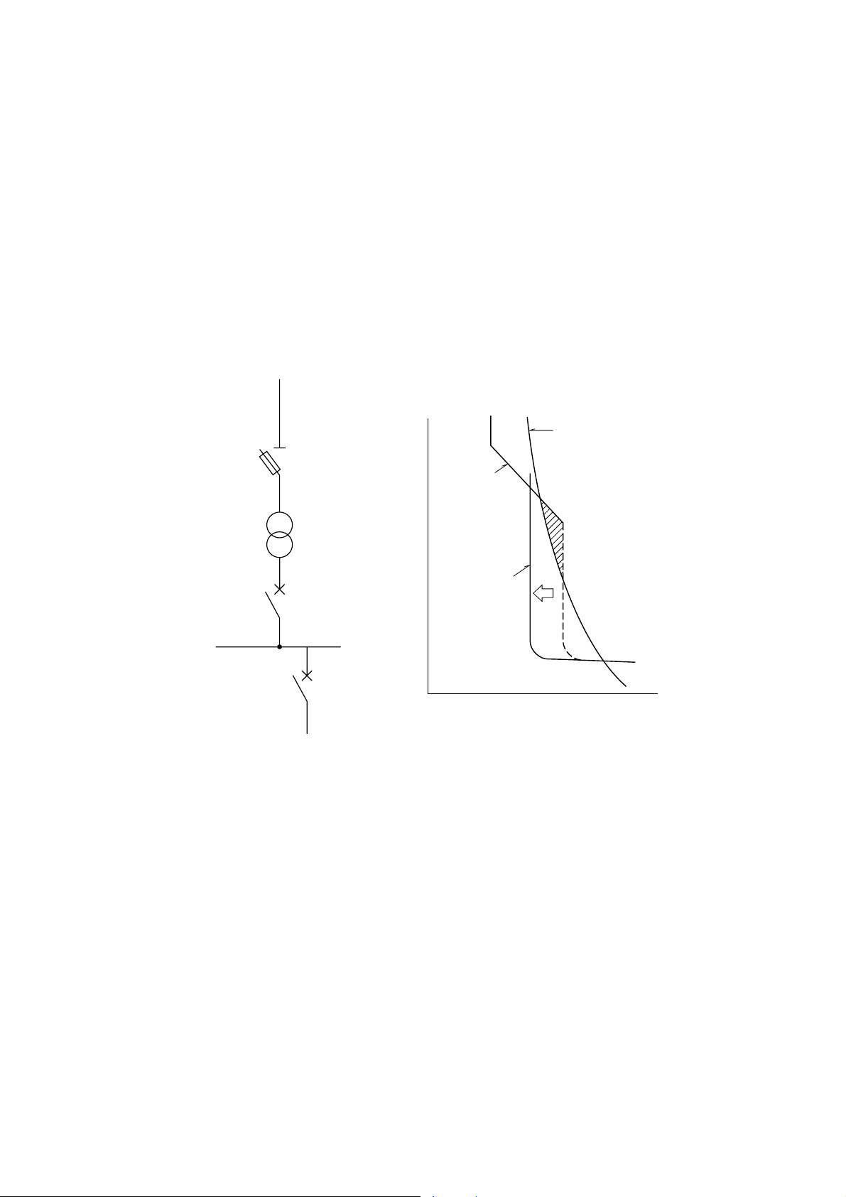
When a power fuse (PF) is used as a high-voltage protector, it must be coordinated
with an MCCBs on the secondary side.
PF short-time tolerancs
capacity
Pf.
MCCB
operating
characteristic
curve
Tr.
MCCB1
MCCB2
Generator: Generator-Protection MCCBs
These MCCBs have long-time-delay operation shorter than standard type and low
instantaneous operation.
Mag-Only : Magnetic trip only MCCBs
These are standard MCCBs minus the thermal tripping device. They have no timedelay tripping characteristic, providing protection only against large-magnitude shortcircuit faults.
Low-inst.MCCBs
Time
Current
14
Page 16

CIRCUIT BREAKER SELECTION TABLE
Frame (A)
Type
Rated current In (A)
Rated insulation voltage Ui (V) AC
AC Breaking
capacity (kA rms)
IEC60947-2
Icu/Ics
Standard
Number of poles
Automatic tripping
device
Rating (A) and
Inst. (A)
690V
500V
440V
400V
230V
Hydraulic-magnetic
Fixed ampere rating and
instantaneous
NF30-CS
3, 5, 10, 15, 20, 30
500
–
–
1.5/1.5 (415V)
1.5/1.5 (380V)
2.5/2 (240V)
23
339± 17
566± 28
10 132 ± 57
15 198 ± 86
20 265 ± 115
30 397 ± 172
30
NF30-SP
3, 5, 10, 15, 20, 30
600
–
2.5/1
2.5/1
5/2
5/2
23
Hydraulic-magnetic
Fixed ampere rating and
instantaneous
333± 10
555± 17
10 110 ± 35
15 165 ± 52
20 220 ± 70
30 330 ± 105
50
NF50-CP
10, 15, 20, 30, 40, 50
600
–
2.5/1
2.5/1
5/2
5/2
23
Hydraulic-magnetic
Fixed ampere rating and
instantaneous
10 110 ± 35
15 165 ± 52
20 220 ± 70
30 330 ± 105
40 440 ± 140
50 550 ± 175
Low-inst
Generator
Mag-Only
Number of poles
Automatic tripping
device
Rating (A) and
Inst. (A)
Number of poles
Automatic tripping
device
Rating (A) and
Inst. (A)
Number of poles
Automatic tripping
device
Rating (A) and
Inst. (A)
–
–
–
–
–
–
–
Magnetic
–
–
Fixed ampere rating
instantaneous
330± 6
550± 10
10 100 ± 20
15 150 ± 30
20 200 ± 40
30 300 ± 60
–
–
–
–
–
–
23
Magnetic
Fixed ampere rating
instantaneous
10 100 ± 20
15 150 ± 30
20 200 ± 40
30 300 ± 60
40 400 ± 80
50 500 ± 100
–
–
–
–
–
–
23
15
Page 17
Frame (A)
Type
Rated current In (A)
Rated insulation voltage Ui (V) AC
AC Breaking
capacity (kA rms)
IEC60947-2
Icu/Ics
Standard
Number of poles
Automatic tripping
device
Rating (A) and
Inst. (A)
690V
500V
440V
400V
230V
50
NF50-HP
10, 15, 20, 30, 40, 50
600
–
7.5/4
10/5
10/5
25/13
234
Hydraulic-magnetic
Fixed ampere rating and
instantaneous
10 110 ± 35
15 165 ± 52
20 220 ± 70
30 330 ± 105
40 440 ± 140
50 550 ± 175
60
NF60-CP
10, 15, 20, 30, 40, 50, 60
600
–
2.5/1
2.5/1
5/2
5/2
23
Hydraulic-magnetic
Fixed ampere rating and
instantaneous
10 110 ± 35
15 165 ± 52
20 220 ± 70
30 330 ± 105
40 440 ± 140
50 550 ± 175
60 660 ± 210
Low-inst
Generator
Mag-Only
Number of poles
Automatic tripping
device
Rating (A) and
Inst. (A)
Number of poles
Automatic tripping
device
Rating (A) and
Inst. (A)
Number of poles
Automatic tripping
device
Rating (A) and
Inst. (A)
–
–
–
–
–
–
234
Magnetic
Fixed ampere rating and
instantaneous
10 100 ± 20
15 150 ± 30
20 200 ± 40
30 300 ± 60
40 400 ± 80
50 500 ± 100
–
–
–
–
–
–
23
Magnetic
Fixed ampere rating and
instantaneous
10 100 ± 20
15 150 ± 30
20 200 ± 40
30 300 ± 60
40 400 ± 80
50 500 ± 100
60 600 ± 120
16
Page 18

Frame (A)
Type
Rated current In (A)
Rated insulation voltage Ui (V) AC
AC Breaking
capacity (kA rms)
IEC60947-2
Icu/Ics
Standard
Low-inst
Generator
Number of poles
Automatic tripping
device
Rating (A) and
Inst. (A)
Number of poles
Automatic tripping
device
Rating (A) and
Inst. (A)
Number of poles
Automatic tripping
device
690V
500V
440V
400V
230V
Hydraulic-magnetic
Fixed ampere rating and
instantaneous
60
NF60-HP
10, 15, 20, 30, 40, 50, 60
600
–
7.5/4
10/5
10/5
25/13
234
10 110 ± 35
15 165 ± 52
20 220 ± 70
30 330 ± 105
40 440 ± 140
50 550 ± 175
60 660 ± 210
–
–
–
–
–
100
NF100-CP NF100-SP
50, 60, 75, 100
600
–
7.5/4
10/5
10/5
25/13
23
Thermal, magnetic
Fixed ampere rating and
instantaneous
50 750 ± 150
60 900 ± 180
75 1125 ± 225
100 1500 ± 300
23
Thermal, magnetic
Fixed ampere rating and
instantaneous
50 300 ± 60
60 360 ± 72
75 450 ± 90
100 600 ± 120
–
–
15, 20, 30, 40, 50, 60, 75, 100
Thermal, magnetic
Fixed ampere rating and
instantaneous
100 1500 ± 300
Thermal, magnetic
Fixed ampere rating and
instantaneous
100 600 ± 120
690
–
15/8
25/13
30/15
50/25
234
15 225 ± 45
20 300 ± 60
30 450 ± 90
40 600 ± 120
50 750 ± 150
60 900 ± 180
75 1125 ± 225
234
15 90 ± 18
20 120 ± 24
30 180 ± 36
40 240 ± 48
50 300 ± 60
60 360 ± 72
75 450 ± 90
–
–
Mag-Only
Rating (A) and
Inst. (A)
Number of poles
Automatic tripping
device
Rating (A) and
Inst. (A)
–
234 2 3
Magnetic
Fixed ampere rating and
instantaneous
10 100 ± 20
15 150 ± 30
20 200 ± 40
30 300 ± 60
40 400 ± 80
50 500 ± 100
60 600 ± 120
Magnetic
Fixed ampere rating and
instantaneous
100 1000 ± 200
–
50 500 ± 100
60 600 ± 120
75 750 ± 150
–
234
Magnetic
Fixed ampere rating and
instantaneous
15 150 ± 30
20 200 ± 40
30 300 ± 60
40 400 ± 80
50 500 ± 100
60 600 ± 120
75 750 ± 150
100 1000 ± 200
17
Page 19

Frame (A) 100
Type
Rated current In (A)
Rated insulation voltage Ui (V) AC
AC Breaking
capacity (kA rms)
IEC60947-2
Icu/Ics
Standard
Number of poles
Automatic tripping
device
Rating (A) and
Inst. (A)
690V
500V
440V
400V
230V
Thermal, magnetic
Adjustable ampere rating
and fixed instantaneous
NF100-CP T/A
15 ~ 20, 20 ~ 25, 25 ~ 40
40 ~ 63, 63 ~ 80, 80 ~ 100
600
–
7.5/4
10/5
10/5
25/13
23
15 ~ 20 225 ± 45
20 ~ 25 300 ± 60
25 ~ 40 375 ± 75
40 ~ 63 600 ± 120
63 ~ 80 945 ± 189
80 ~ 100 1200 ± 240
50
NF50-HRP
15, 20, 30, 40, 50
690
2.5/1
20/10
30/15
30/15
85/43
23
Thermal, magnetic
Fixed ampere rating and
instantaneous
15 225 ± 45
20 300 ± 60
30 450 ± 90
40 600 ± 120
50 750 ± 150
100
NF100-SP T/A
15 ~ 20, 20 ~ 25, 25 ~ 40
40 ~ 63, 63 ~ 80, 80 ~ 100
690
–
15/8
25/13
30/15
50/25
234
Thermal, magnetic
Adjustable ampere rating
and fixed instantaneous
15 ~ 20 225 ± 45
20 ~ 25 300 ± 60
25 ~ 40 375 ± 75
40 ~ 63 600 ± 120
63 ~ 80 945 ± 189
80 ~ 100 1200 ± 240
Low-inst
Generator
Mag-Only
Number of poles
Automatic tripping
device
Rating (A) and
Inst. (A)
Number of poles
Automatic tripping
device
Rating (A) and
Inst. (A)
Number of poles
Automatic tripping
device
Rating (A) and
Inst. (A)
–
–
–
–
–
–
–
–
–
Magnetic
Fixed ampere rating and
instantaneous
15 150 ± 30
20 200 ± 40
30 300 ± 60
40 400 ± 80
50 500 ± 100
–
–
–
–
–
–
23
–
–
–
–
–
–
–
–
–
18
Page 20

Frame (A)
Type
Rated current In (A)
15, 20, 30, 40, 50, 60, 75, 100
100
NF100-HP T/ANF100-HP
15 ~ 20, 20 ~ 25, 25 ~ 40
40 ~ 63, 63 ~ 80, 80 ~ 100
NF100-RP
15, 20, 30, 40, 50, 60, 75, 100
Rated insulation voltage Ui (V) AC
AC Breaking
capacity (kA rms)
IEC60947-2
Icu/Ics
Standard
Low-inst
Number of poles
Automatic tripping
device
Rating (A) and
Inst. (A)
Number of poles
Automatic tripping
device
Rating (A) and
Inst. (A)
690V
500V
440V
400V
230V
690
5/3
30/15
50/25
50/25
100/50
234
Thermal, magnetic
Fixed ampere rating and
instantaneous
15 225 ± 45
20 300 ± 60
30 450 ± 90
40 600 ± 120
50 750 ± 150
60 900 ± 180
75 1125 ± 225
100 1500 ± 300
–
–
690
5/3
30/15
50/25
50/25
100/50
234
Thermal, magnetic
Adjustable ampere rating
and fixed instantaneous
15 ~ 20 225 ± 45
20 ~ 25 300 ± 60
25 ~ 40 375 ± 75
40 ~ 63 600 ± 120
63 ~ 80 945 ± 189
80 ~ 100 1200 ± 240
–
–
690
–
42/42
125/125
125/125
125/125
23
Thermal, magnetic
Fixed ampere rating and
instantaneous
15 225 ± 45
20 300 ± 60
30 450 ± 90
40 600 ± 120
50 750 ± 150
60 900 ± 180
75 1125 ± 225
100 1500 ± 300
–
–
Generator
Mag-Only
Number of poles
Automatic tripping
device
Rating (A) and
Inst. (A)
Number of poles
Automatic tripping
device
Rating (A) and
Inst. (A)
–
–
–
–
234
Magnetic
Fixed ampere rating and
instantaneous
15 150 ± 30
20 200 ± 40
30 300 ± 60
40 400 ± 80
50 500 ± 100
60 600 ± 120
75 750 ± 150
100 1000 ± 200
–
–
–
–
–
–
–
–
–
–
–
–
–
–
19
Page 21
Frame (A)
Type
Rated current In (A)
Rated insulation voltage Ui (V) AC
AC Breaking
capacity (kA rms)
IEC60947-2
Icu/Ics
Standard
Low-inst
Number of poles
Automatic tripping
device
Rating (A) and
Inst. (A)
Number of poles
Automatic tripping
device
690V
500V
440V
400V
230V
Thermal, magnetic
Fixed ampere rating and
instantaneous
NF100-UP NF100-SEP
15, 20, 30, 40, 50, 60, 75, 100
690
10/5
200/200
200/200
200/200
200/200
234
15 225 ± 45
20 300 ± 60
30 450 ± 90
40 600 ± 120
50 750 ± 150
60 900 ± 180
75 1125 ± 225
100 1500 ± 300
–
–
15 ~ 20, 30 ~ 50, 60 ~ 100
Electronic trip relay
Adjustable ampere rating
Adjustable long time delay
operating time, short time delay
pick up, and instantaneous
Short time delay pick up current
Variation is within ±15% of
setting current
15 30-37.5-45-52.5-60-7520 40-50-60-70-80-100-12030 60-75-90-105-120-15040 80-100-120-140-16050 100-125-150-175-20060 120-150-180-210-24075 150-187.5-225-262.5-300-
100 200-250-300-350-400-
Instantaneous pick up current
Variation is within ±15% of
setting current
30 ~ 50 200 ~ 800
60 ~ 100 400 ~ 1600
100
690
–
15/8
25/13
30/15
50/25
34
2 to 10 Ir
90-105-120-150
140-160-200
180-210-240-300
200-240-280-320-400
250-300-350-400-500
300-360-420-480-600
375-450-525-600-750
500-600-700-800-1000
4 In ~ 16 In
–
–
NF100-HEP
15 ~ 20, 30 ~ 50, 60 ~ 100
690
5/3
30/15
50/25
50/25
100/50
34
Electronic trip relay
Adjustable ampere rating
Adjustable long time delay
operating time, short time delay
pick up, and instantaneous
Short time delay pick up current
Variation is within ±15% of
setting current
2 to 10 Ir
15 30-37.5-45-52.5-60-75-
90-105-120-150
20 40-50-60-70-80-100-120-
140-160-200
30 60-75-90-105-120-150-
180-210-240-300
40 80-100-120-140-160-
200-240-280-320-400
50 100-125-150-175-200-
250-300-350-400-500
60 120-150-180-210-240-
300-360-420-480-600
75 150-187.5-225-262.5-300-
375-450-525-600-750
100 200-250-300-350-400-
500-600-700-800-1000
Instantaneous pick up current
Variation is within ±15% of
setting current
4 In ~ 16 In
30 ~ 50 200 ~ 800
60 ~ 100 400 ~ 1600
–
–
Generator
Mag-Only
20
Rating (A) and
Inst. (A)
Number of poles
Automatic tripping
device
Rating (A) and
Inst. (A)
Number of poles
Automatic tripping
device
Rating (A) and
Inst. (A)
–
–
Electronic trip relay
–
–
–
–
–
Adjustable ampere rating
Adjustable long time delay
operating time, short time delay
pick up, and instantaneous
Rating: 15 ~ 20A, 30 ~ 50A,
Inst. : Operating characteristics
–
3
60 ~ 100A
must be adjusted as
follows.
STD q 3 (Is setting)
LTD : minimum setting
L = 12sec setting)
(T
–
–
–
–
3
Electronic trip relay
Adjustable ampere rating
Adjustable long time delay
operating time, short time delay
pick up, and instantaneous
Rating: 15 ~ 20A, 30 ~ 50A,
60 ~ 100A
Inst. : Operating characteristics
must be adjusted as
follows.
STD q 3 (Is setting)
LTD : minimum setting
L = 12sec setting)
(T
–
–
–
Page 22

Frame (A)
Type
Rated current In (A)
Rated insulation voltage Ui (V) AC
AC Breaking
capacity (kA rms)
IEC60947-2
Icu/Ics
Standard
Number of poles
Automatic tripping
device
Rating (A) and
Inst. (A)
690V
500V
440V
400V
230V
Thermal, magnetic
Fixed ampere rating and
instantaneous
NF160-SP
125, 150, 160
690
–
15/8
25/13
30/15
50/25
234
125 1750 ± 350
150 2100 ± 420
160 2240 ± 448
160
NF160-SP T/A
100 ~ 125, 125 ~ 160
690
–
15/8
25/13
30/15
50/25
234
Thermal, magnetic
Adjustable ampere rating and
fixed instantaneous
100 ~125 1400 ± 280
125 ~ 160 1400 ± 280
NF160-HP
125, 150, 160
690
5/3
30/8
50/13
50/13
100/25
234
Thermal, magnetic
Fixed ampere rating and
instantaneous
125 1750 ± 350
150 2100 ± 420
160 2240 ± 448
Low-inst
Generator
Mag-Only
Number of poles
Automatic tripping
device
Rating (A) and
Inst. (A)
Number of poles
Automatic tripping
device
Rating (A) and
Inst. (A)
Number of poles
Automatic tripping
device
Rating (A) and
Inst. (A)
–
–
–
–
–
–
234 234
Magnetic
Fixed ampere rating and
instantaneous
125 1250 ± 250
160 1600 ± 320
–
–
–
–
–
–
–
–
Magnetic
Fixed ampere rating and
instantaneous
125 1250 ± 250
160 1600 ± 320
–
–
–
–
–
–
–
21
Page 23

Frame (A)
Type
Rated current In (A)
160
NF160-HP T/A
125, 150, 175, 200, 225, 250100 ~ 125, 125 ~ 160
NF250-CP
250
NF250-CP T/A
100 ~ 125, 125 ~ 160
150 ~ 200, 200 ~ 250
Rated insulation voltage Ui (V) AC
AC Breaking
capacity (kA rms)
IEC60947-2
Icu/Ics
Standard
Low-inst
Number of poles
Automatic tripping
device
Rating (A) and
Inst. (A)
Number of poles
Automatic tripping
device
Rating (A) and
Inst. (A)
690V
500V
440V
400V
230V
Thermal, magnetic
Adjustable ampere rating
and fixed instantaneous
690
5/3
30/8
50/13
50/13
100/25
234
100 ~ 125 1400 ± 280
125 ~ 160 1400 ± 280
–
–
–
600
–
10/5
15/8
18/9
30/15
23
Thermal, magnetic
Fixed ampere rating and
instantaneous
125 1750 ± 350
150 2100 ± 420
175 2450 ± 490
200 2800 ± 560
225 3150 ± 630
250 2500 ± 500
23
Thermal, magnetic
Fixed ampere rating and
instantaneous
6 In 4 In
125 750 ± 150 500 ± 100
150 900 ± 180 600 ± 120
175 1050 ± 210 700 ± 140
200 1200 ± 240 800 ± 160
225 1350 ± 270 900 ± 180
250 1500 ± 300 1000 ± 200
600
–
10/5
15/8
18/9
30/15
23
Thermal, magnetic
Adjustable ampere rating
and fixed instantaneous
100 ~ 125 1400 ± 280
125 ~160 1400 ± 280
150 ~200 2100 ± 420
200 ~250 2500 ± 500
–
–
–
Generator
Mag-Only
Number of poles
Automatic tripping
device
Rating (A) and
Inst. (A)
Number of poles
Automatic tripping
device
Rating (A) and
Inst. (A)
–
–
–
–
Magnetic
–
–
Fixed ampere rating and
instantaneous
125 1250 ± 250
150 1500 ± 300
175 1750 ± 350
200 2000 ± 400
225 2250 ± 450
250 2250 ± 450
–
–
–
23
–
–
–
–
–
–
22
Page 24

Frame (A)
Type
Rated current In (A)
Rated insulation voltage Ui (V) AC
AC Breaking
capacity (kA rms)
IEC60947-2
Icu/Ics
Standard
Number of poles
Automatic tripping
device
Rating (A) and
Inst. (A)
690V
500V
440V
400V
230V
Thermal, magnetic
Fixed ampere rating and
instantaneous
NF250-SP
125, 150, 175, 200, 225, 250
690
–
15/8
25/13
30/15
50/25
234
125 1750 ± 350
150 2100 ± 420
175 2450 ± 490
200 2800 ± 560
225 3150 ± 630
250 2500 ± 500
250
NF250-SP T/A
100 ~ 125, 125 ~ 160
150 ~ 200, 200 ~ 250
690
–
–
25/20
30/22
50/42
234
Thermal, magnetic
Adjustable ampere rating
and fixed instantaneous
100 ~125 1400 ± 280
125 ~ 160 1400 ± 280
150 ~200 2100 ± 420
200 ~250 2500 ± 500
NF250-HP
125, 150, 175, 200, 225, 250
690
5/3
30/8
50/13
50/13
100/25
234
Thermal, magnetic
Fixed ampere rating and
instantaneous
125 1750 ± 350
150 2100 ± 420
175 2450 ± 490
200 2800 ± 560
225 3150 ± 630
250 2500 ± 500
Low-inst
Generator
Mag-Only
Number of poles
Automatic tripping
device
Rating (A) and
Inst. (A)
Number of poles
Automatic tripping
device
Rating (A) and
Inst. (A)
Number of poles
Automatic tripping
device
Rating (A) and
Inst. (A)
234
Thermal, magnetic
Fixed ampere rating and
instantaneous
6 In4 In
125 750 ± 150 500 ± 100
150 900 ± 180 600 ± 120
175 1050 ± 210 700 ± 140
200 1200 ± 240 800 ± 160
225 1350 ± 270 900 ± 180
250 1500 ± 300 1000 ± 200
–
–
–
234
Magnetic
Fixed ampere rating and
instantaneous
125 1250 ± 250
150 1500 ± 300
175 1750 ± 350
200 2000 ± 400
225 2250 ± 450
250 2250 ± 450
–
–
–
–
–
–
–
Magnetic
–
–
Fixed ampere rating and
instantaneous
125 1250 ± 250
150 1500 ± 300
175 1750 ± 350
200 2000 ± 400
225 2250 ± 450
250 2250 ± 450
–
–
–
–
–
–
234
23
Page 25

Frame (A)
Type
Rated current In (A)
Rated insulation voltage Ui (V) AC
AC Breaking
capacity (kA rms)
IEC60947-2
Icu/Ics
Standard
Number of poles
Automatic tripping
device
Rating (A) and
Inst. (A)
690V
500V
440V
400V
230V
Thermal, magnetic
Adjustable ampere rating and
fixed instantaneous
250
100 ~ 125, 125 ~ 160
150 ~ 200, 200 ~ 250
690
5/3
30/8
50/13
50/13
100/25
234
100 ~125 1400 ± 280
125 ~160 1400 ± 280
150 ~200 2100 ± 420
200 ~250 2500 ± 500
NF225-RPNF250-HP T/A
125, 150, 175, 200, 225
690
–
42/42
125/125
125/125
125/125
23
Thermal, magnetic
Fixed ampere rating and
instantaneous
125 1750 ± 350
150 2100 ± 420
175 2450 ± 490
200 2800 ± 560
225 3150 ± 630
225
NF225-UP
125, 150, 175, 200, 225
690
10/5
200/200
200/200
200/200
200/200
234
Thermal, magnetic
Fixed ampere rating and
instantaneous
125 1750 ± 350
150 2100 ± 420
175 2450 ± 490
200 2800 ± 560
225 3150 ± 630
Low-inst
Generator
Mag-Only
Number of poles
Automatic tripping
device
Rating (A) and
Inst. (A)
Number of poles
Automatic tripping
device
Rating (A) and
Inst. (A)
Number of poles
Automatic tripping
device
–
–
–
–
–
–
–
–
–
–
–
–
–
–
–
–
–
–
–
–
–
–
–
–
24
Rating (A) and
Inst. (A)
–
–
–
Page 26

Frame (A)
Type
Rated current In (A)
Rated insulation voltage Ui (V) AC
AC Breaking
capacity (kA rms)
IEC60947-2
Icu/Ics
Standard
Number of poles
Automatic tripping
device
Rating (A) and
Inst. (A)
690V
500V
440V
400V
230V
NF250-SEP
125-250
690
–
15/8
25/13
30/15
50/25
34
Electronic trip relay
Adjustable ampere rating
Adjustable long time delay
operating time, short time delay
pick up, and instantaneous
Short time delay pick up current
Variation is within ±15% of
setting current
2 to 10 Ir
125 250-312.5-375-437.5-500-
625-750-875-1000-1250
150 300-375-450-525-600-
750-900-1050-1200-1500
175 350-437.5-525-612.5-700-
875-1050-1225-1400-1750
200 400-500-600-700-800-1000-
1200-1400-1600-2000
225 450-562.5-675-787.5-900-
1125-1350-1575-1800-2250
250 500-625-750-875-1000-
1250-1500-1750-2000-2500
Instantaneous pick up current
Variation is within ±15% of
setting current
4 ~ 14 In
125 ~ 250 1000 ~ 3500
250
NF250-HEP
125-250
690
5/3
30/8
50/13
50/13
100/25
34
Electronic trip relay
Adjustable ampere rating
Adjustable long time delay
operating time, short time delay
pick up, and instantaneous
Short time delay pick up current
Variation is within ±15% of
setting current
2 to 10 Ir
125 250-312.5-375-437.5-500-
625-750-875-1000-1250
150 300-375-450-525-600-
750-900-1050-1200-1500
175 350-437.5-525-612.5-700-
875-1050-1225-1400-1750
200 400-500-600-700-800-1000-
1200-1400-1600-2000
225 450-562.5-675-787.5-900-
1125-1350-1575-1800-2250
250 500-625-750-875-1000-
1250-1500-1750-2000-2500
Instantaneous pick up current
Variation is within ±15% of
setting current
4 ~ 14 In
125 ~ 250 1000 ~ 3500
Low-inst
Generator
Mag-Only
Number of poles
Automatic tripping
device
Rating (A) and
Inst. (A)
Number of poles
Automatic tripping
device
Rating (A) and
Inst. (A)
Number of poles
Automatic tripping
device
Rating (A) and
Inst. (A)
–
–
–
3
Electronic trip relay
Adjustable ampere rating
Adjustable long time delay
operating time, short time delay
pick up, and instantaneous
Rating: 125 ~ 250A
Inst. : Operating characteristics
must be adjusted as
follows.
STD q 3 (Is setting)
LTD : minimum setting
L = 12sec setting)
(T
–
–
–
–
–
–
3
Electronic trip relay
Adjustable ampere rating
Adjustable long time delay
operating time, short time delay
pick up, and instantaneous
Rating: 125 ~ 250A
Inst. : Operating characteristics
must be adjusted as
follows.
STD q 3 (Is setting)
LTD : minimum setting
L = 12sec setting)
(T
–
–
–
25
Page 27

Frame (A)
Type
Rated current In (A)
Rated insulation voltage Ui (V) AC
AC Breaking
capacity (kA rms)
IEC60947-2
Icu/Ics
Standard
Number of poles
Automatic tripping
device
690V
500V
440V
400V
230V
Thermal, magnetic
Fixed ampere rating and
instantaneous
NF400-CP
250, 300, 350, 400
600
–
15/8
25/13
36/18
50/25
23
400A
NF400-SP
250, 300, 350, 400
690
10/10
30/30
42/42
45/45
85/85
234
Thermal, magnetic
Fixed ampere rating and
instantaneous
NF400-SEP
200 ~ 400
adjustable
690
10/10
30/30
42/42
45/45
85/85
34
Electronic trip relay
Adjustable ampere rating
Adjustable long time delay
operating time, short time delay
pick up and instantaneous
Low-inst
Generator
Mag-Only
(Inst trip only)
Rating (A) and
Inst. (A)
Number of poles
Automatic tripping
device
Rating (A) and
Inst. (A)
Number of poles
Automatic tripping
device
Rating (A) and
Inst. (A)
Number of poles
Automatic tripping
device
Rating (A) and
Inst. (A)
250 2500 ± 500
300 3000 ± 600
350 3500 ± 700
400 4000 ± 800
23
Thermal, magnetic
Fixed ampere rating and
instantaneous
6 In4 In
250 1500±300 1000±200
300 1800±360 1200±240
350 2100±420 1400±280
400 2400±480 1600±320
–
–
–
23
Magnetic
Fixed ampere rating and
instantaneous
250 2500 ± 500
300 3000 ± 600
350 3500 ± 700
400 4000 ± 800
250 3500 ± 700
300 4200 ± 840
350 4900 ± 980
400 5600 ± 1120
–
–
–
–
–
–
234
Magnetic
Fixed ampere rating and
instantaneous
250 2500 ± 500
300 3000 ± 600
350 3500 ± 700
400 4000 ± 800
Short time delay pick up current
Variation is within ±15% of
setting current
200 400-500-600-700-800-
225 450-562.5-675-787.5-
250 500-625-750-875-1000-
300 600-750-900-1050-1200-
350 700-875-1050-1225-
400 800-1000-1200-1400-
Instantaneous pick up current
Variation is within ±15% of
setting current
2 to 10 Ir
1000-1200-1400-16002000
900-1125-1200-15001800-1350-1575-18002250
1250-1500-1750-20002500
1500-1800-2100-24003000
1400-1750-2100-24502800-3500
1600-2000-2400-28003200-4000
4 In ~ 16 I n
1600 ~ 6400
–
–
–
–
–
–
–
–
–
26
Page 28

Frame (A)
Type
Rated current In (A)
Rated insulation voltage Ui (V) AC
AC Breaking
capacity (kA rms)
IEC60947-2
Icu/Ics
Standard
Number of poles
Automatic tripping
device
690V
500V
440V
400V
230V
Electronic trip relay
Adjustable ampere rating
Adjustable long time delay
operating time, short time delay
pick up and instantaneous
400A
NF400-HEP NF400-REP
200 ~ 400
adjustable
690
10/10
50/50
65/65
70/70
100/100
34
Electronic trip relay
Adjustable ampere rating
Adjustable long time delay
operating time, short time delay
pick up and instantaneous
200 ~ 400
adjustable
690
15/10
70/35
125/63
125/63
150/75
3
NF400-UEP
200 ~ 400
adjustable
690
35/35
170/170
200/200
200/200
200/200
34
Electronic trip relay
Adjustable ampere rating
Adjustable long time delay
operating time, short time delay
pick up and instantaneous
Low-inst
Generator
Mag-Only
(Inst trip only)
Rating (A) and
Inst. (A)
Number of poles
Automatic tripping
device
Rating (A) and
Inst. (A)
Number of poles
Automatic tripping
device
Rating (A) and
Inst. (A)
Number of poles
Automatic tripping
device
Rating (A) and
Inst. (A)
Short time delay pick up current
Variation is within ±15% of
setting current
200 400-500-600-700-800-
225 450-562.5-675-787.5-
250 500-625-750-875-1000-
300 600-750-900-1050-1200-
350 700-875-1050-1225-
400 800-1000-1200-1400-
Instantaneous pick up current
Variation is within ±15% of
setting current
2 to 10 Ir
1000-1200-1400-16002000
900-1125-1200-15001800-1350-1575-18002250
1250-1500-1750-20002500
1500-1800-2100-24003000
1400-1750-2100-24502800-3500
1600-2000-2400-28003200-4000
4 In ~ 16 In
1600 ~ 6400
–
–
–
–
–
–
–
–
–
Short time delay pick up current
Variation is within ±15% of
setting current
200 400-500-600-700-800-
225 450-562.5-675-787.5-
250 500-625-750-875-1000-
300 600-750-900-1050-1200-
350 700-875-1050-1225-
400 800-1000-1200-1400-
Instantaneous pick up current
Variation is within ±15% of
setting current
2 to 10 Ir
1000-1200-1400-16002000
900-1125-1200-15001800-1350-1575-18002250
1250-1500-1750-20002500
1500-1800-2100-24003000
1400-1750-2100-24502800-3500
1600-2000-2400-28003200-4000
4 In ~ 16 I n
1600 ~ 6400
–
–
–
–
–
–
–
–
–
27
Page 29

Frame (A)
Type
Rated current In (A)
Rated insulation voltage Ui (V) AC
AC Breaking
capacity (kA rms)
IEC60947-2
Icu/Ics
Standard
Number of poles
Automatic tripping
device
690V
500V
440V
400V
230V
Thermal, magnetic
Fixed ampere rating and
instantaneous
630A
NF630-CP NF630-SP
500, 600, 630
600
–
18/9
36/18
36/18
50/25
23
500, 600, 630
690
10/10
30/30
42/42
45/45
85/85
234
Thermal, magnetic
adjustable ampere rating and
fixed instantaneous
NF630-SEP
300 ~ 630
adjustable
690
10/10
30/30
42/42
45/45
85/85
34
Electronic trip relay
Adjustable ampere rating
Adjustable long time delay
operating time, short time delay
pick up and instantaneous
Low-inst
Generator
Mag-Only
(Inst trip only)
28
Rating (A) and
Inst. (A)
Number of poles
Automatic tripping
device
Rating (A) and
Inst. (A)
Number of poles
Automatic tripping
device
Rating (A) and
Inst. (A)
Number of poles
Automatic tripping
device
Rating (A) and
Inst. (A)
500 5000 ± 1000
600 6000 ± 1200
630 6300 ± 1260
–
–
–
–
–
–
23
Magnetic
Fixed ampere rating and
instantaneous
500 5000 ± 1000
600 6000 ± 1200
630 6300 ± 1260
500 Lo 2500 ± 500
2 4000
3 5500
Hi 7000 ± 1400
600 Lo 3000 ± 600
2 4800
3 6600
Hi 8400 ± 1680
630 Lo 3150 ± 630
2 5040
3 6930
Hi 8820 ± 1764
–
–
–
–
–
–
234
Thermal, magnetic
adjustable ampere rating and
fixed instantaneous
500 Lo 2000 ± 400
2 3000
3 4000
Hi 5000 ± 1000
600 Lo 2400 ± 480
2 3600
3 4800
Hi 6000 ± 1200
630 Lo 2520 ± 504
2 3780
3 5040
Hi 6300 ± 1260
Short time delay pick up current
Variation is within ±15% of
setting current
300 600-750-900-1050-1200-
350 700-875-1050-1225-
400 800-1000-1200-1400-
500 1000-1250-1500-1750-
600 1200-1500-1800-2100-
630 1260-1575-1890-2205-
Instantaneous pick up current
Variation is within ±15% of
setting current
2 to 10 Ir
1500-1800-2100-24003000
1400-1750-2100-24502800-3500
1600-2000-2400-28003200-4000
2000-2500-3000-35004000-5000
2400-3000-3600-42004800-6000
2520-3150-3780-44105040-6300
4 In ~ 15 I n
2520 ~ 9450
–
–
–
–
–
–
–
–
–
Page 30

Frame (A)
Type
Rated current In (A)
Rated insulation voltage Ui (V) AC
AC Breaking
capacity (kA rms)
IEC60947-2
Icu/Ics
Standard
Number of poles
Automatic tripping
device
690V
500V
440V
400V
230V
NF630-HEP
300 ~ 630
adjustable
690
15/15
50/50
65/65
70/70
100/100
34
Electronic trip relay
Adjustable ampere rating
Adjustable long time delay
operating time, short time delay
pick up and instantaneous
630A
NF630-REP
300 ~ 630
adjustable
690
20/15
70/35
125/63
125/63
150/75
3
Electronic trip relay
Adjustable ampere rating
Adjustable long time delay
operating time, short time delay
pick up and instantaneous
NF630-UEP
300 ~ 630
adjustable
690
35/35
170/170
200/200
200/200
200/200
34
Electronic trip relay
Adjustable ampere rating
Adjustable long time delay
operating time, short time delay
pick up and instantaneous
Low-inst
Generator
Mag-Only
(Inst trip only)
Rating (A) and
Inst. (A)
Number of poles
Automatic tripping
device
Rating (A) and
Inst. (A)
Number of poles
Automatic tripping
device
Rating (A) and
Inst. (A)
Number of poles
Automatic tripping
device
Rating (A) and
Inst. (A)
Short time delay pick up current
Variation is within ±15% of
setting current
300 600-750-900-1050-1200-
350 700-875-1050-1225-
400 800-1000-1200-1400-
500 1000-1250-1500-1750-
600 1200-1500-1800-2100-
630 1260-1575-1890-2205-
Instantaneous pick up current
Variation is within ±15% of
setting current
2 to 10 Ir
1500-1800-2100-24003000
1400-1750-2100-24502800-3500
1600-2000-2400-28003200-4000
2000-2500-3000-35004000-5000
2400-3000-3600-42004800-6000
2520-3150-3780-44105040-6300
4 In ~ 15 In
2520 ~ 9450
–
–
–
–
–
–
–
–
–
Short time delay pick up current
Variation is within ±15% of
setting current
300 600-750-900-1050-1200-
350 700-875-1050-1225-
400 800-1000-1200-1400-
500 1000-1250-1500-1750-
600 1200-1500-1800-2100-
630 1260-1575-1890-2205-
Instantaneous pick up current
Variation is within ±15% of
setting current
2 to 10 Ir
1500-1800-2100-24003000
1400-1750-2100-24502800-3500
1600-2000-2400-28003200-4000
2000-2500-3000-35004000-5000
2400-3000-3600-42004800-6000
2520-3150-3780-44105040-6300
4 In ~ 15 I n
2520 ~ 9450
–
–
–
–
–
–
–
–
–
29
Page 31

Frame (A)
Type
Rated current In (A)
Rated insulation voltage Ui (V) AC
AC Breaking
capacity (kA rms)
IEC60947-2
Icu/Ics
Standard
Number of poles
Automatic tripping
device
690V
500V
440V
400V
230V
Electronic trip relay
Adjustable ampere rating
Adjustable long time delay
operating time, short time delay
pick up and instantaneous
NF800-CEP
400 ~ 800
adjustable
600
–
18/9
36/18
36/18
50/25
3
800A
NF800-SEP
400 ~ 800
adjustable
690
10/10
30/30
42/42
45/45
85/85
34
Electronic trip relay
Adjustable ampere rating
Adjustable long time delay
operating time, short time delay
pick up and instantaneous
NF800-HEP
400 ~ 800
adjustable
690
15/15
50/50
65/65
70/70
100/100
34
Electronic trip relay
Adjustable ampere rating
Adjustable long time delay
operating time, short time delay
pick up and instantaneous
Low-inst
Generator
Mag-Only
(Inst trip only)
Rating (A) and
Inst. (A)
Number of poles
Automatic tripping
device
Rating (A) and
Inst. (A)
Number of poles
Automatic tripping
device
Rating (A) and
Inst. (A)
Number of poles
Automatic tripping
device
Rating (A) and
Inst. (A)
Short time delay pick up current
Variation is within ±15% of
setting current
400 800-1000-1200-1400-
450 900-1150-1350-1575-
500 1000-1250-1500-1750-
600 1200-1500-1800-2100-
700 1400-1750-2100-2450-
800 1260-1575-1890-2205-
Instantaneous pick up current
Variation is within ±15% of
setting current
2 to 10 Ir
1600-2000-2400-28003200-4000
1800-2250-2700-31503600-4500
2000-2500-3000-35004000-5000
2400-3000-3600-42004800-6000
2800-3500-4200-49005600-6300
2520-3150-3780-44105040-6300
4 In ~ 12 I n
3200 ~ 9600
–
–
–
–
–
–
–
–
–
Short time delay pick up current
Variation is within ±15% of
setting current
400 800-1000-1200-1400-
450 900-1150-1350-1575-
500 1000-1250-1500-1750-
600 1200-1500-1800-2100-
700 1400-1750-2100-2450-
800 1260-1575-1890-2205-
Instantaneous pick up current
Variation is within ±15% of
setting current
Electronic trip relay
Adjustable ampere rating,
instantaneous pick up current
Instantaneous pick up current
Variation is within ±15% of
setting current
2 to 10 Ir
1600-2000-2400-28003200-4000
1800-2250-2700-31503600-4500
2000-2500-3000-35004000-5000
2400-3000-3600-42004800-6000
2800-3500-4200-49005600-6300
2520-3150-3780-44105040-6300
4 In ~ 12 In
3200 ~ 9600
–
–
–
–
–
–
34
2 to 10 Ir
Short time delay pick up current
Variation is within ±15% of
setting current
400 800-1000-1200-1400-
450 900-1150-1350-1575-
500 1000-1250-1500-1750-
600 1200-1500-1800-2100-
700 1400-1750-2100-2450-
800 1260-1575-1890-2205-
Instantaneous pick up current
Variation is within ±15% of
setting current
2 to 10 Ir
1600-2000-2400-28003200-4000
1800-2250-2700-31503600-4500
2000-2500-3000-35004000-5000
2400-3000-3600-42004800-6000
2800-3500-4200-49005600-6300
2520-3150-3780-44105040-6300
4 In ~ 12 In
3200 ~ 9600
–
–
–
–
–
–
–
–
–
30
Page 32

Frame (A)
Type
Rated current In (A)
Rated insulation voltage Ui (V) AC
AC Breaking
capacity (kA rms)
IEC60947-2
Icu/Ics
Standard
Number of poles
Automatic tripping
device
690V
500V
440V
400V
230V
NF800-REP
400 ~ 800
adjustable
690
20/15
70/35
125/63
125/63
150/75
3
Electronic trip relay
Adjustable ampere rating
Adjustable long time delay
operating time, short time delay
pick up and instantaneous
800A
NF800-UEP
400 ~ 800
adjustable
690
35/35
170/170
200/200
200/200
200/200
34
Electronic trip relay
Adjustable ampere rating
Adjustable long time delay
operating time, short time delay
pick up and instantaneous
Low-inst
Generator
Mag-Only
(Inst trip only)
Rating (A) and
Inst. (A)
Number of poles
Automatic tripping
device
Rating (A) and
Inst. (A)
Number of poles
Automatic tripping
device
Rating (A) and
Inst. (A)
Number of poles
Automatic tripping
device
Rating (A) and
Inst. (A)
Short time delay pick up current
Variation is within ±15% of
setting current
400 800-1000-1200-1400-
450 900-1150-1350-1575-
500 1000-1250-1500-1750-
600 1200-1500-1800-2100-
700 1400-1750-2100-2450-
800 1260-1575-1890-2205-
Instantaneous pick up current
Variation is within ±15% of
setting current
2 to 10 Ir
1600-2000-2400-28003200-4000
1800-2250-2700-31503600-4500
2000-2500-3000-35004000-5000
2400-3000-3600-42004800-6000
2800-3500-4200-49005600-6300
2520-3150-3780-44105040-6300
4 In ~ 12 I n
3200 ~ 9600
–
–
–
–
–
–
–
–
–
Short time delay pick up current
Variation is within ±15% of
setting current
400 800-1000-1200-1400-
450 900-1150-1350-1575-
500 1000-1250-1500-1750-
600 1200-1500-1800-2100-
700 1400-1750-2100-2450-
800 1260-1575-1890-2205-
Instantaneous pick up current
Variation is within ±15% of
setting current
2 to 10 Ir
1600-2000-2400-28003200-4000
1800-2250-2700-31503600-4500
2000-2500-3000-35004000-5000
2400-3000-3600-42004800-6000
2800-3500-4200-49005600-6300
2520-3150-3780-44105040-6300
4 In ~ 12 In
3200 ~ 9600
–
–
–
–
–
–
–
–
–
31
Page 33

Frame (A)
Type
Rated current In (A)
Rated insulation voltage Ui (V) AC
AC Breaking
capacity (kA rms)
IEC60947-2
Icu/Ics
Standard
Low-inst
Number of poles
Automatic tripping
device
Rating (A) and
Inst. (A)
Number of poles
Automatic tripping
device
Rating (A) and
Inst. (A)
690V
500V
440V
400V
230V
Solid-state
Adjustable ampere rating
Adjustable short time delay pick up
Fixed instantaneous pick up
Short time delay pick up current
Variation is within ±10% of the setting current
Instantaneous pick up current 20000
Variation is within ±10% of the setting current
1000
NF1000-SS
500-600-700-800-900-1000
690
25/13
65/33
85/43
85/43
125/63
34
500 2500-3750-5000
600 3000-4500-6000
700 3500-5250-7000
800 4000-6000-8000
900 4500-6750-9000
1000 5000-7500-10000
Solid-state
Adjustable ampere rating
Adjustable instantaneous pick up
5-7.5-10 In
+4000
–2000
34
5-7.5-10 In 3-4.5-6 In 2-3-4 In
500 2500-3750-5000 1500-2250-3000 1000-1500-2000
600 3000-4500-6000 1800-2700-3600 1200-1800-2400
700 3500-5250-7000 2100-3150-4200 1400-2100-2800
800 4000-6000-8000 2400-3600-4800 1600-2400-3200
900 4500-6750-9000 2700-4050-5400 1800-2700-3600
1000 5000-7500-10000 3000-4500-6000 2000-3000-4000
Generator
Mag-Only
(Inst trip only)
Number of poles
Automatic tripping
device
Rating (A) and
Inst. (A)
Number of poles
Automatic tripping
device
Rating (A) and
Inst. (A)
34
Solid-state
Adjustable ampere rating
Adjustable instantaneous pick up
Variation is within ±10% of the setting current
3-4.5-6 In 2-3-4 In
500 1500-2250-3000 1000-1500-2000
600 1800-2700-3600 1200-1800-2400
700 2100-3150-4200 1400-2100-2800
800 2400-3600-4800 1600-2400-3200
900 2700-4050-5400 1800-2700-3600
1000 3000-4500-6000 2000-3000-4000
34
Solid-state
Adjustable ampere rating
Adjustable instantaneous pick up
Variation is within ±10% of the setting current
5-7.5-10 In
500 2500-3750-5000
600 3000-4500-6000
700 3500-5250-7000
800 4000-6000-8000
900 4500-6750-9000
1000 5000-7500-10000
32
Page 34

Frame (A)
Type
Rated current In (A)
Rated insulation voltage Ui (V) AC
AC Breaking
capacity (kA rms)
IEC60947-2
Icu/Ics
Standard
Low-inst
Number of poles
Automatic tripping
device
Rating (A) and
Inst. (A)
Number of poles
Automatic tripping
device
Rating (A) and
Inst. (A)
690V
500V
440V
400V
230V
Solid-state
Adjustable ampere rating
Adjustable short time delay pick up
Fixed instantaneous pick up
Short time delay pick up current
Variation is within ±10% of the setting current
Instantaneous pick up current 20000
Variation is within ±10% of the setting current
1250
NF1250-SS
600-700-800-1000-1200-1250
690
25/13
65/33
85/43
85/43
125/63
34
600 3000-4500-6000
700 3500-5250-7000
800 4000-6000-8000
1000 5000-7500-10000
1200 6000-9000-12000
1250 6250-9375-12500
Solid-state
Adjustable ampere rating
Adjustable instantaneous pick up
600 3000-4500-6000 1800-2700-3600 1200-1800-2400
700 3500-5250-7000 2100-3150-4200 1400-2100-2800
800 4000-6000-8000 2400-3600-4800 1600-2400-3200
1000 5000-7500-10000 3000-4500-6000 2000-3000-4000
1200 6000-9000-12000 3600-5400-7200 2400-3600-4800
1250 6250-9375-12500 3750-5625-7500 2500-3750-5000
5-7.5-10 In
+4000
–2000
34
5-7.5-10 In 3-4.5-6 In 2-3-4 In
Generator
Mag-Only
(Inst trip only)
Number of poles
Automatic tripping
device
Rating (A) and
Inst. (A)
Number of poles
Automatic tripping
device
Rating (A) and
Inst. (A)
34
Solid-state
Adjustable ampere rating
Adjustable instantaneous pick up
Variation is within ±10% of the setting current
3-4.5-6 In 2-3-4 In
600 1800-2700-3600 1200-1800-2400
700 2100-3150-4200 1400-2100-2800
800 2400-3600-4800 1600-2400-3200
1000 3000-4500-6000 2000-3000-4000
1200 3600-5400-7200 2400-3600-4800
1250 3750-5625-7500 2500-3750-5000
34
Solid-state
Adjustable ampere rating
Adjustable instantaneous pick up
Variation is within ±10% of the setting current
5-7.5-10 In
600 3000-4500-6000
700 3500-5250-7000
800 4000-6000-8000
1000 5000-7500-10000
1200 6000-9000-12000
1250 6250-9375-12500
33
Page 35

Frame (A)
Type
Rated current In (A)
Rated insulation voltage Ui (V) AC
AC Breaking
capacity (kA rms)
IEC60947-2
Icu/Ics
Standard
Low-inst
Number of poles
Automatic tripping
device
Rating (A) and
Inst. (A)
Number of poles
Automatic tripping
device
690V
500V
440V
400V
240V
Solid-state
Adjustable ampere rating
Adjustable short time delay pick up
Fixed instantaneous pick up
Short time delay pick up current
Variation is within ±10% of the setting current
Instantaneous pick up current 20000
600-700-800-1000-1200-1250
600 3000-4500-6000
700 3500-5250-7000
800 4000-6000-8000
1000 5000-7500-10000
1200 6000-9000-12000
1250 6250-9375-12500
5-7.5-10 In
1250
NF1250-UR
690
–
85/42
125/65
125/65
170/85
34
+4000
–2000
–
–
Generator
Mag-Only
(Inst trip only)
Rating (A) and
Inst. (A)
Number of poles
Automatic tripping
device
Rating (A) and
Inst. (A)
Number of poles
Automatic tripping
device
Rating (A) and
Inst. (A)
–
–
–
–
–
–
–
34
Page 36

Frame (A)
Type
Rated current In (A)
Rated insulation voltage Ui (V) AC
AC Breaking
capacity (kA rms)
IEC60947-2
Icu/Ics
Standard
Low-inst
Number of poles
Automatic tripping
device
Rating (A) and
Inst. (A)
Number of poles
Automatic tripping
device
Rating (A) and
Inst. (A)
690V
500V
440V
400V
230V
Solid-state
Adjustable ampere rating
Adjustable short time delay pick up
Fixed instantaneous pick up
Short time delay pick up current
Variation is within ±10% of the setting current
Instantaneous pick up current 20000
Variation is within ±10% of the setting current
1600
NF1600-SS
800-1000-1200-1400-1500-1600
690
25/13
65/33
85/43
85/43
125/63
34
800 2400-3600-4800
1000 3000-4500-6000
1200 3600-5400-7200
1400 4200-6300-8400
1500 4500-6750-9000
1600 4800-7200-9600
Solid-state
Adjustable ampere rating
Adjustable instantaneous pick up
800 2400-3600-4800 1600-2400-3200
1000 3000-4500-6000 2000-3000-4000
1200 3600-5400-7200 2400-3600-4800
1400 4200-6300-8400 2800-4200-5600
1500 4500-6750-9000 3000-4500-6000
1600 4800-7200-9600 3200-4800-6400
3-4.5-6 In
+4000
–2000
34
3-4.5-6 In 2-3-4 In
Generator
Mag-Only
(Inst trip only)
Number of poles
Automatic tripping
device
Rating (A) and
Inst. (A)
Number of poles
Automatic tripping
device
Rating (A) and
Inst. (A)
34
Solid-state
Adjustable ampere rating
Adjustable instantaneous pick up
Variation is within ±10% of the setting current
3-4.5-6 In 2-3-4 In
800 2400-3600-4800 1600-2400-3200
1000 3000-4500-6000 2000-3000-4000
1200 3600-5400-7200 2400-3600-4800
1400 4200-6300-8400 2800-4200-5600
1500 4500-6750-9000 3000-4500-6000
1600 4800-7200-9600 3200-4800-6400
34
Solid-state
Adjustable ampere rating
Adjustable instantaneous pick up
Variation is within ±10% of the setting current
3-4.5-6 In
800 2400-3600-4800
1000 3000-4500-6000
1200 3600-5400-7200
1400 4200-6300-8400
1500 4500-6750-9000
1600 4800-7200-9600
35
Page 37

Frame (A)
Type
Rated current In (A)
Rated insulation voltage Ui (V) AC
AC Interrupting
capacity (kA rms)
IEC157-1
P1/P2
Standard
Low-inst
Number of poles
Automatic tripping
device
Rating (A) and
Inst. (A)
Number of poles
Automatic tripping
device
600V
500V
415V
380V
240V
Thermal, adjustable-magnetic
Fixed ampere rating and
adjustable instantaneous
Variation is within ±10% of the
Hi setting current
1800 3200-4000-4800-5600-
2000 3200-4000-4800-5600-
2000
NF2000-S NFE2000-S
1800, 2000
600
–
65/50
85/50
85/50
125/85
34
Lo 1 2 3
45Hi
6400-7200-8000
Lo 1 2 3
45Hi
6400-7200-8000
–
–
1200-1400-1600-1800-2000
600
–
65/50
85/50
85/50
125/85
34
Solid-state
Adjustable ampere rating,
adjustable short time delay pick up
and fixed instantaneous pick up
Short time delay pick up current
Variation is within ±10% of the
setting current
1200 3600-5400-7200
1400 4200-6300-8400
1600 4800-7200-9600
1800 5400-8100-10800
2000 6000-9000-12000
Instantaneous pick up current
3-4.5-6 In
30000 ± 3000
–
–
2500
NF2500-S
2500
600
–
65/50
85/50
85/50
125/85
3
Thermal, adjustable-magnetic
Fixed ampere rating and
adjustable instantaneous
Variation is within ±10% of the
Hi setting current
2500 4000-5000-6000-7000-
Lo 1 2 3
45Hi
8000-9000-10000
–
–
Generator
Mag-Only
Rating (A) and
Inst. (A)
Number of poles
Automatic tripping
device
Rating (A) and
Inst. (A)
Number of poles
Automatic tripping
device
Rating (A) and
Inst. (A)
–
–
–
–
34
Adjustable-magnetic
Fixed ampere rating and
adjustable instantaneous
Variation is within ±10% of the
Hi setting current
2000 3200-4000-4800-5600-
Lo 1 2 3
45Hi
6400-7200-8000
–
–
–
–
–
–
–
Adjustable-magnetic
Fixed ampere rating and
adjustable instantaneous
Variation is within ±10% of the
Hi setting current
2500 4000-5000-6000-7000-
–
–
–
–
3
Lo 1 2 3
45Hi
8000-9000-10000
36
Specifty frequency
Page 38

Frame (A)
Type
Rated current In (A)
Rated insulation voltage Ui (V) AC
AC Interrupting
capacity (kA rms)
IEC157-1
P1/P2
Standard
Low-inst
Number of poles
Automatic tripping
device
Rating (A) and
Inst. (A)
Number of poles
Automatic tripping
device
600V
500V
415V
380V
240V
Thermal, adjustable-magnetic
Fixed ampere rating and adjustable instantaneous
Variation is within ±10% of the Hi setting current
3000 (3200)
NF3200-S
2800, 3000, 3200
600
–
65/50
85/50
85/50
125/85
3
Lo 1 2 3 4 5 Hi
2800 5000-6600-8300-10000-11600-13300-15000
3000 5000-6600-8300-10000-11600-13300-15000
3200 5000-6600-8300-10000-11600-13300-15000
–
–
NFE3000-S
1800-2000-2500-3000
600
–
65/50
85/50
85/50
125/85
3
Solid-state
Adjustable ampere rating,
adjustable short time delay pick up
and fixed instantaneous pick up
Short time delay pick up current
Variation is within ±10% of the
setting current
1800 3600-5400-7200
2000 4000-6000-8000
2500 5000-7500-10000
3000 6000-9000-12000
Instantaneous pick up current
2-3-4 In
30000 ± 3000
–
–
Generator
Mag-Only
Rating (A) and
Inst. (A)
Number of poles
Automatic tripping
device
Rating (A) and
Inst. (A)
Number of poles
Automatic tripping
device
Rating (A) and
Inst. (A)
–
–
–
3
Adjustable-magnetic
Fixed ampere rating and adjustable instantaneous
Variation is within ±10% of the Hi setting current
Lo 1 2 3 4 5 Hi
3000 5000-6600-8300-10000-11600-13300-15000
3200 5000-6600-8300-10000-11600-13300-15000
–
–
–
–
–
–
–
Specifty frequency
37
Page 39

Frame (A)
Type
Rated current In (A)
Rated insulation voltage Ui (V) AC
AC Interrupting
capacity (kA rms)
IEC157-1
P1/P2
Standard
Low-inst
Number of poles
Automatic tripping
device
Rating (A) and
Inst. (A)
Number of poles
Automatic tripping
device
600V
500V
415V
380V
240V
Thermal, adjustable-magnetic
Fixed ampere rating and adjustable instantaneous
Variation is within ±10% of the Hi setting current
NF4000-S
3600, 4000
600
–
65/50
85/50
85/50
125/85
3
Lo 1 2 3 Hi
3600 8300-10000-11600-13300-15000
4000 8300-10000-11600-13300-15000
–
–
4000
NFE4000-S
2500-3000-3500-4000
600
–
65/50
85/50
85/50
125/85
3
Solid-state
Adjustable ampere rating,
adjustable short time delay pick up
and fixed instantaneous pick up
Short time delay pick up current
Variation is within ±10% of the
setting current
2500 5000-7500-10000
3000 6000-9000-12000
3500 7000-10500-14000
4000 8000-12000-16000
Instantaneous pick up current
2-3-4 In
35000 ± 3500
–
–
Generator
Mag-Only
Rating (A) and
Inst. (A)
Number of poles
Automatic tripping
device
Rating (A) and
Inst. (A)
Number of poles
Automatic tripping
device
Rating (A) and
Inst. (A)
–
–
–
3
Adjustable-magnetic
Fixed ampere rating and adjustable instantaneous
Variation is within ±10% of the Hi setting current
Lo 1 2 3 Hi
4000 8300-10000-11600-13300-15000
–
–
–
–
–
–
–
38
Specifty frequency
Page 40

6. PROTECTIVE CO-ORDINATION
6.1 General
Type of System
The primary purpose of a circuit protection system is to prevent damage to series connected equipment and to
minimise the area and duration of power loss. The first consideration is whether an air circuit breaker or moulded case circuit breaker is most suitable.
The next is the type of system to be used. The three major types are:
Fully Rated, Selective and Cascade Back-Up.
Fully Rated
This system is highly reliable, as all of the breakers are rated for the maximum fault level at the point of their
installation. Discrimination (selective interruption) can be incorporated in some cases. The disadvantage is that
high cost branch breakers may be necessary.
Selective-Interruption(Discrimination)
Selective Interruption requires that in the event of a fault, only the device directly before the fault will trip, and
that other branch circuits of the same or higher level will not be affected. The range of selective Interruption of
the main breaker varies considerably depending on the breaker used.
Cascade Back-Up Protection
This is an economical approach to the use of circuit breakers, whereby only the main (upstream) breaker has
adequate interrupting capacity for the maximum available fault current. The MCCBs downstream cannot handle
this maximum fault current and rely on the opening of the upstream breaker for protection.
The advantage of the cascade back-up approach is that it facilitates the use of low cost, low fault level breakers
downstream, thereby offering savings in both the cost and size of equipment.
As Mitsubishi MCCBs have a very considerable current limiting effect, they can be used to provide this ‘cascade back-up’ protection for downstream circuit breakers.
39
Page 41

6.2 Interrupting Capacity Consideration
Table 1 230VAC
3ph trans.
capacity (kVA)
1ph trans.
capacity (kVA)
Interrupting
capacity
(kA)(sym)
30
50·60
100
160
~
250
400
Frame (A)
630
800
1000
~
4000
Table 2 440VAC
Trans. capacity
(kVA)
Interrupting
capacity
(kA)(sym)
30
50·60
100
160
~
250
400
Frame (A)
630
800
1000
~
4000
30 or less
20 or less
2.5
NF30-
NF30-
CS
SP
NF50-CP
NF60-CP
30 or less 50~100 150~300 500~1000 1500~2000
1.5
NF30-CS
NF30-SP
NF50-CP
NF60-CP
50~75 100 150~300
30~50
5 10 15 25 30 35 50 85 100 125 170 200
NF50-HP, NF60-HP NF50-HRP
NF100-CP
2.5 12585655036307.5 10 15 18 25
NF50-HP
NF60-HP
NF100-CP
NF250-CP
75
NF250-CP
NF400-CP
NF630-CP
NF800-CEP
NF1000-SS~NF1600-SS, NF2000-S~NF4000-S
NFE2000-S, NFE3000-S, NFE4000-S
NF400-CP
NF630-CP
NF800-CEP
NF1000-SS~NF1600-SS, NF2000-S~NF4000-S
NFE2000-S, NFE3000-S, NFE4000-S
100~150
NF50-HRP
NF100-SP
NF100-SEP
NF160-SP
NF250-SP
NF250-SEP
200~500
NF100-SP
NF100-SEP
NF160-SP
NF250-SP
NF250-SEP
NF400-SP, NF400-SEP
NF630-SP,
NF630-SEP
NF800-SEP
42
NF100-HP
NF100-HEP
NF160-HP
NF250-HP
NF250-HEP
NF400-SP, NF400-SEP
NF400-HEP
NF630-SP,
NF630-HEP
NF630-SEP
NF800
NF800-HEP
-SEP
NF100-HP
NF100-HEP
NF160-HP
NF250-HP
NF250-HEP
NF400
-HEP
NF630
-HEP
NF800
-HEP
C Series
NF100-RP
NF225-RP
NF400-REP
NF630-REP
NF800-REP
2000~3000500~1500
–
NF100RP
NF225-
RP
NF400
-REP
NF630
-REP
NF800
-REP
2500~5000
NF1250UR
NF100-UP
NF225-UP
NF400-UEP
NF630-UEP
NF800-UEP
NF1250-
UR
S Series
200
NF100-UP
NF225-UP
NF400-UEP
NF630-UEP
NF800-UEP
40
Page 42

6.3 Selective-Interruption (Discrimination)
6.3.1 Selective-Interruption Combination
Following tables show combinations of main-circuit
selective coordination breakers and branch breakers
and the available selective tripping current at the setting points at the branch-circuits.
Continuous supply
Main breaker
Branch breaker
Selection Conditions
1. The main breaker rated current, STD operating time
and INST pickup current are to be set to the maximum values.
2. When selecting the over-current range, also check
the conformity using the other characteristic curves.
Selective interruption combinations (MCB-MCCB)
230VAC (Sym. kA)
Main Breaker
Note 1
Branch
Breaker
BH-D6
TYPE B
BH-D6
TYPE C
Icu : Rated breaking capacity
Note1 : Reted currents of main breakers are maximum values.
Note2 : Reted currents of branch breakers are 50A or less.
Icu(kA) 50 50
6
6
NF100-SEP NF250-SEP
1.6 Note21.6 Note2
1.6 Note2
Healthy circuit
Branch
breaker
3.5
3.5
Main breaker
Short-circuit point
STD pick up current.
Set up STD operating time in the
maximum value.
Set up inst pick up current
in the maximum value.
41
Page 43

Selective interruption combinations (MCCB-MCCB)
230VAC (Sym. kA)
Main Breaker
Branch
Breaker
NF30-SP
NF50-HP
NF60-HP
NF50-HRP
NF100-SP
NF100-SP T/A
NF100-SEP
NF100-HP
NF100-HP T/A
NF100-HEP
NF160-SP
NF160-SP T/A
NF250-SP
NF250-SEP
S
NF250-SP T/A
NF160-HP
NF160-HP T/A
NF250-HP
NF250-HEP
NF250-HP T/A
NF400-SP
NF400-SEP
NF400-HEP
NF630-SP
NF630-SEP
NF630-HEP
NF50-CP
NF60-CP
NF100-CP
NE100-CP T/A
C
NF250-CP
NF250-CP T/A
NF400-CP
NF630-CP
NF100-RP
NF100-UP
NF225-RP
NF225-UP
U
NF400-UEP
NF630-UEP
NF800-UEP
Icu : Rated breaking capacity
Note : Reted currents main breakers are maximum values.
Icu(kA) 50 100 50 100 85 100 85 100 50 85 100 125
5 1.61.63.53.55555555 5
25 1.6 1.6 3.5 3.5 10 10 20 20 20 20 20 25
85 – – 3.5 3.5 10 10 20 20 20 65 65 85
50 – – 3.5 3.5 7.5 7.5 15 15 15 15 15 50
100 – – 3.5 3.5 10 10 25 25 25 25 25 100
50 ––––6.46.4101010101050
50 ––––––101010101050
50 ––––6.46.4101010101050
50 ––––6.46.4101010101050
100 ––––6.46.4101010101050
100 ––––––101010101050
100 ––––6.46.4101010101050
100 ––––6.46.4101010101050
85 ––––––––10101020
85 ––––––9.59.510101020
100 ––––––9.59.510101020
85 ––––––––––– 20
100 ––––––––––– 20
5 1.61.63.53.55555555 5
25 – – 3.5 3.5 7.5 7.5 10 10 10 10 15 25
30 ––––––7.57.57.57.57.525
30 ––––6.46.47.57.57.57.57.525
50 ––––––––10101020
50 ––––––––––– 20
125 – – 3.5 3.5 22 22 65 65 50 85 85 125
200 – – 3.5 3.5 22 22 65 65 50 85 85 125
125 ––––––––185050125
200 ––––––––185050125
200 ––––––––15151525
200 ––––––––––– 20
200 ––––––––––– –
NF100-SEP
NF100-HEP
NF250-SEP
NF250-HEP
NF400-SEP
NF400-HEP
NF630-SEP
NF630-HEP
NF800-CEP
NF800-SEP
NF800-HEP
NF1000-SS
NF1200-SS
NF1600-SS
42
Page 44

Selective interruption combinations
440VAC (Sym. kA)
Main Breaker
Branch
Breaker
NF30-SP
NF50-HP
NF60-HP
NF50-HRP
NF100-SP
NF100-SP T/A
NF100-SEP
NF100-HP
NF100-HP T/A
NF100-HEP
NF160-SP
NF160-SP T/A
NF250-SP
NF250-SEP
S
NF250-SP T/A
NF160-HP
NF160-HP T/A
NF250-HP
NF250-HEP
NF250-HP T/A
NF400-SP
NF400-SEP
NF400-HEP
NF630-SP
NF630-SEP
NF630-HEP
NF50-CP
NF60-CP
NF100-CP
NE100-CP T/A
C
NF250-CP
NF250-CP T/A
NF400-CP
NF630-CP
NF100-RP
NF100-UP
NF225-RP
NF225-UP
U
NF400-UEP
NF630-UEP
NF800-UEP
Icu : Rated breaking capacity
Note : Reted currents main breakers are maximum values.
Icu(kA) 25 50 25 50 42 65 42 65 36 42 65 85
2.5 1.6 1.6 2.5 2.5 2.5 2.5 2.5 2.5 2.5 2.5 2.5 2.5
10 1.6 1.6 3.5 3.5 7.5 7.5 10 10 10 10 10 10
30 – – 3.5 3.5 7.5 7.5 15 15 15 18 18 30
25 – – 3.5 3.5 5 5 10 10 10 10 10 22
50 – – 3.5 3.5 7.5 7.5 18 18 18 18 18 50
25 ––––6.46.4101010101022
25 ––––––101010101022
25 ––––6.46.4101010101022
25 ––––6.46.4101010101022
50 ––––6.46.4101010101022
50 ––––––101010101022
50 ––––6.46.4101010101022
50 ––––6.46.4101010101022
42 ––––––––10101020
42 ––––––9.59.510101020
65 ––––––9.59.510101020
42 ––––––––––– 20
65 ––––––––––– 20
2.5 1.6 1.6 3.5 3.5 2.5 2.5 2.5 2.5 2.5 2.5 2.5 2.5
10 – – 3.5 3.5 5 5 10 10 10 10 10 10
15 ––––––7.57.57.57.57.515
15 ––––6.46.47.57.57.57.57.515
25 ––––––––10101020
36 ––––––––––– 20
125 – – 3.5 3.5 15 15 30 30 30 42 50 85
200 – – 3.5 3.5 15 15 30 30 30 42 50 85
125 ––––––151515252585
200 ––––––151515252585
200 ––––––9.59.515151525
200 ––––––––––– 20
200 ––––––––––– –
NF100-SEP
NF100-HEP
NF250-SEP
NF250-HEP
NF400-SEP
NF400-HEP
NF630-SEP
NF630-HEP
NF800-CEP
NF800-SEP
NF800-HEP
NF1000-SS
NF1200-SS
NF1600-SS
43
Page 45

Selective interruption combinations (ACB-MCCB)
230VAC (Sym. kA)
Main Breaker
Icu
Branch Breaker
(kA)
NF100-CP
NF100-SP
NF100-SP T/A
NF100-HP
NF100-HP T/A
100
100
NF100-SEP
NF100-HEP
100
NF160-SP
NF160-SP T/A
NF160-HP
NF160-HP T/A
100
100
NF250-CP
NF250-CP T/A
NF250-SP
NF250-SP T/A
NF250-HP
NF250-HP T/A
100
100
NF250-SEP
NF250-HEP
100
NF400-CP
NF400-SP
NF400-SEP
NF400-HEP
100
NF630-CP
NF630-SP
NF630-SEP
NF630-HEP
100
NF800-CEP
NF800-SEP
NF800-HEP
• The values in the table represent the max. rated current for both Series AE-SS air circuit breakers and branch breakers, and the
selective co-ordination applies when the AE-SS series air circuit breakers instantaneous pick up is set to maximum.
• The numerals shown in parentheses are for AE-SS with MCR. (When set MCR.)
100
Ics(kA)
25
50
50
50
50
50
30
30
50
50
50
50
85
85
50
50
85
50
85
AE630-SS
65
15(25)
16(50)
16(50)
24(65)
24(65)
16(50)
24(65)
15(50)
15(50)
9.4(65)
9.4(65)
9.4(30)
9.4(30)
15(50)
15(50)
9.4(65)
9.4(65)
15(50)
9.4(65)
–
–
–
–
–
–
–
–
–
–
–
AE1000-SS
65
25
45(50)
45(50)
65
65
50
65
24(50)
24(50)
25(65)
25(65)
22.5(30)
22.5(30)
24(50)
24(50)
25(65)
25(65)
24(50)
25(65)
15(50)
15(65)
15(65)
15(65)
–
–
15(65)
15(65)
–
–
–
AE1250-SS
65
25
50
50
65
65
50
65
30(50)
30(50)
40(65)
40(65)
30
30
30(50)
30(50)
40(65)
40(65)
30(50)
40(65)
20(50)
20(65)
20(65)
20(65)
18.7(50)
18.7(50)
18.7(65)
18.7(65)
18.7(50)
18.7(65)
18.7(65)
AE1600-SS
65
25
50
50
65
65
50
65
42(50)
42(50)
65
65
30
30
42(50)
42(50)
65
65
42(50)
65
30(50)
30(65)
30(65)
30(65)
24(50)
24(50)
24(65)
24(65)
24(50)
24(65)
24(65)
AE2000-SS
85
25
50
50
85
85
50
85
50
50
85
85
30
30
50
50
85
85
50
85
48(50)
48(65)
48(65)
48(65)
30(50)
30(50)
30(65)
30(65)
30(50)
30(65)
30(65)
AE2500-SS
85
25
50
50
85
85
50
85
50
50
85
85
30
30
50
50
85
85
50
85
50
70
70
70
40(50)
40(50)
40(65)
40(65)
40(50)
40(65)
40(65)
AE3200-SS
85
25
50
50
85
85
50
85
50
50
85
85
30
30
50
50
85
85
50
85
50
85
85
85
50
50
60(65)
60(65)
50
60(65)
60(65)
AE4000-SSC
85
25
50
50
85
85
50
85
50
50
85
85
30
30
50
50
85
85
50
85
50
85
85
85
50
50
85
85
50
85
85
44
Page 46

440VAC (Sym. kA)
Main Breaker
Icu
Branch Breaker
(kA)
NF100-CP
NF100-SP
NF100-SP T/A
NF100-HP
NF100-HP T/A
NF100-SEP
NF100-HEP
NF160-SP
NF160-SP T/A
NF160-HP
NF160-HP T/A
NF250-CP
NF250-CP T/A
NF250-SP
NF250-SP T/A
NF250-HP
NF250-HP T/A
NF250-SEP
NF250-HEP
NF400-CP
NF400-SP
NF400-SEP
NF400-HEP
NF630-CP
NF630-SP
NF630-SEP
NF630-HEP
100
NF800-CEP
NF800-SEP
NF800-HEP
• The values in the table represent the max. rated current for both Series AE-SS air circuit breakers and branch breakers, and the
selective co-ordination applies when the AE-SS series air circuit breakers instantaneous pick up is set to maximum.
• The numerals shown in parentheses are for AE-SS with MCR. (When set MCR.)
100
Ics(kA)
10
30
30
50
50
25
50
25
25
50
50
15
15
25
25
50
50
25
50
25
42
42
65
50
50
85
50
85
AE630-SS
65
9.8(10)
9(30)
9(30)
16(50)
16(50)
9(25)
16(50)
7(25)
7(25)
9(50)
9(50)
9.4(15)
9.4(15)
7(25)
7(25)
7(50)
7(50)
7(25)
7(50)
–
–
–
–
–
–
–
–
–
–
–
AE1000-SS
65
10
20(30)
20(30)
50
50
20(25)
50
14(25)
14(25)
15(50)
15(50)
15
15
14(25)
14(25)
15(50)
15(50)
14(25)
14(50)
15(25)
15(42)
15(42)
15(42)
–
–
15(65)
15(65)
–
–
–
AE1250-SS
65
10
25(30)
25(30)
50
50
25
50
19(25)
19(25)
25(50)
25(50)
15
15
19(25)
19(25)
25(50)
25(50)
19(25)
19(50)
18(25)
18(42)
18(42)
18(65)
18.7(50)
–
18.7(65)
18.7(65)
18.7(50)
18.7(65)
18.7(65)
AE1600-SS
65
10
30
30
50
50
25
50
25
25
42(50)
42(50)
15
15
25
25
42(50)
42(50)
25
25(50)
24(25)
24(42)
24(42)
24(65)
24(50)
24(50)
24(65)
24(65)
24(50)
24(65)
24(65)
AE2000-SS
85
10
30
30
50
50
25
50
25
25
50
50
15
15
25
25
50
50
25
50
25
30(42)
30(42)
30(65)
30(50)
30(50)
30(65)
30(65)
30(50)
30(65)
30(65)
AE2500-SS
85
10
30
30
50
50
25
50
25
25
50
50
15
15
25
25
50
50
25
50
25
30(42)
30(42)
39(65)
37(50)
37(50)
37(65)
37(65)
37(50)
37(65)
37(65)
AE3200-SS
85
10
30
30
50
50
25
50
25
25
50
50
15
15
25
25
50
50
25
50
25
42
42
48(65)
50
50
63(65)
63(65)
50
63(65)
63(65)
AE4000-SSC
85
10
30
30
50
50
25
50
25
25
50
50
15
15
25
25
50
50
25
50
25
42
42
62(65)
50
50
85
85
50
85
85
45
Page 47

6.4 Cascade Back-up Protection
6.4.1 Cascade Back-up Combinations
Following tables show the available MCCB combinations for cascade interruption and their interrupting
capacity.
440VAC
Interrupting capacity (kA)
Main
SCU
MCCB
Branch
MCCB
NF100-SP
NF100-HP
NF160-SP
NF160-HP
NF250-SP
NF250-HP
NF400-SP
25 50 25 50 25 50 42 65
NF400-HEP
NF400-REP
NF630-SP
NF630-HEP
125
42 65
NF30-SP
MB30-SP
2.5 10 14 5 5 5 5
––––––––––––
MB50-CP
MB50-SP
NF50-HP
NF60-HP
NF50-HRP
NF100-SP
MB100-SP
NF100-HP
S
NF160-SP
NF160-HP
NF250-SP
14 20 15 10 15 10 15 10 10 10 10 10 10 10 10 10
7.5
20 30 18–18–15 15 15 14 14 14
10
–
30
50–42–42
–
25
50–42–42 35 35 35 35 35 35 35 35 35 30
–––––––
50
––––––
25
–––––––
50
––––––
25
––––––––––––––––
65 65–65 65–65 65
35 50 50 35 50 50 35 50 50 50
65 65–65 65–65 65 65
35 50 50 35 50 50 35 50 50
MB225-SP
NF250-HP
NF400-SP
NF400-SEP
NF630-SP
NF630-SEP
NF50-CP
NF60-CP
NF100-CP
C
NF250-CP
NF400-CP
NF630-CP
–––––––
50
–––––––
42
––––––––––
42
10 14 5 5 5 5
2.5
10
20 30 14 14 14 14 14 14 14 14 14 14 14 14 14 14
––
15
25
36
25 25 25 25 30 30 30 25 25 25 20 20 20 20 20 20–18 18 18
––––––
–––––––––
65 65–65 65–65 65
65 65–65 65–65 65
65 65–65 65
––––––––––––
35 35 35 35 35 35 35 35 35 30 30 30
42 50 50 42 50 50 42 42 42
Main breaker
Branch
breaker
NF630-REP
NF800-SEP
NF800-HEP
NF800-REP
NF1000-SS, NF1250-SS, NF1600-SS
NF2000-S, NF2500-S
125
42 65
125
85 85 85 15 25 36 36
–––
––––––––––
NF400-CP
NF630-CP
NF800-CEP
NF3200-S, NF4000-S
NF250-CP
NF100-RP
125 200 125 200 200 200 200 125
–––
5
10 10–50
35
125
125
125 125
125 200 125 200 200
––––––
–––––––
125 200 125 200
125 200 125 200 200
––––––––
––––––––
–––––––––
–––––––––
–––––––––––
––––––––––––
–––
5
–––
14 14 14
35
125
125 20050125
––
––––––––
–––––––––
Branch
breaker
Fault point
NF225-RP
NF225-UP
NF400-UEP
NF100-UP
35 50
NF630-UEP
––––
50 50 10 10 10 10
––––
50 50
85 85
50 50 35 30
85 85 65
125 200
85 85 85
125 200 200 200 200
125 200
85 85 85
125 200 200 200 200
200 200 200
200 200
35 50 5
–––
14 14 14 14
125 200
50 30 25 20
50 50 50 30
200 200
NF800-UEP
NF1250-UR
–
–
65
–
65
–
–
42
46
Page 48

230VAC
Interrupting capacity (kA)
Main
MCCB
SCU
Branch
MCCB
NF30-SP
MB30-SP
MB50-CP
MB50-SP
NF50-HP
NF60-HP
NF50-HRP
NF100-SP
MB100-SP
S
NF100-HP
NF160-SP
NF160-HP
NF250-SP
MB225-SP
NF250-HP
NF400-SP
NF400-SEP
NF630-SP
NF630-SEP
NF50-CP
NF60-CP
NF100-CP
C
NF250-CP
NF400-CP
NF630-CP
NF100-SP
NF100-HP
NF160-SP
NF160-HP
NF250-SP
NF250-HP
NF400-SP
NF400-HEP
NF400-REP
NF630-SP
NF630-HEP
NF630-REP
NF800-SEP
NF800-HEP
NF800-REP
NF1000-SS, NF1250-SS, NF1600-SS
NF2000-S, NF2500-S
50
100501005010085100 12585100 12585100 125 125 125 125
5 425010101010
42 85 35 35 35 35 30 30 30 30 30 30
10
50
100
25
85
50
100
50
100
50
100
85
85
5
25
30
50
50
50 50 50 50 50 50 50 50 50 50
––––––––––––––––––––––
–
–
100
85–85 85 85 85 85 85 85
––––––––––––––––––––––
–––85–
––––––––––––––––––––––––
–––85–
––––––––––––––––––––––––
–––––––––––––––
–––––––––––––––
35 50 10 10 10 10
35 85 50 50 50 50 50 50 50 50 50 50
––
50 50 50 50 50 50 50 50 50 50
––––––
–––––––––
––––––––––––
––––––
–––––––
––––––––––
85 85 85 85 85 85 85 70 70 70 70
85 85 85 85 85 85 85 70 70 70 70
––––––––
––––––––
100 100 100
100 100 100
––––––––––––
–––––––
–––––––
85 85 85 85 85 85 85 85 85 85 85 85
85 85 85 85 85 85 85 85 85
NF400-CP
NF630-CP
NF3200-S, NF4000-S
NF250-CP
30 50 50 50
–––
7.5
NF800-CEP
125 200 125 200 200 200 200 170
125 200
25 14 14–125 20085125
30 30–125 20085125
125 200 125 200 200 125 125
125 200 125 200 200 125 125
125 200 125 200 200 125 125
––––––––
–––––––––
–––
7.5
125 200
30 30–125 20085125
–––
35 35
––––––––
–––––––––
NF225-RP
NF100-RP
NF225-UP
NF100-UP
35 50
125 200 200 125 125
125 200 200 200 200
125 200 200 125 125
125 200 200 200 200
35 50
125 200 200
NF400-UEP
NF630-UEP
NF800-UEP
––––
––––
––––
–
–
–
70
–
70
–
200 200 200 100
200 200 100
––––
––
50 50
–
50 50
200 200 200
200 200
85
85
NF1250-UR
47
Page 49

6.5 I2t let-Through and Current Limiting Characteristics (440 VAC)
2
I
t let-through characteristics Current limiting characteristics
(✕106)
10
8
6
4
2
-s)
2
t (A
1
2
0.8
0.6
Max. I
0.4
0.2
0.1
1 2 4 10 20 40 60 80 10086
(✕106)
20
10
5.0
2.0
-s)
2
t (A
1.0
2
Max. I
0.5
0.2
NF100-HP,NF250-HP
NF250-HP
NF100-HP
(40~100A)
NF100-HP
NF100-HP
NF100-HP
short-circuit current,sym.r.m.s.(kA)
NF100-RP,NF100-UP,NF225-RP,NF225-UP
NF225-RP
NF225-UP
NF100-RP
NF100-UP
(30A)
(20A)
(15A)
100
80
60
40
20
Prospective short-circuit
10
8
6
4
current,asym.peak
Max. Iet-through current(kA)
2
1
1 2 4 10 20 40 60 80 10086
short-circuit current,sym.r.m.s.(kA)
200
100
Max. Iet-through current(kA)
NF100-RP,NF100-UP,NF225-RP,NF225-UP
50
30
20
10
5
Prospective short-circuit
current,asym.peak
NF100-HP,NF250-HP
NF225-RP
NF100-RP
NF250-HP
NF100-HP
(40~100A)
NF100-HP(30A)
NF100-HP(20A)
NF100-HP(15A)
NF225-UP
NF100-UP
2
2
-s)
t (A
Max. I
(✕106)
0.8
0.6
0.4
0.2
0.1
40
20
10
8
6
4
2
1
0.1
0.05
3 10 20 50 100 200
short-circuit current,sym.r.m.s.(kA)
NF400-UEP,NF630-UEP,NF800-UEP
1 2 4 10 20 40 60 80100 20086
short-circuit current,sym.r.m.s.(kA)
NF630-UEP
NF800-UEP
NF400-UEP
1
3 10 20 50 100 200
short-circuit current,sym.r.m.s.(kA)
400
200
100
80
60
40
20
10
8
6
Max. Iet-through current(kA)
4
2
1
1 2 4 10 20 40 60 80100 20086
NF400-UEP,NF630-UEP,NF800-UEP
Prospective short-circuit
current,asym.peak
short-circuit current,sym.r.m.s.(kA)
NF630-UEP
NF800-UEP
NF400-UEP
48
Page 50

6.6 Protective Coordination with Wiring
6.6.1 General Considerations
If it is assumed that the heat generated by a large
current passing through a wire is entirely dissipated
within the wire, the following expression is applicable
(for copper wires):
2
I
t=5.05✕10 log
(
)
S
I : Current(A, rms)
S : Wire cross-sectional area(mm2)
t : Current let-through time(s)
T : Wire temperature due to short circuit(°C)
To : Wire temperature before short circuit(°C)
Assume that short-circuit current occurs in a wire carrying its rated current (hot state To=60°C). If 150°C is
the allowable temperature T, the following expression
is applicable (see also Fig. 6.13):
Table 6.4 Allowable Fault Conditions in Conductors
S
Wire size
mm
1
1.5
2.5
4
6
10
16
25
35
50
70
95
120
150
185
240
2
Allowable I2t
A2✕s
0.014✕10
0.032✕10
0.088✕10
0.224✕10
0.504✕10
1.40✕10
3.58✕10
8.75✕10
17.2✕10
35.0✕10
68.6✕10
126✕10
202✕10
315✕10
479✕10
806✕10
Notes: 1. Allowable I2t is calculated assuming that
all heat energy is dissipated in the
conductor, conductor allowable maximum
temperature exceeds 150°C, and hot
start is applied, at 60°C.
2. Is is an asym. value of allowable shortcircuit current reduced to below the
allowable I2t, assuming half cycle
interruption for 16mm2 or less and one
cycle interruption for 25mm2 or more.
4
234+T
e
234+To
Is
Allowable short-circuit
current accoeding to I2t
kA, sym. (PF)
6
6
6
6
6
6
6
6
6
6
6
6
6
6
6
6
1.17 (0.9)
1.76 (0.9)
2.93 (0.9)
4.68 (0.9)
6.79 (0.8)
10.5 (0.6)
16.0 (0.5)
17.3 (0.3)
24.2 (0.3)
34.5 (0.3)
48.3 (0.3)
65.6 (0.3)
82.8 (0.3)
103 (0.3)
128 (0.3)
166 (0.3)
Allowable I2t=14000S
2
Considering let-through energy (∫i2dt) in a fault where
the protector has no current-limiting capability, if shortcircuit occurs when let-through current is max., ∫i2dt
is:
Approx.
Approx.
2
Ie
(A ·s) in
71
2
Ie
(A ·s) in 1
34
2
2
1
cycle interruption
2
(Power factor is 0.5.)
cycle interruption
(Power factor is 0.3.)
where current le is the effective value of the AC component. Half-cycle interruption is applied to wire of up
to 14mm2, and one-cycle interruption to larger wires.
Table 6.4 is restrictive in that, e.g., in a circuit of fault
capacity of 5000A or more, 2.5mm2 wires would not
be permitted. In practice, the impedance of the conductor itself presents a limiting factor, as does the inherent impedance of the MCCB, giving finite letthrough I2t and Ip values that determine the actual
fault-current flow.
1000
700
500
300
200
100
70
50
Temperature rise(°C)
30
20
12 23344567856 1
Fig. 6.13 Temperature Rises Due to Current Flow in Copper Wires
×10
3
(A/mm
2) 2
·s
×10
4
6.6.2 600V Vinyl-Insulated Wire (Overcurrent)
Japanese Electrical Installations Technical Standards
(domestic) specify vinyl-insulated wire operating temperature as 60°C max., being a 30°C rise over a 30°C
ambient temperature. This is to offset aging deterioration attendant on elevated temperatures over long
periods. Criteria for elevated temperatures over short
periods have been presented in a study by B. W. Jones
and J. A. Scott (“Short-Time Current Ratings for Aircraft Wire and Cable,” AIEE Transactions), which proposes 150°C for periods of up to 2 seconds, and 100°C
for periods in the order of 20 seconds. These criteria
can be transposed to currents for different wire sizes
by the curves given in Fig. 6.14. Such figures, however, must be further compensated for the difference
between vinyl materials used for aircraft and for
49
Page 51

1000
800
600
500
400
300
200
100
60
50
40
30
Time (sec)
20
10
6
5
4
3
2
1.0
1.5
2.5
4.0
6.0
Wire sizes (mm2)
630
500
400
300
240
185
150
120
95
70
50
35
25
16
10
1
Fig. 6.14 Relation of Let-through Current to Time until 600V Vinyl-Insulated Wire Reaches a 70°C Temperature Rise.
ground use; ultimately, the temperature figure of 75°C
is derived (100°C per Jones and Scott, compensated)
as a suitable short-time limitation for wiring with heatproof vinyl or styrene-butadene-rubber insulation.
Current transpositions for the range of wire sizes are
not presented, being non-standard ; however, Fig. 6.15
gives MCCB ratings for temperature limitations of 30°C
in normal operation, and 75°C for periods of up to 20
Wire size
(mm
MCCB
rating(A)
15
20
30
40
50
0.2
(In a Start from No Load State at Ambient Temperature of 30°C)
0.4 0.50.6
0.3 10.8 2 3
10
9203040
876540.1
Current (×102A)
seconds.
The apparent disparity of the ambient ratings of 30°C
for wiring against 40°C for MCCBs, is reconcilable in
that wiring, for the most part, is externally routed, while
MCCBs are housed in panelboards or the like. The
two figures can be used compatibly, without modification. It is further noted that, where MCCBs with longdelay elements of the thermal type are employed, the
effect of increased ambient, which would normally
2
)
1
1.5
2.5
4
6
10162535507095
120
185
derate the wiring, is adequately compensated by the
attendant decrease in thermal-region tripping time of
240
the MCCB.
The curves in Fig. 6.17 show the comparison of the
delay regions of MCCB tripping with allowable currents in open-routed wiring. Fig. 6.16 shows the
Protected region
method required by the Japanese standards referred
to above, for derating wiring to be routed in conduit.
50 100 1000200 300 5008060
60
75
100
125
Open wiring
150
175
Time.
Routed in conduit
200
225
250
300
350
Unprotected region
!2!
Current
!
2
1
=Correction factor
!
1
400
Fig. 6.15 MCCBs and Wiring Sizes
Fig. 6.16 Wire Derating Method, for Conduit Routing
50
Page 52

2000
2000
1000
800
600
400
300
200
100
80
60
40
30
20
Tripping time (s)
10
8
6
4
3
MCCB rating
2
1
0.8
0.6
0.5
10 100 1000 10000
2000
1000
800
600
400
300
200
100
80
60
40
30
20
Tripping time (s)
10
8
6
4
3
2
15A
20A
30A
40A
50A
MCCB rating
Wire size
1.0mm
1.5mm
2.5mm
4.0mm
6.0mm
Current (A)
a) 50A-fream MCCB
125A
150A
175A
200A
225A
1000
800
2
2
2
2
2
600
400
300
200
100
80
60
40
30
20
Tripping time (s)
10
8
6
4
3
MCCB rating
60A
75A
100A
Wire size
2
10mm
2
16mm
2
25mm
2
1
0.8
0.6
0.5
10 100 1000 10000
Current (A)
b) 100A-fream MCCB
2000
1000
800
Wire size
16mm
25mm
35mm
50mm
70mm
2
2
2
2
2
600
400
300
200
100
80
60
40
30
20
Tripping time (s)
10
8
6
4
3
MCCB rating
250A
300A
350A
400A
Wire size
2
50mm
2
70mm
2
95mm
120mm
150mm
2
2
2
1
0.8
0.6
0.5
10 100 1000 10000
Current (A)
c) 225A-fream MCCB
Fig. 6.17 600V Wire and MCCB Protection Compatibility
1
0.8
0.6
0.5
100 1000 10000 100000
Current (A)
d) 400A-fream MCCB
51
Page 53

6.7
Protective Coordination with Motor Starters
Motor starters comprise a magnetic contactor and a
thermal overload relay, providing the nesessary
switching function for control of the motor, plus an
automatic cutout function for overload protection.
Mitsubishi Electric’s excellent line of motor starters
are available for a wide range of motor applications
and are compatible with Mitsubishi MCCBs.
Magnetic contactors are rugged switching devices
required to perform under severe load conditions without adverse affect. They are divided into Classes A
through D (by capacity); Class A, e.g., must be able
to perform 5 cycles of closing and opening of 10 times
rated current, followed by 100 closing operations of
the same current after grinding off 3/4 of the contact
thickness.
Current ratings of contactors usually differ according
to the circuit rated voltage, since voltage determines
arc energy, which limits current-handling capability.
Thermal overload relays (OLRs) employ bimetal elements (adjustable) similar to those of MCCBs.
For compatibility with the magnetic contactor, the OLR
must be capable of interrupting 10 times the motor
full-load current without destruction of its heater element. Mitsubishi Type TH OLRs are normally capable
of handing 12 to 20 times rated current; in addition
there is available a unique saturable reactor for parallel connection to the heaters of some types, giving
a fusion-proofing effect of 40~50 times.
6.7.1 Basic Criteria for Coordination
It is necessary to ensure that the MCCB does not trip
due to the normal starting current, but that the OLR
cutout curve intersects the MCCB thermal delay-tripping curve between normal starting current and 10
times full-load current. The MCCB instantaneous-tripping setting should be low enough to protect the OLR
heater element from fusion, in a short-circuit condition.
The above criteria should ensure that either the MCCB
or the OLR will interrupt an overload, to protect the
motor and circuit wiring, etc. In practice it is desirable
for the MCCB instantaneous tripping to be set for about
15 times full-load current as a margin against transients, such as in reclosing after power failure, Y-delta
switching, inching, etc.
Protection function
MCCB
Starter
combination
Fig. 6.18 Protective Coordination; MCCBs and Motor Starters
Motor overheat/burnout curve
MCCB trip. curve
OLR trip. curve
Current-time limitations of motor wiring
Intersection of MCCB and OLR trip curves
OLR heater fusion
Time
Motor starting
current
2134 56
Key
1 . Motor normal starting
current
2 . OLR-MCCB curve
intersection
3 . Transient peak of
motor current
Fig. 6.19 Protection Coordination Criteria for MCCBs and
Motor Starters
Current-time limitations of
MCCB-to-starter wiring
Current
4 . MCCB inst. trip current
5 . Protection limit; the
possible short-circuit at
the motor terminals must
be less than this value.
6 . MCCB rated interruption
capacity
Protects circuit wiring' control devices' and
OLR against fusion.
Protects the motor against overcurrents up
to 10 times rating.
MCCB
Magnetic contactor
and thermal overload
relay
6.7.2 Levels of Protection (Short Circuit)
In some cases it may be advantageous to allow the
starter to be damaged in the event of a short circuit,
provided that the fault is interrupted and the load side
is properly protected.
IEC standards defines 2 types of coordination, summarized as:
1. Type “1” coordination requires that, under shortcircuit conditions, the contactor or starter shall
cause no danger to persons or installation and
may not be suitable for further service without repair and replacement of parts.
2. Type “2” coordination requires that, under shortcircuit conditions, the contactor or starter shall
cause no danger to persons or installation and
shall be suitable for further use. The risk of contact welding is recognized, in which case the
manufacturer shall indicate the measures to be
taken as regards the maintenance of the equipment.
52
Page 54

6.7.3 Motors with Long Starting Times
Residual+source V
Source V
✕Normal starting inrush current
The usual approach is to select a starter with a larger
current rating, but this method, of course, involves a
degree of sacrifice of protection. Mitsubishi provides
a unique solution to this problem in the form of a saturable reactor added to the OLR heater element. The
effect is to change the high-current characteristics,
so that nuisance tripping in starting is eliminated, without loss of overload protection. Mitsubishi saturable
reactors are adjusted to allow around 25~30 seconds
of continuous starting current.
6.7.4 Motor Breakers (M Line MCCBs) and
Magnetic Contactors
M Line MCCBs are provided with trip curves especially suitable for motor protection, with ratings based
on motor full-load currents. They provide overcurrent
and short-circuit protection, and are normally used with
magnetic contactors. The need for protective coordination (as with a regular MCCB plus a starter) is eliminated, and the reliability of protection in a short-circuit condition is far higher than that of the heater of a
starter OLR. Where the motor starting time is long,
the MCCB tripping curve must be checked carefully,
since tripping times are rather short in the delay-trip
range. Care must also be taken with respect to surge
conditions such as inching, reversing, restart, Y-delta
starting, etc.
1. Superimposed DC Transient (Low Power-Factor
Effect) Fig. 6.20 shows that the power factor is about
0.3 at starting, causing a significant DC component,
so that the total transient inrush current may reach
about twice the value of the AC component, even
though the latter is of constant amplitude. Peak inrush current (lt) of 1.4 x normal starting current (lo)
must be allowed for, in selecting the MCCB instantaneous-trip setting.
2. Residual Voltage (Running Restart)
If residual (regenerative) voltages appearing at the
motor terminals are out of phase with the supply voltage (at the time of reclosing after being interrupted,
before the motor speed is substantially reduced), the
cumulative effect of the line voltage and the residual
voltage is equivalent to the motor being directly subjected to a large line overvoltage, with a resulting abnormal inrush current of:
This is a current magnification effect, which may be
1
1+
as much as 2 x in direct restarting, and
( )
3
x in Y-
delta-switching restarting. When the DC-transient factor (§1 above) is added, the magnification becomes
2.4 in the case of direct restarting, and 1.9 for Y-delta
restarting.
6.7.5 Motor Thermal Characteristics
Overload currents in motors can lead to burnout, or
insulation damage resulting in shock or fire hazard;
the basic approaches to protection are (summarized
from Japanese standards):
1. MCCB + magnetic contactor + OLR
2. Motor breaker + magnetic contactor
3. Motor breaker alone
In 1, the OLR is the primary interrupter of overload,
and being adjustable, can be set for the true load requirement. Large overcurrent or short-circuit fault conditions are interrupted by the MCCB instantaneous
trip. In 2, the motor breaker is the protector for both
overload and short-circuit, and not being adjustable
must be selected carefully, for best coordination with
the load concerned. In 3, since the MCCB is relied on
not only for all protective functions but also for switching, this arrangement should be reserved for applications requiring infrequent motor starting and stopping.
6.7.6 Motor Starting Current
Motor starting times of up to 15 seconds are generally
considered safe; more than this is considered
undesirable; more than 30 seconds is considered
dangerous and should be avoided wherever possible.
For instantaneous tripping considerations, the MCCB
is normally set to 600% of the motor full-load current,
for trouble-free line-starting of an induction motor.
More detailed consideration is required where shorttime inrush effects (current magnification) are involved,
such as in Y-delta switching, running restart, etc. Two
basic causations are as follows:
1.8
1.7
1.6
1.5
t
o
I
I
1.4
1.3
1.2
1.1
Fig. 6.20 Transient DC Component
34
32
30
28
26
24
22
20
18
16
14
12
10
Current magnification
8
6
4
2
0
Direct (line) starting
Inching duty
Reversing duty
-delta switching
0.75
0.2 0.4
Motor output (kW)
Fig. 6.21 Peak Inrush-Current Measurements
It
0
0.1 0.2 0.3 0.4 0.5 0.6 0.7
Power factor (lag)
1.5 2.2 3.7 5.5 7.5 22
b) Test results
30
2 Io
Backup
MCCB
Oscillo-
CT
graph
Motor
breaker
Contactor
M
a) Test connections
53
Page 55

Thus, if normal starting current is assumed as 600%
of full-load current, the peak inrush becomes 1200%
in Y-delta restarting and 1600% in direct restarting.
The MCCB instantaneous-trip setting must be selected
at larger than these values.
Fig. 6.21 shows test date with respect to four conditions of transient inrush current, expressed as magnifications of full-load current, measured on motors rated
from 0.2~30kW. The MCCB was used for line-starting switching, and the contactor for the other switching duties. Phase matching between the line and residual voltages was uncontrolled.
The oscillographs taken showed that the peak inrush
currents persist for about one-half cycle, followed by
a rapid decrease to normal starting-current level. From
the curves it can be concluded that peak inrush magnifications vary greatly depending on the duty involved;
for reversing duty, the MCCB instantaneous trip settings must be selected from 1600 ~ 3400% of fullload current. For line starting and Y-delta starting, the
range spans from 1000~2000%.
6.8 Coordination with Devices on the HighVoltage Circuit.
6.8.1 High-Voltage Power Fuse
The MCCB on the secondary (low-voltage) side of a
power transformer must have tripping characteristics
that provide protective coordination with the power
fuse (PF) on the high-voltage side (Fig. 6.22). The
MCCB must always trip in response to overcurrent,
to ensure that the PF does not fuse or deteriorate by
elevated temperature aging.
Fig. 6.23 shows the MCCB curve in relationship to
the deteriorated PF curve (if this is unavailable, the
average fusing curve reduced by 20% can usually be
assumed). The PF characteristic can be converted to
the secondary side, or the MCCB characteristic to the
primary side; the curves must not overlap in the
overcurrent region.
Where the MCCB instantaneous-tripping current of
the MCCB is adjustable, difficulties in matching the
curves can be overcome as shown, but a 10% margin must be included to allow for the tolerance of the
MCCB tripping setting.
The shaded area in Fig. 6.23 belong to overcurrent
region, the overcurrent generally occur at the lower
circuit of MCCB2.
Thus, it may in some cases be better to accept a coordination between the PF and MCCB2, permitting a
mismatch between the PF and MCCB1.
PF
Tr
MCCB1
MCCB2
Fig. 6.22 Protective Coordination of MCCBs and HV-Side PF
Short-delay fusing
of PF (deteriorated)
MCCB tripping
curve
Time
Minimum
setting of
inst,-trip
current
Overcurrent
Fig. 6.23 Coordinated PF and MCCB Characteristics
6.8.2 Electronic MCCBs and HV PF
A basic requirement is that the deteriorated short-delay curve of the PF, and the short-delay trip curve of
Electronic MCCB, which is shifted +10% along the
current axis, do not overlap.
To facilitate matching, the rated current of the PF
should be as large as possible; however, there is an
upper limit, as seen from the following criteria:
1. The rated current should be 1.5~2 times the load
current.
2. To ensure protection in the event of a short circuit,
the PF must interrupt a current of 25 times the transformer rating within 2 seconds.
3. To ensure that the PF neither deteriorates nor fuses
as a result of the transformer excitation surge
current, the short-delay deterioration curve of the
PF must be more than 0.1 seconds, at a current of
10 times the transformer rating. The “10 times”
factor becomes “15 times” in the case of a singlephase transformer.
54
Page 56

PF
Tr
Electronic MCCB
Figs. 6.26 and 6.27 show the setup, and the coordinated characteristics converted to the low-voltage side.
The turns ratio of the CT is 150:5, to match the rated
primary current of 87.5A. Considering cooperation of
the OCR with the upper-ranking substation OCR, the
OCR dial is normally set to 0.2 or less, or 1 second
max. if it has an instantaneous trip element. On the
Mitsubishi Type MOC-E general-purpose relay this is
equivalent to dial setting No. 2. Latching-curve overlap, shown by the broken lines in Fig. 6.27, must be
allowed for. The instantaneous trip is set to 30A, in
accordance with §1, above.
Fig. 6.24 Protective Coordination of Electorinic MCCBs
Time
and PF
3 h
2
1 h
40
30
20
10 min
6
4
1 min
40
30
20
10 s
6
4
2
1 s
0.6
0.4
0.2
0.1
0.06
0.02
0.01
0.006
0.004
200
0.002
150
Fig. 6.25 Coordinated PF and Electronic MCCB
Electronic MCCB
characteristic curve
Short-delay tripping
current setting range
400
800
2,000 4,000 6,000
300
1,000
600
Current (A rms)
Characteristics
Deteriorated
curve of PF
10,000 40,000
20,000
150,000
6.8.3 MCCBs and HV-Side OCR
An overcurrent-relay remote tripping device (OCR) on
the HV side of the circuit must be coordinated with
the MCCBs on the LV side. The OCR setting must
take into consideration the coordination with the OCR
at the power-utility substation and, at the same time,
the following:
1. The setting of an OCR with an instantaneous-trip
element must be at least 10 times the transformer
current rating, to ensure that the excitation surge
of the latter does not trip the OCR.
2. To ensure short-circuit protection, the OCR must
operate within 2 seconds, at 25 times the
transformer rated current.
CB or S
CT ratio
150/5
Type MOC-E
CT
6.6kV/210V
3f1000 kVA
NF800-SEP
600A setting
Fig. 6.26 Electronic MCCBs in Coordination with an HV-
Side OCR
Tr
5A tap
dial < 2
OCR
NF800-SEP
800A setting
NF250-CP
For setting the Electronic MCCBs (800 and 600A versions of Type NF800-SEP), the short-delay tripping
currents of both are set to MIN. NF800-SEP have negligible latching inertia, so that the reset characteristics (except in the instantaneous-trip region) can be
regarded as the same as the tripping characteristics.
Further, there is very little tolerance variation between
units; thus, the tripping characteristics can be shown
as a single line.
If the NF800-SEP short-delay trip current is set at
MAX (where MIN and MAX respectively correspond
to 2 and 10 times rated current), a 600A rating setting
will correspond to 6000A tripping, and an 800A setting will correspond to 8000A tripping. In this case (at
MAX setting), short-delay latching of the NF800-SEP
will overlap the OCR latching (4710A, secondary conversion). But if the NF800-SEP and the OCR are all
set to MIN, so that the latching values do not exceed
4710A, good coordination will be achieved.
As the OCR has an instantaneous-trip element, set
at 30A (secondary conversion 28.3kA), the region of
selective interruption between the OCR and the
NF800-SEP will extend to this value.
Considering the coordination of the Electronic
MCCBs with the lower-level MCCBs (NF250-CP), it
55
Page 57

can be seen from Fig. 6.27 that the maximum trip curve
(tolerance) of the C Line units matches well with the
NF800-SEP curves, with no danger of overlap.
3 h
Time
1 h
10 min
1 min
10 s
1 s
0.6
0.4
0.2
0.1
0.06
2
NF250-CP
40
30
20
6
4
2
30
20
6
4
2
175A
Max.
Min.
Min.
NF800-SEP
800A setting
Max.
MOC-E tripping curve
CT ratio 150/5
Tap 5
Dial #2
Latching curve
0.02
0.01
0.006
0.004
200 400 800 6,000 20,000 60,0002,000
0.002
150 300 600 1,000 4,000 10,000 40,000 80,000
Current (A, rms)
Inst. trip
setting 30A
Fig. 6.27 Coordinated OCR and Electronic MCCB Characteristics
56
Page 58

7. SELECTION
Rated currents
MCCB trip curve
Starting current
and long-delay trip
Inrush and
inst. trip
Motor
starting
current
T
MS
I
MS
Current
Time
In selecting MCCBs for a particular application, in
addition to purely electrical aspects of load and distribution conductor systems, physical factors such as
panelboard configuration, installation environment,
ambient-temperature variations, vibration, etc. must
also be considered.
MCCBs are rated for an ambient of 40°C, and
where panelboard internal temperatures may exceed
this, the MCCBs installed should be derated in accordance with Table 7.1.
1. Actual load currents may exceed the nominal-val-
ues.
2. Load currents may increase with time, due to dete-
rioration of load devices (i.e., friction in motors).
3. Source voltage and frequency may vary.
Table 7.1 MCCB Deratings Due to Installation
Factors
Panelboard max.
internal temp. (°C)
50
55
60
Load allowable, due to
panelboard temp. (%)
90
80
70
7.1 Motor Branch Circuits
The following discussion assumes single motors and
cold-start operation.
7.1.1 General Considerations
The starting current (IMS) and time (TMS) for the motor, and its full-load current, dictate the rated current,
long-delay trip and instantaneous-trip curves for the
MCCB as shown in Fig. 7.2. A safety-margin of up to
50% should be considered for the starting time, to
allow for voltage variations and increase in load friction.
The instantaneous-trip curve should be at least 1.4
x normal starting current to allow for the effect of the
DC component attendant to the low power factor
(about 0.3) of the starting current. For -delta starting the unphased-switching allowance increases the
1.4 margin to 1.9. For running restarting the unphasedswitching allowance increases the factor to 2.4.
Supply
system
Main,submain
or branch use
Regulations
Ambient
temperature
Service
purpose
Fig. 7.2 MCCB and Motor Starting
7.1.2 Motor Breaker
Ambient
conditions
Installation and
connection style
Wire
connection
?
Where starting times are relatively short and currents
are small, the Mitsubishi M Line motor breakers can
be used without the need for a motor starter.
7.2 For Lighting and Heating Branch Cir-
cuits
In such circuits, switching-surge magnitudes and times
Short circuit
Load
current
Load
Operation
conditions
are normally not sufficient to cause spurious tripping
problems; however, in some cases, such as mercuryarc lamps or other large starting-current equipment,
the methods presented in §7.1 above should be considered.
In general, branch MCCBs should be selected so
that the total of ratings of the connected loads is not
more than 80% of the MCCB rating.
Fig. 7.1 MCCB Selection Consideration
57
Page 59

7.3 For Main Circuits
2
7.3.1 For Motor Loads
The method of “synthesized motors” is recommended
– that is, the branch-circuit loads to be connected are
divided into groups of motors to be started simultaneously (assumed), and then each group is regarded
as a single motor having a full-load current of the total
of the individual motors in the group. The groups are
regarded as being sequentially started.
The rating of the branch MCCB for the largest synthesized motor is designated IB max., those of the
subsequent synthesized motors as I1, I2, ...I
n-1
. The
rating of the main MCCB becomes:
I
= IB max + (I1 + I2 +...I
MAIN
n-1
) x D
where D is the demand factor (assumed as 1 if indeterminate).
7.3.2 For Lighting and Heating, and Mixed Loads
For lighting and heating loads the rating of the main
MCCB is given as the total of the branch MCCB ratings times the demand factor. For cases where both
motor-load branches and lighting and heating
branches are served by a common main MCCB, the
summation procedures are handled separately, as
described in the foregoing, then grand-totalized to give
the main MCCB rating.
7.4 For Welding Circuits
7.4.1 Spot Welders
A spot welder is characterized by a short, heavy intermittent load, switched on the transformer primary
side. The following points must be considered in
MCCB selection:
1. The intermittent load must be calculated in terms
of an equivalent continuous current.
2. The excitation transient surge due to the breaker
being on the transformer primary side must be al-
lowed for.
MCCB
Welder
2
W = I
Rt
1
1
and average heat produced:
W
t1 + t
I Rt
1
1
=
t1 + t
2
2
= I
Rβ = R(I1 β )
1
2
2
where β is the duty factor, defined as
total conduction time
total time
This is equivalent to heating by a continuous current of
I
β
1
.
In the example of Fig. 7.4:
I
= I
β = 1200 x 0.0625 = 300 (A)
e
1
i.e., a continuous current of 300A will produce the
average temperature. In practice, however, the instantaneous temperature will fluctuate as shown in Fig.
7.5 and the maximum value (Tm) will be greater than
the average (Te) that would be produced by a continuous current of 300A. The operation of an MCCB
thermal element depends on the maximum rather than
the average temperature, so it must be selected not
to trip at Tm; in other words, it is necessary to ensure
that its hot-start trip delay is at least as great as the
interval of current flow in the circuit. The rated current
of a “mag-only” MCCB (which does not incorporate a
thermal trip function) can be selected based on the
thermal equivalent current of the load, allowing a
margin of approximately 15% to the calculated value
to accommodate supply-voltage fluctuations, equipment tolerance, etc. Thus:
I
= Ie x 1.15 = 300 x 1.15 = 345 (A)
MCCB
The MCCB selected becomes the nearest standard
value above 345A.
Current
t
Time
(Duty factor b = =0.0625)
Fig. 7.4 Welder Intermittent Current
t
(3sec.) (45sec.)
3
3+45
2
1
I
1 = 1200A
Supply
Weld
workpiece
Control
timer
Fig. 7.3 Spot-Welder Circuit
The temperature rise of the MCCB and wiring depends on the thermal-equivalent continuous current.
To convert the welder intermittent current into a thermal-equivalent continuous value (Ie), consider the
current waveform (Fig. 7.4); load resistance (R) gives
power dissipation:
58
T
m
T
e
Temperature
Time
Fig. 7.5 Temperature Due to Intermittent Current
For practical considerations, rather than basing
selection on welding conditions, the MCCB should be
selected to accommodate the maximum possible duty,
based on the capacity and specifications of the welder.
If the welder rated capacity, voltage and duty factor in Fig. 7.3 are 85kVA, 200V and 50% respectively,
the thermal-equivalent continuous current (Ie) be-
Page 60

comes:
β
rated capacity
I
= x duty factor
e
rated voltage
85 + 10
=
200
3
x 0.5 = 300A
Hence, the MCCB rated current becomes:
I
= Ie x 1.15 = 300 x 1.15 = 345A
MCCB
(i.e., the next higher standard value).
The relationship between the duty factor, which
does not exceed the working limitations, and the maximum permissible input Iβ at the above duty factor is:
I
300
I =
e
β
=
β
β
If the total period is taken as 60 seconds and the
duty factor is converted into the actual period during
which current flows, the above relationship can be
expressed graphically as in Fig. 7.6. Thus, although
the thermal equivalent current is 300A, the maximum
permissible input current for a duty factor of 50% (30
seconds current flow) is 425A. For a duty factor of
6.25% (3.75 sec current flow) it is 1200A. Even if the
secondary circuit of the welder were short circuited,
however, the resultant primary current would only increase by about 30% over the standard maximum
welding current. If this is 400kVA, the maximum primary current I
I
max
β
is:
βmax
standard maximum input
= x 1.3
primary voltage
400 x 10
3
200
x 1.3 = 2600A=
Hence the maximum input current Iβ should be restricted to 2600A.
The 75% hot-start characteristic of the 350A Type
NF400-SP breaker is shown by the broken line in Fig.
7.6, and the temperature-rise characteristics up to the
upper limit of the welder, by the solid line. To ensure
protection of the welder from burnout, the delay-trip
characteristic is selected at higher than the solid line;
however, to establish MCCB protection criteria, it is
necessary to look at each welder individually.
Type NF400-SP·350A 75%
30
hot start
10"
7.4.2 MCCB Instantaneous Trip and Transformer Excitation Surge
When a welding-transformer primary circuit is closed,
depending upon the phase angle at the instant of closure, a transient surge current will flow, due to the
super-imposed DC component and the saturation of
the transformer core.
In order to prevent spurious tripping of protective
devices resulting from such surges, and also to maintain constant welding conditions, almost all welders
currently available are provided with a synchronized
switch-on function, with or without wave-peak control.
With synchronized switch-on, the measured ratio
between the RMS value of the primary current under
normal conditions and the maximum peak transient
current ranges from √2 ~ 2.
For nonsynchronized soft-starting-type welders the
measured ratio is a maximum of 4.
Maximum instantaneous transient surge excitation
currents for various starting methods are as follows:
Synchronized switch-on welders with wave peak control:
I
= 2 x I
max
max
Synchronized switch-on welders without wave peak
control:
I
= 2 x I
max
βmax
Nonsynchronized switch-on welders with soft start:
I
= 4 x I
max
βmax
Nonsynchronized switch-on welders without soft start:
I
= 20 x I
max
βmax
If synchronized switch-on is employed, the transient surge excitation currents are relatively consistent, so that the relationship I
max
= 2 I
βmax
is suffi-
cient.
For a synchronized switch-on type welder of maximum primary input (I
I
= 2 x I
max
βmax
) = 2600A
βmax
= 2 x 2600 = 5200A
Since MCCB instantaneous trip currents are specified in terms of RMS value, I
I
I
= = 3680A
inst
max
2
=
5200
2
The MCCB should be selected so that I
is as follows:
inst
is smaller
inst
than the lower tolerance limit, of the instantaneous
trip current.
3.75
Operating time (s)
0.6
425
Primary input current (A)
Fig. 7.6 Welder Temperature Rise and MCCB Trip Curve
7.4.3 Arc Welders
2"
An arc welder is an intermittent load specified. The
MCCB rating can by selected by converting the load
current into thermal-equivalent continuous current. If
this is taken as the rated current, however, the cur-
300026001200
rent duration per cycle will become relatively long, with
the attendant danger of thermal tripping of the MCCB.
In the total period of 10 minutes, if the duty factor is
50%, a 141% overload exists for 5 minutes; if the duty
factor is 40%, a 158% overload exists for 4 minutes;
and if the duty factor is 20%, a 224% overload exists
59
Page 61

for 2 minutes. Thus:
I
MCCB
1.2 x P x 10
≥
3
E
where 1.2: Allowance for random variations in
arc-welder current, and supply-volt-
age fluctuations
P: Welder rated capacity (kVA)
E: Supply voltage (V)
The switching transient in the arc welder is measured as 8~9 times the primary current. Consequently,
using 1.2 allowance, it is necessary to select instantaneous-trip characteristics such that the MCCB does
not trip with a current of 11 times the primary current.
7.5 MCCBs for Transformer-Primary Use
Transformer excitation surge current may possibly
exceed 10 times rated current, with a danger of nuisance tripping of the MCCB. The excitation surge
current will vary depending upon the supply phase
angle at the time of switching, and also on the level of
core residual magnetism. The maximum is as shown
for switching-point P in Fig. 7.7. During the half cycle
following switch-on the core flux will reach the sum of
the residual flux fr, plus the switching-surge flux 2fm.
The total, 2fm +fr, represents an excitation current in
excess of the saturation value. The decay-time constant of this tends to be larger for larger transformer
capacities. Table 7.2 shows typical values of excitation surge current, but as these do not take circuit
impedance into account, the actual values will be
larger. If both the primary leakage impedance and circuit impedance are known, the surge current may be
derived by considering the transformer as an air core
reactor; otherwise the values in Table 7.2 should be
used. This table gives maximum values, however, that
are based on the application of rated voltages to rated
taps; it should be noted that supply overvoltage will
result in even larger surges.
Since it is the instantaneous-trip function of the
MCCB that responds to the transient current, thermal-magnetic MCCBs, which can more easily be
manufactured to handle high instantaneous-trip currents, are advantageous over completely electromagnetic types, where the instantaneous-trip current is a
relatively small multiple of the rated current.
Table 7.2 Transformer Excitation Surge Currents
Capacity
(kVA)
5
10
15
20
30
50
75
100
150
200
300
500
First 1/2-cycle peak
(multiple)
1ph transformer 3ph transformer
37
37
35
35
34
34
29
28
24
22
18
17
Decay time constant
1
(Hz)
4
4
5
5
6
6
6
6
8
8
9
12
First 1/2-cycle peak
(multiple)
1
26
26
26
26
26
23
18
17
14
13
13
11
Note: 1 “Multiple” means the first 1/2-cycle peak as a multiple of the rated-current peak.
Table 7.3 Transformer Capacities and Primary-Side MCCBs
Tran.
kVA
5
7.5
10
15
20
30
50
75
100
150
200
300
500
1 phase 230V
NF100-SP ( 75)
NF100-SP ( 100)
NF250-SP ( 150)
NF250-SP ( 200)
NF400-SP ( 300)
NF400-SP ( 400)
NF630-SEP ( 600)
NF1000-SS ( 500)
NF1000-SS ( 500)
NF1000-SS ( 800)
NFE2000-S (1200)
NFE2000-S (1500)
—
MCCB Type (rated current (A))
1 phase 400V
NF100-SP ( 40)
NF100-SP ( 60)
NF100-SP ( 75)
NF250-SP ( 125)
NF250-SP ( 150)
NF250-SP ( 225)
NF400-SP ( 400)
NF630-SP ( 500)
NF630-SP ( 630)
NF1000-SS ( 500)
NF1000-SS ( 600)
NF1000-SS ( 900)
NFE2000-S (1400)
3 phase 230V
NF50-HP ( 50)
NF100-SP ( 40)
NF100-SP ( 60)
NF100-SP ( 100)
NF250-SP ( 125)
NF250-SP ( 175)
NF400-SP ( 250)
NF400-SP ( 300)
NF400-SP ( 400)
NF630-SP ( 500)
NF630-SP ( 600)
NF1000-SS ( 900)
NF1600-SS (1400)
Decay time constant
(Hz)
4
4
4
4
4
5
5
5
6
6
8
9
3 phase 400V
NF30-SP ( 30)
NF50-HP ( 40)
NF50-HP ( 50)
NF100-SP ( 50)
NF100-SP ( 60)
NF100-SP ( 100)
NF250-SP ( 150)
NF250-SP ( 175)
NF250-SP ( 225)
NF400-SP ( 300)
NF400-SP ( 350)
NF630-SP ( 600)
NF1000-SS ( 900)
60
Page 62

Core saturation
1000 P = 3 VI = 2πfCV
2
1000 P = VI = 2πfCV
2
V
t
V
c
C
V
t
V
c
V
c
i
V
c
t
1
t
2
t
3
E
m
E
m
Vc
= –
3Em
V
t
Vc = Em
V
c
= –
7E
m
Vc = 5E
m
Circuit
opening
flux
φ
r
P
Fig. 7.7 Excitation Surge Effects
2φ
m + φR
Transient flux
Surge current
Voltage
Normal flux
In MC CB selection for 400V, 50kVA transformer-
primary used, rated RMS current is:
Capacity (kVA) x 10
I
= = 72.2A
3 x Voltage (V)
3
50 x 10
=
3
3 x 400
From Table 7.2, the peak value of the excitation surge
current Iφ is 23 times that of the rated current, hence:
Iφ =23 x 2 I = 23 x 2 x 72.2A = 2348A
Thus the MCCB selected should have instantaneous
trip current of no less than 2348A. The Type NF250SP 150A MCCB, with:
I
inst
= 2 x 150 x 11.2 = 2376A
satisfies the above condition. Thus the 3-pole version
of this type is suitable for this application.
Examples of MCCBs selected in this way are shown
in Table 7.3; it is necessary to confirm that the shortcircuit capacities of the breakers given are adequate
for the possible primary-side short-circuit current in
each case.
existent; however, some MCCBs do not make and
break so rapidly, and in such cases, if the load capacitance is large enough, they will not discharge
quickly, and if the arc extinguishes near the peak of
the reverse-going oscillation voltage, the capacitor
voltage will be maintained in the region of –3Em by
the first restriking of the arc; at the second restrike it
will become 5Em, on the third –7Em, etc., ultimately
leading to breakdown of the capacitor. Thus, rapid
switching is essential in leading power-factor circuits.
In selecting an MCCB, first consider the surge current. If the supply voltage is V volts, the capacitor C
farads, the frequency f Hertz and the current Ι amp,
the kVA rating (P) becomes:
For a three-phase system:
For a single-phase system:
Fig. 7.8 Capacitor Circuit
7.6 MCCBs for Use in Capacitor (PF Correction) Circuits
The major surge tendency results from circuit opening due to the leading current. If the capacitor circuit
of Fig. 7.8 is opened at time t1 in Fig. 7.8, arc extinction will occur at time t2, the zero-point of the leading
current (i). Subsequently the supply-side voltage (Vt)
will vary normally, but the load-side voltage (Vc) will
be maintained at the capacitor charge value. The potential difference (Vc-Vt) will appear across the MCCB
contacts and at time t3, approximately 1/2-cycle after
t2, will become about twice the peak value of the supply voltage (Em). If the MCCB contacts are not sufficiently open, an arc will reappear across the gap, resulting in an oscillatory capacitor discharge (at a frequency determined by the circuit reactance, including the capacitor) to an initial peak-to-peak amplitude
of 4Em. When the arc extinguishes, Vc will once again
be maintained at a potential of –Em and the potential
difference across the MCCB contacts will increase
again. This cycle will repeat until the gap between the
contacts becomes too great, and the interruption will
be completed.
contact separation, repetitive arcing is virtually non-
Since Mitsubishi MCCBs exhibit extremely rapid
Fig. 7.9 Circuit-Opening Conditions
(q=CV) must be instantaneously supplied to equal the
Fig. 7.10 Accumulative Capacitor Charge
When the switch (Fig. 7.11) is closed, a charge
61
Page 63

instantaneous supply voltage (V), according to the
phase angle at the instant of circuit closure. This
charge results in a large surge current. If the circuit is
closed at the peak (Em) of the supply voltage (V), the
surge current (i), according to transient phenomena
theory, is:
i =
2 E
4L
C
m
– R
R
t
–
2L
ε
2
sin
4L
C
2L
– R
2
t
From Fig. 7.12, the maximum value (im) is:
under the application of the above current, but selection of an MCCB with an instantaneous-trip current of
greater than
6200
= 4400A is recommended for an
M2
adequate safety margin. Such an MCCB will be rated
at 600A. Accordingly, in this example the Type NF630SP, rated at 600A, is selected. Table 7.4 is a basis for
selection, but since, in cases where the short-circuit
capacity of the circuit is considerably higher than that
of the MCCB, spurious tripping due to the switching
surge may occur, it is also necessary to make calculations along the lines of the above example.
4L
– R
C
R
4L
C
R
– R
arctan
2
E
i
=
m
–
m
ε
L
C
and appears at time t = t0 where:
4L
t
0
2L
=
4L
C
– R
arctan
2
2
– R
C
R
Although V is not constant, τ0 is extremely small, so
that V = Em can be assumed for the transient duration; similarly, the conduction time can be assumed
as 2τ0. Thus, an MCCB for use in a capacitive circuit
must have an instantaneous-trip current of greater
than im x 2τ0.
Example: MCCB selection for a 3-phase 230V 50Hz
150 kVA capacitor circuit.
From Table 7.4, C = 0.9026 x 10⁻² (F) and I =
377(A).
The values of R and L in the circuit must be estimated, and for this purpose it is assumed that the
short-circuit current is approximately 100 times the
circuit capacity – i.e., 50,000A.
Z = R2 + (2πfL)2 ∴ 50,000 =
thus: Z = = 2.66 x 10
and assuming:
230
3 x 50,000
2πfL
R
= 5
V
3 Z
–3
then: 2πfL = 2.60 x 10⁻³ Ω
thus: R = 5.21 x 10⁻⁴ Ω L = 8.29 x 10⁻⁶ (H)
since: Em =
2
V = 188, im and τ0 can be
3
obtained from their respective formulas as,
im =6200A
τ0 = 4.27 x 10⁻⁴ (s).
Since current-flow duration is approximately 2τ0,
an MCCB is selected with a latching time of 0.001
seconds at 6200A. The Type NF630-SP is suitable,
having a latching time of 0.0029 seconds at 10,000A.
Even with a shorter latching time, tripping is unlikely
i
τ
o
iL R
V
c
V
c
C
2
E
m
Fig. 7.11 PF Correction Capacitor
i
m
FIg. 7.12 Currents and Voltages
7.7 MCCBs for Thyristor Circuits
Both overcurrent and overvoltage protection must be
provided for these elements. MCCBs can be used
effectively for overcurrent, although application demands vary widely, and selection must be made carefully in each case. Overvoltage protection must be
provided separately; devices currently in use include
lightning arresters, dischargers, RC filters and others.
1. MCCB Rated Currents
A primary factor determining the rated current of the
MCCB to be used is the question of AC-side or DCside installation. AC-side installation permits a lower
rating, which is a considerable advantage. Fig. 7.13
shows both AC and DC installation (MCCBs 1 and 2);
Table 7.5 gives a selection of circuit formats and current configurations; using this table it is possible to
determine the MCCB rating for either MCCB 1 or 2,
as required. The current curve of the thyristor (average current is usually given) and the tripping curve of
the MCCB should be rechecked to ensure that there
is no possibility of overlap.
When an overcurrent is due to a fault in the load,
causing a danger of thermal destruction of the circuit
elements, either AC or DC protection is adequate,
provided the parameters are properly chosen. When
62
Page 64

Table 7.4 MCCB Selection for Circuits with PF-Correction
a) 230V, 50Hz Circuit
Capacitor rating
kVA
5
10
15
20
25
30
40
50
75
100
150
200
300
400
301
602
903
1203
1504
1805
2407
3009
4513
6017
9026
12034
18052
24069
Single-phase circuit
Capacitor
µF
rated
current
(A)
21.7
43.5
65.2
87.0
108.7
130.4
173.9
217.4
326.1
434.8
652.2
869.6
1304.3
1739.1
MCCB
rated
current
(A)
40
75
100
125
175
200
250
350
500
700
1000
1400
2000
2500
Three-phase circuit
Capacitor
rated
current
(A)
12.6
25.1
37.7
50.2
62.8
75.3
100.4
125.5
188.3
251.0
376.5
502.0
753.1
1004.1
MCCB
rated
current
(A)
20
40
60
75
100
125
150
200
300
400
600
800
1200
1500
c) 400V, 50Hz Circuit
Capacitor rating
Single-phase circuit
Capacitor
kVA
5
10
15
20
25
30
40
50
75
100
150
200
300
400
µF
99
199
298
398
497
597
796
995
1492
1989
2984
3979
5968
7958
rated
current
12.5
25.0
37.5
50.0
62.5
75.0
100.0
125.0
187.5
250.0
375.0
500.0
750.0
1000.0
(A)
MCCB
rated
current
(A)
20
40
60
75
100
125
150
200
300
400
600
800
1200
1500
Three-phase circuit
Capacitor
rated
current
(A)
7.2
14.4
21.7
28.9
36.1
43.3
57.7
72.2
108.3
144.3
216.5
288.7
433.0
577.4
MCCB
rated
current
(A)
15
30
40
50
60
75
100
125
175
225
350
500
700
900
b) 230V, 60Hz Circuit
Capacitor rating
Single-phase circuit
Capacitor
kVA
5
10
15
20
25
30
40
50
75
100
150
200
300
400
µF
251
501
752
1003
1254
1504
2006
2507
3761
5014
7522
10029
15043
20057
rated
current
21.7
43.5
65.2
87.0
108.7
130.4
173.9
217.4
326.1
434.8
652.2
869.6
1304.3
1739.1
(A)
MCCB
rated
current
(A)
40
75
100
125
175
200
250
350
500
700
1000
1400
2000
2500
Three-phase circuit
Capacitor
rated
current
(A)
12.6
25.1
37.7
50.2
62.8
75.3
100.4
125.5
188.3
251.0
376.5
502.0
753.1
1004.1
MCCB
rated
current
(A)
20
40
60
75
100
125
150
200
300
400
600
800
1200
1500
d) 400V, 60Hz Circuit
Capacitor rating
Single-phase circuit
Capacitor
kVA
5
10
15
20
25
30
40
50
75
100
150
200
300
400
µF
83
166
249
332
414
497
663
829
1243
1658
2487
3316
4974
6631
rated
current
12.5
25.0
37.5
50.0
62.5
75.0
100.0
125.0
187.5
250.0
375.0
500.0
750.0
1000.0
(A)
MCCB
rated
current
(A)
20
40
60
75
100
125
150
200
300
400
600
800
1200
1500
Notes: 1. The MCCB rated current should be approx. 150% of the capacitor rated current.
2. The MCCB short-circuit capacity should be adequate for the circuit short-circuit capacity.
the fault is in one of the thyristor elements, resulting
in reverse current, the result is often that other circuit
elements will be destroyed (see Fig. 7.14) if the circuit is not interrupted immediately. In this case ACside protection or protection in series with each element is necessary.
2. Tyristor Overcurrent Protection
Total protection of each element is possible in theory,
but in practice overall coordination and the best compromise for economy are usually demanded. Where
elements are critical, complex combinations of protective devices can be employed, at proportionally
higher cost.
Basically, overcurrent leads to excessive temperature rise of the thyristor junction, resulting in loss of
the control function, and thermal destruction. A fault,
therefore, must be interrupted as quickly as possible,
before the junction temperature rises above its specified limit. In the overcurrent region, designated on the
current-surge withstand curves of the circuit element,
the element can usually withstand the surge for at
least one cycle. The current-surge withstand, generally specified as a peak value, must be converted to
RMS, to select a suitable MCCB.
An overload of short-circuit proportion, either external or in a bridge-circuit thyristor element, necessi-
Three-phase circuit
Capacitor
rated
current
(A)
7.2
14.4
21.7
28.9
36.1
43.3
57.7
72.2
108.3
144.3
216.5
288.7
433.0
577.4
MCCB
rated
current
(A)
15
30
40
50
60
75
100
125
175
225
350
500
700
900
63
Page 65

Load
MCCB1
MCCB2
Fig. 7.13 AC- and DC-side Protectors for Thyristors Fig. 7.14 Fault-Current Flow
Table 7.5 Thyristor Circuits and Current Formats
Circuit No. I Circuit No. II Circuit No. III Circuit No. IV
Fault
element
Load
Circuit diagram
Element average current
(A)
I
F
Element RMS current
(A)
I
e
Average DC current
(A)
I
D
RMS current
I
(A)
B
MCCB1MCCB2
Current
waveform
MCCB1
Load
I
P
π
I
P
2
I
F
π
I
2
or
π
I
2
MCCB1
MCCB1
MCCB2
MCCB2
π
M2
π
2M2
Load
I
P
π
I
P
2
2I
F
I
(6 2.22 IF)
F
or
I
(6 1.11 ID)
D
Load
I
P
π
I
P
2
2I
F
π
F
D
I
F
2
or
π
I
D
4
MCCB1
(6 0.552 IP)
π
(6 2.45 IF)
π
3
MCCB2
Load
I
P
π
14πM3
+
6
3I
F
M3
1
+
3
2π
or
1
+
3
M3
2π
I
P
I
F
I
D
(6 0.817 ID)
I
I
P
I
P
P
I
P
Current flow
RMS current
Current
waveform
I
e
I
(A)
B
or
π
I
D
2
I
P
π
M2
π
2M2
I
F
or
I
D
I
P
Note: Load is assumed resistive, with elements conductive through 180°.
64
π
M2
π
2M2
1
3M3
π
+ I
I
F
2
or
1
I
D
π
2
3
I
P
4π
or
3M3
+ I
4π
6 3I
F
D
6 I
F
D
I
P
Page 66

tates rapid interruption of the circuit. Normally, such
interruption takes place within one cycle; thus, from
the point of view of element thermal destruction, the
time integral of the current squared must be considered. Quantitatively, the permissible ei2dt of the element must be greater than the ei2dt of the MCCB current through interruption, converted to apply to the
element. The latter is influenced by the short-circuit
current magnitude, the interruption time, and the current-limiting capability of the MCCB.
It is important to note that the MCCB interruption
time will be considerably influenced by the short-circuit current rise rate, di/dt, on the load side. In the
short circuit of Figs. 7.15 and 7.16, the current is:
E
i = (1 – ε )
R
–t
L
and the current rise rate di/dt is:
di
( )
dt
t=0
=
E
L
Thus, the inductance of the line, and the smoothing
inductance significantly affect di/dt. Where the potential short-circuit current is very large, the inductance
should be increased, to inhibit the rise rate and assist
the MCCB to interrupt the circuit in safe time. This is
illustrated in Fig. 7.17, for MCCB2 of Fig. 7.15.
The MCCB current during total time (tT) is ei2 dt,
which, converted to the ei2 dt applied to the circuit
element, must be within the limit specified. Having
determined the circuit constants, testing is preferable
to calculation for confirmation of this relationship.
Assuming a large current-rise rate, with an AC-side
short-circuit current i = Ipssin ωt, and an MCCB interruption time of one cycle, the ei2 dt applied to the thyristor is as follows:
1. For circuits I, II and III of Table 7.10:
1
ei2dt = e I
2f
0
2
sin2 ωtdt = I
p
4f
1
2
(A2s)
p
2. For circuit IV:
1
ei2dt = 2e I
3f
1
6f
2
sin2 ωtdt =
p
2
I
p
( )
f
3
+(A
614π
2
s)
where Ip is the peak value of the element current and
f is the supply frequency.
If the ei2 dt of the circuit element is known, the permissible ei2dt for the MCCB can be determined, using the last two equations given above. Provided that
the interruption time is not greater than one cycle, the
MCCB current will be the same as the element current for circuits I and II, and twice that for circuits III
and IV. This means that the MCCB ei2dt through the
interruption time should be within twice the permissible ei2dt of the element.
Diodes are generally stronger against overcurrent
than thyristors, and since diodes can handle larger
2
I
·t, protection is easier.
Fig. 7.17 shows the protection coordination situa-
tion of a selection of devices, plotted together with
the thyristor current-surge withstand curve. AC-side
protection (MCCB1, Fig. 7.15) is presented, but the
DC-protection case (MCCB2) can be plotted in the
same way.
Region 2 in Fig. 7.17 is the area of overcurrent for
which protection is effected by the MCCB. For protection of region 1, an overload relay is effective, and
for region 2, inductance L must be relied on to limit
the fault-current rise rate, or a high-speed current-limiting fuse must be used. Practical considerations, including economy and the actual likelihood of faults in
the regions concerned, may dictate the omission of
the protective devices for regions 1 and 3, in many
cases. The lower the instantaneous-trip setting of the
MCCB, the wider the region 2 coverage becomes.
Smoothing inductance
L
R
MCCB1
E
MCCB2
Short
circuit
Fig. 7.15 Thyristor Short Circuit
Short-circuit current
MCCB
Trip current
q
t
1
t
: Time to MCCB latching
1
: MCCB opening time
t
2
: Time from contact parting to
t
3
current peak value
: Arc duration
t
4
: Total interruption time
t
T
q : Current-rise rate
Fig. 7.16 Thyristor Short-Circuit Interruption
t
3
t
2
t
4
t
T
Arc voltage
Circuit voltage
Load
65
Page 67

2
1
h
30
20
14
10
8
6
4
2
min
1
30
20
10
5
Tripping time
2
1
s
0.5
0.2
0.1
0.05
0.02
0.01
3-Phase Fullwave Rectification
MCCB: Mag-Only
Overcurrent-relay
High-speed current-limiting fuse
MCCB tripping
Thyristor current-surge withstand
Region 1
Region 3
Region 2
125 200 300 400500 600700 1000 1500 2000 3000 4000
100
Current (% of rating)
Fig. 7.17 Thyristor and Protector Operating Curves
3. Element Breakdown in Thyristor-Leonard Systems
In this system of DC motor control, if power outage or
commutation failure due to a thyristor control-circuit
fault occurs during inversion (while motor regenerative power is being returned to the AC supply), the
DC motor, acting as a generator while coasting, will
be connected to a short-circuit path, as in Fig. 7.18.
For thyristor protection, MCCBs must be placed in the
DC side, as shown.
A Mag-Only MCCB with a tripping current of about
3 times the rated current is employed, either 3- or 4pole, series-connected as shown in Fig. 7.20. Since
the element short-circuit current is the same as the
MCCB current, circuit protection is effected provided
that the ei2dt limit for the element is larger than that
for the MCCB interruption duration. This must be established by test.
Commutation element failure
M
Short-circuit path in a power outage
Short-circuit path in a commutation element failure
Fig. 7.18 Ward-Leonard Thyristor Protection
High-speed fuses
AC
supply
M
M
M
b) 4-pole MCCB a) 3-pole MCCB
Fig. 7.19 High-Speed Fuses for Thyristor-Circuit Protection Fig. 7.20 Series Connection of MCCB Poles
66
Page 68

Fig. 7.19 shows connection of high-speed fuses
for protection against thyristor breakdown that would
otherwise result in short-circuit flow from the AC supply side.
4. MCCBs for Lamp Mercury-Lamp Circuits
The ballasts (stabilizers) used in this type of lamp
cover a variety of types and characteristics. For 200V
applications (typical), choke-coil ballasts are used. For
100V applications a leakage-transformer ballast is
employed. Normal ballasts come in low power-factor
versions and high power-factor versions, with correction capacitors. More sophisticated types include the
constant-power (or constant-output) type, which maintains constant lamp current both in starting and normal running, and flickerless types, which minimize the
flicker attendant on the supply frequency.
In selecting an MCCB where normal (high or low
PF) ballasts are to be used, the determining factor is
the starting current, which is about 170% of the stable
running current. In the cases of constant-power or
flickerless types, the determining factor is the normal
running current, which is higher than the starting cur-
rent. For MCCB selection, the latter types can be regarded as lighting and heating general loads, as previously discussed.
For selection of MCCBs for regular ballasts, the
170% starting current is assumed to endure for a
maximum of 5 minutes. MCCBs of 100A or less frame
size have a tripping value very close to rating for overloads of duration of this order, so that the MCCB rating should be the nearest standard value above 170%
of the stable running current. MCCBs of above 100A
frame size can handle a current of around 120% of
the rating for 5 minutes without tripping; thus the nearest standard MCCB rating above
1.7
= 1.4 times the
1.2
stable-running current of the lamp load is the suitable
protector.
As an example, consider MCCB selection for 10
units of 100W, 100V, 50Hz general-purpose high
power-factor mercury lamps. The stable-running current per lamp is 1.35A. Thus:
1.35 x 10 x 1.7 = 23A, and the selection becomes
NF30-SP, 30A rated.
67
Page 69

7.8 Selection of MCCBs in inverter circuit
7.8.1 Cause of distorted-wave current
Distorted-wave current is caused by factors such as the CVCF device of a computer power unit, various rectifiers, induction motor control VVVF device corresponding to more recent energy-saving techniques, etc, wherein
thyristor and transistor are used. Any of these devices generates DC power utilizing the switching function of a
semiconductor and, in addition, transforms the generated DC power into intended AC power. Generally, a large
capacity capacitor is connected on its downstream side from the rectification circuit for smoothing the rectification, so that the charged current for the capacitor flows in pulse form into the power circuit. Because voltage is
chopped at high frequency in AC to DC transforming process, load current to which high frequency current was
superimposed by chopping basic frequency flows into the load line. This paragraph describes the VVVF inverter, of these devices, which will develop further as main control methods for induction motors currently in
broad use in various fields . Fig. 7.27 illustrates an example of MCCBs application to inverter circuit. Two
control methods of PAM (Pulse Amplitude Modulation) and PWM (Pulse Wide Modulation) are available for the
VVVF inverter and generating higher harmonic wave components differs depending on the difference between
the control methods. As seen from Tables 7.9 and 7.10, this harmonic wave component of input current can be
made smaller (improved) by inputting DC reactor (DCL) or AC reactor (ACL). Further, in the case of the output
current waveform in Fig. 7.29, the PWM generates higher harmonic wave components than that of the PAM.
Inverter
Induction motor
M
MCCB
Fig.7.27 Example of MCCBs Application to Inverter Circuit
7.8.2 Selection of MCCBs
MCCBs characteristic variations and temperature rises dependent on distortion of the current wave must be
considered when selecting MCCBs for application to an inverter circuit (power circuit). The relation of rated
current I
I
MCCB
MCCB
Q K x I
to load current I of MCCBs is selected as follows from the MCCBs tripping system.
Thermal-magnetic type (bimetal system) and electronic type (RMS value detection) are both RMS current
detection systems which enable exact overload protection even under distorted-wave current. Due to the above
explanation, it is advantageous to select RMS current detection type MCCBs.
Table 7.8 Reduction Rate
MCCBs tripping system
Thermal-magnetic (bimetal system)
(Note 2) Thermal-magnetic (CT system)
(Note 1) Hydraulic-magnetic
Electronic (RMS value detection)
(Note 3) Electronic (Peak value detection)
Reduction
rate K
1.4
2
1.4
1.4
2
This table is subject to the current which meets the
following requirements.
RMS value of total harmonic
q
Distortion factor
w Peak factor =
e Higher harmonic wave components are mainly No.7 or a lower
harmonic wave.
=
wave component
RMS value of basic frequency
Peak value
RMS value
x 100 q 100% or less
q 3 or less
Notes: 1. The characteristics of hydraulic-magnetic type MCCBs vary significantly depending on wave distor-
tion. Therefore, use of thermal-magnetic type MCCBs is recommended.
2. NF2000-S, NF2500-S, NF3200-S, NF4000-S
3. NFE2000-S, NFE3000-S, NFE4000-S
68
Page 70

Table 7.9 Data of High Harmonic Wave Current Content in Inverter Power Circuit (Example)
High harmonic wave current content (%)
High harmonic
wave degree
Basic
2
3
4
5
6
7
8
9
10
11
12
13
No ACL (Standard)
81.6
_
3.7
_
49.6
_
27.4
_
_
_
7.6
_
6.7
P W M
With power factor modifying ACL With power factor modifying ACL
97.0
_
_
_
21.9
_
7.1
_
_
_
3.9
_
2.8
With standard ACL
83.6
_
2.5
_
48.3
_
23.7
_
_
_
6.2
_
4.7
P A M
Note: No DCL Output frequency 60Hz , subject to 100% load
Table 7.10 Peak Factor of Inverter Input Current
97.2
_
_
_
21.7
_
7.0
_
_
_
3.7
_
2.6
Input current
Circuit
V
with ACL
Large ACL Small
With
DCL
V
ACL
DCL
d
E
d
E
Power factor
Below 58.7
58.7%
58.7–83.5%
83.5%
83.5–95.3%
Waveform factor Peak factor
Above 1.99
1.99
1.99–1.27
1.27
1.27–1.23
95.3% 1.23 1.28
Power factor = (DC voltage x DC) /( 3 x AC RMS voltage x AC RMS current)
Waveform factor = (RMS value) /(Mean value)
Peak factor = (Max value) /(RMS value)
Above 2.16
2.16
2.16–1.71
1.71
1.71–1.28
Waveform
(half wave portion)
I
t
(a) PAM system (b) PWM system
(a) PAM system (b) Equal-value PWM system
Fig.7.28 Inverter Input Current Fig.7.29 Inverter Output Current
69
Page 71

8. ENVIRONMENTAL CHARACTERISTICS
8.1 Atmospheric Environment
Abnormal environments may adversely affect performance, service life, insulation and other aspects of
MCCB quality. Where service conditions differ substantially from the specified range as below, derating
of performance levels may result.
1.
Ambient temperature range
2. Relative humidity 85% max. with no dewing
3. Altitude 2,000m max.
4. Ambient No excessive water or oil
Table 8.1 Abnormal Environments, and Countermeasures
Environment
High temperature
–10˚C~+40˚C (Average
temperature for 24 hours,
however, shall not be
higher than 35˚C.)
vapour, smoke, dust, salt
content, corrosive substance, vibration, and impact
Expected service life
(MTTF) under the above
conditions is 15 years.
Trouble
8.1.1 High Temperature Application
To comply with relevant standards, all circuit breakers are calibrated at 40˚C. If the circuit breaker is to
be used in an environment where the ambient temperature is likely to exceed 40˚C please apply the derating factor shown in table 8.2.
For example: To select a circuit breaker for use on a
system where the full load current is 70A in an ambient temperature at 50˚C then from table 8.2
70A
= 77.8A
0.9
Select a circuit breaker with a trip unit adjustable from
80-100A or fixed at 100A.
Table 8.2 MCCB Derating
Ambient Temperature (°C)
50
55
60
Derating factor
0.9
0.8
0.7
Countermeasures
Low temperature
High humidity
High altitude
Dirt and dust
5:
1. Nuisance tripping
2. Insulation deterioration
1. Condensation and freezing
2. Low-temperature fragility in shipping
(around –40˚C)
1. Insulation resistance loss
2. Corrosion
1. Reduced temperature, otherwise no
problem up to 2,000m
1. Contact discontinuity
2. Impaired mechanism movement
3. Insulation resistance loss
1. Reduce load current (derate).
2. Avoid ambients above 60˚C.
1. Install heater for defrosting and drying.
2. Ship tripped, or if not possible, OFF.
1. Use MCCB enclosure such as Type W.
2. Inspect frequently, or install highcorrosion-resistant MCCBs.
1. See “Low temperature”, above.
1. Use Type I MCCB enclosure.
Corrosive gas, salt air
70
1. Corrosion
1. Use Type W MCCB enclosure or install
high-corrosion-resistant MCCBs.
Page 72

Altitude
3000m
4000m
5000m
6000m
Rated current
0.98
0.96
0.94
0.92
Rated voltage
0.91
0.82
0.73
0.65
8.1.2 Low Temperature Application
In conditions where temperatures reach as low as
–5˚C special MCCBs are usually required. Mitsubishi,
however, have tested their standard MCCBs to temperatures as low as –10°C without any detrimental
effects.
For conditions where temperatures drop below
–10˚C special MCCBs must be used.
If standard MCCBs experience a sudden change
from high temperature, high humidity conditions to low
temperature conditions, there is a possibility of ice
forming inside the mechanism. In such conditions we
recommend that some form of heating be made available to prevent mal-operation.
In conditions of low temperature MCCBs should
be stored in either the tripped or OFF position.
Low Temperature MCCBs
Special low temperature MCCBs are available that
can withstand conditions where temperatures fall to
as low as –40˚C. These special MCCBs are available
in sizes up to 1200A in the standard series and above
50A in the compact series.
8.1.3 High Humidity
In conditions of high humidity the insulation resistance
to earth will be reduced as will the electrical life.
For applications where the relative humidity exceeds 85% the MCCB must be specially prepared or
special enclosures used. Special preparation includes
plating all metal parts to avoid corrosion and special
painting of insulating parts to avoid the build up of
mildew.
There are two degrees of tropicalisation:
Treatment 1- painting of insulating material to avoid
build up of mildew plus special plating
of metal parts to avoid corrosion.
Treatment 2- painting of insulating material to avoid
build up of mildew only.
8.1.4 Corrosive Atmospheres
In the environment containing much corrosive gas, it
is advisable to use MCCB of added corrosion resistive specifications.
For the breakers of added corrosionproof type,
corrosion-proof plating is applied to the metal parts.
Where concentration of corrosive gas exceeds the
level stated below, it is necessary to use MCCB of
added corrosion resistive type being enclosed in a
water-proof type enclosure or in any enclosure of protective structure.
Allowable containment for corrosive gas.
H2S 0.01ppm SO20.05ppm
NH30.25ppm
8.1.5 Affecting of Altitude
When MCCBs are used at altitudes exceeding 2000m
above sea level, the effects of a drop in pressure and
drop in temperature will affect the operating performance of the MCCBs. At an altitude of 2200m, the air
pressure will drop to 80% and it drops to 50% at
5500m, however interrupting capacity is unaffected.
The derating factors that are applicable for high altitude applications are shown in table 8.3. (According
to ANSI C 37.29-1970)
Table 8.3 Derating Factors for High Altitude Appli-
cations
For example: NF800-SEP on 4000m
1. Voltage
The rated operating voltage is AC690V. You should
derate by 690x0.82=565.8V. It means that you can
use this NF800-SEP up to AC565.8V rated voltage.
2. Current
The rated current is 800A. You should derate by
800x0.96=768A. It means that you can use this
NF800-SEP up to 768A rated current.
8.2 Vibration-Withstand Characteristics
8.2.1 The Condition of Test
1. Installation position and Direction of vibration
• Every vertical and horizontal at vertical installed
(as shown in Fig. 8.1)
2. The position of MCCBs and vibration time
Forty minutes in each position (ON, OFF and TRIP)
3. Vibration criteria
• Frequency 10~100Hz
• Vibration acceleration 22 m/s
• Period 10min./cycle
8.2.2 The Result of Test
The samples must show no damage and no change
of operating characteristic (200% release), and must
not be tripped or switched off by the vibration.
Horizontal
Vertical
Wire
connection
Fig. 8.1 Applied Vibration
2
71
Page 73

8.3 Shock-Withstand Characteristics
8.3.1 The Condition of Test
1. MCCBs are drop-tested, as described in Fig. 8.2.
The arrows show the drop direction.
2. The samples are set to ON, with no current flowing.
8.3.2 The Result of Test (as Shown in Table 8.4)
The samples must show no physical damage, and
the switched condition must not be changed by the
drop in any of the drop-attitudes tested.
Line terminals
Line terminals
The judgment of failure:
• A case the switched condition changed from ON
to OFF
• A case the switched condition changed from ON
to Trip
• A case the sample shows physical damage
Table 8.4 Shock-Withstand Characteristics of Mitsubishi MCCB
Series
BH
BH-K BH-P, BH-S, BH-PS, BH-D
Type
MB30-CS
MB
MB30-SP MB50-CP MB50-SP
MB100-SP MB225-SP
NF30-SP NF50-HP
NF50-HRP NF60-HP NF100-SP NF100-SEP
NF100-HP NF100-HEP NF160-SP NF160-HP
NF250-SP NF250-SEP NF250-HP NF250-HEP
NF400-SP NF400-SEP NF400-HEP NF400-REP
S
NF630-SP NF630-SEP NF630-HEP NF630-REP
NF800-SDP NF800-SEP NF800-HEP NF800-REP
NF1000-SS NF1250-SS
NF1600-SS NF2000-S NF2500-S NF3200-S
NF4000-S NFE2000-S NFE3000-S NFE4000-S
NF
NF30-CS
Fig. 8.2 Drop-Test Attitudes
No tripped
2
)
(m/s
147
147
196
196
147
No damage
(m/s2)
490
72
C
NF50-CP NF60-CP
NF100-CP NF250-CP NF400-CP NF630-CP
NF800-CEP
196
196
NF100-UP NF100-RP NF225-UP
U
NF225-RP NF400-UEP NF630-UEP
196
NF800-UEP NF1250-UR
Page 74

9. SHORT-CIRCUIT CURRENT CALCULATIONS
9.1 Purpose
Japanese and international standards require, in summary, that an overcurrent protector must be capable
of interrupting the short-circuit current that may flow
at the location of the protector. Thus it is necessary to
establish practical methods for calculating short-circuit currents for various circuit configurations in lowvoltage systems.
9.2 Definitions
1. % Impedance
The voltage drop resulting from the reference current,
as a percentage of the reference voltage (used for
short-circuit current calculations by the % impedance
method).
% impedance =
(Reference voltage:3-phase – phase voltage)
2. Reference Capacity
The capacity determined from the rated current and
voltage used for computing the % impedance (normally 1000kVA is used).
3. Per-Unit Impedance
The % impedance expressed as a decimal (used for
short-circuit current calculations by the per-unit
method).
4. Power Supply Short-Circuit Capacity
3-phase supply (MVA) = kl3 x rated voltage (kV) x
5. Power Supply Impedance
Impedance computed from the short-circuit capacity
of the supply (normally indicated by the electric power
company; if not known, it is defined, together with the
X/R ratio, as 1000MVA and X/R=25 for a 3-phase
supply (from NEMA.AB1).
6. Motor contribution Current
While a motor is rotating it acts as generator; in the
event of a short circuit it contributes to increase the
total short-circuit current. (Motor current contribution
must be included when measuring 3-phase circuit
short-circuit current).
7. Motor Impedance
The internal impedance of a contributing motor. (A
contributing motor equal to the capacity of the transformer is assumed to be in the same position as the
transformer, and its % impedance and X/R value are
assumed as 25% and 6 (from NEMA.AB1).
8. Power Supply Overall Impedance
The impedance vector sum of the supply (ZL), the
transformer (ZT) and the motor (ZM).
Overall impedance of 3-phase supply
(Zs) = (%Ω)
9. Short-Circuit Current Measurement Locations
In determining the interruption capacity required of
voltage drop at capacity load
reference voltage
short circuit current (kA)
(ZL + ZT) • Z
ZL + ZT + Z
M
M
x 100 (%)
the MCCB, generally, the short-circuit current is calculated from the impedance on the supply side of the
breaker.
Fig. 9.1 represents a summary of Japanese standards.
9.3 Impedances and Equivalent Circuits of
Circuit Components
In computing low-voltage short-circuit current, all impedances from the generator (motor) to the short-circuit point must be included; also, the current contributed by the motor operating as a load. The method is
outlined below.
9.3.1 Impedances
1. Power Supply Impedance (ZL)
The impedance from the power supply to the transformer-primary terminals can be calculated from the
short-circuit capacity specified by the power company,
if known.
Otherwise it should be defined, together with X/R, as
1000MVA and X/R=25 for a 3-phase supply. Note that
it can be ignored completely if significantly smaller
than the remaining circuit impedance.
2. Transformer Impedance (ZT)
Together with the line impedance, this is the largest
factor in determining the short-circuit current magnitude. Transformer impedance is designated as a percentage for the transformer capacity; thus it must be
converted into a reference-capacity value (or if using
Ohm’s law, into an ohmic value).
Tables 9.1 show typical impedance values for transformers, which can be used when the transformer
impedance is not known.
3. Motor Contribution Current and Impedance (ZM)
The additional current contributed by one or more
motors must be included, in considering the total 3phase short-circuit current. Motor impedance depends
on the type and capacity, etc.; however, for typical
induction motors, % impedance can be taken as 25%
and X/R as 6. The short-circuit current will thus increase according to the motor capacity, and the impedance up to the short-circuit point. The following
assumptions can normally be made.
a. The total current contribution can be considered
as a single motor, positioned at the transformer
location.
b. The total input (VA) of motor contribution can be
considered as equal to the capacity of the transformer (even though in practice it is usually larger).
Also, both the power factor and efficiency can be
assumed to be 0.9; thus the resultant motor contribution output is approximately 80% of the transformer capacity.
c. The % impedance of the single motor can be con-
sidered as 25% and the X/R as 6.
73
Page 75

MCCB
Load
Supply side
Load terminal in the case of
insulated line (the line
impedance on the MCCB
load side can be added.)
MCCB load terminals in the case of bare line (the line
impedance on the MCCB load side may not be added).
Fig. 9.1 Short-Circuit Locations for Current Calculations
Table 9.1 Impedances of 3-Phase Transformers
Transformer
capacity (kVA)
50
75
100
150
200
300
500
750
1000
1500
2000
Impedance (%)
%R
1.81
1.78
1.73
1.61
1.63
1.50
1.25
1.31
1.17
1.23
1.13
%X
1.31
1.73
1.74
1.91
2.60
2.82
4.06
4.92
4.94
5.41
5.89
4. Line and Bus-Duct Impedance (ZW, ZB)
Table 9.2 gives unit impedances for various configurations of wiring, and Table 9.3 gives values for ducting.
Since the tables give ohmic values, they must be converted, if the %-impedance method is employed.
Table 9.2 Wiring Impedance
Cable size
(mm2)
1.5
2.5
4.0
6.0
10.0
16.0
25.0
35.0
50.0
70.0
95.0
120.0
150.0
185.0
240.0
300.0
400.0
500.0
630.0
Resistance
(mΩ/m)
12.10
7.41
4.61
3.08
1.83
1.15
0.727
0.524
0.387
0.268
0.193
0.153
0.124
0.0991
0.0754
0.0601
0.0470
0.0366
0.0283
2-or 3-core
cables
0.1076
0.1032
0.0992
0.0935
0.0873
0.0799
0.0793
0.0762
0.0760
0.0737
0.0735
0.0720
0.0721
0.0720
0.0716
0.0712
–
–
–
50Hz
1-core cables
(close-spaced)
0.1576
0.1496
0.1390
0.1299
0.1211
0.1043
0.1014
0.0964
0.0924
0.0893
0.0867
0.0838
0.0797
0.0806
0.0818
0.0790
0.0777
0.0702
0.0691
5. Other Impedances
Other impedances in the path to the short-circuit point
include such items as CTs, MCCBs, control devices,
and so on. Where known, these are taken into consideration, but generally they are small enough to be
ignored.
Reactance(mW/m)
60Hz
1-core cables
(6cm-spaced)
0.2963
0.2803
0.2656
0.2527
0.2369
0.2138
0.2000
0.1879
0.1774
0.1669
0.1573
0.1498
0.1427
0.1356
0.1275
0.1195
0.1116
0.1043
0.0964
2-or 3-core
cables
0.1292
0.1238
0.1191
0.1122
0.1048
0.0959
0.0952
0.0915
0.0912
0.0884
0.0882
0.0864
0.0865
0.0864
0.0859
0.0854
–
–
–
1-core cables
(close-spaced)
0.1891
0.1796
0.1668
0.1559
0.1453
0.1251
0.1217
0.1157
0.1109
0.1072
0.1040
0.1006
0.0956
0.0967
0.0982
0.0948
0.0932
0.0843
0.0829
1-core cables
(6cm-spaced)
0.3555
0.3363
0.3187
0.3033
0.2843
0.2565
0.2400
0.2254
0.2129
0.2001
0.1888
0.1798
0.1712
0.1627
0.1530
0.1434
0.1339
0.1252
0.1157
Notes: 1. Resistance values per IEC 60228
2.
Reactance per the equation: L(mH/km) = 0.05 + 0.4605log10D/r(D=core separation, r=conductor radius)
3. Close-spaced reactance values are used.
Table 9.3 Bus-Duct Impedance
Rated
current (A)
400
600
800
1000
1200
1500
2000
2500
3000
74
Resistance
(mΩ/m) at 20°C
0.125
0.114
0.0839
0.0637
0.0397
0.0328
0.0244
0.0192
0.0162
Reactance (mΩ/m)
50Hz
0.0250
0.0231
0.0179
0.0139
0.0191
0.0158
0.0118
0.0092
0.0077
0.0300
0.0278
0.0215
0.0167
0.0230
0.0190
0.0141
0.0110
0.0092
60Hz
9.3.2 Equivalent Circuits
1. Three-Phase
Based on the foregoing assumptions for motors, the
equivalent circuits of Fig. 9.2 can be used for calculating 3-phase short-circuit current. The motor impedance (ZM) can be considered as shunting the series
string consisting of the supply (ZL) and transformer
(ZT) impedances, by busbars of infinite short-circuit
capacity. When the three impedances are summed,
the total impedance and the resistive and reactive
components are given as:
Page 76

(ZL + ZT) · Z
ZS = = RS + j X
ZL + ZT + Z
M
M
S
(RL + RT + RM) {RM(RL + RT) – XM(XL + XT)}
[
+ (XL + XT + XM) {XM(RL + RT) + RM(XL + XT)}
RS =
(RL + RT + RM)2 + (XL + XT + XM)
(RL + RT + RM) {XM(RL + RT) + RM(XL + XT)}
[
– (XL + XT + XM) {RM(RL + RT) – XM(XL + XT)}
XS =
(RL + RT + RM)2 + (XL + XT + XM)
L
Z
L
Thus, when calculating the short-circuit current at
various points in a load system, if the value ZS is first
computed, it is a simple matter to add the various wire
or bus-duct impedances. Table 9.4 gives values of
]
2
total supply impedance (ZS), using transformer impedance per Table 9.1, power-supply short-circuit capacity
of 1000MVA, and X/R of 25.
]
2
M
Shortcircuit
T
Z
T
B
Z
M
Z
B
W
Z
W
point
Z
M
Z
L
Z
T
Z
S
Z
Fig. 9.2 3-Phase Equivalent Circuits
Table 9.4 Total Impedances for 3-Phase Power Supplies
Transformer capacity
(kA)
50
75
100
150
200
300
500
750
1000
1500
2000
Impedance based on
1000kVA(%)
33.182 +j26.482
21.229 +j22.583
15.473 +j17.109
9.56 +j12.389
6.977 +j12.15
4.306 +j 8.795
2.089 +j 7.27
1.427 +j 5.736
0.969 +j 4.336
0.671 +j 3.142
0.467 +j 2.544
Z
B
Z
B
Ohmic value (mΩ)
230V
17.553+j 14.009
11.230+j 11.946
8.185+j 9.051
5.057+j 6.554
3.691+j 6.427
2.278+j 4.653
1.105+j 3.846
0.755+j 3.034
0.513+j 2.294
0.355+j 1.662
0.247+j 1.346
Z
W
Z
W
440V
64.240+j 51.269
41.099+j 43.720
29.956+j 33.123
18.508+j 23.985
13.507+j 23.522
8.336 +j17.027
4.044 +j14.074
2.763 +j11.104
1.876 +j 8.394
1.299 +j 6.083
0.904 +j 4.925
Notes: 1. Total power-supply impedance
2. For line voltages (E') other than 230V, multiply the ohmic value by
ZS =
(ZL + ZT)Z
Z
+ ZT + Z
L
M
M
2
E'
()
230
75
Page 77

9.4 Classification of Short-Circuit Current
A DC current (Fig. 9.3) of magnitude determined by
the voltage phase angle at the instant of short circuit
and-the circuit power factor will be superimposed on
the AC short-circuit current.
This DC component will rapidly decay; however,
where a high-speed circuit-interruption device such
as an MCCB or fuse is employed, the DC component
must be considered. Further, the mechanical stress
of the electric circuit will be affected by the maximum
instantaneous short-circuit current; hence, the shortcircuit current is divided, as below.
1. RMS Symmetrical Short-Circuit Current (Is)
This is the value exclusive of the DC component; it is
As/M2 of Fig. 9.3.
2. RMS Asymmetrical Short-Circuit Current (Ias)
This value includes the DC component. It is defined
as:
A
I
= )2 + A
as
s
(
2
Accordingly, when the DC component becomes maximum (i.e., θ – ϕ = ±
at short circuit is θ, and the circuit power factor is cosϕ),
I
will also become maximum
as
circuit occurs, as follows:
I
= Is · 1 + 2e = Is · K1, that is: K1 = 1 + 2e
as
where K1 is the single-phase maximum asymmetrical
coefficient, and Ias can be calculated from the asymmetrical value and the circuit power factor. In a 3phase circuit, since the voltage phase angle at switchon differs between phases, Ias will do the same. If the
average of these values is taken
the 3-phase average asymmetrical short-circuit current, the following relationship is obtained:
2
d
π
, where the voltage phase angle
2
1
cycle after the short
2
2πR
–
x
1
cycle later, to give
2
2πR
–
x
I
= I
· { 1 + 2e e+ 2 1 + } = I
as
s
that is: K
1
3
1
= { 1 + 2e e+ 2 1 + }
3
3
2πR
–
x
2πR
–
x
2πR
1
–
x
2
1
2
· K
s
2πR
–
x
K3 is the asymmetrical coefficient, derived from the
symmetrical value and the circuit power factor.
3. Peak Value of Asymmetrical Short-Circuit Current
This value (Ip in Fig. 9.3) depends upon the phase
angle at short circuit closing and on the circuit power
factor; it is maximum when θ = 0. It will reach peak
value in each case, ωt =
π
+ ϕ after the short circuit
2
occurrence. It can be computed as before, by means
of the circuit power factor and the symmetrical shortcircuit current.
I
= I
[1 + sinϕ·e ] = Is · K
p
s
thus: K
= 2 [1 + sinϕ·e ]
p
–( + ϕ)·
x
2
–( + ϕ)·
2πx
p
R
R
π
Kp, the peak asymmetrical short-circuit current coefficient, is also known as the closing-capacity coefficient,
since Ip is called the closing capacity. Thus, in each
case, the asymmetrical coefficients can be derived
from the symmetrical values and the circuit power factor. These coefficients are shown Fig. 9.4.
1
/2 Cycle
A
s
A
d
p
I
A
s
Fig. 9.3 Short-Circuit Current
3
76
:
K
Single-phase maximum
2.0
3.0
1.9
1.8
3
p
1.7
K
K
1
K
2.0
1.0
1.6
1.5
1.4
1.3
1.2
1.1
1.0
0.1 0.2 0.3 0.4 0.5 0.6 0.7 0.8 0.9 1.0
20 10 8 7 6 5 4 3 2.5 2 1.5 1 0.5
K
K
3
Fig. 9.4 Short-Circuit Current Coefficients
K
p
1
1
asymmetrical coefficient
:
3-phase asymmetrical coefficient
K
3
:
Closing capacity coefficient
K
p
Power factor
X
R
Page 78

9.5 Calculation Procedures
Table 9.5 Necessary Equations
Ohmic method % impedance method Remarks
V
= ..................................Eq. 1
I
S
M3 · Z
I
= K3 · Is.......................Eq. 4
as
Key
I
3-phase short-circuit current (A, sym)
:
s
V
Line-line voltage (V)
3-phaseImpedance
:
Z
Circuit impedance (1-phase component)
:
I
3-phase short-circuit current (A, asym.)
:
as
P
Reference capacity (3-phase component, VA)
:
%Z
% impedance of circuit (single-phase component, %)
:
I
Reference current (A)
:
B
K3
3-phase asymmetrical coefficient
:
1
K
=
3
1 + 2e e+ 2 1 +
{
3
· Z
I
S
2πR
–
x
P
= x 100 .................Eq. 2
M3 · V · %Z
I
B
= x 100 .............................Eq. 3
%Z
2πR
1
–
x
2
}
I
B
%Z = x 100 ........................Eq. 1'
V/M3
P = M3 · V · IB...............................Eq. 2'
Á Eq. 2 is derived from Eqs. 1, 1' and 2'.
Á Eq. 3 is derived from Eqs. 1 and 1'.
Á Because Eq. 1 can be obtained from
Eqs. 2 and 12, it can be seen that I
the % impedance method is not affected by the selection of the reference capacity.
Á The single-phase short-circuit current
in a 3-phase circuit is M3/2 times the 3phase short-circuit current. Consequently, a 3-phase circuit can be examined via the 3-phase short-circuit
current.
s
of
Á Conversion from percentage value to
ohmic value
2
V
Z = · %Z x 10–2Ω........................Eq. 9
P
Where P is the capacity at which %Z
was derived.
Á Power supply impedance seen from
primary side
(primary voltages)
Z = .............Eq. 10
short-circuit capacity
Á Supply impedance seen from second-
ary side
primary-side
power supply x
Z =
impedance
..........................................Eq. 11
2
secondary voltages
()
primary voltage
Á Conversion from ohmic value to per-
centage value
P
%Z = · Z x 100%......................Eq. 12
2
V
Á Conversion to %Z at reference capac-
ity
Power-supply impedance:
reference capacity
%Z = x 100......Eq. 13
short-circuit capacity
Transformer impedance, motor impedance:
reference capacity
%Z = x
2
equipment capacity
............................................Eq. 14
9.5.1 Computation Methods
Regardless of method, the aim is to obtain the total
impedance to the short-circuit point. One of two common methods is used, depending upon whether a
percentage or ohmic value is required.
1. Percentage Impedance Method
This method is convenient in that the total can be
derived by simply adding the individual impedances,
without the necessity of conversion when a voltage
transformer is used.
Since impedance is not an absolute value, being
based on reference capacity, the reference value must
first be determined. The reference capacity is normally
taken as 1000kVA; thus, the percentage impedance
at the transformer capacity, the percentage impedance derived from the power supply short-circuit capacity, and also the motor impedance must be converted into values based on 1000kVA (Eqs. 13 and
14). Also, the wiring and bus-duct impedances that
are given in ohmic values must be converted into percentage impedances (Eq. 12).
2. Ohmic Method
In calculating short-circuit currents for a number of
points in a system, since the wire and bus-duct im-
Á Eqs. 9 and 12 are derived from Eqs. 1'
and 2', and Eqs. 3' and 4'.
Á As the supply impedance is defined as
100% at short circuit capacity, for Eq.
13 conversion to reference capacity is
made.
Á When the supply short-circuit capacity
is unknown, the impedance is taken as
0.0040+j0.0999 (%) for 3-phase supply, and 0.0080+j0.1998 (%) for a 1phase supply (see Table 9.6).
Á The motor and transformer impedanc-
es are converted from %Z at their
%Z at equipment capacity
equipment capacities into %Z at reference capacity, using Eq. 14.
Á Eq. 14 for motor impedance becomes
(4.11 + j24.66) x
(For details see Table 9.6.)
reference capacity
equipment capacity
pedances will be different in each case, it is convenient to use Ohm’s law, in that if, for example, the
total supply impedance (Zs) is derived as an ohmic
value, the total impedance up to the short-circuit point
can be obtained by simply adding this value to the
wire and bus-duct impedances, which are in series
with the supply. For total 3-phase supply impedance
(Zs), refer to Table 9.4 (which shows calculations of
Zs based on standard transformers) to eliminate
troublesome calculations attendant to the motor impedance being in parallel with Zs.
9.5.2 Calculation Examples
1. 3-phase Circuit
For the short circuit at point S in Fig. 9.5, the equivalent circuit will be as shown in Fig. 9.6. The 3-phase
short-circuit current can be obtained by either the %impedance method or Ohm’s law, as given in Table
9.6.
77
Page 79

Table 9.6 Calculation Example: 3-Phase Short-Circuit Current
Short-circuit
point S
Z
L
Z
M
Z
W
Z
T
The supply short-circuit capacity, being unknown, is
defined as 1000MVA with XL/RL = 25.
Power supply
impedance
Z
L
Transformer
impedance
Z
T
Motor impedance
Z
M
Total power supply
impedance
Z
S
From Eq. 13, at the 1000kVA reference capacity:
1000 x 10
Z
= x 100 = 0.1 (%)
L
1000 x 10
since XL/RL = 25,
0.1 = R
ZL = RL + jXL = 0.0040 + j0.0999 (%)
From Table 9.1:
= 1.23 + j5.41
Z
T
From Eq. 14, after conversion to reference capacity,
1000kVA:
ZT = (1.23 + j5.41) x
= 0.82 + j3.607 (%)
The total motor capacity, being unknown, is assumed
equal to the transformer capacity, with:
%Z
= 25(%) XM/RM = 6
M
From Eq. 14, at reference capacity, 1000kVA:
ZM = (4.11 + j24.66) x
= 3.42 + j20.55 (%)
(ZL + ZT)Z
ZS =
Z
= 0.671 + j3.142 (%)
(R and X are calculated, per §9.3.2.)
3
6
2
+ (25RL)2 = 25.02R
L
M
+ ZT + Z
L
M
1000 x 10
1500 x 10
1000 x 10
1500 x 10
L
3
3
3
x 0.8
3
Ohmic method% impedance method
The supply short-circuit capacity, being unknown, is
defined as 1000MVA with XL/RL = 25.
From Eq. 10, the supply impedance seen from the
primary sicde:
ZL = = 0.0436 (Ω)
and since X
(6600)
1000 x 10
L/RL
2
6
= 25: ZL = 1.741 + j43.525 (mΩ)
From Eq. 11, supply impedance converted to the
secondary side is:
2
ZL = (1.741 + j43.525) x
440
( )
6600
= 0.00773 + j0.1934 (mΩ)
Note: The supply ohmic impedance can more simply
be derived: since it is 100% at short-circuit capacity, Z
age to ohmic conversion:
ZL =
is obtained from Eq. 9, after percent-
L
2
440
1000 x 10
x 100 x 10–2 x 103 = 0.1936 (mΩ)
6
and since
XL/RL = 25, ZL = 0.0069 + j0.1721 (mΩ)
From Table 9.1:
= 1.23 + j5.41 (%)
Z
T
From Eq. 9, after percentage to ohmic conversion.
ZT = x (1.23 + j5.41) x 10–2 (Ω)
2
440
1500 x 10
3
= 1.2906 + j6.9825 (mΩ)
The total motor capacity, being unknown, is assumed
equal to the transformer capacity, with:
%Z
= 25(%) XM/RM = 6 ZM = 4.11 + j24.66
M
ZM = 4.11 + j24.66 (%)
From Eq. 9, after percentage to ohmic conversion:
ZM = x (4.11 + j24.66) x 10–2 (Ω)
1500 x 10
440
2
3
x 0.8
= 6.6294 + j39.7847 (mΩ)
ZS =
(ZL + ZT)Z
Z
L
+ ZT + Z
M
M
= 1.299 + j6.083 (mΩ)
(R and X are calculated, per §9.3.2.)
Line impedance
Total impedance
3-phase short-circuit
symmetrical current
78
Multiplying the value from Table 9.2 by a wire length
of 10M, and converting to the 1000kVA reference,
from Eq. 12:
Z
W
1000 x 10
Z
= (0.0601 + j0.079) x 10–3 x 10 x 100
W
440
3
2
Multiplying the value from Table 9.2 by a wire length
of 10M.
= (0.0601 + j0.079) x 10
Z
W
= 0.601 + j0.79 (mΩ)
= 0.310 + j0.408 (%)
Z = Z
+ Z
S
W
Z
I
s
= 0.981 + j3.550 = 3.683 (%)
From Eq. 2:
1000 x 10
I
=
s
M3 x 440 x3.683
= 35.622 (A)
3ph 50Hz
6.6kV/440V
Wire
300mm
Short-circuit
point S
10m
2
M
3
x 100
1500kVA
Z = Z
+ Z
S
W
= 1.900 + j6.873 = 7.1307 (mΩ)
From Eq. 1
=
I
s
440
M3 x 7.1307x10
–3
= 35.622 (A)
Fig. 9.6 Equivalent CircuitFig. 9.5 Circuit Configuration
Page 80

MOULDED CASE CIRCUIT BREAKERS
Safety Tips
Made from recycled paper
Y-0525-C 0007 (ROD) Printed in Japan
:
Be sure to read the instruction manual fully before using this product.
HEAD OFFICE: MITSUBISHI DENKI BLDG., MARUNOUCHI, TOKYO 100-8310. TELEX: J24532 CABLE: MELCO TOKYO
Specifications subject to change without notice.
Revised publication, effective July. 2000
 Loading...