

Mitsubishi MXZ-3E54VA-ET1, MXZ-4E72VA-E1, MXZ-3E54VA-ER1, MXZ-3E68VA-ER1, MXZ-3E68VA-E1 Service Manual
...
HFC
utilized
R410A
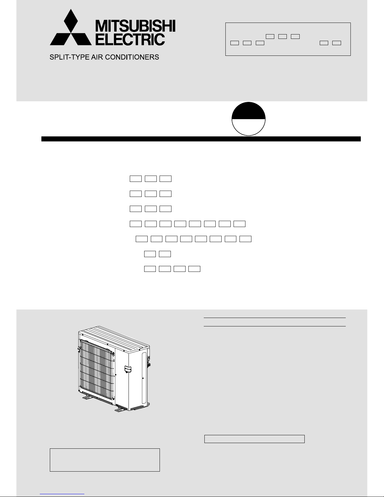
SERVICE MANUAL
No. OBH723
REVISED EDITION-D
OUTDOOR UNIT
NOTE:
RoHS compliant products have <G> mark
on the spec name plate.
PARTS CATALOG (OBB723)
Models
MXZ-3E54VA
-
E1,
ET1, ER1
MXZ-3E68VA
-
E1,
ET1, ER1
MXZ-4E72VA
-
E1,
ET1, ER1
MXZ-4E83VA
-
E1, E2, E3,
ET1, ET2, ET3, ER1, ER2
MXZ-5E102VA
-
E1, E2, E3,
ET1, ET2, ET3, ER1, ER2
MXZ-2E53VAHZ
-
E1,
ER1
MXZ-4E83VAHZ
-
E1, E2,
ER1, ER2
Indoor unit service manual
MSZ-EF•VE Series (OBH589)
MSZ-SF•VA Series (OBH555)
MSZ-SF•VE Series (OBH600)
MSZ-FD•VA Series (OBH488)
MSZ-FH•VE Series (OBH623)
MSZ-GA•VA Series (OB378)
MSZ-GE•VA Series (OBH515)
MSZ-GF•VE Series (OBH634)
MFZ-KA•VA Series (OB409)
MFZ-KJ•VE Series (OBH666)
MLZ-KA•VA Series (OBH483)
SLZ-KA•VA Series (OC320)
SEZ-KD•VA Series (HWE07110)
PLA-RP•BA Series (OCH412)
PCA-RP•KA Series (OCH454)
PEAD-RP•JA Series (HWE08130)
CONTENTS
1. TECHNICAL CHANGES ···································3
2. PART NAMES AND FUNCTIONS ·····················4
3. SPECIFICATION ················································5
4. NOISE CRITERIA CURVES ····························12
5. OUTLINES AND DIMENSIONS ······················14
6. WIRING DIAGRAM ··········································20
7. REFRIGERANT SYSTEM DIAGRAM ·············44
8. PERFORMANCE CURVES ·····························52
9. ACTUATOR CONTROL ···································82
10. SERVICE FUNCTIONS ····································83
11. TROUBLESHOOTING ·····································86
12. DISASSEMBLY INSTRUCTIONS ··················108
INDOOR UNITS COMBINATION SHEETS
MXZ-4E83VA
MXZ-5E102VA
MXZ-2E53VAHZ
OBH723 REVISED EDITION-C is void.
Revision D:
• MXZ-4E83VA- E3,
ET3, ER2
, MXZ-5E102VA-
E3, ET3, ER2
and MXZ-4E83VAHZ- E2,
ER2
have been added.
2
<Preparation before the repair service>
Prepare the proper tools.
Prepare the proper protectors.
Provide adequate ventilation.
After stopping the operation of the air conditioner, turn off the power-supply breaker and remove the power plug.
Discharge the capacitor before the work involving the electric parts.
<Precautions during the repair service>
Do not perform the work involving the electric parts with wet hands.
Do not pour water into the electric parts.
Do not touch the refrigerant.
Do not touch the hot or cold areas in the refrigeration cycle.
When the repair or the inspection of the circuit needs to be done without turning off the power, exercise great caution not to
touch the live parts.
Use the specif ed refrigerant only
Never use any refrigerant other than that specified.
Doing so may cause a burst, an explosion, or fire when the unit is being used, serviced, or disposed of.
Correct refrigerant is specified in the manuals and on the spec labels provided with our products.
We will not be held responsible for mechanical failure, system malfunction, unit breakdown or accidents caused by
failure to follow the instructions.
Revision A:
• MXZ-2E53VAHZ- E1 and MXZ-4E83VAHZ- E1 have been added.
• Values of air flow and fan speed for MXZ-5E102VA-
E1, ET1
have been modified.
Revision B:
• MXZ-3E54VA- E1,
ET1
, MXZ-3E68VA- E1,
ET1
, and MXZ-4E72VA- E1,
ET1
have been added.
Revision C:
• MXZ-3E54VA-
ER1
, MXZ-3E68VA-
ER1
, MXZ-4E72VA-
ER1
, MXZ-4E83VA- E2,
ET2, ER1
, MXZ-5E102VA- E2,
ET2, ER1
,
MXZ-2E53VAHZ-
ER1
and MXZ-4E83VAHZ-
ER1
have been added.
Revision D:
• MXZ-4E83VA- E3,
ET3, ER2
, MXZ-5E102VA- E3,
ET3, ER2
and MXZ-4E83VAHZ- E2,
ER2
have been added.
OBH723D
3
TECHNICAL CHANGES
1
MXZ-4E83VA -E1,
ET1, ER1
MXZ-5E102VA -E1,
ET1, ER1
1. New model
MXZ-2E53VAHZ -E1,
ER1
1. New model
MXZ-4E83VAHZ -E1,
ER1
1. New model
MXZ-3E54VA -E1,
ET1, ER1
MXZ-3E68VA -E1,
ET1, ER1
MXZ-4E72VA -E1,
ET1, ER1
1. New model
MXZ-4E83VA -E1,
ET1
MXZ-4E83VA -
E2, ET2
1. Fan motor has been changed.
2. Outdoor control P.C. board has been changed.
MXZ-5E102VA -E1,
ET1
MXZ-5E102VA -
E2, ET2
1. Fan motor has been changed.
2. Outdoor control P.C. board has been changed.
MXZ-4E83VA -
ER1
MXZ-4E83VA -
ER2
1. Outdoor control P.C. board has been changed.
MXZ-4E83VA -E2,
ET2
MXZ-4E83VA -
E3, ET3
1. Outdoor control P.C. board has been changed.
MXZ-5E102VA -
ER1
MXZ-5E102VA -
ER2
1. Outdoor control P.C. board has been changed.
MXZ-5E102VA -E2,
ET2
MXZ-5E102VA -
E3, ET3
1. Outdoor control P.C. board has been changed.
MXZ-4E83VAHZ -E1,
ER1
MXZ-4E83VAHZ -
E2, ER2
1. Outdoor control P.C. board has been changed.
OBH723D
4
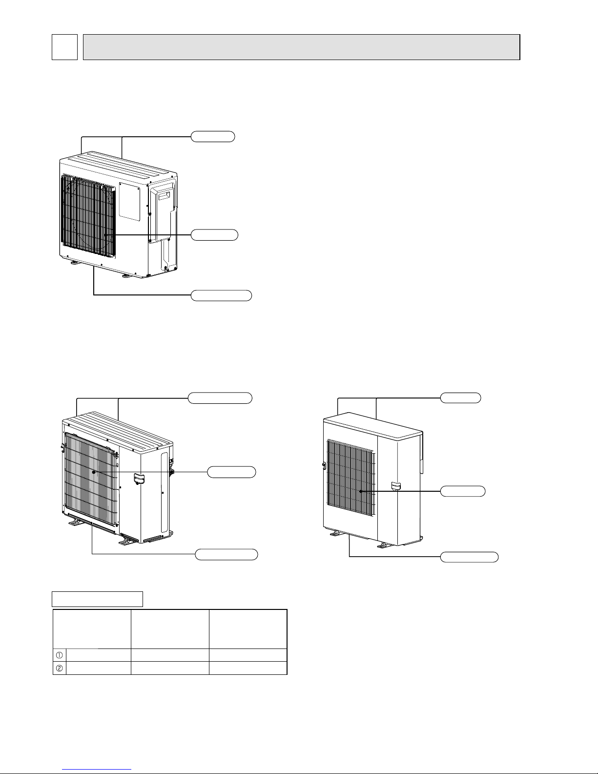
PART NAMES AND FUNCTIONS
2
MXZ-4E83VA
MXZ-5E102VA
MXZ-2E53VAHZ
Air outlet
Drain outlet
Air inlet
(Back and side)
ACCESSORIES
Model
MXZ-3E54VA
MXZ-3E68VA
MXZ-4E72VA
MXZ-4E83VA
MXZ-5E102VA
Drain socket 1 1
Drain cap 2 5
Air outlet
Drain outlet
Air inlet
(Back and side)
MXZ-4E83VAHZ
Air outlet
Drain outlet
Air inlet
(Back and side)
MXZ-3E54VA
MXZ-3E68VA
MXZ-4E72VA
OBH723D
5
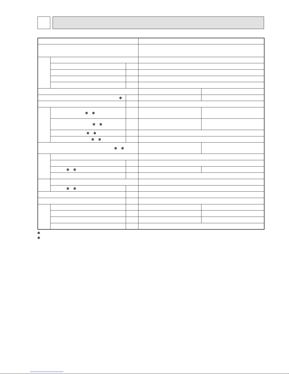
SPECIFICATION
3
Outdoor model MXZ-3E54VA
Outdoor unit power supply
Single phase
230 V, 50 Hz
System
Indoor units number 2 to 3
Piping total length m Max. 50
Connecting pipe length m Max. 25
Height difference (Indoor ~ Outdoor) m Refer to 7 REFRIGERANT SYSTEM DIAGRAM.
Height difference (Indoor ~ Indoor) m Refer to 7 REFRIGERANT SYSTEM DIAGRAM.
Function Cooling Heating
Capacity Rated frequency (Min.-Max.)
2 kW 5.4 (2.9 - 6.8) 7.0 (2.6 - 9.0)
Breaker capacity A 25
Electrical
data
Power input (Total) 1, 2 W 1,350 1,590
Running current (Total)
1, 2 A 5.9 7.0
Power factor (Total)
1, 2% 99
Starting current (Total)
1, 2 A 7.0
Coeff cient of performance (C.O.P) (Total)
1, 2 4.00 4.40
Compressor
Model SNB130FGBH1T
Output W 1,400
Current
1, 2 A 5.72 6.62
Refrigeration oil (Model) L 0.7 (NEO22)
Fan
motor
Model SIC-71FW-F764-2
Current
1, 2 A 0.2
Dimensions W x H x D mm 840 x 710 x 330
Weight kg 58
Special
remarks
Air f ow (Rated) m3 /h 2,334 2,376
Sound level (Rated) dB(A) 50 53
Fan speed (Rated) rpm 650 660
Refrigerant f lling capacity (R410A) kg 2.7
1 Measured under rated operating frequency.
2 When connected with indoor units below.
MSZ-EF18VE + MSZ-EF18VE + MSZ-EF18VE
NOTE: Test conditions are based on ISO 5151. (Refrigerant piping length (one way): 5 m)
COOLING INDOOR Dry-bulb temperature 27.0 °C Wet-bulb temperature 19.0 °C
OUTDOOR Dry-bulb temperature 35.0 °C Wet-bulb temperature 24.0 °C
HEATING INDOOR Dry-bulb temperature 20.0 °C
OUTDOOR Dry-bulb temperature 7.0 °C Wet-bulb temperature 6.0 °C
OBH723D
6
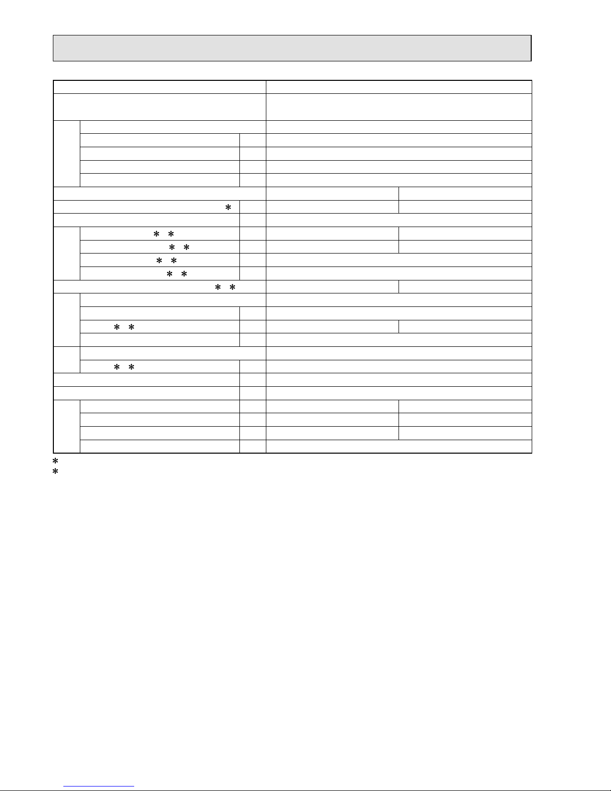
Outdoor model MXZ-3E68VA
Outdoor unit power supply
Single phase
230 V, 50 Hz
System
Indoor units number 2 to 3
Piping total length m Max. 60
Connecting pipe length m Max. 25
Height difference (Indoor ~ Outdoor) m Refer to 7 REFRIGERANT SYSTEM DIAGRAM.
Height difference (Indoor ~ Indoor) m Refer to 7 REFRIGERANT SYSTEM DIAGRAM.
Function Cooling Heating
Capacity Rated frequency (Min.-Max.)
2 kW 6.8 (2.9 - 8.4) 8.6 (2.6 - 10.6)
Breaker capacity A 25
Electrical
data
Power input (Total) 1, 2 W 2,190 2,380
Running current (Total)
1, 2 A 9.6 10.5
Power factor (Total)
1, 2% 99
Starting current (Total)
1, 2 A 10.5
Coeff cient of performance (C.O.P) (Total)
1, 2 3.11 3.61
Compressor
Model SNB172FEGH1T
Output W 1,800
Current
1, 2 A 9.22 10.12
Refrigeration oil (Model) L 0.7 (NEO22)
Fan
motor
Model SIC-71FW-F764-2
Current
1, 2 A 0.2
Dimensions W x H x D mm 840 x 710 x 330
Weight kg 58
Special
remarks
Air f ow (Rated) m3 /h 2,334 2,376
Sound level (Rated) dB(A) 50 53
Fan speed (Rated) rpm 650 660
Refrigerant f lling capacity (R410A) kg 2.7
1 Measured under rated operating frequency.
2 When connected with indoor units below.
MSZ-EF18VE + MSZ-EF25VE + MSZ-EF25VE
NOTE: Test conditions are based on ISO 5151. (Refrigerant piping length (one way): 5 m)
COOLING INDOOR Dry-bulb temperature 27.0 °C Wet-bulb temperature 19.0 °C
OUTDOOR Dry-bulb temperature 35.0 °C Wet-bulb temperature 24.0 °C
HEATING INDOOR Dry-bulb temperature 20.0 °C
OUTDOOR Dry-bulb temperature 7.0 °C Wet-bulb temperature 6.0 °C
OBH723D
7
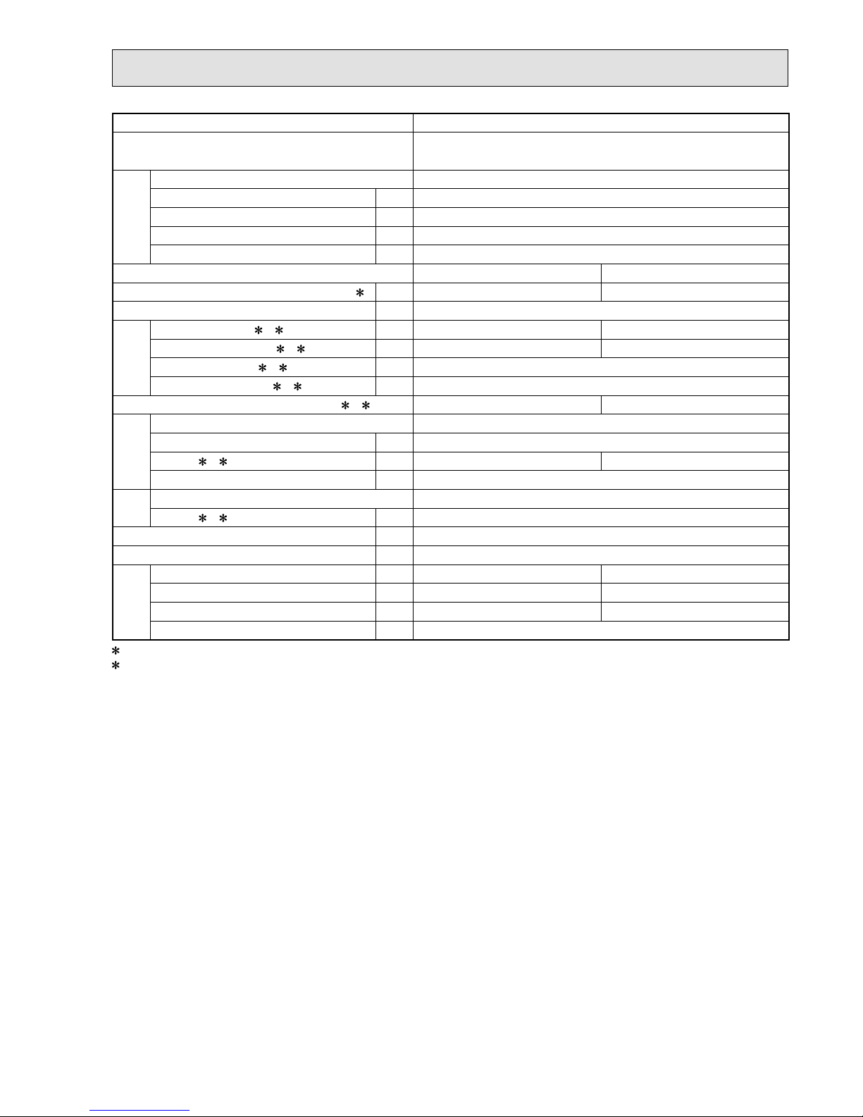
Outdoor model MXZ-4E72VA
Outdoor unit power supply
Single phase
230 V, 50 Hz
System
Indoor units number 2 to 4
Piping total length m Max. 60
Connecting pipe length m Max. 25
Height difference (Indoor ~ Outdoor) m Refer to 7 REFRIGERANT SYSTEM DIAGRAM.
Height difference (Indoor ~ Indoor) m Refer to 7 REFRIGERANT SYSTEM DIAGRAM.
Function Cooling Heating
Capacity Rated frequency (Min.-Max.)
2 kW 7.2 (3.7 - 8.8) 8.6 (3.4 - 10.7)
Breaker capacity A 25
Electrical
data
Power input (Total) 1, 2 W 2,250 2,280
Running current (Total)
1, 2 A 9.9 10.0
Power factor (Total)
1, 2% 99
Starting current (Total)
1, 2 A 10.0
Coeff cient of performance (C.O.P) (Total)
1, 2 3.20 3.77
Compressor
Model SNB172FEGH1T
Output W 2,000
Current
1, 2 A 9.46 9.56
Refrigeration oil (Model) L 0.7 (NEO22)
Fan
motor
Model SIC-71FW-F764-2
Current
1, 2 A 0.2
Dimensions W x H x D mm 840 x 710 x 330
Weight kg 59
Special
remarks
Air f ow (Rated) m3 /h 2,334 2,376
Sound level (Rated) dB(A) 50 53
Fan speed (Rated) rpm 650 660
Refrigerant f lling capacity (R410A) kg 2.7
1 Measured under rated operating frequency.
2 When connected with indoor units below.
MSZ-EF18VE + MSZ-EF18VE + MSZ-EF18VE + MSZ-EF18VE
NOTE: Test conditions are based on ISO 5151. (Refrigerant piping length (one way): 5 m)
COOLING INDOOR Dry-bulb temperature 27.0 °C Wet-bulb temperature 19.0 °C
OUTDOOR Dry-bulb temperature 35.0 °C Wet-bulb temperature 24.0 °C
HEATING INDOOR Dry-bulb temperature 20.0 °C
OUTDOOR Dry-bulb temperature 7.0 °C Wet-bulb temperature 6.0 °C
OBH723D
8
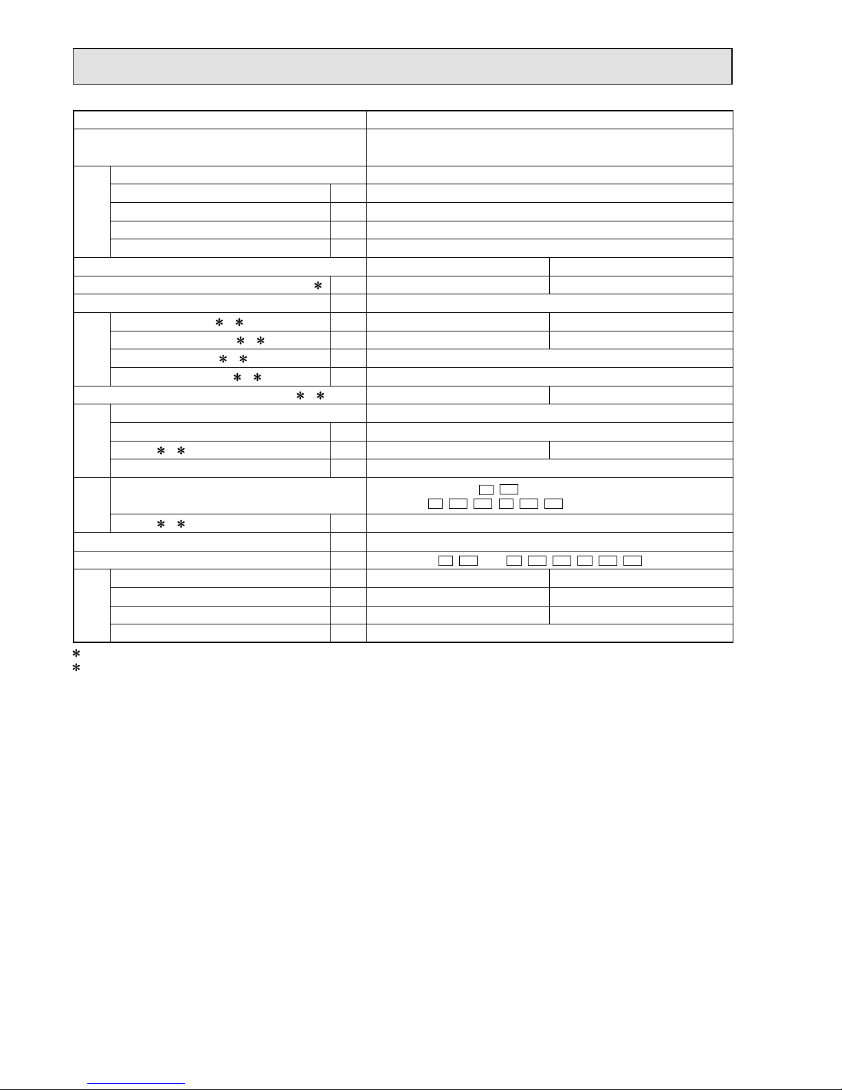
Outdoor model MXZ-4E83VA
Outdoor unit power supply
Single phase
230 V, 50 Hz
System
Indoor units number 2 to 4
Piping total length m Max. 70
Connecting pipe length m Max. 25
Height difference (Indoor ~ Outdoor) m Refer to 7 REFRIGERANT SYSTEM DIAGRAM.
Height difference (Indoor ~ Indoor) m Refer to 7 REFRIGERANT SYSTEM DIAGRAM.
Function Cooling Heating
Capacity Rated frequency (Min.-Max.)
2 kW 8.3 (3.7 - 9.2) 9.3 (3.4 - 11.6)
Breaker capacity A 25
Electrical
data
Power input (Total) 1, 2 W 2,440 2,000
Running current (Total)
1, 2 A 10.7 8.8
Power factor (Total)
1, 2% 99
Starting current (Total)
1, 2 A 10.7
Coeff cient of performance (C.O.P) (Total)
1, 2 3.40 4.65
Compressor
Model SNB220FAGMC
Output W 2,200
Current
1, 2 A 10.1 8.1
Refrigeration oil (Model) L 0.7 (FV50S)
Fan
motor
Model
E1
,
ET1
: SIC-81FW-D888-9
E2
,
ET2
,
ER1
, E3,
ET3
,
ER2
: SIC-88FWJ-D888-1
Current
1, 2 A 0.3
Dimensions W x H x D mm 950 x 796 x 330
Weight kg
E1
,
ET1
: 62 / E2,
ET2
,
ER1
, E3,
ET3
,
ER2
: 63
Special
remarks
Air f ow (Rated) m3 /h 3,336 3,336
Sound level (Rated) dB(A) 49 51
Fan speed (Rated) rpm 620 620
Refrigerant f lling capacity (R410A) kg 2.99
1 Measured under rated operating frequency.
2 When connected with below indoor units.
MSZ-EF18VE + MSZ-EF18VE + MSZ-EF22VE + MSZ-EF25VE
NOTE: Test conditions are based on ISO 5151. (Refrigerant piping length (one way): 5 m)
COOLING INDOOR Dry-bulb temperature 27.0°C Wet-bulb temperature 19.0°C
OUTDOOR Dry-bulb temperature 35.0°C Wet-bulb temperature 24.0°C
HEATING INDOOR Dry-bulb temperature 20.0°C
OUTDOOR Dry-bulb temperature 7.0°C Wet-bulb temperature 6.0°C
OBH723D
9
Outdoor model MXZ-5E102VA
Outdoor unit power supply
Single phase
230 V, 50 Hz
System
Indoor units number 2 to 5
Piping total length m Max. 80
Connecting pipe length m Max. 25
Height difference (Indoor ~ Outdoor) m Refer to 7 REFRIGERANT SYSTEM DIAGRAM.
Height difference (Indoor ~ Indoor) m Refer to 7 REFRIGERANT SYSTEM DIAGRAM.
Function Cooling Heating
Capacity Rated frequency (Min.-Max.)
2 kW 10.2 (3.9 - 11.0) 10.5 (4.1 - 14.0)
Breaker capacity A 25
Electrical
data
Power input (Total) 1, 2 W 3,150 2,340
Running current (Total)
1, 2 A 13.8 10.3
Power factor (Total)
1, 2% 99
Starting current (Total)
1, 2 A 13.8
Coeff cient of performance (C.O.P) (Total)
1, 2 3.24 4.49
Compressor
Model SNB220FAGMC
Output W 2,800
Current
1, 2 A 13.0 9.4
Refrigeration oil (Model) L 0.7 (FV50S)
Fan
motor
Model
E1
,
ET1
: SIC-81FW-D888-9
E2
,
ET2
,
ER1
, E3,
ET3
,
ER2
: SIC-88FWJ-D888-1
Current
1, 2 A 0.5
Dimensions W x H x D mm 950 x 796 x 330
Weight kg
E1
,
ET1
: 63 / E2,
ET2
,
ER1
, E3,
ET3
,
ER2
: 64
Special
remarks
Air f ow (Rated) m3 /h
E1
,
ET1
: 3,336 /
E2
,
ET2
,
ER1
,
E3,
ET3
,
ER2
: 3,906
4,080
Sound level (Rated) dB(A) 52 56
Fan speed (Rated) rpm
E1
,
ET1
: 620 /
E2
,
ET2
,
ER1
,
E3,
ET3
,
ER2
: 720
750
Refrigerant f lling capacity (R410A) kg 2.99
1 Measured under rated operating frequency.
2 When connected with below indoor units.
MSZ-EF18VE + MSZ-EF18VE + MSZ-EF22VE + MSZ-EF22VE + MSZ-EF22VE
NOTE: Test conditions are based on ISO 5151. (Refrigerant piping length (one way): 5 m)
COOLING INDOOR Dry-bulb temperature 27.0°C Wet-bulb temperature 19.0°C
OUTDOOR Dry-bulb temperature 35.0°C Wet-bulb temperature 24.0°C
HEATING INDOOR Dry-bulb temperature 20.0°C
OUTDOOR Dry-bulb temperature 7.0°C Wet-bulb temperature 6.0°C
OBH723D
10
Outdoor model MXZ-2E53VAHZ
Outdoor unit power supply
Single phase
230 V, 50 Hz
System
Indoor units number 2
Piping total length m Max. 30
Connecting pipe length m Max. 20
Height difference (Indoor ~ Outdoor) m Refer to 7 REFRIGERANT SYSTEM DIAGRAM.
Height difference (Indoor ~ Indoor) m Refer to 7 REFRIGERANT SYSTEM DIAGRAM.
Function Cooling Heating
Capacity Rated frequency (Min.-Max.)
2 kW 5.3 (1.1 - 6.0) 6.4 (1.0 - 7.0)
Breaker capacity A 16/25
3
Electrical
data
Power input (Total) 1, 2 W 1,290 1,360
Running current (Total)
1, 2 A 5.7 6.0
Power factor (Total)
1, 2% 98
Starting current (Total)
1, 2 A 6.0
Coeff cient of performance (C.O.P) (Total)
1, 2 4.11 4.71
Compressor
Model SNB220FAGMC
Output W 1,400
Current
1, 2 A 5.3 5.5
Refrigeration oil (Model) L 0.7 (FV50S)
Fan
motor
Model
E1
: SIC-81FW-D888-9, SIC-88FWJ-D888-1
ER1
: SIC-88FWJ-D888-1
Current 1, 2 A 0.3
Dimensions W x H x D mm 950 x 796 x 330
Weight kg 61
Special
remarks
Air f ow (Rated) m3 /h 2,820 2,820
Sound level (Rated) dB(A) 45 47
Fan speed (Rated) rpm 520 520
Refrigerant f lling capacity (R410A) kg 2.0
1 Measured under rated operating frequency.
2 When connected with below indoor units.
3 When the amount of current exceeds the allowed value.
MSZ-EF18VE + MSZ-EF35VE
NOTE: Test conditions are based on ISO 5151. (Refrigerant piping length (one way): 5 m)
COOLING INDOOR Dry-bulb temperature 27.0°C Wet-bulb temperature 19.0°C
OUTDOOR Dry-bulb temperature 35.0°C Wet-bulb temperature 24.0°C
HEATING INDOOR Dry-bulb temperature 20.0°C
OUTDOOR Dry-bulb temperature 7.0°C Wet-bulb temperature 6.0°C
OBH723D
11
Outdoor model MXZ-4E83VAHZ
Outdoor unit power supply
Single phase
230 V, 50 Hz
System
Indoor units number 2 to 4
Piping total length m Max. 70
Connecting pipe length m Max. 25
Height difference (Indoor ~ Outdoor) m Refer to 7 REFRIGERANT SYSTEM DIAGRAM.
Height difference (Indoor ~ Indoor) m Refer to 7 REFRIGERANT SYSTEM DIAGRAM.
Function Cooling Heating
Capacity Rated frequency (Min.-Max.)
2 kW 8.3 ( 3.5 - 9.2 ) 9.0 ( 3.5 - 11.6 )
Breaker capacity A 25/30
3
Electrical
data
Power input (Total) 1, 2 W 2,250 1,900
Running current (Total)
1, 2 A 9.9 8.3
Power factor (Total)
1, 2% 99
Starting current (Total)
1, 2 A 9.9
Coeff cient of performance (C.O.P) (Total)
1, 2 3.68 4.73
Compressor
Model MNB33FBTMC-L
Output W 2,200
Current
1, 2 A 9.30 7.60
Refrigeration oil (Model) L 1.10 (FV50S)
Fan
motor
Model SIC-81FW-D888-9,
SIC-88FWJ-D888-1
Current 1, 2 A 0.3
Dimensions W x H x D mm 950 x 1,048 x 330
Weight kg 87
Special
remarks
Air f ow (Rated) m3 /h 3,780 4,620
Sound level (Rated) dB(A) 53 57
Fan speed (Rated) rpm 650 770
Refrigerant f lling capacity (R410A) kg 3.9
1 Measured under rated operating frequency.
2 When connected with indoor units below.
3 When the amount of current exceeds the allowed value.
MSZ-EF18VE + MSZ-EF18VE + MSZ-EF22VE + MSZ-EF25VE
NOTE: Test conditions are based on ISO 5151. (Refrigerant piping length (one way): 5 m)
COOLING INDOOR Dry-bulb temperature 27.0 °C Wet-bulb temperature 19.0 °C
OUTDOOR Dry-bulb temperature 35.0 °C Wet-bulb temperature 24.0 °C
HEATING INDOOR Dry-bulb temperature 20.0 °C
OUTDOOR Dry-bulb temperature 7.0 °C Wet-bulb temperature 6.0 °C
OBH723D
12
NOISE CRITERIA CURVES
4
90
80
70
60
50
40
30
20
10
63 125 250 500 1000 2000 4000 8000
APPROXIMATE
THRESHOLD OF
HEARING FOR
CONTINUOUS
NOISE
NC-60
NC-50
NC-40
NC-30
NC-20
NC-70
OCTAVE BAND SOUND PRESSURE LEVEL, dB re 0.0002 MICRO BAR
BAND CENTER FREQUENCIES, Hz
CoolingHigh
FUNCTION
FAN SPEED
HeatingHigh
49
SPL(dB(A))51LINE
OUTDOOR UNIT
MICROPHONE
1m
Test conditions
Cooling :Dry-bulb temperature 35.0°C Wet-bulb temperature 24.0°C
Heating :Dry-bulb temperature 7.0°C Wet-bulb temperature 6.0°C
MXZ-4E83VA
90
80
70
60
50
40
30
20
10
63 125 250 500 1000 2000 4000 8000
APPROXIMATE
THRESHOLD OF
HEARING FOR
CONTINUOUS
NOISE
NC-60
NC-50
NC-40
NC-30
NC-20
NC-70
OCTAVE BAND SOUND PRESSURE LEVEL, dB re 0.0002 MICRO BAR
BAND CENTER FREQUENCIES, Hz
CoolingHigh
FUNCTION
FAN SPEED
HeatingHigh
50
SPL(dB(A))53LINE
90
80
70
60
50
40
30
20
10
63 125 250 500 1000 2000 4000 8000
APPROXIMATE
THRESHOLD OF
HEARING FOR
CONTINUOUS
NOISE
NC-60
NC-50
NC-40
NC-30
NC-20
NC-70
OCTAVE BAND SOUND PRESSURE LEVEL, dB re 0.0002 MICRO BAR
BAND CENTER FREQUENCIES, Hz
CoolingHigh
FUNCTION
FAN SPEED
HeatingHigh
50
SPL(dB(A))53LINE
90
80
70
60
50
40
30
20
10
63 125 250 500 1000 2000 4000 8000
APPROXIMATE
THRESHOLD OF
HEARING FOR
CONTINUOUS
NOISE
NC-60
NC-50
NC-40
NC-30
NC-20
NC-70
OCTAVE BAND SOUND PRESSURE LEVEL, dB re 0.0002 MICRO BAR
BAND CENTER FREQUENCIES, Hz
CoolingHigh
FUNCTION
FAN SPEED
HeatingHigh
50
SPL(dB(A))53LINE
MXZ-3E54VA MXZ-3E68VA
MXZ-4E72VA
OBH723D
13
90
80
70
60
50
40
30
20
10
63 125 250 500 1000 2000 4000 8000
APPROXIMATE
THRESHOLD OF
HEARING FOR
CONTINUOUS
NOISE
NC-60
NC-50
NC-40
NC-30
NC-20
NC-70
OCTAVE BAND SOUND PRESSURE LEVEL, dB re 0.0002 MICRO BAR
BAND CENTER FREQUENCIES, Hz
CoolingHigh
FUNCTION
FAN SPEED
HeatingHigh
52
SPL(dB(A))56LINE
MXZ-5E102VA
MXZ-4E83VAHZ
MXZ-2E53VAHZ
90
80
70
60
50
40
30
20
10
63 125 250 500 1000 2000 4000 8000
APPROXIMATE
THRESHOLD OF
HEARING FOR
CONTINUOUS
NOISE
NC-60
NC-50
NC-40
NC-30
NC-20
NC-70
OCTAVE BAND SOUND PRESSURE LEVEL, dB re 0.0002 MICRO BAR
BAND CENTER FREQUENCIES, Hz
CoolingHigh
FUNCTION
FAN SPEED
HeatingHigh
53
SPL(dB(A))57LINE
90
80
70
60
50
40
30
20
10
63 125 250 500 1000 2000 4000 8000
APPROXIMATE
THRESHOLD OF
HEARING FOR
CONTINUOUS
NOISE
NC-60
NC-50
NC-40
NC-30
NC-20
NC-70
OCTAVE BAND SOUND PRESSURE LEVEL, dB re 0.0002 MICRO BAR
BAND CENTER FREQUENCIES, Hz
CoolingHigh
FUNCTION
FAN SPEED
HeatingHigh
45
SPL(dB(A))47LINE
OBH723D
14
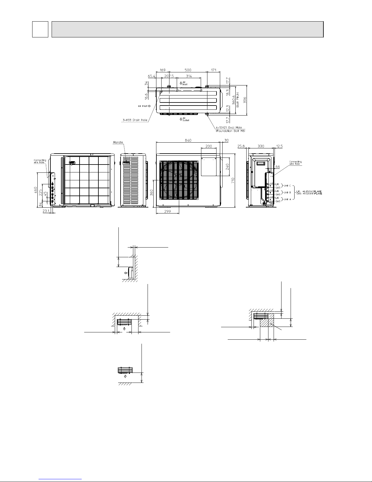
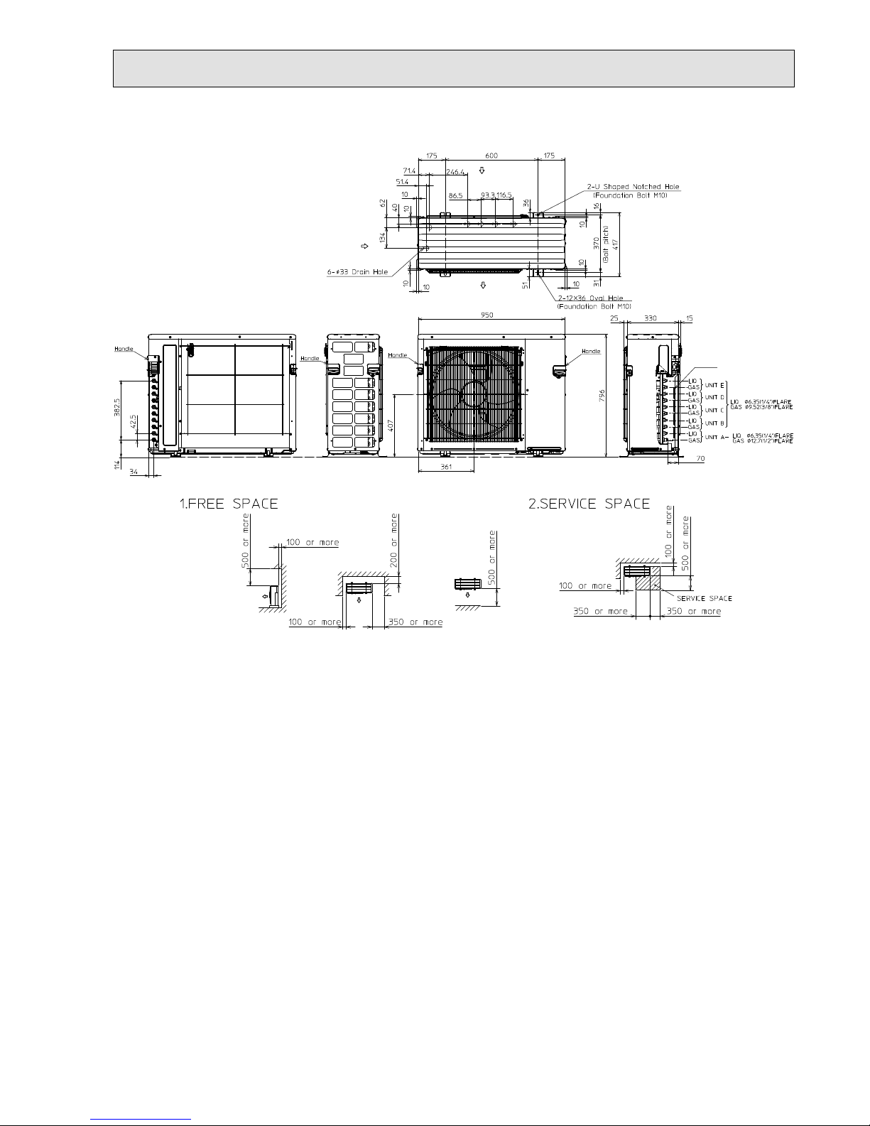
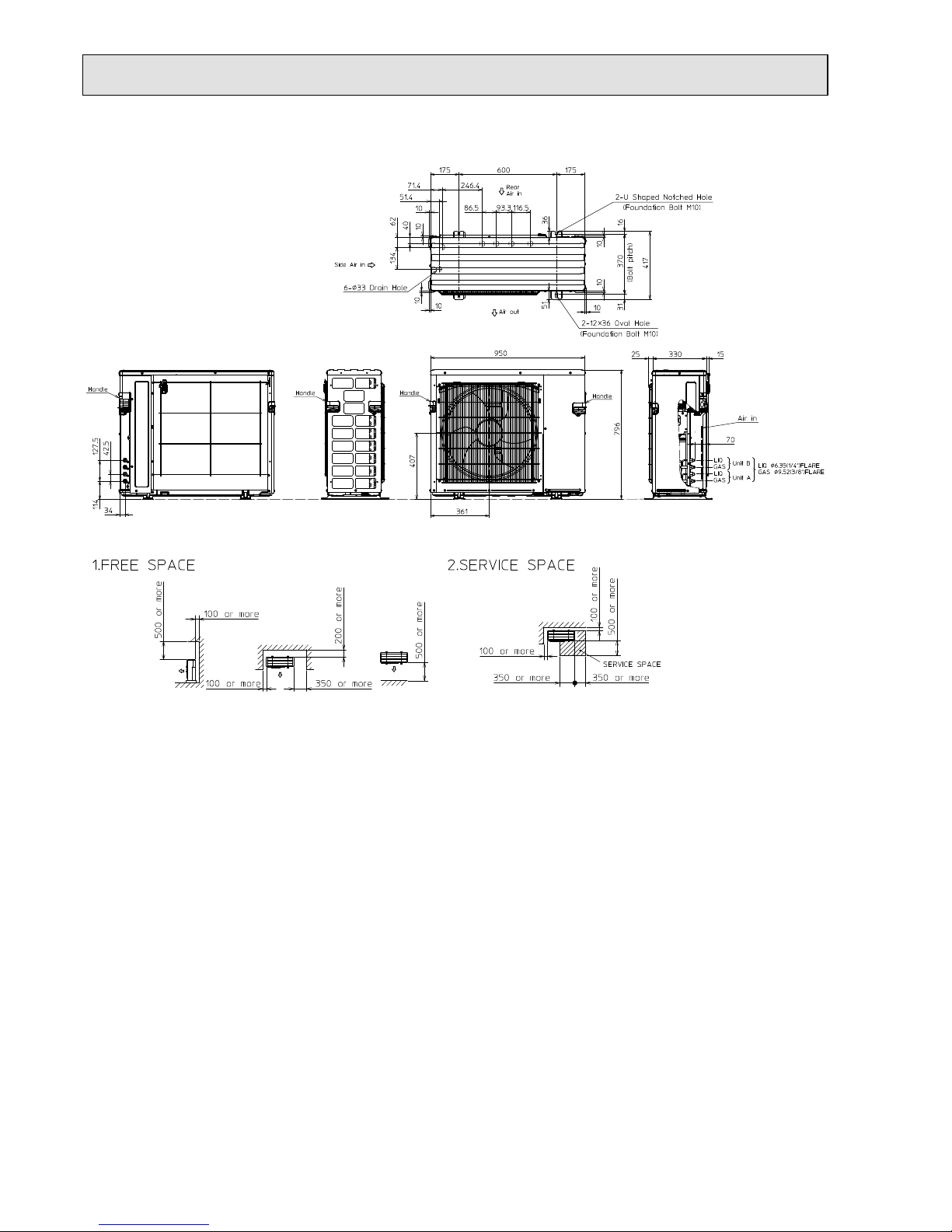
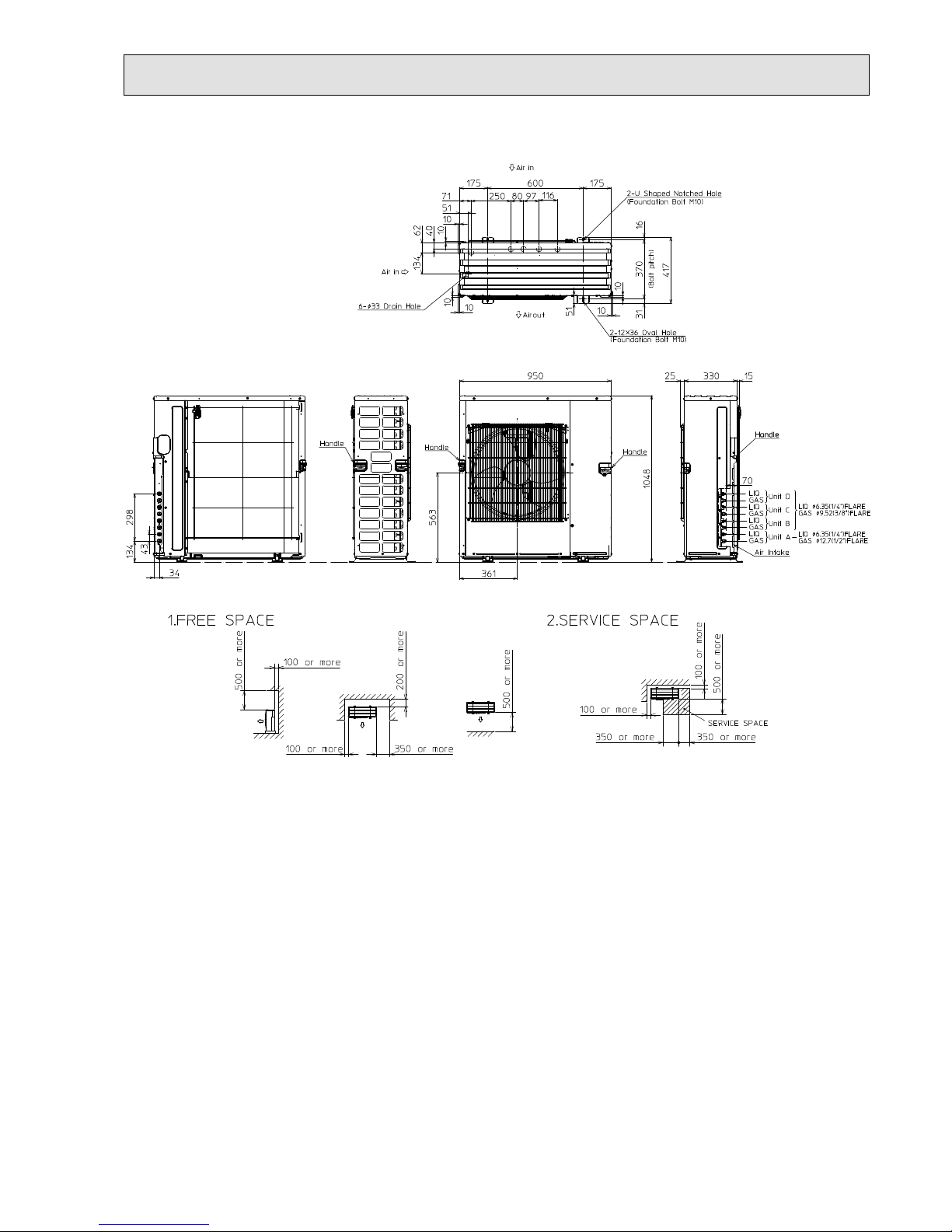
OUTLINES AND DIMENSIONS
5
1.Installation space
Note : Leave front and both sides
free of obstruction.
Note : Leave rear, overhead and
both sides free of obstruction.
500 or more
100 or more
Note : Leave front and overhead
free of obstruction.
100 or more
350 or more
200 or more
500 or more
2.Service space
100 or more
500 or more
350 or more
350 or more
100 or more
Service space
MXZ-3E54VA MXZ-3E68VA
Unit: mm
OBH723D
15
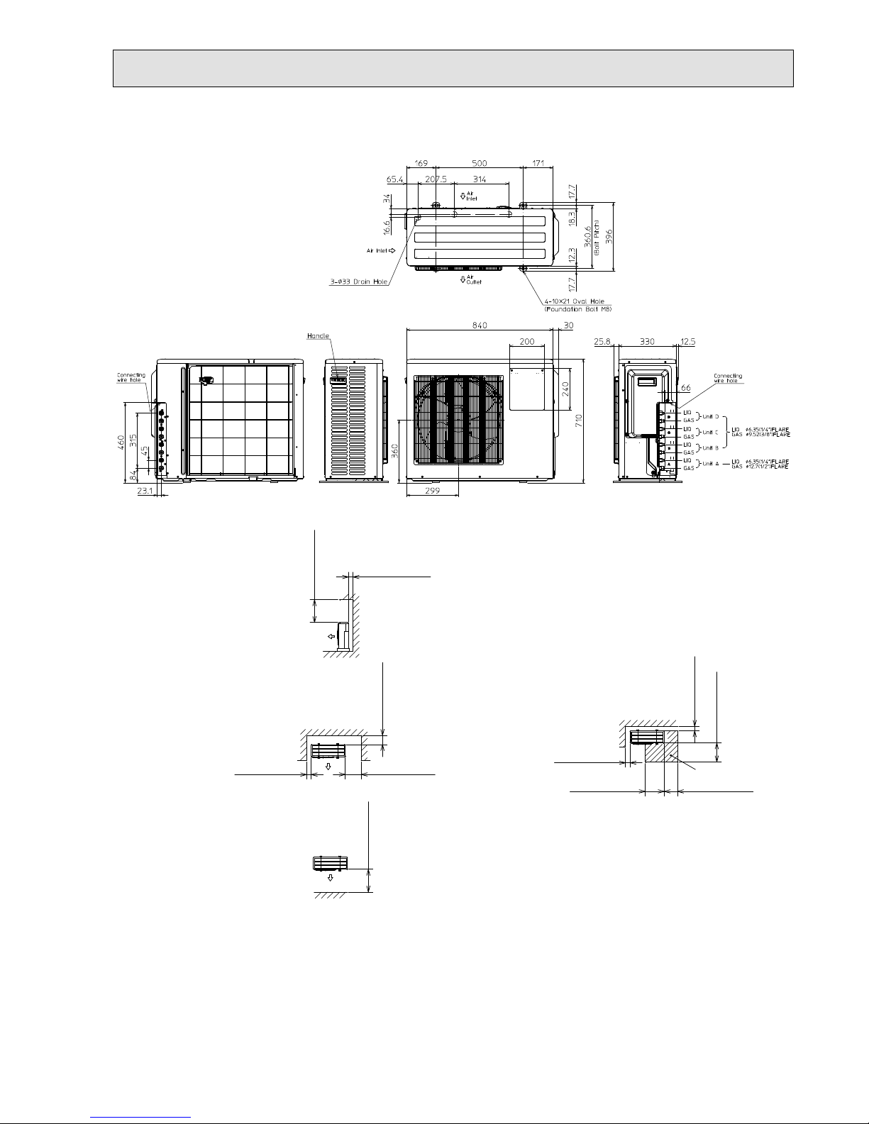
1.Installation space
Note : Leave front and both sides
free of obstruction.
Note : Leave rear, overhead and
both sides free of obstruction.
500 or more
100 or more
Note : Leave front and overhead
free of obstruction.
100 or more
350 or more
200 or more
500 or more
2.Service space
100 or more
500 or more
350 or more
350 or more
100 or more
Service space
MXZ-4E72VA
Unit: mm
OBH723D
16
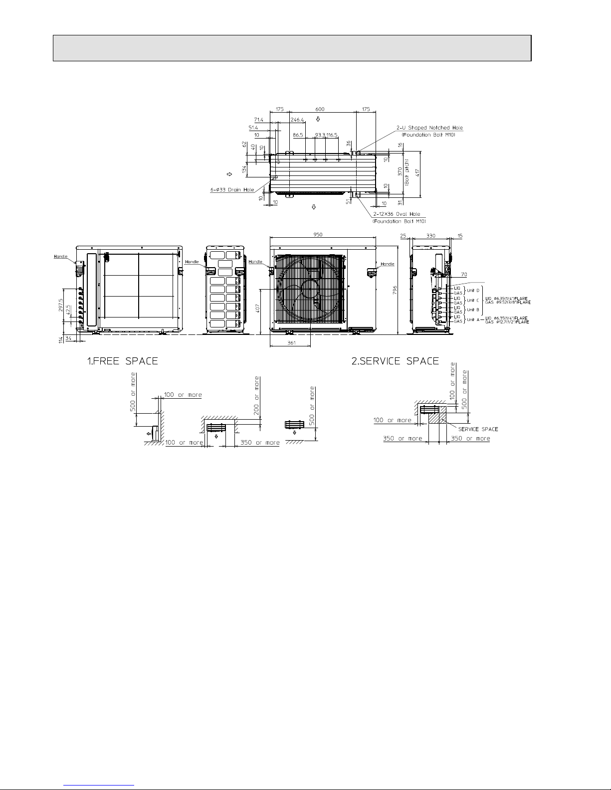
MXZ-4E83VA
Unit: mm
Air in
Air in
Air in
Air out
OBH723D
17
MXZ-5E102VA
Unit: mm
Air in
Air in
Air in
Air out
OBH723D
18
Unit: mm
MXZ-2E53VAHZ
OBH723D
19
MXZ-4E83VAHZ
Unit: mm
OBH723D
20
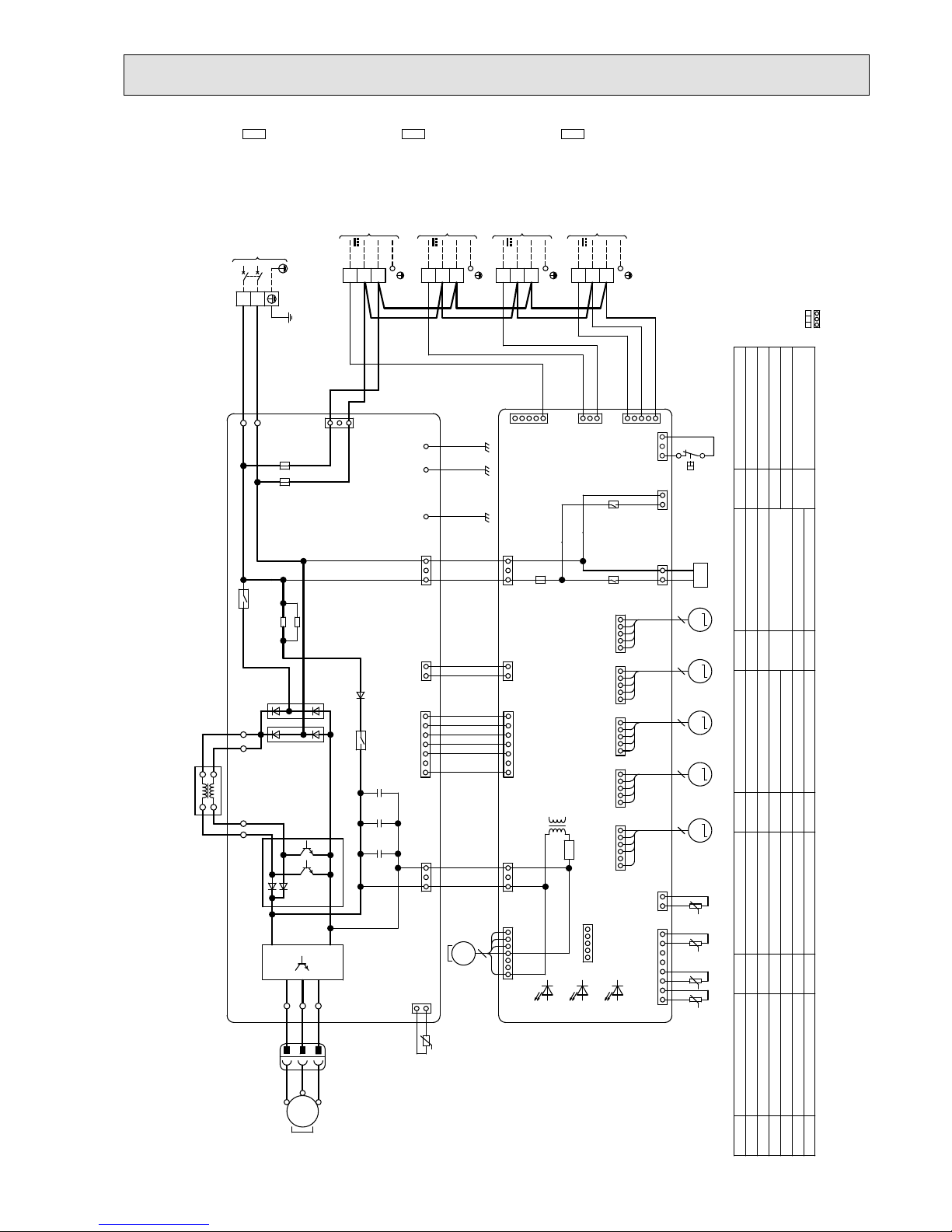
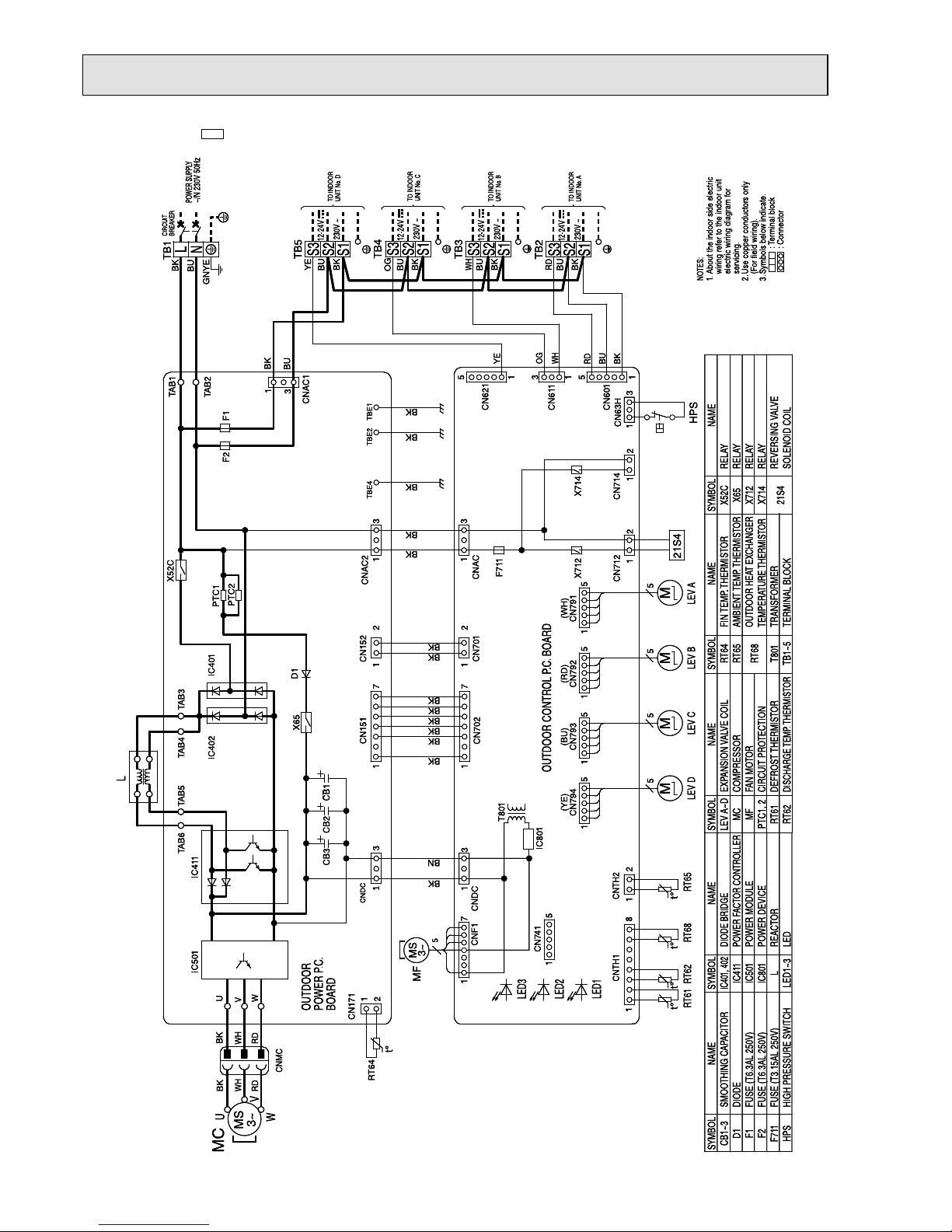
MXZ-3E54VA -E1 MXZ-3E54VA -
ET1
MXZ-3E54VA -
ER1
MXZ-3E68VA -E1 MXZ-3E68VA -
ET1
MXZ-3E68VA -
ER1
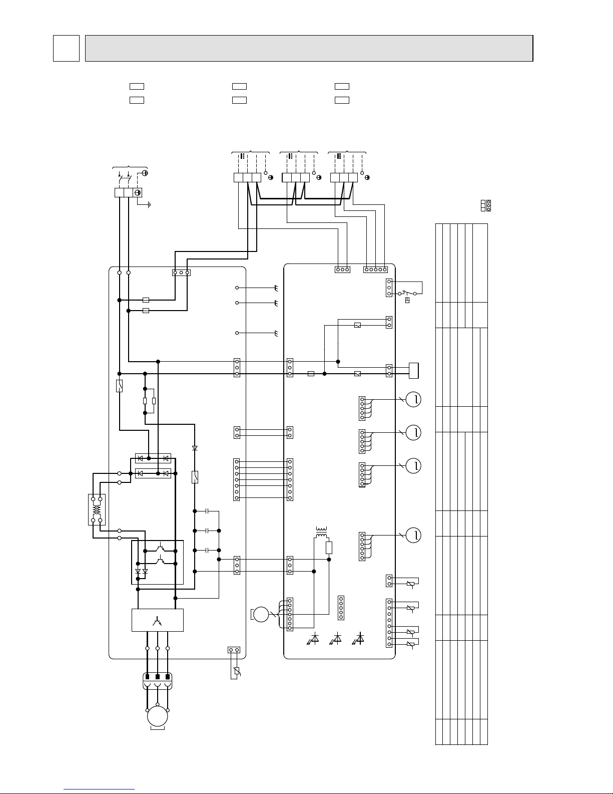
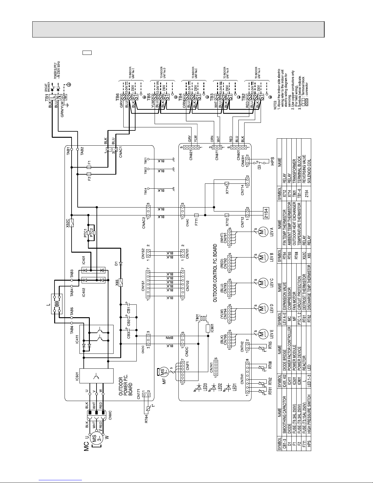
WIRING DIAGRAM
6
t°
21S4
t°°t°t
L
MS
3~
t°
RT64
M
LEV R LEV C LEV ALEV B
RT62
RT61
X714
X712
F711
TO INDOOR
UNIT No.C
TO INDOOR
UNIT No.A
TO INDOOR
UNIT No.B
TB2
TB3
TB4
12-24V
~230V
~230V
12-24V
~230V
12-24V
RT68 RT65
MMM
MS
3~
MF
T801
BLK
WHT
RED
RED
WHT
BLK
U
V
W
MC
CB3
CB2
CB1
BOARD
POWER P.C.
OUTDOOR
OUTDOOR CONTROL P.C. BOARD
F1
F2
TB1
BREAKER
CIRCUIT
POWER SUPPLY
~/N 230V 50Hz
IC801
5
HPS
CN63H
13
1
6
CN797
CN714
1
2
CNAC
CN712
1
2
S1
S2
S3
S1
S2
S3
S1
S2
S3
1
5
CN741
D1
IC401
IC402
2
1
CN171
1
8
CNTH1
2
1
CNTH2
555
CNMC
1
551
1
7
1
CN792 CN791CN793
1
5
5
7
1
CNF1
CN702
1
3
CNDC
U
V
W
1
3
1
CN151
1
7
CNDC
CNAC2
CN701
2
1
1
2
CN152
IC501
IC411
TAB4
TAB6
TAB5
TAB3
X52C
3
5
CN601
1
3
CN611
1
TAB1
TAB2
3
1
CNAC1
3
TBE4 TBE2 TBE1
PTC1
PTC2
X65
L
N
(BLU)
BLK
BLU
RED
BLK
BLU
WHT
BLK
BLU
ORN
BLK
BLK
BRN
BLK
BLK
(RED) (WHT)
(BLU)
BLK
BLK
BLK
BLK
BLK
BLK
BLK
BLK
BLU
RED
BLU
BLK
BLK
BLK
BLK
BLK
BLU
GRN/YLW
WHT
ORN
+++
LEV A~C,R
MC
MF
PTC1,2
RT61
RT62
X52C
X65
X712
X714
21S4
RELAY
RELAY
RELAY
RELAY
REVERSING VALVE
SOLENOID COIL
DEFROST THERMISTOR
FIN TEMP. THERMISTOR
AMBIENT TEMP. THERMISTOR
OUTDOOR HEAT EXCHANGER
TEMPERATURE THERMISTOR
TRANSFORMER
TERMINAL BLOCK
RT64
RT65
RT68
T801
TB1~4
FAN MOTOR
COMPRESSOR
EXPANSION VALVE COIL
DISCHARGE TEMP. THERMISTOR
SMOOTHING CAPACITOR
DIODE
FUSE(T6.3AL250V)
FUSE(T6.3AL250V)
FUSE(T3.15AL250V)
HIGH PRESSURE SWITCH
CB1~3
D1
F1
F2
F711
HPS
CIRCUIT PROTECTION
NOTES:
1.About the indoor side electric
wiring refer to the indoor unit
electric wiring diagram for
servicing.
2.Use copper conductors only
(For field wiring).
3.Symbols below indicate.
:Terminal block
:Connector
SYMBOL
NAME
SYMBOL SYMBOL SYMBOL
NAME NAME NAME
SYMBOL
NAME
DIODE BRIDGE
POWER FACTOR CONTROLLER
POWER MODULE
POWER DEVICE
REACTOR
LED
IC401,402
IC411
IC501
IC801
L
LED1~3
LED3
LED2
LED1
OBH723D
21
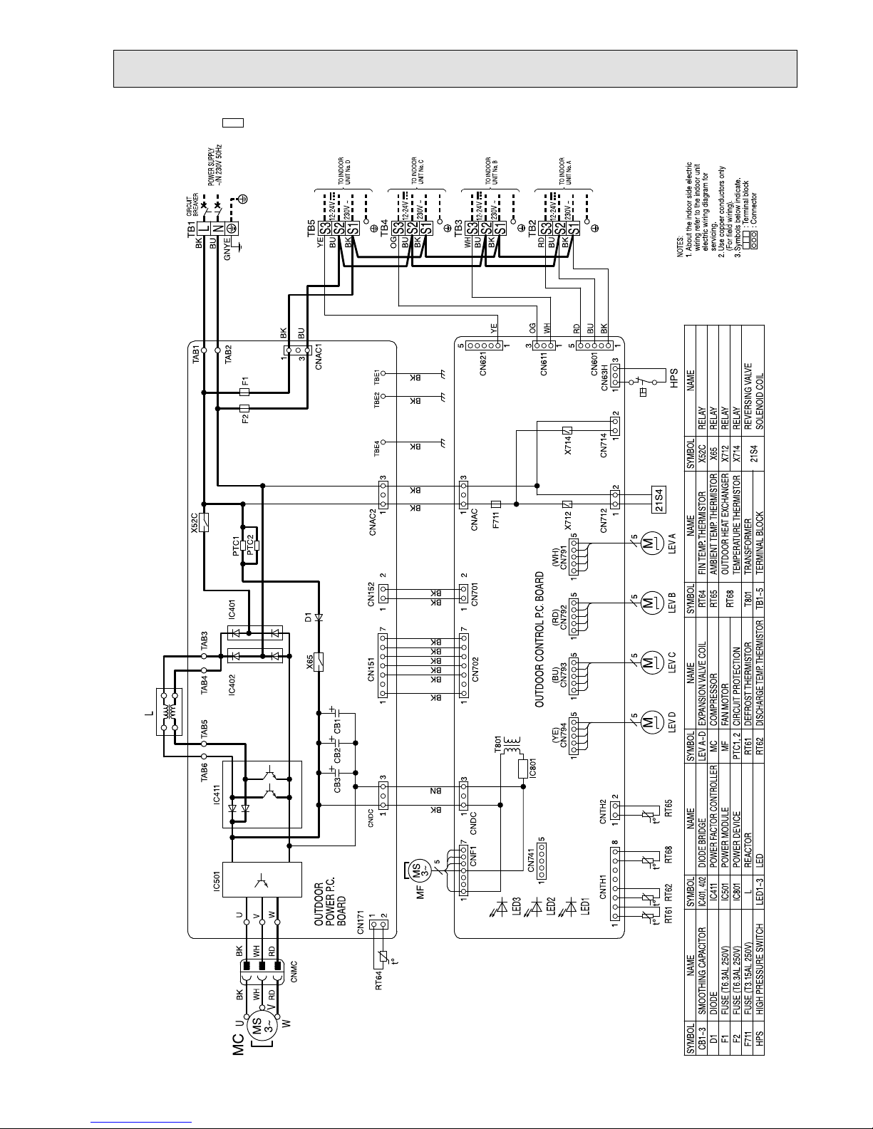
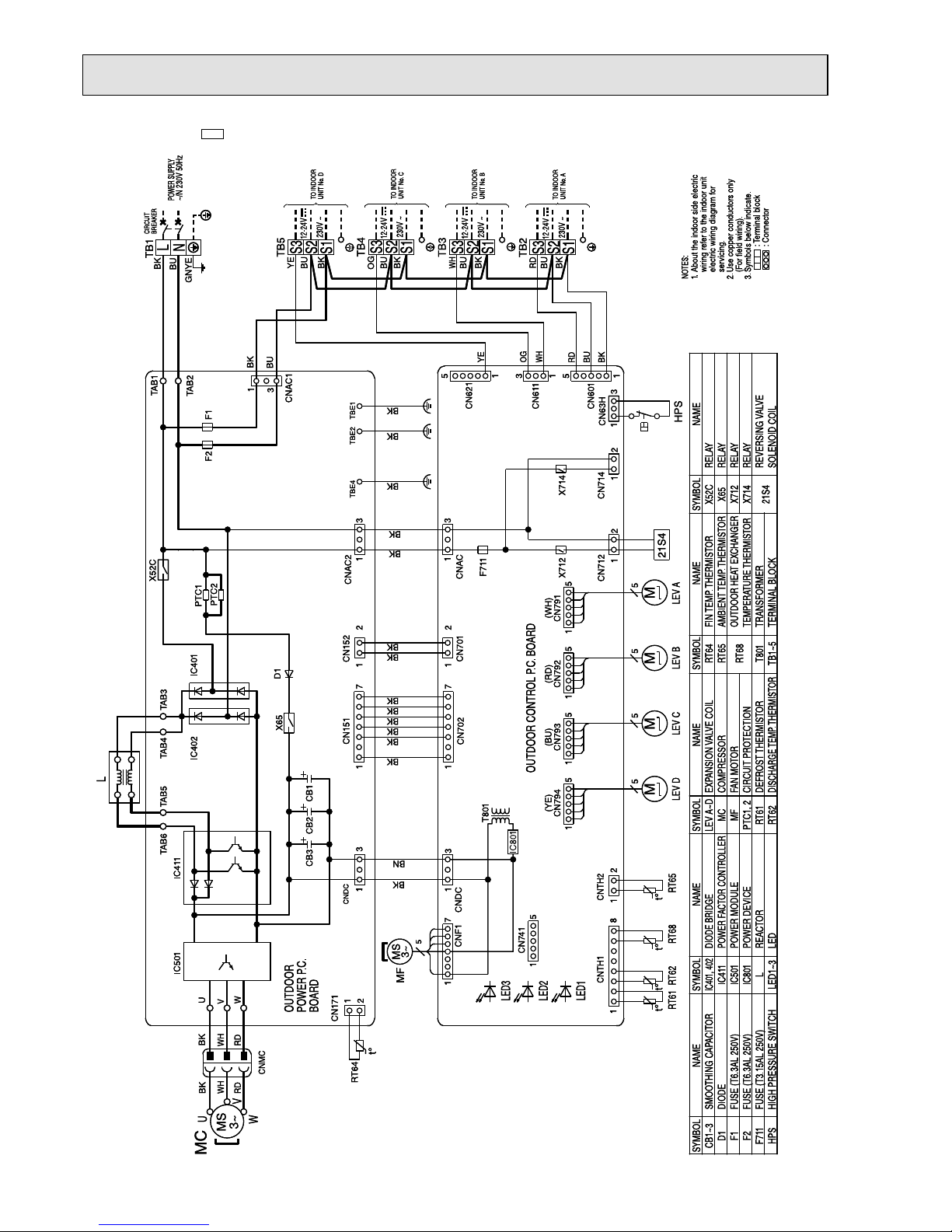
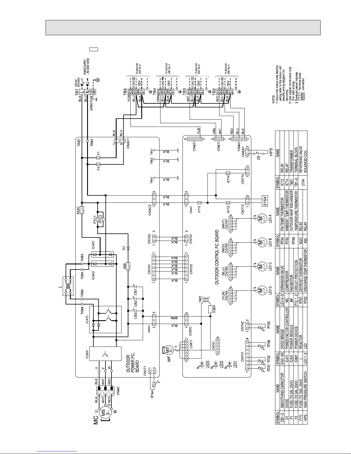
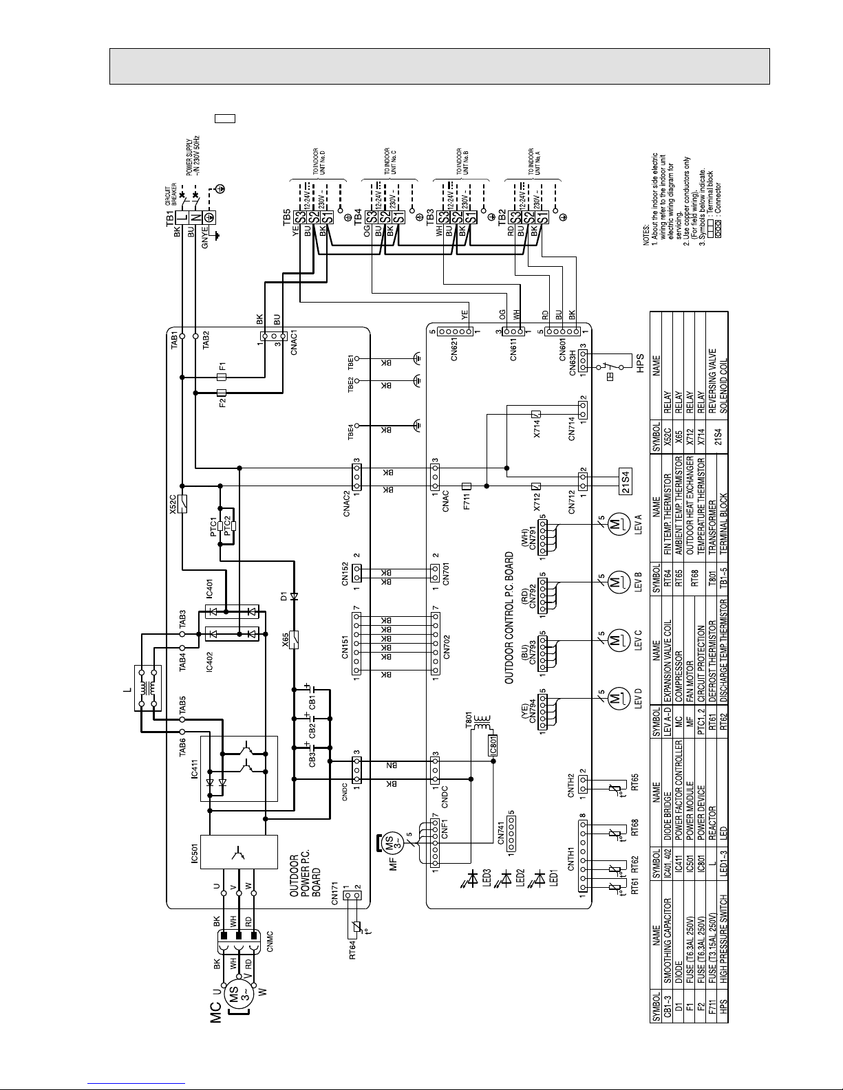
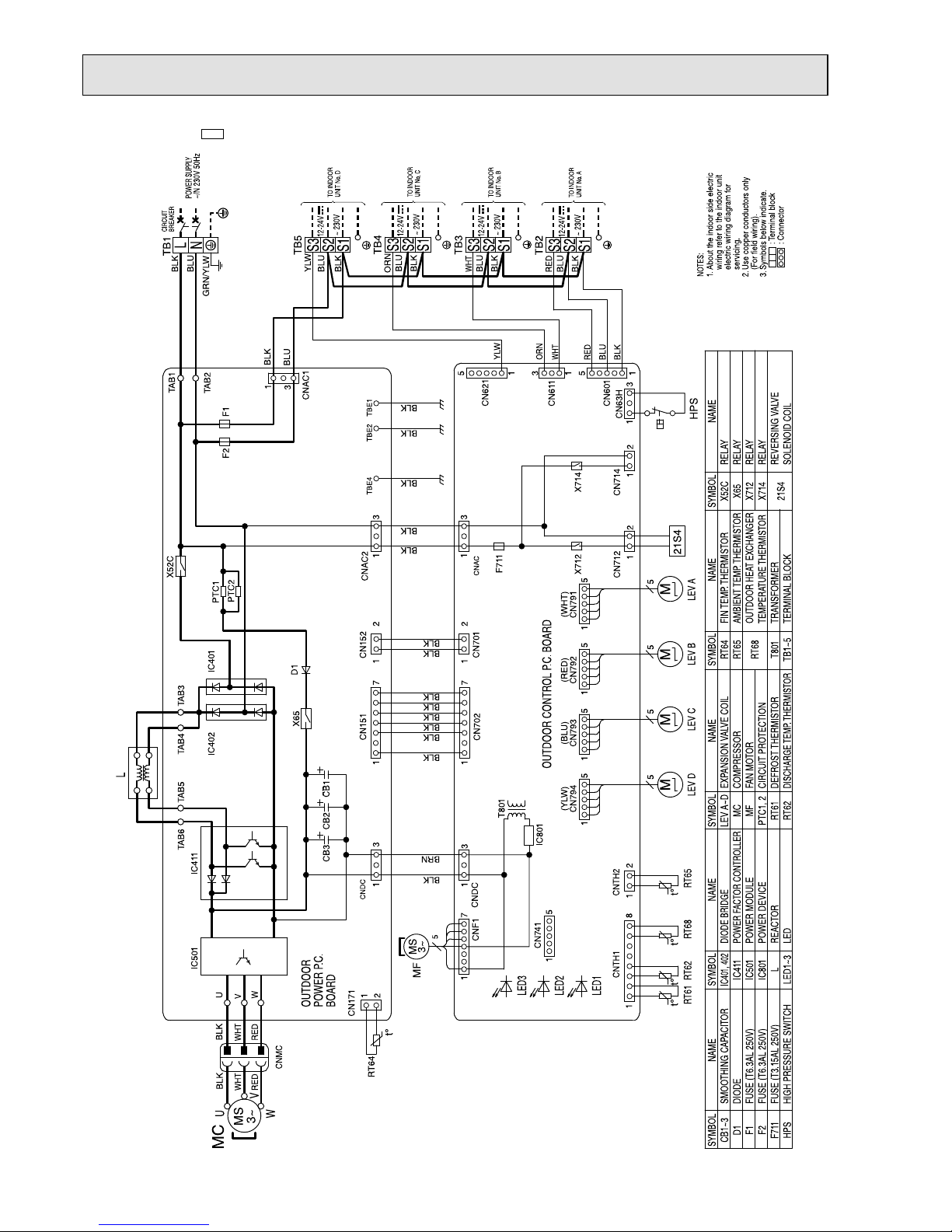
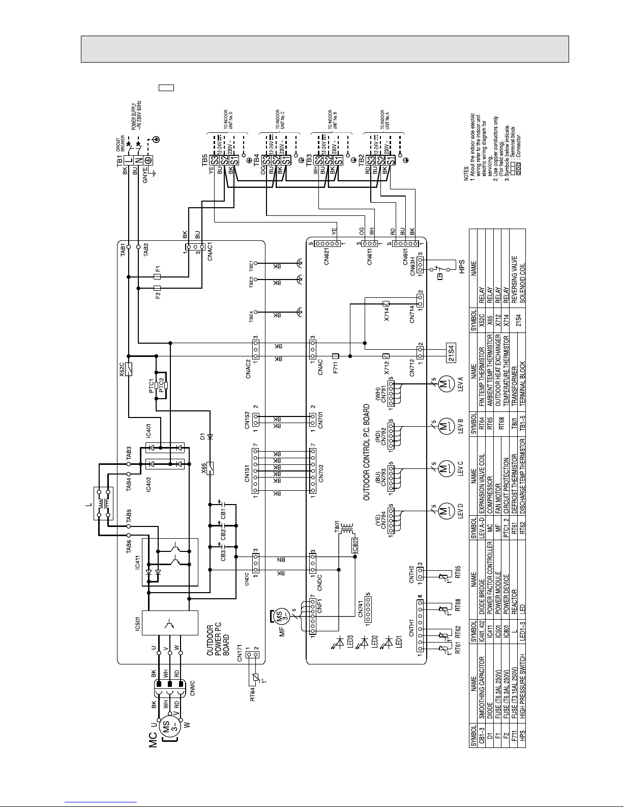
MXZ-4E72VA -E1 MXZ-4E72VA -
ET1
MXZ-4E72VA -
ER1
t°
21S4
t°°t°t
L
MS
3~
RT64
M
LEV R LEV C LEV ALEV B
RT62
RT61
X714
X712
F711
TO INDOOR
UNIT No.C
TO INDOOR
UNIT No.A
TO INDOOR
UNIT No.B
TB2
TB3
TB4
12-24V
~230V
~230V
12-24V
~230V
12-24V
RT68 RT65
MMM
MS
3~
MF
T801
BLK
WHT
RED
RED
WHT
BLK
U
V
W
MC
CB3
CB2
CB1
BOARD
POWER P.C.
OUTDOOR
OUTDOOR CONTROL P.C. BOARD
F1
F2
TB1
BREAKER
CIRCUIT
POWER SUPPLY
~/N 230V 50Hz
LEV D
M
TO INDOOR
UNIT No.D
~230V
12-24V
TB5
IC801
5
HPS
CN63H
13
1
6
CN797
CN714
1
2
CNAC
CN712
1
2
S1
S2
S3
S1
S2
S3
S1
S2
S3
1
5
CN741
D1
IC401
IC402
2
1
CN171
1
8
CNTH1
2
1
CNTH2
555
CNMC
1
551
1
7
1
CN792 CN791CN793
1
5
5
7
1
CNF1
CN702
1
3
CNDC
U
V
W
1
3
1
CN151
1
7
CNDC
CNAC2
CN794
5
1
CN701
2
1
1
2
CN152
IC501
IC411
TAB4
TAB6
TAB5
TAB3
X52C
3
5
CN601
1
3
CN611
1
1
CN621
5
TAB1
TAB2
3
1
CNAC1
3
TBE4 TBE2 TBE1
PTC1
PTC2
X65
L
N
5
S1
S2
S3
(BLU)
BLK
BLU
RED
BLK
BLU
WHT
BLK
BLU
ORN
BLK
BLK
BRN
BLK
BLK
(RED) (WHT)
(BLU)
(YLW)
BLK
BLK
BLK
BLK
BLK
BLK
BLK
BLK
BLU
RED
BLU
BLK
BLK
BLK
BLK
BLK
BLU
GRN/YLW
WHT
ORN
YLW
BLU
BLK
YLW
+++
LEV A~D,R
MC
MF
PTC1,2
RT61
RT62
X52C
X65
X712
X714
21S4
RELAY
RELAY
RELAY
RELAY
REVERSING VALVE
SOLENOID COIL
DEFROST THERMISTOR
FIN TEMP. THERMISTOR
AMBIENT TEMP. THERMISTOR
OUTDOOR HEAT EXCHANGER
TEMPERATURE THERMISTOR
TRANSFORMER
TERMINAL BLOCK
RT64
RT65
RT68
T801
TB1~5
FAN MOTOR
COMPRESSOR
EXPANSION VALVE COIL
DISCHARGE TEMP. THERMISTOR
SMOOTHING CAPACITOR
DIODE
FUSE(T6.3AL250V)
FUSE(T6.3AL250V)
FUSE(T3.15AL250V)
HIGH PRESSURE SWITCH
CB1~3
D1
F1
F2
F711
HPS
CIRCUIT PROTECTION
NOTES:
1.About the indoor side electric
wiring refer to the indoor unit
electric wiring diagram for
servicing.
2.Use copper conductors only
(For field wiring).
3.Symbols below indicate.
:Terminal block
:Connector
SYMBOL
NAME
SYMBOL SYMBOL SYMBOL
NAME NAME NAME
SYMBOL
NAME
DIODE BRIDGE
POWER FACTOR CONTROLLER
POWER MODULE
POWER DEVICE
REACTOR
LED
IC401,402
IC411
IC501
IC801
L
LED1~3
LED3
LED2
LED1
t°
OBH723D

22
MXZ-4E83VA -
E1
OBH723D
23
MXZ-4E83VA -
E2
OBH723D
24
MXZ-4E83VA -
E3
OBH723D
25
MXZ-4E83VA -
ET1
OBH723D
26
MXZ-4E83VA -
ET2
OBH723D
27
MXZ-4E83VA -
ET3
OBH723D
28
MXZ-4E83VA -
ER1
OBH723D
29
MXZ-4E83VA -
ER2
OBH723D
30
MXZ-5E102VA -
E1
OBH723D

31
MXZ-5E102VA -
E2
OBH723D

32
MXZ-5E102VA -
E3
OBH723D

33
MXZ-5E102VA -
ET1
OBH723D

34
MXZ-5E102VA -
ET2
OBH723D

35
MXZ-5E102VA -
ET3
OBH723D

36
MXZ-5E102VA -
ER1
OBH723D

37
MXZ-5E102VA -
ER2
OBH723D

38
MXZ-2E53VAHZ -
E1
OBH723D

39
MXZ-2E53VAHZ -
ER1
OBH723D

40
MXZ-4E83VAHZ -
E1
OBH723D

41
MXZ-4E83VAHZ -
E2
OBH723D

42
MXZ-4E83VAHZ -
ER1
OBH723D

43
MXZ-4E83VAHZ -
ER2
OBH723D

44
REFRIGERANT SYSTEM DIAGRAM
7
Strainer
#100
Power
receiver
LEV A
LEV B
LEV C
Oil separator
Compressor
Defrost
thermistor
RT61
Distributor
Muffler
4-way valve
LEV E
Indoor unit
C
Indoor unit
B
Indoor unit
A
Indoor unit
A
Indoor unit
B
Indoor unit
C
Capillary tube
Capillary tube
Capillary tube
Capillary tube
Capillary tube
Discharge
temperature
thermistor RT62
Strainer
#100
Strainer
#100
Strainer
#100
R.V. coil
OFF
ON
Refrigerant flow in cooling
Refrigerant flow in heating
Ambient
temperature
thermistor
RT65
Outdoor heat
exchanger
temperature
thermistor
RT68
FAN- OUT
HEX-OUT
Strainer
#100
Stop valve with
service port
Stop valve
High-pressure switch
UNIT: mm (inch)
UNIT: mm
MXZ-3E54VA
MAX REFRIGERANT PIPING LENGTH
Outdoor unit union diameter
For
Indoor unit A
Liquid 6.35(1/4)
Gas 9.52(3/8)
Indoor unit B
Liquid 6.35(1/4)
Gas 9.52(3/8)
Indoor unit C
Liquid 6.35(1/4)
Gas 9.52(3/8)
a
b
c
Outdoor
unit
Indoor
units
15 m
10 m
15 m
Max.
Height
difference
Piping length each indoor unit (a, b, c) 25 m
Total piping length (a+b+c) 50 m
Bending point for each unit 25
Total bending point 50
It is irrelevant which unit is higher.
Refrigerant pipe diameter is different according to indoor unit to be
connected. When using extension pipes, refer to the right table.
When diameter of refrigerant pipe is different from that of outdoor
unit union, use optional Different-diameter pipe.
For further information on Different-diameter pipe, refer to "PARTS
CATALOG".
ADDITIONAL REFRIGERANT CHARGE
Outdoor unit
precharged
(g)
Refrigerant piping length (one way, 3 unit total)
40 m 45 m 50 m
2,700 0 100 200
Calculation : Xg = 20 g/m x (Refrigerant piping length (m) - 40)
WHEN CONNECTING TO MFZ-KJ SERIES INDOOR UNIT
MXZ-3E54VA
No. of
MFZ-KJ
indoor units
Refrigerant piping length (L)
Maximum amount of
refrigerant
~ 40 m ~ 50 m
None Charge-less (2,700 g) (L-40) x 20 g/m 2,900 g
1 unit 100 g additional charge (2,800 g) 100 g + (L-40) x 20 g/m 3,000 g
2 units 200 g additional charge (2,900 g) 200 g + (L-40) x 20 g/m 3,100 g
3 units 300 g additional charge (3,000 g) 300 g + (L-40) x 20 g/m 3,200 g
OBH723D
45
Strainer
#100
Power
receiver
LEV A
LEV B
LEV C
Oil separator
Compressor
Defrost
thermistor
RT61
Distributor
Muffler
4-way valve
LEV E
Indoor unit
C
Indoor unit
B
Indoor unit
A
Indoor unit
A
Indoor unit
B
Indoor unit
C
Capillary tube
Capillary tube
Capillary tube
Capillary tube
Capillary tube
Discharge
temperature
thermistor RT62
Strainer
#100
Strainer
#100
Strainer
#100
R.V. coil
OFF
ON
Refrigerant flow in cooling
Refrigerant flow in heating
Ambient
temperature
thermistor
RT65
Outdoor heat
exchanger
temperature
thermistor
RT68
FAN- OUT
HEX-OUT
Strainer
#100
Stop valve with
service port
Stop valve
High-pressure switch
UNIT: mm
MXZ-3E68VA
MAX REFRIGERANT PIPING LENGTH
a
b
c
Outdoor
unit
Indoor
units
15 m
10 m
15 m
Max.
Height
difference
Piping length each indoor unit (a, b, c) 25 m
Total piping length (a+b+c) 60 m
Bending point for each unit 25
Total bending point 60
It is irrelevant which unit is higher.
ADDITIONAL REFRIGERANT CHARGE
Outdoor unit
precharged
(g)
Refrigerant piping length (one way, 3 unit total)
40 m 50 m 60 m
2,700 0 200 400
Calculation : Xg = 20 g/m x (Refrigerant piping length (m) - 40)
UNIT: mm (inch)
Outdoor unit union diameter
For
Indoor unit A
Liquid 6.35(1/4)
Gas 9.52(3/8)
Indoor unit B
Liquid 6.35(1/4)
Gas 9.52(3/8)
Indoor unit C
Liquid 6.35(1/4)
Gas 9.52(3/8)
Refrigerant pipe diameter is different according to indoor unit to be
connected. When using extension pipes, refer to the right table.
When diameter of refrigerant pipe is different from that of outdoor
unit union, use optional Different-diameter pipe.
For further information on Different-diameter pipe, refer to "PARTS
CATALOG".
WHEN CONNECTING TO MFZ-KJ SERIES INDOOR UNIT
MXZ-3E68VA
No. of
MFZ-KJ
indoor units
Refrigerant piping length (L)
Maximum amount of
refrigerant
~ 40 m ~ 60 m
None Charge-less (2,700 g) (L-40) x 20 g/m 3,100 g
1 unit 100 g additional charge (2,800 g) 100 g + (L-40) x 20 g/m 3,200 g
2 units 200 g additional charge (2,900 g) 200 g + (L-40) x 20 g/m 3,300 g
3 units 300 g additional charge (3,000 g) 300 g + (L-40) x 20 g/m 3,400 g
OBH723D

46
MXZ-4E72VA
Indoor unit
D
Power
receiver
LEV A
LEV B
LEV C
LEV D
Oil separator
Compressor
Muffler
4-way valve
LEV E
Indoor unit
C
Indoor unit
B
Indoor unit
A
Indoor unit
A
Indoor unit
B
Indoor unit
C
Indoor unit
D
Capillary tube
Capillary tube
Discharge
temperature
thermistor RT62
Strainer
#100
Strainer
#100
Strainer
#100
Strainer
#100
Strainer
#100
R.V. coil
OFF
ON
Refrigerant flow in cooling
Refrigerant flow in heating
Distributor
HEX-OUT
Outdoor heat
exchanger
temperature
thermistor
RT68
Defrost
thermistor
RT61
Capillary tube
Ambient
temperature
thermistor
RT65
FAN- OUT
Strainer
#100
Stop valve with
service port
Stop valve
High-pressure
switch
UNIT: mm
a
b
c
d
Outdoor
unit
Indoor
units
15 m
10 m
15 m
Max.
Height
difference
UNIT: mm (inch)
Outdoor unit union diameter
For
Indoor unit A
Liquid 6.35(1/4)
Gas 12.7(1/2)
Indoor unit B
Liquid 6.35(1/4)
Gas 9.52(3/8)
Indoor unit C
Liquid 6.35(1/4)
Gas 9.52(3/8)
Indoor unit D
Liquid 6.35(1/4)
Gas 9.52(3/8)
Refrigerant pipe diameter is different according to indoor unit to be
connected. When using extension pipes, refer to the right table.
When diameter of refrigerant pipe is different from that of outdoor
unit union, use optional Different-diameter pipe.
For further information on Different-diameter pipe, refer to "PARTS
CATALOG".
MAX REFRIGERANT PIPING LENGTH
Piping length each indoor unit (a, b, c, d) 25 m
Total piping length (a+b+c+d)
60 m
Bending point for each unit 25
Total bending point 60
It is irrelevant which unit is higher.
ADDITIONAL REFRIGERANT CHARGE
Outdoor unit
precharged
(g)
Refrigerant piping length (one way, 4 unit total)
40 m 50 m 60 m
2,700 0 200 400
Calculation : Xg = 20 g/m x (Refrigerant piping length (m) - 40)
WHEN CONNECTING TO MFZ-KJ SERIES INDOOR UNIT
MXZ-4E72VA
No. of
MFZ-KJ
indoor units
Refrigerant piping length (L)
Maximum amount of
refrigerant
~ 40 m ~ 60 m
None Charge-less (2,700 g) (L-40) x 20 g/m 3,100 g
1 unit 100 g additional charge (2,800 g) 100 g + (L-40) x 20 g/m 3,200 g
2 units 200 g additional charge (2,900 g) 200 g + (L-40) x 20 g/m 3,300 g
3 units 300 g additional charge (3,000 g) 300 g + (L-40) x 20 g/m 3,400 g
4 units 400 g additional charge (3,100 g) 400 g + (L-40) x 20 g/m 3,500 g
OBH723D

47
a
b
c
d
Outdoor
unit
Indoor
units
15 m
15 m
10 m
Refrigerant piping length (one way, 4 unit total)
Calculation : Xg = 20 g/m x (Refrigerant piping length (m) - 25)
Max.
Height
difference
Outdoor unit
precharged
(g)
40 m
300
25 m
0
2,990
55 m
600
70 m
900
R.V.coil
OFF Refrigerant flow in heating
ON Refrigerant flow in cooling
Charge pipe
Compressor
Muffler
High pressure switch
Ø6.35
Ø6.35
Ø9.52
Ø12.7
Accumulator
Ø6.35
LEV A
Ø9.52
Strainer
#100
Strainer
#100
Strainer
#100
Strainer
#100
Union
Union
Header(Gas)
Stop valve
Header (Evaporator)
Ø6.35
Ø9.52
Sub
muffler
Discharge
temperature
thermistor
RT62
Outdoor
heat exchanger
temperature
thermistor
RT68
Ambient
temperature
thermistor
RT65
Defrost
temperature
thermistor
RT61
Capillary tube
Ø4.0 x Ø2.8 x 100
Indoor unit A
Indoor unit D
Indoor unit C
Indoor unit B
4-way valve
Stop valve
(with service port)
Indoor unit A
Indoor unit D
Indoor unit C
Indoor unit B
LEV B
LEV C
LEV D
Outdoor
heat exchanger
Capillary tube
Distributor
Strainer
#100
Straine
r
#50
MXZ-4E83VA
UNIT: mm
Refrigerant pipe diameter is different according to indoor unit to be connected. When using extension pipes, refer to the
tables below.
When diameter of refrigerant pipe is different from that of outdoor unit union, use optional Different-diameter pipe.
For further information on Different-diameter pipe, refer to "PARTS CATALOG".
UNIT: mm (inch)
Piping length each indoor unit (a, b, c, d) 25 m
Total piping length (a+b+c+d) 70 m
Bending point for each unit 25
Total bending point 70
MAX REFRIGERANT PIPING LENGTH
Outdoor unit union diameter
For
Indoor unit A
Liquid 6.35(1/4)
Gas 12.7(1/2)
Indoor unit B
Liquid 6.35(1/4)
Gas 9.52(3/8)
Indoor unit C
Liquid 6.35(1/4)
Gas 9.52(3/8)
Indoor unit D
Liquid 6.35(1/4)
Gas 9.52(3/8)
It is irrelevant which unit is higher.
ADDITIONAL REFRIGERANT CHARGE
OBH723D

48
a
b
c
d
Outdoor
unit
Indoor
units
15 m
10 m
15 m
Refrigerant piping length (one way, 5 unit total)
Calculation : Xg = 20 g/m x (Refrigerant piping length (m) - 0)
e
Max.
Height
difference
Outdoor unit
precharged
(g)
20 m
400
0 m
0
2,990
40 m
800
60 m
1,200
80 m
1,600
R.V.coil
OFF Refrigerant flow in heating
ON Refrigerant flow in cooling
Compressor
Muffler
High pressure switch
Ø6.35
Ø6.35
Ø9.52
Ø12.7
Accumulator
Ø6.35
LEV A
Ø9.52
Strainer
#100
Strainer
#100
Strainer
#100
Strainer
#100
Union
Union
Header(Gas)
Stop valve
Header (Evaporator)
Ø6.35
Ø9.52
Sub
muffler
Discharge
temperature
thermistor
RT62
Outdoor
heat exchanger
temperature
thermistor
RT68
Ambient
temperature
thermistor
RT65
Defrost
temperature
thermistor
RT61
Capillary tube
Ø4.0 x Ø2.8 x 100
Indoor unit A
Indoor unit D
Indoor unit C
Ø9.52
Indoor unit E
Indoor unit B
4-way valve
Stop valve
(with service port)
Indoor unit A
Indoor unit D
Indoor unit C
Indoor unit B
LEV B
LEV C
LEV D
Strainer
#100
Ø6.35
Indoor unit E
LEV E
Outd
oor
heat exchanger
Capillary tube
Distributor
Strainer
#100
Strainer
#50
Charge pipe
MXZ-5E102VA
UNIT: mm
Refrigerant pipe diameter is different according to indoor unit to be connected. When using extension pipes, refer to the
tables below.
When diameter of refrigerant pipe is different from that of outdoor unit union, use optional Different-diameter pipe.
For further information on Different-diameter pipe, refer to "PARTS CATALOG".
UNIT: mm (inch)
Piping length each indoor unit (a, b, c, d,e) 25 m
Total piping length (a+b+c+d+e) 80 m
Bending point for each unit 25
Total bending point 80
MAX REFRIGERANT PIPING LENGTH
Outdoor unit union diameter
For
Indoor unit A
Liquid 6.35(1/4)
Gas 12.7(1/2)
Indoor unit B
Liquid 6.35(1/4)
Gas 9.52(3/8)
Indoor unit C
Liquid 6.35(1/4)
Gas 9.52(3/8)
Indoor unit D
Liquid 6.35(1/4)
Gas 9.52(3/8)
Indoor unit E
Liquid 6.35(1/4)
Gas 9.52(3/8)
It is irrelevant which unit is higher.
ADDITIONAL REFRIGERANT CHARGE
OBH723D

49
Refrigerant piping length (one way, 2 unit total)
Calculation : Xg = 20 g/m x (Refrigerant piping length (m) - 20)
a
b
Outdoor
unit
Indoor
units
15 m
10 m
15 m
Max.
Height
difference
Outdoor unit
precharged
(g)
25 m
100
20 m
0
2,000
30 m
200
R.V.coil
OFF Refrigerant flow in heating
ON Refrigerant flow in cooling
Compressor
Muffler
High pressure switch
Ø6.35
Ø9.52
Ø9.52
Accumulator
Ø6.35
LEV A
Strainer
#100
Strainer
#100
Strainer
Union
Union
Header(Gas)
Stop valve
Header (Evaporator)
Sub
muffler
Discharge
temperature
thermistor
RT62
Outdoor
heat exchanger
temperature
thermistor
RT68
Ambient
temperature
thermistor
RT65
Defrost
temperature
thermistor
RT61
Capillary tube
Ø4.0 x Ø2.8 x 100
Indoor unit A
Indoor unit B
4-way valve
Stop valve
(with service port)
Indoor unit A
Indoor unit B
LEV B
Outdoor
heat exchanger
Capillary tube
Distributor
Strainer
#100
Strainer
#50
Charge pipe
MXZ-2E53VAHZ
UNIT: mm
Refrigerant pipe diameter is different according to indoor unit to be connected. When using extension pipes, refer to the
tables below.
When diameter of refrigerant pipe is different from that of outdoor unit union, use optional Different-diameter pipe.
For further information on Different-diameter pipe, refer to "PARTS CATALOG".
UNIT: mm (inch)
Piping length each indoor unit (a, b) 20 m
Total piping length (a+b) 30 m
Bending point for each unit 20
Total bending point 30
MAX REFRIGERANT PIPING LENGTH
Outdoor unit union diameter
For
Indoor unit A
Liquid 6.35(1/4)
Gas 9.52(3/8)
Indoor unit B
Liquid 6.35(1/4)
Gas 9.52(3/8)
It is irrelevant which unit is higher.
ADDITIONAL REFRIGERANT CHARGE
OBH723D

50
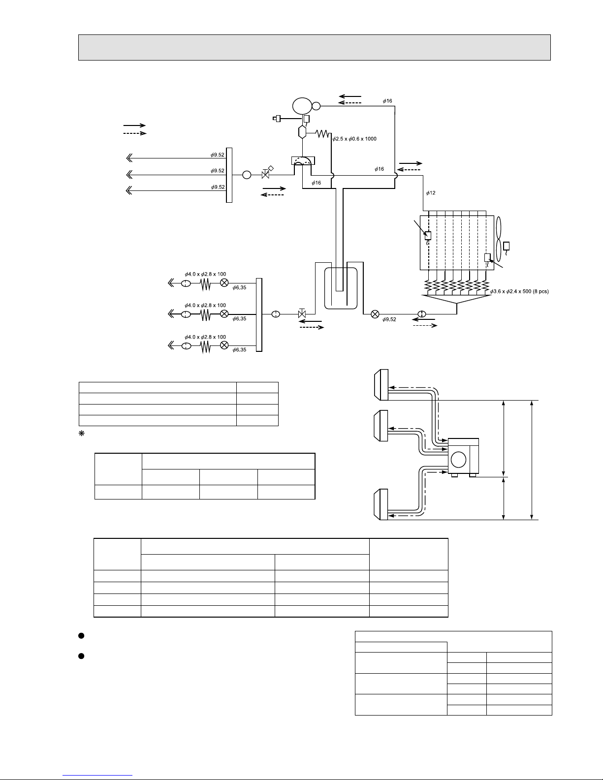
MXZ-4E83VAHZ
R.V.coil
OFF Refrigerant flow in heating
ON Refrigerant flow in cooling
Compressor
Oil separator
High pressure switch
Ø6.3 5
Ø6.3 5
Ø9.5 2
Ø12. 7
Indoor unit A
Accumulator
Ø6.3 5
LEV A
Ø9.5 2
2-way
solenoid valve
Distributor
Strainer #100
Union
Union
Header(Gas)
Stop valve
Strainer
Strainer
#50
Strainer
#50
#100
Header(Evaporator)
Charge pipe
Capillary tube
Capillary tube
Ø2.5 x Ø0.6 x 1000
Ø4.0 x Ø3.0 x 200
Ø6.3 5
Discharge
temperature
thermistor RT62
Outdoor
heat exchanger
temperature
thermistor
RT68
Ambient
temperature
thermistor
RT65
Defrost
temperature
thermistor
RT61
Capillary tube
Ø4.0 x Ø2.8 x 100
Outdoor
heat exchanger
4-way valve
Stop valve
(with service port)
Indoor unit B
Indoor unit C
Ø9.5 2
Indoor unit D
Indoor unit A
Indoor unit B
Indoor unit C
Indoor unit D
Strainer #100
Strainer #100
Strainer #100 LEV B
LEV D
LEV C
Capillary tube
Refrigerant piping length (one way, 4 unit total)
Calculation : Xg = 20 g/m x (Refrigerant piping length (m) - 25)
Outdoor unit
precharged
(g)
40 m
300
25 m
0
3,900
55 m
600
70 m
900
a
b
c
d
Outdoor
unit
Indoor
units
15 m
15 m
10 m
Max.
Height
difference
UNIT: mm
Refrigerant pipe diameter is different according to indoor unit to be connected. When using extension pipes, refer to the
tables below.
When diameter of refrigerant pipe is different from that of outdoor unit union, use optional Different-diameter pipe.
For further information on Different-diameter pipe, refer to "PARTS CATALOG".
Piping length each indoor unit (a, b, c, d) 25 m
Total piping length (a+b+c+d) 70 m
Bending point for each unit 25
Total bending point 70
MAX REFRIGERANT PIPING LENGTH
It is irrelevant which unit is higher.
ADDITIONAL REFRIGERANT CHARGE
UNIT: mm (inch)
Outdoor unit union diameter
For
Indoor unit A
Liquid 6.35(1/4)
Gas 12.7(1/2)
Indoor unit B
Liquid 6.35(1/4)
Gas 9.52(3/8)
Indoor unit C
Liquid 6.35(1/4)
Gas 9.52(3/8)
Indoor unit D
Liquid 6.35(1/4)
Gas 9.52(3/8)
OBH723D

51
When relocating or disposing of the air conditioner, pump down the system following the procedure below so that no refrigerant is
released into the atmosphere.
1) Turn off the breaker.
2) Connect the gauge manifold valve to the service port of the stop valve on the gas pipe side of the outdoor unit.
3) Fully close the stop valve on the liquid pipe side of the outdoor unit.
4) Turn on the breaker.
5) Start the emergency COOL operation on all the indoor units.
6) When the pressure gauge shows 0.05 to 0 MPa [Gauge] (approximately 0.5 to 0 kgf/cm²), fully close the stop valve on the gas
pipe side of the outdoor unit and stop the operation. (Refer to the indoor unit installation manual about the method for stopping
the operation.)
* If too much refrigerant has been added to the air conditioner system, the pressure may not drop to
0.05 to 0 MPa [Gauge] (ap-
proximately 0.5 to 0 kgf/cm²)
, or the protection function may operate due to the pressure increase in the high pressure refrigerant circuit. If this occurs, use a refrigerant collecting device to collect all of the refrigerant in the system, and then recharge the
system with the correct amount of refrigerant after the indoor and outdoor units have been relocated.
7) Turn off the breaker. Remove the pressure gauge and the refrigerant piping.
When pumping down the refrigerant, stop the compressor before disconnecting the refrigerant pipes.
The compressor may burst and cause injury if any foreign substance, such as air, enters the pipes.
WARNING
PUMPING DOWN
OBH723D

52
PERFORMANCE CURVES
8
The standard specifications apply only to the operation of the air conditioner under normal conditions.
Since operating conditions vary according to the areas where these units are installed, the following information has been provided to clarify the operating characteristics of the air conditioner under the conditions indicated by the performance curve.
(1) GUARANTEED VOLTAGE
198 - 264 V 50 Hz
(2) AIR FLOW
Air flow should be set at MAX.
(3) MAIN READINGS
(1) Indoor intake air wet-bulb temperature: °CWB
(2) Indoor outlet air wet-bulb temperature: °CWB
(3) Outdoor intake air dry-bulb temperature: °CDB
(4) Total input: W
(5) Indoor intake air dry-bulb temperature: °CDB
(6) Outdoor intake air wet-bulb temperature: °CWB
(7) Total input: W
Indoor air wet and dry bulb temperature difference on the left side of the following chart shows the difference between the
indoor intake air wet and dry bulb temperature and the indoor outlet air wet and dry bulb temperature for your reference at
service.
How to measure the indoor air wet and dry bulb temperature difference
1. Attach at least 2 sets of wet and dry bulb thermometers to the indoor air intake as shown in the figure, and at least 2 sets
of wet and dry bulb thermometers to the indoor air outlet. The thermometers must be attached to the position where air
speed is high.
2. Attach at least 2 sets of wet and dry bulb thermometers to the outdoor air intake.
Cover the thermometers to prevent direct rays of the sun.
3. Check that the air filter is cleaned.
4. Open windows and doors of room.
5. Press the EMERGENCY OPERATION switch once (twice) to start the EMERGENCY COOL (HEAT) MODE.
6. When system stabilizes after more than 15 minutes, measure temperature and take an average temperature.
7. 10 minutes later, measure temperature again and check that the temperature does not change.
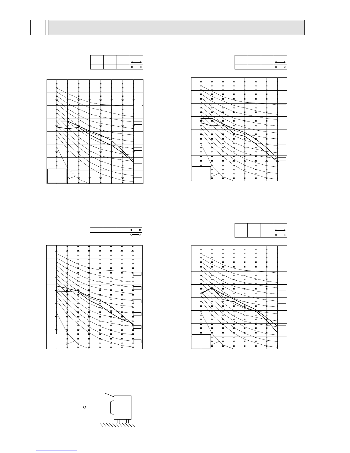
INDOOR UNIT
OUTDOOR UNIT
}
}
Cooling
Heating
Wet and dry bulb
thermometers
BACK VIEW
Wet and dry bulb
thermometers
FRONT VIEW
MXZ-3E54VA MXZ-3E68VA MXZ-4E72VA
MXZ-4E83VA MXZ-5E102VA MXZ-2E53VAHZ MXZ-4E83VAHZ
OBH723D

53
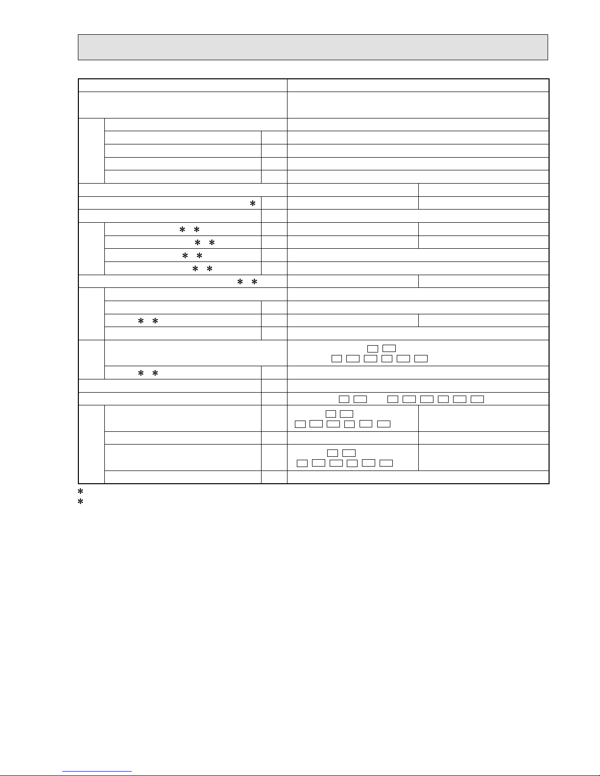
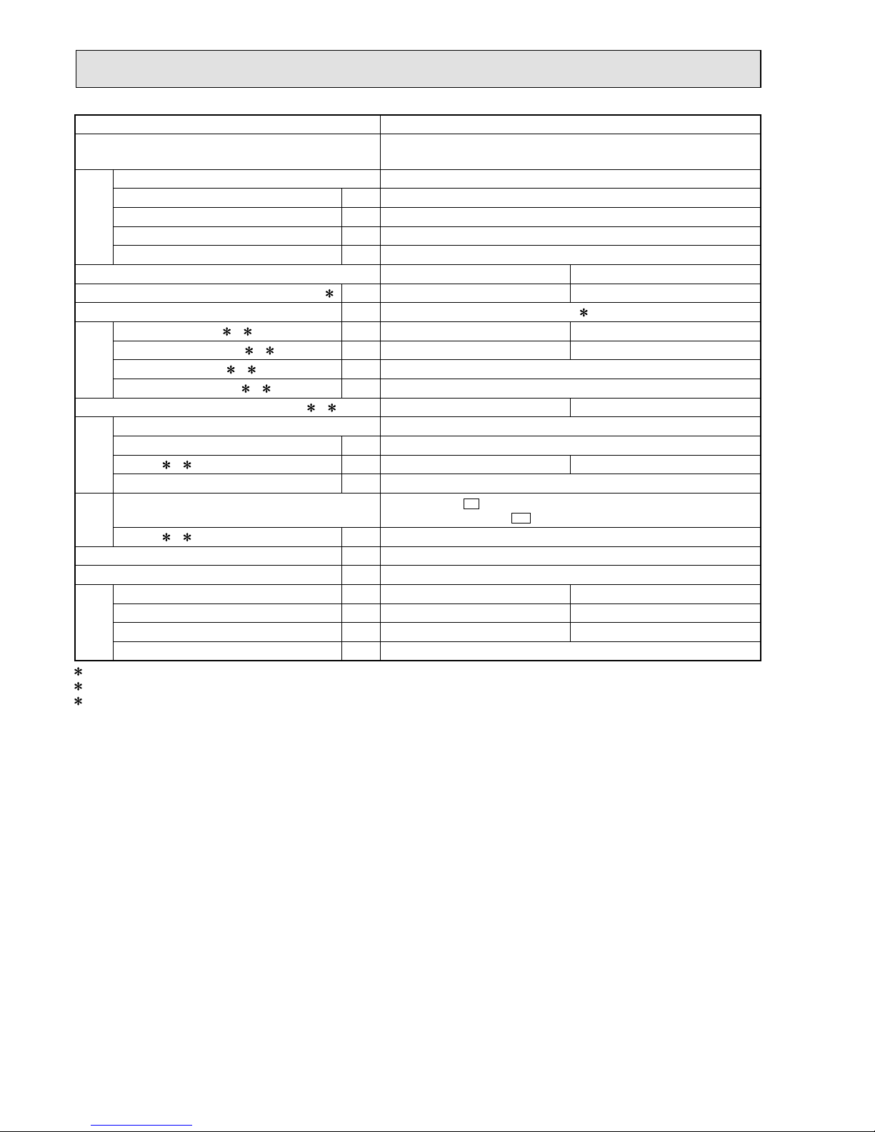
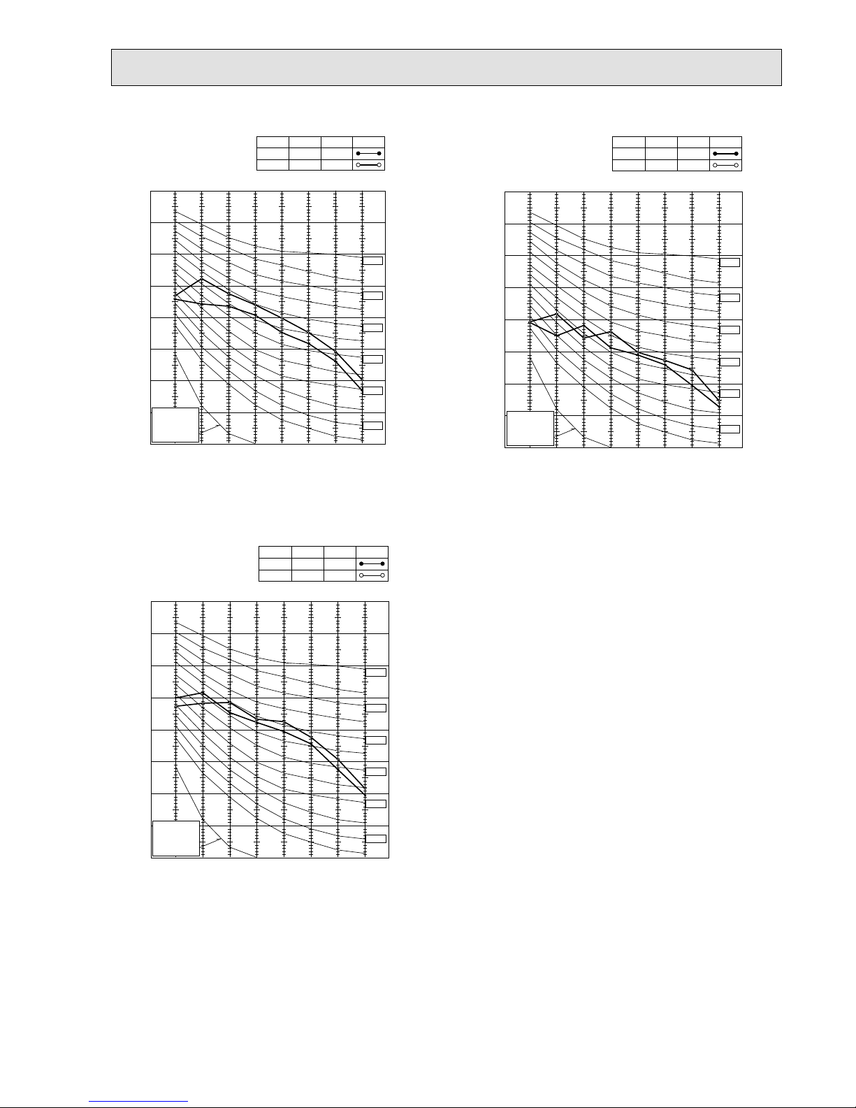
8-1. CAPACITY AND THE INPUT CURVES
0.9
1.0
1.1
1.2
1.3
0.8
-10 0 15
30
45 46
Capacity correction factors
Outdoor intake air Dry
- bulb temperature (
)
Cooling capacity
ºC
0.7
-5 51020253540
-10 0 15
30
45 46
Outdoor intake air Dry
- bulb temperature (
)
ºC
-5 51020253540
Input correction factors
Total input (Cooling)
0.9
1.0
1.1
1.2
1.3
0.8
0.7
0.6
0.5
0.4
18
16
19
22
20
24
26
18
16
19
22
20
24
26
Indoor air Wet-bulb temperature
difference (°C)
22 class
7.1
6.4
5.8
5.1
4.4
3.7
5.3
4.8
4.3
3.9
3.5
3.1
3.5
3.2
2.9
2.6
2.3
2.0
7.8
7.0
6.3
5.6
4.9
4.2
6.7
6.0
5.4
4.8
4.2
3.6
60 class
8.8
7.9
7.1
6.3
5.5
4.7
10.8
9.7
8.7
7.7
6.7
5.7
8.0
7.2
6.5
5.7
4.9
4.1
11. 3
10.1
9.0
8.0
7.0
6.0
50 class
35 class
42 class
25 class
15 class
18 class
20 class
5.8
Indoor intake air Wet-bulb temperature (°C)
Indoor intake air Wet-bulb temperature (°C)
2.7
2.3
1.9
1.7
1.4
1.1
3.0
2.4
1.8
3.0
2.3
1.6
3.5
2.8
2.1
3.9
3.1
2.3
3.3
2.5
1.7
4.7
3.7
2.7
5.0
4.0
3.0
3.8 7.3 7.8 8.5 9.7 8.7 11.9 12.4
3.8 7.3 7.8 8.5 9.7 8.7 11.9 12.4
MXZ-3E54VA MXZ-3E68VA MXZ-4E72VA
0.6
0.7
0.8
0.9
1.0
1.1
1.2
1.3
-16 -8 -4 4 12 18
Capacity correction factors
Outdoor intake air W et
-
bulb temperature (
ºC
)
Heating capacity
15
20
26
1.4
0.5
0.4
-12 0 8 16
-16 -8 -4 4 12 18-12 0 8 16
0.6
0.7
0.8
0.9
1.0
1.1
1.2
1.3
0.5
0.4
Input correction factors
Total input (Heating)
26
20
15
Outdoor intake air Wet
-
bulb temperature (
ºC
)
25.4
17.1
15.8
14.5
13.2
11. 8
10.5
9.2
7.9
19.7
18.2
16.7
15.2
13.6
12.1
10.6
9.1
23.4
21.5
19.5
17.6
15.6
13.7
11. 7
24.0
22.2
20.3
18.5
16.6
14.8
12.9
11. 1
22 class
25 class
60 class
25.9
23.9
21.9
19.9
17.9
15.9
13.9
12.0
31.4
29.0
26.6
24.1
21.7
19.3
16.9
14.5
31.9
29.4
27.0
24.5
22.1
19.6
17.2
14.7
35 class
50 class
27.0
24.9
22.8
20.7
18.7
16.6
14.5
12.4
42 class
15 class
19.0
17.6
16.1
14.5
13.0
11. 6
10.0
8.6
18 class
20 class
18.4 20.4 21.2 27.4 25.8 27.9 29.1 33.8 34.4
7.2
5.8
7.6
6.1
9.7
7.7
10.1
8.2
10.3
8.2
9.3
7.5
12.1
9.7
12.2
9.7
6.6
5.3
25.4
17.1
15.8
14.5
13.2
11. 8
10.5
9.2
7.9
19.7
18.2
16.7
15.2
13.6
12.1
10.6
9.1
23.4
21.5
19.5
17.6
15.6
13.7
11. 7
24.0
22.2
20.3
18.5
16.6
14.8
12.9
11. 1
22 class
25 class
60 class
25.9
23.9
21.9
19.9
17.9
15.9
13.9
12.0
31.4
29.0
26.6
24.1
21.7
19.3
16.9
14.5
31.9
29.4
27.0
24.5
22.1
19.6
17.2
14.7
35 class
50 class
27.0
24.9
22.8
20.7
18.7
16.6
14.5
12.4
42 class
15 class
19.0
17.6
16.1
14.5
13.0
11. 6
10.0
8.6
18 class
20 class
7.2
5.8
7.6
6.1
9.7
7.7
10.1
8.2
10.3
8.2
9.3
7.5
12.1
9.7
12.2
9.7
6.6
5.3
Indoor air Dry-bulb temperature
difference (°C)
Indoor air Dry-bulb temperature
difference (°C)
Indoor intake air Dry-bulb temperature (°C)
Indoor intake air Dry-bulb temperature (°C)
OBH723D

54
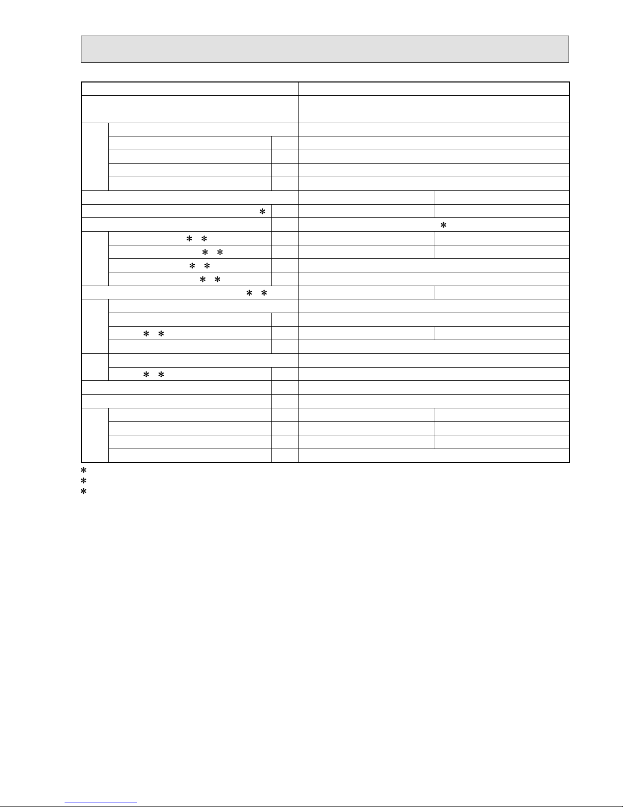
MXZ-4E83VA MXZ-5E102VA
0.9
1.0
1.1
1.2
1.3
0.8
-10 0 15 30 4546
Capacity correction factors
Outdoor intake air Dry
- bulb temperature (
)
Cooling capacity
ºC
0.7
0.9
1.0
1.1
1.2
1.3
0.8
0.7
Input correction factors
Total input (Cooling)
0.6
0.5
0.4
-5 5 10 20 25 35 40
-10 0 15 30 4546
Outdoor intake air Dry
- bulb temperature (
)
ºC
-5 5 10 20 25 35 40
5.4
5.4
18
16
19
22
20
24
26
18
16
19
22
20
24
26
Indoor intake air Wet-bulb temperature (°C)
Indoor intake air Wet-bulb temperature (°C)
Indoor air Wet-bulb temperature
diffrrence (°C)
22 class
4.4
4.0
3.6
3.2
2.8
2.5
5.0
4.6
4.1
3.7
3.2
2.8
4.9
4.5
4.0
3.6
3.2
2.8
6.2
5.7
5.1
4.5
4.0
3.5
71 class
60 class
7.3
6.6
6.0
5.3
4.6
4.0
9.3
8.4
7.5
6.6
5.8
5.0
7.3
6.6
6.0
5.3
4.6
4.0
7.5
6.8
6.1
5.4
4.7
4.1
42 class
35 class
10.6
9.5
8.5
7.5
6.6
5.6
50 class
25 class
15 class
20 class
3.5
3.2
2.9
2.6
2.3
18 class
3.8 6.8 4.8 5.5 8.0 10.2 11.6 8.0 8.2
2.0
3.8 6.8 4.8 5.5 8.0 10.2 11.6 8.0 8.2
2.0
2.3
1.9
1.5
1.7
1.4
1.1
2.9
2.4
1.9
2.1
1.7
1.4
2.0
2.0
1.6
3.4
2.8
2.2
4.2
3.5
2.7
4.8
3.9
3.1
3.4
2.8
2.2
3.5
2.9
2.3
0.6
0.7
0.8
0.9
1.0
1.1
1.2
1.3
-16 -8 -4 4 12 18
Capacity correction factors
Outdoor intake air Wet
-
bulb temperature (
ºC
)
Heating capacity
15
20
26
0.5
0.4
1.4
-12 0 8 16
0.6
0.7
0.8
0.9
1.0
1.1
1.2
1.3
0.5
0.4
-16 -8 -4 4 12 18
Outdoor intake air Wet
-
bulb temperature (
ºC
)
-12 0 8 16
Input correction factors
Total input (Heating)
26
20
15
Indoor intake air Dry-bulb temperature (°C)
Indoor intake air Dry-bulb temperature (°C)
Indoor air Dry-bulb temperature
difference (°C)
22 class
25 class
60 class
71 class
35 class
42 class
50 class
15 class
20 class
18 class
Indoor air Dry-bulb temperature
difference (°C)
22 class
25 class
60 class
71 class
35 class
42 class
50 class
15 class
20 class
18 class
18.3
6.4
5.1
9.0
7.7
11. 6
10.3
14.4
12.9
17.0
15.7
19.7
6.9
5.5
9.7
8.2
12.5
11. 1
15.4
13.9
18.2
16.8
22.0
7.7
6.1
10.9
9.2
14.0
12.4
17.3
15.6
20.5
18.9
19.7
6.9
5.5
9.7
8.2
12.5
11. 1
15.4
13.9
18.2
16.8
19.7
6.9
5.5
9.7
8.2
12.5
11. 1
15.4
13.9
18.2
16.8
23.0
8.0
6.4
11. 4
9.6
14.6
13.0
18.1
16.3
21.4
19.7
31.1
10.8
8.7
15.4
13.0
19.7
17.6
24.4
21.9
28.9
26.6
32.1
11. 2
9.0
15.9
13.4
20.4
18.1
25.2
22.7
29.8
27.5
22.3
7.8
6.2
11. 0
9.3
14.2
12.6
17.5
15.7
20.7
19.1
28.3
9.9
7.9
14.0
11
.9
18.0
16.0
22.3
20.0
26.3
24.3
6.4
5.1
9.0
7.7
11. 6
10.3
14.4
12.9
17.0
15.7
6.9
5.5
9.7
8.2
12.5
11. 1
15.4
13.9
18.2
16.8
7.7
6.1
10.9
9.2
14.0
12.4
17.3
15.6
20.5
18.9
6.9
5.5
9.7
8.2
12.5
11. 1
15.4
13.9
18.2
16.8
6.9
5.5
9.7
8.2
12.5
11. 1
15.4
13.9
18.2
16.8
8.0
6.4
11. 4
9.6
14.6
13.0
18.1
16.3
21.4
19.7
10.8
8.7
15.4
13.0
19.7
17.6
24.4
21.9
28.9
26.6
11. 2
9.0
15.9
13.4
20.4
18.1
25.2
22.7
29.8
27.5
7.8
6.2
11. 0
9.3
14.2
12.6
17.5
15.7
20.7
19.1
9.9
7.9
14.0
11. 9
18.0
16.0
22.3
20.0
26.3
24.3
OBH723D

55
MXZ-2E53VAHZ
0.9
1.0
1.1
1.2
1.3
0.8
-10 0 15 30 45 46
Capacity correction factors
Outdoor intake air Dry
- bulb temperature (
)
Cooling capacity
ºC
0.7
0.9
1.0
1.1
1.2
1.3
0.8
0.7
Input correction factors
Total input (Cooling)
0.6
0.5
0.4
-5 5 10 20 25 35 40
-10 0 15 30 45 46
Outdoor intake air Dry
- bulb temperature (
)
ºC
-5 5 10 20 25 35 40
5.4
5.4
18
16
19
22
20
24
26
18
16
19
22
20
24
26
Indoor intake air Wet-bulb temperature (°C)
Indoor intake air Wet-bulb temperature (°C)
Indoor air Wet-bulb temperature
diffrrence (°C)
22 class
4.4
4.0
3.6
3.2
2.8
2.5
5.0
4.6
4.1
3.7
3.2
2.8
4.9
4.5
4.0
3.6
3.2
2.8
6.2
5.7
5.1
4.5
4.0
3.5
7.3
6.6
6.0
5.3
4.6
4.0
9.3
8.4
7.5
6.6
5.8
5.0
42 class
35 class
10.6
9.5
8.5
7.5
6.6
5.6
50 class
25 class
15 class
20 class
3.5
3.2
2.9
2.6
2.3
18 class
3.8
6.8
4.8 5.5 8.0 10.2
11. 6
2.0
3.8
6.8
4.8 5.5 8.0 10.2
11. 6
2.0
2.3
1.9
1.5
1.7
1.4
1.1
2.9
2.4
1.9
2.1
1.7
1.4
2.0
2.0
1.6
3.4
2.8
2.2
4.2
3.5
2.7
4.8
3.9
3.1
0.6
0.7
0.8
0.9
1.0
1.1
1.2
1.3
-26 -18 -6 2 10 18
Capacity correction factors
Outdoor intake air Wet
-
bulb temperature (
ºC
)
Heating capacity
15
20
26
0.5
1.4
-22 -14 -10 -2 6 14
0.6
0.7
0.8
0.9
1.0
1.1
1.2
1.3
0.5
1.4
1.5
1.6
1.7
-26 -18 -6 2 10 18-22 -14 -10 -2 6 14
Outdoor intake air W et
-
bulb temperature (
ºC
)
Input correction factors
Total input (Heating)
26
20
15
Indoor intake air Dry-bulb temperature (°C)
Indoor intake air Dry-bulb temperature (°C)
Indoor air Dry-bulb temperature
difference (°C)
22 class
25 class
35 class
42 class
50 class
15 class
20 class
18 class
Indoor air Dry-bulb temperature
difference (°C)
22 class
25 class
35 class
42 class
50 class
15 class
20 class
18 class
6.4
18.3
6.4 6.9 7.7
6.9
8.0
10.8
11.2
18.3 19.7 22.0
19.7
23.0
31.1
32.1
19.6 21.2 23.5
21.2
24.6
33.3
34.4
20.9 22.7 25.0
22.7
26.2
35.5
36.7
22.2 24.2 26.5
24.2
27.8
37.7
39.0
12.9
14.4
15.7
17.0
7.7
9.0
10.3
11.6
13.9
15.4
16.8
18.2
8.2
9.7
11.1
12.5
15.6
17.3
18.9
20.5
9.2
10.9
12.4
14.0
13.9
15.4
16.8
18.2
8.2
9.7
11.1
12.5
6.9
19.7
21.2
22.7
24.2
13.9
15.4
16.8
18.2
8.2
9.7
11.1
12.5
16.3
18.1
19.7
21.4
9.6
11.4
13.0
14.6
21.9
24.4
26.6
28.9
13.0
15.4
17.6
19.7
22.7
25.2
27.5
29.8
13.4
15.9
18.1
20.4
17.0
15.7
14.4
12.9
11. 6
10.3
9.0
7.7
6.9
19.7
18.2
16.8
15.4
13.9
12.5
11. 1
9.7
8.2
7.7
22.0
20.5
18.9
17.3
15.6
14.0
12.4
10.9
9.2
6.9
19.7
18.2
16.8
15.4
13.9
12.5
11. 1
9.7
8.2
6.9
19.7
18.2
16.8
15.4
13.9
12.5
11. 1
9.7
8.2
8.0
23.0
21.4
19.7
18.1
16.3
14.6
13.0
11. 4
9.6
10.8
31.1
28.9
26.6
24.4
21.9
19.7
17.6
15.4
13.0
11. 2
32.1
29.8
27.5
25.2
22.7
20.4
18.1
15.9
13.4
OBH723D

56
MXZ-4E83VAHZ
0.9
1.0
1.1
1.2
1.3
0.8
-10 0 15 30 4546
Capacity correction factors
Outdoor intake air Dry
- bulb temperature (
)
Cooling capacity
ºC
0.7
-5 5 10 20 25 35 40
0.9
1.0
1.1
1.2
1.3
0.8
0.7
-10 0 15 30 4546
Outdoor intake air Dry
- bulb temperature (
)
ºC
-5 5 10 20 25 35 40
0.6
0.5
0.4
Input correction factors
Total input (Cooling)
5.4
5.4
18
16
19
22
20
24
26
18
16
19
22
20
24
26
Indoor intake air Wet-bulb temperature (°C)
Indoor intake air Wet-bulb temperature (°C)
Indoor air Wet-bulb temperature
diffrrence (°C)
22 class
4.4
4.0
3.6
3.2
2.8
2.5
5.0
4.6
4.1
3.7
3.2
2.8
4.9
4.5
4.0
3.6
3.2
2.8
6.2
5.7
5.1
4.5
4.0
3.5
71 class
60 class
7.3
6.6
6.0
5.3
4.6
4.0
9.3
8.4
7.5
6.6
5.8
5.0
7.3
6.6
6.0
5.3
4.6
4.0
7.5
6.8
6.1
5.4
4.7
4.1
42 class
35 class
10.6
9.5
8.5
7.5
6.6
5.6
50 class
25 class
15 class
20 class
3.5
3.2
2.9
2.6
2.3
18 class
3.8 6.8 4.8 5.5 8.0 10.2 11.6 8.0 8.2
2.0
3.8 6.8 4.8 5.5 8.0 10.2 11.6 8.0 8.2
2.0
2.3
1.9
1.5
2.0
2.0
1.6
3.4
2.8
2.2
4.2
3.5
2.7
4.8
3.9
3.1
3.4
2.8
2.2
3.5
2.9
2.3
2.1
1.7
1.4
1.7
1.4
1.1
2.9
2.4
1.9
0.6
0.7
0.8
0.9
1.0
1.1
1.2
1.3
-26 -18 -10 2 10 18
Capacity correction factors
Outdoor intake air Wet
-
bulb temperature (
ºC
)
Heating capacity
15
20
26
0.5
1.4
-22 -14 -6 -2 6 14
-26 -18 -10 2 10 18
Outdoor intake air Wet
-
bulb temperature (
ºC
)
-22 -14 -6 -2 6 14
Input correc tion factors
Total input (Heating)
26
20
15
0.6
0.7
0.8
0.9
1.0
1.1
1.2
1.3
0.5
1.4
1.5
1.6
1.7
Indoor intake air Dry-bulb temperature (°C)
Indoor intake air Dry-bulb temperature (°C)
Indoor air Dry-bulb temperature
difference (°C)
18.2
16.8
15.4
13.9
12.5
11. 1
9.7
8.2
17.0
15.7
14.4
12.9
11. 6
10.3
9.0
7.7
20.5
18.9
17.3
15.6
14.0
12.4
10.9
9.2
18.2
16.8
15.4
13.9
12.5
11. 1
9.7
8.2
22 class
25 class
60 class
71 class
21.4
19.7
18.1
16.3
14.6
13.0
11. 4
9.6
28.9
26.6
24.4
21.9
19.7
17.6
15.4
13.0
20.7
19.1
17.5
15.7
14.2
12.6
11. 0
9.3
26.3
24.3
22.3
20.0
18.0
16.0
14.0
11. 9
35 class
42 class
29.8
27.5
25.2
22.7
20.4
18.1
15.9
13.4
50 class
15 class
20 class
18.2
16.8
15.4
13.9
12.5
11. 1
9.7
8.2
18 class
Indoor air Dry-bulb temperature
difference (°C)
22 class
25 class
60 class
71 class
35 class
42 class
50 class
15 class
20 class
18 class
6.4
6.9
7.7
6.9 6.9
8.0
10.8
11. 2
7.8 9.9
18.3 19.7 22.0 19.7 19.7 23.0 31.1 32.1 22.3 28.3
6.4
6.9
7.7
6.9
8.0
10.8
11.2
7.8 9.9
18.3 19.7 22.0 19.7 23.0 31.1 32.1 22.3 28.3
19.6 21.2 23.5 21.2 24.6 33.3 34.4 23.9 30.3
20.9 22.7 25.0 22.7 26.2 35.5 36.7 25.5 32.3
22.2 24.2 26.5 24.2 27.8 37.7 39.0 27.1 34.3
12.9
14.4
15.7
17.0
7.7
9.0
10.3
11.6
13.9
15.4
16.8
18.2
8.2
9.7
11.1
12.5
15.6
17.3
18.9
20.5
9.2
10.9
12.4
14.0
13.9
15.4
16.8
18.2
8.2
9.7
11.1
12.5
6.9
19.7
21.2
22.7
24.2
13.9
15.4
16.8
18.2
8.2
9.7
11.1
12.5
16.3
18.1
19.7
21.4
9.6
11.4
13.0
14.6
21.9
24.4
26.6
28.9
13.0
15.4
17.6
19.7
22.7
25.2
27.5
29.8
13.4
15.9
18.1
20.4
15.7
17.5
19.1
20.7
9.3
11.0
12.6
14.2
20.0
22.3
24.3
26.3
11.9
14.0
16.0
18.0
OBH723D

57
8-2. CAPACITY AND INPUT CORRECTION BY INVERTER OUTPUT FREQUENCY (single operation)
0 50 100 150
1.0
1.5
2.0
2.5
<HEAT>Capacity <HEAT>Total input
Frequency
Hz
Frequency
Hz
0 50 100 150
1.0
1.5
2.0
2.5
050100150
1.0
1.5
2.0
2.5
<HEAT>Capacity <HEAT>Total input
Frequency
Hz
Frequency
Hz
0 50 100 150
0.5
1.0
1.5
0 50 100 150
0.5
1.0
1.5
0 50 100 150
0.5
1.0
1.5
<HEAT>Capacity
Frequency
Hz
0 50 100 150
0.5
1.0
1.5
<HEAT>Total input
Frequency
Hz
<HEAT>Capacity <HEAT>Total input
Frequency
Hz
Frequency
Hz
0 50 100 150
1.0
1.5
2.0
<COOL>Capacity
Frequency
Hz
<COOL>Total input
Frequency
Hz
0 50 100 150
1.0
1.5
2.0
2.5
0 50 100 150
1.0
1.5
2.0
2.5
<COOL>Capacity
Frequency
Hz
<COOL>Total input
Frequency
Hz
0 50 100 150
0.5
1.0
1.5
0 50 100 150
0.5
1.0
1.5
0 50 100 150
0.5
1.0
1.5
<COOL>Capacity
Frequency
Hz
0 50 100 150
0.5
1.0
1.5
<COOL>Total input
Frequency
Hz
<COOL>Capacity
Frequency
Hz
0 50 100 150
1.0
1.5
2.0
<COOL>Total input
Frequency
Hz
0 50 100 150
1.0
1.5
2.0
MXZ-3E54VA
15-class unit
22-class unit
18-class unit
20-class unit
OBH723D

58
25-class unit
0 50 100 150
0.5
1.0
1.5
<COOL>Capacity
Frequency
Hz
0 50 100 150
0.5
1.0
1.5
<HEAT>Capacity
Frequency
Hz
0 50 100 150
0.5
1.0
1.5
<COOL>Capacity
Frequency
Hz
0 50 100 150
0.5
1.0
1.5
<HEAT>Capacity
Frequency
Hz
0 50 100 150
0.5
1.0
1.5
<COOL>Total input
Frequency
Hz
0 50 100 150
0.5
1.0
1.5
<HEAT>Total input
Frequency
Hz
0 50 100 150
0.5
1.0
1.5
<COOL>Total input
Frequency
Hz
0 50 100 150
0.5
1.0
1.5
<HEAT>Total input
Frequency
Hz
<COOL>Capacity
Frequency
Hz
<HEAT>Capacity
Frequency
Hz
<COOL>Total input
Frequency
Hz
<HEAT>Total input
Frequency
Hz
0 50 100 150
0.5
1.0
1.5
0 50 100 150
0.5
1.0
1.5
0 50 100 150
0.5
1.0
1.5
0 50 100 150
0.5
1.0
1.5
0 50 100 150
0.5
1.0
1.5
<COOL>Capacity
Frequency
Hz
0 50 100 150
0.5
1.0
1.5
<HEAT>Capacity
Frequency
Hz
0 50 100 150
0.5
1.0
1.5
<COOL>Total input
Frequency
Hz
0 50 100 150
0.5
1.0
1.5
<HEAT>Total input
Frequency
Hz
MXZ-3E54VA
35-class unit
42-class unit
50-class unit
OBH723D

59
<COOL>Capacity
Frequency
Hz
<COOL>Total input
Frequency
Hz
<COOL>Capacity
Frequency
Hz
0 50 100 150
1.0
1.5
2.0
<COOL>Total input
Frequency
Hz
0 50 100 150
1.0
1.5
2.0
<COOL>Capacity
Frequency
Hz
0 50 100 150
0.5
1.0
1.5
2.0
<COOL>Total input
Frequency
Hz
0 50 100 150
0.5
1.0
1.5
2.0
<COOL>Capacity
Frequency
Hz
0 50 100 150
0.5
1.0
1.5
2.0
<COOL>Total input
Frequency
Hz
0 50 100 150
1.0
1.5
2.0
2.5
0 50 100 150
1.0
1.5
2.0
2.5
<COOL>Capacity
Frequency
Hz
<COOL>Total input
0 50 100 150
0.5
1.0
1.5
2.0
Frequency
Hz
0 50 100 150
0.5
1.0
1.5
2.0
0 50 100 150
0.5
1.0
1.5
<HEAT>Capacity <HEAT>Total input
Frequency
Hz
Frequency
Hz
<HEAT>Capacity <HEAT>Total input
Frequency
Hz
Frequency
Hz
0 50 100 150
1.0
1.5
2.0
<HEAT>Capacity <HEAT>Total input
Frequency
Hz
Frequency
Hz
<HEAT>Capacity <HEAT>Total input
Frequency
Hz
0 50 100 150
0.5
1.0
1.5
Frequency
Hz
0 50 100 150
1.0
1.5
2.0
2.5
0 50 100 150
1.0
1.5
2.0
2.5
0 50 100 150
1.0
1.5
2.0
2.5
3.0
<HEAT>Capacity <HEAT>Total input
Frequency
Hz
0 50 100 150
0.5
1.0
1.5
Frequency
Hz
0 50 100 150
0.5
1.0
1.5
0 50 100 150
0.5
1.0
1.5
050100150
0.5
1.0
1.5
0 50 100 150
0.5
1.0
1.5
MXZ-3E68VA
15-class unit
22-class unit
25-class unit
20-class unit
18-class unit
OBH723D

60
<COOL>Capacity
Frequency
Hz
<COOL>Total input
Frequency
Hz
<HEAT>Capacity <HEAT>Total input
Frequency
Hz
Frequency
Hz
<COOL>Capacity
Frequency
Hz
0 50 100 150
0.5
1.0
1.5
<COOL>Total input
Frequency
Hz
<HEAT>Capacity <HEAT>Total input
Frequency
Hz
Frequency
Hz
<COOL>Capacity
Frequency
Hz
<COOL>Total input
Frequency
Hz
<HEAT>Capacity <HEAT>Total input
Frequency
Hz
Frequency
Hz
<COOL>Capacity
Frequency
Hz
<COOL>Total input
Frequency
Hz
<HEAT>Capacity <HEAT>Total input
Frequency
Hz
Frequency
Hz
0 50 100 150
0.5
1.0
1.5
2.0
0 50 100 150
0.5
1.0
1.5
0 50 100 150
0.5
1.0
1.5
0 50 100 150
0.5
1.0
1.5
0 50 100 150
0.5
1.0
1.5
0 50 100 150
0.5
1.0
1.5
0 50 100 150
0.5
1.0
1.5
0 50 100 150
0.5
1.0
1.5
0 50 100 150
0.5
1.0
1.5
0 50 100 150
0.5
1.0
1.5
0 50 100 150
0.5
1.0
1.5
0 50 100 150
0.5
1.0
1.5
0 50 100 150
0.5
1.0
1.5
0 50 100 150
0.5
1.0
1.5
0 50 100 150
0.5
1.0
1.5
MXZ-3E68VA
35-class unit
42-class unit
50-class unit
60-class unit
OBH723D

61
MXZ-4E72VA
<COOL>Capacity
Frequency
Hz
<COOL>Total input
Frequency
Hz
<HEAT>Capacity <HEAT>Total input
Frequency
Hz
Frequency
Hz
<COOL>Capacity
Frequency
Hz
0 50 100 150
1.0
1.5
2.0
<COOL>Total input
Frequency
Hz
<HEAT>Capacity <HEAT>Total input
0 50 100 150
1.0
1.5
2.0
Frequency
Hz
Frequency
Hz
0 50 100 150
1.0
1.5
2.0
<COOL>Capacity
Frequency
Hz
0 50 100 150
0.5
1.0
1.5
2.0
<COOL>Total input
Frequency
Hz
<HEAT>Capacity <HEAT>Total input
0 50 100 150
0.5
1.0
1.5
2.0
Frequency
Hz
Frequency
Hz
<COOL>Capacity
Frequency
Hz
0 50 100 150
0.5
1.0
1.5
2.0
<COOL>Total input
Frequency
Hz
<HEAT>Capacity <HEAT>Total input
Frequency
Hz
0 50 100 150
0.5
1.0
1.5
Frequency
Hz
0 50 100 150
1.0
1.5
2.0
2.5
0 50 100 150
1.0
1.5
2.0
2.5
0 50 100 150
1.0
1.5
2.0
2.5
0 50 100 150
1.0
1.5
2.0
2.5
0 50 100 150
1.0
1.5
2.0
2.5
3.0
0 50 100 150
0.5
1.0
1.5
0 50 100 150
0.5
1.0
1.5
0 50 100 150
0.5
1.0
1.5
0 50 100 150
0.5
1.0
1.5
<COOL>Capacity
Frequency
Hz
<COOL>Total input
0 50 100 150
0.5
1.0
1.5
2.0
Frequency
Hz
0 50 100 150
0.5
1.0
1.5
2.0
<HEAT>Capacity <HEAT>Total input
Frequency
Hz
0 50 100 150
0.5
1.0
1.5
Frequency
Hz
0 50 100 150
0.5
1.0
1.5
15-class unit
22-class unit
25-class unit
20-class unit
18-class unit
OBH723D

62
MXZ-4E72VA
<COOL>Capacity
Frequency
Hz
<COOL>Total input
Frequency
Hz
<HEAT>Capacity <HEAT>Total input
Frequency
Hz
Frequency
Hz
<COOL>Capacity
Frequency
Hz
0 50 100 150
0.5
1.0
1.5
<COOL>Total input
Frequency
Hz
<HEAT>Capacity <HEAT>Total input
Frequency
Hz
Frequency
Hz
<COOL>Capacity
Frequency
Hz
<COOL>Total input
Frequency
Hz
<HEAT>Capacity <HEAT>Total input
Frequency
Hz
Frequency
Hz
<COOL>Capacity
Frequency
Hz
<COOL>Total input
Frequency
Hz
<HEAT>Capacity <HEAT>Total input
Frequency
Hz
Frequency
Hz
0 50 100 150
0.5
1.0
1.5
2.0
0 50 100 150
0.5
1.0
1.5
0 50 100 150
0.5
1.0
1.5
0 50 100 150
0.5
1.0
1.5
0 50 100 150
0.5
1.0
1.5
0 50 100 150
0.5
1.0
1.5
0 50 100 150
0.5
1.0
1.5
0 50 100 150
0.5
1.0
1.5
0 50 100 150
0.5
1.0
1.5
0 50 100 150
0.5
1.0
1.5
0 50 100 150
0.5
1.0
1.5
0 50 100 150
0.5
1.0
1.5
0 50 100 150
0.5
1.0
1.5
0 50 100 150
0.5
1.0
1.5
0 50 100 150
0.5
1.0
1.5
35-class unit
42-class unit
50-class unit
60-class unit
OBH723D

63
MXZ-4E83VA
<COOL>Capacity
Frequency
Hz
<COOL>Total input
0 50 100 150
0.5
1.0
1.5
Frequency
Hz
0 50 100 150
0.5
1.0
1.5
<COOL>Capacity
Frequency
Hz
<COOL>Total input
0 50 100 150
0.5
1.0
1.5
Frequency
Hz
0 50 100 150
0.5
1.0
1.5
<COOL>Capacity
Frequency
Hz
<COOL>Total input
0 50 100 150
0.5
1.0
1.5
2.0
Frequency
Hz
0 50 100 150
0.5
1.0
1.5
2.0
<COOL>Capacity
Frequency
Hz
<COOL>Total input
0 50 100 150
0.5
1.0
1.5
2.0
Frequency
Hz
0 50 100 150
0.5
1.0
1.5
2.0
<COOL>Capacity
Frequency
Hz
<COOL>Total input
0 50 100 150
0.5
1.0
1.5
2.0
Frequency
Hz
0 50 100 150
0.5
1.0
1.5
2.0
<HEAT>Capacity <HEAT>Total input
Frequency
Hz
0 50 100 150
0.5
1.0
1.5
Frequency
Hz
0 50 100 150
0.5
1.0
1.5
2.0
<HEAT>Capacity <HEAT>Total input
Frequency
Hz
0 50 100 150
0.5
1.0
1.5
Frequency
Hz
0 50 100 150
0.5
1.0
1.5
2.0
<HEAT>Capacity <HEAT>Total input
Frequency
Hz
0 50 100 150
0.5
1.0
1.5
2.0
Frequency
Hz
0 50 100 150
1
2
3
<HEAT>Capacity <HEAT>Total input
Frequency
Hz
0 50 100 150
0.5
1.0
1.5
Frequency
Hz
0 50 100 150
0.5
1.0
1.5
2.0
<HEAT>Capacity <HEAT>Total input
Frequency
Hz
0 50 100 150
0.5
1.0
1.5
2.0
Frequency
Hz
0 50 100 150
1
2
3
15-class unit
22-class unit
25-class unit
20-class unit
18-class unit
OBH723D

64
MXZ-4E83VA
<COOL>Capacity
Frequency
Hz
<COOL>Total input
Frequency
Hz
0 50 100 150
0.5
1.0
1.5
0 50 100 150
0.5
1.0
1.5
<COOL>Capacity
Frequency
Hz
<COOL>Total input
Frequency
Hz
0 50 100 150
0.5
1.0
1.5
0 50 100 150
0.5
1.0
1.5
<COOL>Capacity
Frequency
Hz
<COOL>Total input
Frequency
Hz
0 50 100 150
0.5
1.0
1.5
0 50 100 150
0.5
1.0
1.5
<COOL>Capacity
Frequency
Hz
<COOL>Total input
Frequency
Hz
0 50 100 150
0.5
1.0
1.5
0 50 100 150
0.5
1.0
1.5
<COOL>Capacity
Frequency
Hz
<COOL>Total input
Frequency
Hz
0 50 100 150
0.5
1.0
1.5
0 50 100 150
0.5
1.0
1.5
<HEAT>Capacity
Frequency
Hz
<HEAT>Total input
Frequency
Hz
0 50 100 150
0.5
1.0
1.5
0 50 100 150
0.5
1.0
1.5
<HEAT>Capacity
Frequency
Hz
<HEAT>Total input
Frequency
Hz
0 50 100 150
0.5
1.0
1.5
0 50 100 150
0.5
1.0
1.5
<HEAT>Capacity
Frequency
Hz
<HEAT>Total input
Frequency
Hz
0 50 100 150
0.5
1.0
1.5
0 50 100 150
0.5
1.0
1.5
<HEAT>Capacity
Frequency
Hz
<HEAT>Total input
Frequency
Hz
0 50 100 150
0.5
1.0
1.5
0 50 100 150
0.5
1.0
1.5
<HEAT>Capacity
Frequency
Hz
<HEAT>Total input
Frequency
Hz
0 50 100 150
0.5
1.0
1.5
0 50 100 150
0.5
1.0
1.5
42-class unit
50-class unit
60-class unit
71-class unit
35-class unit
OBH723D

65
MXZ-5E102VA
<COOL>Capacity
Frequency
Hz
<COOL>Total input
0 50 100 150
0.5
1.0
1.5
Frequency
Hz
0 50 100 150
0.5
1.0
1.5
<COOL>Capacity
Frequency
Hz
<COOL>Total input
0 50 100 150
0.5
1.0
1.5
2.0
Frequency
Hz
0 50 100 150
0.5
1.0
1.5
2.0
<COOL>Capacity
Frequency
Hz
<COOL>Total input
0 50 100 150
0.5
1.0
1.5
2.0
Frequency
Hz
0 50 100 150
0.5
1.0
1.5
2.0
<COOL>Capacity
Frequency
Hz
<COOL>Total input
0 50 100 150
0.5
1.0
1.5
2.0
Frequency
Hz
0 50 100 150
0.0
0.5
1.0
1.5
2.0
<COOL>Capacity
Frequency
Hz
<COOL>Total input
0 50 100 150
0.5
1.0
1.5
Frequency
Hz
0 50 100 150
0.5
1.0
1.5
<HEAT>Capacity <HEAT>Total input
Frequency
Hz
0 50 100 150
0.5
1.0
1.5
Frequency
Hz
0 50 100 150
0.5
1.0
1.5
2.0
<HEAT>Capacity <HEAT>Total input
Frequency
Hz
0 50 100 150
0.5
1.0
1.5
2.0
Frequency
Hz
0 50 100 150
1
2
3
<HEAT>Capacity <HEAT>Total input
Frequency
Hz
0 50 100 150
0.5
1.0
1.5
Frequency
Hz
0 50 100 150
0.5
1.0
1.5
2.0
<HEAT>Capacity <HEAT>Total input
Frequency
Hz
0 50 100 150
0.5
1.0
1.5
2.0
Frequency
Hz
0 50 100 150
1
2
3
<HEAT>Capacity <HEAT>Total input
Frequency
Hz
0 50 100 150
0.5
1.0
1.5
Frequency
Hz
0 50 100 150
0.5
1.0
1.5
2.0
15-class unit
22-class unit
25-class unit
20-class unit
18-class unit
OBH723D

66
MXZ-5E102VA
<COOL>Capacity
Frequency
Hz
<COOL>Total input
Frequency
Hz
0 50 100 150
0.5
1.0
1.5
0 50 100 150
0.5
1.0
1.5
<COOL>Capacity
Frequency
Hz
<COOL>Total input
Frequency
Hz
0 50 100 150
0.5
1.0
1.5
0 50 100 150
0.5
1.0
1.5
<COOL>Capacity
Frequency
Hz
<COOL>Total input
Frequency
Hz
0 50 100 150
0.5
1.0
1.5
0 50 100 150
0.5
1.0
1.5
<COOL>Capacity
Frequency
Hz
<COOL>Total input
Frequency
Hz
0 50 100 150
0.5
1.0
1.5
0 50 100 150
0.5
1.0
1.5
<COOL>Capacity
Frequency
Hz
<COOL>Total input
Frequency
Hz
0 50 100 150
0.5
1.0
1.5
0 50 100 150
0.5
1.0
1.5
<HEAT>Capacity
Frequency
Hz
<HEAT>Total input
Frequency
Hz
0 50 100 150
0.5
1.0
1.5
0 50 100 150
0.5
1.0
1.5
<HEAT>Capacity
Frequency
Hz
<HEAT>Total input
Frequency
Hz
0 50 100 150
0.5
1.0
1.5
0 50 100 150
0.5
1.0
1.5
<HEAT>Capacity
Frequency
Hz
<HEAT>Total input
Frequency
Hz
0 50 100 150
0.5
1.0
1.5
0 50 100 150
0.5
1.0
1.5
<HEAT>Capacity
Frequency
Hz
<HEAT>Total input
Frequency
Hz
0 50 100 150
0.5
1.0
1.5
0 50 100 150
0.5
1.0
1.5
<HEAT>Capacity
Frequency
Hz
<HEAT>Total input
Frequency
Hz
0 50 100 150
0.5
1.0
1.5
0 50 100 150
0.5
1.0
1.5
42-class unit
50-class unit
60-class unit
71-class unit
35-class unit
OBH723D

67
MXZ-2E53VAHZ
<COOL>Capacity
Frequency
Hz
<COOL>Total input
0 50 100 150
0.5
1.0
1.5
Frequency
Hz
0 50 100 150
0.5
1.0
1.5
<COOL>Capacity
Frequency
Hz
<COOL>Total input
0 50 100 150
0.5
1.0
1.5
Frequency
Hz
0 50 100 150
0.5
1.0
1.5
<COOL>Capacity
Frequency
Hz
<COOL>Total input
0 50 100 150
0.5
1.0
1.5
2.0
Frequency
Hz
0 50 100 150
0.5
1.0
1.5
2.0
<COOL>Capacity
Frequency
Hz
<COOL>Total input
0 50 100 150
0.5
1.0
1.5
2.0
Frequency
Hz
0 50 100 150
0.5
1.0
1.5
2.0
<COOL>Capacity
Frequency
Hz
<COOL>Total input
0 50 100 150
0.5
1.0
1.5
2.0
Frequency
Hz
0 50 100 150
0.5
1.0
1.5
2.0
<HEAT>Capacity <HEAT>Total input
Frequency
Hz
0 50 100 150
0.5
1.0
1.5
Frequency
Hz
0 50 100 150
0.5
1.0
1.5
2.0
<HEAT>Capacity <HEAT>Total input
Frequency
Hz
0 50 100 150
0.5
1.0
1.5
Frequency
Hz
0 50 100 150
0.5
1.0
1.5
2.0
<HEAT>Capacity <HEAT>Total input
Frequency
Hz
0 50 100 150
0.5
1.0
1.5
2.0
Frequency
Hz
0 50 100 150
1
2
3
<HEAT>Capacity <HEAT>Total input
Frequency
Hz
0 50 100 150
0.5
1.0
1.5
Frequency
Hz
0 50 100 150
0.5
1.0
1.5
2.0
<HEAT>Capacity <HEAT>Total input
Frequency
Hz
0 50 100 150
0.5
1.0
1.5
2.0
Frequency
Hz
0 50 100 150
1
2
3
15-class unit
22-class unit
25-class unit
20-class unit
18-class unit
OBH723D

68
MXZ-2E53VAHZ
<COOL>Capacity
Frequency
Hz
<COOL>Total input
Frequency
Hz
0 50 100 150
0.5
1.0
1.5
0 50 100 150
0.5
1.0
1.5
<COOL>Capacity
Frequency
Hz
<COOL>Total input
Frequency
Hz
0 50 100 150
0.5
1.0
1.5
0 50 100 150
0.5
1.0
1.5
<COOL>Capacity
Frequency
Hz
<COOL>Total input
Frequency
Hz
0 50 100 150
0.5
1.0
1.5
0 50 100 150
0.5
1.0
1.5
<HEAT>Capacity
Frequency
Hz
<HEAT>Total input
Frequency
Hz
0 50 100 150
0.5
1.0
1.5
0 50 100 150
0.5
1.0
1.5
<HEAT>Capacity
Frequency
Hz
<HEAT>Total input
Frequency
Hz
0 50 100 150
0.5
1.0
1.5
0 50 100 150
0.5
1.0
1.5
<HEAT>Capacity
Frequency
Hz
<HEAT>Total input
Frequency
Hz
0 50 100 150
0.5
1.0
1.5
0 50 100 150
0.5
1.0
1.5
42-class unit
50-class unit
35-class unit
OBH723D

69
MXZ-4E83VAHZ
<COOL>Capacity
Frequency
Hz
<COOL>Total input
0 50 100 150
0.5
1.0
1.5
2.0
Frequency
Hz
0 50 100 150
0.5
1.0
1.5
2.0
<COOL>Capacity
Frequency
Hz
<COOL>Total input
0 50 100 150
0.5
1.0
1.5
Frequency
Hz
0 50 100 150
0.5
1.0
1.5
<COOL>Capacity
Frequency
Hz
<COOL>Total input
0 50 100 150
0.5
1.0
1.5
2.0
Frequency
Hz
0 50 100 150
0.5
1.0
1.5
2.0
<COOL>Capacity
Frequency
Hz
<COOL>Total input
0 50 100 150
0.5
1.0
1.5
2.0
Frequency
Hz
0 50 100 150
0.5
1.0
1.5
2.0
<COOL>Capacity
Frequency
Hz
<COOL>Total input
0 50 100 150
0.5
1.0
1.5
2.0
Frequency
Hz
0 50 100 150
0.5
1.0
1.5
2.0
<HEAT>Capacity <HEAT>Total input
Frequency
Hz
0 50 100 150
0.5
1.0
1.5
Frequency
Hz
0 50 100 150
0.5
1.0
1.5
<HEAT>Capacity <HEAT>Total input
Frequency
Hz
0 50 100 150
0.5
1.0
1.5
Frequency
Hz
0 50 100 150
0.5
1.0
1.5
<HEAT>Capacity <HEAT>Total input
Frequency
Hz
0 50 100 150
0.5
1.0
1.5
Frequency
Hz
0 50 100 150
0.5
1.0
1.5
<HEAT>Capacity <HEAT>Total input
Frequency
Hz
0 50 100 150
0.5
1.0
1.5
2.0
Frequency
Hz
0 50 100 150
0.5
1.0
1.5
2.0
2.5
<HEAT>Capacity <HEAT>Total input
Frequency
Hz
0 50 100 150
0.5
1.0
1.5
2.0
Frequency
Hz
0 50 100 150
0.5
1.0
1.5
2.0
15-class unit
22-class unit
25-class unit
20-class unit
18-class unit
OBH723D

70
MXZ-4E83VAHZ
<COOL>Capacity
Frequency
Hz
<HEAT>Capacity
Frequency
Hz
<COOL>Total input
Frequency
Hz
<HEAT>Total input
Frequency
Hz
0 50 100 150
0.5
1.0
1.5
0 50 100 150
0.5
1.0
1.5
0 50 100 150
0.5
1.0
1.5
0 50 100 150
0.5
1.0
1.5
<COOL>Capacity
Frequency
Hz
<HEAT>Capacity
Frequency
Hz
<COOL>Total input
Frequency
Hz
<HEAT>Total input
Frequency
Hz
0 50 100 150
0.5
1.0
1.5
0 50 100 150
0.5
1.0
1.5
0 50 100 150
0.5
1.0
1.5
0 50 100 150
0.5
1.0
1.5
2.0
<COOL>Capacity
Frequency
Hz
<HEAT>Capacity
Frequency
Hz
<COOL>Total input
Frequency
Hz
<HEAT>Total input
Frequency
Hz
0 50 100 150
0.5
1.0
1.5
0 50 100 150
0.5
1.0
1.5
0 50 100 150
0.5
1.0
1.5
0 50 100 150
0.5
1.0
1.5
<COOL>Capacity
Frequency
Hz
<HEAT>Capacity
Frequency
Hz
<COOL>Total input
Frequency
Hz
<HEAT>Total input
Frequency
Hz
0 50 100 150
0.5
1.0
1.5
0 50 100 150
0.5
1.0
1.5
0 50 100 150
0.5
1.0
1.5
0 50 100 150
0.5
1.0
1.5
<COOL>Capacity
Frequency
Hz
<HEAT>Capacity
Frequency
Hz
<COOL>Total input
Frequency
Hz
<HEAT>Total input
Frequency
Hz
0 50 100 150
0.5
1.0
1.5
0 50 100 150
0.5
1.0
1.5
0 50 100 150
0.5
1.0
1.5
0 50 100 150
0.5
1.0
1.5
2.0
42-class unit
50-class unit
60-class unit
71-class unit
35-class unit
OBH723D

71
1. Press EMERGENCY OPERATION switch to start COOL or HEAT mode (COOL: Press once, HEAT: Press twice).
2. Test run operation starts and continues to operate for 30 minutes.
3. Compressor operates at rated frequency.
4. Indoor fan operates at High speed.
5. After 30 minutes, test run operation finishes and EMERGENCY OPERATION starts (Operation frequency of compressor
varies).
6. To cancel test run operation or EMERGENCY OPERATION, press EMERGENCY OPERATION switch or any button on
remote controller.
8-3. HOW TO OPERATE FIXED-FREQUENCY OPERATION <Test run operation>
Both indoor and outdoor units are under the
same temperature/humidity condition.
Operation: TEST RUN OPERATION (Refer to 8-3.)
Dry-bulb temperature (
)
Relative humidity (%)
20
50
25
60
30 70
8-4. OUTDOOR LOW PRESSURE AND OUTDOOR UNIT CURRENT CURVE
(single operation)
NOTE: The unit of pressure has been changed to MPa on the international system of units (SI unit system).
The conversion factor is: 1 (MPa [Gauge]) = 10.2 (kgf/cm2 [Gauge])
(1) COOL operation
15-class unit
MXZ-3E54VA
Outdoor low pressure
(MPa[Gauge])
Ambient temperature ( )
Ambient humidity (%)
Ambient temperature ( )
Ambient humidity (%)
Outdoor unit current (A)
50 60
70
(%)
40Hz
13
12
11
10
8
9
7
6
40Hz
15 20 25 30 35
0.6
0.7
0.8
0.9
1.0
1.1
1.2
1.3
50 60
70
(%)
15 20 25 30 35
1
2
3
4
5
6
18-class unit
Ambient temperature ( )
Ambient humidity (%)
Ambient temperature ( )
Ambient humidity (%)
Outdoor low pressure
(MPa[Gauge])
Outdoor unit current (A)
15
20 25
30
35
50 60
70
0.6
0.7
0.8
0.9
1.0
1.1
1.2
(%)
15
20 25
30
35
50 60
70
(%)
40Hz
1
2
3
4
5
40Hz
12
11
10
9
8
7
6
22-class unit
20-class unit
Ambient temperature ( )
Ambient humidity (%)
Ambient temperature ( )
Ambient humidity (%)
Outdoor low pressure
(MPa[Gauge])
Outdoor unit current (A)
15
20 25
30
35
50 60
70
0.6
0.7
0.8
0.9
1.0
1.1
1.2
(%)
15
20 25
30
35
50 60
70
(%)
40Hz
1
2
3
4
5
40Hz
12
11
10
9
8
7
6
Outdoor low pressure
(MPa[Gauge])
Ambient temperature ( )
Ambient humidity (%)
Ambient temperature ( )
Ambient humidity (%)
Outdoor unit current (A)
50 60
70
(%)
40Hz
13
12
11
10
8
9
7
6
40Hz
15 20 25 30 35
0.6
0.7
0.8
0.9
1.0
1.1
1.2
1.3
50 60
70
(%)
15 20 25 30 35
1
2
3
4
5
6
OBH723D

72
25-class unit
Ambient temperature ( )
Ambient humidity (%)
Ambient temperature ( )
Ambient humidity (%)
Outdoor low pressure
(MPa[Gauge])
Outdoor unit current (A)
0.6
0.7
0.8
0.9
1.0
1.1
1.2
40Hz
1
2
3
4
5
40Hz
12
11
10
9
8
7
6
15
20 25
30
35
50 60
70
(%)
15
20 25
30
35
50 60
70
(%)
35-class unit
Ambient temperature ( )
Ambient humidity (%)
Ambient temperature ( )
Ambient humidity (%)
Outdoor low pressure
(MPa[Gauge])
Outdoor unit current (A)
0.7
0.8
0.9
1.0
1.1
1.2
1.3
40Hz
1
2
3
4
5
40Hz
13
12
11
10
9
8
7
15
20 25
30
35
50 60
70
(%)
15
20 25
30
35
50 60
70
(%)
MXZ-3E54VA
42-class unit
Ambient temperature ( )
Ambient humidity (%)
Ambient temperature ( )
Ambient humidity (%)
Outdoor low pressure
(MPa[Gauge])
Outdoor unit current (A)
13
12
11
10
9
8
7
(%)
50 60
70
(%)
15 20 25 30 35
0.7
0.8
0.9
1.0
1.1
1.2
1.3
40Hz
15 20 25 30 35
1
2
3
4
5
40Hz
50-class unit
Ambient temperature ( )
Ambient humidity (%)
Ambient temperature ( )
Ambient humidity (%)
Outdoor low pressure
(MPa[Gauge])
Outdoor unit current (A)
0.7
0.8
0.9
1.0
1.1
1.2
1.3
40Hz
1
2
3
4
5
40Hz
13
12
11
10
9
8
7
15
20 25
30
35
50 60
70
(%)
15
20 25
30
35
50 60
70
(%)
15-class unit
MXZ-3E68VA MXZ-4E72VA
Outdoor low pressure
(MPa[Gauge])
Ambient temperature ( )
Ambient humidity (%)
Ambient temperature ( )
Ambient humidity (%)
Outdoor unit current (A)
50 60
70
(%)
30Hz
13
12
11
10
8
9
7
6
30Hz
15 20 25 30 35
0.6
0.7
0.8
0.9
1.0
1.1
1.2
1.3
50 60
70
(%)
15 20 25 30 35
1
2
3
4
5
6
18-class unit
Outdoor low pressure
(MPa[Gauge])
Ambient temperature ( )
Ambient humidity (%)
Ambient temperature ( )
Ambient humidity (%)
Outdoor unit current (A)
50 60
70
(%)
30Hz
14
13
12
11
9
10
8
7
30Hz
15 20 25 30 35
0.7
0.8
0.9
1.0
1.1
1.2
1.3
1.4
50 60
70
(%)
15 20 25 30 35
1
2
3
4
5
6
20-class unit
Outdoor low pressure
(MPa[Gauge])
Ambient temperature ( )
Ambient humidity (%)
Ambient temperature ( )
Ambient humidity (%)
Outdoor unit current (A)
50 60
70
(%)
30Hz
13
12
11
10
8
9
7
6
30Hz
15 20 25 30 35
0.6
0.7
0.8
0.9
1.0
1.1
1.2
1.3
50 60
70
(%)
15 20 25 30 35
1
2
3
4
5
6
22-class unit
Outdoor low pressure
(MPa[Gauge])
Ambient temperature ( )
Ambient humidity (%)
Ambient temperature ( )
Ambient humidity (%)
Outdoor unit current (A)
50 60
70
(%)
30Hz
14
13
12
11
9
10
8
7
30Hz
15 20 25 30 35
0.7
0.8
0.9
1.0
1.1
1.2
1.3
1.4
50 60
70
(%)
15 20 25 30 35
1
2
3
4
5
6
OBH723D

73
MXZ-3E68VA MXZ-4E72VA
42-class unit
Outdoor low pressure
(MPa[Gauge])
Ambient temperature ( )
Ambient humidity (%)
Ambient temperature ( )
Ambient humidity (%)
Outdoor unit current (A)
50 60
70
(%)
30Hz
14
13
12
11
9
10
8
7
30Hz
15 20 25 30 35
0.7
0.8
0.9
1.0
1.1
1.2
1.3
1.4
50 60
70
(%)
15 20 25 30 35
1
2
3
4
5
6
50-class unit
Outdoor low pressure
(MPa[Gauge])
Ambient temperature ( )
Ambient humidity (%)
Ambient temperature ( )
Ambient humidity (%)
Outdoor unit current (A)
50 60
70
(%)
30Hz
14
13
12
11
9
10
8
7
30Hz
15 20 25 30 35
0.7
0.8
0.9
1.0
1.1
1.2
1.3
1.4
50 60
70
(%)
15 20 25 30 35
1
2
3
4
5
6
60-class unit
Outdoor low pressure
(MPa[Gauge])
Ambient temperature ( )
Ambient humidity (%)
Ambient temperature ( )
Ambient humidity (%)
Outdoor unit current (A)
50 60
70
(%)
30Hz
14
13
12
11
9
10
8
7
30Hz
15 20 25 30 35
0.7
0.8
0.9
1.0
1.1
1.2
1.3
1.4
50 60
70
(%)
15 20 25 30 35
1
2
3
4
5
6
MXZ-4E83VA
15-class unit
Outdoor low pressure
(MPa[Gauge])
Outdoor unit current (A)
Ambient temperature ( )
Ambient humidity (%)
Ambient temperature ( )
Ambient humidity (%)
50 60
70
(%)
50 60
70
(%)
24Hz
24Hz
12
11
10
9
8
7
6
15 20 25 30 35
0.6
0.7
0.8
0.9
1.0
1.1
1.2
15 20 25 30 35
1
2
3
4
5
6
18-class unit
Outdoor low pressure
(MPa[Gauge])
Outdoor unit current (A)
Ambient temperature ( )
Ambient humidity (%)
Ambient temperature ( )
Ambient humidity (%)
50 60
70
(%)
50 60
70
(%)
24Hz
24Hz
13
12
11
10
9
8
7
15 20 25 30 35
0.7
0.8
0.9
1.0
1.1
1.2
1.3
15 20 25 30 35
1
2
3
4
5
6
25-class unit
Outdoor low pressure
(MPa[Gauge])
Ambient temperature ( )
Ambient humidity (%)
Ambient temperature ( )
Ambient humidity (%)
Outdoor unit current (A)
50 60
70
(%)
30Hz
14
13
12
11
9
10
8
7
30Hz
15 20 25 30 35
0.7
0.8
0.9
1.0
1.1
1.2
1.3
1.4
50 60
70
(%)
15 20 25 30 35
1
2
3
4
5
6
35-class unit
Outdoor low pressure
(MPa[Gauge])
Ambient temperature ( )
Ambient humidity (%)
Ambient temperature ( )
Ambient humidity (%)
Outdoor unit current (A)
50 60
70
(%)
30Hz
14
13
12
11
9
10
8
7
30Hz
15 20 25 30 35
0.7
0.8
0.9
1.0
1.1
1.2
1.3
1.4
50 60
70
(%)
15 20 25 30 35
1
2
3
4
5
6
OBH723D

74
Outdoor low pressure
(MPa[Gauge])
Outdoor unit current (A)
Ambient temperature ( )
Ambient humidity (%)
Ambient temperature ( )
Ambient humidity (%)
50 60
70
(%)
50 60
70
(%)
24Hz
24Hz
13
12
11
10
9
8
7
15 20 25 30 35
0.7
0.8
0.9
1.0
1.1
1.2
1.3
15 20 25 30 35
1
2
3
4
5
6
25-class unit
Outdoor low pressure
(MPa[Gauge])
Outdoor unit current (A)
Ambient temperature ( )
Ambient humidity (%)
Ambient temperature ( )
Ambient humidity (%)
50 60
70
(%)
50 60
70
(%)
24Hz
24Hz
13
12
11
10
9
8
7
15 20 25 30 35
0.7
0.8
0.9
1.0
1.1
1.2
1.3
15 20 25 30 35
1
2
3
4
5
6
35-class unit
MXZ-4E83VA
20-class unit
Outdoor low pressure
(MPa[Gauge])
Outdoor unit current (A)
Ambient temperature ( )
Ambient humidity (%)
Ambient temperature ( )
Ambient humidity (%)
50 60
70
(%)
50 60
70
(%)
24Hz
24Hz
12
11
10
9
8
7
6
15 20 25 30 35
0.6
0.7
0.8
0.9
1.0
1.1
1.2
15 20 25 30 35
1
2
3
4
5
6
22-class unit
Outdoor low pressure
(MPa[Gauge])
Outdoor unit current (A)
Ambient temperature ( )
Ambient humidity (%)
Ambient temperature ( )
Ambient humidity (%)
50 60
70
(%)
50 60
70
(%)
24Hz
24Hz
13
12
11
10
9
8
7
15 20 25 30 35
0.7
0.8
0.9
1.0
1.1
1.2
1.3
15 20 25 30 35
1
2
3
4
5
6
Outdoor low pressure
(MPa[Gauge])
Outdoor unit current (A)
Ambient temperature ( )
Ambient humidity (%)
Ambient temperature ( )
Ambient humidity (%)
50 60
70
(%)
50 60
70
(%)
24Hz
24Hz
13
12
11
10
9
8
7
15 20 25 30 35
0.7
0.8
0.9
1.0
1.1
1.2
1.3
15 20 25 30 35
1
2
3
4
5
6
42-class unit
Outdoor low pressure
(MPa[Gauge])
Outdoor unit current (A)
Ambient temperature ( )
Ambient humidity (%)
Ambient temperature ( )
Ambient humidity (%)
50 60
70
(%)
50 60
70
(%)
24Hz
24Hz
14
13
12
11
10
9
8
15 20 25 30 35
0.8
0.9
1.0
1.1
1.2
1.3
1.4
15 20 25 30 35
1
2
3
4
5
6
60-class unit
Outdoor low pressure
(MPa[Gauge])
Outdoor unit current (A)
Ambient temperature ( )
Ambient humidity (%)
Ambient temperature ( )
Ambient humidity (%)
50 60
70
(%)
50 60
70
(%)
24Hz
24Hz
13
12
11
10
9
8
7
15 20 25 30 35
0.7
0.8
0.9
1.0
1.1
1.2
1.3
15 20 25 30 35
1
2
3
4
5
6
50-class unit
Outdoor low pressure
(MPa[Gauge])
Outdoor unit current (A)
Ambient temperature ( )
Ambient humidity (%)
Ambient temperature ( )
Ambient humidity (%)
50 60
70
(%)
50 60
70
(%)
24Hz
24Hz
14
13
12
11
10
9
8
15 20 25 30 35
0.8
0.9
1.0
1.1
1.2
1.3
15 20 25 30 35
1
2
3
4
5
6
71-class unit
OBH723D

75
MXZ-5E102VA
15-class unit
Outdoor low pressure
(MPa[Gauge])
Outdoor unit current (A)
Ambient temperature ( )
Ambient humidity (%)
Ambient temperature ( )
Ambient humidity (%)
50 60
70
(%)
50 60
70
(%)
24Hz
24Hz
12
11
10
9
8
7
6
15 20 25 30 35
0.6
0.7
0.8
0.9
1.0
1.1
1.2
15 20 25 30 35
1
2
3
4
5
6
20-class unit
Outdoor low pressure
(MPa[Gauge])
Outdoor unit current (A)
Ambient temperature ( )
Ambient humidity (%)
Ambient temperature ( )
Ambient humidity (%)
50 60
70
(%)
50 60
70
(%)
24Hz
24Hz
12
11
10
9
8
7
6
15 20 25 30 35
0.6
0.7
0.8
0.9
1.0
1.1
1.2
15 20 25 30 35
1
2
3
4
5
6
22-class unit
Outdoor low pressure
(MPa[Gauge])
Outdoor unit current (A)
Ambient temperature ( )
Ambient humidity (%)
Ambient temperature ( )
Ambient humidity (%)
50 60
70
(%)
50 60
70
(%)
24Hz
24Hz
13
12
11
10
9
8
7
15 20 25 30 35
0.7
0.8
0.9
1.0
1.1
1.2
1.3
15 20 25 30 35
1
2
3
4
5
6
18-class unit
Outdoor low pressure
(MPa[Gauge])
Outdoor unit current (A)
Ambient temperature ( )
Ambient humidity (%)
Ambient temperature ( )
Ambient humidity (%)
50 60
70
(%)
50 60
70
(%)
24Hz
24Hz
13
12
11
10
9
8
7
15 20 25 30 35
0.7
0.8
0.9
1.0
1.1
1.2
1.3
15 20 25 30 35
1
2
3
4
5
6
Outdoor low pressure
(MPa[Gauge])
Outdoor unit current (A)
Ambient temperature ( )
Ambient humidity (%)
Ambient temperature ( )
Ambient humidity (%)
50 60
70
(%)
50 60
70
(%)
24Hz
24Hz
13
12
11
10
9
8
7
15 20 25 30 35
0.7
0.8
0.9
1.0
1.1
1.2
1.3
15 20 25 30 35
1
2
3
4
5
6
25-class unit
Outdoor low pressure
(MPa[Gauge])
Outdoor unit current (A)
Ambient temperature ( )
Ambient humidity (%)
Ambient temperature ( )
Ambient humidity (%)
50 60
70
(%)
50 60
70
(%)
24Hz
24Hz
13
12
11
10
9
8
7
15 20 25 30 35
0.7
0.8
0.9
1.0
1.1
1.2
1.3
15 20 25 30 35
1
2
3
4
5
6
35-class unit
Outdoor low pressure
(MPa[Gauge])
Outdoor unit current (A)
Ambient temperature ( )
Ambient humidity (%)
Ambient temperature ( )
Ambient humidity (%)
50 60
70
(%)
50 60
70
(%)
24Hz
24Hz
13
12
11
10
9
8
7
15 20 25 30 35
0.7
0.8
0.9
1.0
1.1
1.2
1.3
15 20 25 30 35
1
2
3
4
5
6
42-class unit
Outdoor low pressure
(MPa[Gauge])
Outdoor unit current (A)
Ambient temperature ( )
Ambient humidity (%)
Ambient temperature ( )
Ambient humidity (%)
50 60
70
(%)
50 60
70
(%)
24Hz
24Hz
13
12
11
10
9
8
7
15 20 25 30 35
0.7
0.8
0.9
1.0
1.1
1.2
1.3
15 20 25 30 35
1
2
3
4
5
6
50-class unit
OBH723D

76
Outdoor low pressure
(MPa[Gauge])
Outdoor unit current (A)
Ambient temperature ( )
Ambient humidity (%)
Ambient temperature ( )
Ambient humidity (%)
50 60
70
(%)
50 60
70
(%)
24Hz
24Hz
14
13
12
11
10
9
8
15 20 25 30 35
0.8
0.9
1.0
1.1
1.2
1.3
1.4
15 20 25 30 35
1
2
3
4
5
6
60-class unit
MXZ-5E102VA
Outdoor low pressure
(MPa[Gauge])
Outdoor unit current (A)
Ambient temperature ( )
Ambient humidity (%)
Ambient temperature ( )
Ambient humidity (%)
50 60
70
(%)
50 60
70
(%)
24Hz
24Hz
14
13
12
11
10
9
8
15 20 25 30 35
0.8
0.9
1.0
1.1
1.2
1.3
1.4
15 20 25 30 35
1
2
3
4
5
6
71-class unit
MXZ-2E53VAHZ
15-class unit
Outdoor low pressure
(MPa[Gauge])
Outdoor unit current (A)
Ambient temperature ( )
Ambient humidity (%)
Ambient temperature ( )
Ambient humidity (%)
50 60
70
(%)
50 60
70
(%)
24Hz
24Hz
12
11
10
9
8
7
6
15 20 25 30 35
0.6
0.7
0.8
0.9
1.0
1.1
1.2
15 20 25 30 35
1
2
3
4
5
6
18-class unit
Outdoor low pressure
(MPa[Gauge])
Outdoor unit current (A)
Ambient temperature ( )
Ambient humidity (%)
Ambient temperature ( )
Ambient humidity (%)
50 60
70
(%)
50 60
70
(%)
24Hz
24Hz
13
12
11
10
9
8
7
15 20 25 30 35
0.7
0.8
0.9
1.0
1.1
1.2
1.3
15 20 25 30 35
1
2
3
4
5
6
20-class unit
Outdoor low pressure
(MPa[Gauge])
Outdoor unit current (A)
Ambient temperature ( )
Ambient humidity (%)
Ambient temperature ( )
Ambient humidity (%)
50 60
70
(%)
50 60
70
(%)
24Hz
24Hz
12
11
10
9
8
7
6
15 20 25 30 35
0.6
0.7
0.8
0.9
1.0
1.1
1.2
15 20 25 30 35
1
2
3
4
5
6
22-class unit
Outdoor low pressure
(MPa[Gauge])
Outdoor unit current (A)
Ambient temperature ( )
Ambient humidity (%)
Ambient temperature ( )
Ambient humidity (%)
50 60
70
(%)
50 60
70
(%)
24Hz
24Hz
13
12
11
10
9
8
7
15 20 25 30 35
0.7
0.8
0.9
1.0
1.1
1.2
1.3
15 20 25 30 35
1
2
3
4
5
6
Outdoor low pressure
(MPa[Gauge])
Outdoor unit current (A)
Ambient temperature ( )
Ambient humidity (%)
Ambient temperature ( )
Ambient humidity (%)
50 60
70
(%)
50 60
70
(%)
24Hz
24Hz
13
12
11
10
9
8
7
15 20 25 30 35
0.7
0.8
0.9
1.0
1.1
1.2
1.3
15 20 25 30 35
1
2
3
4
5
6
25-class unit
Outdoor low pressure
(MPa[Gauge])
Outdoor unit current (A)
Ambient temperature ( )
Ambient humidity (%)
Ambient temperature ( )
Ambient humidity (%)
50 60
70
(%)
50 60
70
(%)
24Hz
24Hz
13
12
11
10
9
8
7
15 20 25 30 35
0.7
0.8
0.9
1.0
1.1
1.2
1.3
15 20 25 30 35
1
2
3
4
5
6
35-class unit
OBH723D
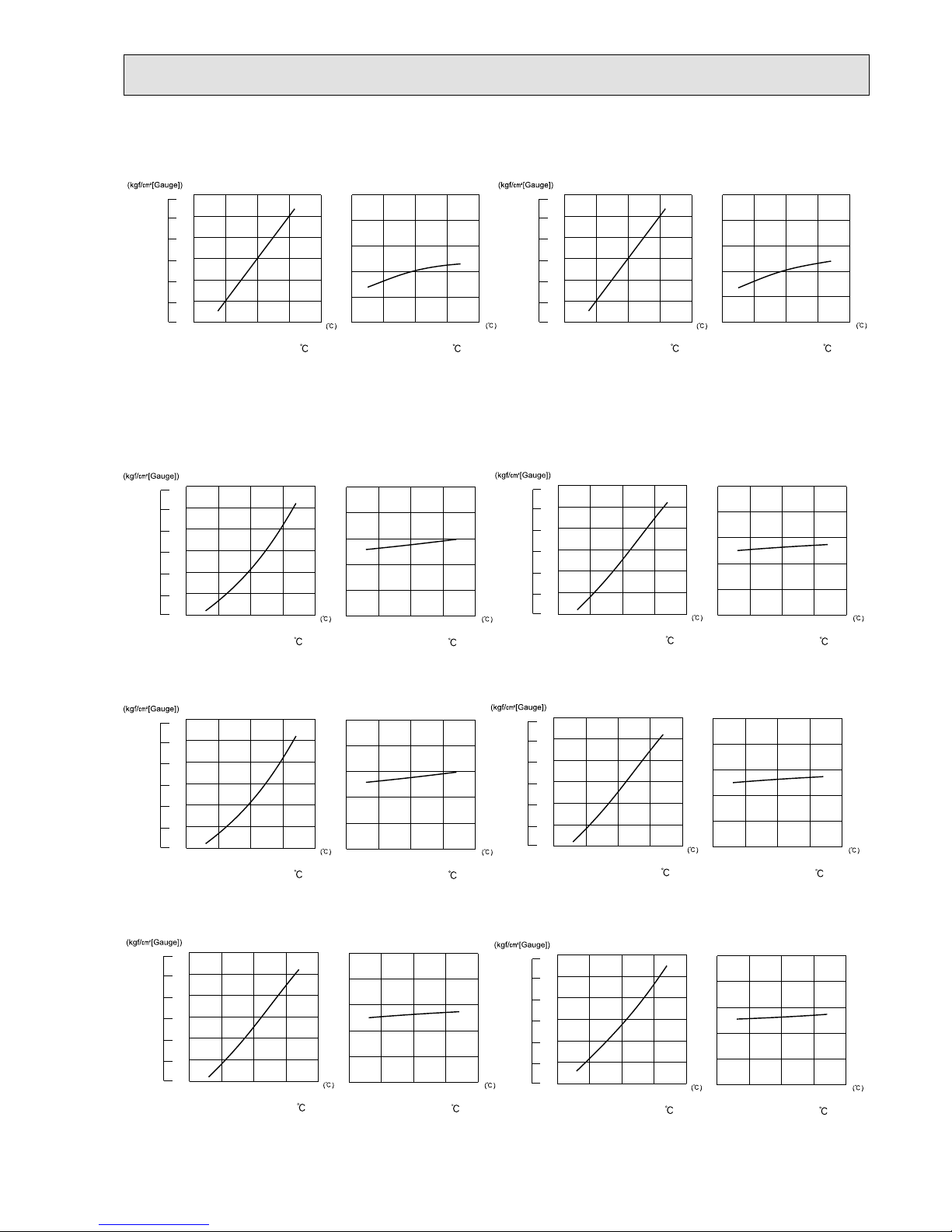
77
MXZ-2E53VAHZ
Outdoor low pressure
(MPa[Gauge])
Outdoor unit current (A)
Ambient temperature ( )
Ambient humidity (%)
Ambient temperature ( )
Ambient humidity (%)
50 60
70
(%)
50 60
70
(%)
24Hz
24Hz
13
12
11
10
9
8
7
15 20 25 30 35
0.7
0.8
0.9
1.0
1.1
1.2
1.3
15 20 25 30 35
1
2
3
4
5
6
42-class unit
Outdoor low pressure
(MPa[Gauge])
Outdoor unit current (A)
Ambient temperature ( )
Ambient humidity (%)
Ambient temperature ( )
Ambient humidity (%)
50 60
70
(%)
50 60
70
(%)
24Hz
24Hz
13
12
11
10
9
8
7
15 20 25 30 35
0.7
0.8
0.9
1.0
1.1
1.2
1.3
15 20 25 30 35
1
2
3
4
5
6
50-class unit
MXZ-4E83VAHZ
15-class unit
Outdoor low pressure
(MPa[Gauge])
Outdoor unit current (A)
Ambient temperature ( )
Ambient humidity (%)
Ambient temperature ( )
Ambient humidity (%)
50 60
70
(%)
50 60
70
(%)
18Hz
18Hz
13
12
11
10
9
8
7
15 20 25 30 35
0.7
0.8
0.9
1.0
1.1
1.2
1.3
15 20 25 30 35
1
2
3
4
5
6
18-class unit
Outdoor low pressure
(MPa[Gauge])
Outdoor unit current (A)
Ambient temperature ( )
Ambient humidity (%)
Ambient temperature ( )
Ambient humidity (%)
50 60
70
(%)
50 60
70
(%)
18Hz
18Hz
14
13
12
12
10
9
8
15 20 25 30 35
0.8
0.9
1.0
1.1
1.2
1.3
1.4
15 20 25 30 35
1
2
3
4
5
6
20-class unit
Outdoor low pressure
(MPa[Gauge])
Outdoor unit current (A)
Ambient temperature ( )
Ambient humidity (%)
Ambient temperature ( )
Ambient humidity (%)
50 60
70
(%)
50 60
70
(%)
18Hz
18Hz
13
12
11
10
9
8
7
15 20 25 30 35
0.7
0.8
0.9
1.0
1.1
1.2
1.3
15 20 25 30 35
1
2
3
4
5
6
Outdoor low pressure
(MPa[Gauge])
Outdoor unit current (A)
Ambient temperature ( )
Ambient humidity (%)
Ambient temperature ( )
Ambient humidity (%)
50 60
70
(%)
50 60
70
(%)
18Hz
18Hz
14
13
12
12
10
9
8
15 20 25 30 35
0.8
0.9
1.0
1.1
1.2
1.3
1.4
15 20 25 30 35
1
2
3
4
5
6
25-class unit
22-class unit
Outdoor low pressure
(MPa[Gauge])
Outdoor unit current (A)
Ambient temperature ( )
Ambient humidity (%)
Ambient temperature ( )
Ambient humidity (%)
50 60
70
(%)
50 60
70
(%)
18Hz
18Hz
14
13
12
12
10
9
8
15 20 25 30 35
0.8
0.9
1.0
1.1
1.2
1.3
1.4
15 20 25 30 35
1
2
3
4
5
6
Outdoor low pressure
(MPa[Gauge])
Outdoor unit current (A)
Ambient temperature ( )
Ambient humidity (%)
Ambient temperature ( )
Ambient humidity (%)
50 60
70
(%)
50 60
70
(%)
18Hz
18Hz
14
13
12
11
10
9
8
15 20 25 30 35
0.8
0.9
1.0
1.1
1.2
1.3
1.4
15 20 25 30 35
1
2
3
4
5
6
35-class unit
OBH723D

78
MXZ-4E83VAHZ
Outdoor low pressure
(MPa[Gauge])
Outdoor unit current (A)
Ambient temperature ( )
Ambient humidity (%)
Ambient temperature ( )
Ambient humidity (%)
50 60
70
(%)
50 60
70
(%)
18Hz
18Hz
15
13
12
11
10
9
8
14
15 20 25 30 35
0.8
0.9
1.0
1.1
1.2
1.3
1.4
1.5
15 20 25 30 35
1
2
3
4
5
6
Outdoor low pressure
(MPa[Gauge])
Outdoor unit current (A)
Ambient temperature ( )
Ambient humidity (%)
Ambient temperature ( )
Ambient humidity (%)
50 60
70
(%)
50 60
70
(%)
18Hz
18Hz
15
13
12
11
10
9
8
14
15 20 25 30 35
0.8
0.9
1.0
1.1
1.2
1.3
1.4
1.5
15 20 25 30 35
1
2
3
4
5
6
50-class unit
60-class unit
Outdoor low pressure
(MPa[Gauge])
Outdoor unit current (A)
Ambient temperature ( )
Ambient humidity (%)
Ambient temperature ( )
Ambient humidity (%)
50 60
70
(%)
50 60
70
(%)
18Hz
18Hz
15
13
12
11
10
9
8
14
15 20 25 30 35
0.8
0.9
1.0
1.1
1.2
1.3
1.4
1.5
15 20 25 30 35
1
2
3
4
5
6
71-class unit
Outdoor low pressure
(MPa[Gauge])
Outdoor unit current (A)
Ambient temperature ( )
Ambient humidity (%)
Ambient temperature ( )
Ambient humidity (%)
50 60
70
(%)
50 60
70
(%)
18Hz
18Hz
14
13
12
11
10
9
8
15 20 25 30 35
0.8
0.9
1.0
1.1
1.2
1.3
1.4
15 20 25 30 35
1
2
3
4
5
6
42-class unit
OBH723D
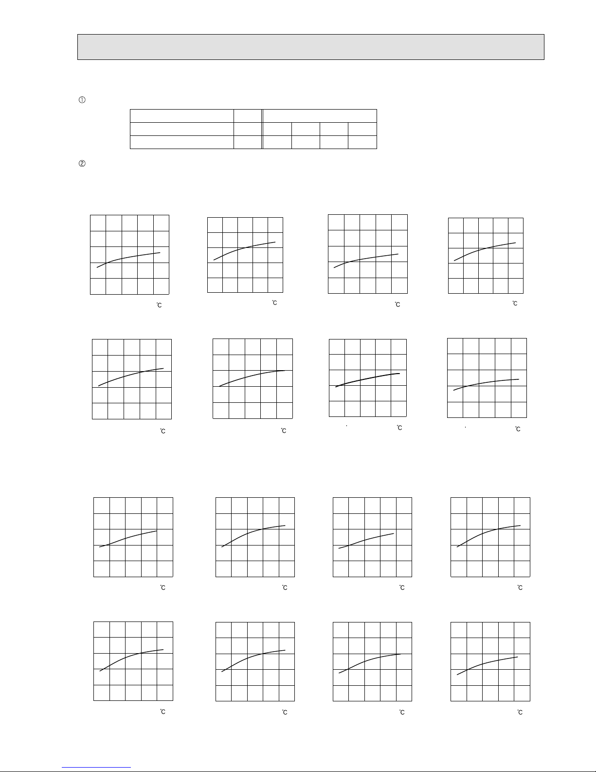
79
Condition:
Operation: TEST RUN OPERATION (Refer to 8-3.)
(2) HEAT operation
Dry bulb temperature (°C)
Indoor
20.0
14.5
2
1
Outdoor
7
6
151220.0
14.5
Wet bulb temperature (°C)
22-class unit
25-class unit
35-class unit
MXZ-3E54VA
42-class unit
50-class unit
15-class unit
20-class unit
50 10152025
2
3
4
5
6
7
Ambient temperature ( )
48Hz
Outdoor unit current (A)
5010152025
2
3
4
5
6
7
Ambient temperature ( )
48Hz
Outdoor unit current (A)
5010152025
2
3
4
5
6
7
Ambient temperature ( )
48Hz
Outdoor unit current (A)
Ambient temperature (
)
Outdoor unit current (A)
48Hz
0 5 10 15 20 25
2
3
4
5
6
7
5010152025
2
3
4
5
6
7
Ambient temperature ( )
48Hz
Outdoor unit current (A)
Ambient temperature ( )
Outdoor unit current (A)
48Hz
0510
15 20 25
2
3
4
5
6
7
Outdoor unit current (A)
Ambient temperature ( )
48Hz
0510
15 20 25
2
3
4
5
6
7
18-class unit
50 10152025
2
3
4
5
6
7
Ambient temperature ( )
48Hz
Outdoor unit current (A)
22-class unit
25-class unit
35-class unit
MXZ-3E68VA MXZ-4E72VA
42-class unit 50-class unit
15-class unit
20-class unit
Ambient temperature ( )
Outdoor unit current (A)
36Hz
0510
15 20 25
2.0
3.0
4.0
5.0
6.0
7.0
Ambient temperature ( )
Outdoor unit current (A)
36Hz
0510
15 20 25
3.0
4.0
5.0
6.0
7.0
8.0
Ambient temperature ( )
Outdoor unit current (A)
36Hz
0510
15 20 25
2.0
3.0
4.0
5.0
6.0
7.0
Ambient temperature ( )
Outdoor unit current (A)
36Hz
0510
15 20 25
3.0
4.0
5.0
6.0
7.0
8.0
Ambient temperature ( )
Outdoor unit current (A)
36Hz
0510
15 20 25
3.0
4.0
5.0
6.0
7.0
8.0
Ambient temperature ( )
Outdoor unit current (A)
36Hz
0510
15 20 25
3.0
4.0
5.0
6.0
7.0
8.0
Ambient temperature ( )
Outdoor unit current (A)
36Hz
0510
15 20 25
3.0
4.0
5.0
6.0
7.0
8.0
18-class unit
Ambient temperature ( )
Outdoor unit current (A)
36Hz
0510
15 20 25
3.0
4.0
5.0
6.0
7.0
8.0
OBH723D

80
60-class unit
Ambient temperature ( )
Outdoor unit current (A)
36Hz
0510
15 20 25
2.0
3.0
4.0
5.0
6.0
7.0
35-class unit
0 5 10 15 20 25
2
3
4
5
6
7
Ambient temperature ( )
32Hz
Outdoor unit current (A)
42-class unit
0 5 10 15 20 25
2
3
4
5
6
7
Ambient temperature ( )
32Hz
Outdoor unit current (A)
50-class unit
0 5 10 15 20 25
2
3
4
5
6
7
Ambient temperature ( )
32Hz
Outdoor unit current (A)
0 5 10 15 20 25
2
3
4
5
6
7
Ambient temperature ( )
32Hz
Outdoor unit current (A)
60-class unit
0 5 10 15 20 25
2
3
4
5
6
7
Ambient temperature ( )
32Hz
Outdoor unit current (A)
22-class unit 25-class unit
0 5 10 15 20 25
2
3
4
5
6
7
Ambient temperature ( )
32Hz
Outdoor unit current (A)
MXZ-4E83VA
15-class unit
20-class unit
0 5 10 15 20 25
2
3
4
5
6
7
Ambient temperature ( )
32Hz
Outdoor unit current (A)
0 5 10 15 20 25
2
3
4
5
6
7
Ambient temperature ( )
32Hz
Outdoor unit current (A)
71-class unit
0 5 10 15 20 25
2
3
4
5
6
7
Ambient temperature ( )
32Hz
Outdoor unit current (A)
18-class unit
0 5 10 15 20 25
2
3
4
5
6
7
Ambient temperature ( )
32Hz
Outdoor unit current (A)
MXZ-5E102VA
15-class unit
0 5 10 15 20 25
2
3
4
5
6
7
Ambient temperature ( )
32Hz
Outdoor unit current (A)
18-class unit
0 5 10 15 20 25
2
3
4
5
6
7
Ambient temperature ( )
32Hz
Outdoor unit current (A)
0 5 10 15 20 25
2
3
4
5
6
7
Ambient temperature ( )
32Hz
Outdoor unit current (A)
22-class unit 20-class unit
0 5 10 15 20 25
2
3
4
5
6
7
Ambient temperature ( )
32Hz
Outdoor unit current (A)
25-class unit
0 5 10 15 20 25
2
3
4
5
6
7
Ambient temperature ( )
32Hz
Outdoor unit current (A)
35-class unit
0 5 10 15 20 25
2
3
4
5
6
7
Ambient temperature ( )
32Hz
Outdoor unit current (A)
MXZ-3E68VA MXZ-4E72VA
50-class unit
0 5 10 15 20 25
2
3
4
5
6
7
Ambient temperature ( )
32Hz
Outdoor unit current (A)
42-class unit
0 5 10 15 20 25
2
3
4
5
6
7
Ambient temperature ( )
32Hz
Outdoor unit current (A)
OBH723D

81
0 5 10 15 20 25
2
3
4
5
6
7
Ambient temperature ( )
32Hz
Outdoor unit current (A)
60-class unit 71-class unit
0 5 10 15 20 25
2
3
4
5
6
7
Ambient temperature ( )
32Hz
Outdoor unit current (A)
MXZ-5E102VA
35-class unit
0 5 10 15 20 25
2
3
4
5
6
7
Ambient temperature ( )
32Hz
Outdoor unit current (A)
42-class unit
0 5 10 15 20 25
2
3
4
5
6
7
Ambient temperature ( )
32Hz
Outdoor unit current (A)
50-class unit
0 5 10 15 20 25
2
3
4
5
6
7
Ambient temperature ( )
32Hz
Outdoor unit current (A)
0 5 10 15 20 25
2
3
4
5
6
7
Ambient temperature ( )
32Hz
Outdoor unit current (A)
22-class unit 25-class unit
0 5 10 15 20 25
2
3
4
5
6
7
Ambient temperature ( )
32Hz
Outdoor unit current (A)
MXZ-2E53VAHZ
15-class unit
20-class unit
0 5 10 15 20 25
2
3
4
5
6
7
Ambient temperature ( )
32Hz
Outdoor unit current (A)
0 5 10 15 20 25
2
3
4
5
6
7
Ambient temperature ( )
32Hz
Outdoor unit current (A)
18-class unit
0 5 10 15 20 25
2
3
4
5
6
7
Ambient temperature ( )
32Hz
Outdoor unit current (A)
MXZ-4E83VAHZ
15-class unit
0 5 10 15 20 25
2
3
4
5
6
7
Ambient temperature ( )
20Hz
Outdoor unit current (A)
18-class unit
0 5 10 15 20 25
2
3
4
5
6
7
Ambient temperature ( )
20Hz
Outdoor unit current (A)
0 5 10 15 20 25
2
3
4
5
6
7
Ambient temperature ( )
20Hz
Outdoor unit current (A)
22-class unit 20-class unit
0 5 10 15 20 25
2
3
4
5
6
7
Ambient temperature ( )
20Hz
Outdoor unit current (A)
25-class unit
0 5 10 15 20 25
2
3
4
5
6
7
Ambient temperature ( )
20Hz
Outdoor unit current (A)
35-class unit
0 5 10 15 20 25
2
3
4
5
6
7
Ambient temperature ( )
20Hz
Outdoor unit current (A)
50-class unit
0 5 10 15 20 25
2
3
4
5
6
7
Ambient temperature ( )
20Hz
Outdoor unit current (A)
42-class unit
0 5 10 15 20 25
2
3
4
5
6
7
Ambient temperature ( )
20Hz
Outdoor unit current (A)
0 5 10 15 20 25
2
3
4
5
6
7
Ambient temperature ( )
20Hz
Outdoor unit current (A)
60-class unit 71-class unit
0 5 10 15 20 25
2
3
4
5
6
7
Ambient temperature ( )
20Hz
Outdoor unit current (A)
OBH723D

82
ACTUATOR CONTROL
9
Relation between main sensor and actuator
Sensor Purpose
Actuator
Compres-
sor
LEV
Outdoor
fan motor
4-way
valve
2-way
solenoid
valve
1
Defrost
heater
2
Discharge temperature
thermistor
Protection
Indoor coil
temperature thermistor
Cooling: Coil frost prevention
Heating:
High pressure protection
Defrost thermistor Heating: Defrosting
Fin temperature thermistor Protection
Ambient temperature
thermistor
Control/Protection
Heating: Defrosting (Heater)
Outdoor heat exchanger
temperature thermistor
Cooling: Control/Protection
Capacity code Control
1 MXZ-4E83VAHZ
2 MXZ-2E53VAHZ, 4E83VAHZ
MXZ-3E54VA MXZ-3E68VA MXZ-4E72VA
MXZ-4E83VA MXZ-5E102VA MXZ-2E53VAHZ MXZ-4E83VAHZ
OBH723D

83
SERVICE FUNCTIONS
10
10-1. PRE-HEAT CONTROL
If moisture gets into the refrigerant cycle, or when refrigerant is liquefied and collected in the compressor, it may interfere
the startup of the compressor.
To improve startup condition, the compressor is energized even while it is not operating.
This is to generate heat at the winding.
The compressor uses about 50 W when pre-heat control is turned ON.
Pre-heat control is ON at initial setting.
[How to deactivate pre-heat control]
Turn OFF the power supply for the air conditioner before making the setting.
Set the "4" of SW2 on the outdoor control P.C. board to ON to deactivate pre-heat control function.
Turn ON the power supply for the air conditioner.
NOTE: Pre-heat control will be turned OFF when the breaker is turned OFF.
Outdoor control P.C. board
SW871
LED
SW1
With this function, you can lock the operation mode of the outdoor unit.
Once the operation mode is locked to either COOL/DRY mode or HEAT mode, the air conditioner
operates in that mode only.
Default setting is required to activate this function.
Please explain about this function to your customers and ask them whether they want to use it.
[How to lock the operation mode]
(1) Turn OFF the power supply and make sure that the LED goes off.
(2) Set SW1 on the outdoor control P.C. board.
(3) Turn ON the power supply.
10-2. LOCKING THE OPERATION MODE OF THE AIR CONDITIONER (COOL, DRY, HEAT) (MXZ-4E83VAHZ)
ON
5
6
SW1
ON
5
6
SW1
Cool/Dry Heat
10-3. LOWERING THE OPERATING NOISE OF THE OUTDOOR UNIT (MXZ-4E83VAHZ)
With this function, you can lower the operating noise of the outdoor unit when the operation load is small,
for example, during night time in COOL mode.
However, note that the cooling and heating capacity can also be lowered if this function is activated.
Default setting is required to activate this function.
Please explain about this function to your customers and ask them whether they want to use it.
[How to lower the operating noise]
(1) Turn OFF the power supply and make sure that the LED goes off.
(2) Set the "5" Switch of SW1 on the outdoor control P.C. board to ON to enable this function.
(3) Turn ON the power supply.
ON
5
6
SW1
MXZ-3E54VA MXZ-3E68VA MXZ-4E72VA
MXZ-4E83VA MXZ-5E102VA MXZ-2E53VAHZ MXZ-4E83VAHZ
OBH723D

84
10-4. AUTO LINE CORRECTING
Outdoor unit has an auto line correcting function which automatically detects and corrects improper wiring or piping.
Improper wiring or piping can be automatically detected by pressing the piping/wiring correction switch (SW871).
When improper wiring or piping is detected, wiring lines are corrected.
This will be completed in about 10 to 20 minutes.
[How to activate this function]
1. Check that outside temperature is above 0˚C.
(This function does not work when outside temperature is not above 0˚C.)
2. Check that the stop valves of the liquid pipe and gas pipe are open.
3. Check that the wiring between indoor and outdoor unit is correct.
(If the wiring is not correct, this function does not work.)
4. Turn ON the power supply and wait at least 1 minute.
5. Press the piping/wiring correction switch (SW871) on the outdoor control P.C. board.
Do not touch energized parts.
6. Press the switch to cancel.
NOTE: Indoor unit cannot be operated while this function is
activated.
When this function is activated while indoor unit is operating, the operation will be stopped.
Operate indoor unit after the auto line correcting is finished.
Pressing the switch during detection cancels this function.
Make sure that the valves are open and the pipes are not collapsed or clogged.
LED indication after cancel :
LED1 (Red)
Lighted
LED indication during detection:
LED indication after detection:
LED2 (Yellow)
Lighted
LED3 (Green)
Once
LED1 (Red)
Lighted
LED2 (Yellow)
Lighted
LED3 (Green)
Not lighted
LED1 (Red)
Lighted
Once
LED2 (Yellow)
Not lighted
Once
Other indications
LED3 (Green)
Lighted
Once
Completed (Problem corrected/ normal)
Not completed (Detection failed)
Refer to "SAFETY PRECAUTIONS WHEN LED FLASHES"
located behind the service panel.
Indication
Press the switch for more than 5 seconds.
LED will show the record of auto correcting for about 30 seconds as shown in the table below:
NOTE: Activate this function to confirm the correct wiring after replacing the outdoor control P.C. board.
(Previous records are deleted when the outdoor control P.C. board is replaced.)
The record cannot be shown if auto line correcting is not canceled (Refer to "How to activate this function").
LED1 (Red)
Once
3 times
LED2 (Yellow)
Once
3 times
LED3 (Green)
Lighted
Lighted
Not corrected
Corrected
Number of blinks
Wiring line
The record of auto line correcting can be confirmed in the following way:
OBH723D

85
10-5. CHANGING THE AMPERE LIMIT (MXZ-2E53VAHZ MXZ-4E83VAHZ)
With this function, the amount of current that flows in the outdoor unit can be changed.
NOTE: Use this function only when the amount of current exceeds the allowed value.
[How to change the ampere limit]
(1) Be sure to turn off the main power for the air conditioner before making the setting.
(2) Make the setting referring to the table below.
(3) Turn ON the power supply.
SW2 on the outdoor control P.C. board
SW2
MXZ-2E53VAHZ MXZ-4E83VAHZ
Factory setting
13.6 A
21 A
18.4 A
Factory setting
25 A
OBH723D

86
11
TROUBLESHOOTING
3. Troubleshooting procedure
1)
Check if the OPERATION INDICATOR lamp on the indoor unit is f ashing on and off to indicate an abnormality. To
make sure, check how many times the OPERATION INDICATOR lamp is f ashing on and off before starting service
work
.
2) Before servicing, check that the connector and terminal are connected properly.
3) When the P.C. board seems to be defective, check the copper foil pattern for disconnection and the components for
bursting and discoloration.
4) Refer to 11-2, 11-3 and 11-4.
11-1. CAUTIONS ON TROUBLESHOOTING
1. Before troubleshooting, check the following:
1) Check the power supply voltage.
2) Check the indoor/outdoor connecting wire for miswiring.
2. Take care of the following during servicing
1) Before servicing the air conditioner, be sure to turn OFF the unit f rst with the remote controller, and after conf rming
the horizontal vane is closed, turn OFF the breaker and/or disconnect the power plug.
2) Be sure to turn OFF the power supply before removing the front panel, the cabinet, the top panel, and the P.C. board.
3) When removing the electrical parts, be careful of the residual voltage of smoothing capacitor.
4) When removing the P.C. board, hold the edge of the board with care NOT to apply stress on the components.
5) When connecting or disconnecting the connectors, hold the connector housing. DO NOT pull the lead wires.
11-2. FAILURE MODE RECALL FUNCTION
This air conditioner can memorize the abnormal condition which has occurred once.
Even though LED indication listed on the troubleshooting check table (11-4.) disappears, the memorized failure details
can be recalled.
1. Flow chart of failure mode recall function for the indoor/outdoor unit
Refer to the service manual of indoor unit.
Lead wiring
Connector housing
<Incorrect>
<Correct>
MXZ-3E54VA MXZ-3E68VA MXZ-4E72VA
MXZ-4E83VA MXZ-5E102VA MXZ-2E53VAHZ MXZ-4E83VAHZ
OBH723D

87
2. Flow chart of the detailed outdoor unit failure mode recall function
2.Blinking pattern when outdoor unit is abnormal:
ON
OFF
No beep
Beeps
Repeated cycle
2.5-second OFF 3-second ON
Blinking at 0.5second interval
No beep Beeps
Repeated cycle
2.5-second OFF 3-second ON
Blinking at 0.5-
second interval
Repeated cycle
Does the OPERATION INDICATOR lamp on the
indoor unit blink at the interval of 0.5 seconds?
Blinks: The outdoor unit is abnormal. Beep is emit-
ted at the same timing as the blinking of the
OPERATION INDICATOR lamp.
2
Yes
(Blinks
)
No
(OFF)
The outdoor unit might be abnormal.
Check if outdoor unit is abnormal according to the following procedures.
Operational procedure
With the remote controller headed towards the indoor unit, press the
TEMPERATURE buttons to adjust the set temperature to 25°C.
1
1 Regardless of normal or abnormal condition, 2 short
beeps are emitted as the signal is received.
The outdoor unit is abnormal.
Check the blinking pattern, and make sure that the abnormal point with
the table of outdoor unit failure mode recall function (11-2.3.).
Make sure to check at least 2 consecutive blinking cycles.
2
Repair the failure parts.
The outdoor unit is normal.
Release the failure mode recall function. 3
NOTE: 1. Make sure to release the failure mode recall function after it is set up, otherwise the unit cannot operate properly.
2. If the abnormal condition is not deleted from the memory, the last abnormal condition is kept memorized.
Delete the memorized abnormal condition. 3
Release the failure mode recall function. 3
3 Refer to the service manual of indoor unit.
Release the failure mode recall function. 3
Make sure that the remote controller is set to the failure mode recall function.
3
OBH723D

88
3. Table of outdoor unit failure mode recall function
The left lamp of
OPERATION IN-
DICATOR lamp
(Indoor unit)
Abnormal point
(Failure mode/protection)
LED indication
(Outdoor P.C.
board)
Condition Remedy
Indoor/
outdoor unit
failure mode
recall function
LED1 LED2
OFF None (Normal) Lighted Lighted
2-time f ash Outdoor power system Lighted Lighted
Overcurrent protection cut-out operates 3 consecutive times within 1 minute after the compressor gets started, or converter protection
cut-out or bus-bar voltage protection cut-out
operates 3 consecutive times within 3 minutes
after startup.
• Check the connection of the compressor connecting wire.
• Refer to 11-6.
"How to check inverter/compres-
sor".
• Check the stop valve.
○
3-time f ash
Discharge temperature thermistor
Lighted Once
A thermistor shorts or opens during
compressor running.
• Refer to 11-6. "Check of outdoor
thermistors".
○
Defrost thermistor
Lighted Once
Ambient temperature thermistor
Lighted Twice
Fin temperature thermistor
Lighted 3 times
P.C. board temperature thermistor
Lighted 4 times • Replace the outdoor control P.C.
board.
Outdoor heat exchanger temperature thermistor
Lighted 9 times • Refer to 11-6.
"Check of outdoor
thermistors".
4-time f ash Overcurrent Once Not
lighted
21 A current f ows into power module.
• Reconnect compressor connector.
• Refer to 11-6.
"How to check in-
verter/compressor".
• Check the stop valve.
—
5-time f ash Discharge temperature Lighted Lighted
The discharge temperature exceeds 115°C
(MXZ-3E54/3E68/4E72VA)/ 106°C(MXZ-
4E83/5E102VA, MXZ-2E52VAHZ)/ 116°C
(MXZ-4E83VAHZ) during operation.
Compressor can restart if discharge temperature thermistor reads 80°C (MXZ-
3E54/3E68/4E72VA)/95°C (MXZ4E83/5E102VA, MXZ-2E52VAHZ)/100°C
(MXZ-4E83VAHZ) or less 3 minutes later.
• Check refrigerant circuit and refrigerant amount.
• Refer to 11-6.
"Check of LEV".
—
6-time f ash High pressure Lighted Lighted
The outdoor heat exchanger temperature exceeds 70°C during cooling or the indoor gas pipe
temperature exceeds 70°C during heating.
• Check refrigerant circuit and refrigerant amount.
• Check the stop valve.
—
7-time f ash Fin temperature 3 times Not
lighted
The fin temperature exceeds 88°C (MXZ-
3E54/3E68/4E72/4E83/5E102VA, MXZ2E52VAHZ)/89°C (MXZ-4E83VAHZ) during
operation.
• Check around outdoor unit.
• Check outdoor unit air passage.
• Refer to 11-6.
"Check of outdoor
fan motor".
—
P.C. board temperature 4 times Not
lighted
The P.C. board temperature exceeds 67°C
(MXZ-3E54/3E68/4E72/4E83/5E102VA, MXZ-
2E52VAHZ)/87°C (MXZ-4E83VAHZ) during
operation.
8-time f ash Outdoor fan motor Lighted Lighted
A failure occurs 3 consecutive times within 30
seconds after the fan gets started.
• Refer to 11-6. "Check of outdoor
fan motor".
—
9-time f ash Outdoor control system Lighted 5 times
Nonvolatile memory data cannot be read properly.
• Replace the outdoor control P.C. board.
○
10-time f ash Low discharge temperature
protection
Lighted Lighted
The frequency of the compressor is kept 80 Hz
or more and the discharge temperature is kept
under 39°C for more than 20 minutes.
• Check refrigerant circuit and refrigerant amount.
• Refer to 11-6.
"Check of LEV".
—
11-time f ash Communication error
between P.C. boards
Lighted 6 times
Communication error occurs between the outdoor control P.C. board and outdoor power P.C.
board for more than 10 seconds.
• Check the connecting wire between
outdoor control P.C. board and outdoor power P.C. board.
—
The communication between boards protection cut-out operates 2 consecutive times.
○
Current sensor Lighted 7 times
A short or open circuit is detected in the current sensor during compressor operating.
—
—
Current sensor protection cut-out operates 2
consecutive times.
○
Zero cross detecting circuit 5 times Not
lighted
Zero cross signal cannot be detected while the
compressor is operating.
• Check the connecting wire among
outdoor control P.C. board and outdoor power P.C. board.
—
The protection cut-out of the zero cross
detecting circuit operates 10 consecutive
times.
○
Converter 5 times Not
lighted
A failure is detected in the operation of the
converter during operation.
• Check the voltage of power supply.
• Replace the outdoor power P.C.
board.
—
Bus-bar voltage 5 times Not
lighted
The bus-bar voltage exceeds 400 V or falls to
low level during compressor operating.
• Check the voltage of power supply.
• Replace the outdoor control P.C.
board.
15-time f ash LEV and drain pump Lighted Lighted The indoor unit detects an abnormality in
the LEV and drain pump.
• Refer to 11-6.
"Check of LEV".
• Check the drain pump of the indoor
unit.
—
NOTE: Blinking patterns of this mode differ from the ones of
Troubleshooting check table (11-4.).
OBH723D

89
Operation start
Check the outdoor unit
LED indicator.
Refer to 11-6.
"Check of power supply".
• Indoor unit
serial signal
error
Refer to 11-6.
"How to
check
miswiring and
serial signal
error".
• COOL or
HEAT
operation only
Refer to 11-6.
"Check of
R.V. coil".
• When cooling,
room is not
cool.
Refer to 11-6.
"How to check
inverter/
compressor".
• When cooling, heat
exchanger of
non-operating indoor
unit frosts.
• When heating, nonoperating indoor unit
gets warm.
Refer to 11-6.
"Check of LEV".
• When heating,
room does not get
warm.
Refer to 11-6.
"How to check
inverter/compressor".
Check mispiping,
shortage of capacity.
• When cooling
dew drops in the
non-operating
indoor unit.
Check of
mispiping.
Refer to 11-4.
"Troubleshooting check table".
Both LED1 and
LED2 are OFF.
Both LED1 and
LED2 are lighting.
LED1 or LED2
has blinked.
11-3. INSTRUCTION OF TROUBLESHOOTING
• Check the indoor unit with referring to the indoor unit service manual, and confirm that there is any problem in the indoor
unit.
Then, check the outdoor unit with referring to this page.
OBH723D

90
11-4. TROUBLESHOOTING CHECK TABLE
No. Symptom
Indication
Abnormal point / Con-
dition
Condition Remedy
LED1(Red) LED2(Yellow)
1 Outdoor
unit does
not operate.
Lighted Once LEV and drain pump
The indoor unit detects an abnormality in the LEV
and drain pump.
• Refer to 11-6.
"Check of LEV".
• Check the drain pump of the indoor unit.
2
Lighted Twice
Outdoor power
system
Overcurrent protection cut-out operates 3 consecutive times within 1 minute after the compressor
gets started, or converter protection cut-out or busbar voltage protection cut-out operates 3 consecutive times within 3 minutes after startup.
• Check the connection of the compressor connecting wire.
• Refer to 11-6.
"How to check inverter/compres-
sor".
• Check the stop valve.
3
Lighted 3 times
Discharge temperature
thermistor
A short circuit is detected in the thermistor during
operation, or an open circuit is detected in the thermistor after 10 minutes of compressor startup.
• Refer to 11-6.
"Check of outdoor thermistors".
4
Lighted 4 times
Fin temperature
thermistor
A short or open circuit is detected in the thermistor
during operation.
• Refer to 11-6.
"Check of outdoor thermistors".
P. C. board temperature thermistor
• Replace the outdoor control P.C. board.
5
Lighted 5 times
Ambient temperature
thermistor
A short or open circuit is detected in the thermistor
during operation.
• Refer to 11-6.
"Check of outdoor thermistors".
Outdoor heat exchanger temperature
thermistor
A short circuit is detected in the thermistor during
operation, or an open circuit is detected in the thermistor after 5 minutes (in cooling) and 10 minutes
(in heating) of compressor startup.
Defrost thermistor
A short circuit is detected in the thermistor during
operation, or an open circuit is detected in the thermistor after 5 minutes of compressor startup.
6
Lighted 6 times
Zero cross detecting
circuit (Outdoor control
P.C. board)
Zero cross signal cannot be detected. • Replace the outdoor control P.C. board.
7
Lighted 7 times Outdoor control system
The nonvolatile memory data cannot be read
properly.
• Replace the outdoor control P.C. board.
8
Lighted 8 times Current sensor
Current sensor protection cut-out operates 2 consecutive times.
• Replace the outdoor power P.C. board.
9
Lighted 11 times
Communication error
between P.C. boards
The communication protection cut-out between
boards operates 2 consecutive times.
• Check the connecting wire between outdoor control P.C. board and outdoor power P.C. board.
M-NET communication
error
M-NET adapter P.C. board detects an abnormality
in the communication error.
• Check the connecting wire between M-NET
adapter P.C. board and outdoor control P.C.
board, or terminal block.
10
Lighted 12 times
Zero cross detecting
circuit (Outdoor power
P.C. board)
The protection cut-out of the zero cross detecting
circuit operates 10 consecutive times.
• Replace the outdoor power P.C. board.
11
Lighted 13 times Current sensor
A short or open circuit is detected in the input current detection circuit during operation.
• Replace the outdoor power P.C. board.
12
Lighted 14 times Voltage sensor
A short or open circuit is detected in the input voltage detection circuit during operation.
• Replace the outdoor power P.C. board.
13 Lighted 15 times Relay operation No relay operation is detected during operation. • Replace the outdoor power P.C. board.
14 'Outdoor unit
stops and
restarts
3 minutes
later' is
repeated.
Twice Not lighted
IPM protection
Overcurrent is detected after 30 seconds of compressor startup.
• Reconnect compressor connector.
• Refer to 11-6.
"How to check inverter/
compressor".
• Check the stop valve.
• Check the power module (PAM module).
Lock protection
Overcurrent is detected within 30 seconds of compressor startup.
15
3 times Not lighted
Discharge temperature
protection
The discharge temperature exceeds 115°C (MXZ-
3E54/3E68/4E72VA)/ 106°C(MXZ-4E83/5E102VA,
MXZ-2E52VAHZ)/ 116°C (MXZ-4E83VAHZ) during
operation.
Compressor can restart if discharge temperature
thermistor reads 80°C (MXZ-3E54/3E68/4E72VA)/
95°C (MXZ-4E83/5E102VA, MXZ-2E52VAHZ)/
100°C (MXZ-4E83VAHZ) or less 3 minutes later.
• Check the amount of gas and refrigerant circuit.
• Refer to 11-6.
"Check of LEV".
16
4 times Not lighted
Fin temperature
protection
The f n temperature exceeds during operation.
•Check refrigerant circuit and refrigerant amount.
•Refer to 11-6.
"Check of outdoor fan motor".
P.C. board temperature
protection
The P.C. board temperature exceeds during operation.
17
5 times Not lighted
High pressure
protection
High pressure is detected with the high pressure
switch (HPS) during operation.
• Check around of gas and the refrigerant circuit.
• Check the stop valve.
The outdoor heat exchanger temperature exceeds
70°C during cooling or the indoor gas pipe temperature exceeds 70°C during heating.
18
6 times Not lighted Pre-heating protection Overcurrent is detected during pre-heating.
• Reconnect compressor connector.
• Refer to 11-6.
"How to check inverter/
compressor".
• Check the power module.
19
8 times Not lighted Converter protection
A failure is detected in the operation of the converter during operation.
• Replace the outdoor power P.C. board.
20
9 times Not lighted
Bus-bar voltage
protection
The bus-bar voltage exceeds 400 V or falls to low
level during compressor operating.
• Check the voltage of power supply.
• Replace the outdoor power P.C. board or the outdoor control P.C. board.
• Refer to 11-6.
"Check of bus-bar voltage".
21
11 times Not lighted
Low outside temperature protection(cooling)
The ambient became -12°C or less.
—
OBH723D

91
No. Symptom
Indication
Abnormal point / Con-
dition
Condition Remedy
LED1(Red) LED2(Yellow)
22 'Outdoor unit
stops and
restarts
3 minutes
later' is
repeated.
13 times Not lighted Outdoor fan motor
A failure occurs 3 consecutive times within 30
seconds after the fan gets started.
• Refer to 11-6.
"Check of outdoor fan motor".
23
Lighted 8 times
Current sensor protection
A short or open circuit is detected in the current
sensor during compressor operating.
• Replace the outdoor power P.C. board.
24
Lighted 11 times
Communication
between P.C. boards
protection
Communication error occurs between the outdoor
control P.C. board and outdoor power P.C. board
for more than 10 seconds.
• Check the connecting wire between outdoor control P.C. board and outdoor power P.C. board.
25
Lighted 12 times
Zero cross detecting
circuit (Outdoor power
P.C. board)
Zero cross signal cannot be detected while the
compressor is operating.
• Replace the outdoor power P.C. board.
26 Outdoor unit
operates. Once Lighted
Primary current protection
The input current exceeds 13.6 A (MXZ-2E53VAHZ)/
15 A (MXZ-3E54VA/3E68VA/4E72VA)/18.4 A (MXZ-
4E83VA/5E102VA)/25 A (MXZ-4E83VAHZ).
These symptoms do not mean any abnormality of
the product, but check the following points.
• Check if indoor f lters are clogged.
• Check if refrigerant is short.
• Check if indoor/outdoor unit air circulation is short
cycled.
27
Twice Lighted
High pressure protection
The indoor gas pipe temperature exceeds 45°C
during heating.
Defrosting in cooling
The indoor gas pipe temperature falls 3°C or below
during cooling.
28
3 times Lighted
Discharge temperature
protection
The frequency of the compressor is kept 80 Hz or
more and the discharge temperature is kept under
50°C(COOL mode)/40°C(HEAT mode) for more
than 40 minutes.
• Check refrigerant circuit and refrigerant amount.
• Refer to 11-6.
"Check of LEV".
• Refer to 11-6.
"Check of outdoor thermistors".
29
4 times Lighted
Low discharge
temperature protection
The frequency of the compressor is kept 80 Hz or
more and the discharge temperature is kept under
39°C for more than 20 minutes.
• Refer to 11-6.
"Check of LEV".
• Check refrigerant circuit and refrigerant amount.
30
5 times Lighted
Cooling high pressure
protection
The outdoor heat exchanger temperature exceeds
58°C during operation.
This symptom does not mean any abnormality of
the product, but check the following points.
• Check if indoor f lters are clogged.
• Check if refrigerant is short.
• Check if indoor/outdoor unit air circulation is short
cycled.
31
7 times Lighted
High Low
Pressure bypass
valve
Cooling evaporating
temperature drop
prevention control
During cooling operation, the temperature of indoor
heat exchanger becomes 3°C or less within 1 hour
after the compressor starts running, or it becomes
less than 12°C - 16°C* later than that.
* It depends on the difference between the set
temperature and the room temperature.
This symptom does not mean any abnormality of
the product, but check the following points.
• Check the indoor f lters are not clogged.
• Check there is suff cient refrigerant.
• Check the indoor/outdoor unit air circulation is not
short cycled.
32
11 times Lighted
M-NET communication
error
M-NET adapter P.C. board detects an abnormality
in the communication error.
• Check the connecting wire between M-NET
adapter P.C. board and outdoor control P.C.
board, or terminal block.
33
Outdoor
unit
operates
normally.
7 times Lighted
High Low
pressure bypass valve
High pressure protection control at startup of
heating operation
MXZ-4E83VAHZ
The room temperature is 24°C or more when 1 or
2 unit(s) start(s) the heating operation.
This symptom does not mean any abnormality of
the product.
High
Low
pressure bypass valve
Compressor oil tempering control at startup of
heating operation
MXZ-4E83VAHZ
Both the following are true:
• The outside temperature is -2°C or less when the
heating operation is started.
• [(Discharge temperature) - (Indoor heat exchanger temperature)] < 5°C
34
8 times Lighted
Cooling evaporating
temperature
protection
During cooling operation, the temperature of
indoor heat exchanger becomes 7°C - 11°C*
or less within 1 hour after the compressor
starts running, or it becomes 9°C - 17°C* or
less later than that.
* It depends on the indoor unit type/model or the
difference between the set temperature and the
room temperature.
35
9 times Lighted Inverter check mode
The unit is operated with emergency operation
switch.
—
36 Lighted Lighted Normal
——
NOTE 1. The location of LED is illustrated at the right figure. Refer to 11-7.1.
2. LED is lighted during normal operation.
The flashing frequency shows the number of times the LED blinks after every 2.5-second OFF.
(Example) When the flashing frequency is “2”.
ON
OFF
2.5-second OFF 2.5-second OFF
0.5-second ON 0.5-second ON
LED1
LED2
Lighted
Outdoor control P.C. board
(Parts side)
OBH723D

92
11-5. TROUBLE CRITERION OF MAIN PARTS
W
U
V
WHT
RED
BLK
LEV
WHT
RED
YLW
ORN
BLU
Linear expansion valve
37.4 Ω ~ 53.9 Ω
NormalColor of lead wire
WHT - RED
RED - ORN
YLW - RED
RED - BLU
High pressure switch
(HPS)
Pressure Normal
HPS
3.43 ± 0.15 MPa
4.41 ± 0.1 MPa
Open
Close
Discharge temperature
thermistor (RT62)
Part name Check method and criterion
Measure the resistance between terminals using a tester.
(Winding temperature: -10 °C ~ 40 °C)
Compressor
Outdoor fan motor
R.V. coil
Defrost thermistor (RT61)
Fin temperature
thermistor (RT64)
Ambient temperature
thermistor (RT65)
Outdoor heat exchanger
temperature thermistor
(RT68)
Measure the resistance with a tester.
Refer to 11-7. “Test point diagram and voltage”, 1. ”Outdoor control P.C.board”,
2. ”Outdoor power P.C. board”, for the chart of thermistor.
Measure the resistance with a tester.
Before measurement, hold the thermistor with your hands to warm it up.
Refer to 11-7. “Test point diagram and voltage”,1. ”Outdoor control P.C. board” for the chart of
thermistor.
0.83 Ω ~ 1.03 Ω0.63 Ω ~ 0.78 Ω0.86 Ω ~ 1.06 Ω
MXZ-3E54VA MXZ-3E68/4E72VA
MXZ-4E83/5E102VA
MXZ-2E53VAHZ
0.77 Ω ~ 0.95 Ω
MXZ-4E83VAHZ
Normal (Each phase)
MXZ-4E83/5E102VA
MXZ-2E53VAHZ
1.20 kΩ ~ 1.77 kΩ
MXZ-3E54/3E68/4E72VA
1.26 kΩ ~ 1.62 kΩ
MXZ-4E83VAHZ
1.24 kΩ ~ 1.86 kΩ
Normal (Each phase)
• Refer to 11-6. .
Measure the resistance using a tester. (Part temperature: -10 °C ~ 40 °C)
Measure the resistance using a tester. (Part temperature: -10 °C ~ 40 °C)
MXZ-3E54VA MXZ-3E68VA MXZ-4E72VA
MXZ-4E83VA MXZ-5E102VA MXZ-2E53VAHZ MXZ-4E83VAHZ
OBH723D

93
Check of power supply
Outdoor unit does not operate.
11-6. TROUBLESHOOTING FLOW
Turn ON the power supply.
No
Yes
Yes
No
No
Yes
Check the main power supply circuit for proper connections.
Is there voltage of 230 V AC in the
power supply terminal block?
Is the output voltage from the outdoor
power P.C. board 325 V DC?
Check the power supply cable.
Replace the outdoor power P.C. board.
Turn OFF the power supply and recconnect the reactor.
Is the reactor short-circuited?
Replace the reactor.
Replace the outdoor control P.C. board.
OBH723D

94
Is there rated voltage in
the power supply?
Is there any miswiring,
poor contact, or wire
disconnection of the
indoor/outdoor
connecting wire?
1 Miswiring may damage indoor electronic control
P.C. board during the operation.
Be sure to confirm the wiring is correct before the
operation starts.
(Lighted
or
not lighted)
No
Yes
No
Yes
Yes
No
Yes
No
Be sure to release the failure-mode
recall function after checking.
No
No
Yes
No
Yes
Yes
Yes
No
Yes
Refer to indoor unit service manual.
Turn OFF the power supply.
Turn ON the power supply.
Is there rated voltage between
outdoor terminal block S1 and
S2?
Does the left lamp of OPERATION
INDICATOR lamp light up?
<Confirmation of the power to the indoor unit>
Press EMERGENCY OPERATION switch once.
Check the power
supply.
A
Turn OFF the power supply.
Check once more if the indoor/outdoor
connecting wire is not miswiring.
Bridge the outdoor terminal block S2 and
S3.
1
B
Turn ON the power supply.
Check the wiring.
Correct them.
Turn OFF the power supply.
Remove the bridge between
outdoor terminal block S2 and S3.
Turn ON the power supply.
Is there amplitude of 10 to 20 V DC
between outdoor terminal block S2
and S3? <Confirmation of serial
signal>
Is there rated voltage between
indoor terminal block S1 and S2?
<Confirmation of power voltage>
Replace the indoor electronic control P.C. board.
2 Be careful of the residual
voltage of smoothing capacitor.
Replace the outdoor control P.C. board.
2
Is there any error of the
indoor/outdoor connecting wire,
such as the damage of the wire,
intermediate connection, poor
contact to the terminal block?
Replace the
indoor/outdoor
connecting wire.
Is serial signal
error indicated
6 minutes later?
Yes
No
· Turn OFF inverter-controlled lighting
equipment.
· Turn OFF the power supply and
then turn ON again.
· Press EMERGENCY OPERATION
switch.
B
· Reinstall
either the
unit or the
light away
from each
other.
· Attach a filter
on remote
control
receiving
section of
the indoor
unit.
A
Is serial signal error indicated 6 minutes later?
No
Does the LED on the outdoor control P.C.
board repeat "3.6-second-OFF
and 0.8-second-ON quick blinking"?
LED indication
for communication status
Communication status is indicated
by the LED.
Blinking: normal communication
Lighting: abnormal communication or
not connected
Pattern 1 and 2 is repeatedly displayed
alternately. Each pattern is displayed for
10 seconds.
NOTE: "Lighting" in the table below does not
indicate abnormal communication.
Unit status
Outdoor control P.C. board
Blinking
LED1 LED2
LED3
LED 1 LED 3LED 2
Pattern
1
2
3
Unit B
status
Unit C
status
Unit A
status
Unit D
status
Unit E
status
Not lighted
Lighted
Blinking
How to check miswiring and serial signal error (when outdoor unit does not work)
• When unit cannot operate neither by the remote controller nor by EMERGENCY OPERATION switch.
Indoor unit does not operate.
• When OPERATION INDICATOR lamp flashes ON and OFF in every 0.5-second.
Outdoor unit does not operate.
OBH723D
95
Check of R.V. coil
The cooling operation or heating operation does not operate.
No
Yes
No
Yes
No
Yes
No
Yes
1. Disconnect the lead wire leading to the compressor.
2. 3 minutes after turning ON the power supply, start EMERGENCY
OPERATION in COOL mode.
Is there voltage of 230 V AC between pin1
and pin2 at connector CN712?
Turn OFF the power supply.
Disconnect the connector CNAC2.
Replace the 4-way valve.
Replace the outdoor
control P.C. board.
Replace the R.V. coil.
Is there voltage 230 V AC
between the pin1 and pin3 at
connector CNAC?
Replace the outdoor
power P.C. board.
Is there normal resistance
to R.V. coil? (Refer to 11-5.)
1. Disconnect the lead wire leading to the compressor.
2. 3 minutes after turning ON the power supply, start EMERGENCY
OPERATION in HEAT mode.
Is there voltage of 230 V AC between pin1 and
pin2 at connector CN712?
Replace the 4-way valve.
Replace the outdoor control P.C. board.
• When cooling operation does not work.
• When heating operation does not work.
CNAC
CN712
Outdoor control
P.C. board
CNAC2
Outdoor power
P.C. board
OBH723D

96
Check of LEV
No
Yes
No
Yes
Turn ON the power supply to the outdoor unit after checking LEV coil is
mounted to the LEV body securely.
Is "click - click" sound heard?
Or, do you feel vibration of LEV coil with your hand?
Disconnect the connectors.
CN791: LEV A, CN792: LEV B,
CN793: LEV C (MXZ-3E/4E/5E),
CN794: LEV D (MXZ-4E/5E),
CN795: LEV E (MXZ-5E)
CN797: LEV R (MXZ-3E/4E72)
Is there normal resistance to LEV coil?
(Refer to 11-5.)
Normal
Replace the outdoor control P.C. board.
Replace LEV coil.
• When cooling, heat exchanger of non-operating indoor unit frosts.
• When heating, non-operating indoor unit gets warm.
CN791
CN792
CN793
CN794
CN795
Outdoor
control
P.C. board
OBH723D

97
How to check inverter/compressor
• When heating, room does not get warm.
• When cooling, room does not get cool.
Disconnect the terminal of the compressor or the connector (CNMC) between the compressor
and the outdoor power P.C. board.
3 minutes after the power supply is turned ON,
start EMERGENCY OPERATION.
Is output balanced?
Clarify the causes by counting time until the inverter stops.
0 to 10 seconds: compressor layer short
10 to 60 seconds: compressor lock
60 seconds to 5 minutes: refrigerant circuit defective
5 minutes or more: normal
Turn OFF the power supply of indoor and
outdoor unit, and measure the compressor
winding resistance between the compressor
terminals.
Is the resistance between each terminal normal?
(Refer to 11-5.)
Is the input voltage to the outdoor control
P.C. board 370 V or more?
Reconnect the lead wire of compressor, and turn ON
the power supply to indoor and outdoor unit.
3 minutes later, start EMERGENCY OPERATION.
Replace the compressor.
Replace the outdoor power P.C. board.
1 • After the outdoor fan starts running, wait for 1 minute
or more before measuring the voltage.
• The output voltage values have the tolerance of ± 20%.
2 • The output differs depending on the capacity or the
number of indoor units to be operated.
Measure the voltage between each
lead wire leading to the compressor.
U (BLK) - V (WHT)
V (WHT) - W (RED)
W (RED) - U (BLK)
Output voltage:
50V-250V
Is proper output voltage detected?
1, 2
No
No
Yes
Yes
Yes
No
Yes
No
OBH723D

98
Check of outdoor thermistors
• When thermistor is abnormal.
Thermistor
Defrost
Discharge temperature
Outdoor heat exchanger temperature
Ambient temperature
Fin temperature
Symbol
RT61
RT62
RT68
RT65
RT64
Connector, Pin No.
Between CNTH1 pin1 and pin2
Between CNTH1 pin3 and pin4
Between CNTH1 pin7 and pin8
Between CNTH2 pin1 and pin2
Between CN171 pin1 and pin2
Outdoor control P.C. board
Outdoor power P.C. board
Board
Normal
Yes
No
Abnormal
Disconnect the connector in the following table and
measure the resistance of the thermistor to check
whether the thermistor is normal or not. (Refer to 11-7.)
Does the unit operate 10 minutes or more without
showing thermistor abnormality?
Replace the thermistor.
Normal
Replace the outdoor control P.C. board or the
outdoor power P.C. board.
Reconnect the connector in the following table and
disconnect the lead wire leading to the compressor.
3 minutes after turning ON the power supply,
start EMERGENCY OPERATION.
(MXZ-4E83VA/5E102VA/2E53VAHZ)
(MXZ-3E54VA/3E68VA/4E72VA/4E83VAHZ)
Replace the thermistor except RT64.
If RT64 is abnormal, replace the outdoor power
P.C. board since RT64 is combined with this board.
OBH723D

99
No
Yes
No
Yes
No
Yes
No
Yes
No
Yes
Disconnect CNF1 and measure the
resistance of the outdoor fan motor.
Is the resistance of outdoor fan motor
normal? (Refer to right table.)
Turn on the power supply to start operation
and measure the voltage of connector CNF1.
Turn OFF the power supply and connect
the connector CNF1.
Turn ON the power supply and measure
the voltage of connector CNF1 while
rotating the motor by the hand.
Does the outdoor fan motor rotate smoothly?
Replace the outdoor fan motor.
Resistance
60 kΩ
160 kΩ
Measuring points
* To measure the resistance, connect
the negative (-) end of the tester to pin4.
* To measure the voltage, connect the negative (-)
end of the tester to pin4.
* Voltage between pin4 and pin6 should be measured
within 1 minute after the operation starts.
pin1 - pin4
pin5 - pin4
pin6 - pin4
pin7 - pin4
Voltage
15 V DC
325 V DC
1 - 5 V DC
CNF1
pin1 - pin4
pin5 - pin4
pin6 - pin4
Is the voltage of connector CNF1
normal? (Refer to right table.)
Does the voltage between pin7 and pin4
of connector CNF1 repeat 0 V and 5 V?
Replace the outdoor fan motor.
Does the fan motor operate for about
5 seconds?
Replace the outdoor fan motor.
Replace the outdoor fan motor.
Start operation.
Replace the outdoor control P.C. board.
Replace the outdoor control P.C. board.
Check of outdoor fan motor
• Fan motor does not operate or stops operating shortly after starting the operation.
CNF1
Outdoor control
P.C. board
OBH723D

100
The other cases
• When the operation frequency does not go up from the lowest frequency.
Check of bus-bar voltage
•Check the voltage of power supply.
•Conf rm outdoor unit failure mode
recall function. (Refer to 11-2.2.)
Blink 5 times
Conf rm LED1 indication lamp on the
outdoor control P.C. board.
Replace the outdoor power
P.C. board.
Blink 9 times
Replace the outdoor control
P.C. board.
Turn OFF power supply before removing P.C. board.
Conf rm LED1 indication lamp
on the outdoor control P.C.
board.
Turn ON power supply. Start
operation.
Lighting
Replace the outdoor control
P.C. board.
Blink 9 times
Replace the outdoor power
P.C. board.
Conf rm LED1 indication lamp
on the outdoor control P.C.
board.
Turn ON power supply. Start
operation.
Normal
Lighting Lighting
Check of HPS
Infinity
0 Ω
No
Yes
1. Disconnect the connector CN63H in the outdoor control P.C. board.
2. Check the resistance of HPS after 1 minute has passed since the outdoor unit power supply was turned OFF.
Check the resistance between each terminal.
Reconnect CN63H.
Turn ON the power supply to the indoor and outdoor unit.
3 minutes later, start EMERGENCY OPERATION.
Is HPS protection displayed immediately
after compressor starts?
Replace HPS.
Replace the outdoor control P.C. board.
Normal
CN63H
Outdoor control
P.C. board
Indoor unit does not operate. (different operating models in multi system)
• When you try to run 2 indoor units simultaneously, one for cooling and the other for heating, the unit which transmits signal to
the outdoor units f rst decides the operation mode.
• When the above situation occurs, set all the indoor units to the same mode, turn OFF the indoor units, and then turn them back
ON.
• Though the top of the indoor unit sometimes gets warm, this does not mean malfunction. The reason is that the refrigerant gas
continuously f ows into the indoor unit even while it is not operating.
OBH723D
 Loading...