

Mitsubishi Electric MXZ-2D33VA, MXZ-2D53VAH, MXZ-2D53VA2, MXZ-2D53VAH2, MXZ-2D42VA Service Manual
...
SERVICE MANUAL
OUTDOOR UNIT
HFC
utilized
R410A
NOTE:
RoHS compliant products have <G> mark
on the spec name plate.
MXZ-2D33VA
MXZ-2D40VA
MXZ-2D42VA
MXZ-2D42VA2
MXZ-2D53VA MXZ-2D53VAH
MXZ-2D53VA2 MXZ-2D53VAH2
Models
MXZ-2D33VA
-
E1, E2, E3, ER2, ER3, ET2, ET3
MXZ-2D40VA
-
E1, ER2
MXZ-2D42VA
-
E2, E3, ER3, ET2, ET3
MXZ-2D42VA2
-
E3, ET3, ER3
MXZ-2D53VA
-
E1, E2, E3, ER2, ER3, ET2, ET3
MXZ-2D53VA2
-
E3, ET3, ER3
MXZ-2D53VAH
-
E1, E2, E3, ER2, ER3
MXZ-2D53VAH2
-
E3
MXZ-3D54VA
-
E1
MXZ-3D54VA2
-
E2, E3, ER2, ER3, ET2, ET3
MXZ-3D68VA
-
E1, E2, E3, ER2, ER3, ET2, ET3
MXZ-4D72VA
-
E1, E2, E3, ER2, ER3, ET2, ET3
MXZ-4D83VA
-
E1, E2, ER1, ER2, ET2
MXZ-5D102VA
-
E1, E2, ER1, ER2, ET2
MXZ-6D122VA
-
E1, ER1, ET1
No. OBH626
REVISED EDITION-K
Please void OBH626 REVISED EDITION-J.
Revision K:
• MXZ-2D42/2D53VA2-
ER3
have been added.
PARTS CATALOG (OBB626)
Indoor unit service manual
MSZ-EF•VE Series (OBH589)
MSZ-GF•VE Series (OBH634)
MSZ-SF•VA Series (OBH555)
MSZ-SF•VE Series (OBH600)
MSZ-FH•VE Series (OBH623)
MFZ-KA•VA Series (OB409)
MFZ-KJ•VE Series (OBH666)
MLZ-KA•VA Series (OBH483)
SLZ-KA•VA Series (OC320)
SLZ-KF•VA Series (OCH600)
SEZ-KD•VA Series (HWE07110)
PLA-RP•BA Series (OCH412)
PCA-RP•KA Series (OCH454)
PEAD-RP•JA Series (HWE08130)
CONTENTS
1. TECHNICAL CHANGES ···································3
2. PART NAMES AND FUNCTIONS ····················· 6
3. SPECIFICATION ················································ 7
4. NOISE CRITERIA CURVES ···························· 17
5. OUTLINES AND DIMENSIONS ······················ 20
6. WIRING DIAGRAM ·········································· 25
7. REFRIGERANT SYSTEM DIAGRAM ············· 73
8. PERFORMANCE CURVES ····························· 83
9. ACTUA TOR CONTROL ··································117
10. SERVICE FUNCTIONS ···································118
11. TROUBLESHOOTING ··································· 124
12. DISASSEMBLY INSTRUCTIONS ·················· 163
INDOOR UNITS COMBINATION SHEETS

2
<Preparation before the repair service>
Prepare the proper tools.
Prepare the proper protectors.
Provide adequate ventilation.
After stopping the operation of the air conditioner, turn off the power-supply breaker and remove the power plug.
Discharge the capacitor before the work involving the electric parts.
<Precautions during the repair service>
Do not perform the work involving the electric parts with wet hands.
Do not pour water into the electric parts.
Do not touch the refrigerant.
Do not touch the hot or cold areas in the refrigeration cycle.
When the repair or the inspection of the circuit needs to be done without turning off the power, exercise great caution not to
touch the live parts.
Use the specifi ed refrigerant only
Never use any refrigerant other than that specified.
Doing so may cause a burst, an explosion, or fire when the unit is being used, serviced, or disposed of.
Correct refrigerant is specified in the manuals and on the spec labels provided with our products.
We will not be held responsible for mechanical failure, system malfunction, unit breakdown or accidents caused by
failure to follow the instructions.
Revision A:
• MXZ-3D54VA- E1, MXZ-3D68VA- E1, MXZ-4D72VA- E1, MXZ-4D83VA- E1 and MXZ-5D102VA- E1 have been added.
Revision B:
• INDOOR UNITS COMBINATION SHEETS for MXZ-3D54VA, MXZ-3D68VA, MXZ-4D72VA, MXZ-4D83VA and MXZ5D102VA have been added.
• 11-4. TROUBLESHOOTING CHECK TABLE (MXZ-2D) has been modified.
Revision C:
• MXZ-4D83VA-
ER1
and MXZ-5D102VA-
ER1
have been added.
Revision D:
• MXZ-2D40VA
-
ER2
,
MXZ-2D42VA
- E2, MXZ-2D53VAH
- E2,
ER2
, MXZ-3D54VA2
- E2,
ER2
and MXZ-2D33/2D53/3D68/4
D72/4D83/5D102VA
- E2,
ER2
have been added.
Revision E:
• The tables of WHEN CONNECTING TO MFZ-KJ SERIES INDOOR UNIT for MXZ-2D33/2D53/3D68/4D72VA- E2,
ER2
,
MXZ-2D42VA-
E2
, MXZ-2D53VAH- E2,
ER2
and MXZ-3D54VA2- E2,
ER2
have been added to 7. REFRIGERANT
SYSTEM DIAGRAM.
Revision F:
• MXZ-2D33/2D42/2D53/3D68/4D72/4D83/5D102VA
-
ET2
and MXZ-3D54VA2
-
ET2
have been added.
Revision H:
• MXZ-6D122VA- E1,
ER1, ET1
have been added.
Revision J:
• MXZ-2D42/2D53VA2- E3,
ET3
and MXZ-2D53VAH2- E3 have been added.
Revision G:
• MXZ-2D33/2D42/2D53VA- E3,
ER3,ET3
, MXZ-2D53VAH- E3,
ER3
, MXZ-3D54VA2- E3,
ER3, ET3
and
MXZ-3D68/4D72VA-
E3, ER3,ET3
have been added.
Revision K:
• MXZ-2D42/2D53VA2-
ER3
have been added.
OBH626K

3
MXZ-2C30VA -
E1
MXZ-2D33VA -
E1
1. Grill has been changed.
2. Ice guard has been added.
3. Electrical parts have been changed.
4. Fan motor has been changed.
5. Indoor units combinations have been added.
6. Compressor has been changed. (KNB073FGDHC
KNB073FFDHC)
TECHNICAL CHANGES
1
MXZ-2C40VA -
E1
MXZ-2D40VA -
E1
MXZ-2C52VA -
E1
MXZ-2D53VA -
E1
1. Grill has been changed.
2. Ice guard has been added.
3. Electrical parts have been changed.
4. Fan motor has been changed.
5. Indoor units combinations have been added.
MXZ-2C52VA -
E1
MXZ-2D53VAH -
E1
1. Grille has been changed.
2. Ice guard has been added.
3. Electrical parts have been changed.
4. Fan motor has been changed.
5. Indoor units combinations have been added.
6. Base heater has been added.
7. Drain socket has been removed.
MXZ-3C54VA -
E1
MXZ-3D54VA -
E1
MXZ-3C68VA -
E1
MXZ-3D68VA -
E1
MXZ-4C71VA -
E1
MXZ-4D72VA -
E1
1. Grille has been changed.
2. Ice guard has been added.
3. Power board has been changed.
4. Electrical control P.C. board has been changed.
5. Noise filter P.C. board has been changed.
6. Fan motor has been changed.
7. Indoor units combinations have been added (MSZ-FH Series).
MXZ-4C80VA2 -
E1
MXZ-4D83VA -
E1
MXZ-5C100VA2 -
E1
MXZ-5D102VA -
E1
1. Indoor units combinations have been added (MSZ-FH Series).
MXZ-4D83VA -
ER1
MXZ-5D102VA -
ER1
1. New model
MXZ-2D33VA -
E1
MXZ-2D33VA -
E2
MXZ-2D53VA -
E1
MXZ-2D42VA -
E2
MXZ-2D53VA -
E1
MXZ-2D53VA -
E2
MXZ-2D53VAH -
E1
MXZ-2D53VAH -
E2
MXZ-3D54VA -
E1
MXZ-3D54VA2 -
E2
MXZ-3D68VA -
E1
MXZ-3D68VA -
E2
MXZ-4D72VA -
E1
MXZ-4D72VA -
E2
MXZ-4D83VA -
E1
MXZ-4D83VA -
E2
MXZ-5D102VA -
E1
MXZ-5D102VA -
E2
1. Indoor units combinations have been added (MFZ-KJ Series).
MXZ-4D83VA -
ER1
MXZ-4D83VA -
ER2
MXZ-5D102VA -
ER1
MXZ-5D102VA -
ER2
1. Indoor units combinations have been added (MFZ-KJ Series).
OBH626K

4
MXZ-2D33VA -
ER2
MXZ-2D53VA -
ER2
MXZ-2D53VAH -
ER2
MXZ-3D54VA2 -
ER2
MXZ-3D68VA -
ER2
MXZ-4D72VA -
ER2
1. New model
2. Indoor units combinations have been added (MFZ-KJ Series).
MXZ-2D40VA -
ER2
1. New model
MXZ-2D33VA -
ET2
MXZ-2D42VA -
ET2
MXZ-2D53VA -
ET2
MXZ-3D54VA2 -
ET2
MXZ-3D68VA -
ET2
MXZ-4D72VA -
ET2
MXZ-4D83VA -
ET2
MXZ-5D102VA -
ET2
1. New model
MXZ-2D33VA -
E2
MXZ-2D33VA -
E3
MXZ-2D42VA -
E2
MXZ-2D42VA -
E3
MXZ-2D53VA -
E2
MXZ-2D53VA -
E3
MXZ-2D53VAH -
E2
MXZ-2D53VAH -
E3
1. Inverter P.C. board has been changed.
2. Fuse has been added.
MXZ-2D33VA -
ER2
MXZ-2D33VA -
ER3
MXZ-2D53VA -
ER2
MXZ-2D53VA -
ER3
MXZ-2D53VAH -
ER2
MXZ-2D53VAH -
ER3
1. Inverter P.C. board has been changed.
2. Fuse has been added.
MXZ-2D33VA -
ET2
MXZ-2D33VA -
ET3
MXZ-2D42VA -
ET2
MXZ-2D42VA -
ET3
MXZ-2D53VA -
ET2
MXZ-2D53VA -
ET3
1. Inverter P.C. board has been changed.
2. Fuse has been added.
MXZ-2D42VA -
ER3
1. New model
MXZ-3D54VA2 -
E2
MXZ-3D54VA2 -
E3
1. High pressure switch has been added.
2. Outdoor control P.C. board has been changed.
OBH626K

5
MXZ-3D68VA -
E2
MXZ-3D68VA -
E3
MXZ-4D72VA -
E2
MXZ-4D72VA -
E3
1. Outdoor control P.C. board has been changed.
2. High pressure switch has been changed.
MXZ-3D54VA2 -
ER2
MXZ-3D54VA2 -
ER3
1. High pressure switch has been added.
2. Outdoor control P.C. board has been changed.
MXZ-3D68VA -
ER2
MXZ-3D68VA -
ER3
MXZ-4D72VA -
ER2
MXZ-4D72VA -
ER3
1. Outdoor control P.C. board has been changed.
2. High pressure switch has been changed.
MXZ-3D54VA2 -
ET2
MXZ-3D54VA2 -
ET3
1. High pressure switch has been added.
2. Outdoor control P.C. board has been changed.
MXZ-3D68VA -
E2
MXZ-3D68VA -
E3
MXZ-4D72VA -
E2
MXZ-4D72VA -
E3
1. Outdoor control P.C. board has been changed.
2. High pressure switch has been changed.
MXZ-3D54VA2 -
ER2
MXZ-3D54VA2 -
ER3
1. High pressure switch has been added.
2. Outdoor control P.C. board has been changed.
MXZ-3D68VA -
ER2
MXZ-3D68VA -
ER3
MXZ-4D72VA -
ER2
MXZ-4D72VA -
ER3
1. Outdoor control P.C. board has been changed.
2. High pressure switch has been changed.
MXZ-3D54VA2 -
ET2
MXZ-3D54VA2 -
ET3
1. High pressure switch has been added.
2. Outdoor control P.C. board has been changed.
MXZ-3D68VA -
ET2
MXZ-3D68VA -
ET3
MXZ-4D72VA -
ET2
MXZ-4D72VA -
ET3
1. Outdoor control P.C. board has been changed.
2. High pressure switch has been changed.
MXZ-6D122VA -
E1
MXZ-6D122VA -
ER1
MXZ-6D122VA -
ET1
1. New model
MXZ-2D42VA -
E3
MXZ-2D42VA2 -
E3
MXZ-2D53VA -
E3
MXZ-2D53VA2 -
E3
MXZ-2D53VAH -
E3
MXZ-2D53VAH2 -
E3
MXZ-2D42VA -
ET3
MXZ-2D42VA2 -
ET3, ER3
MXZ-2D53VA -
ET3
MXZ-2D53VA2 -
ET3, ER3
1. Indoor units combinations have been added (SLZ-KF Series).
2. Inverter P.C. board has been changed.
OBH626K

6
PART NAMES AND FUNCTIONS
2
ACCESSORIES
MXZ-2D33VA
MXZ-2D40VA
MXZ-2D42VA
MXZ-2D42VA2
MXZ-2D53VA MXZ-2D53VAH
MXZ-2D53VA2 MXZ-2D53VAH2
Air inlet
Air outlet
Drain outlet
Piping
Drain hose
(Back and side)
Model
MXZ-2D33VA
MXZ-2D40VA
MXZ-2D42VA
MXZ-2D42VA2
MXZ-2D53VA
MXZ-2D53VA2
MXZ-2D53VAH
MXZ-2D53VAH2
MXZ-4D83VA
MXZ-5D102VA
MXZ-3D54VA
MXZ-3D54VA2
MXZ-3D68VA
MXZ-4D72VA
MXZ-6D122VA
Drain socket 1 1 1
Drain cap 2 5
Air outlet
Drain outlet
Air inlet
(Back and side)
MXZ-3D54VA
MXZ-3D54VA2
MXZ-3D68VA
MXZ-4D72VA
MXZ-4D83VA
MXZ-5D102VA
MXZ-6D122VA
Air outlet
Drain outlet
Air inlet
(Back and side)
Air outlet
Drain outlet
Air inlet
(Back and side)
OBH626K

7
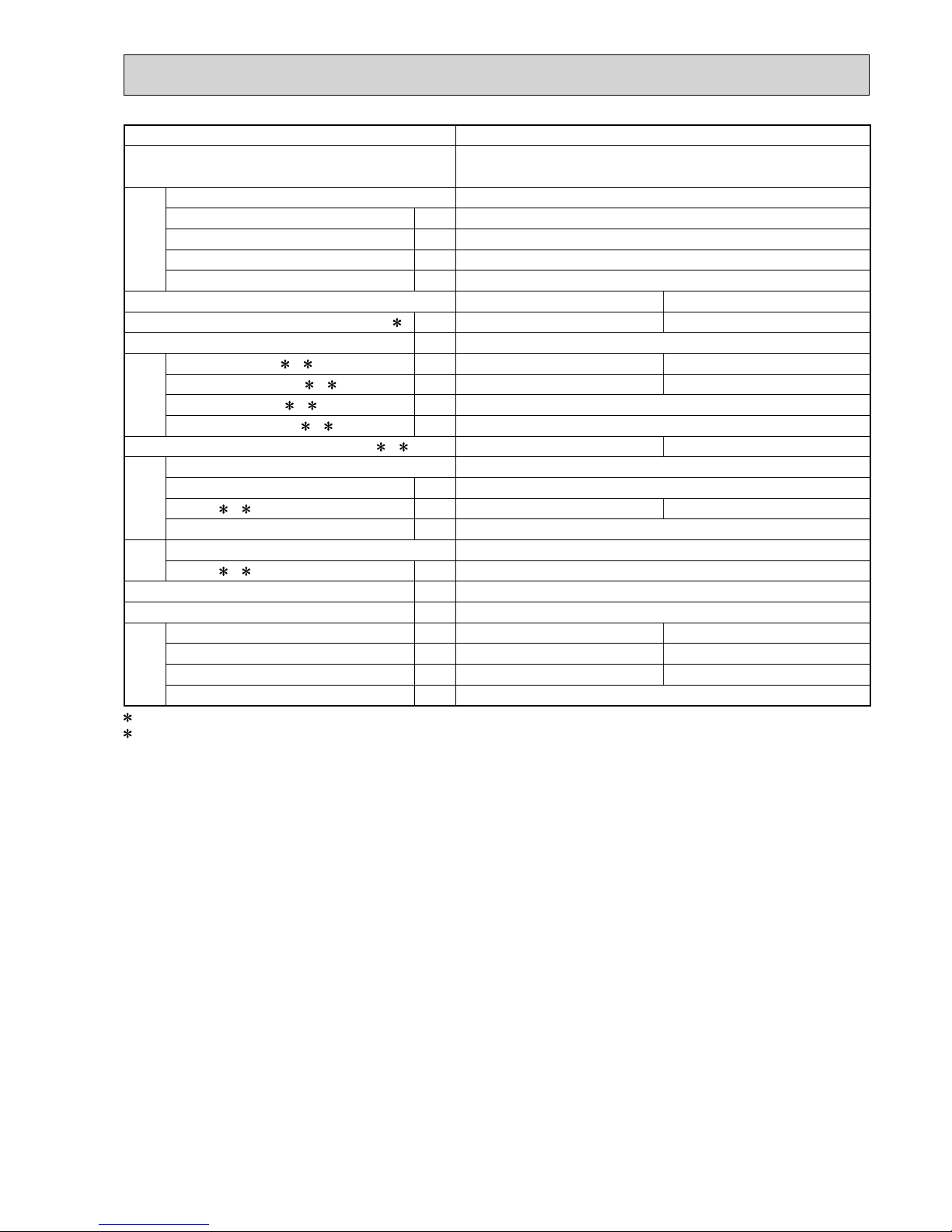
SPECIFICATION
3
Outdoor model MXZ-2D33VA
Outdoor unit power supply
Single phase
230 V, 50 Hz
System
Indoor units number 2
Piping total length m Max. 20
Connecting pipe length m Max. 15
Height difference (Indoor ~ Outdoor) m Refer to 7 REFRIGERANT SYSTEM DIAGRAM.
Height difference (Indoor ~ Indoor) m Refer to 7 REFRIGERANT SYSTEM DIAGRAM.
Function Cooling Heating
Capacity Rated frequency (Min.-Max.)
2 kW 3.3 (1.1 - 3.8) 4.0 (1.0 - 4.1)
Breaker capacity A 15
Electrical
data
Power input (Total) 1, 2 W 900 960
Running current (Total)
1, 2 A 4.3 4.6
Power factor (Total)
1, 2% 90
Starting current (Total)
1, 2 A 4.6
Coeffi cient of performance (C.O.P) (Total)
1, 2 3.67 4.17
Compressor
Model KNB073FFDHC
Output W 800
Current
1, 2 A 4.0 4.2
Refrigeration oil (Model) L 0.32 (NEO22)
Fan
motor
Model RC0J50-FA
Current
1, 2 A 0.35
Dimensions W x H x D mm 800 x 550 x 285
Weight kg 32
Special
remarks
Air fl ow (Rated) m3 /h 1,974 2,022
Sound level (Rated) dB(A) 49 50
Fan speed (Rated) rpm 860 880
Refrigerant fi lling capacity (R410A) kg 1.15
1 Measured under rated operating frequency.
2 When connected with indoor units below.
MSZ-SF15VA + MSZ-EF18VE
NOTE: Test conditions are based on ISO 5151. (Refrigerant piping length (one way): 5 m)
COOLING INDOOR Dry-bulb temperature 27.0 °C Wet-bulb temperature 19.0 °C
OUTDOOR Dry-bulb temperature 35.0 °C Wet-bulb temperature 24.0 °C
HEATING INDOOR Dry-bulb temperature 20.0 °C
OUTDOOR Dry-bulb temperature 7.0 °C Wet-bulb temperature 6.0 °C
OBH626K

8
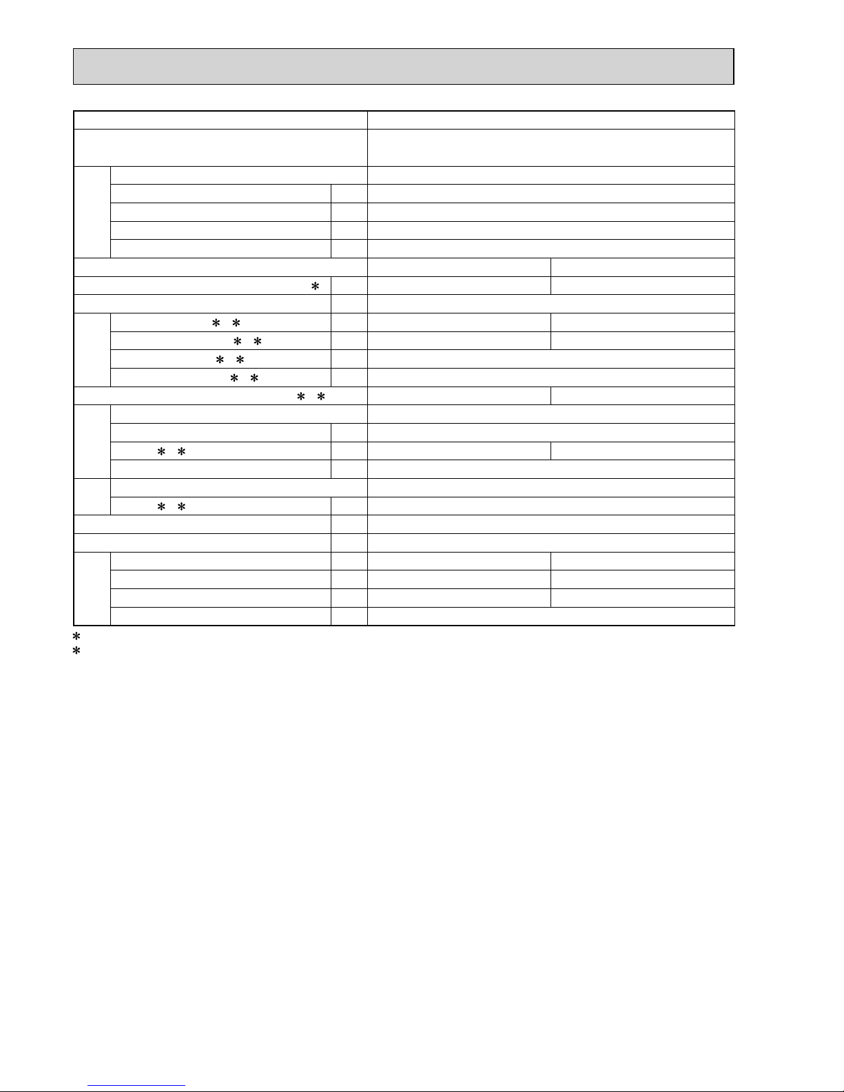
Outdoor model MXZ-2D40VA
Outdoor unit power supply
Single phase
230 V, 50 Hz
System
Indoor units number 2
Piping total length m Max. 30
Connecting pipe length m Max. 20
Height difference (Indoor ~ Outdoor) m Refer to 7 REFRIGERANT SYSTEM DIAGRAM.
Height difference (Indoor ~ Indoor) m Refer to 7 REFRIGERANT SYSTEM DIAGRAM.
Function Cooling Heating
Capacity Rated frequency (Min.-Max.)
2 kW 4.0 (1.1 - 4.3) 4.5 (1.0 - 4.8)
Breaker capacity A 15
Electrical
data
Power input (Total) 1, 2 W 970
Running current (Total)
1, 2 A 4.7
Power factor (Total)
1, 2% 90
Starting current (Total)
1, 2 A 4.7
Coeffi cient of performance (C.O.P) (Total)
1, 2 4.12 4.64
Compressor
Model KNB092FFDHC
Output W 1,100
Current
1, 2 A 4.4 4.2
Refrigeration oil (Model) L 0.32 (NEO22)
Fan
motor
Model RC0J50-FA
Current
1, 2 A 0.35
Dimensions W x H x D mm 800 x 550 x 285
Weight kg 34
Special
remarks
Air fl ow (Rated) m3 /h 1,752 1,662
Sound level (Rated) dB(A) 49 50
Fan speed (Rated) rpm 840 800
Refrigerant fi lling capacity (R410A) kg 1.3
1 Measured under rated operating frequency.
2 When connected with indoor units below.
MSZ-EF18VE + MSZ-EF22VE
NOTE: Test conditions are based on ISO 5151. (Refrigerant piping length (one way): 5 m)
COOLING INDOOR Dry-bulb temperature 27.0 °C Wet-bulb temperature 19.0 °C
OUTDOOR Dry-bulb temperature 35.0 °C Wet-bulb temperature 24.0 °C
HEATING INDOOR Dry-bulb temperature 20.0 °C
OUTDOOR Dry-bulb temperature 7.0 °C Wet-bulb temperature 6.0 °C
OBH626K

9
Outdoor model MXZ-2D42VA MXZ-2D42VA2
Outdoor unit power supply
Single phase
230 V, 50 Hz
System
Indoor units number 2
Piping total length m Max. 30
Connecting pipe length m Max. 20
Height difference (Indoor ~ Outdoor) m Refer to 7 REFRIGERANT SYSTEM DIAGRAM.
Height difference (Indoor ~ Indoor) m Refer to 7 REFRIGERANT SYSTEM DIAGRAM.
Function Cooling Heating
Capacity Rated frequency (Min.-Max.)
2 kW 4.2 (1.1 - 4.4) 4.5 (1.0 - 4.8)
Breaker capacity A 15
Electrical
data
Power input (Total) 1, 2 W 1,000 930
Running current (Total)
1, 2 A 4.5 4.2
Power factor (Total)
1, 2% 97
Starting current (Total)
1, 2 A 4.5
Coeffi cient of performance (C.O.P) (Total)
1, 2 4.20 4.84
Compressor
Model SNB130FGBHT
Output W 1,150
Current
1, 2 A 4.0 3.6
Refrigeration oil (Model) L 0.45 (NEO22)
Fan
motor
Model RC0J50-FA
Current
1, 2 A 0.35
Dimensions W x H x D mm 800 x 550 x 285
Weight kg 37
Special
remarks
Air fl ow (Rated) m3 /h 1,662 1,998
Sound level (Rated) dB(A) 46 51
Fan speed (Rated) rpm 800 910
Refrigerant fi lling capacity (R410A) kg 1.3
1 Measured under rated operating frequency.
2 When connected with indoor units below.
MSZ-EF18VE + MSZ-EF25VE
NOTE: Test conditions are based on ISO 5151. (Refrigerant piping length (one way): 5 m)
COOLING INDOOR Dry-bulb temperature 27.0 °C Wet-bulb temperature 19.0 °C
OUTDOOR Dry-bulb temperature 35.0 °C Wet-bulb temperature 24.0 °C
HEATING INDOOR Dry-bulb temperature 20.0 °C
OUTDOOR Dry-bulb temperature 7.0 °C Wet-bulb temperature 6.0 °C
OBH626K

10
Outdoor model
MXZ-2D53VA MXZ-2D53VAH
MXZ-2D53VA2 MXZ-2D53VAH2
Outdoor unit power supply
Single phase
230 V, 50 Hz
System
Indoor units number 2
Piping total length m Max. 30
Connecting pipe length m Max. 20
Height difference (Indoor ~ Outdoor) m Refer to 7 REFRIGERANT SYSTEM DIAGRAM.
Height difference (Indoor ~ Indoor) m Refer to 7 REFRIGERANT SYSTEM DIAGRAM.
Function Cooling Heating
Capacity Rated frequency (Min.-Max.)
2 kW 5.3 (1.1 - 5.6) 6.4 (1.0 - 7.0)
Breaker capacity A 15
Electrical
data
Power input (Total) 1, 2 W 1,540 1,700
Running current (Total)
1, 2 A 6.9 7.6
Power factor (Total)
1, 2% 97
Starting current (Total)
1, 2 A 7.6
Coeffi cient of performance (C.O.P) (Total)
1, 2 3.44 3.76
Compressor
Model SNB130FGBHT
Output W 1,400
Current
1, 2 A 6.6 7.2
Refrigeration oil (Model) L 0.45 (NEO22)
Fan
motor
Model RC0J50-FA
Current
1, 2 A 0.35
Dimensions W x H x D mm 800 x 550 x 285
Weight kg
MXZ-2D53VA: 37 MXZ-2D53VAH: 38
MXZ-2D53VA2: 37 MXZ-2D53VAH2: 38
Special
remarks
Air fl ow (Rated) m3 /h 1,974 1,998
Sound level (Rated) dB(A) 50 53
Fan speed (Rated) rpm 900 910
Refrigerant fi lling capacity (R410A) kg 1.3
1 Measured under rated operating frequency.
2 When connected with indoor units below.
MSZ-EF18VE + MSZ-EF35VE
NOTE: Test conditions are based on ISO 5151. (Refrigerant piping length (one way): 5 m)
COOLING INDOOR Dry-bulb temperature 27.0 °C Wet-bulb temperature 19.0 °C
OUTDOOR Dry-bulb temperature 35.0 °C Wet-bulb temperature 24.0 °C
HEATING INDOOR Dry-bulb temperature 20.0 °C
OUTDOOR Dry-bulb temperature 7.0 °C Wet-bulb temperature 6.0 °C
OBH626K

11
Outdoor model MXZ-3D54VA MXZ-3D54VA2
Outdoor unit power supply
Single phase
230 V, 50 Hz
System
Indoor units number 2 to 3
Piping total length m Max. 50
Connecting pipe length m Max. 25
Height difference (Indoor ~ Outdoor) m Refer to 7 REFRIGERANT SYSTEM DIAGRAM.
Height difference (Indoor ~ Indoor) m Refer to 7 REFRIGERANT SYSTEM DIAGRAM.
Function Cooling Heating
Capacity Rated frequency (Min.-Max.)
2 kW 5.4 (2.9 - 6.8) 7.0 (2.6 - 9.0)
Breaker capacity A 25
Electrical
data
Power input (Total) 1, 2W
MXZ-3D54VA: 1,390
MXZ-3D54VA2: 1,350
1,590
Running current (Total)
1, 2A
MXZ-3D54VA: 6.1
MXZ-3D54VA2: 5.9
7.0
Power factor (Total)
1, 2% 99
Starting current (Total)
1, 2 A 7.0
Coeffi cient of performance (C.O.P) (Total)
1, 2
MXZ-3D54VA: 3.88
MXZ-3D54VA2: 4.00
4.40
Compressor
Model SNB130FGBH1T
Output W 1,400
Current
1, 2 A 5.72 6.62
Refrigeration oil (Model) L 0.7 (NEO22)
Fan
motor
Model SIC-71FW-F764-1
Current
1, 2 A 0.2
Dimensions W x H x D mm 840 x 710 x 330
Weight kg 57
Special
remarks
Air fl ow (Rated) m3 /h 2,334 2,376
Sound level (Rated) dB(A) 50 53
Fan speed (Rated) rpm 650 660
Refrigerant fi lling capacity (R410A) kg 2.7
1 Measured under rated operating frequency.
2 When connected with indoor units below.
MSZ-EF18VE + MSZ-EF18VE + MSZ-EF18VE
NOTE: Test conditions are based on ISO 5151. (Refrigerant piping length (one way): 5 m)
COOLING INDOOR Dry-bulb temperature 27.0 °C Wet-bulb temperature 19.0 °C
OUTDOOR Dry-bulb temperature 35.0 °C Wet-bulb temperature 24.0 °C
HEATING INDOOR Dry-bulb temperature 20.0 °C
OUTDOOR Dry-bulb temperature 7.0 °C Wet-bulb temperature 6.0 °C
OBH626K

12
Outdoor model MXZ-3D68VA
Outdoor unit power supply
Single phase
230 V, 50 Hz
System
Indoor units number 2 to 3
Piping total length m Max. 60
Connecting pipe length m Max. 25
Height difference (Indoor ~ Outdoor) m Refer to 7 REFRIGERANT SYSTEM DIAGRAM.
Height difference (Indoor ~ Indoor) m Refer to 7 REFRIGERANT SYSTEM DIAGRAM.
Function Cooling Heating
Capacity Rated frequency (Min.-Max.)
2 kW 6.8 (2.9 - 8.4) 8.6 (2.6 - 10.6)
Breaker capacity A 25
Electrical
data
Power input (Total) 1, 2 W 2,190 2,380
Running current (Total)
1, 2 A 9.6 10.5
Power factor (Total)
1, 2% 99
Starting current (Total)
1, 2 A 10.5
Coeffi cient of performance (C.O.P) (Total)
1, 2 3.11 3.61
Compressor
Model SNB172FEGH1T
Output W 1,800
Current
1, 2 A 9.22 10.12
Refrigeration oil (Model) L 0.7 (NEO22)
Fan
motor
Model SIC-71FW-F764-1
Current
1, 2 A 0.2
Dimensions W x H x D mm 840 x 710 x 330
Weight kg 57
Special
remarks
Air fl ow (Rated) m3 /h 2,334 2,376
Sound level (Rated) dB(A) 50 53
Fan speed (Rated) rpm 650 660
Refrigerant fi lling capacity (R410A) kg 2.7
1 Measured under rated operating frequency.
2 When connected with indoor units below.
MSZ-EF18VE + MSZ-EF25VE + MSZ-EF25VE
NOTE: Test conditions are based on ISO 5151. (Refrigerant piping length (one way): 5 m)
COOLING INDOOR Dry-bulb temperature 27.0 °C Wet-bulb temperature 19.0 °C
OUTDOOR Dry-bulb temperature 35.0 °C Wet-bulb temperature 24.0 °C
HEATING INDOOR Dry-bulb temperature 20.0 °C
OUTDOOR Dry-bulb temperature 7.0 °C Wet-bulb temperature 6.0 °C
OBH626K
13
Outdoor model MXZ-4D72VA
Outdoor unit power supply
Single phase
230 V, 50 Hz
System
Indoor units number 2 to 4
Piping total length m Max. 60
Connecting pipe length m Max. 25
Height difference (Indoor ~ Outdoor) m Refer to 7 REFRIGERANT SYSTEM DIAGRAM.
Height difference (Indoor ~ Indoor) m Refer to 7 REFRIGERANT SYSTEM DIAGRAM.
Function Cooling Heating
Capacity Rated frequency (Min.-Max.)
2 kW 7.2 (3.7 - 8.8) 8.6 (3.4 - 10.7)
Breaker capacity A 25
Electrical
data
Power input (Total) 1, 2 W 2,250 2,280
Running current (Total)
1, 2 A 9.9 10.0
Power factor (Total)
1, 2% 99
Starting current (Total)
1, 2 A 10.0
Coeffi cient of performance (C.O.P) (Total)
1, 2 3.20 3.77
Compressor
Model SNB172FEGH1T
Output W 2,000
Current
1, 2 A 9.46 9.56
Refrigeration oil (Model) L 0.7 (NEO22)
Fan
motor
Model SIC-71FW-F764-1
Current
1, 2 A 0.2
Dimensions W x H x D mm 840 x 710 x 330
Weight kg 58
Special
remarks
Air fl ow (Rated) m3 /h 2,334 2,376
Sound level (Rated) dB(A) 50 53
Fan speed (Rated) rpm 650 660
Refrigerant fi lling capacity (R410A) kg 2.7
1 Measured under rated operating frequency.
2 When connected with indoor units below.
MSZ-EF18VE + MSZ-EF18VE + MSZ-EF18VE + MSZ-EF18VE
NOTE: Test conditions are based on ISO 5151. (Refrigerant piping length (one way): 5 m)
COOLING INDOOR Dry-bulb temperature 27.0 °C Wet-bulb temperature 19.0 °C
OUTDOOR Dry-bulb temperature 35.0 °C Wet-bulb temperature 24.0 °C
HEATING INDOOR Dry-bulb temperature 20.0 °C
OUTDOOR Dry-bulb temperature 7.0 °C Wet-bulb temperature 6.0 °C
OBH626K
14
Outdoor model MXZ-4D83VA
Outdoor unit power supply
Single phase
230 V, 50 Hz
System
Indoor units number 2 to 4
Piping total length m Max. 70
Connecting pipe length m Max. 25
Height difference (Indoor ~ Outdoor) m Refer to 7 REFRIGERANT SYSTEM DIAGRAM.
Height difference (Indoor ~ Indoor) m Refer to 7 REFRIGERANT SYSTEM DIAGRAM.
Function Cooling Heating
Capacity Rated frequency (Min.-Max.)
2 kW 8.3 ( 3.7 - 9.2 ) 9.0 ( 3.4 - 11.6 )
Breaker capacity A 25
Electrical
data
Power input (Total) 1, 2 W 2,830 2,420
Running current (Total)
1, 2 A 12.4 10.6
Power factor (Total)
1, 2% 99
Starting current (Total)
1, 2 A 12.4
Coeffi cient of performance (C.O.P) (Total)
1, 2 2.93 3.72
Compressor
Model TNB220FMCH
Output W 2,100
Current
1, 2 A 11.76 9.96
Refrigeration oil (Model) L 0.87 (NEO22)
Fan
motor
Model RC0J60-CC
Current
1, 2 A 0.4
Dimensions W x H x D mm 900 x 915 x 320
Weight kg 69
Special
remarks
Air fl ow (Rated) m3 /h 2,526 2,628
Sound level (Rated) dB(A) 49 50
Fan speed (Rated) rpm 600 620
Refrigerant fi lling capacity (R410A) kg 3.5
1 Measured under rated operating frequency.
2 When connected with indoor units below.
MSZ-EF18VE + MSZ-EF18VE + MSZ-EF22VE + MSZ-EF25VE
NOTE: Test conditions are based on ISO 5151. (Refrigerant piping length (one way): 5 m)
COOLING INDOOR Dry-bulb temperature 27.0 °C Wet-bulb temperature 19.0 °C
OUTDOOR Dry-bulb temperature 35.0 °C Wet-bulb temperature 24.0 °C
HEATING INDOOR Dry-bulb temperature 20.0 °C
OUTDOOR Dry-bulb temperature 7.0 °C Wet-bulb temperature 6.0 °C
OBH626K

15
Outdoor model MXZ-5D102VA
Outdoor unit power supply
Single phase
230 V, 50 Hz
System
Indoor units number 2 to 5
Piping total length m Max. 80
Connecting pipe length m Max. 25
Height difference (Indoor ~ Outdoor) m Refer to 7 REFRIGERANT SYSTEM DIAGRAM.
Height difference (Indoor ~ Indoor) m Refer to 7 REFRIGERANT SYSTEM DIAGRAM.
Function Cooling Heating
Capacity Rated frequency (Min.-Max.)
2 kW 10.2 ( 3.9 - 11.0 ) 10.5 ( 4.1 - 14.0 )
Breaker capacity A 25
Electrical
data
Power input (Total) 1, 2 W 3,910 2,900
Running current (Total)
1, 2 A 17.2 12.7
Power factor (Total)
1, 2% 99
Starting current (Total)
1, 2 A 17.2
Coeffi cient of performance (C.O.P) (Total)
1, 2 2.61 3.62
Compressor
Model TNB220FMCH
Output W 2,700
Current
1, 2 A 16.5 12.0
Refrigeration oil (Model) L 0.87 (NEO22)
Fan
motor
Model RC0J60-CC
Current
1, 2 A 0.4
Dimensions W x H x D mm 900 x 915 x 320
Weight kg 70
Special
remarks
Air fl ow (Rated) m3 /h 3,396 3,558
Sound level (Rated) dB(A) 53 55
Fan speed (Rated) rpm 780 810
Refrigerant fi lling capacity (R410A) kg 4.0
1 Measured under rated operating frequency.
2 When connected with indoor units below.
MSZ-EF18VE + MSZ-EF18VE + MSZ-EF22VE + MSZ-EF22VE + MSZ-EF22VE
NOTE: Test conditions are based on ISO 5151. (Refrigerant piping length (one way): 5 m)
COOLING INDOOR Dry-bulb temperature 27.0 °C Wet-bulb temperature 19.0 °C
OUTDOOR Dry-bulb temperature 35.0 °C Wet-bulb temperature 24.0 °C
HEATING INDOOR Dry-bulb temperature 20.0 °C
OUTDOOR Dry-bulb temperature 7.0 °C Wet-bulb temperature 6.0 °C
OBH626K

16
Outdoor model MXZ-6D122VA
Outdoor unit power supply
Single phase
230 V, 50 Hz
System
Indoor units number 2 to 6
Piping total length m Max. 80
Connecting pipe length m Max. 25
Height difference (Indoor ~ Outdoor) m Refer to 7 REFRIGERANT SYSTEM DIAGRAM.
Height difference (Indoor ~ Indoor) m Refer to 7 REFRIGERANT SYSTEM DIAGRAM.
Function Cooling Heating
Capacity Rated frequency (Min.-Max.)
2 kW 12.2 ( 3.5 - 13.5 ) 14.0 ( 3.5 - 16.5 )
Breaker capacity A 32
Electrical
data
Power input (Total) 1, 2 W 3,660 3,310
Running current (Total)
1, 2 A 16.1 14.5
Power factor (Total)
1, 2% 99
Starting current (Total)
1, 2 A 17.2
Coeffi cient of performance (C.O.P) (Total)
1, 2 3.33 4.23
Compressor
Model MNB33FBTM-L
Output W 1,700
Current
1, 2 A 15.26 12.94
Refrigeration oil (Model) L 1.10 (FV50S)
Fan
motor
Model SIC-81FW-D888-9
Current
1, 2 A 0.3
Dimensions W x H x D mm 950 x 1,048 x 330
Weight kg 88
Special
remarks
Air fl ow (Rated) m3 /h 3,780 4,620
Sound level (Rated) dB(A) 55 57
Fan speed (Rated) rpm 650 750
Refrigerant fi lling capacity (R410A) kg 4.0
1 Measured under rated operating frequency.
2 When connected with indoor units below.
MSZ-EF22VE +MSZ-EF22VE +MSZ-EF22VE +MSZ-EF22VE +MSZ-EF22VE +MSZ-EF22VE
NOTE: Test conditions are based on ISO 5151. (Refrigerant piping length (one way): 5 m)
COOLING INDOOR Dry-bulb temperature 27.0 °C Wet-bulb temperature 19.0 °C
OUTDOOR Dry-bulb temperature 35.0 °C Wet-bulb temperature 24.0 °C
HEATING INDOOR Dry-bulb temperature 20.0 °C
OUTDOOR Dry-bulb temperature 7.0 °C Wet-bulb temperature 6.0 °C
OBH626K

17
90
80
70
60
50
40
30
20
10
63 125 250 500 1000 2000 4000 8000
APPROXIMATE
THRESHOLD OF
HEARING FOR
CONTINUOUS
NOISE
NC-60
NC-50
NC-40
NC-30
NC-20
NC-70
OCTAVE BAND SOUND PRESSURE LEVEL, dB re 0.0002 MICRO BAR
BAND CENTER FREQUENCIES, Hz
CoolingHigh
FUNCTION
FAN SPEED
HeatingHigh
49
SPL(dB(A))50LINE
90
80
70
60
50
40
30
20
10
63 125 250 500 1000 2000 4000 8000
NC-60
NC-50
NC-40
NC-30
NC-20
NC-70
OCTAVE BAND SOUND PRESSURE LEVEL, dB re 0.0002 MICRO BAR
BAND CENTER FREQUENCIES, Hz
APPROXIMATE
THRESHOLD OF
HEARING FOR
CONTINUOUS
NOISE
CoolingHigh
FUNCTION
FAN SPEED
HeatingHigh
46
SPL(dB(A))51LINE
90
80
70
60
50
40
30
20
10
63 125 250 500 1000 2000 4000 8000
NC-60
NC-50
NC-40
NC-30
NC-20
NC-70
OCTAVE BAND SOUND PRESSURE LEVEL, dB re 0.0002 MICRO BAR
BAND CENTER FREQUENCIES, Hz
APPROXIMATE
THRESHOLD OF
HEARING FOR
CONTINUOUS
NOISE
CoolingHigh
FUNCTION
FAN SPEED
HeatingHigh
49
SPL(dB(A))50LINE
90
80
70
60
50
40
30
20
10
63 125 250 500 1000 2000 4000 8000
NC-60
NC-50
NC-40
NC-30
NC-20
NC-70
OCTAVE BAND SOUND PRESSURE LEVEL, dB re 0.0002 MICRO BAR
BAND CENTER FREQUENCIES, Hz
APPROXIMATE
THRESHOLD OF
HEARING FOR
CONTINUOUS
NOISE
CoolingHigh
FUNCTION
FAN SPEED
HeatingHigh
50
SPL(dB(A))53LINE
NOISE CRITERIA CURVES
4
MXZ-2D53VA
MXZ-2D53VA2
MXZ-2D53VAH
MXZ-2D53VAH2
MXZ-2D33VA
MXZ-2D42VA
MXZ-2D42VA2
MXZ-2D40VA
OBH626K

18
90
80
70
60
50
40
30
20
10
63 125 250 500 1000 2000 4000 8000
APPROXIMATE
THRESHOLD OF
HEARING FOR
CONTINUOUS
NOISE
NC-60
NC-50
NC-40
NC-30
NC-20
NC-70
OCTAVE BAND SOUND PRESSURE LEVEL, dB re 0.0002 MICRO BAR
BAND CENTER FREQUENCIES, Hz
CoolingHigh
FUNCTION
FAN SPEED
HeatingHigh
50
SPL(dB(A))53LINE
90
80
70
60
50
40
30
20
10
63 125 250 500 1000 2000 4000 8000
APPROXIMATE
THRESHOLD OF
HEARING FOR
CONTINUOUS
NOISE
NC-60
NC-50
NC-40
NC-30
NC-20
NC-70
OCTAVE BAND SOUND PRESSURE LEVEL, dB re 0.0002 MICRO BAR
BAND CENTER FREQUENCIES, Hz
CoolingHigh
FUNCTION
FAN SPEED
HeatingHigh
50
SPL(dB(A))53LINE
90
80
70
60
50
40
30
20
10
63 125 250 500 1000 2000 4000 8000
APPROXIMATE
THRESHOLD OF
HEARING FOR
CONTINUOUS
NOISE
NC-60
NC-50
NC-40
NC-30
NC-20
NC-70
OCTAVE BAND SOUND PRESSURE LEVEL, dB re 0.0002 MICRO BAR
BAND CENTER FREQUENCIES, Hz
CoolingHigh
FUNCTION
FAN SPEED
HeatingHigh
50
SPL(dB(A))53LINE
90
80
70
60
50
40
30
20
10
63 125 250 500 1000 2000 4000 8000
APPROXIMATE
THRESHOLD OF
HEARING FOR
CONTINUOUS
NOISE
NC-60
NC-50
NC-40
NC-30
NC-20
NC-70
OCTAVE BAND SOUND PRESSURE LEVEL, dB re 0.0002 MICRO BAR
BAND CENTER FREQUENCIES, Hz
CoolingHigh
FUNCTION
FAN SPEED
HeatingHigh
48
SPL(dB(A))51LINE
MXZ-3D54VA
MXZ-3D54VA2
MXZ-3D68VA
MXZ-4D72VA MXZ-4D83VA
OBH626K

19
90
80
70
60
50
40
30
20
10
63 125 250 500 1000 2000 4000 8000
APPROXIMATE
THRESHOLD OF
HEARING FOR
CONTINUOUS
NOISE
NC-60
NC-50
NC-40
NC-30
NC-20
NC-70
OCTAVE BAND SOUND PRESSURE LEVEL, dB re 0.0002 MICRO BAR
BAND CENTER FREQUENCIES, Hz
CoolingHigh
FUNCTION
FAN SPEED
HeatingHigh
48
SPL(dB(A))51LINE
90
80
70
60
50
40
30
20
10
63 125 250 500 1000 2000 4000 8000
APPROXIMATE
THRESHOLD OF
HEARING FOR
CONTINUOUS
NOISE
NC-60
NC-50
NC-40
NC-30
NC-20
NC-70
OCTAVE BAND SOUND PRESSURE LEVEL, dB re 0.0002 MICRO BAR
BAND CENTER FREQUENCIES, Hz
CoolingHigh
FUNCTION
FAN SPEED
HeatingHigh
55
SPL(dB(A))57LINE
MXZ-5D102VA MXZ-6D122VA
OUTDOOR UNIT
MICROPHONE
1m
Test conditions
Cooling :Dry-bulb temperature 35°C Wet-bulb temperature 24°C
Heating :Dry-bulb temperature 7°C Wet-bulb temperature 6°C
OBH626K

20
OUTLINES AND DIMENSIONS
5
MXZ-2D33VA MXZ-2D40VA MXZ-2D42VA MXZ-2D42VA2
MXZ-2D53VA MXZ-2D53VA2 MXZ-2D53VAH MXZ-2D53VAH2
Unit: mm
OBH626K

21
1.Installation space
Note : Leave front and both sides
free of obstruction.
Note : Leave rear, overhead and
both sides free of obstruction.
500 or more
100 or more
Note : Leave front and overhead
free of obstruction.
100 or more
350 or more
200 or more
500 or more
2.Service space
100 or more
500 or more
350 or more
350 or more
100 or more
Service space
Liquid pipe : Ø6.35(flared)1/4
C unit connection
B unit connection
A unit connection
Gas pipe : Ø9.52(flared)3/8
Liquid pipe : Ø6.35(flared)1/4
Gas pipe : Ø9.52(flared)3/8
Liquid pipe : Ø6.35(flared)1/4
Gas pipe : Ø9.52(flared)3/8
MXZ-3D54VA MXZ-3D54VA2 MXZ-3D68VA
Unit: mm
OBH626K

22
MXZ-4D72VA
Unit: mm
1.Installation space
Note : Leave front and both sides
free of obstruction.
Note : Leave rear, overhead and
both sides free of obstruction.
500 or more
100 or more
Note : Leave front and overhead
free of obstruction.
100 or more
350 or more
200 or more
500 or more
2.Service space
100 or more
500 or more
350 or more
350 or more
100 or more
Service space
Liquid pipe : Ø6.35(flared)1/4
D unit connection
C unit connection
B unit connection
Gas pipe : Ø9.52(flared)3/8
Liquid pipe : Ø6.35(flared)1/4
Gas pipe : Ø9.52(flared)3/8
Liquid pipe : Ø6.35(flared)1/4
Gas pipe : Ø9.52(flared)3/8
A unit connection
Liquid pipe : Ø6.35(flared)1/4
Gas pipe : Ø12.7(flared)1/2
OBH626K

23
MXZ-4D83VA
MXZ-5D102VA
Unit: mm
Liquid pipe : Ø6.35(flared)1/4
E unit connection
(MXZ-5D102VA)
D unit connection
C unit connection
B unit connection
Gas pipe : Ø9.52(flared)3/8
Liquid pipe : Ø6.35(flared)1/4
Gas pipe : Ø9.52(flared)3/8
Liquid pipe : Ø6.35(flared)1/4
Gas pipe : Ø9.52(flared)3/8
Liquid pipe : Ø6.35(flared)1/4
Gas pipe : Ø9.52(flared)3/8
A unit connection
Liquid pipe : Ø6.35(flared)1/4
Gas pipe : Ø12.7(flared)1/2
1.Installation space
Note : Leave front and both sides
free of obstruction.
Note : Leave rear, overhead and
both sides free of obstruction.
Air out
42
200 200500
315
355
(Bolt pitch)
387
40
27
16
16
11
24
Drain hole 42
(Fondation bolt M10)
(Fondation bolt M10)
2-U Shaped notched hole
2-12 x 36 Oval hole
Air in
Air in
32025 10
88
475
317
900
Handle
Handle
915
500 or more
100 or more
Note : Leave front and overhead
free of obstruction.
100 or more
350 or more
200 or more
500 or more
2.Service space
100 or more
500 or more
350 or more
350 or more
100 or more
Service space
23
612
147
405
45
Indoor and
outdoor
connect wiring
(35 x 53) hole
OBH626K

24
MXZ-6D122VA
Unit: mm
34
468134
43
Handle
Air Intake
Handle
330
70
25 15
6-ø33 Drain Hole
Air in
Air out
Air in
(Foundation Bolt M10)
2-U Shaped Notched Hole
(Foundation Bolt M10)
2-12×36 Oval Hole
(Bolt pitch)
1169780250
51
71
134
40
62
10
10
10
10
175 600 175
10
10
417
31 16370
36
51
Handle
Handle
Handle
361
563
1048
950
Liquid pipe : Ø6.35(flared)1/4
E unit
connection
D unit
connection
C unit
connection
B unit
connection
A unit
connection
F unit
connection
Gas pipe : Ø9.52(flared)3/8
Liquid pipe : Ø6.35(flared)1/4
Gas pipe : Ø9.52(flared)3/8
Liquid pipe : Ø6.35(flared)1/4
Gas pipe : Ø9.52(flared)3/8
Liquid pipe : Ø6.35(flared)1/4
Gas pipe : Ø9.52(flared)3/8
Liquid pipe : Ø6.35(flared)1/4
Gas pipe : Ø9.52(flared)3/8
Liquid pipe : Ø6.35(flared)1/4
Gas pipe : Ø12.7(flared)1/2
SERVICE SPACE
1.FREE SPACE
2.SERVICE SPACE
100 or more
200 or more
350 or more
500 or more
100 or more
100 or more
350 or more 350 or more
500 or more
100 or more
500 or more
OBH626K

25
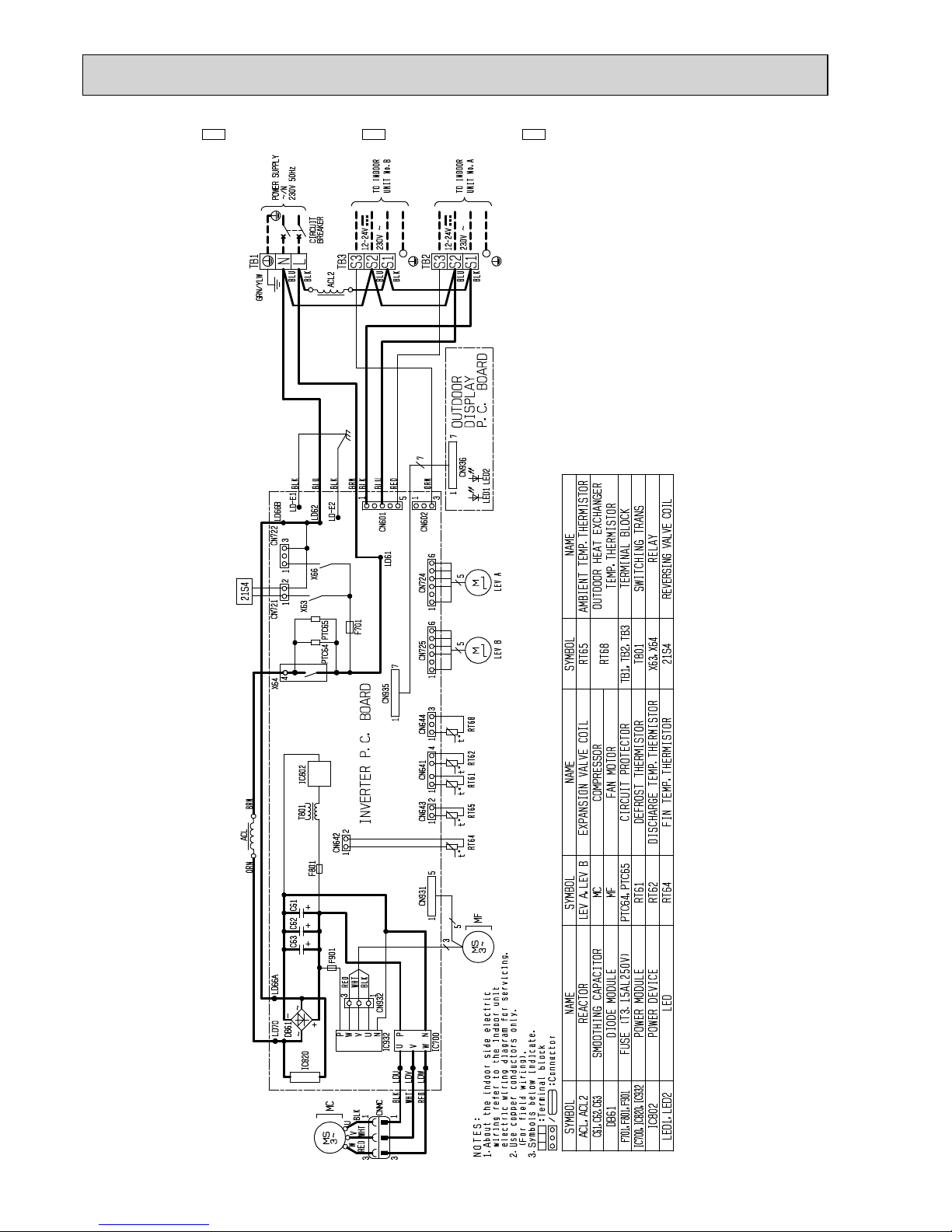
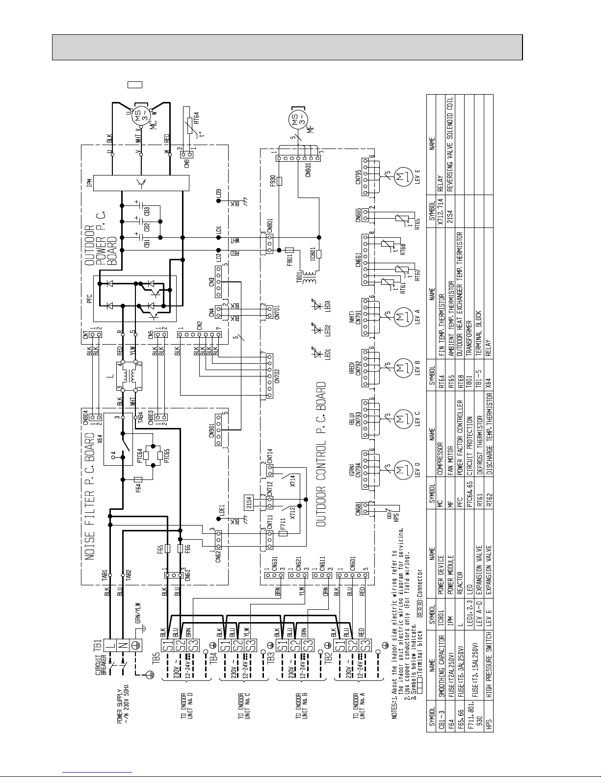
WIRING DIAGRAM
6
MXZ-2D33VA -E1 MXZ-2D40VA -E1 MXZ-2D53VA -
E1
OUTDOOR
DISPLAY
P.C. BOARD
OBH626K

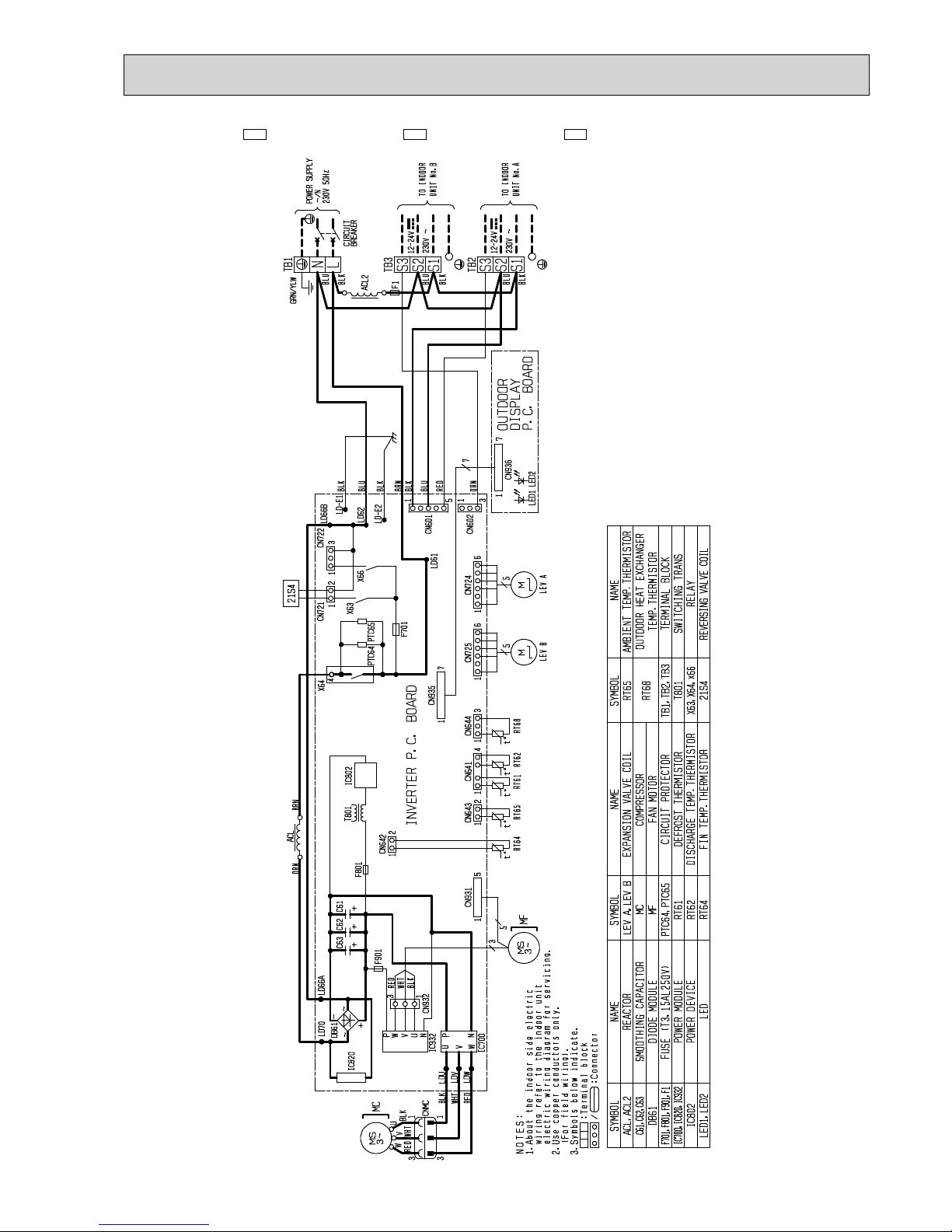
26
MXZ-2D33VA -E2 MXZ-2D42VA -E2 MXZ-2D53VA -
E2
OBH626K

27
MXZ-2D33VA -E3 MXZ-2D42VA -E3 MXZ-2D53VA -
E3
OBH626K
28
MXZ-2D33VA -
ER2
MXZ-2D40VA -
ER2
MXZ-2D53VA -
ER2
OBH626K
29
MXZ-2D33VA -
ER3
MXZ-2D42VA -
ER3
MXZ-2D53VA -
ER3
OBH626K

30
MXZ-2D33VA -
ET2
MXZ-2D42VA -
ET2
MXZ-2D53VA -
ET2
OBH626K

31
MXZ-2D33VA -
ET3
MXZ-2D42VA -
ET3
MXZ-2D53VA -
ET3
OBH626K

32
MXZ-2D42VA2 -E3 MXZ-2D42VA2 -
ET3
MXZ-2D42VA2 -
ER3
MXZ-2D53VA2 -E3 MXZ-2D53VA2 -
ET3
MXZ-2D53VA2 -
ER3
21S4
NAME
4
t°
t°
S3S2S1
12-24V
~ 230V
S3S1S2
12-24V
~ 230V
N
L
ACL, ACL2
C61~63
DB61
F701, 801, 901
F1
IC700, 820, 932
IC802
LED1, 2
SYMBOL
/
NOTES:
RT68
TB1~3
T801
X63, 64, 66
21S4
SYMBOLNAME
LEV A, B
MC
MF
PTC64, 65
RT61
RT62
RT64
RT65
SYMBOLNAME
:Terminal block
1. About the indoor side electric wiring refer to the
indoor unit electric wiring diagram for servicing.
2. Use copper conductors only.
(For field wiring).
3. Symbols below indicate.
:Connector
t°t°
MF
-
~
+
~
MC
LEV A
X64
PTC64
1
3
1
CN644
4
CN641
RT68RT62
t°
RT61
CN935
7
CN725
1
5
M
LEV B
F701
LD61
6
1
CN724
6
5
M
PTC65
X63
CN721
2
1
X66
1
3
CN722
TO INDOOR
UNIT No. B
TO INDOOR
UNIT No. A
POWER SUPPLY
~/N
230V 50Hz
BLK
BLU
BLK
BLU
RED
ORN
ACL2
TB3
TB2
BLK
BLU
BREAKER
CIRCUIT
GRN/YLW
TB1
F1
3
LD66B
LD62
CN602
5
CN601
1
LD-E1
LD-E2
1
BLK
BLU
BLK
BRN
BLK
BLU
RED
ORN
LED1 LED2
CN936
OUTDOOR
DISPLAY
P.C. BOARD
7
1
7
313
1
MS
3~
W
V
U
RED
WHT
F901
T801
F801
IC802
+
C62
+
C61C63
+
ACL
1
2
CN642
BRNORN
3
5
1
CN931
MS
3~
5
1
2
1
CN643
RT65RT64
INVERTER P.C. BOARD
IC700
CNMC
P
U
V
W
N
IC932
N
P
UWV
DB61
IC820
CN932
1
3
LD66A
LD70
LDW
LDV
LDU
RED
BLK
WHT
RED
BLK
WHT
BLK
REACTOR
SMOOTHING CAPACITOR
DIODE MODULE
FUSE (T3.15AL250V)
FUSE (T3.15AL250V)
POWER MODULE
POWER DEVICE
LED
OUTDOOR HEAT EXCHANGER
TEMP . THERMIST OR
TERMINAL BLOCK
SWITCHING TRANS
RELAY
REVERSING VALVE COIL
EXPANSION VALVE COIL
COMPRESSOR
FAN MOTOR
CIRCUIT PROTECTOR
DEFROST THERMISTOR
DISCHARGE TEMP . THERMIST OR
FIN TEMP . THERMIST OR
AMBIENT TEMP. THERMISTOR
OBH626K

33
MXZ-2D53VAH -
E1
OUTDOOR
DISPLAY
P.C. BOARD
OBH626K

34
MXZ-2D53VAH -
E2
OBH626K

35
MXZ-2D53VAH -
E3
OBH626K

36
MXZ-2D53VAH -
ER2
OBH626K

37
MXZ-2D53VAH -
ER3
OBH626K

38
MXZ-2D53VAH2 -
E3
21S4
NAME
4
t°
t°
t°
S3S2S1
12-24V
~ 230V
S3S1S2
12-24V
~ 230V
N
L
ACL, ACL2
C61~63
DB61
F701, 801, 901
F1
H
IC700, 820, 932
IC802
SYMBOL
/
NOTES:
RT65
RT68
TB1~3
T801
X63, 64, 66
21S4
26H
SYMBOLNAME
LED1, 2
LEV A, B
MC
MF
PTC64, 65
RT61
RT62
RT64
SYMBOLNAME
:Terminal block
1.About the indoor side electric
wiring refer to the indoor unit
electric wiring diagram for servicing.
2.Use copper conductors only.
(For field wiring).
3.Symbols below indicate.
:Connector
t°t°
MF
-
~
+
~
MC
LEV A
X64
PTC64
1
3
1
CN644
4
CN641
RT68RT62RT61
CN935
7
CN725
1
5
M
LEV B
F701
LD61
6
1
CN724
6
5
M
PTC65
X63
CN721
2
1
X66
1
3
CN722
TO INDOOR
UNIT No. B
TO INDOOR
UNIT No. A
POWER SUPPLY
~/N
230V 50Hz
BLK
BLU
BLK
BLU
RED
ORN
ACL2
TB3
TB2
BLK
BLU
BREAKER
CIRCUIT
GRN/YLW
TB1
F1
3
LD66B
LD62
CN602
5
CN601
1
LD-E1
LD-E2
1
BLK
BLU
BLK
BRN
BLK
BLU
RED
ORN
LED1 LED2
CN936
OUTDOOR
DISPLAY
P.C. BOARD
7
1
7
313
1
MS
3~
W
V
U
RED
WHT
F901
T801
F801
IC802
+
C62
+
C61C63
+
ACL
1
2
CN642
BRNORN
3
5
1
CN931
MS
3~
5
1
2
1
CN643
RT65RT64
INVERTER P.C. BOARD
IC700
CNMC
P
U
V
W
N
IC932
N
P
UWV
DB61
IC820
CN932
1
3
LD66A
LD70
LDW
LDV
LDU
RED
BLK
WHT
RED
BLK
WHT
BLK
REACTOR
SMOOTHING CAPACITOR
DIODE MODULE
FUSE (T3.15AL250V)
FUSE (T3.15AL250V)
DEFROST HEATER
POWER MODULE
POWER DEVICE
LED
EXPANSION VALVE COIL
COMPRESSOR
FAN MOTOR
CIRCUIT PROTECTOR
DEFROST THERMISTOR
DISCHARGE TEMP . THERMIST OR
FIN TEMP . THERMIST OR
AMBIENT TEMP. THERMISTOR
OUTDOOR HEAT EXCHANGER
TEMP . THERMIST OR
TERMINAL BLOCK
SWITCHING TRANS
RELAY
REVERSING VALVE COIL
HEATER PROTECTOR
RED
YLW
BLK
BLK
BLK
BLK
BLK
H62H62KLB
BLK
221
1
221
1
H
OBH626K

39
MXZ-3D54VA -
E1
OBH626K

40
MXZ-3D54VA2 -
E2
OBH626K

41
MXZ-3D54VA2 -
E3
OBH626K

42
MXZ-3D54VA2 -
ER2
OBH626K

43
MXZ-3D54VA2 -
ER3
OBH626K

44
MXZ-3D54VA2 -
ET2
OBH626K

45
MXZ-3D54VA2 -
ET3
OBH626K

46
MXZ-3D68VA -
E1
OBH626K

47
MXZ-3D68VA -
E2
OBH626K

48
MXZ-3D68VA -
E3
OBH626K

49
MXZ-3D68VA -
ER2
OBH626K

50
MXZ-3D68VA -
ER3
OBH626K

51
MXZ-3D68VA -
ET2
OBH626K

52
MXZ-3D68VA -
ET3
OBH626K

53
MXZ-4D72VA -
E1
OBH626K

54
MXZ-4D72VA -
E2
OBH626K

55
MXZ-4D72VA -
E3
OBH626K
56
MXZ-4D72VA -
ER2
OBH626K

57
MXZ-4D72VA -
ER3
OBH626K

58
MXZ-4D72VA -
ET2
OBH626K

59
MXZ-4D72VA -
ET3
OBH626K

60
MXZ-4D83VA -
E1
OBH626K

61
MXZ-4D83VA -
E2
OBH626K

62
MXZ-4D83VA -
ER1
OBH626K

63
MXZ-4D83VA -
ER2
OBH626K

64
MXZ-4D83VA -
ET2
OBH626K

65
MXZ-5D102VA -
E1
OBH626K

66
MXZ-5D102VA -
E2
OBH626K

67
MXZ-5D102VA -
ER1
OBH626K

68
MXZ-5D102VA -
ER2
OBH626K

69
MXZ-5D102VA -
ET2
OBH626K

70
MXZ-6D122VA -
E1
t°
t°t°°t°t
MS
3~
LEV F
M
LEV D
M
TB7
TO INDOOR
UNIT No.F
230V ~
12-24V
12-24V
TO INDOOR
UNIT No.E
TB6
12-24V
TO INDOOR
UNIT No.D
TB5
TB4
TO INDOOR
UNIT No.C
12-24V
TB3
TO INDOOR
UNIT No.B
12-24V
M
LEV E
L1 L2
LEV ALEV BLEV C
CIRCUIT
BREAKER
POWER SUPPLY
~N 230V 50Hz
TO INDOOR
UNIT No.A
12-24V
TB1
TB2
RT64
F1
F2
X714
HPS
RED
WHT
RT65
BLK
WHT
RED
OUTDOOR
POWER P.C.
BOARD
IC501
WHT
RED
IC411 IC401
MF
MS
3~
CB4
CB3
CB2
CB1
OUTDOOR CONTROL P.C.BOARD
IC801
T801
F711
X712
X713
21S221S4
MMM
RT68
RT62
RT61
MC
W
V
U
RED
BLK
WHT
230V ~
230V ~
230V ~
230V ~
230V ~
CN796
61
5
1
CN794
5
5
S3S2S1
S1
S2
S3
S1
S2
S3
S1
S2
S3
S3S2S1
5
1
CN621
5
CN795
1
5
2
CN63H
2
1
S1
S2
S3
L
N
TAB1
TAB2
1
3
CNAC1
CN171
12
CNAC2
3
3
1
2
1
CN601
5
1
CN611
3
CN714
5
CN741
1
U
V
W
1
CN151
7
TAB5
TAB3
TAB6
TAB4
D1
X65A
1
TBE4TBE3TBE2TBE1
3
1
CNDC
5
1
CN152
2
1
CN702
71
CN701
2
1
CNTH1
81
CNTH2
2
1
CNF1
7
CNDC
1
3
15
CN793
1
CN792
5
15
CN791
1
CNAC
CN712
1
2
CN713
1
555
PTC3
PTC2
PTC1
X52CB
X52CA
CNMC
(GRN) (YLW)
BRN
GRY
YLW
BLU
BLK
BRN
BLK
BLU
BLU
BLK
GRY
YLW
BLU
BLK
BLK
BLU
ORN
BLK
BLU
WHT
(BLK)
GRN/YLW
BLU
BLK
RED
BLU
BLK
BLK
BLU
RED
WHT
ORN
BLK
BLK
BLK
BLK
BLK
BLK
BLK
BLK
BLK
BLK
BLK
BLK
BLK
BRN
BLK
(BLU)
(RED)
(WHT)
BLK
+
+++
NOTES:
1.About the indoor side electric wiring refer to the indoor unit electric wiring diagram for servicing.
2.Use copper conductors only (For field wiring).
3.Symbols below indicate.
: T erminal block
: Connector
SYMBOL NAMESYMBOL
X52CA,B
REVERSING VALVE SOLENOID COIL
21S2
21S4
X713
X714
T801
TB1~7
X65A
X712
MC
MF
L1,L2
LED 1~3
LEV A~F
IC401
IC411
HPS
F711
F1,F2
CB1~4
D1
NAME
IC801
IC501
RT68
PTC1~3
RT61
RT62
RT64
RT65
AMBIENT TEMP.THERMISTOR
FIN TEMP.THERMISTOR
DISCHARGE TEMP.THERMISTOR
DEFROST THERMISTOR
CIRCUIT PROTECTION
TEMPERATURE THERMISTOR
OUTDOOR HEAT EXCHANGER
POWER DEVICE
POWER MODULE
POWER MODULE
DIODE BRIDGE
SMOOTHING CAPACITOR
DIODE
FUSE(T6.3AL250V)
FUSE(T3.15AL250V)
HIGH PRESSURE SWITCH
REACTOR
LED
EXPANSION VALVE
COMPRESSOR
FAN MOTOR
TRANSFORMER
TERMINAL BLOCK
RELAY
RELAY
RELAY
RELAY
RELAY
2 WAY VALVE SOLENOIDE COIL
LED3
LED2
LED1
OBH626K

71
MXZ-6D122VA -
ER1
t°
t°t°°t°t
MS
3~
LEV F
M
LEV D
M
TB7
TO INDOOR
UNIT No.F
230V ~
12-24V
12-24V
TO INDOOR
UNIT No.E
TB6
12-24V
TO INDOOR
UNIT No.D
TB5
TB4
TO INDOOR
UNIT No.C
12-24V
TB3
TO INDOOR
UNIT No.B
12-24V
M
LEV E
L1 L2
LEV ALEV BLEV C
CIRCUIT
POWER SUPPLY
~N 230V 50Hz
BREAKER
TO INDOOR
UNIT No.A
12-24V
TB1
TB2
RT64
F1
F2
X714
HPS
RED
WHT
RT65
BLK
WHT
RED
OUTDOOR
POWER P.C.
BOARD
IC501
WHT
RED
IC411 IC401
MF
MS
3~
CB4
CB3
CB2
CB1
OUTDOOR CONTROL P.C.BOARD
IC801
T801
F711
X712
X713
21S221S4
MMM
RT68
RT62
RT61
MC
W
V
U
RED
BLK
WHT
230V ~
230V ~
230V ~
230V ~
230V ~
CN796
61
5
1
CN794
5
5
S3S2S1
S1
S2
S3
S1
S2
S3
S3S2S1
S3S2S1
5
1
CN621
5
CN795
1
5
2
CN63H
2
1
S1
S2
S3
L
N
TAB1
TAB2
1
3
CNAC1
CN171
12
CNAC2
3
3
1
2
1
CN601
5
1
CN611
3
CN714
5
CN741
1
U
V
W
1
CN151
7
TAB5
TAB3
TAB6
TAB4
D1
X65A
1
TBE4TBE3TBE2TBE1
3
1
CNDC
5
1
CN152
2
1
CN702
71
CN701
2
1
CNTH1
81
CNTH2
2
1
CNF1
7
CNDC
1
3
15
CN793
1
CN792
5
15
CN791
1
CNAC
CN712
1
2
CN713
1
555
PTC3
PTC2
PTC1
X52CB
X52CA
CNMC
(GRN) (YLW)
BRN
GRY
YLW
BLU
BLK
BRN
BLK
BLU
BLU
BLK
GRY
YLW
BLU
BLK
BLK
BLU
ORN
BLK
BLU
WHT
(BLK)
GRN/YLW
BLU
BLK
RED
BLU
BLK
BLK
BLU
RED
WHT
ORN
BLK
BLK
BLK
BLK
BLK
BLK
BLK
BLK
BLK
BLK
BLK
BLK
BLK
BRN
BLK
(BLU)
(RED)
(WHT)
BLK
+
+++
NOTES:
1.About the indoor side electric wiring refer to the indoor unit electric wiring diagram for servicing.
2.Use copper conductors only (For field wiring).
3.Symbols below indicate.
: Terminal block
: Connector
SYMBOL NAMESYMBOL
X52CA,B
REVERSING VALVE SOLENOID COIL
21S2
21S4
X713
X714
T801
TB1~7
X65A
X712
MC
MF
L1,L2
LED 1~3
LEV A~F
IC401
IC411
HPS
F711
F1,F2
CB1~4
D1
NAME
IC801
IC501
RT68
PTC1~3
RT61
RT62
RT64
RT65
AMBIENT TEMP.THERMISTOR
FIN TEMP.THERMISTOR
DISCHARGE TEMP.THERMISTOR
DEFROST THERMISTOR
CIRCUIT PROTECTION
TEMPERATURE THERMISTOR
OUTDOOR HEAT EXCHANGER
POWER DEVICE
POWER MODULE
POWER MODULE
DIODE BRIDGE
SMOOTHING CAPACITOR
DIODE
FUSE(T6.3AL250V)
FUSE(T3.15AL250V)
HIGH PRESSURE SWITCH
REACTOR
LED
EXPANSION VALVE
COMPRESSOR
FAN MOTOR
TRANSFORMER
TERMINAL BLOCK
RELAY
RELAY
RELAY
RELAY
RELAY
2WAY VALVE SOLENOIDE COIL
LED3
LED2
LED1
OBH626K

72
MXZ-6D122VA -
ET1
t°
t°t°°t°t
MS
3~
MM
TB7
TO INDOOR
UNIT No.F
230V ~
12-24V
12-24V
TO INDOOR
UNIT No.E
TB6
12-24V
TO INDOOR
UNIT No.D
TB5
TB4
TO INDOOR
UNIT No.C
12-24V
TB3
TO INDOOR
UNIT No.B
12-24V
M
L1 L2
CIRCUIT
POWER SUPPLY
~N 230V 50Hz
BREAKER
TO INDOOR
UNIT No.A
12-24V
TB1
TB2
RT64
F1
F2
X714
HPS
RED
WHT
RT65
BLK
WHT
RED
OUTDOOR
POWER P.C.
BOARD
IC501
WHT
RED
IC411 IC401
MF
MS
3~
CB4
CB3
CB2
CB1
OUTDOOR CONTROL P.C.BOARD
IC801
T801
F711
X712
X713
21S221S4
MMM
RT68
RT62
RT61
MC
W
V
U
RED
BLK
WHT
230V ~
230V ~
230V ~
230V ~
230V ~
CN796
61
5
1
CN794
5
5
S3S2S1
S1
S2
S3
S1
S2
S3
S3S2S1
S3S2S1
5
1
CN621
5
CN795
1
5
2
CN63H
2
1
S1
S2
S3
L
N
TAB1
TAB2
1
3
CNAC1
CN171
12
CNAC2
3
3
1
2
1
CN601
5
1
CN611
3
CN714
5
CN741
1
U
V
W
1
CN151
7
TAB5
TAB3
TAB6
TAB4
D1
X65A
1
TBE4TBE3TBE2TBE1
3
1
CNDC
5
1
CN152
2
1
CN702
71
CN701
2
1
CNTH1
81
CNTH2
2
1
CNF1
7
CNDC
1
3
15
CN793
1
CN792
5
15
CN791
1
CNAC
CN712
1
2
CN713
1
555
PTC3
PTC2
PTC1
X52CB
X52CA
CNMC
(GRN) (YLW)
BRN
GRY
YLW
BLU
BLK
BRN
BLK
BLU
BLU
BLK
GRY
YLW
BLU
BLK
BLK
BLU
ORN
BLK
BLU
WHT
(BLK)
GRN/YLW
BLU
BLK
RED
BLU
BLK
BLK
BLU
RED
WHT
ORN
BLK
BLK
BLK
BLK
BLK
BLK
BLK
BLK
BLK
BLK
BLK
BLK
BLK
BRN
BLK
(BLU)
(RED)
(WHT)
BLK
+
+++
NOTES:
1.About the indoor side electric wiring refer to the indoor unit electric wiring diagram for servicing.
2.Use copper conductors only (For field wiring).
3.Symbols below indicate.
: T erminal block
: Connector
SYMBOL NAMESYMBOL
X52CA,B
REVERSING VALVE SOLENOID COIL
21S2
21S4
X713
X714
T801
TB1~7
X65A
X712
MC
MF
L1,L2
LED 1~3
LEV A~F
IC401
IC411
HPS
F711
F1,F2
CB1~4
D1
NAME
IC801
IC501
RT68
PTC1~3
RT61
RT62
RT64
RT65
AMBIENT TEMP.THERMISTOR
FIN TEMP.THERMISTOR
DISCHARGE TEMP.THERMISTOR
DEFROST THERMISTOR
CIRCUIT PROTECTION
TEMPERATURE THERMISTOR
OUTDOOR HEAT EXCHANGER
POWER DEVICE
POWER MODULE
POWER MODULE
DIODE BRIDGE
SMOOTHING CAPACITOR
DIODE
FUSE(T6.3AL250V)
FUSE(T3.15AL250V)
HIGH PRESSURE SWITCH
REACTOR
LED
EXPANSION VALVE
COMPRESSOR
FAN MOTOR
TRANSFORMER
TERMINAL BLOCK
RELAY
RELAY
RELAY
RELAY
RELAY
2 WAY VALVE SOLENOIDE COIL
LED3
LED2
LED1
LEV F LEV DLEV E LEV ALEV BLEV C
OBH626K

73
REFRIGERANT SYSTEM DIAGRAM
7
a
b
Outdoor
unit
Indoor
units
10 m
10 m
10 m
Max.
Height
difference
Stop valve
(with strainer #100)
LEV A
LEV B
Compressor
Defrost
thermistor
RT61
Muffler
4-way valve
Indoor unit
B
Indoor unit
A
Indoor unit
A
Indoor unit
B
Capillary tube
Capillary tube
Strainer
#100
Stop valve
(with strainer #100)
R.V. coil
OFF
ON
Refrigerant flow in cooling
Refrigerant flow in heating
Ambient
temperature
thermistor
RT65
Outdoor heat
exchanger
temperature
thermistor
RT68
FAN-OUT
HEX-OUT
Discharge
temperature
thermistor RT62
Stop valve
(with service port)
Stop valve
(with service port)
Sub muffler
Refrigerant pipe diameter is different according to indoor unit to be connected. When using extension pipes, refer to the
table below.
UNIT: mm
MXZ-2D33VA
UNIT: mm (inch)
Outdoor unit union diameter
For
Indoor unit A
Liquid 6.35(1/4)
Gas 9.52(3/8)
Indoor unit B
Liquid 6.35(1/4)
Gas 9.52(3/8)
MAX REFRIGERANT PIPING LENGTH
Piping length each indoor unit (a, b) 15 m
Total piping length (a+b) 20 m
Bending point for each unit 15
Total bending point 20
It is irrelevant which unit is higher.
ADDITIONAL REFRIGERANT CHARGE
Outdoor unit
precharged
(g)
Refrigerant piping length (one way, 2 unit total)
20 m
1,150 0
WHEN CONNECTING TO MFZ-KJ SERIES INDOOR UNIT
MXZ-2D33VA -E2/
ER2/ET2
/E3/
ER3/ET3
No. of
MFZ-KJ
indoor units
Refrigerant piping length (L)
Maximum amount
of refrigerant
~ 20 m
None Charge-less (1,150 g) 1,150 g
1 unit 100 g additional charge (1,250 g) 1,250 g
2 units Not available -
OBH626K

74
Refrigerant pipe diameter is different according to indoor unit to be connected. When using extension pipes, refer to the
table below.
UNIT: mm (inch)
Piping length each indoor unit (a, b) 20 m
Total piping length (a+b) 30 m
Bending point for each unit 20
Total bending point 30
MXZ-2D40VA
MAX REFRIGERANT PIPING LENGTH
a
b
Outdoor
unit
Indoor
units
15 m
10 m
15 m
Refrigerant piping length (one way, 2 unit total)
Calculation : Xg = 20 g/m x (Refrigerant piping length (m) - 20)
Outdoor unit
precharged
(g)
30 m
200
20 m
0
1,300
Max.
Height
difference
Outdoor unit union diameter
For
Indoor unit A
Liquid 6.35(1/4)
Gas 9.52(3/8)
Indoor unit B
Liquid 6.35(1/4)
Gas 9.52(3/8)
Stop valve
(with strainer #100)
LEV A
LEV B
Compressor
Muffler
4-way valve
Indoor unit
B
Indoor unit
A
Indoor unit
A
Indoor unit
B
Capillary tube
Capillary tube
Stop valve
(with strainer #100)
Refrigerant flow in cooling
Refrigerant flow in heating
Discharge
temperature
thermistor RT62
Stop valve
(with service port)
Stop valve
(with service port)
Defrost
thermistor
RT61
Distributor
Capillary tube
Strainer
#100
Ambient
temperature
thermistor
RT65
Outdoor heat
exchanger
temperature
thermistor
RT68
FAN-OUT
HEX-OUT
Sub muffler
It is irrelevant which unit is higher.
ADDITIONAL REFRIGERANT CHARGE
UNIT: mm
OBH626K

75
Stop valve
(with strainer #100)
LEV A
LEV B
Compressor
Defrost
thermistor
RT61
Distributor
Muffler
4-way valve
Indoor unit
B
Indoor unit
A
Indoor unit
A
Indoor unit
B
Capillary tube
Capillary tube
Capillary tube
Strainer
#100
Stop valve
(with strainer #100)
R.V. coil
OFF
ON
Refrigerant flow in cooling
Refrigerant flow in heating
Ambient
temperature
thermistor
RT65
Outdoor heat
exchanger
temperature
thermistor
RT68
FAN-OUT
HEX-OUT
Discharge
temperature
thermistor RT62
Stop valve
(with service port)
Stop valve
(with service port)
Sub muffler
UNIT: mm
MXZ-2D42VA MXZ-2D42VA2 MXZ-2D53VA MXZ-2D53VA2 MXZ-2D53VAH
MXZ-2D53VAH2
MAX REFRIGERANT PIPING LENGTH
Piping length each indoor unit (a, b) 20 m
Total piping length (a+b) 30 m
Bending point for each unit 20
Total bending point 30
It is irrelevant which unit is higher.
a
b
Outdoor
unit
Indoor
units
15 m
10 m
15 m
Max.
Height
dif
ference
UNIT: mm (inch)
Outdoor unit union diameter
For
Indoor unit A
Liquid 6.35(1/4)
Gas 9.52(3/8)
Indoor unit B
Liquid 6.35(1/4)
Gas 9.52(3/8)
ADDITIONAL REFRIGERANT CHARGE
Outdoor unit
precharged
(g)
Refrigerant piping length (one way, 2 unit total)
20 m 30 m
1,300 0 200
Calculation : Xg = 20 g/m x (Refrigerant piping length (m) - 20)
WHEN CONNECTING TO MFZ-KJ SERIES INDOOR UNIT
MXZ-2D42VA -E2/E3/
ER3/ET2/ET3
MXZ-2D42VA2 -E3/
ET3/ER3
MXZ-2D53VA -E2/E3/
ER2/ER3/ET2/ET3
MXZ-2D53VA2 -E3/
ET3/ER3
MXZ-2D53VAH -E2/E3/
ER2/ER3
MXZ-2D53VAH2 -
E3
No. of
MFZ-KJ
indoor units
Refrigerant piping length (L)
Maximum amount of
refrigerant
~ 20 m ~ 30 m
None Charge-less (1,300 g) (L-20) x 20 g/m 1,500 g
1 unit 100 g additional charge (1,400 g) 100 g + (L-20) x 20 g/m 1,600 g
2 units 200 g additional charge (1,500 g) 200 g + (L-20) x 20 g/m 1,700 g
Refrigerant pipe diameter is different according to indoor unit to be
connected. When using extension pipes, refer to the right table.
When diameter of refrigerant pipe is different from that of outdoor
unit union, use optional Different-diameter pipe.
For further information on Different-diameter pipe, refer to "PARTS
CATALOG".
OBH626K

76
Strainer
#100
Power
receiver
LEV A
LEV B
LEV C
Oil separator
Compressor
Defrost
thermistor
RT61
Distributor
Muffler
4-way valve
LEV E
Indoor unit
C
Indoor unit
B
Indoor unit
A
Indoor unit
A
Indoor unit
B
Indoor unit
C
Capillary tube
Capillary tube
Capillary tube
Capillary tube
Capillary tube
Discharge
temperature
thermistor RT62
Strainer
#100
Strainer
#100
Strainer
#100
R.V. coil
OFF
ON
Refrigerant flow in cooling
Refrigerant flow in heating
Ambient
temperature
thermistor
RT65
Outdoor heat
exchanger
temperature
thermistor
RT68
FAN-OUT
HEX-OUT
Strainer
#100
Stop valve with
service port
Stop valve
High-pressure switch
(MXZ-3D54VA2- , , only)
E3 ET3ER3
UNIT: mm (inch)
UNIT: mm
MXZ-3D54VA MXZ-3D54VA2
MAX REFRIGERANT PIPING LENGTH
Outdoor unit union diameter
For
Indoor unit A
Liquid 6.35(1/4)
Gas 9.52(3/8)
Indoor unit B
Liquid 6.35(1/4)
Gas 9.52(3/8)
Indoor unit C
Liquid 6.35(1/4)
Gas 9.52(3/8)
a
b
c
Outdoor
unit
Indoor
units
15 m
10 m
15 m
Max.
Height
difference
Piping length each indoor unit (a, b, c) 25 m
Total piping length (a+b+c) 50 m
Bending point for each unit 25
Total bending point 50
It is irrelevant which unit is higher.
Refrigerant pipe diameter is different according to indoor unit to be
connected. When using extension pipes, refer to the right table.
When diameter of refrigerant pipe is different from that of outdoor
unit union, use optional Different-diameter pipe.
For further information on Different-diameter pipe, refer to "PARTS
CATALOG".
ADDITIONAL REFRIGERANT CHARGE
Outdoor unit
precharged
(g)
Refrigerant piping length (one way, 3 unit total)
40 m 50 m 60 m
2,700 0 200 400
Calculation : Xg = 20 g/m x (Refrigerant piping length (m) - 40)
WHEN CONNECTING TO MFZ-KJ SERIES INDOOR UNIT
MXZ-3D54VA2 -E2/E3/
ER2/ER3/ET2/ET3
No. of
MFZ-KJ
indoor units
Refrigerant piping length (L)
Maximum amount of
refrigerant
~ 40 m ~ 50 m
None Charge-less (2,700 g) (L-40) x 20 g/m 2,900 g
1 unit 100 g additional charge (2,800 g) 100 g + (L-40) x 20 g/m 3,000 g
2 units 200 g additional charge (2,900 g) 200 g + (L-40) x 20 g/m 3,100 g
3 units 300 g additional charge (3,000 g) 300 g + (L-40) x 20 g/m 3,200 g
OBH626K

77
Strainer
#100
Power
receiver
LEV A
LEV B
LEV C
Oil separator
Compressor
Defrost
thermistor
RT61
Distributor
Muffler
4-way valve
LEV E
Indoor unit
C
Indoor unit
B
Indoor unit
A
Indoor unit
A
Indoor unit
B
Indoor unit
C
Capillary tube
Capillary tube
Capillary tube
Capillary tube
Capillary tube
Discharge
temperature
thermistor RT62
Strainer
#100
Strainer
#100
Strainer
#100
R.V. coil
OFF
ON
Refrigerant flow in cooling
Refrigerant flow in heating
Ambient
temperature
thermistor
RT65
Outdoor heat
exchanger
temperature
thermistor
RT68
FAN-OUT
HEX-OUT
Strainer
#100
Stop valve with
service port
Stop valve
High-pressure switch
UNIT: mm
MXZ-3D68VA
MAX REFRIGERANT PIPING LENGTH
a
b
c
Outdoor
unit
Indoor
units
15 m
10 m
15 m
Max.
Height
difference
Piping length each indoor unit (a, b, c) 25 m
Total piping length (a+b+c) 60 m
Bending point for each unit 25
Total bending point 60
It is irrelevant which unit is higher.
ADDITIONAL REFRIGERANT CHARGE
Outdoor unit
precharged
(g)
Refrigerant piping length (one way, 3 unit total)
40 m 50 m 60 m
2,700 0 200 400
Calculation : Xg = 20 g/m x (Refrigerant piping length (m) - 40)
UNIT: mm (inch)
Outdoor unit union diameter
For
Indoor unit A
Liquid 6.35(1/4)
Gas 9.52(3/8)
Indoor unit B
Liquid 6.35(1/4)
Gas 9.52(3/8)
Indoor unit C
Liquid 6.35(1/4)
Gas 9.52(3/8)
Refrigerant pipe diameter is different according to indoor unit to be
connected. When using extension pipes, refer to the right table.
When diameter of refrigerant pipe is different from that of outdoor
unit union, use optional Different-diameter pipe.
For further information on Different-diameter pipe, refer to "PARTS
CATALOG".
WHEN CONNECTING TO MFZ-KJ SERIES INDOOR UNIT
MXZ-3D68VA -E2/E3/
ER2/ER3/ET2/ET3
No. of
MFZ-KJ
indoor units
Refrigerant piping length (L)
Maximum amount of
refrigerant
~ 40 m ~ 60 m
None Charge-less (2,700 g) (L-40) x 20 g/m 3,100 g
1 unit 100 g additional charge (2,800 g) 100 g + (L-40) x 20 g/m 3,200 g
2 units 200 g additional charge (2,900 g) 200 g + (L-40) x 20 g/m 3,300 g
3 units 300 g additional charge (3,000 g) 300 g + (L-40) x 20 g/m 3,400 g
OBH626K

78
MXZ-4D72VA
Indoor unit
D
Power
receiver
LEV A
LEV B
LEV C
LEV D
Oil separator
Compressor
Muffler
4-way valve
LEV E
Indoor unit
C
Indoor unit
B
Indoor unit
A
Indoor unit
A
Indoor unit
B
Indoor unit
C
Indoor unit
D
Capillary tube
Capillary tube
Discharge
temperature
thermistor RT62
Strainer
#100
Strainer
#100
Strainer
#100
Strainer
#100
Strainer
#100
R.V. coil
OFF
ON
Refrigerant flow in cooling
Refrigerant flow in heating
Distributor
HEX-OUT
Outdoor heat
exchanger
temperature
thermistor
RT68
Defrost
thermistor
RT61
Capillary tube
Ambient
temperature
thermistor
RT65
FAN-OUT
Strainer
#100
Stop valve with
service port
Stop valve
High-pressure
switch
UNIT: mm
a
b
c
d
Outdoor
unit
Indoor
units
15 m
10 m
15 m
Max.
Height
difference
UNIT: mm (inch)
Outdoor unit union diameter
For
Indoor unit A
Liquid 6.35(1/4)
Gas 12.7(1/2)
Indoor unit B
Liquid 6.35(1/4)
Gas 9.52(3/8)
Indoor unit C
Liquid 6.35(1/4)
Gas 9.52(3/8)
Indoor unit D
Liquid 6.35(1/4)
Gas 9.52(3/8)
Refrigerant pipe diameter is different according to indoor unit to be
connected. When using extension pipes, refer to the right table.
When diameter of refrigerant pipe is different from that of outdoor
unit union, use optional Different-diameter pipe.
For further information on Different-diameter pipe, refer to "PARTS
CATALOG".
MAX REFRIGERANT PIPING LENGTH
Piping length each indoor unit (a, b, c, d) 25 m
Total piping length (a+b+c+d)
60 m
Bending point for each unit 25
Total bending point 60
It is irrelevant which unit is higher.
ADDITIONAL REFRIGERANT CHARGE
Outdoor unit
precharged
(g)
Refrigerant piping length (one way, 4 unit total)
40 m 50 m 60 m
2,700 0 200 400
Calculation : Xg = 20 g/m x (Refrigerant piping length (m) - 40)
WHEN CONNECTING TO MFZ-KJ SERIES INDOOR UNIT
MXZ-4D72VA -E2/E3/
ER2/ER3/ET2/ET3
No. of
MFZ-KJ
indoor units
Refrigerant piping length (L)
Maximum amount of
refrigerant
~ 40 m ~ 60 m
None Charge-less (2,700 g) (L-40) x 20 g/m 3,100 g
1 unit 100 g additional charge (2,800 g) 100 g + (L-40) x 20 g/m 3,200 g
2 units 200 g additional charge (2,900 g) 200 g + (L-40) x 20 g/m 3,300 g
3 units 300 g additional charge (3,000 g) 300 g + (L-40) x 20 g/m 3,400 g
4 units 400 g additional charge (3,100 g) 400 g + (L-40) x 20 g/m 3,500 g
OBH626K

79
a
b
c
d
Outdoor
unit
Indoor
units
15 m
15 m
10 m
Refrigerant piping length (one way, 4 unit total)
Calculation : Xg = 20 g/m x (Refrigerant piping length (m) - 40)
Max.
Height
difference
Outdoor unit
precharged
(g)
50 m
200
40 m
0
3,500
60 m
400
70 m
600
Indoor unit
D
Stop valve
(with service port)
Stop valve
Power
receiver
LEV A
LEV B
LEV C
LEV D
Oil separator
Compressor
Muffler
4-way valve
LEV F
Indoor unit
C
Indoor unit
B
Indoor unit
A
Indoor unit
A
Indoor unit
B
Indoor unit
C
Indoor unit
D
Capillary tube
Capillary tube
Discharge
temperature
thermistor RT62
High-pressure
switch
Strainer
#100
Strainer
#100
Strainer
#100
Strainer
#100
Strainer
#100
R.V. coil
OFF
ON
Refrigerant flow in cooling
Refrigerant flow in heating
Strainer
#100
Distributor
Outdoor
heat
exchanger
Capillary tube
Defrost
thermistor
RT61
Outdoor heat
exchanger
temperature
thermistor
RT68
Ambient
temperature
thermistor
RT65
HEX-OUT
FAN-OUT
MXZ-4D83VA
UNIT: mm
Refrigerant pipe diameter is different according to indoor unit to be connected. When using extension pipes, refer to the
tables below.
When diameter of refrigerant pipe is different from that of outdoor unit union, use optional Different-diameter pipe.
For further information on Different-diameter pipe, refer to "PARTS CATALOG".
UNIT: mm (inch)
Piping length each indoor unit (a, b, c, d) 25 m
Total piping length (a+b+c+d) 70 m
Bending point for each unit 25
Total bending point 70
MAX REFRIGERANT PIPING LENGTH
Outdoor unit union diameter
For
Indoor unit A
Liquid 6.35(1/4)
Gas 12.7(1/2)
Indoor unit B
Liquid 6.35(1/4)
Gas 9.52(3/8)
Indoor unit C
Liquid 6.35(1/4)
Gas 9.52(3/8)
Indoor unit D
Liquid 6.35(1/4)
Gas 9.52(3/8)
It is irrelevant which unit is higher.
ADDITIONAL REFRIGERANT CHARGE
OBH626K

80
a
b
c
d
Outdoor
unit
Indoor
units
15 m
10 m
15 m
Refrigerant piping length (one way, 5 unit total)
Calculation : Xg = 20 g/m x (Refrigerant piping length (m) - 40)
e
Max.
Height
difference
Outdoor unit
precharged
(g)
50 m
200
40 m
0
4,000
60 m
400
70 m
600
80 m
800
Indoor unit
E
Stop valve
(with service port)
Stop valve
Power
receiver
LEV A
LEV B
LEV C
LEV D
Oil separator
Compressor
Muffler
4-way valve
LEV F
Indoor unit
D
Indoor unit
C
Indoor unit
B
Indoor unit
A
Indoor unit
B
Indoor unit
C
Indoor unit
D
Indoor unit
A
Capillary tube
Capillary tube
Discharge
temperature
thermistor RT62
Strainer
#100
Strainer
#100
Strainer
#100
Strainer
#100
Strainer
#100
LEV E
Indoor unit
E
Strainer
#100
R.V. coil
OFF
ON
Refrigerant flow in cooling
Refrigerant flow in heating
Strainer
#100
Distributor
Outdoor
heat
exchanger
Capillary tube
Defrost
thermistor
RT61
Outdoor heat
exchanger
temperature
thermistor
RT68
Ambient
temperature
thermistor
RT65
High-pressure
switch
HEX-OUT
FAN-OUT
MXZ-5D102VA
UNIT: mm
Refrigerant pipe diameter is different according to indoor unit to be connected. When using extension pipes, refer to the
tables below.
When diameter of refrigerant pipe is different from that of outdoor unit union, use optional Different-diameter pipe.
For further information on Different-diameter pipe, refer to "PARTS CATALOG".
UNIT: mm (inch)
Piping length each indoor unit (a, b, c, d, e) 25 m
Total piping length (a+b+c+d+e) 80 m
Bending point for each unit 25
Total bending point 80
MAX REFRIGERANT PIPING LENGTH
Outdoor unit union diameter
For
Indoor unit A
Liquid 6.35(1/4)
Gas 12.7(1/2)
Indoor unit B
Liquid 6.35(1/4)
Gas 9.52(3/8)
Indoor unit C
Liquid 6.35(1/4)
Gas 9.52(3/8)
Indoor unit D
Liquid 6.35(1/4)
Gas 9.52(3/8)
Indoor unit E
Liquid 6.35(1/4)
Gas 9.52(3/8)
It is irrelevant which unit is higher.
ADDITIONAL REFRIGERANT CHARGE
OBH626K
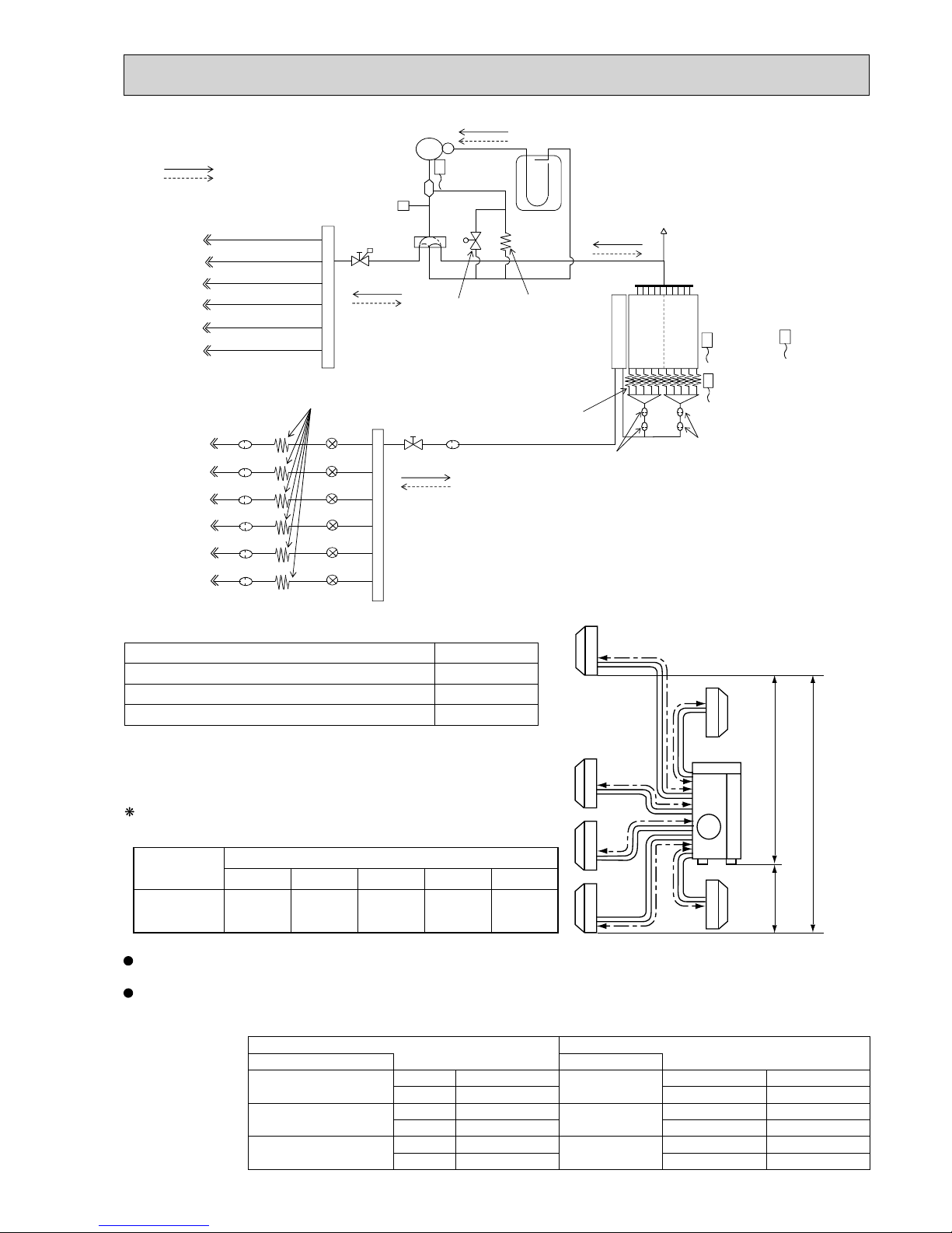
81
R.V.coil
OFF Refrigerant flow in heating
ON Refrigerant flow in cooling
Compressor
Oil separator
High pressure switch
Ø6.35
Ø6.35
Ø9.52
Ø12.7
Indoor unit A
Accumulator
Ø6.35
LEV A
Ø9.52
2-way
solenoid valve
Distributor
Strainer #100
Union
Union
Header(Gas)
Stop valve
Strainer
Strainer
#50
Strainer
#50
#100
Header(Evaporator)
Charge pipe
Capillary tube
Capillary tube
Ø2.5 x Ø0.6 x 1000
Ø4.0 x Ø2.8 x 100
Ø6.35
Ø6.35
Ø9.52
Ø9.52
Compressor shell
temperature
thermistor RT62
Outdoor
heat exchanger
temperature
thermistor
RT68
Ambient
temperature
thermistor
RT65
Defrost
temperature
thermistor
RT61
Capillary tube
Ø4.0 x Ø2.8 x 100
Outdoor
heat exchanger
4-way valve
Stop valve
(with service port)
Indoor unit B
Indoor unit C
Indoor unit E
Ø9.52
Indoor unit D
Indoor unit F
Indoor unit A
Indoor unit B
Indoor unit C
Indoor unit D
Indoor unit E
Strainer #100
Strainer #100
Strainer #100
Strainer #100 LEV B
LEV E
Ø6.35
Indoor unit F
Strainer #100
LEV F
LEV D
LEV C
a
b
c
d
Outdoor
unit
Indoor
units
15 m
10 m
15 m
Refrigerant piping length (one way, 5 unit total)
Calculation : Xg = 20 g/m x (Refrigerant piping length (m) - 30)
e
f
Max.
Height
difference
Outdoor unit
precharged
(g)
50 m
400
40 m
200
4,000
60 m
600
70 m
800
80 m
1000
MXZ-6D122VA
UNIT: mm
Refrigerant pipe diameter is different according to indoor unit to be connected. When using extension pipes, refer to the
tables below.
When diameter of refrigerant pipe is different from that of outdoor unit union, use optional Different-diameter pipe.
For further information on Different-diameter pipe, refer to "PARTS CATALOG".
Piping length each indoor unit (a, b, c, d, e) 25 m
Total piping length (a+b+c+d+e) 80 m
Bending point for each unit 25
Total bending point 80
MAX REFRIGERANT PIPING LENGTH
UNIT: mm (inch)
Outdoor unit union diameter Outdoor unit union diameter
For For
Indoor unit A
Liquid 6.35(1/4)
Indoor unit D
Liquid 6.35(1/4)
Gas 12.7(1/2) Gas 9.52(3/8)
Indoor unit B
Liquid 6.35(1/4)
Indoor unit E
Liquid 6.35(1/4)
Gas 9.52(3/8) Gas 9.52(3/8)
Indoor unit C
Liquid 6.35(1/4)
Indoor unit F
Liquid 6.35(1/4)
Gas 9.52(3/8) Gas 9.52(3/8)
It is irrelevant which unit is higher.
ADDITIONAL REFRIGERANT CHARGE
OBH626K

82
When relocating or disposing of the air conditioner, pump down the system following the procedure below so that no refrigerant is released into the atmosphere.
1) Turn off the breaker.
2) Connect the gauge manifold valve to the service port of the stop valve on the gas pipe side of the outdoor unit.
3) Fully close the stop valve on the liquid pipe side of the outdoor unit.
4) Turn on the breaker.
5) Start the emergency COOL operation on all the indoor units.
6) When the pressure gauge shows 0.05 to 0 MPa [Gauge] (approximately 0.5 to 0 kgf/cm²), fully close the stop valve
on the gas pipe side of the outdoor unit and stop the operation. (Refer to the indoor unit installation manual about the
method for stopping the operation.)
* If too much refrigerant has been added to the air conditioner system, the pressure may not drop to
0.05 to 0 MPa [Gauge]
(approximately 0.5 to 0 kgf/cm²)
, or the protection function may operate due to the pressure increase in the high-pressure refrigerant circuit. If this occurs, use a refrigerant collecting device to collect all of the refrigerant in the system, and
then recharge the system with the correct amount of refrigerant after the indoor and outdoor units have been relocated.
7) Turn off the breaker. Remove the pressure gauge and the refrigerant piping.
When pumping down the refrigerant, stop the compressor before disconnecting the refrigerant pipes.
The compressor may burst and cause injury if any foreign substance, such as air, enters the pipes.
WARNING
PUMPING DOWN
OBH626K

83
PERFORMANCE CURVES
8
The standard specifications apply only to the operation of the air conditioner under normal conditions.
Since operating conditions vary according to the areas where these units are installed, the following information has been pro-
vided to clarify the operating characteristics of the air conditioner under the conditions indicated by the performance curve.
(1) GUARANTEED VOLTAGE
198 - 264 V 50 Hz
(2) AIR FLOW
Air flow should be set at MAX.
(3) MAIN READINGS
(1) Indoor intake air wet-bulb temperature: °CWB
(2) Indoor outlet air wet-bulb temperature: °CWB
(3) Outdoor intake air dry-bulb temperature: °CDB
(4) Total input: W
(5) Indoor intake air dry-bulb temperature: °CDB
(6) Outdoor intake air wet-bulb temperature: °CWB
(7) Total input: W
Indoor air wet and dry bulb temperature difference on the left side of the following chart shows the difference between the
indoor intake air wet and dry bulb temperature and the indoor outlet air wet and dry bulb temperature for your reference at
service.
How to measure the indoor air wet and dry bulb temperature difference
1. Attach at least 2 sets of wet and dry bulb thermometers to the indoor air intake as shown in the figure, and at least 2 sets
of wet and dry bulb thermometers to the indoor air outlet. The thermometers must be attached to the position where air
speed is high.
2. Attach at least 2 sets of wet and dry bulb thermometers to the outdoor air intake.
Cover the thermometers to prevent direct rays of the sun.
3. Check that the air filter is cleaned.
4. Open windows and doors of room.
5. Press the EMERGENCY OPERATION switch once (twice) to start the EMERGENCY COOL (HEAT) MODE.
6. When system stabilizes after more than 15 minutes, measure temperature and take an average temperature.
7. 10 minutes later, measure temperature again and check that the temperature does not change.
INDOOR UNIT
OUTDOOR UNIT
}
}
Cooling
Heating
Wet and dry bulb
thermometers
BACK VIEW
Wet and dry bulb
thermometers
FRONT VIEW
MXZ-2D33VA MXZ-2D40VA MXZ-2D42VA MXZ-2D42VA2
MXZ-2D53VA MXZ-2D53VA2 MXZ-2D53VAH MXZ-2D53VAH2
MXZ-3D54VA MXZ-3D54VA2 MXZ-3D68VA
MXZ-4D72VA MXZ-4D83VA MXZ-5D102VA MXZ-6D122VA
OBH626K

84
8-1. CAPACITY AND THE INPUT CURVES
MXZ-2D33VA MXZ-2D40VA MXZ-2D42VA MXZ-2D42VA2
MXZ-2D53VA MXZ-2D53VA2 MXZ-2D53VAH MXZ-2D53VAH2
Outdoor intake air Dry-bulb temperature (°C)
46454645
Outdoor intake air Dry-bulb temperature (°C)
Indoor intake air Wet-bulb temperature (°C)
Indoor intake air Wet-bulb temperature (°C)
22 class
5.2
4.8
4.4
4.0
3.6
3.2
5.8
5.4
4.9
4.5
4.0
3.6
6.0
5.5
5.0
4.6
4.1
3.7
4.1
3.8
3.5
3.2
2.9
2.6
8.8
8.0
7.3
6.6
6.0
5.3
35 class
10.9
10.0
9.1
8.2
7.3
6.5
42 class
11. 2
10.2
9.3
8.4
7.5
6.7
50 class
25 class
15 class
18 class
7.4
6.8
6.2
5.7
5.1
4.5
20 class
(MXZ-2D53)
(MXZ-2D40/53)
(
MXZ-2D53)
Indoor air Wet-bulb temperature
difference (°C)
Outdoor intake air Wet-bulb temperature (°C) Outdoor intake air Wet-bulb temperature (°C)
Indoor intake air Dry-bulb temperature (°C)
Indoor intake air Dry-bulb temperature (°C)
17.2
15.8
14.4
13.1
11. 7
10.3
9.0
7.7
26.5
24.5
22.2
20.2
18.0
16.0
13.8
11. 8
19.0
17.6
16.1
14.5
13.0
11. 6
10.0
8.6
20.9
19.1
17.5
15.9
14.2
12.6
11. 0
9.3
19.0
17.6
16.1
14.5
13.0
11. 6
10.0
8.6
22 class
25 class
35 class
42 class
(MXZ-2D53)
(MXZ-2D40/53)
26.6
24.5
22.3
20.2
18.0
16.0
13.8
11. 9
21.0
19.2
17.6
16.0
14.2
12.6
11. 1
9.4
21.9
20.2
18.3
16.6
14.8
13.2
11. 5
9.8
50 class
(
MXZ-2D53)
15 class
18 class
20 class
Indoor air Dry-bulb temperature
difference (°C)
Indoor air Wet-bulb temperature
difference (°C)
Outdoor intake air Dry-bulb temperature (°C)
46454645
Outdoor intake air Dry-bulb temperature (°C)
Indoor intake air Wet-bulb temperature (°C)
Indoor intake air Wet-bulb temperature (°C)
22 class
8.5
7.8
7.1
6.4
5.8
5.1
6.3
5.8
5.3
4.8
4.3
3.9
4.1
3.8
3.5
3.2
2.9
2.6
9.3
8.5
7.8
7.0
6.3
5.6
8.0
7.3
6.7
6.0
5.4
4.8
60 class
10.6
9.7
8.8
7.9
7.1
6.3
13.1
11. 9
10.8
9.7
8.7
7.7
9.5
8.7
8.0
7.2
6.5
5.7
13.7
12.4
11. 3
10.1
9.0
8.0
50 class
35 class
42 class
25 class
15 class
18 class
20 class
MXZ-3D54VA MXZ-3D54VA2 MXZ-3D68VA MXZ-4D72VA
25.417.1
15.8
14.5
13.2
11. 8
10.5
9.2
7.9
19.7
18.2
16.7
15.2
13.6
12.1
10.6
9.1
23.4
21.5
19.5
17.6
15.6
13.7
11. 7
24.0
22.2
20.3
18.5
16.6
14.8
12.9
11. 1
22 class
25 class
60 class
25.9
23.9
21.9
19.9
17.9
15.9
13.9
12.0
31.4
29.0
26.6
24.1
21.7
19.3
16.9
14.5
31.9
29.4
27.0
24.5
22.1
19.6
17.2
14.7
35 class
50 class
27.0
24.9
22.8
20.7
18.7
16.6
14.5
12.4
42 class
15 class
19.0
17.6
16.1
14.5
13.0
11. 6
10.0
8.6
18 class
20 class
Indoor air Dry-bulb temperature
difference (°C)
Outdoor intake air Wet-bulb temperature (°C) Outdoor intake air Wet-bulb temperature (°C)
Indoor intake air Dry-bulb temperature (°C)
Indoor intake air Dry-bulb temperature (°C)
OBH626K

85
MXZ-4D83VA MXZ-5D102VA
Indoor air Wet-bulb temperature
diffrrence (°C)
22 class
8.5
7.8
7.1
6.4
5.8
5.1
9.3
8.5
7.8
7.0
6.3
5.6
71 class
60 class
10.6
9.7
8.8
7.9
7.1
6.3
9.5
8.7
8.0
7.2
6.5
5.7
13.7
12.4
11. 3
10.1
9.0
8.0
17.0
15.4
13.9
12.5
11. 1
9.7
42 class
35 class
13.1
11. 9
10.8
9.7
8.7
7.7
50 class
25 class
Indoor air Wet-bulb temperature
diffrrence (°C)
Outdoor intake air Dry-bulb temperature (°C)
4645
4645
Outdoor intake air Dry-bulb temperature (°C)
Indoor intake air Wet-bulb temperature (°C)
Indoor intake air Wet-bulb temperature (°C)
22 class
8.5
7.8
7.1
6.4
5.8
5.1
9.3
8.5
7.8
7.0
6.3
5.6
6.3
5.8
5.3
4.8
4.3
3.9
8.0
7.3
6.7
6.0
5.4
4.8
6.3
5.8
5.3
4.8
4.3
3.9
8.0
7.3
6.7
6.0
5.4
4.8
71 class
60 class
10.6
9.7
8.8
7.9
7.1
6.3
9.5
8.7
8.0
7.2
6.5
5.7
13.7
12.4
11. 3
10.1
9.0
8.0
17.0
15.4
13.9
12.5
11. 1
9.7
42 class
35 class
13.1
11. 9
10.8
9.7
8.7
7.7
50 class
25 class
15 class
20 class
15 class
4.1
3.8
3.5
3.2
2.9
2.6
4.1
3.8
3.5
3.2
2.9
2.6
18 class
18 class
20 class
Indoor air Dry-bulb temperature
difference (°C)
Outdoor intake air Wet-bulb temperature (°C)
Indoor intake air Dry-bulb temperature (°C)
Outdoor intake air Wet-bulb temperature (°C)
Indoor intake air Dry-bulb temperature (°C)
25.4
23.4
21.5
19.5
17.6
15.6
13.7
11. 7
24.0
22.2
20.3
18.5
16.6
14.8
12.9
11. 1
22 class
25 class
60 class
71 class
25.9
23.9
21.9
19.9
17.9
15.9
13.9
12.0
27.0
24.9
22.8
20.7
18.7
16.6
14.5
12.4
31.9
29.4
27.0
24.5
22.1
19.6
17.2
14.7
35.1
32.4
29.7
27.0
24.3
21.6
18.9
16.2
35 class
42 class
31.4
29.0
26.6
24.1
21.7
19.3
16.9
14.5
50 class
Indoor air Dry-bulb temperature
difference (°C)
25.4
23.4
21.5
19.5
17.6
15.6
13.7
11. 7
17.1
15.8
14.5
13.2
11. 8
10.5
9.2
7.9
19.7
18.2
16.7
15.2
13.6
12.1
10.6
9.1
17.1
15.8
14.5
13.2
11. 8
10.5
9.2
7.9
19.7
18.2
16.7
15.2
13.6
12.1
10.6
9.1
24.0
22.2
20.3
18.5
16.6
14.8
12.9
11. 1
22 class
25 class
60 class
71 class
25.9
23.9
21.9
19.9
17.9
15.9
13.9
12.0
27.0
24.9
22.8
20.7
18.7
16.6
14.5
12.4
31.9
29.4
27.0
24.5
22.1
19.6
17.2
14.7
35.1
32.4
29.7
27.0
24.3
21.6
18.9
16.2
35 class
42 class
31.4
29.0
26.6
24.1
21.7
19.3
16.9
14.5
50 class
15 class
20 class
15 class
19.0
17.6
16.1
14.5
13.0
11. 6
10.0
8.6
19.0
17.6
16.1
14.5
13.0
11. 6
10.0
8.6
18 class
18 class
20 class
OBH626K

86
MXZ-6D122VA
Indoor air Wet-bulb temperature
diffrrence (°C)
22 class
5.2
4.8
4.4
4.0
3.6
3.2
6.0
5.5
5.0
4.6
4.1
3.7
71 class
60 class
8.8
8.0
7.3
6.6
6.0
5.3
11.2
10.2
9.3
8.4
7.5
6.6
8.8
8.0
7.3
6.6
6.0
5.3
9.0
8.2
7.5
6.8
6.1
5.4
42 class
35 class
12.8
11.6
10.6
9.5
8.5
7.5
50 class
25 class
Indoor air Wet-bulb temperature
diffrrence (°C)
Outdoor intake air Dry-bulb temperature (°C)
4645
4645
Outdoor intake air Dry-bulb temperature (°C)
Indoor intake air Wet-bulb temperature (°C)
Indoor intake air Wet-bulb temperature (°C)
22 class
5.2
4.8
4.4
4.0
3.6
3.2
6.0
5.5
5.0
4.6
4.1
3.7
5.8
5.4
4.9
4.5
4.0
3.6
7.4
6.8
6.2
5.7
5.1
4.5
5.8
5.4
4.9
4.5
4.0
3.6
7.4
6.8
6.2
5.7
5.1
4.5
71 class
60 class
8.8
8.0
7.3
6.6
6.0
5.3
11.2
10.2
9.3
8.4
7.5
6.6
8.8
8.0
7.3
6.6
6.0
5.3
9.0
8.2
7.5
6.8
6.1
5.4
42 class
35 class
12.8
11.6
10.6
9.5
8.5
7.5
50 class
25 class
15 class
20 class
15 class
4.1
3.8
3.5
3.2
2.9
2.6
4.1
3.8
3.5
3.2
2.9
2.6
18 class
18 class
20 class
Indoor air Dry-bulb temperature
difference (°C)
Outdoor intake air Wet-bulb temperature (°C)
Indoor intake air Dry-bulb temperature (°C)
Outdoor intake air Wet-bulb temperature (°C)
Indoor intake air Dry-bulb temperature (°C)
22 class
25 class
60 class
71 class
35 class
42 class
50 class
Indoor air Dry-bulb temperature
difference (°C)
22 class
25 class
60 class
71 class
35 class
42 class
50 class
15 class
20 class
15 class
18.2
16.8
15.4
13.9
12.5
11.1
9.7
8.2
18.2
16.8
15.4
13.9
12.5
11.1
9.7
8.2
18 class
18 class
20 class
18.2
16.8
15.4
13.9
12.5
11.1
9.7
8.2
18.2
16.8
15.4
13.9
12.5
11.1
9.7
8.2
21.4
19.7
18.1
16.3
14.6
13.0
11.5
9.6
28.9
26.6
24.4
21.9
19.7
17.6
15.7
13.0
20.7
19.1
17.5
15.7
14.2
12.6
11.1
9.3
26.3
24.3
22.3
20.0
18.0
16.0
14.2
11.9
29.8
27.5
25.2
22.7
20.4
18.1
16.2
13.4
18.2
16.8
15.4
13.9
12.5
11.1
9.7
8.2
17.0
15.7
14.4
12.9
11.6
10.3
9.0
7.7
20.5
18.9
17.3
15.6
14.0
12.4
11.0
9.2
17.0
15.7
14.4
12.9
11.6
10.3
9.0
7.7
20.5
18.9
17.3
15.6
14.0
12.4
11.0
9.2
18.2
16.8
15.4
13.9
12.5
11.1
9.7
8.2
21.4
19.7
18.1
16.3
14.6
13.0
11.5
9.6
28.9
26.6
24.4
21.9
19.7
17.6
15.7
13.0
20.7
19.1
17.5
15.7
14.2
12.6
11
.1
9.3
26.3
24.3
22.3
20.0
18.0
16.0
14.2
11.9
29.8
27.5
25.2
22.7
20.4
18.1
16.2
13.4
OBH626K

87
15-class unit
<HEAT>Capacity <HEAT>Total input
Frequency
Hz
Frequency
Hz
<COOL>Capacity
Frequency
Hz
0 50 100 150
1.0
0.5
1.5
2.0
0 50 100 150
0.5
1.0
1.5
2.0
2.5
<
COOL>T
otal input
Frequency
Hz
0 50 100 150
0.5
1.0
1.5
2.0
<
HEAT>C
apacity
Frequency
Hz
0 50 100 150
0.5
1.0
1.5
2.0
0 50 100 150
0.5
1.0
1.5
2.0
2.5
<
HEAT>Total i
npu
t
Frequency
Hz
<COOL>Capacity
Frequency
Hz
<COOL>Total input
Frequency
Hz
0 50 100 150
0.5
1.0
1.5
2.0
050100150
0.5
1.0
1.5
2.0
0 50 100 150
0.5
1.0
1.5
2.0
<HEAT>Capacity <HEAT>Total input
Frequency
Hz
Frequency
Hz
0 50 100 150
0.5
1.0
1.5
<COOL>Capacity
Frequency
Hz
<COOL>Total input
Frequency
Hz
0 50 100 150
0.5
1.0
1.5
2.0
050100150
0.5
1.0
1.5
0 50 100 150
0.5
1.0
1.5
2.0
<HEAT>Capacity <HEAT>Total input
Frequency
Hz
Frequency
Hz
050100150
0.5
1.0
1.5
0 50 100 150
0.5
1.0
1.5
2.0
<HEAT>Capacity <HEAT>Total input
Frequency
Hz
Frequency
Hz
0 50 100 150
0.5
1.0
1.5
<COOL>Capacity
Frequency
Hz
<COOL>Total input
Frequency
Hz
0 50 100 150
0.5
1.0
1.5
050100150
0.5
1.0
1.5
0 50 100 150
0.5
1.0
1.5
2.0
<COOL>Capacity
Frequency
Hz
0 50 100 150
0.5
1.0
1.5
2.0
0 50 100 150
0.5
1.0
1.5
2.0
<COOL>Total input
Frequency
Hz
8-2. CAPACITY AND INPUT CORRECTION BY INVERTER OUTPUT FREQUENCY (single operation)
MXZ-2D33VA
20-class unit
22-class unit
25-class unit
18-class unit
OBH626K

88
0 50 100 150
0.5
1.0
1.5
<COOL>Capacity
Frequency
Hz
0 50 100 150
0.5
1.0
1.5
<COOL>Total input
Frequency
Hz
050100150
0.5
1.0
1.5
<HEAT>Capacity
Frequency
Hz
0 50 100 150
0.5
1.0
1.5
<COOL>Capacity
Frequency
Hz
0 50 100 150
0.5
1.0
1.5
<HEAT>Capacity
Frequency
Hz
0 50 100 150
0.5
1.0
1.5
<HEAT>Total input
Frequency
Hz
050100150
0.5
1.0
1.5
<HEAT>Capacity
Frequency
Hz
0 50 100 150
0.5
1.0
1.5
<HEAT>Total input
Frequency
Hz
0 50 100 150
0.5
1.0
1.5
<COOL>Total input
Frequency
Hz
0 50 100 150
0.5
1.0
1.5
<HEAT>Total input
Frequency
Hz
<HEAT>Capacity <HEAT>Total input
Frequency
Hz
Frequency
Hz
0 50 100 150
0.5
1.0
1.5
0 50 100 150
0.5
1.0
1.5
2.0
<COOL>Capacity
Frequency
Hz
0 50 100 150
0.5
1.0
1.5
2.0
<COOL>Total input
Frequency
Hz
0 50 100 150
0.5
1.0
1.5
2.0
2.5
<HEAT>Capacity
Frequency
Hz
0 50 100 150
0.5
1.0
1.5
2.0
<HEAT>Total input
Frequency
Hz
0 50 100 150
0.5
1.0
1.5
2.0
2.5
3.0
0 50 100 150
0.5
1.0
1.5
<COOL>Capacity
Frequency
Hz
<COOL>Total input
Frequency
Hz
050100150
0.5
1.0
1.5
2.0
<COOL>Capacity
Frequency
Hz
0 50 100 150
0.5
1.0
1.5
2.0
0 50 100 150
0.5
1.0
1.5
2.0
<COOL>Total input
Frequency
Hz
15-class unit
20-class unit
22-class unit
25-class unit
MXZ-2D40VA
18-class unit
OBH626K

89
35-class unit
MXZ-2D40VA
0 50 100 150
0.5
1.0
1.5
<COOL>Capacity
Frequency
Hz
0 50 100 150
0.5
1.0
1.5
<HEAT>Capacity
Frequency
Hz
050100150
0.5
1.0
1.5
<COOL>Total input
Frequency
Hz
0 50 100 150
0.5
1.0
1.5
<HEAT>Total input
Frequency
Hz
0 50 100 150
0.5
1.0
1.5
<COOL>Capacity
Frequency
Hz
050100150
0.5
1.0
1.5
<COOL>Total input
Frequency
Hz
0 50 100 150
0.5
1.0
1.5
<HEAT>Capacity
Frequency
Hz
0 50 100 150
0.5
1.0
1.5
<HEAT>Total input
Frequency
Hz
0 50 100 150
0.5
1.0
1.5
<HEAT>Capacity
Frequency
Hz
0 50 100 150
0.5
1.0
1.5
<HEAT>Total input
Frequency
Hz
<COOL>Capacity
Frequency
Hz
0 50 100 150
0.5
1.0
1.5
2.0
050100150
0.5
1.0
1.5
2.0
<COOL>Total input
Frequency
Hz
<COOL>Capacity
Frequency
Hz
0 50 100 150
0.5
1.0
1.5
<COOL>Total input
Frequency
Hz
<HEAT>Capacity
Frequency
Hz
050100150
0.5
1.0
1.5
2.0
<HEAT>Total input
Frequency
Hz
0 50 100 150
0.5
1.0
1.5
2.0
<COOL>Capacity
Frequency
Hz
0 50 100 150
0.5
1.0
1.5
2.0
<COOL>Total input
Frequency
Hz
0 50 100 150
0.5
1.0
1.5
2.0
2.5
3.0
<HEAT>Capacity
Frequency
Hz
050100150
0.5
1.0
1.5
2.0
<HEAT>Total input
Frequency
Hz
0 50 100 150
0.5
1.0
1.5
2.0
2.5
0 50 100 150
0.5
1.0
1.5
2.0
MXZ-2D42VA MXZ-2D42VA2 MXZ-2D53VA MXZ-2D53VA2 MXZ-2D53VAH MXZ-2D53VAH2
15-class unit
18-class unit
20-class unit
22-class unit
OBH626K

90
0 50 100 150
0.5
1.0
1.5
<COOL>Capacity
Frequency
Hz
0 50 100 150
0.5
1.0
1.5
<HEAT>Capacity
Frequency
Hz
0 50 100 150
0.5
1.0
1.5
<COOL>Total input
Frequency
Hz
0 50 100 150
0.5
1.0
1.5
<HEAT>Total input
Frequency
Hz
0 50 100 150
0.5
1.0
1.5
<COOL>Capacity
Frequency
Hz
0 50 100 150
0.5
1.0
1.5
<HEAT>Capacity
Frequency
Hz
0 50 100 150
0.5
1.0
1.5
<COOL>Total input
Frequency
Hz
0 50 100 150
0.5
1.0
1.5
<HEAT>Total input
Frequency
Hz
25-class unit
35-class unit
<COOL>Capacity
Frequency
Hz
0 50 100 150
0.5
1.0
1.5
<COOL>Total input
Frequency
Hz
<HEAT>Capacity
Frequency
Hz
0 50 100 150
0.5
1.0
1.5
<HEAT>Total input
Frequency
Hz
0 50 100 150
0.5
1.0
1.5
0 50 100 150
0.5
1.0
1.5
42-class unit
<COOL>Capacity
Frequency
Hz
0 50 100 150
0.5
1.0
1.5
<COOL>Total input
Frequency
Hz
<HEAT>Capacity
Frequency
Hz
0 50 100 150
0.5
1.0
1.5
<HEAT>Total input
Frequency
Hz
0 50 100 150
0.5
1.0
1.5
0 50 100 150
0.5
1.0
1.5
50-class unit
MXZ-2D42VA MXZ-2D42VA2 MXZ-2D53VA MXZ-2D53VA2 MXZ-2D53VAH MXZ-2D53VAH2
OBH626K

91
0 50 100 150
1.0
1.5
2.0
2.5
<HEAT>Capacity <HEAT>Total input
Frequency
Hz
Frequency
Hz
0 50 100 150
1.0
1.5
2.0
2.5
050100150
1.0
1.5
2.0
2.5
<HEAT>Capacity <HEAT>Total input
Frequency
Hz
Frequency
Hz
0 50 100 150
0.5
1.0
1.5
0 50 100 150
0.5
1.0
1.5
0 50 100 150
0.5
1.0
1.5
<HEAT>Capacity
Frequency
Hz
0 50 100 150
0.5
1.0
1.5
<HEAT>Total input
Frequency
Hz
<HEAT>Capacity <HEAT>Total input
Frequency
Hz
Frequency
Hz
0 50 100 150
1.0
1.5
2.0
<COOL>Capacity
Frequency
Hz
<COOL>Total input
Frequency
Hz
0 50 100 150
1.0
1.5
2.0
2.5
0 50 100 150
1.0
1.5
2.0
2.5
<COOL>Capacity
Frequency
Hz
<COOL>Total input
Frequency
Hz
0 50 100 150
0.5
1.0
1.5
0 50 100 150
0.5
1.0
1.5
0 50 100 150
0.5
1.0
1.5
<COOL>Capacity
Frequency
Hz
0 50 100 150
0.5
1.0
1.5
<COOL>Total input
Frequency
Hz
<COOL>Capacity
Frequency
Hz
0 50 100 150
1.0
1.5
2.0
<COOL>Total input
Frequency
Hz
0 50 100 150
1.0
1.5
2.0
MXZ-3D54VA MXZ-3D54VA2
15-class unit
22-class unit
18-class unit
20-class unit
OBH626K

92
25-class unit
0 50 100 150
0.5
1.0
1.5
<COOL>Capacity
Frequency
Hz
0 50 100 150
0.5
1.0
1.5
<HEAT>Capacity
Frequency
Hz
0 50 100 150
0.5
1.0
1.5
<COOL>Capacity
Frequency
Hz
0 50 100 150
0.5
1.0
1.5
<HEAT>Capacity
Frequency
Hz
0 50 100 150
0.5
1.0
1.5
<COOL>Total input
Frequency
Hz
0 50 100 150
0.5
1.0
1.5
<HEAT>Total input
Frequency
Hz
0 50 100 150
0.5
1.0
1.5
<COOL>Total input
Frequency
Hz
0 50 100 150
0.5
1.0
1.5
<HEAT>Total input
Frequency
Hz
<COOL>Capacity
Frequency
Hz
<HEAT>Capacity
Frequency
Hz
<COOL>Total input
Frequency
Hz
<HEAT>Total input
Frequency
Hz
0 50 100 150
0.5
1.0
1.5
0 50 100 150
0.5
1.0
1.5
0 50 100 150
0.5
1.0
1.5
0 50 100 150
0.5
1.0
1.5
0 50 100 150
0.5
1.0
1.5
<COOL>Capacity
Frequency
Hz
0 50 100 150
0.5
1.0
1.5
<HEAT>Capacity
Frequency
Hz
0 50 100 150
0.5
1.0
1.5
<COOL>Total input
Frequency
Hz
0 50 100 150
0.5
1.0
1.5
<HEAT>Total input
Frequency
Hz
MXZ-3D54VA MXZ-3D54VA2
35-class unit
42-class unit
50-class unit
OBH626K

93
<COOL>Capacity
Frequency
Hz
<COOL>Total input
Frequency
Hz
<COOL>Capacity
Frequency
Hz
0 50 100 150
1.0
1.5
2.0
<COOL>Total input
Frequency
Hz
0 50 100 150
1.0
1.5
2.0
<COOL>Capacity
Frequency
Hz
0 50 100 150
0.5
1.0
1.5
2.0
<COOL>Total input
Frequency
Hz
0 50 100 150
0.5
1.0
1.5
2.0
<COOL>Capacity
Frequency
Hz
0 50 100 150
0.5
1.0
1.5
2.0
<COOL>Total input
Frequency
Hz
0 50 100 150
1.0
1.5
2.0
2.5
0 50 100 150
1.0
1.5
2.0
2.5
<COOL>Capacity
Frequency
Hz
<COOL>Total input
0 50 100 150
0.5
1.0
1.5
2.0
Frequency
Hz
0 50 100 150
0.5
1.0
1.5
2.0
0 50 100 150
0.5
1.0
1.5
<HEAT>Capacity <HEAT>Total input
Frequency
Hz
Frequency
Hz
<HEAT>Capacity <HEAT>Total input
Frequency
Hz
Frequency
Hz
0 50 100 150
1.0
1.5
2.0
<HEAT>Capacity <HEAT>Total input
Frequency
Hz
Frequency
Hz
<HEAT>Capacity <HEAT>Total input
Frequency
Hz
0 50 100 150
0.5
1.0
1.5
Frequency
Hz
0 50 100 150
1.0
1.5
2.0
2.5
0 50 100 150
1.0
1.5
2.0
2.5
0 50 100 150
1.0
1.5
2.0
2.5
3.0
<HEAT>Capacity <HEAT>Total input
Frequency
Hz
0 50 100 150
0.5
1.0
1.5
Frequency
Hz
0 50 100 150
0.5
1.0
1.5
0 50 100 150
0.5
1.0
1.5
050100150
0.5
1.0
1.5
0 50 100 150
0.5
1.0
1.5
MXZ-3D68VA
15-class unit
22-class unit
25-class unit
20-class unit
18-class unit
OBH626K

94
<COOL>Capacity
Frequency
Hz
<COOL>Total input
Frequency
Hz
<HEAT>Capacity <HEAT>Total input
Frequency
Hz
Frequency
Hz
<COOL>Capacity
Frequency
Hz
0 50 100 150
0.5
1.0
1.5
<COOL>Total input
Frequency
Hz
<HEAT>Capacity <HEAT>Total input
Frequency
Hz
Frequency
Hz
<COOL>Capacity
Frequency
Hz
<COOL>Total input
Frequency
Hz
<HEAT>Capacity <HEAT>Total input
Frequency
Hz
Frequency
Hz
<COOL>Capacity
Frequency
Hz
<COOL>Total input
Frequency
Hz
<HEAT>Capacity <HEAT>Total input
Frequency
Hz
Frequency
Hz
0 50 100 150
0.5
1.0
1.5
2.0
0 50 100 150
0.5
1.0
1.5
0 50 100 150
0.5
1.0
1.5
0 50 100 150
0.5
1.0
1.5
0 50 100 150
0.5
1.0
1.5
0 50 100 150
0.5
1.0
1.5
0 50 100 150
0.5
1.0
1.5
0 50 100 150
0.5
1.0
1.5
0 50 100 150
0.5
1.0
1.5
0 50 100 150
0.5
1.0
1.5
0 50 100 150
0.5
1.0
1.5
0 50 100 150
0.5
1.0
1.5
0 50 100 150
0.5
1.0
1.5
0 50 100 150
0.5
1.0
1.5
0 50 100 150
0.5
1.0
1.5
MXZ-3D68VA
35-class unit
42-class unit
50-class unit
60-class unit
OBH626K
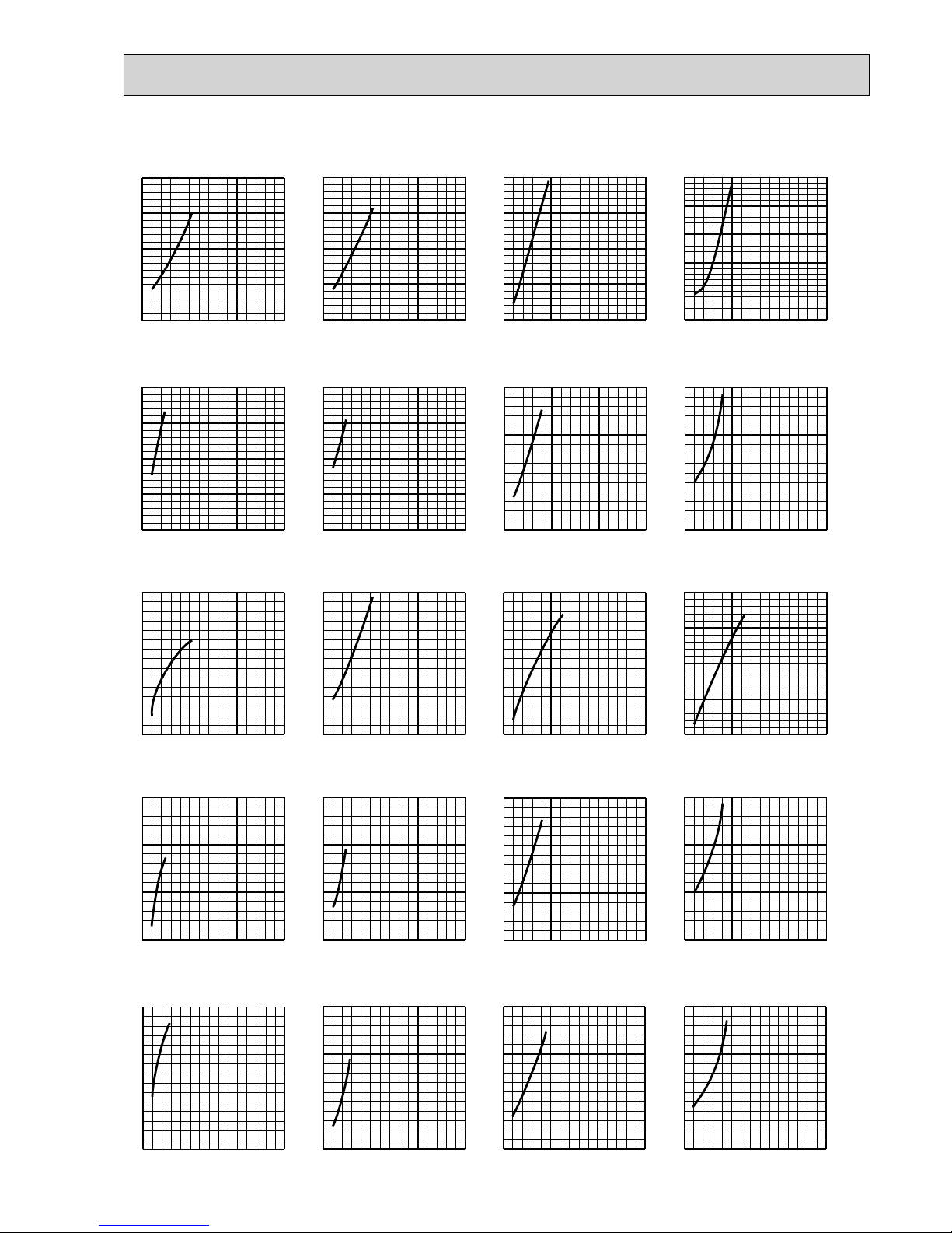
95
MXZ-4D72VA
<COOL>Capacity
Frequency
Hz
<COOL>Total input
Frequency
Hz
<HEAT>Capacity <HEAT>Total input
Frequency
Hz
Frequency
Hz
<COOL>Capacity
Frequency
Hz
0 50 100 150
1.0
1.5
2.0
<COOL>Total input
Frequency
Hz
<HEAT>Capacity <HEAT>Total input
0 50 100 150
1.0
1.5
2.0
Frequency
Hz
Frequency
Hz
0 50 100 150
1.0
1.5
2.0
<COOL>Capacity
Frequency
Hz
0 50 100 150
0.5
1.0
1.5
2.0
<COOL>Total input
Frequency
Hz
<HEAT>Capacity <HEAT>Total input
0 50 100 150
0.5
1.0
1.5
2.0
Frequency
Hz
Frequency
Hz
<COOL>Capacity
Frequency
Hz
0 50 100 150
0.5
1.0
1.5
2.0
<COOL>Total input
Frequency
Hz
<HEAT>Capacity <HEAT>Total input
Frequency
Hz
0 50 100 150
0.5
1.0
1.5
Frequency
Hz
0 50 100 150
1.0
1.5
2.0
2.5
0 50 100 150
1.0
1.5
2.0
2.5
0 50 100 150
1.0
1.5
2.0
2.5
0 50 100 150
1.0
1.5
2.0
2.5
0 50 100 150
1.0
1.5
2.0
2.5
3.0
0 50 100 150
0.5
1.0
1.5
0 50 100 150
0.5
1.0
1.5
0 50 100 150
0.5
1.0
1.5
0 50 100 150
0.5
1.0
1.5
<COOL>Capacity
Frequency
Hz
<COOL>Total input
0 50 100 150
0.5
1.0
1.5
2.0
Frequency
Hz
0 50 100 150
0.5
1.0
1.5
2.0
<HEAT>Capacity <HEAT>Total input
Frequency
Hz
0 50 100 150
0.5
1.0
1.5
Frequency
Hz
0 50 100 150
0.5
1.0
1.5
15-class unit
22-class unit
25-class unit
20-class unit
18-class unit
OBH626K

96
MXZ-4D72VA
<COOL>Capacity
Frequency
Hz
<COOL>Total input
Frequency
Hz
<HEAT>Capacity <HEAT>Total input
Frequency
Hz
Frequency
Hz
<COOL>Capacity
Frequency
Hz
0 50 100 150
0.5
1.0
1.5
<COOL>Total input
Frequency
Hz
<HEAT>Capacity <HEAT>Total input
Frequency
Hz
Frequency
Hz
<COOL>Capacity
Frequency
Hz
<COOL>Total input
Frequency
Hz
<HEAT>Capacity <HEAT>Total input
Frequency
Hz
Frequency
Hz
<COOL>Capacity
Frequency
Hz
<COOL>Total input
Frequency
Hz
<HEAT>Capacity <HEAT>Total input
Frequency
Hz
Frequency
Hz
0 50 100 150
0.5
1.0
1.5
2.0
0 50 100 150
0.5
1.0
1.5
0 50 100 150
0.5
1.0
1.5
0 50 100 150
0.5
1.0
1.5
0 50 100 150
0.5
1.0
1.5
0 50 100 150
0.5
1.0
1.5
0 50 100 150
0.5
1.0
1.5
0 50 100 150
0.5
1.0
1.5
0 50 100 150
0.5
1.0
1.5
0 50 100 150
0.5
1.0
1.5
0 50 100 150
0.5
1.0
1.5
0 50 100 150
0.5
1.0
1.5
0 50 100 150
0.5
1.0
1.5
0 50 100 150
0.5
1.0
1.5
0 50 100 150
0.5
1.0
1.5
35-class unit
42-class unit
50-class unit
60-class unit
OBH626K

97
MXZ-4D83VA
<COOL>Capacity
Frequency
Hz
<COOL>Total input
0 50 100 150
0.5
1.0
1.5
2.0
Frequency
Hz
0 50 100 150
0.5
1.0
1.5
2.0
<COOL>Capacity
Frequency
Hz
<COOL>Total input
0 50 100 150
0.5
1.0
1.5
Frequency
Hz
0 50 100 150
0.5
1.0
1.5
<COOL>Capacity
Frequency
Hz
<COOL>Total input
0 50 100 150
0.5
1.0
1.5
2.0
Frequency
Hz
0 50 100 150
0.5
1.0
1.5
2.0
<COOL>Capacity
Frequency
Hz
050100150
1.0
1.5
2.0
<COOL>Total input
Frequency
Hz
0 50 100 150
1.0
1.5
2.0
Frequency
Hz
050100150
1.0
1.5
2.0
<COOL>Total input
Frequency
Hz
<COOL>Capacity
Frequency
Hz
0 50 100 150
1.0
1.5
2.0
<HEAT>Capacity
<HEAT>Capacity
Frequency
Hz
<HEAT>Total input
Frequency
Hz
0 50 100 150
1.0
1.5
2.0
<HEAT>Total input
Frequency
Hz
0 50 100 150
1.0
1.5
2.0
0 50 100 150
1.0
2.0
3.0
0 50 100 150
1.0
2.0
3.0
<HEAT>Capacity <HEAT>Total input
Frequency
Hz
0 50 100 150
0.5
1.0
1.5
Frequency
Hz
0 50 100 150
0.5
1.0
1.5
2.0
<HEAT>Capacity <HEAT>Total input
Frequency
Hz
0 50 100 150
0.5
1.0
1.5
Frequency
Hz
0 50 100 150
0.5
1.0
1.5
2.0
<HEAT>Capacity <HEAT>Total input
Frequency
Hz
0 50 100 150
0.5
1.0
1.5
Frequency
Hz
0 50 100 150
0.5
1.0
1.5
2.0
15-class unit
22-class unit
25-class unit
20-class unit
18-class unit
OBH626K

98
MXZ-4D83VA
<COOL>Capacity
Frequency
Hz
<HEAT>Capacity
Frequency
Hz
<COOL>Total input
Frequency
Hz
<HEAT>Total input
Frequency
Hz
0 50 100 150
0.5
1.0
1.5
050100150
0.5
1.0
1.5
0 50 100 150
0.5
1.0
1.5
0 50 100 150
0.5
1.0
1.5
<COOL>Capacity
Frequency
Hz
<HEAT>Capacity
Frequency
Hz
<COOL>Total input
Frequency
Hz
<HEAT>Total input
Frequency
Hz
0 50 100 150
0.5
1.0
1.5
050100150
0.5
1.0
1.5
0 50 100 150
0.5
1.0
1.5
0 50 100 150
0.5
1.0
1.5
<COOL>Capacity
Frequency
Hz
<HEAT>Capacity
Frequency
Hz
<COOL>Total input
Frequency
Hz
<HEAT>Total input
Frequency
Hz
0 50 100 150
0.5
1.0
1.5
050100150
0.5
1.0
1.5
0 50 100 150
0.5
1.0
1.5
0 50 100 150
0.5
1.0
1.5
<COOL>Capacity
Frequency
Hz
<HEAT>Capacity
Frequency
Hz
<COOL>Total input
Frequency
Hz
<HEAT>Total input
Frequency
Hz
0 50 100 150
0.5
1.0
1.5
050100150
0.5
1.0
1.5
0 50 100 150
0.5
1.0
1.5
0 50 100 150
0.5
1.0
1.5
<COOL>Capacity
Frequency
Hz
<HEAT>Capacity
Frequency
Hz
<COOL>Total input
Frequency
Hz
<HEAT>Total input
Frequency
Hz
0 50 100 150
0.5
1.0
1.5
050100150
0.5
1.0
1.5
0 50 100 150
0.5
1.0
1.5
0 50 100 150
0.5
1.0
1.5
42-class unit
50-class unit
60-class unit
71-class unit
35-class unit
OBH626K

99
MXZ-5D102VA
<COOL>Capacity
Frequency
Hz
<COOL>Total input
0 50 100 150
0.5
1.0
1.5
2.0
Frequency
Hz
0 50 100 150
0.5
1.0
1.5
2.0
<COOL>Capacity
Frequency
Hz
<COOL>Total input
0 50 100 150
0.5
1.0
1.5
Frequency
Hz
0 50 100 150
0.5
1.0
1.5
<COOL>Capacity
Frequency
Hz
<COOL>Total input
0 50 100 150
0.5
1.0
1.5
2.0
Frequency
Hz
0 50 100 150
0.5
1.0
1.5
2.0
<COOL>Capacity
Frequency
Hz
050100150
1.0
1.5
2.0
<COOL>Total input
Frequency
Hz
0 50 100 150
1.0
1.5
2.0
Frequency
Hz
050100150
1.0
1.5
2.0
<COOL>Total input
Frequency
Hz
<COOL>Capacity
Frequency
Hz
0 50 100 150
1.0
1.5
2.0
<HEAT>Capacity
<HEAT>Capacity
Frequency
Hz
<HEAT>Total input
Frequency
Hz
0 50 100 150
1.0
1.5
2.0
<HEAT>Total input
Frequency
Hz
0 50 100 150
1.0
1.5
2.0
0 50 100 150
1.0
2.0
3.0
0 50 100 150
1.0
2.0
3.0
<HEAT>Capacity <HEAT>Total input
Frequency
Hz
0 50 100 150
0.5
1.0
1.5
Frequency
Hz
0 50 100 150
0.5
1.0
1.5
2.0
<HEAT>Capacity <HEAT>Total input
Frequency
Hz
0 50 100 150
0.5
1.0
1.5
Frequency
Hz
0 50 100 150
0.5
1.0
1.5
2.0
<HEAT>Capacity <HEAT>Total input
Frequency
Hz
0 50 100 150
0.5
1.0
1.5
Frequency
Hz
0 50 100 150
0.5
1.0
1.5
2.0
15-class unit
22-class unit
25-class unit
20-class unit
18-class unit
OBH626K

100
MXZ-5D102VA
<COOL>Capacity
Frequency
Hz
<HEAT>Capacity
Frequency
Hz
<COOL>Total input
Frequency
Hz
<HEAT>Total input
Frequency
Hz
0 50 100 150
0.5
1.0
1.5
050100150
0.5
1.0
1.5
0 50 100 150
0.5
1.0
1.5
0 50 100 150
0.5
1.0
1.5
<COOL>Capacity
Frequency
Hz
<HEAT>Capacity
Frequency
Hz
<COOL>Total input
Frequency
Hz
<HEAT>Total input
Frequency
Hz
0 50 100 150
0.5
1.0
1.5
050100150
0.5
1.0
1.5
0 50 100 150
0.5
1.0
1.5
0 50 100 150
0.5
1.0
1.5
<COOL>Capacity
Frequency
Hz
<HEAT>Capacity
Frequency
Hz
<COOL>Total input
Frequency
Hz
<HEAT>Total input
Frequency
Hz
0 50 100 150
0.5
1.0
1.5
050100150
0.5
1.0
1.5
0 50 100 150
0.5
1.0
1.5
0 50 100 150
0.5
1.0
1.5
<COOL>Capacity
Frequency
Hz
<HEAT>Capacity
Frequency
Hz
<COOL>Total input
Frequency
Hz
<HEAT>Total input
Frequency
Hz
0 50 100 150
0.5
1.0
1.5
050100150
0.5
1.0
1.5
0 50 100 150
0.5
1.0
1.5
0 50 100 150
0.5
1.0
1.5
<COOL>Capacity
Frequency
Hz
<HEAT>Capacity
Frequency
Hz
<COOL>Total input
Frequency
Hz
<HEAT>Total input
Frequency
Hz
0 50 100 150
0.5
1.0
1.5
050100150
0.5
1.0
1.5
0 50 100 150
0.5
1.0
1.5
0 50 100 150
0.5
1.0
1.5
42-class unit
50-class unit
60-class unit
71-class unit
35-class unit
OBH626K
 Loading...