

Mitsubishi MXZ-18NV, MXZ-32NV SERVICE MANUAL
SPLIT-TYPE,HEAT PUMP AIR CONDITIONERS
SERVICE MANUAL
Inverter-controlled multi system
Models
Revision:
●MXZ-18NV- and MXZ-18NV- have been added.
●Page layout has been changed.
●Performance curves has been modified.
●The graph of the outdoor low pressure in the HEAT
operation of the PERFORMANCE CURVE of MXZ32NV was deleted.
●Please void OB185 REVISED EDITION Aand B.
E2E1
No. OB185
REVISED EDITION C
MXZ-18NV MXZ-32NV MXZ-18NV MXZ-32NV -
MXZ-32NV
Model indication
E1
E1
E2
E2
CONTENTS
1. TECHNICAL CHANGES····································2
2. PART NAMES AND FUNCTIONS······················2
3. INDOOR /OUTDOOR
CORRESPONDENCE TABLE··········3
4. INDOOR UNITS COMBINATION ·······················4
5. SPECIFICATION·················································9
6. OUTLINES AND DIMENSIONS························11
7. WIRING DIAGRAM ··········································13
8. REFRIGERANT SYSTEM DIAGRAM··············15
9. PERFORMANCE CURVES······························20
10. MICROPROCESSOR CONTROL ····················30
11. TROUBLESHOOTING ······································39
12. DISASSEMBLY INSTRUCTIONS·····················53
13. PARTS LIST······················································57
14. OPTIONAL PARTS····································BACK
This manual describes technical data of outdoor unit.
For indoor unit refer to the service manuals No.OB207 and OB196 REVISED EDITION Aof corresponding
models.
1
TECHNICAL CHANGES
MXZ-18LV- →MXZ-18NV-
1. Inverter assembly has changed.
2. Gas pipe thermistors were added.
3. H.P.S. has changed.
MXZ-18NV- →MXZ-18NV-
1. MSH-07NV
2. Outdoor unit electronic control P.C. board has changed.
3. The outdoor fan speed control has changed.(HEAT mode single operation : Lo → Hi)
MXZ-32AV- →MXZ-32NV-
1. The desital display self-diagnosis function has adopted.
2. The desorption method of LEV has changed the screw method to the one touch method.
3. The position of the electronical parts has changed.
4. The chargeless system has adopted.
5. The scroll compressor has adopted.
6. The micro control P.C.board has simplifed.
7. The fan speed level has becomed 3 levels (Hi / Me / Lo).
8. The low pressure switch has adopted .
9. The ditection of connector deviation has becomed easily.
MXZ-32NV- →MXZ-32NV-
1. MCFH-13NV
-
and MSH-12NV
-
and MCFH-18NV
E1E1
E2E1
E2E2
-
has been added to the combination of the connectable indoor units.
E1E2
E2E1
E2E2
-
has been added to the combination of the connectable indoor units.
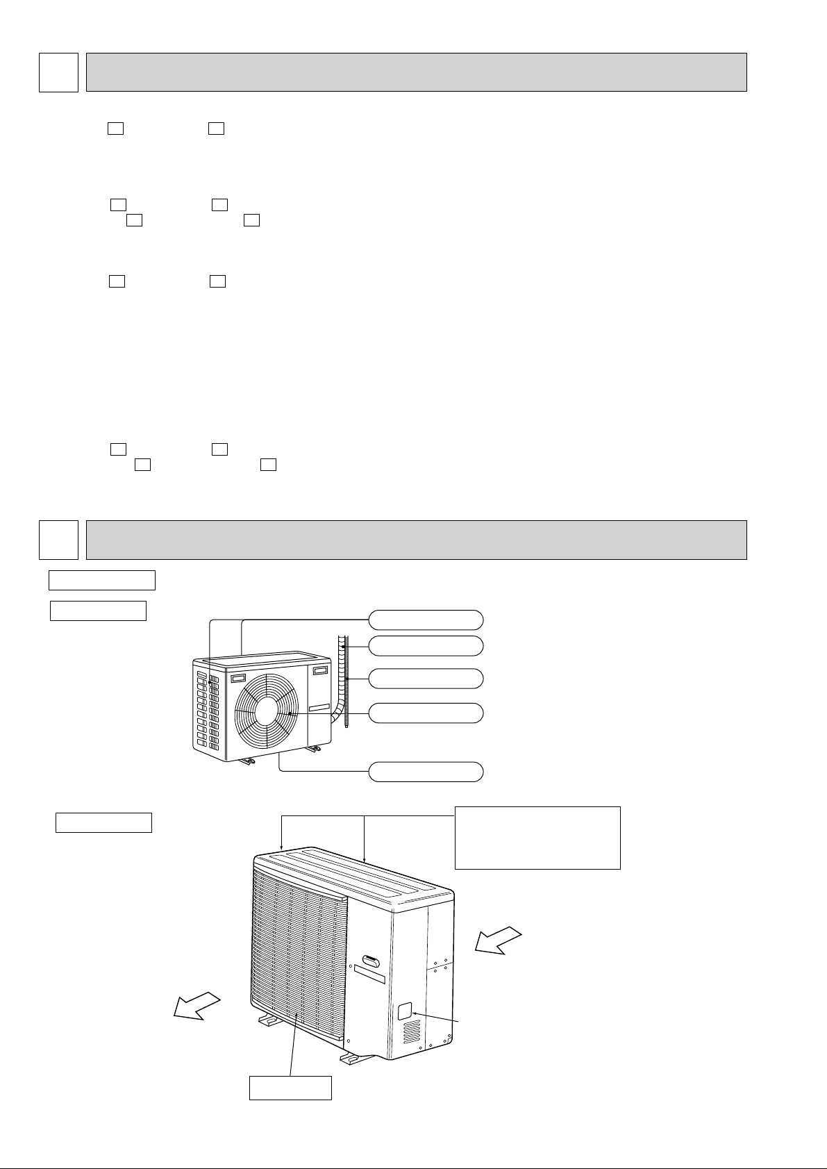
PART NAMES AND FUNCTION2
Outdoor unit
MXZ-18NV
MXZ-32NV
Air inlet
Piping
Drainage hose
Air outlet
Drain outlet
(back and side)
Air intake
Located on the back
and the left side.
Air in
Air out
Model indication
Air outlet
2
3
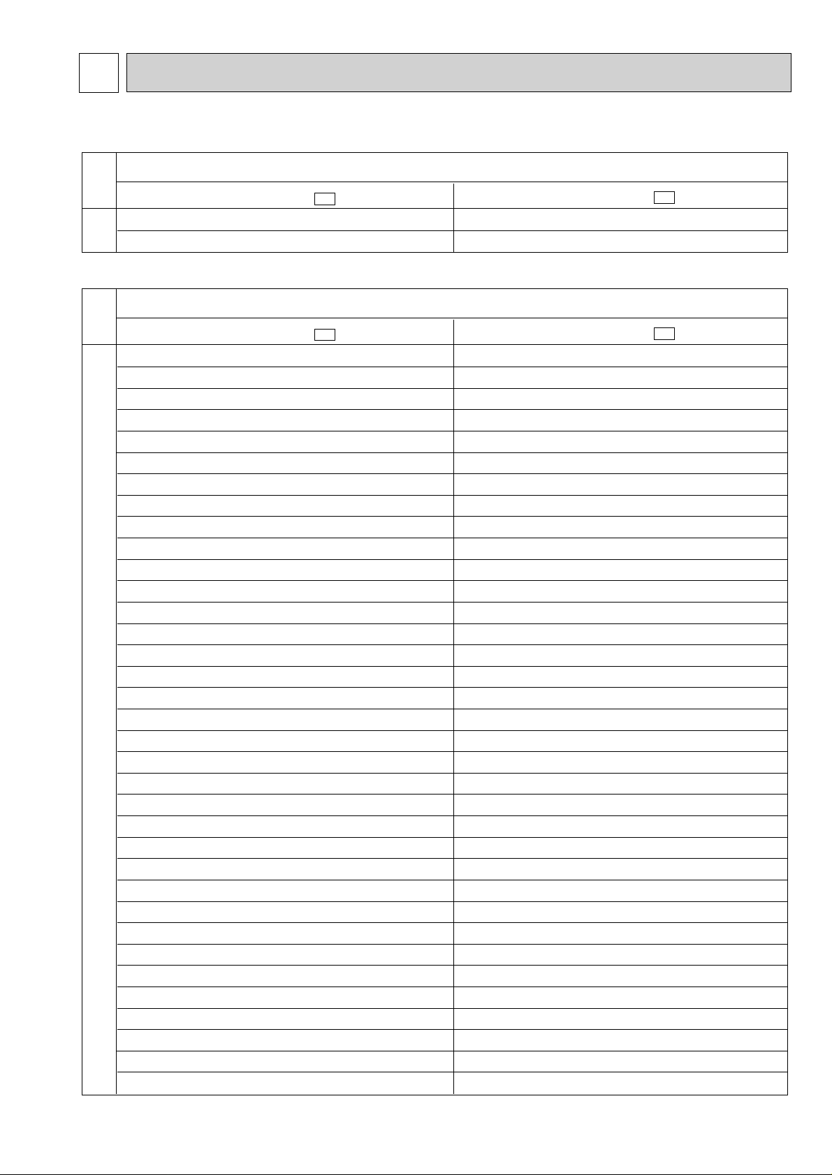
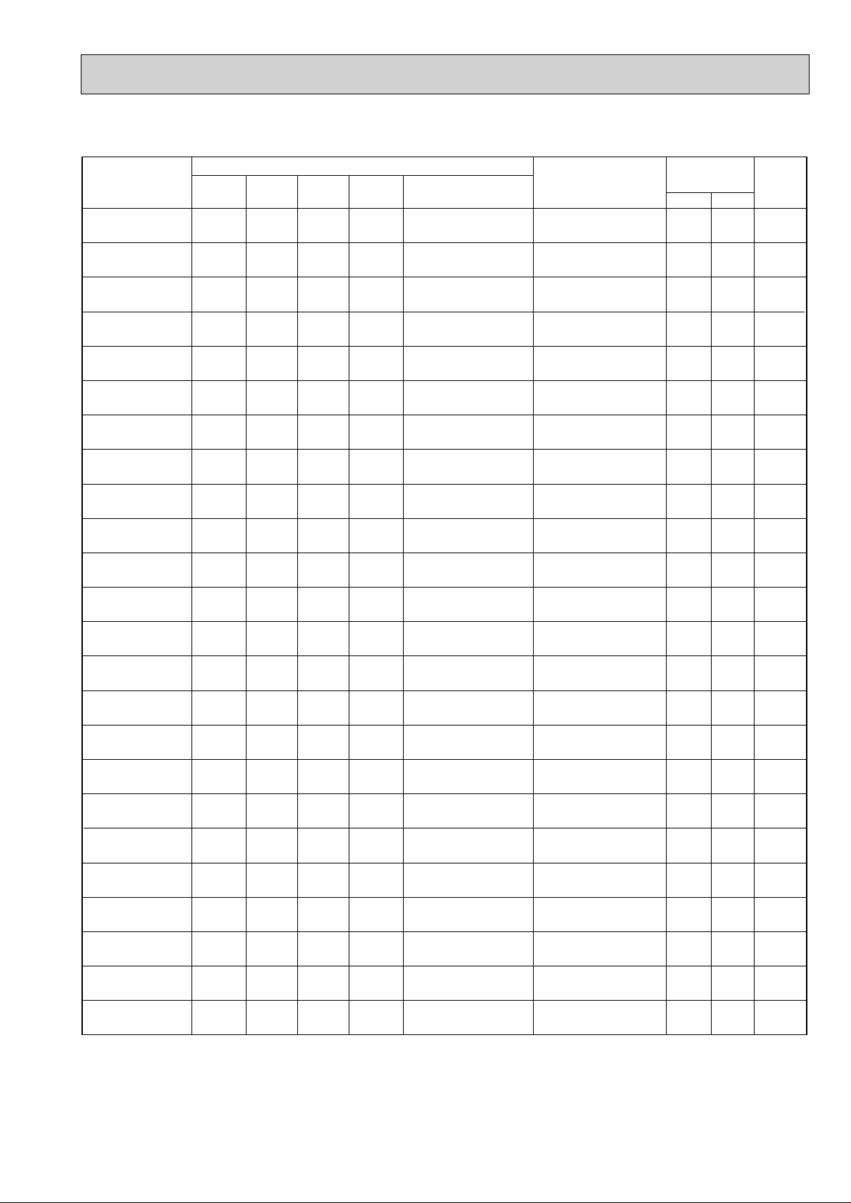
❈There is no combination other than this table.
MXZ-32NV- E2
MXZ-18NV- E2
OUTDOOR UNIT
Combination of the connectable indoor units
07+07+07
07+07+09
07+07+12
07+07+18
07+09+09
07+09+12
07+09+18
07+12+12
07+12+18
07+18+18
09+09+09
09+09+12
09+09+18
09+12+12
09+12+18
09+18+18
12+12+12
12+12+18
07+07+07+07
07+07+07+09
07+07+07+12
07+07+07+18
07+07+09+09
07+07+09+12
07+07+09+18
07+07+12+12
07+07+12+18
07+09+09+09
07+09+09+12
07+09+09+18
07+09+12+12
09+09+09+09
09+09+09+12
09+09+09+18
09+09+12+12
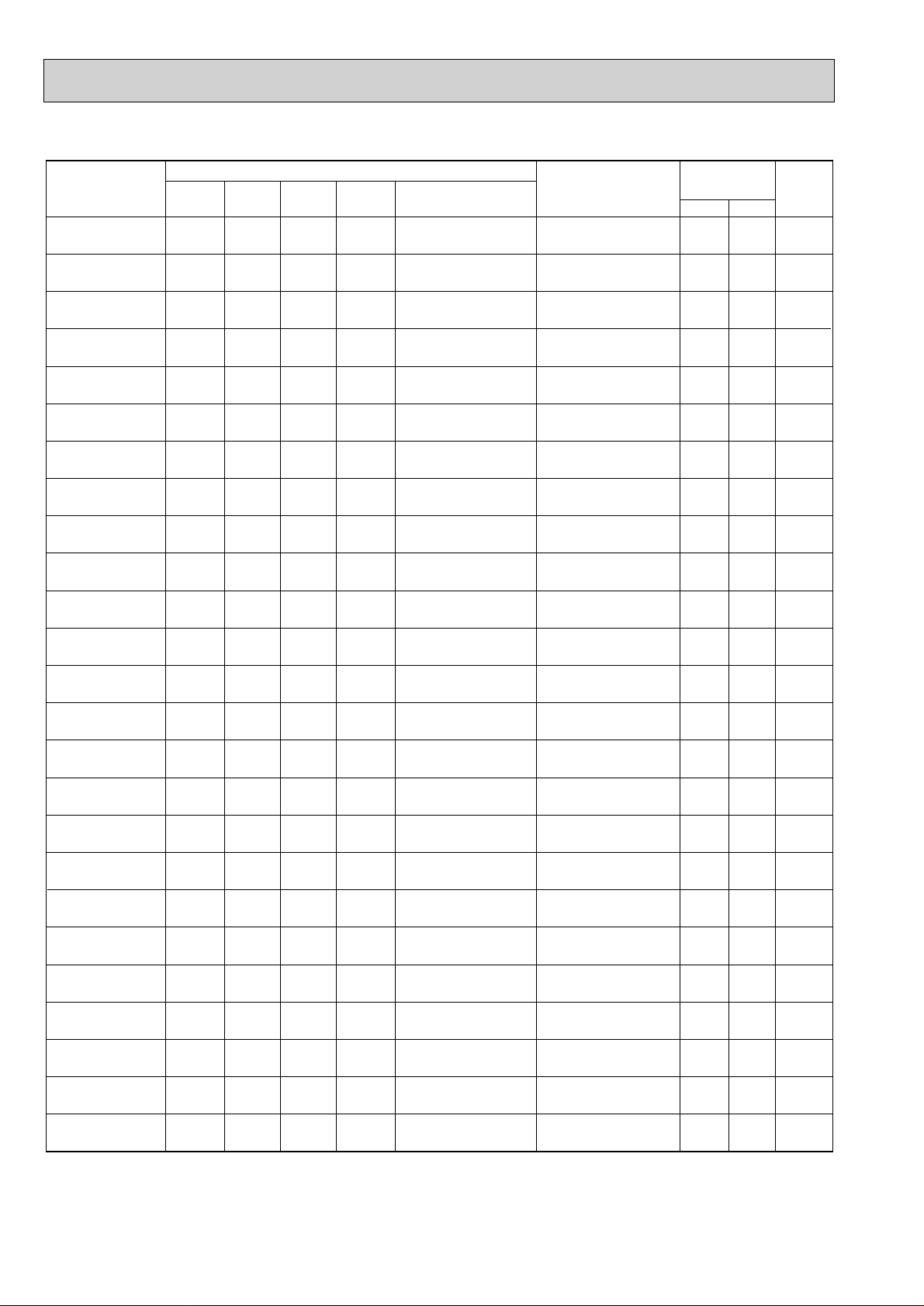
MXZ-32NV-
E1
07+07+07
07+07+09
07+07+(12 or 13)
07+07+18
07+09+09
07+09+(12 or 13)
07+09+18
07+(12 or 13)+(12 or 13)
07+(12 or 13)+18
07+18+18
09+09+09
09+09+(12 or 13)
09+09+18
09+(12 or 13)+(12 or 13)
09+(12 or 13)+18
09+18+18
(12 or 13)+(12 or 13)+(12 or 13)
(12 or 13)+(12 or 13)+18
07+07+07+07
07+07+07+09
07+07+07+(12 or 13)
07+07+07+18
07+07+09+09
07+07+09+(12 or 13)
07+07+09+18
07+07+(12 or 13)+(12 or 13)
07+07+(12 or 13)+18
07+09+09+09
07+09+09+(12 or 13)
07+09+09+18
07+09+(12 or 13)+(12 or 13)
09+09+09+09
09+09+09+(12 or 13)
09+09+09+18
09+09+(12 or 13)+(12 or 13)
OUTDOOR UNIT
09+09
-
MXZ-18NV- E1
09+09
07+12
INDOOR / OUTDOOR CORRESPONDENCE TABLE
MXZ-18NV
MXZ-32NV
3
4
Outdoor unit
power consumption
(kW)
07
09
12
07+12
09+09
Indoor units
combination
Unit B
Unit A
Cooling capacity (kW)
Total
220V 240V
Current
(A)
Power
factor
(%)
2.3
2.5
3.4
2.0
2.25
-
-
-
2.5
2.25
2.3
(1.6 - 2.8)
2.5
(1.7 - 3.0)
3.4
(1.8 - 3.8)
4.5
(2.0 - 4.5)
4.5
(1.9 - 4.5)
1.02
(0.855 - 1.33)
1.05
(0.855 - 1.36)
1.45
(0.855 - 1.63)
2.00
(0.91- 2.00)
2.00
(0.91 - 2.00)
5.20
5.36
7.40
10.21
10.21
89 - 90
89 - 90
89 - 90
89 - 90
89 - 90
4.72
4.86
6.71
9.26
9.26
Outdoor unit
power consumption
(kW)
07
09
12
07+12
09+09
Indoor units
combination
Unit B
Unit A
Heating capacity (kW)
Total
220V 240V
Current
(A)
Power
factor
(%)
3.3
3.6
4.0
2.7
2.9
-
-
-
3.1
2.9
3.3
(2.0 - 4.0)
3.6
(2.0 - 4.5)
4.0
(2.2 - 4.7)
5.8
(2.1 - 5.8)
5.8
(2.0 - 5.8)
1.45
(0.69 - 1.60)
1.47
(0.69 - 1.62)
1.63
(0.69 - 1.69)
1.785
(0.69 - 1.785)
1.785
(0.69 - 1.785)
7.40
7.50
8.32
9.02
9.02
89 - 90
89 - 90
89 - 90
90 - 90
90 - 90
6.71
6.80
7.54
8.26
8.26
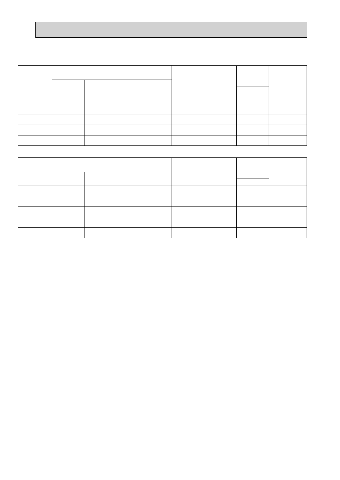
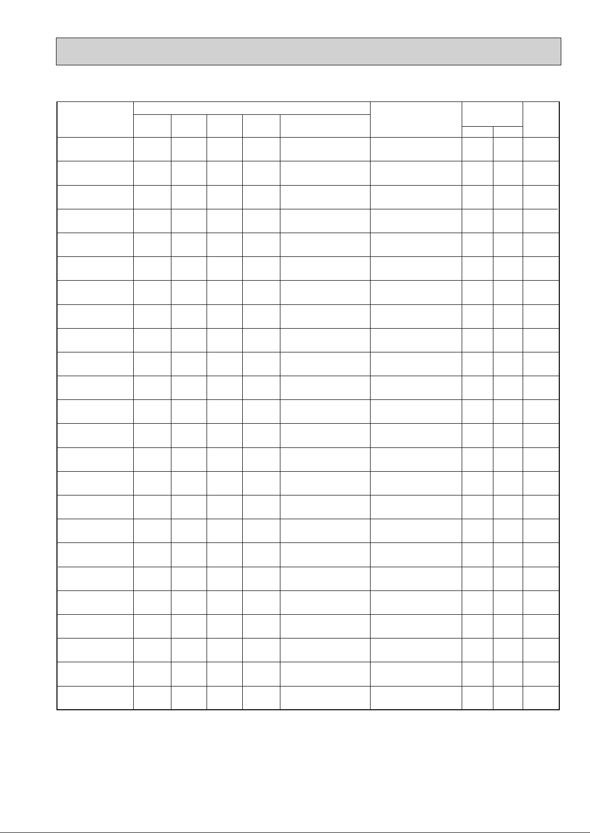
INDOOR UNITS COMBINATION
MXZ-18NV
NOTE:Electrical data is for outdoor unit only.
4
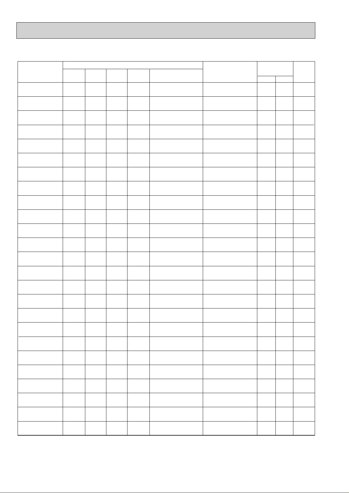
MXZ-32NV
Indoor units
combination
07
09
12(13)
18
07+07
07+09
07+12(13)
07+18
09+09
09+12(13)
09+18
12(13)+12(13)
12(13)+18
18+18
07+07+07
07+07+09
07+07+12(13)
07+07+18
07+09+09
07+09+12(13)
07+09+18
07+12(13)+12(13)
07+12(13)+18
07+18+18
Heating capacity (kw)
Unit A Unit B Unit C Unit D
2.2
2.8
4.0
5.0
2.2
2.2
2.2
2.2
2.8
2.8
2.8
4.0
3.5
4.0
2.2
2.2
2.1
1.9
2.2
1.9
1.7
1.8
1.6
1.5
-
-
-
-
2.2
2.8
4.0
5.0
2.8
4.0
5.0
4.0
4.5
4.0
2.2
2.2
2.1
1.9
2.8
2.5
2.3
3.1
2.8
3.25
-
-
-
-
-
-
-
-
-
-
-
-
-
-
2.2
2.8
3.8
4.2
2.8
3.6
4.0
3.1
3.6
3.25
-
-
-
-
-
-
-
-
-
-
-
-
-
-
-
-
-
-
-
-
-
-
-
-
Total
2.2
(1.8-2.7)
2.8
(1.8-3.2)
4.0
(2.2-4.5)
5.0
(2.2-5.4)
4.4
(3.0-5.4)
5.0
(3.0-6.0)
6.2
(3.0-7.2)
7.2
(3.0-7.6)
5.6
(3.0-6.4)
6.8
(3.0-7.6)
7.8
(3.0-8.6)
8.0
(3.0-8.8)
8.0
(3.0-8.8)
8.0
(3.0-8.8)
6.6
(3.7-8.1)
7.2
(3.7-8.5)
8.0
(3.7-9.0)
8.0
(3.7-9.0)
7.8
(3.7-8.8)
8.0
(3.7-9.0)
8.0
(3.7-9.0)
8.0
(3.7-9.0)
8.0
(3.7-9.0)
8.0
(3.7-9.0)
NOTE: Electrical data is for outdoor unit only.
Outdoor unit
power consumption
(kw)
1.00
(0.96-1.14)
1.77
(0.96-1.36)
1.42
(1.00-1.63)
1.84
(1.00-1.99)
1.63
(1.30-2.03)
1.88
(1.30-2.23)
2.38
(1.30-2.98)
2.74
(1.30-2.98)
2.13
(1.30-2.43)
2.63
(1.30-2.88)
3.29
(1.30-3.60)
3.38
(1.30-3.60)
3.38
(1.30-3.60)
3.38
(1.30-3.60)
3.23
(1.30-3.96)
3.23
(1.30-3.96)
3.23
(1.30-3.96)
3.23
(1.30-3.96)
3.23
(1.30-3.96)
3.23
(1.30-3.96)
3.23
(1.30-3.96)
3.23
(1.30-3.96)
3.23
(1.30-3.96)
3.23
(1.30-3.96)
Current
(A)
220V 240V
5.05
5.91
7.17
9.29
8.23
9.49
12.02
13.84
10.76
12.18
16.62
17.07
17.07
17.07
17.07
16.31
16.31
16.31
16.31
16.31
16.31
16.31
16.31
16.31
4.63
5.42
6.57
8.52
7.55
8.70
11.09
12.69
9.86
12.18
15.23
15.65
15.65
15.65
15.65
14.95
14.95
14.95
14.95
14.95
14.95
14.95
14.95
14.95
Power
factor
(%)
90
90
90
90
90
90
90
90
90
90
90
90
90
90
90
90
90
90
90
90
90
90
90
90
5
Indoor units
combination
Unit A Unit B Unit C Unit D
Heating capacity (kw)
Total
Outdoor unit
power consumption
(kw)
Current
(A)
Power
factor
(%)
220V 240V
90
90
90
90
90
90
90
90
90
90
90
90
90
90
90
90
90
90
90
90
90
90
90
90
90
14.95
14.95
14.95
14.95
14.95
14.95
14.95
14.95
14.95
14.95
14.95
14.95
14.95
14.95
14.95
14.95
14.95
14.95
14.95
14.95
14.95
14.95
14.95
14.95
14.95
16.31
16.31
16.31
16.31
16.31
16.31
16.31
16.31
16.31
16.31
16.31
16.31
16.31
16.31
16.31
16.31
16.31
16.31
16.31
16.31
16.31
16.31
16.31
16.31
16.31
8.0
(3.7-9.0)
8.0
(3.7-9.0)
8.0
(3.7-9.0)
8.0
(3.7-9.0)
8.0
(3.7-9.0)
8.0
(3.7-9.0)
8.0
(3.7-9.0)
8.0
(3.7-9.0)
8.0
(3.7-9.0)
8.0
(3.7-9.0)
8.0
(3.7-9.0)
8.0
(3.7-9.0)
8.0
(3.7-9.0)
8.0
(3.7-9.0)
8.0
(3.7-9.0)
8.0
(3.7-9.0)
8.0
(3.7-9.0)
8.0
(3.7-9.0)
8.0
(3.7-9.0)
8.0
(3.7-9.0)
8.0
(3.7-9.0)
8.0
(3.7-9.0)
8.0
(3.7-9.0)
8.0
(3.7-9.0)
8.0
(3.7-9.0)
3.23
(1.30-3.96)
3.23
(1.30-3.96)
3.23
(1.30-3.96)
3.23
(1.30-3.96)
3.23
(1.30-3.96)
3.23
(1.30-3.96)
3.23
(1.30-3.96)
3.23
(1.30-3.96)
3.23
(1.30-3.96)
3.23
(1.30-3.96)
3.23
(1.30-3.96)
3.23
(1.30-3.96)
3.23
(1.30-3.96)
3.23
(1.30-3.96)
3.23
(1.30-3.96)
3.23
(1.30-3.96)
3.23
(1.30-3.96)
3.23
(1.30-3.96)
3.23
(1.30-3.96)
3.23
(1.30-3.96)
3.23
(1.30-3.96)
3.23
(1.30-3.96)
3.23
(1.30-3.96)
3.23
(1.30-3.96)
3.23
(1.30-3.96)
-
-
-
-
-
-
-
-
2.0
2.4
2.9
3.5
2.2
2.8
3.2
2.6
3.0
2.1
2.7
3.1
2.45
2.0
2.6
3.0
2.35
2.67
3.4
3.8
3.0
3.4
3.1
2.67
3.1
2.0
1.87
1.7
1.5
2.2
2.0
1.8
2.6
2.4
2.1
1.9
1.75
2.45
2.0
1.8
1.67
2.35
2.67
2.3
2.1
2.0
1.9
1.8
2.67
2.45
2.0
1.87
1.7
1.5
1.8
1.6
1.5
1.4
1.3
1.7
1.5
1.4
1.35
2.0
1.8
1.67
1.65
2.67
2.3
2.1
3.0
2.7
3.1
2.67
2.45
2.0
1.87
1.7
1.5
1.8
1.6
1.5
1.4
1.3
2.1
1.9
1.75
1.75
2.0
1.8
1.67
1.65
09+09+09
09+09+12(13)
09+09+18
09+12(13)+12(13)
09+12(13)+18
09+18+18
12(13)+12(13)
+12(13)
12(13)+12(13)+18
07+07+07+07
07+07+07+09
07+07+07+12(13)
07+07+07+18
07+07+09+09
07+07+09+12(13)
07+07+09+18
07+07+12(13)
+12(13)
07+07+12(13)+18
07+09+09+09
07+09+09+12(13)
07+09+09+18
07+09+12(13)
+12(13)
09+09+09+09
09+09+09+12(13)
09+09+09+18
09+09+12(13)
+12(13)
NOTE: Electrical data is for outdoor unit only.
6
Indoor units
combination
07
09
12(13)
18
07+07
07+09
07+12(13)
07+18
09+09
09+12(13)
09+18
12(13)+12(13)
12(13)+18
18+18
07+07+07
07+07+09
07+07+12(13)
07+07+18
07+09+09
07+09+12(13)
07+09+18
07+12(13)+12(13)
07+12(13)+18
07+18+18
Heating capacity (kw)
Unit A Unit B Unit C Unit D
3.4
4.0
6.0
7.1
3.4
3.4
3.35
2.85
4.0
3.7
3.35
4.65
4.3
4.65
3.1
2.95
2.5
2.3
2.8
2.4
2.2
2.0
1.9
1.9
-
-
-
-
3.4
4.0
5.95
6.45
4.0
5.6
5.95
4.65
5.0
4.65
3.1
2.95
2.5
2.3
3.25
2.8
2.6
3.65
3.4
3.75
-
-
-
-
-
-
-
-
-
-
-
-
-
-
3.1
3.4
4.3
4.7
3.25
4.1
4.5
3.65
4.0
3.75
-
-
-
-
-
-
-
-
-
-
-
-
-
-
-
-
-
-
-
-
-
-
-
-
Total
3.4
(2.1-3.6)
4.0
(2.1-4.2)
6.0
(2.2-6.3)
7.1
(2.2-7.5)
6.8
(4.1-7.2)
7.4
(4.1-7.8)
9.3
(4.1-9.7)
9.3
(4.1-9.7)
8.0
(4.1-8.4)
9.3
(4.1-9.7)
9.3
(4.1-9.7)
9.3
(4.1-9.7)
9.3
(4.1-9.7)
9.3
(4.1-9.7)
9.3
(5.2-10.6)
9.3
(5.2-10.6)
9.3
(5.2-10.6)
9.3
(5.2-10.6)
9.3
(5.2-10.6)
9.3
(5.2-10.6)
9.3
(5.2-10.6)
9.3
(5.2-10.6)
9.3
(5.2-10.6)
9.3
(5.2-10.6)
NOTE: Electrical data is for outdoor unit only.
Outdoor unit
power consumption
(kw)
1.20
(0.91-1.28)
1.43
(0.91-1.51)
1.79
(0.94-1.88)
2.10
(0.94-2.21)
1.98
(1.13-2.18)
2.23
(1.13-2.33)
2.82
(1.13-2.96)
2.82
(1.13-2.96)
2.38
(1.13-2.54)
2.82
(1.13-2.96)
2.82
(1.13-2.96)
2.82
(1.13-2.96)
2.82
(1.13-2.96)
2.82
(1.13-2.96)
2.78
(1.19-2.96)
2.78
(1.19-2.96)
2.78
(1.19-3.96)
2.78
(1.19-2.96)
2.78
(1.19-2.96)
2.78
(1.19-2.96)
2.78
(1.19-3.96)
2.78
(1.19-2.96)
2.78
(1.19-2.96)
2.78
(1.19-2.96)
Current
(A)
220V 240V
6.06
7.22
9.04
10.61
10.00
11.26
14.24
14.24
12.02
14.24
14.24
14.24
14.24
14.24
14.04
14.04
14.04
14.04
14.04
14.04
14.04
14.04
14.04
14.04
5.55
6.62
8.29
9.72
9.17
10.32
13.05
13.05
11.01
13.05
13.05
13.05
13.05
13.05
12.87
12.87
12.87
12.87
12.87
12.87
12.87
12.87
12.87
12.87
Power
factor
(%)
90
90
90
90
90
90
90
90
90
90
90
90
90
90
90
90
90
90
90
90
90
90
90
90
7
Indoor units
combination
Unit A Unit B Unit C Unit D
Heating capacity (kw)
Total
Outdoor unit
power consumption
(kw)
Current
(A)
Power
factor
(%)
220V 240V
90
90
90
90
90
90
90
90
90
90
90
90
90
90
90
90
90
90
90
90
90
90
90
90
90
12.87
12.87
12.87
12.87
12.87
12.87
12.87
12.87
12.87
12.87
12.87
12.87
12.87
12.87
12.87
12.87
12.87
12.87
12.87
12.87
12.87
12.87
12.87
12.87
12.87
14.04
14.04
14.04
14.04
14.04
14.04
14.04
14.04
14.04
14.04
14.04
14.04
14.04
14.04
14.04
14.04
14.04
14.04
14.04
14.04
14.04
14.04
14.04
14.04
14.04
9.3
(5.2-10.6)
9.3
(5.2-10.6)
9.3
(5.2-10.6)
9.3
(5.2-10.6)
9.3
(5.2-10.6)
9.3
(5.2-10.6)
9.3
(5.2-10.6)
9.3
(5.2-10.6)
9.3
(5.2-10.6)
9.3
(5.2-10.6)
9.3
(5.2-10.6)
9.3
(5.2-10.6)
9.3
(5.2-10.6)
9.3
(5.2-10.6)
9.3
(5.2-10.6)
9.3
(5.2-10.6)
9.3
(5.2-10.6)
9.3
(5.2-10.6)
9.3
(5.2-10.6)
9.3
(5.2-10.6)
9.3
(5.2-10.6)
9.3
(5.2-10.6)
9.3
(5.2-10.6)
9.3
(5.2-10.6)
9.3
(5.2-10.6)
2.78
(1.19-2.96)
2.78
(1.19-2.96)
2.78
(1.19-2.96)
2.78
(1.19-2.96)
2.78
(1.19-2.96)
2.78
(1.19-2.96)
2.78
(1.19-2.96)
2.78
(1.19-2.96)
2.78
(1.19-2.96)
2.78
(1.19-2.96)
2.78
(1.19-2.96)
2.78
(1.19-2.96)
2.78
(1.19-2.96)
2.78
(1.19-2.96)
2.78
(1.19-2.96)
2.78
(1.19-2.96)
2.78
(1.19-2.96)
2.78
(1.19-2.96)
2.78
(1.19-2.96)
2.78
(1.19-2.96)
2.78
(1.19-2.96)
2.78
(1.19-2.96)
2.78
(1.19-2.96)
2.78
(1.19-2.96)
2.78
(1.19-2.96)
-
-
-
-
-
-
-
-
2.32
2.7
3.3
3.6
2.5
3.3
3.7
2.95
3.3
2.4
3.2
3.6
2.9
2.32
3.15
3.45
2.8
3.1
4.0
4.4
3.5
3.8
3.65
3.1
3.58
2.32
2.2
2.0
1.9
2.5
2.2
2.1
2.95
2.8
2.4
2.15
2.0
2.9
2.32
2.05
1.95
2.8
3.1
2.65
2.45
3.5
3.3
3.65
3.1
2.86
2.32
2.2
2.0
1.9
2.15
1.9
1.75
1.7
1.6
2.4
2.15
2.0
1.9
2.32
2.05
1.95
1.85
3.1
2.65
2.45
2.3
2.2
2.0
3.1
2.86
2.32
2.2
2.0
1.9
2.15
1.9
1.75
1.7
1.6
2.1
1.8
1.7
1.6
2.32
2.05
1.95
1.85
09+09+09
09+09+12(13)
09+09+18
09+12(13)+12(13)
09+12(13)+18
09+18+18
12(13)+12(13)
+12(13)
12(13)+12(13)+18
07+07+07+07
07+07+07+09
07+07+07+12(13)
07+07+07+18
07+07+09+09
07+07+09+12(13)
07+07+09+18
07+07+12(13)
+12(13)
07+07+12(13)+18
07+09+09+09
07+09+09+12(13)
07+09+09+18
07+09+12(13)
+12(13)
09+09+09+09
09+09+09+12(13)
09+09+09+18
09+09+12(13)
+12(13)
NOTE: Electrical data is for outdoor unit only.
8
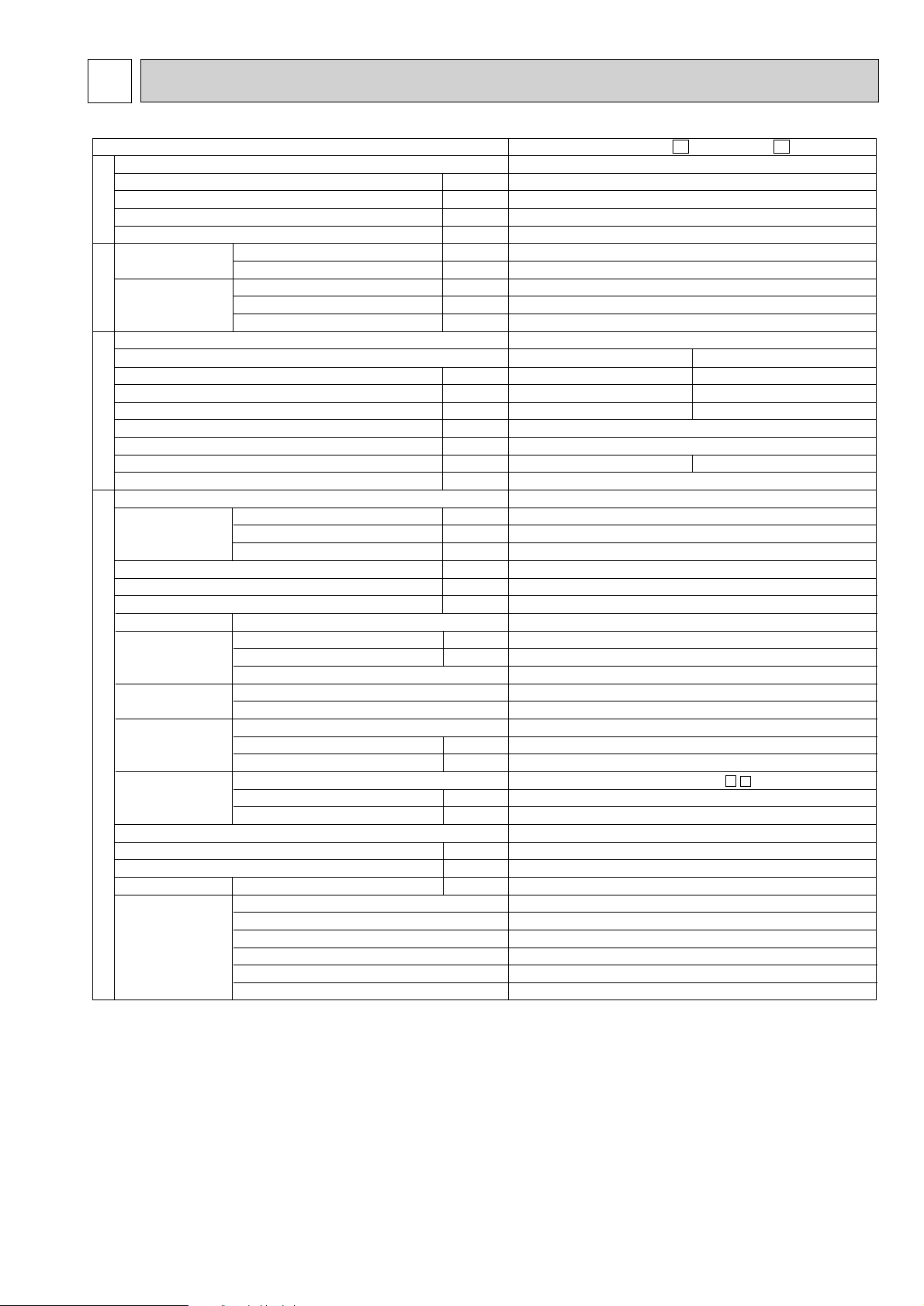
5
Indoor units number
Piping total length
Connecting pipe length
Height difference (indoor ~ outdoor)
Height difference (indoor ~ indoor)
Cooling
Heating
Power supply
Mode
Power consumption
Running current
Power factor
Crankcase heater
Starting current
Compressor motor current
Fan motor current
External finish
Dimensions
Weight
Refrigerant filling capacity (R-22)
Refrigerating oil <Model>
In/Out connecting wire (Each room)
Refrigerant
piping
Protective
device
Compressor
Fan motor
Air flow amount change
Fan speed
Air flow
Power outlet
Thermistor
Model
m
m
m
m
kW
dB
kW
W
dB
W
A
%
W
A
A
A
mm
mm
mm
kg
kg
cc
mm
mm
W
"
W
"
rpm
K/h
A
Capacity
Sound level
Capacity
Booster heater
Sound level
Height
Width
Depth
Liquid pipe
Gas pipe
Connection method
Compressor
Fan motor
Model
Output
Winding resistance (at 20 :)
Model
Output
Winding resistance (at 20 :)
RT61 (at 25:)
RT62 (at 100:)
RT63 (at 70:)
RT64 (at 25:)
RT65 (at 25:)
RT66, 67 (at 25:)
Capacity System
Electrical data ✻ 1
Outdoor unit
2
Max. 30
Max. 20
Max. 7
Max. 7
4.5 (1.7 ~ 4.5)
45
5.8 (2.0 ~ 5.8)
-
46
Single phase, 220-240V, 50Hz
-
10.21
0.4
Munsell 5Y 7/1
650
875
295 (+30)
56
1.3
570cc <MS-56>
2-core, 1pc. [2.0mm
[9.52 (2pcs)
[6.35 (2pcs)
Flared
✻ 2
Inner thermostat
RHV-207FEM (Rotary)
1,100
1.195(U-V, V-W, W-U)
RA6V50 -
50
BLK-WHT 163, BLK-YLW 72, YLW-RED 36
2
630-670
2,460 - 2,580
25
10.0k"
13.4k"
7.9k"
10.0k"
10.0k"
10.0k"
MXZ-18NV-
E1
MXZ-18NV-
E2
Cooling
2,000 (855~2000)
10.21(5.28 - 10.21) - 9.26(4.83 - 9.26)
89 - 90
9.74(4.87 - 9.74) - 8.86(4.43 - 8.86)
Heating
1,785 (690~1785)
9.02(6.38 - 9.02) - 8.26(5.83 - 8.26)
90 - 90
8.62(5.98 - 8.62) - 7.86(5.43 - 7.86)
SPECIFICATION
TEST CONDITIONS COOLING INDOOR DB27.0°C WB19.0°C
HEATING INDOOR DB20.0°C
✽1 Electrical data is for only outdoor unit.
OUTDOOR DB35.0°C WB24.0°C
OUTDOOR DB 7.0°C WB 6.0°C
✽2 Current detection
Discharge temperature detection
High-pressure switch
9
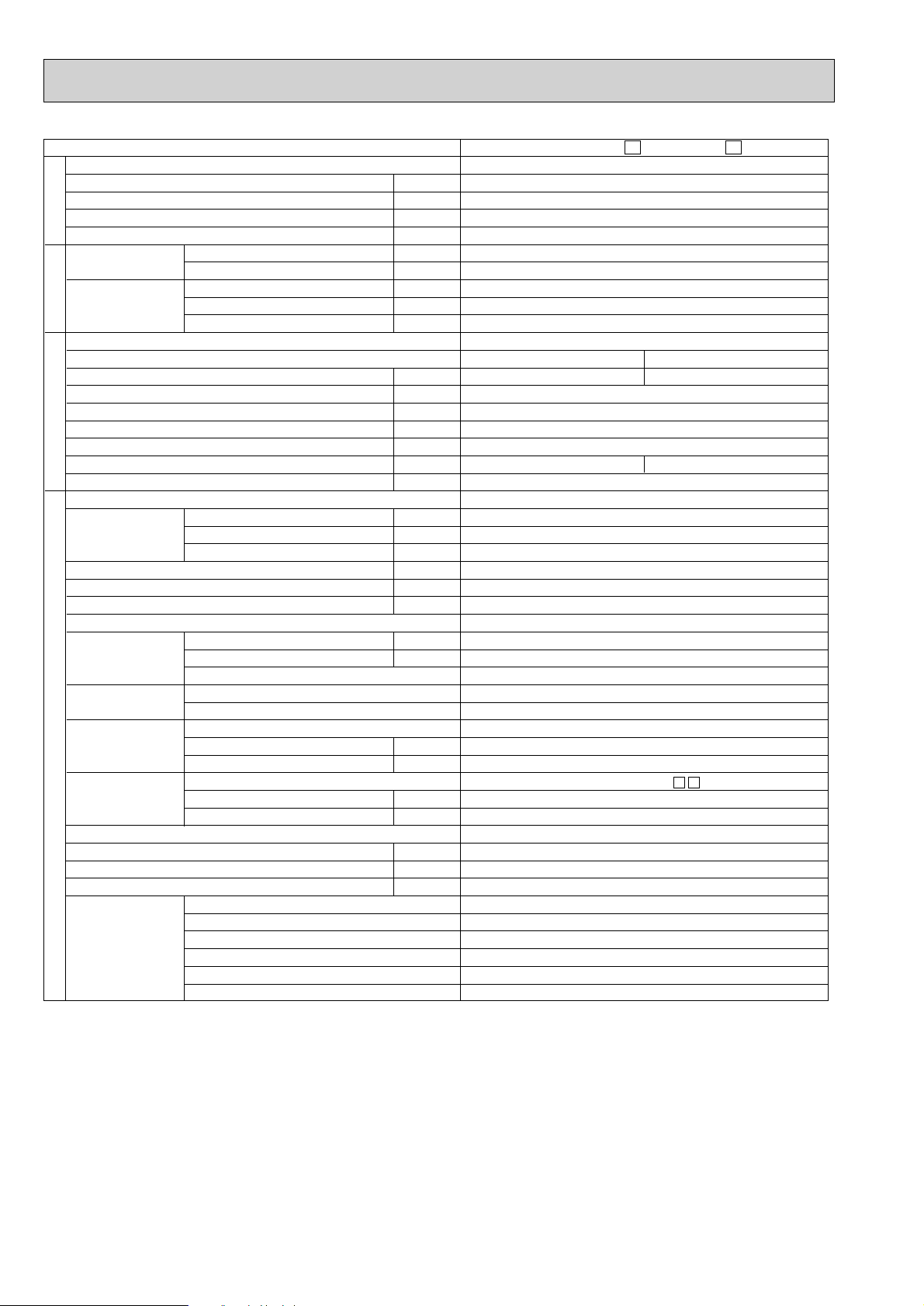
Indoor units number
Piping total length
Connecting pipe length
Height difference (indoor ~ outdoor)
Height difference (indoor ~ indoor)
Cooling
Heating
Power supply
Mode
Power consumption
Running current
Power factor
Crankcase heater
Starting current
Compressor motor current
Fan motor current
External finish
Dimensions
Weight
Refrigerant filling capacity (R-22)
Refrigerating oil <Model>
In/Out connecting wire (Each room)
Refrigerant
piping
Protective
device
Compressor
Fan motor
Air flow amount change
Fan speed
Air flow
Power outlet
Thermistor
Model
m
m
m
m
kW
dB
kW
W
dB
W
A
%
W
A
A
A
mm
mm
mm
kg
kg
cc
mm
mm
W
"
W
"
rpm
K/h
A
Capacity
Sound level
Capacity
Booster heater
Sound level
Height
Width
Depth
Liquid pipe
Gas pipe
Connection method
Compressor
Fan motor
Model
Output
Winding resistance (at 20 :)
Model
Output
Winding resistance (at 20 :)
RT61 (at 100:)
RT62 (at 25:)
RT63 (at 50:)
RT64 (at 25:)
RT65 (at 25:)
RT70,66, 67,68,69 (at 25:)
Capacity System
Electrical data ✻ 1
Outdoor unit
3-4
Max. 60
Max. 25
Max. 10
Max. 10
8.0 (1.8 ~ 9.0)
45-47
9.3 (2.1 ~ 10.6)
-
46-48
Single phase, 220-240V, 50Hz
16.31(4.85 - 20.00) - 14.95(4.44 - 18.33)
90
25
16.31 - 14.95
0.4
Munsell 5Y 8/1
900
900
320 (+35)
83.5
4.2
1070cc <MS-32>
2-core, 1pc. [2.0mm
[12.7 (2pcs) [9.52 (2pcs)
[6.35 (4pcs)
Flared
✻ 2
Inner thermostat
CHV253FAA (Scroal)
2,000
0.54(U-V, V-W, W-U)
RA6V60-
60
BLK-WHT 79.0, BLK-YLW 27.0, YLW-BLU 12.0 BLU-RED 84.0
3
630 - 680 / 525 - 570 / 460 - 500
3000 / 2400 / 2100
25
13.4k"
10.0k"
17.0k"
10.0k"
10.0k"
10.0k"
Cooling
3,230 (960~3,960)
15.71(4.25 - 19.40) - 14.35(3.84 - 17.73)
Heating
2,780 (910~2,960)
13.44(4.00 - 14.35) - 12.27(3.62 - 13.10)
MXZ-32NV-
E1
MXZ-32NV-
E2
TEST CONDITIONS COOLING INDOOR DB27.0°C WB19.0°C
✽1 Electrical data is for only outdoor unit.
OUTDOOR DB35.0°C WB24.0°C
HEATING INDOOR DB20.0°C
OUTDOOR DB 7.0°C WB 6.0°C
✽2 Current detection
Discharge temperature detection
High-pressure switch
Crankcase heater
Low-pressure switch
Inner thermostat
10
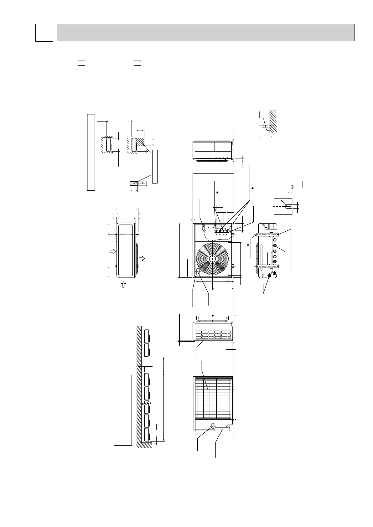
6 OUTLINES AND DIMENSIONS
Necessary surrounding clearance
Necessary surrounding clear-
ance for concentrated installa-
tion.
Leave overhead clearance fully
100
Handle for
monving
200
1000
2957
23
Max. 25
Base bolt length
To drain water in a mass, use
optional drain pan and drain
socket.
Drain pan : PAC-928DP,PAC-SA44DP
Drain socket : PAC-SA46DS
Drain hole
Drain hole
(Base bolt M10)
(Base bolt M10)
2 Oval hols (12 13)
2-U-Shape noched hols
33
524
339
302
524
77
2
25
12
17
R6
40
116
A
B
57
107
57
57
505
30 870
650
10
Max. 10 units
Air in
Air in
Air out
185 185500
362
10
10
500
500
100
500
10
200
330
39.5 27.5
1715
Leave front clearance fully
Space for servicing
Leave overhead
clearance fully
Rear piping
hole
Rear
air-intake
Side
air-intake
Handle for
moving
Handle for moving
Liquid pipe
(flared 6.35)
Ground
terminal
Outlet guide
mounting hole
Gas pipe
(flared 9.52)
MXZ-18NV - MXZ-18NV -
E2E1
Unit:mm
11
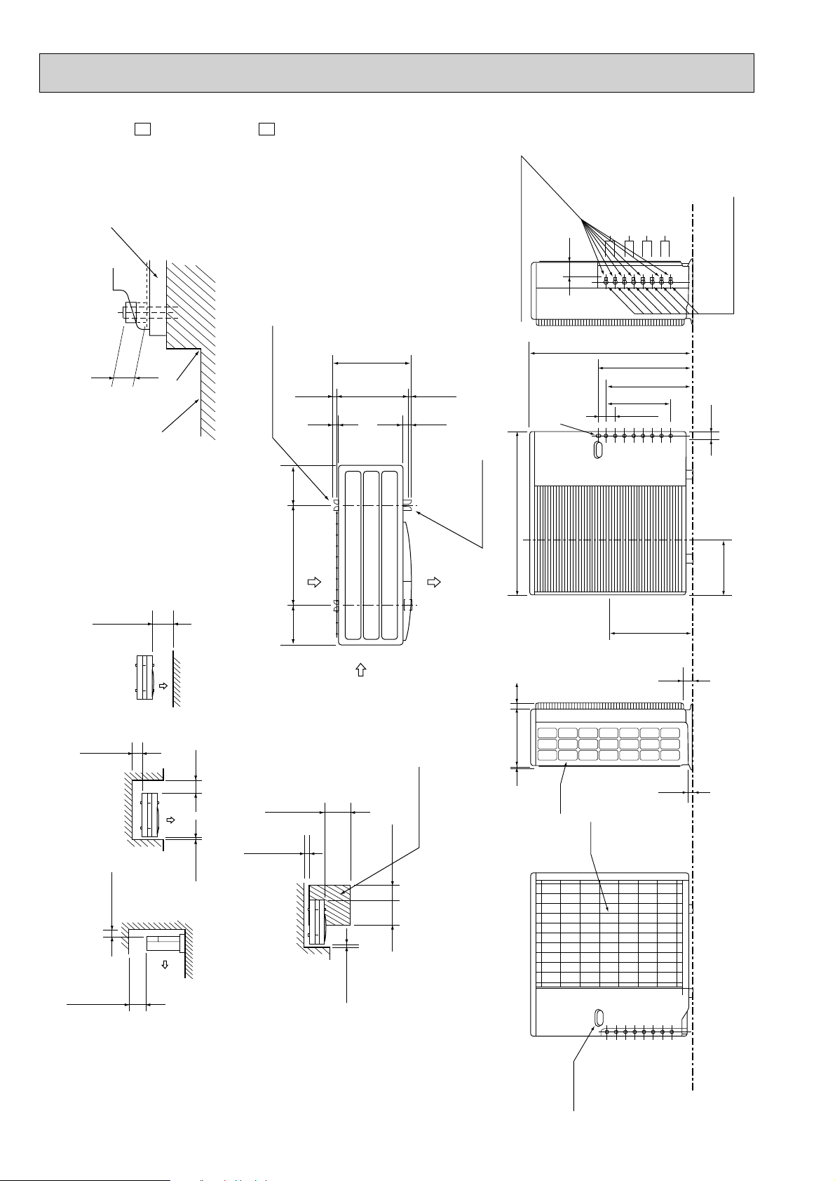
MXZ-32NV - MXZ-32NV -
1.Installation space
2.Service space
More than
100
More than
200
More than
100
More than
500
More than
500
More than
10
More than
10
More than
500
Base bollt length
Less than
25
More than
350
More than
350
Service space
Air in
2-U-shape notched holes
(Base bolt M10)
(Base bolt M10)
Air in
Air out
200 200
387
355
27 40
(16) (16)
500
Veranda
Base
Rubber cushion
More than
500
Note : Leave front and both sides
clearance fully.
Note : Leave front and overhead
clearance fully.
Note : Leave front, overhead and
both clearance fully.
2-12 ✕ 36 Oval hole
23
10 35320
900
88
460
50
900
350.0
480.8
531.3
317
23
33
Handle for
moving
Air in
Indoor and outdoor
connect wiring
Air in
23✕45 hole
D unit connection
C unit connection
B unit connection
A unit connection
6.35 (flared) 1/4
Liquid pipe
12.7 (flared) 1/2 (A , B unit)
9.52 (flared) 3/8 (C , D unit)
[[[
E2E1
Unit:mm
12
7
CIRCUIT BREAKER
DC24V
DC24V
TB
TO
INDOOR
UNIT
CONNECTING
DS61
NF61
INDOOR
UNIT (A)
POWER SUPPLY
220-240V
~/N
50Hz
INDOOR
UNIT (B)
TB
NF62
C61
C64
C63
L61
R64
X64
CT61
NR61
AR61
RELAY P.C.BOARD
N
3
N
3
L
N
LDE1
LD62
F62
3
4
1
2
LD77
LD74
LD73LD71
LD72
3
4
2
1
TB62
TB61
LD61
34
LD63
CN941
BRN
GRN/YLW
BLU
RED
BLU
BLU
RED
BLU
BLU
BLU
RED
BLK
WHT
WHT
GRN
BLU
BRN
BLK
YLW
BRN
RED
YLW
YLW
BLU
RED
BRN
RED
T801
C67
LEV A LEV B
1
2
3
4
FUSE1
CN801
CN761
CN601 CN611
TBAC1
TBAC2
BLU
ORN
YLW
WHT
RED
BLK
BLK
WHT
BLU
BLK
ORN
RED
BLK
BLU
BLU
ORN
YLW
WHT
RED
RT64 RT65
SSR61
RT66 RT67 RT61RT62 RT63
6
5
54321543216
321
2
3
4
1
CN682CN771
BLK
BLK
R65
W
V
UP
N
EwN
BwN
EvN
BvN
EuN
BuN
BwPBvPBuP
BLU
RED
RED
WHT
BLK
RED
WHT
BLK
21S4
RED
RED
X67
X60
HPS
CN683
CN63
CN701
CN671CN641CN681CN661
BLK
WHT
ORN
GRY
GRY
GRY
GRY
BLK
BLK
GRY
GRY
GRY
GRY
GRY
GRY
RED
RED
GRN
YLW
RED
BLU
YLW
RED
BRN
RED
ORN
YLW
GRN
BLU
L
MF
MC
V
WU
WHT WHT
C65
ELECTRONIC CONTROL
P.C.BOARD
12 12 2 4321
8
7
6
5
11
FUSE2
TAB91
CN731
CN621
LD64
BLK
+-
~+-
~
DS63
TR
6
123412 12
2
3
4
1
4
3
2
1
2345
1234 1234
3
2
1
CN61
EwPEvPEuP
RED
RED
BLU
GRN
YLW
ORN
RED
BRN
+
~
~
~
-
+
-
❈
❈❈
❈
❈
❈❈
❈
❈
❈
❈❈
❈❈
❈
❈
❈
❈❈❈
❈
❈
❈
❈
❈❈❈
❈
❈
❈
❈
❈
❈
❈
❈
❈
❈
❈❈
❈❈❈
❈
R64
R65
CURRENT-DETECTING RESISTOR
CURRENT-LIMITING RESISTOR
T801 TRANSFORMER
FUSE2
FUSE(3.15A)
FUSE1
FUSE(1A)
F62
FUSE(3.15A)
SYMBOL
NAME
GAS PIPE TEMPERATUREA.THERMISTOR
RT65
GAS PIPE TEMPERATUREB.THERMISTOR
RT64
DEFROST TEMPERATURETHERMISTOR
DISCHARGE TEMPERATURETHERMISTOR
FIN TEMPERATURETHERMISTOR
EVAPORATION TEMPERATURETHERMISTOR
SUCTION TEMPERATURETHERMISTOR
OUTDOOR FAN MOTOR(INNER THERMOSTAT)
RT61
RT62
RT63
RT66
RT67
21S4 R.V.COIL
TB TERMINAL BLOCK
FAN MOTOR RELAY
TR POWER TRANSISTOR MODULE
X60,67
X64 RELAY
SSR61 SOLID STATE RELAY
SYMBOL
SURGE ABSORBER
POWER-FACTOR CAPACITOR
SMOOTHING CAPACITOR
OUTDOOR FAN CAPACITOR
CERAMIC CAPACITOR
CERAMIC CAPACITOR
AR61
C61
C67
C65
C63
C64
NAME
SYMBOL
NAME
MC
MF
NR61
LEV A,B
DS61,63
L
L61
HPS
CT61
COMPRESSOR
CURRENT TRANSFORMER
VARISTOR
REACTOR
DIODE MODULE
HIGH PRESSURE SWITCH
EXPANSION VALVE
CMC COIL
NF61,62 NOISE FILTER
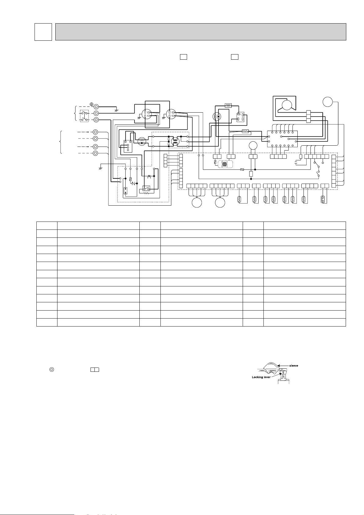
WIRING DIAGRAM
MODELS MXZ-18NV- MXZ-18NV-
E2E1
NOTE:1. For the outdoor electric wining refer to the outdoor unit electric wining diagram for servicing.
2. Use copper conductors only.(For field wining)
3. Symbols below indicate.
: Terminal block, : Connector
4. “ ✻ ”shows the terminals with a lock mechanism,so they cannnot be removed when you pull
the lead wire.
Be sure to pull the wire by pushing the locking lever (project part) of the terminal with a finger.
1.Slide the sleeve.
2.Pull the wire while
pushing the locking
lever.
13
POWER SUPPLY
~/N 220-240V 50Hz
INDOOR
UNIT (A)
12VDC
CIRCUIT BRAKER
TB2
TB3
BLU
RED
TB4
X64
GRN/YLW
GRN/YLW
CN720
CN601
0
4
X64
LD62
CN913
CN791
CN901
64
2
CN902
CN851 CN852
MF61
CH
21S4 21S2
12 12
21
21
12
12
34
123456
12 34567
123456
CN912
C65
LD63
LD64
LDB
LDB
LD61
LDE
L61
F911
SSR61
SSR62
SSR63
X63
X62
X61
1
6
L
N
3
N
INDOOR
UNIT (B)
12VDC
BLU
ORN
CN602
12
3
3
3
N
INDOOR
UNIT (C)
12VDC
BLU
YLW
CN603
12
N
INDOOR
UNIT (D)
12VDC
BLU
BEN
CN604
12
N
BLK
BRN
GRY
BLK
BLK
WHT
YLW
RED
RED
RED
BRN
BLU
ORN
YLW
WHT
ORN
WHT
BLK
BLU
YLW
RED
BLU
BLU
WHT
WHT
ORN
ORN
RED
RED
YLW
YLW
YLW
BLK
BLK
ORN
ORN
BRN
GRY
X65
X66
X67
X67
63H2
X65
X66
CN552
CN553
BLK
RELAY
P.C. BOARD
WHT
WHT
RED
WHT
V
UW
YLW
A
K
L
WHT
NOISE FILTER
P.C.BOARD
RED
DS61
DS62
C61
CT
61
C63 C62
+
+
-
+-+
-
-
BLKREDR
BLU
LEV A
CN792
123456
RED
BRN
BLU
ORN
YLW
WHT
LEV B
CN793
123456
RED
BRN
BLU
ORN
YLW
WHT
LEV C
CN794 CN722 CN663
63H1 RT63
123456
CN662
1234567812 12
123
34
RED
RED
RED
63L
BLK
BLK
BLK
BLK
RT66 RT68
RT67 RT69
GRY
GRY
GRY
GRY
GRY
GRY
GRY
GRY
CN661
CN705
7654321
CN515
1234
4321
CN801
CN501
TAB62
TAB63
T801
CT62
TAB66
TAB65
TAB64
I.P.M P.C. BOARD
F801
(1A)
CN704
CN514
CN554CN551
CN723
12345678
RT62 RT64
RT61 RT65
GRY
GRY
BLK
BLK
GRY
GRY
GRY
GRY
BRN
BLU
ORN
YLW
WHT
LEV D
ELECTRONIC CONTROL P.C. BOARD
MC
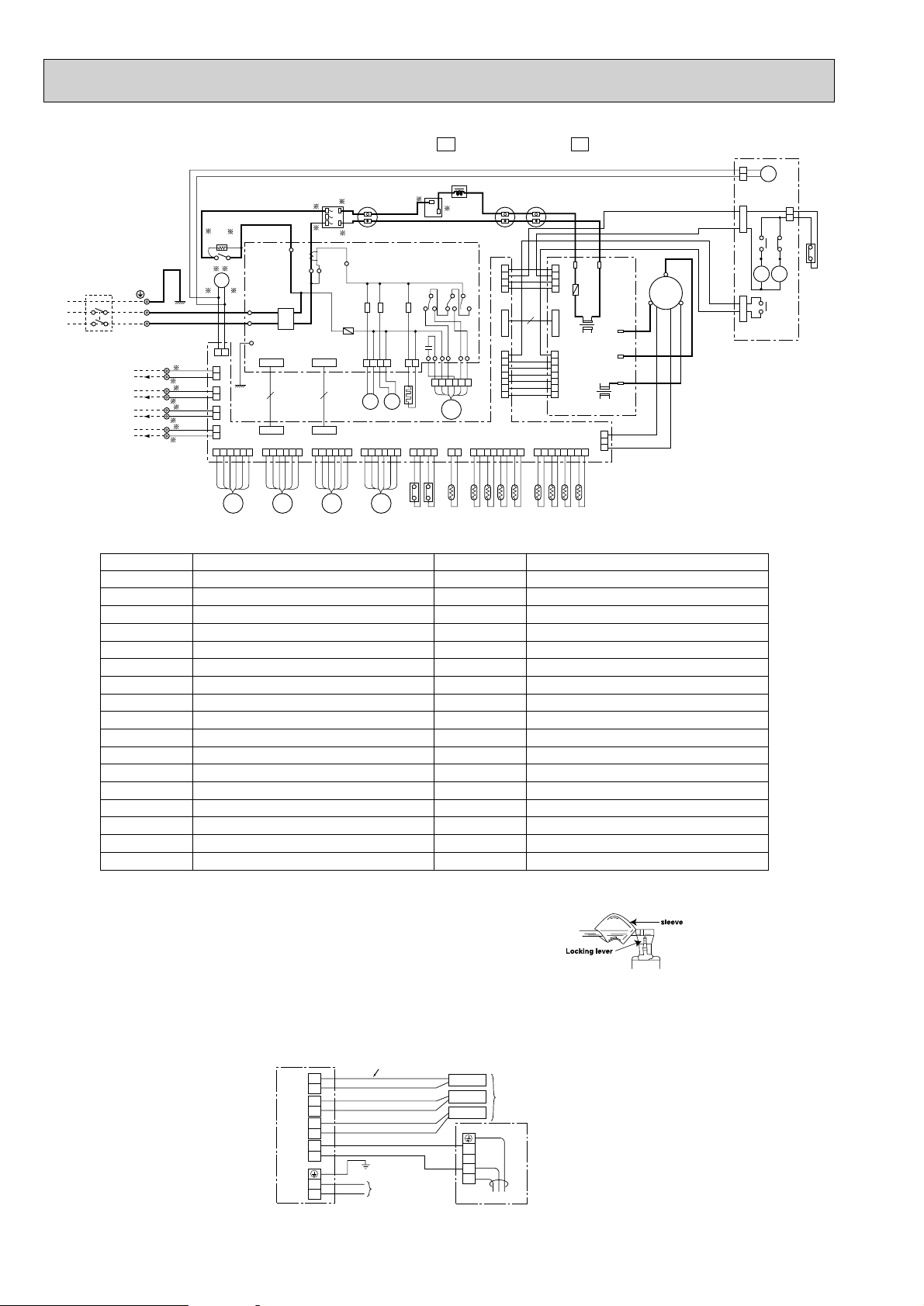
MODELS MXZ-32NV- MXZ-32NV-
OUTDOOR UNIT
GROUND
Power supply cord
Terminal block
POWER SUPPLY
~/N 220-240V 50Hz
Indoor/outdoor connecting wire
Make all connections
as shown below.
D UNIT
A UNIT
D UNIT
3
C UNIT
C UNIT
3
B UNIT
B UNIT
3
A UNIT
3
N
N
N
N
N
L
3
2
N
L
INDOOR UNIT
INDOOR AND OUTDOOR ELECTRICAL WIRING CONNECTION FIGURE
E2E1
SYMBOL
C61
C62,63
C65
CH
CT61,62
DS61
DS62
F801
F911
L
L61
LEV A~D
R
RT61
RT62
RT63
RT64
NAME
POWER FACTOR CAPACITOR
SMOOTHING CAPACITOR
OUTDOOR FAN CAPACITOR
CRANKCASE HEATER
CURRENT TRANSFORMER
DIODE MODULE
DIODE STACK
FUSE (1A)
FUSE (1A)
REACTOR
COMMON MODE CHOKE COIL
EXPANSION VALVE
RESISTOR
DISCHARGE TEMPERATURE THERMIST OR
DEFROST TEMPERA TURE THERMIST OR
FIN TEMPERATURE THERMIST OR
EVAPORATION TEMPERATURE THERMISTOR
NOTE:1. “- - - - “ denotes the wiring at the site.
2 “❈”show the terminals with a lock mechanism, so they cannot be removed
when you pull the lead wire.
Be sure to pull the wire by pushing the locking lever(projected part) of the
terminal with a finger.
14
SYMBOL
RT66,67
RT68,69
SSR61,62
SSR63
TB2,3,4
X61,62,63
X64,65
X66,67
RT65
MC
MF61
T801
21S2
21S4
63H1
63H2
63L
NAME
SUCTION TEMPERATURE THERMIST OR
GUS PIPE TEMPERATURE THERMISTOR
GUS PIPE TEMPERATURE THERMISTOR
COMPRESSOR
OUTDOOR FAN MOTOR (INNER FUSE)
SOLENOID COIL RELAY
CRANKCASE HEATER RELAY
TRANSFORMER
TERMINAL BLOCK
FAN MOTOR RELAY
RELAY
RELAY
SOLENOID COIL
R.V. COIL
HIGH PRESSURE SWITCH
HIGH PRESSURE SWITCH
LOW PRESSURE SWITCH
1.Slide the sleeve.
2.Pull the wire while
pushing the locking
lever.
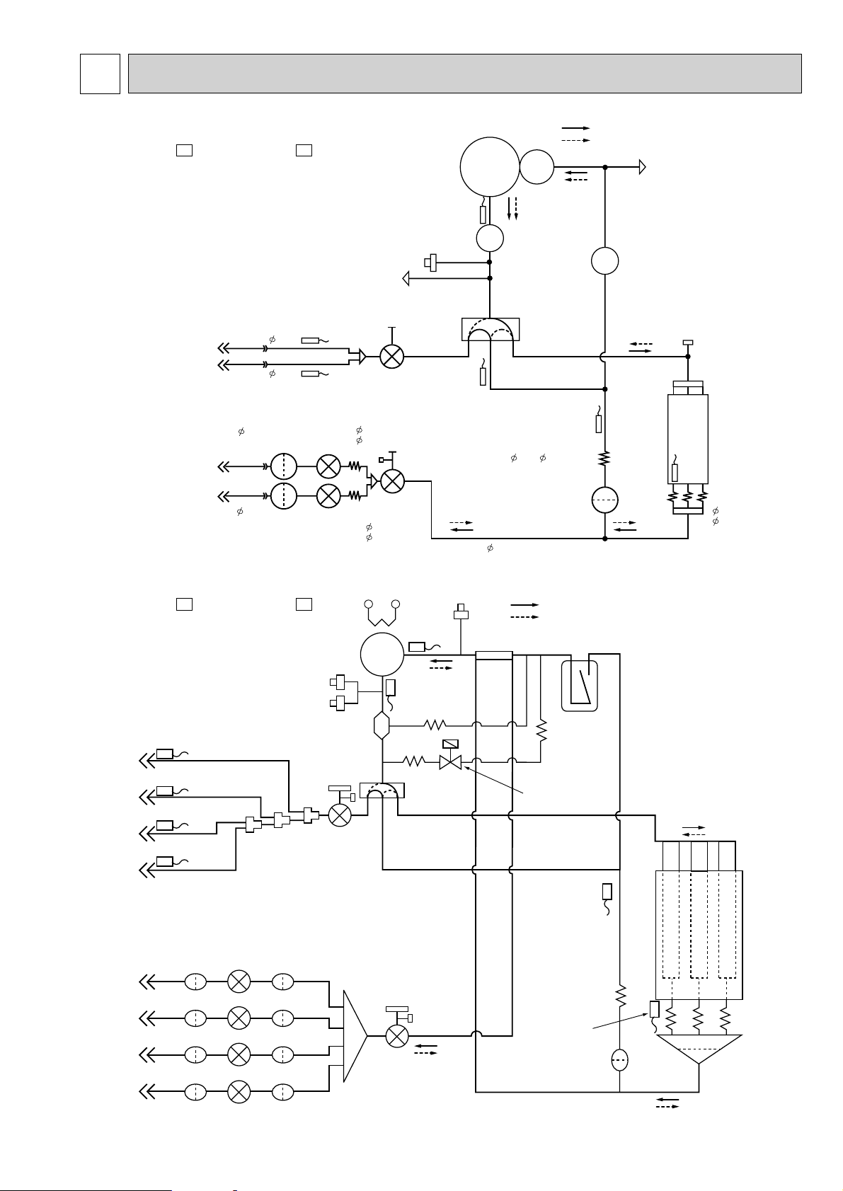
REFRIGERANT SYSTEM DIAGRAM8
9.52
6.35
9.52
9.52
2.0X 0.6X500
Charge port
Capillary
tube
4.0X
2.4X
400
Capillary
tube
4.0X
2.4X
300
Expansion
valve(LEV)
Expansion
valve(LEV)
Strainer
Strainer
Capillary
tube
4.0X
2.4X
300
Ball valve with
service port
Ball valve
Service
port
(high pressure)
Reversing
valve
Suction temperature
thermistor
RT66
Gas pipe
thermistor
Gas pipe
thermistor
Muffler
Compressor
High pressure
switch
Discharge
temperature
thermistor
RT62
Service
port
(Low pressure)
Refrigerant flow in cooling
Refrigerant flow in heating
R.V. coil
heating ON
cooling OFF
Strainer
Capillary
tube
Evaporation
temperature
thermistor
RT67
Defrost
thermistor
RT61
Outdoor
heat
exchanger
6.35
Indoor unit
B
Indoor unit
A
Indoor unit
A
Indoor unit
B
8.1 REFRIGERANT SYSTEM DIAGRAM
MXZ-18NV - MXZ-18NV -
E2E1
Unit:mm
MXZ-32NV - MXZ-32NV -
High pressure
switch 1
High pressure
switch 2
Indoor unit
D
Indoor unit
C
Indoor unit
B
Indoor unit
A
Indoor unit
A
Indoor unit
B
Indoor unit
C
Indoor unit
D
Unit D gas pipe temperature thermistor
Unit C gas pipe temperature thermistor
Unit B gas pipe temperature
thermistor
Unit A gas pipe
temperature thermistor
Strainer StrainerLEV
Strainer StrainerLEV
Strainer StrainerLEV
Strainer StrainerLEV
[12
[12
[9.52
[9.52
E2E1
separator
Ball valve with
service port
[6
[6
[6
[6
Compressor
Oil
Capillary tube
[3.0✕[2.0✕500
[16
Ball valve with
service port
Distributor
Low pressure switch
Suction
temperature
thermistor
Discharge
temperature
thermistor
Capillary tube
[2.5✕ [0.6✕1000
Reversing valve
[16
[9.52
Refrigerant flow in cooling
Refrigerant flow in heating
[16
Accumlator
Capillary tube
[3.0✕[2.0✕ 500
2-way-valve
Evaportation
temperature
thermistor
(RT67)
Capillary tube
[2.5✕[0.6✕ 750
Defrost
thermistor
Strainer
R.V. coil
heating ON
cooling OFF
Outdoor
heat
exchanger
Capillary tube
[4.0✕[2.4✕ 400
Distributor
15
a
b
c
d
Outdoor
unit
Indoor
units
H
H
H
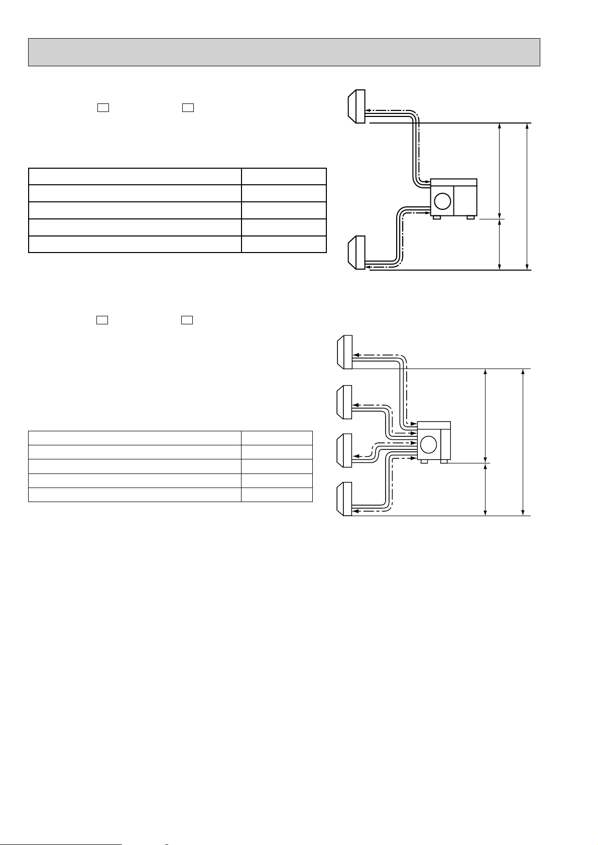
8.2 MAX REFRIGERANT PIPING LENGTH
MXZ-18NV - MXZ-18NV -
Piping length for each indoor unit (a,b) 20m
E2E1
a
Outodoor
unit
H
Total piping length (a+b) 30m
Height difference between units (H) 7m
Bending point for each unit 15
Total bending point 30
❈ It does not matter which unit is higher
MXZ-32NV - MXZ-32NV -
E2E1
Piping length each indoor unit (a, b, c, d) 25m
Total piping length (a+b+c+d) 60m
Height difference between units (H) 10m
Bending point for each unit 15
Total bending point 30
❋It does not matter which unit is higher.
H
H
b
16
8.3 PIPE SIZE SELECTION
MXZ-18NV - MXZ-18NV -
● Refrigerant pipe diameter is different according to indoor unit to be connected. When using extension pipes, refer to the
table below.
● When diameter of refrigerant pipe is different from that of outdoor unit union, use optional L-joint. For further information on
L-joint, see page 62.
Indoor unit
class Pipe diameter
07/09
12
Liquid 6.35(1/4) Liquid 6.35(1/4)
Gas 9.52(3/8) Gas 9.52(3/8)
Liquid 6.35(1/4) Liquid 6.35(1/4)
Gas 12.7(1/2) Gas 12.7(1/2)
E2E1
Extention pipe diameter
Outdoor unit union diameter
For
Indoor unit A
Indoor unit B
Unit : mm (inch)
Liquid 6.35(1/4)
Gas 9.52(3/8)
Liquid 6.35(1/4)
Gas 9.52(3/8)
MXZ-32NV - MXZ-32NV -
●Refrigerant pipe diameter is different according to indoor unit to be connected. When using extention pipes,refer to the tables
below.
●When diameter of refrigerant pipe is different from that of outdoor unit union, use optional Different-diameter pipe. For further
information on Different-diameter pipe,see page 62.
Indoor unit
class Pipe diameter
07/09
12(13)
18
Liquid 6.35(1/4) Liquid 6.35(1/4)
Gas 9.52(3/8) Gas 9.52(3/8)
Liquid 6.35(1/4) Liquid 6.35(1/4)
Gas 12.7(1/2) Gas 12.7(1/2)
Liquid 6.35(1/4) Liquid 6.35(1/4)
Gas 15.88(5/8) Gas 15.88(5/8)
E2E1
Extention pipe diameter
Outdoor unit union diameter
For
Indoor unit A
Indoor unit B
Indoor unit C
Indoor unit D
Unit : mm (inch)
Liquid 6.35(1/4)
Gas 12.7(1/2)
Liquid 6.35(1/4)
Gas 12.7(1/2)
Liquid 6.35(1/4)
Gas 9.52(3/8)
Liquid 6.35(1/4)
Gas 9.52(3/8)
17
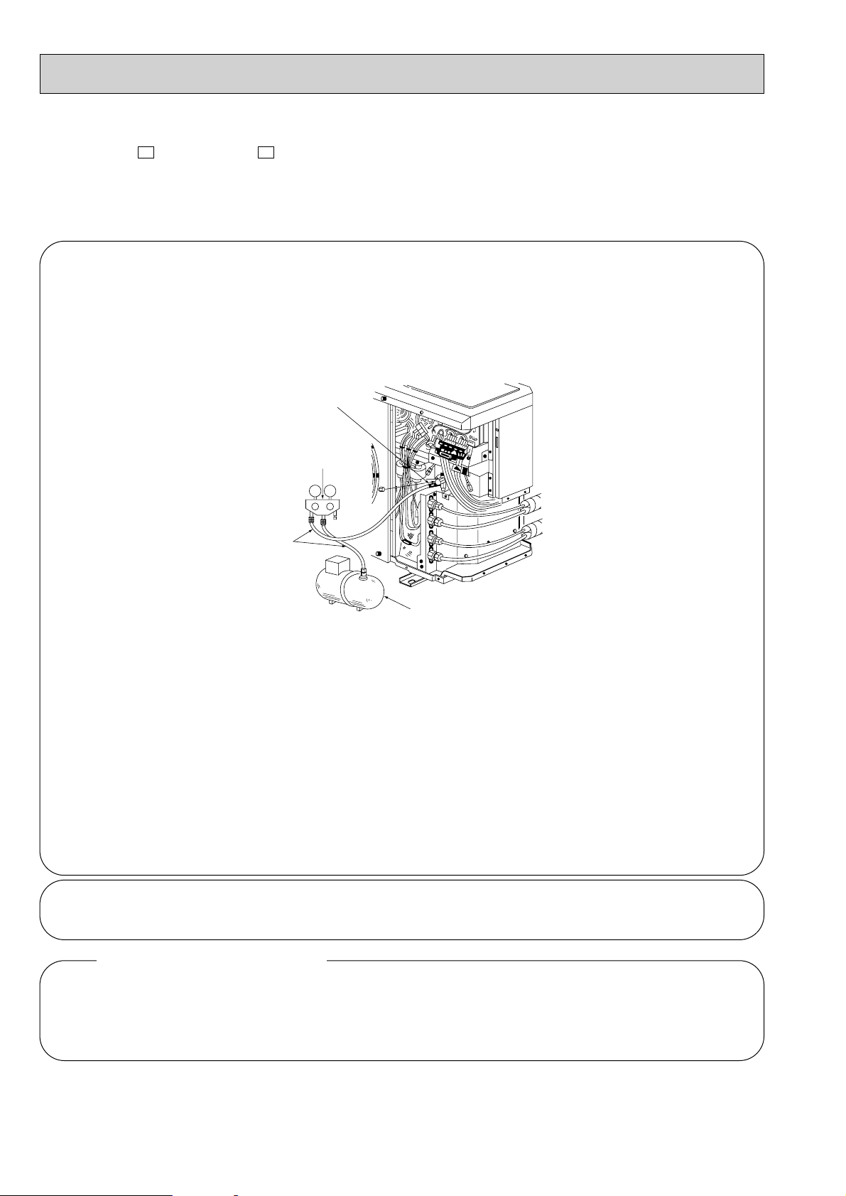
8.4 EVACUATION PROCEDURES
Gauge manifold valve
Connect pipes
Vacuum pump
Service port
MXZ-18NV - MXZ-18NV -
E2E1
CAUTION : If you run this unit with air in its refrigerant pipe before air purge, the compressor will decline in cooling
capacity, which may result in trouble.
❶. Connect the refrigerant pipes (both the liquid and gas pipes) between the indoor and the uotdoor units.
❷. Remove the service port cap of the stop valve on the side of the outdoor unit gas pipe.[ The stop valve
will not work in its initial atate fresh out of the factory (totally closed with cap on).]
❸. Connect the gauge manifold valve and the vacuum pump to the service port of the stop valve on the side
of the outdoor unit gas pipe.
❹. Run the vacuum pump.
❺. Check the vacuum with the gauge manifold valve, then close the gauge manifold valve, and stop the
vacuum pump.
❻. Leave it as is for one or two minutes.Make sure the pointer of the gauge manifold valve remains in the
same position.
❼. Remove the cape from the stop valves of the outdoor unit, liquid pipe, and gas pipe. Pull the handle
towards you with a finger. Turn it one fourth turn counterclockwise, to obtain the full-open position.
❽. Remove the cape manifold valve quickly from the service port of the stop valve.
❾. Tishten the cap to the service port to obtain the initial status.
❿. Thrust the handle of the stop valve into the unit, then retighten the cap.
Leak test
.......
With a gas detector or soap water, check the flared nut connections for any refrigerant leak.
In case of a refrigerant leak
● Retighten the flared nut connections.
● If the leak does not stop even after retightening, repair the leaking point, collect all from inside the unit
through the service port, apply a vacuum to it, then charge a specified amount of gas with a gas cylinder.
18
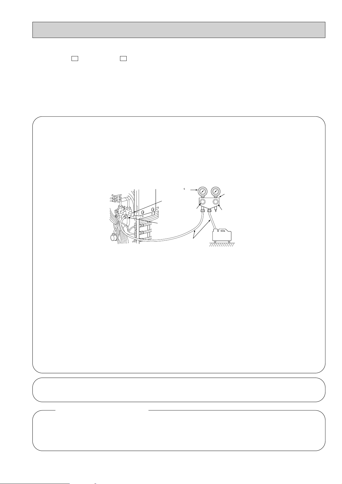
Stop valve
(gas side)
Service port
Valve knob Lo
Valve knob Hi
Charge hose
Vacuum
pump
Gauge
Manifold
Compound gauge Pressure gauge
-1.01✕10 Pa
(-760mmHg)
MXZ-32NV - MXZ-32NV -
E2E1
● For details about how to use manifold valves, see the instruction manual for manifold valves.
● The valve knob Hi below cannot operate during the following work if it is fully closed.
Warning : When installing or moving the unit, do not mix anything other than specified refrigerant (R-22) into the
refrigerating cycle.
If air is mixed, it may cause the refrigerating cycle to get abnormally high temperature, causing a risk of
burst.
❶. Make sure the pipes are connected securely.
❷. Connect the projected side (on which the setting pin is pressed) of the gauge manifold valve´s charge hose to the
stop valve´s service port (gas pipe side).
❸. Make sure the stop valves of gas and liquid pipes are fully closed, and connect the charge house to the vacuum
pump.
❹. Fully open the manifold valve´s valve knob Lo and operate the vacuum pump.
Loosen the stop valve flare nut on the gas pipe side a little bit and make sure that air is entering.
Then tighten the flare nut not to enter the air. After that, make sure that the charge hose is connected firmly to
the service port.
❺. Purge air for more than 15 minutes, and make sure the compound gauge is reading - 1.01 ✕ 10
5
Pa (-760mmHg).
❻. After purging air, fully close the manifold valve´s valve knob Lo and stop operating the vacuum pump.
❼. Leave the situation for about 1 to 2 minutes, make sure the needle of the compound gauge does not return, pull the
stop valve´s knob toward you, and fully open the stop valve by turning it a quarter turn counterclockwise.
❽. Quickly remove the gauge manifold valve´s charge hose from the stop valve´s service port.
❾. Tighten the service port cap 1/12 turn more from where the tightening torque is suddenly increased.
(It is equivalent to a tightening torque of 13.7 to 17.7N-m (140 to 180kgf-cm).)
❿. Tighten the service port cap 1/12 turn more from where the tightening torque is suddenly increased.
(It is equivalent to a tightening torque of 19.6 to 29.4N-m (200 to 300kgf-cm).)
Leak test
● Retighten the flared nut connections.
● If the leak does not stop even after retightening, repair the leaking point, collect all from inside the unit
through the service port, apply a vacuum to it, then charge a specified amount of gas with a gas cylinder.
.......
With a gas detector or soap water, check the flared nut connections for any refrigerant leak.
In case of a refrigerant leak
19
 Loading...