

Mitsubishi Electric MXZ-8B140, MXZ-8B140VA-A, MXZ-160VA-A Installation Manual

English
INSTALLATION MANUAL
For safe and correct use, please read this installation manual thoroughly before installing the air-conditioner
unit.
Air-Conditioners OUTDOOR UNIT
MXZ-8B140,160VA-A
FOR INSTALLER
HFC
utilized
R410A
2
Contents
1. Safety precautions .....................................................................................2
2. Installation diagram & parts ....................................................................... 3
3. Installation location .................................................................................... 4
4. Installing the outdoor unit .......................................................................... 6
5. Installing the refrigerant piping .................................................................. 6
6. Drainage piping work ............................................................................... 10
7. Electrical work .........................................................................................10
8. Test run .................................................................................................... 14
9. Special Functions ....................................................................................15
1.2. Before installation (relocation)
Caution:
• Be extremely careful when transporting the units. Two or more persons are
needed to handle the unit, as it weighs 20 kg or more. Do not grasp the pack
aging bands. Wear protective gloves to remove the unit from the packaging
and to move it, as you can injure your hands on the fins or other parts.
• Be sure to safely dispose of the packaging materials. Packaging materials,
such as nails and other metal or wooden parts may cause stabs or other
injuries.
Warning:
• The unit must not be installed by the user. Ask a dealer or an authorized
technician to install the unit. If the unit is installed incorrectly, water leakage,
electric shock, or fire may result.
• For installation work, follow the instructions in the Installation Manual and use
tools and pipe components specifically made for use with R410A refrigerant.
The R410A refrigerant in the HFC system is pressurized 1.6 times the pressure
of usual refrigerants. If pipe components not designed for R410A refrigerant are
used and the unit is not installed correctly, the pipes may burst and cause damage or injuries. In addition, water leakage, electric shock, or fire may result.
• The unit must be installed according to the instructions in order to minimize
the risk of damage from earthquakes, typhoons, or strong winds. An incor
-
rectly installed unit may fall down and cause damage or injuries.
• The unit must be securely installed on a structure that can sustain its weight.
If the unit is mounted on an unstable structure, it may fall down and cause
damage or injuries.
• If the air conditioner is installed in a small room, measures must be taken to
prevent the refrigerant concentration in the room from exceeding the safety
limit in the event of refrigerant leakage. Consult a dealer regarding the appro
priate measures to prevent the allowable concentration from being exceeded.
Should the refrigerant leak and cause the concentration limit to be exceeded,
hazards due to lack of oxygen in the room may result.
• Ventilate the room if refrigerant leaks during operation. If refrigerant comes
into contact with a flame, poisonous gases will be released.
• All electric work must be performed by a qualified technician according to
local regulations and the instructions given in this manual. The units must be
powered by dedicated power lines and the correct voltage and circuit breakers
must be used. Power lines with insufficient capacity or incorrect electrical
work may result in electric shock or fire.
• Be sure to connect the power supply cords and the connecting wires for
the indoor units, outdoor units, and branch boxes directly to the units (no
intermediate connections).
Intermediate connections can lead to communication errors if water enters
the cords or wires and causes insufficient insulation to ground or a poor
electrical contact at the intermediate connection point.
(If an intermediate connection is necessary, be sure to take measures to
prevent water from entering the cords and wires.)
• Use C1220 copper phosphorus, for copper and copper alloy seamless pipes,
to connect the refrigerant pipes. If the pipes are not connected correctly, the
unit will not be properly grounded and electric shock may result.
• Use only specified cables for wiring. The connections must be made securely
without tension on the terminals. If the cables are connected or installed
incorrectly, overheating or fire may result.
• The terminal block cover panel of the outdoor unit must be firmly attached. If
the cover panel is mounted incorrectly and dust and moisture enter the unit,
electric shock or fire may result.
• When installing or relocating, or servicing the air conditioner, use only the
specified refrigerant (R410A) to charge the refrigerant lines. Do not mix it with
any other refrigerant and do not allow air to remain in the lines.
If air is mixed with the refrigerant, then it can be the cause of abnormal high
pressure in the refrigerant line, and may result in an explosion and other
hazards.
The use of any refrigerant other than that specified for the system will cause
mechanical failure or system malfunction or unit breakdown. In the worst
case, this could lead to a serious impediment to securing product safety.
• Use only accessories authorized by Mitsubishi Electric and ask a dealer or an
authorized technician to install them. If accessories are incorrectly installed,
water leakage, electric shock, or fire may result.
• Do not alter the unit. Consult a dealer for repairs. If alterations or repairs are
not performed correctly, water leakage, electric shock, or fire may result.
• The user should never attempt to repair the unit or transfer it to another location. If the unit is installed incorrectly, water leakage, electric shock, or fire
may result. If the air conditioner must be repaired or moved, ask a dealer or
an authorized technician.
• After installation has been completed, check for refrigerant leaks. If refriger
ant leaks into the room and comes into contact with the flame of a heater or
portable cooking range, poisonous gases will be released.
• Refrigerant leakage may cause suffocation. Provide ventilation in accordance
with EN378-1.
1.1. Before installation
Caution:
• Do not use the unit in an unusual environment. If the air conditioner is installed
in areas exposed to steam, volatile oil (including machine oil), or sulfuric gas,
areas exposed to high salt content such as the seaside, or areas where the
unit will be covered by snow, the performance can be significantly reduced
and the internal parts can be damaged.
• Do not install the unit where combustible gases may leak, be produced, flow,
or accumulate. If combustible gas accumulates around the unit, fire or explosion may result.
• The outdoor unit produces condensation during the heating operation. Make
sure to provide drainage around the outdoor unit if such condensation is likely
to cause damage.
• When installing the unit in a hospital or communications office, be prepared for
noise and electronic interference. Inverters, home appliances, high-frequency
medical equipment, and radio communications equipment can cause the air
conditioner to malfunction or breakdown. The air conditioner may also affect
medical equipment, disturbing medical care, and communications equipment,
harming the screen display quality.
► Before installing the unit, make sure you read all the “Safety precautions”.
► Please report to or take consent by the supply authority before connec-
tion to the system.
► Equipment complying with IEC/EN 61000-3-12
Warning:
Describes precautions that must be observed to prevent danger of injury or
death to the user.
Caution:
Describes precautions that must be observed to prevent damage to the unit.
1. Safety precautions
• The base and attachments of the outdoor unit must be periodically checked
for looseness, cracks or other damage. If such defects are left uncorrected,
the unit may fall down and cause damage or injuries.
• Do not clean the air conditioner unit with water. Electric shock may result.
• Tighten all flare nuts to specification using a torque wrench. If tightened too
much, the flare nut can break after an extended period and refrigerant can
leak out.
After installation work has been completed, explain the “Safety Precautions,” use, and
maintenance of the unit to the customer according to the information in the Operation
Manual and perform the test run to ensure normal operation. Both the Installation
Manual and Operation Manual must be given to the user for keeping. These manuals
must be passed on to subsequent users.
: Indicates a part which must be grounded.
Warning:
Carefully read the labels affixed to the main unit.
3
2. Installation diagram & parts
1. Safety precautions
1.3. Before electric work
Caution:
• Be sure to install circuit breakers. If not installed, electric shock may result.
IMPORTANT
Make sure that the current leakage breaker is one compatible with higher
harmonics.
Always use a current leakage breaker that is compatible with higher harmonics as this unit is equipped with an inverter.
The use of an inadequate breaker can cause the incorrect operation of
inverter.
• For the power lines, use standard cables of sufficient capacity. Otherwise, a
short circuit, overheating, or fire may result.
1.4. Before starting the test run
Caution:
• Turn on the main power switch more than 12 hours before starting operation.
Starting operation just after turning on the power switch can severely damage
the internal parts. Keep the main power switch turned on during the operation
season.
• Before starting operation, check that all panels, guards and other protective
parts are correctly installed. Rotating, hot, or high voltage parts can cause
injuries.
• When installing the power lines, do not apply tension to the cables. If the
connections are loosened, the cables can snap or break and overheating or
fire may result.
• Be sure to ground the unit. Do not connect the ground wire to gas or water
pipes, lighting rods, or telephone grounding lines. If the unit is not properly
grounded, electric shock may result.
• Use circuit breakers (ground fault interrupter, isolating switch (+B fuse), and
molded case circuit breaker) with the specified capacity. If the circuit breaker
capacity is larger than the specified capacity, breakdown or fire may result.
• Do not touch any switch with wet hands. Electric shock may result.
• Do not touch the refrigerant pipes with bare hands during operation. The
refrigerant pipes are hot or cold depending on the condition of the flowing
refrigerant. If you touch the pipes, burns or frostbite may result.
• After stopping operation, be sure to wait at least five minutes before turning off
the main power switch. Otherwise, water leakage or breakdown may result.
1.5. Using R410A refrigerant air conditioners
Caution:
• Use C1220 copper phosphorus, for copper and copper alloy seamless pipes,
to connect the refrigerant pipes. Make sure the insides of the pipes are clean
and do not contain any harmful contaminants such as sulfuric compounds,
oxidants, debris, or dust. Use pipes with the specified thickness. (Refer to
page 6) Note the following if reusing existing pipes that carried R22 refrigerant.
- Replace the existing flare nuts and flare the flared sections again.
- Do not use thin pipes. (Refer to page 6)
• Store the pipes to be used during installation indoors and keep both ends of
the pipes sealed until just before brazing. (Leave elbow joints, etc. in their
packaging.) If dust, debris, or moisture enters the refrigerant lines, oil dete
-
rioration or compressor breakdown may result.
• Use ester oil, ether oil, alkylbenzene oil (small amount) as the refrigeration
oil applied to the flared sections. If mineral oil is mixed in the refrigeration
oil, oil deterioration may result.
• Do not use refrigerant other than R410A refrigerant. If another refrigerant is
used, the chlorine will cause the oil to deteriorate.
• Use the following tools specifically designed for use with R410A refrigerant.
The following tools are necessary to use R410A refrigerant. Contact your
nearest dealer for any questions.
Tools (for R410A)
Gauge manifold Flare tool
Charge hose Size adjustment gauge
Gas leak detector Vacuum pump adapter
Torque wrench Electronic refrigerant charging scale
• Be sure to use the correct tools. If dust, debris, or moisture enters the refrigerant lines, refrigeration oil deterioration may result.
• Do not use a charging cylinder. If a charging cylinder is used, the composition
of the refrigerant will change and the efficiency will be lowered.
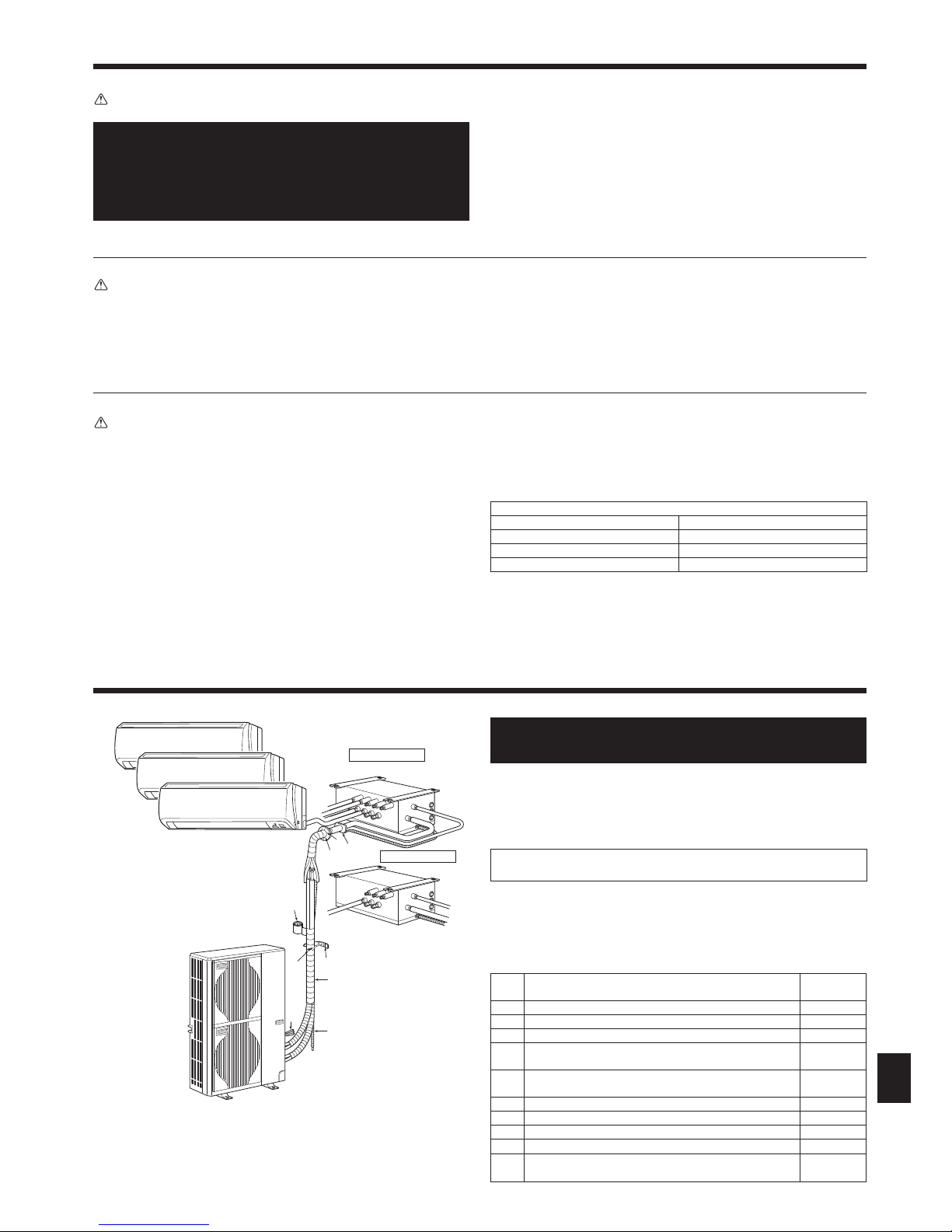
2.1. Before installation (Fig. 2-1)
This installation manual is only for the outdoor unit installation. In installing
the indoor units and branch box, refer to the installation manual attached
to each unit.
Any structural alterations necessary for the installation must comply with the local
building code requirements.
This diagram is intended to show the configuration of accessories.
For actual installation, the outdoor unit is to be turned 180°.
Units should be installed by licensed contractor according to local code requirement.
Note:
The dimensions given along the arrows above are required to guarantee the
air conditioner’s performance. Install the unit in as wide a place as possible
for later service or repairs.
Parts to be locally procured
[A]
Branch box/outdoor unit connecting wire
(3-core, Refer to 7.3. External wiring procedure)
1
[B] Extension pipe 1
[C] Wall hole sleeve 1
[D] Wall hole cover 1
[E]
Pipe fixing band
(The quantity depends on the pipe length.)
2 to 7
[F]
Fixing screw for [E] 4 × 20 mm
(The quantity depends on the pipe length.)
2 to 7
[G] Piping tape 1
[H] Putty 1
[I] Drain hose (hard PVC pipe VP16) 1
[J] Refrigeration oil 1
[K]
Power supply cord
(2-core, Refer to 7.3. External wiring procedure)
1
Fig. 2-1
[K]
[A]
[H]
[I]
[B]
[C]
[D]
[E]
[F]
[G]
Branch box
5-branches type
Outdoor unit
3-branches type
4
Fig. 3-3
Fig. 3-4
Fig. 3-2
3. Installation location
3.1. Refrigerant pipe
Refer to 5.2. Pipe length and height difference.
3.2. Choosing the outdoor unit installation location
• Avoid locations exposed to direct sunlight or other sources of heat.
• Select a location from which noise emitted by the unit will not inconvenience neighbors.
• Select a location permitting easy wiring and pipe access to the power source and
indoor unit.
• Avoid locations where combustible gases may leak, be produced, flow, or accumu
-
late.
• Note that water may drain from the unit during operation.
• Select a level location that can bear the weight and vibration of the unit.
• Avoid locations where the unit can be covered by snow. In areas where heavy snow
fall is anticipated, special precautions such as raising the installation location or
installing a hood on the air intake must be taken to prevent the snow from block
ing the air intake or blowing directly against it. This can reduce the airflow and a
malfunction may result.
• Avoid locations exposed to oil, steam, or sulfuric gas.
• Use the transportation handles of the outdoor unit to transport the unit. If the unit
is carried from the bottom, hands or fingers may be pinched.
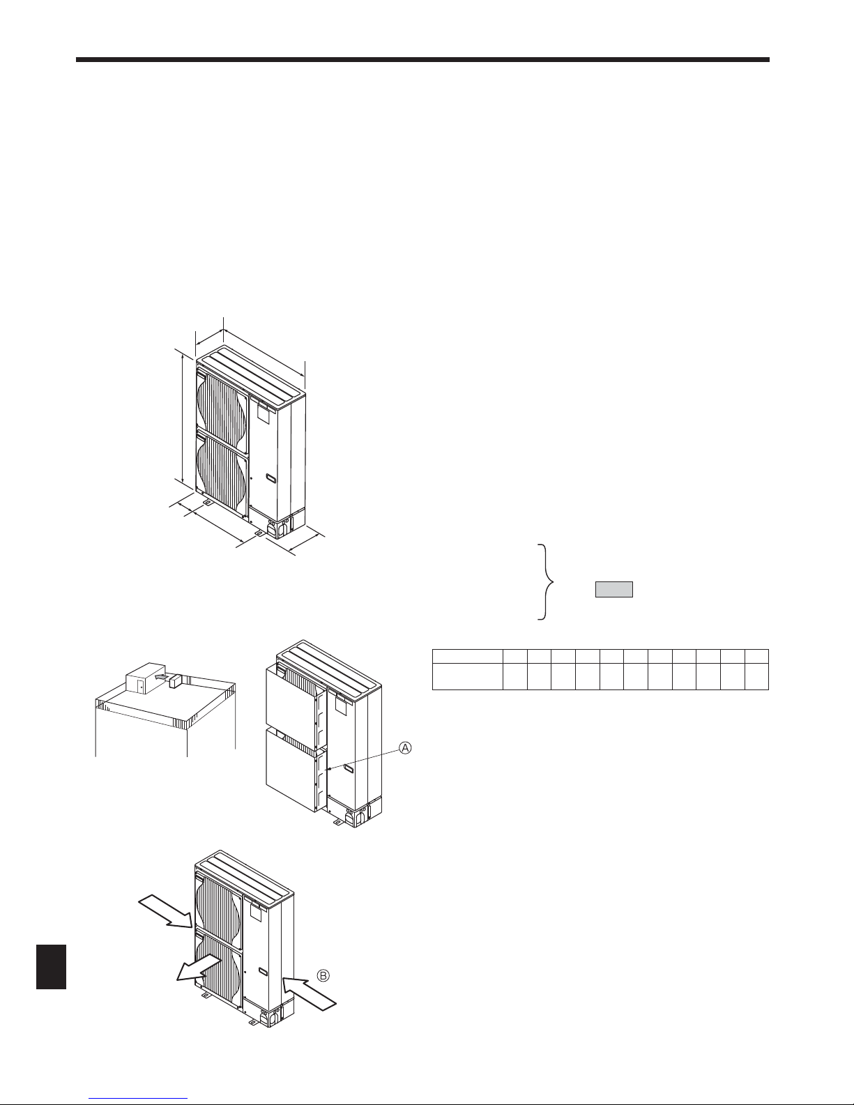
3.3. Outline dimensions (Outdoor unit) (Fig. 3-1)
Constraints on indoor unit installation
You should note that indoor units that can be connected to this outdoor unit are the
following models.
• Indoor units with model numbers 15, 20, 22, 25, 35, 42, 50, 60, 71, 80, 100 can be
connected. Refer to the table below for possible 2-8 room, indoor unit combina
-
tions.
Verification
The rated capacity should be determined by observing the table below. The unit’s
quantities are limited in 2 to 8 units. For the next step, make sure that the total rated
capacity selected will stay in a range as shown below.
• MXZ-8B140 3.0~18.5kw
• MXZ-8B160 3.0~20.2kw
Example: MXZ-8B140
MSZ-60 = 6.0
+
SEZ-35 = 3.5
+
SLZ-35 = 3.5
+
SEZ-25 = 2.5
+
SLZ-25 = 2.5
Indoor unit type 15 20 22 25 35 42 50 60 71 80
100
*1
Rated capacity
(Cooling) (kW)
1.5 2.0 2.2 2.5 3.5 4.2 5.0 6.0 7.1 8.0 10.0
Combinations in which the total capacity of indoor units exceeds the capacity of the
outdoor unit will reduce the cooling capacity of each indoor unit below their rated
cooling capacity. Thus, combine indoor units with an outdoor unit within the outdoor
unit’s capacity, if possible.
*1 When connecting the indoor unit with the model number 100, use the PAC-AK52BC branch box.
Along with this, the PAC-AK52YP-E Y-shape connection pipe is required.
The capacity of outdoor unit
• MXZ-8B140 14.0kw
• MXZ-8B160 15.5kw
3.4. Ventilation and service space
3.4.1. Windy location installation
When installing the outdoor unit on a rooftop or other location unprotected from the
wind, situate the air outlet of the unit so that it is not directly exposed to strong winds.
Strong wind entering the air outlet may impede the normal airflow and a malfunction
may result.
The following shows three examples of precautions against strong winds.
Face the air outlet towards the nearest available wall about 50 cm away from the
wall. (Fig. 3-2)
Install an optional air guide if the unit is installed in a location where strong winds
from a typhoon, etc. may directly enter the air outlet. (Fig. 3-3)
Air guide
Position the unit so that the air outlet blows perpendicularly to the seasonal wind
direction, if possible. (Fig. 3-4)
Wind direction
Fig. 3-1
(mm)
950
330+30
1350
175
600
370
Total rated capacity
18.018.5 kW
5
3. Installation location
Fig. 3-11
Fig. 3-13
Fig. 3-14
Fig. 3-15 Fig. 3-16 Fig. 3-17
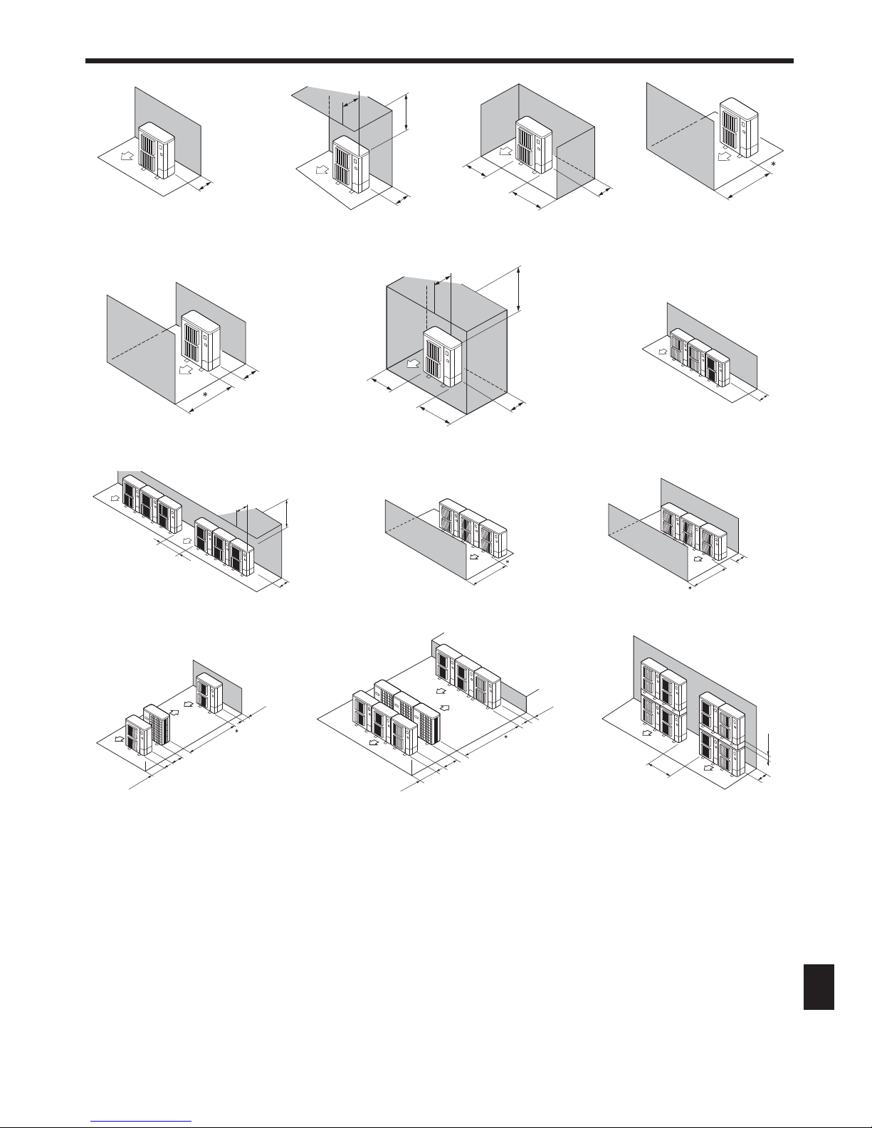
3.4.2. When installing a single outdoor unit
Minimum dimensions are as follows, except for Max., meaning Maximum dimensions, indicated.
Refer to the figures for each case.
Obstacles at rear only (Fig. 3-5)
Obstacles at rear and above only (Fig. 3-6)
Obstacles at rear and sides only (Fig. 3-7)
Obstacles at front only (Fig. 3-8)
∗ When using an optional air outlet guide, the clearance is 500 mm or more.
Obstacles at front and rear only (Fig. 3-9)
∗ When using an optional air outlet guide, the clearance is 500 mm or more.
Obstacles at rear, sides, and above only (Fig. 3-10)
• Do not install the optional air outlet guides for upward airflow.
3.4.3. When installing multiple outdoor units
Leave 10 mm space or more between the units.
Obstacles at rear only (Fig. 3-11)
Obstacles at rear and above only (Fig. 3-12)
• No more than three units must be installed side by side. In addition, leave space as shown.
• Do not install the optional air outlet guides for upward airflow.
Obstacles at front only (Fig. 3-13)
∗ When using an optional air outlet guide, the clearance is 1000 mm or more.
Obstacles at front and rear only (Fig. 3-14)
∗ When using an optional air outlet guide, the clearance is 1000 mm or more.
Single parallel unit arrangement (Fig. 3-15)
∗ When using an optional air outlet guide installed for upward airflow, the clearance is 1000
mm or more.
Multiple parallel unit arrangement (Fig. 3-16)
∗ When using an optional air outlet guide installed for upward airflow, the clearance is 1500
mm or more.
Stacked unit arrangement (Fig. 3-17)
• The units can be stacked up to two units high.
• No more than two stacked units must be installed side by side. In addition, leave space as shown.
Fig. 3-9
Fig. 3-8Fig. 3-7Fig. 3-5
150
200
300
200
1000
150
1000
300
1500
1500
500
1000
600
2000
150
1500
600
3000
500
1500
800
150
Fig. 3-6
Fig. 3-10
Fig. 3-12
Max. 500
Max. 500
Max. 300
1000
300
1500
500
250
250
500
1500
1500
 Loading...