


MELSEC iQ-R MES Interface Module
User's Manual (Startup)
-RD81MES96
-SW1DND-RMESIF-E(MX MESInterface-R)


SAFETY PRECAUTIONS
WARNING
Indicates that incorrect handling may cause hazardous conditions, resulting in
death or severe injury.
CAUTION
Indicates that incorrect handling may cause hazardous conditions, resulting in
minor or moderate injury or property damage.
(Read these precautions before using this product.)
Before using this product, please read this manual and the relevant manuals carefully, and pay full attention to safety to
handle the product correctly.
In this manual, the safety precautions are classified into two levels: " WARNING" and " CAUTION".
Under some circumstances, failure to observe the precautions given under " CAUTION" may lead to serious
consequences.
Observe the precautions of both levels because they are important for personal and system safety.
Make sure that the end users read this manual and then keep the manual in a safe place for future reference.
1

[Design Precautions]
WARNING
● Configure safety circuits external to the programmable controller to ensure that the entire system
operates safely even when a fault occurs in the external power supply or the programmable controller.
Failure to do so may result in an accident due to an incorrect output or malfunction.
(1) Emergency stop circuits, protection circuits, and protective interlock circuits for conflicting
operations (such as forward/reverse rotations or upper/lower limit positioning) must be configured
external to the programmable controller.
(2) When the programmable controller detects an abnormal condition, it stops the operation and all
outputs are:
• Turned off if the overcurrent or overvoltage protection of the power supply module is activated.
• Held or turned off according to the parameter setting if the self-diagnostic function of the CPU
module detects an error such as a watchdog timer error.
(3) All outputs may be turned on if an error occurs in a part, such as an I/O control part, where the
CPU module cannot detect any error. To ensure safety operation in such a case, provide a safety
mechanism or a fail-safe circuit external to the programmable controller. For a fail-safe circuit
example, refer to "General Safety Requirements" in the MELSEC iQ-R Module Configuration
Manual.
(4) Outputs may remain on or off due to a failure of a component such as a relay and transistor in an
output circuit. Configure an external circuit for monitoring output signals that could cause a
serious accident.
● In an output circuit, when a load current exceeding the rated current or an overcurrent caused by a
load short-circuit flows for a long time, it may cause smoke and fire. To prevent this, configure an
external safety circuit, such as a fuse.
● Configure a circuit so that the programmable controller is turned on first and then the external power
supply. If the external power supply is turned on first, an accident may occur due to an incorrect output
or malfunction.
● For the operating status of each station after a communication failure, refer to manuals relevant to the
network. Incorrect output or malfunction due to a communication failure may result in an accident.
● When connecting an external device with a CPU module or intelligent function module to modify data
of a running programmable controller, configure an interlock circuit in the program to ensure that the
entire system will always operate safely. For other forms of control (such as program modification,
parameter change, forced output, or operating status change) of a running programmable controller,
read the relevant manuals carefully and ensure that the operation is safe before proceeding. Improper
operation may damage machines or cause accidents.
● Especially, when a remote programmable controller is controlled by an external device, immediate
action cannot be taken if a problem occurs in the programmable controller due to a communication
failure. To prevent this, configure an interlock circuit in the program, and determine corrective actions
to be taken between the external device and CPU module in case of a communication failure.
2
[Design Precautions]
WARNING
● Do not write any data to the "system area" and "write-protect area" of the buffer memory in the
module. Also, do not use any "use prohibited" signals as an output signal from the CPU module to
each module. Doing so may cause malfunction of the programmable controller system. For the
"system area", "write-protect area", and the "use prohibited" signals, refer to the user's manual for the
module used.
● If a communication cable is disconnected, the network may be unstable, resulting in a communication
failure of multiple stations. Configure an interlock circuit in the program to ensure that the entire
system will always operate safely even if communications fail. Incorrect output or malfunction due to a
communication failure may result in an accident.
● To maintain the safety of the programmable controller system against unauthorized access from
external devices via the network, take appropriate measures. To maintain the safety against
unauthorized access via the Internet, take measures such as installing a firewall.
[Design Precautions]
CAUTION
● Do not install the control lines or communication cables together with the main circuit lines or power
cables. Keep a distance of 100 mm or more between them. Failure to do so may result in malfunction
due to noise.
● During control of an inductive load such as a lamp, heater, or solenoid valve, a large current
(approximately ten times greater than normal) may flow when the output is turned from off to on.
Therefore, use a module that has a sufficient current rating.
● After the CPU module is powered on or is reset, the time taken to enter the RUN status varies
depending on the system configuration, parameter settings, and/or program size. Design circuits so
that the entire system will always operate safely, regardless of the time.
● Do not power off the programmable controller or do not reset the CPU module while the settings are
being written. Doing so will make the data in the flash ROM or SD memory card undefined. The values
need to be set in the buffer memory and written to the flash ROM or the SD memory card again. Doing
so may cause malfunction or failure of the module.
● When changing the operating status of the CPU module from external devices (such as remote RUN/
STOP functions), select "Do Not Open in Program" for "Open Method Setting" in the module
parameters. If "Open in Program" is selected, an execution of remote STOP causes the
communication line to close. Consequently, the CPU module cannot reopen the communication line,
and the external device cannot execute the remote RUN.
3
[Installation Precautions]
WARNING
● Shut off the external power supply (all phases) used in the system before mounting or removing the
module. Failure to do so may result in electric shock or cause the module to fail or malfunction.
[Installation Precautions]
CAUTION
● Use the programmable controller in an environment that meets general specifications written in Safety
Guidelines included in the base unit. Failure to do so may result in electric shock, fire, malfunction, or
damage to or deterioration of the product.
● To mount a module, place the concave part(s) located at the bottom onto the guide(s) of the base unit,
and push in the module, and make sure to fix the module with screws since this module has no
module fixing hook. Incorrect interconnection may cause malfunction, failure, or drop of the module.
● Tighten the screws within the specified torque range. Undertightening can cause drop of the screw,
short circuit, or malfunction. Overtightening can damage the screw and/or module, resulting in drop,
short circuit, or malfunction.
● When using an extension cable, connect it to the extension cable connector of the base unit securely.
Check the connection for looseness. Poor contact may cause malfunction.
● When using an SD memory card, fully insert it into the memory card slot. Check that it is inserted
completely. Poor contact may cause malfunction.
● Securely insert an extended SRAM cassette into the cassette connector of a CPU module. After
insertion, close the cassette cover and check that the cassette is inserted completely. Poor contact
may cause malfunction.
● Do not directly touch any conductive parts and electronic components of the module, SD memory
card, extended SRAM cassette, or connector. Doing so may cause malfunction or failure of the
module.
[Wiring Precautions]
WARNING
● Shut off the external power supply (all phases) used in the system before installation and wiring.
Failure to do so may result in electric shock or cause the module to fail or malfunction.
● After installation and wiring, attach the included terminal cover to the module before turning it on for
operation. Failure to do so may result in electric shock.
4

[Wiring Precautions]
CAUTION
● Individually ground the FG and LG terminals of the programmable controller with a ground resistance
of 100 ohms or less. Failure to do so may result in electric shock or malfunction.
● Use applicable solderless terminals and tighten them within the specified torque range. If any spade
solderless terminal is used, it may be disconnected when the terminal screw comes loose, resulting in
failure.
● Check the rated voltage and signal layout before wiring to the module, and connect the cables
correctly. Connecting a power supply with a different voltage rating or incorrect wiring may cause fire
or failure.
● Connectors for external devices must be crimped or pressed with the tool specified by the
manufacturer, or must be correctly soldered. Incomplete connections may cause short circuit, fire, or
malfunction.
● Securely connect the connector to the module. Poor contact may cause malfunction.
● Do not install the control lines or communication cables together with the main circuit lines or power
cables. Keep a distance of 100 mm or more between them. Failure to do so may result in malfunction
due to noise.
● Place the cables in a duct or clamp them. If not, dangling cable may swing or inadvertently be pulled,
resulting in damage to the module or cables or malfunction due to poor contact. Do not clamp the
extension cables with the jacket stripped. Doing so may change the characteristics of the cables,
resulting in malfunction.
● Check the interface type and correctly connect the cable. Incorrect wiring (connecting the cable to an
incorrect interface) may cause failure of the module and external device.
● Tighten the terminal screws or connector screws within the specified torque range. Undertightening
can cause drop of the screw, short circuit, fire, or malfunction. Overtightening can damage the screw
and/or module, resulting in drop, short circuit, fire, or malfunction.
● When disconnecting the cable from the module, do not pull the cable by the cable part. For the cable
with connector, hold the connector part of the cable. For the cable connected to the terminal block,
loosen the terminal screw. Pulling the cable connected to the module may result in malfunction or
damage to the module or cable.
● Prevent foreign matter such as dust or wire chips from entering the module. Such foreign matter can
cause a fire, failure, or malfunction.
● A protective film is attached to the top of the module to prevent foreign matter, such as wire chips,
from entering the module during wiring. Do not remove the film during wiring. Remove it for heat
dissipation before system operation.
5
[Wiring Precautions]
CAUTION
● Programmable controllers must be installed in control panels. Connect the main power supply to the
power supply module in the control panel through a relay terminal block. Wiring and replacement of a
power supply module must be performed by qualified maintenance personnel with knowledge of
protection against electric shock. For wiring, refer to the MELSEC iQ-R Module Configuration Manual.
● For Ethernet cables to be used in the system, select the ones that meet the specifications in the user's
manual for the module used. If not, normal data transmission is not guaranteed.
[Startup and Maintenance Precautions]
WARNING
● Do not touch any terminal while power is on. Doing so will cause electric shock or malfunction.
● Correctly connect the battery connector. Do not charge, disassemble, heat, short-circuit, solder, or
throw the battery into the fire. Also, do not expose it to liquid or strong shock. Doing so will cause the
battery to produce heat, explode, ignite, or leak, resulting in injury or fire.
● Shut off the external power supply (all phases) used in the system before cleaning the module or
retightening the terminal screws, connector screws, or module fixing screws. Failure to do so may
result in electric shock.
6

[Startup and Maintenance Precautions]
CAUTION
● When connecting an external device with a CPU module or intelligent function module to modify data
of a running programmable controller, configure an interlock circuit in the program to ensure that the
entire system will always operate safely. For other forms of control (such as program modification,
parameter change, forced output, or operating status change) of a running programmable controller,
read the relevant manuals carefully and ensure that the operation is safe before proceeding. Improper
operation may damage machines or cause accidents.
● Especially, when a remote programmable controller is controlled by an external device, immediate
action cannot be taken if a problem occurs in the programmable controller due to a communication
failure. To prevent this, configure an interlock circuit in the program, and determine corrective actions
to be taken between the external device and CPU module in case of a communication failure.
● Do not disassemble or modify the modules. Doing so may cause failure, malfunction, injury, or a fire.
● Use any radio communication device such as a cellular phone or PHS (Personal Handy-phone
System) more than 25cm away in all directions from the programmable controller. Failure to do so
may cause malfunction.
● Shut off the external power supply (all phases) used in the system before mounting or removing the
module. Failure to do so may cause the module to fail or malfunction.
● Tighten the screws within the specified torque range. Undertightening can cause drop of the
component or wire, short circuit, or malfunction. Overtightening can damage the screw and/or module,
resulting in drop, short circuit, or malfunction.
● After the first use of the product, do not mount/remove the module to/from the base unit, and the
terminal block to/from the module, and do not insert/remove the extended SRAM cassette to/from the
CPU module more than 50 times (IEC 61131-2 compliant) respectively. Exceeding the limit may cause
malfunction.
● After the first use of the product, do not insert/remove the SD memory card to/from the CPU module
more than 500 times. Exceeding the limit may cause malfunction.
● Do not touch the metal terminals on the back side of the SD memory card. Doing so may cause
malfunction or failure of the module.
● Do not touch the integrated circuits on the circuit board of an extended SRAM cassette. Doing so may
cause malfunction or failure of the module.
● Do not drop or apply shock to the battery to be installed in the module. Doing so may damage the
battery, causing the battery fluid to leak inside the battery. If the battery is dropped or any shock is
applied to it, dispose of it without using.
● Startup and maintenance of a control panel must be performed by qualified maintenance personnel
with knowledge of protection against electric shock. Lock the control panel so that only qualified
maintenance personnel can operate it.
7
[Startup and Maintenance Precautions]
CAUTION
● Before handling the module, touch a conducting object such as a grounded metal to discharge the
static electricity from the human body. Failure to do so may cause the module to fail or malfunction.
[Operating Precautions]
CAUTION
● When changing data and operating status, and modifying program of the running programmable
controller from an external device such as a personal computer connected to an intelligent function
module, read relevant manuals carefully and ensure the safety before operation. Incorrect change or
modification may cause system malfunction, damage to the machines, or accidents.
● Do not power off the programmable controller or reset the CPU module while the setting values in the
buffer memory are being written to the flash ROM in the module. Doing so will make the data in the
flash ROM or SD memory card undefined. The values need to be set in the buffer memory and written
to the flash ROM or SD memory card again. Doing so can cause malfunction or failure of the module.
[Disposal Precautions]
CAUTION
● When disposing of this product, treat it as industrial waste.
● When disposing of batteries, separate them from other wastes according to the local regulations. For
details on battery regulations in EU member states, refer to the MELSEC iQ-R Module Configuration
Manual.
[Transportation Precautions]
CAUTION
● When transporting lithium batteries, follow the transportation regulations. For details on the regulated
models, refer to the MELSEC iQ-R Module Configuration Manual.
● The halogens (such as fluorine, chlorine, bromine, and iodine), which are contained in a fumigant
used for disinfection and pest control of wood packaging materials, may cause failure of the product.
Prevent the entry of fumigant residues into the product or consider other methods (such as heat
treatment) instead of fumigation. The disinfection and pest control measures must be applied to
unprocessed raw wood.
8

CONDITIONS OF USE FOR THE PRODUCT
(1) Mitsubishi programmable controller ("the PRODUCT") shall be used in conditions;
i) where any problem, fault or failure occurring in the PRODUCT, if any, shall not lead to any major or serious accident;
and
ii) where the backup and fail-safe function are systematically or automatically provided outside of the PRODUCT for the
case of any problem, fault or failure occurring in the PRODUCT.
(2) The PRODUCT has been designed and manufactured for the purpose of being used in general industries.
MITSUBISHI SHALL HAVE NO RESPONSIBILITY OR LIABILITY (INCLUDING, BUT NOT LIMITED TO ANY AND ALL
RESPONSIBILITY OR LIABILITY BASED ON CONTRACT, WARRANTY, TORT, PRODUCT LIABILITY) FOR ANY
INJURY OR DEATH TO PERSONS OR LOSS OR DAMAGE TO PROPERTY CAUSED BY the PRODUCT THAT ARE
OPERATED OR USED IN APPLICATION NOT INTENDED OR EXCLUDED BY INSTRUCTIONS, PRECAUTIONS, OR
WARNING CONTAINED IN MITSUBISHI'S USER, INSTRUCTION AND/OR SAFETY MANUALS, TECHNICAL
BULLETINS AND GUIDELINES FOR the PRODUCT.
("Prohibited Application")
Prohibited Applications include, but not limited to, the use of the PRODUCT in;
• Nuclear Power Plants and any other power plants operated by Power companies, and/or any other cases in which the
public could be affected if any problem or fault occurs in the PRODUCT.
• Railway companies or Public service purposes, and/or any other cases in which establishment of a special quality
assurance system is required by the Purchaser or End User.
• Aircraft or Aerospace, Medical applications, Train equipment, transport equipment such as Elevator and Escalator,
Incineration and Fuel devices, Vehicles, Manned transportation, Equipment for Recreation and Amusement, and
Safety devices, handling of Nuclear or Hazardous Materials or Chemicals, Mining and Drilling, and/or other
applications where there is a significant risk of injury to the public or property.
Notwithstanding the above, restrictions Mitsubishi may in its sole discretion, authorize use of the PRODUCT in one or
more of the Prohibited Applications, provided that the usage of the PRODUCT is limited only for the specific
applications agreed to by Mitsubishi and provided further that no special quality assurance or fail-safe, redundant or
other safety features which exceed the general specifications of the PRODUCTs are required. For details, please
contact the Mitsubishi representative in your region.
9

INTRODUCTION
Thank you for purchasing the Mitsubishi Electric MELSEC iQ-R series programmable controllers.
This manual describes the performance specifications, procedure before operation, wiring, and operation examples to use the
module listed below.
Before using this product, please read this manual and the relevant manuals carefully and develop familiarity with the
functions and performance of the MELSEC iQ-R series programmable controller to handle the product correctly.
When applying the example programs provided in this manual to an actual system, ensure the applicability and confirm that it
will not cause system control problems.
Please make sure that the end users read this manual.
The program examples shown in this manual are the examples in which MES interface module (RD81MES96)
is assigned to the input/output No. X/Y0 to X/Y1F unless otherwise specified. To use the program examples
shown in this manual, the input/output number assignment is required. For details on the assignment of input/
output number, refer to the following manual.
MELSEC iQ-R Module Configuration Manual
Relevant product
RD81MES96
COMPLIANCE WITH THE EMC AND LOW VOLTAGE DIRECTIVES
Method of ensuring compliance
To ensure that Mitsubishi programmable controllers maintain EMC and Low Voltage Directives when incorporated into other
machinery or equipment, certain measures may be necessary. Please refer to one of the following manuals.
• MELSEC iQ-R Module Configuration Manual
• Safety Guidelines (included in a base unit)
The CE mark on the side of the programmable controller indicates compliance with EMC and Low Voltage Directives.
Additional measures
To ensure that this product maintains EMC and Low Voltage Directives, please refer to one of the following manuals.
• MELSEC iQ-R Module Configuration Manual
• Safety Guidelines (included in a base unit)
10

CONTENTS
SAFETY PRECAUTIONS . . . . . . . . . . . . . . . . . . . . . . . . . . . . . . . . . . . . . . . . . . . . . . . . . . . . . . . . . . . . . . . . . . . .1
CONDITIONS OF USE FOR THE PRODUCT . . . . . . . . . . . . . . . . . . . . . . . . . . . . . . . . . . . . . . . . . . . . . . . . . . . .9
INTRODUCTION. . . . . . . . . . . . . . . . . . . . . . . . . . . . . . . . . . . . . . . . . . . . . . . . . . . . . . . . . . . . . . . . . . . . . . . . . .10
COMPLIANCE WITH THE EMC AND LOW VOLTAGE DIRECTIVES . . . . . . . . . . . . . . . . . . . . . . . . . . . . . . . . .10
RELEVANT MANUALS . . . . . . . . . . . . . . . . . . . . . . . . . . . . . . . . . . . . . . . . . . . . . . . . . . . . . . . . . . . . . . . . . . . . .13
TERMS . . . . . . . . . . . . . . . . . . . . . . . . . . . . . . . . . . . . . . . . . . . . . . . . . . . . . . . . . . . . . . . . . . . . . . . . . . . . . . . . .14
CHAPTER 1 PART NAMES 16
CHAPTER 2 SPECIFICATIONS 18
2.1 Performance Specifications . . . . . . . . . . . . . . . . . . . . . . . . . . . . . . . . . . . . . . . . . . . . . . . . . . . . . . . . . . . . . . . 18
Hardware specifications . . . . . . . . . . . . . . . . . . . . . . . . . . . . . . . . . . . . . . . . . . . . . . . . . . . . . . . . . . . . . . . . . . . 18
Software specifications . . . . . . . . . . . . . . . . . . . . . . . . . . . . . . . . . . . . . . . . . . . . . . . . . . . . . . . . . . . . . . . . . . . . 19
2.2 Accessible Devices and Range . . . . . . . . . . . . . . . . . . . . . . . . . . . . . . . . . . . . . . . . . . . . . . . . . . . . . . . . . . . . 23
Accessible CPU modules . . . . . . . . . . . . . . . . . . . . . . . . . . . . . . . . . . . . . . . . . . . . . . . . . . . . . . . . . . . . . . . . . . 23
Accessible routes . . . . . . . . . . . . . . . . . . . . . . . . . . . . . . . . . . . . . . . . . . . . . . . . . . . . . . . . . . . . . . . . . . . . . . . . 24
Accessible devices . . . . . . . . . . . . . . . . . . . . . . . . . . . . . . . . . . . . . . . . . . . . . . . . . . . . . . . . . . . . . . . . . . . . . . . 29
Access units . . . . . . . . . . . . . . . . . . . . . . . . . . . . . . . . . . . . . . . . . . . . . . . . . . . . . . . . . . . . . . . . . . . . . . . . . . . . 31
2.3 Accessible Database. . . . . . . . . . . . . . . . . . . . . . . . . . . . . . . . . . . . . . . . . . . . . . . . . . . . . . . . . . . . . . . . . . . . . 32
Software corresponding to accessible database. . . . . . . . . . . . . . . . . . . . . . . . . . . . . . . . . . . . . . . . . . . . . . . . . 32
Access route . . . . . . . . . . . . . . . . . . . . . . . . . . . . . . . . . . . . . . . . . . . . . . . . . . . . . . . . . . . . . . . . . . . . . . . . . . . . 33
2.4 Usable Data for MES Interface Module . . . . . . . . . . . . . . . . . . . . . . . . . . . . . . . . . . . . . . . . . . . . . . . . . . . . . . 34
Data category . . . . . . . . . . . . . . . . . . . . . . . . . . . . . . . . . . . . . . . . . . . . . . . . . . . . . . . . . . . . . . . . . . . . . . . . . . . 34
Data type . . . . . . . . . . . . . . . . . . . . . . . . . . . . . . . . . . . . . . . . . . . . . . . . . . . . . . . . . . . . . . . . . . . . . . . . . . . . . . . 35
Device tag component/variable . . . . . . . . . . . . . . . . . . . . . . . . . . . . . . . . . . . . . . . . . . . . . . . . . . . . . . . . . . . . . . 37
Constant . . . . . . . . . . . . . . . . . . . . . . . . . . . . . . . . . . . . . . . . . . . . . . . . . . . . . . . . . . . . . . . . . . . . . . . . . . . . . . . 39
Macro. . . . . . . . . . . . . . . . . . . . . . . . . . . . . . . . . . . . . . . . . . . . . . . . . . . . . . . . . . . . . . . . . . . . . . . . . . . . . . . . . . 40
CONTENTS
CHAPTER 3 FUNCTION LIST 41
3.1 Function Overview . . . . . . . . . . . . . . . . . . . . . . . . . . . . . . . . . . . . . . . . . . . . . . . . . . . . . . . . . . . . . . . . . . . . . . 41
3.2 Function List of an MES Interface Module . . . . . . . . . . . . . . . . . . . . . . . . . . . . . . . . . . . . . . . . . . . . . . . . . . . 42
3.3 Function List of MES Interface Function Configuration Tool . . . . . . . . . . . . . . . . . . . . . . . . . . . . . . . . . . . . 43
3.4 Function List of DB Connection Service . . . . . . . . . . . . . . . . . . . . . . . . . . . . . . . . . . . . . . . . . . . . . . . . . . . . . 44
3.5 Function List of DB Connection Service Setting Tool . . . . . . . . . . . . . . . . . . . . . . . . . . . . . . . . . . . . . . . . . . 44
3.6 Function List of Project File Conversion Tool . . . . . . . . . . . . . . . . . . . . . . . . . . . . . . . . . . . . . . . . . . . . . . . . 44
CHAPTER 4 PROCEDURE BEFORE OPERATION 45
4.1 Starting Servers. . . . . . . . . . . . . . . . . . . . . . . . . . . . . . . . . . . . . . . . . . . . . . . . . . . . . . . . . . . . . . . . . . . . . . . . . 45
DB Connection Service/DB Connection Service Setting Tool . . . . . . . . . . . . . . . . . . . . . . . . . . . . . . . . . . . . . . . 46
4.2 Starting an MES Interface Module and an Configuration Personal Computer . . . . . . . . . . . . . . . . . . . . . . 48
MES Interface Function Configuration Tool . . . . . . . . . . . . . . . . . . . . . . . . . . . . . . . . . . . . . . . . . . . . . . . . . . . . . 50
Parameter settings . . . . . . . . . . . . . . . . . . . . . . . . . . . . . . . . . . . . . . . . . . . . . . . . . . . . . . . . . . . . . . . . . . . . . . . 56
4.3 SD Memory Cards . . . . . . . . . . . . . . . . . . . . . . . . . . . . . . . . . . . . . . . . . . . . . . . . . . . . . . . . . . . . . . . . . . . . . . . 58
Connectable SD memory cards (sold separately) . . . . . . . . . . . . . . . . . . . . . . . . . . . . . . . . . . . . . . . . . . . . . . . . 58
Inserting and removing method of SD memory cards . . . . . . . . . . . . . . . . . . . . . . . . . . . . . . . . . . . . . . . . . . . . . 58
Considerations for using SD memory cards . . . . . . . . . . . . . . . . . . . . . . . . . . . . . . . . . . . . . . . . . . . . . . . . . . . . 59
11

CHAPTER 5 SYSTEM CONFIGURATION 61
5.1 System Configuration . . . . . . . . . . . . . . . . . . . . . . . . . . . . . . . . . . . . . . . . . . . . . . . . . . . . . . . . . . . . . . . . . . . . 61
Overall system configuration . . . . . . . . . . . . . . . . . . . . . . . . . . . . . . . . . . . . . . . . . . . . . . . . . . . . . . . . . . . . . . . . 61
Software configuration of MX MESInterface-R . . . . . . . . . . . . . . . . . . . . . . . . . . . . . . . . . . . . . . . . . . . . . . . . . . 62
System configuration when installing . . . . . . . . . . . . . . . . . . . . . . . . . . . . . . . . . . . . . . . . . . . . . . . . . . . . . . . . . 62
System configuration for the initial setting . . . . . . . . . . . . . . . . . . . . . . . . . . . . . . . . . . . . . . . . . . . . . . . . . . . . . . 63
5.2 Operating Environment. . . . . . . . . . . . . . . . . . . . . . . . . . . . . . . . . . . . . . . . . . . . . . . . . . . . . . . . . . . . . . . . . . . 66
Configuration personal computer . . . . . . . . . . . . . . . . . . . . . . . . . . . . . . . . . . . . . . . . . . . . . . . . . . . . . . . . . . . . 66
Server (Database server/Application server). . . . . . . . . . . . . . . . . . . . . . . . . . . . . . . . . . . . . . . . . . . . . . . . . . . . 66
5.3 Considerations for System Configuration . . . . . . . . . . . . . . . . . . . . . . . . . . . . . . . . . . . . . . . . . . . . . . . . . . . 67
CHAPTER 6 WIRING 69
6.1 Ethernet Cable . . . . . . . . . . . . . . . . . . . . . . . . . . . . . . . . . . . . . . . . . . . . . . . . . . . . . . . . . . . . . . . . . . . . . . . . . . 69
Connectable twisted pair cables (sold separately) . . . . . . . . . . . . . . . . . . . . . . . . . . . . . . . . . . . . . . . . . . . . . . . 69
Wiring of an Ethernet cable . . . . . . . . . . . . . . . . . . . . . . . . . . . . . . . . . . . . . . . . . . . . . . . . . . . . . . . . . . . . . . . . . 69
Wiring considerations . . . . . . . . . . . . . . . . . . . . . . . . . . . . . . . . . . . . . . . . . . . . . . . . . . . . . . . . . . . . . . . . . . . . . 70
CHAPTER 7 INSTALLATION AND UNINSTALLATION 71
7.1 Installation Procedure . . . . . . . . . . . . . . . . . . . . . . . . . . . . . . . . . . . . . . . . . . . . . . . . . . . . . . . . . . . . . . . . . . . . 72
Environment after installation . . . . . . . . . . . . . . . . . . . . . . . . . . . . . . . . . . . . . . . . . . . . . . . . . . . . . . . . . . . . . . . 73
7.2 Uninstallation Procedure . . . . . . . . . . . . . . . . . . . . . . . . . . . . . . . . . . . . . . . . . . . . . . . . . . . . . . . . . . . . . . . . . 73
Environment after uninstallation . . . . . . . . . . . . . . . . . . . . . . . . . . . . . . . . . . . . . . . . . . . . . . . . . . . . . . . . . . . . . 73
CHAPTER 8 OPERATION EXAMPLE 74
8.1 Overview. . . . . . . . . . . . . . . . . . . . . . . . . . . . . . . . . . . . . . . . . . . . . . . . . . . . . . . . . . . . . . . . . . . . . . . . . . . . . . . 74
8.2 Setup. . . . . . . . . . . . . . . . . . . . . . . . . . . . . . . . . . . . . . . . . . . . . . . . . . . . . . . . . . . . . . . . . . . . . . . . . . . . . . . . . . 75
System configuration . . . . . . . . . . . . . . . . . . . . . . . . . . . . . . . . . . . . . . . . . . . . . . . . . . . . . . . . . . . . . . . . . . . . . . 75
Device setup . . . . . . . . . . . . . . . . . . . . . . . . . . . . . . . . . . . . . . . . . . . . . . . . . . . . . . . . . . . . . . . . . . . . . . . . . . . . 76
8.3 Creating a Database Table . . . . . . . . . . . . . . . . . . . . . . . . . . . . . . . . . . . . . . . . . . . . . . . . . . . . . . . . . . . . . . . . 78
Database table creation procedure . . . . . . . . . . . . . . . . . . . . . . . . . . . . . . . . . . . . . . . . . . . . . . . . . . . . . . . . . . . 78
8.4 ODBC Setting. . . . . . . . . . . . . . . . . . . . . . . . . . . . . . . . . . . . . . . . . . . . . . . . . . . . . . . . . . . . . . . . . . . . . . . . . . . 80
ODBC setting procedure . . . . . . . . . . . . . . . . . . . . . . . . . . . . . . . . . . . . . . . . . . . . . . . . . . . . . . . . . . . . . . . . . . . 80
8.5 MES Interface Function Setting . . . . . . . . . . . . . . . . . . . . . . . . . . . . . . . . . . . . . . . . . . . . . . . . . . . . . . . . . . . . 81
Parameter setting procedure. . . . . . . . . . . . . . . . . . . . . . . . . . . . . . . . . . . . . . . . . . . . . . . . . . . . . . . . . . . . . . . . 81
Operation check . . . . . . . . . . . . . . . . . . . . . . . . . . . . . . . . . . . . . . . . . . . . . . . . . . . . . . . . . . . . . . . . . . . . . . . . . 98
APPENDIX 100
Appendix 1 External Dimensions . . . . . . . . . . . . . . . . . . . . . . . . . . . . . . . . . . . . . . . . . . . . . . . . . . . . . . . . . . . . . . . 100
Appendix 2 ODBC Setting . . . . . . . . . . . . . . . . . . . . . . . . . . . . . . . . . . . . . . . . . . . . . . . . . . . . . . . . . . . . . . . . . . . . . 101
INDEX 108
REVISIONS. . . . . . . . . . . . . . . . . . . . . . . . . . . . . . . . . . . . . . . . . . . . . . . . . . . . . . . . . . . . . . . . . . . . . . . . . . . . .110
WARRANTY . . . . . . . . . . . . . . . . . . . . . . . . . . . . . . . . . . . . . . . . . . . . . . . . . . . . . . . . . . . . . . . . . . . . . . . . . . . . 111
TRADEMARKS . . . . . . . . . . . . . . . . . . . . . . . . . . . . . . . . . . . . . . . . . . . . . . . . . . . . . . . . . . . . . . . . . . . . . . . . . . 112
12

RELEVANT MANUALS
Manual name [manual number] Description Available form
MELSEC iQ-R MES Interface Module User's Manual
(Startup)
[SH-081422ENG] (this manual)
MELSEC iQ-R MES Interface Module User's Manual
(Application)
[SH-081423ENG]
This manual does not include detailed information on the following:
• General specifications
• Applicable CPU modules and the number of mountable modules
• Applicable remote head modules and the number of mountable modules
• Installation
For details, refer to the following manual.
MELSEC iQ-R Module Configuration Manual
e-Manual refers to the Mitsubishi Electric FA electronic book manuals that can be browsed using a dedicated
tool.
e-Manual has the following features:
• Required information can be cross-searched in multiple manuals.
• Other manuals can be accessed from the links in the manual.
• Hardware specifications of each part can be found from the product figures.
• Pages that users often browse can be bookmarked.
• Sample programs can be copied to an engineering tool.
Explains the specifications, procedure before operation, wiring, and operation
examples of an MES interface module.
Explains the functions, MES Interface Function Configuration Tool, DB
Connection Service, parameter setting, troubleshooting, input/output, and
buffer memory of an MES interface module.
Print book
e-Manual
PDF
Print book
e-Manual
PDF
13

TERMS
Unless otherwise specified, this manual uses the following terms.
Ter m Description
Account A right to use MES interface module or a server, or an ID necessary for their use.
Action A unit for processing defined in a job.
There are three kinds of actions: DB communication action for communicating with a database, operation action for
calculating values of device tag component, and external communication action for executing programs in an application
server.
The DB communication action is a processing unit for sending one SQL statement (Select, Update, Insert, Multiple
Select, or Delete) or one DB procedure execution request.
The operation action is a processing unit for performing a maximum of 20 binary operations.
Configuration personal computer A personal computer to set various settings required for operating MES interface module.
This computer can be shared with a server.
Data source Connection information which is necessary for accessing data using ODBC.
With Windows, a data source name is assigned to connection information for management. The database is accessed
via ODBC by specifying the data source name with the information linkage function.
Database (DB) or relational
database (RDB)
DB buffering A function that temporarily stores SQL statements, that failed to be sent due to a communication error, to an SD memory
DB procedure A program that combines sequential processing procedures into one program against the database, and saves it to the
Device memory or device Various memory data in a CPU module.
Device tag (Tag) Data table that contains a set of information (component) required to access device data in each CPU module on a
Device tag component
(Component)
Engineering tool A tool for setting, programming, debugging, and maintaining programmable controllers.
Handshake For highly reliable processing, devices in a CPU module are used for managing processing between the CPU module
High-speed access A generic term for the following access types.
Item A setting group unit that each setting type in the edit items has.
Job A unit of process for linking information by a MES interface module.
LCPU A generic term for MELSEC-L series CPU modules.
MES An acronym for Manufacturing Execution Systems.
MES Interface Function
Configuration Tool
MES interface module An abbreviation for RD81MES96 MES interface module.
MX MESInterface-R A product name for SW1DND-RMESIF-E.
Network module A generic term for the following modules:
QCPU (Q mode) A generic term for MELSEC-Q series CPU modules and MELSEC-Q series C Controller modules.
RCPU A generic term for MELSEC iQ-R series CPU modules and MELSEC iQ-R series C Controller modules.
RnENCPU A generic term for R04ENCPU, R08ENCPU, R16ENCPU, R32ENCPU, and R120ENCPU.
RnPCPU A generic term for R08PCPU, R16PCPU, R32PCPU, and R120PCPU.
Data management method that follows relational data model logic.
A piece of data is expressed as a collection of multiple items (fields) and a data collection is expressed as a table.
Data can be easily merged and selected using key data.
card, and resends them when the communications have been recovered.
database management system.
This performs processing based on arguments received from MES interface module, and returns the results to MES
interface module.
There are devices handled in each bit and in each word.
network.
MES interface module collects device data for each tag at an interval defined in the tag.
A generic term for components (device data) which configures a device tag.
Data that contains communication routes, data types, devices, etc. required to access device data in each CPU module.
For the supported tools, refer to the following manual.
MELSEC iQ-R Module Configuration Manual
and MES interface module.
• High-speed access (interval specification)
• High-speed access (each scan)
A system for controlling and monitoring the plant status in real time to optimize production activities.
The system enables to speed up responses to changes of a production plan and situation that lead to efficient
production processes and optimization of production activities.
An abbreviation for MELSEC iQ-R series MES Interface Function Configuration Tool.
• CC-Link IE Controller Network module
• CC-Link IE Field Network module
• MELSECNET/H network module
• Ethernet interface module
• CC-Link module
14

Term Description
Server A generic term for a database server and application server.
Database server is a computer with a relational database which links information with MES interface module.
Application server is a computer with a program which operates upon request from MES interface module.
Server service A generic term for the services of a server to which DB Connection Service is installed.
There are a database server service and an application server service.
Database server service is a service for accessing a database.
Application server service is a service for linking with a program.
SQL An abbreviation for Structured Query Language.
A database manipulation language that is used for operating a relational database.
Trigger buffering When trigger conditions (conditions for data transmission) of multiple jobs are satisfied at the same time, their data and
times are buffered in a internal memory of a module so that actions (data operation/transmission) can be executed later
using the buffered data.
Even if the frequency of data transmission triggers is high, jobs are executed without missing any trigger.
Trigger condition Startup conditions for job operation.
Update settings Processing that updates the settings in MES interface module using MES Interface Function Configuration Tool.
Variable (temporary variable) A variable that can be used for saving values selected from a database temporarily, and for writing operation values to a
database or device tag components.
There are two types of variables: local variable which has variable area for each job and global variable which can be
used for other jobs since it has a common variable area for all jobs.
Windows 8 or later A generic term for Windows 8, Windows 8.1, and Windows 10.
For definitions of terms for safety CPUs, refer to the following manual.
MELSEC iQ-R CPU Module User's Manual (Application)
15
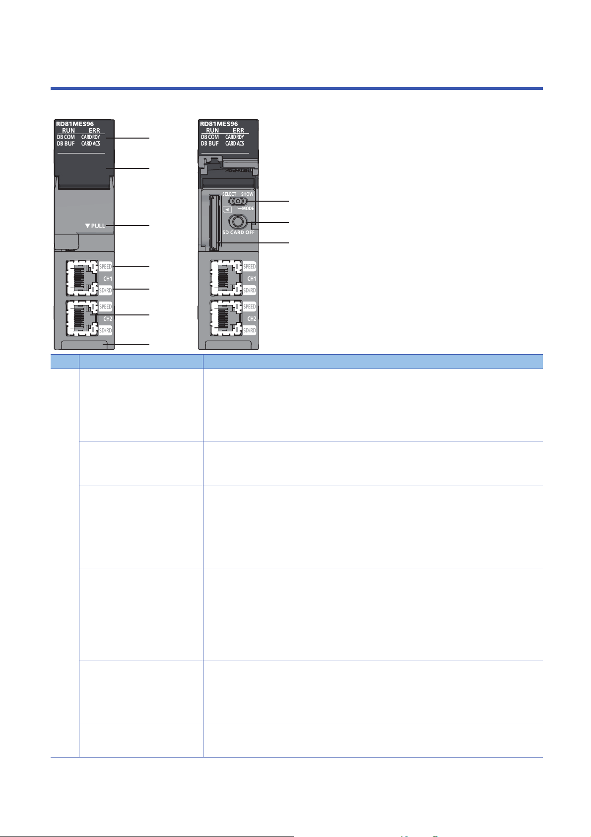
1 PART NAMES
(3)
(2)
(4)
(5)
(10)
(6)
(1)
(7)
(8)
(9)
This chapter shows the part names of an MES interface module.
No. Name Description
(1) RUN LED Indicates the operating status.
• ON: In operation
• Flashing: Checking module, selecting the module for online module change
(Flashes for 10 seconds when checking modules by clicking the [Module Confirmation] button on the "MES
Interface Module Search" screen of MES Interface Function Configuration Tool.)
• OFF: Watchdog timer error (hardware failure), module replacement allowed in the process of the online
module change
ERR LED Indicates the error status of MES interface module.
• ON: Module continuation error or watchdog timer error (hardware failure)
• Flashing: Module stop error
• OFF: In normal status
DB COM LED Indicates the connection status with a database.
• ON: Database normal connection status
(Communication is normally being established with all databases excluding unconnected databases.)
• Flashing: Database communication error status
(A communication error is detected in communication with some or all databases.)
• OFF: Database unconnected status
(Communication has never been established with any database after powering ON, resetting a CPU
module, or updating the setting.)
DB BUF LED Indicates the execution status of DB buffering.
• ON: Executing DB buffering
(Turns ON when the DB buffering setting is enabled and while buffering, or when either DB buffering
setting 1 or 2 is buffering.)
CARD RDY LED Indicates the availability of SD memory card.
CARD ACS LED Indicates the access status of SD memory card.
• Flashing: DB buffer full
(Flashes when the DB buffering setting is enabled and the buffer is full (no capacity), or when either DB
buffering setting 1 or 2 is buffer full.)
• OFF: DB buffering unexecuted
(The DB buffering setting is disabled, or the DB buffering setting is enabled and the buffer is empty.)
• ON: Accessible to an SD memory card
• Flashing: Preparing or formatting an SD memory card
• OFF: Not accessible to an SD memory card (Removable status)
For the considerations when handling SD memory cards, refer to the following section.
Page 59 Considerations for using SD memory cards
• ON: Accessing an SD memory card
• OFF: Not access an SD memory card
16
1 PART NAMES

No. Name Description
(2) Dot matrix LED Displays the contents of each display mode or the results of the self-diagnostic test.
The following contents are displayed in each display mode.
• User specification character: Scrolled and displayed by the width of approximately 3 characters (3.3
characters).
• Error code: Displayed in four digits in hexadecimal (When multiple errors occur, only the latest error code is
displayed.)
• IP address: Scrolled and displayed by 4 characters in decimal.
• DB buffer use rate: Displayed in three digits in decimal + %.
For the display when performing the self-diagnostic test, refer to the following manual.
MELSEC iQ-R MES Interface Module User's Manual (Application)
(3) Slot cover A cover of the SD memory card slot and the switches.
Open this cover to insert/remove an SD memory card or to operate the switches.
Close the cover unless inserting/removing an SD memory card or operating the switches to prevent foreign
material intrusion such as dust.
(4) SPEED LED(CH1, CH2) Indicates the communication speed and the link status for Ethernet.
• ON (orange): Linking-up (1000 Mbps)
• ON (green): Linking-up (100 Mbps)
• OFF: Linking-down or linking-up (10 Mbps)
(5) SD/RD LED(CH1, CH2) Indicates the data sending/receiving status for Ethernet.
• ON: Sending/receiving data
• OFF: Not send/receive data
(6) Ethernet port (CH1, CH2)
(7) Dot matrix LED display mode switch
(SELECT/MODE/SHOW switch)
(8) SD memory card lock switch
(SD CARD OFF button)
(9) SD memory card slot A slot to insert an SD memory card
(10) Product information marking Displays the product information (16 digits) of the module.
*1
A port for connecting to an Ethernet device
(IEEE802.3, 1000BASE-T/100BASE-TX/10BASE-T standards-compliant)
A switch for switching the display of dot matrix LED.
• MODE: Displays the display mode name that is currently selected.
• SELECT: Selects (switches) the display mode
Order: USR → ENo. → IP1 → IP2 → BUF1 → BUF2 → USR
• SHOW: Displays the contents of the selected display mode (Page 17 Dot matrix LED display)
Keep this display mode switch in the SHOW state during operation, and operate the switch only when
switching the display mode.
A switch for disabling access to an SD memory card to remove it.
Removing an SD memory card is prohibited while the CARD RDY LED is ON or flashing.
For the procedure to insert/remove SD memory cards, refer to the following section.
Page 58 Inserting and removing method of SD memory cards
(SD, SDHC standards-compliant: 2 GB (SD) to 16 GB (SDHC))
*1 Only CH1 can be connected to MES Interface Function Configuration Tool with direct connection.
1
Dot matrix LED display
The following table shows the contents of the display mode displayed on the dot matrix LED when switching the display mode
to "SHOW".
Display mode name Description
USR Displays the characters specified in the action.
ENo. Displays the error code.
IP1 Displays the IP address of the Ethernet port CH1.
IP2 Displays the IP address of the Ethernet port CH2.
BUF1 Displays the use rate of the DB buffer 1.
BUF2 Displays the use rate of the DB buffer 2.
The following display switching of dot matrix LED can be set by using MES Interface Function Configuration
To ol .
• Default display mode at power ON (Initial value: USR)
• The display mode is switched to ENo. (error code) forcibly when an error occurs.
• ENo. (error code) is highlighted.
Substitute characters to display on the S_MATRIXLED_DISP (dot matrix LED display) of the system variable in the
action. For details on the action, refer to the following manual.
MELSEC iQ-R MES Interface Module User's Manual (Application)
1 PART NAMES
17

2 SPECIFICATIONS
This chapter explains the performance specifications and accessible devices/device range of an MES interface module.
2.1 Performance Specifications
This section shows the performance specifications of a hardware (MES interface module) and software (MX MESInterface-R).
Hardware specifications
The following table shows the specifications of an MES interface module.
Item Specification
SD memory card slot Interface SD memory card/SDHC memory card (2 GB to 16 GB)
Power supply +3.3 VDC, up to 200 mA
Ethernet port Number of channels 2
*1
Interface
Data transmission rate 1000 Mbps 100 Mbps 10 Mbps
Number of cascaded
*2
stages
Communication mode Full-duplex/half-duplex
Transmission method Base band
Maximum segment
*3
length
Applicable connector for
external wiring
Supported function • Auto-negotiation (automatic recognition of 1000BASE-T/100BASE-TX/10BASE-T)
Number of occupied I/O points 32 points/slot (I/O assignment: Intelli. 32 points)
Clock Acquired from a CPU module (in multiple CPU system, CPU No.1).
5 VDC internal current consumption 1.25 A
External dimensions Height 106 mm
Width 27.8 mm
Depth 110 mm
Weight 0.25 kg
1000BASE-T 100BASE-TX 10BASE-T
Maximum 2 stages Maximum 4 stages
100 m (length between a hub and a node)
RJ45
• Auto-MDI/MDI-X (automatic recognition of a straight/crossing cable)
Page 19 Basic operation specification
*1 1000BASE-T/100BASE-TX/10BASE-T, and full-duplex/half-duplex communication mode are identified by an MES interface module
depending on the hub.
For connection with a hub not having the auto-negotiation function, set the setting on the hub side according to the communication
mode.
*2 It is for a repeater hub.
For a switching hub, consult the manufacturer of the hub used.
*3 For the maximum segment length (length between hubs), consult the manufacturer of the switching hub used.
18
2 SPECIFICATIONS
2.1 Performance Specifications

Software specifications
The following table shows the specifications of MX MESInterface-R.
Item Description Reference
Basic operation specification Specification for the operation (job), startup condition for the job (trigger condition),
operation unit of a job (action), and network information.
Device memory input/output
specification
DB input/output specification Specification for the accessible database, access units (access table/procedure,
Variable input/output
specification
Data operation and processing
specification
External communication client Specification for the communication from an MES interface module to external
Security Specification for security. Page 22 Security
Specification for the accessible target device type and the access units. Page 20 Device memory input/output
access field/procedure argument), and buffering of output data (DB buffering) at
disconnecting.
Specification for user variables (local variables, global variables) which can be
defined freely, system variables to refer to system information, and data types of
variable.
Specification for the operation processing such as addition and subtraction. Page 22 Data operation and
devices.
Basic operation specification
Item Specification
Job (Number of settings) Maximum 64 jobs
Action (Number of settings) Maximum 1920 actions
For one job 30 actions
Trigger condition For one job 2 events/condition
Event/condition type • Condition (Value monitoring)
Condition combination type • OR combination
Trigger buffering count 192 (The value is cleared due to power interruption/reset/setting update.)
Time information handling
(Time information)
Ethernet Connection method IPv4
MES Interface Function
Configuration Tool
*1
Time Acquired from a CPU module (in multiple CPU system, CPU No.1).
Daylight saving time
Time zone
Number of channels 2 channels (CH1/CH2) (Unconnectable to a same network, and no routing function between
Number of default gateways 1 (Only CH1 or CH2 can be registered.)
Simultaneously connectable
number
*1 When using the daylight saving time function of a CPU module, use an MES interface module with the firmware version '03' or later. If an
MES interface module with the firmware version '02' or earlier is used, it may cause the malfunction of the module due to the time
information difference with the CPU module.
For information on the firmware version of a CPU module, refer to the manual of a CPU module used.
• Main processing: 20 actions
• Pre/post-processing: 10 actions
• Condition (Period of time)
• Event (Value changed)
• Event (Fixed time)
• Event (Fixed cycle) (timer interval/time interval)
• Event (Module monitoring) (MES interface module/Control CPU)
• Handshake
• AND combination
CH1 and CH2)
5 (Maximum number of connections to a single MES interface module)
Page 19 Basic operation
specification
Page 21 DB input/output
Page 22 Variable input/output
processing
Page 22 External communication
client
2
2 SPECIFICATIONS
2.1 Performance Specifications
19

Device memory input/output
Item Specification
Access target device Maximum 16 devices
Type of target device • RCPU
Device tag Maximum 64 device tags
Access type • General access
Shortest access interval Each scan
Access interval (general access) • 1 to 9 × 100 ms
Access interval (high-speed access
(interval specification))
Access interval (high-speed access (each
scan))
Device tag component Maximum 65536 components/project (64 tags × 1024 components)
Maximum (for one device tag) 1024 components
Maximum (for one job) 20480 components
Number of data points
(Device tag component)
Number of data points
*4
(Job)
Access data Data type • Bit
Maximum number (per project) 131072 (total number without array tag setting)
Maximum number (for one device tag
component)
Maximum number (per project)
Maximum number (for one job) 46080
*3
*1
*1 For high-speed access, up to 8192 components (points) can be set.
*2 When the trigger buffering is enabled, the maximum is 8192 components (points).
*3 The double word device is counted as 2 points.
*4 When using a same device tag component in multiple jobs, the number is counted for each job.
When using a same device tag component in a same job, the number is not counted for each job.
• QCPU (Q mode)
•LCPU
• High-speed access (interval specification)
• High-speed access (each scan)
• 1 to 3600 sec.
• 1 to 9 ms
• 1 to 9 × 10 ms
• 1 to 9 × 100 ms
• 1 to 60 sec.
• Each scan
*2
2621440 (total number with array tag setting)
40960 (at Multiple Select)
131072 (total number excluding the data assignment settings of the Multiple Select
setting)
2949120 (total number only for the data assignment settings of the Multiple Select)
*2
The total size of character string type: 2048 characters/job (total of the device tag,
variable, constant, and macro)
• Word [Unsigned]/Bit String [16-bit]
• Double Word [Unsigned]/Bit String [32-bit]
• Word [Signed]
• Double Word [Signed]
• 16bit BCD
• 32bit BCD
• FLOAT[Single Precision]
• FLOAT[Double Precision]
• Character string [Unicode]
• Character string [ASCII/SJIS]
*1
20
2 SPECIFICATIONS
2.1 Performance Specifications

DB input/output
Item Specification
Access target server Database type • Oracle
Maximum number of settings 16 servers
Access table/procedure DB communication type • Select
Maximum number of settings (for one
project)
Maximum number of settings (for one
job)
Maximum number of settings (for one
action)
Maximum number of settings (per
access table)
Access field/procedure
argument
DB buffer Number of settings 2 settings
Maximum number of settings (per
*1
project)
Maximum number of settings (for one
*1
job)
Maximum number of settings for access
field (for one table)
Maximum number of settings for access
procedure argument (for one
procedure)
Data type • Integer
Maximum capacity 2048 MB (up to 1024 MB for each buffer)
*2
*2
*1 Maximum number of settings in the job settings.
*2 Maximum number of settings in the access table/procedure settings.
*3 A data type when a character string is set to an access procedure argument.
*4 Data types when a character string is set to an access field.
• Microsoft SQL Server
• Microsoft Access
•MySQL
•PostgreSQL
• Insert
• Update (Data can be inserted if no update target data exist.)
• Delete
• Multiple Select
• Stored Procedure
64 tables/procedures
20 tables/procedures
1 table/procedure
Total length of DB field name: 16384 characters
65536 settings
• When the trigger buffering is disabled: 20480 settings
• When the trigger buffering is enabled: 8192 settings
However, the following limits are applied.
• Date and time type access field/procedure argument: Up to 50 settings
• The total number of characters of character string type: Up to 2048 characters
(The total number of characters of character string type for the device tag, variable,
and constant)
1024 fields
256 settings
• Real number
• Character string [Unicode]
• Character string [Unicode(NCHAR)]
• Character string [Unicode(CHAR)]
• Date and time
2
*3
*4
*4
2 SPECIFICATIONS
2.1 Performance Specifications
21

Variable input/output
Item Specification
Variable type Type • Local variable (retains data only at a job execution and can be used in a same job.)
Data type Type • Bit
Capacity Maximum number of settings (per
project)
Maximum number of settings (for
*2
one job)
• Global variable (retains data until the power supply is turned OFF or the CPU is reset,
and can be used between different jobs.)
• System variable
• Word [Unsigned]/Bit String [16-bit]
• Double Word [Unsigned]/Bit String [32-bit]
• Word [Signed]
• Double Word [Signed]
• FLOAT[Single Precision]
• FLOAT[Double Precision]
• Character string [Unicode]
• Local variable: 1024 words (2048 bytes)
• Global variable: 4096 words (8192 bytes)
• System variable: A defined variable is used.
• Local variable: 1024 words (2048 bytes)
• Global variable: 512 words (1024 bytes)
*1
*1
*1 The number of settings depends on the data size. However, 2 bytes are used even when the data type is bit.
*2 The total number of characters of character string type for one job is up to 2048 characters.
Data operation and processing
Item Specification
Operator Substitution
Arithmetic operation 5 types
Maximum number of
operation settings
Character string
operation
Bit operation 5 types
Type conversion 4 types
Maximum 38400 settings (600 settings × 64 jobs)
For one job 600 settings (20 settings × 30 actions)
For one action 20 settings
8 types
External communication client
Item Specification
External communication client (program
execution)
Number of characters for
execution command
Function • Return value evaluation
Up to 127 characters
• Execution completion standby
Security
Item Specification
Security (user authentication) Number of accounts 16 accounts
22
2 SPECIFICATIONS
2.1 Performance Specifications

2.2 Accessible Devices and Range
This section shows the accessible devices and range.
Accessible CPU modules
Series Model name Access type
*1
RCPU
QCPU (Q mode)
*3
LCPU
*3
*1 When using high-speed access, use a CPU module supporting the sequence scan synchronization sampling function and an MES
interface module with the firmware version '03' or later.
For a CPU module supporting the sequence scan synchronization sampling function, refer to the manual for the CPU module.
*2 Use an MES interface module with the firmware version '07' or later.
*3 Use an MES interface module with the firmware version '03' or later.
*4 Use an MES interface module with the firmware version '05' or later.
*5 It cannot be used as a relay station.
*6 Only a module with a serial number of which the first five digits are 12042 or higher can be accessed.
Programmable controller
CPU
Process CPU
Safety CPU
C Controller module
Programmable controller
CPU
Process CPU Q02PHCPU, Q06PHCPU, Q12PHCPU, and Q25PHCPU
C Controller module
Programmable controller
CPU
*3
*4
R00CPU*2, R01CPU*2, R02CPU*2, R04CPU, R04ENCPU*3, R08CPU,
R08ENCPU
R120CPU, and R120ENCPU
R08PCPU, R16PCPU, R32PCPU, and R120PCPU • General access
R08SFCPU, R16SFCPU, R32SFCPU, and R120SFCPU
*3,*5
R12CCPU-V
Q00JCPU, Q00UJCPU, Q00CPU, Q00UCPU, Q01CPU, Q01UCPU,
Q02CPU, Q02HCPU, Q02UCPU, Q03UDCPU, Q03UDECPU,
Q03UDVCPU, Q04UDHCPU, Q04UDEHCPU, Q04UDVCPU,
Q06HCPU, Q06UDHCPU, Q06UDEHCPU, Q06UDVCPU,
Q10UDHCPU, Q10UDEHCPU, Q12HCPU, Q13UDHCPU,
Q13UDEHCPU, Q13UDVCPU, Q20UDHCPU, Q20UDEHCPU,
Q25HCPU, Q26UDHCPU, Q26UDEHCPU, Q26UDVCPU,
Q50UDEHCPU, and Q100UDEHCPU
*5
Q12DCCPU-V*6, Q24DHCCPU-V, Q24DHCCPU-LS, Q24DHCCPUVG, and Q26DHCCPU-LS
L02SCPU, L02SCPU-P, L02CPU, L02CPU-P, L06CPU, L06CPU-P,
L26CPU, L26CPU-P, L26CPU-BT, and L26CPU-PBT
*3
, R16CPU, R16ENCPU*3, R32CPU, R32ENCPU*3,
*3
*4
• General access
• High-speed access
(interval specification)
• High-speed access
(each scan)
2
When using a multiple CPU system, refer to the following manual.
MELSEC iQ-R Module Configuration Manual
2 SPECIFICATIONS
2.2 Accessible Devices and Range
23
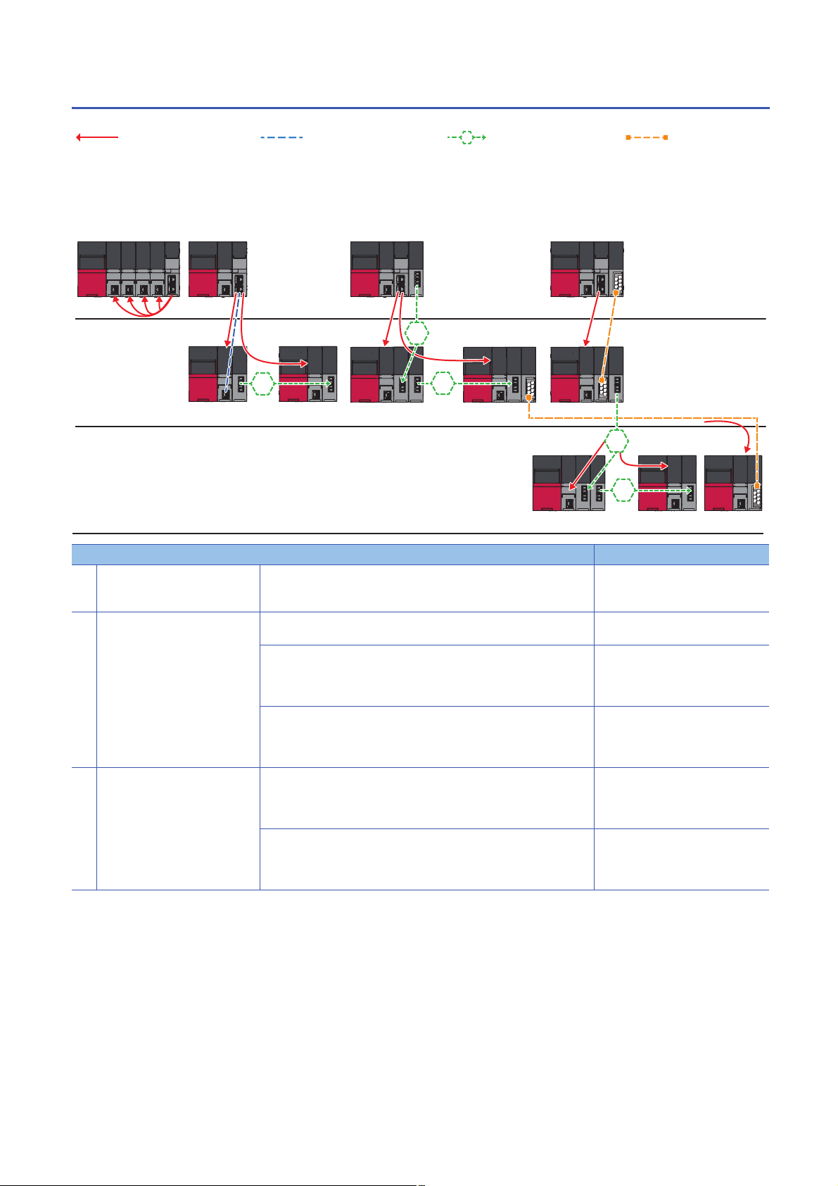
Accessible routes
1···8
ÒÓ Ô Õ
Ö×
(1)
(2)
(3)
1
2···8
1
2···8
The following figure shows accessible routes from an MES interface module.
: Access route from an MES
interface module
: Connection from an Ethernet
port of an MES interface module
: Connection by specifying
the network number and the station
number of a target station
: Connection by
specifying the start I/O No. of a
module to be routed and the
station number of a target
station
Accessible route Reference
(1) Own station (control CPU, another
CPU in a multiple CPU system)
(2) Another station via a single
network
(3) Another station via a co-existence
network
Indicates the own station (control CPU, another CPU in a multiple CPU
system)
Access via an Ethernet port of an MES interface module Page 26 Access via an Ethernet port
Access by specifying the network number and the station number of a
target station
(CC-Link IE Controller Network module, CC-Link IE Field Network module,
MELSECNET/H network module, or Ethernet interface module)
Access by specifying the start I/O No. of a module to be routed and the
station number of a target station
(CC-Link module)
Access from the station accessed in by specifying the network
number and the station number of a target station
Access from the station accessed in by specifying the start I/O No.
of a module that is routed through and the station number of a target
station
Page 25 Own station (control CPU,
another CPU in a multiple CPU
system)
of an MES interface module
Page 27 Access by specifying the
network number and the station
number of a target station
Page 27 Access by specifying the
start I/O number of a module to be
routed and the station number of a
target station
Page 28 Access by specifying the
network number and the station
number via another station on CCLink
Page 28 Accessing from another
station specified by the network
number and the station number via
CC-Link
24
2 SPECIFICATIONS
2.2 Accessible Devices and Range

Own station (control CPU, another CPU in a multiple CPU system)
The following table shows the accessibility to a CPU module of a station on which an MES interface module is mounted.
: Accessible, : No combination
Access route Type of target device (series)
RCPU QCPU (Q mode) LCPU
Programm
able
controller
CPU/
Process
CPU/
Safety
CPU
Control CPU
Other CPUs in multiple CPU system
*1 No combination with RnENCPUs.
*1
(CPU No.1 to
4)
C
Controller
module
(CPU No.1 to
4)
Programm
able
controller
CPU/
Process
CPU
C
Controller
module
Programm
able
controller
CPU
2
2 SPECIFICATIONS
2.2 Accessible Devices and Range
25

Another station via a single network
■Access via an Ethernet port of an MES interface module
A target device can be accessed via an Ethernet port of an MES interface module in the status where the target device is
connected to a network.
For the communication destination from an Ethernet port of an MES interface module, an Ethernet interface module or a CPU
module (Ethernet port) can be specified.
For accessing a target station, direct access and access via another system
*1 It is not available when the series of a target device and a system to be routed differ.
(Example) Access is available when the series of a target device and a system to be routed are 'QCPU'.
: Accessible, : No combination
Access route Type of target device (series)
RCPU QCPU (Q mode) LCPU
Programm
able
controller
CPU/
Process
CPU/
Safety
CPU
Ethernet Ethernet port of an MES
interface module →
Ethernet interface
module
Ethernet port of an MES
interface module →
CPU module (Ethernet
port)
Direct
Via another
system
Direct
Via another
system
CC-Link IE
Controller
Network
CC-Link IE Field
Network
MELSECNET/H
network
*4
Ethernet
CC-Link IE
Controller
Network
CC-Link IE Field
Network
MELSECNET/H
network
*4
Ethernet
*2,*3
(CPU No.1 to
4)
*1
are available.
C
Controller
module
Programm
able
controller
CPU/
C
Controller
module
Programm
able
controller
CPU
Process
CPU
(CPU No.1 to
4)
(CPU No.1 to
4)
(CPU No.1 to
4)
(CPU No.1 to
4)
*5
(CPU No.1 to
4)
*2 It can access to an RnENCPU only in a single CPU system.
*3 No combination with the MELSECNET/H network for process CPUs and safety CPUs.
*4 It is also supported by a QCPU (Q mode) for which the MELSOFT connection extended setting was set.
*5 To access an Ethernet port of Q12DCCPU-V (Basic mode) directly, MELSOFT connection is required to be permitted in the
Q12DCCPU-V (Basic mode) setting.
For details on the setting, refer to the following manual.
C Controller Module User's Manual (Utility Operation, Programming)
2 SPECIFICATIONS
26
2.2 Accessible Devices and Range

■Access by specifying the network number and the station number of a target station
A target device can be accessed via a relay station when the target device is connected within eight networks from a station,
on which an MES interface module is mounted, and can be identified by the network number and the station number (or CPU
number).
: Accessible, : No combination
Access route Type of target device (series)
RCPU QCPU (Q mode) LCPU
Programm
able
controller
CPU/
Process
CPU/
C
Controller
module
Programm
able
controller
CPU/
Process
CPU
C
Controller
module
Programm
able
controller
CPU
Safety
CPU
CC-Link IE Controller Network
CC-Link IE Field Network
MELSECNET/H network
*3
Ethernet
*1,*2
(CPU No.1 to
4)
(CPU No.1 to
4)
(CPU No.1 to
4)
(CPU No.1 to
4)
*1 It can access to an RnENCPU only in a single CPU system.
*2 No combination with the MELSECNET/H network for process CPUs and safety CPUs.
*3 It is also supported by a QCPU (Q mode) for which the MELSOFT connection extended setting was set.
2
■Access by specifying the start I/O number of a module to be routed and the station number of
a target station
The following table shows the accessible routes to connect with a target device and a station on which an MES interface
module is mounted directly.
: Accessible, : No combination
Access route Type of target device (series)
RCPU QCPU (Q mode) LCPU
CC-Link
*1 It can access to an RnENCPU only in a single CPU system.
Programm
able
controller
CPU/
Process
CPU/
Safety
CPU
*1
(CPU No.1 to
4)
C
Controller
module
(CPU No.1 to
4)
Programm
able
controller
CPU/
Process
CPU
(CPU No.1 to
4)
C
Controller
module
(CPU No.1 to
4)
Programm
able
controller
CPU
2 SPECIFICATIONS
2.2 Accessible Devices and Range
27

Another station via a co-existence network
■Access by specifying the network number and the station number via another station on CCLink
The following table shows the accessible route to a target station from a station, on which an MES interface module is
mounted by specifying the network number and the station number of the target station. In this route, another station on CC-
Link is accessed first (first route), then a target station is accessed from there.
: Accessible, : No combination
First access route Second access route (co-existence
network)
CC-Link CC-Link IE Controller Network
CC-Link IE Field Network
MELSECNET/H network
*3
Ethernet
*1 It can access to an RnENCPU only in a single CPU system.
*2 No combination with the MELSECNET/H network for process CPUs and safety CPUs.
*3 It is also supported by a QCPU (Q mode) for which the MELSOFT connection extended setting was set.
Type of target device (series)
RCPU QCPU (Q mode) LCPU
Programm
able
controller
CPU/
Process
CPU/
C
Controller
module
Programm
able
controller
CPU/
Process
CPU
C
Controller
module
Programm
able
controller
CPU
Safety
CPU
*1,*2
(CPU No.1 to
4)
(CPU No.1 to
4)
(CPU No.1 to
4)
(CPU No.1 to
4)
■Accessing from another station specified by the network number and the station number via
CC-Link
The following table shows the accessible route to a target station from a station, on which an MES interface module is
mounted, by specifying the start I/O No. of a module that is routed through and the station number of the target station. In this
route, another station on CC-Link is accessed first by specifying the network number and the station number (first route), then
the target device is accessed from there.
: Accessible, : No combination
First access route Second access route
(co-existence network)
CC-Link IE Controller Network CC-Link
CC-Link IE Field Network
MELSECNET/H network
*3
Ethernet
*1 It can access to an RnENCPU only in a single CPU system.
*2 No combination with the MELSECNET/H network for process CPUs and safety CPUs.
*3 It is also supported by a QCPU (Q mode) for which the MELSOFT connection extended setting was set.
Type of target device (series)
RCPU QCPU (Q mode) LCPU
Programm
able
controller
CPU/
Process
CPU/
C
Controller
module
Programm
able
controller
CPU/
Process
CPU
C
Controller
module
Programm
able
controller
CPU
Safety
CPU
*1,*2
(CPU No.1 to
4)
(CPU No.1 to
4)
(CPU No.1 to
4)
(CPU No.1 to
4)
28
2 SPECIFICATIONS
2.2 Accessible Devices and Range

Accessible devices
The following table shows the accessible devices.
: Accessible, : Not accessible, : No device
Device name (device) Type of target device (series)
RCPU QCPU (Q mode) LCPU
Programmable controller
CPU/Process CPU
*1,*2
CPU
General
access
Function input (FX)
Function output (FY)
Function register (FD)
Special relay (SM)
Special register (SD)
Input relay (X)
Output relay (Y)
Internal relay (M)
Latch relay (L)
Annunciator (F)
Edge relay (V)
Link relay (B)
Data register (D)
Link register (W)
Timer Contact (TS)
Coil (TC)
Current value (T/TN)
Long timer Contact (LTS)
Coil (LTC)
Current value (LT/LTN)
Counter Contact (CS)
Coil (CC)
Current value (C/CN)
Long counter Contact (LCS)
Coil (LCC)
Current value (LC/LCN)
*4
Retentive timer Contact (STS, SS
Coil (STC, SC
Current value (ST/STN,
*4
)
ST/SN
Long retentive
timer
Link special relay (SB)
Link special register (SW)
Step relay (S)
Direct input (DX)
Direct output (DY)
Index register (Z)
Long index register (LZ)
Contact (LSTS)
Coil (LSTC)
Current value (LST/LSTN)
)
*4
)
*1
/Safety
High-speed
access
C Controller
module
Programma
ble
controller
CPU/
Process
CPU
C Controller
module
*3
*3
Programma
ble
controller
CPU
2
2 SPECIFICATIONS
2.2 Accessible Devices and Range
29

Device name (device) Type of target device (series)
RCPU QCPU (Q mode) LCPU
Programmable controller
CPU/Process CPU
*1,*2
CPU
General
access
File register (R)
(ZR)
(ERn\R)
Link direct device Link input (Jn\X)
Link output (Jn\Y)
Link relay (Jn\B)
Link special relay (Jn\SB)
Link register (Jn\W)
Link special register
(Jn\SW)
Module access
device
CPU buffer
memory access
device
Refresh data register (RD)
Module access device/
Intelligent function module
device (Un\G)
Multiple CPU shared
device (U3En\G)
CPU buffer memory
access device (U3En\G)
CPU buffer memory
access device (fixed cycle
communication area)
(U3En\HG)
*5
*1
/Safety
High-speed
access
C Controller
module
Programma
ble
controller
CPU/
Process
CPU
C Controller
module
Programma
ble
controller
CPU
*1 Process CPUs and safety CPUs do not support high-speed access.
*2 Safety devices cannot be accessed.
*3 Q12DCCPU-V (Basic mode) has no device.
*4 A device name for QCPUs (Q mode) and LCPUs
*5 RnENCPUs and safety CPUs have no device.
30
2 SPECIFICATIONS
2.2 Accessible Devices and Range

Access units
The following table shows the number of accessible device points (access units) in one process (one scanning) when
accessing the device memory in a CPU module.
The access units of a CPU module other than the following modules depend on the module type. When data inconsistency is
a problem, set the event/condition type to "Handshake".
Type of target device (series) Device reading Device writing
General access High-speed access
RCPU Programmable
controller CPU
Process CPU Not supported
C Controller module
*1 Access from a module other than an Ethernet port of an MES interface module
*2 Access via an Ethernet port of an MES interface module
118 p oin t s
58 points
*1
*2
8192 points 78 points
Reading/writing in access units
When the number of accessed device points is equal to the access unit or less, device values in a same sequence scan are
obtained and applied.
When the number of device points exceeds the access unit, device values may be obtained from multiple sequence scans
and applied, which may cause data inconsistency.
■When data inconsistency is a problem
Set the following when a sequence program and the data needs to be synchronized and data inconsistency is a problem.
• Set the number of device points accessed at the same time to the access unit or less.
• Change the access type to high-speed access. (Only for device reading)
• Set the event/condition type to "Handshake".
38 points
*1
*2
2
2 SPECIFICATIONS
2.2 Accessible Devices and Range
31

2.3 Accessible Database
An MES interface module can access a database of a server.
Software corresponding to accessible database
The following table shows the database type and supported software that can be accessed by an MES interface module.
Database type Accessible database type
Database server Oracle
Microsoft SQL Server
Microsoft Access
MySQL
PostgreSQL PostgreSQL
*1
Supported software
Oracle 11g Express Edition Only 64-bit version is
Oracle 12c Standard Edition
SQL Server 2008 R2
SQL Server 2012 Express Edition
SQL Server 2014 Express Edition
SQL Server 2016 Express Edition
SQL Server 2017 Express Edition
Access 2010 Only 32-bit version is
Access 2013
Access 2016
*3
MySQL
*3
*1
*2
Supported edition
Standard Edition
Enterprise Edition
Enterprise Edition
Express Edition
Standard Edition
Enterprise Edition
Standard Edition
Enterprise Edition
Standard Edition
Enterprise Edition
Standard Edition
Enterprise Edition
Standard Edition
Enterprise Edition
Community Edition
Standard Edition
*4
supported.
supported.
Only 64-bit version is
supported.
*1 Use a same language version for the operating system and software.
*2 IA-64 cannot be used.
*3 An open source database. The operation has been checked in the following versions.
MySQL: 5.7.10, 5.7.15, 5.7.17
PostgreSQL: 9.4.5, 9.5.4
*4 To use Community Edition, use the ODBC driver of MariaDB.
2 SPECIFICATIONS
32
2.3 Accessible Database

Access route
DB
(1)
Ethernet
(3)
(2)
An MES interface module accesses a database server with DB Connection Service.
(1) Database server
(2) DB Connection Service
(3) MES interface module
2
2 SPECIFICATIONS
2.3 Accessible Database
33

2.4 Usable Data for MES Interface Module
Database
Function
Data
(Entity)
DB procedure argumentDB field
Data
(No entity)
DB connection service
SQL statements SQL execution result
DB input/output function
Access field Access procedure argument
Information linkage function
MES Interface
Function Configuration
Tool
Variable
Constant
Variable input/output function
Device tag component
Macro
Device memory input/output function
MES interface module
Target device
This section shows the specifications of data category and data type handled by an MES interface module.
Data category
The following shows the data category handled by an MES interface module.
Data category Description Reference
Device tag component Data associated with data in an access target device such as a CPU module etc. Page 37 Device tag
Variable Data used for storing the operation result in an MES interface module.
Constant A value set with MES Interface Function Configuration Tool. Page 39 Constant
Macro A special value set with MES Interface Function Configuration Tool.
Access field Data associated with the DB field.
Access procedure argument Data associated with the DB procedure argument.
DB field A data component stored in the table of database.
DB procedure argument An argument of the stored procedure defined to the database.
• Local variable: Used for sending and receiving data between operations in a same
action, and actions in a same job.
• Global variable: Used for sending and receiving data between jobs.
• System variable: Used for retaining system information and controlling hardware.
Since any value is not determined at the setting, MES Interface Function Configuration
Tool specifies a macro name not a value.
A concept used for checking the setting, and it has no entity.
A concept used for checking the setting, and it has no entity.
Associated with the access field.
Associated with the access procedure argument.
component/variable
Page 40 Macro
34
2 SPECIFICATIONS
2.4 Usable Data for MES Interface Module

Data type
The following table lists the data type that can be specified in an MES interface module according to the data category and the
data type classification.
• Numerical value
Data category Numerical value
Integer Real number
Device tag component • Bit
• Word [Unsigned]/Bit String [16-bit]
• Double Word [Unsigned]/Bit String [32-bit]
• Word [Signed]
• Double Word [Signed]
• 16bit BCD
• 32bit BCD
Variable • Bit
• Word [Unsigned]/Bit String [16-bit]
• Double Word [Unsigned]/Bit String [32-bit]
• Word [Signed]
• Double Word [Signed]
Constant Integer Real number
Macro Any of the data type of the device tag component/variable is determined for each macro.
Access field Integer Real number
Access procedure argument Integer Real number
DB field
DB procedure argument
*1
Oracle
Microsoft SQL
Server
Microsoft Access • Yes/No type
MySQL • TINYINT [UNSIGNED]
PostgreSQL • smallint
•NUMBER(p)
• NUMBER(p, 0)
•bit
•tinyint
• smallint
•int
• bigint
• Number: Byte
• Number: Integer
• Number: Long Integer
• SMALLINT [UNSIGNED]
• MEDIUMINT [UNSIGNED]
• INT [UNSIGNED]
• BIGINT [UNSIGNED]
• integer
• bigint
• decimal
• numeric
• decimal(p)
• numeric(p)
• decimal(p, 0)
• numeric(p, 0)
• Number: Decimal • Number: Decimal
• DECIMAL[(M[,0])]
[UNSIGNED]
• numeric(p[,0]) • numeric[(p,s)]
• FLOAT[Single Precision]
• FLOAT[Double Precision]
• FLOAT[Single Precision]
• FLOAT[Double Precision]
• NUMBER(p, s)
• NUMBER
• BINARY_FLOAT
• BINARY_DOUBLE
•real
• float
• Number: Single
• Number: Double
• DECIMAL(M,D) [UNSIGNED]
• FLOAT [UNSIGNED]
• DOUBLE [UNSIGNED]
•real
• double precision
2
• Character string, date and time
Data category Character string Date and time
Device tag component • Character string [Unicode]
• Character string [ASCII/SJIS]
Variable • Character string [Unicode]
Constant • Character string [Unicode]
Macro Any of the data type of the device tag component/variable is determined for each macro.
Access field • Character string
[Unicode(NCHAR)]
Access procedure argument • Character string [Unicode] Date and time [without
• Character string
[Unicode(CHAR)]
Date and time [without
time zone]
time zone]
Date and time [with time
zone]
2 SPECIFICATIONS
2.4 Usable Data for MES Interface Module
35

Data category Character string Date and time
DB field
DB procedure argument
*1
Oracle
Microsoft SQL
Server
Microsoft Access
MySQL • [NATIONAL]
PostgreSQL • character[(n)]
• NCHAR
• NVARCHAR2
• nchar
• nvarchar
*3
• Text type (short
CHAR[(M)]
• [NATIONAL]
VARCHAR(M)
• CHAR[(M)]
• VARCHAR(M)
*5
*5
• CHAR
• VARCHAR2
•char
• varchar
text
• CHAR[(M)]
• VARCHAR(M)
• character
varying[(n)]
*4
)
•DATE
• TIMESTAMP[(p)]
• smalldatetime
•datetime
• datetime2[(p)]
• Date/Time
*6
•DATETIME[(fsp)]
*6
• TIMESTAMP[(fsp)]
• timestamp[(p)] [without
time zone]
• TIMESTAMP[(p)] WITH
TIME ZONE
• datetimeoffset[(p)]
*2
*1 The data type (DATE) in Oracle can store the date from January 1st in 4712 B.C. to December 31st in 9999 A.D. in Julian calendar.
However, the date in B.C cannot be handled in an MES interface module.
*2 It cannot be specified in DB procedure argument.
*3 It cannot be used for DB procedure argument.
*4 Notation in Access 2013 and Access 2016.
*5 It can be specified when the character set setting in a field of a database is utf8.
*6 It can be specified when the character set setting in a field of a database is other than utf8.
*2
36
2 SPECIFICATIONS
2.4 Usable Data for MES Interface Module

Device tag component/variable
The following table lists the specification for the device tag component/variable according to the classification.
Data type
■Integer
Data type Varia ble
Bit 2 bytes
Word [Unsigned]/Bit String [16-bit] 2 bytes
Double Word [Unsigned]/Bit String [32-bit] 4 bytes
Word [Signed] 2 bytes
Double Word [Signed] 4 bytes
16bit BCD
32bit BCD
■Real number
Data type Varia ble
FLOAT[Single Precision] 4 bytes
FLOAT[Double Precision] 8 bytes
■Character string
Data type Character string length Character code Variab le
Character string [Unicode] 1 to 255 characters UTF-16LE
Character string [ASCII/SJIS] 1 to 255 characters Windows Codepage 932
*1,*2,*3
2 bytes/character
2
*1 The character other than BMP (U+10000 to U+10FFFF) cannot be used and it has no BOM.
*2 UTF-16LE has no BOM.
*3 Combining characters can not be used.
2 SPECIFICATIONS
2.4 Usable Data for MES Interface Module
37

System variable list
Variable name Data type Write Description Description of value
S_SERVER_STATUS01 to
S_SERVER_STATUS16
(Connection status of an access
target server)
S_DEVICE_STATUS01 to
S_DEVICE_STATUS16
(Connection status of an access
target device)
S_MATRIXLED_DISP
(Dot matrix LED display)
S_MATRIXLED_MODE
(Dot matrix LED display mode)
*1 When specifying characters other than usable characters, it is converted to period (U+002E) and displayed.
Word [Unsigned]/Bit
String [16-bit]
Word [Unsigned]/Bit
String [16-bit]
Character string
[Unicode] 32 characters
Word [Unsigned]/Bit
String [16-bit]
Not
writable
Not
writable
Writable Displays the user specification
Writable Displays the dot matrix LED display
Displays a connection status to each
access target server.
Displays a connection status to each
access target device.
character string of the dot matrix LED.
Substitute characters to display in the
action. For details on the action, refer
to the following manual.
MELSEC iQ-R MES Interface
Module User's Manual (Application)
mode.
• 0: Not connected
• 1: Connecting
• 2: Disconnecting
• 0: Not connected
• 1: Connecting
• 2: Disconnecting
Usable characters: U+0020 to
*1
U+007E
(The initial value is null character.)
• 0: USR (user specification
character) (initial value)
• 1: ENo. (Error code)
• 2: IP1 (CH1 IP address)
• 3: IP2 (CH2 IP address)
• 4: BUF1 (DB buffer 1 use rate)
• 5: BUF2 (DB buffer 2 use rate)
38
2 SPECIFICATIONS
2.4 Usable Data for MES Interface Module

Constant
The following table lists the specification for the data type of the constant according to the classification.
Data type
The data type of the constant is checked by MES Interface Function Configuration Tool not an MES interface module.
■Integer
Data type Usable characters Minimum value Maximum value Maximum
number of
characters
Integer -, 0, 1, 2, 3, 4, 5, 6, 7, 8, 9 -2147483648
(Minimum value of a signed 32-bit
integer)
■Real number
4294967295
(Maximum value of an unsigned 32-bit
integer)
11 characters
2
Data type Usable characters Minimum of the
absolute values
Real number -, E, .(decimal point), 0, 1, 2, 3, 4, 5,
6, 7, 8, 9
*1 '-123.456789012345e-222' and '0.00000123456789012345' etc. can be set. '1.23456789012345000000' etc. cannot be set.
2.22507385850721E-308 1.79769313486231E308 15 digits 22
Maximum of the
absolute values
Maximum number of
significant digits of
mantissa part
Maximum
number of
characters
characters
■Character string
Data type Usable characters Maximum length of character
string
Character string
[Unicode]
Printable characters including the blank (U + 0020)
(Escape sequences are handled without converting into control characters. (\n etc.))
255 characters
*1
2 SPECIFICATIONS
2.4 Usable Data for MES Interface Module
39

Macro
The data, of which a value is not determined at the job setting such as a date and time when the trigger condition is satisfied,
is set with a macro name and replaced to data in an MES interface module.
The following shows the specification of macro according to the classification.
Macro list
■Time at trigger monitoring
Data type Description
Date and time A date and time when the monitoring of a trigger condition starts.
■Time at trigger ON
Data type Description
Date and time A date and time when the trigger condition of a job is satisfied.
■Job execution start date and time
Data type Description
Date and time A date and time when the first action of a job starts.
■Server date and time
Data type Description
Date and time A server date and time at DB field insertion/update.
• Outputs the value as an identifier of the macro to DB Connection Service.
• MES interface module does not have a data type since the value is not used.
• When checking the setting of the data assignment function with MES Interface Function Configuration
Tool, it is handled as a date and time.
■Failure Action No.
Data type Description
Word [Unsigned]/Bit String [16-bit] An action number executed when a processing failed.
■Upper 8 bits (processing type)
• 1: Pre-processing
• 2: Main processing
• 3: Post-processing
■Lower 8 bits (action number)
• 1 to 20: Action number
■Date and time character string
Data type Description
Character string [Unicode]
Up to 64 characters
A character string converted the time, when the trigger condition is satisfied, based on the specified
format.
Specifies a format character string when using macro.
The following characters in the format character strings are replaced by numeric values.
Example) 'YYYY-MM-DD hh:mm:ss.fff OFFSET' → '2015-02-01 13:05:43.532 +09:00'.
■Characters to
be replaced
• YYYY
•YY
•MM
•DD
•hh
•mm
•ss
•fff
• OFFSET
■Values to be replaced (When a value has a small number of the digits, '0' is
added to the head.)
• Year (4 digits)
• Year (last 2 digits)
• Month (01 to 12)
• Day (01 to 31)
• Hour (00 to 23)
• Minute (00 to 59)
• Second (00 to 59)
• Decimal part of second: Millisecond (000 to 999)
• UTC offset [+|-]xx:xx
40
2 SPECIFICATIONS
2.4 Usable Data for MES Interface Module

3 FUNCTION LIST
DB
Ethernet
(2)
(3)
(b)
(a)
(1)
This chapter shows the function list of a MES interface module, MES Interface Function Configuration Tool, Project File
Conversion Tool, DB Connection Service, and DB Connection Service Setting Tool.
For details on each function, refer to the following manual.
MELSEC iQ-R MES Interface Module User's Manual (Application)
3.1 Function Overview
A MES interface module links information between production equipment and host information systems by using each
function of MES Interface Function Configuration Tool, Project File Conversion Tool, DB Connection Service, and DB
Connection Service Setting Tool.
Name Description Reference
(1) MES interface module A module to link information between production equipment and
host information systems.
(2) Configuration
personal computer
(3) Server (b) DB Connection
(a) MES Interface
Function
Configuration Tool
Project File
Conversion Tool
Service
DB Connection
Service Setting Tool
A tool to set various settings required for operating an MES
interface module.
A tool to convert MELSEC-Q series MES Interface module project
file to MELSEC iQ-R series MES Interface module project file.
Software to link information between MES interface module and a
database.
A tool to set DB Connection Service. Page 44 Function List of DB
Page 42 Function List of an MES
Interface Module
Page 43 Function List of MES
Interface Function Configuration
Tool
Page 44 Function List of Project
File Conversion Tool
Page 44 Function List of DB
Connection Service
Connection Service Setting Tool
3
3 FUNCTION LIST
3.1 Function Overview
41

3.2 Function List of an MES Interface Module
This section shows the function list of an MES interface module.
Function Description
Data input/output
function
External
communication
client function
Information linkage
function
External
communication
server function
Security function User authentication function A function to prevent illegal access to a MES interface module by setting a user name and password.
Other functions SD memory card
Device memory input/output
function
DB input/output function DB record input/output
Variable input/output
function
Program execution function A function to execute programs on the application server via DB Connection Service.
Trigger condition monitoring
function
Job execution control
function
Trigger buffering function A function to buffer information required for the job execution to trigger information as the trigger buffer.
One-shot execution function A function to execute arbitrary jobs at arbitrary timing.
Data operation and
processing function
Data linkage function Data assignment
Communication test
function
REST server function A function that allows to perform job-related operations and acquire job information from an REST client.
management function
Self-diagnostic function A function to diagnose whether an MES interface module operates normally.
Online module change
function
Device memory input
function
Device memory output
function
function
DB buffering function A function to buffer data sent to the database, and resend it after recovery,
System variable input/
output function
User variable input/
output function
A function to monitor values of the time or device tag components etc., and start jobs when trigger
conditions are changed from false to true (the condition is satisfied).
A function to control the job execution such as the availability of the job execution depending of the
number of executable jobs at the same time.
A function to perform the basic arithmetic operations, remainder, and character string operation of device
tag component values.
function
A function to check the communication settings between a MES interface module and access target
device or access target server.
Also supports the XML process function for the MELSEC-Q Series MES interface module.
A function to format an SD memory card.
A function to replace a module to another without stopping a running system. For the procedure, refer to
the following manual.
MELSEC iQ-R Online Module Change Manual
A function to read data in the device memory.
Data used for trigger judgment is read, and then data used for job is read.
A function to write data written in the device tag in the job to the device
memory.
A function to read/write data in the database of the host information system.
when the data can not be linked due to the disconnection of the network
between MES interface module and the database or failure of the database
etc.
A function to read/write data of the system variable storing operating status of
the module such as the status of an MES interface module.
A function to read/write data to a user variable (local variable/global variable)
which can be registered arbitrarily.
• Local variable: can be used in a same job
• Global variable: can be used between jobs
A function to assign and link the device tag, DB data, and variable which are
read by using the data input/output function.
42
3 FUNCTION LIST
3.2 Function List of an MES Interface Module

3.3 Function List of MES Interface Function
Configuration Tool
This section shows the function list of MES Interface Function Configuration Tool.
Function Description
Project file function New Creates a new project file.
Open Opens a project file.
Save Saves a project file.
Information linkage
setting function
Import Imports individual settings of other project files.
Open CSV files Opens a CSV file and apply data in the project being edited.
Save CSV files Saves the project being edited to a CSV file.
Project setting function Displays the home of MES Interface Function Configuration Tool to start setting.
Network setting function Sets two Ethernet ports and a common host name.
Device access setting
function
Server access setting
function
DB information browse
function
Job setting function Job configuration setting Set the necessity of the pre/post-processing etc.
Action setting function DB communication action
Option setting function Variable setting Set the following as a variable of MES interface module.
Target device setting Specify the device type or the CPU No. in a multiple CPU system, and set
Device tag setting Set a logic name to the device memory of the target device as a device tag
Target server setting Set the server type, network information, and user authentication
Access table/procedure
setting
Browse DB table
information
Browse DB field
information
Browse DB procedure
information
Trigger condition setting Set the conditions to start a job.
Read data setting at trigger
judgment
Pre-processing setting Set the pre-processing performed before DB communication.
Main-processing setting Set the main-processing to perform DB communication.
Post-processing setting Set the post-processing performed after DB communication.
Verification setting Set the function used when verifying jobs, such as job execution inhibition
setting
External communication
action setting
Operation action setting Set the operation type (such as basic arithmetic operations) and the target
DB buffer setting Set the capacity, method to resend data in the DB buffer, notification related
Security setting Set the user authentication for connecting to MES interface module.
Dot matrix LED setting Set the settings related to the dot matrix LED.
The setting items imported can be selected.
the network communication route to access from MES interface module.
component.
Also, set the group of device tag components as a device tag.
For a device tag component, global labels and common device comments
set with an engineering tool can be imported.
information.
Set a logic name to the table/procedure and field/procedure argument of the
database as an access table/procedure and access field/procedure
argument.
Set a DB table name of the target table by communicating with the
database and browsing the DB table name.
Set a DB field name and data type of the target table by communicating with
the database and browsing the DB field name and data type.
Set a stored procedure name and argument information by communicating
with the database and browsing the stored procedure name and stored
procedure argument information.
Also, set the trigger buffering when trigger conditions are satisfied at a time.
Set the method and interval for reading necessary data to evaluate the
trigger condition.
Also, set whether to include other data to be used in a job.
or log output.
Set the target table and type of DB communication (Select etc.) , and the
data assignment of DB communication data and MES interface module etc.
Set the target server for program execution or the command actually
executed etc.
data (device tag and/or variable) in an MES interface module for operation.
• Local variable using the area for a job
• Global variable using the user area of the buffer memory
to other DB buffer, and request for using the DB buffering function.
3
3 FUNCTION LIST
3.3 Function List of MES Interface Function Configuration Tool
43

Function Description
Online function Online data operation
function
Diagnostic function Checks the various kinds of information of an MES interface module and the detailed contents, such as
One-shot execution
function
Help function MELSEC iQ-R MES
Performs the following operations to MES interface module.
• Specify Connection Destination: Sets MES interface module of the connection destination.
• Read: Reads the setting from MES interface module, and overwrite the project file being edited.
• Write: Writes the project file being edited to MES interface module.
• Verify: Verifies the contents of the project file being edited with the setting contents in MES interface
module.
• Update setting: Reflects the setting written to MES interface module.
actual values, for each action of jobs and diagnoses them or takes measures.
Displays the detailed logs by requiring the one-shot execution of the job specified to MES interface
module.
Opens MELSEC iQ-R series MES interface module user's manual.
interface module help
Connection to
MITSUBISHI ELECTRIC
FA Global Website
Version information Displays the version information of MES Interface Function Configuration
Connects to MITSUBISHI ELECTRIC FA Global Website
To ol .
3.4 Function List of DB Connection Service
This section shows the function list of DB Connection Service.
Function Description
DB connection function Receives DB communication request from MES interface module, performs DB communication via ODBC, and
returns the result of DB communication to MES interface module.
Program execution function Receives the program execution request from MES interface module, and executes the command directly to the
DB information browse function Acquires and returns the table information or stored procedure information of the database in response to the
Security function Restricts the IP address and service port to limit connectable MES interface modules or applications.
Log output function Outputs the communication log with MES interface module, or the SQL failure log when the SQL execution
application server.
Returns the execution result to MES interface module.
request from the table/procedure information browse function of MES Interface Function Configuration Tool.
failed.
3.5 Function List of DB Connection Service Setting
Tool
This section shows the function list of DB Connection Service Setting Tool.
Function Description
DB Connection Service setting function Sets and changes the settings of DB Connection Service.
Import/export function Imports/exports to/from the file of DB Connection Service setting information.
Help function Displays the product information of DB Connection Service Setting Tool and connects to MITSUBISHI
ELECTRIC FA Global Website.
3.6 Function List of Project File Conversion Tool
This section shows the function list of Project File Conversion Tool.
Function Description
Project file conversion function Converts a project file of the MELSEC-Q series MES interface module to the project file of a MELSEC iQ-R
series MES interface module.
44
3 FUNCTION LIST
3.4 Function List of DB Connection Service

4 PROCEDURE BEFORE OPERATION
Operating procedure
MX MESInterface-R
Server
Database server Application server
*2
Create a table
in a relational database
*1
Prepare an application program
to execute
Create an account to execute
the application program
Set the ODBC of database
Install DB connection service and DB connection service setting tool
*3
Change the setting of DB connection service
Operation starts
This chapter shows the procedure before operation of an MES interface module.
1. Start a server.
Start a server used as a database server or application server.
(Page 45 Starting Servers)
2. Start MES interface module and a configuration personal computer.
Start MES interface module and a configuration personal computer to use MES Interface Function Configuration Tool.
(Page 48 Starting an MES Interface Module and an Configuration Personal Computer)
4.1 Starting Servers
4
*1 Install a relational database, and then create a table after restarting the server.
*2 Set it when using the program execution function. (MELSEC iQ-R MES Interface Module User's Manual (Application))
*3 Page 71 INSTALLATION AND UNINSTALLATION
• Log on to the application server with the created account for the application program execution once before
using the program execution function on the application server.
• For using the application server when using the program execution function, log on with an account other
than the created account for the application program execution function.
4 PROCEDURE BEFORE OPERATION
4.1 Starting Servers
45

DB Connection Service/DB Connection Service Setting Tool
The information linkage function of MES interface module can be used by installing DB Connection Service on the server.
For details on DB Connection Service/DB Connection Service Setting Tool, refer to the following manual.
MELSEC iQ-R MES Interface Module User's Manual (Application)
• DB Connection Service needs to be installed on all the database servers and application servers accessed
from MES interface module.
• When using DB Connection Service on the application server, an account for the application program
execution needs to be created in advance.
• The settings of DB Connection Service are changed with DB Connection Service Setting Tool.
ODBC setting for database
When using DB Connection Service on the database server, the ODBC setting for the database used needs to be set in
advance.
For the ODBC setting method, refer to the following section.
Page 101 ODBC Setting
■ODBC driver
Only the ODBC driver installed at the same time as the installation of the database can be used except for the cases below.
'Microsoft Access Driver(*.mdb)', 'Microsoft ODBC for Oracle', and 'SQL Server' which are supplied with the operating system
cannot be used.
• When connecting the database of Oracle using any of the following DB Connection Services, the 32-bit version of Oracle
Client for the ODBC setting and the ODBC driver of Oracle need to be installed. Install them as necessary.
The DB Connection Service which is stored to MX MESInterface-R whose software version is '1.03D' or earlier.
The DB Connection Service (32-bit) which is stored to MX MESInterface-R whose software version is '1.04E' or later.
• When using PostgreSQL for a database, install an ODBC driver.
■ODBC Data Source Administrator
• When the installation method of Access is Click-to-Run (C2R), install Microsoft Access database engine 2010 first, then
start "ODBC Data Source Administrator".
46
4 PROCEDURE BEFORE OPERATION
4.1 Starting Servers

Startup method
Operating procedure
1. Select DB Connection Service Setting Tool.
Click [MELSOFT] [MESInterface]*2 [DB connection service setting tool] from Windows Start*1.
*1 Select [All apps] on the Start screen or [Start] [All Programs]/[All apps].
*2 Does not appear in Windows 8 or later.
2. When using an operating system with the User Account Control function, a warning message relating to
"DBCnctConf.exe" is displayed. Click "Allow" or the [Yes] button.
• To prevent a warning message from being displayed, refer to the following manual.
MELSEC iQ-R MES Interface Module User's Manual (Application)
• The setting contents of DB Connection Service, which is currently in operation, are displayed during startup.
Screen configuration
■Menu configuration
The following table lists the commands assigned to the menu bar.
Menu name Description
File Import Imports a saved file.
Export Exports setting contents of DB Connection Service Setting Tool to a file.
End Ends DB Connection Service Setting Tool.
Help Product information Displays product information of DB Connection Service Setting Tool.
Connection to MITSUBISHI
ELECTRIC FA Global Website
Displays the "Connection to MITSUBISHI ELECTRIC FA Global Website" screen.
4
4 PROCEDURE BEFORE OPERATION
4.1 Starting Servers
47

4.2 Starting an MES Interface Module and an
MX MESInterface-R
*7
MES interface module
*1
Configuration personal computer
Mount it on a base
*2
Install MES Interface Function Configuration Tool
*3
Switch the dot matrix LED display mode switch
to the right (SHOW)
Connect MES interface module and the configuration personal computer on a 1:1 basis.
*4
Turn the power of the system ON
The ERR LED is flashing since an SD memory card is not inserted
Start MES Interface Function Configuration Tool
Insert an SD memory card
*5
Format the SD memory card with MES Interface Function Configuration
Tool as necessary
Set the network of MES interface module
Specify the IP address and account of MES interface module to a
connection destination
*6
Write the setting to MES
interface module
Turn the power of the system OFF
Connect MES interface module and the configuration personal computer
to a network according to the network setting
MES Interface Function
Configuration Tool
Turn the power of the system ON
Set the settings for MES interface module
Change the connection destination specification according to the
network setting of MES interface module
Write the setting to MES interface module
and reflect the setting
Necessary
Check the operation result
and review the setting
Not necessary
Operation starts
Configuration Personal Computer
Start a server before starting MES interface module and a configuration personal computer.
4 PROCEDURE BEFORE OPERATION
48
4.2 Starting an MES Interface Module and an Configuration Personal Computer

*1 Perform the self-diagnostic test as necessary. (MELSEC iQ-R MES Interface Module User's Manual (Application))
*2 Do not use an electric screwdriver to attach and remove module fixing screws.
*3 Page 71 INSTALLATION AND UNINSTALLATION
*4 Use the Ethernet port (CH1) on MES interface module.
*5 Page 58 Inserting and removing method of SD memory cards
*6 Specify the following (the default network setting and security setting) for connection in the connection destination specification of MES
Interface Function Configuration Tool.
⋅ Connection destination setting
IP address: 192.168.3.3
⋅ User authentication setting (optional)
Use the user authentication :Select the checkbox.
User name: RD81MES96
Password: MITSUBISHI
*7 Perform these steps to change the setting of an MES interface module.
4
4 PROCEDURE BEFORE OPERATION
4.2 Starting an MES Interface Module and an Configuration Personal Computer
49

MES Interface Function Configuration Tool
Operating procedure
(3)
(1)
(2)
(4)
MES Interface Function Configuration Tool is a tool to set various settings required for operating a MES interface module.
Various operations such as checking each status and the working history, and stopping or restarting MES interface module
can be performed.
For details on MES Interface Function Configuration Tool, refer to the following manual.
MELSEC iQ-R MES Interface Module User's Manual (Application)
Startup method
1. Select MES Interface Function Configuration Tool.
Click [MELSOFT] [MESInterface]*2 [MELSEC iQ-R Series MES Interface Function Configuration Tool] from
Windows Start
*1 Select [All apps] on the Start screen or [Start] [All Programs]/[All apps].
*2 Does not appear in Windows 8 or later.
Screen configuration
*1
.
(1) Menu bar
(2) Toolbar
(3) Edit item tree
(4) Setting editing screen
50
4 PROCEDURE BEFORE OPERATION
4.2 Starting an MES Interface Module and an Configuration Personal Computer

■Menu configuration
The following table lists the commands assigned to the menu bar.
Menu name Description
Project New Discards the project being edited and creates a new project.
Open Opens the project file saved in the local disk.
Save Overwrites and saves the edited project to the file.
Save As Saves the edited project under a new file name.
Import Project File Imports the settings of the project file saved in the local disk by selecting a setting item.
Recently used Project file Selects and opens a file which was recently used by MES Interface Function Configuration Tool.
Exit Ends MES Interface Function Configuration Tool.
Edit Add Item Adds items to the setting selected in the edit item tree.
The index of the item to be added is the smallest number of each item.
Delete Item Deletes the item selected in the edit item tree.
Add copyItem Copies the selected item and adds it in the edit item tree.
The index of the item to be added is the smallest number of each item.
Update Data Related to Global Label Updates data of a global label when the value of the import source global label is changed.
View Toolbar Selects whether to display the toolbar.
Status bar Selects whether to display the status bar.
Online Specify Connection Destination Sets the settings for connecting to MES interface module.
Read from MES Interface Module Reads the settings from MES interface module.
Write to MES Interface Module Writes the settings to MES interface module.
Verify with MES Interface Module Compares the settings written to MES interface module with those in MES Interface Function
Configuration Tool.
Update setting of MES Interface
Module
Diagnose MES Interface Module Connects to MES interface module, and performs the module diagnostics and various operations.
One-shot Execution Executes the one-shot to the selected job after the message "Executes the one-shot. Do you really
Communication Test to Target Device Performs communication test for the selected access target device.
Communication Test to Target Server Performs communication test for the selected access target server.
Help MELSEC iQ-R MES Interface Module
Help
Connection to MITSUBISHI ELECTRIC
FA Global Website
Version Information Displays the version information (product information) of MES Interface Function Configuration Tool.
Reflects the written settings to MES interface module.
want to continue?" appears.
Notifies the execution result in the detailed log display regardless of the verification setting.
Opens the user's manual of MES interface module.
Displays the "Connection to MITSUBISHI ELECTRIC FA Global Website" screen.
4
4 PROCEDURE BEFORE OPERATION
4.2 Starting an MES Interface Module and an Configuration Personal Computer
51

■Toolbar configuration
The following table lists the commands assigned to the toolbar.
Character string for the
tooltip display
New (Ctrl+N) Creates new project. Discards the project being edited and creates a new project.
Open (Ctrl+O) Opens existing project. Opens the saved project file.
Save (Ctrl+S) Overwrites and saves the project. Overwrites and saves the edited project to the file.
Add Item (Ctrl+Ins) Adds the setting item. Adds the setting item of the type selected in the edit item tree.
Delete Item (Ctrl+Del) Deletes the setting item. Deletes the setting item selected in the edit item tree.
Write to MES Interface
Module
Read from MES Interface
Module
Diagnose MES Interface
Module
Restart the MES Interface
Function
Stop the MES Interface
Function
One-Shot Execution Performs the one-shot execution. Executes the one-shot of the job.
Open MELSEC iQ-R MES
Interface Module Help
Items displayed on the status bar Description
Writes the settings to MES interface module. Writes the settings to MES interface module.
Reads the settings from MES interface module. Read the setting from MES interface module.
Displays the diagnostic screen. Connects to MES interface module, and performs the
diagnostics and various operations.
The MES interface function is restarted. Connects to MES interface module and restarts the stopped
MES interface function.
The MES interface function is stopped. Connects to MES interface module and stops the operating
MES interface function.
Opens MELSEC iQ-R MES interface module help. Opens the user's manual of MES interface module.
52
4 PROCEDURE BEFORE OPERATION
4.2 Starting an MES Interface Module and an Configuration Personal Computer

Operations of the edit item tree
(1)
(3)
(2)
(4)
The edit item tree shows overall project settings in a tree.
(1) Project root
(2) Setting category
(3) Item
(4) Setting group
■Selecting items
1. The items are displayed by double-clicking the project root or each setting category.
2. The editing screen of the selected item is displayed on the detailed setting editing screen by selecting the displayed item.
■Adding items
1. The item is added by selecting the item to be added or the setting category, and performing any of the following
operations.
• Click Add Item ( )
• Select [Edit] [Add Item]
4
2. When the item is added successfully, the added item is selected automatically and the screen is switched to the editing
screen of the added item.
Refer to the description of each item since the number of items which can be added is limited depending on
the setting type.
■Deleting items
1. The item is deleted by selecting the item to be deleted and performing any of the following operations.
• Click Delete Item ( )
• Select [Edit] [Delete Item]
• The item cannot be deleted if the selected item is being used in other item.
Check where the item is being used and stop using it in other item according to the displayed error dialog
box before deleting.
• The first item (default name: ControlCPU) on the list in the "Target Device Settings" cannot be deleted.
4 PROCEDURE BEFORE OPERATION
4.2 Starting an MES Interface Module and an Configuration Personal Computer
53

■Add copyItem
1. Select an item to be added and select [Edit] [Add copyItem] to copy and add the item.
2. When the item is added successfully, the added item is selected automatically and the screen is switched to the editing
screen of the added item.
Refer to the description of each item since the number of items which can be added is limited depending on
the setting type.
■Moving items
1. The item is moved by dragging and dropping.
• The item can be moved only within each setting: "Job Settings", "Target Device Settings", "Device Tag
Settings", "Target Server Settings", and "Access Table/Procedure Settings".
• The first item (default name: ControlCPU) on the list in the "Target Device Settings" cannot be deleted.
54
4 PROCEDURE BEFORE OPERATION
4.2 Starting an MES Interface Module and an Configuration Personal Computer

Common operation
Operating procedure
Operating procedure
The following shows the common operations of MES Interface Function Configuration Tool.
■Data setting in the data selection control tree
Perform a simple assignment for the single item such as device tag, variable, and constant.
1. Click the cell to enter the data.
(Example) "DB Communication Action Setting" screen
2. Select the data to be set.
Item Description
Device tag (Device tag name) (Device tag component
name)
[Edit] Opens the "Device Tag Settings" screen of the selected device tag.
[Add] Opens new "Device Tag Settings" screen.
Variable Local variable (Local variable name) Set the selected local variable.
[Edit] Opens the "Variable Settings" screen.
Global variable (Global variable name) Set the selected global variable.
[Edit] Opens the "Variable Settings" screen.
System variable (System variable name) Set the selected system variable.
Constant [Integer] Opens the "Integer Type Constant Settings" screen.
[Real Number] Opens the "Real Number Type Constant Settings" screen.
[Character String (Unicode)] Opens the "Character String Type Constant Settings" screen.
Macro Time at Trigger Monitoring Set the selected macro.
Time at Trigger ON
Job Execution Start Date and Time
Server Date and Time
Failure Action No.
[Date and Time Character String] Opens the "Date and Time Character String Macro Settings" screen.
Set the selected device tag component.
4
• Constant/Macro Settings
Set the constant/macro to be used as a data.
1. Enter setting values by clicking "Integer", "Real number", "Character string [Unicode]", or "Date and time character
string" in the data selection control tree.
2. Click the [OK] button.
4 PROCEDURE BEFORE OPERATION
4.2 Starting an MES Interface Module and an Configuration Personal Computer
55

Parameter settings
Operating procedure
Operating procedure
The mode setting, module operations forced change setting, target device response monitoring time setting and module
READY signal delay time setting of MES interface module are set in the parameter setting of the engineering tool.
For details on the parameter setting, refer to the following manual.
MELSEC iQ-R MES Interface Module User's Manual (Application)
• CW Configurator does not support it.
Startup method
1. Start the engineering tool.
Select [MELSOFT] [GX Works3]*2 [GX Works3] from Windows Start*1.
*1 Select [All apps] on the Start screen or [Start] [All Programs]/[All apps].
*2 Does not appear in Windows 8 or later.
Parameter settings
1. Create a new project.
Select [Project] [New] from the menu.
2. Select "Series", "Type", and "Program Language", and click the [OK] button.
3. Set whether to use module labels, click the [OK] button.
4. Display the "Add New Module" screen.
Select "Parameter" on the Navigation window, right-click the "Module Information" and select [Add New Module].
56
4 PROCEDURE BEFORE OPERATION
4.2 Starting an MES Interface Module and an Configuration Personal Computer

5. Add MES interface module.
Select "Information Module" for the "Module Type" and "RD81MES96" for the " Module Name" on the "Add New
Module" screen.
Item Description
Module Type Select the "Information Module".
Module Name Select "RD81MES96".
Mounting Slot No. Select the slot No. where MES interface module is mounted.
Start I/O No. Specification Select "Not Set" when not specifying the start I/O No. of MES interface module, otherwise, select "Set".
Start I/O No. When selecting "Set" in the "Start I/O No. specification", enter the start I/O No. of MES interface module.
6. Set whether to use module labels, click the [OK] button.
4
7. Set the module parameter of MES interface module.
Select "Parameter" "Module Information" "(module name)" on the Navigation window.
8. Write the setting to the CPU module from the engineering tool after completing the parameter setting.
9. Reflect the setting by resetting or powering OFF → ON the CPU module.
4 PROCEDURE BEFORE OPERATION
4.2 Starting an MES Interface Module and an Configuration Personal Computer
57

4.3 SD Memory Cards
(2)
(1)
(2)
(1)
(3)
This section shows the SD memory cards inserted and used in MES interface module.
Connectable SD memory cards (sold separately)
The following table shows the connectable SD memory cards.
For using SD memory cards, make sure to refer to the following section. (Page 59 Considerations for using SD memory
cards)
Model name Description Manufacturer
NZ1MEM-2GBSD SD memory card 2 GB MITSUBISHI
NZ1MEM-4GBSD SD memory card 4 GB
NZ1MEM-8GBSD SD memory card 8 GB
NZ1MEM-16GBSD SD memory card 16 GB
Inserting and removing method of SD memory cards
Make sure to stop the file access when removing or replacing the SD memory card.
If the power is OFF and the file access is not stopped, turn the power ON and stop the file access.
Inserting procedure
1. Insert an SD memory card (1) straight into the SD memory card slot with
its cutout pointed down.
Make sure it is not uplifted after inserting it.
If it is inserted insufficiently, it may cause malfunction due to poor contact.
Removing procedure
2. The CARD RDY LED (2) keeps flashing until the SD memory card is
ready to be used. Once the CARD RDY LED (2) turns ON, the SD
memory card can be used.
1. Press the SD memory card lock switch (1) for one second or longer to
stop the SD memory card access.
2. The CARD RDY LED (2) is flashing while stopping the file access, and it
turns OFF once the processing is completed.
3. Push the SD memory card (3) in once, and pull it out straight.
58
4 PROCEDURE BEFORE OPERATION
4.3 SD Memory Cards

Considerations for using SD memory cards
• For inserting and removing an SD memory card while the power is ON, follow the procedure.
Failure to do so, the data in the SD memory card may be damaged.
• If any of the functions is accessing the SD memory card when removing it, the CARD RDY LED turns OFF once the
function completes accessing.
Therefore, the time until the CARD READY LED turns OFF may differ depending on the function.
SD memory cards to be used
Use the connectable SD memory cards. (Page 58 Connectable SD memory cards (sold separately))
If other SD memory cards are used, the data may be corrupted in the SD memory card or the system may stop.
When using an SD memory card used for other uses, make sure to format the card with MES Interface Module Configuration
Too l . ( MELSEC iQ-R MES Interface Module User's Manual (Application))
Formatting SD memory cards
Format the SD memory card with the SD memory card diagnostics on MES Interface Configuration Function Tool.
(MELSEC iQ-R MES Interface Module User's Manual (Application))
Do not format the SD memory card with standard format commands of operating systems such as Windows.
Powering OFF or resetting CPU modules
When the CPU module is powered OFF or reset while writing data to an SD memory card, the processing to write data to the
SD memory card may not be completed. It may cause a loss of data during DB buffering, corruption of data in the SD memory
card that is being accessed, or occurrence of a file system error. The file is automatically recovered when the MES interface
module is powered ON again, but it will not succeed in some cases.
The operation, powering OFF or resetting the CPU module after stopping file access, should be considered. For the important
data, create backups periodically.
Do not power OFF or reset the CPU module since an SD memory card can be formatted while stopping the file access.
4
4 PROCEDURE BEFORE OPERATION
4.3 SD Memory Cards
59

Removing or replacing SD memory cards
Make sure to stop the file access before removing or replacing the SD memory card. (If the power is OFF and the file access
is not stopped, turn the power ON and stop the file access.)
Otherwise, the data in the SD memory card being accessed may be corrupted or a file system failure may occur.
Check that the SD memory card is not being formatted since it can be formatted while stopping the file access.
The setting of MES interface module is saved in the SD memory card. Therefore, write the setting after replacing the SD
memory card as necessary.
Files in SD memory cards
Do not edit files or folders in the SD memory card directly by inserting the SD memory card in a personal computer.
Make sure to use the SD memory card by inserting in MES interface module.
SD memory card life
An SD memory card has a life (a limit on the number of times for writing data). For details, refer to the specification of the SD
memory card to be used.
Generally, an SD memory card life depends on the free capacity. Set the DB buffering capacity, which should be set by a user,
so that the SD memory card has a sufficient free capacity. (An SD memory card can be used for long time with enough
capacity.)
60
4 PROCEDURE BEFORE OPERATION
4.3 SD Memory Cards

5 SYSTEM CONFIGURATION
DB
Ethernet
(1)
(d)
(3)
(4)
(2)
(a) (b)
(c)
(e)
CC-Link IE Control, CC-Link IE Field, CC-Link, Ethernet ...
This chapter explains the system configuration of MES interface module.
5.1 System Configuration
Overall system configuration
The following figure shows the overall system configuration when using a MES interface module.
5
System configuration Network
(1) Database server (a) • DB Connection Service
• DB Connection Service Setting Tool
(b) • Oracle
• Microsoft SQL Server
• Microsoft Access
•MySQL
•PostgreSQL
(2) Application server (c) • DB Connection Service
(3) MES interface module (d) SD memory card (required) CC-Link IE Control, CC-Link IE Field, CC-Link, and
(4) Configuration personal computer (e) • MES Interface Function Configuration Tool
• All devices and systems (such as a server, configuration personal computer, and target device) which are
connectable via Ethernet can be connected to both Ethernet ports (CH1/CH2) of a MES interface module.
• Ethernet ports (CH1/CH2) cannot be connected to a same network.
• MES interface modules can be connected only by using LAN connection. Connection via the Internet is not
available.
• For applicable CPU modules and the number of mountable modules, refer to the following.
MELSEC iQ-R Module Configuration Manual
• DB Connection Service Setting Tool
• Project File Conversion Tool
Ethernet
Ethernet
Ethernet
Ethernet etc.
Ethernet
5 SYSTEM CONFIGURATION
5.1 System Configuration
61

Software configuration of MX MESInterface-R
(1) (2)
(1) (2)
The following table shows the software stored in MX MESInterface-R.
Item Description
MX MESInterface-R MES Interface Function
Configuration Tool
Project File Conversion Tool Software that runs in a configuration personal computer and converts a
DB Connection Service Software that runs in a server and links a database with a MES interface
DB Connection Service Setting
Tool
Software that runs in a configuration personal computer and is used to set
various settings required for operating a MES interface module.
In addition to the configuration, the following operations are performed.
• Checking the operating status and working history of the MES interface
function
• Stopping/restarting the operation of the MES interface function
• Creating settings of the MES interface function without modules
MELSEC-Q series MES Interface module project file to a MELSEC iQ-R series
MES Interface module project file.
This tool is automatically installed when MES Interface Function Configuration
Tool is installed.
module.
(Required when linking with a database via ODBC of a personal computer with
Windows.)
Software that runs in a server and is used to change the operation of DB
Connection Service.
System configuration when installing
The following shows the system configuration when installing each piece of software stored in MX MESInterface-R.
When installing MES Interface Function Configuration Tool
Install MES Interface Function Configuration Tool in a configuration personal computer.
(1) MX MESInterface-R: MES Interface Function Configuration Tool
(2) Configuration personal computer: Commercially available product
When installing DB Connection Service and DB Connection Service Setting Tool
Install DB Connection Service and DB Connection Service Setting Tool in the server.
(1) MX MESInterface-R: DB Connection Service/DB Connection Service Setting Tool
(2) Server: Commercially available product
62
5 SYSTEM CONFIGURATION
5.1 System Configuration

System configuration for the initial setting
(1)
(2)
(3)
(2)
(4)
(2)
(3)
(1)
The following shows the system configuration for the initial setting, maintenance, and inspection.
Direct connection
(1) MES interface module
(2) Ethernet (twisted pair cable)
(3) Configuration personal computer
Connection via a hub
(1) MES interface module
(2) Ethernet (twisted pair cable)
(3) Configuration personal computer
(4) Hub
A MES interface module and a configuration personal computer can be connected directly or via a hub.
• For direct connection, the Ethernet port (CH1) of a MES interface module can directly be connected to a personal computer
on a 1:1 basis with an Ethernet cable (twisted pair cable) without a hub. The IP address of a MES interface module does
not need to be specified.
• For connection via a hub, the IP address of a MES interface module needs to be specified.
• For initial setting, only Ethernet port (CH1) can be used.
For using the Ethernet port (CH2), set the network in the "Network Settings" in MES Interface Function
Configuration Tool. (MELSEC iQ-R MES Interface Module User's Manual (Application))
5
5 SYSTEM CONFIGURATION
5.1 System Configuration
63

Network setting for connection
Operating procedure
192.168.3.
255.255.255.
3
0
192.168.3.
255.255.255.
1
0
Set a same value
Set a different value
Network part Host part Network part Host part
IP address
Subnet mask
Default value of MES interface module Configuration personal computer
The following shows the network setting for a configuration personal computer when connecting the computer to an MES
interface module via a hub.
1. Set the network setting for a configuration personal computer to the same network address as MES interface module.
2. Set the network setting for the configuration personal computer on the "Internet Protocol Version 4 (TCP/IPv4)
Properties" screen.
5 SYSTEM CONFIGURATION
64
5.1 System Configuration

Considerations for direct connection
■When connecting with LAN
Do not perform communication with direct connection by connecting to LAN line. This may increase the line load and affect
any communication of other devices.
■When connecting via a hub
Do not set the direct connection while MES interface module and the configuration personal computer are connected via a
hub.
■When applying to the condition where communication cannot be performed
The direct connection may not be performed in the following situations.
If it cannot connect, review the settings of MES interface module and the configuration personal computer.
• When all the bits of the MES interface module IP address corresponding to the '0' parts of the configuration personal
computer subnet mask are ON or OFF
• MES interface module IP address: 64.64.255.255
• Configuration personal computer IP address: 64.64.1.1
• Subnet mask on the configuration personal computer side: 255.255.0.0
• When all the bits of the MES interface module IP address corresponding to the host address of each class for the
configuration personal computer IP address are ON or OFF
• MES interface module IP address: 64.64.255.255
• Configuration personal computer IP address: 192.168.0.1
• Subnet mask on the configuration personal computer side: 255.0.0.0
5
• The IP addresses of each class are as follows:
Class A: 0.x.x.x to 127.x.x.x, Class B: 128.x.x.x to 191.x.x.x, Class C: 192.x.x.x to 223.x.x.x
• Host addresses of each class are the '0' parts below.
Class A: 255.0.0.0, Class B: 255.255.0.0, Class C: 255.255.255.0
■When the Windows firewall setting is enabled
Disable the Windows firewall setting.
■When multiple IP addresses are enabled at the same time
The setting for direct connection cannot be set in the configurations where multiple IP addresses are enabled at the same
time as shown below.
• When an IP address is assigned to each Ethernet port of the configuration personal computer with multiple Ethernet ports
• When a wireless LAN setting is enabled in addition to Ethernet port of the configuration personal computer
• When multiple IP addresses are assigned to one network device (Ethernet port) of the configuration personal computer
5 SYSTEM CONFIGURATION
5.1 System Configuration
65

5.2 Operating Environment
Configuration personal computer
The following table shows the operating environment of MES Interface Function Configuration Tool and Project File
Conversion Tool.
Item Description
Personal computer A personal computer on which Microsoft Windows operates
CPU Intel
Memory requirements 64-bit OS: 2 GB or more recommended
Display Resolution 1024 × 768 pixels or higher
Free hard disk space 512 MB or more
Disk drive DVD-ROM disk drive
Communication Interface Ethernet (IPv4) 1000BASE-T/100BASE-TX/10BASE-T
Operating system (English version)
(32-bit version and 64-bit version are
supported.)
Server (Database server/Application server)
The following table shows the operating environment of DB Connection Service and DB Connection Service Setting Tool.
Item Description
Personal computer A personal computer on which Microsoft Windows operates
CPU Intel Core2 Duo Processor 2 GHz or more recommended
Memory requirements Recommended 2GB or more
Display Resolution 1024 × 768 pixels or higher
Free hard disk space 512 MB or more
Disk drive DVD-ROM disk drive
Communication Interface Ethernet (IPv4) 1000BASE-T/100BASE-TX/10BASE-T
Operating system (English version)
(Only 64-bit version is supported.)
Core 2 Duo 2 GHz or more recommended
32-bit OS: 1 GB or more recommended
Windows 10 (Home, Pro, Enterprise, Education)
Windows 8.1, Windows 8.1 (Pro, Enterprise)
Windows 8, Windows 8 (Pro, Enterprise)
Windows 7 (Home Premium, Professional, Ultimate, Enterprise)
Windows Server
Windows 10 (Pro, Enterprise)
Windows 8.1 (Pro, Enterprise)
Windows Server 2012 R2 (Standard)
Windows 8 (Pro, Enterprise)
Windows Server 2012 (Standard)
Windows 7 (Professional, Ultimate, Enterprise)
Windows Server 2008 R2 (Standard)
2016 (Standard)
For accessible databases, refer to the following section.
Page 32 Accessible Database
66
5 SYSTEM CONFIGURATION
5.2 Operating Environment

5.3 Considerations for System Configuration
Considerations for using operating systems
■User authority
For using MX MESInterface-R, logging on to the personal computer as a user with the administrator authority is
recommended.
• Installation and uninstallation are available only for a user logging on with the administrator authority.
• When using a configuration personal computer, MX MESInterface-R can be used by a standard user or a user with the
administrator authority.
• When using a server, MX MESInterface-R can be used only by a user with the administrator authority.
■Functions that cannot be used
When the following functions are used, this product may not run properly.
• Application start-up in Windows compatibility mode
• Fast user switching
• Remote desktop
• Power save mode (standby, hibernate, sleep)
• Windows XP Mode
• Windows Touch or Touch
• Modern UI
• Client Hyper-V
• Server Core installation (when using a server)
• Virtual environment (VMware
• Tablet mode
• Virtual desktop
In the following cases, the screen of this product may not work properly.
• The size of the text and/or other items on the screen are other than default (such as 96 DPI, 100%, and 9 pt).
• The resolution of the screen is changed in operation.
• Windows theme is changed in operation.
• The multi-display is set.
, Windows Virtual PC)
5
■.NET Framework
• If .NET Framework 4.0 and redistributable package of Visual C++ 2010 SP1 (x86) are not installed on the personal
computer on which MES Interface Function Configuration Tool is to be installed, the free space of the approximately 500
MB is required in the system drive to install them.
• For Windows 10, if .NET Framework 4.6 Advanced Services is invalid, it needs to be valid.
• For Windows 8 and Windows 8.1, if .NET Framework 4.5 Advanced Services is invalid, it needs to be valid.
■Others
• When the Windows firewall setting is enabled, the module search function and the direct connection function may not
operate properly. Disable the Windows firewall setting.
5 SYSTEM CONFIGURATION
5.3 Considerations for System Configuration
67

Considerations for using databases
■Restrictions for using databases
• For using a relational database, a license according to the number of MES interface modules is usually required. (Varies
depending on the relational database type and license format.)
For details, consult the relational database vendor.
• The redundant relational database cannot be used.
■When using SQL Server
• Set "SQL Server and Windows Authentication Mode" for the server authentication.
Right-click the server to be used in the object explorer of SQL Server Management Studio [Properties]. Select "SQL
Server and Windows Authentication Mode" for the "Server authentication" in the "Security" on the "Server Properties"
screen, then restart the SQL Server.
• An output argument, an input/output argument, and a return value of the stored procedure that returns a result set cannot
be acquired.
• When installing a software version '1.01B' or earlier of MX MESInterface-R, set the collation sequence of SQL Server to the
default (SQL_Latin1_General_CP1_CI_AS).
This is not applied when installing a software version '1.02C' or later of MX MESInterface-R.
• When MX MESInterface-R whose software version is "1.03D" or earlier is installed, use SQL Server with any of the
following condition:
- The owner of the database file created with SQL Server is an SQL Server authenticated user.
- The server administrator authentication (sysadmin) is not added to the server role of the user whose field information is to
be referenced.
However, this restriction is not applicable when MX MESInterface-R whose software version is "1.04E" or later is installed.
■When using Access
• Using in the following environments is not recommended.
Where under overload
Where high reliability, such as non-stop operation for 24 hours, is required
For details, refer to the website of Microsoft.
blogs.technet.microsoft.com/officesupportjp/2017/02/08/ace_memory
• The number of fields that can be updated in one communication action is up to 127.
• Multiple accesses cannot be made to one file.
(The access from multiple MES interface modules cannot be made.)
■When using MySQL
• It is an open source database. For the software versions in which the operation has been checked, refer to the following
section.
(Page 32 Software corresponding to accessible database)
■When using PostgreSQL
• It is an open source database. For the software versions in which the operation has been checked, refer to the following
section.
(Page 32 Software corresponding to accessible database)
■When handling "(Blank)" DB fields
• For the considerations when handling a DB field for which "(Blank)" was set, refer to the following manual.
MELSEC iQ-R MES Interface Module User's Manual (Application)
68
5 SYSTEM CONFIGURATION
5.3 Considerations for System Configuration

6 WIRING
6.1 Ethernet Cable
This section shows the specifications of connectable Ethernet cables when connecting the Ethernet port (CH1/CH2) to
peripheral devices.
Connectable twisted pair cables (sold separately)
The twisted pair cable compliant with IEEE802.3 1000BASE-T/100BASE-TX/10BASE-T standards can be used.
Transmission rate Unshielded twisted pair cable (UTP cable)
Shielded twisted pair cable (STP cable)
Straight cable Crossing cable
1000 Mbps Category 5e or higher Category 5e
100 Mbps Category 5 or higher Category 5 or 5e
10 Mbps Category 3 or higher Category 3 to 5e
Considerations for 1000BASE-T/100BASE-TX connection
In a high-speed communication (100 Mbps/1000 Mbps) with 1000BASE-T/100BASE-TX connection, a communication error
may occur due to the high frequency noise generated from a device other than MES interface module system depending on
the installation environment.
The following shows the measures to be taken on MES interface module side to prevent the influence of high frequency noise
when configuring a network system.
• Do not bundle a cable with the main circuit or power cable, or do not place it near those lines.
• Place a cable in a duct.
• In the environment where a cable is susceptible to noise, use the STP cable.
• Change the target device connected with MES interface module to one which communicates at 10 Mbps, and decrease the
data transmission rate.
6
Wiring of an Ethernet cable
The following shows the connecting and disconnecting methods of an Ethernet cable to MES interface module.
Connecting procedure
1. Check the insertion direction, and insert an Ethernet cable into the Ethernet port on MES interface module until it clicks.
2. Check if the cable securely is connected by pulling it slightly.
3. Check if the SPEED LED lighting status of the Ethernet port connected with the Ethernet cable. (Page 16 PART
NAMES)
• The time required from when an Ethernet cable is connected to when the SPEED LED turns ON may vary.
Normally, the LED turns ON in a few seconds. However, it may take longer because the linking-up
processing is repeated due to the device condition on the line.
• When the SPEED LED does not turn ON, check if the connected Ethernet cable has any failure.
• The SPEED LED is turned OFF when connecting with an Ethernet device on the network of which the
transmission rate is 10 Mbps. Check the communication state by executing the PING test etc.
Disconnecting procedure
1. Pull out the Ethernet cable while pinching a clip on the connector.
6 WIRING
6.1 Ethernet Cable
69

Wiring considerations
• To establish a reliable system and fully use the functions of MES interface module, a wiring that does not easily receive the
effects of noise is required.
• Sufficient safety measures must be taken when constructing the IEEE802.3 1000BASE-T/100BASE-TX/10BASE-T
networks.
Consult a specialist when handling the terminal processing of connection cable, installing trunk cables, etc.
• Use the cables compliant with IEEE802.3 1000BASE-T/100BASE-TX/10BASE-T standards. (Page 69 Connectable
twisted pair cables (sold separately))
• For the connection on the target device side, check the specifications of the target device in advance.
• Place an Ethernet cable in a duct or clamp it.
Otherwise, the dangling cable may swing or inadvertently be pulled. It may cause a module or an Ethernet cable to damage
or malfunction due to the poor contact.
• Protect the core wire in the connector of Ethernet cable or the port of MES interface module to prevent touching by hand
and sticking dirt or dust.
If any oil from your hand, dirt or dust sticks the core wire, it may increase the transmission loss and fail a data link.
• Check if the Ethernet cable used is disconnected, a short-circuit is generated, and the connector is properly connected.
• Do not use an Ethernet cable with broken clips.
Doing so may cause the cable to unplug or malfunction.
• Hold the connector on the Ethernet cable when connecting or disconnecting it.
If the cable is pulled while being connected to MES interface module, it may cause the module or Ethernet cable to damage
or malfunction due to the poor contact.
• Attach the provided connector cover to protect the unused Ethernet port from dirt and dust.
• The maximum segment length of Ethernet cable is 100 m. However, the length may be shorter depending on the use
environment of the cable. For details, contact the manufacturer of the cable used.
• The bend radius of the Ethernet cable is limited. For details, check the specifications of the Ethernet cable used.
70
6 WIRING
6.1 Ethernet Cable

7 INSTALLATION AND UNINSTALLATION
This chapter explains the installation and uninstallation methods for each piece of execution software of MX MESInterface-R.
For the software that can be installed, refer to the following section.
Page 62 Software configuration of MX MESInterface-R
Considerations for installation/uninstallation
• Log on to a personal computer as a user with an administrator authority.
• Before the installation, end all running applications on the operating system.
If software is installed while other applications are running, the product may not run normally.
• Install software after changing the settings to prevent starting an update program automatically.
The installer may not operate normally because the update program of the operating system or other software, such as
Windows Update or Java
• After completing the installation, the computer may need to be restarted.
If the restart message appears, restart the computer before using it.
■When installing DB Connection Service Setting Tool
• To connect to MELSEC iQ-R series MES interface modules, use DB Connection Service Setting Tool version 1.14Q or
later.
The version can be checked by [Help] [Product information].
update, may automatically start.
7
• If the following message appears, install DB Connection Service Setting Tool after executing 'SETUP.EXE' in the 'EnvMEL'
folder in the DVD-ROM with the MX MESInterface-R product.
If the "Program Compatibility Assistant" screen appears after completing the installation, select "This program installed
correctly".
7 INSTALLATION AND UNINSTALLATION
71

7.1 Installation Procedure
Operating procedure
MX MESInterface-R
The following shows the installation procedure of MES Interface Function Configuration Tool, DB Connection Service and DB
Connection Service Setting Tool.
Project File Conversion Tool is automatically installed when MES Interface Function Configuration Tool is installed.
1. Start the installer.
Double-click 'Setup.exe' in the DVD-ROM with the MX MESInterface-R product.
2. Select the software to be installed, and click the [Install] button.
• When using Access for a database, select "32-bit".
• When selecting "64-bit", configure the ODBC setting which is supported by a 64-bit version DB connection service.
(Page 46 ODBC setting for database)
3. Enter or select the necessary information according to the instructions shown on the screen.
■Windows firewall setting
Perform any of the following operations when the firewall function of the operating system and the security software are
enabled.
Set the following programs to the firewall exception.
For the setting methods, refer to the manuals and online help of the operating system or security software used.
Program Execution file storage destination (operating system is a 64-bit version)
MES Interface Function Configuration
*1
Tool
DB Connection Service Setting Tool
DB Connection Service
*1 This setting is not required when the [Yes] button is selected on the screen below.
*1
*1
• C:\Program Files(x86)\MELSOFT\RMESIF\RMIFConfigTool.exe
• C:\Program Files\MELSOFT\MESIF\DBCnctConf2_64.exe or C:\Program
Files(x86)\MELSOFT\MESIF\DBCnctConf2_32.exe
• C:\MELSEC\MESIF\DBCnctConf.exe
• C:\Program Files\MELSOFT\MESIF\DBConnector2_64.exe or C:\Program
Files(x86)\MELSOFT\MESIF\DBConnector2_32.exe
• C:\MELSEC\MESIF\DBConnector.exe
• C:\Program Files\MELSOFT\MESIF\DBCnctClient2_64.exe or C:\Program
Files(x86)\MELSOFT\MESIF\DBCnctClient2_32.exe
• C:\MELSEC\MESIF\DBCnctClient.exe
*2
*2
*2
*2 For MX MESInterface-R whose software version is "1.03D" or earlier is installed
Disable the firewall function.
72
7 INSTALLATION AND UNINSTALLATION
7.1 Installation Procedure

■Setting to associate the extension (.mu2) of project file and program
Operating procedure
When the [No] button is selected on the screen above, MES Interface Function Configuration Tool does not open by double-
clicking the project file with the extension (.mu2). Perform the following operation to open the project file.
Select [Project] [Open] on the menu in MES Interface Function Configuration Tool
In another way, refer to the online help of the operating system and associate with a program.
Environment after installation
Each piece of software is installed to a specified folder and registered in the start menu.
The following table shows the startup method and the maximum number of software, which can start at the same time, for
each piece of software after installing.
Software Startup method Maximum
No.
MES Interface Function Configuration Tool Click [MELSOFT] [MESInterface]*2 [(each piece of software)] from Windows
DB Connection Service Setting Tool (64-bit) 1
DB Connection Service Setting Tool (32-bit) 1
Project File Conversion Tool Click 'RMESIFCONV\MUPtoMU2.exe' under the execution file storage destination
*1
Start
.
of the MES Interface Function Configuration Tool.
*3
5
No limit
7
*1 Select [All apps] on the Start screen or [Start] [All Programs]/[All apps].
*2 Does not appear in Windows 8 or later.
*3 For 64-bit version operating system, it is installed in the following folder:
C:\Program Files(x86)\MELSOFT\RMESIF
7.2 Uninstallation Procedure
Uninstall from the control panel in Windows.
Project File Conversion Tool is automatically uninstalled when MES Interface Function Configuration Tool is uninstalled.
Disable the Windows firewall if it has been set manually.
For the method to disable the Windows firewall, refer to the manuals and online help of the operating system and the security
software used.
Environment after uninstallation
The installed program files, folders, and start menu are deleted after uninstallation.
If a file, which is output after installation such as DB access log, exists in a folder, the file/folder will not be deleted.
7 INSTALLATION AND UNINSTALLATION
7.2 Uninstallation Procedure
73

8 OPERATION EXAMPLE
DB
Ò
ÓÔ
×
ÖÕ
US2001 10:00:00 0.501kg
US2002 10:00:10 0.495kg
US2035 10:05:50 0.512kg
Ø
(4)
(5)
(2)
(3)
(1)
This chapter shows the operation example of simple data collection in a system configuration including an MES interface
module.
8.1 Overview
The following shows the operation example based on a metal parts manufacturing line automated by a programmable
controller system.
Process
Each process of the metal parts manufacturing line is shown below.
Process Description
Machining Machines metal materials and manufactures finished parts.
Imprint Imprints a lot ID code and a specific serial number on each manufactured part.
Inspection Measures the weight of each completed part.
Operation
The following shows the operation between the control system and the production control database.
(1) Control system (CPU module, MES interface module)
(2) Production control database
(3) Target manufacturing number 35 units, lot ID code (US)
(4) Acquisition of manufacturing schedule information
(5) Delivering the actual manufacturing information
1. Acquire the manufacturing schedule information.
Database → MES interface module → CPU module
• MES interface module acquires the target manufacturing number and lot ID codes from the table of the production control database before starting the
manufacture.
• The parts are manufactured according to the target manufacturing number.
The lot ID code is imprinted in front of the serial number on each part.
2. Deliver the actual manufacturing information.
CPU module → MES interface module → Database
• When each part is moved into the inspection process, the actual data, such as serial numbers, manufacturing time and part weight, are collected by
MES interface module and transferred to the production control database.
3. Change the data to use easily.
Scaling with MES interface module
• The inspection scale notifies the control system of the part weight measured by a positive decimal number in a gram.
The production report from the database information needs to be read in a kilogram.
Therefore, the weight data is converted to g→kg format with MES interface module to prevent control logic changes and extra processing at the
database-level.
74
8 OPERATION EXAMPLE
8.1 Overview

8.2 Setup
DB
(1) (2) (3)
System configuration
This section shows the setting for configuring a sample system including the following devices and software.
Device/Software Product name/description Reference
(1) Programmable
controller system
(2) Twisted pair cable and hub A cable and a hub compliant with IEEE802.3
(3) Personal computer (shared in a server and
configuration personal computer)
Operating system Microsoft Windows 7 Professional Operating
Relational database Microsoft Access 2010 (32-bit version)
Engineering tool GX Works3 SWnDND-GXW3 ('n' indicates its version.) GX Works3 Installation Instructions
MX MESInterface-R
Configuration
software
• The IP address of an MES interface module is '192.168.3.3'.
• The IP address of a personal computer is '192.168.3.100'.
Main base unit R35B MELSEC iQ-R Module Configuration
Power supply module R61P
CPU module R08CPU Page 23 Accessible CPU modules
MES interface module RD81MES96
SD memory card NZ1MEM-nGBSD ('n' indicates a number of
bytes.)
1000BASE-T/100BASE-TX/10BASE-T
standards
A personal computer on which Windows
operates
System (64-bit version)
MES Interface Function
Configuration Tool
DB Connection Service
DB Connection Service
Setting Tool
SW1DND-RMESIF-E Page 62 Software configuration of MX
Manual
Page 58 Connectable SD memory cards (sold
separately)
Page 69 Connectable twisted pair cables
(sold separately)
Page 66 Operating Environment
GX Works3 Operating Manual
MESInterface-R
Page 71 INSTALLATION AND
UNINSTALLATION
8
To set a setting of an CPU module, connect a personal computer and the CPU module with a USB cable.
8 OPERATION EXAMPLE
8.2 Setup
75

Device setup
Operating procedure
Operating procedure
This section shows the setup procedures of devices.
Personal computer setting
1. Install each piece of software (relational database/engineering tool/MX MESInterface-R).
2. Set the IP address of a personal computer to '192.168.3.100'.
This setting can be set on the "Internet Protocol Version 4 (TCP/IPv4) Properties" screen.
Programmable controller system setting
1. Mount a power supply module, CPU module, and MES interface module on a main base unit.
MELSEC iQ-R Module Configuration Manual
2. Insert an SD memory card into the MES interface module.
Page 58 Inserting and removing method of SD memory cards
3. Set parameters and write them to the CPU module in the engineering tool.
Page 56 Parameter settings
For details on the parameter setting and programming in the engineering tool, refer to the following manual.
GX Works3 Operating Manual
76
8 OPERATION EXAMPLE
8.2 Setup

Creating a sample program
When setting parameters in the engineering tool, create a program for simulation and write it to a CPU module.
■Devices used in the sample program
Device name Device Description
Special relay SM400 Always ON signal
SM402 Manufacturing code acquisition trigger
Data register D0 Cumulative manufacturing number
D2 Serial number (numeric value): binary
D10 Random number
D11 Random number division result
D12 Random number remainder
D100 Manufacturing code ID for products
D200 Manufacturing instruction number
D202 Product code
D300 Serial number
D400 Product weight (g)
Low-speed timer T0 Manufacturing execution cyclic signal
Internal relay M0 Manufacturing execution trigger
■Sample program example
The following program is for simulating the metal parts manufacturing line.
8
(0) Manufacturing code setting
(3) Operation stop when reaching to the manufacturing instruction number
(7) to (12) 10 seconds cyclic signal generation
(19) Serial number generation
(31) Weight measurement (emulation)
8 OPERATION EXAMPLE
8.2 Setup
77

8.3 Creating a Database Table
Before setting the ODBC setting and MES interface function setting, create two types of database table in Access 2010.
Database table creation procedure
Creating a [OrderTable] table
1. Start [Microsoft Access 2010] from Windows Start.
2. Select "New" on the [File] tab and enter
'Sample_DB.accdb' in the "File Name", then click the
[Create] button.
In the operation example, the save location is 'C\:MES\'.
3. Right-click "Table 1" in the [Tables] and select [Design
View] from the shortcut menu.
4. Enter 'OrderTable' in the "Table Name" and click the
[OK] button.
5. Set each setting item on the [OrderTable] tab and the
[General] tab according to the following table.
Field Name Data Type Field Size
OrderCode Number Integer
ProductCode Text 2
PlanNumber Number Integer
6. Select "Save" on the [File] tab.
7. Right-click "OrderTable" in the [Tables] and select
[Open] from the shortcut menu.
78
8 OPERATION EXAMPLE
8.3 Creating a Database Table

8. Set each setting item on the [OrderTable] tab according
to the following table.
OrderCode ProductCode PlanNumber
1EN20
2US35
3CN25
Creating a [History] table
1. Click "Table" on the [Create] tab.
2. Right-click "Table 1" in the [Tables] and select [Design
View] from the shortcut menu.
3. Enter 'History' in the "Table Name" and click the [OK]
button.
4. Set each setting item on the [History] tab and the
[General] tab according to the following table.
Field Name Data Type Field Size
SerialCode Text 6
Date_Time Date/Time
Weight_kg Number Single
5. Select "Save" on the [File] tab and end the database
table setting.
8
8 OPERATION EXAMPLE
8.3 Creating a Database Table
79

8.4 ODBC Setting
Set the ODBC setting before setting parameters with MES Interface Function Configuration Tool.
ODBC setting procedure
1. Start the ODBC Data Source Administrator.
Enter the following in the command prompt.
• %SystemRoot%\SysWOW64\odbcad32.exe
2. Select the [System DSN] tab and click the [Add] button.
3. Select "Microsoft Access Driver(*.mdb, *.accdb)", and
click the [Finish] button.
4. Enter 'SAMPLE' in the "Data Source Name" and click
the [Select] button in the "Database".
Any data source name can be set.
The name set above is used for the data
source name in the "Target Server Individual
Settings" in the "Target Server Settings".
5. Select 'Sample_DB.accdb' in the "Data Source Name"
and click the [OK] button.
The database name is for accessing to
Access database.
Specify a save destination for the created
database tables.
6. Select "None" in the "System Database" and click the
[OK] button.
7. Click the [OK] button on the "ODBC Data Source
Administrator" screen to complete the ODBC setting.
80
8 OPERATION EXAMPLE
8.4 ODBC Setting

8.5 MES Interface Function Setting
Data (SQL statement) communication can be performed without creating a program by setting the parameters of MES
Interface Function Configuration Tool.
Parameter setting procedure
Starting MES Interface Function Configuration Tool
1. Start MES Interface Function Configuration Tool.
Select [Start] [All Programs] [MELSOFT]
[MESInterface] [MELSEC iQ-R Series MES
Interface Function Configuration Tool] from Windows
Start.
Setting a network
1. Set a network of MES interface module.
Select "Network Settings" in the edit item tree.
This setting is used as a default.
Setting a target device
8
1. Set a connection route to a target device.
Select "Target Device Settings" in the edit item tree.
This setting is used as a default.
8 OPERATION EXAMPLE
8.5 MES Interface Function Setting
81

Setting device tags
1. Set device tags.
Right-click "Device Tag Settings" in the edit item tree
and select [Add Item] from the shortcut menu.
2. Enter 'GettingData' in the "Device Tag Name" and set
each setting item according to the following table.
Component
Name
OCode ControlCPU D100 D100 Word [Unsigned]/Bit String [16-bit]
SCode ControlCPU D300 D302 Character string [ASCII/SJIS] 6
Weight_g ControlCPU D400 D400 Word [Unsigned]/Bit String [16-bit]
ReportingTrigger ControlCPU M0 M0 Bit
Target Device Device Memory
(Start)
Device Memory (End) Data Type Length
82
8 OPERATION EXAMPLE
8.5 MES Interface Function Setting

3. Add another device tag.
Right-click "Device Tag Settings" in the edit item tree
and select [Add Item] from the shortcut menu.
4. Enter 'PuttingData' in the "Device Tag Name" and set
each setting item according to the following table.
Component
Name
Plan ControlCPU D200 D200 Word [Unsigned]/Bit String [16-bit]
PCode ControlCPU D202 D202 Character string [ASCII/SJIS] 2
Target Device Device Memory
(Start)
Device Memory
(End)
Data Type Length
8
8 OPERATION EXAMPLE
8.5 MES Interface Function Setting
83

Setting a target server
1. Set a target server.
Right-click "Target Server Settings" in the edit item tree
and select [Add Item] from the shortcut menu.
2. Enter 'SampleServer' in the "Target Server Name" and
set each setting item according to the following table.
Setting item Setting content
Target Server Name SampleServer
Target Server Common Settings Server Type Database Server
IP Address 192.168.3.100 (Set the same IP address as the server.)
Port No. 5112
Communication Timeout Time 10
Target Server Individual Settings Data Source Name SAMPLE (Same name as the one set on the [System DSN] tab in the ODBC setting)
User Name
Password
Database Type Access 2010
Access Error Notification Settings
(optional)
Access Error Notification
Setting
Not Notify
84
8 OPERATION EXAMPLE
8.5 MES Interface Function Setting

Setting access tables
1. Set an access table/procedure.
Right-click "Access Table/Proc. Settings" in the edit
item tree and select [Add Item] from the shortcut menu.
2. Enter 'GetPlan' in the "Access Table/Procedure Name".
3. Set each setting item in the "Access Table/Procedure
Settings".
Select "SampleServer" in the "Target Server" in the
"Access Table/Procedure Settings", and select "Access
Table" in the "Table/Procedure Type".
4. Set a DB table name.
Click the [Browse DB Table Information] button in the
"Access Table Detailed Settings".
5. Select "OrderTable" and click the [OK] button.
6. Set the DB field information.
Click the [Browse DB Field Information] button in the
"Access Table Detailed Settings".
8
8 OPERATION EXAMPLE
8.5 MES Interface Function Setting
85

7. Select "OrderCode", "ProductCode", and
"PlanNumber", and click the [OK] button.
8. Set each setting item according to the following table
and click the [OK] button.
Access Field Name DB Field Name Data Type Precision
Hold
OrderCode OrderCode Integer Disable Disable
ProductCode ProductCode Character String
[Unicode(CHAR)]
PlanNumber PlanNumber Integer Disable Disable
Disable Disable
Default Value Setting Default Value
9. Add another access table/procedure.
Right-click "Access Table/Proc. Settings" in the edit
item tree and select [Add Item] from the shortcut menu.
10. Enter 'InsertData' in the "Access Table/Procedure
Name".
11. Set each setting item in the "Access Table/Procedure
Settings".
Select "SampleServer" in the "Target Server" in the
"Access Table/Procedure Settings", and select "Access
Table" in the "Table/Procedure Type".
12. Set a DB table name.
86
Click the [Browse DB Table Information] button in the
"Access Table Detailed Settings".
13. Select "History" and click the [OK] button.
8 OPERATION EXAMPLE
8.5 MES Interface Function Setting

14. Set the DB field information.
Click the [Browse DB Field Information] button in the
"Access Table Detailed Settings".
15. Select "SerialCode", "Date_Time", and "Weight_kg" and
click the [OK] button.
16. Set each setting item according to the following table
and click the [OK] button.
Access Field Name DB Field Name Data Type Precision
Hold
SerialCode SerialCode Character String
[Unicode(CHAR)]
Date_Time Date_Time Date and Time
[Without Time Zone]
Weight_kg Weight_kg Real Number Disable Disable
Disable Disable
Disable Disable
Default Value Setting Default Value
8
8 OPERATION EXAMPLE
8.5 MES Interface Function Setting
87

Setting a variable
1. Set a variable to be used for jobs.
Select "Variable Settings" in the edit item tree.
2. Set a variable on the [Local Variable] tab according to
the following table and click the [OK] button.
Variable Name Comment Job Name to be Used Data Type Length
Conversion FLOAT[Single Precision]
Setting jobs (GettingPlan)
■Job Configuration
1. Set a job.
Right-click "Job Settings" in the edit item tree and
select [Add Item] from the shortcut menu.
2. Enter 'GettingPlan' in the "Job Name". Select "Main
Configuration" in the "Job Configuration" in the "Job
Configuration Selection" and click the [Next] button.
88
8 OPERATION EXAMPLE
8.5 MES Interface Function Setting

■Trigger Conditions
1. Set each setting item according to the following table
Setting item Setting content
Trigger Condition Configuration
Settings
Trigger Buffering Setting (optional) Trigger Buffering Disable
Configuration Type Single Event
Condition Combination Type
2. Set each setting item according to the following table
and click the [Edit] button.
and click the [OK] button.
Setting item Setting content
Event/Condition Type Common Settings Event/Condition Type Event (Module Monitoring)
Detail Type MES Interface Module
Event/Condition Type Individual Settings At Startup of MES Interface Module Select
At Restart/Update of Settings of the MES Interface
Function
Select
3. Click the [Next] button.
8
8 OPERATION EXAMPLE
8.5 MES Interface Function Setting
89

■Main-Processing
1. Set each setting item according to the following table
and click the [Edit] button.
Setting item Setting content
Operation Settings at MainProcessing Failure (optional)
DB Buffering Settings (optional) DB Buffering No Buffering
At Processing Failure Notification: "Not Set"
DB Buffer Use Size [byte]
2. Click the [DB Communication Action] button in the
"Action Type Selection".
3. Set each setting item in the "DB Communication Action
Settings".
Select "Select" in the "DB Communication Type" in the
"DB Communication Action Settings", and select
"GetPlan.SampleServer" in the "Access Table".
90
8 OPERATION EXAMPLE
8.5 MES Interface Function Setting

4. Set each setting item on the [Data Assignment] and the
[Narrowing-Down Conditions] tab according to the
following table, and click the [OK] button.
• Data Assignment Settings
Access Field (Data Type) ⇔ Assignment Data (Data Type)
OrderCode Integer →
ProductCode Character String
[Unicode(CHAR)]
PlanNumber Integer → [TAG]PuttingData.Plan Word [Unsigned]/Bit String [16-bit]
→ [TAG]PuttingData.PCode Character string [ASCII/SJIS]
8
• Narrowing-Down Condition Settings
Com
Access Field (Data Type) Condition Comparison Target (Data Type)
binat
ion
OrderCode Integer = [TAG]GettingData.OCode Word [Unsigned]/Bit String [16-bit]
5. Click the [Next] button.
8 OPERATION EXAMPLE
8.5 MES Interface Function Setting
91

■Verification Settings
1. Set each setting item according to the following table
and click the [OK] button.
Setting item Setting content
Working History Settings (optional) Working History Not output
Detailed Log
Data Output Inhibition Necessity Settings
(optional)
Job Execution Inhibition Necessity Setting
(optional)
Inhibit the data output to the target device Unselected
Inhibit the data output to the target server Unselected
Inhibit the job execution even when the trigger condition is satisfied. Unselected
92
8 OPERATION EXAMPLE
8.5 MES Interface Function Setting

Setting jobs (Reporting)
■Job Configuration
1. Add another job.
Right-click "Job Settings" in the edit item tree and
select [Add Item] from the shortcut menu.
2. Enter 'Reporting' in the "Job Name". Select "Main
Configuration" in the "Job Configuration" in the "Job
Configuration Selection" and click the [Next] button.
■Trigger Conditions
1. Set each setting item according to the following table
Setting item Setting content
Trigger Condition Configuration
Settings
Trigger Buffering Setting (optional) Trigger Buffering Disable
Configuration Type Single Event
Condition Combination Type
8
and click the [Edit] button.
8 OPERATION EXAMPLE
8.5 MES Interface Function Setting
93

2. Set each setting item according to the following table
and click the [OK] button.
"[INT]1" in the "Comparison Target" can be
set on the "Integer Type Constant Settings"
screen.
"Comparison Target" "Constant"
"[Integer]"
Setting item Setting content
Event/Condition Type Common Settings Event/Condition Type Condition (Value Monitoring)
Detail Type
Event/Condition Type Individual Settings Monitoring Target [TAG]GettingData.ReportingTrigger
(Data Type) Bit
Condition =
Comparison Target [INT]1
(Data Type)
*1 When the data type of the monitoring target is "Bit", "[INT]1" in the comparison target indicates 'ON'.
*1
3. Click the [Next] button.
94
8 OPERATION EXAMPLE
8.5 MES Interface Function Setting

■Read Data at Trigger Judgment
1. Set each setting item according to the following table
and click the [Next] button.
Setting item Setting content
Access Type Selection Access Type General Access
Access Interval Settings Access Interval Seconds Specification: '1' second
Reading Target Data Setting (optional) Reading Target Data The Data to be used in Trigger Condition only
■Main-Processing
1. Set each setting item according to the following table
and click the [Edit] button.
Setting item Setting content
Operation Settings at MainProcessing Failure (optional)
DB Buffering Settings (optional) DB Buffering No Buffering
At Processing Failure Notification: "Not Set"
DB Buffer Use Size
2. Click the [Operation Action] button in the "Action Type
Selection".
8
8 OPERATION EXAMPLE
8.5 MES Interface Function Setting
95

3. Set an operation action according to the following table
and click the [OK] button.
Substitution
Item
[LOCAL]ConversionFLOAT[Single
(Data Type) ⇔ Operator First Item (Data Type) Second Item (Data Type)
Precision]
←÷ [TAG]GettingData.Weight_g Word [Unsigned]/Bit
String [16-bit]
4. Add another action.
Select the second row in the action list and click the
[Edit] button.
5. Click the [DB Communication Action] button in the
"Action Type Selection".
[REAL]1000
96
6. Set each setting item in the "DB Communication Action
Settings".
Select "Insert" in the "DB Communication Type" in the
"DB Communication Action Settings" and select
"Insert.SampleServer" in the "Access Table".
8 OPERATION EXAMPLE
8.5 MES Interface Function Setting

7. Set each setting item on the [Data Assignment] tab
according to the following table and click the [OK]
button.
• Data Assignment Settings
Access Field (Data Type) ⇔ Assignment Data (Data Type)
SerialCode Character String
[Unicode(CHAR)]
Date_Time Date and Time [Without
Time Zone]
Weight_kg Real Number ← [LOCAL]Conversion FLOAT[Single
← [TAG]GettingData.SCode Character string
← [MACRO]Job Execution Start Date and
Time
[ASCII/SJIS]
Date and Time
Precision]
8. Click the [Next] button.
■Verification Settings
8
1. Set each setting item according to the following table
and click the [OK] button.
Setting item Setting content
Working History Settings
(optional)
Data Output Inhibition Necessity
Settings (optional)
Job Execution Inhibition
Necessity Setting (optional)
Working History Not output
Detailed Log
Inhibit the data output to the target device Unselected
Inhibit the data output to the target server Unselected
Inhibit the job execution even when the trigger condition is satisfied. Unselected
8 OPERATION EXAMPLE
8.5 MES Interface Function Setting
97

Operation check
The following shows the writing procedure of parameters to MES interface module and checking procedure of the writing
result to a DB table.
Writing procedure of parameters to MES interface module
1. Write the parameters, which have been set with the
MES Interface Function Configuration Tool, to MES
interface module.
Select [Online] [Write to MES Interface Module] in
MES Interface Function Configuration Tool.
2. When the "Specify Connection Destination" screen
appears, enter a user name and password, then click
the [OK] button.
The following are set by default.
User Name: RD81MES96
Password: MITSUBISHI
3. After completing the writing, reset the CPU module and
start MES interface module.
After resetting the CPU module, turn the status to RUN.
4. The parameters are written to the database
automatically after starting MES interface module.
Checking procedure of a writing result to a DB table
1. Select "Open" in Access 2010 and open the
"Sample_DB.accdb" file ("C:\MES\Sample_DB.accdb").
2. Right-click "History" in the [Tables] and select [Open]
from the shortcut menu.
98
8 OPERATION EXAMPLE
8.5 MES Interface Function Setting
 Loading...