

Mitsubishi MVZ-A24AA7, MVZ Series, MVZ-A36AA7, MVZ-A30AA7, PVA series Service Manual
...
Air-Conditioners
SERVICE MANUAL
Series MVZ
Model name
Model name
<Indoor unit>
<Indoor unit>
MVZ-A12AA4
MVZ-A12, 18, 24, 30, 36AA7
MVZ-A18AA4
Multi-Position Air Handler
-
M-SERIES
INDOOR UNIT


Contents
1. SAFETY PRECAUTION .....................................................................................................................................................2
1-1. Always observe for safety .........................................................................................................................................2
1-2. Cautions related to new refrigerant ...........................................................................................................................2
2. PART NAMES AND FUNCTIONS ......................................................................................................................................3
3. SPECIFICATION ................................................................................................................................................................4
4. FAN PERFORMANCE AND CORRECTED AIR FLOW .....................................................................................................6
MVZ-A12AA7 ...................................................................................................................................................................6
MVZ-A18AA7 ...................................................................................................................................................................7
MVZ-A24AA7 ...................................................................................................................................................................8
MVZ-A30AA7 ...................................................................................................................................................................9
MVZ-A36AA7 .................................................................................................................................................................10
MVZ-A12, 18, 24, 30, 36AA7 .........................................................................................................................................11
5. SOUND PRESSURE LEVELS .........................................................................................................................................12
5-1. Sound pressure level ..............................................................................................................................................12
5-2. NC curves ...............................................................................................................................................................12
6. OUTLINES & DIMENSIONS ............................................................................................................................................15
7. WIRING DIAGRAM ..........................................................................................................................................................17
8. REFRIGERANT SYSTEM DIAGRAM ..............................................................................................................................18
9. HEATER CONTROL .........................................................................................................................................................19
&RQWURO6SHFL¿FDWLRQV$QG)XQFWLRQ6HWWLQJ ...........................................................................................................19
9-2. Fan control ..............................................................................................................................................................21
9-3. CN24RELAY-KIT-CM3 (Optional Parts) installation ................................................................................................22
10. HUMIDIFIER CONTROL ................................................................................................................................................24
&RQWURO6SHFL¿FDWLRQV ...........................................................................................................................................24
10-2. Installation .............................................................................................................................................................24
11.
ERV (ENERGY RECOVERY VENTILATION) CONTROL .......................................................................................................................25
&RQWURO6SHFL¿FDWLRQV ............................................................................................................................................25
12. TROUBLESHOOTING ...................................................................................................................................................26
12-1. Cautions on troubleshooting .................................................................................................................................26
12-2. Self-check function ................................................................................................................................................27
12-3. Self-diagnosis action table ....................................................................................................................................29
12-4. Troubleshooting by inferior phenomena ...............................................................................................................33
12-5. Test point diagram .................................................................................................................................................34
12-6. Trouble criterion of main parts...............................................................................................................................36
12-7. Thermistor .............................................................................................................................................................36
12-8. DC Fan motor (FAN MOTOR/INDOOR CONTROLLER BOARD) .......................................................................37
12-9. Functions of DIP switch and jumper wire ..............................................................................................................38
13. DISASSEMBLY PROCEDURE ......................................................................................................................................39
13-1. Control box ............................................................................................................................................................39
13-2. Thermistor (Return Air) ..........................................................................................................................................40
13-3. Coil Assembly........................................................................................................................................................41
13-4. Blower/Fan Assembly............................................................................................................................................43

SAFETY PRECAUTION1
1-1. Always observe for safety
Before obtaining access to terminal, all supply
circuits must be disconnected.
1-2. CAUTIONS RELATED TO NEW REFRIGERANT
1-2. Cautions related to new refrigerant
Cautions for units utilising refrigerant R410A
Use new refrigerant pipes.
In case of using the existing pipes for R22, be careful with
the followings.
· For A36 and A42, be sure to perform replacement oper-
ation before test run.
· Change flare nut to the one provided with this product.
Use a newly flared pipe.
· Avoid using thin pipes.
Make sure that the inside and outside of refrigerant piping is clean and it has no contamination
such as sulfur hazardous for use, oxides, dirt,
shaving particles, etc.
In addition, use pipes with specified thickness.
Contamination inside refrigerant piping can cause deterioration of refrigerant oil etc.
Store the piping to be used indoors during
installation and both ends of the piping sealed
until just before brazing. (Leave elbow joints, etc.
in their packaging.)
If dirt, dust or moisture enters into refrigerant cycle, that can
cause deterioration of refrigerant oil or malfunction of compressor.
Do not use refrigerant other than R410A.
If other refrigerant (R22 etc.) is used, chlorine in refrigerant can cause deterioration of refrigerant oil etc.
Use a vacuum pump with a reverse flow check
valve.
Vacuum pump oil may flow back into refrigerant cycle and
that can cause deterioration of refrigerant oil etc.
Use the following tools specifically designed for
use with R410A refrigerant.
The following tools are necessary to use R410A refrigerant.
Tools for R410A
Gauge manifold
Charge hose
Gas leak detector
Torque wrench
Flare tool
Size adjustment gauge
Vacuum pump adaptor
Electronic refrigerant
charging scale
Handle tools with care.
If dirt, dust or moisture enters into refrigerant cycle, that can
cause deterioration of refrigerant oil or malfunction of compressor.
Use ester oil, ether oil or alkylbenzene oil (small
amount) as the refrigerant oil applied to flares
and flange connections.
If large amount of mineral oil enters, that can cause deterioration of refrigerant oil etc.
Do not use a charging cylinder.
If a charging cylinder is used, the composition of refrigerant will change and the efficiency will be lowered.
Ventilate the room if refrigerant leaks during
Charge refrigerant from liquid phase of gas
cylinder.
If the refrigerant is charged from gas phase, composition
change may occur in refrigerant and the efficiency will be
lowered.
operation. If refrigerant comes into contact with
a flame, poisonous gases will be released.
[1] Cautions for service
(1) Perform service after recovering the refrigerant left in unit completely.
(2) Do not release refrigerant in the air.
(3) After completing service, charge the cycle with specified amount of refrigerant.
(4) When performing service, install a filter drier simultaneously.
Be sure to use a filter drier for new refrigerant.
[2] Additional refrigerant charge
When charging directly from cylinder
· Check that cylinder for R410A on the market is syphon type.
· Charging should be performed with the cylinder of syphon stood vertically. (Refrigerant is charged from liquid phase.)
6SHFL¿FDWLRQVDUHVXEMHFWWRFKDQJHZLWKRXWQRWLFH © 2016 Mitsubishi Electric US, Inc.
2
Gravimeter
[3] Service tools
Use the below service tools as exclusive tools for R410A refrigerant.
No. Tool name Specifications
1 Gauge manifold
2 Charge hose
3 Electronic scale
4 Gas leak detector
5 Adaptor for reverse flow check
6 Refrigerant charge base
7 Refrigerant cylinder
8 Refrigerant recovery equipment
· Only for R410A
· Use the existing fitting specifications. (UNF1/2)
· Use high-tension side pressure of 5.3MPa·G or over.
· Only for R410A
· Use pressure performance of 5.09MPa·G or over.
· Use the detector for R134a, R407C or R410A.
· Attach on vacuum pump.
· Only for R410A · Top of cylinder (Pink)
· Cylinder with syphon
Unit
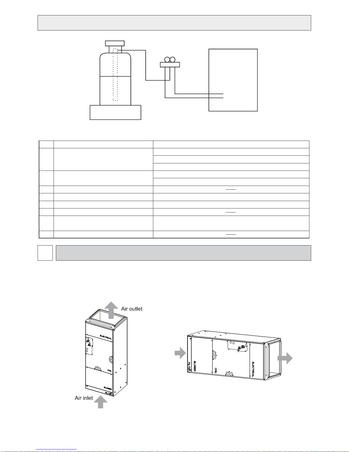
PART NAMES AND FUNCTIONS2
Indoor Unit
•
(1)Vertical
(2)Horizontal Right
Air
inlet
Air
outlet
6SHFL¿FDWLRQVDUHVXEMHFWWRFKDQJHZLWKRXWQRWLFH © 2016 Mitsubishi Electric US, Inc.
3
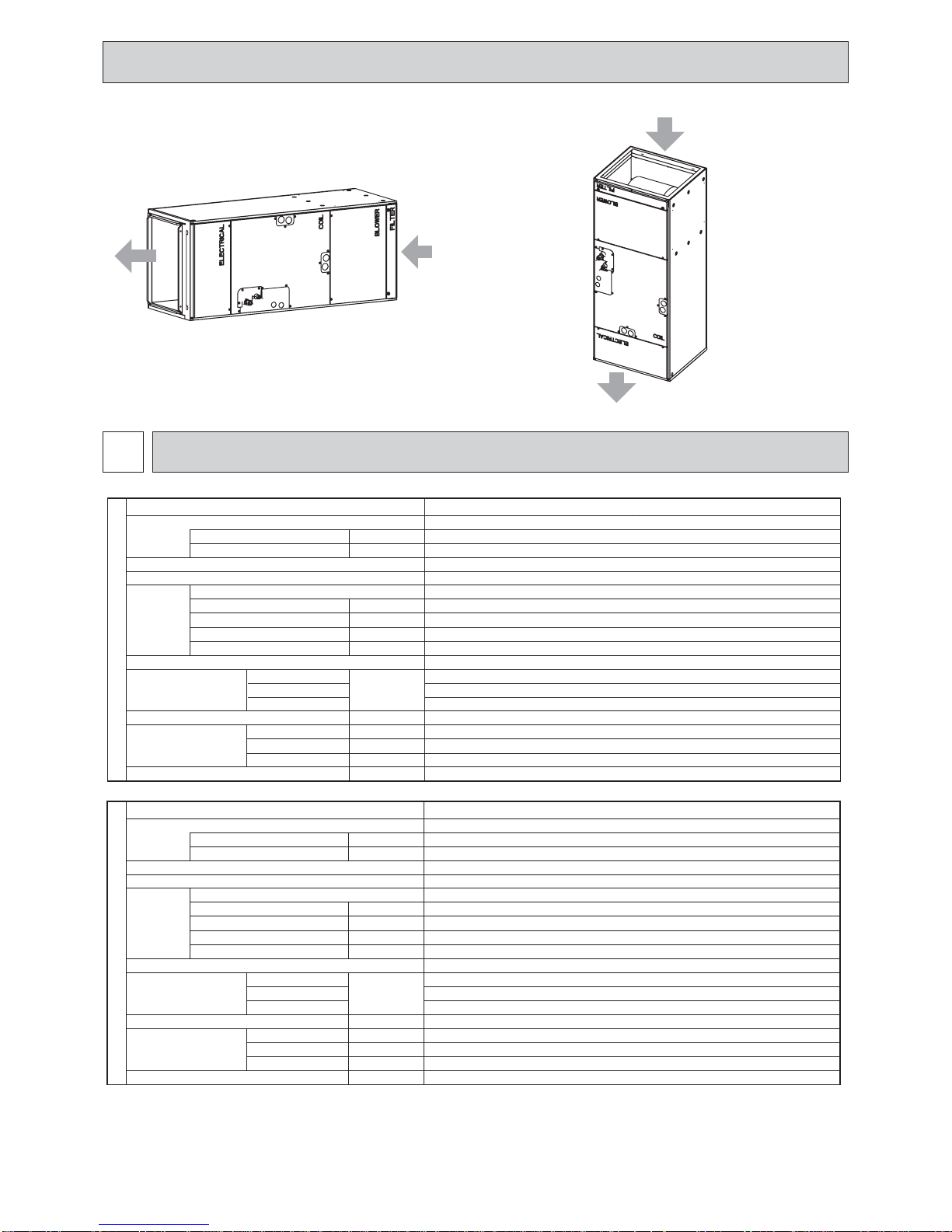
(3)Horizontal left
(4)Down flow
Air inlet
Air
outlet
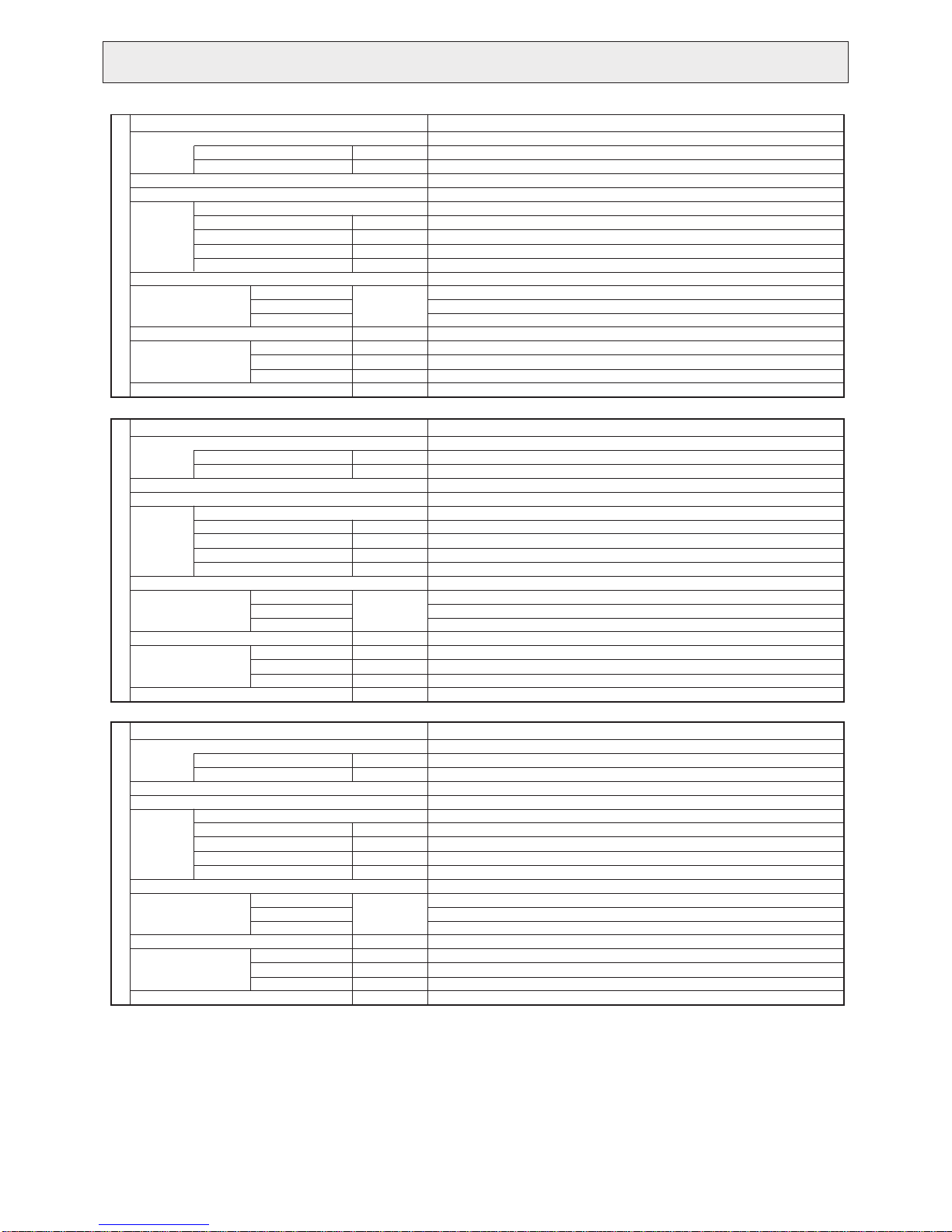
SPECIFICATION3
Servi ce Ref .
Power supply (phase, cycle, voltage)
External finish
Heat exchanger
Fan
Operation control & Thermostat
INDOOR UNIT
Sound pressure level
(Low-Mid-High)
Drain pipe mm (in . )
Dime ns ions W mm (in. )
Weight
Max. Fuse Size
Min. Circuit Ampacity A
Fan (drive) x No.
Fan motor output
Fan mot or
Airflow (Low-Mid-High)
External static pressure
75Pa (0.30 in.WG)
125Pa (0.50 in.WG)
200Pa (0.80 in.WG)
D mm (in. )
H mm (in. )
m
A
kW
F.L.A
3
/mi n (CF M)
Pa (in.WG)
dB ( A )
kg (lbs )
Air
inlet
Air outlet
MVZ-A12AA7
1 pha s e, 60H z, 208/230V
Galvanized steel cabinet - Powder coated Slate Gray
7.9-9.6-11.3 (280-340-400)
75-125-200 (0.30-0.50-0.80)
Remote controller & built-in
15
3.00
Plate n coil
Sirocco fan
19.05 (3/4) FPT
1275 (50-1/4)
x 1
0.121
2.4
24-28-32
27-31-35
32-36-41
432 (17)
548 (21-5/8)
51 (113)
Servi ce Ref .
Power supply (phase, cycle, voltage)
External finish
Heat exchanger
Fan
Operation control & Thermostat
INDOOR UNIT
Sound pressure level
(Low-Mid-High)
Dra in pipe mm (in. )
Dime ns ions W mm (in. )
Weight
6SHFL¿FDWLRQVDUHVXEMHFWWRFKDQJHZLWKRXWQRWLFH © 2016 Mitsubishi Electric US, Inc.
Max. Fuse Size
Min. Circuit A mpacity A
Fan (drive) x No.
Fan motor output
Fan mot or
Airflow (Low-Mid-High)
External static pressure
75Pa (0.30 in.WG)
125Pa (0.50 in.WG)
200Pa (0.80 in.WG)
D mm (in. )
H mm (in. )
kW
F.L.A
3
/mi n (CF M)
m
Pa (in.WG)
dB ( A )
kg (lbs )
MVZ-A18AA7
A
Galvanized Steel Cabinet - Powder coated Slate Gray
1 pha s e, 60H z, 208/230V
11.6-14.1-16.6 (410-497-585)
75-125-200 (0.30-0.50-0.80)
Remote controller & built-in
15
3.00
Plate n coil
Sirocco fan
19.05 (3/4) FPT
1275 (50-1/4)
x 1
0.121
2.4
26-30-34
28-32-36
33-37-41
432 (17)
548 (21-5/8)
51 (113)
4
Servi ce Ref .
Power supply (phase, cycle, voltage)
External finish
Heat exchanger
Fan
Operation control & Thermostat
INDOOR UNIT
Sound pressure level
(Low-Mid-High)
Drain pipe mm (in . )
Dime ns ions W mm (in. )
Weight
Max. Fuse Size
Min. Circuit A mpacity A
Fan (drive) x No.
Fan motor output
Fan mot or
Airflow (Low-Mid-High)
External static pressure
75Pa (0.30 in.WG)
125Pa (0.50 in.WG)
200Pa (0.80 in.WG)
D mm (in. )
H mm (in. )
3
m
/mi n (CF M)
Pa (in.WG)
dB ( A )
kg (lbs )
kW
F.L.A
MVZ-A24AA7
A
Galvanized Steel Cabinet - Powder coated Slate Gray
1 phase, 60Hz, 208/230V
14.6-17.7-20.8 (515-625-735)
75-125-200 (0.30-0.50-0.80)
Remote controller & built-in
15
3.00
Plate n coil
Sirocco fan
19.05 (3/4) FPT
1275 (50-1/4)
x 1
0.121
2.4
28-33-36
30-34-38
34-38-42
432 (17)
548 (21-5/8)
51 (113)
Servi ce Ref .
Power supply (phase, cycle, voltage)
External finish
Heat exchanger
Fan
Operation control & Thermostat
INDOOR UNIT
Sound pressure level
(Low-Mid-High)
Drain pipe mm (in . )
Dime ns ions W mm (in. )
Weight
Servi ce Ref .
Power supply (phase, cycle, voltage)
External finish
Heat exchanger
Fan
Operation control & Thermostat
INDOOR UNIT
Sound pressure level
(Low-Mid-High)
Drain pipe mm (in . )
Dime ns ions W mm (in. )
Weight
Max. Fuse Size
Min. Circuit A mpacity A
Fan (drive) x No.
Fan motor output
Fan mot or
Airflow (Low-Mid-High)
External static pressure
75Pa (0.30 in.WG)
125Pa (0.50 in.WG)
200Pa (0.80 in.WG)
D mm (in. )
H mm (in. )
Max. Fuse Size
Min. Circuit A mpacity A
Fan (drive) x No.
Fan motor output
Fan mot or
Airflow (Low-Mid-High)
External static pressure
75Pa (0.30 in.WG)
125Pa (0.50 in.WG)
200Pa (0.80 in.WG)
D mm (in. )
H mm (in. )
3
m
/mi n (CF M)
Pa (in.WG)
dB ( A )
kg (lbs )
3
m
/mi n (CF M)
Pa (in.WG)
dB ( A )
kg (lbs )
kW
F.L.A
kW
F.L.A
MVZ-A30AA7
A
Galvanized Steel Cabinet - Powder coated Slate Gray
1 phase, 60Hz, 208/230V
17.3-21.1-24.8 (613-744-875)
75-125-200 (0.30-0.50-0.80)
Remote controller & built-in
15
4.13
Plate n coil
Sirocco fan
19.05 (3/4) FPT
1378 (54-1/4)
x 1
0.244
3.3
30-34-38
32-36-40
35-39-43
534 (21)
548 (21-5/8)
64 (141)
MVZ-A36AA7
A
Ga lvanized Steel Cabinet - P owder coated S late Gray
1 phase, 60Hz, 208/230V
21.7-26.4-31.0 (767-931-1095)
75-125-200 (0.30-0.50-0.80)
Re m o te co n tr o ll e r & bu il t- i n
15
4.13
Plate fin coil
S irocco fan
0.244
3.3
33-37-41
35-39-43
37-41-45
19.05 (3/4) FP T
534 (21)
548 (21-5/8)
1378 (54-1/4)
64 (141)
1
6SHFL¿FDWLRQVDUHVXEMHFWWRFKDQJHZLWKRXWQRWLFH © 2016 Mitsubishi Electric US, Inc.
5
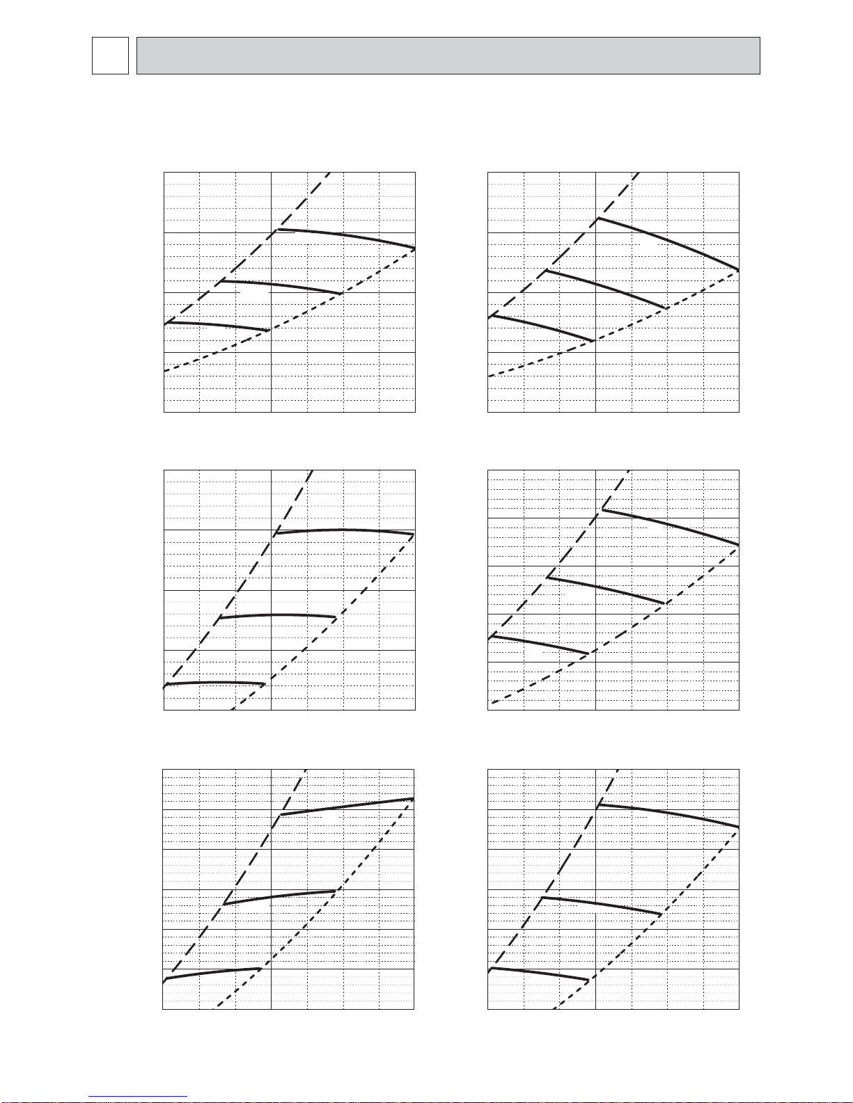
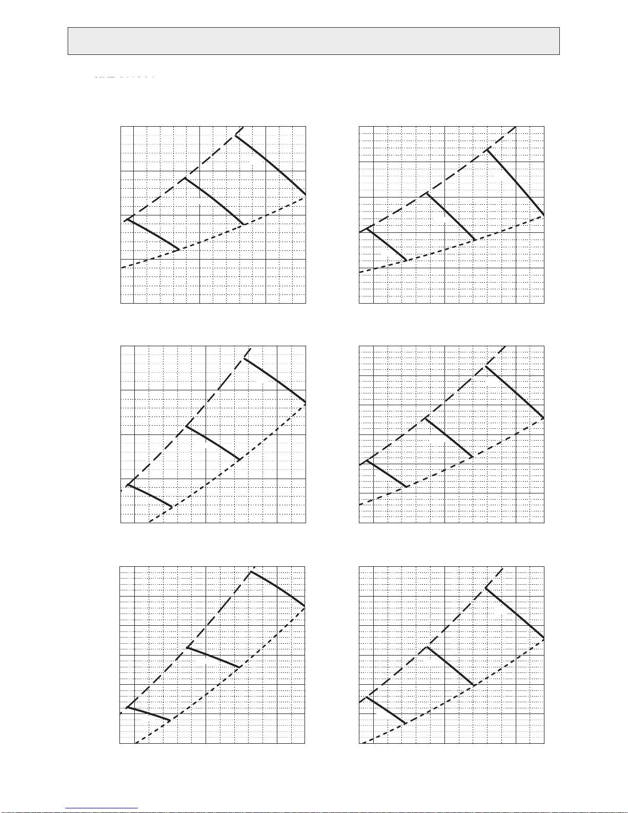
FAN PERFORMANCE AND CORRECTED AIR FLOW4
MVZ-A12AA4
MVZ-A12AA7
• Vertical, Horizontal Right, Horizontal Left • Downflow
External static pressure 0.30 [in.WG] (75Pa) 208/230V 60Hz
[0.40]
100
[0.40]
100
External static pressure 0.30 [in.WG] (75Pa) 208/230V 60Hz
[0.30]
[0.20]
Static pressure (Pa)[in.WG]
[0.10]
[0.60]
[0.50]
[0.40]
Static pressure (Pa)[in.WG]
[0.30]
[0.20]
75
50
Middle
High
Low
25
0
[0]
7
[247]
External static pressure 0.50 [in.WG] (125Pa) 208/230V 60Hz
150
125
100
10
[353]
Airflow rate (m
3
/min)[cfm]
High
Middle
75
Low
50
[247]
7
10
[353]
Airflow rate (m
3
/min)[cfm]
[494]
[494]
75
[0.30]
50
[0.20]
Static pressure (Pa)[in.WG]
25
[0.10]
0
[0.60]
[0.50]
[0.40]
[0]
7
[247]
150
125
100
14
Low
10
[353]
Airflow rate (m
External static pressure 0.50 [in.WG] (125Pa) 208/230V 60Hz
Middle
3
/min)[cfm]
High
High
[494]
14
Middle
75
[0.30]
Static pressure (Pa)[in.WG]
Low
50
[0.20]
25
[0.10]
14
[247]
7
10
[353]
Airflow rate (m
3
/min)[cfm]
[494]
14
External static pressure 0.80 [in.WG] (200Pa) 208/230V 60Hz
225
[0.90]
200
[0.80]
175
[0.70]
150
[0.60]
Middle
Static pressure (Pa)[in.WG]
125
[0.50]
100
[0.40]
[0.30]
75
7
[247]
Low
10
[353]
Airflow rate (m
6SHFL¿FDWLRQVDUHVXEMHFWWRFKDQJHZLWKRXWQRWLFH © 2016 Mitsubishi Electric US, Inc.
3
/min)[cfm]
High
[494]
External static pressure 0.80 [in.WG] (200Pa) 208/230V 60Hz
225
[0.90]
200
[0.80]
[0.70]
[0.60]
175
150
High
Middle
Static pressure (Pa)[in.WG]
125
[0.50]
100
[0.40]
75
[0.30]
14
[247]
7
Low
10
[353]
Airflow rate (m
3
/min)[cfm]
[494]
14
6
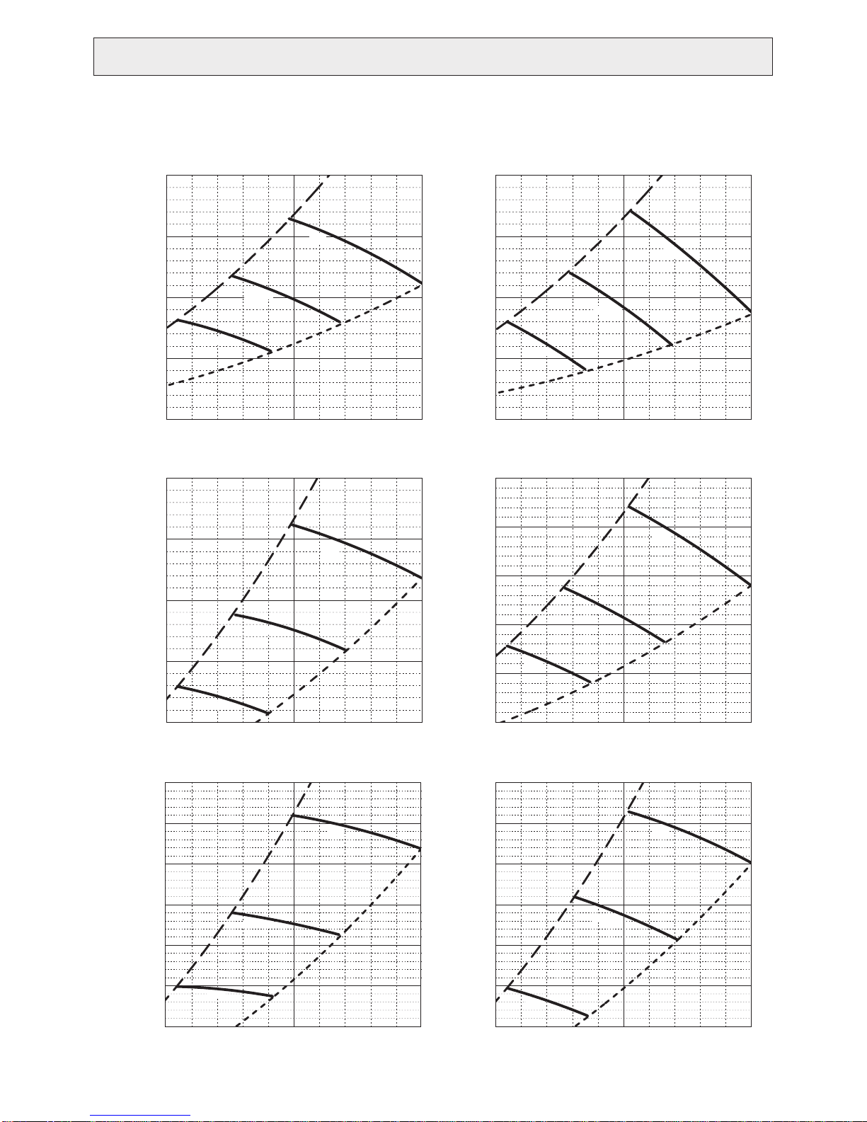
MVZ-A18AA4
MVZ-A18AA7
• Vertical, Horizontal Right, Horizontal Left • Downflow
External static pressure 0.30 [in.WG] (75Pa) 208/230V 60Hz
[0.40]
100
[0.40]
100
External static pressure 0.30 [in.WG] (75Pa) 208/230V 60Hz
[0.30]
[0.20]
Static pressure (Pa)[in.WG]
[0.10]
[0.60]
[0.50]
[0.40]
Static pressure (Pa)[in.WG]
75
50
Middle
High
Low
25
0
[0]
10
[353]
External static pressure 0.50 [in.WG] (125Pa) 208/230V 60Hz
150
125
100
[530]
Airflow rate (m
15
3
/min)[cfm]
High
Middle
[706]
75
[0.30]
50
[0.20]
Static pressure (Pa)[in.WG]
25
[0.10]
0
[0.60]
[0.50]
[0.40]
[0]
10
[353]
150
125
100
20
Low
External static pressure 0.50 [in.WG] (125Pa) 208/230V 60Hz
Middle
[530]
Airflow rate (m
15
3
/min)[cfm]
High
High
[706]
20
Middle
75
[0.30]
Static pressure (Pa)[in.WG]
[0.30]
[0.20]
[0.90]
[0.80]
[0.70]
[0.60]
Static pressure (Pa)[in.WG]
[0.50]
[0.40]
[0.30]
75
Low
50
10
[353]
External static pressure 0.80 [in.WG] (200Pa) 208/230V 60Hz
225
200
175
150
15
[530]
Airflow rate (m3/min)[cfm]
High
Middle
125
100
75
10
[353]
Low
[530]
Airflow rate (m
15
3
/min)[cfm]
[706]
[706]
50
[0.20]
25
20
20
[0.10]
[0.90]
[0.80]
[0.70]
[0.60]
Static pressure (Pa)[in.WG]
[0.50]
[0.40]
[0.30]
225
200
175
150
125
100
75
Low
[353]
10
[530]
Airflow rate (m
15
3
/min)[cfm]
External static pressure 0.80 [in.WG] (200Pa) 208/230V 60Hz
High
Middle
Low
[353]
10
[530]
Airflow rate (m
15
3
/min)[cfm]
[706]
[706]
20
20
6SHFL¿FDWLRQVDUHVXEMHFWWRFKDQJHZLWKRXWQRWLFH © 2016 Mitsubishi Electric US, Inc.
7
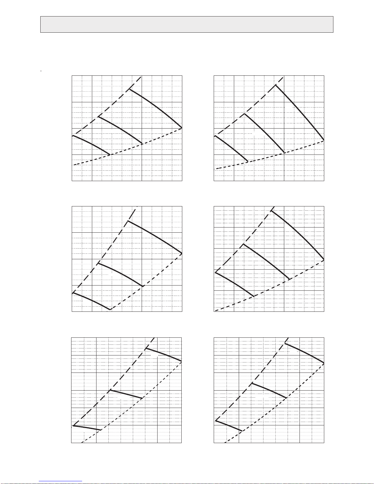
MVZ-A24AA4
MVZ-A24AA7
• Vertical, Horizontal Right, Horizontal Left • Downflow
External static pressure 0.30 [in.WG] (75Pa) 208/230V 60Hz
[0.40]
100
[0.40]
100
External static pressure 0.30 [in.WG] (75Pa) 208/230V 60Hz
[0.30]
[0.20]
Static pressure (Pa)[in.WG]
[0.10]
[0.60]
[0.50]
[0.40]
Static pressure (Pa)[in.WG]
[0.30]
[0.20]
75
50
Middle
High
Low
25
0
[0]
13
[459]
150
125
100
[530]
15
Airflow rate (m
3
/min)[cfm]
[706]
20
External static pressure 0.50 [in.WG] (125Pa) 208/230V 60Hz
High
Middle
75
Low
50
[459]
13
[530]
15
Airflow rate (m
3
/min)[cfm]
[706]
20
[847]
[847]
75
[0.30]
50
[0.20]
Static pressure (Pa)[in.WG]
25
[0.10]
0
[0.60]
[0.50]
[0.40]
[0]
150
125
100
24
Low
[459]
13
[530]
15
External static pressure 0.50 [in.WG] (125Pa) 208/230V 60Hz
Middle
Airflow rate (m
3
/min)[cfm]
20
[706]
High
High
[847]
24
Middle
75
[0.30]
Static pressure (Pa)[in.WG]
Low
50
[0.20]
25
24
[0.10]
[459]
13
[530]
15
Airflow rate (m
3
/min)[cfm]
20
[706]
[847]
24
External static pressure 0.80 [in.WG] (200Pa) 208/230V 60Hz
225
[0.90]
200
[0.80]
175
[0.70]
150
[0.60]
Static pressure (Pa)[in.WG]
[0.50]
[0.40]
[0.30]
125
100
Low
75
[459]
13
[530]
15
Middle
Airflow rate (m
6SHFL¿FDWLRQVDUHVXEMHFWWRFKDQJHZLWKRXWQRWLFH © 2016 Mitsubishi Electric US, Inc.
3
/min)[cfm]
High
[706]
External static pressure 0.80 [in.WG] (200Pa) 208/230V 60Hz
225
[0.90]
/min)[cfm]
High
[706]
20
[777]
22
200
[0.80]
175
[0.70]
150
[0.60]
Static pressure (Pa)[in.WG]
125
[0.50]
100
[0.40]
75
20
[777]
22
[0.30]
[459]
Low
13
[530]
15
Middle
Airflow rate (m
3
8
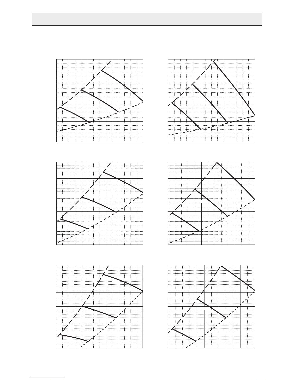
MVZ-A30AA4
MVZ-A30AA7
• Vertical, Horizontal Right, Horizontal Left • Downflow
External static pressure 0.30 [in.WG] (75Pa) 208/230V 60Hz
[0.40]
100
[0.40]
100
External static pressure 0.30 [in.WG] (75Pa) 208/230V 60Hz
[0.30]
[0.20]
Static pressure (Pa)[in.WG]
[0.10]
[0.60]
[0.50]
[0.40]
[0.30]
Static pressure (Pa)[in.WG]
[0.20]
75
50
Middle
High
Low
25
0
[0]
15
[530]
External static pressure 0.50 [in.WG] (125Pa) 208/230V 60Hz
150
125
100
20
[706]
Airflow rate (m
3
/min)[cfm]
[883]
High
Middle
75
50
Low
3
/min)[cfm]
High
High
[883]
25
29
[1024]
75
[0.30]
50
[0.20]
Static pressure (Pa)[in.WG]
25
[0.10]
0
[0.60]
[0.50]
[0.40]
[0]
[530]
150
125
100
25
29
[1024]
Low
15
External static pressure 0.50 [in.WG] (125Pa) 208/230V 60Hz
Middle
20
[706]
Airflow rate (m
Middle
75
[0.30]
Static pressure (Pa)[in.WG]
Low
50
[0.20]
25
[0.10]
15
[530]
External static pressure 0.80 [in.WG] (200Pa) 208/230V 60Hz
225
[0.90]
200
[0.80]
175
[0.70]
150
[0.60]
20
[706]
Airflow rate (m
Middle
Static pressure (Pa)[in.WG]
125
[0.50]
100
[0.40]
[0.30]
75
[530]
Low
15
20
[706]
Airflow rate (m
6SHFL¿FDWLRQVDUHVXEMHFWWRFKDQJHZLWKRXWQRWLFH © 2016 Mitsubishi Electric US, Inc.
3
/min)[cfm]
3
/min)[cfm]
High
[883]
[883]
25
[0.10]
[0.90]
[0.80]
[0.70]
[0.60]
Static pressure (Pa)[in.WG]
[0.50]
[0.40]
[0.30]
15
[530]
External static pressure 0.80 [in.WG] (200Pa) 208/230V 60Hz
225
200
175
150
125
100
75
[530]
Low
15
25
25
29
[1024]
29
[1024]
20
[706]
Airflow rate (m
Middle
20
[706]
Airflow rate (m
3
/min)[cfm]
3
/min)[cfm]
High
[883]
25
[883]
28
[989]
27
25
[953]
9
MVZ-A36AA4
MVZ-A36AA7
• Vertical, Horizontal Right, Horizontal Left • Downflow
External static pressure 0.30 [in.WG] (75Pa) 208/230V 60Hz
[0.40]
100
[0.50]
125
External static pressure 0.30 [in.WG] (75Pa) 208/230V 60Hz
[0.30]
[0.20]
Static pressure (Pa)[in.WG]
[0.10]
[0.60]
[0.50]
[0.40]
Static pressure (Pa)[in.WG]
[0.30]
75
Middle
50
Low
25
0
[0]
19
20
[671]
[706]
External static pressure 0.50 [in.WG] (125Pa) 208/230V 60Hz
150
125
100
25
[883]
Airflow rate (m
3
/min)[cfm]
Middle
75
Low
High
High
30
[1059]
33
[1165]
[0.40]
[0.30]
[0.20]
Static pressure (Pa)[in.WG]
[0.10]
[0.70]
[0.60]
[0.50]
[0.40]
Static pressure (Pa)[in.WG]
[0.30]
[0.20]
100
75
Middle
50
Low
25
0
[0]
19
20
[671]
[706]
External static pressure 0.50 [in.WG] (125Pa) 208/230V 60Hz
175
150
125
100
75
25
[883]
Airflow rate (m3/min)[cfm]
Middle
Low
50
High
High
30
[1059]
32
[1130]
50
[0.20]
[0.90]
[0.80]
[0.70]
[0.60]
Static pressure (Pa)[in.WG]
[0.50]
[0.40]
[0.30]
19
20
[671]
[706]
External static pressure 0.80 [in.WG] (200Pa) 208/230V 60Hz
225
200
175
150
125
100
75
[671]
Low
19
20
[706]
25
[883]
Airflow rate (m
Middle
25
[883]
Airflow rate (m
6SHFL¿FDWLRQVDUHVXEMHFWWRFKDQJHZLWKRXWQRWLFH © 2016 Mitsubishi Electric US, Inc.
3
/min)[cfm]
3
/min)[cfm]
High
30
[1059]
30
[1059]
32
[1130]
32
[1130]
10
[0.10]
[0.80]
[0.70]
[0.60]
[0.50]
Static pressure (Pa)[in.WG]
[0.40]
[0.30]
[0.20]
25
19
20
[671]
[706]
External static pressure 0.60 [in.WG] (150Pa) 208/230V 60Hz
200
175
150
125
25
[883]
Airflow rate (m
3
/min)[cfm]
Middle
100
75
Low
50
[671]
19
20
[706]
25
[883]
Airflow rate (m
3
/min)[cfm]
High
30
[1059]
30
[1059]
32
[1130]
32
[1130]
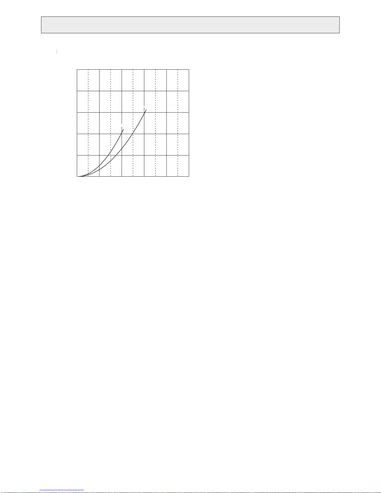
MVZ-A12, 18, 24, 30, 36AA4
A
MVZ-A12, 18, 24, 30, 36AA7
ir filter
Power source:208/230V 60Hz
25
[0.100]
20
[0.080]
15
[0.060]
10
[0.040]
External static pressure (Pa)[in.WG]
5
[0.020]
0
[0]
0
[0]
[353]
10
A12,18,24A12,18,24
20
[706]
Airflow rate (m3/min)[cfm]
[1059]
A30,36
A30,36
30
40
[1412]
50
[1766]
6SHFL¿FDWLRQVDUHVXEMHFWWRFKDQJHZLWKRXWQRWLFH © 2016 Mitsubishi Electric US, Inc.
11
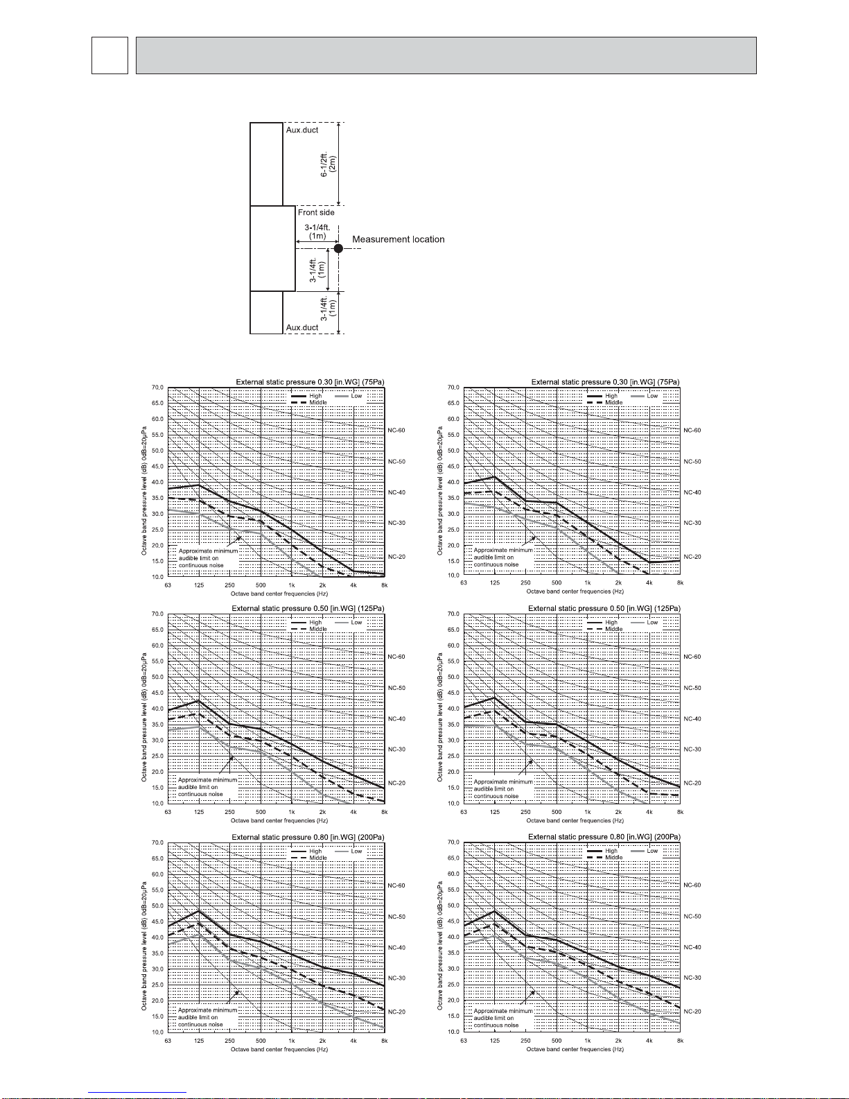
SOUND PRESSURE LEVELS5
5-1. Sound pressure level
Multi-Position
5-2. NC curves
MVZ-A12AA7 MVZ-A18AA7
6SHFL¿FDWLRQVDUHVXEMHFWWRFKDQJHZLWKRXWQRWLFH © 2016 Mitsubishi Electric US, Inc.
12
 Loading...