

Mitsubishi Electric MUZ-FE09NA, MUZ-FE18NA, MUZ-FE12NA, MUZ-FE12NA1, MUZ-FE09NA - 1 Service Manual
...
SERVICE MANUAL
CONTENTS
1. TECHNICAL CHANGES ··································· 2
2. PART NAMES AND FUNCTIONS ····················· 2
3. SPECIFICATION ················································ 3
4. OUTLINES AND DIMENSIONS ························ 5
5. WIRING DIAGRAM ············································ 6
6. REFRIGERANT SYSTEM DIAGRAM ··············· 7
7. DATA ·································································· 9
8. ACTUATOR CONTROL ··································· 16
9. SERVICE FUNCTIONS ··································· 17
10. TROUBLESHOOTING ····································· 17
11. DISASSEMBLY INSTRUCTIONS ···················· 36
Models
MUZ-FE09NA
MUZ-FE12NA
MUZ-FE18NA
SPLIT-TYPE AIR CONDITIONERS
OUTDOOR UNIT
Indoor unit service manual
MSZ-FE•NA Series (OBH542)
NOTE:
RoHS compliant products have <G> mark on the spec name plate.
TM
No. OBH543
REVISED EDITION-A
PARTS CATALOG (OBB543)
Revision A:
• MUZ-FE18NA has been added.
Please void OBH543.
MUZ-FE09NA
MUZ-FE12NA
HFC
utilized
R410A
2
1
TECHNICAL CHANGES
MUZ-FE09NA
MUZ-FE12NA
MUZ-FE18NA
1. New model
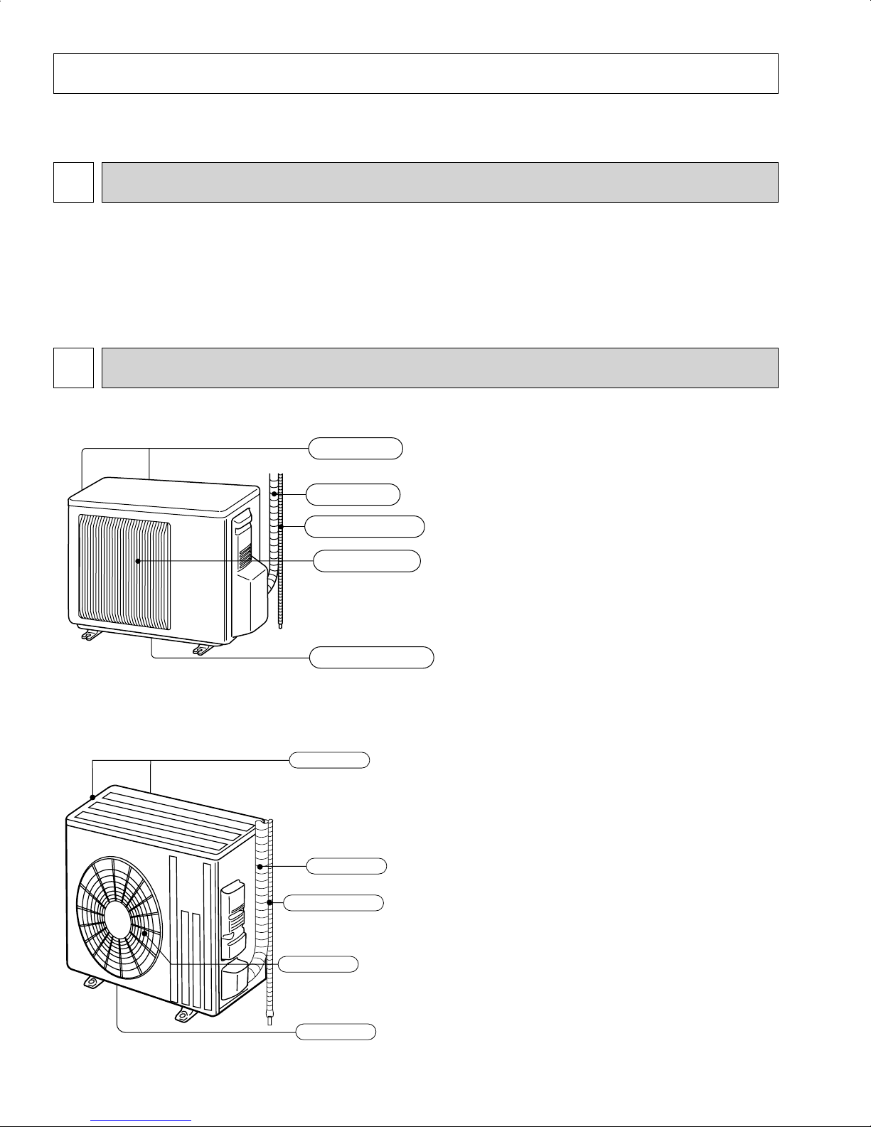
PART NAMES AND FUNCTIONS
2
MUZ-FE09NA MUZ-FE12NA
Air outlet
Drain outlet
Piping
Drain hose
Air inlet
(back and side)
Revision A:
• MUZ-FE18NA has been added.
MUZ-FE18NA
Air outlet
Air inlet
(back and side)
Piping
Drain hose
Drain outlet
3
3
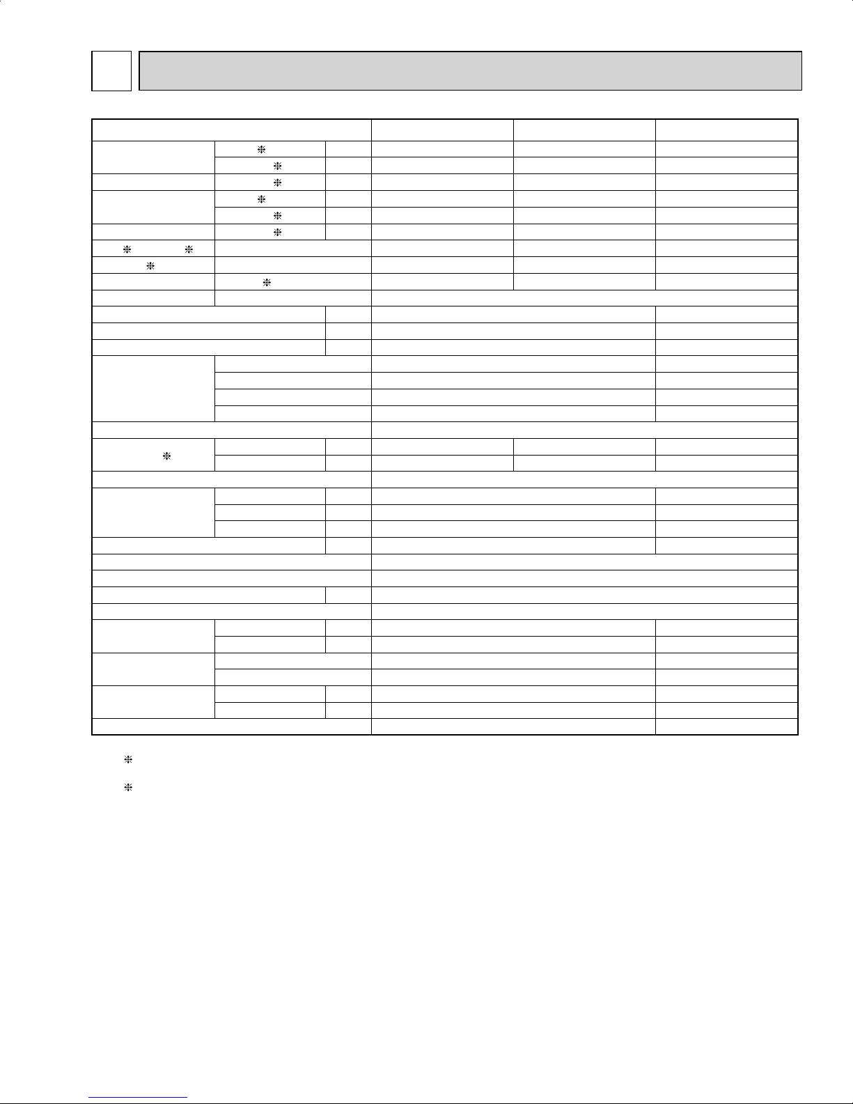
SPECIFICATION
Outdoor unit model MUZ-FE09NA MUZ-FE12NA MUZ-FE18NA
Capacity
Rated (Minimum~Maximum)
Cooling 1
Btu/h 9,000 (2,800~9,000) 12,000 (2,800~12,000) 18,000 (8,200~25,200)
Heating 47 1
Btu/h 10,900 (3,000~18,000) 13,600 (3,000~21,000) 21,600 (7,500~29,700)
Capacity Rated
Heating 17 2
Btu/h 12,500 13,600
19,300
Power consumption
Rated (Minimum~Maximum)
Cooling 1
W
580 (160~650) 930 (160~960)
1,270 (570~2,280)
Heating 47 1
W
710 (150~2,250)
950
(150~2,250)
1,540 (520~2,420)
Power consumption Rated
Heating 17 2
W 1,730 1,780 2,180
EER
1
[SEER] 3 Cooling 15.5 [26.0] 12.9 [23.0] 14.2 [20.2]
HSPF IV
4
Heating 10.0 10.6 10.3
COP Heating 1 4.50 4.20 4.11
Power supply V , phase , Hz 208/230, 1 , 60
Max. fuse size (time delay) A 15 20
Min. circuit ampacity A 12 17.1
Fan motor F.L.A 0.56 0.93
Compressor
Model SNB130FQAH
SNB172FQKMT
R.L.A 8.6 12.9
L.R.A 10.8 16.1
Refrigeration oil L (Model) 0.45 (NEO22) 0.40 (FV50S)
Refrigerant control Linear expansion valve
Sound level
1
Cooling dB(A) 48 48 55
Heating dB(A) 49 49 55
Defrost method Reverse cycle
Dimensions
W in. 31-1/2 33-1/16
D in. 11-1/4 13
H in. 21-5/8 34-5/8
Weight Ib. 80 119
External fi nish Munsell 3Y 7.8/1.1
Remote controller Wireless type
Control voltage
(by built-in transformer)
VDC 12 - 24
Refrigerant piping Not supplied
Refrigerant pipe size
(Min. wall thickness)
Liquid in. 1/4 (0.0315) 3/8 (0.0315)
Gas in. 3/8 (0.0315) 5/8 (0.0315)
Connection method
Indoor Flared Flared
Outdoor Flared Flared
Between the indoor
& outdoor units
Height difference ft. 40 50
Piping length ft. 65 100
Refrigerant charge (R410A) 2 lb. 9 oz. 4 lb. 3 oz.
NOTE: Test conditions are based on AHRI 210/240.
1: Rating conditions (Cooling) — Indoor: 80˚FDB, 67˚FWB, Outdoor: 95˚FDB, (75˚FWB) Rated frequency
(Heating) — Indoor: 70˚FDB, 60˚FWB, Outdoor: 47˚FDB, 43˚FWB Rated frequency
2: (Heating) — Indoor: 70˚FDB, 60˚FWB, Outdoor: 17˚FDB, 15˚FWB Maximum frequency
4
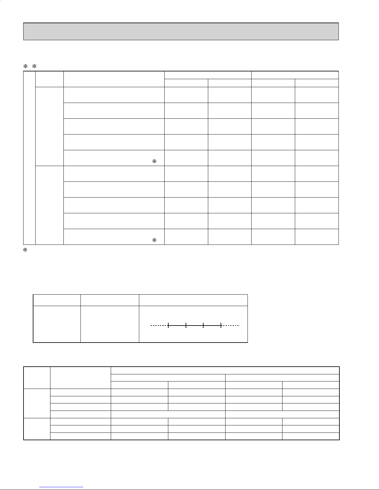
Test condition
ARI
Mode Test
Indoor air condition (°F) Outdoor air condition (°F)
Dry bulb Wet bulb Dry bulb Wet bulb
SEER
(Cooling)
"A-2" Cooling Steady State
at rated compressor Speed
80 67 95 (75)
"B-2" Cooling Steady State
at rated compressor Speed
80 67 82 (65)
"B-1" Cooling Steady State
at minimum compressor Speed
80 67 82 (65)
"F-1" Cooling Steady State
at minimum compressor Speed
80 67 67 (53.5)
"E-V" Cooling Steady State
at Intermediate compressor Speed
5
80 67 87 (69)
HSPF
(Heating)
"H1-2" Heating Steady State
at rated compressor Speed
70 60 47 43
"H3-2" Heating
at rated compressor Speed
70 60 17 15
"H0-1" Heating Steady State
at minimum compressor Speed
70 60 62 56.5
"H1-1" Heating Steady State
at minimum compressor Speed
70 60 47 43
"H2-V" Heating
at Intermediate compressor Speed 5
70 60 35 33
5
: At Intermediate compressor Speed
= ("Cooling rated compressor speed" - "minimum compressor speed") / 3 + "minimum compressor speed".
3, 4
(2) OPERATION
Mode Condition
Intake air temperature (°F)
Indoor Outdoor
DB WB DB WB
Cooling
Standard temperature 80 67 95 —
Maximum temperature 90 73 115 —
Minimum temperature 67 57 14 —
Maximum humidity 78 % —
Heating
Standard temperature 70 60 47 43
Maximum temperature 80 67 75 65
Minimum temperature 70 60 -13 -15
OPERATING RANGE
(1) POWER SUPPLY
Rated voltage Guaranteed voltage (V)
Outdoor unit
208/230 V
1 phase
60 Hz
Min. 187
208 230 Max. 253
5
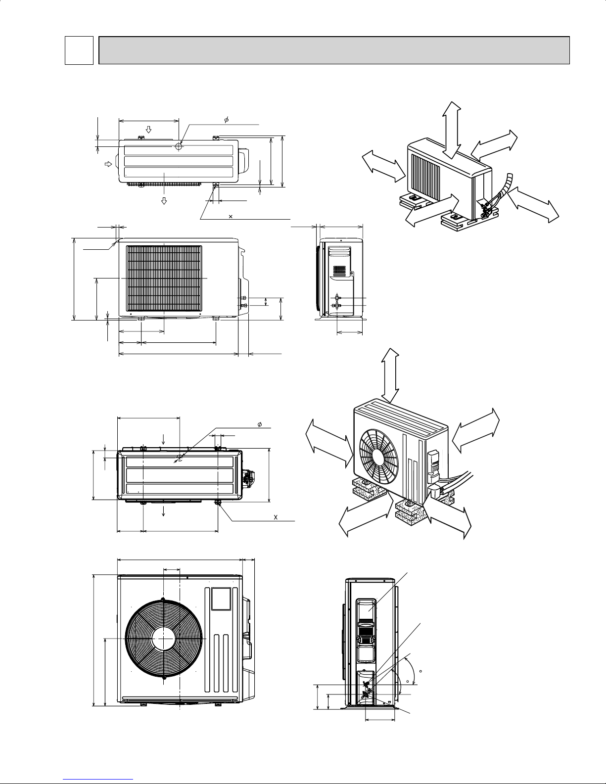
OUTLINES AND DIMENSIONS
4
Unit: inch
MUZ-FE09NA MUZ-FE12NA
MUZ-FE18NA
16-7/16
1-9/16
1-5/8
Drain hole
6-7/8
19-11/16
13
2
Air in
Air out
2-holes 13/32 13/16
14-3/16
33-1/16
4-5/16
3-3/16
34-5/8
17-25/32
Service panel
3-29/32
6-1/2
7-11/16
35
44
Liquid refrigerant
pipe joint
Refrigerant pipe
(flared)
Ø 3/8
Gas refrigerant
pipe joint
Refrigerant pipe
(flared)
Ø 5/8
14 in. or
more
4 in. or more
REQUIRED SPACE
20 in. or more
4 in. or more
20 in. or more
21-5/8
1-3/4
Air in
handle
11-1/32
7/8
13/32
15-3/4
Air in
11-29/32
5-15/16
Drain hole 1-5/8
Air out
2- 3/8 13/16 Oval hole
19-11/16
31-1/2
1-9/16
12 ~ 12-3/4
11/ 16
2
2-23/32
13-9/16
29/32 11-1/4
5-7/8
REQUIRED SPACE
4 in. or more
Open two sides of left,
right, or rear side.
Liquid pipe :1/4 (flared)
Gas pipe :3/8 (flared)
6-23/32
Basically open 4 inch or more
without any obstruction in front
and on both sides of the unit.
4 in. or more
14 in. or more
8 in. or more
6
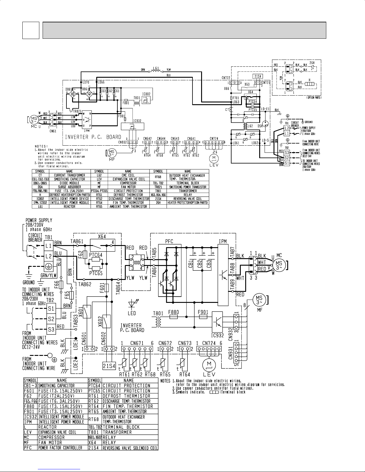
5
WIRING DIAGRAM
MUZ-FE09NA MUZ-FE12NA
MUZ-FE18NA

7
6
REFRIGERANT SYSTEM DIAGRAM
Unit: inch
MUZ-FE09NA MUZ-FE12NA
MUZ-FE18NA
Refrigerant pipe ø3/8
(with heat insulator)
Stop valve
(with service port)
Flared connection
Flared connection
Refrigerant pipe ø1/4
(with heat insulator)
4-way valve
Muffler
Service
port
Stop valve
(with strainer)
Capillary tube
O.D. 0.118 × I.D. 0.079× 9-7/16
(ø3.0 × ø2.0 × 240)
Discharge
temperature
thermistor
RT62
O.D. 0.118 × I.D. 0.071
× 23-5/8
(ø
Expansion
valve
Muffler
Service
port
Compressor
Defrost
thermistor
RT61
Capillary tube
3.0
× ø
1.8×600
Outdoor heat
exchanger
temperature
thermistor
)
Outdoor
heat
exchanger
Strainer
RT68
Ambient
temperature
thermistor
RT65
#100
R.V. coil
heating ON
cooling OFF
Refrigerant flow in cooling
Refrigerant flow in heating
Refrigerant pipe
(with heat insulator)
Refrigerant pipe ø3/8
(with heat insulator)
ø
5/8
Flared connection
Flared connection
4-way valve
Stop valve
(with service port)
Service
port
Strainer
#100
Stop valve
Muffler
#100
Service
port
Discharge
temperature
thermistor
RT62
Compressor
Capillary tube
LEV
Strainer
#100
Defrost
thermistor
RT61
O.D. 0.157 × I.D. 0.094× 3-15/16
(ø4.0×ø2.4×100)
Outdoor
heat
exchanger
Outdoor heat
exchanger
temperature
thermistor
RT68
R.V. coil
heating ON
cooling OFF
Ambient
temperature
thermistor
RT65
Refrigerant flow in cooling
Refrigerant flow in heating
8
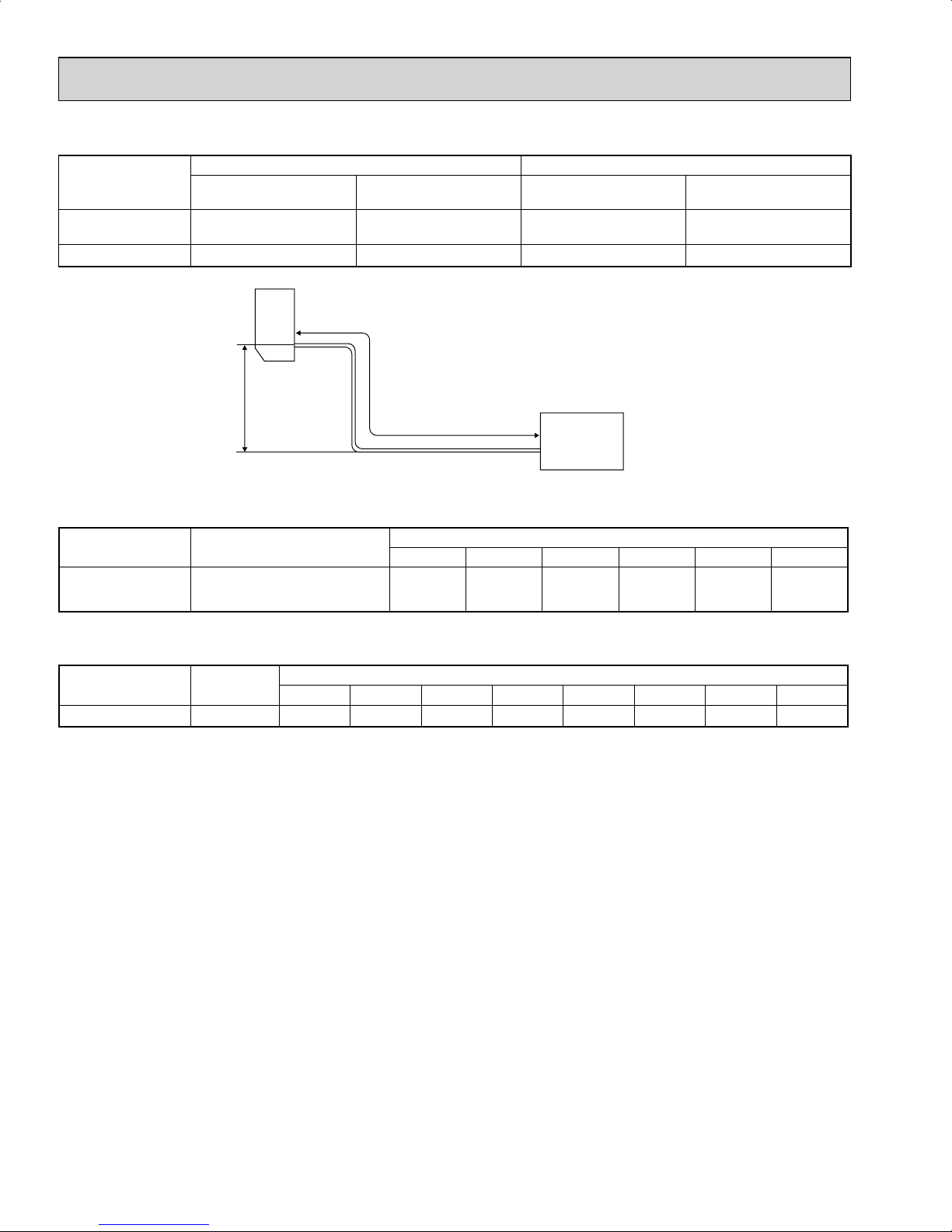
Max. Length
A
Max. Height
difference
B
Indoor
unit
Outdoor unit
MAX. REFRIGERANT PIPING LENGTH and MAX. HEIGHT DIFFERENCE
Model
Refrigerant piping: ft. Piping size O.D: in.
Max. Length
A
Max. Height difference
B
Gas Liquid
MUZ-FE09NA
MUZ-FE12NA
65 40 3/8 1/4
MUZ-FE18NA 100 50 5/8 3/8
ADDITIONAL REFRIGERANT CHARGE (R410A: oz.)
NOTE: Refrigerant piping exceeding 25 ft. requires additional refrigerant charge according to the calculation.
Model Outdoor unit precharged
Refrigerant piping length (one way): ft.
25 30 40 50 60 65
MUZ-FE09NA
MUZ-FE12NA
2 lb. 9 oz. 0 1.62 4.86 8.10 11.34 12.96
Calculation: X oz. = 1.08/5 oz. / ft. × (Refrigerant piping length (ft.) - 25)
NOTE: Refrigerant piping exceeding 33 ft. requires additional refrigerant charge according to the calculation.
Model
Outdoor unit
precharged
Refrigerant piping length (one way): ft.
33 40 50 60 70 80 90 100
MUZ-FE18NA 4 lb. 3 oz. 0 4.14 10.06 15.98 21.90 27.82 33.74 39.66
Calculation: X oz. = 2.96/5 oz. / ft. × (Refrigerant piping length (ft.) - 33)

9
DATA7
MUZ-FE09NA MUZ-FE12NA MUZ-FE18NA
7-1. PERFORMANCE DATA
1) COOLING CAPACITY
Model
Indoor air Outdoor intake air DB temperature (˚F)
IWB (˚F)
75 85 95 105 115
TC SHC TPC TC SHC TPC TC SHC TPC TC SHC TPC TC SHC TPC
MUZ-FE09NA
71 11.0 6.9 0.58 10.3 6.5 0.63 9.7 6.1 0.68 9.0 5.6 0.72 8.3 5.2 0.75
67 10.4 7.9 0.55 9.7 7.4 0.60 9.0 6.8 0.65 8.4 6.4 0.69 7.7 5.8 0.72
63 9.8 8.8 0.52 9.1 8.1 0.58 8.5 7.6 0.62 7.7 6.9 0.66 7.0 6.3 0.69
MUZ-FE12NA
71 14.7 8.8 0.85 13.7 8.2 0.94 12.9 7.7 1.01 12.0 7.2 1.06 11.0 6.6 1.10
67 13.9 10.2 0.81 13.0 9.5 0.89 12.0 8.8 0.96 11.2 8.1 1.02 10.3 7.5 1.07
63 13.1 11.3 0.77 12.1 10.5 0.85 11.3 9.7 0.92 10.3 8.9 0.98 9.4 8.1 1.02
MUZ-FE18NA
71 22.1 15.6 1.13 20.6 14.6 1.24 19.4 13.7 1.33 18.0 12.7 1.40 16.6 11.7 1.46
67 20.9 17.5 1.07 19.4 16.3 1.17 18.0 15.1 1.27 16.7 14.1 1.35 15.4 12.9 1.41
63 19.6 19.1 1.02 18.2 17.7 1.12 16.9 16.5 1.21 15.4 15.0 1.30 14.0 13.7 1.35
NOTE: 1. IWB : Intake air wet-bulb temperature
TC : Total Capacity (x10
3
Btu/h)
SHC : Sensible Heat Capacity (x10
3
Btu/h)
TPC : Total Power Consumption (kW)
2. SHC is based on 80˚F of indoor Intake air DB temperature.
2) COOLING CAPACITY CORRECTIONS
Refrigerant piping length (one way: ft.)
25 (std.) 40 65 100
MUZ-FE09NA
MUZ-FE12NA
1.0 0.954 0.878 -
MUZ-FE18NA 1.0 0.954 0.878 0.771
3) HEATING CAPACITY
Model
Indoor air Outdoor intake air WB temperature (˚F)
IDB (˚F)
5 152535434555
TC TPC TC TPC TC TPC TC TPC TC TPC TC TPC TC TPC
MUZ-FE09NA
75 4.8 0.44 6.3 0.56 7.9 0.66 9.4 0.73 10.6 0.77 11.0 0.78 12.4 0.81
70 5.2 0.42 6.7 0.54 8.2 0.64 9.6 0.71 10.9 0.75 11.2 0.77 12.7 0.80
65 5.5 0.41 6.9 0.52 8.6 0.62 10.0 0.69 11.2 0.73 11.6 0.74 13.0 0.78
MUZ-FE12NA
75 6.0 0.58 7.9 0.73 9.9 0.86 11.8 0.96 13.3 1.00 13.7 1.02 15.5 1.06
70 6.5 0.55 8.4 0.71 10.2 0.84 12.0 0.93 13.6 0.98 14.0 1.00 15.8 1.04
65 6.8 0.53 8.6 0.68 10.7 0.81 12.4 0.91 14.0 0.96 14.4 0.97 16.2 1.02
MUZ-FE18NA
75 9.5 0.91 12.5 1.15 15.7 1.35 18.7 1.50 21.1 1.58 21.7 1.60 24.6 1.66
70 10.3 0.87 13.3 1.11 16.2 1.32 19.1 1.46 21.6 1.54 22.2 1.57 25.2 1.63
65 10.8 0.83 13.6 1.06 17.0 1.27 19.8 1.42 22.2 1.50 22.9 1.52 25.7 1.60
NOTE: 1. IDB : Intake air dry-bulb temperature
TC : Total Capacity (x10
3
Btu/h)
TPC : Total Power Consumption (kW)
2. Above data is for heating operation without any frost.
How to operate with fixed operational frequency of the compressor.
1. Press the EMERGENCY OPERATION switch on the front of the indoor unit, and select either EMERGENCY COOL
mode or EMERGENCY HEAT mode before starting to operate the air conditioner.
2. The compressor starts with operational frequency.
3. The fan speed of the indoor unit is High.
4. This operation continues for 30 minutes.
5. In order to release this operation, press the EMERGENCY OPERATION switch twice or once, or press any button on
the remote controller.
10
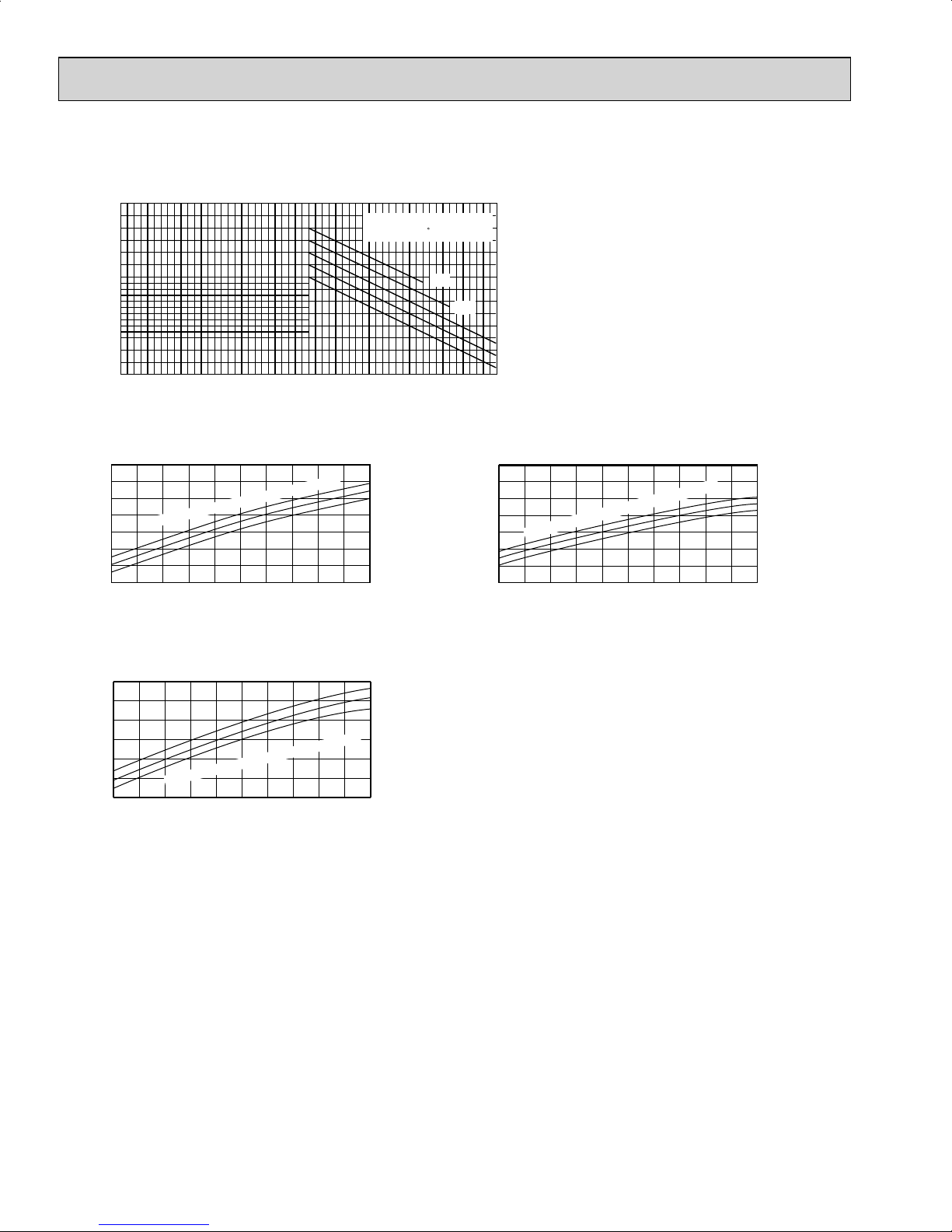
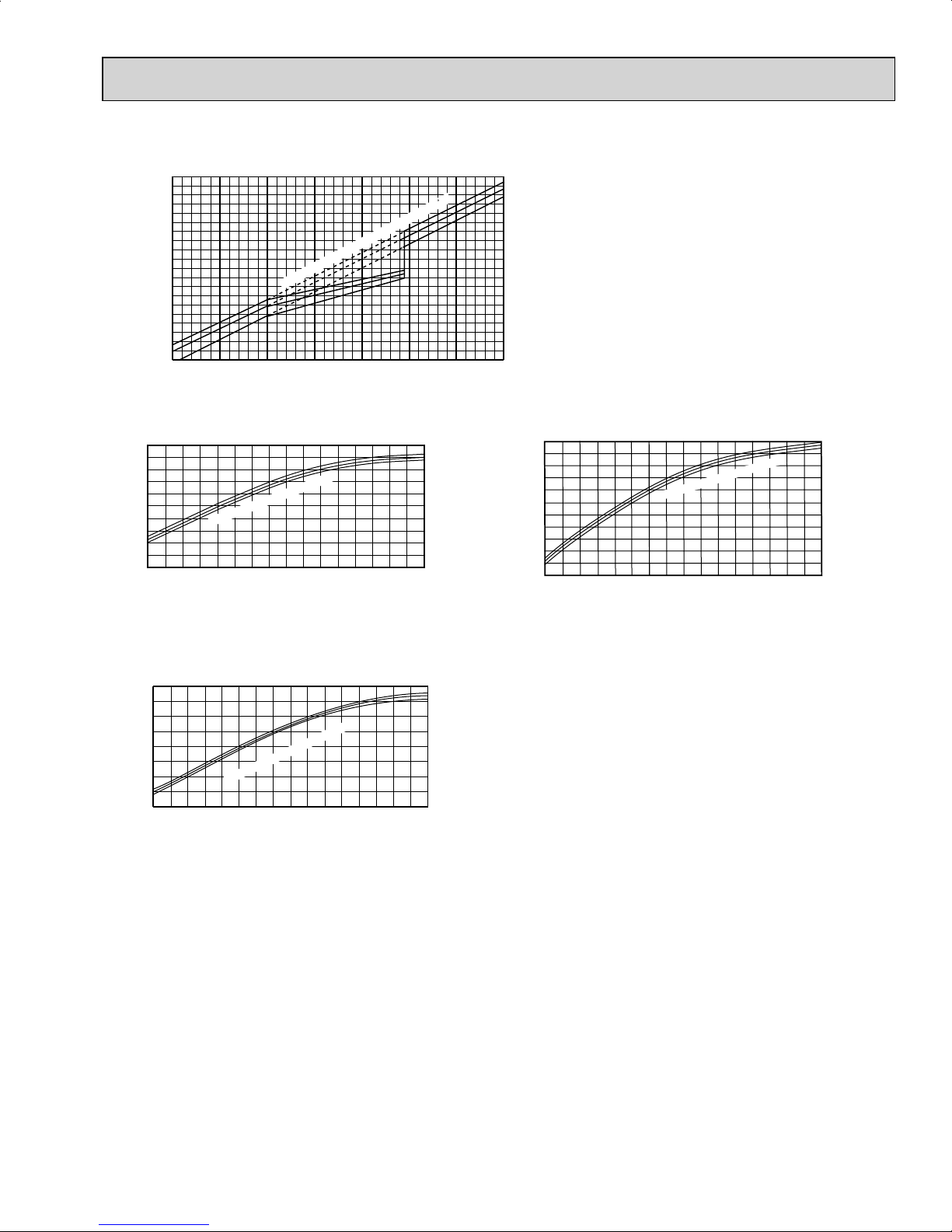
7-2. PERFORMANCE CURVE
Cooling
This value of frequency is not the same as the actual frequency in operating. Refer to 7-5 and 7-6 for the relationships
between frequency and capacity.
MUZ-FE09NA MUZ-FE12NA
MUZ-FE18NA
1.5
Cooling capacity (
1.4
1.3
1.2
1.1
difference (°F)
1.0
Capacity correction factors
0.9
Indoor air Wet-bulb temperature
14 23 32 41 50 59 68 77 86 95 104 113
Outdoor intake air Dry-bulb temperature(°F)
at Rated frequency)
Indoor intake air Wet-bulb
temperature( F)
76
75
72
68
64
SHF at rating condition = 0.76
0.8
0.7
(kW)
0.6
Indoor intake air WB temperature (°F)
0.5
Total power consumption
65 75 85 95 105 115
Outdoor intake air DB temperature (°F)
Airflow
= 307 CFM
1.3
71
67
63
1.2
1.1
1.0
(kW)
0.9
0.8
0.7
Total power consumption
Indoor intake air WB temperature (°F)
65 75 85 95 105 115
Outdoor intake air DB temperature (°F)
SHF at rating condition = 0.73
Airflow
= 350 CFM
71
67
63
1.5
1.4
1.3
1.2
(kW)
1.1
1.0
Total power consumption
0.9
65 70 75 80 85 90 95 100 105 110 115
Outdoor intake air DB temperature (°F)
SHF at rating condition = 0.84
= 634 CFM
Airflow
oor intake air WB temperature (°F)
Ind
71
67
63
11
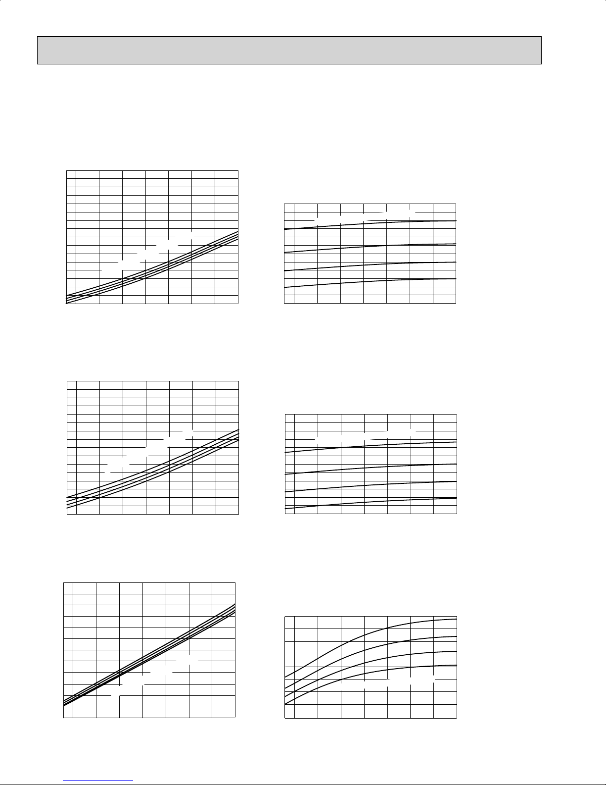
Heating
MUZ-FE09NA
MUZ-FE12NA
MUZ-FE18NA
This value of frequency is not the same as the actual frequency in operating. Refer to 7-5 and 7-6 for the relationships
between frequency and capacity.
1.3
1.2
1.1
1.0
0.9
0.8
0.7
difference (°F)
0.6
0.5
Capacity correction factor
Indoor air Dry-bulb temperature
0.4
-4 5 142332415059
Heating capacity (
Indoor intake air Dry-bulb temperature ( F)
at Rated frequency)
Outdoor intake air Wet-bulb temperature (°F)
59
68
79
0.9
0.8
0.7
0.6
0.5
0.4
(kW)
0.3
0.2
0.1
0
Total power consumption
-15 -5
Outdoor intake air WB temperature (°F)
oor intake air
Ind
1552535455565
Airflow
DB temperature (°F)
1.8
1.6
1.4
1.2
1.0
(kW)
0.8
0.6
Indoor intake air DB temperature (°F)
0.4
0.2
Total power consumption
-15 -5 5 15 25 35 45 55 65
Outdoor intake air WB temperature (°F)
Airflow
= 381 CFM
= 738 CFM
Airflow
75
70
65
75
70
65
1.1
1.0
0.9
0.8
0.7
0.6
0.5
(kW)
0.4
0.3
0.2
0.1
Total power consumption
-5
-15
Outdoor intake air WB temperature (°F)
Indoor intake air DB tem
1552535455565
= 420 CFM
perature (°F)
75
70
65
12
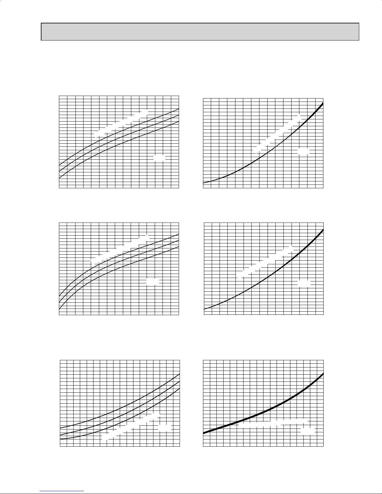
7-3. CONDENSING PRESSURE
Cooling
Data is based on the condition of indoor humidity 50 %.
Air flow should be set to High speed.
MUZ-FE12NA
(PSIG)
Condensing pressure
86
80
75
70
68 70 75 80 85 90 95 100 105(°F)
120
125
130
135
140
145
150
155
160
165
170
175
180
Suction pressure
Outdoor ambient temperature
Indoor DB temperature (°F)
(PSIG)
86
80
75
70
68 70 75 80 85 90 95 100 105(°F)
260
300
340
380
420
460
500
540
580
Indoor DB temperature (°F)
Outdoor ambient temperature
MUZ-FE09NA
(PSIG)
Condensing pressure
86
80
75
70
68 70 75 80 85 90 95 100 105(°F)
120
125
130
135
140
145
150
155
160
165
170
175
180
Suction pressure
Outdoor ambient temperature
Indoor DB temperature (°F)
(PSIG)
86
80
75
70
68 70 75 80 85 90 95 100 105(°F)
260
300
340
380
420
460
500
540
580
Indoor DB temperature (°F)
Outdoor ambient temperature
MUZ-FE18NA
(PSIG)
Condensing pressure
86
80
75
70
70 75 80 85 90 95 100
105(°F)
110
120
130
140
150
160
170
180
190
Suction pressure
Outdoor ambient temperature
Indoor DB temperature (°F)
(PSIG)
86
80
75
70
68
70
75
80
85
90
95
100
105(°F)
240
280
320
360
400
440
480
Indoor DB temperature (°F)
Outdoor ambient temperature
68 70 75 80 85 90 95 100
105(°F)
110
120
130
140
150
160
170
180
190
13
75
70
65
(PSIG)
(PSIG)
Condensing pressure
Outdoor ambient temperature
155 10 2025303540455055606570(°F)
220
200
180
160
140
240
260
280
320
300
340
360
380
400
75
70
65
Suction pressure
Outdoor ambient temperature
15 205 10 25303540455055606570(°F)
80
70
60
50
90
100
110
120
130
140
150
160
170
-10
-15
-10
-15
40
120
Ind
oor DB temperature (°F)
Indoor DB temperature (°F)
58Hz
58Hz
Heating
Data is based on the condition of outdoor humidity 75%.
Air flow should be set to High speed.
Data is for heating operation without any frost.
MUZ-FE12NA
MUZ-FE09NA
75
70
65
(PSIG) (PSIG)
Condensing pressure
Outdoor ambient temperature
20 25 305 1015 3540455055606570(°F)
220
200
180
160
140
240
260
280
320
300
340
360
380
400
75
70
65
Suction pressure
Outdoor ambient temperature
20 25 305 1015 3540455055606570(°F)
80
70
60
50
90
100
110
120
130
140
150
160
170
120
-10
-15
-15 -10
40
Indoor DB
temperature (°F)
Indoor DB temperature (°F)
58Hz
58Hz
MUZ-FE18NA
(PSIG)
Condensing pressure
75
70
65
75
70
65
Suction pressure
Outdoor ambient temperature
(PSIG)
-15 -10 -5 0 5 10 15 20 25 30 35 40 45 50 55
60
65 70 75(°F)
240
260
280
300
320
340
360
380
400
420
440
460
480
-15
-10-505101520253035404550
55
60
657075(°F)
0
20
40
60
80
100
120
140
160
180
200
220
240
Indoor DB temperature (°F)
Outdoor ambient temperature
Indoor DB temperature (°F)
58Hz
58Hz

14
7-4. STANDARD OPERATION DATA
Model MSZ-FE09NA MSZ-FE12NA MSZ-FE18NA
Item Unit Cooling Heating Cooling Heating Cooling Heating
Total
Capacity Btu/h 9,000 10,900 12,000 13,600 18,000 21,600
SHF — 0.76 — 0.73 — 0.84 —
Input kW 0.580 0.710 0.930 0.950 1.800 2.200
Rated frequency Hz 34 42 51 52.5 50.5 62.5
Electrical circuit
Indoor unit MSZ-FE09NA MSZ-FE12NA MSZ-FE18NA
Power supply
V,
phase,
Hz
208/230, 1, 60
Input kW 0.018 0.024 0.024 0.030 0.058
Fan motor current A 0.19/0.17 0.25/0.23 0.25/0.23 0.32/0.29 0.56/0.51
Outdoor unit MUZ-FE09NA MUZ-FE12NA MUZ-FE18NA
Power supply
V,
phase,
Hz
208/230, 1, 60
Input kW 0.562 0.686 0.906 0.920 1.212 1.482
Comp. current A 2.38/2.15 2.98/2.70 4.05/3.66 4.12/3.72 4.47/4.04 5.72/5.17
Fan motor current A 0.35/0.32 1.16/1.05 1.13/1.02
Refrigerant circuit
Condensing pressure PSIG 376 355 402 392 373 357
Suction pressure PSIG 154 108 148 104 151 107
Discharge temperature ˚F 142 145 160 158 150 159
Condensing temperature ˚F 112 108 117 115 111 105
Suction temperature ˚F533653345841
Comp. shell bottom temperature ˚F 144 128 146 129 132 136
Ref. pipe length ft. 25
Refrigerant charge (R410A) 2 lb. 9 oz. 4 lb 3 oz.
Indoor unit
Intake air temperature
DB ˚F807080708070
WB ˚F676067606760
Discharge air temperature
DB ˚F 59 99 58 101 59 102
WB ˚F56—55—56—
Fan speed (High) rpm 1,020 1,120 1,120 1,220 1,300
Airfl ow (High) CFM 307 (Wet) 381 350 (Wet) 420 634 (Wet) 738
Outdoor unit
Intake air temperature
DB ˚F954795479547
WB ˚F — 43 — 43 — 43
Fan speed rpm 810 870 810 870 840 810
Airfl ow CFM 1,102 1,187 1,102 1,187 1,769 1,701
 Loading...