

Mitsubishi Electric MSZ09UN, MSZ12UN, MUZ12UN, MUZ09UN Service Manual
L
I
S
T
E
D
CUS
SPLIT-TYPE, HEAT PUMP AIR CONDITIONERS
Revision A:
●Conditions of operation frequency have been added.
Please void OB297.
SERVICE MANUAL
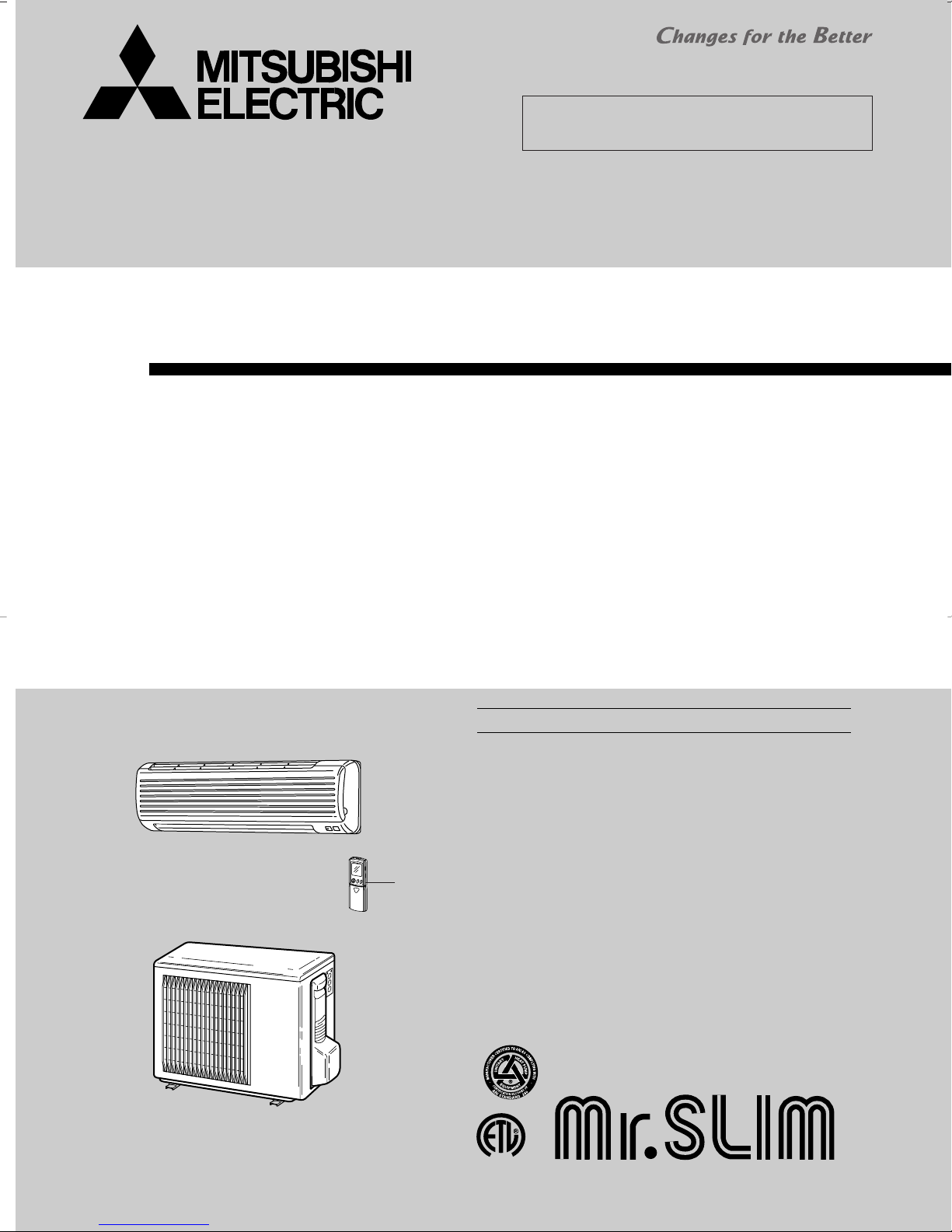
Wireless type
Models
MSZ09UN (W) · MUZ09UN
MSZ12UN (W) · MUZ12UN
No. OB297
REVISED EDITION-A
MSZ09UN
INDOOR UNIT
MUZ09UN
MUZ12UN
OUTDOOR UNIT
Remote
controller
CONTENTS
1. FEATURES·························································2
2. PART NAMES AND FUNCTIONS······················4
3. SPECIFICATION·················································6
4. DATA···································································8
5. OUTLINES AND DIMENSIONS·······················18
6. WIRING DIAGRAM ··········································20
7. REFRIGERANT SYSTEM DIAGRAM··············22
8. MICROPROCESSOR CONTROL ····················23
9. SERVICE FUNCTIONS ····································39
10. TROUBLESHOOTING ······································41
11. DISASSEMBLY INSTRUCTIONS·····················61
12. PARTS LIST······················································68
13. OPTIONAL PARTS···········································74
The Slim Line.
From Mitsubishi Electric.
TM
MSZ09UN
MUZ09UN
MUZ12UN
LCD wireless
remote controller
MSZ12UN
Hours
Room T emperature
Single speed comppressor Model
Temperature is adjusted by
turning on/ off the compressor.
Inverter Model
Constant temperature is maintained
by compressor speed control.
10
13
Cool
MSH12EN
MSZ12UN
6.8
7.7
Heat
MSH12EN
MSZ12UN
Revision A:
• Conditions of operation frequency have been added.
• SPECIFICATION, DATA, WIRING DIAGRAM and PARTS LIST have been partially modified.
1
FEATURES
Optimum comfort year-round
To ensure that a room is never too cold or too hot, inverter technology
allows the system to detect subtle fluctuations in room temperature and
adjust automatically. Unlike conventional air conditioning units that must start
or stop the compressor repetitively, inverter units offer finely tuned operation
– such as the accurate control of room temperature – for a more comforting
airflow and far less temperature variations.
High–speed cooling & heating
Ideal and comforting performance is assured by controlling compressor
rotation according to the cooling and heat load of a room. Inverter technology promotes maximum compressor efficiency by flexibly changing
the rotation speed of it to accurately match operating requirements.
Extra energy – savings
Inverter technology makes the value of SEER and HSPF better compared to non-inverter model’s value.
Model Cooling capacity Heating capacity SEER HSPF(
MSZ09UN 8,800 Btu/h 12,300 Btu/h 12.0 7.7/6.7
MSZ12UN 11,400 Btu/h 16,000 Btu/h 13.0 7.7/6.7
The sound level of indoor unit has been lowered.
Sound level
Fan speed
High / Low
Model
MSH09EW
43 / 32
MSZ09UN
36 / 22
MSH12EN
48 / 38
2
MSZ12UN
42 / 35
(dBA)
44/55
)
SWING
Single rotary:
Centrifugal force always
produced in one direction,
resulting in excessive vibration.
Twin rotary:
Centrifugal force of one
roller counterbalanced
by that of the other roller
for significantly lower vibration.
MSH09EW
MSH12EN
Model
Size
MSZ09UN
MSZ12UN
14-13/16
10-15/16
12-5/8
14-3/16
(in.)
The height of indoor unit has been shortened.
MUH12EN
Sound level (Cooling/Heating)
MUZ12UN
49 / 49
54 / 54
dB(A)
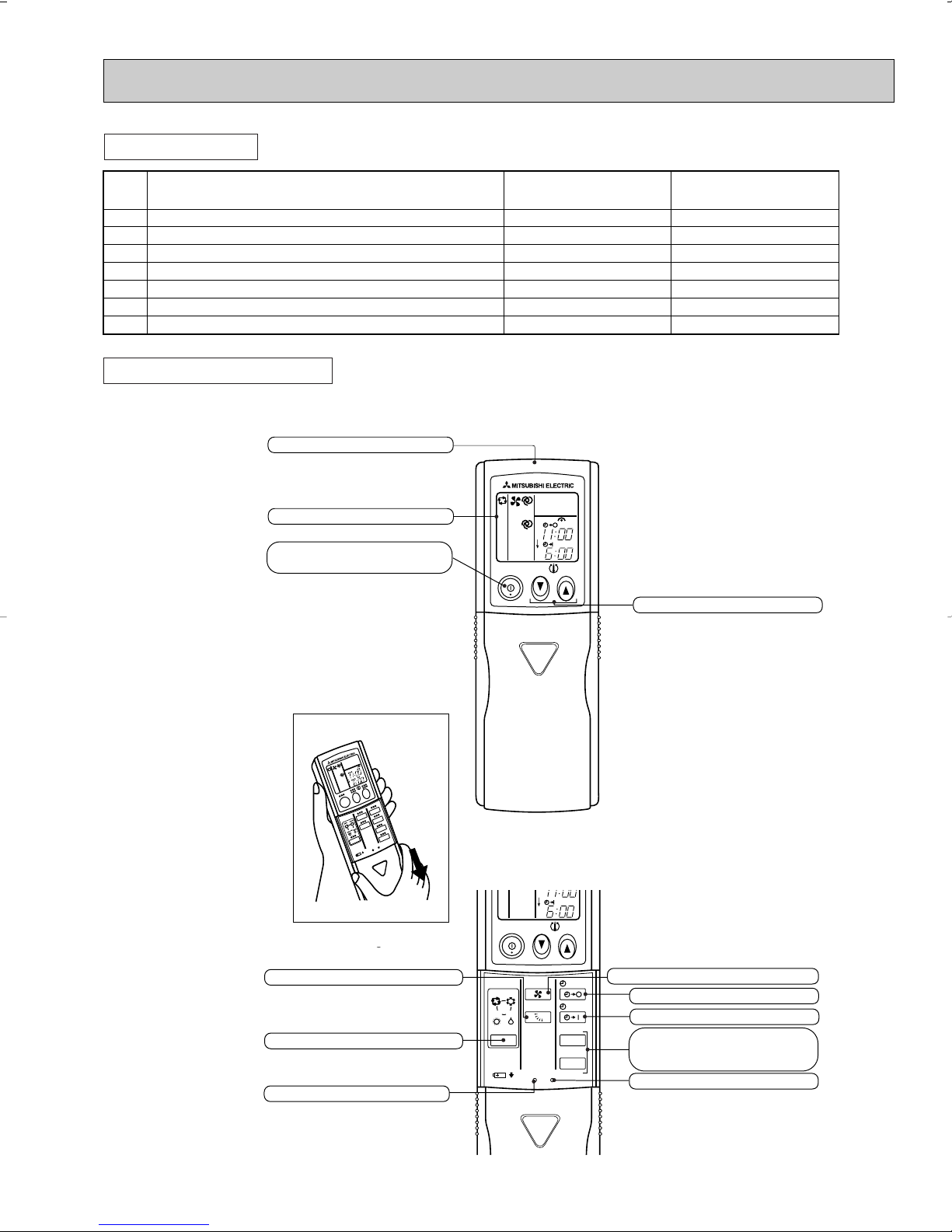
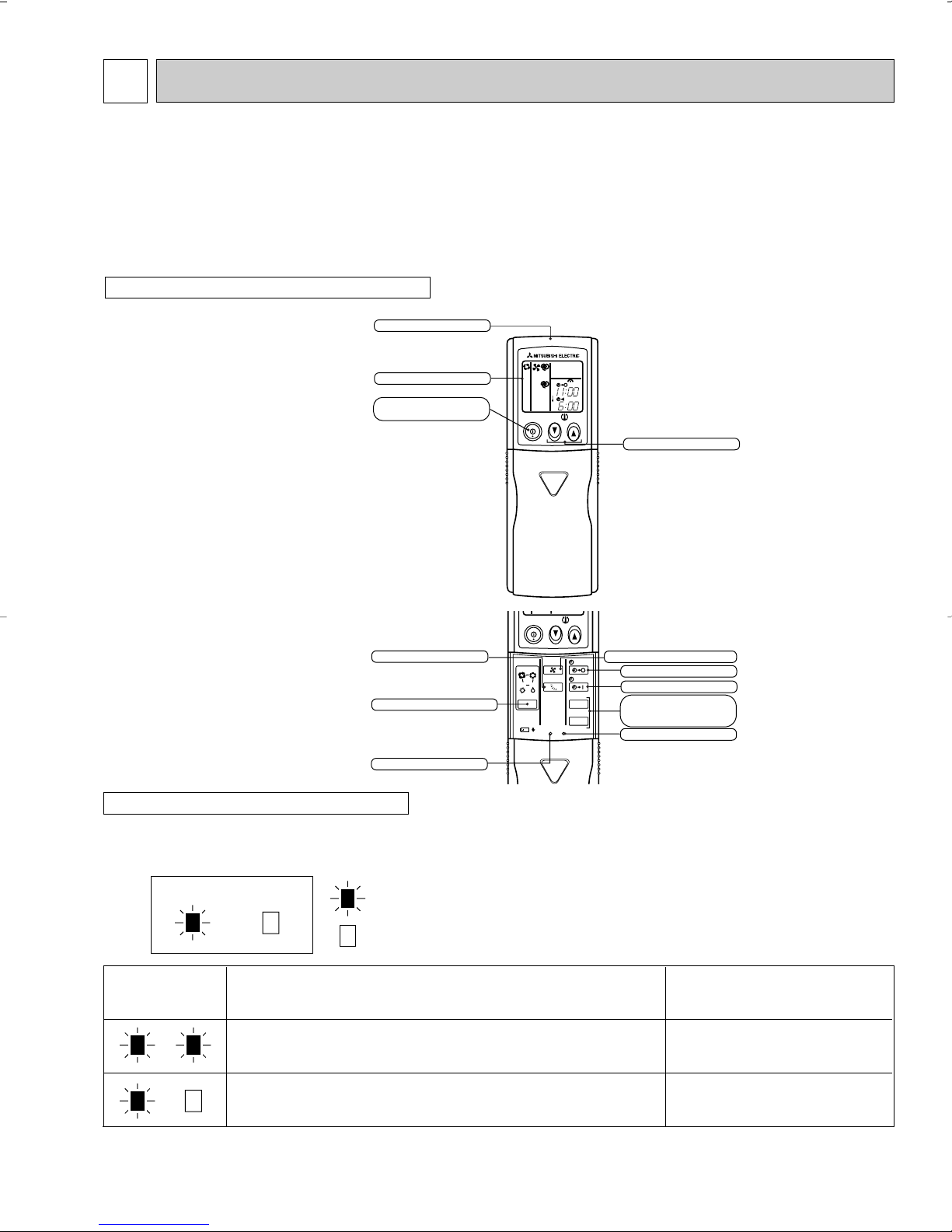
“I FEEL CONTROL” IN OUR LCD WIRELESS REMOTE CONTROLLER WITH ON/OFF PROGRAM TIMER
Mitsubishi Electric’s new wireless remote controller incorporates a number of advanced features that provides even greater
control and ease-to-use. It has a liquid crystal display which indicates such information as mode, fan speed and temperature
selected as well as the programmed ON/OFF timer. It is also equipped with “I Feel Control”, a unique Mitsubishi Electric feature that allows the user to adjust the temperature to exactly the level he or she wants simply by tapping the button that
describes present conditions : “Too Cool” or “Too Warm”. The optimum temperature set this way is that memorized for immediate recall whenever the air conditioner is used again.
Select desired air flow direction.
REMOTE-CONTROL OPERATION MODE
Using the remote controller, you can select from five airflow set-
tings to match room layout and the location of people. Also, you
can set the vane to swing automatically.
AUTO-RESTART FUNCTION
The auto-restart function restarts the equipment when power is
restored following an outage automatically. Operation resumes in
the mode in which the equipment was running immediately before
the outage.
HIGH PERFORMANCE ROTARY COMPRESSOR
The advanced design of Mitsubishi Electric’s powerful and energy
efficient rotary compressor results in lower operating costs and
longer service life.
Outdoor unit: Twin rotary compressor greatly reduces noise
Unlike conventional models equipped with a single rotary, the features a twin-rotary compressor that provides balanced rotation – the centrifugal force of one roller is counterbalanced by the other – for significantly reduced vibration and noise. It’s
exactly this kind of technology that makes Mitsubishi Electric’s outdoor units so quiet.
The sound level of outdoor unit has been lowered.
3
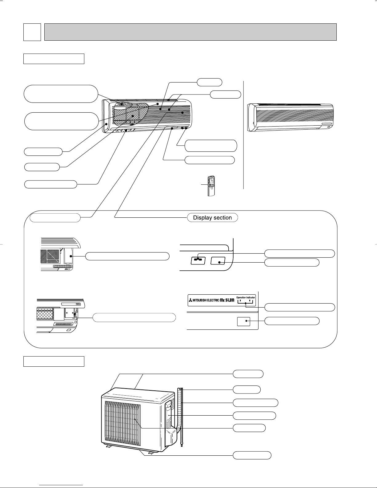
2
Operation section
Emergency operation switch
Horizontal vane
Air filter
Deodorizing filter(option)
(gray sponge type)
Vertical vanes
Air inlet
Grille
Remote control
receiving section
Remote controller
Air cleaning filter(option)
(white bellows type)
Front panel
Emergency operation switch
Operation indicator lamp
Receiving section
Operation indicator lamp
Receiving section
Air inlet (back and side)
Piping
Drainage hose
Service panel
Air outlet
Drain outlet
PART NAMES AND FUNCTIONS
INDOOR UNIT
MSZ09UN
(When the grille is opened)
MSZ09UN
MSZ09UN
MSZ12UN
MSZ12UN
OUTDOOR UNIT
MUZ09UN
MUZ12UN
MSZ12UN
4
Installation plate
Installation plate fixing screw 4 x 25 mm(0.16 x 0.98 in.)
Remote controller mounting hardware
Fixing screw for 3 3.5 x 16 mm(0.14 x 0.63 in.) (Black)
Battery (AAA) for remote controller
Wireless remote controller
Felt tape (Used for left or left-rear piping)
1
5
1
2
2
1
1
1
2
3
4
5
6
7
MSZ09UN
1
6
1
2
2
1
1
MSZ12UN
ACCESSORIES
ON/OFF
TOO
COOL
PM
AM
TOO
WARM
ON/OFF
FAN
TOO
WARM
TOO
COOL
VANE
MODE
STOP
START
HR.
MIN.
I FEEL
COOL
HEAT
DRY
PM
CLOCK
AM
RESET CLOCK
Open the front lid.
Signal transmitting section
Operation display section
OPERATE /STOP
(ON /OFF)button
TEMPERATURE buttons
OPERATION SELECT button
FAN SPEED CONTROL button
OFF-TIMER button
HR. button
MIN. button
(TIME SET button)
ON-TIMER button
RESET button
VANE CONTROL button
CLOCK SET button
REMOTE CONTROLLER
MSZ09UN
MSZ12UN
5
3
Item
Model
MSZ12UN
Capacity
Rated(Minimum~Maximum)
Capacity Rated
Power consumption
Rated(Minimum~Maximum)
Power consumption Rated
EER [SEER]
HSPF IV(V)
COP
INDOOR UNIT MODEL
External finish
Power supply
Max. fuse size (time delay)/ Disconnect switch
Min. circuit ampacity
Fan motor
Auxiliary heater
Airflow Low—Med.—High
Moisture removal
Sound level Low-Med.-High
Cond. drain connection O.D.
Dimensions
Weight
OUTDOOR UNIT MODEL
External finish
Power supply
Max. fuse size (time delay)
Min. circuit ampacity
Fan motor
Compressor
Refrigerant control
Sound level
Defrost method
Dimensions
Weight
REMOTE CONTROLLER
Control voltage (by built-in transformer)
REFRIGERANT PIPING
Refrigerant pipe size
(Min. wall thickness)
Connection method
Between the indoor
& outdoor units
Refrigerant charge (R22)
Refrigerating oil (Model)
Btu/h
Btu/h
Btu/h
W
W
W
V, phase, Hz
A
A
F.L.A
A(kW)
CFM
CFM
pt./h
dB(A)
in.
in.
in.
in.
Ib.
V, phase, Hz
A
A
F.L.A
R.L.A
L.R.A
dB(A)
in.
in.
in.
Ib.
in.
in.
ft.
ft.
oz.
7.7 (6.7)
White
115, 1, 60
15
–
5/8
7-1/2
Munsell 5.6Y 8.0/0.5
208/230, 1, 60
15
14
0.43
SHV-130FEA
U-V 1.05 U-W 1.05 U-W 1.05
9.7
41
Liner expansion valve
49
Reverse cycle
28
10-1/16
21-1/4
75
Wireless type
12V DC
Not supplied (optional parts)
1/4 (0.0265)
Flared
Flared
Max. 25
Max. 49
10.8 (MS56)
11,400(2,900~13,000)
16,000(2,400~19,500)
11,600
1,140(290~1,460)
1,590(280~2,050)
1,760
10.0[13.0]
2.95
MSZ12UN
0.6
0.43
360-395-452
360(311)-395(339)-452(388)
2.8
35-39-42
39-15/16
12-5/8
31
MUZ12UN
1/2 (0.0285)
2 Ib. 14 oz.
8,800(2,600~9,700)
12,300(2,300~15,700)
10,000
980(290~1,250)
1,320(280~1,770)
1,420
9.0 [12.0]
2.73
MSZ09UN
0.5
0.37
184-237-297
148(124)-215(180)-279(233)
2.3
22-29-36
33-1/2
10-15/16
20
3/8 (0.0285)
2 Ib. 7 oz.
❈1 ❈3
❈1
❈1
❈2
❈1
❈1
❈2
Cooling
Heating 47
Heating 17
Cooling
Heating 47
Heating 17
Cooling
Heating
Heating
MSZ09UN
MUZ09UN
HEAT Dry
COOL Dry(Wet)
W
D
H
Model
Winding resistance (at 68˚F) Ω
W
D
H
Liquid
Gas
Indoor
Outdoor
Height difference
Piping length
❈1
❈4
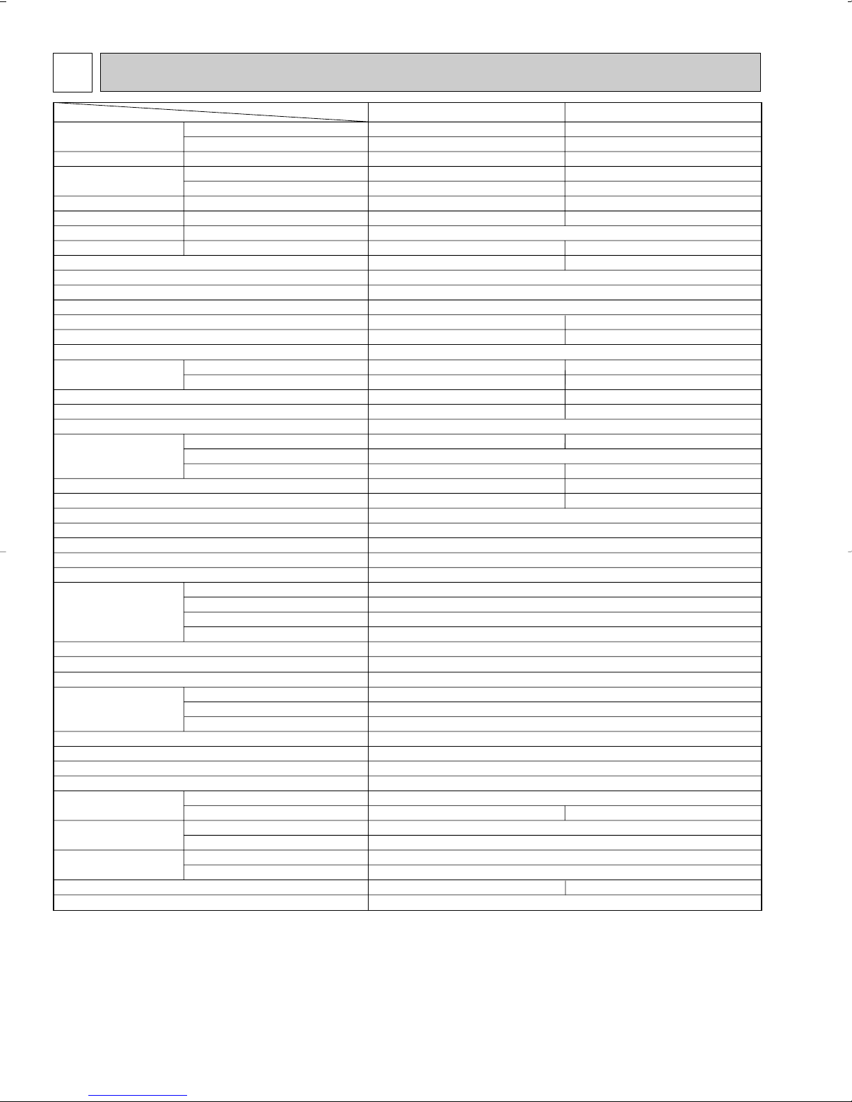
SPECIFICATION
NOTE : Test conditions are based on ARI 210/240.
❈1 : Rating conditions (cooling) — Indoor : 80˚FDB, 67˚FWB, Outdoor : 95˚FDB, (75˚FWB) Rated frequency: Hz
❈2 : (heating) — Indoor : 70˚FDB, 60˚FWB, Outdoor : 17˚FDB, 15˚FWB Maximum frequency: Hz
(heating) — Indoor : 70˚FDB, 60˚FWB, Outdoor : 47˚FDB, 43˚FWB Rated frequency: Hz
6
Indoor
unit
w Max. Height
difference 25ft.
Outdoor unit
Refrigerant Piping
Max.length
A
w Height difference should be within
25ft. regardless of which unit,
indoor or outdoor position is high.
Outside
diameter
Minimum
Wall
thickness
Outside
diameter
Minimum
Wall
thickness
MSZ09UN
MSZ12UN
MUZ09UN
MUZ12UN
Additional piping
Max. length : ft.
A
49
Gas
Piping size : in. Length of connecting pipe : in.
Liquid
Indoor unit
Outdoor unit
Model
Gas :
Liquid :00
Gas :
Liquid :
16-15/16
19-11/16
[ 3/8
[ 1/2
[ 1/4
0.0285
0.0265
Test condition
SEER
(Cooling)
HSPF
(Heating)
ARI
Mode
"A" Cooling Steady State
at rated compressor Speed
"B-2" Cooling Steady State
at rated compressor Speed
"B-1" Cooling Steady State
at minimum compressor Speed
Low ambient Cooling Steady State
at minimum compressor Speed
Intermediate Cooling Steady State
At Intermediate compressor Speed
❈5
Standard Rating-Heating
at rated compressor Speed
Low temperature Heating
at rated compressor Speed
Max temperature Heating
at minimum compressor Speed
High temperature Heating
at minimum compressor Speed
Frost Accumulation
at rated compressor Speed
Test
Indoor air condition Outdoor air condition
Dry bulb
Wet bulb
Dry bulb
Wet bulb
80
80
80
80
80
70
70
70
70
70
70
67
67
67
67
67
60
60
60
60
60
60
Frost Accumulation
at Intermediate compressor Speed
❈5
95
82
82
67
87
47
17
62
47
35
35
(75)
(65)
(65)
(53.5)
(69)
43
15
56.5
43
33
33
❈5 : At Intermediate compressor Speed
=("Cooling rated compressor speed" - "minimum compressor speed") / 3 + "minimum compressor speed".
(Unit : [˚F])
❈3, ❈4
MAX. REFRIGERANT PIPING LENGTH
MAX. HEIGHT DIFFERENCE
7
4
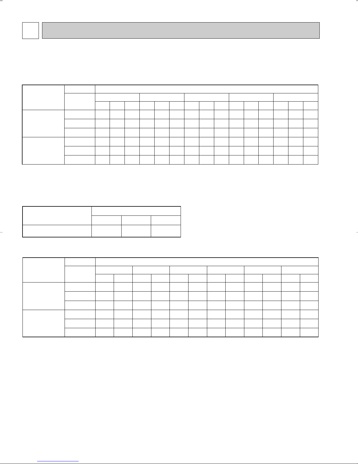
Model
Indoor air Outdoor intake air DB temperature(˚F
)
71
67
63
71
67
63
10.8
10.2
9.6
14.0
13.2
12.4
6.1
7.1
8.0
8.3
9.7
10.7
0.87
0.82
0.78
1.01
0.96
0.91
10.1
9.5
8.9
13.1
12.3
11.5
5.7
6.7
7.4
7.8
9.0
9.9
0.96
0.91
0.87
1.11
1.05
1.01
9.5
8.8
8.3
12.3
11.4
10.7
5.4
6.2
6.9
7.3
8.3
9.3
1.03
0.98
0.94
1.20
1.14
1.09
8.8
8.2
7.5
11.4
10.6
9.7
5.0
5.7
6.3
6.8
7.7
8.4
1.08
1.04
1.00
1.26
1.21
1.16
8.1
7.5
6.9
10.5
9.7
8.9
4.6
5.3
5.7
6.3
7.1
7.7
1.13
1.09
1.04
1.31
1.27
1.21
IWB
(˚F)
75 85 95 105 115
MSZ09UN
MSZ12UN
NOTE 1. IWB : Intake air wet-bulb temperature
TC : Total Capacity (x10
3
Btu/h), SHC : Sensible Heat Capacity (x10
3
Btu/h)
TPC : Total Power Consumption (kW)
2. SHC is based on 80˚F of indoor intake air DB temperature.
TC SHC
TPC TC SHC
TPC
TC SHC
TPC
TC SHC TPC
TC SHC
TPC
Model
Refrigerant piping length (one way : ft.)
1.0
25 (std.)
0.954
40
0.927
49
MSZ09UN
MSZ12UN
MUZ09UN
MUZ12UN
Model
Indoor air Outdoor intake air WB temperature(˚F
)
75
70
65
75
70
65
7.1
7.6
7.7
9.3
9.8
10.1
0.98
0.95
0.91
1.18
1.14
1.10
8.9
9.2
9.7
11.6
12.0
12.6
1.16
1.13
1.09
1.39
1.36
1.31
10.6
10.9
11.3
13.8
14.2
14.6
1.29
1.25
1.22
1.55
1.51
1.47
12.0
12.3
12.7
15.6
16.0
16.5
1.35
1.32
1.29
1.63
1.59
1.55
12.4
12.7
13.0
16.1
16.5
17.0
1.37
1.35
1.31
1.65
1.62
1.57
14.0
14.3
14.6
18.2
18.6
19.0
1.43
1.40
1.37
1.72
1.69
1.65
IDB
(˚F)
15 25 35 43 45 55
MSZ09UN
MSZ12UN
NOTE: 1. IDB : Intake air dry-bulb temperature
TC : Total Capacity (x10
3
Btu/h)
TPC : Total Power Consumption (kW)
2. Above data is for heating operation without any frost.
TC TPC TC TPC TC TPC TC TPC TC TPC TC TPC
DATA
MSZ09UN
MSZ12UN
MUZ09UN
MUZ12UN
4-1. PERFORMANCE DATA
1) COOLING CAPACITY
2) COOLING CAPACITY CORRECTIONS
3) HEATING CAPACITY
How to operate with fixed operational frequency of the compressor.
1. Press the EMERGENCY OPERATION switch on the front of the indoor unit, and select either EMERGENCY COOL mode
or EMERGENCY HEAT mode before starting to operate the air conditioner.
2. The compressor starts up.
The operational frequency of the compressor is MSZ09UN: 64Hz, MSZ12UN: 70Hz in EMERGENCY COOL mode and
58Hz in EMERGENCY HEAT mode.
3. The fan speed of the indoor unit is High.
4. This operation continues for 30minutes.
5. In order to release this operation, press the EMERGENCY OPERATION switch twice or once, or press any button on the
remote controller.
8
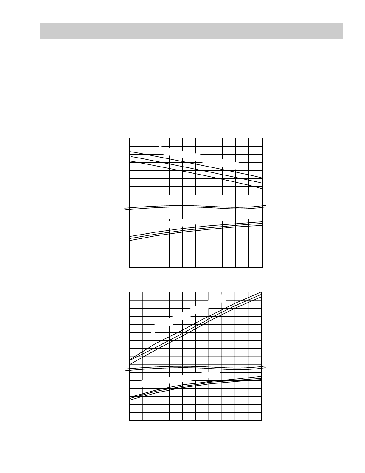
4-2. PERFORMANCE CURVE
71
67
63
71
67
63
65
70
75
75
70
65
Total power consumption (kW) Total capacity (
✕10
3
Btu/h)
Outdoor intake air DB temperature (°F)
SHF at rating condition = 0.70
= 233CFM
= 0.23
Airflow
Bypass Factor
12
10
8
6
1.2
65 75 85 95 105
115
0.8
0.6
Total power consumption (kW) Total capacity ( ✕10
3
Btu/h)
Outdoor intake air WB temperature (°F)
= 297CFM
Airflow
13
15
11
9
7
1.6
1.4
15 25 35 45 55
1.0
0.6
0.8
1.2
1.0
Indoor intake air WB temperature (°F)
Indoor intake air DB temperature (°F)
Indoor intake air DB temperature (°F)
Indoor intake air WB temperature (
°F)
0.4
How to operate with fixed operational frequency of the compressor.
1. Press the EMERGENCY OPERATION switch on the front of the indoor unit, and select either EMERGENCY COOL mode
or EMERGENCY HEAT mode before starting to operate the air conditioner.
2. The compressor starts up.
The operational frequency of the compressor is 64Hz in EMERGENCY COOL mode and 58Hz in EMERGENCY HEAT
mode.
3. The fan speed of the indoor unit is High.
4. This operation continues for 30minutes.
5. In order to release this operation, press the EMERGENCY OPERATION switch twice or once, or press any button on the
remote controller.
MSZ09UN MUZ09UN
(Cooling)
MSZ09UN MUZ09UN
(Heating)
This value of frequency is not the same as the actual frequency in operating. Refer to the page 16, 17 for the relationships
between frequency and capacity.
9
71
67
63
71
67
63
14
12
8
10
1.5
1.3
1.1
0.9
0.7
0.5
Indoor intake air WB temperature (°F)
Indoor intake air WB temperature (°F)
65
70
75
75
70
65
21
17
9
13
2.0
1.0
SHF at rating condition = 0.73
= 388CFM
= 0.19
Airflow
Bypass Factor
65 75 85 95 105 115
Total power consumption (kW) Total capacity ( ✕10 Btu/h)
Outdoor intake air DB temperature (°F)
Indoor intake air DB temperature (
°F)
= 452CFM
Airflow
15 25 35 45 55
Total power consumption (kW) Total capacity ( ✕10 Btu/h)
Outdoor intake air WB temperature (°F)
1.2
1.4
1.6
1.8
Indoor intake air DB temperature (°F)
How to operate with fixed operational frequency of the compressor.
1. Press the EMERGENCY OPERATION switch on the front of the indoor unit, and select either EMERGENCY COOL mode
or EMERGENCY HEAT mode before starting to operate the air conditioner.
2. The compressor starts up.
The operational frequency of the compressor is 70Hz in EMERGENCY COOL mode and 58Hz in EMERGENCY HEAT
mode.
3. The fan speed of the indoor unit is High.
4. This operation continues for 30minutes.
5. In order to release this operation, press the EMERGENCY OPERATION switch twice or once, or press any button on the
remote controller.
MSZ12UN MUZ12UN
(Cooling)
MSZ12UN MUZ12UN
(Heating)
This value of frequency is not the same as the actual frequency in operating. Refer to the page 16, 17 for the relationships
between frequency and capacity.
10
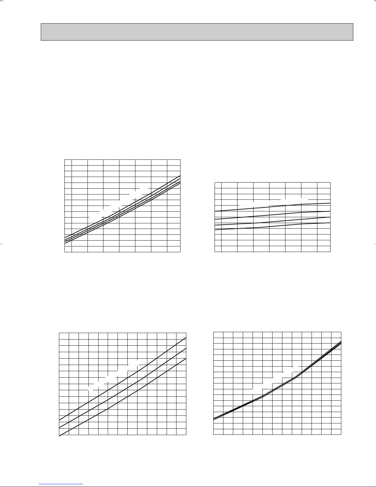
68 70 75 80 85 90 95 100 104
(°F)
40
45
50
55
60
65
70
75
80
85
90
95
100
(PSIG)
Condensing pressure
86
80
75
70
Suction pressure
Outdoor ambient temperature
Indoor DB temperature (
°F)
(PSIG)
86
80
75
70
68 70 75 80 85 90 95 100 104
(°F)
140
160
180
200
220
240
260
280
300
Indoor DB temperature (°F)
Outdoor ambient temperature
75
70
65
(PSIG)
Condensing pressure
Outdoor ambient temperature
5 10152025303540455055606570(°F)
150
160
170
180
190
200
210
220
230
240
250
260
270
280
290
300
310
Indoor DB temperature(
°F)
75
70
65
(PSIG)
Suction pressure
Outdoor ambient temperature
5 10152025303540455055606570(°F)
10
15
20
25
30
35
40
45
50
55
60
65
70
75
80
85
90
95
100
Indoor DB temperature (
°F)
4-3. Condensing pressure
How to operate with fixed operational frequency of the compressor.
1. Press the EMERGENCY OPERATION switch on the front of the indoor unit, and select either EMERGENCY COOL mode
or EMERGENCY HEAT mode before starting to operate the air conditioner.
2. The compressor starts up.
The operational frequency of the compressor is MSZ09UN: 64Hz, MSZ12UN: 70Hz in EMERGENCY COOL mode and
58Hz in EMERGENCY HEAT mode.
3. The fan speed of the indoor unit is High.
4. This operation continues for 30minutes.
5. In order to release this operation, press the EMERGENCY OPERATION switch twice or once, or press any button on the
remote controller.
MSZ09UN
(Cooling)
MSZ09UN
(Heating)
Data is based on the condition of indoor humidity 50%.
Air flow should be set to High speed.
Data is based on the condition of outdoor humidity 75%.
Air flow should be set to High speed.
Data is for heating operation without any frost.
11
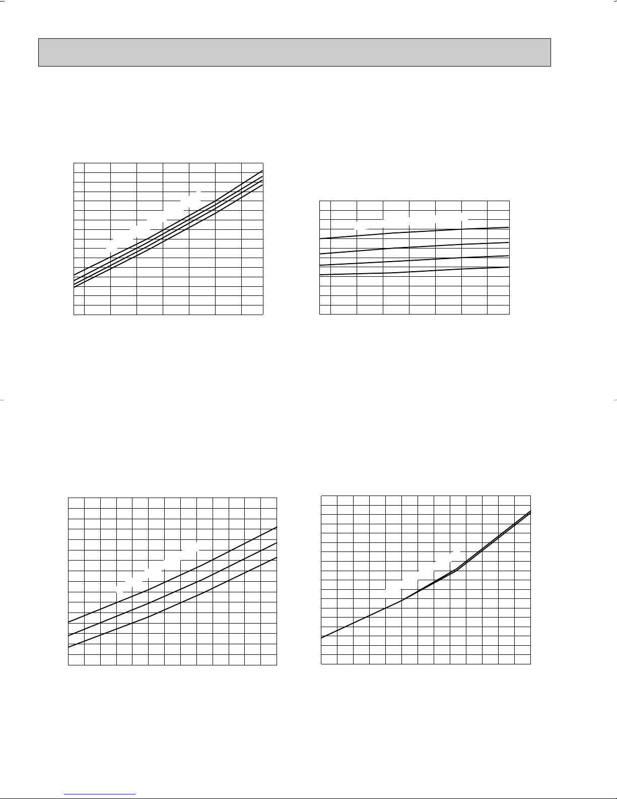
MSZ12UN
68 70 75 80 85 90 95 100 104(°F)
50
55
60
65
70
75
80
85
90
95
100
105
110
(PSIG)
Condensing pressure
86
80
75
70
Suction pressure
Outdoor ambient temperature
Indoor DB temperature (
°F)
(PSIG)
86
80
75
70
68 70 75 80 85 90 95 100 104(°F)
140
160
180
200
220
240
260
280
300
Indoor DB temperature (°F)
Outdoor ambient temperature
75
70
65
(PSIG)
Condensing pressure
Outdoor ambient temperature
5 10152025303540455055606570(°F)
120
130
140
150
160
170
180
190
200
210
220
230
240
250
260
270
280
Indoor DB temperature(
°F)
(PSIG)
Outdoor ambient temperature
75
70
65
Suction pressure
5 10152025303540455055606570(°F)
10
15
20
25
30
35
40
45
50
55
60
65
70
75
80
85
90
95
100
Indoor DB temperature (
°F)
(Cooling)
Data is based on the condition of indoor humidity 50%.
Air flow should be set to High speed.
MSZ12UN
(Heating)
Data is based on the condition of outdoor humidity 75%.
Air flow should be set to High speed.
Data is for heating operation without any frost.
12
4-4. STANDARD OPERATION DATA
MSZ09UN
INDOOR UNIT
115V
1phase 60Hz,
2 wires
OUTDOOR UNIT
208/230V
1phase
60Hz,
2 wires
SIGNAL WIRE
2 wires 12V DC
208/230V
1phase
60Hz,
3 wires
115V
INDOOR UNIT
OUTDOOR UNIT
SIGNAL WIRE
2 wires 12V DC
115V
1phase
60Hz,
2 wires
Disconnect
switch
Cooling
8,800
0.70
980
64
0.945
5.34/5.11
237
74
184
112
52
154
80
67
57
56
950
233(Wet)
95
–
Capacity
SHF
Input
Rated frequency
Indoor unit
Power supply (V, phase, Hz)
Input
Fan motor current
Aux. heater current
Outdoor unit
Power supply (V, phase, Hz)
Input
Comp. current
Fan motor current
Condensing pressure
Suction pressure
Discharge temperature
Condensing temperature
Suction temperature
Comp. shell bottom temp
Ref. pipe length
Refrigerant charge (R22)
Intake air temperature
Discharge air temperature
Fan speed (High)
Airflow (High)
Intake air temperature
Fan speed
Airflow
Unit
Btu / h
—
kW
Hz
kW
A
A
kW
A
A
PSIG
PSIG
˚F
˚F
˚F
˚F
ft.
—
˚F
˚F
˚F
˚F
rpm
CFM
˚F
˚F
rpm
CFM
Cooling
11,400
0.73
1,140
70
1.093
5.84/5.71
256
87
186
54
160
80
67
58
56
388(Wet)
95
–
Heating
16,000
–
1,590
99
1.543
8.24/7.71
265
57
197
34
171
70
60
114
–
452(Dry)
47
43
Heating
12,300
–
1,320
76
1.285
6.84/6.81
276
59
198
122
36
172
70
60
100
–
1,000
297(Dry)
47
43
DB
WB
DB
WB
DB
WB
Item
Model
Total
Electrical
circuit
Refrigerant
circuit
Indoor
unit
Outdoor
unit
MSZ09UN
MSZ09UN
115, 1, 60
0.035
0.34
–
MUZ09UN
208/230, 1, 60
0.36/0.39
25
2 Ib. 7 oz.
650/720
847/953
MSZ12UN
MSZ12UN
115, 1, 60
0.047
0.41
–
MUZ12UN
208/230, 1, 60
0.36/0.39
118
25
2 Ib. 14 oz.
1,200
650/720
847/953
MSZ12UN
INDOOR UNIT
OUTDOOR UNIT
115V
1phase
60Hz,
2wires
208/230V
1phase
60Hz,
2 wires
SIGNAL WIRE
2 wires 12V DC
INDOOR UNIT
OUTDOOR UNIT
208/230V
1phase
60Hz,
3 wires
115V
1phase
60Hz,
2 wires
SIGNAL WIRE
2 wires 12V DC
115V
Disconnect
switch
POWER SUPPLY
✻ Control voltage
Power supply voltage to serial signal circuit is 12V DC.
Voltage between 11- and 33+ on in-out terminal block will be 12V DC peak voltage.
13
4-5. OPERATING RANGE
MSZ09UN
MSZ12UN
MUZ09UN
MUZ12UN
Indoor unit
Outdoor unit
Rated voltage
115V 1phase 60Hz
208/230V 1phase 60Hz
Guaranteed Voltage
Model
Min. 103V
Max. 127V
115V
Min. 198V Max. 253V
208V
230V
Model
MSZ09UN
MSZ12UN
Mode
HEAT
COOL
HEAT
COOL
297
279
233
452
452
388
15.8
14.9
12.4
18.2
18.2
15.6
22.3
21.0
17.6
29.2
29.2
25.2
Air flow
(CFM)
Air speed
(ft./sec.)
Coverage
range (ft.)
Function
Dry
Dry
Wet
Dry
Dry
Wet
MSZ09UN
MSZ12UN
MUZ09UN
MUZ12UN
Outdoor unit
precharged
(up to 25ft.)
2 lb. 7 oz.
2 lb. 14 oz.
25ft.
0
30ft.
1.62
35ft.
3.24
Refrigerant piping length (one way)
40ft.
4.86
45ft.
6.48
49ft.
8.10
Model
78%
—
Function
Cooling
Heating
Standard temperature
Maximum temperature
Minimum temperature
Maximum humidity
Standard temperature
Maximum temperature
Minimum temperature
DB (˚F)
80
95
67
70
80
70
WB (˚F)
67
71
57
60
67
60
Indoor
DB (˚F)
95
115
67
47
75
17
WB (˚F)
—
—
—
43
65
15
Outdoor
Condition
Intake air
temperature
(1) POWER SUPPLY
(2) OPERATION
4-6. OUTLET AIR SPEED AND COVERAGE RANGE
4-7. ADDITIONAL REFRIGERANT CHARGE R22(oz.)
14
● The air coverage range is the figure up
to the position where the air speed is 1
ft./sec., when air is blown out horizontally from the unit properly at the High
speed position.
The coverage range should be used
only as a general guideline since it
varies according to the size of the room
and furniture arranged inside the room.

MSZ09UN
MUZ09UN
The standard data contained in these specifications apply only to the operation of the system under normal conditions. Since
operating conditions vary according to the areas where these units are installed. The following information has been provided
to clarify the operating characteristics of the system under the conditions indicated by the performance curve.
(1) GUARANTEED VOLTAGE
INDOOR UNIT 103 ~ 127V 60Hz
OUTDOOR UNIT 198 ~ 253V 60Hz
(2) AIR FLOW
Air flow should be set at MAX.
(3) MAIN READINGS
(1) Indoor intake air wet-bulb temperature :°F WB
(2) Indoor outlet air wet-bulb temperature :°F WB
(3) Outdoor intake air dry-bulb temperature :°F DB
(4) Total input :W
(5) Indoor intake air dry-bulb temperature :°F DB
(6) Outdoor intake air wet-bulb temperature :°F WB
(7) Total input :W
Indoor air wet/dry-bulb temperature difference on the left side of the chart on page 16 and 17 shows the difference
between the indoor intake air wet/dry-bulb temperature and the indoor outlet air wet/dry-bulb temperature for your reference at service.
MSZ12UN
MUZ12UN
Cooling
}
Heating
}
How to measure the indoor air wet-bulb/ dry-bulb temperature difference
1. Attach at least 2 sets of wet-and dry-bulb thermometers to the indoor air intake as shown in the figure, and at least 2 sets
of wet-and dry-bulb thermometers to the indoor air outlet. The thermometers must be attached to the position where air
speed is high.
2. Attach at least 2 sets of wet-and dry-bulb thermometers to the outdoor air intake.
Cover the thermometers to prevent direct rays of the sun.
3. Check that the air filter is cleaned.
4. Open windows and doors of room.
5. Press the EMERGENCY OPERATION switch once (twice) to start the EMERGENCY COOL (HEAT) MODE.
6. When system stabilizes after more than 15 minutes, measure temperature and take an average temperature.
7. 10 minutes later, measure temperature again and check that the temperature does not change.
INDOOR UNIT
OUTDOOR UNIT
15
0 50 100 150(Hz)
0.0
0.5
1.0
1.5
Correction of Cooling capacity
Capacity correction factors
The operational frequency of compressor
Correction of total input
Input correction factors
The operational frequency of compressor
0 50 100 150(Hz)
0.0
0.5
1.0
1.5
0 50 100 150(Hz)
0.0
0.5
1.0
1.5
Correction of Cooling capacity
Capacity correction factors
The operational frequency of compressor
Correction of total input
Input correction factors
The operational frequency of compressor
0 50 100 150(Hz)
0.0
0.5
1.0
1.5
18.7
17.1
15.5
14.0
12.6
11.2
MSZ09UN
MSZ12UN
13.9
12.8
11.7
10.6
9.5
8.5
80 85 90 95 100 105 110
80 85 90 95 100 105 110
79
75
72
68
64
79
75
72
68
64
Cooling capacity
✴ These values are under rated (frequency).
MUZ09UN
MUZ12UN
MUZ09UN
MUZ12UN
16
0 50 100 150(Hz)
0.0
0.5
1.0
1.5
Correction of Heating capacity
Capacity correction factors
The operational frequency of compressor
Correction of total input
Input correction factors
The operational frequency of compressor
0 50 100 150(Hz)
0.0
0.5
1.0
1.5
50.4
46.6
42.7
38.9
34.9
31.0
27.2
23.2
MSZ09UN
MSZ12UN
43.2
39.8
36.5
33.1
30.0
26.5
23.2
20.0
14
20
30
40
50
60
59
68
79
1.4
1.3
1.2
1.1
1.0
0.9
0.8
0.7
0.6
14
20
30
40
50
59
68
79
60
Heating capacity
NOTE:The following curves are for the heating operation without any frost.
✴ These values are under rated (frequency).
MUZ09UN
Correction of Heating capacity
1.5
1.0
0.5
Capacity correction factors
0.0
0 50 100 150(Hz)
The operational frequency of compressor
MUZ12UN
MUZ09UN
Correction of total input
1.5
1.0
0.5
Input correction factors
0.0
0 50 100 150(Hz)
The operational frequency of compressor
MUZ12UN
17
5
6-3/8
3/4
2-5/16
1/8 11-11/16
17-11/16
17-11/16
13-7/817-1/4
10
10-13/16
13/16
2-3/8
1-9/16
5-7/8 25-1/2 8-9/16
3/167-1/2
39-3/16
7-1/230-1/21-15/16
12-5/8
39-15/16
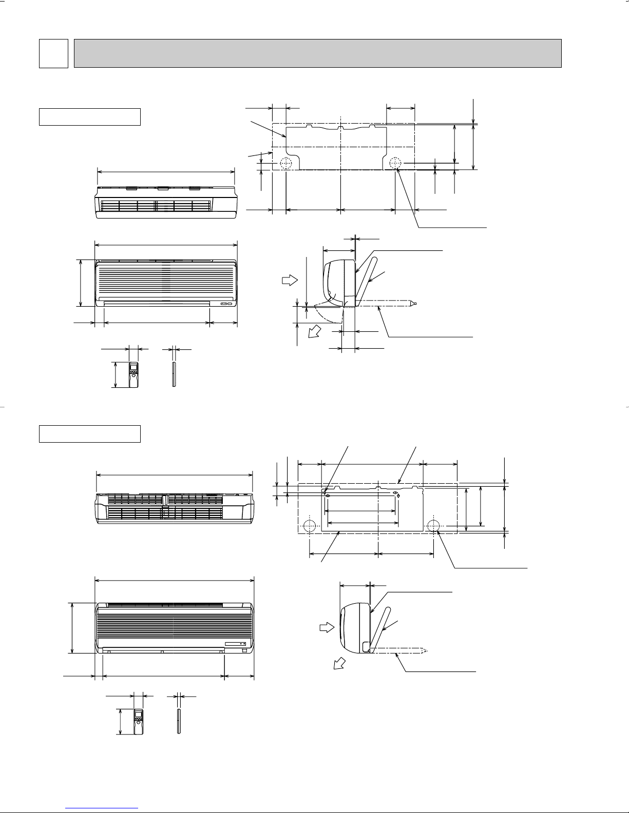
Wireless remote controller
4holes 7/16 O 13/16
Indoor unit
Installation plate
Wall hole [2-15/16
Installation plate
Liquid line [5/16 19-11/16
Gas line [1/2 16-15/16
Insulation [ 1-15/16 O.D
[ 1-1/8 I.D
Insulation [ 1-1/8
Drain hose [
5/8
Air out
{
Air in
OUTLINES AND DIMENSIONS
MSZ09UN
INDOOR UNIT
10-15/16
2-5/16
32-3/16
33-1/2
3/4
6-3/8
Wireless remote controller
3-1/4
Installation plate
Indoor unit
3-1/4
6-1/224-3/42-1/4
1-5/8
Air in
12-13/16 12-13/16
3/16
1/4 or more
3-15/16
Air out
7-7/16
Installation plate
2-5/8
3-1/16
6-5/8
9-1/8
1/8
1-5/8
4-5/8
Wall hole [2-9/16
Liquid line [1/4 19-11/16
Gas line [3/8 16-15/16
{
Insulation [1-7/16 O.D
[13/16 I.D
Drain hose [5/8
(Connected part O.D)
Insulation [1-1/8
Unit: inch
3/16
10-11/16
MSZ12UN
INDOOR UNIT
18
MUZ09UN MUZ12UN
Even if the right/left sides
or back side are vacant, the
top has to be at least 4 in.
unobstructed.
REQUIRED SPACE
Even if the right/left sides or back side
are vacant, the front has to be at least
4 in. unobstructed.
14 in. or more
4 in. or more
4 in. or more
Basically
unobstructed
Basically
unobstructed
WA
WA
WB
WA
WB
In case of poorly-ventilated place, the front or the back
has to be at least 8 in. unobstructed.
The wall may get dirty in case the air is discharged
toward it.
T.B. cover
Lock nut
Conduit cover
Connector
Service panel
Remove one fixing
screw to open the
service panel
Remove the screw
holding the T.B.
cover, and then
remove the cover
OUTDOOR UNIT
14-7/16
Air in
10-7/16
1-9/32
3-5/8
Air in
Drainage holes [1-3/32
1-5/16
4 holes 3/8o13/16
11/16
Handle
19-1/2
Air out
5
Drainage holes [1-3/32
Drainage holes [1-3/32
Drainage holes [1-3/32
1-3/8
1-9/16
10-1/32
1-9/32
11-7/32
25/32
Unit: inch
12-5/8
Service panel
Liquid refrigerant pipe joint
Refrigerant pipe (flared) [1/4
21-1/4
10-5/8
3/8
4-1/8
10-7/16
19-11/16
Bolt pitch for installation
28
6-3/32
3-17/32
2-11/16
5-7/16
Service port
19
43-
35-
Gas refrigerant pipe joint
Refrigerant pipe (flared)
[3/8 (MUZ09UN
[1/2 (MUZ12UN
)
)
6
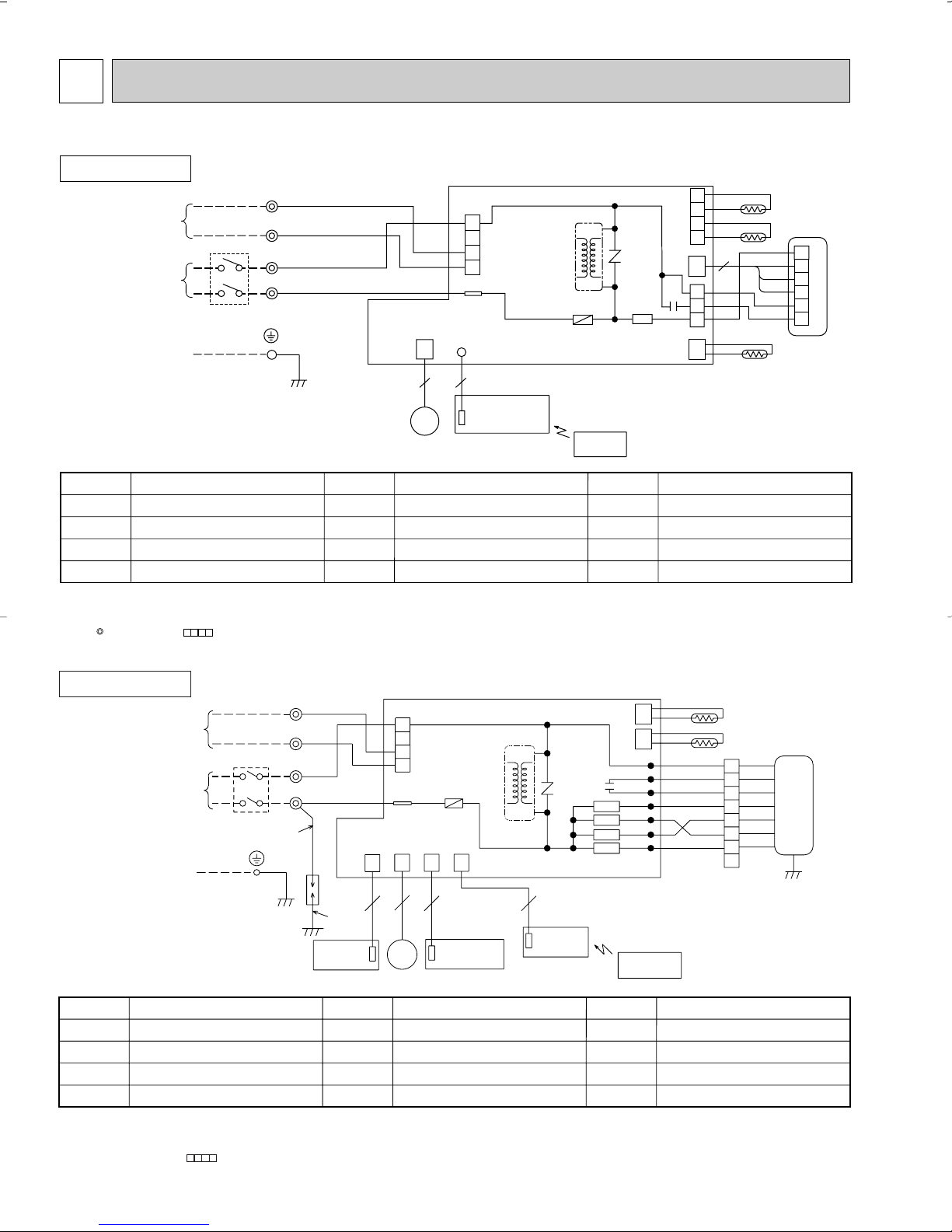
HIC1
( )
FROM OUTDOOR
1 phase
60Hz
CONNECTING
WIRE
TO OUTDOOR
UNIT
12V DC
SUPPLY
POWER
WIRES
CONNECTING
UNIT
115V
w A disconnect may be required by local code.
5
TAB12
P.C.BOARD
DISPLAY
MV
RED
GRN/YLW
DSAR
3
L1
RED
BLK
N
3
4
P.C.BOARD
AUTO RESTART
ASSY
CONTROLLER
REMOTE
RECEIVER
ELECTRONIC CONTROL P.C. BOARD
53
F11
TRANS
LDFVL
SR141
NR11
SR142
SR143
SR144
C11
LDFM
LDFL
LDFH
LDC12
LDC11
LDCOM
TO OUTDOOR
CONNECTING
WIRES
UNIT
CN
102CN151CN104CN101
CN
112
CN
111
TB
CN201
ORN
VLT
1-
3+
1
2
BRN
7
BRN
GRN/YLW
8
YLW
BLU
RED
ORN
WHT
BLK
3
BLU
YLW
BLK
5
6
4
ORN
RED
WHT
2
1
MF
RT11
RT12
w
SYMBOL
RT12
SR141~SR144
TB
SYMBOL
MF
MV
NR11
RT11
SYMBOL
C11
DSAR
F11
HIC1
NAME
NAME NAME
INDOOR FAN CAPACITOR
SURGE ABSORVER
FUSE(3A)
DC/DC CONVERTER
INDOOR FAN MOTOR(INNER FUSE)
VANE MOTOR
VARISTOR
ROOM TEMPERATURE THERMIST OR
INDOOR COIL THERMISTOR
SOLID STATE RELAY
TERMINAL BLOCK
WIRING DIAGRAM
MSZ09UN
MODEL WIRING DIAGRAM
INDOOR UNIT
TB
L1
3+
1-
N
ORN
VLT
BLK
RED
SYMBOL
MV
NR11
RT11
RT12
CN201
1
2
3
4
TAB12
LD101T
CN
151
MV
ELECTRONIC CONTROL P.C. BOARD
5
5
POWER MONITOR,
RECEIVER
P.C.BOARD
NAME NAME
VANE MOTOR
VARISTOR
ROOM TEMPERATURE THERMIST OR
MAIN INDOOR COIL THERMISTOR
TO OUTDOOR
UNIT
CONNECTING
WIRES
12V DC
FROM OUTDOOR
UNIT
CONNECTING
WIRES
POWER
(
)
SUPPLY
115V
1 phase
60Hz
TO OUTDOOR
UNIT
CONNECTING
WIRE
w
w A disconnect may be required by local code.
SYMBOL
C11
F11
HIC1
NOTE:1. About the outdoor side electric wiring, refer to the outdoor unit electric wiring diagram for servicing.
INDOOR FAN CAPACITOR
FUSE(3A)
DC/DC CONVERTER
INDOOR FAN MOTOR(INNER FUSE)
MF
2. Use copper conductors only.(For field wiring)
3. Symbols below indicate;
: Terminal block, : Connector
NAME
HIC1
NR11
TRANS
F11
REMOTE
CONTROLLER
SR141
SYMBOL
RT13
SR141
TB
C11
4
3
2
1
CN112
CN
121
1
2
3
CN211
CN
111
3
RT13
RT12
BLK
GRY
YLW
BRN
WHT
RED
RT11
1
2
3
MF
4
5
6
SUB INDOOR COIL THERMISTOR
SOLID STATE RELAY
TERMINAL BLOCK
MSZ12UN
INDOOR UNIT
NOTE:1. About the outdoor side electric wiring, refer to the outdoor unit electric wiring diagram for servicing.
2. Use copper conductors only. (For field wiring)
3. Symbols below indicate;
/: Terminal block, : Connector
MODEL WIRING DIAGRAM
20
MUZ09UN
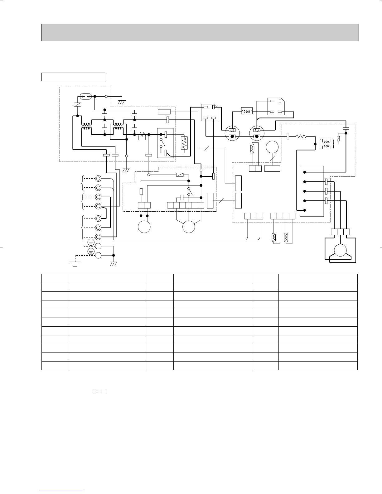
MUZ12UN
OUTDOOR UNIT
MODELS WIRING DIAGRAM
DSA61
NR61
NOISE FILTER
P.C. BOARD
FROM INDOOR UNIT
CONNECTING WIRES
12V DC
TO INDOOR UNIT
CONNECTING
115V
1 phase 60Hz
POWER
SUPPLY
208/230V
1 phase 60Hz
INDOOR UNIT
FROM
GROUND
L62
3
1
N
L1
L1
N
L2
LDE2
TAB66
TB2
TB1
CY61
CY62
ORN
VLT
BLK
RED
RED
BLK
BLU
L63
TAB65
GRN
WHT
12
CN725
TAB69
X64
TAB68
RELAY
P.C. BOARD
CN771
CY63
CT61
CY64
LDE1
GRN
LD64
SSR61
CN721
21S4 MF61
R.V. coil
heating ON
cooling OFF
RED
BLU
3
WHT
R64
4
ORN
LD62
F901
C65
53
642
RED
BLK
X61
1
WHT
DS61
(~)
(–) (~)
4
TAB
67
(+)
YLW
BLU
3
CN723
BLK
DS62
RED
(~)
BLK
C63
123
ORN
(–)
YLW
LEV
6
CN724
RT61 RT62
(+)
(~)
TAB
CN641
RED
N
RED
TAB
P
R61
P
U
V
W
4321
T801
TABU
TABV
TABW
N
IPM
BLK
123
WHT
MC
W
BLK
F801
WHT
V
RED
RED
U
L61
BLK
C61
+
–
YLW
CN726
CN722
CN601
VLT
+
–
RT64
21
CN642
ELECTRONIC
CONTROL
P.C. BOARD
SYMBOL
CT61
C61
C63
C65
CY61~64
DSA61
DS61,62
F801
F901
IPM
NOTE:1. About the indoor side electric wiring refer to the indoor unit electric wiring diagram for servicing.
CURRENT TRANSFORMER
POWER-FACTOR CAPACITOR
SMOOTHING CAPACITOR
OUTDOOR FAN CAPACITOR
CAPACITOR
SURGE ABSORBER
DIODE STACK
FUSE (2A)
FUSE (1A)
INTELLIGENT POWER MODULE
2.Use copper conductors only. (For field wiring)
3. Symbols below indicate.
/: Terminal block, : Connector
NAME
SYMBOL
LEV
L61
L62,L63
MC
MF61
NR61
RT61
RT62
RT64
R61
NAME
EXPANSION VALVE COIL
REACTOR
COMMON MODE CHOKE COIL
COMPRESSOR
OUTDOOR FAN MOTOR(INNER PROTECTOR)
VARISTOR
DEFROST THERMISTOR
DISCHARGE TEMPERATURE THERMIST OR
FIN TEMPERATURE THERMIST OR
CURRENT-DETECTING RESISTOR
SYMBOL
R64
SSR61
TB1,2
T801
X61
X64
21S4
NAME
CURRENT-LIMITING RESISTOR
SOLID STATE RELAY
TERMINAL BLOCK
TRANSFORMER
FAN MOTOR RELAY
RELAY
R.V. COIL
21
7
Room
Temperature
thermistor
RT11
Sub
indoor coil
thermistor
RT13
Main
indoor coil
thermistor
RT12
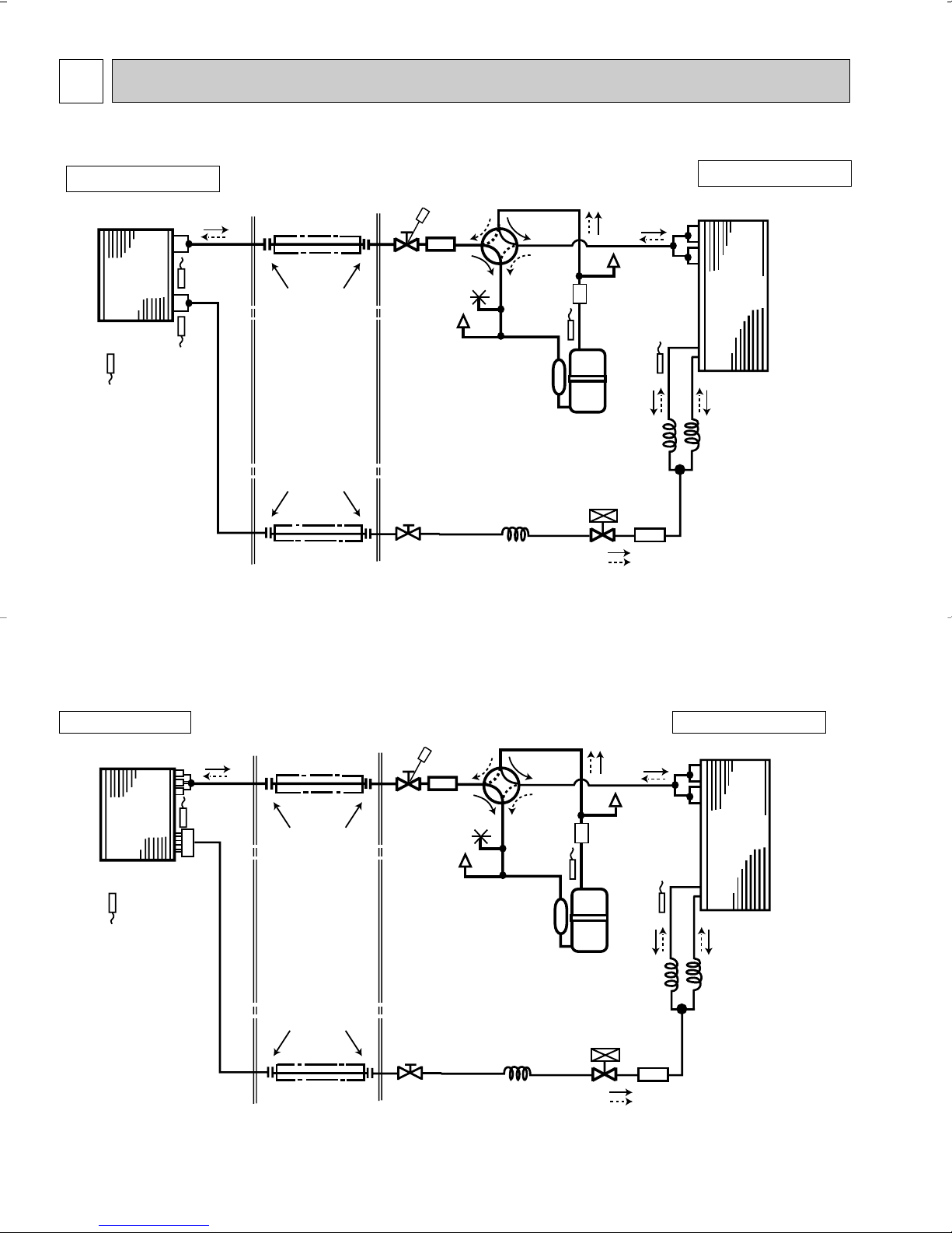
Refrigerant pipe {3/8
(with heat insulator)
Flared connection
Stop valve
(with service port)
Stop valve
(with strainer)
Fusible
plug
Service
port
Service
port
Muffler
Muffler
4-way valve
Compressor
Capillary
tube
Expansion
valve
Capillary tube
O.D.0.12OI.D.0.079O7-7/8
Flow of refrigerant (cooling)
Flow of refrigerant (heating)
Capillary
tube
R.V. coil
heating ON
cooling OFF
O.D.0.12OI.D.0.079O11-13/16 O.D.0.12OI.D.0.079O11-13/16
Discharge
temperature
thermistor
RT62
Flared connection
Refrigerant pipe {1/4
(with heat insulator)
Indoor
heat
exchanger
Outdoor
heat
exchanger
Defrost
thermistor
RT61
Strainer
REFRIGERANT SYSTEM DIAGRAM
MSZ09UN
Unit:inch
MUZ09UN
INDOOR UNIT
OUTDOOR UNIT
Unit:inch
MSZ12UN
MUZ12UN
INDOOR UNIT OUTDOOR UNIT
4-way valve
Discharge
temperature
thermistor
RT62
Service
port
Capillary tube
O.D.0.12OI.D.0.079O7-7/8
O.D.0.12OI.D.0.079O11-13/16 O.D.0.12OI.D.0.079O11-13/16
Service
port
Muffler
Compressor
Defrost
thermistor
RT61
Capillary
tube
Expansion
valve
Strainer
Flow of refrigerant (cooling)
Flow of refrigerant (heating)
Outdoor
heat
exchanger
Capillary
tube
R.V. coil
heating ON
cooling OFF
Indoor
heat
exchanger
Room
Temperature
thermistor
RT11
Main
indoor coil
thermistor
RT12
Refrigerant pipe {1/2
(with heat insulator)
Flared connection
Flared connection
Refrigerant pipe {1/4
(with heat insulator)
Stop valve
(with service port)
Stop valve
(with strainer)
Muffler
Fusible
plug
22
8
lighted
not lighted
Approx. 4 ˚F or more
Difference between target
temperature and room
temperature
Approx. 4 ˚F or less
This shows that the air conditioner is operating to reach
the target temperature.
Please wait until the target temperature is obtained.
This shows that the room temperature is
approaching the target temperature.
Operation stateIndication
Operation Indicator
Operation Indicator lamp
The operation indicator located at the right side of the indoor unit indicates the operation state.
• The following indication applies regardless of shape of the indicatior.
INDOOR UNIT DISPLAY SECTION
ON/OFF
FAN
TOO
WARM
TOO
COOL
VANE
MODE
STOP
START
HR.
MIN.
I FEEL
COOL
HEAT
DRY
RESET CLOCK
OPERATION SELECT button
FAN SPEED CONTROL button
OFF-TIMER button
HR. button
MIN. button
(TIME SET button)
ON-TIMER button
RESET button
VANE CONTROL button
CLOCK SET button
ON/OFF
TOO
COOL
PM
AM
TOO
WARM
Signal transmitting section
Operation display section
OPERATE /STOP
(ON /OFF)button
TEMPERATURE buttons
MICROPROCESSOR CONTROL
MSZ09UN
MSZ12UN
MUZ09UN
MUZ12UN
Once the operation mode are set, the same operation mode can be repeated by simply turning the OPERATE/STOP(ON/OFF)
button ON.
Indoor unit receives the signal with a beep tone.
When the system turns off, 3-minute time delay will operate to protect system from overload and compressor will not restart for
3 minutes.
WIRELESS REMOTE CONTROLLER
23
8-1. “I FEEL CONTROL” OPERATION
(1) Press OPERATE/STOP(ON/OFF) button on the remote controller.
OPERATION INDICATOR lamp of the indoor unit turns on with a
beep tone.
(2) Press OPERATION SELECT button to set “I FEEL CONTROL”.
Then a beep tone is heard.
(3) The operation mode is determined by the room temperature at
start-up of the operation.
● Once the mode is fixed, the mode does not change by room temperature afterwards.
● Under the ON-TIMER ( START) operation, mode is determined according to the room temperature as the operation
starts.
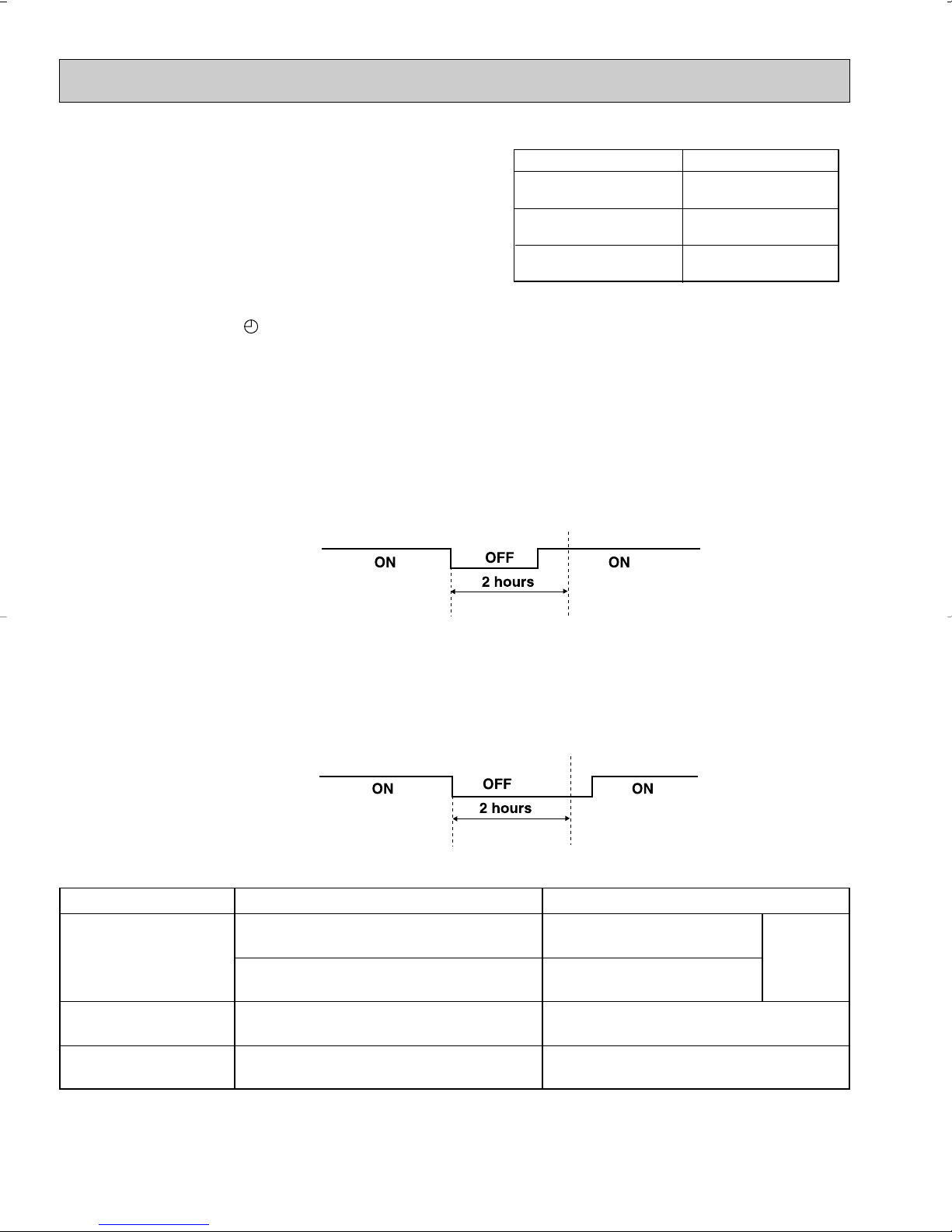
● When the system is stopped with the OPERATE/STOP(ON/OFF) button on the remote controller, and restarted within 2
hours in “I FEEL CONTROL” mode, the system operates in previous mode automatically regardless of the room temperature.
Operation time chart
Example
Initial room temperature
77˚F or more
73˚F to 77˚F
less than 73˚F
“I FEEL CONTROL”
“I FEEL CONTROL”
“I FEEL CONTROL”
mode
COOL mode of
DRY mode of
HEAT mode of
Previous operation
COOL mode of
“I FEEL CONTROL”
or COOL mode
When the system is restarted after 2 hours and more, the operation mode is determined by the room temperature at
start-up of the operation.
Operation time chart
Example
Previous operation
COOL mode of
“I FEEL CONTROL” or
COOL mode
(4) The initial set temperature is decided by the initial room temperature.
Restart
COOL mode of
“I FEEL CONTROL”
Restart
COOL or DRY or HEAT
mode of “I FEEL CONTROL” that determined
by room temperature at
start-up of the operation.
Mode Initial room temperature Initial set temperature
COOL mode of
“I FEEL CONTROL”
DRY mode of
“I FEEL CONTROL”
HEAT mode of
“I FEEL CONTROL”
❈1 When the system is restarted with the remote controller, the system operates with the previous set temperature regard-
less of the room temperature at restart.
The set temperature is calculated by the previous set temperature.
79˚F or more
77˚F to 79˚F
73˚F to 77˚F
less than 73˚F
24
75˚F
Initial room temperature
minus 4˚F
Initial room temperature
minus 4˚F
79˚F
❈ 1
 Loading...