

Mitsubishi Electric MUY-TP-VF, MSY-TP35VF-E1, MSY-TP35VF-ET1, MSY-TP50VF-E1, MSY-TP50VF-ET1 Service Manual
Page 1
CONTENTS
1. TECHNICAL CHANGES ··································· 3
2. PART NAMES AND FUNCTIONS ····················· 4
3. SPECIFICATION ················································ 5
4. NOISE CRITERIA CURVES ······························ 6
5. OUTLINES AND DIMENSIONS ························ 7
6. WIRING DIAGRAM ············································ 8
7. REFRIGERANT SYSTEM DIAGRAM ··············· 9
8. SERVICE FUNCTIONS ··································· 10
9. MICROPROCESSOR CONTROL ····················11
10. TROUBLESHOOTING ····································· 17
11. DISASSEMBLY INSTRUCTIONS ···················· 27
MSY-TP35VF
-
E1
,
ET1
MSY-TP50VF
-
E1, ET1
Outdoor unit service manual
MUY-TP·VF Series (OBH817)
SERVICE MANUAL
No. OBH816
PARTS CATALOG (OBB816)
Models
INDOOR UNIT
Page 2

2
<Preparation before the repair service>
Prepare the proper tools.
Prepare the proper protectors.
Provide adequate ventilation.
After stopping the operation of the air conditioner, turn off the power-supply breaker and remove the power plug.
Discharge the capacitor before the work involving the electric parts.
<Precautions during the repair service>
Do not perform the work involving the electric parts with wet hands.
Do not pour water into the electric parts.
Do not touch the refrigerant.
Do not touch the hot or cold areas in the refrigeration cycle.
When the repair or the inspection of the circuit needs to be done without turning off the power, exercise great caution not to
touch the live parts.
Use the specied refrigerant only
Never use any refrigerant other than that specified.
Doing so may cause a burst, an explosion, or fire when the unit is being used, serviced, or disposed of.
Correct refrigerant is specified in the manuals and on the spec labels provided with our products.
We will not be held responsible for mechanical failure, system malfunction, unit breakdown or accidents caused by
failure to follow the instructions.
OBH816
Page 3

3
1
TECHNICAL CHANGES
MSY-TP35VF -
E1
,
ET1
MSY-TP50VF -
E1
,
ET1
1. New model
OBH816
Page 4
4
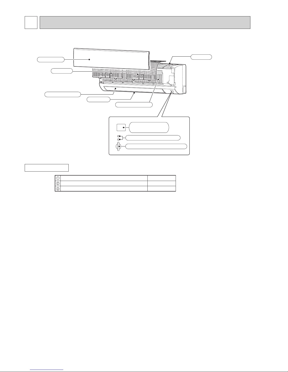
Operation indicator lamp
Remote control
receiving section
Horizontal vane
Air inlet
Air filter
Front panel
Air outlet
Heat exchanger
Emergency operation switch
ACCESSORIES
MSY-TP35VF MSY-TP50VF
Installation plate 1
Installation plate xing screw 4 × 25 mm 5
Felt tape (Used for left or left-rear piping) 1
2
PART NAMES AND FUNCTIONS
OBH816
Page 5
5
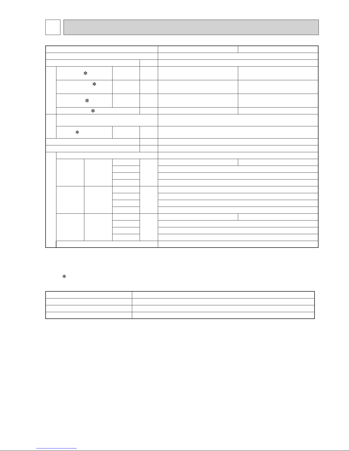
Indoor model MSY-TP35VF MSY-TP50VF
Power supply Single phase 230 V, 50 Hz
Breaker Capacity A
10
Electrical data
Power input 1 (Total) Cooling W 760 1,450
Running current
1
(Total)
Cooling A 3.6 6.4
Power factor
1 (Total) Cooling % 91 98
Starting current
1 (Total) A 3.6 6.4
Fan motor
Model RC0J30-MD
Current
1 Cooling A 0.32
Dimensions W × H × D mm 923 × 305 × 250
Weight kg 12.5
Special remarks
Air direction 5
Airow
Cooling
Super High
m
3
/h
984 990
High 822
Med. 696
Low 606
Sound
level
Cooling
Super High
dB(A)
45
High 40
Med. 36
Low 31
Fan speed
Cooling
Super High
rpm
1,070 1,080
High 930
Med. 820
Low 740
Fan speed regulator 4
NOTE : Test conditions are based on ISO 5151.
Cooling : Indoor Dry-bulb temperature 27°C Wet-bulb temperature 19°C
Outdoor Dry-bulb temperature 35°C
1 Measured under rated operating frequency.
Specifications and rated conditions of main electric parts
Fuse (F11) T3.15AL250V
Horizontal vane motor (MV) 12 V DC
Varistor
(NR11)
470 V
Terminal block (TB) 5P
3
SPECIFICATION
OBH816
Page 6
6
4
NOISE CRITERIA CURVES
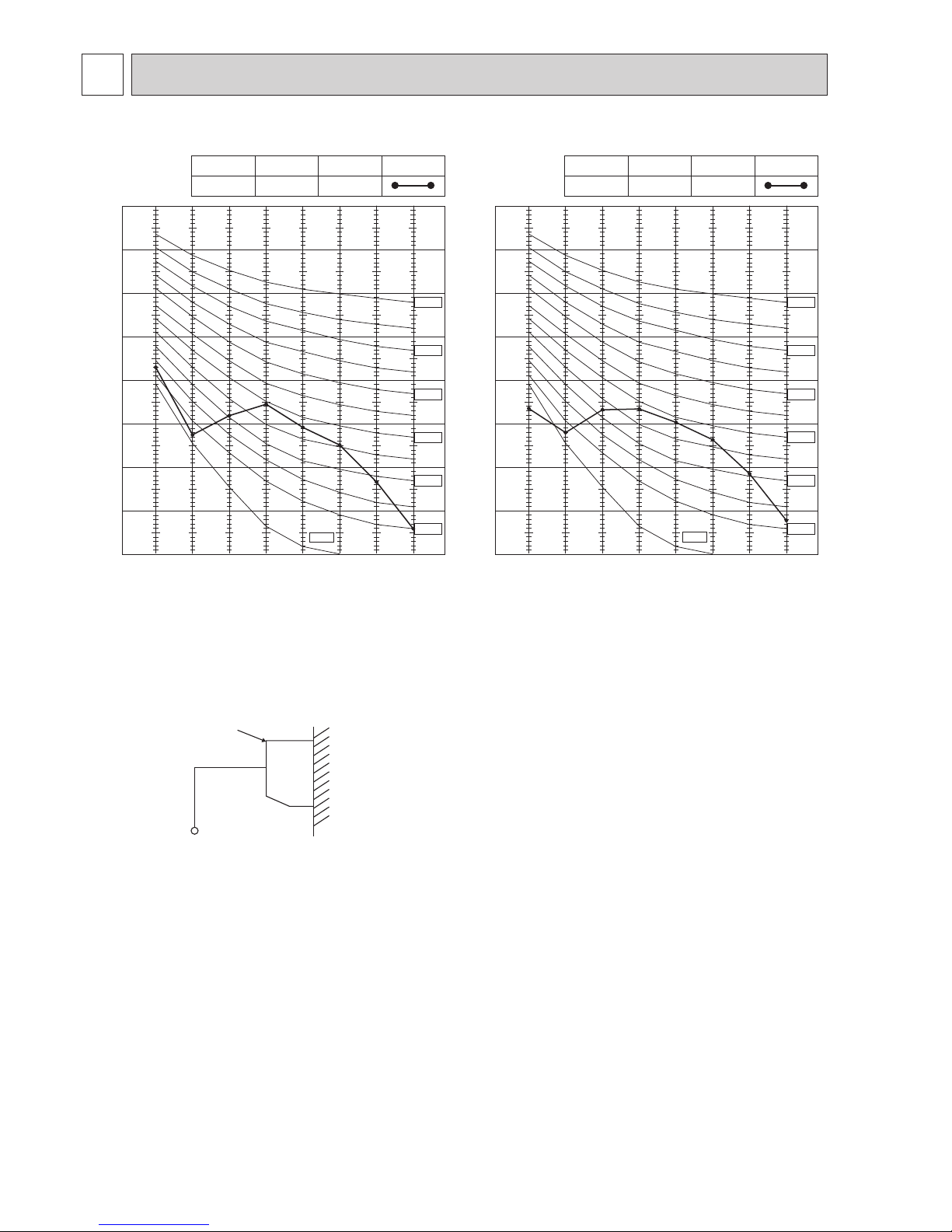
MSY-TP35VF MSY-TP50VF
90
80
70
60
50
40
30
20
10
63 125 250 500 1000 2000 4000 8000
NC-60
NC-50
NC-40
NC-30
NC-20
NC-70
OCTAVE BAND SOUND PRESSURE LEVEL, dB re 0.0002 MICRO BAR
BAND CENTER FREQUENCIES, Hz
NC-10
COOLING
FUNCTION
SPL(dB(A))
LINE
Super High
FAN SPEED
45
90
80
70
60
50
40
30
20
10
63 125 250 500 1000 2000 4000 8000
NC-60
NC-50
NC-40
NC-30
NC-20
NC-70
OCTAVE BAND SOUND PRESSURE LEVEL, dB re 0.0002 MICRO BAR
BAND CENTER FREQUENCIES, Hz
NC-10
COOLING
FUNCTION
SPL(dB(A))
LINE
Super High
FAN SPEED
45
INDOOR UNIT
WALL
MICROPHONE
0.8m
1m
Test conditions
Cooling : Dry-bulb temperature 27°C Wet-bulb temperature 19°C
OBH816
Page 7
7
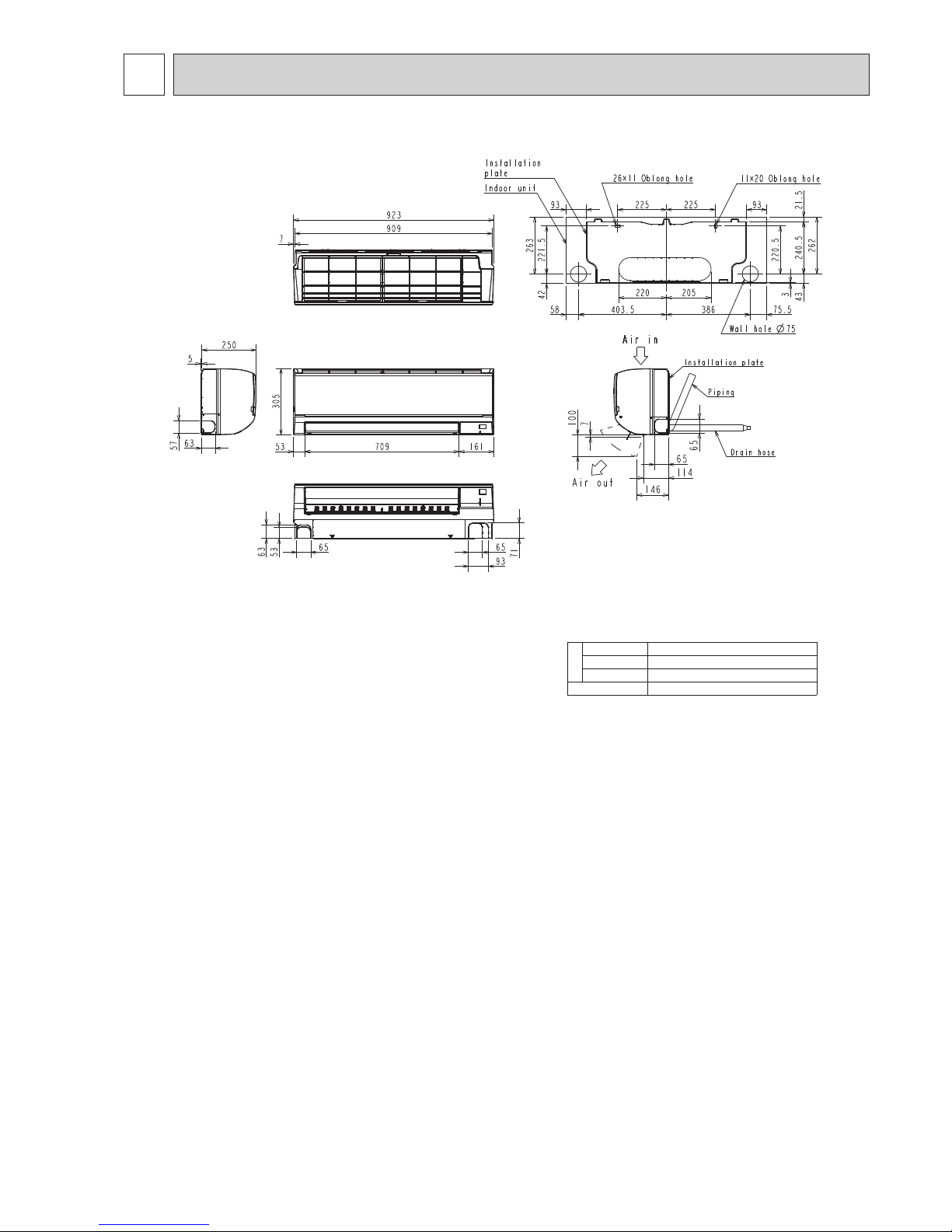
Unit: mm
5
OUTLINES AND DIMENSIONS
MSY-TP35VF MSY-TP50VF
Piping
Insulation Ø50 O.D
Liquid line Ø8 - 0.5m (Flared connection Ø6.35)
Gas line Ø12 - 0.45m (Flared connection Ø9.52)
Drain hose
Insulation Connected part Ø16 O.D
OBH816
Page 8

8
6
WIRING DIAGRAM
MSY-TP35VF -E1 MSY-TP50VF -
E1
MSY-TP35VF -
ET1
MSY-TP50VF -
ET1
Terminal bloğu
Konektör
KANAT MOTORU
(YATAY)
TERMİK SİGORTA
(
102
Ý
4.5A
)
GÜÇ KAYNAĞI
DIŞ ÜNİTEYE
SİGORTA
3.
Sembolleri gösterir
2.
Sadece bakır besleme
kablosu kullanın
NOTLAR
:
1.
Dış ünite elektronik kablolaması için dış ünite
elektronik kablo devre şemasını referans alınız.
İÇ ÜNİTE GÜÇ
KARTI
İÇ ÜNİTE ELEKTRONİK
KONTROL KARTI
REAKTÖR
PARÇA ADI
SİGORTA
(T3.15AL250V)
FAN MOTORU
VARİSTÖR
ODA SICAKLIK
TERMİSTÖRÜ
BORU SICAKLIK
TERMİSTÖRÜ(ANA)
BORU SICAKLIK
TERMİSTÖRÜ(YARDIMCI)
TRAFO
TERMİNAL BLOĞU
KONTAKTÖR
TERMİNAL UCU
OBH816
Page 9

9
MSY-TP35VF MSY-TP50VF
Unit: mm
7
REFRIGERANT SYSTEM DIAGRAM
Indoor
heat
exchanger
Flared connection
Room temperature
thermistor
RT 11
Flared connection
Refrigerant flow in cooling
Refrigerant pipe ø9.52
(with heat insulator)
Refrigerant pipe ø6.35
(with heat insulator)
Indoor coil
thermistor
RT12
Indoor coil
thermistor
RT13
OBH816
Page 10
10
8-1. TIMER SHORT MODE
For service, the following set time can be shortened by bridging the timer short mode point on the electronic control P.C.
board. (Refer to 10-7.)
Set time : 3-minute → 3-second (It takes 3 minutes for the compressor to start operation. However, the starting time is
shortened by bridging the timer short mode point.)
NOTE: While the relay 52C is ON, the compressor starting time cannot be shortened.
MSY-TP35VF MSY-TP50VF
8
SERVICE FUNCTIONS
NOTE:
• The operation settings are memorized when 10 seconds have passed after the indoor unit was operated with the remote
controller.
• If main power is turned OFF or a power failure occurs while AUTO START/STOP timer is active, the timer setting is can-
celled.
• If the unit has been turned OFF with the remote controller before power failure, the auto restart function does not work
as the power button of the remote controller is off.
• To prevent the breaker from tripping OFF due to the rush of starting current, systematize other home appliance not to
turn ON at the same time.
• When some air conditioners are connected to the same supply system, if they are operated before power failure, the
starting current of all the compressors may flow simultaneously at restart.
Therefore, the special counter measures are required to prevent the main voltage-drop or the rush of the starting current
by adding to the system that allows the units to start one by one.
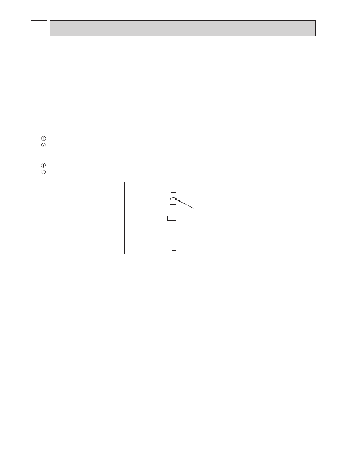
JR77
Indoor electronic
control P.C. board
CN10ACN 111
CN151
CN112
CN110
8-2. AUTO RESTART FUNCTION
When the indoor unit is controlled with the remote controller, the operation mode, the set temperature, and the fan speed
are memorized by the indoor electronic control P.C. board. “AUTO RESTART FUNCTION” automatically starts operation in
the same mode just before the shutoff of the main power.
Operation
If the main power has been cut, the operation settings remain.
After the power is restored, the unit restarts automatically according to the memory.
(However, it takes at least 3 minutes
for the compressor to start running.)
How to disable “AUTO RESTART FUNCTION”
Turn off the main power for the unit.
Cut the Jumper wire to JR77 on the indoor electronic control P.C. board. (Refer to 10-7.)
OBH816
Page 11

11
WIRED REMOTE CONTROLLER (Option : Example) PAR-33MAA
MSY-TP35VF MSY-TP50VF
9
MICROPROCESSOR CONTROL
The main display can be displayed in 2 different modes: "Full" and "Basic."
The initial setting is "Full."
Fri
Mode Temp. Fan
Room
Cool Auto
Set temp.
Fri
Cool
Mode Temp. Fan
AutoSet temp.
1
2
3
4
5
21
20
4
3
191716
15
14
13
12
6
8
10
1
11
7
9
22
5
2
Fan speed setting appears here.
4 Fan speed
Appears while the units are operated in the
energy-saving mode.
Appears while the outdoor units are operated in
the silent mode.
Preset temperature appears here.
Appears when the ON/OFF operation is centrally
controlled.
Current time appears here.
Appears when the buttons are locked.
Indoor unit operation mode appears here.
Appears when the operation mode is centrally
controlled.
15
16
2 Preset temperature
6
12
1 Operation mode
7
Appears when the units are operated in the
energy-saving mode with 3D i-see Sensor.
18
Indicates the louver setting.
Indicates the ventilation setting.
Appears when the On/Off timer or Night setback
function is enabled.
20
21
13
Indicates when filter needs maintenance.
Appears when the filter reset function is centrally
controlled.
Appears when the preset temperature is centrally
controlled.
10
9
8
Appears when the Weekly timer is enabled.
14
Appears when the preset temperature range is
restricted.
22
Functions of the corresponding buttons appear
here.
5 Button function guide
Appears when the built-in thermistor on the
remote controller is activated to monitor the
room temperature (a).
appears when the thermistor on the
indoor unit is activated to monitor the room
temperature.
17
3 Clock
(See the Installation Manual.)
Current room temperature appears here.
11 Room temperature
(See the Installation Manual.)
Note: All icons are displayed for explanation.
5
6
1234
Press to turn ON/OFF the indoor unit.
1
This lamp lights up in green while the unit
is in operation. It blinks while the remote
controller is starting up or when there is
an error.
Press to save the setting.
Main display: Press to change the operation
mode.
Main menu: Press to move the cursor down.
Press to return to the previous screen.
Main
display
: Press to decrease temperature.
Main menu: Press to move the cursor up.
Press to bring up the Main menu.
Main
display
: Press to increase temperature.
Main menu: Press to go to the previous page.
Operation settings will appear.
When the backlight is off, pressing any
button turns the backlight on and it
will stay lit for a certain period of time
depending on the screen.
Main
display
: Press to change the fan speed.
Main menu: Press to go to the next page.
6 ON/OFF lamp
2 SELECT button
7 Function button F1
3 RETURN button
8 Function button F2
4 MENU button
9 Function button F3
5 Backlit LCD
10 Function button F4
Fri
Room
Set temp.
Mode Temp. Fan
Cool Auto
Main
Main display:
Cursor Page
Main menu
Vane·Louver·Vent. (Lossnay)
High power
Timer
Weekly timer
OU silent mode
The functions of the function buttons
change depending on the screen. Refer
to the button function guide that appears
at the bottom of the LCD for the functions
they serve on a given screen.
When the system is centrally controlled,
the button function guide that
corresponds to the locked button will not
appear.
Main display Main menu
Function guide
7 8 9 0 7 8 9 10
• When the backlight is off, pressing any button turns the backlight on and
does not perform its function. (except for the OFF/ON button)
• Most settings (except OFF/ON, mode, fan speed, temperature) can be
made from the Menu screen.
Display
Full mode
Basic mode
Controller interface
Function buttons
10987
18
Indicates the vane setting.
19
OFF/ON button
OBH816
Page 12

12
Not all functions are available on all models of indoor units.
Energy-saving
Auto return
Schedule
Night setback
Main menu
Press button.
Move the cursor to the desired item with
and
buttons, and press
button.
Vane · Louver · Vent. (Lossnay)
High power
Weekly timer
Restriction
Maintenance
Initial setting
ON/OFF timer
Auto-OFF timer
Temp. range
Operation lock
Manual vane angle
Main/Sub
Timer
Main display
Contrast
Display details
Auto mode
Administrator password
Language selection
Daylight saving time
Service
Input maintenance info.
Function setting
Check
Self check
Maintenance password
Remote controller check
Test run
Clock
Auto descending panel
Menu structure
Filter information
Error information
3D i-see Sensor
OBH816
Page 13

13
Setting and display items Setting details
Vane · Louver · Vent.
(Lossnay)
Use to set the vane angle.
• Select a desired vane setting from 5 different settings.
Use to turn ON/OFF the louver.
Not available
Use to set the amount of ventilation.
Not available
High power Use to reach the comfortable room temperature quickly.
Not available
Timer ON/OFF timer* Use to set the operation ON/OFF times.
• Time can be set in 5-minute increments.
Auto-Off timer Use to set the Auto-OFF time.
• Time can be set to a value from 30 to 240 in 10-minute increments.
Filter information Use to check the lter status.
Not available
Error information Use to check error information when an error occurs.
• Check code, error source, refrigerant address, unit model, manufacturing number, contact information (dealer's phone
number) can be displayed.
(The unit model, manufacturing number, and contact information need to be registered in advance to be displayed.)
Weekly timer* Use to set the weekly operation ON/OFF times.
• Up to 8 operation patterns can be set for each day.
(Not valid when the ON/OFF timer is enabled.)
Energy saving Auto return Use to get the units to operate at the preset temperature after performing energy-saving operation for a
specied time period.
• Time can be set to a value from 30 and 120 in 10-minute increments.
(This function will not be valid when the preset temperature ranges are restricted.)
Schedule* Set the start/stop times to operate the units in the energy-saving mode for each day of the week, and set the
energy-saving rate.
Not available
Night setback* Use to make Night setback settings.
•
Select "Yes" to enable the setting, and "No" to disable the setting. The temperature range and the start/stop times can be set.
Restriction Temp. range Use to restrict the preset temperature range.
• Different temperature ranges can be set for different operation modes.
Operation lock Use to lock selected functions.
• The locked functions cannot be operated.
Maintenance Auto descending panel Not available
Manual vane angle Not available
3D i-see Sensor Not available
Initial setting Main/Sub When connecting 2 remote controllers, one of them needs to be designated as a sub controller.
Clock Use to set the current time.
Main display Use to switch between "Full" and "Basic" modes for the Main display.
• The initial setting is "Full."
Contrast Use to adjust screen contrast.
Display details Make the settings for the remote controller related items as necessary.
Clock: The initial settings are "Yes" and "24h" format.
Temperature: Set either Celsius (°C) or Fahrenheit (°F).
Room temp. : Set Show or Hide.
Auto mode: Set the Auto mode display or Only Auto display.
Auto mode Whether or not to use the AUTO mode can be selected by using the button.
This setting is valid only when indoor units with the AUTO mode function are connected.
Administrator
pass-
word
The administrator password is required to make the settings for the following items.
• Timer setting • Energy-saving setting • Weekly timer setting
• Restriction setting • Outdoor unit silent mode setting • Night set back
Language selection Use to select the desired language.
Daylight saving time Sets the daylight saving time.
Service Test run Select "Test run" from the Service menu to bring up the Test run menu.
Not available
Input maintenance Select "Input maintenance Info." from the Service menu to bring up the Maintenance information screen.
The following settings can be made from the Maintenance Information screen.
• Model name input • Serial No. input • Dealer information input
Function setting Not available
Check Error history: Display the error history and delete the error history.
Refrigerant leak check: Not available
Smooth maintenance: Not available
Request code
: Not available
Self check Error history of each unit can be checked via the remote controller.
Maintenance password Use to change the maintenance password.
Remote controller
check
When the remote controller does not work properly, use the remote controller checking function to troubleshoot the problem.
* Clock setting is required.
Main menu list
OBH816
Page 14

14
(1) Press
button.
OFF/ON lamp will light up in green and the operation will start.
(2) Select COOL mode with
button.
(3) Press
button to decrease the preset temperature, and button to increase.
The setting range is 16 ~ 31°C.
1. Coil frost prevention
The compressor operational frequency is controlled by
the temperature of the indoor heat exchanger to prevent
the coil from frosting.
When the temperature of indoor heat exchanger
becomes too low, the coil frost prevention mode works.
The indoor fan operates at the set speed and the compressor stops. This mode continues until the temperature of indoor heat exchanger rises.
9-2. DRY ( ) OPERATION
(1) Press button.
OFF/ON lamp will light up in green and the operation
will start.
(2) Select DRY mode with
button.
(3) Press
button to decrease the preset temperature, and button to in crease.
1. Coil frost prevention
Coil frost prevention works the same way as that in COOL mode. (9-1.1.)
Operation status memory
Remote controller setting
Operation mode Operation mode before the power was turned off
Preset temperature Preset temperature before the power was turned off
Fan speed Fan speed before the power was turned off
Settable preset temperature range
Operation mode Preset temperature range
Cool/Dry 16 ~ 31ºC
Fan/Ventilation Not settable
Operation Indicator lamp
The operation indicator at the right side of the indoor unit indicates the operation state.
•The following indication applies regardless of shape of the indication.
Indication Operation state Room temperature
The unit is operating to
reach the set temperature.
About 2°C or more away
from set temperature
The room temperature is
approaching the set temperature.
About 1 to 2°C from set
temperature
Lit
Blinking
Not lit
INDOOR UNIT DISPLAY SECTION
9-1. COOL ( ) OPERATION
Mode selection
Press button to go through the operation
modes in the order of “Cool”, “Dry”, and
“Fan”. Select the desired operation mode.
Cool Dry Fan
F1 F2 F3 F4
Cool
Room
AutoSet temp.
Mode Temp. Fan
Fri
F1
Example display
(Centigrade in 0.5-degree
increments)
Preset temperature will be displayed either in Centigrade in 0.5- or 1-degree•
increments, or in Fahrenheit, depending on the display mode setting on the
remote controller.
Cool
Room
AutoSet temp.
Mode Temp. Fan
Fri
F1 F2 F3 F4
Cool
Room
AutoSet temp.
Mode Temp. Fan
Fri
OBH816
Page 15

15
9-4. AUTO VANE OPERATION
1. Horizontal vane
(1) Vane motor drive
These models are equipped with a stepping motor for the horizontal vane. The rotating direction, speed, and angle of
the motor are controlled by pulse signals (approximately 12 V) transmitted from indoor microprocessor.
(2) How to set the vane angle
Press the button.
Select “Vane·Louver·Vent. (Lossnay)” with or button, and press button.
Press or button to go through the vane setting options: “Auto”, “Step 1”, “Step 2”, “Step 3”, “Step 4”, “Step 5”
and “Swing”, and select the desired setting.
Press button to go back to the Main menu.
(3) Positioning
To confirm the standard position, the vane moves until it touches the vane stopper. Then the vane is set to the selected
angle.
Confirmation of standard position is performed in the following cases:
(a) When the operation starts or finishes (including timer operation).
(b) When the test run starts.
F1 F2 F3 F4
Cool
Room
AutoSet temp.
Mode Temp. Fan
Fri
Press button to go through the fan speeds in the following order.
Auto
Low Med.
Super High High
F1 F2 F3 F4
Main
Main display:
Cursor Page
Main menu
Vane·Louver·Vent. (Lossnay)
High power
Timer
Weekly timer
OU silent mode
F1 F2 F3 F4
Fri
Swing Off Off
LouverVent.Vane
Auto
Auto
Swing
Step 1 Step 2
Step 4Step 3
Swing
Step 5
9-3. FAN( )OPERATION
(1) Press button. OFF/ON lamp will light up in green and the operation will start.
(2) Select FAN mode with button.
(3) Press
button to select the desired fan speed. When AUTO, it becomes Low.
Only indoor fan operates. Outdoor unit does not operate.
OBH816
Page 16

16
(4) VANE AUTO (
) mode
In VANE AUTO mode, the microprocessor automatically determines the vane angle to make the optimum room temperature distribution.
Horizontal
position
In COOL and DRY operation
Vane angle is fixed to Horizontal position.
(5) STOP (operation OFF) and ON TIMER standby
In the following cases, the horizontal vane returns to the closed position.
(a) When
button is pressed (POWER OFF).
(b) When the operation is stopped by the emergency operation.
(c) When ON TIMER is ON standby.
(6) Dew prevention
During COOL or DRY operation with the vane angle at Angle 3 ~ 5 when the compressor cumulative operation time
exceeds 1 hour, the vane angle automatically changes to Angle 2 for dew prevention.
(7) SWING (
) mode
Select “Swing” to move the vanes up and down automatically.
When set to “Step 1” through “Step 5”, the vane will be xed at the selected angle.
9-5. TIMER OPERATION (ON/OFF TIMER)
The unit automatically turns on or off at the preset time.
Select "Timer" from the Main menu, and press
button (Refer to the appropriate operation manual include with
remote controller.).
EMERGENCY OPERATION switch
9-6. EMERGENCY/TEST OPERATION
In the case of test run operation or emergency operation, use EMERGENCY OPERATION switch on the right side of the
indoor unit. Emergency operation is available when the remote controller is missing or has failed, or when the batteries in
the remote controller are running down. The unit will start and OPERATION INDICATOR lamp will light up.
The first 30 minutes of operation is the test run operation. This operation is for servicing. The indoor fan runs at High
speed and the temperature control does not work.
After 30 minutes of test run operation, the system shifts to EMERGENCY COOL MODE with a set temperature of 24°C.
The fan speed shifts to Med.
The coil frost prevention works even in the test run or the emergency operation.
In the test run or emergency operation, the horizontal vane operates in VANE AUTO (
) mode.
Emergency operation continues until EMERGENCY OPERATION switch is pressed once or the unit receives any signal
from the remote controller. In the latter case, normal operation will start.
NOTE: Do not press EMERGENCY OPERATION switch during normal operation.
Operation mode COOL
Set temperature 24°C
Fan speed Med.
Horizontal vane Auto
The operation mode is indicated by the
Operation Indicator lamp as follows:
Operation Indicator lamp
EMERGENCY COOL
↓
STOP
Lit
Not lit
9-7. 3-MINUTE TIME DELAY OPERATION
When the system turns OFF, compressor will not restart for 3 minutes as 3-minute time delay function operates to protect
compressor from overload.
OBH816
Page 17

17
3. Troubleshooting procedure
1) Check if the OPERATION INDICATOR lamp on the indoor unit is blinking ON and OFF to indicate an abnormality.
To make sure, check how many times the OPERATION INDICATOR lamp is blinking ON and OFF before starting ser-
vice work.
2) Before servicing, check that the connector and terminal are connected properly.
3) When the P.C. board seems to be defective, check the copper foil pattern for disconnection and the components for
bursting and discoloration.
4) When troubleshooting, Refer to 10-2, 10-3 and 10-4.
10-1. CAUTIONS ON TROUBLESHOOTING
1. Before troubleshooting, check the following:
1) Check the power supply voltage.
2) Check the indoor/outdoor connecting wire for miswiring.
2. Take care of the following during servicing
1) Before servicing the air conditioner, be sure to turn OFF the main unit first with the remote controller, and then after
confirming the horizontal vane is closed, turn OFF the breaker and/or disconnect the power plug.
2) Be sure to turn OFF the power supply before removing the front panel, the cabinet, the top panel, and the P.C. board.
3) When removing the P.C. board, hold the edge of the board with care NOT to apply stress on the components.
4) When connecting or disconnecting the connectors, hold the connector housing. DO NOT pull the lead wires.
MSY-TP35VF MSY-TP50VF
10
TROUBLESHOOTING
Lead wiring
Connector housing
<Incorrect>
<Correct>
OBH816
Page 18

18
10-2. FAILURE MODE RECALL FUNCTION
Outline of the function
This air conditioner can memorize the abnormal condition which has occurred once.
Even though LED indication listed on the troubleshooting check table (10-4.) disappears, the memorized failure details can
be recalled.
This mode is very useful when the unit needs to be repaired for the abnormality which does not recur.
1. Flow chart of failure mode recall function for
the indoor/outdoor unit
Does upper lamp of OPERATION INDICATOR
lamp on the indoor unit blink at the interval of 0.5
seconds?
Blinks: Either indoor or outdoor unit is abnormal.
Beep is emitted at the same timing as the
blinking of upper lamp of OPERATION
INDICATOR lamp. 2
Indoor unit is normal.
But the outdoor unit might be abnormal because there are some abnormalities that cannot be recalled with this way.
Check if outdoor unit is abnormal according to the detailed outdoor unit
failure mode recall function.
No
Yes
The cause of abnormality cannot be found because the abnormality does not recur.
Turn ON the power supply.
<Preparation of the remote controller>
While pressing both OPERATION SELECT button and TOO COOL button on the
remote controller at the same time, press RESET button.
First, release RESET button.
Hold down the other 2 buttons for another 3 seconds. Make sure that the indicators
on the LCD screen shown in the right gure are all displayed. Then release the buttons.
Before blinking, does upper lamp of
OPERATION INDICATOR lamp stay ON for 3
seconds?
When it stays ON for 3 seconds (without beep):
The outdoor unit is abnormal.
The indoor unit is abnormal.
Check the blinking pattern, and identify the abnormal point by referring to the
indoor unit failure recall mode table. (Refer to 10-2.2)
Make sure to check at least 2 consecutive blinking cycles.
2
Release the failure mode recall function by the following procedures.
Turn OFF the power supply and turn it ON again.
Press RESET button of the remote controller.
The outdoor unit is abnormal.
Check the blinking pattern, and identify the abnormal point by referring to the outdoor unit failure recall mode table. (Refer to outdoor unit
service manual.)
Make sure to check at least 2 consecutive blinking cycles.
3
Repair the failure parts.
Yes
(Blinks)
No
(OFF)
Setting up the failure mode recall function
Judgment of indoor/outdoor abnormality
Releasing the failure mode recall function
Deleting the memorized abnormal condition
Operational procedure
NOTE: 1. Make sure to release the failure mode recall function after it is set up, otherwise the unit cannot operate properly.
2. If the abnormal condition is not deleted from the memory, the last abnormal condition is kept memorized.
2. Blinking pattern when the indoor unit is abnormal:
3.Blinking pattern when the outdoor unit is abnormal:
ON
OFF
Beeps
Repeated cycle Repeated cycle
ON
OFF
No beep Beeps
Repeated cycle
2.5-second OFF
Blinking at 0.5second interval
2.5-second OFF 3-second ON
Blinking at 0.5second interval
Beeps
Repeated cycle
2.5-second OFF
Blinking at 0.5-
second interval
No beep Beeps
Repeated cycle
2.5-second OFF 3-second ON
Blinking at 0.5second interval
Repeated cycle
Beeps
1. Regardless of normal or abnormal condition, a short beep is emitted once the signal
is received.
Press STOP/OPERATE (OFF/ON) button of the remote controller (the set temperature is
displayed) with the remote controller headed towards the indoor unit.
1
After repairing the unit, recall the failure mode again according to "Setting up the failure mode recall function" men-
tioned above.
Press STOP/OPERATE (OFF/ON) button of the remote controller (the set temperature is displayed) with the remote
controller headed towards the indoor unit.
Press EMERGENCY OPERATION switch so that the memorized abnormal condition is deleted.
Release the failure mode recall function according to "Releasing the failure mode recall function" mentioned above.
NOTE: Use the wireless remote controller of MSZ-HJ25VA-E2 (Refer to parts catalog OBB647.) .
The remote controller has the indication of "HEAT" and a button for it, but HEAT mode cannot be used since MSY-
TP series are cooling only model.
The remote controller has the indication of "ECONO COOL" and a button for it, but ECONO COOL mode cannot be
used since it is not available on MSY-TP series.
OBH816
Page 19

19
10-3. INSTRUCTION OF TROUBLESHOOTING
Indoor unit operates.
Outdoor unit
does not operate.
If blinking of OPERATION INDICATOR lamp cannot be checked,
it can be checked with failure
mode recall function.
Indoor unit does
not receive
the signal from
remote controller.
OPERATION INDICATOR
lamp on the indoor unit is
blinking on and off.
Outdoor unit
operates only
in Test Run
operation.
Outdoor unit
does not
operate even
in Test Run
operation.
Indoor unit
operates, when
EMERGENCY
OPERATION
switch is pressed.
Indoor unit does
not operate, when
EMERGENCY
OPERATION
switch is pressed.
Check room
temperature
thermistor.
Refer to 10-7.
"Test point
diagram and
voltage".
Refer to "How
to check
inverter/compressor".
Check the instruction manual
of wired remotecontroller or replace the indoor
electronic
control P.C.
board".
1. Check indoor/outdoor connecting wire.
(Check if the power is
supplied to the indoor
unit.)
2. Refer to 10-6.
"Check of indoor P.C.
board and indoor fan
motor".
Start
"Test Run operation" means
the operation within 30 minutes
after EMERGENCY OPERATION switch is pressed.
Refer to outdoor unit service manual.
Upper lamp
Blink on and
off at 0.5-second intervals
Cause:
Indoor/Outdoor
unit
• Miswiring or
trouble of
serial signal
Upper lamp
2-time blink
Cause:
Indoor unit
• Trouble
of room
temperature
/ indoor coil
thermistor
Upper lamp
3-time blink
Cause:
Indoor unit
• Trouble of
indoor fan
motor
Upper lamp
4-time blink
Cause:
Indoor unit
• Trouble
of indoor
unit control
system
Upper lamp
5-time blink
Cause:
Outdoor unit
• Outdoor
power system abnormality
Upper lamp
6-time blink
Cause:
Outdoor unit
• Trouble of
thermistor in
outdoor unit
Upper lamp
7-time blink
Cause:
Outdoor unit
• Trouble of
outdoor control system
Upper lamp
14-time blink
or more
Cause:
Outdoor unit
• Other abnormality
Refer to
10-6. "How
to check miswiring and
serial signal
error".
Check room
temperature
thermistor
and indoor
coil thermistor. Refer to
10-7."Test
point diagram
and voltage".
Refer to
10-6.
"Check of
indoor fan
motor".
Replace the
indoor electronic control
P.C. board.
Refer to
"How to
check
inverter/compressor".
Refer to
"Check of
outdoor thermistors".
Replace the
inverter P.C.
board or
the outdoor
electronic
control P.C.
board.
Check "Flow
chart of the
detailed
outdoor unit
failure mode
recall function."
OBH816
Page 20

20
10-4. TROUBLESHOOTING CHECK TABLE
Before taking measures, make sure that the symptom reappears for accurate troubleshooting.
When the indoor unit has started operation and detected an abnormality of the following condition (the first detection after
the power ON), the indoor fan motor turns OFF and OPERATION INDICATOR lamp blinks.
No.
Abnormal
point
Operation indicator lamp Symptom Condition Remedy
1
Miswiring
or serial
signal
Upper lamp blinks.
0.5-second ON
0.5-second OFF
Indoor unit and
outdoor unit do
not operate.
The serial signal from the outdoor unit is not
received for 6 minutes.
•
Refer to 10-6.
"How to check
miswiring and serial signal error".
2
Indoor coil
thermistor
Upper lamp blinks.
2-time blink
2.5-second OFF
The indoor coil or the room temperature thermistor is short or open circuit.
•
Refer to the characteristics of
indoor coil thermistor, and the
room temperature thermistor
(10-7.).
Room temperature
thermistor
3
Indoor fan
motor
Upper lamp blinks.
3-time blink
2.5-second OFF
The rotational frequency feedback signal is
not emitted during the indoor fan operation.
•
Refer to 10-6.
"Check of
indoor fan motor".
4
Indoor control system
Upper lamp blinks.
4-time blink
2.5-second OFF
It cannot properly read data in the nonvolatile
memory of the indoor electronic control P.C.
board.
•
Replace the indoor electronic
control P.C. board.
5
Outdoor
power system
Upper lamp blinks.
5-time blink
2.5-second OFF
It consecutively occurs 3 times that the compressor stops for overcurrent protection or
start-up failure protection within 1 minute after
start-up.
•
Refer to "How to check of inverter/compressor".
Refer to outdoor unit service
manual
•
Check the stop valve.
6
Outdoor
thermistors
Upper lamp blinks.
6-time blink
2.5-second OFF
The outdoor thermistors short or open circuit
during the compressor operation.
•
Refer to "Check of outdoor
thermistor".
Refer to outdoor unit service
manual.
7
Outdoor
control system
Upper lamp blinks.
7-time blink
2.5-second OFF
It cannot properly read data in the nonvolatile
memory of the inverter P.C. board or the outdoor electronic control P.C. board.
•
Replace the inverter P.C. board
or the outdoor electronic control P.C. board.
Refer to outdoor unit service
manual.
8
Other abnormality
Upper lamp blinks.
14-time blink or more
2.5-second OFF
An abnormality other than above mentioned
is detected.
•
Check the stop valve.
•
Conrm the abnormality in
detail using the failure mode
recall function for outdoor unit.
9
Outdoor
control system
Upper lamp lights up
Outdoor unit
does not operate
It cannot properly read data in the nonvolatile
memory of the inverter P.C. board or the outdoor electronic control P.C. board.
•
Check the blinking pattern of
the LED on the inverter P.C.
board or the outdoor electronic
control P.C. board.
OPERATION INDICATOR
Lit
Blinking
Not lit
OBH816
Page 21

21
10-5. TROUBLE CRITERION OF MAIN PARTS
MSY-TP35VF MSY-TP50VF
Part name Check method and criterion Figure
Room temperature
thermistor (RT11)
Measure the resistance with a tester.
Refer to 10-7. "Test point diagram and voltage", "2. Indoor electronic control
P.C. board", for the chart of thermistor.
Indoor coil thermistor
(RT12, RT13)
Indoor fan motor (MF)
Check 10-6. .
Vane motor (MV)
Measure the resistance between the terminals with a tester.
(Part temperature 10 ~ 30°C)
Color of the lead wire Normal
RED - BLK 235 ~ 255 Ω
BLK
BLK
RED
BLK
BLK
ROTOR
OBH816
Page 22

22
10-6. TROUBLESHOOTING FLOW
A Check of indoor fan motor
The indoor fan motor error has occurred, and the indoor fan does not operate.
Turn OFF the power supply.
Is there any foreign matter that interferes
the rotation of the line ow fan?
Yes
No
Remove the foreign matter and
adjust the line ow fan.
Pay enough attention to the high voltage on the fan motor connector CN211.
Turn ON the power supply, wait 5 seconds or more, and then press
EMERGENCY OPERATION switch.
Measure the supply voltage as follows within 12 seconds after EMERGENCY OPERATION switch is pressed.
If more than 12 seconds passes, turn OFF the power supply and turn it
ON again, then measure the voltage.
<Indoor power P.C. board>
1. Measure the voltage between CN211
(+) and (–).
2. Measure the voltage between CN211
(+) and (–).
<Indoor electronic control P.C. board>
3. Measure the voltage between CN10A (+) and GND (–).
If more than 12 seconds passes after EMERGENCY OPERATION switch
is pressed, the voltage measured at 2. above goes 0 V DC although the
indoor P.C. board is normal.
Does the voltage between CN211
(+) and (–) on the power P.C. board
rise to the range of 3 to 6 V DC within
12 seconds after EMERGENCY
OPERATION switch is pressed?
Replace the indoor fan motor.
Yes
No
The indoor fan motor error has occurred, and the indoor fan repeats "12-second ON and 30-second OFF" 3 times, and then stops.
Measure the voltage between CN211
(+) and (–) while the fan motor is
rotating.
Replace the indoor power
P.C. board.
Is it unchanged holding 0
or 15 V DC?
No
(Changed)
Yes
(Unchanged)
Measure the voltage CN10A
(+) and GND (–) on the indoor
electronic control P.C board when
the fan motor is rotaring.
Replace the indoor fan motor.
Is there 325 V DC
between CN211 (+)
and (–) ?
Yes
Does the voltage between CN10A
(+) and GND (–) on the indoor
electronic control P.C. board fall to
2 V or less within 12 seconds after
EMERGENCY OPERATION switch is
pressed?
Replace the indoor electronic
control P.C. board.
No
Yes
Replace the indoor power P.C.
board.
Is it unchanged holding 0
or 5 V DC?
No
(Changed)
Yes
(Unchanged)
Replace the indoor
electronic control P.C.
board.
No
OBH816
Page 23

23
B Check of indoor P.C. board and indoor fan motor
Turn OFF the power supply.
Remove indoor fan motor connector CN211
from indoor power P.C. board and vane
motor connector CN151 from the indoor
electronic control P.C. board and turn ON
the power supply.
Does the unit operate with the remote
controller?
Does OPERATION INDICATOR lamp light
up by pressing EMERGENCY OPERATION
switch?
Yes
No
Measure the resistance of indoor fan
motor.
Refer to 10-5.
Short circuit:
Replace the indoor fan motor.
Turn OFF the power supply.
Check both “parts side” and “pattern
side” of the indoor power P.C. board
visually.
Replace the varistor (NR11)
and fuse (F11). 3
Is the varistor (NR11)
burnt and the fuse (F11)
blown?
No
No
Yes
Yes
Be sure to check both the fuse
and the varistor in any case.
Is the fuse (F11) blown
only?
Measure the resistance between
CN211
(+) and (-) of indoor fan
motor connector. 1, 2
Yes
Is the resistance 1MΩ or more?
Replace the fuse (F11) and the
indoor fan motor. 3
No
Replace the fuse (F11).
3
Measure the resistance of reactor (L111)
on the indoor power P.C. board.
No
No
Replace the indoor
power P.C. board, the
indoor terminal P.C.
board and the indoor fan
motor.
Replace the indoor electronic control P.C. board.
Measure the resistance of the vane
motor coil.
Refer to 10-5.
Short circuit:
Replace the vane motor and the indoor
electronic control P.C. board.
1. The fan motor connector's lead wire is red,
whereas is black.
2. Connect "+" of the tester to fan motor
connector's lead wire, and “-” to lead wire,
otherwise the resistance cannot be measured
properly.
3. Please replace the fuse after removing the
indoor power P.C. board from the electrical
box.
Is there approximately 5 V DC between
5 V (+) and GND (-) of the indoor
electronic control P.C. board? Is there
approximately 9 V to 13 V DC between
12 V (+) and GND (-) of the indoor
electronic control P.C. board?
Is the connector CN10A on
the indoor electronic control
P.C. board or lead wires
disconnected?
Yes
Replace the indoor fan motor.
Yes
Connect the connector CN10A or repair
disconnection.
No
Indoor electronic control
P.C. board
GND
CN10A
12 V DC
5 V DC
Indoor power P.C. board
CN211
L111
Is the resistance of reactor (L111)
approximately 4 Ω ?
Yes
With a tester, check the
continuity between the
connector CN201
on the
indoor power P.C. board and
S2 on the terminal block.
Is electricity
conducted? (The
resistance is 0 Ω .)
Yes
No
The thermal fuse connected
to the terminal block has
failed.
Replace the terminal block
assembly.
OBH816
Page 24

24
C How to check miswiring and serial signal error
A
• Reinstall either the unit
or the light
away from
each other.
• Attach a lter
on remote
control
receiving
section of
the indoor
unit.
• Turn OFF inverter-controlled lighting
equipment.
• Turn OFF the power supply and then
turn ON again.
• Press the emergency operation switch.
After the relay
52C is turned on
3 minutes later, is
miswiring or the
serial signal error
indicated?
No
B
Yes
1 Make sure that the wiring is correct. If the pro-
cedure is performed without correcting miswiring, it may lead to damage to the P.C. board.
3
Be sure to release the failure-mode recall function after checking.
Turn OFF the power supply.
Is there rated voltage in the
power supply?
Yes
No
1. Turn ON the power supply.
2. Press the emergency operation switch.
Check the power supply.
Has the relay 52C been turned on 3 minuets later ?
[The relay will be turned on in 3 to 7 seconds by
bridging the timer short mode point (Refer to 11-7.).]
Is there any miswiring, poor
contact, or wire disconnection of the indoor/outdoor
connecting wire?
Correct them.
No
Yes
Aim the remote controller at the indoor unit, and press OPERATE (OFF/ON) button. The relay 52C will be turned on, and the
outdoor unit will be energized.
Is the rated supply voltage applied
between the S1 and S2 on the
outdoor terminal block? (Check of
supply voltage)
No
Is there any problem in the
indoor/outdoor connecting wire,
such as the damage of the wire,
intermediate connection, poor
contact with the terminal block?
Yes
Replace
the indoor/
outdoor connecting wire.
No
Replace the indoor electronic control
P.C. board.
3
Is there approximately 250 V DC – 370
V DC between DB61 (+) and DB61
(–) on the inverter P.C. board in the
outdoor unit? (Voltage check of the
inverter P.C. board in the outdoor unit)
No
Replace the
inverter P.C.
board in the
outdoor unit. 2
Yes
Yes
Does the LED on the inverter P.C.
board in the outdoor unit repeat
"3.6-second-OFF and 0.8-secondON quick blinking" for 3 minutes
after the outdoor unit is energized?
(Check the blinking pattern within 3
minutes after LED is turned on. After 3 minutes, LED will blink 6 times
whether the inverter P.C. board in
the outdoor unit is normal or not.)
No
Replace the
inverter P.C.
board in the
outdoor unit.
2
Yes
A
2
Be careful of 140
V DC – 280 V DC
residual charge in
the capacitor on the
main inverter circuit.
B
Turn OFF the power supply. Make sure again that the
indoor/outdoor connecting wire is correctly connected.
With the indoor/outdoor connecting wire connected, bridge
between S2 and S3 on the outdoor terminal block. 1
<Preparation of the remote controller>
While pressing both OPERATION SELECT button and
TOO COOL button on the remote controller at the same
time, press RESET button.
First, release RESET button.
Hold down the other two buttons for another 3 seconds.
Make sure that the indicators on the LCD screen shown in
the right gure are all displayed. Then release the buttons.
(Setting up the failure mode recall function)
Indication of miswiring
Indication of serial signal error
OPERATION
INDICATOR lamp
Continuous blinks
Initializing the determination of the power
receiving system
The microprocessor may have mistaken the
unit as a model receiving power from the
outdoor unit. Follow the procedure below to
start the determination of the power receiving system all over again.
1. Hold down the emergency operation
switch for 30 seconds. (Do not release the
switch even though a buzzer beeps once
in about 5 seconds. Keep holding down
the switch until a buzzer beeps again for
1 second after 30 seconds. Figure 1)
2. Turn off the power supply.
3. Wait for about 30 seconds.
4. Turn on the power supply.
5. Press the emergency operation switch.
6. The relay 52C will be turned on in 3 minutes.
Has the miswiring or the serial error
been indicated?
Yes
No
ON
OFF
Buzzer
0.5-second 1-second
ON
OFF
Emergency
operation switch
30-second
ON
OFF
5-second
Beeps
BeepsBeeps
Figure 1
Yes
No
NOTE: Use the wireless remote controller of
MSZ-HJ25VA-
E2
(Refer to parts cat-
alog OBB647.).
The remote controller has the indication
of "HEAT" and a button for it, but HEAT
mode cannot be used since MSY-TP
series are cooling only model.
The remote controller has the indication
of "ECONO COOL" and a button for
it, but ECONO COOL mode cannot be
used since it is not available on MSY-
TP series.
OBH816
Page 25

25
D Electromagnetic noise enters into TV sets or radios
Yes
Is the unit earthed?
No
Earth the unit.
Yes
Is the distance between the antennas
and the indoor unit within 3 m, or is the
distance between the antennas and the
outdoor unit within 3 m?
No
Extend the distance between the antennas and
the indoor unit, and/or the antennas and the
outdoor unit.
Is the distance between the TV sets or
radios and the indoor unit within 1 m, or
is the distance between the TV sets or
radios and the outdoor unit within 3 m?
Yes
Extend the distance between the TV sets and/or
radios and the indoor unit, or the TV sets or
radios and the outdoor unit.
Are the antennas damaged?
Is the coaxial cable damaged?
Is there any poor contact in the antenna wiring?
Yes
No
No
Replace or repair the antenna.
Replace or repair the coaxial cable.
Is the indoor/outdoor connecting wire
of the air conditioner and the wiring of
the antennas close?
Yes
Extend the distance between the indoor/outdoor
connecting wire of the air conditioner and the wiring of the antennas.
No
Even if all of the above conditions are fullled, the electromagnetic noise may enter, depending on the electric eld strength
or the installation condition (combination of specic conditions such as antennas or wiring).
Check the following before asking for service.
1. Devices affected by the electromagnetic noise
TV sets, radios (FM/AM broadcast, shortwave)
2. Channel, frequency, broadcast station affected by the electromagnetic noise
3. Channel, frequency, broadcast station unaffected by the electromagnetic noise
4. Layout of ;
indoor/outdoor unit of the air conditioner, indoor/outdoor wiring, earth wire, antennas, wiring from antennas, receiver
5. Electric eld intensity of the broadcast station affected by the electromagnetic noise
6. Presence or absence of amplier such as booster
7. Operation condition of air conditioner when the electromagnetic noise enters in
1) Turn OFF the power supply once, and then turn ON the power supply. In this situation, check for the electromagnetic
noise.
2) Within 3 minutes after turning ON the power supply, press
button on the remote controller for power ON,
and check for the electromagnetic noise.
3) After a short time (3 minutes later after turning ON), the outdoor unit starts running. During operation, check for the
electromagnetic noise.
4) Press button on the remote controller for power OFF, when the outdoor unit stops but the indoor/outdoor
communication still runs on. In this situation, check for the electromagnetic noise.
OBH816
Page 26

26
12V
GND
5V
Room temperature thermistor (RT11)
Indoor coil thermistor (RT12, RT13)
Temperature (°C)
Resistance (kΩ)
Fuse (F11)
T3.15AL250V
Varistor (NR11)
Connector to indoor electronic
control P.C. board (CN20A)
5 V DC
12 V DC
GND
Connector to Indoor fan
motor (CN211)
Reactor (L111 )
Connector to
Terminal block
(CN201)
Indoor terminal block
connecting (TAB1)
(+)3-6 V DC
15 V DC
(-) GND
(High voltage DC)
325 V DC
(+)0 or 15 V DC
Indoor terminal block
connecting (TAB2)
Timer short
mode point
(Refer to
8-1.)
Room temperature thermistor RT11 (CN111)
Connector to
Indoor coil
thermistor
RT12, RT13
(CN112)
Vane motor
(CN151)
Connector to indoor power
P.C. board (CN10A)
12V DC
5V DC
To disable "Auto restart function",cut the
Jumper wire to JR77. (Refer to 8-3.)
Emergency operation
switch (E.O. SW) (SW1)
GND
MSY-TP35VF MSY-TP50VF
1. Indoor power P.C. board
2. Indoor electronic control P.C. board
10-7. TEST POINT DIAGRAM AND VOLTAGE
OBH816
Page 27

OPERATING PROCEDURE PHOTOS/FIGURES
1. Removing the panel
(1) Remove the screw caps on the panel and remove the
screws of the panel.
(2) Pull the panel slightly toward you, and then remove the
panel by pushing it upward.
27
11
DISASSEMBLY INSTRUCTIONS
<Detaching method of the terminal with locking mechanism>
The terminal which has the locking mechanism can be detached as shown below.
There are following 2 types of the terminal with locking mechanism.
The terminal without locking mechanism can be detached by pulling it out.
Check the shape of the terminal before detaching.
(1) Slide the sleeve and check if there is a locking lever or not. (2) The terminal with this connector shown below
has the locking mechanism.
Slide the sleeve.
Pull the terminal while
pushing the locking
lever.
Hold the sleeve, and
pull out the terminal
slowly.
Connector
Sleeve
Locking lever
11-1. MSY-TP35VF MSY-TP50VF
NOTE: Turn OFF the power supply before disassembly.
Photo 1
Screws of the panel
Front panel
: Indicates the visible parts in the photos/figures.
: Indicates the invisible parts in the photos/figures.
OBH816
Page 28

OPERATING PROCEDURE PHOTOS/FIGURES
2. Removing the indoor power P.C. board and the
electrical box
(1) Remove the panel. (Refer to section 1.) Remove the
right corner box.
(2) Disconnect the following connectors:
<Indoor electronic control P.C. board>
CN151 (Vane motor)
CN112 (Indoor coil thermistor)
CN10A (To the indoor power P.C. board)
(3) Unhook the catch on the left side of the control P.C.
board holder. Pull the control P.C. board holder as if
opening the door at 90 degrees. Remove the control P.C.
board holder from the axial rod on the electrical box.
(4) Remove the screw of the V.A. clamp.
(5) Remove the V.A. clamp and the indoor/outdoor con-
necting wire.
(6) Remove the screws of the earth plate. (Photo 2)
(7) Remove the indoor coil thermistor from the water cover.
(8) Disengage the hooks of the water cover and remove
the water cover.
(9) Remove the screw of the electrical cover and remove
the electrical cover.
(10) Disconnect the CN211 (Indoor fan motor) from the
indoor power P.C. board.
(11) Remove the upper catch of the electrical box, and pull
out the electrical box.
To attach the electrical box, pass the wires connecting
the indoor power P.C. board and the indoor electronic
control P.C. board through A. Pass the lead wires of the
fan motor through B as shown in the Photo 3.
(12) Disconnect the following connectors and tabs.
<Indoor power P.C. board>
CN201, TAB1, TAB2 (Terminal block)
CN20A (To the indoor electronic control P.C. board)
28
Photo 2
Screw of the
V.A. clamp
Control P.C. board holder
Screw of the
electrical cover
Water cover
Indoor coil thermistor connector CN112
Indoor coil thermistor
Indoor electronic
control P.C. board
Vane motor
connector (CN151)
Screws of the earth plate
Connector
CN10A
(To indoor power
P.C. board)
Photo 3
TAB1 (Terminal block)TAB2 (Terminal block)
Terminal block
connector CN201
B
A
Connector CN20A
(To indoor electronic P.C. board)
Indoor fan motor
connector CN211
Electrical box
OBH816
Page 29

OPERATING PROCEDURE PHOTOS/FIGURES
3. Removing the indoor electronic control P.C.
board
(1) Remove the panel. (Refer to section 1.) Remove the right
corner box.
(2) Disconnect the following connectors:
<Indoor electronic control P.C. board>
CN151 (Vane motor)
CN112 (Indoor coil thermistor)
CN10A (To the indoor power P.C. board)
(3) Unhook the catch on the left side of the control P.C.
board holder. Pull the control P.C. board holder as if
opening the door at 90 degrees. Remove the control P.C.
board holder from the axial rod on the electrical box.
(4) Remove the room temperature thermistor from the back
side of the control P.C. board holder.
(5) Unhook the catches of the control P.C. board holder, and
open the control P.C. board holder.
(6) Remove the indoor electronic control P.C. board from the
control P.C. board holder.
4. Removing the vane motor
(1) Remove the panel. (Refer to section 1.) Remove the
corner box.
(2) Remove the control P.C. board holder, water cover and
the electrical box. (Refer to section 2.)
(3) Pull out the drain hose from the nozzle assembly and
remove the nozzle assembly.
(4) Remove the screws of the vane motor and remove the
vane motor.
(5) Disconnect the connector from the vane motor.
29
Photo 5
Screws of the vane motor
Photo 4
Room temperature thermistor
Indoor electronic
control P.C. board
Catch
Catch
Control P.C. board holder (Inside)
Control P.C. board holder (Back side)
OBH816
Page 30

OPERATING PROCEDURE PHOTOS/FIGURES
5. Removing the indoor fan motor, the indoor coil
thermistor and the line flow fan
(1) Remove the panel. (Refer to section 1.) Remove the
corner box.
(2) Remove the control P.C. board holder, the water cover,
the electrical box and the nozzle assembly. (Refer to
section 2.)
(3) Remove the screws fixing the motor bed.
(4) Loosen the screw fixing the line flow fan.
(5) Remove the motor bed together with the indoor fan
motor and the motor band.
(6) Disconnect the lead wire of the fan motor from the
motor band.
(7) Disengage the hooks of the motor band and remove
the motor band. Pull out the indoor fan motor.
(8) Remove the indoor coil thermistor from the heat
exchanger.
Install the indoor coil thermistor in its former position
when assembling it.
(9) Remove the screws fixing the left side and upper right
side of the heat exchanger.
(10) Lift the heat exchanger, and pull out the line flow fan
to the lower-left.
When attaching the line flow fan, screw the line flow fan
so 4 mm gap is provided between the right end of the
line flow fan and the right wall of the air passage of the
box (Figure 1).
30
Photo 6
Screw of the line flow fan
Figure 1
4 mm
Screws
of the left
side of
the heat
exchanger
Photo 9
Photo 7
Screws of the
motor bed
Photo 8
Screw of the upper right side of the heat exchanger
OBH816
Page 31

31
Fixing the indoor coil thermistor
There are 2 forms of parts for fixing the indoor coil thermistor.
NOTE:
Take care to avoid loss and accidental falling of the clip-shape part inside the unit.
Mount the clip-shape part on the marked position.
Do not pull the lead wire when removing the indoor coil thermistor.
Holder shapeClip shape
When fixing the indoor coil thermistor
to the clip-shape/holder-shape part, the
lead wire should point down.
1. Set the indoor coil
thermistor in the center of
the clip-shape part.
2. Check the (marked)
mounting position.
3. Mount the
clip-shape part.
Position and procedure for mounting the clip-shape part
About the
same length
OBH816
Page 32

HEAD OFFICE: TOKYO BUILDING, 2-7-3, MARUNOUCHI, CHIYODA-KU, TOKYO 100-8310, JAPAN
© Copyright 2018 MITSUBISHI ELECTRIC CORPORATION
Published: Oct. 2018. No. OBH816
Made in Japan Specifications are subject to change without notice.
 Loading...