

Mitsubishi MT160, MT160-180, MT180 Repair Manual
i
ISO

p
I
I
I I
FRONT
STEERING
AXLE
AND
UN
ISSION
I
ION
I
I
GE
SYSTEM
SYSTEM
SYSTEM
(Sliding gear type)
(Hydrostatic Transmission)
(Position Control)
I

E L
ISO

TABLE
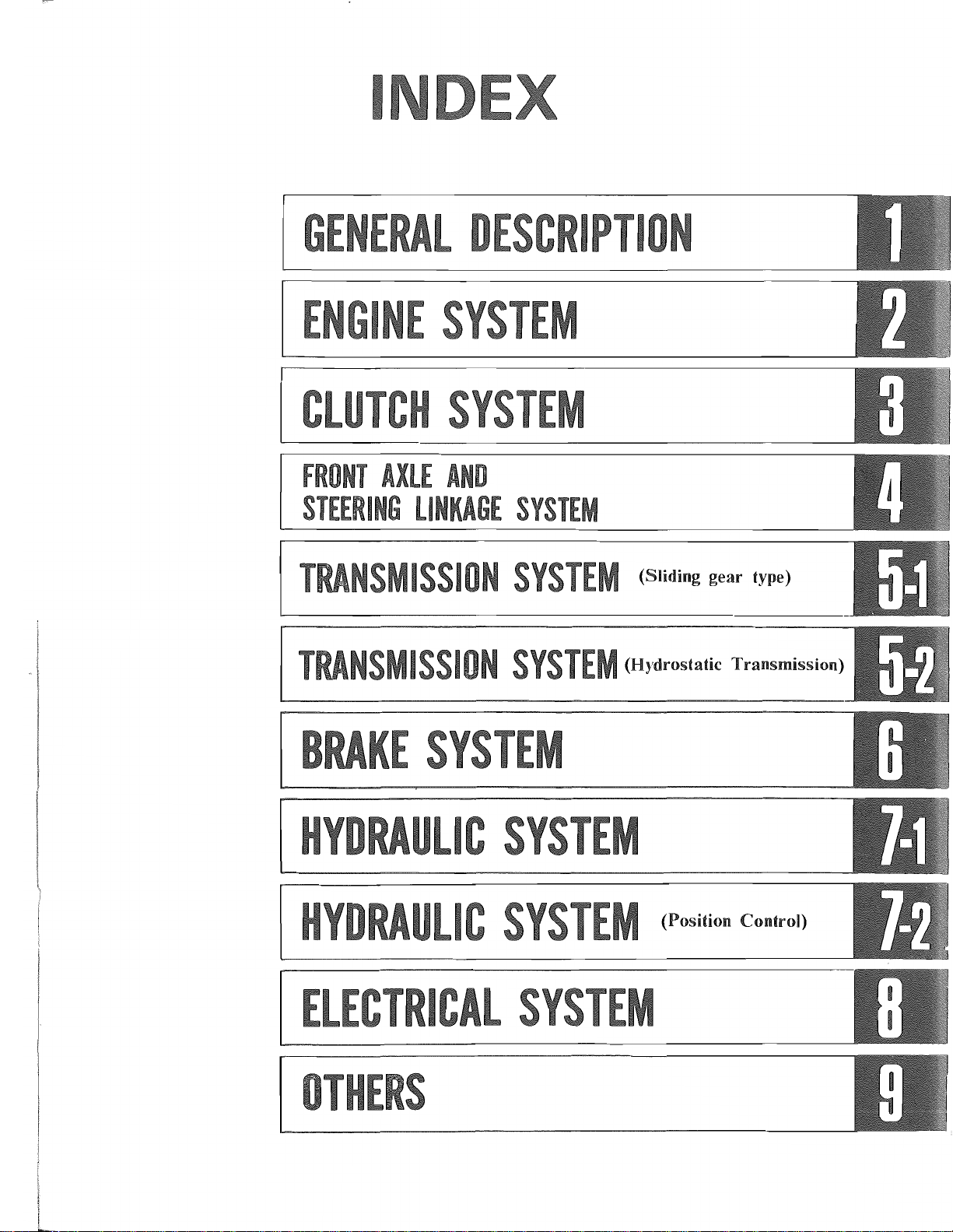
Specifications
Greasing diagram . . . . . . . . . . . . . . . . . . . . . . . . . . . . . . . . . . . . . . . . . .
Periodical
Lubrication
Wiring
An tifreeze
Tigh tening
Serial
Sealants
diagram.
number
..............................................
maintenance
table
. . . . . . . . . . . . . . . . . . . . . . . . . . . . . . . . . . . . . . . . . . .
................................................
torque
location
..................................................
services
..........................................
..........................................
........................................
OF
CONTENTS
................................
..
..
Page
I-I
1-12
1-13
1-14
1-15
1-16
1-17
1-17
1-18

t
1
.:..,
Tractor model
Type
Body structure
Overall
length
Overall width
Overall
height
Wheelbase
Dimensions
CD
c
's,
c
w
Ground clearnce
Gross
Load distribution
(without load)
Turning radius (with brakes) mm (in.)
Model
Type
Number ofcylinders
Combustion chamber type
Cylinder liner
Bore and stroke
Piston displacement
Compression ratio
Firing order
Rated rpm
Max.
rpm
Idling rpm
Max.
bare
HP
Max.
torque
l To end
of
rear tire
I To end of3-point linkage
I To top
weight
of
steering wheel
I Front axle
I Rear axle
(SAE)
-
MT160
2200 (86-19/32)
mm(in.)
1155 (45-15/32) 1165 (45-7/8)
260 (10-1/4) 215 (8-15/32)
565 (1246) 615 (1356) 575 (1268) 625 (1278)
kg
(lb)
mm (in.)
cc
(cu in.)
rpm
,
HP/rpm
Jllli~/rpm
~
t-Ip/rpm)_
260 (573)
MlTSUBISHI K3A-13MT
65 x 78 (2-9/16 x 3)
MT160D
975 (38-3/8)
310 (684) 260 (573)
305 (673)
Vertical, 4-stroke cycle, water cooled, overhead
776 (47.4) 900 (54.9)
16.5/2700
4.5 (32.5)/1900
MT180
All
purpose wheel tractor
Monocoque type
2225 (87-19/32)
2523 (99-11/32)
940 (37)
1175 (46-1/4) 1185 (46-21/32) 1175 (46-1/4)
1300 (51-3/16)
280 (11-1/32) 215 (8-15/32) 280 (11-1/32)
315 (695) 305 (673)
1850 (72-27/32)
Swirl combustion chamber with preheater
Non liner
2900+
925± 25
MT180D
970 (38-3/16) 940 (37)
320 (706) 260 (573)
MITSUBISlll K3C-13MT
valve,
3
70 x 78 (2-49/64 x 3)
23:
1
1 -3 - 2
2700
0
-75
18.5/2700
5.2 (37.6)/1900
MT180H
575 (1268)
315(695)
in line, diesel
MT180HD
970 (38-3/16) I
1185 (46-21/32) I
215 (8-15/32)
625 (1278)
320 (706)
305 (673)
I
I
I
G')
m
Z
m
:0
»
r
o
m
Ul
()
:0
-0
-;
o
z
r:.,
Tractor model
Compression pressure
Number
ofpiston
rings
Open
Intake valves
Exhaust valves
Close
Open
Close
Q)
c
Injection timing
'0,
c
w
Valve clearance
Intake valves
Exhaust valves
Fuel consumption
of
Direction
rotation
Weight, dry
-
Radiator fin
Radiator cap pressure
Type
Begins
to
Thermostat
open
Full open
E
Q)
....
en
>-
en
Water pump
Cl
c Feeding capacity
"0
0
u
Cooling fan Number
Lift
Type
Diameter
of
Blade meterial
Pulley ratio
offan
and crankshaft pulley
Drive system
blades
2
kg/cm
(psi)jrpm
deg
mm(in.)
g/HP/h
(oz/HP/h)
kg
(lb)
2
kg/cm
(psi)
°c
CF)
mm (in.)
\'
g /min
(U.S. gal/min.)
mm (in.)
MT160
MT160D
I
220 (7.7)
1
MT180
I
MT180D
I
32 (455) /280
compression rings and 1 oil ring
3
At
18° before TDC
At
46° after
At 46° before
At
18°
At
21
° ± 2° before TDC
after
BDC
BDC
TDC
0.25 (0.01) at cold
0.25 (0.01) at cold
230 (8.1)
I
Clockwise (as viewed from front)
125 (276)
Corrugate type
0.9 (12.8)
Wax
pellet type
82 (180)
95 (203)
8 (0.3)
at 95° C (203
Centrifugal impeller type
52 (13.7) at 2600 engine rpm
290
(ll-13/Tn
4
Plastic
1.32
"V"
- type belt
OF)
MT180H
MT180HD
I
CJ
m
Z
m
:0
~
r
o
m
til
(')
:0
-0
-l
o
Z
I
r
l
w
Fuel
Type
Fuel injection
pump
E
al
...
'"
>-
Fuel injection
'"
nozzles
Cii
::
u.
Model
Diameter
Cam lift
Type
Model
Injection pressure
Fuel filter
Oil pump
s::
0
.
.;:;
.2
E
Oil
"-al
.0
.....
::'"
...I~
"-
al
s::
C<l
al
t;
"-
~
filter
Relief valve setting
Type
Filter
Cleaning efficiency
Type
Feeding capacity
Dust holding
(5
Type
EE
alal
>
....
Speed control
0'"
C!l~
Type
Generator
E Voltage
al
....
'"
>-
'"
C;;
.~
...
<.J
.2
w
Starter motor
Model
Capacity
Type
Model
Voltage
Output
of
plunger
mm (in.)
2
kg/cm
(psi)
CJmin.
( .S. gal/min.)
2
kg/cm
(psi)
g (oz)
rpm
V
A
V
kW
Bruns grade No. 2-D fuel
oil
(ASTM specifications)
Bosch "M" plunger in line
NIPPON
DENSO
ND-PFR-3M
5.5 (7/32)
7 (9/32)
Throttle type
NIPPON DENSO ND-DN4SD24
120
+10
(1706
-0
+142)
- 0
Paper element type
Trochoid type
20 (5.28) at 2600 engine rpm
Full flow paper element filter cartridge type
4 (57)
Cyclone dry air cleaner
Dry paper element cartridge type
More than 99.9%
20 (0.7)
Mechanical all-speed control
90~2900
Alternator
MITSUBISHI AH2053M4
12
35
Magnet type
MITSUBISHI M002T50381
12
1.6
---
...
--
Cl
m
Z
m
:0
»
r
o
m
en
(')
:0
'"tl
---
--
--
-
-I
o
Z
j,.
Tractor
Regulator
E
CD
....
'"
>-
'"
iii
.~
....
Glow plugs
t.:I
~
w
Glow
indica or
~lug
Type
Model
Regulator voltage (no load)
Warning lamp lighting. on
voltage
Warning lamp lighting
off
V
voltage
Type
Rated voltage V (A)
Resistance capacity
normal temperature)
(at
n
Type
Rated current
Terminal-to-terminal
voltage
A
V
MT160
MT160D
I
I
MT180
MT180D
I
Tirrill type
MITSUBISHI RQB2220Dl
14.8
0.5
~
3.0
~
5.2
4.2
Sheathed type
10.5
1
~
1.2
Red heat type
30
0.9 ~ 1.1
(at
30A)
MT180H I MT180HD
G)
m
Z
m
:0
»
r
o
m
en
()
:0
-0
~
o
z
Type
E
CD
Clutch disc diameter
....
'"
>-
Lining thickness
'"
J::
t.:I
...
:::I
Torque capacity
U
Spring pressure
Number
s:::
.~
en
Speeds
.~
E
Speed change method
s:::
'"
co
...
Differential
I-
of
shift levers
Differential lock
mm(in.)
~-m
( -lb)
kg(lb)
Dry single disc plate diaphragm spring type
184 x 127 (7-5/16 x 5-1/32)
2-
6 - forward,
reverse
Selective sliding gear type
Bevel gear type with differential lock
Foot
pedal (right side
7.8 (5/16)
11.0 (79.6)
195 (430)
2
of
transmission case)
2-forward, 2-reverse
Hydrostatic type
------
----
--
1
1
cJ,
'"0
'"
cu
cu
Cl..
'"
Q)
;;-
<e
...
E--
MTl60
(2-WD
and
Speed
F-l L-I
F-2
F-3
F-4 H-I
F-5
F-6
I
R-I
I
R-2
Tire size:
Speed
F-I
F-2
F-3
F-4
F-5
F-6
I
R-J
I L-R
R-2
I
and MTl60D.
4-WD)
(at engine speed 2700 rpm)
Lever
position
km/hr mile/hr m/sec
L-2
L-3
H-2
H-3
13.5
(max)
L-R
H-R
8-18AG
Lever
position
tile
km/hr
L-l
L-2
L-3
H-J
H-2
H-3
14.5
(max)
I
H-R
I
-
1.1
1.7
2.9
4.9 3.04
7.4 4.60
1.4
6.3
0.31
0.68
0.47 F-2
1.06
0.81
1.80
1.36
2.06
3.75
8.38
0.39
0.87
1.75
3.91
mile/hr m/sec Speed
1.2
1.8
3.1
5.3
7.9
1.5
6.7
0.75
1.12 0.50
1.93
3.29
4.91
9.00
0.73
4.16
0.33·
0.86
1.47
2.19
4.03
0.42
1.86
MTl80
and
MTl80D
(2-WD
and
4-WD)
(at engine speed 2700 rpm)
Speed
Lever
position
F-I L-I
L-2
F-3
L-3
F-4 H-I 5.13
F-5
F-6
R-I
R-2
Tire size:
F-I
F-2
F-3
H-2
H-3
L-R
H-R
9.5-18ES
Lever
position
L-l
L-2
L-3
F-4 H-I
F-5
F-6
R-J
R-2
H-2
H-3
L-R 1.55
H-R 6.94
km/hr mile/hr m/sec
1.15
1.78
3.04
0.71 0.32
1.11
1.89 0.85
3.18
4.82 2.16
8.78
0.91 I 0.41
4.09 I 1.83.
14.14
I
I
7.75
1.47 I
6.56 I
tire
km/hr mile/hr m/sec
1.24
0.78
1.86 1.16
3.21 2.00
5.49
2.18
3.41
5.09
15.02 9.32
0.96
4.31
0.49
1.42
3.93
0.34
0.52
0.89
1.52
1..27
4.17
0.43
1.93
MTl80H
and
(2-WD and 4-WD)
F-I
F-2
R-I
R-2
F·l
F-2
R-J
R-2
rise:
Lever
position
L
H
L
H
9.5-18ES
Lever
position
L
f----
H
L
H
Speed
-
Tire
Speed
----
~---
MTl80HD
(at
lan/hr
0~6.2
o
~
0~3.4
O~
tire
Km/hr mile/hr
0~6.4
-
o ~ 17.2
0~3.5
O~
engine speed 2700rpm)
0~3.9
16.6 o
0~2.1
8.5
O~
0~4.0
O~
0~2.2
8.8
o~
mile/hr
~
10.3
5.3
10.7
5.5
m/sec.
O~
1.7
0~4.6
0~0.9
0~2.4
m/sec.
O~
1.8
0~4.8
o
~
0.97
O~
2.4
G)
m
Z
m
:0
»
r
0
m
en
(")
:0
-0
-l
0
Z
6l
Tractor model
t::
Final reduction gear
0
'';::;
Reduction ratio
_<.l
ce~
t::-c
Type
of
.-
IJ..
'"
...
rear axle
Power take-o ff step
Power take-off
Power take-o
..-
Power take-o
-
0
.;,
rpm
.:.:
ce
...
...
'"
s:
Standard power
0
Q..
take-off
ff
ff
HP
shaft
Direction 0 f rotation
Steering system
Axle center
Steering knuckle arrangement
First
Second
Third
Shift position
First
Third( second)
HP/rpm
rpm
MT160
13.6/2700
Lemoine
type
MT160D
MT180
3-step
1-3/8 in. 6-spline
623/2700 engine rpm
919/2700 engine rpm
1,506/2700 engine rpm
540/2660 engine rpm
1,000/1793 engine rpm
Clockwise
Ackerman
Reverse Elliott
I Lemoine Reverse Elliott I Lemoine
type type
MT180D
Spur gear
11/72 (0.153)
1/2 floating type
SAE
as
viewed from the rear
jant
method
Center pivot type
type type type
15.5/2700
standard
MT180H
MT180HD
2-step
606/2700 engine rpm
1,186/2700 engine rpm
540/2405 engine rpm
1,000/2278 engine rpm
Reverse Elliott
G>
m
Z
m
:Il
»
r
o
m
(J)
(")
:Il
-c
-I
o
Z
I
Tread adjustment
Axle center
Cl
Kingpin angle
.§
Camber
'"
...
'"
en
Caster
Swing
Toe-in
Steering angle
Steering gear box (inside)
Gear ratio
Steering wheel diameter
Type
",E
.:.:'"
ttl ....
...
<J>
Brake pedal
oa~
Parking brake and operating
I _
angle
deg
mm(in.)
deg
mm(in.)
8 10
3
6.4±L5(l
/4±1 / 16)
55
Not
adjustable
8
8
10
2.5
0
0-6(15/64)
53
3
6'.4±L5(\/4±1/16)
55
0
0-6(15/64)
53
Ball screw fype
15
403 (15-29/32)
Foot
operating, internal expansion, waterproof dry type
Seperate with interlocking foot operating type
Main brake used hand, operating lock, type
8
3 0
6.4±L5(1/4±1/16)
55
10
0-6(15/64)
53
I
I
~
Lining
E
Ol
....
Drum diameter
'"
>-
'"
Ol Brake location
~
::!
Brake pedal free play
m
FrontAG
Front
~
I-
ES
(option)
Rear AG
Lengh x width x thickness
Number oflinings
Tire size and ply rating
Tire pattern
Tire pressure
Outside diameter
Tire width
Maximum load
Type
of
valve
Rim size
Tire size and ply rating
Tire
pattem
Tire
pressure
Outside diameter
Tire width
Maximum load
Type
of
vI
ave
Rim size
Tire size and ply rating
Tire pattern
Tire pressure
Outside <llinneter
Tire width
Maximum load
of
Type
valve
Rim size
mm(in.)
mm(in.)
mm(in.)
kg/cm
(psi)
mm(in.)
kg (lb)
2
kgfcrn
(Psi)
mm(in.)
kg(1b)
kg/cm
(psi)
mm(in.)
kg/(lb)
119 x 28.5 x 4.0 (4-11/16 x 1-1/8 x 5/32)
4
114 (4-31/64)
Differential shaft
25
~
30
(63/64 ~ 1-3/16)
4.00-9-4PR
5-12-4PR 4.50-10-4PR
5-12-4PR
4.50-10-4PR 5-12-4PR
Three-rib:F-2 Farm-lug:R-1 Three-rib:F-2 Farm-lug:R-l Three-rib:F-2 Farm-lug:R-l
2
3.25(46.2)
457
(18) 550(21-21/32)
113 (4-7/16) 123(4-27/32) 120(4-23/32) 123(4-27/32) 120(4-23/32) 123(4-27/32)
200(441)
210
(463)
488(19-7/32) 550(21-21/32) 488(19-7/32) 550(21-21/32)
205
(452)
2.2 (31.3)
210
(463)
205
(452)
TR-13
3.00Dx9DT
18x7.00-8-4PR 6-12-4PR 20x8.00-10-4PR 6-12-4PR 20x8.00-10-4PR 6-12-4PR
Pillow-dia:G 2
20(28.4) 2.2(31.3) 1.7 (24.2) 2.2(31.3)
457 (18)
170(7-3/32) 155(6-3/32) 193(7-19/32) 155(6-3/32)
310
(684)
TR
- 413
5.50x8DT
8 - 16 -
2
4JAx12 3.00DxlODT 4JAx12 3.00DxlODT 4JAx12
All-weather:R-3
Pillow-dia:G 2
All-weather:R-3
Pillow-dia:G2
1.7(24.2) 2.2(31.3)
564(22-7/32) 495(19-15/32) 564(22-7/32)
495(19-15/32) 564(22-7/32)
193(7-19/32)
270
(595)
TR-13
410
TR-
(904)
413
270
TR-13
(595)
410
(904) 270 (595)
TR-
413
5JAx12 6.00IxlODT 5JAx12 6.00IxlODT 5JAx12
4PR
Farm-lug:
R-l
8 - 18 -
4PR
1.0 (14.2)
783 (30 - 13/16)
197
(7 -3/4)
475
(1047) 515 (1136)
TR-15
W6
x 16
-------
840 (33 - 5/64)
197
(7 -3/4)
TR-
281A
W6
x 18
~-~
~-
210
(463)
All-weather:R-3
155(6-3/32)
TR-13
I
Gl
m
2
m
::0
»
r
o
m
en
(')
::0
"'0
-l
o
2
Co
Tractomr model
(option)
CI)
...
I-
AG
tire
ES
tire
....
I:
CI)
E
...
'"
::l
:0
'"
-c
CI)
'"
...
I-
MT160
Tire size and ply rating
Tire pattern
Tire pressure
Outside diameter
I Tire width
Maximum load kg(lb) 555 (1224)
Type
of
valve
Rim size
Standard
tread
Max. tread
Standard
tread
Max.
tread
- -
l<!e.'''L'321
~"O-
I',
I
"
~
~
~-~
AG/F
Front
Rear
Front
Rear
Front
Rear
Front
Rear
MT160
(2-WD)
$/--
11"'"
ES/F
kg/cmz
(psi)
mm(in.)
720(28-13/32)1 785(30-29/32)
790(31-3/32) 1
m-'"o-
:;'"
AG/R
I
9.5 -
16
- 4PR
All-weather:
1.0 (14.2)
820 (32 - 9/32)
242(9-17/32)
TR-15
W8x
16
740 (29 - 3/32)
-
1
890 (35)
800 (31-1/2)
790
(31-
3/32)
-
1
840 (33 - 3/32)
MT160D
R-3
-
-
MT180
720(28-13/32)1 785(30-29/32A 720(28-13/32)1 785(30-29/32)
-
795(31-5/16) 1
-
MT160D
'I""'"
f''''-
I
!~
AG/F
MT180D
I
9.5-18-4PR
All-
870 (
242 ( 9 - 17/32)
600 (1323)
TR-
740 (29 - 3/32)
-
I
800(31-1/2) 1 795(31-5/16) 1 800(31-1/2)
770 (30 - 5/16)
-
I
865 (34 - 1/16)
(4-WD)
w;:--
,,--,'"
ES/F
MT180H
I
weather:
1.0 (14.2)
34
- 1/4)
218A
W8x18
I
890 (35)
1
.n
m'~
AG/R
R-3
~
MT180HD
-
I
-
1
-
-
h---""
Gl
m
Z
m
::tJ
l>
r
o
m
Ul
()
::tJ
"'tI
-I
o
Z
t
i
~.--
Ii
1315)
I I
i
AG/Max.R
S'.,
II
•
I
;--1
ES/R
,"0'
-
~rr'"o
i
II!
.
-iT
ES/Max·R
''''0.
I
l
890-
II
I
,35)
~'.o_~.'"
i
AG/Max·R
~--
- -
ES/R
(3,
_3/3<:)
,
--r-
~-
I
ES/Max·R
(3:l_3/32~
I
I
I
"1
r"
"1
MT180
I r
""
...
s::
Q)
E
...
'"
:::I
:0-
ct!
"C
ct!
~
I-
m
I
-1-~
AG/F
I I
I'
".-
~
I
'"'30>
'>0
'"
'3.
i
AG/Max.R
Control
Type
Cylinder Diameter
Stroke
of
Maximum lift power
Pressure for pump reliefvalve setting
at
end
& MT180H
,
f~
I,
II
ES/F
~
i'.
ES/R
of
piston mm(in.)
piston
oflower
:"~,
-
~",""e.
" I I
'ff
-;""
link
'i-~
' I
AG/R
..
-
~"".-
fi-~"··
ES/Max-R
kg(lb)
kg/cm
(psi)
MT180D & MT180HD
' .
785
,I
, i I
,:
i~1
~Ik
' ! )
AG/F
m~"-
' i
AG/Max'R
Lift,hold,down,flow control
2
~
'30'Om'
(361
II
Position control, downspeed control and lock
I
Single -acting
60 (2 - 3/8)
71
500 (1103)
135 (1920)
~
ES/F
~-·-m"""-
ES/R
(2 - 13/16)
...
I
,,"
III
:
-1
'-r'""
-
~"".-
-
\-1
AG/R
i
",,,"
ES/Max·R
I
cO
E
Q)
...
Hydraulic pump
'"
>
'"
Co)
:::I
ct!
"-
Control valve type
"C
>
J:
Oil lock valve
Strainer mesh
Hydraulic
Hydraulic external adaptor
Lifting speed
oil
on-point
Type
Name and model
Capacity
linkage
I liter/min
(U.S.gai/min )
sec
Spool valve, 3-port, 3-position
In line, non-return valve, flow control valve type
SAE # 80
Pressure loading gear type
GP
NACHI
12.9 (3.4) at 2700 engine rpm
I
# 42 x 100 mesh
gear oil same
- 3607 A
2 spool valve with unload
as
transmission oil
Optional
1
G)
valve
---_
...
--,--
-
m
Z
m
::c
»
r
o
m
CIl
()
::c
-0
-l
o
Z
....
o
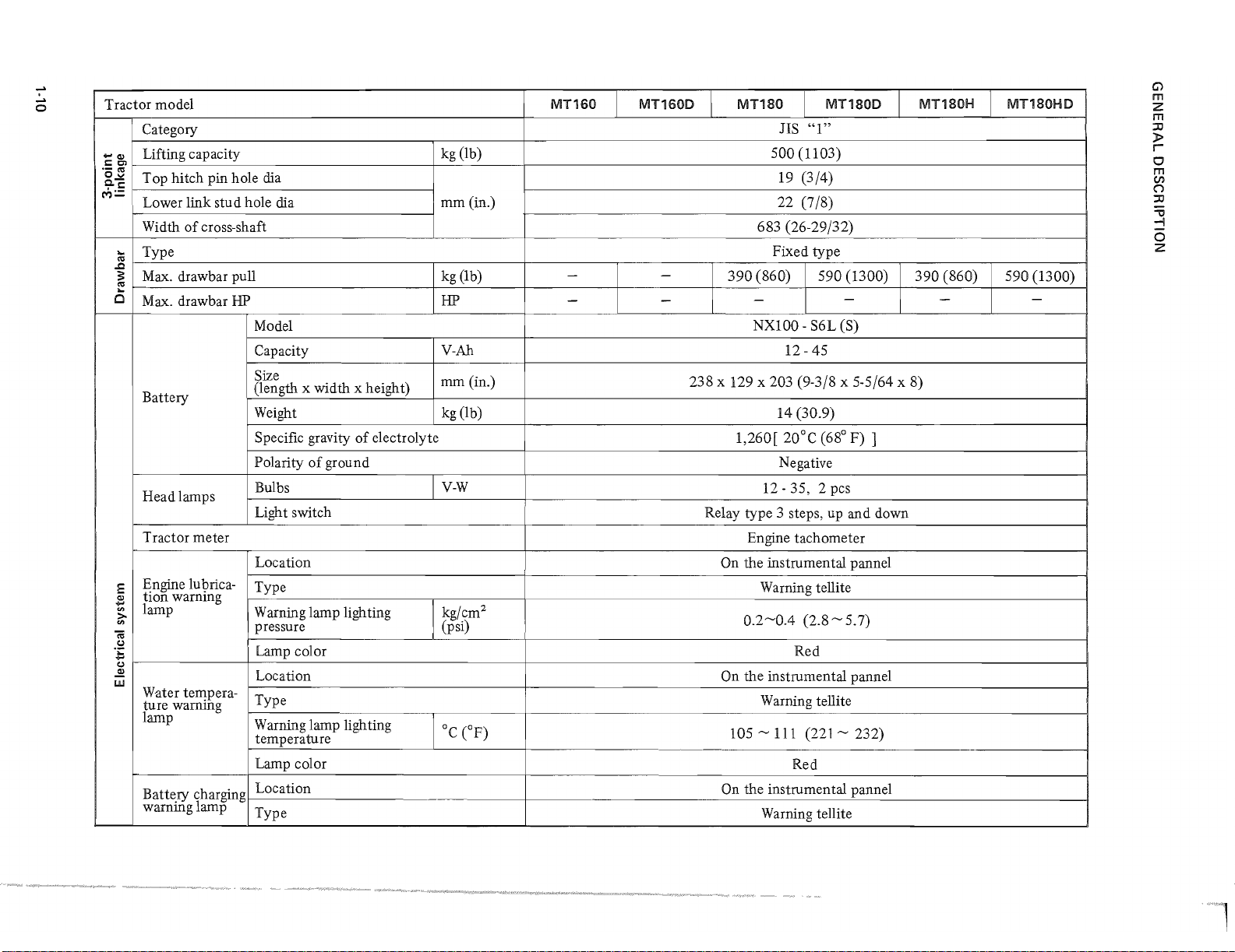
Tractor model
Category
Lifting capacity
~C!l
S:::e>
.-
'"
o~
Top hitch pin hole dia
Cos:::
M=
Lower link stud hole dia
Width
of
cross-shaft
...
Type
..c
'"
s:
Max.
...
'"
0
drawbar pull kg (Ib)
Max. drawbar
Battery
Head lamps
Tractor meter
Engine lubrica-
E
tion warning
.lB
lamp
'"
>
'"
cti
Co)
.;:
..
Co)
..:2
w
Water terrwera-
ture warrung
lamp
Battery charging
warning lamp
HP
Model
Capacity
Size
(length x width x height)
Weight
Specific gravity
Polarity
of
ground
of
electrolyte
Bulbs
Light switch
Location
Type
Warning lamp lighting
pressure (psi)
Lamp color
Location
Type
Warning lamp lighting
temperature
Lamp color
Location
Type
--_._-
--
kg (lb)
mm(in.)
HP
V-Ah
mm
(in.)
kg
(lb)
V-W
2
kg/cm
°c
CF)
MT160
-
-
MT160D
-
-
MT180
ns
MT180D
"1"
500 (1103)
19 (3/4)
22 (7/8)
683 (26-29/32)
Fixed type
390
(860) 590 (1300)
-
NXIOO
-
- S6L (S)
12 -45
238 x 129 x 203 (9-3/8 x 5-5/64 x 8)
14 (30.9)
1,260[ 20°C (68° F) ]
Negative
12 - 35, 2 pcs
Relay type 3 steps, up and down
Engine tachometer
On the instrumental pannel
Warning tellite
0.2
~0.4
(2.8 ~ 5.7)
Red
On the instrumental pannel
Warning tellite
105 ~ 111
(221 ~ 232)
Red
On
the instrumental panne1
Warning tellite
MT180H
390
(860)
-
MT180HD
590 (1300)
-
G)
m
Z
m
:0
»
r
o
m
en
()
:0
."
-I
o
Z
'1
Battery charging
warning lamp
E
.,
....
~
Safe~
co
SWltc
·5
'"
~
w
Working lamp
(optional)
starter
Warning lamp lights on
Warning lamp lights
off
Lamp color
Capacity
Stroke
Bulb
Location
Fuse
Cooling water
;;::
co
.
.;::;
Engine oil
:~
~
'"
Transmission oil
E
·x
0
"-
Steering gearbox
0.
0.
'"
-
Hydraulic oil
'"
-!
Front
.tj
'"
0.
'"
u
differential case oil
Incl. kingpin case oil
Fuel tank (U.S.gal-pint)
liter(pint)
(U.S. gal-pint)
liter(pint)
V
V-A
mm (in.)
V-W
A
liter
(quart)
liter
CC
(oz)
0.5 ~ 3.0
4.2
~
5.2
I
Red
12 - 35 (Momentary 70A)
3 ± 0.5
(l/8
± 1/64)
12 - 23
of
At the rear
righ t hand fender
10
5 (5)
3 (6)
12(3-1)
I
14 (3-6)
200 (6.8)
Same
as
transmission oil
-
2.5 (5)
I
~~
--~--
I
---_._.-
-
18 (4 -6)
l
-
2.5 (5)
These specifications are subject
-
f
to
change without notice.
I
2.5 (5)
..:.,.
G)
m
Z
m
:0
»
r
o
m
en
(")
:0
-0
-l
o
Z
GENERAL
DESCRIPTION
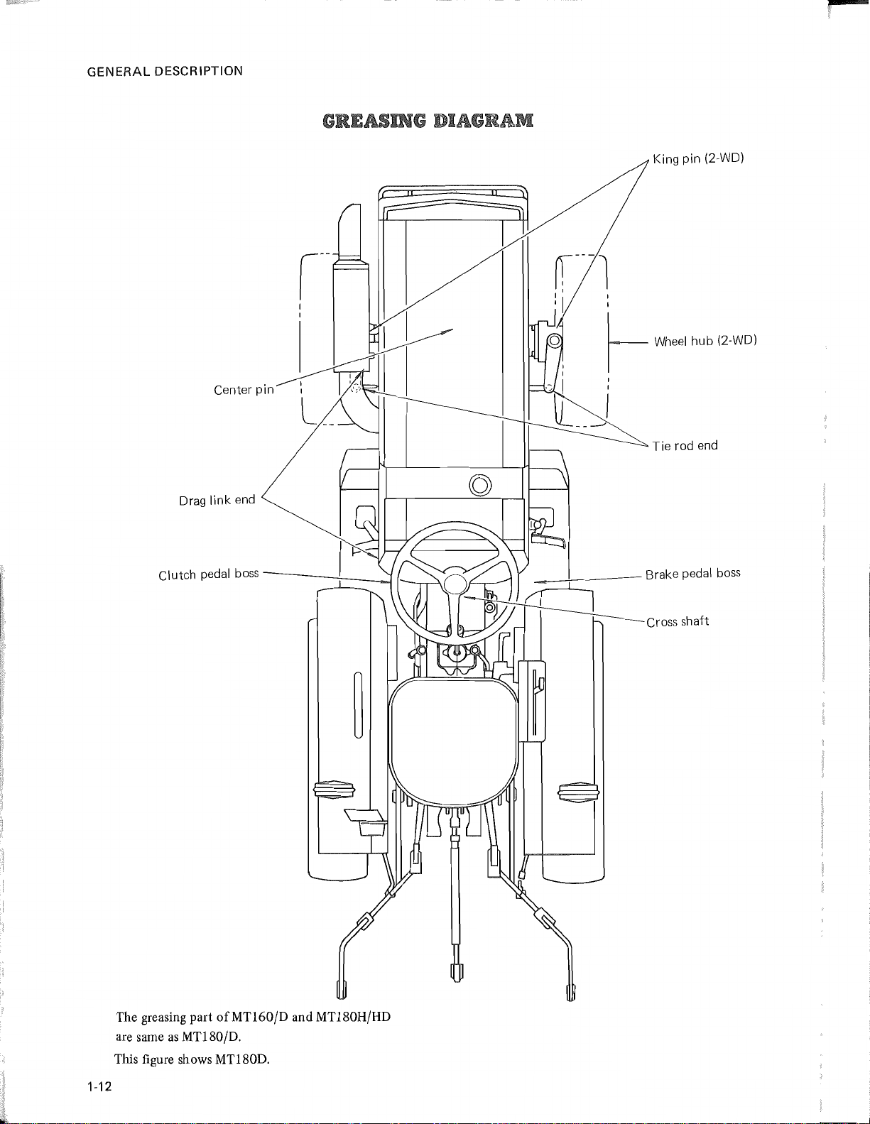
GREASING JlUllJIlA"l"-""'''''''''''''-'''''
Center pin
Drag link end
f---l
I
I'
, I
,
I
,~
I :
lL
,
~
____
I
King pin
Wheel
Tie rod end
(2-WD)
hob
12-WDI
Clutch pedal
boss--
__
~_~
Brake pedal boss
l
Cross shaft
The greasing part
as
are same
This figure shows MTl80D.
1-12
MTl80/D.
ofMTl60/D
and MTl80H/HD
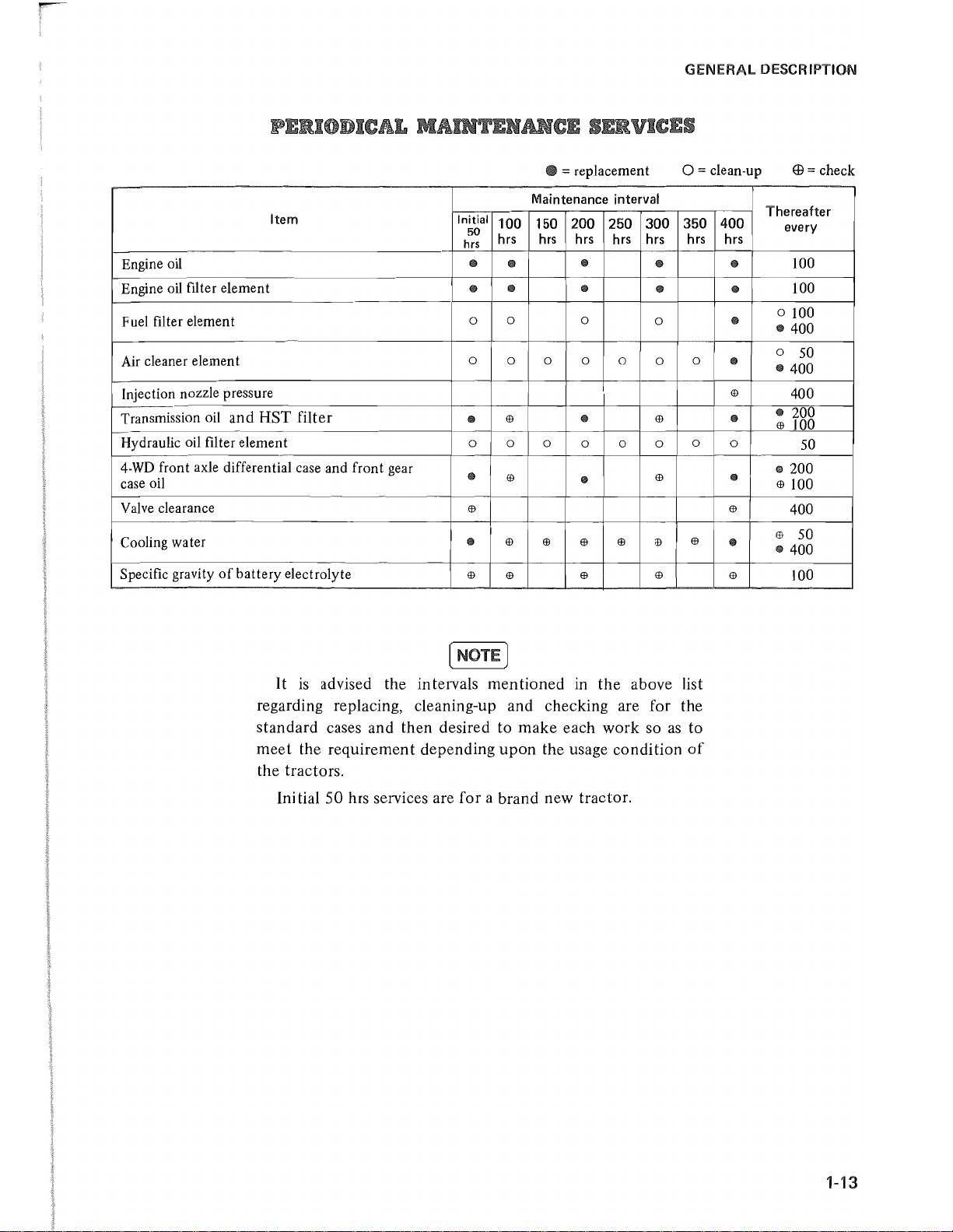
• = replacement
GENERAL DESCRIPTION
0=
clean-up
EB
= check
Item
Engine oil
Engine oil filter
element
Fuel filter element
Air cleaner element
Injection nozzle pressure
Transmission oil
and HST filter
Hydraulic oil filter element
4-WD
front axle differential case and
case oil
Valve clearance
Cooling water
Specific gravity
of
battery
electrolyte
front
gear
Maintenance interval
Initial
100
150
50
hrs hrs hrs hrs hrs hrs
hrs
till
till
till
•
0 0
0
0
0 0
6J
till
0 0 0
till
Ef)
6J
6J
•
6J
6J 6J
200 250
6J
till
till
0
•
0 0 0
till
6J
0
6J
300 350
till
till
0
0 0
6J
0
6J
6J
6J
6J
400
hrs
till
•
till
till
6J
•
0
•
6J
•
6J
Thereafter
every
100
100
o 100
.400
0
50
·400
400
• 200
6J
100
50
.200
6J
100
400
6J
50
·400
100
[NOTE]
It
is
advised the intervals mentioned in the above list
regarding replacing, cleaning-up and checking are for the
standard cases and then desired to make each work so
meet the requirement depending upon the usage condition
the tractors.
Initial 50 hrs services are for a brand new tractor.
as
to
of
1-13
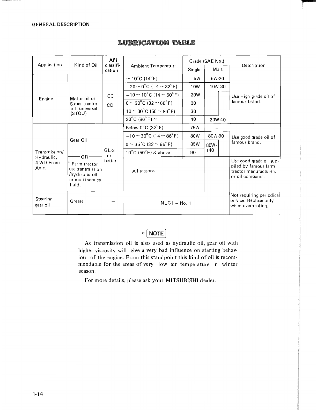
GENERAL
DESCRIPTION
Application
Engine
Transmission/
Hydraulic,
4-WD Front
Axle.
Steering
gear
oil
Kind
of
Motor
oil
Super
tractor
oil universal
(STOU)
Gear
Oil
f--OR-
* Farm
tractor
use
transm
/hydrau I
or
mu
Iti
fluid.
Grease
ic
-service
Oil
or
iss
oil
ion
API
classifi-
cation
ee
eD
GL-3
or
better
-
Ambient
~
100e (14°F)
-20 ~ oOe
-10 ~ 100e (14 ~ 50°F)
o ~ 200e (32 ~ 68°F)
10~30oe
0
30
e (86°F)
Below
-10~30oe
o
~
0
10
e (50°F) &
All
Temperature
(-4 ~ 32°F)
(50~86°F)
~
oOe
(32°F)
(14~86°F)
35°e
(32 ~ 95°F)
seasons
above
NLG1 -
Grade (SAE No.)
Single
5W
10W
20W
20
30
40
75W
80W
85W
90
No.1
Multi
5W-20
10W-30
20W-40
-
80W-90
85W-
140
Description
r---
Use
High
famous brand.
Use
good
famous brand.
Use
good
plied by famous farm
tractor manufacturers
or
oil companies.
Not
requiring periodical
service. Replace only
when overhauling.
grade
grade
grade
oil
of
oil
of
oil sup·
As
transmission oil
higher viscosity will
iour
of
the
engine. From this
give
mendable for the areas
season.
For
more details, please ask
is
also used
as
hydraulic oil, gear oil with
a very bad influence on starting behav-
standpoint
of
very low air temperature in winter
your
this kind
of
oil
MITSUBISHI dealer.
is
recom-
1-14
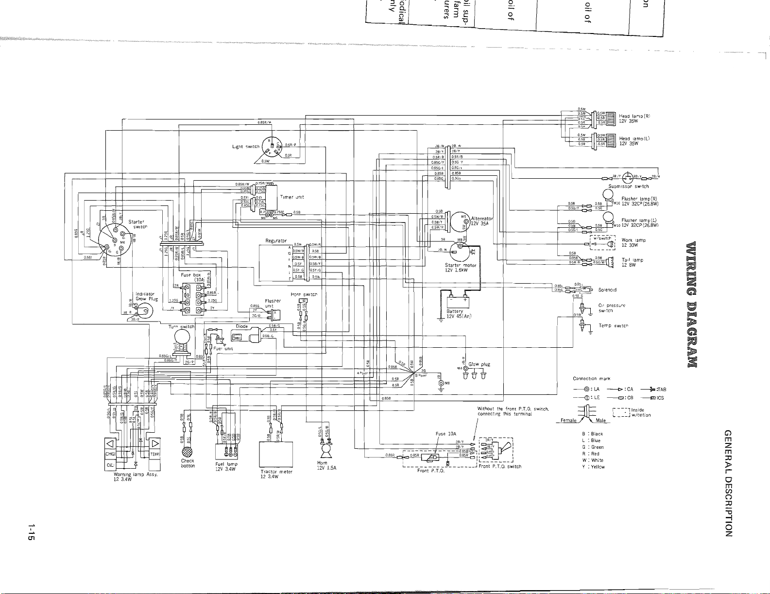
r<"
Light
switch
II
OB5R!W
O.5W.'
"i!l--,0",5R""£.B
+-f--~
05R
Regu
I:~'
F _5W/8 I
L
.5Y/G
'~
E
0.56!
1
~
~I
1\
05W
H:
28/W
28/v
28iY
O.SR/S
05RfB
05G!Y
085G!Y
O.SG/l
085G/L
0858
0858
O.5Gy
O.SSG
I
~ ~
05W
I
!H~;~~'
lO.58
'O-,A
-05R
~
.5W~
DOR
Head
12V
Head
12V
i g I
35W
35W
8/~-.ll/Y_~BJ
OB5L
[TI;SL
SolenOId
Oil pressure
switch
Temp. SWitch
lamp
lamp(L)
(R)
.:..,.
01
'--
Warning lamp Assy.
123.4W
TEMPi
1--
L-
~II
~I
~
Check
botton
'::::::Ef=
~I,
o~
,~~
o
i!>EB6
tI
Fuel
lamp
12V
3.4W
°1?~1
~
~~
~
u
Tractor
123.4W
meter
L----j-
H
Horn
12V
1.5A
0.858
~;:~(
Fuse lOA I
-+
r--
L
___ ~ __
Front P.T.D.
Without the front
connecting this terminal
__
~t
~
",28",1'''---'0>
\ 2B/Y 1
2a~;58
__
-.:~1
______
J
~r~~t
Connection
----@:
LA
----{]):
LE
P.T.C.
switch.
~
______
"
-P~T~O~;~jtCh
~
B : Black
L : Blue
G : Green
R :
W:
Y :
Male
Red
White
Yellow
mark
--!>
:
CA
~
oJ
w/optlOn
----£I
:TAB
:CS
--0:
CB
:--::I",ide
'-
___
G)
m
Z
m
:0
»
r
o
m
en
(")
:0
""C
-I
o
Z
GENERAL
DESCRIPTION
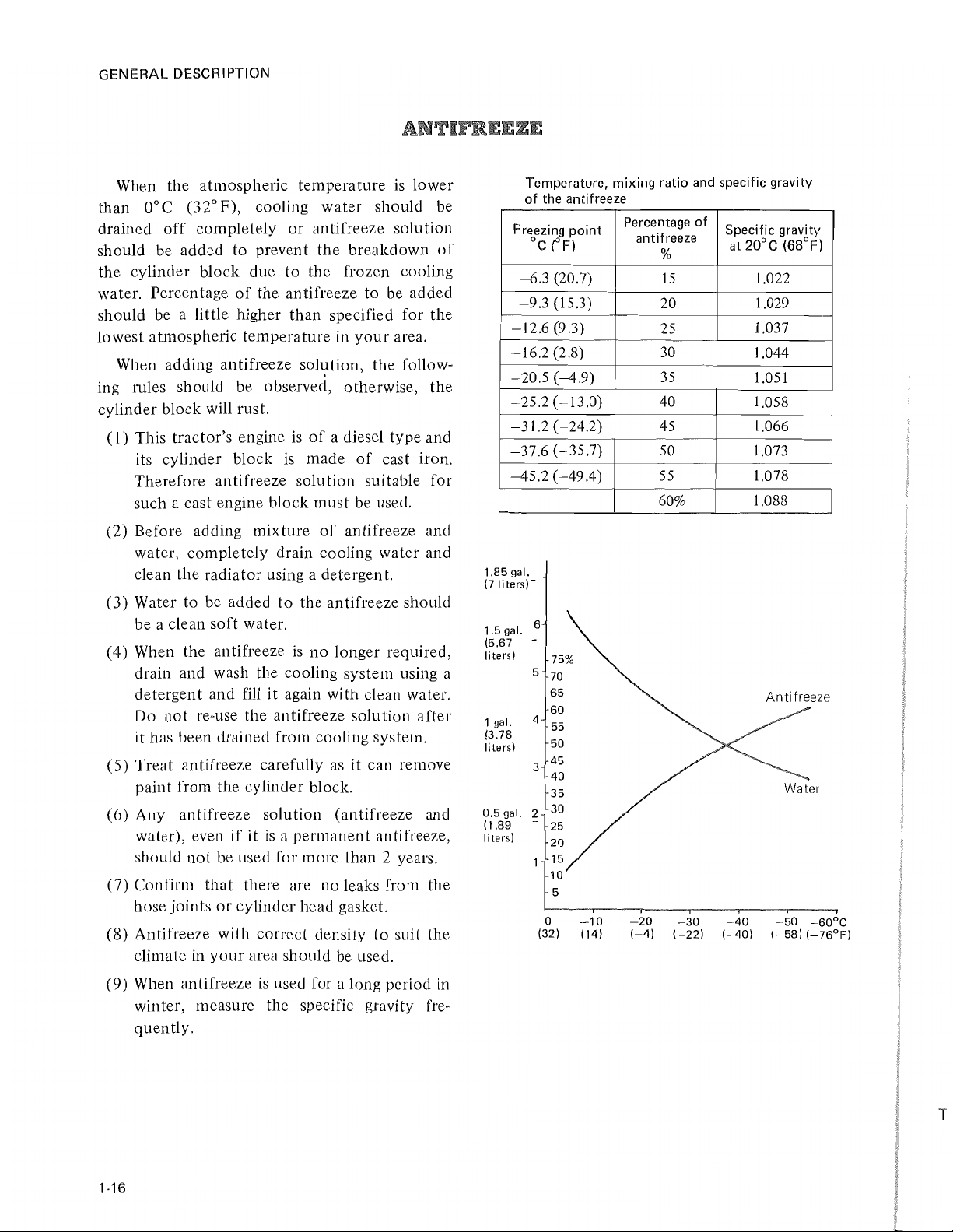
When the atmospheric
than
should be added
drained
O°C
(32°P),
off
completely
to
the cylinder block due
water. Percentage
of
temperature
is
lower
cooling water should be
or
antifreeze solution
prevent
the
breakdown
to
the frozen cooling
of
the antifreeze to be added
should be a little higher than specified for the
lowest atmospheric
temperature
in
your
area.
When adding an tifreeze solution, the follow-
ing rules should be observed, otherwise, the
cylinder block will rust.
(1)
This tractor's engine
its cylinder block
is
is
of
a diesel type and
made
of
cast iron.
Therefore antifreeze solution suitable for
such a cast engine block
(2) Before adding mixture
must
be used.
of
antifreeze and
water, completely drain cooling water and
clean the radia tor using a de tergen
(3) Water to be added
to
the antifreeze should
t.
be a clean soft water.
(4) When the an tifreeze
is
no
longer required,
drain and wash the cooling system using a
it
detergent and fill
not
Do
it
re-use
has been drained from cooling system.
(5) Treat antifreeze carefully
again with clean water.
the
antifreeze solution after
as
it can remove
paint from the cylinder block.
(6) Any antifreeze solution (antifreeze and
if
it
water), even
should
(7)
Confirm.
hose joints
not
be used for more than 2 years.
that
or
is a permanent
there are no leaks from the
cylinder head gasket.
(8) Antifreeze with correct density
climate in
your
area should be used.
antifreeze,
to
suit the
Temperature, mixing ratio and specific gravity
of the antifreeze
-10
(14)
Percentage of
antifreeze
%
15
20
25
30
35
40
45
50
55
60%
-20
(-4)
I
-30
(-22)
Freezing point
°c
-6.3
-9.3
-12.6
-16.2
-20.5
-25.2
-31.2
-37.6
-45.2
1.85
gal.
(7Iiters)-
1.5
gal.
(5.67
liters)
5
gal.
4
3
2
-
1 gal.
(3.78
liters)
0.5
(1.89
liters)
(OF)
(20.7)
(15.3)
(9.3)
(2.8)
(-4.9)
(-13.0)
(-24.2)
(-35.7)
(-49.4)
6
75%
70
65
60
55
50
45
40
35
30
25
20
1 15
10
5
o
(32)
Specific gravity
at 20°C (68°F)
1.022
1.029
1.037
1.044
1.051
1.058
1.066
1.073
1.078
1.088
Anti freeze
Water
I
-40
(-40)
j ,
-50
(-58)
(-76°F)
-60°C
(9) When antifreeze
is
used for a long period in
winter, measure the specific gravity fre-
quently.
1·16
T
ty
F)
F
GENERAL DESCRIPTION
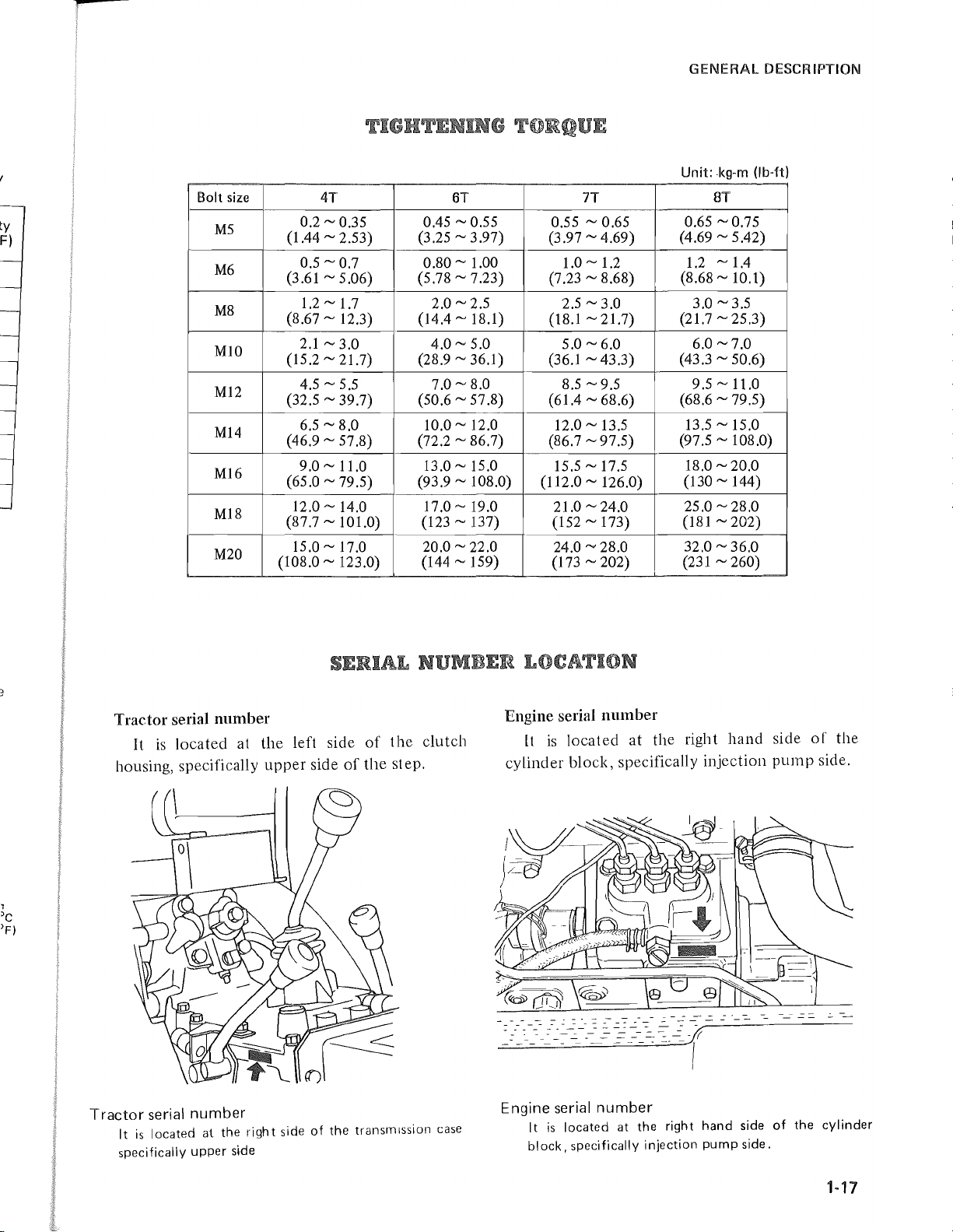
Unit·
kg-m
(lb-tt)
."
Bolt
size 4T
M5
M6
M8
MlO
M12
M14
M16
MI8
M20
0.2 ~ 0.35 0.45 ~ 0.55
(1.44
0.5 ~ 0.7
(3.61 ~ 5.06)
1.2
(8.67
2.1
(15.2
4.5
(32.5
6.5 ~ 8.0 10.0 ~ 12.0
(46.9
9.0
(65.0
12.0 ~ 14.0
(87.7
15.0~17.0
(108.0 ~ 123.0)
6T 7T
0.55
(3.25
~
~
2.53)
0.80
(5.78
~ 1.7 2.0 ~ 2.5 2.5 ~ 3.0
~
12.3) (14.4 ~ 18.1)
~
3.0 4.0 ~ 5.0
~
21.7) (28.9 ~ 36.1) (36.1 ~ 43.3)
~ 5.5 7.0 ~ 8.0 8.5 ~ 9.5 9.5 ~ 11.0
~
39.7)
~
57.8) (72.2 ~ 86.7) (86.7 ~ 97.5)
~
11.0
~
79.5) (93.9 ~ 108.0)
(50.6 ~ 57.8)
3.97)
~ 1.00 1.0 ~ 1.2
~
7.23)
~ 15.0
13.0
17.0 - 19.0
~
101.0) (123 ~ 137)
20.0
~22.0
(144
~
159)
~ 0.65
~
~
~
4.69)
8.68)
21.7)
(3.97
(7.23
(18.1
5.0 - 6.0
(61.4 - 68.6)
12.0~13.5
15.5
~ 17.5
(112.0
~
126.0)
21.0 ~ 24.0
(152
~
173)
24.0,....,
(173
28.0 32.0 ~ 36.0
~
202)
8T
~
1.2
0.75
~
5.42)
~1.4
~
10.1)
0.65
(4.69
(8.68
3.0 - 3.5
(21.7
~
25.3)
6.0 ~ 7.0
(43.3
~
50.6)
(68.6 ~ 79.5)
13.5 ~ 15.0
~
~
20.0
108.0)
(97.5
18.0
(130 ~ 144)
25.0
~ 28.0
(181
~202)
(231
~
260)
,
'c
'F)
Tractor
It
is
serial
located at
housing, specifically
Tractor
serial
It
is
located
specifically
number
upper
number
at
the
side
the
upper
right
left
side
side
side
of
the
of
the
of
the
step.
transmission
clutch
case
Engine serial
It
is
number
located
at
the right
hand
cylinder block, specifically injection
- - -
-::-:
:---=
-
~
=-
=-=
~~-.:::-
Engine serial
It
is
located
block,
specifically
~
-=
number
::---=-
-=--==-
at
---------
---
- -
=:
~-~1
the
right
injection
-~-----------------
hand
side
pump
side.
side
pump
of
the
of
the
side.
cylinder
1-17
r
GENERAL DESCRIPTiON
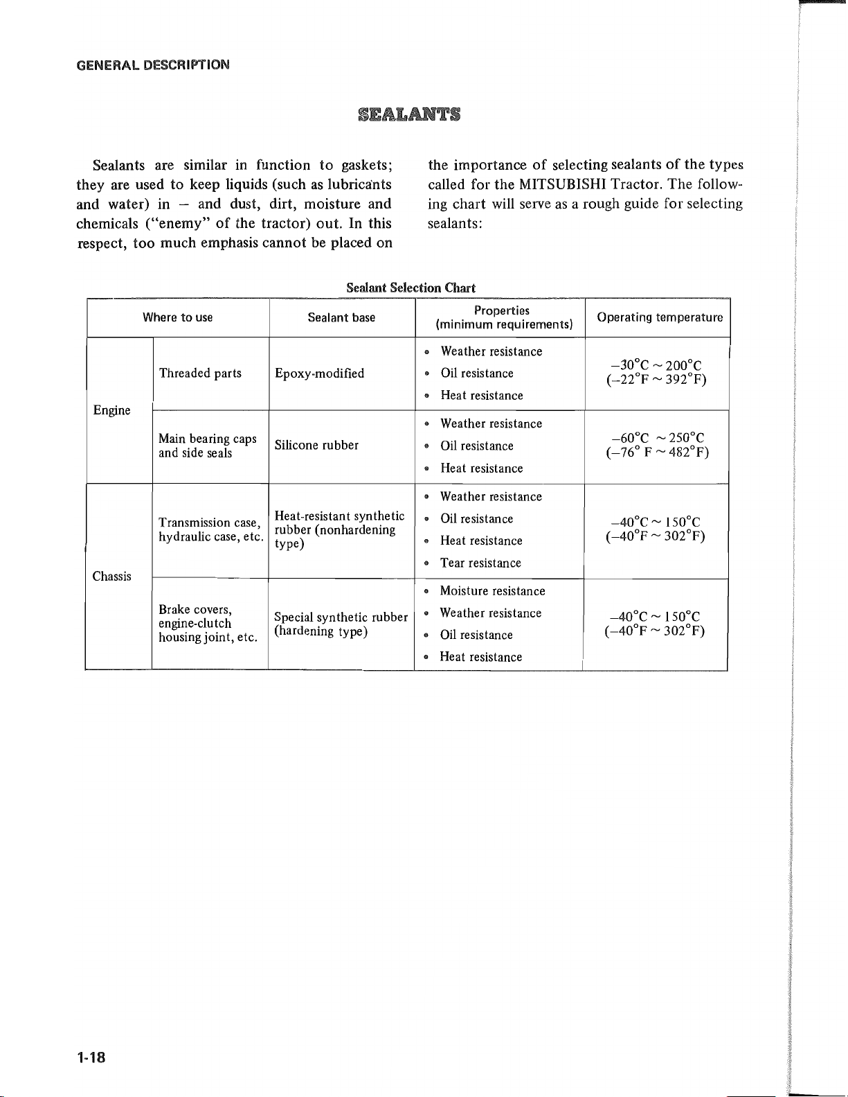
Sealants are similar in function
to
they are used
keep liquids (such
to
gaskets;
as
lubrica'nts
and water) in - and dust, dirt, moisture and
chemicals
respect,
Engine
("enemy"
too
much emphasis cannot be placed on
Where
Threaded parts
Main bearing caps
and side seals
to
of
the tractor) out. In this
use
Epoxy-modified
Silicone rubber
Sealant
Sealant Selection Chart
base
the importance
selecting sealants
of
the types
of
called for the MITSUBISHI Tractor, The follow-
ing chart will serve
as
a rough guide for selecting
sealants:
Properties
(minimum requirements)
..
Weather resistance
Oil resistance
•
..
Heat resistance
Weather resistance
"
..
Oil resistance
Heat resistance
•
Operating
-30°C ~ 200°C
(-22°F ~ 392°F)
-60°C ~ 2S0°C
(_76°
temperature
F ~ 482°F)
Chassis
Transmission case,
hydraulic case, etc,
Brake covers,
engine-clu tch
housing joint, etc,
Heat-resistant synthetic
rubber (nonhardening
type)
Special synthetic rubber
(hardening type)
..
Weather resistance
Oil resistance
•
Heat resistance
"
Tear resistance
"
Moisture resistance
"
Weather resistance
•
..
Oil resistance
Heat resistance
"
-40°C ~ ISO°C
(_40°F ~ 302°F)
-40°C ~ ISO°C
(-40°F ~ 302°F)
1-18
~
types
ol1ow-
ecting
Ire
ISO

f
r
!
TABLE
Description
Sectional views
Construction
Cylinder head assembly
Cylinder block assembly
Engine services. . . . . . . . . . . . . . . . . . . . . . . . . . . . . . . . . . . . . . . . . . . .
Engine removal
Engine installation
Piston
Piston installation
Water
Cy
linder head disassembly
Cylinder block disassembly . . . . . . . . . . . . . . . . . . . . . . . . . . . . . . . .
Inspection
Reassembly
Lubrication system
Description
Removal and disassembly
Inspection
Reassembly . . . . . . . . . . . . . . . . . . . . . . . . . . . . . . . . . . . . . . . . . . . .
Fuel system . . . . . . . . . . . . . . . . . . . . . . . . . . . . . . . . . . . . . . . . . . . . . .
Description . . . . . . . . . . . . . . . . . . . . . . . . . . . . . . . . . . . . . . . . . . . .
Disassembly
Inspection
Reassembly
Governor system . . . . . . . . . . . . . . . . . . . . . . . . . . . . . . . . . . . . . . . . . .
Description " . . . . . . . . . . . . . . . . . . . . . . . . . . . . . . . . . . . . . . . . . .
Disassem bly . . . . . . . . . . . . . . . . . . . . . . . . . . . . . . . . . . . . . . . . . . . .
Inspection
Reassembly
Cooling system
Water
Thermo
Thermostat
Coolan
Rust
..............................................
....................................
................................
..........................................
........................................
removal.
pump
punlp
switch
. . . . . . . . . . . . . . . . . . . . . . . . . . . . . . . . . . . . . . . . .
removal
..............................................
..............................................
.............
..............................................
..............................................
..............................................
..............................................
..............................................
..................
............................................
............................................
......
..............................................
......................................
..........................................
, . . . . . . . . . . . . . . . . . . . . . . . . . . . . . . . . . . .
t change 2-47
inhibitors and antifreeze additives
OF
CONTENTS
..................................
"
................................
..................................
:
.........................
........................
. .
Page
"
2-1
2-2
2-4
2-4
..
2-6
..
2-10
2-10
2-13
..
2-13
2-14
2-14
2-14
..
2-15
2-1
2-22
2-29
2-29
2-30
2-30
..
2-31
..
2-32
..
2-32
2-36
2-38
2-39
..
2-43
..
2-43
..
2-44
2-44
" 2-44
2-45
" 2-45
..
2-46
2-46
2-47
6
?
Air cleaner
Description
Air cleaner services
Periodical maintenance service chart
Engine maintenance guide
When
Compression pressure test - how
Engine diagnosis on the basis
Engine diagnosis on the basis
...............................................
.............................................
.......................................
...................................
to
overhaul
.........................................
of
compression pressure readings
of
oil consumption
...........................
to
measure compression pressure
General working rules on disassembling and reassembling steps
Troubleshooting
Specifications and maintenance standards
Tightening
Application
Special service tools
...........................................
torque
of
.........................................
sealants
......................................
.........................................
.......................
......
.....
...
.
.
.
.
.
.
.
.
.
.
.
.
.
2-49
2-49
2-49
2-50
2-51
2-51
2-52
2-52
2-52
2-52
2-54
2-58
2-66
2-66
2-67
Ml
Co(
cyJ
Th
all(
M'l
kw
swi
blli
 Loading...