

Page 1
SERVICE TECHNICAL GUIDE
CONTENTS
1.
MSC/MS/MSH MICROPROCESSOR CONTROL
····· 4
2. MSZ/MLZ MICROPROCESSOR CONTROL ·······11
3. MXZ MICROPROCESSOR CONTROL ··············· 24
SPLIT-TYPE AIR CONDITIONERS
No. OBT17
REVISED EDITION-G
Revision G:
• MSZ-EF·VEW -
E
, MSZ-EF·VEB -E, MSZ-
EF·VES -
E
and MXZ-C·VA -E have been
added.
Please void OBT17 REVISED EDITION-F.
CONFIDENTIAL
(FOR INTERNAL USE ONLY)
Models
MSC-GE•VB -
E
MS-GD•VB -
E
· MU-GD•VB -
E
MS-GE•VB -
E
· MU-GE•VB -
E
MSH-GD•VB -
E
· MUH-GD•VB -
E
MSH-GE•VB -
E
· MUH-GE•VB -
E
MSZ-GC•VA -
E
· MUZ-GC•VA(H) -
E
MSZ-HC•VA(B) -
E
· MUZ-HC•VA(B) -
E
MSZ-CHC•VA -
E
MSZ-FD•VA(S) -
E
· MUZ-FD•VA(H)(BH) -
E
MSZ-GE•VA -
E
· MUZ-GE•VA(H) -
E
MSZ-CGE•VA -
E
MSZ-SF•VA -
E
MSZ-EF•VEW -
E
· MUZ-EF•VE -
E
MSZ-EF•VEB -
E
· MUZ-EF•VEH -
E
MSZ-EF•VES -
E
· MXZ-B•VA -
E
MLZ-KA•VA -
E
· MXZ-C•VA -
E
Page 2
2
Revision A:
• MSZ-FD·VA -
E
has been added.
Revision B:
• MS-GD·VB -E and MSH-GD·VB -E have been added.
1. MSC/MS/MSH MICROPROCESSOR CONTROL· ·······························································································4
Indoor unit models Outdoor unit models
MSC-GE20VB
MSC-GE25VB
MSC-GE35VB
MS-GD80VB MU-GD80VB
MS-GE50VB MU-GE50VB
MSH-GD80VB MUH-GD80VB
MSH-GE50VB MUH-GE50VB
1-1. COOL OPERATION ·····································································································································4
1-2. DRY OPERATION ········································································································································5
1-3. HEAT OPERATION ······································································································································5
1-4. INDOOR FAN MOTOR CONTROL ··············································································································8
1-5. AUTO VANE OPERATION ··························································································································· 8
1-6. EXPANSION VALVE CONTROL (LEV CONTROL) ··················································································10
Revision C:
• MSZ-FD50VA -
E
, MSZ-GE·VA -E, MSZ-CHC·VA -
E
and MSZ-CGE·VA -E have been added.
Revision D:
• MSC-GE·VB-E, MS-GE·VB-E, MSH-GE·VB-E, MUZ-FD50VA -E, MSZ-GE42/50VA -
E
and MSZ-CGE42/50VA -E
have been added.
Revision E:
• MSZ-GE60/71VA-E, MUZ-GE60/71VA -E, MSZ-SF15/20VA -
E
, MXZ-3B54VA -
E
, MXZ-3B68VA -E,
MXZ-4B71VA -
E
, MXZ-4B80VA -E and MXZ-5B100VA -E have been added.
Revision F:
• MXZ-2B30VA -
E
, MXZ-2B40VA -E and MXZ-2B52VA -E have been added.
Revision G:
• MSZ-EF·VEW -
E
, MSZ-EF·VEB -E, MSZ-EF·VES -E and MXZ-C·VA -E have been added.
Page 3

3
2. MSZ/MLZ MICROPROCESSOR CONTROL······································································································11
Indoor unit models Outdoor unit models
MSZ-GC22/25/35VA MUZ-GC25/35VA(H)
MSZ-HC25VA MSZ-HC35VA(B) MUZ-HC25VA
MUZ-HC35VA(B)
MSZ-CHC25/35VA
MSZ-FD25/35/50VA(S) MUZ-FD25/35VA(H)(BH)
MUZ-FD50VABH
MSZ-GE22/25/35/42/50/60/71VA MUZ-GE25/35/42/50/60/71VA(H)
MSZ-CGE22/25/35/42/50VA MUZ-EF25/35/42/50VE
MSZ-EF22/25/35/42/50VEW MUZ-EF25/35VEH
MSZ-EF22/25/35/42/50VEB
MSZ-EF22/25/35/42/50VES
MSZ-SF15/20VA
MLZ-KA25/35/50VA
2-1. COOL OPERATION ··································································································································· 11
2-2. DRY OPERATION ······································································································································ 12
2-3. HEAT OPERATION ····································································································································12
2-4. AUTO CHANGE OVER ··· AUTO MODE OPERATION·············································································15
2-5. OUTDOOR FAN MOTOR CONTROL ········································································································15
2-6. AUTO VANE OPERATION ························································································································· 15
2-7. DRAIN PUMP/FLOAT SENSOR CONTROL ····························································································· 16
2-8. INVERTER SYSTEM CONTROL ···············································································································17
2-9. OPERATIONAL FREQUENCY CONTROL OF OUTDOOR UNIT ····························································21
2-10. PRE-HEAT CONTROL ·····························································································································21
2-11. EXPANSION VALVE CONTROL/LEV CONTROL ··················································································· 22
2-12. STANDBY POWER CONTROL ···············································································································23
NOTE: As for the MXZ-A type models or MU/MUH-GA type models, refer to the appropriate service technical
guide as well as this service technical guide.
3. MXZ MICROPROCESSOR CONTROL ··············································································································24
Outdoor unit models
MXZ-2B30VA MXZ-3B68VA MXZ-3C54VA MXZ-5C100VA
MXZ-2B40VA MXZ-4B71VA MXZ-3C68VA MXZ-6C120VA
MXZ-2B52VA MXZ-4B80VA MXZ-4C71VA
MXZ-3B54VA MXZ-5B100VA MXZ-4C80VA
3-1. INVERTER SYSTEM CONTROL ···············································································································24
3-2. EXPANSION VALVE CONTROL (LEV CONTROL) ··················································································28
3-3. OPERATIONAL FREQUENCY RANGE ····································································································34
3-4. HEAT DEFROSTING CONTROL ··············································································································· 36
3-5. DISCHARGE TEMPERATURE PROTECTION CONTROL ······································································36
3-6. REFRIGERANT RECOVERY CONTROL ON HEATING ··········································································36
3-7. OUTDOOR FAN CONTROL ······················································································································37
3-8. PRE-HEAT CONTROL ·······························································································································38
3-9. COOL OPERATION ···································································································································38
3-10. DRY OPERATION ······································································································································38
3-11. HEAT OPERATION ····································································································································39
Page 4
4
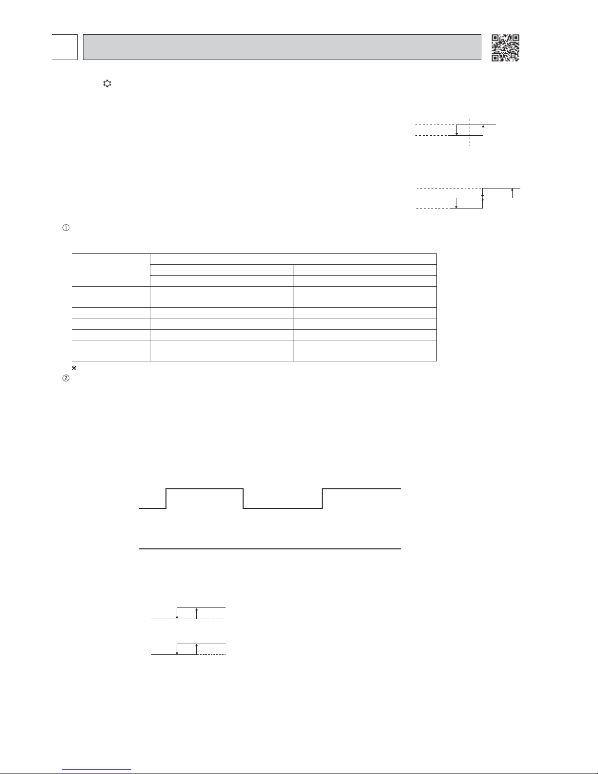
2. Indoor fan speed control
Indoor fan operates at the set speed by FAN SPEED CONTROL button.
In AUTO the fan speed is as follows.
Initial temperature difference Fan Speed
Room temperature minus set temperature: 1.7°C or more
························································ High
Room temperature minus set temperature: between 1 and 1.7°
C ·············································Med.
Room temperature minus set temperature: less than 1°
C ·························································Low
1°C 1.7°C
3°C
3. Coil frost prevention
Temperature control
The coil frost prevention mode in the temperature control is that the indoor fan operates at the set speed and the com-
pressor stops for 5 minutes or more.
Model
Coil frost prevention
ON OFF
Indoor coil thermistor (°C) Indoor coil thermistor (°C)
MSC-GE20VB
MSC-GE25VB
4 °C or less More than 4 °C
MSC-GE35VB 0 °C or less More than 0 °C
MS-GD80VB -1 °C or less More than -1 °C
MS-GE50VB 3 °C or less More than 3 °C
MSH-GD80VB
MSH-GE50VB
1 °C or less More than 1 °C
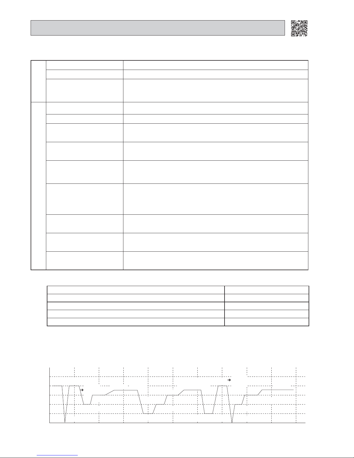
The coil frost prevention does not work for 5 minutes after the compressor started.
Compressor
Outdoor fan
OFF
ON
(Continuously at set speed)
Indoor fan
ON
ON
OFF
Operation chart
Example
5. Discharge temperature protection (MU-GD80VB, MUH-GD80VB)
The compressor is controlled by the temperature of discharge temperature thermistor for excess rise protection of compressor discharge pressure.
• Compressor
When the temperature of discharge temperature thermistor goes to 120°C or more, the compressor is turned OFF. After 3
minutes since the compressor has been turned OFF, if the temperature of discharge temperature thermistor becomes 100
°C or less, the compressor is turned ON.
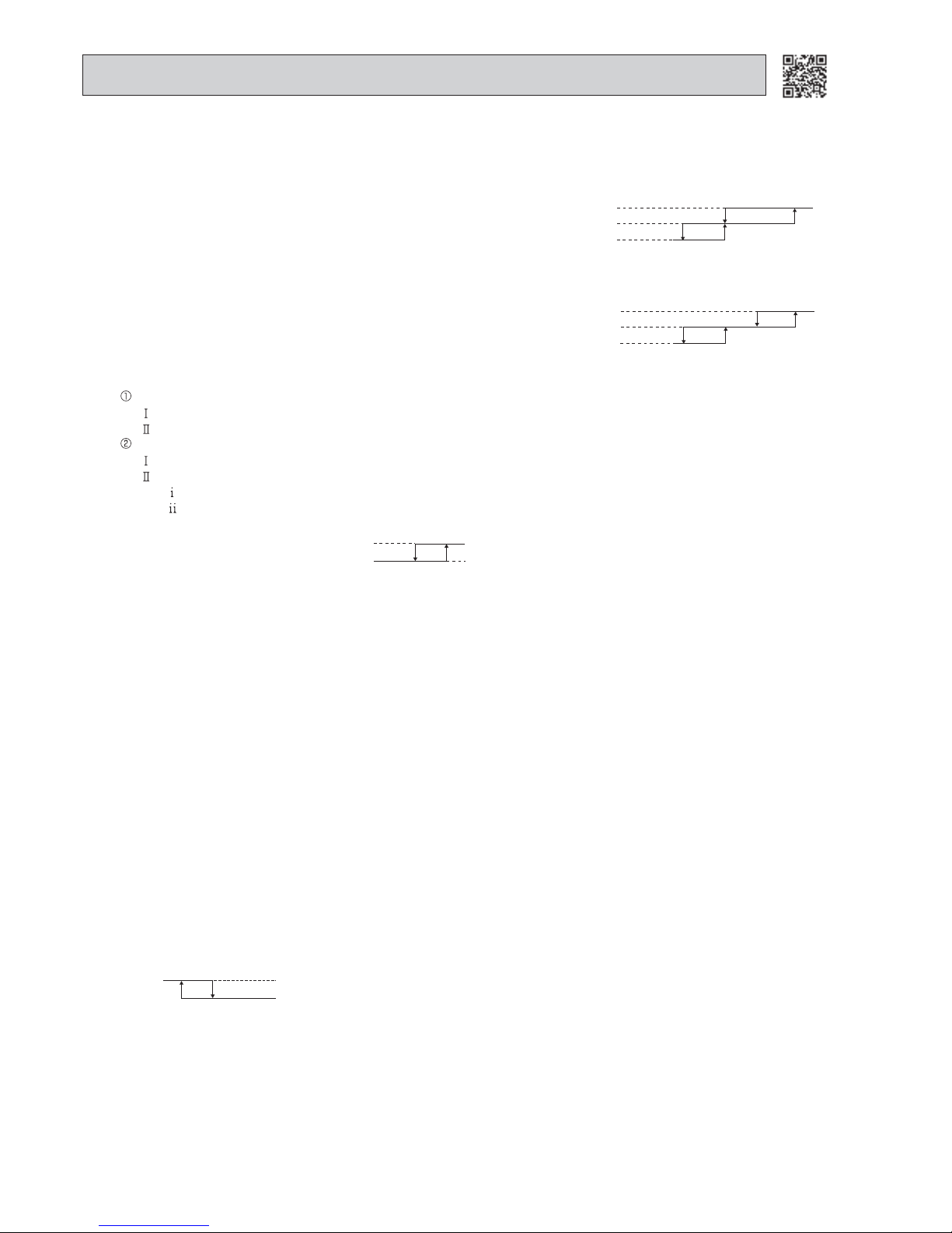
4. Outdoor fan speed control (MU-GD80VB, MUH-GD80VB)
Outdoor fan speed control is as follows.
Outdoor
fan speed
High
or
Med.
Indoor
fan speed
20°C 22°C
Low
30°C 33°C
High
Temperature of
ambient temperature
thermistor
Low
High
Low
1-1. COOL ( ) OPERATION
1
MSC/MS/MSH MICROPROCESSOR CONTROL
Time control
When the three conditions as follows have been satisfied for 1 hour and 45 minutes, compressor stops for 3 minutes.
a. Compressor has been continuously operating.
b. Indoor fan speed is Low or Med.
c. Room temperature is 26°C or less.
When compressor stops, the accumulated time is cancelled and when compressor restarts, time counting starts from the
beginning.
Time counting also stops temporarily when the indoor fan speed becomes High or the room temperature exceeds 26°C.
However, when two of the above conditions (b. and c.) are satisfied again, time accumulation is resumed.
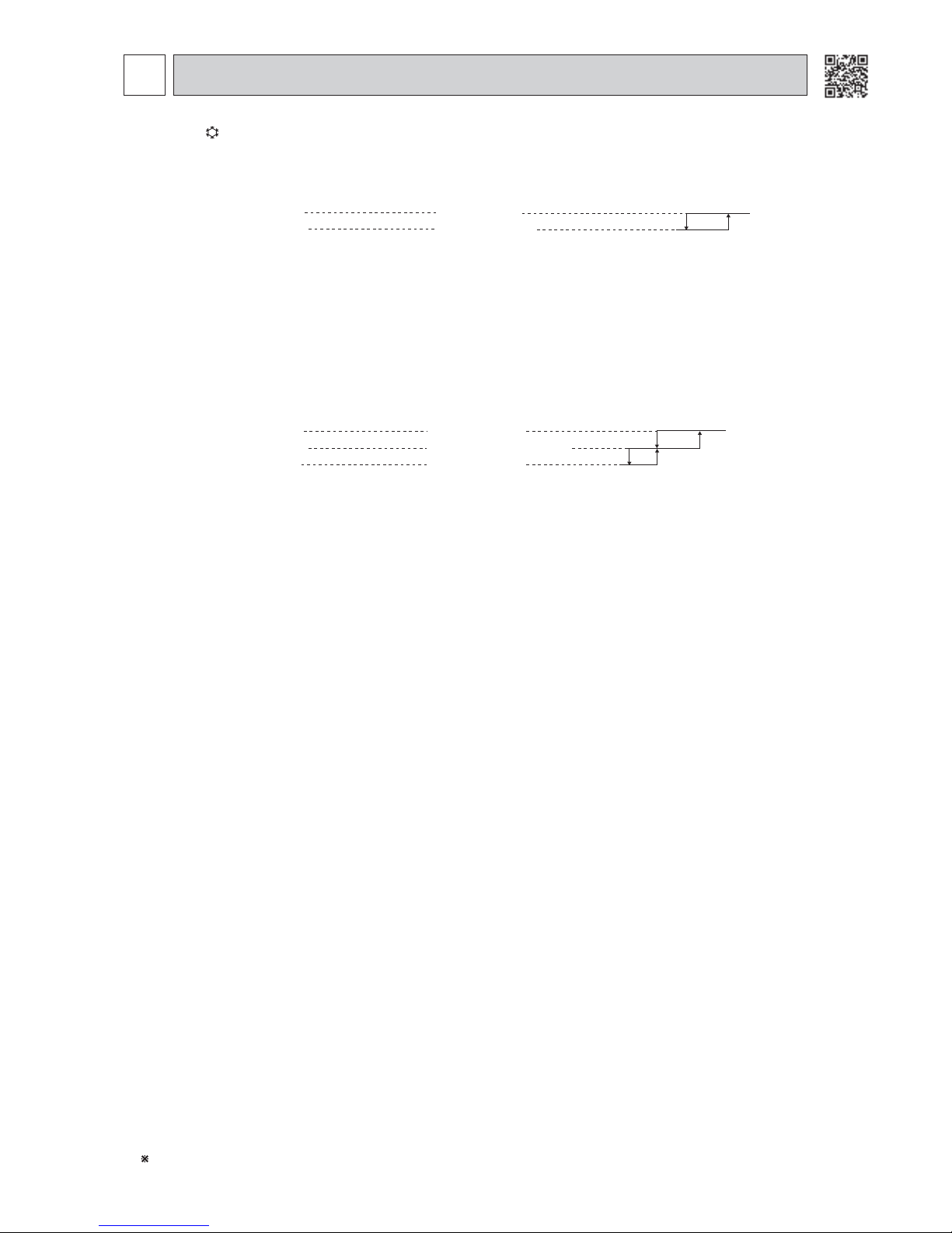
-0.3°C
0.3°C
1. Thermostat control (MSC-GE20/25/35VB)
Thermostat turns ON or OFF by the difference between room temperature and set temperature
Initial temperature difference Thermostat
Room temperature minus set temperature : 0.3°C or more ················································ ON
Room temperature minus set temperature : less than -0.3°C ·············································OFF
Set temperature
Difference between room
temperature and set temperature during operation
Difference between room
temperature and set temperature during operation
Page 5
5
2. Indoor fan speed control
Indoor fan operates at the set speed by FAN SPEED CONTROL button.
In Auto fan speed becomes Low.
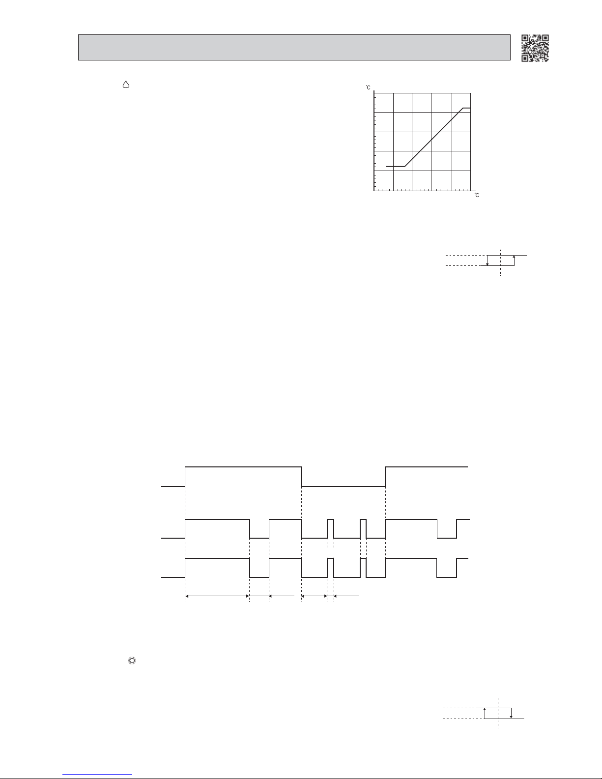
3. The operation of the compressor and indoor/outdoor fan
Compressor operates by room temperature control and time control.
Set temperature is controlled to fall 2°C from initial room temperature.
Indoor fan and outdoor fan operate in the same cycle as the compressor.
● When the room temperature is 23°C or over:
When the thermostat is ON, the compressor repeats 8 minutes ON and 3 minutes OFF.
When the thermostat is OFF, the compressor repeats 4 minutes OFF and 1 minute ON.
● When the room temperature is under 23°C.
When the thermostat is ON, the compressor repeats 2 minutes ON and 3 minutes OFF.
When the thermostat is OFF, the compressor repeats 4 minutes OFF and 1 minute ON.
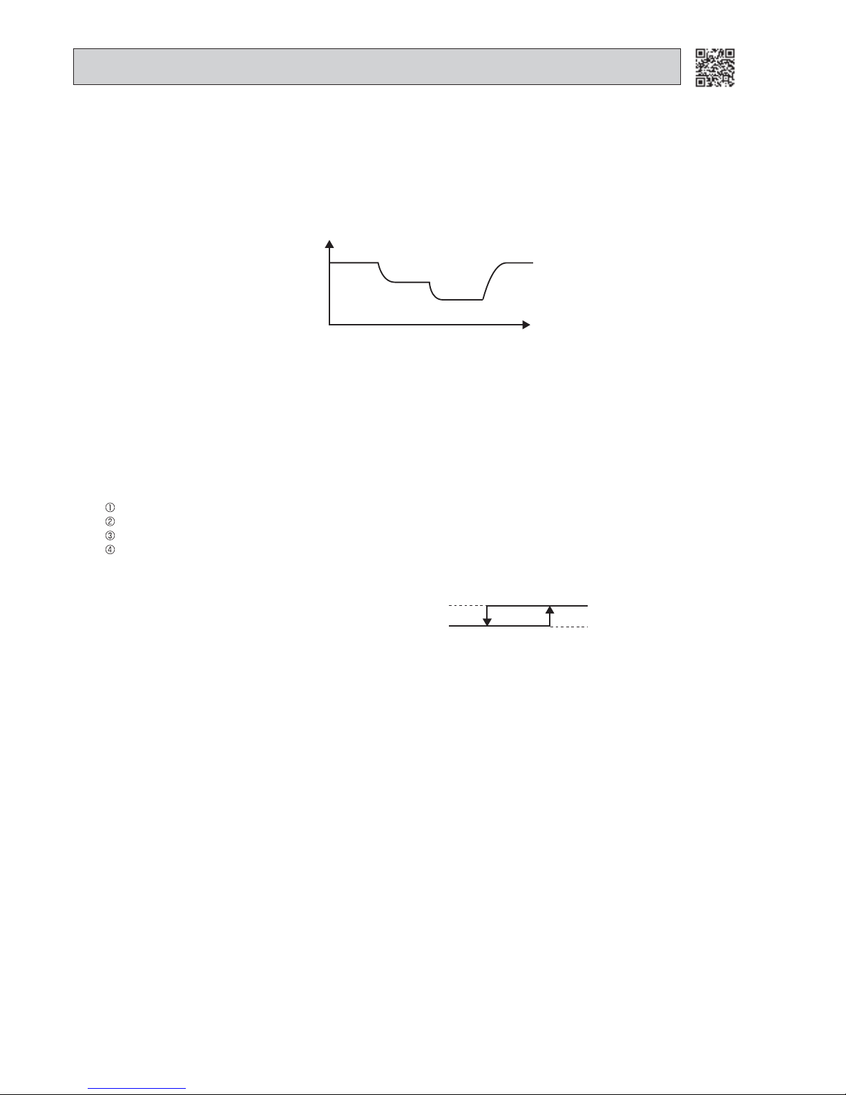
Set temperature is as shown on the right chart.
The system for dry operation uses the same refrigerant circuit as the
cooling circuit.
The compressor and the indoor fan are controlled by the room temperature.
By such controls, indoor flow amounts will be reduced in order to
lower humidity without much room temperature decrease.
DRY operation will not work when the room temperature is 13°C or
below.
1-2. DRY ( ) OPERATION
35
30
25
20
15
10
10 15 20 25 30 35
Set temperature
Initial room temperature
Set temperature and
initial room temperature in DRY mode
Thermostat
Indoor fan
Outdoor fan
Compressor
ON
8 minutes
3
minutes
ON
OFFOFF
OFF
OFF
OFF
OFF
OFF
OFF
ON
ON
ON
ON
ON
ON
Operation time chart
Example
When the room temperature is 23°C or over:
4. Coil frost prevention
• The operation is the same as coil frost prevention during COOL mode.
• The indoor fan operates at the set speed and the compressor does not operate for 5 minutes because the coil frost prevention has priority.
1
minute
4
minutes
-0.3°C
0.3°C
1. Thermostat control (MSC-GE20/25/35VB)
Thermostat turns ON or OFF by the difference between room temperature and set temperature.
Initial temperature difference Thermostat
Room temperature minus set temperature : 0.3°C or more ··············································ON
Room temperature minus set temperature : less than -0.3°C ··········································· OFF
Set temperature
Difference between room
temperature and set temperature during operation
-0.3°C
0.3°C
Set temperature
Difference between room
temperature and set temperature during operation
1. Thermostat control (MSC-GE20/25/35VB)
Thermostat turns ON or OFF by the difference between room temperature and set temperature.
Initial temperature difference Thermostat
Room temperature minus set temperature : less than -0.3°C ·············································ON
Room temperature minus set temperature : 0.3°C or more ················································OFF
1-3. HEAT ( ) OPERATION (MSC-GE20/25/35VB, MSH-GD80VB, MSH-GE50VB)
Page 6
6
(3) Warm air control
When compressor starts in heating operation or after defrosting, the fan changes the speed due to the indoor coil thermistor temperature to blow out warm air.
After releasing of cold air prevention, when the indoor coil thermistor temperature is 37°C or above, the fan speed shifts
to the set speed, and when the fan speed is changed by the remote controller, the fan speed is the set speed.
When the indoor coil thermistor temperature is less than 37°C, the fan speed is controlled by time as below.
<Time condition> <Indoor fan speed>
Less than 2 minutes ······················· Low
2 minutes to 4 minutes ···················Med.
4 minutes or more ··························High
The upper limit of the fan speed in MANUAL is the set speed.
The upper limit of the fan speed in AUTO is the speed decided by the indoor fan speed control. (Refer to 1-3.2.(1).)
If the thermostat turns OFF, this operation changes to flow soft control. (MSH-GD80VB, MSH-GE50VB)
(4) Flow soft control (MSH-GD80VB, MSH-GE50VB)
After the thermostat turns OFF, the indoor fan operates at Very Low.
NOTE: When the thermostat turns ON, the fan operates at the set speed. Due to the cold air prevention control, the fan
does not start at set speed until the indoor coil thermistor reads 22°C or more.
3. Outdoor fan speed control (MUH-GD80VB)
Outdoor fan speed control is as follows.
13°C 18°C
Outdoor
fan speed
High
Low
T
emperature of
ambient temperature
thermistor
(2) Cold air prevention control
When the compressor is not operating (MSC-GE20/25/35VB):
( ) If the temperature of indoor coil thermistor RT12 is 0°C or less, the fan stops.
( ) If the temperature of indoor coil thermistor RT12 is more than 0°C, the fan operates at Very Low.
When the compressor is operating:
( ) If the temperature of RT12 is 22°C or more, the fan operates at set speed.
( ) If the temperature of RT12 is less than 22°C and
( ) if the temperature of room temperature thermistor RT11 is 15°C or less, the fan stops.
( ) if the temperature of room temperature thermistor RT11 is more than 15°C, the fan operates at Very Low.
NOTE : If the temperature of RT12 reads from 18°C to 22°C at the air conditioner stating and also after defrosting, this
control works.
Released
Cold Air Prevention
18°C 22°C
Fan speed
Set speed
Very Low or stop
(MSH-GD80VB, MSH-GE50VB) Initial temperature difference Fan speed
Set temperature minus room temperature: 2°C or more ·····················································High
Set temperature minus room temperature: between 1 and 2°C········································· Med.
Set temperature minus room temperature: less than 1°C ····················································Low
1°C 1.7°C
4°C
2°C
2. Indoor fan speed control
(1) In AUTO the fan speed
(MSC-GE20/25/35VB)
Indoor fan speed at set speed by FAN SPEED CONTROL button.
Initial temperature difference Fan speed
Set temperature minus room temperature: 1.7°C or more ·················································High
Set temperature minus room temperature: between 1 and 1.7°
C ·································
Med.
Set temperature minus room temperature: less than 1°
C ·············································
Low
1°C
1.7°C
3°C
Difference between room
temperature and set temperature during operation
Difference between room
temperature and set temperature during operation
Page 7
7
4. High pressure protection (MUH-GD80VB, MUH-GE50VB)
During heating operation, the outdoor fan and the compressor are controlled by the temperature of indoor coil thermistor
for excess rise protection of compressor discharge pressure.
• Outdoor fan
When the temperature of indoor coil thermistor goes to 55°C or more, the outdoor fan is turned OFF.
When the temperature of indoor coil thermistor becomes 52°C or less, the outdoor fan is turned ON.
• Compressor
When the temperature of indoor coil thermistor goes to 75°C or more, the compressor is turned OFF.
3 minutes after the compressor is turned OFF and if the temperature of indoor coil thermistor becomes 75°C or less, the
compressor is turned ON.
NOTE: During the high pressure protection and for 10 seconds after high pressure protection, defrosting of outdoor heat
exchanger is not detected by the defrost thermistor.
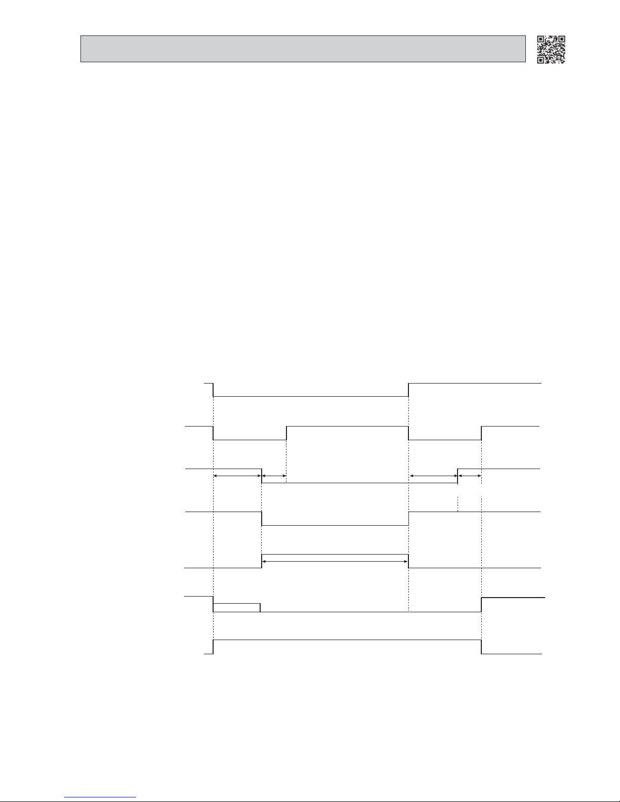
5. Defrosting
Defrosting of outdoor heat exchanger is controlled by deicer P.C. board, with detection by the defrost thermistor.
(1) Starting conditions of defrost
When all conditions of a) ~ c) are satisfied, the defrosting operation starts.
a) Under the heat operation, the compressor cumulative operation time exceeds 40 minutes without the defrosting opera-
tion working.
b) The defrost thermistor reads -3°C or less.
c) After releasing the high pressure protection 4 minutes and 10 seconds have elapsed.
(2) Releasing conditions of defrost
When the condition d) or e) is satisfied, the defrosting operation stops.
d) The defrost thermistor reads 10°C (MUH-GE50VB) /13°C or more (MUH-GD80VB).
e) The defrosting time exceeds 10 minutes.
(3) Defrosting time chart
Defrost thermistor
13°C or more (MUH-GD80VB)
10°C or more (MUH-GE50VB)
-3°C or less
Outdoor 52C
contactor
(Compressor)
X62
(R.V. coil)
SR61
Outdoor fan
Defrost
counter
Indoor fan
Indoor vane
ON
OFF
ON
OFF
ON
OFF
ON
OFF
ON
OFF
Horizontal
Set position
Maximum 10 minutes
30 seconds
15 seconds
30 seconds
5 seconds
NOTE
Very Low
NOTE: • When the indoor coil thermistor reads above 18°C, indoor fan operates at Very Low for 30 seconds.
• When the indoor coil thermistor reads 18°C or less, the indoor fan stops.
Page 8
8
1-4. INDOOR FAN MOTOR CONTROL
(1) Rotational frequency feedback control
The indoor fan motor is equipped with a rotational frequency sensor, and outputs signal to the microprocessor to feed-
back the rotational frequency. Comparing the current rotational frequency with the target rotational frequency (High,
Med., Low), the microprocessor controls SR141 and adjusts fan motor electric current to make the current rotational
frequency close to the target rotational frequency. With this control, when the fan speed is switched, the rotational frequency changes smoothly.
High
Rotational frequency
High
time
Med.
Low
(2) Fan motor lock-up protection
When the rotational frequency feedback signal has not output for 12 seconds, (or when the microprocessor cannot
detect the signal for 12 seconds) the fan motor is regarded locked-up. Then the electric current to the fan motor is shutoff. 3 minutes later, the electric current is applied to the fan motor again. During the fan motor lock-up, the OPERATION
INDICATOR lamp flashes ON and OFF to show the fan motor abnormality.
1-5. AUTO VANE OPERATION (MSC, MSH)
1. Horizontal vane
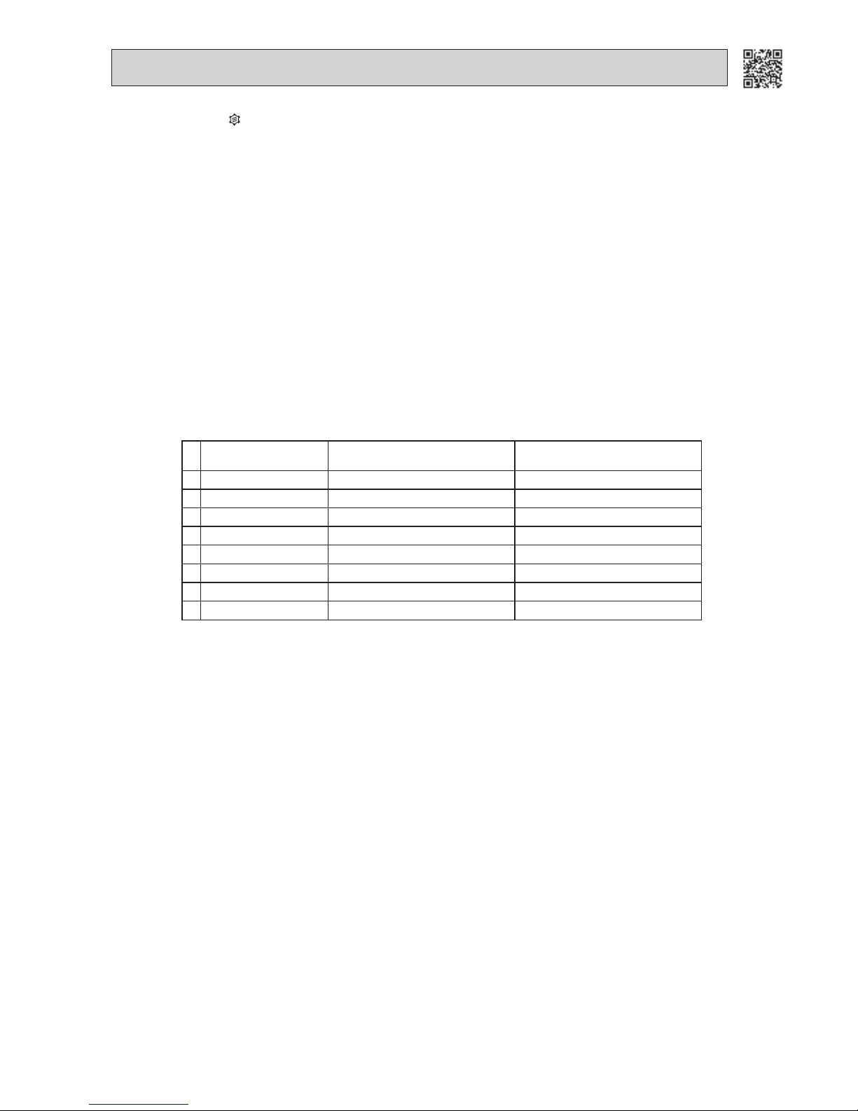
(1) Cold air prevention in HEAT operation
When any of the following conditions occur in HEAT operation, the vane angle changes to Angle 1 automatically to pre-
vent cold air blowing on users.
Compressor is not operating.
Defrosting is performed.
Indoor coil thermistor reads 24°C or below.
Indoor coil thermistor temperature is rising from 24°C or below until it reaches 28°C.
NOTE1: If the temperature of the indoor coil thermistor reads from 24 to 28°C at the air conditioner starting, this control
works.
NOTE2: When 2 or more indoor units are operated with multi outdoor unit, even if any indoor unit turns thermostat OFF, this
control does not work in the indoor unit.
Released
Cold Air Prevention
24°C 28°C
Angle 1
Horizontal vane
Set position
Indoor coil thermistor temperature
Page 9
9
(2) ECONO COOL ( ) operation (ECONOmical operation)
When ECONO COOL button is pressed in COOL mode, set temperature is automatically set 2°C higher.
Also the horizontal vane swings in various cycle according to the temperature of indoor heat exchanger.
SWING operation makes you feel cooler than set temperature. So, even though the set temperature is higher, the air
conditioner can keep comfort. As a result, energy can be saved.
To cancel this operation, select a different mode or press one of the following buttons in ECONO COOL operation:
ECONO COOL, VANE CONTROL or LONG button.
NOTE: ECONO COOL operation does not work in COOL mode of “I FEEL CONTROL”.
<SWING operation>
In swing operation of ECONO COOL operation mode, the initial airflow direction is adjusted to “Horizontal”.
According to the temperature of indoor coil thermistor at starting of this operation, next downward blow time is decided.
Then when the downward blow has been finished, next horizontal blow time is decided.
For initial 10 minutes the swing operation is performed in table G~H for quick cooling.
Also, after 10 minutes when the difference between set temperature and room temperature is more than 2°C, the swing
operation is performed in table D ~ H for more cooling.
The air conditioner repeats the swing operation in various cycle as follows.
Temperature of
indoor coil thermistor(°C)
Downward blow time
(second)
Horizontal blow time
(second)
A
15 or less 2 23
B
15 to 17 5 20
C
17 to 18 8 17
D
18 to 20
11 14
E
20 to 21 14 11
F
21 to 22 17 8
G
22 to 24 20 5
H
More than 24 23 2
Page 10
10
NOTE : Opening increases and decreases to be in the target discharge temperature during operation.
Opening
completely
Positioning
Power ON
Initial opening
Standard opening
Remote
controller
ON
Operation
Thermostat
OFF
Standard opening
Thermostat
ON
Opening in stop
Operation
Opening in stop
Remote
controller
OFF
Opening
completely
Remote
controller
ON
Positioning
Standard opening
Operation
Time
LEV opening
Initial opening
Initial opening
Open
Close
(2) LEV time chart
1-6. EXPANSION VALVE CONTROL (LEV CONTROL) (MU-GD80VB, MUH-GD80VB)
LEV (Expansion valve) is controlled by “Thermostat ON” commands given from the unit.
Standard
specification
Control range Minimum: 54 pulse, Maximum: 500 pulse
Drive speed 30 ~ 90 pulse/second
Opening set The setting is always in opening direction.
(To close LEV, it is closed to the pulse smaller than the one set finally.
Then LEV is opened to the final setting pulse.)
General operation
Stop of indoor unit Opening in stop: 150 pulse → LEV opening is set to become 500 pulse after 3 min-
utes.
Remote controller ON LEV positioning (LEV is closed completely at once)
Power ON (Breaker ON) LEV is positioned. However, afterwards, LEV is not positioned when the remote
controller is turned ON for the first time after the power ON.
Approximately for 2 minutes after
compressor has started.
Opening is set by the initial opening.
(Initial opening is set according to each operation mode and outer temperature conditions.)
Approximately 2 to 13 minutes (for
11 minutes) after compressor has
started.
Opening is set by standard opening.
(Standard opening is set according to each operation mode and outer temperature
conditions.)
13 minutes after compressor has
started.
LEV opening is corrected every 2 minutes so that discharge temperature becomes
the target discharge temperature.
(When the discharge temperature is lower than the target temperature: LEV is corrected in closed direction, when the discharge temperature is higher than the target
temperature: LEV is corrected in opening direction.)
Thermostat OFF
Opening in stop: 150 pulse → LEV is set to the initial opening after about 3 minutes.
Thermostat ON
Same as the starting of compressor operation
Remote controller OFF
Opening in stop: 150 pulse → LEV is set so that the opening is opened completely
at the speed of 4 pulse every 5 seconds in opening after about 3 minutes.
Operation mode Target discharge temperature (°C)
HEAT (MUH-GD80VB) 85
COOL (Normal) 80
COOL (∆RT is less than 2°C, or ∆RT is 2°C or more and less than 3°C.) 70
COOL (∆RT is 3°C or more.) 65
NOTE: When the discharge temperature is 50°C or less on the cool operation, or is 49°C or less on heat operation
(MUH-GD80VB), LEV opening is set in 54 pulse.
When this state continues for 20 minutes, the compressor is stopped and restarts in 3 minutes.
When the compressor is stopped, the indoor unit indicates the abnormality of refrigerant system and stops.
(OPERATION INDICATOR lamp is 10-time flashing ON and OFF.)
(1) Control data
Reference value of target discharge temperature
Page 11
11
1. Thermostat control (MSZ)
Thermostat turns ON or OFF by the difference between room temperature and set temperature.
2-1. COOL ( ) OPERATION
2. Indoor fan speed control
Indoor fan operates continuously at the set speed by FAN SPEED CONTROL button regardless of the thermostat’s OFFON. [When the thermostat turns OFF, the indoor fan stops running to reduce power consumption.
After that, the indoor fan stops for 60 seconds and then operates at Very Low for 10 seconds to sense accurate room
temperature. The indoor fan alternates ON and OFF at this interval while the thermostat is OFF.
When the room temperature rises and the thermostat is ON, the indoor fan starts running according to the settings on the
remote controller. (MSZ-GE60/71VA)]
[When the thermostat turns OFF, the indoor fan operates at very Low to reduce power consumption. When the room temperature rises and the thermostat turns ON, the indoor fan starts running according to the settings on the remote controller
(MSZ-EF)]
In AUTO, the fan speed is as follows.
3. Coil frost prevention (MSZ)
The compressor operational frequency is controlled to prevent the temperature of indoor heat exchanger from falling excessively.
The compressor is turned OFF for 5 minutes when the temperature of indoor coil thermistor continues 3°C or less for
5 minutes or more.
The indoor fan maintains the actual speed at the time.
4. Low outside temperature operation (MUZ-GC/FD/GE/EF)
MUZ-GC25
If the outside temperature falls to 17°C or less during operation in COOL mode, the unit will switch to the low outside
temperature operation mode.
Each outdoor actuator (compressor/fan/LEV) is operated in the exclusive control, which is different from one of normal cool
operation.
Especially, fan motor does not operate continuously to maintain sufficient cooling capacity.
<Operation>
(1) Outdoor fan control
Basically, outdoor unit (compressor) operates with outdoor fan OFF.
But, when any of following conditions are satisfied, the outdoor fan turns ON for about 5 seconds.
a). The defrost thermistor reads 45°C or more.
b). The fin temperature thermistor reads 60°C or more.
(2) LEV (expansion valve) control
In normal cool operation, the opening degree of expansion valve is corrected according to the discharge temperature.
But in this mode it is fixed to the value corresponding to the operation frequency of compressor.
(3) Dew drop prevention
When the ambient temperature thermistor reads -20°C or less, as coil frost or dew drop from indoor unit may occur, the
compressor turns OFF with the outdoor fan ON for prevention of it.
(4) Outdoor temperature detecting control
To detect the exact outdoor temperature in this mode, the compressor turns OFF, but the outdoor fan stays ON for
3 minutes once every 1 hour. If the outdoor temperature rises over 19°C, the unit goes back to the normal COOL mode.
If the outside temperature stays below 19°C, the unit continues to run in the low outside temperature operation mode.
MUZ-GC35, FD, GE, EF
If the outside temperature falls to 18°C or less during operation in COOL mode, the unit will switch to the low outside
temperature operation mode.
<Operation>
(1) Outdoor fan control
The outdoor fan rotation speed slows down to maintain sufficient cooling capacity.
NOTE: Even when the unit is in the "thermostat-off" status under the low outside temperature operation mode, the
outdoor fan rotation does not stop.
(2) Dew drop prevention
When the ambient temperature thermistor reads the following temperature, as coil frost or dew drop from indoor unit
may occur, the compressor turns OFF with the outdoor fan OFF for prevention of dew drop.
• -20°C or less (MUZ-GC35, FD25/35, GE25/35/42, EF25/35/42)
• -15°C or less (MUZ-FD50)
• -12°C or less (MUZ-GE50/60/71,EF50)
(3) Outdoor temperature detecting control
To detect the exact outdoor temperature in this mode, the compressor turns OFF but the outdoor fan stays ON for
3 minutes once every 1 hour. If the outdoor temperature rises over about 18°C, the unit goes back to the normal COOL mode.
If the outside temperature stays below about 18°C, the unit continues to run in the low outside temperature operation mode.
Other protections work as well as in the normal COOL mode.
ON
-1°C or more
Less than -1°C
-1°C
-0.75°C
Room temperature minus
set temperature (During operation)
Room temperature minus
set temperature (Initial)
Thermostat
OFF
High
Med.
Low
1.75°C
3°C
1°C
Fan speed
Room temperature minus
set temperature (During operation)
Room temperature minus
set temperature (Initial)
Between 1 and 1.75°C
Less than 1°C
1.75°C or more
2
MSZ/MLZ MICROPROCESSOR CONTROL
Page 12

12
2. Indoor fan speed control
Indoor fan operates continuously at the set speed by FAN SPEED CONTROL button regardless of the thermostat’s OFFON. [When the thermostat turns OFF, the indoor fan stops running to reduce power consumption.
After that, the indoor fan stops for 60 seconds and then operates at Very Low for 10 seconds to sense accurate room
temperature. The indoor fan alternates ON and OFF at this interval while the thermostat is OFF.
When the room temperature rises and the thermostat is ON, the indoor fan starts running according to the settings on the
remote controller. (MSZ-GE60/71VA)]
[When the thermostat turns OFF, the indoor fan operates at very Low to reduce power consumption. When the room temperature rises and the thermostat turns ON, the indoor fan starts running according to the settings on the remote controller
(MSZ-EF)]
In AUTO, the fan speed is as follows.
3. Coil frost prevention (MSZ)
Coil frost prevention is as same as COOL mode. (2-1.3.)
The indoor fan maintains the actual speed of the moment. However, when coil frost prevention works while the compressor
is not operating, its speed becomes the set speed.
4. Low outside temperature operation (MUZ-GC/FD/GE/EF)
Low outside temperature operation is as same as COOL mode. (2-1.4.)
NOTE: When 2 or more indoor units are operated with a multi type outdoor unit, the fan operates intermittently at Very Low or
stops in the thermostat-OFF units while at least one unit is thermostat-ON.
High
Med.
Low
1.75°C
2.5°C
1°C
Fan speed
Room temperature minus
set temperature (During operation)
Room temperature minus
set temperature (Initial)
Between 1 and 1.75°C
Less than 1°C
1.75°C or more
2-2. DRY ( ) OPERATION
Set temperature is as shown on the right chart.
The system for dry operation uses the same refrigerant circuit as the
cooling circuit.
The compressor and the indoor fan are controlled by the room temperature.
By such controls, indoor air flow amounts will be reduced in order to
lower humidity without much room temperature decrease.
35
30
25
20
15
10
10 15 20 25 30 35
Set temperature (°C)
Initial room temperature (°C)
Set temperature and
initial room temperature in dry mode
1. Thermostat control (MSZ)
Thermostat turns ON or OFF by the difference between room temperature and set temperature.
ON
OFF
-2°C
-1.75°C (MSZ-GE25/35/42,EF25/35/42/50)
-2°C
-0.75°C (Other models)
Thermostat
Room temperature minus
set temperature (Initial)
Room temperature minus
set temperature (During operation)
-2
°C or more
Less than -2
°C
2-3. HEAT ( ) OPERATION
1. Thermostat control (MSZ)
Thermostat turns ON or OFF by the difference between room temperature and set temperature.
ON
1°C or more
Less than 1°C
0.75°C
1°C (MSZ-GE60/71,EF25/35/42/50)
Room temperature minus
set temperature (During operation)
Room temperature minus
set temperature (Initial)
Thermostat
OFF
ON
2°C or more
Less than 2°C
1.75°C
2°C (Other models)
OFF
2. Indoor fan speed control
(1) Indoor fan operates at the set speed by F
AN SPEED CONTROL button.
In Auto, the fan speed is as follows.
High
Med.
Low
Fan speed
Room temperature minus
set temperature (During operation)
Room temperature minus
set temperature (Initial)
Between 0.25 and 2°C
Less than 0.25°C
2°C or more
0.25°C
1.75°C
2°C
4°C
Page 13

13
(2) Cold air prevention control
When the compressor is not operating,
(
) if the temperature of room temperature thermistor is less than 19°C, the fan stops.
(
) if the temperature of room temperature thermistor is 19°C or more and
(
) if the temperature of indoor coil thermistor is less than 0°C, the fan stops.
(
) if the temperature of indoor coil thermistor is 0°C or more, the fan operates at Very Low.
When the compressor is operating,
(
) if the temperature of indoor coil thermistor is 40°C or more, the fan operates at set speed.
(
) if the temperature of indoor coil thermistor is less than 40°C and
(
) if heating operation starts after defrosting, the fan stops.
(
) if the temperature of room temperature thermistor is 19°C or less, the fan stops.
(
) if the temperature of room temperature thermistor is more than 19°C, the fan operates at Very Low.
NOTE: When 3 minutes have passed since the compressor started operation, this control is released regardless of the
temperature of room temperature thermistor and indoor coil thermistor.
(3) Warm air control (MSZ-FD/GE/EF/GC/HC/CHC/CGE)
When the following any condition of
(a. ~ c.) and the condition of are satisfied at the same time, warm air control
works.
a.) Fan speed is used in MANUAL.
b.) When cold air prevention has been released.
c.) When defrosting has been finished.
When the temperature of indoor coil thermistor is less than 40°C.
When warm air control works, the fan speed changes as follows to blow out warm air gradually.
Gradation of fan speed in initial
<Time condition> <Indoor fan speed>
Less than 2 minutes ------------ Low
2 to 4 minutes -------------------- Med.
More than 4 minutes ----------- High or Super high
The upper limit of the fan speed in MANUAL is the set speed.
When the temperature of indoor coil thermistor has been 40°C or more, or when the set speed has been changed, this
control is released and the fan speed is the set speed.
3. Overload starting
When the room temperature thermistor reads 18°C or more, the compressor runs with its regulated maximum frequency for
a few minutes after the start-up.
4. Defrosting
(1) Starting conditions of defrosting
When the following conditions a) ~ c) are satisfied, the defrosting starts.
a) The defrost thermistor reads: -3°C or less (MUZ-GC, HC, FD25/35, GE, EF).
-0.6°C or less (MUZ-FD50).
b) The cumulative operation time of the compressor has reached any of the set values
(defrost interval: 40-150 min-
utes).
c) More than 5 minutes have passed since the start-up of the compressor.
The defrost interval is decided by the previous defrosting time. The next defrost interval extends or shortens 0-20
minutes compared with the previous defrost interval.
(2) Releasing conditions of defrosting
Defrosting is released when any of the following conditions are satisfied:
a) The defrost thermistor continues to read following temperature for 30 seconds:
• 5°C or more (MUZ-GC•VA, HC, FD25/35, GE25/35/42, EF25/35/42)
• 8°C or more (MUZ-GC•VAH, FD50)
• 15°C or more (MUZ-GE50)
• 10°C or more (MUZ-GE60/71,EF50)
b) Defrosting time exceeds 10 minutes.
c) Any other mode than HEAT mode is set during defrosting.
Page 14

14
Time chart of defrosting in HEAT mode (reverse type)
Set position
Set speed
Set position
Set speed
Indoor fan
Compressor normal
Outdoor fan
R.V. coil
(21S4)
OFF (COOL)
OFF
Maximum frequency
Horizontal
Horizontal vane
Very Low (Temperature of indoor coil thermistor > 18 °C)
30
seconds
30
seconds
30
seconds
40
seconds
5 seconds 5 seconds
40
seconds
OFF
OFF
OFF
ON (HEAT)
ON ON
ON (HEAT)
Compressor normal
<FD50>
Reverse defrost frequency
30
seconds
30
seconds
30
seconds
5 seconds 5 seconds
30
seconds
OFF
OFF
Horizontal (Temperature of indoor coil thermistor 39 °C
)
<Indoor unit>
<Outdoor unit>
30
seconds
5. Defrost heater (MUZ-GC·VAH, FD·VAH/VABH, GE·VAH, EF·VEH)
(1) Starting conditions
When all of the following conditions a) ~ d) are satisfied, defrost heater turns ON to prevent ice from foaming on the
base of outdoor unit.
a) HEAT mode is selected.
b) The ambient temperature thermistor reads 5°C or less for 5 minutes continuously. (NOTE 1).
c) The defrost thermistor reads -1°C or less for 5 minutes continuously.
d) Outdoor fan motor is turned ON.
(2) Releasing conditions
When any of the following conditions are satisfied, defrost heater turns OFF.
a) Any other mode than HEAT mode is selected. (NOTE 2).
b) The ambient temperature thermistor reads 8°C or more for 5 minutes continuously. (NOTE 1).
c) The defrost thermistor reads more than 15°C for 5 minutes continuously.
d) Outdoor fan motor is turned OFF.
NOTE 1: Ambient temperature thermistor
NOTE 2: During defrosting operation, defrost heater continues to be ON.
Defrost heater
ON
OFF
5°C 8°C
Page 15

15
2-4. AUTO CHANGE OVER ··· AUTO MODE OPERATION (MSZ-GC/FD/GE/CGE/SF/EF, MLZ-KA)
Once desired temperature is set, unit operation is switched automatically between COOL and HEAT operation.
1. Mode selection
(1) Initial mode
At first, indoor unit operates only indoor fan with outdoor unit OFF for 3 minutes to detect present room temperature.
Following the conditions below, operation mode is selected.
If the room temperature thermistor reads higher than set temperature, COOL mode is selected.
If the room temperature thermistor reads set temperature or lower, HEAT mode is selected.
(2) Mode change
In case of the following conditions, the operation mode is changed.
COOL mode changes to HEAT mode when 15 minutes have passed with the room temperature 1 - 2°C below the set
temperature.
HEAT mode changes to COOL mode when 15 minutes have passed with the room temperature 1 - 2°C above the set
temperature.
In the other cases than the above conditions, the present operation mode is continued.
NOTE1: Mode selection is performed when multi standby (refer to NOTE2) is released and the unit starts operation with
ON timer.
NOTE2: If 2 or more indoor units are operating in multi system, there might be a case that the indoor unit, which is oper-
ating in AUTO ( ), cannot change over the other operating mode (COOL ↔ HEAT) and becomes a state of
standby.
(3) Indoor fan control/Vane control
As the indoor fan speed and the horizontal vane position depend on the selected operation mode, when the operation
mode changes over, they change to the exclusive ones.
2-5. OUTDOOR FAN MOTOR CONTROL
Fan speed is switched according to the compressor frequency.
2-6. AUTO VANE OPERATION
1. Horizontal vane
(1) Cold air prevention in HEAT operation
When any of the following conditions occur in HEAT operation, the vane angle changes to horizontal position automatically to prevent cold air blowing directly onto users.
Compressor is not operating.
Defrosting is performed.
Temperature of indoor coil thermistor does not exceed following temperature within about 3 minutes after compressor
starts.
• 24°C (MSZ)
• 18°C (MLZ)
NOTE: When 2 or more indoor units are operated with multi outdoor unit, even if any indoor unit turns thermostat OFF,
this control does not work in the indoor unit.
(2) ECONO COOL (
) operation (ECONOmical operation)
When ECONO COOL button is pressed in COOL mode, set temperature is automatically set 2°C higher.
Also the horizontal vane swings in various cycle according to the temperature of indoor coil thermistor.
SWING operation makes you feel cooler than set temperature. So, even though the set temperature is higher, the air
conditioner can keep comfort. As a result, energy can be saved.
To cancel this operation, select a different mode or press one of the following buttons in ECONO COOL operation:
ECONO COOL, VANE CONTROL, LONG or POWERFUL button.
Compressor frequency (Hz)
Down Up
MUZ-HC/GC
41 54
MUZ-FD25/35
MUZ-GE35/42
MUZ-EF35/42
33 43
MUZ-FD50
25 33
MUZ-GE25, EF25
41 54
MUZ-GE50, EF50
33 44
MUZ-GE60
33 44
MUZ-GE71
33 43
High
Low
Down Up
Fan speed
Minimum Compressor frequency Maximum
Page 16
16
<SWING operation>
In swing operation of ECONO COOL operation mode, the initial air flow direction is adjusted to “Horizontal”.
According to the temperature of indoor coil thermistor at starting of this operation, next downward blow time is decided.
After the downward blow has been finished, next horizontal blow time is decided.
For initial 10 minutes, the swing operation is performed in table G ~ H for quick cooling.
Also, after 10 minutes when the difference between set temperature and room temperature is more than 2°C, the swing
operation is performed in table D ~ H for more cooling.
The air conditioner repeats the swing operation in various cycle as follows.
Temperature of indoor coil
thermistor (°C)
Downward blow time
(second)
Horizontal blow time
(second)
A 15 or less 2 23
B 15 to 17 5 20
C 17 to 18 8 17
D
18 to 20
11 14
E 20 to 21 14 11
F 21 to 22 17 8
G 22 to 24 20 5
H More than 24 23 2
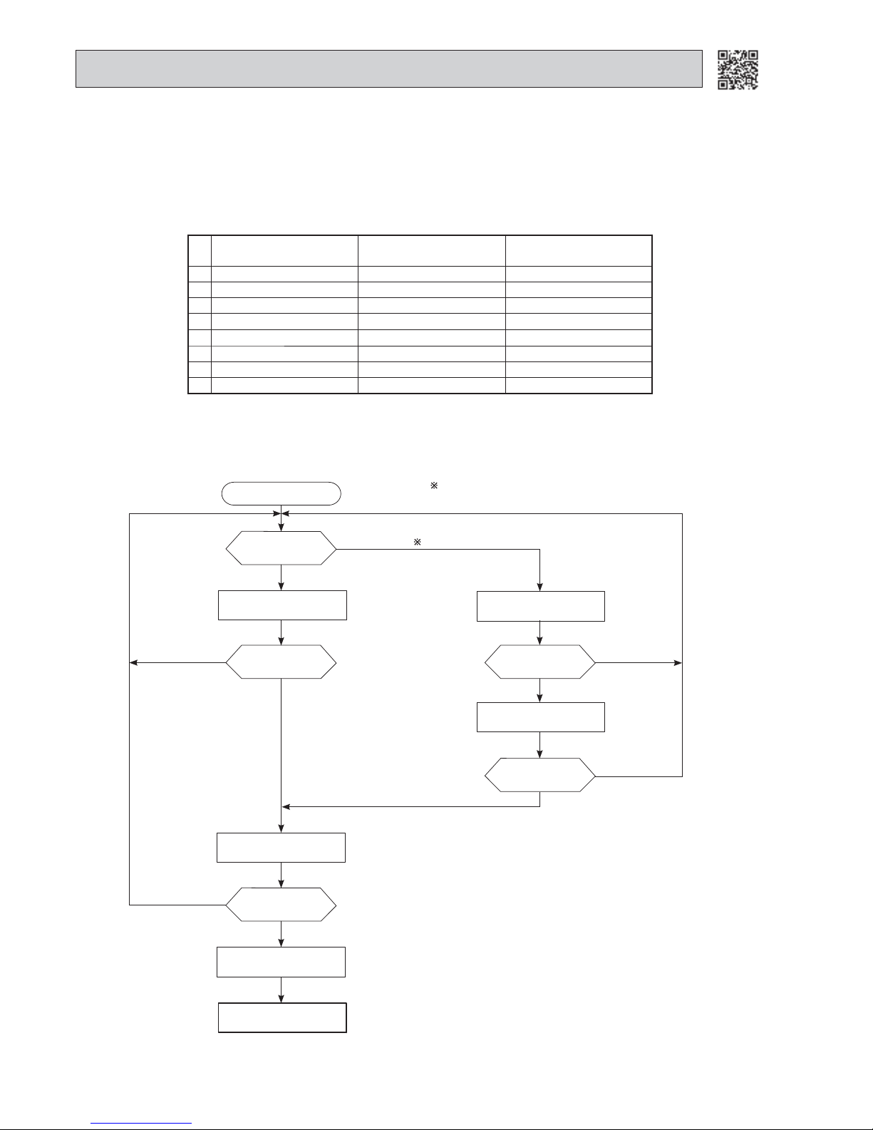
2-7. DRAIN PUMP/FLOAT SENSOR CONTROL (MLZ)
Drain pump motor OFF
When ON timer is set, or during multi system operation.
Operation mode
Start
Judge water level
COOL/DRY
Above fi xed point
Outdoor unit STOP
Rejudge water level
Indoor unit STOP
Above fi xed point
Abnormal indication
Below fi xed point
Below fi xed point
Drain pump motor ON
Above fi xed point
Judge water level
Below fi xed point
2 minutes later
Judge water level
Above fi xed point
HEAT/STAND-BY /STOP
Drain pump motor ON
Below fi xed point
Page 17
17
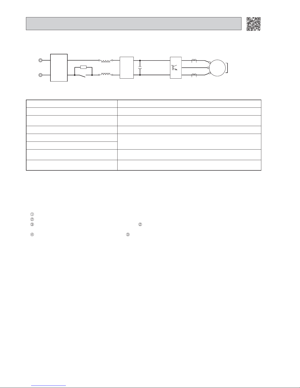
Function of main parts
NAME FUNCTION
INTELLIGENT POWER MODULE It supplies 3-phase AC power to compressor.
SMOOTHING CAPACITOR
It stabilizes the DC voltage and supply it to INTELLIGENT POWER MODULE.
CURRENT TRANSFORMER It measures the current of the compressor motor.
DIODE MODULE 1 It converts the AC voltage to DC voltage.
RESISTOR
It absorbs the rush current not to run into the main power supply circuit
when the power is turned ON.
RELAY
It keeps the RESISTOR, which restricts rush current, short-circuit while
the compressor is operating.
BOOSTER
CHOPPER
CIRCUIT
DIODE MODULE 2
It improves power factor.
It controls the bus-bar voltage.
SWITCHING POWER TRANSISTOR
REACTOR
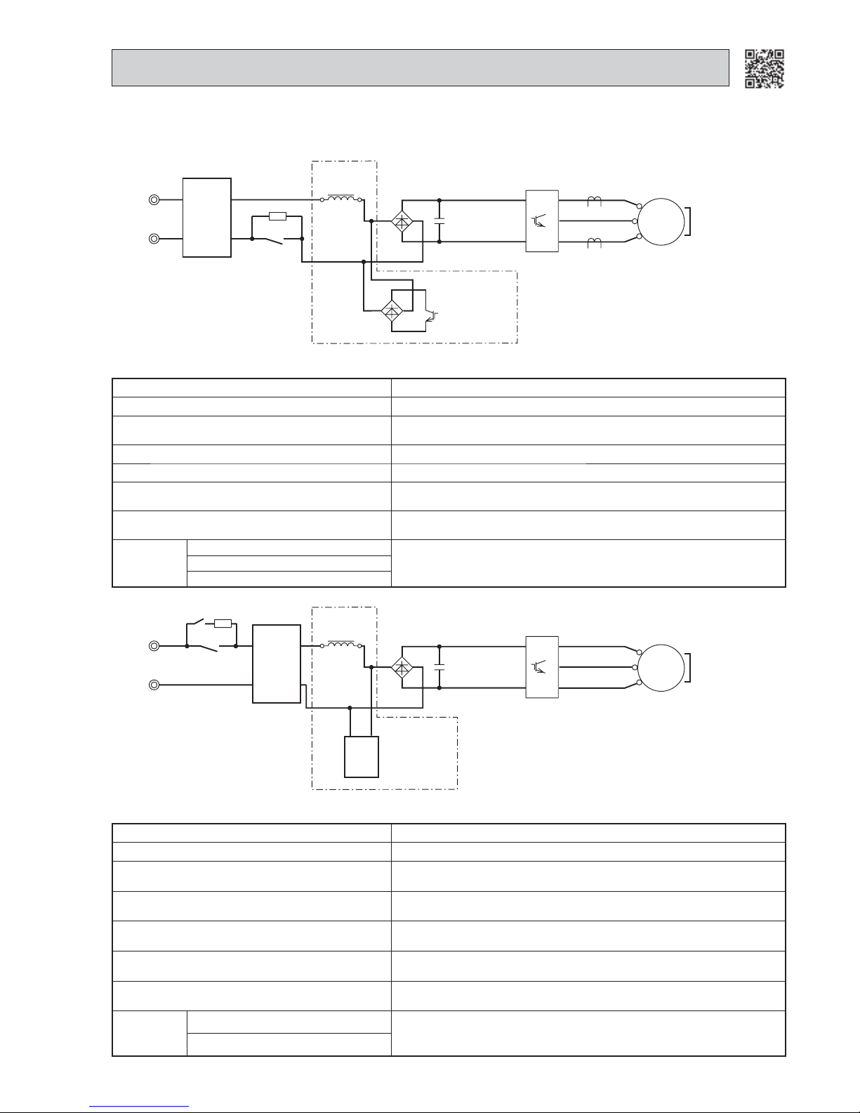
2-8. INVERTER SYSTEM CONTROL
2-8-1. Inverter main power supply circuit
MUZ-GC, HC, FD25/35, GE25/35/42/50
POWER
SUPPLY
NOISE
FILTER
CIRCUIT
RESISTOR
SWITCHING
POWER
TRANSISTOR
RELAY
SMOOTHING
CAPACITOR
CURRENT
TRANSFORMER
COMPRESSOR
DIODE
MODULE1
DIODE
MODULE2
REACTOR
P
W
V
U
N
INTELLIGENT
POWER
MODULE
U
W
MS
3~
V
+
BOOSTER CHOPPER CIRCUIT
+
-
~~
+
-
~~
Function of main parts
NAME FUNCTION
INTELLIGENT POWER MODULE It supplies 3-phase AC power to compressor.
SMOOTHING CAPACITOR
It stabilizes the DC voltage and supply it to INTELLIGENT POWER MODULE.
DIODE MODULE 1 It converts the AC voltage to DC voltage.
RESISTOR
It absorbs the rush current not to run into the main power supply circuit
when the power is turned ON.
RELAY1 It passes the rush current to RESISTOR when the power is turned ON.
RELAY2
It keeps the RESISTOR, which restricts rush current, short-circuit while
the compressor is operating.
BOOSTER
CHOPPER
CIRCUIT
POWER FACTOR CORRECTION MODULE
It improves power factor.
It controls the bus-bar voltage.
REACTOR
MUZ- EF
POWER
SUPPLY
NOISE
FILTER
CIRCUIT
RESISTOR
RELAY2
SMOOTHING
CAPACITOR
COMPRESSOR
DIODE
MODULE1
REACTOR
P
W
V
U
N
INTELLIGENT
POWER
MODULE
U
W
MS
3~
V
+
BOOSTER CHOPPER CIRCUIT
+
-
~~
POWER
FACTOR
CORRECTION
MODULE
RELAY1
Page 18
18
2-8-2. Outline of main power supply circuit
MUZ-GC, HC, FD25/35, GE25/35/42/50, EF
1. At the start of operation
Main power supply circuit is formed when RELAY is turned ON at COMPRESSOR startup.
To prevent rush current from running into the circuit when power supply is turned ON, RESISTOR is placed in sub circuit.
2. At normal operation
When AC runs into P.C. board, its external noise is eliminated in the NOISE FILTER CIRCUIT.
After noise is eliminated from AC, it is rectifi ed to DC by DIODE MODULE 1.
DC voltage, to which AC has been rectifi ed by process , is stabilized by SMOOTHING CAPACITOR and supplied to IN-
TELLIGENT POWER MODULE.
DC voltage, which has been stabilized in process , is converted to 3-phase AC by INTELLIGENT POWER MODULE and
supplied to COMPRESSOR.
3. Purpose of PAM adoption
PAM: Pulse Amplitude Modulation
PAM has been adopted for the effi ciency improvement and the adaptation to IEC harmonic current emission standard.
Outline of simple partial switching method
In conventional inverter models, DIODE MODULE rectifi es AC voltage to DC voltage, SMOOTHING CAPACITOR makes its DC
waveform smooth, and INTELLIGENT POWER MODULE converts its DC voltage to imitate AC voltage again in order to drive
the compressor motor.
However, it has been diffi cult to meet IEC harmonic current emission standard by above circuit because harmonic gets gener-
ated in the input current waveform and power factor gets down. The simple partial switching method with PAM, which has been
adopted this time, places and utilizes BOOSTER CHOPPER CIRCUIT before rectifying AC voltage in the general passive-method converter circuit. As harmonic gets suppressed and the peak of waveform gets lower by adding BOOSTER CHOPPER CIRCUIT as mentioned above and by synchronizing the timing of switching with the zero-cross point of waveform, the input current
waveform can be improved and the requirement of IEC harmonic current emission standard can be satisfi ed. Since the switching
is synchronized with the zero cross point, this simple partial switching method has the feature of lower energy loss compared to
active fi lter method. In addition, output and effi ciency is enhanced by combining with vector-controlled inverter in order to boost
the voltage of power supplied to INTELLIGENT POWER MODULE.
POWER
SUPPLY
NOISE
FILTER
CIRCUIT
RESISTOR
RELAY
SMOOTHING
CAPACITOR
CURRENT
TRANSFORMER
COMPRESSOR
REACTOR
P
W
V
U
N
INTELLIGENT
POWER
MODULE
POWER
FACTOR
CORRECTION
MODULE
U
W
MS
3~
V
+
MUZ-FD50, GE60/71
Function of main parts
NAME FUNCTION
INTELLIGENT POWER MODULE It supplies 3-phase AC power to compressor.
SMOOTHING CAPACITOR
It stabilizes the DC voltage and supplies it to INTELLIGENT POWER MODULE.
CURRENT TRANSFORMER It measures the current of the compressor motor.
REACTOR
It rectifi es AC, controls its voltage and improves the power factor of power
supply.
POWER FACTOR CORRECTION MODULE
RESISTOR
It absorbs the rush current not to run into the main power supply circuit when
the power is turned ON.
RELAY
It keeps the RESISTOR, which restricts rush current, short-circuit while the
compressor is operating.
Page 19

19
MUZ-FD50,GE60/71
1. At the start of operation
Main power supply circuit is formed when RELAY is turned ON at COMPRESSOR startup.
To prevent rush current from running into the circuit when power supply is turned ON, RESISTOR are placed in sub circuit.
2. At normal operation
When AC runs into noise fi lter P.C. board, its external noise is eliminated in NOISE FILTER CIRCUIT.
After noise being eliminated from AC, it is rectifi ed to DC by REACTOR and POWER FACTOR CORRECTION MODULE. If
the operating frequency becomes 25 Hz or more, DC voltage rises to 370 V.
DC voltage, to which has AC been rectifi ed by process , is stabilized by SMOOTHING CAPACITOR and supplied to IN-
TELLIGENT POWER MODULE.
The DC (Bus voltage), which has been stabilized in process , is converted to 3-phase AC by INTELLIGENT POWER
MODULE and supplied to COMPRESSOR.
CURRENT TRANSFORMER which is placed in the power supply circuit to COMPRESSOR, is used to measure the value
of phase current and locates the polar direction of rotor with algorithm. PWM (Pulse width modulation) controls
impressed voltage and frequency with those pieces of information.
3. Power factor improvement
Booster coil reactor and POWER FACTOR CORRECTION MODULE rectify AC to DC and control its voltage.
In the motor drive system of sine wave control, power factor can be improved by reducing harmonics. POWER FACTOR CORRECTION MODULE and reactor stabilize the voltage of DC supplied to inverter circuit and make its waveform smooth.
4. Intelligent power module
INTELLIGENT POWER MODULE consists of the following components.
• Power Transistors (x6) : Converts DC waveform to 3-phase AC waveform and outputs it.
• Drive Circuit : Drives transistors.
• Protection circuit : Protects transistors from over current.
Since the above components are all integrated in INTELLIGENT POWER MODULE, INTELLIGENT POWER MODULE has a
merit that can get the control circuit simplifi ed and miniaturized.
5. Elimination of electrical noise
NOISE FILTER CIRCUIT, which is formed by *CMC COILS and capacitors placed on the noise fi lter P.C. board, eliminates
electrical noise of AC power that is supplied to main power supply circuit. In short, common mode noise is absorbed in this circuit.
Moreover, normal mode noise is absorbed in another NOISE FILTER CIRCUIT which is formed by *NMC COILS and capacitors.
Both NOISE FILTER CIRCUITS exist for preventing the electrical noise generated in the inverter circuit from leaking out.
*CMC COILS: Common mode choke coils
*NMC COILS: Normal mode choke coils
4. Intelligent power module
INTELLIGENT POWER MODULE consists of the following components
• IGBT (x6) : Converts DC waveform to 3-phase AC waveform and outputs it.
• Drive Circuit : Drives transistors.
• Protection circuit : Protects transistors from overcurrent.
Since the above components are all integrated in INTELLIGENT POWER MODULE, INTELLIGENT POWER MODULE has a
merit to make the control circuit simplify and miniaturize.
5. Elimination of electrical noise
NOISE FILTER CIRCUIT, which is formed by *CMC COILS capacitors placed on P.C. board, eliminates electrical noise of AC
power that is supplied to main power supply circuit. And this circuit prevents the electrical noise generated in the inverter circuit from leaking out.
*CMC COILS: Common mode choke coils
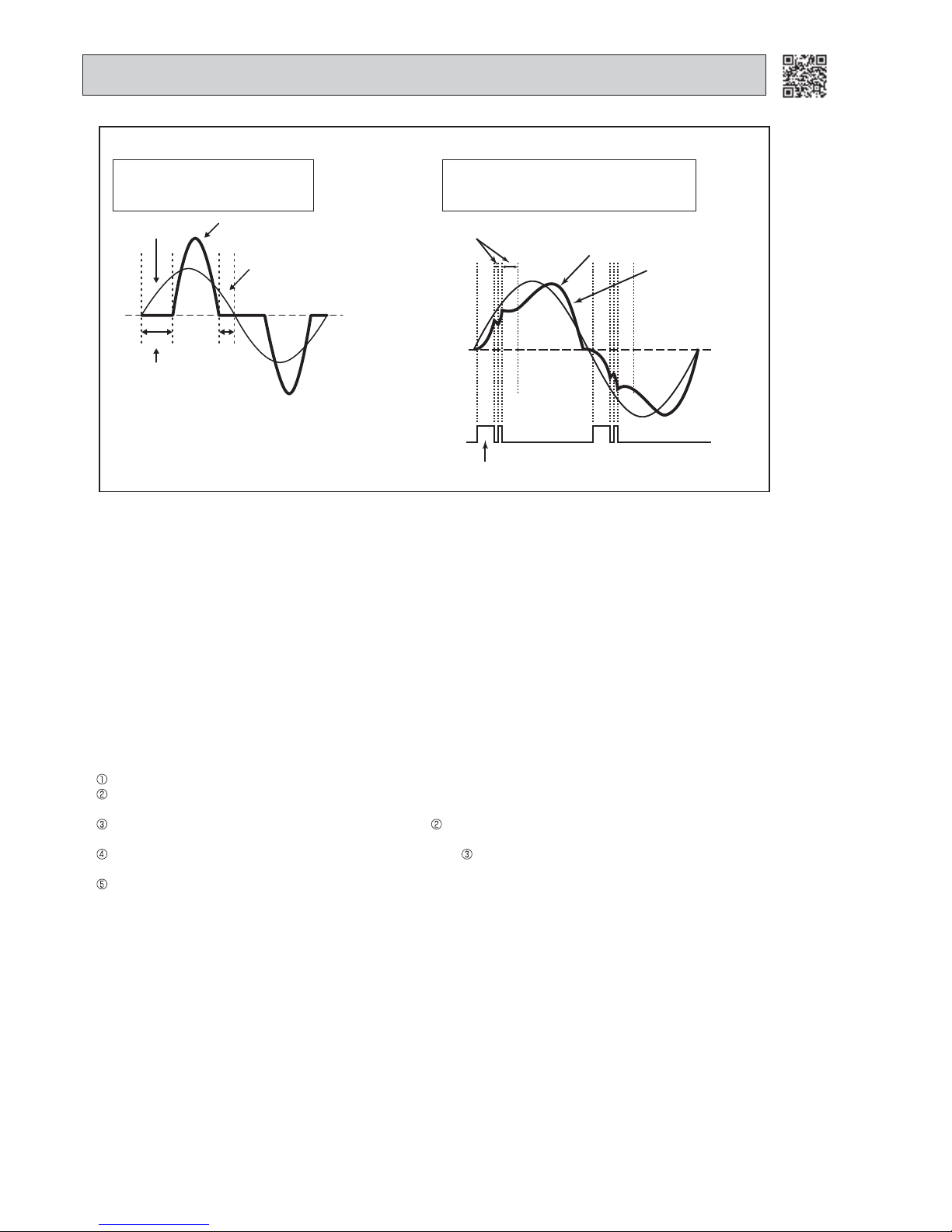
Input current waveform without PAM Input current waveform with PAM
Due to the time of no electricity;
• Power factor gets worse.
• Harmonic gets increased.
Input voltage
Energized time is short in
case L inductance is small.
No electricity runs into
diode module because the
voltage at both sides of smoothing
capacitor is higher than input voltage.
Input current
Owing to the increase of energized time;
• Power factor gets better.
• Harmonic gets suppressed.
Release of energy stored in L.
Peak gets down.
Energized time is
extended by
optimization
of L inductance.
Compulsory energizing
by switching.
Page 20

20
2-8-5. Control Method of Rotational Speed
Sine wave control makes the current transformers conduct real time detection of the value of the current running into the motor, locates the rotor position from the detected value, and decides if voltage should be impressed and if frequency should be
changed.
Compared to the conventional control and rotor position detection method, sine wave control can provide fi ner adjustment of the
voltage of supplied power. The value of the current running into the motor is determined by each motor characteristic.
2-8-4. Characteristics of sine wave control in case of brushless DC motor
● Although ordinary 3-phase induction motor requires energy to excite the magnetic fi eld of rotor, brushless DC motor does not
need it. So, higher effi ciency and torque are provided.
● This control provides the most effi cient waveform corresponding to the rotational speed of compressor motor.
● The rotation can be set to higher compared to the conventional motor drive system. So, the time in which air conditioner can
be operated with less energy is longer than conventional models. This can save annual electric consumption.
● Compared to square wave control, the torque pulsation is reduced at rotation so that the motor operates more quietly.
● Since the response and effi ciency of motor are enhanced in sine wave control, fi ner adjustment can be provided.
DC Motor AC Motor
Rotor Permanent magnet is embedded. Excited by magnetic fi eld of stator
Rotor Position Signal Necessary Unnecessary
In brushless DC motor, permanent magnet is embedded in the rotor. Therefore, it does not require energy to excite the rotor
like AC motor does. However, it is necessary to control the frequency of 3-phase AC current supplied to the stator according to the polar direction of magnet embedded in the rotor so as to drive the motor effi ciently. Controlling 3-phase AC cur-
rent frequency also means controlling the timing to switch the polarity of stator. Therefore, the polar direction of rotor needs
to be detected.
2-8-3. Sine wave control
In these air conditioners, compressor equips brushless DC motor which does not have hall element.
In short, the motor is sensorless. However, it is necessary to locate the polar direction of rotor in order to drive brushless DC motor effi ciently. The general detection method of the polar direction for such a DC motor is to locate it from the voltage induced by
deenergized stator.
Therefore, it is necessary to have a certain period of time in which the stator is being unenergized for the rotor position detection
when the voltage of supplied power is impressed.
So the motor has been driven by square wave control (the conventional motor drive system) which energizes the motor only
when the range of electrical angle is within 120° because it is forced to be unenergized within 30° at start and end of one heap
in one waveform cycle (180°) when the voltage is impressed.
However, torque pulsation occurs at rotation in this method when the current-carrying phases are switched over to other phases
in sequence. Therefore, sine wave control system is adopted for these air conditioners because it can make the phase-to-phase
current waveform smoother (sine wave) in order to drive the motor more effi ciently and smoothly.
2-9. OPERATIONAL FREQUENCY CONTROL OF OUTDOOR UNIT
1. Outline
The operational frequency is as follows:
First, the target operational frequency is set based on the difference between the room temperature and the set temperature.
Second, the target operational frequency is regulated by discharge temperature protection, high pressure protection,
electric current protection, overload protection, and the maximum/minimum frequency.
Page 21

21
2. Maximum/minimum frequency in each operation mode
Applied model
Operational frequency (Hz)
COOL HEAT DRY
Minimum Maximum Minimum Maximum Minimum Maximum
MUZ-GC25 32 85 28 105 32 41
MUZ-GC35 32 98 48 105 32 58
MUZ-HC25 28 85 28 105 28 41
MUZ-HC35 28 98 28 98 28 41
MUZ-FD25 10 52 18 90 28 41
MUZ-FD35VA 10 62 18 90 28 41
MUZ-FD35VAH/VABH 10 62 18 115 28 41
MUZ-FD50 20 85 20 130 20
45
MUZ-GE25 24 93 32 105 38
48
MUZ-GE35 20 98 32 98 38
55
MUZ-GE42 10 90 18 115 35
54
MUZ-GE50 20 98 20 108 20
98
MUZ-GE60 20 104 30 117 20
104
MUZ-GE71 26 120 26 124 26
120
MUZ-EF25 28 93 30 105 28
48
MUZ-EF35 20 98 30 98 20
55
MUZ-EF42 10 90 18 100 10
54
MUZ-EF50 20 98 20 108 20
83
The operation frequency in COOL mode is restricted by the upper limit frequency after 0.5 - 1 hour as shown below for
dew prevention. It is rated frequency or less.
Maximum
frequency
0.5 - 1 hour
Upper limit
frequency
Rated frequency or less
Time
2-10. PRE-HEAT CONTROL
1. Outline
Compressor is energized to improve the start-up of compressor at a low outside temperature even when compressor
is stopped.
2. Pre-heat control
MUZ-GC/HC/FD/GE
30 minutes 1 hour
ON
ON
OFF
OFF
20 °C
Compressor
Pre-heat control
Defrost thermistor
Pre-heat control ON condition
(1) Compressor is not operating. (However, pre-heat control is still OFF for 30 minutes after compressor is stopped,
regardless of the outside temperature.)
(2) Defrost thermistor reads 20°C or below.
Defrost thermistor monitor hourly, and when defrost thermistor reads 20°C or below, pre-heat control is turned ON.
When pre-heat control is turned ON, compressor is energized about 50 W (40-60 W). (Compressor and fan are not operated.)
Page 22
22
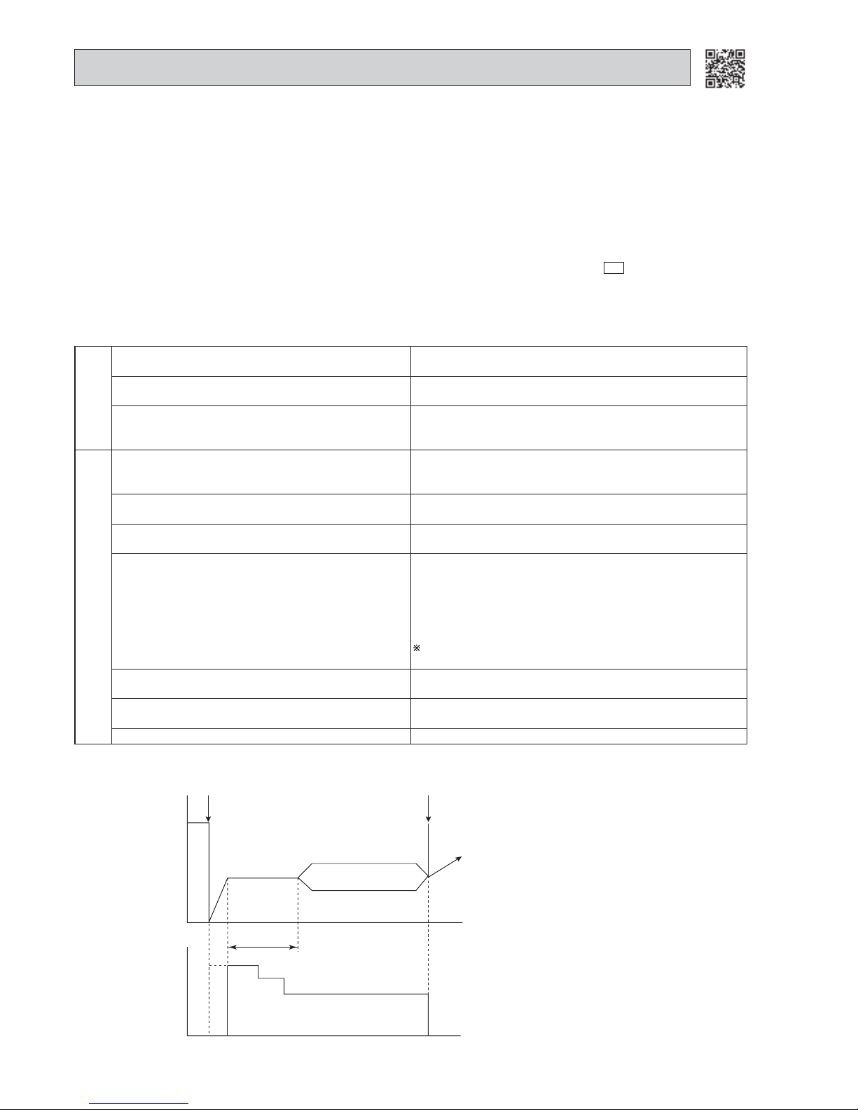
2-11. EXPANSION VALVE CONTROL/LEV CONTROL (MUZ-GC/FD/GE/EF/HC35VA(B)-
E2
)
(1) Outline of LEV control
The LEV basic control is setting of LEV opening degree to the standard opening degrees set for each operational frequency of the compressor. However, when any change in indoor/outdoor temperatures or other factors cause air conditioning load fluctuation, the LEV control also works to correct LEV opening degree based on discharge temperature (Shell
temperature) of the compressor, developing the unit’s performance.
Standard
specification
Control range
Minimum : 54 pulse
Maximum : 500 pulse
Actuating speed
Open: 40 pulse/second
Close: 90 pulse/second.
Opening degree adjustment LEV opening degree is always adjusted in opening direction.
(When reducing the opening degree, LEV is once over-closed,
and then adjusted to the proper degree by opening.
General operation
Unit OFF LEV remains at maximum opening degree. (LEV is reached
maximum opening degree approximately in 15 minutes after
compressor stops.)
Remote controller ON LEV is positioned. (First LEV is full closed at zero pulse and
then positioned.)
During 1 to 15 minutes after compressor starts LEV is fixed to standard opening degree according to opera-
tional frequency of compressor.
More than about 15 minutes have passed since compressor start-up
LEV opening degree is corrected to get target discharge tem-
perature of compressor.
(For lower discharge temperature than target temperature,
LEV is corrected in closing direction.)
(For higher discharge temperature than target temperature,
LEV is corrected in opening direction.)
It may take more than 30 minutes to reach target tempera-
ture, depending on operating conditions.
Thermostat OFF LEV is adjusted to exclusive opening degree for thermostat
OFF.
Thermostat ON LEV is controlled in the same way as that after the compres-
sor has started up.
Defrosting in HEAT mode LEV is adjusted to open 500 pulse.
(2) Time chart
OFF Time
Ti
me
ON
Operational frequency
of the compressor
Commanded
to open
Standard
opening
degree
Opening degree is
corrected according
to discharge
temperature.
(Refer to (3))
Positioning
Air conditioner ON
Air conditioner OFF
(thermostat off)
LEV opening degree
About 15 minutes
MUZ-EF
Pre-heat control ON condition
(1) Compressor is not operating. (However, pre-heat control is still OFF for 60 minutes after compressor is stopped,
regardless of the compressor temperature.)
(2) Compressor temperature is monitored hourly, and when the compressor temperature is 20°C or below, pre-heat con-
trol is turned ON.
(3) When the compressor temperature exceeds 30 °C, pre-heat control is turned OFF.
When pre-heat control is turned ON, compressor is energized about 50 W (40-60 W). (Compressor and fan are not operated.)
Page 23

23
In COOL operation, the two indoor coil
thermistors (one main and one sub) sense
temperature ununiformity (super heat)
at the heat exchanger, and when temperature difference have developed, the
indoor coil thermistors adjust LEV opening degree to get approximate 10°C lower
temperature than the target discharge
temperature in the table on the left, thus
diminishing super heat.
(3) Control data
Reference value of target discharge temperature (COOL/HEAT °C)
Applied model
ABCDEF
MUZ-GC25 54/36 59/46 65/55 70/63 75/70 79/76
MUZ-
HC35VA(B)-
E2
52/46 57/50 64/55 70/64 74/73 74/73
MUZ-GC35 51/42 57/50 62/58 67/65 71/70 71/70
MUZ-FD25/35
MUZ-GE42
49/43 55/51 61/59 67/69 72/75 76/80
MUZ-FD50 45/51 58/59 65/65 72/72 72/72 72/72
MUZ-GE25 52/43 58/50 65/55 67/59 70/65 71/69
MUZ-GE35 53/43 60/51 64/58 67/59 72/69 76/75
MUZ-GE50 57/60 60/65 62/70 67/75 74/75 81/75
MUZ-GE60 49/42 53/49 59/58 64/67 69/75 74/83
MUZ-GE71 55/46 61/56 66/66 72/75 77/83 81/86
MUZ-EF25 52/43 58/50 65/55 67/59 70/65 71/69
MUZ-EF35 53/43 60/51 64/58 67/59 72/69 76/75
MUZ-EF42 49/43 55/51 61/59 67/69 72/75 76/80
MUZ-EF50 49/42 53/49 59/58 64/67 69/75 74/83
F
E
D
C
B
A
Target discharge
temperature
30 50 70
Operational frequency of the compressor (Hz)
90 110 130
23 38 53 69 84 99 (GE60/71)
(Other models)
2-12. STANDBY POWER CONTROL
MUZ-EF
(1) Outline
This control allows the power consumption in the standby mode to be maintained at 1 W or less. The control is enabled from the moment the main power is turned on until the operation starts. About 10 minutes later after the operation stops, the control becomes enabled again until the main power is turned off.
(2) Standby power control time chart
[e.g.] Remote controllerON[e.g.] Remote controller
OFF
[e.g.] Remote controller
ON
Main power
ON
Operarion
Standby
power control
Disabled
Enabled
About 10 minutes
1 W or less 1 W or less
ON
OFF
Page 24

24
3
MXZ MICROPROCESSOR CONTROL
3-1. INVERTER SYSTEM CONTROL
3-1-1. Inverter main power supply circuit
POWER
SUPPLY
NOISE
FILTER
CIRCUIT
RESISTOR
RELAY
SMOOTHING
CAPACITOR
CURRENT
TRANSFORMER
COMPRESSOR
REACTOR
P
W
V
U
N
INTELLIGENT
POWER
MODULE
POWER
FACTOR
CORRECTION
MODULE
U
W
MS
3~
V
+
MXZ-3B54VA MXZ-3B68VA MXZ-4B71VA MXZ-4B80VA MXZ-5B100VA
MXZ-3C54VA MXZ-3C68VA MXZ-4C71VA MXZ-4C80VA MXZ-5C100VA
Function of main parts
NAME FUNCTION
INTELLIGENT POWER MODULE It supplies 3-phase AC power to compressor.
SMOOTHING CAPACITOR
It stabilizes the DC voltage and supplies it to INTELLIGENT POWER MODULE.
CURRENT TRANSFORMER It measures the current of the compressor motor.
REACTOR
It rectifi es AC, controls its voltage and improves the power factor of power
supply.
POWER FACTOR CORRECTION MODULE
RESISTOR
It absorbs the rush current not to run into the main power supply circuit the
power is turned ON.
RELAY
It keeps the RESISTOR, which restricts rush current, short-circuited while
the compressor is operating.
MXZ-2B30VA MXZ-2B40VA MXZ-2B52VA
POWER
SUPPLY
NOISE
FILTER
CIRCUIT
RESISTOR
SWITCHING
POWER
TRANSISTOR
RELAY
SMOOTHING
CAPACITOR
CURRENT
TRANSFORMER
COMPRESSOR
DIODE
MODULE1
DIODE
MODULE2
REACTOR
P
W
V
U
N
INTELLIGENT
POWER MODULE
U
W
MS
3~
V
+
BOOSTER CHOPPER CIRCUIT
+
-
~~
+
-
~~
Function of main parts
NAME FUNCTION
INTELLIGENT POWER MODULE It supplies 3-phase AC power to compressor.
SMOOTHING CAPACITOR
It stabilizes the DC voltage and supply it to INTELLIGENT POWER MODULE.
CURRENT TRANSFORMER It measures the current of the compressor motor.
DIODE MODULE 1 It converts the AC voltage to DC voltage.
RESISTOR
It absorbs the rush current not to run into the main power supply circuit the
power is turned ON.
RELAY
It keeps the RESISTOR, which restricts rush current, short-circuited while
the compressor is operating
BOOSTER
CHOPPER
CIRCUIT
DIODE MODULE 2
It improves power factor.
It controls the bus-bar voltage.
SWITCHING POWER TRANSISTOR
REACTOR
Page 25

25
1. At the start of operation
Main power supply circuit is formed when RELAY is turned ON at COMPRESSOR startup.
To prevent rush current from running into the circuit when power supply is turned ON, RESISTOR is placed in sub circuit.
2. At normal operation
When AC runs into P.C. board, its external noise is eliminated in NOISE FILTER CIRCUIT.
After noise is eliminated from AC, it is rectifi ed to DC by DIODE MODULE 1.
DC voltage, to which AC has been rectifi ed by process , is stabilized by SMOOTHING CAPACITOR and supplied to IN-
TELLIGENT POWER MODULE.
DC voltage, which has been stabilized in process , is converted to 3-phase AC by INTELLIGENT POWER MODULE and
supplied to COMPRESSOR.
CURRENT TRANSFORMER which is placed in the power supply circuit to COMPRESSOR, is used to measure the value
of phase current and locates the polar direction of rotor with algorithm. PWM (Pulse width modulation) controls impressed
voltage and frequency with those pieces of information.
3. Purpose of PAM adoption
PAM: Pulse Amplitude Modulation
PAM has been adopted for the effi ciency improvement and the adaptation to IEC harmonic current emission standard.
Outline of simple partial switching method
I
n conventional inverter models, DIODE MODULE rectifi es AC voltage to DC voltage, SMOOTHING CAPACITOR makes its DC waveform
smooth, and INTELLIGENT POWER MODULE converts its DC voltage to imitate AC voltage again in order to drive the compressor motor.
However, it has been diffi cult to meet IEC harmonic current emission standard by above circuit because harmonic gets generated in the
input current waveform and power factor gets down. The simple partial switching method with PAM, which has been adopted this time,
places and utilizes BOOSTER CHOPPER CIRCUIT before rectifying AC voltage in the general passive-method converter circuit. As harmonic gets suppressed and the peak of waveform gets lower by adding BOOSTER CHOPPER CIRCUIT as mentioned above and by synchronizing the timing of switching with the zero-cross point of waveform, the input current waveform can be improved and the requirement
of IEC harmonic current emission standard can be satisfi ed. Since the switching is synchronized with the zero cross point, this simple par-
tial switching method has the feature of lower energy loss compared to active fi lter method. In addition, output and effi ciency is enhanced
by combining with vector-controlled inverter in order to boost the voltage of power supplied to INTELLIGENT POWER MODULE.
3-1-2. Outline of main power supply circuit
MXZ-2B30VA MXZ-2B40VA MXZ-2B52VA
REACTOR
SMOOTHING
CAPACITOR
MS
3
~
U
+
-
+
~~
P
W
V
U
N
W
POWER
SUPPLY
RELAY
RESISTOR
NOISE
FILTER
CIRCUIT
SWITCHING
POWER
TRANSISTOR
CURRENT
TRANSFORMER
COMPRESSOR
DIODE
DIODE
BRIDGE
POWER
TRANSISTER
BRIDGE
POWER
MODULE
MXZ-6C120VA
Function of main parts
NAME FUNCTION
RESISTOR
It absorbs the rush current not to run into the main power supply circuit
when
the power is turned ON.
.
RELAY
It keeps the RESISTOR, which restricts rush current, short-circuited while
the compressor is operating.
DIODE BRIDGE It converts the AC voltage to DC voltage.
REACTOR
It improves power factor.
It controls the bus-bar voltage.
SWITCHING POWER TRANSISTOR
DIODE
SMOOTHING CAPACITOR
It stabilizes the DC voltage and supply it to INTELLIGENT POWER
MODULE.
POWER TRANSISTOR BRIDGE It supplies 3-phase AC power to compressor.
CURRENT TRANSFORMER It measures the current of the compressor motor.
Page 26
26
1. At the start of operation
Main power supply circuit is formed when RELAY is turned ON at COMPRESSOR startup.
To prevent rush current from running into the circuit when power supply is turned ON, RESISTOR is placed in sub circuit.
2. At normal operation
When AC runs into noise fi lter P.C. board, its external noise is eliminated in NOISE FILTER CIRCUIT.
After noise is eliminated from AC, it is rectifi ed to DC by REACTOR and POWER FACTOR CORRECTION MODULE. If the
operating frequency becomes 25 Hz or more, DC voltage rises to 370 V.
DC voltage, to which AC has been rectifi ed by process , is stabilized by SMOOTHING CAPACITOR and supplied to IN-
TELLIGENT POWER MODULE.
The DC (Bus voltage), which has been stabilized in process , is converted to 3-phase AC by INTELLIGENT POWER
MODULE and supplied to COMPRESSOR.
CURRENT TRANSFORMER which is placed in the power supply circuit to COMPRESSOR, is used to measure the value
of phase current and locates the polar direction of rotor with algorithm. PWM (Pulse width modulation) controls impressed
voltage and frequency with those pieces of information.
3. Power factor improvement
Booster coil reactor and POWER FACTOR CORRECTION MODULE rectify AC to DC and control its voltage.
In the motor drive system of sine wave control, power factor can be improved by reducing harmonics. POWER FACTOR
CORRECTION MODULE and reactor stabilize the voltage of DC supplied to inverter circuit and make its waveform smooth.
4. Intelligent power module
INTELLIGENT POWER MODULE consists of the following components.
• IGBT (x6): Converts DC waveform to 3-phase AC waveform and outputs it.
• Drive Circuit: Drives transistors.
• Protection circuit: Protects transistors from over current.
Since the above components are all integrated in INTELLIGENT POWER MODULE, INTELLIGENT POWER MODULE has a
merit to make the control circuit simplifi ed and miniaturized.
5. Elimination of electrical noise
NOISE FILTER CIRCUIT, which is formed by *CMC COILS, *NMC COILS and capacitors placed on P.C. board, eliminates
electrical noise of AC power that is supplied to main power supply circuit. This circuit also prevents electrical noise generated
in the inverter circuit from leaking out.
*CMC COILS; Common mode choke coils
*NMC COILS; Normal mode choke coils
MXZ-3B54VA MXZ-3B68VA MXZ-4B71VA MXZ-4B80VA MXZ-5B100VA
MXZ-3C54VA MXZ-3C68VA MXZ-4C71VA MXZ-4C80VA MXZ-5C100VA
Input current waveform without PAM Input current waveform with PAM
Due to the time of no electricity;
• Power factor gets worse.
• Harmonic gets increased.
Input voltage
Energized time is short in
case L inductance is small.
No electricity runs into
diode module because the
voltage at both sides of smoothing
capacitor is higher than input voltage.
Input current
Owing to the increase of energized time;
• Power factor gets better.
• Harmonic gets suppressed.
Release of energy stored in L.
Peak gets down.
Energized time is
extended by
optimization
of L inductance.
Compulsory energizing
by switching.
4. Intelligent power module
INTELLIGENT POWER MODULE consists of the following components
• IGBT (x6): Converts DC waveform to 3-phase AC waveform and outputs it.
• Drive Circuit: Drives transistors.
• Protection circuit: Protects transistors from overcurrent.
Since the above components are all integrated in INTELLIGENT POWER MODULE, INTELLIGENT POWER MODULE
has a merit to make the control circuit simplify and miniaturize.
5. Elimination of electrical noise
NOISE FILTER CIRCUIT, which is formed by *CMC COILS capacitors placed on P.C. board, eliminates electrical noise of AC power that
is supplied to main power supply circuit. And this circuit prevents the electrical noise generated in the inverter circuit from leaking out.
*CMC COILS; Common mode choke coils
Page 27

27
3-1-3. Sine wave control
In these air conditioners, compressor equips brushless DC motor which does not have Hall element.
In short, the motor is sensorless. However, it is necessary to locate the polar direction of rotor in order to drive brushless DC motor effi ciently. The general detection method of the polar direction for such a DC motor is to locate it from the voltage induced by
unenergized stator.
Therefore, it is necessary to have a certain period of time in which the stator is being unenergized for the rotor position detection
when the voltage of supplied power is impressed.
So the motor has been driven by square wave control (the conventional motor drive system) which energizes the motor only
when the range of electrical angle is within 120
because it is forced to be unenergized within 30° at start and end of one heap
in one waveform cycle (180 ) when the voltage is impressed.
However, torque pulsation occurs at rotation in this method when the current-carrying phases are switched over to other phases
in sequence. Therefore, sine wave control system is adopted for these air conditioners because it can make the phase-to-phase
current waveform smoother (sine wave) in order to drive the motor more effi ciently and smoothly.
MXZ-6C120VA
1. At the start of operation
Main power supply circuit is formed when RELAY is turned ON at COMPRESSOR startup.
To prevent rush current from running into the circuit when power supply is turned ON, RESISTOR are placed in sub circuit.
2. At normal operation
When AC runs into P.C. board, its external noise is eliminated in NOISE FILTER CIRCUIT.
After noise is eliminated from AC, it is rectifi ed to DC by DIODE BRIDGE.
Then REACTOR ,SWITCHING POWER TRANSISTOR and DIODE boost the DC voltage to 350V.
DC voltage, to which AC has been rectifi ed by process , is stabilized by SMOOTHING CAPACITOR and supplied to
POWER TRANSISTOR BRIDGE.
The DC (Bus voltage), which has been stabilized in process , is converted to 3-phase AC by POWER TRANSISTOR
BRIDGE and supplied to COMPRESSOR.
CURRENT TRANSFORMER which is placed in the power supply circuit to COMPRESSOR, is used to measure the value
of phase current and locates the polar direction of rotor with algorithm. PWM (Pulse width modulation) controls impressed
voltage and frequency with those pieces of information.
3. Power factor improvement
An AC/DC converter circuit made up of DIODE BRIDGE and SMOOTHING CAPACITOR causes waveform distortion of the
input current. Waveform distortion leads to lower input power factor and higher input current.
It also causes increase of harmonic current.
A circuit made up of REACTOR, SWITCHING POWER TRANSISTOR and DIODE controls the input current and
thus smoothes the input current waveform. This circuit improves the power factor and reduces the input current.
Also, the input current waveform will satisfy the harmonic current standard.
4. Power module
Power module consists of the following components.
• Diode bridge (Diode x4): It converts AC voltage to DC votage.
• Switching power transistor, Diode: It improves the power factor and controls the bus-bar voltage with the reactor.
• Power transistor bridge (Transistor x6): It converts DC voltage to 3-phase AC voltage.
5. Elimination of electrical noise
NOISE FILTER CIRCUIT, which is formed by choke coils and capacitors placed on P.C. board, eliminates electrical noise of
AC power that is supplied to main power supply circuit.
And this circuit prevents the electrical noise generated in the inverter circuit from leaking out.
Input current waveform without power factor
improvement
Input current waveform with power factor
improvement
Input voltage
Input current
Input voltage
Input current
Page 28

28
3-1-5. Control Method of Rotational Speed
Sine wave control makes the current transformers conduct real time detection of the value of the current running into the motor, locates the rotor position from the detected value and decides if voltage should be impressed and if frequency should be
changed.
Compared to the conventional control and rotor position detection method, sine wave control can provide fi ner adjustment of the
voltage of supplied power. The value of the current running into the motor is determined by each motor characteristic.
3-2. EXPANSION VALVE CONTROL (LEV CONTROL)
Linear expansion valve (LEV) is controlled by "Thermostat ON" commands given from each unit.
Indoor unit status LEV opening
Stop of all indoor unit Opening before stop → 500 pulse in 15 minutes
When outdoor unit is operating, some
indoor units stop and some operate.
COOL: 5 pulse (fully closed)
HEAT: 59 pulse (slightly opened) (MXZ-2B), 100 → 52 pulse (MXZ-3B/4B71/3C/4C71VA),
100
59 pulse (MXZ-4B80/5B/4C80/5C/6C)
Thermostat OFF in
COOL or DRY mode
When the outdoor unit operates (When the other indoor unit operates): 5 pulse.
When the outdoor unit stops. (When the other indoor unit stops or thermo OFF):
Maintain LEV opening before stop → 500 pulse in 15 minutes
Thermostat ON in
COOL or DRY mode
• LEV opening for each indoor unit is determined by adding adjustment according to the
number of operating unit and the capacity class to standard opening, based on the operation
frequency:
e.g.) Opening 130 pulse in standard opening 1 → Minimum 80 pulse, Maximum 205 pulse.
(Capacity code 4 at 1 unit operation) (Capacity code 1 at 4 units operation)
• After starting operation, adjustment according to intake superheat, discharge temperature is
included in standard opening.
1
NOTE: LEV opening in each frequency at DRY operation and COOL operation is the same.
However, velocity and compressor operation frequency controls are different. (Refer
to 3-3. OPERATIONAL FREQUENCY RANGE)
(As far as the indoor unit velocity control goes, refer to DRY operation in MICRO-
PROCESSOR CONTROL in indoor unit.)
Thermostat OFF in HEAT mode
• When the outdoor unit operates. (When the other indoor unit operates):
59 pules (MXZ-2B), 140 pulse (MXZ-3B/4B/5B/3C/4C/5C/6C).
• When the outdoor unit stops. (When the other indoor unit stops or thermo OFF):
Maintain LEV opening before stop → 500 pulse in 15 minutes.
Thermostat ON in HEAT mode
• LEV opening for each indoor unit is determined by adding adjustment according to the
number of operating unit and the capacity class to standard opening, based on the operation
frequency:
e.g.) Opening 120 pulse in standard opening 1 → Minimum 70 pulse, Maximum 165 pulse.
(Capacity code 4 at 1 unit operation) (Capacity code 1 at 4 units operation)
• After starting operation, opening becomes the one that adjustment according to discharge
temperature that was added to basic opening.
1
1 LEV opening when the outdoor unit is operating: Upper limit 500 pulse, Lower limit 59 pulse
(MXZ-2B/4B80/5B/4C80/5C/6C), 53 pulse (MXZ-3B/4B71/3C/4C71).
3-1-4. Characteristics of sine wave control in case of brushless DC motor
● Although ordinary 3-phase induction motor requires energy to excite the magnetic fi eld of rotor, brushless DC motor does not
need it. So, higher effi ciency and torque are provided.
● This control provides the most effi cient waveform corresponding to the rotational speed of compressor motor.
● The rotation can be set to higher compared to the conventional motor drive system. So, the time in which air conditioner can
be operated with less energy is longer than conventional models. This can save annual electric consumption.
● Compared to square wave control, the torque pulsation is reduced at rotation so that the motor operates more quietly.
● Since the response and effi ciency of motor are enhanced in sine wave control, fi ner adjustment can be provided.
DC Motor AC Motor
Rotor Permanent magnet is embedded. Excited by magnetic field of stator
Rotor Position Signal Necessary Unnecessary
In brushless DC motor, permanent magnet is embedded in the rotor. Therefore, it does not require energy to excite the rotor
like AC motor does. However, it is necessary to control the frequency of 3-phase AC current supplied to the stator according to the polar direction of magnet embedded in the rotor so as to drive the motor effi ciently. Controlling 3-phase AC current
frequency also means controlling the timing to switch the polarity of stator. Therefore, the polar direction of rotor needs to be
detected.
Page 29

29
23 54 69 84 100 115 131 14638
14 32 41 50 59 68 77 86
MXZ-2B52/3B/4B71/3C/4C71VA
33 76 98 120 142 163 185 20755 MXZ-2B30/2B40VA
MXZ-4B80/5B100/4C80/5C100VA23
20 40 49 59 69 79 89 99 MXZ-6C120VA30
Compressor operating frequency (Hz)
4Hz
01
02
03
04
05
06
07
08
09
10
LEV Opening (code)
MXZ-2B30VA
Standard opening (pulse)
LEV Opening(code)
12345678910
COOL 340 360 360 360 390 390 390 390 400 410
HEAT 200 220 250 280 300 320 340 360 380 400
MXZ-2B40VA
Standard opening (pulse)
LEV Opening(code)
12345678910
COOL 240 260 280 300 330 350 370 390 400 410
HEAT 200 220 250 280 300 320 340 360 380 400
MXZ-2B52VA
Standard opening (pulse)
LEV Opening(code)
12345678910
COOL 340 360 360 360 390 390 390 390 400 410
HEAT 200 220 250 280 300 320 340 360 380 400
Operation number
Difference in capacity
Difference in operation number
Code3,4 Code5,6 Code7,8 2
COOL 10 20 30 -60
HEAT 5 10 15 -100
• The standard opening is on the straight line, which connects an each standard point in the section where divided into seven
according to the operation frequency of compressor as shown in the figure below.
(LEV opening is controlled in proportion to the operation frequency.)
NOTE: Opening is adjusted at the standard opening according to the indoor unit conditions.
However, inclination of standard opening in each point of opening does not change with the original curve.
• Add opening provided in Difference in Capacity in the table below to the standard opening from 1 to 8 (MXZ-2B)/ 1 to 15 or
above (MXZ-3B/4B/5B/3C/4C/5C/6C), when capacity of the indoor unit is excluding code 1.
• Add opening provided in Difference in Operation number in the table below to determined LEV opening for each indoor unit,
when 2, 3, 4, 5 or 6 indoor units are operated at the same time.
NOTE:
Even when the adjusted standard opening exceeds the driving range from 59 to 500 pulse, actual driving output opening
is in a range from 59 to 500 pulse.
Page 30

30
MXZ-3B54VA MXZ-3B68VA MXZ-4B71VA
MXZ-3C54VA MXZ-3C68VA MXZ-4C71VA
Exclusive LEV
Standard opening (pulse)
LEV Opening (code)
12345678910
COOL 120 130 136 146 156 160 170 180 190 200
HEAT 248 248 258 266 274 280 286 292 300 306
Difference in capacity
Difference in operation number
Code 1,2 Code 3,4 Code 5,6 Code 7,8
Code 9,10 Code 11,12 Code 13,14
Code 15 or above
234
COOL 0 3 6 9 12 15 25 35 -20 -30 -40
HEAT 0 3 6 9 52 55 65 75 30 0 -12
Receiver LEV
Standard opening (pulse)
LEV Opening (code)
12345678910
COOL 140 150 160 170 180 190 200 200 200 200
HEAT 80 84 90 110 120 130 140 150 160 170
Operation number
Difference in operation number
234
COOL 0 0 0
HEAT -16 -60 -125
MXZ-4B80VA MXZ-5B100VA
MXZ-4C80VA MXZ-5C100VA
Exclusive LEV
Standard opening (pulse)
LEV Opening (code)
12345678910
COOL 126 130 134 138 150 160 170 180 190 200
HEAT 248 248 258 266 274 280 286 292 300 306
Difference in capacity
Difference in operation number
Code 1,2 Code 3,4 Code 5,6 Code 7,8
Code 9,10 Code 11,12 Code 13,14
Code 15 or above
2345
COOL 0 3 6 9 12 15 25 35 -20 -30 -30 -30
HEAT 0 3 6 9 52 55 65 75 -4 -8 -12 -16
Receiver LEV
Standard opening (pulse)
LEV Opening (code)
12345678910
COOL 270 280 290 300 310 320 330 340 350 360
HEAT 140 152 160 170 180 200 224 244 274 280
Operation number
Difference in operation number
2345
COOL 28 56 84 112
HEAT -45 -60 -60 -60
Capacity code
Capacity code 2 3 4 7 9 10 12 13
Indoor unit capacity (kW)
1.5/2.0 2.2 2.5 3.5 4.2 5.0 6.0 7.1
Page 31

31
(1) LEV opening correction by discharge temperature
The target discharge temperature is determined according to frequency zone and number of operation unit of the com-
pressor.
<Correction>
COOL DRY HEAT
Discharge temperature
● ● ●
Each correction
(Main indoor coil thermistor - Sub indoor coil thermistor)
●●
-
Correct the LEV opening by discharge temperature.
MXZ-2B30VA MXZ-2B40VA
Operation frequency
of compressor (Hz)
Target discharge temperature (°C)
COOL HEAT
1 unit 2 units 1 unit 2 units
Minimum ~ 33 56 60 55 51
34 ~ 55 59 61 60 58
56 ~ 76 59 64 65 64
77 ~ 98 60 67 70 71
MXZ-2B52VA
Operation frequency
of compressor (Hz)
Target discharge temperature (°C)
COOL HEAT
1 unit 2 units 1 unit 2 units
Minimum ~ 23 56 60 57 51
24 ~ 38 59 61 63 58
39 ~ 54 59 64 69 64
55 ~ 69 60 67 75 71
70 ~ 85 61 67 80 77
86 ~ 100 62 69 86 83
101 ~ Maximum 63 70 90 90
MXZ-6C120VA
Exclusive LEV
Standard opening (pulse)
LEV Opening (code)
12345678910
COOL 204 204 204 216 216 216 216 216 216 216
HEAT 130 130 130 140 140 150 150 160 160 170
Difference in capacity
Difference in operation number
Code 1,2 Code 3,4 Code 5,6 Code 7,8
Code 9,10 Code 11,12 Code 13,14
Code 15 or above
234 5/6
COOL 03695255657500-128 -128
HEAT 0 53565950202020-4-8-12-16
Receiver LEV
Standard opening (pulse)
LEV Opening (code)
12345678910
COOL 190 190 200 200 210 210 220 230 240 250
HEAT 60 70 80 90 100 110 130 150 150 200
Operation number
Difference in operation number
2 3 4 5/6
COOL 0 0 100 100
HEAT 0000
Capacity code
Capacity code 2 3 4 7 10 12 13
Indoor unit capacity (kW)
1.5/2.0 2.2 2.5 3.5 5.0 6.0 7.1
Page 32

32
MXZ-4B80VA MXZ-5B100VA
MXZ-4C80VA MXZ-5C100VA
Operation frequency
of compressor (Hz)
Target discharge temperature (°C)
COOL HEAT
1 unit 2 units 3 units 4,5 units 1 unit 2 unit 3 units 4,5 units
Minimum ~ 14 35 55 57 60 52 62 50 50
15 ~ 23 42 55 57 60 58 66 55 50
24 ~ 32 49 58 63 60 65 74 60 50
33 ~ 41 58 60 65 62 68 78 67 50
42 ~ 50 65 65 65 65 68 78 72 55
51 ~ 59 68 68 73 65 68 78 76 60
60 ~ 68 70 70 75 70 68 78 76 60
69 ~ 77 75 70 80 72 68 78 76 60
78 ~ 86 75 70 82 72 68 78 76 60
87 ~ Maximum 75 75 82 72 78 78 76 60
"5 units" is MXZ-5B/5C
MXZ-6C120VA
Operation frequency
of compressor (Hz)
Target discharge temperature (°C)
COOL HEAT
1 unit 2 units 3,4 units 5,6 units 1 unit 2 unit 3,4 units
5,6 Units
Minimum ~ 19 40 55 55 59 54 62 54 50
20 ~ 29 55 61 64 62 64 74 63 52
30 ~ 39 64 64 68 64 67 77 67 55
40 ~ 48 70 68 73 67 70 79 71 57
49 ~ 58 75 72 78 69 72 79 76 59
59 ~ 68 78 76 83 72 74 79 80 61
69 ~ 78 80 80 88 74 75 85 85 64
79 ~ 88 80 83 88 77 75 85 88 66
89 ~ 98 80 87 88 80 80 85 88 68
99 ~ Maximum 80 87 88 84 80 85 88 70
MXZ-3B54VA MXZ-3B68VA MXZ-4B71VA
MXZ-3C54VA MXZ-3C68VA MXZ-4C71VA
Operation frequency
of compressor (Hz)
Target discharge temperature (°C)
COOL HEAT
1 unit 2 units 3 units
4 units
(MXZ-4B71VA)
(MXZ-4C71VA)
1 unit 2 units 3 units
4 units
(MXZ-4B71VA)
(MXZ-4C71VA)
Minimum ~ 23 35 58 62 62 50 50 50 50
24 ~ 38 40 60 65 65 56 50 55 55
39 ~ 54 49 65 70 70 60 56 60 60
55 ~ 69 58 68 70 70 63 60 60 60
70 ~ 85 65 70 72 72 66 60 60 60
86 ~ 100 70 70 72 72 67 60 60 60
101 ~ Maximum 70 70 85 85 70 60 60 60
Correct the LEV opening according to the difference between target discharge temperature and discharge temperature.
MXZ-2B30VA
Discharge temperature (°C)
LEV opening correction (pulse)
COOL HEAT
More than Target discharge temperature + 10 5 10
Target discharge temperature + 10 to Target discharge temperature + 5 4 4
Target discharge temperature + 5 to Target discharge temperature + 2 2 1
Target discharge temperature + 2 to Target discharge temperature - 2 0 0
Target discharge temperature - 2 to Target discharge temperature - 5 -1 -1
Target discharge temperature - 5 to Target discharge temperature - 10 -3 -2
Target discharge temperature - 10 or less -4 -3
Page 33
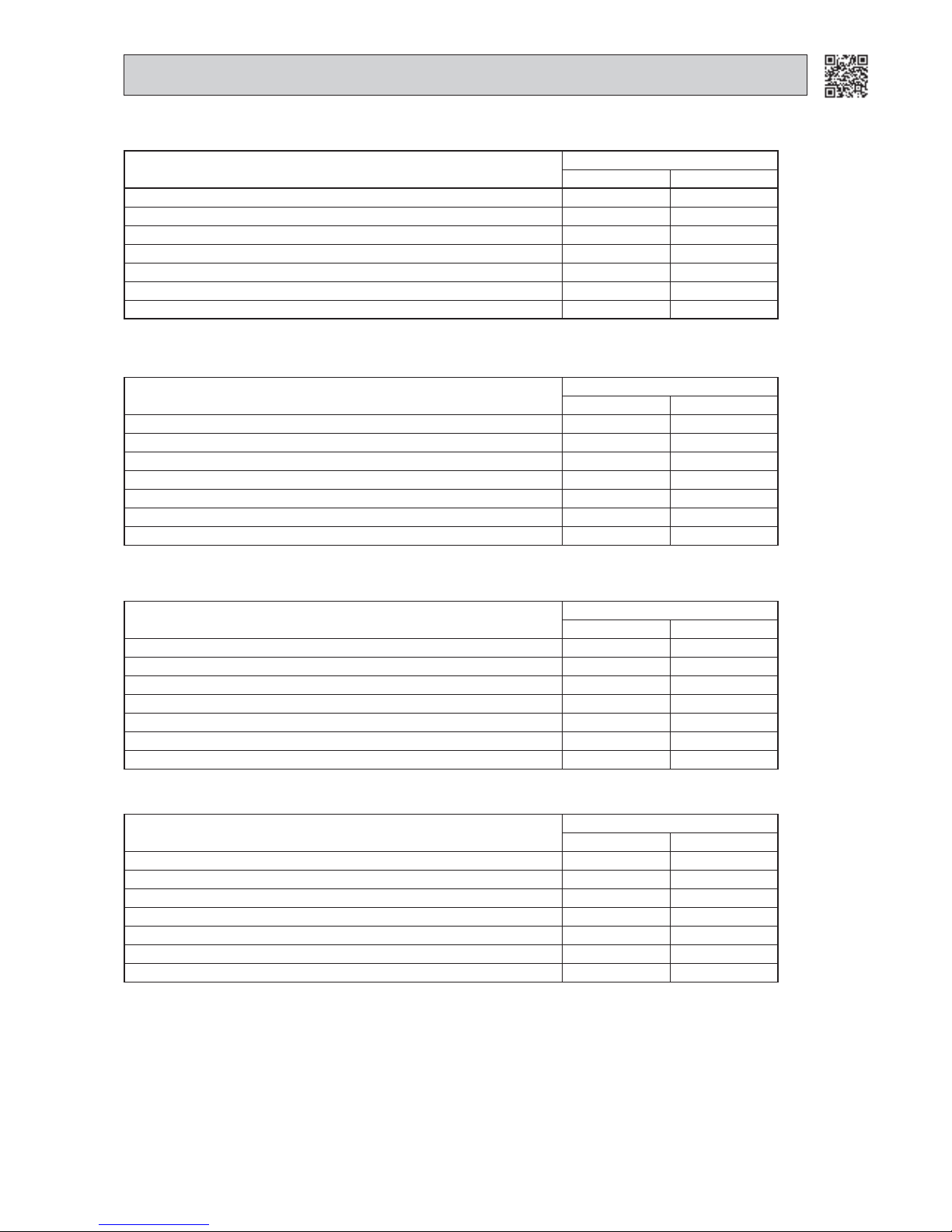
33
MXZ-3B54VA MXZ-3B68VA MXZ-4B71VA
MXZ-3C54VA MXZ-3C68VA MXZ-4C71VA
Discharge temperature (°C)
LEV opening correction (pulse)
COOL HEAT
More than Target discharge temperature + 10 5 8
Target discharge temperature + 10 to Target discharge temperature + 5 4 3
Target discharge temperature + 5 to Target discharge temperature + 2 2 1
Target discharge temperature + 2 to Target discharge temperature - 2 0 0
Target discharge temperature - 2 to Target discharge temperature - 5 -1 -1
Target discharge temperature - 5 to Target discharge temperature - 10 -3 -2
Target discharge temperature - 10 or less -4 -3
MXZ-2B40VA MXZ-2B52VA
Discharge temperature (°C)
LEV opening correction (pulse)
COOL HEAT
More than Target discharge temperature + 10 5 8
Target discharge temperature + 10 to Target discharge temperature + 5 4 3
Target discharge temperature + 5 to Target discharge temperature + 2 2 1
Target discharge temperature + 2 to Target discharge temperature - 2 0 0
Target discharge temperature - 2 to Target discharge temperature - 5 -1 -1
Target discharge temperature - 5 to Target discharge temperature - 10 -3 -2
Target discharge temperature - 10 or less -4 -3
MXZ-4B80VA MXZ-5B100VA
MXZ-4C80VA MXZ-5C100VA
Discharge temperature (°C)
LEV opening correction (pulse)
COOL HEAT
More than Target discharge temperature + 12 4 6
Target discharge temperature + 12 to Target discharge temperature + 5 2 2
Target discharge temperature + 5 to Target discharge temperature + 3 1 1
Target discharge temperature + 3 to Target discharge temperature - 3 0 0
Target discharge temperature - 3 to Target discharge temperature - 5 -1 -1
Target discharge temperature - 5 to Target discharge temperature - 12 -3 -2
Target discharge temperature - 12 or less -8 -8
MXZ-6C120VA
Discharge temperature (°C)
LEV opening correction (pulse)
COOL HEAT
More than Target discharge temperature + 12 4 6
Target discharge temperature + 12 to Target discharge temperature + 5 2 2
Target discharge temperature + 5 to Target discharge temperature + 3 1 1
Target discharge temperature + 3 to Target discharge temperature - 3 0 0
Target discharge temperature - 3 to Target discharge temperature - 5 -1 -1
Target discharge temperature - 5 to Target discharge temperature - 12 -3 -2
Target discharge temperature - 12 or less -8 -8
Page 34

34
(2) Separate correction (COOL, DRY)
(Correction by the separate superheat)
Correct the LEV separately by temperature difference
"∆RT" between main/sub indoor coil thermistor.
∆RT
LEV opening correction (pulse)
MXZ-2B/3B/4B71/3C/4C71 MXZ-4B80/5B/4C80/5C/6C
4
∆RT 2 3
2 ∆RT< 4 1 1
∆RT< 2 0 0
MXZ-3B54VA
MXZ-3C54VA
Number of operating
unit
Capacity code
COOL (Hz)
DRY (Hz)
HEAT (Hz)
Min. Max. Min. Max. Defrost
1
1,2 20 58 23 48 72 72
3,4 20 72 23 48 92 92
7 208523489292
9,10 20 101 45 48 101 100
12 34 101 58 48 101 100
13 34 101 58 48 101 100
2
~4 34 101 44 58 112 100
5~7 34 101 52 58 112 100
8~10 34 101 52 58 112 100
11~13 34 101 52 58 112 100
14~16 34 101 52 58 112 100
17~ 34 101 80 58 112 100
3 3~ 40 101 58 58 112 100
3-3. OPERATIONAL FREQUENCY RANGE
MXZ-2B30VA
Number of operating
unit
Capacity
code
COOL(Hz)
DRY(Hz)
HEAT(Hz)
Min Max Min Max defrost
1
1,2 40 64 40 35 97 97
3,4 40 64 44 35 97 97
2
~4 55 97 78 35 97 97
5~7 55 97 78 35 97 97
8 559786359797
MXZ-2B40VA
Number of operating
unit
Capacity
code
COOL(Hz)
DRY(Hz)
HEAT(Hz)
Min Max Min Max defrost
1
1,2 30 58 30 35 98 98
3,4 30 58 34 35 98 98
7 306834359898
2
~4 37 98 48 35 98 98
5~7 37 98 48 35 98 98
8~10 37 98 48 35 98 98
11 37 98 68 35 98 98
MXZ-2B52VA
Number of operating
unit
Capacity
code
COOL(Hz)
DRY(Hz)
HEAT(Hz)
Min Max Min Max defrost
1
1,2 12 48 20 21 57 57
3,4 12 48 25 21 71 71
7 124825218080
9 124844218080
2
~4 16 80 39 40 95 95
5~7 16 105 48 40 105 105
8~10 16 105 48 40 15 15
11~13 16 105 52 40 105 105
14 16 105 52 40 105 105
Page 35
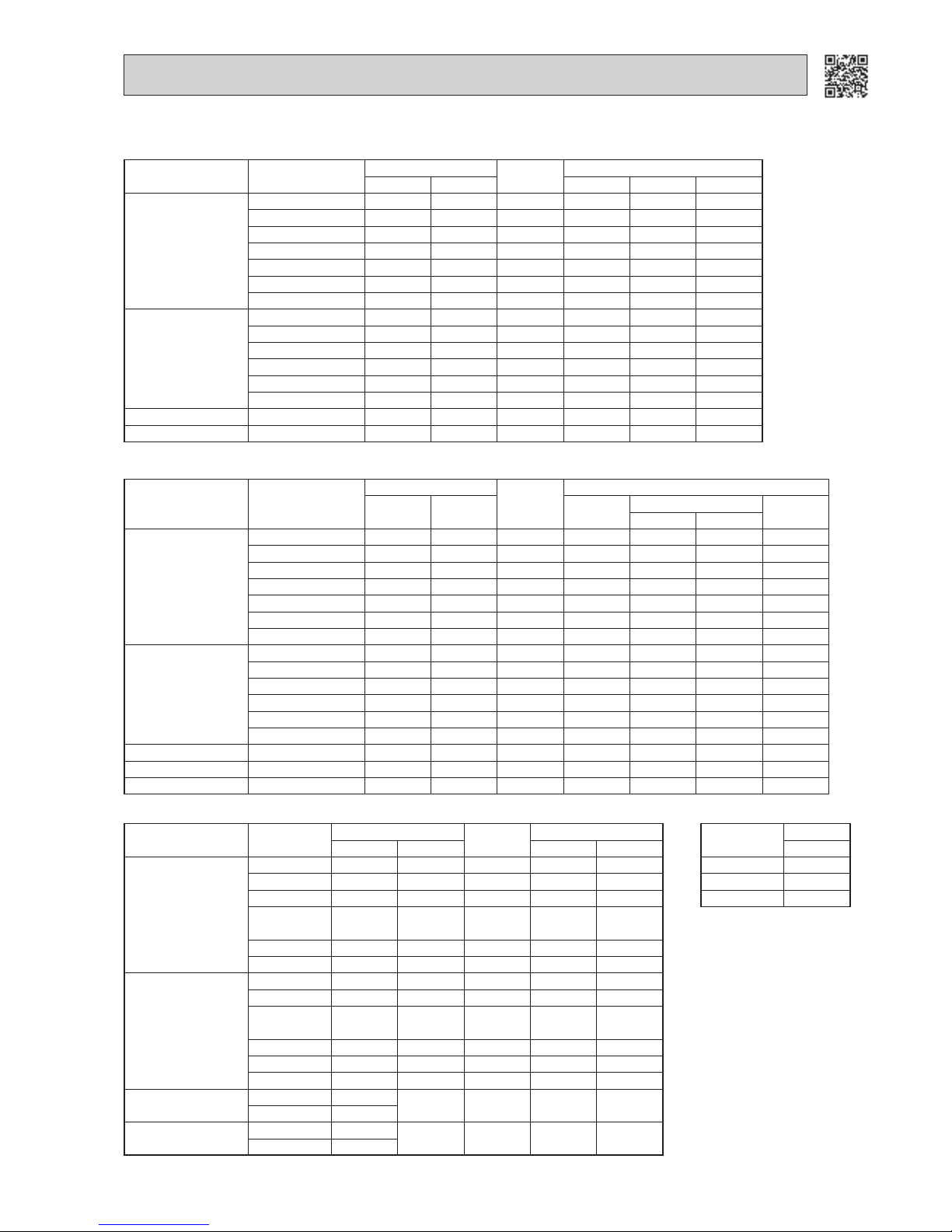
35
MXZ-3B68VA MXZ-4B71VA
MXZ-3C68VA MXZ-4C71VA
Number of operating
unit
Capacity code
COOL (Hz)
DRY (Hz)
HEAT (Hz)
Min. Max. Min. Max. Defrost
1
1,2 20 52 20 36 52 52
3,4 20 52 20 36 70 70
7 205820367676
9 207636367676
10 26 76 36 36 76 76
12 26 76 44 36 76 76
13 26 76 44 36 76 76
2
~4 26 76 30 44 85 76
5~7 26 76 39 44 85 76
8~10 26 76 39 44 85 76
11~13 26 76 39 44 85 76
14~16 26 76 40 44 85 76
17~ 26 76 48 44 85 76
3 3~ 3076484411476
4 4~ 3976646411476
MXZ-4B80VA MXZ-5B100VA
MXZ-4C80VA MXZ-5C100VA
Number of operating
unit
Capacity code
COOL (Hz)
DRY (Hz)
HEAT (Hz)
Min. Max. Min.
Max.
Defrost
4B 5B
1
1,2 15 40 15 22 58 58 58
3,4 15 58 18 22 70 70 70
7 15581822707070
9 15683122808080
10 18 68 31 22 80 80 80
12 18 68 42 22 90 90 80
13 18 79 42 22 90 90 80
2
~4 24 72 30 35 80 80 80
5~7 24 80 30 35 80 80 80
8~10 24 80 31 35 80 80 80
11~13 24 90 31 35 94 94 80
14~16 24 90 31 35 94 94 80
17~ 24 90 52 35 94 94 80
3 3~ 429042399410580
4 4~ 539453529412080
5 5~ 539453529412080
MXZ-6C120VA
Number of operating
unit
Capacity code
COOL (Hz)
DRY (Hz)
HEAT (Hz)
Min. Max. Max. Defrost
1
2 1540158548
3,4 15 40 15 85 48
7 1540158548
9,10
15 (code 9)/
18 (code 10)
52 22 85 48
12 18 52 28 85 48
13 18 57 28 85 48
2
~4 15 53 22 85 48
5~7 15 62 22 85 48
8~10
15 (code 8,9)/
18 (code 10)
62 22 85 48
11~13 18 65 22 85 48
14~16 18 65 22 85 48
17~ 18 65 37 85 48
3,4
3~9 15
80 38 93 48
10~ 18
5,6
5~9 15
84 42 110 48
10~ 18
Connecting
units
HEAT (Hz)
Min.
218
3,4 18
5,6 18
Page 36

36
3-4. HEAT DEFROSTING CONTROL
(1) Starting conditions of defrosting
When the following conditions a) ~ c) are satisfied, the defrosting starts.
a) The defrost thermistor reads -2.3°C or less.
b) The cumulative operation time of the compressor has reached any of the set values
(31, 35, 45, 55, 65, 75, 85, 95,
105, 115, 150 minutes).
c) More than 5 minutes have passed since the start-up of the compressor.
Set value of compressor operation time (hereinafter referred to as defrost interval)
This is decided by the temperature of defrost thermistor and ambient temperature thermistor, the previous defrosting
time. For example, the first defrost interval is 40 minutes long, and the second is 45 minutes long. The third and subsequent intervals are set to be longer, and less frequent, depending on defrosting time.
The third and subsequent defrost intervals follow any of the three patterns …5 or 10 to 20 minutes longer, the same,
or 5 or 10 to 20 minutes shorter compared with the previous defrost interval … with the longest 125 minutes and the
shortest 40 minutes.
(2) Releasing conditions of defrosting
Defrosting is released when any of the following conditions is satisfied:
a) The defrost thermistor continues to read 10.4°C (MXZ-2B/3B/4B71/3C/4C71)/13°C (MXZ-4B80/5B/4C80/5C/6C).
b) Defrosting time exceeds 10 minutes.
c) Any other mode than HEAT mode is set during defrosting.
3-5. DISCHARGE TEMPERATURE PROTECTION CONTROL
This protection controls the compressor ON/OFF and operation frequency according to temperature of the discharge tem-
perature thermistor.
(1) Compressor ON/OFF
When the temperature of the discharge temperature thermistor exceeds 116°C (MXZ-2B/3B/4B/5B/3C/4C/5C)/114°C
(MXZ-6C) the control stops the compressor.
When the temperature of the discharge temperature thermistor is 80°C (MXZ-2B40/2B52/3B/4B71/3C/4C71)/100°C (MXZ-
2B30/4B80/5B/4C80/5C/6C) or less, the controls start the compressor.
(2) Compressor operation frequency
When the temperature of the discharge temperature thermistor is expected to be higher than 116°C (MXZ-2B/3B/4B/5B/
3C/4C/5C)/113°C (MXZ-6C) the control decreases 12 Hz from the current frequency.
When the temperature of the discharge temperature thermistor is expected to be higher than 111°C and less than 116°C
(MXZ-2B/3B/4B/5B/3C/4C/5C)/113°C (MXZ-6C) the control decreases 6 Hz from the current frequency.
When the temperature of the discharge temperature thermistor is expected to be higher than 104°C and less than 111°C,
the control is set at the current frequency.
3-6. REFRIGERANT RECOVERY CONTROL ON HEATING
MXZ-2B30VA MXZ-2B40VA MXZ-2B52VA
<Control status>
The control performs when the all the following status are satisfied;
• When one or more indoor units are operating in HEAT mode. (Excluding thermostat OFF)
• When the discharge temperature becomes 107°C or more.
• When it passed 60 minutes or more since the operation has started or the last refrigerant recovery has controlled.
<Control details>
LEV opening of indoor unit not operating is controlled to be 80 pulse.
<Control finish status>
The control finishes either as follows. However, the LEV opening is considered to be 59 pulse.
• When it passed 60 seconds since the control has started.
• When the discharge temperature is 90°C or less.
Page 37
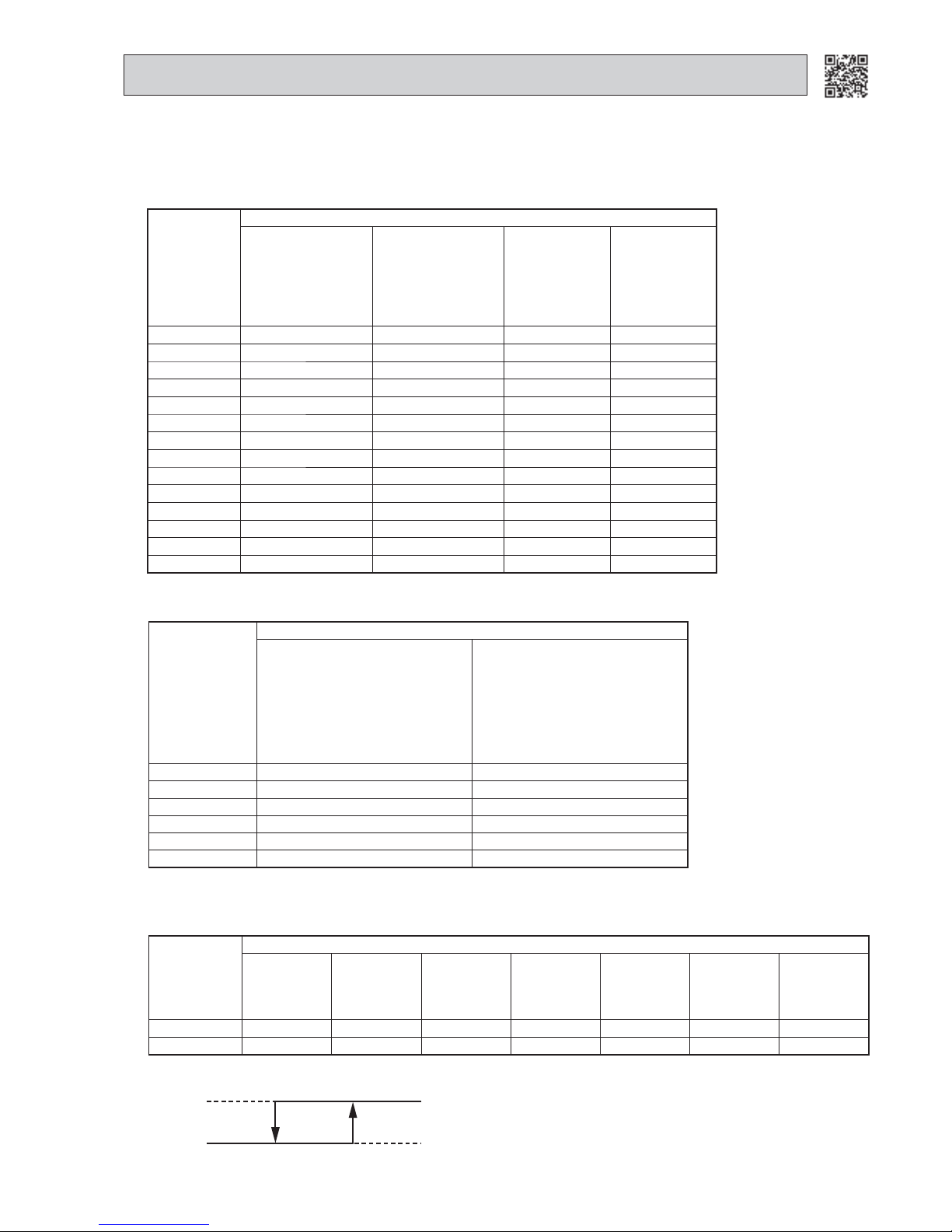
37
MXZ-3B54VA MXZ-3B68VA MXZ-4B71VA MXZ-4B80VA MXZ-5B100VA
MXZ-3C54VA MXZ-3C68VA MXZ-4C71VA MXZ-4C80VA MXZ-5C100VA MXZ-6C120VA
COOL
Fan speed changes so that the condensing temperature stays within the target range.
Fan speed
Revolution per minutes (rpm)
MXZ-2B30VA
MXZ-2B40VA
MXZ-2B52VA
MXZ-3B54VA
MXZ-3B68VA
MXZ-4B71VA
MXZ-3C54VA
MXZ-3C68VA
MXZ-4C71VA
MXZ-4B80VA
MXZ-5B100VA
MXZ-4C80VA
MXZ-5C100VA
MXZ-6C120VA
1 100 100 100 120
2 150 150 150 150
3 200 200 200 175
4 250 250 250 225
5 300 300 300 275
6 350 350 350 325
7 400 400 400 325
8 450 450 450 425
9 500 500 500 425
10 550 550 550 525
11 600 600 600 575
12 700 650 650 585
13 800 700 700 590
14 900 750 750 750
Frequency (Hz)
Target condensing temperature (ºC)
MXZ-2B30/40/52VA
MXZ-3B54/68VA
MXZ-4B71/80VA
MXZ-5B100VA
MXZ-3C54/68VA
MXZ-4C71/80VA
MXZ-5C100VA
MXZ-6C120VA
~24 31~35 38~42
25~34 33~37 37~41
35~44 35~39 37~41
45~54 37~41 37~41
55~64 37~41 37~41
65~ 37~41 37~41
Up
Down
Fan speed
High
Low
Compressor frequencyMin. Max.
3-7. OUTDOOR FAN CONTROL
HEAT
Fan speed is switched according to the compressor frequency.
Fan speed
Compressor speed (Hz)
MXZ-2B30VA MXZ-2B40VA MXZ-2B52VA
MXZ-3B54VA
MXZ-3C54VA
MXZ-3B68VA
MXZ-4B71VA
MXZ-3C68VA
MXZ-4C71VA
MXZ-4B80VA
MXZ-5B100VA
MXZ-4C80VA
MXZ-5C100VA
MXZ-6C120VA
Up 71 56 40 58 30 50 53
Down 53 42 30 52 23 40 40
Page 38

38
2. Coil frost prevention
Coil frost prevention is as same as COOL mode. (3-8.2.)
3-10. DRY OPERATION
1. Thermostat control
Thermostat is ON or OFF by the difference between room temperature and set temperature.
ON -1°C or more
OFF less than -1°C
-1°C -0.7°C
Room temperature minus
set temperature (During operation)
Room temperature minus
set temperature (Initial)
Thermostat
3-9. COOL OPERATION
2. Coil frost prevention
The the compressor operational frequency is controlled to prevent the indoor heat exchanger temperature from falling
excessively.
Compressor is turned OFF for 5 minutes when the temperature of indoor coil thermistor continues 3°C or less for 5 minutes or more.
1. Thermostat control
Thermostat is ON or OFF by the difference between room temperature and set temperature.
ON -1°C or more
OFF less than -1°C
-1°C -0.7°C
Room temperature minus
set temperature (During operation)
Room temperature minus
set temperature (Initial)
Thermostat
3-8. PRE-HEAT CONTROL
The compressor is energized even while it is not operating.
This is to generate heat at the winding to improve the compressor's start-up condition.
NOTE: When the unit is started with the remote controller, pre-heat control is turned OFF.
Compressor uses 50 W when pre-heat control is turned ON.
1. Pre-heat control is turned ON for 15 or 30 minutes after the breaker is turned ON.
2. 30 minutes after the unit is stopped, pre-heat control is turned ON for 15 or 30 minutes
and turned OFF for 30 minutes.
This is repeated as shown in the graph until the breaker is turned OFF.
When the defrost thermistor reads less than 21°C, pre-heat control is ON for 30 minutes.
When the defrost thermistor reads 21°C or more, pre-heat control is ON for 15 minutes.
Power ON
OFF
Compressor ON
OFF
Defrost thermistor
30 minutes 30 minutes 30 minutes 30 minutes 30 minutes 30 minutes
15
minutes
15
minutes
30minutes
30minutes
Pre-heat ON
OFF
Breaker ON
21°C
Stop
operation
Start
operation
When the defrost
thermistor reads
21°C or more
Page 39

39
3-11. HEAT OPERATION
2. High pressure protection
In HEAT operation the indoor coil thermistor detects the temperature of the indoor heat exchanger. The compressor operational frequency is controlled to prevent the condensing pressure from increasing excessively.
1. Thermostat control
Thermostat turns ON or OFF by difference between room temperature and set temperature.
ON less than 1°C
OFF 1°C or more
0.7°C 1°C
Thermostat
Room temperature minus
set temperature (Initial)
Room temperature minus
set temperature (During operation)
Page 40

HEAD OFFICE: TOKYO BLDG.,2-7-3, MARUNOUCHI, CHIYODA-KU, TOKYO 100-8310, JAPAN
New publication, effective Nov. 2010
Specifications subject to change without notice.
© Copyright 2007 MITSUBISHI ELECTRIC CO.,LTD
Distributed in Nov. 2010. No. OBT17 REVISED EDITION-G
Distributed in Jan. 2010. No. OBT17 REVISED EDITION-F 5
Distributed in Oct. 2009. No. OBT17 REVISED EDITION-E 6
Distributed in Dec. 2008. No. OBT17 REVISED EDITION-D 6
Distributed in Aug. 2008. No. OBT17 REVISED EDITION-C 5
Distributed in Apr. 2008. No. OBT17 REVISED EDITION-B 7
Distributed in Aug. 2007. No. OBT17 REVISED EDITION-A 7
Distributed in Feb. 2007. No. OBT17 7
Made in Japan
 Loading...