

Mitsubishi Electric Mr. Slim MUZ-D30NA, Mr. Slim MUZ-D36NA, Mr. Slim MUY-D30NA, Mr. Slim MUY-D36NA Service Manual
SERVICE MANUAL
CONTENTS
1. TECHNICAL CHANGES ··································· 3
2. PART NAMES AND FUNCTIONS ····················· 3
3. SPECIFICATION ················································ 4
4. OUTLINES AND DIMENSIONS ························ 6
5. WIRING DIAGRAM ············································ 7
6. REFRIGERANT SYSTEM DIAGRAM ··············11
7. DATA ································································ 13
8. ACTUATOR CONTROL ··································· 20
9. SERVICE FUNCTIONS ··································· 21
10. TROUBLESHOOTING ····································· 22
11. DISASSEMBLY INSTRUCTIONS ···················· 41
Models
MUZ-D30NA / -
1
/ - U1 / -
U2
MUZ-D36NA / -
1
/ - U1 / -
U2
MUY-D30NA / -
1
MUY-D36NA / -
1
SPLIT-TYPE AIR CONDITIONERS
OUTDOOR UNIT
Indoor unit service manual
MSZ-D•NA Series (OBH501)
MSY-D•NA Series (OBH501)
NOTE:
RoHS compliant products have <G> mark on the spec name plate.
TM
HFC
utilized
R410A
No. OBH502
REVISED EDITION-B
PARTS CATALOG (OBB502)
Revision B:
• MUZ-D•NA-1/-U2 and MUY-D•NA-1 have
been corrected.
Please void OBH502 REVISED EDITION-A.

2
Revision A:
• 3. SPECIFICATION has been corrected.
Revision B:
• MUZ-D•NA-1/-U2 and MUY-D•NA-1 have been corrected.
3
MUZ-D30NA MUZ-D30NA-
U1
MUZ-D36NA MUZ-D36NA-
U1
MUY-D30NA
MUY-D36NA
1. New model
MUZ-D30NA → MUZ-D30NA-
1
MUZ-D30NA-U1 → MUZ-D30NA-
U2
MUZ-D36NA → MUZ-D36NA-
1
MUZ-D36NA-U1 → MUZ-D36NA-
U2
MUY-D30NA → MUY-D30NA-
1
MUY-D36NA → MUY-D36NA-
1
1. Wiring diagram has been changed.
2. Fan motor has been changed.
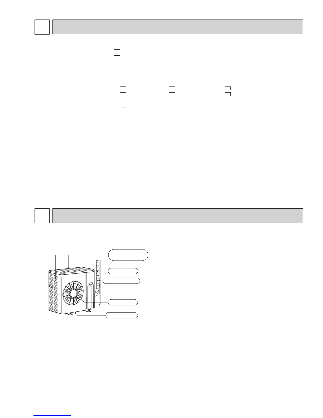
PART NAMES AND FUNCTIONS
2
MUZ-D30NA MUZ-D36NA MUY-D30NA MUY-D36NA
Piping
Air outlet
Drain hose
Drain outlet
Air inlet
(back and side)
1
TECHNICAL CHANGES
4
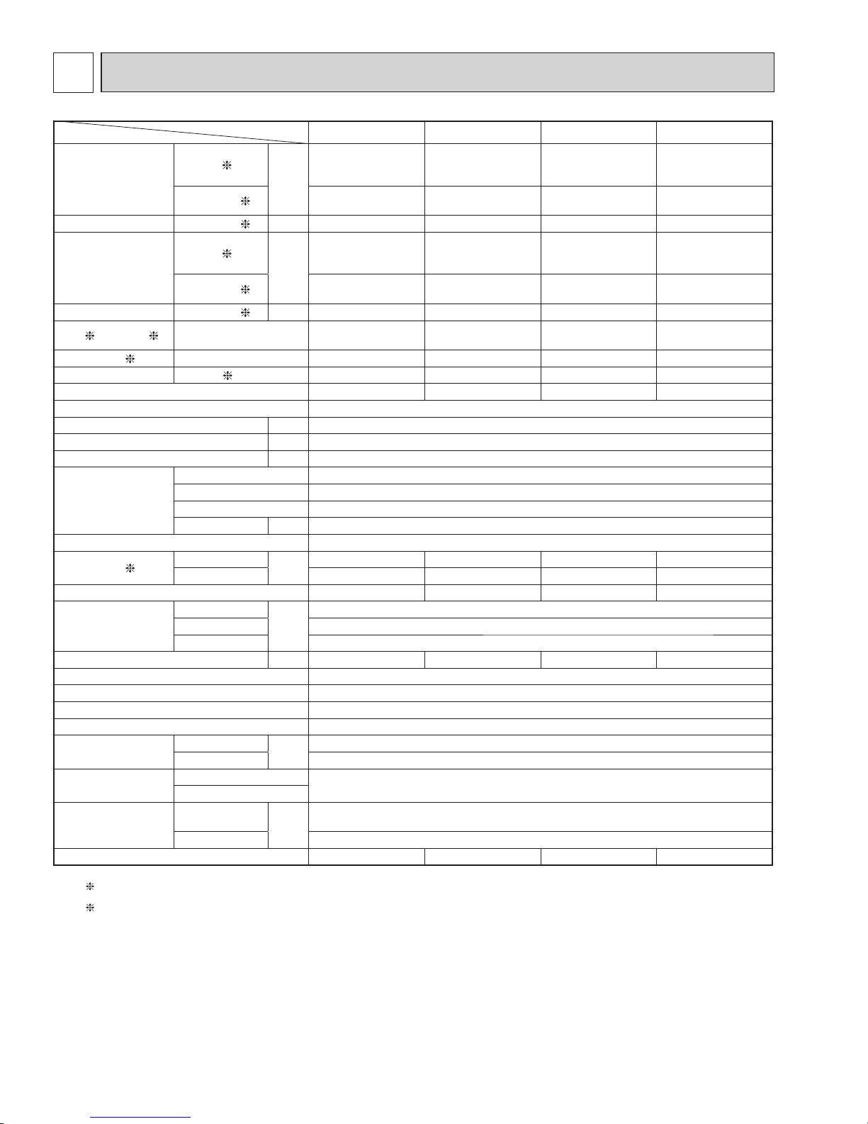
Item Model MSZ-D30NA MSY-D30NA MSZ-D36NA MSY-D36NA
Capacity
Rated (Minimum ~
Maximum)
Cooling 1
Btu/h
30,700
(9,800 ~ 30,700)
30,700
(9,800 ~ 30,700)
32,000/33,200
(9,800 ~ 32,000) /
(9,800 ~ 33,200)
33,200/34,600
(9,800 ~ 33,200) /
(9,800 ~ 34,600)
Heating 47
1
32,600
(8,700 ~ 34,000)
—
35,200
(8,700 ~ 36,000)
—
Capacity Heating 17 2 Btu/h 20,800 — 22,800 —
Power consumption
Rated (Minimum ~
Maximum)
(TOTAL)
Cooling 1
W
3,850
(620 ~ 3,850)
3,380
(620 ~ 3,380)
4,140/4,360
(620 ~ 4,140) /
(620 ~ 4,360)
4,
210/4,240
(620 ~ 4,210) /
(620 ~ 4,240)
Heating 47 1
3,360
(520 ~ 3,600)
—
3,840
(520 ~ 4,100)
—
Power consumption Heating 17 2 W 2,620 — 3,000 —
EER
1
[SEER] 3 Cooling 8.0 [14.5] 9.1 [16.0]
7.7/7.6
[14.5]
7.9/8.2
[15.1]
HSPF IV(V)
4 Heating 8.2 (6.7) — 8.2 (6.7) —
COP Heating 1 2.84 — 2.69 —
Outdoor unit model MUZ-D30NA MUY-D30NA MUZ-D36NA MUY-D36NA
Power supply V , phase , Hz 208/230 , 1 , 60
Max. fuse size (time delay) A 25
Min. circuit ampacity A 21
Fan motor F.L.A 0.93
Compressor
Model TNB220FMCHT
R.L.A 16
L.R.A 20
Refrigeration oil cc 870 (NEO22)
Refrigerant control Linear expansion valve
Sound level 1
Cooling
dB(A)
55 55 56 56
Heating 57 — 57 —
Defrost method Reverse cycle — Reverse cycle —
Dimensions
W
in.
33-1/16
D13
H 33-7/16
Weight Ib. 141 126 141 126
External fi nish Munsell 3Y 7.8/1.1
Remote controller Wireless type
Control voltage (by built-in transformer) 12 - 24 VDC
Refrigerant piping Not supplied
Refrigerant pipe size
(Min. wall thickness)
Liquid
in.
3/8 (0.0315)
Gas 5/8 (0.0394)
Connection method
Indoor
Flared
Outdoor
Between the indoor
& outdoor units
Height
difference
ft.
50
Piping length 100
Refrigerant charge (R410A) 4 lb. 10 oz. 4 lb. 4 lb. 10 oz. 4 lb.
NOTE: Test conditions are based on ARI 210/240.
1: Rating conditions (Cooling) — Indoor: 80˚FDB, 67˚FWB, Outdoor: 95˚FDB, (75˚FWB) Rated frequency
(Heating) — Indoor: 70˚FDB, 60˚FWB, Outdoor: 47˚FDB, 43˚FWB Rated frequency
2: (Heating) — Indoor: 70˚FDB, 60˚FWB, Outdoor: 17˚FDB, 15˚FWB Maximum frequency
3
SPECIFICATION
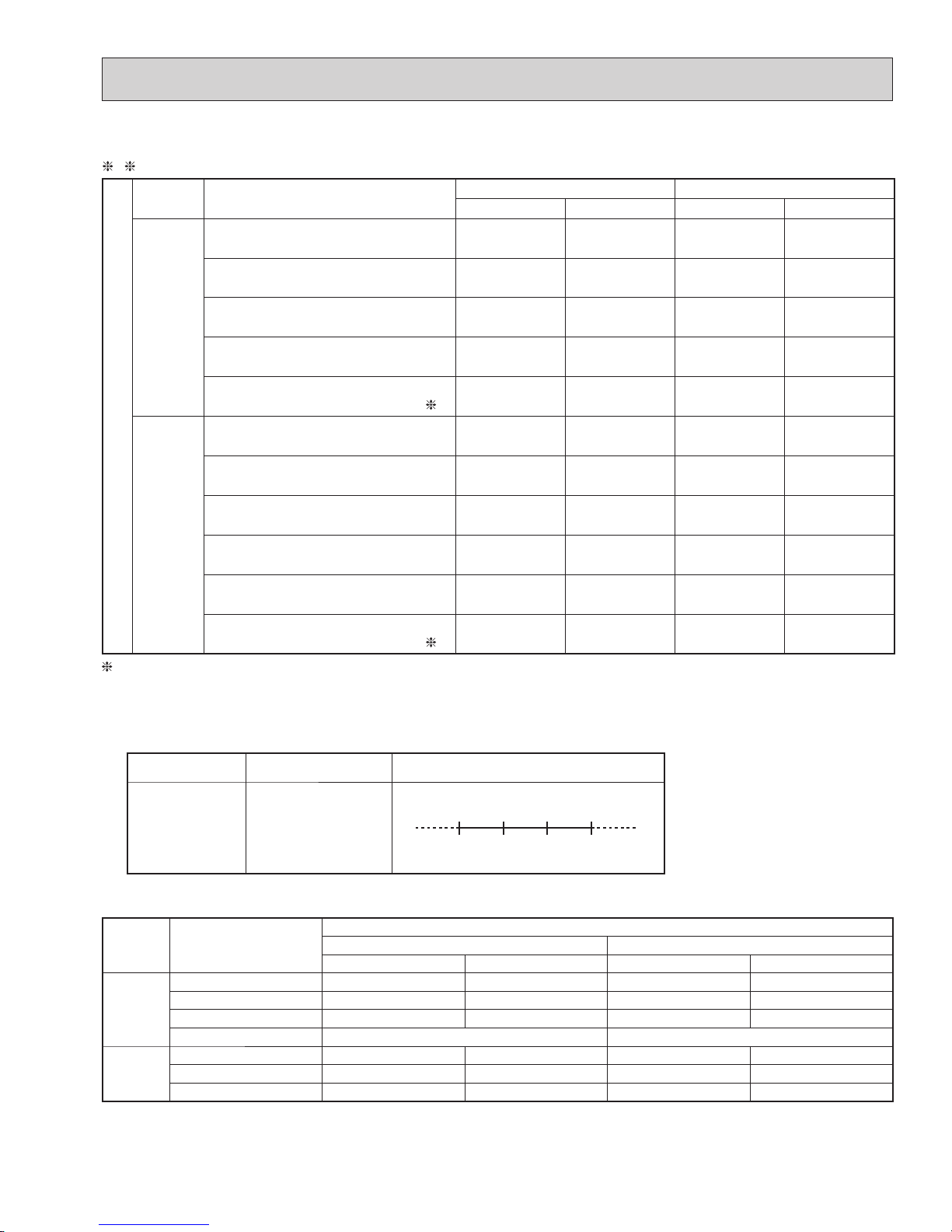
5
Test condition
ARI
Mode Test
Indoor air condition (°F) Outdoor air condition (°F)
Dry bulb Wet bulb Dry bulb Wet bulb
SEER
(Cooling)
"A" Cooling Steady State
at rated compressor Speed
80 67 95 (75)
"B-2" Cooling Steady State
at rated compressor Speed
80 67 82 (65)
"B-1" Cooling Steady State
at minimum compressor Speed
80 67 82 (65)
Low ambient Cooling Steady State
at minimum compressor Speed
80 67 67 (53.5)
Intermediate Cooling Steady State
at Intermediate compressor Speed 5
80 67 87 (69)
HSPF
(Heating)
Standard Rating-Heating
at rated compressor Speed
70 60 47 43
Low temperature Heating
at rated compressor Speed
70 60 17 15
Max temperature Heating
at minimum compressor Speed
70 60 62 56.5
High temperature Heating
at minimum compressor Speed
70 60 47 43
Frost Accumulation
at rated compressor Speed
70 60 35 33
Frost Accumulation
at Intermediate compressor Speed
5
70 60 35 33
5: At Intermediate compressor Speed
=("Cooling rated compressor speed" - "minimum compressor speed") / 3 + "minimum compressor speed".
3, 4
OPERATING RANGE
(1) POWER SUPPLY
Rated voltage Guaranteed voltage (V)
Outdoor unit
208/230 V
1 phase
60 Hz
Min. 187
208 230 Max. 253
(2) OPERATION
Mode Condition
Intake air temperature (°F)
Indoor Outdoor
DB WB DB WB
Cooling
Standard temperature 80 67 95 —
Maximum temperature 90 73 115 —
Minimum temperature 67 57 14 —
Maximum humidity 78% —
Heating
Standard temperature 70 60 47 43
Maximum temperature 80 67 75 65
Minimum temperature 70 60 14 13
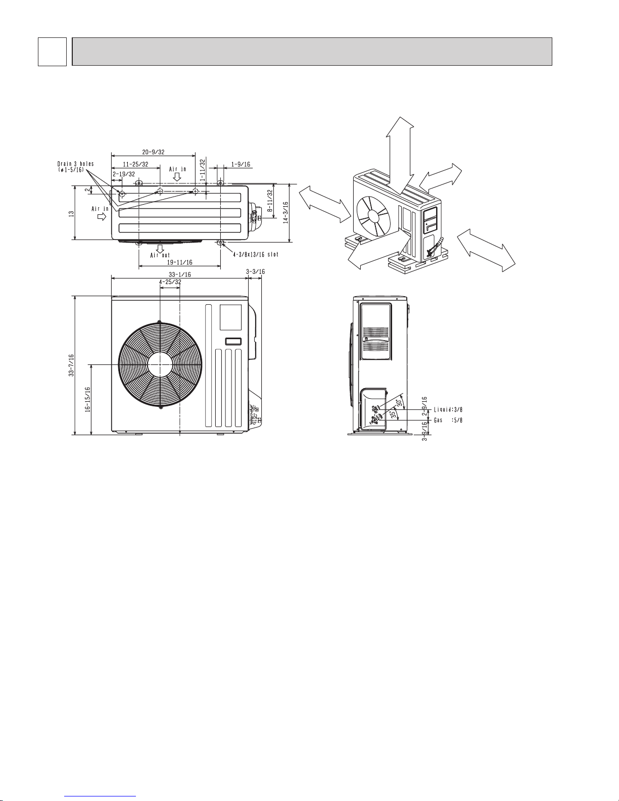
6
Open as a rule
20 inch or more if
the front and both
sides are open
4 inch or more /
8 inch or more if
there are obstacles
to both sides
Open as a rule
20 inch or more if the back,
both sides and top are open
14 in. or more
4 in. or more
REQUIRED SPACE
Unit: inch
MUZ-D30NA MUZ-D36NA MUY-D30NA MUY-D36NA
4
OUTLINES AND DIMENSIONS
7
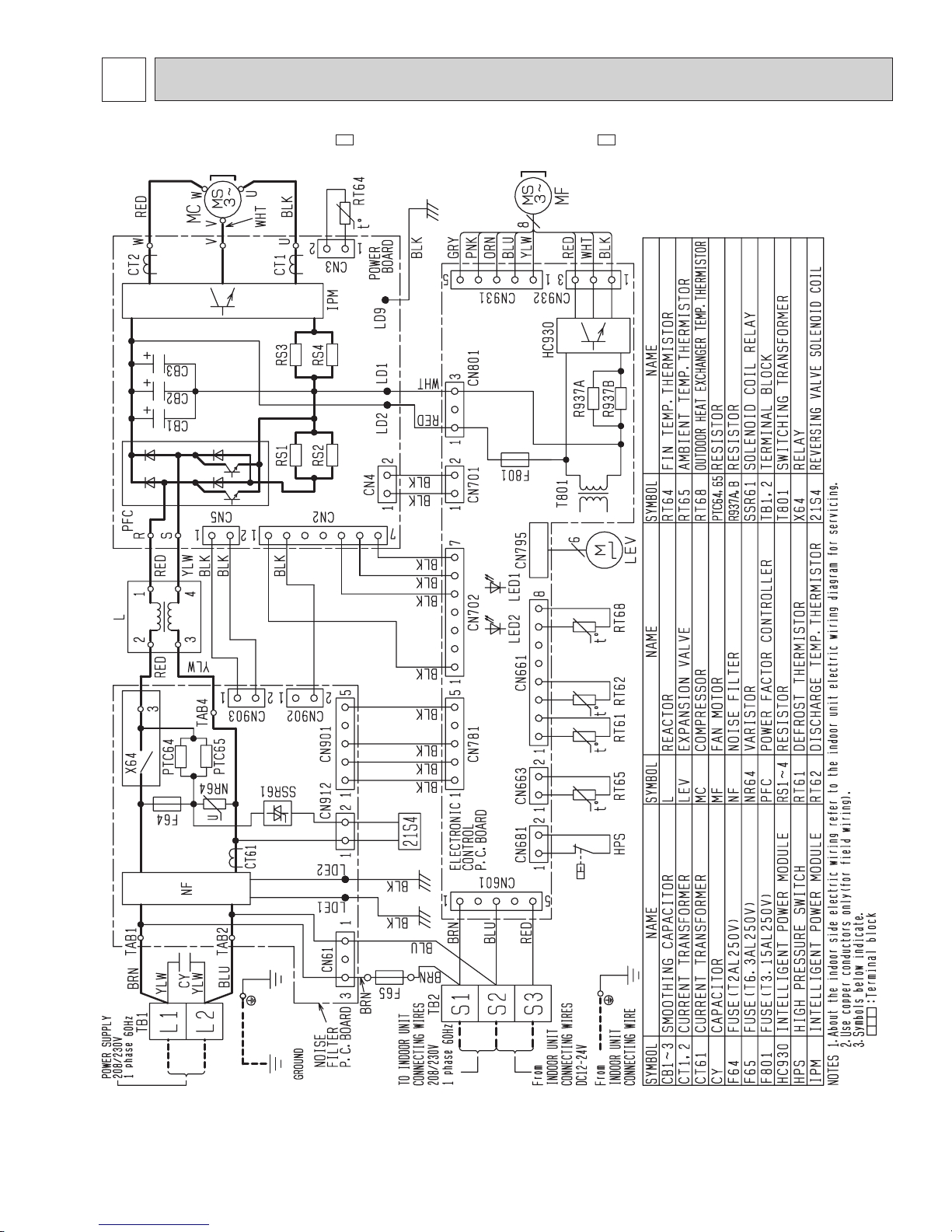
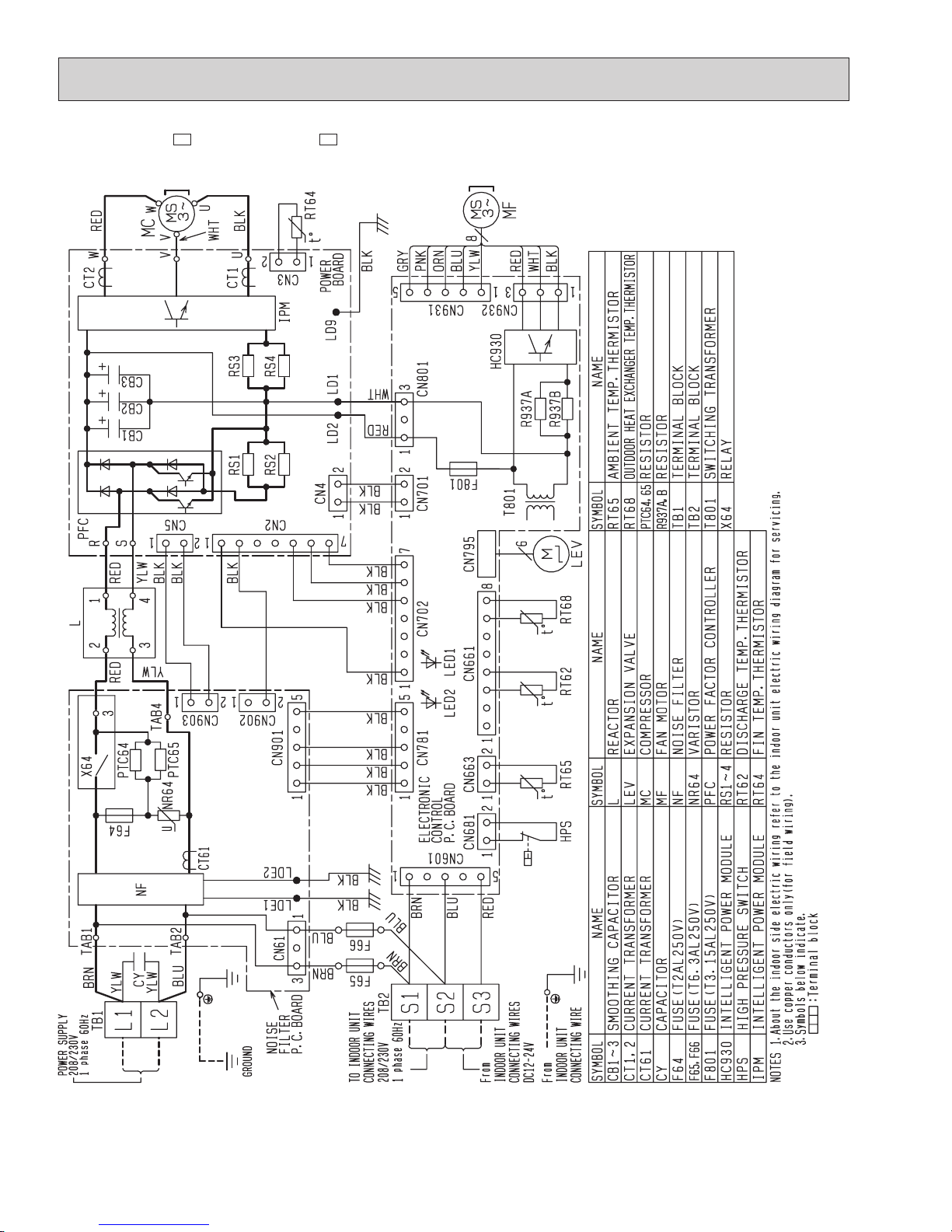
MUZ-D30NA MUZ-D30NA-
U1
MUZ-D36NA MUZ-D36NA-
U1
5
WIRING DIAGRAM
8
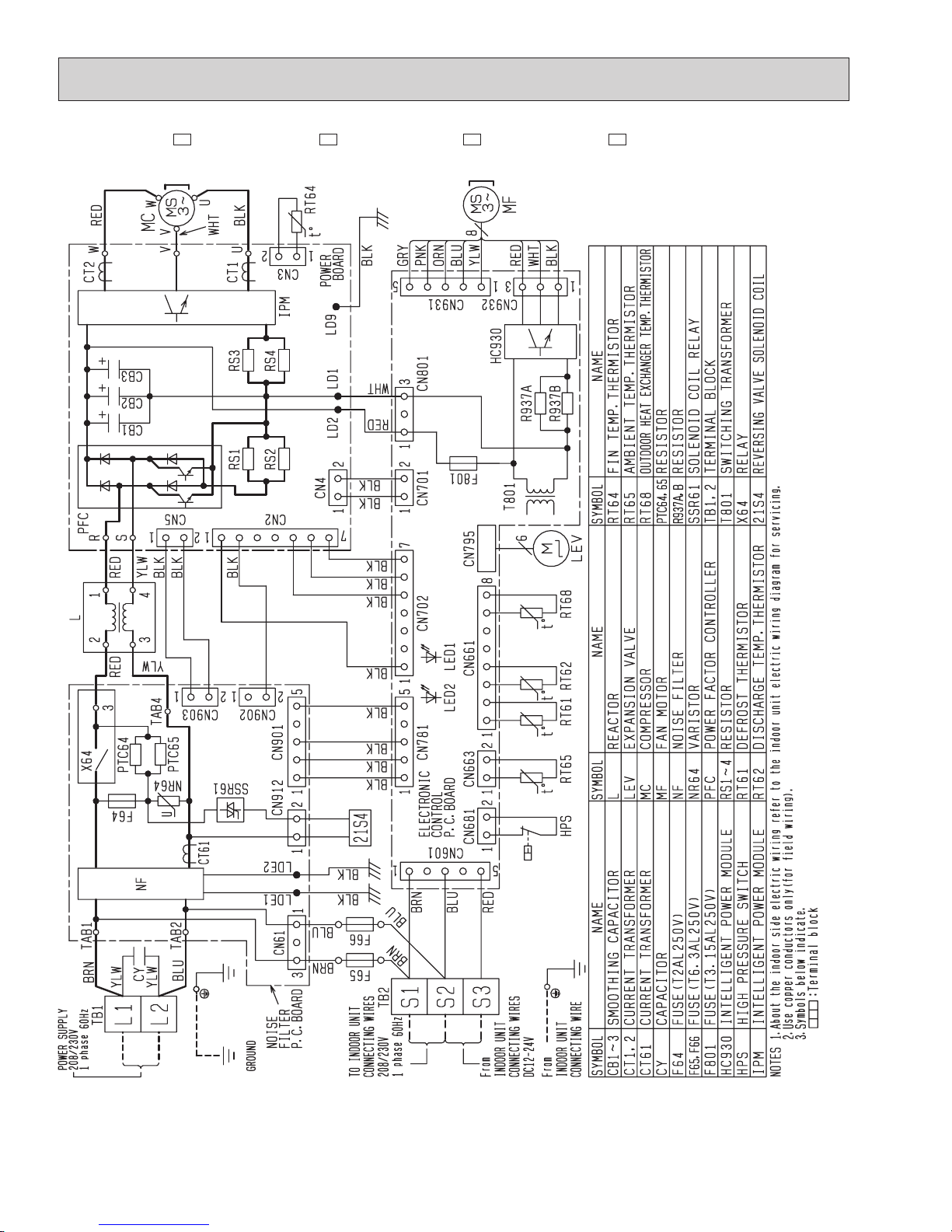
MUZ-D30NA-1 MUZ-D30NA-
U2
MUZ-D36NA-1 MUZ-D36NA-
U2
9
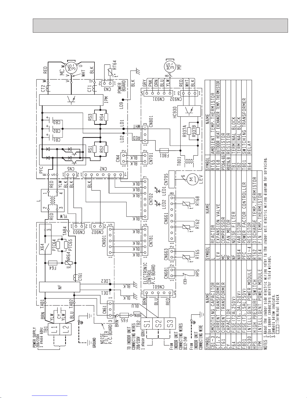
MUY-D30NA MUY-D36NA
10
MUY-D30NA-1 MUY-D36NA-
1
11
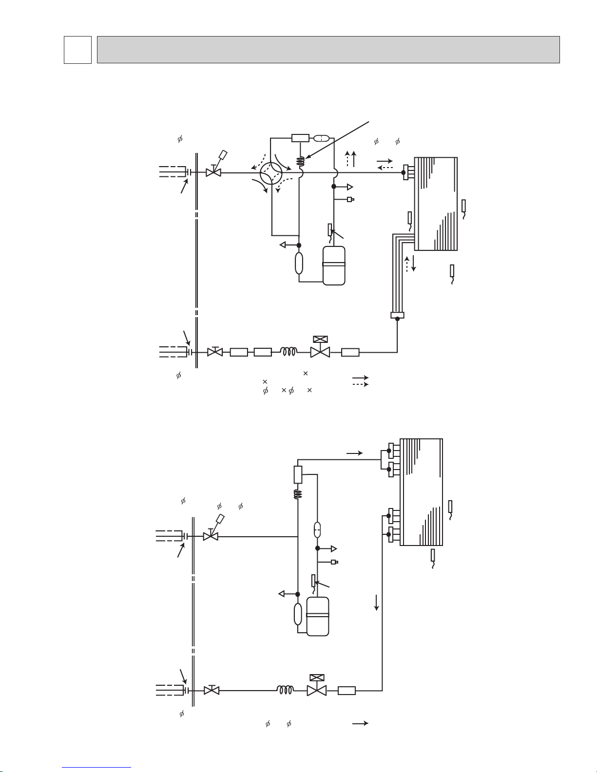
Unit: inch
MUZ-D30NA MUZ-D36NA
MUY-D30NA MUY-D36NA
Outdoor
heat
exchanger
Flared connection
Defrost
thermistor
RT61
Service
port
Service
port
Discharge
temperature
thermistor
RT62
Flared connection
Stop valve
Stop valve
(with service port)
Capillary tube
Refrigerant flow in cooling
Compressor
4-way valve
Refrigerant flow in heating
LEV
R.V. coil
heating ON
cooling OFF
Strainer
#100
Receiver
Outdoor heat
exchanger
temperature
thermistor
RT68
Ambient
temperature
thermistor
RT65
Strainer
#100
Refrigerant pipe
5/8
(with heat insulator)
Refrigerant pipe 3/8
(with heat insulator)
O.D. 0.142 I.D. 0.094
1-31/32
(
3.6 2.4 50
)
Oil
separator
Strainer
#100
High-pressure
Switch
Capillary tube
O.D. 0.071 x I.D. 0.024
x 39-3/8
( 1.8 x 0.6 x 1,000)
O.D. 0.142 x I.D. 0.094
x 1-31/32
( 3.6 x 2.4 x 50)
Capillary tube
High-pressure
Switch
Flared connection
Discharge
temperature
thermistor
RT62
Flared connection
Stop valve
Stop valve
(with service port)
Capillary tube
Refrigerant flow in cooling
Refrigerant pipe 5/8
(with heat insulator)
Refrigerant pipe 3/8
(with heat insulator)
Strainer
#100
Strainer
#100
Oil separator
Outdoor
heat
exchanger
Ambient
temperature
thermistor
RT65
Outdoor heat
exchanger
temperature
thermistor
RT68
Compressor
Service
port
LEV
Service
port
O.D. 0.071 x I.D. 0.024
x 39-3/8
( 1.8 x 0.6 x 1,000)
6
REFRIGERANT SYSTEM DIAGRAM
Unit: inch
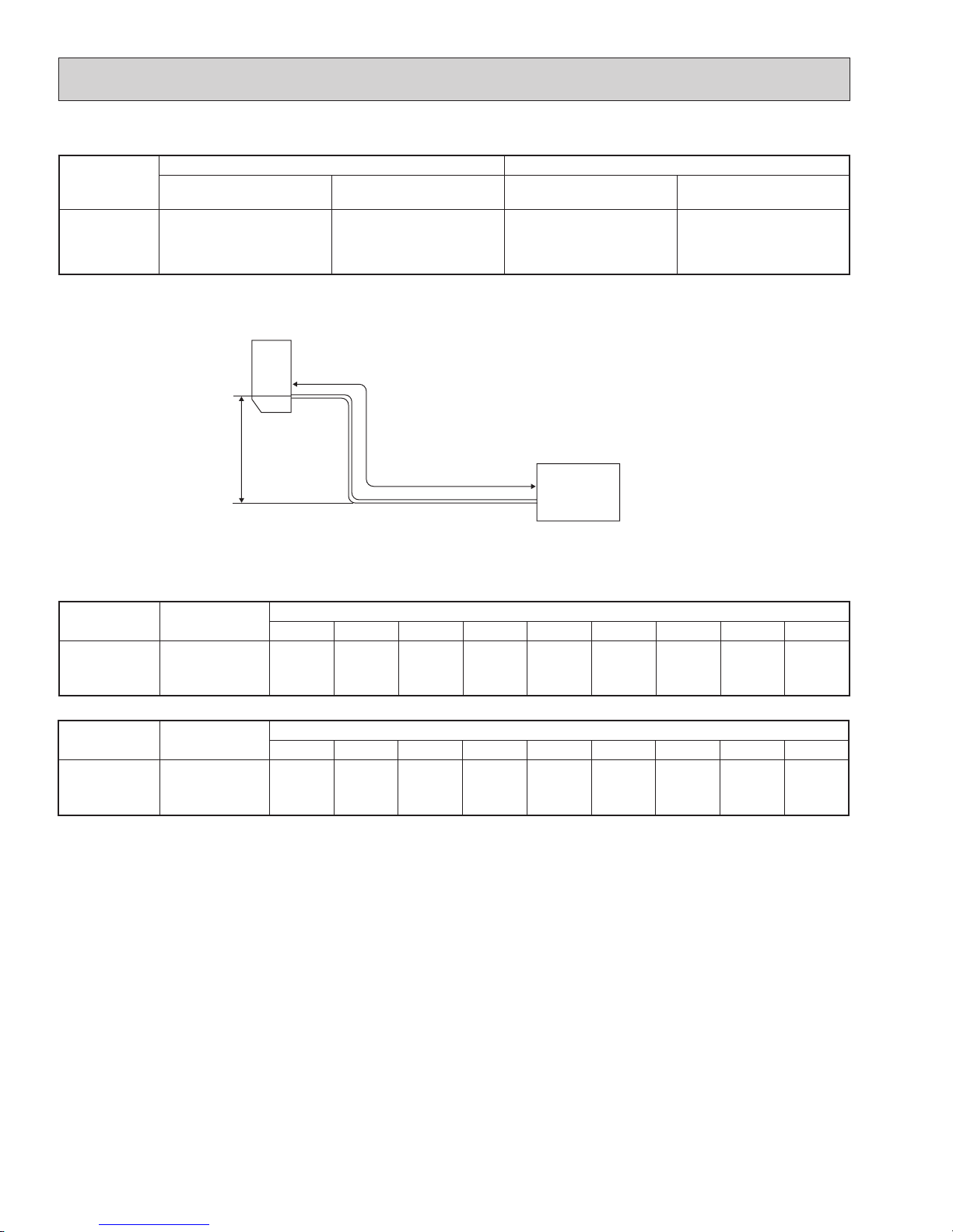
12
Max. Length
A
Max. Height
difference
B
Indoor
unit
Outdoor unit
MAX. REFRIGERANT PIPING LENGTH and MAX. HEIGHT DIFFERENCE
Model
Refrigerant piping: ft. Piping size O.D: in.
Max. Length
A
Max. Height difference
B
Gas Liquid
MUZ-D30NA
MUZ-D36NA
MUY-D30NA
MUY-D36NA
100 50 5/8 3/8
ADDITIONAL REFRIGERANT CHARGE (R410A: oz.)
Refrigerant piping exceeding 25 ft. requires additional refrigerant charge according to the calculation.
Model
Outdoor unit
precharged
Refrigerant piping length (one way): ft.
25 30 40 50 60 70 80 90 100
MUZ-D30NA
MUZ-D36NA
4 lb. 10 oz. 0 2.96 8.88 14.80 20.72 26.64 32.56 38.48 44.40
Calculation: X oz. = 2.96/5 oz. / ft. × (Refrigerant piping length (ft.) - 25)
Model
Outdoor unit
precharged
Refrigerant piping length (one way): ft.
25 30 40 50 60 70 80 90 100
MUY-D30NA
MUY-D36NA
4 lb. 0 1.08 3.24 5.40 7.56 9.72 11.88 14.04 16.20
Calculation: X oz. = 1.08/5 oz. / ft. × (Refrigerant piping length (ft.) - 25)
NOTE: Refrigerant piping exceeding 25 ft. requires additional refrigerant charge according to the calculation.
13
MUZ-D30NA MUZ-D36NA MUY-D30NA MUY-D36NA
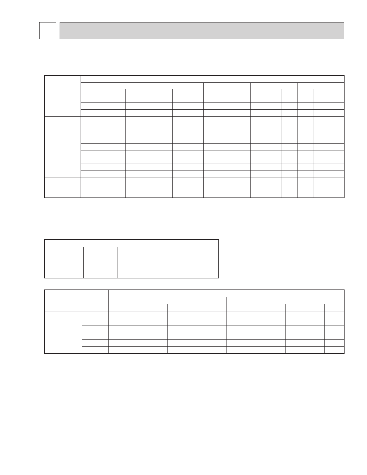
7-1. PERFORMANCE DATA
1) COOLING CAPACITY
Model
Indoor air Outdoor intake air DB temperature (˚F)
IWB (˚F)
75 85 95 105 115
TC SHC TPC TC SHC TPC TC SHC TPC TC SHC TPC TC SHC TPC
MUZ-D30NA
71 37.6 19.1 3.43 35.2 17.8 3.75 33.0 16.7 4.04 30.7 15.6 4.25 28.2 14.3 4.43
67 35.6 22.8 3.23 33.2 21.2 3.56 30.7 19.6 3.85 28.6 18.3 4.08 26.2 16.8 4.27
63 33.5 25.9 3.08 31.0 24.0 3.41 28.9 22.3 3.68 26.2 20.3 3.93 23.9 18.5 4.08
MUZ-D36NA
71 40.7 19.8 3.88 38.0 18.5 4.25 35.7 17.4 4.58 33.2 16.2 4.82 30.5 14.9 5.01
67 38.5 23.9 3.66 35.9 22.2 4.03 33.2 20.6 4.36 30.9 19.1 4.62 28.4 17.6 4.84
63 36.2 27.3 3.49 33.5 25.3 3.86 31.2 23.5 4.16 28.4 21.4 4.45 25.9 19.5 4.62
MUY-D30NA
71 37.6 19.1 3.01 35.2 17.8 3.30 33.0 16.7 3.55 30.7 15.6 3.73 28.2 14.3 3.89
67 35.6 22.8 2.84 33.2 21.2 3.13 30.7 19.6 3.38 28.6 18.3 3.58 26.2 16.8 3.75
63 33.5 25.9 2.70 31.0 24.0 2.99 28.9 22.3 3.23 26.2 20.3 3.45 23.9 18.5 3.58
MUY-D36NA
(208 V)
71 40.7 19.8 3.75 38.0 18.5 4.10 35.7 17.4 4.42 33.2 16.2 4.65 30.5 14.9 4.84
67 38.5 23.9 3.54 35.9 22.2 3.89 33.2 20.6 4.21 30.9 19.1 4.46 28.4 17.6 4.67
63 36.2 27.3 3.37 33.5 25.3 3.73 31.2 23.5 4.02 28.4 21.4 4.29 25.9 19.5 4.46
MUY-D36NA
(230 V)
71 42.4 20.6 3.77 39.6 19.3 4.13 37.2 18.1 4.45 34.6 16.8 4.69 31.8 15.5 4.88
67 40.1 24.9 3.56 37.4 23.2 3.92 34.6 21.5 4.24 32.2 20.0 4.49 29.6 18.3 4.71
63 37.7 28.4 3.39 34.9 26.3 3.75 32.5 24.5 4.05 29.6 22.3 4.32 27.0 20.3 4.49
NOTE: 1. IWB : Intake air wet-bulb temperature
TC : Total Capacity (x10
3
Btu/h)
SHC : Sensible Heat Capacity (x10
3
Btu/h)
TPC : Total Power Consumption (kW)
2. SHC is based on 80˚F of indoor Intake air DB temperature.
2) COOLING CAPACITY CORRECTIONS
Refrigerant piping length (one way: ft.)
25 (std.) 40 65 100
MUZ-D30NA
MUZ-D36NA
MUY-D30NA
MUY-D36NA
1.0 0.95 0.878 0.713
3) HEATING CAPACITY
Model
Indoor air Outdoor intake air WB temperature (˚F)
IDB (˚F)
15 25 35 43 45 55
TC TPC TC TPC TC TPC TC TPC TC TPC TC TPC
MUZ-D30NA
75 18.9 2.50 23.6 2.94 28.2 3.28 31.8 3.44 32.8 3.49 37.2 3.63
70 20.0 2.42 24.5 2.87 28.9 3.19 32.6 3.36 33.6 3.43 38.0 3.56
65 20.5 2.32 25.6 2.77 29.8 3.11 33.6 3.28 34.6 3.33 38.8 3.49
MUZ-D36NA
75 20.4 2.86 25.5 3.36 30.4 3.74 34.3 3.94 35.4 3.99 40.1 4.15
70 21.6 2.76 26.4 3.28 31.2 3.65 35.2 3.84 36.3 3.92 41.0 4.07
65 22.2 2.65 27.6 3.17 32.2 3.55 36.3 3.74 37.3 3.80 41.9 3.99
NOTE: 1. IDB : Intake air dry-bulb temperature
TC : Total Capacity (x103 Btu/h)
TPC : Total Power Consumption (kW)
2. Above data is for heating operation without any frost.
How to operate with fixed operational frequency of the compressor.
1. Press the EMERGENCY OPERATION switch on the front of the indoor unit, and select either EMERGENCY COOL
mode or EMERGENCY HEAT mode before starting to operate the air conditioner.
2. The compressor starts with operational frequency.
3. The fan speed of the indoor unit is High.
4. This operation continues for 30 minutes.
5. In order to release this operation, press the EMERGENCY OPERATION switch twice or once, or press any button on
the remote controller.
7 DATA
14
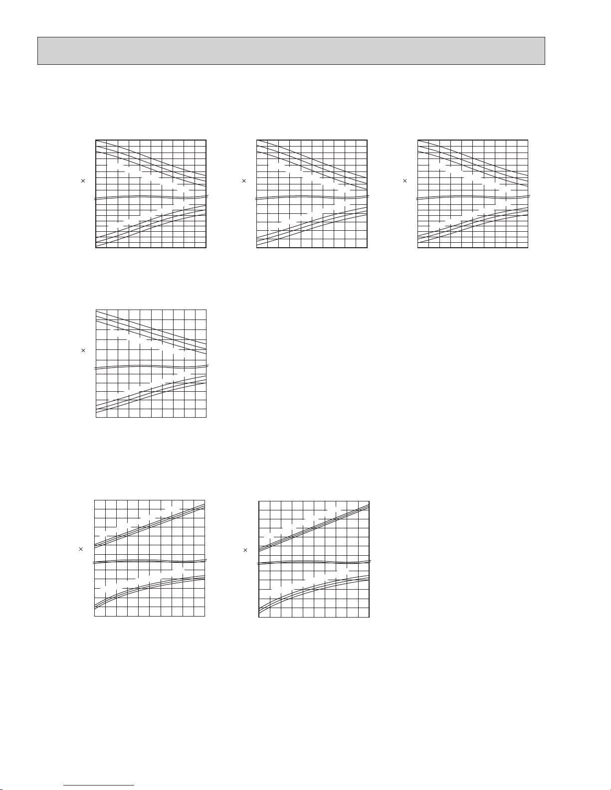
7-2. PERFORMANCE CURVE
65
70
75
75
70
65
45
40
35
30
25
20
15
Indoor intake air DB temperature (°F)
= 848 CFM
Airflow
15 25 35 45 55
Outdoor intake air WB temperature (°F)
4.0
3.6
3.2
2.8
2.4
Ind
oor intake air DB temperature (°F)
Total power consumption
(kW)
Total capacity
(10
3
Btu/h)
65
70
75
75
70
65
48
43
38
33
28
23
18
Indoor intake air DB temperature (°F)
= 848 CFM
Airflow
15 25 35 45 55
Outdoor intake air WB temperature (°F)
4.5
4.1
3.7
3.3
2.9
Ind
oor
intake air
DB
tem
perature (°F)
Total power consumption
(kW)
Total capacity
(10
3
Btu/h)
Cooling
This value of frequency is not the same as the actual frequency in operating. Refer to 7-5 and 7-6 for the relationships
between frequency and capacity.
71
67
63
71
67
63
24
26
28
30
32
34
36
38
40
Indoor intake air WB temperat
ure (°F)
Indoor intake air
WB te
mperature (°F)
4.5
4.3
4.1
3.9
3.7
3.5
3.3
3.1
SHF at rating condition = 0.64
= 763 CFM
Airflow
65 75 85 95 105 115
Outdoor intake air DB temperature (°F)
Total power consumption
(kW)
Total capacity
(10
3
Btu/h)
71
67
63
71
67
63
27
29
31
33
35
37
39
41
43
Indoor intake air
WB te
mperature (°F)
5.2
4.8
4.4
4.0
3.6
Indoor intake air WB temperat
ure (°F)
SHF at rating condition = 0.62
= 763 CFM
Airflow
65 75 85 95 105 115
Outdoor intake air DB temperature (°F)
Total power consumption
(kW)
Total capacity
(10
3
Btu/h)
MUZ-D30NA
MUZ-D36NA
Heating
MUZ-D30NA
MUZ-D36NA
MUY-D36NA
MUY-D30NA
71
67
63
71
67
63
24
26
28
30
32
34
36
38
40
Ind
oor intak
e air WB temperature (°F)
Indoor intake air WB temperature (°F
)
4.0
3.8
3.6
3.4
3.2
3.0
2.8
2.6
SHF at rating condition = 0.64
= 763 CFM
Airflow
65 75 85 95 105 115
Outdoor intake air DB temperature (°F)
Total power consumption
(kW)
Total capacity
(10
3
Btu/h)
71
67
63
71
67
63
46
42
38
34
30
26
Indoor intake air WB temperature (°F
)
5.0
4.6
4.2
3.8
3.4
Indoor intake air WB te
mpe
rat
ure
(°F
)
SHF at rating condition = 0.62
= 763 CFM
Airflow
65 75 85 95 105 115
Outdoor intake air DB temperature (°F)
Total power consumption
(kW)
Total capacity
(10
3
Btu/h)
 Loading...