

Mitsubishi MR-J4-20B-RJ010, MR-J4-40B-RJ010, MR-J4-60B-RJ010, MR-J4-70B-RJ010, MR-J4-100B-RJ010 Instruction Manual
...
General-Purpose AC Servo
CC-Link IE Field Network interface with Motion
MODEL (Servo amplifier)
MR-J4-_B-RJ010
MR-J4-_B4-RJ010
MODEL (CC-Link IE Field Network interface unit)
MR-J3-T10
SERVO AMPLIFIER
INSTRUCTION MANUAL
B

Safety Instructions
Please read the instructions carefully before using the equipment.
To use the equipment correctly, do not attempt to install, operate, maintain, or inspect the equipment until
you have read through this Instruction Manual, Installation guide, and appended documents carefully. Do not
use the equipment until you have a full knowledge of the equipment, safety information and instructions.
In this Instruction Manual, the safety instruction levels are classified into "WARNING" and "CAUTION".
WARNING
CAUTION
Note that the CAUTION level may lead to a serious consequence according to conditions.
Please follow the instructions of both levels because they are important to personnel safety.
What must not be done and what must be done are indicated by the following diagrammatic symbols.
Indicates that incorrect handling may cause hazardous conditions,
resulting in death or severe injury.
Indicates that incorrect handling may cause hazardous conditions,
resulting in medium or slight injury to personnel or may cause physical
damage.
Indicates what must not be done. For example, "No Fire" is indicated by .
Indicates what must be done. For example, grounding is indicated by .
In this Instruction Manual, instructions at a lower level than the above, instructions for other functions, and so
on are classified into "POINT".
After reading this Instruction Manual, keep it accessible to the operator.
A - 1
1. To prevent electric shock, note the following
WARNING
Before wiring or inspection, turn off the power and wait for 15 minutes or more until the charge lamp
turns off. Then, confirm that the voltage between P+ and N- is safe with a voltage tester and others.
Otherwise, an electric shock may occur. In addition, when confirming whether the charge lamp is off or
not, always confirm it from the front of the servo amplifier.
Ground the servo amplifier and servo motor securely.
Any person who is involved in wiring and inspection should be fully competent to do the work.
Do not attempt to wire the servo amplifier and servo motor until they have been installed. Otherwise, it
may cause an electric shock.
Do not operate switches with wet hands. Otherwise, it may cause an electric shock.
The cables should not be damaged, stressed, loaded, or pinched. Otherwise, it may cause an electric
shock.
During power-on or operation, do not open the front cover of the servo amplifier. Otherwise, it may cause
an electric shock.
Do not operate the servo amplifier with the front cover removed. High-voltage terminals and charging
area are exposed and you may get an electric shock.
Except for wiring and periodic inspection, do not remove the front cover of the servo amplifier even if the
power is off. The servo amplifier is charged and you may get an electric shock.
To prevent an electric shock, always connect the protective earth (PE) terminal (marked ) of the servo
amplifier to the protective earth (PE) of the cabinet.
When using an earth-leakage current breaker (RCD), select the type B.
To avoid an electric shock, insulate the connections of the power supply terminals.
2. To prevent fire, note the following
CAUTION
Install the servo amplifier, servo motor, and regenerative resistor on incombustible material. Installing
them directly or close to combustibles will lead to a fire.
Always connect a magnetic contactor between the power supply and the main circuit power supply (L1,
L2, and L3) of the servo amplifier, in order to configure a circuit that shuts down the power supply on the
side of the servo amplifier’s power supply. If a magnetic contactor is not connected, continuous flow of a
large current may cause a fire when the servo amplifier malfunctions.
When using the regenerative resistor, switch power off with the alarm signal. Not doing so may cause a
fire when a regenerative transistor malfunctions or the like may overheat the regenerative resistor.
Provide adequate protection to prevent screws and other conductive matter, oil and other combustible
matter from entering the servo amplifier, servo motor, and MR-J3-T10.
Always connect a molded-case circuit breaker to the power supply of the servo amplifier.
A - 2
3. To prevent injury, note the following
CAUTION
Only the voltage specified in the Instruction Manual should be applied to each terminal. Otherwise, a
burst, damage, etc. may occur.
Connect cables to the correct terminals. Otherwise, a burst, damage, etc. may occur.
Ensure that polarity (+/-) is correct. Otherwise, a burst, damage, etc. may occur.
The servo amplifier heat sink, regenerative resistor, servo motor, etc. may be hot while power is on or for
some time after power-off. Take safety measures, e.g. provide covers, to avoid accidentally touching the
parts (cables, etc.) by hand.
4. Additional instructions
The following instructions should also be fully noted. Incorrect handling may cause a malfunction, injury,
electric shock, etc.
(1) Transportation and installation
CAUTION
Transport the products correctly according to their mass.
Stacking in excess of the specified number of product packages is not allowed.
Do not hold the front cover when transporting the servo amplifier. Otherwise, it may drop.
Install the servo amplifier and the servo motor in a load-bearing place in accordance with the Instruction
Manual.
Do not get on or put heavy load on the equipment.
The equipment must be installed in the specified direction.
Leave specified clearances between the servo amplifier and the cabinet walls or other equipment.
Do not install or operate the servo amplifier and MR-J3-T10 which have been damaged or have any
parts missing.
Do not block the intake and exhaust areas of the servo amplifier and MR-J3-T10. Otherwise, it may
cause a malfunction.
Do not drop or strike the servo amplifier, servo motor, and MR-J3-T10. Isolate them from all impact
loads.
When you keep or use the equipment, please fulfill the following environment.
Item Environment
Operation 0 °C to 55 °C (non-freezing)
Ambient
temperature
Operation
Ambient
humidity
Ambience Indoors (no direct sunlight), free from corrosive gas, flammable gas, oil mist, dust, and dirt
Altitude 1000 m or less above sea level
Vibration resistance 5.9 m/s2, at 10 Hz to 55 Hz (directions of X, Y and Z axes)
When the product has been stored for an extended period of time, contact your local sales office.
When handling the servo amplifier and MR-J3-T10, be careful about the edged parts such as corners of
them.
The servo amplifier and MR-J3-T10 must be installed in a metal cabinet.
When fumigants that contain halogen materials such as fluorine, chlorine, bromine, and iodine are used
for disinfecting and protecting wooden packaging from insects, they cause malfunction when entering our
products. Please take necessary precautions to ensure that remaining materials from fumigant do not
enter our products, or treat packaging with methods other than fumigation (heat method).Additionally,
disinfect and protect wood from insects before packing products.
Storage -20 °C to 65 °C (non-freezing)
Storage
90 %RH or less (non-condensing)
A - 3

(2) Wiring
CAUTION
Wire the equipment correctly and securely. Otherwise, the servo motor may operate unexpectedly.
Do not install a power capacitor, surge killer, or radio noise filter (FR-BIF-(H) option) on the servo
amplifier output side.
To avoid a malfunction, connect the wires to the correct phase terminals (U, V, and W) of the servo
amplifier and servo motor.
Connect the servo amplifier power output (U, V, and W) to the servo motor power input (U, V, and W)
directly. Do not let a magnetic contactor, etc. intervene. Otherwise, it may cause a malfunction.
Servo amplifier
U
V
W
Servo motor
U
V
W
Servo motorServo amplifier
U
M
V
W
U
V
W
M
The connection diagrams in this installation guide are shown for sink interfaces, unless stated otherwise.
The surge absorbing diode installed to the DC relay for control output should be fitted in the specified
direction. Otherwise, the emergency stop and other protective circuits may not operate.
Servo amplifier
DOCOM
Control output
signal
For sink output interface
24 V DC
RA
Servo amplifier
DOCOM
Control output
signal
For source output interface
24 V DC
RA
When the cable is not tightened enough to the terminal block, the cable or terminal block may generate
heat because of the poor contact. Be sure to tighten the cable with specified torque.
Connecting a servo motor for different axis to U, V, W, or CN2 of the servo amplifier may cause a
malfunction.
(3) Test run and adjustment
CAUTION
Before operation, check the parameter settings. Improper settings may cause some machines to operate
unexpectedly.
Never make a drastic adjustment or change to the parameter values as doing so will make the operation
unstable.
Do not close to moving parts at servo-on status.
(4) Usage
CAUTION
When it is assumed that a hazardous condition may occur due to a power failure or product malfunction,
use a servo motor with an external brake to prevent the condition.
Do not disassemble, repair, or modify the equipment.
A - 4
(4) Usage
CAUTION
Before resetting an alarm, make sure that the run signal of the servo amplifier is off in order to prevent a
sudden restart. Otherwise, it may cause an accident.
Use a noise filter, etc. to minimize the influence of electromagnetic interference. Electromagnetic
interference may be given to the electronic equipment used near the servo amplifier.
Burning or breaking a servo amplifier may cause a toxic gas. Do not burn or break it.
Use the servo amplifier with the specified servo motor.
The electromagnetic brake on the servo motor is designed to hold the motor shaft and should not be
used for ordinary braking.
For such reasons as service life and mechanical structure (e.g. where a ball screw and the servo motor
are coupled via a timing belt), the electromagnetic brake may not hold the motor shaft. To ensure safety,
install a stopper on the machine side.
(5) Corrective actions
CAUTION
When it is assumed that a hazardous condition may occur due to a power failure or product malfunction,
use a servo motor with an electromagnetic brake or external brake to prevent the condition.
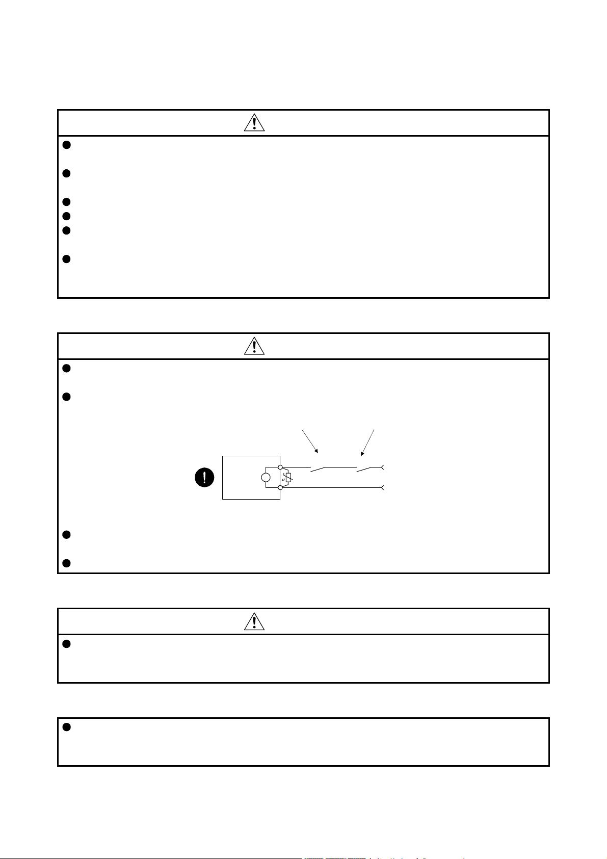
Configure an electromagnetic brake circuit so that it is activated also by an external EMG stop switch.
Contacts must be opened when ALM
(Malfunction) or MBR (Electromagnetic
brake interlock) turns off.
Contacts must be opened
with the EMG stop switch.
Servo motor
B
Electromagnetic brake
When any alarm has occurred, eliminate its cause, ensure safety, and deactivate the alarm before
restarting operation.
Provide an adequate protection to prevent unexpected restart after an instantaneous power failure.
RA
24 V DC
(6) Maintenance, inspection and parts replacement
CAUTION
With age, the electrolytic capacitor of the servo amplifier will deteriorate. To prevent a secondary
accident due to a malfunction, it is recommend that the electrolytic capacitor be replaced every 10 years
when it is used in general environment. Please contact your local sales office.
(7) General instruction
To illustrate details, the equipment in the diagrams of this Instruction Manual may have been drawn
without covers and safety guards. When the equipment is operated, the covers and safety guards must
be installed as specified. Operation must be performed in accordance with this Instruction Manual.
A - 5

DISPOSAL OF WASTE
Please dispose a servo amplifier, battery (primary battery) and other options according to your local laws and
regulations.
EEP-ROM life
The number of write times to the EEP-ROM, which stores parameter settings, etc., is limited to 100,000. If
the total number of the following operations exceeds 100,000, the servo amplifier may malfunction when the
EEP-ROM reaches the end of its useful life.
Write to the EEP-ROM due to parameter setting changes
Write to the EEP-ROM due to device changes
STO function of the servo amplifier
When using the STO function of the servo amplifier, refer to chapter 13 of "MR-J4-_B_(-RJ) Servo Amplifier
Instruction Manual".
For the MR-J3-D05 safety logic unit, refer to appendix 5 of "MR-J4-_B_(-RJ) Servo Amplifier Instruction
Manual".
Compliance with global standards
For the compliance with global standards, refer to appendix 4 of "MR-J4-_B_(-RJ) Servo Amplifier Instruction
Manual".
A - 6
«About the manual»
You must have this Instruction Manual and the following manuals to use the servo. Ensure to prepare
them to use the servo safely.
Relevant manuals
Manual name Manual No.
MELSERVO-J4 Series Instructions and Cautions for Safe Use of AC Servos
(Packed with 200 V class servo amplifiers)
MELSERVO-J4 Series Instructions and Cautions for Safe Use of AC Servos
(Packed with 400 V class servo amplifiers)
MR-J4-_B_(-RJ) AMPLIFIER INSTRUCTION MANUAL SH(NA)030106
MELSERVO-J4 SERVO AMPLIFIER INSTRUCTION MANUAL (TROUBLESHOOTING) SH(NA)030109
MELSERVO Servo Motor Instruction Manual (Vol. 3) SH(NA)030113
EMC Installation Guidelines IB(NA)67310
MELSEC-Q QD77GF Simple motion module User's Manual (Positioning Control) IB(NA)0300202
MELSEC-Q QD77GF Simple motion module User's Manual (Network) IB(NA)0300203
IB(NA)0300175
IB(NA)0300197
This Instruction Manual does not describe the following items. The followings are the same as MR-J4-_B_
servo amplifiers. For details of the items, refer to each chapter/section of the detailed description field.
"MR-J4-_B_" means "MR-J4-_B_(-RJ) Servo Amplifier Instruction Manual".
Item Detailed explanation
Normal gain adjustment MR-J4-_B_ chapter 6
Special adjustment functions (except gain
switching function)
Characteristics MR-J4-_B_ chapter 10
Absolute position detection system MR-J4-_B_ chapter 12
Using STO function MR-J4-_B_ chapter 13
MR-J4-_B_ chapter 7
«Cables used for wiring»
Wires mentioned in this Instruction Manual are selected based on the ambient temperature of 40 °C.
«U.S. customary units»
U.S. customary units are not shown in this manual. Convert the values if necessary according to the
following table.
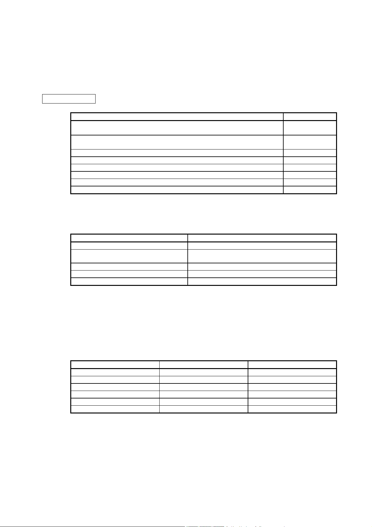
Quantity SI (metric) unit U.S. customary unit
Mass 1 [kg] 2.2046 [lb]
Length 1 [mm] 0.03937 [in]
Torque 1 [N•m] 141.6 [oz•in]
Moment of inertia 1 [(× 10-4 kg•m2)] 5.4675 [oz•in2]
Load (thrust load/axial load) 1 [N] 0.2248 [lbf]
Temperature N [°C] × 9/5 + 32 N [°F]
A - 7

MEMO
A - 8

CONTENTS
1. FUNCTIONS AND CONFIGURATION 1- 1 to 1-44
1.1 Summary............................................................................................................................................ 1- 1
1.2 Function block diagram...................................................................................................................... 1- 2
1.3 Standard specifications...................................................................................................................... 1- 8
1.3.1 Servo amplifier............................................................................................................................. 1- 8
1.3.2 MR-J3-T10 Field Network interface unit..................................................................................... 1-10
1.4 Combinations of servo amplifiers and servo motors......................................................................... 1-10
1.5 Function list....................................................................................................................................... 1-12
1.6 Model designation............................................................................................................................. 1-13
1.7 Structure............................................................................................................................................ 1-15
1.7.1 Parts identification ...................................................................................................................... 1-15
1.7.2 Parts identification of MR-J3-T10............................................................................................... 1-27
1.8 Installation and removal of MR-J3-T10............................................................................................. 1-28
1.9 Configuration including peripheral equipment .................................................................................. 1-32
1.9.1 200 V class................................................................................................................................. 1-32
1.9.2 400 V class................................................................................................................................. 1-38
2. INSTALLATION 2- 1 to 2- 4
2.1 Installation direction and clearances.................................................................................................. 2- 2
2.2 Keep out foreign materials................................................................................................................. 2- 4
3. SIGNALS AND WIRING 3- 1 to 3-18
3.1 I/O signal connection example........................................................................................................... 3- 3
3.1.1 For sink I/O interface ................................................................................................................... 3- 3
3.1.2 For source I/O interface............................................................................................................... 3- 5
3.2 Servo motor with an electromagnetic brake ...................................................................................... 3- 6
3.2.1 Safety precautions....................................................................................................................... 3- 6
3.2.2 Timing chart................................................................................................................................. 3- 7
4. STARTUP 4- 1 to 4-12
4.1 Switching power on for the first time.................................................................................................. 4- 2
4.1.1 Startup procedure........................................................................................................................ 4- 2
4.1.2 Wiring check................................................................................................................................ 4- 3
4.1.3 Surrounding environment............................................................................................................ 4- 6
4.2 Switch setting and display of the servo amplifier............................................................................... 4- 6
4.2.1 Switches ...................................................................................................................................... 4- 6
4.2.2 Scrolling display .......................................................................................................................... 4- 9
4.2.3 Status display of a station .......................................................................................................... 4-10
4.3 Display of MR-J3-T10 CC-Link IE Field Network interface unit........................................................ 4-12
5. PARAMETERS 5- 1 to 5-36
5.1 Parameter list..................................................................................................................................... 5- 1
5.1.1 Basic setting parameters ([Pr. PA_ _ ])....................................................................................... 5- 2
1

5.1.2 Gain/filter setting parameters ([Pr. PB_ _ ]) ................................................................................ 5- 3
5.1.3 Extension setting parameters ([Pr. PC_ _ ])................................................................................ 5- 4
5.1.4 I/O setting parameters ([Pr. PD_ _ ])........................................................................................... 5- 5
5.1.5 Extension setting 2 parameters ([Pr. PE_ _ ]).............................................................................5- 6
5.1.6 Extension setting 3 parameters ([Pr. PF_ _ ]).............................................................................5- 7
5.1.7 Option setting parameters ([Pr. Po_ _) ....................................................................................... 5- 8
5.2 Detailed list of parameters ................................................................................................................ 5-10
5.2.1 Basic setting parameters ([Pr. PA_ _ ])...................................................................................... 5-10
5.2.2 Gain/filter setting parameters ([Pr. PB_ _ ]) ............................................................................... 5-17
5.2.3 Extension setting parameters ([Pr. PC_ _ ])............................................................................... 5-26
5.2.4 I/O setting parameters ([Pr. PD_ _ ]).......................................................................................... 5-31
5.2.5 Extension setting 2 parameters ([Pr. PE_ _ ])............................................................................ 5-33
5.2.6 Extension setting 3 parameters ([Pr. PF_ _ ])............................................................................ 5-34
5.2.7 Option setting parameters ([Pr. Po_ _) ...................................................................................... 5-36
6. TROUBLESHOOTING 6- 1 to 6- 8
6.1 Alarm and warning list........................................................................................................................ 6- 1
6.2 Troubleshooting at power on ............................................................................................................. 6- 6
7. DIMENSIONS 7- 1 to 7-18
7.1 Servo amplifier ................................................................................................................................... 7- 2
7.1.1 200 V class.................................................................................................................................. 7- 2
7.1.2 400 V class................................................................................................................................. 7-11
7.2 MR-J3-T10 CC-Link IE Field Network interface unit......................................................................... 7-18
8. OPTIONS AND PERIPHERAL EQUIPMENT 8- 1 to 8- 4
8.1 Combinations of cable/connector sets............................................................................................... 8- 2
8.2 Cable for CC-Link IE Field Network................................................................................................... 8- 4
APPENDIX App.- 1 to App.- 5
App. 1 Peripheral equipment manufacturer (for reference)................................................................ App.- 1
App. 2 Analog monitor ........................................................................................................................App.- 1
App. 3 Special specification ................................................................................................................App.- 4
2

1. FUNCTIONS AND CONFIGURATION
1. FUNCTIONS AND CONFIGURATION
The following item is the same as MR-J4-_B_ Servo amplifiers. For details of the item, refer to the section of
the detailed description field. "MR-J4-_B_" means "MR-J4-_B_(-RJ) Servo Amplifier Instruction Manual".
Removal and reinstallation of the front cover MR-J4-_B_ section 1.7.2
1.1 Summary
This instruction manual explains about CC-Link IE Field Network interface AC servo amplifier with Motion
MR-J4-_B_-RJ010 and CC-Link IE Field Network interface unit MR-J3-T10. Refer to "MR-J4-_B_(-RJ) Servo
Amplifier Instruction Manual" for the information not given in this manual.
Always use MR-J4-_B_-RJ010 with MR-J3-T10.
Connecting MR-J4-_B_-RJ010 and MR-J3-T10 to CC-Link IE Field simple motion module QD77GF_
enables you to drive a servo motor using CC-Link IE Field motion function.
Item Detailed explanation
1 - 1
1. FUNCTIONS AND CONFIGURATION
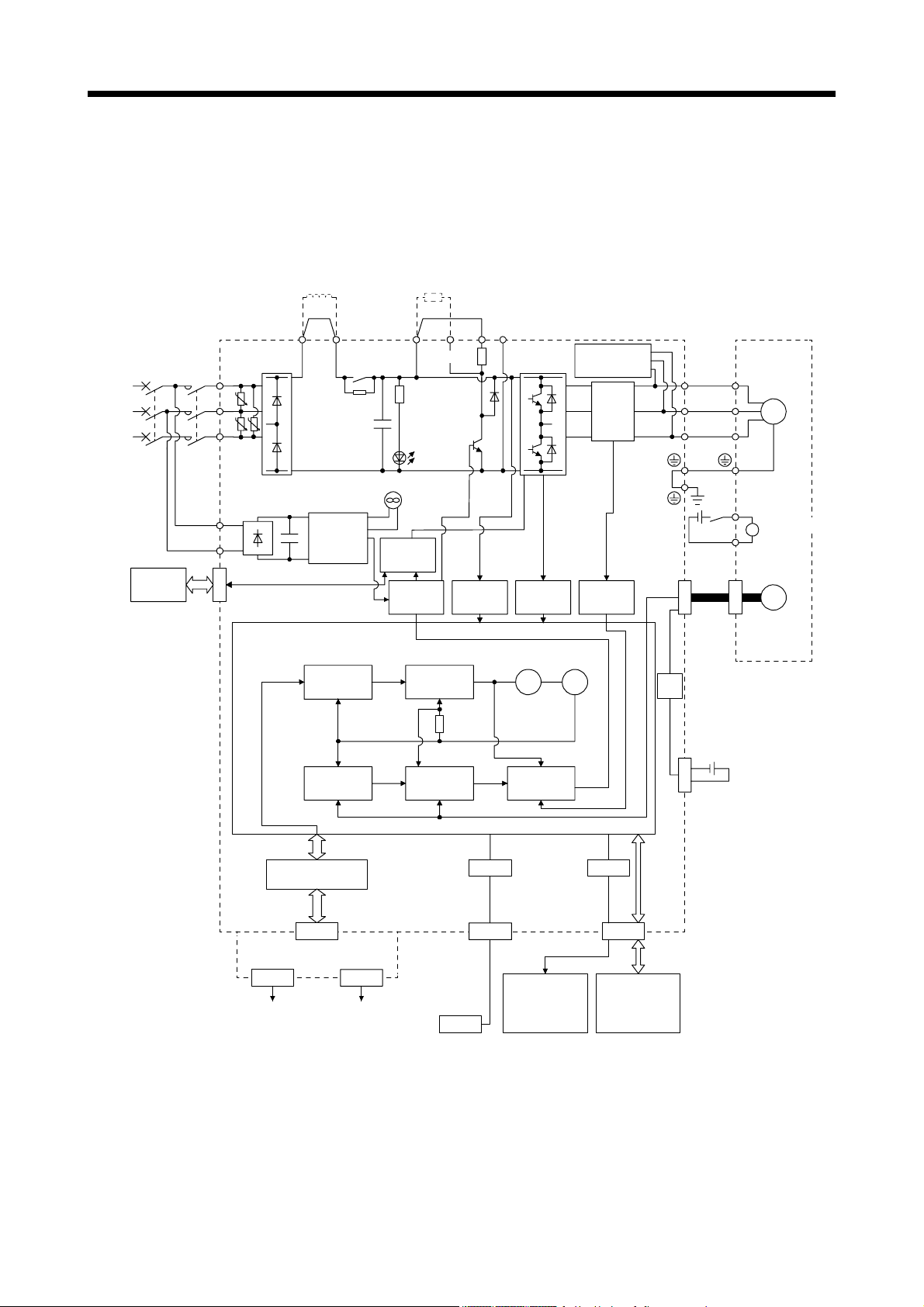
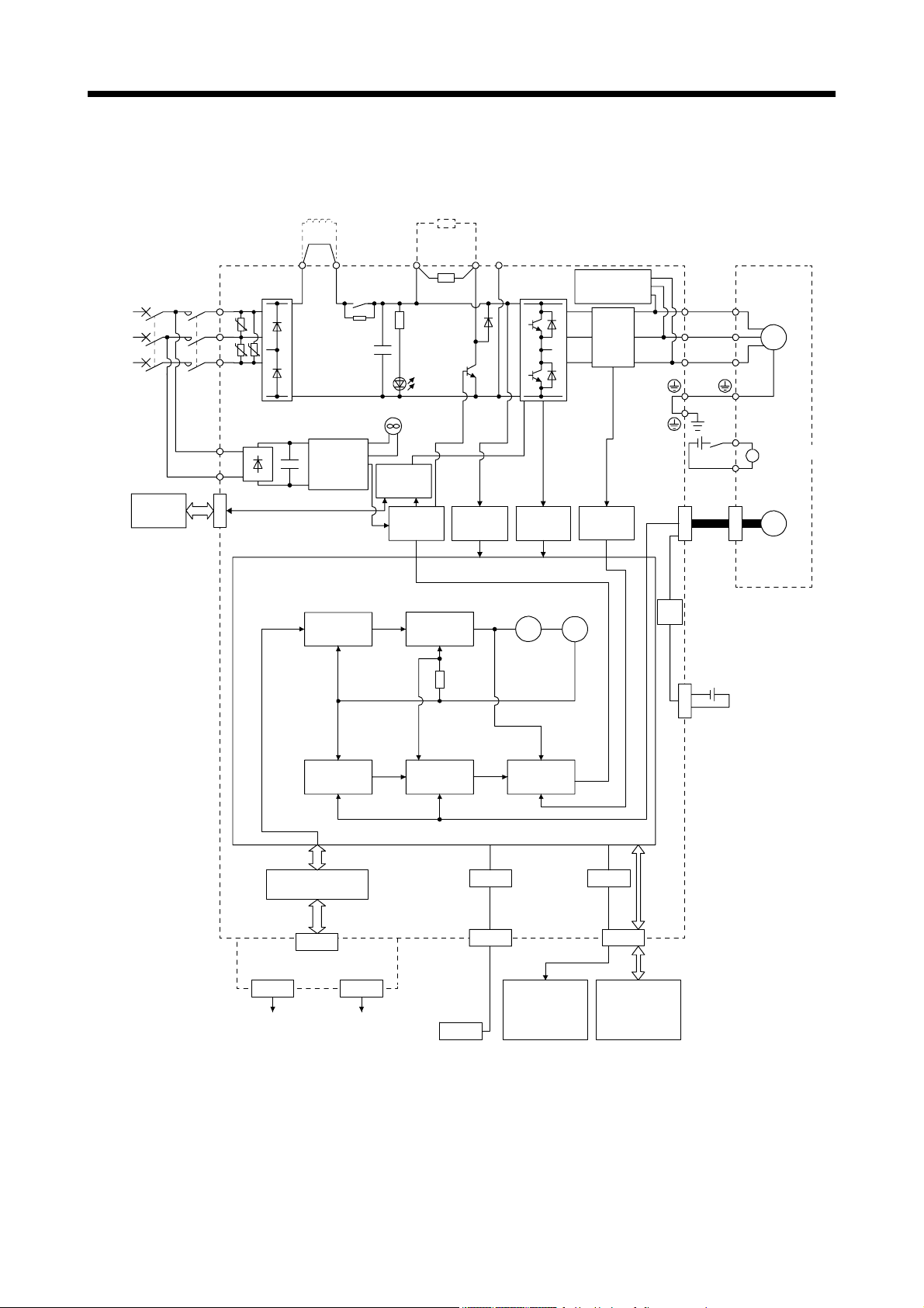
1.2 Function block diagram
The function block diagram of this servo is shown below.
(1) 200 V class
(a) MR-J4-500B-RJ010 or less
Power factor improving
DC reactor (Note 5)
Regenerative
option
(Note 2)
Power
supply
STO
switch
Servo amplifier
MCMCCB
L1
U
L2
UU
L3
L11
L21
CN8
P3 P4
Diode
stack
Position
command
input
+
(Note 4)
Relay
Cooling fan
(Note 3)
Control
circuit
power
supply
Model
position
control
Model position
Actual
position
control
P+
(Note 1)
+
Regenerative
TR
CHARGE
lamp
STO
circuit
Base
amplifier
Voltage
detection
Model
speed
control
Model speed Model torque
Actual
speed
control
N-CD
Overcurrent
protection
Virtual
motor
Current
control
detection
Virtual
encoder
Dynamic
brake
circuit
Current
encoder
Current
U
U
V
V
W
W
RA
24 V DC
CN2
Stepdown
circuit
CN4
Optional battery
(for absolute position
detection system)
Servo motor
M
B1
Electromagnetic
B
brake
B2
Encoder
I/F Control
CN7
MR-J3-T10
CN10A CN10B
CC-Link IE
Field Network
CC-Link IE
Field Network
Personal
computer
USB
USB
CN5
Analog monitor
(2 channels)
D/A
CN3
Digital I/O
control
Note 1. The built-in regenerative resistor is not provided for the MR-J4-10B-RJ010.
2. For 1-phase 200 V AC to 240 V AC, connect the power supply to L1 and L3. Leave L2 open.
For power supply specifications, refer to section 1.3.1.
3. Servo amplifiers MR-J4-70B-RJ010 or more have a cooling fan.
4. MR-J4 servo amplifier has P3 and P4 in the upstream of the inrush current suppression circuit. They are different from P1 and
P2 of MR-J3 servo amplifiers.
5. The power factor improving AC reactor can also be used. In this case, the power factor improving DC reactor cannot be used.
When not using the power factor improving DC reactor, short P3 and P4.
1 - 2
1. FUNCTIONS AND CONFIGURATION
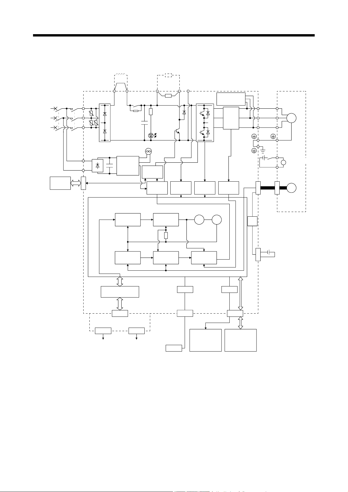
(b) MR-J4-700B-RJ010
Power factor improving
DC reactor (Note 3)
Regenerative
option
(Note 1)
Power
supply
STO
switch
Servo amplifier
MCMCCB
L1
U
L2
U U
L3
L11
L21
CN8
P3 P4
Diode
stack
Position
command
input
+
(Note 2)
Relay
Cooling fan
Control
circuit
power
supply
Model
position
control
Model position
Actual
position
control
P+
Regene-
+
rative
TR
CHARGE
lamp
STO
circuit
Model
speed
control
Voltage
detection
Base
amplifier
Model speed Model torque
Actual
speed
control
N-C
Overcurrent
Virtual
motor
Current
protection
control
detection
Virtual
encoder
Dynamic
brake
circuit
Current
encoder
Current
U
U
V
V
W
W
RA
24 V DC
CN2
Stepdown
circuit
CN4
Optional battery
(for absolute position
detection system)
Servo motor
M
B1
Electromagnetic
B
brake
B2
Encoder
I/F Control
CN7
USB
CN5
D/A
CN3
MR-J3-T10
CN10A CN10B
CC-Link IE
Field Network
CC-Link IE
Field Network
Personal
computer
USB
Analog monitor
(2 channels)
Digital I/O
control
Note 1. For power supply specifications, refer to section 1.3.1.
2. MR-J4 servo amplifier has P3 and P4 in the upstream of the inrush current suppression circuit. They are different from P1 and
P2 of MR-J3 servo amplifiers.
3. The power factor improving AC reactor can also be used. In this case, the power factor improving DC reactor cannot be used.
When not using the power factor improving DC reactor, short P3 and P4.
1 - 3
1. FUNCTIONS AND CONFIGURATION
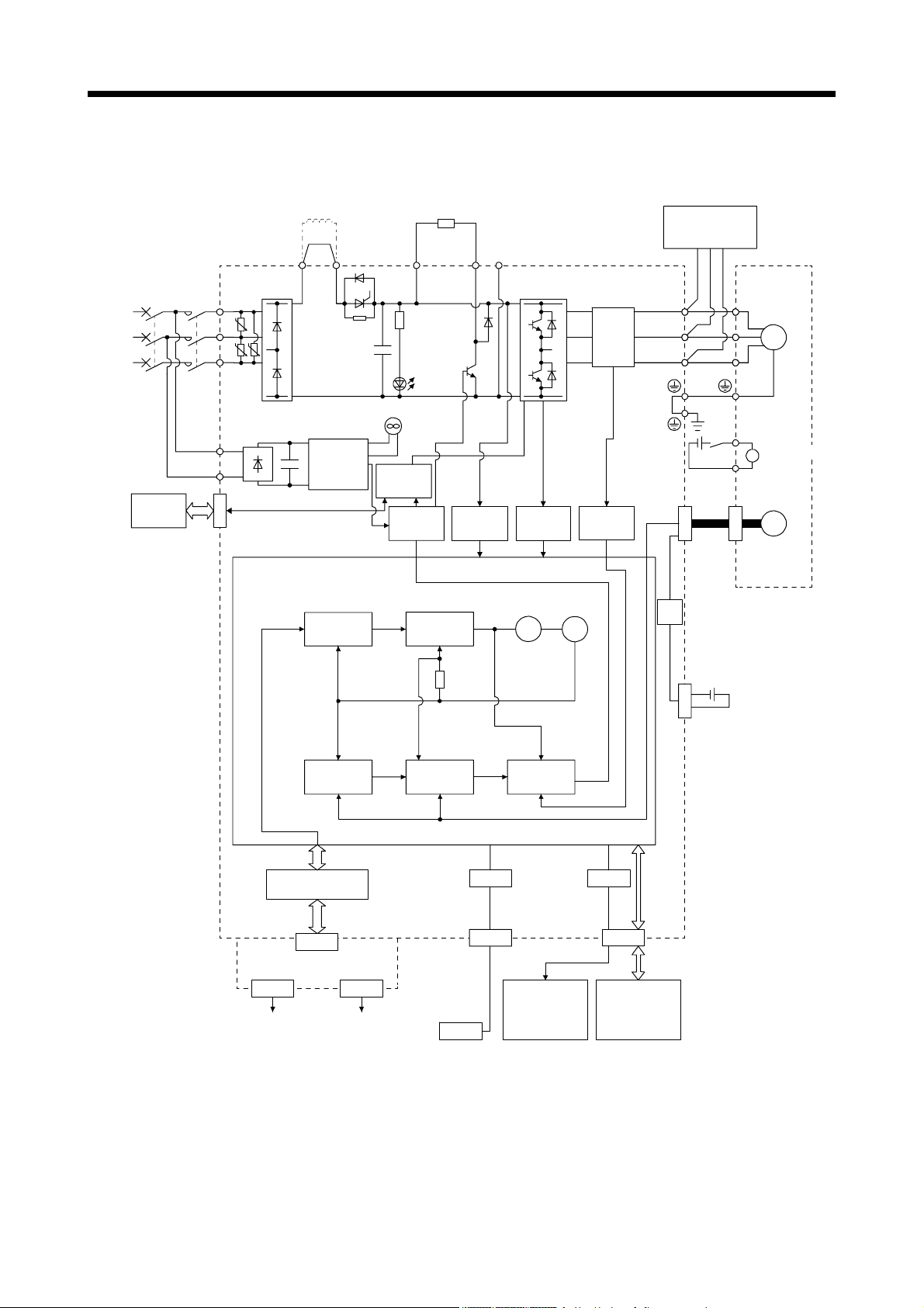
(c) MR-J4-11KB-RJ010/MR-J4-15KB-RJ010/MR-J4-22KB-RJ010
(Note 1)
Power
supply
STO
switch
Servo amplifier
MCMCCB
L1
U
L2
U U
L3
L11
L21
CN8
(Note 4)
Power factor
improving
DC reactor
P3 P4 (Note 2)
Diode
stack
Control
+
circuit
power
supply
Thyristor
Cooling fan
External
regenerative resistor
or
regenerative option
P+
+
Regenerative
TR
Charge
lamp
STO
circuit
Base
amplifier
Voltage
detection
N-C
Overcurrent
protection
Current
detector
Current
detection
(Note 3)
External
dynamic brake
(optional)
U
V
W
W
RA
24 V DC
CN2
Servo motor
U
V
M
B1
Electromagnetic
B
brake
B2
Encoder
Position
command
input
Model
position
control
Actual
position
control
I/F Control
CN7
MR-J3-T10
CN10A CN10B
CC-Link IE
Field Network
CC-Link IE
Field Network
Model position
Virtual
motor
encoder
Model
speed
control
Model speed Model torque
Actual
speed
control
Current
control
USB
CN5
Personal
computer
Analog monitor
(2 channels)
USB
Virtual
D/A
CN3
Digital I/O
control
Stepdown
circuit
CN4
Optional battery
(For absolute
position detection
system)
Note 1. Refer to section 1.3.1 for the power supply specification.
2. MR-J4 servo amplifier has P3 and P4 in the upstream of the inrush current suppression circuit. They are different from P1 and
P2 of MR-J3 servo amplifiers.
3. Use an external dynamic brake for this servo amplifier. Failure to do so will cause an accident because the servo motor does
not stop immediately but coasts at an alarm occurrence for which the servo motor does not decelerate to stop. Ensure the
safety in the entire equipment. For alarms for which the servo motor does not decelerate to stop, refer to section 6.1.
4. The power factor improving AC reactor can also be used. In this case, the power factor improving DC reactor cannot be used.
When not using the power factor improving DC reactor, short P3 and P4.
1 - 4
1. FUNCTIONS AND CONFIGURATION
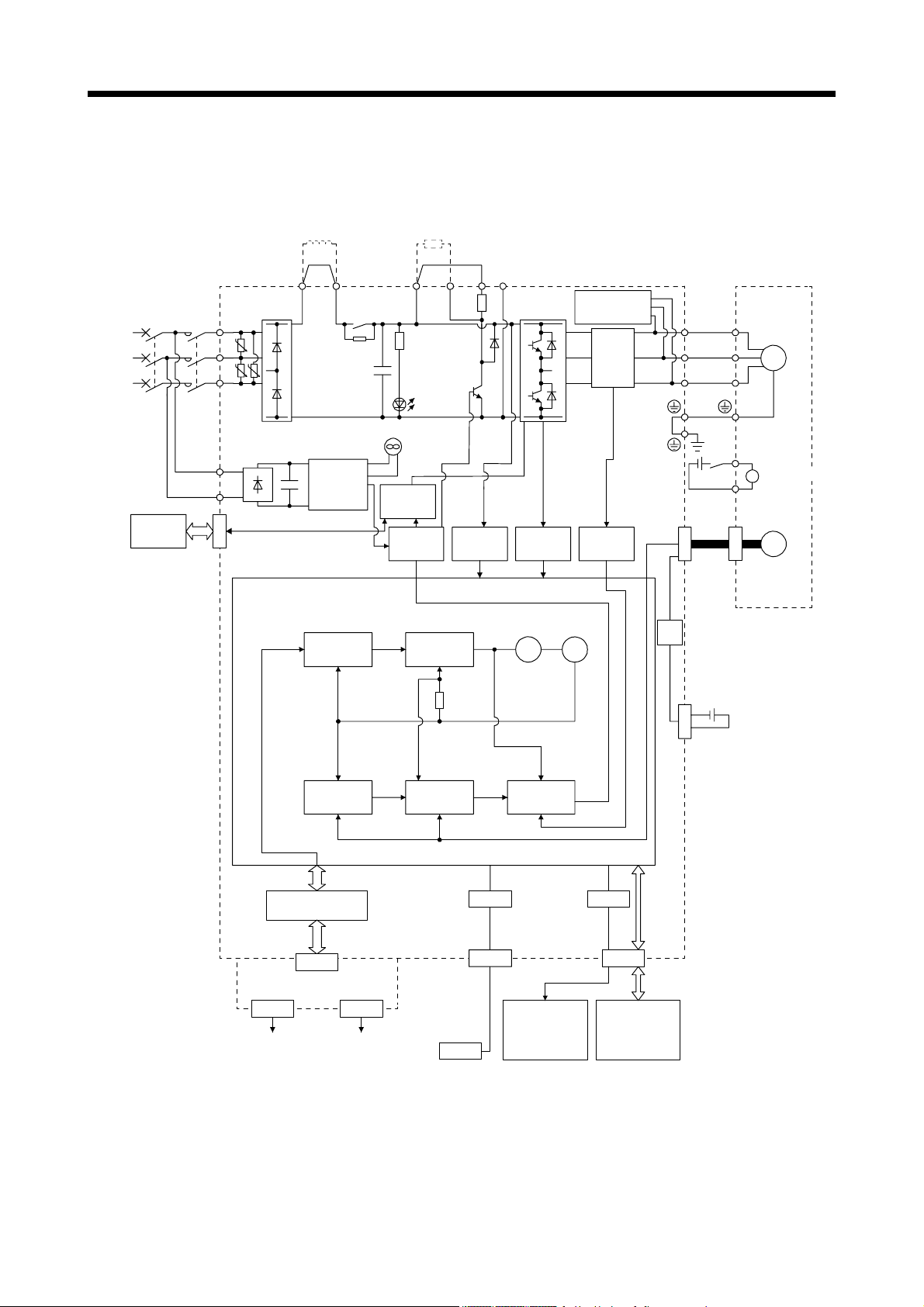
(2) 400 V class
(a) MR-J4-350B4-RJ010 or less
(Note 4)
Power factor
improving
DC reactor
Regenerative
option
(Note 1)
Power
supply
STO
switch
Servo amplifier
MCMCCB
L1
U
L2
U U
L3
L11
L21
CN8
P3 P4 (Note 3)
Diode
stack
+
Position
command
input
Relay
(Note 2)
Control
circuit
power
supply
Model
position
control
+
Cooling fan
STO
circuit
Base
amplifier
P+
Regenerative
TR
Charge
lamp
Model
speed
control
Voltage
detection
N-CD
Overcurrent
protection
Virtual
motor
detection
Virtual
encoder
Dynamic
brake
circuit
Current
detector
Current
Stepdown
circuit
U
V
W
RA
24 V DC
CN2
Servo motor
U
V
W
B1
B
B2
M
Electromagnetic
brake
Encoder
CN4
Optional battery
(For absolute
position detection
system)
Actual
position
control
I/F Control
CN7
Model position
Model speed Model torque
Actual
speed
control
Current
control
USB
CN5
D/A
CN3
MR-J3-T10
CN10A CN10B
CC-Link IE
Field Network
CC-Link IE
Field Network
Personal
computer
USB
Analog monitor
(2 channels)
Digital I/O
control
Note 1. Refer to section 1.3.1 for the power supply specification.
2. Servo amplifiers MR-J4-200B4(-RJ) or more have a cooling fan.
3. MR-J4 servo amplifier has P3 and P4 in the upstream of the inrush current suppression circuit. They are different from P1 and
P2 of MR-J3 servo amplifiers.
4. The power factor improving AC reactor can also be used. In this case, the power factor improving DC reactor cannot be used.
When not using the power factor improving DC reactor, short P3 and P4.
1 - 5
1. FUNCTIONS AND CONFIGURATION
(b) MR-J4-500B4-RJ010/MR-J4-700B4-RJ010
(Note 3)
Power factor
improving
DC reactor
Regenerative
option
(Note 1)
Power
supply
STO
switch
Servo amplifier
MCMCCB
L1
U
L2
U U
L3
L11
L21
CN8
P3 P4 (Note 2)
Diode
stack
+
Position
command
input
Relay
Control
circuit
power
supply
Model
position
control
+
Cooling fan
STO
circuit
Base
amplifier
P+
Regenerative
TR
Charge
lamp
Model
speed
control
Voltage
detection
N-C
Overcurrent
Virtual
motor
protection
detection
Virtual
encoder
Dynamic
brake
circuit
Current
detector
Current
Stepdown
circuit
U
V
W
RA
24 V DC
CN2
Servo motor
U
V
W
B1
B
B2
M
Electromagnetic
brake
Encoder
CN4
Optional battery
(For absolute
position detection
system)
Actual
position
control
I/F Control
CN7
Model position Model speed Model torque
Actual
speed
control
Current
control
USB
CN5
D/A
CN3
MR-J3-T10
CN10A CN10B
CC-Link IE
Field Network
CC-Link IE
Field Network
Personal
computer
USB
Analog monitor
(2 channels)
Digital I/O
control
Note 1. Refer to section 1.3.1 for the power supply specification.
2. MR-J4 servo amplifier has P3 and P4 in the upstream of the inrush current suppression circuit. They are different from P1 and
P2 of MR-J3 servo amplifiers.
3. The power factor improving AC reactor can also be used. In this case, the power factor improving DC reactor cannot be used.
When not using the power factor improving DC reactor, short P3 and P4.
1 - 6

1. FUNCTIONS AND CONFIGURATION
(c) MR-J4-11KB4-RJ010/MR-J4-15KB4-RJ010/MR-J4-22KB4-RJ010
(Note 1)
Power
supply
STO
switch
Servo amplifier
MCMCCB
L1
U
L2
U U
L3
L11
L21
CN8
(Note 4)
Power factor
improving
DC reactor
P3 P4 (Note 2)
Diode
stack
Control
+
circuit
power
supply
Thyristor
Cooling fan
External
regenerative resistor
or
regenerative option
P+
+
Regenerative
TR
Charge
lamp
STO
circuit
Base
amplifier
Voltage
detection
N-C
Overcurrent
protection
Current
detector
Current
detection
(Note 3)
External
dynamic brake
(optional)
U
V
W
W
RA
24 V DC
CN2
Servo motor
U
V
M
B1
Electromagnetic
B
brake
B2
Encoder
Position
command
input
Model
position
control
Actual
position
control
I/F Control
CN7
MR-J3-T10
CN10A CN10B
CC-Link IE
Field Network
CC-Link IE
Field Network
Model position
Virtual
motor
encoder
Model
speed
control
Model speed Model torque
Actual
speed
control
Current
control
USB
CN5
Personal
computer
Analog monitor
(2 channels)
USB
Virtual
D/A
CN3
Digital I/O
control
Stepdown
circuit
CN4
Optional battery
(For absolute
position detection
system)
Note 1. Refer to section 1.3.1 for the power supply specification.
2. MR-J4 servo amplifier has P3 and P4 in the upstream of the inrush current suppression circuit. They are different from P1 and
P2 of MR-J3 servo amplifiers.
3. Use an external dynamic brake for this servo amplifier. Failure to do so will cause an accident because the servo motor does
not stop immediately but coasts at an alarm occurrence for which the servo motor does not decelerate to stop. Ensure the
safety in the entire equipment. For alarms for which the servo motor does not decelerate to stop, refer to section 6.1.
4. The power factor improving AC reactor can also be used. In this case, the power factor improving DC reactor cannot be used.
When not using the power factor improving DC reactor, short P3 and P4.
1 - 7
1. FUNCTIONS AND CONFIGURATION
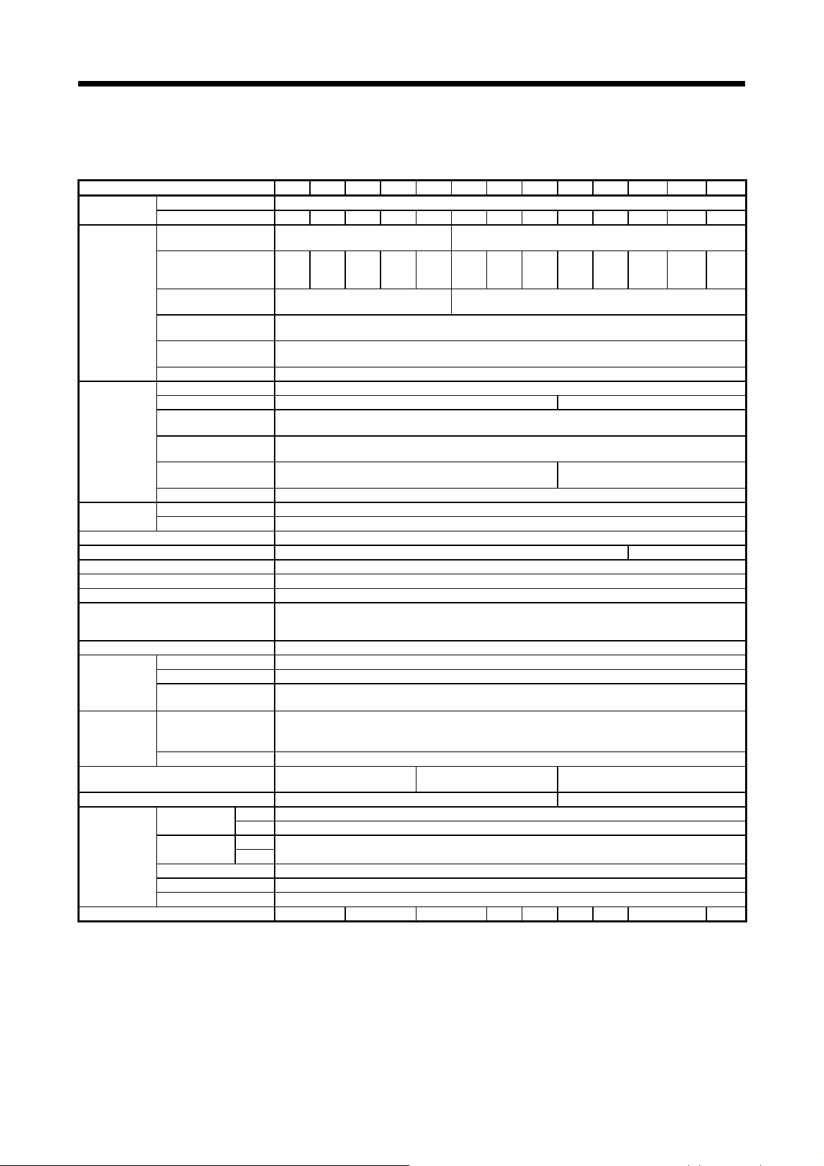
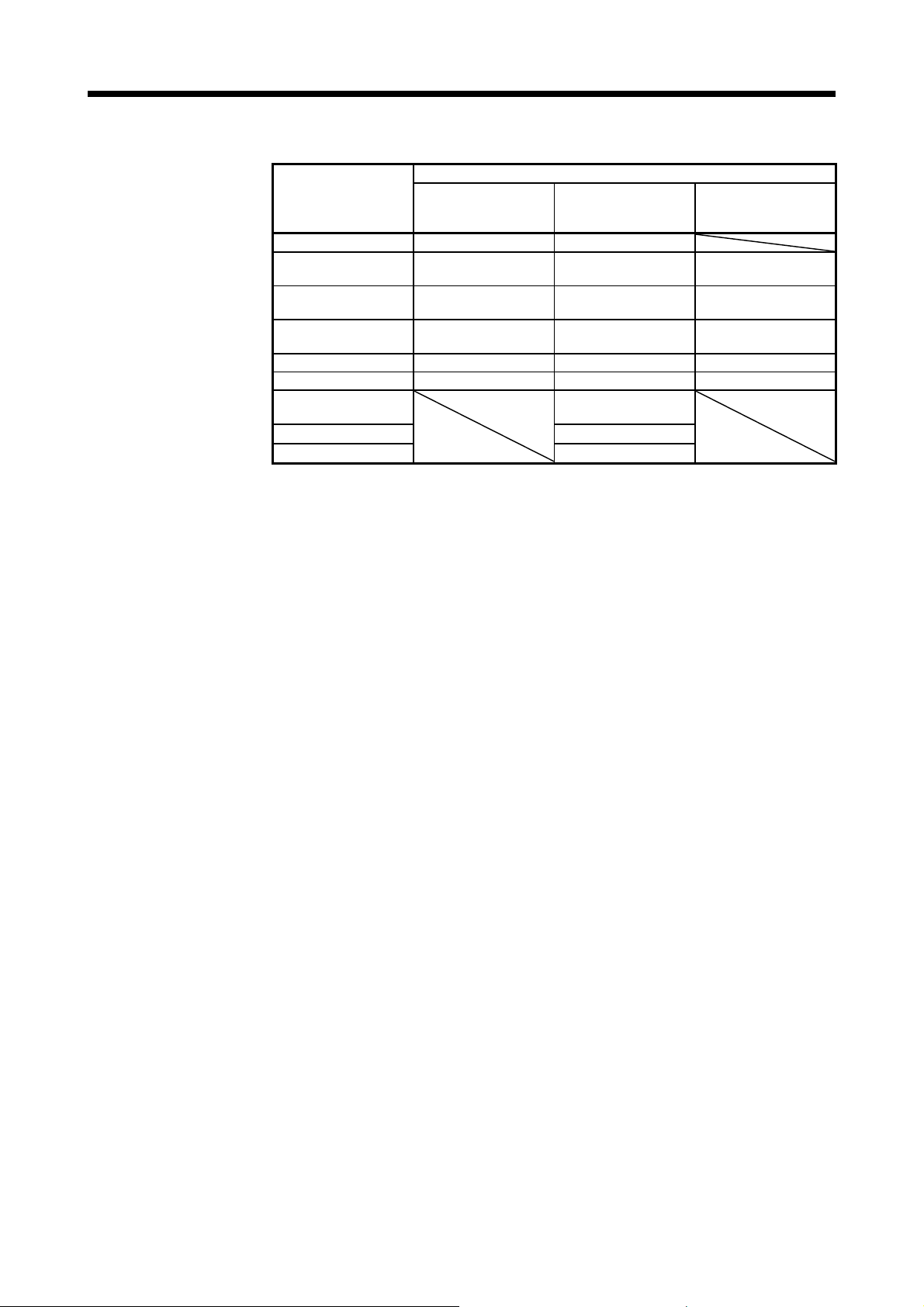
1.3 Standard specifications
1.3.1 Servo amplifier
Model: MR-J4-_-RJ010 10B 20B 40B 60B 70B 100B 200B 350B 500B 700B 11KB 15KB 22KB
Output
Main circuit
power supply
input
Control circuit
power supply
input
Interface power
supply
Control method Sine-wave PWM control, current control method
Dynamic brake Built-in External option (Note 6)
Communication function USB: connection to a personal computer or others (MR Configurator2-compatible)
Encoder output pulses Compatible (A/B/Z-phase pulse)
Analog monitor 2 channels
Protective functions
Safety function STO (IEC/EN 61800-5-2)
Safety
performance
Compliance to
standards
Structure (IP rating) Natural cooling, open (IP20) Force cooling, open (IP20)
Close mounting (Note 2) Possible Impossible
Environment
Mass [kg] 0.8 1.0 1.4 2.1 2.3 4.0 6.2 13.4 18.2
Note 1. 0.3 A is the value applicable when all I/O signals are used. The current capacity can be decreased by reducing the number of
2. When closely mounting the servo amplifier of 3.5 kW or less, operate them at the ambient temperatures of 0 °C to 45 °C or at
3. Test pulse is a signal which instantaneously turns off a signal to the servo amplifier at a constant period for external circuit to
4. Except for the terminal block.
5. The rated current is 2.9 A when the servo amplifier is used with UL or CSA compliant servo motor.
6. Use an external dynamic brake for this servo amplifier. Failure to do so will cause an accident because the servo motor does
Rated voltage 3-phase 170 V AC
Rated current [A] 1.1 1.5 2.8 3.2 5.8 6.0 11.0 17.0 28.0 37.0 68.0 87.0 126.0
Voltage/Frequency
Rated current [A] 0.9 1.5 2.6
Permissible voltage
fluctuation
Permissible frequency
fluctuation
Power supply
capacity
Inrush current [A] MR-J4-_B_(-RJ) Servo Amplifier Instruction Manual section 10.5
Voltage/Frequency 1-phase 200 V AC to 240 V AC, 50 Hz/60 Hz
Rated current [A] 0.2 0.3
Permissible voltage
fluctuation
Permissible frequency
fluctuation
Power
consumption
Inrush current [A] MR-J4-_B_(-RJ) Servo Amplifier Instruction Manual section 10.5
Voltage 24 V DC ± 10%
Current capacity [A] (Note 1) 0.3 (including CN8 connector signals)
Standards certified by CB EN ISO 13849-1 category 3 PL d, IEC 61508 SIL 2, EN 62061 SIL CL 2, and EN 61800-5-2 SIL 2
Response performance 8 ms or less (STO input off → energy shut off)
(Note 3)
Test pulse input (STO)
CE marking
UL standard UL 508C
Ambient
temperature
Ambient
humidity
Ambience Indoors (no direct sunlight), free from corrosive gas, flammable gas, oil mist, dust, and dirt
Altitude 1000 m or less above sea level
Vibration resistance 5.9 m/s2, at 10 Hz to 55 Hz (directions of X, Y and Z axes)
[kVA] MR-J4-_B_(-RJ) Servo Amplifier Instruction Manual section 10.2
[W] 30 45
Operation
Storage
Operation
Storage
3-phase or 1-phase
200 V AC to 240 V AC, 50 Hz/60 Hz
3.2
(Note
3.8 5.0 10.5 16.0 21.7 28.9 46.0 64.0 95.0
5)
3-phase or 1-phase
170 V AC to 264 V AC
1-phase 170 V AC to 264 V AC
Overcurrent shut-off, regenerative overvoltage shut-off, overload shut-off (electronic thermal), servo motor
overheat protection, encoder error protection, regenerative error protection, undervoltage, instantaneous
power failure protection, overspeed protection, and error excessive protection
Test pulse interval: 1 Hz to 25 Hz
Test pulse off time: Up to 1 ms
MD: EN ISO 13849-1, EN 61800-5-2, EN 62061
0 °C to 55 °C (non-freezing)
-20 °C to 65 °C (non-freezing)
90 %RH or less (non-condensing)
3-phase 200 V AC to 240 V AC, 50 Hz/60 Hz
3-phase 170 V AC to 264 V AC
Within ±5%
Within ±5%
LVD: EN 61800-5-1
EMC: EN 61800-3
Force cooling, open
(IP20) (Note 4)
I/O points.
75% or smaller effective load ratio.
self-diagnose.
not stop immediately but coasts at emergency stop. Ensure the safety in the entire equipment.
1 - 8
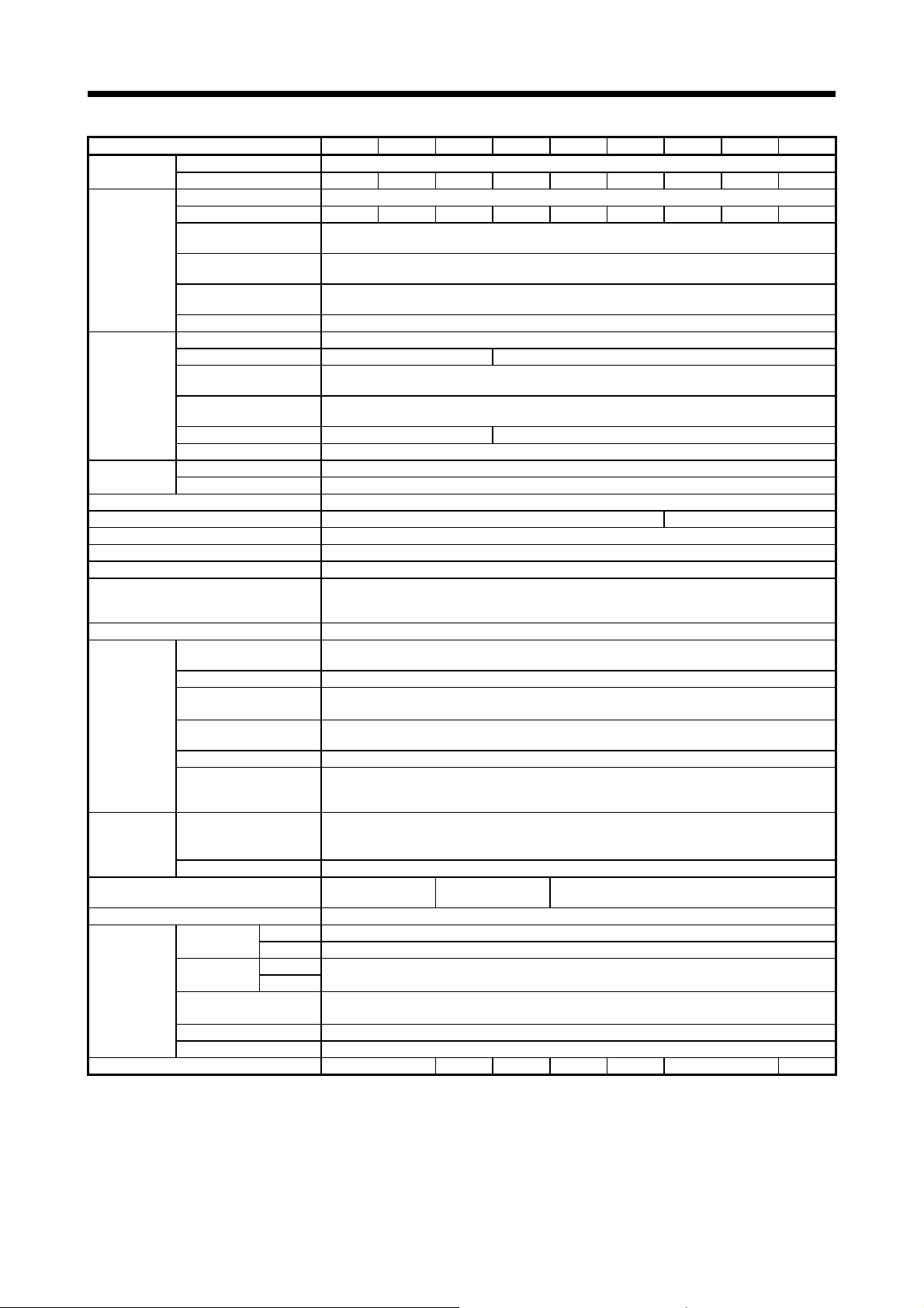
1. FUNCTIONS AND CONFIGURATION
Model: MR-J4- 60B4 100B4 200B4 350B4 500B4 700B4 11KB4 15KB4 22KB4
Output
Main circuit
power supply
input
Voltage/Frequency 1-phase 380 V AC to 480 V AC, 50 Hz/60 Hz
Rated current [A] 0.1 0.2
Control circuit
power supply
input
Power consumption [W] 30 45
Inrush current [A] MR-J4-_B_(-RJ) Servo Amplifier Instruction Manual section 10.5
Interface power
supply
Control method Sine-wave PWM control, current control method
Dynamic brake Built-in External option (Note 4)
Communication function USB: connection to a personal computer or others (MR Configurator2-compatible)
Encoder output pulses Compatible (A/B/Z-phase pulse)
Analog monitor Two channels
Protective functions
Functional safety STO (IEC/EN 61800-5-2)
Standards certified by CB
Response performance 8 ms or less (STO input off → energy shut off)
Safety
performance
Compliance to
standards
Structure (IP rating)
Close mounting Impossible
Environment
Mass [kg] 1.7 2.1 3.6 4.3 6.5 13.4 18.2
Note 1. 0.3 A is the value applicable when all I/O signals are used. The current capacity can be decreased by reducing the number of
2. Test pulse is a signal which instantaneously turns off a signal to the servo amplifier at a constant period for external circuit to
3. Except for the terminal block.
4. Use an external dynamic brake for this servo amplifier. Failure to do so will cause an accident because the servo motor does
Rated voltage 3-phase 323 V AC
Rated current [A] 1.5 2.8 5.4 8.6 14.0 17.0 32.0 41.0 63.0
Voltage/Frequency 3-phase 380 V AC to 480 V AC, 50 Hz/60 Hz
Rated current [A] 1.4 2.5 5.1 7.9 10.8 14.4 23.1 31.8 47.6
Permissible voltage
fluctuation
Permissible frequency
fluctuation
Power supply
capacity
Inrush current [A] MR-J4-_B_(-RJ) Servo Amplifier Instruction Manual section 10.5
Permissible voltage
fluctuation
Permissible frequency
fluctuation
Voltage 24 V DC ± 10%
Current capacity [A] (Note 1) 0.3 (including CN8 connector signals)
(Note 2)
Test pulse input (STO)
Mean time to dangerous
failure (MTTFd)
Diagnosis converge (DC) Medium (90% to 99%)
Average probability of
dangerous failures per hour
(PFH)
CE marking
UL standard UL 508C
Ambient
temperature
Ambient
humidity
Ambience
Altitude 1000 m or less above sea level
Vibration resistance 5.9 m/s2, at 10 Hz to 55 Hz (directions of X, Y and Z axes)
[kVA] MR-J4-_B_(-RJ) Servo Amplifier Instruction Manual section 10.2
Operation 0 ˚C to 55 ˚C (non-freezing)
Storage -20 ˚C to 65 ˚C (non-freezing)
Operation
Storage
3-phase 323 V AC to 528 V AC
Within ±5%
1-phase 323 V AC to 528 V AC
Within ±5%
Overcurrent shut-off, regenerative overvoltage shut-off, overload shut-off (electronic thermal), servo
motor overheat protection, encoder error protection, regenerative error protection, undervoltage
protection, instantaneous power failure protection, overspeed protection, error excessive protection
EN ISO 13849-1 category 3 PL d, IEC 61508 SIL 2, EN 62061 SIL CL 2, and
100 years or longer
1.68 × 10
MD: EN ISO 13849-1, EN 61800-5-2, EN 62061
Natural cooling, open
(IP20)
90 %RH or less (non-condensing)
Force cooling, open
(IP20)
free from corrosive gas, flammable gas, oil mist, dust, and dirt
EN 61800-5-2 SIL 2
Test pulse interval: 1 Hz to 25 Hz
Test pulse off time: Up to 1 ms
-10
[1/h]
LVD: EN 61800-5-1
EMC: EN 61800-3
Force cooling, open (IP20) (Note 3)
Indoors (no direct sunlight),
I/O points.
self-diagnose.
not stop immediately but coasts at emergency stop. Ensure the safety in the entire equipment.
1 - 9
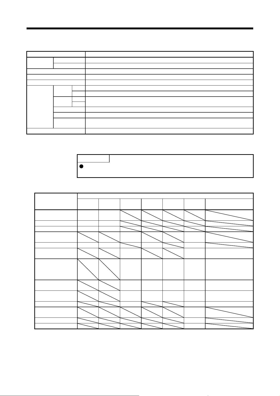
1. FUNCTIONS AND CONFIGURATION
1.3.2 MR-J3-T10 Field Network interface unit
Model MR-J3-T10
Control circuit
power supply
I/O interfaces CC-Link IE Field Network interface
Number of communication ports 2 (CN10A connector/CN10B connector)
Structure Natural-cooling, open (IP rating: IP 00)
Environment
Mass [g] 150
1.4 Combinations of servo amplifiers and servo motors
(1) 200 V class
MR-J4-10B-RJ010 053
MR-J4-20B-RJ010 23 23
MR-J4-40B-RJ010 43 43
MR-J4-60B-RJ010 51
MR-J4-70B-RJ010 73 73 72 73
MR-J4-100B-RJ010 81
MR-J4-200B-RJ010 121
MR-J4-350B-RJ010 301
MR-J4-500B-RJ010 421
MR-J4-700B-RJ010 702 703 503
MR-J4-11KB-RJ010 903
MR-J4-15KB-RJ010 15K1M
MR-J4-22KB-RJ010 22K1M
Voltage 5 V DC (supplied from the servo amplifier)
Rated current [A] 0.8
Ambient
temperature
Ambient
humidity
Ambience Indoors (no direct sunlight), free from corrosive gas, flammable gas, oil mist, dust, and dirt
Altitude 1000 m or less above sea level
Vibration
resistance
Operation
Storage
Operation
Storage
POINT
5.9 m/s
0 °C to 55 °C (non-freezing)
-20 °C to 65 °C (non-freezing)
90 %RH or less (non-condensing)
2
, at 10 Hz to 55 Hz (directions of X, Y and Z axes)
Linear servo motors and direct drive motors cannot be used with the MR-J4_B_-RJ010 servo amplifier.
Rotary servo motor
Servo amplifier
HG-KR HG-MR HG-SR HG-UR HG-RR HG-JR
13
053
13
53
52
103 53
102
201
152
202
352
502
152 103
153
202 203 353 153
352
502
353
503
153
203
503 353
11K1M
(at maximum torque 400%)
HG-JR
73
103
203
1 - 10
1. FUNCTIONS AND CONFIGURATION
(2) 400 V class
Servo amplifier
MR-J4-60B4-RJ010 524 534
MR-J4-100B4-RJ010 1024 734
MR-J4-200B4-RJ010 1524
MR-J4-350B4-RJ010 3524 3534 1534
MR-J4-500B4-RJ010 5024 5034 3534
MR-J4-700B4-RJ010 7024 7034 5034
MR-J4-11KB4-RJ010 9034
MR-J4-15KB4-RJ010 15K1M4
MR-J4-22KB4-RJ010
HG-SR HG-JR
2024
Rotary servo motor
HG-JR
(at maximum torque
400%)
534
1034
1534
2034
11K1M4
22K1M4
734
1034
2034
1 - 11
1. FUNCTIONS AND CONFIGURATION
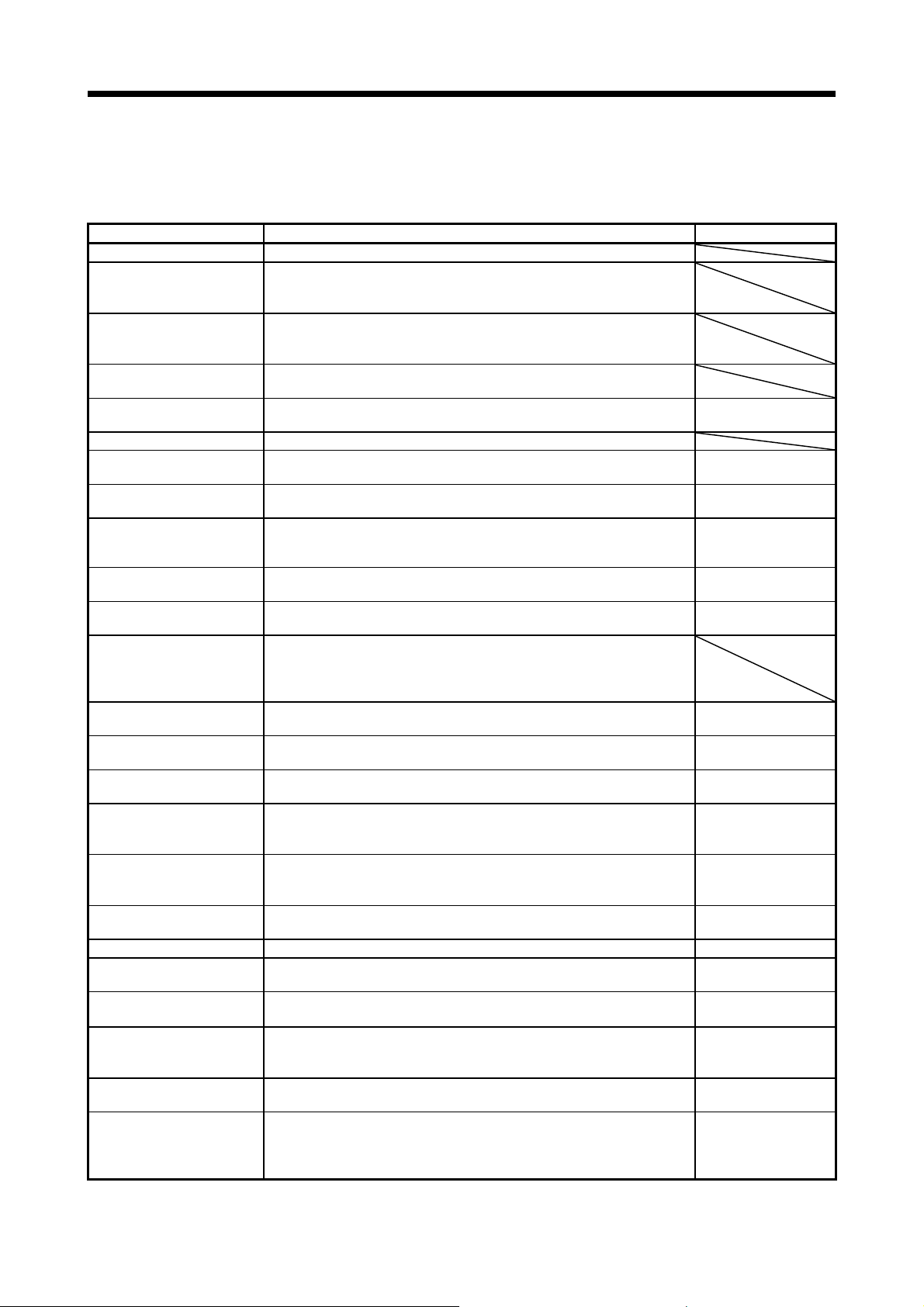
1.5 Function list
The following table lists the functions of this servo. For details of the functions, refer to each section of the
detailed description field. "MR-J4-_B_" means "MR-J4-_B_(-RJ) Servo Amplifier Instruction Manual".
Position control mode This servo is used as a position control servo.
Speed control mode
Torque control mode
High-resolution encoder
Absolute position detection
system
Gain switching function This is not available with the MR-J4-_B_-RJ010 servo amplifier.
Advanced vibration
suppression control II
Machine resonance
suppression filter
Shaft resonance suppression
filter
Adaptive filter II
Low-pass filter
Machine analyzer function
Robust filter
Slight vibration suppression
control
Auto tuning
Brake unit
Power regeneration converter
Regenerative option
Alarm history clear Alarm history is cleared. [Pr. PC21]
Output signal selection
(device settings)
Output signal (DO) forced
output
Test operation mode
Analog monitor output Servo status is output in terms of voltage in real time.
MR Configurator2
Function Description Detailed explanation
This servo is used as a speed control servo.
The speed control mode is used with servo amplifiers with software version
A1 or later.
This servo is used as a torque control servo.
The torque control mode is used with servo amplifiers with software version
A1 or later.
High-resolution encoder of 4194304 pulses/rev is used as the encoder of the
rotary servo motor compatible with the MELSERVO-J4 series.
Merely setting a home position once makes home position return
unnecessary at every power-on.
This function suppresses vibration at the arm end or residual vibration.
This is a filter function (notch filter) which decreases the gain of the specific
frequency to suppress the resonance of the mechanical system.
When a load is mounted to the servo motor shaft, resonance by shaft torsion
during driving may generate a mechanical vibration at high frequency. The
shaft resonance suppression filter suppresses the vibration.
Servo amplifier detects mechanical resonance and sets filter characteristics
automatically to suppress mechanical vibration.
Suppresses high-frequency resonance which occurs as servo system
response is increased.
Analyzes the frequency characteristic of the mechanical system by simply
connecting a MR Configurator2 installed personal computer and servo
amplifier.
MR Configurator2 is necessary for this function.
This function provides better disturbance response in case low response
level that load to motor inertia ratio is high for such as roll send axes.
Suppresses vibration of ±1 pulse produced at a servo motor stop. [Pr. PB24]
Automatically adjusts the gain to optimum value if load applied to the servo
motor shaft varies.
Used when the regenerative option cannot provide enough regenerative
power.
Can be used for the 5 kW or more servo amplifier.
Used when the regenerative option cannot provide enough regenerative
power.
Can be used for the 5 kW or more servo amplifier.
Used when the built-in regenerative resistor of the servo amplifier does not
have sufficient regenerative capability for the regenerative power generated.
The output devices including ALM (Malfunction) can be assigned to
specified pins of the CN3 connector.
Output signal can be forced on/off independently of the servo status.
Use this function for checking output signal wiring, etc.
Jog operation, positioning operation, motor-less operation, DO forced output,
and program operation
MR Configurator2 is necessary for this function.
Using a personal computer, you can perform the parameter setting, test
operation, monitoring, and others.
Use MR Configurator2 of software version 1.19V or later for the MR-J4-_B_RJ010 servo amplifier.
MR-J4-_B_ chapter 12
MR-J4-_B_ section
7.1.5
MR-J4-_B_ section
7.1.1
MR-J4-_B_ section
7.1.3
MR-J4-_B_ section
7.1.2
MR-J4-_B_ section
7.1.4
[Pr. PE41]
MR-J4-_B_ section 6.3
MR-J4-_B_ section
11.3
MR-J4-_B_ section
11.4
MR-J4-_B_ section
11.2
[Pr. PD07] to
[Pr. PD09]
MR-J4-_B_ section
4.5.1 (1) (d)
MR-J4-_B_ section 4.5
[Pr. PC09],
[Pr. PC10]
MR-J4-_B_ section
11.7
1 - 12
1. FUNCTIONS AND CONFIGURATION
Function Description Detailed explanation
Linear servo system This is not available with the MR-J4-_B_-RJ010 servo amplifier.
Direct drive servo system This is not available with the MR-J4-_B_-RJ010 servo amplifier.
Fully closed loop system This is not available with the MR-J4-_B_-RJ010 servo amplifier.
Gain adjustment is performed just by one click on a certain button on MR
One-touch tuning
Tough drive function
Drive recorder function
STO function
Servo amplifier life diagnosis
function
Power monitoring function
Machine diagnosis function
Master-slave operation
function
Scale measurement function
J3 compatibility mode
Continuous operation to
torque control
1.6 Model designation
Configurator2.
MR Configurator2 is necessary for this function.
This function makes the equipment continue operating even under the
condition that an alarm occurs.
The tough drive function includes two types: the vibration tough drive and
the instantaneous power failure tough drive.
This function continuously monitors the servo status and records the status
transition before and after an alarm for a fixed period of time. You can check
the recorded data on the drive recorder window on MR Configurator2 by
clicking the "Graph" button.
However, the drive recorder will not operate on the following conditions.
1. You are using the graph function of MR Configurator2.
2. You are using the machine analyzer function.
3. [Pr. PF21] is set to "-1".
4. The controller is not connected (except the test operation mode).
5. An alarm related to the controller is occurring.
This function is a protective functions that complies with IEC/EN 61800-5-2.
You can create a safety system for the equipment easily.
You can check the cumulative energization time and the number of on/off
times of the inrush relay. This function gives an indication of the replacement
time for parts of the servo amplifier including a capacitor and a relay before
they malfunction.
MR Configurator2 is necessary for this function.
This function calculates the power running energy and the regenerative
power from the data in the servo amplifier such as speed and current. Power
consumption and others are displayed on MR Configurator2.
From the data in the servo amplifier, this function estimates the friction and
vibrational component of the drive system in the equipment and recognizes
an error in the machine parts, including a ball screw and bearing.
MR Configurator2 is necessary for this function.
This is not available with the MR-J4-_B-RJ010 servo amplifier.
MR-J4-_B_ section 6.2
MR-J4-_B_ section 7.3
[Pr. PA23]
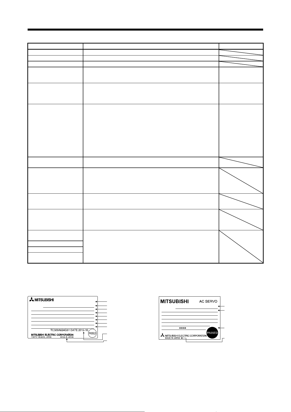
(1) Rating plate
The following shows an example of rating plate for explanation of each item.
AC SERVO
MODEL
MR-J4-10B-RJ010
: 100W
POWER
: 3AC/AC200-240V 0.9A/1.5A 50/60Hz
INPUT
: 3PH170V 0-360Hz 1.1A
OUTPUT
STD.: IEC/EN61800-5-1 MAN.: IB(NA)0300175
Max. Surrounding Air Temp.: 55°C
IP20
Servo amplifier
SER.S21001001
Serial number
Model
Capacit
Applicable power supply
Rated output current
Standard, Manual number
Ambient temperature
IP rating
The year and month of
manufacture
Country of origin
MODEL
CC-Link IE Field Network interface unit
POWER
INPUT
OUTPUT
SERIAL
MR-J3-T10
:
IP00 MANUAL IB-0300171
:
1.5A 3PH+1PH
2.2A 1PH 200-230V
:
170V 0-360Hz 1.5A
:
1 - 13
Model
IP rating Installation guide
3PH+1PH200-230V
Serial number
Country of origin
1. FUNCTIONS AND CONFIGURATION
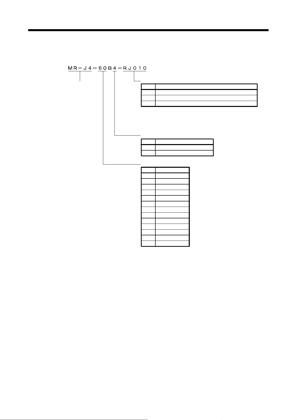
(2) Model
The following describes what each block of a model name indicates. Not all combinations of the symbols
are available.
Series
Special specifications
Symbol Special specifications
RJ010 CC-Link IE Field Network interface with Motion
RU010 MR-J4-_B_-RJ010 without a dynamic brake (Note1)
RZ010
Note 1. Dynamic brake which is built in 7 kW or smaller servo amplifiers
Symbol Power supply
Symbol Rated output [kW]
MR-J4-_B_-RJ010 without regenerative resistor (Note2)
is removed. Refer to Appendix 3.1 for details.
2. Indicates a servo amplifier of 11 kW to 22 kW that does not
use a regenerative resistor as standard accessory. Refer to
Appendix 3.2 for details.
Power supply
None
3-phase 200 V AC to 240 V AC
4 3-phase 380 V AC to 480 V AC
Rated output
10 0.1
20 0.2
40 0.4
60 0.6
70 0.75
100 1
200
350 3.5
500 5
700 7
11k
15k 15
22k 22
2
11
1 - 14
1. FUNCTIONS AND CONFIGURATION
1.7 Structure
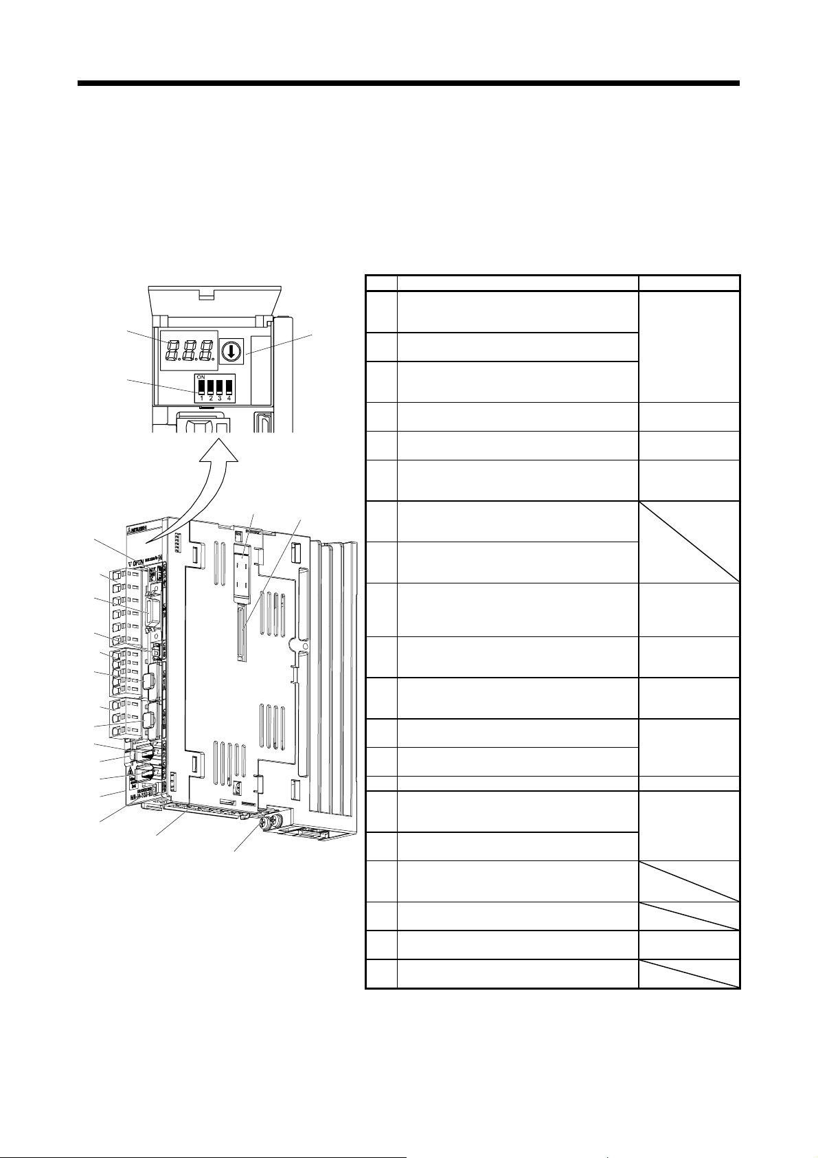
1.7.1 Parts identification
(1) 200 V class
"MR-J4-_B_" means "MR-J4-_B_(-RJ) Servo Amplifier Instruction Manual".
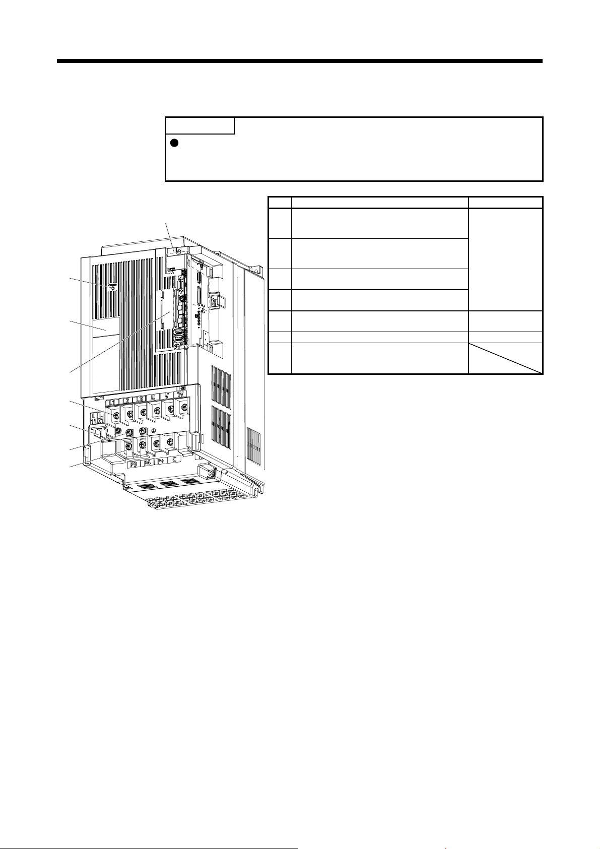
(a) MR-J4-200B-RJ010 or less
(4)
(13)
(5)
(6)
(15)
(7)
(16)
(8)
(9)
(17)
(18)
(14)
Side
(10)
"MR-J4-_B_" means "MR-J4-_B_(-RJ) Servo Amplifier Instruction Manual".
No. Name/Application Detailed explanation
Display
(1)
The 3-digit, seven-segment LED shows the servo
(1)
(3)
(11)
Inside of the display
cover
(20)
(12)
(2)
(19)
status and the alarm number.
Station number setting rotary switch (SW1)
(2)
Used to set a station No. of servo amplifier.
Auxiliary station number setting switch (SW2)
(3)
This consists of the test operation select switch and
auxiliary station number setting switches.
USB communication connector (CN5)
(4)
Connect with the personal computer.
I/O signal connector (CN3)
(5)
Used to connect digital I/O signals.
STO input signal connector (CN8)
(6)
Used to connect MR-J3-D05 safety logic unit and
external safety relay.
Manufacturer setting connector (CN1A)
(7)
This is not available with the servo amplifier. Always
cap the connector.
Manufacturer setting connector (CN1B)
(8)
This is not available with the servo amplifier. Always
cap the connector.
Encoder connector (CN2)
Used to connect the servo motor encoder.
(9)
Battery connector (CN4)
(10)
Used to connect the battery or the battery unit for
absolute position data backup.
Battery holder
(11)
Install the the battery for absolute position data
backup.
Protective earth (PE) terminal
(12)
Grounding terminal
Main circuit power supply connector (CNP1)
(13)
Connect the input power supply.
(14) Rating plate Section 1.6
Control circuit power supply connector (CNP2)
(15)
Connect the control circuit power supply or
regenerative option.
Servo motor power supply connector (CNP3)
(16)
Connect the servo motor.
Charge lamp
(17)
When the main circuit is charged, this will light. While
this lamp is lit, do not reconnect the cables.
Manufacturer setting connector (CN2L)
(18)
This is not available with the servo amplifier.
Optional unit connector (CN7)
(19)
This is for connecting MR-J3-T10.
Manufacturer setting connector (CN9)
(20)
This is not available with the servo amplifier.
Section 4.2
MR-J4-_B_ section
11.7
Section 3.1
MR-J4-_B_ section 3.4
MR-J4-_B_ chapter 13
MR-J4-_B_ app. 5
MR-J4-_B_ section 3.4
"Servo Motor
Instruction Manual
(Vol. 3)"
MR-J4-_B_ chapter 12
MR-J4-_B_ section
12.2
MR-J4-_B_ section 3.1
MR-J4-_B_ section 3.3
MR-J4-_B_ section 3.1
MR-J4-_B_ section 3.3
Section 1.8
1 - 15
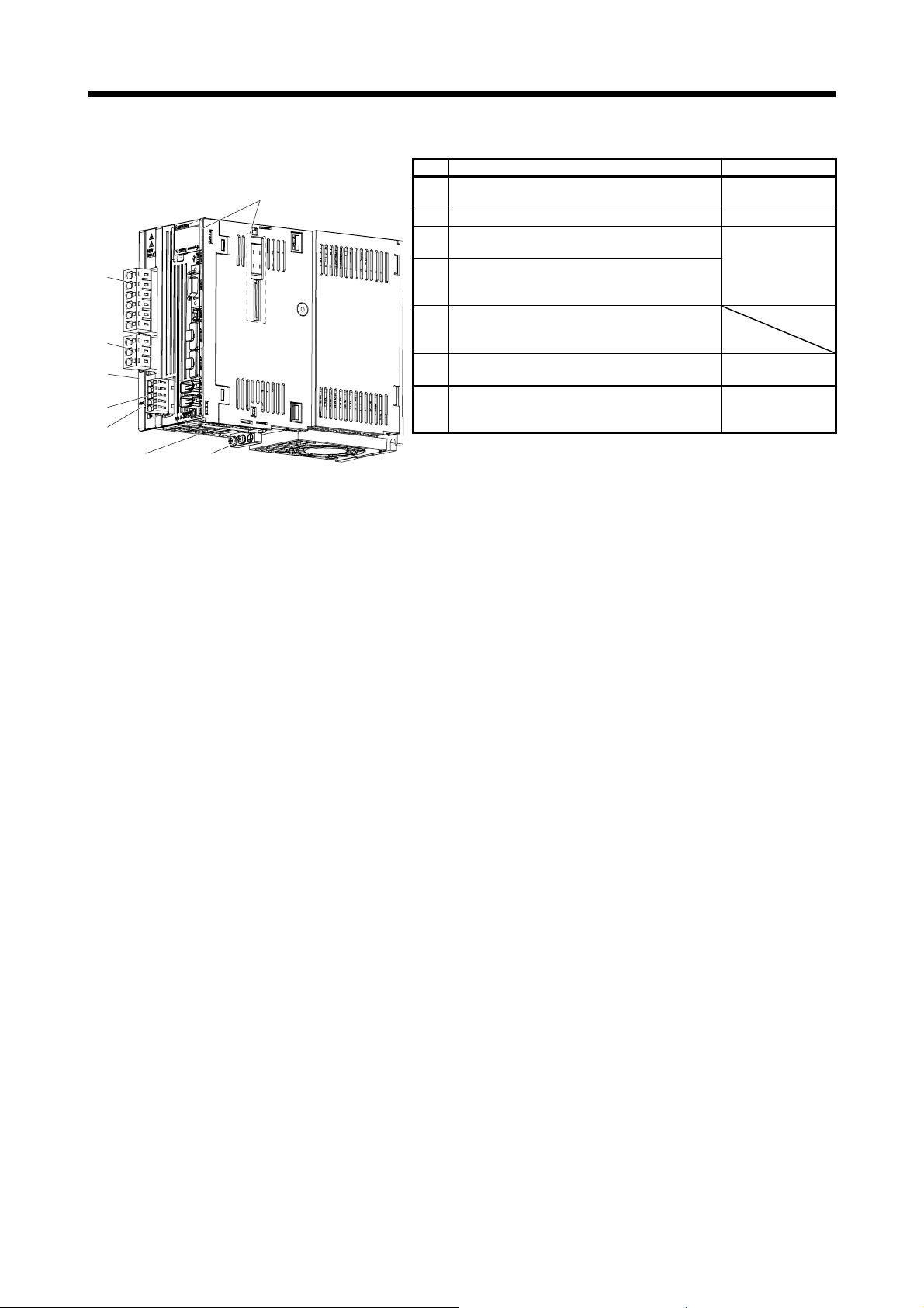
1. FUNCTIONS AND CONFIGURATION
(b) MR-J4-350B-RJ010
No. Name/Application Detailed explanation
Main circuit power supply connector (CNP1)
(1)
Connect the input power supply.
(2) Rating plate Section 1.6
Servo motor power supply connector (CNP3)
(3)
Connect the servo motor.
Control circuit power supply connector (CNP2)
(4)
Connect the control circuit power supply or
regenerative option.
Charge lamp
(5)
When the main circuit is charged, this will light.
While this lamp is lit, do not reconnect the cables.
Protective earth (PE) terminal
(6)
Grounding terminal
Battery holder
(7)
Install the the battery for absolute position data
backup.
(1)
(3)
(2)
Side
(4)
(5)
The broken line area is the same as
MR-J4-200B-RJ010 or less.
(6)(7)
MR-J4-_B_ section 3.1
MR-J4-_B_ section 3.3
MR-J4-_B_ section 3.1
MR-J4-_B_ section 3.3
MR-J4-_B_ section 3.1
MR-J4-_B_ section 3.3
MR-J4-_B_ section
12.2
1 - 16
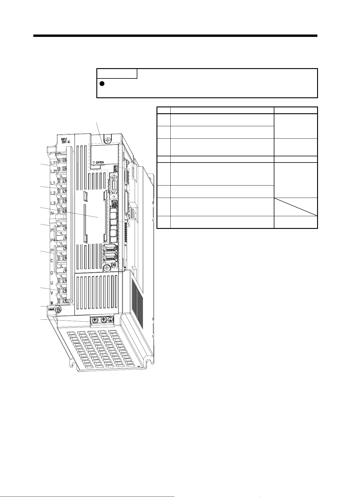
1. FUNCTIONS AND CONFIGURATION
(c) MR-J4-500B-RJ010
No. Name/Application Detailed explanation
Control circuit terminal block (TE2)
(1)
Used to connect the control circuit power supply.
Main circuit terminal block (TE1)
(2)
Connect the input power supply.
Battery holder
(3)
Install the the battery for absolute position data
backup.
(4) Rating plate Section 1.6
Regenerative option/power factor improving reactor
terminal block (TE3)
(5)
Used to connect regenerative options and a power
factor improving DC reactor.
Servo motor power supply terminal block (TE4)
(6)
Connect the servo motor.
Charge lamp
(7)
When the main circuit is charged, this will light.
While this lamp is lit, do not reconnect the cables.
Protective earth (PE) terminal
(8)
Grounding terminal
(1)
(2)
(3)
(Note)
(4)
Side
POINT
The servo amplifier is shown with the front cover open. The front cover cannot
be removed.
The broken line area is the same as
MR-J4-200B-RJ010 or less.
MR-J4-_B_ section 3.1
MR-J4-_B_ section 3.3
MR-J4-_B_ section
12.2
MR-J4-_B_ section 3.1
MR-J4-_B_ section 3.3
MR-J4-_B_ section 3.1
MR-J4-_B_ section 3.3
(5)
(6)
(7)
(8)
Note. Lines for slots around the battery holder are omitted from the illustration.
1 - 17
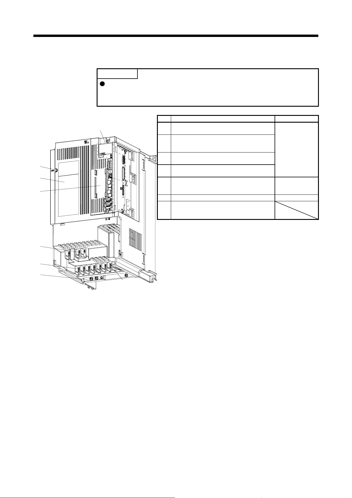
1. FUNCTIONS AND CONFIGURATION
(d) MR-J4-700B-RJ010
No. Name/Application Detailed explanation
Power factor improving reactor terminal block (TE3)
(1)
Used to connect the DC reactor.
Main circuit terminal block (TE1)
(2)
Used to connect the input power supply, regenerative
option, and servo motor.
Control circuit terminal block (TE2)
(3)
Used to connect the control circuit power supply.
Protective earth (PE) terminal
(4)
Grounding terminal
Battery holder
(5)
Install the the battery for absolute position data
backup.
(6) Rating plate Section 1.6
Charge lamp
(7)
When the main circuit is charged, this will light.
While this lamp is lit, do not reconnect the cables.
(7)
(6)
(5)
(Note)
POINT
The servo amplifier is shown without the front cover. For removal of the front
cover, refer to section 1.7.2 of "MR-J4-_B_(-RJ) Servo Amplifier Instruction
Manual".
The broken line area is the same as
MR-J4-200B-RJ010 or less.
MR-J4-_B_ section 3.1
MR-J4-_B_ section 3.3
MR-J4-_B_ section
12.2
(1)
(2)
(4)
(3)
Note. Lines for slots around the battery holder are omitted from the illustration.
1 - 18
1. FUNCTIONS AND CONFIGURATION
(e) MR-J4-11KB-RJ010/MR-J4-15KB-RJ010
No. Name/Application Detailed explanation
Power factor improving reactor terminal block (TE1-2)
(1)
Used to connect a power factor improving DC reactor
and a regenerative option.
Main circuit terminal block (TE1-1)
(2)
Used to connect the input power supply and servo
motor.
Control circuit terminal block (TE2)
(3)
Used to connect the control circuit power supply.
Protective earth (PE) terminal
(4)
Grounding terminal
Battery holder
(5)
Install the battery for absolute position data backup.
(6) Rating plate Section 1.6
Charge lamp
(7)
When the main circuit is charged, this will light up.
While this lamp is lit, do not reconnect the cables.
The broken line area is the same as
MR-J4-200B-RJ010 or less.
(7)
(7)
(6)
(6)
(5)
(Note)
POINT
The servo amplifier is shown without the front cover. For removal of the front
cover, refer to section 1.7.2 of "MR-J4-_B_(-RJ) Servo Amplifier Instruction
Manual".
MR-J4-_B_ section
3.1
MR-J4-_B_ section
3.3
MR-J4-_B_ section
12.2
(2)
(2)
(3)
(3)
(4)
(4)
(1)
(1)
Note. Lines for slots around the battery holder are omitted from the illustration.
1 - 19

1. FUNCTIONS AND CONFIGURATION
(f) MR-J4-22KB-RJ010
No. Name/Application Detailed explanation
Power factor improving reactor terminal block (TE1-2)
(1)
Used to connect a power factor improving DC reactor
and a regenerative option.
Main circuit terminal block (TE1-1)
(2)
Used to connect the input power supply and servo
motor.
Control circuit terminal block (TE2)
(3)
Used to connect the control circuit power supply.
Protective earth (PE) terminal
(4)
Grounding terminal
Battery holder
(5)
Install the battery for absolute position data backup.
(6) Rating plate Section 1.6
Charge lamp
(7)
When the main circuit is charged, this will light up.
While this lamp is lit, do not reconnect the cables.
(7)
(5)
(Note)
(6)
(2)
POINT
The servo amplifier is shown without the front cover. For removal of the front
cover, refer to section 1.7.2 of "MR-J4-_B_(-RJ) Servo Amplifier Instruction
Manual".
The broken line area is the same as
MR-J4-200B-RJ010 or less.
MR-J4-_B_ section
3.1
MR-J4-_B_ section
3.3
MR-J4-_B_ section
12.2
(3)
(1)
(4)
Note. Lines for slots around the battery holder are omitted from the illustration.
1 - 20

1. FUNCTIONS AND CONFIGURATION
(2) 400 V class
(a) MR-J4-200B4-RJ010 or less
No. Name/Application Detailed explanation
Display
(1)
The 3-digit, 7-segment LED shows the servo status
and the alarm number.
Axis selection rotary switch (SW1)
(2)
Used to set the axis No. of servo amplifier.
Control axis setting switch (SW2)
The test operation switch, the control axis deactivation
(3)
setting switch, and the auxiliary axis number setting
switch are available.
USB communication connector (CN5)
(4)
Connect with the personal computer.
I/O signal connector (CN3)
(5)
Used to connect digital I/O signals.
STO input signal connector (CN8)
(6)
Used to connect MR-J3-D05 safety logic unit or
external safety relay.
SSCNET III cable connector (CN1A)
(7)
Used to connect the servo system controller or the
previous axis servo amplifier.
SSCNET III cable connector (CN1B)
(8)
Used to connect the next axis servo amplifier. For the
final axis, put a cap.
Encoder connector (CN2)
(9)
Used to connect the servo motor encoder.
Battery connector (CN4)
(10)
Used to connect the battery for absolute position data
backup.
Battery holder
(11)
Install the battery for absolute position data backup.
Protective earth (PE) terminal
(12)
Grounding terminal
Main circuit power supply connector (CNP1)
(13)
Connect the input power supply.
(14) Rating plate Section 1.6
Control circuit power supply connector (CNP2)
(15)
Connect the control circuit power supply and
regenerative option.
Servo motor power output connector (CNP3)
(16)
Connect the servo motor.
Charge lamp
(17)
When the main circuit is charged, this will light up.
While this lamp is lit, do not reconnect the cables.
Manufacturer setting connector (CN2L)
(18)
This is not available with the servo amplifier.
Optional unit connector (CN7)
(19)
This is for connecting MR-J3-T10.
Manufacturer setting connector (CN9)
(20)
This is not available with the servo amplifier.
(17)
(4)
(5)
(6)
(13)
(15)
(7)
(8)
(16)
(9)
(18)
(14)
Side
(1)
(3)
(10) (11)
Bottom
(12)
Inside of the display
cover
(20)
(19)
(2)
MR-J4-_B_ section
4.3
MR-J4-_B_ section
11.7
MR-J4-_B_ section
3.2
Section 3.4
MR-J4-_B_ chapter
13
MR-J4-_B_ app. 5
MR-J4-_B_ section
3.2
MR-J4-_B_ section
3.4
MR-J4-_B_ section
3.4
MR-J4-_B_ chapter
12
MR-J4-_B_ section
12.2
MR-J4-_B_ section
3.1
MR-J4-_B_ section
3.3
MR-J4-_B_ section
3.1
MR-J4-_B_ section
3.3
Section 1.8
1 - 21

1. FUNCTIONS AND CONFIGURATION
(b) MR-J4-350B4-RJ010
The broken line area is the same as
MR-J4-200B4-RJ010 or less.
(1)
(7)
(3)
(2)
Side
(4)
(5)
No. Name/Application Detailed explanation
Main circuit power connector (CNP1)
Connect the input power supply.
(1)
(2) Rating plate Section 1.6
Control circuit power connector (CNP2)
(3)
Connect the control circuit power supply and
regenerative option.
Servo motor power output connector (CNP3)
(4)
Connect the servo motor.
Charge lamp
(5)
When the main circuit is charged, this will light up.
While this lamp is lit, do not reconnect the cables.
Protective earth (PE) terminal
Grounding terminal
(6)
Battery holder
(7)
Install the battery for absolute position data backup.
MR-J4-_B_ section
3.1
MR-J4-_B_ section
3.3
MR-J4-_B_ section
3.1
MR-J4-_B_ section
3.3
MR-J4-_B_ section
3.1
MR-J4-_B_ section
3.3
MR-J4-_B_ section
12.2
(6)
1 - 22

1. FUNCTIONS AND CONFIGURATION
(c) MR-J4-500B4-RJ010
No. Name/Application Detailed explanation
Control circuit terminal block (TE2)
(1)
Used to connect the control circuit power supply.
Main circuit terminal block (TE1)
(2)
Used to connect the input power supply.
Battery holder
(3)
Install the battery for absolute position data backup.
(4) Rating plate Section 1.6
Regenerative option, Power factor improving reactor
terminal block (TE3)
(5)
Used to connect a regenerative option and a power
factor improving DC reactor.
Charge lamp
(6)
When the main circuit is charged, this will light up.
While this lamp is lit, do not reconnect the cables.
Protective earth (PE) terminal
Grounding terminal
(7)
The broken line area is the same as
MR-J4-200B4-RJ010 or less.
(6)
(3)
(Note)
(4)
(5)
(1)
POINT
The servo amplifier is shown without the front cover. For removal of the front
cover, refer to section 1.7.2 of "MR-J4-_B_(-RJ) Servo Amplifier Instruction
Manual".
MR-J4-_B_ section
3.1
MR-J4-_B_ section
3.3
MR-J4-_B_ section
12.2
MR-J4-_B_ section
3.1
MR-J4-_B_ section
3.3
MR-J4-_B_ section
3.1
MR-J4-_B_ section
3.3
(2)
(7)
Note. Lines for slots around the battery holder are omitted from the illustration.
1 - 23

1. FUNCTIONS AND CONFIGURATION
(d) MR-J4-700B4-RJ010
No. Name/Application Detailed explanation
Power factor improving reactor terminal block (TE3)
(1)
Used to connect a power factor improving DC reactor.
Main circuit terminal block (TE1)
(2)
Used to connect the input power supply, regenerative
option and servo motor.
Control circuit terminal block (TE2)
(3)
Used to connect the control circuit power supply.
Protective earth (PE) terminal
(4)
Grounding terminal
Battery holder
(5)
Install the battery for absolute position data backup.
(6) Rating plate Section 1.6
Charge lamp
(7)
When the main circuit is charged, this will light up.
While this lamp is lit, do not reconnect the cables.
(7)
(6)
(5)
(Note)
POINT
The servo amplifier is shown without the front cover. For removal of the front
cover, refer to section 1.7.2 of "MR-J4-_B_(-RJ) Servo Amplifier Instruction
Manual".
The broken line area is the same as
MR-J4-200B4-RJ010 or less.
MR-J4-_B_ section
3.1
MR-J4-_B_ section
3.3
MR-J4-_B_ section
12.2
(1)
(2)
(4)
(3)
Note. Lines for slots around the battery holder are omitted from the illustration.
1 - 24

1. FUNCTIONS AND CONFIGURATION
(e) MR-J4-11KB4-RJ010/MR-J4-15KB4-RJ010
No. Name/Application Detailed explanation
Power factor improving reactor terminal block (TE1-2)
(1)
Used to connect a power factor improving DC reactor
and a regenerative option.
Main circuit terminal block (TE1-1)
(2)
Used to connect the input power supply and servo
motor.
Control circuit terminal block (TE2)
(3)
Used to connect the control circuit power supply.
Protective earth (PE) terminal
(4)
Grounding terminal
Battery holder
(5)
Install the battery for absolute position data backup.
(6) Rating plate Section 1.6
Charge lamp
(7)
When the main circuit is charged, this will light up.
While this lamp is lit, do not reconnect the cables.
The broken line area is the same as
MR-J4-200B4-RJ010 or less.
(7)
(7)
(6)
(6)
(5)
(Note)
POINT
The servo amplifier is shown without the front cover. For removal of the front
cover, refer to section 1.7.2 of "MR-J4-_B_(-RJ) Servo Amplifier Instruction
Manual".
MR-J4-_B_ section
3.1
MR-J4-_B_ section
3.3
MR-J4-_B_ section
12.2
(2)
(2)
(3)
(3)
(4)
(4)
(1)
(1)
Note. Lines for slots around the battery holder are omitted from the illustration.
1 - 25

1. FUNCTIONS AND CONFIGURATION
(f) MR-J4-22KB4-RJ010
No. Name/Application Detailed explanation
Power factor improving reactor terminal block (TE1-2)
(1)
Used to connect a power factor improving DC reactor
and a regenerative option.
Main circuit terminal block (TE1-1)
(2)
Used to connect the input power supply and servo
motor.
Control circuit terminal block (TE2)
(3)
Used to connect the control circuit power supply.
Protective earth (PE) terminal
(4)
Grounding terminal
Battery holder
(5)
Install the battery for absolute position data backup.
(6) Rating plate Section 1.6
Charge lamp
(7)
When the main circuit is charged, this will light up.
While this lamp is lit, do not reconnect the cables.
(7)
(5)
(Note)
(6)
(2)
POINT
The servo amplifier is shown without the front cover. For removal of the front
cover, refer to section 1.7.2 of "MR-J4-_B_(-RJ) Servo Amplifier Instruction
Manual".
The broken line area is the same as
MR-J4-200B4-RJ010 or less.
MR-J4-_B_ section
3.1
MR-J4-_B_ section
3.3
MR-J4-_B_ section
12.2
(3)
(1)
(4)
Note. Lines for slots around the battery holder are omitted from the illustration.
1 - 26

1. FUNCTIONS AND CONFIGURATION
1.7.2 Parts identification of MR-J3-T10
MR-J3-T10
RUN
ERR.
D LINK
(1)
SD
RD
L.ERR
(3)
(4)
CN10ACN10B
(2)
(2)
PUSH PUSH
No. Name/Application Detailed explanation
Display
RUN
D LINK
SD
(1)
RD
ERR.
L ERR.
Display
(2)
LINK
L.ER
CC-Link IE Field Network communication connector
(CN10A)
(3)
Connect to CC-Link IE Field Network.
CC-Link IE Field Network communication connector
(CN10B)
(4)
Connect to CC-Link IE Field Network.
Status of CC-Link IE communication is
displayed.
Section 4.3
Status of CC-Link IE communication is
displayed.
Section 3.1
Chapter 8
1 - 27

1. FUNCTIONS AND CONFIGURATION
1.8 Installation and removal of MR-J3-T10
Before installing or removing the CC-Link IE interface unit, turn off the power and
wait for 15 minutes or more until the charge lamp turns off. Then, confirm that the
WARNING
CAUTION
voltage between P+ and N- is safe with a voltage tester and others. Otherwise, an
electric shock may occur. In addition, when confirming whether the charge lamp is
off or not, always confirm it from the front of the servo amplifier.
Avoid installing and removing MR-J3-T10 repeatedly. Any contact failure of the
connector may be caused.
Avoid unsealing MR-J3-T10 to be free of dust and dirt against the connector
except installing. Make sure to use the pre-packing when storing.
Avoid using MR-J3-T10 of which the hook and knobs for fixing are damaged. Any
contact failure of the connector may be caused.
When installing and removing MR-J3-T10 to the MR-J4-500B-RJ010 or more,
avoid dropping out the installing screw inside it. Otherwise, it may cause a
malfunction.
When installing MR-J3-T10 to the MR-J3-500B-RJ010 or more, avoid damaging
the control board by the fixing plate. Otherwise, it may cause a malfunction.
Make sure to tighten MR-J3-T10 with the enclosed installing screws when
installing.
POINT
The internal circuits of the servo amplifier and MR-J3-T10 may be damaged by
static electricity. Always take the following precautions.
Ground human body and work bench.
Do not touch the conductive areas, such as connector pins and electrical
parts, directly by hand.
1 - 28

1. FUNCTIONS AND CONFIGURATION
(1) MR-J4-350B-RJ010 or smaller capacity models
(a) Installation of MR-J3-T10
1)
2)
2)
Guide pin
POINT
Do not remove the cover of the CN9 connector because the connector is not
used.
Guide hole
MR-J3-T10
1) Remove the cover of connector for connecting an option.
Make sure to store the removed cover.
2) Find the guide hole on the side of the servo amplifier. To
the guide hole, insert the MR-J3-T10's guide pins.
Knob
(b) Removal of MR-J3-T10
a)
2)
2)
b)
3) Push the four corners of the side of MR-J3-T10
simultaneously to the servo amplifier until the four knobs
click so that the CN7 connector is connected straight.
4) Tighten the unit with the enclosed installing screw (M4).
4)
1) Remove the installing screw.
2) Keep pushing the knobs ( a) , b) ) and pull out MR-J3-T10
to the arrow direction. Avoid pulling out MR-J3-T10 while it
is tightened with the installation screw.
1)
After removing MR-J3-T10, make sure to cap the
connector for connecting an option to avoid dust
and dirt.
1 - 29

1. FUNCTIONS AND CONFIGURATION
(2) MR-J4-350B-RJ010/MR-J4-500B-RJ010/MR-J4-700B-RJ010
(a) Removal of the side cover
1) Keep pushing the knobs ( a) , b) ) and pull out the side
cover to the arrow direction.
a)
1)
b)
(b) Installation of MR-J3-T10
1) Find the guide hole on the side of the servo amplifier. To
the guide hole, insert the MR-J3-T10's guide pins.
Guide hole
a)
1)
1)
Guide pin
2)
Knob
(c) Removal of MR-J3-T10
a)
2)2)
b)
2) Push MR-J3-T10 until the knobs click.
3) Tighten the unit with the enclosed installing screw (M4).
3)
1) Remove the installing screw.
2) Keep pushing the knobs ( a) , b) ) and pull out MR-J3-T10
to the arrow direction. Avoid pulling out MR-J3-T10 while it
is tightened with the installation screw.
1)
1 - 30

1. FUNCTIONS AND CONFIGURATION
(d) Installation of the side cover
a)
1)
1)
Side cover setting tab
1) Insert the side cover setting tabs into the sockets a) of
servo amplifier.
2) Push the side cover at the supporting point a) until the
knobs click.
2)
Knob
(3) MR-J4-11KB(4)-RJ010 to MR-J4-22KB(4)-RJ010
Avoid touching any remained burr after cutting off the part a) of the case.
CAUTION
Otherwise, it may cause injury.
The installing screw holes for the MR-J4-11KB(4)-RJ010 to MR-J4-22KB(4)-RJ010 servo amplifiers are
covered at shipping. When installing the unit for the first time, cut off the part a) of the case after
removing the side cover.
When cutting off the part a), avoid damaging the case of the servo amplifier. After cutting off it, inside of
the servo amplifier has been exposed even though the side cover and the unit are installed. Avoid
unwanted parts from entering through the opened area into the servo amplifier.
For installing or removing the unit, refer to (2) in this section. The side cover structure is the same for
MR-J4-11KB(4)-RJ010 to MR-J4-22KB(4)-RJ010 and for this unit. Install or remove the side cover with
the same way as for the unit. However, the installing screw for the side cover is unnecessary.
a)
1 - 31

1. FUNCTIONS AND CONFIGURATION
1.9 Configuration including peripheral equipment
CAUTION
1.9.1 200 V class
(1) MR-J4-200B-RJ010 or less
(Note 2)
Power supply
Molded-case
circuit breaker
(MCCB)
RS T
Connecting a servo motor for different axis to U, V, W, or CN2 of the servo
amplifier may cause a malfunction.
POINT
Equipment other than the servo amplifier and servo motor are optional or
recommended products.
Servo amplifier MR-J3-T10
CN5
MR Configurator2
Personal
computer
(Note 3)
Magnetic
contactor
(MC)
Line noise
filter
(FR-BSF01)
Power factor
improving DC
reactor
(FR-HEL)
Regenerative
option
(Note 1)
L1
L2
L3
P+
C
P3
P4
L11
L21
CN3
CN8
CN10A
U
V
W
CN10B
CN2
CN4
Battery
To safety relay or MR-J3-D05
safety logic unit
CC-Link IE
Field Network
CC-Link IE
Field Network
Junction terminal block
Servo motor
Note 1. The power factor improving AC reactor can also be used. In this case, the power factor improving DC reactor cannot be used.
When not using the power factor improving DC reactor, short P3 and P4.
2. A 1-phase 200 V AC to 240 V AC power supply may be used with the servo amplifier of MR-J4-70B-RJ010 or less. For 1phase 200 V AC to 240 V AC, connect the power supply to L1 and L3. Leave L2 open. For power supply specifications, refer to
section 1.3.1.
3. Depending on the main circuit voltage and operation pattern, bus voltage decreases, and that may cause the forced stop
deceleration to shift to the dynamic brake deceleration. When dynamic brake deceleration is not required, slow the time to turn
off the magnetic contactor.
1 - 32

1. FUNCTIONS AND CONFIGURATION
(2) MR-J4-350B-RJ010
(Note 2)
Power supply
Molded-case
circuit breaker
(MCCB)
(Note 3)
Magnetic
contactor
(MC)
Line noise
filter
(FR-BSF01)
RS T
Servo amplifier MR-J3-T10
(Note 1)
CN5
CN3
CN8
MR Configurator2
Personal
computer
Junction terminal block
To safety relay or MR-J3-D05
safety logic unit
Power factor
improving DC
reactor
(FR-HEL)
Regenerative
option
L1
L2
L3
P+
C
U
V
W
P3
P4
L11
L21
CN10A
CN10B
CN2
CN4
Battery
Servo motor
CC-Link IE
Field Network
CC-Link IE
Field Network
Note 1. The power factor improving AC reactor can also be used. In this case, the power factor improving DC reactor cannot be used.
When not using the power factor improving DC reactor, short P3 and P4.
2. For power supply specifications, refer to section 1.3.1.
3. Depending on the main circuit voltage and operation pattern, bus voltage decreases, and that may cause the forced stop
deceleration to shift to the dynamic brake deceleration. When dynamic brake deceleration is not required, slow the time to turn
off the magnetic contactor.
1 - 33

1. FUNCTIONS AND CONFIGURATION
(3) MR-J4-500B-RJ010
(Note 1)
RS T
Servo amplifier MR-J3-T10
L11
L21
(Note 2)
Power supply
Molded-case
circuit breaker
(MCCB)
(Note 3)
Magnetic
contactor
(MC)
MR Configurator2
CN5
CN3
Personal
computer
Junction terminal block
Line noise
filter
(FR-BLF)
Power factor
improving DC
reactor
(FR-HEL)
Regenerative
option
L1
L2
L3
P+
C
P3
P4
CN8
CN10A
CN10B
To safety relay or MR-J3-D05
safety logic unit
CC-Link IE
Field Network
CC-Link IE
Field Network
CN2
U
V
W
CN4
Servo motor
Battery
Note 1. The power factor improving AC reactor can also be used. In this case, the power factor improving DC reactor cannot be used.
When not using the power factor improving DC reactor, short P3 and P4.
2. For power supply specifications, refer to section 1.3.1.
3. Depending on the main circuit voltage and operation pattern, bus voltage decreases, and that may cause the forced stop
deceleration to shift to the dynamic brake deceleration. When dynamic brake deceleration is not required, slow the time to turn
off the magnetic contactor.
1 - 34

1. FUNCTIONS AND CONFIGURATION
(4) MR-J4-700B-RJ010
(Note 2)
Power supply
Molded-case
circuit breaker
(MCCB)
(Note 3)
Magnetic
contactor
(MC)
Line noise
filter
(FR-BLF)
RS T
Servo amplifier MR-J3-T10
(Note 1)
CN5
CN3
CN8
CN10A
MR Configurator2
Personal
computer
Junction terminal block
To safety relay or MR-J3-D05
safety logic unit
CC-Link IE
Field Network
Power factor
improving
DC reactor
(FR-HEL)
L3
L2
L1
P3
P4
L21
L11
C
P+
Regenerative
option
CN10B
CN2
CN4
Battery
WVU
Servo motor
CC-Link IE
Field Network
Note 1. The power factor improving AC reactor can also be used. In this case, the power factor improving DC reactor cannot be used.
When not using the power factor improving DC reactor, short P3 and P4.
2. For power supply specifications, refer to section 1.3.1.
3. Depending on the main circuit voltage and operation pattern, bus voltage decreases, and that may cause the forced stop
deceleration to shift to the dynamic brake deceleration. When dynamic brake deceleration is not required, slow the time to turn
off the magnetic contactor.
1 - 35

1. FUNCTIONS AND CONFIGURATION
(5) MR-J4-11KB-RJ010/MR-J4-15KB-RJ010
RS T
(Note 2)
Power supply
Molded-case
circuit breaker
(MCCB)
CN5
MR Configurator2
Personal
computer
(Note 3)
Magnetic
contactor
(MC)
(Note 1)
Line noise
filter
(FR-BLF)
L3
L2
L1
Power factor
improving DC
reactor
(FR-HEL)
P3
P4
L21
L11
CN3
CN8
CN10A
CN10B
CN2
CN4
Battery
Junction terminal block
To safety relay or MR-J3-D05
safety logic unit
CC-Link IE
Field Network
CC-Link IE
Field Network
P+ C
Regenerative
option
Servo motor
Note 1. The power factor improving AC reactor can also be used. In this case, the power factor improving DC reactor cannot be used.
When not using the power factor improving DC reactor, short P3 and P4.
2. For power supply specifications, refer to section 1.3.1.
3. Depending on the main circuit voltage and operation pattern, bus voltage decreases, and that may cause the forced stop
deceleration to shift to the dynamic brake deceleration. When dynamic brake deceleration is not required, slow the time to turn
off the magnetic contactor.
1 - 36

1. FUNCTIONS AND CONFIGURATION
(6) MR-J4-22KB-RJ010
(Note 2)
Power supply
Molded-case
circuit breaker
(MCCB)
(Note 3)
Magnetic
contactor
(MC)
Line noise
filter
(FR-BLF)
RS T
(Note 1)
CN5
CN3
CN8
CN10A
MR Configurator2
Personal
computer
Junction terminal block
To safety relay or MR-J3-D05
safety logic unit
CC-Link IE
Field Network
L3
L2
L1
Power factor
improving DC
reactor
(FR-HEL)
P3
P4
L21
L11
C
P+
Regenerative
option
CN10B
CN2
CN4
Battery
CC-Link IE
Field Network
Servo motor
Note 1. The power factor improving AC reactor can also be used. In this case, the power factor improving DC reactor cannot be used.
When not using the power factor improving DC reactor, short P3 and P4.
2. For power supply specifications, refer to section 1.3.1.
3. Depending on the main circuit voltage and operation pattern, bus voltage decreases, and that may cause the forced stop
deceleration to shift to the dynamic brake deceleration. When dynamic brake deceleration is not required, slow the time to turn
off the magnetic contactor.
1 - 37

1. FUNCTIONS AND CONFIGURATION
1.9.2 400 V class
(1) MR-J4-200B4-RJ010 or less
(Note 2)
Power supply
Molded-case
circuit breaker
(MCCB)
(Note 3)
Magnetic
contactor
(MC)
Line noise
filter
(FR-BSF01)
RS T
(Note 1)
MR Configurator2
CN5
CN3
CN8
Personal
computer
Junction terminal block
To safety relay or MR-J3-D05
safety logic unit
Power factor
improving DC
reactor
(FR-HEL-H)
Regenerative
option
L1
L2
L3
P+
C
P3
P4
L11
L21
CN10A
CN10B
U
V
W
CN2
CN4
Servo motor
Battery
CC-Link IE
Field Network
CC-Link IE
Field Network
Note 1. The power factor improving AC reactor can also be used. In this case, the power factor improving DC reactor cannot be used.
When not using the power factor improving DC reactor, short P3 and P4.
2. For power supply specifications, refer to section 1.3.1.
3. Depending on the main circuit voltage and operation pattern, bus voltage decreases, and that may cause the forced stop
deceleration to shift to the dynamic brake deceleration. When dynamic brake deceleration is not required, slow the time to turn
off the magnetic contactor.
1 - 38

1. FUNCTIONS AND CONFIGURATION
(2) MR-J4-350B4-RJ010
(Note 2)
Power supply
Molded-case
circuit breaker
(MCCB)
(Note 3)
Magnetic
contactor
(MC)
RS T
(Note 1)
CN5
CN3
MR Configurator2
Personal
computer
Junction terminal block
Line noise
filter
(FR-BSF01)
Power factor
improving DC
reactor
(FR-HEL-H)
Regenerative
option
L1
L2
L3
P+
C
P3
P4
L11
L21
CN8
CN10A
CN10B
CN2
U
V
W
CN4
Battery
To safety relay or MR-J3-D05
safety logic unit
CC-Link IE
Field Network
CC-Link IE
Field Network
Servo motor
Note 1. The power factor improving AC reactor can also be used. In this case, the power factor improving DC reactor cannot be used.
When not using the power factor improving DC reactor, short P3 and P4.
2. For power supply specifications, refer to section 1.3.1.
3. Depending on the main circuit voltage and operation pattern, bus voltage decreases, and that may cause the forced stop
deceleration to shift to the dynamic brake deceleration. When dynamic brake deceleration is not required, slow the time to turn
off the magnetic contactor.
1 - 39

1. FUNCTIONS AND CONFIGURATION
(3) MR-J4-500B4-RJ010
(Note 1)
RS T
L3
L2
L1
Power factor
improving DC
reactor
(FR-HEL-H)
P4
L21
L11
P3
(Note 2)
Power supply
Molded-case
circuit breaker
(MCCB)
(Note 3)
Magnetic
contactor
(MC)
Line noise
filter
(FR-BSF01)
CN5
CN3
CN8
CN10A
CN10B
CN2
CN4
Battery
MR Configurator2
Personal
computer
Junction terminal block
To safety relay or MR-J3-D05
safety logic unit
CC-Link IE
Field Network
CC-Link IE
Field Network
WVU
P+ C
Regenerative
option
Servo motor
Note 1. The power factor improving AC reactor can also be used. In this case, the power factor improving DC reactor cannot be used.
When not using the power factor improving DC reactor, short P3 and P4.
2. For power supply specifications, refer to section 1.3.1.
3. Depending on the main circuit voltage and operation pattern, bus voltage decreases, and that may cause the forced stop
deceleration to shift to the dynamic brake deceleration. When dynamic brake deceleration is not required, slow the time to turn
off the magnetic contactor.
1 - 40

1. FUNCTIONS AND CONFIGURATION
(4) MR-J4-700B4-RJ010
(Note 2)
Power supply
Molded-case
circuit breaker
(MCCB)
RS T
CN5
MR Configurator2
Personal
computer
(Note 3)
Magnetic
contactor
(MC)
(Note 1)
Line noise
filter
(FR-BLF)
Power factor
improving DC
reactor
(FR-HEL-H)
L3
L2
L1
P3
P4
L21
L11
CN3
CN8
CN10A
CN10B
CN2
CN4
Battery
WVU
To safety relay or MR-J3-D05
safety logic unit
CC-Link IE
Field Network
CC-Link IE
Field Network
Junction terminal block
C
P+
Regenerative
option
Servo motor
Note 1. The power factor improving AC reactor can also be used. In this case, the power factor improving DC reactor cannot be used.
When not using the power factor improving DC reactor, short P3 and P4.
2. For power supply specifications, refer to section 1.3.1.
3. Depending on the main circuit voltage and operation pattern, bus voltage decreases, and that may cause the forced stop
deceleration to shift to the dynamic brake deceleration. When dynamic brake deceleration is not required, slow the time to turn
off the magnetic contactor.
1 - 41

1. FUNCTIONS AND CONFIGURATION
(5) MR-J4-11KB4-RJ010/MR-J4-15KB4-RJ010
RS T
(Note 2)
Power supply
Molded-case
circuit breaker
(MCCB)
CN5
MR Configurator2
Personal
computer
(Note 3)
Magnetic
contactor
(MC)
(Note 1)
Line noise
filter
(FR-BLF)
L3
L2
L1
Power factor
improving DC
reactor
(FR-HEL)
P3
P4
L21
L11
CN3
CN8
CN10A
CN10B
CN2
CN4
Battery
Junction terminal block
To safety relay or MR-J3-D05
safety logic unit
CC-Link IE
Field Network
CC-Link IE
Field Network
P+ C
Regenerative
option
Servo motor
Note 1. The power factor improving AC reactor can also be used. In this case, the power factor improving DC reactor cannot be used.
When not using the power factor improving DC reactor, short P3 and P4.
2. For power supply specifications, refer to section 1.3.1.
3. Depending on the main circuit voltage and operation pattern, bus voltage decreases, and that may cause the forced stop
deceleration to shift to the dynamic brake deceleration. When dynamic brake deceleration is not required, slow the time to turn
off the magnetic contactor.
1 - 42

1. FUNCTIONS AND CONFIGURATION
(6) MR-J4-22KB4-RJ010
(Note 2)
Power supply
Molded-case
circuit breaker
(MCCB)
(Note 3)
Magnetic
contactor
(MC)
Line noise
filter
(FR-BLF)
RS T
(Note 1)
CN5
CN3
CN8
CN10A
MR Configurator2
Personal
computer
Junction terminal block
To safety relay or MR-J3-D05
safety logic unit
CC-Link IE
Field Network
L3
L2
L1
Power factor
improving DC
reactor
(FR-HEL)
P3
P4
L21
L11
C
P+
Regenerative
option
CN10B
CN2
CN4
Battery
CC-Link IE
Field Network
Servo motor
Note 1. The power factor improving AC reactor can also be used. In this case, the power factor improving DC reactor cannot be used.
When not using the power factor improving DC reactor, short P3 and P4.
2. For power supply specifications, refer to section 1.3.1.
3. Depending on the main circuit voltage and operation pattern, bus voltage decreases, and that may cause the forced stop
deceleration to shift to the dynamic brake deceleration. When dynamic brake deceleration is not required, slow the time to turn
off the magnetic contactor.
1 - 43

1. FUNCTIONS AND CONFIGURATION
MEMO
1 - 44

2. INSTALLATION
2. INSTALLATION
WARNING
CAUTION
The following item is the same as MR-J4-_B_ servo amplifiers. For details of the items, refer to each
chapter/section of the detailed description field. "MR-J4-_B_" means "MR-J4-_B_(-RJ) Servo Amplifier
Instruction Manual".
Keep out foreign materials MR-J4-_B_ section 2.2
Encoder cable stress MR-J4-_B_ section 2.3
Inspection items MR-J4-_B_ section 2.5
Parts having service lives MR-J4-_B_ section 2.6
To prevent electric shock, ground each equipment securely.
Stacking in excess of the specified number of product packages is not allowed.
Install the equipment on incombustible material. Installing it directly or close to
combustibles will lead to a fire.
Install the servo amplifier and the servo motor in a load-bearing place in
accordance with the Instruction Manual.
Do not get on or put heavy load on the equipment. Otherwise, it may cause injury.
Use the equipment within the specified environment. For the environment, refer to
section 1.3.
Provide adequate protection to prevent screws and other conductive matter, oil
and other combustible matter from entering the servo amplifier and MR-J3-T10.
Do not block the intake and exhaust areas of the servo amplifier and MR-J3-T10.
Otherwise, it may cause a malfunction.
Do not drop or strike the servo amplifier and MR-J3-T10. Isolate them from all
impact loads.
Do not install or operate the servo amplifier and MR-J3-T10 which have been
damaged or have any parts missing.
When the product has been stored for an extended period of time, contact your
local sales office.
When handling the servo amplifier and MR-J3-T10, be careful about the edged
parts such as corners of them.
The servo amplifier and MR-J3-T10 must be installed in a metal cabinet.
When fumigants that contain halogen materials such as fluorine, chlorine,
bromine, and iodine are used for disinfecting and protecting wooden packaging
from insects, they cause malfunction when entering our products. Please take
necessary precautions to ensure that remaining materials from fumigant do not
enter our products, or treat packaging with methods other than fumigation (heat
method). Additionally, disinfect and protect wood from insects before packing
products.
POINT
When pulling out CNP1, CNP2, and CNP3 connectors of MR-J4-10B-RJ010,
MR-J4-20B-RJ010, MR-J4-40B-RJ010, and MR-J4-60B-RJ010, pull out CN3
and CN8 connectors beforehand.
Item Detailed explanation
2 - 1

2. INSTALLATION
2.1 Installation direction and clearances
The equipment must be installed in the specified direction. Otherwise, it may
CAUTION
(1) Installation clearances of the servo amplifier
(a) Installation of one servo amplifier
cause a malfunction.
Leave specified clearances between the servo amplifier/MR-J3-T10 and the
cabinet walls or other equipment. Otherwise, it may cause a malfunction.
Cabinet Cabinet
40 mm or more
Servo amplifier
10 mm
or more
(Note 2)
40 mm
or more
(Note 1)
Note 1. For the 11 kW to 22 kW servo amplifiers, the clearance between the bottom and the ground will be 120 mm or more.
2. For the MR-J4-500B-RJ010, the clearance between the left side and wall will be 25 mm or more.
10 mm
or more
Wiring allowance
80 mm or more
Top
Bottom
2 - 2

2. INSTALLATION
t
t
(b) Installation of two or more servo amplifiers
POINT
Close mounting is possible depending on the capacity of the servo amplifier.
Refer to section 1.3.1 for availability of close mounting.
When mounting the servo amplifiers closely, do not install the servo amplifier
whose depth is larger than that of the left side servo amplifier since CNP1,
CNP2, and CNP3 connectors cannot be disconnected.
Leave a large clearance between the top of the servo amplifier and the cabinet walls, and install a
cooling fan to prevent the internal temperature of the cabinet from exceeding the environment.
When mounting the servo amplifiers closely, leave a clearance of 1 mm between the adjacent servo
amplifiers in consideration of mounting tolerances. In this case, keep the ambient temperature within
0 °C to 45 °C or use the servo amplifier with 75% or less of the effective load ratio.
Cabine
Cabine
100 mm or more
30 mm
or more
40 mm or more
(Note 1)
Leaving clearance Mounting closely
Note 1. For the 11 kW to 22 kW servo amplifiers, the clearance between the bottom and the ground will be 120 mm or more.
2. For the MR-J4-500B-RJ010, the clearance between the left side and wall will be 25 mm or more.
10 mm or more
(Note 2)
30 mm
or more
1 mm
100 mm or more
1 mm
40 mm or more
(2) Others
When using heat generating equipment such as the regenerative option, install them with full
consideration of heat generation so that the servo amplifier is not affected.
Install the servo amplifier on a perpendicular wall in the correct vertical direction.
30 mm
or more
Top
Bottom
2 - 3

2. INSTALLATION
2.2 Keep out foreign materials
(1) When drilling in the cabinet, prevent drill chips and wire fragments from entering the servo amplifier.
(2) Prevent oil, water, metallic dust, etc. from entering the servo amplifier through openings in the cabinet or
a cooling fan installed on the ceiling.
(3) When installing the cabinet in a place where toxic gas, dirt and dust exist, conduct an air purge (force
clean air into the cabinet from outside to make the internal pressure higher than the external pressure) to
prevent such materials from entering the cabinet.
2 - 4

3. SIGNALS AND WIRING
3. SIGNALS AND WIRING
Any person who is involved in wiring should be fully competent to do the work.
Before wiring, turn off the power and wait for 15 minutes or more until the charge
lamp turns off. Then, confirm that the voltage between P+ and N- is safe with a
voltage tester and others. Otherwise, an electric shock may occur. In addition,
when confirming whether the charge lamp is off or not, always confirm it from the
front of the servo amplifier.
WARNING
Ground the servo amplifier and servo motor securely.
Do not attempt to wire the servo amplifier and servo motor until they have been
installed. Otherwise, it may cause an electric shock.
The cables should not be damaged, stressed, loaded, or pinched. Otherwise, it
may cause an electric shock.
To avoid an electric shock, insulate the connections of the power supply
terminals.
Wire the equipment correctly and securely. Otherwise, the servo motor may
operate unexpectedly, resulting in injury.
Connect cables to the correct terminals. Otherwise, a burst, damage, etc. may
occur.
Ensure that polarity (+/-) is correct. Otherwise, a burst, damage, etc. may occur.
The surge absorbing diode installed to the DC relay for control output should be
fitted in the specified direction. Otherwise, the emergency stop and other
protective circuits may not operate.
Servo amplifier
DOCOM
24 V DC
Servo amplifier
DOCOM
24 V DC
CAUTION
Control output
signal
For sink output interface
RA
Control output
signal
For source output interface
RA
Use a noise filter, etc. to minimize the influence of electromagnetic interference.
Electromagnetic interference may be given to the electronic equipment used near
the servo amplifier.
Do not install a power capacitor, surge killer or radio noise filter (FR-BIF-(H)
option) with the power line of the servo motor.
When using the regenerative resistor, switch power off with the alarm signal.
Otherwise, a transistor fault or the like may overheat the regenerative resistor,
causing a fire.
Do not modify the equipment.
3 - 1

3. SIGNALS AND WIRING
Connect the servo amplifier power output (U, V, and W) to the servo motor power
input (U, V, and W) directly. Do not let a magnetic contactor, etc. intervene.
Otherwise, it may cause a malfunction.
Servo motor
U
V
W
Servo motorServo amplifier
U
M
V
W
U
V
W
CAUTION
Servo amplifier
U
V
W
Connecting a servo motor for different axis to U, V, W, or CN2 of the servo
amplifier may cause a malfunction.
The following item is the same as MR-J4-_B_ servo amplifiers. For details of the items, refer to each
chapter/section of the detailed description field. "MR-J4-_B_" means "MR-J4-_B_(-RJ) Servo Amplifier
Instruction Manual".
Item Detailed explanation
Input power supply circuit MR-J4-_B_ section 3.1
Explanation of power supply system MR-J4-_B_ section 3.3
Connector and pin assignment MR-J4-_B_ section 3.4
Signal (device) explanations MR-J4-_B_ section 3.5
Forced stop deceleration function MR-J4-_B_ section 3.6
Interface MR-J4-_B_ section 3.8
Grounding MR-J4-_B_ section 3.11
M
3 - 2

3. SIGNALS AND WIRING
3.1 I/O signal connection example
POINT
Be sure to mount a data line filter to the CC-Link IE Field Network cable.
For the branch of CC-Link IE Field Network by the switching hub, use DT135TX
(Mitsubishi Electric System & Service Co., Ltd.). For details of the switching hub,
refer to "MELSEC-Q QD77GF Simple Motion Module User's Manual (Positioning
Control)".
3.1.1 For sink I/O interface
10 m or shorter
(Note 12)
(Note 3, 4)
Forced stop 2
(Note 11)
(Note 5)
MR Configurator2
+
FLS
RLS
DOG
Main circuit power supply
(Note 7) 24 V DC
Personal
computer
MR-J3USBCBL3M
USB cable
(option)
Servo amplifier
(Note 9)
CN3
20EM2
DI1
12
DI2
19
DI3
DICOM 10
2
5DICOM
CN5
(Note 9)
CN3
3
13 MBR
15 ALM
6LA
16 LAR
7LB
17 LBR
8LZ
18 LZR
11 LG
10 m or shorter
(Note 7) 24 V DC
DOCOM
RA1
Electromagnetic brake interlock
RA3
Malfunction (Note 8)
(Note 2)
Encoder A-phase pulse
(differential line driver)
Encoder B-phase pulse
(differential line driver)
Encoder Z-phase pulse
(differential line driver)
Control common
(Note 10)
Analog monitor 1
±10 V DC
Analog monitor 2
±10 V DC
CC-Link IE Field Network
(Note 13)
Short-circuit connector
(Packed with the servo amplifier)
CC-Link IE Field Network
Data line filter
ZCAT1730-0730 (TDK)
80 mm or shorter 80 mm or shorter
CN8
CN1A
CN7
MR-J3-T10
(Note 14)
CN10A
MO1
4
LG
1
MO2
14
SDPlate
2 m or shorter
CN1B
CN10B
(Note 6)(Note 6)
(Note 1)
Data line filter
ZCAT1730-0730 (TDK)
3 - 3

3. SIGNALS AND WIRING
Note 1. To prevent an electric shock, always connect the protective earth (PE) terminal (marked
protective earth (PE) of the cabinet.
2. Connect the diode in the correct direction. If it is connected reversely, the servo amplifier will malfunction and will not output
signals, disabling EM2 (Forced stop 2) and other protective circuits.
3. If the controller does not have forced stop function, always install the forced stop 2 switch (normally closed contact).
4. When starting operation, always turn on EM2 (Forced stop 2). (Normally closed contact)
5. Use SW1DNC-MRC2-J. (Refer to "MR-J4-_B_(-RJ) Servo Amplifier Instruction Manual" section 11.7.)
6. CN1A and CN1B cannot be used. Be sure to cap CN1A and CN1B connector.
7. Supply 24 V DC ± 10% for interfaces from outside. Set the total current capacity to 300 mA. 300 mA is the value applicable
when all I/O signals are used. The current capacity can be decreased by reducing the number of I/O points. Refer to section
3.8.2 (1) of "MR-J4-_B_(-RJ) Servo Amplifier Instruction Manual" that gives the current value necessary for the interface. The
illustration of the 24 V DC power supply is divided between input signal and output signal for convenience. However, they can
be configured by one.
8. ALM (Malfunction) turns on in normal alarm-free condition. (Normally closed contact)
9. The pins with the same signal name are connected in the servo amplifier.
10. You can change devices of these pins with [Pr. PD07], [Pr. PD08], and [Pr. PD09].
11. Devices can be assigned for these devices with controller setting. For devices that can be assigned, refer to the controller
instruction manual. The following devices can be assigned for QD77GF_.
FLS: Upper stroke limit
RLS: Lower stroke limit
DOG: Proximity dog
12. Configure a circuit to turn off EM2 when the main circuit power is turned off to prevent an unexpected restart of the servo
amplifier.
13. When not using the STO function, attach a short-circuit connector supplied with a servo amplifier.
14. Connector covers are mounted on the CN10A and the CN10B connectors when the product is shipped from the factory.
Remove those connector covers to connect the CC-Link IE Field Network cables.
) of the servo amplifier to the
3 - 4

3. SIGNALS AND WIRING
3.1.2 For source I/O interface
POINT
For notes, refer to section 3.1.1.
(Note 3, 4)
Forced stop 2
(Note 11)
(Note 5)
MR Configurator2
+
FLS
RLS
DOG
(Note 7) 24 V DC
Personal
computer
10 m or shorter
(Note 12)
Main circuit power supply
USB cable
MR-J3USBCBL3M
(option)
Servo amplifier
(Note 9)
CN3
20EM2
DI1
12
DI2
19
DI3
DICOM 10
2
5DICOM
CN5
(Note 9)
CN3
3
13 MBR
15 ALM
6LA
16 LAR
7LB
17 LBR
8LZ
18 LZR
11 LG
10 m or shorter
(Note 7) 24 V DC
DOCOM
RA1
Electromagnetic brake interlock
RA3
Malfunction (Note 8)
(Note 2)
Encoder A-phase pulse
(differential line driver)
Encoder B-phase pulse
(differential line driver)
Encoder Z-phase pulse
(differential line driver)
Control common
(Note 10)
Analog monitor 1
±10 V DC
Analog monitor 2
±10 V DC
CC-Link IE Field Network
(Note 13)
Short-circuit connector
(Packed with the servo amplifier)
CC-Link IE Field Network
Data line filter
ZCAT1730-0730 (TDK)
80 mm or shorter 80 mm or shorter
CN8
CN1A
CN7
MR-J3-T10
(Note 14)
CN10A
MO1
4
LG
1
MO2
14
SDPlate
2 m or shorter
CN1B
CN10B
(Note 6)(Note 6)
(Note 1)
Data line filter
ZCAT1730-0730 (TDK)
3 - 5

3. SIGNALS AND WIRING
r
3.2 Servo motor with an electromagnetic brake
3.2.1 Safety precautions
Configure an electromagnetic brake circuit so that it is activated also by an
external EMG stop switch.
Contacts must be opened when ALM
(Malfunction) or MBR (Electromagnetic
brake interlock) turns off.
Contacts must be opened
with the EMG stop switch.
CAUTION
Servo motor
B
Electromagnetic brake
RA
The electromagnetic brake is provided for holding purpose and must not be used
for ordinary braking.
Before operating the servo motor, be sure to confirm that the electromagnetic
brake operates properly.
Do not use the 24 V DC interface power supply for the electromagnetic brake.
Always use the power supply designed exclusively for the electromagnetic brake.
Otherwise, it may cause a malfunction.
POINT
Refer to "Servo Motor Instruction Manual (Vol. 3)" for specifications such as the
power supply capacity and operation delay time of the electromagnetic brake.
Refer to "Servo Motor Instruction Manual (Vol. 3)" for the selection of a surge
absorber for the electromagnetic brake.
Note the following when the servo motor with an electromagnetic brake is used.
1) The brake will operate when the power (24 V DC) turns off.
2) Turn off the servo-on command after the servo motor stopped.
(1) Connection diagram
Servo amplifie
ALM
(Malfaunction)
(Note 1)
DOCOM
MBR
(Note 2)
24 V DC
MBR
RA1
24 V DC
RA1
24 V DC
B1
U
B2
Servo motor
B
Note 1. Create the circuit in order to shut off by interlocking with the emergency stop switch.
2. Do not use the 24 V DC interface power supply for the electromagnetic brake.
(2) Setting
In [Pr. PC02 Electromagnetic brake sequence output], set the time delay (Tb) from electromagnetic
brake operation to base circuit shut-off at a servo-off as in the timing chart in section 3.2.2.
3 - 6

3. SIGNALS AND WIRING
r
y
t
3.2.2 Timing chart
(1) When you use the forced stop deceleration function
POINT
To enable the function, set "2 _ _ _ (initial value)" in [Pr. PA04].
(a) At power-on to ready-off from the controller
Main circuit
Control circuit
Initialization
power supply
ON
OFF
EM2 (Forced stop 2)
Controlword
(Controller → Servo amplifier)
Statusword
(Servo amplifie
Controller)
→
Bus voltage
Internal inrush rela
Dynamic brake
Base circuit
(Energy supply to
he servo motor)
MBR
(Electromagnetic
brake interlock)
(Note 1)
Electromagnetic brake
ON (disabled)
OFF (enabled)
(A) Not ready
0 V
ON
OFF
Release
Operation
ON
OFF
ON
OFF
Release
Operation
Initial value
to switch on
(B) Switch on
disabled
(2) Shutdown (3) Switch on
(C) Ready to
switch on
215 V
100 ms
(Note 4)
Ready-on command on
(D) Switched on (E) Operation enabled
(4) Enable operation
Servo-on command on
Approx. 95 ms
(8) Shutdown
(C) Ready to
switch on
Operation command
(Controller→ Servo amplifier)
Servo motor speed
0 r/min
0 r/min
Gate-on processing
start
(Note 3)
Gate-on
blocked
Release delay
time and external
relay, etc. (Note 2)
Operation delay time of the
electromagnetic brake
Note 1. ON: Electromagnetic brake is not activated.
OFF: Electromagnetic brake is activated.
2. Electromagnetic brake is released after delaying for the release delay time of electromagnetic brake and operation time of
external circuit relay. For the release delay time of electromagnetic brake, refer to "Servo Motor Instruction Manual (Vol. 3)".
3. To prevent the servo motor from rotating rapidly at servo-on, give a current position as a position command from the controller
before servo-on.
4. It will be 200 ms for 5 kW and 7 kW servo amplifiers.
3 - 7

3. SIGNALS AND WIRING
r
t
(b) Servo-on command on/off
When servo-on command is turned off, the servo lock will be released after Tb [ms], and the servo
motor will coast. If the electromagnetic brake is enabled during servo-lock, the brake life may be
shorter. Therefore, set Tb about 1.5 times of the minimum delay time where the moving part will not
drop down for a vertical axis system, etc.
Main circuit
Control circuit
EM2 (Forced stop 2)
power supply
ON
OFF
ON (disabled)
OFF (enabled)
Controlword
(Controller → Servo amplifier)
Statusword
(Servo amplifie
Dynamic brake
Base circuit
(Energy supply to
he servo motor)
MBR
(Electromagnetic
brake interlock)
Electromagnetic brake
Servo motor speed
Note 1. ON: Electromagnetic brake is not activated.
OFF: Electromagnetic brake is activated.
2. Tb is a delay time from electromagnetic brake start to base circuit shut-off at servo-off. Set
Tb in [Pr. PC02].
Controller)
→
(Note 1)
Release
Operation
ON
OFF
ON
OFF
Release
Operation
0 r/min
(4) Enable operation
Servo-on command on
(5) Disable operation
Servo-on command off
(D) Switched on(E) Operation enabled
(Note 2)
Tb
Coasting
Operation delay time of
the electromagnetic brake
3 - 8

3. SIGNALS AND WIRING
r
t
A
W
POINT
To enable the function, set "2 _ _ _ (initial value)" in [Pr. PA04].
(c) Forced stop 2 on/off
EM2 (Forced stop 2)
ON (disabled)
OFF (enabled)
Controlword
(Controller → Servo amplifier)
Statusword
(Servo amplifie
Base circuit
(Energy supply to
he servo motor)
MBR
(Electromagnetic
brake interlock)
LM (Malfunction)
NG (Warning)
Dynamic brake
Servo motor speed
Note 1. ON: Electromagnetic brake is not activated.
2. The model speed command is a speed command generated in the servo amplifier for forced stop deceleration of
3. Tb is a delay time from electromagnetic brake start to base circuit shut-off at servo-off. Set Tb in [Pr. PC02].
Controller)
→
ON
OFF
(Note 1)
OFF: Electromagnetic brake is activated.
the servo motor.
ON
OFF
ON (No alarm)
OFF (alarm)
ON (No alarm)
OFF (alarm)
Release
Operation
0 r/min
(4) Enable operation
Servo-on command on
(E) Operation enabled (F) Quick stop active
(B) Switched on
disabled
(Note 3)
Tb
(Note 2)
Model speed command = 0, and
equal to or less than zero speed
3 - 9

3. SIGNALS AND WIRING
r
t
y
A
(d) Alarm occurrence
1) When the forced stop deceleration function is enabled
Alarm resetAlarm occurrence
EM2 (Forced stop 2)
Controlword
(Controller → Servo amplifier)
Statusword
(Servo amplifie
Base circuit
(Energy supply to
Controller)
→
he servo motor)
MBR
(Electromagnetic
brake interlock)
(Note 1)
LM (Malfunction)
Dynamic brake
Servo motor speed
ON (disabled)
OFF (enabled)
ON
OFF
ON
OFF
ON (No alarm)
OFF (alarm)
Release
Operation
0 r/min
(4) Enable operation
Servo-on command on
(E) Operation
enabled
(G) Fault reaction active
Controller command is ignored.
(15) Fault Reset
(4) Enable operation
Servo-on command on
(B) Switched on
disabled
(H) Fault
(Note 3)
Tb
(Note 2)
Model speed command = 0, and
equal to or less than zero speed
(C) Ready to
switch on
Approx. 210 ms
(Note 4)
(D) Switched on
(E) Operation
enabled
Servo amplifier displa
No alarm Alarm No. No alarm
Note 1. ON: Electromagnetic brake is not activated.
OFF: Electromagnetic brake is activated.
2. The model speed command is a speed command generated in the servo amplifier for forced stop deceleration of the servo
motor.
3. Tb is a delay time from electromagnetic brake start to base circuit shut-off at servo-off. Set Tb in [Pr. PC02].
4. Waiting time for relay-on + waiting time for servo-on
3 - 10

3. SIGNALS AND WIRING
r
t
y
A
2) When the forced stop deceleration function is disabled
Alarm occurrence
EM2 (Forced stop 2)
Controlword
(Controller → Servo amplifier)
Statusword
(Servo amplifie
Base circuit
(Energy supply to
Controller)
→
he servo motor)
MBR
(Electromagnetic
brake interlock)
(Note)
LM (Malfunction)
Dynamic brake
Servo motor speed
ON (disabled)
OFF (enabled)
ON
OFF
ON
OFF
ON (No alarm)
OFF (alarm)
Release
Operation
0 r/min
(4) Enable operation
Servo-on command on
(G) Fault reaction active
(H) Fault(E) Operation enabled
Dynamic brake
operation delay time
Approx. 10 ms
Operation delay time of the
electromagnetic brake
Dynamic brake
Dynamic brake +
electromagnetic brake
Servo amplifier displa
No alarm Alarm No.
Note. ON: Electromagnetic brake is not activated.
OFF: Electromagnetic brake is activated.
3 - 11

3. SIGNALS AND WIRING
r
t
y
A
3) When CC-Link IE Field communication brake occurred
EM2 (Forced stop 2)
Controlword
(Controller → Servo amplifier)
Statusword
(Servo amplifie
Base circuit
(Energy supply to
Controller)
→
he servo motor)
MBR
(Electromagnetic
brake interlock)
(Note 1)
LM (Malfunction)
Dynamic brake
ON (disabled)
OFF (enabled)
ON
OFF
ON
OFF
ON (No alarm)
OFF (alarm)
Release
Operation
Communication broke
(unexpected parallel off)
(Note 5)
(4) Enable operation
Servo-on command on
(E) Operation
enabled
Initial value
(F) Quick stop active
Communication recovered
(B) Switch on
(A) Not ready to switch on
(Note 3)
Tb
disabled
(parallel on)
(C) Ready to
(4) Enable operation
Servo-on command on
(D) Switched on
switch on
Approx. 210 ms
(Note 4)
(E) Operation
enabled
(Note 2)
Model speed command = 0, and
equal to or less than zero speed
Servo motor speed
Servo amplifier displa
0 r/min
No alarm (d1 or E7) AA No alarm
Note 1. ON: Electromagnetic brake is not activated.
OFF: Electromagnetic brake is activated.
2. The model speed command is a speed command generated in the servo amplifier for forced stop deceleration of the servo
motor.
3. Tb is a delay time from electromagnetic brake start to base circuit shut-off at servo-off. Set Tb in [Pr. PC02].
4. Waiting time for relay-on + waiting time for servo-on
5. A delay time will be generated between communication brake occurrence and deceleration start due to processing time of
parallel off. The dynamic brake will start depending on status of communication brake.
3 - 12

3. SIGNALS AND WIRING
r
t
A
(c) Both main and control circuit power supplies off
Main circuit, Control circuit
power
off
Main circuit
Control circuit
power supply
EM2 (Forced stop 2)
Controlword
(Controller → Servo amplifier)
Statusword
(Servo amplifie
Base circuit
(Energy supply to
he servo motor)
Controller)
→
MBR
(Electromagnetic
brake interlock)
LM (Malfunction)
[AL. 10.1 Undervoltage]
(Note 1)
Dynamic brake
Servo motor speed
ON
OFF
ON (disabled)
OFF (enabled)
ON
OFF
ON
OFF
ON (No alarm)
OFF (alarm)
Release
Operation
0 r/min
(4) Enable operation
Servo-on command on
(E) Operation
enabled
(Note 2)
Dynamic brake
operation delay time
Approx. 10 ms
Dynamic brake
Operation delay time of the
electromagnetic brake
Dynamic brake +
electromagnetic brake
Note 1. ON: Electromagnetic brake is not activated.
OFF: Electromagnetic brake is activated.
2. Variable according to the operation status.
3 - 13

3. SIGNALS AND WIRING
r
t
A
(d) Main circuit power supply off during control circuit power supply on
Main circuit
Control circuit
power supply
EM2 (Forced stop 2)
ON
OFF
ON (disabled)
OFF (enabled)
Controlword
(Controller → Servo amplifier)
Statusword
(Servo amplifie
Base circuit
(Energy supply to
Controller)
→
he servo motor)
MBR
(Electromagnetic
brake interlock)
(Note 1)
LM (Malfunction)
[AL. 10.1 Undervoltage]
Dynamic brake
Servo motor speed
ON
OFF
ON
OFF
ON (No alarm)
OFF (alarm)
Release
Operation
0 r/min
(4) Enable operation
Servo-on command on
(G) Fault reaction active
(E) Operation
enabled
The time until a bus
voltage drop is detected.
(Note 2)
Operation delay time of the
electromagnetic brake
(H) Fault
Forced stop deceleration
Dynamic brake
Dynamic brake +
electromagnetic brake
Approx. 10 ms
Dynamic brake operation delay time
Note 1. ON: Electromagnetic brake is not activated.
OFF: Electromagnetic brake is activated.
2. Variable according to the operation status.
3 - 14

3. SIGNALS AND WIRING
r
r
t
(2) When you do not use the forced stop deceleration function
POINT
To disable the function, set "0 _ _ _" in [Pr. PA04].
(a) At power-on to ready-off from the controller
It is the same as (1) (a) of this section.
(b) Servo-on command on/off
It is the same as (1) (b) of this section.
(c) Off/on of the forced stop command or Forced stop 1
Main circuit
Control circuit
Forced stop command
(Controller→ Servo amplifier)
o
EM1 (Forced stop 1)
Controlword
(Controller → Servo amplifier)
Statusword
(Servo amplifie
Base circuit
(Energy supply to
he servo motor)
MBR
(Electromagnetic
brake interlock)
Dynamic brake
Servo motor speed
power supply
Controller)
→
(Note 1)
ON
OFF
ON (disabled)
OFF (enabled)
ON
OFF
ON
OFF
Release
Operation
0 r/min
(4) Enable operation
Servo-on command on
(E) Operation
enabled
Operation delay time of the
electromagnetic brake
(B) Switched on disabled
Dynamic brake
operation delay time
Approx. 10 ms
Dynamic brake
Dynamic brake +
electromagnetic brake
(C) Ready to
Approx. 210 ms (Note 2)
(D) Switched on(F) Quick stop active
switch on
Electromagnetic brake release
(E) Operation
enabled
Note 1. ON: Electromagnetic brake is not activated.
OFF: Electromagnetic brake is activated.
2. Waiting time for relay-on + waiting time for servo-on
(d) Alarm occurrence
1) At alarm occurrence
The servo motor driving during an alarm is the same as (1) (d) 2) of this section.
3 - 15

3. SIGNALS AND WIRING
r
t
y
A
2) When CC-Link IE Field communication brake occurred
EM2 (Forced stop 2)
ON (disabled)
OFF (enabled)
Communication broke
(unexpected parallel off)
(Note 3)
Communication recovered
(parallel on)
Controlword
(Controller → Servo amplifier)
Statusword
(Servo amplifie
Base circuit
(Energy supply to
Controller)
→
he servo motor)
MBR
(Electromagnetic
brake interlock)
(Note 1)
LM (Malfunction)
Dynamic brake
Servo motor speed
Servo amplifier displa
ON
OFF
ON
OFF
ON (No alarm)
OFF (alarm)
Release
Operation
0 r/min
(4) Enable operation
Servo-on command on
(E) Operation enabled
No alarm (d1 or E7) AA No alarm
Initial value
(F) Quick stop active
(A) Not ready to switch on
Dynamic brake
operation delay time
Approx. 10 ms
Dynamic brake
Dynamic brake +
electromagnetic brake
Operation delay time of the
electromagnetic brake
(B) Switch on
disabled
(4) Enable operation
(C) Ready to
switch on
Approx. 210 ms
(Note 2)
Servo-on command on
(D) Switched on
(E) Operation
enabled
Note 1. ON: Electromagnetic brake is not activated.
OFF: Electromagnetic brake is activated.
2. Waiting time for relay-on + waiting time for servo-on
3. A delay time will be generated between communication brake occurrence and deceleration start due to processing time of
parallel off.
(e) Both main and control circuit power supplies off
It is the same as (1) (c) of this section.
3 - 16

3. SIGNALS AND WIRING
y
r
r
t
A
(f) Main circuit power supply off during control circuit power supply on
Main circuit power suppl
Forced stop command
(Controller→ Servo amplifier)
o
EM2 (Forced stop 2)
Controlword
(Controller → Servo amplifier)
Statusword
(Servo amplifie
Base circuit
(Energy supply to
Controller)
→
he servo motor)
MBR
(Electromagnetic
brake interlock)
(Note 1)
LM (Malfunction)
[AL. 10.1 Undervoltage]
Dynamic brake
Servo motor speed
ON
OFF
ON (disabled)
OFF (enabled)
ON
OFF
ON
OFF
ON (No alarm)
OFF (alarm)
Release
Operation
0 r/min
(4) Enable operation
Servo-on command on
(E) Operation
enabled
Operation delay time of the
electromagnetic brake
(G) Fault reaction active
(H) Fault
(Note 2)
Dynamic brake
operation delay time
Approx. 10 ms
Dynamic brake
Dynamic brake +
electromagnetic brake
Note 1. ON: Electromagnetic brake is not activated.
OFF: Electromagnetic brake is activated.
2. Waiting time for relay-on + waiting time for servo-on
3 - 17

3. SIGNALS AND WIRING
MEMO
3 - 18

4. STARTUP
4. STARTUP
WARNING
CAUTION
The following item is the same as MR-J4-_B_ servo amplifiers. For details of the items, refer to each
chapter/section of the detailed description field. "MR-J4-_B_" means "MR-J4-_B_(-RJ) Servo Amplifier
Instruction Manual".
Test operation MR-J4-_B_ section 4.4
Test operation mode MR-J4-_B_ section 4.5
Do not operate the switches with wet hands. Otherwise, it may cause an electric
shock.
Before starting operation, check the parameters. Improper settings may cause
some machines to operate unexpectedly.
The servo amplifier heat sink, regenerative resistor, servo motor, etc. may be hot
while power is on or for some time after power-off. Take safety measures, e.g.
provide covers, to avoid accidentally touching the parts (cables, etc.) by hand.
During operation, never touch the rotor of the servo motor. Otherwise, it may
cause injury.
Item Detailed explanation
4 - 1

4. STARTUP
4.1 Switching power on for the first time
When switching power on for the first time, follow this section to make a startup.
4.1.1 Startup procedure
Wiring check
Surrounding environment check
Axis No. settings
Parameter setting
Test operation of the servo motor
alone in test operation mode
Test operation of the servo
motor alone by commands
Test operation with the servo
motor and machine connected
Gain adjustment
Actual operation
Stop
Check whether the servo amplifier and servo motor are wired correctly using
visual inspection, DO forced output function ("MR-J4-_B_(-RJ) Servo
Amplifier Instruction Manual" section 4.5.1), etc. (Refer to section 4.1.2.)
Check the surrounding environment of the servo amplifier and servo motor.
(Refer to section 4.1.3.)
Set a station No. with the auxiliary station number setting switches (SW2-3,
SW2-4) and station number setting rotary switch (SW1). (Refer to section
4.2.1 (2).)
Set the parameters as necessary, such as the used operation mode and
regenerative option selection. (Refer to chapter 5.)
For the test operation, with the servo motor disconnected from the machine
and operated at the speed as low as possible, check whether the servo
motor rotates correctly. (Refer to "MR-J4-_B_(-RJ) Servo Amplifier
Instruction Manual" section 4.5.)
For the test operation with the servo motor disconnected from the machine
and operated at the speed as low as possible, give commands to the servo
amplifier and check whether the servo motor rotates correctly.
After connecting the servo motor with the machine, check machine motions
with sending operation commands from the controller.
Make gain adjustment to optimize the machine motions. (Refer to "MR-J4_B(-RJ) Servo Amplifier Instruction Manual" chapter 6.)
Stop giving commands and stop operation.
4 - 2

4. STARTUP
r
r
r
r
r
4.1.2 Wiring check
(1) Power supply system wiring
Before switching on the main circuit and control circuit power supplies, check the following items.
(a) Power supply system wiring
The power supplied to the power input terminals (L1, L2, L3, L11, and L21) of the servo amplifier
should satisfy the defined specifications. (Refer to section 1.3.1.)
(b) Connection of servo amplifier and servo motor
1) The servo amplifier power output (U, V, and W) should match in phase with the servo motor
power input terminals (U, V, and W).
Servo amplifie
U
V
W
Servo moto
U
V
W
M
2) The power supplied to the servo amplifier should not be connected to the power outputs (U, V,
and W). Doing so will fail the connected servo amplifier and servo motor.
Servo amplifier Servo motor
U
L1
V
L2
W
L3
U
V
W
M
3) The grounding terminal of the servo motor is connected to the PE terminal of the servo amplifier.
Servo amplifie
Servo moto
M
4) The CN2 connector of the servo amplifier should be connected to the encoder of the servo motor
securely using the encoder cable.
5) Between P3 and P4 should be connected.
Servo amplifie
P3
P4
(c) When you use an option and peripheral equipment
1) 200 V class
a) When you use a regenerative option for 5 kW or less servo amplifiers
The lead wire between P+ terminal and D terminal should not be connected.
The regenerative option should be connected to P+ terminal and C terminal.
A twisted cable should be used. (Refer to "MR-J4-_B_(-RJ) Servo Amplifier Instruction
Manual" section 11.2.4.)
4 - 3

4. STARTUP
r
b) When you use a regenerative option for 7 kW or more servo amplifiers
For 7 kW servo amplifiers, the lead wire of the built-in regenerative resistor connected to P+
terminal and C terminal should not be connected.
The regenerative option should be connected to P+ terminal and C terminal.
A twisted cable should be used. (Refer to "MR-J4-_B_(-RJ) Servo Amplifier Instruction
Manual" section 11.2.4.)
c) When you use a brake unit and power regeneration converter for 5 kW or more servo
amplifiers
For 5 kW or less servo amplifiers, the lead wire between P+ terminal and D terminal should
not be connected.
For 7 kW servo amplifiers, the lead wire of the built-in regenerative resistor connected to P+
terminal and C terminal should not be connected.
Brake unit or power regeneration converter should be connected to P+ terminal and Nterminal. (Refer to "MR-J4-_B_(-RJ) Servo Amplifier Instruction Manual" section 11.3 to
11.4.)
A twisted cable should be used when wiring is over 5m and under 10m using a brake unit.
(Refer to "MR-J4-_B_(-RJ) Servo Amplifier Instruction Manual" section 11.3.)
d) When you use a power regeneration common converter
For 5 kW or less servo amplifiers, the lead wire between P+ terminal and D terminal should
not be connected.
For 7 kW servo amplifiers, the lead wires of the built-in regenerative resistor connected to
P+ terminal and C terminal should not be connected.
The wire of power regeneration common converter should be connected to P4 terminal and
N- terminal. (Refer to "MR-J4-_B_(-RJ) Servo Amplifier Instruction Manual" section 11.5.)
e) The power factor improving DC reactor should be connected between P3 and P4. (Refer to
"MR-J4-_B_(-RJ) Servo Amplifier Instruction Manual" section 11.11.)
Power factor improving
DC reactor
(Note)
Servo amplifie
P3
P4
Note. Always disconnect between P3 and P4 terminals.
2) 400 V class
a) When you use a regenerative option for 3.5 kW or less servo amplifiers
The lead wire between P+ terminal and D terminal should not be connected.
The regenerative option should be connected to P+ terminal and C terminal.
A twisted cable should be used. (Refer to "MR-J4-_B_(-RJ) Servo Amplifier Instruction
Manual" section 11.2.4.)
b) When you use a regenerative option for 5 kW or more servo amplifiers
For 5 kW or 7 kW servo amplifiers, the lead wire of the built-in regenerative resistor
connected to P+ terminal and C terminal should not be connected.
The regenerative option should be connected to P+ terminal and C terminal.
A twisted cable should be used. (Refer to "MR-J4-_B_(-RJ) Servo Amplifier Instruction
Manual" section 11.2.4.)
4 - 4

4. STARTUP
r
c) When you use a brake unit and power regeneration converter for 5 kW or more servo
amplifiers
For 5 kW or 7 kW servo amplifiers, the lead wire of built-in regenerative resistor connected
to P+ terminal and C terminal should not be connected.
Brake unit, power regeneration converter should be connected to P+ terminal and Nterminal. (Refer to "MR-J4-_B_(-RJ) Servo Amplifier Instruction Manual" section 11.3 to
11.4.)
A twisted cable should be used when wiring is over 5m and under 10m using a brake unit.
(Refer to "MR-J4-_B_(-RJ) Servo Amplifier Instruction Manual" section 11.3.)
d) When you use a power regeneration common converter for 11 kW or more servo amplifiers
Power regeneration common converter should be connected to P4 terminal and N- terminal.
(Refer to "MR-J4-_B_(-RJ) Servo Amplifier Instruction Manual" section 11.5.)
e) The power factor improving DC reactor should be connected between P3 and P4. (Refer to
"MR-J4-_B_(-RJ) Servo Amplifier Instruction Manual" section 11.11.)
Power factor improving
DC reactor
(Note)
Servo amplifie
P3
P4
Note. Always disconnect between P3 and P4.
(2) I/O signal wiring
(a) The I/O signals should be connected correctly.
Use DO forced output to forcibly turn on/off the pins of the CN3 connector. This function can be used
to perform a wiring check. In this case, switch on the control circuit power supply only.
Refer to section 3.1 for details of I/O signal connection.
(b) 24 V DC or higher voltage is not applied to the pins of the CN3 connector.
(c) SD and DOCOM of the CN3 connector is not shorted.
Servo amplifier
CN3
DOCOM
SD
4 - 5

4. STARTUP
A
4.1.3 Surrounding environment
(1) Cable routing
(a) The wiring cables should not be stressed.
(b) The encoder cable should not be used in excess of its bending life. (Refer to "MR-J4-_B_(-RJ) Servo
(2) Environment
4.2 Switch setting and display of the servo amplifier
Switching to the test operation mode and setting station No. are enabled with switches on the servo
amplifier.
On the servo amplifier display (three-digit, seven-segment LED), check the status of communication with the
controller at power-on and station No., and diagnose a malfunction at occurrence of an alarm.
4.2.1 Switches
The following explains the test operation select switch, the auxiliary station number setting switches, and the
station number setting rotary switch.
Amplifier Instruction Manual" section 10.4.)
(c) The connector of the servo motor should not be stressed.
Signal cables and power cables are not shorted by wire offcuts, metallic dust or the like.
When switching the station number setting rotary switch (SW1) and auxiliary
station number setting switches (SW2), use an insulated screw driver. Do not use
WARNING
a metal screw driver. Touching patterns on electronic boards, lead of electronic
parts, etc. may cause an electric shock.
POINT
Turning "ON (up)" all the auxiliary station number setting switches (SW2)
enables an operation mode for manufacturer setting and displays "off". The
mode is not available. Set the auxiliary station number setting switches (SW2)
correctly according to this section.
Cycling the main circuit power supply and control circuit power supply enables
the setting of each switch.
3-digit, 7-segment LED
uxiliary station number
setting switches
(SW2)
Station number setting rotary switch
(SW1)
ON
1
234
Auxiliary station number setting switches
Switch for manufacturer setting
Test operation select switch
4 - 6

4. STARTUP
)
(1) Test operation select switch (SW2-1)
To use the test operation mode, turn "ON (up)" the switch. Turning "ON (up)" the switch enables the test
operation mode. In the test operation mode, the functions such as JOG operation, positioning operation,
and machine analyzer are available with MR Configurator2.
1ON2 3 4
Test operation select switch
Turn it "ON (up)".
(2) Switches for setting station No.
POINT
Set a station No. with the auxiliary station number setting switches (SW2-3,
SW2-4) and station number setting rotary switch (SW1). When connecting the
amplifier to the Mitsubishi simple motion module QD77GF_, set the station No.
between 1 and 16.
For setting the station number setting rotary switch, use a flat-blade screwdriver
with the blade edge width of 2.1 mm to 2.3 mm and the blade edge thickness of
0.6 mm to 0.7 mm.
When connecting the amplifier to the Mitsubishi simple motion module
QD77GF_, set the station No. between 1 and 16.
You can set the station No. between 1 and 63 by using the auxiliary station number setting switches with
the station number setting rotary switch. (Refer to (2) (c) in this section.)
If the same numbers are set to different stations in a single communication system, the system will not
operate properly. The station numbers may be set independently of the CC-Link IE cable connection
sequence. The following shows the description of each switch.
(a) Auxiliary station number setting switches (SW2-3 and SW2-4)
Turning these switches "ON (up)" enables you to set the station No. 16 or more.
(b) Station number setting rotary switch (SW1)
You can set the station No. between 1 and 63 by using auxiliary station number setting switches with
this switch. (Refer to (2) (c) of this section.)
Station number setting rotary switch (SW1
8
9
7
6
5
4
3
2
A
B
C
D
E
F
1
0
4 - 7

4. STARTUP
(c) Switch combination list for the station No. setting
The following lists show the setting combinations of the auxiliary station number setting switches and
station number setting rotary switch.
Station
Auxiliary station
number setting switch
1ON2 3 4
Auxiliary station
number setting switch
1ON2 3 4
number
setting rotary
switch
0
1 1 1 17
2 2 2 18
3 3 3 19
4 4 4 20
5 5 5 21
6 6 6 22
7 7 7 23
8 8 8 24
9 9 9 25
A 10 A 26
B 11 B 27
C 12 C 28
D 13 D 29
E 14 E 30
F 15
Station
number
setting rotary
switch
0 32 0 48
1 33 1 49
2 34 2 50
3 35 3 51
4 36 4 52
5 37 5 53
6 38 6 54
7 39 7 55
8 40 8 56
9 41 9 57
A 42 A 58
B 43 B 59
C 44 C 60
D 45 D 61
E 46 E 62
F 47
The station No. of the servo amplifier will be set in the following order of priority.
Priority order Prior station No.
1 Station No. specified with master station
2 Station No. 1 to 120 specified with [Pr. Po02] (Note)
3
Note. Set a station No. with [Pr. Po02] within the range of 1 to 120. Setting over the range will result in [AL. 37
Parameter error].
Station No.set with the station number setting rotary switch and auxiliary station number
setting switches when [Pr. Po02] is "0"
Station No.
Station No.
setting
standby
Station No.
Auxiliary station
number setting switch
1ON2 3 4
Auxiliary station
number setting switch
1ON2 3 4
Station
number
setting rotary
switch
0 16
F 31
Station
number
setting rotary
switch
F 63
Station No.
Station No.
4 - 8

4. STARTUP
4.2.2 Scrolling display
(1) Normal display
When there is no alarm, the station No. and blank are displayed in rotation.
After 1.6 s
Status
Blank
After 0.2 s
Status
(1 digit)
Station No.
(2 digits)
"b": Indicates ready-off and servo-off status.
"C": Indicates ready-on and servo-off status.
"d": Indicates ready-on and servo-on status.
(2) Alarm display
When an alarm occurs, the alarm number (two digits) and the alarm detail (one digit) are displayed
following the status display. For example, the following shows when [AL. 32 Overcurrent] is occurring.
After 0.8 s
Status
After 0.8 s
Alarm No.
After 0.2 s
Blank
Status
(1 digit)
Station No.
(2 digits)
"n": Indicates that an alarm is occurring.
Alarm No.
(2 digits)
Alarm detail
(1 digit)
4 - 9

4. STARTUP
4.2.3 Status display of a station
(1) Display sequence
Servo amplifier power on
Controller power on
(CC-Link IE communication starts)
System check in progress
Waiting for controller power-on (CC-Link IE communication)
Initial data communication with the servo system controller
(initialization communication)
When alarm occurs,
its alarm code appears.
(Note)
Ready-on
(Note)
Servo-on
(Note)
Ordinary operation
Controller power off
Controller power on
Ready-off, servo-off
Ready-on, servo-off
Ready-on, servo-on
When an alarm No. or warning No. is displayed
Example:
Example:
When [AL. 50 Overload 1] occurred
at station No. 1
Flickering
After 0.8 s
Flickering
After 0.8 s
Blank
When [AL. E1 Overload warning 1]
occurred at station No. 1
Flickering
After 0.8 s
Flickering
After 0.8 s
Blank
During a non servo-off causing warning,
the decimal point on the third digit LED
shows the servo-on status.
Alarm reset or warning cleared
Note.
Station
No. 1
Station
No. 2
Station
No. 63
The segment of the last 2 digits shows the station number.
4 - 10

4. STARTUP
(2) Indication list
Display Status Description
A b
Initializing
A b .
(Note 4) Initializing During initial setting for communication specifications
A C
Initializing
A A
Initializing standby
b # #
(Note 1) Ready-off The ready-off command from the controller was received.
d # #
(Note 1) Servo-on The servo-on command from the controller was received.
C # #
(Note 1) Servo-off The servo-off command from the controller was received.
(Note 2) Alarm and warning The alarm No. and the warning No. that occurred is displayed.
8 88
CPU error CPU watchdog error has occurred.
# #b.
(Note 1, 4)
# #d.
# #C.
Note 1. The meanings of ## are listed below. They are displayed in decimal to 99. However, they will be irregular from 100. (The
tenths and hundreds digits will be hexadecimal.)
## Description Remarks
00 Set to the test operation mode.
01 Station No. 1
02 Station No. 2
99 Station No. 99
A0 Station No. 100
A9 Station No. 109
B0 Station No. 110
b9 Station No. 119
C0 Station No. 120
2. "***" indicates the alarm No. and the warning No.
3. Requires the MR Configurator2.
4. The decimal point in the first digit flickers.
Initializing System check in progress
The servo amplifier power was switched on when the controller power was off.
The station Nos. set to the auxiliary station number setting switches (SW2-3 and
SW2-4) and the station number setting rotary switch (SW1) do not match the one
set to the servo system controller.
A servo amplifier malfunctioned, or communication error occurred with the
controller or the previous station servo amplifier.
The controller is malfunctioning.
The initial setting for communication specifications was completed and the amplifier
received a communication synchronization setting from the controller. Synchronizing
The power supply of controller was turned off during the servo amplifier power
supply on.
The communication did not continue and resulted in parallel off.
(Note 3)
Test operation mode
-- Station No. 0 (unspecified)
:
:
:
:
:
:
Motor-less operation
:
:
:
:
:
:
If 0 (unspecified) is set as the station No., the communication is
performed with the station No. set by the master station.
4 - 11

4. STARTUP
4.3 Display of MR-J3-T10 CC-Link IE Field Network interface unit
The table below shows the detailed description of the communication alarm display area. MR-J3-T10 has
eight kinds of LED indication.
Table 4.1 LED indication list
MR-J3-T10
RUN
ERR.
D LINK
SD
RD
L.ERR
CN10ACN10B
PUSH PUSH
Green
Red
Red
Green (LINK)
Red (L.ER)
Green (LINK)
Red (L.ER)
No. LED Name
1 RUN Operation status Lit Operating normally (RUN status)
2 D LINK Lit Linking data (In cyclic transmission)
Flickering Data not linked (after receiving Parameter)
Cyclic communication
status
3
4
SD Network transmission
status
RD Network reception
status
5 ERR. Unit error status Lit Unit error
6 L ERR. Line error status Lit Erroneous data is being received.
7
8
L ER
(port 1/2)
LINK
(port 1/2)
Line error status Lit Erroneous data is being received.
Link status Lit Linking up
LED
status
Extinguished
Extinguished
Hardware error (WDT error)
Data not linked (In parallel off)
Lit Data transmitting
Lit Data receiving
Extinguished
No problem found.
Description
The following shows indication example of each state.
No. Status RUN D LINK ERR. L ERR.
L ER
(port 1/2)
1 Error at start
- - -
2 Normal (condition before communication connection)
3 Normal (condition before cyclic commutation established)
-
-
4 Normal (during cyclic communication)
-
5 Error occurred (communication disabled due to MRJ3-T10
malfunction)
6 Error occurred (cyclic communication stopped due to MRJ3-
T10 malfunction)
-
-
7 Error occurred (WDT error) - - - 74.3
8 Error occurred (MR-J3-T10 came off)
9 Error occurred (cyclic communication stopped due to
incorrect setting)
-
10 Error occurred (erroneous data received) - - - 9E.1
11 Error occurred (parallel off due to twisted pair cable, etc.
came off)
12 Error occurred (cyclic data not received)
13 Error occurred (erroneous station/network No. designated by
the master)
-
-
- -
14 Reserved station specification - 8d.5
15 Error occurred (watchdog counter error)
16 Error occurred (synchronization error)
-
- -
( : Lit, : Extinguished, : Flickers, -: Refer to table 4.1.)
LINK
(port 1/2)
Servo
amplifier
display
74.1
74.2
37.1
1 to 5
Ab
Ab
AC
b**
C**
d**
74.4
74.5
75.3
75.4
9d.1
to
9d.4
8d.2
8d.1
8d.7
8d.3
8d.6
8d.8
8d.9
8d.A
4 - 12

5. PARAMETERS
5. PARAMETERS
CAUTION
5.1 Parameter list
Never make a drastic adjustment or change to the parameter values as doing so
will make the operation unstable.
If fixed values are written in the digits of a parameter, do not change these values.
Do not change parameters for manufacturer setting.
Do not set values other than described values to each parameter.
POINT
When you connect the amplifier to a controller, servo parameter values of the
controller will be written to each parameter.
POINT
The parameter whose symbol is preceded by * is enabled with the following
conditions:
*: After setting the parameter, cycle the power or reset the controller.
**: After setting the parameter, cycle the power.
5 - 1

5. PARAMETERS
5.1.1 Basic setting parameters ([Pr. PA_ _ ])
No. Symbol Name
PA01 For manufacturer setting 1000h
PA02 **REG Regenerative option 0000h
PA03 *ABS Absolute position detection system 0000h
PA04 *AOP1 Function selection A-1 2000h
PA05 For manufacturer setting 10000
PA06 1
PA07
PA08 ATU Auto tuning mode 0001h
PA09 RSP Auto tuning response 16
PA10 INP In-position range 1600 [pulse]
PA11 For manufacturer setting 1000.0
PA12 1000.0
PA13
PA14 *POL Rotation direction selection 0
PA15 *ENR Encoder output pulses 4000 [pulse/rev]
PA16 *ENR2 Encoder output pulses 2 1
PA17 For manufacturer setting 0000h
PA18
PA19 *BLK Parameter writing inhibit 00ABh
PA20 *TDS Tough drive setting 0000h
PA21 *AOP3 Function selection A-3 0001h
PA22 For manufacturer setting 0000h
PA23 DRAT Drive recorder arbitrary alarm trigger setting 0000h
PA24 AOP4 Function selection A-4 0000h
PA25 OTHOV One-touch tuning - Overshoot permissible level 0 [%]
PA26 For manufacturer setting 0000h
PA27 0000h
PA28 0000h
PA29 0000h
PA30 0000h
PA31 0000h
PA32
1
0000h
0000h
0000h
Initial
value
Unit
5 - 2

5. PARAMETERS
5.1.2 Gain/filter setting parameters ([Pr. PB_ _ ])
No. Symbol Name
PB01 FILT Adaptive tuning mode (adaptive filter II) 0000h
PB02 VRFT Vibration suppression control tuning mode (advanced vibration suppression control II) 0000h
PB03 For manufacturer setting 18000
PB04 FFC Feed forward gain 0 [%]
PB05 For manufacturer setting 500
PB06 GD2 Load to motor inertia ratio 7.00 [Multiplier]
PB07 PG1 Model loop gain 15.0 [rad/s]
PB08 PG2 Position loop gain 37.0 [rad/s]
PB09 VG2 Speed loop gain 823 [rad/s]
PB10 VIC Speed integral compensation 33.7 [ms]
PB11 For manufacturer setting 980
PB12 OVA Overshoot amount compensation 0 [%]
PB13 NH1 Machine resonance suppression filter 1 4500 [Hz]
PB14 NHQ1 Notch shape selection 1 0000h
PB15 NH2 Machine resonance suppression filter 2 4500 [Hz]
PB16 NHQ2 Notch shape selection 2 0000h
PB17 NHF Shaft resonance suppression filter 0000h
PB18 LPF Low-pass filter setting 3141 [rad/s]
PB19 VRF11 Vibration suppression control 1 - Vibration frequency 100.0 [Hz]
PB20 VRF12 Vibration suppression control 1 - Resonance frequency 100.0 [Hz]
PB21 VRF13 Vibration suppression control 1 - Vibration frequency damping 0.00
PB22 VRF14 Vibration suppression control 1 - Resonance frequency damping 0.00
PB23 VFBF Low-pass filter selection 0000h
PB24 *MVS Slight vibration suppression control 0000h
PB25 For manufacturer setting 0000h
PB26 0000h
PB27 10
PB28 1
PB29 7.00
PB30 0.0
PB31 0
PB32 0.0
PB33 0.0
PB34 0.0
PB35 0.00
PB36 0.00
PB37 1600
PB38 0.00
PB39 0.00
PB40 0.00
PB41 0
PB42 0
PB43 0000h
PB44
PB45 CNHF Command notch filter 0000h
PB46 NH3 Machine resonance suppression filter 3 4500 [Hz]
PB47 NHQ3 Notch shape selection 3 0000h
PB48 NH4 Machine resonance suppression filter 4 4500 [Hz]
PB49 NHQ4 Notch shape selection 4 0000h
PB50 NH5 Machine resonance suppression filter 5 4500 [Hz]
PB51 NHQ5 Notch shape selection 5 0000h
PB52 VRF21 Vibration suppression control 2 - Vibration frequency 100.0 [Hz]
PB53 VRF22 Vibration suppression control 2 - Resonance frequency 100.0 [Hz]
0.00
Initial
value
Unit
5 - 3

5. PARAMETERS
No. Symbol Name
PB54 VRF23 Vibration suppression control 2 - Vibration frequency damping 0.00
PB55 VRF24 Vibration suppression control 2 - Resonance frequency damping 0.00
PB56 For manufacturer setting 0.0
PB57 0.0
PB58 0.00
PB59 0.00
PB60 0.0
PB61 0.0
PB62 0000h
PB63 0000h
PB64
0000h
5.1.3 Extension setting parameters ([Pr. PC_ _ ])
Initial
value
Unit
No. Symbol Name
PC01 ERZ Error excessive alarm level 0 [rev]
PC02 MBR Electromagnetic brake sequence output 0 [ms]
PC03 *ENRS Encoder output pulse selection 0000h
PC04 **COP1 Function selection C-1 0000h
PC05 **COP2 Function selection C-2 0000h
PC06 *COP3 Function selection C-3 0000h
PC07 ZSP Zero speed 50 [r/min]
PC08 OSL Overspeed alarm detection level 0 [r/min]
PC09 MOD1 Analog monitor 1 output 0000h
PC10 MOD2 Analog monitor 2 output 0001h
PC11 MO1 Analog monitor 1 offset 0 [mV]
PC12 MO2 Analog monitor 2 offset 0 [mV]
PC13 MOSDL Analog monitor - Feedback position output standard data - Low 0 [pulse]
PC14 MOSDH Analog monitor - Feedback position output standard data - High 0
PC15 For manufacturer setting 0
PC16
PC17 **COP4 Function selection C-4 0000h
PC18 *COP5 Function selection C-5 0000h
PC19 For manufacturer setting 0000h
PC20 *COP7 Function selection C-7 0000h
PC21 *BPS Alarm history clear 0000h
PC22 For manufacturer setting 0
PC23
PC24 RSBR Forced stop deceleration time constant 100 [ms]
PC25 For manufacturer setting 0
PC26 0000h
PC27 0000h
PC28
PC29 *COPB Function selection C-B 0000h
PC30 For manufacturer setting 0
PC31 RSUP1 Vertical axis freefall prevention compensation amount 0 [0.0001 rev]
PC32 For manufacturer setting 0000h
PC33 0
PC34 100
PC35 0000h
PC36 0000h
PC37 0000h
PC38 0000h
PC39 0000h
PC40
0000h
0000h
0000h
0000h
Initial
value
Unit
[10000 pulses]
5 - 4

5. PARAMETERS
No. Symbol Name
PC41 For manufacturer setting 0000h
PC42 0000h
PC43 0000h
PC44 0000h
PC45 0000h
PC46 0000h
PC47 0000h
PC48 0000h
PC49 0000h
PC50 0000h
PC51 0000h
PC52 0000h
PC53 0000h
PC54 0000h
PC55 0000h
PC56 0000h
PC57 0000h
PC58 0000h
PC59 0000h
PC60 0000h
PC61 0000h
PC62 0000h
PC63 0000h
PC64
0000h
5.1.4 I/O setting parameters ([Pr. PD_ _ ])
Initial
value
Unit
No. Symbol Name
PD01 For manufacturer setting 0000h
PD02 *DIA2 Input signal automatic on selection 2 0000h
PD03 For manufacturer setting 0020h
PD04 0021h
PD05 0022h
PD06
PD07 *DO1 Output device selection 1 0005h
PD08 *DO2 Output device selection 2 0004h
PD09 *DO3 Output device selection 3 0003h
PD10 For manufacturer setting 0000h
PD11
PD12 *DOP1 Function selection D-1 0000h
PD13 For manufacturer setting 0000h
PD14 *DOP3 Function selection D-3 0000h
PD15 For manufacturer setting 0000h
PD16 0000h
PD17 0000h
PD18 0000h
PD19 0000h
PD20 0
PD21 0
PD22 0
PD23 0
PD24 0000h
PD25 0000h
PD26 0000h
PD27 0000h
PD28
0000h
0004h
0000h
Initial
value
Unit
5 - 5

5. PARAMETERS
No. Symbol Name
PD29 For manufacturer setting 0000h
PD30 0
PD31 0
PD32 0
PD33 0000h
PD34 0000h
PD35 0000h
PD36 0000h
PD37 0000h
PD38 0000h
PD39 0000h
PD40 0000h
PD41 0000h
PD42 0000h
PD43 0000h
PD44 0000h
PD45 0000h
PD46 0000h
PD47 0000h
PD48
0000h
5.1.5 Extension setting 2 parameters ([Pr. PE_ _ ])
Initial
value
Unit
No. Symbol Name
PE01 For manufacturer setting 0000h
PE02 0000h
PE03 0003h
PE04 1
PE05 1
PE06 400
PE07 100
PE08 10
PE09 0000h
PE10 0000h
PE11 0000h
PE12 0000h
PE13 0000h
PE14 0111h
PE15 20
PE16 0000h
PE17 0000h
PE18 0000h
PE19 0000h
PE20 0000h
PE21 0000h
PE22 0000h
PE23 0000h
PE24 0000h
PE25 0000h
PE26 0000h
PE27 0000h
PE28 0000h
PE29 0000h
PE30
0000h
Initial
value
Unit
5 - 6

5. PARAMETERS
No. Symbol Name
PE31 For manufacturer setting 0000h
PE32 0000h
PE33 0000h
PE34 1
PE35 1
PE36 0.0
PE37 0.00
PE38 0.00
PE39 20
PE40
PE41 EOP3 Function selection E-3 0000h
PE42 For manufacturer setting 0
PE43 0.0
PE44 0000h
PE45 0000h
PE46 0000h
PE47 0000h
PE48 0000h
PE49 0000h
PE50 0000h
PE51 0000h
PE52 0000h
PE53 0000h
PE54 0000h
PE55 0000h
PE56 0000h
PE57 0000h
PE58 0000h
PE59 0000h
PE60 0000h
PE61 0.00
PE62 0.00
PE63 0.00
PE64
0000h
0.00
5.1.6 Extension setting 3 parameters ([Pr. PF_ _ ])
Initial
value
Unit
No. Symbol Name
PF01 For manufacturer setting 0000h
PF02 0000h
PF03 0000h
PF04 0
PF05
PF06 *FOP5 Function selection F-5 0000h
PF07 For manufacturer setting 0000h
PF08 0000h
PF09 0
PF10 0
PF11
PF12 DBT Electronic dynamic brake operating time 2000 [ms]
PF13 For manufacturer setting 0000h
PF14 10
PF15 0000h
PF16 0000h
PF17 0000h
PF18
0000h
0
0000h
Initial
value
5 - 7
Unit

5. PARAMETERS
No. Symbol Name
PF19 For manufacturer setting 0000h
PF20
PF21 DRT Drive recorder switching time setting 0 [s]
PF22 For manufacturer setting 200
PF23 OSCL1 Vibration tough drive - Oscillation detection level 50 [%]
PF24 *OSCL2 Vibration tough drive function selection 0000h
PF25 CVAT SEMI-F47 function - Instantaneous power failure detection time 200 [ms]
PF26 For manufacturer setting 0
PF27 0
PF28 0
PF29 0000h
PF30
PF31 FRIC Machine diagnosis function - Friction judgement speed 0 [r/min]
PF32 For manufacturer setting 50
PF33 0000h
PF34 0000h
PF35 0000h
PF36 0000h
PF37 0000h
PF38 0000h
PF39 0000h
PF40 0000h
PF41 0000h
PF42 0000h
PF43 0000h
PF44 0000h
PF45 0000h
PF46 0000h
PF47 0000h
PF48
0000h
0
0000h
5.1.7 Option setting parameters ([Pr. Po_ _)
Initial
value
Unit
No. Symbol Name
Po01 For manufacturer setting 0000h
Po02 *STNO CC-Link IE communication station No. selection 0
Po03 *NWNO CC-Link IE communication network number 0
Po04 For manufacturer setting 0000h
Po05 0000h
Po06 0
Po07 0
Po08 0
Po09 0
Po10 0
Po11 0
Po12 0000h
Po13 0000h
Po14 0000h
Po15 0000h
Po16 0000h
Po17 0000h
Po18 0000h
Po19 0000h
Po20
0000h
Initial
value
Unit
5 - 8

5. PARAMETERS
No. Symbol Name
Po21 For manufacturer setting 0000h
Po22 0000h
Po23 0000h
Po24 0000h
Po25 0000h
Po26 0000h
Po27 0000h
Po28 0000h
Po29 0000h
Po30 0000h
Po31 0000h
Po32
0000h
Initial
value
Unit
5 - 9

5. PARAMETERS
5.2 Detailed list of parameters
POINT
"x" in the "Setting digit" columns means which digit to set a value.
5.2.1 Basic setting parameters ([Pr. PA_ _ ])
No. Symbol Name and function
PA02 **REG Regenerative option
Used to select the regenerative option.
Incorrect setting may cause the regenerative option to burn.
If a selected regenerative option is not for use with the servo amplifier, [AL. 37 Parameter
error] occurs.
Initial
value
[unit]
Refer to Name
and function
column.
Setting
range
Initial
Setting
digit
_ _ x x Regenerative option selection
00: Regenerative option is not used.
For servo amplifier of 100 W, regenerative option is not used.
For servo amplifier of 0.2 kW to 7 kW, built-in regenerative
resistor is used.
Supplied regenerative resistors or regenerative option is used
with the servo amplifier of 11 kW to 22 kW.
01: FR-RC-(H)/FR-CV-(H)/FR-BU2-(H)
When you use FR-RC-(H), FR-CV-(H) or FR-BU2-(H), select
"Mode 2 (_ _ _ 1)" of "Undervoltage alarm detection mode
selection" in [Pr. PC20].
02: MR-RB032
03: MR-RB12
04: MR-RB32
05: MR-RB30
06: MR-RB50 (Cooling fan is required.)
08: MR-RB31
09: MR-RB51 (Cooling fan is required.)
0B: MR-RB3N
0C: MR-RB5N (Cooling fan is required.)
80: MR-RB1H-4
81: MR-RB3M-4 (Cooling fan is required.)
82: MR-RB3G-4 (Cooling fan is required.)
83: MR-RB5G-4 (Cooling fan is required.)
84: MR-RB34-4 (Cooling fan is required.)
85: MR-RB54-4 (Cooling fan is required.)
91: MR-RB3U-4 (Cooling fan is required.)
92: MR-RB5U-4 (Cooling fan is required.)
FA: When the supplied regenerative resistor or a regenerative
option used with the servo amplifier of 11 kW to 22 kW is
cooled by a cooling fan to increase regenerative ability.
_ x _ _ For manufacturer setting 0h
x _ _ _ 0h
Explanation
value
00h
5 - 10

5. PARAMETERS
Initial
No. Symbol Name and function
PA03 *ABS Absolute position detection system
Set this parameter when using the absolute position detection system. The parameter is not
available in the speed control mode and torque control mode.
value
[unit]
Refer to Name
and function
column.
Initial
Setting
digit
_ _ _ x Absolute position detection system selection
0: Disabled (used in incremental system)
1: Enabled (used in absolute position detection system)
_ _ x _ For manufacturer setting 0h
_ x _ _ 0h
x _ _ _ 0h
PA04 *AOP1 Function selection A-1
This is used to select the forced stop input and forced stop deceleration function.
Explanation
Setting
digit
_ _ _ x For manufacturer setting 0h
_ _ x _ 0h
_ x _ _ Servo forced stop selection
0: Enabled (The forced stop input EM2 or EM1 is used.)
1: Disabled (The forced stop input EM2 and EM1 are not used.)
Refer to table 5.1 for details.
x _ _ _ Forced stop deceleration function selection
0: Forced stop deceleration function disabled (EM1)
2: Forced stop deceleration function enabled (EM2)
Refer to table 5.1 for details.
Deceleration method
0 0 _ _ EM1 MBR (Electromagnetic brake
2 0 _ _ EM2 MBR (Electromagnetic brake
0 1 _ _ Not using
2 1 _ _ Not using
Setting
value
EM2/EM1
EM2 or EM1
EM2 or EM1
Table 5.1 Deceleration method
EM2 or EM1 is off Alarm occurred
interlock) turns off without the
forced stop deceleration.
interlock) turns off after the
forced stop deceleration.
MBR (Electromagnetic brake
MBR (Electromagnetic brake
Explanation
MBR (Electromagnetic brake
interlock) turns off without the
forced stop deceleration.
MBR (Electromagnetic brake
interlock) turns off after the
forced stop deceleration.
interlock) turns off without the
forced stop deceleration.
interlock) turns off after the
forced stop deceleration.
value
0h
Refer to Name
and function
column.
Initial
value
0h
2h
Setting
range
5 - 11
 Loading...