

Mitsubishi MR-J4-100B(-RJ), MR-J4-20B(-RJ), MR-J4-350B(-RJ), MR-J4-200B(-RJ), MR-J4-500B(-RJ) Instruction Manual
...
General-Purpose AC Servo
SSCNET /H Interface
MODEL
MR-J4-_B_(-RJ)
SERVO AMPLIFIER
INSTRUCTION MANUAL
P
Safety Instructions
Please read the instructions carefully before using the equipment.
To use the equipment correctly, do not attempt to install, operate, maintain, or inspect the equipment until
you have read through this Instruction Manual, Installation guide, and appended documents carefully. Do not
use the equipment until you have a full knowledge of the equipment, safety information and instructions.
In this Instruction Manual, the safety instruction levels are classified into "WARNING" and "CAUTION".
WARNING
CAUTION
Note that the CAUTION level may lead to a serious consequence according to conditions.
Please follow the instructions of both levels because they are important to personnel safety.
What must not be done and what must be done are indicated by the following diagrammatic symbols.
Indicates that incorrect handling may cause hazardous conditions,
resulting in death or severe injury.
Indicates that incorrect handling may cause hazardous conditions,
resulting in medium or slight injury to personnel or may cause physical
damage.
Indicates what must not be done. For example, "No Fire" is indicated by
Indicates what must be done. For example, grounding is indicated by
In this Instruction Manual, instructions at a lower level than the above, instructions for other functions, and so
on are classified into "POINT".
After reading this Instruction Manual, keep it accessible to the operator.
.
.
A - 1
1. To prevent electric shock, note the following
WARNING
Before wiring and inspections, turn off the power and wait for 15 minutes or more until the charge lamp
turns off. Then, confirm that the voltage between P+ and N- is safe with a voltage tester and others.
Otherwise, an electric shock may occur. In addition, when confirming whether the charge lamp is off or
not, always confirm it from the front of the servo amplifier.
Ground the servo amplifier and servo motor securely.
Any person who is involved in wiring and inspection should be fully competent to do the work.
Do not attempt to wire the servo amplifier and servo motor until they have been installed. Otherwise, it
may cause an electric shock.
Do not operate switches with wet hands. Otherwise, it may cause an electric shock.
The cables should not be damaged, stressed, loaded, or pinched. Otherwise, it may cause an electric
shock.
During power-on or operation, do not open the front cover of the servo amplifier. Otherwise, it may cause
an electric shock.
Do not operate the servo amplifier with the front cover removed. High-voltage terminals and charging
area are exposed and you may get an electric shock.
Except for wiring and periodic inspection, do not remove the front cover of the servo amplifier even if the
power is off. The servo amplifier is charged and you may get an electric shock.
To prevent an electric shock, always connect the protective earth (PE) terminal (marked ) of the servo
amplifier to the protective earth (PE) of the cabinet.
To avoid an electric shock, insulate the connections of the power supply terminals.
2. To prevent fire, note the following
CAUTION
Install the servo amplifier, servo motor, and regenerative resistor on incombustible material. Installing
them directly or close to combustibles will lead to smoke or a fire.
Always connect a magnetic contactor between the power supply and the main circuit power supply (L1/
L2/L3) of the servo amplifier, in order to configure a circuit that shuts down the power supply on the side
of the servo amplifier’s power supply. If a magnetic contactor is not connected, continuous flow of a large
current may cause smoke or a fire when the servo amplifier malfunctions.
Always connect a molded-case circuit breaker, or a fuse to each servo amplifier between the power
supply and the main circuit power supply (L1/L2/L3) of the servo amplifier, in order to configure a circuit
that shuts down the power supply on the side of the servo amplifier’s power supply. If a molded-case
circuit breaker or fuse is not connected, continuous flow of a large current may cause smoke or a fire
when the servo amplifier malfunctions.
When using the regenerative resistor, switch power off with the alarm signal. Otherwise, a regenerative
transistor malfunction or the like may overheat the regenerative resistor, causing smoke or a fire.
Provide adequate protection to prevent screws and other conductive matter, oil and other combustible
matter from entering the servo amplifier and servo motor.
A - 2
3. To prevent injury, note the following
CAUTION
Only the power/signal specified in the Instruction Manual should be applied to each terminal. Otherwise,
it may cause an electric shock, fire, injury, etc.
Connect cables to the correct terminals. Otherwise, a burst, damage, etc., may occur.
Ensure that polarity (+/-) is correct. Otherwise, a burst, damage, etc., may occur.
The servo amplifier heat sink, regenerative resistor, servo motor, etc., may be hot while the power is on
and for some time after power-off. Take safety measures such as providing covers to avoid accidentally
touching them by hands and parts such as cables.
4. Additional instructions
The following instructions should also be fully noted. Incorrect handling may cause a malfunction, injury,
electric shock, fire, etc.
(1) Transportation and installation
CAUTION
Transport the products correctly according to their mass.
Stacking in excess of the specified number of product packages is not allowed.
Do not hold the front cover, cables, or connectors when carrying the servo amplifier. Otherwise, it may
drop.
Install the servo amplifier and the servo motor in a load-bearing place in accordance with the Instruction
Manual.
Do not get on or put heavy load on the equipment. Otherwise, it may cause injury.
The equipment must be installed in the specified direction.
Maintain specified clearances between the servo amplifier and the inner surfaces of a control cabinet or
other equipment.
Do not install or operate the servo amplifier and servo motor which have been damaged or have any
parts missing.
Do not block the intake and exhaust areas of the servo amplifier. Otherwise, it may cause a malfunction.
Do not drop or apply heavy impact on the servo amplifiers and the servo motors. Otherwise, it may cause
injury, malfunction, etc.
Do not strike the connector. Otherwise, it may cause a connection failure, malfunction, etc.
When you keep or use the equipment, please fulfill the following environment.
Item Environment
Ambient
temperature
Storage -20 °C to 65 °C (non-freezing)
Ambient
humidity
Storage
Ambience Indoors (no direct sunlight), free from corrosive gas, flammable gas, oil mist, dust, and dirt
Altitude 2000 m or less above sea level (Contact your local sales office for the altitude for options.)
Vibration resistance 5.9 m/s2, at 10 Hz to 55 Hz (X, Y, Z axes)
When the product has been stored for an extended period of time, contact your local sales office.
When handling the servo motor, be careful with the sharp edges of the servo motor.
The servo amplifier must be installed in a metal cabinet.
Operation 0 °C to 55 °C (non-freezing)
Operation
5 %RH to 90 %RH (non-condensing)
A - 3
CAUTION
When fumigants that contain halogen materials, such as fluorine, chlorine, bromine, and iodine, are used
for disinfecting and protecting wooden packaging from insects, they cause a malfunction when entering
our products. Please take necessary precautions to ensure that remaining materials from fumigant do not
enter our products, or treat packaging with methods other than fumigation, such as heat treatment.
Additionally, disinfect and protect wood from insects before packing the products.
To prevent a fire or injury in case of an earthquake or other natural disasters, securely install, mount, and
wire the servo motor in accordance with the Instruction Manual.
(2) Wiring
CAUTION
Wire the equipment correctly and securely. Otherwise, the servo motor may operate unexpectedly.
Make sure to connect the cables and connectors by using the fixing screws and the locking mechanism.
Otherwise, the cables and connectors may be disconnected during operation.
Do not install a power capacitor, surge killer, or radio noise filter (optional FR-BIF(-H)) on the servo
amplifier output side.
To avoid a malfunction, connect the wires to the correct phase terminals (U/V/W) of the servo amplifier
and servo motor.
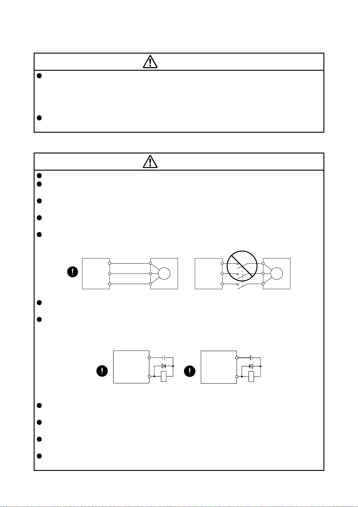
Connect the servo amplifier power output (U/V/W) to the servo motor power input (U/V/W) directly. Do
not connect a magnetic contactor and others between them. Otherwise, it may cause a malfunction.
Servo amplifier
U
V
W
Servo motor
U
V
W
Servo motorServo amplifier
U
M
V
W
U
V
W
M
The connection diagrams in this Instruction Manual are shown for sink interfaces, unless stated
otherwise.
The surge absorbing diode installed to the DC relay for control output should be fitted in the specified
direction. Otherwise, the converter unit and the drive unit will malfunction and will not output signals,
disabling the emergency stop and other protective circuits.
Servo amplifier
DOCOM
Control output
signal
For sink output interface
24 V DC
RA
Servo amplifier
24 V DC
DOCOM
Control output
signal
For source output interface
RA
When the wires are not tightened enough to the terminal block, the wires or terminal block may generate
heat because of the poor contact. Be sure to tighten the wires with specified torque.
Connecting a servo motor of the wrong axis to U, V, W, or CN2 of the servo amplifier may cause a
malfunction.
Configure a circuit to turn off EM2 or EM1 when the main circuit power supply is turned off to prevent an
unexpected restart of the servo amplifier.
To prevent malfunction, avoid bundling power lines (input/output) and signal cables together or running
them in parallel to each other. Separate the power lines from the signal cables.
A - 4
(3) Test run and adjustment
CAUTION
When executing a test run, follow the notice and procedures in this instruction manual. Otherwise, it may
cause a malfunction, damage to the machine, or injury.
Before operation, check and adjust the parameter settings. Improper settings may cause some machines
to operate unexpectedly.
Never make a drastic adjustment or change to the parameter values as doing so will make the operation
unstable.
Do not get close to moving parts during the servo-on status.
(4) Usage
CAUTION
Provide an external emergency stop circuit to stop the operation and shut the power off immediately.
For equipment in which the moving part of the machine may collide against the load side, install a limit
switch or stopper to the end of the moving part. The machine may be damaged due to a collision.
Do not disassemble, repair, or modify the product. Otherwise, it may cause an electric shock, fire, injury,
etc. Disassembled, repaired, and/or modified products are not covered under warranty.
Before resetting an alarm, make sure that the run signal of the servo amplifier is off in order to prevent a
sudden restart. Otherwise, it may cause an accident.
Use a noise filter, etc., to minimize the influence of electromagnetic interference. Electromagnetic
interference may affect the electronic equipment used near the servo amplifier.
Do not burn or destroy the servo amplifier. Doing so may generate a toxic gas.
Use the servo amplifier with the specified servo motor.
Wire options and peripheral equipment, etc. correctly in the specified combination. Otherwise, it may
cause an electric shock, fire, injury, etc.
The electromagnetic brake on the servo motor is designed to hold the motor shaft and should not be
used for ordinary braking.
For such reasons as incorrect wiring, service life, and mechanical structure (e.g. where a ball screw and
the servo motor are coupled via a timing belt), the electromagnetic brake may not hold the motor shaft.
To ensure safety, install a stopper on the machine side.
If the dynamic brake is activated at power-off, alarm occurrence, etc., do not rotate the servo motor by an
external force. Otherwise, it may cause a fire.
A - 5
(5) Corrective actions
CAUTION
Ensure safety by confirming the power off, etc. before performing corrective actions. Otherwise, it may
cause an accident.
If it is assumed that a power failure, machine stoppage, or product malfunction may result in a hazardous
situation, use a servo motor with an electromagnetic brake or provide an external brake system for
holding purpose to prevent such hazard.
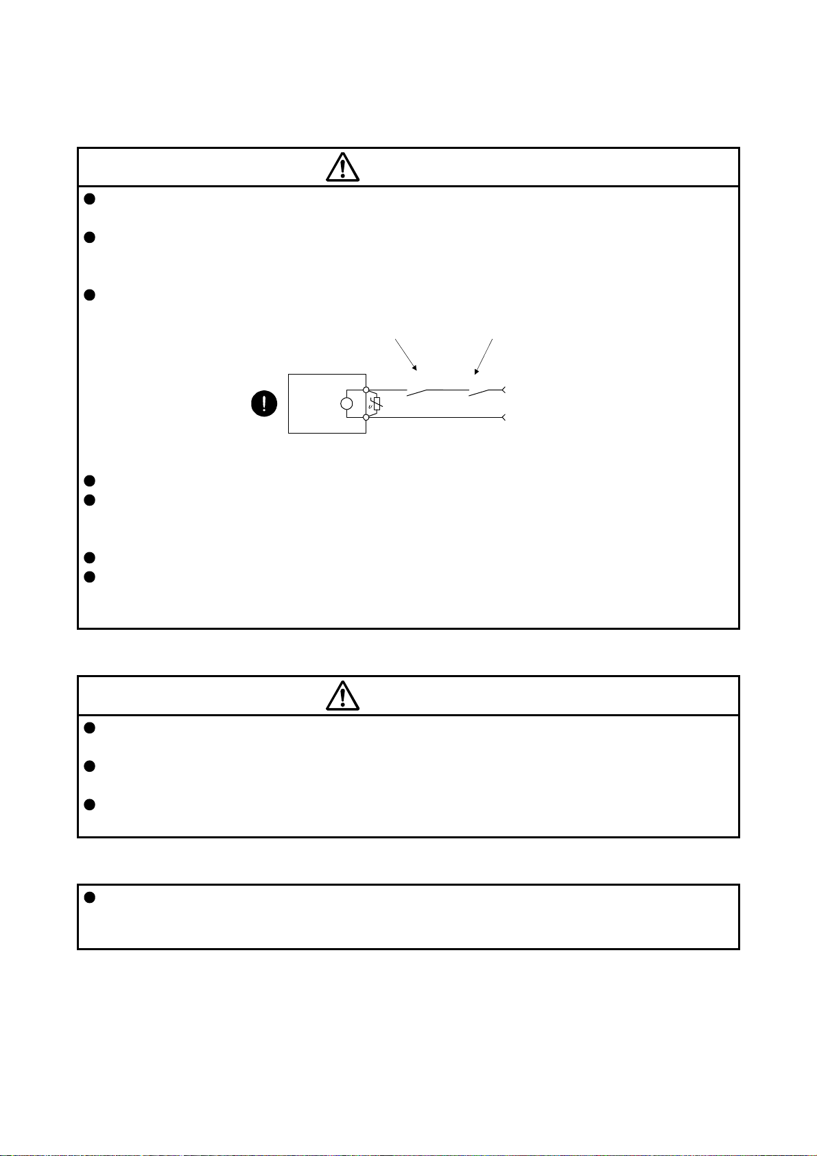
Configure an electromagnetic brake circuit which is interlocked with an external emergency stop switch.
Contacts must be opened when ALM
(Malfunction) or MBR (Electromagnetic
brake interlock) turns off.
Contacts must be opened with
the emergency stop switch.
Servo motor
B
Electromagnetic brake
When an alarm occurs, eliminate its cause, ensure safety, and deactivate the alarm to restart operation.
If the molded-case circuit breaker or fuse is activated, be sure to remove the cause and secure safety
before switching the power on. If necessary, replace the servo amplifier and recheck the wiring.
Otherwise, it may cause smoke, fire, or an electric shock.
Provide an adequate protection to prevent unexpected restart after an instantaneous power failure.
After an earthquake or other natural disasters, ensure safety by checking the conditions of the
installation, mounting, wiring, and equipment before switching the power on to prevent an electric shock,
injury, or fire.
RA
24 V DC
(6) Maintenance, inspection and parts replacement
CAUTION
Make sure that the emergency stop circuit operates properly such that an operation can be stopped
immediately and a power is shut off by the emergency stop switch.
It is recommended that the servo amplifier be replaced every 10 years when it is used in general
environment.
When using the servo amplifier that has not been energized for an extended period of time, contact your
local sales office.
(7) General instruction
To illustrate details, the equipment in the diagrams of this Instruction Manual may have been drawn
without covers and safety guards. When the equipment is operated, the covers and safety guards must
be installed as specified. Operation must be performed in accordance with this Instruction Manual.
A - 6
DISPOSAL OF WASTE
Please dispose a servo amplifier, battery (primary battery) and other options according to your local laws and
regulations.
EEP-ROM life
The number of write times to the EEP-ROM, which stores parameter settings, etc., is limited to 100,000. If
the total number of the following operations exceeds 100,000, the servo amplifier may malfunction when the
EEP-ROM reaches the end of its useful life.
Write to the EEP-ROM due to parameter setting changes
Write to the EEP-ROM due to device changes
STO function of the servo amplifier
The servo amplifier complies with safety integrity level 3 (SIL 3) of the IEC 61508:2010 functional safety
standard.
Refer to app. 14 for schedule.
When using the STO function of the servo amplifier, refer to chapter 13.
For the MR-J3-D05 safety logic unit, refer to app. 5.
Compliance with global standards
For the compliance with global standards, refer to app. 4.
«About the manuals»
You must have this Instruction Manual and the following manuals to use this servo. Ensure to prepare
them to use the servo safely.
Relevant manuals
Manual name Manual No.
MELSERVO MR-D30 Instruction Manual (Note 5) SH(NA)030132ENG
MELSERVO MR-CV_/MR-CR55K_/MR-J4-DU_(-RJ) Instruction Manual (Note 6) SH(NA)030153ENG
MELSERVO-J4 Servo Amplifier Instruction Manual (Troubleshooting) SH(NA)030109ENG
MELSERVO Servo Motor Instruction Manual (Vol. 3) (Note 1) SH(NA)030113ENG
MELSERVO Linear Servo Motor Instruction Manual (Note 2) SH(NA)030110ENG
MELSERVO Direct Drive Motor Instruction Manual (Note 3) SH(NA)030112ENG
MELSERVO Linear Encoder Instruction Manual (Note 2, 4) SH(NA)030111ENG
MELSERVO EMC Installation Guidelines IB(NA)67310ENG
Note 1. It is necessary for using a rotary servo motor.
2. It is necessary for using a linear servo motor.
3. It is necessary for using a direct drive motor.
4. It is necessary for using a fully closed loop system.
5. It is necessary for using an MR-D30 functional safety unit.
6. It is necessary for using an MR-CV_ power regeneration converter unit/MR-CR_ resistance regeneration
converter unit, and MR-J4-DU_B_(-RJ) drive unit.
A - 7

«Wiring»
Wires mentioned in this Instruction Manual are selected based on the ambient temperature of 40 °C.
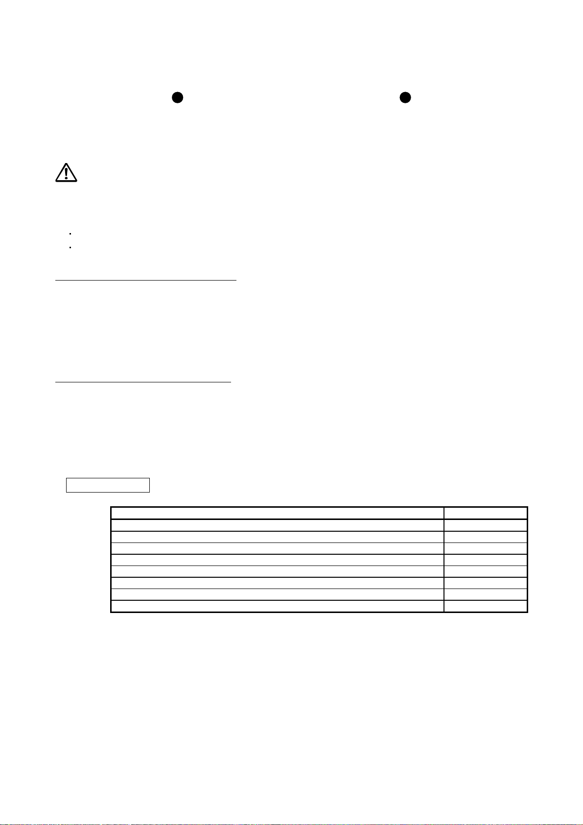
«U.S. customary units»
U.S. customary units are not shown in this manual. Convert the values if necessary according to the
following table.
Quantity SI (metric) unit U.S. customary unit
Mass 1 [kg] 2.2046 [lb]
Length 1 [mm] 0.03937 [inch]
Torque 1 [N•m] 141.6 [oz•inch]
Moment of inertia 1 [(× 10-4 kg•m2)] 5.4675 [oz•inch2]
Load (thrust load/axial load) 1 [N] 0.2248 [lbf]
Temperature N [°C] × 9/5 + 32 N [°F]
A - 8

CONTENTS
1. FUNCTIONS AND CONFIGURATION 1- 1 to 1-52
1.1 Summary ........................................................................................................................................... 1- 1
1.2 Function block diagram ..................................................................................................................... 1- 3
1.3 Servo amplifier standard specifications ........................................................................................... 1-13
1.4 Combinations of servo amplifiers and servo motors ....................................................................... 1-19
1.5 Function list ...................................................................................................................................... 1-21
1.6 Model designation ............................................................................................................................ 1-23
1.7 Structure .......................................................................................................................................... 1-24
1.7.1 Parts identification ..................................................................................................................... 1-24
1.7.2 Removal and reinstallation of the front cover............................................................................ 1-37
1.8 Configuration including peripheral equipment ................................................................................. 1-39
2. INSTALLATION 2- 1 to 2- 8
2.1 Installation direction and clearances ................................................................................................ 2- 2
2.2 Keeping out of foreign materials ....................................................................................................... 2- 4
2.3 Encoder cable stress ........................................................................................................................ 2- 4
2.4 SSCNET III cable laying ................................................................................................................... 2- 4
2.5 Inspection items ................................................................................................................................ 2- 6
2.6 Parts having service life .................................................................................................................... 2- 7
2.7 Restrictions when using this product at altitude exceeding 1000 m and up to 2000 m
above sea level ................................................................................................................................. 2- 8
3. SIGNALS AND WIRING 3- 1 to 3-46
3.1 Input power supply circuit ................................................................................................................. 3- 3
3.1.1 200 V class ................................................................................................................................. 3- 4
3.1.2 400 V class ................................................................................................................................ 3-10
3.1.3 100 V class ................................................................................................................................ 3-14
3.2 I/O signal connection example ......................................................................................................... 3-15
3.2.1 For sink I/O interface ................................................................................................................. 3-15
3.2.2 For source I/O interface ............................................................................................................ 3-17
3.3 Explanation of power supply system ............................................................................................... 3-18
3.3.1 Signal explanations ................................................................................................................... 3-18
3.3.2 Power-on sequence .................................................................................................................. 3-19
3.3.3 Wiring CNP1, CNP2, and CNP3 ............................................................................................... 3-20
3.4 Connectors and pin assignment ...................................................................................................... 3-24
3.5 Signal (device) explanations ............................................................................................................ 3-26
3.5.1 Input device ............................................................................................................................... 3-26
3.5.2 Output device ............................................................................................................................ 3-27
3.5.3 Output signal ............................................................................................................................. 3-28
3.5.4 Power supply ............................................................................................................................. 3-28
3.6 Forced stop deceleration function ................................................................................................... 3-29
3.6.1 Forced stop deceleration func tion ............................................................................................. 3-30
3.6.2 Base circuit shut-off delay time function ................................................................................... 3-31
3.6.3 Vertical axis freefall prevention function ................................................................................... 3-32
3.6.4 Residual risks of the forced stop function (EM2) ...................................................................... 3-32
3.7 Alarm occurrence timing chart ......................................................................................................... 3-33
1

3.7.1 When you use the forced stop deceleration function ................................................................ 3-33
3.7.2 When you do not use the forced stop deceleration function ..................................................... 3-34
3.8 Interfaces ......................................................................................................................................... 3-35
3.8.1 Internal connection diagram ...................................................................................................... 3-35
3.8.2 Detailed explanation of interfaces ............................................................................................. 3-36
3.8.3 Source I/O interfaces ................................................................................................................ 3-38
3.9 SSCNET III cable connection .......................................................................................................... 3-39
3.10 Servo motor with an electromagnetic brake .................................................................................. 3-41
3.10.1 Safety precautions .................................................................................................................. 3-41
3.10.2 Timing chart ............................................................................................................................ 3-42
3.11 Grounding ...................................................................................................................................... 3-46
4. STARTUP 4- 1 to 4-20
4.1 Switching power on for the first time ................................................................................................. 4- 2
4.1.1 Startup procedure ...................................................................................................................... 4- 2
4.1.2 Wiring check ............................................................................................................................... 4- 3
4.1.3 Surrounding environment ........................................................................................................... 4- 6
4.2 Startup .............................................................................................................................................. 4- 6
4.3 Switch setting and display of the servo amplifier .............................................................................. 4- 8
4.3.1 Switches ..................................................................................................................................... 4- 8
4.3.2 Scrolling display ........................................................................................................................ 4-11
4.3.3 Status display of an axis ........................................................................................................... 4-12
4.4 Test operation .................................................................................................................................. 4-14
4.5 Test operation mode ........................................................................................................................ 4-14
4.5.1 Test operation mode in MR Configurator2 ................................................................................ 4-15
4.5.2 Motor-less operation in controller .............................................................................................. 4-18
5. PARAMETERS 5- 1 to 5-56
5.1 Parameter list .................................................................................................................................... 5- 1
5.1.1 Basic setting parameters ([Pr. PA_ _ ]) ...................................................................................... 5- 2
5.1.2 Gain/filter setting parameters ([Pr. PB_ _ ]) ............................................................................... 5- 3
5.1.3 Extension setting parameters ([Pr. PC_ _ ]) .............................................................................. 5- 4
5.1.4 I/O setting parameters ([Pr. PD_ _ ]) ......................................................................................... 5- 6
5.1.5 Extension setting 2 parameters ([Pr. PE_ _ ]) ............................................................................ 5- 7
5.1.6 Extension setting 3 parameters ([Pr. PF_ _ ]) ............................................................................ 5- 8
5.1.7 Linear servo motor/DD motor setting parameters ([Pr. PL_ _ ]) ................................................ 5- 9
5.2 Detailed list of parameters ............................................................................................................... 5-11
5.2.1 Basic setting parameters ([Pr. PA_ _ ]) ..................................................................................... 5-11
5.2.2 Gain/filter setting parameters ([Pr. PB_ _ ]) .............................................................................. 5-22
5.2.3 Extension setting parameters ([Pr. PC_ _ ]) ............................................................................. 5-35
5.2.4 I/O setting parameters ([Pr. PD_ _ ]) ........................................................................................ 5-42
5.2.5 Extension setting 2 parameters ([Pr. PE_ _ ]) ........................................................................... 5-48
5.2.6 Extension setting 3 parameters ([Pr. PF_ _ ]) ........................................................................... 5-51
5.2.7 Linear servo motor/DD motor setting parameters ([Pr. PL_ _ ]) ............................................... 5-53
6. NORMAL GAIN ADJUSTMENT 6- 1 to 6-28
6.1 Different adjustment methods ........................................................................................................... 6- 1
6.1.1 Adjustment on a single servo amplifier ...................................................................................... 6- 1
2

6.1.2 Adjustment using MR Configurator2 .......................................................................................... 6- 2
6.2 One-touch tuning .............................................................................................................................. 6- 3
6.2.1 One-touch tuning flowchart ........................................................................................................ 6- 5
6.2.2 Display transition and operation procedure of one-touch tuning ............................................... 6- 7
6.2.3 Caution for one-touch tuning ..................................................................................................... 6-17
6.3 Auto tuning ....................................................................................................................................... 6-18
6.3.1 Auto tuning mode ...................................................................................................................... 6-18
6.3.2 Auto tuning mode basis ............................................................................................................. 6-19
6.3.3 Adjustment procedure by auto tuning ....................................................................................... 6-20
6.3.4 Response level setting in auto tuning mode ............................................................................. 6-21
6.4 Manual mode ................................................................................................................................... 6-22
6.5 2 gain adjustment mode .................................................................................................................. 6-25
7. SPECIAL ADJUSTMENT FUNCTIONS 7- 1 to 7-38
7.1 Filter setting ...................................................................................................................................... 7- 1
7.1.1 Machine resonance suppression filter ....................................................................................... 7- 2
7.1.2 Adaptive filter II ........................................................................................................................... 7- 5
7.1.3 Shaft resonance suppression filter ............................................................................................. 7- 7
7.1.4 Low-pass filter ............................................................................................................................ 7- 8
7.1.5 Advanced vibration suppression control II ................................................................................. 7- 8
7.1.6 Command notch filter ................................................................................................................ 7-13
7.2 Gain switching function .................................................................................................................... 7-15
7.2.1 Applications ............................................................................................................................... 7-15
7.2.2 Function block diagram ............................................................................................................. 7-16
7.2.3 Parameter .................................................................................................................................. 7-17
7.2.4 Gain switching procedure ......................................................................................................... 7-20
7.3 Tough drive function ........................................................................................................................ 7-24
7.3.1 Vibration tough drive function.................................................................................................... 7-24
7.3.2 Instantaneous power failure tough drive function ..................................................................... 7-26
7.4 Compliance with SEMI-F47 standard .............................................................................................. 7-30
7.5 Model adaptive control disabled ...................................................................................................... 7-33
7.6 Lost motion compensation function ................................................................................................. 7-34
7.7 Super trace control .......................................................................................................................... 7-37
8. TROUBLESHOOTING 8- 1 to 8-16
8.1 Explanation for the lists ..................................................................................................................... 8- 1
8.2 Alarm list ........................................................................................................................................... 8- 2
8.3 Warning list ...................................................................................................................................... 8-12
8.4 Troubleshooting at power on ........................................................................................................... 8-15
9. DIMENSIONS 9- 1 to 9-22
9.1 Servo amplifier .................................................................................................................................. 9- 1
9.2 Connector ........................................................................................................................................ 9-20
10. CHARACTERISTICS 10- 1 to 10-16
10.1 Overload protection characteristics .............................................................................................. 10- 1
10.2 Power supply capacity and generated loss .................................................................................. 10- 5
3

10.3 Dynamic brake characteristics ...................................................................................................... 10- 8
10.3.1 Dynamic brake operation ....................................................................................................... 10- 9
10.3.2 Permissible load to motor inertia when the dynamic brake is used ...................................... 10-12
10.4 Cable bending life ........................................................................................................................ 10-13
10.5 Inrush currents at power-on of main circuit and control circuit .................................................... 10-14
11. OPTIONS AND PERIPHERAL EQUIPMENT 11- 1 to 11-110
11.1 Cable/connector sets .................................................................................................................... 11- 1
11.1.1 Combinations of cable/connector sets ................................................................................... 11- 2
11.1.2 MR-D05UDL3M-B STO cable ................................................................................................ 11- 6
11.1.3 SSCNET III cable ................................................................................................................... 11- 7
11.1.4 Battery cable/junction battery cable ....................................................................................... 11- 9
11.2 Regenerative options ................................................................................................................... 11-10
11.2.1 Combination and regenerative power ................................................................................... 11-10
11.2.2 Selection of regenerative option ........................................................................................... 11-12
11.2.3 Parameter setting .................................................................................................................. 11-15
11.2.4 Connection of regenerative option ........................................................................................ 11-15
11.2.5 Dimensions ........................................................................................................................... 11-20
11.3 FR-BU2-(H) brake unit ................................................................................................................. 11-24
11.3.1 Selection................................................................................................................................ 11-24
11.3.2 Brake unit parameter setting ................................................................................................. 11-25
11.3.3 Connection example ............................................................................................................. 11-26
11.3.4 Dimensions ........................................................................................................................... 11-34
11.4 FR-RC-(H) power regeneration converter ................................................................................... 11-37
11.5 FR-CV-(H) power regeneration common converter .................................................................... 11-41
11.5.1 Model designation ................................................................................................................. 11-42
11.5.2 Selection................................................................................................................................ 11-42
11.6 Junction terminal block PS7DW-20V14B-F (recommended) ...................................................... 11-50
11.7 MR Configurator2 ........................................................................................................................ 11-51
11.7.1 Specifications ........................................................................................................................ 11-51
11.7.2 System configuration ............................................................................................................. 11-52
11.7.3 Precautions for using USB communication function ............................................................. 11-53
11.8 Battery ..................................................................................................................
........................ 11-54
11.8.1 Selection of battery ............................................................................................................... 11-54
11.8.2 MR-BAT6V1SET battery ....................................................................................................... 11-54
11.8.3 MR-BAT6V1BJ battery for junction battery cable ................................................................. 11-58
11.8.4 MR-BT6VCASE battery case ................................................................................................ 11-62
11.8.5 MR-BAT6V1 battery .............................................................................................................. 11-68
11.9 Selection example of wires .......................................................................................................... 11-69
11.10 Molded-case circuit breakers, fuses, magnetic contactors ....................................................... 11-73
11.11 Power factor improving DC reactors .......................................................................................... 11-76
11.12 Power factor improving AC reactors .......................................................................................... 11-78
11.13 Relay (recommended) ............................................................................................................... 11-81
11.14 Noise reduction techniques ....................................................................................................... 11-82
11.15 Earth-leakage current breaker ................................................................................................... 11-89
11.16 EMC filter (recommended) ........................................................................................................ 11-92
11.17 External dynamic brake ............................................................................................................. 11-99
11.18 Panel through attachment (MR-J4ACN15K/MR-J3ACN) ........................................................ 11-105
4

12. ABSOLUTE POSITION DETECTION SYSTEM 12- 1 to 12- 6
12.1 Summary ....................................................................................................................................... 12- 1
12.1.1 Features ................................................................................................................................. 12- 1
12.1.2 Structure ................................................................................................................................. 12- 2
12.1.3 Parameter setting ................................................................................................................... 12- 2
12.1.4 Confirmation of absolute position detection data ................................................................... 12- 2
12.2 Battery ........................................................................................................................................... 12- 3
12.2.1 Using MR-BAT6V1SET battery .............................................................................................. 12- 3
12.2.2 Using MR-BAT6V1BJ battery for junction battery cable ........................................................ 12- 4
12.2.3 Using MR-BT6VCASE battery case ....................................................................................... 12- 5
13. USING STO FUNCTION 13- 1 to 13-14
13.1 Introduction ................................................................................................................................... 13- 1
13.1.1 Summary ................................................................................................................................ 13- 1
13.1.2 Terms related to safety .......................................................................................................... 13- 1
13.1.3 Cautions ................................................................................................................................. 13- 1
13.1.4 Residual risks of the STO function ......................................................................................... 13- 2
13.1.5 Specifications ......................................................................................................................... 13- 3
13.1.6 Maintenance ........................................................................................................................... 13- 4
13.2 STO I/O signal connector (CN8) and signal layouts ..................................................................... 13- 4
13.2.1 Signal layouts ......................................................................................................................... 13- 4
13.2.2 Signal (device) explanations .................................................................................................. 13- 5
13.2.3 How to pull out the STO cable ............................................................................................... 13- 5
13.3 Connection example ..................................................................................................................... 13- 6
13.3.1 Connection example for CN8 connector ................................................................................ 13- 6
13.3.2 External I/O signal connection example using an MR-J3-D05 safety logic unit .................... 13- 7
13.3.3 External I/O signal connection example using an external safety relay unit ........................ 13-10
13.3.4 External I/O signal connection example using a motion controller ....................................... 13-11
13.4 Detailed description of interfaces ................................................................................................ 13-12
13.4.1 Sink I/O interface ................................................................................................................... 13-12
13.4.2 Source I/O interface .............................................................................................................. 13-14
14. USING A LINEAR SERVO MOTOR 14- 1 to 14-34
14.1 Functions and configuration ......................................................................................................... 14- 1
14.1.1 Summary ................................................................................................................................ 14- 1
14.1.2 Servo system with auxiliary equipment .................................................................................. 14- 2
14.2 Signals and wiring ......................................................................................................................... 14- 6
14.3 Operation and functions ................................................................................................................ 14- 8
14.3.1 Startup .................................................................................................................................... 14- 8
14.3.2 Magnetic pole detection ........................................................................................................ 14-11
14.3.3 Home position return ............................................................................................................. 14-20
14.3.4 Test operation mode in MR Configurator2 ............................................................................ 14-24
14.3.5 Operation from controller ...................................................................................................... 14-25
14.3.6 Function................................................................................................................................. 14-27
14.3.7 Absolute position detection system ....................................................................................... 14-29
14.4 Characteristics ............................................................................................................................. 14-30
14.4.1 Overload protection characteristics ...................................................................................... 14-30
14.4.2 Power supply capacity and generated loss .......................................................................... 14-31
5

14.4.3 Dynamic brake characteristics .............................................................................................. 14-32
14.4.4 Permissible load to motor mass ratio when the dynamic brake is used ............................... 14-33
15. USING A DIRECT DRIVE MOTOR 15- 1 to 15-22
15.1 Functions and configuration ......................................................................................................... 15- 1
15.1.1 Summary ................................................................................................................................ 15- 1
15.1.2 Servo system with auxiliary equipment .................................................................................. 15- 2
15.2 Signals and wiring ......................................................................................................................... 15- 3
15.3 Operation and functions ................................................................................................................ 15- 4
15.3.1 Startup procedure .................................................................................................................. 15- 5
15.3.2 Magnetic pole detection ......................................................................................................... 15- 6
15.3.3 Operation from controller ...................................................................................................... 15-14
15.3.4 Function................................................................................................................................. 15-15
15.4 Characteristics ............................................................................................................................. 15-17
15.4.1 Overload protection characteristics ...................................................................................... 15-17
15.4.2 Power supply capacity and generated loss .......................................................................... 15-19
15.4.3 Dynamic brake characteristics .............................................................................................. 15-20
16. FULLY CLOSED LOOP SYSTEM 16- 1 to 16-26
16.1 Functions and configuration ......................................................................................................... 16- 1
16.1.1 Function block diagram .......................................................................................................... 16- 1
16.1.2 Selecting procedure of control mode ..................................................................................... 16- 3
16.1.3 System configuration .............................................................................................................. 16- 4
16.2 Load-side encoder ........................................................................................................................ 16- 6
16.2.1 Linear encoder ....................................................................................................................... 16- 6
16.2.2 Rotary encoder ....................................................................................................................... 16- 6
16.2.3 Configuration diagram of encoder cable ................................................................................ 16- 6
16.2.4 MR-J4FCCBL03M branch cable ............................................................................................ 16- 8
16.3 Operation and functions ................................................................................................................ 16- 9
16.3.1 Startup .................................................................................................................................... 16- 9
16.3.2 Home position return ............................................................................................................. 16-16
16.3.3 Operation from controller ...................................................................................................... 16-19
16.3.4 Fully closed loop control error detection functions................................................................ 16-21
16.3.5 Auto tuning function .............................................................................................................. 16-22
16.3.6 Machine analyzer function .................................................................................................... 16-22
16.3.7 Test operation mode ............................................................................................................. 16-22
16.3.8 Absolute position detection system under fully closed loop system ..................................... 16-23
16.3.9 About MR Configurator2 ....................................................................................................... 16-24
17. APPLICATION OF FUNCTIONS 17- 1 to 17-82
17.1 J3 compatibility mode ................................................................................................................... 17- 1
17.1.1 Outline of J3 compatibility mode ............................................................................................ 17- 1
17.1.2 Operation modes supported by J3 compatibility mode .......................................................... 17- 2
17.1.3 J3 compatibility mode supported function list ........................................................................ 17- 2
17.1.4 How to switch J4 mode/J3 compatibility mode ...................................................................... 17- 5
17.1.5 How to use the J3 compatibility mode ................................................................................... 17- 6
17.1.6 Cautions for switching J4 mode/J3 compatibility mode ......................................................... 17- 7
17.1.7 Cautions for the J3 compatibility mode .................................................................................. 17- 8
6

17.1.8 Change of specifications of "J3 compatibility mode" switching process ................................ 17- 9
17.1.9 J3 extension function ............................................................................................................ 17-11
17.2 Master-slave operation function .................................................................................................. 17-69
17.3 Scale measurement function ....................................................................................................... 17-73
17.3.1 Functions and configuration .................................................................................................. 17-73
17.3.2 Scale measurement encoder ................................................................................................ 17-76
17.3.3 How to use scale measurement function .............................................................................. 17-80
APPENDIX App.- 1 to App.-74
App. 1 Peripheral equipment manufacturer (for reference) .............................................................. App.- 1
App. 2 Handling of AC servo amplifier batteries for the United Nations Recommendations on the
Transport of Dangerous Goods ............................................................................................ App.- 1
App. 3 Symbol for the new EU Battery Directive .............................................................................. App.- 4
App. 4 Compliance with global standards ........................................................................................ App.- 5
App. 5 MR-J3-D05 Safety logic unit ................................................................................................ App.-21
App. 6 EC declaration of conformity ................................................................................................ App.-39
App. 7 How to replace servo amplifier without magnetic pole detection ......................................... App.-42
App. 8 Two-wire type encoder cable for HG-MR/HG-KR ................................................................ App.-43
App. 9 SSCNET III cable (SC-J3BUS_M-C) manufactured by Mitsubishi Electric System &
Service ................................................................................................................................. App.-45
App. 10 Analog monitor ..................................................................................................................... App.-45
App. 11 Special specification ............................................................................................................. App.-57
App. 12 Driving on/off of main circuit power supply with DC power supply ...................................... App.-61
App. 13 Optional data monitor function ............................................................................................. App.-63
App. 14 STO function with SIL 3 certification .................................................................................... App.-66
App. 15 When using the servo amplifier with the DC power supply input ......................................... App.-68
App. 16 Status of general-purpose AC servo products for compliance with the China RoHS
directive ................................................................................................................................ App.-73
7

MEMO
8

1. FUNCTIONS AND CONFIGURATION
1. FUNCTIONS AND CONFIGURATION
1.1 Summary
The Mitsubishi Electric MELSERVO-J4 series general-purpose AC servo has further higher performance
and higher functions compared to the previous MELSERVO-J3 series.
MR-J4-_B_ servo amplifier is connected to controllers, including a servo system controller, on the highspeed synchronous network SSCNET III/H. The servo amplifier directly receives a command from a
controller to drive a servo motor.
MELSERVO-J4 series compatible rotary servo motor is equipped with 22-bit (4194304 pulses/rev) highresolution absolute encoder. In addition, speed frequency response is increased to 2.5 kHz. Thus, faster and
more accurate control is enabled as compared to MELSERVO-J3 series.
MR-J4-_B_ servo amplifier operates MELSERVO-J4 series compatible rotary servo motors, linear servo
motors, and direct drive motors as standard.
With one-touch tuning and real-time auto tuning, you can automatically adjust the servo gains according to
the machine.
The tough drive function and the drive recorder function, which are well-received in the MELSERVO-JN
series, have been improved. The MR-J4 servo amplifier supports the improved functions. Additionally, the
preventive maintenance support function detects an error in the machine parts. This function provides strong
support for the machine maintenance and inspection.
SSCNET III/H achieves high-speed communication of 150 Mbps full duplex with high noise tolerance due to
the SSCNET III optical cables. Large amounts of data are exchanged in real-time between the controller and
the servo amplifier. Servo monitor information is stored in the upper information system and is used for
control.
On the SSCNET III/H network, the stations are connected with a maximum distance of 100 m between them.
This allows you to create a large system.
The MR-J4-_B_ servo amplifier supports the STO (Safe Torque Off) function. When the servo amplifier is
connected to a SSCNET III/H-compatible servo system controller, in addition to the STO function, the servo
amplifier also supports the SS1 (Safe Stop 1), SS2 (Safe Stop 2), SOS (Safe Operating Stop), SLS (SafelyLimited Speed), SBC (Safe Brake Control) and SSM (Safe Speed Monitor) functions.
The servo amplifier has a USB communication interface. Therefore, you can connect the servo amplifier to
the personal computer with MR Configurator2 installed to perform the parameter setting, test operation, gain
adjustment, and others.
In MELSERVO-J4 series, servo amplifiers with CN2L connector is also available as MR-J4-_B_-RJ. By using
CN2L connector, an A/B/Z-phase differential output method external encoder can be connected to the servo
amplifier. In a fully closed loop system, a four-wire type external encoder is connectable as well. The
following table indicates the communication method of the external encoder compatible with MR-J4-_B_ and
MR-J4-_B_-RJ servo amplifiers.
1 - 1
1. FUNCTIONS AND CONFIGURATION
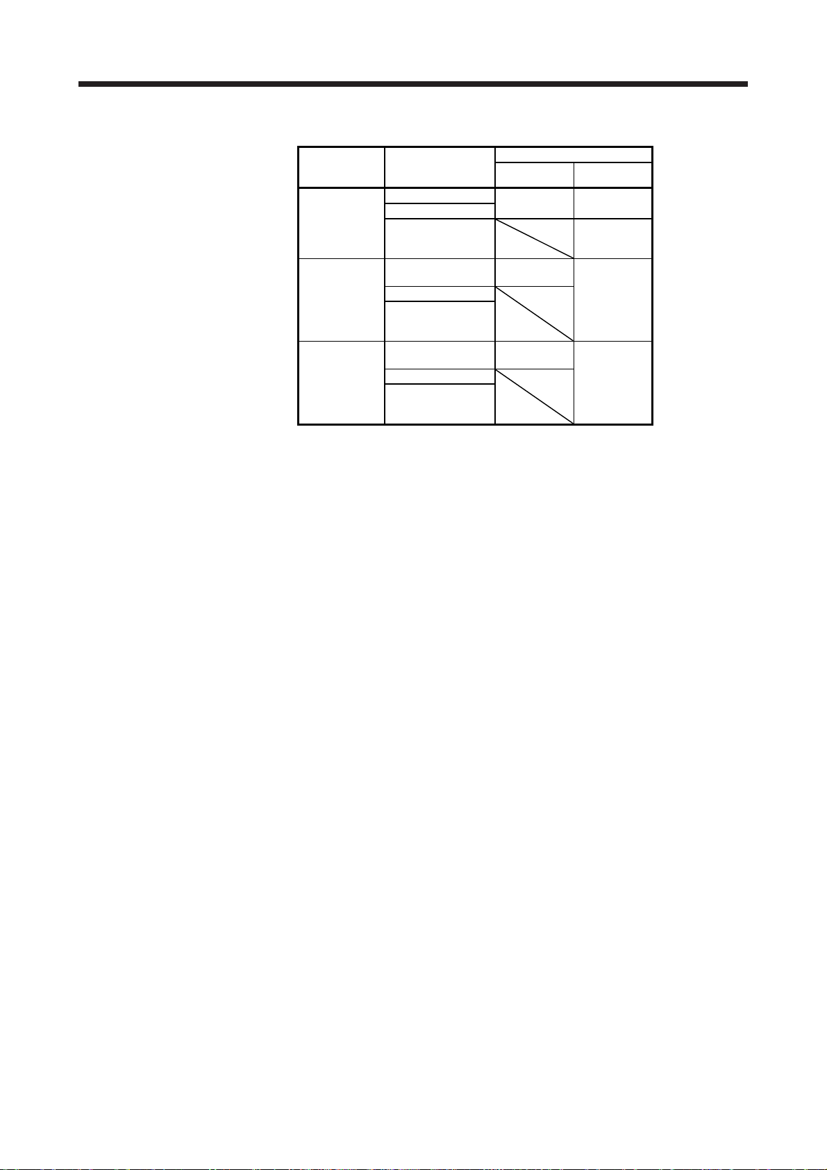
Table 1.1 Connectors to connect external encoders
Operation
mode
Linear servo
motor system
Fully closed
loop system
Scale
measurement
function
Note 1. The MR-J4THCBL03M branch cable is necessary.
2. The MR-J4FCCBL03M branch cable is necessary.
3. When the communication method of the servo motor encoder is four-wire type,
MR-J4-_B_ cannot be used. Use an MR-J4-_B_-RJ.
4. This is used with servo amplifiers with software version A3 or later.
5. This is used with servo amplifiers with software version A8 or later.
6. Connect a thermistor to CN2.
External encoder
communication
method
Two-wire type
Four-wire type
A/B/Z-phase
differential output
method
Two-wire type
Four-wire type
A/B/Z-phase
differential output
method
Two-wire type
Four-wire type
A/B/Z-phase
differential output
method
Connector
MR-J4-_B_ MR-J4-_B_-RJ
CN2 (Note 1) CN2 (Note 1)
CN2L (Note 6)
CN2
(Note 2, 3, 4)
CN2L
CN2
(Note 2, 3, 5)
CN2L (Note 5)
1 - 2
1. FUNCTIONS AND CONFIGURATION
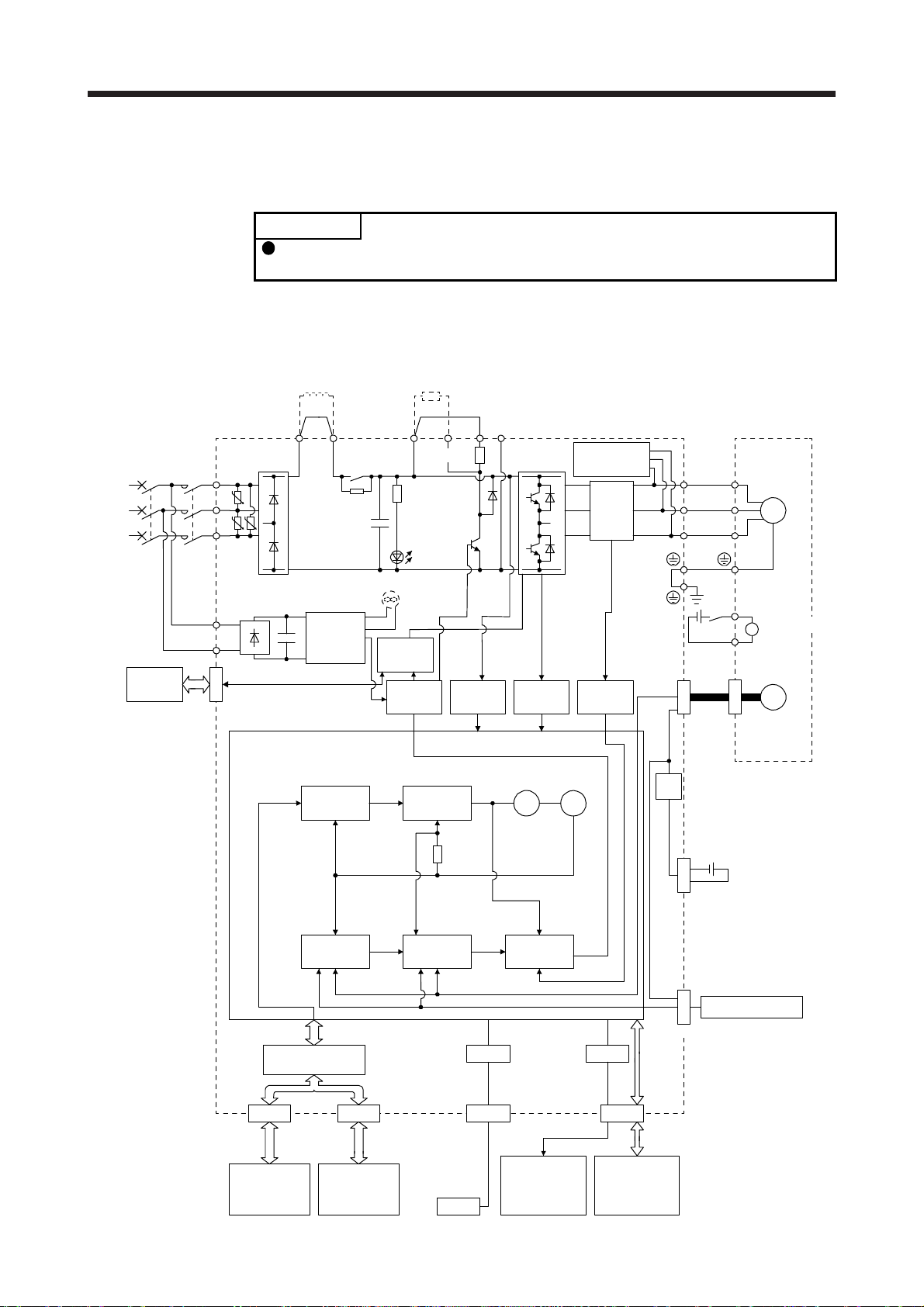
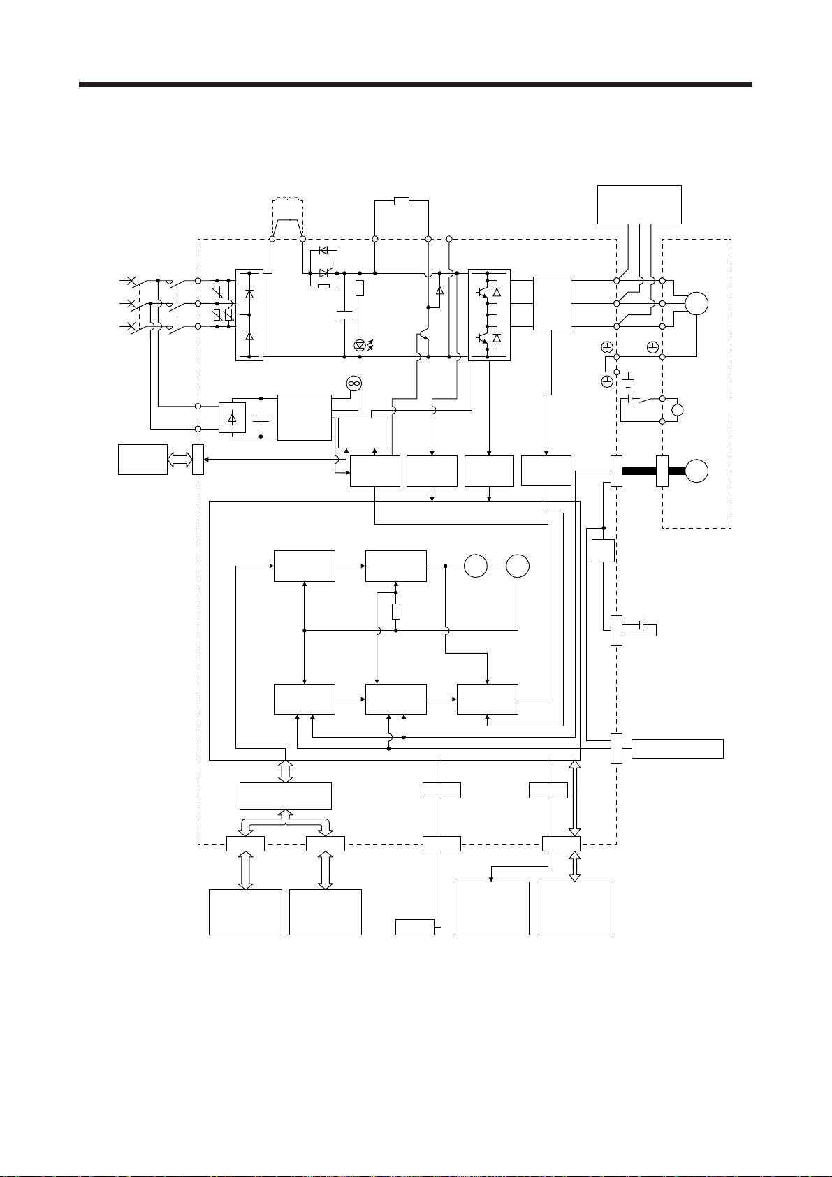
1.2 Function block diagram
The function block diagram of this servo is shown below.
Regenerative
option
(1) 200 V class
(a) MR-J4-500B(-RJ) or less
POINT
The diagram shows for MR-J4-_B_-RJ as an example. MR-J4-_B_ servo
amplifier does not have CN2L connector.
(Note 6)
Power factor improving
DC reactor
(Note 2)
Power
supply
STO
switch
Servo amplifier
MCMCCB
L1
U
L2
U U
L3
L11
L21
CN8
P3 P4
Diode
stack
Position
command
input
+
(Note 4)
Relay
Cooling fan
(Note 3)
Control
circuit
power
supply
Model
position
control
+
CHARGE
lamp
STO
circuit
Base
amplifier
P+
(Note 1)
Regenerative
TR
Model
speed
control
Voltage
detection
N-CD
Overcurrent
protection
Virtual
motor
detection
Virtual
encoder
Dynamic
brake
circuit
Current
encoder
Current
Stepdown
circuit
U
V
W
RA
24 V DC
CN2
Servo motor
U
V
W
B1
B
B2
M
Electromagnetic
brake
Encoder
position
I/F Control
CN1A CN1B
Servo system
controller or
servo amplifier
Model position
Actual
control
Servo
amplifier
or cap
Model speed Model torque
Actual
speed
control
Personal
computer
USB
USB
CN5
Analog monitor
(2 channels)
Current
control
1 - 3
D/A
CN3
Digital I/O
control
CN4
Battery
(for absolute position
detection system)
External encoder
CN2L
(Note 5)

1. FUNCTIONS AND CONFIGURATION
Note 1. The built-in regenerative resistor is not provided for MR-J4-10B(-RJ).
2. For 1-phase 200 V AC to 240 V AC, connect the power supply to L1 and L3. Leave L2 open.
Refer to section 1.3 for the power supply specifications.
3. Servo amplifiers MR-J4-70B(-RJ) or more have a cooling fan.
4. MR-J4 servo amplifier has P3 and P4 in the upstream of the inrush current suppression circuit. They are different from P1 and
P2 of MR-J3 servo amplifiers.
5. This is for MR-J4-_B-RJ servo amplifier. MR-J4-_B servo amplifier does not have CN2L connector.
6. The power factor improving AC reactor can also be used. In this case, the power factor improving DC reactor cannot be used.
When not using the power factor improving DC reactor, short P3 and P4.
1 - 4
1. FUNCTIONS AND CONFIGURATION
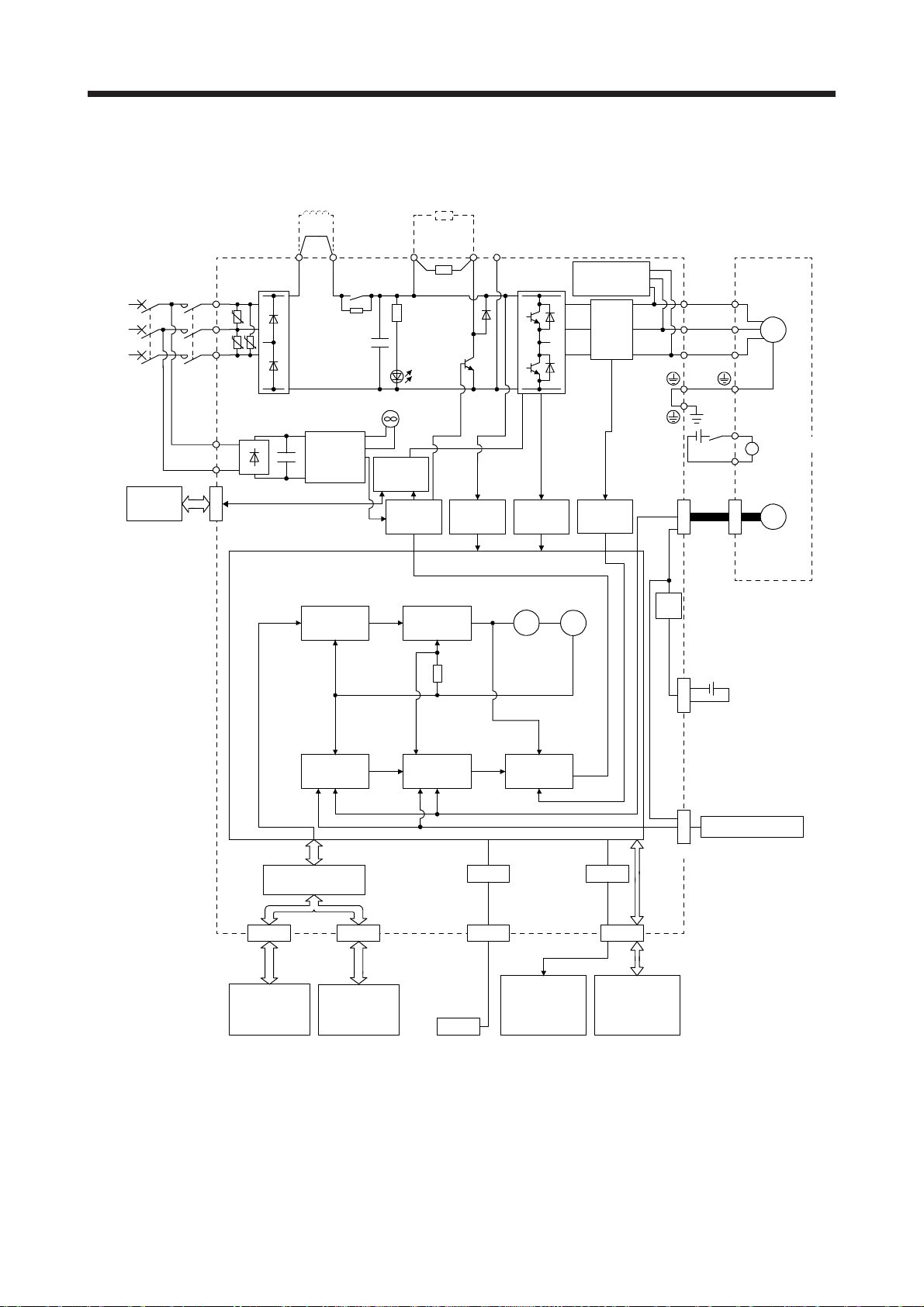
(b) MR-J4-700B(-RJ)
(Note 4)
Power factor improving
DC reactor
Regenerative
option
(Note 1)
Power
supply
STO
switch
Servo amplifier
MCMCCB
L1
U
L2
U U
L3
L11
L21
CN8
P3 P4
Diode
stack
Position
command
input
+
(Note 2)
Relay
Cooling fan
Control
circuit
power
supply
Model
position
control
+
CHARGE
lamp
STO
circuit
Base
amplifier
P+
Regenerative
TR
Model
speed
control
Voltage
detection
N-C
Overcurrent
Virtual
motor
protection
detection
Virtual
encoder
Dynamic
brake
circuit
Current
encoder
Current
Stepdown
circuit
U
V
W
RA
24 V DC
CN2
Servo motor
U
V
W
B1
B
B2
M
Electromagnetic
brake
Encoder
CN4
Battery
(for absolute position
detection system)
External encoder
CN2L
(Note 3)
position
I/F Control
CN1A CN1B
Servo system
controller or
servo amplifier
Model position
Actual
control
Servo
amplifier
or cap
Model speed Model torque
Actual
speed
control
Current
control
USB
CN5
Personal
computer
Analog monitor
(2 channels)
USB
D/A
CN3
Digital I/O
control
Note 1. Refer to section 1.3 for the power supply specifications.
2. MR-J4 servo amplifier has P3 and P4 in the upstream of the inrush current suppression circuit. They are different from P1 and
P2 of MR-J3 servo amplifiers.
3. This is for MR-J4-_B-RJ servo amplifier. MR-J4-_B servo amplifier does not have CN2L connector.
4. The power factor improving AC reactor can also be used. In this case, the power factor improving DC reactor cannot be used.
When not using the power factor improving DC reactor, short P3 and P4.
1 - 5

1. FUNCTIONS AND CONFIGURATION
(c) MR-J4-11KB(-RJ)/MR-J4-15KB(-RJ)/MR-J4-22KB(-RJ)
(Note 1)
Power
supply
Servo amplifier
MCMCCB
L1
U
L2
U U
L3
(Note 5)
Power factor improving
DC reactor
P3 P4
Diode
stack
External regenerative
regenerative option
(Note 2)
Thyristor
+
resistor or
P+
Regenerative
TR
(Note 4, 6)
External dynamic
brake (optional)
N-C
U
Current
encoder
V
W
Servo motor
U
V
M
W
STO
switch
L11
L21
CN8
Position
command
input
Cooling fan
Control
+
circuit
power
supply
Model
position
control
Actual
position
control
I/F Control
CHARGE
STO
circuit
Base
amplifier
Model position
lamp
Overcurrent
protection
Virtual
motor
Model
speed
control
Voltage
detection
Model speed Model torque
Actual
speed
control
Current
control
USB
detection
Virtual
encoder
Current
D/A
RA
24 V DC
CN2
Stepdown
circuit
CN4
Battery
(for absolute position
detection system)
External encoder
CN2L
(Note 3)
B1
Electromagnetic
B
brake
B2
Encoder
CN1A CN1B
Servo system
controller or
servo amplifier
Servo
amplifier
or cap
Personal
computer
USB
CN5
Analog monitor
(2 channels)
CN3
Digital I/O
control
1 - 6

1. FUNCTIONS AND CONFIGURATION
Note 1. Refer to section 1.3 for the power supply specifications.
2. MR-J4 servo amplifier has P3 and P4 in the upstream of the inrush current suppression circuit. They are different from P1 and
P2 of MR-J3 servo amplifiers.
3. This is for MR-J4-_B-RJ servo amplifier. MR-J4-_B servo amplifier does not have CN2L connector.
4. Use an external dynamic brake for this servo amplifier. Failure to do so will cause an accident because the servo motor does
not stop immediately but coasts at an alarm occurrence for which the servo motor does not decelerate to stop. Ensure the
safety in the entire equipment. For alarms for which the servo motor does not decelerate to stop, refer to chapter 8.
5. The power factor improving AC reactor can also be used. In this case, the power factor improving DC reactor cannot be used.
When not using the power factor improving DC reactor, short P3 and P4.
6. The external dynamic brake cannot be used for compliance with SEMI-F47 standard. Do not assign DB (Dynamic brake
interlock) in [Pr. PD07] to [Pr. PD09]. Failure to do so will cause the servo amplifier to become servo-off when an
instantaneous power failure occurs.
1 - 7
1. FUNCTIONS AND CONFIGURATION
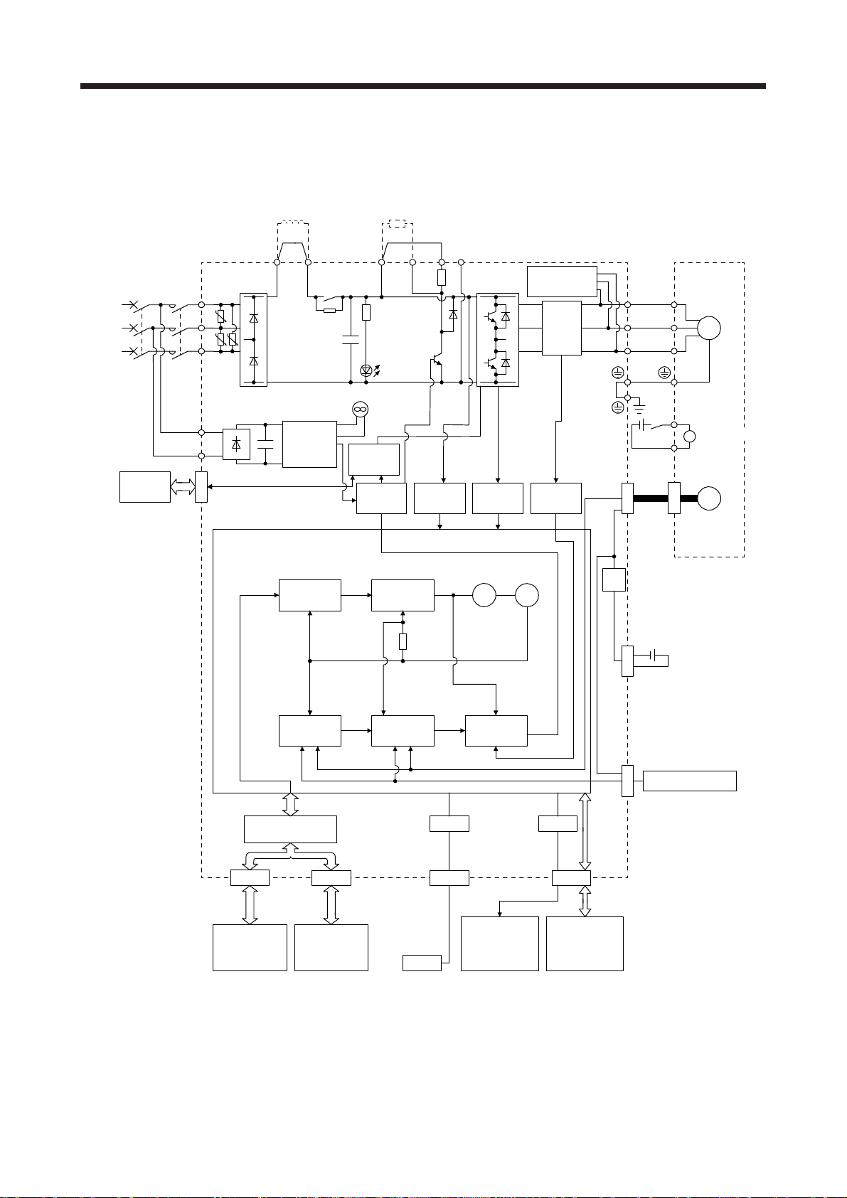
(2) 400 V class
(a) MR-J4-350B4(-RJ) or less
(Note 5)
Power factor
improving
DC reactor
Regenerative
option
(Note 1)
Power
supply
STO
switch
Servo amplifier
MCMCCB
L1
U
L2
U U
L3
L11
L21
CN8
P3 P4 (Note 3)
Diode
stack
+
Position
command
input
Relay
(Note 2)
Control
circuit
power
supply
Model
position
control
+
Cooling fan
STO
circuit
Base
amplifier
P+
Regenerative
TR
Charge
lamp
Model
speed
control
Voltage
detection
N-CD
Overcurrent
protection
Virtual
motor
detection
Virtual
encoder
Dynamic
brake
circuit
Current
detector
Current
Stepdown
circuit
U
V
W
RA
24 V DC
CN2
Servo motor
U
V
W
B1
B
B2
M
Electromagnetic
brake
Encoder
CN4
Battery
(For absolute
position detection
system)
External encoder
CN2L
(Note 4)
position
IF Control
CN1A CN1B
Servo system
controller or
servo amplifier
Model position
Actual
control
Servo
amplifier
or cap
Model speed Model torque
Actual
speed
control
Current
control
USB
CN5
Personal
computer
Analog monitor
(2 channels)
USB
D/A
CN3
Digital I/O
control
Note 1. Refer to section 1.3 for the power supply specification.
2. Servo amplifiers MR-J4-200B4(-RJ) or more have a cooling fan.
3. MR-J4 servo amplifier has P3 and P4 in the upstream of the inrush current suppression circuit. They are different from P1 and
P2 of MR-J3 servo amplifiers.
4. This is for MR-J4-_B4-RJ servo amplifier. MR-J4-_B4 servo amplifier does not have CN2L connector.
5. The power factor improving AC reactor can also be used. In this case, the power factor improving DC reactor cannot be used.
When not using the power factor improving DC reactor, short P3 and P4.
1 - 8
1. FUNCTIONS AND CONFIGURATION
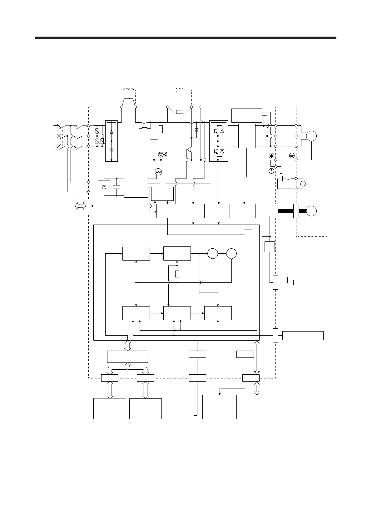
(b) MR-J4-500B4(-RJ)/MR-J4-700B4(-RJ)
(Note 4)
Power factor
improving
DC reactor
Regenerative
option
(Note 1)
Power
supply
STO
switch
Servo amplifier
MCMCCB
L1
U
L2
U U
L3
L11
L21
CN8
P3 P4 (Note 2)
Diode
stack
+
Position
command
input
Relay
Control
circuit
power
supply
Model
position
control
+
Cooling fan
STO
circuit
Base
amplifier
P+
Regenerative
TR
Charge
lamp
Model
speed
control
Voltage
detection
N-C
Overcurrent
Virtual
motor
protection
detection
Virtual
encoder
Dynamic
brake
circuit
Current
detector
Current
Stepdown
circuit
U
V
W
RA
24 V DC
CN2
Servo motor
U
V
W
B1
B
B2
M
Electromagnetic
brake
Encoder
CN4
Battery
(For absolute
position detection
system)
External encoder
CN2L
(Note 3)
position
IF Control
CN1A CN1B
Servo system
controller or
servo amplifier
Model position Model speed Model torque
Actual
control
Actual
speed
control
USB
CN5
Servo
amplifier
or cap
Personal
computer
USB
Analog monitor
(2 channels)
Current
control
D/A
CN3
Digital I/O
control
Note 1. Refer to section 1.3 for the power supply specification.
2. MR-J4 servo amplifier has P3 and P4 in the upstream of the inrush current suppression circuit. They are different from P1 and
P2 of MR-J3 servo amplifiers.
3. This is for MR-J4-_B4-RJ servo amplifier. MR-J4-_B4 servo amplifier does not have CN2L connector.
4. The power factor improving AC reactor can also be used. In this case, the power factor improving DC reactor cannot be used.
When not using the power factor improving DC reactor, short P3 and P4.
1 - 9
1. FUNCTIONS AND CONFIGURATION
(c) MR-J4-11KB4(-RJ)/MR-J4-15KB4(-RJ)/MR-J4-22KB4(-RJ)
External
regenerative resistor
or
regenerative option
P+
+
Regenerative
TR
Charge
lamp
STO
circuit
Base
amplifier
Voltage
detection
(Note 1)
Power
supply
STO
switch
Servo amplifier
MCMCCB
L1
U
L2
U U
L3
L11
L21
CN8
(Note 5)
Power factor
improving
DC reactor
P3 P4 (Note 2)
Diode
stack
Control
+
circuit
power
supply
Thyristor
Cooling fan
N-C
Overcurrent
protection
Current
detector
Current
detection
(Note 4, 6)
External
dynamic brake
(optional)
U
V
W
W
RA
24 V DC
CN2
Servo motor
U
V
M
B1
Electromagnetic
B
brake
B2
Encoder
Position
command
input
position
position
IF Control
CN1A CN1B
Servo system
controller or
servo amplifier
Model
control
Model position
Actual
control
Servo
amplifier
or cap
Virtual
motor
encoder
Model
speed
control
Model speed Model torque
Actual
speed
control
Current
control
USB
CN5
Personal
computer
Analog monitor
(2 channels)
USB
Virtual
D/A
CN3
Digital I/O
control
Stepdown
circuit
CN4
Battery
(For absolute
position detection
system)
CN2L
(Note 3)
External encoder
1 - 10

1. FUNCTIONS AND CONFIGURATION
Note 1. Refer to section 1.3 for the power supply specification.
2. MR-J4 servo amplifier has P3 and P4 in the upstream of the inrush current suppression circuit. They are different from P1 and
P2 of MR-J3 servo amplifiers.
3. This is for MR-J4-_B4-RJ servo amplifier. MR-J4-_B4 servo amplifier does not have CN2L connector.
4. Use an external dynamic brake for this servo amplifier. Failure to do so will cause an accident because the servo motor does
not stop immediately but coasts at an alarm occurrence for which the servo motor does not decelerate to stop. Ensure the
safety in the entire equipment. For alarms for which the servo motor does not decelerate to stop, refer to chapter 8.
5. The power factor improving AC reactor can also be used. In this case, the power factor improving DC reactor cannot be used.
When not using the power factor improving DC reactor, short P3 and P4.
6. The external dynamic brake cannot be used for compliance with SEMI-F47 standard. Do not assign DB (Dynamic brake
interlock) in [Pr. PD07] to [Pr. PD09]. Failure to do so will cause the servo amplifier to become servo-off when an
instantaneous power failure occurs.
1 - 11
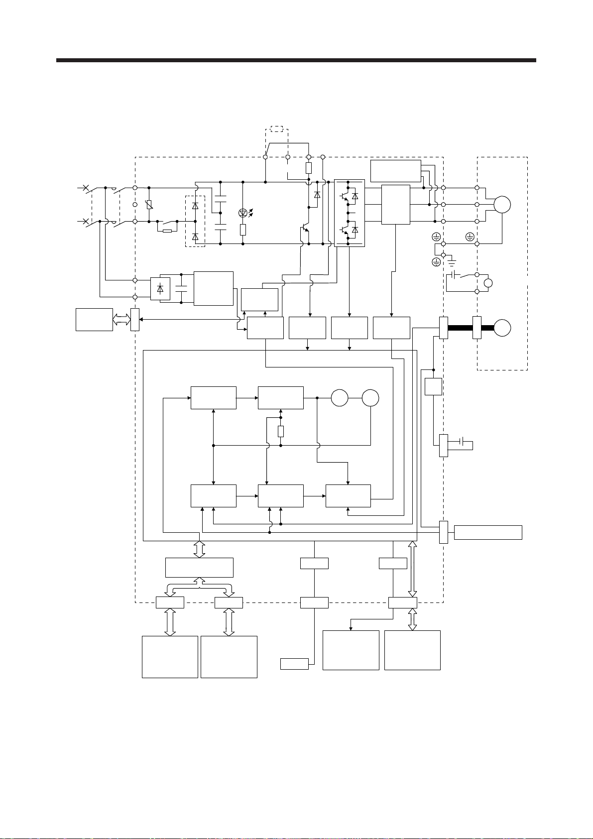
1. FUNCTIONS AND CONFIGURATION
(3) 100 V class
Regenerative
option
(Note 2)
Power
supply
STO
switch
Servo amplifier
MCMCCB
L1
U
L2
L11
L21
CN8
Relay
Diode stack
Position
command
input
+
Control
circuit
power
supply
Model
position
control
U
V
W
RA
Servo motor
M
B1
Electromagnetic
B
brake
B2
P+
(Note 1)
N-CD
Dynamic brake
circuit
U
+
Charge
lamp
Regene-
+
rative TR
Current
encoder
V
W
24 V DC
STO
circuit
Base
amplifier
Voltage
detection
Overcurrent
protection
Current
detection
CN2
Encoder
Model
speed
control
Virtual
encoder
Virtual
Stepdown
circuit
motor
Model speed Model torque
Actual
speed
control
Current
control
USB
CN5
Personal
computer
Analog monitor
(two channel)
USB
D/A
CN3
Digital I/O
control
IF Control
CN1A CN1B
Servo system
controller or
servo amplifier
Model position
Actual
position
control
Servo
amplifier
or cap
Note 1. The built-in regenerative resistor is not provided for MR-J4-10B1(-RJ).
2. Refer to section 1.3 for the power supply specifications.
3. This is for MR-J4-_B1-RJ servo amplifier. MR-J4-_B1 servo amplifier does not have CN2L connector.
CN4
Battery
(for absolute position
detection system)
External encoder
CN2L
(Note 3)
1 - 12
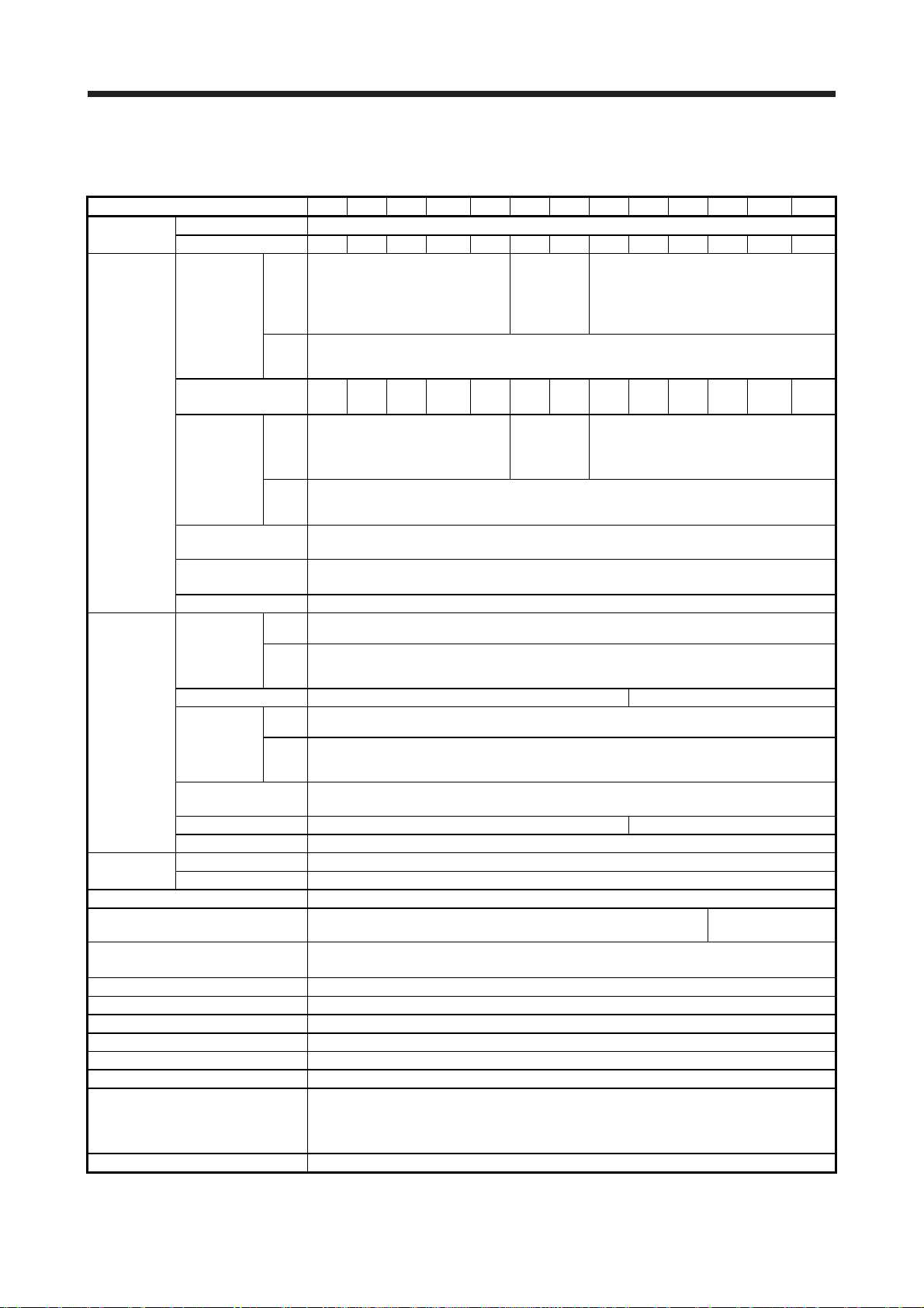
1. FUNCTIONS AND CONFIGURATION
1.3 Servo amplifier standard specifications
(1) 200 V class
Model: MR-J4-_(-RJ) 10B 20B 40B 60B 70B 100B 200B 350B 500B 700B 11KB 15KB 22KB
Output
Main circuit
power supply
input
Control circuit
power supply
input
Interface power
supply
Control method Sine-wave PWM control, current control method
Dynamic brake Built-in
SSCNET III/H communication cycle
(Note 8)
Fully closed loop control Compatible (Note 7)
Scale measurement function Compatible (Note 10)
Load-side encoder interface (Note 5) Mitsubishi Electric high-speed serial communication
Communication function USB: connection to a personal computer or others (MR Configurator2-compatible)
Encoder output pulses Compatible (A/B/Z-phase pulse)
Analog monitor Two channels
Protective functions
Functional safety STO (IEC/EN 61800-5-2)
Rated voltage 3-phase 170 V AC
Rated current [A] 1.1 1.5 2.8 3.2 5.8 6.0 11.0 17.0 28.0 37.0 68.0 87.0 126.0
3-phase or 1-
At AC
Voltage/
Frequency
Rated current
(Note 11)
Permissible
voltage
fluctuation
Permissible frequency
fluctuation
Power supply capacity
Inrush current [A] Refer to section 10.5.
Voltage/
Frequency
Rated current [A] 0.2 0.3
Permissible
voltage
fluctuation
Permissible frequency
fluctuation
Power consumption [W] 30 45
Inrush current [A] Refer to section 10.5.
Voltage 24 V DC ± 10%
Current capacity [A] 0.3 (including CN8 connector signals) (Note 1)
input
At DC
input
(Note 16)
[A] 0.9 1.5 2.6
At AC
input
At DC
input
(Note 16)
[kVA]
At AC
input
At DC
input
(Note 16)
At AC
input
At DC
input
(Note 16)
3-phase or 1-phase
200 V AC to 240 V AC, 50 Hz/60 Hz
3.2
(Note 6)
3-phase or 1-phase
170 V AC to 264 V AC
1-phase 200 V AC to 240 V AC, 50 Hz/60 Hz
Overcurrent shut-off, regenerative overvoltage shut-off, overload shut-off (electronic thermal), servo motor
overheat protection, encoder error protection, regenerative error protection, undervoltage protection,
instantaneous power failure protection, overspeed protection, error excessive protection, magnetic pole
detection protection, and linear servo control fault protection
phase 200 V
AC to 240 V
AC, 50 Hz/60
Hz (Note 13)
283 V DC to 340 V DC
3.8 5.0 10.5 16.0 21.7 28.9 46.0 64.0 95.0
3-phase or 1-
phase 170 V
AC to 264 V
AC (Note 13)
241 V DC to 374 V DC
Within ±5%
Refer to section 10.2.
283 V DC to 340 V DC
1-phase 170 V AC to 264 V AC
241 V DC to 374 V DC
Within ±5%
0.222 ms, 0.444 ms, 0.888 ms
3-phase 200 V AC to 240 V AC, 50 Hz/60 Hz
3-phase 170 V AC to 264 V AC
External option
(Note 9, 12)
1 - 13

1. FUNCTIONS AND CONFIGURATION
Model: MR-J4-_(-RJ) 10B 20B 40B 60B 70B 100B 200B 350B 500B 700B 11KB 15KB 22KB
Standards certified by CB
(Note 14)
Response performance 8 ms or less (STO input off → energy shut off)
Test pulse input (STO)
Safety
performance
Compliance
with global
standards
Structure (IP rating) Natural cooling, open (IP20) Force cooling, open (IP20) Force cooling, open (IP20) (Note 4)
Close
mounting
(Note 2)
Environment
Mass [kg] 0.8 1.0 1.4 2.1 2.3 4.0 6.2 13.4 18.2
(Note 3)
Mean time to dangerous
failure (MTTFd)
Diagnostic coverage (DC) DC = Medium, 97.6 [%]
Average probability of
dangerous failures per
hour (PFH)
CE marking
UL standard UL 508C
3-phase power supply input Possible Impossible
1-phase power supply input Possible Impossible
Ambient
temperature
Ambient
humidity
Ambience
Altitude 2000 m or less above sea level (Note 15)
Vibration resistance 5.9 m/s2, at 10 Hz to 55 Hz (directions of X, Y and Z axes)
Operation 0 ˚C to 55 ˚C (non-freezing)
Storage -20 ˚C to 65 ˚C (non-freezing)
Operation
Storage
Note 1. 0.3 A is the value applicable when all I/O signals are used. The current capacity can be decreased by reducing the number of
I/O points.
2. When closely mounting the servo amplifiers, operate them at the ambient temperature of 0 ˚C to 45 ˚C or at 75% or smaller
effective load ratio.
3. Test pulse is a signal which instantaneously turns off a signal to the servo amplifier at a constant period for external circuit to
self-diagnose.
4. Except for the terminal block.
5. MR-J4-_B servo amplifier is compatible only with two-wire type. MR-J4-_B-RJ servo amplifier is compatible with two-wire type,
four-wire type, and A/B/Z-phase differential output method. Refer to table 1.1 for details.
6 The rated current is 2.9 A when the servo amplifier is used with UL or CSA compliant servo motor.
7. For the compatible version of fully closed loop system, refer to table 1.1. Check the software version of the servo amplifier with
MR Configurator2.
8. The communication cycle depends on the controller specifications and the number of axes connected.
9. Use an external dynamic brake for this servo amplifier. Failure to do so will cause an accident because the servo motor does
not stop immediately but coasts at emergency stop. Ensure the safety in the entire equipment.
10. For the compatible version for the scale measurement function, refer to table 1.1. Check the software version of the servo
amplifier with MR Configurator2.
11. This value is applicable when a 3-phase power supply is used.
12. The external dynamic brake cannot be used for compliance with SEMI-F47 standard. Do not assign DB (Dynamic brake
interlock) in [Pr. PD07] to [Pr. PD09]. Failure to do so will cause the servo amplifier to become servo-off when an
instantaneous power failure occurs.
13. When using 1-phase 200 V AC to 240 V AC power supply, operate the servo amplifier at 75% or smaller effective load ratio.
14. The safety level depends on the setting value of [Pr. PF18 STO diagnosis error detection time] and whether STO input
diagnosis by TOFB output is performed or not. For details, refer to the Function column of [Pr. PF18] in section 5.2.6.
15. Follow the restrictions in section 2.7 when using this product at altitude exceeding 1000 m and up to 2000 m above sea level.
16. The DC power supply input is available only with MR-J4-_B-RJ servo amplifiers. For the connection example of the power
circuit when a DC input is used, refer to app. 15.
EN ISO 13849-1 Category 3 PL e, IEC 61508 SIL 3, EN 62061 SIL CL3, EN 61800-5-2
Test pulse interval: 1 Hz to 25 Hz
Test pulse off time: Up to 1 ms
MTTFd ≥ 100 [years] (314a)
-9
PFH = 6.4 × 10
LVD: EN 61800-5-1
EMC: EN 61800-3
MD: EN ISO 13849-1, EN 61800-5-2, EN 62061
5 %RH to 90 %RH (non-condensing)
Indoors (no direct sunlight),
free from corrosive gas, flammable gas, oil mist, dust, and dirt
[1/h]
1 - 14

1. FUNCTIONS AND CONFIGURATION
(2) 400 V class
Model: MR-J4-_(-RJ) 60B4 100B4 200B4 350B4 500B4 700B4 11KB4 15KB4 22KB4
Output
Main circuit
power supply
input
Voltage/Frequency 1-phase 380 V AC to 480 V AC, 50 Hz/60 Hz
Rated current [A] 0.1 0.2
Control circuit
power supply
input
Power consumption [W] 30 45
Inrush current [A] Refer to section 10.5.
Interface power
supply
Control method Sine-wave PWM control, current control method
Dynamic brake Built-in External option (Note 6, 8)
SSCNET III/H communication cycle (Note 5) 0.222 ms, 0.444 ms, 0.888 ms
Fully closed loop control Compatible
Scale measurement function Compatible (Note 7)
Load-side encoder interface (Note 4) Mitsubishi Electric high-speed serial communication
Communication function USB: connection to a personal computer or others (MR Configurator2-compatible)
Encoder output pulses Compatible (A/B/Z-phase pulse)
Analog monitor Two channels
Protective functions
Functional safety STO (IEC/EN 61800-5-2)
Safety
performance
Compliance
with global
standards
Structure (IP rating)
Close mounting Impossible
Rated voltage 3-phase 323 V AC
Rated current [A] 1.5 2.8 5.4 8.6 14.0 17.0 32.0 41.0 63.0
Voltage/Frequency 3-phase 380 V AC to 480 V AC, 50 Hz/60 Hz
Rated current [A] 1.4 2.5 5.1 7.9 10.8 14.4 23.1 31.8 47.6
Permissible voltage
fluctuation
Permissible frequency
fluctuation
Power supply capacity
[kVA]
Inrush current [A] Refer to section 10.5.
Permissible voltage
fluctuation
Permissible frequency
fluctuation
Voltage 24 V DC ± 10%
Current capacity [A] 0.3 (including CN8 connector signals) (Note 1)
Standards certified by CB
(Note 9)
Response performance 8 ms or less (STO input off → energy shut off)
Test pulse input (STO)
(Note 2)
Mean time to dangerous
failure (MTTFd)
Diagnosis converge (DC) DC = Medium, 97.6 [%]
Average probability of
dangerous failures per hour
(PFH)
CE marking
UL standard UL 508C
3-phase 323 V AC to 528 V AC
Within ±5%
Refer to section 10.2.
1-phase 323 V AC to 528 V AC
Within ±5%
Overcurrent shut-off, regenerative overvoltage shut-off, overload shut-off (electronic thermal), servo
motor overheat protection, encoder error protection, regenerative error protection, undervoltage
protection, instantaneous power failure protection, overspeed protection, error excessive protection,
magnetic pole detection protection, and linear servo control fault protection
EN ISO 13849-1 Category 3 PL e, IEC 61508 SIL 3, EN 62061 SIL CL3, EN 61800-5-2
MTTFd ≥ 100 [years] (314a)
Natural cooling, open
(IP20)
Force cooling, open
Test pulse interval: 1 Hz to 25 Hz
Test pulse off time: Up to 1 ms
PFH = 6.4 × 10
LVD: EN 61800-5-1
EMC: EN 61800-3
MD: EN ISO 13849-1, EN 61800-5-2, EN 62061
(IP20)
-9
[1/h]
Force cooling, open (IP20) (Note 3)
1 - 15

1. FUNCTIONS AND CONFIGURATION
Model: MR-J4-_(-RJ) 60B4 100B4 200B4 350B4 500B4 700B4 11KB4 15KB4 22KB4
Ambient
temperature
Ambient
Environment
Mass [kg] 1.7 2.1 3.6 4.3 6.5 13.4 18.2
humidity
Ambience
Altitude 2000 m or less above sea level (Note 10)
Vibration resistance 5.9 m/s2, at 10 Hz to 55 Hz (directions of X, Y and Z axes)
Note 1. 0.3 A is the value applicable when all I/O signals are used. The current capacity can be decreased by reducing the number of
I/O points.
2. Test pulse is a signal which instantaneously turns off a signal to the servo amplifier at a constant period for external circuit to
self-diagnose.
3. Except for the terminal block.
4. MR-J4-B4 servo amplifier is compatible only with two-wire type. MR-J4-B4-RJ servo amplifier is compatible with two-wire type,
four-wire type, and A/B/Z-phase differential output method. Refer to table 1.1 for details.
5. The communication cycle depends on the controller specifications and the number of axes connected.
6. Use an external dynamic brake for this servo amplifier. Failure to do so will cause an accident because the servo motor does
not stop immediately but coasts at emergency stop. Ensure the safety in the entire equipment.
7. For the compatible version for the scale measurement function, refer to table 1.1. Check the software version of the servo
amplifier with MR Configurator2.
8. The external dynamic brake cannot be used for compliance with SEMI-F47 standard. Do not assign DB (Dynamic brake
interlock) in [Pr. PD07] to [Pr. PD09]. Failure to do so will cause the servo amplifier to become servo-off when an
instantaneous power failure occurs.
9. The safety level depends on the setting value of [Pr. PF18 STO diagnosis error detection time] and whether STO input
diagnosis by TOFB output is performed or not. For details, refer to the Function column of [Pr. PF18] in section 5.2.6.
10. Follow the restrictions in section 2.7 when using this product at altitude exceeding 1000 m and up to 2000 m above sea level.
Operation 0 ˚C to 55 ˚C (non-freezing)
Storage -20 ˚C to 65 ˚C (non-freezing)
Operation
Storage
free from corrosive gas, flammable gas, oil mist, dust, and dirt
5 %RH to 90 %RH (non-condensing)
Indoors (no direct sunlight),
1 - 16
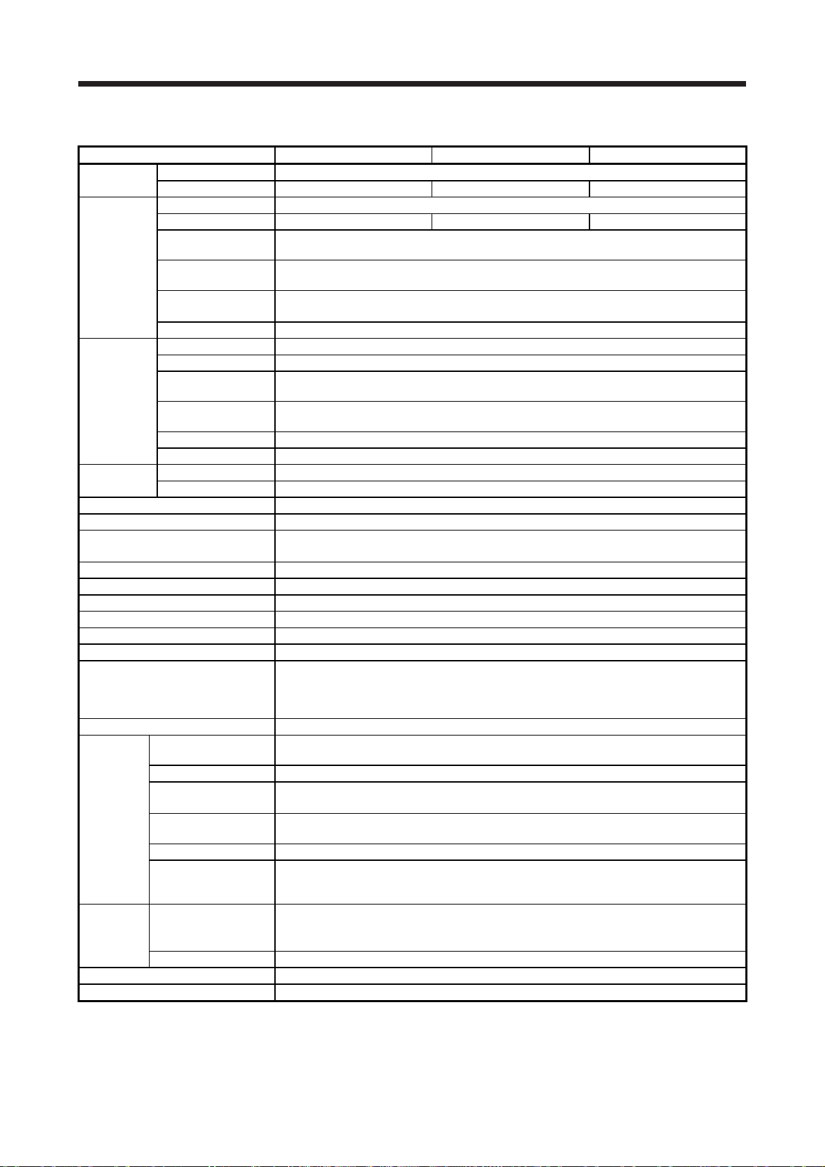
1. FUNCTIONS AND CONFIGURATION
(3) 100 V class
Model: MR-J4-_(-RJ) 10B1 20B1 40B1
Output
Main circuit
power supply
input
Control circuit
power supply
input
Interface power
supply
Control method Sine-wave PWM control, current control method
Dynamic brake Built-in
SSCNET III/H communication cycle
(Note 6)
Fully closed loop control Compatible (Note 5)
Scale measurement function Compatible (Note 7)
Load-side encoder interface (Note 4) Mitsubishi Electric high-speed serial communication
Communication function USB: connection to a personal computer or others (MR Configurator2-compatible)
Encoder output pulses Compatible (A/B/Z-phase pulse)
Analog monitor Two channels
Protective functions
Functional safety STO (IEC/EN 61800-5-2)
Safety
performance
Compliance
with global
standards
Structure (IP rating) Natural cooling, open (IP20)
Close mounting (Note 2) Possible
Rated voltage 3-phase 170 V AC
Rated current [A] 1.1 1.5 2.8
Voltage/Frequency 1-phase 100 V AC to 120 V AC, 50 Hz/60 Hz
Rated current [A] 3.0 5.0 9.0
Permissible voltage
fluctuation
Permissible frequency
fluctuation
Power supply capacity
[kVA]
Inrush current [A] Refer to section 10.5.
Voltage/Frequency 1-phase 100 V AC to 120 V AC, 50 Hz/60 Hz
Rated current [A] 0.4
Permissible voltage
fluctuation
Permissible frequency
fluctuation
Power consumption [W] 30
Inrush current [A] Refer to section 10.5.
Voltage 24 V DC ± 10%
Current capacity [A] 0.3 (including CN8 connector signals) (Note 1)
Standards certified by CB
(Note 8)
Response performance 8 ms or less (STO input off → energy shut off)
Test pulse input (STO)
(Note 3)
Mean time to dangerous
failure (MTTFd)
Diagnostic coverage (DC) DC = Medium, 97.6 [%]
Average probability of
dangerous failures per
hour (PFH)
CE marking
UL standard UL 508C
Within ±5%
Refer to section 10.2.
1-phase 85 V AC to 132 V AC
Within ±5%
0.222 ms, 0.444 ms, 0.888 ms
Overcurrent shut-off, regenerative overvoltage shut-off, overload shut-off (electronic thermal), servo motor
overheat protection, encoder error protection, regenerative error protection, undervoltage protection,
instantaneous power failure protection, overspeed protection, error excessive protection, magnetic pole
detection protection, and linear servo control fault protection
EN ISO 13849-1 Category 3 PL e, IEC 61508 SIL 3, EN 62061 SIL CL3, EN 61800-5-2
1-phase 85 V AC to 132 V AC
Test pulse interval: 1 Hz to 25 Hz
Test pulse off time: Up to 1 ms
MTTFd ≥ 100 [years] (314a)
-9
PFH = 6.4 × 10
LVD: EN 61800-5-1
EMC: EN 61800-3
MD: EN ISO 13849-1, EN 61800-5-2, EN 62061
[1/h]
1 - 17

1. FUNCTIONS AND CONFIGURATION
Model: MR-J4-_(-RJ) 10B1 20B1 40B1
Ambient
temperature
Ambient
Environment
Mass [kg] 0.8 1.0
humidity
Ambience
Altitude 2000 m or less above sea level (Note 9)
Vibration resistance 5.9 m/s2, at 10 Hz to 55 Hz (directions of X, Y and Z axes)
Note 1. 0.3 A is the value applicable when all I/O signals are used. The current capacity can be decreased by reducing the number of
I/O points.
2. When closely mounting the servo amplifiers, operate them at the ambient temperature of 0 °C to 45 °C or at 75% or smaller
effective load ratio.
3. Test pulse is a signal which instantaneously turns off a signal to the servo amplifier at a constant period for external circuit to
self-diagnose.
4. MR-J4-_B servo amplifier is compatible only with two-wire type. MR-J4-_B-RJ servo amplifier is compatible with two-wire type,
four-wire type, and A/B/Z-phase differential output method. Refer to table 1.1 for details.
5. For the compatible version of fully closed loop system, refer to table 1.1. Check the software version of the servo amplifier with
MR Configurator2.
6 The communication cycle depends on the controller specifications and the number of axes connected.
7. For the compatible version for the scale measurement function, refer to table 1.1. Check the software version of the servo
amplifier with MR Configurator2.
8. The safety level depends on the setting value of [Pr. PF18 STO diagnosis error detection time] and whether STO input
diagnosis by TOFB output is performed or not. For details, refer to the Function column of [Pr. PF18] in section 5.2.6.
9. Follow the restrictions in section 2.7 when using this product at altitude exceeding 1000 m and up to 2000 m above sea level.
Operation 0 °C to 55 °C (non-freezing)
Storage -20 °C to 65 °C (non-freezing)
Operation
Storage
free from corrosive gas, flammable gas, oil mist, dust, and dirt
5 %RH to 90 %RH (non-condensing)
Indoors (no direct sunlight),
1 - 18

1. FUNCTIONS AND CONFIGURATION
1.4 Combinations of servo amplifiers and servo motors
POINT
When a 1-phase 200 V AC input is used, the maximum torque of 400% cannot
be achieved with HG-JR series servo motor.
When you use the MR-J4-100B(-RJ) or MR-J4-200B(-RJ) with the 1-phase 200
V AC input, contact your local sales office for the torque characteristics of the
HG-UR series, HG-RR series, and HG-JR series servo motors.
(1) 200 V class
Servo amplifier
MR-J4-10B(-RJ) 053
MR-J4-20B(-RJ)
MR-J4-40B(-RJ)
MR-J4-60B(-RJ)
MR-J4-70B(-RJ)
MR-J4-100B(-RJ)
MR-J4-200B(-RJ)
MR-J4-350B(-RJ)
MR-J4-500B(-RJ)
MR-J4-700B(-RJ)
MR-J4-11KB(-RJ)
MR-J4-15KB(-RJ)
MR-J4-22KB(-RJ)
HG-KR HG-MR HG-SR HG-UR HG-RR HG-JR
053
13
13
23 23
43 43
73 73 72 73
702
Note 1. This is available with servo amplifiers with software version C8 or later.
2. This combination increases the maximum torque of the servo motor to 400%.
3. This combination increases the rated torque and the maximum torque.
Rotary servo motor
51
52
81
102
121
201
152
202
301
352
421
502
53
103
153
353
503
53 (Note 2)
103
73 (Note 2)
103 (Note 2)
153
203
153 (Note 2)
203 (Note 2)
353
353 (Note 2)
503
503 (Note 2)
601
701M
703
801
12K1
11K1M
903
15K1
15K1M
20K1
25K1
22K1M
152
202 203
352
502
Linear servo motor
(primary side)
LM-U2PAB-05M-0SS0
LM-U2PBB-07M-1SS0
LM-H3P2A-07P-BSS0
LM-H3P3A-12P-CSS0
LM-K2P1A-01M-2SS1
LM-U2PAD-10M-0SS0
LM-U2PAF-15M-0SS0
LM-U2PBD-15M-1SS0 TM-RFM006C20
LM-H3P3B-24P-CSS0
LM-H3P3C-36P-CSS0
LM-H3P7A-24P-ASS0
LM-K2P2A-02M-1SS1
LM-U2PBF-22M-1SS0
TM-RFM018E20
LM-H3P3D-48P-CSS0
LM-H3P7B-48P-ASS0
LM-H3P7C-72P-ASS0
LM-FP2B-06M-1SS0
LM-K2P1C-03M-2SS1
LM-U2P2B-40M-2SS0
LM-H3P7D-96P-ASS0
LM-K2P2C-07M-1SS1
LM-K2P3C-14M-1SS1
LM-U2P2C-60M-2SS0
LM-FP2D-12M-1SS0
LM-FP4B-12M-1SS0
LM-K2P2E-12M-1SS1
LM-K2P3E-24M-1SS1
LM-U2P2D-80M-2SS0
LM-FP2F-18M-1SS0
LM-FP4D-24M-1SS0
LM-FP4F-36M-1SS0
LM-FP4F-48M-1SS0
Direct drive motor
TM-RFM002C20
TM-RG2M002C30 (Note 1)
TM-RU2M002C30 (Note 1)
TM-RG2M004E30 (Note 1)
TM-RU2M004E30 (Note 1)
TM-RFM004C20
TM-RG2M004E30 (Note 1, 3)
TM-RU2M004E30 (Note 1, 3)
TM-RG2M009G30 (Note 1)
TM-RU2M009G30 (Note 1)
TM-RFM006E20
TM-RFM012E20
TM-RFM012G20
TM-RFM040J10
TM-RFM048G20
TM-RFM072G20
TM-RFM120J10
TM-RFM240J10
1 - 19

1. FUNCTIONS AND CONFIGURATION
(2) 400 V class
Servo amplifier
MR-J4-60B4(-RJ) 524 534
MR-J4-100B4(-RJ)
MR-J4-200B4(-RJ)
MR-J4-350B4(-RJ)
MR-J4-500B4(-RJ)
MR-J4-700B4(-RJ)
MR-J4-11KB4(-RJ)
MR-J4-15KB4(-RJ) 15K14
MR-J4-22KB4(-RJ) 20K14
Note. This combination is for increasing the maximum torque of the servo motor to 400%.
(3) 100 V class
Servo amplifier
MR-J4-10B1(-RJ) 053
MR-J4-20B1(-RJ)
MR-J4-40B1(-RJ)
Note 1. This is available with servo amplifiers with software version C8 or later.
2. This combination increases the rated torque and the maximum torque.
Rotary servo motor
HG-SR HG-JR
534 (Note)
1024
1524
2024
3524
5024
7024
Rotary servo motor
HG-KR HG-MR
13
23 23
43 43
734
1034
734 (Note)
1034 (Note)
1534
2034
1534 (Note)
2034 (Note)
3534
3534 (Note)
5034
5034 (Note)
6014
701M4
7034
8014
12K14
11K1M4
9034
15K1M4
25K14
22K1M4
053
13
Linear servo motor
LM-FP5H-60M-1SS0
Linear servo motor
LM-U2PAB-05M-0SS0
LM-U2PBB-07M-1SS0
LM-H3P2A-07P-BSS0
LM-H3P3A-12P-CSS0
LM-K2P1A-01M-2SS1
LM-U2PAD-10M-0SS0
LM-U2PAF-15M-0SS0
(primary side)
(primary side)
Direct drive motor
TM-RFM002C20
TM-RG2M002C30 (Note 1)
TM-RU2M002C30 (Note 1)
TM-RG2M004E30 (Note 1)
TM-RU2M004E30 (Note 1)
TM-RFM004C20
TM-RG2M004E30 (Note 1, 2)
TM-RU2M004E30 (Note 1, 2)
TM-RG2M009G30 (Note 1)
TM-RU2M009G30 (Note 1)
1 - 20
1. FUNCTIONS AND CONFIGURATION
1.5 Function list
The following table lists the functions of this servo. For details of the functions, refer to each section of the
detailed description field.
Function Description
This realizes a high response and stable control following the ideal model. The twodegrees-of-freedom-model model adaptive control enables you to set a response to
Model adaptive control
Position control mode This servo amplifier is used as a position control servo.
Speed control mode This servo amplifier is used as a speed control servo.
Torque control mode This servo amplifier is used as a torque control servo.
High-resolution encoder
Absolute position detection
system
Gain switching function
Advanced vibration
suppression control II
Machine resonance
suppression filter
Shaft resonance suppression
filter
Adaptive filter II
Low-pass filter
Machine analyzer function
Robust filter
Slight vibration suppression
control
Auto tuning
Brake unit
Power regeneration converter
Regenerative option
Alarm history clear Alarm history is cleared. [Pr. PC21]
Output signal selection
(device settings)
Output signal (DO) forced
output
Test operation mode
Analog monitor output Servo status is output in terms of voltage in real time.
MR Configurator2
Linear servo system Linear servo system can be configured using a linear servo motor and linear encoder. Chapter 14
Direct drive servo system Direct drive servo system can be configured to drive a direct drive motor. Chapter 15
the command and response to the disturbance separately. Additionally, this function
can be disabled. Refer to section 7.5 for disabling this function. This is used with
servo amplifiers with software version B4 or later. Check the software version of the
servo amplifier with MR Configurator2.
High-resolution encoder of 4194304 pulses/rev is used as the encoder of the rotary
servo motor compatible with the MELSERVO-J4 series.
Merely setting a home position once makes home position return unnecessary at
every power-on.
You can switch gains during rotation and during stop, and can use an input device to
switch gains during operation.
This function suppresses vibration at the arm end or residual vibration. Section 7.1.5
This is a filter function (notch filter) which decreases the gain of the specific frequency
to suppress the resonance of the mechanical system.
When a load is mounted to the servo motor shaft, resonance by shaft torsion during
driving may generate a mechanical vibration at high frequency. The shaft resonance
suppression filter suppresses the vibration.
Servo amplifier detects mechanical resonance and sets filter characteristics
automatically to suppress mechanical vibration.
Suppresses high-frequency resonance which occurs as servo system response is
increased.
Analyzes the frequency characteristic of the mechanical system by simply connecting
a MR Configurator2 installed personal computer and servo amplifier.
MR Configurator2 is necessary for this function.
This function provides better disturbance response in case low response level that
load to motor inertia ratio is high for such as roll send axes.
Suppresses vibration of ±1 pulse produced at a servo motor stop. [Pr. PB24]
Automatically adjusts the gain to optimum value if load applied to the servo motor
shaft varies.
Used when the regenerative option cannot provide enough regenerative power.
Can be used for the 5 kW or more servo amplifier.
Used when the regenerative option cannot provide enough regenerative power.
Can be used for the 5 kW or more servo amplifier.
Used when the built-in regenerative resistor of the servo amplifier does not have
sufficient regenerative capability for the regenerative power generated.
The output devices including ALM (Malfunction) and DB (Dynamic brake interlock) can
be assigned to certain pins of the CN3 connector.
Output signal can be forced on/off independently of the servo status.
Use this function for checking output signal wiring, etc.
Jog operation, positioning operation, motor-less operation, DO forced output, and
program operation
MR Configurator2 is necessary for this function.
Using a personal computer, you can perform the parameter setting, test operation,
monitoring, and others.
Detailed
explanation
Chapter 12
Section 7.2
Section 7.1.1
Section 7.1.3
Section 7.1.2
Section 7.1.4
[Pr. PE41]
Section 6.3
Section 11.3
Section 11.4
Section 11.2
[Pr. PD07] to
[Pr. PD09]
Section 4.5.1
(1) (d)
Section 4.5
[Pr. PC09],
[Pr. PC10]
Section 11.7
1 - 21

1. FUNCTIONS AND CONFIGURATION
Function Description
Fully closed loop system can be configured using the load-side encoder.
Fully closed loop system
One-touch tuning
SEMI-F47 function (Note)
Tough drive function
Drive recorder function
STO function
Servo amplifier life diagnosis
function
Power monitoring function
Machine diagnosis function
Master-slave operation
function
Scale measurement function
J3 compatibility mode
Continuous operation to
torque control mode
Lost motion compensation
function
Super trace control
Note. For servo system controllers which are available with this, contact your local sales office.
This is used with servo amplifiers with software version A3 or later. Check the
software version of the servo amplifier with MR Configurator2.
Gain adjustment is performed just by one click on a certain button on MR
Configurator2.
MR Configurator2 is necessary for this function.
Enables to avoid triggering [AL. 10 Undervoltage] using the electrical energy charged
in the capacitor in case that an instantaneous power failure occurs during operation.
Use a 3-phase for the input power supply of the servo amplifier. Using a 1-phase 100
V AC/200 V AC for the input power supply will not comply with SEMI-F47 standard.
This function makes the equipment continue operating even under the condition that
an alarm occurs.
The tough drive function includes two types: the vibration tough drive and the
instantaneous power failure tough drive.
This function continuously monitors the servo status and records the status transition
before and after an alarm for a fixed period of time. You can check the recorded data
on the drive recorder window on MR Configurator2 by clicking the "Graph" button.
However, the drive recorder will not operate on the following conditions.
1. You are using the graph function of MR Configurator2.
2. You are using the machine analyzer function.
3. [Pr. PF21] is set to "-1".
4. The controller is not connected (except the test operation mode).
5. An alarm related to the controller is occurring.
This function is a functional safety that complies with IEC/EN 61800-5-2. You can
create a safety system for the equipment easily.
You can check the cumulative energization time and the number of on/off times of the
inrush relay. This function gives an indication of the replacement time for parts of the
servo amplifier including a capacitor and a relay before they malfunction.
MR Configurator2 is necessary for this function.
This function calculates the power running energy and the regenerative power from
the data in the servo amplifier such as speed and current. For the SSCNET III/H
system, MR Configurator2 can display the data, including the power consumption.
Since the servo amplifier can send the data to a servo system controller, you can
analyze the data and display the data on a display.
From the data in the servo amplifier, this function estimates the friction and vibrational
component of the drive system in the equipment and recognizes an error in the
machine parts, including a ball screw and bearing.
MR Configurator2 is necessary for this function.
The function transmits a master axis torque to slave axes using driver communication
and the torque as a command drives slave axes by torque control.
This is used with servo amplifiers with software version A8 or later. Check the
software version of the servo amplifier with MR Configurator2.
The function transmits position information of a scale measurement encoder to the
controller by connecting the scale measurement encoder in semi closed loop control.
This is used with servo amplifiers with software version A8 or later. Check the
software version of the servo amplifier with MR Configurator2.
This amplifier has "J3 compatibility mode" which compatible with the previous MR-J3-
B series. Refer to section 17.1 for software versions.
This enables to smoothly switch the mode from position control mode/speed control
mode to torque control mode without stopping. This also enables to decrease load to
the machine and high quality molding without rapid changes in speed or torque. For
details of the continuous operation to torque control mode, refer to the manuals for
servo system controllers.
This function improves the response delay occurred when the machine moving
direction is reversed. This is used with servo amplifiers with software version B4 or
later. Check the software version of the servo amplifier with MR Configurator2.
This function sets constant and uniform acceleration/deceleration droop pulses to
almost 0. This is used with servo amplifiers with software version B4 or later. Check
the software version of the servo amplifier with MR Configurator2.
Detailed
explanation
Chapter 16
Section 6.2
[Pr. PA20]
[Pr. PF25]
Section 7.4
Section 7.3
[Pr. PA23]
Section 17.2
Section 17.3
Section 17.1
[Pr. PB03]
Refer to the
servo system
controller
manual used.
Section 7.6
Section 7.7
1 - 22

1. FUNCTIONS AND CONFIGURATION
1.6 Model designation
(1) Rating plate
The following shows an example of rating plate for explanation of each item.
AC SERVO
MODEL
INPUT : 3AC/AC200-240V 0.9A/1.5A 50/60Hz
OUTPUT: 3PH170V 0-360Hz 1.1A
STD.: IEC/EN 61800-5-1
Max. Surrounding Air Temp.: 55°C
IP20
KCC-REI-MEK-TC300A624G51
TOKYO 100-8310, JAPAN MADE IN JAPAN
MR-J4-10B
POWER :100W
SER.A45001001
MAN.: IB(NA)0300175
DATE:2014-05
(2) Model
The following describes what each block of a model name indicates. Not all combinations of the symbols
are available.
MR - J 4 - 6 0 B 4 - RJ
Serial number
Model
Capacity
Applicable power supply
Rated output current
Standard, Manual number
Ambient temperature
IP rating
KC certification number, The year and month of manufacture
Country of origin
Series
Rated output
Symbol Rated output [kW]
10 0.1
20 0.2
40 0.4
60 0.6
70 0.75
100 1
200 2
350 3.5
500 5
700 7
11K 11
15K 15
22K 22
SSCNETIII/H interface
Note 1. Indicates a servo amplifier of 11 kW to 22 kW that does not use a regenerative resistor as standard accessory.
Refer to app. 11.2 for details.
2. Dynamic brake which is built in 7 kW or smaller servo amplifiers is removed. Refer to app. 11.1 for details.
3. Type with a specially-coated servo amplifier board (IEC 60721-3-3 Class 3C2). Refer to app. 11.3 for details.
Special specifications
Symbol Special specifications
None Standard
Fully closed loop control four-wire type/load-side encoder
-RJ
A/B/Z-phase input compatible/Compatible with MR-D30
functional safety unit
MR-J4-_B_ without a dynamic brake (Note 2)
-ED
MR-J4-_B_-RJ without a dynamic brake (Note 2)
-RU
-PX
MR-J4-_B_ without regenerative resistor (Note 1)
MR-J4-_B_-RJ without regenerative resistor (Note 1)
-RZ
MR-J4-_B_ with a special coating specification (3C2) (Note 3)
-EB
MR-J4-_B_-RJ with a special coating specification (3C2) (Note 3)
-KS
Power supply
Symbol Power supply
None
1
4
3-phase or 1-phase
200 V AC to 240 V AC
1-phase 100 V AC to 120 V AC
3-phase 380 V AC to 480 V AC
1 - 23

1. FUNCTIONS AND CONFIGURATION
y
r
1.7 Structure
1.7.1 Parts identification
(1) 200 V class
(a) MR-J4-200B(-RJ) or less
The diagram is for MR-J4-10B-RJ.
No. Name/Application
Displa
(1)
The 3-digit, 7-segment LED shows the servo status
and the alarm number.
Axis selection rotary switch (SW1)
(2)
Used to set the axis No. of servo amplifier.
Control axis setting switch (SW2)
The test operation switch, the disabling control axis
(3)
switch, and the auxiliary axis number setting switch
are available.
USB communication connector (CN5)
(4)
Connect with the personal computer.
I/O signal connector (CN3)
(5)
Used to connect digital I/O signals.
STO input signal connector (CN8)
(6)
Used to connect MR-J3-D05 safety logic unit and
external safety relay.
SSCNET III cable connector (CN1A)
(7)
Used to connect the servo system controller or the
previous axis servo amplifier.
SSCNET III cable connector (CN1B)
(8)
Used to connect the next axis servo amplifier. For
the final axis, put a cap.
Encoder connector (CN2)
Used to connect the servo motor encoder.
(9)
Used to connect the servo motor encoder or
(Note
external encoder. Refer to table 1.1 for the
2)
compatible external encoders.
Battery connector (CN4)
(10)
Used to connect the battery for absolute position
data backup.
Battery holde
(11)
Install the battery for absolute position data backup.
(12) Protective earth (PE) terminal
Main circuit power connector (CNP1)
(13)
Connect the input power supply.
(14) Rating plate Section 1.6
Control circuit power connector (CNP2)
(15)
Connect the control circuit power supply and
regenerative option.
Servo motor power output connector (CNP3)
(16)
Connect the servo motor.
Charge lamp
(17)
When the main circuit is charged, this will light.
While this lamp is lit, do not reconnect the cables.
External encoder connector (CN2L)
(18)
Refer to table 1.1 for connections of external
(Note
encoders.
1, 2)
Optional unit connector 1 (CN7)
(19)
This is for connecting the optional unit. This
connector is attached only on MR-J4-_B_-RJ.
Optional unit connector 2 (CN9)
(20)
This is for connecting the optional unit. This
connector is attached only on MR-J4-_B_-RJ.
Note 1. This is for MR-J4-_B-RJ servo amplifier. MR-J4-_B servo
2. "External encoder" is a term for linear encoder used in the linear
(4)
(5)
(13)
(6)
(15)
(7)
(8)
(16)
(9)
(17)
(18)
(14)
Side
(10)
(1)
(3)
(11)
Bottom
(2)
Inside of the display cover
(19)(20)
(12)
Detailed
explanation
Section 4.3
Section
11.7
Section 3.2
Section 3.4
Chapter 13
App. 5
Section 3.2
Section 3.4
Section 3.4
"Servo
Motor
Instruction
Manual
(Vol. 3)"
Chapter 12
amplifier does not have CN2L connector.
servo system, load-side encoder used in the fully closed loop
system, and scale measurement encoder used with the scale
measurement function in this manual.
Section
12.2
Section 3.1
Section 3.3
Section 3.1
Section 3.3
Section 3.4
"Linear
Encoder
Instruction
Manual"
1 - 24

1. FUNCTIONS AND CONFIGURATION
(b) MR-J4-350B(-RJ)
No. Name/Application
Main circuit power connector (CNP1)
(1)
Connect the input power supply.
(2) Rating plate Section 1.6
Servo motor power connector (CNP3)
(3)
Connect the servo motor.
Control circuit power connector (CNP2)
(4)
Connect the control circuit power supply and
regenerative option.
Charge lamp
(5)
When the main circuit is charged, this will light.
While this lamp is lit, do not reconnect the cables.
Protective earth (PE) terminal Section 3.1
(6)
Battery holder
(7)
Install the battery for absolute position data backup.
(1)
(3)
(2)
Side
(4)
(5)
(7)
The broken line area is the same as
MR-J4-200B(-RJ) or less.
(6)
Detailed
explanation
Section 3.1
Section 3.3
Section 3.1
Section 3.3
Section 3.3
Section
12.2
1 - 25

1. FUNCTIONS AND CONFIGURATION
(c) MR-J4-500B(-RJ)
No. Name/Application
Control circuit terminal block (TE2)
(1)
Used to connect the control circuit power supply.
Main circuit terminal block (TE1)
(2)
Connect the input power supply.
Battery holder
(3)
Install the battery for absolute position data backup.
(4) Rating plate Section 1.6
Regenerative option/power factor improving reactor
terminal block (TE3)
(5)
Used to a connect a regenerative option and a
power factor improving DC reactor.
Servo motor power supply terminal block (TE4)
(6)
Connect the servo motor.
Charge lamp
(7)
When the main circuit is charged, this will light.
While this lamp is lit, do not reconnect the cables.
Protective earth (PE) terminal Section 3.1
(8)
(1)
(2)
(3)
(Note)
(4)
Side
(5)
POINT
The servo amplifier is shown with the front cover open. The front cover cannot
be removed.
The broken line area is the same as
MR-J4-200B(-RJ) or less.
Detailed
explanation
Section 3.1
Section 3.3
Section
12.2
Section 3.1
Section 3.3
Section 3.3
(6)
(7)
(8)
Note. Lines for slots around the battery holder are omitted from the illustration.
1 - 26

1. FUNCTIONS AND CONFIGURATION
(d) MR-J4-700B(-RJ)
POINT
The servo amplifier is shown without the front cover. For removal of the front
cover, refer to section 1.7.2.
The broken line area is the same as
MR-J4-200B4(-RJ) or less.
(7)
(6)
(5)
(Note)
No. Name/Application
Power factor improving reactor terminal block (TE3)
(1)
Used to connect the DC reactor.
Main circuit terminal block (TE1)
(2)
Used to connect the input power supply,
regenerative option, and servo motor.
Control circuit terminal block (TE2)
(3)
Used to connect the control circuit power supply.
(4) Protective earth (PE) terminal
Battery holder
(5)
Install the battery for absolute position data backup.
(6) Rating plate Section 1.6
Charge lamp
(7)
When the main circuit is charged, this will light.
While this lamp is lit, do not reconnect the cables.
Detailed
explanation
Section 3.1
Section 3.3
Section
12.2
(1)
(2)
(4)
(3)
Note. Lines for slots around the battery holder are omitted from the illustration.
1 - 27

1. FUNCTIONS AND CONFIGURATION
(e) MR-J4-11KB(-RJ)/MR-J4-15KB(-RJ)
No. Name/Application
Power factor improving reactor terminal block (TE1-
2)
(1)
Used to connect a power factor improving DC
reactor and a regenerative option.
Main circuit terminal block (TE1-1)
(2)
Used to connect the input power supply and servo
motor.
Control circuit terminal block (TE2)
(3)
Used to connect the control circuit power supply.
(4) Protective earth (PE) terminal
Battery holder
(5)
Install the battery for absolute position data backup.
(6) Rating plate Section 1.6
Charge lamp
(7)
When the main circuit is charged, this will light.
While this lamp is lit, do not reconnect the cables.
(7)
(7)
(6)
(6)
(5)
(Note)
(2)
(2)
POINT
The servo amplifier is shown without the front cover. For removal of the front
cover, refer to section 1.7.2.
The broken line area is the same as
MR-J4-200B(-RJ) or less.
Detailed
explanation
Section 3.1
Section 3.3
Section
12.2
(3)
(3)
(4)
(4)
(1)
(1)
Note. Lines for slots around the battery holder are omitted from the illustration.
1 - 28

1. FUNCTIONS AND CONFIGURATION
(f) MR-J4-22KB(-RJ)
No. Name/Application
Power factor improving reactor terminal block (TE1-
2)
(1)
Used to connect a power factor improving DC
reactor and a regenerative option.
Main circuit terminal block (TE1-1)
(2)
Used to connect the input power supply and servo
motor.
Control circuit terminal block (TE2)
(3)
Used to connect the control circuit power supply.
(4) Protective earth (PE) terminal
Battery holder
(5)
Install the battery for absolute position data backup.
(6) Rating plate Section 1.6
Charge lamp
(7)
When the main circuit is charged, this will light.
While this lamp is lit, do not reconnect the cables.
(7)
(5)
(Note)
(6)
(2)
(3)
POINT
The servo amplifier is shown without the front cover. For removal of the front
cover, refer to section 1.7.2.
The broken line area is the same as
MR-J4-200B4(-RJ) or less.
Detailed
explanation
Section 3.1
Section 3.3
Section
12.2
(1)
(4)
Note. Lines for slots around the battery holder are omitted from the illustration.
1 - 29

1. FUNCTIONS AND CONFIGURATION
y
r
(2) 400 V class
(a) MR-J4-200B4(-RJ) or less
The diagram is for MR-J4-60B4-RJ.
No. Name/Application
(1)
(2)
(3)
(4)
(5)
(6)
(7)
(8)
(9)
(Note
2)
(10)
(11)
(12) Protective earth (PE) terminal
(13)
(14) Rating plate Section 1.6
(15)
(16)
(17)
(18)
(Note
1, 2)
(19)
(20)
Note 1. This is for MR-J4-_B4-RJ servo amplifier. MR-J4-_B4 servo
2. "External encoder" is a term for linear encoder used in the linear
(17)
(4)
(5)
(6)
(13)
(15)
(7)
(8)
(16)
(9)
(18)
(14)
Side
(1)
(3)
(10) (11)
Bottom
(2)
Inside of the display cover
(19)(20)
(12)
Detailed
explanation
Displa
The 3-digit, 7-segment LED shows the servo
status and the alarm number.
Axis selection rotary switch (SW1)
Used to set the axis No. of servo amplifier.
Control axis setting switch (SW2)
The test operation switch, the disabling control
axis switch and the auxiliary axis number setting
switch are available.
USB communication connector (CN5)
Connect with the personal computer.
I/O signal connector (CN3)
Used to connect digital I/O signals.
STO input signal connector (CN8)
Used to connect MR-J3-D05 safety logic unit and
external safety relay.
SSCNET III cable connector (CN1A)
Used to connect the servo system controller or the
previous axis servo amplifier.
SSCNET III cable connector (CN1B)
Used to connect the next axis servo amplifier. For
the final axis, put a cap.
Encoder connector (CN2)
Used to connect the servo motor encoder or
external encoder. Refer to table 1.1 for the
compatible external encoders.
Battery connector (CN4)
Used to connect the battery for absolute position
data backup.
Battery holde
Install the battery for absolute position data
backup.
Main circuit power connector (CNP1)
Connect the input power supply.
Control circuit power connector (CNP2)
Connect the control circuit power supply and
regenerative option.
Servo motor power output connector (CNP3)
Connect the servo motor.
Charge lamp
When the main circuit is charged, this will light.
While this lamp is lit, do not reconnect the cables.
External encoder connector (CN2L)
Used to connect the external encoder. Refer to
table 1.1 for the compatible external encoders.
Optional unit connector 1 (CN7)
This is for connecting the optional unit. This
connector is attached only on MR-J4-_B_-RJ.
Optional unit connector 2 (CN9)
This is for connecting the optional unit. This
connector is attached only on MR-J4-_B_-RJ.
amplifier does not have CN2L connector.
servo system, load-side encoder used in the fully closed loop
system, and scale measurement encoder used with the scale
measurement function in this manual.
Section 4.3
Section 11.7
Section 3.2
Section 3.4
Chapter 13
App. 5
Section 3.2
Section 3.4
Section 3.4
"Servo
Motor
Instruction
Manual
(Vol. 3)"
Chapter 12
Section
12.2
Section 3.1
Section 3.3
Section 3.1
Section 3.3
Section 3.4
"Linear
Encoder
Instruction
Manual"
1 - 30

1. FUNCTIONS AND CONFIGURATION
(b) MR-J4-350B4(-RJ)
The broken line area is the same as
MR-J4-200B4(-RJ) or less.
(1)
(7)
(3)
(2)
Side
(4)
(5)
No. Name/Application
(1)
(2) Rating plate Section 1.6
(3)
(4)
(5)
(6)
(7)
Detailed
explanation
Main circuit power connector (CNP1)
Connect the input power supply.
Control circuit power connector (CNP2)
Connect the control circuit power supply and
regenerative option.
Servo motor power output connector (CNP3)
Connect the servo motor.
Charge lamp
When the main circuit is charged, this will light.
While this lamp is lit, do not reconnect the cables.
Protective earth (PE) terminal Section 3.1
Battery holder
Install the battery for absolute position data
backup.
Section 3.1
Section 3.3
Section 3.1
Section 3.3
Section 3.3
Section 12.2
(6)
1 - 31

1. FUNCTIONS AND CONFIGURATION
(c) MR-J4-500B4(-RJ)
No. Name/Application
(1)
(2)
(3)
(4) Rating plate Section 1.6
(5)
(6)
(7)
(6)
(3)
(Note)
(4)
(5)
(1)
(2)
POINT
The servo amplifier is shown without the front cover. For removal of the front
cover, refer to section 1.7.2.
The broken line area is the same as
MR-J4-200B4(-RJ) or less.
Detailed
explanation
Control circuit terminal block (TE2)
Used to connect the control circuit power supply.
Main circuit terminal block (TE1)
Used to connect the input power supply,
regenerative option, and servo motor.
Battery holder
Install the battery for absolute position data
backup.
Power factor improving reactor terminal block
(TE3)
Used to connect a power factor improving DC
reactor.
Charge lamp
When the main circuit is charged, this will light.
While this lamp is lit, do not reconnect the cables.
Protective earth (PE) terminal Section 3.1
Section 3.1
Section 3.3
Section 12.2
Section 3.1
Section 3.3
Section 3.3
(7)
Note. Lines for slots around the battery holder are omitted from the illustration.
1 - 32

1. FUNCTIONS AND CONFIGURATION
(d) MR-J4-700B4(-RJ)
No. Name/Application
(1)
(2)
(3)
(4) Protective earth (PE) terminal
(5)
(6) Rating plate Section 1.6
(7)
(7)
(6)
(5)
(Note)
POINT
The servo amplifier is shown without the front cover. For removal of the front
cover, refer to section 1.7.2.
The broken line area is the same as
MR-J4-200B4(-RJ) or less.
Power factor improving reactor terminal block
(TE3)
Used to connect the DC reactor.
Main circuit terminal block (TE1)
Used to connect the input power supply,
regenerative option, and servo motor.
Control circuit terminal block (TE2)
Used to connect the control circuit power supply.
Battery holder
Install the battery for absolute position data
backup.
Charge lamp
When the main circuit is charged, this will light.
While this lamp is lit, do not reconnect the cables.
Detailed
explanation
Section 3.1
Section 3.3
Section 12.2
(1)
(2)
(4)
(3)
Note. Lines for slots around the battery holder are omitted from the illustration.
1 - 33

1. FUNCTIONS AND CONFIGURATION
(e) MR-J4-11KB4(-RJ)/MR-J4-15KB4(-RJ)
No. Name/Application
(1)
(2)
(3)
(4) Protective earth (PE) terminal
(5)
(6) Rating plate Section 1.6
(7)
(7)
(6)
(5)
(Note)
(2)
(3)
POINT
The servo amplifier is shown without the front cover. For removal of the front
cover, refer to section 1.7.2.
The broken line area is the same as
MR-J4-200B4(-RJ) or less.
Power factor improving reactor terminal block
(TE1-2)
Used to connect a power factor improving DC
reactor and a regenerative option.
Main circuit terminal block (TE1-1)
Used to connect the input power supply and servo
motor.
Control circuit terminal block (TE2)
Used to connect the control circuit power supply.
Battery holder
Install the battery for absolute position data
backup.
Charge lamp
When the main circuit is charged, this will light.
While this lamp is lit, do not reconnect the cables.
Detailed
explanation
Section 3.1
Section 3.3
Section 12.2
(4)
(1)
Note. Lines for slots around the battery holder are omitted from the illustration.
1 - 34

1. FUNCTIONS AND CONFIGURATION
(f) MR-J4-22KB4(-RJ)
No. Name/Application
(1)
(2)
(3)
(4) Protective earth (PE) terminal
(5)
(6) Rating plate Section 1.6
(7)
(7)
(5)
(Note)
(6)
(2)
(3)
POINT
The servo amplifier is shown without the front cover. For removal of the front
cover, refer to section 1.7.2.
The broken line area is the same as
MR-J4-200B4(-RJ) or less.
Power factor improving reactor terminal block
(TE1-2)
Used to connect a power factor improving DC
reactor and a regenerative option.
Main circuit terminal block (TE1-1)
Used to connect the input power supply and servo
motor.
Control circuit terminal block (TE2)
Used to connect the control circuit power supply.
Battery holder
Install the battery for absolute position data
backup.
Charge lamp
When the main circuit is charged, this will light.
While this lamp is lit, do not reconnect the cables.
Detailed
explanation
Section 3.1
Section 3.3
Section 12.2
(1)
(4)
Note. Lines for slots around the battery holder are omitted from the illustration.
1 - 35

1. FUNCTIONS AND CONFIGURATION
(3) 100 V class
The diagram is for MR-J4-10B1-RJ.
No. Name/Application
Display
(1)
The 3-digit, 7-segment LED shows the servo status
and the alarm number.
Axis selection rotary switch (SW1)
(2)
Used to set the axis No. of servo amplifier.
Control axis setting switch (SW2)
The test operation switch, the disabling control axis
(3)
switch and the auxiliary axis number setting switch
are available.
USB communication connector (CN5)
(4)
Connect with the personal computer.
I/O signal connector (CN3)
(5)
Used to connect digital I/O signals.
STO input signal connector (CN8)
(6)
Used to connect MR-J3-D05 safety logic unit and
external safety relay.
SSCNET III cable connector (CN1A)
(7)
Used to connect the servo system controller or the
previous axis servo amplifier.
SSCNET III cable connector (CN1B)
(8)
Used to connect the next axis servo amplifier. For
the final axis, put a cap.
Encoder connector (CN2)
Used to connect the servo motor encoder.
(9)
Used to connect the servo motor encoder or
(Note
external encoder. Refer to table 1.1 for the
2)
compatible external encoders.
Battery connector (CN4)
(10)
Used to connect the battery for absolute position
data backup.
Battery holder
(11)
Install the battery for absolute position data backup.
(12) Protective earth (PE) terminal
Main circuit power connector (CNP1)
(13)
Connect the input power supply.
(14) Rating plate Section 1.6
Control circuit power connector (CNP2)
(15)
Connect the control circuit power supply and
regenerative option.
Servo motor power output connector (CNP3)
(16)
Connect the servo motor.
Charge lamp
(17)
When the main circuit is charged, this will light.
While this lamp is lit, do not reconnect the cables.
External encoder connector (CN2L)
(18)
Refer to table 1.1 for connections of external
(Note
encoders.
1, 2)
Optional unit connector 1 (CN7)
(19)
This is for connecting the optional unit. This
connector is attached only on MR-J4-_B_-RJ.
Optional unit connector 2 (CN9)
(20)
This is for connecting the optional unit. This
connector is attached only on MR-J4-_B_-RJ.
Note 1. This is for MR-J4-_B1-RJ servo amplifier. MR-J4-_B1 servo
2. "External encoder" is a term for linear encoder used in the linear
(4)
(5)
(13)
(6)
(15)
(7)
(8)
(16)
(9)
(17)
(18)
(14)
Side
(10)
(1)
(3)
(11)
Bottom
(2)
Inside of the display cover
(19)(20)
(12)
Detailed
explanation
Section 4.3
Section
11.7
Section 3.2
Section 3.4
Chapter 13
App. 5
Section 3.2
Section 3.4
Section 3.4
"Servo
Motor
Instruction
Manual
(Vol. 3)"
Chapter 12
Section
12.2
Section 3.1
Section 3.3
Section 3.1
Section 3.3
Section 3.4
"Linear
Encoder
Instruction
Manual"
amplifier does not have CN2L connector.
servo system, load-side encoder used in the fully closed loop
system, and scale measurement encoder used with the scale
measurement function in this manual.
1 - 36

1. FUNCTIONS AND CONFIGURATION
1.7.2 Removal and reinstallation of the front cover
Before removing or installing the front cover, turn off the power and wait for 15
minutes or more until the charge lamp turns off. Then, confirm that the voltage
WARNING
The following shows how to remove and reinstall the front cover of MR-J4-700B(-RJ) to MR-J4-22KB(-RJ)
and MR-J4-500B4(-RJ) to MR-J4-22KB4(-RJ).
The diagram is for MR-J4-700B.
(1) Removal of the front cover
between P+ and N- is safe with a voltage tester and others. Otherwise, an electric
shock may occur. In addition, when confirming whether the charge lamp is off or
not, always confirm it from the front of the servo amplifier.
1) Hold the ends of lower side of the front cover with
both hands.
A)
A)
2) Pull up the cover, supporting at point A).
3) Pull out the front cover to remove.
1 - 37

1. FUNCTIONS AND CONFIGURATION
(2) Reinstallation of the front cover
Front cover
setting tab
A)
1) Insert the front cover setting tabs into the sockets of
servo amplifier (2 places).
2) Push down the cover, supporting at point A).
A)
Setting tab
3) Press the cover against the terminal box until the
installing knobs click.
1 - 38

1. FUNCTIONS AND CONFIGURATION
1.8 Configuration including peripheral equipment
CAUTION
Connecting a servo motor of the wrong axis to U, V, W, or CN2 of the servo
amplifier may cause a malfunction.
POINT
Equipment other than the servo amplifier and servo motor are optional or
recommended products.
When using the MR-J4-_B-RJ servo amplifier with the DC power supply input,
refer to app. 15.
1 - 39

1. FUNCTIONS AND CONFIGURATION
A
(1) 200 V class
(a) MR-J4-200B(-RJ) or less
The diagram is for MR-J4-20B-RJ.
(Note 2)
Power supply
Molded-case
circuit breaker
(MCCB)
(Note 3)
Magnetic
contactor
(MC)
RS T
(Note 1)
CN5
CN3
MR Configurator2
Personal
computer
Junction terminal
block
Line noise
filter
(FR-BSF01)
L1
L2
L3
Power factor
improving DC
reactor
(FR-HEL)
Regenerative
option
Note 1. The power factor improving AC reactor can also be used. In this case, the power factor improving DC reactor cannot be used.
When not using the power factor improving DC reactor, short P3 and P4.
2. For 1-phase 200 V AC to 240 V AC, connect the power supply to L1 and L3. Leave L2 open. Refer to section 1.3 for the power
supply specifications.
3. Depending on the main circuit voltage and operation pattern, bus voltage decreases, and that may cause the forced stop
deceleration to shift to the dynamic brake deceleration. When dynamic brake deceleration is not required, slow the time to turn
off the magnetic contactor.
4. This is for MR-J4-_B-RJ servo amplifier. MR-J4-_B servo amplifier does not have CN2L connector. When using MR-J4-_B-RJ
servo amplifier in the linear servo system or in the fully closed loop system, connect an external encoder to this connector.
Refer to table 1.1 and "Linear Encoder Instruction Manual" for the compatible external encoders.
5.
lways connect between P+ and D terminals. When using the regenerative option, refer to section 11.2.
P3
P4
P+
C
L11
L21
D (Note 5)
U
V
W
CN8
CN1A
CN1B
CN2
CN2L (Note 4)
CN4
Battery
To safety relay or MR-J3-D05
safety logic unit
Servo system controller or
previous servo amplifier
CN1B
Next servo amplifier CN1A or
cap
Servo motor
1 - 40

1. FUNCTIONS AND CONFIGURATION
A
(b) MR-J4-350B(-RJ)
(Note 2)
Power supply
Molded-case
circuit breaker
(MCCB)
(Note 3)
Magnetic
contactor
(MC)
Line noise
filter
(FR-BSF01)
Power factor
improving DC
reactor
(FR-HEL)
Regenerative
option
RS T
L1
L2
L3
P+
C
(Note 1)
P3
P4
U
V
W
D (Note 5)
L11
MR Configurator2
CN5
CN3
CN8
CN1A
CN1B
CN2
CN2L (Note 4)
CN4
Battery
Personal
computer
Junction terminal
block
To safety relay or MR-J3-D05
safety logic unit
Servo system controller or
previous servo amplifier
CN1B
Next servo amplifier CN1A or
cap
L21
Servo motor
Note 1. The power factor improving AC reactor can also be used. In this case, the power factor improving DC reactor cannot be used.
When not using the power factor improving DC reactor, short P3 and P4.
2. Refer to section 1.3 for the power supply specifications.
3. Depending on the main circuit voltage and operation pattern, bus voltage decreases, and that may cause the forced stop
deceleration to shift to the dynamic brake deceleration. When dynamic brake deceleration is not required, slow the time to turn
off the magnetic contactor.
4. This is for MR-J4-_B-RJ servo amplifier. MR-J4-_B servo amplifier does not have CN2L connector. When using MR-J4-_B-RJ
servo amplifier in the linear servo system or in the fully closed loop system, connect an external encoder to this connector.
Refer to table 1.1 and "Linear Encoder Instruction Manual" for the compatible external encoders.
5.
lways connect between P+ and D terminals. When using the regenerative option, refer to section 11.2.
1 - 41

1. FUNCTIONS AND CONFIGURATION
A
(c) MR-J4-500B(-RJ)
(Note 1)
RS T
L11
L21
(Note 2)
Power supply
Molded-case
circuit breaker
(MCCB)
(Note 3)
Magnetic
contactor
(MC)
MR Configurator2
CN5
CN3
Personal
computer
Junction terminal
block
Line noise
filter
(FR-BLF)
Power factor
improving DC
reactor
(FR-HEL)
Regenerative
option
L1
L2
L3
P+
C
P3
P4
D (Note 5)
U
V
W
CN8
CN1A
CN1B
CN2
CN2L (Note 4)
CN4
Battery
Servo motor
To safety relay or MR-J3-D05
safety logic unit
Servo system controller or
previous servo amplifier
CN1B
Next servo amplifier CN1A or
cap
Note 1. The power factor improving AC reactor can also be used. In this case, the power factor improving DC reactor cannot be used.
When not using the power factor improving DC reactor, short P3 and P4.
2. Refer to section 1.3 for the power supply specifications.
3. Depending on the main circuit voltage and operation pattern, bus voltage decreases, and that may cause the forced stop
deceleration to shift to the dynamic brake deceleration. When dynamic brake deceleration is not required, slow the time to turn
off the magnetic contactor.
4. This is for MR-J4-_B-RJ servo amplifier. MR-J4-_B servo amplifier does not have CN2L connector. When using MR-J4-_B-RJ
servo amplifier in the linear servo system or in the fully closed loop system, connect an external encoder to this connector.
Refer to table 1.1 and "Linear Encoder Instruction Manual" for the compatible external encoders.
5.
lways connect between P+ and D terminals. When using the regenerative option, refer to section 11.2.
1 - 42

1. FUNCTIONS AND CONFIGURATION
(d) MR-J4-700B(-RJ)
(Note 2)
Power supply
Molded-case
circuit breaker
(MCCB)
(Note 3)
Magnetic
contactor
(MC)
RS T
(Note 1)
MR Configurator2
CN5
CN3
Personal
computer
Junction terminal
block
Line noise
filter
(FR-BLF)
Power factor
improving DC
reactor
(FR-HEL)
L3
L2
L1
P4
P3
L21
L11
(Note 5) Regenerative
P+
option
CN8
CN1A
CN1B
CN2
CN2L (Note 4)
CN4
Battery
WVU
C
To safety relay or MR-J3-D05
safety logic unit
Servo system controller or
previous servo amplifier
CN1B
Next servo amplifier CN1A or
cap
Servo motor
Note 1. The power factor improving AC reactor can also be used. In this case, the power factor improving DC reactor cannot be used.
When not using the power factor improving DC reactor, short P3 and P4.
2. Refer to section 1.3 for the power supply specifications.
3. Depending on the main circuit voltage and operation pattern, bus voltage decreases, and that may cause the forced stop
deceleration to shift to the dynamic brake deceleration. When dynamic brake deceleration is not required, slow the time to turn
off the magnetic contactor.
4. This is for MR-J4-_B-RJ servo amplifier. MR-J4-_B servo amplifier does not have CN2L connector. When using MR-J4-_B-RJ
servo amplifier in the linear servo system or in the fully closed loop system, connect an external encoder to this connector.
Refer to table 1.1 and "Linear Encoder Instruction Manual" for the compatible external encoders.
5. When using the regenerative option, refer to section 11.2.
1 - 43

1. FUNCTIONS AND CONFIGURATION
(e) MR-J4-11KB(-RJ)/MR-J4-15KB(-RJ)
(Note 2)
Power supply
Molded-case
circuit breaker
(MCCB)
RS T
CN5
MR Configurator2
Personal
computer
(Note 3)
Magnetic
contactor
(MC)
(Note 1)
Line noise
filter
(FR-BLF)
L3
L2
L1
Power factor
improving DC
reactor
(FR-HEL)
P3
L21
L11
CN3
CN8
CN1A
CN1B
CN2
CN2L (Note 4)
CN4
Battery
To safety relay or MR-J3-D05
safety logic unit
Servo system controller or
previous servo amplifier
CN1B
Next servo amplifier CN1A or
cap
Junction terminal
block
WVU
P4
(Note 5) Regenerative
P+ C
option
Servo motor
Note 1. The power factor improving AC reactor can also be used. In this case, the power factor improving DC reactor cannot be used.
When not using the power factor improving DC reactor, short P3 and P4.
2. Refer to section 1.3 for the power supply specifications.
3. Depending on the main circuit voltage and operation pattern, bus voltage decreases, and that may cause the forced stop
deceleration to shift to the dynamic brake deceleration. When dynamic brake deceleration is not required, slow the time to turn
off the magnetic contactor.
4. This is for MR-J4-_B-RJ servo amplifier. MR-J4-_B servo amplifier does not have CN2L connector. When using MR-J4-_B-RJ
servo amplifier in the linear servo system or in the fully closed loop system, connect an external encoder to this connector.
Refer to table 1.1 and "Linear Encoder Instruction Manual" for the compatible external encoders.
5. When using the regenerative option, refer to section 11.2.
1 - 44

1. FUNCTIONS AND CONFIGURATION
(f) MR-J4-22KB(-RJ)
(Note 2)
Power supply
Molded-case
circuit breaker
(MCCB)
(Note 3)
Magnetic
contactor
(MC)
(Note 1)
Line noise
filter
(FR-BLF)
RS T
CN5
CN3
CN8
CN1A
MR Configurator2
Personal
computer
Junction terminal
block
To safety relay or MR-J3-D05
safety logic unit
Servo system controller or
previous servo amplifier
CN1B
L3
L2
L1
Power factor
improving DC
reactor
(FR-HEL)
P3
P4
L21
L11
(Note 5) Regenerative
option
P+
CN1B
CN2
CN2L (Note 4)
CN4
Battery
WVU
C
Next servo amplifier CN1A or
cap
Servo motor
Note 1. The power factor improving AC reactor can also be used. In this case, the power factor improving DC reactor cannot be used.
When not using the power factor improving DC reactor, short P3 and P4.
2. Refer to section 1.3 for the power supply specifications.
3. Depending on the main circuit voltage and operation pattern, bus voltage decreases, and that may cause the forced stop
deceleration to shift to the dynamic brake deceleration. When dynamic brake deceleration is not required, slow the time to turn
off the magnetic contactor.
4. This is for MR-J4-_B-RJ servo amplifier. MR-J4-_B servo amplifier does not have CN2L connector. When using MR-J4-_B-RJ
servo amplifier in the linear servo system or in the fully closed loop system, connect an external encoder to this connector.
Refer to table 1.1 and "Linear Encoder Instruction Manual" for the compatible external encoders.
5. When using the regenerative option, refer to section 11.2.
1 - 45

1. FUNCTIONS AND CONFIGURATION
A
(2) 400 V class
(a) MR-J4-200B4(-RJ) or less
The diagram is for MR-J4-60B4-RJ and MR-J4-100B4-RJ.
RS T
(Note 2)
Power supply
Molded-case
circuit breaker
(MCCB)
(Note 3)
Magnetic
contactor
(MC)
(Note 1)
MR Configurator2
CN5
CN3
Personal
computer
Junction terminal
block
Line noise filter
(FR-BSF01)
Power factor
improving DC
reactor
(FR-HEL-H)
Regenerative
option
L1
L2
L3
P+
C
P3
P4
L11
L21
D (Note 5)
U
V
W
CN8
CN1A
CN1B
CN2
CN2L (Note 4)
CN4
Battery
Servo motor
To safety relay or
MR-J3-D05 safety
logic unit
Servo system controller
or previous servo
amplifier CN1B
Next servo amplifier
CN1A or cap
Note 1. The power factor improving AC reactor can also be used. In this case, the power factor improving DC reactor cannot be used.
When not using the power factor improving DC reactor, short P3 and P4.
2. Refer to section 1.3 for the power supply specification.
3. Depending on the main circuit voltage and operation pattern, bus voltage decreases, and that may cause the forced stop
deceleration to shift to the dynamic brake deceleration. When dynamic brake deceleration is not required, slow the time to turn
off the magnetic contactor.
4. This is for MR-J4-_B4-RJ servo amplifier. MR-J4-_B4 servo amplifier does not have CN2L connector. When using MR-J4-_B4RJ servo amplifier in the linear servo system or in the fully closed loop system, connect an external encoder to this connector.
Refer to Table 1.1 and "Linear Encoder Instruction Manual" for the compatible external encoders.
5.
lways connect between P+ and D terminals. When using the regenerative option, refer to section 11.2.
1 - 46

1. FUNCTIONS AND CONFIGURATION
A
(b) MR-J4-350B4(-RJ)
(Note 2)
Power supply
Molded-case
circuit breaker
(MCCB)
(Note 3)
Magnetic
contactor
(MC)
RS T
(Note 1)
CN5
CN3
MR Configurator2
Personal
computer
Junction terminal
block
Line noise filter
(FR-BSF01)
Power factor
improving DC
reactor
(FR-HEL-H)
Regenerative
option
L1
L2
L3
P+
C
P3
P4
L11
L21
D (Note 5)
U
V
W
CN8
CN1A
CN1B
CN2
CN2L (Note 4)
CN4
Battery
To safety relay or
MR-J3-D05 safety
logic unit
Servo system controller
or previous servo
amplifier CN1B
Next servo amplifier
CN1A or cap
Servo motor
Note 1. The power factor improving AC reactor can also be used. In this case, the power factor improving DC reactor cannot be used.
When not using the power factor improving DC reactor, short P3 and P4.
2. Refer to section 1.3 for the power supply specification.
3. Depending on the main circuit voltage and operation pattern, bus voltage decreases, and that may cause the forced stop
deceleration to shift to the dynamic brake deceleration. When dynamic brake deceleration is not required, slow the time to turn
off the magnetic contactor.
4. This is for MR-J4-_B4-RJ servo amplifier. MR-J4-_B4 servo amplifier does not have CN2L connector. When using MR-J4-_B4RJ servo amplifier in the linear servo system or in the fully closed loop system, connect an external encoder to this connector.
Refer to Table 1.1 and "Linear Encoder Instruction Manual" for the compatible external encoders.
5.
lways connect between P+ and D terminals. When using the regenerative option, refer to section 11.2.
1 - 47
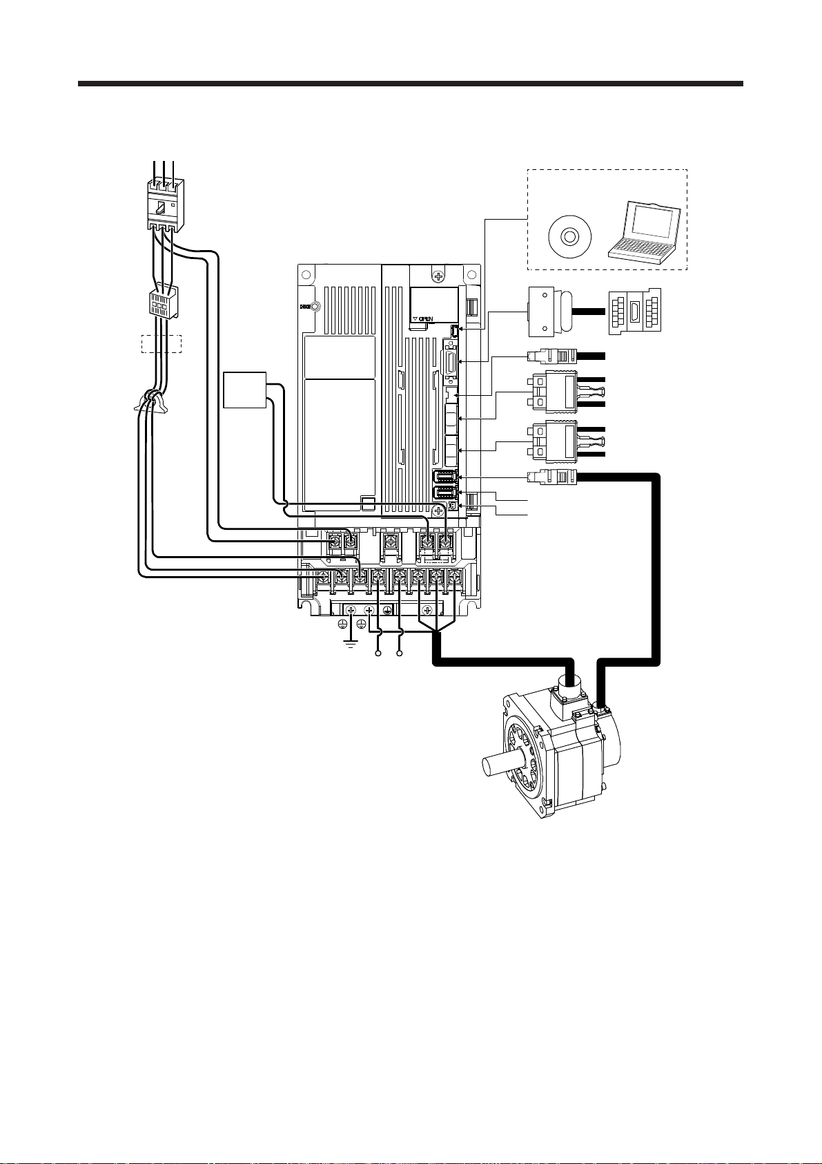
1. FUNCTIONS AND CONFIGURATION
(c) MR-J4-500B4(-RJ)
RS T
(Note 2)
Power supply
Molded-case
circuit breaker
(MCCB)
(Note 3)
Magnetic
contactor
(MC)
(Note 1)
Line noise filter
(FR-BSF01)
Power factor
improving DC
reactor
(FR-HEL-H)
P4
L21
P3
MR Configurator2
CN5
CN3
CN8
CN1A
CN1B
CN2
CN2L (Note 4)
CN4
Battery
Personal
computer
Junction terminal
block
To safety relay or
MR-J3-D05 safety
logic unit
Servo system controller
or previous servo
amplifier CN1B
Next servo amplifier
CN1A or cap
L3
L2
L1
L11
(Note 5) Regenerative
P+ C
option
WVU
Servo motor
Note 1. The power factor improving AC reactor can also be used. In this case, the power factor improving DC reactor cannot be used.
When not using the power factor improving DC reactor, short P3 and P4.
2. Refer to section 1.3 for the power supply specification.
3. Depending on the main circuit voltage and operation pattern, bus voltage decreases, and that may cause the forced stop
deceleration to shift to the dynamic brake deceleration. When dynamic brake deceleration is not required, slow the time to turn
off the magnetic contactor.
4. This is for MR-J4-_B4-RJ servo amplifier. MR-J4-_B4 servo amplifier does not have CN2L connector. When using MR-J4-_B4RJ servo amplifier in the linear servo system or in the fully closed loop system, connect an external encoder to this connector.
Refer to Table 1.1 and "Linear Encoder Instruction Manual" for the compatible external encoders.
5. When using the regenerative option, refer to section 11.2.
1 - 48

1. FUNCTIONS AND CONFIGURATION
(d) MR-J4-700B4(-RJ)
RS T
(Note 2)
Power supply
Molded-case
circuit breaker
(MCCB)
CN5
MR Configurator2
Personal
computer
(Note 3)
Magnetic
contactor
(MC)
(Note 1)
Line noise filter
(FR-BLF)
Power factor
improving DC
reactor
(FR-HEL-H)
L3
L2
L1
P4
P3
L21
L11
CN3
CN8
CN1A
CN1B
CN2
CN2L (Note 4)
CN4
Battery
WVU
To safety relay or
MR-J3-D05 safety
logic unit
Servo system controller
or previous servo
amplifier CN1B
Next servo amplifier
CN1A or cap
Junction terminal
block
C
(Note 5) Regenerative
P+
option
Servo motor
Note 1. The power factor improving AC reactor can also be used. In this case, the power factor improving DC reactor cannot be used.
When not using the power factor improving DC reactor, short P3 and P4.
2. Refer to section 1.3 for the power supply specification.
3. Depending on the main circuit voltage and operation pattern, bus voltage decreases, and that may cause the forced stop
deceleration to shift to the dynamic brake deceleration. When dynamic brake deceleration is not required, slow the time to turn
off the magnetic contactor.
4. This is for MR-J4-_B4-RJ servo amplifier. MR-J4-_B4 servo amplifier does not have CN2L connector. When using MR-J4-_B4RJ servo amplifier in the linear servo system or in the fully closed loop system, connect an external encoder to this connector.
Refer to Table 1.1 and "Linear Encoder Instruction Manual" for the compatible external encoders.
5. When using the regenerative option, refer to section 11.2.
1 - 49

1. FUNCTIONS AND CONFIGURATION
(e) MR-J4-11K4B(-RJ)/MR-J4-15K4B(-RJ)
RS T
(Note 2)
Power supply
Molded-case
circuit breaker
(MCCB)
CN5
MR Configurator2
Personal
computer
(Note 3)
Magnetic
contactor
(MC)
(Note 1)
Line noise filter
(FR-BLF)
L3
L2
L1
Power factor
improving DC
reactor
(FR-HEL-H)
P3
L21
L11
CN3
CN8
CN1A
CN1B
CN2
CN2L (Note 4)
CN4
Battery
To safety relay or
MR-J3-D05 safety
logic unit
Servo system controller
or previous servo
amplifier CN1B
Next servo amplifier
CN1A or cap
Junction terminal
block
WVU
P4
(Note 5) Regenerative
P+ C
option
Servo motor
Note 1. The power factor improving AC reactor can also be used. In this case, the power factor improving DC reactor cannot be used.
When not using the power factor improving DC reactor, short P3 and P4.
2. Refer to section 1.3 for the power supply specification.
3. Depending on the main circuit voltage and operation pattern, bus voltage decreases, and that may cause the forced stop
deceleration to shift to the dynamic brake deceleration. When dynamic brake deceleration is not required, slow the time to turn
off the magnetic contactor.
4. This is for MR-J4-_B4-RJ servo amplifier. MR-J4-_B4 servo amplifier does not have CN2L connector. When using MR-J4-_B4RJ servo amplifier in the linear servo system or in the fully closed loop system, connect an external encoder to this connector.
Refer to Table 1.1 and "Linear Encoder Instruction Manual" for the compatible external encoders.
5. When using the regenerative option, refer to section 11.2.
1 - 50

1. FUNCTIONS AND CONFIGURATION
(f) MR-J4-22K4B(-RJ)
CN5
MR Configurator2
Personal
computer
(Note 2)
Power supply
Molded-case
circuit breaker
(MCCB)
(Note 3)
Magnetic
contactor
(MC)
(Note 1)
Line noise filter
(FR-BLF)
RS T
L3
L2
L1
Power factor
improving DC
reactor
(FR-HEL-H)
P3
L21
L11
CN3
CN8
CN1A
CN1B
CN2
CN2L (Note 4)
CN4
Battery
To safety relay or
MR-J3-D05 safety
logic unit
Servo system controller
or previous servo
amplifier CN1B
Next servo amplifier
CN1A or cap
Junction terminal
block
WVU
P4
(Note 5) Regenerative
P+ C
option
Servo motor
Note 1. The power factor improving AC reactor can also be used. In this case, the power factor improving DC reactor cannot be used.
When not using the power factor improving DC reactor, short P3 and P4.
2. Refer to section 1.3 for the power supply specification.
3. Depending on the main circuit voltage and operation pattern, bus voltage decreases, and that may cause the forced stop
deceleration to shift to the dynamic brake deceleration. When dynamic brake deceleration is not required, slow the time to turn
off the magnetic contactor.
4. This is for MR-J4-_B4-RJ servo amplifier. MR-J4-_B4 servo amplifier does not have CN2L connector. When using MR-J4-_B4RJ servo amplifier in the linear servo system or in the fully closed loop system, connect an external encoder to this connector.
Refer to Table 1.1 and "Linear Encoder Instruction Manual" for the compatible external encoders.
5. When using the regenerative option, refer to section 11.2.
1 - 51

1. FUNCTIONS AND CONFIGURATION
A
(3) 100 V class
The diagram is for MR-J4-20B1-RJ.
(Note 2)
Power supply
Molded-case
circuit breaker
(MCCB)
(Note 3)
Magnetic
contactor
(MC)
Power factor
improving AC
reactor
(FR-HAL)
Line noise
filter
(FR-BSF01)
RT
(Note 1)
L1
L2
(Note 1)
D (Note 5)
U
V
W
CN5
CN3
CN8
CN1A
CN1B
MR Configurator2
Personal
computer
Junction terminal
block
To safety relay or MR-J3-D05
safety logic unit
Servo system controller or
previous servo amplifier
CN1B
Next servo amplifier CN1A or
cap
CN2
CN2L (Note 4)
Regenerative
option
Note 1. The power factor improving DC reactor cannot be used.
2. For power supply specifications, refer to section 1.3.
3. Depending on the main circuit voltage and operation pattern, bus voltage decreases, and that may cause the forced stop
deceleration to shift to the dynamic brake deceleration. When dynamic brake deceleration is not required, slow the time to turn
off the magnetic contactor.
4. This is for MR-J4-_B1-RJ servo amplifier. MR-J4-_B1 servo amplifier does not have CN2L connector. Refer to Table 1.1 and
Linear Encoder Instruction Manual for the compatible external encoders.
5.
P+
C
L11
L21
lways connect between P+ and D terminals. When using the regenerative option, refer to section 11.2.
CN4
Battery
Servo motor
1 - 52

2. INSTALLATION
2. INSTALLATION
WARNING
CAUTION
To prevent electric shock, ground each equipment securely.
Stacking in excess of the specified number of product packages is not allowed.
Do not hold the front cover, cables, or connectors when carrying the servo
amplifier. Otherwise, it may drop.
Install the equipment on incombustible material. Installing it directly or close to
combustibles will lead to a fire.
Install the servo amplifier and the servo motor in a load-bearing place in
accordance with the Instruction Manual.
Do not get on or put heavy load on the equipment. Otherwise, it may cause injury.
Use the equipment within the specified environment. For the environment, refer to
section 1.3.
Provide an adequate protection to prevent screws and other conductive matter, oil
and other combustible matter from entering the servo amplifier.
Do not block the intake and exhaust areas of the servo amplifier. Otherwise, it
may cause a malfunction.
Do not drop or apply heavy impact on the servo amplifiers and the servo motors.
Otherwise, injury, malfunction, etc. may occur.
Do not install or operate the servo amplifier which have been damaged or have
any parts missing.
When the product has been stored for an extended period of time, contact your
local sales office.
When handling the servo amplifier, be careful about the edged parts such as
corners of the servo amplifier.
The servo amplifier must be installed in the metal cabinet.
When fumigants that contain halogen materials such as fluorine, chlorine,
bromine, and iodine are used for disinfecting and protecting wooden packaging
from insects, they cause malfunction when entering our products. Please take
necessary precautions to ensure that remaining materials from fumigant do not
enter our products, or treat packaging with methods other than fumigation (heat
method).Additionally, disinfect and protect wood from insects before packing
products.
POINT
When pulling out CNP1, CNP2, and CNP3 connectors of 100 V class/600 W or
lower 200 V class servo amplifier, pull out CN3 and CN8 connectors
beforehand.
2 - 1

2. INSTALLATION
2.1 Installation direction and clearances
The equipment must be installed in the specified direction. Otherwise, it may
CAUTION
(1) Installation clearances of the servo amplifier
(a) Installation of one servo amplifier
cause a malfunction.
Leave specified clearances between the servo amplifier and the cabinet walls or
other equipment. Otherwise, it may cause a malfunction.
Cabinet Cabinet
40 mm or more
Servo amplifier
10 mm
or more
(Note 2)
40 mm
or more
(Note 1)
Note 1. For 11 kW to 22 kW servo amplifiers, the clearance between the bottom and ground will be 120 mm or more.
2. When mounting MR-J4-500B(-RJ), maintain a minimum clearance of 25 mm on the left side.
10 mm
or more
Wiring allowance
80 mm or more
Top
Bottom
2 - 2

2. INSTALLATION
(b) Installation of two or more servo amplifiers
POINT
Close mounting is possible depending on the capacity of the servo amplifier.
Refer to section 1.3 for availability of close mounting.
When closely mounting multiple servo amplifiers, the servo amplifier on the right
must have a larger depth than that on the left. Otherwise, the CNP1, CNP2, and
CNP3 connectors cannot be removed.
Leave a large clearance between the top of the servo amplifier and the cabinet walls, and install a
cooling fan to prevent the internal temperature of the cabinet from exceeding the environment.
When mounting the servo amplifiers closely, leave a clearance of 1 mm between the adjacent servo
amplifiers in consideration of mounting tolerances. In this case, keep the ambient temperature within
0 ˚C to 45 ˚C or use the servo amplifier with 75% or less of the effective load ratio.
Cabinet
Cabinet
100 mm or more
30 mm
or more
40 mm or more
(Note 1)
Leaving clearance Mounting closely
Note 1. For 11 kW to 22 kW servo amplifiers, the clearance between the bottom and ground will be 120 mm or more.
2. When mounting MR-J4-500B(-RJ), maintain a minimum clearance of 25 mm between the MR-J4-500B(-RJ) and a servo
amplifier mounted on the left side.
10 mm or more
(Note 2)
30 mm
or more
1 mm
100 mm or more
1 mm
40 mm or more
30 mm
or more
(2) Others
When using heat generating equipment such as the regenerative option, install them with full
consideration of heat generation so that the servo amplifier is not affected.
Install the servo amplifier on a perpendicular wall in the correct vertical direction.
Top
Bottom
2 - 3

2. INSTALLATION
2.2 Keeping out of foreign materials
(1) When drilling in the cabinet, prevent drill chips and wire fragments from entering the servo amplifier.
(2) Prevent oil, water, metallic dust, etc. from entering the servo amplifier through openings in the cabinet or
a cooling fan installed on the ceiling.
(3) When installing the cabinet in a place where toxic gas, dirt and dust exist, conduct an air purge (force
clean air into the cabinet from outside to make the internal pressure higher than the external pressure) to
prevent such materials from entering the cabinet.
2.3 Encoder cable stress
(1) The way of clamping the cable must be fully examined so that bending stress and cable's own weight
stress are not applied to the cable connection.
(2) For use in any application where the servo motor moves, fix the cables (encoder, power supply, and
brake) with having some slack from the connector connection part of the servo motor to avoid putting
stress on the connector connection part. Use the optional encoder cable within the bending life range.
Use the power supply and brake wiring cables within the bending life of the cables.
(3) Avoid any probability that the cable insulator might be cut by sharp chips, rubbed by a machine corner or
stamped by workers or vehicles.
(4) For installation on a machine where the servo motor moves, the bending radius should be made as large
as possible. Refer to section 10.4 for the bending life.
2.4 SSCNET III cable laying
SSCNET III cable is made from optical fiber. If optical fiber is added a power such as a major shock, lateral
pressure, haul, sudden bending or twist, its inside distorts or breaks, and optical transmission will not be
available. Especially, as optical fiber for MR-J3BUS_M/MR-J3BUS_M-A is made of synthetic resin, it melts
down if being left near the fire or high temperature. Therefore, do not make it touched the part, which can
become hot, such as heat sink or regenerative option of servo amplifier.
Read described item in this section carefully and handle it with caution.
(1) Minimum bend radius
Make sure to lay the cable with greater radius than the minimum bend radius. Do not press the cable to
edges of equipment or others. For SSCNET III cable, the appropriate length should be selected with due
consideration for the dimensions and arrangement of servo amplifier. When closing the door of cabinet,
pay careful attention for avoiding the case that SSCNET III cable is hold down by the door and the cable
bend becomes smaller than the minimum bend radius. For the minimum bend radius, refer to section
11.1.3.
2 - 4

2. INSTALLATION
r
(2) Prohibition of vinyl tape use
Migrating plasticizer is used for vinyl tape. Keep the MR-J3BUS_M, and MR-J3BUS_M-A cables away
from vinyl tape because the optical characteristic may be affected.
Optical cord
Cable
(3) Precautions for migrating plasticizer added materials
Generally, soft polyvinyl chloride (PVC), polyethylene resin (PE) and fluorine resin contain non-migrating
plasticizer and they do not affect the optical characteristic of SSCNET III cable. However, some wire
sheaths and cable ties, which contain migrating plasticizer (phthalate ester), may affect MR-J3BUS_M
and MR-J3BUS_M-A cables (plastic).
In addition, MR-J3BUS_M-B cable (silica glass) is not affected by plasticizer.
A chemical substance may affect its optical characteristic. Therefore, previously check that the cable is
not affected by the environment.
(4) Bundle fixing
Fix the cable at the closest part to the connector with bundle material in order to prevent SSCNET III
cable from putting its own weight on CN1A/CN1B connector of servo amplifier. Optical cord should be
given loose slack to avoid from becoming smaller than the minimum bend radius, and it should not be
twisted.
When bundling the cable, fix and hold it in position by using cushioning such as sponge or rubber which
does not contain migratable plasticizers.
If adhesive tape for bundling the cable is used, fire resistant acetate cloth adhesive tape 570F (Teraoka
Seisakusho Co., Ltd) is recommended.
SSCNET III cable Cord Cable
MR-J3BUS_M
MR-J3BUS_M-A
MR-J3BUS_M-B
: Phthalate ester plasticizer such as DBP and DOP
may affect optical characteristic of cable.
: Cord and cable are not basically affected by
plasticizer.
Connecto
Optical cord
Loose slack
Bundle material
Recommended product: NK clamp SP type
(NIX, INC)
Cable
2 - 5

2. INSTALLATION
(5) Tension
If tension is added on optical cable, the increase of transmission loss occurs because of external force
which concentrates on the fixing part of optical fiber or the connecting part of optical connector. Doing so
may cause the breakage of the optical fiber or damage of the optical connector. For cable laying, handle
without putting forced tension. For the tension strength, refer to section 11.1.3.
(6) Lateral pressure
If lateral pressure is added on optical cable, the optical cable itself distorts, internal optical fiber gets
stressed, and then transmission loss will increase. Doing so may cause the breakage of the optical
cable. As the same condition also occurs at cable laying, do not tighten up optical cable with a thing
such as nylon band (TY-RAP).
Do not trample it down or tuck it down with the door of cabinet or others.
(7) Twisting
If optical fiber is twisted, it will become the same stress added condition as when local lateral pressure or
bend is added. Consequently, transmission loss increases, and the breakage of optical fiber may occur.
(8) Disposal
When incinerating optical cable (cord) used for SSCNET III, hydrogen fluoride gas or hydrogen chloride
gas which is corrosive and harmful may be generated. For disposal of optical fiber, request for
specialized industrial waste disposal services who has incineration facility for disposing hydrogen
fluoride gas or hydrogen chloride gas.
2.5 Inspection items
Before starting maintenance and/or inspection, turn off the power and wait for 15
minutes or more until the charge lamp turns off. Then, confirm that the voltage
between P+ and N- is safe with a voltage tester and others. Otherwise, an electric
WARNING
shock may occur. In addition, when confirming whether the charge lamp is off or
not, always confirm it from the front of the servo amplifier.
To avoid an electric shock, only qualified personnel should attempt inspections.
For repair and parts replacement, contact your local sales office.
Do not perform insulation resistance test on the servo amplifier. Otherwise, it may
CAUTION
It is recommended that the following points periodically be checked.
(1) Check for loose terminal block screws. Retighten any loose screws.
(2) Check the cables and the like for scratches or cracks. Inspect them periodically according to operating
conditions especially when the servo motor is movable.
(3) Check that the connector is securely connected to the servo amplifier.
(4) Check that the wires are not coming out from the connector.
cause a malfunction.
Do not disassemble and/or repair the equipment on customer side.
2 - 6

2. INSTALLATION
(5) Check for dust accumulation on the servo amplifier.
(6) Check for unusual noise generated from the servo amplifier.
(7) Make sure that the emergency stop circuit operates properly such that an operation can be stopped
immediately and a power is shut off by the emergency stop switch.
2.6 Parts having service life
Service life of the following parts is listed below. However, the service life varies depending on operation and
environment. If any fault is found in the parts, they must be replaced immediately regardless of their service
life. For parts replacement, please contact your local sales office.
(1) Smoothing capacitor
The characteristic of smoothing capacitor is deteriorated due to ripple currents, etc. The life of the
capacitor greatly depends on ambient temperature and operating conditions. The capacitor will reach
the end of its life in 10 years of continuous operation in air-conditioned environment (ambient
temperature of 40 °C or less).
(2) Relays
Contact faults will occur due to contact wear arisen from switching currents. Relays reach the end of
their life when the power has been turned on, forced stop by EM1 (Forced stop 1) has occurred, and
controller forced stop has occurred 100,000 times in total, or when the STO has been turned on and off
1,000,000 times while the servo motor is stopped under servo-off state. However, the life of relays may
depend on the power supply capacity.
(3) Servo amplifier cooling fan
The cooling fan bearings reach the end of their life in 10,000 hours to 30,000 hours. Normally, therefore,
the cooling fan must be replaced in a few years of continuous operation as a guideline. If unusual noise
or vibration is found during inspection, the cooling fan must also be replaced.
The life indicates under the yearly average ambient temperature of 40 ˚C, free from corrosive gas,
flammable gas, oil mist, dust and dirt.
Part name Life guideline
Smoothing capacitor 10 years
Number of power-on, forced stop by EM1 (Forced
Relay
Cooling fan 10,000 hours to 30,000 hours (2 years to 3 years)
Absolute position battery Refer to section 12.2.
stop 1), and controller forced stop times: 100,000
times
Number of on and off for STO: 1,000,000 times
2 - 7

2. INSTALLATION
2.7 Restrictions when using this product at altitude exceeding 1000 m and up to 2000 m above sea level
(1) Effective load ratio and regenerative load ratio
As heat dissipation effects decrease in proportion to the decrease in air density, use the product within
the effective load ratio and regenerative load ratio shown in the following figure.
[%]
100
95
Effective load ratio
0
0
Regenerative load ratio
Altitude
When closely mounting the servo amplifiers, operate them at the ambient temperature of 0 °C to 45 °C
or at 75% or smaller effective load ratio. (Refer to section 2.1.)
(2) Input voltage
Generally, a withstand voltage decreases as increasing altitude; however, there is no restriction on the
withstand voltage. Use in the same manner as in 1000 m or less. (Refer to section 1.3.)
(3) Parts having service life
(a) Smoothing capacitor
The capacitor will reach the end of its life in 10 years of continuous operation in air-conditioned
environment (ambient temperature of 30 °C or less).
(b) Relay
There is no restriction. Use in the same manner as in 1000 m or less. (Refer to section 2.6.)
(c) Servo amplifier cooling fan
There is no restriction. Use in the same manner as in 1000 m or less. (Refer to section 2.6.)
[m]
20001000
2 - 8

3. SIGNALS AND WIRING
3. SIGNALS AND WIRING
Any person who is involved in wiring should be fully competent to do the work.
Before wiring, turn off the power and wait for 15 minutes or more until the charge
lamp turns off. Then, confirm that the voltage between P+ and N- is safe with a
voltage tester and others. Otherwise, an electric shock may occur. In addition,
when confirming whether the charge lamp is off or not, always confirm it from the
front of the servo amplifier.
WARNING
Ground the servo amplifier and servo motor securely.
Do not attempt to wire the servo amplifier and servo motor until they have been
installed. Otherwise, it may cause an electric shock.
The cables should not be damaged, stressed, loaded, or pinched. Otherwise, it
may cause an electric shock.
To avoid an electric shock, insulate the connections of the power supply
terminals.
Wire the equipment correctly and securely. Otherwise, the servo motor may
operate unexpectedly, resulting in injury.
Connect cables to the correct terminals. Otherwise, a burst, damage, etc. may
occur.
Ensure that polarity (+/-) is correct. Otherwise, a burst, damage, etc. may occur.
The surge absorbing diode installed to the DC relay for control output should be
fitted in the specified direction. Otherwise, the emergency stop and other
protective circuits may not operate.
CAUTION
Servo amplifier
DOCOM
Control output
signal
For sink output interface
24 V DC
RA
Servo amplifier
24 V DC
DOCOM
Control output
signal
For source output interface
RA
Use a noise filter, etc. to minimize the influence of electromagnetic interference.
Electromagnetic interference may be given to the electronic equipment used near
the servo amplifier.
Do not install a power capacitor, surge killer or radio noise filter (optional FR-BIF(H)) with the power line of the servo motor.
When using the regenerative resistor, switch power off with the alarm signal.
Otherwise, a transistor fault or the like may overheat the regenerative resistor,
causing a fire.
Do not modify the equipment.
3 - 1

3. SIGNALS AND WIRING
Connect the servo amplifier power output (U/V/W) to the servo motor power input
(U/V/W) directly. Do not let a magnetic contactor, etc. intervene. Otherwise, it may
cause a malfunction.
CAUTION
Servo amplifier
U
V
W
Servo motor
U
V
W
Servo motorServo amplifier
U
M
V
W
U
V
W
Connecting a servo motor of the wrong axis to U, V, W, or CN2 of the servo
amplifier may cause a malfunction.
Before wiring, switch operation, etc., eliminate static electricity. Otherwise, it may
cause a malfunction.
POINT
When you use a linear servo motor, replace the following words in the left to the
words in the right.
Load to motor inertia ratio → Load mass
Torque → Thrust
(Servo motor) speed → (Linear servo motor) speed
M
3 - 2

3. SIGNALS AND WIRING
3.1 Input power supply circuit
Always connect a magnetic contactor between the power supply and the main
circuit power supply (L1/L2/L3) of the servo amplifier, in order to configure a
circuit that shuts down the power supply on the side of the servo amplifier’s power
supply. If a magnetic contactor is not connected, continuous flow of a large
current may cause a fire when the servo amplifier malfunctions.
Use ALM (Malfunction) to switch main circuit power supply off. Not doing so may
cause a fire when a regenerative transistor malfunctions or the like may overheat
the regenerative resistor.
Check the servo amplifier model, and then input proper voltage to the servo
CAUTION
amplifier power supply. If input voltage exceeds the upper limit, the servo amplifier
will break down.
The servo amplifier has a built-in surge absorber (varistor) to reduce exogenous
noise and to suppress lightning surge. Exogenous noise or lightning surge
deteriorates the varistor characteristics, and the varistor may be damaged. To
prevent a fire, use a molded-case circuit breaker or fuse for input power supply.
Connecting a servo motor of the wrong axis to U, V, W, or CN2 of the servo
amplifier may cause a malfunction.
The N- terminal is not a neutral point of the power supply. Incorrect wiring will
cause a burst, damage, etc.
POINT
Even if alarm has occurred, do not switch off the control circuit power supply.
When the control circuit power supply has been switched off, optical module
does not operate, and optical transmission of SSCNET III/H communication is
interrupted. Therefore, the next axis servo amplifier displays "AA" at the
indicator and turns into base circuit shut-off. The servo motor stops with starting
dynamic brake.
EM2 has the same function as EM1 in the torque control mode.
Connect the 1-phase 200 V AC to 240 V AC power supply to L1 and L3. One of
the connecting destinations is different from MR-J3 Series Servo Amplifier's.
When using MR-J4 as a replacement for MR-J3, be careful not to connect the
power to L2.
When using the MR-J4-_B-RJ servo amplifier with the DC power supply input,
refer to app. 15.
Configure the wiring so that the main circuit power supply is shut off and the servo-on command turned off
after deceleration to a stop due to an alarm occurring, an enabled servo forced stop, or an enabled controller
forced stop. A molded-case circuit breaker (MCCB) must be used with the input cables of the main circuit
power supply.
3 - 3

3. SIGNALS AND WIRING
A
3.1.1 200 V class
(1) Using 3-phase 200 V AC to 240 V AC power supply for MR-J4-10B(-RJ) to MR-J4-350B(-RJ)
(Note 4)
Malfunction
RA1
Emergency stop switch
OFF
ON
MC
MC
SK
3-phase
200 V AC to
240 V AC
(Note 5) Forced stop 2
MCCB
(Note 8)
Main circuit power supply
24 V DC (Note 12)
(Note 9)
Short-circuit connector
(Packed with the servo amplifier)
MC
(Note 7)
(Note 1)(Note 10)
(Note 2)
Servo amplifier
CNP1
L1
L2
L3
N-
P3
P4
CNP2
P+
C
D
L11
L21
CN3
EM2
DICOM
CN8
(Note 11)
CNP3
U
V
W
(Note 11)
CN2
CN3
DOCOM
ALM
(Note 6)
(Note 3)
Encoder
cable
24 V DC (Note 12)
RA1
Servo motor
U
Motor
V
W
Malfunction (Note 4)
M
Encoder
(Note 5)
Note 1. Between P3 and P4 is connected by default. When using the power factor improving DC reactor, remove the short bar
between P3 and P4. Refer to section 11.11 for details. Additionally, a power factor improving DC reactor and power factor
improving AC reactor cannot be used simultaneously.
2.
3. For the encoder cable, use of the option cable is recommended. For selecting cables, refer to "Servo Motor Instruction
4. If disabling ALM (Malfunction) output with the parameter, configure up the power supply circuit which switches off the
5. This diagram shows sink I/O interface. For source I/O interface, refer to section 3.8.3.
6. For connecting servo motor power wires, refer to "Servo Motor Instruction Manual (Vol. 3)".
7. Use a magnetic contactor with an operation delay time (interval between current being applied to the coil until closure of
8. Configure a circuit to turn off EM2 when the main circuit power is turned off to prevent an unexpected restart of the servo
9. When not using the STO function, attach the short-circuit connector came with a servo amplifier.
10. When wires used for L11 and L21 are thinner than wires used for L1, L2, and L3, use a molded-case circuit breaker. (Refer
11. Connecting a servo motor of the wrong axis to U, V, W, or CN2 of the servo amplifier may cause a malfunction.
12. The illustration of the 24 V DC power supply is divided between input signal and output signal for convenience. However,
lways connect between P+ and D terminals (factory-wired). When using the regenerative option, refer to section 11.2.
Manual (Vol. 3)".
magnetic contactor after detection of alarm occurrence on the controller side.
contacts) of 80 ms or less. Depending on the main circuit voltage and operation pattern, bus voltage decreases, and that
may cause the forced stop deceleration to shift to the dynamic brake deceleration. When dynamic brake deceleration is not
required, slow the time to turn off the magnetic contactor.
amplifier.
to section 11.10.)
they can be configured by one.
3 - 4

3. SIGNALS AND WIRING
A
(2) Using 1-phase 200 V AC to 240 V AC power supply for MR-J4-10B(-RJ) to MR-J4-200B(-RJ)
Emergency stop switch
MC
(Note 7)
(Note 1)
(Note 2)
CNP1
L1
L2
L3
N-
P3
P4
CNP2
P+
C
D
L11
L21
CN3
EM2
DICOM
CN8
OFF
Servo amplifier
(Note 11)
CNP3
(Note 11)
ON
MC
U
V
W
CN2
24 V DC (Note 12)
CN3
DOCOM
ALM
MC
SK
(Note 6)
(Note 3)
Encoder
cable
Servo motor
U
Motor
V
W
RA1
Malfunction (Note 4)
M
Encoder
1-phase
200 V AC to
240 V AC
(Note 5) Forced stop 2
POINT
Connect the 1-phase 200 V AC to 240 V AC power supply to L1 and L3. One of
the connecting destinations is different from MR-J3 Series Servo Amplifier's.
When using MR-J4 as a replacement for MR-J3, be careful not to connect the
power to L2.
(Note 4)
Malfunction
RA1
MCCB
(Note 10)
(Note 8)
Main circuit power supply
24 V DC (Note 12)
(Note 9)
Short-circuit connector
(Packed with the servo amplifier)
(Note 5)
Note 1. Between P3 and P4 is connected by default. When using the power factor improving DC reactor, remove the short bar
between P3 and P4. Refer to section 11.11 for details. Additionally, a power factor improving DC reactor and power factor
improving AC reactor cannot be used simultaneously.
2.
3. For the encoder cable, use of the option cable is recommended. For selecting cables, refer to "Servo Motor Instruction
4. If disabling ALM (Malfunction) output with the parameter, configure up the power supply circuit which switches off the
5. This diagram shows sink I/O interface. For source I/O interface, refer to section 3.8.3.
6. For connecting servo motor power wires, refer to "Servo Motor Instruction Manual (Vol. 3)".
7. Use a magnetic contactor with an operation delay time (interval between current being applied to the coil until closure of
8. Configure a circuit to turn off EM2 when the main circuit power is turned off to prevent an unexpected restart of the servo
9. When not using the STO function, attach the short-circuit connector came with a servo amplifier.
10. When wires used for L11 and L21 are thinner than wires used for L1, and L3, use a molded-case circuit breaker. (Refer to
11. Connecting a servo motor of the wrong axis to U, V, W, or CN2 of the servo amplifier may cause a malfunction.
12. The illustration of the 24 V DC power supply is divided between input signal and output signal for convenience. However,
lways connect between P+ and D terminals (factory-wired). When using the regenerative option, refer to section 11.2.
Manual (Vol. 3)".
magnetic contactor after detection of alarm occurrence on the controller side.
contacts) of 80 ms or less. Depending on the main circuit voltage and operation pattern, bus voltage decreases, and that
may cause the forced stop deceleration to shift to the dynamic brake deceleration. When dynamic brake deceleration is not
required, slow the time to turn off the magnetic contactor.
amplifier.
section 11.10.)
they can be configured by one.
3 - 5

3. SIGNALS AND WIRING
A
r
(3) MR-J4-500B(-RJ)
(Note 4)
Malfunction
RA1
OFF
Emergency stop switch
ON
MC
MC
SK
3-phase
200 V AC to
240 V AC
(Note 5) Forced stop 2
MCCB
(Note 10)
(Note 8)
Main circuit power supply
(Note 9)
Short-circuit connector
(Packed with the servo amplifier)
24 V DC (Note 12)
MC
(Note 7)
(Note 1)
(Note 2)
Servo amplifier
L1
L2
L3
N-
L11
L21
P3
P4
P+
C
D
CN3
EM2
DICOM
CN8
(Note 11)
U
V
W
(Note 11)
CN2
CN3
DOCOM
ALM
(Note 6)
(Note 3)
Encoder
cable
24 V DC (Note 12)
RA1
Servo motor
U
Motor
V
W
Malfunction (Note 4)
M
Encoder
(Note 5)
Note 1. Between P3 and P4 is connected by default. When using the power factor improving DC reactor, remove the short bar
between P3 and P4. Refer to section 11.11 for details. Additionally, a power factor improving DC reactor and power factor
improving AC reactor cannot be used simultaneously.
2.
3. For the encoder cable, use of the option cable is recommended. For selecting cables, refer to "Servo Motor Instruction
4. If disabling ALM (Malfunction) output with the parameter, configure up the power supply circuit which switches off the
5. This diagram shows sink I/O interface. For source I/O interface, refer to section 3.8.3.
6. For connecting servo motor power wires, refer to "Servo Motor Instruction Manual (Vol. 3)".
7. Use a magnetic contactor with an operation delay time (interval between current being applied to the coil until closure of
8. Configure a circuit to turn off EM2 when the main circuit power is turned off to prevent an unexpected restart of the servo
9. When not using the STO function, attach the short-circuit connector came with a servo amplifier.
10. When wires used for L11 and L21 are thinner than wires used for L1, L2, and L3, use a molded-case circuit breaker. (Refe
11. Connecting a servo motor of the wrong axis to U, V, W, or CN2 of the servo amplifier may cause a malfunction.
12. The illustration of the 24 V DC power supply is divided between input signal and output signal for convenience. However,
lways connect between P+ and D terminals (factory-wired). When using the regenerative option, refer to section 11.2.
Manual (Vol. 3)".
magnetic contactor after detection of alarm occurrence on the controller side.
contacts) of 80 ms or less. Depending on the main circuit voltage and operation pattern, bus voltage decreases, and that
may cause the forced stop deceleration to shift to the dynamic brake deceleration. When dynamic brake deceleration is
not required, slow the time to turn off the magnetic contactor.
amplifier.
to section 11.10.)
they can be configured by one.
3 - 6

3. SIGNALS AND WIRING
2
2
r
(4) MR-J4-700B(-RJ)
(Note 4)
Malfunction
RA1
OFF
Emergency stop switch
ON
MC
MC
SK
3-phase
00 V AC to
40 V AC
(Note 5) Forced stop 2
MCCB
(Note 10)
(Note 8)
Main circuit power supply
(Note 9)
Short-circuit connector
(Packed with the servo amplifier)
24 V DC (Note 12)
MC
(Note 7)
(Note 2)
(Note 1)
Servo amplifier
L1
Built-in
L2
regenerative
resistor
L3
P+
C
L11
L21
N-
P3
P4
CN3
EM2
DICOM
CN8
(Note 11)
U
V
W
(Note 11)
CN2
CN3
DOCOM
ALM
(Note 6)
(Note 3)
Encoder
cable
24 V DC (Note 12)
RA1
Servo motor
U
Motor
V
W
Malfunction (Note 4)
M
Encoder
(Note 5)
Note 1. Between P3 and P4 is connected by default. When using the power factor improving DC reactor, remove the short bar
between P3 and P4. Refer to section 11.11 for details. Additionally, a power factor improving DC reactor and power factor
improving AC reactor cannot be used simultaneously.
2. When using the regenerative option, refer to section 11.2.
3. For the encoder cable, use of the option cable is recommended. For selecting cables, refer to "Servo Motor Instruction
Manual (Vol. 3)".
4. If disabling ALM (Malfunction) output with the parameter, configure up the power supply circuit which switches off the
magnetic contactor after detection of alarm occurrence on the controller side.
5. This diagram shows sink I/O interface. For source I/O interface, refer to section 3.8.3.
6. For connecting servo motor power wires, refer to "Servo Motor Instruction Manual (Vol. 3)".
7. Use a magnetic contactor with an operation delay time (interval between current being applied to the coil until closure of
contacts) of 80 ms or less. Depending on the main circuit voltage and operation pattern, bus voltage decreases, and that
may cause the forced stop deceleration to shift to the dynamic brake deceleration. When dynamic brake deceleration is
not required, slow the time to turn off the magnetic contactor.
8. Configure a circuit to turn off EM2 when the main circuit power is turned off to prevent an unexpected restart of the servo
amplifier.
9. When not using the STO function, attach the short-circuit connector came with a servo amplifier.
10. When wires used for L11 and L21 are thinner than wires used for L1, L2, and L3, use a molded-case circuit breaker. (Refe
to section 11.10.)
11. Connecting a servo motor of the wrong axis to U, V, W, or CN2 of the servo amplifier may cause a malfunction.
12. The illustration of the 24 V DC power supply is divided between input signal and output signal for convenience. However,
they can be configured by one.
3 - 7

3. SIGNALS AND WIRING
(5) MR-J4-11KB(-RJ)/MR-J4-15KB(-RJ)/MR-J4-22KB(-RJ)
(Note 4)
3-phase
200 V AC to
240 V AC
MCCB
(Note 10)
Malfunction
RA1
(Note 7)
Emergency stop switch
MC
(Note 2)
OFF
Servo amplifier
L1
L2
L3
P+
C
L11
L21
ON
MC
(Note 11)
U
V
W
MC
SK
(Note 15, 16)
External
dynamic
brake (optional)
(Note 6)
Servo motor
U
V
W
Motor
M
(Note 14)
Cooling fan
power supply
MCCB
(Note 5) Forced stop 2
(Note 1)
(Note 8)
Main circuit power supply
(Note 9)
Short-circuit connector
(Packed with the servo amplifier)
24 V DC (Note 12)
N-
P3
P4
CN3
EM2
DICOM
CN8
(Note 11)
CN2
CN3
DOCOM
ALM
(Note 3)
Encoder
cable
24 V DC (Note 12)
RA1
Encoder
BU
BV
BW
Cooling fan
Malfunction (Note 4)
(Note 13)
(Note 5)
3 - 8

3. SIGNALS AND WIRING
Note 1. Between P3 and P4 is connected by default. When using the power factor improving DC reactor, remove the short bar
between P3 and P4. Refer to section 11.11 for details. Additionally, a power factor improving DC reactor and power factor
improving AC reactor cannot be used simultaneously.
2. When using the regenerative option, refer to section 11.2.
3. For the encoder cable, use of the option cable is recommended. For selecting cables, refer to "Servo Motor Instruction Manual
(Vol. 3)".
4. If disabling ALM (Malfunction) output with the parameter, configure up the power supply circuit which switches off the magnetic
contactor after detection of alarm occurrence on the controller side.
5. This diagram shows sink I/O interface. For source I/O interface, refer to section 3.8.3.
6. For connecting servo motor power wires, refer to "Servo Motor Instruction Manual (Vol. 3)".
7. Use a magnetic contactor with an operation delay time (interval between current being applied to the coil until closure of
contacts) of 80 ms or less. Depending on the main circuit voltage and operation pattern, bus voltage decreases, and that may
cause the forced stop deceleration to shift to the dynamic brake deceleration. When dynamic brake deceleration is not
required, slow the time to turn off the magnetic contactor.
8. Configure a circuit to turn off EM2 when the main circuit power is turned off to prevent an unexpected restart of the servo
amplifier.
9. When not using the STO function, attach the short-circuit connector came with a servo amplifier.
10. When wires used for L11 and L21 are thinner than wires used for L1, L2, and L3, use a molded-case circuit breaker. (Refer to
section 11.10.)
11. Connecting a servo motor of the wrong axis to U, V, W, or CN2 of the servo amplifier may cause a malfunction.
12. The illustration of the 24 V DC power supply is divided between input signal and output signal for convenience. However, they
can be configured by one.
13. For the servo motor with a cooling fan.
14. For the cooling fan power supply, refer to "Servo Motor Instruction Manual (Vol. 3)".
15. Use an external dynamic brake for this servo amplifier. Failure to do so will cause an accident because the servo motor does
not stop immediately but coasts at an alarm occurrence for which the servo motor does not decelerate to stop. Ensure the
safety in the entire equipment. For alarms for which the servo motor does not decelerate to stop, refer to chapter 8. For wiring
of the external dynamic brake, refer to section 11.17.
16. The external dynamic brake cannot be used for compliance with SEMI-F47 standard. Do not assign DB (Dynamic brake
interlock) in [Pr. PD07] to [Pr. PD09]. Failure to do so will cause the servo amplifier to become servo-off when an
instantaneous power failure occurs.
3 - 9

3. SIGNALS AND WIRING
A
3.1.2 400 V class
(1) MR-J4-60B4(-RJ) to MR-J4-350B4(-RJ)
(Note 4)
Malfunction
RA1
(Note 12)
Step-down
transformer
MCCB
3-phase
380 V AC to
480 V AC
(Note 8)
Main circuit power supply
(Note 5) Forced stop 2
(Note 9)
Short-circuit connector
(Packed with the servo amplifier)
24 V DC (Note 13)
Emergency stop switch
(Note 7)
MC
(Note 1)(Note 10)
(Note 2)
CNP1
NL1
L2
L3
P3
P4
CNP2
P+
C
D
L11
L21
CN3
EM2
DICOM
CN8
OFF
Servo amplifier Servo motor
ON
MC
(Note 11)
CNP3
U
V
W
(Note 11)
CN2
CN3
DOCOM
ALM
MC
SK
(Note 6)
(Note 3)
Encoder cable
24 V DC (Note 13)
RA1
U
Motor
V
W
Encoder
(Note 4)
Malfunction
M
(Note 5)
Note 1. Between P3 and P4 is connected by default. When using the power factor improving DC reactor, remove the short bar
between P3 and P4. Refer to section 11.11 for details. Additionally, a power factor improving DC reactor and power factor
improving AC reactor cannot be used simultaneously.
2.
3. For the encoder cable, use of the option cable is recommended. For selecting cables, refer to "Servo Motor Instruction
4. If disabling ALM (Malfunction) output with the parameter, configure up the power supply circuit which switches off the
5. This diagram shows sink I/O interface. For source I/O interface, refer to section 3.8.3.
6. For connecting servo motor power wires, refer to "Servo Motor Instruction Manual (Vol. 3)".
7. Use a magnetic contactor with an operation delay time (interval between current being applied to the coil until closure of
8. Configure a circuit to turn off EM2 when the main circuit power is turned off to prevent an unexpected restart of the servo
9. When not using the STO function, attach the short-circuit connector came with a servo amplifier.
10. When wires used for L11 and L21 are thinner than wires used for L1, L2, and L3, use a molded-case circuit breaker. (Refer
11. Connecting a servo motor for different axis to U, V, W, or CN2 of the servo amplifier may cause a malfunction.
12. Stepdown transformer is required when the coil voltage of the magnetic contactor is 200 V class.
13. The illustration of the 24 V DC power supply is divided between input signal and output signal for convenience. However,
lways connect between P+ and D terminals (factory-wired). When using the regenerative option, refer to section 11.2.
Manual (Vol. 3)".
magnetic contactor after detection of alarm occurrence on the controller side.
contacts) of 80 ms or less. Depending on the main circuit voltage and operation pattern, bus voltage decreases, and that
may cause the forced stop deceleration to shift to the dynamic brake deceleration. When dynamic brake deceleration is not
required, slow the time to turn off the magnetic contactor.
amplifier.
to section 11.10.)
they can be configured by one.
3 - 10

3. SIGNALS AND WIRING
(2) MR-J4-500B4(-RJ)/MR-J4-700B4(-RJ)
(Note 4)
Malfunction
RA1
(Note 12)
Step-down
transformer
MCCB
3-phase
380 V AC to
480 V AC
(Note 10)
Emergency stop switch
(Note 7)
MC
(Note 2)
L1
L2
L3
P+
C
OFF
Servo amplifier Servo motor
Built-in
regenerative
resistor
ON
MC
(Note 11)
U
V
W
MC
SK
(Note 6)
U
Motor
V
W
M
L11
L21
N-
(Note 1)
(Note 8)
Main circuit power supply
(Note 5) Forced stop 2
24 V DC (Note 13)
(Note 9)
Short-circuit connector
(Packed with the servo amplifier)
Note 1. Between P3 and P4 is connected by default. When using the power factor improving DC reactor, remove the short bar
between P3 and P4. Refer to section 11.11 for details. Additionally, a power factor improving DC reactor and power factor
improving AC reactor cannot be used simultaneously.
2. When using the regenerative option, refer to section 11.2.
3. For the encoder cable, use of the option cable is recommended. For selecting cables, refer to "Servo Motor Instruction
Manual (Vol. 3)".
4. If disabling ALM (Malfunction) output with the parameter, configure up the power supply circuit which switches off the
magnetic contactor after detection of alarm occurrence on the controller side.
5. This diagram shows sink I/O interface. For source I/O interface, refer to section 3.8.3.
6. For connecting servo motor power wires, refer to "Servo Motor Instruction Manual (Vol. 3)".
7. Use a magnetic contactor with an operation delay time (interval between current being applied to the coil until closure of
contacts) of 80 ms or less. Depending on the main circuit voltage and operation pattern, bus voltage decreases, and that
may cause the forced stop deceleration to shift to the dynamic brake deceleration. When dynamic brake deceleration is not
required, slow the time to turn off the magnetic contactor.
8. Configure a circuit to turn off EM2 when the main circuit power is turned off to prevent an unexpected restart of the servo
amplifier.
9. When not using the STO function, attach the short-circuit connector came with a servo amplifier.
10. When wires used for L11 and L21 are thinner than wires used for L1, L2, and L3, use a molded-case circuit breaker. (Refer
to section 11.10.)
11. Connecting a servo motor for different axis to U, V, W, or CN2 of the servo amplifier may cause a malfunction.
12. Stepdown transformer is required when the coil voltage of the magnetic contactor is 200 V class.
13. The illustration of the 24 V DC power supply is divided between input signal and output signal for convenience. However,
they can be configured by one.
P3
P4
CN3
EM2
DICOM
CN8
(Note 11)
CN2
CN3
DOCOM
ALM
(Note 3)
Encoder cable
24 V DC (Note 13)
RA1
Encoder
(Note 4)
Malfunction
(Note 5)
3 - 11

3. SIGNALS AND WIRING
4
(3) MR-J4-11KB4(-RJ) to MR-J4-22KB4(-RJ)
(Note 4)
Malfunction
RA1
3-phase
380 V AC to
80 V AC
(Note 12)
Step-down
transformer
MCCB
(Note 10)
Emergency stop switch
(Note 7)
MC
(Note 2)
(Note 1)
OFF
Servo amplifier Servo motor
L1
L2
L3
P+
C
L11
L21
N-
P3
P4
ON
MC
(Note 11)
U
V
W
(Note 11)
CN2
MC
SK
(Note 16, 17)
External
dynamic brake
(optional)
(Note 6)
(Note 3)
Encoder cable
U
V
W
Motor
M
Encoder
Cooling fan
power supply
BU
BV
BW
(Note 14)
Cooling fan
(Note 13)
MCCB
(Note 5) Forced stop 2
(Note 8)
Main circuit power supply
(Note 9)
Short-circuit connector
(Packed with the servo amplifier)
24 V DC (Note 15)
CN3
EM2
DICOM
CN8
CN3
DOCOM
ALM
24 V DC (Note 15)
RA1
(Note 4)
Malfunction
(Note 5)
3 - 12

3. SIGNALS AND WIRING
Note 1. Between P3 and P4 is connected by default. When using the power factor improving DC reactor, remove the short bar
between P3 and P4. Refer to section 11.11 for details. Additionally, a power factor improving DC reactor and power factor
improving AC reactor cannot be used simultaneously.
2. When using the regenerative option, refer to section 11.2.
3. For the encoder cable, use of the option cable is recommended. For selecting cables, refer to "Servo Motor Instruction Manual
(Vol. 3)".
4. If disabling ALM (Malfunction) output with the parameter, configure up the power supply circuit which switches off the magnetic
contactor after detection of alarm occurrence on the controller side.
5. This diagram shows sink I/O interface. For source I/O interface, refer to section 3.8.3 in MR-J4-_B(-RJ) Servo Amplifier
Instruction Manual.
6. For connecting servo motor power wires, refer to "Servo Motor Instruction Manual (Vol. 3)".
7. Use a magnetic contactor with an operation delay time (interval between current being applied to the coil until closure of
contacts) of 80 ms or less. Depending on the main circuit voltage and operation pattern, bus voltage decreases, and that may
cause the forced stop deceleration to shift to the dynamic brake deceleration. When dynamic brake deceleration is not
required, slow the time to turn off the magnetic contactor.
8. Configure a circuit to turn off EM2 when the main circuit power is turned off to prevent an unexpected restart of the servo
amplifier.
9. When not using the STO function, attach the short-circuit connector came with a servo amplifier.
10. When wires used for L11 and L21 are thinner than wires used for L1, L2, and L3, use a molded-case circuit breaker. (Refer to
section 11.10.)
11. Connecting a servo motor for different axis to U, V, W, or CN2 of the servo amplifier may cause a malfunction.
12. Stepdown transformer is required for coil voltage of magnetic contactor more than 200 V class servo amplifiers.
13. For the servo motor with a cooling fan.
14. For the cooling fan power supply, refer to "Servo Motor Instruction Manual (Vol. 3)".
15. The illustration of the 24 V DC power supply is divided between input signal and output signal for convenience. However, they
can be configured by one.
16. Use an external dynamic brake for this servo amplifier. Failure to do so will cause an accident because the servo motor does
not stop immediately but coasts at an alarm occurrence for which the servo motor does not decelerate to stop. Ensure the
safety in the entire equipment. For alarms for which the servo motor does not decelerate to stop, refer to chapter 8. For wiring
of the external dynamic brake, refer to section 11.17.
17. The external dynamic brake cannot be used for compliance with SEMI-F47 standard. Do not assign DB (Dynamic brake
interlock) in [Pr. PD07] to [Pr. PD09]. Failure to do so will cause the servo amplifier to become servo-off when an
instantaneous power failure occurs.
3 - 13

3. SIGNALS AND WIRING
A
3.1.3 100 V class
(Note 4)
Malfunction
RA1
OFF
Emergency stop switch
ON
MC
MC
SK
1-phase
100 V AC to
120 V AC
(Note 5) Forced stop 2
MCCB
(Note 8)
Main circuit power supply
24 V DC (Note 12)
(Note 9)
Short-circuit connector
(Packed with the servo amplifier)
MC
(Note 7)
(Note 1)(Note 10)
(Note 2)
Servo amplifier
CNP1
L1
Unassigned
L2
N-
Unassigned
Unassigned
CNP2
P+
C
D
L11
L21
CN3
EM2
DICOM
CN8
(Note 11)
CNP3
U
V
W
(Note 11)
CN2
CN3
DOCOM
ALM
(Note 6)
(Note 3)
Encoder
cable
24 V DC (Note 12)
RA1
Servo motor
U
Motor
V
W
Malfunction (Note 4)
M
Encoder
(Note 5)
Note 1. The power factor improving DC reactor cannot be used.
2.
3. For the encoder cable, use of the option cable is recommended. For selecting cables, refer to "Servo Motor Instruction
4. If disabling ALM (Malfunction) output with the parameter, configure up the power supply circuit which switches off the
5. This diagram shows sink I/O interface. For source I/O interface, refer to section 3.8.3.
6. For connecting servo motor power wires, refer to "Servo Motor Instruction Manual (Vol. 3)".
7. Use a magnetic contactor with an operation delay time (interval between current being applied to the coil until closure of
8. Configure a circuit to turn off EM2 when the main circuit power is turned off to prevent an unexpected restart of the servo
9. When not using the STO function, attach the short-circuit connector came with a servo amplifier.
10. When wires used for L11 and L21 are thinner than wires used for L1 and L2, use a molded-case circuit breaker. (Refer to
11. Connecting a servo motor of the wrong axis to U, V, W, or CN2 of the servo amplifier may cause a malfunction.
12. The illustration of the 24 V DC power supply is divided between input signal and output signal for convenience. However,
lways connect between P+ and D terminals (factory-wired). When using the regenerative option, refer to section 11.2.
Manual (Vol. 3)".
magnetic contactor after detection of alarm occurrence on the controller side.
contacts) of 80 ms or less. Depending on the main circuit voltage and operation pattern, bus voltage decreases, and that
may cause the forced stop deceleration to shift to the dynamic brake deceleration. When dynamic brake deceleration is not
required, slow the time to turn off the magnetic contactor.
amplifier.
section 11.10.)
they can be configured by one.
3 - 14

3. SIGNALS AND WIRING
3.2 I/O signal connection example
POINT
EM2 has the same function as EM1 in the torque control mode.
3.2.1 For sink I/O interface
Servo amplifier
(Note 3, 4)
Forced stop 2
(Note 14)
(Note 5)
MR Configurator2
+
Servo system
controller
(Note 16)
Short-circuit connector
(Packed with the servo amplifier)
10 m or less
(Note 15)
Main circuit power supply
FLS
RLS
DOG
(Note 10) 24 V DC
Personal
computer
(Note 6)
SSCNET III cable
(option)
USB cable
MR-J3USBCBL3M
(option)
DI1
DI2
DI3
DICOM
DICOM
CN8
(Note 12)
(Note 12)
CN3
20EM2
2
12
19
5
10
CN5
CN3
CN1BCN1A
10 m or less
24 V DC (Note 10)
DOCOM
3
13 MBR
9 INP
15 ALM
6LA
16 LAR
7LB
17 LBR
8LZ
18 LZR
11 LG Control common
MO1
4
LG
1
MO2
14
SDPlate
(Note 1)
(Note 2)
2 m or less
(Note 17)
RA1
Electromagnetic brake interlock
RA2
In-position
RA3
Malfunction (Note 11)
Encoder A-phase pulse
(differential line driver)
Encoder B-phase pulse
(differential line driver)
Encoder Z-phase pulse
(differential line driver)
Analog monitor 1
DC ± 10 V
Analog monitor 2
DC ± 10 V
Servo amplifier
CN1A
CN1B
(Note 13)
(Note 7)
The last servo amplifier (Note 8)
(Note 7)
(Note 6)
SSCNET III cable
(option)
(Note 9)
Cap
CN1A
CN1B
3 - 15

3. SIGNALS AND WIRING
A
Note 1. To prevent an electric shock, always connect the protective earth (PE) terminal (marked ) of the servo amplifier to the
protective earth (PE) of the cabinet.
2. Connect the diode in the correct direction. If it is connected reversely, the servo amplifier will malfunction and will not output
signals, disabling EM2 (Forced stop 2) and other protective circuits.
3. If the controller does not have forced stop function, always install the forced stop 2 switch (normally closed contact).
4. When starting operation, always turn on EM2 (Forced stop 2). (Normally closed contact)
5. Use SW1DNC-MRC2-_. (Refer to section 11.7.)
6. Use SSCNET III cables listed in the following table.
7. The wiring after the second servo amplifier is omitted.
8. Up to 64 axes of servo amplifiers can be connected. The number of connectable axes depends on the controller you use.
Refer to section 4.3.1 for setting of axis selection.
9. Make sure to cap the unused CN1B connector.
10. Supply 24 V DC ± 10% for interfaces from outside. Set the total current capacity to 300 mA. 300 mA is the value applicable
when all I/O signals are used. The current capacity can be decreased by reducing the number of I/O points. Refer to section
3.8.2 (1) that gives the current value necessary for the interface. The illustration of the 24 V DC power supply is divided
between input signal and output signal for convenience. However, they can be configured by one.
11.
12. The pins with the same signal name are connected in the servo amplifier.
13. You can change devices of these pins with [Pr. PD07], [Pr. PD08], and [Pr. PD09].
14. Devices can be assigned for these signals with controller setting. For devices that can be assigned, refer to the controller
15. Configure a circuit to turn off EM2 when the main circuit power is turned off to prevent an unexpected restart of the servo
16. When not using the STO function, attach the short-circuit connector came with a servo amplifier.
17. When you use a linear servo motor or direct drive motor, use MBR (Electromagnetic brake interlock) for an external brake
LM (Malfunction) turns on in normal alarm-free condition. (Normally closed contact)
instruction manual. The following devices can be assigned for R_MTCPU, Q17_DSCPU, RD77MS_ and QD77MS_.
FLS: Upper stroke limit
RLS: Lower stroke limit
DOG: Proximity dog
amplifier.
mechanism.
Cable Cable model Cable length
Standard cord inside
cabinet
Standard cable
outside cabinet
Long-distance cable MR-J3BUS_M-B 30 m to 50 m
MR-J3BUS_M 0.15 m to 3 m
MR-J3BUS_M-A 5 m to 20 m
3 - 16

3. SIGNALS AND WIRING
3.2.2 For source I/O interface
POINT
For notes, refer to section 3.2.1.
Servo amplifier
(Note 3, 4)
Forced stop 2
(Note 14)
(Note 5)
MR Configurator2
+
Servo system
controller
(Note 16)
Short-circuit connector
(Packed with the servo
amplifier) 10 m or less
(Note 15)
Main circuit power supply
FLS
RLS
DOG
(Note 10) 24 V DC
Personal
computer
(Note 6)
SSCNET III cable
(option)
10 m or less
USB cable
MR-J3USBCBL3M
(option)
DI1
DI2
DI3
DICOM
CN8
(Note 12)
(Note 12)
CN3
20EM2
2
12
19
5DICOM
10
CN5
CN3
3
13 MBR
9 INP
15 ALM
6LA
16 LAR
7LB
17 LBR
8LZ
18 LZR
11 L G
4
1
14
Plate
CN1BCN1A
DOCOM
MO1
LG
MO2
SD
2 m or less
(Note 1)
24 V DC (Note 10)
RA1
RA2
RA3
(Note 2)
Electromagnetic brake interlock
In-position
Malfunction (Note 11)
Encoder A-phase pulse
(differential line driver)
Encoder B-phase pulse
(differential line driver)
Encoder Z-phase pulse
(differential line driver)
Control common
Analog monitor 1
Analog monitor 2
Servo amplifier
(Note 7)
CN1A
CN1B
(Note 13)
The last servo amplifier (Note 8)
(Note 7)
(Note 6)
SSCNET III cable
(option)
(Note 9)
Cap
CN1A
CN1B
3 - 17

3. SIGNALS AND WIRING
3.3 Explanation of power supply system
3.3.1 Signal explanations
POINT
For the layout of connector and terminal block, refer to chapter 9 DIMENSIONS.
When using the MR-J4-_B-RJ servo amplifier with the DC power supply input,
refer to app. 15.
Symbol
L1/L2/L3
P3/P4
P+/C/D Regenerative option
Connection target
(application)
Main circuit power
supply
Power factor
improving DC reactor
Supply the following power to L1, L2, and L3. For 1-phase 200 V AC to 240 V AC, connect the
power supply to L1 and L3. Leave L2 open.
Servo amplifier
Power
3-phase 200 V AC to
240 V AC, 50 Hz/60 Hz
1-phase 200 V AC to
240 V AC, 50 Hz/60 Hz
3-phase 380 V AC to
480 V AC, 50 Hz/60 Hz
1-phase 100 V AC to
120 V AC, 50 Hz/60 Hz
When not using the power factor improving DC reactor, connect P3 and P4. (factory-wired)
When using the power factor improving DC reactor, disconnect P3 and P4, and connect the
power factor improving DC reactor to P3 and P4. Additionally, the power factor improving DC
reactor cannot be used for the 100 V class servo amplifiers.
Refer to section 11.11 for details.
(1) 200 V class/100 V class
1) MR-J4-500B(-RJ) or less and MR-J4-40B1(-RJ) or less
When using a servo amplifier built-in regenerative resistor, connect P+ and D. (factory-
wired)
When using a regenerative option, disconnect P+ and D, and connect the regenerative
option to P+ and C.
2) MR-J4-700B(-RJ) to MR-J4-22KB(-RJ)
MR-J4-700B(-RJ) to MR-J4-22KB(-RJ) do not have D.
When using a servo amplifier built-in regenerative resistor, connect P+ and C. (factory-
wired)
When using a regenerative option, disconnect wires of P+ and C for the built-in
regenerative resistor. And then connect wires of the regenerative option to P+ and C.
(2) 400 V class
1) MR-J4-350B4(-RJ) or less
When using a servo amplifier built-in regenerative resistor, connect P+ and D. (factory-
wired)
When using a regenerative option, disconnect P+ and D, and connect the regenerative
option to P+ and C.
2) MR-J4-500B4(-RJ) to MR-J4-22KB4(-RJ)
MR-J4-500B4(-RJ) to MR-J4-22KB4(-RJ) do not have D.
When using a servo amplifier built-in regenerative resistor, connect P+ and C. (factory-
wired)
When using a regenerative option, disconnect wires of P+ and C for the built-in
regenerative resistor. And then connect wires of the regenerative option to P+ and C.
Refer to section 11.2 for details.
Description
MR-J4-10B
(-RJ) to
MR-J4-200B
(-RJ)
L1/L3
MR-J4-350B
(-RJ) to
MR-J4-22KB
(-RJ)
L1/L2/L3
MR-J4-60B4
(-RJ) to
MR-J4-22KB4
(-RJ)
L1/L2/L3
L1/L2
MR-J4-10B1 to
MR-J4-40B1
3 - 18

3. SIGNALS AND WIRING
Symbol
L11/L21
U/V/W
N-
3.3.2 Power-on sequence
Connection target
(application)
Control circuit power
supply
Servo motor power
output
Power regeneration
converter
Power regeneration
common converter
Brake unit
Protective earth (PE)
The output signal, etc. may be unstable at power-on.
Supply the following power to L11 and L21.
Servo amplifier
Power
1-phase 200 V AC to
240 V AC, 50 Hz/60 Hz
1-phase 380 V AC to
480 V AC, 50 Hz/60 Hz
1-phase 100 V AC to
120 V AC, 50 Hz/60 Hz
Connect the servo amplifier power output (U/V/W) to the servo motor power input (U/V/W)
directly. Do not let a magnetic contactor, etc. intervene. Otherwise, it may cause a malfunction.
This terminal is used for a power regeneration converter, power regeneration common
converter and brake unit.
Refer to section 11.3 to 11.5 for details.
Connect it to the grounding terminal of the servo motor and to the protective earth (PE) of the
cabinet for grounding.
POINT
Description
MR-J4-10B(-RJ) to
MR-J4-22KB(-RJ)
L11/L21
L11/L21
L11/L21
MR-J4-60B4(-RJ) to
MR-J4-22KB4(-RJ)
MR-J4-10B1 to
MR-J4-40B1
(1) Power-on procedure
1) Always wire the power supply as shown in above section 3.1 using the magnetic contactor with
the main circuit power supply (L1/L2/L3). Configure up an external sequence to switch off the
magnetic contactor as soon as an alarm occurs.
2) Switch on the control circuit power supply (L11/L21) simultaneously with the main circuit power
supply or before switching on the main circuit power supply. If the control circuit power supply is
turned on with the main circuit power supply off, and then the servo-on command is transmitted,
[AL. E9 Main circuit off warning] will occur. Turning on the main circuit power supply stops the
warning and starts the normal operation.
3) The servo amplifier receives the servo-on command within 3 s to 4 s after the main circuit power
supply is switched on.
(Refer to (2) in this section.)
3 - 19

3. SIGNALS AND WIRING
(2) Timing chart
Main circuit
Control circuit
Base circuit
Servo-on command
(from controller)
Note 1. This range will be "5 s to 6 s" for the linear servo system and fully closed loop system.
2. The time will be longer during the magnetic pole detection of a linear servo motor and direct drive motor.
3.3.3 Wiring CNP1, CNP2, and CNP3
power supply
POINT
For the wire sizes used for wiring, refer to section 11.9.
When wiring, remove the power connectors from the servo amplifier.
Insert only one wire or ferrule to each wire insertion hole.
MR-J4-500B(-RJ) or more and MR-J4-500B4(-RJ) or more do not have these
connectors.
Servo-on command accepted
(Note 1)
(3 s to 4 s)
ON
OFF
ON
OFF
ON
OFF
95 ms (Note 2) 10 ms 95 ms
Use the servo amplifier power connector for wiring CNP1, CNP2, and CNP3.
(1) Connector
(a) MR-J4-10B(-RJ) to MR-J4-100B(-RJ)
Servo amplifier
CNP1
CNP2
CNP3
Table 3.1 Connector and applicable wire
Connector Receptacle assembly
CNP1 06JFAT-SAXGDK-H7.5
CNP2 05JFAT-SAXGDK-H5.0
CNP3 03JFAT-SAXGDK-H7.5
Applicable wire
Size Insulator OD
AWG 18 to 14 3.9 mm or shorter 9
Stripped
length [mm]
Open tool Manufacturer
J-FAT-OT (N)
or
J-FAT-OT
JST
3 - 20

3. SIGNALS AND WIRING
r
(b) MR-J4-200B(-RJ)/MR-J4-350B(-RJ)
MR-J4-200B(-RJ)
Servo amplifier
MR-J4-350B(-RJ)
Servo amplifier
CNP1
CNP2
CNP3
Table 3.2 Connector and applicable wire
Connector Receptacle assembly
CNP1 06JFAT-SAXGFK-XL
CNP3 03JFAT-SAXGFK-XL
CNP2 05JFAT-SAXGDK-H5.0 AWG 18 to 14 3.9 mm or shorter 9
AWG 16 to 10 4.7 mm or shorter 11.5
Applicable wire
Size Insulator OD
(c) MR-J4-60B4(-RJ) to MR-J4-350B4(-RJ)
Servo amplifie
(Note)
CNP1
CNP2
Stripped
length [mm]
CNP1
CNP3
CNP2
Open tool Manufacturer
J-FAT-OT-EXL JST
Connector Receptacle assembly
CNP1 06JFAT-SAXGDK-HT10.5
CNP2 05JFAT-SAXGDK-HT7.5
CNP3 03JFAT-SAXGDK-HT10.5
CNP3
Note. A pin for preventing improper connection is inserted to N- of CNP1 connector.
Table 3.3 Connector and applicable wire
Applicable wire
Size Insulator OD
AWG 16 to 14 3.9 mm or shorter 10 J-FAT-OT-XL JST
Stripped
length [mm]
Open tool Manufacturer
3 - 21

3. SIGNALS AND WIRING
r
(d) MR-J4-10B1(-RJ) to MR-J4-40B1(-RJ)
Table 3.4 Connector and applicable wire
Connector Receptacle assembly
CNP1 06JFAT-SAXGDK-H7.5
CNP2 05JFAT-SAXGDK-H5.0
CNP3 03JFAT-SAXGDK-H7.5
(2) Cable connection procedure
(a) Fabrication on cable insulator
Refer to table 3.1 to 3.4 for stripped length of cable insulator. The appropriate stripped length of
cables depends on their type, etc. Set the length considering their status.
AWG 18 to 14 3.9 mm or shorter 9
Servo amplifier
CNP1
CNP2
CNP3
Applicable wire
Size Insulator OD
Insulato
Core
Stripped
length [mm]
Open tool Manufacturer
J-FAT-OT (N)
or
J-FAT-OT
JST
Stripped length
Twist strands lightly and straighten them as follows.
Loose and bent strands Twist and straighten
the strands.
3 - 22

3. SIGNALS AND WIRING
You can also use a ferrule to connect with the connectors. When using a ferrule, select a ferrule and
crimping tool listed in the table below.
Servo amplifier Wire size
MR-J4-10B(-RJ) to
MR-J4-100B(-RJ)
MR-J4-200B(-RJ) to
MR-J4-350B(-RJ)
MR-J4-60B4(-RJ) to
MR-J4-350B4(-RJ)
MR-J4-10B1(-RJ) to
MR-J4-40B1(-RJ)
AWG 16 AI1.5-10BK AI-TWIN2×1.5-10BK
AWG 14 AI2.5-10BU
AWG 16 AI1.5-10BK AI-TWIN2×1.5-10BK
AWG 14 AI2.5-10BU AI-TWIN2×2.5-10BU
AWG 12 AI4-10GY
AWG 16 AI1.5-10BK AI-TWIN2×1.5-10BK
AWG 14 AI2.5-10BU
AWG 16 AI1.5-10BK AI-TWIN2×1.5-10BK
AWG 14 AI2.5-10BU
(b) Inserting wire
Insert only one wire or ferrule to each wire insertion hole.
Insert the open tool as follows and push it down to open the spring. While the open tool is pushed
down, insert the stripped wire into the wire insertion hole. Check the wire insertion depth, and make
sure that the cable insulator will not be caught by the spring and that the conductive part of the
stripped wire will not be exposed.
Release the open tool to fix the wire. Pull the wire lightly to confirm that the wire is surely connected.
In addition, make sure that no conductor wire sticks out of the connector.
The following shows a connection example of the CNP3 connector for MR-J4-200B(-RJ) and MR-J4350B(-RJ).
Ferrule model (Phoenix Contact)
For one For two
Crimping tool
(Phoenix Contact)
CRIMPFOX-ZA3
1) Push down the open tool.
3) Release the open tool to fix the wire.
2) Insert the wire.
3 - 23
 Loading...