


General-Purpose AC Servo
Multi-network Interface AC Servo
MODEL
MR-J4-_TM_
SERVO AMPLIFIER
INSTRUCTION MANUAL
(EtherCAT)
E
Safety Instructions
Please read the instructions carefully before using the equipment.
To use the equipment correctly, do not attempt to install, operate, maintain, or inspect the equipment until
you have read through this Instruction Manual, Installation guide, and appended documents carefully. Do not
use the equipment until you have a full knowledge of the equipment, safety information and instructions.
In this Instruction Manual, the safety instruction levels are classified into "WARNING" and "CAUTION".
WARNING
CAUTION
Note that the CAUTION level may lead to a serious consequence according to conditions.
Please follow the instructions of both levels because they are important to personnel safety.
What must not be done and what must be done are indicated by the following diagrammatic symbols.
Indicates that incorrect handling may cause hazardous conditions,
resulting in death or severe injury.
Indicates that incorrect handling may cause hazardous conditions,
resulting in medium or slight injury to personnel or may cause physical
damage.
Indicates what must not be done. For example, "No Fire" is indicated by
Indicates what must be done. For example, grounding is indicated by
In this Instruction Manual, instructions at a lower level than the above, instructions for other functions, and so
on are classified into "POINT".
After reading this Instruction Manual, keep it accessible to the operator.
.
.
A - 1
1. To prevent electric shock, note the following
WARNING
Before wiring and inspections, turn off the power and wait for 15 minutes or more until the charge lamp
turns off. Then, confirm that the voltage between P+ and N- is safe with a voltage tester and others.
Otherwise, an electric shock may occur. In addition, when confirming whether the charge lamp is off or
not, always confirm it from the front of the servo amplifier.
Ground the servo amplifier and servo motor securely.
Any person who is involved in wiring and inspection should be fully competent to do the work.
Do not attempt to wire the servo amplifier and servo motor until they have been installed. Otherwise, it
may cause an electric shock.
Do not operate switches with wet hands. Otherwise, it may cause an electric shock.
The cables should not be damaged, stressed, loaded, or pinched. Otherwise, it may cause an electric
shock.
During power-on or operation, do not open the front cover of the servo amplifier. Otherwise, it may cause
an electric shock.
Do not operate the servo amplifier with the front cover removed. High-voltage terminals and charging
area are exposed and you may get an electric shock.
Except for wiring and periodic inspection, do not remove the front cover of the servo amplifier even if the
power is off. The servo amplifier is charged and you may get an electric shock.
To prevent an electric shock, always connect the protective earth (PE) terminal (marked ) of the servo
amplifier to the protective earth (PE) of the cabinet.
To avoid an electric shock, insulate the connections of the power supply terminals.
2. To prevent fire, note the following
CAUTION
Install the servo amplifier, servo motor, and regenerative resistor on incombustible material. Installing
them directly or close to combustibles will lead to smoke or a fire.
Always connect a magnetic contactor between the power supply and the main circuit power supply (L1,
L2, and L3) of the servo amplifier, in order to configure a circuit that shuts down the power supply on the
side of the servo amplifier’s power supply. If a magnetic contactor is not connected, continuous flow of a
large current may cause smoke or a fire when the servo amplifier malfunctions.
Always connect a molded-case circuit breaker, or a fuse to each servo amplifier between the power
supply and the main circuit power supply (L1, L2, and L3) of the servo amplifier, in order to configure a
circuit that shuts down the power supply on the side of the servo amplifier’s power supply. If a moldedcase circuit breaker or fuse is not connected, continuous flow of a large current may cause smoke or a
fire when the servo amplifier malfunctions.
When using the regenerative resistor, switch power off with the alarm signal. Otherwise, a regenerative
transistor malfunction or the like may overheat the regenerative resistor, causing smoke or a fire.
Provide adequate protection to prevent screws and other conductive matter, oil and other combustible
matter from entering the servo amplifier and servo motor.
A - 2
3. To prevent injury, note the following
CAUTION
Only the power/signal specified in the Instruction Manual should be applied to each terminal. Otherwise,
it may cause an electric shock, fire, injury, etc.
Connect cables to the correct terminals. Otherwise, a burst, damage, etc., may occur.
Ensure that polarity (+/-) is correct. Otherwise, a burst, damage, etc., may occur.
The servo amplifier heat sink, regenerative resistor, servo motor, etc., may be hot while the power is on
and for some time after power-off. Take safety measures such as providing covers to avoid accidentally
touching them by hands and parts such as cables.
4. Additional instructions
The following instructions should also be fully noted. Incorrect handling may cause a malfunction, injury,
electric shock, fire, etc.
(1) Transportation and installation
CAUTION
Transport the products correctly according to their mass.
Stacking in excess of the specified number of product packages is not allowed.
Do not hold the front cover, cables, or connectors when carrying the servo amplifier. Otherwise, it may
drop.
Install the servo amplifier and the servo motor in a load-bearing place in accordance with the Instruction
Manual.
Do not get on or put heavy load on the product. Otherwise, it may cause injury.
The equipment must be installed in the specified direction.
Maintain specified clearances between the servo amplifier and the inner surfaces of a control cabinet or
other equipment.
Do not install or operate the servo amplifier and servo motor which have been damaged or have any
parts missing.
Do not block the intake and exhaust areas of the servo amplifier. Otherwise, it may cause a malfunction.
Do not drop or apply heavy impact on the servo amplifiers and the servo motors. Otherwise, it may cause
injury, malfunction, etc.
Do not strike the connector. Otherwise, it may cause a connection failure, malfunction, etc.
When you keep or use the equipment, please fulfill the following environment.
Item Environment
Ambient
temperature
Storage -20 °C to 65 °C (non-freezing)
Ambient
humidity
Storage
Ambience Indoors (no direct sunlight), free from corrosive gas, flammable gas, oil mist, dust, and dirt
Altitude 2000 m or less above sea level (Contact your local sales office for the altitude for options.)
Vibration resistance 5.9 m/s2, at 10 Hz to 55 Hz (X, Y, Z axes)
When the product has been stored for an extended period of time, contact your local sales office.
When handling the servo motor, be careful with the sharp edges of the servo motor.
The servo amplifier must be installed in a metal cabinet.
Operation 0 °C to 55 °C (non-freezing)
Operation
5 %RH to 90 %RH (non-condensing)
A - 3
CAUTION
When fumigants that contain halogen materials, such as fluorine, chlorine, bromine, and iodine, are used
for disinfecting and protecting wooden packaging from insects, they cause a malfunction when entering
our products. Please take necessary precautions to ensure that remaining materials from fumigant do not
enter our products, or treat packaging with methods other than fumigation, such as heat treatment.
Additionally, disinfect and protect wood from insects before packing the products.
To prevent a fire or injury in case of an earthquake or other natural disasters, securely install, mount, and
wire the servo motor in accordance with the Instruction Manual.
(2) Wiring
CAUTION
Wire the equipment correctly and securely. Otherwise, the servo motor may operate unexpectedly.
Make sure to connect the cables and connectors by using the fixing screws and the locking mechanism.
Otherwise, the cables and connectors may be disconnected during operation.
Do not install a power capacitor, surge killer, or radio noise filter (optional FR-BIF(-H)) on the servo
amplifier output side.
To avoid a malfunction, connect the wires to the correct phase terminals (U/V/W) of the servo amplifier
and servo motor.
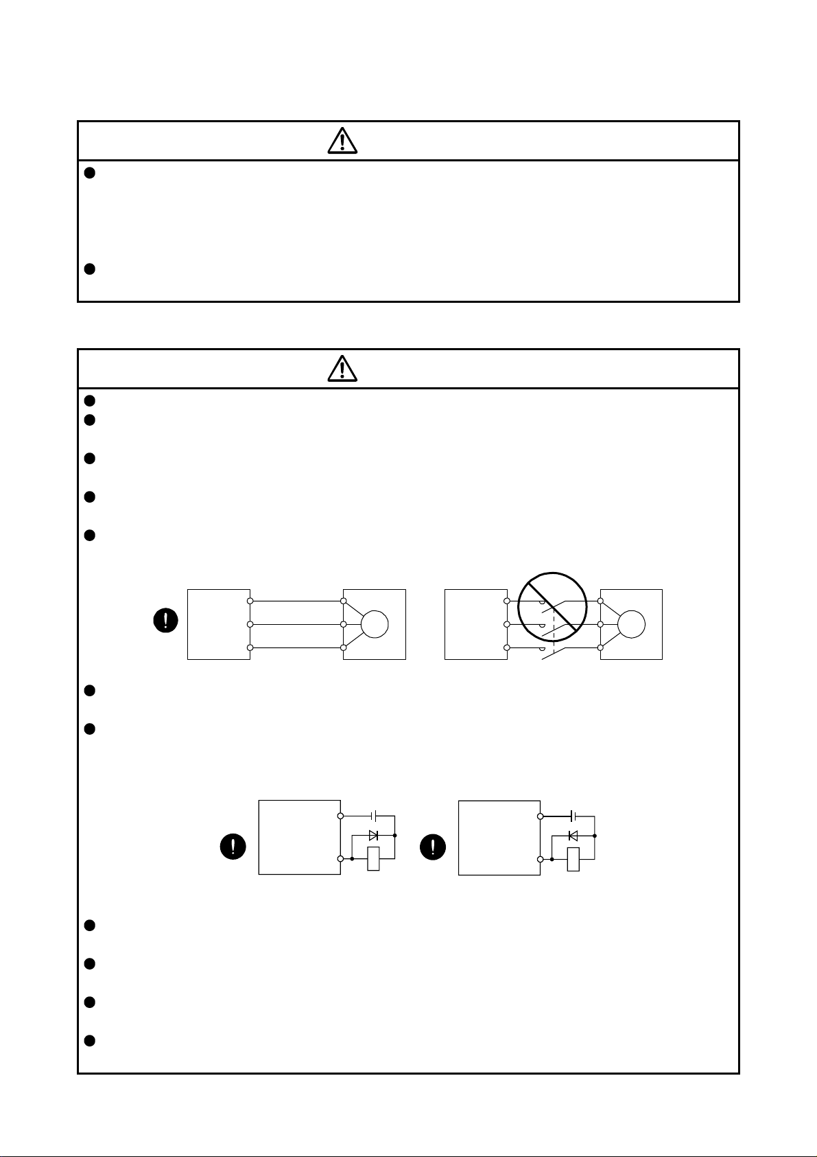
Connect the servo amplifier power output (U/V/W) to the servo motor power input (U/V/W) directly. Do
not connect a magnetic contactor and others between them. Otherwise, it may cause a malfunction.
Servo amplifier
U
V
W
Servo motor
U
V
W
Servo motorServo amplifier
U
M
V
W
U
V
W
M
The connection diagrams in this Instruction Manual are shown for sink interfaces, unless stated
otherwise.
The surge absorbing diode installed to the DC relay for control output should be fitted in the specified
direction. Otherwise, the converter unit and the drive unit will malfunction and will not output signals,
disabling the emergency stop and other protective circuits.
Servo amplifier
DOCOM
Control output
signal
For sink output interface
24 V DC
RA
Servo amplifier
24 V DC
DOCOM
Control output
signal
For source output interface
RA
When the wires are not tightened enough to the terminal block, the wires or terminal block may generate
heat because of the poor contact. Be sure to tighten the wires with specified torque.
Connecting a servo motor of the wrong axis to U, V, W, or CN2 of the servo amplifier may cause a
malfunction.
Configure a circuit to turn off EM2 or EM1 when the main circuit power supply is turned off to prevent an
unexpected restart of the servo amplifier.
To prevent malfunction, avoid bundling power lines (input/output) and signal cables together or running
them in parallel to each other. Separate the power lines from the signal cables.
A - 4

(3) Test run and adjustment
CAUTION
When executing a test run, follow the notice and procedures in this instruction manual. Otherwise, it may
cause a malfunction, damage to the machine, or injury.
Before operation, check and adjust the parameter settings. Improper settings may cause some machines
to operate unexpectedly.
Never make a drastic adjustment or change to the parameter values as doing so will make the operation
unstable.
Do not get close to moving parts during the servo-on status.
(4) Usage
CAUTION
Provide an external emergency stop circuit to stop the operation and shut the power off immediately.
For equipment in which the moving part of the machine may collide against the load side, install a limit
switch or stopper to the end of the moving part. The machine may be damaged due to a collision.
Do not disassemble, repair, or modify the product. Otherwise, it may cause an electric shock, fire, injury,
etc. Disassembled, repaired, and/or modified products are not covered under warranty.
Before resetting an alarm, make sure that the run signal of the servo amplifier is off in order to prevent a
sudden restart. Otherwise, it may cause an accident.
Use a noise filter, etc., to minimize the influence of electromagnetic interference. Electromagnetic
interference may affect the electronic equipment used near the servo amplifier.
Do not burn or destroy the servo amplifier. Doing so may generate a toxic gas.
Use the servo amplifier with the specified servo motor.
Wire options and peripheral equipment, etc. correctly in the specified combination. Otherwise, it may
cause an electric shock, fire, injury, etc.
The electromagnetic brake on the servo motor is designed to hold the motor shaft and should not be
used for ordinary braking.
For such reasons as incorrect wiring, service life, and mechanical structure (e.g. where a ball screw and
the servo motor are coupled via a timing belt), the electromagnetic brake may not hold the motor shaft.
To ensure safety, install a stopper on the machine side.
If the dynamic brake is activated at power-off, alarm occurrence, etc., do not rotate the servo motor by an
external force. Otherwise, it may cause a fire.
A - 5

(5) Corrective actions
CAUTION
Ensure safety by confirming the power off, etc. before performing corrective actions. Otherwise, it may
cause an accident.
If it is assumed that a power failure, machine stoppage, or product malfunction may result in a hazardous
situation, use a servo motor with an electromagnetic brake or provide an external brake system for
holding purpose to prevent such hazard.
Configure an electromagnetic brake circuit which is interlocked with an external emergency stop switch.
Contacts must be opened when ALM
(Malfunction) or MBR (Electromagnetic
brake interlock) turns off.
Contacts must be opened with
the emergency stop switch.
Servo motor
B
Electromagnetic brake
When an alarm occurs, eliminate its cause, ensure safety, and deactivate the alarm to restart operation.
If the molded-case circuit breaker or fuse is activated, be sure to remove the cause and secure safety
before switching the power on. If necessary, replace the servo amplifier and recheck the wiring.
Otherwise, it may cause smoke, fire, or an electric shock.
Provide an adequate protection to prevent unexpected restart after an instantaneous power failure.
After an earthquake or other natural disasters, ensure safety by checking the conditions of the
installation, mounting, wiring, and equipment before switching the power on to prevent an electric shock,
injury, or fire.
RA
24 V DC
(6) Maintenance, inspection and parts replacement
CAUTION
Make sure that the emergency stop circuit operates properly such that an operation can be stopped
immediately and a power is shut off by the emergency stop switch.
It is recommended that the servo amplifier be replaced every 10 years when it is used in general
environment.
When using the servo amplifier that has not been energized for an extended period of time, contact your
local sales office.
(7) General instruction
To illustrate details, the equipment in the diagrams of this Instruction Manual may have been drawn
without covers and safety guards. When the equipment is operated, the covers and safety guards must
be installed as specified. Operation must be performed in accordance with this Instruction Manual.
A - 6

DISPOSAL OF WASTE
Please dispose a servo amplifier, battery (primary battery) and other options according to your local laws and
regulations.
EEP-ROM life
The number of write times to the EEP-ROM, which stores parameter settings, etc., is limited to 100,000. If
the total number of the following operations exceeds 100,000, the servo amplifier may malfunction when the
EEP-ROM reaches the end of its useful life.
Write to the EEP-ROM due to parameter setting changes
Write to the EEP-ROM due to device changes
Write to the EEP-ROM due to point table setting changes
STO function of the servo amplifier
When using the STO function of the servo amplifier, refer to chapter 13 of "MR-J4-_TM_ Servo Amplifier
Instruction Manual".
For the MR-J3-D05 safety logic unit, refer to app. 5 of "MR-J4-_TM_ Servo Amplifier Instruction Manual".
Compliance with global standards
For the compliance with global standards, refer to app. 4 of "MR-J4-_TM_ Servo Amplifier Instruction
Manual".
«About the manuals»
You must have this Instruction Manual and the following manuals to use this servo. Ensure to prepare
them to use the servo safely.
Relevant manuals
Manual name Manual No.
MELSERVO MR-J4-_TM_ Servo Amplifier Instruction Manual SH(NA)030193ENG
MELSERVO-J4 Servo Amplifier Instruction Manual (Troubleshooting) SH(NA)030109ENG
MELSERVO MR-D30 Instruction Manual (Note 5) SH(NA)030132ENG
MELSERVO Servo Motor Instruction Manual (Vol. 3) (Note 1) SH(NA)030113ENG
MELSERVO Linear Servo Motor Instruction Manual (Note 2) SH(NA)030110ENG
MELSERVO Direct Drive Motor Instruction Manual (Note 3) SH(NA)030112ENG
MELSERVO Linear Encoder Instruction Manual (Note 2, 4) SH(NA)030111ENG
MELSERVO EMC Installation Guidelines IB(NA)67310ENG
Note 1. It is necessary for using a rotary servo motor.
2. It is necessary for using a linear servo motor.
3. It is necessary for using a direct drive motor.
4. It is necessary for using a fully closed loop system.
5. It is necessary for using an MR-D30 functional safety unit.
A - 7

«Wiring»
Wires mentioned in this Instruction Manual are selected based on the ambient temperature of 40 °C.
«U.S. customary units»
U.S. customary units are not shown in this manual. Convert the values if necessary according to the
following table.
Quantity SI (metric) unit U.S. customary unit
Mass 1 [kg] 2.2046 [lb]
Length 1 [mm] 0.03937 [inch]
Torque 1 [N•m] 141.6 [oz•inch]
Moment of inertia 1 [(× 10-4 kg•m2)] 5.4675 [oz•inch2]
Load (thrust load/axial load) 1 [N] 0.2248 [lbf]
Temperature N [°C] × 9/5 + 32 N [°F]
A - 8

CONTENTS
1. EtherCAT COMMUNICATION 1- 1 to 1-12
1.1 Summary ........................................................................................................................................... 1- 1
1.2 Function list ....................................................................................................................................... 1- 4
1.3 Communication specifications .......................................................................................................... 1- 7
1.4 EtherCAT State Machine (ESM) ....................................................................................................... 1- 8
1.4.1 Communication status ................................................................................................................ 1- 8
1.4.2 EtherCAT state ........................................................................................................................... 1- 9
1.4.3 Startup ....................................................................................................................................... 1-10
1.4.4 Network disconnection procedure ............................................................................................. 1-11
1.5 Summary of object dictionary (OD).................................................................................................. 1-12
1.5.1 Section definition of object dictionary ........................................................................................ 1-12
1.5.2 Saving object dictionary data to EEP-ROM .............................................................................. 1-12
2. EtherCAT NETWORK MODULE (ABCC-M40-ECT) 2- 1 to 2- 4
2.1 Specifications .................................................................................................................................... 2- 1
2.2 Parts identification ............................................................................................................................. 2- 2
2.3 LED indication ................................................................................................................................... 2- 2
2.3.1 LED indication definition ............................................................................................................. 2- 2
2.3.2 LED indication list ....................................................................................................................... 2- 3
2.4 Connecting Ethernet cable ............................................................................................................... 2- 4
3. PDO (PROCESS DATA OBJECT) COMMUNICATION 3- 1 to 3- 6
3.1 PDO communication cycle ................................................................................................................ 3- 1
3.2 PDO setting-related object ................................................................................................................ 3- 1
3.3 PDO default mapping ....................................................................................................................... 3- 2
3.4 PDO variable mapping ...................................................................................................................... 3- 4
3.5 Mapping-necessary objects .............................................................................................................. 3- 5
4. SDO (SERVICE DATA OBJECT) COMMUNICATION 4- 1 to 4- 2
4.1 SDO communication-related service ................................................................................................ 4- 1
4.2 SDO Abort Code ............................................................................................................................... 4- 2
5. CiA 402 DRIVE PROFILE 5- 1 to 5-90
5.1 FSA state .......................................................................................................................................... 5- 1
5.2 Controlword/Control DI ..................................................................................................................... 5- 4
5.2.1 Bit definition of Controlword ....................................................................................................... 5- 4
5.2.2 Bit definition of Control DI .......................................................................................................... 5- 5
5.3 Statusword/Status DO ...................................................................................................................... 5- 7
5.3.1 Bit definition of Statusword ......................................................................................................... 5- 7
5.3.2 Bit definition of Status DO .......................................................................................................... 5- 8
5.4 Control mode ................................................................................................................................... 5-12
5.4.1 Selecting control mode (Modes of operation) ........................................................................... 5-12
5.4.2 Control switching ....................................................................................................................... 5-12
5.4.3 Cyclic synchronous position mode (csp) .................................................................................. 5-13
1

5.4.4 Cyclic synchronous velocity mode (csv) ................................................................................... 5-16
5.4.5 Cyclic synchronous torque mode (cst) ...................................................................................... 5-18
5.4.6 Profile position mode (pp) ......................................................................................................... 5-20
5.4.7 Profile velocity mode (pv) .......................................................................................................... 5-24
5.4.8 Profile torque mode (tq) ............................................................................................................ 5-27
5.4.9 Homing mode (hm) ................................................................................................................... 5-30
5.4.10 Point table mode (pt) ............................................................................................................... 5-59
5.4.11 Jog mode (jg) .......................................................................................................................... 5-64
5.4.12 Indexer mode (idx) .................................................................................................................. 5-71
5.5 Touch probe ..................................................................................................................................... 5-78
5.6 Quick stop ........................................................................................................................................ 5-82
5.7 Halt ................................................................................................................................................... 5-83
5.8 Software position limit ...................................................................................................................... 5-84
5.9 Torque limit ...................................................................................................................................... 5-84
5.10 Polarity ........................................................................................................................................... 5-85
5.11 Degree function ............................................................................................................................. 5-87
5.12 Torque offset .................................................................................................................................. 5-89
6. MANUFACTURER FUNCTIONS 6- 1 to 6-12
6.1 Object for status monitor ................................................................................................................... 6- 1
6.2 Incremental counter .......................................................................................................................... 6- 3
6.3 Stroke end ......................................................................................................................................... 6- 3
6.4 Definition of alarm-related objects .................................................................................................... 6- 4
6.5 Parameter object ............................................................................................................................... 6- 5
6.5.1 Definition of parameter objects .................................................................................................. 6- 5
6.5.2 Enabling parameters .................................................................................................................. 6- 6
6.6 Scale measurement function ............................................................................................................ 6- 7
6.7 One-touch tuning .............................................................................................................................. 6- 8
6.8 Machine diagnosis function ............................................................................................................. 6-10
6.9 Servo amplifier life diagnosis function ............................................................................................. 6-12
7. OBJECT DICTIONARY 7- 1 to 7-82
7.1 Store Parameters .............................................................................................................................. 7- 1
7.2 Supported object dictionary list ......................................................................................................... 7- 2
7.3 Object dictionary ............................................................................................................................... 7- 6
7.3.1 General Objects ......................................................................................................................... 7- 6
7.3.2 PDO Mapping Objects .............................................................................................................. 7-12
7.3.3 Sync Manager Communication Objects .................................................................................... 7-16
7.3.4 Parameter Objects .................................................................................................................... 7-21
7.3.5 Alarm Objects ............................................................................................................................ 7-24
7.3.6 Monitor Objects ......................................................................................................................... 7-27
7.3.7 Manufacturer Specific Control Objects ..................................................................................... 7-40
7.3.8 PDS Control Objects ................................................................................................................. 7-51
7.3.9 Position Control Function Objects ............................................................................................. 7-55
7.3.10 Profile Velocity Mode Objects ................................................................................................. 7-58
7.3.11 Profile Torque Mode Objects .................................................................................................. 7-60
7.3.12 Profile Position Mode Objects ................................................................................................. 7-62
7.3.13 Homing Mode Objects............................................................................................................. 7-66
7.3.14 Factor Group Objects .............................................................................................................. 7-72
2

7.3.15 Touch Probe Function Objects ............................................................................................... 7-75
7.3.16 Optional application FE Objects .............................................................................................. 7-76
7.3.17 Point Table Mode Objects ....................................................................................................... 7-79
7.3.18 Cyclic synchronous position mode Objects ............................................................................ 7-82
3

MEMO
4

1. EtherCAT COMMUNICATION
1. EtherCAT COMMUNICATION
1.1 Summary
EtherCAT is the abbreviation of Ethernet for Control Automation Technology. It is open network
communication between a master and slaves developed by Beckhoff Automation that uses real-time
Ethernet. ETG (EtherCAT Technology Group) owns EtherCAT.
The EtherCAT communication is available when the EtherCAT network module (ABCC-M40-ECT
manufactured by HMS Industrial Networks) is connected to the MR-J4-_TM_ servo amplifier. The MR-J4_TM_ servo amplifier to which the EtherCAT network module is connected operates as a slave station
compliant with CAN application protocol over EtherCAT (CoE) standards. The device type is a power drive
system and is compatible with the CiA 402 drive profile.
(1) CiA 402 drive profile compatible
The MR-J4-_TM_ servo amplifier operates as a slave station compliant with CAN application protocol
over EtherCAT (CoE) standards. The device type is a power drive system and is compatible with the CiA
402 drive profile.
1 - 1

1. EtherCAT COMMUNICATION
(2) Various control modes supported
The MR-J4-_TM_ servo amplifier supports the following control modes. In the table below, whether the
synchronous mode and asynchronous mode can be used in each control mode. For the synchronous
mode and asynchronous mode, refer to (3) in this section.
Control mode Symbol Description
This is a position mode where a position command is received
Cyclic synchronous
position mode
Cyclic synchronous
velocity mode
Cyclic synchronous
torque mode
Profile position mode pp
Profile velocity mode pv
Profile torque mode tq
Homing mode hm
Point table mode pt
JOG mode jg
Indexer mode idx
at a constant period to drive the servo motor in the
synchronous or asynchronous communication with a
csp
controller.
Use an absolute position address for a command.
This is a speed mode where a speed command is received at
csv
a constant period to drive the servo motor in the synchronous
or asynchronous communication with a controller.
This is a torque mode where a torque command is received at
cst
a constant period to drive the servo motor in the synchronous
or asynchronous communication with a controller.
This is a positioning operation mode where an end position
command is received to drive the servo motor in the
synchronous or asynchronous communication with a
controller.
Use an absolute position address or relative position address
for a command.
This is a mode where a target speed command is received to
drive the servo motor in the synchronous or asynchronous
communication with a controller.
This is a mode where a target torque command is received to
drive the servo motor in the synchronous or asynchronous
communication with a controller.
This is a mode where the servo amplifier performs a home
position return operation using the method directed by the
controller.
In this control mode, the servo motor is driven according to
the travel distance and speed stored in the point table No.
which is specified in the synchronous or asynchronous
communication with a controller. This control mode is specific
to Mitsubishi Electric, not in CiA 402 standard.
This is available with servo amplifiers with software version
B2 or later.
In this control mode, the servo motor is manually driven at a
speed set in the synchronous or asynchronous
communication with a controller. This control mode is not in
CiA 402 standard (Mitsubishi Electric original).
This is available with servo amplifiers with software version
B2 or later.
In this control mode, the servo motor is driven to the station
specified in the synchronous or asynchronous communication
with a controller. This control mode is not in CiA 402 standard
(Mitsubishi Electric original).
This is available with servo amplifiers with software version
B2 or later.
Note 1. Servo amplifiers with software version B3 or earlier cannot be used in the asynchronous mode. When the controller sends an
operation command in the asynchronous mode, the error code that indicates the state transition is not allowed is notified and
the ERROR LED of the network module blinks.
2. Servo amplifiers with software version B4 or later can be used in the asynchronous mode. When it is used in the asynchronous
mode, Cycle time (1C32h: 2) setting is required. For details on Cycle time (1C32h: 2), refer to (4) in this section.
Synchronous
mode
Available
Asynchronous
mode
Available
(Note 1, 2)
Available
1 - 2
1. EtherCAT COMMUNICATION
(3) Synchronous mode (DC mode)
In the synchronous mode, it is necessary to keep the synchronous jitter 2 μs or less. When the
synchronous jitter is 2 μs or more, an error may be detected and an alarm may set off.
Synchronous mode setting
Sync0 Sync1
0.25 ms (When the PDO communication cycle is set to 0.25 ms)
Cycle time
(1C32h: 2)
Shift time
(1C32h: 3)
(4) Asynchronous mode (Free-run mode)
In the asynchronous mode, when using the cyclic synchronous position mode, the cyclic synchronous
speed mode, and the cyclic synchronous torque mode, set as shown in the following table. Input the
command value for each communication cycle set in Cycle time (1C32h: 2). If the command is not
inputted on each communication cycle, the previously input command will be maintained.
Note. If the value is not set for Cycle time, the PDO communication cycle is 0.25 ms (initial
(5) Compliance with standards
MR-J4-_TM_ servo amplifiers comply with the following standards. Refer to the following standards for
the description not written in this Instruction Manual.
ETG.1000.2 EtherCAT Specification – Part2
Physical Layer service definition and protocol specification
ETG.1000.3 EtherCAT Specification – Part3
Data Link Layer service definition
ETG.1000.4 EtherCAT Specification – Part4
Data Link Layer protocol specification
ETG.1000.5 EtherCAT Specification – Part5
Application Layer service definition
ETG.1000.6 EtherCAT Specification – Part6
Application Layer protocol specification
ETG.1020 EtherCAT Protocol Enhancements V1.1.0
ETG.1300 EtherCAT Indicator and Labeling Specification V1.1.0
ETG.2000 EtherCAT Slave Information (ESI) Specification V1.0.7
ETG.6010 Implementation Directive for CiA 402 Drive Profile V1.1.0
IEC 61800-7-201 Adjustable speed electrical power drive systems –
Part 7-201: Generic interface and use of profiles for power drive systems –
Profile type 1 specification
Adjustable speed electrical power drive systems –
Part 7-301: Generic interface and use of profiles for power drive systems –
Mapping of profile type 1 to network technologies
0.5 ms (When the PDO communication cycle is set to 0.5 ms)
1 ms (When the PDO communication cycle is set to 1 ms)
2 ms (When the PDO communication cycle is set to 2 ms)
0
Local Cycle time
Cycle time
(1C32h: 2)
(Note)
value).
0.25 ms (When the PDO communication cycle is set to 0.25 ms)
0.5 ms (When the PDO communication cycle is set to 0.5 ms)
1 ms (When the PDO communication cycle is set to 1 ms)
2 ms (When the PDO communication cycle is set to 2 ms)
Standards Version
Unused
V1.0.3
V1.0.3
V1.0.3
V1.0.3
V1.0.3
Edition 1.0
Edition 1.0
1 - 3

1. EtherCAT COMMUNICATION
1.2 Function list
The following table lists the functions available with the MR-J4-_TM_ servo amplifier to which the EtherCAT
network module is connected. "MR-J4-_TM_" means "MR-J4-_TM_ Servo Amplifier Instruction Manual".
Cyclic synchronous position
mode (csp)
Cyclic synchronous velocity
mode (csv)
Cyclic synchronous torque mode
(cst)
Profile position mode (pp)
Profile velocity mode (pv)
Profile torque mode (tq)
Homing mode (hm) The home position return operation specified in each network is supported.
Point table mode (pt)
Indexer mode (idx)
JOG mode (jg)
Model adaptive control
High-resolution encoder
Absolute position detection
system
Gain switching function
Advanced vibration suppression
control II
Machine resonance suppression
filter
Shaft resonance suppression
filter
Adaptive filter II
Low-pass filter
Machine analyzer function
Robust filter
Slight vibration suppression
control
Electronic gear
S-pattern acceleration/
deceleration time constant
Function Description Reference
The position control operation performed by a synchronous sequential position
command through network is supported.
The speed control operation performed by a synchronous sequential speed
command through network is supported.
The torque control operation performed by a synchronous sequential torque
command through network is supported.
The positioning operation performed by an asynchronous end position command
through network is supported.
The speed control operation performed by an asynchronous speed command
through network is supported.
The torque control operation performed by an asynchronous torque command
through network is supported.
Select any 1 to 255 point table and perform operation in accordance with the set
values.
This is available with servo amplifiers with software version B2 or later.
Perform operation to the station positions divided into 2 to 255.
This is available with servo amplifiers with software version B2 or later.
This is a control mode where the servo motor speed is set to drive the servo motor
manually.
This is available with servo amplifiers with software version B2 or later.
This function achieves a high response and stable control following the ideal
model. The two-degrees-of-freedom model adaptive control enables you to set a
response to the command and a response to the disturbance separately.
Additionally, this function can be disabled. To disable this function, refer to section
7.5 of "MR-J4-_TM_ Servo Amplifier Instruction Manual".
High-resolution encoder of 4194304 pulses/rev is used for the encoder of the rotary
servo motor compatible with the MELSERVO-J4 series.
Setting a home position once makes home position return unnecessary at every
power-on.
You can switch gains during rotation/stop, and can use input devices to switch
gains during operation.
This function suppresses vibration at an arm end or residual vibration.
This filter function (notch filter) decreases the gain of the specific frequency to
suppress the resonance of the mechanical system.
When a load is mounted to the servo motor shaft, resonance by shaft torsion
during driving may generate a mechanical vibration of high frequency. The shaft
resonance suppression filter suppresses the vibration.
The servo amplifier detects mechanical resonance and sets filter characteristics
automatically to suppress mechanical vibration.
Suppresses high-frequency resonance which occurs as the servo system response
is increased.
This function analyzes the frequency characteristic of the mechanical system by
simply connecting an MR Configurator2-installed personal computer and the servo
amplifier.
MR Configurator2 is necessary for this function.
For roll feed axis, etc. of which a response level cannot be increased because of
the large load to motor inertia ratio, this function improves a disturbance response.
This function suppresses vibration of ±1 pulse generated at a servo motor stop. [Pr. PB24]
Positioning control is performed with the value obtained by multiplying the position
command from the controller by a set electronic gear ratio.
Speed can be increased and decreased smoothly. [Pr. PT51]
Section 5.4
MR-J4-_TM_
Chapter 12
MR-J4-_TM_
Section 7.2
MR-J4-_TM_
Section 7.1.5
MR-J4-_TM_
Section 7.1.1
MR-J4-_TM_
Section 7.1.3
MR-J4-_TM_
Section 7.1.2
MR-J4-_TM_
Section 7.1.4
[Pr. PE41]
[Pr. PA06]
[Pr. PA07]
1 - 4

1. EtherCAT COMMUNICATION
Function Description Reference
Auto tuning
Brake unit
Power regeneration converter
Regenerative option
Alarm history clear This function clears alarm histories. [Pr. PC21]
Torque limit Limits the servo motor torque.
Speed limit This function limits the servo motor speed. [Pr. PT67]
Status display Shows servo status on the 3-digit, 7-segment LED display
Input signal selection (device
settings)
Output signal selection (device
settings)
Output signal (DO) forced output
Test operation mode
Analog monitor output This function outputs servo status with voltage in real time.
MR Configurator2
Linear servo system
Direct drive servo system The direct drive servo system can be configured to drive a direct drive motor.
Fully closed loop system Fully closed loop system can be configured using the load-side encoder.
Latch function
(Touch probe)
One-touch tuning
SEMI-F47 function
Tough drive function
Automatically adjusts the gain to optimum value if load applied to the servo motor
shaft varies.
Use the brake unit when the regenerative option cannot provide sufficient
regenerative capability.
The brake unit can be used for the servo amplifiers of the 5 kW or more.
Use the power regeneration converter when the regenerative option cannot provide
sufficient regenerative capability.
The power regeneration converter can be used for the servo amplifiers of the 5 kW
or more.
Use a regenerative option when the built-in regenerative resistor of the servo
amplifier does not have sufficient regenerative capacity for a large regenerative
power generated.
LSP (Forward rotation stroke end), LSN (Reverse rotation stroke end) and other
input device can be assigned to any pins.
The output devices including ALM (Malfunction) can be assigned to specified pins
of the CN3 connector.
Turns on/off the output signals forcibly independently of the servo status.
Use this function for checking output signal wiring, etc.
Jog operation, positioning operation, motor-less operation, DO forced output, and
program operation
MR Configurator2 is necessary for this function.
Using a personal computer, you can perform the parameter setting, test operation,
monitoring, and others.
Linear servo system can be configured using a linear servo motor and linear
encoder.
This function latches the current position at the rising edge of the external latch
input signal.
Gain adjustment is performed just by one click a certain button on MR
Configurator2.
Also, one-touch tuning can be performed via a network. One-touch tuning via a
network is available with servo amplifiers with software version B0 or later.
This function enables to avoid triggering [AL. 10 Undervoltage] using the electrical
energy charged in the capacitor in case that an instantaneous power failure occurs
during operation. Use a 3-phase for the input power supply of the servo amplifier.
Using a 1-phase 100 V AC/200 V AC for the input power supply will not comply
with SEMI-F47 standard.
This function makes the equipment continue operating even under the condition
that an alarm occurs. The tough drive function includes two types: the vibration
tough drive and the instantaneous power failure tough drive.
MR-J4-_TM_
Section 6.3
MR-J4-_TM_
Section 11.3
MR-J4-_TM_
Section 11.4
MR-J4-_TM_
Section 11.2
[Pr. PA11]
[Pr. PA12]
MR-J4-_TM_
Section 4.3
[Pr. PD03] to
[Pr. PD05]
[Pr. PD07] to
[Pr. PD09]
MR-J4-_TM_
Section 4.5.1
(1) (d)
MR-J4-_TM_
Section 4.5
[Pr. PC09]
[Pr. PC10]
MR-J4-_TM_
Section 11.7
MR-J4-_TM_
Chapter 14
MR-J4-_TM_
Chapter 15
MR-J4-_TM_
Chapter 16
Section 5.5
MR-J4-_TM_
Section 3.5
[Pr. PD37]
Section 6.7
MR-J4-_TM_
Section 6.2
MR-J4-_TM_
Section 7.4
[Pr. PA20]
[Pr. PF25]
MR-J4-_TM_
Section 7.3
1 - 5

1. EtherCAT COMMUNICATION
Function Description Reference
This function continuously monitors the servo status and records the status
transition before and after an alarm for a fixed period of time. You can check the
recorded data on the drive recorder window on MR Configurator2 by clicking the
"Graph" button.
Drive recorder function
STO function
Servo amplifier life diagnosis
function
Power monitoring function
Machine diagnosis function
Scale measurement function
MR-D30 functional safety unit MR-D30 functional safety unit is supported.
Lost motion compensation
function
Super trace control
Limit switch
Software limit
FoE (File Access over
EtherCAT)
However, the drive recorder is not available when:
1. The graph function of MR Configurator2 is being used.
2. The machine analyzer function is being used.
3. [Pr. PF21] is set to "-1".
4. The controller is not connected (except the test operation mode).
5. An alarm related to the controller is occurring.
This amplifier complies with the STO function as functional safety of IEC/EN
61800-5-2. You can create a safety system for the equipment easily.
You can check the cumulative energization time and the number of on/off times of
the inrush relay. This function gives an indication of the replacement time for parts
of the servo amplifier including a capacitor and a relay before they malfunction.
This function is available with MR Configurator2 or via a network.
The servo amplifier life diagnosis function via a network is available with servo
amplifiers with software version B0 or later.
This function calculates the power running energy and the regenerative power from
the data in the servo amplifier such as speed and current. Power consumption and
others are displayed on MR Configurator2. Also, the power monitoring function can
be used via a network.
From the data in the servo amplifier, this function estimates the friction and
vibrational component of the drive system in the equipment and recognizes an
error in the machine parts, including a ball screw and bearing.
This function is available with MR Configurator2 or via a network.
The machine diagnosis function via a network is available with servo amplifiers
with software version B0 or later.
The function transmits position information of a scale measurement encoder to the
controller by connecting the scale measurement encoder in semi closed loop
control.
This is used with servo amplifiers with software version B0 or later.
This function improves the response delay occurred when the machine moving
direction is reversed.
This function sets constant and uniform acceleration/deceleration droop pulses to
almost 0.
Travel intervals can be limited with the limit switch using LSP (Forward rotation
stroke end) and LSN (Reverse rotation stroke end)
Limits travel intervals by address using parameters.
The same function with the limit switch is enabled by setting parameters.
This servo amplifier supports FoE (File Access over EtherCAT). For details,
contact your local sales office.
This is used with servo amplifiers with software version B3 or later.
[Pr. PA23]
MR-J4-_TM_
Chapter 13
Section 6.9
Section 6.1
Section 6.8
Section 6.6
MR-J4-_TM_
Section 17.1
MR-J4-_TM_
Section 17.2
MR-J4-_TM_
Section 7.6
MR-J4-_TM_
Section 7.7
Section 5.8
MR-J4-_TM_
Section 5.3
[Pr. PT15] to
[Pr. PT18]
1 - 6

1. EtherCAT COMMUNICATION
1.3 Communication specifications
The following table shows the communication specifications.
EtherCAT communication
specifications
Physical layer 100BASE-TX (IEEE802.3)
Communication connector RJ45, 2 ports (IN port, OUT port)
Communication cable
Network topology
Variable communication speed 100 Mbps (Full duplex)
Transmission speed between
stations
Number of nodes
SDO (Mailbox) communication
PDO (Process Data)
communication
PDO mapping
Distributed clock (DC)
Explicit Device Identification Supported
LED display RUN, ERROR, LINK/Activity (IN, OUT)
Item Description Remark
IEC 61158 Type121
CAN application protocol over EtherCAT
(CoE), IEC 61800-7 CiA 402 Drive Profile
CAT5e, shielded twisted pair (4 pair) straight
cable
Line, Tree, Star, or a connection topology
where the topologies are used together
Max. 100 m
Max. 65535 The number of connection nodes for actual use
Asynchronous
Sending/Receiving: 1 channel each
Cycle time: Select from 0.25 ms, 0.5 ms, 1
ms, and 2 ms.
Receive (RxPDO): 1 channel
Send (TxPDO): 1 channel
Variable PDO mapping supported Maximum size of RxPDO and TxPDO: 64 bytes
The DC mode and Free-run mode can be
selected.
(In servo amplifiers with software version B3
or earlier, the DC mode is required in the csp,
csv, and cst mode.)
Double-shielded type recommended
varies depending on the specifications of the
master controller used.
Maximum data size in sending/receiving
1486 bytes each
Data size at PDO default mapping
RxPDO: 29 bytes
TxPDO: 41 bytes
each
Maximum number of object mapping: 32 each
Sync0: Set the same cycle as the PDO
communication cycle.
Sync1: Not used
1 - 7

1. EtherCAT COMMUNICATION
1.4 EtherCAT State Machine (ESM)
The communication status of MR-J4-_TM_ servo amplifiers is classified and managed by EtherCAT State
Machine (ESM) that the EtherCAT standard specifies.
1.4.1 Communication status
The following table shows the classification of the communication status. Two communication types are
provided: One is the PDO (process data object) communication where command data and feedback data
are sent and received at a constant period. Another is the SDO (service data object) communication where
object data is sent and received asynchronously. Refer to chapter 3 for details of the PDO communication.
Refer to chapter 4 for details of the SDO communication.
ESM status Description
After the power is on, the communication status is the init state. The SDO communication and PDO
Init
Pre-Operational
Safe-Operational
Operational
Bootstrap
communication cannot be performed. The master accesses the DL-Information register and initializes
communication.
The SDO communication can be performed. The PDO communication cannot be performed. The initial setting
for network and initial transfer of parameters can be performed in this state.
The SDO communication can be performed. Though the PDO communication also can be performed, all
operations (commands) such as servo motor drive are invalid. When the DC mode is selected, synchronization
is established in this state.
Both the SDO communication and PDO communication can be performed. Commands using the PDO
communication are valid and the servo motor can be driven.
The mailbox communication with the FoE protocol can be performed. Firmware can be updated through
EtherCAT in this state. (For manufacturer setting)
1 - 8
1. EtherCAT COMMUNICATION
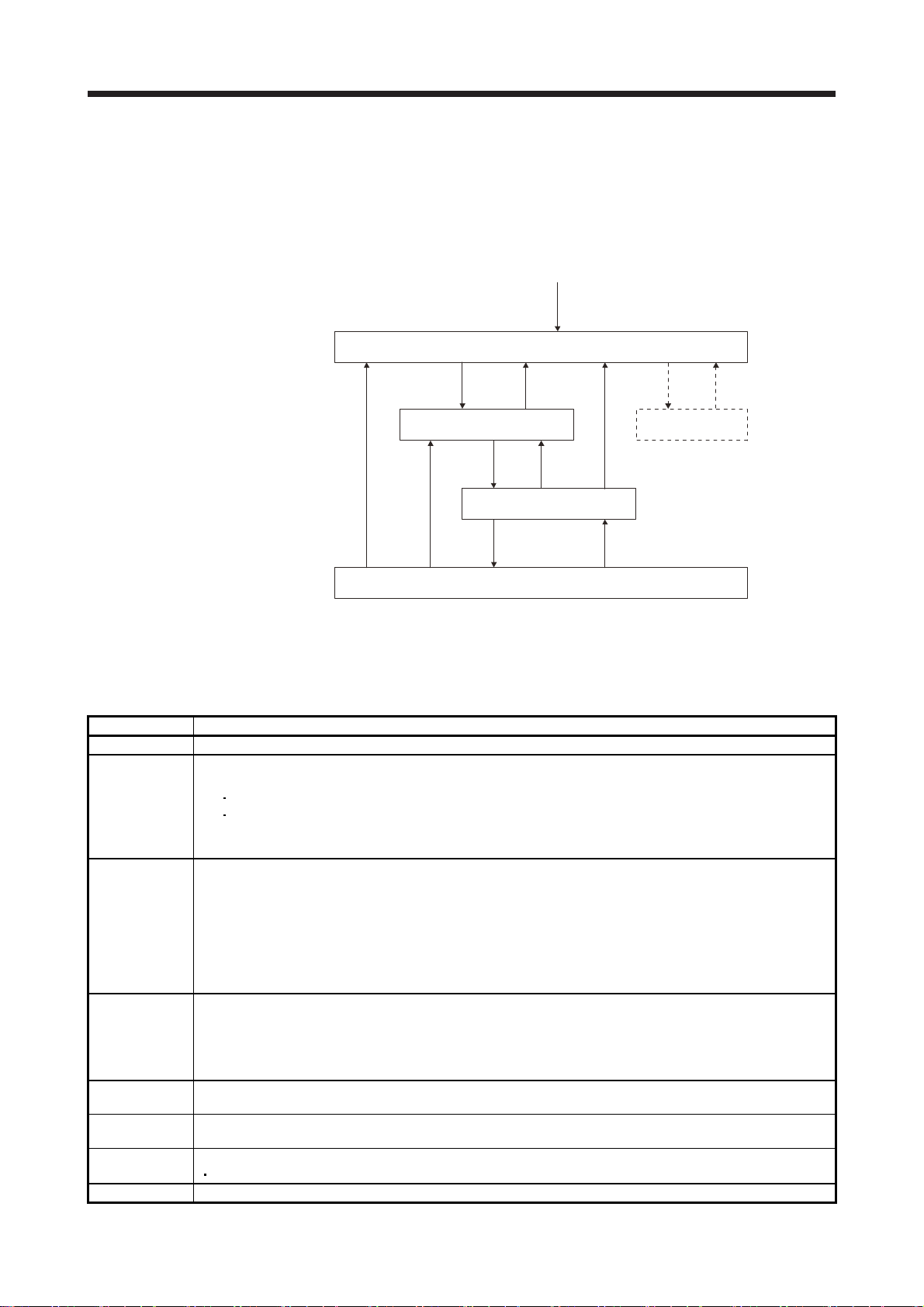
1.4.2 EtherCAT state
EtherCAT states shift under the conditions shown in figure 1.1 and table 1.1.
When the state shifts from the Init state through the Pre-Operational and Safe-Operational state to the
Operational state, the servo amplifier can be operated. When the Operational state shifts to another state,
the servo amplifier executes initialization to clear the internal status.
Power on
(1)
Init
(2)
Pre-Operational
(4)
(12)
Note. This state is for manufacturer setting.
(3)
(5)
Safe-Operational
(7)
Operational
(10)
Bootstrap
(Note)
(6)(9)
(8)
Fig. 1.1
Table. 1.1 EtherCAT state transition
Transition No. Description
(1) Power on
SDO communication configuration
(a) The master sets the registers of the slaves. The following shows the registers to be set.
(2)
(4)
(7)
(5), (12)
(8)
(3), (6), (9), (11)
(10) When the master requests the slave to shift to the Bootstrap state, the state shifts to the Bootstrap state.
DL Address register
Sync Manager channel for SDO communication
(b) The master requests the slaves to shift to the Pre-Operational state.
(c) The state shifts to the Pre-Operational state.
PDO communication configuration
(a) Set the configuration parameter of the master (such as PDO mapping) using the SDO communication.
(b) The master sets the Sync Manager channel and FMMU channel for the PDO communication of the slaves.
FMMU (Fieldbus Memory Management Unit) is a mechanism to manage the relationship between the global
address area and the local address area in the EtherCAT communication. The global address area is used for
the PDO communication. The local address area stores object data for each station.
(c) The master requests the slave to shifts to the Safe-Operational state.
(d) The state shifts to the Safe-Operational state.
Synchronous
(a) The master and slave use Distributed Clocks to synchronize.
(b) The master starts to output a valid command value.
(c) The master requests the slave to shift to the Operational state.
(d) The state shifts to the Operational state.
When the master requests the slave to shifts to the Pre-Operational state, the state shifts to the Pre-Operational
state.
When the master requests the slave to shifts to the Safe-Operational state, the state shifts to the Safe-Operational
state.
In the following case, the state shifts to the init state.
When the master requests the slave to shifts to the Init state.
(11)
1 - 9
1. EtherCAT COMMUNICATION
1.4.3 Startup
The following describes the setting and startup of the EtherCAT communication. Refer to section 4.1 of "MRJ4-_TM_ Servo Amplifier Instruction Manual" for the startup procedure other than the network setting.
(1) Connection with the controller
POINT
Use the latest ESI file when setting up the controller. If the ESI file is old, newly
added objects may not be usable. For ESI files available with the servo
amplifiers you use, contact your local sales office.
Set up the controller following the manual of the controller used. For the setup, the EtherCAT Slave
Information (ESI) file listing the information about the communication setting of devices is available.
Store the ESI file in the controller to use it. The controller configures the setting for the slave connected
to the master according to the contents of the ESI file corresponding to the slave connected.
(2) Parameter setting
Set the control mode with [Pr. PA01 Operation mode]. Refer to section 5.2.1 of "MR-J4-_TM_ Servo
Amplifier Instruction Manual" for the parameter setting.
(3) Node address setting
POINT
The node address of MR-J4-_TM_ servo amplifiers complies with the
specifications of Explicit Device Identification. Configure the setting of Set
Explicit Device Identification for the controller.
Do not connect multiple devices with the same node address setting.
Node address setting via network and Configured Station Alias (0012h) are
available with the combination of servo amplifiers with software version B2 or
later and network modules with software version 2.00.03 or later.
If the value in SII Configured Station Alias is set to other than 0000h when the
node address is set with the axis selection rotary switch (SW2/SW3) or [Pr.
PN01 Node address setting], the ERROR LED of the network module blinks.
Cycling the power resets the set value in SII Configured Station Alias to 0000h
and this enables the servo amplifier to start normally.
Set the node address of EtherCAT with the axis selection rotary switch (SW2/SW3) on the display, [Pr.
PN01 Node address setting] or SII Configured Station Alias as necessary. You can set a node address
as follows. After the node address setting is changed, cycle the power.
Axis selection rotary
switch (SW2/SW3)
00h 0000h 0001h to FFFFh
00h 0001h to FFFFh 0000h (Note) The value of [Pr. PN01] is set as the node address.
01h to FFh 0000h to FFFFh 0000h (Note)
Pr. PN01
SII Configured Station
Alias
Node address setting value
The value set in SII Configured Station Alias via network
is the node address.
The set value of the rotary switch (SW2/SW3) is set as
the node address.
Note. If the value in SII Configured Station Alias is set to other than 0000h, the ERROR LED of the network module blinks. Cycling the
power resets the set value in SII Configured Station Alias to 0000h and this enables the servo amplifier to start normally.
1 - 10

1. EtherCAT COMMUNICATION
(4) Specifying the slave with the node address
The controller can specify the slave with the node address in the following two methods.
(a) Specify with AL Status Code (0134h)
The value of the node address set in the axis selection rotary switch (SW2/SW3) or [Pr. PN01 Node
1.4.4 Network disconnection procedure
To disconnect the network by stopping device operation or other means, follow the procedure shown below.
If the network is disconnected without following the procedure, [AL. 86.1 Network communication error 1]
may occur.
(1) Stop the servo motor.
(2) Set the Shutdown command for Controlword (6040h) to establish the servo-off status.
(3) Shift the state to the Pre-Operational state.
(4) Shut off the power of the servo amplifier and controller.
address setting] can be read.
(b) Specify with Configured Station Alias (0012h)
The value of the node address set in the axis selection rotary switch (SW2/SW3), [Pr. PN01 Node
address setting] or SII Configured Station Alias can be read.
1 - 11
1. EtherCAT COMMUNICATION
1.5 Summary of object dictionary (OD)
POINT
Refer to chapter 7 for details of the object dictionary.
Each data set that CAN application protocol over EtherCAT (CoE) devices have such as control parameters,
command values, and feedback values is handled as an object composed of an Index value, object name,
object type, R/W attribute, and other elements. The object data can be exchanged between the master and
slave devices. The aggregate of these objects is called object dictionary (OD).
1.5.1 Section definition of object dictionary
In the CAN application protocol over EtherCAT (CoE) standard, objects of the object dictionary are
categorized by Index depending on the area type as shown in the following table. Refer to the Reference
column for the chapters and the section where the details of each object are described.
Index Description Reference
0000h to 0FFFh Data type area
1000h to 1FFFh CoE communication area
2000h to 25FFh Parameter area (Vendor-specific) Section 6.5, Chapter 7
2800h to 29FFh Point table area (Vendor-specific) (Note) Chapter 7
2A00h to 2FFFh Servo control command/monitor area (Vendor-specific) Chapter 6, Chapter 7
6000h to 6FFFh CiA 402 Drive profile area
Note. This is available with servo amplifiers with software version B2 or later.
1.5.2 Saving object dictionary data to EEP-ROM
Chapter 1, Chapter 3,
Chapter 4, Chapter 7
Chapter 5, Chapter 7
There are two types of object dictionary data: One is saved to EEP-ROM and another is not saved. Refer to
Section 7.3 for the availability and details of save for each object.
1 - 12
2. EtherCAT NETWORK MODULE (ABCC-M40-ECT)
A
A
2. EtherCAT NETWORK MODULE (ABCC-M40-ECT)
POINT
For EtherCAT Network module, be sure to use ABCC-M40-ECT which is a
dedicated model for Mitsubishi Electric MELSERVO. For purchasing, contact
your local sales office.
Refer to "MR-J4-_TM_ Servo Amplifier Instruction Manual" for how to mount the
EtherCAT Network module (ABCC-M40-ECT) to the MR-J4-_TM_ servo
amplifier.
For the quality assurance on the EtherCAT Network module (ABCC-M40-ECT),
contact HMS Industrial Networks.
The EtherCAT communication with an MR-J4-_TM_ servo amplifier requires the EtherCAT Network module
(ABCC-M40-ECT). The following shows the details.
2.1 Specifications
Item Description
Product name ABCC-M40-ECT (Anybus Compact Com M40 ECT)
Model AB6916-C-203 (Note 1, 2, 3, 4)
Manufacturer HMS Industrial Networks
External interface
Dimensions
Mass Approx. 30 g
MR-J4-_TM_ servo amplifier connecting interface: Compact flash connector with standard 50 pins
EtherCAT communication port interface: RJ45 connector
52 (W) × 50 (D) × 20 (H)
(Except the protrusion of the EtherCAT communication port connector)
Note 1. The model name was changed from 6916-C-203 to AB6916-C-203 in November 2018.
2.
3. When using AB6916-B or AB6916-C, Configured Station Alias cannot be used. Refer to section 1.4.3 (3) for details.
4. When using AB6916-B, use EtherCAT Slave Information (ESI). Without ESI, the controller does not recognize the
lthough it is recommended that you use AB6916-C-203 for the servo amplifiers with software version B2 or later,
B6916-B and AB6916-C are also available. Although it is recommended that you use AB6916-C for the servo
amplifiers with software version B1 or earlier, AB6916-B is also available.
711th and later objects because Get OD List can read only object information of 710 sets.
2 - 1
2. EtherCAT NETWORK MODULE (ABCC-M40-ECT)
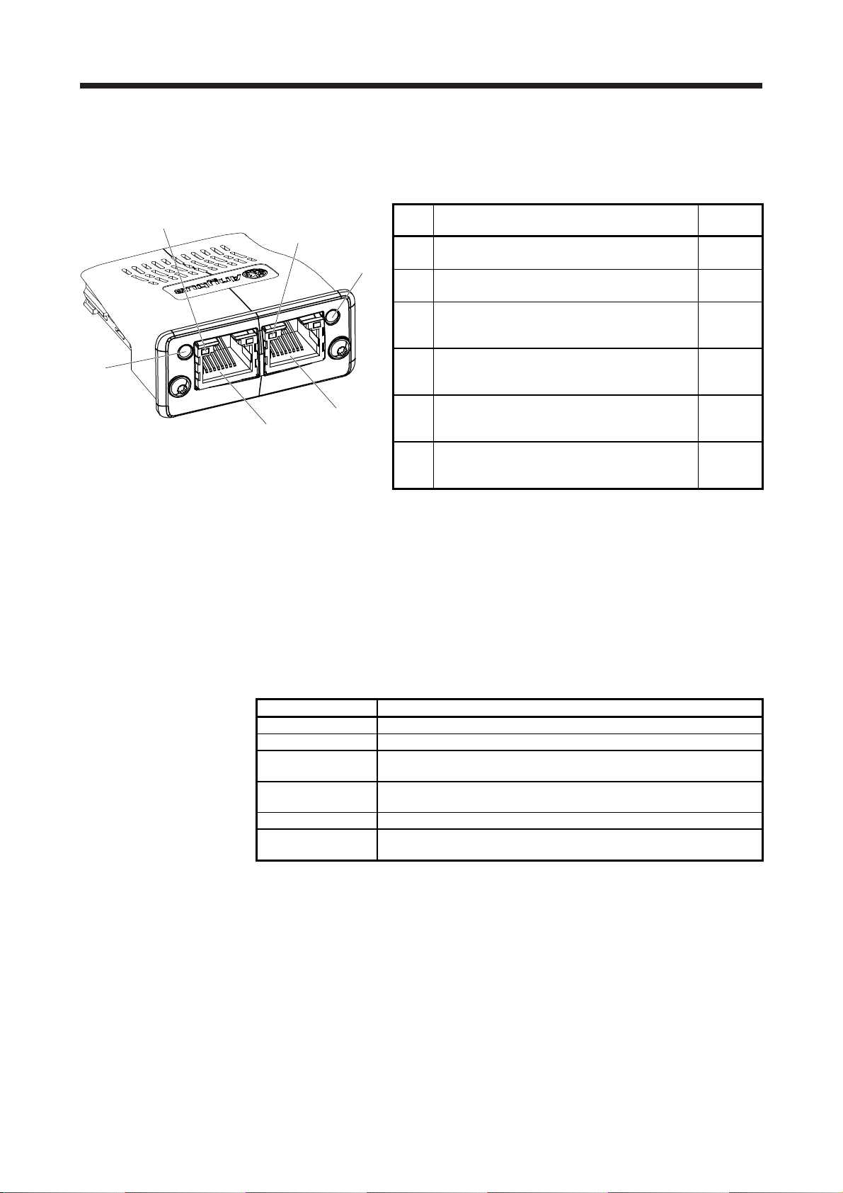
2.2 Parts identification
This section describes the EtherCAT Network module (ABCC-M40-ECT) only. Refer to section 1.7 of "MRJ4-_TM_ Servo Amplifier Instruction Manual" for the MR-J4-_TM_ servo amplifier.
(5)
(6)
2.3 LED indication
(4)
(3)
(2)
(1)
No. Name/Application
ERROR LED
(1)
Indicates an error of the EtherCAT communication.
RJ45 EtherCAT communication port (OUT port)
(2)
Used to connect the next axis servo amplifier.
Link/Activity (OUT port) LED
(3)
Indicates the link status of each EtherCAT
communication port.
RJ45 EtherCAT communication port (IN port)
(4)
Used to connect the EtherCAT master controller or
the previous axis servo amplifier.
Link/Activity (IN port) LED
(5)
Indicates the link status of each EtherCAT
communication port.
RUN LED
(6)
Indicates the EtherCAT communication status
(ESM).
Detailed
explanation
Section
2.3.2 (2)
Section
2.4
Section
2.3.2 (3)
Section
2.4
Section
2.3.2 (3)
Section
2.3.2 (1)
The LEDs of the EtherCAT Network module (ABCC-M40-ECT) function according to the regulations of the
EtherCAT standard (ETG.1300 EtherCAT Indicator and Labeling Specification). Under certain condition,
such as when a fatal error occurs, the EtherCAT Network module (ABCC-M40-ECT) indicates its status by
its own specifications.
2.3.1 LED indication definition
The following shows the LED indication definitions.
LED status Definition
Lit An LED remains lit.
Extinguished An LED remains extinguished.
Flickering An LED is switching between lit and extinguished at 10 Hz cycles (every
50 ms).
Blinking An LED is switching between lit and extinguished at 2.5 Hz cycles (every
200 ms).
Single flash An LED is lit for 200 ms and extinguished 1000 ms repeatedly.
Double flash
An LED is lit for 200 ms, extinguished for 200 ms, lit for 200 ms, and
extinguished for 1000 ms repeatedly.
2 - 2

2. EtherCAT NETWORK MODULE (ABCC-M40-ECT)
2.3.2 LED indication list
(1) RUN LED
The RUN LED indicates the EtherCAT communication status (ESM status). The extinguished RUN LED
may be affected by the LED status of the Link/Activity LEDs. Refer to section 1.4 for the communication
status (ESM status).
Extinguished Indicates that the power supply is shut off or the Init state.
Blinking
Single flash Indicates the Safe-Operational state.
(2) ERROR LED
The ERROR LED indicates an error of the EtherCAT communication. If the servo amplifier indicates an
alarm, follow the remedy of the alarm number.
Extinguished No error
Blinking
Single flash
Double flash Indicates a watchdog error in the Sync manager.
Flickering
(3) Link/Activity LED (OUT port/IN port)
The Link/Activity LEDs indicate the link status of each EtherCAT communication port.
Extinguished Indicates that the power supply is shut off or the link-unestablished state.
Flickering Indicates that the link is established with traffic.
LED
Status Color
Indicates the Pre-Operational state.
Green
Lit Indicates the Operational state.
Lit Red
LED
Status Color
Red
Lit
LED
Status Color
Lit
Green
Indicates that a fatal error has occurred. This indication is specific to the
EtherCAT Network module (ABCC-M40-ECT).
Indicates that the EtherCAT state cannot be changed according to the master
command.
Indicates that the EtherCAT state has been changed autonomously due to an
internal error.
Indicates the EXCEPTION state, which is an error state of the EtherCAT Network
module (ABCC-M40-ECT).
Indicates an error at start-up of the EtherCAT Network module (ABCC-M40ECT).
Indicates that the link is established without traffic.
Description
Description
Description
2 - 3
2. EtherCAT NETWORK MODULE (ABCC-M40-ECT)
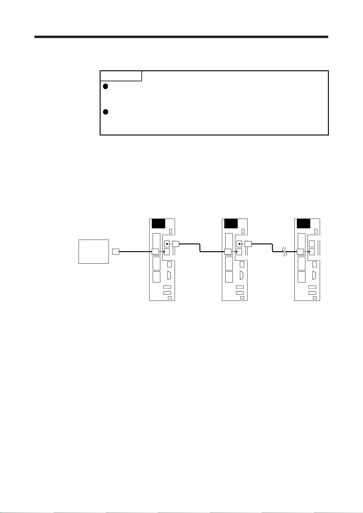
2.4 Connecting Ethernet cable
POINT
Use a twisted pair cable (double shielded) with Ethernet Category 5e
(100BASE-TX) or higher as the Ethernet cable. The maximum cable length
between nodes is 100 m.
When connecting an Ethernet cable to an EtherCAT network port, ensure that
the connection destination (OUT port (upper side) or IN port (lower side)) is
correct.
To the RJ45 EtherCAT communication port (IN port), connect the Ethernet cable connected to the controller
or the previous axis servo amplifier. To the RJ45 EtherCAT communication port (OUT port), connect the
Ethernet cable connected to the next axis servo amplifier. When the RJ45 EtherCAT communication port
(OUT port) is not used, leave this port open.
When the node address is not used, an incorrect connection destination sets node addresses that do not
correspond to the actual connection order and may cause a malfunction, such as an unintended axis
operation.
The first axis
servo amplifier
The second axis
servo amplifier
The final axis
servo amplifier
Controller
Ethernet cable
OUT port
IN port
Ethernet cable
OUT port
IN port
Ethernet cable
OUT port
IN port
2 - 4
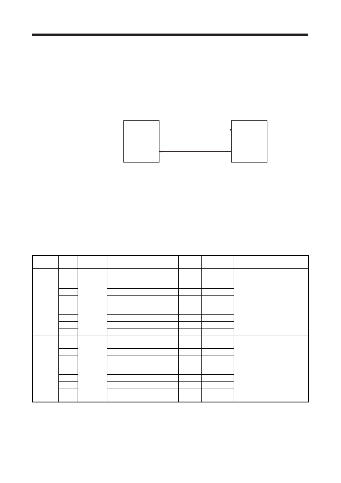
3. PDO (PROCESS DATA OBJECT) COMMUNICATION
3. PDO (PROCESS DATA OBJECT) COMMUNICATION
The PDO (process data object) communication can transfer command data and feedback data between a
master (controller) and slaves (servo amplifier) at a constant cycle. PDOs include RxPDOs, which are used
by the slaves to receive data from the controller, and TxPDOs, which are used by the slaves to send data to
the controller.
Master
(controller)
The variable PDO mapping function enables the PDO communication to transfer multiple PDOs in any array.
3.1 PDO communication cycle
Communication at a constant period
Command data (RxPDO)
Status data (TxPDO)
Slave
(servo amplifier)
The same cycle is applied to communication of RxPDOs and TxPDOs of the MR-J4-_TM_ servo amplifier.
The communication cycle can be changed via a network through rewriting the sub object Cycle time (Sub
index = 2) of SM output parameter (1C32h) with SDO download in the Pre Operational state.
3.2 PDO setting-related object
The following table lists the objects related to the PDO setting.
Index Sub Object Name
1C32h
1C33h
0
1 Synchronization type U16 rw 0
2 Cycle time U32 rw 250000
3 Shift time U32 rw (Note) 222222
RECORD
4
5 Minimum cycle time U32 ro 250000
6 Calc and copy time U32 ro 222722
9 Delay time U32 ro 0
12 Cycle time too small U16 ro 0
0
1 Synchronization type U16 rw 0
2 Cycle time U32 ro 250000
3 Shift time U32 rw (Note) 27778
RECORD
4
5 Minimum cycle time U32 ro 250000
6 Calc and copy time U32 ro 306055
9 Delay time U32 ro 0
12 Cycle time too small U16 ro 0
SM output parameter U8 ro 12
Synchronization types
supported
SM input parameter U8 ro 12
Synchronization types
supported
Data
Type
U16 ro 0025h
U16 ro 0025h
Access Default Description
Refer to section 7.3.3 (4).
Refer to section 7.3.3 (5).
Note. No value can be written because Shift time (1C32: 3, 1C33: 3) is set automatically. Writing any value causes SDO Abort Code
(0609 0030h Value range of parameter exceeded).
3 - 1

3. PDO (PROCESS DATA OBJECT) COMMUNICATION
3.3 PDO default mapping
POINT
The MR-J4-_TM_ servo amplifier supports the variable PDO mapping function,
which can select objects transferred in the PDO communication. Refer to section
3.4 for changing the PDO mapping.
(1) RxPDO default mapping
In the default mapping setting, command data is sent from the master (controller) to slaves (servo
amplifier) with RxPDO in the following array. In the MR-J4-_TM_ servo amplifier, the mapping objects of
1600h to 1603h can be used as the RxPDO default mapping table.
Map number Mapping initial setting Expected application of the initial map
1st RxPDO map (1600h) Modes of operation (6060h)
Controlword (6040h)
Control DI 1 (2D01h)
Control DI 2 (2D02h)
Control DI 3 (2D03h)
Target position (607Ah)
Target velocity (60FFh)
Velocity limit value (2D20h) (Note 1)
Target torque (6071h)
Positive torque limit value (60E0h) (Note 2)
Negative torque limit value (60E1h) (Note 2)
Touch probe function (60B8h)
2nd RxPDO map (1601h) Modes of operation (6060h)
Controlword (6040h)
Control DI 1 (2D01h)
Control DI 2 (2D02h)
Control DI 3 (2D03h)
Target position (607Ah)
Target velocity (60FFh)
Velocity limit value (2D20h) (Note 1)
Target torque (6071h)
Profile velocity (6081h)
Profile acceleration (6083h)
Profile deceleration (6084h)
Torque slope (6087h)
Positive torque limit value (60E0h) (Note 2)
Negative torque limit value (60E1h) (Note 2)
Touch probe function (60B8h)
3rd RxPDO map (1602h) Modes of operation (6060h)
Controlword (6040h)
Control DI 1 (2D01h)
Control DI 2 (2D02h)
Control DI 3 (2D03h)
Target point table (2D60h) (Note 3)
Profile velocity (6081h)
Profile acceleration (6083h)
Profile deceleration (6084h)
Touch probe function (60B8h)
4th RxPDO map (1603h) Unassigned
Note 1. The Velocity limit value (2D20h) is a speed limit value for the torque control. Be sure to set a correct value because setting 0
will limit the speed to 0.
2. Positive torque limit value (60E0h)/Negative torque limit value (60E1h) are torque limit values of forward/reverse rotation.
Setting 0 will not generate torque. Be sure to set a correct value.
3. This is available with servo amplifiers with software version B2 or later.
Cyclic synchronous position mode (csp)
Cyclic synchronous velocity mode (csv)
Cyclic synchronous torque mode (cst)
Homing mode (hm)
Mapping for an application in which the modes
above are switched
The following functions can be used together.
Speed limit function (in cst)
Torque limit function
Touch probe function
Map size: 29 bytes
Profile position mode (pp)
Profile velocity mode (pv)
Profile torque mode (tq)
Homing mode (hm)
Mapping for an application in which the modes
above are switched
The following functions can be used together.
Speed limit function (in tq)
Torque limit function
Touch probe function
Map size: 45 bytes
Point table mode (pt) or indexer mode (idx)
Jog mode (jg)
Homing mode (hm)
Mapping for an application in which the modes
above are switched.
Map size: 25 bytes
3 - 2

3. PDO (PROCESS DATA OBJECT) COMMUNICATION
(2) TxPDO default mapping
In the default mapping setting, status data of the MR-J4-_TM_ servo amplifier is sent to the master
(controller) with TxPDO in the following array. In the MR-J4-_TM_ servo amplifier, the mapping objects
of 1A00h to 1A03h can be used as the TxPDO default mapping table.
Note. This is available with servo amplifiers with software version B2 or later.
Map number Mapping initial setting Expected application of the initial map
1st TxPDO map (1A00h) Modes of operation display (6061h)
Statusword (6041h)
Status DO 1 (2D11h)
Status DO 2 (2D12h)
Status DO 3 (2D13h)
Position actual value (6064h)
Velocity actual value (606Ch)
Following error actual value (60F4h)
Torque actual value (6077h)
Touch probe status (60B9h)
Touch probe pos1 pos value (60BAh)
Touch probe pos1 neg value (60BBh)
Touch probe pos2 pos value (60BCh)
Touch probe pos2 neg value (60BDh)
2nd TxPDO map (1A01h) Modes of operation display (6061h)
Statusword (6041h)
Status DO 1 (2D11h)
Status DO 2 (2D12h)
Status DO 3 (2D13h)
Status DO 5 (2D15h)
Status DO 7 (2D17h)
Position actual value (6064h)
Velocity actual value (606Ch)
Following error actual value (60F4h)
Torque actual value (6077h)
Point demand value (2D68h) (Note)
Point actual value (2D69h) (Note)
M code actual value (2D6Ah) (Note)
Touch probe status (60B9h)
Touch probe pos1 pos value (60BAh)
Touch probe pos1 neg value (60BBh)
Touch probe pos2 pos value (60BCh)
Touch probe pos2 neg value (60BDh)
3rd TxPDO map (1A02h) Unassigned
4th TxPDO map (1A03h) Unassigned
Cyclic synchronous position mode (csp)
Cyclic synchronous velocity mode (csv)
Cyclic synchronous torque mode (cst)
Homing mode (hm)
Mapping for an application in which the modes
above are switched
Mapping for an application in which the modes
below are switched
Profile position mode (pp)
Profile velocity mode (pv)
Profile torque mode (tq)
Homing mode (hm)
The latched position by the touch probe function can
be monitored.
Map size: 41 bytes
Point table mode (pt) or indexer mode (idx)
Jog mode (jg)
Homing mode (hm)
Mapping for an application in which the modes
above are switched.
Map size: 54 bytes
3 - 3

3. PDO (PROCESS DATA OBJECT) COMMUNICATION
3.4 PDO variable mapping
POINT
The PDO mapping can be changed only in the Pre Operational state.
The MR-J4-_TM_ servo amplifier supports the variable PDO mapping function, which can arrange objects in
any array for the data transferred with RxPDO or TxPDO.
The following table shows the specifications of the PDO variable mapping.
The following table lists the PDO mapping objects.
Index Sub Object Name
1600h
1601h
1602h
1603h
1A00h
1A01h
1A02h
1A03h
1C12h
1C13h
0
1 to 32
0
1 to 32
0
1 to 32
0
1 to 32
0
1 to 32
0
1 to 32
0
1 to 32
0
1 to 32
0
1
0
1
RECORD
RECORD
RECORD
RECORD
RECORD
RECORD
RECORD
RECORD
ARRAY
ARRAY
Receive PDO Mapping U8 rw 12
Mapped Object 001
Mapped Object 032
Receive PDO Mapping U8 rw 16
Mapped Object 001
Mapped Object 032
Receive PDO Mapping U8 rw 10
Mapped Object 001
Mapped Object 032
Receive PDO Mapping U8 rw 0
Mapped Object 001
Mapped Object 032
Transmit PDO Mapping U8 rw 14
Mapped Object 001
Mapped Object 032
Transmit PDO Mapping U8 rw 19
Mapped Object 001
Mapped Object 032
Transmit PDO Mapping U8 rw 0
Mapped Object 001
Mapped Object 032
Transmit PDO Mapping U8 rw 0
Mapped Object 001
Mapped Object 032
Sync Manager 2 PDO
PDO Mapping object
index of assigned
Sync Manager 3 PDO
PDO Mapping object
index of assigned
Communication
RxPDO
TxPDO 4 (1A00h to 1A03h)
to
to
to
to
to
to
to
to
Assignment
RxPDO
Assignment
TxPDO
Maximum number of
objects
32 64
Data
Type
U32 rw
U32 rw
U32 rw
U32 rw
U32 rw
U32 rw
U32 rw
U32 rw
U16 rw 1600h
U16 rw 1A00h
Access Default Description
U8 ro 1
U8 ro 1
Maximum size [byte]
60600008h
to
00000000h
60600008h
to
00000000h
60600008h
to
00000000h
60610008h
to
00000000h
60610008h
to
00000000h
Number of mapping
settings
4 (1600h to 1603h)
Refer to section 7.3.2 (1).
Refer to section 7.3.2 (2).
Refer to section 7.3.2 (3).
Refer to section 7.3.2 (4).
Refer to section 7.3.2 (5).
Refer to section 7.3.2 (6).
Refer to section 7.3.2 (7).
Refer to section 7.3.2 (8).
Refer to section 7.3.3 (2).
Refer to section 7.3.3 (3).
3 - 4

3. PDO (PROCESS DATA OBJECT) COMMUNICATION
3.5 Mapping-necessary objects
The following table lists the objects which are required for each mode.
(1) RxPDO
Mode (Note 1)
Object name (Index)
csp csv cst pp pv tq
Controlword (6040h)
Control DI 1 (2D01h) Gain switching
Control DI 2 (2D02h) Proportional control
Control DI 3 (2D03h) - - - - - -
Target position (607Ah)
Target velocity (60FFh) -
Target torque (6071h) - -
Profile velocity (6081h) - - -
Profile acceleration (6083h) - - -
Profile deceleration (6084h) - - -
Torque slope (6087h) - - - - -
Velocity limit value (2D20h) - -
Positive torque limit value (60E0h)
Negative torque limit value (60E1h)
Touch probe function (60B8h)
Watch dog counter DL (2D23h)
Target point table (2D60h) (Note 2) - - - - - -
- -
- -
-
- -
- - - - - -
- -
- -
- - -
- -
- - - - - - - -
Note 1. : Mapping required
: Mapping recommended
-: Mapping not required
2. This is available with servo amplifiers with software version B2 or later.
pt
jg
(Note 2)
- -
hm
-
-
-
-
-
(Note 2)
-
- - - - -
- - - -
- -
- -
- - - -
- - - -
idx
(Note 2)
Function
(Note 1)
Touch
probe
-
3 - 5

3. PDO (PROCESS DATA OBJECT) COMMUNICATION
(2) TxPDO
Mode (Note 1)
Object name (Index)
csp csv cst pp pv tq
Statusword (6041h)
Status DO 1 (2D11h)
Status DO 2 (2D12h)
Status DO 3 (2D13h)
Status DO 5 (2D15h) - - - - - -
Status DO 7 (2D17h) - - - - - -
Position actual value (6064h)
Following error actual value (60F4h)
Velocity actual value (606Ch)
Torque actual value (6077h)
Touch probe status (60B9h)
Touch probe pos1 pos value (60BAh)
Touch probe pos1 neg value (60BBh)
Touch probe pos2 pos value (60BCh)
Touch probe pos2 neg value (60BDh)
Watch dog counter UL (2D24h)
Point actual value (2D69h) (Note 2) - - - - - -
M code actual value (2D6Ah) (Note 2) - - - - - -
Point demand value (2D68h) (Note 2) - - - - - -
- -
- -
- - - - - - - -
Note 1. : Mapping required
: Mapping recommended
-: Mapping not required
2. This is available with servo amplifiers with software version B2 or later.
pt
(Note 2)
jg
hm
(Note 2)
-
- - -
-
- -
- - - -
- -
idx
(Note 2)
-
Function
(Note 1)
Touch
probe
-
-
-
3 - 6

4. SDO (SERVICE DATA OBJECT) COMMUNICATION
4. SDO (SERVICE DATA OBJECT) COMMUNICATION
The SDO (service data object) communication can transfer object data between a master (controller) and
slaves (servo amplifier) asynchronously.
Object data
(SDO Download Expedited)
(SDO Download Normal)
(Download SDO Segment)
Master
(controller)
Object data
(SDO Upload Expedited)
(SDO Upload Normal)
(Upload SDO Segment)
(Abort SDO Transfer)
(Get OD List)
(Get Object Description)
(Get Entry Description)
(Emergency)
Slave
(servo amplifier)
4.1 SDO communication-related service
The MR-J4-_TM_ servo amplifier supports the following services relating to the SDO communication.
Service Description
SDO Download Expedited Writes data of up to 4 bytes to a slave.
SDO Download Normal Writes data of the specified bytes to a slave.
Download SDO Segment Writes additional data when the object size is larger than the specified byte size.
SDO Upload Expedited Reads data of up to 4 bytes from a slave.
SDO Upload Normal (Note) Reads data of the specified bytes from a slave.
Upload SDO Segment Reads additional data when the object size is larger than the specified number of octets.
Abort SDO Transfer Sends SDO Abort Code when an error occurs in a service.
Get OD List Reads a list of available object indexes.
Get Object Description Reads the detail of an index.
Get Entry Description Reads the detail of Sub Index.
Emergency Notifies an alarm.
Note. Complete Access is not supported.
4 - 1

4. SDO (SERVICE DATA OBJECT) COMMUNICATION
4.2 SDO Abort Code
When an error occurs in the SDO communication, the following error messages are returned with the Abort
SDO Transfer service.
SDO Abort Code Meaning Cause
0504 0005h Out of memory. The memory is out of the range.
0601 0001h Attempt to read to a write only object Reading is attempted to a write-only object.
0601 0002h Attempt to write to a read only object Writing is attempted to a read-only object.
0601 0006h
0602 0000h The object does not exist in the object dictionary A non-existent index is specified.
0604 0043h General parameter incompatibility reason. An unsupported command is issued.
0607 0012h
0607 0013h
0609 0011h Subindex does not exist A non-existent Sub Index is specified.
0609 0030h Value range of parameter exceeded A parameter value outside the range is specified.
0609 0031h Value of parameter written too high The value of the parameter written is too large.
0609 0032h Value of parameter written too low The value of the parameter written is too small.
0800 0000h Generic error. General error
0800 0021h
0800 0022h
Object mapped to RxPDO, SDO download blocked. SDO Download is executed to an object mapped to
RxPDO.
Data type does not match,
length of service parameter too high.
Data type does not match,
length of service parameter too short.
Data cannot be transferred or stored to the application
because of local control.
Data cannot be transferred or stored to the application
because of the present device state.
The data type does not match. The data length is too
long.
The data type does not match. The data length is too
short.
Writing is limited in the device.
Data cannot be read or written due to the current device
status.
4 - 2

5. CiA 402 DRIVE PROFILE
5. CiA 402 DRIVE PROFILE
5.1 FSA state
The inside state of the MR-J4-_TM_ servo amplifier is controlled based on the FSA state, defined in the CiA
402 drive profile standard. Figure 5.1 and Table 5.1 show the transition conditions between the FSA states.
The states are switched when the master sends a command following the table (sets Controlword) with the
PDO communication established (the AL state Operational reached). When the state has transitioned from
Not ready to switch on, which is right after the power on, to Operation enabled with the predetermined
procedure, the servo motor becomes ready to operate.
5 - 1

5. CiA 402 DRIVE PROFILE
f
Power on
(0)
Power of
(A): Ready-off, Servo-off
Fault
(14)
(B): Ready-on, Servo-off
active
(C): Ready-on, Servo-on
(2)
(12)
Quick stop
(10)
(3) (6)
(4) (5)
(16)
active
(11)
Transition by slave
Transition by master
Transition by slave or master
Not ready to
switch on
(1)
Switch on
disabled
Ready to
switch on
Switched on
Operation
enabled
(15)
(7)
(8) (9)
Fault reaction
(13)
Error occurs
Figure 5.1 Transition between the FSA states
Table 5.1 State transition
Transition
No.
(0) The control circuit power supply is turned on. Initialization
The state automatically transitions when the control circuit power
(1)
supply is turned on.
(2) The state transitions with the Shutdown command from the master.
(3) The state transitions with the Switch on command from the master. RA turns on.
The state transitions with the Enable operation command from the
(4)
master.
The state transitions with the Disable operation command from the
(5)
master.
(6) The state transitions with the Shutdown command from the master. RA turns off.
The state transitions with the Disable Voltage command or Quick
(7)
Stop command from the master.
(a) The state transitions with the Shutdown command from the
(8)
master.
(b) The state transitions when the main circuit power supply is
turned off.
The state transitions with the Disable Voltage command from the
(9)
master.
The state transitions with the Disable Voltage command or Quick
(10)
Stop command from the master.
(11) The state transitions with the Quick Stop command from the master. Quick Stop starts.
(a) The state automatically transitions after Quick Stop is completed.
(12)
(If the Quick Stop option code is 1, 2, 3, or 4)
(b) The state transitions with the Disable Voltage command from the
master.
(13) Alarm occurrence Processing against the alarm is executed.
Event Remark
Communication setting
The operation becomes ready after servo-on.
The operation is disabled after servo-off.
Operation is disabled after servo-off or RA-off.
Operation is disabled after servo-off or RA-off.
RA turns off.
Operation is disabled after servo-off or RA-off.
5 - 2

5. CiA 402 DRIVE PROFILE
Transition
No.
(14) Automatic transition
(15) The state transitions with the Fault Reset command from the master.
(16)
(Not
supported)
(Note)
The state transitions with the Enable Operation command from the
master.
(If the Quick Stop option code is 5, 6, 7, or 8)
Note. This is not supported by the MR-J4-_TM_ servo amplifier.
The following table lists the commands issued to the servo amplifier. Turn on the bits according to the
command.
Command
Shutdown 0 1 1 0 (2)/(6)/(8)
Switch On 0 0 1 1 1 (3)
Disable Voltage 0 0 (7)/(9)/(10)/(12)
Quick Stop 0 0 1 (7)/(10)/(11)
Disable Operation 0 0 1 1 1 (5)
Enable Operation 0 1 1 1 1 (4)/(16)
Fault Reset 0 → 1 (Note) (15)
Bit 7
Fault Reset
Note. In faulty communication, hold the state of Bit 7 = 1 for at least 10 ms for the Fault Reset command to prevent the command from
failing to be recognized.
Figure 5.1 and Table 5.1 show the FSA state transition conditions of the EtherCAT standard. The transition
from the Switch on disabled state to the Operation enabled state requires Shutdown, Switch on, and Enable
operation to be issued in this order. However, with the MR-J4-_TM_ servo amplifier, transition to the target
state skipping the states in between is possible.
Switch on disabled Switch on Switched on
Switch on disabled Enable operation Operation enabled
Ready to switch on Enable operation Operation enabled
Event Remark
After processing against the alarm has been
completed, servo-off or RA-off is performed and the
operation is disabled.
Alarms are reset.
Alarms that can be reset are reset.
The operation becomes ready.
Command bit setting of Controlword
Bit 3
Enable
Operation
Current state Command State after transition
Bit 2
Quick Stop
Bit 1
Enable Voltage
Bit 0
Switch On
Transition No.
5 - 3

5. CiA 402 DRIVE PROFILE
5.2 Controlword/Control DI
The FSA state can be switched and control commands for the functions of the drive can be issued by
rewriting the objects of Controlword (6040h) and Control DI (2D01h to 2D03h) from the master (controller).
Use 6040h to issue control commands defined with CiA 402. Use 2D01h to 2D03h to issue control
commands of the other manufacturer functions.
Index Sub Object Name
6040h VAR Controlword U16 rw
2D01h
2D02h Control DI 2
2D03h Control DI 3
VAR
Control DI 1
5.2.1 Bit definition of Controlword
Controlword (6040h) can control the FSA state and issue control commands. Use Bit 0 to Bit 3 and Bit 7 for
the FSA state. The following table shows the bit definition of Controlword (6040h).
Bit Symbol Description
0 SO Switch-on
1 EV Enable voltage
2 QS Quick stop
3 EO Enable operation
4
5
6
7 FR Fault reset
8 HALT
9 OMS Differs depending on Modes of operation (6060h). (Refer to section 5.4.)
10
11
12
13
14
15
OMS Differs depending on Modes of operation (6060h). (Refer to section 5.4.)
0: Operation ready
1: Temporary stop
The value at reading is undefined. Set "0" at writing.
Data
Type
U16 rw
Access Description
Control commands to control the
servo amplifier can be set.
5 - 4

5. CiA 402 DRIVE PROFILE
5.2.2 Bit definition of Control DI
Control DI can control the FSA state and issue control commands. The following table shows the bit
definition of Control DI.
(1) Control DI 1
(2) Control DI 2
Bit Symbol Description
0 The value at reading is undefined. Set "0" at writing.
1
2
3
Gain switching
4 C_CDP
5 C_CLD
6 The value at reading is undefined. Set "0" at writing.
7
8
9
10
11
12
13
14
15
Bit Symbol Description
0
1
2
3
4
5
6
7
8 C_PC
9
10
11
12
13
14
15 C_ORST
Turn on C_CDP to use the values of [Pr. PB29] to [Pr. PB36] and [Pr. PB56] to [Pr. PB60]
as the load to motor inertia ratio and gain values.
Fully closed loop control switching
Use this bit when the semi closed loop control/fully closed loop control switching is enabled
with [Pr. PE01].
Turn off C_CLD to select the semi closed loop control, and turn on C_CLD to select the
fully closed loop control.
The value at reading is undefined. Set "0" at writing.
Proportional control
Turn C_PC on to switch the speed amplifier from the proportional integral type to the
proportional type.
If the servo motor at a stop is rotated even one pulse due to any external factor, it
generates torque to compensate for a position mismatch. When the servo motor shaft is to
be locked mechanically after positioning completion (stop), switching on the C_PC upon
positioning completion will suppress the unnecessary torque generated to compensate for
a position mismatch.
When the shaft is to be locked for a long time, use the C_PC and torque limit at the same
time to make the torque less than the rated torque.
The value at reading is undefined. Set "0" at writing.
Operation alarm reset
Turn on C_ORST from off to reset [AL. F4 Positioning warning].
5 - 5

5. CiA 402 DRIVE PROFILE
(3) Control DI 3
Bit Symbol Description
0
1
2
3
4
5
6
7
8 C_ABS2
9
10
11
12
13
14
15
The value at reading is undefined. Set "0" at writing.
Home position return completion (for scale measurement)
When C_ABS2 is turned on with the scale measurement function, the absolute position
erased status of a scale measurement encoder can be canceled.
S_ABSV2 turns off.
This is used with servo amplifiers with software version B0 or later.
The value at reading is undefined. Set "0" at writing.
5 - 6

5. CiA 402 DRIVE PROFILE
5.3 Statusword/Status DO
The objects of Statusword or Status DO notify the master (controller) of the FSA state of the MR-J4-_TM_
servo amplifier and other drive status. Use 6041h to notify the status defined with CiA 402. Use 2D11h to
2D13h, 2D15h and 2D17h for the other Vendor-specific statuses.
Index Sub Object Name
6041h VAR Statusword U16 ro
2D11h
2D12h Status DO 2
2D13h Status DO 3
2D15h Status DO 5
2D17h Status DO 7
VAR
Status DO 1
5.3.1 Bit definition of Statusword
The following table shows the bit definition of Statusword.
Bit Symbol Description
0 RTSO Ready-to-switch-on
1 SO Switch-on
2 OE Operation-enabled
3 F Fault
Voltage-enabled
4 VE
5 QS
6 SOD Switch on disabled
7 W
8 The value at reading is undefined.
9 RM
10 TR
11 ILA
12
13
14
15
OMS
0: The bus voltage is lower than the certain (RA) level.
1: The bus voltage is equal to or higher than the certain level.
Quick stop
0: During a quick stop
1: No during a quick stop (including during the test mode)
Warning
0: No warning has been occurred.
1: A warning has occurred.
Remote
0: Not following the Controlword command
1: In operation following the Controlword command
Target reached
Differs depending on Modes of operation (6060h). (Refer to section 5.4.)
Internal limit active
0: The forward rotation stroke end, reverse rotation stroke end, and software position limit
have not been reached
1: The forward rotation stroke end, reverse rotation stroke end, or software position limit
has been reached.
(Enabled in the csp, csv, pp, pv, hm, pt, jg, or idx mode)
Differs depending on Modes of operation (6060h). (Refer to section 5.4.)
The value at reading is undefined.
Data
Type
U16 ro The servo status is returned.
Access Description
5 - 7

5. CiA 402 DRIVE PROFILE
Bit 0 to Bit 3, Bit 5, and Bit 6 are switched depending on the FSA state (internal state of the MR-J4-_TM_
servo amplifier). Refer to the following table for details.
Note. Statusword is not sent in the Not ready to switch on state.
5.3.2 Bit definition of Status DO
The following table shows the bit definition of Status DO.
(1) Status DO 1
Bit Symbol Description
0
1
2 S_SA
3 S_MBR
4 S_CDPS
5 S_CLD
6
7
8
9
10
11
12 S_INP
13 S_TLC
14 S_ABSV
15 S_BWNG
The value at reading is undefined.
Speed reached
S_SA turns off during servo-off. When the servo motor speed reaches the following range,
S_SA turns on.
Preset speed ± ((Preset speed × 0.05) + 20) r/min
When the preset speed is 20 r/min or slower, S_SA always turns on.
Electromagnetic brake interlock
When a servo-off status or alarm occurs, S_MBR turns off.
Variable gain selection
S_CDPS will turn on during variable gain.
During fully closed loop control switching
S_CLD turns on during fully closed loop control.
The value at reading is undefined.
In-position
When the number of droop pulses is in the in-position range, S_INP turns on. The in-
position range can be changed with [Pr. PA10]. When the in-position range is increased,
S_INP may be always on during low-speed rotation.
The Status DO cannot be used in the velocity mode or torque mode.
Limiting torque
When the torque reaches the torque limit value during torque generation, S_TLC turns on.
When the servo is off, S_TLC will be turned off.
This Status DO cannot be used in the torque mode.
Absolute position undetermined
When the absolute position is erased, S_ABSV turns on.
The Status DO cannot be used in the velocity mode or torque mode.
Battery warning
When [AL. 92 Battery cable disconnection warning] or [AL. 9F Battery warning] has
occurred, S_BWNG turns on. When the battery warning is not occurring, turning on the
power will turn off S_BWNG after 2.5 s to 3.5 s.
Statusword (bin) FSA state
x0xx xxx0 x0xx 0000 Not ready to switch on (Note)
x0xx xxx0 x1xx 0000 Switch on disabled
x0xx xxx0 x01x 0001 Ready to switch on
x0xx xxx0 x01x 0011 Switched on
x0xx xxx0 x01x 0111 Operation enabled
x0xx xxx0 x00x 0111 Quick stop active
x0xx xxx0 x0xx 1111 Fault reaction active
x0xx xxx0 x0xx 1000 Fault
5 - 8

5. CiA 402 DRIVE PROFILE
(2) Status DO 2
Bit Symbol
Z-phase already passed
0 S_ZPAS
1
2
3 S_ZSP
4 S_VLC
5 The value at reading is undefined.
6 S_IPF
7
8 S_PC
9 The value at reading is undefined.
10 S_DB
11
12
13
14
15 S_ZP2
0: Z-phase unpassed after start-up
1: Z-phase passed once or more after start-up
The value at reading is undefined.
Zero speed detection
When the servo motor speed is at zero speed or slower, S_ZSP turns on. Zero speed can
be changed with [Pr. PC07].
Limiting speed
When the speed reaches the speed limit value in the torque mode, S_VLC turns on. When
the servo is off, S_TLC will be turned off.
The Status DO cannot be used in the position mode or velocity mode.
During IPF
S_IPF turns on during an instantaneous power failure.
Under proportional control
S_PC turns on under proportional control.
External dynamic brake output
When the dynamic brake needs to operate, S_DB turns off.
The value at reading is undefined.
Home position return completion 2 (incremental system)
When a home position return completes normally, S_ZP2 turns on. S_ZP2 is always on
unless the home position is erased.
It will be off with the following conditions.
1) [AL. 69 Command error] occurs.
2) Home position return is not being executed.
3) Home position return is in progress.
Home position return completion 2 (absolute position detection system)
If a home position return completes once, S_ZP2 is always on. However, it will be off with
the following conditions.
1) [AL. 69 Command error] occurs.
2) Home position return is not being executed.
3) Home position return is in progress.
4) The home position return is not performed after [AL. 25 Absolute position erased] or
[AL. E3 Absolute position counter warning] occurred.
5) The home position return is not performed after the electronic gear ([Pr. PA06] or [Pr.
PA07]) was changed.
6) The home position return is not performed after the setting of [Pr. PA03 Absolute
position detection system selection] was changed from "Disabled" to "Enabled".
7) [Pr. PA14 Rotation direction selection/travel direction selection] was changed.
8) [Pr. PA01 Operation mode] was changed.
Description
5 - 9

5. CiA 402 DRIVE PROFILE
(3) Status DO 3
(4) Status DO 5
Bit Symbol Description
0
1
2
3
4
5 S_STO
6
7
8 S_ABSV2
9
10
11 S_MTTR
12
13
14
15
Bit Symbol
0
1
2
3
4
5 S_CPO
6 S_MEND
7
8
9
10
11
12
13
14
15
The value at reading is undefined.
During STO
S_STO turns on during STO.
The value at reading is undefined.
Absolute position undetermined 2 (for scale measurement)
When the absolute position is erased from a scale measurement encoder with the scale
measurement function, S_ABSV2 turns on.
This is used with servo amplifiers with software version B0 or later.
The value at reading is undefined.
Transition to tough drive mode in process
When a tough drive is "Enabled" in [Pr. PA20], activating the instantaneous power failure
tough drive will turn on S_MTTR.
The value at reading is undefined.
The value at reading is undefined.
Rough match
When a command remaining distance is lower than the rough match output range set with
[Pr. PT12], S_CPO turns on.
This is available with servo amplifiers with software version B2 or later.
Travel completion
When the droop pulses are within the in-position output range set with [Pr. PA10] and the
command remaining distance is "0", S_MEND turns on.
S_MEND turns on with servo-on.
S_MEND is off at servo-off status. However, S_MEND will not be off in the indexer method.
This is available with servo amplifiers with software version B0 or later.
The value at reading is undefined.
Description
5 - 10

5. CiA 402 DRIVE PROFILE
(5) Status DO 7
Bit Symbol Description
0
1
2 S_POT
3
4
5
6
7
8
9
10
11
12
13
14
15
The value at reading is undefined.
Position range output
When an actual current position is within the range set with [Pr. PT19] to [Pr. PT22],
S_POT turns on. This will be off when a home position return is not completed or base
circuit shut-off is in progress.
This is available with servo amplifiers with software version B2 or later.
The value at reading is undefined.
5 - 11

5. CiA 402 DRIVE PROFILE
5.4 Control mode
5.4.1 Selecting control mode (Modes of operation)
Specify a control mode with Modes of operation (6060h). Modes of operation (6060h) can be rewritten with
PDO or SDO. Note that usable control modes are limited depending on the setting of [Pr. PA01], as shown in
the following table.
Pr. PA01 setting value pp pv tq hm csp csv cst
_ _ _ 0: Automatic selection by each network
_ _ _ 1: Cyclic synchronous mode
_ _ _ 2: Profile mode
_ _ _ 6: Positioning mode (point table method)
(Note)
_ _ _ 8: Positioning mode (indexer method)
(Note)
1 (pp)
Note. This is available with servo amplifiers with software version B2 or later.
The following table shows the objects selected for control modes.
Index Sub Object Name
6060h VAR Modes of operation I8 rw
6061h VAR
6502h VAR
Modes of operation
display
Supported drive
mode
Data
Type
U32 ro
Access Default Description
I8 ro
5.4.2 Control switching
POINT
Changes to the OMS bit of Controlword (6040h) are not accepted until control
switching is completed. Before inputting commands, check that the control mode
has been switched referring to Modes of operation display (6061h).
Differs
depending on
[Pr. PA01].
Differs
depending on
[Pr. PA01].
Refer to
section 7.3.8
jg
pt
(Note)
(Note)
8 (csp)
(8).
idx
(Note)
-101 (pt)
Refer to section 7.3.8 (6).
Refer to section 7.3.8 (7).
Refer to section 7.3.8 (8).
-103 (idx)
6060h/6061h
Default value
Because control switching has a delay, the controller must keep sending command values corresponding to
the control mode before and after the switching. After the completion of control switching has been checked
with Modes of operation display (6061h), update of the command value before the switching can be stopped.
Before switching the mode from or to the position mode, check that the servo motor speed is zero speed.
Zero speed can be obtained with Bit 3 (S_ZSP) of Status DO 2 (2D12h). If the servo motor speed is not zero
speed, the control will not be switched and Modes of operation display (6061h) will not change.
5 - 12

5. CiA 402 DRIVE PROFILE
5.4.3 Cyclic synchronous position mode (csp)
The following shows the functions and related objects of the cyclic synchronous position mode (csp).
Torque limit value (60E0h, 60E1h)
Torque offset (60B2h)
Quick stop deceleration (6085h)
Quick stop option code (605Ah)
Target position (607Ah)
Software position limit (607Dh)
Gear ratio (6091h)
Polarity (607Eh)
Following error actual value
(60F4h)
Position actual value (6064h)
Velocity actual value (606Ch)
Torque actual value (6077h)
(1) Related object
Position
limit
function
[Pos units] +
-
[Pos units]
[Pos units]
Index Sub Object Name
[Enc inc]
×××
××
×
×
Position
trajectry
generator
×
×
Position ac tual internal value
(6063h)
Data
Type
Access Default Description
607Ah VAR Target position I32 rw Command position (Pos units)
607Bh
(Note 2)
607Dh
0
1
ARRAY
2
0
1 Min position limit I32 rw 0
ARRAY
Position range limit U8 ro 2 Number of entries
Min position range
limit
Max position range
limit
I32 rw
I32 rw
Software position limit U8 ro 2 Number of entries
2 Max position limit I32 rw 0
6085h VAR
605Ah VAR
Quick stop
deceleration
Quick stop option
code
U32 rw 100
I16 rw 2
6080h VAR Max motor speed U32 rw
6063h VAR
Position actual
internal value
I32 ro
6064h VAR Position actual value I32 ro Current position (command unit)
606Ch VAR Velocity actual value I32 ro
Position
control
chapter 7.
Control
effort
(60FAh)
Refer to
control
++
Torque
control
Velocity
Minimum value of the position range
limit
The value is automatically set
according to the setting of "Position
data unit" in [Pr. PT01].
pulse: -2147483648
degree: 0
The cyclic synchronous mode
supports pulses only.
Maximum value of the position
range limit
The value is automatically set
according to the setting of "Position
data unit" in [Pr. PT01].
pulse: 2147483647
degree: 359999
The cyclic synchronous mode
supports pulses only.
Minimum position address (Pos
units)
Maximum position address (Pos
units)
Deceleration at deceleration to a
stop by Quick stop
Unit: ms
Operation setting for Quick stop
Refer to section 5.6.
Servo motor maximum speed
Unit: r/min
Current position (after electronic
gear)
Current speed
Unit: 0.01 r/min or 0.01 mm/s
(linear)
Motor
Encoder
5 - 13

5. CiA 402 DRIVE PROFILE
Index Sub Object Name
6077h VAR Torque actual value I32 ro
0
6092h
(Note 2)
60F4h VAR
60FAh VAR Control effort I32 ro
60E0h VAR
60E1h VAR
6091h
607Eh VAR Polarity U8 rw 0
60A8h
(Note 2)
60A9h
(Note 2)
60B2h
(Note 3)
1 Feed
2 Shaft revolutions
0
1 Motor revolutions
2 Shaft revolutions 1
ARRAY
ARRAY
VAR SI unit position U32 rw 0
VAR SI unit velocity U32 rw 0
VAR Torque offset I16 rw 0
Feed constant U8 ro 2
Following error actual
value
Positive torque limit
value
Negative torque limit
value
Gear ratio U8 ro 2 Gear ratio
Data
Type
U32 rw
U16 rw 10000
U16 rw 10000
U32 rw
Note 1. In the cyclic synchronous mode of the software version B2 or earlier, setting Motor revolutions (6091h: 1) or Shaft revolutions
(6091h: 2) to anything other than "1" will trigger [AL. 37].
2. This is used with servo amplifiers with software version B0 or later.
3. This is available with servo amplifiers with software version B2 or later.
Access Default Description
Current torque
Unit: 0.1% (rated torque of 100%)
Travel distance per revolution of an
output shaft
I32 ro Droop pulses (Pos units)
1
Travel distance
Refer to section 7.3.14 (4).
Number of servo motor shaft
revolutions
Refer to section 7.3.14 (4).
Position control loop output (speed
command)
Unit: Vel unit (0.01 r/min or 0.01
mm/s)
Torque limit value (forward)
Unit: 0.1% (rated torque of 100%)
Torque limit value (reverse)
Unit: 0.1% (rated torque of 100%)
Number of revolutions of the servo
motor axis (numerator) (Note 1)
Number of revolutions of the drive
axis (denominator) (Note 1)
Polarity selection
Bit 7: Position POL
Bit 6: Velocity POL
Bit 5: Torque POL (Note 2)
Refer to section 5.10.
SI unit position
The value is automatically set
according to the setting of "Position
data unit" of [Pr. PT01].
Refer to section 7.3.14 (5).
SI unit velocity
0.01 r/min or 0.01 mm/s
FB010300h (0.01 mm/s)
FEB44700h (0.01 r/min)
Torque offset
Unit: 0.1% (rated torque of 100%)
This can be set within -32768 to
32767. When this is set to a value
exceeding the maximum torque of
the servo amplifier, the value is
clamped at the maximum torque.
Refer to section 5.12.
5 - 14

5. CiA 402 DRIVE PROFILE
(2) Electronic gear function (unit conversion for position data)
The unit system of position data used inside and outside the MR-J4-_TM_ servo amplifier can be
mutually converted with the Gear ratio value used as a coefficient.
External position information (position information
exchanged with the controller)
Internal position information (position information in
the servo amplifier)
The following shows the equation.
Position actual value (6064h) =
(3) OMS bit of Controlword (csp mode)
Bit Symbol Description
(4) OMS bit of Statusword (csp mode)
Bit Symbol Description
10 (reserved) The value at reading is undefined.
12
13 Following error
Outside/inside Applicable object example Unit notation
Current position (Position actual value (6064h))
Command position (Target position (607Ah))
Internal current position (Position actual internal value
(6063h))
Position actual internal value (6063h) × Feed constant (6092h)
Position encoder resolution (608Fh) × Gear ratio (6091h)
Position actual internal value (6063h) ×
4 (reserved) The value at reading is undefined. Set "0" at writing.
5 (reserved)
6 (reserved)
8 (reserved)
9 (reserved)
Target position
ignored
0: Target position (607Ah) is being discarded.
1: Target position (607Ah) is being used as a position control loop input.
0: No following error
1: Following error
Judgment condition for Following error
When the time set with Following error time out (6066h) has elapsed with the number of
droop pulses exceeding the set value of the Following error window (6065h), this bit
becomes "1".
Shaft revolutions (6091h: 2)
Motor revolutions (6091h: 1)
Pos units
Enc inc
5 - 15

5. CiA 402 DRIVE PROFILE
5.4.4 Cyclic synchronous velocity mode (csv)
The following shows the functions and related objects of the cyclic synchronous velocity mode (csv).
Torque limit value (60E0h, 60E1h)
Torque offset (60B2h)
Quick stop deceleration (6085h)
Quick stop option code (605Ah)
Max motor speed (6080h)
Target velocity (60FFh)
Gear ratio (6091h)
Polarity (607Eh)
×
Velocity
demand
limit
value
(606Bh)
Velocity
control
++
Torque
control
Velocity
function
×
Motor
Encoder
Position actual value (6064h)
Velocity actual value (606Ch)
Torque actual value (6077h)
(1) Related object
Index Sub Object Name
Position actual internal value
××
×
×
Data
Type
Access Default Description
(6063h)
Command speed
60FFh VAR Target velocity I32 rw
Unit: Vel unit (0.01 r/min or 0.01
mm/s)
Deceleration at deceleration to a
stop by Quick stop
Unit: ms
Operation setting for Quick stop
Refer to section 5.6.
Servo motor maximum speed
Unit: r/min
Command speed (after limit)
Current position (after electronic
gear)
6085h VAR
605Ah VAR
Quick stop
deceleration
Quick stop option
code
U32 rw 100
I16 rw 2
6080h VAR Max motor speed U32 rw
606Bh VAR
6063h VAR
Velocity demand
value
Position actual
internal value
I32 ro
I32 ro
6064h VAR Position actual value I32 ro Current position (command unit)
Current speed
606Ch VAR Velocity actual value I32 ro
Unit: 0.01 r/min or 0.01 mm/s
(linear)
6077h VAR Torque actual value I32 ro
6092h
(Note 2)
0
1 Feed
ARRAY
Feed constant U8 ro 2
U32 rw
2 Shaft revolutions
Current torque
Unit: 0.1% (rated torque of 100%)
Travel distance per revolution of an
output shaft
Travel distance
Refer to section 7.3.14 (4).
Number of servo motor shaft
revolutions
Refer to section 7.3.14 (4).
60E0h VAR
60E1h VAR
Positive torque limit
value
Negative torque limit
value
U16 rw 10000
U16 rw 10000
Torque limit value (forward)
Unit: 0.1% (rated torque of 100%)
Torque limit value (reverse)
Unit: 0.1% (rated torque of 100%)
5 - 16

5. CiA 402 DRIVE PROFILE
Index Sub Object Name
0
6091h
607Eh VAR Polarity U8 rw 0
60A8h
(Note 2)
60A9h
(Note 2)
60B2h
(Note 3)
1 Motor revolutions
2 Shaft revolutions 1
ARRAY
VAR SI unit position U32 rw 0
VAR SI unit velocity U32 rw 0
VAR Torque offset I16 rw 0
Gear ratio U8 ro 2 Gear ratio
Data
Type
U32 rw
Note 1. In the cyclic synchronous mode of the software version B2 or earlier, setting Motor revolutions (6091h: 1) or Shaft revolutions
(6091h: 2) to anything other than "1" will trigger [AL. 37].
2. This is used with servo amplifiers with software version B0 or later.
3. This is available with servo amplifiers with software version B2 or later.
(2) OMS bit of Controlword (csv mode)
Bit Symbol Description
4 (reserved) The value at reading is undefined. Set "0" at writing.
5 (reserved)
6 (reserved)
8 (reserved)
9 (reserved)
(3) OMS bit of Statusword (csv mode)
Bit Symbol Description
10 (reserved) The value at reading is undefined.
12
13 (reserved) The value at reading is undefined.
Target velocity
ignored
0: Target velocity (60FFh) is being discarded.
1: Target velocity (60FFh) is being used as a speed control loop input.
Access Default Description
1
Number of revolutions of the servo
motor axis (numerator) (Note 1)
Number of revolutions of the drive
axis (denominator) (Note 1)
Polarity selection
Bit 7: Position POL
Bit 6: Velocity POL
Bit 5: Torque POL (Note 2)
Refer to section 5.10.
SI unit position
The value is automatically set
according to the setting of "Position
data unit" of [Pr. PT01].
Refer to section 7.3.14 (5).
SI unit velocity
0.01 r/min or 0.01 mm/s
FB010300h (0.01 mm/s)
FEB44700h (0.01 r/min)
Torque offset
Unit: 0.1% (rated torque of 100%)
This can be set within -32768 to
32767. When this is set to a value
exceeding the maximum torque of
the servo amplifier, the value is
clamped at the maximum torque.
Refer to section 5.12.
5 - 17

5. CiA 402 DRIVE PROFILE
5.4.5 Cyclic synchronous torque mode (cst)
The following shows the functions and related objects of the cyclic synchronous torque mode (cst).
Max torque (6072h)
Torque limit value (60E0h, 60E1h)
Target torque (6071h)
Torque offset (60B2h)
Gear ratio (6091h)
Polarity (607Eh)
Torque
function
+
+
limit
Torque
demand
value
(6074h)
Torque
×
control
Motor
Encoder
Position actual value (6064h)
Velocity actual value (606Ch)
Torque actual value (6077h)
(1) Related object
Index Sub Object Name
Data
Type
×
×
Access Default Description
6071h VAR Target torque I16 rw
6072h VAR Max torque U16 rw
6074h VAR Torque demand I16 ro
6063h VAR
Position actual
internal value
I32 ro Current position (Enc inc)
Position actual internal value
××
(6063h)
Command torque
Unit: 0.1% (rated torque of 100%)
Maximum torque
Unit: 0.1% (rated torque of 100%)
Command torque (after limit)
Unit: 0.1% (rated torque of 100%)
6064h VAR Position actual value I32 ro Current position (Pos units)
Current speed
606Ch VAR Velocity actual value I32 ro
Unit: Vel unit (0.01 r/min or 0.01
mm/s)
6077h VAR Torque actual value I32 ro
6092h
(Note 2)
0
1 Feed
ARRAY
Feed constant U8 ro 2
U32 rw
2 Shaft revolutions
Current torque
Unit: 0.1% (rated torque of 100%)
Travel distance per revolution of an
output shaft
Travel distance
Refer to section 7.3.14 (4).
Number of servo motor shaft
revolutions
Refer to section 7.3.14 (4).
60E0h VAR
60E1h VAR
0
6091h
1 Motor revolutions
ARRAY
2 Shaft revolutions 1
Positive torque limit
value
Negative torque limit
value
U16 rw 10000
U16 rw 10000
Gear ratio U8 ro 2 Gear ratio
1
U32 rw
Torque limit value (forward)
Unit: 0.1% (rated torque of 100%)
Torque limit value (reverse)
Unit: 0.1% (rated torque of 100%)
Number of revolutions of the servo
motor axis (numerator) (Note 1)
Number of revolutions of the drive
axis (denominator) (Note 1)
Polarity selection
Bit 7: Position POL
607Eh VAR Polarity U8 rw 0
Bit 6: Velocity POL
Bit 5: Torque POL (Note 2)
Refer to section 5.10.
5 - 18

5. CiA 402 DRIVE PROFILE
Index Sub Object Name
2D20h VAR Velocity limit value I32 rw 50000
60A8h
(Note 2)
60A9h
(Note 2)
60B2h
(Note 3)
VAR SI unit position U32 rw 0
VAR SI unit velocity U32 rw 0
VAR Torque offset I16 rw 0
Data
Type
Note 1. In the cyclic synchronous mode of the software version B2 or earlier, setting Motor revolutions (6091h: 1) or Shaft revolutions
(6091h: 2) to anything other than "1" will trigger [AL. 37].
2. This is used with servo amplifiers with software version B0 or later.
3. This is available with servo amplifiers with software version B2 or later.
(2) OMS bit of Controlword (cst mode)
Bit Symbol Description
4 (reserved) The value at reading is undefined. Set "0" at writing.
5 (reserved)
6 (reserved)
8 (reserved)
9 (reserved)
(3) OMS bit of Statusword (cst mode)
Bit Symbol Description
10 (reserved) The value at reading is undefined.
12 Target torque ignored
13 (reserved) The value at reading is undefined.
0: Target torque (6071h) is being discarded.
1: Target torque (6071h) is being used as a torque control loop input.
Access Default Description
Speed limit value
Unit: Vel unit (0.01 r/min or 0.01
mm/s)
SI unit position
The value is automatically set
according to the setting of "Position
data unit" of [Pr. PT01].
Refer to section 7.3.14 (5).
SI unit velocity
0.01 r/min or 0.01 mm/s
FB010300h (0.01 mm/s)
FEB44700h (0.01 r/min)
Torque offset
Unit: 0.1% (rated torque of 100%)
This can be set within -32768 to
32767. When this is set to a value
exceeding the maximum torque of
the servo amplifier, the value is
clamped at the maximum torque.
Refer to section 5.12.
5 - 19

5. CiA 402 DRIVE PROFILE
5.4.6 Profile position mode (pp)
The following shows the functions and related objects of the profile position mode (pp).
Torque limit value (60E0h, 60E1h)
Motion profile type (6086h)
Profile acceleration (6083h)
Profile deceleration (6084h)
Quick stop deceleration (6085h)
Quick stop option code (605Ah)
Profile velocity (6081h)
Max profile velocity (607Fh)
Max motor speed (6080h)
Target position (607Ah)
Software position limit (607Dh)
Gear ratio (6091h)
Polarity (607Eh)
Following error actual value (60F4h)
Position actual value (6064h)
Velocity actual value (606Ch)
Torque actual value (6077h)
Acceleration
limit
function
Velocity
limit
function
Position
limit
function
+
-
×××
×
Position
trajectry
generator
×
×
×
×
Position actual internal value (6063h)×
×
Position
control
Control
effort
(60FAh)
Velocity
control
Torque
control
Motor
Encoder
(1) Related object
Index Sub Object Name
Data
Type
Access Default Description
607Ah VAR Target position I32 rw Command position (Pos units)
0
Position range limit U8 ro 2 Number of entries
Minimum value of the position range
limit
The value is automatically set
1
Min position range
limit
I32 rw
according to the setting of "Position
data unit" in [Pr. PT01].
mm/inch/pulse: -2147483648
degree: 0
607Bh
(Note 2)
ARRAY
The cyclic synchronous mode
supports pulses only.
Maximum value of the position
range limit
The value is automatically set
2
Max position range
limit
I32 rw
according to the setting of "Position
data unit" in [Pr. PT01].
mm/inch/pulse: 2147483647
degree: 359999
The cyclic synchronous mode
supports pulses only.
607Dh
0
1 Min position limit I32 rw 0
ARRAY
2 Max position limit I32 rw 0
Software position limit U8 ro 2 Number of entries
Minimum position address (Pos
units)
Maximum position address (Pos
units)
maximum speed
607Fh VAR Max profile velocity U32 rw 2000000
Unit: Vel unit (0.01 r/min or 0.01
mm/s)
6080h VAR Max motor speed U32 rw
Servo motor maximum speed
Unit: r/min
5 - 20

5. CiA 402 DRIVE PROFILE
Index Sub Object Name
6081h VAR Profile velocity U32 rw 10000
6083h VAR Profile Acceleration U32 rw 0
6084h VAR Profile deceleration U32 rw 0
6085h VAR
6086h VAR Motion profile type I16 rw 0
605Ah VAR
6063h VAR
6064h VAR Position actual value I32 ro Current position (Pos units)
606Ch VAR Velocity actual value I32 ro
6077h VAR Torque actual value I32 ro
0
6092h
(Note 2)
60F4h VAR
60FAh VAR Control effort I32 ro
60E0h VAR
60E1h VAR
6091h
1 Feed
2 Shaft revolutions
0
1 Motor revolutions
2 Shaft revolutions 1
ARRAY
ARRAY
Quick stop
deceleration
Quick stop option
code
Position actual
internal value
Feed constant U8 ro 2
Following error actual
value
Positive torque limit
value
Negative torque limit
value
Gear ratio U8 ro 2 Gear ratio
Data
Type
U32 rw 100
U32 rw
U16 rw 10000
U16 rw 10000
U32 rw
Access Default Description
Speed after acceleration completed
Unit: Vel unit (0.01 r/min or 0.01
mm/s)
Acceleration at start of movement to
target position
Unit: ms
Deceleration at arrival at target
position
Unit: ms
Deceleration at deceleration to a
stop by Quick stop
Unit: ms
Acceleration/deceleration type
selection
-1: S-pattern
0: Linear ramp (not supported)
(Note 1)
2
ramp (not supported) (Note
1: Sin
1)
2: Jerk-free ramp (not supported)
(Note 1)
3: Jerk-limited ramp (not supported)
(Note 1)
I16 rw 2
I32 ro Current position (Enc inc)
I32 ro Droop pulses (Pos units)
1
Operation setting for Quick stop
Refer to section 5.6.
Current speed
Unit: Vel unit (0.01 r/min or 0.01
mm/s)
Current torque
Unit: 0.1% (rated torque of 100%)
Travel distance per revolution of an
output shaft
Travel distance
Refer to section 7.3.14 (4).
Number of servo motor shaft
revolutions
Refer to section 7.3.14 (4).
Position control loop output (speed
command)
Unit: Vel unit (0.01 r/min or 0.01
mm/s)
Torque limit value (forward)
Unit: 0.1% (rated torque of 100%)
Torque limit value (reverse)
Unit: 0.1% (rated torque of 100%)
Number of revolutions of the servo
motor axis (numerator)
Number of revolutions of the drive
axis (denominator)
5 - 21

5. CiA 402 DRIVE PROFILE
Index Sub Object Name
607Eh VAR Polarity U8 rw 0
60A8h
(Note 2)
60A9h
(Note 2)
VAR SI unit position U32 rw 0
VAR SI unit velocity U32 rw 0
Data
Type
Note 1. This is not supported by the MR-J4-_TM_ servo amplifier.
2. This is used with servo amplifiers with software version B0 or later.
(2) Details on the OMS bit of Controlword (pp mode)
Bit Symbol Description
4 New set-point New positioning parameters are obtained when this bit turns on.
5
6 abs/rel
8 HALT
9 Change on set-point
Change set
immediately
0: Set of set-points
1: Single set-point
0: Absolute position command
1: Relative position command
When the unit is set to degree, relative position commands are disabled. When the relative
position command is specified and positioning is started, [AL. F4.8] occurs and positioning
cannot be started.
0: Positioning is executed.
1: The servo motor stops according to Halt option code (605Dh).
Enabled only for Set of set-points (Bit 5 = 0).
0: The next positioning starts after the current positioning is completed (stopped). (black
line (Refer to (5) in this section.)).
1: The next positioning starts after positioning is executed with Profile velocity (6081h)
held up to the current set-point. (gray line (Refer to (5) in this section.)).
(3) Details on the OMS bit of Statusword (pp mode)
Bit Symbol Description
0 (Halt (Bit 8) = 0): Target position not reached.
0 (Halt (Bit 8) = 1): Axis decelerates
1 (Halt (Bit 8) = 0): Target position reached.
10 Target reached
12
13 Following error
Set-point
acknowledge
1 (Halt (Bit 8) = 1): Velocity of axis is 0
Judgment condition for Target position reached
If the error between Position actual value (6064h) and Target position (607Ah) has stayed
within Position window (6067h) for Position window time (6068h) or more, Target position
reached is stored.
0: Positioning completed (wait for next command)
1: Positioning being executed (The set-point can be overwritten.)
0: No following error
1: Following error
Judgment condition for Following error
When the time set with Following error time out (6066h) has elapsed with the number of
droop pulses exceeding the set value of the Following error window (6065h), this bit
becomes "1".
Access Default Description
Polarity selection
Bit 7: Position POL
Bit 6: Velocity POL
Bit 5: Torque POL (Note 2)
Refer to section 5.10.
SI unit position
The value is automatically set
according to the setting of "Position
data unit" of [Pr. PT01].
Refer to section 7.3.14 (5).
SI unit velocity
0.01 r/min or 0.01 mm/s
FB010300h (0.01 mm/s)
FEB44700h (0.01 r/min)
5 - 22

5. CiA 402 DRIVE PROFILE
T
t
A
t
T
t
T
v
A
t
T
t
(4) Single Set-point
Update of positioning parameters during a positioning operation is immediately accepted. (The current
positioning operation is cancelled and the next positioning is started.)
ctual
speed
New
set-point
(bit 4)
arge
position
(set-point)
Profile velocity
Current targe
position
processed
Set-point
acknowledge
(bit 12)
arge
reached
(bit 10)
t
t
t
t
t
t
t
(5) Set of set-points
After the current positioning operation is completed, the next positioning is started. Whether positioning
is stopped at the first positioning point when at an update of the positioning parameter before completion
of the positioning can be switched. To switch the setting, use Change on set-point (Bit 9 of Controlword).
ctual
speed
New
set-point
(bit 4)
arget position
(set-point)
Profile
elocity
Current
arget
position
processed
Set-point
acknowledge
(bit 12)
arge
reached
(bit 10)
t
t
t
t
t
t
t
5 - 23

5. CiA 402 DRIVE PROFILE
5.4.7 Profile velocity mode (pv)
The following shows the functions and related objects of the profile velocity mode (pv).
Torque limit value (60E0h, 60E1h)
Motion profile type (6086h)
Profile acceleration (6083h)
Profile deceleration (6084h)
Quick stop deceleration (6085h)
Quick stop option code (605Ah)
Target velocity (60FFh)
Max profile velocity (607Fh)
Max motor speed (6080h)
Gear ratio (6091h)
Polarity (607Eh)
Velocity demand value (606Bh)
Position actual value (6064h)
Velocity actual value (606Ch)
Torque actual value (6077h)
Acceleration
limit
function
Velocity
limit
function
Velocity
trajectry
generator
×
××××Position actual internal value (6063h)
×
×
Velocity
control
Torque
control
Motor
Encoder
(1) Related object
Index Sub Object Name
Data
Type
Access Default Description
Command speed
60FFh VAR Target velocity I32 rw
Unit: Vel unit (0.01 r/min or 0.01
mm/s)
maximum speed
607Fh VAR Max profile velocity U32 rw 2000000
Unit: Vel unit (0.01 r/min or 0.01
mm/s)
6080h VAR Max motor speed U32 rw
Servo motor maximum speed
Unit: r/min
Acceleration at start of movement to
6083h VAR Profile Acceleration U32 rw 0
target position
Unit: ms
Deceleration at arrival at target
6084h VAR Profile deceleration U32 rw 0
position
Unit: ms
Deceleration at deceleration to a
stop by Quick stop
Unit: ms
6085h VAR
Quick stop
deceleration
U32 rw 100
Acceleration/deceleration type
selection
-1: S-pattern
0: Linear ramp (not supported)
(Note 1)
6086h VAR Motion profile type I16 rw 0
2
ramp (not supported) (Note
1: Sin
1)
2: Jerk-free ramp (not supported)
(Note 1)
3: Jerk-limited ramp (not supported)
(Note 1)
605Ah VAR
6063h VAR
Quick stop option
code
Position actual
internal value
I16 rw 2
I32 ro Current position (Enc inc)
Operation setting for Quick stop
Refer to section 5.6.
6064h VAR Position actual value I32 ro Current position (Pos units)
5 - 24

5. CiA 402 DRIVE PROFILE
Index Sub Object Name
606Bh VAR
606Ch VAR Velocity actual value I32 ro
6077h VAR Torque actual value I32 ro
0
6092h
(Note 2)
60E0h VAR
60E1h VAR
6091h
607Eh VAR Polarity U8 rw 0
606Dh VAR Velocity window U16 rw 2000
606Eh VAR Velocity window time U16 rw 0
606Fh VAR Velocity threshold U16 rw 5000
6070h VAR
60A8h
(Note 2)
60A9h
(Note 2)
1 Feed
2 Shaft revolutions
0
1 Motor revolutions
2 Shaft revolutions 1
ARRAY
ARRAY
VAR SI unit position U32 rw 0
VAR SI unit velocity U32 rw 0
Velocity demand
value
Feed constant U8 ro 2
Positive torque limit
value
Negative torque limit
value
Gear ratio U8 ro 2 Gear ratio
Velocity threshold
time
Data
Type
U32 rw
U16 rw 10000
U16 rw 10000
U32 rw
U16 rw 10
Note 1. This is not supported by the MR-J4-_TM_ servo amplifier.
2. This is used with servo amplifiers with software version B0 or later.
(2) Details on the OMS bit of Controlword (pv mode)
Bit Symbol Description
4 (reserved) The value at reading is undefined. Set "0" at writing.
5 (reserved)
6 (reserved)
8 HALT
9 (reserved) The value at reading is undefined. Set "0" at writing.
0: The servo motor is driven.
1: The servo motor is stopped according to Halt option code (605Dh).
Access Default Description
I32 ro
Speed command (after trajectory
generation)
Current speed
Unit: Vel unit (0.01 r/min or 0.01
mm/s)
Current torque
Unit: 0.1% (rated torque of 100%)
Travel distance per revolution of an
output shaft
1
Travel distance
Refer to section 7.3.14 (4).
Number of servo motor shaft
revolutions
Refer to section 7.3.14 (4).
Torque limit value (forward)
Unit: 0.1% (rated torque of 100%)
Torque limit value (reverse)
Unit: 0.1% (rated torque of 100%)
Number of revolutions of the servo
motor axis (numerator)
Number of revolutions of the drive
axis (denominator)
Polarity selection
Bit 7: Position POL
Bit 6: Velocity POL
Bit 5: Torque POL (Note 2)
Refer to section 5.10.
Speed error threshold for judging
Target reached
Unit: 0.01 r/min or 0.01 mm/s
Target reached judgment time
Unit: ms
Zero speed threshold for judging
Speed
Unit: 0.01 r/min or 0.01 mm/s
Speed judgment time
Unit: ms
SI unit position
The value is automatically set
according to the setting of "Position
data unit" of [Pr. PT01].
Refer to section 7.3.14 (5).
SI unit velocity
0.01 r/min or 0.01 mm/s
FB010300h (0.01 mm/s)
FEB44700h (0.01 r/min)
5 - 25

5. CiA 402 DRIVE PROFILE
V
T
y
T
(3) Details on the OMS bit of Statusword (pv mode)
(4) pv mode operation sequence
Bit Symbol Description
0 (Halt (Bit 8) = 0): Target velocity not reached.
0 (Halt (Bit 8) = 1): Axis decelerates
1 (Halt (Bit 8) = 0): Target velocity reached.
10 Target reached
12 Speed
13 Max slippage error
Note. This is not supported by the MR-J4-_TM_ servo amplifier.
1 (Halt (Bit 8) = 1): Velocity of axis is 0
Judgment condition for Target velocity reached
If the error between Velocity actual value (606Ch) and Target velocity (60FFh) has stayed
within Velocity window (606Dh) for Velocity window time (606Eh) or more, Target velocity
reached is stored.
0: Speed is not equal 0
1: Speed is equal 0
Judgment condition for Speed is not equal 0
If the absolute value of Velocity actual value (606Ch) has exceeded Velocity threshold
(606Fh) for Velocity threshold time (6070h) or more, Speed is not equal 0 is stored.
0: Maximum slippage not reached
1: Maximum slippage reached (not supported) (Note)
Max slippage is a maximum slippage of the asynchronous servo motor.
elocity Actual Value
(606Ch)
arget Velocit
(60FFh)
arget reached
Statusword
(6041h) bit 10
Speed Statusword
(6041h) bit 12
Decelerates with Profile deceleration (6084h)
Accelerates with Profile acceleration (6083h)
Velocity window time (606Eh)
Velocity threshold time (6070h)
5 - 26

5. CiA 402 DRIVE PROFILE
5.4.8 Profile torque mode (tq)
The following shows the functions and related objects of the profile torque mode (tq).
Target torque (6071h)
Torque slope (6087h)
Torque profile type (6088h)
Controlword (6040h)
Max torque (6072h)
Torque limit value (60E0h, 60E1h)
Gear ratio (6091h)
Polarity (607Eh)
Position actual value (6064h)
Velocity actual value (606Ch)
Torque actual value (6077h)
Trajectry
generator
Torque demand
(6074h)
×
×
× ×
×
×
Position actual internal
value (6063h)
Torque
control
and
power
stage
Motor
Encoder
(1) Related object
Index Sub Object Name
Data
Type
Access Default Description
6040h VAR Controlword U16 rw Common control command
6071h VAR Target torque I16 rw
6072h VAR Max torque U16 rw
6074h VAR Torque demand I16 ro
6087h VAR Torque slope U32 rw 0
Command torque
Unit: 0.1% (rated torque of 100%)
Maximum torque
Unit: 0.1% (rated torque of 100%)
Command torque (after limit)
Unit: 0.1% (rated torque of 100%)
Torque variation
Unit: 0.1%/s (rated torque of 100%)
Torque variation pattern
0000h: Linear ramp
2
0001h: Sin
6088h VAR Torque profile type U32 rw 0
ramp (not supported)
(Note 1)
0002h to 7FFFh: reserved
8000h to FFFFh: Manufacturer
specific
6063h VAR
Position actual
internal value
I32 ro
Current position (Enc inc)
6064h VAR Position actual value I32 ro Current position (Pos units)
Current speed
606Ch VAR Velocity actual value I32 ro
Unit: Vel unit (0.01 r/min or 0.01
mm/s)
6077h VAR Torque actual value I32 ro
6092h
(Note 2)
0
1 Feed
ARRAY
Feed constant U8 ro 2
U32 rw
2 Shaft revolutions
Current torque
Unit: 0.1% (rated torque of 100%)
Travel distance per revolution of an
output shaft
Travel distance
Refer to section 7.3.14 (4).
Number of servo motor shaft
revolutions
Refer to section 7.3.14 (4).
5 - 27

5. CiA 402 DRIVE PROFILE
Index Sub Object Name
60E0h VAR
60E1h VAR
0
6091h
607Eh VAR Polarity U8 rw 0
2D20h VAR Velocity limit value I32 rw 5000
60A8h
(Note 2)
60A9h
(Note 2)
1 Motor revolutions
2 Shaft revolutions 1
ARRAY
VAR SI unit position U32 rw 0
VAR SI unit velocity U32 rw 0
Positive torque limit
value
Negative torque limit
value
Gear ratio U8 ro 2 Gear ratio
Data
Type
U16 rw 10000
U16 rw 10000
U32 rw
Note 1. This is not supported by the MR-J4-_TM_ servo amplifier.
2. This is used with servo amplifiers with software version B0 or later.
(2) Details on the OMS bit of Controlword (tq mode)
Bit Symbol Description
4 (reserved) The value at reading is undefined. Set "0" at writing.
5 (reserved)
6 (reserved)
8 HALT
9 (reserved) The value at reading is undefined.
0: The servo motor is driven.
1: The servo motor is stopped according to Halt option code (605Dh).
(3) Details on the OMS bit of Statusword (tq mode)
Bit Symbol Description
0 (Halt (Bit 8) = 0): Target torque not reached.
0 (Halt (Bit 8) = 1): Axis decelerates
10
12 (reserved) The value at reading is undefined.
13 (reserved)
Target reached
(not supported) (Note)
1 (Halt (Bit 8) = 0): Target torque reached.
1 (Halt (Bit 8) = 1): Velocity of axis is 0
Judgment condition for Target torque reached
If the error between Torque actual value (6077h) and Target torque (6071h) has stayed
within Torque window for Torque window time or more, Target torque reached is stored.
Note. This is not supported by the MR-J4-_TM_ servo amplifier.
Access Default Description
Torque limit value (forward)
Unit: 0.1% (rated torque of 100%)
Torque limit value (reverse)
Unit: 0.1% (rated torque of 100%)
1
Number of revolutions of the servo
motor axis (numerator)
Number of revolutions of the drive
axis (denominator)
Polarity selection
Bit 7: Position POL
Bit 6: Velocity POL
Bit 5: Torque POL (Note 2)
Refer to section 5.10.
Speed limit value
Unit: Vel unit (0.01 r/min or 0.01
mm/s)
SI unit position
The value is automatically set
according to the setting of "Position
data unit" of [Pr. PT01].
Refer to section 7.3.14 (5).
SI unit velocity
0.01 r/min or 0.01 mm/s
FB010300h (0.01 mm/s)
FEB44700h (0.01 r/min)
5 - 28

5. CiA 402 DRIVE PROFILE
T
T
(4) tq mode operation sequence
orque demand
(6074h)
t
arget torque
(6071h)
Halt
Controlword
(6040h) Bit 8
Changed with Torque slope (6087h)
Changed with Torque slope (6087h)
t
t
5 - 29

5. CiA 402 DRIVE PROFILE
5.4.9 Homing mode (hm)
The following shows the function and related objects of the homing mode (hm).
Controlword (6040h)
Homing method (6098h)
Homing speeds (6099h)
Homing acceleration (609Ah)
Home offset (607Ch)
(1) Related object
Index Sub Object Name
607Ch 0 VAR Home offset I32 ro
6098h 0 VAR Homing Method I8 rw -1
0
1
6099h
2
609Ah 0 VAR Homing acceleration U32 rw 0
0
1
60E3h
to
39
ARRAY
ARRAY
Homing Speeds U8 rw 2
Speed during search
for switch
Speed during search
for zero
Supported Homing
Method
st
1
supported homing
method
th
39
supported
homing method
Homing
method
Data
Type
U32 rw 10000
U32 rw 1000
Access Default Description
U8 ro 39
I8 ro
I8 ro
Statusword (6041h)
Refer to
section 7.3.13
(5).
Refer to
section 7.3.13
(5).
The home position saved in EEPROM is stored at power-on.
If a home position return is executed
in the homing mode (hm), the home
position will be updated.
If [Pr. PA03 Absolute position
detection system] is disabled, 0 is
always stored.
Specify a home position return type.
Refer to (4) in this section for
supported home position return
types.
Number of entries of the home
position return speed
Specify the travel speed until dog
detection.
Unit: Vel unit (0.01 r/min or 0.01
mm/s)
Range: 0 to servo motor maximum
speed
Specify the travel speed up to the
home position after dog detection.
(Note)
Unit: Vel unit (0.01 r/min or 0.01
mm/s)
Range: 0 to servo motor maximum
speed
Acceleration/deceleration time
constant at home position return
Unit: ms
Number of entries of the supported
home position return type
The supported home position return
type is returned.
The supported home position return
type is returned.
Note. In the homing mode (hm), the servo motor is brought to a sudden stop according to the deceleration time constant when the
stroke end is detected. Set the home position return speed carefully.
5 - 30

5. CiA 402 DRIVE PROFILE
(2) Details on the OMS bit of Controlword (hm mode)
(3) Details on the OMS bit of Statusword (hm mode)
Bit Symbol Description
Homing operation start
4 HOS
5 (reserved) The value at reading is undefined. Set "0" at writing.
6 (reserved)
8 HALT
9 (reserved) The value at reading is undefined. Set "0" at writing.
POINT
0: Do not start homing procedure
1: Start or continue homing procedure
Halt
0: Bit 4 enable
1: Stop axis according to halt option code (605Dh)
In the indexer method, this bit is disabled.
When the mode is switched to the hm mode after home position return
completion, Statusword is "Homing procedure is completed successfully" unless
"0" is set in Bit 12. The following shows the conditions when "0" is set in Bit 12.
For incremental system
At power-on
At communication shut-off by controller reset
At home position return start
At home position erasure
For absolute position detection system
At home position return start
At home position erasure
To check the home position return status with Statusword, note the following.
(when the communication cycle of 4 ms or less is set)
When the mode is switched to the hm mode, Modes of operation display is
changed to 6 (hm) and Statusword changes at the same time.
The status change of Statusword may take 50 ms at a maximum after Bit 4 of
Controlword (Homing operation start) is set. To obtain the status of
Statusword without any fault, wait 50 ms or more.
Before updating the position after a home position return completion, check that
both Bit 12 and Bit 10 of Statusword are changed to "1" and then wait 8 ms.
If 8 ms has not elapsed, the position information may not be updated correctly
depending on the communication cycle setting.
Bit Symbol Description
10 Target reached Refer to the following table for the definition.
12 Homing attained
13 Homing error
5 - 31

5. CiA 402 DRIVE PROFILE
The following shows the definition of Bit 10, Bit 12, and Bit 13 of Statusword in the hm mode.
(4) List of Homing method
Bit 13 Bit 12 Bit 10 Definition
0 0 0 Homing procedure is in progress
0 0 1 Homing procedure is interrupted or not started
0 1 0 Homing is attained, but target is not reached
0 1 1 Homing procedure is completed successfully
1 0 0 Homing error occurred, velocity is not 0
1 0 1 Homing error occurred, velocity is 0
1 1 reserved
POINT
In the following cases, make sure that the Z-phase has been passed through
once before the home position return. Z-phase unpassed will trigger [AL. 90.5 Zphase unpassed].
When using an incremental linear encoder in the linear servo motor control
mode
When using an incremental external encoder in the fully closed loop control
mode
For the use in the DD motor control mode
To execute a home position return securely, start a home position return after
moving the servo motor to the opposite stroke end with csv or pv from the
controller and others. Whether the servo motor has reached the stroke end can
be checked with Digital inputs (60FDh).
When changing the mode after the home position return completion, set 0 to the
Target position (607Ah) and change the control mode.
The Method numbers which can be used in indexer method are only -1, -33, -3,
35 and 37.
5 - 32

5. CiA 402 DRIVE PROFILE
To specify the home position return type in the homing mode (hm), use Homing Method (6098h). The
MR-J4-_TM_ servo amplifier supports Homing method in the following table.
Method No. Home position return type Rotation direction Description
Deceleration starts at the front end of the proximity dog. After the
rear end is passed, the position specified by the first Z-phase signal,
-1
-33 Reverse rotation
-3
-4
-36 Reverse rotation
-2
-34 Reverse rotation
-6
-38 Reverse rotation
-7
-39 Reverse rotation
-8
-40 Reverse rotation
-9
-41 Reverse rotation
-10
-42 Reverse rotation
-11
-43 Reverse rotation
0
3
4
5
Homing on negative home
Dog type
(Rear end detection Z-
phase reference)/
torque limit changing dog
type
(Front end detection Z-
phase reference)
Data set type home
position return/
torque limit changing data
set type
Stopper type
(Stopper position
reference)
Count type
(Front end detection Z-
phase reference)
Dog type
(Rear end detection rear
end reference)
Count type
(Front end detection front
end reference)
Dog cradle type
Dog type last Z-phase
reference
Dog type front end
reference
Dogless Z-phase
reference
No homing method
assigned
Homing on positive home
switch and index pulse
Homing on positive home
switch and index pulse
switch and index pulse
Forward rotation
Forward rotation
Forward rotation
Forward rotation
Forward rotation
Forward rotation
Forward rotation
Forward rotation
Forward rotation
Forward rotation
Forward rotation
Reverse rotation
or the position of the first Z-phase signal shifted by the specified
home position shift distance is used as the home position.
In the indexer method, deceleration starts at the front end of the
proximity dog, and then the first Z-phase signal at which a
deceleration to a stop is possible or the position of the Z-phase
signal shifted by the specified home position shift distance is used
as the home position. The torque limit values in Positive torque limit
value (60E0h) and Negative torque limit value (60E1h) are enabled
during execution of home position return, and the torque limit value
in Torque limit value2 (2D6Bh) is enabled when the home position
return is stopped.
The current position is set as the home position.
In the indexer method, the current position is set as the home
position. The torque limit value becomes 0 when switched to the
homing mode (hm).
A workpiece is pressed against a mechanical stopper, and the
position where it is stopped is set as the home position.
At the front end of the proximity dog, deceleration starts. After the
front end is passed, the position specified by the first Z-phase signal
after the set distance or the position of the Z-phase signal shifted by
the set home position shift distance is set as a home position.
Deceleration starts from the front end of the proximity dog. After the
rear end is passed, the position is shifted by the travel distance after
proximity dog and the home position shift distance. The position
after the shifts is set as the home position.
Deceleration starts from the front end of the proximity dog. The
position is shifted by the travel distance after proximity dog and the
home position shift distance. The position after the shifts is set as
the home position.
A position, which is specified by the first Z-phase signal after the
front end of the proximity dog is detected, is set as the home
position.
After the front end of the proximity dog is detected, the position is
shifted away from the proximity dog in the reverse direction. Then,
the position specified by the first Z-phase signal or the position of
the first Z-phase signal shifted by the home position shift distance is
used as the home position.
Starting from the front end of the proximity dog, the position is
shifted by the travel distance after proximity dog and the home
position shift distance. The position after the shifts is set as the
home position.
The position specified by the first Z-phase signal, or the position of
the first Z-phase signal shifted by the home position shift distance is
used as the home position.
Home position return cannot be performed. Starting home position
return causes "Homing error".
Same as the dog type last Z-phase reference home position return.
Note that if the stroke end is detected during home position return,
[AL. 90 Home position return incomplete warning] occurs.
Same as the dog cradle type home position return.
Note that if the stroke end is detected during home position return,
[AL. 90 Home position return incomplete warning] occurs.
Same as the dog type last Z-phase reference home position return.
Note that if the stroke end is detected during home position return,
[AL. 90 Home position return incomplete warning] occurs.
5 - 33

5. CiA 402 DRIVE PROFILE
Method No. Home position return type Rotation direction Description
6
7
8
11
12
19
20
21
22
23
24
27
28
33 Homing on index pulse Reverse rotation
34 Homing on index pulse Forward rotation
35 Homing on current position
37 Homing on current position
Homing on negative home
switch and index pulse
Homing on home switch
and index pulse
Homing on home switch
and index pulse
Homing on home switch
and index pulse
Homing on home switch
and index pulse
Homing without index
pulse
Homing without index
pulse
Homing without index
pulse
Homing without index
pulse
Homing without index
pulse
Homing without index
pulse
Homing without index
pulse
Homing without index
pulse
Reverse rotation
Forward rotation
Forward rotation
Reverse rotation
Reverse rotation
Forward rotation
Forward rotation
Reverse rotation
Reverse rotation
Forward rotation
Forward rotation
Reverse rotation
Reverse rotation
Same as the dog cradle type home position return.
Note that if the stroke end is detected during home position return,
[AL. 90 Home position return incomplete warning] occurs.
Same as the dog type last Z-phase reference home position return.
Same as the dog cradle type home position return.
Same as the dog type last Z-phase reference home position return.
Same as the dog cradle type home position return.
Same as the dog type front end reference home position return.
Note that if the stroke end is detected during home position return,
[AL. 90 Home position return incomplete warning] occurs.
Although this type is the same as the dog cradle type home position
return, the stop position is not on the Z-phase. Starting from the front
end of the dog, the position is shifted by the travel distance after
proximity dog and the home position shift distance. The position
after the shifts is set as the home position.
If the stroke end is detected during home position return, [AL. 90
Home position return incomplete warning] occurs.
Same as the dog type front end reference home position return.
Although this type is the same as the dog cradle type home position
return, the stop position is not on the Z-phase. Starting from the front
end of the dog, the position is shifted by the travel distance after
proximity dog and the home position shift distance. The position
after the shifts is set as the home position.
Although this type is the same as the dogless Z-phase reference
home position return, the creep speed is applied as the movement
start speed.
Although this type is the same as the dogless Z-phase reference
home position return, the creep speed is applied as the movement
start speed.
The current position is set as the home position. This type can be
executed not in the Operation enabled state.
The current position is set as the home position. This type can be
executed not in the Operation enabled state.
5 - 34

5. CiA 402 DRIVE PROFILE
(5) CiA 402-type homing method
(a) Home position return type in CiA 402 type
The following shows the CiA 402-type home position return.
1) Method 3 and 4: Homing on positive home switch and index pulse
These home position return types use the front end of the proximity dog as reference and set the
Z-phase right before and right after the dog as a home position.
Method 3 has the operation of the dog type last Z-phase reference home position return, and
Method 4 has the operation of the dog cradle type home position return at a forward rotation start.
However, if the stroke end is detected during home position return, [AL. 90] occurs.
3
3
4
4
Index Pulse
Home Switch
2) Method 5 and 6: Homing on negative home switch and index pulse
These home position return types use the front end of the proximity dog as reference and set the
Z-phase right before and right after the dog as a home position. Method 5 and 6 differ from
Method 3 and Method 4 in the starting direction: the starting direction of Method 5 and 6 is the
reversed direction.
5 - 35

5. CiA 402 DRIVE PROFILE
3) Method 7, 8, 11, 12: Homing on home switch and index pulse
These types include the operation at stroke end detection in addition to the operation of Method 3
to Method 6. Thus, the home position is the same as that of Method 3 to Method 6. Method 7 has
the operation of the dog type last Z-phase reference home position return. Method 8 has the
operation of the dog cradle type home position return at a forward rotation start. Method 11 and
12 differ from Method 7 and Method 8 only in the starting direction: the starting direction of
Method 11 and 12 is the reversed direction.
8
7
7
8
7
8
Index Pulse
Home Switch
Positive Limit Switch
4) Method 17 to 30: Homing without index pulse
Method 17 to 30 have the operation of Method 1 to Method 14; however, these types set the
home position not on the Z-phase but on the dog. Method 17 to 30 have the operation of Method
1 to Method 14; however, these types set the home position not on the Z-phase but on the dog.
The following figure shows the operation of the home position return type of Method 19 and
Method 20. Method 19 and Method 20 have the operation of Method 3 and Method 4; however,
these types set the home position not on the Z-phase but on the dog Method 19 has the
operation of the dog type front end reference home position return. Method 20 has the operation
of the dog cradle type home position return; however, the stop position is not on the Z-phase but
on the dog.
19
19
20
20
Home Switch
5 - 36

5. CiA 402 DRIVE PROFILE
5) Method 33 and 34: Homing on index pulse
These home position return types set the Z-phase detected first as a home position. The
operation is the same as that of the dogless Z-phase reference home position return except that
the creep speed is applied at the start.
Index Pulse
6) Method 35 and 37: Homing on current position
These home position return types set the current position as a home position. The operation is
the same as that of the data set type home position return; however, these types can be
executed even during servo-off.
Statusword bit 12
Homing attained
ON
OFF
33
34
Servo motor speed
Controlword bit 4
Homing operation start
Forward
rotation
0 r/min
Reverse
rotation
ON
OFF
Home position return position data
5 - 37

5. CiA 402 DRIVE PROFILE
(b) Operation example of the CiA 402-type Homing method
The following shows an operation example of the home position return in the CiA 402-type Homing
method.
1) Method 3 (Homing on positive home switch and index pulse) and Method 5 (Homing on negative
home switch and index pulse)
The following figure shows the operation of Homing method 3. The operation direction of Homing
method 5 is opposite to that of Homing method 3.
Statusword bit 10
Target reached
Statusword bit 12
Homing attained
ON
OFF
ON
OFF
Servo motor speed
Z-phase
DOG (Proximity dog)
Controlword bit 4
Homing operation start
Forward
rotation
0 r/min
Reverse
rotation
ON
OFF
ON
OFF
ON
OFF
Acceleration time
constant
3 ms or shorter
Home position shift distance
Servo motor speed
Home position return speed
Creep speed
Home position
return direction
0 r/min
Reverse
rotation
After retracting to before proximity dog,
the home position return starts from here.
Deceleration time constant
Proximity dog
Home position return position data
Proximity dog
Home position return start position
When a home position return is started from the proximity dog
Home position
Forward
Servo motor speed 0 r/min
rotation
Home position return start position
return direction
Stroke end
The servo motor stops due to
the occurrence of [AL. 90].
When the stroke end is detected
5 - 38

5. CiA 402 DRIVE PROFILE
2) Method 4 (Homing on positive home switch and index pulse) and Method 6 (Homing on negative
home switch and index pulse)
The following figure shows the operation of Homing method 4. The operation direction of Homing
method 6 is opposite to that of Homing method 4.
Statusword bit 10
Target reached
Statusword bit 12
Homing attained
Servo motor speed
ON
OFF
ON
OFF
Forward
rotation
0 r/min
Reverse
rotation
Acceleration time
constant
Home position return speed
3 ms or shorter
Deceleration time constant
Creep speed
Proximity dog
Home position
shift distance
Home position return
position data
Z-phase
DOG (Proximity dog)
Controlword bit 4
Homing operation start
ON
OFF
ON
OFF
ON
OFF
Forward
rotation
Servo motor speed
0 r/min
Reverse
rotation
When a home position return is started from the proximity dog
Servo motor speed 0 r/min
Home position
return direction
shift distance
Home position
return direction
Forward
rotation
Home position return start position
Proximity dog
Home position
return position data
Home position return start positionHome position
Stroke end
The servo motor stops due to
the occurrence of [AL. 90].
When the stroke end is detected
5 - 39

5. CiA 402 DRIVE PROFILE
3) Method 7 and Method 11 (Homing on home switch and index pulse)
The following figure shows the operation of Homing method 7. The operation direction of Homing
method 11 is opposite to that of Homing method 7.
Statusword bit 10
Target reached
Statusword bit 12
Homing attained
ON
OFF
ON
OFF
Servo motor speed
Z-phase
DOG (Proximity dog)
Controlword bit 4
Homing operation start
Forward
rotation
0 r/min
Reverse
rotation
ON
OFF
ON
OFF
ON
OFF
Acceleration time
constant
3 ms or shorter
Home position shift distance
Servo motor speed
Home position return speed
Creep speed
Home position
return direction
0 r/min
Reverse
rotation
After retracting to before proximity dog,
the home position return starts from here.
Deceleration time constant
Proximity dog
Home position return position data
Proximity dog
Home position return start position
When a home position return is started from the proximity dog
Home position
return direction
Forward
rotation
Servo motor speed
Note. The software limit cannot be used with these functions.
0 r/min
Reverse
rotation
The home position return starts from here.
Home position return start position
Proximity dog
Stroke end (Note)
When the movement is returned at the stroke end
5 - 40

5. CiA 402 DRIVE PROFILE
4) Method 8 and Method 12 (Homing on home switch and index pulse)
The following figure shows the operation of Homing method 8. The operation direction of Homing
method 12 is opposite to that of Homing method 8.
Statusword bit 10
Target reached
Statusword bit 12
Homing attained
Servo motor speed
ON
OFF
ON
OFF
Forward
rotation
0 r/min
Reverse
rotation
Acceleration time
constant
Home position return speed
3 ms or shorter
Deceleration time constant
Creep speed
Proximity dog
Home position
shift distance
Home position return
position data
Z-phase
DOG (Proximity dog)
Controlword bit 4
Homing operation start
Servo motor speed
ON
OFF
ON
OFF
ON
OFF
Servo motor speed
When a home position return is started from the proximity dog
Forward
rotation
0 r/min
Reverse
rotation
Home position
shift distance
Home position
return direction
Forward
rotation
0 r/min
Reverse
rotation
shift distance
Proximity dog
Home position return
position data
Proximity dog
Home position
return direction
Home position return
start position
Home position
return position data
Home position return start positionHome position
Stroke end (Note)
Note. The software limit cannot be used with these functions.
When the movement is returned at the stroke end
5 - 41

5. CiA 402 DRIVE PROFILE
5) Method 19 and Method 21 (Homing without index pulse)
The following figure shows the operation of Homing method 19. The operation direction of
Homing method 21 is opposite to that of Homing method 19.
Statusword bit 10
Target reached
Statusword bit 12
Homing attained
Servo motor speed
DOG (Proximity dog)
Controlword bit 4
Homing operation start
ON
OFF
ON
OFF
Forward
rotation
0 r/min
Reverse
rotation
ON
OFF
ON
OFF
Acceleration time
constant
Home position return position data
3 ms or shorter
Home position
return speed
Deceleration time constant
Creep speed
Travel distance after proximity dog
Home position shift distance
Proximity dog
+
Home position
Servo motor speed
After retracting to before proximity dog,
the home position return starts from here.
0 r/min
Reverse
rotation
return direction
Proximity dog
Home position return start position
When a home position return is started from the proximity dog
Home position
Forward
Servo motor speed 0 r/min
rotation
Home position return start position
return direction
Stroke end
The servo motor stops due to
the occurrence of [AL. 90].
When the stroke end is detected
5 - 42

5. CiA 402 DRIVE PROFILE
6) Method 20 and Method 22 (Homing without index pulse)
The following figure shows the operation of Homing method 20. The operation direction of
Homing method 22 is opposite to that of Homing method 20.
Statusword bit 10
Target reached
Statusword bit 12
Homing attained
Servo motor speed
ON
OFF
ON
OFF
Forward
rotation
0 r/min
Reverse
rotation
Acceleration time
constant
Home position return speed
3 ms or shorter
Deceleration time
constant
Creep speed
Home position shift distance
Travel distance after proximity dog
Proximity dog
+
Home position return
position data
Z-phase
DOG (Proximity dog)
Controlword bit 4
Homing operation start
ON
OFF
ON
OFF
ON
OFF
Forward
Servo motor speed
rotation
0 r/min
Reverse
rotation
Home position shift distance
Travel distance after proximity dog
When a home position return is started from the proximity dog
Forward
Servo motor speed 0 r/min
rotation
Home position
return direction
+
Home position
return direction
Home position return start position
Proximity dog
Home position
return position data
Home position return start position
Stroke end
The servo motor stops due to
the occurrence of [AL. 90].
When the stroke end is detected
5 - 43

5. CiA 402 DRIVE PROFILE
7) Method 23 and Method 27 (Homing without index pulse)
The following figure shows the operation of Homing method 23. The operation direction of
Homing method 27 is opposite to that of Homing method 23.
Statusword bit 10
Target reached
Statusword bit 12
Homing attained
Servo motor speed
DOG (Proximity dog)
Controlword bit 4
Homing operation start
ON
OFF
ON
OFF
Forward
rotation
0 r/min
Reverse
rotation
ON
OFF
ON
OFF
Acceleration time
constant
Home position return position data
3 ms or shorter
Home position
return speed
Deceleration time constant
Creep speed
Travel distance after proximity dog
Home position shift distance
Proximity dog
+
Home position
Servo motor speed
After retracting to before proximity dog,
the home position return starts from here.
0 r/min
Reverse
rotation
return direction
Proximity dog
Home position return start position
When a home position return is started from the proximity dog
Home position
return direction
Forward
rotation
Servo motor speed
Note. The software limit cannot be used with these functions.
0 r/min
Reverse
rotation
The home position return starts from here.
Home position return start position
Proximity dog
Stroke end (Note)
When the movement is returned at the stroke end
5 - 44

5. CiA 402 DRIVE PROFILE
8) Method 24 and Method 28 (Homing without index pulse)
The following figure shows the operation of Homing method 24. The operation direction of
Homing method 28 is opposite to that of Homing method 24.
Statusword bit 10
Target reached
Statusword bit 12
Homing attained
Servo motor speed
ON
OFF
ON
OFF
Forward
rotation
0 r/min
Reverse
rotation
Acceleration time
constant
Home position return speed
3 ms or shorter
Deceleration time
constant
Creep speed
Home position shift distance
Travel distance after proximity dog
Proximity dog
+
Home position return
position data
Z-phase
DOG (Proximity dog)
Controlword bit 4
Homing operation start
Servo motor speed
ON
OFF
ON
OFF
ON
OFF
Servo motor speed
Home position shift distance
Travel distance after proximity dog
When a home position return is started from the proximity dog
Forward
rotation
0 r/min
Reverse
rotation
Home position
shift distance
Home position
return direction
Forward
rotation
0 r/min
Reverse
rotation
+
Proximity dog
Home position return
position data
Proximity dog
Home position
return direction
Home position return
start position
Home position
return position data
Home position return start position
Stroke end (Note)
Note. The software limit cannot be used with these functions.
When the movement is returned at the stroke end
5 - 45

5. CiA 402 DRIVE PROFILE
9) Method 33 and Method 34 (Homing on index pulse)
The following figure shows the operation of Homing method 34. The operation direction of
Homing method 33 is opposite to that of Homing method 34.
Statusword bit 10
Target reached
Statusword bit 12
Homing attained
ON
OFF
ON
OFF
Servo motor speed
Z-phase
Controlword bit 4
Homing operation start
10) Method 35 and Method 37 (Homing on current position)
The following figure shows the operation of Homing method 35 and Homing method 37. These
methods can be performed in the servo-off status.
Statusword bit 12
Homing attained
Forward
rotation
0 r/min
Reverse
rotation
OFF
ON
OFF
ON
OFF
Acceleration time
constant
3 ms or shorter
Home position return
position data
Home position shift distanceON
Servo motor speed 0 r/min
Creep speed
Creep speed
Home position
return direction
Forward
rotation
Home position return start position
When the stroke end is detected
Deceleration time
constant
Stroke end
The servo motor stops due to
the occurrence of [AL. 90].
Servo motor speed
Controlword bit 4
Homing operation start
Forward
rotation
0 r/min
Reverse
rotation
ON
OFF
Home position return position data
5 - 46

5. CiA 402 DRIVE PROFILE
(6) Operation example of Manufacturer-specific Homing method
The following shows an operation example of the Manufacturer-specific home return.
(a) Method -1 and -33
1) Dog type home position return
The following figure shows the operation of Homing method -1. The operation direction of Homing
method -33 is opposite to that of Homing method -1.
Statusword bit 10
Target reached
Statusword bit 12
Homing attained
Servo motor speed
ON
OFF
ON
OFF
Forward
rotation
0 r/min
Reverse
rotation
Acceleration time
constant
Home position return speed
3 ms or shorter
Deceleration time
constant
Creep speed
td
Proximity dog(Note)
Home position
shift distance
Home position return
position data
Z-phase
DOG (Proximity dog)
Controlword bit 4
Homing operation start
Note. After the front end of the proximity dog is detected, if the distance after proximity dog is traveled without reaching the creep speed,
[AL. 90] occurs. Set the travel distance after proximity dog enough for deceleration from the home position return speed to the
creep speed.
ON
OFF
ON
OFF
ON
OFF
5 - 47

5. CiA 402 DRIVE PROFILE
Home position
Servo motor speed
After retracting to before proximity dog,
the home position return starts from here.
0 r/min
Reverse
rotation
return direction
Proximity dog
Home position return start position
When a home position return is started from the proximity dog
Home position
return direction
Forward
Servo motor speed
Note. The software limit cannot be used with these functions.
rotation
0 r/min
Reverse
rotation
The home position return starts from here.
Home position return start position
Proximity dog
Stroke end (Note)
When the movement is returned at the stroke end
5 - 48

5. CiA 402 DRIVE PROFILE
2) Torque limit changing dog type home position return
POINT
Torque limit changing dog type home position return is available with servo
amplifiers with software version B2 or later.
The following figure shows the operation of Homing method -1 in the indexer method. The
operation direction of Homing method -33 is opposite to that of Homing method -1.
Power supply
Statusword bit 10
Target reached
Statusword bit 12
Homing attained
ON
OFF
ON
OFF
ON
OFF
Point actual value
Forward
rotation
Servo motor speed
Z-phase
Controlword bit 4
Homing operation start
DOG (Proximity dog)
Enabled torque limit value
Note. A delay time can be set with [Pr. PT39].
0 r/min
Reverse
rotation
ON
OFF
ON
OFF
ON
OFF
Torque limit
value2
Hold the previous value
Home position
return speed
Set time in
[Pr. PT56]
Positive torque limit value
Negative torque limit value
Set time in [Pr. PT56]
or [Pr. PT57]
Creep speed
Home position
shift distance
0
Position where the station home
position shift distance is added
(Note)
Torque limit value2
5 - 49

5. CiA 402 DRIVE PROFILE
(b) Method -2 and -34 (Count type home position return)
Home position return speed
Travel distance after
proximity dog
The following figure shows the operation of Homing method -2. The operation direction of Homing
method -34 is opposite to that of Homing method -2.
Statusword bit 10
Target reached
Statusword bit 12
Homing attained
Servo motor speed
ON
OFF
ON
OFF
Forward
rotation
0 r/min
Reverse
rotation
POINT
For the count type home position return, after the front end of the proximity dog
is detected, the position is shifted by the distance set in the travel distance after
proximity dog. Then, the first Z-phase is set as the home position. Therefore,
when the on-time of the proximity dog is 10 ms or more, the length of the
proximity dog has no restrictions. Use this home position return type when the
dog type home position return cannot be used because the length of the
proximity dog cannot be reserved or other cases.
Acceleration time
constant
3 ms or shorter
Deceleration time
constant
Proximity dog(Note)
Creep speed
Home position
shift distance
Home position return
position data
Z-phase
DOG (Proximity dog)
Controlword bit 4
Homing operation start
Note. After the front end of the proximity dog is detected, if the distance after proximity dog is traveled without reaching the creep speed,
[AL. 90] occurs. Set the travel distance after proximity dog enough for deceleration from the home position return speed to the
creep speed.
ON
OFF
ON
OFF
ON
OFF
Home position
Servo motor speed
After retracting to before proximity dog,
the home position return starts from here.
return direction
0 r/min
Reverse
rotation
Proximity dog
Home position return start position
When a home position return is started from the proximity dog
5 - 50

5. CiA 402 DRIVE PROFILE
Home position
return direction
Proximity dog
Stroke end (Note)
Servo motor speed
Note. The software limit cannot be used with these functions.
(c) Method -3
1) Data set type home position return
The following figure shows the operation of Homing method -3. This type cannot be executed
during servo-off.
Statusword bit 12
Homing attained
Servo motor speed
Controlword bit 4
Homing operation start
ON
OFF
Forward
rotation
0 r/min
Reverse
rotation
ON
OFF
Forward
rotation
0 r/min
Reverse
rotation
The home position return starts from here.
Home position return start position
When the movement is returned at the stroke end
Home position return position data
2) Torque limit changing data set type home position return
Torque limit changing data set type home position return is available with servo
amplifiers with software version B2 or later.
The following figure shows the operation of Homing method -3 in the indexer method. This type
cannot be executed during servo-off.
Modes of operation
Statusword bit 12
Homing attained
Point actual value
Servo motor speed 0 r/min
Controlword bit 4
Homing operation start
ON
OFF
Forward
rotation
Reverse
rotation
ON
OFF
POINT
Homing mode (hm)
Hold the previous value 0
Home position return
position data
Enabled torque limit value
Torque limit
value2
0% Torque limit value2
5 - 51

5. CiA 402 DRIVE PROFILE
(d) Method -4 and -36 (stopper type home position return)
Home position return speed
3 ms or shorter
5 ms or longer
The following figure shows the operation of Homing method -4. The operation direction of Homing
method -36 is opposite to that of Homing method -4.
Statusword bit 10
Target reached
Statusword bit 12
Homing attained
Servo motor speed
Controlword bit 4
Homing operation start
TLC (Limiting torque)
Torque limit value
ON
OFF
ON
OFF
Forward
rotation
0 r/min
Reverse
rotation
ON
OFF
ON
OFF
POINT
Since the workpiece collides with the mechanical stopper, the home position
return speed must be low enough.
Acceleration time
constant
[Pr. PT10 Stopper type home position return stopper time]
Torque limit value (Note 1)
Home position return
position data
Stopper
(Note 2)
[Pr. PT11] Torque limit value (Note 1)
Note 1. When Method -4 is set, the torque limit value of Positive torque limit value (60E0h) is applied. When Method -36 is set, the
torque limit value of Negative torque limit value (60E1h) is applied.
2. If the torque limit value is reached, TLC remains on after the home position return is completed.
Home position
Forward
Servo motor speed 0 r/min
rotation
Home position return start position
return direction
Stroke end
The servo motor stops due to
the occurrence of [AL. 90].
When the stroke end is detected
5 - 52

5. CiA 402 DRIVE PROFILE
(e) Method -6 and -38 (dog type rear end reference home position return)
Home position return speed
Deceleration time
constant
Proximity dog(Note)
The following figure shows the operation of Homing method -6. The operation direction of Homing
method -38 is opposite to that of Homing method -6.
Statusword bit 10
Target reached
Statusword bit 12
Homing attained
Servo motor speed
DOG (Proximity dog)
Controlword bit 4
Homing operation start
ON
OFF
ON
OFF
Forward
rotation
0 r/min
Reverse
rotation
ON
OFF
ON
OFF
POINT
This home position return type depends on the timing of reading DOG (Proximity
dog) that has detected the rear end of the proximity dog. Therefore, when the
creep speed is set to 100 r/min and a home position return is performed, the
home position has an error of ± (Encoder resolution) × 100/65536 [pulse]. The
higher the creep speed, the greater the error of the home position.
Acceleration time
constant
3 ms or shorter
Travel distance after proximity dog
Home position shift distance
Creep speed
+
Home position return
position data
Note. After the front end of the proximity dog is detected, if the rear end of the proximity dog is detected without reaching the creep
speed, [AL. 90] occurs. Check the length of the proximity dog or check the home position return speed and creep speed.
Home position
Servo motor speed
After retracting to before proximity dog,
the home position return starts from here.
0 r/min
Reverse
rotation
return direction
Proximity dog
Home position return start position
When a home position return is started from the proximity dog
Home position
return direction
Forward
rotation
Servo motor speed
Note. The software limit cannot be used with these functions.
0 r/min
Reverse
rotation
The home position return starts from here.
Home position return start position
Proximity dog
Stroke end (Note)
When the movement is returned at the stroke end
5 - 53

5. CiA 402 DRIVE PROFILE
(f) Method -7 and -39 (count type front end reference home position return)
Home position return speed
Deceleration time
constant
The following figure shows the operation of Homing method -7. The operation direction of Homing
method -39 is opposite to that of Homing method -7.
Statusword bit 10
Target reached
Statusword bit 12
Homing attained
Servo motor speed
DOG (Proximity dog)
Controlword bit 4
Homing operation start
ON
OFF
ON
OFF
Forward
rotation
0 r/min
Reverse
rotation
ON
OFF
ON
OFF
POINT
This home position return type depends on the timing of reading DOG (Proximity
dog) that has detected the front end of the proximity dog. Therefore, when the
creep speed is set to 100 r/min and a home position return is performed, the
home position has an error of ± (Encoder resolution) × 100/65536 [pulse]. The
faster home position return speed sets a larger error in the home position.
Acceleration time
constant
3 ms or shorter
Travel distance after proximity dog
Home position shift distance
Creep speed
Proximity dog
+
Home position return
position data
Home position
Servo motor speed
After retracting to before proximity dog,
the home position return starts from here.
0 r/min
Reverse
rotation
return direction
Proximity dog
Home position return start position
When a home position return is started from the proximity dog
Home position
return direction
Forward
rotation
Servo motor speed
Note. The software limit cannot be used with these functions.
0 r/min
Reverse
rotation
The home position return starts from here.
Home position return start position
Proximity dog
Stroke end (Note)
When the movement is returned at the stroke end
5 - 54

5. CiA 402 DRIVE PROFILE
(g) Method -8 and -40 (dog cradle type home position return)
The following figure shows the operation of Homing method -8. The operation direction of Homing
method -40 is opposite to that of Homing method -8.
Statusword bit 10
Target reached
Statusword bit 12
Homing attained
Servo motor speed
ON
OFF
ON
OFF
Forward
rotation
0 r/min
Reverse
rotation
Acceleration time
constant
Home position return speed
3 ms or shorter
Deceleration time constant
Creep speed
Proximity dog
Home position
shift distance
Home position return
position data
Z-phase
DOG (Proximity dog)
Controlword bit 4
Homing operation start
Servo motor speed
ON
OFF
ON
OFF
ON
OFF
Servo motor speed
When a home position return is started from the proximity dog
Forward
rotation
0 r/min
Reverse
rotation
Home position
shift distance
Home position
return direction
Forward
rotation
0 r/min
Reverse
rotation
shift distance
Proximity dog
Home position return
position data
Proximity dog
Home position
return direction
Home position return
start position
Home position
return position data
Home position return start positionHome position
Stroke end (Note)
Note. The software limit cannot be used with these functions.
When the movement is returned at the stroke end
5 - 55

5. CiA 402 DRIVE PROFILE
(h) Method -9 and -41 (dog type last Z-phase reference home position return)
The following figure shows the operation of Homing method -9. The operation direction of Homing
method -41 is opposite to that of Homing method -9.
Statusword bit 10
Target reached
Statusword bit 12
Homing attained
ON
OFF
ON
OFF
Acceleration time
constant
Forward
Servo motor speed
Z-phase
DOG (Proximity dog)
Controlword bit 4
Homing operation start
Note. After the front end of the proximity dog is detected, if the rear end of the proximity dog is detected without stop, [AL. 90] occurs.
Check the length of the proximity dog or check the home position return speed and creep speed.
rotation
0 r/min
Reverse
rotation
ON
OFF
ON
OFF
ON
OFF
3 ms or shorter
Home position shift distance
Servo motor speed
Home position return speed
Creep speed
(Note)
Home position
return direction
0 r/min
Reverse
rotation
Deceleration time constant
Proximity dog
Home position return position data
Proximity dog
Home position return start position
After retracting to before proximity dog,
the home position return starts from here.
When a home position return is started from the proximity dog
Home position
return direction
Forward
rotation
Servo motor speed
Note. The software limit cannot be used with these functions.
0 r/min
Reverse
rotation
The home position return starts from here.
Home position return start position
Proximity dog
Stroke end (Note)
When the movement is returned at the stroke end
5 - 56

5. CiA 402 DRIVE PROFILE
(i) Method -10 and -42 (dog type front end reference home position return)
The following figure shows the operation of Homing method -10. The operation direction of Homing
method -42 is opposite to that of Homing method -10.
Statusword bit 10
Target reached
Statusword bit 12
Homing attained
Servo motor speed
ON
OFF
ON
OFF
Forward
rotation
0 r/min
Reverse
rotation
Acceleration time
constant
Home position return position data
3 ms or shorter
Home position
return speed
Deceleration time constant
Creep speed
Travel distance after proximity dog
Home position shift distance
+
(Note)
DOG (Proximity dog)
Controlword bit 4
Homing operation start
Note. After the front end of the proximity dog is detected, if the rear end of the proximity dog is detected without reaching the creep
speed, [AL. 90] occurs. Check the length of the proximity dog or check the home position return speed and creep speed.
ON
OFF
ON
OFF
Proximity dog
Home position
Servo motor speed
After retracting to before proximity dog,
the home position return starts from here.
0 r/min
Reverse
rotation
return direction
Proximity dog
Home position return start position
When a home position return is started from the proximity dog
Home position
return direction
Proximity dog
Stroke end (Note)
Forward
rotation
Servo motor speed
Note. The software limit cannot be used with these functions.
0 r/min
Reverse
rotation
The home position return starts from here.
Home position return start position
When the movement is returned at the stroke end
5 - 57

5. CiA 402 DRIVE PROFILE
(j) Method -11 and -43 (dogless Z-phase reference home position return)
The following figure shows the operation of Homing method -11. The operation direction of Homing
method -43 is opposite to that of Homing method -11.
Statusword bit 10
Target reached
Statusword bit 12
Homing attained
ON
OFF
ON
OFF
Acceleration time
constant
Home position return speed
Deceleration time
constant
Servo motor speed
Z-phase
Controlword bit 4
Homing operation start
Forward
rotation
0 r/min
Reverse
rotation
ON
OFF
ON
OFF
Home position return
position data
3 ms or shorter
Home position shift distance
Forward
Servo motor speed 0 r/min
rotation
Home position return start position
When the stroke end is detected
Creep speed
Home position
return direction
Stroke end
The servo motor stops due to
the occurrence of [AL. 90].
5 - 58

5. CiA 402 DRIVE PROFILE
5.4.10 Point table mode (pt)
POINT
Point table mode (pt) is available with servo amplifiers with software version B2
or later.
The following shows the functions and related objects of the point table mode (pt).
Torque limit value
(60E0h, 60E1h)
Quick stop deceleration
(6085h)
Quick stop option code
(605Ah)
Target point table
(2D60h)
Point table
(2801h to 28FFh)
Software position limit
(607Dh)
Point demand value
(2D68h)
Point actual value
(2D69h)
Point table error
(2A43h)
M code actual value
(2D6Ah)
Gear ratio
(6091h)
Polarity
(607Eh)
Following error actual value
(60F4h)
Position actual value
(6064h)
Velocity actual value
(606Ch)
Torque actual value
(6077h)
Acceleration
limit
function
Point
table
function
+
-
Speed
(2801h: 2 to 28FFh: 2)
Acceleration
(2801h: 3 to 28FFh: 3)
Deceleration
(2801h: 4 to 28FFh: 4)
Point data
(2801h: 1 to 28FFh: 1)
Control
effort
Position
limit
function
× ×
Position
trajectry
generator
Position
control
(60FAh)
Velocity
control
Torque
control
Motor
Encoder
×××
×
×
×
Position actual internal value (6063h)
×
(1) Related object
Index Sub Object Name
607Bh
607Dh
0
1
ARRAY
2
0
1 Min position limit I32 rw 0
ARRAY
Position range limit U8 ro 2 Number of entries
Min position range
Max position range
Software position limit U8 ro 2 Number of entries
2 Max position limit I32 rw 0
limit
limit
Data
Type
Access Default Description
I32 rw
I32 rw
5 - 59
Minimum value of the position range
limit
The value is automatically set
according to the setting of "Position
data unit" of [Pr. PT01].
mm/inch/pulse: -2147483648
Maximum value of the position
range limit
The value is automatically set
according to the setting of "Position
data unit" of [Pr. PT01].
mm/inch/pulse: 2147483647
Minimum position address (Pos
units)
Maximum position address (Pos
units)

5. CiA 402 DRIVE PROFILE
Index Sub Object Name
6085h VAR
605Ah VAR
6063h VAR
6064h VAR Position actual value I32 ro Current position (Pos units)
606Ch VAR Velocity actual value I32 ro
6077h VAR Torque actual value I32 ro
0
6092h
60F4h VAR
60FAh VAR Control effort I32 ro
60E0h VAR
60E1h VAR
6091h
607Eh VAR Polarity U8 rw 0
60A8h VAR SI unit position U32 rw 0
60A9h VAR SI unit velocity U32 rw 0
2D60h VAR Target point table I16 rw 0
2D68h VAR Point demand value I16 ro
2D69h VAR Point actual value I16 ro
1 Feed
2 Shaft revolutions
0
1 Motor revolutions
2 Shaft revolutions 1
ARRAY
ARRAY
Quick stop
deceleration
Quick stop option
code
Position actual
internal value
Feed constant U8 ro 2
Following error actual
value
Positive torque limit
value
Negative torque limit
value
Gear ratio U8 ro 2 Gear ratio
Data
Type
U32 rw 100
U32 rw
U16 rw 10000
U16 rw 10000
U32 rw
Access Default Description
Deceleration at deceleration to a
stop by Quick stop
Unit: ms
I16 rw 2
I32 ro Current position (Enc inc)
I32 ro Droop pulses (Pos units)
1
Operation setting for Quick stop
Refer to section 5.6.
Current speed
Unit: Vel unit (0.01 r/min or 0.01
mm/s)
Current torque
Unit: 0.1% (rated torque of 100%)
Travel distance per revolution of an
output shaft
Travel distance
Refer to section 7.3.14 (4).
Number of servo motor shaft
revolutions
Refer to section 7.3.14 (4).
Position control loop output (speed
command)
Unit: Vel unit (0.01 r/min or 0.01
mm/s)
Torque limit value (forward)
Unit: 0.1% (rated torque of 100%)
Torque limit value (reverse)
Unit: 0.1% (rated torque of 100%)
Number of revolutions of the servo
motor axis (numerator)
Number of revolutions of the drive
axis (denominator)
Polarity selection
Bit 7: Position POL
Bit 6: Velocity POL
Bit 5: Torque POL
Refer to section 5.10.
SI unit position
The value is automatically set
according to the setting of "Position
data unit" of [Pr. PT01].
Refer to section 7.3.14 (5).
SI unit velocity
0.01 r/min or 0.01 mm/s
FB010300h (0.01 mm/s)
FEB44700h (0.01 r/min)
0: Not operate
1 to 255: Execute the specified point
table
-1: High-speed home position return
The currently specified point table
No. is returned.
While the servo motor is stopped,
the value becomes the set value of
the Target point table (2D60h).
The completed point table is
returned.
5 - 60

5. CiA 402 DRIVE PROFILE
Index Sub Object Name
0
1 Point data I32 rw
2 Speed I32 rw
2801h
to
28FFh
2A43h
2D6Ah VAR M code actual value U8 ro
3 Acceleration I32 rw
4 Deceleration I32 rw
5 Dwell I32 rw
6 Auxiliary I32 rw
7 M code I32 rw M code
0
1 Point table error No. I32 ro Point table error number
2
ARRAY
ARRAY
Point table 001 to 255 U8 ro 7
Point table error U8 ro 2
Point table error
factor
Data
Type
(2) Details on the OMS bit of Controlword (pt mode)
Bit Symbol Description
4 New set-point
5 (reserved) The value at reading is undefined. Set "0" when writing.
6 (reserved)
8 HALT
9 (reserved) The value at reading is undefined. Set "0" when writing.
The operation starts from the point table specified with the Target point table (2D60h) when
the Bit turns on.
0: Positioning is executed.
1: The servo motor stops according to Halt option code (605Dh).
(3) Details on the OMS bit of Statusword (pt mode)
Bit Symbol Description
0 (Halt (Bit 8) = 0): Target position not reached.
0 (Halt (Bit 8) = 1): Axis decelerates
1 (Halt (Bit 8) = 0): Target position reached.
10 Target reached
12
13 Following error
Set-point
acknowledge
1 (Halt (Bit 8) = 1): Velocity of axis is 0
Judgment condition for Target position reached
When the current position and the point table command position vary within Position
window (6067h) and this state exceeds Position window time (6068h), this bit becomes
Target position reached.
0: Positioning completed (wait for next command)
1: Positioning being executed
0: No following error
1: Following error
Judgment condition for Following error
When the time set with Following error time out (6066h) has elapsed with the number of
droop pulses exceeding the set value of the Following error window (6065h), this bit
becomes "1".
Access Default Description
I32 ro
Number of entries
Point table
Position data
Unit: pos units
Speed
Unit: 0.01 r/min or 0.01 mm/s
Acceleration time constant
Unit: ms
Deceleration time constant
Unit: ms
Dwell
Unit: ms
Auxiliary function
Refer to section 7.3.17 (4).
Number of entries
Point table error
Point table error factor
The error status is indicated when
this bit is turned on.
Refer to section 7.3.17 (5).
The completed M code of the point
table is returned.
5 - 61

5. CiA 402 DRIVE PROFILE
(4) pt mode operation sequence
(a) Automatic individual positioning operation
While the servo motor is stopped under servo-on state, switching on "Controlword bit 4 (New setpoint)" starts the automatic positioning operation.
The following shows a timing chart.
Controlword bit 4
(New set-point)
ON
OFF
(Note)
Target point table
Forward
Servo motor speed
Statusword bit 12
(Set-point acknowledge)
Statusword bit 10
(Target reached)
INP/S_INP
(In-position)
Status DO 5 bit 5
(S_CPO (Rough match))
Status DO 5 bit 6
(S_MEND (Travel completion))
Point actual value
Point demand value
M code actual value
rotation
Reverse
rotation
0 r/min
ON
OFF
ON
OFF
ON
OFF
ON
OFF
ON
OFF
12
Point table
No. 1
Point table
No. 2
1
1
M code of point table No. 1
2
2
M code of point table
No. 2
Note. Switching on "Controlword bit 4 (New set-point)" is invalid while the servo motor is rotating.
5 - 62

5. CiA 402 DRIVE PROFILE
(b) Automatic continuous positioning operation
By merely selecting a point table and switching on "Controlword bit 4 (New set-point)", the operation
can be performed in accordance with the point tables having consecutive numbers.
The following shows a timing chart.
Controlword bit 4
(New set-point)
ON
OFF
(Note)
Target point table
Forward
Servo motor speed
Statusword bit 12
(Set-point acknowledge)
Statusword bit 10
(Target reached)
INP/S_INP
(In-position)
Status DO 5 bit 5
(S_CPO (Rough match))
Status DO 5 bit 6
(S_MEND (Travel completion))
Point actual value
Point demand value
M code actual value
rotation
Reverse
rotation
0 r/min
ON
OFF
ON
OFF
ON
OFF
ON
OFF
ON
OFF
Point table
No. 1
1
1
Point table
No. 2
1
2
M code of point table
No. 1
Note. Switching on "Controlword bit 4 (New set-point)" is invalid while the servo motor is rotating.
5 - 63
 Loading...