


General-Purpose AC Servo
General-Purpose Interface AC Servo
MODEL
MR-J4-_A(-RJ)
MR-J4-_A4(-RJ)
SERVO AMPLIFIER
INSTRUCTION MANUAL
G
Safety Instructions
Please read the instructions carefully before using the equipment.
To use the equipment correctly, do not attempt to install, operate, maintain, or inspect the equipment until
you have read through this Instruction Manual, Installation guide, and appended documents carefully. Do not
use the equipment until you have a full knowledge of the equipment, safety information and instructions.
In this Instruction Manual, the safety instruction levels are classified into "WARNING" and "CAUTION".
WARNING
CAUTION
Note that the CAUTION level may lead to a serious consequence according to conditions.
Please follow the instructions of both levels because they are important to personnel safety.
What must not be done and what must be done are indicated by the following diagrammatic symbols.
Indicates that incorrect handling may cause hazardous conditions,
resulting in death or severe injury.
Indicates that incorrect handling may cause hazardous conditions,
resulting in medium or slight injury to personnel or may cause physical
damage.
Indicates what must not be done. For example, "No Fire" is indicated by .
Indicates what must be done. For example, grounding is indicated by .
In this Instruction Manual, instructions at a lower level than the above, instructions for other functions, and so
on are classified into "POINT".
After reading this Instruction Manual, keep it accessible to the operator.
A - 1
1. To prevent electric shock, note the following
WARNING
Before wiring and inspections, turn off the power and wait for 15 minutes or more until the charge lamp
turns off. Then, confirm that the voltage between P+ and N- is safe with a voltage tester and others.
Otherwise, an electric shock may occur. In addition, when confirming whether the charge lamp is off or
not, always confirm it from the front of the servo amplifier.
Ground the servo amplifier and servo motor securely.
Any person who is involved in wiring and inspection should be fully competent to do the work.
Do not attempt to wire the servo amplifier and servo motor until they have been installed. Otherwise, it
may cause an electric shock.
Do not operate switches with wet hands. Otherwise, it may cause an electric shock.
The cables should not be damaged, stressed, loaded, or pinched. Otherwise, it may cause an electric
shock.
During power-on or operation, do not open the front cover of the servo amplifier. Otherwise, it may cause
an electric shock.
Do not operate the servo amplifier with the front cover removed. High-voltage terminals and charging
area are exposed and you may get an electric shock.
Except for wiring and periodic inspection, do not remove the front cover of the servo amplifier even if the
power is off. The servo amplifier is charged and you may get an electric shock.
To prevent an electric shock, always connect the protective earth (PE) terminal (marked ) of the servo
amplifier to the protective earth (PE) of the cabinet.
When using a residual current device (RCD), select the type B.
To avoid an electric shock, insulate the connections of the power supply terminals.
2. To prevent fire, note the following
CAUTION
Install the servo amplifier, servo motor, and regenerative resistor on incombustible material. Installing it
directly or close to combustibles will lead to a fire.
Always connect a magnetic contactor between the power supply and the main circuit power supply (L1,
L2, and L3) of the servo amplifier, in order to configure a circuit that shuts down the power supply on the
side of the servo amplifier’s power supply. If a magnetic contactor is not connected, continuous flow of a
large current may cause a fire when the servo amplifier malfunctions.
When using the regenerative resistor, switch power off with the alarm signal. Not doing so may cause a
fire when a regenerative transistor malfunctions or the like may overheat the regenerative resistor.
Provide adequate protection to prevent screws and other conductive matter, oil and other combustible
matter from entering the servo amplifier and servo motor.
Always connect a molded-case circuit breaker to the power supply of the servo amplifier.
A - 2
3. To prevent injury, note the following
CAUTION
Only the voltage specified in the Instruction Manual should be applied to each terminal. Otherwise, a
burst, damage, etc. may occur.
Connect cables to the correct terminals. Otherwise, a burst, damage, etc. may occur.
Ensure that polarity (+/-) is correct. Otherwise, a burst, damage, etc. may occur.
The servo amplifier heat sink, regenerative resistor, servo motor, etc. may be hot while power is on or for
some time after power-off. Take safety measures, e.g. provide covers, to prevent accidental contact of
hands and parts (cables, etc.) with them.
4. Additional instructions
The following instructions should also be fully noted. Incorrect handling may cause a fault, injury, electric
shock, etc.
(1) Transportation and installation
CAUTION
Transport the products correctly according to their mass.
Stacking in excess of the specified number of product packages is not allowed.
Do not hold the front cover when transporting the servo amplifier. Otherwise, it may drop.
Install the servo amplifier and the servo motor in a load-bearing place in accordance with the Instruction
Manual.
Do not get on or put heavy load on the equipment.
The equipment must be installed in the specified direction.
Leave specified clearances between the servo amplifier and the cabinet walls or other equipment.
Do not install or operate the servo amplifier and servo motor which have been damaged or have any
parts missing.
Do not block the intake and exhaust areas of the servo amplifier. Otherwise, it may cause a malfunction.
Do not drop or strike the servo amplifier and servo motor. Isolate them from all impact loads.
When you keep or use the equipment, please fulfill the following environment.
temperature
When the equipment has been stored for an extended period of time, consult your local sales office.
When handling the servo amplifier, be careful about the edged parts such as corners of the servo
amplifier.
The servo amplifier must be installed in the metal cabinet.
When fumigants that contain halogen materials such as fluorine, chlorine, bromine, and iodine are used
for disinfecting and protecting wooden packaging from insects, they cause malfunction when entering our
products. Please take necessary precautions to ensure that remaining materials from fumigant do not
enter our products, or treat packaging with methods other than fumigation (heat method).Additionally,
disinfect and protect wood from insects before packing products.
Items Environment
Ambient
Ambient
humidity
Vibration resistance 5.9 m/s
Operation 0 °C to 55 °C (non-freezing)
Storage -20 °C to 65 °C (non-freezing)
Operation
Storage
Ambience Indoors (no direct sunlight), free from corrosive gas, flammable gas, oil mist, dust, and dirt
Altitude Max. 1000 m above sea level
90 %RH or less (non-condensing)
2
at 10 Hz to 55 Hz (directions of X, Y, and Z axes)
A - 3

r
(2) Wiring
CAUTION
Wire the equipment correctly and securely. Otherwise, the servo motor may operate unexpectedly.
Do not install a power capacitor, surge killer, or radio noise filter (FR-BIF-(H) option) on the servo
amplifier output side.
To avoid a malfunction, connect the wires to the correct phase terminals (U, V, and W) of the servo
amplifier and servo motor.
Connect the servo amplifier power output (U, V, and W) to the servo motor power input (U, V, and W)
directly. Do not let a magnetic contactor, etc. intervene. Otherwise, it may cause a malfunction.
Servo amplifier
U
V
W
Servo motor
U
V
W
Servo motorServo amplifier
U
M
V
W
U
V
W
M
The connection diagrams in this instruction manual are shown for sink interfaces, unless stated
otherwise.
The surge absorbing diode installed to the DC relay for control output should be fitted in the specified
direction. Otherwise, the emergency stop and other protective circuits may not operate.
Servo amplifier
DOCOM
Control output
signal
For sink output interface
24 V DC
RA
Servo amplifie
DOCOM
Control output
signal
For source output interface
24 V DC
RA
When the cable is not tightened enough to the terminal block, the cable or terminal block may generate
heat because of the poor contact. Be sure to tighten the cable with specified torque.
Connecting a servo motor for different axis to the U, V, W, or CN2 may cause a malfunction.
(3) Test run and adjustment
CAUTION
Before operation, check the parameter settings. Improper settings may cause some machines to perform
unexpected operation.
Never adjust or change the parameter values extremely as it will make operation unstable.
Do not close to moving parts at servo-on status.
(4) Usage
CAUTION
Provide an external emergency stop circuit to ensure that operation can be stopped and power switched
off immediately.
Do not disassemble, repair, or modify the equipment.
Before resetting an alarm, make sure that the run signal of the servo amplifier is off in order to prevent a
sudden restart. Otherwise, it may cause an accident.
A - 4
CAUTION
Use a noise filter, etc. to minimize the influence of electromagnetic interference. Electromagnetic
interference may be given to the electronic equipment used near the servo amplifier.
Burning or breaking a servo amplifier may cause a toxic gas. Do not burn or break it.
Use the servo amplifier with the specified servo motor.
The electromagnetic brake on the servo motor is designed to hold the motor shaft and should not be
used for ordinary braking.
For such reasons as service life and mechanical structure (e.g. where a ball screw and the servo motor
are coupled via a timing belt), the electromagnetic brake may not hold the motor shaft. To ensure safety,
install a stopper on the machine side.
(5) Corrective actions
CAUTION
When it is assumed that a hazardous condition may occur due to a power failure or product malfunction,
use a servo motor with an electromagnetic brake or external brake to prevent the condition.
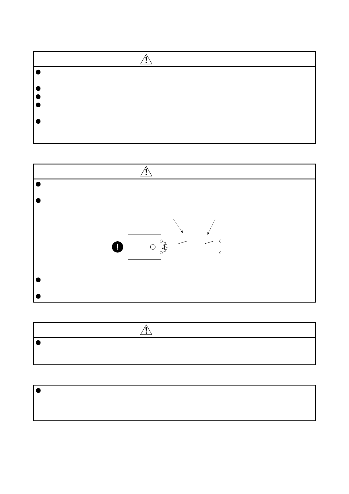
Configure an electromagnetic brake circuit so that it is activated also by an external EMG stop switch.
Contacts must be opened when ALM
(Malfunction) or MBR (Electromagnetic
brake interlock) turns off.
Contacts must be opened
with the EMG stop switch.
Servo motor
B
Electromagnetic brake
When any alarm has occurred, eliminate its cause, ensure safety, and deactivate the alarm before
restarting operation.
Provide an adequate protection to prevent unexpected restart after an instantaneous power failure.
RA
24 V DC
(6) Maintenance, inspection and parts replacement
CAUTION
With age, the electrolytic capacitor of the servo amplifier will deteriorate. To prevent a secondary
accident due to a malfunction, it is recommend that the electrolytic capacitor be replaced every 10 years
when it is used in general environment. Please contact your local sales office.
(7) General instruction
To illustrate details, the equipment in the diagrams of this Instruction Manual may have been drawn
without covers and safety guards. When the equipment is operated, the covers and safety guards must
be installed as specified. Operation must be performed in accordance with this Specifications and
Instruction Manual.
A - 5
DISPOSAL OF WASTE
Please dispose a servo amplifier, battery (primary battery) and other options according to your local laws and
regulations.
EEP-ROM life
The number of write times to the EEP-ROM, which stores parameter settings, etc., is limited to 100,000. If
the total number of the following operations exceeds 100,000, the servo amplifier may malfunction when the
EEP-ROM reaches the end of its useful life.
Write to the EEP-ROM due to parameter setting changes
Write to the EEP-ROM due to device changes
STO function of the servo amplifier
When using the STO function of the servo amplifier, refer to chapter 13.
For the MR-J3-D05 safety logic unit, refer to appendix 5.
Compliance with global standards
For the compliance with global standards, refer to appendix 4.
«About the manuals»
You must have this Instruction Manual and the following manuals to use this servo. Ensure to prepare
them to use the servo safely.
Relevant manuals
Manual name Manual No.
MELSERVO-J4 Series Instructions and Cautions for Safe Use of AC Servos
(Packed with the 200 V class servo amplifier)
MELSERVO-J4 Series Instructions and Cautions for Safe Use of AC Servos
(Packed with the 400 V class servo amplifier)
MR-J4 Servo Amplifier Instruction Manual (Troubleshooting) SH(NA)030109
MELSERVO Servo Motor Instruction Manual (Vol. 3) (Note 1) SH(NA)030113
MELSERVO Linear Servo Motor Instruction Manual (Note 2) SH(NA)030110
MELSERVO Direct Drive Motor Instruction Manual (Note 3) SH(NA)030112
MELSERVO Linear Encoder Instruction Manual (Note 2, 4) SH(NA)030111
EMC Installation Guidelines IB(NA)67310
IB(NA)0300175
IB(NA)0300197
Note 1. It is necessary for using a rotary servo motor.
2. It is necessary for using a linear servo motor.
3. It is necessary for using a direct drive motor.
4. It is necessary for using a fully closed loop system.
A - 6

«Wiring»
Wires mentioned in this Instruction Manual are selected based on the ambient temperature of 40 °C.
«U.S. customary units»
U.S. customary units are not shown in this manual. Convert the values if necessary according to the
following table.
Quantity SI (metric) unit U.S. customary unit
Mass 1 [kg] 2.2046 [lb]
Length 1 [mm] 0.03937 [in]
Torque 1 [N•m] 141.6 [oz•in]
Moment of inertia 1 [(× 10-4 kg•m2)] 5.4675 [oz•in2]
Load (thrust load/axial load) 1 [N] 0.2248 [lbf]
Temperature N [°C] × 9/5 + 32 N [°F]
A - 7

MEMO
A - 8

CONTENTS
1. FUNCTIONS AND CONFIGURATION 1- 1 to 1-44
1.1 Summary........................................................................................................................................... 1- 1
1.2 Function block diagram..................................................................................................................... 1- 2
1.3 Servo amplifier standard specifications ............................................................................................ 1- 9
1.4 Combinations of servo amplifiers and servo motors ....................................................................... 1-13
1.5 Function list...................................................................................................................................... 1-14
1.6 Model designation............................................................................................................................ 1-16
1.7 Structure .......................................................................................................................................... 1-17
1.7.1 Parts identification..................................................................................................................... 1-17
1.7.2 Removal and reinstallation of the front cover............................................................................ 1-29
1.8 Configuration including peripheral equipment ................................................................................. 1-31
2. INSTALLATION 2- 1 to 2- 6
2.1 Installation direction and clearances ................................................................................................ 2- 2
2.2 Keep out foreign materials................................................................................................................ 2- 3
2.3 Encoder cable stress ........................................................................................................................ 2- 4
2.4 Inspection items................................................................................................................................ 2- 4
2.5 Parts having service lives ................................................................................................................. 2- 5
3. SIGNALS AND WIRING 3- 1 to 3-70
3.1 Input power supply circuit ................................................................................................................. 3- 2
3.1.1 200 V class................................................................................................................................. 3- 3
3.1.2 400 V class................................................................................................................................. 3- 8
3.2 I/O signal connection example......................................................................................................... 3-11
3.2.1 Position control mode................................................................................................................ 3-11
3.2.2 Speed control mode.................................................................................................................. 3-14
3.2.3 Torque control mode................................................................................................................. 3-17
3.3 Explanation of power supply system ............................................................................................... 3-20
3.3.1 Signal explanations................................................................................................................... 3-20
3.3.2 Power-on sequence .................................................................................................................. 3-21
3.3.3 Wiring CNP1, CNP2, and CNP3............................................................................................... 3-22
3.4 Connectors and pin assignment ...................................................................................................... 3-25
3.5 Signal (device) explanations............................................................................................................ 3-28
3.6 Detailed explanation of signals........................................................................................................ 3-37
3.6.1 Position control mode................................................................................................................ 3-37
3.6.2 Speed control mode.................................................................................................................. 3-42
3.6.3 Torque control mode................................................................................................................. 3-44
3.6.4 Position/speed control switching mode..................................................................................... 3-47
3.6.5 Speed/torque control switching mode....................................................................................... 3-49
3.6.6 Torque/position control switching mode.................................................................................... 3-51
3.7 Forced stop deceleration function ................................................................................................... 3-52
3.7.1 Forced stop deceleration function (SS1)................................................................................... 3-52
3.7.2 Base circuit shut-off delay time function ................................................................................... 3-54
3.7.3 Vertical axis freefall prevention function ................................................................................... 3-55
3.7.4 Residual risks of the forced stop function (EM2) ...................................................................... 3-55
1

3.8 Alarm occurrence timing chart......................................................................................................... 3-56
3.8.1 When you use the forced stop deceleration function................................................................ 3-56
3.8.2 When you do not use the forced stop deceleration function..................................................... 3-57
3.9 Interfaces ......................................................................................................................................... 3-58
3.9.1 Internal connection diagram...................................................................................................... 3-58
3.9.2 Detailed explanation of interfaces............................................................................................. 3-59
3.9.3 Source I/O interfaces ................................................................................................................ 3-63
3.10 Servo motor with an electromagnetic brake .................................................................................. 3-64
3.10.1 Safety precautions .................................................................................................................. 3-64
3.10.2 Timing chart ............................................................................................................................ 3-65
3.11 Grounding ...................................................................................................................................... 3-69
4. STARTUP 4- 1 to 4-42
4.1 Switching power on for the first time................................................................................................. 4- 2
4.1.1 Startup procedure ...................................................................................................................... 4- 2
4.1.2 Wiring check............................................................................................................................... 4- 3
4.1.3 Surrounding environment........................................................................................................... 4- 6
4.2 Startup in position control mode ....................................................................................................... 4- 6
4.2.1 Power on and off procedures ..................................................................................................... 4- 6
4.2.2 Stop ............................................................................................................................................ 4- 7
4.2.3 Test operation ............................................................................................................................ 4- 8
4.2.4 Parameter setting....................................................................................................................... 4- 9
4.2.5 Actual operation ......................................................................................................................... 4- 9
4.2.6 Trouble at start-up...................................................................................................................... 4- 9
4.3 Startup in speed control mode......................................................................................................... 4-12
4.3.1 Power on and off procedures .................................................................................................... 4-12
4.3.2 Stop ........................................................................................................................................... 4-12
4.3.3 Test operation ........................................................................................................................... 4-13
4.3.4 Parameter setting...................................................................................................................... 4-14
4.3.5 Actual operation ........................................................................................................................ 4-14
4.3.6 Trouble at start-up..................................................................................................................... 4-14
4.4 Startup in torque control mode ........................................................................................................ 4-16
4.4.1 Power on and off procedures .................................................................................................... 4-16
4.4.2 Stop ........................................................................................................................................... 4-16
4.4.3 Test operation ........................................................................................................................... 4-17
4.4.4 Parameter setting...................................................................................................................... 4-18
4.4.5 Actual operation ........................................................................................................................ 4-18
4.4.6 Trouble at start-up..................................................................................................................... 4-19
4.5 Display and operation sections........................................................................................................ 4-20
4.5.1 Summary................................................................................................................................... 4-20
4.5.2 Display flowchart ....................................................................................................................... 4-21
4.5.3 Status display mode.................................................................................................................. 4-22
4.5.4 Diagnostic mode ....................................................................................................................... 4-29
4.5.5 Alarm mode............................................................................................................................... 4-31
4.5.6 Parameter mode ....................................................................................................................... 4-32
4.5.7 External I/O signal display......................................................................................................... 4-34
4.5.8 Output signal (DO) forced output.............................................................................................. 4-37
4.5.9 Test operation mode ................................................................................................................. 4-38
2

5. PARAMETERS 5- 1 to 5-58
5.1 Parameter list.................................................................................................................................... 5- 1
5.1.1 Basic setting parameters ([Pr. PA_ _ ])...................................................................................... 5- 2
5.1.2 Gain/filter setting parameters ([Pr. PB_ _ ])............................................................................... 5- 3
5.1.3 Extension setting parameters ([Pr. PC_ _ ]) .............................................................................. 5- 5
5.1.4 I/O setting parameters ([Pr. PD_ _ ]) ......................................................................................... 5- 7
5.1.5 Extension setting 2 parameters ([Pr. PE_ _ ])............................................................................ 5- 8
5.1.6 Extension setting 3 parameters ([Pr. PF_ _ ])........................................................................... 5-10
5.1.7 Linear servo motor/DD motor setting parameters ([Pr. PL_ _ ]) ............................................... 5-11
5.2 Detailed list of parameters ............................................................................................................... 5-12
5.2.1 Basic setting parameters ([Pr. PA_ _ ])..................................................................................... 5-12
5.2.2 Gain/filter setting parameters ([Pr. PB_ _ ]) .............................................................................. 5-23
5.2.3 Extension setting parameters ([Pr. PC_ _ ]) ............................................................................. 5-34
5.2.4 I/O setting parameters ([Pr. PD_ _ ]) ........................................................................................ 5-46
5.2.5 Extension setting 2 parameters ([Pr. PE_ _ ])........................................................................... 5-52
5.2.6 Extension setting 3 parameters ([Pr. PF_ _ ])........................................................................... 5-54
5.2.7 Linear servo motor/DD motor setting parameters ([Pr. PL_ _ ]) ............................................... 5-56
6. NORMAL GAIN ADJUSTMENT 6- 1 to 6-24
6.1 Different adjustment methods........................................................................................................... 6- 1
6.1.1 Adjustment on a single servo amplifier ...................................................................................... 6- 1
6.1.2 Adjustment using MR Configurator2.......................................................................................... 6- 2
6.2 One-touch tuning .............................................................................................................................. 6- 3
6.2.1 One-touch tuning flowchart ........................................................................................................ 6- 3
6.2.2 Display transition and operation procedure of one-touch tuning ............................................... 6- 5
6.2.3 Caution for one-touch tuning..................................................................................................... 6-13
6.3 Auto tuning....................................................................................................................................... 6-14
6.3.1 Auto tuning mode...................................................................................................................... 6-14
6.3.2 Auto tuning mode basis............................................................................................................. 6-15
6.3.3 Adjustment procedure by auto tuning ....................................................................................... 6-16
6.3.4 Response level setting in auto tuning mode ............................................................................. 6-17
6.4 Manual mode ................................................................................................................................... 6-18
6.5 2 gain adjustment mode .................................................................................................................. 6-21
7. SPECIAL ADJUSTMENT FUNCTIONS 7- 1 to 7-30
7.1 Filter setting ...................................................................................................................................... 7- 1
7.1.1 Machine resonance suppression filter ....................................................................................... 7- 2
7.1.2 Adaptive filter II........................................................................................................................... 7- 5
7.1.3 Shaft resonance suppression filter............................................................................................. 7- 7
7.1.4 Low-pass filter ............................................................................................................................ 7- 8
7.1.5 Advanced vibration suppression control II.................................................................................7- 8
7.1.6 Command notch filter................................................................................................................ 7-13
7.2 Gain switching function.................................................................................................................... 7-15
7.2.1 Applications............................................................................................................................... 7-15
7.2.2 Function block diagram............................................................................................................. 7-16
7.2.3 Parameter.................................................................................................................................. 7-17
7.2.4 Gain switching procedure ......................................................................................................... 7-20
7.3 Tough drive function ........................................................................................................................ 7-23
3

7.3.1 Vibration tough drive function.................................................................................................... 7-23
7.3.2 Instantaneous power failure tough drive function ..................................................................... 7-25
7.4 Compliance with SEMI-F47 standard .............................................................................................. 7-28
8. TROUBLESHOOTING 8- 1 to 8- 8
9. OUTLINE DRAWINGS 9- 1 to 9-20
9.1 Servo amplifier.................................................................................................................................. 9- 1
9.2 Connector ........................................................................................................................................ 9-18
10. CHARACTERISTICS 10- 1 to 10-12
10.1 Overload protection characteristics .............................................................................................. 10- 1
10.2 Power supply capacity and generated loss .................................................................................. 10- 4
10.3 Dynamic brake characteristics...................................................................................................... 10- 7
10.3.1 Dynamic brake operation....................................................................................................... 10- 7
10.3.2 Permissible load to motor inertia when the dynamic brake is used...................................... 10-10
10.4 Cable bending life........................................................................................................................ 10-11
10.5 Inrush currents at power-on of main circuit and control circuit.................................................... 10-12
11. OPTIONS AND AUXILIARY EQUIPMENT 11- 1 to 11-94
11.1 Cable/connector sets.................................................................................................................... 11- 1
11.1.1 Combinations of cable/connector sets................................................................................... 11- 2
11.1.2 MR-D05UDL3M-B STO cable................................................................................................ 11- 5
11.2 Regenerative options.................................................................................................................... 11- 6
11.2.1 Combination and regenerative power.................................................................................... 11- 6
11.2.2 Selection of regenerative option ............................................................................................ 11- 8
11.2.3 Parameter setting.................................................................................................................. 11-11
11.2.4 Connection of regenerative option........................................................................................ 11-11
11.2.5 Dimensions ........................................................................................................................... 11-16
11.3 FR-BU2-(H) Brake unit ................................................................................................................ 11-20
11.3.1 Selection................................................................................................................................ 11-21
11.3.2 Brake unit parameter setting................................................................................................. 11-22
11.3.3 Connection example ............................................................................................................. 11-23
11.3.4 Dimensions ........................................................................................................................... 11-33
11.4 FR-RC-(H) power regeneration converter ................................................................................... 11-35
11.5 FR-CV-(H) power regeneration common converter .................................................................... 11-41
11.5.1 Model designation................................................................................................................. 11-41
11.5.2 Selection example................................................................................................................. 11-42
11.6 Junction terminal block MR-TB50................................................................................................ 11-50
11.7 MR Configurator2 ........................................................................................................................ 11-52
11.7.1 Specifications ........................................................................................................................ 11-52
11.7.2 System configuration............................................................................................................. 11-53
11.7.3 Precautions for using USB communication function............................................................. 11-54
11.8 Battery.......................................................................................................................................... 11-55
11.8.1 MR-BAT6V1SET battery....................................................................................................... 11-55
11.8.2 MR-BAT6V1BJ battery for junction battery cable ................................................................. 11-55
4

11.9 Selection example of wires.......................................................................................................... 11-56
11.10 Molded-case circuit breakers, fuses, magnetic contactors (recommended).............................. 11-60
11.11 Power factor improving DC reactors........................................................................................... 11-62
11.12 Power factor improving AC reactors........................................................................................... 11-66
11.13 Relays (recommended) .............................................................................................................. 11-69
11.14 Noise reduction techniques ........................................................................................................ 11-70
11.15 Earth-leakage current breaker.................................................................................................... 11-77
11.16 EMC filter (recommended).......................................................................................................... 11-80
11.17 External dynamic brake .............................................................................................................. 11-84
11.18 Heat sink outside mounting attachment (MR-J4ACN15K/MR-J3ACN)...................................... 11-90
12. ABSOLUTE POSITION DETECTION SYSTEM 12- 1 to 12-36
12.1 Summary....................................................................................................................................... 12- 1
12.1.1 Features ................................................................................................................................. 12- 1
12.1.2 Restrictions ............................................................................................................................ 12- 2
12.1.3 Structure................................................................................................................................. 12- 2
12.1.4 Parameter setting................................................................................................................... 12- 3
12.1.5 Confirmation of absolute position detection data................................................................... 12- 3
12.2 Battery........................................................................................................................................... 12- 4
12.2.1 Using MR-BAT6V1SET battery.............................................................................................. 12- 4
12.2.2 Using MR-BAT6V1BJ battery for junction battery cable........................................................ 12- 9
12.3 Standard connection example ..................................................................................................... 12-13
12.4 Signal explanation ....................................................................................................................... 12-14
12.5 Startup procedure........................................................................................................................ 12-15
12.6 Absolute position data transfer protocol ...................................................................................... 12-16
12.6.1 Data transfer procedure........................................................................................................ 12-16
12.6.2 Transfer method.................................................................................................................... 12-17
12.6.3 Home position setting............................................................................................................ 12-26
12.6.4 Use of servo motor with an electromagnetic brake............................................................... 12-28
12.6.5 How to process the absolute position data at detection of stroke end ................................. 12-29
12.7 Absolute position data transfer errors.......................................................................................... 12-29
12.8 Communication-based absolute position transfer system........................................................... 12-32
12.8.1 Serial communication command........................................................................................... 12-32
12.8.2 Absolute position data transfer protocol ............................................................................... 12-32
13. USING STO FUNCTION 13- 1 to 13-12
13.1 Introduction ................................................................................................................................... 13- 1
13.1.1 Summary................................................................................................................................ 13- 1
13.1.2 Terms related to safety .......................................................................................................... 13- 1
13.1.3 Cautions ................................................................................................................................. 13- 1
13.1.4 Residual risks of the STO function......................................................................................... 13- 2
13.1.5 Specifications ......................................................................................................................... 13- 3
13.1.6 Maintenance........................................................................................................................... 13- 4
13.2 STO I/O signal connector (CN8) and signal layouts..................................................................... 13- 4
13.2.1 Signal layouts......................................................................................................................... 13- 4
13.2.2 Signal (device) explanations.................................................................................................. 13- 5
13.2.3 How to pull out the STO cable ............................................................................................... 13- 5
13.3 Connection example..................................................................................................................... 13- 6
13.3.1 Connection example for CN8 connector................................................................................ 13- 6
5

13.3.2 External I/O signal connection example using an MR-J3-D05 safety logic unit.................... 13- 7
13.3.3 External I/O signal connection example using an external safety relay unit ......................... 13- 9
13.4 Detailed description of interfaces ................................................................................................ 13-10
13.4.1 Sink I/O interface................................................................................................................... 13-10
13.4.2 Source I/O interface .............................................................................................................. 13-11
14. COMMUNICATION FUNCTION 14- 1 to 14-38
14.1 Structure ....................................................................................................................................... 14- 1
14.1.1 Configuration diagram............................................................................................................ 14- 1
14.1.2 Precautions for using RS-422/RS-232C/USB communication function ................................ 14- 3
14.2 Communication specifications ...................................................................................................... 14- 4
14.2.1 Outline of communication ...................................................................................................... 14- 4
14.2.2 Parameter setting................................................................................................................... 14- 4
14.3 Protocol......................................................................................................................................... 14- 5
14.3.1 Transmission data configuration............................................................................................ 14- 5
14.3.2 Character codes..................................................................................................................... 14- 6
14.3.3 Error codes............................................................................................................................. 14- 7
14.3.4 Checksum .............................................................................................................................. 14- 7
14.3.5 Time-out processing............................................................................................................... 14- 7
14.3.6 Retry processing .................................................................................................................... 14- 8
14.3.7 Initialization ............................................................................................................................ 14- 8
14.3.8 Communication procedure example...................................................................................... 14- 9
14.4 Command and data No. list ......................................................................................................... 14-10
14.4.1 Reading command................................................................................................................ 14-10
14.4.2 Writing commands ................................................................................................................ 14-16
14.5 Detailed explanations of commands............................................................................................ 14-18
14.5.1 Data processing .................................................................................................................... 14-18
14.5.2 Status display mode.............................................................................................................. 14-20
14.5.3 Parameter ............................................................................................................................. 14-21
14.5.4 External I/O signal status (DIO diagnosis)............................................................................ 14-25
14.5.5 Input device on/off................................................................................................................. 14-27
14.5.6 Disabling/enabling I/O devices (DIO).................................................................................... 14-28
14.5.7 Input devices on/off (test operation)...................................................................................... 14-29
14.5.8 Test operation mode ............................................................................................................. 14-30
14.5.9 Output signal pin on/off (output signal (DO) forced output).................................................. 14-34
14.5.10 Alarm history ....................................................................................................................... 14-35
14.5.11 Current alarm ...................................................................................................................... 14-36
14.5.12 Other commands................................................................................................................. 14-37
15. USING A LINEAR SERVO MOTOR 15- 1 to 15-28
15.1 Functions and configuration ......................................................................................................... 15- 1
15.1.1 Summary................................................................................................................................ 15- 1
15.1.2 Configuration including peripheral equipment ....................................................................... 15- 2
15.2 Signals and wiring......................................................................................................................... 15- 5
15.3 Operation and functions................................................................................................................ 15- 6
15.3.1 Startup.................................................................................................................................... 15- 6
15.3.2 Magnetic pole detection......................................................................................................... 15- 9
15.3.3 Home position return............................................................................................................. 15-16
15.3.4 Test operation mode in MR Configurator2............................................................................ 15-20
6

15.3.5 Function................................................................................................................................. 15-21
15.3.6 Absolute position detection system....................................................................................... 15-24
15.4 Characteristics ............................................................................................................................. 15-25
15.4.1 Overload protection characteristics ...................................................................................... 15-25
15.4.2 Power supply capacity and generated loss .......................................................................... 15-26
15.4.3 Dynamic brake characteristics.............................................................................................. 15-27
15.4.4 Permissible load to motor mass ratio when the dynamic brake is used............................... 15-28
16. USING A DIRECT DRIVE MOTOR 16- 1 to 16-20
16.1 Functions and configuration ......................................................................................................... 16- 1
16.1.1 Summary................................................................................................................................ 16- 1
16.1.2 Configuration including peripheral equipment ....................................................................... 16- 2
16.2 Signals and wiring......................................................................................................................... 16- 3
16.3 Operation and functions................................................................................................................ 16- 4
16.3.1 Startup procedure .................................................................................................................. 16- 5
16.3.2 Magnetic pole detection......................................................................................................... 16- 6
16.3.3 Function................................................................................................................................. 16-12
16.4 Absolute position detection system ............................................................................................. 16-14
16.5 Characteristics ............................................................................................................................. 16-15
16.5.1 Overload protection characteristics ...................................................................................... 16-15
16.5.2 Power supply capacity and generated loss .......................................................................... 16-17
16.5.3 Dynamic brake characteristics.............................................................................................. 16-18
17. FULLY CLOSED LOOP SYSTEM 17- 1 to 17-24
17.1 Functions and configuration ......................................................................................................... 17- 1
17.1.1 Function block diagram.......................................................................................................... 17- 1
17.1.2 Selecting procedure of control mode..................................................................................... 17- 3
17.1.3 System configuration.............................................................................................................. 17- 4
17.2 Load-side encoder........................................................................................................................ 17- 6
17.2.1 LINEAR ENCODER ............................................................................................................... 17- 6
17.2.2 Rotary encoder....................................................................................................................... 17- 6
17.2.3 Configuration diagram of encoder cable................................................................................ 17- 7
17.2.4 MR-J4FCCBL03M branch cable............................................................................................ 17- 9
17.3 Operation and functions............................................................................................................... 17-10
17.3.1 Startup................................................................................................................................... 17-10
17.3.2 Home position return............................................................................................................. 17-17
17.3.3 Fully closed loop control error detection functions................................................................ 17-19
17.3.4 Auto tuning function .............................................................................................................. 17-20
17.3.5 Machine analyzer function .................................................................................................... 17-20
17.3.6 Test operation mode ............................................................................................................. 17-20
17.3.7 Absolute position detection system under fully closed loop system..................................... 17-21
17.3.8 About MR Configurator2 ....................................................................................................... 17-22
APPENDIX App.- 1 to App.-45
App. 1 Peripheral equipment manufacturer (for reference)..............................................................App.- 1
App. 2 Handling of AC servo amplifier batteries for the United Nations Recommendations on the
Transport of Dangerous Goods ............................................................................................App.- 1
App. 3 Symbol for the new EU Battery Directive..............................................................................App.- 3
7

App. 4 Compliance with global standards ........................................................................................App.- 3
App. 5 MR-J3-D05 Safety logic unit ................................................................................................App.-19
App. 6 EC declaration of conformity................................................................................................App.-37
App. 7 Analog monitor ..................................................................................................................... App.-39
App. 8 Two-wire type encoder cable for HG-MR/HG-KR................................................................App.-43
App. 9 How to replace servo amplifier without magnetic pole detection.........................................App.-44
8
1. FUNCTIONS AND CONFIGURATION
1. FUNCTIONS AND CONFIGURATION
1.1 Summary
The Mitsubishi MELSERVO-J4 series general-purpose AC servo has further higher performance and higher
functions compared to the previous MELSERVO-J3 series.
The MELSERVO-J4 series compatible rotary servo motor is equipped with 22-bit (4194304 pulses/rev) highresolution absolute encoder. In addition, speed frequency response is increased to 2.5 kHz. Thus, faster and
more accurate control is enabled as compared to the MELSERVO-J3 series.
The servo amplifier has position, speed, and torque control modes. In the position control mode, the
maximum pulse train of 4 Mpulses/s is supported. Further, it can perform operation with the control modes
switched, e.g. position/speed control, speed/torque control and torque/position control. Hence, it is
applicable to a wide range of fields, not only precision positioning and smooth speed control of machine tools
and general industrial machines but also line control and tension control.
With one-touch tuning and real-time auto tuning, you can automatically adjust the servo gains according to
the machine.
The tough drive function and the drive recorder function, which are well-received in the MELSERVO-JN
series, have been improved. The MR-J4 servo amplifier supports the improved functions. Additionally, the
preventive maintenance support function detects an error in the machine parts. This function provides strong
support for the machine maintenance and inspection.
The MR-J4-_A_ servo amplifier supports the Safe Torque Off (STO) function. By combining with optional
MR-J3-D05, the servo amplifier supports Safe stop 1 (SS1) function.
The servo amplifier has a USB communication interface. Therefore, you can connect the servo amplifier to
the personal computer with MR Configurator2 installed to perform the parameter setting, test operation, gain
adjustment, and others.
In the MELSERVO-J4 series, servo amplifiers with the CN2L connector are also available as MR-J4-_A_-RJ.
By using the CN2L connector, an A/B/Z-phase differential output type external encoder can be connected to
the servo amplifier. In a fully closed loop system, a four-wire type external encoder is connectable as well.
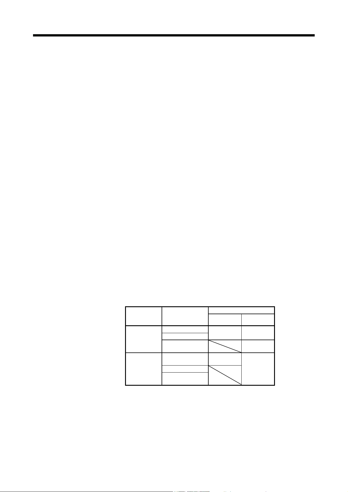
The following table indicates the communication method of the external encoder compatible with the MR-J4_A_ and MR-J4-_A_-RJ servo amplifiers.
Table 1.1 Connectors to connect from external encoders
Operation
mode
Linear servo
motor system
Fully closed
loop system
External encoder
communication
method
Two-wire type
Four-wire type
A/B/Z-phase
differential output type
Two-wire type
Four-wire type
A/B/Z-phase
differential output type
(Note 2, 3, 4)
Note 1. The MR-J4THCBL03M branch cable is necessary.
2. The MR-J4FCCBL03M branch cable is necessary.
3. When the communication method of the servo motor encoder is four-wire type,
MR-J4-_A_ cannot be used. Use an MR-J4-_A_-RJ.
4. This is used with software version A5 or later.
5. Connect a thermistor to CN2.
Connector
MR-J4-_A_ MR-J4-_A_-RJ
CN2
(Note 1, 4)
CN2
CN2
(Note 1)
CN2L
(Note 5)
CN2L
1 - 1
1. FUNCTIONS AND CONFIGURATION
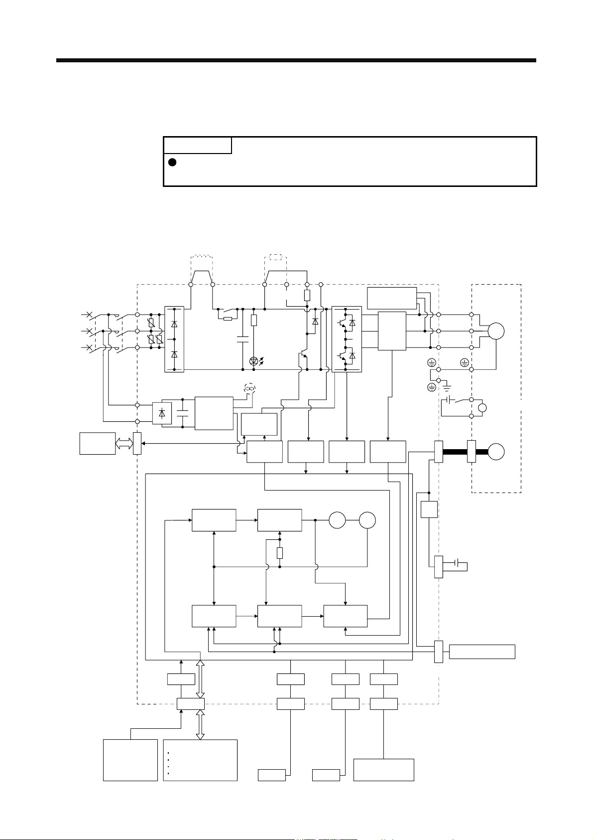
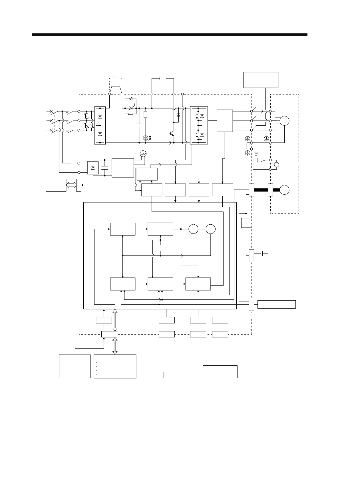
1.2 Function block diagram
The function block diagram of this servo is shown below.
Regenerative
option
(1) 200 V class
(a) MR-J4-500A(-RJ) or less
POINT
The diagram shows MR-J4-_A_-RJ as an example. The MR-J4-_A_ servo
amplifier does not have the CN2L connector.
(Note 6)
Power factor improving
DC reactor
(Note 2)
Power
supply
STO
switch
Servo amplifier
MCMCCB
L1
U
L2
U U
L3
L11
L21
CN8
P3 P4
Diode
stack
Position
command
input
+
(Note 4)
Relay
Cooling fan
(Note 3)
Control
circuit
power
Model
position
control
+
CHARGE
lamp
STO
circuit
Base
amplifier
P+
(Note 1)
Regene-
rative
Model
speed
control
TR
Voltage
detection
N-CD
Overcurrent
protection
Virtual
motor
detection
Virtual
encoder
Dynamic
brake
circuit
Current
encoder
Current
Stepdown
circuit
U
V
W
RA
24 V DC
CN2
Servo motor
U
V
W
B1
B
B2
M
Electromagnetic
brake
Encoder
Model position
Actual
position
control
I/F
CN1
DI/O control
Analog
(two channel)
Servo-on
Input command pulse.
Start
Malfunction, etc
Model speed Model torque
Actual
speed
control
USB RS-422 D/AA/D
CN5 CN3 CN6
Personal
computer
USB RS-422
Controller
Current
control
Analog monitor
(two channel)
CN4
Optional battery
(for absolute position
detection system)
External encoder
CN2L
(Note 5)
1 - 2

1. FUNCTIONS AND CONFIGURATION
Note 1. The built-in regenerative resistor is not provided for MR-J4-10A(-RJ).
2. For 1-phase 200 V AC to 240 V AC, connect the power supply to L1 and L3. Leave L2 open.
For the power supply specifications, refer to section 1.3.
3. Servo amplifiers MR-J4-70A(-RJ) or more have a cooling fan.
4. The MR-J4 servo amplifier has P3 and P4 in the upstream of the inrush current suppression circuit. They are different from P1
and P2 of the MR-J3 servo amplifiers.
5. This is for the MR-J4-_A-RJ servo amplifier. The MR-J4-_A servo amplifier does not have the CN2L connector.
6. The power factor improving AC reactor can also be used. In this case, the power factor improving DC reactor cannot be used.
When not using the power factor improving DC reactor, short P3 and P4.
1 - 3
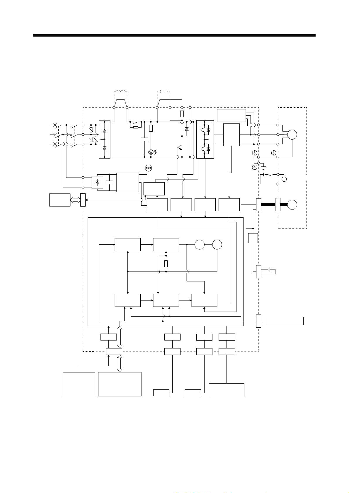
1. FUNCTIONS AND CONFIGURATION
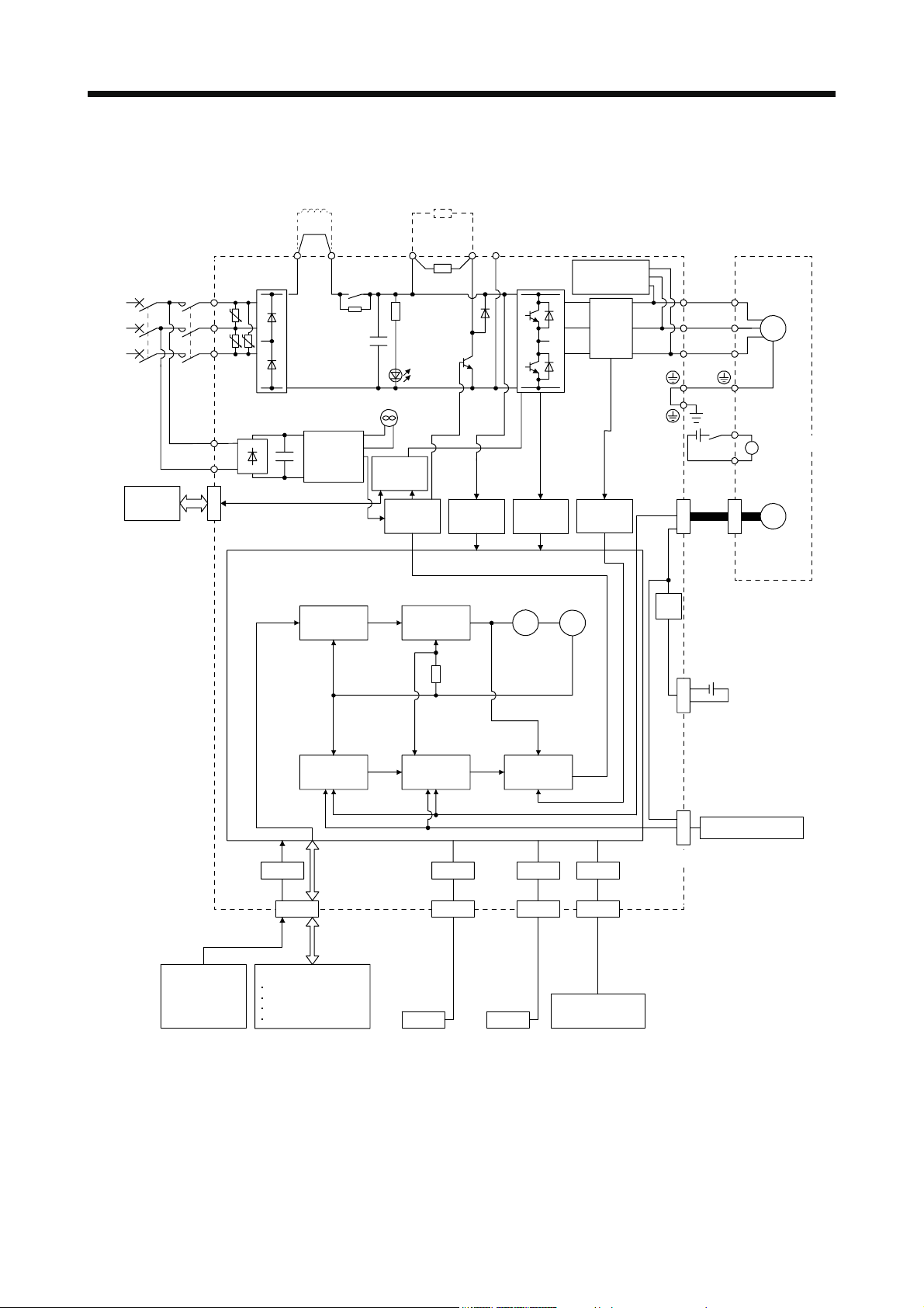
(b) MR-J4-700A(-RJ)
(Note 4)
Power factor improving
DC reactor
Regenerative
option
(Note 1)
Power
supply
STO
switch
Servo amplifier
MCMCCB
L1
U
L2
U U
L3
L11
L21
CN8
P3 P4
Diode
stack
Position
command
input
+
(Note 2)
Relay
Cooling fan
Control
circuit
power
Model
position
control
+
CHARGE
lamp
STO
circuit
Base
amplifier
P+
Regene-
rative
TR
Model
speed
control
Voltage
detection
N-C
Overcurrent
Virtual
motor
protection
detection
Virtual
encoder
Dynamic
brake
circuit
Current
encoder
Current
Stepdown
circuit
U
V
W
RA
24 V DC
CN2
Servo motor
U
V
W
B1
B
B2
M
Electromagnetic
brake
Encoder
Model position Model speed Model torque
Actual
position
control
Actual
speed
control
Current
control
CN4
Optional battery
(for absolute position
detection system)
External encoder
CN2L
(Note 3)
USB RS-422 D/AA/D
I/F
CN5 CN3 CN6
Personal
computer
Controller
USB RS-422
Analog monitor
(two channel)
Analog
(two channel)
CN1
DI/O control
Servo-on
Input command pulse.
Start
Malfunction, etc
Note 1. For the power supply specifications, refer to section 1.3.
2. The MR-J4 servo amplifier has P3 and P4 in the upstream of the inrush current suppression circuit. They are different from P1
and P2 of MR-J3 servo amplifiers.
3. This is for the MR-J4-_A-RJ servo amplifier. The MR-J4-_A servo amplifier does not have the CN2L connector.
4. The power factor improving AC reactor can also be used. In this case, the power factor improving DC reactor cannot be used.
When not using the power factor improving DC reactor, short P3 and P4.
1 - 4
1. FUNCTIONS AND CONFIGURATION
(c) MR-J4-11KA(-RJ)/MR-J4-15KA(-RJ)/MR-J4-22KA(-RJ)
External regenerative
regenerative option
(Note 2)
Thyristor
+
CHARGE
lamp
STO
circuit
Base
amplifier
resistor or
Regene-
rative
TR
detection
Voltage
(Note 1)
Power
supply
STO
switch
Servo amplifier
MCMCCB
L1
U
L2
U U
L3
L11
L21
CN8
(Note 5)
Power factor improving
DC reactor
P3 P+
Diode
stack
P4
Cooling fan
Control
+
circuit
power
(Note 4)
External dynamic
brake (optional)
RA
Servo motor
U
V
M
W
B1
Electromagnetic
B
brake
N-
C
U
Current
encoder
V
W
24 V DC
B2
Overcurrent
protection
Current
detection
CN2
Encoder
Analog
(two channel)
Position
command
input
CN1
DI/O control
Servo-on
Input command pulse.
Start
Malfunction, etc
Model
position
control
Model position
Actual
position
control
I/F
Model
speed
control
Virtual
motor
Model speed Model torque
Actual
speed
control
USB RS-422 D/AA/D
CN5 CN3 CN6
Personal
computer
Controller
USB RS-422
Current
control
Virtual
encoder
Analog monitor
(two channel)
Stepdown
circuit
CN4
Optional battery
(for absolute position
detection system)
External encoder
CN2L
(Note 3)
Note 1. For the power supply specifications, refer to section 1.3.
2. The MR-J4 servo amplifier has P3 and P4 in the upstream of the inrush current suppression circuit. They are different from P1
and P2 of the MR-J3 servo amplifiers.
3. This is for the MR-J4-_A-RJ servo amplifier. The MR-J4-_A servo amplifier does not have the CN2L connector.
4. Use an external dynamic brake for this servo amplifier. Failure to do so will cause an accident because the servo motor dose
not stop immediately but coasts at an alarm occurrence for which the servo motor does not decelerate to stop. Ensure the
safety in the entire equipment. For alarms for which the servo motor does not decelerate to stop, refer to chapter 8.
5. The power factor improving AC reactor can also be used. In this case, the power factor improving DC reactor cannot be used.
When not using the power factor improving DC reactor, short P3 and P4.
1 - 5
1. FUNCTIONS AND CONFIGURATION
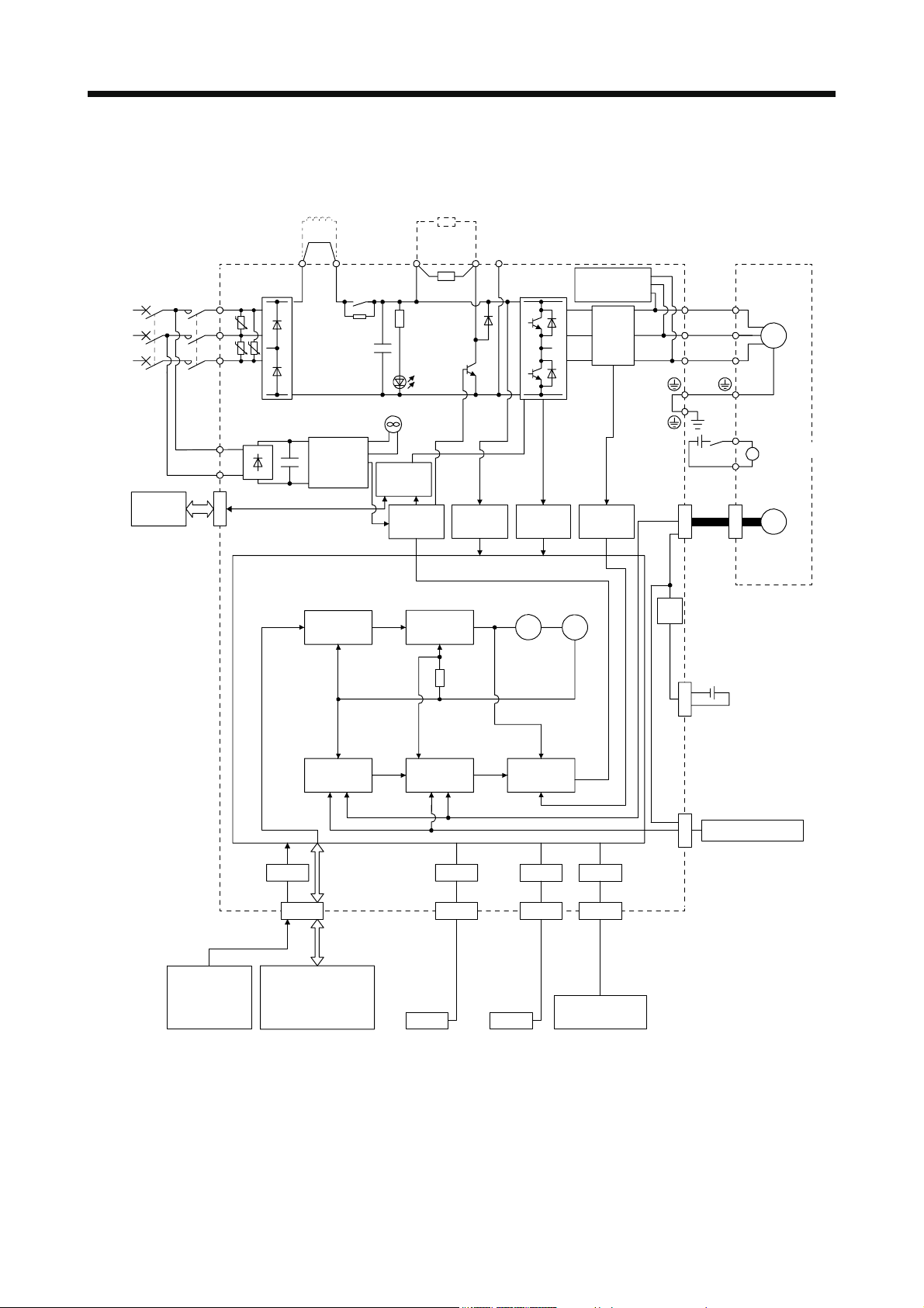
(2) 400 V class
(a) MR-J4-350A4(-RJ) or less
(Note 5)
Power factor
improving
DC reactor
Regenerative
option
(Note 1)
Power
supply
STO
switch
Servo amplifier
MCMCCB
L1
U
L2
U U
L3
L11
L21
CN8
P3 P4 (Note 3)
Diode
stack
+
Position
command
input
Relay
(Note 2)
Control
circuit
power
supply
Model
position
control
+
Cooling fan
STO
circuit
Base
amplifier
P+
Regenerative
TR
Charge
lamp
Model
speed
control
Voltage
detection
N-CD
Overcurrent
protection
Virtual
motor
detection
Virtual
encoder
Dynamic
brake
circuit
Current
detector
Current
Stepdown
circuit
U
V
W
RA
24 V DC
CN2
Servo motor
U
V
W
B1
B
B2
M
Electromagnetic
brake
Encoder
Model position
Actual
position
control
Model speed Model torque
Actual
speed
control
Current
control
CN4
Optional battery
(For absolute
position detection
system)
External encoder
CN2L
(Note 4)
USB RS-422 D/AA/D
I/F
CN5 CN3 CN6
Personal
computer
Controller
USB RS-422
Analog monitor
(2 channels)
Analog
(2 channels)
CN1
DI/O control
•Servo-on
•Input command pulse.
•Start
•Malfunction, etc
Note 1. Refer to section 1.3 for the power supply specification.
2. Servo amplifiers MR-J4-200A4(-RJ) or more have a cooling fan.
3. MR-J4 servo amplifier has P3 and P4 in the upstream of the inrush current suppression circuit. They are different from P1 and
P2 of MR-J3 servo amplifiers.
4. This is for MR-J4-_A4-RJ servo amplifier. MR-J4-_A4 servo amplifier does not have CN2L connector.
5. The power factor improving AC reactor can also be used. In this case, the power factor improving DC reactor cannot be used.
When not using the power factor improving DC reactor, short P3 and P4.
1 - 6
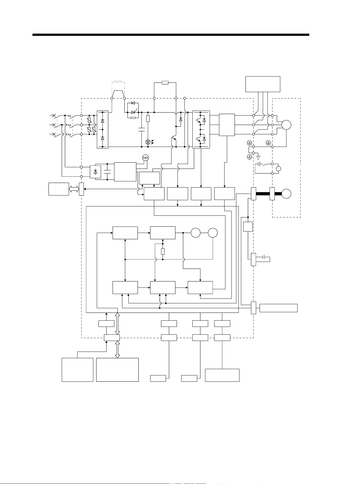
1. FUNCTIONS AND CONFIGURATION
(b) MR-J4-500A4(-RJ)/MR-J4-700A4(-RJ)
(Note 4)
Power factor
improving
DC reactor
Regenerative
option
(Note 1)
Power
supply
STO
switch
Servo amplifier
MCMCCB
L1
U
L2
U U
L3
L11
L21
CN8
P3 P4 (Note 2)
Diode
stack
+
Position
command
input
Relay
Control
circuit
power
supply
Model
position
control
+
Cooling fan
STO
circuit
Base
amplifier
P+
Regenerative
TR
Charge
lamp
Model
speed
control
Voltage
detection
N-C
Overcurrent
Virtual
motor
protection
detection
Virtual
encoder
Dynamic
brake
circuit
Current
detector
Current
Stepdown
circuit
U
V
W
RA
24 V DC
CN2
Servo motor
U
V
W
B1
B
B2
M
Electromagnetic
brake
Encoder
Model position
Actual
position
control
Model speed Model torque
Actual
speed
control
Current
control
CN4
Optional battery
(For absolute
position detection
system)
External encoder
CN2L
(Note 3)
USB RS-422 D/AA/D
I/F
CN5 CN3 CN6
Personal
computer
Controller
USB RS-422
Analog monitor
(2 channels)
Analog
(2 channels)
CN1
DI/O control
•Servo-on
•Input command pulse.
•Start
•Malfunction, etc
Note 1. Refer to section 1.3 for the power supply specification.
2. MR-J4 servo amplifier has P3 and P4 in the upstream of the inrush current suppression circuit. They are different from P1 and
P2 of MR-J3 servo amplifiers.
3. This is for MR-J4-_A4-RJ servo amplifier. MR-J4-_A4 servo amplifier does not have CN2L connector.
4. The power factor improving AC reactor can also be used. In this case, the power factor improving DC reactor cannot be used.
When not using the power factor improving DC reactor, short P3 and P4.
1 - 7
1. FUNCTIONS AND CONFIGURATION
(c) MR-J4-11KA4(-RJ)/MR-J4-15KA4(-RJ)/MR-J4-22KA4(-RJ)
(Note 1)
Power
supply
STO
switch
Servo amplifier
MCMCCB
L1
U
L2
U U
L3
L11
L21
CN8
(Note 5)
Power factor
improving
DC reactor
P3 P4 (Note 2)
Diode
stack
Control
+
circuit
power
supply
Thyristor
Cooling fan
External
regenerative resistor
or
regenerative option
P+
+
Regenerative
TR
Charge
lamp
STO
circuit
Base
amplifier
Voltage
detection
N-C
Overcurrent
protection
Current
detector
Current
detection
(Note 4)
External
dynamic brake
(optional)
U
V
W
RA
24 V DC
CN2
Servo motor
U
V
M
W
B1
Electromagnetic
B
brake
B2
Encoder
Analog
(2 channels)
Position
command
input
Model
position
control
Actual
position
control
CN1
DI/O control
•Servo-on
•Input command pulse.
•Start
•Malfunction, etc
Model position
I/F
Model
speed
control
Virtual
motor
Model speed Model torque
Actual
speed
control
USB RS-422 D/AA/D
CN5 CN3 CN6
Personal
computer
Controller
USB RS-422
Current
control
Virtual
encoder
Analog monitor
(2 channels)
Stepdown
circuit
CN4
Optional battery
(For absolute
position detection
system)
CN2L
(Note 3)
External encoder
Note 1. Refer to section 1.3 for the power supply specification.
2. MR-J4 servo amplifier has P3 and P4 in the upstream of the inrush current suppression circuit. They are different from P1 and
P2 of MR-J3 servo amplifiers.
3. This is for MR-J4-_A4-RJ servo amplifier. MR-J4-_A4 servo amplifier does not have CN2L connector.
4. Use an external dynamic brake for this servo amplifier. Failure to do so will cause an accident because the servo motor does
not stop immediately but coasts at an alarm occurrence for which the servo motor does not decelerate to stop. Ensure the
safety in the entire equipment. For alarms for which the servo motor does not decelerate to stop, refer to chapter 8.
5. The power factor improving AC reactor can also be used. In this case, the power factor improving DC reactor cannot be used.
When not using the power factor improving DC reactor, short P3 and P4.
1 - 8
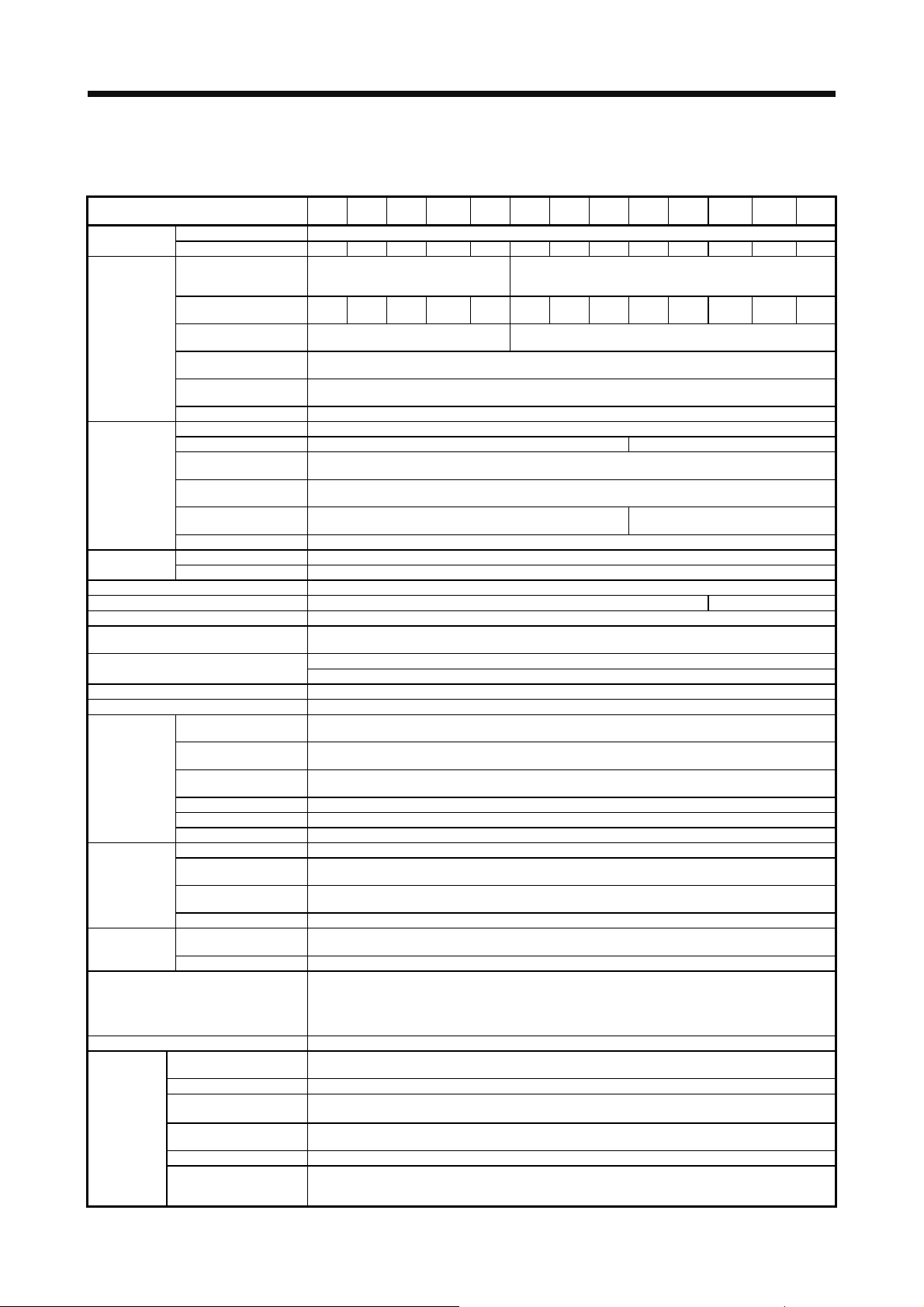
1. FUNCTIONS AND CONFIGURATION
1.3 Servo amplifier standard specifications
(1) 200 V class
Model: MR-J4-
Output
Main circuit
power supply
input
Control circuit
power supply
input
Interface power
supply
Control method Sine-wave PWM control, current control method
Dynamic brake Built-in External option (Note 8)
Fully closed loop control Available (Note 9)
Load-side encoder interface
(Note 10)
Communication function
Encoder output pulses Compatible (A/B/Z-phase pulse)
Analog monitor Two channels
Position control
mode
Speed control
mode
Torque control
mode
Protective functions
Functional safety STO (IEC/EN 61800-5-2)
Safety
performance
Rated voltage 3-phase 170 V AC
Rated current [A] 1.1 1.5 2.8 3.2 5.8 6.0 11.0 17.0 28.0 37.0 68.0 87.0 126.0
Voltage/Frequency
Rated current [A] 0.9 1.5 2.6
Permissible voltage
fluctuation
Permissible frequency
fluctuation
Power supply
capacity
Inrush current [A] Refer to section 10.5.
Voltage/Frequency 1-phase 200 V AC to 240 V AC, 50 Hz/60 Hz
Rated current [A] 0.2 0.3
Permissible voltage
fluctuation
Permissible frequency
fluctuation
Power
consumption
Inrush current [A] Refer to section 10.5.
Voltage 24 V DC ± 10%
Current capacity [A] (Note 1) 0.5 (including the CN8 connector signals)
Max. input pulse
frequency
Positioning feedback
pulse
Command pulse
multiplying factor
In-position range setting 0 pulse to ±65535 pulses (command pulse unit)
Error excessive Set by parameter setting or external analog input (0 V DC to +10 V DC/maximum torque)
Torque limit ±3 revolutions
Speed control range Analog speed command 1: 2000, Internal speed command 1: 5000
Analog speed command
input
Speed fluctuation ratio
Torque limit Set by parameter setting or external analog input (0 V DC to +10 V DC/maximum torque)
Analog torque command
input
Speed limit Set by parameter setting or external analog input (0 V DC to 10 V DC/rated speed)
Standards certified by CB
Response performance 8 ms or less (STO input off → energy shut off)
(Note 3)
Test pulse input (STO)
Mean time to dangerous
failure (MTTFd)
Diagnosis coverage (DC) Medium (90% to 99%)
Average probability of
dangerous failures per
hour (PFH)
10A
20A
40A
60A
70A
100A
200A
350A
500A
700A
(-RJ)
(-RJ)
(-RJ)
(-RJ)
(-RJ)
(-RJ)
(-RJ)
(-RJ)
(-RJ)
3-phase or 1-phase
200 V AC to 240 V AC,
50 Hz/60 Hz
3-phase or 1-phase 170 V AC to 264 V
[kVA] Refer to section 10.2.
[W] 30 45
Mitsubishi high-speed serial communication
USB: Connection to a personal computer or others (MR Configurator2-compatible)
4 Mpulses/s (for differential receiver) (Note 6), 200 kpulses/s (for open collector)
0 to ±10 V DC/rated speed (The speed at 10 V is changeable with [Pr. PC12].)
±0.01% or less (load fluctuation: 0% to 100%), 0% (power fluctuation: ±10%)
±0.2% or less (ambient temperature: 25 °C ± 10 °C) when using analog speed command
Overcurrent shut-off, regenerative overvoltage shut-off, overload shut-off (electronic thermal), servo motor
encoder error protection, regenerative error protection, undervoltage protection, instantaneous power
error excessive protection, magnetic pole detection protection, and linear servo control fault protection
3.2
(Note 5)
AC
Encoder resolution (resolution per servo motor revolution): 22 bits
Electronic gear A:1 to 16777215, B:1 to 16777215, 1/10 < A/B < 4000
0 V DC to ±8 V DC/maximum torque (input impedance 10 kΩ to 12 kΩ )
EN ISO 13849-1 category 3 PL d, IEC 61508 SIL 2, EN 62061 SIL CL 2,
3.8 5.0 10.5 16.0 21.7 28.9 46.0 64.0 95.0
1-phase 170 V AC to 264 V AC
RS-422: 1:n communication (up to 32 axes) (Note 7)
overheat protection,
failure protection, overspeed protection,
and EN 61800-5-2 SIL 2
Test pulse interval: 1 Hz to 25 Hz
Test pulse off time: Up to 1 ms
100 years or longer
1.68 × 10
200 V AC to 240 V AC, 50 Hz/60 Hz
3-phase 170 V AC to 264 V AC
Within ±5%
Within ±5%
-10
[1/h]
3-phase
(-RJ)
11KA
(-RJ)
15KA
(-RJ)
22KA
(-RJ)
1 - 9
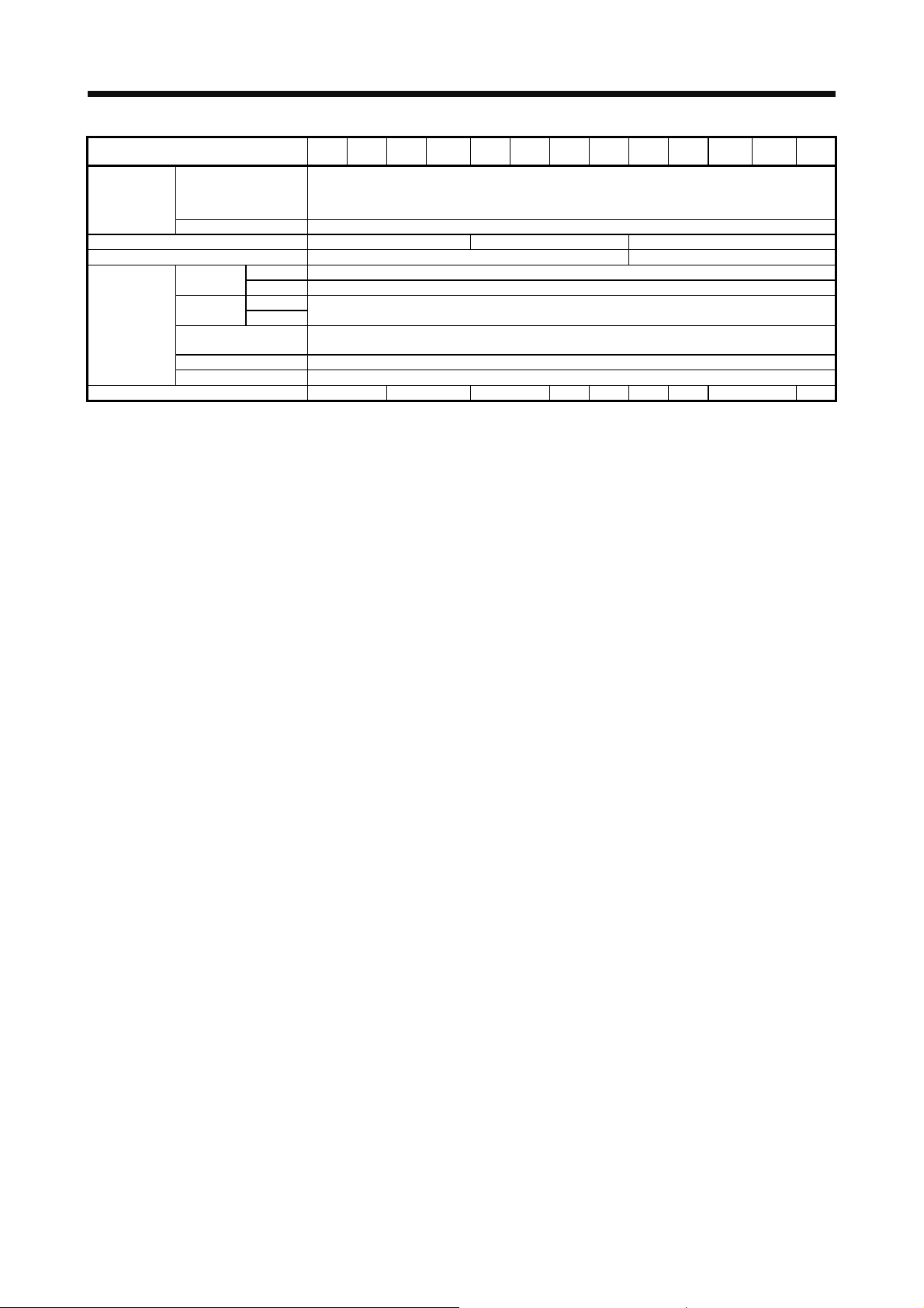
1. FUNCTIONS AND CONFIGURATION
10A
20A
40A
60A
70A
100A
200A
350A
500A
700A
11KA
15KA
Model: MR-J4-
Compliance to
global
standards
Structure (IP rating) Natural cooling, open (IP20) Force cooling, open (IP20) Force cooling, open (IP20) (Note 4)
Close mounting (Note 2) Possible Impossible
Environment
Mass [kg] 0.8 1.0 1.4 2.1 2.3 4.0 6.2 13.4 18.2
CE marking
UL standard UL 508C
Ambient
temperature
Ambient
humidity
Ambience
Altitude 1000 m or less above sea level
Vibration resistance 5.9 m/s2, at 10 Hz to 55 Hz (directions of X, Y and Z axes)
Operation 0 ˚C to 55 ˚C (non-freezing)
Storage -20 ˚C to 65 ˚C (non-freezing)
Operation
Storage
(-RJ)
(-RJ)
(-RJ)
(-RJ)
(-RJ)
(-RJ)
(-RJ)
(-RJ)
(-RJ)
LVD: EN 61800-5-1
EMC: EN 61800-3
MD: EN ISO 13849-1, EN 61800-5-2, EN 62061
90 %RH or less (non-condensing)
free from corrosive gas, flammable gas, oil mist, dust, and dirt
Indoors (no direct sunlight),
(-RJ)
(-RJ)
Note 1. 0.5 A is the value applicable when all I/O signals are used. The current capacity can be decreased by reducing the number of
I/O points.
2. When closely mounting the servo amplifier of 3.5 kW or less, operate them at the ambient temperatures of 0 ˚C to 45 ˚C or at
75% or smaller effective load ratio.
3. Test pulse is a signal which instantaneously turns off a signal to the servo amplifier at a constant period for external circuit to
self-diagnose.
4. Except for the terminal block.
5. The rated current is 2.9 A when the servo amplifier is used with a UL or CSA compliant servo motor.
6. 1 Mpps or lower commands are supported in the initial setting. When inputting commands over 1 Mpulse/s and 4 Mpulses/s or
lower, change the setting in [Pr. PA13].
7. RS-422 communication is supported by servo amplifier with software version A3.
8. Use an external dynamic brake for this servo amplifier. Failure to do so will cause an accident because the servo motor does
not stop immediately but coasts at emergency stop. Ensure the safety in the entire equipment.
9. For the compatible version for the fully closed loop system, refer to table 1.1. Check the software version of the servo amplifier
using MR Configurator2.
10. The MR-J4-_A servo amplifier is compatible only with the two-wire type.
The MR-J4-_A-RJ servo amplifier is compatible with the two-wire type, four-wire type, and A/B/Z-phase differential output type.
Refer to table 1.1 for details.
(-RJ)
22KA
(-RJ)
1 - 10
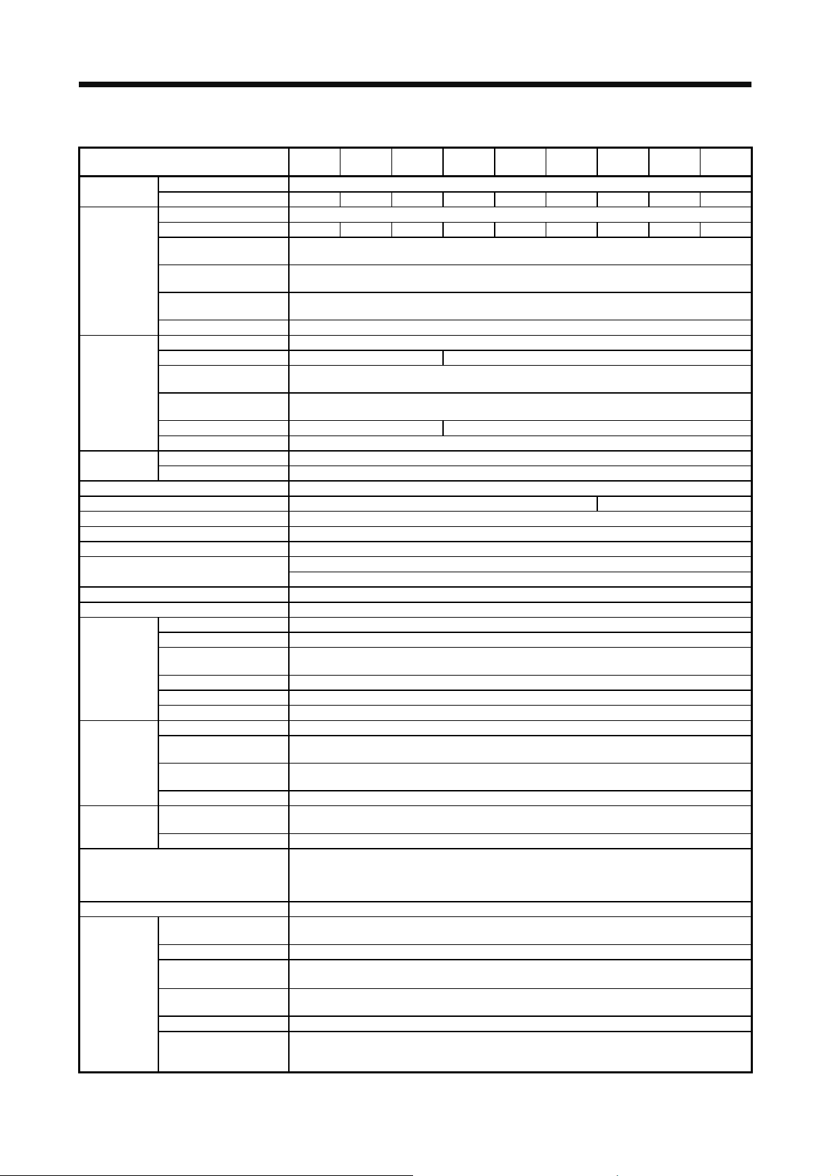
1. FUNCTIONS AND CONFIGURATION
(2) 400 V class
Model: MR-J4-
Output
Main circuit
power supply
input
Voltage/Frequency 1-phase 380 V AC to 480 V AC, 50 Hz/60 Hz
Rated current [A] 0.1 0.2
Control circuit
power supply
input
Power consumption [W] 30 45
Inrush current [A] Refer to section 10.5.
Interface power
supply
Control method Sine-wave PWM control, current control method
Dynamic brake Built-in External option (Note 6)
Fully closed loop control Compatible
Scale measurement function Not compatible
Load-side encoder interface (Note 5) Mitsubishi high-speed serial communication
Communication function
Encoder output pulses Compatible (A/B/Z-phase pulse)
Analog monitor Two channels
Position control
mode
Speed control
mode
Torque control
mode
Protective functions
Functional safety STO (IEC/EN 61800-5-2)
Standards certified by CB
Response performance 8 ms or less (STO input off → energy shut off)
Safety
performance
Rated voltage 3-phase 323 V AC
Rated current [A] 1.5 2.8 5.4 8.6 14.0 17.0 32.0 41.0 63.0
Voltage/Frequency 3-phase 380 V AC to 480 V AC, 50 Hz/60 Hz
Rated current [A] 1.4 2.5 5.1 7.9 10.8 14.4 23.1 31.8 47.6
Permissible voltage
fluctuation
Permissible frequency
fluctuation
Power supply
capacity
Inrush current [A] Refer to section 10.5.
Permissible voltage
fluctuation
Permissible frequency
fluctuation
Voltage 24 V DC ± 10%
Current capacity [A] (Note 1) 0.5 (including CN8 connector signals)
Max. input pulse frequency 4 Mpulses/s (for differential receiver) (Note 4), 200 kpulses/s (for open collector)
Positioning feedback pulse Encoder resolution (resolution per servo motor revolution): 22 bits
Command pulse multiplying
factor
In-position range setting 0 pulse to ±65535 pulses (command pulse unit)
Error excessive ±3 revolutions
Torque limit Set by parameter setting or external analog input (0 V DC to +10 V DC/maximum torque)
Speed control range Analog speed command 1: 2000, internal speed command 1: 5000
Analog speed command
input
Speed fluctuation ratio
Torque limit Set by parameter setting or external analog input (0 V DC to +10 V DC/maximum torque)
Analog torque command
input
Speed limit Set by parameter setting or external analog input (0 V DC to 10 V DC/rated speed)
(Note 2)
Test pulse input (STO)
Mean time to dangerous
failure (MTTFd)
Diagnosis coverage (DC) Medium (90% to 99%)
Average probability of
dangerous failures per hour
(PFH)
[kVA] Refer to section 10.2.
USB: connection to a personal computer or others (MR Configurator2-compatible)
RS-422: 1 : n communication (up to 32 axes)
60A4
(-RJ)
±0.01% or less (load fluctuation 0 % to 100%), 0% (power fluctuation ±10%), ±0.2% or less (ambient
Overcurrent shut-off, regenerative overvoltage shut-off, overload shut-off (electronic thermal), servo
protection, instantaneous power failure protection, overspeed protection, error excessive protection,
100A4
(-RJ)
3-phase 323 V AC to 528 V AC
Within ±5%
1-phase 323 V AC to 528 V AC
Within ±5%
0 to ±10 V DC/rated speed (The speed at 10 V is changeable with [Pr. PC12].)
motor overheat protection, encoder error protection, regenerative error protection, undervoltage
magnetic pole detection protection, and linear servo control fault protection
100 years or longer
1.68 × 10
200A4
(-RJ)
Electronic gear A:1 to 16777215, B:1 to 16777215, 1/10 < A/B < 4000
temperature 25 ± 10 °C) when using analog speed command
0 V DC to ±8 V DC/maximum torque (input impedance 10 kΩ to 12 kΩ )
EN ISO 13849-1 category 3 PL d, IEC 61508 SIL 2, EN 62061 SIL CL 2,
350A4
(-RJ)
Test pulse interval: 1 Hz to 25 Hz
Test pulse off time: Up to 1 ms
500A4
(-RJ)
and EN 61800-5-2 SIL 2
700A4
(-RJ)
-10
[1/h]
11KA4
(-RJ)
15KA4
(-RJ)
22KA4
(-RJ)
1 - 11
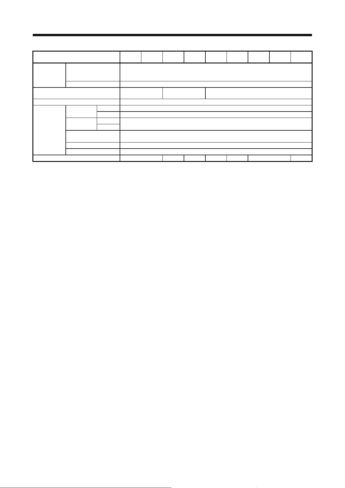
1. FUNCTIONS AND CONFIGURATION
Model: MR-J4-
Compliance to
standards
Structure (IP rating)
Close mounting Impossible
Operation 0 ˚C to 55 ˚C (non-freezing)
Environment
Altitude 1000 m or less above sea level
Vibration resistance 5.9 m/s2, at 10 Hz to 55 Hz (directions of X, Y and Z axes)
Mass [kg] 1.7 2.1 3.6 4.3 6.5 13.4 18.2
CE marking
UL standard UL 508C
Ambient
temperature
Ambient
humidity
Ambience
Storage -20 ˚C to 65 ˚C (non-freezing)
Operation
Storage
60A4
(-RJ)
Natural cooling, open
Note 1. 0.5 A is the value applicable when all I/O signals are used. The current capacity can be decreased by reducing the number of
I/O points.
2. Test pulse is a signal which instantaneously turns off a signal to the servo amplifier at a constant period for external circuit to
self-diagnose.
3. Except for the terminal block.
4. 1 Mpulse/s or lower commands are supported in the initial setting. When inputting commands over 1 Mpulse/s and 4
Mpulses/s or lower, change the setting in [Pr. PA13].
5. MR-J4-_A4 servo amplifier is compatible only with two-wire type. MR-J4-_A4-RJ servo amplifier is compatible with two-wire
type, four-wire type, and A/B/Z-phase differential output type. Refer to table 1.1 for details.
6. Use an external dynamic brake for this servo amplifier. Failure to do so will cause an accident because the servo motor does
not stop immediately but coasts at emergency stop. Ensure the safety in the entire equipment.
100A4
(-RJ)
(IP20)
90 %RH or less (non-condensing)
200A4
(-RJ)
Force cooling, open
free from corrosive gas, flammable gas, oil mist, dust, and dirt
350A4
(-RJ)
MD: EN ISO 13849-1, EN 61800-5-2, EN 62061
(IP20)
Indoors (no direct sunlight),
500A4
(-RJ)
LVD: EN 61800-5-1
EMC: EN 61800-3
Force cooling, open (IP20) (Note 3)
700A4
(-RJ)
11KA4
(-RJ)
15KA4
(-RJ)
22KA4
(-RJ)
1 - 12
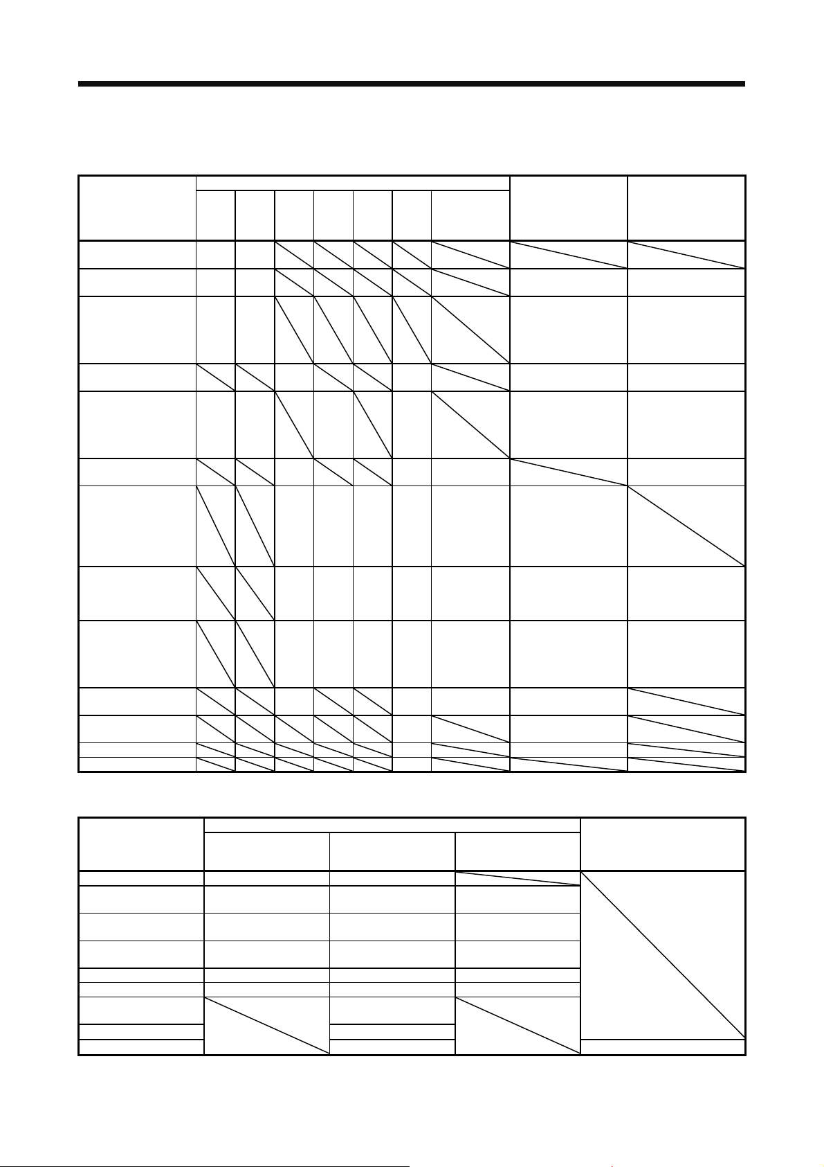
1. FUNCTIONS AND CONFIGURATION
1.4 Combinations of servo amplifiers and servo motors
(1) 200 V class
Servo amplifier
MR-J4-10A(-RJ) 053
MR-J4-20A(-RJ)
MR-J4-40A(-RJ)
MR-J4-60A(-RJ)
MR-J4-70A(-RJ)
MR-J4-100A(-RJ)
MR-J4-200A(-RJ)
MR-J4-350A(-RJ)
MR-J4-500A(-RJ)
MR-J4-700A(-RJ)
MR-J4-11KA(-RJ)
MR-J4-15KA(-RJ) 15K1M LM-FP4F-48M-1SS0
MR-J4-22KA(-RJ) 22K1M
(2) 400 V class
Servo amplifier
MR-J4-60A4(-RJ) 524 534
MR-J4-100A4(-RJ) 1024
MR-J4-200A4(-RJ)
MR-J4-350A4(-RJ) 3524 3534
MR-J4-500A4(-RJ) 5024 5034 3534
MR-J4-700A4(-RJ) 7024 7034 5034
MR-J4-11KA4(-RJ)
MR-J4-15KA4(-RJ) 15K1M4
MR-J4-22KA4(-RJ)
Rotary servo motor
HG-JR
HG-KR HG-MR HG-SR HG-UR HG-RR HG-JR
053
13
13
23 23
43 43
73 73 72 73
702 703 503
HG-SR HG-JR
51
52
81
102
121
201
152
202
301
352
421
502
Rotary servo motor
1524
2024
53
103 53
103
152
202 203 353
352
502
153
153
203
353
503 353
503
903
11K1M
734
1034
1534
2034
9034
11K1M4
22K1M4
(When the
maximum
torque is 400%)
73
103
153
203
(When the maximum
Linear servo motor
(primary side)
LM-U2PAB-05M-0SS0
LM-U2PBB-07M-1SS0
LM-H3P2A-07P-BSS0
LM-H3P3A-12P-CSS0
LM-K2P1A-01M-2SS1
LM-U2PAD-10M-0SS0
LM-U2PAF-15M-0SS0
LM-U2PBD-15M-1SS0 TM-RFM006C20
LM-H3P3B-24P-CSS0
LM-H3P3C-36P-CSS0
LM-H3P7A-24P-ASS0
LM-K2P2A-02M-1SS1
LM-U2PBF-22M-1SS0
TM-RFM018E20
LM-H3P3D-48P-CSS0
LM-H3P7B-48P-ASS0
LM-H3P7C-72P-ASS0
LM-FP2B-06M-1SS0
LM-K2P1C-03M-2SS1
LM-U2P2B-40M-2SS0
LM-H3P7D-96P-ASS0
LM-K2P2C-07M-1SS1
LM-K2P3C-14M-1SS1
LM-U2P2C-60M-2SS0
LM-FP2D-12M-1SS0
LM-FP4B-12M-1SS0
LM-K2P2E-12M-1SS1
LM-K2P3E-24M-1SS1
LM-U2P2D-80M-2SS0
LM-FP2F-18M-1SS0
LM-FP4D-24M-1SS0
LM-FP4F-36M-1SS0
HG-JR
torque is 400%)
534
734
1034
1534
2034
LM-FP5H-60M-1SS0
TM-RFM002C20
TM-RFM004C20
TM-RFM006E20
TM-RFM012E20
TM-RFM012G20
TM-RFM040J10
TM-RFM048G20
TM-RFM072G20
TM-RFM120J10
TM-RFM240J10
Linear servo motor (primary side)
Direct
drive motor
1 - 13

1. FUNCTIONS AND CONFIGURATION
1.5 Function list
The following table lists the functions of this servo. For details of the functions, refer to each section
indicated in the detailed explanation field.
Function Description
Position control mode This servo is used as a position control servo.
Speed control mode This servo is used as a speed control servo.
Torque control mode This servo is used as a torque control servo.
Position/speed control
change mode
Speed/torque control change
mode
Torque/position control
change mode
High-resolution encoder
Absolute position detection
system
Gain switching function
Advanced vibration
suppression control II
Machine resonance
suppression filter
Shaft resonance suppression
filter
Adaptive filter II
Low-pass filter
Machine analyzer function
Robust filter
Slight vibration suppression
control
Electronic gear Input pulses can be multiplied by 1/10 to 4000.
S-pattern
acceleration/deceleration time
constant
Auto tuning
Brake unit
Power regeneration converter
Regenerative option
Alarm history clear Alarm history is cleared. [Pr. PC18]
Input signal selection (device
settings)
Using an input device, control can be switched between position control and speed
control.
Using an input device, control can be switched between speed control and torque
control.
Using an input device, control can be switched between torque control and position
control.
High-resolution encoder of 4194304 pulses/rev is used as the encoder of the rotary
servo motor compatible with the MELSERVO-J4 series.
Merely setting a home position once makes home position return unnecessary at
every power-on.
You can switch gains during rotation and during stop, and can use an input device to
switch gains during operation.
This function suppresses vibration at the arm end or residual vibration. Section 7.1.5
This is a filter function (notch filter) which decreases the gain of the specific frequency
to suppress the resonance of the mechanical system.
When a load is mounted to the servo motor shaft, resonance by shaft torsion during
driving may generate a mechanical vibration at high frequency. The shaft resonance
suppression filter suppresses the vibration.
Servo amplifier detects mechanical resonance and sets filter characteristics
automatically to suppress mechanical vibration.
Suppresses high-frequency resonance which occurs as servo system response is
increased.
Analyzes the frequency characteristic of the mechanical system by simply connecting
an MR Configurator2 installed personal computer and servo amplifier.
MR Configurator2 is necessary for this function.
This function provides better disturbance response in case low response level that
load to motor inertia ratio is high for such as roll send axes.
Suppresses vibration of ±1 pulse produced at a servo motor stop. [Pr. PB24]
Speed can be increased and decreased smoothly. [Pr. PC03]
Automatically adjusts the gain to optimum value if load applied to the servo motor
shaft varies.
Used when the regenerative option cannot provide enough regenerative power.
Can be used for the 5 kW or more servo amplifier.
Used when the regenerative option cannot provide enough regenerative power.
Can be used for the 5 kW or more servo amplifier.
Used when the built-in regenerative resistor of the servo amplifier does not have
sufficient regenerative capability for the large regenerative power generated.
ST1 (Forward rotation start), ST2 (Reverse rotation start), and SON (Servo-on) and
other input device can be assigned to any pins.
Detailed
explanation
Section 3.2.1
Section 3.6.1
Section 4.2
Section 3.2.2
Section 3.6.2
Section 4.3
Section 3.2.3
Section 3.6.3
Section 4.4
Section 3.6.4
Section 3.6.5
Section 3.6.6
Chapter 12
Section 7.2
Section 7.1.1
Section 7.1.3
Section 7.1.2
Section 7.1.4
[Pr. PE41]
[Pr. PA06]
[Pr. PA07]
Section 6.3
Section 11.3
Section 11.4
Section 11.2
[Pr. PD03] to
[Pr. PD22]
1 - 14

1. FUNCTIONS AND CONFIGURATION
Function Description
Output signal selection
(device settings)
Output signal (DO) forced
output
Restart after instantaneous
power failure
Command pulse selection Command pulse train form can be selected from among three different types. [Pr. PA13]
Torque limit Servo motor torque can be limited to any value.
Speed limit Servo motor speed can be limited to any value.
Status display Servo status is shown on the 5-digit, 7-segment LED display Section 4.5
External I/O signal display On/off statuses of external I/O signals are shown on the display. Section 4.5.7
Automatic VC offset
Alarm code output If an alarm has occurred, the corresponding alarm number is outputted in 3-bit code. Chapter 8
Test operation mode
Analog monitor output Servo status is output in terms of voltage in real time.
MR Configurator2
Linear servo system
Direct drive
servo system
Fully closed loop system
One-touch tuning
Tough drive function
Drive recorder function
STO function
Servo amplifier life diagnosis
function
Power monitoring function
Machine diagnosis function
The output devices including MBR (Electromagnetic brake interlock) can be assigned
to certain pins of the CN1 connector.
Output signal can be forced on/off independently of the servo status.
Use this function for checking output signal wiring, etc.
If the input power supply voltage had reduced to cause an alarm but has returned to
normal, the servo motor can be restarted by merely switching on the start signal.
(available in the future)
Voltage is automatically offset to stop the servo motor if it does not come to a stop
when VC (Analog speed command) or VLA (Analog speed limit is 0 V.
Jog operation, positioning operation, motor-less operation, DO forced output, and
program operation
MR Configurator2 is required to perform positioning operation or program operation.
Using a personal computer, you can perform the parameter setting, test operation,
monitoring, and others.
Linear servo system can be configured using a linear servo motor and liner encoder.
This is used with servo amplifiers with software version A5 or later. Check the
software version of the servo amplifier using MR Configurator2.
The direct drive servo system can be configured to drive a direct drive motor.
This is used with servo amplifiers with software version A5 or later. Check the
software version of the servo amplifier using MR Configurator2.
Fully closed loop system can be configured using the load-side encoder.
This is used with servo amplifiers with software version A5 or later. Check the
software version of the servo amplifier using MR Configurator2.
Gain adjustment is performed just by one click on a certain button on MR
Configurator2 or operation section.
This function makes the equipment continue operating even under the condition that
an alarm occurs.
The tough drive function includes two types: the vibration tough drive and the
instantaneous power failure tough drive.
This function continuously monitors the servo status and records the status transition
before and after an alarm for a fixed period of time. You can check the recorded data
on the drive recorder window on MR Configurator2 by clicking the "Graph" button.
However, the drive recorder will not operate on the following conditions.
1. You are using the graph function of MR Configurator2.
2. You are using the machine analyzer function.
3. [Pr. PF21] is set to "-1".
This function is a functional safety that complies with IEC/EN 61800-5-2. You can
create a safety system for the equipment easily.
You can check the cumulative energization time and the number of on/off times of the
inrush relay. This function gives an indication of the replacement time for parts of the
servo amplifier including a capacitor and a relay before they malfunction.
MR Configurator2 is necessary for this function.
This function calculates the power running energy and the regenerative power from
the data in the servo amplifier such as speed and current. Power consumption and
others are displayed on MR Configurator2.
From the data in the servo amplifier, this function estimates the friction and vibrational
component of the drive system in the equipment and recognizes an error in the
machine parts, including a ball screw and bearing.
MR Configurator2 is necessary for this function.
Detailed
explanation
[Pr. PD23] to
[Pr. PD28]
Section 4.5.8
Section 3.6.1
(5)
[Pr. PA11]
[Pr. PA12]
Section 3.6.3
(3)
[Pr. PC05] to
[Pr. PC11]
Section 4.5.4
Section 4.5.9
[Pr. PC14],
[Pr. PC15]
Section 11.7
Chapter 15
Chapter 16
Chapter 17
Section 6.1
Section 7.3
[Pr. PA23]
Chapter 13
1 - 15

1. FUNCTIONS AND CONFIGURATION
1.6 Model designation
(1) Rating plate
The following shows an example of rating plate for explanation of each item.
AC SERVO
MODEL
POWER
INPUT
OUTPUT
STD.: IEC/EN61800-5-1 MAN.: IB(NA)0300175
Max. Surrounding Air Temp.: 55°C
IP20
TOKYO 100-8310, JAPAN MADE IN JAPAN
MR-J4-10A
: 100W
: 3AC/AC200-240V 0.9A/1.5A 50/60Hz
: 3PH170V 0-360Hz 1.1A
SER.S21001001
(2) Model
The following describes what each block of a model name indicates. Not all combinations of the symbols
are available.
Serial number
Model
Capacity
Applicable power supply
Rated output current
Standard, Manual number
Ambient temperature
IP rating
KC certification number, the year
and month of manufacture
Country of origin
Series
Rated output
Rated output [kW]
Symbol
10 0.1
20 0.2
40 0.4
60 0.6
70 0.75
100 1
200 2
350 3.5
500 5
700 7
11K 11
15K 15
22K 22
Special specification
Symbol
None
-RJ
-PX
-RZ
Note. Indicates a servo amplifier of 11 kW to 22 kW that
does not use a regenerative resistor as standard
accessory.
Power supply
Symbol Power supply
None
4
General-purpose interface
Fully closed loop control four-wire type/
load-side encoder A/B/Z-phase input compatible
MR-J4-_A_-RJ without regenerative resistor (Note)
200 V AC to 240 V AC
3-phase 380 V AC to 480 V AC
Special specification
Standard
Without regenerative resistor (Note)
3-phase or 1-phase
1 - 16

1. FUNCTIONS AND CONFIGURATION
1.7 Structure
1.7.1 Parts identification
(1) 200 V class
(a) MR-J4-200A(-RJ) or less
No. Name/Application
Display
(1)
(1)
(2)
MODE UP DOWN SET
Inside of the display cover
(18)
(3)
(4)
(12)
(5)
(6)
(14)
(7)
(15)
(8)
(16)
(17)
(9)
(13)
Side
(10) (11)
The 5-digit, 7-segment LED shows the servo status and the
alarm number.
Operation section
Used to perform status display, diagnostic, alarm, and
parameter setting operations. Push the "MODE" and "SET"
buttons at the same time for 3 s or more to switch to the
one-touch tuning mode.
(2)
USB communication connector (CN5)
(3)
Connect with the personal computer.
Analog monitor connector (CN6)
(4)
Outputs the analog monitor.
RS-422 communication connector (CN3)
(5)
Connect with the personal computer, etc.
STO input signal connector (CN8)
(6)
Used to connect the MR-J3-D05 safety logic unit and
external safety relay.
I/O signal connector (CN1)
(7)
Used to connect digital I/O signals.
Encoder connector (CN2)
Used to connect the servo motor encoder or external
(8)
encoder. Refer to table 1.1 for the compatible external
(Note
encoders.
2)
Battery connector (CN4)
(9)
Used to connect the battery for absolute position data
backup.
Battery holder
(10)
Install the the battery for absolute position data backup.
Protective earth (PE) terminal
(11)
Grounding terminal
Main circuit power supply connector (CNP1)
(12)
Connect the input power supply.
(13) Rating plate Section 1.6
Control circuit power supply connector (CNP2)
(14)
Connect the control circuit power supply and regenerative
option.
Servo motor power output connector (CNP3)
(15)
Connect the servo motor.
Charge lamp
(16)
When the main circuit is charged, this will light up. While
this lamp is lit, do not reconnect the cables.
External encoder connector (CN2L)
(17)
Refer to table 1.1 for the compatible external encoders.
(Note
1, 2)
Manufacturer setting connector (CN7)
This connector is attached on the MR-J4-_A-RJ servo
(18)
amplifier, but not for use. The MR-J4-_A servo amplifier
does not have this connector.
Note 1. This is for the MR-J4-_A-RJ servo amplifier. The MR-J4-_A servo
2. "External encoder" is a term for linear encoder used in the linear servo
Detailed
explanation
Section 4.5
MODE UP DOWN SET
Used to set data.
Push this button
together with the "MODE"
button for 3 s or more
to switch to the
one-touch tuning mode.
Used to change the
display or data in each
mode.
Used to change the mode.
Push this button
together with the "SET"
button for 3 s or more
to switch to the
one-touch tuning mode.
amplifier does not have the CN2L connector.
system and load-side encoder used in the fully closed loop system in this
manual.
Section 4.5
Section
11.7
Section 3.2
Chapter 14
Chapter 13
App. 5
Section 3.2
Section 3.4
Section 3.4
"Servo
Motor
Instruction
Manual
(Vol. 3)"
Chapter 12
Section
12.2
Section 3.1
Section 3.3
Section 3.1
Section 3.3
"Linear
Encoder
Instruction
Manual"
1 - 17

1. FUNCTIONS AND CONFIGURATION
(b) MR-J4-350A(-RJ)
No. Name/Application
Main circuit power supply connector (CNP1)
(1)
Connect the input power supply.
(2) Rating plate
Servo motor power supply connector (CNP3)
(3)
Connect the servo motor.
Control circuit power supply connector (CNP2)
(4)
Connect the control circuit power supply and
regenerative option.
Charge lamp
(5)
When the main circuit is charged, this will light up.
While this lamp is lit, do not reconnect the cables.
Protective earth (PE) terminal
(6)
Grounding terminal
Battery holder
(7)
Install the the battery for absolute position data
backup.
(1)
(3)
(2)
Side
(4)
(5)
The broken line area is the same as
MR-J4-200A(-RJ) or less.
(6)
(7)
Detailed
explanation
Section 3.1
Section 3.3
Section 1.6
Section 3.1
Section 3.3
Section 3.1
Section 3.3
Section
12.2
1 - 18

1. FUNCTIONS AND CONFIGURATION
(c) MR-J4-500A(-RJ)
No. Name/Application
Control circuit terminal block (TE2)
(1)
Used to connect the control circuit power supply.
Main circuit terminal block (TE1)
(2)
Connect the input power supply.
Battery holder
(3)
Install the the battery for absolute position data
backup.
(4) Rating plate
Regenerative option/power factor improving reactor
terminal block (TE3)
(5)
Used to connect a regenerative option or a power
factor improving DC reactor.
Servo motor power supply terminal block (TE4)
(6)
Connect the servo motor.
Charge lamp
(7)
When the main circuit is charged, this will light up.
While this lamp is lit, do not reconnect the cables.
Protective earth (PE) terminal
(8)
Grounding terminal
(1)
(2)
(3)
(Note)
(4)
Side
(5)
POINT
The servo amplifier is shown with the front cover open. The front cover cannot
be removed.
The broken line area is the same as
MR-J4-200A(-RJ) or less.
Detailed
explanation
Section 3.1
Section 3.3
Section
12.2
Section 1.6
Section 3.1
Section 3.3
Section 3.1
Section 3.3
(6)
(7)
(8)
Note. Lines for slots around the battery holder are omitted from the illustration.
1 - 19

1. FUNCTIONS AND CONFIGURATION
(d) MR-J4-700A(-RJ)
No. Name/Application
Power factor improving reactor terminal block (TE3)
(1)
Used to connect the DC reactor.
Main circuit terminal block (TE1)
(2)
Used to connect the input power supply,
regenerative option, and servo motor.
Control circuit terminal block (TE2)
(3)
Used to connect the control circuit power supply.
Protective earth (PE) terminal
(4)
Grounding terminal
Battery holder
(5)
Install the the battery for absolute position data
backup.
(6) Rating plate
Charge lamp
(7)
When the main circuit is charged, this will light up.
While this lamp is lit, do not reconnect the cables.
(7)
(6)
(5)
(Note)
POINT
The servo amplifier is shown without the front cover. For removal of the front
cover, refer to section 1.7.2.
The broken line area is the same as
MR-J4-200A(-RJ) or less.
Detailed
explanation
Section 3.1
Section 3.3
Section
12.2
Section 1.6
(1)
(2)
(4)
(3)
Note. Lines for slots around the battery holder are omitted from the illustration.
1 - 20

1. FUNCTIONS AND CONFIGURATION
(e) MR-J4-11KA(-RJ)/MR-J4-15KA(-RJ)
No. Name/Application
Power factor improving reactor terminal block (TE1-
2)
(1)
Used to connect a power factor improving DC
reactor and a regenerative option.
Main circuit terminal block (TE1-1)
(2)
Used to connect the input power supply and servo
motor.
Control circuit terminal block (TE2)
(3)
Used to connect the control circuit power supply.
Protective earth (PE) terminal
(4)
Grounding terminal
Battery holder
(5)
Install the the battery for absolute position data
backup.
(6) Rating plate
Charge lamp
(7)
When the main circuit is charged, this will light up.
While this lamp is lit, do not reconnect the cables.
(7)
(6)
(5)
(Note)
(2)
(3)
POINT
The servo amplifier is shown without the front cover. For removal of the front
cover, refer to section 1.7.2.
The broken line area is the same as
MR-J4-200A(-RJ) or less.
Detailed
explanation
Section 3.1
Section 3.3
Section
12.2
Section 1.6
(4)
(1)
Note. Lines for slots around the battery holder are omitted from the illustration.
1 - 21

1. FUNCTIONS AND CONFIGURATION
(f) MR-J4-22KA(-RJ)
No. Name/Application
Power factor improving reactor terminal block (TE1-
2)
(1)
Used to connect a power factor improving DC
reactor and a regenerative option.
Main circuit terminal block (TE1-1)
(2)
Used to connect the input power supply and servo
motor.
Control circuit terminal block (TE2)
(3)
Used to connect the control circuit power supply.
Protective earth (PE) terminal
(4)
Grounding terminal
Battery holder
(5)
Install the the battery for absolute position data
backup.
(6) Rating plate
Charge lamp
(7)
When the main circuit is charged, this will light up.
While this lamp is lit, do not reconnect the cables.
(7)
(5)
(Note)
(6)
(2)
(3)
POINT
The servo amplifier is shown without the front cover. For removal of the front
cover, refer to section 1.7.2.
The broken line area is the same as
MR-J4-200A(-RJ) or less.
Detailed
explanation
Section 3.1
Section 3.3
Section
12.2
Section 1.6
(1)
(4)
Note. Lines for slots around the battery holder are omitted from the illustration.
1 - 22

1. FUNCTIONS AND CONFIGURATION
_
(2) 400 V class
(a) For MR-J4-200A4(-RJ) or less
The diagram is for MR-J4-60A4-RJ.
No. Name/Application
(3)
(16)
(4)
(12)
(5)
(6)
(14)
(7)
(8)
(15)
(17)
(9)
(13)
Side
(1)
(2)
MODE UP DOWN SET
(10)
Inside of the display cover
(18)
(11)
(1)
(2)
(3)
(4)
(5)
(6)
(7)
(8)
(Note
2)
(9)
(10)
(11)
(12)
(13) Rating plate Section 1.6
(14)
(15)
(16)
(17)
(Note
1)
(18)
Display
The 5-digit, seven-segment LED shows the servo
status and the alarm number.
Operation section
Used to perform status display, diagnostic, alarm,
and parameter setting operations. Push the
"MODE" and "SET" buttons at the same time for 3 s
or more to switch to the one-touch tuning mode.
MODE UP DOWN SET
Used to set data. Push
this button together with
the "MODE" button for
3 s or more to switch to
the one-touch tuning
mode.
Used to change the
display or data in each
mode.
Used to change the
mode. Push this button
together wish the "SET"
button for 3 s or more to
switch to the one-touch
tuning mode.
USB communication connector (CN5)
Connect with the personal computer.
Analog monitor connector (CN6)
Outputs the analog monitor.
RS-422 communication connector (CN3)
Connect with the personal computer, etc.
STO input signal connector (CN8)
Used to connect MR-J3-D05 safety logic unit and
external safety relay.
I/O signal connector (CN1)
Used to connect digital I/O signals.
Encoder connector (CN2)
Used to connect the servo motor encoder or
external encoder. Refer to table 1.1 for the
compatible external encoders.
Battery connector (CN4)
Used to connect the battery for absolute position
data backup.
Battery holder
Install the battery for absolute position data backup.
Protective earth (PE) terminal
Grounding terminal
Main circuit power supply connector (CNP1)
Connect the input power supply.
Control circuit power supply connector (CNP2)
Connect the control circuit power supply and
regenerative option.
Servo motor power output connector (CNP3)
Connect the servo motor.
Charge lamp
When the main circuit is charged, this will light.
While this lamp is lit, do not reconnect the cables.
External encoder connector (CN2L)
Used to connect the external encoder. Refer to
table 1.1 for the compatible external encoders.
Manufacturer setting connector (CN2L)
This connector is attached on MR-J4-_A4-RJ servo
amplifier, but not for use. MR-J4does not have this connector.
A4 servo amplifier
Detailed
explanation
Section 4.5
Section
11.7
Section 3.2
Chapter 14
Chapter 13
App. 5
Section 3.2
Section 3.4
Section 3.4
"Servo
Motor
Instruction
Manual
(Vol. 3)"
Chapter 12
Section
12.2
Section 3.1
Section 3.3
Section 3.1
Section 3.3
"Linear
Encoder
Instruction
Manual"
1 - 23

1. FUNCTIONS AND CONFIGURATION
Note 1. This is for MR-J4-_A4-RJ servo amplifier. MR-J4-_A4 servo
2. "External encoder" is a term for linear encoder used in the linear
(b) MR-J4-350A4(-RJ)
The broken line area is the same as
MR-J4-200A4(-RJ) or less.
(1)
(7)
(3)
(2)
Side
(4)
(5)
No. Name/Application
(1)
(2) Rating plate Section 1.6
(3)
(4)
(5)
(6)
(7)
amplifier does not have CN2L connector.
servo system and load-side encoder used in the fully closed
loop system in this manual.
Detailed
explanation
Main circuit power supply connector (CNP1)
Connect the input power supply.
Control circuit power supply connector (CNP2)
Connect the control circuit power supply and
regenerative option.
Servo motor power output connector (CNP3)
Connect the servo motor.
Charge lamp
When the main circuit is charged, this will light.
While this lamp is lit, do not reconnect the cables.
Protective earth (PE) terminal
Grounding terminal
Battery holder
Install the battery for absolute position data
backup.
Section 3.1
Section 3.3
Section 3.1
Section 3.3
Section 3.1
Section 3.3
Section 12.2
(6)
1 - 24

1. FUNCTIONS AND CONFIGURATION
(c) MR-J4-500A4(-RJ)
No. Name/Application
(1)
(2)
(3)
(4) Rating plate Section 1.6
(5)
(6)
(7)
(6)
(3)
(Note)
(4)
(5)
(1)
(2)
POINT
The servo amplifier is shown without the front cover. For removal of the front
cover, refer to section 1.7.2.
The broken line area is the same as
MR-J4-200A4(-RJ) or less.
Control circuit terminal block (TE2)
Used to connect the control circuit power supply.
Main circuit terminal block (TE1)
Used to connect the input power supply and servo
motor.
Battery holder
Install the battery for absolute position data
backup.
Regenerative option/power factor improving
reactor terminal block (TE3)
Used to connect a regenerative option and a
power factor improving DC reactor.
Charge lamp
When the main circuit is charged, this will light.
While this lamp is lit, do not reconnect the cables.
Protective earth (PE) terminal
Grounding terminal
Detailed
explanation
Section 3.1
Section 3.3
Section 12.2
Section 3.1
Section 3.3
Section 3.1
Section 3.3
(7)
Note. Lines for slots around the battery holder are omitted from the illustration.
1 - 25

1. FUNCTIONS AND CONFIGURATION
(d) MR-J4-700A4(-RJ)
No. Name/Application
(1)
(2)
(3)
(4)
(5)
(6) Rating plate Section 1.6
(7)
(7)
(6)
(5)
(Note)
(1)
POINT
The servo amplifier is shown without the front cover. For removal of the front
cover, refer to section 1.7.2.
The broken line area is the same as
MR-J4-200A4(-RJ) or less.
Power factor improving reactor terminal block
(TE3)
Used to connect the DC reactor.
Main circuit terminal block (TE1)
Used to connect the input power supply,
regenerative option, and servo motor.
Control circuit terminal block (TE2)
Used to connect the control circuit power supply.
Protective earth (PE) terminal
Grounding terminal
Battery holder
Install the battery for absolute position data
backup.
Charge lamp
When the main circuit is charged, this will light.
While this lamp is lit, do not reconnect the cables.
Detailed
explanation
Section 3.1
Section 3.3
Section 12.2
(2)
(4)
(3)
Note. Lines for slots around the battery holder are omitted from the illustration.
1 - 26

1. FUNCTIONS AND CONFIGURATION
(e) MR-J4-11KA4(-RJ)/MR-J4-15KA4(-RJ)
No. Name/Application
(1)
(2)
(3)
(4)
(5)
(6) Rating plate Section 1.6
(7)
(7)
(6)
(5)
(Note)
(2)
(3)
(4)
POINT
The servo amplifier is shown without the front cover. For removal of the front
cover, refer to section 1.7.2.
The broken line area is the same as
MR-J4-200A4(-RJ) or less.
Power factor improving reactor terminal block
(TE1-2)
Used to connect a power factor improving DC
reactor and a regenerative option.
Main circuit terminal block (TE1-1)
Used to connect the input power supply and servo
motor.
Control circuit terminal block (TE2)
Used to connect the control circuit power supply.
Protective earth (PE) terminal
Grounding terminal
Battery holder
Install the battery for absolute position data
backup.
Charge lamp
When the main circuit is charged, this will light.
While this lamp is lit, do not reconnect the cables.
Detailed
explanation
Section 3.1
Section 3.3
Section 12.2
(1)
Note. Lines for slots around the battery holder are omitted from the illustration.
1 - 27

1. FUNCTIONS AND CONFIGURATION
(f) MR-J4-22KA4(-RJ)
No. Name/Application
(1)
(2)
(3)
(4)
(5)
(6) Rating plate Section 1.6
(7)
(7)
(5)
(Note)
(6)
(2)
(3)
(1)
POINT
The servo amplifier is shown without the front cover. For removal of the front
cover, refer to section 1.7.2.
The broken line area is the same as
MR-J4-200A4(-RJ) or less.
Power factor improving reactor terminal block
(TE1-2)
Used to connect a power factor improving DC
reactor and a regenerative option.
Main circuit terminal block (TE1-1)
Used to connect the input power supply and servo
motor.
Control circuit terminal block (TE2)
Used to connect the control circuit power supply.
Protective earth (PE) terminal
Grounding terminal
Battery holder
Install the battery for absolute position data
backup.
Charge lamp
When the main circuit is charged, this will light.
While this lamp is lit, do not reconnect the cables.
Detailed
explanation
Section 3.1
Section 3.3
Section 12.2
(4)
Note. Lines for slots around the battery holder are omitted from the illustration.
1 - 28

1. FUNCTIONS AND CONFIGURATION
1.7.2 Removal and reinstallation of the front cover
Before removing or installing the front cover, turn off the power and wait for 15
minutes or more until the charge lamp turns off. Then, confirm that the voltage
CAUTION
The following shows how to remove and reinstall the front cover of MR-J4-700A(-RJ) to MR-J4-22KA(-RJ)
and MR-J4-500A4(-RJ) to MR-J4-22KA4(-RJ).
The diagram shows MR-J4-700A.
Removal of the front cover
between P+ and N- is safe with a voltage tester and others. Otherwise, an electric
shock may occur. In addition, when confirming whether the charge lamp is off or
not, always confirm it from the front of the servo amplifier.
1) Hold the ends of lower side of the front cover with
both hands.
A)
A)
2) Pull up the cover, supporting at point A).
3) Pull out the front cover to remove. Hold the ends of
lower side of the front cover with both hands.
1 - 29

1. FUNCTIONS AND CONFIGURATION
Reinstallation of the front cover
Front cover
setting tab
A)
1) Insert the front cover setting tabs into the sockets of
the servo amplifier (2 places).
2) Push down the cover, supporting at point A).
A)
Setting tab
3) Press the cover against the terminal box until the
setting tabs click.
1 - 30

1. FUNCTIONS AND CONFIGURATION
1.8 Configuration including peripheral equipment
CAUTION
(1) 200 V class
(a) MR-J4-200A(-RJ) or less
The diagram shows MR-J4-20A-RJ.
(Note 2)
Power
supply
Molded-case
circuit breaker
(MCCB)
RS T
Connecting a servo motor of the wrong axis to U, V, W, or CN2 of the servo
amplifier may cause a malfunction.
POINT
Equipment other than the servo amplifier and servo motor are optional or
recommended products.
CN5
MR Configurator2
Personal
computer
(Note 3)
Magnetic
contactor
(MC)
Line noise
filter
(FR-BSF01)
Power factor
improving DC
reactor
(FR-HEL)
Regenerative
option
(Note 1)
L1
L2
L3
P+
C
P3
P4
L11
L21
CN6
CN3
Personal computer and other
CN8
U
V
W
CN1
CN2
CN2L (Note 4)
CN4
Battery
Analog monitor
To safety relay or
MR-J3-D05 safety
logic unit
Junction terminal block
Servo motor
1 - 31

1. FUNCTIONS AND CONFIGURATION
_
Note 1. The power factor improving AC reactor can also be used. In this case, the power factor improving DC reactor cannot be used.
When not using the power factor improving DC reactor, short P3 and P4.
2. A 1-phase 200 V AC to 240 V AC power supply may be used with the servo amplifier of MR-J4-70A(-RJ) or less. For 1-phase
200 V AC to 240 V AC, connect the power supply to L1 and L3. Leave L2 open. For the power supply specifications, refer to
section 1.3.
3. Depending on the main circuit voltage and operation pattern, bus voltage decreases, and that may cause the forced stop
deceleration to shift to the dynamic brake deceleration. When dynamic brake deceleration is not required, slow the time to turn
off the magnetic contactor.
4. This is for the MR-J4-_A-RJ servo amplifier. The MR-J4MR-J4-_A-RJ servo amplifier in the linear servo system or in the fully closed loop system, connect an external encoder to this
connector. Refer to table 1.1 and "Linear Encoder Instruction Manual" for the compatible external encoders.
A servo amplifier does not have the CN2L connector. When using an
1 - 32

1. FUNCTIONS AND CONFIGURATION
(b) MR-J4-350A(-RJ)
(Note 2)
Power
supply
Molded-case
circuit breaker
(MCCB)
(Note 3)
Magnetic
contactor
(MC)
Line noise
filter
(FR-BSF01)
RS T
(Note 1)
MR Configurator2
CN5
CN6
CN3
CN8
Analog monitor
Personal computer and other
Personal
computer
To safety relay or
MR-J3-D05 safety
logic unit
Power factor
improving DC
reactor
(FR-HEL)
Regenerative
option
L1
L2
L3
P+
C
P3
P4
L11
L21
U
V
W
CN1
CN2
CN2L (Note 4)
CN4
Servo motor
Battery
Junction terminal block
Note 1. The power factor improving AC reactor can also be used. In this case, the power factor improving DC reactor cannot be used.
When not using the power factor improving DC reactor, short P3 and P4.
2. For the power supply specifications, refer to section 1.3.
3. Depending on the main circuit voltage and operation pattern, bus voltage decreases, and that may cause the forced stop
deceleration to shift to the dynamic brake deceleration. When dynamic brake deceleration is not required, slow the time to turn
off the magnetic contactor.
4. This is for the MR-J4-_A-RJ servo amplifier. The MR-J4-_A servo amplifier does not have the CN2L connector. When using
MR-J4-_A-RJ servo amplifier in the linear servo system or in the fully closed loop system, connect an external encoder to this
connector. Refer to table 1.1 and "Linear Encoder Instruction Manual" for the compatible external encoders.
1 - 33

1. FUNCTIONS AND CONFIGURATION
_
(c) MR-J4-500A(-RJ)
(Note 2)
Power
supply
Molded-case
circuit breaker
(MCCB)
(Note 3)
Magnetic
contactor
(MC)
(Note 1)
Line noise
filter
(FR-BLF)
RS T
L11
L21
MR Configurator2
CN5
CN6
CN3
CN8
Analog monitor
Personal computer and other
Personal
computer
To safety relay or
MR-J3-D05 safety
logic unit
Power factor
improving DC
reactor
(FR-HEL)
Regenerative
option
L1
L2
L3
P+
C
P3
P4
CN1
CN2
CN2L
(Note 4)
U
V
W
CN4
Servo motor
Battery
Junction terminal block
Note 1. The power factor improving AC reactor can also be used. In this case, the power factor improving DC reactor cannot be used.
When not using the power factor improving DC reactor, short P3 and P4.
2. For the power supply specifications, refer to section 1.3.
3. Depending on the main circuit voltage and operation pattern, bus voltage decreases, and that may cause the forced stop
deceleration to shift to the dynamic brake deceleration. When dynamic brake deceleration is not required, slow the time to turn
off the magnetic contactor.
4. This is for the MR-J4-_A-RJ servo amplifier. The MR-J4MR-J4-_A-RJ servo amplifier in the linear servo system or in the fully closed loop system, connect an external encoder to this
connector. Refer to table 1.1 and "Linear Encoder Instruction Manual" for the compatible external encoders.
A servo amplifier does not have the CN2L connector. When using an
1 - 34

1. FUNCTIONS AND CONFIGURATION
_
(d) MR-J4-700A(-RJ)
(Note 2)
Power
supply
Molded-case
circuit breaker
(MCCB)
(Note 3)
Magnetic
contactor
(MC)
(Note 1)
Line noise
filter
(FR-BLF)
RS T
MR Configurator2
CN5
CN6
CN3
CN8
CN1
Analog monitor
Personal computer and other
Personal
computer
To safety relay or
MR-J3-D05 safety
logic unit
Power factor
improving DC
reactor
(FR-HEL)
L3
L2
L1
P3
P4
L21
L11
C
P+
Regenerative
option
CN2
CN2L
(Note 4)
CN4
Battery
WVU
Junction terminal block
Servo motor
Note 1. The power factor improving AC reactor can also be used. In this case, the power factor improving DC reactor cannot be used.
When not using the power factor improving DC reactor, short P3 and P4.
2. For the power supply specifications, refer to section 1.3.
3. Depending on the main circuit voltage and operation pattern, bus voltage decreases, and that may cause the forced stop
deceleration to shift to the dynamic brake deceleration. When dynamic brake deceleration is not required, slow the time to turn
off the magnetic contactor.
4. This is for the MR-J4-_A-RJ servo amplifier. The MR-J4MR-J4-_A-RJ servo amplifier in the linear servo system or in the fully closed loop system, connect an external encoder to this
connector. Refer to table 1.1 and "Linear Encoder Instruction Manual" for the compatible external encoders.
A servo amplifier does not have the CN2L connector. When using an
1 - 35

1. FUNCTIONS AND CONFIGURATION
(e) MR-J4-11KA(-RJ)/MR-J4-15KA(-RJ)
(Note 2)
Power
supply
Molded-case
circuit breaker
(MCCB)
(Note 3)
Magnetic
contactor
(MC)
(Note 1)
Line noise
filter
(FR-BLF)
RS T
L3
L2
L1
L21
L11
MR Configurator2
CN5
CN6
CN3
CN8
CN1
CN2
CN2L
(Note 4)
CN4
Battery
Analog monitor
Personal computer and other
Personal
computer
To safety relay or
MR-J3-D05 safety
logic unit
Junction terminal block
WVU
Power factor
improving DC
reactor
(FR-HEL)
P3
P4
C
P+
Regenerative
option
Servo motor
Note 1. The power factor improving AC reactor can also be used. In this case, the power factor improving DC reactor cannot be used.
When not using the power factor improving DC reactor, short P3 and P4.
2. For the power supply specifications, refer to section 1.3.
3. Depending on the main circuit voltage and operation pattern, bus voltage decreases, and that may cause the forced stop
deceleration to shift to the dynamic brake deceleration. When dynamic brake deceleration is not required, slow the time to turn
off the magnetic contactor.
4. This is for the MR-J4-_A-RJ servo amplifier. The MR-J4-_A servo amplifier does not have the CN2L connector. When using an
MR-J4-_A-RJ servo amplifier in the linear servo system or in the fully closed loop system, connect an external encoder to this
connector. Refer to table 1.1 and "Linear Encoder Instruction Manual" for the compatible external encoders.
1 - 36

1. FUNCTIONS AND CONFIGURATION
_
(f) MR-J4-22KA(-RJ)
(Note 2)
Power
supply
Molded-case
circuit breaker
(MCCB)
(Note 3)
Magnetic
contactor
(MC)
(Note 1)
RS T
MR Configurator2
CN5
CN6
CN3
CN8
CN1
Analog monitor
Personal computer and other
Personal
computer
To safety relay or
MR-J3-D05 safety
logic unit
Line noise
filter
(FR-BLF)
L3
L2
L1
Power factor
improving DC
reactor
(FR-HEL)
P3
P4
L21
L11
C
P+
Regenerative
option
CN2
CN2L
(Note 4)
CN4
Battery
Junction terminal block
VU
W
Servo motor
Note 1. The power factor improving AC reactor can also be used. In this case, the power factor improving DC reactor cannot be used.
When not using the power factor improving DC reactor, short P3 and P4.
2. For the power supply specifications, refer to section 1.3.
3. Depending on the main circuit voltage and operation pattern, bus voltage decreases, and that may cause the forced stop
deceleration to shift to the dynamic brake deceleration. When dynamic brake deceleration is not required, slow the time to turn
off the magnetic contactor.
4. This is for the MR-J4-_A-RJ servo amplifier. The MR-J4MR-J4-_A-RJ servo amplifier in the linear servo system or in the fully closed loop system, connect an external encoder to this
connector. Refer to table 1.1 and "Linear Encoder Instruction Manual" for the compatible external encoders.
A servo amplifier does not have the CN2L connector. When using an
1 - 37

1. FUNCTIONS AND CONFIGURATION
(2) 400 V class
(a) MR-J4-200A4(-RJ) or less
The diagram is for MR-J4-60A4-RJ and MR-J4-100A4-RJ.
(Note 2)
Power supply
Molded-case
circuit breaker
(MCCB)
RST
Personal
computer
MR Configurator2
CN5
(Note 3)
Magnetic
contactor
(MC)
(Note 1)
Line noise filter
(FR-BSF01)
Power factor
improving DC
reactor
(FR-HEL-H)
Regenerative
option
L1
L2
L3
P+
C
P3
P4
L11
L21
CN6
CN3
Personal computer and others
CN8
CN1
U
V
W
CN2
CN2L (Note 4)
CN4
Battery
Analog monitor
To safety relay or
MR-J3-D05 safety
logic unit
Junction terminal block
Servo motor
Note 1. The power factor improving AC reactor can also be used. In this case, the power factor improving DC reactor cannot be used.
When not using the power factor improving DC reactor, short P3 and P4.
2. Refer to section 1.3 for the power supply specification.
3. Depending on the main circuit voltage and operation pattern, bus voltage decreases, and that may cause the forced stop
deceleration to shift to the dynamic brake deceleration. When dynamic brake deceleration is not required, slow the time to turn
off the magnetic contactor.
4. This is for MR-J4-_A4-RJ servo amplifier. MR-J4-_A4 servo amplifier does not have CN2L connector. When using MR-J4-_A4RJ servo amplifier in the linear servo system or in the fully closed loop system, connect an external encoder to this connector.
Refer to Table 1.1 and "Linear Encoder Instruction Manual" for the compatible external encoders.
1 - 38

1. FUNCTIONS AND CONFIGURATION
(b) MR-J4-350A4(-RJ)
RS T
(Note 2)
Power supply
Molded-case
circuit breaker
(MCCB)
(Note 3)
Magnetic
contactor
(MC)
(Note 1)
Line noise filter
(FR-BSF01)
L1
Power factor
improving DC
reactor
(FR-HEL-H)
Regenerative
option
L2
L3
P3
P4
P+
C
L11
U
V
W
MR Configurator2
CN5
CN6
CN3
CN8
CN1
CN2
CN2L (Note 4)
CN4
Analog monitor
Personal computer and others
Battery
Personal
computer
To safety relay or
MR-J3-D05 safety
logic unit
Junction terminal block
L21
Servo motor
Note 1. The power factor improving AC reactor can also be used. In this case, the power factor improving DC reactor cannot be used.
When not using the power factor improving DC reactor, short P3 and P4.
2. Refer to section 1.3 for the power supply specification.
3. Depending on the main circuit voltage and operation pattern, bus voltage decreases, and that may cause the forced stop
deceleration to shift to the dynamic brake deceleration. When dynamic brake deceleration is not required, slow the time to turn
off the magnetic contactor.
4. This is for MR-J4-_A4-RJ servo amplifier. MR-J4-_A4 servo amplifier does not have CN2L connector. When using MR-J4-_A4RJ servo amplifier in the linear servo system or in the fully closed loop system, connect an external encoder to this connector.
Refer to Table 1.1 and "Linear Encoder Instruction Manual" for the compatible external encoders.
1 - 39

1. FUNCTIONS AND CONFIGURATION
(c) MR-J4-500A4(-RJ)
(Note 1)
RS T
Power factor
improving DC
reactor
(FR-HEL-H)
P3
P4
(Note 2)
Power supply
Molded-case
circuit breaker
(MCCB)
(Note 3)
Magnetic
contactor
(MC)
Line noise filter
(FR-BSF01)
MR Configurator2
CN5
CN6
CN3
CN8
CN1
Analog monitor
Personal computer and others
Personal
computer
To safety relay or
MR-J3-D05 safety
logic unit
L3
L2
L1
L21
L11
P+ C
Regenerative
option
WVU
CN2
CN2L (Note 4)
CN4
Battery
Junction terminal block
Servo motor
Note 1. The power factor improving AC reactor can also be used. In this case, the power factor improving DC reactor cannot be used.
When not using the power factor improving DC reactor, short P3 and P4.
2. Refer to section 1.3 for the power supply specification.
3. Depending on the main circuit voltage and operation pattern, bus voltage decreases, and that may cause the forced stop
deceleration to shift to the dynamic brake deceleration. When dynamic brake deceleration is not required, slow the time to turn
off the magnetic contactor.
4. This is for MR-J4-_A4-RJ servo amplifier. MR-J4-_A4 servo amplifier does not have CN2L connector. When using MR-J4-_A4RJ servo amplifier in the linear servo system or in the fully closed loop system, connect an external encoder to this connector.
Refer to Table 1.1 and "Linear Encoder Instruction Manual" for the compatible external encoders.
1 - 40

1. FUNCTIONS AND CONFIGURATION
(d) MR-J4-700A4(-RJ)
(Note 2)
Power supply
Molded-case
circuit breaker
(MCCB)
RS T
CN5
MR Configurator2
Personal
computer
(Note 3)
Magnetic
contactor
(MC)
(Note 1)
Line noise filter
(FR-BLF)
Power factor
improving DC
reactor
(FR-HEL-H)
L3
L2
L1
P3
P4
L21
L11
CN6
CN3
CN8
CN1
CN2
CN2L (Note 4)
CN4
Analog monitor
Personal computer and others
To safety relay or
MR-J3-D05 safety
logic unit
Junction terminal block
Battery
WVU
P+ C
Regenerative
option
Servo motor
Note 1. The power factor improving AC reactor can also be used. In this case, the power factor improving DC reactor cannot be used.
When not using the power factor improving DC reactor, short P3 and P4.
2. Refer to section 1.3 for the power supply specification.
3. Depending on the main circuit voltage and operation pattern, bus voltage decreases, and that may cause the forced stop
deceleration to shift to the dynamic brake deceleration. When dynamic brake deceleration is not required, slow the time to turn
off the magnetic contactor.
4. This is for MR-J4-_A4-RJ servo amplifier. MR-J4-_A4 servo amplifier does not have CN2L connector. When using MR-J4-_A4RJ servo amplifier in the linear servo system or in the fully closed loop system, connect an external encoder to this connector.
Refer to Table 1.1 and "Linear Encoder Instruction Manual" for the compatible external encoders.
1 - 41

1. FUNCTIONS AND CONFIGURATION
(e) MR-J4-11KA4(-RJ)/MR-J4-15KA4(-RJ)
RS T
(Note 2)
Power supply
Molded-case
circuit breaker
(MCCB)
(Note 3)
Magnetic
contactor
(MC)
(Note 1)
Line noise filter
(FR-BLF)
L21
L11
MR Configurator2
CN5
CN6
CN3
CN8
CN1
CN2
CN2L (Note 4)
CN4
Personal computer and others
Battery
Personal
computer
Analog monitor
To safety relay or
MR-J3-D05 safety
logic unit
Junction terminal block
L3
L2
L1
Power factor
improving DC
reactor
(FR-HEL-H)
P3
P4
C
P+
Regenerative
option
WVU
Servo motor
Note 1. The power factor improving AC reactor can also be used. In this case, the power factor improving DC reactor cannot be used.
When not using the power factor improving DC reactor, short P3 and P4.
2. Refer to section 1.3 for the power supply specification.
3. Depending on the main circuit voltage and operation pattern, bus voltage decreases, and that may cause the forced stop
deceleration to shift to the dynamic brake deceleration. When dynamic brake deceleration is not required, slow the time to turn
off the magnetic contactor.
4. This is for MR-J4-_A4-RJ servo amplifier. MR-J4-_A4 servo amplifier does not have CN2L connector. When using MR-J4-_A4RJ servo amplifier in the linear servo system or in the fully closed loop system, connect an external encoder to this connector.
Refer to Table 1.1 and "Linear Encoder Instruction Manual" for the compatible external encoders.
1 - 42

1. FUNCTIONS AND CONFIGURATION
(f) MR-J4-22KA4(-RJ)
(Note 2)
Power supply
Molded-case
circuit breaker
(MCCB)
(Note 3)
Magnetic
contactor
(MC)
Line noise filter
(FR-BLF)
RS T
(Note 1)
L21
L11
MR Configurator2
CN5
CN6
CN3
CN8
CN1
CN2
CN2L (Note 4)
CN4
Analog monitor
Personal computer and others
Battery
Personal
computer
To safety relay or
MR-J3-D05 safety
logic unit
Junction terminal block
L3
L2
L1
Power factor
improving DC
reactor
(FR-HEL-H)
P3
P4
C
P+
Regenerative
option
VU
W
Servo motor
Note 1. The power factor improving AC reactor can also be used. In this case, the power factor improving DC reactor cannot be used.
When not using the power factor improving DC reactor, short P3 and P4.
2. Refer to section 1.3 for the power supply specification.
3. Depending on the main circuit voltage and operation pattern, bus voltage decreases, and that may cause the forced stop
deceleration to shift to the dynamic brake deceleration. When dynamic brake deceleration is not required, slow the time to turn
off the magnetic contactor.
4. This is for MR-J4-_A4-RJ servo amplifier. MR-J4-_A4 servo amplifier does not have CN2L connector. When using MR-J4-_A4RJ servo amplifier in the linear servo system or in the fully closed loop system, connect an external encoder to this connector.
Refer to Table 1.1 and "Linear Encoder Instruction Manual" for the compatible external encoders.
1 - 43

1. FUNCTIONS AND CONFIGURATION
MEMO
1 - 44

2. INSTALLATION
2. INSTALLATION
WARNING
CAUTION
To prevent electric shock, ground each equipment securely.
Stacking in excess of the specified number of product packages is not allowed.
Install the equipment on incombustible material. Installing it directly or close to
combustibles will lead to a fire.
Install the servo amplifier and the servo motor in a load-bearing place in
accordance with the Instruction Manual.
Do not get on or put heavy load on the equipment. Otherwise, it may cause injury.
Use the equipment within the specified environment. For the environment, refer to
section 1.3.
Provide an adequate protection to prevent screws and other conductive matter, oil
and other combustible matter from entering the servo amplifier.
Do not block the intake and exhaust areas of the servo amplifier. Otherwise, it
may cause a malfunction.
Do not drop or strike the servo amplifier. Isolate it from all impact loads.
Do not install or operate the servo amplifier which have been damaged or have
any parts missing.
When the equipment has been stored for an extended period of time, contact your
local sales office.
When handling the servo amplifier, be careful about the edged parts such as
corners of the servo amplifier.
The servo amplifier must be installed in the metal cabinet.
When fumigants that contain halogen materials such as fluorine, chlorine,
bromine, and iodine are used for disinfecting and protecting wooden packaging
from insects, they cause malfunction when entering our products. Please take
necessary precautions to ensure that remaining materials from fumigant do not
enter our products, or treat packaging with methods other than fumigation (heat
method). Additionally, disinfect and protect wood from insects before packing
products.
POINT
When pulling out CNP1, CNP2, and CNP3 connectors of MR-J4-10A(-RJ), MRJ4-20A(-RJ), MR-J4-40A(-RJ) and MR-J4-60A(-RJ), pull out CN3 and CN8
connectors beforehand.
2 - 1

2. INSTALLATION
2.1 Installation direction and clearances
The equipment must be installed in the specified direction. Otherwise, it may
CAUTION
(1) Installation clearances of the servo amplifier
(a) Installation of one servo amplifier
10 mm
or more
(Note 2)
cause a malfunction.
Leave specified clearances between the servo amplifier and the cabinet walls or
other equipment. Otherwise, it may cause a malfunction.
Cabinet Cabinet
40 mm
or more
Servo amplifier
10 mm
or more
Wiring
allowance
80 mm or more
Top
40 mm
or more
(Note 1)
Note 1. For 11 kW to 22 kW servo amplifiers, the clearance between the bottom and ground will be 120 mm or more.
2. For the MR-J4-500A(-RJ), the clearance between the left side and wall will be 25 mm or more.
Bottom
2 - 2

2. INSTALLATION
(b) Installation of two or more servo amplifiers
POINT
Close mounting is possible depending on the capacity of the servo amplifier.
Refer to section 1.3 for availability of close mounting.
When mounting the servo amplifiers closely, do not install the servo amplifier
whose depth is larger than that of the left side servo amplifier since CNP1,
CNP2, and CNP3 connectors cannot be disconnected.
Leave a large clearance between the top of the servo amplifier and the cabinet walls, and install a
cooling fan to prevent the internal temperature of the cabinet from exceeding the environment.
When mounting the servo amplifiers closely, leave a clearance of 1 mm between the adjacent servo
amplifiers in consideration of mounting tolerances. In this case, keep the ambient temperature within
0 °C to 45 °C or use the servo amplifier with 75% or less of the effective load ratio.
Cabinet
Cabinet
100 mm
or more
30 mm
or more
40 mm or more
(Note 1)
Leaving clearance Mounting closely
Note 1. For 11 kW to 22 kW servo amplifiers, the clearance between the bottom and ground will be 120 mm or more.
2. When you install the MR-J4-500A(-RJ) on the right side, the clearance between the left side and wall will be 25 mm or more.
10 mm or more
(Note 2)
30 mm
or more
1 mm
100 mm
or more
40 mm
or more
1 mm
30 mm
or more
Top
Bottom
(2) Others
When using heat generating equipment such as the regenerative option, install them with full
consideration of heat generation so that the servo amplifier is not affected.
Install the servo amplifier on a perpendicular wall in the correct vertical direction.
2.2 Keep out foreign materials
(1) When drilling in the cabinet, prevent drill chips and wire fragments from entering the servo amplifier.
(2) Prevent oil, water, metallic dust, etc. from entering the servo amplifier through openings in the cabinet or
a cooling fan installed on the ceiling.
2 - 3

2. INSTALLATION
(3) When installing the cabinet in a place where toxic gas, dirt and dust exist, conduct an air purge (force
clean air into the cabinet from outside to make the internal pressure higher than the external pressure) to
prevent such materials from entering the cabinet.
2.3 Encoder cable stress
(1) The way of clamping the cable must be fully examined so that bending stress and cable's own weight
stress are not applied to the cable connection.
(2) For use in any application where the servo motor moves, fix the cables (encoder, power supply, and
brake) with having some slack from the connector connection part of the servo motor to avoid putting
stress on the connector connection part. Use the optional encoder cable within the bending life range.
Use the power supply and brake wiring cables within the bending life of the cables.
(3) Avoid any probability that the cable sheath might be cut by sharp chips, rubbed by a machine corner or
stamped by workers or vehicles.
(4) For installation on a machine where the servo motor moves, the bending radius should be made as large
as possible. Refer to section 10.4 for the bending life.
2.4 Inspection items
Before starting maintenance and/or inspection, turn off the power and wait for 15
minutes or more until the charge lamp turns off. Then, confirm that the voltage
between P+ and N- is safe with a voltage tester and others. Otherwise, an electric
WARNING
CAUTION
It is recommended that the following points periodically be checked.
(1) Check for loose terminal block screws. Retighten any loose screws.
(2) Check the cables and the like for scratches or cracks. Inspect them periodically according to operating
conditions especially when the servo motor is movable.
(3) Check that the connector is securely connected to the servo amplifier.
(4) Check that the wires are not coming out from the connector.
(5) Check for dust accumulation on the servo amplifier.
(6) Check for unusual noise generated from the servo amplifier.
shock may occur. In addition, when confirming whether the charge lamp is off or
not, always confirm it from the front of the servo amplifier.
To avoid an electric shock, only qualified personnel should attempt inspections.
For repair and parts replacement, contact your local sales office.
Do not perform insulation resistance test on the servo amplifier. Otherwise, it may
cause a malfunction.
Do not disassemble and/or repair the equipment on customer side.
2 - 4

2. INSTALLATION
2.5 Parts having service lives
Service lives of the following parts are listed below. However, the service life vary depending or operating
methods and environment. If any fault is found in the parts, they must be replaced immediately regardless of
their service lives. For parts replacement, please contact your sales representative.
(1) Smoothing capacitor
The characteristic of smoothing capacitor is deteriorated due to ripple currents, etc. The life of the
capacitor greatly depends on ambient temperature and operating conditions. The capacitor will reach
the end of its life in 10 years of continuous operation in normal air-conditioned environment (40 °C
surrounding air temperature or less).
(2) Relays
Contact faults will occur due to contact wear arisen from switching currents. Relays reach the end of
their lives when the power has been turned on and forced stop by EM1 (Forced stop 1) has occurred
100,000 times in total, or when the STO has been turned on and off 1,000,000 times while the servo
motor is stopped under servo-off state. However, the lives of relays may depend on the power supply
capacity.
(3) Servo amplifier cooling fan
The cooling fan bearings reach the end of their life in 10,000 hours to 30,000 hours. Normally, therefore,
the cooling fan must be replaced in a few years of continuous operation as a guideline. It must also be
changed if unusual noise or vibration is found during inspection.
The life indicates under the yearly average ambient temperature of 40 °C, free from corrosive gas,
flammable gas, oil mist, dust and dirt.
Part name Life guideline
Smoothing capacitor 10 years
Number of power-on and forced stop by EM1
Relay
Cooling fan 10,000 hours to 30,000 hours (2 years to 3 years)
Absolute position battery Refer to section 12.2.
(Forced stop 1) times: 100,000 times
Number of on and off for STO: 1,000,000 times
2 - 5

2. INSTALLATION
MEMO
2 - 6

3. SIGNALS AND WIRING
r
3. SIGNALS AND WIRING
Any person who is involved in wiring should be fully competent to do the work.
Before wiring, turn off the power and wait for 15 minutes or more until the charge
lamp turns off. Then, confirm that the voltage between P+ and N- is safe with a
voltage tester and others. Otherwise, an electric shock may occur. In addition,
when confirming whether the charge lamp is off or not, always confirm it from the
front of the servo amplifier.
WARNING
Ground the servo amplifier and servo motor securely.
Do not attempt to wire the servo amplifier and servo motor until they have been
installed. Otherwise, it may cause an electric shock.
The cables should not be damaged, stressed, loaded, or pinched. Otherwise, it
may cause an electric shock.
To avoid an electric shock, insulate the connections of the power supply
terminals.
Wire the equipment correctly and securely. Otherwise, the servo motor may
operate unexpectedly, resulting in injury.
Connect cables to the correct terminals. Otherwise, a burst, damage, etc. may
occur.
Ensure that polarity (+/-) is correct. Otherwise, a burst, damage, etc. may occur.
The surge absorbing diode installed to the DC relay for control output should be
fitted in the specified direction. Otherwise, the emergency stop and other
protective circuits may not operate.
Servo amplifier
DOCOM
24 V DC
Servo amplifie
DOCOM
24 V DC
CAUTION
Control output
signal
For sink output interface
RA
Control output
signal
For source output interface
RA
Use a noise filter, etc. to minimize the influence of electromagnetic interference.
Electromagnetic interference may be given to the electronic equipment used near
the servo amplifier.
Do not install a power capacitor, surge killer or radio noise filter (optional FR-BIF(H)) with the power line of the servo motor.
When using the regenerative resistor, switch power off with the alarm signal.
Otherwise, a transistor fault or the like may overheat the regenerative resistor,
causing a fire.
Do not modify the equipment.
Connect the servo amplifier power output (U, V, and W) to the servo motor power
input (U, V, and W) directly. Do not let a magnetic contactor, etc. intervene.
Otherwise, it may cause a malfunction.
Servo amplifier
U
V
W
Servo motor
U
V
W
Servo motorServo amplifier
U
M
V
W
U
V
W
Connecting a servo motor of the wrong axis to U, V, W, or CN2 of the servo
amplifier may cause a malfunction.
M
3 - 1

3. SIGNALS AND WIRING
POINT
When you use a linear servo motor, replace the following left words to the right
words.
Load to motor inertia ratio → Load to motor mass ratio
Torque → Thrust
(Servo motor) speed → (Linear servo motor) speed
3.1 Input power supply circuit
Always connect a magnetic contactor between the power supply and the main
circuit power supply (L1, L2, and L3) of the servo amplifier, in order to configure a
circuit that shuts down the power supply on the side of the servo amplifier’s power
supply. If a magnetic contactor is not connected, continuous flow of a large
current may cause a fire when the servo amplifier malfunctions.
Use ALM (Malfunction) to switch main circuit power supply off. Not doing so may
cause a fire when a regenerative transistor malfunctions or the like may overheat
the regenerative resistor.
CAUTION
Configure the wirings so that the main circuit power supply is shut off and SON (Servo-on) is turned off after
deceleration to a stop due to an alarm occurring, enabled servo forced stop, etc. A molded-case circuit
breaker (MCCB) must be used with the input cables of the main circuit power supply.
Check the servo amplifier model, and then input proper voltage to the servo
amplifier power supply. If input voltage exceeds the upper limit of the
specification, the servo amplifier will break down.
The servo amplifier has a built-in surge absorber (varistor) to reduce noise and to
suppress lightning surge. The varistor can break down due to its aged
deterioration. To prevent a fire, use a molded-case circuit breaker or fuse for input
power supply.
Connecting a servo motor of the wrong axis to U, V, W, or CN2 of the servo
amplifier may cause a malfunction.
POINT
EM2 has the same function as EM1 in the torque control mode.
Connect the 1-phase 200 V AC to 240 V AC power supply to L1 and L3. One of
the connecting destinations is different from MR-J3 Series Servo Amplifier's.
When using MR-J4 as a replacement for MR-J3, be careful not to connect the
power to L2.
3 - 2

3. SIGNALS AND WIRING
3.1.1 200 V class
(1) For 3-phase 200 V AC to 240 V AC power supply of MR-J4-10A(-RJ) to MR-J4-350A(-RJ)
3-phase
200 V AC to
240 V AC
MCCB
Malfunction
RA1
(Note 6)
EMG stop switch
MC
(Note 1)(Note 9)
(Note 2)
OFF
Servo amplifier
CNP1
L1
L2
L3
NP3
P4
CNP2
P+
C
D
L11
L21
ON
MC
(Note 10)
CNP3
U
V
W
(Note 10)
CN2
MC
SK
(Note 5)
(Note 3)
Encoder cable
U
V
W
Servo motor
Motor
M
Encoder
(Note 7)
Main circuit power supply
(Note 4)
Note 1. Between P3 and P4 is connected by default. When using the power factor improving DC reactor, remove the short bar
between P3 and P4. Refer to section 11.11 for details. Additionally, a power factor improving DC reactor and power factor
improving AC reactor cannot be used simultaneously.
2. Always connect between P+ and D terminals (factory-wired). When using the regenerative option, refer to section 11.2.
3. For the encoder cable, use of the option cable is recommended. For selecting cables, refer to "Servo Motor Instruction Manual
(Vol. 3)".
4. This diagram shows sink I/O interface. For source I/O interface, refer to section 3.9.3.
5. For connecting servo motor power wires, refer to "Servo Motor Instruction Manual (Vol. 3)".
6. Use a magnetic contactor with an operation delay time (interval between current being applied to the coil until closure of
contacts) of 80 ms or less. Depending on the main circuit voltage and operation pattern, bus voltage decreases, and that may
cause the forced stop deceleration to shift to the dynamic brake deceleration. When dynamic brake deceleration is not
required, slow the time to turn off the magnetic contactor.
7. Configure a circuit to turn off EM2 when the main circuit power is turned off to prevent an unexpected restart of the servo
amplifier.
8. When not using the STO function, attach the short-circuit connector came with a servo amplifier.
9. When wires used for L11 and L21 are thinner than wires used for L1, L2, and L3, use a molded-case circuit breaker. (Refer to
section 11.10.)
10. Connecting a servo motor of the wrong axis to U, V, W, or CN2 of the servo amplifier may cause a malfunction.
11. The illustration of the 24 V DC power supply is divided between input signal and output signal for convenience. However, they
can be configured by one.
Forced stop 2
Servo-on
24 V DC (Note 11)
(Note 8)
Short-circuit connector
(Packed with the servo amplifier)
CN1
EM2
SON
DICOM
CN8
24 V DC (Note 11)
CN1
DOCOM
ALM
RA1
Malfunction
(Note 4)
3 - 3

3. SIGNALS AND WIRING
(2) For 1-phase 200 V AC to 240 V AC power supply of MR-J4-10A(-RJ) to MR-J4-70A(-RJ)
POINT
Connect the 1-phase 200 V AC to 240 V AC power supply to L1 and L3. One of
the connecting destinations is different from MR-J3 Series Servo Amplifier's.
When using MR-J4 as a replacement for MR-J3, be careful not to connect the
power to L2.
1-phase
200 V AC to
240 V AC
(Note 4)
MCCB
(Note 9)
(Note 7)
Main circuit power supply
Forced stop 2
Servo-on
(Note 8)
Short-circuit connector
(Packed with the servo amplifier)
Malfunction
RA1
EMG stop switch
(Note 6)
MC
(Note 1)
(Note 2)
24 V DC (Note 11)
OFF
Servo amplifier
CNP1
L1
L2
L3
NP3
P4
CNP2
P+
C
D
L11
L21
CN1
EM2
SON
DICOM
CN8
ON
MC
(Note 10)
CNP3
U
V
W
(Note 10)
CN2
CN1
DOCOM
ALM
MC
SK
(Note 5)
(Note 3)
Encoder cable
24 V DC (Note 11)
RA1
Malfunction
Servo motor
U
V
W
Encoder
Motor
M
(Note 4)
Note 1. Between P3 and P4 is connected by default. When using the power factor improving DC reactor, remove the short bar
between P3 and P4. Refer to section 11.11 for details. Additionally, a power factor improving DC reactor and power factor
improving AC reactor cannot be used simultaneously.
2. Always connect between P+ and D terminals (factory-wired). When using the regenerative option, refer to section 11.2.
3. For the encoder cable, use of the option cable is recommended. For selecting cables, refer to "Servo Motor Instruction Manual
(Vol. 3)".
4. This diagram shows sink I/O interface. For source I/O interface, refer to section 3.9.3.
5. For connecting servo motor power wires, refer to "Servo Motor Instruction Manual (Vol. 3)".
6. Use a magnetic contactor with an operation delay time (interval between current being applied to the coil until closure of
contacts) of 80 ms or less. Depending on the main circuit voltage and operation pattern, bus voltage decreases, and that may
cause the forced stop deceleration to shift to the dynamic brake deceleration. When dynamic brake deceleration is not
required, slow the time to turn off the magnetic contactor.
7. Configure a circuit to turn off EM2 when the main circuit power is turned off to prevent an unexpected restart of the servo
amplifier.
8. When not using the STO function, attach the short-circuit connector came with a servo amplifier.
9. When wires used for L11 and L21 are thinner than wires used for L1, and L3, use a molded-case circuit breaker. (Refer to
section 11.10.)
10. Connecting a servo motor of the wrong axis to U, V, W, or CN2 of the servo amplifier may cause a malfunction.
11. The illustration of the 24 V DC power supply is divided between input signal and output signal for convenience. However, they
can be configured by one.
3 - 4

3. SIGNALS AND WIRING
(3) MR-J4-500A(-RJ)
MCCB
3-phase
200 V AC to
240 V AC
Malfunction
RA1
(Note 6)
EMG stop switch
MC
OFF
Servo amplifier
L1
L2
L3
N-
ON
MC
(Note 10)
U
V
W
SK
(Note 5)
MC
Servo motor
U
Motor
V
W
M
(Note 9)
(Note 1)
(Note 2)
(Note 7)
Main circuit power supply
(Note 4)
Note 1. Between P3 and P4 is connected by default. When using the power factor improving DC reactor, remove the short bar
between P3 and P4. Refer to section 11.11 for details. Additionally, a power factor improving DC reactor and power factor
improving AC reactor cannot be used simultaneously.
2. Always connect between P+ and D terminals (factory-wired). When using the regenerative option, refer to section 11.2.
3. For the encoder cable, use of the option cable is recommended. For selecting cables, refer to "Servo Motor Instruction Manual
(Vol. 3)".
4. This diagram shows sink I/O interface. For source I/O interface, refer to section 3.9.3.
5. For connecting servo motor power wires, refer to "Servo Motor Instruction Manual (Vol. 3)".
6. Use a magnetic contactor with an operation delay time (interval between current being applied to the coil until closure of
contacts) of 80 ms or less. Depending on the main circuit voltage and operation pattern, bus voltage decreases, and that may
cause the forced stop deceleration to shift to the dynamic brake deceleration. When dynamic brake deceleration is not
required, slow the time to turn off the magnetic contactor.
7. Configure a circuit to turn off EM2 when the main circuit power is turned off to prevent an unexpected restart of the servo
amplifier.
8. When not using the STO function, attach the short-circuit connector came with a servo amplifier.
9. When wires used for L11 and L21 are thinner than wires used for L1, L2, and L3, use a molded-case circuit breaker. (Refer to
section 11.10.)
10. Connecting a servo motor of the wrong axis to U, V, W, or CN2 of the servo amplifier may cause a malfunction.
11. The illustration of the 24 V DC power supply is divided between input signal and output signal for convenience. However, they
can be configured by one.
Forced stop 2
Servo-on
24 V DC (Note 11)
(Note 8)
Short-circuit connector
(Packed with the servo amplifier)
L11
L21
P3
P4
P+
C
D
CN1
EM2
SON
DICOM
CN8
(Note 10)
CN2
CN1
DOCOM
ALM
(Note 3)
Encoder cable
24 V DC (Note 11)
RA1
Encoder
Malfunction
(Note 4)
3 - 5

3. SIGNALS AND WIRING
(4) MR-J4-700A(-RJ)
MCCB
3-phase
200 V AC to
240 V AC
(Note 9)
Malfunction
RA1
(Note 6)
EMG stop switch
MC
(Note 2)
OFF
Servo amplifier
L1
Built-in
L2
regenerative
resistor
L3
P+
C
L11
L21
ON
MC
(Note 10)
U
V
W
(Note 5)
MC
SK
Servo motor
U
V
W
Motor
M
N-
(Note 1)
(Note 7)
Main circuit power supply
(Note 4)
Note 1. Between P3 and P4 is connected by default. When using the power factor improving DC reactor, remove the short bar
between P3 and P4. Refer to section 11.11 for details. Additionally, a power factor improving DC reactor and power factor
improving AC reactor cannot be used simultaneously.
2. When using the regenerative option, refer to section 11.2.
3. For the encoder cable, use of the option cable is recommended. For selecting cables, refer to "Servo Motor Instruction Manual
(Vol. 3)".
4. This diagram shows sink I/O interface. For source I/O interface, refer to section 3.9.3.
5. For connecting servo motor power wires, refer to "Servo Motor Instruction Manual (Vol. 3)".
6. Use a magnetic contactor with an operation delay time (interval between current being applied to the coil until closure of
contacts) of 80 ms or less. Depending on the main circuit voltage and operation pattern, bus voltage decreases, and that may
cause the forced stop deceleration to shift to the dynamic brake deceleration. When dynamic brake deceleration is not
required, slow the time to turn off the magnetic contactor.
7. Configure a circuit to turn off EM2 when the main circuit power is turned off to prevent an unexpected restart of the servo
amplifier.
8. When not using the STO function, attach the short-circuit connector came with a servo amplifier.
9. When wires used for L11 and L21 are thinner than wires used for L1, L2, and L3, use a molded-case circuit breaker. (Refer to
section 11.10.)
10. Connecting a servo motor of the wrong axis to U, V, W, or CN2 of the servo amplifier may cause a malfunction.
11. The illustration of the 24 V DC power supply is divided between input signal and output signal for convenience. However, they
can be configured by one.
Forced stop 2
Servo-on
24 V DC (Note 11)
(Note 8)
Short-circuit connector
(Packed with the servo amplifier)
P3
P4
CN1
EM2
SON
DICOM
CN8
(Note 10)
CN2
CN1
DOCOM
ALM
(Note 3)
Encoder cable
24 V DC (Note 11)
RA1
Encoder
Malfunction
(Note 4)
3 - 6

3. SIGNALS AND WIRING
2
2
(5) MR-J4-11KA(-RJ)/MR-J4-15KA(-RJ)/MR-J4-22KA(-RJ)
3-phase
00 V AC to
40 V AC
MCCB
(Note 9)
Malfunction
RA1
(Note 6)
EMG stop switch
MC
(Note 2)
OFF
Servo amplifier
L1
L2
L3
P+
C
L11
L21
ON
MC
(Note 10)
U
V
W
MC
SK
(Note 14)
External
dynamic brake
(optional)
(Note 5)
Servo motor
U
V
W
Motor
M
(Note 13) Cooling
fan power supply
MCCB
(Note 10)
CN2
CN1
DOCOM
ALM
(Note 3)
Encoder cable
24 V DC (Note 11)
RA1
Encoder
Cooling fan
Malfunction
BU
BV
BW
(Note 12)
(Note 4)
(Note 4)
(Note 7)
Main circuit power supply
Forced stop 2
Servo-on
24 V DC (Note 11)
(Note 8)
Short-circuit connector
(Packed with the servo amplifier)
(Note 1)
N-
P3
P4
CN1
EM2
SON
DICOM
CN8
Note 1. Between P3 and P4 is connected by default. When using the power factor improving DC reactor, remove the short bar
between P3 and P4. Refer to section 11.11 for details. Additionally, a power factor improving DC reactor and power factor
improving AC reactor cannot be used simultaneously.
2. When using the regenerative option, refer to section 11.2.
3. For the encoder cable, use of the option cable is recommended. For selecting cables, refer to "Servo Motor Instruction Manual
(Vol. 3)".
4. This diagram shows sink I/O interface. For source I/O interface, refer to section 3.9.3.
5. For connecting servo motor power wires, refer to "Servo Motor Instruction Manual (Vol. 3)".
6. Use a magnetic contactor with an operation delay time (interval between current being applied to the coil until closure of
contacts) of 80 ms or less. Depending on the main circuit voltage and operation pattern, bus voltage decreases, and that may
cause the forced stop deceleration to shift to the dynamic brake deceleration. When dynamic brake deceleration is not
required, slow the time to turn off the magnetic contactor.
7. Configure a circuit to turn off EM2 when the main circuit power is turned off to prevent an unexpected restart of the servo
amplifier.
8. When not using the STO function, attach the short-circuit connector came with a servo amplifier.
9. When wires used for L11 and L21 are thinner than wires used for L1, L2, and L3, use a molded-case circuit breaker. (Refer to
section 11.10.)
10. Connecting a servo motor of the wrong axis to U, V, W, or CN2 of the servo amplifier may cause a malfunction.
11. The illustration of the 24 V DC power supply is divided between input signal and output signal for convenience. However, they
can be configured by one.
12. Only HG-JP22K1M servo motor is equipped with a cooling fan.
13. For the cooling fan power supply, refer to "Servo Motor Instruction Manual (Vol. 3)".
14. Use an external dynamic brake for this servo amplifier. Failure to do so will cause an accident because the servo motor dose
not stop immediately but coasts at an alarm occurrence for which the servo motor does not decelerate to stop. Ensure the
safety in the entire equipment. For alarms for which the servo motor does not decelerate to stop, refer to section 8.1.
3 - 7

3. SIGNALS AND WIRING
3.1.2 400 V class
(1) MR-J4-60A4(-RJ) to MR-J4-350A4(-RJ)
Malfunction
RA1
(Note 11)
Step-down
transformer
MCCB
3-phase
380 V AC to
480 V AC
Emergency stop switch
(Note 6)
MC
(Note 1)(Note 9)
(Note 2)
CNP1
NL1
L2
L3
P3
P4
CNP2
P+
C
D
L11
L21
OFF
Servo amplifier
(Note 10)
CNP3
(Note 10)
ON
MC
U
V
W
CN2
MC
SK
(Note 5)
(Note 3)
Encoder cable
Servo motor
U
V
W
Encoder
Motor
M
(Note 7)
Main circuit power supply
(Note 4)
Note 1. Between P3 and P4 is connected by default. When using the power factor improving DC reactor, remove the short
2. Always connect between P+ and D terminals. (factory-wired) When using the regenerative option, refer to section
3. For the encoder cable, use of the option cable is recommended. For selecting cables, refer to "Servo Motor
4. This diagram is for sink I/O interface. For source I/O interface, refer to section 3.9.3.
5. For connecting servo motor power wires, refer to "Servo Motor Instruction Manual (Vol. 3)".
6. Use a magnetic contactor with an operation delay time (interval between current being applied to the coil until
7. Configure a circuit to turn off EM2 when the main circuit power is turned off to prevent an unexpected restart of the
8. When not using the STO function, attach the short-circuit connector came with a servo amplifier.
9. When wires used for L11 and L21 are thinner than wires used for L1, L2, and L3, use a molded-case circuit
10. Connecting a servo motor for different axis to U, V, W, or CN2 of the servo amplifier may cause a malfunction.
11. Stepdown transformer is required when the coil voltage of the magnetic contactor is 200 V class.
12. The illustration of the 24 V DC power supply is divided between input signal and output signal for convenience.
Forced stop 2
Servo-on
24 V DC (Note 12)
(Note 8)
Short-circuit connector
(Packed with the servo amplifier)
bar between P3 and P4. Refer to section 11.11 for details. Additionally, a power factor improving DC reactor and
power factor improving AC reactor cannot be used simultaneously.
11.2.
Instruction Manual (Vol. 3)".
closure of contacts) of 80 ms or less. Depending on the main circuit voltage and operation pattern, bus voltage
decreases, and that may cause the forced stop deceleration to shift to the dynamic brake deceleration. When
dynamic brake deceleration is not required, slow the time to turn off the magnetic contactor.
servo amplifier.
breaker. (Refer to section 11.10.)
However, they can be configured by one.
CN1
EM2
SON
DICOM
CN8
CN1
DOCOM
ALM
24 V DC (Note 12)
RA1
Malfunction
(Note 4)
3 - 8

3. SIGNALS AND WIRING
(2) MR-J4-500A4(-RJ)/MR-J4-700A4(-RJ)
Malfunction
RA1
(Note 11)
Step-down
3-phase
380 V AC to
480 V AC
transformer
MCCB
(Note 9)
(Note 6)
OFF
Emergency stop switch
Servo amplifier Servo motor
MC
(Note 2)
L1
L2
regenerative
L3
P+
C
L11
L21
Built-in
resistor
ON
MC
(Note 10)
U
V
W
MC
SK
(Note 5)
U
Motor
V
W
M
N-
(Note 1)
(Note 7)
Main circuit power supply
(Note 4)
Note 1. Between P3 and P4 is connected by default. When using the power factor improving DC reactor, remove the short
2. When using the regenerative option, refer to section 11.2.
3. For the encoder cable, use of the option cable is recommended. For selecting cables, refer to "Servo Motor
4. This diagram is for sink I/O interface. For source I/O interface, refer to section 3.9.3.
5. For connecting servo motor power wires, refer to "Servo Motor Instruction Manual (Vol. 3)".
6. Use a magnetic contactor with an operation delay time (interval between current being applied to the coil until
7. Configure a circuit to turn off EM2 when the main circuit power is turned off to prevent an unexpected restart of the
8. When not using the STO function, attach the short-circuit connector came with a servo amplifier.
9. When wires used for L11 and L21 are thinner than wires used for L1, L2, and L3, use a molded-case circuit
10. Connecting a servo motor for different axis to U, V, W, or CN2 of the servo amplifier may cause a malfunction.
11. Stepdown transformer is required when the coil voltage of the magnetic contactor is 200 V class.
12. The illustration of the 24 V DC power supply is divided between input signal and output signal for convenience.
Forced stop 2
Servo-on
24 V DC (Note 12)
(Note 8)
Short-circuit connector
(Packed with the servo amplifier)
bar between P3 and P4. Refer to section 11.11 for details. Additionally, a power factor improving DC reactor and
power factor improving AC reactor cannot be used simultaneously.
Instruction Manual (Vol. 3)".
closure of contacts) of 80 ms or less. Depending on the main circuit voltage and operation pattern, bus voltage
decreases, and that may cause the forced stop deceleration to shift to the dynamic brake deceleration. When
dynamic brake deceleration is not required, slow the time to turn off the magnetic contactor.
servo amplifier.
breaker. (Refer to section 11.10.)
However, they can be configured by one.
P3
P4
CN1
EM2
SON
DICOM
CN8
(Note 10)
CN2
CN1
DOCOM
ALM
(Note 3)
Encoder cable
24 V DC (Note 12)
RA1
Encoder
Malfunction
(Note 4)
3 - 9

3. SIGNALS AND WIRING
(3) MR-J4-11KA4(-RJ) to MR-J4-22KA4(-RJ)
Malfunction
RA1
Emergency stop switch
(Note 6)
MC
Regenerative
resistor
(Note 2)
3-phase
380 V AC to
480 V AC
(Note 11)
Step-down
transformer
MCCB
(Note 9)
OFF
Servo amplifier Servo motor
L1
L2
L3
P+
C
L11
L21
ON
MC
(Note 10)
U
V
W
MC
SK
External
dynamic brake
(optional)
(Note 15)
(Note 5)
U
Motor
V
M
W
(Note 13)
Cooling fan
power supply
MCCB
(Note 10)
CN2
CN1
DOCOM
ALM
(Note 3)
Encoder cable
24 V DC (Note 14)
RA1
Encoder
Cooling fan
Malfunction
BU
BV
BW
(Note 12)
(Note 4)
(Note 4)
(Note 7)
Forced stop 2
Servo-on
Main circuit power supply
(Note 8)
Short-circuit connector
(Packed with the servo amplifier)
(Note 1)
24 V DC (Note 14)
N-
P3
P4
CN1
EM2
SON
DICOM
CN8
Note 1. Between P3 and P4 is connected by default. When using the power factor improving DC reactor, remove the short bar
between P3 and P4. Refer to section 11.11 for details. Additionally, a power factor improving DC reactor and power factor
improving AC reactor cannot be used simultaneously.
2. When using the regenerative resistor, refer to section 11.2.
3. For the encoder cable, use of the option cable is recommended. For selecting cables, refer to "Servo Motor Instruction Manual
(Vol. 3)".
4. This diagram is for sink I/O interface. For source I/O interface, refer to section 3.9.3.
5. For connecting servo motor power wires, refer to "Servo Motor Instruction Manual (Vol. 3)".
6. Use a magnetic contactor with an operation delay time (interval between current being applied to the coil until closure of
contacts) of 80 ms or less. Depending on the main circuit voltage and operation pattern, bus voltage decreases, and that may
cause the forced stop deceleration to shift to the dynamic brake deceleration. When dynamic brake deceleration is not
required, slow the time to turn off the magnetic contactor.
7. Configure a circuit to turn off EM2 when the main circuit power is turned off to prevent an unexpected restart of the servo
amplifier.
8. When not using the STO function, attach the short-circuit connector came with a servo amplifier.
9. When wires used for L11 and L21 are thinner than wires used for L1, L2, and L3, use a molded-case circuit breaker. (Refer to
section 11.10.)
10. Connecting a servo motor for different axis to U, V, W, or CN2 of the servo amplifier may cause a malfunction.
11. Stepdown transformer is required when the coil voltage of the magnetic contactor is 200 V class.
12. Only HG-JR22K1M4 servo motor is equipped with a cooling fan.
13. For the cooling fan power supply, refer to "Servo Motor Instruction Manual (Vol. 3)".
14. The illustration of the 24 V DC power supply is divided between input signal and output signal for convenience. However, they
can be configured by one.
15. Use an external dynamic brake for this servo amplifier. Failure to do so will cause an accident because the servo motor does
not stop immediately but coasts at an alarm occurrence for which the servo motor does not decelerate to stop. Ensure the
safety in the entire equipment. For alarms for which the servo motor does not decelerate to stop, refer to chapter 8.
3 - 10

3. SIGNALS AND WIRING
r
3.2 I/O signal connection example
3.2.1 Position control mode
(1) Sink I/O interface
(Note 4)
Positioning module
(Note 3, 5)
(Note 5)
Analog torque limit
+10 V/maximum torque
(Note 9)
MR Configurator2
+
QD75D
CLEARCOM
CLEAR
RDYCOM
READY
PULSE F+
PULSE F-
PULSE R+
PULSE R-
PG0
PG0 COM
Forced stop 2
Servo-on
Reset
Proportion control
External torque limit
selection
Forward rotation
stroke end
Reverse rotation
stroke end
Upper limit setting
Personal
computer
24 V DC
14
13
12
11
15
16
17
18
9
10
(Note 11)
10 m or less (Note 8)
10 m or less
(Note 13)
Main circuit power supply
(Note 4) 24 V DC
2 m or less
(Note 10)
USB cable
(Note 12)
Short-circuit connector
(Packed with the servo amplifier)
(option)
DICOM
DOCOM
CR
RD
PP
PG
NP
NG
LZ
LZR
LG
SD
EM2
SON
RES
PC
TL
LSP
LSN
DICOM
P15R
TLA
LG 28
SD
Servo amplifie
(Note 7)
20
CN1
47 DOCOM
48 ALM
(Note 7)
CN1
46
41
23 ZSP
25 TLC
49
10
24 INP
11
35
36
8
9
3
4
5 LAR
6LB
7
Plate
34 LG
33
Plate
(Note 7)
CN1
42
15
(Note 7)
CN6
19
17
18
43
3 MO1
1LG
2
44
21
1
27
Plate
CN5
CN8
LA
LBR
OP
SD
2 m or less
MO2
2 m or less
(Note 1)
(Note 4)
24 V DC
(Note 2)
RA1
RA2
RA3
RA4
10 m or less
Malfunction
(Note 6)
Zero speed
detection
Limiting torque
In-position
Encoder A-phase pulse
(differential line driver)
Encoder B-phase pulse
(differential line driver)
Control common
Control common
Encoder Z-phase pulse
(open collector)
Analog monitor 1
DC ± 10 V
DC ± 10 V
Analog monitor 2
(Note 12)
(Note 16)
3 - 11

3. SIGNALS AND WIRING
Note 1. To prevent an electric shock, always connect the protective earth (PE) terminal (marked ) of the servo amplifier to the
protective earth (PE) of the cabinet.
2. Connect the diode in the correct direction. If it is connected reversely, the servo amplifier will malfunction and will not output
signals, disabling EM2 (Forced stop 2) and other protective circuits.
3. The forced stop switch (normally closed contact) must be installed.
4. Supply 24 V DC ± 10% to interfaces from outside. The total current capacity is up to 500 mA. 500 mA is the value applicable
when all I/O signals are used. The current capacity can be decreased by reducing the number of I/O points. Refer to section
3.9.2 (1) that gives the current value necessary for the interface. The illustration of the 24 V DC power supply is divided
between input signal and output signal for convenience. However, they can be configured by one.
5. When starting operation, always turn on EM2 (Forced stop 2), LSP (Forward rotation stroke end) and LSN (Reverse rotation
stroke end). (Normally closed contact)
6. ALM (Malfunction) turns on in normal alarm-free condition. When this signal (normally closed contact) is switched off (at
occurrence of an alarm), the output of the programmable controller should be stopped by the sequence program.
7. The pins with the same signal name are connected in the servo amplifier.
8. This length applies to the command pulse train input in the differential line driver type. It is 2 m or less in the open-collector
type.
9. Use SW1DNC-MRC2-J. (Refer to section 11.7.) The RS-422 communication function is used with servo amplifiers with
software version A3 or later.
10. Personal computers can also be connected via the CN3 connector, enabling RS-422 communication. Note that using the USB
communication function (CN5 connector) prevents the RS-422 communication function (CN3 connector) from being used, and
vice versa. They cannot be used together.
Personal
computer
RS-232C/RS-422 conversion cable
recommended cable: interface cable
DSV-CABV
(Diatrend)
Servo amplifier
CN3
To RS-232C connector
11. This connection is not required for QD75D. However, to enhance noise immunity, it is recommended to connect LG of servo
amplifier and control common depending on the positioning module.
12. When not using the STO function, attach the short-circuit connector came with a servo amplifier.
13. Configure a circuit to turn off EM2 when the main circuit power is turned off to prevent an unexpected restart of the servo
amplifier.
14. Plus and minus of the power of source interface are the opposite of those of sink interface.
15. CLEAR and CLEARCOM of source interface are interchanged to sink interface.
16. When a command cable for connection with the controller side malfunctions due to disconnection or noise, a position
mismatch can occur. To avoid position mismatch, it is recommended that Encoder A-phase pulse and Encoder B-phase pulse
be checked.
3 - 12

3. SIGNALS AND WIRING
(2) Source I/O interface
POINT
For notes, refer to (1) in this section.
CLEAR
CLEARCOM
READY
PG0
(Note 4, 14)
24 V DC
13
14
12
11
15
16
17
18
9
10
(Note 11)
10 m or less (Note 8)
(Note 13)
Main circuit power supply
(Note 4, 14) 24 V DC
(Note 12)
Short-circuit connector
(Packed with the servo amplifier)
(Note 15)
(Note 3, 5)
(Note 5)
Analog torque limit
+10 V/maximum torque
(Note 9)
MR Configurator2
Positioning module
QD75D
RDYCOM
PULSE F+
PULSE F-
PULSE R+
PULSE R-
PG0 COM
Forced stop 2
Servo-on
Reset
Proportion control
External torque limit
selection
Forward rotation
stroke end
Reverse rotation
stroke end
Upper limit setting
Personal
computer
+
+
10 m or less
2 m or less
(Note 10)
USB cable
(option)
DICOM
DOCOM
CR
RD
PP
PG
NP
NG
LZ
LZR
LG
SD
EM2
SON
RES
PC
TL
LSP
LSN
DICOM
P15R
TLA
LG 28
SD
Servo amplifier
(Note 7)
CN1
(Note 7)
CN1
20
47
48 ALM
46
41
23 ZSP
25 TLC
49
10
24 INP
11
35
36
8
9
3
4
5 LAR
6LB
7
Plate
34 LG
33
Plate
(Note 7)
CN1
42
15
(Note 7)
19
CN6
17
18
43
3 MO1
1LG
2
44
21
1
27
Plate
CN5
CN8
DOCOM
LA
LBR
OP
SD
2 m or less
MO2
2 m or less
(Note 1)
(Note 4, 14)
24 V DC
(Note 2)
RA1
RA1
RA2
RA2
RA3
RA3
RA4
RA4
10 m or less
Malfunction
(Note 6)
Zero speed
detection
Limiting torque
In-position
Encoder A-phase pulse
(differential line driver)
Encoder B-phase pulse
(differential line driver)
Control common
Control common
Encoder Z-phase pulse
(open collector)
Analog monitor 1
DC ± 10 V
DC ± 10 V
Analog monitor 2
3 - 13

3. SIGNALS AND WIRING
3.2.2 Speed control mode
(1) Sink I/O interface
(Note 13)
Main circuit power supply
(Note 3, 5)
(Note 5)
(Note 11)
(Note 8)
(Note 9)
MR Configurator2
Forced stop 2
Servo-on
Reset
Speed selection 1
Speed selection 2
Forward rotation start
Reverse rotation start
Forward rotation
stroke end
Reverse rotation
stroke end
Upper limit setting
Analog speed command
±10 V/rated speed
Upper limit setting
Analog torque limit
+10 V/maximum torque
Personal
computer
+
(Note 4)
24 V DC
(Note 12)
Short-circuit connector
(Packed with the servo amplifier)
10 m or less
2 m or less
(Note 10)
USB cable
(option)
EM2
SON
RES
SP1
SP2
ST1
ST2
LSP
LSN
DICOM
P15R
VC
LG
TLA
SD
Servo amplifier
(Note 7)
CN1
46
47 DOCOM
(Note 7)
CN1
42
15
48
23 ZSP
25 TLC
19
41
16
24 SA
49 RD
17
18
43
44
20
21DICOM
1
2
28
27
8LZ
9 LZR
4LA
5 LAR
6LB
7 LBR
34 LG
33 OP
Plate
Plate
(Note 7)
CN5
CN6
3 MO1
1LG
2 MO2
CN8
DOCOM
ALM
SD
2 m or less
2 m or less
(Note 1)
(Note 4)
24 V DC
(Note 2)
RA1
RA2
RA3
RA4
RA5
10 m or less
Encoder Z-phase pulse
(open collector)
Malfunction
(Note 6)
Zero speed
detection
Limiting torque
Speed reached
Ready
Encoder Z-phase pulse
(differential line driver)
(
Encoder A-phase pulse
(differential line driver)
(
Encoder B-phase pulse
(differential line driver)
Control common
Analog monitor 1
DC ± 10 V
DC ± 10 V
Analog monitor 2
3 - 14

3. SIGNALS AND WIRING
Note 1. To prevent an electric shock, always connect the protective earth (PE) terminal (marked ) of the servo amplifier to the
protective earth (PE) of the cabinet.
2. Connect the diode in the correct direction. If it is connected reversely, the servo amplifier will malfunction and will not output
signals, disabling EM2 (Forced stop 2) and other protective circuits.
3. The forced stop switch (normally closed contact) must be installed.
4. Supply 24 V DC ± 10% to interfaces from outside. The total current capacity is up to 500 mA. 500 mA is the value applicable
when all I/O signals are used. The current capacity can be decreased by reducing the number of I/O points. Refer to section
3.9.2 (1) that gives the current value necessary for the interface. The 24 V DC power supply can be used both for input signals
and output signals.
5. When starting operation, always turn on EM2 (Forced stop 2), LSP (Forward rotation stroke end) and LSN (Reverse rotation
stroke end). (Normally closed contact)
6. ALM (Malfunction) turns on in normal alarm-free condition. (Normally closed contact)
7. The pins with the same signal name are connected in the servo amplifier.
8. TLA will be available when TL (External torque limit selection) is enabled with [Pr. PD03] to [Pr. PD22]. (Refer to section 3.6.1
(5).)
9. Use SW1DNC-MRC2-J. (Refer to section 11.7.) The RS-422 communication function is used with servo amplifiers with
software version A3 or later.
10. Personal computers can also be connected via the CN3 connector, enabling RS-422 communication. Note that using the USB
communication function (CN5 connector) prevents the RS-422 communication function (CN3 connector) from being used, and
vice versa. They cannot be used together.
Personal
computer
RS-232C/RS-422 conversion cable
recommended cable: interface cable
DSV-CABV
(Diatrend)
Servo amplifier
CN3
To RS-232C connector
11. Use an external power supply when inputting a negative voltage.
12. When not using the STO function, attach the short-circuit connector came with a servo amplifier.
13. Configure a circuit to turn off EM2 when the main circuit power is turned off to prevent an unexpected restart of the servo
amplifier.
14. Plus and minus of the power of source interface are the opposite of those of sink interface.
3 - 15

3. SIGNALS AND WIRING
(2) Source I/O interface
POINT
For notes, refer to (1) in this section.
(Note 3, 5)
(Note 5)
(Note 11)
(Note 9)
MR Configurator2
Analog speed command
±10 V/rated speed
(Note 8)
Analog torque limit
+10 V/maximum torque
Forced stop 2
Servo-on
Reset
Speed selection 1
Speed selection 2
Forward rotation start
Reverse rotation start
Forward rotation
stroke end
Reverse rotation
stroke end
Upper limit setting
Upper limit setting
Personal
computer
+
+
(Note 13)
Main circuit power supply
(Note 4, 14)
24 V DC
(Note 12)
Short-circuit connector
(Packed with the servo amplifier)
10 m or less
2 m or less
(Note 10)
USB cable
(option)
EM2
SON
RES
SP1
SP2
ST1
ST2
LSP
LSN
DICOM
P15R
VC
LG
TLA
SD
Servo amplifier
(Note 7)
CN1
46
47 DOCOM
(Note 7)
CN1
42
15
48
23 ZSP
25 TLC
19
41
16
24 SA
49 RD
17
18
43
44
20DICOM
21
1
2
28
27
8LZ
9 LZR
4LA
5 LAR
6LB
7 LBR
34 LG
33 OP
Plate
Plate
(Note 7)
CN5
CN5
CN6
3 MO1
1LG
2 MO2
CN8
CN8
DOCOM
ALM
SD
2 m or less
2 m or less
(Note 1)
(Note 4, 14)
24 V DC
(Note 2)
RA1
RA2
RA3
RA4
RA5
10 m or less
Malfunction
(Note 6)
Zero speed
detection
Limiting torque
Speed reached
Ready
Encoder Z-phase pulse
(differential line driver)
Encoder A-phase pulse
(differential line driver)
Encoder B-phase pulse
(differential line driver)
Control common
Encoder Z-phase pulse
(open collector)
Analog monitor 1
DC ± 10 V
DC ±
DC ± 10 V
DC ± 1
Analog monitor 2
3 - 16

3. SIGNALS AND WIRING
r
3.2.3 Torque control mode
POINT
EM2 has the same function as EM1 in the torque control mode.
(1) For sink I/O interface
(Note 11)
Main circuit power supply
(Note 3)
(Note 9)
(Note 7)
MR Configurator2
Forced stop 2
Servo-on
Reset
Speed selection 1
Forward rotation selection
Reverse rotation selection
Upper limit setting
Analog torque command
±8 V/maximum torque
Upper limit setting
Analog speed limit
0 to ±10 V/rated speed
Personal
computer
+
(Note 4)
24 V DC
(Note 10)
Short-circuit connector
(Packed with the servo amplifier)
10 m or less
2 m or less
(Note 8)
USB cable
(option)
EM2
SON
RES
SP1
SP2
RS1
RS2
DICOM
P15R
TC
LG
VLA
SD
Servo amplifie
(Note 6)
CN1
46
47
(Note 6)
CN1
42
15
19
41
16Speed selection 2
18
17
20
21DICOM
1
27
28
2
Plate
CN5
CN8
48 ALM
23 ZSP
25 VLC
49 RD
8LZ
9
4LA
5 LAR
6LB
7 LBR
34 LG
33 OP
Plate
(Note 6)
CN6
3 MO1
1LG
2 MO2
DOCOM
DOCOM
LZR
SD
2 m or less
2 m or less
(Note 1)
(Note 4)
24 V DC
(Note 2)
RA1
RA2
RA3
RA4
10 m or less
Encoder Z-phase pulse
(open collector)
Malfunction
(Note 5)
Zero speed
detection
Limiting speed
Ready
Encoder Z-phase pulse
(differential line driver)
Encoder A-phase pulse
(differential line driver)
Encoder B-phase pulse
(differential line driver)
Control common
DC ± 10 V
DC ± 10 V
Analog monitor 1
Analog monitor 2
3 - 17

3. SIGNALS AND WIRING
Note 1. To prevent an electric shock, always connect the protective earth (PE) terminal (marked ) of the servo amplifier to the
protective earth (PE) of the cabinet.
2. Connect the diode in the correct direction. If it is connected reversely, the servo amplifier will malfunction and will not output
signals, disabling EM2 (Forced stop 2) and other protective circuits.
3. The forced stop switch (normally closed contact) must be installed.
4. Supply 24 V DC ± 10% to interfaces from outside. The total current capacity is up to 500 mA. 500 mA is the value applicable
when all I/O signals are used. The current capacity can be decreased by reducing the number of I/O points. Refer to section
3.9.2 (1) that gives the current value necessary for the interface. The 24 V DC power supply can be used both for input signals
and output signals.
5. ALM (Malfunction) turns on in normal alarm-free condition. (Normally closed contact)
6. The pins with the same signal name are connected in the servo amplifier.
7. Use SW1DNC-MRC2-J. (Refer to section 11.7.) The RS-422 communication function is used with servo amplifiers with
software version A3 or later.
8. Personal computers can also be connected via the CN3 connector, enabling RS-422 communication. Note that using the USB
communication function (CN5 connector) prevents the RS-422 communication function (CN3 connector) from being used, and
vice versa. They cannot be used together.
Personal
computer
RS-232C/RS-422 conversion cable
recommended cable: interface cable
DSV-CABV
(Diatrend)
Servo amplifier
CN3
To RS-232C connector
9. Use an external power supply when inputting a negative voltage.
10. When not using the STO function, attach the short-circuit connector came with a servo amplifier.
11. Configure a circuit to turn off EM2 when the main circuit power is turned off to prevent an unexpected restart of the servo
amplifier.
12 Plus and minus of the power of source interface are the opposite of those of sink interface.
3 - 18

3. SIGNALS AND WIRING
r
(2) For source I/O interface
POINT
For notes, refer to (1) in this section.
Servo amplifie
(Note 6)
CN1
46 DOCOM
(Note 4, 12)
24 V DC
(Note 3)
(Note 9)
(Note 7)
MR Configurator2
Forced stop 2
Servo-on
Reset
Speed selection 1
Speed selection 2
Forward rotation selection
Reverse rotation selection
Analog torque command
±8 V/maximum torque
Analog speed limit
0 to ±10 V/rated speed
+
+
Upper limit setting
Upper limit setting
Personal
computer
(Note 10)
Short-circuit connector
(Packed with the servo amplifier)
10 m or less
(Note 11)
Main circuit power supply
(Note 4, 12)
24 V DC
2 m or less
(Note 8)
USB cable
(option)
EM2
SON
RES
SP1
SP2
RS1
RS2
DICOM
DICOM
P15R
TC
LG
VLA
SD
(Note 6)
CN1
42
15
19
41
16
18
17
20
21
1
27
28
2
Plate
CN5
CN5
CN8
CN8
47 DOCOM
48 ALM
23 ZSP
25 VLC
49 RD
8LZ
9
4LA
5 LAR
6LB
7 LBR
34 LG
33 OP
Plate
(Note 6)
CN6
3 MO1
1LG
2 MO2
LZR
SD
2 m or less
2 m or less
(Note 1)
(Note 2)
RA1
RA2
RA3
RA4
10 m or less
Encoder Z-phase pulse
(open collector)
Malfunction
(Note 5)
Zero speed
detection
Limiting speed
Ready
Encoder Z-phase pulse
(differential line driver)
Encoder A-phase pulse
(differential line driver)
Encoder B-phase pulse
(differential line driver)
Control common
DC ± 10 V
DC ± 10 V
Analog monitor 1
Analog monitor 2
3 - 19

3. SIGNALS AND WIRING
3.3 Explanation of power supply system
3.3.1 Signal explanations
POINT
For the layout of connector and terminal block, refer to chapter 9 DIMENSIONS.
Symbol
L1/L2/L3
P3/P4
P+/C/D Regenerative option
L11/L21
Connection target
(application)
Main circuit power
supply
Power factor
improving
DC reactor
Control circuit power
supply
Supply the following power to L1, L2, and L3. For 1-phase 200 V AC to 240 V AC, connect the
power supply to L1 and L3. Leave L2 open.
Servo amplifier
Power
3-phase 200 V AC to 240
V AC, 50 Hz/60 Hz
1-phase 200 V AC to 240
V AC, 50 Hz/60 Hz
3-phase 380 V AC to 480
V AC, 50 Hz/60 Hz
When not using the power factor improving DC reactor, connect P3 and P4(factory-wired).
When using the power factor improving DC reactor, disconnect P3 and P4, and connect the
power factor improving DC reactor to P3 and P4.
Refer to section 11.11 for details.
(1) 200 V class
1) MR-J4-500A(-RJ) or less
When using a servo amplifier built-in regenerative resistor, connect P+ and D (factory-
wired).
When using a regenerative option, disconnect P+ and D, and connect the regenerative
option to P+ and C.
2) MR-J4-700A(-RJ) to MR-J4-22KA(-RJ)
MR-J4-700A(-RJ) to MR-J4-22KA(-RJ) do not have D.
When using a servo amplifier built-in regenerative resistor, connect P+ and C (factory-
wired).
When using a regenerative option, disconnect wires of P+ and C for the built-in
regenerative resistor. And then connect wires of the regenerative option to P+ and C.
(2) 400 V class
1) MR-J4-350A4(-RJ) or less
When using a servo amplifier built-in regenerative resistor, connect P+ and D. (factory-
wired)
When using a regenerative option, disconnect P+ and D, and connect the regenerative
option to P+ and C.
2) MR-J4-500A4(-RJ) to MR-J4-22KA4(-RJ)
MR-J4-500A4(-RJ) to MR-J4-22KA4(-RJ) do not have D.
When using a servo amplifier built-in regenerative resistor, connect P+ and C. (factory-
wired)
When using a regenerative option, disconnect wires of P+ and C for the built-in
regenerative resistor. And then connect wires of the regenerative option to P+ and C.
Refer to section 11.2 to 11.5 for details.
Supply the following power to L11 and L21.
Servo amplifier
Power
1-phase 200 V AC to 240 V AC L11/L21
1-phase 380 V AC to 480 V AC L11/L21
Description
MR-J4-10A(-RJ) to
MR-J4-70A(-RJ)
L1/L3
MR-J4-10A(-RJ) to
MR-J4-22KA(-RJ)
MR-J4-100A(-RJ) to
MR-J4-22KA(-RJ)
L1/L2/L3
MR-J4-60A4(-RJ) to
MR-J4-22KA4(-RJ)
L1/L2/L3
MR-J4-60A4(-RJ) to
MR-J4-22KA4(-RJ)
3 - 20

3. SIGNALS AND WIRING
Symbol
U/V/W
N-
3.3.2 Power-on sequence
(1) Power-on procedure
(2) Timing chart
Connection target
(application)
Servo motor
power output
Power regeneration
converter
Power regeneration
common converter
Brake unit
Protective earth (PE)
Connect the servo amplifier power output (U, V, and W) to the servo motor power input (U, V,
and W) directly. Do not let a magnetic contactor, etc. intervene. Otherwise, it may cause a
malfunction.
This terminal is used for a power regeneration converter, power regeneration common
converter and brake unit.
Refer to section 11.3 to 11.5 for details.
Connect it to the grounding terminal of the servo motor and to the protective earth (PE) of the
cabinet for grounding.
POINT
The voltage of analog monitor output, output signal, etc. may be unstable at
power-on.
1) Always use a magnetic contactor for the main circuit power supply wiring (3-phase: L1, L2, and
L3, 1-phase: L1 and L3) as shown in above section 3.1. Configure up an external sequence to
switch off the magnetic contactor as soon as an alarm occurs.
2) Switch on the control circuit power supply (L11 and L21) simultaneously with the main circuit
power supply or before switching on the main circuit power supply. If the main circuit power
supply is not on, the display shows the corresponding warning. However, by switching on the
main circuit power supply, the warning disappears and the servo amplifier will operate properly.
3) The servo amplifier receives the SON (Servo-on) 2.5 s to 3.5 s after the main circuit power supply
is switched on. Therefore, when SON (Servo-on) is switched on simultaneously with the main
circuit power supply, the base circuit will switch on in about 2.5 s to 3.5 s, and the RD (Ready) will
switch on in further about 5 ms, making the servo amplifier ready to operate. (Refer to (2) of this
section.)
4) When RES (Reset) is switched on, the base circuit is shut off and the servo motor shaft coasts.
Main circuit
Control circuit
Base circuit
SON (Servo-on)
RES (Reset)
RD (Ready)
ALM
(Malfunction)
power supply
No alarm (ON)
Alarm (OFF)
ON
OFF
ON
OFF
ON
OFF
ON
OFF
ON
OFF
SON (Servo-on) accepted
(Note)
(2.5 s to 3.5 s)
5 ms
2.5 s to 3.5 s
Description
10 ms
10 ms
95 ms
5 ms
10 ms
10 ms
95 ms
5 ms
10 ms
Note. The time will be longer during the magnetic pole detection of a linear servo motor and direct drive motor.
3 - 21

3. SIGNALS AND WIRING
3.3.3 Wiring CNP1, CNP2, and CNP3
POINT
For the wire sizes used for wiring, refer to section 11.9.
MR-J4-500A(-RJ) or more do not have these connectors.
Use the servo amplifier power connector for wiring CNP1, CNP2, and CNP3.
(1) Connector
(a) MR-J4-10A(-RJ) to MR-J4-100A(-RJ)
Servo amplifier
CNP1
CNP2
Table 3.1 Connector and applicable wire
Connector Receptacle assembly
CNP1 06JFAT-SAXGDK-H7.5
CNP2 05JFAT-SAXGDK-H5.0
CNP3 03JFAT-SAXGDK-H7.5
(b) MR-J4-200A(-RJ)/MR-J4-350A(-RJ)
CNP3
Applicable wire
Size Insulator OD
AWG18 to 14 3.9 mm or shorter 9 J-FAT-OT JST
MR-J4-200A(-RJ)
Servo amplifier
CNP1
Stripped
length [mm]
Open tool
MR-J4-350A(-RJ)
CNP1
Manufa
cturer
Servo amplifier
CNP2
CNP3
CNP3
CNP2
Connector Receptacle assembly
CNP1 06JFAT-SAXGFK-XL
CNP3 03JFAT-SAXGFK-XL
CNP2 05JFAT-SAXGDK-H5.0 AWG18 to 14 3.9 mm or shorter 9
Table 3.2 Connector and applicable wire
Applicable wire
Size Insulator OD
AWG16 to 10 4.7 mm or shorter 11.5
3 - 22
Stripped
length [mm]
Open tool
J-FAT-OT-EXL JST
Manufa
cturer

3. SIGNALS AND WIRING
(c) MR-J4-60A4(-RJ) to MR-J4-350A4(-RJ)
(Note)
Note. A pin for preventing improper connection is inserted to N- of CNP1 connector.
Table 3.3 Connector and applicable wire
Connector Receptacle assembly
CNP1 06JFAT-SAXGDK-HT10.5
CNP2 05JFAT-SAXGDK-HT7.5
CNP3 03JFAT-SAXGDK-HT10.5
Servo amplifier
CNP1
CNP2
CNP3
Applicable wire
Size Insulator OD
AWG 16 to 14 3.9 mm or shorter 10 J-FAT-OT-XL JST
Stripped
length [mm]
Open tool
Manufa
cturer
3 - 23

3. SIGNALS AND WIRING
r
(2) Cable connection procedure
(a) Fabrication on cable insulator
Refer to table 3.1 to 3.3 for stripped length of cable insulator. The appropriate stripped length of
cables depends on their type, etc. Set the length considering their status.
Twist strands lightly and straighten them as follows.
Insulato
Stripped length
Core
You can also use a ferrule to connect with the connectors. The following shows references to select
ferrules according to wire sizes.
MR-J4-100A(-RJ)
MR-J4-200A(-RJ)
MR-J4-350A(-RJ)
MR-J4-350A4(-RJ)
(b) Inserting wire
Insert the open tool as follows and push down it to open the spring. While the open tool is pushed
down, insert the stripped wire into the wire insertion hole. Check the insertion depth so that the wire
insulator does not get caught by the spring.
Release the open tool to fix the wire. Pull the wire lightly to confirm that the wire is surely connected.
The following shows a connection example of the CNP3 connector for MR-J4-200A(-RJ) and MR-J4350A(-RJ).
Servo amplifier Wire size
AWG16 AI1.5-10BK AI-TWIN2×1.5-10BK MR-J4-10A(-RJ)
to
to
to
AWG14 AI2.5-10BU
AWG16 AI1.5-10BK AI-TWIN2×1.5-10BK
AWG14 AI2.5-10BU AI-TWIN2×2.5-10BU
AWG12 AI4-10GY
AWG 16 AI1.5-10BK AI-TWIN2×1.5-10BK MR-J4-60A4(-RJ)
AWG 14 AI2.5-10BU
Loose and bent strands Twist and straighten
Ferrule model (Phoenix Contact)
For one For two
the strands.
Crimp terminal
(Phoenix Contact)
CRIMPFOX-ZA3
1) Push down the open tool.
3) Release the open tool to fix the wire.
2) Insert the wire.
3 - 24

3. SIGNALS AND WIRING
3.4 Connectors and pin assignment
POINT
The pin assignment of the connectors are as viewed from the cable connector
wiring section.
For the STO I/O signal connector (CN8), refer to chapter 13.
For the CN1 connector, securely connect the external conductive portion of the
shielded cable to the ground plate and fix it to the connector shell.
Screw
Cable
Screw
Ground plate
3 - 25

3. SIGNALS AND WIRING
The servo amplifier front view shown is that of the MR-J4-20A-RJ or less. Refer to chapter 9 DIMENSIONS
for the appearances and connector layouts of the other servo amplifiers.
CN8
For the STO I/O signal connector,
refer to section 11.13.
(Note 2) CN2
2
LG 8
1
P5
4
MRR
3
MR
6
THM2
5
THM1
MXR
7
MX
10
9
BAT
The 3M make connector is shown.
(Note 1, 2) CN2L
(For using serial encoder)
2
LG 8
1
P5
(for using A/B/Z-phase pulse encoder)
2
LG 8
1
P5
6
4
MRR2
MXR2
5
3
MR2
7
MX2
(Note 1, 2) CN2L
6
PBR
4
PAR
PZR
5
PB
3
PA
7
PZ
10
9
BAT
10
PSEL
9
CN5 (USB connector)
refer to section 11.7.
CN4
(Battery connector)
refer to section 11.8.
The frames of the CN1 connectors
are connected to the protective earth
terminal in the servo amplifier.
CN3 (RS-422 connector)
refer to chapter 14.
CN6
3
MO1
2
MO2
1
LG
2
4
6
8
10
11
12
13
14
15
16
17
18
19
20
21
22
23
24
25 50
CN1
1
3
5
7
9
26
27
28
29
30
31
32
33
34
35
36
37
38
39
40
41
42
43
44
45
46
47
48
49
Note 1. The MR-J4-_A_-RJ servo amplifiers have CN2L connectors. This CN2L is a connector of 3M.
When using any other connector, refer to each servo motor instruction manual.
2. Refer to table 1.1 for connections of external encoders.
The device assignment of the CN1 connector pins changes depending on the control mode. For the pins
which are given parameters in the related parameter column, their devices will be changed using those
parameters.
3 - 26

3. SIGNALS AND WIRING
Pin No.
(Note 1)
I/O
1 P15R P15R P15R P15R P15R P15R
2 I -/VC VC VC/VLA VLA VLA/-
3 LG LG LG LG LG LG
4 O LA LA LA LA LA LA
5 O LAR LAR LAR LAR LAR LAR
6 O LB LB LB LB LB LB
7 O LBR LBR LBR LBR LBR LBR
8 O LZ LZ LZ LZ LZ LZ
9 O LZR LZR LZR LZR LZR LZR
10 I PP PP/- -/PP
11 I PG PG/- -/PG
12 OPC OPC/- -/OPC
13
14
15 I SON SON SON SON SON SON Pr. PD03/Pr. PD04
16 I -/SP2 SP2 SP2/SP2 SP2 SP2/- Pr. PD05/Pr. PD06
17 I PC PC/ST1 ST1 ST1/RS2 RS2 RS2/PC Pr. PD07/Pr. PD08
18 I TL TL/ST2 ST2 ST2/RS1 RS1 RS1/TL Pr. PD09/Pr. PD10
19 I RES RES RES RES RES RES Pr. PD11/Pr. PD12
20 DICOM DICOM DICOM DICOM DICOM DICOM
21 DICOM DICOM DICOM DICOM DICOM DICOM
22 O INP INP/SA SA SA/- -/INP Pr. PD23
23 O ZSP ZSP ZSP ZSP ZSP ZSP Pr. PD24
24 O INP INP/SA SA SA/- -/INP Pr. PD25
25 O TLC TLC TLC TLC/VLC VLC VLC/TLC Pr. PD26
26
27 I TLA
28 LG LG LG LG LG LG
29
30 LG LG LG LG LG LG
31
32
33 O OP OP OP OP OP OP
34 LG LG LG LG LG LG
35 I NP NP/- -/NP
36 I NG NG/- -/NG
37
38
39
40
41 I CR CR/SP1 SP1 SP1/SP1 SP1 SP1/CR Pr. PD13/Pr. PD14
42 I EM2 EM2 EM2 EM2 EM2 EM2
43 I LSP LSP LSP LSP/- -/LSP Pr. PD17/Pr. PD18
44 I LSN LSN LSN LSN/- -/LSN Pr. PD19/Pr. PD20
45 I LOP LOP LOP LOP LOP LOP Pr. PD21/Pr. PD22
46 DOCOM DOCOM DOCOM DOCOM DOCOM DOCOM
47 DOCOM DOCOM DOCOM DOCOM DOCOM DOCOM
48 O ALM ALM ALM ALM ALM ALM
49 O RD RD RD RD RD RD Pr. PD28
50
Note 1. I: Input signal, O: Output signal
2. P: Position control mode, S: Speed control mode, T: Torque control mode, P/S: Position/speed control change
mode, S/T: Speed/torque control change mode, T/P: Torque/position control change mode
3. TLA will be available when TL (External torque limit selection) is enabled with [Pr. PD03] to [Pr. PD22].
(Note 2) I/O signals in control modes
P P/S S S/T T T/P
(Note 3)
TLA
(Note 3)
TLA
(Note 3)
TLA/TC
Related parameter
TC TC/TLA
3 - 27

3. SIGNALS AND WIRING
3.5 Signal (device) explanations
For the I/O interfaces (symbols in I/O division column in the table), refer to section 3.9.2. In the control mode
field of the table
P: Position control mode, S: Speed control mode, T: Torque control mode
: devices used with initial setting status, : devices used by setting [Pr. PA04] and [Pr. PD03] to [Pr.
PD28]
The pin numbers in the connector pin No. column are those in the initial status.
(1) I/O device
(a) Input device
Device Symbol
Forced stop 2 EM2 CN1-42
Connector
pin No.
Function and application
Turn off EM2 (open between commons) to decelerate the servo motor to a
stop with commands.
Turn EM2 on (short between commons) in the forced stop state to reset
that state.
The following shows the setting of [Pr. PA04].
Deceleration method
[Pr. PA04]
setting
0 _ _ _ EM1
2 _ _ _ EM2
EM2 and EM1 are mutually exclusive.
EM2 has the same function as EM1 in the torque control mode.
Forced stop 1 EM1 (CN1-42) When using EM1, set [Pr. PA04] to "0 _ _ _" to enable EM1.
Turn EM1 off (open between commons) to bring the motor to a forced stop
state. The base circuit is shut off, the dynamic brake is operated and
decelerate the servo motor to a stop.
Turn EM1 on (short between commons) in the forced stop state to reset
that state.
Servo-on SON CN1-15 Turn SON on to power on the base circuit and make the servo amplifier
ready to operate. (servo-on status)
Turn it off to shut off the base circuit and coast the servo motor.
Set "_ _ _ 4" in [Pr. PD01] to switch this signal on (keep terminals
connected) automatically in the servo amplifier.
Reset RES CN1-19 Turn on RES for more than 50 ms to reset the alarm.
Some alarms cannot be deactivated by RES (Reset). Refer to section 8.1.
Turning RES on in an alarm-free status shuts off the base circuit. The base
circuit is not shut off when " _ _ 1 _ " is set in [Pr. PD30].
This device is not designed to make a stop. Do not turn it on during
operation.
EM2/EM1
EM2 or EM1 is off Alarm occurred
MBR (Electromagnetic
brake interlock) turns
off without the forced
stop deceleration.
MBR (Electromagnetic
brake interlock) turns
off after the forced
stop deceleration.
MBR (Electromagnetic
brake interlock) turns
off without the forced
stop deceleration.
MBR (Electromagnetic
brake interlock) turns
off after the forced
stop deceleration.
division
I/O
DI-1
DI-1
DI-1
DI-1
Control
mode
P S T
3 - 28

3. SIGNALS AND WIRING
Device Symbol
Forward rotation
stroke end
Connector
pin No.
LSP CN1-43 To start operation, turn on LSP and LSN. Turn it off to bring the motor to a
sudden stop and make it servo-locked.
Setting [Pr. PD30] to " _ _ _ 1" will enable a slow stop.
Function and application
division
LSN CN1-44 (Note) Input device Operation Reverse rotation
stroke end
1 1
0 1
1 0
0 0
Note. 0: Off
Set [Pr. PD01] as indicated below to switch on the signals (keep terminals
connected) automatically in the servo amplifier.
LSP LSN
1: On
CCW
direction
CW
direction
Status
When LSP or LSN turns off, [AL. 99 Stroke limit warning] occurs, and WNG
(Warning) turns on. When using WNG, enable it by the setting of [Pr.
PD23] to [Pr. PD28].
In the torque control mode, this device cannot be used during normal
operation. It can be used during the magnetic pole detection in the linear
servo motor control mode and the DD motor control mode. Also, when the
magnetic pole detection in the torque control mode is completed, this
signal will be disabled.
External torque
limit selection
Internal torque
limit selection
Forward rotation
start
TL CN1-18 Turning off TL will enable [Pr. PA11 Forward torque limit] and [Pr. PA12
Reverse torque limit], and turning on it will enable TLA (Analog torque
limit). For details, refer to section 3.6.1 (5).
TL1 To select [Pr. PC35 Internal torque limit 2], enable TL1 with [Pr. PD03] to
[Pr. PD22]. For details, refer to section 3.6.1 (5).
ST1 CN1-17 This is used to start the servo motor.
The following shows the directions.
[Pr. PD01]
_ 4 _ _
_ 8 _ _
_ C _ _
LSP LSN
Automatic
on
Automatic
on
Automatic
on
Automatic
on
(Note) Input device
ST2 ST1
0 0 Stop (servo-lock)
0 1 CCW
1 0 CW
1 1 Stop (servo-lock)
Note. 0: Off
1: On
Reverse rotation
start
ST2 CN1-18 If both ST1 and ST2 are switched on or off during operation, the servo
motor will be decelerated to a stop according to the [Pr. PC02] setting and
servo-locked.
When " _ _ _1" is set in [Pr. PC23], the servo motor is not servo-locked
after deceleration to a stop.
Servo motor starting direction
Control
I/O
mode
PST
DI-1
DI-1
DI-1
DI-1
3 - 29

3. SIGNALS AND WIRING
Device Symbol
Forward rotation
selection
Connector
pin No.
RS1 CN1-18 This is used to select a servo motor torque generation directions.
The following shows the torque generation directions.
Function and application
division
(Note) Input device
RS2 RS1
0 0 Torque is not generated.
Reverse rotation
selection
1 1 Torque is not generated.
Note. 0: Off
Speed selection 1 SP1 CN1-41 1. For speed control mode
RS2 CN1-17
0 1
1 0
1: On
This is used to select the command speed for operation.
Torque generation direction
Forward rotation in power
running mode/reverse rotation
in regenerative mode
Reverse rotation in power
running mode/forward rotation
in regenerative mode
Speed selection 2 SP2 CN1-16
SP3 SP2 SP1
Speed selection 3 SP3
2. For the torque control mode
This is used to select the limit speed for operation.
(Note) Input device
0 0 0 VC (Analog speed command)
0 0 1
0 1 0
0 1 1
1 0 0
1 0 1
1 1 0
1 1 1
Note. 0: Off
1: On
Speed command
Pr. PC05 Internal speed
command 1
Pr. PC06 Internal speed
command 2
Pr. PC07 Internal speed
command 3
Pr. PC08 Internal speed
command 4
Pr. PC09 Internal speed
command 5
Pr. PC10 Internal speed
command 6
Pr. PC11 Internal speed
command 7
DI-1
DI-1
(Note) Input device
SP3 SP2 SP1
0 0 0 VLA (Analog speed limit)
0 0 1 Pr. PC05 Internal speed limit 1
0 1 0 Pr. PC06 Internal speed limit 2
0 1 1 Pr. PC07 Internal speed limit 3
1 0 0 Pr. PC08 Internal speed limit 4
1 0 1 Pr. PC09 Internal speed limit 5
1 1 0 Pr. PC10 Internal speed limit 6
1 1 1 Pr. PC11 Internal speed limit 7
Note. 0: Off
1: On
Speed limit
Control
I/O
mode
PST
DI-1
DI-1
3 - 30

3. SIGNALS AND WIRING
Device Symbol
Proportion control PC CN1-17 Turn PC on to switch the speed amplifier from the proportional integral type
Clear CR CN1-41 Turn CR on to clear the position control counter droop pulses on its leading
Electronic gear
selection 1
Connector
pin No.
to the proportional type.
If the servo motor at a stop is rotated even one pulse due to any external
factor, it generates torque to compensate for a position shift. When the
servo motor shaft is to be locked mechanically after positioning completion
(stop), switching on the PC (Proportion control) upon positioning
completion will suppress the unnecessary torque generated to compensate
for a position shift.
When the shaft is to be locked for a long time, switch on the PC
(Proportion control) and TL (External torque limit selection) at the same
time to make the torque less than the rated by TLA (Analog torque limit).
edge. The pulse width should be 10 ms or longer.
The delay amount set in [Pr. PB03 Position command
acceleration/deceleration time constant] is also cleared. When " _ _ _1 " is
set to [Pr. PD32], the pulses are always cleared while CR is on.
CM1 The combination of CM1 and CM2 enables you to select four different
electronic gear numerators set in the parameters.
CM1 and CM2 cannot be used in the absolute position detection system.
Function and application
division
(Note) Input device
CM2 CM1
Electronic gear
selection 2
1 0 Pr. PC33
1 1 Pr. PC34
Gain switching CDP Turn on CDP to use the values of [Pr. PB29] to [Pr. PB36] and [Pr. PB56]
CM2
0 0 Pr. PA06
to [Pr. PB60] as the load to motor inertia ratio and gain values.
0 1 Pr. PC32
Note. 0: Off
1: On
Electronic gear numerator
DI-1
I/O
PST
DI-1
DI-1
DI-1
DI-1
Control
mode
3 - 31

3. SIGNALS AND WIRING
Device Symbol
Control switching LOP CN1-45 «Position/speed control change mode»
Connector
pin No.
Function and application
This is used to select the control mode in the position/speed control
switching mode.
division
(Note)
LOP
0 Position
1 Speed
«Speed/torque control change mode»
Note. 0: Off
1: On
This is used to select the control mode in the speed/torque control
switching mode.
Control
mode
(Note)
LOP
0 Speed
1 Torque
«Torque/position control change mode»
Note. 0: Off
1: On
This is used to select the control mode in the torque/position control
switching mode.
Control
mode
(Note)
LOP
0 Torque
1 Position
Second
acceleration/dec
eleration
selection
(Note)
0 Pr. PC01 Acceleration time
1 Pr. PC30 Acceleration time
STAB2 The device allows selection of the acceleration/deceleration time constant
Note. 0: Off
1: On
at servo motor rotation in the speed control mode or torque control mode.
The s-pattern acceleration/deceleration time constant is always uniform.
STAB2
Note. 0: Off
1: On
Control
mode
Acceleration/deceleration time
Pr. PC02 Deceleration time
Pr. PC31 Deceleration time
constant
constant
constant
constant 2
constant 2
Control
I/O
mode
PST
DI-1 Refer to
Function
and
application
.
DI-1
3 - 32

3. SIGNALS AND WIRING
Device Symbol
ABS transfer
mode
ABS request ABSR CN1-18 This is an ABS request device.
Fully closed loop
selection
Motor-side/loadside position
deviation counter
clear
ABSM CN1-17 This is an ABS transfer mode request device.
MECR
(b) Output device
Device Symbol
Malfunction ALM CN1-48 When an alarm occurs, ALM will turn off.
Dynamic
brake interlock
Ready RD CN1-49 Enabling servo-on to make the servo amplifier ready to operate will turn on
In-position INP CN1-22
Speed reached SA When the servo motor speed reaches the following range, SA will turn on.
Limiting speed VLC CN1-25 VLC turns on when speed reaches a value limited with any of [Pr. PC05
Limiting torque TLC TLC turns on when a generated torque reaches a value set with any of [Pr.
Connector
pin No.
When "_ _ _ 1" is set in [Pr. PA03] and absolute position detection system
by DIO is selected, CN1-17 pin will become ABSM. (Refer to chapter 12.)
When "_ _ _ 1" is set in [Pr. PA03] and absolute position detection system
by DIO is selected, CN1-18 pin will become ABSR. (Refer to chapter 12.)
CLD This is used when the semi closed loop control/fully closed loop control
switching is enabled with [Pr. PE01].
Turn off CLD to select the semi closed loop control, and turn on CLD to
select the fully closed loop control.
Turn on MECR to clear the motor-side/load-side position deviation counter
to zero.
- It operates during the fully closed loop control.
- It does not affect the position control droop pulses.
- Turning on this device during the semi closed loop control does not affect
the operation.
- Turning on this device while the fully closed loop control error detection
function is disabled in [Pr. PE03] does not affect the operation.
Connector
pin No.
When an alarm does not occur, ALM will turn on after 2.5 s to 3.5 s after
power-on.
When [Pr. PD34] is "_ _ 1 _", an alarming or warning will turn off ALM.
DB When using the signal, enable it by setting [Pr. PD23] to [Pr. PD26] and
[Pr. PD28]. DB turns off when the dynamic brake needs to operate. When
using the external dynamic brake on the servo amplifier of 11 kW or more,
this device is required. (Refer to section 11.17.)
For the servo amplifier of 7 kW or less, it is not necessary to use this
device.
RD.
When the number of droop pulses is in the preset in-position range, INP
CN1-24
will turn on. The in-position range can be changed using [Pr. PA10]. When
the in-position range is increased, INP may be on during low-speed
rotation.
INP turns on when servo-on turns on.
Set speed ± ((Set speed × 0.05) + 20) r/min
When the preset speed is 20 r/min or less, SA always turns on.
SA does not turn on even when the SON (Servo-on) is turned off or the
servo motor speed by the external force reaches the preset speed while
both ST1 (Forward rotation start) and ST2 (reverse rotation start) are off.
Internal speed limit 1] to [Pr. PC11 Internal speed limit 7] or VLA (Analog
speed limit).
This turns off when SON (Servo-on) turns off.
PA11 Forward torque limit], [Pr. PA12 Reverse torque limit], or TLA
(Analog torque limit).
Function and application
Function and application
Control
I/O
I/O
mode
PST
Control
mode
PST
division
DI-1
DI-1
DI-1
DI-1
division
DO-1
DO-1
DO-1
DO-1
DO-1
DO-1
DO-1
3 - 33
 Loading...