

Mitsubishi Electric MELSERVO-J3W, MR-J3W-0303BN6, MR-J3W-1010B, MR-J3W-22B, MR-J3W-44B Instruction Manual
...
General-Purpose AC Servo
J3W Series
SSCNET interface 2-axis AC Servo Amplifier
MODEL
MR-J3W-0303BN6
MR-J3W- B
SERVO AMPLIFIER
INSTRUCTION MANUAL
The following servo motors will be available in the future. All specifications
of followings may be changed without notice.
HG-AK0136B
HG-AK0236B
HG-AK0336B
For situations of conformity with UL/CSA standard of the MR-J3W-0303BN6
servo amplifier, contact your local sales office.
C
Safety Instructions
Always read these instructions before using the equipment.
Do not attempt to install, operate, maintain or inspect the servo amplifier and servo motor until you have read
through this Instruction Manual, Installation guide, Servo motor Instruction Manual (Vol.2) and appended
documents carefully and can use the equipment correctly. Do not use the servo amplifier and servo motor until
you have a full knowledge of the equipment, safety information and instructions.
In this Instruction Manual, the safety instruction levels are classified into "WARNING" and "CAUTION".
WARNING
CAUTION
Note that the CAUTION level may lead to a serious consequence according to conditions. Please follow the
instructions of both levels because they are important to personnel safety.
What must not be done and what must be done are indicated by the following diagrammatic symbols.
Indicates that incorrect handling may cause hazardous conditions,
resulting in death or severe injury.
Indicates that incorrect handling may cause hazardous conditions,
resulting in medium or slight injury to personnel or may cause physical
damage.
: Indicates what must not be done. For example, "No Fire" is indicated by
: Indicates what must be done. For example, grounding is indicated by
In this Instruction Manual, instructions at a lower level than the above, instructions for other functions, and so on
are classified into "POINT".
After reading this Instruction Manual, always keep it accessible to the operator.
.
.
A - 1
1. To prevent electric shock, note the following
WARNING
Before wiring or inspection, turn off the power and wait for 15 minutes or more until the charge lamp turns
off. Otherwise, an electric shock may occur. In addition, always confirm from the front of the servo amplifier,
whether the charge lamp is off or not.
Connect the servo amplifier and servo motor to ground.
Any person who is involved in wiring and inspection should be fully competent to do the work.
Do not attempt to wire the servo amplifier and servo motor until they have been installed. Otherwise, you
may get an electric shock.
Operate the switches with dry hand to prevent an electric shock.
The cables should not be damaged, stressed, loaded, or pinched. Otherwise, you may get an electric
shock.
To prevent an electric shock, always connect the protective earth (PE) terminal (terminal marked ) of the
servo amplifier with the protective earth (PE) of the control box.
When using an earth-leakage current breaker (RCD), select the type B.
To avoid an electric shock, insulate the connections of the power supply terminals.
2. To prevent fire, note the following
CAUTION
Install the servo amplifier, servo motor and regenerative resistor on incombustible material. Installing them
directly or close to combustibles will lead to a fire.
Always connect a magnetic contactor between the power supply and the main circuit power supply (L1, L2,
and L3) of the servo amplifier, in order to configure a circuit that shuts down the power supply on the side of
the servo amplifier’s power supply. If a magnetic contactor is not connected, continuous flow of a large
current may cause a fire when the servo amplifier malfunctions.
Always connect a circuit protector between the power supply and power supply voltage input terminals (24,
0, and M) of the servo amplifier, in order to configure a circuit that shuts down the power supply on the side
of the servo amplifier's power supply. If a circuit protector is not connected, continuous flow of a large
current may cause a fire when the servo amplifier malfunctions.
When a regenerative resistor is used, use an alarm signal to switch main power off. Otherwise, a
regenerative transistor fault or the like may overheat the regenerative resistor, causing a fire.
Provide adequate protection to prevent screws and other conductive matter, oil and other combustible
matter from entering the servo amplifier and servo motor.
Always connect a molded-case circuit breaker to the power supply of the servo amplifier.
A - 2
3. To prevent injury, note the following
CAUTION
Only the voltage specified in the Instruction Manual should be applied to each terminal, Otherwise, a burst,
damage, etc. may occur.
Connect the terminals correctly to prevent a burst, damage, etc.
Ensure that polarity ( , ) is correct. Otherwise, a burst, damage, etc. may occur.
Take safety measures, e.g. provide covers, to prevent accidental contact of hands and parts (cables, etc.)
with the servo amplifier heat sink, regenerative resistor, servo motor, etc. since they may be hot while
power is on or for some time after power-off. Their temperatures may be high and you may get burnt or a
parts may damaged.
During operation, never touch the rotating parts of the servo motor. Doing so can cause injury.
4. Additional instructions
The following instructions should also be fully noted. Incorrect handling may cause a fault, injury, electric shock,
etc.
(1) Transportation and installation
CAUTION
Transport the products correctly according to their mass.
Stacking in excess of the specified number of products is not allowed.
Do not carry the servo motor by the cables, shaft or encoder.
Install the servo amplifier in a load-bearing place in accordance with the Instruction Manual.
Do not climb or stand on servo equipment. Do not put heavy objects on equipment.
The servo amplifier and servo motor must be installed in the specified direction.
Leave specified clearances between the servo amplifier and control enclosure walls or other equipment.
Do not install or operate the servo amplifier and servo motor which has been damaged or has any parts
missing.
Do not block the intake and exhaust areas of the servo amplifier. Doing so may cause faults.
Do not drop or strike servo amplifier or servo motor. Isolate from all impact loads.
Securely attach the servo motor to the machine. If attach insecurely, the servo motor may come off during
operation.
The geared servo motor must be installed in the specified direction to prevent oil leakage.
Take safety measures, e.g. provide covers, to prevent accidental access to the rotating parts of the servo
motor during operation.
Never hit the servo motor or shaft, especially when coupling the servo motor to the machine. The encoder
may become faulty.
Do not subject the servo motor shaft to more than the permissible load. Otherwise, the shaft may break.
When the equipment has been stored for an extended period of time, contact your local sales office.
When treating the servo amplifier be careful about the edged parts such as the corners of the servo
amplifier.
The servo amplifier must be installed in the metal cabinet.
A - 3

CAUTION
When you keep or use it, please fulfill the following environmental conditions.
Ambient
temperature
Ambient
humidity
Ambience Indoors (no direct sunlight) Free from corrosive gas, flammable gas, oil mist, dust and dirt
Altitude Max. 1000m above sea level
(Note)
Vibration resistance
Note. Except the servo motor with a reduction gear.
Item
Operation
Storage
Operation 90 RH or less (non-condensing) 80 RH or less (non-condensing)
Storage 90
[ ] 0 to 55 (non-freezing) 0 to 40 (non-freezing)
[
] 32 to 131 (non-freezing) 32 to 104 (non-freezing)
[ ] 20 to 65 (non-freezing) 15 to 70 (non-freezing)
[
] 4 to 149 (non-freezing) 5 to 158 (non-freezing)
RH or less (non-condensing)
2
5.9 m/s
(directions of X, Y and Z axes)
Servo amplifier Servo motor
at 10 to 55Hz
Wire the equipment correctly and securely. Otherwise, the servo motor may operate unexpectedly.
Do not install a power capacitor, surge killer or radio noise filter (FR-BIF option) between the servo motor
and servo amplifier.
Connect the wires to the correct phase terminals (U, V, W) of the servo amplifier and servo motor.
Not doing so may cause unexpected operation.
Connect the servo amplifier power output (U, V, and W) to the servo motor power input (U, V, and W)
directly. Do not let a magnetic contactor, etc. intervene. Otherwise, it may cause a malfunction.
Environment
HF-MP series
HF-KP series
HF-SP51 52
HC-UP72
HF-JP53
73 103
HC-LP52
HG-AK series X, Y: 49 m/s
X, Y: 49 m/s
X, Y: 24.5 m/s
X: 9.8 m/s
Y: 24.5 m/s
2
2
2
2
2
Servo amplifier
U
V
W
Servo motor
U
V
W
Servo motorServo amplifier
U
M
V
W
U
V
M
W
A - 4
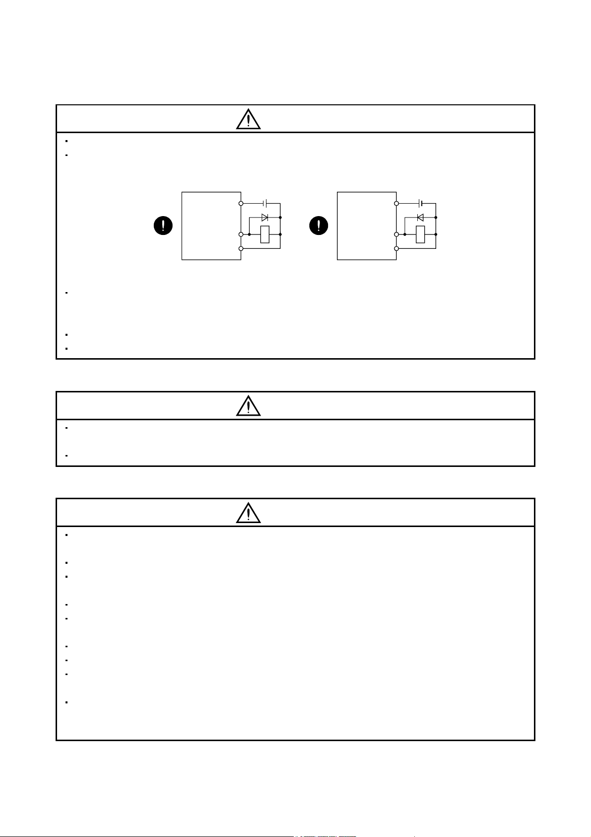
(2) Wiring
CAUTION
Do not connect AC power directly to the servo motor. Otherwise, a fault may occur.
The surge absorbing diode installed to the DC relay for control output should be fitted in the specified
direction. Otherwise, the emergency stop and other protective circuits may not operate.
Servo amplifier
24VDC
DOCOM
Servo amplifier
24VDC
DOCOM
Control output
signal
DICOM
For the sink output interface
RA
Control output
signal
DICOM
For the source output interface
RA
When the cable is not tightened enough to the terminal block (connector), the cable or terminal block
(connector) may generate heat because of the poor contact. Be sure to tighten the cable with specified
torque.
Connecting an encoder for different axis to the CN2A or CN2B connector may cause a malfunction.
Connecting a servo motor for different axis to the CNP3A or CNP3B connector may cause a malfunction.
(3) Test run adjustment
CAUTION
Before operation, check the parameter settings. Improper settings may cause some machines to perform
unexpected operation.
Never adjust or change the parameter values extremely as it will make operation instable.
(4) Usage
CAUTION
Provide an external emergency stop circuit to ensure that operation can be stopped and power switched off
immediately.
Any person who is involved in disassembly and repair should be fully competent to do the work.
Before resetting an alarm, make sure that the run signal of the servo amplifier is off to prevent an accident.
A sudden restart is made if an alarm is reset with the run signal on.
Do not modify the equipment.
Use a noise filter, etc. to minimize the influence of electromagnetic interference, which may be caused by
electronic equipment used near the servo amplifier.
Burning or breaking a servo amplifier may cause a toxic gas. Do not burn or break a servo amplifier.
Use the servo amplifier with the specified servo motor.
The electromagnetic brake on the servo motor is designed to hold the motor shaft and should not be used
for ordinary braking.
For such reasons as service life and mechanical structure (e.g. where a ball screw and the servo motor are
coupled via a timing belt), the electromagnetic brake may not hold the motor shaft. To ensure safety, install
a stopper on the machine side.
A - 5
(5) Corrective actions
CAUTION
When it is assumed that a hazardous condition may take place at the occur due to a power failure or a
product fault, use a servo motor with an electromagnetic brake or an external brake mechanism for the
purpose of prevention.
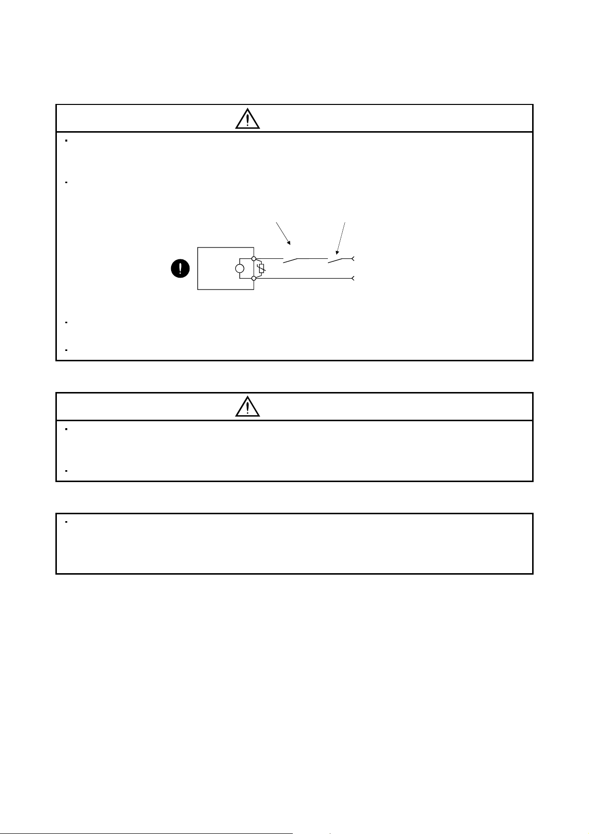
Configure a electromagnetic brake circuit so that it is activated also by an external emergency stop switch.
Contacts must be opened when a
malfunction (ALM-A/ALM-B) and when an
electromagnetic brake interlock (MBR-A/
MBR-B).
Servo motor
RA
Contacts must be opened with
the emergency stop switch.
B
U
Electromagnetic brake
24VDC
When any alarm has occurred, eliminate its cause, ensure safety, and deactivate the alarm before
restarting operation.
Provide an adequate protection to prevent unexpected restart after an instantaneous power failure.
(6) Maintenance, inspection and parts replacement
CAUTION
With age, the electrolytic capacitor of the servo amplifier will deteriorate. To prevent a secondary accident
due to a fault, it is recommended to replace the electrolytic capacitor every 10 years when used in general
environment.
Please contact your local sales office.
(7) General instruction
To illustrate details, the equipment in the diagrams of this Specifications and Instruction Manual may have
been drawn without covers and safety guards. When the equipment is operated, the covers and safety
guards must be installed as specified. Operation must be performed in accordance with this Specifications
and Instruction Manual.
A - 6

DISPOSAL OF WASTE
Please dispose a converter unit, servo amplifier (drive unit), battery (primary battery) and other options according
to your local laws and regulations.
EEP-ROM life
The number of write times to the EEP-ROM, which stores parameter settings, etc., is limited to 100,000. If the
total number of the following operations exceeds 100,000, the servo amplifier may fail when the EEP-ROM
reaches the end of its useful life.
Write to the EEP-ROM due to parameter setting changes
Write to the EEP-ROM due to device changes
Precautions for Choosing the Products
Mitsubishi will not be held liable for damage caused by factors found not to be the cause of Mitsubishi; machine
damage or lost profits caused by faults in the Mitsubishi products; damage, secondary damage, accident
compensation caused by special factors unpredictable by Mitsubishi; damages to products other than
Mitsubishi products; and to other duties.
A - 7
COMPLIANCE WITH CE MARKING
Refer to Appendix 3 for the compliance with CE marking.
COMPLIANCE WITH UL/CSA STANDARD
Refer to Appendix 4 for the compliance with UL/CSA standard.
<<About the manuals>>
This Instruction Manual and the following Servo Amplifier/Servo Motor Instruction Manuals (Vol.2) are
required if you use the General-Purpose AC servo MR-J3Wuse the MR-J3WRefer to chapter 15 for using MR-J3W-0303BN6.
Relevant manuals
MELSERVO-J3W Series Instructions and Cautions for Safe Use of AC Servos IB(NA)0300148
MELSERVO Servo Motor Instruction Manual (Vol.2)(Note 1) SH(NA)030041
EMC Installation Guidelines IB(NA)67310
SSCNET III Interface Linear Servo MR-J3- B-RJ004 INSTRUCTION MANUAL (Note 2) SH(NA)030054
SSCNET III Interface Direct drive servo MR-J3- B-RJ004 INSTRUCTION MANUAL (Note 3) In production
Note 1. Required to use the rotary servo motor.
2. Required to use the linear servo motor.
3. Required to use the direct drive motor.
<<Wiring>>
B safely.
Manual name Manual No.
B for the first time. Always purchase them and
Wires mentioned in this instruction manual are selected based on the ambient temperature of 40
A - 8
(104 ).

CONTENTS
1. FUNCTIONS AND CONFIGURATION 1 - 1 to 1 - 10
1.1 Summary .................................................................................................................................................. 1 - 1
1.2 Function block diagram............................................................................................................................ 1 - 2
1.3 Servo amplifier standard specifications................................................................................................... 1 - 3
1.4 Function list .............................................................................................................................................. 1 - 5
1.5 Model code definition ............................................................................................................................... 1 - 6
1.6 Combination with servo motor .................................................................................................................1 - 7
1.7 Parts identification.................................................................................................................................... 1 - 8
1.8 Configuration including auxiliary equipment ........................................................................................... 1 - 9
2. INSTALLATION 2 - 1 to 2 - 6
2.1 Installation direction and clearances .......................................................................................................2 - 1
2.2 Keep out foreign materials ....................................................................................................................... 2 - 3
2.3 Cable stress ............................................................................................................................................. 2 - 3
2.4 SSCNET
2.5 Inspection items .......................................................................................................................................2 - 5
2.6 Parts having service lives ........................................................................................................................ 2 - 6
cable laying........................................................................................................................... 2 - 3
3. SIGNALS AND WIRING 3 - 1 to 3 -40
3.1 Input power supply circuit ........................................................................................................................ 3 - 2
3.2 I/O signal connection example ................................................................................................................ 3 - 4
3.3 Explanation of power supply system ....................................................................................................... 3 - 6
3.3.1 Signal explanations ........................................................................................................................... 3 - 6
3.3.2 Power-on sequence ..........................................................................................................................3 - 8
3.3.3 CNP1, CNP2, CNP3A, CNP3B wiring method ................................................................................ 3 - 9
3.4 Connectors and signal arrangements ....................................................................................................3 -12
3.5 Signal (device) explanations................................................................................................................... 3 -13
3.6 Alarm occurrence timing chart................................................................................................................ 3 -17
3.6.1 Timing chart...................................................................................................................................... 3 -17
3.6.2 Supplementary information.............................................................................................................. 3 -18
3.7 Interfaces ................................................................................................................................................. 3 -19
3.7.1 Internal connection diagram ............................................................................................................ 3 -19
3.7.2 Detailed description of interfaces..................................................................................................... 3 -20
3.7.3 Source I/O interfaces ....................................................................................................................... 3 -22
3.8 Treatment of cable shield external conductor ........................................................................................3 -23
3.9 SSCNET
3.10 Connection of servo amplifier and servo motor ................................................................................... 3 -26
3.10.1 Connection instructions.................................................................................................................. 3 -26
3.10.2 Power supply cable wiring diagrams ............................................................................................. 3 -27
3.11 Servo motor with an electromagnetic brake......................................................................................... 3 -31
3.11.1 Safety precautions ......................................................................................................................... 3 -31
3.11.2 Timing charts.................................................................................................................................. 3 -33
3.11.3 Wiring diagrams (HF-MP series
3.12 Grounding.............................................................................................................................................. 3 -38
cable connection .................................................................................................................3 -24
HF-KP series servo motor)..................................................... 3 -36
1
3.13 Control axis selection............................................................................................................................ 3 -39
3.14 Servo motor selection switch (SW3) .................................................................................................... 3 -40
4. STARTUP 4 - 1 to 4 -14
4.1 Switching power on for the first time ....................................................................................................... 4 - 2
4.1.1 Startup procedure.............................................................................................................................. 4 - 2
4.1.2 Wiring check ......................................................................................................................................4 - 3
4.1.3 Surrounding environment.................................................................................................................. 4 - 4
4.2 Startup ...................................................................................................................................................... 4 - 4
4.3 Servo amplifier display............................................................................................................................. 4 - 6
4.3.1 Scrolling display................................................................................................................................. 4 - 6
4.3.2 Status display of an axis ................................................................................................................... 4 - 7
4.4 Test operation ..........................................................................................................................................4 - 9
4.5 Test operation mode ............................................................................................................................... 4 -10
4.5.1 Test operation mode in MR Configurator ........................................................................................ 4 -10
4.5.2 Motor-less operation in controller .................................................................................................... 4 -12
5. PARAMETERS 5 - 1 to 5 -30
5.1 Basic setting parameters (No.PA ) ................................................................................................... 5 - 1
5.1.1 Parameter list ....................................................................................................................................5 - 2
5.1.2 Parameter write inhibit ......................................................................................................................5 - 3
5.1.3 Selection of control mode ................................................................................................................. 5 - 4
5.1.4 Selection of regenerative option .......................................................................................................5 - 4
5.1.5 Using absolute position detection system ........................................................................................5 - 5
5.1.6 Forced stop input selection ............................................................................................................... 5 - 5
5.1.7 Auto tuning ........................................................................................................................................ 5 - 6
5.1.8 In-position range................................................................................................................................ 5 - 7
5.1.9 Selection of servo motor rotation direction ....................................................................................... 5 - 8
5.1.10 Encoder output pulse ......................................................................................................................5 - 8
5.2 Gain/filter parameters (No.PB
5.2.1 Parameter list ...................................................................................................................................5 -10
5.2.2 List of details..................................................................................................................................... 5 -11
5.3 Extension setting parameters (No.PC
5.3.1 Parameter list ...................................................................................................................................5 -17
5.3.2 List of details..................................................................................................................................... 5 -18
5.3.3 Analog monitor .................................................................................................................................5 -21
5.3.4 Alarm history clear............................................................................................................................ 5 -23
5.4 I/O setting parameters (No.PD
5.4.1 Parameter list ...................................................................................................................................5 -24
5.4.2 List of details..................................................................................................................................... 5 -25
5.5 Option setting parameters (No.Po
5.5.1 List of parameters............................................................................................................................. 5 -27
5.5.2 List of details.....................................................................................................................................5 -28
)........................................................................................................ 5 -10
) ...........................................................................................5 -17
) ......................................................................................................5 -24
) .................................................................................................5 -27
6. GENERAL GAIN ADJUSTMENT 6 - 1 to 6 -12
6.1 Different adjustment methods.................................................................................................................. 6 - 1
6.1.1 Adjustment on a single servo amplifier............................................................................................. 6 - 1
2

6.1.2 Adjustment using MR Configurator................................................................................................... 6 - 2
6.2 Auto tuning ............................................................................................................................................... 6 - 3
6.2.1 Auto tuning mode .............................................................................................................................. 6 - 3
6.2.2 Auto tuning mode basis .................................................................................................................... 6 - 4
6.2.3 Adjustment procedure by auto tuning............................................................................................... 6 - 5
6.2.4 Response level setting in auto tuning mode ....................................................................................6 - 6
6.3 Manual mode 1 (simple manual adjustment).......................................................................................... 6 - 7
6.4 Interpolation mode ..................................................................................................................................6 -11
7. SPECIAL ADJUSTMENT FUNCTIONS 7 - 1 to 7 -10
7.1 Function block diagram............................................................................................................................ 7 - 1
7.2 Machine resonance suppression filter..................................................................................................... 7 - 1
7.3 Vibration suppression control manual mode........................................................................................... 7 - 3
7.4 Low-pass filter .......................................................................................................................................... 7 - 5
7.5 Gain changing function ............................................................................................................................7 - 5
7.5.1 Applications .......................................................................................................................................7 - 5
7.5.2 Function block diagram .....................................................................................................................7 - 6
7.5.3 Parameters ........................................................................................................................................ 7 - 7
7.5.4 Gain changing procedure.................................................................................................................. 7 - 9
8. TROUBLESHOOTING 8 - 1 to 8 -34
8.1 Alarms and warning list............................................................................................................................ 8 - 1
8.2 Troubleshooting at power on ................................................................................................................... 8 - 3
8.3 Remedies for alarms................................................................................................................................ 8 - 4
8.4 Remedies for warnings ........................................................................................................................... 8 -29
9. OUTLINE DRAWINGS 9 - 1 to 9 - 4
9.1 Servo amplifier .........................................................................................................................................9 - 1
9.2 Connector ................................................................................................................................................. 9 - 3
10. CHARACTERISTICS 10- 1 to 10- 8
10.1 Overload protection characteristics ...................................................................................................... 10- 1
10.2 Power supply equipment capacity and generated loss .......................................................................10- 2
10.3 Dynamic brake characteristics.............................................................................................................. 10- 4
10.3.1 Dynamic brake operation............................................................................................................... 10- 4
10.3.2 The dynamic brake at the load inertia moment............................................................................. 10- 6
10.4 Cable bending life .................................................................................................................................10- 6
10.5 Inrush currents at power-on of main circuit and control circuit ............................................................10- 7
11. OPTIONS AND AUXILIARY EQUIPMENT 11- 1 to 11-56
11.1 Cable/connector sets ............................................................................................................................ 11- 1
11.1.1 Combinations of cable/connector sets ..........................................................................................11- 1
11.1.2 Encoder cable/connector sets .......................................................................................................11- 9
11.1.3 Motor power supply cables ...........................................................................................................11-20
11.1.4 Motor brake cables........................................................................................................................11-21
3

11.1.5 SSCNET
11.1.6 Battery cable..................................................................................................................................11-24
11.2 Regenerative options ...........................................................................................................................11-25
11.3 MR-BTCASE battery case and MR-BAT battery ................................................................................ 11-30
11.4 MR Configurator ...................................................................................................................................11-31
11.5 Selection example of wires ..................................................................................................................11-36
11.6 No-fuse breakers, fuses, magnetic contactors ...................................................................................11-40
11.7 Power factor improving AC reactors ................................................................................................... 11-41
11.8 Relays (recommended) .......................................................................................................................11-42
11.9 Noise reduction techniques ................................................................................................................. 11-42
11.10 Earth-leakage current breaker...........................................................................................................11-49
11.11 EMC filter (recommended) ................................................................................................................11-52
11.12 Junction terminal block MR-TB26A................................................................................................... 11-54
11.13 Surge absorbers (recommended) .....................................................................................................11-55
12. ABSOLUTE POSITION DETECTION SYSTEM 12- 1 to 12- 8
12.1 Features ............................................................................................................................................... 12-.1
12.2 Specifications ........................................................................................................................................ 12- 2
12.3 Assembling a battery unit ..................................................................................................................... 12- 5
12.3.1 Required items ...............................................................................................................................12- 5
12.3.2 Disassembly and assembly of the battery case MR-BTCASE..................................................... 12- 5
12.3.3 Battery transportation..................................................................................................................... 12- 7
12.4 Confirmation of absolute position detection data................................................................................. 12- 8
cable ..........................................................................................................................11-22
13. USING A LINEAR SERVO MOTOR 13- 1 to 13-84
13.1 Functions and configuration ................................................................................................................. 13- 1
13.1.1 Summary ........................................................................................................................................ 13- 1
13.1.2 Combinations of Servo Amplifiers and Linear Servo Motors........................................................ 13- 2
13.1.3 Configuration including auxiliary equipment.................................................................................. 13- 4
13.2 Connection of servo amplifier and linear servo motor .........................................................................13- 5
13.2.1 Connection instructions.................................................................................................................. 13- 5
13.2.2 Power supply cable wiring diagrams............................................................................................. 13- 6
13.3 Linear encoder ......................................................................................................................................13- 7
13.3.1 Compatible linear encoder list ....................................................................................................... 13- 7
13.3.2 Linear encoder and branch cable .................................................................................................. 13- 8
13.4 Signals and wiring ................................................................................................................................. 13- 9
13.4.1 Precautions on this chapter ..........................................................................................................13-10
13.4.2 Power supply system circuit connection example ....................................................................... 13-10
13.4.3 Internal connection diagram .........................................................................................................13-13
13.5 Operation and functions....................................................................................................................... 13-14
13.5.1 Startup ...........................................................................................................................................13-14
13.5.2 Magnetic pole detection ................................................................................................................ 13-17
13.5.3 Home position return.....................................................................................................................13-26
13.5.4 Test operation mode in MR Configurator .....................................................................................13-29
13.5.5 Operation from the controller ........................................................................................................13-30
13.5.6 Functions .......................................................................................................................................13-33
13.5.7 Absolute position detection system ..............................................................................................13-35
13.6 Parameters ........................................................................................................................................... 13-36
4
13.6.1 Parameter write inhibit (Parameter No.PA19).............................................................................. 13-37
13.6.2 Basic setting parameters (No.PA
13.6.3 Gain/Filter parameters (No.PB
13.6.4 Extension setting parameters (No.PC
13.6.5 I/O setting parameters (No.PD
13.6.6 Special setting parameters (No.PS
13.6.7 Option setting parameter .............................................................................................................. 13-57
13.7 Troubleshooting ...................................................................................................................................13-58
13.7.1 Alarms and warning list................................................................................................................. 13-58
13.7.2 Remedies for alarms ..................................................................................................................... 13-60
13.7.3 Remedies for warnings .................................................................................................................13-80
13.7.4 Detailed explanation of linear encoder error 1 (2A.
14. USING A DIRECT DRIVE MOTOR 14- 1 to 14-72
14.1 Functions and configuration ................................................................................................................. 14- 1
14.1.1 Summary ........................................................................................................................................ 14- 1
14.1.2 Combinations of servo amplifier and direct drive motor ............................................................... 14- 2
14.1.3 Configuration including peripheral equipment............................................................................... 14- 3
14.2 Connection of servo amplifier and direct drive motor ..........................................................................14- 4
14.3 Signals and wiring ................................................................................................................................. 14- 5
14.3.1 Notes of this chapter ......................................................................................................................14- 6
14.3.2 Input power supply circuit .............................................................................................................. 14- 7
14.3.3 Internal connection diagram ......................................................................................................... 14-10
14.4 Operation and functions....................................................................................................................... 14-11
14.4.1 Startup procedure ......................................................................................................................... 14-12
14.4.2 Magnetic pole detection ................................................................................................................14-13
14.4.3 Operation from controller .............................................................................................................. 14-20
14.4.4 Function ......................................................................................................................................... 14-25
14.5 Parameters ........................................................................................................................................... 14-27
14.5.1 Parameter writing inhibit (parameter No.PA19) ...........................................................................14-28
14.5.2 Basic setting parameters (No.PA
14.5.3 Gain/filter parameters (No.PB ).............................................................................................. 14-32
14.5.4 Extension setting parameters (No.PC
14.5.5 I/O setting parameters (No.PD
14.5.6 Special setting parameters (No.PS )...................................................................................... 14-36
14.5.7 Option setting parameters (No.Po
14.6 Troubleshooting ...................................................................................................................................14-41
14.6.1 Alarm and warning list................................................................................................................... 14-41
14.6.2 Remedies for alarms ..................................................................................................................... 14-43
14.6.3 Remedies for warnings .................................................................................................................14-56
14.7 Characteristics .....................................................................................................................................14-61
14.7.1 Overload protection characteristics ..............................................................................................14-61
14.7.2 Dynamic brake characteristics...................................................................................................... 14-62
14.8 Options for direct drive motor ..............................................................................................................14-64
14.8.1 Cable/connector sets ....................................................................................................................14-64
14.8.2 Absolute position storage unit MR-BTAS01................................................................................. 14-71
)......................................................................................... 13-38
)............................................................................................. 13-42
) ................................................................................. 13-45
)............................................................................................. 13-51
)...................................................................................... 13-52
) ................................................................13-84
)......................................................................................... 14-29
) ................................................................................. 14-34
)............................................................................................. 14-35
) ....................................................................................... 14-40
5
15. MR-J3W-0303BN6 SERVO AMPLIFIER 15- 1 to 15-72
15.1 Functions and configuration ................................................................................................................. 15- 1
15.1.1 Function block diagram ..................................................................................................................15- 2
15.1.2 Servo amplifier standard specifications ......................................................................................... 15- 3
15.1.3 Model designation .......................................................................................................................... 15- 5
15.1.4 Combination with servo motor ....................................................................................................... 15- 5
15.1.5 Parts identification ..........................................................................................................................15- 6
15.1.6 Configuration including peripheral equipment............................................................................... 15- 7
15.2 Installation (direction and clearances).................................................................................................. 15- 8
15.3 Signals and wiring ................................................................................................................................ 15-10
15.3.1 Input power supply circuit .............................................................................................................15-11
15.3.2 I/O signal connection example...................................................................................................... 15-13
15.3.3 Explanation of power supply system ............................................................................................ 15-15
15.3.4 Connectors and pin assignment ................................................................................................... 15-19
15.3.5 Alarm occurrence timing chart ......................................................................................................15-20
15.3.6 Connection of servo amplifier and HG-AK series servo motor.................................................... 15-23
15.3.7 Servo motor with an electromagnetic brake................................................................................. 15-26
15.3.8 Grounding...................................................................................................................................... 15-31
15.4 Startup .................................................................................................................................................. 15-32
15.4.1 Startup procedure ......................................................................................................................... 15-33
15.4.2 Troubleshooting during "24V ERROR" lamp on. .........................................................................15-33
15.4.3 Wiring check ..................................................................................................................................15-34
15.4.4 Surrounding environment .............................................................................................................15-35
15.5 Parameters ........................................................................................................................................... 15-36
15.5.1 Basic setting parameters (No.PA
15.5.2 Extension setting parameters (No.PC
15.5.3 Manufacturer setting parameters (No.PE
15.5.4 Other function parameters (No.PF
15.5.5 Option setting parameters (No.Po
15.6 Troubleshooting ...................................................................................................................................15-44
15.7 Dimensions...........................................................................................................................................15-52
15.8 Characteristics .....................................................................................................................................15-53
15.8.1 Overload protection characteristics ..............................................................................................15-53
15.8.2 Power supply capacity and generated loss.................................................................................. 15-54
15.8.3 Dynamic brake characteristics...................................................................................................... 15-54
15.8.4 Inrush currents at power-on of main circuit and control circuit ....................................................15-56
15.9 Options and peripheral equipment ...................................................................................................... 15-57
15.9.1 Cable/connector sets .................................................................................................................... 15-57
15.9.2 Selection example of wires ........................................................................................................... 15-64
15.9.3 Circuit protector ............................................................................................................................. 15-65
15.10 Absolute position detection system ...................................................................................................15-66
15.10.1 Features ...................................................................................................................................... 15-66
15.10.2 Specifications ..............................................................................................................................15-67
15.10.3 Battery replacement procedure ..................................................................................................15-69
15.10.4 Battery mounting/removing procedure .......................................................................................15-70
15.10.5 Procedure to replace battery with the control circuit power off.................................................. 15-71
)......................................................................................... 15-36
) ................................................................................. 15-38
)............................................................................ 15-42
)....................................................................................... 15-43
) ....................................................................................... 15-43
6

APPENDIX App.- 1 to App.-17
App. 1 Difference between MR-J3-B and MR-J3W-B ..............................................................................App.- 1
App. 2 Signal layout recording paper ........................................................................................................App.- 5
App. 3 COMPLIANCE WITH CE MARKING.............................................................................................App.- 6
App. 4 COMPLIANCE WITH UL/CSA STANDARD .................................................................................App.- 9
App. 5 Handling of AC servo amplifier batteries for the United Nations
Recommendations on the Transport of Dangerous Goods.........................................................App.-14
App. 6 Symbol for the new EU Battery Directive .....................................................................................App.-15
App. 7 Recommended cable for servo amplifier power supply ...............................................................App.-16
7

MEMO
8

1. FUNCTIONS AND CONFIGURATION
1. FUNCTIONS AND CONFIGURATION
1.1 Summary
The Mitsubishi AC servo amplifier MELSERVO-J3W series is an AC servo that requires less space, less wiring,
and less energy while it maintains high performance, functionality and usability of MELSERVO-J3-B.
Two servo motors can be driven by this MR-J3W servo amplifier. Driving two servo motors by one MR-J3W
servo amplifier cuts down the installation area compared to the area required for two MR-J3 servo amplifiers.
Side-by-side installation is also available, making the system more compact.
Integrated 2-axis structure allows two axes to share the same SSCNET
main circuit power cable, cutting down the wiring area.
The capacitor in the MELSERVO-J3W series is re-charged, doubling the reusable energy compared to it of the
MELSERVO-J3 series. Regenerative energy is generated during deceleration of a servo motor. By reusing that
energy, much energy is saved. Depending on the operating condition, the regenerative option may be disabled.
The MR-J3W-77B servo amplifier has a 100W regenerative resistor built in, making the regenerative option
unnecessary even for a large regenerative load.
By simply shifting the switch, a rotary servo motor, a linear servo motor or a direct drive motor can be used for
each axis for the MR-J3W servo amplifier. A rotary servo motor, a linear servo motor and a direct drive motor
with different capacities can be connected to the MR-J3W-22B and MR-J3W-44B servo amplifier axes.
Using MELSERVO-J3W makes the linear servo motor and the direct drive motor structure simple and the
equipment compact with high performance. Using MELSERVO-J3W also saves the space.
As explained above, integrated 2-axis structure, multi-function, and improved regeneration efficiency reduce the
required parts for a servo system.
cable, control circuit power cable, and
1 - 1
1. FUNCTIONS AND CONFIGURATION
1.2 Function block diagram
The function block diagram of this servo is shown below.
Regenerative
option
(Note 2)
Power
supply
MCCB
Servo amplifier
MC
Diode
stack
L1
L2
CNP1CNP2
3
L
L11
L21
Base amplifier
Relay
CHARGE
(Note 1)
Control
circuit
power
supply
lamp
Cooling fan
PC D
CNP2
Regenerative
TR
Built-in regenerative resistor
TRM(A)
TRM(B)
Current
detector
Current
detector
Dynamic
brake circuit
(A)
Dynamic
brake circuit
(B)
A-axis Servo motor
U
U
V
V
W
W
CNP3ACN2A
B1
RA
24VDC
B
B2
Encoder
B-axis Servo motor
U
U
V
V
W
W
CNP3BCN2B
B1
RA
24VDC
B
B2
M
Electromagnetic
brake
M
Electromagnetic
brake
Virtual
motor
Current
detection
B
Virtual
encoder
Encoder
-
MR
BTCASE
CN4
Optional battery
Regenerative
brake
Control (A)
Model position
control (A)
Overcurrent
Model speed
control (A)
Current
detection
A
Virtual
encoder
Virtual
motor
A
Overvoltage
Control (B)
Model position
control (B)
Overcurrent
Model speed
control (B)
B
Case Battey
(for absolute position
detection system)
Actual position
control (A)
CN1A CN1B
Controller or
servo amplifier
Actual speed
control (A)
I/F
Control
Servo amplifier
or cap
Current
control (A)
Personal
computer
Actual position
control (B)
USB
CN5
USB
Actual speed
control (B)
D/A
Analog monitor
(2 channels)
Current
control (B)
CN3
Digital I/O
control
1 - 2

1. FUNCTIONS AND CONFIGURATION
Note 1. MR-J3W-22B dose not have a cooling fan.
2. For 1-phase 200 to 230VAC, connect the power supply to L
specification.
1.3 Servo amplifier standard specifications
Servo amplifier
MR-J3W-
Item
Rated output capacity
Rated voltage 3-phase 170VAC
Output
Rated current [A] 1.5 1.5 2.8 2.8 5.8 5.8 6.0 6.0
Voltage, frequency 3-phase or 1-phase 200 to 230VAC, 50/60Hz 3-phase 200 to 230VAC, 50/60Hz
Rated current [A] 3.5 6.1 10.4 13.9
Permissible voltage fluctuation
Permissible frequency fluctuation Within 5
Power supply capacity Refer to section 10.2
Main circuit power supply
Inrush current Refer to section 10.5
Voltage, frequency 1-phase 200 to 230VAC, 50/60Hz
Rated current [A] 0.4
Permissible voltage
Control circuit
power supply
Interface power
supply
fluctuation
Permissible
frequency fluctuation
Power
consumption
Inrush current Refer to section 10.5
Voltage 24VDC 10
Power supply
capacity
[W] 55
[A] (Note 1) 0.25
22B 44B 77B 1010B
A-axis
200W
3-phase or 1-phase 200 to 230VAC:
1-phase 170 to 253VAC
Within
B-axis
200W
170 to 253VAC
1, L2 and leave L3 open. Refer to section 1.3 for the power supply
A-axis
400W
B-axis
400W
A-axis
750W
5
B-axis
750W
3-phase 170 to 253VAC
A-axis
1kW
B-axis
1kW
1 - 3
1. FUNCTIONS AND CONFIGURATION
Servo amplifier
MR-J3W-
Item
Reusable
regenerative energy
(Note 3) [J]
Rotary servo motor’s
inertia moment
Capacitor
regenerative
Control system Sine-wave PWM control, current control system
Built-in regenerative resistor [W] 10 100
Dynamic brake Built-in
Protective functions
Structure
Side-by-side installation (Note 2)
Ambient
temperature
humidity
Ambient
Environmental conditions
Altitude Max. 1000m above sea level
Vibration resistance 5.9 m/s2 at 10 to 55Hz (X, Y and Z directions)
Mass
Note 1. 0.25A is the value applicable when all I/O signals are used. The current capacity can be decreased by reducing the number of I/O
points.
2. When closely mounting MR-J3W-44B, operate them at 90
3. The regenerative energy is generated under the following conditions.
Rotary servo motor: The energy is generated when a machine with the inertia moment equivalent to permissible charging amount
Linear servo motor: The energy is generated when a machine with the mass equivalent to permissible charging amount decelerates
Direct drive motor: The energy is generated when a machine with the inertia moment equivalent to permissible charging amount
4. This value is inertia moment when decelerating rotary servo motor from the rated speed to a stop. When decelerating two axes
simultaneously, the inertia moment is a total of two axes. When not decelerating two axes simultaneously, the inertia moment is for
one axis. This note also applies to the direct drive motor.
5. This value is mass when decelerating linear servo motor from the rated speed to a stop. The mass includes a mass of primary side
(coil). When decelerating two axes simultaneously, the mass is a total of two axes. When not decelerating two axes simultaneously,
the mass is for one axis.
equivalent to
permissible charging
amount (Note 4)
[
10-4kg m2]
Linear servo motor’s
mass equivalent to
permissible charging
amount (Note 5) [kg]
Self-cooled, open
Operation
Storage
Operation Ambient
Storage
[kg] 1.4 2.3
[lb] 3.09 5.07
decelerates from the rated speed to stop.
from the maximum speed to stop.
decelerates from the rated speed to stop.
Overcurrent shut-off, regenerative overvoltage shut-off, overload shut-off (electronic thermal
[ ] 0 to 55 (non-freezing)
[
] 32 to 131 (non-freezing)
[ ] 20 to 65 (non-freezing)
[
] 4 to 149 (non-freezing)
22B 44B 77B 1010B
17 22 46
3.45 4.46 9.32
8.5 11.0 23.0
relay), servo motor overheat protection, encoder error protection, regenerative error protection,
undervoltage, instantaneous power failure protection, overspeed protection, excessive error
protection, magnetic pole detection protection, Linear servo control error detection protection
(IP rating: IP00)
Free from corrosive gas, flammable gas, oil mist, dust and dirt
Force-cooling, open (IP rating: IP00)
90
RH or less (non-condensing)
Indoors (no direct sunlight)
or smaller effective load ratio.
1 - 4

1. FUNCTIONS AND CONFIGURATION
1.4 Function list
The following table lists the functions of this servo. For details of the functions, refer to the reference field.
Function Description Reference
High-resolution encoder
Absolute position detection
system
Gain changing function
Low-pass filter
Machine analyzer function
Machine simulation
Gain search function
Slight vibration suppression
control
Auto tuning
Regenerative option
Alarm history clear Alarm history is cleared. Parameter No.PC21
Output signal (DO)
forced output
Test operation mode
Analog monitor output Servo status is output in terms of voltage in real time. Parameter No.PC09
MR Configurator
High-resolution encoder of 262144 pulses/rev is used as a rotary servo motor
encoder.
Merely setting a home position once makes home position return unnecessary
at every power-on.
Switches gains by using input devices or gain switching conditions (including the
servo motor speed).
Suppresses high-frequency resonance which occurs as servo system response
is increased.
Analyzes the frequency characteristic of the mechanical system by simply
connecting an MR Configurator installed personal computer and servo amplifier.
MR Configurator is necessary for this function.
Can simulate machine motions on a personal computer screen on the basis of
the machine analyzer results.
MR Configurator is necessary for this function.
Personal computer with MR Configurator changes gains automatically and
searches for overshoot-free gains in a short time.
MR Configurator is necessary for this function.
Suppresses vibration of
Automatically adjusts the gain to optimum value if load applied to the servo
motor shaft varies.
Used when the built-in regenerative resistor of the servo amplifier does not have
sufficient regenerative capability for the regenerative power generated.
Output signal can be forced on/off independently of the servo status.
Use this function for output signal wiring check, etc.
JOG operation
However, MR Configurator is necessary for positioning operation.
Using a personal computer, parameter setting, test operation, status display,
etc. can be performed.
positioning operation DO forced output
1 pulse produced at a servo motor stop. Parameters No.PB24
Chapter 12
Section 7.5
Section 7.4
Chapter 6
Section 11.2
Section 4.5.1 (1) (d)
Section 4.5
Section 11.4
1 - 5
1. FUNCTIONS AND CONFIGURATION
1.5 Model code definition
(1) Rating plate
MITSUBISHI
(2) Model
MODEL
POWER:
INPUT:
OUTPUT:
SERIAL: A99001050
KCC-REI-MEK-TC300A***G51
MITSUBISHI ELECTRIC CORPORATION
MADE IN JAPAN
Series
MR-J3W-44B
400W(A)+400W(B)
6.1A 3PH+1PH200-230V 50Hz
170V 0-360Hz 2.8A(A)+2.8A(B)
AC SERVO
DATE 2011-08
3PH+1PH200-230V 60Hz
PASSED
SSCNET interface
Rated output
Rated outpur[W]
Symbol
A-axis
22 200 200
44 400 400
77 750 750
1010 1k 1k
B-axis
The year and month
of manufacture
Model
Capacity
Applicable power supply
Rated output current
Serial number
KC mark number
Country of origin
Rating plate
1 - 6
1. FUNCTIONS AND CONFIGURATION
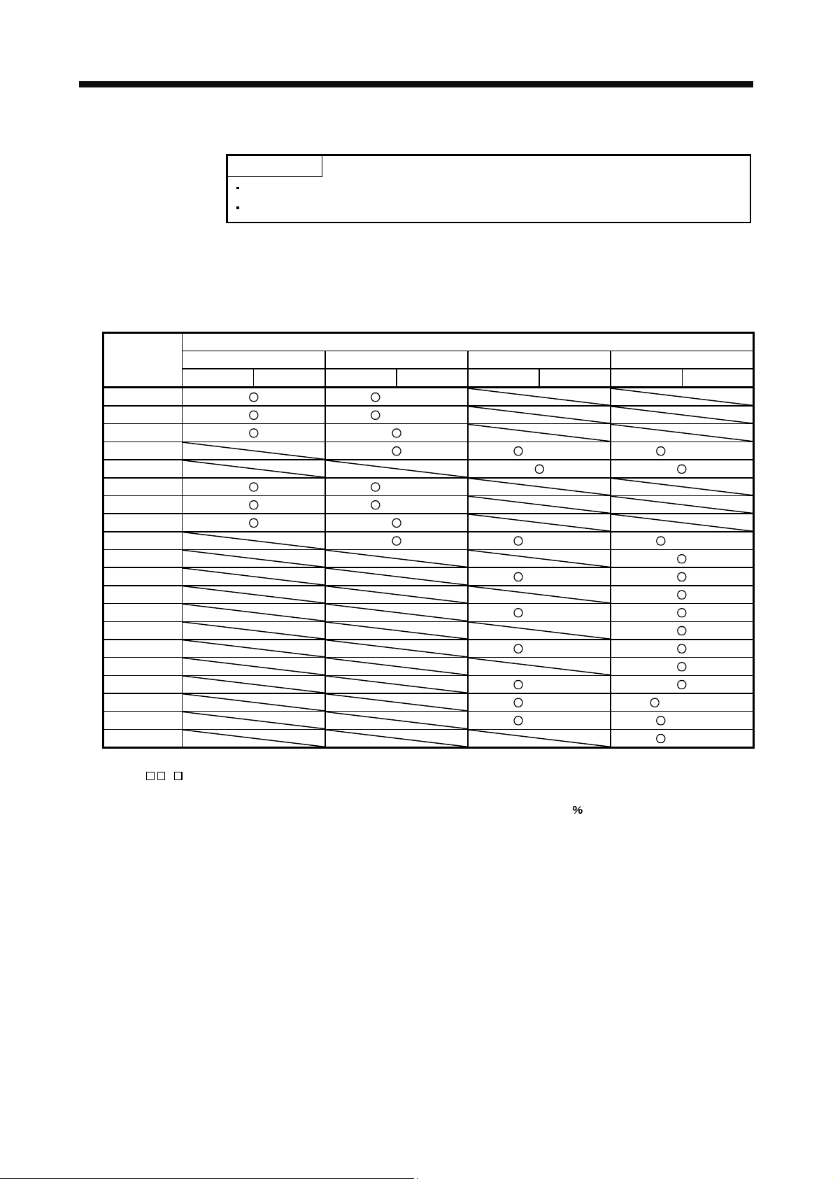
1.6 Combination with servo motor
POINT
Refer to section 13.1.2 for the combinations with linear servo motors.
Refer to section 14.1.2 for the combinations with direct drive motors.
The following table lists combinations of servo amplifiers and servo motors. The same combinations apply to the
models with an electromagnetic brake and the models with a reduction gear.
With the servo amplifier whose software version is B3 or later, the following servo motors can be used without
parameter change.
Servo amplifier
Servo motor MR-J3W-22B MR-J3W-44B MR-J3W-77B MR-J3W-1010B
A-axis B-axis A-axis B-axis A-axis B-axis A-axis B-axis
HF-MP053 (Note 1)
HF-MP13 (Note 1)
HF-MP23
HF-MP43 (Note 1) (Note 1)
HF-MP73
HF-KP053 (Note 1)
HF-KP13 (Note 1)
HF-KP23
HF-KP43 (Note 1) (Note 1)
HF-KP73
HF-SP51 (Note 1)
HF-SP81
HF-SP52 (Note 1)
HF-SP102
HC-LP52 (Note 1)
HC-LP102
HC-UP72 (Note 1)
HF-JP53 (Note 2) (Note 2, 3)
HF-JP73 (Note 2) (Note 2)
HF-JP103 (Note 2)
Note 1. With the servo amplifier whose software version is B2 or earlier, this servo motor can be used by setting parameter No.Po04 to
"
1 ". With the servo amplifier whose software version is B3 or later, no parameter setting is required.
2. This servo motor can be used with the servo amplifier whose software version is B3 or later.
3. With this combination, the maximum torque of the HF-JP53 servo motor increases to 400
of the rated torque.
1 - 7
1. FUNCTIONS AND CONFIGURATION
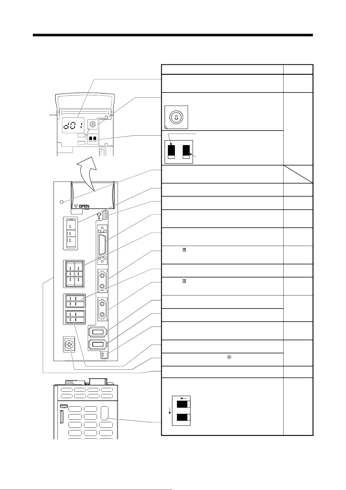
1.7 Parts identification
Side view
SW1
TEST
SW2
7
6
5
4
3
2
ON 4E
12
Name/Application
Detailed
explanation
Display
The 3-digit, seven-segment LED shows the servo status
Section 4.3
and alarm number.
Rotary axis setting switch (SW1)
SW1
8
7
6
5
4
8
9
A
B
C
D
E
F
1
0
3
2
1
0
SW2
Used to set the axis No. of servo amplifier.
9
A
B
C
D
E
F
Test operation select switch (SW2-1)
Used to perform the test operation
Section 3.13
mode by using MR Configurator.
1
to the "Down" position).
For manufacturer setting (Be sure to set
2
Charge lamp
Lit to indicate that the main circuit is charged. While this
lamp is lit, do not reconnect the cables.
Main circuit power supply connector (CNP1)
Connect the input power supply.
USB communication connector (CN5)
Connect the personal computer.
I/O signal connector (CN3)
Used to connect digital I/O signals.
More over an analog monitor is output.
Control circuit connector (CNP2)
Connect the control circuit power supply/regenerative
option.
Section 3.1
Section 3.3
Section 11.4
Section 3.2
Section 3.4
Section 3.1
Section 3.3
SSCNET cable connector (CN1A)
Used to connect the servo system controller or the front
Section 3.9
axis servo amplifier.
A-axis servo motor power output connector (CNP3A)
Connect the A-axis servo motor.
Section 3.1
Section 3.3
SSCNET cable connector (CN1B)
Used to connect the rear axis servo amplifier. For the final
Section 3.9
axis, puts a cap.
A-axis servo motor encoder connector (CN2A)
Used to connect the A-axis servo motor encoder.
B-axis servo motor encoder connector (CN2B)
Section 3.4
Section 11.1
Used to connect the B-axis servo motor encoder.
Battery connector (CN4)
Used to connect the battery for absolute position data
backup. Battery is not required in fully closed control.
Section 11.3
Chapter 12
B-axis servo motor power output connector (CNP3B)
Connect the B-axis servo motor.
Protective earth (PE) terminal ( )
Section 3.1
Section 3.3
Ground terminal.
Rating plate
Section 1.5
Servo motor selection switch (SW3)
NO
A-axis
SW3
Bottom
21
Front side
B-axis
Used to select the servo motor to
be used.
Section 3.14
OFF: Rotary servo motor
ON : Linear servo motor and
direct drive motor
1 - 8
1. FUNCTIONS AND CONFIGURATION
1.8 Configuration including auxiliary equipment
CAUTION
(Note 2)
Power supply
Molded-case
circuit breaker
(MCCB) or fuse
Magnetic
contactor
(MC)
Power factor
improving AC
reactor
(FR-BAL)
Line noise
filter
(FR-BSF01)
RST
(Note 2)
Connecting a servo motor for different axis to the CNP3A or CNP3B connector may
cause a malfunction.
POINT
Equipment other than the servo amplifier and the servo motor are optional or
recommended products.
To use a rotary servo motor, turn SW3 off (factory setting).
Servo amplifier
MR Configurator
CN5
L
1
L2
L
3
CNP1
CN3
(Note 3)
V
U
W
P
C
D
W
V
U
CNP2
CNP3A
CNP3B
CN1A
CN1B
CN2A
Regenerative
option
Personal
computer
I/O signal
Servo system
controller or Front axis
servo amplifier CN1B
Rear servo amplifier
CN1A or Cap
CN2B
(Note 1)
L
L11
21
CN4
Battery
unit
A-axis servo motorB-axis servo motor
SW3
ON
12
Front side
A-axis
B-axis
Note 1. A battery unit consists of one MR-BTCASE battery case and eight MR-BAT batteries. Use the battery unit in the absolute position
detection system of the position control mode. (Refer to section 12.3.)
2. For 1-phase 200V to 230VAC, connect the power supply to L
1 L2 and leave L3 open. Refer to section 1.3 for the power supply
specification.
3. Make sure to connect the P
terminal to the D terminal. When using the regenerative option, refer to section 11.2.
1 - 9

1. FUNCTIONS AND CONFIGURATION
MEMO
1 - 10
2. INSTALLATION
2. INSTALLATION
WARNING
CAUTION
2.1 Installation direction and clearances
To prevent electric shock, ground each equipment securely.
Stacking in excess of the limited number of products is not allowed.
Install the equipment on incombustible material. Installing it directly or close to
combustibles will lead to a fire.
Install the equipment in a load-bearing place in accordance with this Instruction
Manual.
Do not get on or put heavy load on the equipment to prevent injury.
Use the equipment within the specified environmental condition range. (For the
environmental conditions, refer to section 1.3.)
Provide an adequate protection to prevent screws and other conductive matter, oil
and other combustible matter from entering the servo amplifier.
Do not block the intake and exhaust areas of the servo amplifier. Doing so may
cause faults.
Do not drop or strike the servo amplifier. Isolate from all impact loads.
Do not install or operate the servo amplifier which has been damaged or has any
parts missing.
Do not install or operate a faulty servo amplifier.
When the product has been stored for an extended period of time, contact your local
sales office.
When treating the servo amplifier, be careful about the edged parts such as the
corners of the servo amplifier.
The servo amplifier must be installed in the metal cabinet.
The equipment must be installed in the specified direction. Otherwise, a fault may
CAUTION
When using heat generating equipment such as the regenerative option, install them with full consideration of
heat generation so that the servo amplifier is not affected.
Install the servo amplifier on a perpendicular wall in the correct vertical direction.
occur.
Leave specified clearances between the servo amplifier and control box inside walls
or other equipment. Doing so may cause faults.
2 - 1
2. INSTALLATION
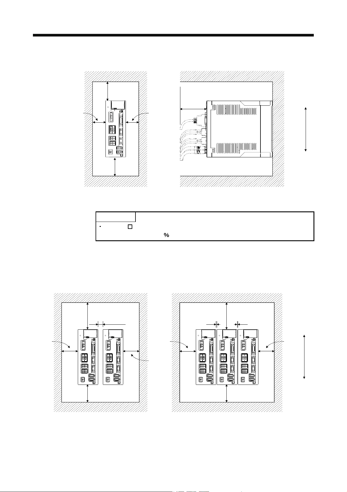
(1) Installation of one servo amplifier
40mm
or more
Servo amplifier
10mm
or more
40mm
or more
10mm
or more
Wiring
allowance
80mm
Control boxControl box
Top
Bottom
(2) Installation of two or more servo amplifiers
POINT
MR-J3W- B can be installed side-by-side. However, use MR-J3W-44B with the
effective load ratio of 90
or less.
Leave a large clearance between the inner surface of a control box and the servo amplifier to circulate air above
and below the servo amplifier.
When installing the servo amplifiers closely, leave a clearance of 1mm between the adjacent servo amplifiers in
consideration of mounting tolerances.
1mm
Control box
100mm
or more
1mm
Top
30mm
or more
30mm
or more
Control box
100mm
or more
10mm
or more
30mm
or more
30mm
or more
Bottom
40mm
or more
Leaving clearance Mounting closely
40mm
or more
2 - 2

2. INSTALLATION
2.2 Keep out foreign materials
(1) When installing the unit in a control box, prevent drill chips and wire fragments from entering the servo
amplifier.
(2) Prevent oil, water, metallic dust, etc. from entering the servo amplifier through openings in the control box or
a cooling fan installed on the ceiling.
(3) When installing the control box in a place where there are much toxic gas, dirt and dust, conduct an air
purge (force clean air into the control box from outside to make the internal pressure higher than the
external pressure) to prevent such materials from entering the control box.
2.3 Cable stress
(1) The way of clamping the cable must be fully examined so that bending stress and cable's own weight stress
are not applied to the cable connection.
(2) For use in any application where the servo motor moves, fix the cables (encoder, power supply, brake) with
having some slack from the connector connection part of the servo motor to avoid putting stress on the
connector connection part. Use the optional encoder cable within the bending life range. Use the power
supply and brake wiring cables within the bending life of the cables.
(3) Avoid any probability that the cable sheath might be cut by sharp chips, rubbed by a machine corner or
stamped by workers or vehicles.
(4) For installation on a machine where the servo motor will move, the bending radius should be made as large
as possible. Refer to section 10.4 for the bending life.
2.4 SSCNET
cable laying
SSCNET
pressure, haul, sudden bending or twist, its inside distorts or breaks, and optical transmission will not be
available. Especially, as optical fiber for MR-J3BUS
down if being left near the fire or high temperature. Therefore, do not make it touched the part, which becomes
high temperature, such as radiator or regenerative option of servo amplifier.
Read described item of this section carefully and handle it with caution.
(1) Minimum bend radius
cable is made from optical fiber. If optical fiber is added a power such as a major shock, lateral
M MR-J3BUS M-A is made of synthetic resin, it melts
Make sure to lay the cable with greater radius than the minimum bend radius. Do not press the cable to
edges of equipment or others. For SSCNET
consideration for the dimensions and arrangement of servo amplifier. When closing the door of control box,
pay careful attention for avoiding the case that SSCNET
bend becomes smaller than the minimum bend radius.
For the minimum bend radius, refer to section 11.1.5.
cable, the appropriate length should be selected with due
cable is hold down by the door and the cable
2 - 3

2. INSTALLATION
(2) Prohibition of vinyl tape use
Migrating plasticizer is used for vinyl tape. Keep the MR-J3BUS
from vinyl tape because the optical characteristic may be affected.
Optical cord Cable
(3) Precautions for migrating plasticizer added materials
Generally, soft polyvinyl chloride (PVC), polyethylene resin (PE) and fluorine resin contain non-migrating
plasticizer and they do not affect the optical characteristic of SSCNET cable.
However, some wire sheaths and cable ties, which contain migrating plasticizer (phthalate ester), may affect
MR-J3BUS
In addition, MR-J3BUS
M and MR-J3BUS M-A cables (made of plastic).
M-B cable (made of quartz glass) is not affected by plasticizer.
(4) Bundle fixing
Fix the cable at the closest part to the connector with bundle material in order to prevent SSCNET
from putting its own weight on CN1A
CN1B connector of servo amplifier. Optical cord should be given
loose slack to avoid from becoming smaller than the minimum bend radius, and it should not be twisted.
When bundling the cable, fix and hold it in position by using cushioning such as sponge or rubber which
does not contain migratable plasticizers.
If using adhesive tape for bundling the cable, fire resistant acetate cloth adhesive tape 570F (Teraoka
Seisakusho Co., Ltd) is recommended.
M, and MR-J3BUS M-A cables away
SSCNET cable Cord Cable
MR-J3BUS M
MR-J3BUS M-A
MR-J3BUS M-B
: Phthalate ester plasticizer such as DBP and DOP
may affect optical characteristic of cable.
: Normally, cable is not affected by plasticizer.
cable
Connector
Optical cord
Loose slack
Bundle material
Recommended product:
NK clamp SP type
( NIX, INC.)
Cable
(5) Tension
If tension is added on optical cable, the increase of transmission loss occurs because of external force
which concentrates on the fixing part of optical fiber or the connecting part of optical connector. At worst, the
breakage of optical fiber or damage of optical connector may occur. For cable laying, handle without putting
forced tension. For the tension strength, refer to section 11.1.5.
2 - 4

2. INSTALLATION
(6) Lateral pressure
If lateral pressure is added on optical cable, the optical cable itself distorts, internal optical fiber gets
stressed, and then transmission loss will increase. At worst, the breakage of optical cable may occur. As the
same condition also occurs at cable laying, do not tighten up optical cable with a thing such as nylon band
(TY-RAP).
Do not trample it down or tuck it down with the door of control box or others.
(7) Twisting
If optical fiber is twisted, it will become the same stress added condition as when local lateral pressure or
bend is added. Consequently, transmission loss increases, and the breakage of optical fiber may occur at
worst.
(8) Disposal
When incinerating optical cable (cord) used for SSCNET
which is corrosive and harmful may be generated. For disposal of optical fiber, request for specialized
industrial waste disposal services who has incineration facility for disposing hydrogen fluoride gas or
hydrogen chloride gas.
2.5 Inspection items
, hydrogen fluoride gas or hydrogen chloride gas
Before wiring or inspection, turn off the power and wait for 15 minutes or more until
the charge lamp turns off. Otherwise, an electric shock may occur. In addition,
always confirm from the front of the servo amplifier, whether the charge lamp is off
WARNING
CAUTION
It is recommended to make the following checks periodically.
(1) Check for loose terminal block screws. Retighten any loose screws.
(2) Check if the cables and the wires have no damage or crack. Perform periodic inspection according to
operating conditions.
(3) Check that the connector is securely connected to the servo amplifier.
(4) Check that the wires are not coming out from the connector.
(5) Check for dust accumulation on the servo amplifier.
(6) Check for unusual noise generated from the servo amplifier.
or not.
To avoid an electric shock, only qualified personnel should attempt inspections.
Otherwise, you may get an electric shock. For repair and parts replacement, contact
your safes representative.
Do not perform insulation resistance test on the servo amplifier as damage may
result.
Do not disassemble and/or repair the equipment on customer side.
2 - 5

2. INSTALLATION
2.6 Parts having service lives
Service lives of the following parts are listed below. However, the service lives vary depending on operating
methods and environmental conditions. If any fault is found in the parts, they must be replaced immediately
regardless of their service lives. For parts replacement, please contact your sales representative.
Part name Life guideline
Smoothing capacitor 10 years
Relay
Cooling fan 50,000 to 70,000 hours (2 to 3 years)
Absolute position battery Refer to section 12.2
(1) Smoothing capacitor
Affected by ripple currents, etc. and deteriorates in characteristic. The life of the capacitor greatly depends
on ambient temperature and operating conditions. The capacitor will reach the end of its life in 10 years of
continuous operation in normal air–conditioned environment (40
less).
(2) Relays
Their contacts will wear due to switching currents and contact faults occur. Relays reach the end of their
lives when the power is turned on and forced stop/controller forced stop occurs 100,000 times in total.
(3) Servo amplifier cooling fan
The cooling fan bearings reach the end of their life in 50,000 to 70,000 hours. Normally, therefore, the fan
must be changed in seven or eight years of continuous operation as a guideline.
It must also be changed if unusual noise or vibration is found during inspection.
The life of the servo amplifier cooling fan applies under an environment of an average ambient temperature
of 40
(104 ) a year, and a corrosive gas-free, flammable gases-free, an oil-mist-free, and a dust-free
environment.
Number of power-on, forced stop, and controller
forced stop times: 100000 times
(104 ) surrounding air temperature or
2 - 6

3. SIGNALS AND WIRING
3. SIGNALS AND WIRING
Any person who is involved in wiring should be fully competent to do the work.
Before wiring or inspection, turn off the power and wait for 15 minutes or more until
the charge lamp turns off. Otherwise, an electric shock may occur. In addition,
always confirm from the front of the servo amplifier, whether the charge lamp is off
or not.
WARNING
Ground the servo amplifier and the servo motor securely.
Do not attempt to wire the servo amplifier and servo motor until they have been
installed. Otherwise, you may get an electric shock.
The cables should not be damaged, stressed excessively, loaded heavily, or
pinched. Otherwise, you may get an electric shock.
To avoid an electric shock, insulate the connections of the power supply terminals.
Wire the equipment correctly and securely. Otherwise, the servo motor may operate
unexpectedly, resulting in injury.
Connect cables to correct terminals to prevent a burst, fault, etc.
Ensure that polarity ( , ) is correct. Otherwise, a burst, damage, etc. may occur.
The surge absorbing diode installed to the DC relay for control output should be fitted
in the specified direction. Otherwise, the emergency stop and other protective
circuits may not operate.
CAUTION
Servo amplifier
24VDC
DOCOM
Control output
signal
DICOM
For the sink output interface
RA
Servo amplifier
DOCOM
Control output
signal
DICOM
For the source output interface
24VDC
RA
Use a noise filter, etc. to minimize the influence of electromagnetic interference,
which may be given to electronic equipment used near the servo amplifier.
Do not install a power capacitor, surge suppressor or radio noise filter (FR-BIF
option) with the power line of the servo motor.
When using the regenerative resistor, switch power off with the alarm signal.
Otherwise, a transistor fault or the like may overheat the regenerative resistor,
causing a fire.
Do not modify the equipment.
Connect the servo amplifier power output (U, V, and W) to the servo motor power
input (U, V, and W) directly. Do not let a magnetic contactor, etc. intervene.
Otherwise, it may cause a malfunction.
Servo amplifier
U
V
W
Servo motor
U
V
W
Servo motorServo amplifier
U
M
V
W
U
V
M
W
3 - 1

3. SIGNALS AND WIRING
3.1 Input power supply circuit
Always connect a magnetic contactor between the power supply and the main circuit
power supply (L1, L2, and L3) of the servo amplifier, in order to configure a circuit
that shuts down the power supply on the side of the servo amplifier’s power supply. If
a magnetic contactor is not connected, continuous flow of a large current may cause
a fire when the servo amplifier malfunctions.
CAUTION
Wire the power supply/main circuit as shown below so that power is shut off and the servo-on command turned
off as soon as an alarm occurs, a servo forced stop is made valid, or a controller forced stop is made valid. A
molded-case circuit breaker (MCCB) must be used with the input cables of the main circuit power supply.
Shut off the main circuit power supply when alarms are occurring in both of the A-
axis and the B-axis. Otherwise, a regenerative transistor fault or the like may
overheat the regenerative resistor, causing a fire.
Check the servo amplifier model, and then input proper voltage to the servo amplifier
power supply. If input voltage exceeds the upper limit, the servo amplifier will break
down.
POINT
Even if alarm has occurred, do not switch off the control circuit power supply.
When the control circuit power supply has been switched off, optical module does
not operate, and optical transmission of SSCNET
Therefore, the servo amplifier on the rear axis displays "AA" at the indicator and
turns into base circuit shut-off. The servo amplifier stops with starting dynamic
brake.
communication is interrupted.
3 - 2

3. SIGNALS AND WIRING
(Note 9)
Power
supply
(Note 3)
Malfunction
RA1(A-axis)
RA2(B-axis)
(Note 8)
MCMCCB
(Note 1)
Controller
forced stop
Forced stop
CNP1
L1
L2
L
3
CNP2
P
C
D
L
11
L21
OFF
(Note 6)
Servo amplifier
(Note 10)
CNP3A
CN2A
PE( )
(Note 10)
CNP3B
U
V
W
U
V
W
ONRA3
MC
MC
SK
(Note 5)
(Note 2)
Encoder cable
(Note 5)
A-axis servo motor
U
Motor
V
M
W
Encoder
B-axis servo motor
U
Motor
V
M
W
(Note 2)
Encoder cable
24VDC
RA1
RA2
Encoder
A-axis malfunction
(Note 3)
B-axis malfunction
(Note 3)
(Note 4)
(Note 4)
(Note 6) Forced stop
EM1
DOCOM
SW3 (Note 7)
ON
21
Front side
A-axis
B-axis
CN2B
CN3CN3
DOCOM
DICOM
ALM-A
ALM-B
Note 1. Always connect P and D. When using the regenerative option, refer to section 11.2.
2. For the encoder cable, use of the option cable is recommended. Refer to section 11.1 for selection of the cable.
3. If deactivating output of malfunction (ALM-A/ALM-B) with parameter change, configure up the power supply circuit which switches
off the magnetic contactor after detection of alarm occurrence on the controller side. In this connection example, the operation
continues in the other axis when an alarm occurs in the A-axis or the B-axis. To stop both axes in an alarm occurrence, connect
RA1 and RA2 in series.
4. For the sink I/O interface. For the source I/O interface, refer to section 3.7.3.
5. For the power line connection, refer to section 3.10.
6. Configure the circuit to shut down the main circuit power supply simultaneously with the turn off of forced stop (EM1) using the
external sequence.
7. This connection example is a connection using a rotary servo motor. Turn SW3 off (factory setting). (Refer to section 3.14.)
8. Be sure to use a magnetic contactor with an operation delay time of 80ms or less. The operation delay time is the time interval
between current being applied to the coil until closure of contacts.
9. For 1-phase 200V to 230VAC, connect the power supply to L
1 L2 and leave L3 open. Refer to section 1.3 for the power supply
specification.
10. Connecting a servo motor for different axis to the CNP3A or CNP3B connector may cause a malfunction.
3 - 3

3. SIGNALS AND WIRING
3.2 I/O signal connection example
(Note 14)
(Note 3, 4) Forced
A-axis upper stroke limit (FLS)
A-axis lower stroke limit (RLS)
(Note 15)
A-axis proximity dog (DOG)
B-axis upper stroke limit (FLS)
B-axis lower stroke limit (RLS)
B-axis proximity dog (DOG)
(Note 5)
MR Configurator
Personal
computer
MR-J3USBCBL3M
10m or less 10m or less
Servo amplifier
(1 axis 2 axis)
(Note 10)
24VDC
DICOM
DOCOM
EM1
DI1-A
DI2-A
DI3-A
DI1-B
DI2-B
DI3-B
USB cable
(option)
(Note 12)
CN3
23
26
10
7
8
9
20
21
22
CN5
(Note 12)
CN3
11
12
24
25
3
16
4
17
5
18
6
19
ALM-A
MBR-A
ALM-B
MBR-B
LA-A
LAR-A
LB-A
LBR-A
LA-B
LAR-B
LB-B
LBR-B
(Note 2)
RA1
RA2
RA3
RA4
A-axis malfunction
(Note 11)
A-axis electromagnetic
brake interlock (Note 17)
B-axis malfunction
(Note 11)
B-axis electromagnetic
brake interlock (Note 17)
A-axis encoder A-phase pulse
(Differential line driver)
A-axis encoder B-phase pulse
(Differential line driver)
B-axis encoder A-phase pulse
(Differential line driver)
B-axis encoder B-phase pulse
(Differential line driver)
(Note 13, 14)
Servo system
controller
(Note 6)
SSCNET cable
(option)
(Note 6)
SSCNET cable
(option)
15
14
Plate
CN1A
SW1
SW2
CN1B
SW3 (Note 16)
ON
1
A-axis
2
B-axis
Front side
MR-J3W-B
(3 axis 4 axis)
CN1A
CN1B
SW3 (Note 16)
Front sideFront side
(n-1 axis n axis)
CN1A
SW1
SW2
ON
1
A-axis
2
B-axis
MR-J3W-B
SW1
2MO1
1LG
MO2
LG
SD
(Note 8)
21
(Note 1)
(Note 7)
(Note 8)
21
(Note 7)
10VDC Analog monitor 1
10VDC Analog monitor 2
(Note 9)
Cap
CN1B
SW3 (Note 16)
ON
1
A-axis
2
B-axis
SW2
(Note 8)
21
3 - 4

3. SIGNALS AND WIRING
Note 1. To prevent an electric shock, always connect the protective earth (PE) terminal (terminal marked ) of the servo amplifier to the
protective earth (PE) of the control box.
2. Connect the diode in the correct direction. If it is connected reversely, the servo amplifier will be faulty and will not output signals,
disabling the emergency stop and other protective circuits.
3. If the controller does not have forced stop function, always install the forced stop 2 switch (Normally closed contact).
4. When starting operation, always turn on the forced stop (EM1). (Normally closed contact) By setting "
No.PA04 the forced stop (EM1) can be made invalid.
5. Use MRZJW3-SETUP 221E. (Refer to section 11.4)
6. Use SSCNET
cables listed in the following table.
Cable Cable model name Cable length
Standard cord inside panel MR-J3BUS M 0.15 to 3m
Standard cable outside panel MR-J3BUS M-A 5 to 20m
Long-distance cable MR-J3BUS M-B 30 to 50m
7. The wiring of the third and subsequent axes is omitted.
8. Up to sixteen axes may be connected. Refer to section 3.13 for setting of axis selection.
9. Make sure to put a cap on the unused CN1A
10. Supply 24VDC
The current capacity can be decreased by reducing the number of I/O points. Refer to section 3.7.2 (1) that gives the current value
necessary for the interface.
11. Malfunction (ALM-A/ALM-B) turns on in normal alarm-free condition. (Normally closed contact)
12. The pins with the same signal name are connected in the servo amplifier.
13. The signal can be changed by parameter No.PD07, PD09.
14. For the sink I/O interface. For the source I/O interface, refer to section 3.7.3.
15. Devices can be assigned for DI1-A
refer to the controller instruction manual. The assigned devices are for the Q173DCPU
Q170MCPU, QD74MH
16. Select the servo motor to be used as below. (Refer to section 3.14.)
OFF: Rotary servo motor, ON: Linear servo motor
17. When you use a linear servo motor or direct drive motor, use MBR (Electromagnetic brake interlock) for an external brake
mechanism.
10 250mA current for interfaces from the outside. 250mA is the value applicable when all I/O signals are used.
DI2-A DI3-A DI1-B DI2-B DI3-B with controller setting. For devices that can be assigned,
, QD75MH and LD77MH .
CN1B.
Q172DCPU Q173HCPU Q172HCPU,
1 " in parameter
3 - 5

3. SIGNALS AND WIRING
3.3 Explanation of power supply system
3.3.1 Signal explanations
POINT
Keep the manufacturer-setting terminals open.
(1) Signal layout and connector application
CNP1
L1
L
2
L
3
CNP2
P
C
(Note)
D
AB
CNP3A
W
AB
CNP3B
W
AB
1
2
3
L11
L
U
V
U
V
Servo amplifier
1
2
21
3
1
2
1
2
Connector Name Function/Application
CNP1 Main circuit power supply connector Used to input the main circuit power
CNP2 Control circuit power supply connector Used to input the control circuit power
CNP3A A-axis Servo motor power connector Used to connect to the A-axis servo motor.
CNP3B B-axis Servo motor power connector Used to connect to the B-axis servo motor.
supply.
supply. Used to connect the regenerative
option.
Note. For manufacturer setting. Keep the manufacturer-setting terminals open.
3 - 6

3. SIGNALS AND WIRING
(2) Detailed description
Abbreviation
L1 L2 L3
P C D Regenerative option
L11 L21
U V W Servo motor power
Connection target
(Application)
Main circuit power
supply
Control circuit
power supply
Protective earth
(PE)
Description
Supply the following power to L1, L2, L3. For the 1-phase 200V to 230VAC power supply, connect
the power supply to L
3-phase 200V to 230VAC, 50/60Hz L1L2L3
1-phase 200V to 230VAC, 50/60Hz L1L2
When using servo amplifier built-in regenerative resistor, connect P
regenerative option, connect regenerative option to P
Refer to section 11.2.
Supply the following power to L11 L21.
1-phase 200V to 230VAC, 50/60Hz L11 L21
Connect to the servo motor power supply terminals (U, V, W). Connect the servo amplifier power
output (U, V, and W) to the servo motor power input (U, V, and W) directly. Do not let a magnetic
contactor, etc. intervene. Otherwise, it may cause a malfunction.
Connect to the earth terminal of the servo motor and to the protective earth (PE) of the control box
to perform grounding.
Power supply
Power supply
1, L2, and keep L3 open.
Servo amplifier
Servo amplifier
MR-J3W-22B
MR-J3W-44B
and C.
MR-J3W-22B to MR-J3W-1010B
MR-J3W-77B
MR-J3W-1010B
and D. When using
3 - 7

3. SIGNALS AND WIRING
3.3.2 Power-on sequence
POINT
A voltage, output signal, etc. of analog monitor output may be irregular at poweron.
(1) Power-on procedure
1) Always wire the power supply as shown in above section 3.1 using the magnetic contactor with the
main circuit power supply (three-phase: L
(2) Timing chart
sequence which switches off the magnetic contactor when an alarm occurs in both A and B axes.
2) Switch on the control circuit power supply L
or before switching on the main circuit power supply. If the main circuit power supply is not on, the
display shows the corresponding warning. However, by switching on the main circuit power supply,
the warning disappears and the servo amplifier will operate properly.
3) The servo amplifier can accept the servo-on command within 3s the main circuit power supply is
switched on. (Refer to paragraph (2) of this section.)
, L2, L3, single-phase: L1, L2). Configure an external
1
, L21 simultaneously with the main circuit power supply
11
Servo-on command accepted
(3s)
Main circuit
Control circuit
Base circuit
Servo-on command
(from controller)
power
ON
OFF
ON
OFF
ON
OFF
95ms
(3) Forced stop
Install an forced stop circuit externally to ensure that operation can be stopped and
CAUTION
power shut off immediately.
If the controller does not have an forced stop function, make up a circuit that switches off main circuit power
as soon as EM1 is turned off at a forced stop. When EM1 is turned off, the dynamic brake is operated to
stop the servo motor. At this time, the display shows the servo forced stop warning (E6.1).
During ordinary operation, do not use forced stop (EM1) to alternate stop and run. The service life of the
servo amplifier may be shortened.
Servo amplifier
24VDC
(Note)
Forced stop
DICOM
EM1
95ms10ms
Note. For the sink I/O interface. For the source I/O interface, refer to section 3.7.3.
3 - 8

3. SIGNALS AND WIRING
3.3.3 CNP1, CNP2, CNP3A, CNP3B wiring method
POINT
Refer to section 11.5 for the wire sizes used for wiring.
Connectors to wire CNP1, CNP2, CNP3A, and CNP3B are not supplied with the
servo amplifier.
This section shows the recommended products.
(1) Crimping type
Refer to section 11.1, and purchase the connector set.
Servo amplifier
CNP1
1)
CNP2
2)
CNP3A
3)
CNP3B
4)
Connector
No.
for
1) CNP1 J43FSS-03V-KX BJ4F-71GF-M3.0
2) CNP2 F32FMS-06V-KXY BF3F-71GF-P2.0
LF3F-41GF-P2.0
3-178129-6 917511-2
353717-2
3)
CNP3A/
4)
CNP3B
LF3F-41GF-P2.0
175363-1 917511-2
353717-2
175218-2 Option cable: MR-PWS CBL PEW12
Receptacle
housing
F35FDC-04V-K BF3F-71GF-P2.0
Model Description
Receptacle contact
Cable size: 1.25 to 2.0mm
Insulator OD:
Cable size: 1.25 to 2.0mm
Insulator OD:
Cable size: 0.75 to 1.25mm
Insulator OD: 1.8 to 2.8mm
Cable size: 1.25 to 2.0mm
Insulator OD:
Cable size: 1.25 to 2.0mm
Insulator OD: 3.3 to 3.8mm
Cable size: 1.25 to 2.0mm
Insulator OD:
Outer diameter of finished cable:
Insulator OD:
Option cable: MR-PWS
Cable size: 1.25 to 2.0mm
Insulator OD:
Cable size: 1.25 to 2.0mm
Insulator OD:
(AWG16 to AWG14)
(AWG16 to AWG14)
(AWG19 to AWG16)
(AWG16 to AWG14)
(AWG16 to AWG14)
(AWG16 to AWG14)
2.4 to 3.3mm
(AWG16 to AWG14)
(AWG16 to AWG14)
2
2.0 to 3.8mm
2.4 to 3.4mm
2.2 to 2.8mm
2.4 to 3.4mm
1.8 to 2.8mm
2.2 to 2.8mm
3.3 to 3.8mm
2
2
2
2
CBL
2
2
Crimping tool Manufacturer
YRF-1130
YRF-1070
2
YRF-880
91560-1 TE Connectivity
91561-1
YRF-1070
YRF-880
91560-1 TE Connectivity
91561-1
1762957-1
(Dice)
Japan Solderless
Terminals
Japan Solderless
Terminals
Japan Solderless
Terminals
3 - 9

3. SIGNALS AND WIRING
(2) Terminal block type (Spring type)
(a) Connector
Servo amplifier
No. Connector for Receptacle assembly
1) CNP1 03JFAT-SAXGFK-43
2) CNP2 06JFAT-SAXYGG-F-KK
3)
CNP3A/
4)
CNP3B
(b) Connection method
1) Stripping off the wire sheath
For the strip-off length of the wire sheath, refer to table 3.1.
1)
2)
3)
4)
Table 3.1 Connectors and applicable wires
04JFAT-SAGG-G-KK
CNP1
CNP2
CNP3A
CNP3B
Applicable
wire size
AWG16 to
AWG14
AWG16 to
AWG14
AWG19 to
AWG14
Strip-off length
[mm]
11.5 J-FAT-OT-EXL(Large size)
9 J-FAT-OT-EXL(Small size)
9 J-FAT-OT-EXL(Small size)
Open tool Manufacturer
Japan Solderless
Terminals
Sheath
Strip-off length
Core wires
Twist the core wires lightly to straighten them as shown in the following figure.
Loose or bended
core wires
Make sure to twist
the core wires to
strengthen them.
3 - 10

3. SIGNALS AND WIRING
2) Inserting the wire
Insert the open tool as shown in the following figure, and push down the open tool to open the spring
hole. The open tool has protrusions for the CNP1 (large size) on one side and those for the others
(small size) on another side. While the open tool is pushed down, insert the stripped wire into the
wire insertion hole. Check the insertion depth so that the wire sheath does not get caught by the
spring. The following shows a connection example of the CNP1 connector.
Open tool
Wire insertion hole
3) Securing the wire
Release the open tool, and secure the wire. Pull the wire lightly, and check that the wire is connected
firmly.
3 - 11

3. SIGNALS AND WIRING
3.4 Connectors and signal arrangements
POINT
The pin configurations of the connectors are as viewed from the cable connector
wiring section.
CN5 (USB connector)
Refer to section 11.4.
CN3
CN2A
2
LG 8
1
P5
4
MRR
3
MR
6
THM2
5
THM1
MDR
7
MD
10
9
BAT
CN2B
2
LG 8
1
P5
4
MRR
3
MR
6
THM2
5
THM1
MDR
7
MD
10
9
BAT
The 3M make connector is shown.
When using any other connector,
refer to section 11.1.2.
The frames of the CN2A, CN2B and
CN3 connectors are connected to
the PE (earth) terminal ( ) in the
amplifier.
CN1A
Connector for
SSCNET cable
for previous servo
amplifier axis
CN1B
Connector for
SSCNET cable
for next servo
amplifier axis
2
MO1
4
LB-A
6
LB-B
8
DI2-A
10
EM1
12
MBR-A
1
LG
3
LA-A
5
LA-B
7
DI1-A
9
DI3-A
11
ALM-A
13
15
MO2
17
LBR-A
19
LBR-B
21
DI2-B
23
DICOM
25
MBR-B
14
LG
16
LAR-A
18
LAR-B
20
DI1-B
22
DI3-B
24
ALM-B
26
DOCOM
3 - 12

3. SIGNALS AND WIRING
3.5 Signal (device) explanations
For the I/O interfaces (symbols in I/O division column in the table), refer to section 3.7.2.
In the control mode field of the table
The pin No.s in the connector pin No. column are those in the initial status.
(1) Connector applications
Connector Name Function/Application
CN1A Connector for bus cable from
preceding axis.
CN1B Connector for bus cable to
next axis
CN2A A-axis encoder connector Used for connection with the A-axis servo motor encoder.
CN2B B-axis encoder connector Used for connection with the B-axis servo motor encoder.
CN4 (Note) Battery unit
connection connector
CN5 Communication connector The personal computer is connected.
Note. A battery unit is a unit that has eight MR-BAT batteries inserted in an MR-BTCASE battery case.
(2) I/O device
(a) Input device
Device Symbol
Forced stop EM1 CN3-10 Turn EM1 off (open between commons) to bring the motor to an forced stop
DI1-A CN3-7 DI-1
DI2-A CN3-8 DI-1
DI3-A CN3-9 DI-1
DI1-B CN3-20 DI-1
DI2-B CN3-21 DI-1
DI3-B CN3-22
Connector
pin No.
Used for connection with the controller or preceding-axis servo amplifier.
Used for connection with the next-axis servo amplifier or for connection of the cap.
When using as absolute position detection system, connect to battery unit.
Before connecting a battery unit, turn off the power and wait for 15 minutes or more
until the charge lamp turns off. Otherwise, an electric shock may occur. In addition,
always confirm from the front of the servo amplifier whether the charge lamp is off or
not. Replace the battery unit with main circuit power OFF and with control circuit power
ON. Replacing the battery with the control circuit power OFF results in loosing absolute
position data.
Function/Application
state, in which the base circuit is shut off and the dynamic brake is operated.
Turn EM1 on (short between commons) in the forced stop state to reset that
state.
When parameter No.PA.04 is set to "
ON) can be set inside.
Devices can be assigned for DI1-A DI2-A DI3-A DI1-B DI2-B DI3-B with
controller setting. For devices that can be assigned, refer to the controller
instruction manual. The following devices can be assigned for
Q173DCPU
QD74MH
DI1-A: A-axis upper stroke limit (FLS)
DI2-A: A-axis lower stroke limit (RLS)
DI3-A: A-axis proximity dog (DOG)
DI1-B: B-axis upper stroke limit (FLS)
DI2-B: B-axis lower stroke limit (RLS)
DI3-B: B-axis proximity dog (DOG)
Q172DCPU Q173HCPU Q172HCPU Q170MCPU
QD75MH LD77MH .
1 ", automatically ON (always
division
DI-1
DI-1
I/O
3 - 13

3. SIGNALS AND WIRING
(b) Output device
Device Symbol
A-axis malfunction ALM-A CN3-11
B-axis malfunction ALM-B CN3-24
A-axis
electromagnetic
brake interlock
B-axis
electromagnetic
brake interlock
A-axis in-position INP-A DO-1
B-axis in-position INP-B
A-axis ready RD-A DO-1
B-axis ready RD-B
A-axis speed
reached
B-axis speed
reached
A-axis limiting
speed
B-axis limiting
speed
A-axis limiting
torque
B-axis limiting
torque
MBR-A CN3-12 When using this signal, set operation delay time of the electromagnetic brake
MBR-B CN3-25
SA-A DO-1
SA-B
VLC-A DO-1
VLC-B
TLC-A DO-1
TLC-B
Connector
pin No.
ALM-A/ALM-B turns off when power is switched off or the protective circuit is
activated to shut off the base circuit.
Without alarm occurring, ALM-A/ALM-B turns on within about 1.5s after
power-on.
in parameter No.PC02.
In the servo-off or alarm status, MBR-A/MBR-B turns off.
When using the signal, make it usable by the setting of parameter No.PD07
or PD09.
INP-A/INP-B turns on when the number of droop pulses is in the preset inposition range. The in-position range can be changed using parameter
No.PA10.
When the in-position range is increased, INP-A/INP-B may be on conductive
status during low-speed rotation.
INP turns on when servo on turns on.
This signal cannot be used in the speed loop mode and the torque loop
mode.
When using the signal, make it usable by the setting of parameter No.PD07
or PD09.
RD-A/RD-B turns on when the servo is switched on and the servo amplifier is
ready to operate.
When using this signal, make it usable by the setting of parameter No.PD07
or PD09.
When the servo is off, SA will be turned OFF. When servo motor rotation
speed becomes approximately setting speed, SA-A/SA-B will be turned ON.
When the preset speed is 20r/min or less, SA-A/SA-B always turns on. This
signal cannot be used in the position loop mode and the torque loop mode.
When using this signal, make it usable by the setting of parameter No.PD07
or PD09.
VLC-A/VLC-B turns on when the servo motor speed reaches the speed set
with the controller in the torque loop mode. VLC-A/VLC-B turns off when the
servo turns off.
This signal cannot be used in position loop mode and the torque loop mode.
When using this signal, make it usable by the setting of parameter No.PD07
or PD09.
When torque is produced level of torque set with controller, TLC-A/TLC-B will
be turned ON. When the servo is off, TLC-A/TLC-B will be turned OFF.
This signal cannot be used in the torque loop mode.
Function/Application
I/O
division
DO-1
DO-1
3 - 14

3. SIGNALS AND WIRING
Device Symbol
A-axis zero speed ZSP-A DO-1
Connector
pin No.
When using this signal, make it usable by the setting of parameter No.PD07
or PD09.
ZSP-A/ZSP-B turns on when the servo motor speed is zero speed (50r/min)
or less. Zero speed can be changed using parameter No.PC07.
Example
Zero speed is 50r/min
Function/Application
I/O
division
B-axis zero speed ZSP-B
A-axis warning WNG-A
B-axis warning WNG-B
A-axis battery
warning
B-axis battery
warning
A-axis variable
gain selection
B-axis variable
gain selection
A-axis absolute
position erasing
B-axis absolute
position erasing
BWNG-A DO-1
BWNG-B
CDPS-A DO-1
CDPS-B
ABSV-A DO-1
ABSV-B
Forward
rotation
direction
Servo motor
speed
Reverse
rotation
direction
Zero speed
(ZSP-A/
ZSP-B)
ZSP-A/ZSP-B turns on 1) when the servo motor is decelerated to 50r/min,
and ZSP-A/ZSP-B turns off 2) when the servo motor is accelerated to
70r/min again.
ZSP-A/ZSP-B turns on 3) when the servo motor is decelerated again to
50r/min, and turns off
The range from the point when the servo motor speed has reached ON level,
and ZSP-A/ZSP-B turns on, to the point when it is accelerated again and has
reached OFF level is called hysteresis width.
Hysteresis width is 20r/min for the MR-J3W-B servo amplifier.
When using this signal, make it usable by the setting of parameter No.PD07
or PD09.
When warning has occurred, WNG-A/WNG-B turns on. When there is no
warning, WNG-A/WNG-B turns off within about 1.5s after power-on.
When using this signal, make it usable by the setting of parameter No.PD07
or PD09.
BWNG-A/BWNG-B turns on when battery cable disconnection warning
(92.1) or battery warning (9F.1) has occurred. When there is no battery
warning, BWNG-A/BWNG-B turns off within about 1.5s after power-on.
When using this signal, make it usable by the setting of parameter No.PD07
or PD09.
CDPS-A/CDPS-B is on during variable gain.
When using this signal, make it usable by the setting of parameter No.PD07
or PD09.
ABSV-A/ABSV-B turns on when the absolute position erased.
This signal cannot be used in the speed loop mode and the torque loop
mode.
OFF level
70r/min
ON level
50r/min
0r/min
ON level
50r/min
OFF level
70r/min
ON
OFF
1)
3)
2)
4)
when the servo motor speed has reached -70r/min.
4)
20r/min
(Hysteresis width)
Parameter
No.PC07
Parameter
No.PC07
20r/min
(Hysteresis width)
DO-1
3 - 15

3. SIGNALS AND WIRING
(c) Output signals
Signal name Symbol
A-axis encoder Aphase pulse
(Differential line
driver)
A-axis encoder Bphase pulse
(Differential line
driver)
B-axis encoder Aphase pulse
(Differential line
driver)
B-axis encoder Bphase pulse
(Differential line
driver)
Analog monitor 1 MO1 CN3-2 Used to output the data set in parameter No.PC09 to across MO1-LG in terms of
Analog monitor 2 MO2 CN3-15 Used to output the data set in parameter No.PC10 to across MO2-LG in terms of
LA-A
LAR-A
LB-A
LBR-A
LA-B
LAR-B
LB-B
LBR-B
Connector
pin No.
CN3-6
CN3-16
CN3-4
CN3-17
CN3-5
CN3-18
CN3-6
CN3-19
Outputs pulses per servo motor revolution set in parameter No.PA15 in the differential
line driver type. In CCW rotation of the servo motor, the encoder B-phase pulse lags the
encoder A-phase pulse by a phase angle of
The relationships between rotation direction and phase difference of the A and B-phase
pulses can be changed using parameter No.PC03.
Output pulse specification and dividing ratio setting can be set. (Refer to section 5.1.10.)
voltage. Resolution 10 bits
voltage. Resolution 10 bits
(d) Power supply
Signal name Symbol
Digital I/F power
supply input
Digital I/F
common
Monitor common LG CN3-1 Common terminal of MO1 MO2
Shield SD Plate Connect the external conductor of the shield cable.
DICOM CN3-23 Used to input 24VDC (24VDC 10 250mA) for I/O interface of the servo amplifier. The
DOCOM CN3-26 Common terminal for input device such as EM1 of the servo amplifier. Pins are
Connector
pin No.
power supply capacity changes depending on the number of I/O interface points to be
used.
For the sink interface, connect
For the source interface, connect
connected internally. Separated from LG.
For the sink interface, connect
For the source interface, connect
Pins are connected internally.
Function/Application
/2.
Function/Application
of 24VDC external power supply.
of 24VDC external power supply.
of 24VDC external power supply.
of 24VDC external power supply.
3 - 16

3. SIGNALS AND WIRING
3.6 Alarm occurrence timing chart
When an alarm has occurred, remove its cause, make sure that the operation signal
is not being input, ensure safety, and reset the alarm before restarting operation.
CAUTION
When an alarm occurs in the servo amplifier, the base circuit is shut off and the servo motor is coated to a stop.
Switch off the main circuit power supply in the external sequence. To deactivate the alarm, power the control
circuit off, then on or give the error reset or CPU reset command from the servo system controller. However, the
alarm cannot be deactivated unless its cause is removed.
3.6.1 Timing chart
(1) Occurrence of all axis stop alarm
A-axis
B-axis
Main circuit
Control circuit
Base circuit
Dynamic brake
Servo-on command
(from controller)
Alarm
Reset command
Base circuit
Dynamic brake
Servo-on command
(from controller)
Alarm
Reset command
power
Shut off the main circuit power supply when alarms are occurring in both of the A-
axis and the B-axis. Otherwise, a regenerative transistor fault or the like may
overheat the regenerative resistor, causing a fire.
ON
OFF
ON
OFF
ON
OFF
ON
OFF
ON
OFF
ON
OFF
ON
OFF
ON
OFF
ON
OFF
ON
OFF
ON
OFF
Base circuit ON
Brake operation Brake operation
Servo-on command
Occurrence of all a xis stop alarm Oc currence of all axis stop alar m
Base circuit ON Base circuit ON
Brake operation Brake operation
Servo-on command
No alarm No alarm No alarm
1.5s
Occurrence of all a xis stop alarm Oc currence of all axis stop alar m
Fault cause
removed
Occurrence of all
axis stop alarm
Power ON Power ON
Base circuit ON Base circuit ON Base circuit ON
Brake operation
Servo-on command
No alarmNo alarm No alarm No alarm
Reset operation
Servo-on command Servo-on command
No alarm
50ms or
more
Alarm reset Alarm reset
Fault cause
removed
Occurrence of all
axis stop alarm
Servo-on command
Occurrence of all axis stop alarm
Base circuit ON Base circuit ON
Brake operation
Occurrence of all axis stop alarm
Reset operation
50ms or
more
60ms or
more
Power onPower shutoffPower on
3 - 17

3. SIGNALS AND WIRING
(2) Occurrence of each axis stop alarm
A-axis
B-axis
Main circuit
Control circuit
Base circuit
Dynamic brake
Servo-on command
(from controller)
Alarm
Reset command
Base circuit
Dynamic brake
Servo-on command
(from controller)
Alarm
Reset command
power
ON
OFF
ON
OFF
ON
OFF
ON
OFF
ON
OFF
ON
OFF
ON
OFF
ON
OFF
ON
OFF
ON
OFF
ON
OFF
Base circuit ON
Servo-on command
1.5s
A-axis stop alarm Alarm reset
Power ON Power ON
Base circuit ON Base circuit ON
Brake operation
Servo-on command
Each axis stop alarm
Reset operation
Base circuit ON
Servo-on command Servo-on command
No alarm No alarm No alarm
Fault cause
removed
50ms or
more
Alarm reset
B-axis stop alarm
No alarmNo alarm No alarmNo alarm
Base circuit ON
Brake operation
Each axi s stop alarm
Reset operation
Fault cause
removed
50ms or
more
Brake operation
Occurrence of all axis stop alarm
Brake operation
Occurrence of all axis stop alarm
60ms or
more
Power onPower shutoffPower on
Base circuit ON
3.6.2 Supplementary information
(1) Overcurrent, overload 1 or overload 2
If operation is repeated by switching control circuit power off, then on to reset the overcurrent (32.
overload 1 (50.
) or overload 2 (51. ) alarm after its occurrence, without removing its cause, the servo
amplifier and servo motor may become faulty due to temperature rise. Securely remove the cause of the
alarm and also allow about 30 minutes for cooling before resuming operation.
(2) Regenerative alarm
If operation is repeated by switching control circuit power off, then on to reset the regenerative (30.
after its occurrence, the regenerative resistor will generate heat, resulting in an accident.
(3) Instantaneous power failure
Undervoltage (10.
) occurs when the input power is in either of the following statuses.
Power failure of the control circuit power supply has continued for 60ms or longer, then the power
restores.
Bus voltage drops to 200VDC or less during the servo-on status.
),
) alarm
3 - 18

3. SIGNALS AND WIRING
3.7 Interfaces
3.7.1 Internal connection diagram
24VDC
(Note 2)
(Note 1)
USB
CN3
DICOM
DOCOM
EM1
DI1-A
DI2-A
DI3-A
DI1-B
DI2-B
DI3-B
CN5
VBUS
D12
D
GND
23
26
10
20
21
22
7
8
9
3
5
Approx
5.6k
Approx
5.6k
<Isolated>
Servo amplifier
CN3
11
12
24
25
CN3
3
16
4
17
5
18
6
19
14 LG
CN3
ALM-A
MBR-A
ALM-B
MBR-B
LA-A
LAR-A
LB-A
LBR-A
LA-B
LAR-B
LB-B
LBR-B
MO12
RA
(Note 2)
RA
Differential line
driver output
(35mA or less)
Analog monitor
Note 1. Signal can be assigned for these pins with the controller setting.
For contents of signals, refer to the instruction manual of the controller.
2. For the sink I/O interface. For the source I/O interface, refer to section 3.7.3.
15
1
CN2A
7
8
3
4
2
CNP3A
2A
CN2B
7
8
3
4
2
CNP3B
2A
MO2
LG
A-axis servo motor
MD
MDR
MR
MRR
LG
E
B-axis servo motor
MD
MDR
MR
MRR
LG
E
10VDC
10VDC
Encoder
M
Encoder
M
3 - 19

3. SIGNALS AND WIRING
3.7.2 Detailed description of interfaces
This section provides the details of the I/O signal interfaces (refer to the I/O division in the table) given in section
3.5. Refer to this section and make connection with the external equipment.
(1) Digital input interface DI-1
Give a signal with a relay or open collector transistor. Refer to section 3.7.3 for the source input.
For transistor
Approx. 5mA
TR
V
1.0V
CES
I
100 A
CEO
Switch
24VDC 10
250mA
Servo amplifier
EM1,
Approx. 5.6k
etc.
DICOM
(2) Digital output interface DO-1
A lamp, relay or photocoupler can be driven. Install a diode (D) for an inductive load, or install an inrush
current suppressing resistor (R) for a lamp load. (Rated current: 40mA or less, maximum current: 50mA or
less, inrush current: 100mA or less) A maximum of 2.6V voltage drop occurs in the servo amplifier.
Refer to section 3.7.3 for the source output.
Servo amplifier
If polarity of diode is
reversed, servo
ALM,
etc.
DOCOM
Lord
(Note) 24VDC 10
250mA
amplifier will fail.
Note. If the voltage drop (maximum of 2.6V) interferes with the relay operation, apply high
voltage (maximum of 26.4V) from external source.
3 - 20

3. SIGNALS AND WIRING
(3) Encoder output pulse DO-2 (differential line driver type)
(a) Interface
Max. output current: 35mA
Servo amplifier
LA-A/LA-B
(LB-A/LB-B)
LAR-A/LAR-B
(LBR-A/LBR-B)
SD
(b) Output pulse
(4) Analog output
LG
Am26LS32 or equivalent
150
Servo motor CCW rotation
LA-A/LA-B
LAR-A/LAR-B
LB-A/LB-B
LBR-A/LBR-B
Servo amplifier
/2
Servo amplifier
LA-A/LA-B
(LB-A/LB-B)
LAR-A/LAR-B
(LBR-A/LBR-B)
SD
100
High-speed photocoupler
Time cycle (T) is determined by the settings
of parameter No.PA15, PA16 and PC03.
T
MO1
(MO2)
Output voltage: 10V (Note)
LG
Max. Output current: 1mA
Resolution: 10 bits or equivalent
Note. Output voltage range varies depending on the monitored signal. (Refer to section 5.3.3
or 13.8.4(3).) When connecting an analog output to an external device, use one whose
withstand voltage is 15VDC or more.
3 - 21

3. SIGNALS AND WIRING
3.7.3 Source I/O interfaces
In this servo amplifier, source type I/O interfaces can be used. In this case, all DI-1 input signals and DO-1
output signals are of source type. Perform wiring according to the following interfaces.
(1) Digital input interface DI-1
Servo amplifier
EM1,
etc.
Approx. 5.6k
Switch
DICOM
Approx. 5mA
1.0V
V
CES
100 A
I
CEO
(2) Digital output interface DO-1
A maximum of 2.6V voltage drop occurs in the servo amplifier.
24VDC 10
250mA
Servo amplifier
If polarity of diode is
reversed, servo
ALM,
etc.
DOCOM
(Note) 24VDC 10
250mA
Note. If the voltage drop (maximum of 2.6V) interferes with the relay operation, apply high
voltage (up to 26.4V) from external source.
Lord
amplifier will fail.
3 - 22

3. SIGNALS AND WIRING
3.8 Treatment of cable shield external conductor
In the case of the CN3 connectors, securely connect the shielded external conductor of the cable to the ground
plate as shown in this section and fix it to the connector shell.
External conductor Sheath
Strip the sheath.
(1) For CN3 connector (3M connector)
Ground plate
Screw
External conductor
SheathCore
Pull back the external conductor to cover the sheath
Screw
Cable
(2) For CN2A and CN2B connector (3M or Molex connector)
Ground plate
Cable
Screw
3 - 23

3. SIGNALS AND WIRING
3.9 SSCNET
(1) SSCNET
For CN1A connector, connect SSCNET
For CN1B connector, connect SSCNET
For CN1B connector of the final axis, put a cap came with servo amplifier.
cable connection
POINT
Do not see directly the light generated from CN1A CN1B connector of servo
amplifier or the end of SSCNET
When the light gets into eye, may feel something is wrong for eye.
cable connection
cable.
cable connected to controller in host side or servo amplifier.
cable connected to servo amplifier in lower side.
Servo amplifier Servo amplifier Final axis servo amplifier
SSCNET cable
Controller
(2) How to connect/disconnect cable.
POINT
CN1A CN1B connector is put a cap to protect light device inside connector from
dust.
For this reason, do not remove a cap until just before mounting SSCNET
Then, when removing SSCNET
Keep the cap for CN1A CN1B connector and the tube for protecting optical cord
end of SSCNET
prevent them from becoming dirty.
When asking repair of servo amplifier for some troubles, make sure to put a cap on
CN1A
CN1B connector.
When the connector is not put a cap, the light device may be damaged at the
transit.
In this case, exchange and repair of light device is required.
(a) Mounting
1) For SSCNET
connector. Remove this tube.
2) Remove the CN1A
cable in the shipping status, the tube for protect optical cord end is put on the end of
CN1B connector cap of servo amplifier.
SSCNET cable
CN1A
CN1B
SSCNET cable
CN1A
CN1B
cable, make sure to put a cap.
cable in a plastic bag with a zipper of SSCNET cable to
CN1A
Cap
CN1B
cable.
3 - 24

3. SIGNALS AND WIRING
3) With holding a tab of SSCNET
of servo amplifier until you hear the click.
If the end face of optical cord tip is dirty, optical transmission is interrupted and it may cause
malfunctions.
If it becomes dirty, wipe with a bonded textile, etc.
Do not use solvent such as alcohol.
cable connector, make sure to insert it into CN1A CN1B connector
Click
(b) Removal
Tab
With holding a tab of SSCNET
When pulling out the SSCNET
cable connector, pull out the connector.
cable from servo amplifier, be sure to put the cap on the connector
parts of servo amplifier to prevent it from becoming dirty.
For SSCNET
cable, attach the tube for protection optical cord's end face on the end of connector.
3 - 25

3. SIGNALS AND WIRING
3.10 Connection of servo amplifier and servo motor
Connect the servo amplifier power output (U, V, and W) to the servo motor power
input (U, V, and W) directly. Do not let a magnetic contactor, etc. intervene.
Otherwise, it may cause a malfunction.
CAUTION
Servo amplifier
U
V
W
Servo motor
U
V
W
Servo motorServo amplifier
U
M
V
W
U
V
M
W
POINT
To use a rotary servo motor, turn SW3 off (factory setting).
3.10.1 Connection instructions
WARNING
To avoid an electric shock, insulate the connections of the power supply terminals.
Connect the wires to the correct phase terminals (U, V, W) of the servo amplifier and
servo motor. Not doing so may cause unexpected operation.
Do not connect AC power supply directly to the servo motor. Otherwise, a fault may
CAUTION
occur.
Do not use the 24VDC interface power supply for the electromagnetic brake. Always
use the power supply designed exclusively for the electromagnetic brake. Otherwise,
a fault may occur.
POINT
Refer to section 11.1 for the selection of the encoder cable.
Refer to section 11.13 for the selection of a surge absorber for the electromagnetic
brake.
This section indicates the connection of the servo motor power (U, V, W). Use of the optional cable and
connector set is recommended for connection between the servo amplifier and servo motor. When the options
are not available, use the recommended products. Refer to section 11.1 for details of the options.
For grounding, connect the earth cable of the servo motor to the protective earth (PE) terminal (
) of the servo
amplifier and connect the ground cable of the servo amplifier to the earth via the protective earth of the control
box. Do not connect them directly to the protective earth of the control panel.
Control box
Servo amplifier
PE
terminal
Servo motor
3 - 26

3. SIGNALS AND WIRING
3.10.2 Power supply cable wiring diagrams
(1) HF-MP series
HF-KP series HF-KP series servo motor
(a) When cable length is 10m or less
(b) When cable length exceeds 10m
When the cable length exceeds 10m, fabricate an extension cable as shown below. In this case, the
motor power supply cable should be within 2m long.
Refer to section 11.5 for the wire used for the extension cable.
CNP3
U
V
W
CNP3
U
V
W
10m or less
MR-PWS1CBL M-A1-L
MR-PWS1CBL M-A2-L
MR-PWS1CBL M-A1-H
MR-PWS1CBL M-A2-H
AWG 19 (red)
AWG 19 (white)
AWG 19 (black)
AWG 19 (green/yellow)
50m or less
Extension cable
Servo motorServo amplifier
U
V
M
W
2m or less
MR-PWS1CBL2M-A1-L
MR-PWS1CBL2M-A2-L
MR-PWS1CBL2M-A1-H
MR-PWS1CBL2M-A2-H
MR-PWS2CBL03M-A1-L
MR-PWS2CBL03M-A2-L
AWG 19 (red)
AWG 19 (white)
AWG 19 (black)
AWG 19 (green/yellow)
Servo motorServo amplifier
U
M
V
W
(Note)
Relay connector for
a)
extension cable
Note. Use of the following connectors is recommended when ingress protection (IP65) is necessary.
(Note)
b)
Relay connector for motor
power supply cable
Relay connector Description IP rating
a) Relay connector for
extension cable
b) Relay connector for
motor power supply
cable
Connector: RM15WTPZ-4P(71)
Cord clamp: JR13WCC-5(72)
(Hirose Electric)
Connector: RM15WTJZ-4S(71)
Cord clamp: JR13WCC-8(72)
(Hirose Electric)
Numeral changes depending on the cable OD.
Numeral changes depending on the cable OD.
IP65
IP65
3 - 27

3. SIGNALS AND WIRING
(2) HF-SP series
HC-UP series HC-LP series servo motor
POINT
Insert a contact in the direction shown in the figure. If inserted in the wrong
direction, the contact is damaged and falls off.
(a) Wiring diagrams
Refer to section 11.5 for the cables used for wiring.
1) When the power supply connector and the electromagnetic brake connector are separately supplied.
Soldered part
or crimping part
facing up
Servo amplifier
CNP3A
U
V
W
DOCOM
DICOM
ALM-A
Model: CM10-SP10S-VP-M
CM10-AP10S-VP-M
(Note 2)
24VDC
RA1
24VDC power
supply for
electromagnetic
brake
Soldered part or
crimping part
facing down
50m or less
(Note 3)
Model: CM10-SP2S-VP CM10-AP2S-VP-
ALM-A
RA1
MBR-A
RA2
U
Pin No.1Pin No.1
A-axis servo motor
U
V
W
B1
B2
M
B
(Note 1)
MBR-A
ALM-B
MBR-B
RA2
RA3
RA4
ALM-B
RA3
MBR-B
RA4
B-axis servo motor
B1
B2
B
U
(Note 1)
CNP3B
U
V
W
U
V
M
W
Note 1. There is no polarity in electromagnetic brake terminals B1 and B2.
2. Do not use the 24VDC interface power supply for the electromagnetic brake.
3. Shut off the circuit by interlocking with the emergency stop switch.
3 - 28

3. SIGNALS AND WIRING
2) When the power supply connector and the electromagnetic brake connector are shared.
Servo amplifier
CNP3A
U
V
W
DOCOM
DICOM
ALM-A
MBR-A
ALM-B
MBR-B
CNP3B
U
V
W
24VDC
(Note 2)
RA1
RA2
RA3
RA4
50m or less
24VDC power
supply for
electromagnetic
brake
(Note 3)
ALM-A
RA1
ALM-B
RA3
MBR-A
RA2
MBR-B
RA4
A-axis servo motor
U
V
W
B1
B2
B
U
B-axis servo motor
B1
B2
B
U
U
V
W
M
(Note 1)
(Note 1)
M
Note 1. There is no polarity in electromagnetic brake terminals B1 and B2.
2. Do not use the 24VDC interface power supply for the electromagnetic brake.
3. Shut off the circuit by interlocking with the emergency stop switch.
(b) Connector and signal allotment
The connector fitting the servo motor is prepared as optional equipment. Refer to section 11.1. For
types other than those prepared as optional equipment, refer to chapter 3 in Servo Motor Instruction
Manual, (Vol. 2) to select.
Servo motor
HF-SP51
HF-SP81
HF-SP52
HF-SP102
HC-UP72
HC-LP52
HC-LP102
HF-JP53
HF-JP73
HF-JP103
Servo motor side connectors
Encoder Power supply
MS3102A18-10P
CM10-R10P
(DDK)
CE05-2A22-23PD-B
MS3102A18-10P
Electromagnetic
brake
CM10-R2P
(DDK)
Shared with the
power supply
CM10-R2P
(DDK)
3 - 29

3. SIGNALS AND WIRING
Encoder connector signal allotment
CM10-R10P
Terminal
7
6
5
4
View a
3
2
1
10
9
8
No.
1 MR A U A U
2 MRR B V B V
3 C W C W
4 BAT
5 LG
6 E
7
8 P5 B1
9
10 SHD B2
Signal
Brake connector signal allotment
CM10-R2P
View c
Terminal
12
Note. For the motor
No.
1
2
with an
electromagneti
c brake, supply
electromagneti
c brake power
(24VDC).
There is no
polarity.
Signal
(Note)
(Note)
Power supply connector signal allotment
MS3102A18-10P
Terminal
No.
CD
AB
D
View b
Signal
(earth)
B1
B2
Power supply connector signal allotment
CE05-2A22-23PD-B
G
H
D
View b
A
B
C
F
E
Terminal
No.
D
Signal
(earth)
F
G
H
Note. For the motor
with an
electromagnetic
brake, supply
electromagnetic
brake power
(24VDC). There
is no polarity.
(Note)
(Note)
3 - 30

3. SIGNALS AND WIRING
3.11 Servo motor with an electromagnetic brake
3.11.1 Safety precautions
Configure a electromagnetic brake circuit so that it is activated also by an external
emergency stop switch.
CAUTION
Contacts must be opened when a
malfunction (ALM-A/ALM-B) and when an
electromagnetic brake interlock (MBR-A/
MBR-B).
Servo motor
B
U
Electromagnetic brake
Contacts must be opened with
the emergency stop switch.
RA
The electromagnetic brake is provided for holding purpose and must not be used for
ordinary braking.
Before performing the operation, be sure to confirm that the electromagnetic brake
operates properly.
Do not use the 24VDC interface power supply for the electromagnetic brake. Always
use the power supply designed exclusively for the electromagnetic brake. Otherwise,
a fault may occur.
POINT
Refer to the Servo Motor Instruction Manual (Vol.2) for specifications such as the
power supply capacity and operation delay time of the electromagnetic brake.
Refer to section 11.13 for the selection of a surge absorber for the electromagnetic
brake.
Note the following when the servo motor with an electromagnetic brake is used.
1) The brake will operate when the power (24VDC) switches off.
2) Switch off the servo-on command after the servo motor has stopped.
24VDC
3 - 31

3. SIGNALS AND WIRING
(1) Connection diagram
24VDC
EM1
EM1
DICOM
DOCOM
DICOM
ALM-A
MBR-A
ALM-B
MBR-B
A-axis servo motorServo amplifier
(Note 2)
(Note 1)
24VDC power
supply for
RA1
RA2
RA3
RA4
electromagnetic
brake
RA5
ALM-A
RA1
ALM-B
RA3
MBR-A
RA2
MBR-B
RA4
U
B1
B
B2
B-axis servo motor
B1
U
B2
Note 1. Do not use the 24VDC interface power supply for the electromagnetic brake.
2. Shut off the circuit by interlocking with the emergency stop switch.
(2) Setting
In parameter No.PC02 (electromagnetic brake sequence output), set the time delay (Tb) from
electromagnetic brake operation to base circuit shut-off at a servo off time as in the timing chart in section
3.11.2.
B
3 - 32

3. SIGNALS AND WIRING
3.11.2 Timing charts
(1) Servo-on command (from controller) ON/OFF
Tb [ms] after the servo-on is switched off, the servo lock is released and the servo motor coasts. If the
electromagnetic brake is made valid in the servo lock status, the brake life may be shorter. Therefore, when
using the electromagnetic brake in a vertical lift application or the like, set delay time (Tb) to about the same
as the electromagnetic brake operation delay time to prevent a drop.
Servo motor speed
Base circuit
Electromagnetic
brake interlock
(MBR-A/MBR-B)
Servo-on command
(from controller)
Ready-on command
(from controller)
Operation command
(from controller)
Electromagnetic
brake
Note 1. ON: Electromagnetic brake is not activated.
OFF: Electromagnetic brake is activated.
2. Electromagnetic brake is released after delaying for the release delay time of electromagnetic brake and operation time of external
circuit relay. For the release delay time of electromagnetic brake, refer to the Servo Motor Instruction Manual (Vol.2).
3. Give the operation command from the controller after the electromagnetic brake is released.
0 r/min
ON
OFF
(Note 1) ON
OFF
ON
OFF
ON
OFF
0 r/min
Release
Activate
(95ms)
(95ms)
(Note 3)
Release delay time and external relay (Note 2)
Coasting
Tb
Electromagnetic
brake operation
delay time
(2) Forced stop command (from controller) or forced stop (EM1) ON/OFF
Dynamic brake
Dynamic brake
Servo motor speed
Base circuit
Electromagnetic
brake interlock
(MBR-A/MBR-B)
Forced stop command
(from controller)
or
Forced stop (EM1)
(Note)
Invalid
Valid
(10ms)
ON
OFF
ON
OFF
(ON)
(OFF)
Electromagnetic brake
Electromagnetic brake
Electromagnetic brake release
(210ms)
(210ms)
Electromagnetic brake
operation delay time
Note. ON: Electromagnetic brake is not activated.
OFF: Electromagnetic brake is activated.
3 - 33

3. SIGNALS AND WIRING
(3) Alarm occurrence
Servo motor speed
Base circuit
Electromagnetic
brake interlock
(MBR-A/MBR-B)
Alarm
Note. ON: Electromagnetic brake is not activated.
OFF: Electromagnetic brake is activated.
(4) Both main and control circuit power supplies off
Servo motor speed
Base circuit
Electromagnetic
brake interlock
(MBR-A/MBR-B)
Alarm
(Note 2)
(Note)
No
Yes
No
Yes
ON
OFF
ON
OFF
(ON)
(OFF)
ON
OFF
ON
OFF
(ON)
(OFF)
(10ms)
(Note 1)
15 to 100ms
10ms
Dynamic brake
Dynamic brake
Electromagnetic brake
Electromagnetic brake
Electromagnetic brake
operation delay time
Dynamic brake
(10ms)
Dynamic brake
Electromagnetic brake
Electromagnetic brake
Electromagnetic brake
operation delay time
(Note 2)
Main circuit
Control circuit
power
ON
OFF
Note 1. Changes with the operating status.
2. ON: Electromagnetic brake is not activated.
OFF: Electromagnetic brake is activated.
3 - 34

3. SIGNALS AND WIRING
A
(5) Only main circuit power supply off (control circuit power supply remains on)
Servo motor speed
Base circuit
Electromagnetic
brake interlock
(MBR-A/MBR-B)
larm
(Note 2)
No
Yes
ON
OFF
ON
OFF
(ON)
(OFF)
(Note 1)
15ms or more
(10ms)
Dynamic brake
Dynamic brake
Electromagnetic brake
Electromagnetic brake
Electromagnetic brake
operation delay time
Main circuit
Control circuit
Note 1. Changes with the operating status.
2. ON: Electromagnetic brake is not activated.
(6) Ready off command from the controller
Servo motor speed
Base circuit
Electromagnetic
brake interlock
(MBR)
Ready-on command
(For controller)
Note. ON: Electromagnetic brake is not activated.
OFF: Electromagnetic brake is activated.
power
OFF: Electromagnetic brake is activated.
(Note)
ON
OFF
Dynamic brake
(10ms)
ON
OFF
ON
OFF
ON
OFF
Dynamic brake
Electromagnetic brake
Electromagnetic brake
Electromagnetic brake
operation delay time
3 - 35

3. SIGNALS AND WIRING
3.11.3 Wiring diagrams (HF-MP series
POINT
For HF-SP/HC-UP/HC-LP/HF-JP series servo motors, refer to section 3.10.2 (2).
(1) When cable length is 10m or less
(Note 4)
24VDC power
supply for
electromagnetic
brake
HF-KP series servo motor)
10m or less
A-axis electromagnetic
brake interlock
(Note 3)
A-axis malfunction
(ALM-A)
B-axis malfunction
(ALM-B)
(MBR-A)
B-axis electromagnetic
brake interlock
(MBR-B)
(Note 1)
(Note 1)
MR-BKS1CBL M-A1-L
MR-BKS1CBL M-A2-L
MR-BKS1CBL M-A1-H
MR-BKS1CBL M-A2-H
AWG20
U
MR-BKS1CBL M-A1-L
MR-BKS1CBL M-A2-L
MR-BKS1CBL M-A1-H
MR-BKS1CBL M-A2-H
U
AWG20
AWG20
AWG20
Servo motor
(Note 2)
B1
B
B2
Servo motor
(Note 2)
B1
B
B2
Note 1. Connect a surge absorber as close to the servo motor as possible.
2. There is no polarity in electromagnetic brake terminals (B1 and B2).
3. Shut off the circuit by interlocking with the emergency stop switch.
4. Do not use the 24VDC interface power supply for the electromagnetic brake.
When fabricating the motor brake cable MR-BKS1CBL-
M-H, refer to section 11.1.4.
3 - 36

3. SIGNALS AND WIRING
(2) When cable length exceeds 10m
When the cable length exceeds 10m, fabricate an extension cable as shown below on the customer side. In
this case, the motor brake cable should be within 2m long.
Refer to section 11.5 for the wire used for the extension cable.
2m or less
MR-BKS1CBL2M-A1-L
MR-BKS1CBL2M-A2-L
MR-BKS1CBL2M-A1-H
MR-BKS1CBL2M-A2-H
MR-BKS2CBL03M-A1-L
MR-BKS2CBL03M-A2-L
U
Servo motor
(Note 4)
AWG20
AWG20
(Note 5)
24VDC power
supply for
electromagnetic
brake
(Note 3)
50m or less
A-axis electromagnetic
brake interlock
A-axis malfunction
(ALM-A)
(MBR-A)
(Note 1)
B1
B
B2
(Note 2)
b) Relay connector for
motor brake cable
MR-BKS1CBL2M-A1-L
MR-BKS1CBL2M-A2-L
MR-BKS1CBL2M-A1-H
MR-BKS1CBL2M-A2-H
MR-BKS2CBL03M-A1-L
MR-BKS2CBL03M-A2-L
AWG20
AWG20
(Note 2)
b) Relay connector for
motor brake cable
Servo motor
(Note 4)
B1
B
B2
B-axis electromagnetic
brake interlock
(MBR-B)
B-axis malfunction
(ALM-B)
(Note 2)
Relay connector for
a)
extension cable
(Note 1)
(Note 2)
a)
Relay connector for
extension cable
U
Note 1. Connect a surge absorber as close to the servo motor as possible.
2. Use of the following connectors is recommended when ingress protection (IP65) is necessary.
Relay connector Description IP rating
a) Relay connector for
extension cable
b) Relay connector for
motor brake cable
CM10-CR2P(DDK)
CMV1-SP2S-
(DDK)
Wire size: S, M, L
Wire size: S, M1, M2, L
IP65
IP65
3. Shut off the circuit by interlocking with the emergency stop switch.
4. There is no polarity in electromagnetic brake terminals (B1 and B2).
5. Do not use the 24VDC interface power supply for the electromagnetic brake.
3 - 37

3. SIGNALS AND WIRING
3.12 Grounding
Ground the servo amplifier and servo motor securely.
WARNING
The servo amplifier switches the power transistor on-off to supply power to the servo motor. Depending on the
wiring and ground cable routing, the servo amplifier may be affected by the switching noise (due to di/dt and
dv/dt) of the transistor. To prevent such a fault, refer to the following diagram and always ground.
To conform to the EMC Directive, refer to the EMC Installation Guidelines (IB(NA)67310).
(Note 1)
Power
supply
To prevent an electric shock, always connect the protective earth (PE) terminal
(terminal marked
control box.
Line filter
) of the servo amplifier with the protective earth (PE) of the
Control box
Servo amplifier
CNP1
MCMCCB
L
1
L2
L
3
CNP2
L11
L
21
CNP3A
CN2A
U
V
W
(Note 2)
A-axis servo motor
U
V
W
Encoder
M
B-axis servo motor
controller
Servo system
CNP3B
Protective earth (PE)
CN2B
Encoder
U
V
W
(Note 2)
Outer
box
U
M
V
W
Note 1. For 1-phase 200V to 230VAC, connect the power supply to L1 L2 and leave L3 open. Refer to section 1.3 for the
power supply specification.
2. Ensure to connect it to
control panel.
of a CN3A/CN3B connector. Do not connect it directly to the protective earth of the
3 - 38

3. SIGNALS AND WIRING
3.13 Control axis selection
POINT
The control axis number set to rotary axis setting switch (SW1) should be the same
as the one set to the servo system controller.
For changing the setting of the rotary switch, use a flat-blade screwdriver with the
blade edge width of 2.1 to 2.3 [mm] and the blade edge thickness of 0.6 to 0.7
[mm].
When the test operation mode is selected by using the test operation select switch
(SW2-1), the SSCNET
operation mode and the following servo amplifiers is blocked.
Use the rotary axis setting switch (SW1) to set the control axis number for the servo. If the same numbers are
set to different control axes in a single communication system, the system will not operate properly. The control
axes may be set independently of the SSCNET
communication for the servo amplifier in the test
cable connection sequence.
Rotary axis setting switch(SW1)
8
9
7
6
5
4
3
2
A
B
C
D
E
F
1
0
(Note) SW2
Test operation select switch (SW2-1)
Set the test operation select switch to the "Up" position, when
performing the test operation mode by using MR Configurator.
Note. This table indicates the status when the switch is set to "Down".
(Default)
For manufacturer setting (Be sure to set to the
"Down" position. Setting the switch to the "Up"
position causes the switch setting error (11.2).)
Up
Down
Manufacturer
setting switch
Down
(Be sure to set to the
"Down" position.)
Note 1. Setting the switch to the "F" position causes the switch setting error (11.1).
2. An axis number is assigned even for the axis that is set as motor-less operation. Set SW1
so as to avoid overlapping the axis numbers.
Rotary axis setting switch (SW1)
0 Axis No.1 Axis No.2
1 Axis No.2 Axis No.3
2 Axis No.3 Axis No.4
3 Axis No.4 Axis No.5
4 Axis No.5 Axis No.6
5 Axis No.6 Axis No.7
6 Axis No.7 Axis No.8
7 Axis No.8 Axis No.9
8 Axis No.9 Axis No.10
9 Axis No.10 Axis No.11
A Axis No.11 Axis No.12
B Axis No.12 Axis No.13
C Axis No.13 Axis No.14
D Axis No.14 Axis No.15
E Axis No.15 Axis No.16
F (Note 1) Cannot be set Cannot be set
(Note 2)
A-axis
(Note 2)
B-axis
3 - 39

3. SIGNALS AND WIRING
3.14 Servo motor selection switch (SW3)
POINT
To prevent an electric shock, wait at least 15 minutes after turning off the power
and confirm that the charge lamp is off before changing the servo motor selection
switch (SW3) setting.
amplifier whether the charge lamp is off or not.
One servo amplifier can use rotary servo motors, linear servo motors and direct
drive motor in combination.
If the connected servo motor does not match the SW3 setting, the switch setting
error (11.3) occurs.
MR-J3W-0303BN6 does not have SW3.
Select the servo motor type by using the servo motor selection switch (SW3) located on the bottom of the servo
amplifier.
Make sure to confirm the power-off before changing the SW3 setting.
A servo motor can be selected for each of the A-axis and the B-axis.
SW3
NO
12
Front side
In addition, always confirm from the front of the servo
SW3 setting status Servo motor type
A-axis
B-axis
OFF
(factory setting)
ON
Rotary servo motor
Linear servo motor
Direct drive motor
3 - 40

4. STARTUP
4. STARTUP
WARNING
Do not operate the switches with wet hands. You may get an electric shock.
Before starting operation, check the parameters. Some machines may perform
unexpected operation.
Take safety measures, e.g. provide covers, to prevent accidental contact of hands
and parts (cables, etc.) with the servo amplifier heat sink, regenerative resistor,
CAUTION
servo motor, etc. since they may be hot while power is on or for some time after
power-off. Their temperatures may be high and you may get burnt or a parts may
damaged.
During operation, never touch the rotating parts of the servo motor. Doing so can
cause injury.
POINT
To use a rotary servo motor, turn SW3 off (factory setting). MR-J3W-0303BN6
does not have SW3.
SW3
NO
12
Front side
A-axis
B-axis
When using only one of A-axis or B-axis, set " 1" in the parameter No.PC05
of the axis, which not connected to the servomotor, to select the motor-less
operation.
4 - 1

4. STARTUP
4.1 Switching power on for the first time
When switching power on for the first time, follow this section to make a startup.
4.1.1 Startup procedure
Setting status check of the servo
motor selection switch (SW3)
Wiring check
Surrounding environment check
Axis No. settings
Parameter setting
Test operation of servo motor
alone in test operation mode
Test operation of servo motor
alone by commands
Test operation with servo motor
and machine connected
Gain adjustment
Actual operation
Stop
Check that the setting status matches the servo motor type to be used.
(Refer
to section 3.14.)
Check whether the servo amplifier and servo motor are wired correctly using
visual inspection, DO forced output function (section 4.5.1), etc. (Refer to
section 4.1.2.)
Check the surrounding environment of the servo amplifier and servo motor.
(Refer to section 4.1.3.)
Confirm that the axis No. settings for rotary axis setting switch (SW1) and
servo system controller are consistent. (Refer to section 3.13.)
Set the parameters as necessary, such as the used control mode and
regenerative option selection. (Refer to chapter 5.)
For the test operation, with the servo motor disconnected from the machine
and operated at the speed as low as possible, check whether the servo motor
rotates correctly. (Refer to section 4.5.)
For the test operation with the servo motor disconnected from the machine and
operated at the speed as low as possible, give commands to the servo
amplifier and check whether the servo motor rotates correctly.
Connect the servo motor with the machine, give operation commands from the
host command device, and check machine motions.
Make gain adjustment to optimize the machine motions. (Refer to chapter 6.)
Stop giving commands and stop operation.
4 - 2

4. STARTUP
4.1.2 Wiring check
(1) Power supply system wiring
Before switching on the main circuit and control circuit power supplies, check the following items.
(a) Power supply system wiring
The power supplied to the power input terminals (L
the defined specifications. (Refer to section 1.3.)
(b) Connection of servo amplifier and servo motor
1) The servo motor power supply terminals (U, V, W) of the servo amplifier match in phase with the
power input terminals (U, V, W) of the servo motor.
2) The power supplied to the servo amplifier should not be connected to the servo motor power supply
terminals (U, V, W). To do so will fail the connected servo amplifier and servo motor.
Servo amplifier Servo motor
, L2, L3, L11, L21) of the servo amplifier should satisfy
1
U
V
W
Servo amplifier Servo motor
U
V
M
W
3) The earth terminal of the servo motor is connected to the PE terminal of the servo amplifier.
4) The built-in regenerative resistor is connected to the P
(c) When option and auxiliary equipment are used
When regenerative option is used
The generative brake option should be connected to P terminal and C terminal.
A twisted cable should be used. (Refer to section 11.2.)
UVW
UVW
Servo amplifier Servo motor
M
terminal and the C terminal.
Servo amplifier
Built-in
regenerative
resistor
P
C
M
4 - 3

4. STARTUP
(2) I/O signal wiring
(a) The I/O signals should be connected correctly.
Use DO forced output to forcibly turn on/off the pins of the CN3 connector. This function can be used to
4.1.3 Surrounding environment
(1) Cable routing
(2) Environment
4.2 Startup
perform a wiring check. In this case, switch on the control circuit power supply only.
(b) 24VDC or higher voltage is not applied to the pins of connectors CN3.
(c) SD and DOCOM of connector CN3 is not shorted.
Servo amplifier
CN3
DOCOM
SD
(a) The wiring cables are free from excessive force.
(b) The encoder cable should not be used in excess of its bending life. (Refer to section 10.4.)
(c) The connector part of the servo motor should not be strained.
Signal cables and power cables are not shorted by wire offcuts, metallic dust or the like.
POINT
The controller recognizes MR-J3W- B as two servo amplifiers. For this reason,
select "MR-J3-B" for both of the A-axis and the B-axis. The following tables shows
the servo amplifier setting in the controller when using the MR-J3Wamplifier.
Motion controller
(Q172HCPU, Q173HCPU, Q172DCPU,
Q173DCPU, Q170MCPU)
Positioning module
(QD75MH, QD74MH
Compatible controller Servo amplifier selection
Select "MR-J3-B" in the system setting screen.
Select "MR-J3-B" in "Servo series" (Pr.100) of the
, LD77MH )
servo parameter.
B servo
Connect the servo motor with a machine after confirming that the servo motor operates properly alone.
4 - 4

4. STARTUP
(1) Power on
When the main and control circuit power supplies are switched on, "b01" (for the first axis) appears on the
servo amplifier display.
In the absolute position detection system, first power-on results in the absolute position lost (25.1) alarm and
the servo system cannot be switched on.
The alarm can be deactivated by then switching power off once and on again.
Also in the absolute position detection system, if power is switched on at the servo motor speed of
2000r/min or higher, position mismatch may occur due to external force or the like. Power must therefore be
switched on when the servo motor is at a stop.
(2) Parameter setting
Set the parameters according to the structure and specifications of the machine. Refer to chapter 5 for the
parameter definitions.
Parameter No. Name Setting Description
PA14 Rotation direction setting 0
PA08 Auto tuning mode 1 Used.
PA09 Auto tuning response 12 Slow response (factory setting) is selected.
After setting the above parameters, switch power off once. Then switch power on again to make the set
parameter values valid.
(3) Servo-on
Switch the servo-on in the following procedure.
1) Switch on main circuit/control circuit power supply.
2) The controller transmits the servo-on command.
When placed in the servo-on status, the servo amplifier is ready to operate and the servo motor is locked.
(4) Home position return
Always perform home position return before starting positioning operation.
(5) Stop
If any of the following situations occurs, the servo amplifier suspends the running of the servo motor and
brings it to a stop.
When the servo motor is with an electromagnetic brake, refer to section 3.11.
Operation/command Stopping condition
Servo off command The base circuit is shut off and the servo motor coasts.
The base circuit is shut off and the dynamic brake operates to bring the
servo motor to stop.
The base circuit is shut off and the dynamic brake operates to bring the
servo motor to stop. The controller forced stop warning (E7.1) occurs.
The base circuit is shut off and the dynamic brake operates to bring the
servo motor to stop.
The base circuit is shut off and the dynamic brake operates to bring the
servo motor to stop. The servo forced stop warning (E6.1) occurs.
Servo system controller
Servo amplifier
Ready off command
Forced stop command
Alarm occurrence
Forced stop
(EM1) OFF
Increase in positioning address rotates the motor in
the CCW direction.
4 - 5

4. STARTUP
4.3 Servo amplifier display
On the servo amplifier display (3-digit, 7-segment display), check the status of communication with the servo
system controller at power-on, check the axis number, and diagnose a fault at occurrence of an alarm.
4.3.1 Scrolling display
The statuses of the A-axis and the B-axis are displayed alternately. The statuses of the both axes can be
checked.
(1) Normal display
When there is no alarm, the statuses of the A-axis and the B-axis are displayed alternately.
the A-axis is set as the first axis, and the B-axis as the second axis.
After 2s
B-axis status displayA-axis status display
After 2s
In this example,
Status display
(1 digit)
"b"
"C"
"d"
Axis number
(2 digits)
: Indicates ready OFF/servo OFF status.
: Indicates ready ON/servo OFF status.
: Indicates ready ON/servo ON status.
(2) Alarm display
When there is an alarm, the alarm number (two digits) and the alarm detail (one digit) are displayed
following the status display.
In this example, the encoder initial communication error 1 (16.1) is occurring in
the A-axis, and the overcurrent (32.2) is occurring in the B-axis.
After 2s
A-axis status display
Status display
(1 digit)
"F": Indicates that an alarm is occurring.
Axis number
(2 digits)
A-axis alarm number
display
After 2s
B-axis status display
After 2s
After 2s
B-axis alarm number
Alarm number
(2 digits)
display
Alarm detail
(1 digit)
4 - 6

4. STARTUP
4.3.2 Status display of an axis
(1) Display sequence
(SSCNET communication beginning)
Servo amplifier power ON
Waiting for servo system controller
power to switch ON
(SSCNET communication)
Servo system controller power ON
Initial data communication with servo
system controller
(Initialization communication)
When alarm occurs,
alarm code appears.
(Note)
Ready ON
(Note)
Servo ON
(Note)
Ordinary operation
Servo system controller power OFF
Servo system controller power ON
Ready OFF/servo OFF
Ready ON/servo OFF
Ready ON/servo ON
When alarm warning No. is displayed
Example: At occurrence of overload
Flicker display
After 2s
Flicker display
Example: At occurrence of overload
Flicker display
After 2s
Flicker display
Only alarm and warning No. are
displayed, but no axis No. is
displayed.
During a non servo-off causing
warning, the decimal point on the
third digit LED shows the servo-on
status.
Alarm reset or warning cleared
Note.
Axis 1 Axis 2 Axis 16
The segment of the last 2 digits shows the axis number.
(Below example indicates Axis 1)
4 - 7

4. STARTUP
(2) Indication list
Indication Status Description
Power of the servo amplifier was switched on at the condition that the power of
servo system controller is OFF.
The axis No. set to the servo system controller does not match the axis No. set
A b
A C
A d
A E
A F
A H
A A
(Note 1)
(Note 1)
(Note 1)
(Note 2)
(Note 1)
Note 1. ## denotes any of numerals 00 to 16 and what it means is listed below.
b # #
d # #
C # #
(Note 3)
0 A.b 0 b.b
Initializing
.Ab
Initializing During initial setting for communication specifications
Initializing
Initializing During initial parameter setting communication with servo system controller
Initializing
Initializing During initial signal data communication with servo system controller
Initializing completion
Initializing standby
Ready OFF The ready off signal from the servo system controller was received.
Servo ON The ready off signal from the servo system controller was received.
Servo OFF The ready off signal from the servo system controller was received.
Warning The alarm No./warning No. that occurred is displayed. (Refer to section 8.1.)
Alarm
8 88
CPU Error CPU watchdog error has occurred.
(Note 3)
# #.b
Test operation mode
# #.d
# #.C
2. ** indicates the warning/alarm No. "A" in the third digit indicates the A-axis, and the "B" indicates the B-axis.
3. Requires the MR Configurator.
with the rotary axis setting switch (SW1) of the servo amplifier.
A servo amplifier fault, or communication error with the servo system controller or
the prior servo amplifier axis occured. In this case, the indication changes as
follows:
"Ab "
"AC " "Ad " "Ab "
The servo system controller is faulty.
Initial setting for communication specifications completed, and then it synchronized
with servo system controller.
During motor
controller
During the completion process for initial data communication with servo system
controller
The power supply of servo system controller is turned off during the power supply of
servo amplifier is on.
JOG operation, positioning operation, program operation, DO forced output.
Motor-less operation
# Description
0A/0B Set to the test operation mode.
1 First axis
2 Second axis
3 Third axis
4 Fourth axis
5 Fifth axis
6 Sixth axis
7 Seventh axis
8 Eighth axis
9 Ninth axis
10 Tenth axis
11 Eleventh axis
12 Twelfth axis
13 Thirteenth axis
14 Fourteenth axis
15 Fifteenth axis
16 Sixteenth axis
encoder information and telecommunication with servo system
4 - 8

4. STARTUP
4.4 Test operation
Before starting actual operation, perform test operation to make sure that the machine operates normally.
Refer to section 4.2 for the power on and off methods of the servo amplifier.
POINT
If necessary, verify controller program by using motor-less operation.
Refer to section 4.5.2 for the motor-less operation.
Test operation of servo motor
alone in JOG operation of test
operation mode
Test operation of servo motor
alone by commands
Test operation with servo motor
and machine connected
In this step, confirm that the servo amplifier and servo motor operate normally.
With the servo motor disconnected from the machine, use the test operation
mode and check whether the servo motor rotates correctly. Refer to section 4.5
for the test operation mode.
In this step, confirm that the servo motor rotates correctly under the commands
from the controller.
Make sure that the servo motor rotates in the following procedure.
Give a low speed command at first and check the rotation direction, etc. of the
servo motor.
If the servo motor does not operate in the intended direction, check the input
signal.
In this step, connect the servo motor with the machine and confirm that the
machine operates normally under the commands from the command device.
Make sure that the servo motor rotates in the following procedure.
Give a low speed command at first and check the operation direction, etc. of
the machine. If the machine does not operate in the intended direction, check
the input signal. By using MR Configurator, check if the servo motor speed, the
load ratio, and the other items in the status display are not incorrect.
Then, check automatic operation with the program of the command device.
4 - 9

4. STARTUP
4.5 Test operation mode
The test operation mode is designed for servo operation confirmation and not for
CAUTION
By using a personal computer and the MR Configurator, you can execute jog operation, positioning operation,
DO forced output program operation without connecting the servo system controller.
4.5.1 Test operation mode in MR Configurator
(1) Test operation mode
(a) Jog operation
Jog operation can be performed without using the servo system controller. Use this operation with the
forced stop reset. This operation may be used independently of whether the servo is on or off and
whether the servo system controller is connected or not.
Exercise control on the jog operation screen of the MR Configurator.
1) Operation pattern
2) Operation method
When the check box of "Rotation only while the button is being pushed" is checked.
When the check box of "Rotation only while the button is being pushed" is not checked.
machine operation confirmation. Do not use this mode with the machine. Always use
the servo motor alone.
If an operation fault occurred, use the forced stop (EM1) to make a stop.
POINT
The content described in this section indicates the environment that servo amplifier
and personal computer are directly connected.
POINT
When using MR-J3W- B, both of the A-axis and the B-axis go into the test
operation mode, but only one of them can be operated.
When the test operation mode is selected by using the test operation select switch
(SW2-1), the SSCNET
operation mode and the following servo amplifiers is blocked.
Speed [r/min] 200 0 to max. speed
Acceleration/deceleration time constant [ms] 1000 0 to 50000
Forward rotation start Keep pressing the "Forward" button.
Reverse rotation start Keep pressing the "Reverse" button.
Stop Release "Forward" or "Reverse" button.
Forward rotation start Click the "Forward" button.
Reverse rotation start Click the "Reverse" button.
Stop Click the "Stop" button.
communication for the servo amplifier in the test
Item Factory setting Setting range
Operation Screen control
Operation Screen control
4 - 10

4. STARTUP
(b) Positioning operation
Positioning operation can be performed without using the servo system controller. Use this operation
with the forced stop reset. This operation may be used independently of whether the servo is on or off
and whether the servo system controller is connected or not.
Exercise control on the positioning operation screen of the MR Configurator.
1) Operation pattern
Travel distance [pulse] 4000 0 to 99999999
Speed [r/min] 200 0 to max. speed
Acceleration/deceleration time constant [ms] 1000 0 to 50000
Repeat operation
Dwell time [s] 2.0 0.5 to 50.0
Number of repeats [time] 1 1 to 9999
2) Operation method
(c) Program operation
Positioning operation can be performed in two or more operation patterns combined, without using the
servo system controller. Use this operation with the forced stop reset. This operation may be used
independently of whether the servo is on or off and whether the servo system controller is connected or
not.
Exercise control on the program operation screen of the MR Configurator. For full information, refer to
the MR Configurator Installation Guide.
(d) Output signal (DO) forced output
Output signals can be switched on/off forcibly independently of the servo status. Use this function for
output signal wiring check, etc.
Exercise control on the DO forced output screen of the MR Configurator.
Item Factory setting Setting range
Fwd. rot. (CCW)
Fwd. rot. (CCW)
Rev. rot. (CW)
Operation Screen control
Forward rotation start Click the "Forward" button.
Reverse rotation start Click the "Reverse" button.
Pause Click the "Pause" button.
Operation Screen control
Start Click the "Start" button.
Stop Click the "Reset" button.
Fwd. rot. (CCW)
Rev rot. (CW)
Rev rot. (CW)
Fwd. rot. (CCW)
Rev rot. (CW)
Fwd. rot. (CCW)
Rev rot. (CW)
4 - 11

4. STARTUP
(2) Operation procedure
(a) Switch power off.
(b) Set SW2-1 to "UP".
8
9
7
A
6
B
5
C
4
D
3
E
SW1
TEST
SW2
2
ON 4E
12
F
1
0
Set SW2-1 to "UP"
12
SW2
Changing SW2-1 to "UP" while power is on will not start the test operation mode.
(c) Switch servo amplifier power on.
When initialization is over, the display shows the following screen.
After 2s
Flicker
After 2s
Flicker
(d) Perform operation with the personal computer.
4.5.2 Motor-less operation in controller
POINT
Use motor-less operation which is available by making the servo system controller
parameter setting.
Motor-less operation is done while connected with the servo system controller.
(1) Motor-less operation
Without connecting the servo motor, output signals or status displays can be provided in response to the
servo system controller commands as if the servo motor is actually running. This operation may be used to
check the servo system controller sequence. Use this operation with the forced stop reset. Use this
operation with the servo amplifier connected to the servo system controller.
For stopping the motor-less operation, set the selection of motor-less operation to [Invalid] in servo
parameter setting of servo system controller. Motor-less operation will be invalid condition after switching on
power supply next time.
(a) Load conditions
Load item Condition
Load torque 0
Load inertia moment ratio Same as servo motor inertia moment
UP
DOWN
4 - 12

4. STARTUP
(b) Alarms
The following alarms and warning do not occur. However, the other alarms and warnings occur as when
the servo motor is connected.
Encoder initial communication error 1 (16. )
Encoder normal communication error 1 (20. )
Encoder normal communication error 2 (21. )
Absolute position erase (25. )
(2) Operating procedure
1) Switch off servo amplifier
2) Set parameter No.PC05 to "1", change test operation mode switch (SW2-1) to normal condition side
"Down", and then turn on the power supply.
Battery cable disconnection warning (92.1)
Battery warning (9F.1)
Main circuit off warning (E9. )
8
9
7
A
6
B
5
C
4
D
3
E
SW1
TEST
SW2
2
ON 4E
12
F
1
0
Set SW2-1 to "DOWN"
UP
DOWN
12
3) Perform motor-less operation with the personal computer.
The display shows the following screen.
SW2
Decimal point flickers.
4 - 13

4. STARTUP
MEMO
4 - 14

5. PARAMETERS
5. PARAMETERS
Never adjust or change the parameter values extremely as it will make operation
CAUTION
In this servo amplifier, the parameters are classified into the following groups on a function basis.
Parameter group Main description
Basic setting parameters
(No.PA
Gain/filter parameters
(No.PB
Extension setting parameters
(No.PC
I/O setting parameters
(No.PD
Extension control parameters
(No.PE
Option setting parameters
(No.Po
Mainly setting the basic setting parameters (No.PA
introduction.
5.1 Basic setting parameters (No.PA
)
)
)
)
)
)
instable.
When the fixed values are indicated for any digits of a parameter, never change the
values of the digits.
POINT
When the servo amplifier is connected with the servo system controller, the
parameters are set to the values of the servo system controller.
Setting may not be made to some parameters and ranges depending on the model
or software version of the servo system controller. For details, refer to the servo
system controller user's manual.
Make basic setting with these parameters. Generally, the operation is possible only with these
parameter settings.
Use these parameters when making gain adjustment manually.
When changing settings such as analog monitor output signal or encoder electromagnetic brake
sequence output, use these parameters.
Use these parameters when changing the I/O signals of the servo amplifier.
Use these parameters when selecting a function in the fully closed loop system.
These parameters are dedicated to MR-J3W.
) allows the setting of the basic parameters at the time of
)
POINT
The parameter whose symbol preceded by * can be validated with the following
conditions.
* : Turn off the power and then on again, or reset the controller after setting the
parameter.
**: Turn off the power and then on again after setting the parameter.
5 - 1

5. PARAMETERS
5.1.1 Parameter list
No. Symbol Name
PA01 **STY Control mode Each axis 0000h
PA02 **REG Regenerative option Common 0000h
PA03 *ABS Absolute position detection system Each axis 0000h
PA04 *AOP1 Function selection A-1 Common 0000h
PA05 This parameter is not used. Do not change the value. 0
PA06 1
PA07
PA08 ATU Auto tuning mode Each axis 0001h
PA09 RSP Auto tuning response Each axis 12
PA10 INP In-position range Each axis 100 pulse
PA11 This parameter is not used. Do not change the value. 1000.0
PA12 1000.0
PA13
PA14 *POL Rotation direction selection Each axis 0
PA15 *ENR Encoder output pulses Each axis 4000 pulse/rev
PA16 *ENR2 Encoder output pulses 2 Each axis 0
PA17 This parameter is not used. Do not change the value. 0000h
PA18
PA19 *BLK Parameter write inhibit Each axis 000Bh
Note 1. Each axis: Set a value for each of the A-axis and the B-axis.
2. Valid for the A-axis and the B-axis.
Common: Common parameters for the A-axis and the B-axis. Set same values for the A-axis and the B-axis. If different values are
set, the last set value becomes valid.
Setting
(Note 1)
Factory
setting
(Note 2)
1
0000h
0000h
Unit
5 - 2

5. PARAMETERS
5.1.2 Parameter write inhibit
Parameter
No. Symbol Name
PA19 *BLK Parameter write inhibit Each axis 000Bh
Setting
Factory
setting
Unit
Setting
range
Refer to
the text.
POINT
Turn off the power and then on again, or reset the controller after setting the
parameter to validate the parameter value.
In the factory setting, this servo amplifier allows changes to the basic setting parameter, gain/filter parameter
and extension setting parameter settings. With the setting of parameter No.PA19, write can be disabled to
prevent accidental changes.
The following table indicates the parameters which are enabled for reference and write by the setting of
parameter No.PA19. Operation can be performed for the parameters marked
Extension
setting
parameters
No.PC
I/O setting
parameters
No.PD
Parameter No.
PA19 setting
0000h
(factory setting)
000Ch
000Dh
000Eh
100Bh
100Ch
100Dh
100Eh
Note. Do not use this parameter when using a rotary servo motor.
Setting
operation
Reference
Write
Reference 000Bh
Write
Reference
Write
Reference
Write
Reference
Write
Reference
Write No.PA19 only
Reference
Write No.PA19 only
Reference
Write No.PA19 only
Reference
Write No.PA19 only
Basic setting
parameters
No.PA
Gain/filter
parameters
No.PB
.
Special setting
parameters
No.PS
(Note)
Option setting
parameters
No.Po
5 - 3

5. PARAMETERS
5.1.3 Selection of control mode
Parameter
No. Symbol Name
PA01 **STY Control mode Each axis 0000h
Setting
Factory
setting
POINT
Turn off the power and then on again after setting the parameter to validate the
parameter value.
The direct drive motor can be used with the servo amplifier whose software version
is B3 or later.
Select the control mode.
This parameter is set as "
0 " (rotary servo motor) in the initial setting.
Parameter No.PA01
00
0
Control mode selection
0: Rotary servo motor
4: Linear servo motor
6: Direct drive motor
5.1.4 Selection of regenerative option
Unit
Setting
range
Refer to
the text.
Parameter
No. Symbol Name
PA02 **REG Regenerative option Common 0000h
Setting
Factory
setting
POINT
Turn off the power and then on again after setting the parameter to validate the
parameter value.
Wrong setting may cause the regenerative option to burn.
If the regenerative option selected is not for use with the servo amplifier, parameter
error (37.2) occurs.
The MR-RB3B can be used with the servo amplifier whose software version is B3
or later.
This parameter is not for MR-J3W-0303BN6. Do not change this value by any
means.
Set this parameter when using the regenerative option.
Parameter No.PA02
00
Selection of regenerative option
00: Regenerative option is not used (built-in regenerative resistor is used)
0D: MR-RB14
0E: MR-RB34
10: MR-RB3B
Unit
Setting
range
Refer to
the text.
5 - 4

5. PARAMETERS
5.1.5 Using absolute position detection system
Parameter
No. Symbol Name
PA03 *ABS Absolute position detection system Each axis 0000h
Setting
Factory
setting
Unit
POINT
Turn off the power and then on again, or reset the controller after setting the
parameter to validate the parameter value.
This parameter cannot be used in the speed control mode.
Set this parameter when using the absolute position detection system in the position control mode.
Parameter No.PA03
000
Selection of absolute position detection system (refer to chapter 12)
0: Used in incremental system
1: Used in absolute position detection system
5.1.6 Forced stop input selection
Parameter
No. Symbol Name
PA04 *AOP1 Function selection A-1 Common 0000h
Setting
POINT
Turn off the power and then on again, or reset the controller after setting the
parameter to validate the parameter value.
The servo forced stop function is avoidable.
Factory
setting
Unit
Setting
range
Refer to
the text.
Setting
range
Refer to
the text.
Parameter No.PA04
000
Selection of servo forced stop
0: Valid (Forced stop (EM1) is used.)
1: Invalid (Forced stop (EM1) is not used.)
When not using the forced stop (EM1) of servo amplifier, set the selection of servo forced stop to Invalid (
). At this time, the forced stop (EM1) automatically turns on inside the servo amplifier.
5 - 5
1

5. PARAMETERS
5.1.7 Auto tuning
Parameter
No. Symbol Name
PA08 ATU Auto tuning mode Each axis 0001h
PA09 RSP Auto tuning response Each axis 12 1 to 32
Setting
Factory
setting
Unit
Setting
range
Refer to
the text.
POINT
This parameter cannot be used in the torque control mode.
Make gain adjustment using auto tuning. Refer to section 6.2 for details.
(1) Auto tuning mode (parameter No.PA08)
Select the gain adjustment mode.
Parameter No.PA08
000
Gain adjustment mode setting
Setting Gain adjustment mode Automatically set parameter No. (Note)
0
Interpolation mode
1
Auto tuning mode 1
2
Auto tuning mode 2
3
Manual mode
PB06 PB08 PB09 PB10
PB06 PB07 PB08 PB09 PB10
PB07 PB08 PB09 PB10
Note. The parameters have the following names.
Parameter No. Name
PB06 Load to motor inertia moment ratio
PB07 Model loop gain
PB08 Position loop gain
PB09 Speed loop gain
PB10 Speed integral compensation
5 - 6

5. PARAMETERS
(2) Auto tuning response (parameter No.PA09)
If the machine hunts or generates large gear sound, decrease the set value. To improve performance, e.g.
shorten the settling time, increase the set value.
Setting Response
1 Low response 10.0 17 Middle response 67.1
2 11.3 18 75.6
3 12.7 19 85.2
4 14.3 20 95.9
5 16.1 21 108.0
6 18.1 22 121.7
7 20.4 23 137.1
8 23.0 24 154.4
9 25.9 25 173.9
10 29.2 26 195.9
11 32.9 27 220.6
12 37.0 28 248.5
13 41.7 29 279.9
14 47.0 30 315.3
15
16 Middle response 59.6 32 High response 400.0
5.1.8 In-position range
Guideline for machine
resonance frequency [Hz]
52.9 31
Setting Response
Guideline for machine
resonance frequency [Hz]
355.1
Parameter
No. Symbol Name
PA10 INP In-position range Each axis 100 pulse 0 to 65535
Setting
Factory
setting
Unit
Setting
range
POINT
This parameter cannot be used in the speed control mode and the torque control
mode.
Set the range, where in position (INP-A/INP-B) is output, in the command pulse unit.
Servo motor droop pulses
Command pulse
Droop pulses
ON
In-position (INP-A/INP-B)
OFF
Command pulse
In-position range [pulse]
5 - 7

5. PARAMETERS
5.1.9 Selection of servo motor rotation direction
Parameter
No. Symbol Name
PA14 *POL Rotation direction selection Each axis 0 0 1
Setting
Factory
setting
Unit
Setting
range
POINT
Turn off the power and then on again, or reset the controller after setting the
parameter to validate the parameter value.
Select servo motor rotation direction relative.
Servo motor rotation direction (Note)
When positioning address increases
Parameter No.PA14
setting
0 CCW CW
1 CW CCW
Note. Torque generation direction for the torque control
Command speed in the positive direction
Command torque in the positive direction
(Position control)
(Speed control)
(Torque control)
When positioning address decreases
(Position control)
Command speed in the negative direction
(Speed control)
Command torque in the negative direction
(Torque control)
Forward rotation (CCW)
Reverse rotation (CW)
5.1.10 Encoder output pulse
Parameter
No.
PA15 *ENR Encoder output pulses Each axis 4000 pulse/rev 1 to 65535
PA16 *ENR2 Encoder output pulses 2 Each axis 0 0 to 65535
Setting
Factory
setting
Unit
Setting
range
POINT
Turn off the power and then on again, or reset the controller after setting the
parameter to validate the parameter value.
Used to set the encoder pulses (A/B-phase) output by the servo amplifier.
Set the value 4 times greater than the A-phase or B-phase pulses.
You can use parameter No.PC03 to choose the output pulse setting or output division ratio setting.
The number of A/B-phase pulses actually output is 1/4 times greater than the preset number of pulses.
The maximum output frequency is 4.6Mpps (after multiplication by 4). Use this parameter within this range.
5 - 8

5. PARAMETERS
(1) For output pulse designation
Set "
Set the number of pulses per servo motor revolution.
Output pulse
For instance, set "5600" to Parameter No.PA15, the actually output A/B-phase pulses are as indicated
below.
0 " in parameter No.PC03.
set value [pulses/rev]
A/B-phase output pulses 1400 [pulse]
(2) For output division ratio setting
Set "
The number of pulses per servo motor revolution is divided by the set value.
Output pulse
For instance, set "8" to Parameter No.PA15, the actually output A/B-phase pulses are as indicated below.
A/B-phase output pulses 8192 [pulse]
(3) A/B-phase pulse electronic gear setting
This parameter is made valid when parameter No.PC03 is set to "
Set the encoder pulses (A/B-phase) output by the servo amplifier.
Set the encoder pulses output by the servo amplifier by parameter No.PA15 and parameter No.PA16.
Travel distance [pulse] of the linear encoder is multiplied by the set value.
Output pulse Travel distance of linear encoder [pulse]
1 " in parameter No.PC03.
Resolution per servo motor revolution
5600
4
Set value
262144 81
4
[pulses/rev]
3 ".
Set value of parameter No.PA15
Set value of parameter No.PA16
The number of A/B-phase pulses actually output is 1/4 times greater than the preset number of pulses. Also,
the maximum output frequency is 4.6Mpps (after multiplication by 4). Use this parameter within the range.
When the set value is "0 (factory setting)", it is internally treated as "1".
5 - 9

5. PARAMETERS
5.2 Gain/filter parameters (No.PB
POINT
The parameter whose symbol preceded by * can be validated with the following
conditions.
* : Turn off the power and then on again, or reset the controller after setting the
parameter.
The gain/filter parameters (No.PB ) cannot be used in the torque loop mode.
5.2.1 Parameter list
)
No. Symbol Name
PB01 FILT Adaptive tuning mode (Adaptive filter ) Each axis 0000h
PB02 VRFT Vibration suppression control tuning mode
(advanced vibration suppression control)
PB03 This parameter is not used. Do not change the value. 0
PB04 FFC Feed forward gain Each axis 0 %
PB05 This parameter is not used. Do not change the value. 500
PB06 GD2 Load to motor inertia moment ratio Each axis 7.0 Multiplier
PB07 PG1 Model loop gain Each axis 24 rad/s
PB08 PG2 Position loop gain Each axis 37 rad/s
PB09 VG2 Speed loop gain Each axis 823 rad/s
PB10 VIC Speed integral compensation Each axis 33.7 ms
PB11 VDC Speed differential compensation Each axis 980
PB12 This parameter is not used. Do not change the value. 0
PB13 NH1 Machine resonance suppression filter 1 Each axis 4500 Hz
PB14 NHQ1 Notch shape selection 1 Each axis 0000h
PB15 NH2 Machine resonance suppression filter 2 Each axis 4500 Hz
PB16 NHQ2 Notch shape selection 2 Each axis 0000h
PB17 Automatic setting parameter
PB18 LPF Low-pass filter setting Each axis 3141 rad/s
PB19 VRF1 Vibration suppression control vibration frequency setting Each axis 100.0 Hz
PB20 VRF2 Vibration suppression control resonance frequency setting Each axis 100.0 Hz
PB21 This parameter is not used. Do not change the value. 0.00
PB22
PB23 VFBF Low-pass filter selection Each axis 0000h
PB24 *MVS Slight vibration suppression control selection Each axis 0000h
PB25 This parameter is not used. Do not change the value. 0000h
PB26 *CDP Gain changing selection Each axis 0000h
PB27 CDL Gain changing condition Each axis 10
PB28 CDT Gain changing time constant Each axis 1 ms
PB29 GD2B Gain changing load to motor inertia moment ratio Each axis 7.0 Multiplier
PB30 PG2B Gain changing position loop gain Each axis 37 rad/s
PB31 VG2B Gain changing speed loop gain Each axis 823 rad/s
PB32 VICB Gain changing speed integral compensation Each axis 33.7 ms
PB33 VRF1B Gain changing vibration suppression control vibration frequency setting Each axis 100.0 Hz
PB34 VRF2B Gain changing vibration suppression control resonance frequency setting Each axis 100.0 Hz
Setting
(Note 1)
Each axis 0000h
Factory
setting
(Note 2)
0.00
Unit
(
(
1)
1)
5 - 10

5. PARAMETERS
No. Symbol Name
PB35 This parameter is not used. Do not change the value. 0.00
PB36 0.00
PB37 100
PB38 0.0
PB39 0.0
PB40 0.0
PB41 1125
PB42 1125
PB43 0004h
PB44 0.0
PB45
Note 1. Each axis: Set a value for each of the A-axis and the B-axis.
2. Valid for the A-axis and the B-axis.
Common: Common parameters for the A-axis and the B-axis. Set same values for the A-axis and the B-axis. If different values are
set, the last set value becomes valid.
Setting
(Note 1)
5.2.2 List of details
Factory
setting
(Note 2)
0000h
Unit
No. Symbol Name and function Setting
PB01 FILT Adaptive tuning mode (Adaptive filter )
Used to set the mode for the machine resonance suppression filter 1.
Each
axis
Factory
setting
0000h Refer to
Unit
000
Filter tuning mode
0: Invalid
1: Cannot be set
2: Manual setting
If " 1" is set for this parameter, it is automatically rewritten as " 0".
PB02 VRFT Vibration suppression control tuning mode (advanced vibration suppression
control)
Used to set the tuning mode for the vibration suppression control.
Each
axis
0000h Refer to
000
Vibration suppression control
tuning mode
0: Invalid
1: Cannot be set
2: Manual setting
If " 1" is set for this parameter, it is automatically rewritten as " 0".
PB03 This parameter is not used. Do not change the value. 0
PB04 FFC Feed forward gain
This parameter cannot be used in the speed control mode.
Set the feed forward gain. When the setting is 100%, the droop pulses during
operation at constant speed are nearly zero. However, sudden
acceleration/deceleration will increase the overshoot. As a guideline, when the
feed forward gain setting is 100%, set 1s or more as the acceleration time
constant up to the rated speed.
Each
axis
0 % 0
Setting
range
Name
and
function
column.
Name
and
function
column.
to
100
5 - 11

5. PARAMETERS
Each
axis
Each
axis
Each
axis
Each
axis
Each
axis
Each
axis
Factory
setting
7.0 Multiplier
24 rad/s 1
37 rad/s 1
823 rad/s 20
33.7 ms 0.1
980 0
No. Symbol Name and function Setting
PB05 This parameter is not used. Do not change the value. 500
PB06 GD2 Load to motor inertia moment ratio
Used to set the ratio of the load inertia moment to the servo motor shaft inertia
moment. When auto tuning mode 1 and interpolation mode is selected, the
result of auto tuning is automatically used.
(Refer to section 6.1.1)
In this case, it varies between 0 and 100.0.
When parameter No.PA08 is set to "
be set manually.
PB07 PG1 Model loop gain
Set the response gain up to the target position.
Increase the gain to improve track ability in response to the command.
When auto turning mode 1, 2 is selected, the result of auto turning is
automatically used.
When parameter No.PA08 is set to "
be set manually.
PB08 PG2 Position loop gain
This parameter cannot be used in the speed control mode.
Used to set the gain of the position loop.
Set this parameter to increase the position response to level load disturbance.
Higher setting increases the response level but is liable to generate vibration
and/or noise.
When auto tuning mode 1, 2 and interpolation mode is selected, the result of
auto tuning is automatically used.
When parameter No.PA08 is set to "
manually.
PB09 VG2 Speed loop gain
Set this parameter when vibration occurs on machines of low rigidity or large
backlash.
Higher setting increases the response level but is liable to generate vibration
and/or noise.
When auto tuning mode 1, 2 and interpolation mode is selected, the result of
auto tuning is automatically used.
When parameter No.PA08 is set to "
manually.
PB10 VIC Speed integral compensation
Used to set the integral time constant of the speed loop.
Lower setting increases the response level but is liable to generate vibration
and/or noise.
When auto tuning mode 1, 2 and interpolation mode is selected, the result of
auto tuning is automatically used.
When parameter No.PA08 is set to "
manually.
PB11 VDC Speed differential compensation
Used to set the differential compensation.
When parameter No.PB24 is set to "
When parameter No.PA08 is set to "
instructions of controller.
PB12 This parameter is not used. Do not change the value. 0
2" or " 3", this parameter can
0" or " 3", this parameter can
3", this parameter can be set
3", this parameter can be set
3", this parameter can be set
3 ", this parameter is made valid.
0 ", this parameter is made valid by
Unit
(
1) 0 to
Setting
range
300.0
to
2000
to
1000
to
50000
to
1000.0
to
1000
5 - 12

5. PARAMETERS
No. Symbol Name and function Setting
PB13 NH1 Machine resonance suppression filter 1
Set the notch frequency of the machine resonance suppression filter 1.
When the parameter No.PB01 setting is "
is ignored.
If a value exceeding "3000" is set for this parameter, it is automatically rewritten
as "3000".
PB14 NHQ1 Notch shape selection 1
Select the shape of the machine resonance suppression filter 1.
0", the setting of this parameter
00
Notch depth selection
Setting value Depth Gain
0 Deep
1 14dB
2 8dB
3 4dBShallow
Notch width
Setting value Width
02Standard
13
24
35Wide
40dB
to
to
Each
axis
Each
axis
Factory
setting
4500 Hz 100
0000h Refer to
Unit
Setting
range
to
4500
Name
and
function
column.
When the parameter No.PB01 setting is " 0", the setting of this parameter
is ignored.
PB15 NH2 Machine resonance suppression filter 2
Set the notch frequency of the machine resonance suppression filter 2.
Set parameter No.PB16 (notch shape selection 2) to "
parameter valid.
If a value exceeding "3000" is set for this parameter, it is automatically rewritten
as "3000".
PB16 NHQ2 Notch shape selection 2
Select the shape of the machine resonance suppression filter 2.
0
Machine resonance suppression filter 2 selection
0: Invalid
1: Valid
Notch depth selection
Setting value Depth Gain
0 40dBDeep
1 14dB
2 8dB
3 4dBShallow
Notch width
Setting value Width
02Standard
1
2
3Wide
Each
axis
1" to make this
Each
axis
to
to
3
4
5
4500 Hz 100
to
4500
0000h Refer to
Name
and
function
column.
5 - 13
 Loading...