

Page 1

General-Purpose AC Servo
J3 Series
Built-in Positioning Function
MODEL(SERVO AMPLIFIER)
MR-J3- _T
MODEL(CC-LINK IE FIELD NETWORK INTERFACE UNIT)
MR-J3-T10
SERVO AMPLIFIER
INSTRUCTION MANUAL
(CC-Link IE Field Network interface)
Page 2
Safety Instructions
Please read the instructions carefully before using the equipment.
Do not attempt to install, operate, maintain or inspect the equipment until you have read through this
Instruction Manual and appended documents carefully and can use the equipment correctly. Do not use the
servo amplifier and servo motor until you have a full knowledge of the equipment, safety information and
instructions.
In this Instruction Manual, the safety instruction levels are classified into "WARNING" and "CAUTION".
WARNING
CAUTION
Note that the CAUTION level may lead to a serious consequence according to conditions.
Please follow the instructions of both levels because they are important to personnel safety.
What must not be done and what must be done are indicated by the following diagrammatic symbols.
Indicates that incorrect handling may cause hazardous conditions,
resulting in death or severe injury.
Indicates that incorrect handling may cause hazardous conditions,
resulting in medium or slight injury to personnel or may cause physical
damage.
Indicates what must not be done. For example, "No Fire" is indicated by .
Indicates what must be done. For example, grounding is indicated by .
In this Instruction Manual, instructions at a lower level than the above, instructions for other functions, and so
on are classified into "POINT".
After reading this installation guide, keep it accessible to the operator.
A - 1
Page 3
1. Transportation and installation
CAUTION
Transport the products correctly according to their mass.
Stacking in excess of the limited number of product packages is not allowed.
Install the servo amplifier and servo motor in a load-bearing place in accordance with the Instruction
Manual.
Do not get on or put heavy load on the equipment.
Install the equipment in the specified direction.
Provide an adequate protection to prevent screws and other conductive matter, oil and other combustible
matter from entering the unit.
This unit is a precision instrument. Do not drop or strike the unit. Isolate it from all impact loads.
Store and use this unit in the environment conditions described in the section 1.3.
When the equipment has been stored for an extended period of time, contact your local sales office.
2. Wiring
CAUTION
Wire the equipment correctly and securely. After wiring, check again for incorrect wiring and tightening of
terminal screws, etc. Otherwise, the servo motor may operate unexpectedly.
3. Usage
CAUTION
Immediately shut off the power supply if smoke, abnormal noise, or odor arises from this unit.
Disassembly and repair must be performed by a qualified person.
Do not modify the equipment.
4. Corrective actions
CAUTION
When any alarm has occurred, eliminate its cause, ensure safety, and deactivate the alarm before
restarting operation.
Provide an adequate protection to prevent unexpected restart after an instantaneous power failure.
5. Maintenance, inspection and parts replacement
CAUTION
Do not touch connector contacts and leads of the IC and other devices.
Do not place the unit on a metal object which is vulnerable to electric leakage, or on a wooden object
where static electricity may be charged. Do not place the unit on the object made of materials such as
plastic and vinyl.
Do not perform an insulation resistance test (megger test) at inspection.
A - 2
Page 4
6. General instruction
To illustrate details, the equipment in the diagrams of this Instruction Manual may have been drawn
without covers and safety guards. When the equipment is operated, the covers and safety guards must
be installed as specified. Operation must be performed in accordance with this Instruction Manual.
«About the manuals»
You must have this Instruction Manual and the following manuals to use this unit. Ensure to prepare them
to use the unit safely.
Relevant manuals
Manual name Manual number
MR-J3-_T Servo Amplifier Instruction Manual SH(NA)030058
MELSERVO Servo Motor Instruction Manual (Vol.2) SH(NA)030041
EMC Installation Guidelines IB(NA)67310
«Wiring»
Wires mentioned in this instruction manual are selected based on the ambient temperature of 40 °C
(104 °F).
A - 3
Page 5

MEMO
A - 4
Page 6

CONTENTS
1. FUNCTIONS AND CONFIGURATION 1- 1 to 1- 6
1.1 Summary........................................................................................................................................... 1- 1
1.2 System configuration ........................................................................................................................ 1- 1
1.3 Standard specifications..................................................................................................................... 1- 1
1.4 Rating plate....................................................................................................................................... 1- 2
1.5 Connector/interface .......................................................................................................................... 1- 2
1.6 Contents of the package................................................................................................................... 1- 2
1.7 Installation and removal of the unit ................................................................................................... 1- 3
2. I/O SIGNAL CONNECTION EXAMPLE 2- 1 to 2- 2
3. PARAMETERS 3- 1 to 3- 8
3.1 Basic setting parameters [Pr. PA_ _ ]............................................................................................... 3- 1
3.2 Gain/filter parameters [Pr. PB_ _ ].................................................................................................... 3- 2
3.3 Extension setting parameters [Pr. PC_ _ ] ....................................................................................... 3- 3
3.3.1 Parameter list ............................................................................................................................. 3- 3
3.3.2 Detail description........................................................................................................................ 3- 4
3.4 I/O setting parameters [Pr. PD_ _ ]................................................................................................... 3- 5
3.4.1 Parameter list ............................................................................................................................. 3- 5
3.4.2 Detail description........................................................................................................................ 3- 6
3.5 Option unit parameters [Pr. Po_ _ ] .................................................................................................. 3- 7
3.5.1 Parameter list ............................................................................................................................. 3- 7
3.5.2 Detail description........................................................................................................................ 3- 8
4. DISPLAY/OPERATING PARTS 4- 1 to 4- 4
4.1 MR-J3-_T servo amplifier ................................................................................................................. 4- 1
4.1.1 Explanation on the display/operating parts ................................................................................4- 1
4.1.2 Display details ............................................................................................................................ 4- 2
4.1.3 Unspecified station number ....................................................................................................... 4- 2
4.2 MR-J3-T10 IE Field Network interface unit....................................................................................... 4- 3
4.3 Selecting the station number and network number .......................................................................... 4- 4
5. TROUBLESHOOTING 5- 1 to 5- 4
5.1 Alarm and warning list ...................................................................................................................... 5- 2
5.2 Remedies for alarms......................................................................................................................... 5- 3
5.3 Remedies for warnings ..................................................................................................................... 5- 4
6. DIMENSIONS 6- 1 to 6- 2
1
Page 7

7. CC-LINK IE FIELD NETWORK COMMUNICATION FUNCTION 7- 1 to 7- 12
7.1 System configuration ........................................................................................................................ 7- 1
7.2 Communication specifications .......................................................................................................... 7- 1
7.3 I/O device.......................................................................................................................................... 7- 2
7.3.1 I/O devices for a programmable controller CPU ........................................................................ 7- 2
7.3.2 I/O devices for a programmable controller CPU during indexer positioning operation ............. 7- 7
7.4 Restrictions on the CC-Link IE Field Network wiring ....................................................................... 7-12
2
Page 8
1. FUNCTIONS AND CONFIGURATION
1. FUNCTIONS AND CONFIGURATION
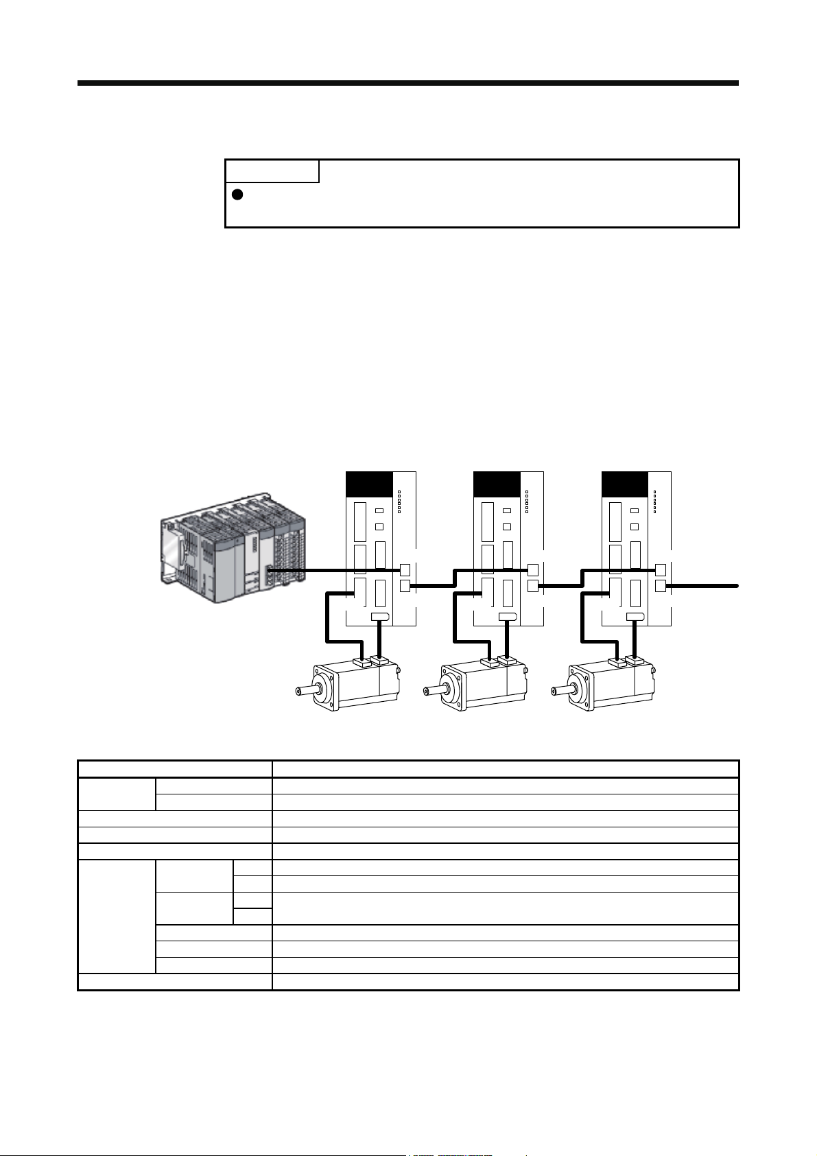
POINT
CC-Link IE Field Network communication function is available for the MR-J3-_T
servo amplifiers of which software version is B0 or above.
1.1 Summary
This instruction manual explains about MR-J3-T10 CC-Link IE Field Network interface unit. Refer to MR-J3_T Servo Amplifier Instruction Manual for the information not given in this manual.
Always use MR-J3-T10 with an MR-J3-_T. MR-J3-T10 enables an MR-J3-_T to connect to the CC-Link IE
Field Network by being attached to the MR-J3-_T.
The CC-Link IE Field Network communication function is exclusive of the CC-Link communication function. It
cannot be used with the CC-Link communication function at the same time.
1.2 System configuration
Master
Controller
CN10A
Slave
MR-J3-_T
MR-J3-T10 MR-J3-_T MR-J3-T10MR-J3-_T MR-J3-T10
CN10A
CN10A
CNP3
CN2
CN10B
CNP3
CN2
CN10B
1.3 Standard specifications
Model MR-J3-T10
Control circuit
power supply
I/O interfaces CC-Link IE Field Network interface
Number of communication ports 2 (CN10A connector/CN10B connector)
Structure Natural-cooling, open (IP rating: IP 00)
Environment
Mass [g] 150
Voltage 5 V DC (supplied from the servo amplifier)
Rated current [A] 0.8
Ambient
temperature
Ambient
humidity
Ambience Indoors (no direct sunlight), free from corrosive gas, flammable gas, oil mist, dust and dirt
Altitude 1000 m or less above sea level
Vibration resistance 5.9 m/s
Operation
Storage
Operation
Storage
0 °C to 55 °C (non-freezing)
-20 °C to 65 °C (non-freezing)
90 %RH or less (non-condensing)
2
at 10 Hz to 55 Hz (X, Y and Z axes)
CNP3
CN2
CN10B
1 - 1
Page 9
1. FUNCTIONS AND CONFIGURATION
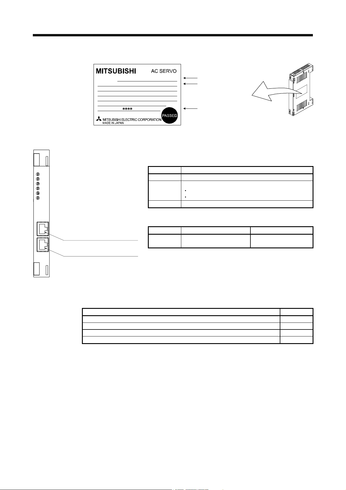
1.4 Rating plate
MODEL
POWER
INPUT
OUTPUT
SERIAL
1.5 Connector/interface
MR-J3-T10
RUN
ERR.
D LINK
SD
RD
L.ERR
CN10ACN10B
PUSH PUSH
CC-Link IE Field Network
communication connector (CN10A)
CC-Link IE Field Network
communication connector (CN10B)
1.6 Contents of the package
MR-J3-T10
:
IP00 MANUAL IB-0300171
1.5A 3PH+1PH
:
3PH+1PH200-230V
2.2A 1PH 200-230V
:
170V 0-360Hz 1.5A
:
For the wiring of CC-Link IE Field Network, use the following
wiring tools recommended by the CC-Link Partner Association.
Items Description
Cable type Shielded twisted pair cable (Category 5e)
Standard
Connector Category 5e or more RJ-45 plug
Commercially available products (as of April 2012)
Model Manufacturer Contact (Note)
SC-E5EW(-L)
(Note 1)
Note. The SC-E5EW cable is for in-enclosure and indoor uses. The SC-E5EW-
L cable is for outdoor use.
The CC-Link IE controller network cable cannot be used for the
CC-Link IE Field Network.
Model
IP rating Installation guide
Serial number
One of the following standards must be met.
IEEE802.3 1000BASE-T
ANSI/TIA/EIA-568-B (Category 5e)
Mitsubishi Electric System &
Service
email: oss-ip@melsc.jp
Contents Quantity
MR-J3-T10 CC-Link IE Field Network interface unit 1
MR-J3-T10 Installation Guide (IB(NA)0300159) 1
ZCAT1730-0730 data line filer (TDK) (Note 1) 2
Connector cover for CN10A/CN10B/CN3 (Note 2) 3
Note 1. Use the data line filters on the cables connected to the CN10A and CN10B connectors.
2. Two of the connector covers are already mounted on the CN10A and CN10B connectors when the
product is shipped from the factory. The other connector cover is for the CN3 connector of the MR-J3_T servo amplifier.
1 - 2
Page 10
1. FUNCTIONS AND CONFIGURATION
1.7 Installation and removal of the unit
Before installing or removing the unit, turn off the power and wait for 15 minutes
or more until the charge lamp turns off. Then, confirm that the voltage between P
WARNING
CAUTION
(+) and N (-) is safe with a voltage tester and others. Otherwise, an electric shock
may occur. In addition, when confirming whether the charge lamp is off or not,
always confirm it from the front of the servo amplifier.
Avoid installing and removing the unit repeatedly. Any contact failure of the
connector may be caused.
Avoid unsealing the unit to be free of dust and dirt against the connector except
installing. Make sure to use the pre-packing when storing.
Avoid using the unit of which the hook and knobs for fixing are damaged. Any
contact failure of the connector may be caused.
When installing and removing the unit to the MR-J3-500T or more, avoid dropping
out the installing screw inside it. Otherwise, it may cause a malfunction.
When installing and removing the unit to the MR-J3-500T or more, avoid
damaging the control board by the fixing plate. Otherwise, it may cause a
malfunction.
Make sure to tighten the unit with the enclosed installing screws when installing.
POINT
The internal circuits of the servo amplifier and the unit may be damaged by
static electricity. Always take the following precautions.
Ground human body and work bench.
Do not touch the conductive areas, such as connector pins and electrical
parts, directly by hand.
1 - 3
Page 11
1. FUNCTIONS AND CONFIGURATION
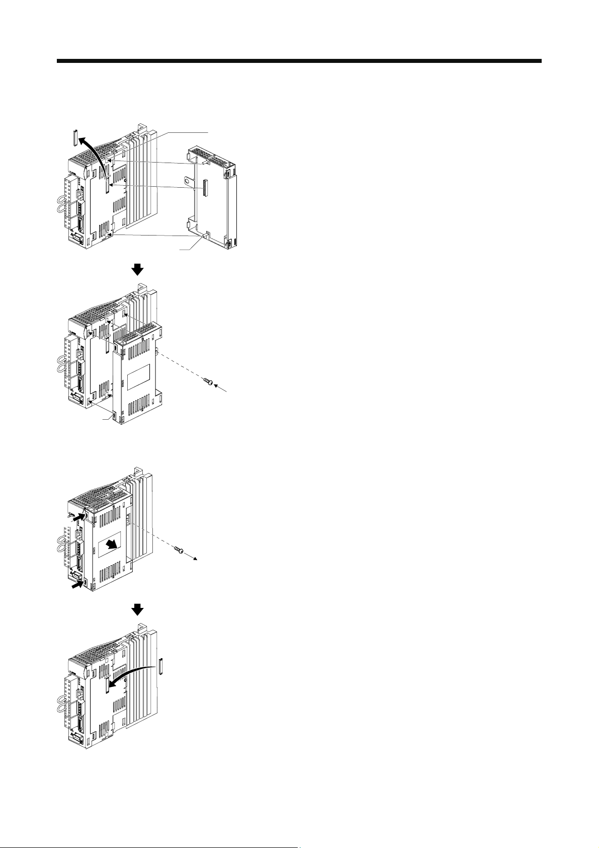
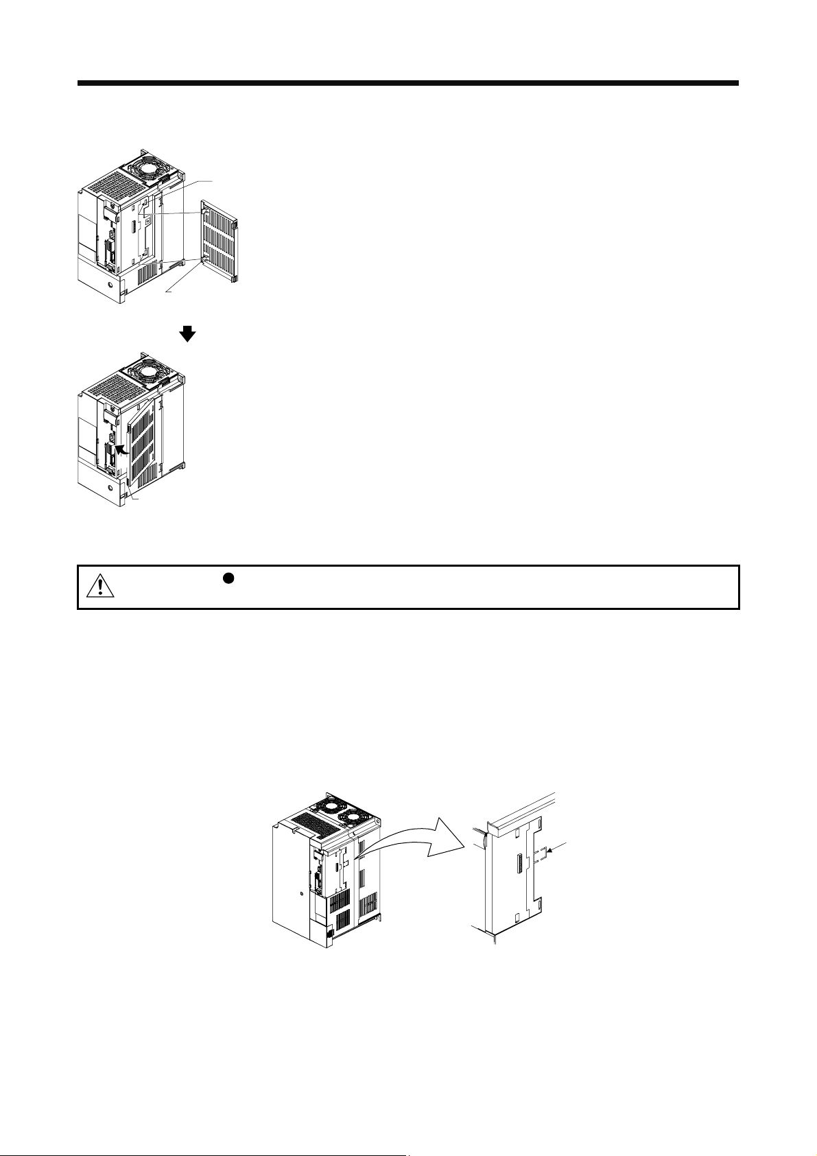
(1) MR-J3-350T or less/MR-J3-200T4 or less
(a) Installation of the unit
1)
Guide hole
2)
2)
Guide pins
Unit
(MR-J3-T10)
1) Remove the cover of connector for connecting
an option. Make sure to store the removed
cover.
2) Find the guide hole on the side of the servo
amplifier. To the guide hole, insert the unit's
guide pins.
Knobs
(b) Removal of the unit
a)
2)
3) Push the unit until the knobs click.
4) Tighten the unit with the enclosed installing
screw (M4).
4)
1) Remove the installing screw.
2) Keep pushing the knobs ( a) , b)) and pull out
the unit to the arrow direction. Avoid pulling out
the unit while it is tightened with the installation
1)
screw.
b)
When removing the unit, make sure to reinstall the
cover of connector for connecting an option to
avoid dust and dirt.
1 - 4
Page 12
1. FUNCTIONS AND CONFIGURATION
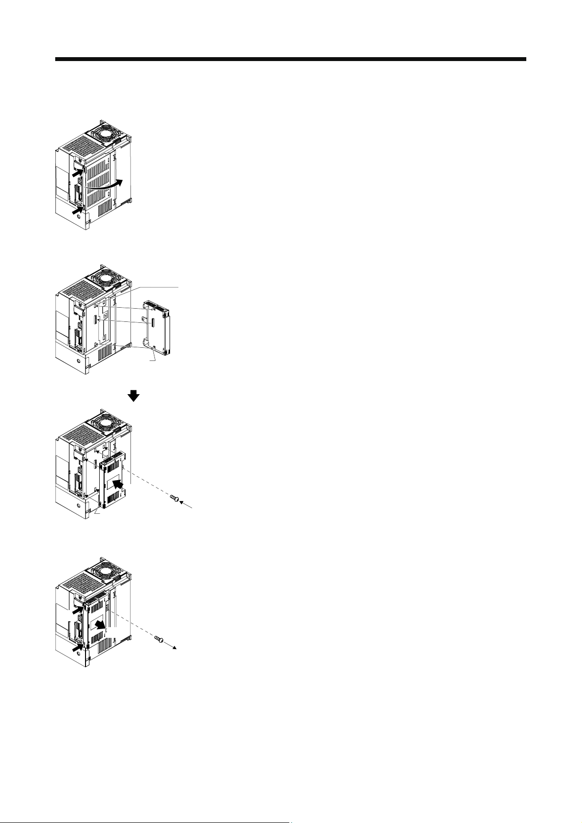
(2) MR-J3-350T4/MR-J3-500T(4)/MR-J3-700T(4)
(a) Removal of the side cover
a)
b)
(b) Installation of the unit
1)
Guide hole
1)
Keep pushing the knobs ( a) , b)) and pull out the
side cover to the arrow direction.
1) Find the guide hole on the side of the servo
amplifier. To the guide hole, insert the unit's
guide pins.
1)
Guide pins
2)
Knobs
(c) Removal of the unit
a)
2)
2) Push the unit until the knobs click.
3) Tighten the unit with the enclosed installing
screw (M4).
3)
1) Remove the installing screw.
2) Keep pushing the knobs ( a) , b)) and pull out
the unit to the arrow direction. Avoid pulling out
the unit while it is tightened with an installation
1)
screw.
b)
1 - 5
Page 13
1. FUNCTIONS AND CONFIGURATION
(d) Installation of the side cover
a)
1)
1)
Hook of the side cover
1) Insert the side cover setting tabs into the
sockets a) of servo amplifier.
2) Push the side cover at the supporting point a)
until the knob clicks.
2)
Knob
(3) MR-J3-11KT(4) to MR-J3-22KT(4)
Avoid touching any remained burr after cutting off the part a) of the case.
CAUTION
Otherwise, injury may occur.
The installing screw holes for the MR-J3-11KT(4) to MR-J3-22KT(4) are covered at shipping. When
installing the unit for the first time, cut off the part a) of the case after removing the side cover.
When cutting off the part a), avoid damaging the case of the servo amplifier. After cutting off it, inside of
the servo amplifier has been exposed even though the side cover and the unit are installed. Avoid
unwanted parts from entering through the opened area into the servo amplifier. For installing or
removing the unit, refer to (2) in this section. The side cover structure is the same for MR-J3-11KT(4) to
MR-J3-22KT(4) and for this unit. Install or remove the side cover with the same way as for the unit.
However, the installing screw for the side cover is unnecessary.
a)
1 - 6
Page 14
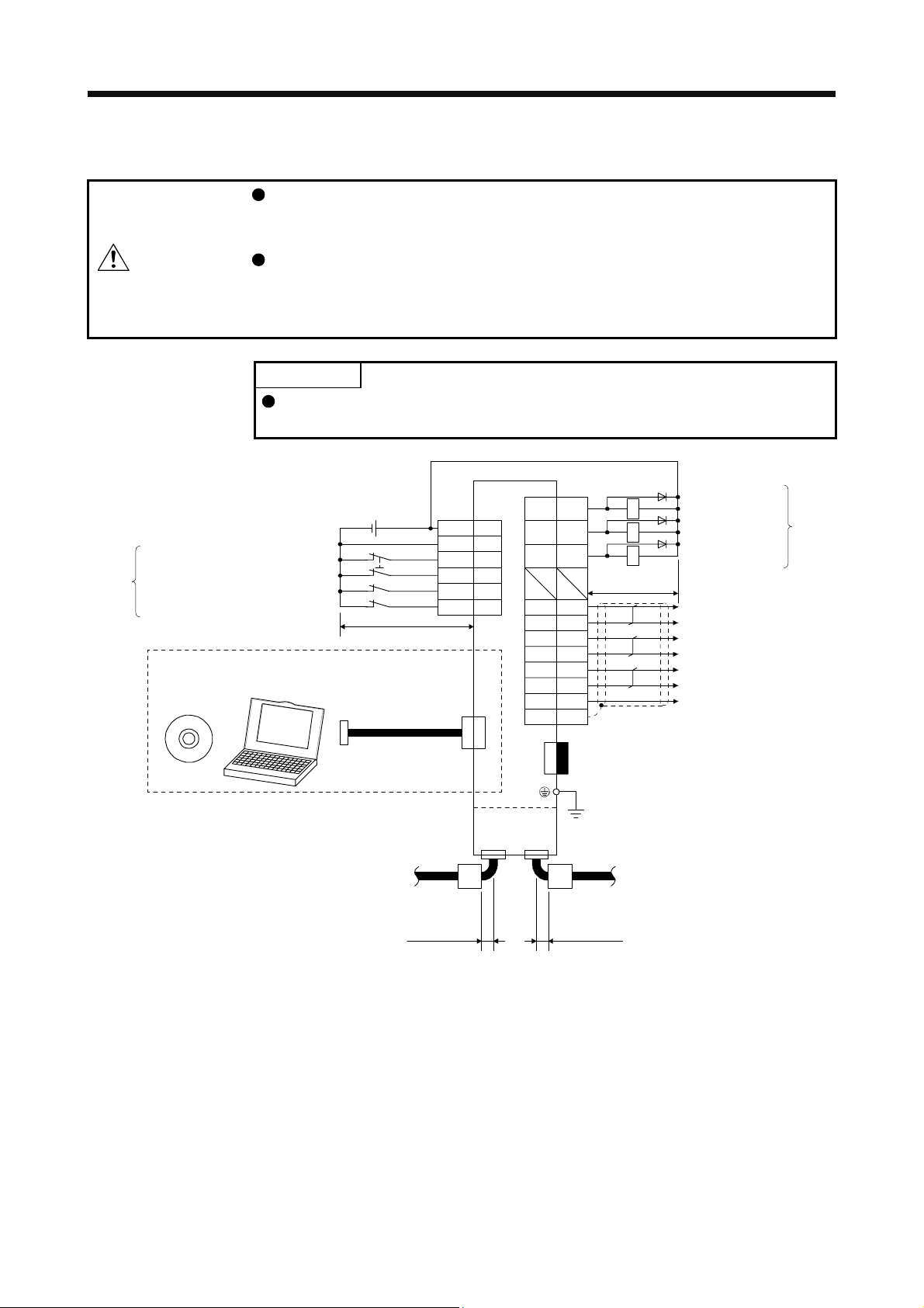
2. I/O SIGNAL CONNECTION EXAMPLE
2. I/O SIGNAL CONNECTION EXAMPLE
This chapter describes an example of connecting I/O signals. For details of MRJ3-_T signals and how to connect them, be sure to refer to the chapter 4 of MRJ3-_T Servo Amplifier Instruction Manual.
CAUTION
(Note 3, 5)
(Note 9)
(Note 5)
(Note 8)
(Note 7)
MR Configurator/
MR Configurator2
Forced stop
Proximity dog
Forward rotation stroke end
Reverse rotation stroke end
Connecting the CC-Link IE Field Network cable to the CN3 connector on MR-J3_T causes malfunctions in network devices. Pay attention when connecting the
CC-Link IE Field Network cable because the CN3, CN10A, and CN10B
connectors have the same shape.
POINT
Use MR Configurator of MRZJW3-SETUP221E (software version C4 or above).
Use MR Configurator2 of SW1DNC-MRC2-E (software version 1.10L or above).
Servo amplifier
24 V DC (Note 4)
10 m or less
Personal
computer
MR-J3USBCBL3M
(Option)
+
CN6
DICOM
DOCOM
EMG
DOG
LSP
LSN
CN5
CN6
14 RD
5
17
1
2
3
4
15
16 ZP
13
26
11
24
12
25
23
Plate
CN3
ALM
LZ
LZR
LA
LAR
LB
LBR
LG
SD
(Note 1)
(Note 2)
RA1
RA3
RA4
10 m or less
(Note 12)
Connector cover
Ready
Malfunction (Note 6)
Home position
return completion
Encoder Z-phase pulse
(differential line driver)
Encoder A-phase pulse
(differential line driver)
Encoder B-phase pulse
(differential line driver)
Control common
(Note 9)
MR-J3-T10
(Note 10, 11)
CN10B
CN10A
CC-Link IE Field Network
Data line filter
ZCAT1730-0730 (TDK)
Data line filter
ZCAT1730-0730 (TDK)
80 mm or less 80 mm or less
CC-Link IE Field Network
2 - 1
Page 15
2. I/O SIGNAL CONNECTION EXAMPLE
r
Note 1. To prevent an electric shock, always connect the protective earth (PE) terminal (marked ) of the servo amplifier to the
protective earth (PE) of the cabinet.
2. Connect the diode in the correct direction. If it is connected reversely, the servo amplifier will be faulty and will not output
signals, disabling EMG (Forced stop) and other protective circuits.
3. The forced stop switch (normally closed contact) must be installed.
4. Supply 24 V DC ± 10% 150 mA current for interfaces from the outside. 150 mA is the value applicable when all I/O signals are
used. The current capacity can be decreased by reducing the number of I/O points. Refer to section 4.8.2 (1) in MR-J3-_T
Servo Amplifier Instruction Manual that gives the current value necessary for the interface.
5. When starting operation, always turn on EMG (Forced stop) and LSP/LSN (Forward/Reverse rotation stroke end). (Normally
closed contact)
6. ALM (Malfunction) turns on in normal alarm-free condition.
7. Use MR Configurator of MRZJW3-SETUP221E (software version C4 or above). Use MR Configurator2 of SW1DNC-MRC2-E
(software version 1.10L or above).
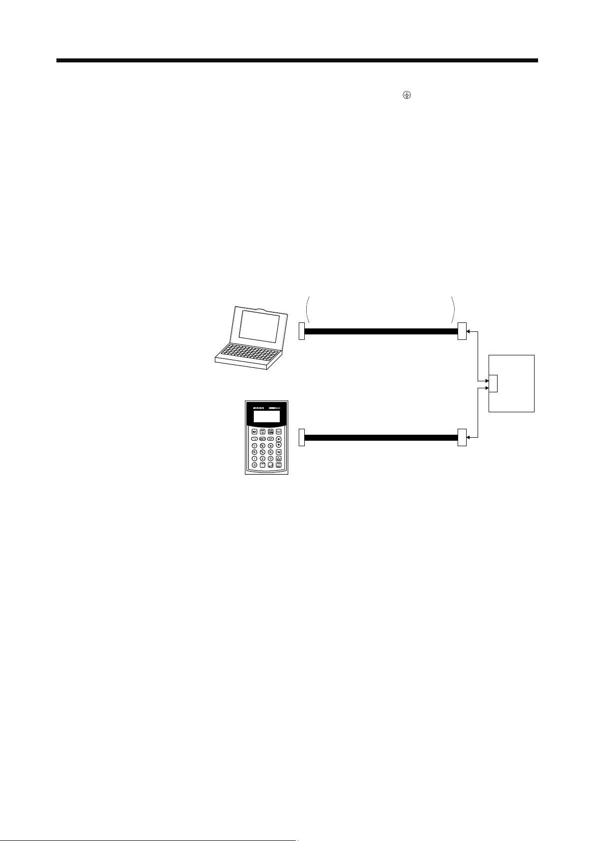
8. Personal computers or parameter units can also be connected via the CN3 connector, enabling RS-422 communication. Note
that using the USB communication function (CN5 connector) prevents the RS-422 communication function (CN3 connector)
from being used, and vice versa. They cannot be used together.
Personal compute
RS-232C/RS-422 conversion cable
Recommended product: Interface cable
DSV-CABV
(Diatrend)
To RS-232C connector
or
MR-PRU03
parameter unit
EIA568-compliant cable (10BASE-T cable, etc.)
9. This diagram is for sink I/O interface. For source I/O interface, refer to section 4.8.3 in MR-J3-_T Servo Amplifier Instruction
Manual.
10. Note that using the CC-Link IE Field Network communication function prevents the CC-Link communication function from
being used, and vice versa. They cannot be used together.
11. Connecting the CC-Link IE Field Network cable to the CN3 connector of MR-J3-_T causes malfunctions in network devices.
Pay attention when connecting the CC-Link IE Field Network cable because the CN3, CN10A, and CN10B connectors have
the same shape. Connector covers are mounted on the CN10A and the CN10B connectors when the product is shipped from
the factory. Remove those connector covers to connect the CC-Link IE Field Network cables.
12. To avoid incorrect connection, set a connector cover, which is supplied with MR-J3-T10, to the CN3 connector of MR-J3-_T.
Servo amplifier
CN3
2 - 2
Page 16

3. PARAMETERS
3. PARAMETERS
The MR-J3-_T parameters during CC-Link IE Field Network communication are
CAUTION
3.1 Basic setting parameters [Pr. PA_ _ ]
the same with the parameters during CC-Link communication, except for [Pr.
Po34] and [Pr. Po35]. Refer to the chapter 6 of MR-J3-_T Servo Amplifier
Instruction Manual for the details of the parameters not listed in this chapter.
POINT
Parameter whose symbol is preceded by * is made valid with the following
conditions.
*: After setting the parameter, turn off the power and then on again.
No. Symbol Name
PA01 *STY Control mode 0000h
PA02 *REG Regenerative option 0000h
PA03 *ABS Absolute position detection system 0000h
PA04 *AOP1 Function selection A-1 0000h
PA05 *FTY Feeding function selection 0000h
PA06 *CMX Electronic gear numerator 1
PA07 *CDV Electronic gear denominator 1
PA08 ATU Auto tuning mode 0001h
PA09 RSP Auto tuning response 12
PA10 INP In-position range 100 µm
PA11 TLP Forward rotation torque limit 100.0 %
PA12 TLN Reverse rotation torque limit 100.0 %
PA13 This parameter is not used. Do not change this value by any means. 0002h
PA14 *POL Rotation direction selection 0
PA15 *ENR Encoder output pulses 4000 pulse/rev
PA16 This parameter is not used. Do not change this value by any means. 0
PA17 0000h
PA18
PA19 *BLK Parameter write inhibit 000Ch
0000h
Initial
value
Unit
3 - 1
Page 17

3. PARAMETERS
3.2 Gain/filter parameters [Pr. PB_ _ ]
No. Symbol Name
PB01 FILT Adaptive tuning mode (adaptive filter II) 0000h
PB02 VRFT
PB03 This parameter is not used. Do not change this value by any means. 0000h
PB04 FFC Feed forward gain 0 %
PB05 This parameter is not used. Do not change this value by any means. 500
PB06 GD2 Load to motor inertia ratio 7.0 Multiplier
PB07 PG1 Model loop gain 24 rad/s
PB08 PG2 Position loop gain 37 rad/s
PB09 VG2 Speed loop gain 823 rad/s
PB10 VIC Speed integral compensation 33.7 ms
PB11 VDC Speed differential compensation 980
PB12 This parameter is not used. Do not change this value by any means. 0
PB13 NH1 Machine resonance suppression filter 1 4500 Hz
PB14 NHQ1 Notch shape selection 1 0000h
PB15 NH2 Machine resonance suppression filter 2 4500 Hz
PB16 NHQ2 Notch shape selection 2 0000h
PB17 Automatic setting parameter
PB18 LPF Low-pass filter setting 3141 rad/s
PB19 VRF1 Vibration frequency for vibration suppression control 100.0 Hz
PB20 VRF2 Resonance frequency for vibration suppression control 100.0 Hz
PB21 This parameter is not used. Do not change this value by any means. 0.00
PB22
PB23 VFBF Low-pass filter selection 0000h
PB24 *MVS Slight vibration suppression control selection 0000h
PB25 This parameter is not used. Do not change this value by any means. 0000h
PB26 *CDP Gain switching selection 0000h
PB27 CDL Gain switching condition 10
PB28 CDT Gain switching time constant 1 ms
PB29 GD2B Load to motor inertia ratio after gain switching 7.0 Multiplier
PB30 PG2B Gain changing position loop gain 37 rad/s
PB31 VG2B Gain changing speed loop gain 823 rad/s
PB32 VICB Gain switching speed integral compensation 33.7 ms
PB33 VRF1B Vibration frequency for vibration suppression control after gain switching 100.0 Hz
PB34 VRF2B Resonance frequency for vibration suppression control after gain switching 100.0 Hz
PB35 This parameter is not used. Do not change this value by any means. 0.00
PB36 0.00
PB37 100
PB38 0
PB39 0
PB40 0
PB41 1125
PB42 1125
PB43 0004h
PB44 0000h
PB45
Vibration suppression control tuning mode (advanced vibration suppression
control)
0.00
0000h
Initial
value
0000h
Unit
3 - 2
Page 18

3. PARAMETERS
3.3 Extension setting parameters [Pr. PC_ _ ]
3.3.1 Parameter list
No. Symbol Name
Initial
value
Unit
PC01 This parameter is not used. Do not change this value by any means. 0000h
PC02 *ZTY Home position return type 0000h
PC03 *ZDIR Home position return direction 0001h
PC04 ZRF Home position return speed 500 r/min
PC05 CRF Creep speed 10 r/min
PC06 ZST Home position shift distance 0 µm
PC07 *ZPS Home position return data 0 × 10
PC08 DCT Moving distance after proximity dog 1000 × 10
STM
STM
µm
µm
PC09 ZTM Stopper type home position return stopper time 100 ms
PC10 ZTT Stopper type home position return torque limit value 15.0 %
PC11 CRP Rough match output range 0 × 10
STM
µm
PC12 JOG Jog speed 100 r/min
PC13 *STC S-shaped acceleration/deceleration time constant 0 ms
PC14 *BKC Backlash compensation 0 pulse
PC15 This parameter is not used. Do not change this value by any means. 0000h
PC16 MBR Electromagnetic brake sequence output 100 ms
PC17 ZSP Zero speed 50 r/min
PC18 *BPS Alarm history clear 0000h
PC19 *ENRS Encoder output pulses selection 0000h
PC20 *SNO Station number setting 0 station
PC21 *SOP RS-422 communication function selection 0000h
PC22 *COP1 Function selection C-1 0000h
PC23 This parameter is not used. Do not change this value by any means. 0000h
PC24 *COP3 Function selection C-3 0000h
PC25 This parameter is not used. Do not change this value by any means. 0000h
PC26 *COP5 Function Selection C-5 0000h
PC27 This parameter is not used. Do not change this value by any means. 0000h
PC28 *COP7 Function selection C-7 0000h
PC29 This parameter is not used. Do not change this value by any means. 0000h
PC30 *DSS Remote register-based position/speed specifying system selection 0000h
PC31 LMPL Software limit + 0 × 10
PC32 LMPH
PC33 LMNL Software limit - 0 × 10
STM
STM
µm
µm
PC34 LMNH
PC35 TL2 Internal torque limit 2 100.0 %
PC36 This parameter is not used. Do not change this value by any means. 0000h
PC37 *LPPL Position range output address + 0 × 10
PC38 *LPPH
PC39 *LNPL Position range output address - 0 × 10
STM
STM
µm
µm
PC40 *LNPH
PC41 This parameter is not used. Do not change this value by any means. 0000h
PC42 0000h
PC43 0000h
PC44 0000h
PC45 0000h
PC46 0000h
PC47 0000h
PC48 0000h
PC49
0000h
PC50 *COPA Function selection C-A 0000h
3 - 3
Page 19

3. PARAMETERS
3.3.2 Detail description
POINT
The parameter names of [Pr. PC50] is not displayed with the following versions
of MR Configurator/MR Configurator2. However, this setting value is
changeable. Follow the instructions in this Instruction Manual to set a value.
MRZJW3-SETUP221E: software version C3 or below
SW1DNC-MRC2-E: software version 1.09K or below
No. Symbol Name and function
PC50 *COPA Function selection C-A
000
[AL. 8D CC-Link IE communication error] extended
function selection
0: No extended function
1: Delayed [AL. 8D] detection
Use [Pr. PD25] to set how long to delay the
occurrence timing of [AL. 8D].
Initial
value
0000h Refer to
Setting
range
Name
and
function
column.
Unit
3 - 4
Page 20

3. PARAMETERS
3.4 I/O setting parameters [Pr. PD_ _ ]
3.4.1 Parameter list
No. Symbol Name
PD01 *DIA1 Input signal automatic on selection 1 0000h
PD02 This parameter is not used. Do not change this value by any means. 0000h
PD03 *DIA3 Input signal automatic on selection 3 0000h
PD04 *DIA4 Input signal automatic on selection 4 0000h
PD05 This parameter is not used. Do not change this value by any means. 0000h
PD06 *DI2 Input signal device selection 2 (CN6-2) 002Bh
PD07 *DI3 Input signal device selection 3 (CN6-3) 000Ah
PD08 *DI4 Input signal device selection 4 (CN6-4) 000Bh
PD09 *DO1 Output signal device selection 1 (CN6-14) 0002h
PD10 *DO2 Output signal device selection 2 (CN6-15) 0003h
PD11 *DO3 Output signal device selection 3 (CN6-16) 0024h
PD12 DIN1 External DI function selection 1 0C00h
PD13 This parameter is not used. Do not change this value by any means. 0000h
PD14 DIN3 External DI function selection 3 0800h
PD15 This parameter is not used. Do not change this value by any means. 0000h
PD16 *DIAB Input polarity selection 0000h
PD17 This parameter is not used. Do not change this value by any means. 0000h
PD18
PD19 *DIF Input filter setting 0002h
PD20 *DOP1 Function selection D-1 0010h
PD21 This parameter is not used. Do not change this value by any means. 0000h
PD22 *DOP3 Function selection D-3 0000h
PD23 This parameter is not used. Do not change this value by any means. 0000h
PD24 *DOP5 Function selection D-5 0000h
PD25 A8DT [AL. 8D CC-Link IE communication error] detection time 0000h ms
PD26 This parameter is not used. Do not change this value by any means. 0000h
PD27 0000h
PD28 0000h
PD29 0000h
PD30
0000h
0000h
Initial
value
Unit
3 - 5
Page 21

3. PARAMETERS
3.4.2 Detail description
POINT
The parameter names of [Pr. PD25] is not displayed with the following versions
of MR Configurator/MR Configurator2. However, this setting value is
changeable. Follow the instructions in this Instruction Manual to set a value.
MRZJW3-SETUP221E: software version C3 or below
SW1DNC-MRC2-E: software version 1.09K or below
No. Symbol Name and function
PD25 A8DT [AL. 8D CC-Link IE communication error] detection time
Selecting the [AL. 8D] detection time in [Pr. PC50] activates the time setting of
[AL. 8D].
It is 10 ms when [Pr. PC50] = "0".
Convert a decimal value to a hexadecimal value for input.
The setting range is up to 1000 ms. A set value is limited within the setting
range.
For example) If "03E8h" is set, the set value becomes 1000 ms.
The converted decimal value of "1388h" is 10000 ms, but it is
limited to 1000 ms, which is the upper limit of the setting range.
Initial
value
0000h 0000h
Setting
range
to
03E8h
Unit
ms
If [AL. 8D CC-Link IE
communication error] does not
have to be detected, use the
communication time-out setting in
the initial setting. When you
CAUTION
change the setting value, do not
set an unnecessarily long time
period. Doing so interferes swift
stop operation at an occurrence of
[AL. 8D CC-Link IE
communication error].
3 - 6
Page 22

3. PARAMETERS
3.5 Option unit parameters [Pr. Po_ _ ]
3.5.1 Parameter list
No. Symbol Name
Po01 This parameter is not used. Do not change this value by any means. 0000h
Po02 0302h
Po03 0905h
Po04 2524h
Po05 2026h
Po06 0427h
Po07 0807h
Po08 2726h
Po09 0423h
Po10 2101h
Po11 0000h
Po12 0000h
Po13 0000h
Po14 0001h
Po15 0
Po16 0
Po17 0
Po18 0
Po19 0
Po20 0
Po21 0
Po22 0
Po23 0000h
Po24 0050h
Po25 0200h
Po26 0
Po27 0
Po28 0
Po29 0000h
Po30 0000h
Po31 0000h
Po32 0000h
Po33
Po34 *STNO CC-Link IE communication station number selection 0000h
Po35 *NWNO CC-Link IE communication network number 0000h
0000h
Initial
value
Unit
3 - 7
Page 23

3. PARAMETERS
3.5.2 Detail description
POINT
The parameter names of [Pr. Po34] and [Pr. Po35] are not displayed with the
following versions of MR Configurator/MR Configurator2. However, their setting
values are changeable. Follow the instructions in this Instruction Manual to set a
value.
MRZJW3-SETUP221E: software version C3 or below
SW1DNC-MRC2-E: software version 1.09K or below
No. Symbol Name and function
Po34 *STNO CC-Link IE communication station number selection
Use this parameter to set the station number of the servo amplifier.
Convert a decimal value to a hexadecimal value for input.
If you are using an automatic station number, which is designated by the
master station, do not change the initial value "0000h".
If you are designating a station number, set a value in the range of 1 to 120
(0001h to 0078h). A value higher the maximum value will trigger [AL. 37
parameter error].
For example) The setting value "0078h" sets the station number of 120.
The setting value "0079h" or a higher will trigger [AL. 37
parameter error].
Po35 *NWNO CC-Link IE communication network number
Use this parameter to set the network number of the servo amplifier.
Convert a decimal value to a hexadecimal value for input.
The network number is 1 at the initial value of "0000h".
The maximum setting value for the network number is 239.
A value higher than the maximum value will trigger [AL. 37 parameter error].
For example) The setting value "00EFh" sets the station number of 239.
The setting value "012Ch" will trigger [AL. 37 parameter error].
If an automatic number has been selected with [Pr. Po34] and the rotary
switch on the MR-J3-_T, this parameter setting is ignored. Instead, the
network number transmitted from the master station is used.
Initial
value
0000h 0000h
0000h 0000h
Setting
range
to
0078h
to
00EFh
Unit
3 - 8
Page 24

4. DISPLAY/OPERATING PARTS
4. DISPLAY/OPERATING PARTS
4.1 MR-J3-_T servo amplifier
4.1.1 Explanation on the display/operating parts
5
6
4
7
3
8
2
9
1
0
5
5
6
4
3
2
6
4
7
7
3
8
8
2
9
1
9
1
0
0
Name/application
Display
The 3-digit, seven-segment LED shows the servo status and alarm
number.
Baud rate switch (MODE)
MODE
5
6
4
Do not change the initially set value (0).
7
3
8
2
9
1
0
Station number switches (STATION NO.)
For the setting method, refer to the section 4.3.
X10 STATION NO. X1
5
5
6
4
3
2
1
6
4
7
7
3
8
8
2
9
9
1
0
0
Set the ones place.
Set the tens place.
Occupied station count switch (SW1)
SW1
Do not change the initial setting (off).
4 - 1
Page 25

4. DISPLAY/OPERATING PARTS
4.1.2 Display details
On the servo amplifier display (three-digit, seven-segment display), check the status of communication with
the CC-Link IE controller at power-on, check the station number, and diagnose a fault at occurrence of an
alarm.
The table below shows the details.
Display Status Description
b## CC-Link IE communication
waiting
(Note 1) d## Ready Servo-on has been performed after initialization, and it is ready for operation. (The
(Note 1) C## Not ready Initialization is in progress, or an alarm has occurred.
(Note 2) $$$ Drive enabled The drive enabled condition has lasted for 2 s after turning on RYn1 (servo-on).
(Note 3) A** Alarm/Warning The alarm No./warning No. that occurred is displayed.
888 CPU Error CPU watchdog error has occurred.
(Note 4) b00 JOG operation, positioning operation, program operation, DO forced output, and 1
(Note 1) d##.
C##.
(Note 4)
Test operation mode
Note 1. ## denotes any of symbols or numerals of -- or 00 to C0 and what it means is listed below.
2. $$$ indicates the number of the point table No. being executed. $$$ is a number between 0 and 255.
3. ** indicates the warning/alarm No.
4. MR Configurator/MR Configurator2 or an MR-PRU03 parameter unit is required.
4.1.3 Unspecified station number
Power of the servo amplifier was switched on at the condition that the power of the
CC-Link IE master module is off.
CC-Link IE master module is faulty.
display appears for 2 s.)
step feed
Motor-less operation
## Description
00 Set to the test operation mode.
-- For the station No. 0 (unset), refer to section 4.1.3.
01 Station No. 1
02 Station No. 2
: :
: :
99 Station No. 99
A0 Station No. 100
: :
: :
A9 Station No. 109
b0 Station No. 110
: :
: :
b9 Station No. 119
c0 Station No. 120
If 0 (unspecified) is set as the station number, the communication is performed with the station number set
by the master station.
Display
Servo amplifier
power on
b- - cAO
CC-Link IE communication starts
Station No.100 designated by the master station
4 - 2
Page 26

4. DISPLAY/OPERATING PARTS
4.2 MR-J3-T10 IE Field Network interface unit
The table below shows the detailed description of the communication alarm display area. MR-J3-T10 has
eight LEDs.
Table 4.1 LED display description
MR-J3-T10
No. LED Name
1 RUN Operating status Lit Operating normally (RUN status)
RUN
ERR.
D LINK
SD
RD
L.ERR
Red
Red
Green
2 D LINK Cyclic communication
status
Flashing Data not linked (after parameter frame
3 SD Network transmission
CN10ACN10B
Green (LINK)
Red (L.ER)
Green (LINK)
Red (L.ER)
4 RD Network reception
5 ERR. Unit error status Lit Unit error
6 L ERR. Communication error
status
status
status
7 L ER
PUSH PUSH
(port 1/2)
8 LINK
Communication error
status
Link status Lit Linking up
(port 1/2)
The table below shows display pattens for different statuses.
No. Status RUN D LINK ERR. L ERR.
1 Failure at start
2 Normal (condition before communication connection)
3 Normal (condition before cyclic commutation established)
4 Normal (during cyclic communication)
5 Failure occurred (communication disabled due to faulty MR-
J3-T10)
6 Failure occurred (cyclic communication stopped due to faulty
MR-J3-T10)
7 Failure occurred (WDT error)
8 Failure occurred (option card come off)
9 Failure occurred (cyclic communication stopped due to
incorrect setting)
10 Failure occurred (abnormal data received, data looped back)
11 Failure occurred (disconnection due to twisted pair cable
came off)
12 Failure occurred (cyclic data not received)
13 Failure occurred (abnormal station/network number
designated by the master)
14 Reserved station specification
LED
status
Extinguished
Hardware fault (WDT error)
Description
Lit Linking data (cyclic transmitting)
received)
Extinguished
Data not linked (disconnecting)
Lit Data transmitting
Lit Data receiving
Extinguished
Nothing abnormal
Lit Receiving abnormal data. Or, data is looped
back to its own station.
Lit Receiving abnormal data. Or, data is looped
back to its own station.
L ER
(port)
- - - A74
- - - A74
LINK
(port)
- b**
- b**
- c**
- A74
- A74
-
-
- - A9E
- A9d
- A8d
- A8d
- A8d
- A8d
( : lit, : extinguished, : flashing, -: refer to Table 4.1.)
Servo
amplifier
display
A37
A8d
A75
4 - 3
Page 27

4. DISPLAY/OPERATING PARTS
4.3 Selecting the station number and network number
(1) How to number the stations
Set the servo station numbers before powering on the servo amplifiers. Station numbers may be set
within the range 1 to 120.
(2) Station number setting method
(a) Use the station number switches (RSW1, RSW2) on the front face of the MR-J3-_T to select a
station number between 1 to 64. In the initial status, the station number is set to station 1. When the
station number is set to 0, communication is performed with the station number designated by the
master station.
X10 STATION NO. X1
5
5
6
4
3
2
1
(b) Use [Pr. Po34] to select the station number 65 or above. In this case, the setting made by the station
number switches is ignored.
(c) A station number command from a master module through CC-Link IE Field Network has a priority
over the command sources (a) and (b). For how to use the master station to designate a station
number to a servo amplifier, refer to the user's manual of the CC-Link IE Field Network master/local
module.
(3) Network number setting
Use [Pr. Po35] to set a network number to a servo amplifier. The network number can be set between 1
and 239. When the station number is set to 0, communication is performed with the station number
designated by the master station. In the initial status, 0 is set. For how to use the master station to
designate a network number, refer to the user's manual of the CC-Link IE Field Network master/local
module.
6
4
7
7
3
8
8
2
9
9
1
0
0
Set the ones place.
Set the tens place.
4 - 4
Page 28

5. TROUBLESHOOTING
5. TROUBLESHOOTING
POINT
This chapter describes about the alarms and warnings, which are different from
the ones displayed in the CC-Link communication operation. Refer to the
chapter 11 of MR-J3-_T Servo Amplifier Instruction Manual for the alarms and
warnings not listed in this chapter.
The alarm names of [AL. 74] and [AL. 75] are not displayed with the following
versions of MR Configurator/MR Configurator2, and the alarms of CC-Link
communication are displayed for [AL. 8D], [AL. 97], [AL. 9D], and [AL. 9E].
Replace the alarm cause, etc. to the ones listed in this instruction manual.
MRZJW3-SETUP221E: software version C3 or below
SW1DNC-MRC2-E: software version 1.09K or below
5 - 1
Page 29

5. TROUBLESHOOTING
5.1 Alarm and warning list
After its cause has been removed, the alarm can be deactivated in any of the methods marked
in the
alarm deactivation column. The alarm is automatically canceled after removing the cause of occurrence.
Alarm deactivation No. Name
No. Name
10 Undervoltage
12 Memory error 1 (RAM)
Alarm
13 Clock error
15 Memory error 2 (EEP-ROM)
16 Encoder error 1 (at power-on)
17 Board error
19 Memory error 3 (Flash-ROM)
1A Motor combination error
20 Encoder error 2
24 Main circuit error
25 Absolute position erased
30 Regenerative error (Note 1) (Note 1) (Note 1)
31 Overspeed
32 Overcurrent
33 Overvoltage
35 Command pulse frequency error
37 Parameter error
45 Main circuit device overheat (Note 1) (Note 1) (Note 1)
46 Servo motor overheat (Note 1) (Note 1) (Note 1)
47 Cooling fan error
50 Overload 1 (Note 1) (Note 1) (Note 1)
51 Overload 2 (Note 1) (Note 1) (Note 1)
52 Error excessive
61 Operation alarm
74 Option card error
75 Option card error 2
8A
8D CC-Link IE communication error
8E Serial communication error
888 Watchdog
Serial communication time-out
error
Power
off to on
(Note 3)
MR Configurator/
MR Configurator2
Parameter unit
97 Next station warning
99 Stroke limit warning
9D CC-Link IE warning 1
9E CC-Link IE warning 2
9F Battery warning
E0 Excessive regeneration warning
E1 Overload warning 1
ED Output watt excess warning
(Note 4)
(Note 2)
Alarm
reset
(Note 4)
Warning
E9 Main circuit off warning
EC Overload warning 2
Home position return
90
incomplete warning
Battery cable disconnection
92
warning
96 Home position setting warning
98 Software limit warning
Absolute position counter
E3
warning
E6 Servo forced stop warning
Cooling fan speed reduction
E8
warning
Note 1. Wait for about 30 minutes as cooling time after removing the cause of occurrence, then deactivate the alarm.
2. Turns on RY (n + 1) A or RY (n + 3) A.
3. Clicking the "Alarm reset" button on the "Alarm display" screen of MR Configurator/MR Configurator2 allows an alarm to be
deactivated.
Pressing the "STOP RESET" key of the parameter unit allows an alarm to be deactivated.
4. Deactivation of the alarm may not be possible. Refer to the section 5.2 for details.
5 - 2
Page 30

5. TROUBLESHOOTING
5.2 Remedies for alarms
When an alarm occurs, ALM (Malfunction) switches on and the dynamic brake is operated to stop the servo
motor. At this time, the display indicates the alarm No.
Remove the cause of the alarm in accordance with this section. MR Configurator/MR Configurator2 may be
used to refer to the cause.
No. Name Description Cause Action
74 Option card error MR-J3-T10 is not properly
recognized.
75 Option card error 2 MR-J3-T10 is not properly
recognized.
8D 1. The station number is set to 65 or
CC-Link IE
communication
error
3. The network number is set to a
4. The transmission status is
5. CC-Link IE Field Network
6. CC-Link IE Field Network cable
7. CC-Link IE Field Network cable
8. Noise entered the CC-Link IE Field
9. A reserved station has been
Normal communication with
the master station cannot be
made.
MR-J3-T10 faulty. Replace the MR-J3-T10.
Connection failure of MR-J3-T10. Check the connection between
MR-J3-T10 and a servo
amplifier.
Set the station within the range 1
higher.
2. The station number is set to a
value other than 1 to 120 with the
master station.
value other than 1 to 239 with the
master station.
abnormal.
connector has come off.
wiring incorrect.
faulty.
Network cable.
selected by the master station, and
the cyclic communication has
stopped.
to 64, and turn the power on.
Set a value in the range 1 to 120
with the master station. After the
cause has been removed, the
alarm can be deactivated with a
reset.
Set a value in the range 1 to 239
with the master station. After the
cause has been removed, the
alarm can be deactivated with a
reset .
Review the wiring. After the
cause has been removed, the
alarm can be deactivated with a
reset.
1. Connect the cable or
connector correctly.
2. Repair or change the CC-Link
IE Field Network cable.
After the cause has been
removed, the alarm can be
deactivated with a reset.
Take the noise reduction
measures. After the cause has
been removed, the alarm can be
deactivated with a reset.
Deselect the reserved station
with the master station.
5 - 3
Page 31

5. TROUBLESHOOTING
5.3 Remedies for warnings
If [AL. 98 Software limit warning] and [AL. E6 Servo forced stop warning] occur, the servo off status is
established. If any other warning occurs, operation can be continued but an alarm may take place or proper
operation may not be performed.
Remove the cause of warning according to this section. Use MR Configurator/MR Configurator2 to refer to a
factor of warning occurrence.
No. Name Description Cause Action
97 Next station
warning (out of
setting range
warning)
9D CC-Link IE
warning 1
9E CC-Link IE
warning 2
2. CC-Link IE Field Network
3. CC-Link IE Field Network cable
4. CC-Link IE Field Network cable
5. Communication with the master
6. Data is looped back to its own
Setting error of point
table/next station/speed
selection
The station number switch or
baud rate switch setting has
been changed after power-on.
Communication error with the
cable.
A number for point table/next
station/speed selection has been set
with the master station.
1. The station number switch setting
has been changed after power-on.
2. The setting at the master station
side is incorrect.
1. The transmission status is
abnormal.
connector has come off.
wiring incorrect.
faulty.
station is abnormal.
station in a ring connection.
For the point table/next
station/speed selection, set a
number within the setting range
with the master station.
Return to the setting at poweron.
Review the setting on the master
station side.
Take the noise reduction
measures.
1. Connect the cable or
connector correctly.
2. Change the CC-Link IE Field
Network cable.
Review the communication
setting on the master station
side.
1. Connect the cable or
connector correctly.
2. Change the CC-Link IE Field
Network cable.
5 - 4
Page 32

6. DIMENSIONS
6. DIMENSIONS
(1) MR-J3-T10
[Unit: mm]
28
20
MR-J3-T10
103
98
94
5 × 6 mounting hole for grounding
161
114.5
97
Rating plate
24.5
Mass: 0.15 kg
6 - 1
Page 33

6. DIMENSIONS
r
(2) When the unit is mounted on a servo amplifier
100 V/200 V 0.1 kW to 3.5 kW
400 V 0.6 kW to 2 kW
MR-J3-T10 MR-J3-T10
CN5
CNP1
CN3
CN1
CNP2
CN10A
CN6
CNP3
CN10B
CN2
CN4
L
200 V 5 kW/7 kW
400 V 3.5 kW to 7 kW
Servo amplifierServo amplifie
CN5
CN3
CN1
CN10A
CN6
CN10B
CN2
CN4
L
Servo amplifier L [mm]
MR-J3-10T1 to MR-J3-401
20
MR-J3-10T to MR-J3-100T
MR-J3-60T4 to MR-J3-100T4
MR-J3-200TN/MR-J3-350T
15
MR-J3-200T4
MR-J3-500T/MR-J3-700T
10
MR-J3-350T4 to MR-J3-700T4
MR-J3-11KT to MR-J3-22KT
0
MR-J3-11KT4 to MR-J3-22KT4
6 - 2
Page 34

7. CC-LINK IE FIELD NETWORK COMMUNICATION FUNCTION
7. CC-LINK IE FIELD NETWORK COMMUNICATION FUNCTION
7.1 System configuration
Item CC-Link IE Field Network
Network topology Line/start/ring
Variable communication speed 1 Gbps
Transmission speed between stations 100 m
Number of connected units Max. 120
7.2 Communication specifications
Item Description
Device type CC-Link IE Field Network intelligent device station
Number of communication ports 2 ports (RJ45-1000BASE-T)
Cyclic communication
Receiving control signal (RY) 128 points, control data (RWw) 16 points
Transmitting control signal (RY) 128 points, control data (RWr) 16 points
7 - 1
Page 35

7. CC-LINK IE FIELD NETWORK COMMUNICATION FUNCTION
7.3 I/O device
Most devices used in CC-Link IE Field Network communication are the same with the devices used in CCLink communication with two occupied stations. However, some device numbers have been changed. The
devices, of which device numbers are different from the numbers in CC-Link communication, are shaded.
7.3.1 I/O devices for a programmable controller CPU
(1) Bit device (master station → servo amplifier RY)
(Note 1)
Device No.
RYn0 Servo-on Servo-on Servo-on
1 Forward rotation start Forward rotation start Forward rotation start
2 Reverse rotation start Reverse rotation start Reverse rotation start
3 Proximity dog Proximity dog Proximity dog
4 Forward rotation stroke end Forward rotation stroke end Forward rotation stroke end
5 Reverse rotation stroke end Reverse rotation stroke end Reverse rotation stroke end
6 Automatic/manual selection Automatic/manual selection Automatic/manual selection
7 Temporary stop/restart Temporary stop/restart Temporary stop/restart
8 Monitor output execution demand Monitor output execution demand Monitor output execution demand
9 Instruction code execution demand Instruction code execution demand Instruction code execution demand
A Point table No. selection 1 Point table No. selection 1 Reserved
B Point table No. selection 2 Point table No. selection 2 Reserved
C Point table No. selection 3 Point table No. selection 3 Reserved
D Point table No. selection 4 Point table No. selection 4 Reserved
E Point table No. selection 5 Point table No. selection 5 Reserved
F Clear Clear Clear
RY (n + 1) 0 Reserved Reserved Reserved
1 Reserved Reserved Reserved
2 Reserved Reserved Reserved
3 Reserved Reserved Reserved
4 Reserved Reserved Reserved
5 Reserved Reserved Reserved
6 Reserved Reserved Reserved
7 Reserved Reserved Reserved
8 Reserved Reserved Reserved
9 Reserved Reserved Reserved
A Reset Reserved Reserved
B Reserved Reserved Reserved
C Reserved Reserved Reserved
D Reserved Reserved Reserved
E Reserved Reserved Reserved
F Reserved Reserved Reserved
CC-Link (1 station)
RY (32 points)
CC-Link (2 stations)
RY (64 points)
CC-Link IE Field
RY (128 points) (Note 2)
7 - 2
Page 36

7. CC-LINK IE FIELD NETWORK COMMUNICATION FUNCTION
(Note 1)
Device No.
RY (n + 2) 0 Position command execution demand Position command execution demand
1 Speed command execution demand Speed command execution demand
2 Reserved Reserved
3 Point table No. selection 6 Reserved
4 Point table No. selection 7 Reserved
5 Point table No. selection 8 Reserved
6 Internal torque limit selection Internal torque limit selection
7 Proportional control Proportional control
8 Gain switching Gain switching
9 Reserved Reserved
A
B
C Reserved Reserved
D Reserved Reserved
E Reserved Reserved
F Reserved Reserved
RY (n + 3) 0 Reserved Reserved
1 Reserved Reserved
2 Reserved Reserved
3 Reserved Reserved
4 Reserved Reserved
5 Reserved Reserved
6 Reserved Reserved
7 Reserved Reserved
8 Reserved Reserved
9 Reserved Reserved
A Reset Reset
B Reserved Reserved
C Reserved Reserved
D Reserved Reserved
E Reserved Reserved
F Reserved Reserved
Note 1. "n" depends on the station number setting.
2. The number of bit device points is fixed to 128. If a point other than 128 is set, [AL. 9D] will occur. Device No. RY (n + 4) to RY
(n + 7) are reserved.
CC-Link (1 station)
RY (32 points)
CC-Link (2 stations)
RY (64 points)
Position/speed specifying system
selection
Absolute value/incremental value
selection
CC-Link IE Field
RY (128 points) (Note 2)
Position/speed specifying system
selection
Absolute value/incremental value
selection
7 - 3
Page 37

7. CC-LINK IE FIELD NETWORK COMMUNICATION FUNCTION
(2) Bit device (servo amplifier → master station RX)
(Note 1)
Device No.
RXn0 Ready Ready Ready
1 In-position In-position In-position
2 Rough match Rough match Rough match
3 Home position return completion Home position return completion Home position return completion
4 Limiting torque Limiting torque Limiting torque
5 Reserved Reserved Reserved
6 Electromagnetic brake interlock Electromagnetic brake interlock Electromagnetic brake interlock
7 Temporary stop Temporary stop Temporary stop
8 Monitoring Monitoring Monitoring
9 Instruction code execution completion Instruction code execution completion Instruction code execution completion
A Warning Warning Warning
B Battery warning Battery warning Battery warning
C Travel completion Travel completion Travel completion
D Dynamic brake interlock Dynamic brake interlock Dynamic brake interlock
E Position range output Position range output Position range output
F Reserved Reserved Reserved
RX (n + 1) 0 Reserved Reserved Reserved
1 Reserved Reserved Reserved
2 Reserved Reserved Reserved
3 Reserved Reserved Reserved
4 Reserved Reserved Reserved
5 Reserved Reserved Reserved
6 Reserved Reserved Reserved
7 Reserved Reserved Reserved
8 Reserved Reserved Reserved
9 Reserved Reserved Reserved
A Malfunction Reserved Reserved
B Remote station communication ready Reserved Reserved
C Reserved Reserved Reserved
D Reserved Reserved Reserved
E Reserved Reserved Reserved
F Reserved Reserved Reserved
RX (n + 2) 0
1
2 Point table No. output 1 Reserved
3 Point table No. output 2 Reserved
4 Point table No. output 3 Reserved
5 Point table No. output 4 Reserved
6 Point table No. output 5 Reserved
7 Point table No. output 6 Reserved
8 Point table No. output 7 Reserved
9 Point table No. output 8 Reserved
A Reserved Reserved
B Reserved Reserved
C Reserved Reserved
D Reserved Reserved
E Reserved Reserved
F Reserved Reserved
CC-Link (1 station)
RX (32 points)
CC-Link (2 stations)
RX (64 points)
Position command execution
completion
Speed command execution
completion
CC-Link IE Field
RX (128 points) (Note 2)
Position command execution
completion
Speed command execution
completion
7 - 4
Page 38

7. CC-LINK IE FIELD NETWORK COMMUNICATION FUNCTION
(Note 1)
Device No.
RX (n + 3) 0 Reserved Reserved
1 Reserved Reserved
2 Reserved Reserved
3 Reserved Reserved
4 Reserved Reserved
5 Reserved Reserved
6 Reserved Reserved
7 Reserved Reserved
8 Reserved Reserved
9 Reserved Reserved
A Malfunction Malfunction
B Remote station communication ready Remote station communication ready
C Reserved Reserved
D Reserved Reserved
E Reserved Reserved
F Reserved Reserved
Note 1. "n" depends on the station number setting.
2. The number of bit device points is fixed to 128. If a point other than 128 is set, [AL. 9D] will occur. Device No. RX (n + 4) to RX
(n + 7) are reserved.
(3) Word device (master station → servo amplifier RWw)
(Note 1)
Device No.
RWwn0 Monitor 1 Monitor 1 Monitor 1
1 Monitor 2 Monitor 2 Reserved
2 Instruction code Instruction code Monitor 2
3 Writing data Writing data Reserved
4
5
6
7
8
9
A
B
C
D
E
F
Note 1. "n" depends on the station number setting.
2. If an out-of-range value is set to Point table No. selection, [AL. 97] will occur.
3. The number of word device points is fixed to 16. If a point other than 16 is set, [AL. 9D] will occur.
CC-Link (1 station)
RX (32 points)
CC-Link (1 station)
RWw (4 points)
CC-Link (2 stations)
RX (64 points)
CC-Link (2 stations)
RWw (8 points)
Position command data lower 16 bits
/Point table No.
Position command data upper 16 bits Writing data
Speed command data/Point table No. Point table No. selection (Note 2)
Reserved Reserved
Instruction code
Position command data lower 16 bits
/Point table No.
Position command data upper 16 bits
Speed command data/Point table No.
Reserved
Reserved
Reserved
Reserved
Reserved
CC-Link IE Field
RX (128 points) (Note 2)
CC-Link IE Field
RWw (16 points) (Note 3)
7 - 5
Page 39

7. CC-LINK IE FIELD NETWORK COMMUNICATION FUNCTION
(4) Word device (servo amplifier → master station RWr)
(Note 1)
Device No.
RWrn0 Monitor 1 data Monitor 1 data lower 16 bits Monitor 1 data lower 16 bits
1 Monitor 2 data Monitor 1 data upper 16 bits Monitor 1 data upper 16 bits
2 Respond code Respond code Monitor 2 data lower 16 bits
3 Reading data Reading data Monitor 2 data upper 16 bits
4
5
6
7
8
9
A
B
C
D
E
F
Note 1. "n" depends on the station number setting.
2. The number of word device points is fixed to 16. If a point other than 16 is set, [AL. 9D] will occur.
CC-Link (1 station)
RWr (4 points)
CC-Link (2 stations)
RWr (8 points)
Reserved Respond code
Monitor 2 data lower 16 bits Reading data
Monitor 2 data upper 16 bits Point table No. output
Reserved Reserved
Reserved
Reserved
Reserved
Reserved
Reserved
Reserved
Reserved
Reserved
CC-Link IE Field
RWr (16 points) (Note 2)
7 - 6
Page 40

7. CC-LINK IE FIELD NETWORK COMMUNICATION FUNCTION
7.3.2 I/O devices for a programmable controller CPU during indexer positioning operation
(1) Bit device (master station → servo amplifier RY)
(Note 1)
Device No.
RYn0 Servo-on Servo-on Servo-on
1 Start Start Start
2 Rotation direction specifying Rotation direction specifying Rotation direction specifying
3 Reserved Reserved Reserved
4 Reserved Reserved Reserved
5 Reserved Reserved Reserved
6 Operation mode selection 1 Operation mode selection 1 Operation mode selection 1
7 Operation mode selection 2 Operation mode selection 2 Operation mode selection 2
8 Monitor output execution demand Monitor output execution demand Monitor output execution demand
9 Instruction code execution demand Instruction code execution demand Instruction code execution demand
A Next station selection 1 Next station selection 1 Reserved
B Next station selection 2 Next station selection 2 Reserved
C Next station selection 3 Next station selection 3 Reserved
D Next station selection 4 Next station selection 4 Reserved
E Next station selection 5 Next station selection 5 Reserved
F Reserved Reserved Reserved
RY (n + 1) 0 Reserved Reserved Reserved
1 Reserved Reserved Reserved
2 Reserved Reserved Reserved
3 Reserved Reserved Reserved
4 Reserved Reserved Reserved
5 Reserved Reserved Reserved
6 Reserved Reserved Reserved
7 Reserved Reserved Reserved
8 Reserved Reserved Reserved
9 Reserved Reserved Reserved
A Reset Reserved Reserved
B Reserved Reserved Reserved
C Reserved Reserved Reserved
D Reserved Reserved Reserved
E Reserved Reserved Reserved
F Reserved Reserved Reserved
CC-Link (1 station)
RY (32 points)
CC-Link (2 stations)
RY (64 points)
CC-Link IE Field
RY (128 points) (Note 2)
7 - 7
Page 41

7. CC-LINK IE FIELD NETWORK COMMUNICATION FUNCTION
(Note 1)
Device No.
RY (n + 2) 0 Position command execution demand Position command execution demand
1 Speed command execution demand Speed command execution demand
2 Reserved Reserved
3 Next station selection 6 Reserved
4 Next station selection 7 Reserved
5 Next station selection 8 Reserved
6 Internal torque limit selection Internal torque limit selection
7 Proportional control Proportional control
8 Gain switching Gain switching
9 Reserved Reserved
A
B Reserved Reserved
C Speed selection 1 Speed selection 1
D Speed selection 2 Speed selection 2
E Speed selection 3 Speed selection 3
F Reserved Reserved
RY (n + 3) 0 Reserved Reserved
1 Reserved Reserved
2 Reserved Reserved
3 Reserved Reserved
4 Reserved Reserved
5 Reserved Reserved
6 Reserved Reserved
7 Reserved Reserved
8 Reserved Reserved
9 Reserved Reserved
A Reset Reset
B Reserved Reserved
C Reserved Reserved
D Reserved Reserved
E Reserved Reserved
F Reserved Reserved
Position/speed specifying system
Note 1. "n" depends on the station number setting.
2. The number of bit device points is fixed to 128. If a point other than 128 is set, [AL. 9D] will occur. Device No. RY (n + 4) to RY
(n + 7) are reserved.
CC-Link (1 station)
RY (32 points)
selection
CC-Link (2 stations)
RY (64 points)
CC-Link IE Field
RY (128 points) (Note 2)
Position/speed specifying system
selection
7 - 8
Page 42

7. CC-LINK IE FIELD NETWORK COMMUNICATION FUNCTION
(2) Bit device (servo amplifier → master station RX)
(Note 1)
Device No.
RXn0 Ready Ready Ready
1 In-position In-position In-position
2 Rough match Rough match Rough match
3 Home position return completion Home position return completion Home position return completion
4 Limiting torque Limiting torque Limiting torque
5 Reserved Reserved Reserved
6 Electromagnetic brake interlock Electromagnetic brake interlock Electromagnetic brake interlock
7 Temporary stop Temporary stop Temporary stop
8 Monitoring Monitoring Monitoring
9 Instruction code execution completion Instruction code execution completion Instruction code execution completion
A Warning Warning Warning
B Battery warning Battery warning Battery warning
C Travel completion Travel completion Travel completion
D Dynamic brake interlock Dynamic brake interlock Dynamic brake interlock
E Reserved Reserved Reserved
F Reserved Reserved Reserved
RX (n + 1) 0 Reserved Reserved Reserved
1 Reserved Reserved Reserved
2 Reserved Reserved Reserved
3 Reserved Reserved Reserved
4 Reserved Reserved Reserved
5 Reserved Reserved Reserved
6 Reserved Reserved Reserved
7 Reserved Reserved Reserved
8 Reserved Reserved Reserved
9 Reserved Reserved Reserved
A Malfunction Reserved Reserved
B Remote station communication ready Reserved Reserved
C Reserved Reserved Reserved
D Reserved Reserved Reserved
E Reserved Reserved Reserved
F Reserved Reserved Reserved
RX (n + 2) 0
1
2
3
4
5
6
7
8
9
A
B
C
D
E
F
CC-Link (1 station)
RX (32 points)
CC-Link (2 stations)
RX (64 points)
Position command execution
completion
Speed command execution
completion
Station output 1 Reserved
Station output 2 Reserved
Station output 3 Reserved
Station output 4 Reserved
Station output 5 Reserved
Station output 6 Reserved
Station output 7 Reserved
Station output 8 Reserved
Reserved Reserved
Reserved Reserved
Reserved Reserved
Reserved Reserved
Reserved Reserved
Reserved Reserved
Position command execution
completion
Speed command execution
completion
CC-Link IE Field
RX (128 points) (Note 2)
7 - 9
Page 43

7. CC-LINK IE FIELD NETWORK COMMUNICATION FUNCTION
(Note 1)
Device No.
RX (n + 3) 0
1
2
3
4
5
6
7
8
9
A
B
C
D
E
F
Note 1. "n" depends on the station number setting.
2. The number of bit device points is fixed to 128. If a point other than 128 is set, [AL. 9D] will occur. Device No. RX (n + 4) to RX
(n + 7) are reserved.
(3) Word device (master station → servo amplifier RWw)
(Note 1)
Device No.
RWwn0 Monitor 1 Monitor 1 Monitor 1
1 Monitor 2 Monitor 2 Reserved
2 Instruction code Instruction code Monitor 2
3 Writing data Writing data Reserved
4
5
6
7
8
9
A
B
C
D
E
F
Note 1. "n" depends on the station number setting.
2. This device is used to select the remote register-based position/speed specifying method.
3. If an out-of-range value is set to the next station No. selection, [AL. 97] will occur.
4. The number of word device points is fixed to 16. If a point other than 16 is set, [AL. 9D] will occur.
CC-Link (1 station)
RX (32 points)
CC-Link (1 station)
RWw (4 points)
CC-Link (2 stations)
RX (64 points)
Reserved Reserved
Reserved Reserved
Reserved Reserved
Reserved Reserved
Reserved Reserved
Reserved Reserved
Reserved Reserved
Reserved Reserved
Reserved Reserved
Reserved Reserved
Malfunction Malfunction
Remote station communication ready Remote station communication ready
Reserved Reserved
Reserved Reserved
Reserved Reserved
Reserved Reserved
CC-Link (2 stations)
RWw (8 points)
Next station No. (Note 2) Instruction code
Reserved Writing data
Speed command data/next station
No.
Reserved Reserved
Next station No. selection (Note 3)
Next station No. (Note 2)
Reserved
Speed command data/next station
No.
Reserved
Reserved
Reserved
Reserved
Reserved
CC-Link IE Field
RX (128 points) (Note 2)
CC-Link IE Field
RWw (16 points) (Note 4)
7 - 10
Page 44

7. CC-LINK IE FIELD NETWORK COMMUNICATION FUNCTION
(4) Word device (servo amplifier → master station RWr)
(Note 1)
Device No.
RWrn0 Monitor 1 data Monitor 1 data lower 16 bits Monitor 1 data lower 16 bits
1 Monitor 2 data Monitor 1 data upper 16 bits Monitor 1 data upper 16 bits
2 Respond code Respond code Monitor 2 data lower 16 bits
3 Reading data Reading data Monitor 2 data upper 16 bits
4
5
6
7
8
9
A
B
C
D
E
F
Note 1. "n" depends on the station number setting.
2. The number of word device points is fixed to 16. If a point other than 16 is set, [AL. 9D] will occur.
CC-Link (1 station)
RWr (4 points)
CC-Link (2 stations)
RWr (8 points)
Reserved Respond code
Monitor 2 data lower 16 bits Reading data
Monitor 2 data upper 16 bits Next station No. output
Reserved Reserved
Reserved
Reserved
Reserved
Reserved
Reserved
Reserved
Reserved
Reserved
CC-Link IE Field
RWr (16 points) (Note 2)
7 - 11
Page 45

7. CC-LINK IE FIELD NETWORK COMMUNICATION FUNCTION
7.4 Restrictions on the CC-Link IE Field Network wiring
POINT
This chapter explains about the restrictions that apply to a network change
during cyclic communication.
If communication is disconnected in a line of a network where several servo amplifiers are connected, [AL.
8D CC-Link IE communication error] may occur in the servo amplifiers that are not on the disconnected line.
(Refer to figures 7.1 and 7.2.)
Master
station
Servo
amplifier
01 station
Master
station
Network HUB
Servo
amplifier
02 station
Servo
amplifier
03 station
[AL. 8D] occurs at all stations.
A line is disconnected.
Network HUB
Servo
amplifier
04 station
Servo
amplifier
05 station
Servo
amplifier
06 station
Servo
amplifier
01 station
[AL. 8D] occurs at all stations.
Network HUB
Servo
amplifier
02 station
New line is added.
Servo
amplifier
03 station
Figure 7.1 When communication is disconnected in a line
Figure 7.2 When a line is newly added
[AL. 8D CC-Link IE communication error] is detected when cyclic transmission stops for a time period longer
than the communication time-out detection time of the servo amplifier. Such cyclic transmission stop occurs
because of a disconnected/reconnected station due to a shut-off/reconnected network path.
An initial value is set for the communication time-out detection time in consideration of applications that
require real-time operation. Therefore, the initial value is shorter than the general time-out detection time for
CC-Link IE Field Network devices. (10 ms detection time in the initial value)
If the above initial setting creates inconvenience for an application requiring frequent communication path
switching, change the communication time-out detection time setting with [Pr. PC50] and [Pr. PD25].
The communication time-out detection time must be set in accordance with the number of stations
connected to the network and the detection time at hub connection changes. Use the following formula as a
reference.
Communication time-out detection time [ms]
= (0.08 × (total link points byte) + Ka × (number of stations) + Kb + Kc) / 1000 + 2 ms + 1.5 ms × (number of
connected stations) + 3 ms × (number of total HUB ports)
Ka = 25.8, Kb = 655, Kc = 160
If [AL. 8D CC-Link IE communication error] does not have to be detected, use the
communication time-out setting in the initial setting. When you change the setting
CAUTION
value, do not set an unnecessarily long time period. Doing so interferes swift stop
operation at an occurrence of [AL. 8D CC-Link IE communication error].
7 - 12
Page 46

REVISIONS
*The manual number is given on the bottom left of the back cover.
Print Data *Manual Number Revision
Apr. 2012 SH(NA)030100-A First edition
This manual confers no industrial property rights or any rights of any other kind, nor does it confer any patent licenses.
Mitsubishi Electric Corporation cannot be held responsible for any problems involving industrial property rights which
may occur as a result of using the contents noted in this manual.
© 2012 MITSUBISHI ELECTRIC CORPORATION
Page 47

Country/Region
Sales office
Tel/Fax
USA
Germany
Italy
China
Taiwan
Korea
Singapore
Mitsubishi Electric Automation Inc.
500 Corporate Woods Parkway, Vernon Hills, IL 60061, USA
Mitsubishi Electric Europe B.V. German Branch
Gothaer Strasse 8, D-40880 Ratingen, Germany
Mitsubishi Electric Europe B.V. Italian Branch
Viale Colleoni 7
1-20041 Agrate Brianza (Milano), Italy
Mitsubishi Electric Automation (China) Ltd.
4F Zhi Fu Plazz, No. 80 Xin Chang Road
Shanghai 200003, China
Setsuyo Enterprise Co., Ltd.
6F, No.105 Wu-Kung 3rd Rd, Wu-Ku Hsiang, Taipei Hsine, Taiwan
Mitsubishi Electric Automation Korea Co., Ltd.
3F, 1480-6, Gayang-dong, Gangseo-gu, Seoul
157-200, Korea
Mitsubishi Electric Asia Pte, Ltd.
307 Alexandra Road #05-01/02,
Mitsubishi Electric Building Singapore 159943
Tel : 1-847-478-2100
Fax : 1-847-478-0327
Tel : 49-2102-486-0
Fax : 49-2102-486-1120
Tel : 39-39-60531
Fax : 39-39-6053312
Tel : 86-21-6120-0808
Fax : 86-21-6121-2444
Tel : 886-2-2299-2499
Fax : 886-2-2299-2509
Tel : 82-2-3660-9552
Fax : 82-2-3664-8372
Tel : 65-6470-2460
Fax : 65-6476-7439
Page 48

Warranty
1. Warranty period and coverage
[Term]
The term of warranty for Product is twelve (12) months after your purchase or delivery of the Product to a place designated by you or
eighteen (18) months from the date of manufacture whichever comes first (“Warranty Period”). Warranty period for repaired Product
cannot exceed beyond the original warranty period before any repair work.
[Limitations]
(1) You are requested to conduct an initial failure diagnosis by yourself, as a general rule.
(2) This limited warranty applies only when the condition, method, environment, etc. of use are in compliance with the terms and
(3) Even during the term of warranty, the repair cost will be charged on you in the following cases;
2. Term of warranty after the stop of production
(1) We may accept the repair at charge for another seven (7) years after the production of the product is discontinued. The
(2) Please note that the Product (including its spare parts) cannot be ordered after its stop of production.
3. Service in overseas countries
4. Exclusion of responsibility for compensation against loss of opportunity, secondary loss, etc.
5. Change of Product specifications
6. Application and use of the Product
(1) For the use of our General-Purpose AC Servo, its applications should be those that may not result in a serious damage even if any
(2) Our General-Purpose AC Servo is designed and manufactured as a general purpose product for use at general industries.
We will repair any failure or defect hereinafter referred to as "failure" in our FA equipment hereinafter referred to as the "Product"
arisen during warranty period at no charge due to causes for which we are responsible through the distributor from which you
purchased the Product or our service provider. However, we will charge the actual cost of dispatching our engineer for an on-site
repair work on request by customer in Japan or overseas countries. We are not responsible for any on-site readjustment and/or trial
run that may be required after a defective unit are repaired or replaced.
It can also be carried out by us or our service company upon your request and the actual cost will be charged. However, it will not
be charged if we are responsible for the cause of the failure.
conditions and instructions that are set forth in the instruction manual and user manual for the Product and the caution label
affixed to the Product.
(i) a failure caused by your improper storing or handling, carelessness or negligence, etc., and a failure caused by your
hardware or software problem
(ii) a failure caused by any alteration, etc. to the Product made on your side without our approval
(iii) a failure which may be regarded as avoidable, if your equipment in which the Product is incorporated is equipped with a
safety device required by applicable laws and has any function or structure considered to be indispensable according to a
common sense in the industry
(iv) a failure which may be regarded as avoidable if consumable parts designated in the instruction manual, etc. are duly
maintained and replaced
(v) any replacement of consumable parts (battery, fan, smoothing capacitor, etc.)
(vi) a failure caused by external factors such as inevitable accidents, including without limitation fire and abnormal fluctuation of
voltage, and acts of God, including without limitation earthquake, lightning and natural disasters
(vii) a failure generated by an unforeseeable cause with a scientific technology that was not available at the time of the shipment
of the Product from our company
(viii) any other failures which we are not responsible for or which you acknowledge we are not responsible for
announcement of the stop of production for each model can be seen in our Sales and Service, etc.
Our regional FA Center in overseas countries will accept the repair work of the Product. However, the terms and conditions of the
repair work may differ depending on each FA Center. Please ask your local FA center for details.
Whether under or after the term of warranty, we assume no responsibility for any damages arisen from causes for which we are not
responsible, any losses of opportunity and/or profit incurred by you due to a failure of the Product, any damages, secondary
damages or compensation for accidents arisen under a specific circumstance that are foreseen or unforeseen by our company,
any damages to products other than the Product, and also compensation for any replacement work, readjustment, start-up test run
of local machines and the Product and any other operations conducted by you.
Specifications listed in our catalogs, manuals or technical documents may be changed without notice.
failure or malfunction occurs in General-Purpose AC Servo, and a backup or fail-safe function should operate on an external
system to General-Purpose AC Servo when any failure or malfunction occurs.
Therefore, applications substantially influential on the public interest for such as atomic power plants and other power plants of
electric power companies, and also which require a special quality assurance system, including applications for railway companies
and government or public offices are not recommended, and we assume no responsibility for any failure caused by these
applications when used
In addition, applications which may be substantially influential to human lives or properties for such as airlines, medical treatments,
railway service, incineration and fuel systems, man-operated material handling equipment, entertainment machines, safety
machines, etc. are not recommended, and we assume no responsibility for any failure caused by these applications when used.
We will review the acceptability of the abovementioned applications, if you agree not to require a specific quality for a specific
application. Please contact us for consultation.
Page 49

SH(NA)030100-A
Page 50

MODEL
MODEL
CODE
HEAD OFFICE : TOKYO BLDG MARUNOUCHI TOKYO 100-8310
This Instruction Manual uses recycled paper.
SH (NA) 030100-A (1204) MEE Printed in Japan Specifications subject to change without notice.
 Loading...