

Mitsubishi Electric MR-J3-B-RJ006 Instruction Manual

General-Purpose AC Servo
J3 Series
SSCNET Fully Closed Loop Control
MODEL
MR-J3- B-RJ006
SERVO AMPLIFIER
INSTRUCTION MANUAL
C
Safety Instructions
(Always read these instructions before using the equipment.)
Do not attempt to install, operate, maintain or inspect the servo amplifier and servo motor until you have read
through this Instruction Manual, Installation guide, Servo motor Instruction Manual and appended documents
carefully and can use the equipment correctly. Do not use the servo amplifier and servo motor until you have a
full knowledge of the equipment, safety information and instructions.
In this Instruction Manual, the safety instruction levels are classified into "WARNING" and "CAUTION".
WARNING
CAUTION
Indicates that incorrect handling may cause hazardous conditions,
resulting in death or severe injury.
Indicates that incorrect handling may cause hazardous conditions,
resulting in medium or slight injury to personnel or may cause physical
Note that the CAUTION level may lead to a serious consequence according to conditions. Please follow the
instructions of both levels because they are important to personnel safety.
What must not be done and what must be done are indicated by the following diagrammatic symbols.
: Indicates what must not be done. For example, "No Fire" is indicated by
: Indicates what must be done. For example, grounding is indicated by
In this Instruction Manual, instructions at a lower level than the above, instructions for other functions, and so
on are classified into "POINT".
After reading this installation guide, always keep it accessible to the operator.
damage.
.
.
A - 1
1. To prevent electric shock, note the following
WARNING
Before wiring or inspection, turn off the power and wait for 15 minutes or more until the charge lamp turns
off. Then, confirm that the voltage between P(
Otherwise, an electric shock may occur. In addition, always confirm from the front of the servo amplifier,
whether the charge lamp is off or not.
Connect the servo amplifier and servo motor to ground.
Any person who is involved in wiring and inspection should be fully competent to do the work.
Do not attempt to wire the servo amplifier and servo motor until they have been installed. Otherwise, you
may get an electric shock.
Operate the switches with dry hand to prevent an electric shock.
The cables should not be damaged, stressed, loaded, or pinched. Otherwise, you may get an electric
shock.
During power-on or operation, do not open the front cover of the servo amplifier. You may get an electric
shock.
Do not operate the servo amplifier with the front cover removed. High-voltage terminals and charging area
are exposed and you may get an electric shock.
Except for wiring or periodic inspection, do not remove the front cover even of the servo amplifier if the
power is off. The servo amplifier is charged and you may get an electric shock.
) and N( ) is safe with a voltage tester and others.
2. To prevent fire, note the following
CAUTION
Install the servo amplifier, servo motor and regenerative resistor on incombustible material. Installing them
directly or close to combustibles will lead to a fire.
Always connect a magnetic contactor (MC) between the main circuit power supply and L1, L2, and L3 of
the servo amplifier, and configure the wiring to be able to shut down the power supply on the side of the
servo amplifier’s power supply. If a magnetic contactor (MC) is not connected, continuous flow of a large
current may cause a fire when the servo amplifier malfunctions.
When a regenerative resistor is used, use an alarm signal to switch main power off. Otherwise, a
regenerative transistor fault or the like may overheat the regenerative resistor, causing a fire.
3. To prevent injury, note the follow
CAUTION
Only the voltage specified in the Instruction Manual should be applied to each terminal, Otherwise, a
burst, damage, etc. may occur.
Connect the terminals correctly to prevent a burst, damage, etc.
Ensure that polarity ( , ) is correct. Otherwise, a burst, damage, etc. may occur.
Take safety measures, e.g. provide covers, to prevent accidental contact of hands and parts (cables, etc.)
with the servo amplifier heat sink, regenerative resistor, servo motor, etc. since they may be hot while
power is on or for some time after power-off. Their temperatures may be high and you may get burnt or a
parts may damaged.
During operation, never touch the rotating parts of the servo motor. Doing so can cause injury.
A - 2
4. Additional instructions
The following instructions should also be fully noted. Incorrect handling may cause a fault, injury, electric shock,
etc.
(1) Transportation and installation
CAUTION
Transport the products correctly according to their weights.
Stacking in excess of the specified number of products is not allowed.
Do not carry the servo motor by the cables, shaft or encoder.
Do not hold the front cover to transport the servo amplifier. The servo amplifier may drop.
Install the servo amplifier in a load-bearing place in accordance with the Instruction Manual.
Do not climb or stand on servo equipment. Do not put heavy objects on equipment.
The servo amplifier and servo motor must be installed in the specified direction.
Leave specified clearances between the servo amplifier and control enclosure walls or other equipment.
Do not install or operate the servo amplifier and servo motor which has been damaged or has any parts
missing.
Provide adequate protection to prevent screws and other conductive matter, oil and other combustible
matter from entering the servo amplifier and servo motor.
Do not drop or strike servo amplifier or servo motor. Isolate from all impact loads.
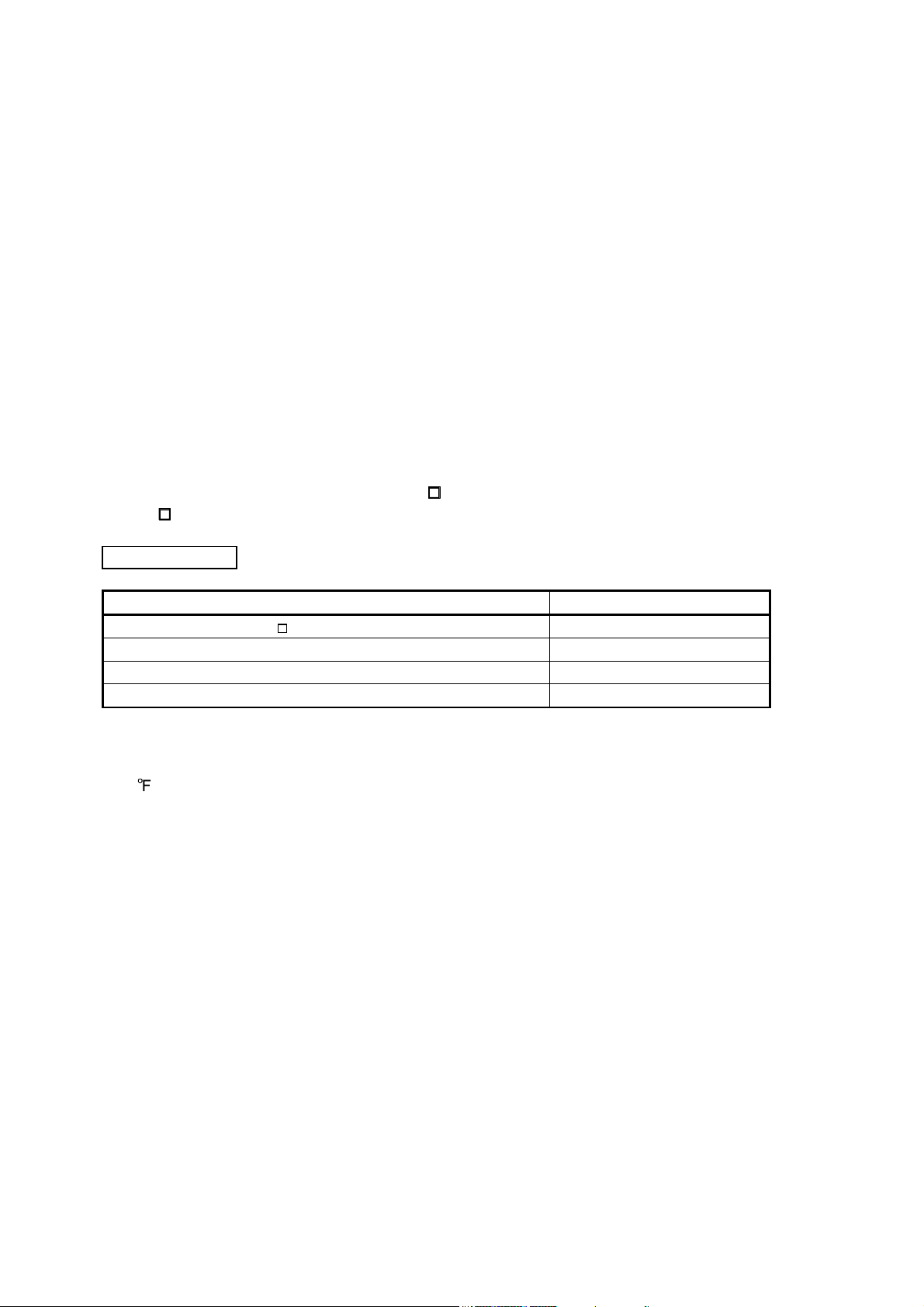
When you keep or use it, please fulfill the following environmental conditions.
Conditions
[] 0 to 55 (non-freezing) 0 to 40 (non-freezing)
Ambient
temperature
[] 20 to 65 (non-freezing) 15 to 70 (non-freezing)
Ambient
In operation 90%RH or less (non-condensing) 80%RH or less (non-condensing)
humidity
Ambience Indoors (no direct sunlight) Free from corrosive gas, flammable gas, oil mist, dust and dirt
Altitude Max. 1000m above sea level
(Note)
Vibration
Note. Except the servo motor with reduction gear.
Securely attach the servo motor to the machine. If attach insecurely, the servo motor may come off during
operation.
The servo motor with reduction gear must be installed in the specified direction to prevent oil leakage.
Environment
In
operation
In storage
In storage 90%RH or less (non-condensing)
[
] 32 to 131 (non-freezing) 32 to 104 (non-freezing)
[ ] 4 to 149 (non-freezing) 5 to 158 (non-freezing)
2
[m/s
] 5.9 or less
Servo amplifier Servo motor
HF-MP series HF-KP series X, Y: 49 m/s2
HF-SP51 81 HF-SP52 to 152
HF-SP524 to 1524 HC-RP Series
HF-SP121
HF-SP2024
HF-SP301 421 HF-SP502 702
HA-LP601 to 12K1 HA-LP701M to 15K1M
HA-LP502 to 22K2 HA-LP6014
HA-LP701M4
HA-LP15K1 to 25K1 HA-LP22K1M
HA-LP15K14
HC-UP72
HF-SP5024
HC-LP52 to 152 X: 9.8 m/s2 Y: 24.5 m/s2
HC-LP202 to 302 X: 19.6 m/s2 Y: 49 m/s2
15K1M4 HA-LP11K24 to 22K24
152
201 HF-SP202 352
3524 HC-UP202 to 502
7024
12K14
20K14 HA-LP22K1M4
X, Y: 24.5 m/s
X: 24.5 m/s
X: 24.5 m/s
X: 11.7 m/s
X, Y: 9.8 m/s
2
Y: 49 m/s2
2
Y: 29.4 m/s2
2
Y: 29.4 m/s2
2
2
A - 3
CAUTION
Take safety measures, e.g. provide covers, to prevent accidental access to the rotating parts of the servo
motor during operation.
Never hit the servo motor or shaft, especially when coupling the servo motor to the machine. The encoder
may become faulty.
Do not subject the servo motor shaft to more than the permissible load. Otherwise, the shaft may break.
When the equipment has been stored for an extended period of time, consult Mitsubishi.
(2) Wiring
CAUTION
Wire the equipment correctly and securely. Otherwise, the servo motor may operate unexpectedly.
Do not install a power capacitor, surge absorber or radio noise filter (FR-BIF option) between the servo
motor and servo amplifier.
Connect the wires to the correct phase terminals (U, V, W) of the servo amplifier and servo motor.
Not doing so may cause unexpected operation.
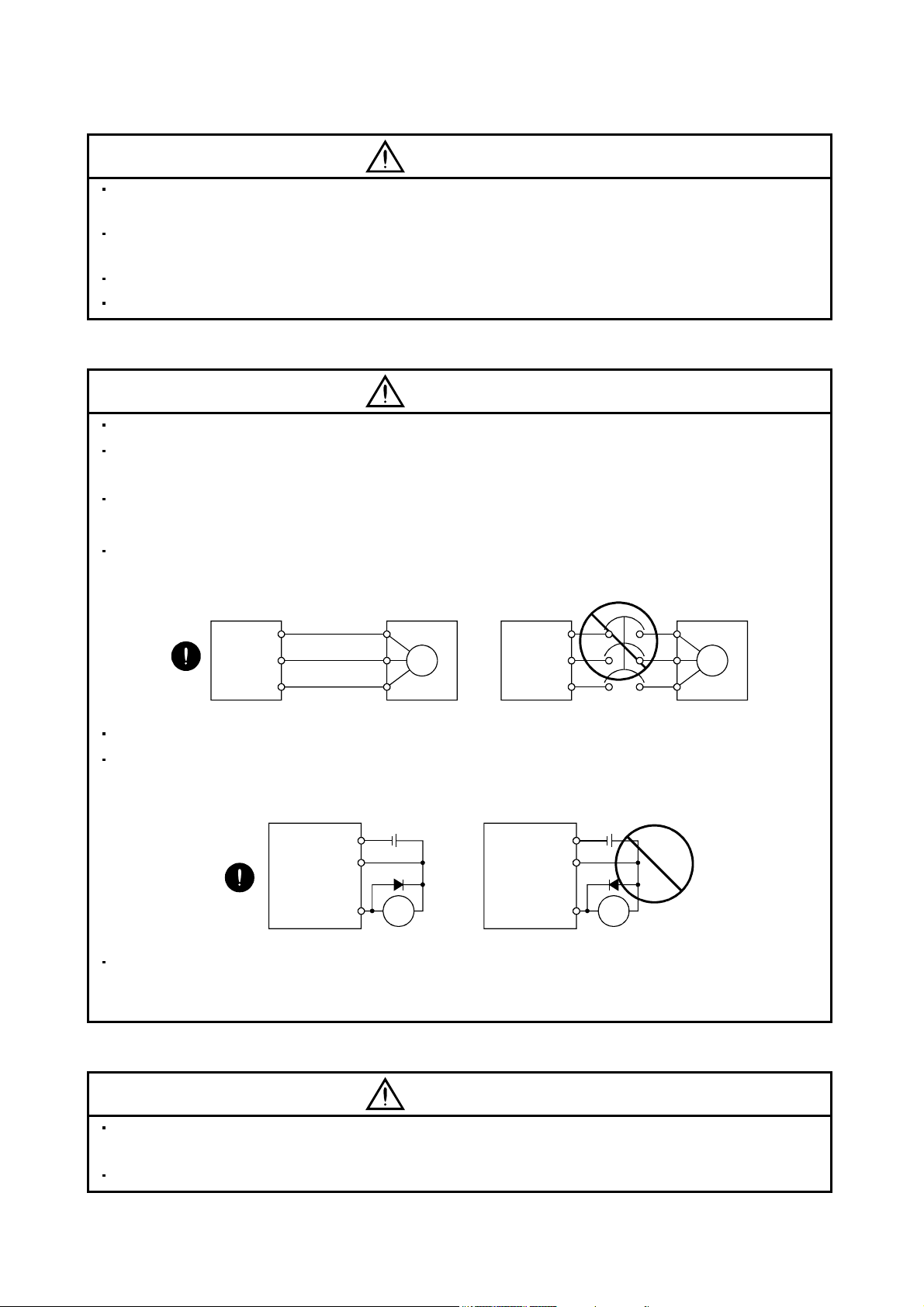
Connect the servo motor power terminal (U, V, W) to the servo motor power input terminal (U, V, W)
directly. Do not let a magnetic contactor, etc. intervene.
Servo amplifier
U
V
W
Servo motor
U
V
W
Servo motorServo amplifier
U
M
V
W
U
V
M
W
Do not connect AC power directly to the servo motor. Otherwise, a fault may occur.
The surge absorbing diode installed on the DC output signal relay of the servo amplifier must be wired in
the specified direction. Otherwise, the forced stop (EM1) and other protective circuits may not operate.
Servo amplifier Servo amplifier
DOCOM
DICOM
Control
output
signal
24VDC
RA
DOCOM
DICOM
Control
output
signal
24VDC
RA
When the cable is not tightened enough to the terminal block (connector), the cable or terminal block
(connector) may generate heat because of the poor contact. Be sure to tighten the cable with specified
torque.
(3) Test run adjustment
CAUTION
Before operation, check the parameter settings. Improper settings may cause some machines to perform
unexpected operation.
The parameter settings must not be changed excessively. Operation will be insatiable.
A - 4
(4) Usage
CAUTION
Provide an external emergency stop circuit to ensure that operation can be stopped and power switched
off immediately.
Any person who is involved in disassembly and repair should be fully competent to do the work.
Before resetting an alarm, make sure that the run signal of the servo amplifier is off to prevent an
accident. A sudden restart is made if an alarm is reset with the run signal on.
Do not modify the equipment.
Use a noise filter, etc. to minimize the influence of electromagnetic interference, which may be caused by
electronic equipment used near the servo amplifier.
Burning or breaking a servo amplifier may cause a toxic gas. Do not burn or break a servo amplifier.
Use the servo amplifier with the specified servo motor.
The electromagnetic brake on the servo motor is designed to hold the motor shaft and should not be used
for ordinary braking.
For such reasons as service life and mechanical structure (e.g. where a ball screw and the servo motor
are coupled via a timing belt), the electromagnetic brake may not hold the motor shaft. To ensure safety,
install a stopper on the machine side.
(5) Corrective actions
CAUTION
When it is assumed that a hazardous condition may take place at the occur due to a power failure or a
product fault, use a servo motor with electromagnetic brake or an external brake mechanism for the
purpose of prevention.
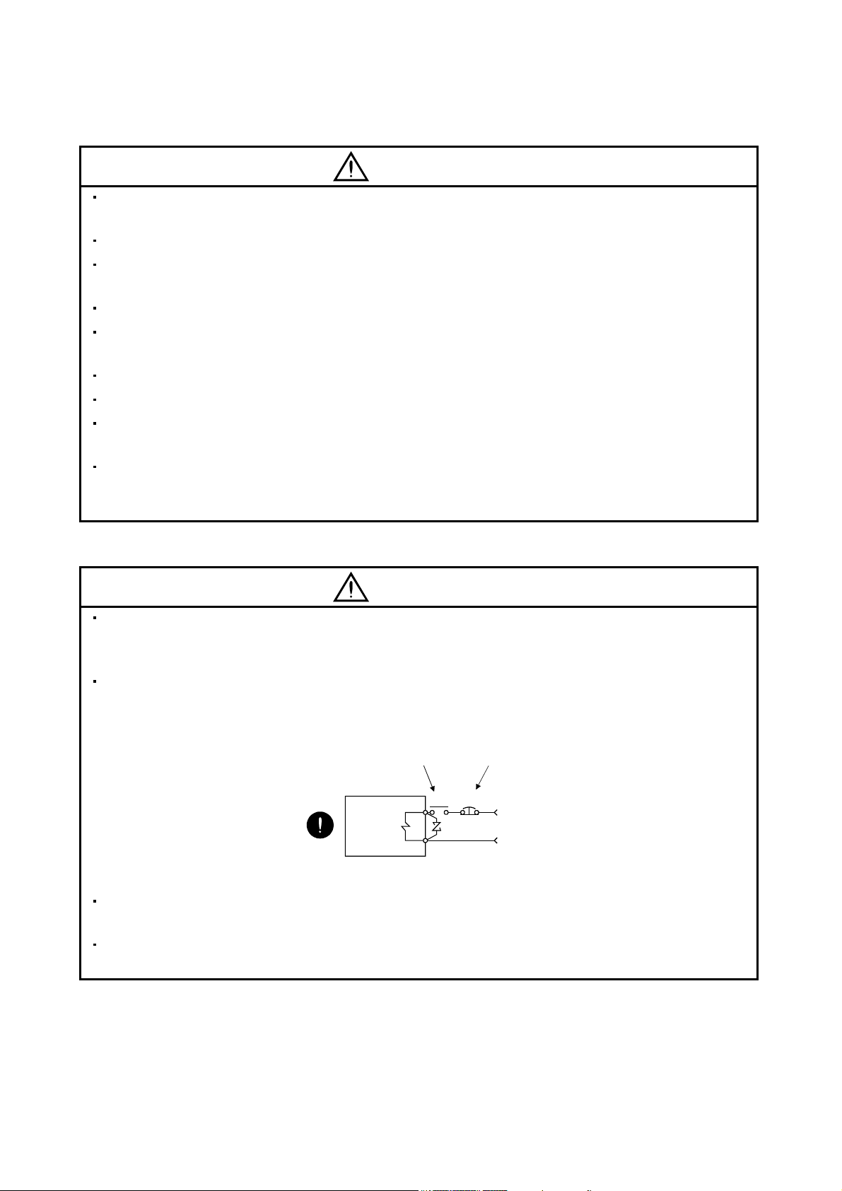
Configure the electromagnetic brake circuit so that it is activated not only by the servo amplifier signals
but also by an external forced stop (EM1).
Contacts must be open when
servo-off, when an trouble (ALM)
and when an electromagnetic brake
interlock (MBR).
Servo motor
Electromagnetic brake
When any alarm has occurred, eliminate its cause, ensure safety, and deactivate the alarm before
restarting operation.
When power is restored after an instantaneous power failure, keep away from the machine because the
machine may be restarted suddenly (design the machine so that it is secured against hazard if restarted).
Circuit must be
opened during
forced stop (EM1).
EM1RA
24VDC
A - 5
(6) Maintenance, inspection and parts replacement
CAUTION
With age, the electrolytic capacitor of the servo amplifier will deteriorate. To prevent a secondary accident
due to a fault, it is recommended to replace the electrolytic capacitor every 10 years when used in general
environment.
Please consult our sales representative.
(7) General instruction
To illustrate details, the equipment in the diagrams of this Specifications and Instruction Manual may have
been drawn without covers and safety guards. When the equipment is operated, the covers and safety
guards must be installed as specified. Operation must be performed in accordance with this
Specifications and Instruction Manual.
A - 6
About processing of waste
When you discard servo amplifier, a battery (primary battery), and other option articles, please follow the law of
each country (area).
FOR MAXIMUM SAFETY
These products have been manufactured as a general-purpose part for general industries, and have not
been designed or manufactured to be incorporated in a device or system used in purposes related to
human life.
Before using the products for special purposes such as nuclear power, electric power, aerospace,
medicine, passenger movement vehicles or under water relays, contact Mitsubishi.
These products have been manufactured under strict quality control. However, when installing the product
where major accidents or losses could occur if the product fails, install appropriate backup or failsafe
functions in the system.
EEP-ROM life
The number of write times to the EEP-ROM, which stores parameter settings, etc., is limited to 100,000. If
the total number of the following operations exceeds 100,000, the servo amplifier and/or converter unit may
fail when the EEP-ROM reaches the end of its useful life.
Write to the EEP-ROM due to parameter setting changes
Write to the EEP-ROM due to device changes
Precautions for Choosing the Products
Mitsubishi will not be held liable for damage caused by factors found not to be the cause of Mitsubishi;
machine damage or lost profits caused by faults in the Mitsubishi products; damage, secondary damage,
accident compensation caused by special factors unpredictable by Mitsubishi; damages to products other
than Mitsubishi products; and to other duties.
A - 7

COMPLIANCE WITH EC DIRECTIVES
1. WHAT ARE EC DIRECTIVES?
The EC directives were issued to standardize the regulations of the EU countries and ensure smooth
distribution of safety-guaranteed products. In the EU countries, the machinery directive (effective in January,
1995), EMC directive (effective in January, 1996) and low voltage directive (effective in January, 1997) of the
EC directives require that products to be sold should meet their fundamental safety requirements and carry the
CE marks (CE marking). CE marking applies to machines and equipment into which servo amplifiers have
been installed.
(1) EMC directive
The EMC directive applies not to the servo units alone but to servo-incorporated machines and equipment.
This requires the EMC filters to be used with the servo-incorporated machines and equipment to comply
with the EMC directive. For specific EMC directive conforming methods, refer to the EMC Installation
Guidelines (IB(NA)67310).
(2) Low voltage directive
The low voltage directive applies also to servo units alone. Hence, they are designed to comply with the low
voltage directive.
This servo is certified by TUV, third-party assessment organization, to comply with the low voltage directive.
(3) Machine directive
Not being machines, the servo amplifiers need not comply with this directive.
2. PRECAUTIONS FOR COMPLIANCE
(1) Servo amplifiers and servo motors used
Use the servo amplifiers and servo motors which comply with the standard model.
Servo amplifier series: MR-J3-10B-RJ006 to MR-J3-22KB-RJ006
MR-J3-10B1-RJ006 to MR-J3-40B1-RJ006
MR-J3-60B4-RJ006 to MR-J3-22KB4-RJ006
Servo motor series : HF-MP
HF-KP
HF-SP
HF-SP
HC-RP
HC-UP
HC-LP
HA-LP
HA-LP
Note. For the latest information of compliance, contact Mitsubishi.
(Note)
4 (Note)
(Note)
4 (Note)
A - 8
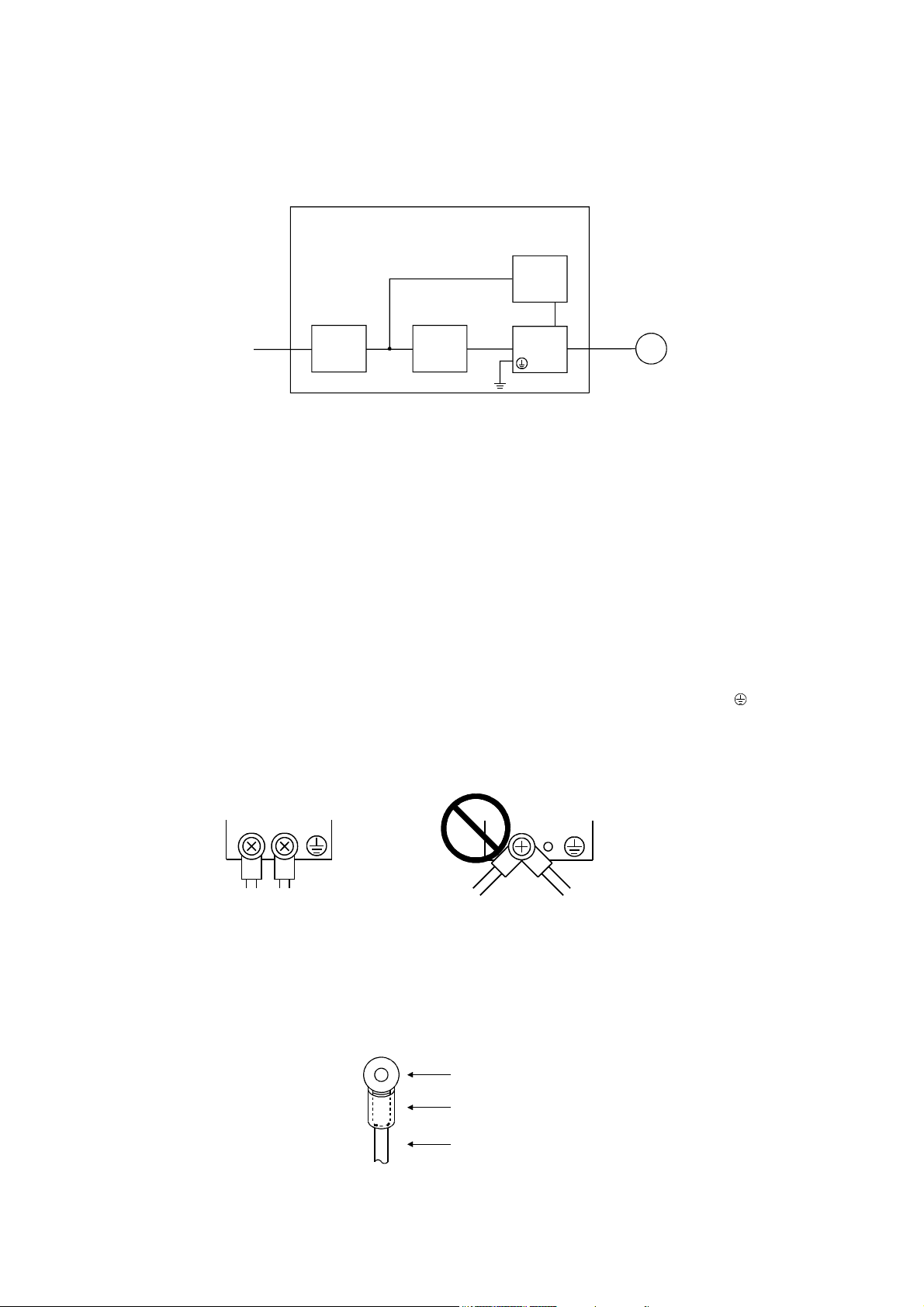
(2) Configuration
The control circuit provide safe separation to the main circuit in the servo amplifier.
Control box
Reinforced
insulating type
24VDC
No-fuse
breaker
NFB
Magnetic
contactor
MC
power
supply
Servo
amplifier
Servo
motor
M
(3) Environment
Operate the servo amplifier at or above the contamination level 2 set forth in IEC60664-1. For this purpose,
install the servo amplifier in a control box which is protected against water, oil, carbon, dust, dirt, etc. (IP54).
(4) Power supply
(a) This servo amplifier can be supplied from star-connected supply with earthed neutral point of
overvoltage category III set forth in IEC60664-1. However, when using the neutral point of 400V system
for single-phase supply, a reinforced insulating transformer is required in the power input section.
(b) When supplying interface power from external, use a 24VDC power supply which has been insulation-
reinforced in I/O.
(5) Grounding
(a) To prevent an electric shock, always connect the protective earth (PE) terminals (marked
) of the
servo amplifier to the protective earth (PE) of the control box.
(b) Do not connect two ground cables to the same protective earth (PE) terminal. Always connect the
cables to the terminals one-to-one.
PE terminals
PE terminals
(c) If a leakage current breaker is used to prevent an electric shock, the protective earth (PE) terminals of the
servo amplifier must be connected to the corresponding earth terminals.
(6) Wiring
(a) The cables to be connected to the terminal block of the servo amplifier must have crimping terminals
provided with insulating tubes to prevent contact with adjacent terminals.
Crimping terminal
Insulating tube
Cable
A - 9

(b) Use the servo motor side power connector which complies with the EN Standard. The EN Standard
compliant power connector sets are available from us as options. (Refer to section 11.1 of the MR-J3-
B Servo Amplifier Instruction Manual)
(7) Auxiliary equipment and options
(a) The no-fuse breaker and magnetic contactor used should be the EN or IEC standard-compliant
products of the models described in section 11.12 of the MR-J3Use a type B (Note) breaker. When it is not used, provide insulation between the servo amplifier and
other device by double insulation or reinforced insulation, or install a transformer between the main
power supply and servo amplifier.
Note. Type A: AC and pulse detectable
Type B: Both AC and DC detectable
(b) The sizes of the cables described in section 11.11 of the MR-J3-
meet the following requirements. To meet the other requirements, follow Table 5 and Appendix C in
EN60204-1.
Ambient temperature: 40 (104) [°C (°F)]
Sheath: PVC (polyvinyl chloride)
Installed on wall surface or open table tray
(c) Use the EMC filter for noise reduction.
(8) Performing EMC tests
When EMC tests are run on a machine/device into which the servo amplifier has been installed, it must
conform to the electromagnetic compatibility (immunity/emission) standards after it has satisfied the
operating environment/electrical equipment specifications.
For the other EMC directive guidelines on the servo amplifier, refer to the EMC Installation Guidelines
(IB(NA)67310).
B Servo Amplifier Instruction Manual.
B Servo Amplifier Instruction Manual
A - 10
CONFORMANCE WITH UL/C-UL STANDARD
(1) Servo amplifiers and servo motors used
Use the servo amplifiers and servo motors which comply with the standard model.
Servo amplifier series: MR-J3-10B-RJ006 to MR-J3-22KB-RJ006
MR-J3-10B1-RJ006 to MR-J3-40B1-RJ006
MR-J3-60B4-RJ006 to MR-J3-22KB4-RJ006
Servo motor series : HF-MP
HF-KP
HF-SP
HF-SP
HC-RP
HC-UP
HC-LP
HA-LP
HA-LP
Note. For the latest information of compliance, contact Mitsubishi.
(2) Installation
Install a cooling fan of 100CFM (2.8m
cooling of at least equivalent capability.
(3) Short circuit rating: SCCR (Short Circuit Current Rating)
This servo amplifier conforms to the circuit whose peak current is limited to 100kA or less. Having been
subjected to the short-circuit tests of the UL in the alternating-current circuit, the servo amplifier conforms to
the above circuit.
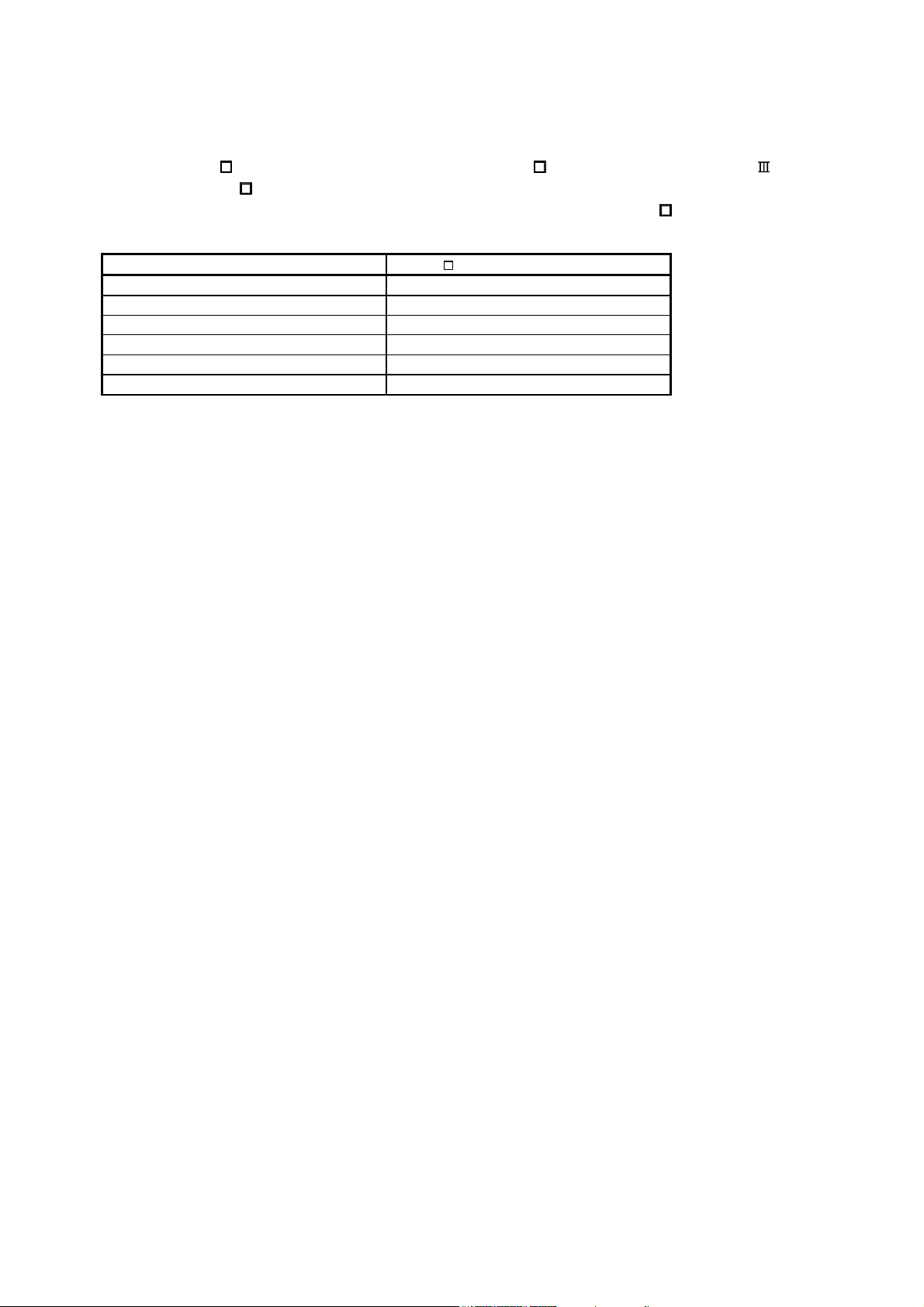
(4) Capacitor discharge time
The capacitor discharge time is as listed below. To ensure safety, do not touch the charging section for 15
minutes after power-off.
Servo amplifier
MR-J3-
40B 60B(4) 10B1 20B1 2
200B(4) 350B 9
350B4 500B(4) 700B(4) 10
-RJ006
10B 20B 1
70B 3
40B1 4
100B(4) 5
11KB(4) 4
15KB(4) 6
22KB(4) 8
(Note)
4 (Note)
(Note)
4 (Note)
Discharge time
3
/min) air flow 4 in (10.16 cm) above the servo amplifier or provide
[min]
A - 11
(5) Options and auxiliary equipment
Use UL/C-UL standard-compliant products.
(6) Attachment of a servo motor
For the flange size of the machine side where the servo motor is installed, refer to “CONFORMANCE WITH
UL/C-UL STANDARD” in the Servo Motor Instruction Manual (Vol.2).
(7) About wiring protection
For installation in United States, branch circuit protection must be provided, in accordance with the National
Electrical Code and any applicable local codes.
For installation in Canada, branch circuit protection must be provided, in accordance with the Canada
Electrical Code and any applicable provincial codes.
<<About the manuals>>
This Instruction Manual and the following Servo Amplifier/Servo Motor Instruction Manuals are required if
you use the General-Purpose AC servo MR-J3MR-J3-
B safely.
B for the first time. Always purchase them and use the
Relevant manuals
Manual name Manual No.
MELSERVO-J3 Series MR-J3- B Servo Amplifier Instruction Manual SH(NA)030051
MELSERVO-J3 Series Instructions and Cautions for Safe Use of AC Servos IB(NA)0300077
MELSERVO Servo Motor Instruction Manual Vol.2 SH(NA)030041
EMC Installation Guidelines IB(NA)67310
<<About the wires used for wiring>>
Wiring wires mentioned in this instruction manual are selected based on the ambient temperature of 40°C
(104
).
A - 12
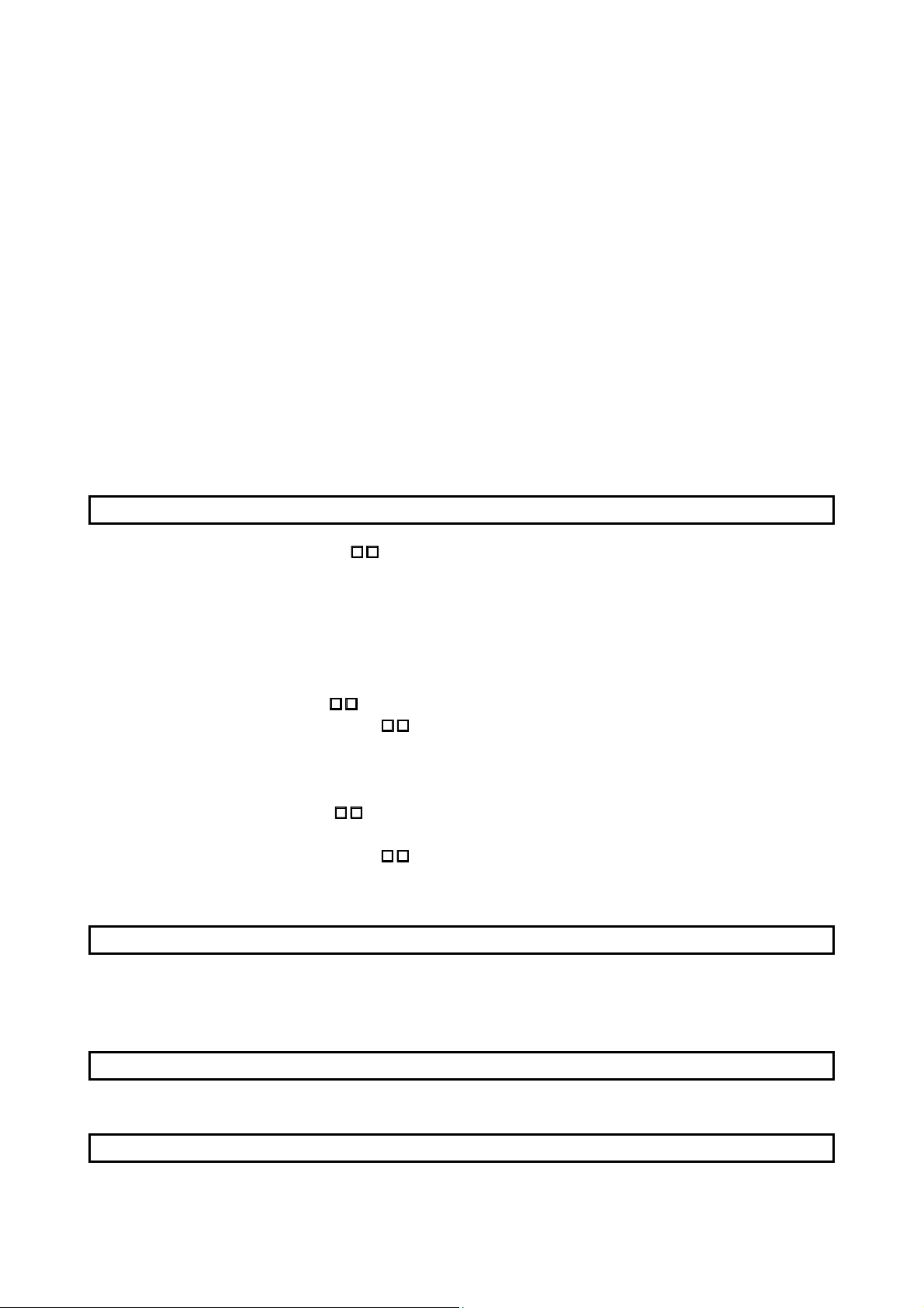
This Instruction Manual describes the functions unique to the fully closed loop control compatible servo
amplifier MR-J3Compatible MR-J3described in this Instruction Manual. For details of these items, refer to the MR-J3-
B-RJ006. Therefore, when using the MR-J3- B-RJ006, refer to the SSCNET
B Servo Amplifier Instruction Manual as well. However, the following items are not
B Servo Amplifier
Instruction Manual.
Item MR-J3- B Servo Amplifier Instruction Manual
INSTALLATION CHAPTER 2
STARTUP CHAPTER 4
GENERAL GAIN ADJUSTMENT CHAPTER 6
SPECIAL ADJUSTMENT FUNCTIONS CHAPTER 7
CHARACTERISTICS CHAPTER 10
OPTIONS AND AUXILIARY EQUIPMENT CHAPTER 11
A - 13

MEMO
A - 14

CONTENTS
1. FUNCTIONS AND CONFIGURATION 1 - 1 to 1 -28
1.1 Overview................................................................................................................................................... 1 - 1
1.2 Control block diagram .............................................................................................................................. 1 - 2
1.3 Servo amplifier standard specifications................................................................................................... 1 - 3
1.4 Function list .............................................................................................................................................. 1 - 5
1.5 Selecting procedure of control mode....................................................................................................... 1 - 6
1.5.1 Control mode configuration............................................................................................................... 1 - 6
1.5.2 Dual feedback filter equivalent block diagram.................................................................................. 1 - 6
1.6 Model code definition ............................................................................................................................... 1 - 7
1.7 Combination with servo motor .................................................................................................................1 - 9
1.8 Structure .................................................................................................................................................. 1 -10
1.8.1 Parts identification ............................................................................................................................ 1 -10
1.8.2 Removal and reinstallation of the front cover.................................................................................. 1 -17
1.9 Configuration including auxiliary equipment .......................................................................................... 1 -20
1.10 System configuration ............................................................................................................................ 1 -28
2. SIGNALS AND WIRING 2 - 1 to 2 -18
2.1 Precautions for this chapter ..................................................................................................................... 2 - 2
2.2 Input power supply circuit ........................................................................................................................ 2 - 2
2.3 I/O signal connection example ............................................................................................................... 2 -13
2.4 Connector and signal arrangements ...................................................................................................... 2 -15
2.5 Internal connection diagram ...................................................................................................................2 -16
2.6 Treatment of cable shield external conductor ........................................................................................ 2 -17
3. LOAD SIDE ENCODER 3 - 1 to 3 -32
3.1 Compatible linear encoder list ................................................................................................................. 3 - 1
3.2 Mitsubishi serial interface compatible linear encoder ............................................................................. 3 - 2
3.2.1 Linear scales manufactured by Mitutoyo Corporation (absolute type) ............................................ 3 - 2
3.2.2 Linear encoder manufactured by Heidenhain Corporation............................................................. 3 -11
3.2.3 Linear encoder manufactured by Sony Manufacturing Systems Corporation (Incremental type) 3 -19
3.2.4 Linear encoder manufactured by Renishaw Inc. (Incremental type).............................................. 3 -24
3.3 ABZ-phase differential output load side encoder ................................................................................... 3 -27
3.4 Mitsubishi optional cable
3.4.1 MR-EKCBL
3.4.2 MR-ECNM ........................................................................................................................................3 -32
3.4.3 MR-J3CN2 ........................................................................................................................................ 3 -32
M-H ............................................................................................................................ 3 -30
connector sets.............................................................................................. 3 -30
4. OPERATION AND FUNCTIONS 4 - 1 to 4 -22
4.1 Startup ...................................................................................................................................................... 4 - 1
4.1.1 Startup procedure.............................................................................................................................. 4 - 1
4.1.2 Selection of fully closed loop system ................................................................................................ 4 - 2
4.1.3 Selection of load side encoder communication system................................................................... 4 - 3
4.1.4 Setting of load side encoder polarity ................................................................................................ 4 - 3
1
4.1.5 Setting of feedback pulse electronic gear ........................................................................................4 - 4
4.1.6 Confirmation of load side encoder position data .............................................................................. 4 - 6
4.1.7 Setting of fully closed loop dual feedback filter ................................................................................ 4 - 7
4.2 Home position return operation ............................................................................................................... 4 - 8
4.2.1 General precautions .......................................................................................................................... 4 - 8
4.2.2 Load side encoder types and home position return methods.......................................................... 4 - 8
4.3 Operation from controller ........................................................................................................................4 -12
4.3.1 Operation from controller ................................................................................................................. 4 -12
4.3.2 Servo system controller setting........................................................................................................ 4 -12
4.4 Functions ................................................................................................................................................. 4 -14
4.4.1 Fully closed loop control error detection.......................................................................................... 4 -14
4.4.2 Auto tuning function ......................................................................................................................... 4 -15
4.4.3 Machine analyzer function ............................................................................................................... 4 -15
4.4.4 Test operation................................................................................................................................... 4 -16
4.5 Absolute position detection system under fully closed loop system ..................................................... 4 -16
4.6 About MR Configurator ...........................................................................................................................4 -17
5. PARAMETERS 5 - 1 to 5 -20
5.1 Basic setting parameters (No.PA ).................................................................................................... 5 - 1
5.1.1 Parameter list .................................................................................................................................... 5 - 2
5.1.2 Parameter write inhibit ...................................................................................................................... 5 - 3
5.1.3 Selecting a control mode .................................................................................................................. 5 - 4
5.1.4 Using absolute position detection system ........................................................................................ 5 - 4
5.1.5 In-position range................................................................................................................................ 5 - 5
5.1.6 Encoder output pulse ........................................................................................................................5 - 5
5.2 Gain/filter parameters (No.PB
5.3 Extension setting parameters (No.PC
5.3.1 Parameter list .................................................................................................................................... 5 - 9
5.3.2 List of details..................................................................................................................................... 5 -10
5.3.3 Analog monitor .................................................................................................................................5 -13
5.4 I/O setting parameters (No.PD
5.4.1 Parameter list ...................................................................................................................................5 -16
5.5 Extension control parameters (No.PE
5.5.1 Parameter list ...................................................................................................................................5 -17
5.5.2 List of details..................................................................................................................................... 5 -18
)......................................................................................................... 5 - 7
) ............................................................................................ 5 - 9
) ...................................................................................................... 5 -16
) ........................................................................................... 5 -17
6. TROUBLESHOOTING 6 - 1 to 6 - 6
6.1 Alarms and warning list............................................................................................................................ 6 - 1
6.2 Remedies for alarms ................................................................................................................................ 6 - 2
6.3 Detailed explanation of linear encoder error 1 (2A) ................................................................................6 - 5
7. OUTLINE DRAWINGS 7 - 1 to 7 -10
APPENDIX App.- 1 to App.- 6
App. 1 Parameter list..................................................................................................................................App.- 1
2

App. 2 Signal layout recording paper ........................................................................................................App.- 2
App. 3 Change of connector sets to the RoHS compatible products.......................................................App.- 3
App. 4 MR-J3-200B-RJ006 servo amplifiers manufactured before March 2008.....................................App.- 4
3

MEMO
4

1. FUNCTIONS AND CONFIGURATION
1. FUNCTIONS AND CONFIGURATION
1.1 Overview
This Instruction Manual explains the product that imports a position feedback signal from a load side encoder,
such as a linear encoder, to the MR-J3A control mode has the semi closed loop control, dual feedback control and fully closed loop control.
The control modes can be changed by the parameter setting.
For the features of each control mode, refer to section 1.2 in this manual.
[Items changed from those of the standard model (MR-J3-
(a) The Mitsubishi serial interface compatible or ABZ-phase pulse train interface compatible linear encoder
is used to detect the position feedback signal of the load side encoder.
(b) In addition to the fully closed loop control that feeds back the position signal of the load side encoder, a
dual feedback control that feeds back a signal composed of the load side encoder's position feedback
signal and the motor position feedback signal has been added as an extended function.
(c) Function to switch output pulse between the load side encoder and motor side encoder
[Functions deleted from the standard model (MR-J3-
Motor-less operation (test operation)
B servo amplifier to perform fully closed loop control.
B)]
B)]
1 - 1
1. FUNCTIONS AND CONFIGURATION
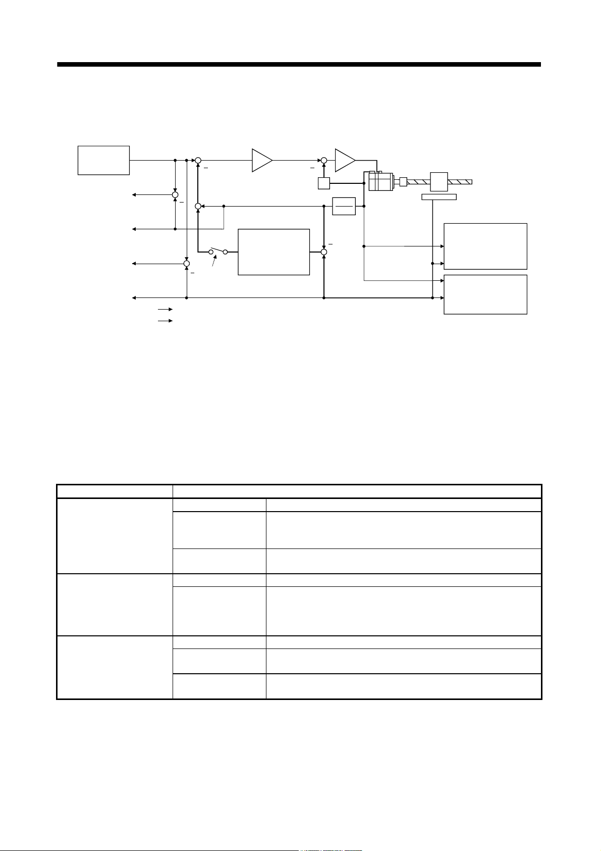
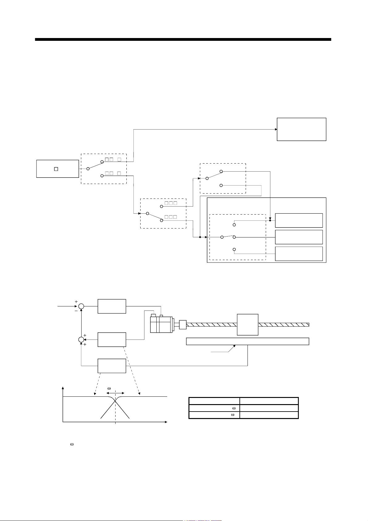
1.2 Control block diagram
A fully closed loop control block diagram is shown below. The fully closed loop system is controlled in the load
side encoder unit.
Controller
(Motor side)
Droop pulses
(Motor side)
Feedback
pulses
accumulation
Load side
droop pulses
Load side
feedback
pulses
accumulation
Note. 1. Switching between semi closed loop control and fully closed loop control can be performed by changing the setting of
parameter No.PE01.
When semi closed loop control is selected, a control is always performed on the bases of the position data of the motor
encoder independently of whether the motor is at a stop or running.
2. When parameter No.PE01 "fully closed loop system" is valid, dual feedback control in which the motor feedback signal and
load side encoder feedback signal are combined by the dual feedback filter in parameter No.PE08 is performed.
In this case, fully closed loop control is performed when the motor is at a stop, and semi closed loop control is performed when
the motor is operating to improve control performance. When "4500" is set as the filter value of parameter No.PE08, fully
closed loop control is always performed.
+
+
Motor side feedback pulse
(Load side resolution unit)
+
+
+
(Note 1, 2)
Fully closed loop selection
Parameter No.PE01, PE08
Control
Monitoring
Dual feedback
filter
(Note 2)
Parameter No.PE08
+
S
FBN
FBD
+
Load side feedback pulse
Servo motor
Linear encoder
Encoder pulse setting
(Refer to
section 5.1.6.)
Fully closed loop
control error detection
function selection
Parameter No.PE03
The following table shows the functions of each control mode.
Control mode Description
Feature Position is controlled according to the motor side data.
Since this control is insusceptible to machine influence (such as machine
Semi closed loop control
Dual feedback control
Fully closed loop control
Advantage
Disadvantage
Feature Position is controlled according to the motor side data and load side data.
Advantage
Feature Position is controlled according to the load side data.
Advantage
Disadvantage
resonance), the gains of the servo amplifier can be raised and the settling
time shortened.
If the motor side is at a stop, the side may be vibrating or the load side
accuracy not obtained.
Control is performed according to the motor side data during operation,
and according to the load side data at a stop in sequence to raise the gains
during operation and shorten the settling time.
A stop is made with the load side accuracy.
The load side accuracy is obtained not only at a stop but also during
operation.
Since this control is susceptible to machine resonance or other influences,
the gains of the servo amplifier do not rise and the settling time increases.
1 - 2
1. FUNCTIONS AND CONFIGURATION
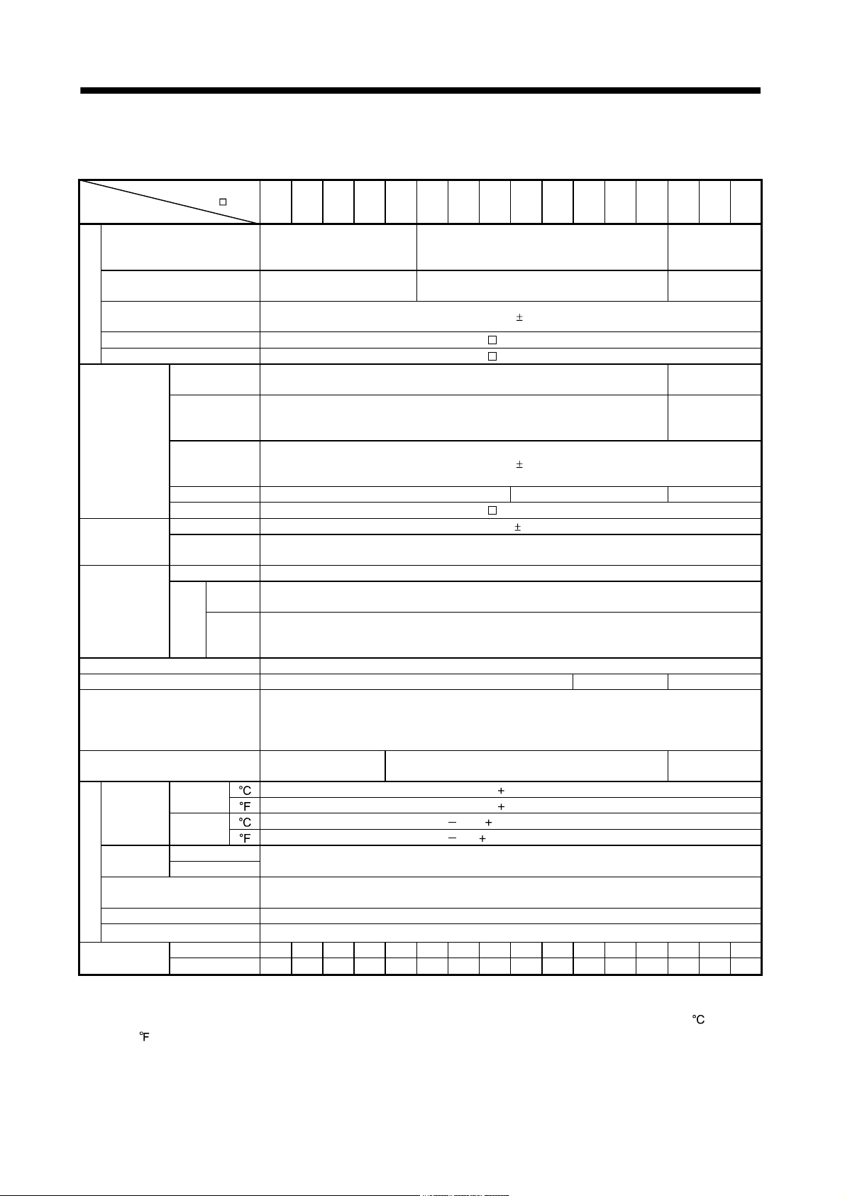
1.3 Servo amplifier standard specifications
(1) 200V class, 100V class
Servo amplifier
-RJ006
MR-J3-
Item
Voltage/frequency
Permissible voltage fluctuation
Permissible frequency
Power supply
fluctuation
Power supply capacity Refer to section 10.2 "MR-J3- B Servo Amplifier Instruction Manual"
Inrush current Refer to section 10.5 "MR-J3- B Servo Amplifier Instruction Manual"
Voltage,
frequency
Permissible
voltage
Control circuit
power supply
Interface power
supply
Load side
encoder
interface
Control System Sine-wave PWM control, current control system
Dynamic brake Built-in External option Built-in
Protective functions
Structure
Ambient
temperature
humidity
Environment
Ambient
Altitude Max. 1000m above sea level
Vibration 5.9 [m/s2] or less
Mass
Note 1. 150mA is the value applicable when all I/O signals are used. The current capacity can be decreased by reducing the number of
I/O points.
2. When closely mounting the servo amplifiers of 3.5kW or less, operate them at the ambient temperatures of 0 to 45
113
fluctuation
Permissible
frequency
fluctuation
Input 30W 45W 30W
Inrush current Refer to section 10.5 "MR-J3-
Voltage 24VDC 10%
Power supply
capacity
Serial interface Mitsubishi high-speed serial communication
Input
Pulse
signal
train
Minimum
inter-
phase
face
differential
operation
In storage
In operation Ambient
In storage
or at 75% or a smaller effective load ratio.
)
10B 20B 40B 60B 70B 100B 200B 350B 500B 700B 11KB 15KB 22KB 10B1 20B1 40B1
3-phase or 1-phase 200 to
230VAC, 50/60Hz
3-phase or 1-phase 200 to
230VAC: 170 to 253VAC
1-phase 200 to 230VAC, 50/60Hz
1-phase 170 to 253VAC
Overcurrent shut-off, regenerative overvoltage shut-off, overload shut-off (electronic thermal relay),
servo motor overheat protection, encoder error protection, regenerative brake error protection,
undervoltage, instantaneous power failure protection, overspeed protection, excessive error
protection
Self-cooled, open
(IP00)
[ ] (Note 2) 0 to 55 (non-freezing) In
] (Note 2) 32 to 131 (non-freezing)
[
[ ] 20 to 65 (non-freezing)
[
] 4 to 149 (non-freezing)
Free from corrosive gas, flammable gas, oil mist, dust and dirt
[kg] 0.8 0.8 1.0 1.0 1.4 1.4 2.1 2.3 4.6 6.2 18 18 19 0.8 0.8 1.0
[lb] 1.8 1.8 2.2 2.2 3.1 3.1 4.63 5.07 10.1 13.7 39.7 39.7 41.9 1.8 1.8 2.2
3-phase 200 to 230VAC, 50/60Hz
3-phase 170 to 253VAC
5%
Within
5%
Within
B Servo Amplifier Instruction Manual"
(Note 1) 150mA or more
ABZ-phase differential input signal
200ns
Force-cooling, open (IP00)
90%RH or less (non-condensing)
Indoors (no direct sunlight)
1-phase 100V to
120VAC,
50/60Hz
1-phase 85 to
132VAC
1-phase 100 to
120VAC, 50/60Hz
1-phase 85 to
132VAC
Self-cooled,
open (IP00)
(32 to
1 - 3
1. FUNCTIONS AND CONFIGURATION
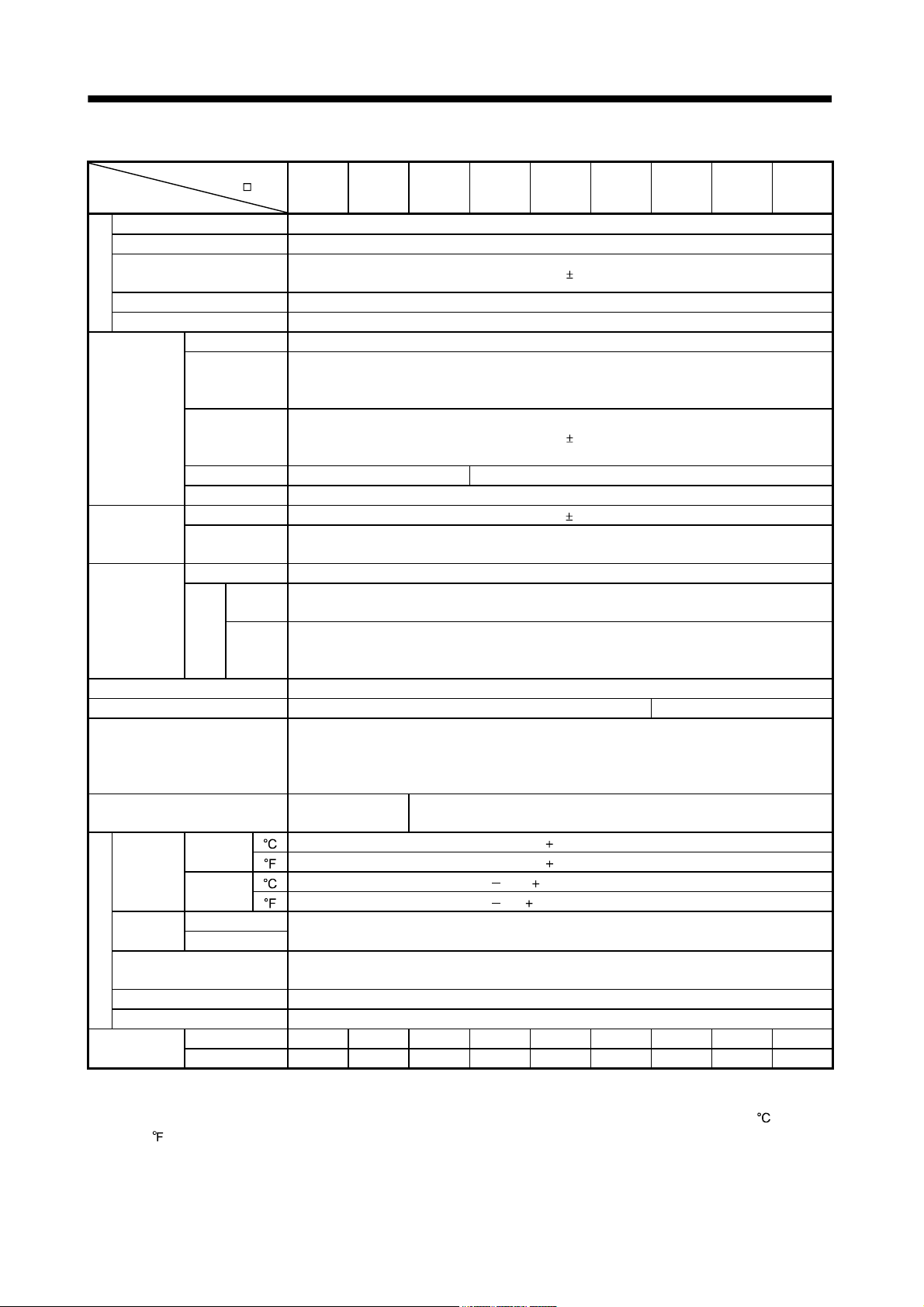
(2) 400V class
Servo amplifier
MR-J3-
-RJ006
Item
Voltage/frequency 3-phase 380 to 480VAC, 50/60Hz
Permissible voltage fluctuation 3-phase 323 to 528VAC
Permissible frequency
fluctuation
Power supply capacity Refer to section 10.2
Power supply
Inrush current Refer to section 10.5
Voltage/frequency 1-phase 380 to 480VAC, 50/60Hz
Permissible
voltage
Control circuit
power supply
Interface power
supply
Load side
encoder
interface
Control System Sine-wave PWM control, current control system
Dynamic brake Built-in External option
Protective functions
Structure
Ambient
temperature
humidity
Environment
Ambient
Altitude Max. 1000m above sea level
Vibration 5.9 [m/s2] or less
Mass
Note 1. 150mA is the value applicable when all I/O signals are used. The current capacity can be decreased by reducing the number of
I/O points.
2. When closely mounting the servo amplifiers of 3.5kW or less, operate them at the ambient temperatures of 0 to 45
113
fluctuation
Permissible
frequency
fluctuation
Input 30W 45W
Inrush current Refer to section 10.5
Voltage 24VDC 10%
Power supply
capacity
Serial interface Mitsubishi high-speed serial communication
Input
Pulse
signal
train
Minimum
inter-
phase
face
differential
operation
In storage
In operation Ambient
In storage
or at 75% or a smaller effective load ratio.
)
60B4 100B4 200B4 350B4 500B4 700B4 11KB4 15KB4 22KB4
Within
5%
1-phase 323 to 528VAC
Within
5%
(Note 1) 150mA or more
ABZ-phase differential input signal
200ns
Overcurrent shut-off, regenerative overvoltage shut-off, overload shut-off (electronic thermal relay),
servo motor overheat protection, encoder error protection, regenerative brake error protection,
undervoltage, instantaneous power failure protection, overspeed protection, excessive error
protection
Self-cooled, open
(IP00)
[ ] (Note 2) 0 to 55 (non-freezing) In
[
] (Note 2) 32 to 131 (non-freezing)
[ ] 20 to 65 (non-freezing)
[
] 4 to 149 (non-freezing)
[kg] 1.7 1.7 2.1 4.6 4.6 6.2 18 18 19
[lb] 3.75 3.75 4.63 10.1 10.1 13.7 39.7 39.7 41.9
Force-cooling, open (IP00)
90%RH or less (non-condensing)
Indoors (no direct sunlight)
Free from corrosive gas, flammable gas, oil mist, dust and dirt
(32 to
1 - 4
1. FUNCTIONS AND CONFIGURATION
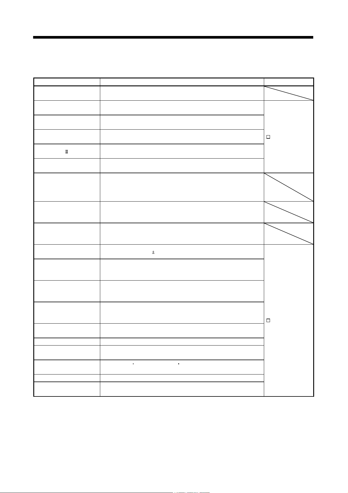
1.4 Function list
The following table lists the functions of this servo. For details of the functions, refer to the reference field.
Function Description Reference
High-resolution encoder
Absolute position detection
system
Gain changing function
Advanced vibration
suppression control
Adaptive filter
Low-pass filter
Machine analyzer function
Machine simulation
Gain search function
Slight vibration suppression
control
Auto tuning
Brake until
Power regenerative converter
Regenerative option
Alarm history clear Alarm history is cleared.
Output signal (DO)
forced output
Test operation mode
Analog monitor output Servo status is output in terms of voltage in real time.
MR Configurator
High-resolution encoder of 262144 pulses/rev is used as a servo motor
encoder.
Merely setting a home position once makes home position return
unnecessary at every power-on.
You can switch between gains during rotation and gains during stop or use
an external signal to change gains during operation.
This function suppresses vibration at the arm end or residual vibration.
Servo amplifier detects mechanical resonance and sets filter characteristics
automatically to suppress mechanical vibration.
Suppresses high-frequency resonance which occurs as servo system
response is increased.
Analyzes the frequency characteristic of the mechanical system by simply
connecting a servo configuration software-installed personal computer and
servo amplifier.
MR Configurator is necessary for this function.
Can simulate machine motions on a personal computer screen on the basis
of the machine analyzer results.
MR Configurator is necessary for this function.
Personal computer changes gains automatically and searches for overshoot-
free gains in a short time.
MR Configurator is necessary for this function.
Suppresses vibration of
Automatically adjusts the gain to optimum value if load applied to the servo
motor shaft varies. Higher in performance than MR-J2-Super series servo
amplifier.
Used when the regenerative option cannot provide enough regenerative
power.
Can be used the 5kW or more servo amplifier.
Used when the regenerative option cannot provide enough regenerative
power.
Can be used the 5kW or more servo amplifier.
Used when the built-in regenerative resistor of the servo amplifier does not
have sufficient regenerative capability for the regenerative power generated.
Output signal can be forced on/off independently of the servo status.
Use this function for output signal wiring check, etc.
JOG operation
However, MR Configurator is necessary for positioning operation.
Using a personal computer, parameter setting, test operation, status display,
etc. can be performed.
positioning operation DO forced output.
1 pulse produced at a servo motor stop.
Refer to the MR-J3-
B Servo Amplifier
Instruction Manual.
Refer to the MR-J3-
B Servo Amplifier
Instruction Manual.
1 - 5
1. FUNCTIONS AND CONFIGURATION
1.5 Selecting procedure of control mode
1.5.1 Control mode configuration
In this servo, a semi closed loop system or fully closed loop system can be selected as a control system.
Also, on the fully closed loop system, the semi closed loop control, fully closed loop control and dual feedback
control can be switched by the parameter No.PE08 settings.
Semi closed loop system
Semi closed loop
control
MR-J3- B-RJ006
Control mode selection
Parameter No.PA01
0
1
(Refer to section 5.1.3.)
Fully closed loop
Selection 1
Parameter No.PE01
1
0
(Refer to section 5.5.2.)
Controller command
Semi closed loop control/
fully closed loop control switching bit
OFF
ON
Fully closed loop system
Fully closed loop dual
feedback filter
Parameter No.PE08
0000
0001 to 4499
4500
Semi closed loop
control
Dual feedback
control
Fully closed loop
control
1.5.2 Dual feedback filter equivalent block diagram
A dual feedback filter equivalent block diagram on the dual feedback control is shown below.
Positioning
controller
Servo motor
High-pass
filter
Linear encoder
Low-pass
filter
(Note)
Fully closed
loop control
Note. (a dual feedback filter band) is set by parameter No.PE08.
Semi closed
loop control
Frequency [rad/s]
Operating status Controlling status
At motor stop (0 to )
At operating (from )
<Dual feedback filter>
Fully closed loop control
Semi closed loop control
1 - 6

1. FUNCTIONS AND CONFIGURATION
1.6 Model code definition
(1) Rating plate
MR-J3-10B-RJ006
POWER :
INPUT :
OUTPUT:
SERIAL :
100W
0.9A 3PH+1PH200-230V 50Hz
1.3A 1PH 200-230V 50/60Hz
170V 0-360Hz 1.1A
A34230001
AC SERVO
3PH+1PH200-230V 60Hz
Model
Capacity
Applicable power supply
Rated output current
Serial number
1 - 7
1. FUNCTIONS AND CONFIGURATION
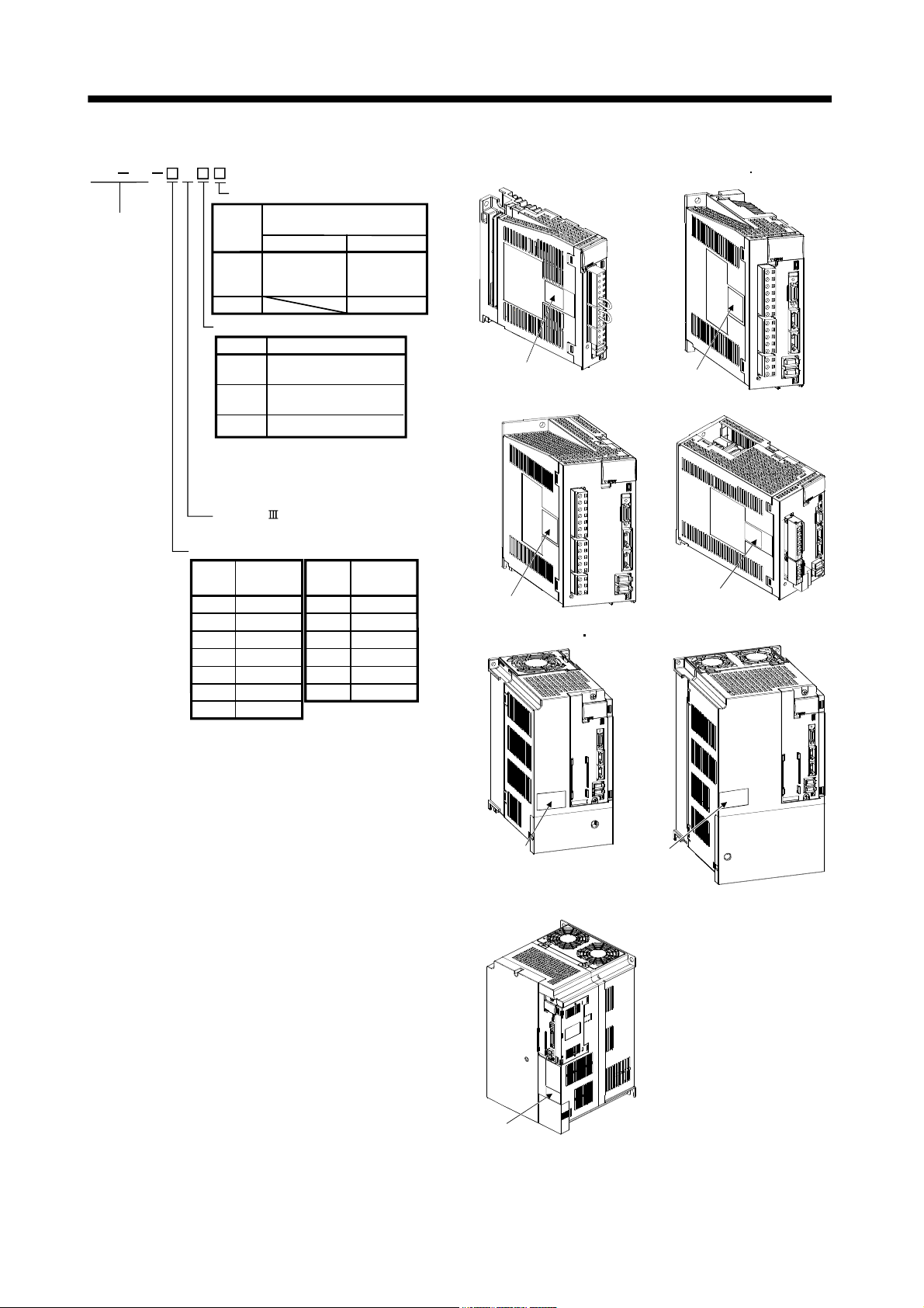
(2) Model
MR J3 B
Fully closed loop control symbol
Series
Symbol
RJ006
RZ006
Power supply
Symbol
None
(Note 1)
(Note 2)
Note 1. 1-phase 200V to 230V is
supported by 750W or less.
2. 1-phase 100V to 120V is
supported by 400W or less.
SSCNET compatible
Standard regeneration
brake resistor
0.1kW to 7kW
Built-in
(No built-in for
0.1kW)
Power supply
3-phase or 1-phase 200
to 230VAC
1-phase 100 to 120VAC
1
3-phase 380 to 480VAC
4
11kW to 2kW
Standard
attachment
No attachment
MR-J3-100B-RJ006 or less
Rating plate
MR-J3-200B(4)-RJ006
MR-J3-60B4-RJ006 100B4-RJ006
Rating plate
MR-J3-350B-RJ006
Rated output
Rated
Symbol
output [kW]
10
20 0.2
40 0.4
60 0.6
70 0.75
100 1
200 2
0.1
Symbol
350
500
700
11k
15k
22k
Rated
output [kW]
3.5
5
7
11
15
22
Rating plate
Rating plate
MR-J3-350B4-RJ006 500B(4)-RJ006
Rating plate
MR-J3-11KB(4)-RJ006 to 22KB(4)-RJ006
Rating plate
MR-J3-700B(4)-RJ006
Rating plate
1 - 8
1. FUNCTIONS AND CONFIGURATION
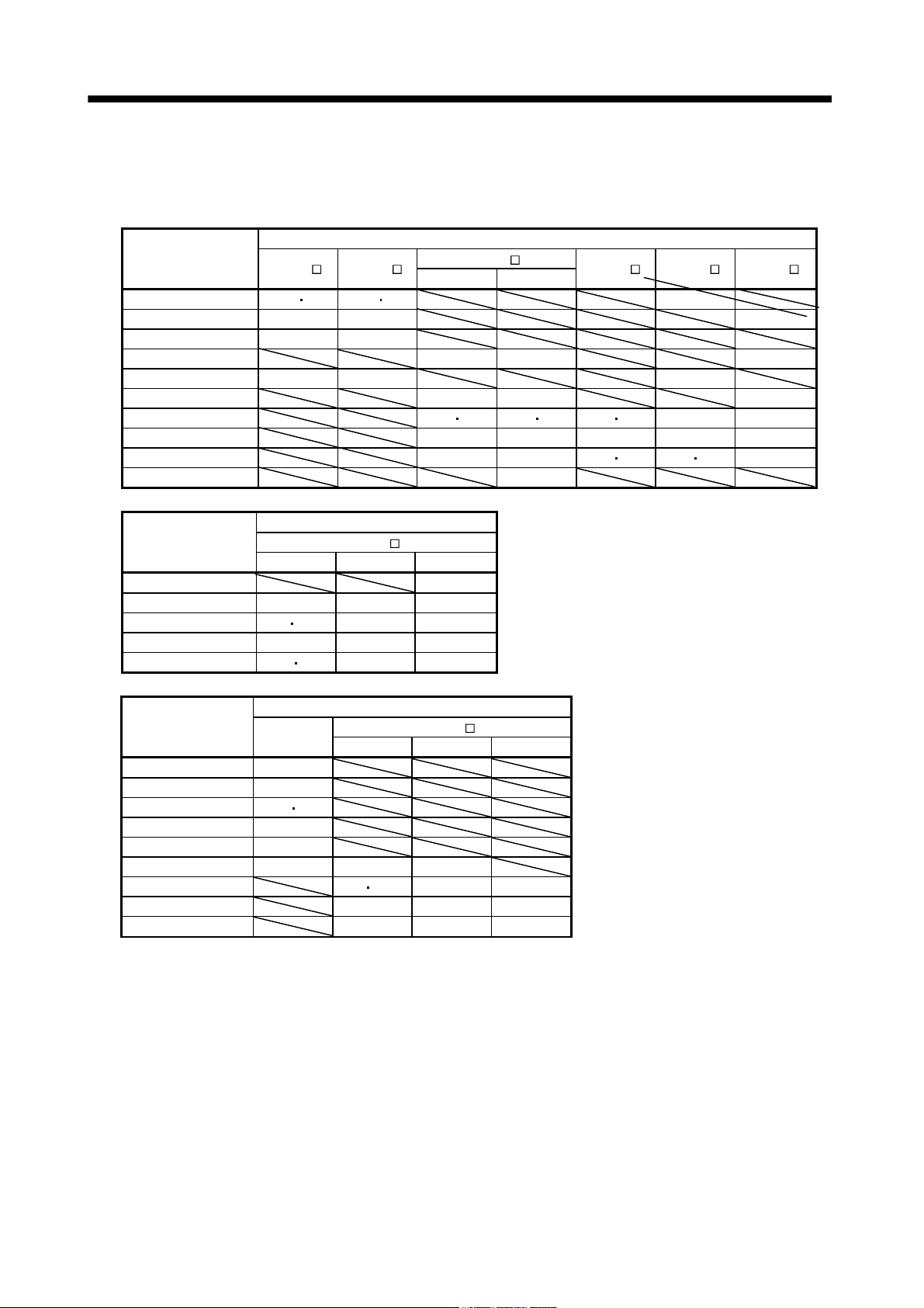
1.7 Combination with servo motor
The following table lists combinations of servo amplifiers and servo motors. The same combinations apply to
the models with electromagnetic brakes.
Servo motors
Servo amplifier
MR-J3-10B (1) -RJ006 053 13 053 13
MR-J3-20B (1) -RJ006 23 23
MR-J3-40B (1) -RJ006 43 43
MR-J3-60B-RJ006 51 52 52
MR-J3-70B-RJ006 73 73 72
MR-J3-100B-RJ006 81 102 102
MR-J3-200B-RJ006 121 201 152 202 103
MR-J3-350B-RJ006 301 352 203 202 202
MR-J3-500B-RJ006 421 502 353
MR-J3-700B-RJ006 702
HF-KP
HF-MP
HF-SP
1000r/min 2000r/min
HC-RP HC-UP HC-LP
152 152
153
503
352
302
502
Servo motors
Servo amplifier
1000r/min 1500r/min 2000r/min
MR-J3-500B-RJ006 502
MR-J3-700B-RJ006 601 701M 702
MR-J3-11KB-RJ006 801 12K1 11K1M 11K2
MR-J3-15KB-RJ006 15K1 15K1M 15K2
MR-J3-22KB-RJ006 20K1 25K1 22K1M 22K2
HA-LP
Servo motors
Servo amplifier
MR-J3-60B4-RJ006 524
MR-J3-100B4-RJ006 1024
MR-J3-200B4-RJ006 1524 2024
MR-J3-350B4-RJ006 3524
MR-J3-500B4-RJ006 5024
MR-J3-700B4-RJ006 7024 6014 701M4
MR-J3-11KB4-RJ006 8014 12K14 11K1M4 11K24
MR-J3-15KB4-RJ006 15K14 15K1M4 15K24
MR-J3-22KB4-RJ006 20K14 22K1M4 22K24
HF-SP
HA-LP
1000r/min 1500r/min 2000r/min
1 - 9
1. FUNCTIONS AND CONFIGURATION
1.8 Structure
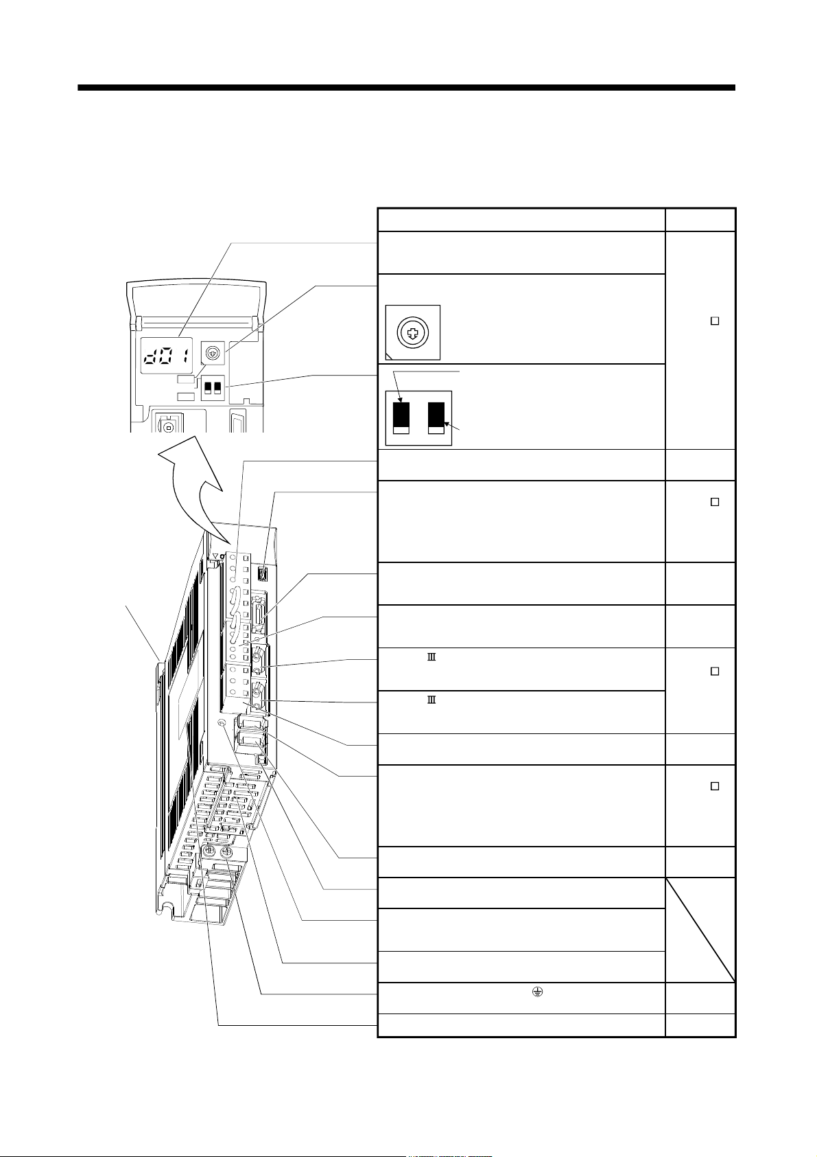
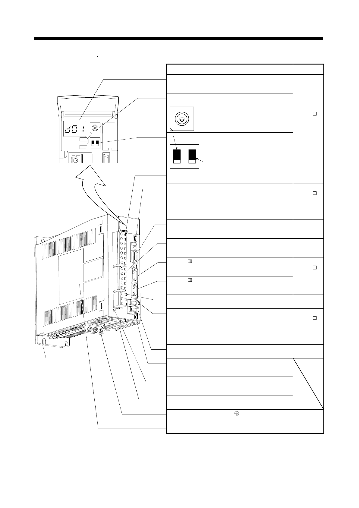
1.8.1 Parts identification
(1) MR-J3-100B-RJ006 or less
Fixed part
(2 places)
SW1
TEST
SW2
7
6
5
4
3
2
ON 4E
12
Name/Application
Detailed
explanation
Display
The 3-digit, seven-segment LED shows the servo
status and alarm number.
Rotary axis setting switch (SW1)
SW1
8
Used to set the axis No. of servo amplifier.
9
7
A
6
B
5
C
4
D
3
8
9
A
B
C
D
E
F
1
0
2
1
SW2
E
F
0
Test operation select switch (SW2-1)
Used to perform the test operation
Refer to the
MR-J3- B
Servo
Amplifier
Instruction
Manual.
mode by using MR Configurator.
Spare (Be sure to set to the "Down"
position).
2
1
Main circuit power supply connector (CNP1)
Connect the input power supply.
USB communication connector (CN5)
Connect the personal computer.
Section 2.2
Refer to the
MR-J3- B
Servo
Amplifier
Instruction
Manual.
I/O signal connector (CN3)
Used to connect digital I/O signals.
More over an analog monitor is output.
Section 2.3
Section 2.4
Control circuit connector (CNP2)
Connect the control circuit power supply/regenerative
Section 2.2
option.
SSCNET cable connector (CN1A)
Used to connect the servo system controller or the front
axis servo amplifier.
SSCNET cable connector (CN1B)
Used to connect the rear axis servo amplifier. For the final
axis, puts a cap.
Servo motor power connector (CNP3)
Connect the servo motor.
Encoder connector (CN2)
Used to connect the servo motor encoder.
Refer to the
MR-J3- B
Servo
Amplifier
Instruction
Manual.
Section 2.2
Refer to the
MR-J3- B
Servo
Amplifier
Instruction
Manual.
Load side encoder connector (CN2L)
Connect the load side encoder.
Chapter 3
Connector for manufacturer setting
Not used for this servo amplifier.
Charge lamp
Lit to indicate that the main circuit is charged. While this
lamp is lit, do not reconnect the cables.
Battery holder
Not used for this servo amplifier.
Protective earth (PE) terminal ( )
Ground terminal.
Rating plate
Section 2.2
Section 1.6
1 - 10
1. FUNCTIONS AND CONFIGURATION
(2) MR-J3-60B4-RJ006
MR-J3-100B4-RJ006
Fixed part
(3 places)
SW1
TEST
SW2
7
6
5
4
3
2
ON 4E
12
Name/Application
Detailed
explanation
Display
The 3-digit, seven-segment LED shows the servo
status and alarm number.
Rotary axis setting switch (SW1)
SW1
8
Used to set the axis No. of servo amplifier.
9
7
A
6
B
5
C
4
D
3
8
9
A
B
C
D
E
F
1
0
2
F
1
0
SW2
E
Test operation select switch (SW2-1)
Used to perform the test operation
Refer to the
MR-J3- B
Servo
Amplifier
Instruction
Manual.
mode by using MR Configurator.
Spare (Be sure to set to the "Down"
position).
2
1
Main circuit power supply connector (CNP1)
Connect the input power supply.
USB communication connector (CN5)
Connect the personal computer.
Section 2.2
Refer to the
MR-J3- B
Servo
Amplifier
Instruction
Manual.
I/O signal connector (CN3)
Used to connect digital I/O signals.
More over an analog monitor is output.
Section 2.3
Section 2.4
Control circuit connector (CNP2)
Connect the control circuit power supply/regenerative
Section 2.2
option.
SSCNET cable connector (CN1A)
Used to connect the servo system controller or the front
axis servo amplifier.
SSCNET cable connector (CN1B)
Used to connect the rear axis servo amplifier. For the final
axis, puts a cap.
Servo motor power connector (CNP3)
Connect the servo motor.
Encoder connector (CN2)
Used to connect the servo motor encoder.
Refer to the
MR-J3- B
Servo
Amplifier
Instruction
Manual.
Section 2.2
Refer to the
MR-J3- B
Servo
Amplifier
Instruction
Manual.
Load side encoder connector (CN2L)
Connect the load side encoder.
Chapter 3
Battery connector (CN4)
Used to connect the battery for absolute position data
backup.
Charge lamp
Lit to indicate that the main circuit is charged. While this
lamp is lit, do not reconnect the cables.
Battery holder
Contains the battery for absolute position data backup.
Protective earth (PE) terminal ( )
Ground terminal.
Rating plate
Section 2.2
Section 1.6
1 - 11
 Loading...