

Page 1

General-Purpose AC Servo
J3 Series
SSCNET Compatible
MODEL
MR-J3- B
SERVO AMPLIFIER
INSTRUCTION MANUAL
D
Page 2
Safety Instructions
(Always read these instructions before using the equipment.)
Do not attempt to install, operate, maintain or inspect the converter unit, servo amplifier (drive unit) and servo
motor until you have read through this Instruction Manual, Installation guide, Servo motor Instruction Manual
(Vol.2) and appended documents carefully and can use the equipment correctly. Do not use the converter unit,
servo amplifier (drive unit) and servo motor until you have a full knowledge of the equipment, safety information
and instructions.
In this Instruction Manual, the safety instruction levels are classified into "WARNING" and "CAUTION".
WARNING
CAUTION
Indicates that incorrect handling may cause hazardous conditions,
resulting in death or severe injury.
Indicates that incorrect handling may cause hazardous conditions,
resulting in medium or slight injury to personnel or may cause physical
damage.
Note that the CAUTION level may lead to a serious consequence according to conditions. Please follow the
instructions of both levels because they are important to personnel safety.
What must not be done and what must be done are indicated by the following diagrammatic symbols.
: Indicates what must not be done. For example, "No Fire" is indicated by
: Indicates what must be done. For example, grounding is indicated by
In this Instruction Manual, instructions at a lower level than the above, instructions for other functions, and so
on are classified into "POINT".
After reading this installation guide, always keep it accessible to the operator.
.
.
A - 1
Page 3
1. To prevent electric shock, note the following
WARNING
Before wiring or inspection, turn off the power and wait for 15 minutes or more (20 minutes or for drive
unit 30kW or more) until the charge lamp turns off. Then, confirm that the voltage between P(
) (L and L
N(
electric shock may occur. In addition, always confirm from the front of the servo amplifier (converter unit),
whether the charge lamp is off or not.
Connect the converter unit, servo amplifier (drive unit) and servo motor to ground.
Any person who is involved in wiring and inspection should be fully competent to do the work.
Do not attempt to wire the converter unit, servo amplifier (drive unit) and servo motor until they have been
installed. Otherwise, you may get an electric shock.
Operate the switches with dry hand to prevent an electric shock.
The cables should not be damaged, stressed loaded, or pinched. Otherwise, you may get an electric
shock.
During power-on or operation, do not open the front cover. You may get an electric shock.
Do not operate the converter unit and servo amplifier (drive unit) with the front cover removed. Highvoltage terminals and charging area are exposed and you may get an electric shock.
Except for wiring or periodic inspection, do not remove the front cover even if the power is off. The servo
amplifier (drive unit) is charged and you may get an electric shock.
for drive unit 30kW or more)
is safe with a voltage tester and others. Otherwise, an
2. To prevent fire, note the following
) and
CAUTION
Install the converter unit, servo amplifier (drive unit), servo motor and regenerative resistor on
incombustible material. Installing them directly or close to combustibles will lead to a fire.
Always connect a magnetic contactor (MC) between the main circuit power supply and L1, L2, and L3 of
the converter unit, servo amplifier (drive unit), and configure the wiring to be able to shut down the power
supply on the side of the converter unit, servo amplifier (drive unit) power supply. If a magnetic contactor
(MC) is not connected, continuous flow of a large current may cause a fire when the converter unit, servo
amplifier (drive unit) malfunctions.
When a regenerative resistor is used, use an alarm signal to switch main power off. Otherwise, a
regenerative transistor fault or the like may overheat the regenerative resistor, causing a fire.
3. To prevent injury, note the follow
CAUTION
Only the voltage specified in the instruction manual should be applied to each terminal, Otherwise, a burst,
damage, etc. may occur.
Connect the terminals correctly to prevent a burst, damage, etc.
Ensure that polarity ( , ) is correct. Otherwise, a burst, damage, etc. may occur.
Take safety measures, e.g. provide covers, to prevent accidental contact of hands and parts (cables, etc.)
with the converter unit and servo amplifier (drive unit) heat sink, regenerative resistor, servo motor, etc.
since they may be hot while power is on or for some time after power-off. Their temperatures may be high
and you may get burnt or a parts may damaged.
During operation, never touch the rotating parts of the servo motor. Doing so can cause injury.
A - 2
Page 4
4. Additional instructions
The following instructions should also be fully noted. Incorrect handling may cause a fault, injury, electric shock,
etc.
(1) Transportation and installation
CAUTION
Transport the products correctly according to their weights.
Stacking in excess of the specified number of products is not allowed.
Do not carry the servo motor by the cables, shaft or encoder.
Do not hold the front cover to transport the converter unit and servo amplifier (drive unit). The converter
unit and servo amplifier (drive unit) may drop.
Install the converter unit and servo amplifier (drive unit) in a load-bearing place in accordance with the
Instruction Manual.
Do not climb or stand on servo equipment. Do not put heavy objects on equipment.
The converter unit, servo amplifier (drive unit), and servo motor must be installed in the specified
direction.
Leave specified clearances between the converter unit, servo amplifier (drive unit), and control enclosure
walls or other equipment.
Do not install or operate the converter unit, servo amplifier (drive unit), and servo motor which has been
damaged or has any parts missing.
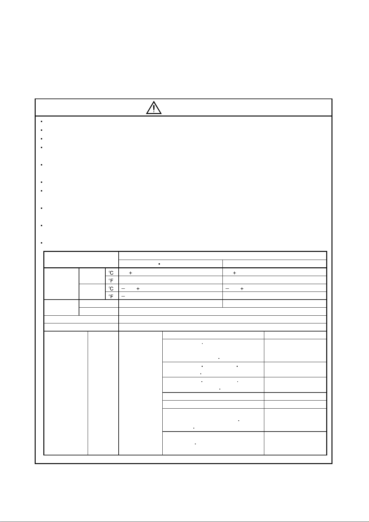
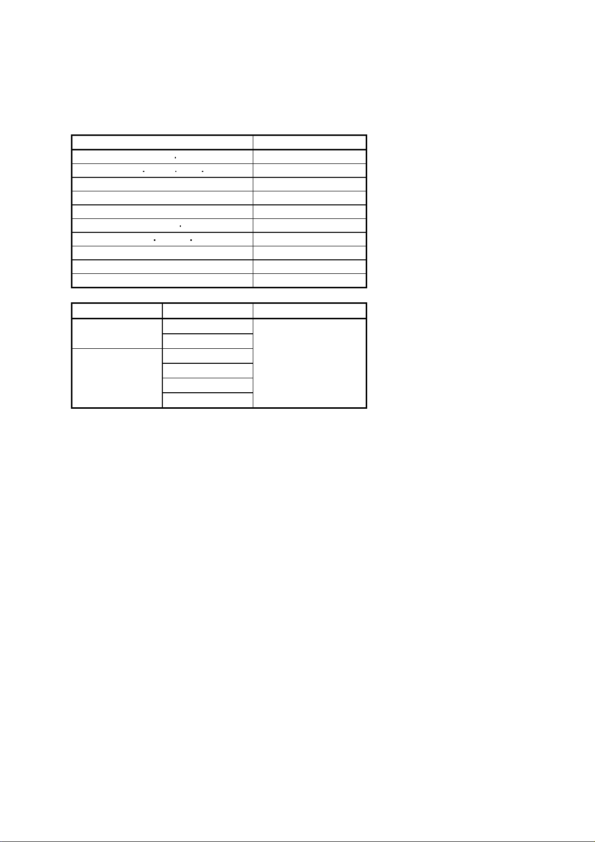
When you keep or use it, please fulfill the following environmental conditions.
Conditions
[] 0 to 55 (non-freezing) 0 to 40 (non-freezing)
Ambient
temperature
[] 20 to 65 (non-freezing) 15 to 70 (non-freezing)
Ambient
In operation 90%RH or less (non-condensing) 80%RH or less (non-condensing)
humidity
Ambience Indoors (no direct sunlight) Free from corrosive gas, flammable gas, oil mist, dust and dirt
Altitude Max. 1000m (3280 ft) above sea level
(Note)
Vibration
Note. Except the servo motor with reduction gear.
Environment
In
operation
In storage
In storage 90%RH or less (non-condensing)
[ ] 32 to 131 (non-freezing) 32 to 104 (non-freezing)
[
2
[m/s
] 5.9 or less
Converter unit servo amplifier (drive unit) Servo motor
] 4 to 149 (non-freezing) 5 to 158 (non-freezing)
HF-MP series HF-KP series X, Y: 49 m/s2
HF-SP51 81 HF-SP52 to 152
HF-SP524 to 1524 HC-RP Series
HC-UP72
HF-SP121
HF-SP2024
HF-SP301 421 HF-SP502 702
HF-SP5024
HC-LP52 to 152 X: 9.8 m/s2 Y: 24.5 m/s2
HC-LP202 to 302 X: 19.6 m/s2 Y: 49 m/s2
HA-LP601 to 12K1 HA-LP701M to 15K1M
HA-LP502 to 22K2 HA-LP6014
HA-LP701M4
HA-LP15K1 to 37K1 HA-LP22K1M to 37K1M
HA-LP30K2
HA-LP22K1M4 to 50K1M4 HA-LP30K24 to 55K24
15K1M4 HA-LP11K24 to 22K24
37K2 HA-LP15K14 to 37K14
152
201 HF-SP202 352
3524 HC-UP202 to 502
7024
12K14
X, Y: 24.5 m/s
X: 24.5 m/s
X: 24.5 m/s
X: 11.7 m/s
X, Y: 9.8 m/s2
2
Y: 49 m/s2
2
Y: 29.4 m/s2
2
Y: 29.4 m/s2
2
A - 3
Page 5
CAUTION
Provide adequate protection to prevent screws and other conductive matter, oil and other combustible
matter from entering the converter unit, servo amplifier (drive unit), and servo motor.
Do not drop or strike converter unit, servo amplifier (drive unit), or servo motor. Isolate from all impact
loads.
Securely attach the servo motor to the machine. If attach insecurely, the servo motor may come off during
operation.
The servo motor with reduction gear must be installed in the specified direction to prevent oil leakage.
Take safety measures, e.g. provide covers, to prevent accidental access to the rotating parts of the servo
motor during operation.
Never hit the servo motor or shaft, especially when coupling the servo motor to the machine. The encoder
may become faulty.
Do not subject the servo motor shaft to more than the permissible load. Otherwise, the shaft may break.
When the equipment has been stored for an extended period of time, consult Mitsubishi.
(2) Wiring
CAUTION
Wire the equipment correctly and securely. Otherwise, the servo motor may operate unexpectedly.
Do not install a power capacitor, surge absorber or radio noise filter (FR-BIF (-H) option) between the
servo motor and servo amplifier (drive unit).
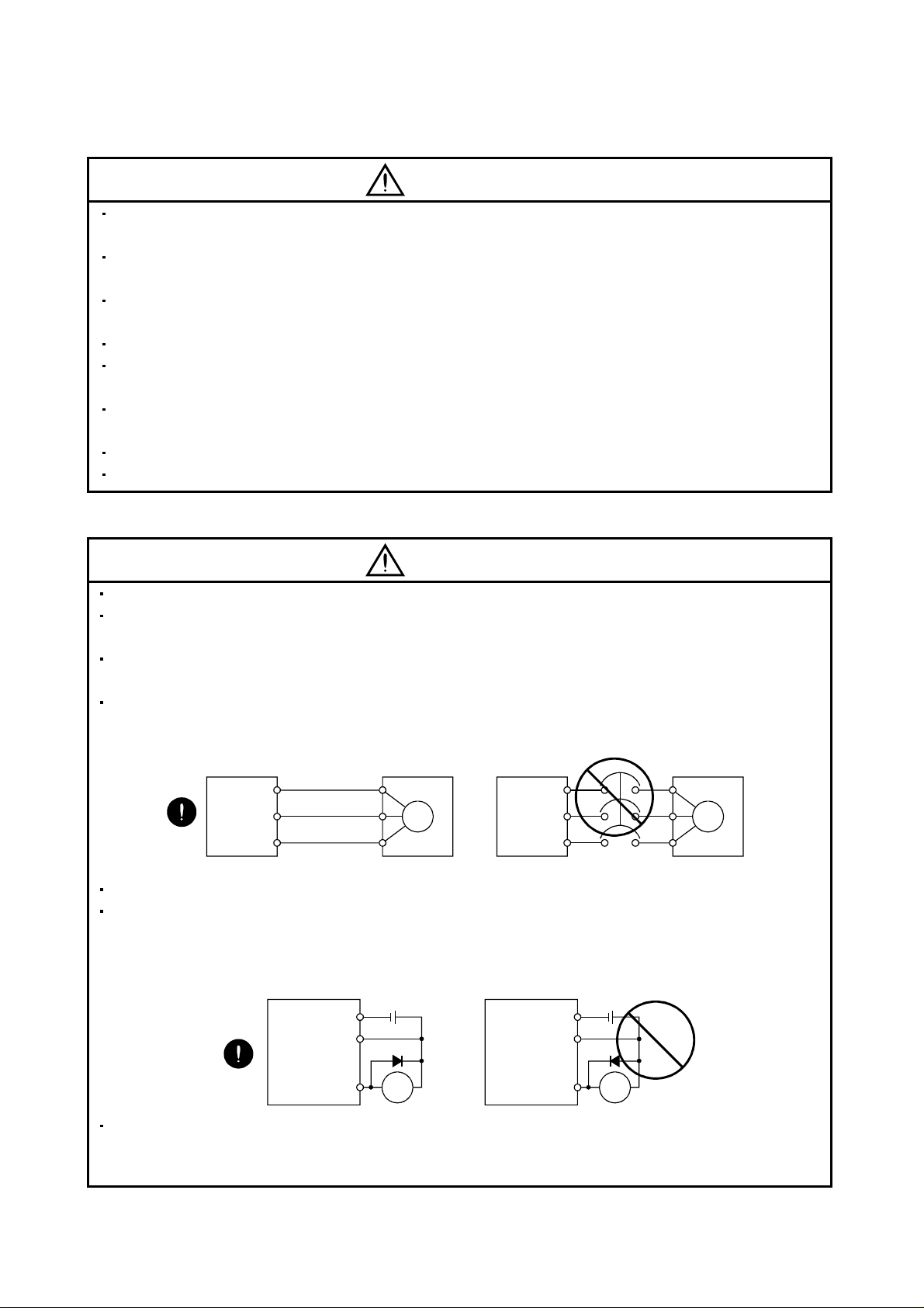
Connect the wires to the correct phase terminals (U, V, W) of the servo amplifier (drive unit) and servo
motor. Otherwise, the servo motor does not operate properly.
Connect the servo motor power terminal (U, V, W) to the servo motor power input terminal (U, V, W)
directly. Do not let a magnetic contactor, etc. intervene.
Servo amplifier
(drive unit)
U
V
W
Servo motor
U
V
W
M
Do not connect AC power directly to the servo motor. Otherwise, a fault may occur.
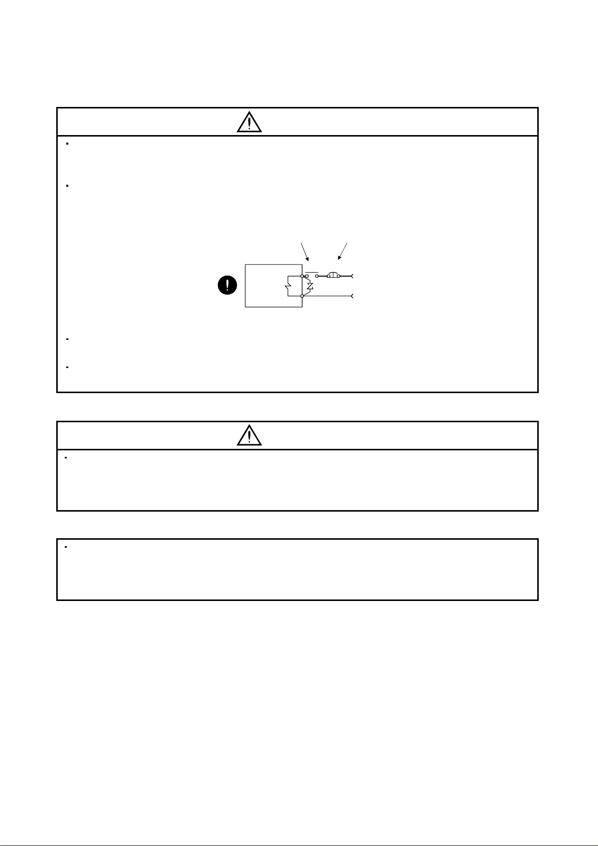
The surge absorbing diode installed on the DC output signal relay of the servo amplifier (drive unit) must
be wired in the specified direction. Otherwise, the forced stop (EM1) and other protective circuits may not
operate.
Servo amplifier
(drive unit)
DOCOM
DICOM
24VDC
Servo amplifier
(drive unit)
U
V
W
Servo amplifier
(drive unit)
DOCOM
DICOM
24VDC
Servo motor
U
V
W
M
Control
output
signal
RA
Control
output
signal
RA
When the cable is not tightened enough to the terminal block (connector), the cable or terminal block
(connector) may generate heat because of the poor contact. Be sure to tighten the cable with specified
torque.
A - 4
Page 6
(3) Test run adjustment
CAUTION
Before operation, check the parameter settings. Improper settings may cause some machines to perform
unexpected operation.
The parameter settings must not be changed excessively. Operation will be insatiable.
(4) Usage
CAUTION
Provide an external emergency stop circuit to ensure that operation can be stopped and power switched
off immediately.
Any person who is involved in disassembly and repair should be fully competent to do the work.
Before resetting an alarm, make sure that the run signal of the servo amplifier (drive unit) is off to prevent
an accident. A sudden restart is made if an alarm is reset with the run signal on.
Do not modify the equipment.
Use a noise filter, etc. to minimize the influence of electromagnetic interference, which may be caused by
electronic equipment used near the converter unit and servo amplifier (drive unit).
Burning or breaking a converter unit and servo amplifier (drive unit) may cause a toxic gas. Do not burn or
break a converter unit and servo amplifier (drive unit).
Use the converter unit and servo amplifier (drive unit) with the specified servo motor.
The electromagnetic brake on the servo motor is designed to hold the motor shaft and should not be used
for ordinary braking.
For such reasons as service life and mechanical structure (e.g. where a ball screw and the servo motor
are coupled via a timing belt), the electromagnetic brake may not hold the motor shaft. To ensure safety,
install a stopper on the machine side.
A - 5
Page 7
(5) Corrective actions
CAUTION
When it is assumed that a hazardous condition may take place at the occur due to a power failure or a
product fault, use a servo motor with an electromagnetic brake or an external brake mechanism for the
purpose of prevention.
Configure the electromagnetic brake circuit so that it is activated not only by the servo amplifier (drive unit)
signals but also by an external forced stop (EM1).
Contacts must be open when
servo-off, when an trouble (ALM)
and when an electromagnetic brake
interlock (MBR).
Servo motor
Circuit must be
opened during
forced stop (EM1).
EM1RA
24VDC
Electromagnetic brake
When any alarm has occurred, eliminate its cause, ensure safety, and deactivate the alarm before
restarting operation.
When power is restored after an instantaneous power failure, keep away from the machine because the
machine may be restarted suddenly (design the machine so that it is secured against hazard if restarted).
(6) Maintenance, inspection and parts replacement
CAUTION
With age, the electrolytic capacitor of the converter unit and servo amplifier (drive unit) will deteriorate. To
prevent a secondary accident due to a fault, it is recommended to replace the electrolytic capacitor every
10 years when used in general environment.
Please consult our sales representative.
(7) General instruction
To illustrate details, the equipment in the diagrams of this Specifications and Instruction Manual may have
been drawn without covers and safety guards. When the equipment is operated, the covers and safety
guards must be installed as specified. Operation must be performed in accordance with this Specifications
and Instruction Manual.
A - 6
Page 8

About processing of waste
When you discard converter unit and servo amplifier (drive unit), a battery (primary battery), and other option
articles, please follow the law of each country (area).
FOR MAXIMUM SAFETY
These products have been manufactured as a general-purpose part for general industries, and have not
been designed or manufactured to be incorporated in a device or system used in purposes related to
human life.
Before using the products for special purposes such as nuclear power, electric power, aerospace,
medicine, passenger movement vehicles or under water relays, contact Mitsubishi.
These products have been manufactured under strict quality control. However, when installing the product
where major accidents or losses could occur if the product fails, install appropriate backup or failsafe
functions in the system.
EEP-ROM life
The number of write times to the EEP-ROM, which stores parameter settings, etc., is limited to 100,000. If
the total number of the following operations exceeds 100,000, the converter unit, servo amplifier (drive unit)
and/or converter unit may fail when the EEP-ROM reaches the end of its useful life.
Write to the EEP-ROM due to parameter setting changes
Write to the EEP-ROM due to device changes
Precautions for Choosing the Products
Mitsubishi will not be held liable for damage caused by factors found not to be the cause of Mitsubishi;
machine damage or lost profits caused by faults in the Mitsubishi products; damage, secondary damage,
accident compensation caused by special factors unpredictable by Mitsubishi; damages to products other
than Mitsubishi products; and to other duties.
A - 7
Page 9

COMPLIANCE WITH EC DIRECTIVES
1. WHAT ARE EC DIRECTIVES?
The EC directives were issued to standardize the regulations of the EU countries and ensure smooth
distribution of safety-guaranteed products. In the EU countries, the machinery directive (effective in January,
1995), EMC directive (effective in January, 1996) and low voltage directive (effective in January, 1997) of the
EC directives require that products to be sold should meet their fundamental safety requirements and carry the
CE marks (CE marking). CE marking applies to machines and equipment into which servo have been installed.
(1) EMC directive
The EMC directive applies not to the servo units alone but to servo-incorporated machines and equipment.
This requires the EMC filters to be used with the servo-incorporated machines and equipment to comply
with the EMC directive. For specific EMC directive conforming methods, refer to the EMC Installation
Guidelines (IB(NA)67310).
(2) Low voltage directive
The low voltage directive applies also to servo units alone. Hence, they are designed to comply with the low
voltage directive.
This servo is certified by TUV, third-party assessment organization, to comply with the low voltage directive.
(3) Machine directive
Not being machines, the converter unit, servo amplifiers (drive unit) need not comply with this directive.
2. PRECAUTIONS FOR COMPLIANCE
(1) Converter unit, servo amplifiers (drive unit), and servo motors used
Use the converter unit, servo amplifiers (drive unit), and servo motors which comply with the standard
model.
Converter unit series :MR-J3-CR55K
MR-J3-CR55K4
Servo amplifier (drive unit) series :MR-J3-10B to MR-J3-22KB
MR-J3-10B1 to MR-J3-40B1
MR-J3-60B4 to MR-J3-22KB4
MR-J3-DU30KB to MR-J3-DU37KB
MR-J3-DU30KB4 to MR-J3-DU55KB4
Servo motor series :HF-MP
HF-KP
HF-SP
HF-SP
HC-RP
HC-UP
HC-LP
HA-LP
HA-LP
Note. For the latest information of compliance, contact Mitsubishi.
(Note)
4 (Note)
(Note)
4 (Note)
A - 8
Page 10
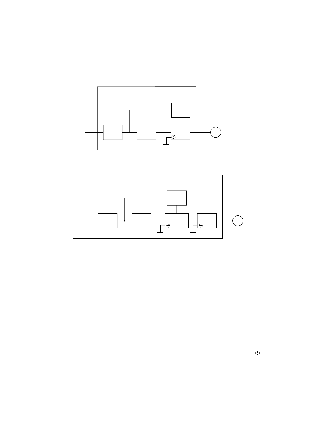
(2) Configuration
The control circuit provide safe separation to the main circuit in the converter unit and servo amplifier (drive
unit).
(a) MR-J3-22KB(4) or less
Control box
Reinforced
insulating type
24VDC
power
No-fuse
breaker
NFB MC
Magnetic
contactor
supply
Servo
amplifier
Servo
motor
M
(b) MR-J3-DU30KB(4) or more
Control box
Reinforced
insulating type
24VDC
power
No-fuse
breaker
NFB MC
Magnetic
contactor
supply
Converter
unit
Drive
unit
Servo
motor
M
(3) Environment
Operate the converter unit and servo amplifier (drive unit) at or above the contamination level 2 set forth in
IEC60664-1. For this purpose, install the converter unit and servo amplifier (drive unit) in a control box
which is protected against water, oil, carbon, dust, dirt, etc. (IP54).
(4) Power supply
(a) This converter unit and servo amplifier (drive unit) can be supplied from star-connected supply with
earthed neutral point of overvoltage category III set forth in IEC60664-1. However, when using the
neutral point of 400V class for single-phase supply, a reinforced insulating transformer is required in the
power input section.
(b) When supplying interface power from external, use a 24VDC power supply which has been insulation-
reinforced in I/O.
(5) Grounding
(a) To prevent an electric shock, always connect the protective earth (PE) terminals (marked
) of the
converter unit and servo amplifier (drive unit) to the protective earth (PE) of the control box.
A - 9
Page 11
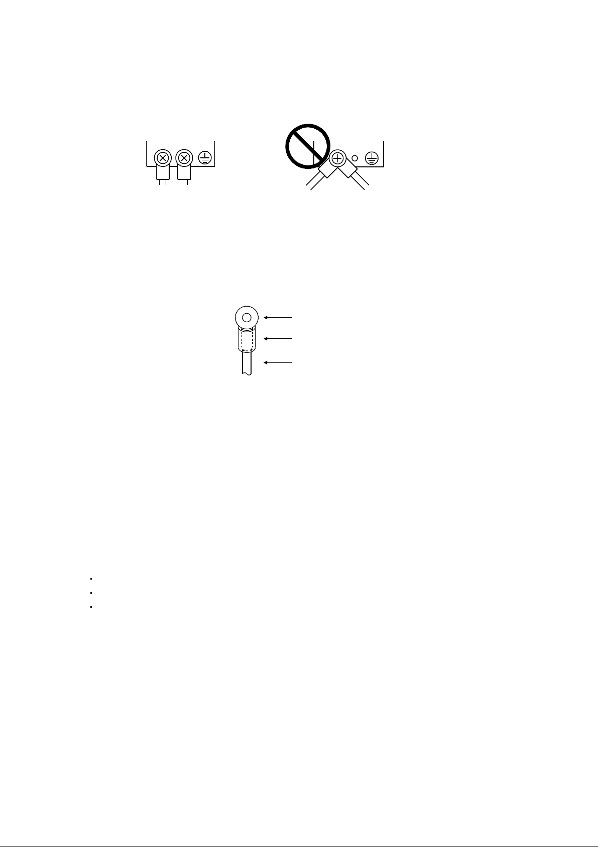
(b) Do not connect two ground cables to the same protective earth (PE) terminal. Always connect the
cables to the terminals one-to-one.
PE terminals
PE terminals
(c) If a leakage current breaker is used to prevent an electric shock, the protective earth (PE) terminals of
the converter unit and servo amplifier (drive unit) must be connected to the corresponding earth
terminals.
(6) Wiring
(a) The cables to be connected to the terminal block of the converter unit and servo amplifier (drive unit)
must have crimping terminals provided with insulating tubes to prevent contact with adjacent terminals.
Crimping terminal
Insulating tube
Cable
(b) Use the servo motor side power connector which complies with the EN Standard. The EN Standard
compliant power connector sets are available from us as options. (Refer to section 11.1)
(7) Auxiliary equipment and options
(a) The no-fuse breaker and magnetic contactor used should be the EN or IEC standard-compliant
products of the models described in section 11.12 (Section 13.9.5 for 30kW or more).
Use a type B (Note) breaker. When it is not used, provide insulation between the converter unit, servo
amplifier (drive unit) and other device by double insulation or reinforced insulation, or install a
transformer between the main power supply, converter unit and servo amplifier (drive unit).
Note. Type A: AC and pulse detectable
Type B: Both AC and DC detectable
(b) The sizes of the cables described in section 11.8 meet the following requirements. To meet the other
requirements, follow Table 5 and Appendix C in EN60204-1.
Ambient temperature: 40 (104) [°C (°F)]
Sheath: PVC (polyvinyl chloride)
Installed on wall surface or open table tray
(c) Use the EMC filter for noise reduction.
(8) Performing EMC tests
When EMC tests are run on a machine/device into which the converter unit and servo amplifier (drive unit)
has been installed, it must conform to the electromagnetic compatibility (immunity/emission) standards after
it has satisfied the operating environment/electrical equipment specifications.
For the other EMC directive guidelines on the converter unit and servo amplifier (drive unit), refer to the
EMC Installation Guidelines(IB(NA)67310).
A - 10
Page 12

CONFORMANCE WITH UL/C-UL STANDARD
(1) Converter unit, servo amplifiers (drive unit) and servo motors used
Use the converter unit, servo amplifiers (drive unit) and servo motors which comply with the standard model.
Converter unit series :MR-J3-CR55K
MR-J3-CR55K4
Servo amplifier (drive unit) series :MR-J3-10B to MR-J3-22KB
MR-J3-10B1 to MR-J3-40B1
MR-J3-60B4 to MR-J3-22KB4
MR-J3-DU30KB to MR-J3-DU37KB
MR-J3-DU30KB4 to MR-J3-DU55KB4
Servo motor series :HF-MP
HF-KP
HF-SP
HF-SP
HC-RP
HC-UP
HC-LP
HA-LP
HA-LP
Note. For the latest information of compliance, contact Mitsubishi.
(2) Installation
Install a fan of 100CFM (2.8m
provide cooling of at least equivalent capability to ensure that the ambient temperature conforms to the
environment conditions (55
(3) Short circuit rating: SCCR (Short Circuit Current Rating)
This servo amplifier (drive unit) conforms to the circuit whose peak current is limited to 100kA or less,
500Volts Maximum. Having been subjected to the short-circuit tests of the UL in the alternating-current
circuit, the servo amplifier (drive unit) conforms to the above circuit.
3
/min) air flow 4[in] (10.16[cm]) above the servo amplifier (drive unit) or
or less).
(Note)
4 (Note)
(Note)
4 (Note)
A - 11
Page 13
(4) Capacitor discharge time
The capacitor discharge time is as listed below. To ensure safety, do not touch the charging section for 15
minutes (more than 20 minutes in case drive unit is 30kW or more) after power-off.
Servo amplifier Discharge time [min]
MR-J3-10B 20B 1
MR-J3-40B 60B(4) 10B1 20B1 2
MR-J3-70B 3
MR-J3-40B1 4
MR-J3-100B(4) 5
MR-J3-200B(4) 350B 9
MR-J3-350B4 500B(4) 700B(4) 10
MR-J3-11KB(4) 4
MR-J3-15KB(4) 6
MR-J3-22KB(4) 8
Converter unit Drive unit Discharge time [min]
MR-J3-CR55K
MR-J3-DU30KB4
MR-J3-CR55K4
MR-J3-DU55KB4
MR-J3-DU30KB
MR-J3-DU37KB
MR-J3-DU37KB4
MR-J3-DU45KB4
20
(5) Options and auxiliary equipment
Use UL/C-UL standard-compliant products.
(6) Attachment of a servo motor
For the flange size of the machine side where the servo motor is installed, refer to “CONFORMANCE WITH
UL/C-UL STANDARD” in the Servo Motor Instruction Manual (Vol.2).
(7) About wiring protection
For installation in United States, branch circuit protection must be provided, in accordance with the National
Electrical Code and any applicable local codes.
For installation in Canada, branch circuit protection must be provided, in accordance with the Canada
Electrical Code and any applicable provincial codes.
A - 12
Page 14

<<About the manuals>>
This Instruction Manual and the MELSERVO Servo Motor Instruction Manual (Vol.2) are required if you use
the General-Purpose AC servo MR-J3-B for the first time. Always purchase them and use the MR-J3-B
safely.
Relevant manuals
Manual name Manual No.
MELSERVO-J3 Series Instructions and Cautions for Safe Use of AC Servos
(Enclosed in converter unit and servo amplifier (drive unit).)
MELSERVO Servo Motor Instruction Manual Vol.2 SH(NA)030041
EMC Installation Guidelines IB(NA)67310
IB(NA)0300077
Details of MR-J3-CR55K(4) and MR-J3-DU30KB(4) to MR-J3-DU55KB4 are described in chapter 13 of this
INSTRUCTION MANUAL.
For the products of 30kW or more, refer to chapter 13.
<<About the wires used for wiring>>
Wiring wires mentioned in this instruction manual are selected based on the ambient temperature of 40°C
(104
).
A - 13
Page 15

MEMO
A - 14
Page 16
CONTENTS
1. FUNCTIONS AND CONFIGURATION 1 - 1 to 1 -28
1.1 Introduction ............................................................................................................................................... 1 - 1
1.2 Function block diagram............................................................................................................................ 1 - 2
1.3 Servo amplifier standard specifications................................................................................................... 1 - 5
1.4 Function list .............................................................................................................................................. 1 - 7
1.5 Model code definition ...............................................................................................................................1 - 8
1.6 Combination with servo motor ................................................................................................................ 1 -10
1.7 Structure .................................................................................................................................................. 1 -11
1.7.1 Parts identification ............................................................................................................................ 1 -11
1.7.2 Removal and reinstallation of the front cover.................................................................................. 1 -18
1.8 Configuration including auxiliary equipment........................................................................................... 1 -21
2. INSTALLATION 2 - 1 to 2 - 6
2.1 Installation direction and clearances ....................................................................................................... 2 - 1
2.2 Keep out foreign materials ....................................................................................................................... 2 - 3
2.3 Cable stress ............................................................................................................................................. 2 - 3
2.4 SSCNET
2.5 Inspection items .......................................................................................................................................2 - 6
2.6 Parts having service lives ........................................................................................................................ 2 - 6
cable laying............................................................................................................................ 2 - 4
3. SIGNALS AND WIRING 3 - 1 to 3 -52
3.1 Input power supply circuit ........................................................................................................................ 3 - 2
3.2 I/O signal connection example ............................................................................................................... 3 -10
3.3 Explanation of power supply system ...................................................................................................... 3 -12
3.3.1 Signal explanations .......................................................................................................................... 3 -12
3.3.2 Power-on sequence .........................................................................................................................3 -13
3.3.3 CNP1, CNP2, CNP3 wiring method ................................................................................................3 -14
3.4 Connectors and signal arrangements ....................................................................................................3 -23
3.5 Signal (device) explanations................................................................................................................... 3 -24
3.6 Alarm occurrence timing chart................................................................................................................ 3 -27
3.7 Interfaces .................................................................................................................................................3 -28
3.7.1 Internal connection diagram ............................................................................................................ 3 -28
3.7.2 Detailed description of interfaces..................................................................................................... 3 -29
3.7.3 Source I/O interfaces ....................................................................................................................... 3 -31
3.8 Treatment of cable shield external conductor ........................................................................................ 3 -32
3.9 SSCNET
3.10 Connection of servo amplifier and servo motor ................................................................................... 3 -35
3.10.1 Connection instructions.................................................................................................................. 3 -35
3.10.2 Power supply cable wiring diagrams ............................................................................................. 3 -36
3.11 Servo motor with an electromagnetic brake......................................................................................... 3 -46
3.11.1 Safety precautions ......................................................................................................................... 3 -46
3.11.2 Timing charts .................................................................................................................................. 3 -47
3.11.3 Wiring diagrams (HF-MP series
3.12 Grounding.............................................................................................................................................. 3 -51
cable connection .................................................................................................................. 3 -33
HF-KP series servo motor) ..................................................... 3 -50
1
Page 17
3.13 Control axis selection ............................................................................................................................ 3 -52
4. STARTUP 4 - 1 to 4 -10
4.1 Switching power on for the first time ....................................................................................................... 4 - 1
4.1.1 Startup procedure.............................................................................................................................. 4 - 1
4.1.2 Wiring check ......................................................................................................................................4 - 2
4.1.3 Surrounding environment.................................................................................................................. 4 - 3
4.2 Start up ..................................................................................................................................................... 4 - 4
4.3 Servo amplifier display............................................................................................................................. 4 - 5
4.4 Test operation .......................................................................................................................................... 4 - 7
4.5 Test operation mode ................................................................................................................................ 4 - 8
4.5.1 Test operation mode in MR Configurator ......................................................................................... 4 - 8
4.5.2 Motorless operation in controller...................................................................................................... 4 -10
5. PARAMETERS 5 - 1 to 5 -28
5.1 Basic setting parameters (No.PA )..................................................................................................... 5 - 1
5.1.1 Parameter list .................................................................................................................................... 5 - 2
5.1.2 Parameter write inhibit ...................................................................................................................... 5 - 3
5.1.3 Selection of regenerative option .......................................................................................................5 - 4
5.1.4 Using absolute position detection system ........................................................................................5 - 5
5.1.5 Forced stop input selection ............................................................................................................... 5 - 5
5.1.6 Auto tuning ........................................................................................................................................ 5 - 6
5.1.7 In-position range................................................................................................................................ 5 - 7
5.1.8 Selection of servo motor rotation direction ....................................................................................... 5 - 8
5.1.9 Encoder output pulse ........................................................................................................................5 - 8
5.2 Gain/filter parameters (No. PB
5.2.1 Parameter list ..................................................................................................................................5 - 10
5.2.2 Detail list ........................................................................................................................................... 5 -11
5.3 Extension setting parameters (No. PC
5.3.1 Parameter list ...................................................................................................................................5 -18
5.3.2 List of details..................................................................................................................................... 5 -19
5.3.3 Analog monitor .................................................................................................................................5 -22
5.3.4 Alarm history clear............................................................................................................................ 5 -24
5.4 I/O setting parameters (No. PD
5.4.1 Parameter list ...................................................................................................................................5 -25
5.4.2 List of details..................................................................................................................................... 5 -26
)....................................................................................................... 5 - 10
) ...........................................................................................5 -18
)....................................................................................................... 5 -25
6. GENERAL GAIN ADJUSTMENT 6 - 1 to 6 -12
6.1 Different adjustment methods .................................................................................................................. 6 - 1
6.1.1 Adjustment on a single servo amplifier............................................................................................. 6 - 1
6.1.2 Adjustment using MR Configurator................................................................................................... 6 - 2
6.2 Auto tuning ............................................................................................................................................... 6 - 3
6.2.1 Auto tuning mode .............................................................................................................................. 6 - 3
6.2.2 Auto tuning mode operation.............................................................................................................. 6 - 4
6.2.3 Adjustment procedure by auto tuning............................................................................................... 6 - 5
6.2.4 Response level setting in auto tuning mode .................................................................................... 6 - 6
6.3 Manual mode 1 (simple manual adjustment) .......................................................................................... 6 - 7
2
Page 18

6.4 Interpolation mode .................................................................................................................................. 6 -11
6.5 Differences between MELSERVO-J2-Super and MELSERVO-J3 in auto tuning ................................ 6 -12
7. SPECIAL ADJUSTMENT FUNCTIONS 7 - 1 to 7 -16
7.1 Function block diagram............................................................................................................................ 7 - 1
7.2 Adaptive filter
7.3 Machine resonance suppression filter..................................................................................................... 7 - 4
7.4 Advanced vibration suppression control ................................................................................................. 7 - 6
7.5 Low-pass filter ......................................................................................................................................... 7 -10
7.6 Gain changing function ...........................................................................................................................7 -10
7.6.1 Applications ......................................................................................................................................7 -10
7.6.2 Function block diagram ....................................................................................................................7 -11
7.6.3 Parameters ....................................................................................................................................... 7 -12
7.6.4 Gain changing operation .................................................................................................................. 7 -14
8. TROUBLESHOOTING 8 - 1 to 8 -10
8.1 Alarms and warning list ............................................................................................................................ 8 - 1
8.2 Remedies for alarms ................................................................................................................................ 8 - 2
8.3 Remedies for warnings ............................................................................................................................8 - 8
......................................................................................................................................... 7 - 1
9. OUTLINE DRAWINGS 9 - 1 to 9 -12
9.1 Servo amplifier ......................................................................................................................................... 9 - 1
9.2 Connector ................................................................................................................................................ 9 -10
10. CHARACTERISTICS 10- 1 to 10-10
10.1 Overload protection characteristics ...................................................................................................... 10- 1
10.2 Power supply equipment capacity and generated loss .......................................................................10- 3
10.3 Dynamic brake characteristics.............................................................................................................. 10- 6
10.3.1 Dynamic brake operation ............................................................................................................... 10- 6
10.3.2 The dynamic brake at the load inertia moment............................................................................. 10- 9
10.4 Cable flexing life................................................................................................................................... 10-10
10.5 Inrush currents at power-on of main circuit and control circuit ........................................................... 10-10
11. OPTIONS AND AUXILIARY EQUIPMENT 11- 1 to 11-90
11.1 Cable/connector sets ............................................................................................................................ 11- 1
11.1.1 Combinations of cable/connector sets .......................................................................................... 11- 2
11.1.2 Encoder cable/connector sets .......................................................................................................11- 8
11.1.3 Motor power supply cables ........................................................................................................... 11-17
11.1.4 Motor brake cables........................................................................................................................ 11-18
11.1.5 SSCNET
11.2 Regenerative options ...........................................................................................................................11-21
11.3 FR-BU2-(H) Brake unit.........................................................................................................................11-34
11.3.1 Selection........................................................................................................................................ 11-35
11.3.2 Brake unit parameter setting......................................................................................................... 11-35
11.3.3 Connection example ..................................................................................................................... 11-36
cable ...........................................................................................................................11-19
3
Page 19

11.3.4 Outline dimension drawings.......................................................................................................... 11-43
11.4 Power regeneration converter ............................................................................................................. 11-45
11.5 Power regeneration common converter .............................................................................................. 11-48
11.6 External dynamic brake ....................................................................................................................... 11-56
11.7 Junction terminal block PS7DW-20V14B-F (recommended) ............................................................. 11-61
11.8 MR Configurator ...................................................................................................................................11-62
11.9 Battery MR-J3BAT ...............................................................................................................................11-64
11.10 Heat sink outside mounting attachment (MR-J3ACN)...................................................................... 11-65
11.11 Selection example of wires ................................................................................................................ 11-67
11.12 No-fuse breakers, fuses, magnetic contactors ................................................................................. 11-72
11.13 Power factor improving DC reactor ................................................................................................... 11-72
11.14 Power factor improving AC reactors ................................................................................................. 11-74
11.15 Relays (recommended) ..................................................................................................................... 11-75
11.16 Surge absorbers (recommended) .....................................................................................................11-76
11.17 Noise reduction techniques ............................................................................................................... 11-76
11.18 Leakage current breaker.................................................................................................................... 11-83
11.19 EMC filter (recommended) ................................................................................................................ 11-85
12. ABSOLUTE POSITION DETECTION SYSTEM 12- 1 to 12- 6
12.1 Features ................................................................................................................................................ 12- 1
12.2 Specifications ........................................................................................................................................ 12- 2
12.3 Battery installation procedure ............................................................................................................... 12- 3
12.4 Confirmation of absolute position detection data................................................................................. 12- 5
13. SERVO AMPLIFIERS WITH A LARGE CAPACITY (30k TO 55kW) 13- 1 to 13-102
13.1. Functions and menus........................................................................................................................... 13- 1
13.1.1 Function block diagram ..................................................................................................................13- 2
13.1.2 Packing list ..................................................................................................................................... 13- 4
13.1.3 Standard specifications.................................................................................................................. 13- 5
13.1.4 Model definition .............................................................................................................................. 13- 8
13.1.5 Combinations of converter units, drive unit and servo motors ..................................................... 13- 9
13.1.6 Parts identification .........................................................................................................................13-10
13.1.7 Removal and reinstallation of the terminal block cover ............................................................... 13-13
13.1.8 Servo system with auxiliary equipment ........................................................................................13-19
13.2 Installation ............................................................................................................................................ 13-20
13.2.1 Installation direction and clearances ............................................................................................ 13-21
13.2.2 Inspection ......................................................................................................................................13-22
13.3 Signals and wiring ................................................................................................................................ 13-23
13.3.1 Magnetic contactor control connector (CNP1) .............................................................................13-24
13.3.2 Input power supply circuit .............................................................................................................13-26
13.3.3 Terminal......................................................................................................................................... 13-31
13.3.4 How to use the connection bars ...................................................................................................13-32
13.3.5 Connectors and signal arrangements .......................................................................................... 13-33
13.3.6 Converter unit signal (device) explanations ................................................................................. 13-35
13.3.7 Timing chart................................................................................................................................... 13-37
13.3.8 Servo motor side details ............................................................................................................... 13-47
13.4 Display section and operation section of the converter unit ............................................................... 13-49
4
Page 20

13.4.1 Display flowchart ...........................................................................................................................13-49
13.4.2 Status display mode...................................................................................................................... 13-50
13.4.3 Diagnostic mode............................................................................................................................ 13-51
13.4.4 Alarm mode ................................................................................................................................... 13-53
13.4.5 Parameter mode ........................................................................................................................... 13-54
13.5. Parameters for converter unit .............................................................................................................13-55
13.5.1 Parameter list ................................................................................................................................13-55
13.5.2 List of details.................................................................................................................................. 13-56
13.6 Troubleshooting ................................................................................................................................... 13-57
13.6.1 Converter unit ................................................................................................................................ 13-57
13.6.2 Drive unit........................................................................................................................................ 13-62
13.7 Outline drawings .................................................................................................................................. 13-64
13.7.1 Converter unit (MR-J3-CR55K(4))................................................................................................ 13-64
13.7.2 Drive unit........................................................................................................................................ 13-65
13.8 Characteristics...................................................................................................................................... 13-67
13.8.1 Overload protection characteristics ..............................................................................................13-67
13.8.2 Power supply equipment capacity and generated loss ............................................................... 13-68
13.8.3 Dynamic brake characteristics...................................................................................................... 13-69
13.8.4 Inrush currents at power-on of main circuit and control circuit .................................................... 13-72
13.9 Options .................................................................................................................................................13-72
13.9.1 Cables and connectors .................................................................................................................13-72
13.9.2 Regenerative option ...................................................................................................................... 13-75
13.9.3 External dynamic brake ................................................................................................................13-79
13.9.4 Selection example of wires ........................................................................................................... 13-82
13.9.5 No-fuse breakers, fuses, magnetic contactors............................................................................. 13-84
13.9.6 Power factor improving DC reactor ..............................................................................................13-84
13.9.7 Line noise filter (FR-BLF).............................................................................................................. 13-85
13.9.8 Leakage current breaker............................................................................................................... 13-86
13.9.9 EMC filter (recommended)............................................................................................................ 13-88
13.9.10 FR-BU2-(H) Brake Unit ............................................................................................................... 13-90
APPENDIX App.- 1 to App.- 9
App. 1 Parameter list..................................................................................................................................App.- 1
App. 2 Signal layout recording paper ........................................................................................................App.- 3
App. 3 Twin type connector : Outline drawing for 721-2105/026-000 (WAGO).......................................App.- 3
App. 4 Change of connector sets to the RoHS compatible products .......................................................App.- 4
App. 5 MR-J3-200B-RT servo amplifier ....................................................................................................App.- 5
App. 6 Selection example of servo motor power cable ............................................................................App.- 9
5
Page 21

MEMO
6
Page 22

1. FUNCTIONS AND CONFIGURATION
1. FUNCTIONS AND CONFIGURATION
1.1 Introduction
The Mitsubishi MELSERVO-J3 series general-purpose AC servo has further higher performance and higher
functions compared to the current MELSERVO-J2-Super series.
The MR-J3-B servo amplifier connects to servo system controller and others via high speed synchronous
network and operates by directly reading position data. The rotation speed/direction control of servo motor and
the high accuracy positioning are executed with the data from command module. SSCNET
MR-J3-B servo amplifier greatly improved its communication speed and noise tolerance by adopting optical
communication system compared to the current SSCNET. For wiring distance, 50m of the maximum distance
between electrodes is also offered.
The torque limit with clamping circuit is put on the servo amplifier in order to protect the power transistor of
main circuit from the overcurrent caused by rapid acceleration/deceleration or overload. In addition, torque limit
value can be changed to desired value in the controller.
As this new series has the USB communication function, a MR Configurator-installed personal computer or the
like can be used to perform parameter setting, test operation, status display monitoring, gain adjustment, etc.
With real-time auto tuning, you can automatically adjust the servo gains according to the machine.
The MELSERVO-J3 series servo motor is with an absolute position encoder which has the resolution of
262144 pulses/rev to ensure more accurate control as compared to the MELSERVO-J2-Super series. Simply
adding a battery to the servo amplifier makes up an absolute position detection system. This makes home
position return unnecessary at power-on or alarm occurrence by setting a home position once.
equipped by the
1 - 1
Page 23
1. FUNCTIONS AND CONFIGURATION
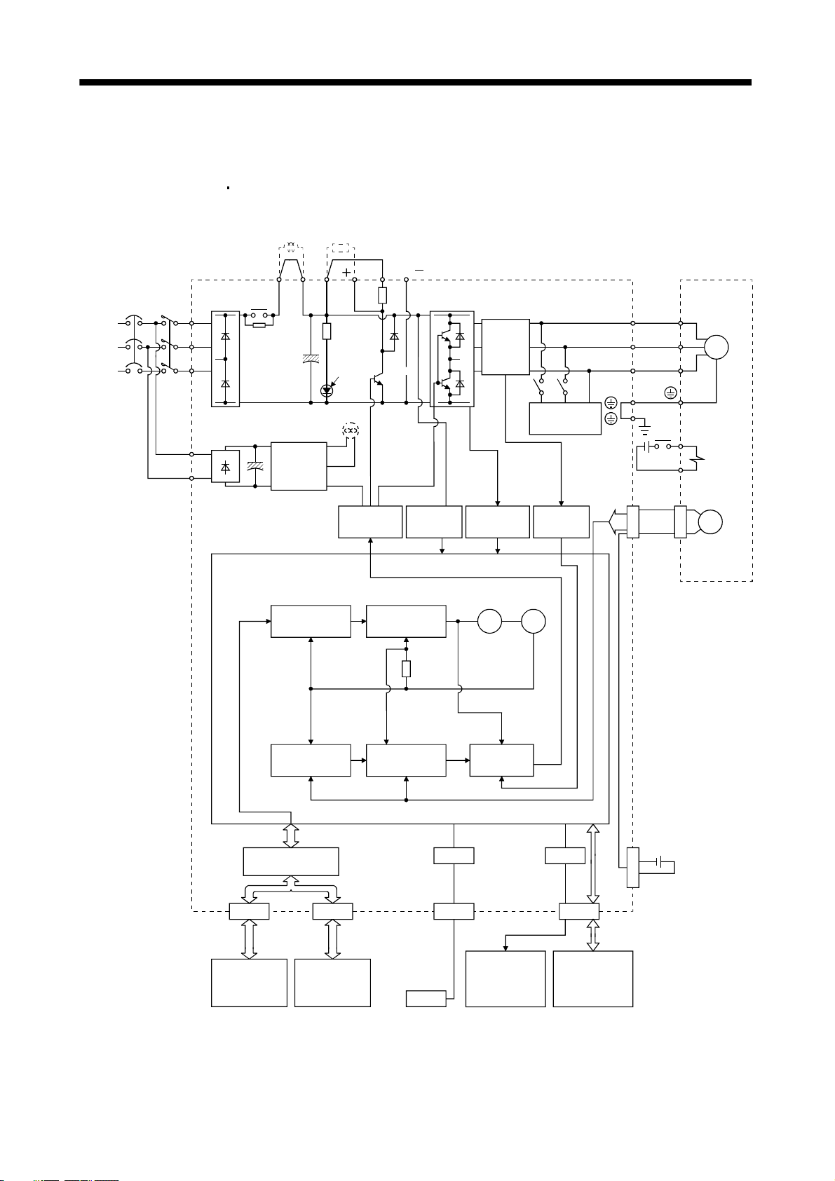
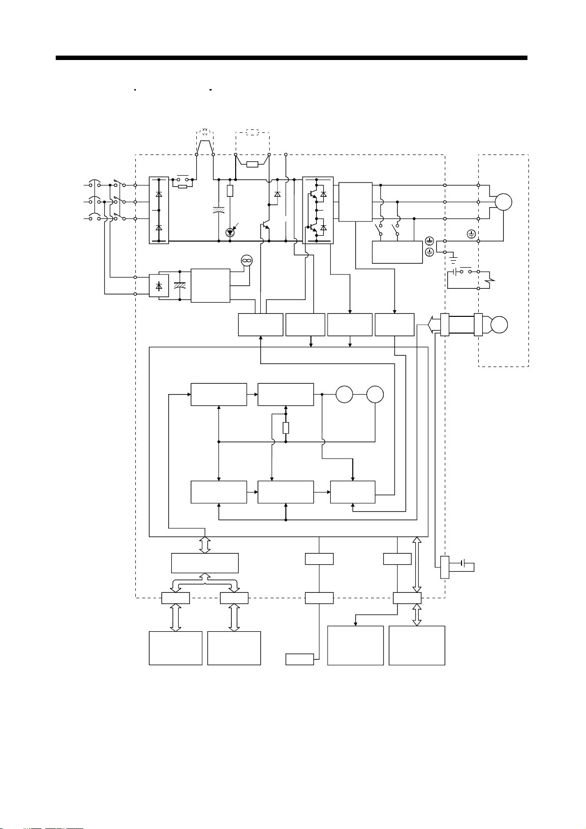
1.2 Function block diagram
The function block diagram of this servo is shown below.
(1) MR-J3-350B or less
MR-J3-200B4 or less
Power factor
improving DC
reactor
Regenerative
option
(Note 2)
Power
supply
NFB MC
L
L2
L
L
L21
1
3
11
Diode
Relay
stack
Position
command
input
P
2
P( )
CHARGE
lamp
P
1
(Note 3)Cooling fan
Control
circuit
power
supply
Model position
control
Base
amplifier
Model speed
N( )
DC
Regenerative
TR
control
(Note 1)
Voltage
detection
Current
detector
Overcurrent
protection
encoder
Virtual
motor
Virtual
Dynamic
brake
Current
detection
U
V
W
24VDC
CN2
RA
B1
B2
Servo motorServo amplifier
U
V
W
Electromagnetic
brake
Encoder
M
I/F Control
Controller or
servo amplifier
Model
position
Actual position
control
CN1BCN1A
Servo amplifier
or cap
Model
speed
Actual speed
control
USB
CN5
Personal
computer
USB
Note 1. The built-in regenerative resistor is not provided for the MR-J3-10B (1).
2. For 1-phase 200 to 230VAC, connect the power supply to L
There is no L
3. Servo amplifiers MR-J3-70B or greater have a cooling fan.
3 for 1-phase 100 to 120VAC power supply. Refer to section 1.3 for the power supply specification.
1, L2 and leave L3 open.
1 - 2
Model
torque
Current
control
Analog monitor
(2 channels)
D/A
CN3
Digital I/O
control
MR-J3BAT
CN4
Optional battery
(for absolute position
detection system)
Page 24
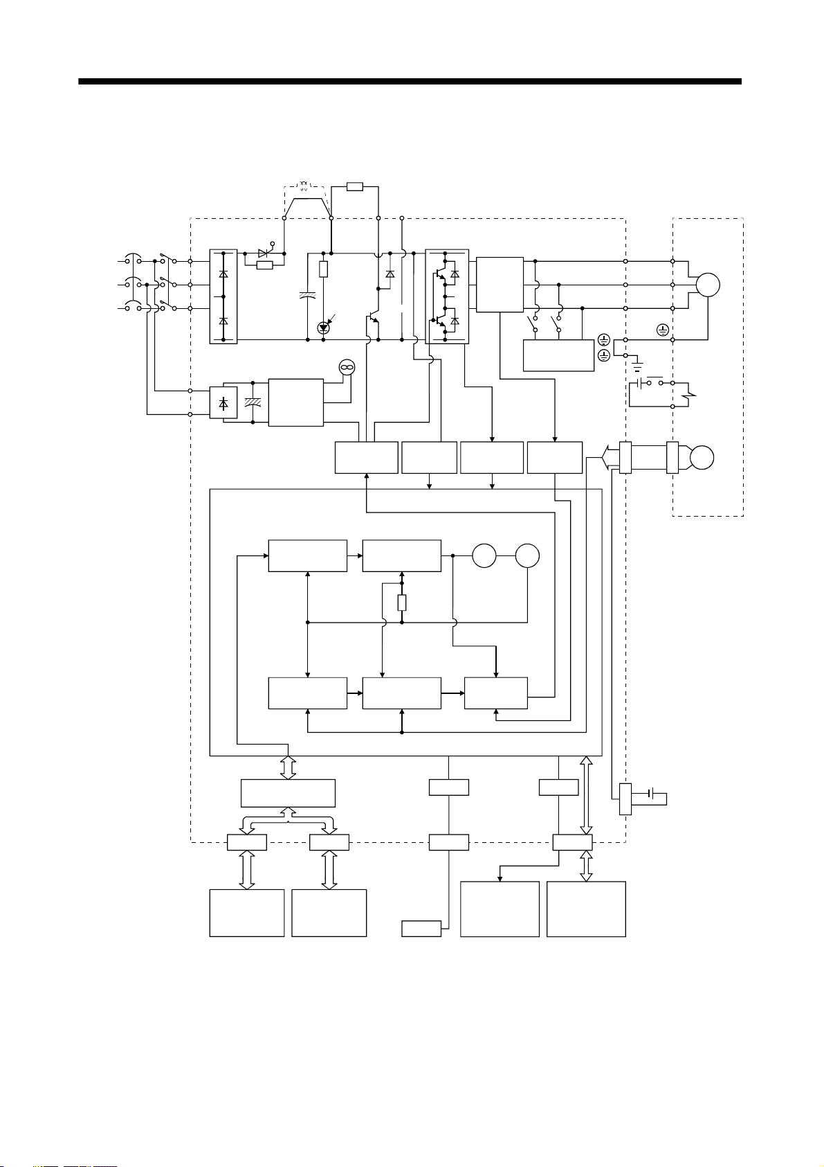
1. FUNCTIONS AND CONFIGURATION
(2) MR-J3-350B4
NFB MC
(Note)
Power
supply
MR-J3-500B(4) MR-J3-700B(4)
Power factor
L
L2
L
L
L21
1
3
11
Diode
stack
improving DC
reactor
P
1
Relay
Control
circuit
power
supply
Regenerative
option
P
P
2
CHARGE
lamp
Cooling fan
amplifier
Base
C
Regenerative
TR
N
Voltage
detection
Current
detector
Overcurrent
protection
Dynamic
brake
Current
detection
U
V
W
24VDC
CN2
RA
B1
B2
Servo motorServo amplifier
U
V
W
Electromagnetic
brake
Encoder
M
Position
command
input
I/F Control
Controller or
servo amplifier
Model position
control
Model
position
Actual position
control
CN1BCN1A
Servo amplifier
or cap
Model speed
control
Model
speed
Actual speed
control
Personal
computer
USB
Virtual
motor
USB
CN5
Analog monitor
(2 channels)
Model
torque
Current
control
Virtual
encoder
D/A
CN3
Digital I/O
control
MR-J3BAT
CN4
Optional battery
(for absolute position
detection system)
Note. Refer to section 1.3 for the power supply specification.
1 - 3
Page 25
1. FUNCTIONS AND CONFIGURATION
(3) MR-J3-11KB(4) to 22KB(4)
Power factor
improving DC
reactor
Regenerative
option
(Note)
Power
supply
NFB MC
L
L2
L
L
L21
1
3
11
Diode
stack
Thyristor
Position
command
input
P
1
CHARGE
Cooling fan
Control
circuit
power
supply
Model position
control
P
lamp
amplifier
C
Regenerative
TR
Base
Model speed
control
N
Voltage
detection
Current
detector
Overcurrent
protection
encoder
Virtual
motor
Virtual
Dynamic
brake
Current
detection
U
V
W
24VDC
CN2
RA
B1
B2
Servo motorServo amplifier
U
V
W
Electromagnetic
brake
Encoder
M
Model
position
Actual position
control
I/F Control
CN1BCN1A
Controller or
servo amplifier
Servo amplifier
or cap
Note. Refer to section 1.3 for the power supply specification.
Model
speed
Actual speed
control
Personal
computer
USB
USB
CN5
Analog monitor
(2 channels)
Model
torque
Current
control
D/A
CN3
Digital I/O
control
MR-J3BAT
CN4
Optional battery
(for absolute position
detection system)
1 - 4
Page 26
y
t
1. FUNCTIONS AND CONFIGURATION
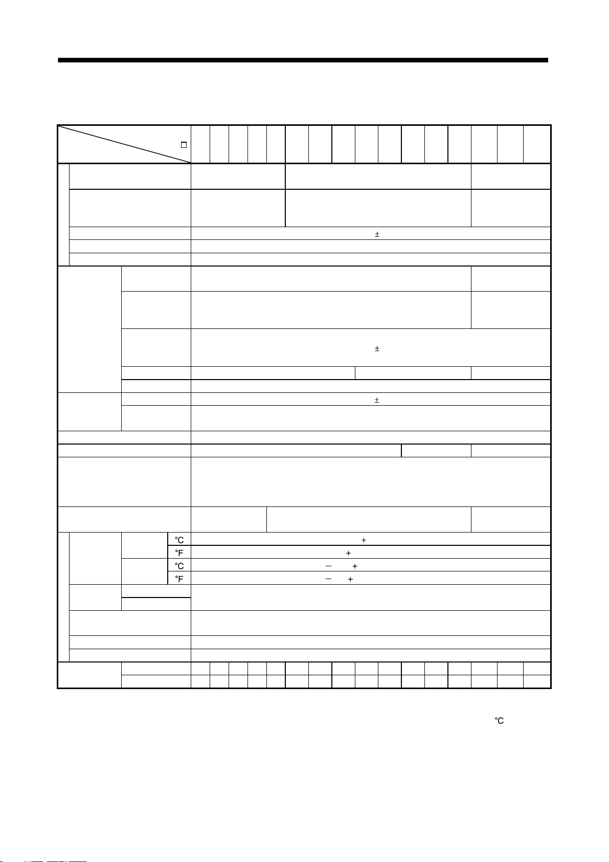
1.3 Servo amplifier standard specifications
(1) 200V class, 100V class
Servo amplifier
MR-J3-
Item
Voltage/frequency
Permissible voltage fluctuation
Permissible frequency fluctuation Within 5%
Power suppl
Power supply capacity Refer to section 10.2
Inrush current Refer to section 10.5
Voltage,
frequency
Permissible
voltage
Control circuit
power supply
Interface power
supply
Control System Sine-wave PWM control, current control system
Dynamic brake Built-in External option Built-in
Protective functions
Structure
Ambient
temperature
humidity
Environmen
Ambient
Altitude Max. 1000m above sea level
Vibration 5.9 [m/s2] or less
Mass
Note 1. 150mA is the value applicable when all I/O signals are used. The current capacity can be decreased by reducing the number of
I/O points.
2. When closely mounting the servo amplifier of 3.5kW or less, operate them at the ambient temperatures of 0 to 45
smaller effective load ratio.
fluctuation
Permissible
frequency
fluctuation
Input 30W 45W 30W
Inrush current Refer to section 10.5
Voltage 24VDC 10%
Power supply
capacity
operation
In storage
In operation Ambient
In storage
10B 20B 40B 60B 70B 100B 200B 350B 500B 700B 11KB 15KB 22KB 10B1 20B1 40B1
3-phase or 1-phase 200
to 230VAC, 50/60Hz
3-phase or 1-phase 200
to 230VAC: 170 to
253VAC
1-phase 200 to 230VAC, 50/60Hz
Overcurrent shut-off, regenerative overvoltage shut-off, overload shut-off (electronic thermal relay),
servo motor overheat protection, encoder error protection, regenerative error protection,
undervoltage, instantaneous power failure protection, overspeed protection, excessive error
protection.
Self-cooled, open
(IP00)
[ ] (Note 2) 0 to 55 (non-freezing) In
] 32 to 131 (non-freezing)
[
[ ] 20 to 65 (non-freezing)
[
] 4 to 149 (non-freezing)
Free from corrosive gas, flammable gas, oil mist, dust and dirt
[kg] 0.8 0.8 1.0 1.0 1.4 1.4 2.1 2.3 4.6 6.2 18 18 19 0.8 0.8 1.0
[lb] 1.76 1.76 2.21 2.21 3.09 3.09 4.63 5.07 10.1 13.7 39.7 39.7 41.9 1.76 1.76 2.21
3-phase 200 to 230VAC, 50/60Hz
3-phase 170 to 253VAC
1-phase 170 to 253VAC
Within
(Note 1) 150mA or more
Force-cooling, open (IP00)
90%RH or less (non-condensing)
Indoors (no direct sunlight)
5%
1-phase 100V to
120VAC, 50/60Hz
1-phase 85 to
132VAC
1-phase 100 to
120VAC, 50/60Hz
1-phase 85 to
132VAC
Self-cooled, open
(IP00)
or at 75% or
1 - 5
Page 27
y
t
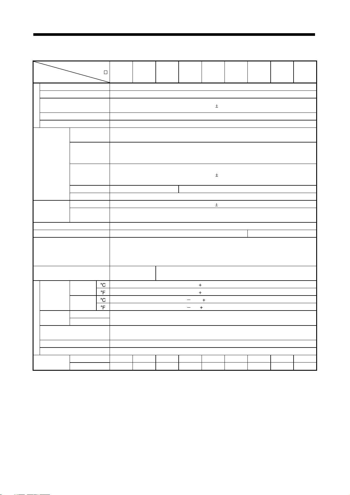
1. FUNCTIONS AND CONFIGURATION
(2) 400V class
Servo amplifier
MR-J3-
Item
Voltage/frequency 3-phase 380 to 480VAC, 50/60Hz
Permissible voltage fluctuation 3-phase 323 to 528VAC
Permissible frequency
fluctuation
Power supply capacity Refer to section 10.2
Power suppl
Inrush current Refer to section 10.5
Voltage,
frequency
Permissible
voltage
Control circuit
power supply
Interface power
supply
Control System Sine-wave PWM control, current control system
Dynamic brake Built-in External option
Protective functions
Structure
Ambient
temperature
humidity
Environmen
Ambient
Altitude Max. 1000m above sea level
Vibration 5.9 [m/s2] or less
Mass
Note. 150mA is the value applicable when all I/O signals are used. The current capacity can be decreased by reducing the number of
I/O points.
fluctuation
Permissible
frequency
fluctuation
Input 30W 45W
Inrush current Refer to section 10.5
Voltage 24VDC 10%
Power supply
capacity
operation
In storage
In operation Ambient
In storage
[kg] 1.7 1.7 2.1 4.6 4.6 6.2 18 18 19
[lb] 3.75 3.75 4.63 10.14 10.14 13.67 39.68 39.68 41.88
60B4 100B4 200B4 350B4 500B4 700B4 11KB4 15KB4 22KB4
Within
1-phase 380 to 480VAC, 50/60Hz
1-phase 323 to 528VAC
Within
(Note) 150mA
Overcurrent shut-off, regenerative overvoltage shut-off, overload shut-off (electronic thermal relay),
servo motor overheat protection, encoder error protection, regenerative error protection,
undervoltage, instantaneous power failure protection, overspeed protection, excessive error
protection.
Self-cooled, open
(IP00)
[ ] 0 to 55 (non-freezing) In
[
] 32 to 131 (non-freezing)
[ ] 20 to 65 (non-freezing)
[
] 4 to 149 (non-freezing)
Force-cooling, open (IP00)
90%RH or less (non-condensing)
Indoors (no direct sunlight)
Free from corrosive gas, flammable gas, oil mist, dust and dirt
5%
5%
1 - 6
Page 28
1. FUNCTIONS AND CONFIGURATION
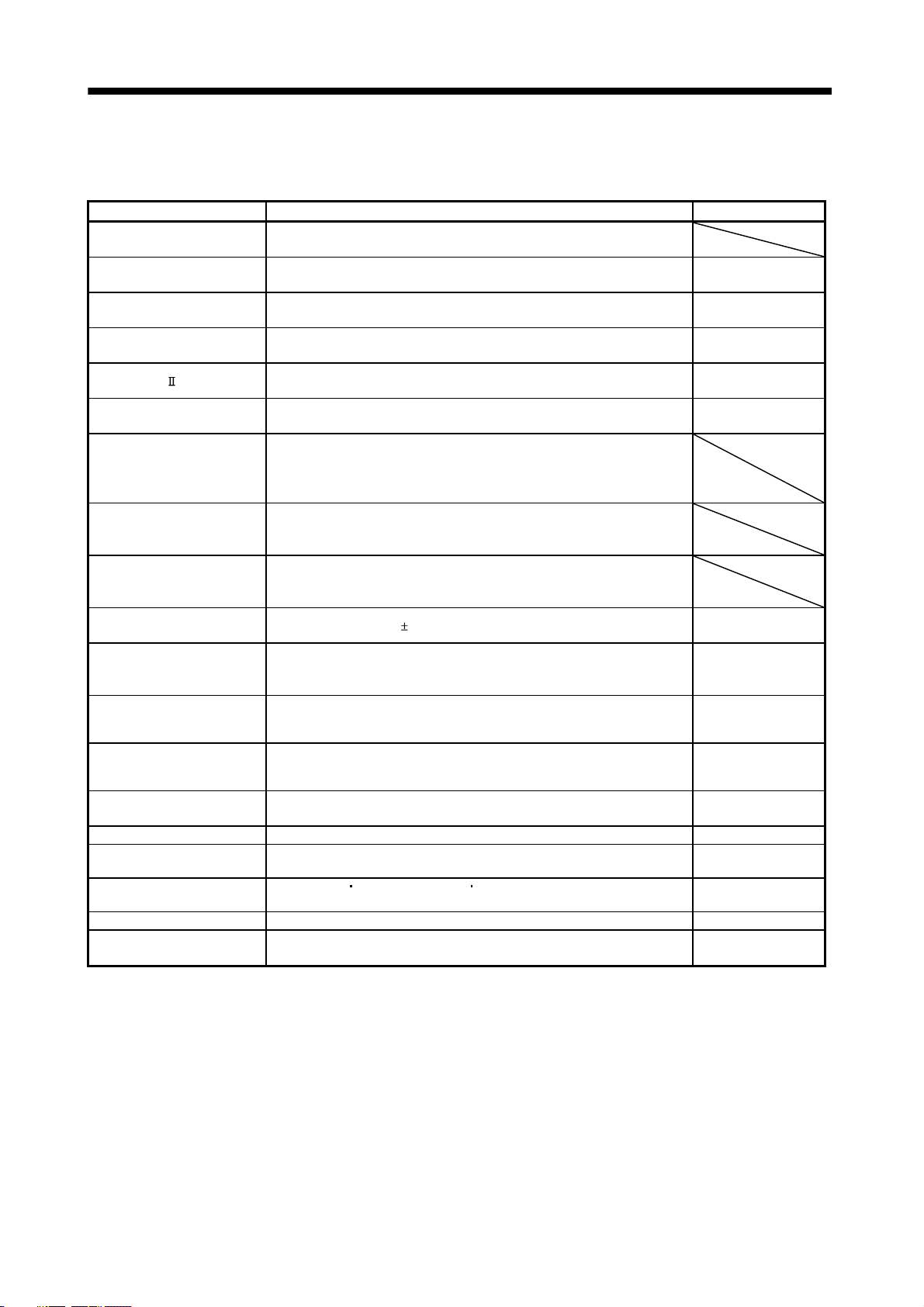
1.4 Function list
The following table lists the functions of this servo. For details of the functions, refer to the reference field.
Function Description Reference
High-resolution encoder
Absolute position detection
system
Gain changing function
Advanced vibration
suppression control
Adaptive filter
Low-pass filter
Machine analyzer function
Machine simulation
Gain search function
Slight vibration suppression
control
Auto tuning
Brake unit
Return converter
Regenerative option
Alarm history clear Alarm history is cleared. Parameter No.PC21
Output signal (DO)
forced output
Test operation mode
Analog monitor output Servo status is output in terms of voltage in real time. Parameter No.PC09
MR Configurator
High-resolution encoder of 262144 pulses/rev is used as a servo motor
encoder.
Merely setting a home position once makes home position return
unnecessary at every power-on.
You can switch between gains during rotation and gains during stop or use
an input device to change gains during operation.
This function suppresses vibration at the arm end or residual vibration. Section 7.4
Servo amplifier detects mechanical resonance and sets filter characteristics
automatically to suppress mechanical vibration.
Suppresses high-frequency resonance which occurs as servo system
response is increased.
Analyzes the frequency characteristic of the mechanical system by simply
connecting a MR Configurator installed personal computer and servo
amplifier.
MR Configurator is necessary for this function.
Can simulate machine motions on a personal computer screen on the basis
of the machine analyzer results.
MR Configurator is necessary for this function.
Personal computer changes gains automatically and searches for overshootfree gains in a short time.
MR Configurator is necessary for this function.
Suppresses vibration of
Automatically adjusts the gain to optimum value if load applied to the servo
motor shaft varies. Higher in performance than MR-J2-Super series servo
amplifier.
Used when the regenerative option cannot provide enough regenerative
power.
Can be used the 5kW or more servo amplifier.
Used when the regenerative option cannot provide enough regenerative
power.
Can be used the 5kW or more servo amplifier.
Used when the built-in regenerative resistor of the servo amplifier does not
have sufficient regenerative capability for the regenerative power generated.
Output signal can be forced on/off independently of the servo status.
Use this function for output signal wiring check, etc.
JOG operation
However, MR Configurator is necessary for positioning operation.
Using a personal computer, parameter setting, test operation, status display,
etc. can be performed.
positioning operation DO forced output.
1 pulse produced at a servo motor stop. Parameters No.PB24
Chapter 12
Section 7.6
Section 7.2
Section 7.5
Chapter 6
Section 11.3
Section 11.4
Section 11.2
Section 4.5.1 (1) (d)
Section 4.5
Section 11.8
1 - 7
Page 29

1. FUNCTIONS AND CONFIGURATION
1.5 Model code definition
(1) Rating plate
MR-J3-10B
POWER :
INPUT :
OUTPUT:
SERIAL :
AC SERVO
100W
0.9A 3PH+1PH200-230V 50Hz
3PH+1PH200-230V 60Hz
1.3A 1PH 200-230V 50/60Hz
170V 0-360Hz 1.1A
A34230001
Model
Capacity
Applicable power supply
Rated output current
Serial number
1 - 8
Page 30
1. FUNCTIONS AND CONFIGURATION
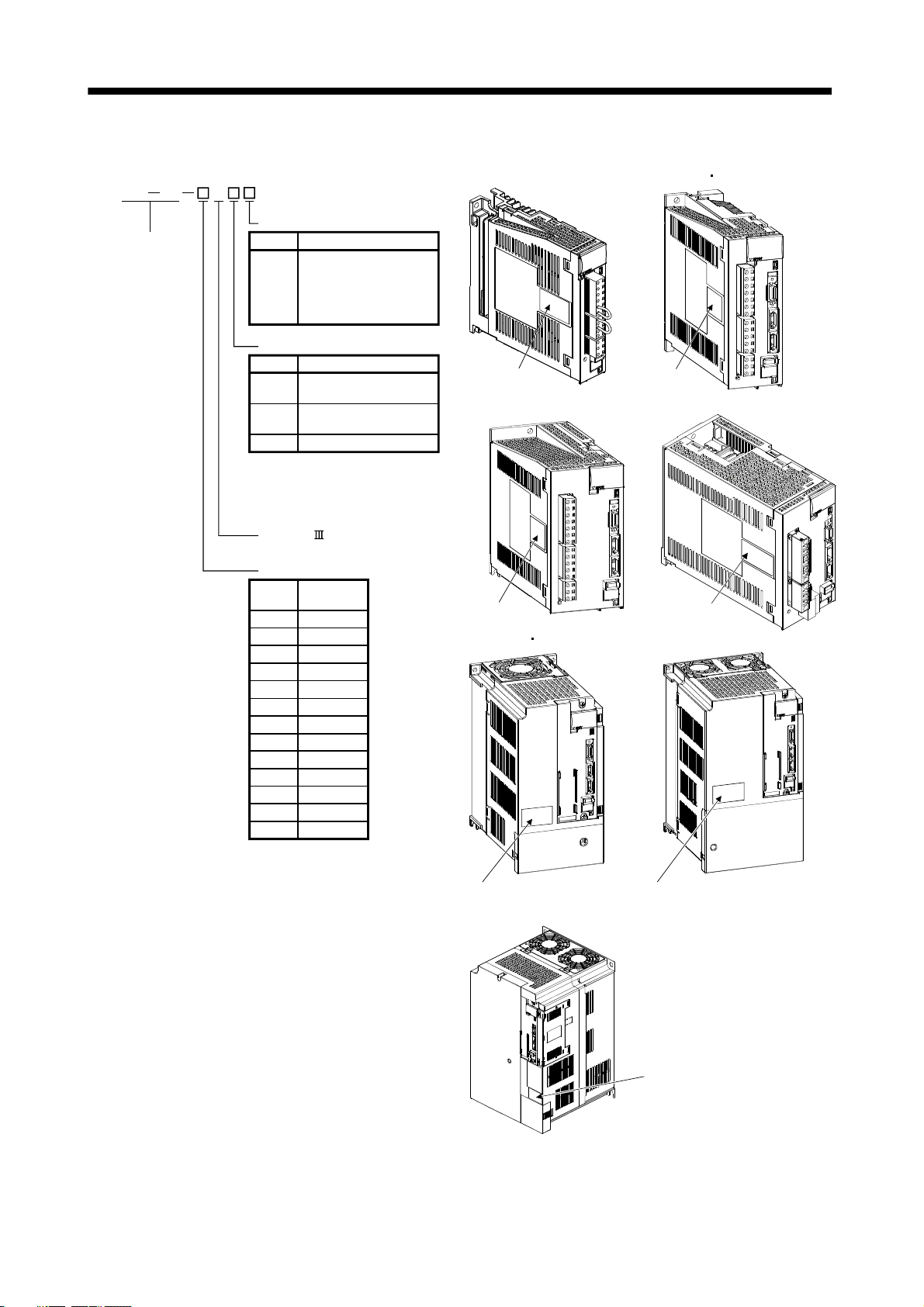
(2) Model
MR J3 B
With no regenerative resistor
Series
Symbol Description
Indicates a servo
amplifier of 11k to 22kW
that does not use a
-PX
regenerative resistor as
standard accessory.
Power supply
Symbol Power supply
(Note 1)
(Note 2)
Note 1. 1-phase 200 to 230V is
supported by 750W or less.
2. 1-phase 100 to 120V is
supported by 400W or less.
3-phase or 1-phase 200
to 230VAC
None
1-phase 100 to 120VAC
1
4 3-phase 380 to 480VAC
MR-J3-100B or less
Rating plate
MR-J3-200B(4)
MR-J3-60B4 100B4
Rating plate
MR-J3-350B
SSCNET compatible
Rated output
Symbol
Rated
output [kW]
10 0.1
20 0.2
40 0.4
60 0.6
70 0.75
100 1
200 2
350 3.5
500 5
700 7
11K 11
15K 15
22K 22
Rating plate
MR-J3-350B4 500B(4)
Rating plate
MR-J3-11KB(4) to 22KB(4)
Rating plate
MR-J3-700B(4)
Rating plate
Rating plate
1 - 9
Page 31

1. FUNCTIONS AND CONFIGURATION
1.6 Combination with servo motor
The following table lists combinations of servo amplifiers and servo motors. The same combinations apply to
the models with an electromagnetic brake and the models with a reduction gear.
Servo motors
Servo amplifier
MR-J3-10B (1) 053 13 053 13
MR-J3-20B (1) 23 23
MR-J3-40B (1) 43 43
MR-J3-60B 51 52 52
MR-J3-70B 73 73 72
MR-J3-100B 81 102 102
MR-J3-200B 121 201 152 202 103
MR-J3-350B 301 352 203 202 202
MR-J3-500B 421 502 353
MR-J3-700B 702
MR-J3-11KB
MR-J3-15KB
MR-J3-22KB
HF-MP
HF-KP
1000r/min 2000r/min
HF-SP
HC-RP HC-UP HC-LP
152 152
153
352
503
302
502
Servo motors
Servo amplifier
MR-J3-500B 502
MR-J3-700B 601 701M 702
MR-J3-11KB 801 12K1 11K1M 11K2
MR-J3-15KB 15K1 15K1M 15K2
MR-J3-22KB 20K1 25K1 22K1M 22K2
HA-LP
1000r/min 1500r/min 2000r/min
Servo motors
Servo amplifier
MR-J3-60B4 524
MR-J3-100B4 1024
MR-J3-200B4 1524 2024
MR-J3-350B4 3524
MR-J3-500B4 5024
MR-J3-700B4 7024 6014 701M4
MR-J3-11KB4 8014 12K14 11K1M4 11K24
MR-J3-15KB4 15K14 15K1M4 15K24
MR-J3-22KB4 20K14 22K1M4 22K24
HF-SP
HA-LP
1000r/min 1500r/min 2000r/min
1 - 10
Page 32

1. FUNCTIONS AND CONFIGURATION
1.7 Structure
1.7.1 Parts identification
(1) MR-J3-100B or less
SW1
TEST
SW2
7
6
5
4
3
2
ON 4F
12
Name/Application
Detailed
explanation
Display
The 3-digit, seven-segment LED shows the servo
Chapter 4
status and alarm number.
Rotary axis setting switch (SW1)
SW1
8
7
6
8
9
A
B
C
D
E
F
1
0
5
4
3
2
1
Used to set the axis No. of servo amplifier.
9
A
B
C
D
E
F
0
Section 3.13
Test operation select switch (SW2-1)
SW2
Used to perform the test operation
mode by using MR Configurator.
Section 3.13
Spare (Be sure to set to the "Down"
12
Main circuit power supply connector (CNP1)
Connect the input power supply.
USB communication connector (CN5)
Connect the personal computer.
I/O signal connector (CN3)
Used to connect digital I/O signals.
More over an analog monitor is output.
Control circuit connector (CNP2)
Connect the control circuit power supply/regenerative
option.
SSCNET cable connector (CN1A)
Used to connect the servo system controller or the front
axis servo amplifier.
SSCNET cable connector (CN1B)
Used to connect the rear axis servo amplifier. For the final
axis, puts a cap.
Servo motor power connector (CNP3)
Connect the servo motor.
Encoder connector (CN2)
Used to connect the servo motor encoder.
position).
Section 3.1
Section 3.3
Section 11.8
Section 3.2
Section 3.4
Section 3.1
Section 3.3
Section 3.2
Section 3.4
Section 3.2
Section 3.4
Section 3.1
Section 3.3
Section 3.4
Section 11.1
Charge lamp
Lit to indicate that the main circuit is charged. While
this lamp is lit, do not reconnect the cables.
Battery connector (CN4)
Used to connect the battery for absolute position data
backup.
Battery holder
Contains the battery for absolute position data backup.
Section 11.9
Chapter 12
Section 12.3
Fixed part
(2 places)
Protective earth (PE) terminal ( )
Ground terminal.
Rating plate
1 - 11
Section 3.1
Section 3.3
Section 1.5
Page 33

1. FUNCTIONS AND CONFIGURATION
(2) MR-J3-60B4
MR-J3-100B4
Fixed part
(3 places)
SW1
TEST
SW2
7
6
5
4
3
2
ON 4F
12
Name/Application
Detailed
explanation
Display
The 3-digit, seven-segment LED shows the servo
Chapter 4
status and alarm number.
Rotary axis setting switch (SW1)
SW1
8
7
6
8
9
A
B
C
D
E
F
1
0
5
4
3
2
1
0
Used to set the axis No. of servo amplifier.
9
A
B
C
D
E
F
Section 3.13
Test operation select switch (SW2-1)
SW2
Used to perform the test operation
mode by using MR Configurator.
Section 3.13
Spare (Be sure to set to the "Down"
12
Main circuit power supply connector (CNP1)
Connect the input power supply.
USB communication connector (CN5)
Connect the personal computer.
I/O signal connector (CN3)
Used to connect digital I/O signals.
More over an analog monitor is output.
Control circuit connector (CNP2)
Connect the control circuit power supply/regenerative
option.
SSCNET cable connector (CN1A)
Used to connect the servo system controller or the front
axis servo amplifier.
SSCNET cable connector (CN1B)
Used to connect the rear axis servo amplifier. For the final
axis, puts a cap.
Servo motor power connector (CNP3)
Connect the servo motor.
Encoder connector (CN2)
Used to connect the servo motor encoder.
Battery connector (CN4)
Used to connect the battery for absolute position data
backup.
position).
Section 3.1
Section 3.3
Section 11.8
Section 3.2
Section 3.4
Section 3.1
Section 3.3
Section 3.2
Section 3.4
Section 3.2
Section 3.4
Section 3.1
Section 3.3
Section 3.4
Section 11.1
Section 11.9
Chapter 12
Charge lamp
Lit to indicate that the main circuit is charged. While
this lamp is lit, do not reconnect the cables.
Battery holder
Contains the battery for absolute position data backup.
Section 12.3
Protective earth (PE) terminal ( )
Ground terminal.
Rating plate
Section 3.1
Section 3.3
Section 1.5
1 - 12
Page 34

1. FUNCTIONS AND CONFIGURATION
(3) MR-J3-200B(4)
SW1
TEST
SW2
7
6
5
4
3
2
ON 4F
12
Name/Application
Detailed
explanation
Display
The 3-digit, seven-segment LED shows the servo
Chapter 4
status and alarm number.
Rotary axis setting switch (SW1)
SW1
8
7
6
8
9
A
B
C
D
E
F
1
0
5
4
3
2
1
Used to set the axis No. of servo amplifier.
9
A
B
C
D
E
F
0
Section 3.13
Test operation select switch (SW2-1)
SW2
Used to perform the test operation
mode by using MR Configurator.
Section 3.13
Spare (Be sure to set to the "Down"
(Note)
12
Main circuit power supply connector (CNP1)
Connect the input power supply.
USB communication connector (CN5)
Connect the personal computer.
I/O signal connector (CN3)
Used to connect digital I/O signals.
More over an analog monitor is output.
SSCNET cable connector (CN1A)
Used to connect the servo system controller or the front
axis servo amplifier.
Servo motor power connector (CNP3)
Connect the servo motor.
SSCNET cable connector (CN1B)
Used to connect the rear axis servo amplifier. For the final
axis, puts a cap.
Encoder connector (CN2)
Used to connect the servo motor encoder.
Battery connector (CN4)
Used to connect the battery for absolute position data
backup.
Control circuit connector (CNP2)
Connect the control circuit power supply/regenerative
option.
position).
Section 3.1
Section 3.3
Section 11.8
Section 3.2
Section 3.4
Section 3.2
Section 3.4
Section 3.1
Section 3.3
Section 3.2
Section 3.4
Section 3.4
Section 11.1
Section 11.9
Chapter 12
Section 3.1
Section 3.3
Battery holder
Contains the battery for absolute position data backup.
Section 12.3
Charge lamp
Cooling Fan
Fixed part
(3 places)
Lit to indicate that the main circuit is charged. While
this lamp is lit, do not reconnect the cables.
Protective earth (PE) terminal ( )
Ground terminal.
Rating plate
Section 3.1
Section 3.3
Section 1.5
Note. Connectors (CNP1, CNP2, and CNP3) and appearance of MR-J3-200B servo amplifier have been changed from January 2008
production. Model name of the existing servo amplifier is changed to MR-J3-200B-RT. For MR-J3-200B-RT, refer to appendix 5.
1 - 13
Page 35

1. FUNCTIONS AND CONFIGURATION
(4) MR-J3-350B
SW1
TEST
SW2
7
6
5
4
3
2
ON 4F
12
Name/Application
Detailed
explanation
Display
The 3-digit, seven-segment LED shows the servo
Chapter 4
status and alarm number.
Rotary axis setting switch (SW1)
SW1
8
7
6
8
9
A
B
C
D
E
F
1
0
5
4
3
2
1
0
Used to set the axis No. of servo amplifier.
9
A
B
C
D
E
F
Section 3.13
Test operation select switch (SW2-1)
SW2
Used to perform the test operation
mode by using MR Configurator.
Section 3.13
Spare (Be sure to set to the "Down"
12
Main circuit power supply connector (CNP1)
Connect the input power supply.
USB communication connector (CN5)
Connect the personal computer.
I/O signal connector (CN3)
Used to connect digital I/O signals.
More over an analog monitor is output.
SSCNET cable connector (CN1A)
Used to connect the servo system controller or the front
axis servo amplifier.
Servo motor power connector (CNP3)
Connect the servo motor.
SSCNET cable connector (CN1B)
Used to connect the rear axis servo amplifier. For the final
axis, puts a cap.
Encoder connector (CN2)
Used to connect the servo motor encoder.
Battery connector (CN4)
Used to connect the battery for absolute position data
backup.
Control circuit connector (CNP2)
Connect the control circuit power supply/regenerative
option.
position).
Section 3.1
Section 3.3
Section 11.8
Section 3.2
Section 3.4
Section 3.2
Section 3.4
Section 3.1
Section 3.3
Section 3.2
Section 3.4
Section 3.4
Section 11.1
Section 11.9
Chapter 12
Section 3.1
Section 3.3
Battery holder
Contains the battery for absolute position data backup.
Section 12.3
Charge lamp
Lit to indicate that the main circuit is charged. While
this lamp is lit, do not reconnect the cables.
Cooling fan
Fixed part
(3 places)
Protective earth (PE) terminal ( )
Ground terminal.
Rating plate
Section 3.1
Section 3.3
Section 1.5
1 - 14
Page 36

1. FUNCTIONS AND CONFIGURATION
(5) MR-J3-350B4
MR-J3-500B(4)
POINT
The servo amplifier is shown without the front cover. For removal of the front
cover, refer to section 1.7.2.
8
9
7
A
6
B
5
C
4
D
3
E
F
2
1
0
ON 4F
SW1
TEST
12
SW2
Cooling fan
Name/Application
Display
The 3-digit, seven-segment LED shows the servo
status and alarm number.
Rotary axis setting switch (SW1)
SW1
8
7
6
5
4
3
2
1
0
Used to set the axis No. of servo amplifier.
9
A
B
C
D
E
F
Test operation select switch (SW2-1)
SW2
Used to perform the test operation
mode by using MR Configurator.
Spare (Be sure to set to the "Down"
12
position).
USB communication connector (CN5)
Connect the personal computer.
Detailed
explanation
Chapter 4
Section 3.13
Section 3.13
Section 11.8
I/O signal connector (CN3)
Used to connect digital I/O signals.
More over an analog monitor is output.
Battery holder
Contains the battery for absolute position data backup.
SSCNET cable connector (CN1A)
Used to connect the servo system controller or the front
axis servo amplifier.
SSCNET cable connector (CN1B)
Used to connect the rear axis servo amplifier. For the final
axis, puts a cap.
Encoder connector (CN2)
Used to connect the servo motor encoder.
Battery connector (CN4)
Used to connect the battery for absolute position data
backup.
DC reactor terminal block (TE3)
Used to connect the DC reactor.
Section 3.2
Section 3.4
Section 12.3
Section 3.2
Section 3.4
Section 3.2
Section 3.4
Section 3.4
Section 11.1
Section 11.9
Chapter 12
Section 3.4
Section 11.1
Charge lamp
Lit to indicate that the main circuit is charged. While
this lamp is lit, do not reconnect the cables.
Fixed part
(4 places)
Main circuit terminal block (TE1)
Used to connect the input power supply and servo
motor.
Control circuit terminal block (TE2)
Used to connect the control circuit power supply.
Protective earth (PE) terminal ( )
Ground terminal.
Rating plate
Section 3.1
Section 3.3
Section 3.1
Section 3.3
Section 3.1
Section 3.3
Section 1.5
1 - 15
Page 37

1. FUNCTIONS AND CONFIGURATION
(6) MR-J3-700B(4)
POINT
The servo amplifier is shown without the front cover. For removal of the front
cover, refer to section 1.7.2.
8
9
7
A
6
B
5
C
4
D
3
E
F
2
1
0
ON 4F
SW1
TEST
12
SW2
Cooling fan
Fixed part
(4 places)
Name/Application
Display
The 3-digit, seven-segment LED shows the servo
status and alarm number.
Rotary axis setting switch (SW1)
SW1
8
7
6
5
4
3
2
1
Used to set the axis No. of servo amplifier.
9
A
B
C
D
E
F
0
Test operation select switch (SW2-1)
SW2
Used to perform the test operation
mode by using MR Configurator.
Spare (Be sure to set to the "Down"
12
position).
USB communication connector (CN5)
Connect the personal computer.
Detailed
explanation
Chapter 4
Section 3.13
Section 3.13
Section 11.8
I/O signal connector (CN3)
Used to connect digital I/O signals.
More over an analog monitor is output.
SSCNET cable connector (CN1A)
Used to connect the servo system controller or the front
axis servo amplifier.
Battery holder
Contains the battery for absolute position data backup.
SSCNET cable connector (CN1B)
Used to connect the rear axis servo amplifier. For the final
axis, puts a cap.
Encoder connector (CN2)
Used to connect the servo motor encoder.
Battery connector (CN4)
Used to connect the battery for absolute position data
backup.
DC reactor terminal block (TE3)
Used to connect the DC reactor.
Section 3.2
Section 3.4
Section 3.2
Section 3.4
Section 12.3
Section 3.2
Section 3.4
Section 3.4
Section 11.1
Section 11.9
Chapter 12
Section 3.4
Section 11.1
Charge lamp
Lit to indicate that the main circuit is charged. While
this lamp is lit, do not reconnect the cables.
Control circuit terminal block (TE2)
Used to connect the control circuit power supply.
Main circuit terminal block (TE1)
Used to connect the input power supply and servo
motor.
Protective earth (PE) terminal ( )
Ground terminal.
Rating plate
Section 3.1
Section 3.3
Section 3.1
Section 3.3
Section 3.1
Section 3.3
Section 1.5
1 - 16
Page 38

1. FUNCTIONS AND CONFIGURATION
(7) MR-J3-11KB(4) to MR-J3-22KB(4)
POINT
The servo amplifier is shown without the front cover. For removal of the front
cover, refer to section 1.7.2.
8
9
7
A
6
B
5
C
4
D
3
E
F
2
1
0
ON 4F
SW1
TEST
12
SW2
Cooling fan
Fixed part
(4 places)
Name/Application
Display
The 3-digit, seven-segment LED shows the servo
status and alarm number.
Rotary axis setting switch (SW1)
SW1
8
7
6
5
4
3
2
1
0
Used to set the axis No. of servo amplifier.
9
A
B
C
D
E
F
Test operation select switch (SW2-1)
SW2
Used to perform the test operation
mode by using MR Configurator.
Spare (Be sure to set to the "Down"
12
position).
USB communication connector (CN5)
Connect the personal computer.
Detailed
explanation
Chapter 4
Section 3.13
Section 3.13
Section 11.8
I/O signal connector (CN3)
Used to connect digital I/O signals.
More over an analog monitor is output.
SSCNET cable connector (CN1A)
Used to connect the servo system controller or the front
axis servo amplifier.
Battery holder
Contains the battery for absolute position data backup.
SSCNET cable connector (CN1B)
Used to connect the rear axis servo amplifier. For the final
axis, puts a cap.
Encoder connector (CN2)
Used to connect the servo motor encoder.
Battery connector (CN4)
Used to connect the battery for absolute position data
backup.
Rating plate
Charge lamp
Lit to indicate that the main circuit is charged. While
this lamp is lit, do not reconnect the cables.
Main circuit terminal block control circuit protective
earth (TE)
Used to connect the input power supply, servo motor,
regenerative option and ground.
Section 3.2
Section 3.4
Section 3.2
Section 3.4
Section 12.3
Section 3.2
Section 3.4
Section 3.4
Section 11.1
Section 11.9
Chapter 12
Section 1.5
Section 3.1
Section 3.3
1 - 17
Page 39

1. FUNCTIONS AND CONFIGURATION
1.7.2 Removal and reinstallation of the front cover
Before removing or installing the front cover, turn off the power and wait for 15
minutes or more until the charge lamp turns off. Then, confirm that the voltage
WARNING
(1) For MR-J3-350B4
Removal of the front cover
MR-J3-500B(4) MR-J3-700B(4)
between P(
electric shock may occur. In addition, always confirm from the front of the servo
amplifier whether the charge lamp is off or not.
) and N( ) is safe with a voltage tester and others. Otherwise, an
Hold the ends of lower side of the front cover with
both hands.
A)
A)
Pull up the cover, supporting at point
A)
.
Pull out the front cover to remove.
1 - 18
Page 40

1. FUNCTIONS AND CONFIGURATION
Reinstallation of the front cover
Front cover
setting tab
A)
A)
Insert the front cover setting tabs into the sockets of
servo amplifier (2 places).
Setting tab
Push the setting tabs until they click.
Pull up the cover, supporting at point
A)
.
1 - 19
Page 41

k
1. FUNCTIONS AND CONFIGURATION
(2) For MR-J3-11KB(4) to MR-J3-22KB(4)
Removal of the front cover
C)
B)
A)
1) Press the removing knob on the lower side of the
front cover ( A) and B) ) and release the installation
hook.
2) Press the removing knob of C) and release the
external hook.
Reinstallation of the front cover
C)
D)
B)
A)
3) Pull it to remove the front cover.
(Note 1)
(Note 1)
(Note 2)
1) Fit the front cover installation hooks on the sockets
of body cover ( A) to D) ) to reinstall it.
Note 1. The cooling fan cover can be locked with enclosed screws (M4 40).
2. By drilling approximately
14).
4 of a hole on the front cover, the front cover can be locked on the body with an enclosed screw (M4
2) Push the front cover until you hear the clicking
noise of the installation hook.
1 - 20
Installation hoo
Page 42

1. FUNCTIONS AND CONFIGURATION
1.8 Configuration including auxiliary equipment
POINT
Equipment other than the servo amplifier and servo motor are optional or
recommended products.
(1) MR-J3-100B or less
(a) For 3-phase or 1-phase 200V to 230VAC
R S T
(Note 3)
Power supply
No-fuse breaker
(NFB) or fuse
Magnetic
contactor
(MC)
(Note 2)
Line noise
filter
(FR-BSF01)
Servo amplifier
W
UV
CN5
CN3
CN1A
CN1B
CN2
Personal
computer
MR Configurator
Junction terminal
block
Servo system
controller or Front axis
servo amplifier CN1B
Rear servo amplifier
CN1A or Cap
CN4
(Note 1)
Battery
MR-J3BAT
Servo motor
(Note 2)
Power factor
improving DC
reactor
(FR-BEL)
1
L
2
L
L3
1
P
P2
Regenerative option
PC
L11
L
21
Note 1. The battery (option) is used for the absolute position detection system in the position control mode.
2. The AC reactor can also be used. In this case, the DC reactor cannot be used. When not using DC reactor, short P
3. A 1-phase 200V to 230VAC power supply may be used with the servo amplifier of MR-J3-70B or less.
For 1-phase 200V to 230VAC, connect the power supply to L
1 L2 and leave L3 open. Refer to section 1.3 for the power supply
specification.
1 and P2.
1 - 21
Page 43

1. FUNCTIONS AND CONFIGURATION
(b) For 1-phase 100V to 120VAC
(Note 3)
Power supply
No-fuse breaker
(NFB) or fuse
Magnetic
contactor
(MC)
Power factor
improving
(FR-BAL)
Line noise filter
(FR-BSF01)
R S
L
Personal
MR Configurator
CN5
Servo amplifier
CN3
computer
Junction
terminal
block
UV
(Note 2)
W
CN1A
CN1B
CN2
CN4
(Note 1)
Battery
MR-J3BAT
Servo system
controller or Front axis
servo amplifier CN1B
Rear servo amplifier
CN1A or Cap
L
1
2
PC
Regenerative option
L11
L
21
Note 1. The battery (option) is used for the absolute position detection system in the position control mode.
2. The power factor improving DC reactor cannot be used.
3. Refer to section 1.3 for the power supply specification.
Servo motor
1 - 22
Page 44

1. FUNCTIONS AND CONFIGURATION
(2) MR-J3-60B4
MR-J3-100B4
(Note 3)
Power supply
No-fuse breaker
(NFB) or fuse
Magnetic
contactor
(MC)
(Note 2)
Line noise
filter
(FR-BSF01)
(Note 2)
Power factor
improving DC
reactor
(FR-BEL-H)
R S T
1
L
2
L
3
L
P
Regenerative option
1
P2
PC
11
L
Servo amplifier
UVW
CN5
CN3
CN1A
CN1B
CN2
CN4
(Note 1)
Battery
MR-J3BAT
Personal
computer
MR Configurator
Junction
terminal
block
Servo system
controller or Front axis
servo amplifier CN1B
Rear servo amplifier
CN1A or Cap
Servo motor
21
L
Note 1. The battery (option) is used for the absolute position detection system in the position control mode.
2. The AC reactor can also be used. In this case, the DC reactor cannot be used. When not using DC reactor, short P
3. A 1-phase 200V to 230VAC power supply may be used with the servo amplifier of MR-J3-70B or less.
For 1-phase 200V to 230VAC, connect the power supply to L
1 L2 and leave L3 open. Refer to section 1.3 for the power supply
specification.
1 and P2.
1 - 23
Page 45

1. FUNCTIONS AND CONFIGURATION
(3) MR-J3-200B(4)
(Note 3)
Power supply
No-fuse breaker
(NFB) or fuse
Magnetic
contactor
(MC)
Line noise filter
(FR-BSF01)
(Note 2)
Power factor
improving DC
reactor
(FR-BEL/
FR-BEL-H)
L
11
L
21
R S T
P1
P2
(Note 2)
1
L
L
2
L3
Regenerative
option
P
C
Servo amplifier
(Note 4)
CN5
CN3
CN1A
CN1B
Personal
computer
MR Configurator
Junction
terminal
block
Servo system
controller or Front axis
servo amplifier CN1B
Rear servo amplifier
CN1A or Cap
CN2
CN4
(Note 1)
Battery
MR-J3BAT
UV W
Servo motor
Note 1. The battery (option) is used for the absolute position detection system in the position control mode.
2. The AC reactor can also be used. In this case, the DC reactor cannot be used. When not using DC reactor, short P
3. Refer to section 1.3 for the power supply specification.
4. Connectors (CNP1, CNP2, and CNP3) and appearance of MR-J3-200B servo amplifier have been changed from January 2008
production. Model name of the existing servo amplifier is changed to MR-J3-200B-RT. For MR-J3-200B-RT, refer to appendix 5.
1 - 24
1 and P2.
Page 46

1. FUNCTIONS AND CONFIGURATION
(4) MR-J3-350B
(Note 3)
Power supply
No-fuse breaker
(NFB) or fuse
Magnetic
contactor
(MC)
Line noise filter
(FR-BLF)
R S T
(Note 2)
Personal
computer
MR Configurator
CN5
Servo amplifier
(Note 2)
Power factor
improving DC
reactor
(FR-BEL)
L
11
L
21
UV
P
P2
W
1
L1
L
2
L
3
Regenerative
option
CN3
CN1A
P
C
CN1B
CN2
CN4
(Note 1)
Battery
MR-J3BAT
Servo system
controller or Front axis
servo amplifier CN1B
Rear servo amplifier
CN1A or Cap
Junction
terminal
block
Servo motor
Note 1. The battery (option) is used for the absolute position detection system in the position control mode.
2. The AC reactor can also be used. In this case, the DC reactor cannot be used. When not using DC reactor, short P
3. Refer to section 1.3 for the power supply specification.
1 - 25
1 and P2.
Page 47

1. FUNCTIONS AND CONFIGURATION
(5) MR-J3-350B4
(Note 3)
Power supply
MR-J3-500B(4)
R S T
No-fuse breaker
(NFB) or fuse
Servo amplifier
CN5
MR Configurator
Personal
computer
Magnetic
contactor
(MC)
Line noise filter
(FR-BLF)
L3
L
2
L
1
(Note 2)
L
CN3
(Note 1)
Battery
MR-J3BAT
L
21
11
CP
Regenerative option
CN1A
CN1B
CN2
CN4
P
1
P
2
UVW
(Note 2)
Power factor
improving DC
reactor
(FR-BEL-(H))
Servo system
controller or Front axis
servo amplifier CN1B
Rear servo amplifier
CN1A or Cap
Junction
terminal
block
Servo motor
Note 1. The battery (option) is used for the absolute position detection system in the position control mode.
2. The AC reactor can also be used. In this case, the DC reactor cannot be used. When not using DC reactor, short P
3. Refer to section 1.3 for the power supply specification.
1 - 26
1 and P2.
Page 48

1. FUNCTIONS AND CONFIGURATION
(6) MR-J3-700B(4)
(Note 3)
Power supply
No-fuse breaker
(NFB) or fuse
Magnetic
contactor
(MC)
Line noise filter
(FR-BLF)
R S T
(Note 2)
(Note 2)
Power factor
improving DC
reactor
(FR-BEL-(H))
3
L
2
L
1
L
Personal
MR Configurator
CN5
Servo amplifier
CN3
CN1A
11
L21L
2
P
1
P
(Note 1)
Battery
MR-J3BAT
CN1B
CN2
CN4
computer
Junction
terminal
block
Servo system
controller or Front axis
servo amplifier CN1B
Rear servo amplifier
CN1A or Cap
CP
UVW
Regenerative option
Servo motor
Note 1. The battery (option) is used for the absolute position detection system in the position control mode.
2. The AC reactor can also be used. In this case, the DC reactor cannot be used. When not using DC reactor, short P
3. Refer to section 1.3 for the power supply specification.
1 and P2.
1 - 27
Page 49

1. FUNCTIONS AND CONFIGURATION
(7) MR-J3-11KB(4) to MR-J3-22KB(4)
(Note 3)
Power supply
No-fuse
breaker (NFB)
or fuse
Magnetic
contactor
(MC)
Line noise filter
(FR-BLF)
R S T
L
(Note 2)
Personal
MR Configurator
CN5
L
21
11
Servo amplifier
(Note 1)
Battery
MR-J3BAT
CN3
CN1A
CN1B
CN2
CN4
Servo system
controller or Front axis
servo amplifier CN1B
Rear servo amplifier
CN1A or Cap
computer
Junction
terminal
block
L3
L2
L
(Note 2)
Power factor improving
DC reactor (FR-BEL-(H))
1
P
1
P
CP
Regenerative option
UVW
Servo motor
Note 1. The battery (option) is used for the absolute position detection system in the position control mode.
2. The AC reactor can also be used. In this case, the DC reactor cannot be used. When not using DC reactor, short P
3. Refer to section 1.3 for the power supply specification.
1 and P.
1 - 28
Page 50

2. INSTALLATION
2. INSTALLATION
Stacking in excess of the limited number of products is not allowed.
Install the equipment on incombustible material. Installing them directly or close to
combustibles will lead to a fire.
Install the equipment in a load-bearing place in accordance with this Instruction
Manual.
Do not get on or put heavy load on the equipment to prevent injury.
Use the equipment within the specified environmental condition range. (For the
environmental conditions, refer to section 1.3.)
Provide an adequate protection to prevent screws, metallic detritus and other
CAUTION
2.1 Installation direction and clearances
conductive matter or oil and other combustible matter from entering the servo
amplifier.
Do not block the intake/exhaust ports of the servo amplifier. Otherwise, a fault may
occur.
Do not subject the servo amplifier to drop impact or shock loads as they are
precision equipment.
Do not install or operate a faulty servo amplifier.
When the product has been stored for an extended period of time, consult
Mitsubishi.
When treating the servo amplifier, be careful about the edged parts such as the
corners of the servo amplifier.
The equipment must be installed in the specified direction. Otherwise, a fault may
occur.
CAUTION
Leave specified clearances between the servo amplifier and control box inside
walls or other equipment.
(1) 7kW or less
(a) Installation of one servo amplifier
Control box
40mm
or more
Servo amplifier
10mm
or more
40mm
or more
10mm
or more
Control box
Wiring allowance
80mm
Top
Bottom
2 - 1
Page 51

2. INSTALLATION
(b) Installation of two or more servo amplifiers
POINT
Close mounting is available for the servo amplifier of under 3.5kW for 200V
class and 400W for 100V class.
Leave a large clearance between the top of the servo amplifier and the internal surface of the control
box, and install a cooling fan to prevent the internal temperature of the control box from exceeding the
environmental conditions.
When installing the servo amplifiers closely, leave a clearance of 1mm between the adjacent servo
amplifiers in consideration of mounting tolerances.
In this case, bring the ambient temperature within 0 to 45
(32 to 113 ), or use it at 75% or smaller
effective load ratio.
Control box
Control box
100mm
or more
10mm
or more
30mm
or more
40mm
or more
Leaving clearance
(2) 11k to 22kW
(a) Installation of one servo amplifier
1mm 1mm
30mm
or more
Control box Control box
30mm
or more
Mounting closely
100mm
or more
Top
30mm
or more
Bottom
40mm or more
40mm or more
Servo amplifier
10mm
or more
120mm
or more
10mm
or more
Wiring allowance
80mm
Top
Bottom
2 - 2
Page 52

2. INSTALLATION
(b) Installation of two or more servo amplifiers
Leave a large clearance between the top of the servo amplifier and the internal surface of the control
box, and install a cooling fan to prevent the internal temperature of the control box from exceeding the
environmental conditions.
Control box
100mm
or more
10mm or more
Top
30m
or more
120mm or more
30mm
or more
Bottom
(3) Others
When using heat generating equipment such as the regenerative option, install them with full consideration
of heat generation so that the servo amplifier is not affected.
Install the servo amplifier on a perpendicular wall in the correct vertical direction.
2.2 Keep out foreign materials
(1) When installing the unit in a control box, prevent drill chips and wire fragments from entering the servo
amplifier.
(2) Prevent oil, water, metallic dust, etc. from entering the servo amplifier through openings in the control box or
a cooling fan installed on the ceiling.
(3) When installing the control box in a place where there are much toxic gas, dirt and dust, conduct an air
purge (force clean air into the control box from outside to make the internal pressure higher than the
external pressure) to prevent such materials from entering the control box.
2.3 Cable stress
(1) The way of clamping the cable must be fully examined so that flexing stress and cable's own weight stress
are not applied to the cable connection.
(2) For use in any application where the servo motor moves, fix the cables (encoder, power supply, brake) with
having some slack from the connector connection part of the servo motor to avoid putting stress on the
connector connection part. Use the optional encoder cable within the flexing life range. Use the power
supply and brake wiring cables within the flexing life of the cables.
2 - 3
Page 53

2. INSTALLATION
(3) Avoid any probability that the cable sheath might be cut by sharp chips, rubbed by a machine corner or
stamped by workers or vehicles.
(4) For installation on a machine where the servo motor will move, the flexing radius should be made as large
as possible. Refer to section 10.4 for the flexing life.
2.4 SSCNET
cable laying
SSCNET
cable is made from optical fiber. If optical fiber is added a power such as a major shock, lateral
pressure, haul, sudden bending or twist, its inside distorts or breaks, and optical transmission will not be
available. Especially, as optical fiber for MR-J3BUS
M MR-J3BUS M-A is made of synthetic resin, it
melts down if being left near the fire or high temperature. Therefore, do not make it touched the part, which
becomes high temperature, such as radiator or regenerative option of servo amplifier.
Read described item of this section carefully and handle it with caution.
(1) Minimum bend radius
Make sure to lay the cable with greater radius than the minimum bend radius. Do not press the cable to
edges of equipment or others. For SSCNET
cable, the appropriate length should be selected with due
consideration for the dimensions and arrangement of servo amplifier. When closing the door of control box,
pay careful attention for avoiding the case that SSCNET
cable is hold down by the door and the cable
bend becomes smaller than the minimum bend radius.
For the minimum bend radius, refer to section 11.1.5.
(2) Prohibition of vinyl tape use
Migrating plasticizer is used for vinyl tape. Keep the MR-J3BUS
M, and MR-J3BUS M-A cables away
from vinyl tape because the optical characteristic may be affected.
SSCNET cable Code Cable
MR-J3BUS M
MR-J3BUS M-A
MR-J3BUS M-B
Optical code Cable
: Phthalate ester plasticizer such as DBP and DOP
may affect optical characteristic of cable.
: Cable is not affected by plasticizer.
(3) Precautions for migrating plasticizer added materials
Generally, soft polyvinyl chloride (PVC), polyethylene resin (PE) and Teflon (fluorine resin) contain nonmigrating plasticizer and they do not affect the optical characteristic of SSCNET
cable.
However, some wire sheaths and cable ties, which contain migrating plasticizer (phthalate ester), may
affect MR-J3BUS
In addition, MR-J3BUS
M and MR-J3BUS M-A cables.
M-B cable is not affected by plasticizer.
2 - 4
Page 54

2. INSTALLATION
(4) Bundle fixing
Fix the cable at the closest part to the connector with bundle material in order to prevent SSCNET
from putting its own weight on CN1A
CN1B connector of servo amplifier. Optical cord should be given
loose slack to avoid from becoming smaller than the minimum bend radius, and it should not be twisted.
When bundling the cable, fix and hold it in position by using cushioning such as sponge or rubber which
does not contain migratable plasticizers.
If using adhesive tape for bundling the cable, fire resistant acetate cloth adhesive tape 570F (Teraoka
Seisakusho Co., Ltd) is recommended.
Connector
Optical cord
Loose slack
cable
Bundle material
Recommended product:
NK clamp SP type
( NIX, INC.)
Cable
(5) Tension
If tension is added on optical cable, the increase of transmission loss occurs because of external force
which concentrates on the fixing part of optical fiber or the connecting part of optical connector. At worst,
the breakage of optical fiber or damage of optical connector may occur. For cable laying, handle without
putting forced tension. For the tension strength, refer to section 11.1.5.
(6) Lateral pressure
If lateral pressure is added on optical cable, the optical cable itself distorts, internal optical fiber gets
stressed, and then transmission loss will increase. At worst, the breakage of optical cable may occur. As
the same condition also occurs at cable laying, do not tighten up optical cable with a thing such as nylon
band (TY-RAP).
Do not trample it down or tuck it down with the door of control box or others.
(7) Twisting
If optical fiber is twisted, it will become the same stress added condition as when local lateral pressure or
bend is added. Consequently, transmission loss increases, and the breakage of optical fiber may occur at
worst.
(8) Disposal
When incinerating optical cable (cord) used for SSCNET
, hydrogen fluoride gas or hydrogen chloride gas
which is corrosive and harmful may be generated. For disposal of optical fiber, request for specialized
industrial waste disposal services who has incineration facility for disposing hydrogen fluoride gas or
hydrogen chloride gas.
2 - 5
Page 55

2. INSTALLATION
2.5 Inspection items
Before starting maintenance and/or inspection, turn off the power and wait for 15
minutes or more until the charge lamp turns off. Then, confirm that the voltage
between P(
) and N( ) is safe with a voltage tester and others. Otherwise, an
electric shock may occur. In addition, always confirm from the front of the servo
WARNING
amplifier whether the charge lamp is off or not.
Any person who is involved in inspection should be fully competent to do the work.
Otherwise, you may get an electric shock. For repair and parts replacement,
contact your safes representative.
POINT
Do not test the servo amplifier with a megger (measure insulation resistance),
or it may become faulty.
Do not disassemble and/or repair the equipment on customer side.
It is recommended to make the following checks periodically.
(1) Check for loose terminal block screws. Retighten any loose screws.
(2) Check the cables and the like for scratches and cracks. Perform periodic inspection according to operating
conditions.
2.6 Parts having service lives
The following parts must be changed periodically as listed below. If any part is found faulty, it must be changed
immediately even when it has not yet reached the end of its life, which depends on the operating method and
environmental conditions. For parts replacement, please contact your sales representative.
Part name Life guideline
Smoothing capacitor 10 years
Number of power-on and number of emergency
stop times : 100,000 times
Servo amplifier
Relay
Cooling fan 10,000 to 30,000hours (2 to 3 years)
Absolute position battery Refer to section 12.2
(1) Smoothing capacitor
Affected by ripple currents, etc. and deteriorates in characteristic. The life of the capacitor greatly depends
on ambient temperature and operating conditions. The capacitor will reach the end of its life in 10 years of
continuous operation in normal air-conditioned environment.
(2) Relays
Their contacts will wear due to switching currents and contact faults occur. Relays reach the end of their life
when the cumulative number of power-on and emergency stop times is 100,000, which depends on the
power supply capacity.
(3) Servo amplifier cooling fan
The cooling fan bearings reach the end of their life in 10,000 to 30,000 hours. Normally, therefore, the
cooling fan must be changed in a few years of continuous operation as a guideline.
It must also be changed if unusual noise or vibration is found during inspection.
2 - 6
Page 56

3. SIGNALS AND WIRING
3. SIGNALS AND WIRING
Any person who is involved in wiring should be fully competent to do the work.
Before wiring, turn off the power and wait for 15 minutes or more until the charge
lamp turns off. Then, confirm that the voltage between P(
a voltage tester and others. Otherwise, an electric shock may occur. In addition,
always confirm from the front of the servo amplifier whether the charge lamp is off
WARNING
or not.
Ground the servo amplifier and the servo motor securely.
Do not attempt to wire the servo amplifier and servo motor until they have been
installed. Otherwise, you may get an electric shock.
The cables should not be damaged, stressed excessively, loaded heavily, or
pinched. Otherwise, you may get an electric shock.
Wire the equipment correctly and securely. Otherwise, the servo motor may
operate unexpectedly, resulting in injury.
Connect cables to correct terminals to prevent a burst, fault, etc.
Ensure that polarity ( , ) is correct. Otherwise, a burst, damage, etc. may occur.
The surge absorbing diode installed to the DC relay designed for control output
should be fitted in the specified direction. Otherwise, the signal is not output due to
a fault, disabling the forced stop (EM1) and other protective circuits.
) and N( ) is safe with
CAUTION
Servo amplifier
DOCOM
DICOM
Control output
signal
24VDC
RA
Servo amplifier
DOCOM
DICOM
Control output
signal
24VDC
RA
Use a noise filter, etc. to minimize the influence of electromagnetic interference,
which may be given to electronic equipment used near the servo amplifier.
Do not install a power capacitor, surge suppressor or radio noise filter (FR-BIF (-H)
option) with the power line of the servo motor.
When using the regenerative resistor, switch power off with the alarm signal.
Otherwise, a transistor fault or the like may overheat the regenerative resistor,
causing a fire.
Do not modify the equipment.
During power-on, do not open or close the motor power line. Otherwise, a
malfunction or faulty may occur.
3 - 1
Page 57

3. SIGNALS AND WIRING
3.1 Input power supply circuit
Always connect a magnetic contactor (MC) between the main circuit power supply
1, L2, and L3 of the servo amplifier, and configure the wiring to be able to shut
and L
down the power supply on the side of the servo amplifier’s power supply. If a
magnetic contactor (MC) is not connected, continuous flow of a large current may
CAUTION
cause a fire when the servo amplifier malfunctions.
Use the trouble signal to switch main circuit power supply off. Otherwise, a
regenerative transistor fault or the like may overheat the regenerative resistor,
causing a fire.
POINT
Even if alarm has occurred, do not switch off the control circuit power supply.
When the control circuit power supply has been switched off, optical module
does not operate, and optical transmission of SSCNET
communication is
interrupted. Therefore, the servo amplifier on the rear axis displays "AA" at
the indicator and turns into base circuit shut-off. The servo amplifier stops
with starting dynamic brake.
Wire the power supply/main circuit as shown below so that power is shut off and the servo-on command turned
off as soon as an alarm occurs, a servo forced stop is made valid, or a controller forced stop is made valid. A
no-fuse breaker (NFB) must be used with the input cables of the main circuit power supply.
(1) For 3-phase 200V to 230VAC power supply to MR-J3-10B to MR-J3-350B
(Note 4)
Alarm
RA1
NFB MC
3-phase
200 to
230VAC
Controller
forced stop
RA2
(Note 1)
(Note 2)
Forced
stop
CNP1
CNP2
OFF
Servo amplifier Servo motor
L
1
L
2
L3
N( )
P1
P
2
P( )
C
D
L11
L21
CNP3
U
V
W
PE
CN2
ON
MC
(Note 6)
(Note 3)
Encoder cable
MC
SK
U
2
V
3
W
4
1
Encoder
Motor
M
CN3CN3
(Note 5)
Forced stop
EM1
DOCOM
DOCOM
DICOM
ALM RA1
24VDC
Trouble
(Note 4)
(Note 5)
3 - 2
Page 58

3. SIGNALS AND WIRING
Note 1. Always connect P1 and P2. (Factory-wired.) When using the power factor improving DC reactor, refer to section 11.13.
2. Always connect P(
) and D. (Factory-wired.) When using the regenerative option, refer to section 11.2.
3. For the encoder cable, use of the option cable is recommended. Refer to section 11.1 for selection of the cable.
4. If deactivating output of trouble (ALM) with parameter change, configure up the power supply circuit which switches off the
magnetic contactor after detection of alarm occurrence on the controller side.
5. For the sink I/O interface. For the source I/O interface, refer to section 3.7.3.
6. Refer to section 3.10.
(2) For 1-phase 200V to 230VAC power supply to MR-J3-10B to MR-J3-70B
1-phase
200 to
230VAC
NFB MC
(Note 5)
Forced stop
(Note 4)
Alarm
RA1
Controller
forced stop
RA2
(Note 1)
(Note 2)
Forced
stop
OFF
ON
MC
MC
SK
Servo amplifier Servo motor
CNP1
L
L
L3
N
P1
P
1
2
2
CNP3
U
V
W
PE
(Note 6)
U
2
V
3
W
4
1
CNP2
P
C
D
11
L
CN2
(Note 3)
Encoder cable
Encoder
L21
EM1
DOCOM
CN3CN3
DOCOM
DICOM
ALM RA1
24VDC
Trouble
(Note 4)
Motor
M
(Note 5)
Note 1. Always connect P1 and P2. (Factory-wired.) When using the power factor improving DC reactor, refer to section 11.13.
2. Always connect P and D. (Factory-wired.) When using the regenerative option, refer to section 11.2.
3. For the encoder cable, use of the option cable is recommended. Refer to section 11.1 for selection of the cable.
4. If deactivating output of trouble (ALM) with parameter change, configure up the power supply circuit which switches off the
magnetic contactor after detection of alarm occurrence on the controller side.
5. For the sink I/O interface. For the source I/O interface, refer to section 3.7.3.
6. Refer to section 3.10.
3 - 3
Page 59

3. SIGNALS AND WIRING
(3) For MR-J3-10B1 to MR-J3-40B1
1-phase
100 to
120VAC
NFB MC
(Note 5)
Forced stop
(Note 4)
Alarm
RA1
Controller
forced stop
RA2
(Note 1)
(Note 2)
Forced
stop
CNP1
Blank
CNP2
EM1
DOCOM
OFF
Servo amplifier Servo motor
L
1
L2
N
P1
P2
P
C
D
L11
L21
ON
MC
CNP3
(Note 6)
U
V
W
PE
CN2
CN3CN3
DOCOM
DICOM
ALM RA1
(Note 3)
Encoder cable
24VDC
MC
SK
U
V
W
2
3
4
1
Encoder
Trouble
(Note 4)
Motor
M
(Note 5)
Note 1. Always connect P1 and P2. (Factory-wired.) The power factor improving DC reactor cannot be used.
2. Always connect P and D. (Factory-wired.) When using the regenerative option, refer to section 11.2.
3. For the encoder cable, use of the option cable is recommended. Refer to section 11.1 for selection of the cable.
4. If deactivating output of trouble (ALM) with parameter change, configure up the power supply circuit which switches off the
magnetic contactor after detection of alarm occurrence on the controller side.
5. For the sink I/O interface. For the source I/O interface, refer to section 3.7.3.
6. Refer to section 3.10.
3 - 4
Page 60

3. SIGNALS AND WIRING
(4) MR-J3-60B4 to MR-J3-200B4
3-phase
200 to
230VAC
(Note 7)
Stepdown
transformer
NFB MC
(Note 5)
Forced stop
(Note 4)
Alarm
RA1
Controller
forced stop
RA2
(Note 1)
(Note 2)
Forced
stop
CNP1
CNP2
EM1
DOCOM
OFF
Servo amplifier Servo motor
L
1
L
2
L3
N
P1
P2
P
C
D
L11
L21
ON
MC
CNP3
(Note 6)
U
V
W
PE
CN2
CN3CN3
DOCOM
DICOM
ALM RA1
(Note 3)
Encoder cable
24VDC
MC
SK
U
V
W
2
3
4
1
Encoder
Trouble
(Note 4)
Motor
M
(Note 5)
Note 1. Always connect P1 and P2. (Factory-wired.) When using the power factor improving DC reactor, refer to section 11.13.
2. Always connect P and D. (Factory-wired.) When using the regenerative option, refer to section 11.2.
3. For the encoder cable, use of the option cable is recommended. Refer to section 11.1 for selection of the cable.
4. If deactivating output of trouble (ALM) with parameter change, configure up the power supply circuit which switches off the
magnetic contactor after detection of alarm occurrence on the controller side.
5. For the sink I/O interface. For the source I/O interface, refer to section 3.7.3.
6. Refer to section 3.10.
7. Stepdown transformer is required for coil voltage of magnetic contactor more than 200V class.
3 - 5
Page 61

3. SIGNALS AND WIRING
(5) MR-J3-500B
MR-J3-700B
3-phase
200 to
230VAC
NFB MC
(Note 5)
Forced stop
(Note 4)
Alarm
RA1
Controller
forced stop
RA2
(Note 2)
(Note 1)
Forced
stop
OFF
ON
MC
MC
SK
Servo amplifier Servo motor
TE1
L
1
Built-in
L
2
regenerative
resistor
L
3
N
P1
TE2
U
V
W
PE
(Note 6)
U
2
V
3
W
4
1
L11
L
21
TE3
N
P1
P
EM1
DOCOM
CN2
2
CN3CN3
DOCOM
DICOM
ALM RA1
(Note 3)
Encoder cable
24VDC
Encoder
Cooling fan
Trouble
(Note 4)
(Note 7)
Power supply
of Cooling fan
Motor
M
NFB
BU
BV
(Note 5)
Note 1. Always connect P1 and P2. (Factory-wired.) When using the power factor improving DC reactor, refer to section 11.13.
2. When using the regenerative option, refer to section 11.2.
3. For the encoder cable, use of the option cable is recommended. Refer to section 11.1 for selection of the cable.
4. If deactivating output of trouble (ALM) with parameter change, configure up the power supply circuit which switches off the
magnetic contactor after detection of alarm occurrence on the controller side.
5. For the sink I/O interface. For the source I/O interface, refer to section 3.7.3.
6. Refer to section 3.10.
7. A cooling fan is attached to the HA-LP601 and the HA-LP701M servo motors. For power supply specification of the cooling fan,
refer to section 3.10.2 (3) (b).
3 - 6
Page 62

3. SIGNALS AND WIRING
(6) MR-J3-350B4 to MR-J3-700B4
3-phase
380 to
480VAC
(Note 7)
Stepdown
transformer
NFB MC
(Note 5)
Forced stop
(Note 4)
Alarm
RA1
Controller
forced stop
RA2
(Note 2)
(Note 1)
Forced
stop
OFF
ON
MC
MC
SK
Servo amplifier Servo motor
TE1
L
1
Built-in
L
2
regenerative
resistor
L
3
P
C
TE2
U
V
W
PE
(Note 6)
U
2
V
3
W
4
1
L11
L
21
TE3
N
P1
P
EM1
DOCOM
CN2
2
CN3CN3
DOCOM
DICOM
ALM RA1
(Note 3)
Encoder cable
24VDC
Encoder
Cooling fan
Trouble
(Note 4)
(Note 8)
Power supply
of Cooling fan
Motor
M
NFB
BU
BV
(Note 5)
Note 1. Always connect P1 and P2. (Factory-wired.) When using the power factor improving DC reactor, refer to section 11.13.
2. When using the regenerative option, refer to section 11.2.
3. For the encoder cable, use of the option cable is recommended. Refer to section 11.1 for selection of the cable.
4. If deactivating output of trouble (ALM) with parameter change, configure up the power supply circuit which switches off the
magnetic contactor after detection of alarm occurrence on the controller side.
5. For the sink I/O interface. For the source I/O interface, refer to section 3.7.3.
6. Refer to section 3.10.
7. Stepdown transformer is required for coil voltage of magnetic contactor more than 200V class.
8. A cooling fan is attached to the HA-LP6014 and the HA-LP701M4 servo motors. For power supply specification of the cooling
fan, refer to section 3.10.2 (3) (b).
3 - 7
Page 63

3. SIGNALS AND WIRING
(7) MR-J3-11KB to MR-J3-22KB
3-phase
200 to
230VAC
Servo motor
(Note 4)
thermal relay
RA3
NFB MC
Regenerative
resistor
Alarm
RA1
Controller
forced stop
RA2
Servo amplifier
TE1
L
1
L
2
L
3
C
(Note 2)
P
(Note 1)
P
1
L
11
L
21
Forced
stop
U
V
W
PE
CN2
OFF
Dynamic
(Option)
(Note 6)
(Note 3)
Encoder cable
ON
MC
break
U
V
W
MC
SK
Servo motor
M
Encoder
Cooling fan
BU
BV
BW
NFB
(Note 7)
24VDC
power supply
Servo motor
thermal relay
RA3
OHS2OHS1
(Note 5)
Forced stop
EM1
DOCOM
CN3CN3
DOCOM
DICOM
ALM
24VDC
RA1
Trouble
(Note 5)
(Note 4)
Note 1. Always connect P1 and P. (Factory-wired.) When using the power factor improving DC reactor, refer to section 11.13.
2. When using the regenerative option, refer to section 11.2.
3. For the encoder cable, use of the option cable is recommended. Refer to section 11.1 for selection of the cable.
4. If deactivating output of trouble (ALM) with parameter change, configure up the power supply circuit which switches off the
magnetic contactor after detection of alarm occurrence on the controller side.
5. For the sink I/O interface. For the source I/O interface, refer to section 3.7.3.
6. Refer to section 3.10.
7. Cooling fan power supply of the HA-LP11K2 servo motor is 1-phase. Power supply specification of the cooling fan is different
from that of the servo amplifier. Therefore, separate power supply is required.
3 - 8
Page 64

3. SIGNALS AND WIRING
(8) MR-J3-11KB4 to MR-J3-22KB4
3-phase
380 to
480VAC
Servo motor
thermal relay
RA3
(Note 9)
Stepdown
transformer
NFB MC
Regenerative
(Note 4)
Alarm
RA1
resistor
Controller
forced stop
RA2
Servo amplifier
TE1
L
1
L
2
L3
C
(Note 2)
P
(Note 1)
P
1
L
11
L
21
Forced
stop
U
V
W
PE
CN2
OFF
Dynamic
(Option)
(Note 6)
(Note 3)
Encoder cable
ON
MC
break
U
V
W
MC
SK
Servo motor
M
Encoder
Cooling fan
(Note 8)
Cooling fan
power supply
BU
BV
BW
NFB
(Note 7)
24VDC
power supply
Servo motor
thermal relay
RA3
OHS2OHS1
(Note 5)
Forced stop
EM1
DOCOM
CN3CN3
DOCOM
DICOM
ALM RA1
24VDC
Trouble
(Note 5)
(Note 4)
Note 1. Always connect P1 and P. (Factory-wired.) When using the power factor improving DC reactor, refer to section 11.13.
2. When using the regenerative option, refer to section 11.2.
3. For the encoder cable, use of the option cable is recommended. Refer to section 11.1 for selection of the cable.
4. If deactivating output of trouble (ALM) with parameter change, configure up the power supply circuit which switches off the
magnetic contactor after detection of alarm occurrence on the controller side.
5. For the sink I/O interface. For the source I/O interface, refer to section 3.7.3.
6. Refer to section 3.10.
7. Servo amplifiers does not have BW when the cooling fan power supply is 1-phase.
8. For the cooling fan power supply, refer to section 3.10.2 (3) (b).
9. Stepdown transformer is required for coil voltage of magnetic contactor more than 200V class.
3 - 9
Page 65

3. SIGNALS AND WIRING
3.2 I/O signal connection example
(Note 14)
(Note 3,4)Forced stop
Upper stroke limit (FLS)
(Note 15)
Lower stroke limit (RLS)
Proximity dog (DOG)
(Note 5)
MR Configurator
Servo system
controller
(Note 10)
24VDC
Power
supply
Personal
computer
(Note 6)
SSCNET cable
(option)
Between electrodes
DICOM
DOCOM
EM1
DI1
DI2
DI3
USB cable
MR-J3USBCBL3M
(option)
Servo amplifier
(Note 12)
(Note 12)
CN3
CN3
5
3
20
2
12
19
CN5
Plate SD
CN1A
SW1
SW2
CN1B
MR-J3-B
(2 axis)
CN1A
SW1
13
MBR
9
INP
15
ALM
DICOM
10
6
LA
16
LAR
7
LB
17
LBR
8LZ
18 LZR
11 LG
4MO1
1LG
14 MO2
(Note 8)
21
(Note 1)
(Note 7)
RA1
RA2
RA3
2m Max
(Note 2)
Magnetic brake interlock
In-position
Trouble (Note 11)
Encoder A-phase pulse
(differential line driver)
Encoder B-phase pulse
(differential line driver)
Encoder Z-phase pulse
(differential line driver)
Control common
10k
10k
Analog monitor 1
Max. 1mA meter
both directions
Analog monitor 2
Max. 1mA meter
A
A
both directions
(Note 13,14)
(Note 8)
CN1B
SW2
21
(Note 6 )
SSCNET cable
(option)
CN1A
CN1B
MR-J3-B
(3 axis)
SW1
SW2
(Note 7)
(Note 8)
21
(Note 9)
Cap
CN1A
CN1B
MR-J3-B
(n axis)
SW1
SW2
21
(Note 7)
(Note 8)
3 - 10
Page 66

3. SIGNALS AND WIRING
Note 1 To prevent an electric shock, always connect the protective earth (PE) terminal (terminal marked ) of the servo amplifier to the
protective earth (PE) of the control box.
2. Connect the diode in the correct direction. If it is connected reversely, the servo amplifier will be faulty and will not output
signals, disabling the forced stop (EM1) and other protective circuits.
3. If the controller does not have an forced stop (EM1) function, always install a forced stop switch (Normally closed).
4. When starting operation, always turn on the forced stop (EM1). (Normally closed contacts) By setting "
parameter No.PA04 of the drive unit, the forced stop (EM1) can be made invalid.
5. Use MRZJW3-SETUP 221E.
6. For the distance between electrodes of SSCNET
cable, refer to the following table.
1 " in DRU
Cable Cable model name Cable length
Standard code inside panel MR-J3BUS M 0.15m to 3m
Standard cable outside panel MR-J3BUS M-A 5m to 20m
Long-distance cable MR-J3BUS M-B 30m to 50m 50m
Distance between
electrodes
20m
7. The wiring of the second and subsequent axes is omitted.
8. Up to eight axes (n
9. Make sure to put a cap on the unused CN1A
10. Supply 24VDC
used. The current capacity can be decreased by reducing the number of I/O points. Refer to section 3.7.2 (1) that gives the
current value necessary for the interface.
11. Trouble (ALM) turns on in normal alarm-free condition. When this signal is switched off (at occurrence of an alarm), the output
of the programmable controller should be stopped by the sequence program.
12. The pins with the same signal name are connected in the servo amplifier.
13. The signal can be changed by parameter No.PD07, PD08, PD09.
14. For the sink I/O interface. For the source I/O interface, refer to section 3.7.3.
15. Devices can be assigned for DI1
instruction manual. The assigned devices are for the Q173DCPU
1 to 8) may be connected. Refer to section 3.13 for setting of axis selection.
CN1B.
10% 150mA current for interfaces from the outside. 150mA is the value applicable when all I/O signals are
DI2 DI3 with controller setting. For devices that can be assigned, refer to the controller
Q172DCPU Q173HCPU Q172HCPU and QD75MH .
3 - 11
Page 67

3. SIGNALS AND WIRING
3.3 Explanation of power supply system
3.3.1 Signal explanations
Abbreviation
L1
L
2
L
3
P1
P
2
P
C
D
L11
L
21
U
V
W
N
Connection target
Main circuit power
supply
Power factor
improving DC
reactor
Regenerative
option
Control circuit
power supply
Servo motor power
Return converter
Brake unit
Protective earth
(PE)
(Application)
POINT
For the layout of connector and terminal block, refer to outline drawings in
chapter 9.
Description
Supply the following power to L1, L2, L3. For the 1-phase 200V to 230VAC power supply, connect
the power supply to L
Power supply
1, L2, and keep L3 open.
Servo amplifier
MR-J3-
10B to 70B
MR-J3100B to
22KB
MR-J3-
10B1 to
40B1
3-phase 200V to 230VAC, 50/60Hz L1 L2 L3
1-phase 200V to 230VAC, 50/60Hz L1 L2
1-phase 100V to 120VAC, 50/60Hz L1 L2
Power supply
Servo amplifier
MR-J3-60B4 to 22KB4
3-phase 380V to 480VAC, 50/60Hz L1 L2 L3
1) MR-J3-700B or less
When not using the power factor improving DC reactor, connect P
When using the power factor improving DC reactor, disconnect P
power factor improving DC reactor to P
1 and P2.
1 and P2. (Factory-wired.)
1 and P2, and connect the
2) MR-J3-11KB(4) to 22KB(4)
MR-J3-11KB(4) to 22KB(4) do not have P
When not using the power factor improving reactor, connect P
When using the power factor improving reactor, connect it to P and P
2.
1 and P. (Factory-wired)
1.
Refer to section 11.13.
1) MR-J3-350B or less
When using servo amplifier built-in regenerative resistor, connect P(
MR-J3-200B4 or less
) and D. (Factorywired)
When using regenerative option, disconnect P(
) and D, and connect regenerative option to
P and C.
2) MR-J3-350B4
MR-J3-350B4
500B(4) 700B(4)
500B(4) 700B(4) do not have D.
When using servo amplifier built-in regenerative resistor, connect P and C. (Factory-wired)
When using regenerative option, disconnect P and C, and connect regenerative option to P
and C.
3) MR-J3-11KB(4) to 22KB(4)
MR-J3-11KB(4) to 22KB(4) do not have D.
When not using the power regenerative converter and the brake unit, make sure to connect
the regenerative option to P and C.
Refer to section 11.2 to 11.5.
Supply the following power to L11 L21.
Power supply
Servo amplifier
MR-J3-10B to
22KB
MR-J3-10B1 to
40B1
MR-J3-60B4 to
22KB4
1-phase 200V to 230VAC, 50/60Hz L11 L21
1-phase 100V to 120VAC, 50/60Hz L11 L21
1-phase 380V to 480VAC, 50/60Hz L11 L21
Connect to the servo motor power supply terminals (U, V, W). During power-on, do not open or
close the motor power line. Otherwise, a malfunction or faulty may occur.
When using the power regenerative converter/brake unit, connect it to P and N.
Do not connect to servo amplifier MR-J3-350B(4) or less.
For details, refer to section 11.3 to 11.5.
Connect to the earth terminal of the servo motor and to the protective earth (PE) of the control
box to perform grounding.
3 - 12
Page 68

3. SIGNALS AND WIRING
3.3.2 Power-on sequence
(1) Power-on procedure
1) Always wire the power supply as shown in above section 3.1 using the magnetic contactor with the main
circuit power supply (three-phase: L
, L2, L3, single-phase: L1, L2). Configure up an external sequence
1
to switch off the magnetic contactor as soon as an alarm occurs.
2) Switch on the control circuit power supply L
, L21 simultaneously with the main circuit power supply or
11
before switching on the main circuit power supply. If the main circuit power supply is not on, the display
shows the corresponding warning. However, by switching on the main circuit power supply, the warning
disappears and the servo amplifier will operate properly.
3) The servo amplifier can accept the servo-on command within 3s the main circuit power supply is
switched on. (Refer to paragraph (2) of this section.)
(2) Timing chart
SON accepted
(3s)
Main circuit
Control circuit
Base circuit
Servo-on command
(from controller)
power
ON
OFF
ON
OFF
ON
OFF
10ms 95ms95ms
(3) Forced stop
Install an forced stop circuit externally to ensure that operation can be stopped and
CAUTION
power shut off immediately.
If the controller does not have an forced stop function, make up a circuit that switches off main circuit power
as soon as EM1 is turned off at a forced stop. When EM1 is turned off, the dynamic brake is operated to
stop the servo motor. At this time, the display shows the servo forced stop warning (E6).
During ordinary operation, do not use forced stop (EM1) to alternate stop and run. The service life of the
servo amplifier may be shortened.
Servo amplifier
24VDC
(Note)
Forced stop
DICOM
DOCOM
EM1
Note. For the sink I/O interface. For the source I/O interface, refer to section 3.7.3.
3 - 13
Page 69

3. SIGNALS AND WIRING
3.3.3 CNP1, CNP2, CNP3 wiring method
POINT
Refer to table 11.1 in section 11.11 for the wire sizes used for wiring.
MR-J3-500B or more MR-J3-350B4 or more does not have these connectors.
Use the supplied servo amplifier power supply connectors for wiring of CNP1, CNP2 and CNP3.
(1) MR-J3-10B to MR-J3-100B
(a) Servo amplifier power supply connectors
(Note)Servo amplifier power supply connectors
Connector for CNP1
<Applicable cable example>
Cable finish OD: to 3.8mm
54928-0670 (Molex)
Connector for CNP2
54928-0520 (Molex)
Connector for CNP3
54928-0370 (Molex)
Servo amplifier
CNP1
CNP2
CNP3
Note. These connectors are of insert type. As the crimping type, the following connectors (Molex) are recommended.
For CNP1: 51241-0600 (connector), 56125-0128 (terminal)
For CNP2: 51240-0500 (connector), 56125-0128 (terminal)
For CNP3: 51241-0300 (connector), 56125-0128 (terminal)
Crimping tool: CNP57349-5300
<Connector applicable cable example>
Cable finish OD: to
3.8mm
(b) Termination of the cables
Solid wire: After the sheath has been stripped, the cable can be used as it is.
Sheath
8 to 9mm
Core
Twisted wire: Use the cable after stripping the sheath and twisting the core. At this time, take care to
avoid a short caused by the loose wires of the core and the adjacent pole. Do not solder
the core as it may cause a contact fault. Alternatively, a bar terminal may be used to put
the wires together.
Cable size Bar terminal type
[mm2] AWG For 1 cable (Note 1) For 2 cable
1.25/1.5 16 AI1.5-10BK AI-TWIN2 1.5-10BK
2/2.5 14 AI2.5-10BU
Note 1. Manufacturer: Phoenix Contact
2. Manufacturer: WAGO
Crimping tool (Note 2)
Variocrimp 4 206-204
3 - 14
Page 70

3. SIGNALS AND WIRING
(c) The twin type connector for CNP2 (L
11 L21): 721-2105/026-000 (WAGO)
Using this connector enables passing a wire of control circuit power supply.
Refer to appendix 3 for details of connector.
Twin type connector for CNP2
CNP2
L
Power supply
or Front axis
11
L
21
L11
Rear axis
L
21
(2) MR-J3-200B
MR-J3-60B4 to MR-J3-200B4
(a) Servo amplifier power supply connectors
Servo amplifier power supply connectors
Connector for CNP1
721-207/026-000(Plug)
(WAGO)
<Applicable cable example>
Cable finish OD: 4.1mm or less
Connector for CNP2
721-205/026-000(Plug)
(WAGO)
Connector for CNP3
721-203/026-000(Plug)
(WAGO)
(b) Termination of the cables
Solid wire: After the sheath has been stripped, the cable can be used as it is.
Sheath
Core
Servo amplifier
CNP1
CNP2
CNP3
8 to 9mm
Twisted wire: Use the cable after stripping the sheath and twisting the core. At this time, take care to
avoid a short caused by the loose wires of the core and the adjacent pole. Do not solder
the core as it may cause a contact fault. Alternatively, a bar terminal may be used to put
the wires together.
Cable size Bar terminal type
[mm2] AWG For 1 cable (Note 1) For 2 cable
1.25/1.5 16 AI1.5-10BK AI-TWIN2 1.5-10BK
2/2.5 14 AI2.5-10BU
Note 1. Manufacturer: Phoenix Contact
2. Manufacturer: WAGO
Crimping tool (Note 2)
Variocrimp 4 206-204
3 - 15
Page 71

3. SIGNALS AND WIRING
(c) The twin type connector for CNP2 (L
11 L21): 721-2205/026-000 (WAGO)
Using this connector enables passing a wire of control circuit power supply.
Refer to appendix 3 for details of connector.
Twin type connector for CNP2
CNP2
L
Power supply
or Front axis
11
L
21
L11
Rear axis
L
21
(3) MR-J3-350B
(a) Servo amplifier power supply connectors
Servo amplifier power supply connectors
Connector for CNP1
PC4/6-STF-7.62-CRWH
(Phoenix Contact)
<Applicable cable example>
Cable finish OD: 5mm or less
Connector for CNP3
PC4/3-STF-7.62-CRWH
(Phoenix Contact)
Servo amplifier
CNP1
CNP3
CNP2
Connector for CNP2(Note)
<Applicable cable example>
Cable finish OD: 3.8mm or less
54928-0520 (Molex)
Note. As twin type connector for CNP2 (L11, L21) is the same as MR-J3-100B or smaller. Refer to (1) (c) of this section.
(b) Termination of the cables
1) CNP1
CNP3
Solid wire: After the sheath has been stripped, the cable can be used as it is.
Sheath
7mm
Core
Twisted wire: Use the cable after stripping the sheath and twisting the core. At this time, take care to
avoid a short caused by the loose wires of the core and the adjacent pole. Do not
solder the core as it may cause a contact fault. Alternatively, a bar terminal may be
used to put the wires together.
Cable size Bar terminal type
[mm2] AWG For 1 cable For 2 cables
1.25/1.5 16 AI1.5-8BK AI-TWIN2 1.5-8BK
2.0/2.5 14 AI2.5-8BU AI-TWIN2 2.5-10BU CRIMPFOX-ZA3 Phoenix Contact
3.5 12 AI4-10GY
Crimping tool Manufacturer
3 - 16
Page 72

3. SIGNALS AND WIRING
2) CNP2
CNP2 is the same as MR-J3-100B or smaller capacities. Refer to (1) (b) of this section.
(4) Insertion of cable into Molex and WAGO connectors
Insertion of cable into 54928-0610, 54928-0520, 54928 (Molex) connectors and 721-207/026-000, 721-205/
026-000 and 721-203/026-000 (WAGO) connectors are as follows.
The following explains for Molex, however use the same procedures for inserting WAGO connectors as
well.
POINT
It may be difficult for a cable to be inserted to the connector depending on
wire size or bar terminal configuration. In this case, change the wire type or
correct it in order to prevent the end of bar terminal from widening, and then
insert it.
How to connect a cable to the servo amplifier power supply connector is shown below.
3 - 17
Page 73

3. SIGNALS AND WIRING
(a) When using the supplied cable connection lever
1) The servo amplifier is packed with the cable connection lever.
a) 54932-0000 (Molex)
20.6
10
MXJ
Approx. 3 4.9
7.7
4.7
54932
[Unit: mm]
3.46.5
Approx. 4.9
Approx. 7.7
Approx.3.4
b) 231-131 (WAGO)
[Unit: mm]
3.4
4.9
20.3
10
3
6.5
1.3
1.5
7.6
16
17.5
3 - 18
Page 74

3. SIGNALS AND WIRING
2) Cable connection procedure
Cable connection lever
1) Attach the cable connection lever to the housing.
(Detachable)
2) Push the cable connection lever in the direction
of arrow.
3) Hold down the cable connection lever and insert
the cable in the direction of arrow.
4) Release the cable connection lever.
3 - 19
Page 75

3. SIGNALS AND WIRING
(b) Inserting the cable into the connector
1) Applicable flat-blade screwdriver dimensions
Always use the screwdriver shown here to do the work.
Approx. R0.3
0.6
Approx. R0.3
Approx. 22
[Unit: mm]
3
3 to 3.5
2) When using the flat-blade screwdriver - part 1
1) Insert the screwdriver into the square hole.
Insert it along the top of the square hole to insert it smoothly.
2) If inserted properly, the screwdriver is held.
3) With the screwdriver held, insert the cable in the direction
of arrow. (Insert the cable as far as it will go.)
4) Releasing the screwdriver connects the cable.
3 - 20
Page 76

3. SIGNALS AND WIRING
3) When using the flat-blade screwdriver - part 2
1) Insert the screwdriver into the
square window at top of the
connector.
4) Releasing the screwdriver connects the cable.
2) Push the screwdriver in the
direction of arrow.
3) With the screwdriver pushed, insert the cable in the
direction of arrow. (Insert the cable as far as it will go.)
3 - 21
Page 77

3. SIGNALS AND WIRING
(4) How to insert the cable into Phoenix Contact connector
POINT
Do not use a precision driver because the cable cannot be tightened with
enough torque.
Insertion of cables into Phoenix Contact connector PC4/6-STF-7.62-CRWH or PC4/3-STF-7.62-CRWH is
shown as follows.
Before inserting the cable into the opening, make sure that the screw of the terminal is fully loose. Insert the
core of the cable into the opening and tighten the screw with a flat-blade screwdriver. When the cable is not
tightened enough to the connector, the cable or connector may generate heat because of the poor contact.
(When using a cable of 1.5mm2 or less, two cables may be inserted into one opening.)
Secure the connector to the servo amplifier by tightening the connector screw.
For securing the cable and the connector, use a flat-blade driver with 0.6mm blade edge thickness and
3.5mm diameter (Recommended flat-blade screwdriver: Phoenix Contact SZS 0.6
m torque to screw.
N
3.5). Apply 0.5 to 0.6
[Unit: mm]
Flat-blade
screwdriver
To loosen To tighten
Opening
Wire
3.5 0.6
180
100
(35)
Connector screw
Servo amplifier power
supply connector
Recommended flat-blade screwdriver dimensions
To loosen To tighten
Flat-blade
screwdriver
3 - 22
Page 78

3. SIGNALS AND WIRING
3.4 Connectors and signal arrangements
POINT
The pin configurations of the connectors are as viewed from the cable
connector wiring section.
(1) Signal arrangement
The servo amplifier front view shown is that of the MR-J3-20B or less. Refer to chapter 9 Outline Drawings
for the appearances and connector layouts of the other servo amplifiers.
CN5 (USB connector)
Refer to section 11.8.
CN3
OPEN
L1
L2
3
L
N
1
P
2
P
P
C
D
11
L
12
L
U
V
W
CHARGE
Connector for
the front axis of
CN1A SSCNET
cable.
Connector for the
rear axis of CN1B
SSCNET cable.
111
2
DI1
4
MO1
6
LA
8
LZ
10
DICOM
12
LG LG
DI2
313
14
DOCOM
MO2
515
16
DICOM
LAR
717
18
LB LBR
LZR
919
20
INP DI1
EM1
MBR
ALM
CN2
LG
P5
2
1
4
MRR
3
MR
6
8
MDR
5
7
MD
The 3M make connector is shown.
When using any other connector,
refer to section 11.1.2.
10
BAT
CN4 CN2L CN2 CN1B CN1A CN3 CN5
9
The frames of the CN2 and CN3
connectors are connected to the
PE (earth) terminal ( ) in the
amplifier.
3 - 23
Page 79

3. SIGNALS AND WIRING
3.5 Signal (device) explanations
For the I/O interfaces (symbols in I/O division column in the table), refer to section 3.7.2.
In the control mode field of the table
The pin No.s in the connector pin No. column are those in the initial status.
(1) Connector applications
Connector Name Function/Application
CN1A Connector for bus cable
from preceding axis.
CN1B Connector for bus cable to
next axis
CN2 Encoder connector Used for connection with the servo motor encoder.
CN4 Battery connection
connector
CN5 Communication connector The personal computer is connected.
Used for connection with the controller or preceding-axis servo amplifier.
Used for connection with the next-axis servo amplifier or for connection of the cap.
When using as absolute position detection system, connect to battery (MR-J3BAT).
Before installing a battery, turn off the main circuit power while keeping the control
circuit power on. Wait for 15 minutes or more (20 minutes or for drive unit 30kW or
more) until the charge lamp turns off. Then, confirm that the voltage between P(
and N(
others. Otherwise, an electric shock may occur. In addition, always confirm from the
front of the servo amplifier whether the charge lamp is off or not. Replace the
battery with main circuit power OFF and with control circuit power ON. Replacing
the battery with the control circuit power OFF results in loosing absolute position
data.
) (L and L for drive unit 30kW or more) is safe with a voltage tester and
(2) I/O device
(a) Input device
Device Symbol
Forced stop EM1 CN3-20 Turn EM1 off (open between commons) to bring the motor to an forced
DI1 CN3-2 DI-1
DI2 CN3-12 DI-1
DI3 CN3-19
Connector
pin No.
Function/Application
stop state, in which the base circuit is shut off and the dynamic brake is
operated.
Turn EM1 on (short between commons) in the forced stop state to reset
that state.
When parameter No.PA.04 is set to "
(always ON) can be set inside.
Devices can be assigned for DI1 DI2 DI3 with controller setting.
For devices that can be assigned, refer to the controller instruction
manual. The following devices can be assigned for Q172HCPU
Q173HCPU QD75MH.
DI1: upper stroke limit (FLS)
DI2: lower stroke limit (RLS)
DI3: proximity dog (DOG)
1 ", automatically ON
)
I/O
division
DI-1
DI-1
3 - 24
Page 80

3. SIGNALS AND WIRING
(b) Output device
Device Symbol
Trouble ALM CN3-15 ALM turns off when power is switched off or the protective circuit is
Electromagnetic
brake interlock
In-position
(Positioning
completed)
Ready RD When using the signal, make it usable by the setting of parameter
Dynamic brake
interlock
Speed reached SA When using this signal, make it usable by the setting of parameter
Limiting torque TLC When using this signal, make it usable by the setting of parameter
Zero speed ZSP
MBR CN3-13 When using this signal, set operation delay time of the electromagnetic
INP CN3-9 INP turns on when the number of droop pulses is in the preset in-position
DB When using the signal, make it usable by the setting of parameter
Connector
pin No.
Function/Application
activated to shut off the base circuit.
Without alarm occurring, ALM turns on within about 1s after power-on.
brake in parameter No.PC02.
In the servo-off or alarm status, MBR turns off.
range. The in-position range can be changed using parameter No.PA10.
When the in-position range is increased, INP may be on conductive
status during low-speed rotation.
INP turns on when servo on turns on.
This signal cannot be used in the speed loop mode.
No.PD07 to PD09.
RD turns on when the servo is switched on and the servo amplifier is
ready to operate.
No.PD07 to PD09. DB turns off simultaneously when the dynamic brake
is operated. When using the external dynamic brake on the servo
amplifier of 11 kW or more, this device is required. (Refer to section
11.6.) For the servo amplifier of 7kW or less, it is not necessary to use
this device.
No.PD07 to PD09.
When the servo is off, SA will be turned OFF. When servo motor rotation
speed becomes approximately setting speed, SA will be turned ON.
When the preset speed is 20r/min or less, SA always turns on. This
signal cannot be used in position loop mode.
No.PD07 to PD09.
When torque is produced level of torque set with controller, TLC will be
turned ON. When the servo is off, TLC will be turned OFF.
When using this signal, make it usable by the setting of parameter
No.PD07 to PD09.
When the servo is off, SA will be turned OFF.
ZSP turns on when the servo motor speed is zero speed (50r/min) or
less. Zero speed can be changed using parameter No.PC07.
Example
Zero speed is 50r/min
I/O
division
DO-1
DO-1
DO-1
DO-1
DO-1
DO-1
DO-1
DO-1
1)
3)
2)
4)
20r/min
(Hysteresis width)
Parameter
No.PC07
Parameter
No.PC07
20r/min
(Hysteresis width)
Forward
rotation
direction
Servo motor
speed
Reverse
rotation
direction
zero speed
(ZSP)
ZPS turns on 1) when the servo motor is decelerated to 50r/min, and
ZPS turns off 2) when the servo motor is accelerated to 70r/min again.
ZPS turns on 3) when the servo motor is decelerated again to 50r/min,
and turns off
The range from the point when the servo motor speed has reached ON
level, and ZPS turns on, to the point when it is accelerated again and has
reached OFF level is called hysteresis width.
Hysteresis width is 20r/min for the MR-J3-B servo amplifier.
OFF level
70r/min
ON level
50r/min
0r/min
ON level
50r/min
OFF level
70r/min
ON
OFF
when the servo motor speed has reached -70r/min.
4)
3 - 25
Page 81

3. SIGNALS AND WIRING
Device Symbol
Warning WNG
Battery warning BWNG
Variable gain
selection
Absolute position
erasing
CDPS
ABSV
Connector
pin No.
Function/Application
When using this signal, make it usable by the setting of parameter
No.PD07 to PD09.
When warning has occurred, WNG turns on. When there is no warning,
WNG turns off within about 1.5s after power-on.
When using this signal, make it usable by the setting of parameter
No.PD07 to PD09.
BWNG turns on when battery cable disconnection warning (92) or battery
warning (9F) has occurred. When there is no battery warning, BWNG
turns off within about 1.5s after power-on.
When using this signal, make it usable by the setting of parameter
No.PD07 to PD09.
CDPS is on during variable gain.
When using this signal, make it usable by the setting of parameter
No.PD07 to PD09.
ABSV turns on when the absolute position erased.
This signal cannot be used in position loop mode.
I/O
division
DO-1
DO-1
DO-1
DO-1
(c) Output signals
Signal name Symbol
Encoder A-phase
pulse
(Differential line
driver)
Encoder B-phase
pulse
(Differential line
driver)
Encoder Z-phase
pulse
(Differential line
driver)
Analog monitor 1 MO1 CN3-4 Used to output the data set in parameter No.PC09 to across MO1-LG in terms of
Analog monitor 2 MO2 CN3-14 Used to output the data set in parameter No.PC10 to across MO2-LG in terms of
LA
LAR
LB
LBR
LZ
LZR
Connector
pin No.
CN3-6
CN3-16
CN3-7
CN3-17
CN3-8
CN3-18
Function/Application
Outputs pulses per servo motor revolution set in parameter No.PA15 in the differential
line driver system. In CCW rotation of the servo motor, the encoder B-phase pulse
lags the encoder A-phase pulse by a phase angle of
The relationships between rotation direction and phase difference of the A- and Bphase pulses can be changed using parameter No.PC03.
Output pulse specification and dividing ratio setting can be set. (Refer to section
5.1.9.)
Outputs the zero-point signal in the differential line driver system of the encoder. One
pulse is output per servo motor revolution. turns on when the zero-point position is
reached.
The minimum pulse width is about 400
set the creep speed to 100r/min. or less.
voltage. Resolution 10 bits
voltage. Resolution 10 bits
s. For home position return using this pulse,
/2.
(d) Power supply
Signal name Symbol
Digital I/F power
supply input
Digital I/F common DOCOM CN3-3 Common terminal for input device such as EM1 of the servo amplifier. Pins are
Monitor common LG CN3-1
Shield SD Plate Connect the external conductor of the shield cable.
DICOM CN3-5
Connector
pin No.
CN3-10
CN3-11
Function/Application
Used to input 24VDC (24VDC 10% 150mA) for I/O interface of the servo amplifier.
The power supply capacity changes depending on the number of I/O interface points
to be used. Connect the positive terminal of the 24VDC external power supply for the
sink interface.
connected internally. Separated from LG. Connect the positive terminal of the 24VDC
external power supply for the source interface.
Common terminal of M01 M02
Pins are connected internally.
3 - 26
Page 82

3. SIGNALS AND WIRING
3.6 Alarm occurrence timing chart
When an alarm has occurred, remove its cause, make sure that the operation
signal is not being input, ensure safety, and reset the alarm before restarting
CAUTION
operation.
As soon as an alarm occurs, make the Servo off status and interrupt the main
circuit power.
When an alarm occurs in the servo amplifier, the base circuit is shut off and the servo motor is coated to a stop.
Switch off the main circuit power supply in the external sequence. To deactivate the alarm, power the control
circuit off, then on or give the error reset or CPU reset command from the servo system controller. However,
the alarm cannot be deactivated unless its cause is removed.
(Note)
Main circuit
Control circuit
Base circuit
Dynamic brake
Servo-on command
(from controller)
Alarm
Reset command
(from controller)
Note. Switch off the main circuit power as soon as an alarm occurs.
power
ON
OFF
ON
OFF
Valid
Invalid
ON
OFF
ON
OFF
NO
1s
Alarm occurs.
Brake operation
YES
50ms or more 60ms or more
Remove cause of trouble.
NO
Power off
Brake operation
YES
Power on
NO
(1) Overcurrent, overload 1 or overload 2
If operation is repeated by switching control circuit power off, then on to reset the overcurrent (32), overload
1 (50) or overload 2 (51) alarm after its occurrence, without removing its cause, the servo amplifier and
servo motor may become faulty due to temperature rise. Securely remove the cause of the alarm and also
allow about 30 minutes for cooling before resuming operation.
(2) Regenerative alarm
If operation is repeated by switching control circuit power off, then on to reset the regenerative (30) alarm
after its occurrence, the external regenerative resistor will generate heat, resulting in an accident.
(3) Instantaneous power failure
Undervoltage (10) occurs when the input power is in either of the following statuses.
A power failure of the control circuit power supply continues for 60ms or longer and the control circuit is
not completely off.
The bus voltage dropped to 200VDC or less for the MR-J3- B, to 158VDC or less for the MR-J3- B1, or
to 380VDC or less for the MR-J3-
B4.
3 - 27
Page 83

3. SIGNALS AND WIRING
3.7 Interfaces
3.7.1 Internal connection diagram
EM1
CN3
20
Forced stop
Approx
5.6k
Servo amplifier
CN3
10
DICOM
(Note 3)
(Note 1)
24VDC
USB
DI1 2
DI2 12
DI3 19
DICOM
DOCOM
VBUS
D12
D
GND
5
3
CN5
3
5
Approx
5.6k
<Isolated>
13
9
15
CN3
6
16
7
17
8
18
CN3
4
14
11
CN2
7
8
3
4
2
MBR
(Note 2)
INP
ALM
LA
LAR
LB
LBR
LZ
LZR
MO1
LG1
MO2
LG
MD
MDR
MR
MRR
LG
RA
RA
Differential line
driver output
(35mA or less)
Analog monitor
10VDC
10VDC
Servo motor
Encoder
E
M
(Note 3)
Note 1. Signal can be assigned for these pins with host controller setting.
For contents of signals, refer to the instruction manual of host controller.
2. This signal cannot be used with speed loop mode.
3. For the sink I/O interface. For the source I/O interface, refer to section 3.7.3.
3 - 28
Page 84

3. SIGNALS AND WIRING
3.7.2 Detailed description of interfaces
This section provides the details of the I/O signal interfaces (refer to the I/O division in the table) given in
section 3.5. Refer to this section and make connection with the external equipment.
(1) Digital input interface DI-1
Give a signal with a relay or open collector transistor. Refer to section 3.7.3 for the source input.
For transistor
Approx. 5mA
TR
V
1.0V
CES
100 A
I
CEO
Switch
24VDC 10%
150mA
EM1,
etc.
DICOM
Servo amplifier
5.6k
(2) Digital output interface DO-1
A lamp, relay or photocoupler can be driven. Install a diode (D) for an inductive load, or install an inrush
current suppressing resistor (R) for a lamp load. (Rated current: 40mA or less, maximum current: 50mA or
less, inrush current: 100mA or less) A maximum of 2.6V voltage drop occurs in the servo amplifier.
Refer to section 3.7.3 for the source output.
If polarity of diode is
Servo amplifier
ALM,
etc.
(Note)
Load
24VDC 10%
150mA
DOCOM
Note. If the voltage drop (maximum of 2.6V) interferes with the relay operation, apply high voltage (up to
26.4V) from external source.
reversed, servo
amplifier will fail.
3 - 29
Page 85

t
3. SIGNALS AND WIRING
(3) Encoder output pulse DO-2 (Differential line driver system)
(a) Interface
Max. output current: 35mA
Servo amplifier Servo amplifier
LA
(LB, LZ)
LAR
(LBR, LZR)
LG
SD
Am26LS32 or equivalent High-speed photocoupler
150
LAR
(LBR, LZR)
(b) Output pulse
Servo motor CCW rotation
LA
LAR
LB
T
Time cycle (T) is determined by the settings
of parameter No.PA15 and PC03.
LA
(LB, LZ)
SD
100
(4) Analog output
Servo amplifier
LBR
LZ
LZR
MO1
(MO2)
LG
/2
400 s or more
Output voltage 10V
Max. 1mA
Max. Output current Resolution: 10 bi
3 - 30
Page 86

3. SIGNALS AND WIRING
3.7.3 Source I/O interfaces
In this servo amplifier, source type I/O interfaces can be used. In this case, all DI-1 input signals and DO-1
output signals are of source type. Perform wiring according to the following interfaces.
(1) Digital input interface DI-1
Servo amplifier
EM1,
Approx. 5.6k
etc.
Switch
DICOM
Approx. 5mA
1.0V
V
CES
100 A
I
CEO
24VDC 10%
150mA
(2) Digital output interface DO-1
A maximum of 2.6V voltage drop occurs in the servo amplifier.
If polarity of diode is
Servo amplifier
ALM,
etc.
(Note)
Load
24VDC 10%
150mA
DOCOM
Note. If the voltage drop (maximum of 2.6V) interferes with the relay operation, apply high voltage (up to
26.4V) from external source.
reversed, servo
amplifier will fail.
3 - 31
Page 87

3. SIGNALS AND WIRING
3.8 Treatment of cable shield external conductor
In the case of the CN2 and CN3 connectors, securely connect the shielded external conductor of the cable to
the ground plate as shown in this section and fix it to the connector shell.
External conductor Sheath
Strip the sheath.
(1) For CN3 connector (3M connector)
Ground plate
Screw
Screw
Cable
External conductor
SheathCore
Pull back the external conductor to cover the sheath
(2) For CN2 connector (3M or Molex connector)
Ground plate
Cable
Screw
3 - 32
Page 88

3. SIGNALS AND WIRING
3.9 SSCNET
cable connection
POINT
Do not see directly the light generated from CN1A CN1B connector of servo
amplifier or the end of SSCNET
cable.
When the light gets into eye, may feel something is wrong for eye.
(The light source of SSCNET
complies with class1 defined in JIS C6802 or
IEC60825-1.)
(1) SSCNET
For CN1A connector, connect SSCNET
For CN1B connector, connect SSCNET
cable connection
cable connected to controller in host side or servo amplifier.
cable connected to servo amplifier in lower side.
For CN1B connector of the final axis, put a cap came with servo amplifier.
Axis No.1 servo amplifier Axis No.2 servo amplifier Final axis servo amplifier
Controller
SSCNET cable
SSCNET cable SSCNET cable
CN1A
CN1B
CN1A
CN1B
CN1A
Cap
CN1B
(2) How to connect/disconnect cable.
POINT
CN1A CN1B connector is put a cap to protect light device inside connector
from dust.
For this reason, do not remove a cap until just before mounting SSCNET
cable.
Then, when removing SSCNET
Keep the cap for CN1A CN1B connector and the tube for protecting light
code end of SSCNET
cable to prevent them from becoming dirty.
When asking repair of servo amplifier for some troubles, make sure to put a
cap on CN1A
When the connector is not put a cap, the light device may be damaged at the
transit.
In this case, exchange and repair of light device is required.
(a) Mounting
1) For SSCNET
cable in the shipping status, the tube for protect light code end is put on the end of
connector. Remove this tube.
2) Remove the CN1A
CN1B connector cap of servo amplifier.
cable, make sure to put a cap.
cable in a plastic bag with a zipper of SSCNET
CN1B connector.
3 - 33
Page 89

3. SIGNALS AND WIRING
3) With holding a tab of SSCNET
of servo amplifier until you hear the click.
If the end face of optical code tip is dirty, optical transmission is interrupted and it may cause
malfunctions.
If it becomes dirty, wipe with a bonded textile, etc.
Do not use solvent such as alcohol.
cable connector, make sure to insert it into CN1A CN1B connector
Click
Tab
(b) Removal
With holding a tab of SSCNET
When pulling out the SSCNET
cable connector, pull out the connector.
cable from servo amplifier, be sure to put the cap on the connector
parts of servo amplifier to prevent it from becoming dirty.
For SSCNET
cable, attach the tube for protection optical code's end face on the end of connector.
3 - 34
Page 90

3. SIGNALS AND WIRING
3.10 Connection of servo amplifier and servo motor
CAUTION
malfunction or faulty may occur.
3.10.1 Connection instructions
Insulate the connections of the power supply terminals to prevent an electric
During power-on, do not open or close the motor power line. Otherwise, a
WARNING
shock.
Connect the wires to the correct phase terminals (U, V, W) of the servo amplifier
and servo motor. Not doing so may cause unexpected operation.
CAUTION
Do not connect AC power supply directly to the servo motor. Otherwise, a fault
may occur.
POINT
Refer to section 11.1 for the selection of the encoder cable.
This section indicates the connection of the servo motor power (U, V, W). Use of the optional cable and
connector set is recommended for connection between the servo amplifier and servo motor. When the
options are not available, use the recommended products. Refer to section 11.1 for details of the options.
(1) For grounding, connect the earth cable of the servo motor to the protective earth (PE) terminal (
) of the
servo amplifier and connect the ground cable of the servo amplifier to the earth via the protective earth of
the control box. Do not connect them directly to the protective earth of the control panel.
Control box
Servo
amplifier
PE terminal
Servo motor
(2) Do not share the 24VDC interface power supply between the interface and electromagnetic brake. Always
use the power supply designed exclusively for the electromagnetic brake.
3 - 35
Page 91

3. SIGNALS AND WIRING
3.10.2 Power supply cable wiring diagrams
(1) HF-MP service
HF-KP series HF-KP series servo motor
(a) When cable length is 10m or less
10m or less
MR-PWS1CBL M-A1-L
MR-PWS1CBL M-A2-L
CNP3
U
V
W
MR-PWS1CBL M-A1-H
MR-PWS1CBL M-A2-H
AWG 19(red)
AWG 19(white)
AWG 19(black)
AWG 19(green/yellow)
Servo motorServo amplifier
U
V
M
W
(b) When cable length exceeds 10m
When the cable length exceeds 10m, fabricate an extension cable as shown below. In this case, the
motor power supply cable should be within 2m long.
Refer to section 11.11 for the wire used for the extension cable.
2m or less
MR-PWS1CBL2M-A1-L
MR-PWS1CBL2M-A2-L
MR-PWS1CBL2M-A1-H
MR-PWS1CBL2M-A2-H
MR-PWS2CBL03M-A1-L
MR-PWS2CBL03M-A2-L
AWG 19(red)
AWG 19(white)
AWG 19(black)
AWG 19(green/yellow)
Servo motorServo amplifier
U
M
V
W
CNP3
U
V
W
50m or less
Extension cable
(Note)
Relay connector for
a)
extension cable
Note. Use of the following connectors is recommended when ingress protection (IP65) is necessary.
(Note)
b)
Relay connector for motor
power supply cable
Relay connector Description
a) Relay connector for
extension cable
b) Relay connector for
motor power supply
cable
Connector: RM15WTPZ-4P(71)
Cord clamp: RM15WTP-CP(5)(71)
(Hirose Electric) Numeral changes depending on the cable OD.
Connector: RM15WTJA-4S(71)
Cord clamp: RM15WTP-CP(8)(71)
(Hirose Electric)
Numeral changes depending on the cable OD.
Protective
structure
IP65
IP65
3 - 36
Page 92

3. SIGNALS AND WIRING
(2) HF-SP series
HC-RP series HC-UP series HC-LP series servo motor
POINT
Insert a contact in the direction shown in the figure. If inserted in the wrong
direction, the contact is damaged and falls off.
Soldered part
or crimping part
facing up
Soldered part or
crimping part
facing down
For CM10-SP2S-For CM10-SP10S-
(a) Wiring diagrams
Refer to section 11.11 for the cables used for wiring.
1) When the power supply connector and the electromagnetic brake connector are separately supplied.
Servo amplifier
U
W
CN3
DOCOM
DICOM
ALM
50m or less
V
24VDC
RA1
Servo motor
U
V
W
M
Pin No.1Pin No.1
(MBR)
RA2
RA2
Trouble
(ALM)
RA1
Forced
stop
(EM1)
B1
B2
(Note)
MBR
Electromagnetic
brake interlock
24VDC power
supply for
electromagnetic
brake
Note. There is no polarity in electromagnetic brake terminals B1 and B2.
3 - 37
Page 93

3. SIGNALS AND WIRING
2) When the power supply connector and the electromagnetic brake connector are shared.
Servo amplifier
50m or less
Servo motor
U
V
W
CN3
DOCOM
DICOM
ALM
MBR
Electromagnetic
brake interlock
24VDC power
supply for
electromagnetic
brake
Note. There is no polarity in electromagnetic brake terminals B1 and B2.
24VDC
(MBR)
RA2
RA1
RA2
Trouble
(ALM)
RA1
Forced
stop
(EM1)
W
B1
B2
U
V
M
(Note)
(b) Connector and signal allotment
The connector fitting the servo motor is prepared as optional equipment. Refer to section 11.1. For types
other than those prepared as optional equipment, refer to chapter 3 in Servo Motor Instruction Manual,
Vol. 2 to select.
Servo motor side connectors
Servo motor
HF-SP52(4) to 152(4)
HF-SP51 81
HF-SP202 352 502(4)
a
c
b
HF-SP121 to 301
HF-SP421 702(4) CE05-2A32-17PD-B
HC-RP103 to 203 CE05-2A22-23PD-B
HC-RP353 503 CE05-2A24-10PD-B
HC-UP72 152 CE05-2A22-23PD-B
HC-UP202 to 502 CE05-2A24-10PD-B MS3102A10SL-4P
HC-LP52 to 152 CE05-2A22-23PD-B
HC-LP202 302
Encoder Power supply
MS3102A18-10P
MS3102A22-22P
CM10-R10P
(DDK)
CE05-2A24-10PD-B MS3102A10SL-4P
Electromagnetic
The connector for
power is shared
The connector for
power is shared
brake
CM10-R2P
(DDK)
3 - 38
Page 94

3. SIGNALS AND WIRING
Power supply connector signal allotment
Encoder connector signal allotment
CM10-R10P
7
6
5
4
View a
3
2
1
10
9
8
Terminal
No.
1 MR A U A U
2 MRR B V B V
3 C W C W
4 BAT
5 LG
6 E
7
8 P5 B1
9
10 SHD B2
Signal
Note. For the motor
MS3102A18-10P
MS3102A22-22P
CE05-2A32-17PD-B
CD
AB
View b
Terminal
No.
D
F
Signal
(earth)
Power supply connector signal allotment
CE05-2A22-23PD-B
G
H
D
View b
A
B
C
F
E
Power supply connector signal allotment
CE05-2A24-10PD-B
F
E
DGC
View b
Terminal
No.
A
B
A U B1 B1
B V
C W B2 B2
D
E
F
G
Note. For the motor
Signal
(earth)
B1
(Note)
B2
(Note)
with an
electromagnetic
brake, supply
electromagnetic
brake power
(24VDC). There
is no polarity.
Brake connector signal allotment
CM10-R2P
Terminal
No.
12
View c
1
2
Note. For the motor
with an
electromagnetic
brake, supply
electromagnetic
brake power
(24VDC). There
is no polarity.
Signal
(Note)
(Note)
Brake connector signal allotment
MS3102A10SL-4P
AB
View c
Terminal
No.
D
Signal
(earth)
G
H
Terminal
No.
A
B
Note. For the motor
(Note)
(Note)
with an
electromagnetic
brake, supply
electromagnetic
brake power
(24VDC). There
is no polarity.
Signal
(Note)
(Note)
with an
electromagnetic
brake, supply
electromagnetic
brake power
(24VDC). There
is no polarity.
3 - 39
Page 95

3. SIGNALS AND WIRING
(3) HA-LP series servo motor
(a) Wiring diagrams
Refer to section 11.11 for the cables used for wiring.
1) 200V class
NFB
Servo amplifier
MC
L
1
L2
L
3
24VDC power
supply for
electromagnetic
brake
TE
U
V
W
CN3
DOCOM
DICOM
ALM
MBR
Electromagnetic
brake interlock
24VDC
(MBR)
RA2
50m or less
RA1
RA2
Trouble
(ALM)
RA1
24VDC
power supply
Forced
stop
(EM1)
U
V
W
B1
B2
(Note 3)
RA3
Servo motor
M
Cooling fan
(Note 2)
(Note 1)
BU
BV
BW
OHS2OHS1 Servo motor
thermal relay
Note 1. There is no polarity in electromagnetic brake terminals B1 and B2.
2. Cooling fan power supply of the HA-LP601, the HA-LP701M and the HA-LP11K2 servo motor is 1-phase. Power supply
specification of the cooling fan is different from that of the servo amplifier. Therefore, separate power supply is required.
3. Configure the power supply circuit which turns off the magnetic contactor after detection of servo motor thermal.
3 - 40
Page 96

3. SIGNALS AND WIRING
2) 400V class
(Note4)
Cooling fan power supply
Servo amplifier
MC
L
1
L
2
L3
24VDC power
supply for
electromagnetic
brake
TE
U
V
W
CN3
DOCOM
DICOM
ALM
MBR
Electromagnetic
brake interlock
24VDC
(MBR)
RA2
50m or less
RA1
RA2
Trouble
(ALM)
RA1
24VDC
power supply
Forced
stop
(EM1)
U
V
W
B1
B2
(Note 3)
RA3
Servo motor
M
Cooling fan
(Note 2)
(Note 1)
NFB
BU
BV
BW
OHS2OHS1 Servo motor
thermal relay
Note 1. There is no polarity in electromagnetic brake terminals B1 and B2.
2. There is no BW when the power supply of the cooling fan is a 1-phase.
3. Configure the power supply circuit which turns off the magnetic contactor after detection of servo motor thermal.
4. For the cooling fan power supply, refer to (3) (b) of this section.
3 - 41
Page 97

3. SIGNALS AND WIRING
(b) Servo motor terminals
Encoder connector
CM10-R10P
Terminal box
Brake connector
MS3102A10SL-4P
Encoder connector signal
allotment
CM10-R10P
7
10
9
8
3
6
2
5
1
4
Terminal box inside (HA-LP601(4)
Motor power supply
terminal block
(U V W) M6 screw
Terminal
No.
1 MR B1
2 MRR
3 B2
4 BAT
5 LG
6
7
8 P5
9
10 SHD
Signal
Brake connector signal
allotment
MS3102A10SL-4P
1
2
Terminal
No.
1
2
Note. For the motor
with an
electromagnetic
brake, supply
electromagnetic
brake power
(24VDC). There
is no polarity.
Signal
(Note)
(Note)
701M(4) 11K2(4) )
Thermal sensor terminal
block
(OHS1 OHS2) M4 screw
Cooling fan terminal
block
(BU BV) M4 screw
Earth terminal( )
M6 screw
Encoder connector
CM10-R10P
3 - 42
Terminal block signal
arrangement
OHS1 OHS2
UVW
BU BV
Page 98

3. SIGNALS AND WIRING
Terminal box inside (HA-LP801(4) 12K1(4) 11K1M(4) 15K1M(4) 15K2(4) 22K2(4))
Cooling fan terminal
block
(BU BV BW)
M4 screw
Motor power supply
terminal block
(U V W) M8 screw
Terminal box inside (HA-LP15K1(4)
Motor power supply
terminal block
(U V W) M8
Encoder connector
CM10-R10P
Thermal sensor
terminal block
(OHS1 OHS2)
M4 screw
Terminal block signal
Encoder connector
CM10-R10P
Earth terminal( )
M6 screw
arrangement
BU BV
UVW
20K1(4) 22K1M(4))
OHS1OHS2BW
U
W
V
Thermal sensor
terminal block
(OHS1 OHS2) M4 screw
Cooling fan
terminal block
(BU BV BW) M4 screw
Earth terminal M6 screw
Terminal block signal arrangement
BU
BV
UVW
BW OHS1 OHS2
3 - 43
Page 99

3. SIGNALS AND WIRING
Terminal box inside (HA-LP25K1)
Motor power supply
terminal block
(U V W) M10 screw
Encoder connector
CM10-R10P
WVU
Earth terminal( )
M6 screw
OHS2OHS1BWBVBU
Thermal sensor terminal
block
(OHS1 OHS2) M4 screw
Cooling fan terminal block
(BU BV BW) M4 screw
Terminal block signal arrangement
BV
UVW
BU
BW OHS1 OHS2
3 - 44
Page 100

3. SIGNALS AND WIRING
Signal name
Power supply
Cooling fan
Motor thermal relay
Earth terminal
Note. There is no BW when the power supply of the cooling fan is a 1-phase.
Abbreviation Description
U
(Note)
BU
OHS1
V W
BV BW
OHS2
Connect to the motor output terminals (U, V, W) of the servo amplifier. During power-on, do
not open or close the motor power line. Otherwise, a malfunction or faulty may occur.
Supply power which satisfies the following specifications.
Servo motor
HA-LP601, 701M,
11K2
HA-LP801, 12K1,
11K1M, 15K1M,
15K2, 22K2
HA-LP15K1, 20K1,
22K1M
HA-LP25K1
HA-LP6014, 701M4,
11K24
HA-LP8014, 12K14,
11K1M4, 15K1M4,
15K24, 22K24
HA-LP15K14,
20K14, 22K1M4
HA-LP25K14
OHS2 are opened when heat is generated to an abnormal temperature.
OHS1
Maximum rating: 125V AC/DC, 3A or 250V AC/DC, 2A
Minimum rating: 6V AC/DC, 0.15A
For grounding, connect to the earth of the control box via the earth terminal of the servo
amplifier.
Voltage
division
200V
class
400V
class
3-phase 380 to 440VAC
65(50Hz)
Voltage/
frequency
3-phase 200 to 220VAC
50Hz
3-phase 200 to 230VAC
60Hz
3-phase 200 to 230VAC
50Hz/60Hz
1-phase 200 to 220VAC
50Hz
3-phase 200 to 230VAC
60Hz
50Hz
3-phase 380 to 480VAC
60Hz
3-phase 380 to 460VAC
50Hz
3-phase 380 to 480VAC
60Hz
Power
consumption
[W]
42(50Hz)
54(60Hz)
62(50Hz)
76(60Hz)
65(50Hz)
85(60Hz)
120(50Hz)
175(60Hz)
42(50Hz)
54(60hz)
62(50Hz)
76(60Hz)
85(60Hz)
110(50Hz)
150(60Hz)
Rated
current
[A]
0.21(50Hz)
0.25(60Hz)
0.18(50Hz)
0.17(60Hz)
0.20(50Hz)
0.22(60Hz)
0.65(50Hz)
0.80(60Hz)
0.21(50Hz)
0.25(60Hz)
0.14(50Hz)
0.11(60Hz)
0.12(50Hz)
0.14(60Hz)
0.20(50Hz)
0.22(60Hz)
3 - 45
 Loading...