

Page 1

General-Purpose AC Servo
J3 Series
Built-in Positioning Function
MODEL
MR-J3- T
SERVO AMPLIFIER
INSTRUCTION MANUAL
(CC-Link)
E
Page 2
Safety Instructions
(Always read these instructions before using the equipment.)
Do not attempt to install, operate, maintain or inspect the servo amplifier and servo motor until you have read
through this Instruction Manual, Installation guide, Servo motor Instruction Manual (Vol.2) and appended
documents carefully and can use the equipment correctly. Do not use the servo amplifier and servo motor until
you have a full knowledge of the equipment, safety information and instructions.
In this Instruction Manual, the safety instruction levels are classified into "WARNING" and "CAUTION".
WARNING
CAUTION
Indicates that incorrect handling may cause hazardous conditions,
resulting in death or severe injury.
Indicates that incorrect handling may cause hazardous conditions,
resulting in medium or slight injury to personnel or may cause physical
Note that the CAUTION level may lead to a serious consequence according to conditions. Please follow the
instructions of both levels because they are important to personnel safety.
What must not be done and what must be done are indicated by the following diagrammatic symbols.
: Indicates what must not be done. For example, "No Fire" is indicated by
: Indicates what must be done. For example, grounding is indicated by
In this Instruction Manual, instructions at a lower level than the above, instructions for other functions, and so
on are classified into "POINT".
After reading this installation guide, always keep it accessible to the operator.
damage.
.
.
A - 1
Page 3

1. To prevent electric shock, note the following
WARNING
Before wiring or inspection, turn off the power and wait for 15 minutes or more until the charge lamp turns
off. Then, confirm that the voltage between P(
Otherwise, an electric shock may occur. In addition, always confirm from the front of the servo amplifier,
whether the charge lamp is off or not.
Connect the servo amplifier and servo motor to ground.
Any person who is involved in wiring and inspection should be fully competent to do the work.
Do not attempt to wire the servo amplifier and servo motor until they have been installed. Otherwise, you
may get an electric shock.
Operate the switches with dry hand to prevent an electric shock.
The cables should not be damaged, stressed, loaded, or pinched. Otherwise, you may get an electric
shock.
During power-on or operation, do not open the front cover of the servo amplifier. You may get an electric
shock.
Do not operate the servo amplifier with the front cover removed. High-voltage terminals and charging area
are exposed and you may get an electric shock.
Except for wiring or periodic inspection, do not remove the front cover even of the servo amplifier if the
power is off. The servo amplifier is charged and you may get an electric shock.
) and N( ) is safe with a voltage tester and others.
2. To prevent fire, note the following
CAUTION
Install the servo amplifier, servo motor and regenerative resistor on incombustible material. Installing them
directly or close to combustibles will lead to a fire.
Always connect a magnetic contactor (MC) between the main circuit power supply and L1, L2, and L3 of
the servo amplifier, and configure the wiring to be able to shut down the power supply on the side of the
servo amplifier’s power supply. If a magnetic contactor (MC) is not connected, continuous flow of a large
current may cause a fire when the servo amplifier malfunctions.
When a regenerative resistor is used, use an alarm signal to switch main power off. Otherwise, a
regenerative transistor fault or the like may overheat the regenerative resistor, causing a fire.
3. To prevent injury, note the follow
CAUTION
Only the voltage specified in the Instruction Manual should be applied to each terminal, Otherwise, a
burst, damage, etc. may occur.
Connect the terminals correctly to prevent a burst, damage, etc.
Ensure that polarity ( , ) is correct. Otherwise, a burst, damage, etc. may occur.
Take safety measures, e.g. provide covers, to prevent accidental contact of hands and parts (cables, etc.)
with the servo amplifier heat sink, regenerative resistor, servo motor, etc. since they may be hot while
power is on or for some time after power-off. Their temperatures may be high and you may get burnt or a
parts may damaged.
During operation, never touch the rotating parts of the servo motor. Doing so can cause injury.
A - 2
Page 4
4. Additional instructions
The following instructions should also be fully noted. Incorrect handling may cause a fault, injury, electric shock,
etc.
(1) Transportation and installation
CAUTION
Transport the products correctly according to their weights.
Stacking in excess of the specified number of products is not allowed.
Do not carry the servo motor by the cables, shaft or encoder.
Do not hold the front cover to transport the servo amplifier. The servo amplifier may drop.
Install the servo amplifier in a load-bearing place in accordance with the Instruction Manual.
Do not climb or stand on servo equipment. Do not put heavy objects on equipment.
The servo amplifier and servo motor must be installed in the specified direction.
Leave specified clearances between the servo amplifier and control enclosure walls or other equipment.
Do not install or operate the servo amplifier and servo motor which has been damaged or has any parts
missing.
Provide adequate protection to prevent screws and other conductive matter, oil and other combustible
matter from entering the servo amplifier and servo motor.
Do not drop or strike servo amplifier or servo motor. Isolate from all impact loads.
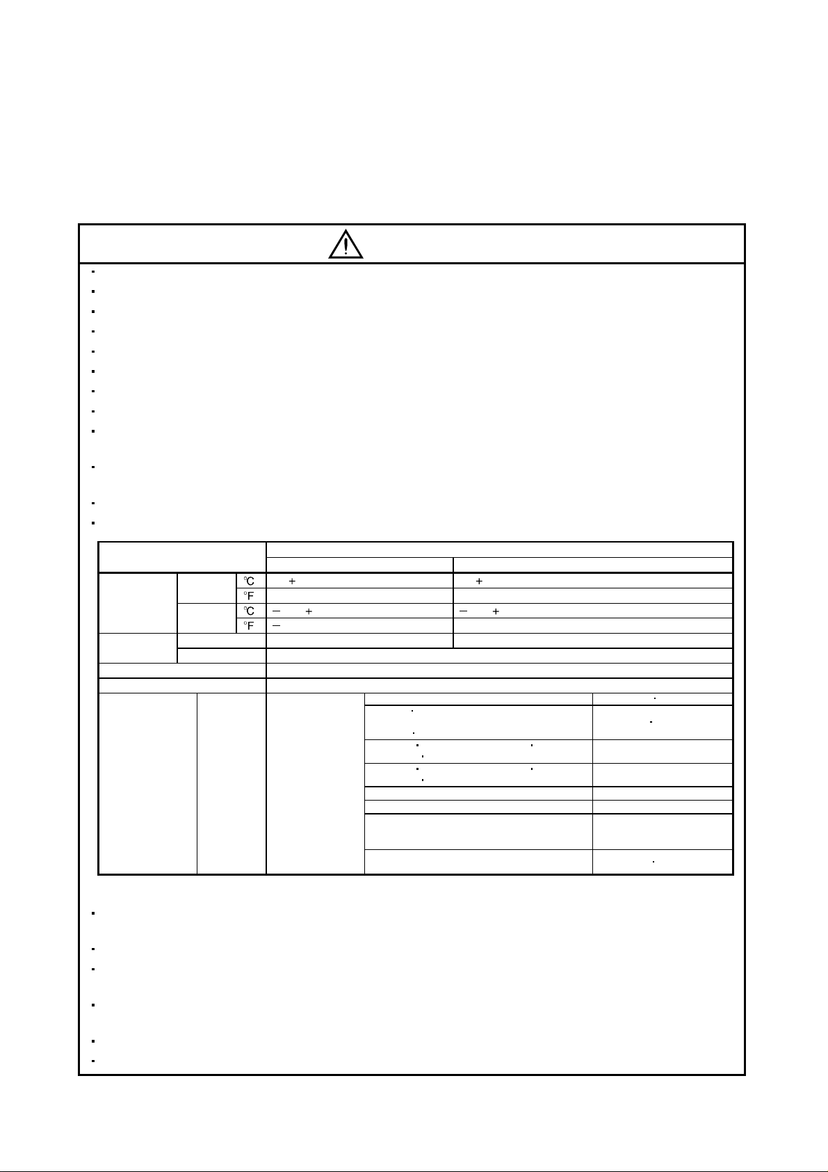
When you keep or use it, please fulfill the following environmental conditions.
Ambient
temperature
Ambient
humidity
Ambience Indoors (no direct sunlight) Free from corrosive gas, flammable gas, oil mist, dust and dirt
Altitude Max. 1000m (3280 ft) above sea level
(Note)
Vibration
Note. Except the servo motor with a reduction gear.
Environment
] 0 to 55 (non-freezing) 0 to 40 (non-freezing)
In operation
In storage
In operation 90%RH or less (non-condensing) 80%RH or less (non-condensing)
In storage 90%RH or less (non-condensing)
[
] 32 to 131 (non-freezing) 32 to 104 (non-freezing)
[
]
[
[
2
] 5.9 or less
[m/s
20 to 65 (non-freezing) 15 to 70 (non-freezing)
]
4 to 149 (non-freezing)
Servo amplifier Servo motor
HF-MP series HF-KP series X Y: 49
HF-SP51 81 HF-SP52 to 152
HF-SP524 to 1524 HC-RP Series
HC-UP72
HF-SP121
HF-SP2024
HF-SP301 421 HF-SP502 702
HF-SP5024
HA-LP601 to 12K1 HA-LP701M to 15K1M
HA-LP502 to 22K2 HA-LP6014 to 12K14
HA-LP701M4 to 15K1M4 HA-LP11K24 to 22K24
HA-LP15K1 to 25K1 HA-LP37K1M
HA-LP15K14 to 20K14 HA-LP22K1M4
152
201 HF-SP202 352
3524 HC-UP202 to 502
7024
Securely attach the servo motor to the machine. If attach insecurely, the servo motor may come off during
operation.
The servo motor with a reduction gear must be installed in the specified direction to prevent oil leakage.
Take safety measures, e.g. provide covers, to prevent accidental access to the rotating parts of the servo
motor during operation.
Never hit the servo motor or shaft, especially when coupling the servo motor to the machine. The encoder
may become faulty.
Do not subject the servo motor shaft to more than the permissible load. Otherwise, the shaft may break.
When the equipment has been stored for an extended period of time, consult Mitsubishi.
A - 3
Conditions
5 to 158 (non-freezing)
X
Y: 24.5
X: 24.5 Y: 49
X: 24.5 Y: 29.4
HC-LP52 to 152 X: 9.8 Y: 24.5
HC-LP202 to 302 X: 19.6 Y: 49
X: 11.7 Y: 29.4
X
Y: 9.8
Page 5
(2) Wiring
CAUTION
Wire the equipment correctly and securely. Otherwise, the servo motor may operate unexpectedly.
Do not install a power capacitor, surge absorber or radio noise filter (FR-BIF-(H) option) between the
servo motor and servo amplifier.
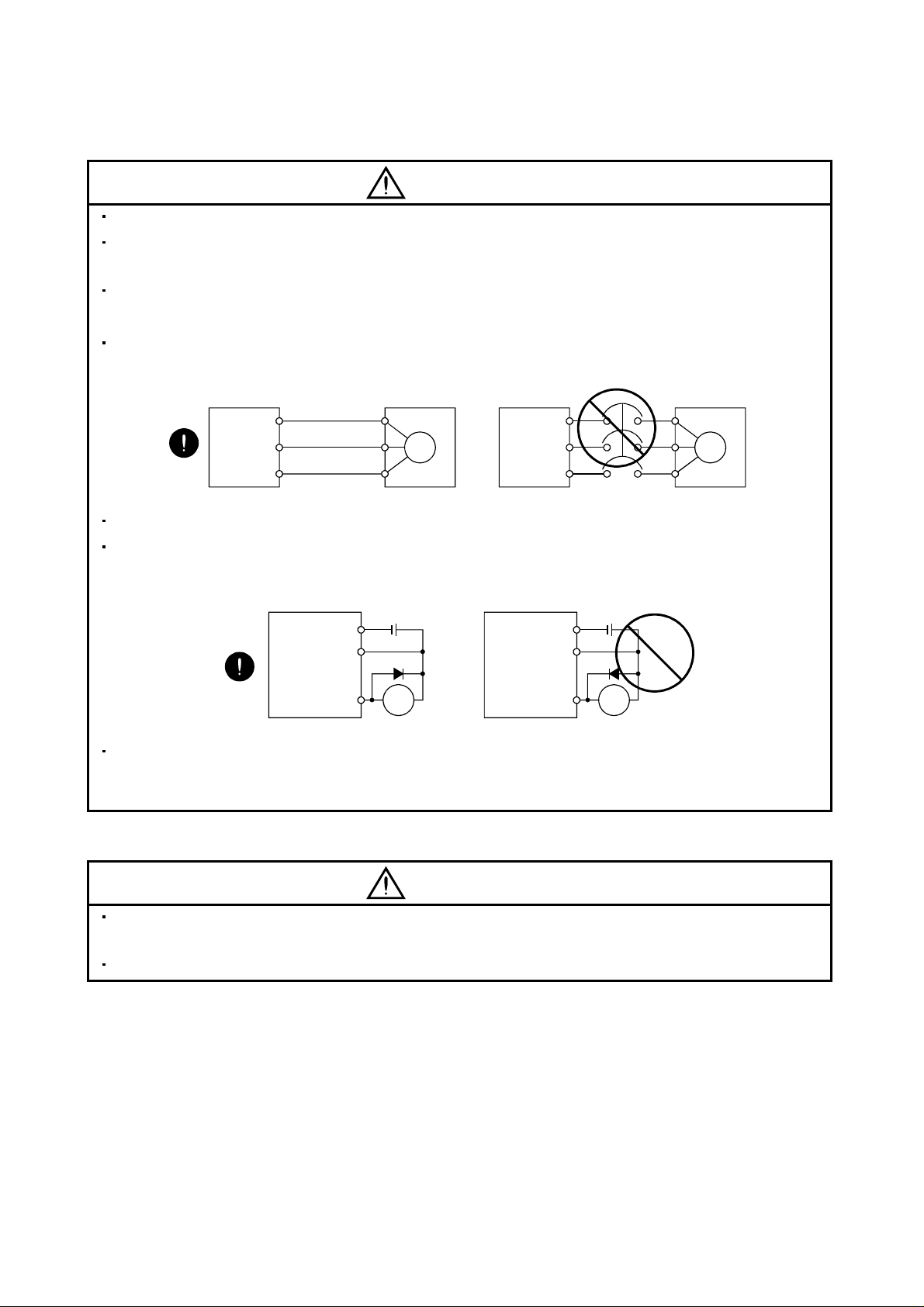
Connect the wires to the correct phase terminals (U, V, W) of the servo amplifier and servo motor.
Not doing so may cause unexpected operation.
Connect the servo motor power terminal (U, V, W) to the servo motor power input terminal (U, V, W)
directly. Do not let a magnetic contactor, etc. intervene.
Servo amplifier
U
V
W
Servo motor
U
V
W
Servo motorServo amplifier
U
M
V
W
U
V
M
W
Do not connect AC power directly to the servo motor. Otherwise, a fault may occur.
The surge absorbing diode installed on the DC output signal relay of the servo amplifier must be wired in
the specified direction. Otherwise, the forced stop (EMG) and other protective circuits may not operate.
Servo amplifier Servo amplifier
DOCOM
DICOM
Control
output
signal
24VDC
RA
DOCOM
DICOM
Control
output
signal
24VDC
RA
When the cable is not tightened enough to the terminal block (connector), the cable or terminal block
(connector) may generate heat because of the poor contact. Be sure to tighten the cable with specified
torque.
(3) Test run adjustment
CAUTION
Before operation, check the parameter settings. Improper settings may cause some machines to perform
unexpected operation.
The parameter settings must not be changed excessively. Operation will be insatiable.
A - 4
Page 6
(4) Usage
CAUTION
Provide an external emergency stop circuit to ensure that operation can be stopped and power switched
off immediately.
Any person who is involved in disassembly and repair should be fully competent to do the work.
Before resetting an alarm, make sure that the run signal of the servo amplifier is off to prevent an
accident. A sudden restart is made if an alarm is reset with the run signal on.
Do not modify the equipment.
Use a noise filter, etc. to minimize the influence of electromagnetic interference, which may be caused by
electronic equipment used near the servo amplifier.
Burning or breaking a servo amplifier may cause a toxic gas. Do not burn or break a servo amplifier.
Use the servo amplifier with the specified servo motor.
The electromagnetic brake on the servo motor is designed to hold the motor shaft and should not be used
for ordinary braking.
For such reasons as service life and mechanical structure (e.g. where a ball screw and the servo motor
are coupled via a timing belt), the electromagnetic brake may not hold the motor shaft. To ensure safety,
install a stopper on the machine side.
(5) Corrective actions
CAUTION
When it is assumed that a hazardous condition may take place at the occur due to a power failure or a
product fault, use a servo motor with an electromagnetic brake or an external brake mechanism for the
purpose of prevention.
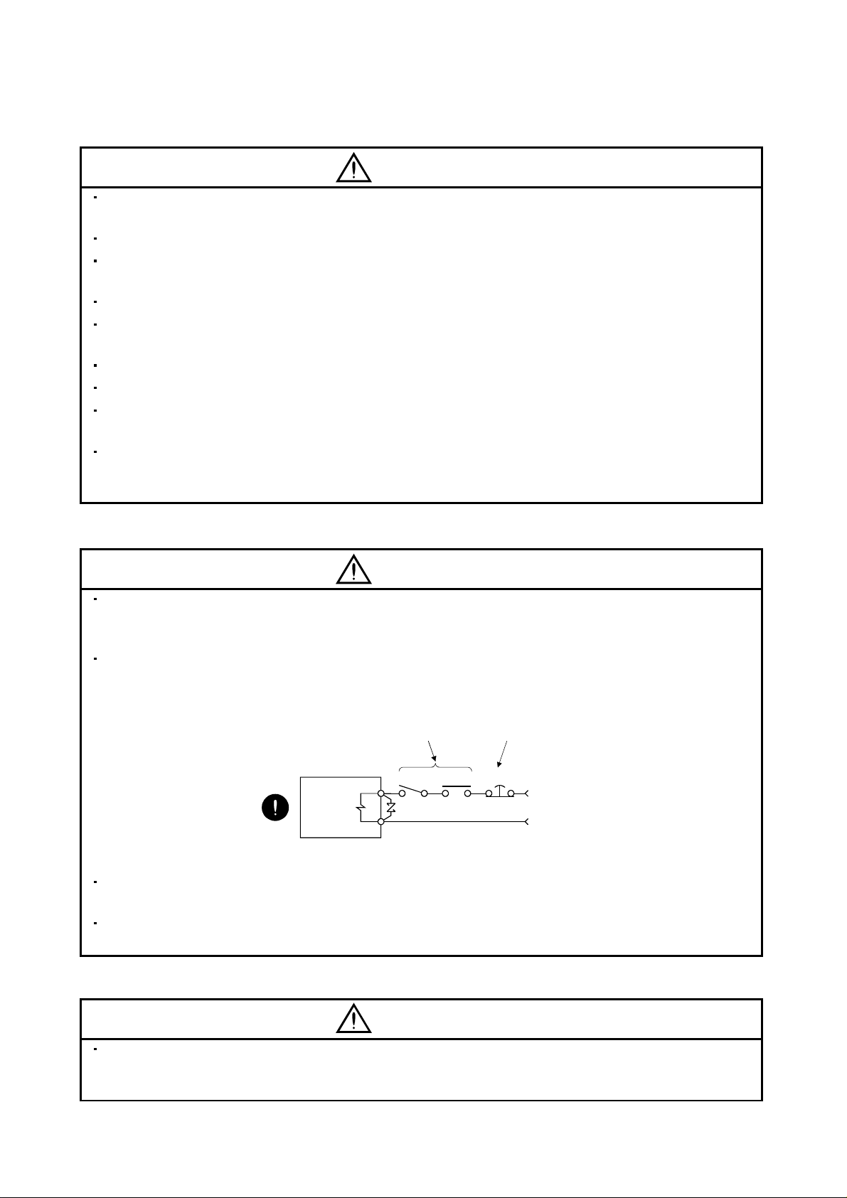
Configure the electromagnetic brake circuit so that it is activated not only by the servo amplifier signals
but also by an external forced stop (EMG).
Contacts must be open when
servo-off, when an trouble (ALM)
and when an electromagnetic brake
interlock (MBR).
SON RA
Electromagnetic brake
When any alarm has occurred, eliminate its cause, ensure safety, and deactivate the alarm before
restarting operation.
When power is restored after an instantaneous power failure, keep away from the machine because the
machine may be restarted suddenly (design the machine so that it is secured against hazard if restarted).
Circuit must be
opened during
forced stop (EMG).
EMG
24VDC
(6) Maintenance, inspection and parts replacement
CAUTION
With age, the electrolytic capacitor of the servo amplifier will deteriorate. To prevent a secondary accident
due to a fault, it is recommended to replace the electrolytic capacitor every 10 years when used in general
environment. Please consult our sales representative.
A - 5
Page 7
(7) General instruction
To illustrate details, the equipment in the diagrams of this Specifications and Instruction Manual may have
been drawn without covers and safety guards. When the equipment is operated, the covers and safety
guards must be installed as specified. Operation must be performed in accordance with this
Specifications and Instruction Manual.
About processing of waste
When you discard servo amplifier, a battery (primary battery), and other option articles, please follow the law of
each country (area).
FOR MAXIMUM SAFETY
These products have been manufactured as a general-purpose part for general industries, and have not
been designed or manufactured to be incorporated in a device or system used in purposes related to
human life.
Before using the products for special purposes such as nuclear power, electric power, aerospace,
medicine, passenger movement vehicles or under water relays, contact Mitsubishi.
These products have been manufactured under strict quality control. However, when installing the product
where major accidents or losses could occur if the product fails, install appropriate backup or failsafe
functions in the system.
EEP-ROM life
The number of write times to the EEP-ROM, which stores parameter settings, etc., is limited to 100,000. If
the total number of the following operations exceeds 100,000, the servo amplifier and/or converter unit may
fail when the EEP-ROM reaches the end of its useful life.
Write to the EEP-ROM due to parameter setting changes
Home position setting in the absolute position detection system
Write to the EEP-ROM due to device changes
Write to the EEP-ROM due to point table changes
Precautions for Choosing the Products
Mitsubishi will not be held liable for damage caused by factors found not to be the cause of Mitsubishi;
machine damage or lost profits caused by faults in the Mitsubishi products; damage, secondary damage,
accident compensation caused by special factors unpredictable by Mitsubishi; damages to products other
than Mitsubishi products; and to other duties.
A - 6
Page 8

COMPLIANCE WITH EC DIRECTIVES
1. WHAT ARE EC DIRECTIVES?
The EC directives were issued to standardize the regulations of the EU countries and ensure smooth
distribution of safety-guaranteed products. In the EU countries, the machinery directive (effective in January,
1995), EMC directive (effective in January, 1996) and low voltage directive (effective in January, 1997) of the
EC directives require that products to be sold should meet their fundamental safety requirements and carry the
CE marks (CE marking). CE marking applies to machines and equipment into which servo amplifiers have
been installed.
(1) EMC directive
The EMC directive applies not to the servo units alone but to servo-incorporated machines and equipment.
This requires the EMC filters to be used with the servo-incorporated machines and equipment to comply
with the EMC directive. For specific EMC directive conforming methods, refer to the EMC Installation
Guidelines (IB(NA)67310).
(2) Low voltage directive
The low voltage directive applies also to servo units alone. Hence, they are designed to comply with the low
voltage directive.
This servo is certified by TUV, third-party assessment organization, to comply with the low voltage directive.
(3) Machine directive
Not being machines, the servo amplifiers need not comply with this directive.
2. PRECAUTIONS FOR COMPLIANCE
(1) Servo amplifiers and servo motors used
Use the servo amplifiers and servo motors which comply with the standard model.
Servo amplifier :MR-J3-10T to MR-J3-22KT
MR-J3-10T1 to MR-J3-40T1
MR-J3-60T4 to MR-J3-22KT4
Servo motor :HF-MP
HF-KP
HF-SP
HF-SP
HC-RP
HC-UP
HC-LP
HA-LP
HA-LP
Note. For the latest information of compliance, contact Mitsubishi.
(Note)
4 (Note)
(Note)
4 (Note)
A - 7
Page 9
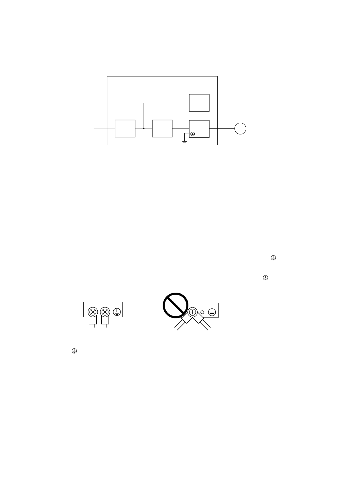
(2) Configuration
The control circuit provide safe separation to the main circuit in the servo amplifier.
Control box
Reinforced
insulating type
24VDC
No-fuse
breaker
NFB
Magnetic
contactor
MC
power
supply
Servo
amplifier
Servo
motor
M
(3) Environment
Operate the servo amplifier at or above the contamination level 2 set forth in IEC60664-1. For this purpose,
install the servo amplifier in a control box which is protected against water, oil, carbon, dust, dirt, etc. (IP54).
(4) Power supply
(a) This servo amplifier can be supplied from star-connected supply with earthed neutral point of
overvoltage category III set forth in IEC60664-1. However, when using the neutral point of 400V class
for single-phase supply, a reinforced insulating transformer is required in the power input section.
(b) When supplying interface power from external, use a 24VDC power supply which has been insulation-
reinforced in I/O.
(5) Grounding
(a) To prevent an electric shock, always connect the protective earth (PE) terminals (marked
) of the
servo amplifier to the protective earth (PE) of the control box.
(b) Do not connect two ground cables to the same protective earth (PE) terminal (marked
). Always
connect the cables to the terminals one-to-one.
PE terminals
PE terminals
(c) If a leakage current breaker is used to prevent an electric shock, the protective earth (PE) terminals
(marked
) of the servo amplifier must be connected to the corresponding earth terminals.
A - 8
Page 10

(6) Wiring
(a) The cables to be connected to the terminal block of the servo amplifier must have crimping terminals
provided with insulating tubes to prevent contact with adjacent terminals.
Crimping terminal
Insulating tube
Cable
(b) Use the servo motor side power connector which complies with the EN Standard. The EN Standard
compliant power connector sets are available from us as options. (Refer to section 14.1)
(7) Auxiliary equipment and options
(a) The no-fuse breaker and magnetic contactor used should be the EN or IEC standard-compliant
products of the models described in section 14.10.
Use a type B (Note) breaker. When it is not used, provide insulation between the servo amplifier and
other device by double insulation or reinforced insulation, or install a transformer between the main
power supply and servo amplifier.
Note. Type A: AC and pulse detectable
Type B: Both AC and DC detectable
(b) The sizes of the cables described in section 14.9 meet the following requirements. To meet the other
requirements, follow Table 5 and Appendix C in EN60204-1.
Ambient temperature: 40 (104) [°C (°F)]
Sheath: PVC (polyvinyl chloride)
Installed on wall surface or open table tray
(c) Use the EMC filter for noise reduction.
(8) Performing EMC tests
When EMC tests are run on a machine/device into which the servo amplifier has been installed, it must
conform to the electromagnetic compatibility (immunity/emission) standards after it has satisfied the
operating environment/electrical equipment specifications.
For the other EMC directive guidelines on the servo amplifier, refer to the EMC Installation Guidelines
(IB(NA)67310).
A - 9
Page 11

CONFORMANCE WITH UL/C-UL STANDARD
(1) Servo amplifiers and servo motors used
Use the servo amplifiers and servo motors which comply with the standard model.
Servo amplifier :MR-J3-10T to MR-J3-22KT
MR-J3-10T1 to MR-J3-40T1
MR-J3-60T4 to MR-J3-22KT4
Servo motor :HF-MP
HF-KP
HF-SP
HF-SP
HC-RP
HC-UP
HC-LP
HA-LP
HA-LP
Note. For the latest information of compliance, contact Mitsubishi.
(2) Installation
Install a fan of 100CFM (2.8m
of at least equivalent capability to ensure that the ambient temperature conforms to the environment
conditions (55
or less).
(3) Short circuit rating (SCCR: Short Circuit Current Rating)
Suitable For Use In A Circuit Capable Of Delivering Not More Than 100 kA rms Symmetrical Amperes, 500
Volts Maximum.
(4) Capacitor discharge time
The capacitor discharge time is as listed below. To ensure safety, do not touch the charging section for 15
minutes after power-off.
Servo amplifier
MR-J3-10T 20T 1
MR-J3-40T 60T(4) 10T1 20T1 2
MR-J3-70T 3
MR-J3-40T1 4
MR-J3-100T(4) 5
MR-J3-200T(4) 350T 9
MR-J3-350T4 500T(4) 700T(4) 10
MR-J3-11KT(4) 4
MR-J3-15KT(4) 6
MR-J3-22KT(4) 8
(Note)
4 (Note)
(Note)
4 (Note)
3
/min) air flow 4[in] (10.16[cm]) above the servo amplifier or provide cooling
Discharge time
[min]
A - 10
Page 12

(5) Options and auxiliary equipment
Use UL/C-UL standard-compliant products.
(6) Attachment of a servo motor
For the flange size of the machine side where the servo motor is installed, refer to “CONFORMANCE WITH
UL/C-UL STANDARD” in the Servo Motor Instruction Manual (Vol.2).
(7) About wiring protection
For installation in United States, branch circuit protection must be provided, in accordance with the National
Electrical Code and any applicable local codes.
For installation in Canada, branch circuit protection must be provided, in accordance with the Canada
Electrical Code and any applicable provincial codes.
<<About the manuals>>
This Instruction Manual and the MELSERVO Servo Motor Instruction Manual (Vol.2) are required if you use
the General-Purpose AC servo MR-J3-T for the first time. Always purchase them and use the MR-J3-T
safely.
Relevant manuals
Manual name Manual No.
MELSERVO-J3 Series Instructions and Cautions for Safe Use of AC Servos IB(NA)0300077
MELSERVO Servo Motor Instruction Manual (Vol.2) SH(NA)030041
EMC Installation Guidelines IB(NA)67310
<<About the wires used for wiring>>
Wiring wires mentioned in this instruction manual are selected based on the ambient temperature of 40°C
(104
).
A - 11
Page 13

MEMO
A - 12
Page 14

CONTENTS
1. FUNCTIONS AND CONFIGURATION 1 - 1 to 1 -36
1.1 Introduction ............................................................................................................................................... 1 - 1
1.1.1 Features of CC-Link communication functions ................................................................................ 1 - 1
1.1.2 Function block diagram ..................................................................................................................... 1 - 2
1.1.3 System configuration......................................................................................................................... 1 - 5
1.2 Servo amplifier standard specifications................................................................................................... 1 - 7
1.3 Function list ............................................................................................................................................. 1 -13
1.4 Model code definition .............................................................................................................................. 1 -15
1.5 Combination with servo motor ................................................................................................................ 1 -16
1.6 Structure .................................................................................................................................................. 1 -17
1.6.1 Parts identification ............................................................................................................................ 1 -17
1.6.2 Removal and reinstallation of the front cover.................................................................................. 1 -23
1.7 Configuration including auxiliary equipment .......................................................................................... 1 -26
1.8 Selection of operation method................................................................................................................ 1 -34
2. INSTALLATION 2 - 1 to 2 - 4
2.1 Installation direction and clearances ....................................................................................................... 2 - 1
2.2 Keep out foreign materials ....................................................................................................................... 2 - 3
2.3 Cable stress ............................................................................................................................................. 2 - 3
2.4 Inspection items .......................................................................................................................................2 - 4
2.5 Parts having service lives ........................................................................................................................ 2 - 4
3. CC-LINK COMMUNICATION FUNCTIONS 3 - 1 to 3 -60
3.1 Communication specifications ................................................................................................................. 3 - 1
3.2 System configuration ............................................................................................................................... 3 - 2
3.2.1 Configuration example ......................................................................................................................3 - 2
3.2.2 Wiring method ................................................................................................................................... 3 - 3
3.2.3 Station number setting ...................................................................................................................... 3 - 5
3.2.4 Communication baud rate setting..................................................................................................... 3 - 6
3.2.5 Occupied station count setting.......................................................................................................... 3 - 6
3.3 Functions .................................................................................................................................................. 3 - 7
3.3.1 Function block diagram ..................................................................................................................... 3 - 7
3.3.2 Functions ...........................................................................................................................................3 - 7
3.4 Servo amplifier setting ............................................................................................................................. 3 - 8
3.5 I/O signals (I/O devices) transferred to/from the programmable controller CPU ................................... 3 - 9
3.5.1 I/O signals (I/O devices).................................................................................................................... 3 - 9
3.5.2 Detailed explanation of I/O signals .................................................................................................. 3 -12
3.5.3 Monitor codes ................................................................................................................................... 3 -22
3.5.4 Instruction codes (RWwn+2
3.5.5 Respond codes (RWrn+2) ...............................................................................................................3 -31
3.5.6 Setting the CN6 external input signals ............................................................................................ 3 -32
3.6 Data communication timing charts .........................................................................................................3 -34
3.6.1 Monitor codes ................................................................................................................................... 3 -34
3.6.2 Instruction codes ..............................................................................................................................3 -36
RWwn+3) .........................................................................................3 -23
1
Page 15

3.6.3 Remote register-based position/speed setting................................................................................ 3 -38
3.7 Function-by-function programming examples........................................................................................ 3 -41
3.7.1 System configuration example......................................................................................................... 3 -41
3.7.2 Reading the servo amplifier status ..................................................................................................3 -44
3.7.3 Writing the operation commands..................................................................................................... 3 -45
3.7.4 Reading the data .............................................................................................................................. 3 -46
3.7.5 Writing the data ................................................................................................................................3 -49
3.7.6 Operation.......................................................................................................................................... 3 -52
3.8 Continuous operation program example ................................................................................................ 3 -55
3.8.1 System configuration example when 1 station is occupied ............................................................ 3 -55
3.8.2 Program example when 1 station is occupied ................................................................................3 -56
3.8.3 System configuration example when 2 stations are occupied........................................................ 3 -58
3.8.4 Program example when 2 stations are occupied ............................................................................ 3 -59
4. SIGNALS AND WIRING 4 - 1 to 4 -54
4.1 Input power supply circuit ........................................................................................................................ 4 - 2
4.2 I/O signal connection diagram ................................................................................................................ 4 -10
4.3 Explanation of power supply system ...................................................................................................... 4 -11
4.3.1 Signal explanations ..........................................................................................................................4 -11
4.3.2 Power-on sequence .........................................................................................................................4 -12
4.3.3 CNP1, CNP2, CNP3 wiring method ................................................................................................4 -14
4.4 Connectors and signal arrangements ....................................................................................................4 -22
4.5 Signal (device) explanation..................................................................................................................... 4 -23
4.5.1 I/O devices ........................................................................................................................................ 4 -23
4.5.2 Input signals .....................................................................................................................................4 -26
4.5.3 Output signals................................................................................................................................... 4 -26
4.5.4 Power supply.................................................................................................................................... 4 -27
4.6 Detailed description of signals (devices)................................................................................................ 4 -27
4.6.1 Forward rotation start
4.6.2 Movement completion
4.6.3 Torque limit ....................................................................................................................................... 4 -30
4.7 Alarm occurrence timing chart................................................................................................................ 4 -31
4.8 Interface................................................................................................................................................... 4 -32
4.8.1 Internal connection diagram ............................................................................................................ 4 -32
4.8.2 Detailed description of interfaces..................................................................................................... 4 -33
4.8.3 Source I/O interfaces ....................................................................................................................... 4 -35
4.9 Treatment of cable shield external conductor ........................................................................................ 4 -36
4.10 Connection of servo amplifier and servo motor ...................................................................................4 -37
4.10.1 Connection instructions.................................................................................................................. 4 -37
4.10.2 Power supply cable wiring diagrams ............................................................................................. 4 -38
4.11 Servo motor with an electromagnetic brake......................................................................................... 4 -48
4.11.1 Safety precautions ......................................................................................................................... 4 -48
4.11.2 Timing charts .................................................................................................................................. 4 -49
4.11.3 Wiring diagrams (HF-MP series
4.12 Grounding.............................................................................................................................................. 4 -53
reverse rotation start temporary stop/restart........................................... 4 -27
rough match in position .......................................................................... 4 -28
HF-KP series servo motor) ..................................................... 4 -52
2
Page 16

5. OPERATION 5 - 1 to 5 -60
5.1 Switching power on for the first time ....................................................................................................... 5 - 1
5.1.1 Startup procedure.............................................................................................................................. 5 - 1
5.1.2 Wiring check ......................................................................................................................................5 - 2
5.1.3 Surrounding environment.................................................................................................................. 5 - 3
5.2 Startup ...................................................................................................................................................... 5 - 4
5.2.1 Power on and off procedures............................................................................................................ 5 - 4
5.2.2 Stop.................................................................................................................................................... 5 - 4
5.2.3 Test operation.................................................................................................................................... 5 - 5
5.2.4 Parameter setting .............................................................................................................................. 5 - 6
5.2.5 Point table setting.............................................................................................................................. 5 - 7
5.2.6 Actual operation ................................................................................................................................ 5 - 7
5.3 Servo amplifier display............................................................................................................................. 5 - 8
5.4 Automatic operation mode ...................................................................................................................... 5 -10
5.4.1 What is automatic operation mode?................................................................................................ 5 -10
5.4.2 Automatic operation using point table .............................................................................................5 -12
5.4.3 Remote register-based position/speed setting................................................................................ 5 -22
5.5 Manual operation mode .......................................................................................................................... 5 -28
5.5.1 JOG operation .................................................................................................................................. 5 -28
5.5.2 Manual pulse generator ................................................................................................................... 5 -29
5.6 Manual home position return mode........................................................................................................ 5 -31
5.6.1 Outline of home position return........................................................................................................ 5 -31
5.6.2 Dog type home position return......................................................................................................... 5 -34
5.6.3 Count type home position return ..................................................................................................... 5 -36
5.6.4 Data setting type home position return............................................................................................ 5 -38
5.6.5 Stopper type home position return ..................................................................................................5 -39
5.6.6 Home position ignorance (servo-on position defined as home position) .......................................5 -41
5.6.7 Dog type rear end reference home position return .........................................................................5 -42
5.6.8 Count type front end reference home position return ..................................................................... 5 -44
5.6.9 Dog cradle type home position return ............................................................................................. 5 -46
5.6.10 Dog type first Z-phase reference home position return ................................................................ 5 -48
5.6.11 Dog type front end reference home position return method......................................................... 5 -50
5.6.12 Dogless Z-phase reference home position return method ........................................................... 5 -52
5.6.13 Home position return automatic return function ............................................................................ 5 -54
5.6.14 Automatic positioning function to the home position..................................................................... 5 -55
5.7 Roll feed display function in roll feed mode............................................................................................ 5 -56
5.8 Absolute position detection system ........................................................................................................ 5 -57
6. PARAMETERS 6 - 1 to 6 -40
6.1 Basic setting parameters (No.PA )................................................................................................... 6 - 1
6.1.1 Parameter list ....................................................................................................................................6 - 1
6.1.2 Parameter write inhibit ......................................................................................................................6 - 2
6.1.3 Selection of command system.......................................................................................................... 6 - 3
6.1.4 Selection of regenerative option .......................................................................................................6 - 3
6.1.5 Using absolute position detection system ........................................................................................6 - 4
6.1.6 Follow-up for absolute value command system in incremental system .......................................... 6 - 4
6.1.7 Feeding function selection ................................................................................................................ 6 - 5
3
Page 17

6.1.8 Electronic gear................................................................................................................................... 6 - 6
6.1.9 Auto tuning ........................................................................................................................................ 6 - 7
6.1.10 In-position range.............................................................................................................................. 6 - 8
6.1.11 Torque limit...................................................................................................................................... 6 - 9
6.1.12 Selection of servo motor rotation direction .................................................................................... 6 -10
6.1.13 Encoder output pulse .....................................................................................................................6 -10
6.2 Gain/filter parameters (No. PB
6.2.1 Parameter list ...................................................................................................................................6 -12
6.2.2 Detail list ........................................................................................................................................... 6 -13
6.3 Extension setting parameters (No. PC
6.3.1 Parameter list ...................................................................................................................................6 -20
6.3.2 Detail list ........................................................................................................................................... 6 -21
6.3.3 S-pattern acceleration/deceleration................................................................................................. 6 -27
6.3.4 Alarm history clear............................................................................................................................ 6 -27
6.3.5 Rough match output......................................................................................................................... 6 -27
6.3.6 Software limit .................................................................................................................................... 6 -28
6.4 I/O setting parameters (No. PD
6.4.1 Parameter list ...................................................................................................................................6 -29
6.4.2 Detail list ........................................................................................................................................... 6 -30
6.4.3 Stopping method when the forward stroke end (LSP) or reverse stroke end (LSN) is valid ......... 6 -38
6.4.4 Stopping method when a software limit is detected........................................................................ 6 -39
)...................................................................................................... 6 -12
) .........................................................................................6 -20
)..................................................................................................... 6 -29
7. MR Configurator 7 - 1 to 7 -26
7.1 Specifications ...........................................................................................................................................7 - 1
7.2 System configuration ............................................................................................................................... 7 - 2
7.3 Station selection ....................................................................................................................................... 7 - 4
7.4 Parameters ............................................................................................................................................... 7 - 5
7.5 Point table................................................................................................................................................. 7 - 7
7.6 Device assignment method ..................................................................................................................... 7 - 9
7.7 Test operation .........................................................................................................................................7 -13
7.7.1 Jog operation.................................................................................................................................... 7 -13
7.7.2 Positioning operation........................................................................................................................ 7 -15
7.7.3 Motor-less operation ........................................................................................................................ 7 -18
7.7.4 Output signal (DO) forced output..................................................................................................... 7 -19
7.7.5 Single-step feed ............................................................................................................................... 7 -20
7.8 Alarm ....................................................................................................................................................... 7 -23
7.8.1 Alarm display .................................................................................................................................... 7 -23
7.8.2 Batch display of data at alarm occurrence ...................................................................................... 7 -24
7.8.3 Alarm history..................................................................................................................................... 7 -26
8. PARAMETER UNIT (MR-PRU03) 8 - 1 to 8 -20
8.1 External appearance and key explanations ............................................................................................ 8 - 2
8.2 Specifications ...........................................................................................................................................8 - 3
8.3 Outline dimension drawings..................................................................................................................... 8 - 3
8.4 Connection with servo amplifier............................................................................................................... 8 - 4
8.4.1 Single axis .........................................................................................................................................8 - 4
8.4.2 Multidrop connection ......................................................................................................................... 8 - 5
4
Page 18

8.5 Display ...................................................................................................................................................... 8 - 7
8.5.1 Outline of screen transition ............................................................................................................... 8 - 7
8.5.2 MR-PRU03 parameter unit setting ................................................................................................... 8 - 8
8.5.3 Monitor mode (status display)........................................................................................................... 8 - 9
8.5.4 Alarm/diagnostic mode .................................................................................................................... 8 -11
8.5.5 Parameter mode............................................................................................................................... 8 -13
8.5.6 Point table mode .............................................................................................................................. 8 -14
8.5.7 Test operation mode ........................................................................................................................8 -15
8.6 Error message list ...................................................................................................................................8 -19
9. GENERAL GAIN ADJUSTMENT 9 - 1 to 9 -12
9.1 Different adjustment methods.................................................................................................................. 9 - 1
9.1.1 Adjustment on a single servo amplifier............................................................................................. 9 - 1
9.1.2 Adjustment using MR Configurator................................................................................................... 9 - 2
9.2 Auto tuning ............................................................................................................................................... 9 - 3
9.2.1 Auto tuning mode .............................................................................................................................. 9 - 3
9.2.2 Auto tuning mode operation.............................................................................................................. 9 - 4
9.2.3 Adjustment procedure by auto tuning............................................................................................... 9 - 5
9.2.4 Response level setting in auto tuning mode ....................................................................................9 - 6
9.3 Manual mode 1 (simple manual adjustment) .......................................................................................... 9 - 7
9.4 Interpolation mode .................................................................................................................................. 9 -11
9.5 Differences between MELSERVO-J2-Super and MELSERVO-J3 in auto tuning ................................ 9 -12
10. SPECIAL ADJUSTMENT FUNCTIONS 10- 1 to 10-16
10.1 Function block diagram......................................................................................................................... 10- 1
10.2 Adaptive filter
10.3 Machine resonance suppression filter.................................................................................................. 10- 4
10.4 Advanced vibration suppression control .............................................................................................. 10- 6
10.5 Low-pass filter ......................................................................................................................................10-10
10.6 Gain changing function ........................................................................................................................10-10
10.6.1 Applications ...................................................................................................................................10-10
10.6.2 Function block diagram .................................................................................................................10-11
10.6.3 Parameters.................................................................................................................................... 10-12
10.6.4 Gain changing operation ............................................................................................................... 10-14
11. TROUBLESHOOTING 11- 1 to 11-14
11.1 Trouble at start-up................................................................................................................................. 11- 1
11.2 Operation at error occurrence ..............................................................................................................11- 2
11.3 CC-Link communication error............................................................................................................... 11- 2
11.4 When alarm or warning has occurred ..................................................................................................11- 3
11.4.1 Alarms and warning list.................................................................................................................. 11- 3
11.4.2 Remedies for alarms ...................................................................................................................... 11- 4
11.4.3 Remedies for warnings ................................................................................................................. 11-11
11.5 Point table error .................................................................................................................................... 11-13
...................................................................................................................................... 10- 1
5
Page 19

12. OUTLINE DRAWINGS 12- 1 to 12-12
12.1 Servo amplifier ......................................................................................................................................12- 1
12.2 Connector ............................................................................................................................................. 12-10
13. CHARACTERISTICS 13- 1 to 13-10
13.1 Overload protection characteristics ...................................................................................................... 13- 1
13.2 Power supply equipment capacity and generated loss .......................................................................13- 3
13.3 Dynamic brake characteristics.............................................................................................................. 13- 6
13.3.1 Dynamic brake operation ............................................................................................................... 13- 6
13.3.2 The dynamic brake at the load inertia moment............................................................................. 13- 9
13.4 Cable flexing life................................................................................................................................... 13-10
13.5 Inrush currents at power-on of main circuit and control circuit ........................................................... 13-10
14. OPTIONS AND AUXILIARY EQUIPMENT 14- 1 to 14-90
14.1 Cable/connector sets ............................................................................................................................ 14- 1
14.1.1 Combinations of cable/connector sets ..........................................................................................14- 2
14.1.2 Encoder cable/connector sets .......................................................................................................14- 8
14.1.3 Motor power supply cables ........................................................................................................... 14-17
14.1.4 Motor brake cables........................................................................................................................ 14-18
14.2 Regenerative options ........................................................................................................................... 14-19
14.3 FR-BU2-(H) brake unit ......................................................................................................................... 14-32
14.3.1 Selection........................................................................................................................................ 14-33
14.3.2 Brake unit parameter setting......................................................................................................... 14-33
14.3.3 Connection example ..................................................................................................................... 14-34
14.3.4 Outline dimension drawings.......................................................................................................... 14-41
14.4 Power regeneration converter ............................................................................................................. 14-43
14.5 Power regeneration common converter ..............................................................................................14-46
14.6 External dynamic brake ....................................................................................................................... 14-54
14.7 Battery MR-J3BAT ............................................................................................................................... 14-59
14.8 Heat sink outside mounting attachment (MR-J3ACN)........................................................................ 14-60
14.9 Selection example of wires .................................................................................................................. 14-62
14.10 No-fuse breakers, fuses, magnetic contactors ................................................................................. 14-68
14.11 Power factor improving DC reactor ...................................................................................................14-69
14.12 Power factor improving reactors........................................................................................................ 14-71
14.13 Relays (recommended) ..................................................................................................................... 14-73
14.14 Surge absorbers (recommended) .....................................................................................................14-73
14.15 Noise reduction techniques ...............................................................................................................14-74
14.16 Leakage current breaker.................................................................................................................... 14-81
14.17 EMC filter (recommended) ................................................................................................................ 14-83
14.18 MR-HDP01 manual pulse generator .................................................................................................14-88
15. COMMUNICATION FUNCTION 15- 1 to 15-46
15.1 Configuration ......................................................................................................................................... 15- 1
15.2 Communication specifications ..............................................................................................................15- 3
15.2.1 Communication overview............................................................................................................... 15- 3
15.2.2 Parameter setting ........................................................................................................................... 15- 4
6
Page 20

15.3 Protocol ................................................................................................................................................. 15- 5
15.3.1 Transmission data configuration.................................................................................................... 15- 5
15.3.2 Character codes ............................................................................................................................. 15- 6
15.3.3 Error codes ..................................................................................................................................... 15- 7
15.3.4 Checksum....................................................................................................................................... 15- 7
15.3.5 Time-out operation ......................................................................................................................... 15- 8
15.3.6 Retry operation............................................................................................................................... 15- 8
15.3.7 Initialization ..................................................................................................................................... 15- 9
15.3.8 Communication procedure example.............................................................................................. 15- 9
15.4 Command and data No. list ................................................................................................................. 15-10
15.4.1 Read commands ........................................................................................................................... 15-10
15.4.2 Write commands ...........................................................................................................................15-14
15.5 Detailed explanations of commands ................................................................................................... 15-17
15.5.1 Data processing ............................................................................................................................ 15-17
15.5.2 Status display ................................................................................................................................ 15-19
15.5.3 Parameters.................................................................................................................................... 15-20
15.5.4 External I/O signal statuses (DIO diagnosis) ...............................................................................15-23
15.5.5 Device ON/OFF.............................................................................................................................15-28
15.5.6 Disable/enable of I/O devices (DIO) ............................................................................................. 15-29
15.5.7 Input devices ON/OFF (test operation) ........................................................................................15-30
15.5.8 Test operation mode .....................................................................................................................15-31
15.5.9 Alarm history.................................................................................................................................. 15-37
15.5.10 Current alarm .............................................................................................................................. 15-38
15.5.11 Point table.................................................................................................................................... 15-39
15.5.12 Servo amplifier group designation .............................................................................................. 15-45
15.5.13 Other commands......................................................................................................................... 15-46
16. INDEXER POSITIONING OPERATION 16- 1 to 16-112
16.1 Function ................................................................................................................................................. 16- 1
16.1.1 Overview......................................................................................................................................... 16- 1
16.1.2 Servo amplifier standard specifications (functions only)............................................................... 16- 1
16.1.3 Function list .................................................................................................................................... 16- 2
16.2 I/O signals (I/O devices) transferred to/from the programmable controller CPU ................................ 16- 3
16.2.1 I/O signals (I/O devices)................................................................................................................. 16- 3
16.2.2 Detailed explanation of I/O signals ................................................................................................ 16- 5
16.2.3 Monitor codes ................................................................................................................................ 16-14
16.2.4 Instruction codes (RWwn
16.2.5 Respond codes (RWrn
16.3 Signal.................................................................................................................................................... 16-23
16.3.1 Signal (device) explanation........................................................................................................... 16-23
16.3.2 Detailed description of signals (devices) ...................................................................................... 16-26
16.4 Switching power on for the first time ................................................................................................... 16-29
16.4.1 Startup procedure ......................................................................................................................... 16-29
16.4.2 Wiring check ..................................................................................................................................16-30
16.4.3 Surrounding environment .............................................................................................................16-31
16.5 Startup .................................................................................................................................................. 16-32
16.5.1 Power on and off procedures........................................................................................................ 16-32
16.5.2 Stop................................................................................................................................................ 16-32
2 RWwn 3) ................................................................................... 16-15
2) .......................................................................................................... 16-22
7
Page 21

16.5.3 Test operation ............................................................................................................................... 16-33
16.5.4 Parameter setting ..........................................................................................................................16-34
16.5.5 Point table setting.......................................................................................................................... 16-35
16.5.6 Actual operation ............................................................................................................................16-35
16.6 Servo amplifier display ......................................................................................................................... 16-36
16.7 Automatic operation mode................................................................................................................... 16-38
16.7.1 What is automatic operation mode?............................................................................................. 16-38
16.7.2 Automatic operation mode 1 (Rotation direction specifying indexer) .......................................... 16-39
16.7.3 Automatic operation mode 2 (Shortest rotating indexer) ............................................................. 16-49
16.8 Manual operation mode ....................................................................................................................... 16-58
16.8.1 Indexer JOG operation.................................................................................................................. 16-58
16.8.2 JOG operation ............................................................................................................................... 16-60
16.9 Home position return mode .................................................................................................................16-61
16.9.1 Outline of home position return..................................................................................................... 16-61
16.9.2 Torque limit changing dog type home position return.................................................................. 16-63
16.9.3 Torque limit changing data setting type home position return..................................................... 16-65
16.9.4 Home position return automatic return function ........................................................................... 16-66
16.10 Absolute position detection system ...................................................................................................16-67
16.11 Parameters ......................................................................................................................................... 16-70
16.11.1 Basic setting parameters (No.PA
16.11.2 Gain/filter parameters (No.PB
16.11.3 Extension setting parameters (No.PC
16.11.4 I/O setting parameters (No.PD
16.12 TROUBLESHOOTING ...................................................................................................................... 16-98
16.12.1 Trouble at start-up ....................................................................................................................... 16-98
16.12.2 Operation at error occurrence..................................................................................................... 16-99
16.12.3 CC-Link communication error..................................................................................................... 16-99
16.12.4 When alarm or warning has occurred ......................................................................................16-100
16.12.5 Point table error......................................................................................................................... 16-112
)....................................................................................... 16-70
)............................................................................................ 16-79
) ............................................................................... 16-87
)....................................................................................... 16-93
APPENDIX App.- 1 to App.-30
App. 1 Parameter list..................................................................................................................................App.- 1
App. 2 Signal layout recording paper ........................................................................................................App.- 3
App. 3 Twin type connector: outline drawing for 721-2105/026-000(WAGO) .........................................App.- 4
App. 4 Change of connector sets to the RoHS compatible products.......................................................App.- 5
App. 5 MR-J3-200T-RT servo amplifier.....................................................................................................App.- 6
App. 6 Selection example of servo motor power cable ...........................................................................App.-10
App. 7 Parameter list.................................................................................................................................App.-11
App. 8 Program example with MELSEC-A series programmable controllers
(point table positioning operation) .................App.-13
8
Page 22

1. FUNCTIONS AND CONFIGURATION
1. FUNCTIONS AND CONFIGURATION
1.1 Introduction
The MR-J3axes of servo amplifiers can be controlled/monitored from the programmable controller side.
As the servo, it has the function to perform positioning operation by merely setting the position data (target
positions), servo motor speeds, acceleration and deceleration time constants, etc. to point tables as if setting
them in parameters. The servo amplifier is the most appropriate to configure a program-free, simple positioning
system or to simplify a system, for example.
There are 31 points of point tables to be used when 1 station is occupied and 255 points when 2 stations are
occupied.
All servo motors are equipped with an absolute position encoder as standard. An absolute position detection
system can be configured by merely adding a battery to the servo amplifier. Once the home position has been
set, home position return is not required at power on, alarm occurrence, etc.
The MR-J3-T is made easier to use and higher in function by using it with the MR Configurator.
1.1.1 Features of CC-Link communication functions
(1) Fast communication
Fast communication can be made by cyclic transmission of not only bit data but also word data.
(a) The highest communication speed is 10Mbps.
(b) The broadcast polling system ensures as high as 3.9ms to 6.7ms even at the maximum link scan
(2) Variable communication speed/distance system
Selection of speed/distance allows use in a wide range of areas from a system requiring high speed to a
system requiring long distance.
(3) System fault prevention (station separating function)
Because of connection in the bus system, any remote or local station that has become faulty due to poweroff or the like does not affect communications with normal remote and local stations.
In addition, use of the two-piece terminal block allows the unit to be changed during data link.
(4) Factory Automation compatible
As the remote device stations of CC-Link, the servo amplifiers share a link system and can be
controlled/monitored with programmable controller user programs.
From the programmable controller side, the running speed, acceleration/deceleration time constant and
other settings of servo motors can be changed/checked and the servo motors started and stopped.
T CC-Link compatible servo amplifier can support the CC-Link communication functions. Up to 42
(10Mbps).
1 - 1
Page 23
1. FUNCTIONS AND CONFIGURATION
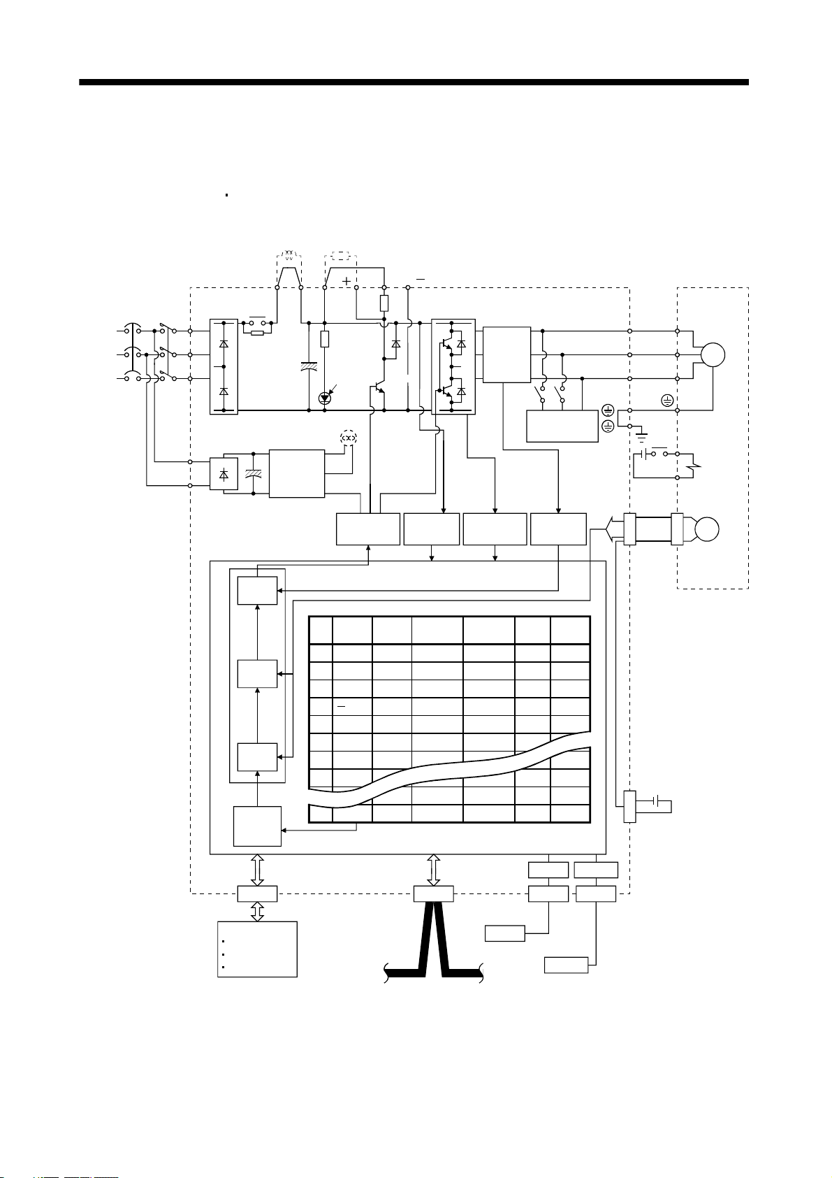
1.1.2 Function block diagram
The function block diagram of this servo is shown below.
(1) MR-J3-350T or less
MCNFB
(Note 2)
Power
supply
MR-J3-200T4 or less
Power factor
improving DC
reactor
P
1
Diode
Relay
stack
L
1
L2
L
3
Regenerative
P( )
P
2
CHARGE
option
lamp
N( )
D
C
(Note 1)
Regenerative
TR
Current
detector
Servo motorServo amplifier
U
V
W
U
V
M
W
L11
L
(Note 4) Cooling fan
Control
circuit
21
power
supply
Base
amplifier
Voltage
detection
Overcurrent
protection
Dynamic
brake
Current
detection
24VDC
CN2
RA
B1
B2
Electromagnetic
brake
Encoder
Current
control
Point table
No.
Position
data
Speed
Acceleration
time
constant
Deceleration
time
constant
Dwell Auxiliary
1 1000 1000 80 80 0 0
control
Model adaptive control
Position
control
Position
command
creation
Speed
(Note 3)
2
2000 2000 100 100 0 0
3
4000 2000 70 60 500 1
4
500 2000 60 70 1000 1
5
6
7
8
2000 80 80 0 0
1000
2000 1000 80 80 0 0
1000 1000 80 80 0 0
1000 1000 100 100 0 0
1000 1000 100 100 0 0
255 2000 2000 80 80 0 0
USB
RS-422
MR-J3BAT
CN4
Optional battery
(for absolute position
detection system)
CN1CN6
Personal
computer
DI/O Control
Servo on
Start
Failure, etc
CC-Link
USB
Controller
RS-422
Note 1. The built-in regenerative resistor is not provided for the MR-J3-10T (1).
2. For 1-phase 200 to 230VAC, connect the power supply to L
There is no L
3 for 1-phase 100 to 120VAC power supply. Refer to section 1.2 for the power supply specification.
1, L2 and leave L3 open.
3. For the case when 2 stations are occupied. When 1 station is occupied, the point table ends at No.31.
4. Servo amplifiers MR-J3-70T or greater have a cooling fan.
1 - 2
CN3CN5
Page 24
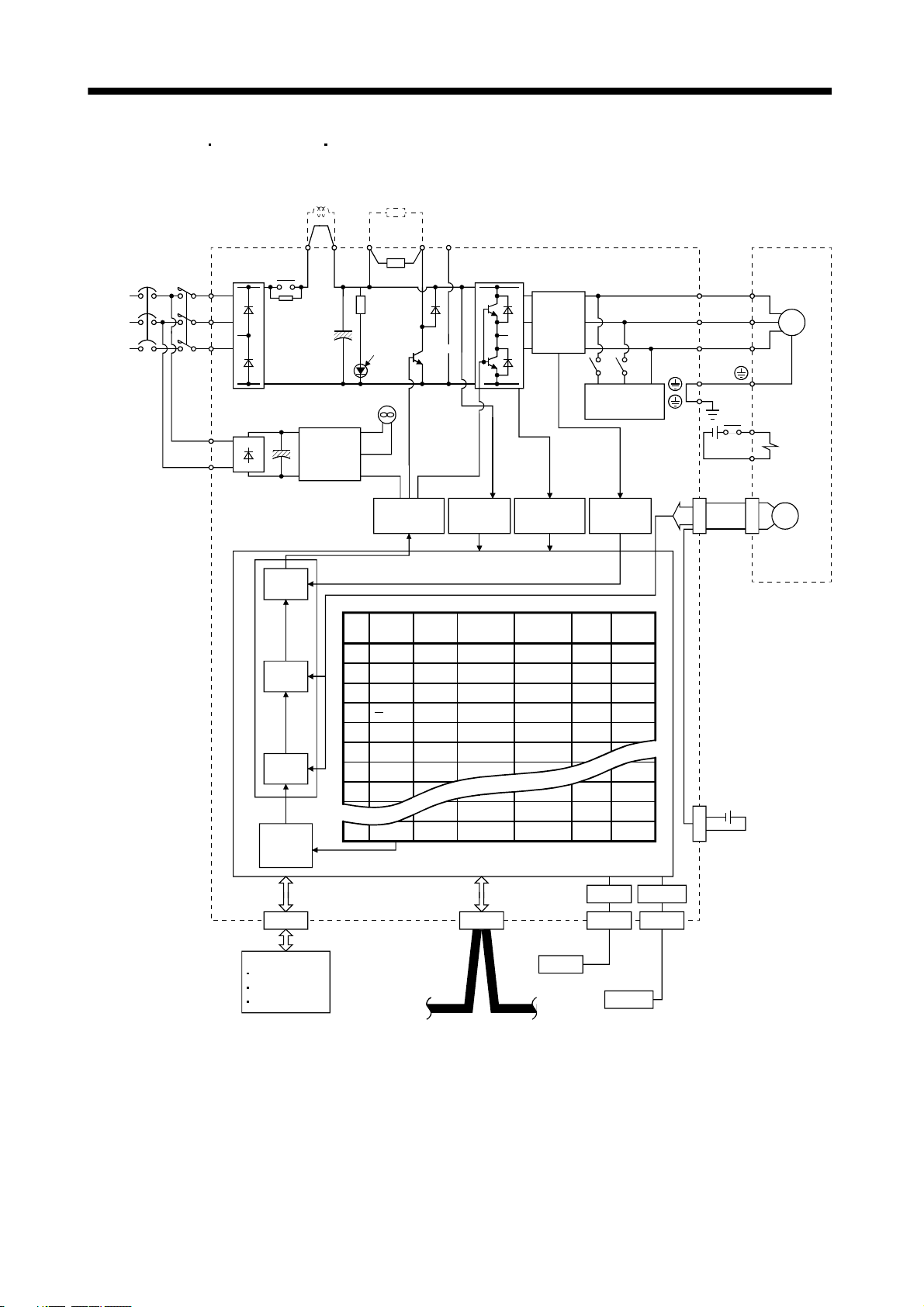
1. FUNCTIONS AND CONFIGURATION
(2) MR-J3-350T4
MR-J3-500T(4) MR-J3-700T(4)
Power factor
improving DC
reactor
Regenerative
option
(Note 1)
Power
supply
P
P
P
1
2
Diode
Relay
MCNFB
stack
L
1
L2
L
3
CHARGE
lamp
Cooling fan
L11
L
21
Control
circuit
power
supply
Base
amplifier
N
C
Regenerative
TR
Voltage
detection
Current
detector
Overcurrent
protection
Dynamic
brake
Current
detection
U
V
W
24VDC
CN2
RA
B1
B2
Servo motorServo amplifier
U
V
W
M
Electromagnetic
brake
Encoder
Current
control
Point table
No.
Position
data
Speed
Acceleration
time
constant
Deceleration
time
constant
Dwell Auxiliary
1 1000 1000 80 80 0 0
control
Model adaptive control
Position
control
Position
command
creation
Speed
(Note 2)
2
2000 2000 100 100 0 0
4000 2000 70 60 500 1
3
4
500 2000 60 70 1000 1
5
6
7
8
2000 80 80 0 0
1000
2000 1000 80 80 0 0
1000 1000 80 80 0 0
1000 1000 100 100 0 0
1000 1000 100 100 0 0
255 2000 2000 80 80 0 0
USB
RS-422
MR-J3BAT
CN4
Optional battery
(for absolute position
detection system)
CN1CN6
Personal
computer
DI/O Control
Servo on
Start
Failure, etc
CC-Link
USB
Controller
RS-422
Note 1. Refer to section 1.2 for the power supply specification.
2. For the case when 2 stations are occupied. When 1 station is occupied, the point table ends at No.31.
1 - 3
CN3CN5
Page 25
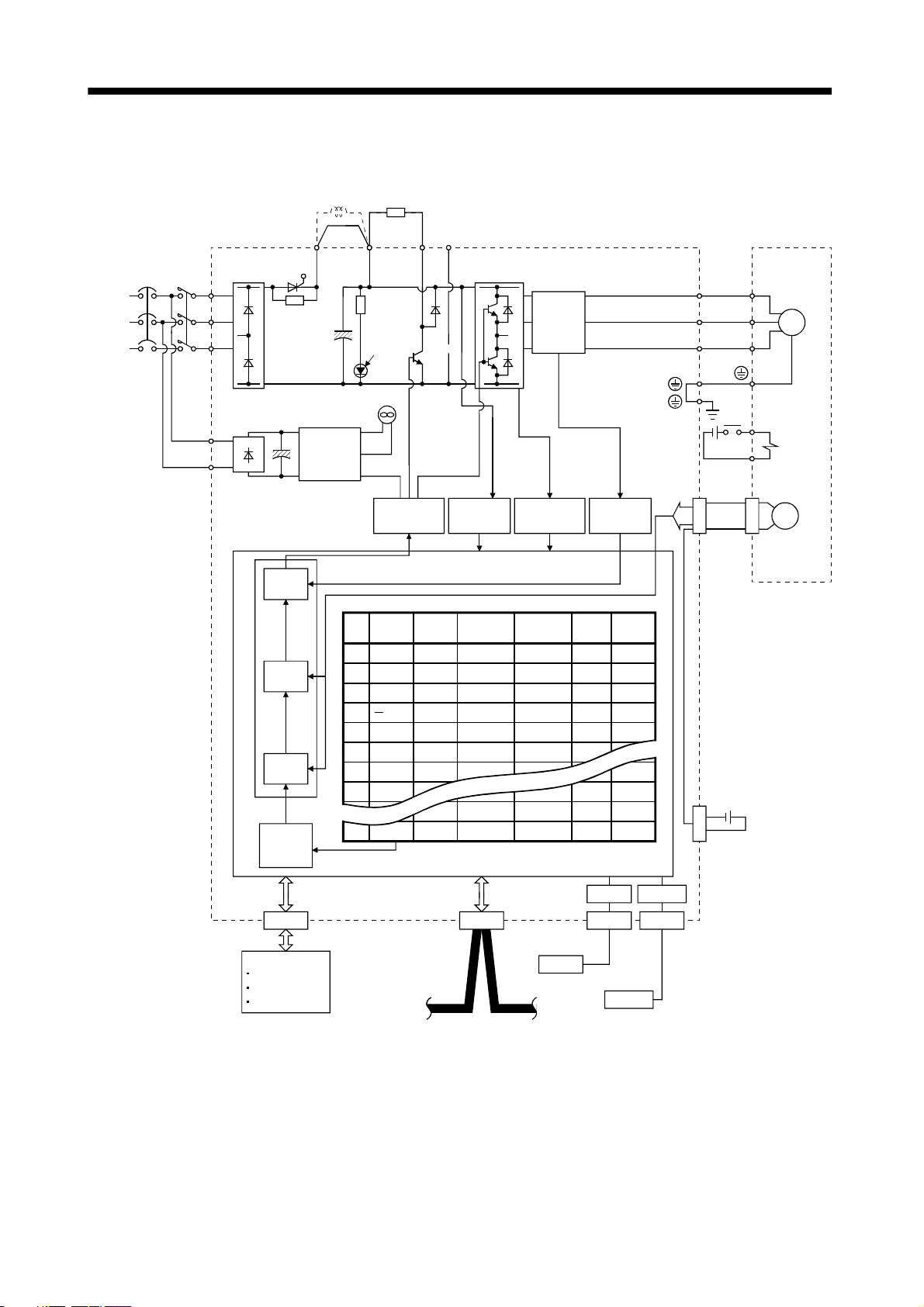
1. FUNCTIONS AND CONFIGURATION
(3) MR-J3-11KT(4) to 22KT(4)
Power factor
improving DC
reactor
Regenerative
option
(Note 1)
Power
supply
P
1
Diode
Thyristor
MCNFB
stack
L
1
P
L2
L
3
CHARGE
lamp
N
C
Regenerative
TR
Current
detector
U
V
W
Servo motorServo amplifier
U
V
M
W
Cooling fan
RA
L11
L
Control
circuit
21
power
supply
Base
amplifier
Voltage
detection
Overcurrent
protection
Current
detection
24VDC
CN2
B1
B2
Electromagnetic
brake
Encoder
Current
control
Point table
No.
Position
data
Speed
Acceleration
time
constant
Deceleration
time
constant
Dwell Auxiliary
1 1000 1000 80 80 0 0
control
Model adaptive control
Position
control
Position
command
creation
Speed
(Note 2)
2
2000 2000 100 100 0 0
4000 2000 70 60 500 1
3
4
500 2000 60 70 1000 1
5
6
7
8
2000 80 80 0 0
1000
2000 1000 80 80 0 0
1000 1000 80 80 0 0
1000 1000 100 100 0 0
1000 1000 100 100 0 0
255 2000 2000 80 80 0 0
USB
RS-422
MR-J3BAT
CN4
Optional battery
(for absolute position
detection system)
CN1CN6
Personal
computer
DI/O Control
Servo on
Start
Failure, etc
CC-Link
USB
Controller
RS-422
Note 1. Refer to section 1.2 for the power supply specification.
2. For the case when 2 stations are occupied. When 1 station is occupied, the point table ends at No.31.
1 - 4
CN3CN5
Page 26
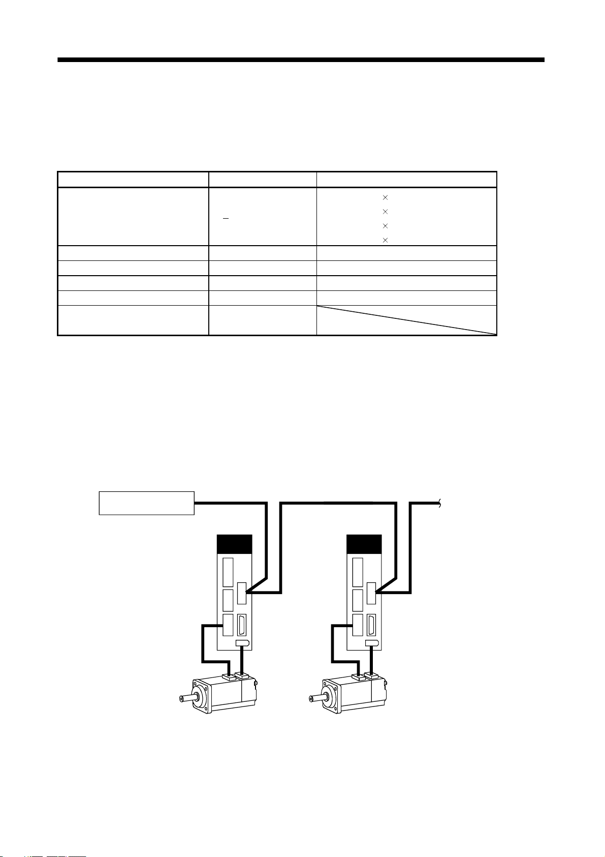
1. FUNCTIONS AND CONFIGURATION
1.1.3 System configuration
This section provides operations using this servo.
Use of CC-Link enables you to freely configure any system from a single-axis system to an up to 42-axis
system.
Set the following values to the point table.
Name Setting range Unit
0.001[mm]
Position data 999999 to 999999
Servo motor speed 0 to max. speed [r/min]
Acceleration time constant 0 to 20000 [ms]
Deceleration time constant 0 to 20000 [ms]
Dwell 0 to 20000 [ms]
Auxiliary function
(Refer to section 4.2)
0 to 3
0.01[mm]
0.1[mm]
1[mm]
There are 31 points of point tables to be used when 1 station is occupied and 255 points when 2 stations are
occupied.
(1) Operation using CC-Link communication functions
(a) Operation
All devices can be controlled by CC-Link communication. Also, each point table setting, point table
selection, parameter value change, setting, monitor, servo motor operation and others can be
performed.
(b) Configuration
Programmable controller
CC-Link master unit
Servo amplifier
(Axis 1)
CNP3
CN2
CN1
CN6
Servo amplifier
(Axis 2)
CN1
CN6
CNP3
CN2
To the next axis
1 - 5
Page 27

1. FUNCTIONS AND CONFIGURATION
(2) Operation using CC-Link communication functions and external input signals
(a) Operation
Using parameter No.PD06 to PD08 and parameter No.PD12, PD14, input devices can be assigned to
the external input devices of CN1A and CN1B. The signals assigned to the external input signals cannot
be used with the CC-Link communication functions. Output devices can be used with the CN6
connectors and CC-Link communication functions simultaneously.
(b) Configuration
Programmable controller
CC-Link master unit
Servo amplifier
(Axis 1)
CN1
CNP3 CNP3
CN6
CN2
External I/O
signal
Servo amplifier
(Axis 2)
CN1
CN6
CN2
External I/O
signal
To the next axis
1 - 6
Page 28

1. FUNCTIONS AND CONFIGURATION
1.2 Servo amplifier standard specifications
(1) 200V class, 100V class
Servo amplifier
MR-J3-
Item
Voltage/frequency
Permissible voltage fluctuation
Permissible frequency
fluctuation
Power supply
Power supply capacity Refer to section 13.2
Inrush current Refer to section 13.5
Voltage,
frequency
Permissible
Control circuit
power supply
Interface power
supply
Control System Sine-wave PWM control, current control system
Dynamic brake Built-in External option Built-in
Protective functions
Point table
number
input
Position
Command system
command
data input
(when 2
stations are
occupied)
Automatic
operation
mode
Manual
Operation mode
operation
mode
voltage fluctuation
Permissible
frequency
fluctuation
Input 30W 45W 30W
Inrush current Refer to section 13.5
Voltage 24VDC 10%
Power supply
capacity
Operational
specifications
Position command
input
Speed command
input
System
Operational
specifications
Position command
input
Speed command
input
System
Point table
Automatic
continuous
operation
Jog
Manual pulse
generator
10T 20T 40T 60T 70T 100T 200T 350T 500T 700T 11KT 15KT 22KT 10T1 20T1 40T1
3-phase or 1-phase 200 to
230VAC, 50/60Hz
3-phase or 1-phase 200 to
230VAC: 170 to 253VAC
1-phase 200 to 230VAC, 50/60Hz
1-phase 170 to 253VAC
Overcurrent shut-off, regenerative overvoltage shut-off, overload shut-off (electronic thermal relay),
servo motor overheat protection, encoder error protection, regenerative brake error protection,
undervoltage, instantaneous power failure protection, overspeed protection, excessive error
protection
Positioning by specifying the point table No. (255 points)
Set in point table. 1-point feed length setting range: 1[ m] to 999.999[mm]
Set in point table. Acceleration/deceleration time is set in point table.
S-pattern acceleration/deceleration time constant is set in parameter No.PC13.
Signed absolute value command system, incremental value command system, signed absolute
value command/incremental value command specifying system
Remote register setting is used for positioning.
Remote register is used to set position command data.
Feed length input setting range:
Remote register is used to make selection from point table.
Remote register is used to set speed command data (speed).
S-pattern acceleration/deceleration time constant is set in parameter No.PC13.
Signed absolute value command system, incremental value command system, signed absolute
value command/incremental value command specifying system
Point table number input, position data input system
Positioning operation is performed once in accordance with the position and speed commands.
Varied speed operation (2 to 255 speeds), automatic continuous positioning operation (2 to 255
points)
Jog operation is performed in accordance with the parameter-set speed command by contact input
or through CC-Link communication function.
Manual feed is made by manual pulse generator.
Command pulse multiplication:
3-phase 200 to 230VAC, 50/60Hz
3-phase 170 to 253VAC
Within
5%
Within
5%
(Note 1) 150mA
1 m to 999.999m
1, 10 or 100 is selected using parameter.
1-phase 100V to
120VAC, 50/60Hz
1-phase 85 to
132VAC
1-phase 100 to
120VAC, 50/60Hz
1-phase 85 to
132VAC
1 - 7
Page 29

1. FUNCTIONS AND CONFIGURATION
Servo amplifier
Item
Dog type
Count type
Data setting type
Stopper type
Home position
ignorance
(Servo-on position
as home position)
Dog type rear end
Home
position
return
mode
Operation mode
Automatic positioning to home
position
Other functions
Structure
reference
Count type front
end reference
Dog cradle type
Dog type last
Z-phase reference
Dog type front end
reference
Dogless
Z-phase reference
MR-J3-
10T 20T 40T 60T 70T 100T 200T 350T 500T 700T 11KT 15KT 22KT 10T1 20T1 40T1
Home position return is made starting with Z-phase pulse after passage of proximity dog.
Home position address may be set. Home position shift distance may be set. Home position return
direction may be selected.
Automatic at-dog home position return return/automatic stroke return function.
Home position return is made by counting encoder pulses after contact with proximity dog.
Home position address may be set. Home position shift value may be set. Home position return
direction may be set.
Automatic at-dog home position return return/automatic stroke return function.
Home position return is made without dog.
Home position may be set at any position by manual operation, etc. Home position address may be
set.
Home position return is made by pressing machine part against stroke end.
Home position address may be set. Home position return direction may be set.
Position where servo-on (RYn0) is switched on is defined as home position.
Home position address may be set.
Home position return is made with respect to the rear end of a proximity dog.
Home position address may be set. Home position shift value may be set. Home position return
direction may be set.
Automatic at-dog home position return return/automatic stroke return function.
Home position return is made with respect to the front end of a proximity dog.
Home position address may be set. Home position shift value may be set. Home position return
direction may be set.
Automatic at-dog home position return return/automatic stroke return function.
Home position return is made with respect to the front end of a proximity dog by the first Z-phase
pulse.
Home position address may be set. Home position shift value may be set. Home position return
direction may be set.
Automatic at-dog home position return return/automatic stroke return function.
Home position return is made with respect to the front end of a proximity dog by the last Z-phase
pulse.
Home position address may be set. Home position shift value may be set. Home position return
direction may be set.
Automatic at-dog home position return return/automatic stroke return function.
Home position return is made to the dog front end with respect to the front end of a proximity dog.
Home position address may be set. Home position shift value may be set. Home position return
direction may be set.
Automatic at-dog home position return return/automatic stroke return function.
Home position return is made with respect to the first Z-phase to the Z-phase.
Home position address may be set. Home position shift value may be set. Home position return
direction may be set.
High-speed automatic return to a defined home position.
Absolute position detection, backlash function
Overtravel prevention using external limit switch
Software stroke limit
Self-cooled, open
(IP00)
Force-cooling, open (IP00)
Self-cooled, open
(IP00)
1 - 8
Page 30
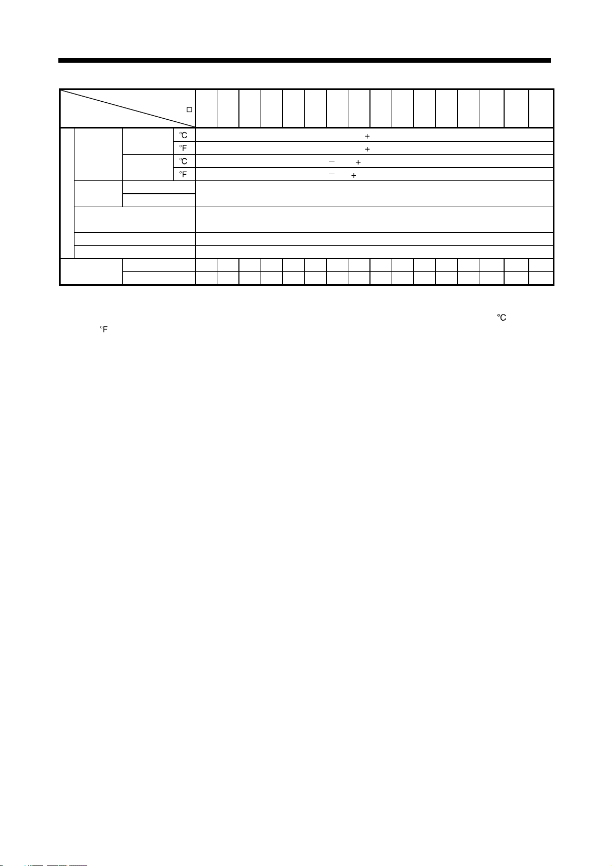
1. FUNCTIONS AND CONFIGURATION
Servo amplifier
MR-J3-
Item
Ambient
temperature
humidity
Environment
Ambient
Altitude Max. 1000m above sea level
Vibration 5.9 [m/s2] or less
Mass
Note 1. 150mA is the value applicable when all I/O signals are used. The current capacity can be decreased by reducing the number of
I/O points.
2. When closely mounting the servo amplifier of 3.5kW or less, operate them at the ambient temperatures of 0 to 45
113
In operation
In storage
In operation Ambient
In storage
[kg] 0.8 0.8 1.0 1.0 1.4 1.4 2.1 2.3 4.6 6.2 18 18 19 0.8 0.8 1.0
[lb] 1.76 1.76 2.21 2.21 3.09 3.09 4.63 5.07 10.1 13.7 39.7 39.7 41.9 1.76 1.76 2.21
) or at 75% or smaller effective load ratio.
10T 20T 40T 60T 70T 100T 200T 350T 500T 700T 11KT 15KT 22KT 10T1 20T1 40T1
[ ] (Note 2) 0 to 55 (non-freezing)
] (Note 2) 32 to 131 (non-freezing)
[
[ ] 20 to 65 (non-freezing)
[
] 4 to 149 (non-freezing)
90%RH or less (non-condensing)
Indoors (no direct sunlight)
Free from corrosive gas, flammable gas, oil mist, dust and dirt
(32 to
1 - 9
Page 31

1. FUNCTIONS AND CONFIGURATION
(2) 400V class
Servo amplifier
MR-J3-
Item
Voltage/frequency 3-phase 380 to 480VAC, 50/60Hz
Permissible voltage fluctuation 3-phase 323 to 528VAC
Permissible frequency
fluctuation
Power supply capacity Refer to section 13.2
Power supply
Inrush current Refer to section 13.5
Voltage,
frequency
Permissible
Control circuit
power supply
Interface power
supply
Control System Sine-wave PWM control, current control system
Dynamic brake Built-in External option
Protective functions
Point table
number
input
Position
Command system
command
data input
(when 2
stations are
occupied)
Automatic
operation
mode
Manual
Operation mode
operation
mode
voltage fluctuation
Permissible
frequency
fluctuation
Input 30W 45W
Inrush current Refer to section 13.5
Voltage 24VDC 10%
Power supply
capacity
Operational
specifications
Position command
input
Speed command
input
System
Operational
specifications
Position command
input
Speed command
input
System
Point table
Automatic
continuous
operation
Jog
Manual pulse
generator
60T4 100T4 200T4 350T4 500T4 700T4 11KT4 15KT4 22KT4
5%
Within
1-phase 380 to 480VAC, 50/60Hz
1-phase 323 to 528VAC
Within
5%
(Note) 150mA
Overcurrent shut-off, regenerative overvoltage shut-off, overload shut-off (electronic thermal relay),
servo motor overheat protection, encoder error protection, regenerative brake error protection,
undervoltage, instantaneous power failure protection, overspeed protection, excessive error
protection
Positioning by specifying the point table No. (255 points)
Set in point table. 1-point feed length setting range: 1[ m] to 999.999[mm]
Set in point table. Acceleration/deceleration time is set in point table.
S-pattern acceleration/deceleration time constant is set in parameter No.PC13.
Signed absolute value command system, incremental value command system, signed absolute
value command/incremental value command specifying system
Remote register setting is used for positioning.
Remote register is used to set position command data.
Feed length input setting range:
Remote register is used to make selection from point table.
Remote register is used to set speed command data (speed).
S-pattern acceleration/deceleration time constant is set in parameter No.PC13.
Signed absolute value command system, incremental value command system, signed absolute
value command/incremental value command specifying system
Point table number input, position data input system
Positioning operation is performed once in accordance with the position and speed commands.
Varied speed operation (2 to 255 speeds), automatic continuous positioning operation (2 to 255
points)
Jog operation is performed in accordance with the parameter-set speed command by contact input
or through CC-Link communication function.
Manual feed is made by manual pulse generator.
Command pulse multiplication:
1 m to 999.999m
1, 10 or 100 is selected using parameter.
1 - 10
Page 32

1. FUNCTIONS AND CONFIGURATION
Servo amplifier
60T4 100T4 200T4 350T4 500T4 700T4 11KT4 15KT4 22KT4
Home position return is made starting with Z-phase pulse after passage of proximity dog.
Home position address may be set. Home position shift distance may be set. Home position return
direction may be selected.
Automatic at-dog home position return return/automatic stroke return function.
Home position return is made by counting encoder pulses after contact with proximity dog.
Home position address may be set. Home position shift value may be set. Home position return
direction may be set.
Automatic at-dog home position return return/automatic stroke return function.
Home position return is made without dog.
Home position may be set at any position by manual operation, etc. Home position address may be
set.
Home position return is made by pressing machine part against stroke end.
Home position address may be set. Home position return direction may be set.
Position where servo-on (RYn0) is switched on is defined as home position.
Home position address may be set.
Home position return is made with respect to the rear end of a proximity dog.
Home position address may be set. Home position shift value may be set. Home position return
direction may be set.
Automatic at-dog home position return return/automatic stroke return function.
Home position return is made with respect to the front end of a proximity dog.
Home position address may be set. Home position shift value may be set. Home position return
direction may be set.
Automatic at-dog home position return return/automatic stroke return function.
Home position return is made with respect to the front end of a proximity dog by the first Z-phase
pulse.
Home position address may be set. Home position shift value may be set. Home position return
direction may be set.
Automatic at-dog home position return return/automatic stroke return function.
Home position return is made with respect to the front end of a proximity dog by the last Z-phase
pulse.
Home position address may be set. Home position shift value may be set. Home position return
direction may be set.
Automatic at-dog home position return return/automatic stroke return function.
Home position return is made to the dog front end with respect to the front end of a proximity dog.
Home position address may be set. Home position shift value may be set. Home position return
direction may be set.
Automatic at-dog home position return return/automatic stroke return function.
Home position return is made with respect to the first Z-phase to the Z-phase.
Home position address may be set. Home position shift value may be set. Home position return
direction may be set.
High-speed automatic return to a defined home position.
Absolute position detection, backlash function
Overtravel prevention using external limit switch
Software stroke limit
Self-cooled, open
(IP00)
Item
Dog type
Count type
Data setting type
Stopper type
Home position
ignorance
(Servo-on position
as home position)
Dog type rear end
Home
position
return
mode
Operation mode
Automatic positioning to home
position
Other functions
Structure
reference
Count type front
end reference
Dog cradle type
Dog type last
Z-phase reference
Dog type front end
reference
Dogless
Z-phase reference
MR-J3-
Force-cooling, open (IP00)
1 - 11
Page 33

1. FUNCTIONS AND CONFIGURATION
Servo amplifier
MR-J3-
Item
Ambient
temperature
humidity
Environment
Ambient
Altitude Max. 1000m above sea level
Vibration 5.9 [m/s2] or less
Mass
Note. 150mA is the value applicable when all I/O signals are used. The current capacity can be decreased by reducing the number of
I/O points.
In operation
In storage
In operation Ambient
In storage
[kg] 1.7 1.7 2.1 4.6 4.6 6.2 18 18 19
[lb] 3.75 3.75 4.63 10.1 10.1 13.7 39.7 39.7 41.9
60T4 100T4 200T4 350T4 500T4 700T4 11KT4 15KT4 22KT4
[ ] 0 to 55 (non-freezing)
] 32 to 131 (non-freezing)
[
[ ] 20 to 65 (non-freezing)
[
] 4 to 149 (non-freezing)
90%RH or less (non-condensing)
Indoors (no direct sunlight)
Free from corrosive gas, flammable gas, oil mist, dust and dirt
1 - 12
Page 34

1. FUNCTIONS AND CONFIGURATION
1.3 Function list
The following table lists the functions of this servo. For details of the functions, refer to the reference field.
Function Description Reference
Select the required ones from among 31 preset point tables and perform
Positioning by automatic
operation
Varied speed operation
Automatic continuous positioning
operation
Home position return
High-resolution encoder
Absolute position detection
system
Gain changing function
Advanced vibration suppression
control
Adaptive filter
Low-pass filter
Machine analyzer function
Machine simulation
Gain search function
Slight vibration suppression
control
Electronic gear
Auto tuning
S-pattern
acceleration/deceleration time
constant
Regenerative option
Brake unit
Regeneration converter
Alarm history clear
operation in accordance with the set values.
Use the external input signal or communication function to choose the point
tables.
Servo motor speed can be varied continuously until the preset moving
distance is reached. (Max. set speeds: 255 speeds)
By merely choosing one point table and starting operation, positioning can
be executed continuously in accordance with several point tables.
Dog type, count type, data setting type, stopper type, home position
ignorance, dog type rear end reference, count type front end reference, dog
cradle type
High-resolution encoder of 262144 pulses/rev is used as a servo motor
encoder.
By merely setting the home position once, home position return need not be
done at each power on.
You can switch between gains during rotation and gains during stop or use
an input device to change gains during operation.
This function suppresses vibration at the arm end or residual vibration.
Servo amplifier detects mechanical resonance and sets filter characteristics
automatically to suppress mechanical vibration.
Suppresses high-frequency resonance which occurs as servo system
response is increased.
Analyzes the frequency characteristic of the mechanical system by simply
connecting a MR Configurator installed personal computer and servo
amplifier.
MR Configurator is necessary for this function.
Can simulate machine motions on a personal computer screen on the basis
of the machine analyzer results.
MR Configurator is necessary for this function.
Personal computer changes gains automatically and searches for
overshoot-free gains in a short time.
MR Configurator is necessary for this function.
Suppresses vibration of 1 pulse produced at a servo motor stop. Parameters No.
The electronic gear is used to make adjustment so that the servo amplifier
setting matches the machine moving distance. Also, changing the electronic
gear value allows the machine to be moved at any multiplication ratio to the
moving distance using the servo amplifier.
Automatically adjusts the gain to optimum value if load applied to the servo
motor shaft varies.
Acceleration/deceleration can be made smoothly.
Used when the built-in regenerative resistor of the servo amplifier does not
have sufficient regenerative capability for the regenerative power generated.
Used when the regenerative option cannot provide enough regenerative
power.
Can be used with the servo amplifier of 5kW or more.
Used when the regenerative option cannot provide enough regenerative
power.
Can be used with the servo amplifier of 5kW or more.
Alarm history is cleared. Parameter No.
Section 5.4
Section 5.4.2
(4)(b)
Section 5.4.2 (4)
Section 5.6
Section 5.7
Section 10.6
Section 10.4
Section 10.2
Section 10.5
PB24
Parameter No.
PA06, PA07
Section 9.2
Parameters No.
PC13
Section 14.2
Section 14.3
Section 14.4
PC18
1 - 13
Page 35

1. FUNCTIONS AND CONFIGURATION
Function Description Reference
I/O signal selection (Device
setting)
Torque limit
Output signal (DO) forced output
Test operation mode
Limit switch
Software limit
Any input device such as servo-on (SON) can be assigned to any pin of CN6
connector.
Servo motor-torque is limited. Section 4.6.3
Output signal can be forced on/off independently of the servo status.
Use this function for output signal wiring check, etc.
JOG operation
feed.
MR Configurator is necessary for this function.
The servo motor travel region can be limited using the forward rotation
stroke end (LSP)/reverse rotation stroke end (LSN).
The travel region is limited using parameters in terms of address.
The function similar to that of a limit switch is limited by parameter.
positioning operation DO forced output single - step
Parameter No.
PD06 to PD08
PD12
PD14
Section 6.1.11
Section 7.7.4
Section 8.5.7(4)
Section 7.7
Section 8.5.7
Section 6.3.6
1 - 14
Page 36

1. FUNCTIONS AND CONFIGURATION
1.4 Model code definition
(1) Rating plate
(2) Model
Series
MITSUBISHI
MODEL
MR-J3-10T
POWER :
INPUT :
OUTPUT :
SERIAL :
With no regenerative resistor
Power supply
(Note 1)
(Note 2)
Note 1. 1-phase 200V to 230V is
supported by 750W or less.
2. 1-phase 100V to 120V is
supported by 400W or less.
100W
0.9A 3PH+1PH200-230V 50Hz
3PH+1PH200-230V 60Hz
1.3A 1PH 200-230V 50/60Hz
170V 0-360Hz 1.1A
A34230001
MITSUBISHI ELECTRIC CORPORATION
MADE IN JAPAN
Symbol Description
Indicates a servo
amplifier of 11k to 22kW
-PX
that does not use a
regenerative resistor as
standard accessory.
Symbol
None
1
4 3-phase 380 to 480VAC
Description
3-phase or 1-phase 200
to 230VAC
1-phase 100 to 120VAC
AC SERVO
PASSED
MR-J3-100T(4) or less
Rating plate
MR-J3-350T
Model
Capacity
Applicable power supply
Rated output current
Serial number
MR-J3-200T(4)
Rating plate
MR-J3-350T4 500T(4)
Built-in positioning function
Rated output
Symbol
Rated
output [kW]
10 0.1
20 0.2
40 0.4
60 0.6
70 0.75
100 1
200 2
350 3.5
500 5
700 7
11K 11
15K 15
22K 22
Rating plate
MR-J3-700T(4)
Rating plate
Rating plate
MR-J3-11KT(4) to 22KT(4)
Rating plate
1 - 15
Page 37

1. FUNCTIONS AND CONFIGURATION
1.5 Combination with servo motor
The following table lists combinations of servo amplifiers and servo motors. The same combinations apply to
the servo motors with an electromagnetic brakes and the servo motors with a reduction gear.
Servo motors
Servo amplifier
MR-J3-10T (1) 053 13 053 13
MR-J3-20T (1) 23 23
MR-J3-40T (1) 43 43
MR-J3-60T 51 52 52
MR-J3-70T 73 73 72
MR-J3-100T 81 102 102
MR-J3-200T 121 201 152 202 103 153 152 152
MR-J3-350T 301 352 203 202 202
MR-J3-500T 421 502 353 503 352 502 302
MR-J3-700T 702
MR-J3-11KT
MR-J3-15KT
MR-J3-22KT
HF-MP
HF-KP
1000r/min 2000r/min
HF-SP
HC-RP HC-UP HC-LP
Servo motors
Servo amplifier
MR-J3-500T 502
MR-J3-700T 601 701M 702
MR-J3-11KT 801 12K1 11K1M 11K2
MR-J3-15KT 15K1 15K1M 15K2
MR-J3-22KT 20K1 25K1 22K1M 22K2
HA-LP
1000r/min 1500r/min 2000r/min
Servo motors
Servo amplifier
MR-J3-60T4 524
MR-J3-100T4 1024
MR-J3-200T4 1524 2024
MR-J3-350T4 3524
MR-J3-500T4 5024
MR-J3-700T4 7024 6014 701M4
MR-J3-11KT4 8014 12K14 11K1M4 11K24
MR-J3-15KT4 15K14 15K1M4 15K24
MR-J3-22KT4 20K14 22K1M4 22K24
HF-SP
HA-LP
1000r/min 1500r/min 2000r/min
1 - 16
Page 38

1. FUNCTIONS AND CONFIGURATION
1.6 Structure
1.6.1 Parts identification
(1) MR-J3-100T or less
Name/Application
Display
The 3-digit, seven-segment LED shows the servo
status and alarm number.
5
6
4
7
3
8
2
9
1
0
5
5
6
6
4
4
7
3
2
1
7
3
8
8
2
9
9
1
0
0
Baud rate switch (MODE)
MODE
5
6
4
7
3
Select the CC-Link communication baud rate.
8
2
9
1
0
Station number switches (STATION NO.)
Set the station number of the servo amplifier.
X10 STATION NO. X1
3
5
5
4
2
1
6
6
4
7
7
3
8
8
2
9
9
1
0
0
Detailed
explanation
Section 5.3
Chapter 11
Section 3.2.4
Section 3.2.3
Set the one place.
Set the ten place.
Occupied station count switch (SW1)
SW1
Set the number of occupied stations.
Main circuit power supply connector (CNP1)
Used to connect the input power supply.
Section 3.2.5
Section 4.1
Section 4.3
Section 12.1
Communication alarm display section
Indicates alarms in CC-Link communication.
L.RUN
SD
RD
Section 11.3
L.ERR
USB communication connector (CN5)
Used to connect the personal computer.
RS-422 communication connector (CN3)
Used to connect the MR-PRU03 parameter unit or
personal computer.
CC-Link connector (CN1)
Wire the CC-Link cable.
Control circuit connector (CNP2)
Used to connect the control circuit power supply/
regenerative option.
Chapter 7
Chapter 7
Chapter 8
Chapter 15
Section 3.2.2
Section 4.1
Section 4.3
Section 12.1
Section 14.2
I/O signal connector (CN6)
Used to connect digital I/O signals.
Servo motor power connector (CNP3)
Used to connect the servo motor.
Section 4.2
Section 4.4
Section 4.1
Section 4.3
Section 12.1
Encoder connector (CN2)
Used to connect the servo motor encoder.
Battery connector (CN4)
Used to connect the battery for absolute position data
backup.
Section 4.10
Section 14.1
Section 5.8
Section 14.7
Charge lamp
Lit to indicate that the main circuit is charged. While
this lamp is lit, do not reconnect the cables.
Battery holder
Contains the battery for absolute position data backup.
Section 5.8
Fixed part
(2 places)
Rating plate
Protective earth (PE) terminal ( )
Ground terminal.
Section 1.4
Section 4.1
Section 4.3
Section 12.1
1 - 17
Page 39

1. FUNCTIONS AND CONFIGURATION
(2) MR-J3-200T(4) or less
Cooling fan
Fixed part
(3 places)
Name/Application
Display
The 3-digit, seven-segment LED shows the servo
status and alarm number.
5
7
3
8
2
0
5
5
7
7
3
3
8
8
2
2
0
0
Baud rate switch (MODE)
MODE
5
6
4
7
3
Select the CC-Link communication baud rate.
8
2
9
1
0
Station number switches (STATION NO.)
Set the station number of the servo amplifier.
X10 STATION NO. X1
3
5
5
4
2
1
6
6
4
7
7
3
8
8
2
9
9
1
0
0
Detailed
explanation
Section 5.3
Chapter 11
Section 3.2.4
Section 3.2.3
Set the one place.
Set the ten place.
Occupied station count switch (SW1)
SW1
Set the number of occupied stations.
Main circuit power supply connector (CNP1)
Used to connect the input power supply.
Section 3.2.5
Section 4.1
Section 4.3
Section 12.1
Communication alarm display section
Indicates alarms in CC-Link communication.
L.RUN
SD
RD
Section 11.3
L.ERR
(Note)
USB communication connector (CN5)
Used to connect the personal computer.
RS-422 communication connector (CN3)
Used to connect the MR-PRU03 parameter unit or
personal computer.
CC-Link connector (CN1)
Wire the CC-Link cable.
I/O signal connector (CN6)
Used to connect digital I/O signals.
Encoder connector (CN2)
Used to connect the servo motor encoder.
Battery connector (CN4)
Used to connect the battery for absolute position data
backup.
Control circuit connector (CNP2)
Used to connect the control circuit power supply/
regenerative option.
Chapter 7
Chapter 7
Chapter 8
Chapter 15
Section 3.2.2
Section 4.2
Section 4.4
Section 4.10
Section 14.1
Section 5.8
Section 14.7
Section 4.1
Section 4.3
Section 12.1
Section 14.2
Servo motor power connector (CNP3)
Used to connect the servo motor.
Section 4.1
Section 4.3
Section 12.1
Battery holder
Contains the battery for absolute position data backup.
Section 5.8
Charge lamp
Lit to indicate that the main circuit is charged. While
this lamp is lit, do not reconnect the cables.
Protective earth (PE) terminal ( )
Ground terminal.
Section 4.1
Section 4.3
Section 12.1
Rating plate
Section 1.4
Note. Connectors (CNP1, CNP2, and CNP3) and appearance of MR-J3-200T servo amplifier have been changed from January 2008
production. Model name of the existing servo amplifier is changed to MR-J3-200T-RT. For MR-J3-200T-RT, refer to appendix 5.
1 - 18
Page 40

1. FUNCTIONS AND CONFIGURATION
(3) MR-J3-350T
Cooling fan
Fixed part
(3 places)
Name/Application
Display
The 3-digit, seven-segment LED shows the servo
status and alarm number.
5
6
4
7
3
8
2
9
1
0
5
5
6
6
4
4
7
3
2
1
7
3
8
8
2
9
9
1
0
0
Baud rate switch (MODE)
MODE
5
6
4
7
3
Select the CC-Link communication baud rate.
8
2
9
1
0
Station number switches (STATION NO.)
Set the station number of the servo amplifier.
X10 STATION NO. X1
3
5
5
4
2
1
6
6
4
7
7
3
8
8
2
9
9
1
0
0
Detailed
explanation
Section 5.3
Chapter 11
Section 3.2.4
Section 3.2.3
Set the one place.
Set the ten place.
Occupied station count switch (SW1)
SW1
Set the number of occupied stations.
Main circuit power supply connector (CNP1)
Used to connect the input power supply.
Section 3.2.5
Section 4.1
Section 4.3
Section 12.1
Communication alarm display section
Indicates alarms in CC-Link communication.
L.RUN
SD
RD
L.ERR
USB communication connector (CN5)
Used to connect the personal computer.
RS-422 communication connector (CN3)
Used to connect the MR-PRU03 parameter unit or
personal computer.
CC-Link connector (CN1)
Wire the CC-Link cable.
Servo motor power connector (CNP3)
Used to connect the servo motor.
Section 11.3
Chapter 7
Chapter 7
Chapter 8
Chapter 15
Section 3.2.2
Section 4.1
Section 4.3
Section 12.1
I/O signal connector (CN6)
Used to connect digital I/O signals.
Encoder connector (CN2)
Used to connect the servo motor encoder.
Battery connector (CN4)
Used to connect the battery for absolute position data
backup.
Control circuit connector (CNP2)
Used to connect the control circuit power supply/
regenerative option.
Section 4.2
Section 4.4
Section 4.10
Section 14.1
Section 5.8
Section 14.7
Section 4.1
Section 4.3
Section 12.1
Section 14.2
Battery holder
Contains the battery for absolute position data backup.
Section 5.8
Charge lamp
Lit to indicate that the main circuit is charged. While
this lamp is lit, do not reconnect the cables.
Protective earth (PE) terminal ( )
Ground terminal.
Section 4.1
Section 4.3
Section 12.1
Rating plate
Section 1.4
1 - 19
Page 41
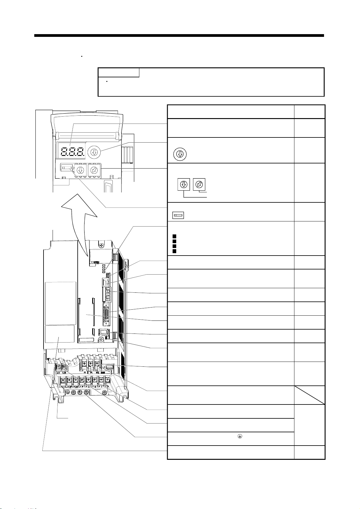
1. FUNCTIONS AND CONFIGURATION
(4) MR-J3-350T4
MR-J3-500T(4)
POINT
The servo amplifier is shown without the front cover. For removal of the front
cover, refer to section 1.6.2.
Cooling fan
5
6
4
7
3
8
2
9
1
0
Fixed part
(4 places)
Name/Application
Display
The 3-digit, seven-segment LED shows the servo
status and alarm number.
Baud rate switch (MODE)
5
6
4
7
3
8
2
9
1
0
5
6
4
7
3
8
2
9
1
0
MODE
5
6
4
7
3
Select the CC-Link communication baud rate.
8
2
9
1
0
Station number switches (STATION NO.)
Set the station number of the servo amplifier.
X10 STATION NO. X1
3
5
5
4
2
1
6
6
4
7
7
3
8
8
2
9
9
1
0
0
Detailed
explanation
Section 5.3
Chapter 11
Section 3.2.4
Section 3.2.3
Set the one place.
Set the ten place.
Occupied station count switch (SW1)
SW1
Set the number of occupied stations.
Section 3.2.5
Communication alarm display section
Indicates alarms in CC-Link communication.
L.RUN
SD
RD
L.ERR
USB communication connector (CN5)
Used to connect the personal computer.
RS-422 communication connector (CN3)
Used to connect the MR-PRU03 parameter unit or
personal computer.
CC-Link connector (CN1)
Wire the CC-Link cable.
I/O signal connector (CN6)
Used to connect digital I/O signals.
Battery holder
Contains the battery for absolute position data backup.
Encoder connector (CN2)
Used to connect the servo motor encoder.
Battery connector (CN4)
Used to connect the battery for absolute position data
backup.
DC reactor terminal block (TE3)
Used to connect the DC reactor.
Section 11.3
Chapter 7
Chapter 7
Chapter 8
Chapter 15
Section 3.2.2
Section 4.2
Section 4.4
Section 5.8
Section 4.10
Section 14.1
Section 5.8
Section 14.7
Section 4.1
Section 4.3
Section 12.1
Section 14.11
Charge lamp
Lit to indicate that the main circuit is charged. While
this lamp is lit, do not reconnect the cables.
Main circuit terminal block (TE1)
Used to connect the input power supply and servo motor.
Control circuit terminal block (TE2)
Used to connect the control circuit power supply.
Section 4.1
Section 4.3
Section 12.1
Protective earth (PE) terminal ( )
Ground terminal.
Rating plate
Section 1.4
1 - 20
Page 42
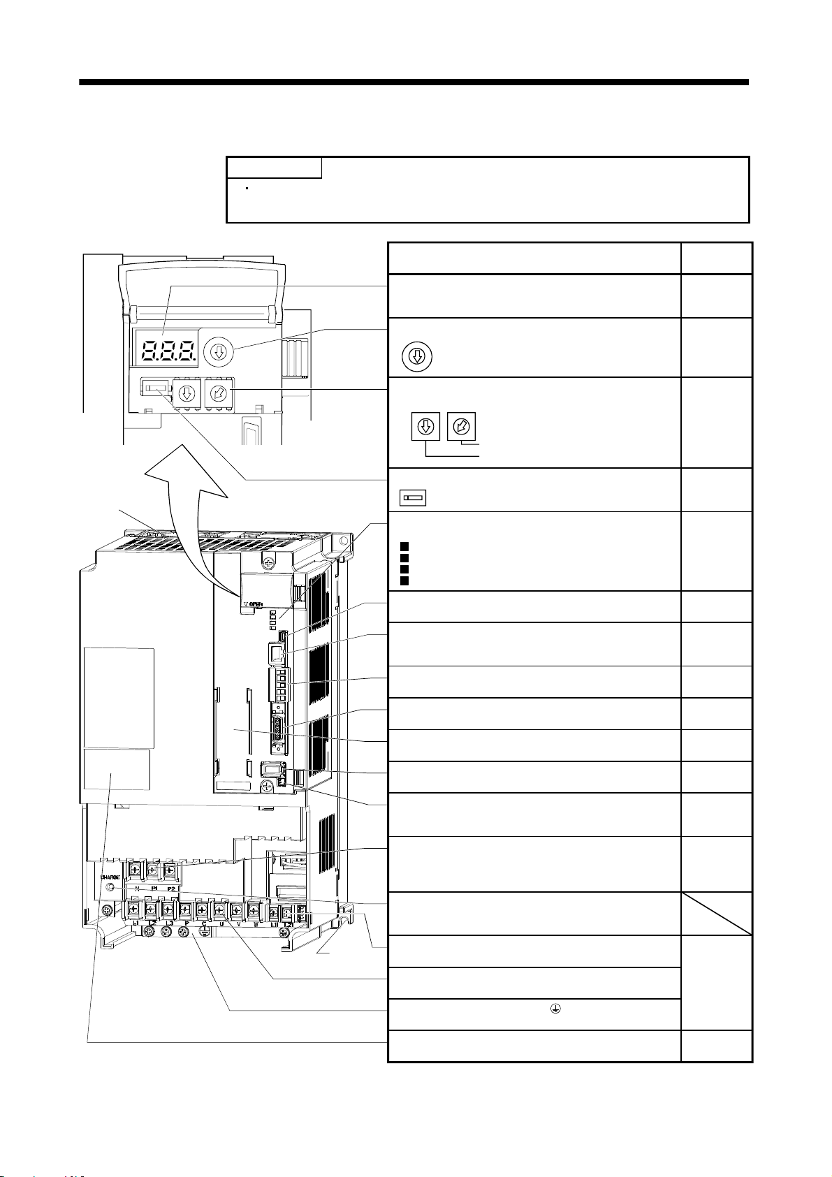
1. FUNCTIONS AND CONFIGURATION
(5) MR-J3-700T(4)
POINT
The servo amplifier is shown without the front cover. For removal of the front
cover, refer to section 1.6.2.
Cooling fan
Name/Application
Display
The 3-digit, seven-segment LED shows the servo
status and alarm number.
Baud rate switch (MODE)
5
6
4
7
3
8
2
9
1
0
5
5
6
6
4
4
7
3
2
1
7
3
8
8
2
9
9
1
0
0
MODE
5
6
4
7
3
Select the CC-Link communication baud rate.
8
2
9
1
0
Station number switches (STATION NO.)
Set the station number of the servo amplifier.
X10 STATION NO. X1
3
5
5
6
6
4
4
2
1
7
7
3
8
8
2
9
9
1
0
0
Detailed
explanation
Section 5.3
Chapter 11
Section 3.2.4
Section 3.2.3
Set the one place.
Set the ten place.
Occupied station count switch (SW1)
SW1
Set the number of occupied stations.
Section 3.2.5
Communication alarm display section
Indicates alarms in CC-Link communication.
L.RUN
SD
RD
L.ERR
USB communication connector (CN5)
Used to connect the personal computer.
RS-422 communication connector (CN3)
Used to connect the MR-PRU03 parameter unit or
personal computer.
CC-Link connector (CN1)
Wire the CC-Link cable.
I/O signal connector (CN6)
Used to connect digital I/O signals.
Battery holder
Contains the battery for absolute position data backup.
Encoder connector (CN2)
Used to connect the servo motor encoder.
Battery connector (CN4)
Used to connect the battery for absolute position data
backup.
DC reactor terminal block (TE3)
Used to connect the DC reactor.
Section 11.3
Chapter 7
Chapter 7
Chapter 8
Chapter 15
Section 3.2.2
Section 4.2
Section 4.4
Section 5.8
Section 4.10
Section 14.1
Section 5.8
Section 14.7
Section 4.1
Section 4.3
Section 12.1
Section 14.11
Charge lamp
Lit to indicate that the main circuit is charged. While
this lamp is lit, do not reconnect the cables.
Fixed part
(4 places)
Control circuit terminal block (TE2)
Used to connect the control circuit power supply.
Main circuit terminal block (TE1)
Used to connect the input power supply and servo motor.
Section 4.1
Section 4.3
Section 12.1
Protective earth (PE) terminal ( )
Ground terminal.
Rating plate
Section 1.4
1 - 21
Page 43

1. FUNCTIONS AND CONFIGURATION
(6) MR-J3-11KT(4) to MR-J3-22KT(4)
POINT
The servo amplifier is shown without the front cover. For removal of the front
cover, refer to section 1.6.2.
Fixed part
(4 places)
Name/Application
Display
The 3-digit, seven-segment LED shows the servo
status and alarm number.
Baud rate switch (MODE)
MODE
5
6
4
7
3
Select the CC-Link communication baud rate.
8
2
9
1
0
5
6
4
7
3
8
2
9
1
0
5
5
6
4
3
2
6
4
7
7
3
8
8
2
9
1
9
1
0
0
Station number switches (STATION NO.)
Set the station number of the servo amplifier.
X10 STATION NO. X1
3
5
5
4
2
1
6
6
4
7
7
3
8
8
2
9
9
1
0
0
Set the one place.
Set the ten place.
Occupied station count switch (SW1)
SW1
Set the number of occupied stations.
Cooling fan
Communication alarm display section
Detailed
explanation
Section 5.3
Chapter 11
Section 3.2.4
Section 3.2.3
Section 3.2.5
Indicates alarms in CC-Link communication.
L.RUN
SD
RD
L.ERR
USB communication connector (CN5)
Used to connect the personal computer.
RS-422 communication connector (CN3)
Used to connect the MR-PRU03 parameter unit or
personal computer.
CC-Link connector (CN1)
Wire the CC-Link cable.
I/O signal connector (CN6)
Used to connect digital I/O signals.
Encoder connector (CN2)
Used to connect the servo motor encoder.
Battery connector (CN4)
Used to connect the battery for absolute position data
backup.
Battery holder
Contains the battery for absolute position data backup.
Section 11.3
Chapter 7
Chapter 7
Chapter 8
Chapter 15
Section 3.2.2
Section 4.2
Section 4.4
Section 4.10
Section 14.1
Section 5.8
Section 14.7
Section 5.8
Charge lamp
Lit to indicate that the main circuit is charged. While
this lamp is lit, do not reconnect the cables.
Rating plate
Protective earth (PE) terminal ( )
Ground terminal.
Section 1.4
Section 4.1
Section 4.3
Section 12.1
Section 14.11
1 - 22
Page 44

1. FUNCTIONS AND CONFIGURATION
1.6.2 Removal and reinstallation of the front cover
Before removing or installing the front cover, turn off the power and wait for 15
minutes or more until the charge lamp turns off. Then, confirm that the voltage
WARNING
(1) For MR-J3-350T4
Removal of the front cover
MR-J3-500T(4) MR-J3-700T(4)
between P(
electric shock may occur. In addition, always confirm from the front of the servo
amplifier whether the charge lamp is off or not.
) and N( ) is safe with a voltage tester and others. Otherwise, an
Hold the ends of lower side of the front cover with
both hands.
a)
a)
Pull up the cover, supporting at point
a)
.
Pull out the front cover to remove.
1 - 23
Page 45
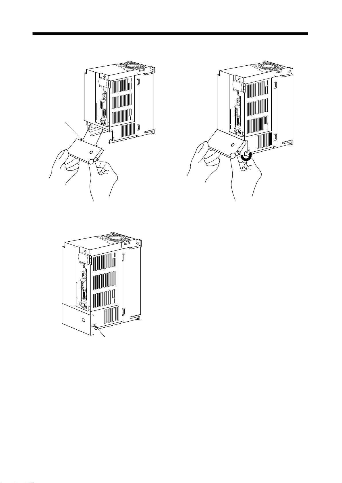
1. FUNCTIONS AND CONFIGURATION
Reinstallation of the front cover
Front cover
setting tab
a)
a)
Insert the front cover setting tabs into the sockets of
servo amplifier (2 places).
Setting tab
Push the setting tabs until they click.
Pull up the cover, supporting at point
a)
.
1 - 24
Page 46

k
1. FUNCTIONS AND CONFIGURATION
(2) For MR-J3-11KT(4) to MR-J3-22KT(4)
Removal of the front cover
c)
b)
a)
1) Press the removing knob on the lower side of the
front cover ( a) and b) ) and release the installation
hook.
2) Press the removing knob of c) and release the
external hook.
Reinstallation of the front cover
d)
c)
b)
a)
3) Pull it to remove the front cover.
(Note 1)
(Note 1)
(Note 2)
1) Fit the front cover installation hooks on the sockets
of body cover ( a) to d) ) to reinstall it.
2) Push the front cover until you hear the clicking
noise of the installation hook.
Note 1. The cooling fan cover can be locked with enclosed screws (M4 40).
2. By drilling approximately
14).
4 of a hole on the front cover, the front cover can be locked on the body with an enclosed screw (M4
1 - 25
Installation hoo
Page 47

1. FUNCTIONS AND CONFIGURATION
1.7 Configuration including auxiliary equipment
POINT
Equipment other than the servo amplifier and servo motor are optional or
recommended products.
(1) MR-J3-100T or less
(a) For 3-phase or 1-phase 200V to 230VAC
R S T
(Note 3)
Power supply
No-fuse breaker
(NFB) or fuse
Magnetic
contactor
(MC)
(Note 2)
Line noise
filter
(FR-BSF01)
MR Configurator
Servo amplifier
CN5
CN3
CN1
Personal
computer
CC-Link
U
L1
L
2
L
3
(Note 2)
Power factor
improving DC
reactor
(FR-BEL)
Note 1. The battery (option) is used for the absolute position detection system in the position control mode.
2. The AC reactor can also be used. In this case, the DC reactor cannot be used. When not using DC reactor, short P
3. A 1-phase 200V to 230VAC power supply may be used with the servo amplifier of MR-J3-70T or less.
For 1-phase 200V to 230VAC, connect the power supply to L
specification.
P
1
P2
PC
Regenerative option
V
W
1 L2 and leave L3 open. Refer to section 1.2 for the power supply
CN6
CN2
CN4
(Note 1)
Battery
MR-J3BAT
I/O signal
Servo motor
1 and P2.
1 - 26
Page 48

1. FUNCTIONS AND CONFIGURATION
(b) For 1-phase 100V to 120VAC
(Note 3)
Power supply
No-fuse breaker
(NFB) or fuse
Magnetic
contactor
(MC)
Power factor
improving DC
reactor
(FR-BEL)
Line noise
filter
(FR-BSF01)
R S
Servo amplifier
(Note 2)
MR Configurator
CN5
CN3
CN1
Personal
computer
CC-Link
U
L
1
L2
PC
Regenerative option
Note 1. The battery (option) is used for the absolute position detection system in the position control mode.
2. The power factor improving DC reactor cannot be used.
3. Refer to section 1.2 for the power supply specification.
V
W
CN6
CN2
CN4
(Note 1)
Battery
MR-J3BAT
I/O signal
Servo motor
1 - 27
Page 49

1. FUNCTIONS AND CONFIGURATION
(2) MR-J3-60T4
(Note 3)
Power supply
No-fuse breaker
(NFB) or fuse
MR-J3-100T4
R S T
MR Configurator
Personal
computer
Magnetic
contactor
(MC)
(Note 2)
Line noise
filter
(FR-BSF01)
(Note 2)
Power factor
improving DC
reactor
(FR-BEL-H)
Servo amplifier
CN5
CC-Link
CN3
CN1
L
1
L
2
L
3
CN6
I/O signal
CN2
P
1
P
2
CN4
(Note 1)
Battery
MR-J3BAT
Servo motor
PC
WVU
Regenerative option
L
11
L21
Note 1. The battery (option) is used for the absolute position detection system in the position control mode.
2. The AC reactor can also be used. In this case, the DC reactor cannot be used. When not using DC reactor, short P
3. Refer to section 1.2 for the power supply specification.
1 - 28
1 and P2.
Page 50

1. FUNCTIONS AND CONFIGURATION
(3) MR-J3-200T(4)
R S T
(Note 3)
Power supply
No-fuse breaker
(NFB) or fuse
Magnetic
contactor
(MC)
Line noise filter
(FR-BSF01)
(Note 2)
Power factor
improving
DC reactor
(FR-BEL/
FR-BEL-H)
L
L22
P
P
11
L1
L
L3
1
2
(Note 2)
2
Regenerative
option
MR Configurator
Servo amplifier
CN5
(Note 4)
P
C
CN3
CN1
CN6
CN2
CN4
Personal
computer
CC-Link
I/O signal
(Note 1)
Battery
MR-J3BAT
UVW
Servo motor
Note 1. The battery (option) is used for the absolute position detection system in the position control mode.
2. The AC reactor can also be used. In this case, the DC reactor cannot be used. When not using DC reactor, short P
3. Refer to section 1.2 for the power supply specification.
4. Connectors (CNP1, CNP2, and CNP3) and appearance of MR-J3-200T servo amplifier have been changed from January 2008
production. Model name of the existing servo amplifier is changed to MR-J3-200T-RT. For MR-J3-200T-RT, refer to appendix 5.
1 - 29
1 and P2.
Page 51

1. FUNCTIONS AND CONFIGURATION
(4) MR-J3-350T
(Note 3)
Power supply
No-fuse breaker
(NFB) or fuse
Magnetic
contactor
(MC)
R S T
(Note 2)
MR Configurator
Personal
computer
Line noise filter
(FR-BLF)
(Note 2)
Power factor
improving DC
reactor(FR-BEL)
L
11
L
21
L1
L
2
L
3
P
1
P
2
Regenerative option
Servo amplifier
CN5
CN3
CC-Link
CN1
P
C
CN6
I/O signal
CN2
CN4
(Note 1)
Battery
MR-J3BAT
UV
W
U
Note 1. The battery (option) is used for the absolute position detection system in the position control mode.
2. The AC reactor can also be used. In this case, the DC reactor cannot be used. When not using DC reactor, short P
3. Refer to section 1.2 for the power supply specification.
1 - 30
Servo motor
1 and P2.
Page 52

1. FUNCTIONS AND CONFIGURATION
(5) MR-J3-350T4
MR-J3-500T(4)
(Note 3)
Power supply
No-fuse breaker
(NFB) or fuse
Magnetic
contactor
(MC)
Line noise
filter
(FR-BLF)
R S T
(Note 2)
Servo amplifier
(Note 1)
Battery
MR-J3BAT
CN1
MR Configurator
CN5
CN3
CN6
CN2
CN4
Personal
computer
CC-Link
I/O signal
L
L
21
11
P1
P2
L
3
L
2
L
1
(Note 2)
Power factor
improving DC
reactor
(FR-BEL-(H))
CP
Regenerative option
UVW
Servo motor
Note 1. The battery (option) is used for the absolute position detection system in the position control mode.
2. The AC reactor can also be used. In this case, the DC reactor cannot be used. When not using DC reactor, short P
3. Refer to section 1.2 for the power supply specification.
1 and P2.
1 - 31
Page 53

1. FUNCTIONS AND CONFIGURATION
(6) MR-J3-700T(4)
(Note 3)
Power supply
No-fuse breaker
(NFB) or fuse
Magnetic
contactor
(MC)
Line noise
filter
(FR-BLF)
R S T
(Note 2)
L
(Note 2)
Power factor
improving DC
reactor
(FR-BEL-(H))
Servo amplifier
L
21
11
P2
(Note 1)
Battery
MR-J3BAT
MR Configurator
CN5
CN3
CN6
CN2
CN4
Personal
computer
CC-Link
I/O signal
P
1
L3
L2
L
1
CP
UVW
Regenerative option
Servo motor
Note 1. The battery (option) is used for the absolute position detection system in the position control mode.
2. The AC reactor can also be used. In this case, the DC reactor cannot be used. When not using DC reactor, short P
3. Refer to section 1.2 for the power supply specification.
1 and P2.
1 - 32
Page 54

1. FUNCTIONS AND CONFIGURATION
(7) MR-J3-11KT(4) to MR-J3-22KT(4)
R S T
(Note 3)
Power supply
No-fuse breaker
(NFB) or fuse
L
21
L
11
Magnetic
contactor
(MC)
Line noise
filter
(FR-BLF)
(Note 2)
Servo amplifier
(Note 1)
Battery
MR-J3BAT
MR Configurator
CN5
CN3
Personal
computer
CC-Link
(Note 2)
Power factor
improving DC
reactor
(FR-BEL-(H))
CN6
CN2
CN4
L
3
L2
L1
P
1
P
Regenerative option
CP
UVW
Servo motor
I/O signal
Note 1. The battery (option) is used for the absolute position detection system in the position control mode.
2. The AC reactor can also be used. In this case, the DC reactor cannot be used. When not using DC reactor, short P
3. Refer to section 1.2 for the power supply specification.
1 - 33
1 and P.
Page 55

1. FUNCTIONS AND CONFIGURATION
1.8 Selection of operation method
Using the CC-Link communication functions, this servo enables a wide variety of operation methods. The
operation method changes depending on the input device, parameter and point table setting.
The flow of the operation method that changes depending on the device and parameter setting status is shown
in the chart for your reference.
Servo amplifier
MR-J3-T
MR-J3-T occupied
station count setting
switch SW1
OFF OFF
OFF ON
(Refer to section 3.2.5)
1 station
occupied
Remote input position/speed
specifying system selection
(RY(n+2)A)
OFF
2 stations
occupied
ON
Parameter No.PA30
0
1
2
Remote input-based point
table No. setting auxiliary
function valid
(Refer to section 5.4)
Remote register-based
point table No. setting
auxiliary function invalid
Remote register-based
position data setting/point
table No. (speed) setting
auxiliary function invalid
Remote register-based
position data/speed data
setting auxiliary function
invalid
1 - 34
Page 56

1. FUNCTIONS AND CONFIGURATION
Point table
auxiliary function
0
Absolute value
command
specifying system
Parameter No.PA01
0
1
Parameter No.PA01
0
1
Parameter No.PA01
0
1
Parameter No.PA01
0
1
Incremental value
command
specifying system
Absolute value
command
specifying system
Incremental value
command
specifying system
Absolute value
command
specifying system
Incremental value
command
specifying system
Absolute value
command
specifying system
Incremental value
command
specifying system
auxiliary function
Remote input absolute
value/incremental value
selection (RY(n+2)B)
Remote input absolute
value/incremental value
selection (RY(n+2)B)
Remote input absolute
value/incremental value
selection (RY(n+2)B)
3
Point table
0
1
OFF
ON
OFF
ON
OFF
ON
Reference Main description
Positioning operation is
executed once with
position data handled
as absolute value.
Continuous positioning
1
2
operation is executed with
position data handled as
absolute values.
Positioning operation is
executed once with
position data handled
as incremental value.
Continuous positioning
operation is executed with
position data handled as
incremental values.
Positioning operation is
executed once in
incremental value
Section 3.8.2
Section
5.4.2 (1)
Section 3.8.2
Section
5.4.2 (4)(b)1)
Section 3.8.2
Section
5.4.2 (2)
Section 3.8.2
Section
5.4.2 (4)(b)1)
Section 3.8.2
Section
5.4.2 (1)
command system.
Continuous positioning
operation is executed
in incremental value
command system.
Section 3.8.2
Section
5.2.2 (4)(b)2)
Positioning operation is
executed once with
position data handled
as absolute value.
Positioning operation is
executed once with
position data handled
as incremental value.
Positioning operation is
executed once in
incremental value
command system.
Positioning operation is
executed once with
Section
3.6.3 (1)
Section
3.7.6 (3)
position data handled
as absolute value.
Positioning operation is
executed once with
position data handled
Section
3.6.3 (2)
as incremental value.
Positioning operation is
executed once in
incremental value
command system.
Positioning operation is
executed once with
position data handled
as absolute value.
Positioning operation is
executed once with
position data handled
as incremental value.
Positioning operation is
executed once in
incremental value
command system.
Section 3.6.3(3)
Section 3.8.4
Section 5.4.3(1)
Section
3.6.3 (3)
Section
5.4.3 (2)
Section 3.6.3(3)
Section 3.7.6(2)
Section 5.4.3(3)
Positioning is started by
making the start signal
valid after selection of
the point table with the
remote input. Using the
auxiliary function,
automatic continuous
operation can be
performed with multiple
point tables.
Positioning is started by
making the start signal
valid after selection of
the point table with the
remote register. The
auxiliary function cannot
be used.
Set the position data
directly with the remote
register, and use the
settings of the point table
selected with the remote
register as the servo
motor speed and
acceleration/deceleration
time constants.
Positioning is started by
making the start signal
valid. The auxiliary
function cannot be used.
Set the position data and
servo motor speed
directly with the remote
register.
Use the settings of the
point table No.1 as the
acceleration/deceleration
time constants.
Positioning is started by
making the start signal
valid. The auxiliary
function cannot be used.
1 - 35
Page 57

1. FUNCTIONS AND CONFIGURATION
MEMO
1 - 36
Page 58

2. INSTALLATION
2. INSTALLATION
Stacking in excess of the limited number of products is not allowed.
Install the equipment on incombustible material. Installing them directly or close to
combustibles will lead to a fire.
Install the equipment in a load-bearing place in accordance with this Instruction
Manual.
Do not get on or put heavy load on the equipment to prevent injury.
Use the equipment within the specified environmental condition range. (For the
environmental conditions, refer to section 1.2.)
Provide an adequate protection to prevent screws, metallic detritus and other
CAUTION
2.1 Installation direction and clearances
conductive matter or oil and other combustible matter from entering the servo
amplifier.
Do not block the intake/exhaust ports of the servo amplifier. Otherwise, a fault may
occur.
Do not subject the servo amplifier to drop impact or shock loads as they are
precision equipment.
Do not install or operate a faulty servo amplifier.
When the product has been stored for an extended period of time, consult
Mitsubishi.
When treating the servo amplifier, be careful about the edged parts such as the
corners of the servo amplifier.
The equipment must be installed in the specified direction. Otherwise, a fault may
occur.
CAUTION
Leave specified clearances between the servo amplifier and control box inside
walls or other equipment.
(1) 7kW or less
(a) Installation of one servo amplifier
Control box
40mm
or more
Servo amplifier
10mm
or more
40mm
or more
10mm
or more
Control box
Wiring allowance
80mm
or more
Top
Bottom
2 - 1
Page 59

2. INSTALLATION
(b) Installation of two or more servo amplifiers
POINT
Close mounting is available for the servo amplifier of under 3.5kW for 200V
class and 400W for 100V class.
Leave a large clearance between the top of the servo amplifier and the internal surface of the control
box, and install a cooling fan to prevent the internal temperature of the control box from exceeding the
environmental conditions.
When installing the servo amplifiers closely, leave a clearance of 1mm between the adjacent servo
amplifiers in consideration of mounting tolerances.
In this case, bring the ambient temperature within 0 to 45
(32 to 113
), or use it at 75% or a smaller
effective load ratio.
Control box
Control box
100mm
or more
30mm
or more
40mm or more
Leaving clearance
10mm
or more
(2) 11k to 22kW
(a) Installation of one servo amplifier
10mm
or more
30mm
or more
Control box
40mm or more
Servo amplifier
30mm
or more
10mm
or more
40mm or more
Mounting closely
Control box
Wiring allowance
80mm
100mm
or more
1mm 1mm
Top
30mm
or more
Bottom
Top
120mm
or more
Bottom
2 - 2
Page 60

2. INSTALLATION
(b) Installation of two or more servo amplifiers
Leave a large clearance between the top of the servo amplifier and the internal surface of the control
box, and install a cooling fan to prevent the internal temperature of the control box from exceeding the
environmental conditions.
Control box
100mm
or more
10mm or more
Top
30mm
or more
120mm or more
30mm
or more
Bottom
(3) Others
When using heat generating equipment such as the regenerative option, install them with full consideration
of heat generation so that the servo amplifier is not affected.
Install the servo amplifier on a perpendicular wall in the correct vertical direction.
2.2 Keep out foreign materials
(1) When installing the unit in a control box, prevent drill chips and wire fragments from entering the servo
amplifier.
(2) Prevent oil, water, metallic dust, etc. from entering the servo amplifier through openings in the control box
or a cooling fan installed on the ceiling.
(3) When installing the control box in a place where there are much toxic gas, dirt and dust, conduct an air
purge (force clean air into the control box from outside to make the internal pressure higher than the
external pressure) to prevent such materials from entering the control box.
2.3 Cable stress
(1) The way of clamping the cable must be fully examined so that flexing stress and cable's own weight stress
are not applied to the cable connection.
(2) For use in any application where the servo motor moves, fix the cables (encoder, power supply, brake) with
having some slack from the connector connection part of the servo motor to avoid putting stress on the
connector connection part. Use the optional encoder cable within the flexing life range. Use the power
supply and brake wiring cables within the flexing life of the cables.
(3) Avoid any probability that the cable sheath might be cut by sharp chips, rubbed by a machine corner or
stamped by workers or vehicles.
(4) For installation on a machine where the servo motor will move, the flexing radius should be made as large
as possible. Refer to section 10.4 for the flexing life.
2 - 3
Page 61

2. INSTALLATION
2.4 Inspection items
Before starting maintenance and/or inspection, turn off the power and wait for 15
minutes or more until the charge lamp turns off. Then, confirm that the voltage
between P(
) and N( ) is safe with a voltage tester and others. Otherwise, an
electric shock may occur. In addition, always confirm from the front of the servo
WARNING
amplifier whether the charge lamp is off or not.
Any person who is involved in inspection should be fully competent to do the work.
Otherwise, you may get an electric shock. For repair and parts replacement,
contact your safes representative.
POINT
Do not test the servo amplifier with a megger (measure insulation resistance),
or it may become faulty.
Do not disassemble and/or repair the equipment on customer side.
It is recommended to make the following checks periodically.
(1) Check for loose terminal block screws. Retighten any loose screws.
(2) Check the cables and the like for scratches and cracks. Perform periodic inspection according to operating
conditions.
2.5 Parts having service lives
The following parts must be changed periodically as listed below. If any part is found faulty, it must be changed
immediately even when it has not yet reached the end of its life, which depends on the operating method and
environmental conditions. For parts replacement, please contact your sales representative.
Part name Life guideline
Smoothing capacitor 10 years
Number of power-on and number of emergency stop
times : 100,000 times
Servo amplifier
Relay
Cooling fan 10,000 to 30,000hours (2 to 3 years)
Absolute position battery Refer to section 5.8
(1) Smoothing capacitor
Affected by ripple currents, etc. and deteriorates in characteristic. The life of the capacitor greatly depends
on ambient temperature and operating conditions. The capacitor will reach the end of its life in 10 years of
continuous operation in normal air-conditioned environment.
(2) Relays
Their contacts will wear due to switching currents and contact faults occur. Relays reach the end of their life
when the cumulative number of power-on and emergency stop times is 100,000, which depends on the
power supply capacity.
(3) Servo amplifier cooling fan
The cooling fan bearings reach the end of their life in 10,000 to 30,000 hours. Normally, therefore, the
cooling fan must be changed in a few years of continuous operation as a guideline.
It must also be changed if unusual noise or vibration is found during inspection.
2 - 4
Page 62

3. CC-LINK COMMUNICATION FUNCTIONS
3. CC-LINK COMMUNICATION FUNCTIONS
3.1 Communication specifications
POINT
This servo is equivalent to a remote device station.
For details of the programmable controller side specifications, refer to the CC-Link system master unit manual.
Item Specifications
Power supply 5VDC supplied from servo amplifier
Applicable CC-Link version Ver.1.10
Communication speed 10M/5M/2.5M/625k/156kbps
Communication system Broadcast polling system
Synchronization system Frame synchronization system
Encoding system MRZI
Transmission path format Bus format (conforming to EIA RS485)
Error control system CRC (X16+X12+X5+1)
CC-Link
Connection cable CC-Link Ver.1.10-compliant cable (Shielded 3-core twisted pair cable)
Transmission format Conforming to HDLC
Remote station number 1 to 64
(Note)
Cable
length
Number of servo amplifiers connected
Note. If the system comprises of both CC-Link Ver.1.00- and Ver.1.10-compliant cables, Ver.1.00 specifications are applied to the
overall cable length and the cable length between stations. For more information, refer to the CC-Link system master/local unit
user's manual.
Communication speed 156Kbps 625Kbps 2.5Mbps 5Mbps 10Mbps
Maximum overall cable length 1200m 900m 400m 160m 100m
Inter-station cable length 0.2m or more
Max. 42 (when 1 station is occupied by 1 servo amplifier), (max. 32 when 2
stations are occupied by 1 servo amplifier), when there are only remote
device stations. Can be used with other equipment.
3 - 1
Page 63

3. CC-LINK COMMUNICATION FUNCTIONS
3.2 System configuration
3.2.1 Configuration example
(1) Programmable controller side
Fit "Type QJ61BT11N", "Type A1SJ61BT11" or "Type A1SJ61QBT11" "Control & Communication Link
system master/local module" to the main or extension base unit which is loaded with the programmable
controller CPU used as the master station.
(2) Wiring
Connect the programmable controller CC-Link unit master station and the servo amplifier by a twisted pair
cable (3-wire type).
Programmable controller
CC-Link unit
CC-Link Ver.1.10-compliant cable
3 - 2
Page 64

(
r
3. CC-LINK COMMUNICATION FUNCTIONS
3.2.2 Wiring method
(1) Communication connector
The pin layout of the communication connector CN10 on the servo amplifier unit is shown below.
Servo amplifier
CN1
CN1
DA DGDB SLD FG
(2) Connection example
The servo amplifier and programmable controller CC-Link master unit are wired as shown below. Refer to
section 14.9 (3) for the CC-Link Ver.1.10-compliant cable used for connection.
Programmable controller
CC-Link master unit
Servo amplifier
CN1
FG
SLD
DG
DB
DA
FG
SLD
DG
DB
DA
(3) Example of connecting multiple servo units
As the remote I/O stations of CC-Link, servo amplifiers share the link system and can be
controlled/monitored using programmable controller user programs.
Programmable controller
CC-Link master unit
Termination register
FG
SLD
DG
DB
DA
MR-J3- T option unit
CC-Link connector (CN1)
FG
DA DGDB SLD
MR-J3- T option unit
CC-Link connector (CN1)
FG
SLD
(Note 1)
Termination registe
DA DGDB
Note 2) CC-Link Ver.1.10-compliant cable
Note 1. Use the termination resistor supplied with the programmable controller. The resistance of the termination resistor depends on
the cable used. For details, refer to the open field network CC-Link catalog (L(NA)74108143).
2. Refer to (4) in this section.
3 - 3
Page 65

3. CC-LINK COMMUNICATION FUNCTIONS
(4) How to wire the CC-Link connector (CN1)
(a) Strip the sheath of the cable and separate the internal wires and braided shield.
(b) Strip the sheaths of the braided shield and internal wires and twist the cores.
Braided shield
3-core twisted pair cable
Approx. 10mm
(c) Match and twist the wires and braided shield of the cable connected to the preceding axis or
programmable controller and the corresponding wires and braided shield of the cable connected to the
subsequent axis.
(d) For the last axis, work the termination resistor supplied to the CC-Link master unit as shown below.
Termination register
(10mm) (10mm)
Cut
Cut
Remove sheath
Remove sheath
Fold lead wire
(e) Insert the core of the cable into the opening and tighten it with a flat-blade screwdriver so that it will not
come off. (Tightening torque: 0.5 to 0.6N
m) When inserting the wire into the opening, make sure that
the terminal screw is fully loose.
To the preceding station or
programmable controller
To the next
station
Flat blade screwdriver
Tip thickness 0.4 to 0.6mm
Full wide 2.5 to 3.5mm
Loosen
Tighten
CC-Link connector (CN1)
POINT
Do not solder the cores as it may cause a contact fault.
Use of a flat-blade torque screwdriver is recommended to manage the screw tightening torque. The
following table indicates the recommended products of the torque screwdriver for tightening torque
management and the flat-blade bit for torque screwdriver. When managing torque with a Phillips bit, please
consult us.
Product Model Manufacturer/Representative
Torque screwdriver N6L TDK Nakamura Seisakusho
Bit for torque screwdriver B-30, flat-blade, H3.5 X 73L Shiro Sangyo
3 - 4
Page 66

3. CC-LINK COMMUNICATION FUNCTIONS
3.2.3 Station number setting
POINT
Be sure to set the station numbers within the range of 1 to 64. Do not set the
other values.
(1) How to number the stations
Set the servo station numbers before powering on the servo amplifiers. Note the following points when
setting the station numbers.
(a) Station numbers may be set within the range 1 to 64.
(b) One servo amplifier occupies 1 or 2 stations. (One station of programmable controller remote device
station)
(c) Max. number of connected units: 42
Note that the following conditions must be satisfied.
{(1
a) (2 b) (3 c) (4 d)} 64
a: Number of 1-station occupying units
b: Number of 2-station occupying units
c: Number of 3-station occupying units (not available for MR-J3-T)
d: Number of 4-station occupying units (not available for MR-J3-T)
{(16
A) (54 B) (88 C)} 2304
A: Number of remote I/O stations
B: Number of remote device stations
C: Number of local stations
64
42
26
(d) When the number of units connected is 4, station numbers can be set as shown below.
Servo amplifier No.2
(When 2 stations are
occupied)
Remote device station
Servo amplifier No.3
(When 2 stations are
occupied)
Remote device station
CC-Link
master unit
Programmable controller
remote I/O station
(1 station occupied)
Servo amplifier No.1
(When 2 stations are
occupied)
Remote device station
Station No.1
Station No.2
Station No.4
Number of connected units is 4.
Station No.6
(2) Station number setting method
Set the station number with the station number switches (STATION NO.) on the servo amplifier front. The
station number that may be set is any of 1 to 64 in decimal. In the initial status, the station number is set to
station 1.
Servo amplifier
X10 STATION No. X1
5
6
4
3
2
7
8
9
1
0
5
6
4
3
2
7
8
9
1
0
Set the units. (initial value: 1)
Set the tens. (initial value: 0)
3 - 5
Page 67

3. CC-LINK COMMUNICATION FUNCTIONS
3.2.4 Communication baud rate setting
Set the transfer baud rate of CC-Link with the transfer baud rate switch (MODE) on the servo amplifier front.
The initial value is set to 156kbps.
The overall distance of the system changes with the transfer speed setting. For details, refer to the CC-Link
system master/local unit user's manual.
Servo amplifier
505
MODE
5
6
4
5
0
0
3
7
2
8
9
1
0
No.
0 (initial value)
1
2
3
4
5 to 9
Baud rate
156kbps
625kbps
2.5Mbps
5Mbps
10Mbps
Not used
3.2.5 Occupied station count setting
Set the number of occupied stations with the occupied station count switch (SW1) on the servo amplifier front.
The usable I/O device and the number of connectable units change with the set number of occupied stations.
Refer to section 3.2.3. In the initial status, the number of stations occupied is set to 1.
Servo amplifier
SW1 setting Number of occupied stations
1 station occupied
2 station occupied
(Note)
505
5
0
0
Initial value
Note.
SW1
This switch hidden under the cover is for manufacturer setting.
Do not change this setting by any means.
3 - 6
Page 68

3. CC-LINK COMMUNICATION FUNCTIONS
3.3 Functions
3.3.1 Function block diagram
This section explains the transfer of I/O data to/from the servo amplifier in CC-Link, using function blocks.
(1) Between the master station and servo amplifier in the CC-Link system, link refresh is normally performed at
intervals of 3.5 to 18ms (512 points). The link scan time of link refresh changes with the communication
speed. For details, refer to the CC-Link system master/local unit user's manual.
(2) The I/O refresh and master station sequence program are executed asynchronously. Some programmable
controllers allow link scans to be synchronized with programmable controller scans.
(3) The FROM instruction from the buffer memory of the CC-Link system master/local unit is used to read data
from the servo amplifier, and the TO instruction is used to write data. Some programmable controllers allow
automatic refresh to be set to omit the FROM and TO instructions.
Programmable controller
CC-Link unit
Servo amplifier
CC-Link interface
3) CC-Link
Ver.1.10compliant
cable
Input
Output
CC-Link interface
Servo amplifier CPU
1) QJ61B11N
I/O signal
CPU
2) Buffer memory access
Programmable controller
Interface with
programmable controller
CPU
Buffer
memory
3.3.2 Functions
The following table lists the functions that may be performed from the programmable controller in the CC-Link
system in the CC-Link operation mode or test operation mode.
Item
Monitor
Operation
Parameter write
Parameter read
Point table data write
Point table data read
CC-Link operation mode Test operation mode
Operation mode
3 - 7
Page 69

3. CC-LINK COMMUNICATION FUNCTIONS
3.4 Servo amplifier setting
(1) Servo amplifier side operation modes
This servo amplifier has the following operation modes.
Operation mode Description
Test operation mode
CC-Link operation mode
Parameter unit or personal computer in which MR Configurator is installed is used to run the
servo motor.
CC-Link communication functions are used to operate the servo with the programmable
controller programs.
(2) Operation mode changing
(a) Operation mode changing conditions
Change the operation mode after making sure that.
1) The servo motor is at a stop.
2) The forward rotation start (RYn1) or reverse rotation start (RYn2) is OFF.
(b) Operation mode changing method
When changing from test operation to CC-Link operation, deselect test operation by switching power
OFF/ON.
Test operation mode is selected using a parameter unit
or a personal computer in which MR Configurator is
installed.
CC-Link
operation mode
Deselect test operation mode by switching power
OFF/ON.
Test operation mode
3 - 8
Page 70

3. CC-LINK COMMUNICATION FUNCTIONS
3.5 I/O signals (I/O devices) transferred to/from the programmable controller CPU
3.5.1 I/O signals (I/O devices)
The input signals (input devices) may be used as either the CC-Link or CN6 external input signals. Make
selection in parameter No.PD06 to PD11, PD12 and PD14. The output signals (output devices) can be used as
both the CC-Link
CN6 external output signals.
POINT
In the factory-shipped status, the forward rotation stroke end (LSP), reverse
rotation stroke end (LSN) and proximity dog (DOG) are valid as the CN6
external input signals.
(1) When 1 station is occupied
RYn/RXn: 32 points each, RWrn/RWwn: 4 points each
Programmable controller Servo amplifier (RYn) Servo amplifier Programmable controller (RXn)
(Note)
Device No.
RYn0 Servo-on SON RXn0 Ready RD 14
RYn1 Forward rotation start ST1 RXn1 In position INP
RYn2 Reverse rotation start ST2 RXn2 Rough match CPO
RYn3 Proximity dog DOG 2 RXn3 Home position return completion ZP 16
RYn4 Forward rotation stroke end LSP 3 RXn4 Limiting torque TLC
RYn5 Reverse rotation stroke end LSN 4 RXn5 Reserved
RYn6 Automatic/manual selection MDO RXn6 Electromagnetic brake interlock MBR
RYn7 Temporary stop/Restart TSTP RXn7 Temporary stop PUS
RYn8 Monitor output execution demand MOR RXn8 Monitoring MOF
RYn9 Instruction code execution demand COR
RYnA Point table No. selection 1 DI0
RYnB Point table No. selection 2 DI1 RXnA Warning WNG
RYnC Point table No. selection 3 DI2 RXnB Battery warning BWNG
RYnD Point table No. selection 4 DI3 RXnC Movement completion MEND
RYnE Point table No. selection 5 DI4 RXnD Dynamic brake interlock DB
RYnF Clear CR RXnE Position range output POT
RY(n 1)0 RXnF Reserved
to Reserved RX(n 1)1
RY(n 1)9
RY(n 1)A Reset RES RX(n 1)9
RY(n 1)B RX(n 1)A Trouble ALM 15
to Reserved
RY(n 1)F
RX(n 1)C
to Reserved
RX(n 1)F
Signal name
Signal
abbreviation
CN6
connector
pin No.
(Note)
Device No.
RXn9
to Reserved
RX(n
Instruction code execution
completion
Remote station communication
1)B
ready
Signal name
Signal
abbreviation
COF
CRD
CN6
connector
pin No.
Programmable controller Servo amplifier (RWwn) Servo amplifier Programmable controller (RWrn)
Address No. Signal name Address No. Signal name
RWwn Monitor 1 RWrn Monitor 1 data
RWwn 1 Monitor 2 RWrn 1 Monitor 2 data
RWwn 2 Instruction code RWrn 2 Respond code
RWwn 3 Writing data RWrn 3 Reading data
Note. "n" depends on the station number setting.
3 - 9
Page 71

3. CC-LINK COMMUNICATION FUNCTIONS
(2) When 2 stations are occupied
RXn/RYn: 64 points each, RWrn/RWwn: 8 points each
Programmable controller Servo amplifier (RYn) Servo amplifier Programmable controller (RXn)
(Note 1)
Device No.
RYn0 Servo-on SON RXn0 Ready RD 14
RYn1 Forward rotation start ST1 RXn1 In position INP
RYn2 Reverse rotation start ST2 RXn2 Rough match CPO
RYn3 Proximity dog DOG 2 RXn3 Home position return completion ZP 16
RYn4 Forward rotation stroke end LSP 3 RXn4 Limiting torque TLC
RYn5 Reverse rotation stroke end LSN 4 RXn5 Reserved
RYn6 Automatic/manual selection MDO RXn6 Electromagnetic brake interlock MBR
RYn7 Temporary stop/Restart TSTP RXn7 Temporary stop PUS
RYn8 Monitor output execution demand MOR RXn8 Monitoring MOF
RYn9
RYnA Point table No. selection 1 DI0 RXnA Warning WNG
RYnB Point table No. selection 2 DI1 RXnB Battery warning BWNG
RYnC Point table No. selection 3 DI2 RXnC Movement completion MEND
RYnD Point table No. selection 4 DI3 RXnD Dynamic brake interlock DB
RYnE Point table No. selection 5 DI4 RXnE Position range output POT
RYnF Clear CR RXnF
RY(n 1)0 to Reserved
RY(n 1)F
RY(n 2)0
RY(n 2)1
RY(n 2)2 Reserved RX(n 2)3 Point table No. output 2 PT1
RY(n 2)3 Point table No. selection 6 DI5 RX(n 2)4 Point table No. output 3 PT2
RY(n 2)4 Point table No. selection 7 DI6 RX(n 2)5 Point table No. output 4 PT3
RY(n 2)5 Point table No. selection 8 DI7 RX(n 2)6 Point table No. output 5 PT4
RY(n 2)6 Internal torque limit selection TL1 RX(n 2)7 Point table No. output 6 PT5
RY(n 2)7 Proportion control PC RX(n 2)8 Point table No. output 7 PT6
RY(n 2)8 Gain changing CDP RX(n 2)9 Point table No. output 8 PT7
RY(n 2)9 Reserved RX(n 2)A
RY(n 2)A
RY(n 2)B
RY(n 2)C RX(n 3)9
RY(n 2)F
RY(n 3)0
RY(n 3)9
RY(n 3)A Reset RES RX(n 3)F
RY(n 3)B
RY(n 3)F
Instruction code execution
demand
to Reserved RX(n 1)F
Position instruction execution
demand (Note)
Speed instruction execution
demand (Note)
Position/speed specifying system
selection
Absolute value/incremental value
selection
to Reserved RX(n 3)A Trouble ALM 15
to Reserved RX(n 3)C
to Reserved
Signal name
Signal
abbreviation
COR RXn9
CN6
connector
pin No.
(Note 1)
Device No.
Instruction code execution
completion
RX(n 2)0
RX(n 2)1
RX(n 2)2 Point table No. output 1 PT0
RX(n 2)F
RX(n 3)0
RX(n
Position instruction execution
completion
Speed instruction execution
completion
to Reserved
to Reserved
Remote station communication
3)B
ready
to Reserved
Signal name
Signal
abbreviation
COF
CRD
Note. "n" depends on the station number setting.
CN6
connector
pin No.
3 - 10
Page 72

3. CC-LINK COMMUNICATION FUNCTIONS
Programmable controller Servo amplifier (RWwn) Servo amplifier Programmable controller (RWrn)
(Note 1)
Address No.
RWwn (Note 2) Monitor 1 RWrn Monitor 1 data lower 16 bit
RWwn 1 (Note 2) Monitor 2 RWwn 1 Monitor 1 data upper 16 bit
RWwn 2 Instruction code RWwn 2 Respond code
RWwn 3 Writing data RW wn 3 Reading data
RWwn 4 (Note 3) Position command data lower 16 bit/Point table No. RWwn 4
RWwn 5 Position command data upper 16 bit RWwn 5 Monitor 2 data lower 16 bit
RWwn 6 (Note 4) Speed command data/Point table No. RWwn 6 Monitor 2 data upper 16 bit
RWwn 7 Reserved RW wn 7 Reserved
Signal name
(Note 1)
Address No.
Note 1. "n" depends on the station number setting.
2. Specify the code of the lower 16 bit as the monitor code of 32-bit data.
3. When the parameter No.PC30 setting is "
setting is "
demand (RY(n
1" or " 2", specify the position data in RWwn 4/RWwn 5 and turn ON Position instruction execution
2)0).
4. When the parameter No.PC30 setting is "
setting is "
2", specify the speed data in RWwn 6, and turn ON Speed instruction execution demand (RY(n 2)1). When
setting the parameter No.PC30 to "
When the parameter No.PC30 setting is "
0", specify the point table No. in RWwn 4. When the parameter No.PC30
1", specify the point table No. in RWwn 6. When the parameter No.PC30
2", always set the acceleration/deceleration time constant in the point table No.1.
0", the RWwn 6 value is not used.
Signal name
3 - 11
Page 73

3. CC-LINK COMMUNICATION FUNCTIONS
3.5.2 Detailed explanation of I/O signals
(1) Input signals (Input devices)
The note signs in the remarks column indicates the following descriptions.
1: Can be used as external input signals of CN6 connector by setting parameters No.PD06 to PD08 and
parameter No.PD12 PD14.
2: Can be automatic turned ON internally by setting parameters No.PD01 PD04.
The device whose Device No. field has an oblique line cannot be used in CC-Link.
Signal name
(Device name)
Servo-on Turning RYn0 ON powers on the base circuit, making
operation ready to start. (Servo on status)
Turning it OFF powers off the base circuit, coasting the servo
motor. (Servo off status)
Forward rotation start 1. In absolute value command system
Turning RYn1 ON for automatic operation executes
positioning once on the basis of the position data set to the
point table.
Turning RYn1 ON for a home position return immediately
starts a home position return.
Keeping RYn1 ON for JOG operation performs rotation in
the forward rotation direction.
Forward rotation indicates the address increasing direction.
2. In incremental value command system
Turning RYn1 ON for automatic operation executes
positioning once in the forward rotation direction on the basis
of the position data set to the point table.
Turning RYn1 ON for a home position return immediately
starts a home position return.
Keeping RYn1 ON for JOG operation performs rotation in
the forward rotation direction.
Forward rotation indicates the address increasing direction.
Reverse rotation start Use this device in the incremental value command system.
Turning RYn2 ON for automatic operation executes positioning
once in the reverse rotation direction on the basis of the
position data set to the point table.
Keeping RYn2 ON for JOG operation performs rotation in the
reverse rotation direction.
Reverse rotation indicates the address decreasing direction.
Reverse rotation start (RYn2) is also used as the start signal of
the high-speed automatic positioning function to the home
position.
Description
Device No.
1 station
occupied
RYn0 RYn0
RYn1 RYn1
RYn2 RYn2
2 stations
occupied
Remarks
1
1
1
3 - 12
Page 74

3. CC-LINK COMMUNICATION FUNCTIONS
Signal name Description
Proximity dog In the shipment status, the proximity dog external input signal
(CN6-2) is valid. For use in CC-Link, make it usable in
parameter No.PD14. When RYn3 is turned OFF, the proximity
dog is detected. The polarity of dog detection can be changed
using parameter No.PD16.
Device No.
1 station
occupied
RYn3 RYn3 1
2 stations
occupied
Remarks
Parameter No.PD16
0 (initial value)
1
Forward rotation stroke end RYn4 RYn4
Reverse rotation stroke end
Automatic/manual selection Turning RYn6 ON selects the automatic operation mode, and
Temporary stop/Restart Turning RYn7 ON during automatic operation makes a
In the factory-shipped status, the forward rotation stroke end is
valid as the external input signal (CN6-3) and the reverse
rotation stroke end is valid as the external input signal (CN6-4).
Before operation, short between CN6-3 and DOCOM, and
between CN6-4 and DOCOM. Opening them causes a sudden
stop, resulting in servo lock.
For use in CC-Link, make it usable in parameter No.PD12.
When starting operation, turn RYn4/RYn5 to ON. Turning it to
OFF causes a sudden stop, resulting in servo lock. A stopping
method can be changed in parameter No.PD20.
When not using the forward/reverse rotation stroke end, set
"Automatic ON" in parameter No.PD01.
(Note) Input signal
RYn4 RYn5
1
0
1
0
Note. 0: OFF 1: ON
turning it OFF selects the manual operation mode.
temporary stop.
Turning RYn7 ON again makes a restart.
Forward rotation start (RYn1) or Reverse rotation start (RYn2)
is ignored if it is turned ON during a temporary stop.
When the automatic operation mode is changed to the manual
operation mode during a temporary stop, the movement
remaining distance is erased.
During a home position return or during JOG operation,
Temporary stop/Restart input is ignored.
Proximity dog (RYn3) detection polarity
OFF
ON
Operation
CCW direction
1
1
0
0
CW direction
RYn5 RYn5
RYn6 RYn6 1
RYn7 RYn7
1
2
3 - 13
Page 75

g
3. CC-LINK COMMUNICATION FUNCTIONS
Device No.
Signal name Description
Monitor output execution
demand
When RYn8 is turned ON, the following data and signals are
set. At the same time, RXn8 turns ON. While RYn8 is ON, the
monitor values are kept updated.
1) When 1 station is occupied
Remote register RWrn: Data demanded by Monitor 1
(RWwn)
Remote register RWrn
1: Data demanded by Monitor 2
(RWwn+1)
Remote register RWrn
2: Respond code indicating normal
or error
2) When 2 stations are occupied
Remote register RWrn: Lower 16 bits of data demanded by
Monitor 1 (RWwn)
Remote register RWrn
1: Upper 16 bits of data demanded
by Monitor 1 (RWwn)
Remote register RWrn
5: Lower 16 bits of data demanded
by Monitor 2 (RWwn+2)
Remote register RWrn
6: Upper 16 bits of data demanded
by Monitor 2 (RWwn+2)
Remote register RWrn
2: Respond code indicating normal
or error
Instruction code execution
demand
Turning RYn9 ON executes the processing corresponding to
the instruction code stored in remote register RWwn
2.
After completion of instruction code execution, the respond
code indicating normal or error is set to RWrn
2. At the same
time, RXn9 turns ON.
Refer to section 16.2.4 for details.
Point table No. selection 1 The point table No. and the home position return are selected
by RYnA to RY(n
Point table No. selection 2 RYnB RYnB
Point
Point table No. selection 3 RYnC RYnC
Point table No. selection 4 RYnD RYnD
Point table No. selection 5 RYnE RYnE
table No.
(Note 2)
1
2
3
4
(n+2)5
RY
0
0
0
0
0
2)5.
RY
(n+2)4RY(n+2)3
0
0
0
0
0
0
0
0
0
0
(Note 1) Remote input
RYnCRYnDRYnE
0
0
0
0
0
0
0
0
0
0
0
0
0
0
1
RYnB RYnA
0
0
1
1
0
1 station
occupied
2 stations
occupied
RYn8 RYn8
RYn9 RYn9
RYnA RYnA
0
1
0
1
0
Remarks
1
2
Point table No. selection 6 RY(n 2)3
1
Point table No. selection 7 RY(n 2)4
Point table No. selection 8
254
255
Note 1. 0: OFF 1: ON
2. Home position return is a settin
1 1 1
1
1 1 1
1
Clear When the parameter No.PD22 setting is " 1", the position
1 1 1
1
0
1
1
RY(n 2)5
RYnF RYnF
control counter droop pulses is cleared at the leading edge of
RYnF. The pulse width should be 10ms or more.
When the parameter No.PD22 setting is "
2", the pulses
are always cleared while RYnF is on.
3 - 14
1
2
Page 76

3. CC-LINK COMMUNICATION FUNCTIONS
Signal name Description
Position instruction demand When RY(n 2)0 is turned ON, the point table No. or position
command data set to remote register RWwn
set.
When it is set to the servo amplifier, the respond code
indicating normal or error is set to RWrn
RX(n
2)0 turns ON.
Refer to section 3.6.3 for details.
Speed instruction demand When RY(n 2)1 is turned ON, the point table No. or speed
command data set to remote register RWwn
When it is set to the servo amplifier, the respond code
indicating normal or error is set to RWrn
RX(n
2)1 turns ON.
Refer to section 3.6.3 for details.
Internal torque limit selection Turning RY(n 2)6 OFF makes the torque limit value of
parameter No.PA11 (forward rotation torque limit)
No.PA12 (reverse rotation torque limit) valid, and turning it ON
makes that of parameter No.PC35 (internal torque limit). (Refer
to section 4.6.3)
Proportion control When RY(n 2)7 is turned ON, the speed amplifier is switched
from the proportional integral type to the proportional type.
If the servo motor at a stop is rotated even one pulse by an
external factor, it develops torque in an attempt to compensate
for a position shift. When the shaft is locked mechanically after
Movement completion (RXnC) is turned OFF, for example,
turning Proportion control (RY(n
Movement completion (RXnC) turns OFF allows control of
unnecessary torque developed in an attempt to compensate for
a position shift.
When the shaft is to be locked for an extended period of time,
turn Internal torque limit selection (RY(n
simultaneously with Proportion control (RY(n
torque not more than the rated torque using Internal torque
limit (parameter No.PC35).
Gain changing When RY(n 2)8 is turned ON, the load inertia moment ratio
and the corresponding gain values change to the values of
parameter No.PB29 to PB32. To change the gain using
RY(n
2)8, make the auto tuning invalid.
Position/speed specifying
system selection
Select how to give a position command/speed command.
(Refer to section 3.6.3.)
OFF: Remote input-based position/speed specifying system
Specifying the point table No. with Point table No.
selection (RYnA to RYnE) gives a position
command/speed command.
ON : Remote register-based position/speed specifying system
Setting the instruction code to the remote register
(RWwn
command/speed command.
Set the parameter No.PC30 (direct specification
selection) to "
4 to RWwn 6) gives a position
2)7) ON as soon as
2".
4/RWwn 5 is
2. At the same time,
6 is set.
2. At the same time,
parameter
2)6) ON
2)7) to make the
Device No.
1 station
occupied
2 stations
occupied
RY(n
RY(n
RY(n
RY(n
RY(n+2)8
RY(n
Remarks
2)0
2)1
2)6 1
2)7 1
2
1
2)A
3 - 15
Page 77

3. CC-LINK COMMUNICATION FUNCTIONS
Signal name Description
Absolute value/incremental
value selection
Reset Keeping RY(n 1)A or RY(n 3)A ON for 50ms or longer
Forced stop This device is exclusively used as a CN6 external input signal.
RY(n 2)B is made valid when the remote register-based
position/speed specifying system is selected with
Position/speed specifying system selection (RY(n
the absolute value command system is selected in parameter
No.PD10. Turn RY(n
set position data is in the absolute value command system or
incremental value command system.
OFF: Position data is handled as an absolute value.
ON : Position data is handled as an incremental value.
allows an alarm to be deactivated.
Some alarms cannot be deactivated by Reset RY(n
RY(n
3)A. (Refer to section 11.4.1.)
If RY(n
occurring, the base circuit will not be shut off. When "
is set in parameter No.PD20 (function selection D-1), the base
circuit is shut off.
This device is not designed to make a stop. Do not turn it ON
during operation.
It cannot be used for CC-Link.
Turn EMG off to bring the motor to an forced stop state, in
which the base circuit is shut off and the dynamic brake is
operated.
Turn EMG on in the forced stop state to reset that state.
1)A or RY(n 3)A is turned ON with no alarm
2)B OFF or ON to select whether the
2)A) and
1)A or
1 "
Device No.
1 station
occupied
RY(n
2 stations
occupied
RY(n
1)A RY(n 3)A 1
Remarks
2)B
3 - 16
Page 78

3. CC-LINK COMMUNICATION FUNCTIONS
(2) Output signals (Output device)
POINT
The output devices can be used for both the remote output and the external
output signals of CN6 connector.
The signal whose Device No. field has an oblique line cannot be used in CC-Link.
Device No.
Signal name Description
Ready In the factory-shipped status, a ready is assigned to the CN6-14 pin as an
external output signal. RXn0 turns ON when the servo amplifier is ready to
operate after servo-on.
In position RXn1 turns ON when the droop pulse value is within the preset in-position
range.
The in-position range can be changed using parameter No.PA10.
Increasing the in-position range may result in a continuous conduction
status during low-speed rotation.
RXn1 turns ON at servo-on.
Rough match RXn2 turns ON when the command remaining distance becomes less than
the rough match output range set in the parameter.
RXn2 turns ON at servo-on.
Home position return
completion
Limiting torque RXn4 turns ON when the torque is reached at the time of torque
Electromagnetic brake
interlock
Temporary stop RXn7 turns ON when deceleration is started to make a stop by Temporary
Monitoring Refer to Monitor output execution demand (RYn8). RXn8 RXn8
In the factory-shipped status, the home position return completion is
assigned to the CN6-16 pin as an external output signal. RXn3 turns ON
when a home position return is completed. RXn3 turns ON at completion of
a home position return.
In an absolute position detection system, RXn3 turns ON when operation is
ready to start, but turns OFF in any of the following cases.
1) Servo-on (RYn0) is turned OFF.
2) Forced stop (EMG) is turned OFF.
3) Reset (RY(n
4) Alarm occurs.
5) Forward rotation stroke end (RYn4) or Reverse rotation stroke end
(RYn5) is turned OFF.
6) Home position return has not been made after product purchase.
7) Home position return has not been made after occurrence of Absolute
position erase (A25) or Absolute position counter warning (AE3).
8) Home position return has not been made after electronic gear change.
9) Home position return has not been made after the absolute position
detection system was changed from invalid to valid.
10) Parameter No.PA14 (Rotation direction selection) has been changed.
11) Software limit is valid.
12) While a home position return is being made.
When any of 1) to 12) has not occurred and a home position return is
already completed at least once, Home position return completion (RXn3)
turns to the same output status as Ready (RXn0).
generation.
RXn6 turns OFF at servo-off or alarm occurrence. At alarm occurrence, it
turns OFF independently of the base circuit status.
stop/Restart (RYn7). When Temporary stop/Restart (RYn7) is made valid
again to resume operation, RXn7 turns OFF.
1)A or RY(n 3)A) is turned ON.
1 station
occupied
RXn0 RXn0
RXn1 RXn1
RXn2 RXn2
RXn3 RXn3
RXn4 RXn4
RXn6 RXn6
RXn7 RXn7
2 stations
occupied
3 - 17
Page 79
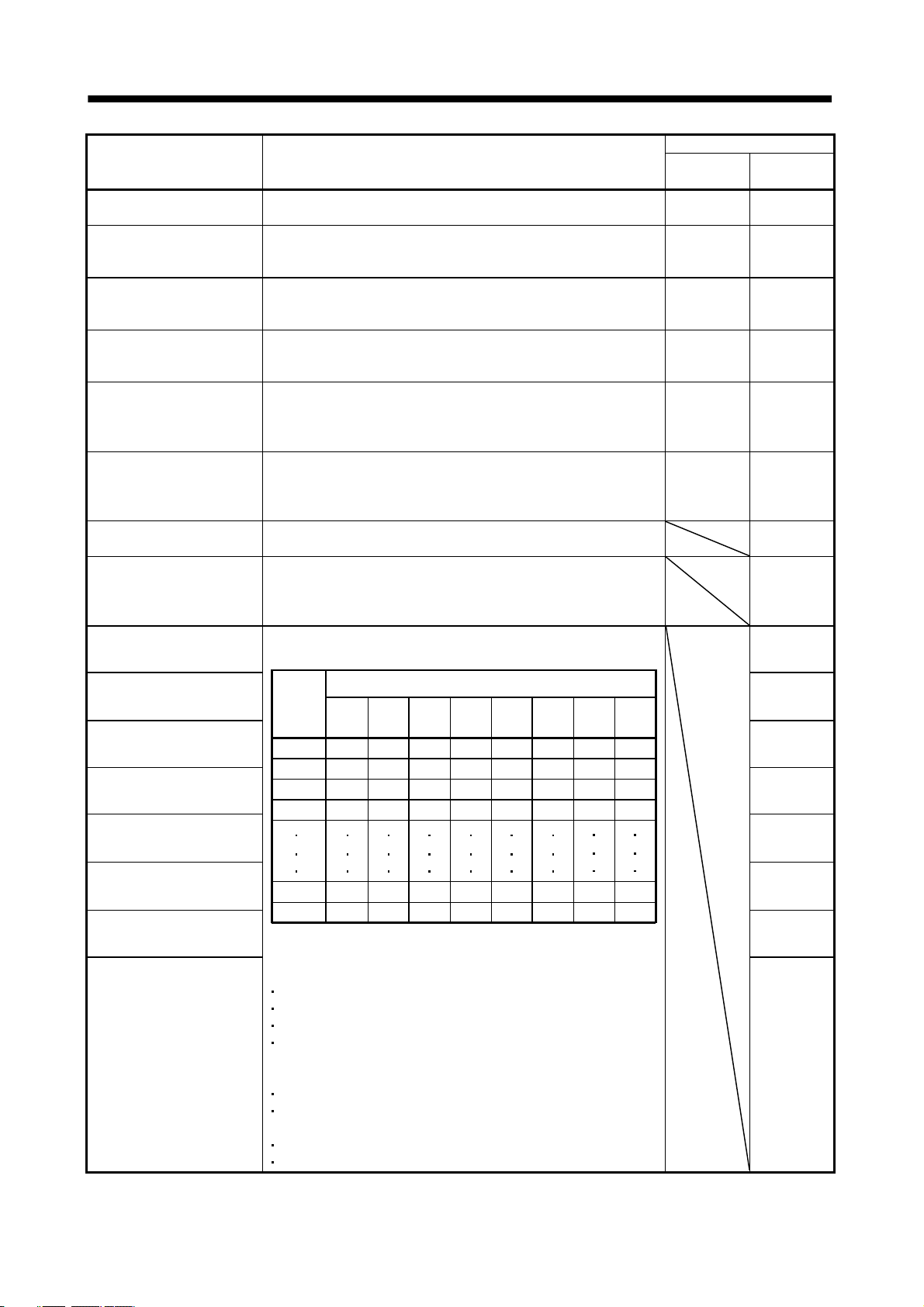
3. CC-LINK COMMUNICATION FUNCTIONS
Device No.
Signal name Description
Instruction code execution
Refer to Instruction code execution demand (RYn9). RXn9 RXn9
completion
Warning RXnA turns ON when a warning occurs.
When no warning has occurred, RXnA turns OFF within about 1s after
power-on.
Battery warning RXnB turns ON when Open battery cable warning (A92) or Battery
warning (A9F) occurs. When no battery warning has occurred, RXnB
turns OFF within about 1s after power-on.
Movement completion RXnC turns ON when In position (RXn1) turns ON and the command
remaining distance is "0".
RXnC turns ON at servo-on.
Dynamic brake interlock RXnD turns off simultaneously when the dynamic brake is operated.
When using the external dynamic brake on the servo amplifier of 11 kW
or more, this device is required. (Refer to section 14.6.) For the servo
amplifier of 7kw or less, it is not necessary to use this device.
Position range RXnE turns ON when the actual current position falls within the range
set in the parameter.
It is OFF when a home position return is not yet completed or while the
base circuit is off.
Position instruction execution
Refer to Speed instruction execution demand (RY(n+2)0). RX(n+2)0
completion
Speed instruction execution
completion
Refer to Position instruction execution demand (RY(n+2)1). This device
is required when using the external dynamic brake with a servo
amplifier of 11kW or more. (Refer to section 14.6.)
This is not required with servo amplifiers of 7kW or less.
Point table No. output 1 RX(n+2)2
As soon as Movement completion (RXnC) turns ON, the point table No.
is output in 8-bit code.
1 station
occupied
2 stations
occupied
RXnA RXnA
RXnB RXnB
RXnC RXnC
RXnD RXnD
RXnE RXnE
RX(n+2)1
Point table No. output 2 RX(n+2)3
Point
table No.
Point table No. output 3 RX(n+2)4
Point table No. output 4 RX(n+2)5
(n+2)9
1
2
3
4
RX
0
0
0
0
RX
(n+2)8RX(n+2)7
0
0
0
0
(Note) Remote output
RX
(n+2)6RX(n+2)5RX(n+2)4RX(n+2)3RX(n+2)2
0
0
0
0
0
0
0
0
0
0
0
0
0
0
1
0
0
1
1
0
1
1
0
0
Point table No. output 5 RX(n+2)6
Point table No. output 6 RX(n+2)7
1
254
Point table No. output 7 RX(n+2)8
Point table No. output 8
255
Note. 0: OFF 1: ON
RX(n+2)2 to RX(n+2)9 turn OFF in any of the following statuses.
1 1 1
1
1 1 1
1
1
1
0
1
1
1
1
RX(n+2)9
Power on
Servo off
During home position return
Home position return completion
In any of the following statuses, RX(n+2)2 to RX(n+2)9 maintain their
pre-change status (ON/OFF).
When operation mode is changed
When Automatic/manual selection (RYn6) is turned from OFF to ON
or from ON to OFF to change the operation mode.
During manual operation
During execution of automatic positioning to home position
3 - 18
Page 80

3. CC-LINK COMMUNICATION FUNCTIONS
Signal name Description
Trouble A trouble is assigned to the CN6-15 pin as an external output signal.
RX(n
1)A or RX(n 3)A turns ON when the protective circuit is
activated to shut off the base circuit.
Remote station
communication ready
When no alarm has occurred, RX(n
about 1.5s after power is switched ON.
This signal turns ON at power-on and turns off at a trouble occurrence
or in the reset (RY(n
1)A or RY(n 3)A) ON status.
1)A or RX(n 3)A turns OFF within
(3) Remote registers
The signal whose Remote Register field has an oblique line cannot be used.
(a) Input (Programmable controller
Remote register
1 station
occupied
RWwn RWwn Monitor 1 Demands the status indication data of the servo amplifier.
RWwn 1 RWwn 1 Monitor 2 Demands the status indication data of the servo amplifier.
2 stations
occupied
Signal name Description Setting range
Servo amplifier)
1) When 1 station is occupied
Setting the monitor code of the status indication item to
be monitored to RWwn and turning RYn8 to ON sets data
to RWrn. RXn8 turns on at the same time.
2) When 2 stations are occupied
Setting the monitor code of the status indication item to
be monitored to RWwn and turning RYn8 to ON sets data
to RWrn. RXn8 turns on at the same time.
When demanding 32-bit data, specifying the lower 16-bit
code No. and turning RYn8 to ON sets the lower 16-bit
data to RWwn and the upper 16-bit data to RWrn. Data is
stored in the RXn8. RXn8 turns on at the same time.
Refer to section 3.5.3 for the item of the monitor code of
the status indication.
1) When 1 station is occupied
Setting the monitor code of the status indication item to
be monitored to RWwn
data to RWrn
2) When 2 stations are occupied
Setting the monitor code of the status indication item to
be monitored to RWwn
data to RWrn
When demanding 32-bit data, specifying the lower 16-bit
code No. and turning RYn8 to ON sets the lower 16-bit
data to RWwn
Data is stored in the RXn8. RXn8 turns on at the same
time.
Refer to section 3.5.3 for the item of the monitor code of
the status indication.
1. RXn8 turns on at the same time.
5. RXn8 turns on at the same time.
5 and the upper 16-bit data to RWrn 6.
1 and turning RYn8 to ON sets
1 and turning RYn8 to ON sets
Device No.
1 station
occupied
1)A RX(n 3)A
RX(n
1)B RX(n 3)B
RX(n
Refer to section
3.5.3.
Refer to section
3.5.3.
2 stations
occupied
3 - 19
Page 81

3. CC-LINK COMMUNICATION FUNCTIONS
Remote register
1 station
occupied
RWwn+2 RWwn+2 Instruction code Sets the instruction code used to perform parameter or
RWwn+3 RWwn+3 Writing data Sets the written data used to perform parameter or point
2 stations
occupied
RWwn+4 Point table
RWwn+5 Position command
RWwn+6 Point table
Signal name Description Setting range
point table data read and write, alarm reference or the like.
Setting the instruction code No. to RWwn+2 and turning
RYn9 to ON executes the instruction. RXn9 turns to ON on
completion of instruction execution.
Refer to section 3.5.4 (1) for instruction code No. definitions.
table data write, alarm history clear or the like.
Setting the written data to RWwn+3 and turning RYn9 to ON
writes the data to the servo amplifier. RXn9 turns to ON on
completion of write.
Refer to section 3.5.4 (2) for written data definitions.
Set the point table No. to be executed in the automatic
No./Position
command data
lower 16 bit
data upper 16 bit
No./Speed
command data
operation mode when 2 stations are occupied.
When the point table No. is set to RWwn+4 and RY(n+2)0 is
turned ON, the point table No. is set to the servo amplifier.
On completion of setting, RX(n+2)0 turns ON.
When the point table is not used, set the position command
data.
When the lower 16 bits are set to RWwn+4 and the upper
16 bits to RWwn+5, and RY(n+2)0 is turned ON, the
position command data in the upper and lower 16 bits are
written. On complete of write, RX(n+2)0 turns ON.
Use parameter No.PC30 to select whether point table No.
setting or position command data setting will be made.
Refer to section 3.6.3 for details of Point table No./Position
command data.
When the point table is not used, set the point table No. to
be executed or the speed command data (servo motor
speed [r/min]).
When the point table No. is set to RWwn+6 and RY(n+2)1 is
turned ON, the point table No. or speed command data is
set to the servo amplifier. On completion of setting,
RX(n+2)1 turns ON.
Use parameter No.PC30 to select whether point table No.
setting or speed command data setting will be made.
Refer to section 3.6.3 for details of Point table No./Speed
command data.
When setting the servo motor speed in this remote register,
always set the acceleration/deceleration time constant in
the point table No.1.
Refer to section
3.5.4 (1).
Refer to section
3.5.4 (2).
Point table No.:
0 to 255
Absolute value
command: Position
command data:
999999 to 999999
Incremental value
command: Position
command data:
0 to 999999
Point table No.:
0 to 255
Speed command
data:
0 to permissible
speed
3 - 20
Page 82

3. CC-LINK COMMUNICATION FUNCTIONS
(b) Output (Servo amplifier
Programmable controller)
Note that the data set to RWrn and RWrn+1 depends on whether 1 station or 2 stations are occupied.
If you set inappropriate code No. or data to the remote register input, the error code is set to respond
code (RWrn+2). Refer to section 3.5.5 for the error code.
When 1 station is occupied
Remote register Signal name Description
RWrn Monitor 1 data The data of the monitor code set to RWwn is set.
RWrn+1 Monitor 2 data The data of the monitor code set to RWwn+1 is set.
RWrn+2 Respond code
RWrn+3 Reading data Data corresponding to the read code set to RWwn+2 is set.
"0000" is set when the codes set to RWwn to RWwn+3 are executed
normally.
When 2 stations are occupied
Remote register Signal name Description
RWrn Monitor 1 data lower 16bit The lower 16 bits of the data of the monitor code set to RWwn are set.
RWrn+1
RWrn+2
RWrn+3 Reading data Data corresponding to the read code set to RWwn+2 is set.
RWrn+4
RWrn+5 Monitor 2 data lower 16bit The lower 16 bits of the data of the monitor code set to RWwn+1 are set.
RWrn+6
RWrn+7
Monitor 1 data upper 16bit The upper 16 bits of the data of the monitor code set to RWwn are set. A
sign is set if there are no data in the upper 16 bits.
Respond code "0000" is set when the codes set to RWwn to RWwn+6 are executed
normally.
Monitor 2 data upper 16bit The upper 16 bits of the data of the monitor code set to RWwn+1 are set. A
sign is set if there are no data in the upper 16 bits.
3 - 21
Page 83

3. CC-LINK COMMUNICATION FUNCTIONS
3.5.3 Monitor codes
To demand 32-bit data when 2 stations are occupied, specify the lower 16-bit code No. Use any of the
instruction codes 0101 to 011C to read the decimal point position (multiplying factor) of the status indication.
Setting any code No. that is not given in this section will set the error code (
1 ) to respond code
(RWrn+2). At this time, "0000" is set to RWrn, RWrn+1, RWrn+5 and RWrn+6.
For monitor data, refer to section 8.5.3 (2).
Code No.
1 station
occupied
0000h 0000h
0001h 0001h Current position lower 16bit 16bit
0002h Current position upper 16bit 16bit
0003h 0003h Command position lower 16bit 16bit
0004h Command position upper 16bit 16bit
0005h 0005h Command remaining distance lower 16bit 16bit
0006h Command remaining distance upper 16bit 16bit
0007h 0007h
0008h 0008h Point table No. 16bit [No.]
0009h
000Ah 000Ah Feedback pulse value lower 16bit 16bit [pulse]
000Bh Feedback pulse value upper 16bit 16bit [pulse]
000Ch
000Dh
000Eh 000Eh Droop pulse value lower 16bit 16bit [pulse]
000Fh Droop pulse value upper 16bit 16bit [pulse]
0010h 0010h
0011h 0011h Regenerative load factor 16bit [%]
0012h 0012h Effective load factor 16bit [%]
0013h 0013h Peak load factor 16bit [%]
0014h Instantaneously occurring torque 16bit [%]
0015h 0015h ABS counter 16bit [rev]
0016h 0016h Motor speed lower 16bit 16bit 0.1[rev/min]
0017h Motor speed upper 16bit 16bit 0.1[rev/min]
0018h 0018h Bus voltage 16bit [V]
0019h 0019h ABS position lower 16bit 16bit [pulse]
001Ah ABS position middle 16bit 16bit [pulse]
001Bh 001Bh ABS position upper 16bit 16bit [pulse]
001Ch 001Ch Within one-revolution position lower 16bit 16bit [pulse]
001Dh Within one-revolution position upper 16bit 16bit [pulse]
2 stations
occupied
Monitored item
(Servo amplifier
Data length Unit
Answer data
Programmable controller)
STM
10
[mm] or
STM
10
[inch]
3 - 22
Page 84

t
3. CC-LINK COMMUNICATION FUNCTIONS
3.5.4 Instruction codes (RWwn+2
RWwn+3)
Refer to section 3.6.2 for the instruction code timing charts.
(1) Read instruction codes
The word data requested to be read with the instruction code 0000h to 0AFFh is read by Read code
(RWrn+3).
Set the command code No. corresponding to the item to RWrn+2. The codes and answer data are all 4digit hexadecimal numbers.
Setting any command code No. that is not given in this section will set the error code (
1 ) to respond
code (RWrn+2). At this time, "0000" is set to Reading data (RWrn+3).
Code No. Item/Function
0000h Operation mode
Reads the current operation mode.
0002h Travel multiplying factor
Reads the multiplying factor of the position
data in the point table set in parameter No.
PA05.
0010h Current alarm (warning) reading
Reads the alarm No. or warning No. occurring
currently.
0020h Alarm number in alarm history
(most recent alarm)
0021h Alarm number in alarm history
(first recent alarm)
0022h Alarm number in alarm history
(second recent alarm)
0023h Alarm number in alarm history
(third recent alarm)
0024h Alarm number in alarm history
(fourth recent alarm)
0025h Alarm number in alarm history
(fifth recent alarm)
0030h Alarm occurrence time in alarm history
(most recent alarm)
0031h Alarm occurrence time in alarm history
(first recent alarm)
0032h Alarm occurrence time in alarm history
(second recent alarm)
0033h Alarm occurrence time in alarm history
(third recent alarm)
0034h Alarm occurrence time in alarm history
(fourth recent alarm)
0035h Alarm occurrence time in alarm history
(fifth recent alarm)
Reading data (RWrn
(Servo amplifier
0000: CC-Link operation mode
0001: Test operation mode
Travel multiplying factor
0300: 1000
0200: 100
0100: 10
0000: 1
0
0
Occurring alarm No./warning No.
0
0
Alarm No. that occurred in past
Occurrence time of alarm that occurred in pas
Programmable controller)
3) contents
3 - 23
Page 85

3. CC-LINK COMMUNICATION FUNCTIONS
Code No. Item/Function
0040h Input device status 0
Reads the statuses (OFF/ON) of the input
devices.
0041h Input device status 1
Reads the statuses (OFF/ON) of the input
devices.
0042h Input device status 2
Reads the statuses (OFF/ON) of the input
devices.
bit 0 to bit F indicate the OFF/ON statuses of the corresponding input
devices. Refer to section 3.5.1 for the meanings of the abbreviations.
bitFbit0
When 2 stations are occupied, DI0, DI1 and DI2 do not function and
therefore they are always "0".
bit0: SON bit4: LSP bit8: MOR bitC: DI2
bit1: ST1 bit5: LSN bit9: COR bitD: DI3
bit2: ST2 bit6: MDO bitA: DI0 bitE: DI4
bit3: DOG bit7: TSTP bitB: DI1 bitF:
bit 0 to bit F indicate the OFF/ON statuses of the corresponding input
devices. Refer to section 3.5.1 for the meanings of the abbreviations.
bitFbit0
bit0: PSR bit4: DI6 bit8: CDP bitC:
bit1: SPR bit5: DI7 bit9:
bit2:
bit3: DI5 bit7: PC bitB: INC bitF:
bit 0 to bit F indicate the OFF/ON statuses of the corresponding input
devices. Refer to section 3.5.1 for the meanings of the abbreviations.
bitFbit0
Reading data (RWrn
(Servo amplifier
bit6: TL1 bitA: CSL bitE:
Programmable controller)
3) contents
bitD:
0050h Output device status 0
Reads the statuses (OFF/ON) of the Output
devices.
0051h Output device status 1
Reads the statuses (OFF/ON) of the Output
devices.
bit0: bit4: bit8: bitC:
bit1:
bit2:
bit3:
bit 0 to bit F indicate the OFF/ON statuses of the corresponding
output devices. Refer to section 3.5.1 for the meanings of the
abbreviations.
bitFbit0
bit5: bit9: bitD:
bit6: bitA: RES bitE:
bit7: bitB: bitF:
bit0: RD bit4: TLC bit8: MOF bitC: MEND
bit1: INP bit5:
bit2: CPO bit6: MBR bitA: WNG bitE: POT
bit3: ZP bit7: PUS bitB: BWNG bitF:
bit 0 to bit F indicate the OFF/ON statuses of the corresponding
output devices. Refer to section 3.5.1 for the meanings of the
abbreviations.
bitFbit0
bit9: COF bitD:
bit0: PSF bit4: PT2 bit8: PT6 bitC:
bit1: SPF bit5: PT3 bit9: PT7 bitD:
bit2: PT0 bit6: PT4 bitA:
bit3: PT1 bit7: PT5 bitB:
bitE:
bitF:
3 - 24
Page 86

3. CC-LINK COMMUNICATION FUNCTIONS
Code No. Item/Function
0052h Output device status 2
Reads the statuses (OFF/ON) of the Output
devices.
0081h Energization time
Reads the energization time from shipment.
bit 0 to bit F indicate the OFF/ON statuses of the corresponding
output devices. Refer to section 3.5.1 for the meanings of the
abbreviations.
bitFbit0
bit0:
bit1:
bit2:
bit3:
Returns the energization time [h].
Reading data (RWrn
(Servo amplifier
bit4:
bit5:
bit6: bitA: ALM
bit7: bitB: CRD bitF:
Programmable controller)
bit8: bitC:
bit9: bitD:
3) contents
bitE:
0082h Power ON frequency
Reads the number of power-on times from
shipment.
00A0h Ratio of load inertia moment
Reads the estimated ratio of load inertia
moment to servo motor shaft inertia moment.
00B0h Home position within-1-revolution position
lower 16bit (CYC0)
Reads the lower 16 bits of the cycle counter
value of the absolute home position.
00B1h Home position within-1-revolution position
upper 16bit
Reads the upper 16 bits of the cycle counter
value of the absolute home position.
00B2h Home position Multi-revolution data (ABS0)
Multi-revolution counter value of absolute
home position reading.
00C0h Error parameter No./Point data No. reading
Reads the parameter No./point table No. in
error.
Energization time
Returns the number of power-on times.
Power ON frequency
Return unit [times].
Ratio of load inertia moment
Return unit [pulses].
Cycle counter value
Return unit [pulses].
Cycle counter value
Return unit [rev].
Multi-revolution counter value
Parameter No. or point table No.
Parameter group
0: Basic setting parameters (No.PA )
1: Gain/filter parameters (No.PB )
2: Extension setting parameters (No.PC )
3: I/O setting parameters (No.PD )
Type
1: Parameter No.
2: Point table No.
3 - 25
Page 87

3. CC-LINK COMMUNICATION FUNCTIONS
Code No. Item/Function
0100h
to
011Dh
0200h
0201h
to
02FFh
0301h
to
03FFh
Monitor multiplying factor
Reads the multiplying factor of the data to be
read with the monitor code.
The instruction codes 0100 to 011D
correspond to the monitor codes 0000 to
001D.
0000 applies to the instruction code that does
not correspond to the monitor code.
Parameter group reading
Reads the parameter group to be read with
code No.8200h to be written.
Parameter data reading
Reads the set value of each No. of the
parameter group read with code No.0200h.
The decimal value converted from the 2 lower
digits of the code No. corresponds to the
parameter No.
If the instruction code is set outside the range
set in parameter No.PA19, an error code is
returned and the data cannot be read.
Data form of parameter
Reads the data format of each No. of the
parameter group read with code No.0200h.
The decimal value converted from the 2 lower
digits of the code No. corresponds to the
parameter No.
If the instruction code is set outside the range
set in parameter No.PA19, an error code is
returned and the data cannot be read.
The value set in the parameter No. corresponding to the requested
group name is stored.
The value set in the parameter No. corresponding to the requested
group name is stored.
(Servo amplifier
000
0
Reading data (RWrn
Programmable controller)
Monitor multiplying factor
0003: 1000
0002: 100
0001: 10
0000: 1
Parameter group
0: Basic setting parameters (No.PA )
1: Gain/filter parameters (No.PB )
2: Extension setting parameters (No.PC )
3: I/O setting parameters (No.PD )
Data format
0: Used unchanged
as hexadecimal
1: Must be converted
into decimal
3) contents
Decimal point position
0: Without decimal point
1: First least significant digit
(without decimal point)
2: Second least significant digit
3: Third least significant digit
4: Fourth least significant digit
0401h
to
04FFh
0501h
to
05FFh
Position data of point table No.1 to 255
Reads the point table data of point table No.1
to 255.
0400 to 04FF: Position data in lower 16 bits of
point table No.1 to 255
0500 to 05FF: Position data in upper 16 bits
of point table No.1 to 255
Example
Instruction code 0413: Lower 16 bits of point
table No.19
Instruction code 0513: Upper 16 bits of point
table No.19
Parameter write type
0: Valid after write
1: Valid when power is switched on again after write
The position data (upper 16 bits or lower 16 bits) set in the requested
point table No. is returned.
3 - 26
Page 88

3. CC-LINK COMMUNICATION FUNCTIONS
Code No. Item/Function
0601h
to
06FFh
Servo motor speed of point table No.1 to 255
The decimal value converted from the 2 lower
digits of the code No. corresponds to the point
table No.
The servo motor speed set to the requested point table No. is
returned.
Reading data (RWrn
(Servo amplifier
3) contents
Programmable controller)
0701h
to
07FFh
0801h
to
08FFh
0901h
to
09FFh
0A01h
to
0AFFh
Acceleration time constant of point table No.1
to 255
The decimal value converted from the 2 lower
digits of the code No. corresponds to the point
table No.
Deceleration time constant of point table No.1
to 255
The decimal value converted from the 2 lower
digits of the code No. corresponds to the point
table No.
Dwell of point table No.1 to 255
The decimal value converted from the 2 lower
digits of the code No. corresponds to the point
table No.
Auxiliary function of point table No.1 to 255
The decimal value converted from the 2 lower
digits of the code No. corresponds to the point
table No.
Servo motor speed
The acceleration time constant set to the requested point table No. is
returned.
The deceleration time constant set to the requested point table No. is
returned.
The dwell set to the requested point table No. is returned.
The Auxiliary function set to the requested point table No. is returned.
(2) Write instruction codes
Set the data, which was requested to be written with the instruction code 8010h to 91FFh.
Set the instruction code No. corresponding to the item to Instruction code (RWwn+2) and the written data to
Writing data (RWwn+3). The codes and answer data are all 4-digit hexadecimal numbers.
When the instruction code which has not been described in this section is set, the error code (
stored in respond code (RWrn+2).
Code No. Item
8010h
8101h
8200h
Alarm reset command
Deactivates the alarm that occurred.
Feedback pulse value display data is clear
Resets the display data of the status
indication "feedback pulse value" to 0.
Parameter group write command
Writes the group of parameters that are
written to with codes No.8201h to 82FFh and
8301h to 83FFh.
Writes the group of parameters that are read
with codes No.0201h to 02FFh and 0301h to
03FFh.
Writing data (RWwn
(Programmable controller
1EA5
1EA5
000
Parameter group
0: Basic setting parameters (No.PA )
1: Gain/filter parameters (No.PB )
2: Extension setting parameters (No.PC )
3: I/O setting parameters (No.PD )
3) contents
Servo amplifier)
1 ) is
3 - 27
Page 89

3. CC-LINK COMMUNICATION FUNCTIONS
Code No. Item
8201h
to
82FFh
8301h
to
83FFh
8401h
to
84FFh
8501h
to
85FFh
Data RAM instruction of parameter
Writes the set value of each No. of the
parameter group written by code No.8200h to
RAM. These values are cleared when power
is switched off.
The decimal value converted from the 2 lower
digits of the code No. corresponds to the
parameter No.
An error code is returned if an instruction
code outside the range set in parameter No.
PA19 or a value outside the setting range of
the corresponding parameter is written.
Data EEP-ROM instruction of parameter
Writes the set value of each No. of the
parameter group written with code No.8200h
to EEP-ROM. Written to EEP-ROM, these
values are held if power is switched off.
The decimal value converted from the 2 lower
digits of the code No. corresponds to the
parameter No.
An error code is returned if an instruction
code outside the range set in parameter No.
PA19 or a value outside the setting range of
the corresponding parameter is written.
Position data RAM command of point table
Writes the position data of point table No. 1 to
255 to RAM. These values are cleared when
power is switched off.
Point
A set of the upper and lower bits makes position data. When changing the
Convert the decimal values into hexadecimal before setting.
Convert the decimal values into hexadecimal before setting.
Convert the values into hexadecimal before setting.
Writing data (RWwn+3) contents
(Programmable controller
Servo amplifier)
data, always set the data of both lower and upper bits in order of lower 16bit data and upper 16-bit data.
8400h to 84FFh: Position data in lower 16 bits of point table No.1 to 255
8500h to 85FFh: Position data in upper 16 bits of point table No.1 to 255
Example
Instruction code 8413h: Lower 16 bits of point table No.19
Instruction code 8513h: Upper 16 bits of point table No.19
8601h
to
86FFh
8701h
to
87FFh
Motor speed of point table
Writes the motor speeds of point table No.1 to
255 to RAM. These values are cleared when
power is switched off.
The decimal value converted from the 2 lower
digits of the code No. corresponds to the point
table No.
Acceleration time constant data RAM
command of point table
Writes the acceleration time constants of point
table No.1 to 255 to RAM. These values are
cleared when power is switched off.
The decimal value converted from the 2 lower
digits of the code No. corresponds to the point
table No.
Convert the values into hexadecimal before setting.
Convert the values into hexadecimal before setting.
3 - 28
Page 90

3. CC-LINK COMMUNICATION FUNCTIONS
Code No. Item
8801h
to
88FFh
8901h
to
89FFh
8A01h
to
8AFFh
8B01h
to
8BFFh
8C01h
to
8CFFh
Deceleration time constant data RAM
command of point table
Writes the deceleration time constants of
point table No.1 to 255 to RAM. These values
are cleared when power is switched off.
The decimal value converted from the 2 lower
digits of the code No. corresponds to the point
table No.
Dwell data RAM command of point table
Writes the dwell data of point table No.0 to
255 to RAM. These values are cleared when
power is switched off.
The decimal value converted from the 2 lower
digits of the code No. corresponds to the point
table No.
Auxiliary function data RAM command of
point table
Writes the auxiliary function data of point table
No.0 to 31 to RAM. These values are cleared
when power is switched off.
The decimal value converted from the 2 lower
digits of the code No. corresponds to the point
table No.
Position data EEP-ROM command of point
table
Writes the position data of point table No.1 to
255 to EEP-ROM. Written to EEP-ROM,
these values are held if power is switched off.
Point
Convert the values into hexadecimal before setting.
Convert the values into hexadecimal before setting.
Convert the values into hexadecimal before setting.
Convert the values into hexadecimal before setting.
A set of the upper and lower bits makes position data. When changing the
data, always set the data of both lower and upper bits in order of lower 16bit data and upper 16-bit data.
8B01h to 8BFFh: Position data in lower 16 bits of point table No.1 to 255
8C01h to 8CFFh: Position data in upper 16 bits of point table No.1 to 255
Example
Instruction code 8B13h: Lower 16 bits of point table No.19
Instruction code 8C13h: Upper 16 bits of point table No.19
Writing data (RWwn
(Programmable controller
3) contents
Servo amplifier)
8D01h
to
8DFFh
Servo motor speed data EEP-ROM command
of point table
Writes the servo motor speeds of point table
No.1 to 255 to EEP-ROM. Written to EEPROM, these values are held if power is
switched off.
The decimal value converted from the 2 lower
digits of the code No. corresponds to the point
table No.
Convert the values into hexadecimal before setting.
3 - 29
Page 91

3. CC-LINK COMMUNICATION FUNCTIONS
Code No. Item
8E01h
to
8EFFh
8F01h
to
8FFFh
9001h
to
90FFh
9101h
to
91FFh
Acceleration time constant data EEP-ROM
command of point table
Writes the acceleration time constants of point
table No.1 to 255 to EEP-ROM. Written to
EEP-ROM, these values are held if power is
switched off.
The decimal value converted from the 2 lower
digits of the code No. corresponds to the point
table No.
Deceleration time constant data EEP-ROM
command of point table
Writes the deceleration time constants of
point table No.1 to 255 to EEP-ROM. Written
to EEP-ROM, these values are held if power
is switched off.
The decimal value converted from the 2 lower
digits of the code No. corresponds to the point
table No.
Dwell data EEP-ROM command of point table
Writes the dwell data of point table No.1 to
255 to EEP-ROM. Written to EEP-ROM,
these values are held if power is switched off.
The decimal value converted from the 2 lower
digits of the code No. corresponds to the point
table No.
Auxiliary function data EEP-ROM command
of point table
Writes the auxiliary function data of point table
No.1 to 255 to EEP-ROM. Written to EEPROM, these values are held if power is
switched off.
The decimal value converted from the 2 lower
digits of the code No. corresponds to the point
table No.
Convert the values into hexadecimal before setting.
Convert the values into hexadecimal before setting.
Convert the values into hexadecimal before setting.
Convert the values into hexadecimal before setting.
Writing data (RWwn+3) contents
(Programmable controller
Servo amplifier)
3 - 30
Page 92

3. CC-LINK COMMUNICATION FUNCTIONS
3.5.5 Respond codes (RWrn+2)
If any of the monitor codes, instruction codes, position command data/point table Nos., speed command
data/point table Nos. set to the remote register is outside the setting range, the corresponding error code is set
to respond code (RWwn+2). "0000" is set if they are normal.
Error related to Monitor code 1/Monitor code 2
Error related to Instruction code/Writing data
Error related to Position instruction data/Point table No.
Error related to Speed instruction data/Point table No.
Code No. Error Details
0 Normal answer Instruction was completed normally.
1
2
3
Code error
Parameter
selection error
Write range error
point table
The monitor code not in the specifications was set.
Read/write of the point table of No.255 or later was set.
The parameter No. disabled for reference was set.
An attempt was made to write the parameter or point table data outside
the setting range.
3 - 31
Page 93
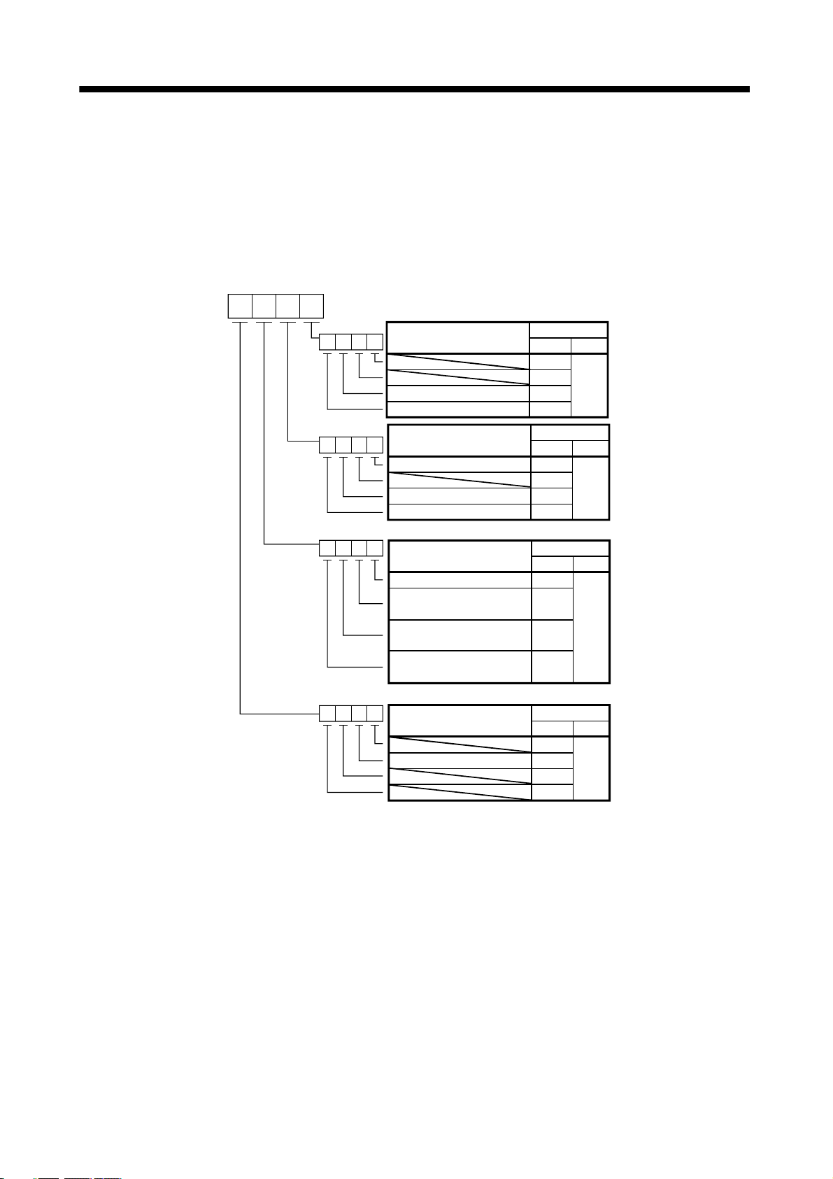
3. CC-LINK COMMUNICATION FUNCTIONS
3.5.6 Setting the CN6 external input signals
Using parameter No.PD06 to PD08, PD12 and PD14, you can assign the input devices as the CN6 external
input signals. The signals assigned as the CN6 external input devices cannot be used in CC-Link. Refer to
section 4.5.1 for the pins to which signals can be assigned.
In the initial status, the forward rotation stroke end, reverse rotation stroke end and proximity dog are preset to
be usable as the CN6 external input signals.
Parameter No.PD12
Device name
Servo-on (SON)
Reset (RES)
Device name
Proportion control (PC)
Clear (CR)
Forward rotation start (ST1)
Device name
Reverse rotation start (ST2)
Internal torque limit
selection (TL1)
Forward rotation stroke end
(LSP)
Reverse rotation stroke end
(LSN)
Device name
Gain changing (CDP)
BIN 0: Used in CC-Link
BIN 1: Used as CN6 external input signal
Initial value
BIN HEX
0
0
0
0
Initial value
BIN HEX
0
0
0
0
Initial value
BIN HEX
0
0
1
1
Initial value
BIN HEX
0
0
0
0
0
0
C
0
3 - 32
Page 94

3. CC-LINK COMMUNICATION FUNCTIONS
Parameter No.PD14
0
Automatic/manual selection
(MD0)
Device name
Initial value
BIN HEX
0
0
0
0
0
Device name
Temporary stop/Restart
(TSTP)
Device name
Proximity dog (DOG)
BIN 0: Used in CC-Link
BIN 1: Used as CN6 external input signal
Initial value
BIN HEX
0
0
0
0
0
Initial value
BIN HEX
0
0
8
0
1
3 - 33
Page 95

3. CC-LINK COMMUNICATION FUNCTIONS
3.6 Data communication timing charts
3.6.1 Monitor codes
(1) When 1 station is occupied
Monitor 1
(RWwn)
Monitor 2
(RWwn+1)
Monitor execution
demand (RYn8)
Monitoring
(RXn8)
Monitor 1 data
(RWrn)
Monitor 2 data
(RWrn+1)
Respond code
(RWrn+2)
ON
OFF
ON
OFF
Data HOLD
Set the monitor codes (refer to section 3.5.3) to Monitor 1 (RWwn) and Monitor 2 (RWwn+1) and turn Monitor
output execution demand (RYn8) to ON. Turning Monitor execution demand (RYn8) to ON sets the next data.
Data are all hexadecimal numbers. At this time, Monitoring (RXn8) turns to ON at the same time.
Monitor data 1 (RWrn): Data demanded by Monitor 1 (RWwn)
Monitor data 2 (RWrn+1): Data demanded by Monitor 2 (RWwn+1)
For 32-bit data, set the lower 16 bits of the monitor code to Monitor 1 (RWwn) and the upper 16 bits to Monitor
2 (RWwn+1) and read them simultaneously.
The monitor data set to the remote register are always updated while Monitor execution demand (RYn8) is ON.
When Monitoring (RXn8) turns to OFF, the data set to Monitor data RWrn, RWrn+1 are held. If the monitor
code not in the specifications is set to either Monitor 1 (RWwn) or Monitor 2 (RWwn+1), the corresponding
error code (
1) is set to respond code.
3 - 34
Page 96

3. CC-LINK COMMUNICATION FUNCTIONS
(2) When 2 stations are occupied
Monitor 1
(RWwn)
Monitor 2
(RWwn+1)
Monitor execution
demand (RYn8)
Monitoring
(RXn8)
Monitor 1 data
Lower 16bit (RWrn)
Monitor 1 data
Upper 16bit (RWrn+1)
Monitor 2 data
Lower 16bit (RWrn+5)
Monitor 2 data
Upper 16bit (RWrn+6)
Respond code
(RWrn+2)
ON
OFF
ON
OFF
Data HOLD
Set the monitor codes (refer to section 3.5.3) to Monitor 1 (RWwn) and Monitor 2 (RWwn+1) and turn Monitor
output execution demand (RYn8) to ON. Turning Monitor execution demand (RYn8) to ON sets the next data.
32-bit data are all divided into the upper 16 bits and lower 16 bits, and set to the remote register. Data are all
hexadecimal numbers. At this time, Monitoring (RXn8) turns to ON at the same time.
Monitor data 1 lower 16 bit (RWrn): Lower 16 bits of data demanded by Monitor 1 (RWwn)
Monitor data 1 upper 16 bit (RWrn+1): Upper 16 bits of data demanded by Monitor 1 (RWwn)
Monitor data 2 lower 16 bit (RWrn+5): Lower 16 bits of data demanded by Monitor 2 (RWwn+1)
Monitor data 2 upper 16 bit (RWrn+6): Upper 16 bits of data demanded by Monitor 2 (RWwn+1)
A sign is set if data does not exist in RWrn+1
RWrn+6. A " " sign is indicated by "0000", and " " by "FFFF".
The monitor data set to the remote register are always updated while Monitoring (RXn8) is ON.
When Monitoring (RXn8) turns to OFF, the data set to Monitor data RWrn, RWrn+1, RWrn+5, RWrn+6 are
held.
If the monitor code not in the specifications is set to either Monitor 1 (RWwn) or Monitor 2 (RWwn+1), the
corresponding error code (
1) is set to respond code.
3 - 35
Page 97

3. CC-LINK COMMUNICATION FUNCTIONS
3.6.2 Instruction codes
(1) Read instruction codes (0000h to 0A1Fh)
Instruction code
(RWwn+2)
Instruction code
execution demand
(RYn9)
Instruction code
execution completion
(RXn9)
Reading data
(RWrn+3)
Respond code
(RWrn+2)
Data read period
Set the read instruction code (refer to section 3.5.4 (1)) to Instruction code (RWwn+2) and turn Instruction
code execution demand (RYn9) to ON. Turning Instruction code execution demand (RYn9) to ON sets the
data corresponding to the preset read code to Reading data (RWrn+3). Data are all hexadecimal numbers.
At this time, Instruction code execution completion (RXn9) turns to ON at the same time.
Read the read data set to Reading data (RWrn+3) while Instruction code execution completion (RXn9) is
ON. The data set to Reading data (RWrn+3) is held until the next read instruction code is set and
Instruction code execution demand (RYn9) is turned to ON.
If the instruction code not in the specifications is set to Instruction code (RWwn+2), the corresponding error
code (
error code (
1 ) is set to respond code. If any unusable parameter, point table is read, the corresponding
2 ) is set.
Turn Instruction code execution demand (RYn9) to OFF after completion of data read.
3 - 36
Page 98

3. CC-LINK COMMUNICATION FUNCTIONS
(2) Write instruction codes (8000h to 911Fh)
Instruction code
(RWwn+2)
Writing data
(RWwn+3)
Instruction code
execution demand
(RYn9)
Instruction code
processing
Instruction code
execution completion
(RXn9)
Respond code
(RWrn+2)
Write in execution
Set the write instruction code (refer to section 3.5.4 (2)) to Instruction code (RWwn+2) and the data to be
written (data to be executed) to Writing data (RWwn+3) in hexadecimal, and turn Instruction code execution
demand (RYn9) to ON.
Turning instruction code execution completion to ON sets the data set in Wiring data (RWwn+3) to the item
corresponding to the write instruction code. When write is executed, Instruction code execution completion
(RXn9) turns to ON.
If the instruction code not in the specifications is set to Instruction code (RWwn+2), the corresponding error
code (
1 ) is set to respond code.
Turn Instruction code execution demand (RYn9) to OFF after Instruction code execution completion (RXn9)
has turned to ON.
3 - 37
Page 99

(
)
3. CC-LINK COMMUNICATION FUNCTIONS
3.6.3 Remote register-based position/speed setting
The functions in this section are usable when Position/speed specifying system selection (RY(n+2)A) is ON
(remote register-based position/speed specifying system is selected) with 2 stations occupied.
The position command/speed command necessary for positioning can be selected by parameter No.PC30
setting as indicated below.
Parameter No.PC30
Set value
0
1
2
Position command
Specify the point table No.
Set the position data.
Specify the point table No.
Set the servo motor speed.
Speed command
(1) When setting the point table No.
Specify the point table No. stored in the servo amplifier and execute positioning.
Preset "
Point table No.
(RWwn+4)
Position instruction
demand
(RY(n+2)0)
Point table No.
designation
Position instruction
execution
completion
(RX(n+2)0)
Respond code
(RWrn+2)
Forward/reverse
rotation start
RYn1 RYn2
0" (initial value) in parameter No.PC30 to enable point table No.-setting operation.
ON
OFF
(Note) Data reserved
ON
OFF
6ms
ON
OFF
Note. This data is stored into RAM of the servo amplifier. Hence, the data is cleared when power is switched off.
Set the point table No. to point table No. (RWwn+4) and turn Position instruction demand (RY(n+2)0) to
ON.
Turning RY(n+2)0 to ON stores the position block No. into RAM of the servo amplifier.
When the data is stored, Position instruction execution completion (RX(n+2)0) turns to ON.
If data outside the setting range is set to Position block No. (RWwn+4), the error code (refer to section
3.5.5) is set to respond code.
Turn Forward rotation start (RYn1)/Reverse rotation start (RYn2) to ON after Position instruction execution
completion (RX(n+2)0) has turned to ON.
3 - 38
Page 100
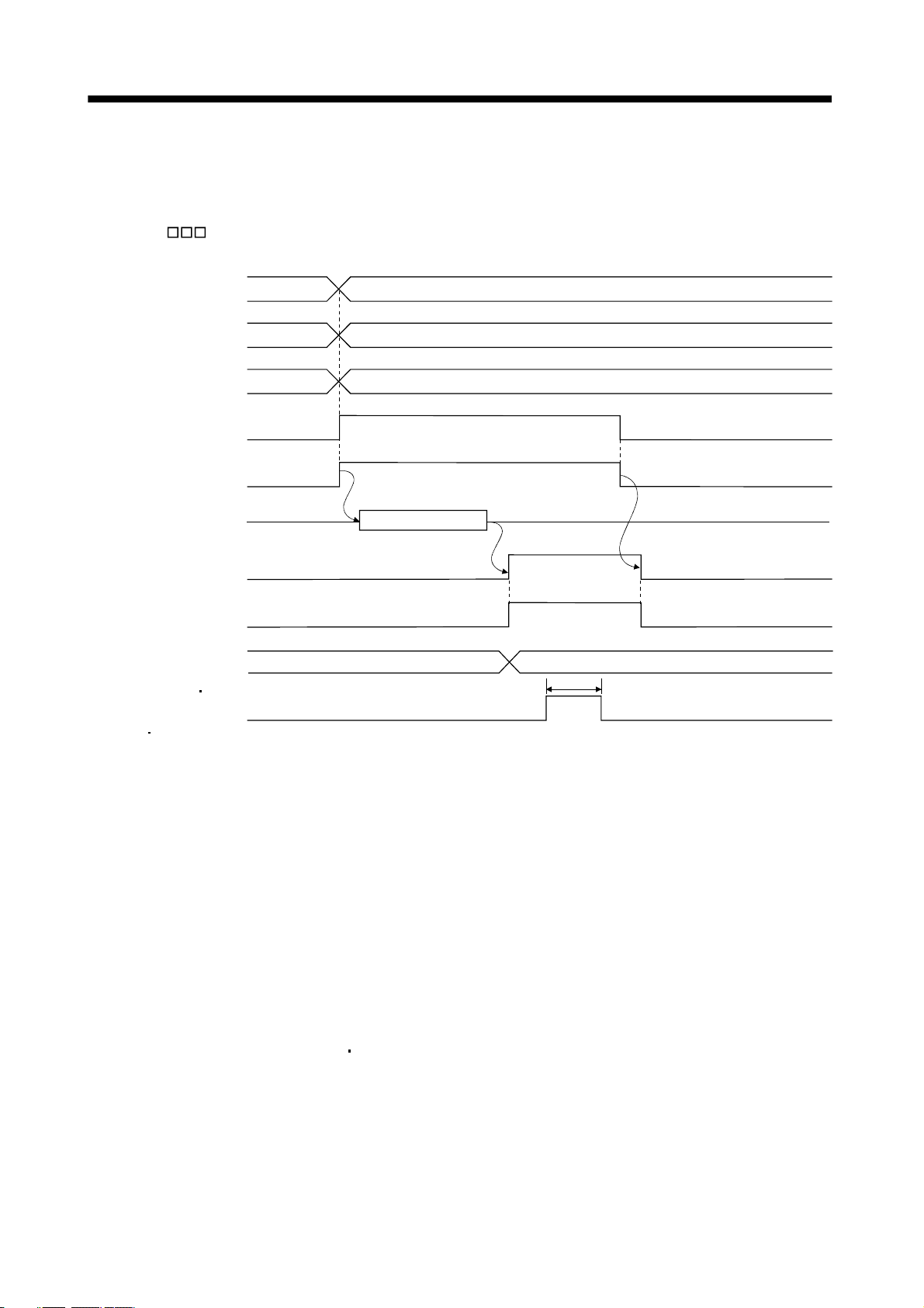
3. CC-LINK COMMUNICATION FUNCTIONS
(2) When setting the position command data/point table No. (speed command)
Specify the position address with the remote register, and specify the speed command data by specifying
the point table No. to use the preset servo motor speed, acceleration time constant and deceleration time
constant the speed command data, and execute positioning.
Preset "
1" in parameter No.PC30 to enable position command data-set and point table No. (speed
instruction)-setting operation.
Position instruction data
Lower 16bit (RWwn+4)
Position instruction data
Upper 16bit (RWwn+5)
Point table No.
(RWwn+6)
Position instruction
demand
(RY(n+2)0)
Speed instruction
demand
(RY(n+2)1)
Position data setting
Point table No.
designation
Position instruction
execution completion
(RX(n+2)0)
Speed instruction
execution completion
(RX(n+2)1)
Respond code
(RWrn+2)
Forward rotation
Reverse rotation
start
(RYn1 RYn2)
Note. This data is stored into RAM of the servo amplifier. Hence, the data is cleared when power is switched off.
ON
OFF
ON
OFF
(Note) Data reserved
ON
OFF
ON
OFF
6ms
ON
OFF
Set the lower 16 bits of the position instruction data to Position instruction data lower 16 bit (RWwn+4), the
upper 16 bits of the position instruction data to Position instruction data upper 16 bit (RWwn+5), and point
table for speed command No. to point table No. (RWwn+6), and turn Position instruction demand
(RY(n+2)0) and Speed instruction demand (RY(n+2)1) to ON.
Turning RY(n+2)0 and RY(n+2)1 to ON stores the position command data and point table No. into RAM of
the servo amplifier.
When the data are stored, Position instruction execution completion (RX(n+2)0) and Speed instruction
execution completion (RX(n+2)1) turn to ON.
If data outside the setting range is set to any of Position instruction data lower 16 bit (RWwn+4), Position
instruction data upper 16 bit (RWwn+5) and point table No. (RWwn+6), the error code (refer to section
3.5.5) is set to respond code.
Turn Forward rotation start (RYn1)
Reverse rotation start (RYn2) to ON after Position instruction execution
completion (RX(n+2)0) and Speed instruction execution completion (RX(n+2)1) have turned to ON.
3 - 39
 Loading...